Embed Size (px)
Citation preview

8/13/2019 t644 Service Manual
http://slidepdf.com/reader/full/t644-service-manual 1/423
Lexm ark™ T640, T642, and T644
4061-xx0
• Table of Con tents
• Start Diagnos t ics
• Safety and Not ices
• Trademarks
• Index
Revised : May 26, 2009
8/13/2019 t644 Service Manual
http://slidepdf.com/reader/full/t644-service-manual 2/423
Edition: May 26, 2009
The following paragraph does not apply to any country where such provisions are inconsistent with local law :LEXMARK INTERNATIONAL, INC. PROVIDES THIS PUBLICATION “AS IS” WITHOUT WARRANTY OF ANY KIND,EITHER EXPRESS OR IMPLIED, INCLUDING, BUT NOT LIMITED TO, THE IMPLIED WARRANTIES OFMERCHANTABILITY OR FITNESS FOR A PARTICULAR PURPOSE. Some states do not allow disclaimer of express orimplied warranties in certain transactions; therefore, this statement may not apply to you.
This publication could include technical inaccuracies or typographical errors. Changes are periodically made to the
information herein; these changes will be incorporated in later editions. Improvements or changes in the products or theprograms described may be made at any time.
Comments may be addressed to Lexmark International, Inc., Department D22A/032-2, 740 West New Circle Road,Lexington, Kentucky 40550, U.S.A or e-mail at [email protected]. Lexmark may use or distribute anyof the information you supply in any way it believes appropriate without incurring any obligation to you.
Lexmark, Lexmark with diamond design, MarkNet, and MarkVision are trademarks of Lexmark International, Inc.,registered in the United States and/or other countries
4061-xx0
8/13/2019 t644 Service Manual
http://slidepdf.com/reader/full/t644-service-manual 3/423
4061-xx0
Table of contents
Laser notices . . . . . . . . . . . . . . . . . . . . . . . . . . . . . . . . . . . . . . . . . . . . . . . . . . . . . . . . . . xi
Safety information . . . . . . . . . . . . . . . . . . . . . . . . . . . . . . . . . . . . . . . . . . . . . . . . . . . . xvii
Preface . . . . . . . . . . . . . . . . . . . . . . . . . . . . . . . . . . . . . . . . . . . . . . . . . . . . . . . . . . . . . . xxDefinitions . . . . . . . . . . . . . . . . . . . . . . . . . . . . . . . . . . . . . . . . . . . . . . . . . . . . . . . . . . . . . . . . . . . . . . . . . v-xx
General information . . . . . . . . . . . . . . . . . . . . . . . . . . . . . . . . . . . . . . . . . . . . . . . . . . .1-1Maintenance approach . . . . . . . . . . . . . . . . . . . . . . . . . . . . . . . . . . . . . . . . . . . . . . . . . . . . . . . . . . . . . . . 1-1Options . . . . . . . . . . . . . . . . . . . . . . . . . . . . . . . . . . . . . . . . . . . . . . . . . . . . . . . . . . . . . . . . . . . . . . . . . . . . 1-2
Configured models . . . . . . . . . . . . . . . . . . . . . . . . . . . . . . . . . . . . . . . . . . . . . . . . . . . . . . . . . . . . . . . . 1-3
Specifications . . . . . . . . . . . . . . . . . . . . . . . . . . . . . . . . . . . . . . . . . . . . . . . . . . . . . . . . . . . . . . . . . . . . . . . 1-4Resolution . . . . . . . . . . . . . . . . . . . . . . . . . . . . . . . . . . . . . . . . . . . . . . . . . . . . . . . . . . . . . . . . . . . . . . 1-4Data streams . . . . . . . . . . . . . . . . . . . . . . . . . . . . . . . . . . . . . . . . . . . . . . . . . . . . . . . . . . . . . . . . . . . . 1-4Print speed and performance print speed . . . . . . . . . . . . . . . . . . . . . . . . . . . . . . . . . . . . . . . . . . . . . . 1-4
Performance. . . . . . . . . . . . . . . . . . . . . . . . . . . . . . . . . . . . . . . . . . . . . . . . . . . . . . . . . . . . . . . . . 1-4Time to first print . . . . . . . . . . . . . . . . . . . . . . . . . . . . . . . . . . . . . . . . . . . . . . . . . . . . . . . . . . . . . 1-4
Memory configuration . . . . . . . . . . . . . . . . . . . . . . . . . . . . . . . . . . . . . . . . . . . . . . . . . . . . . . . . . . . . . 1-5Operating clearances . . . . . . . . . . . . . . . . . . . . . . . . . . . . . . . . . . . . . . . . . . . . . . . . . . . . . . . . . . . . . . 1-5Dimensions . . . . . . . . . . . . . . . . . . . . . . . . . . . . . . . . . . . . . . . . . . . . . . . . . . . . . . . . . . . . . . . . . . . . . 1-6Power requirements . . . . . . . . . . . . . . . . . . . . . . . . . . . . . . . . . . . . . . . . . . . . . . . . . . . . . . . . . . . . . . . 1-7Electrical specifications . . . . . . . . . . . . . . . . . . . . . . . . . . . . . . . . . . . . . . . . . . . . . . . . . . . . . . . . . . . . 1-7Environment . . . . . . . . . . . . . . . . . . . . . . . . . . . . . . . . . . . . . . . . . . . . . . . . . . . . . . . . . . . . . . . . . . . . . 1-8Acoustics . . . . . . . . . . . . . . . . . . . . . . . . . . . . . . . . . . . . . . . . . . . . . . . . . . . . . . . . . . . . . . . . . . . . . . . 1-8
Media specifications . . . . . . . . . . . . . . . . . . . . . . . . . . . . . . . . . . . . . . . . . . . . . . . . . . . . . . . . . . . . . . . . . 1-9Paper and specialty media guidelines . . . . . . . . . . . . . . . . . . . . . . . . . . . . . . . . . . . . . . . . . . . . . . . . . 1-9Supported print media . . . . . . . . . . . . . . . . . . . . . . . . . . . . . . . . . . . . . . . . . . . . . . . . . . . . . . . . . . . . . 1-9Selecting print media . . . . . . . . . . . . . . . . . . . . . . . . . . . . . . . . . . . . . . . . . . . . . . . . . . . . . . . . . . . . . 1-16
Paper . . . . . . . . . . . . . . . . . . . . . . . . . . . . . . . . . . . . . . . . . . . . . . . . . . . . . . . . . . . . . . . . . . . . . 1-16Paper characteristics . . . . . . . . . . . . . . . . . . . . . . . . . . . . . . . . . . . . . . . . . . . . . . . . . . . . . . . . . 1-16Weight . . . . . . . . . . . . . . . . . . . . . . . . . . . . . . . . . . . . . . . . . . . . . . . . . . . . . . . . . . . . . . . . . . . . 1-16Unacceptable paper . . . . . . . . . . . . . . . . . . . . . . . . . . . . . . . . . . . . . . . . . . . . . . . . . . . . . . . . . . 1-16Transparencies . . . . . . . . . . . . . . . . . . . . . . . . . . . . . . . . . . . . . . . . . . . . . . . . . . . . . . . . . . . . . 1-17Selecting transparencies . . . . . . . . . . . . . . . . . . . . . . . . . . . . . . . . . . . . . . . . . . . . . . . . . . . . . . 1-17Envelopes . . . . . . . . . . . . . . . . . . . . . . . . . . . . . . . . . . . . . . . . . . . . . . . . . . . . . . . . . . . . . . . . . 1-17Labels. . . . . . . . . . . . . . . . . . . . . . . . . . . . . . . . . . . . . . . . . . . . . . . . . . . . . . . . . . . . . . . . . . . . . 1-18
Card stock . . . . . . . . . . . . . . . . . . . . . . . . . . . . . . . . . . . . . . . . . . . . . . . . . . . . . . . . . . . . . . . . . 1-19Storing print media . . . . . . . . . . . . . . . . . . . . . . . . . . . . . . . . . . . . . . . . . . . . . . . . . . . . . . . . . . . . . . . 1-19Avoiding jams . . . . . . . . . . . . . . . . . . . . . . . . . . . . . . . . . . . . . . . . . . . . . . . . . . . . . . . . . . . . . . . . . . 1-20Print area . . . . . . . . . . . . . . . . . . . . . . . . . . . . . . . . . . . . . . . . . . . . . . . . . . . . . . . . . . . . . . . . . . . . . . 1-20
Tools required . . . . . . . . . . . . . . . . . . . . . . . . . . . . . . . . . . . . . . . . . . . . . . . . . . . . . . . . . . . . . . . . . . . . . 1-20
Acronyms . . . . . . . . . . . . . . . . . . . . . . . . . . . . . . . . . . . . . . . . . . . . . . . . . . . . . . . . . . . . . . . . . . . . . . . . . 1-21
8/13/2019 t644 Service Manual
http://slidepdf.com/reader/full/t644-service-manual 4/423
4061-xx0
Symptom tables . . . . . . . . . . . . . . . . . . . . . . . . . . . . . . . . . . . . . . . . . . . . . . . . . . . . . . . . . . . . . . . . . . . . . .2-5Base printer symptoms . . . . . . . . . . . . . . . . . . . . . . . . . . . . . . . . . . . . . . . . . . . . . . . . . . . . . . . . . . . . .2-5High-capacity feeder (2000-sheet) symptoms . . . . . . . . . . . . . . . . . . . . . . . . . . . . . . . . . . . . . . . . . . .2-5
Paper tray symptoms . . . . . . . . . . . . . . . . . . . . . . . . . . . . . . . . . . . . . . . . . . . . . . . . . . . . . . . . . . . . . .2-6Duplex option symptoms . . . . . . . . . . . . . . . . . . . . . . . . . . . . . . . . . . . . . . . . . . . . . . . . . . . . . . . . . . . .2-6Envelope feeder symptoms . . . . . . . . . . . . . . . . . . . . . . . . . . . . . . . . . . . . . . . . . . . . . . . . . . . . . . . . .2-6Output expander . . . . . . . . . . . . . . . . . . . . . . . . . . . . . . . . . . . . . . . . . . . . . . . . . . . . . . . . . . . . . . . . . .2-6StapleSmart finisher . . . . . . . . . . . . . . . . . . . . . . . . . . . . . . . . . . . . . . . . . . . . . . . . . . . . . . . . . . . . . . .2-7
Messages and error codes . . . . . . . . . . . . . . . . . . . . . . . . . . . . . . . . . . . . . . . . . . . . . . . . . . . . . . . . . . . . . 2-8Service error codes . . . . . . . . . . . . . . . . . . . . . . . . . . . . . . . . . . . . . . . . . . . . . . . . . . . . . . . . . . . . . . . .2-8User status displays . . . . . . . . . . . . . . . . . . . . . . . . . . . . . . . . . . . . . . . . . . . . . . . . . . . . . . . . . . . . . .2-31User attendance messages . . . . . . . . . . . . . . . . . . . . . . . . . . . . . . . . . . . . . . . . . . . . . . . . . . . . . . . .2-32
User line 2 link messages . . . . . . . . . . . . . . . . . . . . . . . . . . . . . . . . . . . . . . . . . . . . . . . . . . . . . . 2-43Check device connection messages . . . . . . . . . . . . . . . . . . . . . . . . . . . . . . . . . . . . . . . . . . . . . .2-43
User attendance messages—paper jams and paper handling errors (2 xx . xx ) . . . . . . . . . . . . . . . . . .2-44
Service checks . . . . . . . . . . . . . . . . . . . . . . . . . . . . . . . . . . . . . . . . . . . . . . . . . . . . . . . . . . . . . . . . . . . . . .2-725-Bin mailbox service check . . . . . . . . . . . . . . . . . . . . . . . . . . . . . . . . . . . . . . . . . . . . . . . . . . . . . . . .2-72900.xx Error code service check . . . . . . . . . . . . . . . . . . . . . . . . . . . . . . . . . . . . . . . . . . . . . . . . . . . . .2-75927.xx Fan service check . . . . . . . . . . . . . . . . . . . . . . . . . . . . . . . . . . . . . . . . . . . . . . . . . . . . . . . . . .2-76
Main fan. . . . . . . . . . . . . . . . . . . . . . . . . . . . . . . . . . . . . . . . . . . . . . . . . . . . . . . . . . . . . . . . . . . . 2-76Cartridge fan service check. . . . . . . . . . . . . . . . . . . . . . . . . . . . . . . . . . . . . . . . . . . . . . . . . . . . .2-76
950.00 through 950.29 EPROM mismatch failure . . . . . . . . . . . . . . . . . . . . . . . . . . . . . . . . . . . . . . .2-77
950.30 through 950.60 EPROM mismatch failure . . . . . . . . . . . . . . . . . . . . . . . . . . . . . . . . . . . . . . .2-78Charge roll service check . . . . . . . . . . . . . . . . . . . . . . . . . . . . . . . . . . . . . . . . . . . . . . . . . . . . . . . . . .2-79Cover closed switch/cable service check . . . . . . . . . . . . . . . . . . . . . . . . . . . . . . . . . . . . . . . . . . . . . .2-80Dead machine service check . . . . . . . . . . . . . . . . . . . . . . . . . . . . . . . . . . . . . . . . . . . . . . . . . . . . . . .2-80Duplex option service check . . . . . . . . . . . . . . . . . . . . . . . . . . . . . . . . . . . . . . . . . . . . . . . . . . . . . . . .2-82Envelope feeder service check . . . . . . . . . . . . . . . . . . . . . . . . . . . . . . . . . . . . . . . . . . . . . . . . . . . . . .2-84Fuser service checks . . . . . . . . . . . . . . . . . . . . . . . . . . . . . . . . . . . . . . . . . . . . . . . . . . . . . . . . . . . . .2-87
920.xx—Cold fuser service check . . . . . . . . . . . . . . . . . . . . . . . . . . . . . . . . . . . . . . . . . . . . . . . .2-87922.xx—Cold fuser check . . . . . . . . . . . . . . . . . . . . . . . . . . . . . . . . . . . . . . . . . . . . . . . . . . . . . . 2-89923.xx—Hot fuser service check. . . . . . . . . . . . . . . . . . . . . . . . . . . . . . . . . . . . . . . . . . . . . . . . .2-90
924.xx—Hot fuser service check. . . . . . . . . . . . . . . . . . . . . . . . . . . . . . . . . . . . . . . . . . . . . . . . .2-91925.xx—Hot fuser service check. . . . . . . . . . . . . . . . . . . . . . . . . . . . . . . . . . . . . . . . . . . . . . . . .2-91
Fuser exit sensor service check . . . . . . . . . . . . . . . . . . . . . . . . . . . . . . . . . . . . . . . . . . . . . . . . . . . . .2-92Fuser narrow media sensor service check . . . . . . . . . . . . . . . . . . . . . . . . . . . . . . . . . . . . . . . . . . . . .2-93Fuser solenoid service check . . . . . . . . . . . . . . . . . . . . . . . . . . . . . . . . . . . . . . . . . . . . . . . . . . . . . . .2-95High-capacity feeder input tray service check . . . . . . . . . . . . . . . . . . . . . . . . . . . . . . . . . . . . . . . . . .2-96High-capacity output stacker service check . . . . . . . . . . . . . . . . . . . . . . . . . . . . . . . . . . . . . . . . . . .2-101Input sensor service check . . . . . . . . . . . . . . . . . . . . . . . . . . . . . . . . . . . . . . . . . . . . . . . . . . . . . . . .2-103Input tray(s) service check . . . . . . . . . . . . . . . . . . . . . . . . . . . . . . . . . . . . . . . . . . . . . . . . . . . . . . . .2-103Interconnect card service check . . . . . . . . . . . . . . . . . . . . . . . . . . . . . . . . . . . . . . . . . . . . . . . . . . . .2-105
Main drive service check . . . . . . . . . . . . . . . . . . . . . . . . . . . . . . . . . . . . . . . . . . . . . . . . . . . . . . . . . . 2-106Operator panel service check . . . . . . . . . . . . . . . . . . . . . . . . . . . . . . . . . . . . . . . . . . . . . . . . . . . . . .2-107
One or more operator panel buttons fail . . . . . . . . . . . . . . . . . . . . . . . . . . . . . . . . . . . . . . . . . .2-107No buttons work . . . . . . . . . . . . . . . . . . . . . . . . . . . . . . . . . . . . . . . . . . . . . . . . . . . . . . . . . . . .2-107Operator panel display . . . . . . . . . . . . . . . . . . . . . . . . . . . . . . . . . . . . . . . . . . . . . . . . . . . . . . . 2-108
Options service check . . . . . . . . . . . . . . . . . . . . . . . . . . . . . . . . . . . . . . . . . . . . . . . . . . . . . . . . . . . .2-109Flash Memory Option(s) . . . . . . . . . . . . . . . . . . . . . . . . . . . . . . . . . . . . . . . . . . . . . . . . . . . . . . 2-109
8/13/2019 t644 Service Manual
http://slidepdf.com/reader/full/t644-service-manual 5/423
4061-xx0
Signature button assembly service check . . . . . . . . . . . . . . . . . . . . . . . . . . . . . . . . . . . . . . . . . . . . 2-123StapleSmart finisher service check . . . . . . . . . . . . . . . . . . . . . . . . . . . . . . . . . . . . . . . . . . . . . . . . . 2-124System board service check . . . . . . . . . . . . . . . . . . . . . . . . . . . . . . . . . . . . . . . . . . . . . . . . . . . . . . 2-127
Toner sensor service check . . . . . . . . . . . . . . . . . . . . . . . . . . . . . . . . . . . . . . . . . . . . . . . . . . . . . . . 2-128Transfer roll service check . . . . . . . . . . . . . . . . . . . . . . . . . . . . . . . . . . . . . . . . . . . . . . . . . . . . . . . . 2-129
Diagnostic aids . . . . . . . . . . . . . . . . . . . . . . . . . . . . . . . . . . . . . . . . . . . . . . . . . . . . . . .3-1Accessing service menus . . . . . . . . . . . . . . . . . . . . . . . . . . . . . . . . . . . . . . . . . . . . . . . . . . . . . . . . . . . . . 3-1
Diagnostics mode . . . . . . . . . . . . . . . . . . . . . . . . . . . . . . . . . . . . . . . . . . . . . . . . . . . . . . . . . . . . . . . . . . . 3-2Entering Diagnostics mode . . . . . . . . . . . . . . . . . . . . . . . . . . . . . . . . . . . . . . . . . . . . . . . . . . . . . . . . . 3-2Available tests . . . . . . . . . . . . . . . . . . . . . . . . . . . . . . . . . . . . . . . . . . . . . . . . . . . . . . . . . . . . . . . . . . . 3-2Exiting Diagnostics mode . . . . . . . . . . . . . . . . . . . . . . . . . . . . . . . . . . . . . . . . . . . . . . . . . . . . . . . . . . 3-4
REGISTRATION . . . . . . . . . . . . . . . . . . . . . . . . . . . . . . . . . . . . . . . . . . . . . . . . . . . . . . . . . . . . . . . . . 3-4Quick Test . . . . . . . . . . . . . . . . . . . . . . . . . . . . . . . . . . . . . . . . . . . . . . . . . . . . . . . . . . . . . . . . . . 3-5
PRINT TESTS . . . . . . . . . . . . . . . . . . . . . . . . . . . . . . . . . . . . . . . . . . . . . . . . . . . . . . . . . . . . . . . . . . . 3-6Input source tests. . . . . . . . . . . . . . . . . . . . . . . . . . . . . . . . . . . . . . . . . . . . . . . . . . . . . . . . . . . . . 3-6Print quality pages (Prt Quality Pgs) . . . . . . . . . . . . . . . . . . . . . . . . . . . . . . . . . . . . . . . . . . . . . . 3-6
HARDWARE TESTS . . . . . . . . . . . . . . . . . . . . . . . . . . . . . . . . . . . . . . . . . . . . . . . . . . . . . . . . . . . . . . 3-7Panel Test . . . . . . . . . . . . . . . . . . . . . . . . . . . . . . . . . . . . . . . . . . . . . . . . . . . . . . . . . . . . . . . . . . 3-7Button Test. . . . . . . . . . . . . . . . . . . . . . . . . . . . . . . . . . . . . . . . . . . . . . . . . . . . . . . . . . . . . . . . . . 3-7DRAM Test. . . . . . . . . . . . . . . . . . . . . . . . . . . . . . . . . . . . . . . . . . . . . . . . . . . . . . . . . . . . . . . . . . 3-7CACHE Test. . . . . . . . . . . . . . . . . . . . . . . . . . . . . . . . . . . . . . . . . . . . . . . . . . . . . . . . . . . . . . . . . 3-8Parallel Wrap tests . . . . . . . . . . . . . . . . . . . . . . . . . . . . . . . . . . . . . . . . . . . . . . . . . . . . . . . . . . . . 3-8Serial Wrap tests . . . . . . . . . . . . . . . . . . . . . . . . . . . . . . . . . . . . . . . . . . . . . . . . . . . . . . . . . . . . . 3-9
DUPLEX TESTS . . . . . . . . . . . . . . . . . . . . . . . . . . . . . . . . . . . . . . . . . . . . . . . . . . . . . . . . . . . . . . . . . 3-9Quick Test (duplex) . . . . . . . . . . . . . . . . . . . . . . . . . . . . . . . . . . . . . . . . . . . . . . . . . . . . . . . . . . . 3-9Top Margin (duplex) . . . . . . . . . . . . . . . . . . . . . . . . . . . . . . . . . . . . . . . . . . . . . . . . . . . . . . . . . . 3-10Sensor Test (duplex) . . . . . . . . . . . . . . . . . . . . . . . . . . . . . . . . . . . . . . . . . . . . . . . . . . . . . . . . . 3-10Motor Test (duplex) . . . . . . . . . . . . . . . . . . . . . . . . . . . . . . . . . . . . . . . . . . . . . . . . . . . . . . . . . . 3-11Duplex Feed 1 . . . . . . . . . . . . . . . . . . . . . . . . . . . . . . . . . . . . . . . . . . . . . . . . . . . . . . . . . . . . . . 3-12Duplex Feed 2 . . . . . . . . . . . . . . . . . . . . . . . . . . . . . . . . . . . . . . . . . . . . . . . . . . . . . . . . . . . . . . 3-12
INPUT TRAY TESTS . . . . . . . . . . . . . . . . . . . . . . . . . . . . . . . . . . . . . . . . . . . . . . . . . . . . . . . . . . . . . 3-13Feed Tests (input tray) . . . . . . . . . . . . . . . . . . . . . . . . . . . . . . . . . . . . . . . . . . . . . . . . . . . . . . . . 3-13Sensor Test (input tray) . . . . . . . . . . . . . . . . . . . . . . . . . . . . . . . . . . . . . . . . . . . . . . . . . . . . . . . 3-13
OUTPUT BIN TESTS . . . . . . . . . . . . . . . . . . . . . . . . . . . . . . . . . . . . . . . . . . . . . . . . . . . . . . . . . . . . 3-14Feed Tests (output bins) . . . . . . . . . . . . . . . . . . . . . . . . . . . . . . . . . . . . . . . . . . . . . . . . . . . . . . 3-14Feed To All Bins. . . . . . . . . . . . . . . . . . . . . . . . . . . . . . . . . . . . . . . . . . . . . . . . . . . . . . . . . . . . . 3-14Sensor Test (standard output bin) . . . . . . . . . . . . . . . . . . . . . . . . . . . . . . . . . . . . . . . . . . . . . . . 3-15Sensor Test (Output Expander) . . . . . . . . . . . . . . . . . . . . . . . . . . . . . . . . . . . . . . . . . . . . . . . . . 3-15Sensor Test (high capacity output stacker) . . . . . . . . . . . . . . . . . . . . . . . . . . . . . . . . . . . . . . . . 3-16Sensor Tests (5-bin mailbox) . . . . . . . . . . . . . . . . . . . . . . . . . . . . . . . . . . . . . . . . . . . . . . . . . . . 3-16
Diverter Test. . . . . . . . . . . . . . . . . . . . . . . . . . . . . . . . . . . . . . . . . . . . . . . . . . . . . . . . . . . . . . . . 3-16FINISHER TESTS . . . . . . . . . . . . . . . . . . . . . . . . . . . . . . . . . . . . . . . . . . . . . . . . . . . . . . . . . . . . . . . 3-17Staple Test . . . . . . . . . . . . . . . . . . . . . . . . . . . . . . . . . . . . . . . . . . . . . . . . . . . . . . . . . . . . . . . . . 3-17Feed Tests (finisher) . . . . . . . . . . . . . . . . . . . . . . . . . . . . . . . . . . . . . . . . . . . . . . . . . . . . . . . . . 3-17Sensor Test (finisher). . . . . . . . . . . . . . . . . . . . . . . . . . . . . . . . . . . . . . . . . . . . . . . . . . . . . . . . . 3-17
BASE SENSOR TEST . . . . . . . . . . . . . . . . . . . . . . . . . . . . . . . . . . . . . . . . . . . . . . . . . . . . . . . . . . . . 3-18DEVICE TESTS . . . . . . . . . . . . . . . . . . . . . . . . . . . . . . . . . . . . . . . . . . . . . . . . . . . . . . . . . . . . . . . . . 3-18
Quick Disk Test 3 18
8/13/2019 t644 Service Manual
http://slidepdf.com/reader/full/t644-service-manual 6/423
4061-xx0
Model Name . . . . . . . . . . . . . . . . . . . . . . . . . . . . . . . . . . . . . . . . . . . . . . . . . . . . . . . . . . . . . . . .3-20Configuration ID . . . . . . . . . . . . . . . . . . . . . . . . . . . . . . . . . . . . . . . . . . . . . . . . . . . . . . . . . . . . . 3-21Edge to Edge. . . . . . . . . . . . . . . . . . . . . . . . . . . . . . . . . . . . . . . . . . . . . . . . . . . . . . . . . . . . . . . .3-21
Parallel strobe adjustment (Par x Strobe Adj) . . . . . . . . . . . . . . . . . . . . . . . . . . . . . . . . . . . . . . .3-21EP SETUP . . . . . . . . . . . . . . . . . . . . . . . . . . . . . . . . . . . . . . . . . . . . . . . . . . . . . . . . . . . . . . . . . . . . .3-22
EP Defaults . . . . . . . . . . . . . . . . . . . . . . . . . . . . . . . . . . . . . . . . . . . . . . . . . . . . . . . . . . . . . . . . . 3-22Fuser Temperature (Fuser Temp). . . . . . . . . . . . . . . . . . . . . . . . . . . . . . . . . . . . . . . . . . . . . . . .3-22Fuser Page Count . . . . . . . . . . . . . . . . . . . . . . . . . . . . . . . . . . . . . . . . . . . . . . . . . . . . . . . . . . . .3-22Warm Up Time . . . . . . . . . . . . . . . . . . . . . . . . . . . . . . . . . . . . . . . . . . . . . . . . . . . . . . . . . . . . . . 3-22Transfer . . . . . . . . . . . . . . . . . . . . . . . . . . . . . . . . . . . . . . . . . . . . . . . . . . . . . . . . . . . . . . . . . . . .3-22Print Contrast . . . . . . . . . . . . . . . . . . . . . . . . . . . . . . . . . . . . . . . . . . . . . . . . . . . . . . . . . . . . . . . 3-22Charge Roll . . . . . . . . . . . . . . . . . . . . . . . . . . . . . . . . . . . . . . . . . . . . . . . . . . . . . . . . . . . . . . . . . 3-22Gap Adjust. . . . . . . . . . . . . . . . . . . . . . . . . . . . . . . . . . . . . . . . . . . . . . . . . . . . . . . . . . . . . . . . . . 3-22
EVENT LOG . . . . . . . . . . . . . . . . . . . . . . . . . . . . . . . . . . . . . . . . . . . . . . . . . . . . . . . . . . . . . . . . . . . .3-23Display Log . . . . . . . . . . . . . . . . . . . . . . . . . . . . . . . . . . . . . . . . . . . . . . . . . . . . . . . . . . . . . . . . . 3-23Print Log . . . . . . . . . . . . . . . . . . . . . . . . . . . . . . . . . . . . . . . . . . . . . . . . . . . . . . . . . . . . . . . . . . . 3-23Clear Log. . . . . . . . . . . . . . . . . . . . . . . . . . . . . . . . . . . . . . . . . . . . . . . . . . . . . . . . . . . . . . . . . . . 3-24
EXIT DIAGNOSTICS . . . . . . . . . . . . . . . . . . . . . . . . . . . . . . . . . . . . . . . . . . . . . . . . . . . . . . . . . . . . .3-24
Configuration menu (CONFIG MENU) . . . . . . . . . . . . . . . . . . . . . . . . . . . . . . . . . . . . . . . . . . . . . . . . . . .3-25Entering Configuration Menu . . . . . . . . . . . . . . . . . . . . . . . . . . . . . . . . . . . . . . . . . . . . . . . . . . . . . . .3-25Available menus . . . . . . . . . . . . . . . . . . . . . . . . . . . . . . . . . . . . . . . . . . . . . . . . . . . . . . . . . . . . . . . . .3-25Maintenance page count (Maint Cnt Value) . . . . . . . . . . . . . . . . . . . . . . . . . . . . . . . . . . . . . . . . . . . .3-25
Maintenance page counter reset (Reset Maint Cnt) . . . . . . . . . . . . . . . . . . . . . . . . . . . . . . . . . . . . . .3-26Print quality pages (Prt Quality Pgs) . . . . . . . . . . . . . . . . . . . . . . . . . . . . . . . . . . . . . . . . . . . . . . . . . .3-26SIZE SENSING . . . . . . . . . . . . . . . . . . . . . . . . . . . . . . . . . . . . . . . . . . . . . . . . . . . . . . . . . . . . . . . . . .3-27Panel Menus . . . . . . . . . . . . . . . . . . . . . . . . . . . . . . . . . . . . . . . . . . . . . . . . . . . . . . . . . . . . . . . . . . . .3-27PPDS Emulation . . . . . . . . . . . . . . . . . . . . . . . . . . . . . . . . . . . . . . . . . . . . . . . . . . . . . . . . . . . . . . . . .3-27Download Emuls . . . . . . . . . . . . . . . . . . . . . . . . . . . . . . . . . . . . . . . . . . . . . . . . . . . . . . . . . . . . . . . . .3-27Demo Mode . . . . . . . . . . . . . . . . . . . . . . . . . . . . . . . . . . . . . . . . . . . . . . . . . . . . . . . . . . . . . . . . . . . .3-27Factory Defaults . . . . . . . . . . . . . . . . . . . . . . . . . . . . . . . . . . . . . . . . . . . . . . . . . . . . . . . . . . . . . . . . .3-28Energy Conserve . . . . . . . . . . . . . . . . . . . . . . . . . . . . . . . . . . . . . . . . . . . . . . . . . . . . . . . . . . . . . . . .3-28EVENT LOG . . . . . . . . . . . . . . . . . . . . . . . . . . . . . . . . . . . . . . . . . . . . . . . . . . . . . . . . . . . . . . . . . . . .3-28
Paper Prompts . . . . . . . . . . . . . . . . . . . . . . . . . . . . . . . . . . . . . . . . . . . . . . . . . . . . . . . . . . . . . . . . . .3-28Env Prompts . . . . . . . . . . . . . . . . . . . . . . . . . . . . . . . . . . . . . . . . . . . . . . . . . . . . . . . . . . . . . . . . . . . .3-28Jobs On Disk . . . . . . . . . . . . . . . . . . . . . . . . . . . . . . . . . . . . . . . . . . . . . . . . . . . . . . . . . . . . . . . . . . . . 3-28Disk Encryption . . . . . . . . . . . . . . . . . . . . . . . . . . . . . . . . . . . . . . . . . . . . . . . . . . . . . . . . . . . . . . . . . .3-28Font Sharpening . . . . . . . . . . . . . . . . . . . . . . . . . . . . . . . . . . . . . . . . . . . . . . . . . . . . . . . . . . . . . . . . .3-29LCD Brightness . . . . . . . . . . . . . . . . . . . . . . . . . . . . . . . . . . . . . . . . . . . . . . . . . . . . . . . . . . . . . . . . . . 3-29LCD Contrast . . . . . . . . . . . . . . . . . . . . . . . . . . . . . . . . . . . . . . . . . . . . . . . . . . . . . . . . . . . . . . . . . . .3-29Exit Config Menu . . . . . . . . . . . . . . . . . . . . . . . . . . . . . . . . . . . . . . . . . . . . . . . . . . . . . . . . . . . . . . . . . 3-29
Additional useful menu locations . . . . . . . . . . . . . . . . . . . . . . . . . . . . . . . . . . . . . . . . . . . . . . . . . . . . . . 3-29Hex Trace . . . . . . . . . . . . . . . . . . . . . . . . . . . . . . . . . . . . . . . . . . . . . . . . . . . . . . . . . . . . . . . . . . . . . .3-29
Menu settings page . . . . . . . . . . . . . . . . . . . . . . . . . . . . . . . . . . . . . . . . . . . . . . . . . . . . . . . . . . . . . . . 3-30Printing menu settings page . . . . . . . . . . . . . . . . . . . . . . . . . . . . . . . . . . . . . . . . . . . . . . . . . . . . . . . .3-30
Theory . . . . . . . . . . . . . . . . . . . . . . . . . . . . . . . . . . . . . . . . . . . . . . . . . . . . . . . . . . . . . . . . . . . . . . . . . . . . .3-31Autocompensator operation . . . . . . . . . . . . . . . . . . . . . . . . . . . . . . . . . . . . . . . . . . . . . . . . . . . . . . . .3-31Autoconnect system, paper tray options, envelope feeder—electrical . . . . . . . . . . . . . . . . . . . . . . . .3-32
Autoconnect cabling and connectors . . . . . . . . . . . . . . . . . . . . . . . . . . . . . . . . . . . . . . . . . . . . . 3-32Duplex Option . . . . . . . . . . . . . . . . . . . . . . . . . . . . . . . . . . . . . . . . . . . . . . . . . . . . . . . . . . . . . . .3-32
8/13/2019 t644 Service Manual
http://slidepdf.com/reader/full/t644-service-manual 7/423
4061-xx0
202 Paper Jam Open Rear Door . . . . . . . . . . . . . . . . . . . . . . . . . . . . . . . . . . . . . . . . . . . . . . . . 3-4323x Paper Jam Open Duplex Rear Door . . . . . . . . . . . . . . . . . . . . . . . . . . . . . . . . . . . . . . . . . . 3-44270 and 280 Paper Jams . . . . . . . . . . . . . . . . . . . . . . . . . . . . . . . . . . . . . . . . . . . . . . . . . . . . . . 3-45
27x Paper Jam Check Bin x. . . . . . . . . . . . . . . . . . . . . . . . . . . . . . . . . . . . . . . . . . . . . . . . . . . . 3-4528x Paper Jam Check Finisher . . . . . . . . . . . . . . . . . . . . . . . . . . . . . . . . . . . . . . . . . . . . . . . . . 3-46Clearing staple jams . . . . . . . . . . . . . . . . . . . . . . . . . . . . . . . . . . . . . . . . . . . . . . . . . . . . . . . . . . . . . 3-48
Repair information . . . . . . . . . . . . . . . . . . . . . . . . . . . . . . . . . . . . . . . . . . . . . . . . . . . .4-1Handling ESD-sensitive parts . . . . . . . . . . . . . . . . . . . . . . . . . . . . . . . . . . . . . . . . . . . . . . . . . . . . . . . . . . 4-1
Adjustment procedures . . . . . . . . . . . . . . . . . . . . . . . . . . . . . . . . . . . . . . . . . . . . . . . . . . . . . . . . . . . . . . . 4-2Fuser solenoid adjustment . . . . . . . . . . . . . . . . . . . . . . . . . . . . . . . . . . . . . . . . . . . . . . . . . . . . . . . . . . 4-2Gap adjustment . . . . . . . . . . . . . . . . . . . . . . . . . . . . . . . . . . . . . . . . . . . . . . . . . . . . . . . . . . . . . . . . . . 4-2
Printhead assembly adjustment . . . . . . . . . . . . . . . . . . . . . . . . . . . . . . . . . . . . . . . . . . . . . . . . . . . . . . 4-2Paper alignment assembly adjustment . . . . . . . . . . . . . . . . . . . . . . . . . . . . . . . . . . . . . . . . . . . . . . . . 4-3
Removal procedures . . . . . . . . . . . . . . . . . . . . . . . . . . . . . . . . . . . . . . . . . . . . . . . . . . . . . . . . . . . . . . . . . 4-5Covers removals . . . . . . . . . . . . . . . . . . . . . . . . . . . . . . . . . . . . . . . . . . . . . . . . . . . . . . . . . . . . . . . . . 4-5
Fuser wiper cover assembly removal. . . . . . . . . . . . . . . . . . . . . . . . . . . . . . . . . . . . . . . . . . . . . . 4-5Redrive cap cover removal . . . . . . . . . . . . . . . . . . . . . . . . . . . . . . . . . . . . . . . . . . . . . . . . . . . . . 4-6Paper support removal. . . . . . . . . . . . . . . . . . . . . . . . . . . . . . . . . . . . . . . . . . . . . . . . . . . . . . . . . 4-6Left door removal . . . . . . . . . . . . . . . . . . . . . . . . . . . . . . . . . . . . . . . . . . . . . . . . . . . . . . . . . . . . . 4-7Redrive door. . . . . . . . . . . . . . . . . . . . . . . . . . . . . . . . . . . . . . . . . . . . . . . . . . . . . . . . . . . . . . . . . 4-8Right cover removal . . . . . . . . . . . . . . . . . . . . . . . . . . . . . . . . . . . . . . . . . . . . . . . . . . . . . . . . . . . 4-9Upper front cover removal . . . . . . . . . . . . . . . . . . . . . . . . . . . . . . . . . . . . . . . . . . . . . . . . . . . . . 4-12Upper front cover latch removal . . . . . . . . . . . . . . . . . . . . . . . . . . . . . . . . . . . . . . . . . . . . . . . . . 4-14Upper front cover outer bezel removal. . . . . . . . . . . . . . . . . . . . . . . . . . . . . . . . . . . . . . . . . . . . 4-15Multipurpose feeder/lower front cover assembly removal . . . . . . . . . . . . . . . . . . . . . . . . . . . . . 4-16Left cover handle holder removal . . . . . . . . . . . . . . . . . . . . . . . . . . . . . . . . . . . . . . . . . . . . . . . . 4-17Right cover handle holder removal . . . . . . . . . . . . . . . . . . . . . . . . . . . . . . . . . . . . . . . . . . . . . . 4-17Left and right frame extensions . . . . . . . . . . . . . . . . . . . . . . . . . . . . . . . . . . . . . . . . . . . . . . . . . 4-18Pass thru plate . . . . . . . . . . . . . . . . . . . . . . . . . . . . . . . . . . . . . . . . . . . . . . . . . . . . . . . . . . . . . . 4-19Laser cover removal. . . . . . . . . . . . . . . . . . . . . . . . . . . . . . . . . . . . . . . . . . . . . . . . . . . . . . . . . . 4-20
Bevel gear removal . . . . . . . . . . . . . . . . . . . . . . . . . . . . . . . . . . . . . . . . . . . . . . . . . . . . . . . . . . . . . . 4-22Cartridge duct removal . . . . . . . . . . . . . . . . . . . . . . . . . . . . . . . . . . . . . . . . . . . . . . . . . . . . . . . . . . . 4-24Developer drive assembly removal . . . . . . . . . . . . . . . . . . . . . . . . . . . . . . . . . . . . . . . . . . . . . . . . . . 4-25Developer drive coupler kit removal . . . . . . . . . . . . . . . . . . . . . . . . . . . . . . . . . . . . . . . . . . . . . . . . . 4-26ESD cover removal . . . . . . . . . . . . . . . . . . . . . . . . . . . . . . . . . . . . . . . . . . . . . . . . . . . . . . . . . . . . . . 4-26Fuser assembly removal . . . . . . . . . . . . . . . . . . . . . . . . . . . . . . . . . . . . . . . . . . . . . . . . . . . . . . . . . . 4-27Fuser exit sensor removal . . . . . . . . . . . . . . . . . . . . . . . . . . . . . . . . . . . . . . . . . . . . . . . . . . . . . . . . . 4-29Fuser exit sensor flag and spring removal . . . . . . . . . . . . . . . . . . . . . . . . . . . . . . . . . . . . . . . . . . . . . 4-31Fuser lamp removal . . . . . . . . . . . . . . . . . . . . . . . . . . . . . . . . . . . . . . . . . . . . . . . . . . . . . . . . . . . . . . 4-33Fuser narrow media sensor removal . . . . . . . . . . . . . . . . . . . . . . . . . . . . . . . . . . . . . . . . . . . . . . . . . 4-35
Fuser narrow media flag and spring removal . . . . . . . . . . . . . . . . . . . . . . . . . . . . . . . . . . . . . . . . . . 4-37Fuser to LVPS AC cable removal . . . . . . . . . . . . . . . . . . . . . . . . . . . . . . . . . . . . . . . . . . . . . . . . . . . 4-39Fuser top cover removal . . . . . . . . . . . . . . . . . . . . . . . . . . . . . . . . . . . . . . . . . . . . . . . . . . . . . . . . . . 4-42Fuser transfer plate removal . . . . . . . . . . . . . . . . . . . . . . . . . . . . . . . . . . . . . . . . . . . . . . . . . . . . . . . 4-44Gear release link removal . . . . . . . . . . . . . . . . . . . . . . . . . . . . . . . . . . . . . . . . . . . . . . . . . . . . . . . . . 4-45High voltage power supply removal . . . . . . . . . . . . . . . . . . . . . . . . . . . . . . . . . . . . . . . . . . . . . . . . . . 4-46Inner paper deflector assembly removal . . . . . . . . . . . . . . . . . . . . . . . . . . . . . . . . . . . . . . . . . . . . . . 4-48I t l 4 49
8/13/2019 t644 Service Manual
http://slidepdf.com/reader/full/t644-service-manual 8/423
4061-xx0
MPF solenoid assembly removal . . . . . . . . . . . . . . . . . . . . . . . . . . . . . . . . . . . . . . . . . . . . . . . . . . . .4-63Operator panel board removal . . . . . . . . . . . . . . . . . . . . . . . . . . . . . . . . . . . . . . . . . . . . . . . . . . . . . .4-67Operator panel buttons removal . . . . . . . . . . . . . . . . . . . . . . . . . . . . . . . . . . . . . . . . . . . . . . . . . . . . .4-68
Outer shield removal . . . . . . . . . . . . . . . . . . . . . . . . . . . . . . . . . . . . . . . . . . . . . . . . . . . . . . . . . . . . . .4-69Paper alignment assembly removal . . . . . . . . . . . . . . . . . . . . . . . . . . . . . . . . . . . . . . . . . . . . . . . . . .4-70Paper bin full sensor flag removal . . . . . . . . . . . . . . . . . . . . . . . . . . . . . . . . . . . . . . . . . . . . . . . . . . . . 4-71Paper size sensing board removal . . . . . . . . . . . . . . . . . . . . . . . . . . . . . . . . . . . . . . . . . . . . . . . . . . .4-72Power takeoff shaft and spring removal . . . . . . . . . . . . . . . . . . . . . . . . . . . . . . . . . . . . . . . . . . . . . . .4-73Printhead removal . . . . . . . . . . . . . . . . . . . . . . . . . . . . . . . . . . . . . . . . . . . . . . . . . . . . . . . . . . . . . . . . 4-74Redrive assembly removal . . . . . . . . . . . . . . . . . . . . . . . . . . . . . . . . . . . . . . . . . . . . . . . . . . . . . . . . .4-75Signature button contact assembly removal . . . . . . . . . . . . . . . . . . . . . . . . . . . . . . . . . . . . . . . . . . . .4-76System board and inner shield removal . . . . . . . . . . . . . . . . . . . . . . . . . . . . . . . . . . . . . . . . . . . . . . .4-77Toner sensor removal . . . . . . . . . . . . . . . . . . . . . . . . . . . . . . . . . . . . . . . . . . . . . . . . . . . . . . . . . . . . .4-78
Transfer roll assembly removal . . . . . . . . . . . . . . . . . . . . . . . . . . . . . . . . . . . . . . . . . . . . . . . . . . . . . .4-78Upper front cover hinge assembly removal . . . . . . . . . . . . . . . . . . . . . . . . . . . . . . . . . . . . . . . . . . . .4-79Upper paper deflector assembly removal . . . . . . . . . . . . . . . . . . . . . . . . . . . . . . . . . . . . . . . . . . . . . .4-80USB board assembly removal . . . . . . . . . . . . . . . . . . . . . . . . . . . . . . . . . . . . . . . . . . . . . . . . . . . . . .4-80
Connector locations and connections . . . . . . . . . . . . . . . . . . . . . . . . . . . . . . . . . . . . 5-1Connections . . . . . . . . . . . . . . . . . . . . . . . . . . . . . . . . . . . . . . . . . . . . . . . . . . . . . . . . . . . . . . . . . . . . . . . . .5-1
System board . . . . . . . . . . . . . . . . . . . . . . . . . . . . . . . . . . . . . . . . . . . . . . . . . . . . . . . . . . . . . . . . . . . .5-1Autoconnect . . . . . . . . . . . . . . . . . . . . . . . . . . . . . . . . . . . . . . . . . . . . . . . . . . . . . . . . . . . . . . . . . . . . .5-7
Fuser Board . . . . . . . . . . . . . . . . . . . . . . . . . . . . . . . . . . . . . . . . . . . . . . . . . . . . . . . . . . . . . . . . . . . . .5-7High-capacity output stacker board . . . . . . . . . . . . . . . . . . . . . . . . . . . . . . . . . . . . . . . . . . . . . . . . . . .5-8High voltage power supply . . . . . . . . . . . . . . . . . . . . . . . . . . . . . . . . . . . . . . . . . . . . . . . . . . . . . . . . . .5-9Interconnect card . . . . . . . . . . . . . . . . . . . . . . . . . . . . . . . . . . . . . . . . . . . . . . . . . . . . . . . . . . . . . . . . .5-9Low voltage power supply . . . . . . . . . . . . . . . . . . . . . . . . . . . . . . . . . . . . . . . . . . . . . . . . . . . . . . . . . . 5-10Output expander control board . . . . . . . . . . . . . . . . . . . . . . . . . . . . . . . . . . . . . . . . . . . . . . . . . . . . . .5-11StapleSmart finisher . . . . . . . . . . . . . . . . . . . . . . . . . . . . . . . . . . . . . . . . . . . . . . . . . . . . . . . . . . . . . .5-12
Preventive maintenance . . . . . . . . . . . . . . . . . . . . . . . . . . . . . . . . . . . . . . . . . . . . . . . 6-1
Safety inspection guide . . . . . . . . . . . . . . . . . . . . . . . . . . . . . . . . . . . . . . . . . . . . . . . . . . . . . . . . . . . . . . . 6-1Lubrication specifications . . . . . . . . . . . . . . . . . . . . . . . . . . . . . . . . . . . . . . . . . . . . . . . . . . . . . . . . . . . . . 6-1
Scheduled maintenance . . . . . . . . . . . . . . . . . . . . . . . . . . . . . . . . . . . . . . . . . . . . . . . . . . . . . . . . . . . . . . .6-1Maintenance kit . . . . . . . . . . . . . . . . . . . . . . . . . . . . . . . . . . . . . . . . . . . . . . . . . . . . . . . . . . . . . . . . . . . 6-1
Parts catalog . . . . . . . . . . . . . . . . . . . . . . . . . . . . . . . . . . . . . . . . . . . . . . . . . . . . . . . . . 7-1How to use this parts catalog . . . . . . . . . . . . . . . . . . . . . . . . . . . . . . . . . . . . . . . . . . . . . . . . . . . . . . . . . . . 7-1
Assembly 1: Covers . . . . . . . . . . . . . . . . . . . . . . . . . . . . . . . . . . . . . . . . . . . . . . . . . . . . . . . . . . . . . . . . 7-2
Assembly 2: Frame 1 . . . . . . . . . . . . . . . . . . . . . . . . . . . . . . . . . . . . . . . . . . . . . . . . . . . . . . . . . . . . . . . 7-4Assembly 3: Frame 2 . . . . . . . . . . . . . . . . . . . . . . . . . . . . . . . . . . . . . . . . . . . . . . . . . . . . . . . . . . . . . . . 7-6
Assembly 4: Frame 3 . . . . . . . . . . . . . . . . . . . . . . . . . . . . . . . . . . . . . . . . . . . . . . . . . . . . . . . . . . . . . . . 7-8
Assembly 5: Printhead . . . . . . . . . . . . . . . . . . . . . . . . . . . . . . . . . . . . . . . . . . . . . . . . . . . . . . . . . . . . . 7-10
Assembly 6: Paper feed—autocompensator . . . . . . . . . . . . . . . . . . . . . . . . . . . . . . . . . . . . . . . . . . . 7-12
Assembly 7: Paper feed—multipurpose feeder . . . . . . . . . . . . . . . . . . . . . . . . . . . . . . . . . . . . . . . . . 7-14
A bl 8 P f d li t 7 16
8/13/2019 t644 Service Manual
http://slidepdf.com/reader/full/t644-service-manual 9/423
4061-xx0
Assembly 16: Electronics—shields . . . . . . . . . . . . . . . . . . . . . . . . . . . . . . . . . . . . . . . . . . . . . . . . . . . 7-32
Assembly 17: Cabling diagrams 1 . . . . . . . . . . . . . . . . . . . . . . . . . . . . . . . . . . . . . . . . . . . . . . . . . . . . 7-34
Assembly 18: Cabling diagrams 2 . . . . . . . . . . . . . . . . . . . . . . . . . . . . . . . . . . . . . . . . . . . . . . . . . . . 7-35
Assembly 19: Cabling diagrams 3 . . . . . . . . . . . . . . . . . . . . . . . . . . . . . . . . . . . . . . . . . . . . . . . . . . . . 7-36Assembly 20: Cabling diagrams 4 . . . . . . . . . . . . . . . . . . . . . . . . . . . . . . . . . . . . . . . . . . . . . . . . . . . . 7-38
Assembly 21: Cabling diagrams 5 . . . . . . . . . . . . . . . . . . . . . . . . . . . . . . . . . . . . . . . . . . . . . . . . . . . . 7-40
Assembly 22: Optional 250-sheet paper drawer . . . . . . . . . . . . . . . . . . . . . . . . . . . . . . . . . . . . . . . . . 7-42
Assembly 23: Optional 250-sheet paper tray . . . . . . . . . . . . . . . . . . . . . . . . . . . . . . . . . . . . . . . . . . . 7-43
Assembly 24: Optional 500-sheet paper drawer . . . . . . . . . . . . . . . . . . . . . . . . . . . . . . . . . . . . . . . . . 7-44
Assembly 25: Optional 500-sheet paper tray . . . . . . . . . . . . . . . . . . . . . . . . . . . . . . . . . . . . . . . . . . . 7-45
Assembly 26: Duplex option . . . . . . . . . . . . . . . . . . . . . . . . . . . . . . . . . . . . . . . . . . . . . . . . . . . . . . . . . 7-46
Assembly 27: Envelope feeder . . . . . . . . . . . . . . . . . . . . . . . . . . . . . . . . . . . . . . . . . . . . . . . . . . . . . . . 7-47Assembly 28: Output expander 1 . . . . . . . . . . . . . . . . . . . . . . . . . . . . . . . . . . . . . . . . . . . . . . . . . . . . . 7-48
Assembly 29: Output expander 2 . . . . . . . . . . . . . . . . . . . . . . . . . . . . . . . . . . . . . . . . . . . . . . . . . . . . . 7-49
Assembly 30: High-capacity output expander 1 . . . . . . . . . . . . . . . . . . . . . . . . . . . . . . . . . . . . . . . . . 7-50
Assembly 31: High-capacity output expander 2 . . . . . . . . . . . . . . . . . . . . . . . . . . . . . . . . . . . . . . . . . 7-51
Assembly 32: High-capacity output expander 3 . . . . . . . . . . . . . . . . . . . . . . . . . . . . . . . . . . . . . . . . . 7-52
Assembly 33: 5-bin mailbox 1 . . . . . . . . . . . . . . . . . . . . . . . . . . . . . . . . . . . . . . . . . . . . . . . . . . . . . . . 7-54
Assembly 34: 5-bin mailbox 2 . . . . . . . . . . . . . . . . . . . . . . . . . . . . . . . . . . . . . . . . . . . . . . . . . . . . . . . 7-56
Assembly 35: High-capacity feeder 1 . . . . . . . . . . . . . . . . . . . . . . . . . . . . . . . . . . . . . . . . . . . . . . . . . 7-58Assembly 36: High-capacity feeder 2 . . . . . . . . . . . . . . . . . . . . . . . . . . . . . . . . . . . . . . . . . . . . . . . . . 7-60
Assembly 37: High-capacity feeder 3 . . . . . . . . . . . . . . . . . . . . . . . . . . . . . . . . . . . . . . . . . . . . . . . . . 7-62
Assembly 38: High-capacity feeder 4 . . . . . . . . . . . . . . . . . . . . . . . . . . . . . . . . . . . . . . . . . . . . . . . . . 7-63
Assembly 39: Kiosk—vertical and horizontal paper adapters . . . . . . . . . . . . . . . . . . . . . . . . . . . . . 7-64
Assembly 40: StapleSmart finisher I . . . . . . . . . . . . . . . . . . . . . . . . . . . . . . . . . . . . . . . . . . . . . . . . . . 7-65
Assembly 41: StapleSmart finisher 2 . . . . . . . . . . . . . . . . . . . . . . . . . . . . . . . . . . . . . . . . . . . . . . . . . . 7-66
Assembly 42: StapleSmart finisher 3 . . . . . . . . . . . . . . . . . . . . . . . . . . . . . . . . . . . . . . . . . . . . . . . . . . 7-67
Assembly 43: StapleSmart finisher 4 . . . . . . . . . . . . . . . . . . . . . . . . . . . . . . . . . . . . . . . . . . . . . . . . . . 7-68
Assembly 44: Options . . . . . . . . . . . . . . . . . . . . . . . . . . . . . . . . . . . . . . . . . . . . . . . . . . . . . . . . . . . . . . 7-69
Appendix A—Options and features . . . . . . . . . . . . . . . . . . . . . . . . . . . . . . . . . . . . . . A-1Installing input options. . . . . . . . . . . . . . . . . . . . . . . . . . . . . . . . . . . . . . . . . . . . . . . . . . . . . . . . . . . . . . . . A-1
Order of installation . . . . . . . . . . . . . . . . . . . . . . . . . . . . . . . . . . . . . . . . . . . . . . . . . . . . . . . . . . . . . . . A-1Installing a 250-sheet or 500-sheet drawer . . . . . . . . . . . . . . . . . . . . . . . . . . . . . . . . . . . . . . . . . . . . A-1Installing a duplex unit . . . . . . . . . . . . . . . . . . . . . . . . . . . . . . . . . . . . . . . . . . . . . . . . . . . . . . . . . . . . A-3
Installing memory or option cards . . . . . . . . . . . . . . . . . . . . . . . . . . . . . . . . . . . . . . . . . . . . . . . . . . . . . . A-4
Accessing the printer system board . . . . . . . . . . . . . . . . . . . . . . . . . . . . . . . . . . . . . . . . . . . . . . . . . . . . . A-5Removing or installing a memory card . . . . . . . . . . . . . . . . . . . . . . . . . . . . . . . . . . . . . . . . . . . . . . . . . . . A-7
Removal . . . . . . . . . . . . . . . . . . . . . . . . . . . . . . . . . . . . . . . . . . . . . . . . . . . . . . . . . . . . . . . . . . . . . . . A-7Installation . . . . . . . . . . . . . . . . . . . . . . . . . . . . . . . . . . . . . . . . . . . . . . . . . . . . . . . . . . . . . . . . . . . . . . A-8
Removing or installing a flash memory or firmware card . . . . . . . . . . . . . . . . . . . . . . . . . . . . . . . . . . . . A-8Removal . . . . . . . . . . . . . . . . . . . . . . . . . . . . . . . . . . . . . . . . . . . . . . . . . . . . . . . . . . . . . . . . . . . . . . . A-8Installation . . . . . . . . . . . . . . . . . . . . . . . . . . . . . . . . . . . . . . . . . . . . . . . . . . . . . . . . . . . . . . . . . . . . . . A-9

8/13/2019 t644 Service Manual
http://slidepdf.com/reader/full/t644-service-manual 10/423
4061-xx0
Linking trays . . . . . . . . . . . . . . . . . . . . . . . . . . . . . . . . . . . . . . . . . . . . . . . . . . . . . . . . . . . . . . . . . . . . . . . A-17Identifying and linking output bins . . . . . . . . . . . . . . . . . . . . . . . . . . . . . . . . . . . . . . . . . . . . . . . . . . A-18Linking output bins . . . . . . . . . . . . . . . . . . . . . . . . . . . . . . . . . . . . . . . . . . . . . . . . . . . . . . . . . . . . . . A-20
Index . . . . . . . . . . . . . . . . . . . . . . . . . . . . . . . . . . . . . . . . . . . . . . . . . . . . . . . . . . . . . . . .I-1
Part number index . . . . . . . . . . . . . . . . . . . . . . . . . . . . . . . . . . . . . . . . . . . . . . . . . . . . .I-9
8/13/2019 t644 Service Manual
http://slidepdf.com/reader/full/t644-service-manual 11/423
4061-xx0
Laser notices
Laser notice
The printer is certified in the U.S. to conform to the requirements of DHHS 21 CFR Subchapter J for Class I (1)laser products, and elsewhere is certified as a Class I laser product conforming to the requirements of IEC60825-1.
Class I laser products are not considered to be hazardous. The printer contains internally a Class IIIb (3b) laserthat is nominally a 5 milliwatt gallium arsenide laser operating in the wavelength region of 770-795 nanometers.The laser system and printer are designed so there is never any human access to laser radiation above a Class
I level during normal operation, user maintenance, or prescribed service condition.
Laser
Der Drucker erfüllt gemäß amtlicher Bestätigung der USA die Anforderungen der Bestimmung DHHS(Department of Health and Human Services) 21 CFR Teil J für Laserprodukte der Klasse I (1). In anderenLändern gilt der Drucker als Laserprodukt der Klasse I, der die Anforderungen der IEC (InternationalElectrotechnical Commission) 60825-1 gemäß amtlicher Bestätigung erfüllt.
Laserprodukte der Klasse I gelten als unschädlich. Im Inneren des Druckers befindet sich ein Laser der KlasseIIIb (3b), bei dem es sich um einen Galliumarsenlaser mit 5 Milliwatt handelt, der Wellen der Länge 770-795Nanometer ausstrahlt. Das Lasersystem und der Drucker sind so konzipiert, daß im Normalbetrieb, bei derWartung durch den Benutzer oder bei ordnungsgemäßer Wartung durch den Kundendienst Laserbestrahlung,die die Klasse I übersteigen würde, Menschen keinesfalls erreicht.
Avis relatif à l’utilisation de laser
Pour les Etats-Unis : cette imprimante est certifiée conforme aux provisions DHHS 21 CFR alinéa J concernantles produits laser de Classe I (1). Pour les autres pays : cette imprimante répond aux normes IEC 60825-1relatives aux produits laser de Classe I.
Les produits laser de Classe I sont considérés comme des produits non dangereux. Cette imprimante estéquipée d’un laser de Classe IIIb (3b) (arséniure de gallium d’une puissance nominale de 5 milliwatts) émettantsur des longueurs d’onde comprises entre 770 et 795 nanomètres. L’imprimante et son système laser sontconçus pour impossible, dans des conditions normales d’utilisation, d’entretien par l’utilisateur ou de révision,l’exposition à des rayonnements laser supérieurs à des rayonnements de Classe I .
8/13/2019 t644 Service Manual
http://slidepdf.com/reader/full/t644-service-manual 12/423
4061-xx0
Avvertenze sui prodotti laser
Questa stampante è certificata negli Stati Uniti per essere conforme ai requisiti del DHHS 21 CFR SottocapitoloJ per i prodotti laser di classe 1 ed è certificata negli altri Paesi come prodotto laser di classe 1 conforme airequisiti della norma CEI 60825-1.
I prodotti laser di classe non sono considerati pericolosi. La stampante contiene al suo interno un laser di classeIIIb (3b) all’arseniuro di gallio della potenza di 5mW che opera sulla lunghezza d’onda compresa tra 770 e 795nanometri. Il sistema laser e la stampante sono stati progettati in modo tale che le persone a contatto con lastampante, durante il normale funzionamento, le operazioni di servizio o quelle di assistenza tecnica, nonricevano radiazioni laser superiori al livello della classe 1.
Avisos sobre el láser
Se certifica que, en los EE.UU., esta impresora cumple los requisitos para los productos láser de Clase I (1)establecidos en el subcapítulo J de la norma CFR 21 del DHHS (Departamento de Sanidad y Servicios) y, enlos demás países, reúne todas las condiciones expuestas en la norma IEC 60825-1 para productos láser deClase I (1).
Los productos láser de Clase I no se consideran peligrosos. La impresora contiene en su interior un láser de
Clase IIIb (3b) de arseniuro de galio de funcionamiento nominal a 5 milivatios en una longitud de onda de 770 a795 nanómetros. El sistema láser y la impresora están diseñados de forma que ninguna persona pueda verseafectada por ningún tipo de radiación láser superior al nivel de la Clase I durante su uso normal, elmantenimiento realizado por el usuario o cualquier otra situación de servicio técnico.
Declaração sobre Laser
A impressora está certificada nos E.U.A. em conformidade com os requisitos da regulamentação DHHS 21 CFRSubcapítulo J para a Classe I (1) de produtos laser. Em outros locais, está certificada como um produto laser daClasse I, em conformidade com os requisitos da norma IEC 60825-1.
Os produtos laser da Classe I não são considerados perigosos. Internamente, a impressora contém um produtolaser da Classe IIIb (3b), designado laser de arseneto de potássio, de 5 milliwatts, operando numa faixa decomprimento de onda entre 770 e 795 nanómetros. O sistema e a impressora laser foram concebidos de formaa nunca existir qualquer possiblidade de acesso humano a radiação laser superior a um nível de Classe Idurante a operação normal, a manutenção feita pelo utilizador ou condições de assistência prescritas.
8/13/2019 t644 Service Manual
http://slidepdf.com/reader/full/t644-service-manual 13/423
4061-xx0
Laserinformatie
De printer voldoet aan de eisen die gesteld worden aan een laserprodukt van klasse I. Voor de VerenigdeStaten zijn deze eisen vastgelegd in DHHS 21 CFR Subchapter J, voor andere landen in IEC 60825-1.
Laserprodukten van klasse I worden niet als ongevaarlijk aangemerkt. De printer is voorzien van een laser vanklasse IIIb (3b), dat wil zeggen een gallium arsenide-laser van 5 milliwatt met een golflengte van 770-795nanometer. Het lasergedeelte en de printer zijn zo ontworpen dat bij normaal gebruik, bij onderhoud of reparatieconform de voorschriften, nooit blootstelling mogelijk is aan laserstraling boven een niveau zoalsvoorgeschreven is voor klasse 1.
Lasermeddelelse
Printeren er godkendt som et Klasse I-laserprodukt, i overenstemmelse med kravene i IEC 60825-1.
Klasse I-laserprodukter betragtes ikke som farlige. Printeren indeholder internt en Klasse IIIB (3b)-laser, dernominelt er en 5 milliwatt galliumarsenid laser, som arbejder på bølgelængdeområdet 770-795 nanometer.Lasersystemet og printeren er udformet således, at mennesker aldrig udsættes for en laserstråling over KlasseI-niveau ved normal drift, brugervedligeholdelse eller obligatoriske servicebetingelser.
Huomautus laserlaitteesta
Tämä kirjoitin on Yhdysvalloissa luokan I (1) laserlaitteiden DHHS 21 CFR Subchapter J -määrityksen mukainen ja muualla luokan I laserlaitteiden IEC 60825-1 -määrityksen mukainen.
Luokan I laserlaitteiden ei katsota olevan vaarallisia käyttäjälle. Kirjoittimessa on sisäinen luokan IIIb (3b) 5milliwatin galliumarsenidilaser, joka toimii aaltoalueella 770 - 795 nanometriä. Laserjärjestelmä ja kirjoitin onsuunniteltu siten, että käyttäjä ei altistu luokan I määrityksiä voimakkaammalle säteilylle kirjoittimen normaalin
toiminnan, käyttäjän tekemien huoltotoimien tai muiden huoltotoimien yhteydessä.
VARO! Avattaessa ja suojalukitus ohitettaessa olet alttiina näkymättömälle lasersäteilylle. Älä katso säteeseen.
VARNING! Osynlig laserstrålning när denna del är öppnad och spärren är urkopplad. Betrakta ej strålen.
8/13/2019 t644 Service Manual
http://slidepdf.com/reader/full/t644-service-manual 14/423
4061-xx0
Laser-notis
Denna skrivare är i USA certifierad att motsvara kraven i DHHS 21 CFR, underparagraf J för laserprodukter avKlass I (1). I andra länder uppfyller skrivaren kraven för laserprodukter av Klass I enligt kraven i IEC 60825-1.
Laserprodukter i Klass I anses ej hälsovådliga. Skrivaren har en inbyggd laser av Klass IIIb (3b) som består aven laserenhet av gallium-arsenid på 5 milliwatt som arbetar i våglängdsområdet 770-795 nanometer.Lasersystemet och skrivaren är utformade så att det aldrig finns risk för att någon person utsätts förlaserstrålning över Klass I-nivå vid normal användning, underhåll som utförs av användaren eller annanföreskriven serviceåtgärd.
Laser-melding
Skriveren er godkjent i USA etter kravene i DHHS 21 CFR, underkapittel J, for klasse I (1) laserprodukter, og eri andre land godkjent som et Klasse I-laserprodukt i samsvar med kravene i IEC 60825-1.
Klasse I-laserprodukter er ikke å betrakte som farlige. Skriveren inneholder internt en klasse IIIb (3b)-laser, sombestår av en gallium-arsenlaserenhet som avgir stråling i bølgelengdeområdet 770-795 nanometer.Lasersystemet og skriveren er utformet slik at personer aldri utsettes for laserstråling ut over klasse I-nivå undervanlig bruk, vedlikehold som utføres av brukeren, eller foreskrevne serviceoperasjoner.
Avís sobre el Làser
Segons ha estat certificat als Estats Units, aquesta impressora compleix els requisits de DHHS 21 CFR, apartatJ, pels productes làser de classe I (1), i segons ha estat certificat en altres llocs, és un producte làser de classeI que compleix els requisits d’IEC 60825-1.
Els productes làser de classe I no es consideren perillosos. Aquesta impressora conté un làser de classe IIIb
(3b) d’arseniür de gal.li, nominalment de 5 mil.liwats, i funciona a la regió de longitud d’ona de 770-795nanòmetres. El sistema làser i la impressora han sigut concebuts de manera que mai hi hagi exposició a laradiació làser per sobre d’un nivell de classe I durant una operació normal, durant les tasques de mantenimentd’usuari ni durant els serveis que satisfacin les condicions prescrites.
8/13/2019 t644 Service Manual
http://slidepdf.com/reader/full/t644-service-manual 15/423
4061-xx0
Japanese Laser Notice
8/13/2019 t644 Service Manual
http://slidepdf.com/reader/full/t644-service-manual 16/423
4061-xx0
Korean Laser Notice
8/13/2019 t644 Service Manual
http://slidepdf.com/reader/full/t644-service-manual 17/423
4061-xx0
Safety information
• The safety of this product is based on testing and approvals of the original design and specificcomponents. The manufacturer is not responsible for safety in the event of use of unauthorizedreplacement parts.
• The maintenance information for this product has been prepared for use by a professionalservice person and is not intended to be used by others.
• There may be an increased risk of electric shock and personal injury during disassembly andservicing of this product. Professional service personnel should understand this and takenecessary precautions.
• CAUTION: When you see this symbol, there is a danger from hazardous voltage in thearea of the product where you are working. Unplug the product before you begin, or usecaution if the product must receive power in order to perform the task.
Consignes de sécurité
• La sécurité de ce produit repose sur des tests et desagréations portant sur sa conception d'origine et sur des composants particuliers. Le fabricantn'assume aucune responsabilité concernant la sécurité en cas d'utilisation de pièces derechange non agréées.
• Les consignes d'entretien et de réparation de ce produit s'adressent uniquement à un personnelde maintenance qualifié.
• Le démontage et l'entretien de ce produit pouvant présenter certains risques électriques, lepersonnel d'entretien qualifié devra prendre toutes les précautions nécessaires.
• ATTENTION : Ce symbole indique la présence d'une tension dangereuse dans la partiedu produit sur laquelle vous travaillez. Débranchez le produit avant de commencer ou
faites preuve de vigilance si l'exécution de la tâche exige que le produit reste soustension.
Norme di sicurezza
• La sicurezza del prodotto si basa sui test e sull'approvazione del progetto originale e deicomponenti specifici. Il produttore non è responsabile per la sicurezza in caso di sostituzionenon autorizzata delle parti.
• Le informazioni riguardanti la manutenzione di questo prodotto sono indirizzate soltanto alpersonale di assistenza autorizzato.
• Durante lo smontaggio e la manutenzione di questo prodotto,il rischio di subire scosse elettriche e danni alla persona è più elevato. Il personale di assistenzaautorizzato deve, quindi, adottare le precauzioni necessarie.
• ATTENZIONE: Questo simbolo indica la presenza di tensione pericolosa nell'area del
8/13/2019 t644 Service Manual
http://slidepdf.com/reader/full/t644-service-manual 18/423
4061-xx0
Sicherheitshinweise
• Die Sicherheit dieses Produkts basiert auf Tests und Zulassungen des ursprünglichen Modellsund bestimmter Bauteile. Bei Verwendung nicht genehmigter Ersatzteile wird vom Herstellerkeine Verantwortung oder Haftung für die Sicherheit übernommen.
• Die Wartungsinformationen für dieses Produkt sind ausschließlich für die Verwendung durcheinen Wartungsfachmann bestimmt.
• Während des Auseinandernehmens und der Wartung des Geräts besteht ein zusätzlichesRisiko eines elektrischen Schlags und körperlicher Verletzung. Das zuständige Fachpersonalsollte entsprechende Vorsichtsmaßnahmen treffen.
• ACHTUNG: Dieses Symbol weist auf eine gefährliche elektrische Spannung hin, die indiesem Bereich des Produkts auftreten kann. Ziehen Sie vor den Arbeiten am Gerätden Netzstecker des Geräts, bzw. arbeiten Sie mit großer Vorsicht, wenn das Produktfür die Ausführung der Arbeiten an den Strom angeschlossen sein muß.
Pautas de Seguridad
• La seguridad de este producto se basa en pruebas y aprobaciones del diseño original y
componentes específicos. El fabricante no es responsable de la seguridad en caso de uso depiezas de repuesto no autorizadas.
• La información sobre el mantenimiento de este producto está dirigida exclusivamente alpersonal cualificado de mantenimiento.
• Existe mayor riesgo de descarga eléctrica y de daños personales durante el desmontaje y lareparación de la máquina. El personal cualificado debe ser consciente de este peligro y tomarlas precauciones necesarias.
• PRECAUCIÓN: este símbolo indica que el voltaje de la parte del equipo con la que está
trabajando es peligroso. Antes de empezar, desenchufe el equipo o tenga cuidado si,para trabajar con él, debe conectarlo.
Informações de Segurança
• A segurança deste produto baseia-se em testes e aprovações do modelo original e decomponentes específicos. O fabricante não é responsável pela segunrança, no caso de uso depeças de substituição não autorizadas.
• As informações de segurança relativas a este produto destinam-se a profissionais destesserviços e não devem ser utilizadas por outras pessoas.
• Risco de choques eléctricos e ferimentos graves durante a desmontagem e manutenção desteproduto. Os profissionais destes serviços devem estar avisados deste facto e tomar oscuidados necessários.
• CUIDADO: Quando vir este símbolo existe a possível presença de uma potencial
8/13/2019 t644 Service Manual
http://slidepdf.com/reader/full/t644-service-manual 19/423
4061-xx0
Informació de Seguretat
• La seguretat d'aquest producte es basa en l'avaluació i aprovació del disseny original i elscomponents específics.El fabricant no es fa responsable de les qüestions deseguretat si s'utilitzen peces de recanvi no autoritzades.
• La informació pel manteniment d’aquest producte està orientada exclusivament a professionalsi no està destinadaa ningú que no ho sigui.
• El risc de xoc elèctric i de danys personals pot augmentar durant el procés de desmuntatge i deservei d’aquest producte. El personal professional ha d’estar-ne assabentat i prendreles mesures convenients.
• PRECAUCIÓ: aquest símbol indica que el voltatge de la part de l'equip amb la qualesteu treballant és perillós. Abans de començar, desendolleu l'equip o extremeu lesprecaucions si, per treballar amb l'equip, l'heu de connectar.
8/13/2019 t644 Service Manual
http://slidepdf.com/reader/full/t644-service-manual 20/423
4061-xx0
Preface
This manual contains maintenance procedures for service personnel. It is divided into the followingchapters:
1. General information contains a general description of the printer and the maintenanceapproach used to repair it. Special tools and test equipment are listed in this chapter, as well asgeneral environmental and safety instructions.
2. Diagnostic information contains an error indicator table, symptom tables, and service checksused to isolate failing field replaceable units (FRUs).
3. Diagnostic aids contains tests and checks used to locate or repeat symptoms of printerproblems.
4. Repair information provides instructions for making printer adjustments and removing andinstalling FRUs.
5. Connector locations uses illustrations to identify the connector locations and test points on theprinter.
6. Preventive maintenance contains the lubrication specifications and recommendations toprevent problems.
7. Parts catalog contains illustrations and part numbers for individual FRUs.
Definitions
Note: A note provides additional information.
Warning: A warning identifies something that might damage the product hardware or software.
CAUTION: A caution identifies something that might cause a servicer harm.
CAUTION: When you see this symbol, there is a danger from hazardous voltage in thearea of the product where you are working. Unplug the product before you begin, or usecaution if the product must receive power in order to perform the task.
8/13/2019 t644 Service Manual
http://slidepdf.com/reader/full/t644-service-manual 21/423
4061-xx0
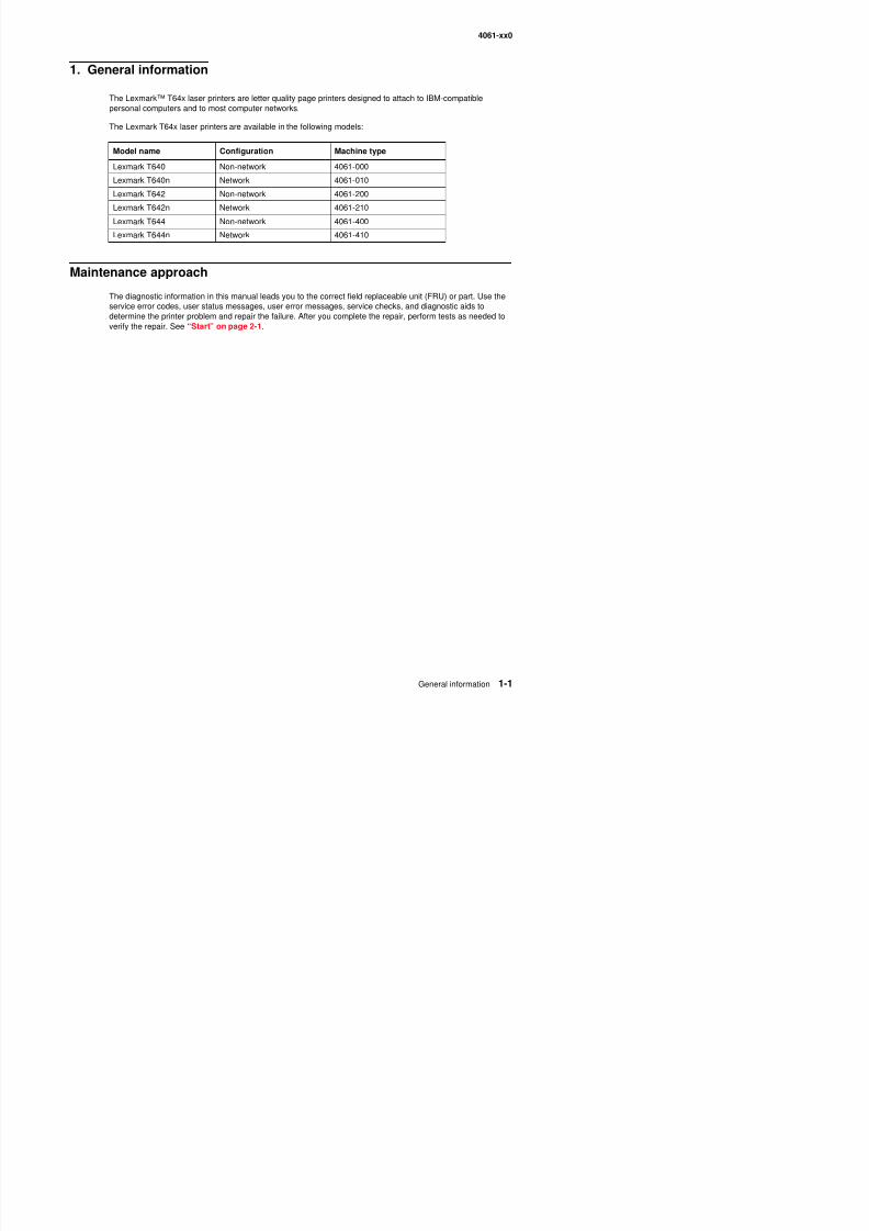
1. General information
The Lexmark™ T64x laser printers are letter quality page printers designed to attach to IBM-compatiblepersonal computers and to most computer networks.
The Lexmark T64x laser printers are available in the following models:
Maintenance approach
The diagnostic information in this manual leads you to the correct field replaceable unit (FRU) or part. Use theservice error codes, user status messages, user error messages, service checks, and diagnostic aids todetermine the printer problem and repair the failure. After you complete the repair, perform tests as needed toverify the repair. See “Start” on page 2-1.
Model name Configuration Machine type
Lexmark T640 Non-network 4061-000
Lexmark T640n Network 4061-010
Lexmark T642 Non-network 4061-200
Lexmark T642n Network 4061-210
Lexmark T644 Non-network 4061-400
Lexmark T644n Network 4061-410
8/13/2019 t644 Service Manual
http://slidepdf.com/reader/full/t644-service-manual 22/423
4061-xx0
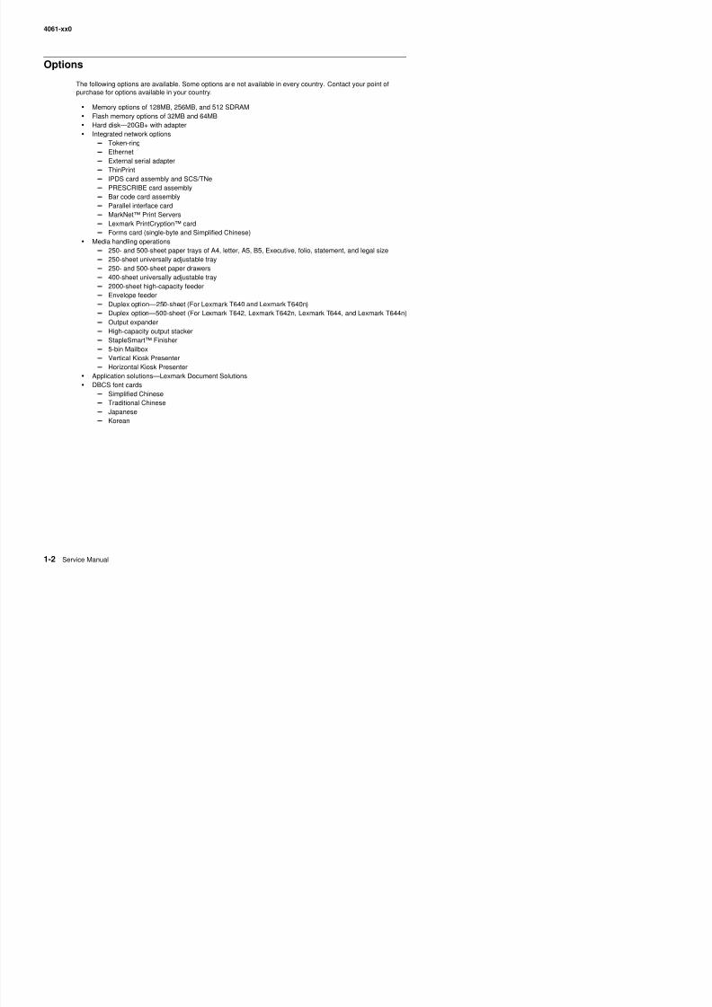
Options
The following options are available. Some options are not available in every country. Contact your point ofpurchase for options available in your country.
• Memory options of 128MB, 256MB, and 512 SDRAM• Flash memory options of 32MB and 64MB• Hard disk—20GB+ with adapter• Integrated network options
– Token-ring – Ethernet
– External serial adapter – ThinPrint – IPDS card assembly and SCS/TNe – PRESCRIBE card assembly – Bar code card assembly – Parallel interface card – MarkNet™ Print Servers – Lexmark PrintCryption™ card – Forms card (single-byte and Simplified Chinese)
• Media handling operations – 250- and 500-sheet paper trays of A4, letter, A5, B5, Executive, folio, statement, and legal size – 250-sheet universally adjustable tray – 250- and 500-sheet paper drawers – 400-sheet universally adjustable tray – 2000-sheet high-capacity feeder – Envelope feeder – Duplex option—250-sheet (For Lexmark T640 and Lexmark T640n) – Duplex option—500-sheet (For Lexmark T642, Lexmark T642n, Lexmark T644, and Lexmark T644n)
– Output expander – High-capacity output stacker – StapleSmart™ Finisher – 5-bin Mailbox – Vertical Kiosk Presenter – Horizontal Kiosk Presenter
• Application solutions—Lexmark Document Solutions• DBCS font cards
– Simplified Chinese
– Traditional Chinese – Japanese – Korean
8/13/2019 t644 Service Manual
http://slidepdf.com/reader/full/t644-service-manual 23/423
4061-xx0
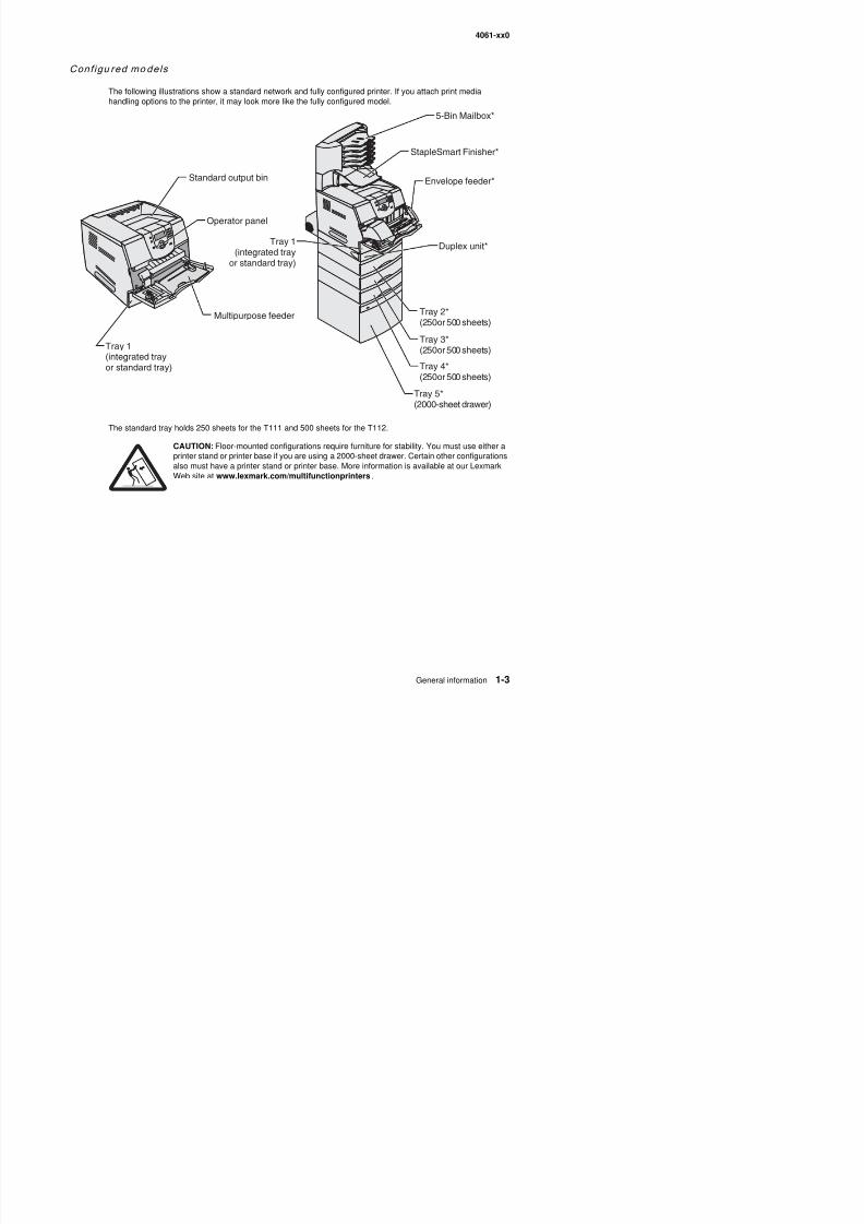
Conf igu red models
The following illustrations show a standard network and fully configured printer. If you attach print media
handling options to the printer, it may look more like the fully configured model.
The standard tray holds 250 sheets for the T111 and 500 sheets for the T112.
CAUTION: Floor-mounted configurations require furniture for stability. You must use either aprinter stand or printer base if you are using a 2000-sheet drawer. Certain other configurationsalso must have a printer stand or printer base. More information is available at our LexmarkWeb site at www.lexmark.com/multifunctionprinters .
Tray 1(integrated trayor standard tray)
Multipurpose feeder
Operator panel
Standard output bin
Tray 1(integrated tray
or standard tray)
5-Bin Mailbox*
StapleSmart Finisher*
Envelope feeder*
Duplex unit*
Tray 2*(250or 500 sheets)
Tray 3*(250or 500 sheets)
Tray 4*(250or 500 sheets)
Tray 5*(2000-sheet drawer)
8/13/2019 t644 Service Manual
http://slidepdf.com/reader/full/t644-service-manual 24/423
4061-xx0
Specifications
Resolut ion
• 1200 1200 dpi• 2400 Image Quality• 1200 Image Quality• 600 x 600 dpi
Data streams
• PostScript 3 emulation• PCL 6 emulation• PPDS migration tool• PDF v1.5 emulation
Print speed and perform ance print speed
Performance
Performance speed depends on:
• Interface to the host (USB, serial, parallel, network)• Host system and application• Page complexity and content• Printer options installed or selected• Available printer memory• Media size and type• Resolution
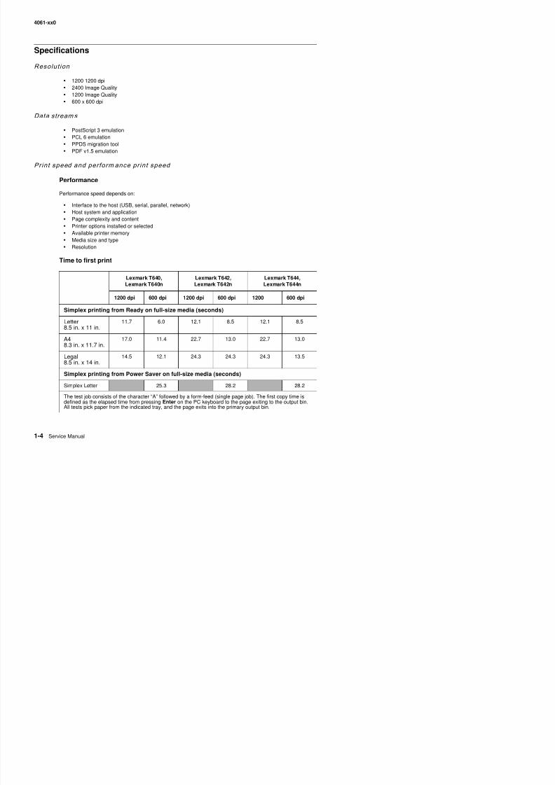
Time to first print
Lexmark T640,Lexmark T640n
Lexmark T642,Lexmark T642n
Lexmark T644,Lexmark T644n
1200 dpi 600 dpi 1200 dpi 600 dpi 1200 600 dpi
Simplex printing from Ready on full-size media (seconds)
Letter8.5 in. x 11 in.
11.7 6.0 12.1 8.5 12.1 8.5
A48.3 in. x 11.7 in.
17.0 11.4 22.7 13.0 22.7 13.0
Legal 14 5 12 1 24 3 24 3 24 3 13 5
06 0
8/13/2019 t644 Service Manual
http://slidepdf.com/reader/full/t644-service-manual 25/423
4061-xx0
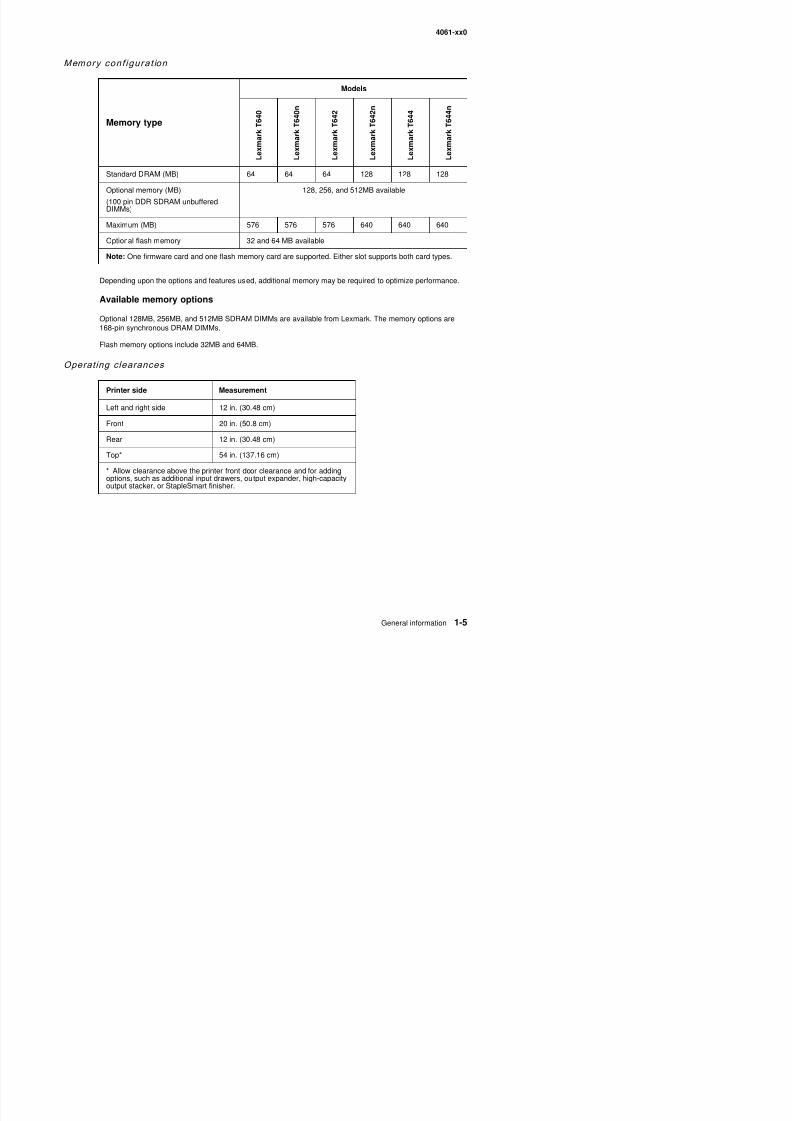
Memory conf igurat ion
Depending upon the options and features used, additional memory may be required to optimize performance.
Available memory options
Optional 128MB, 256MB, and 512MB SDRAM DIMMs are available from Lexmark. The memory options are168-pin synchronous DRAM DIMMs.
Flash memory options include 32MB and 64MB.
Operating clearances
Memory type
Models
L e x m a r k T 6 4 0
L e x m a r k T 6 4 0 n
L e x m a r k T 6 4 2
L e x m a r k T 6 4 2 n
L e x m a r k T 6 4 4
L e x m a r k T 6 4 4 n
Standard DRAM (MB) 64 64 64 128 128 128
Optional memory (MB)
(100 pin DDR SDRAM unbufferedDIMMs)
128, 256, and 512MB available
Maximum (MB) 576 576 576 640 640 640
Optional flash memory 32 and 64 MB available
Note: One firmware card and one flash memory card are supported. Either slot supports both card types.
Printer side Measurement
Left and right side 12 in. (30.48 cm)
Front 20 in. (50.8 cm)
Rear 12 in. (30.48 cm)
Top* 54 in. (137.16 cm)
* Allow clearance above the printer front door clearance and for addingoptions, such as additional input drawers, output expander, high-capacityoutput stacker, or StapleSmart finisher.
4061 0
8/13/2019 t644 Service Manual
http://slidepdf.com/reader/full/t644-service-manual 26/423
4061-xx0
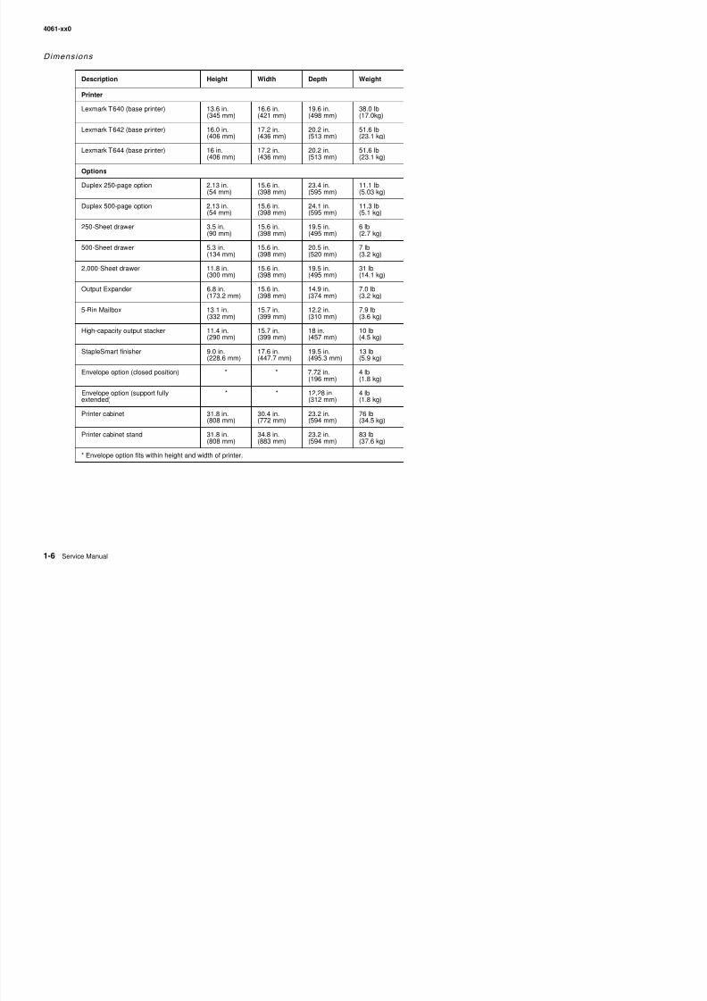
Dimensions
Description Height Width Depth Weight
Printer
Lexmark T640 (base printer) 13.6 in.(345 mm)
16.6 in.(421 mm)
19.6 in.(498 mm)
38.0 lb(17.0kg)
Lexmark T642 (base printer) 16.0 in.(406 mm)
17.2 in.(436 mm)
20.2 in.(513 mm)
51.6 lb(23.1 kg)
Lexmark T644 (base printer) 16 in.(406 mm)
17.2 in.(436 mm)
20.2 in.(513 mm)
51.6 lb(23.1 kg)
Options
Duplex 250-page option 2.13 in.(54 mm)
15.6 in.(398 mm)
23.4 in.(595 mm)
11.1 lb(5.03 kg)
Duplex 500-page option 2.13 in.(54 mm)
15.6 in.(398 mm)
24.1 in.(595 mm)
11.3 lb(5.1 kg)
250-Sheet drawer 3.5 in.(90 mm)
15.6 in.(398 mm)
19.5 in.(495 mm)
6 lb(2.7 kg)
500-Sheet drawer 5.3 in.(134 mm)
15.6 in.(398 mm)
20.5 in.(520 mm)
7 lb(3.2 kg)
2,000-Sheet drawer 11.8 in.(300 mm)
15.6 in.(398 mm)
19.5 in.(495 mm)
31 lb(14.1 kg)
Output Expander 6.8 in.(173.2 mm)
15.6 in.(398 mm)
14.9 in.(374 mm)
7.0 lb(3.2 kg)
5-Bin Mailbox 13.1 in.(332 mm)
15.7 in.(399 mm)
12.2 in.(310 mm)
7.9 lb(3.6 kg)
High-capacity output stacker 11.4 in.(290 mm)
15.7 in.(399 mm)
18 in.(457 mm)
10 lb(4.5 kg)
StapleSmart finisher 9.0 in.(228.6 mm)
17.6 in.(447.7 mm)
19.5 in.(495.3 mm)
13 lb(5.9 kg)
Envelope option (closed position) * * 7.72 in.(196 mm)
4 lb(1.8 kg)
Envelope option (support fullyextended)
* * 12.28 in.(312 mm)
4 lb(1.8 kg)
Printer cabinet 31.8 in.(808 mm)
30.4 in.(772 mm)
23.2 in.(594 mm)
76 lb(34.5 kg)
Printer cabinet stand 31.8 in.(808 mm)
34.8 in.(883 mm)
23.2 in.(594 mm)
83 lb(37.6 kg)
* E l ti fit ithi h i ht d idth f i t
4061 xx0
8/13/2019 t644 Service Manual
http://slidepdf.com/reader/full/t644-service-manual 27/423
4061-xx0
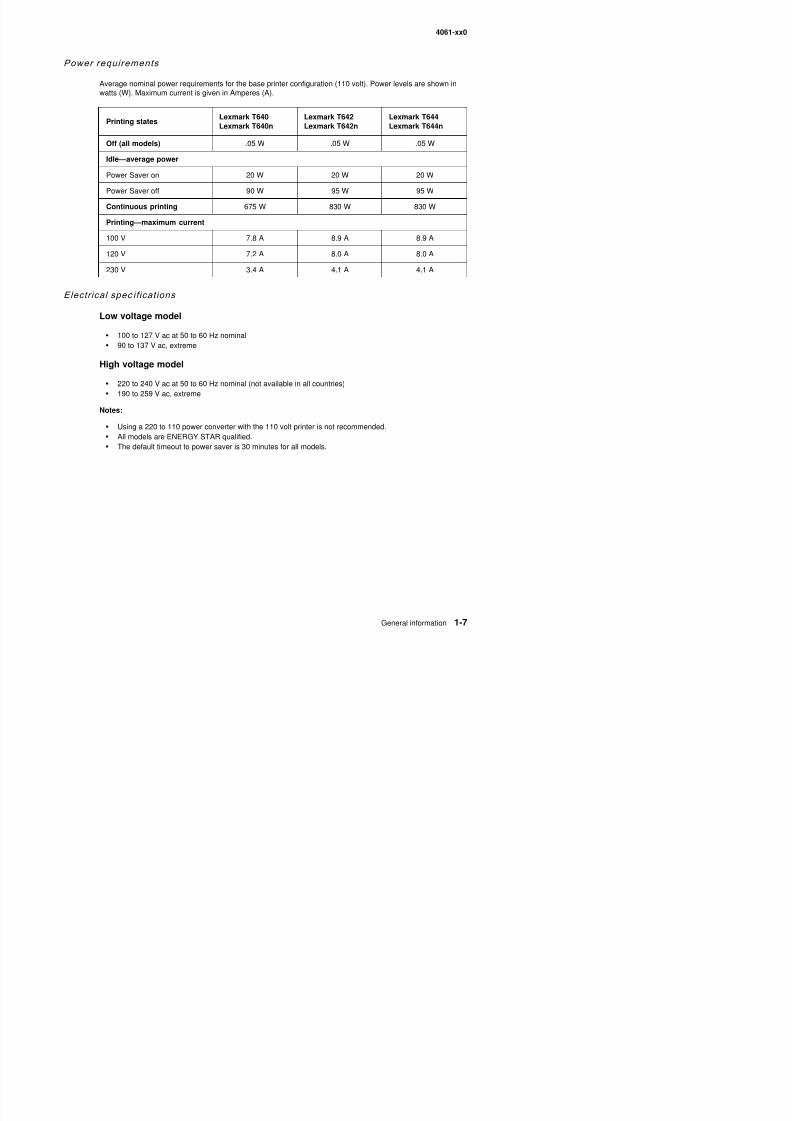
Power requirements
Average nominal power requirements for the base printer configuration (110 volt). Power levels are shown in
watts (W). Maximum current is given in Amperes (A).
Electrical spec if ications
Low voltage model
• 100 to 127 V ac at 50 to 60 Hz nominal• 90 to 137 V ac, extreme
High voltage model
• 220 to 240 V ac at 50 to 60 Hz nominal (not available in all countries)• 190 to 259 V ac, extreme
Notes:
• Using a 220 to 110 power converter with the 110 volt printer is not recommended.• All models are ENERGY STAR qualified.• The default timeout to power saver is 30 minutes for all models.
Printing statesLexmark T640Lexmark T640n
Lexmark T642Lexmark T642n
Lexmark T644Lexmark T644n
Off (all models) .05 W .05 W .05 W
Idle—average power
Power Saver on 20 W 20 W 20 W
Power Saver off 90 W 95 W 95 W
Continuous printing 675 W 830 W 830 W
Printing—maximum current
100 V 7.8 A 8.9 A 8.9 A
120 V 7.2 A 8.0 A 8.0 A
230 V 3.4 A 4.1 A 4.1 A
4061-xx0
8/13/2019 t644 Service Manual
http://slidepdf.com/reader/full/t644-service-manual 28/423
4061 xx0
Env i ronment
Printer temperature and humidity
• Operating – Temperature: 16 to 32° C (60° to 90° F) – Relative humidity: 8 to 80% – Altitude: 10,000 ft. (0 to 3,048 meters)
• Storage and shipping environment (packaged) – Temperature: -40° to 43° C (-40° to 110° F) – Relative humidity: 5% to 95% – Altitude: equivalent to 10,300 meters (0 to 34,000 feet)
• Storage environment (unpacked) – Temperature: 0° to 40° C (32° to 104° F) – Relative humidity: 5% to 80%
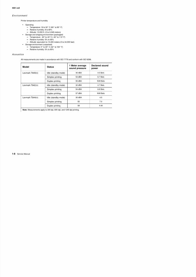
Acoust ics
All measurements are made in accordance with ISO 7779 and conform with ISO 9296.
Model Status
1 Meter average
sound pressure
Declared sound
power
Lexmark T640(n) Idle (standby mode) 30 dBA 4.0 Bels
Simplex printing 53 dBA 6.7 Bels
Duplex printing 55 dBA N/M Bels
Lexmark T642(n) Idle (standby mode) 32 dBA 4.7 Bels
Simplex printing 54 dBA 6.8 Bels
Duplex printing 57 dBA N/M Bels
Lexmark T644(n) Idle (standby mode) 30 dBA 4.5
Simplex printing 55 7.0
Duplex printing 58 N/M
Note: Measurements apply to 300 dpi, 600 dpi, and 1200 dpi printing.
4061-xx0
8/13/2019 t644 Service Manual
http://slidepdf.com/reader/full/t644-service-manual 29/423
4061 xx0
Media specifications
Paper and special ty media guid el ines
Print media is paper, card stock, transparencies, labels, and envelopes. This printer provides high qualityprinting on a variety of print media. You must consider a number of things concerning print media before youprint, including:
• Supported print media• Selecting print media• Storing print media
•Avoiding jams
For more details about the types of paper and specialty media your printer supports, refer to the Card Stock &
Label Guide available on our Lexmark Web site at www.lexmark.com.
We recommend that you try a limited sample of any paper or specialty media you are considering using with theprinter before purchasing large quantities.
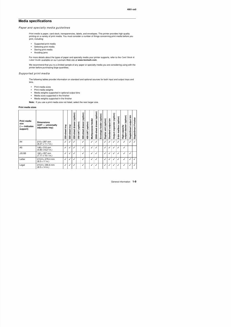
Supported pr in t media
The following tables provide information on standard and optional sources for both input and output trays andbins.
• Print media sizes• Print media weights• Media weights supported in optional output bins• Media sizes supported in the finisher• Media weights supported in the finisher
Note: If you use a print media size not listed, select the next larger size.
Print media sizes
Print mediasize(3 — indicatessupport)
Dimensions(UAT — universallyadjustable tray)
2 5 0 - s h e
e t t r a y
5 0 0 - s h e
e t t r a y
2 5 0 - s h e
e t d r a w e r ( o p t i o n )
2 5 0 U A T ( o p t i o n )
5 0 0 - s h e
e t d r a w e r ( o p t i o n )
4 0 0 U A T ( o p t i o n )
M u l t i p u
r p o s e f e e d e r
2 0 0 0 - s h
e e t d r a w e r ( o p t i o n )
E n v e l o p e f e e d e r ( o p t i o n )
D u p l e x
u n i t ( o p t i o n )
S t a n d a r d o u t p u t b i n
O u t p u t
e x p a n d e r ( o p t i o n )
5 - b i n m
a i l b o x ( o p t i o n )
H i g h - c a
p a c i t y
o u t p u t s t a c k e r ( o p t i o n )
S t a p l e S
m a r t o u t p u t b i n
S t a p l e S
m a r t F i n i s h e r
A4 210 x 297 mm(8.27 x 11.7 in.)
✓ ✓ ✓ ✓ ✓ ✓ ✓ ✓ ✓ ✓ ✓ ✓ ✓
A5 148 x 210 mm ✓ ✓ ✓ ✓ ✓ ✓ ✓ ✓ ✓ ✓ ✓
4061-xx0
8/13/2019 t644 Service Manual
http://slidepdf.com/reader/full/t644-service-manual 30/423
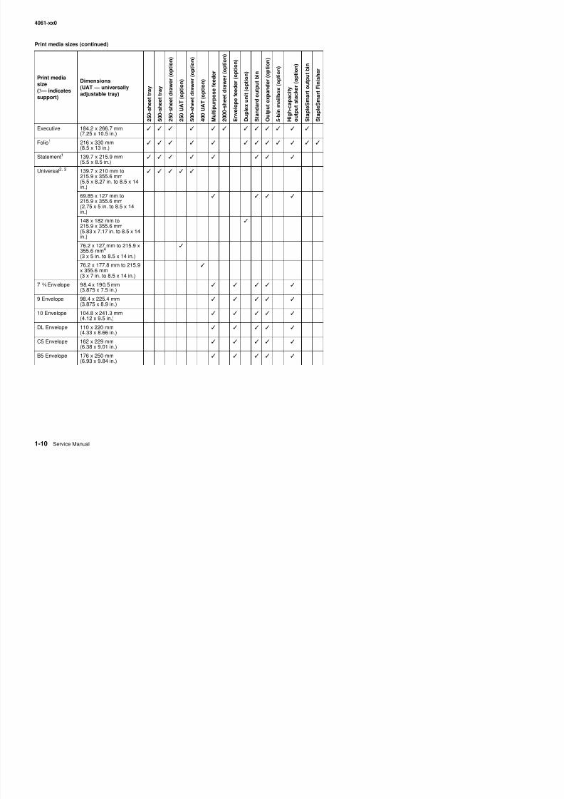
Executive 184.2 x 266.7 mm(7.25 x 10.5 in.)
✓ ✓ ✓ ✓ ✓ ✓ ✓ ✓ ✓ ✓ ✓ ✓
Folio1 216 x 330 mm(8.5 x 13 in.)
✓ ✓ ✓ ✓ ✓ ✓ ✓ ✓ ✓ ✓ ✓ ✓
Statement1 139.7 x 215.9 mm(5.5 x 8.5 in.)
✓ ✓ ✓ ✓ ✓ ✓ ✓ ✓
Universal2, 3 139.7 x 210 mm to215.9 x 355.6 mm(5.5 x 8.27 in. to 8.5 x 14in.)
✓ ✓ ✓ ✓ ✓
69.85 x 127 mm to215.9 x 355.6 mm(2.75 x 5 in. to 8.5 x 14in.)
✓ ✓ ✓ ✓
148 x 182 mm to215.9 x 355.6 mm(5.83 x 7.17 in. to 8.5 x 14in.)
✓
76.2 x 127 mm to 215.9 x355.6 mm4
(3 x 5 in. to 8.5 x 14 in.)
✓
76.2 x 177.8 mm to 215.9x 355.6 mm(3 x 7 in. to 8.5 x 14 in.)
✓
7 ¾ Envelope 98.4 x 190.5 mm(3.875 x 7.5 in.)
✓ ✓ ✓ ✓ ✓
9 Envelope 98.4 x 225.4 mm(3.875 x 8.9 in.)
✓ ✓ ✓ ✓ ✓
10 Envelope 104.8 x 241.3 mm(4.12 x 9.5 in.)
✓ ✓ ✓ ✓ ✓
DL Envelope 110 x 220 mm(4.33 x 8.66 in.)
✓ ✓ ✓ ✓ ✓
C5 Envelope 162 x 229 mm(6.38 x 9.01 in.)
✓ ✓ ✓ ✓ ✓
B5 Envelope 176 x 250 mm(6 93 x 9 84 in )
✓ ✓ ✓ ✓ ✓
Print media sizes (continued)
Print mediasize(3 — indicatessupport)
Dimensions(UAT — universallyadjustable tray)
2 5 0 - s h e e t t r a y
5 0 0 - s h e e t t r a y
2 5 0 - s h e e t d r a w e r ( o p t
i o n )
2 5 0 U A T ( o p t i o n )
5 0 0 - s h e e t d r a w e r ( o p t
i o n )
4 0 0 U A T ( o p t i o n )
M u l t i p u r p o s e f e e d e r
2 0 0 0 - s h e e t d r a w e r ( o p
t i o n )
E n v e l o p e f e e d e r ( o p t i o n )
D u p l e x u n i t ( o p t i o n )
S t a n d a r d o u t p u t b i n
O u t p u t e x p a n d e r ( o p t i o n )
5 - b i n m a i l b o x ( o p t i o n )
H i g h - c a p a c i t y
o u t p u t s t a c k e r ( o p t i o n
)
S t a p l e S m a r t o u t p u t b i
n
S t a p l e S m a r t F i n i s h e r
4061-xx0
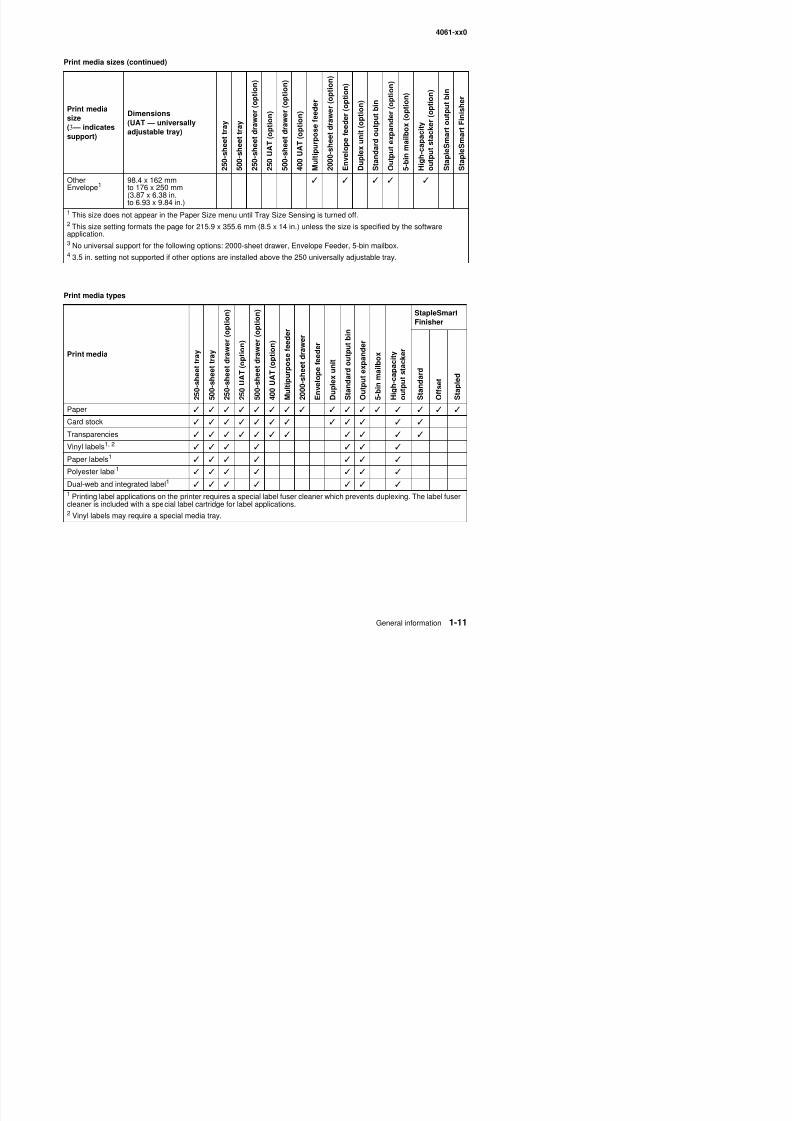
8/13/2019 t644 Service Manual
http://slidepdf.com/reader/full/t644-service-manual 31/423
OtherEnvelope1
98.4 x 162 mmto 176 x 250 mm(3.87 x 6.38 in.to 6.93 x 9.84 in.)
✓ ✓ ✓ ✓ ✓
1 This size does not appear in the Paper Size menu until Tray Size Sensing is turned off.2 This size setting formats the page for 215.9 x 355.6 mm (8.5 x 14 in.) unless the size is specified by the softwareapplication.3 No universal support for the following options: 2000-sheet drawer, Envelope Feeder, 5-bin mailbox.4 3.5 in. setting not supported if other options are installed above the 250 universally adjustable tray.
Print media types
Print media
2 5 0 - s h e e t t
r a y
5 0 0 - s h e e t t
r a y
2 5 0 - s h e e t d
r a w e r ( o p t i o n )
2 5 0 U A T ( o
p t i o n )
5 0 0 - s h e e t d
r a w e r ( o p t i o n )
4 0 0 U A T ( o
p t i o n )
M u l t i p u r p o
s e f e e d e r
2 0 0 0 - s h e e t
d r a w e r
E n v e l o p e f e e d e r
D u p l e x u n i t
S t a n d a r d o
u t p u t b i n
O u t p u t e x p
a n d e r
5 - b i n m a i l b
o x
H i g h - c a p a c
i t y
o u t p u t s t a c
k e r
StapleSmartFinisher
S t a n d a r d
O f f s e t
S t a p l e d
Paper ✓ ✓ ✓ ✓ ✓ ✓ ✓ ✓ ✓ ✓ ✓ ✓ ✓ ✓ ✓ ✓
Card stock ✓ ✓ ✓ ✓ ✓ ✓ ✓ ✓ ✓ ✓ ✓ ✓
Transparencies ✓ ✓ ✓ ✓ ✓ ✓ ✓ ✓ ✓ ✓ ✓
Vinyl labels1, 2✓ ✓ ✓ ✓ ✓ ✓ ✓
Paper labels1 ✓ ✓ ✓ ✓ ✓ ✓ ✓
Polyester label1 ✓ ✓ ✓ ✓ ✓ ✓ ✓
Dual-web and integrated label1 ✓ ✓ ✓ ✓ ✓ ✓ ✓ 1 Printing label applications on the printer requires a special label fuser cleaner which prevents duplexing. The label fusercleaner is included with a special label cartridge for label applications.
Print media sizes (continued)
Print mediasize(3 — indicatessupport)
Dimensions(UAT — universallyadjustable tray)
2 5 0 - s h e e t t r a y
5 0 0 - s h e e t t r a y
2 5 0 - s h e e t d r a w e r ( o p t
i o n )
2 5 0 U A T ( o p t i o n )
5 0 0 - s h e e t d r a w e r ( o p t
i o n )
4 0 0 U A T ( o p t i o n )
M u l t i p u r p o s e f e e d e r
2 0 0 0 - s h e e t d r a w e r ( o p
t i o n )
E n v e l o p e f e e d e r ( o p t i o n )
D u p l e x u n i t ( o p t i o n )
S t a n d a r d o u t p u t b i n
O u t p u t e x p a n d e r ( o p t i o n )
5 - b i n m a i l b o x ( o p t i o n )
H i g h - c a p a c i t y
o u t p u t s t a c k e r ( o p t i o n
)
S t a p l e S m a r t o u t p u t b i n
S t a p l e S m a r t F i n i s h e r
4061-xx0
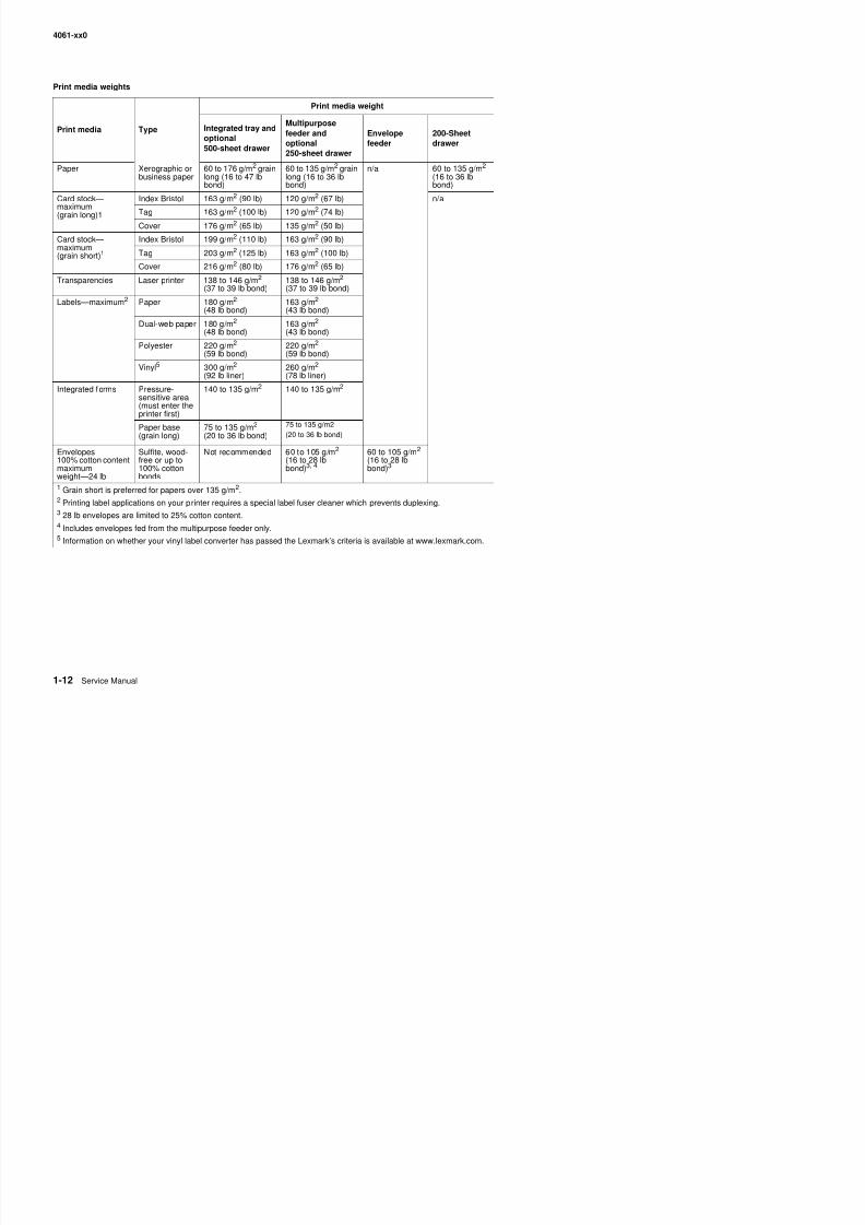
8/13/2019 t644 Service Manual
http://slidepdf.com/reader/full/t644-service-manual 32/423
Print media weights
Print media Type
Print media weight
Integrated tray andoptional500-sheet drawer
Multipurposefeeder andoptional250-sheet drawer
Envelopefeeder
200-Sheetdrawer
Paper Xerographic orbusiness paper
60 to 176 g/m2 grainlong (16 to 47 lbbond)
60 to 135 g/m2 grainlong (16 to 36 lbbond)
n/a 60 to 135 g/m2
(16 to 36 lbbond)
Card stock—maximum(grain long)1
Index Bristol 163 g/m
2
(90 lb) 120 g/m
2
(67 lb) n/aTag 163 g/m2 (100 lb) 120 g/m2 (74 lb)
Cover 176 g/m2 (65 lb) 135 g/m2 (50 lb)
Card stock—maximum(grain short)1
Index Bristol 199 g/m2 (110 lb) 163 g/m2 (90 lb)
Tag 203 g/m2 (125 lb) 163 g/m2 (100 lb)
Cover 216 g/m2 (80 lb) 176 g/m2 (65 lb)
Transparencies Laser printer 138 to 146 g/m2
(37 to 39 lb bond)138 to 146 g/m2
(37 to 39 lb bond)
Labels—maximum2 Paper 180 g/m2 (48 lb bond)
163 g/m2(43 lb bond)
Dual-web paper 180 g/m2 (48 lb bond)
163 g/m2
(43 lb bond)
Polyester 220 g/m2
(59 lb bond)220 g/m2
(59 lb bond)
Vinyl5 300 g/m2
(92 lb liner)260 g/m2
(78 lb liner)
Integrated forms Pressure-
sensitive area(must enter theprinter first)
140 to 135 g/m2 140 to 135 g/m2
Paper base(grain long)
75 to 135 g/m2
(20 to 36 lb bond)75 to 135 g/m2(20 to 36 lb bond)
Envelopes100% cotton contentmaximumweight—24 lb
Sulfite, wood-free or up to100% cottonbonds
Not recommended 60 to 105 g/m2
(16 to 28 lbbond)3, 4
60 to 105 g/m2 (16 to 28 lbbond)3
1 Grain short is preferred for papers over 135 g/m2.2 Printing label applications on your printer requires a special label fuser cleaner which prevents duplexing.3 28 lb envelopes are limited to 25% cotton content.4 Includes envelopes fed from the multipurpose feeder only.5 Information on whether your vinyl label converter has passed the Lexmark’s criteria is available at www.lexmark.com.
4061-xx0
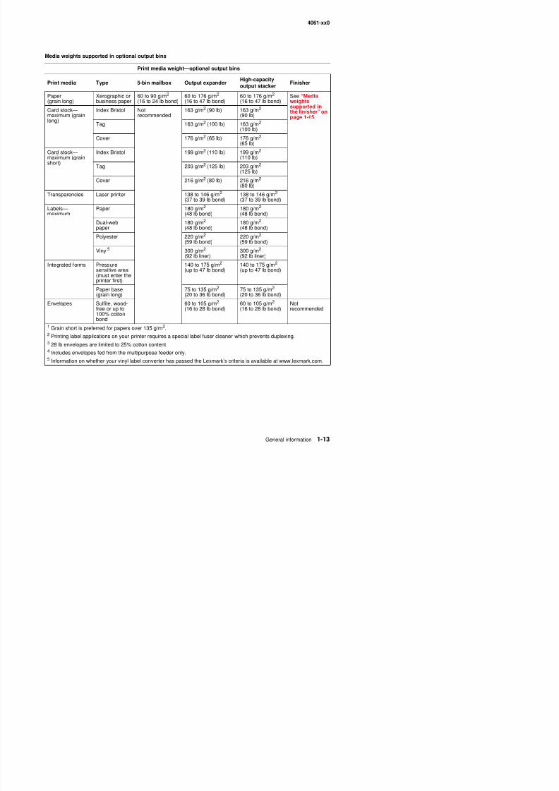
8/13/2019 t644 Service Manual
http://slidepdf.com/reader/full/t644-service-manual 33/423
Media weights supported in optional output bins
Print media weight—optional output bins
Print media Type 5-bin mailbox Output expanderHigh-capacityoutput stacker
Finisher
Paper(grain long)
Xerographic orbusiness paper
60 to 90 g/m2
(16 to 24 lb bond)60 to 176 g/m2
(16 to 47 lb bond)60 to 176 g/m2
(16 to 47 lb bond)See “Mediaweightssupported inthe finisher” onpage 1-15.
Card stock—maximum (grainlong)
Index Bristol Notrecommended
163 g/m2 (90 lb) 163 g/m2 (90 lb)
Tag 163 g/m2 (100 lb) 163 g/m2
(100 lb)Cover 176 g/m2 (65 lb) 176 g/m2
(65 lb)
Card stock—maximum (grainshort)
Index Bristol 199 g/m2 (110 lb) 199 g/m2
(110 lb)
Tag 203 g/m2 (125 lb) 203 g/m2
(125 lb)
Cover 216 g/m2 (80 lb) 216 g/m2
(80 lb)
Transparencies Laser printer 138 to 146 g/m2(37 to 39 lb bond) 138 to 146 g/m2
(37 to 39 lb bond)
Labels—maximum
Paper 180 g/m2
(48 lb bond)180 g/m2
(48 lb bond)
Dual-webpaper
180 g/m2
(48 lb bond)180 g/m2
(48 lb bond)
Polyester 220 g/m2
(59 lb bond)220 g/m2
(59 lb bond)
Vinyl5 300 g/m2
(92 lb liner)
300 g/m2
(92 lb liner)Integrated forms Pressure
sensitive area(must enter theprinter first)
140 to 175 g/m2
(up to 47 lb bond)140 to 175 g/m2
(up to 47 lb bond)
Paper base(grain long)
75 to 135 g/m2
(20 to 36 lb bond)75 to 135 g/m2
(20 to 36 lb bond)
Envelopes Sulfite, wood-free or up to100% cotton
bond
60 to 105 g/m2
(16 to 28 lb bond)60 to 105 g/m2
(16 to 28 lb bond)Notrecommended
1 Grain short is preferred for papers over 135 g/m2.2 Printing label applications on your printer requires a special label fuser cleaner which prevents duplexing.3 28 lb envelopes are limited to 25% cotton content.4 Includes envelopes fed from the multipurpose feeder only.5
4061-xx0
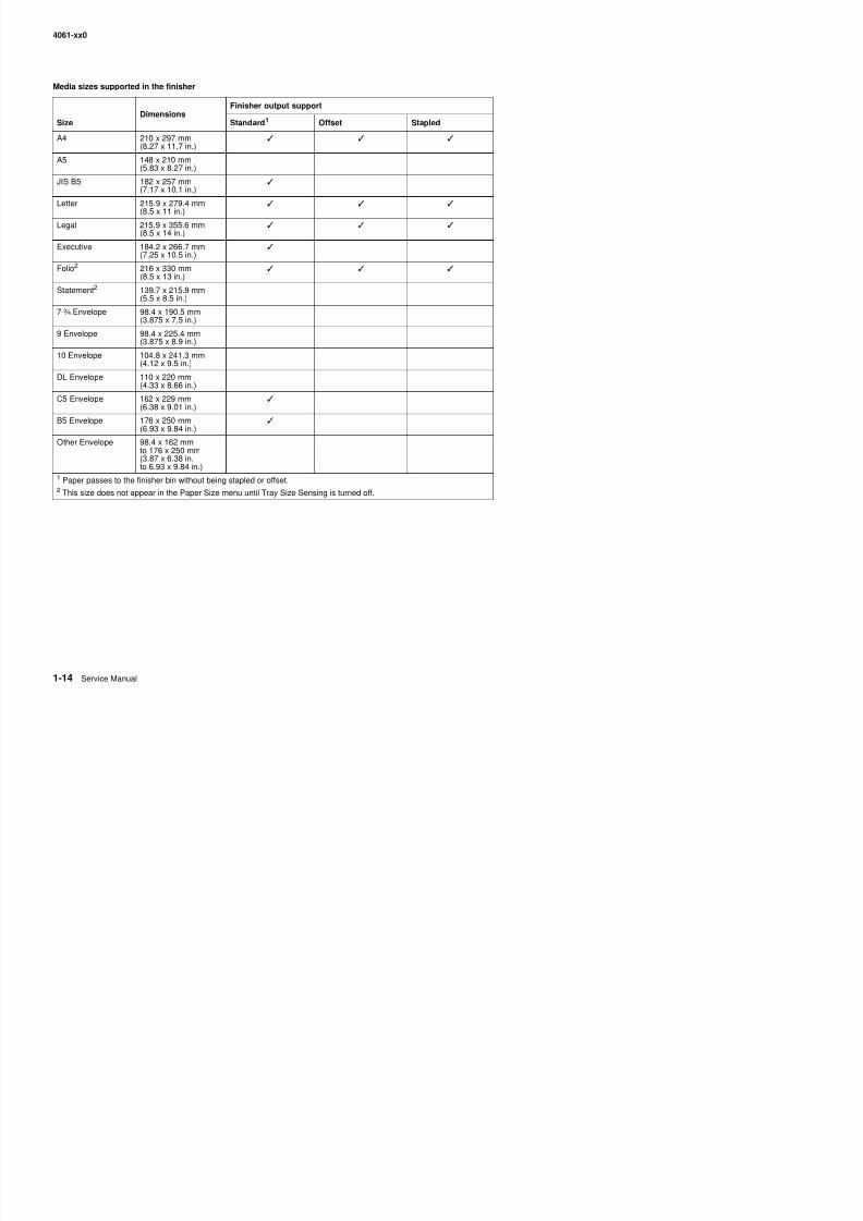
8/13/2019 t644 Service Manual
http://slidepdf.com/reader/full/t644-service-manual 34/423
Media sizes supported in the finisher
Dimensions Finisher output support
Size Standard1 Offset Stapled
A4 210 x 297 mm(8.27 x 11.7 in.)
✓ ✓ ✓
A5 148 x 210 mm(5.83 x 8.27 in.)
JIS B5 182 x 257 mm(7.17 x 10.1 in.)
✓
Letter 215.9 x 279.4 mm(8.5 x 11 in.)✓ ✓ ✓
Legal 215.9 x 355.6 mm(8.5 x 14 in.)
✓ ✓ ✓
Executive 184.2 x 266.7 mm(7.25 x 10.5 in.)
✓
Folio2 216 x 330 mm(8.5 x 13 in.)
✓ ✓ ✓
Statement2 139.7 x 215.9 mm
(5.5 x 8.5 in.)7 ¾ Envelope 98.4 x 190.5 mm
(3.875 x 7.5 in.)
9 Envelope 98.4 x 225.4 mm(3.875 x 8.9 in.)
10 Envelope 104.8 x 241.3 mm(4.12 x 9.5 in.)
DL Envelope 110 x 220 mm(4.33 x 8.66 in.)
C5 Envelope 162 x 229 mm(6.38 x 9.01 in.)
✓
B5 Envelope 176 x 250 mm(6.93 x 9.84 in.)
✓
Other Envelope 98.4 x 162 mmto 176 x 250 mm(3.87 x 6.38 in.to 6.93 x 9.84 in.)
1 Paper passes to the finisher bin without being stapled or offset.2 This size does not appear in the Paper Size menu until Tray Size Sensing is turned off.
4061-xx0
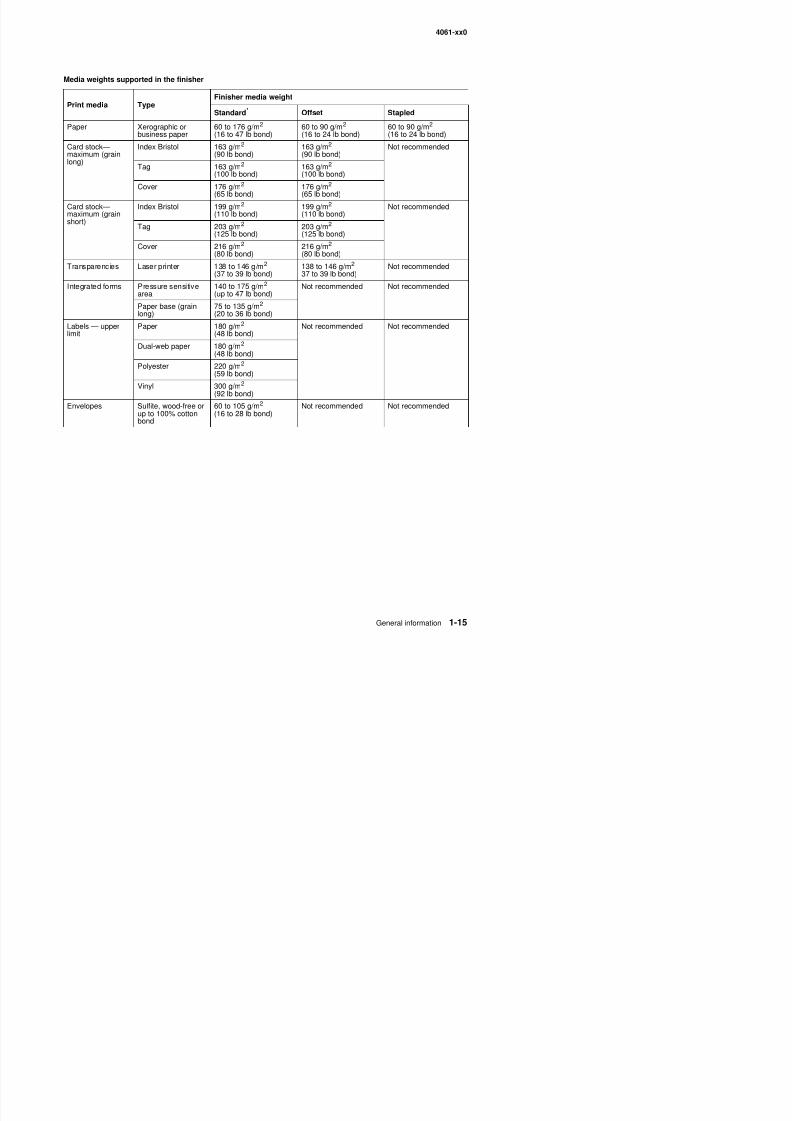
8/13/2019 t644 Service Manual
http://slidepdf.com/reader/full/t644-service-manual 35/423
Media weights supported in the finisher
Print media Type Finisher media weight
Standard* Offset Stapled
Paper Xerographic orbusiness paper
60 to 176 g/m2
(16 to 47 lb bond)60 to 90 g/m2
(16 to 24 lb bond)60 to 90 g/m2
(16 to 24 lb bond)
Card stock—maximum (grainlong)
Index Bristol 163 g/m2
(90 lb bond)163 g/m2
(90 lb bond)Not recommended
Tag 163 g/m2
(100 lb bond)163 g/m2
(100 lb bond)
Cover 176 g/m2(65 lb bond) 176 g/m2
(65 lb bond)
Card stock—maximum (grainshort)
Index Bristol 199 g/m2
(110 lb bond)199 g/m2
(110 lb bond)Not recommended
Tag 203 g/m2
(125 lb bond)203 g/m2
(125 lb bond)
Cover 216 g/m2
(80 lb bond)216 g/m2
(80 lb bond)
Transparencies Laser printer 138 to 146 g/m2
(37 to 39 lb bond)
138 to 146 g/m2
37 to 39 lb bond)
Not recommended
Integrated forms Pressure sensitivearea
140 to 175 g/m2
(up to 47 lb bond)Not recommended Not recommended
Paper base (grainlong)
75 to 135 g/m2
(20 to 36 lb bond)
Labels — upperlimit
Paper 180 g/m2
(48 lb bond)Not recommended Not recommended
Dual-web paper 180 g/m2
(48 lb bond)
Polyester 220 g/m2(59 lb bond)
Vinyl 300 g/m2
(92 lb bond)
Envelopes Sulfite, wood-free orup to 100% cottonbond
60 to 105 g/m2
(16 to 28 lb bond)Not recommended Not recommended
4061-xx0
8/13/2019 t644 Service Manual
http://slidepdf.com/reader/full/t644-service-manual 36/423
Select ing print media
Selecting the appropriate print media for your printer helps you avoid printing problems. The following sections
contain guidelines for choosing the correct print media for your printer.• Paper• Transparencies• Envelopes• Labels• Card stock
Paper
For the best print quality, use 75 g/m2 (20 lb) xerographic, grain long paper. Try a sample of any paper you areconsidering using with the printer before buying large quantities.
When loading paper, note the recommended print side on the paper package, and load paper accordingly.
Paper characteristics
The following paper characteristics affect print quality and reliability. We recommend that you follow theseguidelines when evaluating new paper stock.
For detailed information, refer to the Card Stock & Label Guide located on the Lexmark Web site atwww.lexmark.com.
The laser printing process heats paper to high temperatures of 225°C (437°F) for Magnetic Ink CharacterRecognition (MICR) applications, and 205°C (401°F) for non-MICR applications. Use only paper able towithstand these temperatures without discoloring, bleeding, or releasing hazardous emissions. Check with themanufacturer or vendor to determine whether the paper you have chosen is acceptable for laser printers.
Weight
The printer can automatically feed paper weights from 60 to 176 g/m2 (16 to 47 lb bond) grain long in theintegrated and optional 500–sheet trays and paper weights from 60 to 135 g/m2 (16 to 36 lb bond) grain long inthe multipurpose feeder and optional 250–sheet trays. Paper lighter than 60 g/m2 (16 lb) might not be stiffenough to feed properly, causing jams. For best performance, use 75 g/m2 (20 lb bond) grain long paper. Whenusing paper narrower than 182 x 257 mm (7.2 x 10.1 in.), make sure the weight is greater than or equal to 90 g/ m2 (24 lb bond).
Unacceptable paper
The following papers are not recommended for use with the printer:
• Chemically treated papers used to make copies without carbon paper, also known as carbonless papers,carbonless copy paper (CCP), or no carbon required (NCR) paper
• Preprinted papers with chemicals that may contaminate the printer• Preprinted papers that can be affected by the temperature in the printer fuser• Preprinted papers that require a registration (the precise print location on the page) greater than ±0 09 in
4061-xx0
8/13/2019 t644 Service Manual
http://slidepdf.com/reader/full/t644-service-manual 37/423
Transparencies
You can feed transparencies from the standard tray (250-sheet tray for the T111 or 500-sheet tray for the T112),optional 250- or 500-sheet trays, or the multipurpose feeder. Try a sample of any transparencies you areconsidering using with the printer before buying large quantities.
When printing on transparencies:
• Be sure to set the Paper Type to Transparency from the printer driver or the Local Printer Setup Utility toavoid damaging your printer.
• Use transparencies designed specifically for laser printers. Transparencies must be able to withstandtemperatures of 225°C (437°F) without melting, discoloring, offsetting or releasing hazardous emissions.
• To prevent print quality problems, avoid getting fingerprints on the transparencies.• Before loading transparencies, fan the stack to prevent sheets from sticking together.
Selecting transparencies
The printer can print directly on transparencies designed for use in laser printers. Print quality and durabilitydepend on the transparency used. Always print samples on the transparencies you are considering beforebuying large quantities.
The Paper Type setting should be set to Transparency to help prevent jams. Check with the manufacturer orvendor to determine whether your transparencies are compatible with laser printers that heat transparencies to
225°C (437°F). Use only transparencies that are able to withstand these temperatures without melting,discoloring, offsetting, or releasing hazardous emissions. For detailed information, refer to the Card Stock &
Label Guide, which is available on the Lexmark Web site at www.lexmark.com.
Transparencies can be fed automatically from the multipurpose feeder and all standard and optional trays,except the 2000-sheet drawer.
Be careful when you handle transparencies. Fingerprints on the surface of the transparency cause poor printquality.
EnvelopesYou can load up to 10 envelopes in the multipurpose feeder and 85 envelopes in the envelope feeder. Try asample of any envelopes you are considering using with the printer before buying large quantities.
When printing on envelopes:
• To achieve the best possible print quality, use only high-quality envelopes that are designed for use inlaser printers.
• Set the Paper Size/Type in the Paper Menu to MP Feeder, Manual Env, or Env Feeder depending on the
source you are using, set the paper type to Envelope, and select the correct envelope size from theoperator panel, the printer driver, in the Local Printer Setup Utility, or from MarkVision™.• For best performance, use envelopes made from 75 g/m2 (20 lb bond) paper. You can use up to 105 g/m2
(28 lb bond) weight for the multipurpose feeder or 105 g/m2 (28 lb bond) weight for the envelope feeder aslong as the cotton content is 25% or less. Envelopes with 100% cotton content must not exceed 90 g/m2
(24 lb bond) weight.• Use only new undamaged envelopes
4061-xx0
8/13/2019 t644 Service Manual
http://slidepdf.com/reader/full/t644-service-manual 38/423
• For best performance and to minimize jams, do not use envelopes that: – Have excessive curl or twist. – Are stuck together or damaged in any way. – Contain windows, holes, perforations, cutouts or embossing.
– Use metal clasps, string ties, or metal folding bars. – Have an interlocking design. – Have postage stamps attached. – Have any exposed adhesive when the flap is in the sealed or closed position. – Have nicked edges or bent corners. – Have rough, cockle, or laid finishes.
• Use envelopes that can withstand temperatures of 225°C (437°F) without sealing, excessive curling,wrinkling, or releasing hazardous emissions. If you have any doubts about the envelopes you areconsidering using, check with the envelope supplier.
• Load only one size of envelope at a time in the envelope feeder.• A combination of high humidity (over 60%) and the high printing temperatures may seal the envelopes.
Labels
• Your printer can print on many labels designed for use with laser printers. These labels are supplied inletter size, A4 size, and legal size sheets. Label adhesives, face sheet (printable stock), and topcoats mustbe able to withstand temperatures of 225°C (437°F) and pressure of 25 pounds per square inch (psi).
• Try a sample of any labels you are considering using with the printer before purchasing a large quantity.
• For detailed information on label printing, characteristics, and design, refer to the Card Stock & LabelGuide available on the Lexmark Web site at www.lexmark.com/publications .
Note: Labels are one of the most difficult print media for laser printers. All printer models require a special fusercleaner for label applications to optimize feed reliability.
After printing approximately 10,000 pages of labels (or each time you replace the print cartridge), complete thefollowing steps to maintain printer feeding reliability:
1. Print five sheets of paper.2. Wait approximately five seconds.
3. Print five more sheets of paper.
When printing on labels:
• Set the Paper Size/Type menu item to Labels in the Paper Menu. You can set the Paper Size/Type fromthe printer operator panel, the printer driver, the Local Printer Setup Utility, or from MarkVision.
• Feed vinyl labels from the standard 250- or 500-sheet trays, or the optional 250- or 500-sheet drawers. Forvinyl labels, you must set the Paper Type to Labels, the Labels Texture to Smooth, and the Label Weight toHeavy.
•Do not load labels with paper or transparencies in the same source; mixing print media can cause feedingproblems.
• Do not use label sheets with a slick backing material.• Use full label sheets. Partial sheets may cause labels to peel off during printing, resulting in a jam. Partial
sheets also contaminate your printer and your cartridge with adhesive, and could void your printer andcartridge warranties.
• Use labels that can withstand temperatures of 225°C (437°F) without sealing excessive curling wrinkling
4061-xx0
8/13/2019 t644 Service Manual
http://slidepdf.com/reader/full/t644-service-manual 39/423
• Portrait orientation is preferred, especially when printing bar codes.• Do not use labels that have exposed adhesive.
Card stock
Card stock is single ply, and has a large array of properties, such as the moisture content, thickness, andtexture, that can significantly affect print quality. See “Supported print media” on page 1-9 for information onthe preferred weight and for the grain direction of print media.
Try a sample of any card stock you are considering using with the printer before purchasing a large quantity.
After printing approximately 10,000 pages of card stock (or each time you replace the print cartridge), completethe following steps to maintain printer feeding reliability:
1. Print five sheets of paper.2. Wait approximately five seconds.3. Print five more sheets of paper.
When printing on card stock:
• Set the Paper Type menu item in the Paper Menu to Card Stock from the operator panel, from the printerdriver, in the Local Printer Setup Utility, or from MarkVision.
• Be aware that preprinting, perforation, and creasing can significantly affect the print quality and cause printmedia handling or jamming problems.
• Avoid using card stock that may release hazardous emissions when heated.• Do not use preprinted card stock manufactured with chemicals that may contaminate the printer.
Preprinting introduces semi-liquid and volatile components into the printer.• We recommend the use of grain short card stock.
Storing print media
Use the following guidelines to avoid paper feeding problems and uneven print quality.
• Store paper in an environment where the temperature is approximately 21°C (70°F) and the relativehumidity is 40%.
• Store cartons of paper on a pallet or shelf rather than directly on the floor.• If you store individual packages of paper out of the original carton, make sure they rest on a flat surface so
the edges do not buckle or curl.• Do not place anything on top of paper packages.• Store paper in its original wrapper until you load it into the printer.
4061-xx0
8/13/2019 t644 Service Manual
http://slidepdf.com/reader/full/t644-service-manual 40/423
Avoid ing jams
Use appropriate print media (paper, transparencies, labels, and card stock) to help ensure trouble-free printing.See “Supported print media” on page 1-9 for more information.
Note: Try a limited sample of any print media you are considering using with the printer before purchasing largequantities.
By selecting the appropriate print media and loading it properly, you can avoid most jams.
The following hints can help you avoid jams:
• Use only recommended print media.• Do not overload the print media sources. Make sure the stack height does not exceed the maximum height
indicated by the stack line on the labels in the sources.• Do not load wrinkled, creased, damp, or curled print media.• Flex, fan, and straighten print media before you load it. If jams do occur with print media, try feeding one
sheet at a time through the multipurpose feeder.• Do not use print media that you have cut or trimmed yourself.• Do not mix print media sizes, weights, or types in the same print media source.• Make sure the recommended print side is loaded in the source according to your simplex or duplex needs.• Keep print media stored in an acceptable environment. See “Storing print media” on page 1-19.• Do not remove trays during a print job.
• Push all trays in firmly after loading them.• Make sure the guides in the trays are properly positioned for the size of print media you have loaded. Make
sure the guides are not placed too tightly against the stack of print media.
Print area
The printable area is limited to within 4.2 mm (0.167 in.) of all edges of the media. Any information placedoutside this specified printable area does not print.
Tools required
Flat-blade screwdrivers, various sizesPhillips screwdrivers, various sizes7/32 inch (5.5 mm) open-end wrench7.0 mm nut driverNeedlenose pliersDiagonal side cuttersSpring hookFeeler gaugesAnalog or digital multimeterParallel wrap plug 1319128Twinax/serial debug cable 1381963Flash light (optional)
4061-xx0
8/13/2019 t644 Service Manual
http://slidepdf.com/reader/full/t644-service-manual 41/423
Acronyms
BLDC Brushless DC motorCRU Customer Replaceable UnitCSU Customer setupDIMM Dual Inline Memory ModuleDRAM Dynamic Random Access MemoryDVM Digital multimeterEDO Enhanced Data OutEEPROM Electrically Erasable Programable Read-Only MemoryEP Electrophotographic process
EPROM Erasable Programmable Read-Only MemoryESD Electrostatic DischargeFRU Field Replaceable UnitGB GigabyteHCIT High-capacity Input TrayHVPS High Voltage Power SupplyITC Internal Tray CardLASER Light Amplification by Stimulated Emission of RadiationLCD Liquid Crystal Display
LED Light-Emitting DiodeLVPS Low Voltage Power SupplyMPF Multipurpose feederMROM Masked Read Only MemoryMS MicroswitchNVRAM Nonvolatile Random Access MemoryOEM Original Equipment ManufacturerOPT Optical SensorPC Photoconductor
pel Picture elementPOR Power-On ResetPOST Power-On Self TestPP Parts PacketPWM Pulse Width ModulationRIP Raster Imaging ProcessorROM Read Only MemorySDRAM Synchronous Dynamic Random Access MemorySIMM Single Inline Memory Module
SRAM Static Random Access MemoryUAT Universally Adjustable Tray)UPR Used Parts ReturnV ac Volts alternating currentV dc Volts direct currentVOM Volt Ohmmeter
4061-xx0

8/13/2019 t644 Service Manual
http://slidepdf.com/reader/full/t644-service-manual 42/423
4061-xx0
8/13/2019 t644 Service Manual
http://slidepdf.com/reader/full/t644-service-manual 43/423
2. Diagnostic information
StartCAUTION: Remove the power cord from the printer or wall outlet before you connect ordisconnect any cable or electronic board or assembly for personal safety and to prevent damageto the printer. Use the handholds on the side of the printer. Make sure your fingers are not underthe printer when you lift or set the printer down.
Use the service error code, user status message, user error message, symptom table, service checks, anddiagnostic aids in this chapter to determine the corrective action necessary to repair a malfunctioning printer.They will lead you to solutions or service checks, including use of various tests.
Symptom tables
If your machine completes the “Power-On Self Test (POST) sequence” on page 2-4 without an error, and youhave a symptom, go to “Symptom tables” on page 2-5. Locate your symptom, and take the appropriate action.The following tables are available:
• “Base printer symptoms” on page 2-5• “High-capacity feeder (2000-sheet) symptoms” on page 2-5
• “Paper tray symptoms” on page 2-6• “Duplex option symptoms” on page 2-6• “Envelope feeder symptoms” on page 2-6• “Output expander” on page 2-6• “StapleSmart finisher” on page 2-7
Service errors (9xx.xx’s)
If a service error code appears while you are working on the machine, go to “Service error codes” onpage 2-8, and take the indicated action for that error.
Service error codes are indicated by a three-digit error code followed by a period and additional numbers in theformat XXX.YY. In most cases, five digits are shown.
User status and attendance messages
• User status messages provide the user with information on the current status of the printer. Ready displayson the first line of the display unless invoked, and then Power Saver displays. If a user status message isdisplayed, go to “User status displays” on page 2-31.
• User attendance messages are indicated by a two or three-digit error code that provides the user withinformation that explains a problem with a print cartridge, paper jam, option, port, and so on. If a user errormessage displays, go to “User attendance messages” on page 2-32 and “User attendancemessages—paper jams and paper handling errors (2xx.xx)” on page 2-44.
Additional information
4061-xx0
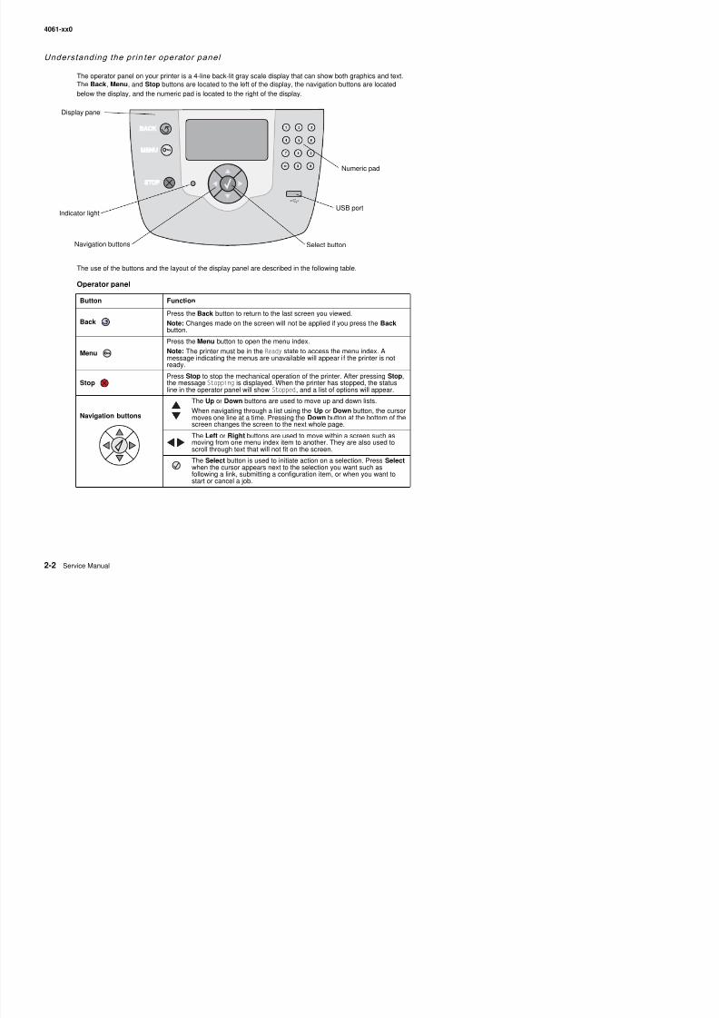
8/13/2019 t644 Service Manual
http://slidepdf.com/reader/full/t644-service-manual 44/423
Understanding the prin ter operator panel
The operator panel on your printer is a 4-line back-lit gray scale display that can show both graphics and text.The Back, Menu, and Stop buttons are located to the left of the display, the navigation buttons are locatedbelow the display, and the numeric pad is located to the right of the display.
The use of the buttons and the layout of the display panel are described in the following table.
Operator panel
Button Function
BackPress the Back button to return to the last screen you viewed.
Note: Changes made on the screen will not be applied if you press the Back
button.
Menu
Press the Menu button to open the menu index.
Note: The printer must be in the Ready state to access the menu index. Amessage indicating the menus are unavailable will appear i f the printer is notready.
StopPress Stop to stop the mechanical operation of the printer. After pressing Stop,the message Stopping is displayed. When the printer has stopped, the statusline in the operator panel will show Stopped, and a list of options will appear.
Navigation buttons
The Up or Down buttons are used to move up and down lists.
When navigating through a list using the Up or Down button, the cursormoves one line at a time. Pressing the Down button at the bottom of thescreen changes the screen to the next whole page.
The Left or Right buttons are used to move within a screen such asmoving from one menu index item to another. They are also used toscroll through text that will not fit on the screen.
The Select button is used to initiate action on a selection Press Select
Navigation buttons
Numeric pad
Display panel
Indicator lightUSB port
Select button
4061-xx0
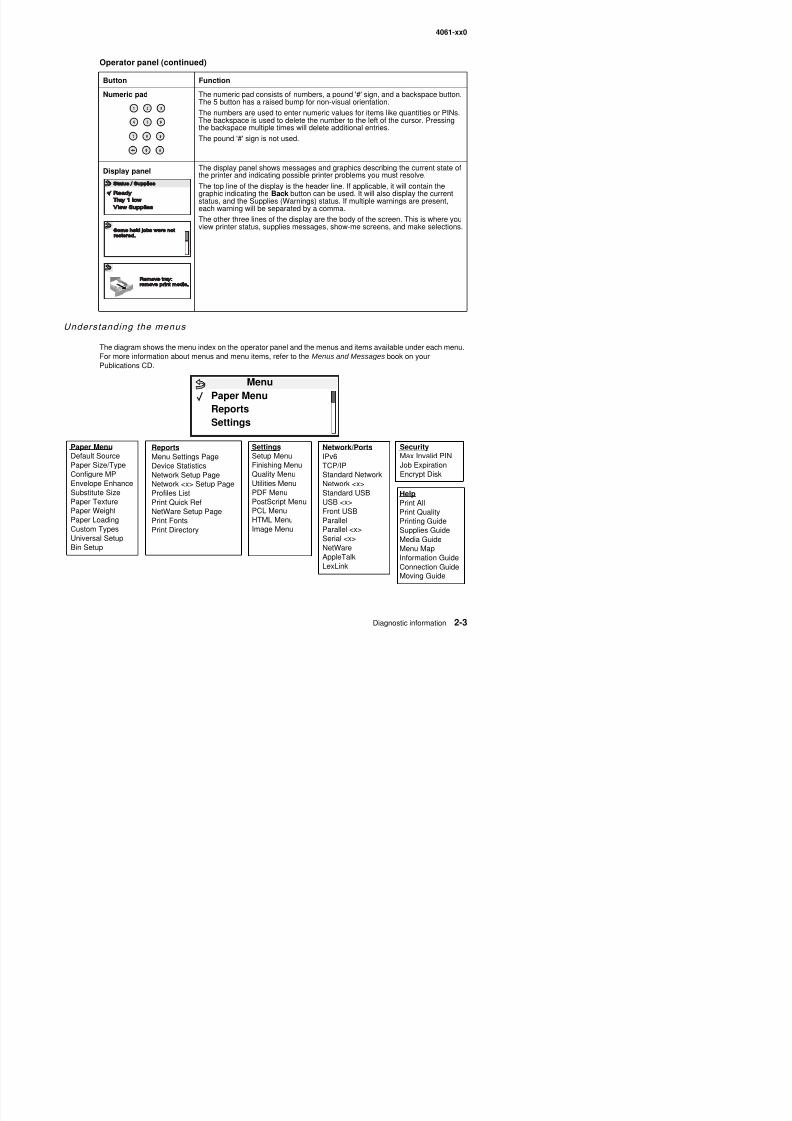
8/13/2019 t644 Service Manual
http://slidepdf.com/reader/full/t644-service-manual 45/423
Understanding the menus
The diagram shows the menu index on the operator panel and the menus and items available under each menu.For more information about menus and menu items, refer to the Menus and Messages book on your
Publications CD.
Numeric pad The numeric pad consists of numbers, a pound '#' sign, and a backspace button.The 5 button has a raised bump for non-visual orientation.The numbers are used to enter numeric values for items like quantities or PINs.The backspace is used to delete the number to the left of the cursor. Pressingthe backspace multiple times will delete additional entries.
The pound '#' sign is not used.
Display panel The display panel shows messages and graphics describing the current state ofthe printer and indicating possible printer problems you must resolve.
The top line of the display is the header line. If applicable, it will contain thegraphic indicating the Back button can be used. It will also display the currentstatus, and the Supplies (Warnings) status. If multiple warnings are present,each warning will be separated by a comma.
The other three lines of the display are the body of the screen. This is where youview printer status, supplies messages, show-me screens, and make selections.
Operator panel (continued)
Button Function
Paper Menu
Default SourcePaper Size/TypeConfigure MPEnvelope EnhanceSubstitute SizePaper TextureP W i ht
Reports
Menu Settings PageDevice StatisticsNetwork Setup PageNetwork <x> Setup PageProfiles ListPrint Quick Ref
Settings
Setup MenuFinishing MenuQuality MenuUtilities MenuPDF MenuPostScript MenuPCL M
Network/Ports
IPv6TCP/IPStandard NetworkNetwork <x>Standard USBUSB <x>
S
Security
Max Invalid PINJob ExpirationEncrypt Disk
HelpPrint All
MenuPaper MenuReportsSettings
4061-xx0
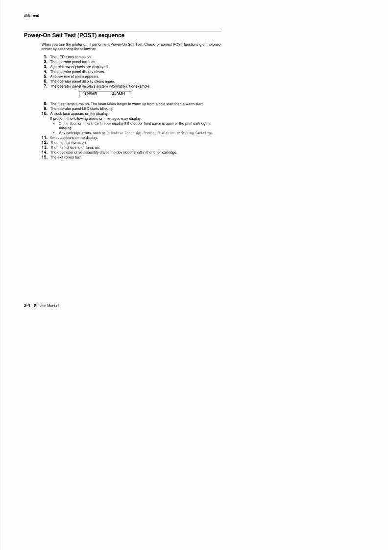
8/13/2019 t644 Service Manual
http://slidepdf.com/reader/full/t644-service-manual 46/423
Power-On Self Test (POST) sequence
When you turn the printer on, it performs a Power-On Self Test. Check for correct POST functioning of the base
printer by observing the following:
1. The LED turns comes on.2. The operator panel turns on.3. A partial row of pixels are displayed.4. The operator panel display clears.5. Another row of pixels appears.6. The operator panel display clears again.7. The operator panel displays system information. For example:
8. The fuser lamp turns on. The fuser takes longer to warm up from a cold start than a warm start.9. The operator panel LED starts blinking.
10. A clock face appears on the display.If present, the following errors or messages may display:
• Close Door or Insert Cartridge display if the upper front cover is open or the print cartridge ismissing.
• Any cartridge errors, such as Defective Cartridge, Prebate Violation, or Missing Cartridge.
11. Ready appears on the display.12. The main fan turns on.13. The main drive motor turns on.14. The developer drive assembly drives the developer shaft in the toner cartridge.15. The exit rollers turn.
*128MB 449MH
4061-xx0
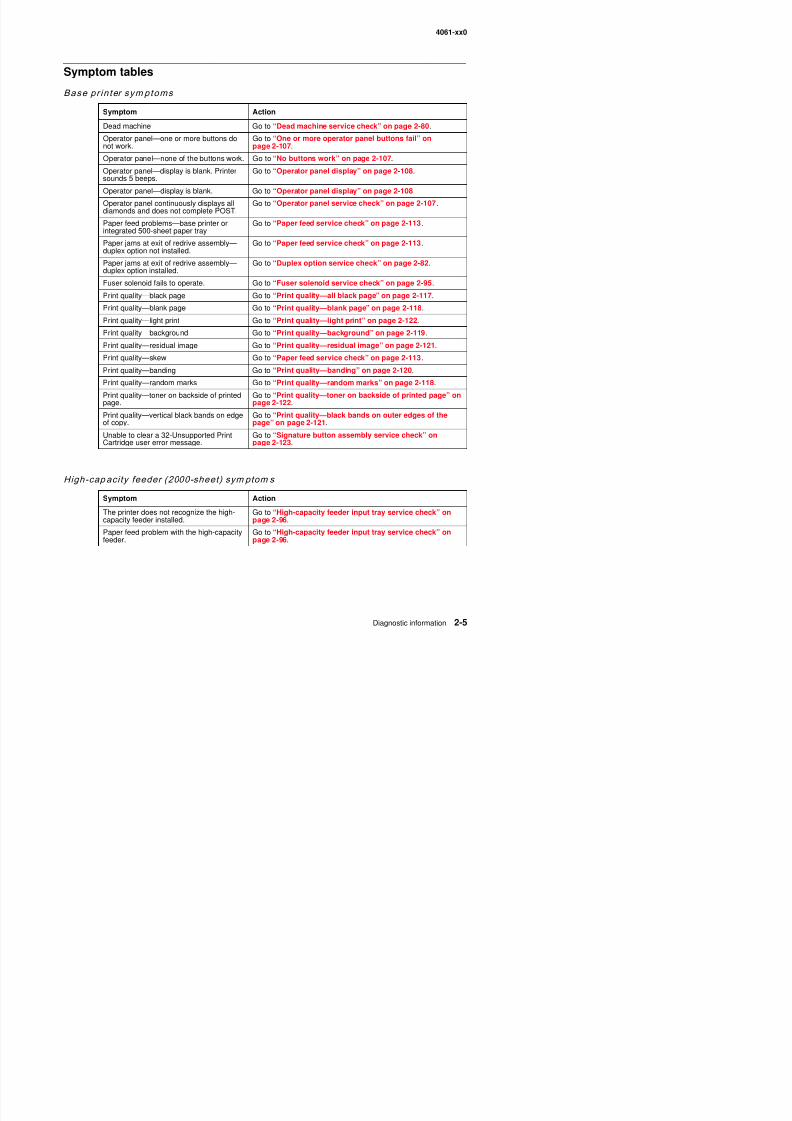
8/13/2019 t644 Service Manual
http://slidepdf.com/reader/full/t644-service-manual 47/423
Symptom tables
Base pr in ter sym ptoms
Symptom Action
Dead machine Go to “Dead machine service check” on page 2-80.
Operator panel—one or more buttons donot work.
Go to “One or more operator panel buttons fail” onpage 2-107.
Operator panel—none of the buttons work. Go to “No buttons work” on page 2-107.
Operator panel—display is blank. Printersounds 5 beeps.
Go to “Operator panel display” on page 2-108.
Operator panel—display is blank. Go to “Operator panel display” on page 2-108Operator panel continuously displays alldiamonds and does not complete POST.
Go to “Operator panel service check” on page 2-107.
Paper feed problems—base printer orintegrated 500-sheet paper tray
Go to “Paper feed service check” on page 2-113.
Paper jams at exit of redrive assembly—duplex option not installed.
Go to “Paper feed service check” on page 2-113.
Paper jams at exit of redrive assembly—duplex option installed.
Go to “Duplex option service check” on page 2-82.
Fuser solenoid fails to operate. Go to “Fuser solenoid service check” on page 2-95.
Print quality—black page Go to “Print quality—all black page” on page 2-117.
Print quality—blank page Go to “Print quality—blank page” on page 2-118.
Print quality—light print Go to “Print quality—light print” on page 2-122.
Print quality—background Go to “Print quality—background” on page 2-119.
Print quality—residual image Go to “Print quality—residual image” on page 2-121.
Print quality—skew Go to “Paper feed service check” on page 2-113.
Print quality—banding Go to “Print quality—banding” on page 2-120.
Print quality—random marks Go to “Print quality—random marks” on page 2-118.
Print quality—toner on backside of printedpage.
Go to “Print quality—toner on backside of printed page” onpage 2-122.
Print quality—vertical black bands on edgeof copy.
Go to “Print quality—black bands on outer edges of thepage” on page 2-121.
Unable to clear a 32-Unsupported PrintCartridge user error message.
Go to “Signature button assembly service check” onpage 2-123.
High-cap acity feeder (2000-sheet) sym ptom s
Symptom Action
4061-xx0
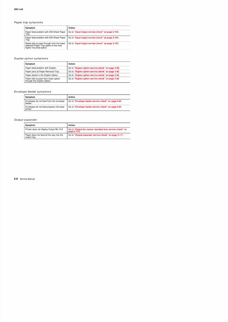
8/13/2019 t644 Service Manual
http://slidepdf.com/reader/full/t644-service-manual 48/423
Paper tray symp toms
Symptom ActionPaper feed problem with 250-Sheet PaperTray.
Go to “Input tray(s) service check” on page 2-103.
Paper feed problem with 500-Sheet PaperTray.
Go to “Input tray(s) service check” on page 2-103.
Media fails to pass through from the lowerattached Paper Tray option to the nexthigher mounted option.
Go to “Input tray(s) service check” on page 2-103.
Duplex opt ion symptom s
Symptom Action
Paper feed problem with Duplex. Go to “Duplex option service check” on page 2-82.
Paper jams at Paper Removal Tray. Go to “Duplex option service check” on page 2-82.
Paper skews in the Duplex Option. Go to “Duplex option service check” on page 2-82.
Paper fails to pass from lower optionthrough the Duplex Option.
Go to “Duplex option service check” on page 2-82.
Envelope feeder symptom s
Symptom Action
Envelopes do not feed from the envelopefeeder.
Go to “Envelope feeder service check” on page 2-84.
Envelopes do not feed properly into baseprinter.
Go to “Envelope feeder service check” on page 2-84.
Output expander
Symptom Action
Printer does not display Output Bin Full. Go to “Output bin sensor standard tray service check” on
page 2-110.Paper does not feed all the way into theoutput tray.
Go to “Output expander service check” on page 2-111.
4061-xx0
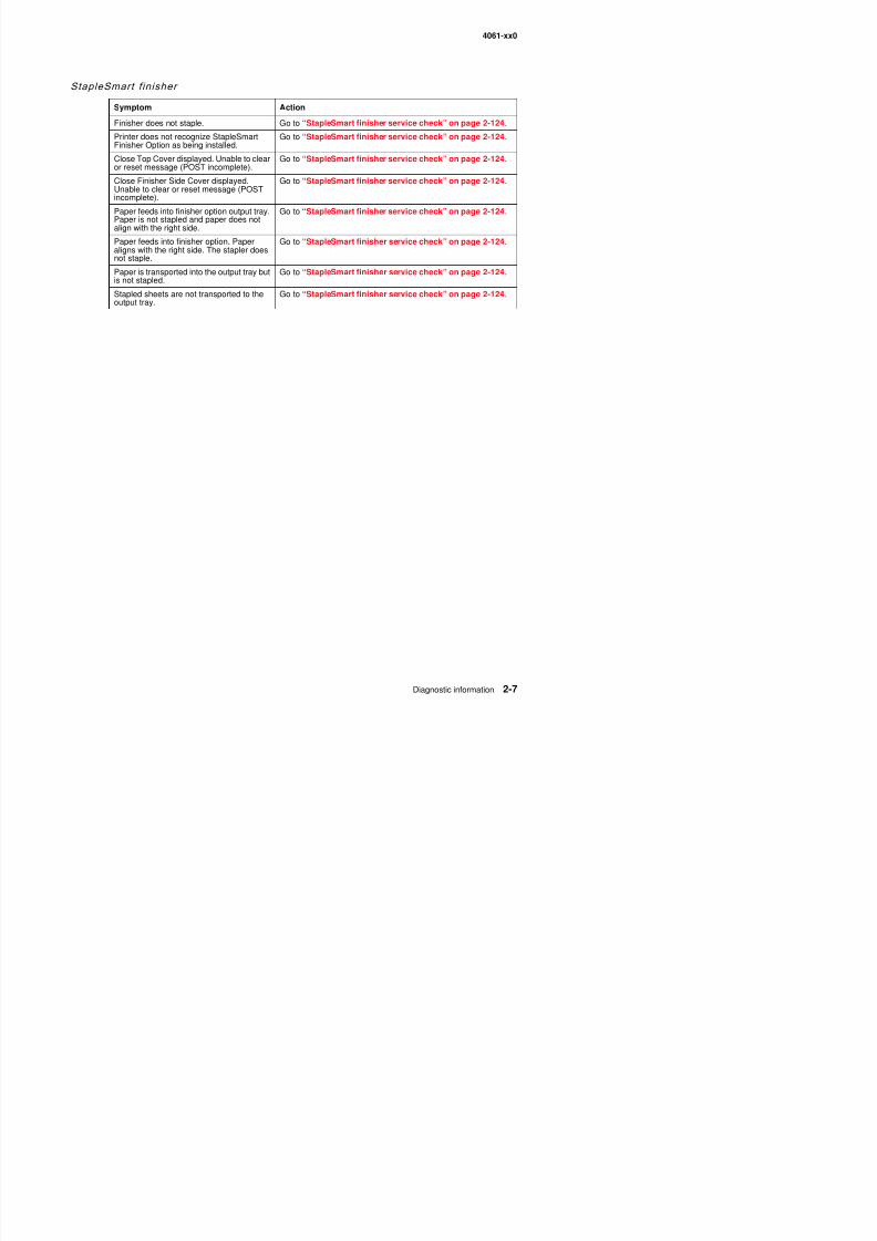
8/13/2019 t644 Service Manual
http://slidepdf.com/reader/full/t644-service-manual 49/423
StapleSmart f inisher
Symptom ActionFinisher does not staple. Go to “StapleSmart finisher service check” on page 2-124.
Printer does not recognize StapleSmartFinisher Option as being installed.
Go to “StapleSmart finisher service check” on page 2-124.
Close Top Cover displayed. Unable to clearor reset message (POST incomplete).
Go to “StapleSmart finisher service check” on page 2-124.
Close Finisher Side Cover displayed.Unable to clear or reset message (POSTincomplete).
Go to “StapleSmart finisher service check” on page 2-124.
Paper feeds into finisher option output tray.Paper is not stapled and paper does notalign with the right side.
Go to “StapleSmart finisher service check” on page 2-124.
Paper feeds into finisher option. Paperaligns with the right side. The stapler doesnot staple.
Go to “StapleSmart finisher service check” on page 2-124.
Paper is transported into the output tray butis not stapled.
Go to “StapleSmart finisher service check” on page 2-124.
Stapled sheets are not transported to theoutput tray.
Go to “StapleSmart finisher service check” on page 2-124.
4061-xx0
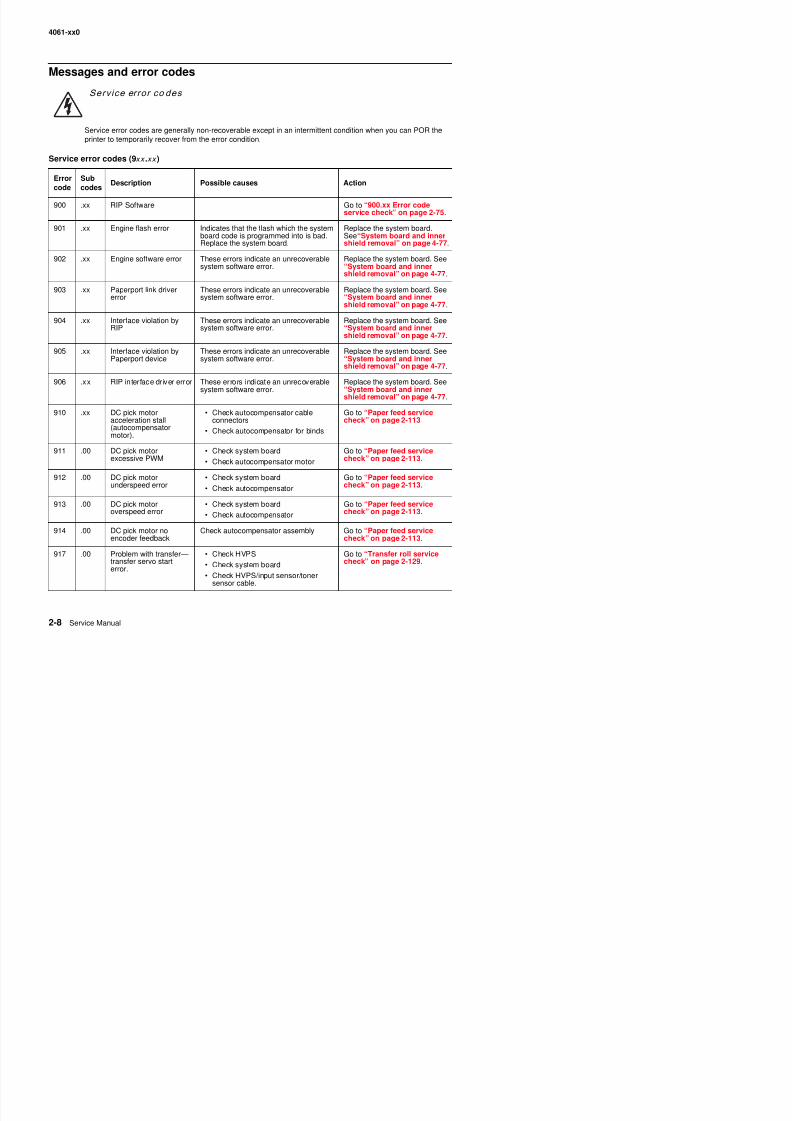
8/13/2019 t644 Service Manual
http://slidepdf.com/reader/full/t644-service-manual 50/423
Messages and error codes
Service error co des
Service error codes are generally non-recoverable except in an intermittent condition when you can POR theprinter to temporarily recover from the error condition.
Service error codes (9xx .xx )
Error
code
Sub
codes
Description Possible causes Action
900 .xx RIP Software Go to “900.xx Error codeservice check” on page 2-75.
901 .xx Engine flash error Indicates that the flash which the systemboard code is programmed into is bad.Replace the system board.
Replace the system board.See“System board and innershield removal” on page 4-77.
902 .xx Engine software error These errors indicate an unrecoverablesystem software error.
Replace the system board. See“System board and innershield removal” on page 4-77.
903 .xx Paperport link drivererror
These errors indicate an unrecoverablesystem software error.
Replace the system board. See“System board and innershield removal” on page 4-77.
904 .xx Interface violation byRIP
These errors indicate an unrecoverablesystem software error.
Replace the system board. See“System board and innershield removal” on page 4-77.
905 .xx Interface violation byPaperport device
These errors indicate an unrecoverablesystem software error.
Replace the system board. See“System board and inner
shield removal” on page 4-77.906 .xx RIP interface driver error These errors indicate an unrecoverable
system software error.Replace the system board. See“System board and innershield removal” on page 4-77.
910 .xx DC pick motoracceleration stall(autocompensatormotor).
• Check autocompensator cableconnectors
• Check autocompensator for binds
Go to “Paper feed servicecheck” on page 2-113.
911 .00 DC pick motorexcessive PWM
• Check system board
• Check autocompensator motor
Go to “Paper feed servicecheck” on page 2-113.
912 .00 DC pick motorunderspeed error
• Check system board
• Check autocompensator
Go to “Paper feed servicecheck” on page 2-113.
913 .00 DC pick motor • Check system board Go to “Paper feed service
4061-xx0
Service error codes (9xx xx ) (continued)
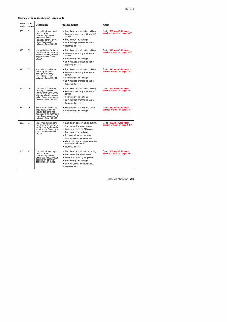
8/13/2019 t644 Service Manual
http://slidepdf.com/reader/full/t644-service-manual 51/423
920 .01 Hot roll took too long toheat up aftertransitioning to newenhanced mode(standby control only.Fuser page countbetween 0 and 99,999.
• Bad thermistor, circuit or cabling.
• Fuser not receiving sufficient ACpower.
• Poor supply line voltage.
• Low wattage or incorrect lamp.
• Incorrect hot roll.
Go to “920.xx—Cold fuserservice check” on page 2-87.
920 .02 Hot roll fell too far belowthe desired temperature
while in standby. Fuserpage between 0 and99,999.
• Bad thermistor, circuit or cabling.
• Fuser not receiving sufficient ACpower.• Poor supply line voltage.
• Low wattage or incorrect lamp.
• Incorrect hot roll.
Go to “920.xx—Cold fuserservice check” on page 2-87.
920 .03 Hot roll too cool whenchecking for slopechange in standby.Fuser page countbetween 0 and 99,999.
• Bad thermistor, circuit or cabling.
• Fuser not receiving sufficient ACpower.
• Poor supply line voltage.
• Low wattage or incorrect lamp.• Incorrect hot roll.
Go to “920.xx—Cold fuserservice check” on page 2-87.
920 .04 Hot roll too cool whenheating to desiredtemperature after slopechange (standby controlonly). Fuser page countbetween 0 and 99,999.
• Bad thermistor, circuit or cabling.
• Fuser not receiving sufficient ACpower.
• Poor supply line voltage.
• Low wattage or incorrect lamp.
• Incorrect hot roll.
Go to “920.xx—Cold fuserservice check” on page 2-87.
920 .06 Fuser is not increasingin temperature eventhough the lamp hasbeen on for an extendedtime. Fuser page countbetween 0 and 99,999.
• Fuser is not receiving AC power.
• Poor supply line voltage.
Go to “920.xx—Cold fuserservice check” on page 2-87.
920. .07 Fuser has been belowthe desired temperaturefor too long while mediais in the nip. Fuser page
count between 0 and99,999.
• Bad thermistor, circuit, or cabling.
• Very noisy thermistor signal.
• Fuser not receiving AC power.
• Poor supply line voltage.• Excessive load on the fuser.
• Low voltage or incorrect lamp.
• Abrupt change in temperature thathas disrupted control.
I t h t ll
Go to “920.xx—Cold fuserservice check” on page 2-87.
Service error codes (9xx .xx ) (continued)
Errorcode
Subcodes
Description Possible causes Action
4061-xx0
Service error codes (9xx .xx ) (continued)
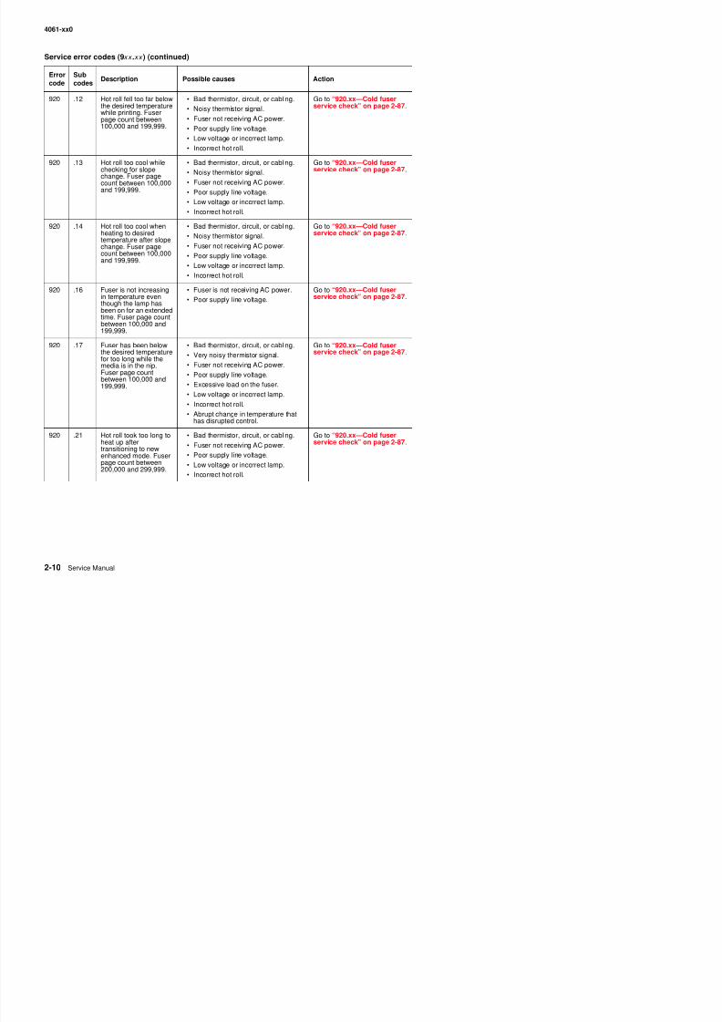
8/13/2019 t644 Service Manual
http://slidepdf.com/reader/full/t644-service-manual 52/423
920 .12 Hot roll fell too far belowthe desired temperaturewhile printing. Fuserpage count between100,000 and 199,999.
• Bad thermistor, circuit, or cabling.
• Noisy thermistor signal.
• Fuser not receiving AC power.
• Poor supply line voltage.
• Low voltage or incorrect lamp.
• Incorrect hot roll.
Go to “920.xx—Cold fuserservice check” on page 2-87.
920 .13 Hot roll too cool while
checking for slopechange. Fuser pagecount between 100,000and 199,999.
• Bad thermistor, circuit, or cabling.
• Noisy thermistor signal.• Fuser not receiving AC power.
• Poor supply line voltage.
• Low voltage or incorrect lamp.
• Incorrect hot roll.
Go to “920.xx—Cold fuser
service check” on page 2-87.
920 .14 Hot roll too cool whenheating to desiredtemperature after slopechange. Fuser page
count between 100,000and 199,999.
• Bad thermistor, circuit, or cabling.
• Noisy thermistor signal.
• Fuser not receiving AC power.
• Poor supply line voltage.• Low voltage or incorrect lamp.
• Incorrect hot roll.
Go to “920.xx—Cold fuserservice check” on page 2-87.
920 .16 Fuser is not increasingin temperature eventhough the lamp hasbeen on for an extendedtime. Fuser page countbetween 100,000 and199,999.
• Fuser is not receiving AC power.
• Poor supply line voltage.
Go to “920.xx—Cold fuserservice check” on page 2-87.
920 .17 Fuser has been belowthe desired temperaturefor too long while themedia is in the nip.Fuser page countbetween 100,000 and199,999.
• Bad thermistor, circuit, or cabling.
• Very noisy thermistor signal.
• Fuser not receiving AC power.
• Poor supply line voltage.
• Excessive load on the fuser.
• Low voltage or incorrect lamp.
• Incorrect hot roll.
• Abrupt change in temperature thathas disrupted control.
Go to “920.xx—Cold fuserservice check” on page 2-87.
920 .21 Hot roll took too long toheat up aftertransitioning to newenhanced mode. Fuserpage count between
• Bad thermistor, circuit, or cabling.
• Fuser not receiving AC power.
• Poor supply line voltage.
L lt i t l
Go to “920.xx—Cold fuserservice check” on page 2-87.
Service error codes (9xx .xx ) (continued)
Errorcode
Subcodes
Description Possible causes Action
4061-xx0
Service error codes (9xx .xx ) (continued)
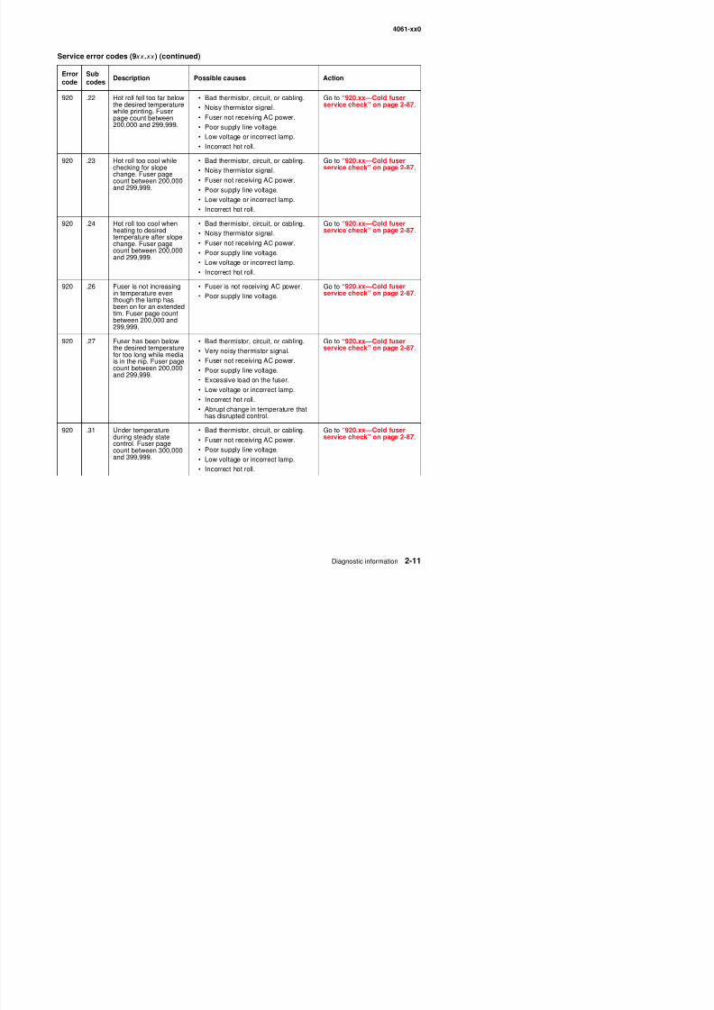
8/13/2019 t644 Service Manual
http://slidepdf.com/reader/full/t644-service-manual 53/423
920 .22 Hot roll fell too far belowthe desired temperaturewhile printing. Fuserpage count between200,000 and 299,999.
• Bad thermistor, circuit, or cabling.
• Noisy thermistor signal.
• Fuser not receiving AC power.
• Poor supply line voltage.
• Low voltage or incorrect lamp.
• Incorrect hot roll.
Go to “920.xx—Cold fuserservice check” on page 2-87.
920 .23 Hot roll too cool while
checking for slopechange. Fuser pagecount between 200,000and 299,999.
• Bad thermistor, circuit, or cabling.
• Noisy thermistor signal.• Fuser not receiving AC power.
• Poor supply line voltage.
• Low voltage or incorrect lamp.
• Incorrect hot roll.
Go to “920.xx—Cold fuser
service check” on page 2-87.
920 .24 Hot roll too cool whenheating to desiredtemperature after slopechange. Fuser page
count between 200,000and 299,999.
• Bad thermistor, circuit, or cabling.
• Noisy thermistor signal.
• Fuser not receiving AC power.
• Poor supply line voltage.• Low voltage or incorrect lamp.
• Incorrect hot roll.
Go to “920.xx—Cold fuserservice check” on page 2-87.
920 .26 Fuser is not increasingin temperature eventhough the lamp hasbeen on for an extendedtim. Fuser page countbetween 200,000 and299,999.
• Fuser is not receiving AC power.
• Poor supply line voltage.
Go to “920.xx—Cold fuserservice check” on page 2-87.
920 .27 Fuser has been belowthe desired temperaturefor too long while mediais in the nip. Fuser pagecount between 200,000and 299,999.
• Bad thermistor, circuit, or cabling.
• Very noisy thermistor signal.
• Fuser not receiving AC power.
• Poor supply line voltage.
• Excessive load on the fuser.
• Low voltage or incorrect lamp.
• Incorrect hot roll.
• Abrupt change in temperature thathas disrupted control.
Go to “920.xx—Cold fuserservice check” on page 2-87.
920 .31 Under temperatureduring steady statecontrol. Fuser pagecount between 300,000and 399 999
• Bad thermistor, circuit, or cabling.
• Fuser not receiving AC power.
• Poor supply line voltage.
L lt i t l
Go to “920.xx—Cold fuserservice check” on page 2-87.
( ) ( )
Errorcode
Subcodes
Description Possible causes Action
4061-xx0
Service error codes (9xx .xx ) (continued)
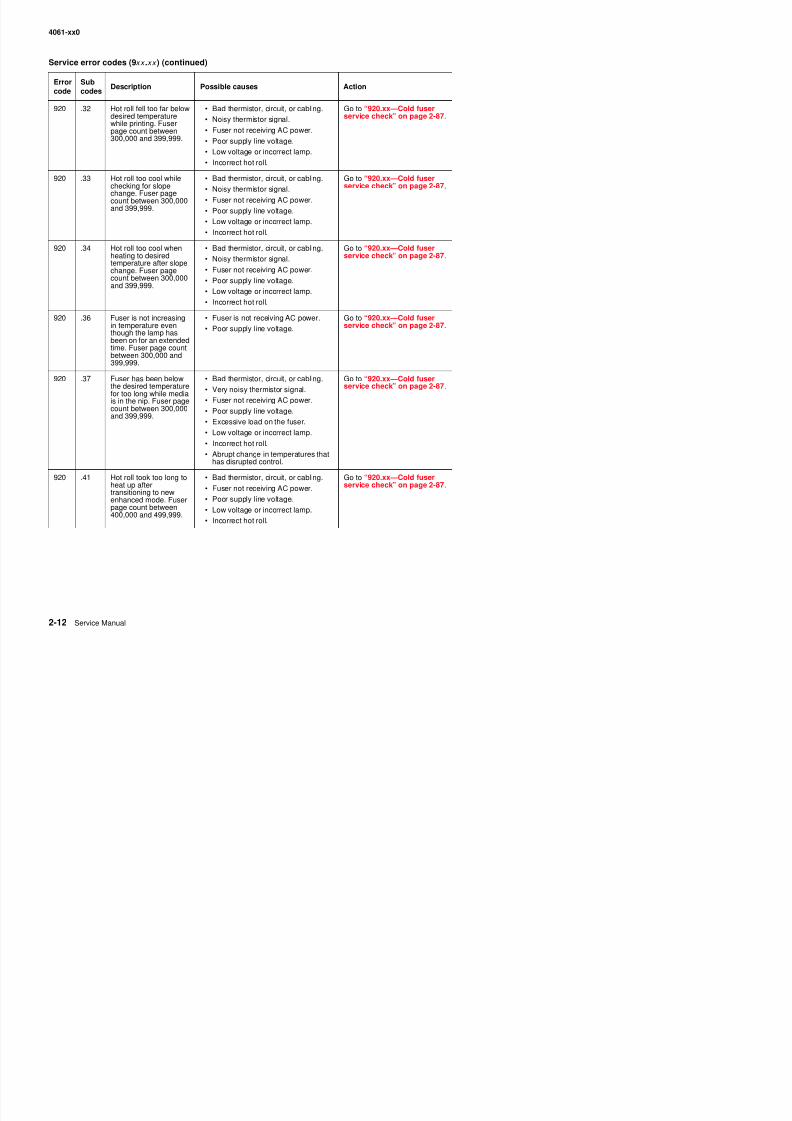
8/13/2019 t644 Service Manual
http://slidepdf.com/reader/full/t644-service-manual 54/423
920 .32 Hot roll fell too far belowdesired temperaturewhile printing. Fuserpage count between300,000 and 399,999.
• Bad thermistor, circuit, or cabling.
• Noisy thermistor signal.
• Fuser not receiving AC power.
• Poor supply line voltage.
• Low voltage or incorrect lamp.
• Incorrect hot roll.
Go to “920.xx—Cold fuserservice check” on page 2-87.
920 .33 Hot roll too cool whilechecking for slopechange. Fuser pagecount between 300,000and 399,999.
• Bad thermistor, circuit, or cabling.
• Noisy thermistor signal.• Fuser not receiving AC power.
• Poor supply line voltage.
• Low voltage or incorrect lamp.
• Incorrect hot roll.
Go to “920.xx—Cold fuserservice check” on page 2-87.
920 .34 Hot roll too cool whenheating to desiredtemperature after slopechange. Fuser page
count between 300,000and 399,999.
• Bad thermistor, circuit, or cabling.
• Noisy thermistor signal.
• Fuser not receiving AC power.
• Poor supply line voltage.• Low voltage or incorrect lamp.
• Incorrect hot roll.
Go to “920.xx—Cold fuserservice check” on page 2-87.
920 .36 Fuser is not increasingin temperature eventhough the lamp hasbeen on for an extendedtime. Fuser page countbetween 300,000 and399,999.
• Fuser is not receiving AC power.
• Poor supply line voltage.
Go to “920.xx—Cold fuserservice check” on page 2-87.
920 .37 Fuser has been belowthe desired temperaturefor too long while mediais in the nip. Fuser pagecount between 300,000and 399,999.
• Bad thermistor, circuit, or cabling.
• Very noisy thermistor signal.
• Fuser not receiving AC power.
• Poor supply line voltage.
• Excessive load on the fuser.
• Low voltage or incorrect lamp.
• Incorrect hot roll.
• Abrupt change in temperatures thathas disrupted control.
Go to “920.xx—Cold fuserservice check” on page 2-87.
920 .41 Hot roll took too long toheat up aftertransitioning to newenhanced mode. Fuserpage count between
• Bad thermistor, circuit, or cabling.
• Fuser not receiving AC power.
• Poor supply line voltage.
L lt i t l
Go to “920.xx—Cold fuserservice check” on page 2-87.
( ) ( )
Errorcode
Subcodes
Description Possible causes Action
4061-xx0
Service error codes (9xx .xx ) (continued)
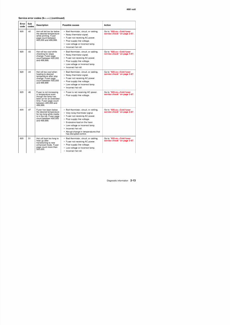
8/13/2019 t644 Service Manual
http://slidepdf.com/reader/full/t644-service-manual 55/423
920 .42 Hot roll fell too far belowthe desired temperaturewhile printing. Fuserpage count between400,000 and 499,999.
• Bad thermistor, circuit, or cabling.
• Noisy thermistor signal.
• Fuser not receiving AC power.
• Poor supply line voltage.
• Low voltage or incorrect lamp.
• Incorrect hot roll.
Go to “920.xx—Cold fuserservice check” on page 2-87.
920 .43 Hot roll too cool whilechecking for slopechange. Fuser pagecount between 400,000and 499,999.
• Bad thermistor, circuit, or cabling.
• Noisy thermistor signal.• Fuser not receiving AC power.
• Poor supply line voltage.
• Low voltage or incorrect lamp.
• Incorrect hot roll.
Go to “920.xx—Cold fuserservice check” on page 2-87.
920 .44 Hot roll too cool whenheating to desiredtemperature after slopchange. Fuser page
count between 400,000and 499,999
• Bad thermistor, circuit, or cabling.
• Noisy thermistor signal.
• Fuser not receiving AC power.
• Poor supply line voltage.• Low voltage or incorrect lamp.
• Incorrect hot roll.
Go to “920.xx—Cold fuserservice check” on page 2-87.
920 .46 Fuser is not increasingin temperature eventhough the lamp hasbeen on for an extendedtime. Fuser page countbetween 400,000 and499,999.
• Fuser is not receiving AC power.
• Poor supply line voltage.
Go to “920.xx—Cold fuserservice check” on page 2-87.
920 .47 Fuser has been belowthe desired temperaturefor too long while mediais in the nip. Fuser pagecount between 400,000and 499,999.
• Bad thermistor, circuit, or cabling.
• Very noisy thermistor signal.
• Fuser not receiving AC power.
• Poor supply line voltage.
• Excessive load on the fuser.
• Low voltage or incorrect lamp.
• Incorrect hot roll.
• Abrupt change in temperatures thathas disrupted control.
Go to “920.xx—Cold fuserservice check” on page 2-87.
920 .51 Hot roll took too long toheat up aftertransitioning to newenhanced mode. Fuserpage count more than
• Bad thermistor, circuit, or cabling.
• Fuser not receiving AC power.
• Poor supply line voltage.
L lt i t l
Go to “920.xx—Cold fuserservice check” on page 2-87.
Errorcode
Subcodes
Description Possible causes Action
4061-xx0
Service error codes (9xx .xx ) (continued)
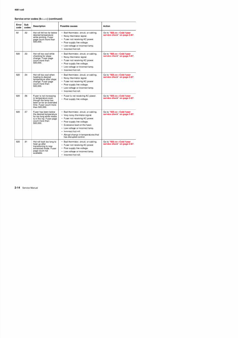
8/13/2019 t644 Service Manual
http://slidepdf.com/reader/full/t644-service-manual 56/423
92 .52 Hot roll fell too far belowdesired temperaturewhile printing. Fuserpage count more than500,000.
• Bad thermistor, circuit, or cabling.
• Noisy thermistor signal.
• Fuser not receiving AC power.
• Poor supply line voltage.
• Low voltage or incorrect lamp.
• Incorrect hot roll.
Go to “920.xx—Cold fuserservice check” on page 2-87.
920 .53 Hot roll too cool whilechecking for slopechange. Fuser pagecount more than500,000.
• Bad thermistor, circuit, or cabling.
• Noisy thermistor signal.• Fuser not receiving AC power.
• Poor supply line voltage.
• Low voltage or incorrect lamp.
• Incorrect hot roll.
Go to “920.xx—Cold fuserservice check” on page 2-87.
920 .54 Hot roll too cool whenheating to desiredtemperature after slopechange. Fuser page
count more than500,000.
• Bad thermistor, circuit, or cabling.
• Noisy thermistor signal.
• Fuser not receiving AC power.
• Poor supply line voltage.• Low voltage or incorrect lamp.
• Incorrect hot roll.
Go to “920.xx—Cold fuserservice check” on page 2-87.
920 .56 Fuser is not increasingin temperature eventhough the lamp hasbeen on for an extendedtime. Fuser count morethan 500,000.
• Fuser is not receiving AC power.
• Poor supply line voltage.
Go to “920.xx—Cold fuserservice check” on page 2-87.
920 .57 Fuser has been belowthe desired temperaturefor too long while mediais in the nip. Fuser pagecount more than500,000.
• Bad thermistor, circuit, or cabling.• Very noisy thermistor signal.
• Fuser not receiving AC power.
• Poor supply line voltage.
• Excessive load on the fuser.
• Low voltage or incorrect lamp.
• Incorrect hot roll.
• Abrupt change in temperatures thathas disrupted control.
Go to “920.xx—Cold fuserservice check” on page 2-87.
920 .91 Hot roll took too long toheat up aftertransitioning to newenhanced mode. Fuserpage count notavailable
• Bad thermistor, circuit, or cabling.
• Fuser not receiving AC power.
• Poor supply line voltage.
• Low voltage or incorrect lamp.
Go to “920.xx—Cold fuserservice check” on page 2-87.
Errorcode
Subcodes
Description Possible causes Action
4061-xx0
Service error codes (9xx .xx ) (continued)
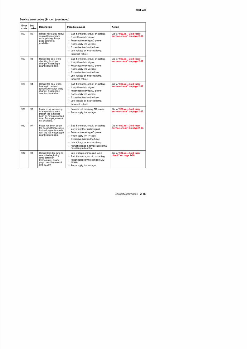
8/13/2019 t644 Service Manual
http://slidepdf.com/reader/full/t644-service-manual 57/423
920 .92 Hot roll fell too far belowdesired temperaturewhile printing. Fuserpage count notavailable.
• Bad thermistor, circuit, or cabling.
• Noisy thermistor signal.
• Fuser not receiving AC power.
• Poor supply line voltage.
• Excessive load on the fuser.
• Low voltage or incorrect lamp.
• Incorrect hot roll.
Go to “920.xx—Cold fuserservice check” on page 2-87.
920 .93 Hot roll too cool whilechecking for slopechange. Fuser pagecount not available.
• Bad thermistor, circuit, or cabling.• Noisy thermistor signal.
• Fuser not receiving AC power.
• Poor supply line voltage.
• Excessive load on the fuser.
• Low voltage or incorrect lamp.
• Incorrect hot roll.
Go to “920.xx—Cold fuserservice check” on page 2-87.
920 .94 Hot roll too cool when
heating to desiredtemperature after slopechange. Fuser pagecount not available.
• Bad thermistor, circuit, or cabling.
• Noisy thermistor signal.• Fuser not receiving AC power.
• Poor supply line voltage.
• Excessive load on the fuser.
• Low voltage or incorrect lamp.
• Incorrect hot roll.
Go to “920.xx—Cold fuser
service check” on page 2-87.
920 .96 Fuser is not increasingin temperature even
though the lamp hasbeen on for an extendedtime. Fuser page countnot available.
• Fuser is not receiving AC power.
• Poor supply line voltage.
Go to “920.xx—Cold fuserservice check” on page 2-87.
920 .97 Fuser has been belowthe desired temperaturefor too long while mediais in the nip. Fuser pagecount not available.
• Bad thermistor, circuit, or cabling.
• Very noisy thermistor signal.
• Fuser not receiving AC power.
• Poor supply line voltage.
• Excessive load on the fuser.
• Low voltage or incorrect lamp.• Abrupt change in temperatures that
has disrupted control.
Go to “920.xx—Cold fuserservice check” on page 2-87.
922 .02 Hot roll took too long toreach the beginninglamp detection
• Low wattage or incorrect lamp.
• Bad thermistor, circuit, or cabling.
Go to “922.xx—Cold fusercheck” on page 2-89.
Errorcode
Subcodes
Description Possible causes Action
4061-xx0
Service error codes (9xx .xx ) (continued)
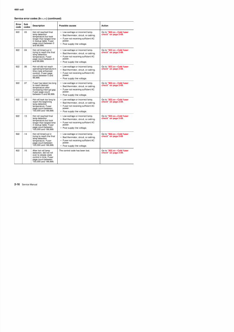
8/13/2019 t644 Service Manual
http://slidepdf.com/reader/full/t644-service-manual 58/423
922 .03 Hot roll reached finallamp detectiontemperature but tooklonger than largest timein lookup table. Fuserpage count between 0and 99,999.
• Low wattage or incorrect lamp.
• Bad thermistor, circuit, or cabling.
• Fuser not receiving sufficient ACpower.
• Poor supply line voltage.
Go to “922.xx—Cold fusercheck” on page 2-89.
922 .04 Hot roll timed out intrying to reach the finallamp detection
temperature. Fuserpage count between 0and 99,999.
• Low wattage or incorrect lamp.
• Bad thermistor, circuit, or cabling.
• Fuser not receiving sufficient ACpower.
• Poor supply line voltage.
Go to “922.xx—Cold fusercheck” on page 2-89.
922 .06 Hot roll did not reachoperating temperature intime (new enhancedcontrol). Fuser pagecount between 0 and99,999.
• Low wattage or incorrect lamp.
• Bad thermistor, circuit, or cabling.
• Fuser not receiving sufficient ACpower.
• Poor supply line voltage.
Go to “922.xx—Cold fusercheck” on page 2-89.
922 .07 Fuser has taken too longto reach desiredtemperature afterincreasing interrupt gap.Fuser page countbetween 0 and 99,999.
• Low wattage or incorrect lamp.• Bad thermistor, circuit, or cabling.
• Fuser not receiving sufficient ACpower.
• Poor supply line voltage.
Go to “922.xx—Cold fusercheck” on page 2-89.
922 .12 Hot roll took too long toreach the beginninglamp detectiontemperature. Fuser
page count between100,000 and 199,999.
• Low wattage or incorrect lamp.
• Bad thermistor, circuit, or cabling.
• Fuser not receiving sufficient ACpower.
• Poor supply line voltage.
Go to “922.xx—Cold fusercheck” on page 2-89.
922 .13 Hot roll reached finallamp detectiontemperature but tooklonger than largest timein lookup table. Fuserpage count between100,000 and 199,999.
• Low wattage or incorrect lamp.
• Bad thermistor, circuit, or cabling.
• Fuser not receiving sufficient ACpower.
• Poor supply line voltage.
Go to “922.xx—Cold fusercheck” on page 2-89.
922 .14 Hot roll timed out in
trying to reach the finallamp detectiontemperature. Fuserpage count between100,000 and 199,999.
• Low wattage or incorrect lamp.
• Bad thermistor, circuit, or cabling.
• Fuser not receiving sufficient ACpower.
• Poor supply line voltage.
Go to “922.xx—Cold fuser
check” on page 2-89.
922 15 After hot roll lamp The control code has been lost Go to “922 xx Cold fuser
Errorcode
Subcodes
Description Possible causes Action
4061-xx0
Service error codes (9xx .xx ) (continued)
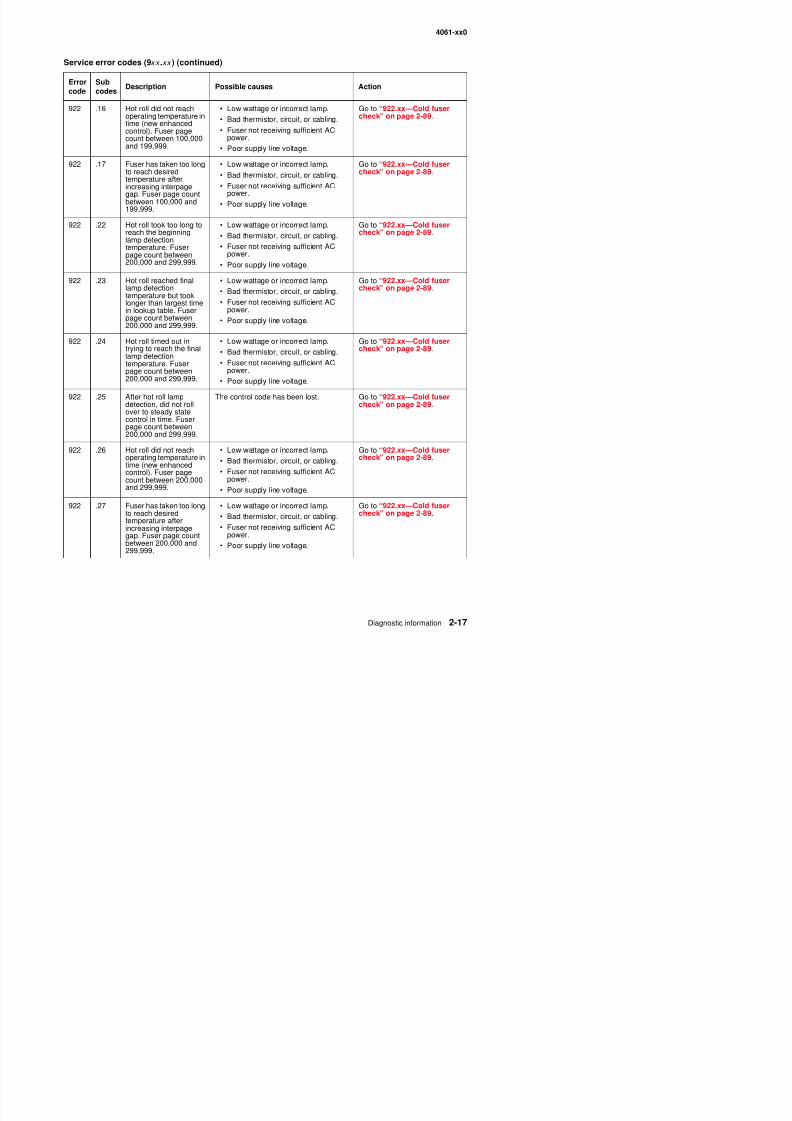
8/13/2019 t644 Service Manual
http://slidepdf.com/reader/full/t644-service-manual 59/423
922 .16 Hot roll did not reachoperating temperature intime (new enhancedcontrol). Fuser pagecount between 100,000and 199,999.
• Low wattage or incorrect lamp.
• Bad thermistor, circuit, or cabling.
• Fuser not receiving sufficient ACpower.
• Poor supply line voltage.
Go to “922.xx—Cold fusercheck” on page 2-89.
922 .17 Fuser has taken too longto reach desiredtemperature afterincreasing interpagegap. Fuser page countbetween 100,000 and199,999.
• Low wattage or incorrect lamp.
• Bad thermistor, circuit, or cabling.
• Fuser not receiving sufficient ACpower.
• Poor supply line voltage.
Go to “922.xx—Cold fusercheck” on page 2-89.
922 .22 Hot roll took too long toreach the beginninglamp detectiontemperature. Fuserpage count between200,000 and 299,999.
• Low wattage or incorrect lamp.
• Bad thermistor, circuit, or cabling.
• Fuser not receiving sufficient ACpower.
• Poor supply line voltage.
Go to “922.xx—Cold fusercheck” on page 2-89.
922 .23 Hot roll reached finallamp detectiontemperature but tooklonger than largest timein lookup table. Fuserpage count between200,000 and 299,999.
• Low wattage or incorrect lamp.• Bad thermistor, circuit, or cabling.
• Fuser not receiving sufficient ACpower.
• Poor supply line voltage.
Go to “922.xx—Cold fusercheck” on page 2-89.
922 .24 Hot roll timed out intrying to reach the finallamp detectiontemperature. Fuserpage count between200,000 and 299,999.
• Low wattage or incorrect lamp.
• Bad thermistor, circuit, or cabling.
• Fuser not receiving sufficient AC
power.• Poor supply line voltage.
Go to “922.xx—Cold fusercheck” on page 2-89.
922 .25 After hot roll lampdetection, did not rollover to steady statecontrol in time. Fuserpage count between200,000 and 299,999.
The control code has been lost. Go to “922.xx—Cold fusercheck” on page 2-89.
922 .26 Hot roll did not reach
operating temperature intime (new enhancedcontrol). Fuser pagecount between 200,000and 299,999.
• Low wattage or incorrect lamp.
• Bad thermistor, circuit, or cabling.• Fuser not receiving sufficient AC
power.
• Poor supply line voltage.
Go to “922.xx—Cold fuser
check” on page 2-89.
922 .27 Fuser has taken too long • Low wattage or incorrect lamp. Go to “922.xx—Cold fuser
Errorcode
Subcodes
Description Possible causes Action
4061-xx0
Service error codes (9xx .xx ) (continued)
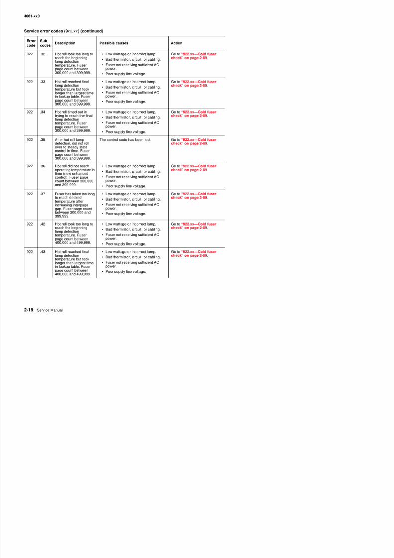
8/13/2019 t644 Service Manual
http://slidepdf.com/reader/full/t644-service-manual 60/423
922 .32 Hot roll took too long toreach the beginninglamp detectiontemperature. Fuserpage count between300,000 and 399,999.
• Low wattage or incorrect lamp.
• Bad thermistor, circuit, or cabling.
• Fuser not receiving sufficient ACpower.
• Poor supply line voltage.
Go to “922.xx—Cold fusercheck” on page 2-89.
922 .33 Hot roll reached finallamp detectiontemperature but tooklonger than largest timein lookup table. Fuserpage count between300,000 and 399,999.
• Low wattage or incorrect lamp.
• Bad thermistor, circuit, or cabling.
• Fuser not receiving sufficient ACpower.
• Poor supply line voltage.
Go to “922.xx—Cold fusercheck” on page 2-89.
922 .34 Hot roll timed out intrying to reach the finallamp detectiontemperature. Fuserpage count between300,000 and 399,999.
• Low wattage or incorrect lamp.
• Bad thermistor, circuit, or cabling.
• Fuser not receiving sufficient ACpower.
• Poor supply line voltage.
Go to “922.xx—Cold fusercheck” on page 2-89.
922 .35 After hot roll lampdetection, did not rollover to steady statecontrol in time. Fuserpage count between300,000 and 399,999.
The control code has been lost. Go to “922.xx—Cold fusercheck” on page 2-89.
922 .36 Hot roll did not reachoperating temperature intime (new enhancedcontrol). Fuser pagecount between 300,000
and 399,999.
• Low wattage or incorrect lamp.
• Bad thermistor, circuit, or cabling.
• Fuser not receiving sufficient ACpower.
• Poor supply line voltage.
Go to “922.xx—Cold fusercheck” on page 2-89.
922 .37 Fuser has taken too longto reach desiredtemperature afterincreasing interpagegap. Fuser page countbetween 300,000 and399,999.
• Low wattage or incorrect lamp.
• Bad thermistor, circuit, or cabling.
• Fuser not receiving sufficient ACpower.
• Poor supply line voltage.
Go to “922.xx—Cold fusercheck” on page 2-89.
922 .42 Hot roll took too long to
reach the beginninglamp detectiontemperature. Fuserpage count between400,000 and 499,999.
• Low wattage or incorrect lamp.
• Bad thermistor, circuit, or cabling.• Fuser not receiving sufficient AC
power.
• Poor supply line voltage.
Go to “922.xx—Cold fuser
check” on page 2-89.
922 .43 Hot roll reached final • Low wattage or incorrect lamp. Go to “922.xx—Cold fuser
Errorcode
Subcodes
Description Possible causes Action
4061-xx0
Service error codes (9xx .xx ) (continued)
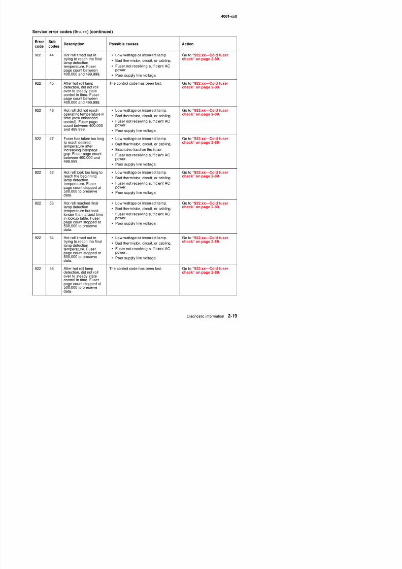
8/13/2019 t644 Service Manual
http://slidepdf.com/reader/full/t644-service-manual 61/423
922 .44 Hot roll timed out intrying to reach the finallamp detectiontemperature. Fuserpage count between400,000 and 499,999.
• Low wattage or incorrect lamp.
• Bad thermistor, circuit, or cabling.
• Fuser not receiving sufficient ACpower.
• Poor supply line voltage.
Go to “922.xx—Cold fusercheck” on page 2-89.
922 .45 After hot roll lampdetection, did not rollover to steady statecontrol in time. Fuserpage count between400,000 and 499,999.
The control code has been lost. Go to “922.xx—Cold fusercheck” on page 2-89.
922 .46 Hot roll did not reachoperating temperature intime (new enhancedcontrol). Fuser pagecount between 400,000and 499,999.
• Low wattage or incorrect lamp.
• Bad thermistor, circuit, or cabling.
• Fuser not receiving sufficient ACpower.
• Poor supply line voltage.
Go to “922.xx—Cold fusercheck” on page 2-89.
922 .47 Fuser has taken too long
to reach desiredtemperature afterincreasing interpagegap. Fuser page countbetween 400,000 and499,999.
• Low wattage or incorrect lamp.
• Bad thermistor, circuit, or cabling.• Excessive load on the fuser.
• Fuser not receiving sufficient ACpower.
• Poor supply line voltage.
Go to “922.xx—Cold fuser
check” on page 2-89.
922 .52 Hot roll took too long toreach the beginninglamp detectiontemperature. Fuser
page count stopped at500,000 to preservedata.
• Low wattage or incorrect lamp.
• Bad thermistor, circuit, or cabling.
• Fuser not receiving sufficient AC
power.• Poor supply line voltage.
Go to “922.xx—Cold fusercheck” on page 2-89.
922 .53 Hot roll reached finallamp detectiontemperature but tooklonger than largest timein lookup table. Fuserpage count stopped at500,000 to preservedata.
• Low wattage or incorrect lamp.
• Bad thermistor, circuit, or cabling.
• Fuser not receiving sufficient ACpower.
• Poor supply line voltage.
Go to “922.xx—Cold fusercheck” on page 2-89.
922 .54 Hot roll timed out intrying to reach the finallamp detectiontemperature. Fuserpage count stopped at500,000 to preserve
• Low wattage or incorrect lamp.
• Bad thermistor, circuit, or cabling.
• Fuser not receiving sufficient ACpower.
• Poor supply line voltage
Go to “922.xx—Cold fusercheck” on page 2-89.
Errorcode
Subcodes
Description Possible causes Action
4061-xx0
Service error codes (9xx .xx ) (continued)
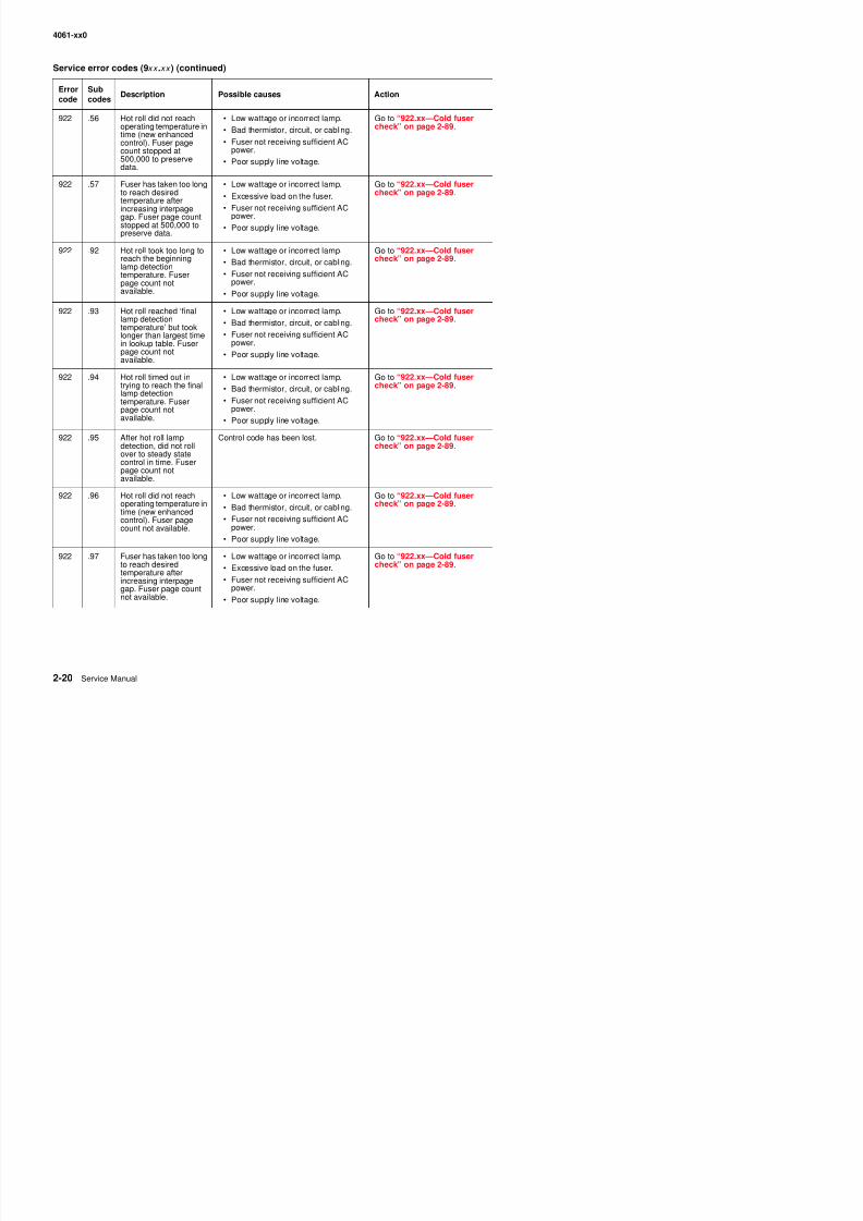
8/13/2019 t644 Service Manual
http://slidepdf.com/reader/full/t644-service-manual 62/423
922 .56 Hot roll did not reachoperating temperature intime (new enhancedcontrol). Fuser pagecount stopped at500,000 to preservedata.
• Low wattage or incorrect lamp.
• Bad thermistor, circuit, or cabling.
• Fuser not receiving sufficient ACpower.
• Poor supply line voltage.
Go to “922.xx—Cold fusercheck” on page 2-89.
922 .57 Fuser has taken too longto reach desiredtemperature after
increasing interpagegap. Fuser page countstopped at 500,000 topreserve data.
• Low wattage or incorrect lamp.
• Excessive load on the fuser.
• Fuser not receiving sufficient ACpower.
• Poor supply line voltage.
Go to “922.xx—Cold fusercheck” on page 2-89.
922 .92 Hot roll took too long toreach the beginninglamp detectiontemperature. Fuserpage count notavailable.
• Low wattage or incorrect lamp.
• Bad thermistor, circuit, or cabling.
• Fuser not receiving sufficient ACpower.
• Poor supply line voltage.
Go to “922.xx—Cold fusercheck” on page 2-89.
922 .93 Hot roll reached ‘finallamp detectiontemperature’ but tooklonger than largest timein lookup table. Fuserpage count notavailable.
• Low wattage or incorrect lamp.
• Bad thermistor, circuit, or cabling.
• Fuser not receiving sufficient ACpower.
• Poor supply line voltage.
Go to “922.xx—Cold fusercheck” on page 2-89.
922 .94 Hot roll timed out intrying to reach the finallamp detection
temperature. Fuserpage count notavailable.
• Low wattage or incorrect lamp.
• Bad thermistor, circuit, or cabling.
• Fuser not receiving sufficient ACpower.
• Poor supply line voltage.
Go to “922.xx—Cold fusercheck” on page 2-89.
922 .95 After hot roll lampdetection, did not rollover to steady statecontrol in time. Fuserpage count notavailable.
Control code has been lost. Go to “922.xx—Cold fusercheck” on page 2-89.
922 .96 Hot roll did not reachoperating temperature intime (new enhancedcontrol). Fuser pagecount not available.
• Low wattage or incorrect lamp.
• Bad thermistor, circuit, or cabling.
• Fuser not receiving sufficient ACpower.
• Poor supply line voltage.
Go to “922.xx—Cold fusercheck” on page 2-89.
922 97 F h t k t l L tt i t l G t “922 C ld f
Errorcode
Subcodes
Description Possible causes Action
4061-xx0
Service error codes (9xx .xx ) (continued)
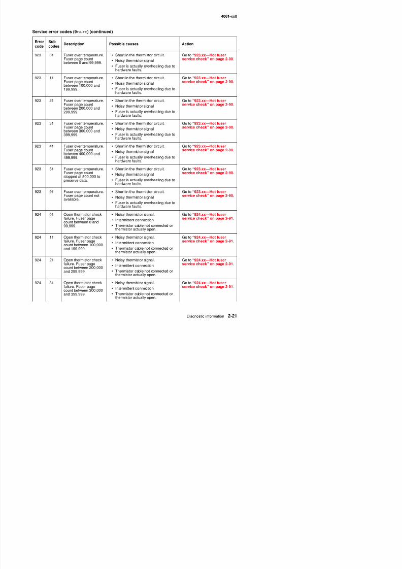
8/13/2019 t644 Service Manual
http://slidepdf.com/reader/full/t644-service-manual 63/423
923 .01 Fuser over temperature.Fuser page countbetween 0 and 99,999.
• Short in the thermistor circuit.
• Noisy thermistor signal
• Fuser is actually overheating due tohardware faults.
Go to “923.xx—Hot fuserservice check” on page 2-90.
923 .11 Fuser over temperature.Fuser page countbetween 100,000 and199,999.
• Short in the thermistor circuit.
• Noisy thermistor signal
• Fuser is actually overheating due tohardware faults.
Go to “923.xx—Hot fuserservice check” on page 2-90.
923 .21 Fuser over temperature.Fuser page countbetween 200,000 and299,999.
• Short in the thermistor circuit.
• Noisy thermistor signal
• Fuser is actually overheating due tohardware faults.
Go to “923.xx—Hot fuserservice check” on page 2-90.
923 .31 Fuser over temperature.Fuser page countbetween 300,000 and399,999.
• Short in the thermistor circuit.
• Noisy thermistor signal
• Fuser is actually overheating due tohardware faults.
Go to “923.xx—Hot fuserservice check” on page 2-90.
923 .41 Fuser over temperature.Fuser page countbetween 400,000 and499,999.
• Short in the thermistor circuit.
• Noisy thermistor signal
• Fuser is actually overheating due tohardware faults.
Go to “923.xx—Hot fuserservice check” on page 2-90.
923 .51 Fuser over temperature.Fuser page countstopped at 500,000 topreserve data.
• Short in the thermistor circuit.
• Noisy thermistor signal
• Fuser is actually overheating due tohardware faults.
Go to “923.xx—Hot fuserservice check” on page 2-90.
923 .91 Fuser over temperature.Fuser page count notavailable.
• Short in the thermistor circuit.
• Noisy thermistor signal
• Fuser is actually overheating due tohardware faults.
Go to “923.xx—Hot fuserservice check” on page 2-90.
924 .01 Open thermistor checkfailure. Fuser pagecount between 0 and99,999.
• Noisy thermistor signal.
• Intermittent connection.
• Thermistor cable not connected orthermistor actually open.
Go to “924.xx—Hot fuserservice check” on page 2-91.
924 .11 Open thermistor checkfailure. Fuser pagecount between 100,000and 199,999.
• Noisy thermistor signal.
• Intermittent connection.
• Thermistor cable not connected orthermistor actually open.
Go to “924.xx—Hot fuserservice check” on page 2-91.
Errorcode
Subcodes
Description Possible causes Action
4061-xx0
Service error codes (9xx .xx ) (continued)
E S b
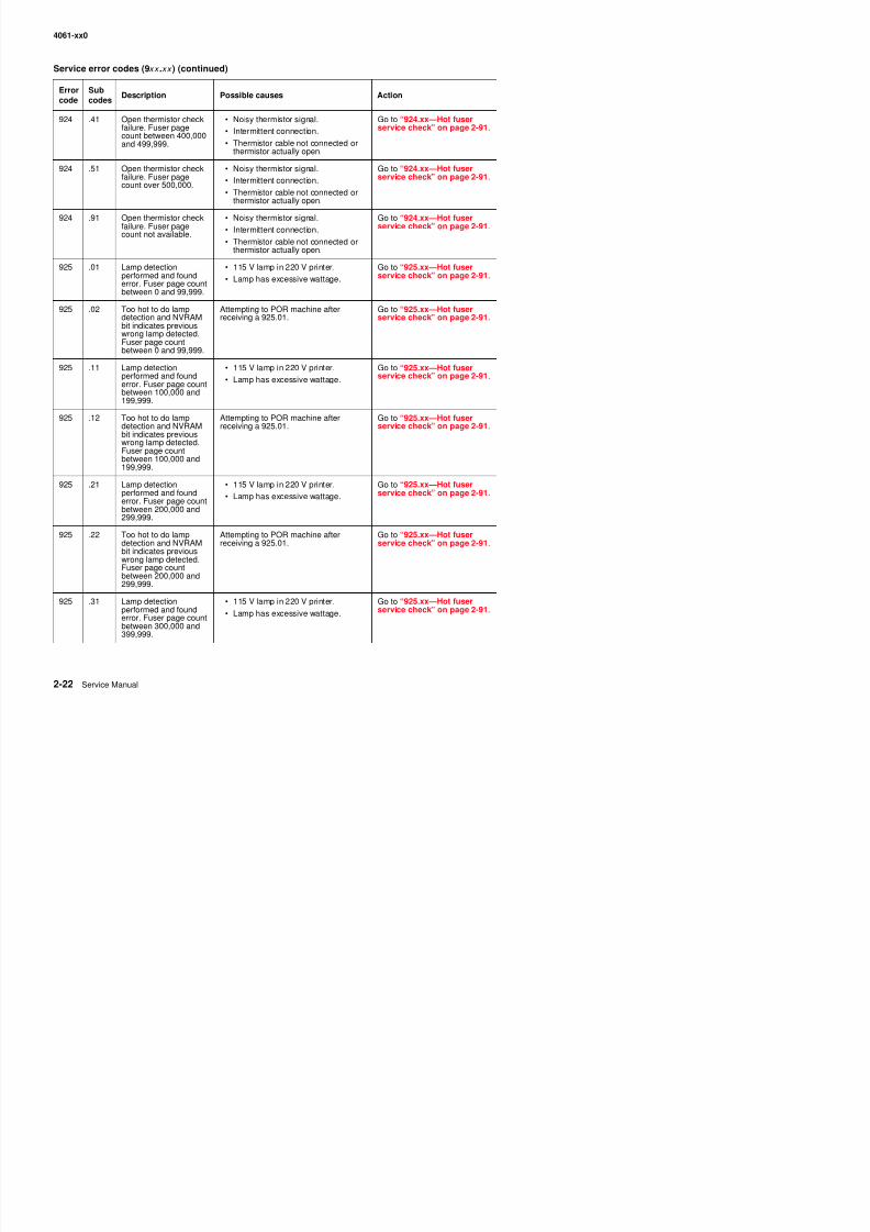
8/13/2019 t644 Service Manual
http://slidepdf.com/reader/full/t644-service-manual 64/423
924 .41 Open thermistor checkfailure. Fuser pagecount between 400,000and 499,999.
• Noisy thermistor signal.
• Intermittent connection.
• Thermistor cable not connected orthermistor actually open.
Go to “924.xx—Hot fuserservice check” on page 2-91.
924 .51 Open thermistor checkfailure. Fuser pagecount over 500,000.
• Noisy thermistor signal.
• Intermittent connection.
• Thermistor cable not connected orthermistor actually open.
Go to “924.xx—Hot fuserservice check” on page 2-91.
924 .91 Open thermistor checkfailure. Fuser pagecount not available.
• Noisy thermistor signal.
• Intermittent connection.
• Thermistor cable not connected orthermistor actually open.
Go to “924.xx—Hot fuserservice check” on page 2-91.
925 .01 Lamp detectionperformed and founderror. Fuser page countbetween 0 and 99,999.
• 115 V lamp in 220 V printer.
• Lamp has excessive wattage.
Go to “925.xx—Hot fuserservice check” on page 2-91.
925 .02 Too hot to do lampdetection and NVRAMbit indicates previouswrong lamp detected.Fuser page countbetween 0 and 99,999.
Attempting to POR machine afterreceiving a 925.01. Go to “925.xx—Hot fuserservice check” on page 2-91.
925 .11 Lamp detectionperformed and founderror. Fuser page countbetween 100,000 and199,999.
• 115 V lamp in 220 V printer.
• Lamp has excessive wattage.
Go to “925.xx—Hot fuserservice check” on page 2-91.
925 .12 Too hot to do lampdetection and NVRAMbit indicates previouswrong lamp detected.Fuser page countbetween 100,000 and199,999.
Attempting to POR machine afterreceiving a 925.01.
Go to “925.xx—Hot fuserservice check” on page 2-91.
925 .21 Lamp detectionperformed and founderror. Fuser page countbetween 200,000 and299,999.
• 115 V lamp in 220 V printer.
• Lamp has excessive wattage.
Go to “925.xx—Hot fuserservice check” on page 2-91.
925 .22 Too hot to do lampdetection and NVRAMbit indicates previouswrong lamp detected
Attempting to POR machine afterreceiving a 925.01.
Go to “925.xx—Hot fuserservice check” on page 2-91.
Errorcode
Subcodes
Description Possible causes Action
4061-xx0
Service error codes (9xx .xx ) (continued)
Error Sub
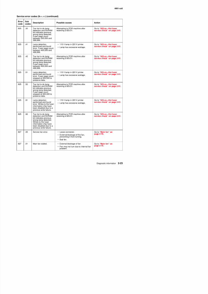
8/13/2019 t644 Service Manual
http://slidepdf.com/reader/full/t644-service-manual 65/423
925 .32 Too hot to do lampdetection and NVRAMbit indicates previouswrong lamp detected.Fuser page countbetween 300,000 and399,999.
Attempting to POR machine afterreceiving a 925.01.
Go to “925.xx—Hot fuserservice check” on page 2-91.
925 .41 Lamp detectionperformed and founderror. Fuser page count
between 400,000 and499,999.
• 115 V lamp in 220 V printer.
• Lamp has excessive wattage.
Go to “925.xx—Hot fuserservice check” on page 2-91.
925 .42 Too hot to do lampdetection and NVRAMbit indicates previouswrong lamp detected.Fuser page countbetween 400,000 and499,999.
Attempting to POR machine afterreceiving a 925.01.
Go to “925.xx—Hot fuserservice check” on page 2-91.
925 .51 Lamp detectionperformed and founderror. Fuser page countstopped at 500,000 topreserve data.
• 115 V lamp in 220 V printer.
• Lamp has excessive wattage.
Go to “925.xx—Hot fuser
service check” on page 2-91.
925 .52 Too hot to do lampdetection and NVRAMbit indicates previouswrong lamp detected.Fuser page countstopped at 500,000 topreserve data.
Attempting to POR machine afterreceiving a 925.01.
Go to “925.xx—Hot fuserservice check” on page 2-91.
925 .91 Lamp detectionperformed and founderror. Writes to the fuserinformation chip havebeen disabled due to aprevious write failure.
• 115 V lamp in 220 V printer.
• Lamp has excessive wattage.
Go to “925.xx—Hot fuserservice check” on page 2-91.
925 .92 Too hot to do lampdetection and NVRAMbit indicates previous
wrong lamp detected.Writes to the fuserinformation chip havebeen disabled due to aprevious write failure.
Attempting to POR machine afterreceiving a 925.01.
Go to “925.xx—Hot fuserservice check” on page 2-91.
927 .00 Service fan error. • Loose connector. Go to “Main fan” on2 76
Errorcode
Subcodes
Description Possible causes Action
4061-xx0
Service error codes (9xx .xx ) (continued)
Error Sub
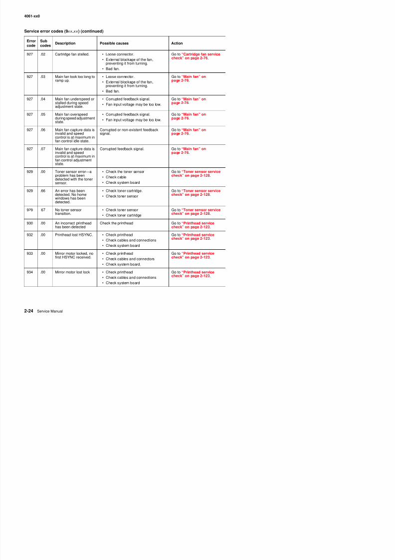
8/13/2019 t644 Service Manual
http://slidepdf.com/reader/full/t644-service-manual 66/423
927 .02 Cartridge fan stalled. • Loose connector.
• External blockage of the fan,preventing it from turning.
• Bad fan.
Go to “Cartridge fan servicecheck” on page 2-76.
927 .03 Main fan took too long toramp up.
• Loose connector.
• External blockage of the fan,preventing it from turning.
• Bad fan.
Go to “Main fan” onpage 2-76.
927 .04 Main fan underspeed orstalled during speedadjustment state.
• Corrupted feedback signal.
• Fan input voltage may be too low.
Go to “Main fan” onpage 2-76.
927 .05 Main fan overspeedduring speed adjustmentstate.
• Corrupted feedback signal.
• Fan input voltage may be too low.
Go to “Main fan” onpage 2-76.
927 .06 Main fan capture data isinvalid and speedcontrol is at maximum in
fan control idle state.
Corrupted or non-existent feedbacksignal.
Go to “Main fan” onpage 2-76.
927 .07 Main fan capture data isinvalid and speedcontrol is at maximum infan control adjustmentstate.
Corrupted feedback signal. Go to “Main fan” onpage 2-76.
929 .00 Toner sensor error—aproblem has beendetected with the tonersensor.
• Check the toner sensor
• Check cable
• Check system board
Go to “Toner sensor servicecheck” on page 2-128.
929 .66 An error has beendetected. No homewindows has beendetected.
• Check toner cartridge.
• Check toner sensor
Go to “Toner sensor servicecheck” on page 2-128.
929 .67 No toner sensortransition.
• Check toner sensor
• Check toner cartridge
Go to “Toner sensor servicecheck” on page 2-128.
930 .00 An incorrect printheadhas been detected
Check the printhead Go to “Printhead servicecheck” on page 2-123.
932 .00 Printhead lost HSYNC. • Check printhead
• Check cables and connections
• Check system board
Go to “Printhead servicecheck” on page 2-123.
933 00 Mirror motor locked no • Check printhead Go to “Printhead service
Errorcode
Subcodes
Description Possible causes Action
4061-xx0
Service error codes (9xx .xx ) (continued)
Error Sub
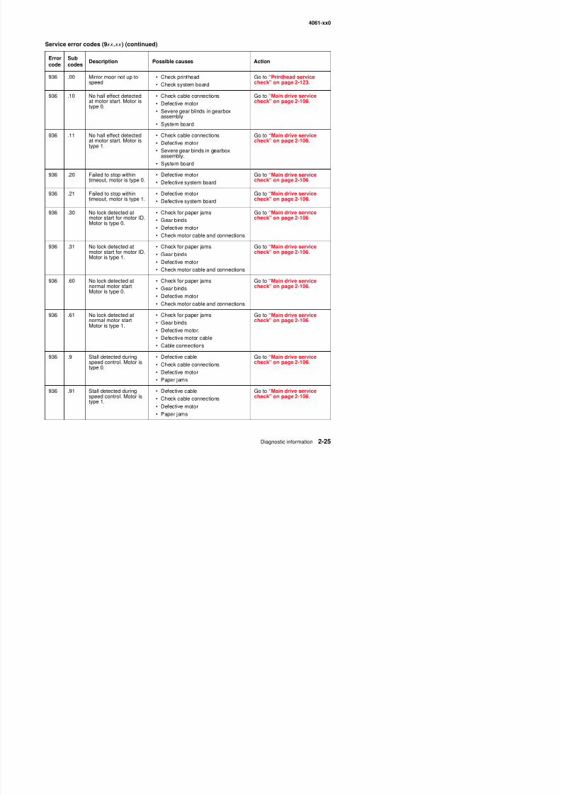
8/13/2019 t644 Service Manual
http://slidepdf.com/reader/full/t644-service-manual 67/423
936 .00 Mirror moor not up tospeed
• Check printhead
• Check system board
Go to “Printhead servicecheck” on page 2-123.
936 .10 No hall effect detectedat motor start. Motor istype 0.
• Check cable connections
• Defective motor
• Severe gear blinds in gearboxassembly
• System board
Go to “Main drive servicecheck” on page 2-106.
936 .11 No hall effect detectedat motor start. Motor istype 1.
• Check cable connections• Defective motor
• Severe gear binds in gearboxassembly.
• System board
Go to “Main drive servicecheck” on page 2-106.
936 .20 Failed to stop withintimeout, motor is type 0.
• Defective motor
• Defective system board
Go to “Main drive servicecheck” on page 2-106.
936 .21 Failed to stop within
timeout, motor is type 1.
• Defective motor
• Defective system board
Go to “Main drive service
check” on page 2-106.
936 .30 No lock detected atmotor start for motor ID.Motor is type 0.
• Check for paper jams
• Gear binds
• Defective motor
• Check motor cable and connections
Go to “Main drive servicecheck” on page 2-106.
936 .31 No lock detected atmotor start for motor ID.Motor is type 1.
• Check for paper jams
• Gear binds
• Defective motor• Check motor cable and connections
Go to “Main drive servicecheck” on page 2-106.
936 .60 No lock detected atnormal motor start.Motor is type 0.
• Check for paper jams
• Gear binds
• Defective motor
• Check motor cable and connections
Go to “Main drive servicecheck” on page 2-106.
936 .61 No lock detected atnormal motor start.
Motor is type 1.
• Check for paper jams
• Gear binds
• Defective motor.
• Defective motor cable
• Cable connections
Go to “Main drive servicecheck” on page 2-106.
936 .9 Stall detected duringd t l M t i
• Defective cable Go to “Main drive serviceh k” 2 106
Errorcode
Subcodes
Description Possible causes Action
4061-xx0
Service error codes (9xx .xx ) (continued)
Error SubD i ti P ibl A ti
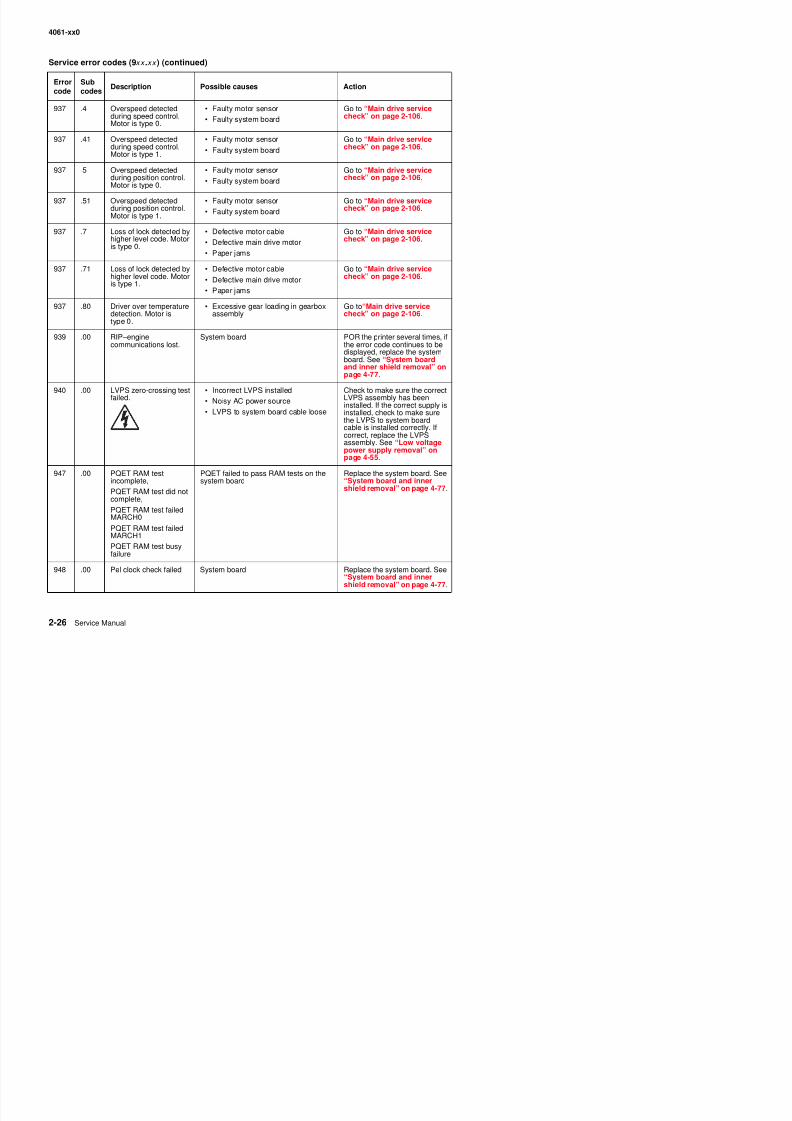
8/13/2019 t644 Service Manual
http://slidepdf.com/reader/full/t644-service-manual 68/423
937 .4 Overspeed detectedduring speed control.Motor is type 0.
• Faulty motor sensor
• Faulty system board
Go to “Main drive servicecheck” on page 2-106.
937 .41 Overspeed detectedduring speed control.Motor is type 1.
• Faulty motor sensor
• Faulty system board
Go to “Main drive servicecheck” on page 2-106.
937 .5 Overspeed detectedduring position control.Motor is type 0.
• Faulty motor sensor
• Faulty system board
Go to “Main drive servicecheck” on page 2-106.
937 .51 Overspeed detectedduring position control.Motor is type 1.
• Faulty motor sensor
• Faulty system board
Go to “Main drive servicecheck” on page 2-106.
937 .7 Loss of lock detected byhigher level code. Motoris type 0.
• Defective motor cable
• Defective main drive motor
• Paper jams
Go to “Main drive servicecheck” on page 2-106.
937 .71 Loss of lock detected byhigher level code. Motoris type 1.
• Defective motor cable
• Defective main drive motor• Paper jams
Go to “Main drive servicecheck” on page 2-106.
937 .80 Driver over temperaturedetection. Motor istype 0.
• Excessive gear loading in gearboxassembly
Go to“Main drive servicecheck” on page 2-106.
939 .00 RIP–enginecommunications lost.
System board POR the printer several times, ifthe error code continues to bedisplayed, replace the systemboard. See “System boardand inner shield removal” onpage 4-77.
940 .00 LVPS zero-crossing testfailed.
• Incorrect LVPS installed
• Noisy AC power source
• LVPS to system board cable loose
Check to make sure the correctLVPS assembly has beeninstalled. If the correct supply isinstalled, check to make surethe LVPS to system boardcable is installed correctly. Ifcorrect, replace the LVPSassembly. See “Low voltagepower supply removal” on
page 4-55.947 .00 PQET RAM test
incomplete,
PQET RAM test did notcomplete,
PQET RAM t t f il d
PQET failed to pass RAM tests on thesystem board
Replace the system board. See“System board and innershield removal” on page 4-77.
code codesDescription Possible causes Action
4061-xx0
Service error codes (9xx .xx ) (continued)
Error SubDescription Possible causes Action
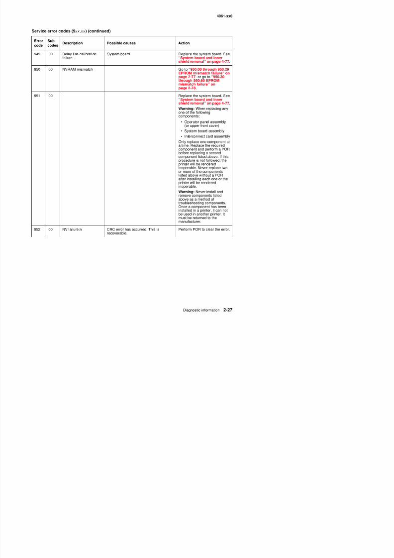
8/13/2019 t644 Service Manual
http://slidepdf.com/reader/full/t644-service-manual 69/423
949 .00 Delay line calibrationfailure
System board Replace the system board. See“System board and innershield removal” on page 4-77.
950 .00 NVRAM mismatch Go to “950.00 through 950.29EPROM mismatch failure” onpage 2-77. or go to “950.30through 950.60 EPROMmismatch failure” onpage 2-78.
951 .00 Replace the system board. See“System board and innershield removal” on page 4-77.
Warning: When replacing anyone of the followingcomponents:
• Operator panel assembly(or upper front cover)
• System board assembly
• Interconnect card assembly
Only replace one component ata time. Replace the requiredcomponent and perform a PORbefore replacing a secondcomponent listed above. If thisprocedure is not followed, theprinter will be renderedinoperable. Never replace twoor more of the componentslisted above without a PORafter installing each one or theprinter will be renderedinoperable.Warning: Never install andremove components listedabove as a method oftroubleshooting components.Once a component has beeninstalled in a printer, it can notbe used in another printer. Itmust be returned to themanufacturer.
952 .00 NV failure:n CRC error has occurred. This isrecoverable. Perform POR to clear the error.
code codesDescription Possible causes Action
4061-xx0
Service error codes (9xx .xx ) (continued)
Error SubDescription Possible causes Action
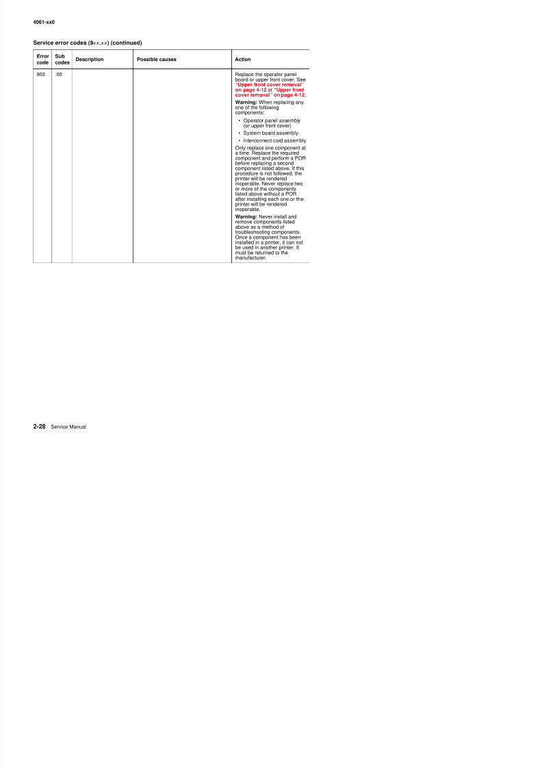
8/13/2019 t644 Service Manual
http://slidepdf.com/reader/full/t644-service-manual 70/423
953 .00 Replace the operator panelboard or upper front cover. See“Upper front cover removal”on page 4-12 or “Upper frontcover removal” on page 4-12.
Warning: When replacing anyone of the followingcomponents:
• Operator panel assembly(or upper front cover)
• System board assembly• Interconnect card assembly
Only replace one component ata time. Replace the requiredcomponent and perform a PORbefore replacing a secondcomponent listed above. If thisprocedure is not followed, theprinter will be renderedinoperable. Never replace twoor more of the components
listed above without a PORafter installing each one or theprinter will be renderedinoperable.
Warning: Never install andremove components listedabove as a method oftroubleshooting components.Once a component has beeninstalled in a printer, it can notbe used in another printer. It
must be returned to themanufacturer.
code codesDescription Possible causes Action
4061-xx0
Service error codes (9xx .xx ) (continued)
Errord
Subd
Description Possible causes Action
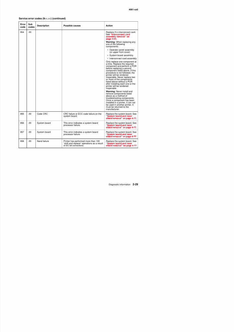
8/13/2019 t644 Service Manual
http://slidepdf.com/reader/full/t644-service-manual 71/423
954 .00 Replace the interconnect card.See “Interconnect cardassembly removal” onpage 4-54.
Warning: When replacing anyone of the followingcomponents:
• Operator panel assembly(or upper front cover)
• System board assembly
• Interconnect card assemblyOnly replace one component ata time. Replace the requiredcomponent and perform a PORbefore replacing a secondcomponent listed above. If thisprocedure is not followed, theprinter will be renderedinoperable. Never replace twoor more of the componentslisted above without a POR
after installing each one or theprinter will be renderedinoperable.
Warning: Never install andremove components listedabove as a method oftroubleshooting components.Once a component has beeninstalled in a printer, it can notbe used in another printer. Itmust be returned to the
manufacturer.955 .00 Code CRC CRC failure or ECC code failure on the
system board.Replace the system board. See“System board and innershield removal” on page 4-77.
956 .00 System board This error indicates a system boardprocessor failure.
Replace the system board. See“System board and innershield removal” on page 4-77.
957 .00 System board This error indicates a system boardprocessor failure.
Replace the system board. See“System board and inner
shield removal” on page 4-77.958 .00 Nand failure Printer has performed more than 100
“shift and replace” operations as a resultof EC bit corrections.
Replace the system board. See“System board and innershield removal” on page 4-77.
code codesDescription Possible causes Action
4061-xx0
Service error codes (9xx .xx ) (continued)
Errorcode
Subcodes
Description Possible causes Action
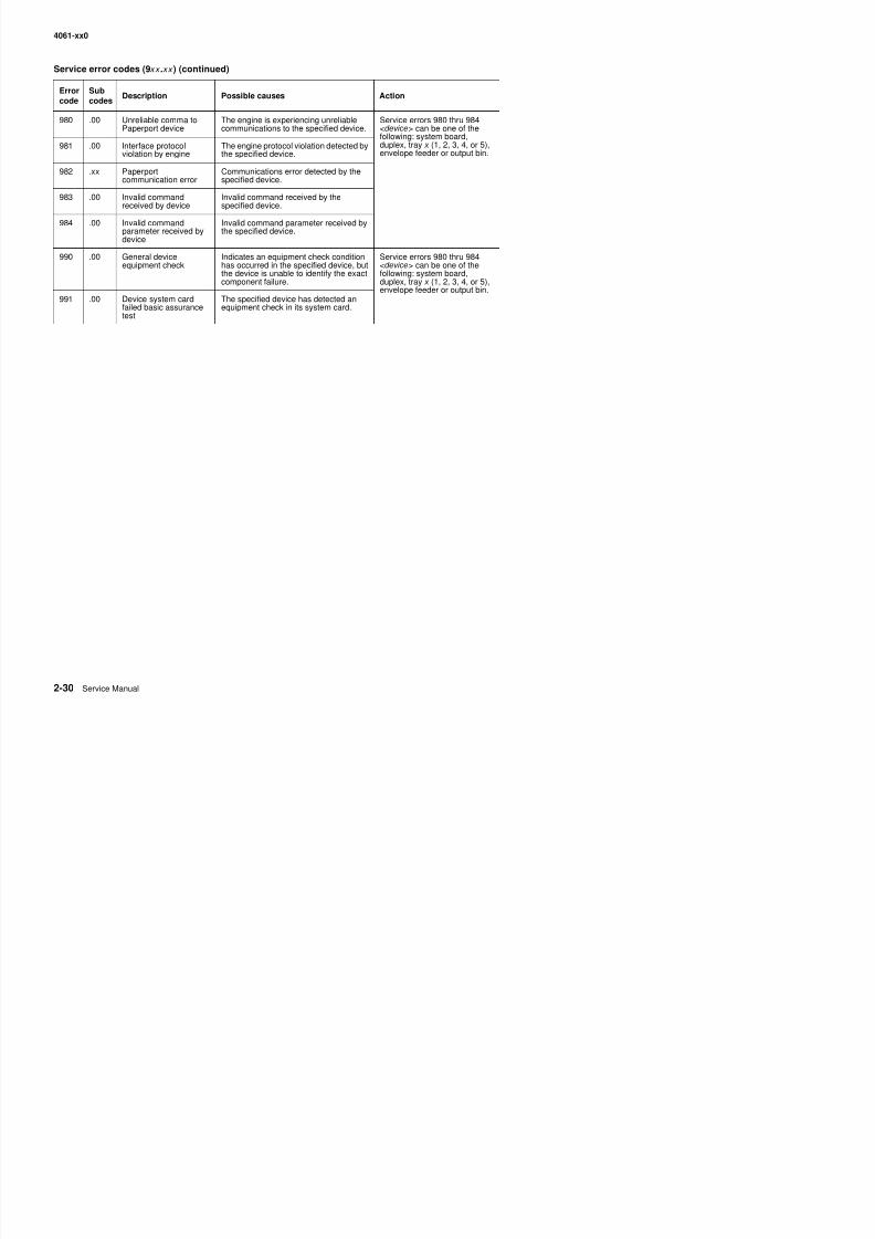
8/13/2019 t644 Service Manual
http://slidepdf.com/reader/full/t644-service-manual 72/423
980 .00 Unreliable comma toPaperport device
The engine is experiencing unreliablecommunications to the specified device.
Service errors 980 thru 984<device> can be one of thefollowing: system board,duplex, tray x (1, 2, 3, 4, or 5),envelope feeder or output bin.
981 .00 Interface protocolviolation by engine
The engine protocol violation detected bythe specified device.
982 .xx Paperportcommunication error
Communications error detected by thespecified device.
983 .00 Invalid commandreceived by device
Invalid command received by thespecified device.
984 .00 Invalid commandparameter received bydevice
Invalid command parameter received bythe specified device.
990 .00 General deviceequipment check
Indicates an equipment check conditionhas occurred in the specified device, butthe device is unable to identify the exactcomponent failure.
Service errors 980 thru 984<device> can be one of thefollowing: system board,duplex, tray x (1, 2, 3, 4, or 5),envelope feeder or output bin.
991 .00 Device system cardfailed basic assurancetest
The specified device has detected anequipment check in its system card.
code codesp
4061-xx0
User status displays
Warning messages (second lines)
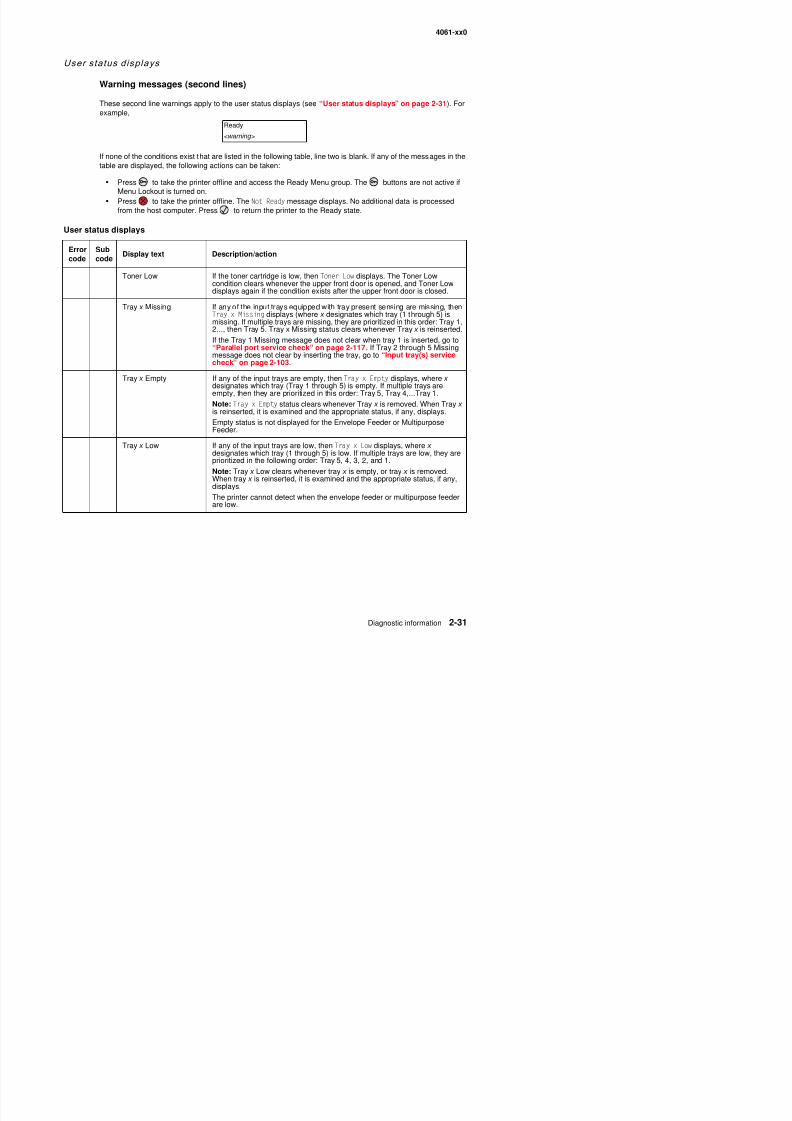
8/13/2019 t644 Service Manual
http://slidepdf.com/reader/full/t644-service-manual 73/423
These second line warnings apply to the user status displays (see “User status displays” on page 2-31). Forexample,
If none of the conditions exist that are listed in the following table, line two is blank. If any of the messages in thetable are displayed, the following actions can be taken:
• Press to take the printer offline and access the Ready Menu group. The buttons are not active if
Menu Lockout is turned on.• Press to take the printer offline. The Not Ready message displays. No additional data is processedfrom the host computer. Press to return the printer to the Ready state.
User status displays
Errorcode
Subcode
Display text Description/action
Toner Low If the toner cartridge is low, then Toner Low displays. The Toner Low
condition clears whenever the upper front door is opened, and Toner Lowdisplays again if the condition exists after the upper front door is closed.
Tray x Missing If any of the input trays equipped with tray present sensing are missing, thenTray x Missing displays (where x designates which tray (1 through 5) ismissing. If multiple trays are missing, they are prioritized in this order: Tray 1,2..., then Tray 5. Tray x Missing status clears whenever Tray x is reinserted.
If the Tray 1 Missing message does not clear when tray 1 is inserted, go to“Parallel port service check” on page 2-117. If Tray 2 through 5 Missingmessage does not clear by inserting the tray, go to “Input tray(s) servicecheck” on page 2-103.
Tray x Empty If any of the input trays are empty, then Tray x Empty displays, where x designates which tray (Tray 1 through 5) is empty. If multiple trays areempty, then they are prioritized in this order: Tray 5, Tray 4,...Tray 1.
Note: Tray x Empty status clears whenever Tray x is removed. When Tray x is reinserted, it is examined and the appropriate status, if any, displays.
Empty status is not displayed for the Envelope Feeder or MultipurposeFeeder.
Tray x Low If any of the input trays are low, then Tray x Low displays, where x designates which tray (1 through 5) is low. If multiple trays are low, they are
prioritized in the following order: Tray 5, 4, 3, 2, and 1.Note: Tray x Low clears whenever tray x is empty, or tray x is removed.When tray x is reinserted, it is examined and the appropriate status, if any,displays.
The printer cannot detect when the envelope feeder or multipurpose feederare low.
Ready
<warning>
4061-xx0
User attendance messages
User attendance messages
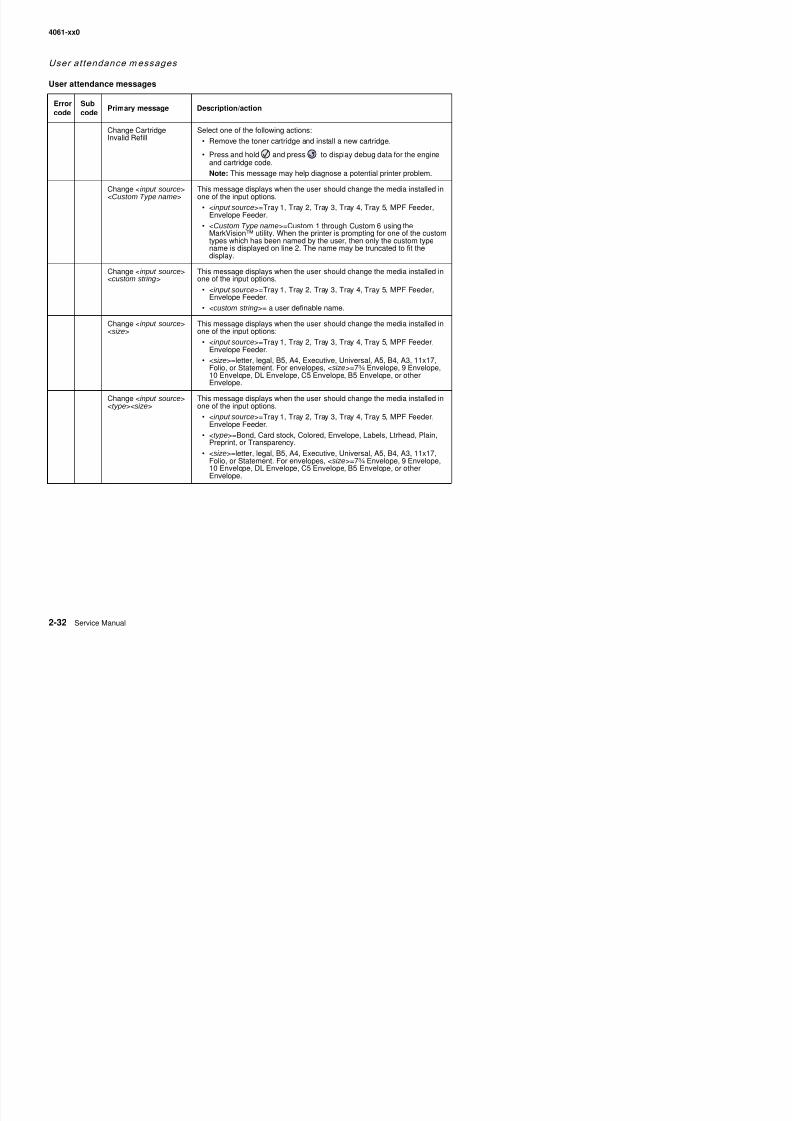
8/13/2019 t644 Service Manual
http://slidepdf.com/reader/full/t644-service-manual 74/423
Errorcode Subcode Primary message Description/action
Change CartridgeInvalid Refill
Select one of the following actions:
• Remove the toner cartridge and install a new cartridge.
• Press and hold and press to display debug data for the engineand cartridge code.
Note: This message may help diagnose a potential printer problem.
Change <input source><Custom Type name>
This message displays when the user should change the media installed inone of the input options.
• <input source>=Tray 1, Tray 2, Tray 3, Tray 4, Tray 5, MPF Feeder,Envelope Feeder.
• <Custom Type name>=Custom 1 through Custom 6 using theMarkVision™ utility. When the printer is prompting for one of the customtypes which has been named by the user, then only the custom typename is displayed on line 2. The name may be truncated to fit thedisplay.
Change <input source><custom string>
This message displays when the user should change the media installed inone of the input options.
• <input source>=Tray 1, Tray 2, Tray 3, Tray 4, Tray 5, MPF Feeder,Envelope Feeder.
• <custom string>= a user definable name.
Change <input source><size>
This message displays when the user should change the media installed inone of the input options:
• <input source>=Tray 1, Tray 2, Tray 3, Tray 4, Tray 5, MPF Feeder,Envelope Feeder.
• <size>=letter, legal, B5, A4, Executive, Universal, A5, B4, A3, 11x17,Folio, or Statement. For envelopes, <size>=7¾ Envelope, 9 Envelope,10 Envelope, DL Envelope, C5 Envelope, B5 Envelope, or otherEnvelope.
Change <input source><type><size>
This message displays when the user should change the media installed inone of the input options.
• <input source>=Tray 1, Tray 2, Tray 3, Tray 4, Tray 5, MPF Feeder,Envelope Feeder.
• <type>=Bond, Card stock, Colored, Envelope, Labels, Ltrhead, Plain,Preprint, or Transparency.
• <size>=letter, legal, B5, A4, Executive, Universal, A5, B4, A3, 11x17,
Folio, or Statement. For envelopes, <size>=7¾ Envelope, 9 Envelope,10 Envelope, DL Envelope, C5 Envelope, B5 Envelope, or otherEnvelope.
4061-xx0
User attendance messages (continued)
Errorcode
Subcode
Primary message Description/action
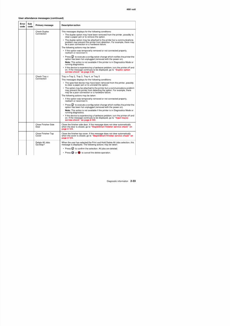
8/13/2019 t644 Service Manual
http://slidepdf.com/reader/full/t644-service-manual 75/423
Check DuplexConnection
This messages displays for the following conditions:• The duplex option may have been removed from the printer, possibly to
clear a paper jam or to remove the option.
• The duplex option may be attached to the printer but a communicationsproblem may prevent the printer from detection. For example, there maybe a poor connection or a hardware failure.
The following actions may be taken:
• If the option was temporarily removed or not connected properly,reattach or reconnect it.
• Press to execute a configuration change which notifies the printer theoption has been hot unplugged (removed with the power on).
Note: This action is not available if the printer is in Diagnostics Mode orrunning diagnostics.
• If the device is experiencing a hardware problem, turn the printer off andon. If the message continues to be displayed, go to “Duplex optionservice check” on page 2-82.
Check Tray x Connection
Tray x =Tray 2, Tray 3, Tray 4, or Tray 5
This messages displays for the following conditions:
• The specified device may have been removed from the printer, possiblyto clear a paper jam or to uninstall the option.
• The option may be attached to the printer but a communications problemmay prevent the printer from detecting the option. For example, theremay be a poor connection or a hardware failure.
The following actions may be taken:
• If the option was temporarily removed or not connected properly,reattach or reconnect it.
• Press to execute a configuration change which notifies the printer theoption has been hot unplugged (removed with the power on).
Note: This action is not available if the printer is in Diagnostics Mode orrunning diagnostics.
• If the device is experiencing a hardware problem, turn the printer off andon. If the message continues to be displayed, go to “Input tray(s)service check” on page 2-103.
Close Finisher SideDoor
Close the finisher side door. If the message does not clear automaticallywhen the door is closed, go to “StapleSmart finisher service check” onpage 2-124.
Close Finisher TopCover Close the finisher top cover. If the message does not clear automaticallywhen the cover is closed, go to “StapleSmart finisher service check” onpage 2-124.
Delete All JobsGo/Stop?
When the user has selected the Print and Hold Delete All Jobs selection, thismessage is displayed. The following actions may be taken:
P fi h l i All j b d l d
code code
4061-xx0
User attendance messages (continued)
Errorcode
Subcode
Primary message Description/action
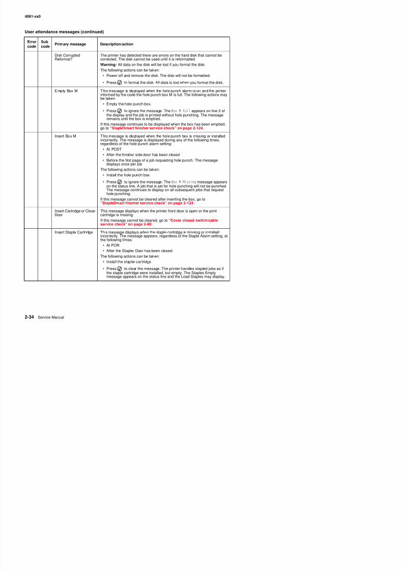
8/13/2019 t644 Service Manual
http://slidepdf.com/reader/full/t644-service-manual 76/423
Disk CorruptedReformat?
The printer has detected there are errors on the hard disk that cannot becorrected. The disk cannot be used until it is reformatted.
Warning: All data on the disk will be lost if you format the disk.
The following actions can be taken:
• Power off and remove the disk. The disk will not be formatted.
• Press to format the disk. All data is lost when you format the disk.
Empty Box M This message is displayed when the hole punch alarm is on and the printerinformed by the code the hole punch box M is full. The following actions may
be taken:• Empty the hole punch box.
• Press to ignore the message. The Box M Full appears on line 2 ofthe display and the job is printed without hole punching. The messageremains until the box is emptied.
If this message continues to be displayed when the box has been emptied,go to “StapleSmart finisher service check” on page 2-124.
Insert Box M This message is displayed when the hole punch box is missing or installedincorrectly. The message is displayed during any of the following times,
regardless of the hole punch alarm setting:• At POST
• After the finisher side door has been closed
• Before the first page of a job requesting hole punch. The messagedisplays once per job.
The following actions can be taken:
• Install the hole punch box.
• Press to ignore the message. The Box M Missing message appearson the status line. A job that is set for hole punching will not be punched.
The message continues to display on all subsequent jobs that requesthole punching.
If this message cannot be cleared after inserting the box, go to“StapleSmart finisher service check” on page 2-124.
Insert Cartridge or CloseDoor
This message displays when the printer front door is open or the printcartridge is missing.
If this message cannot be cleared, go to “Cover closed switch/cableservice check” on page 2-80.
Insert Staple Cartridge This message displays when the staple cartridge is missing or installed
incorrectly. The message appears, regardless of the Staple Alarm setting, atthe following times:
• At POR
• After the Stapler Door has been closed.
The following actions can be taken:
4061-xx0
User attendance messages (continued)
Errorcode
Subcode
Primary message Description/action
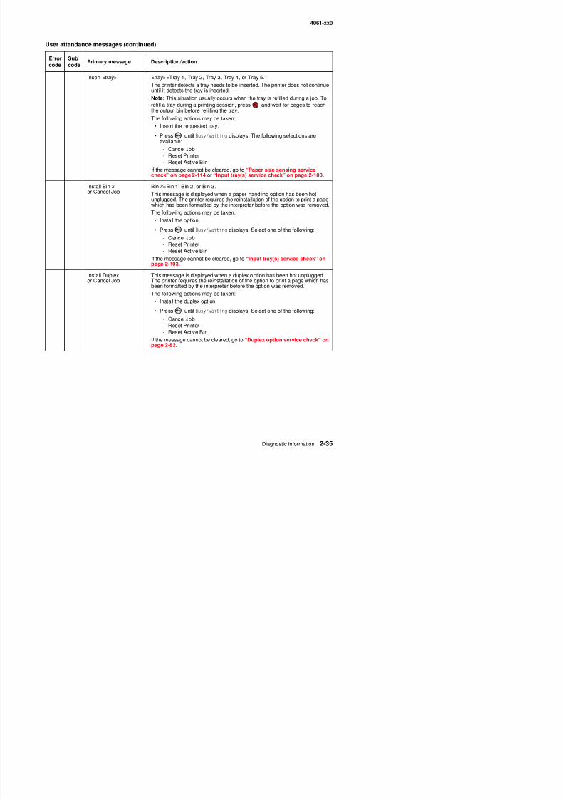
8/13/2019 t644 Service Manual
http://slidepdf.com/reader/full/t644-service-manual 77/423
Insert <tray > <tray >=Tray 1, Tray 2, Tray 3, Tray 4, or Tray 5.The printer detects a tray needs to be inserted. The printer does not continueuntil it detects the tray is inserted.
Note: This situation usually occurs when the tray is refilled during a job. Torefill a tray during a printing session, press and wait for pages to reachthe output bin before refilling the tray.
The following actions may be taken:
• Insert the requested tray.
• Press until Busy/Waiting displays. The following selections areavailable:
- Cancel Job- Reset Printer- Reset Active Bin
If the message cannot be cleared, go to “Paper size sensing servicecheck” on page 2-114 or “Input tray(s) service check” on page 2-103.
Install Bin x or Cancel Job
Bin x =Bin 1, Bin 2, or Bin 3.
This message is displayed when a paper handling option has been hotunplugged. The printer requires the reinstallation of the option to print a pagewhich has been formatted by the interpreter before the option was removed.The following actions may be taken:
• Install the option.
• Press until Busy/Waiting displays. Select one of the following:
- Cancel Job- Reset Printer- Reset Active Bin
If the message cannot be cleared, go to “Input tray(s) service check” on
page 2-103.Install Duplexor Cancel Job
This message is displayed when a duplex option has been hot unplugged.The printer requires the reinstallation of the option to print a page which hasbeen formatted by the interpreter before the option was removed.
The following actions may be taken:
• Install the duplex option.
• Press until Busy/Waiting displays. Select one of the following:
- Cancel Job- Reset Printer
- Reset Active BinIf the message cannot be cleared, go to “Duplex option service check” onpage 2-82.
4061-xx0
User attendance messages (continued)
Errorcode
Subcode
Primary message Description/action
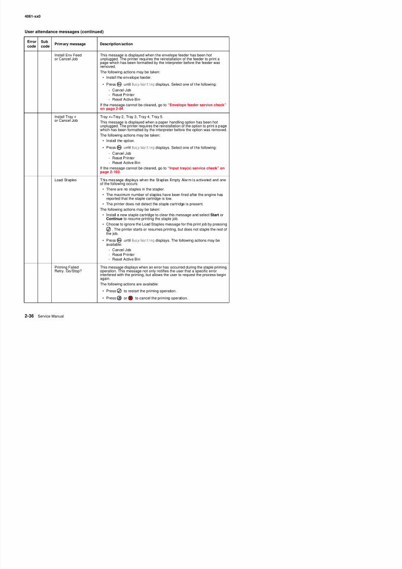
8/13/2019 t644 Service Manual
http://slidepdf.com/reader/full/t644-service-manual 78/423
Install Env Feedor Cancel Job
This message is displayed when the envelope feeder has been hotunplugged. The printer requires the reinstallation of the feeder to print apage which has been formatted by the interpreter before the feeder wasremoved.
The following actions may be taken:
• Install the envelope feeder.
• Press until Busy/Waiting displays. Select one of the following:
- Cancel Job- Reset Printer
- Reset Active BinIf the message cannot be cleared, go to “Envelope feeder service check”on page 2-84.
Install Tray x or Cancel Job
Tray x =Tray 2, Tray 3, Tray 4, Tray 5.
This message is displayed when a paper handling option has been hotunplugged. The printer requires the reinstallation of the option to print a pagewhich has been formatted by the interpreter before the option was removed.
The following actions may be taken:
• Install the option.
• Press until Busy/Waiting displays. Select one of the following:
- Cancel Job- Reset Printer- Reset Active Bin
If the message cannot be cleared, go to “Input tray(s) service check” onpage 2-103.
Load Staples This message displays when the Staples Empty Alarm is activated and oneof the following occurs:
• There are no staples in the stapler.• The maximum number of staples have been fired after the engine has
reported that the staple cartridge is low.
• The printer does not detect the staple cartridge is present.
The following actions may be taken:
• Install a new staple cartridge to clear this message and select Start orContinue to resume printing the staple job.
• Choose to ignore the Load Staples message for this print job by pressing. The printer starts or resumes printing, but does not staple the rest of
the job.• Press until Busy/Waiting displays. The following actions may be
available:
- Cancel Job- Reset Printer
R t A ti Bi
4061-xx0
User attendance messages (continued)
Errorcode
Subcode
Primary message Description/action
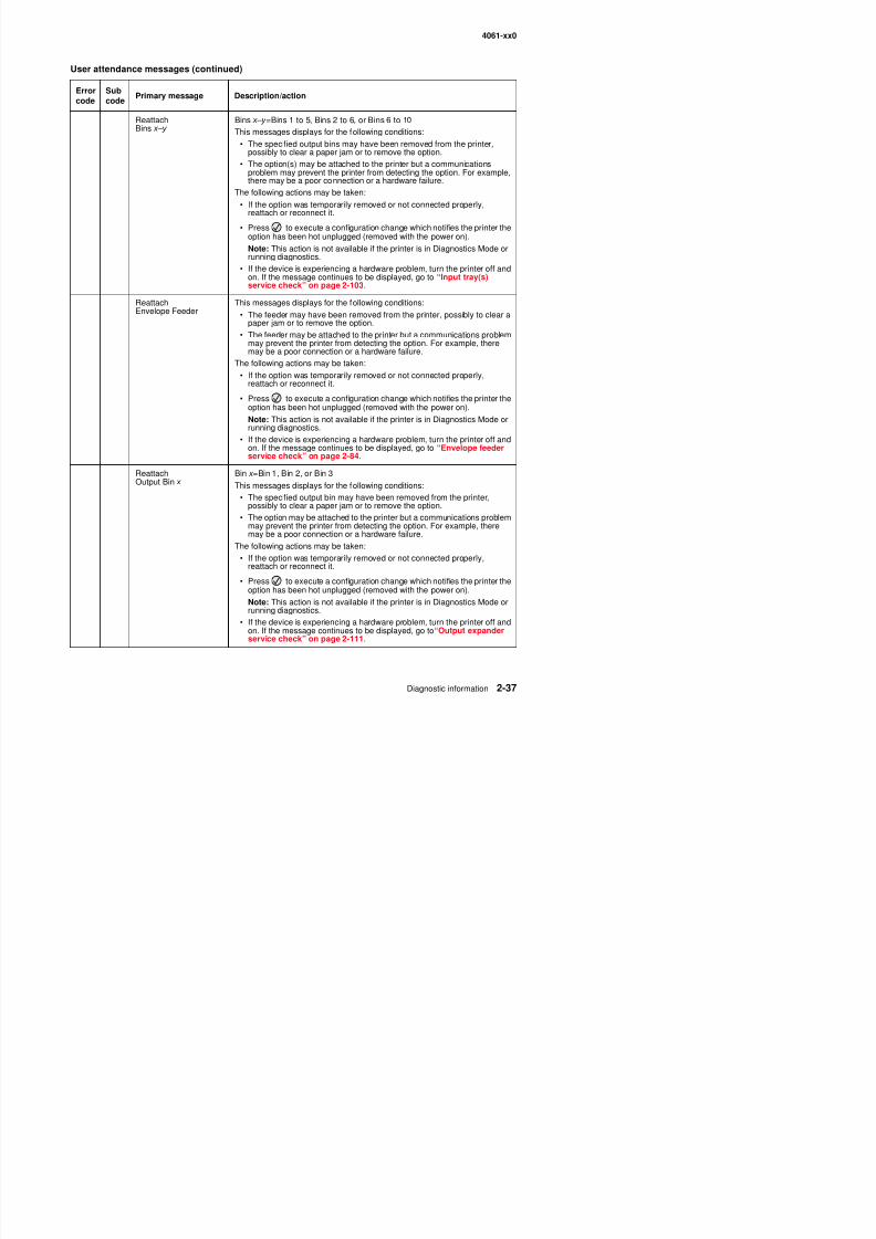
8/13/2019 t644 Service Manual
http://slidepdf.com/reader/full/t644-service-manual 79/423
ReattachBins x–y
Bins x–y =Bins 1 to 5, Bins 2 to 6, or Bins 6 to 10This messages displays for the following conditions:
• The specified output bins may have been removed from the printer,possibly to clear a paper jam or to remove the option.
• The option(s) may be attached to the printer but a communicationsproblem may prevent the printer from detecting the option. For example,there may be a poor connection or a hardware failure.
The following actions may be taken:
• If the option was temporarily removed or not connected properly,
reattach or reconnect it.• Press to execute a configuration change which notifies the printer the
option has been hot unplugged (removed with the power on).
Note: This action is not available if the printer is in Diagnostics Mode orrunning diagnostics.
• If the device is experiencing a hardware problem, turn the printer off andon. If the message continues to be displayed, go to “Input tray(s)service check” on page 2-103.
Reattach
Envelope Feeder
This messages displays for the following conditions:
• The feeder may have been removed from the printer, possibly to clear apaper jam or to remove the option.
• The feeder may be attached to the printer but a communications problemmay prevent the printer from detecting the option. For example, theremay be a poor connection or a hardware failure.
The following actions may be taken:
• If the option was temporarily removed or not connected properly,reattach or reconnect it.
• Press to execute a configuration change which notifies the printer theoption has been hot unplugged (removed with the power on).
Note: This action is not available if the printer is in Diagnostics Mode orrunning diagnostics.
• If the device is experiencing a hardware problem, turn the printer off andon. If the message continues to be displayed, go to “Envelope feederservice check” on page 2-84.
ReattachOutput Bin x
Bin x =Bin 1, Bin 2, or Bin 3
This messages displays for the following conditions:
• The specified output bin may have been removed from the printer,possibly to clear a paper jam or to remove the option.
• The option may be attached to the printer but a communications problemmay prevent the printer from detecting the option. For example, theremay be a poor connection or a hardware failure.
The following actions may be taken:
• If the option was temporarily removed or not connected properly,
4061-xx0
User attendance messages (continued)
Errorcode
Subcode
Primary message Description/action
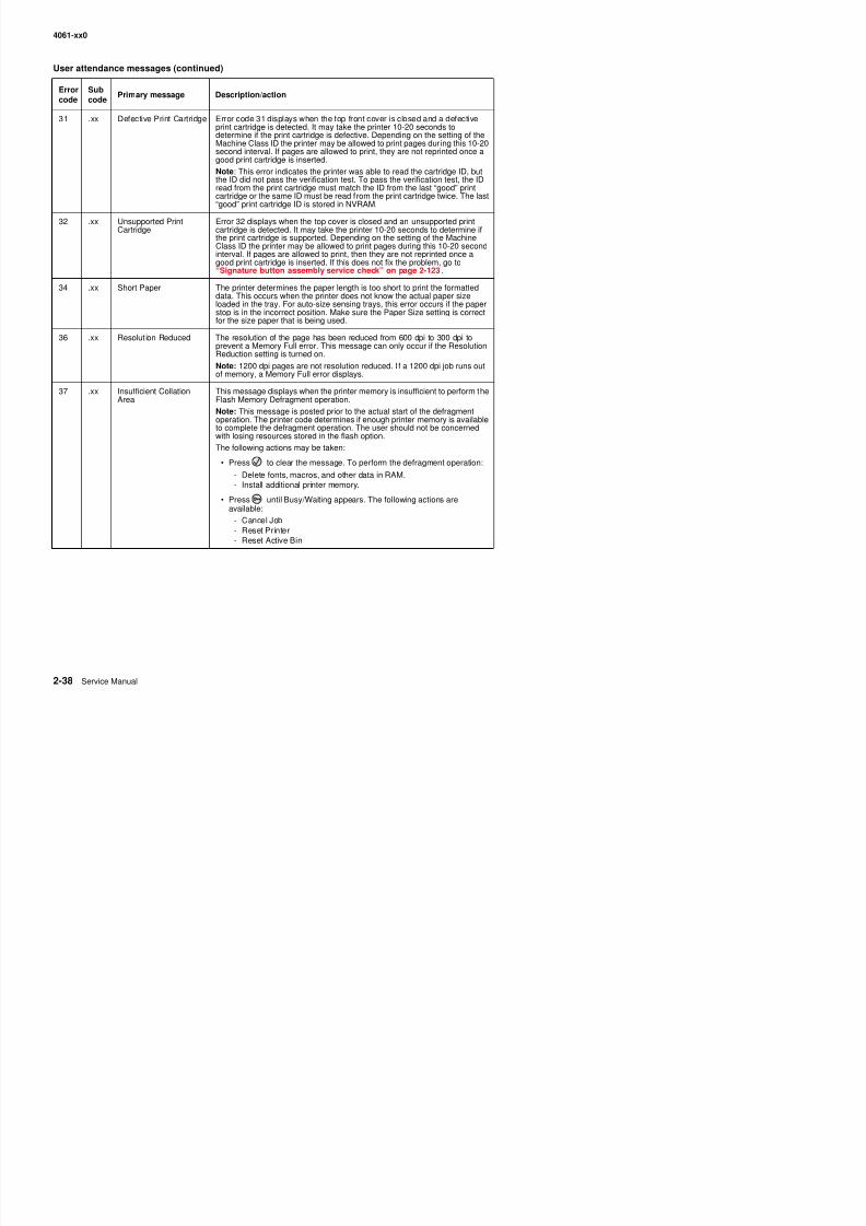
8/13/2019 t644 Service Manual
http://slidepdf.com/reader/full/t644-service-manual 80/423
31 .xx Defective Print Cartridge Error code 31 displays when the top front cover is closed and a defectiveprint cartridge is detected. It may take the printer 10-20 seconds todetermine if the print cartridge is defective. Depending on the setting of theMachine Class ID the printer may be allowed to print pages during this 10-20second interval. If pages are allowed to print, they are not reprinted once agood print cartridge is inserted.
Note: This error indicates the printer was able to read the cartridge ID, butthe ID did not pass the verification test. To pass the verification test, the IDread from the print cartridge must match the ID from the last “good” printcartridge or the same ID must be read from the print cartridge twice. The last“good” print cartridge ID is stored in NVRAM.
32 .xx Unsupported PrintCartridge
Error 32 displays when the top cover is closed and an unsupported printcartridge is detected. It may take the printer 10-20 seconds to determine ifthe print cartridge is supported. Depending on the setting of the MachineClass ID the printer may be allowed to print pages during this 10-20 secondinterval. If pages are allowed to print, then they are not reprinted once agood print cartridge is inserted. If this does not fix the problem, go to“Signature button assembly service check” on page 2-123.
34 .xx Short Paper The printer determines the paper length is too short to print the formatteddata. This occurs when the printer does not know the actual paper sizeloaded in the tray. For auto-size sensing trays, this error occurs if the paper
stop is in the incorrect position. Make sure the Paper Size setting is correctfor the size paper that is being used.
36 .xx Resolut ion Reduced The resolution of the page has been reduced from 600 dpi to 300 dpi toprevent a Memory Full error. This message can only occur if the ResolutionReduction setting is turned on.
Note: 1200 dpi pages are not resolution reduced. I f a 1200 dpi job runs outof memory, a Memory Full error displays.
37 .xx Insufficient CollationArea
This message displays when the printer memory is insufficient to perform theFlash Memory Defragment operation.
Note: This message is posted prior to the actual start of the defragmentoperation. The printer code determines if enough printer memory is availableto complete the defragment operation. The user should not be concernedwith losing resources stored in the flash option.
The following actions may be taken:
• Press to clear the message. To perform the defragment operation:
- Delete fonts, macros, and other data in RAM.- Install additional printer memory.
• Press until Busy/Waiting appears. The following actions are
available:- Cancel Job- Reset Printer- Reset Active Bin
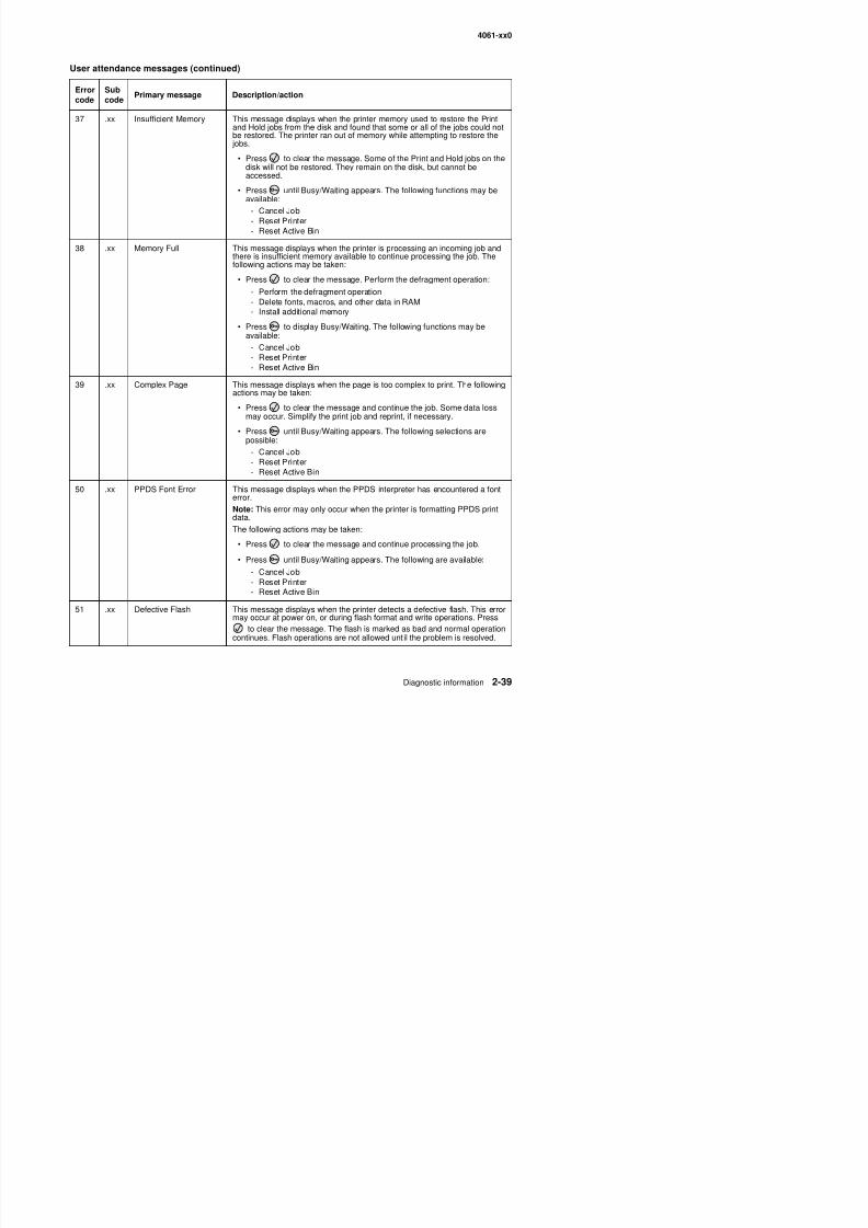
8/13/2019 t644 Service Manual
http://slidepdf.com/reader/full/t644-service-manual 81/423
4061-xx0
User attendance messages (continued)
Errorcode
Subcode
Primary message Description/action
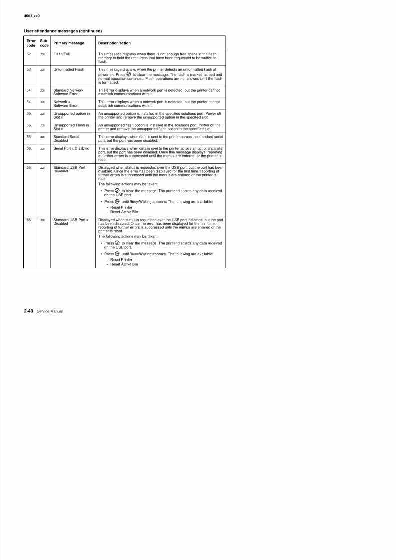
8/13/2019 t644 Service Manual
http://slidepdf.com/reader/full/t644-service-manual 82/423
52 .xx Flash Full This message displays when there is not enough free space in the flashmemory to hold the resources that have been requested to be written toflash.
53 .xx Unformatted Flash This message displays when the printer detects an unformatted f lash atpower on. Press to clear the message. The flash is marked as bad andnormal operation continues. Flash operations are not allowed until the flashis formatted.
54 .xx Standard NetworkSoftware Error
This error displays when a network port is detected, but the printer cannotestablish communications with it.
54 .xx Network x Software Error
This error displays when a network port is detected, but the printer cannotestablish communications with it.
55 .xx Unsupported option inSlot x
An unsupported option is installed in the specified solutions port. Power offthe printer and remove the unsupported option in the specified slot.
55 .xx Unsupported Flash inSlot x
An unsupported flash option is installed in the solutions port. Power off theprinter and remove the unsupported flash option in the specified slot.
56 .xx Standard SerialDisabled
This error displays when data is sent to the printer across the standard serialport, but the port has been disabled.
56 .xx Serial Port x Disabled This error displays when data is sent to the printer across an optional parallelport, but the port has been disabled. Once this message displays, reportingof further errors is suppressed until the menus are entered, or the printer isreset.
56 .xx Standard USB PortDisabled
Displayed when status is requested over the USB port, but the port has beendisabled. Once the error has been displayed for the first time, reporting offurther errors is suppressed until the menus are entered or the printer isreset.
The following actions may be taken:
• Press to clear the message. The printer discards any data receivedon the USB port.
• Press until Busy/Waiting appears. The following are available:
- Reset Printer- Reset Active Bin
56 .xx Standard USB Port x Disabled
Displayed when status is requested over the USB port indicated, but the porthas been disabled. Once the error has been displayed for the first time,reporting of further errors is suppressed until the menus are entered or the
printer is reset.The following actions may be taken:
• Press to clear the message. The printer discards any data receivedon the USB port.
• Press until Busy/Waiting appears The following are available:
4061-xx0
User attendance messages (continued)
Errorcode
Subcode
Primary message Description/action

8/13/2019 t644 Service Manual
http://slidepdf.com/reader/full/t644-service-manual 83/423
56 .xx Standard Parallel PortDisabled
This error is displayed when data is sent to the printer across the parallelport, but the parallel port has been disabled. Once this message isdisplayed, reporting of further errors is suppressed until the menus areentered, or the printer is reset. The following actions may be taken:
• Press to clear the message. The printer discards any data receivedon the parallel port.
• Press until Busy/Waiting appears. The following are available:
- Reset Printer- Reset Active Bin
56 .xx Parallel Port x Disabled This error is displayed when data is sent to the printer across the parallelport, but the parallel port indicated has been disabled. Once this message isdisplayed, reporting of further errors is suppressed until the menus areentered, or the printer is reset. The following actions may be taken:
• Press to clear the message. The printer discards any data receivedon the parallel port.
• Press until Busy/Waiting appears. The following are available:
- Reset Printer- Reset Active Bin
57 .xx Configuration Change The printer has attempted to restore the Print and Hold jobs from the diskand found that some or all of the jobs could not be restored. The printercould not restore jobs from the disk because the configuration of the printerhas changed. This message alternates with the secondary message, Heldjobs may not be restored.
Some configuration changes that may cause this condition are:
• Code version change
• Paper handling option is removed
• Disk has been moved to a different model printer.
Press to clear the message. Some of the Print and Hold jobs stored onthe disk will not be restored. They remain on the disk, but cannot beaccessed.
58 .xx Too Many TraysAttached
This error code displays when too many input trays are attached to theprinter.
58 .xx Too Many DisksInstalled
This error displays when too many disks are attached to the printer.
59 .xx Incompatible OutputBin x An incompatible output bin is installed. For Output Bin x , x =1, 2, or 3.Remove the incompatible output bin and press to clear the message.
Note: If the user installed the incompatible device to satisfy a Check DeviceConnections/reattach message, the user should reinstall an associatedcompatible option or hot unplug the option.
4061-xx0
User attendance messages (continued)
Errorcode
Subcode
Primary message Description/action
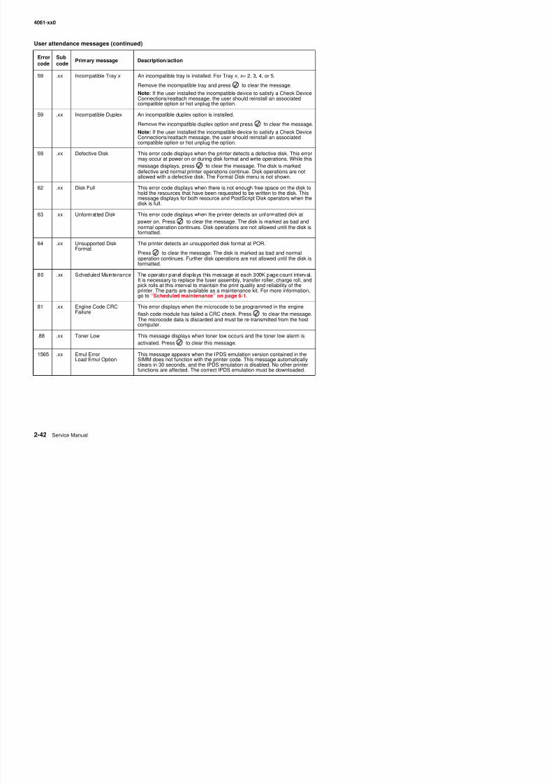
8/13/2019 t644 Service Manual
http://slidepdf.com/reader/full/t644-service-manual 84/423
59 .xx Incompatible Tray x An incompatible tray is installed. For Tray x , x = 2, 3, 4, or 5.Remove the incompatible tray and press to clear the message.
Note: If the user installed the incompatible device to satisfy a Check DeviceConnections/reattach message, the user should reinstall an associatedcompatible option or hot unplug the option.
59 .xx Incompatible Duplex An incompatible duplex option is installed.
Remove the incompatible duplex option and press to clear the message.
Note: If the user installed the incompatible device to satisfy a Check Device
Connections/reattach message, the user should reinstall an associatedcompatible option or hot unplug the option.
59 .xx Defective Disk This error code displays when the printer detects a defective disk. This errormay occur at power on or during disk format and write operations. While thismessage displays, press to clear the message. The disk is markeddefective and normal printer operations continue. Disk operations are notallowed with a defective disk. The Format Disk menu is not shown.
62 .xx Disk Full This error code displays when there is not enough free space on the disk tohold the resources that have been requested to be written to the disk. This
message displays for both resource and PostScript Disk operators when thedisk is full.
63 .xx Unformatted Disk This error code displays when the printer detects an unformatted disk atpower on. Press to clear the message. The disk is marked as bad andnormal operation continues. Disk operations are not allowed until the disk isformatted.
64 .xx Unsupported DiskFormat
The printer detects an unsupported disk format at POR.
Press to clear the message. The disk is marked as bad and normaloperation continues. Further disk operations are not allowed until the disk isformatted.
80 .xx Scheduled Maintenance The operator panel displays this message at each 300K page count interval.It is necessary to replace the fuser assembly, transfer roller, charge roll, andpick rolls at this interval to maintain the print quality and reliability of theprinter. The parts are available as a maintenance kit. For more information,go to “Scheduled maintenance” on page 6-1.
81 .xx Engine Code CRCFailure
This error displays when the microcode to be programmed in the engineflash code module has failed a CRC check. Press to clear the message.The microcode data is discarded and must be re-transmitted from the host
computer.
.88 .xx Toner Low This message displays when toner low occurs and the toner low alarm isactivated. Press to clear this message.
1565 xx Emul Error This message appears when the IPDS emulation version contained in the
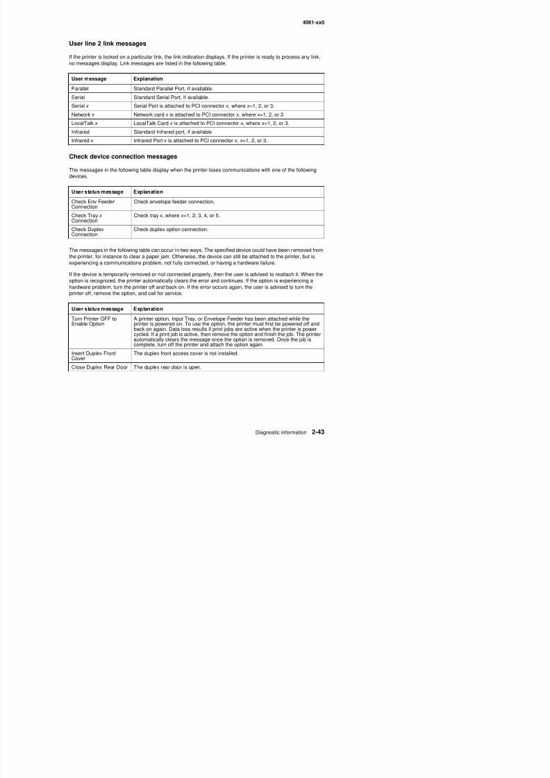
8/13/2019 t644 Service Manual
http://slidepdf.com/reader/full/t644-service-manual 85/423
4061-xx0
User attendance m essages—paper jams and p aper handl ing errors (2xx.xx)
When the printer jams, the appropriate jam message will be displayed on the printer operator panel. If you selectShow Areas on the operator panel, you can view one or more images to help you clear the jam.
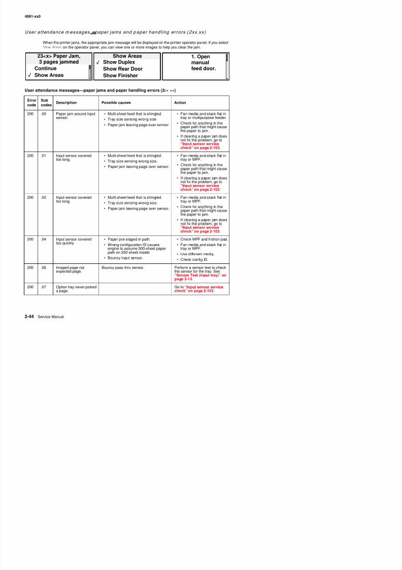
8/13/2019 t644 Service Manual
http://slidepdf.com/reader/full/t644-service-manual 86/423
User attendance messages—paper jams and paper handling errors (2xx.xx )
Errorcode
Subcodes
Description Possible causes Action
200 .00 Paper jam around inputsensor.
• Multi-sheet feed that is shingled.
• Tray size sensing wrong size
• Paper jam leaving page over sensor
• Fan media and stack flat intray or multipurpose feeder.
• Check for anything in thepaper path that might causethe paper to jam.
• If clearing a paper jam doesnot fix the problem, go to
“Input sensor servicecheck” on page 2-103.
200 .01 Input sensor coveredtoo long.
• Multi-sheet feed that is shingled.
• Tray size sensing wrong size.
• Paper jam leaving page over sensor.
• Fan media and stack flat intray or MPF.
• Check for anything in thepaper path that might causethe paper to jam.
• If clearing a paper jam doesnot fix the problem, go to“Input sensor service
check” on page 2-103.200 .02 Input sensor covered
too long.• Multi-sheet feed that is shingled.
• Tray size sensing wrong size.
• Paper jam leaving page over sensor.
• Fan media and stack flat intray or MPF.
• Check for anything in thepaper path that might causethe paper to jam.
• If clearing a paper jam doesnot fix the problem, go to“Input sensor servicecheck” on page 2-103.
200 .04 Input sensor coveredtoo quickly
• Paper pre-staged in path.
• Wrong configuration ID causesengine to assume 500-sheet paperpath on 250-sheet model.
• Bouncy input sensor
• Check MPF and friction pad.
• Fan media and stack flat intray or MPF.
• Use different media.
Ch k fi ID
23<x> Paper Jam,3 pages jammed
ContinueShow Areas
1. Openmanualfeed door.
Show AreasShow DuplexShow Rear DoorShow Finisher
4061-xx0
User attendance messages—paper jams and paper handling errors (2xx.xx )
Errorcode
Subcodes
Description Possible causes Action
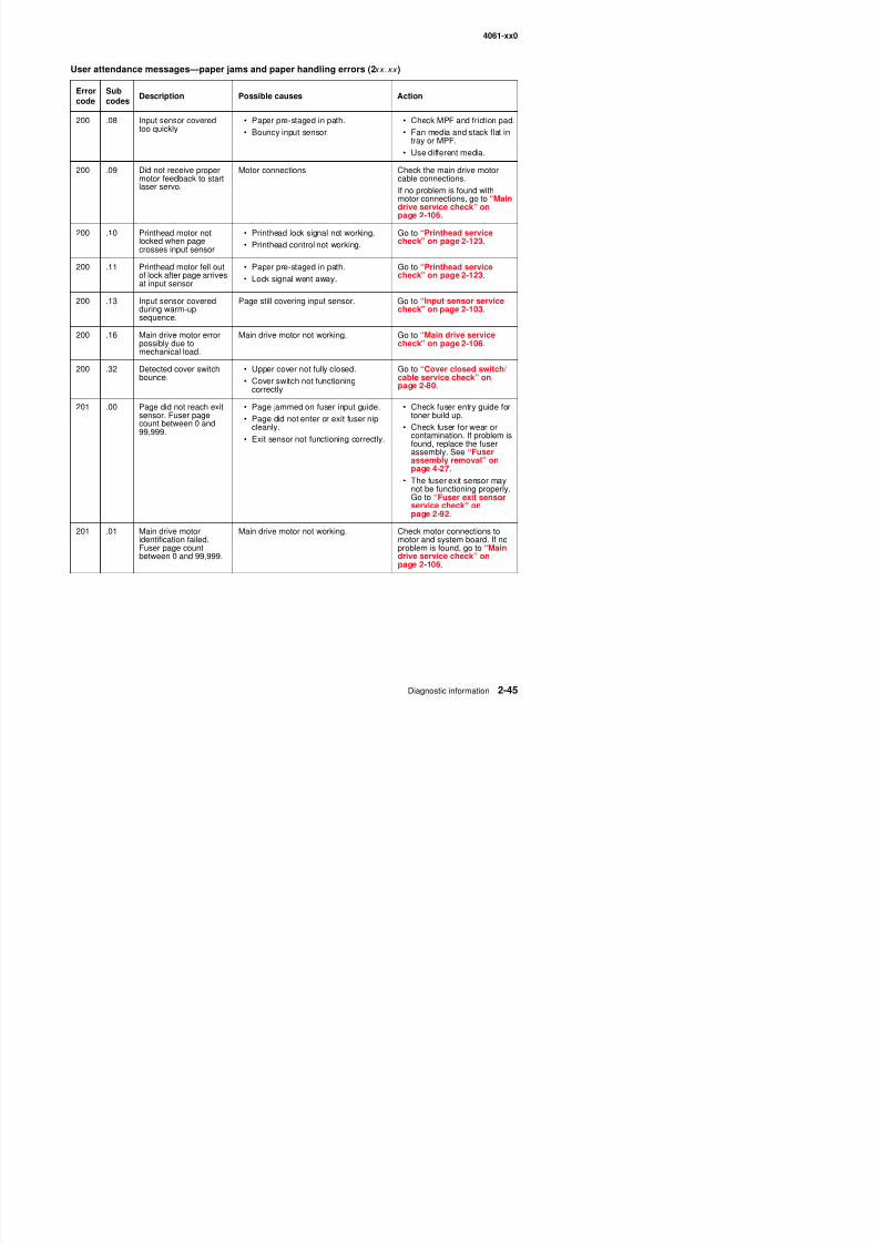
8/13/2019 t644 Service Manual
http://slidepdf.com/reader/full/t644-service-manual 87/423
200 .08 Input sensor coveredtoo quickly • Paper pre-staged in path.• Bouncy input sensor.
• Check MPF and friction pad.• Fan media and stack flat in
tray or MPF.
• Use different media.
200 .09 Did not receive propermotor feedback to startlaser servo.
Motor connections Check the main drive motorcable connections.
If no problem is found withmotor connections, go to “Maindrive service check” on
page 2-106.200 .10 Printhead motor not
locked when pagecrosses input sensor
• Printhead lock signal not working.
• Printhead control not working.
Go to “Printhead servicecheck” on page 2-123.
200 .11 Printhead motor fell outof lock after page arrivesat input sensor
• Paper pre-staged in path.
• Lock signal went away.
Go to “Printhead servicecheck” on page 2-123.
200 .13 Input sensor coveredduring warm-up
sequence.
Page still covering input sensor. Go to “Input sensor servicecheck” on page 2-103.
200 .16 Main drive motor errorpossibly due tomechanical load.
Main drive motor not working. Go to “Main drive servicecheck” on page 2-106.
200 .32 Detected cover switchbounce.
• Upper cover not fully closed.
• Cover switch not functioningcorrectly.
Go to “Cover closed switch/cable service check” onpage 2-80.
201 .00 Page did not reach exit
sensor. Fuser pagecount between 0 and99,999.
• Page jammed on fuser input guide.
• Page did not enter or exit fuser nipcleanly.
• Exit sensor not functioning correctly.
• Check fuser entry guide for
toner build up.• Check fuser for wear or
contamination. If problem isfound, replace the fuserassembly. See “Fuserassembly removal” onpage 4-27.
• The fuser exit sensor maynot be functioning properly.Go to “Fuser exit sensorservice check” on
page 2-92.201 .01 Main drive motor
identification failed.Fuser page countbetween 0 and 99,999.
Main drive motor not working. Check motor connections tomotor and system board. If noproblem is found, go to “Maindrive service check” onpage 2 106
4061-xx0
201 02 P did t h it P j d f i t id Ch k f t id f
User attendance messages—paper jams and paper handling errors (2xx.xx )
Errorcode
Subcodes
Description Possible causes Action
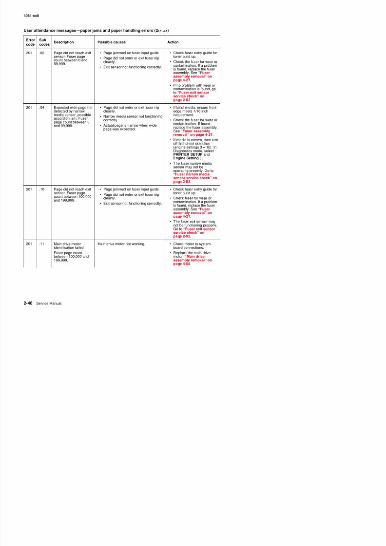
8/13/2019 t644 Service Manual
http://slidepdf.com/reader/full/t644-service-manual 88/423
201 .02 Page did not reach exitsensor. Fuser pagecount between 0 and99,999.
• Page jammed on fuser input guide.• Page did not enter or exit fuser nip
cleanly.
• Exit sensor not functioning correctly.
• Check fuser entry guide fortoner build up.
• Check the fuser for wear orcontamination. If a problemis found, replace the fuserassembly. See “Fuserassembly removal” onpage 4-27.
• If no problem with wear orcontamination is found, goto “Fuser exit sensor
service check” onpage 2-92
201 .04 Expected wide page notdetected by narrowmedia sensor, possibleaccordion jam. Fuserpage count between 0and 99,999.
• Page did not enter or exit fuser nipcleanly.
• Narrow media sensor not functioningcorrectly.
• Actual page is narrow when widepage was expected.
• If label media, ensure frontedge meets 1/16 inchrequirement.
• Check the fuser for wear orcontamination. If found,replace the fuser assembly.See “Fuser assemblyremoval” on page 4-27.
• If media is narrow, then turnoff first sheet detection(engine settings 3 = 16). InDiagnostics mode, selectPRINTER SETUP andEngine Setting 3.
• The fuser narrow mediasensor may not beoperating properly. Go to“Fuser narrow mediasensor service check” on
page 2-93.201 .10 Page did not reach exit
sensor. Fuser pagecount between 100,000and 199,999.
• Page jammed on fuser input guide.
• Page did not enter or exit fuser nipcleanly.
• Exit sensor not functioning correctly.
• Check fuser entry guide fortoner build up.
• Check fuser for wear orcontamination. If a problemis found, replace the fuserassembly. See “Fuserassembly removal” onpage 4-27.
• The fuser exit sensor may
not be functioning properly.Go to “Fuser exit sensorservice check” onpage 2-92.
201 .11 Main drive motoridentification failed
Main drive motor not working. • Check motor to systemboard connections
4061-xx0
201 12 Page did not reach exit Page jammed on fuser input guide Check fuser entry guide for
User attendance messages—paper jams and paper handling errors (2xx.xx )
Errorcode
Subcodes
Description Possible causes Action
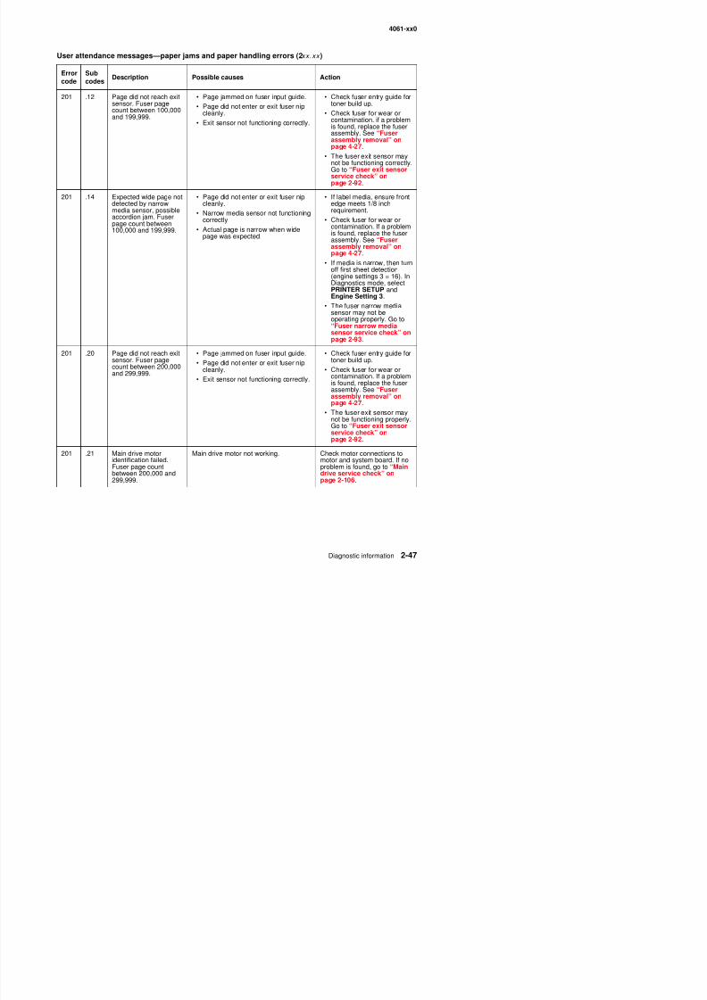
8/13/2019 t644 Service Manual
http://slidepdf.com/reader/full/t644-service-manual 89/423
201 .12 Page did not reach exitsensor. Fuser pagecount between 100,000and 199,999.
• Page jammed on fuser input guide.• Page did not enter or exit fuser nip
cleanly.
• Exit sensor not functioning correctly.
• Check fuser entry guide fortoner build up.
• Check fuser for wear orcontamination. if a problemis found, replace the fuserassembly. See “Fuserassembly removal” onpage 4-27.
• The fuser exit sensor maynot be functioning correctly.Go to “Fuser exit sensor
service check” onpage 2-92.
201 .14 Expected wide page notdetected by narrowmedia sensor, possibleaccordion jam. Fuserpage count between100,000 and 199,999.
• Page did not enter or exit fuser nipcleanly.
• Narrow media sensor not functioningcorrectly.
• Actual page is narrow when widepage was expected.
• If label media, ensure frontedge meets 1/8 inchrequirement.
• Check fuser for wear orcontamination. If a problemis found, replace the fuserassembly. See “Fuserassembly removal” on
page 4-27.• If media is narrow, then turnoff first sheet detection(engine settings 3 = 16). InDiagnostics mode, selectPRINTER SETUP andEngine Setting 3.
• The fuser narrow mediasensor may not beoperating properly. Go to“Fuser narrow media
sensor service check” onpage 2-93.
201 .20 Page did not reach exitsensor. Fuser pagecount between 200,000and 299,999.
• Page jammed on fuser input guide.
• Page did not enter or exit fuser nipcleanly.
• Exit sensor not functioning correctly.
• Check fuser entry guide fortoner build up.
• Check fuser for wear orcontamination. If a problemis found, replace the fuserassembly. See “Fuserassembly removal” onpage 4-27.
• The fuser exit sensor maynot be functioning properly.Go to “Fuser exit sensorservice check” onpage 2-92.
201 21 Main drive motor Main drive motor not working Check motor connections to
4061-xx0
201 22 Page did not reach exit • Page jammed on fuser input guide • Check fuser entry guide for
User attendance messages—paper jams and paper handling errors (2xx.xx )
Errorcode
Subcodes
Description Possible causes Action
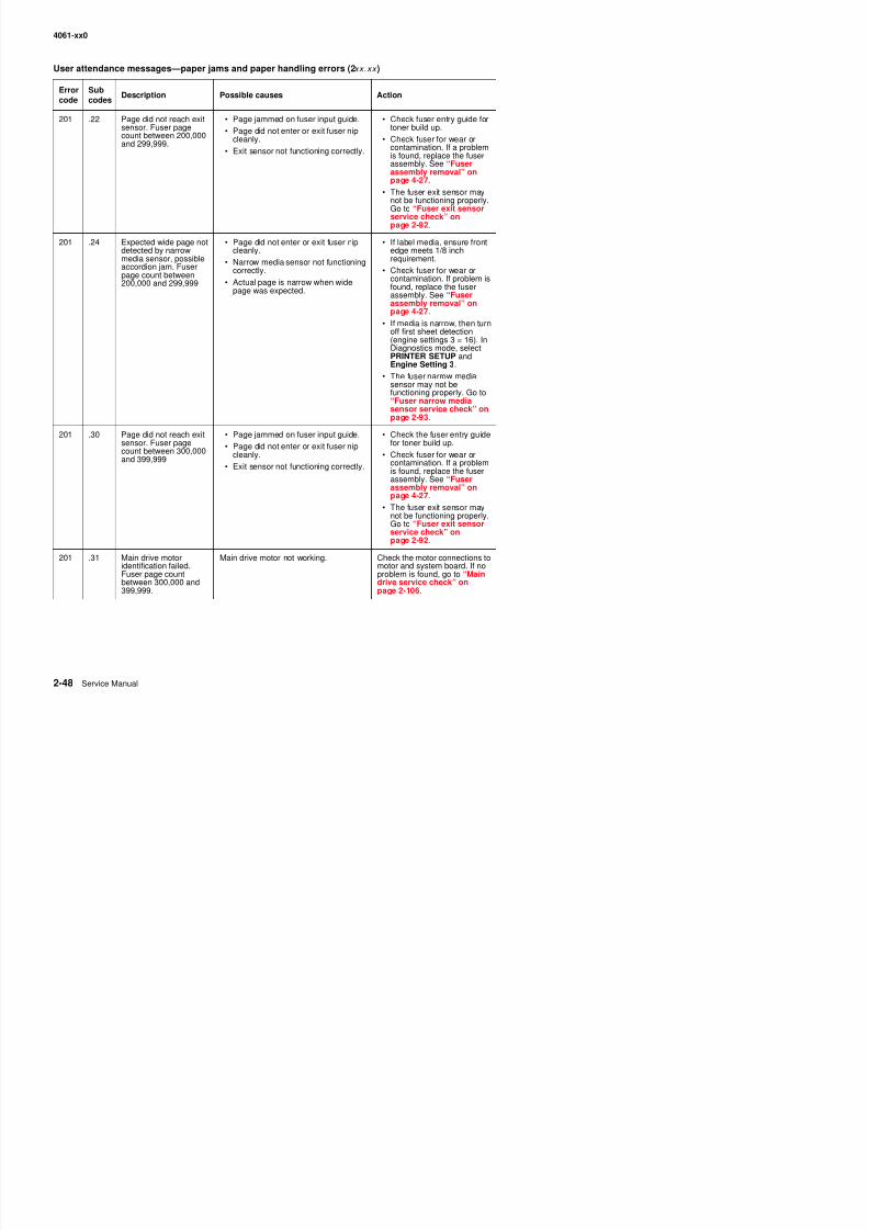
8/13/2019 t644 Service Manual
http://slidepdf.com/reader/full/t644-service-manual 90/423
201 .22 Page did not reach exitsensor. Fuser pagecount between 200,000and 299,999.
• Page jammed on fuser input guide.• Page did not enter or exit fuser nip
cleanly.
• Exit sensor not functioning correctly.
• Check fuser entry guide fortoner build up.
• Check fuser for wear orcontamination. If a problemis found, replace the fuserassembly. See “Fuserassembly removal” onpage 4-27.
• The fuser exit sensor maynot be functioning properly.Go to “Fuser exit sensor
service check” onpage 2-92.
201 .24 Expected wide page notdetected by narrowmedia sensor, possibleaccordion jam. Fuserpage count between200,000 and 299,999
• Page did not enter or exit fuser nipcleanly.
• Narrow media sensor not functioningcorrectly.
• Actual page is narrow when widepage was expected.
• If label media, ensure frontedge meets 1/8 inchrequirement.
• Check fuser for wear orcontamination. If problem isfound, replace the fuserassembly. See “Fuserassembly removal” on
page 4-27.• If media is narrow, then turnoff first sheet detection(engine settings 3 = 16). InDiagnostics mode, selectPRINTER SETUP andEngine Setting 3.
• The fuser narrow mediasensor may not befunctioning properly. Go to“Fuser narrow media
sensor service check” onpage 2-93.
201 .30 Page did not reach exitsensor. Fuser pagecount between 300,000and 399,999
• Page jammed on fuser input guide.
• Page did not enter or exit fuser nipcleanly.
• Exit sensor not functioning correctly.
• Check the fuser entry guidefor toner build up.
• Check fuser for wear orcontamination. If a problemis found, replace the fuserassembly. See “Fuserassembly removal” onpage 4-27.
• The fuser exit sensor maynot be functioning properly.Go to “Fuser exit sensorservice check” onpage 2-92.
201 31 Main drive motor Main drive motor not working Check the motor connections to
4061-xx0
201 32 Page did not reach exitF • Page jammed on fuser input guide • Check the fuser entry guidef t b ild
User attendance messages—paper jams and paper handling errors (2xx.xx )
Errorcode
Subcodes
Description Possible causes Action
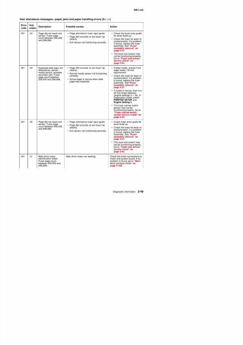
8/13/2019 t644 Service Manual
http://slidepdf.com/reader/full/t644-service-manual 91/423
201 .32 Page did not reach exitsensor. Fuser pagecount between 300,000and 399,999.
Page jammed on fuser input guide.• Page did not enter or exit fuser nip
cleanly.
• Exit sensor not functioning correctly.
Check the fuser entry guidefor toner build up.
• Check the fuser for wear orcontamination. If a problemis found, replace the fuserassembly. See “Fuserassembly removal” onpage 4-27.
• The fuser exit sensor maynot be functioning properly.Go to “Fuser exit sensor
service check” onpage 2-92.
201 .34 Expected wide page notdetected by narrowmedia sensor, possibleaccordion jam. Fuserpage count between300,000 and 399,999.
• Page did not enter or exit fuser nipcleanly.
• Narrow media sensor not functioningcorrectly.
• Actual page is narrow when widepage was expected.
• If label media, ensure frontedge meets 1/8 inchrequirement.
• Check the fuser for wear orcontamination. If a problemis found, replace the fuserassembly. See“Fuserassembly removal” on
page 4-27.• If media is narrow, then turnoff first sheet detection(engine settings 3 = 16). InDiagnostics mode, selectPRINTER SETUP andEngine Setting 3.
• The fuser narrow mediasensor may not befunctioning properly. Go to“Fuser narrow mediasensor service check” onpage 2-93.
201 .40 Page did not reach exitsensor. Fuser pagecount between 400,000and 499,999.
• Page jammed on fuser input guide.
• Page did not enter or exit fuser nipcleanly.
• Exit sensor not functioning correctly.
• Check fuser entry guide fortoner build up.
• Check the fuser for wear orcontamination. If a problemis found, replace the fuserassembly. See “Fuserassembly removal” onpage 4-27.
• The fuser exit sensor maynot be functioning properly.Go to “Fuser exit sensorservice check” onpage 2-92.
201 41 Main drive motor Main drive motor not working Check the motor connections to
4061-xx0
201 .42 Page did not reach exitsensor Fuser page • Page jammed on fuser input guide. • Check the fuser entry guidefor toner build up
User attendance messages—paper jams and paper handling errors (2xx.xx )
Errorcode
Subcodes
Description Possible causes Action

8/13/2019 t644 Service Manual
http://slidepdf.com/reader/full/t644-service-manual 92/423
201 .42 Page did not reach exitsensor. Fuser pagecount between 400,000and 499,999.
Page jammed on fuser input guide.• Page did not enter or exit fuser nip
cleanly.
• Exit sensor not functioning correctly.
Check the fuser entry guidefor toner build up.
• Check the fuser for wear orcontamination. If a problemis found, replace the fuserassembly. See “Fuserassembly removal” onpage 4-27.
• The fuser exit sensor maynot be functioning properly.Go to “Fuser exit sensor
service check” onpage 2-92.
201 .44 Expected wide page notdetected by narrowmedia sensor, possibleaccordion jam. Fuserpage count between400,000 and 499,999.
• Page did not enter or exit fuser nipcleanly.
• Narrow media sensor not functioningcorrectly.
• Actual page is narrow when widepage was expected.
• If label media, ensure frontedge meets 1/8 inchrequirement.
• Check the fuser for wear orcontamination. If a problemis found, replace the fuserassembly. See “Fuserassembly removal” onpage 4-27.
• If media is narrow, then turnoff first sheet detection(engine settings 3 = 16). InDiagnostics mode, selectPRINTER SETUP andEngine Setting 3.
• The fuser narrow mediasensor may not befunctioning properly. Go to“Fuser narrow mediasensor service check” onpage 2-93.
201 .50 Page did not reach exitsensor. Fuser pagecount stopped at500,000 to preservedata.
• Page jammed on fuser input guide.
• Page did not enter or exit fuser nipcleanly.
• Exit sensor not functioning correctly.
• Check the fuser entry guidefor toner build up.
• Check the fuser for wear orcontamination. If a problemis found, replace the fuserassembly. See “Fuserassembly removal” onpage 4-27.
• The fuser exit sensor maynot be functioning properly.Go to “Fuser exit sensorservice check” onpage 2-92.
201 51 Main drive motor Main drive motor not working Check the connections to the
4061-xx0
201 .52 Page did not reach exitsensor Fuser page • Page jammed on fuser input guide.P did t t it f i
• Check the fuser entry guidefor toner build up
User attendance messages—paper jams and paper handling errors (2xx.xx )
Errorcode
Subcodes
Description Possible causes Action
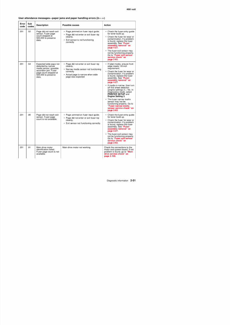
8/13/2019 t644 Service Manual
http://slidepdf.com/reader/full/t644-service-manual 93/423
gsensor. Fuser pagecount stopped at500,000 to preservedata.
g j p g• Page did not enter or exit fuser nip
cleanly.
• Exit sensor is not functioningcorrectly.
y gfor toner build up.
• Check the fuser for wear orcontamination. If a problemis found, replace the fuserassembly. See “Fuserassembly removal” onpage 4-27.
• The fuser exit sensor maynot be functioning properly.Go to “Fuser exit sensor
service check” onpage 2-92.
201 .54 Expected wide page notdetected by narrowmedia sensor, possibleaccordion jam. Fuserpage count stopped at500,000 to preservedata.
• Page did not enter or exit fuser nipcleanly.
• Narrow media sensor not functioningcorrectly.
• Actual page is narrow when widepage was expected.
• If label media, ensure frontedge meets 1/8 inchrequirement.
• Check the fuser for wear orcontamination. If a problemis found, replace the fuserassembly. See “Fuserassembly removal” onpage 4-27.
• If media is narrow, then turnoff first sheet detection(engine settings 3 = 16). InDiagnostics mode, selectPRINTER SETUP andEngine Setting 3.
• The fuser narrow mediasensor may not befunctioning properly. Go to“Fuser narrow mediasensor service check” onpage 2-93.
201 .90 Page did not reach exitsensor. Fuser pagecount is not available.
• Page jammed on fuser input guide.
• Page did not enter or exit fuser nipcleanly.
• Exit sensor not functioning correctly.
• Check the fuser entry guidefor toner build up.
• Check the fuser for wear orcontamination. If a problemis found, replace the fuserassembly. See “Fuserassembly removal” onpage 4-27.
• The fuser exit sensor maynot be functioning properly.Go to “Fuser exit sensorservice check” onpage 2-92.
201 91 Main drive motor Main drive motor not working Check the connections to the
4061-xx0
201 .92 Page did not reach exitsensor. Fuser page • Page jammed on fuser input guide.Page did not enter or exit fuser nip
• Check the fuser entry guidefor toner build up.
User attendance messages—paper jams and paper handling errors (2xx.xx )
Errorcode
Subcodes
Description Possible causes Action
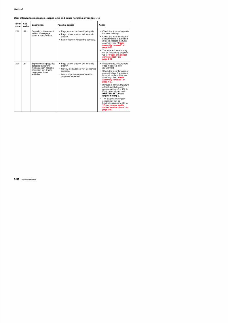
8/13/2019 t644 Service Manual
http://slidepdf.com/reader/full/t644-service-manual 94/423
sensor. Fuser pagecount is not available. • Page did not enter or exit fuser nip
cleanly.
• Exit sensor not functioning correctly.
for toner build up.
• Check the fuser for wear orcontamination. If a problemis found, replace the fuserassembly. See “Fuserassembly removal” onpage 4-27.
• The fuser exit sensor maynot be functioning properly.Go to “Fuser exit sensor
service check” onpage 2-92.
201 .94 Expected wide page notdetected by narrowmedia sensor, possibleaccordion jam. Fuserpage count is notavailable.
• Page did not enter or exit fuser nipcleanly.
• Narrow media sensor not functioningcorrectly.
• Actual page is narrow when widepage was expected.
• If label media, ensure frontedge meets 1/8 inchrequirement.
• Check the fuser for wear orcontamination. If a problemis found, replace the fuserassembly. See “Fuserassembly removal” onpage 4-27.
• If media is narrow, then turnoff first sheet detection(engine settings 3 = 16). InDiagnostics mode, selectPRINTER SETUP andEngine Setting 3.
• The fuser narrow mediasensor may not befunctioning properly. Go to“Fuser narrow mediasensor service check” onpage 2-93.
4061-xx0
202 .00 Paper jam at fuser exitor redrive area. Fuser Page may be jammed in fuser exit orredrive area. • Make sure the redrive dooris complete closed.
User attendance messages—paper jams and paper handling errors (2xx.xx )
Errorcode
Subcodes
Description Possible causes Action

8/13/2019 t644 Service Manual
http://slidepdf.com/reader/full/t644-service-manual 95/423
page count between 0and 99,999.
p
• Check the fuser for anysigns of wear orcontamination. If any arefound, replace the fuserassembly. See “Fuserassembly removal” onpage 4-27.
• Turn media over to reduce+W curl.
• Check upper redrivediverter and diverter springfor any signs of damage, aloose spring, or bindingparts. Repair the redrive asnecessary.
• Check any installed outputoption(s) that may beinstalled for correctinstallation and alignment.
• The fuser exit sensor may
not be functioning properly.Go to “Fuser exit sensorservice check” onpage 2-92.
202 .01 Page did not cleanly exitfuser or redrive area.Fuser page countbetween 0 and 99,999.
Page may be jammed in fuser exit orredrive area.
• Make sure the redrive dooris complete closed.
• Check the fuser for anysigns of wear orcontamination. If any arefound, replace the fuser
assembly. See “Fuserassembly removal” onpage 4-27.
• Turn media over to reduce+W curl.
• Check upper redrivediverter and diverter springfor any signs of damage, aloose spring, or bindingparts. Repair the redrive asnecessary.
• Check any installed outputoptions(s) that may beinstalled for correctinstallation and alignment.
• The fuser exit sensor maynot be functioning properly
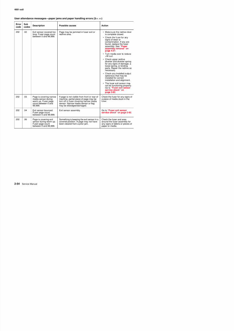
8/13/2019 t644 Service Manual
http://slidepdf.com/reader/full/t644-service-manual 96/423
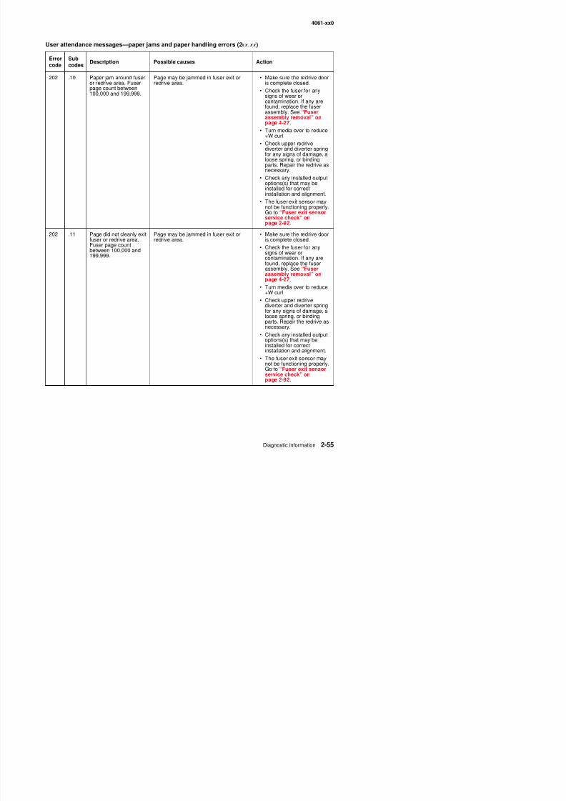
8/13/2019 t644 Service Manual
http://slidepdf.com/reader/full/t644-service-manual 97/423
4061-xx0
202 .12 Exit sensor covered toolong. Fuser page countbetween 100 000 and
Page may be jammed in fuser exit orredrive area. • Make sure the redrive dooris complete closed.
User attendance messages—paper jams and paper handling errors (2xx.xx )
Errorcode
Subcodes
Description Possible causes Action

8/13/2019 t644 Service Manual
http://slidepdf.com/reader/full/t644-service-manual 98/423
between 100,000 and199,999. • Check the fuser for any
signs of wear orcontamination. If any arefound, replace the fuserassembly. See “Fuserassembly removal” onpage 4-27.
• Turn media over to reduce+W curl.
• Check upper redrivediverter and diverter springfor any signs of damage, aloose spring, or bindingparts. Repair the redrive asnecessary.
• Check any installed outputoptions(s) that may beinstalled for correctinstallation and alignment.
• The fuser exit sensor may
not be functioning properly.Go to “Fuser exit sensorservice check” onpage 2-92.
202 .13 Page is covering narrowmedia sensor duringwarm up. Fuser pagecount between 100,000and 199,999.
• If page is not visible from front or rearof the machine, partial piece may betorn off in the fuser covering thenarrow media sensor.
• The narrow media sensor or flag maybe dislodged or damaged.
Check the fuser and areaaround the fuser assembly forany signs of debris or pieces ofpaper or media.
202 .14 Exit sensor bounced.Fuser page countbetween 100,000 and199,999.
Exit sensor assembly. Go to “Fuser exit sensorservice check” on page 2-92.
202 .16 Page is covering exitsensor during warm up.Fuser page countbetween 100,000 and199,999.
Something is keeping the exit sensor in acovered position. A page may not havebeen cleared from a prior jam.
Check the fuser and areaaround the fuser assembly forany signs of debris or pieces ofpaper or media.
4061-xx0
202 .20 Paper jam around fuserexit or redrive area.Fuser page count
Paper may be jammed in fuser exit orredrive area. • Make sure the redrive dooris complete closed.
Ch k th f f
User attendance messages—paper jams and paper handling errors (2xx.xx )
Errorcode
Subcodes
Description Possible causes Action

8/13/2019 t644 Service Manual
http://slidepdf.com/reader/full/t644-service-manual 99/423
Fuser page countbetween 200,000 and299,999.
• Check the fuser for anysigns of wear orcontamination. If any arefound, replace the fuserassembly. See “Fuserassembly removal” onpage 4-27.
• Turn media over to reduce+W curl.
• Check upper redrivediverter and diverter springfor any signs of damage, aloose spring, or bindingparts. Repair the redrive asnecessary.
• Check any installed outputoptions(s) that may beinstalled for correctinstallation and alignment.
• The fuser exit sensor may
not be functioning properly.Go to “Fuser exit sensorservice check” onpage 2-92.
202 .21 Page did not cleanly exitfuser or redrive area.Fuser page countbetween 200,000 and299,999.
Page may be jammed in fuser exit orredrive area.
• Make sure the redrive dooris complete closed.
• Check the fuser for anysigns of wear orcontamination. If any arefound, replace the fuser
assembly. See “Fuserassembly removal” onpage 4-27.
• Turn media over to reduce+W curl.
• Check upper redrivediverter and diverter springfor any signs of damage, aloose spring, or bindingparts. Repair the redrive asnecessary.
• Check any installed outputoptions(s) that may beinstalled for correctinstallation and alignment.
• The fuser exit sensor maynot be functioning properly

8/13/2019 t644 Service Manual
http://slidepdf.com/reader/full/t644-service-manual 100/423
4061-xx0
202 .30 Paper jam around thefuser exit or redrivearea. Fuser page count
Page may be jammed in fuser exit orredrive area. • Make sure the redrive dooris complete closed.
• Check the fuser for any
User attendance messages—paper jams and paper handling errors (2xx.xx )
Errorcode
Subcodes
Description Possible causes Action

8/13/2019 t644 Service Manual
http://slidepdf.com/reader/full/t644-service-manual 101/423
p gbetween 300,000 and399,999.
• Check the fuser for anysigns of wear orcontamination. If any arefound, replace the fuserassembly. See “Fuserassembly removal” onpage 4-27.
• Turn media over to reduce+W curl.
• Check upper redrivediverter and diverter springfor any signs of damage, aloose spring, or bindingparts. Repair the redrive asnecessary.
• Check any installed outputoptions(s) that may beinstalled for correctinstallation and alignment.
• The fuser exit sensor may
not be functioning properly.Go to “Fuser exit sensorservice check” onpage 2-92.
202 .31 Page did not cleanly exitfuser or redrive area.Fuser page countbetween 300,000 and399,999.
Page may be jammed in fuser exit orredrive area.
• Make sure the redrive dooris complete closed.
• Check the fuser for anysigns of wear orcontamination. If any arefound, replace the fuser
assembly. See “Fuserassembly removal” onpage 4-27.
• Turn media over to reduce+W curl.
• Check upper redrivediverter and diverter springfor any signs of damage, aloose spring, or bindingparts. Repair the redrive asnecessary.
• Check any installed outputoptions(s) that may beinstalled for correctinstallation and alignment.
• The fuser exit sensor maynot be functioning properly
4061-xx0
202 .32 Exit sensor covered toolong. Fuser page countbetween 300,000 and399 999
Page may be jammed in fuser exit orredrive area. • Make sure the redrive dooris complete closed.
• Check the fuser for any
User attendance messages—paper jams and paper handling errors (2xx.xx )
Errorcode
Subcodes
Description Possible causes Action

8/13/2019 t644 Service Manual
http://slidepdf.com/reader/full/t644-service-manual 102/423
399,999. Check the fuser for anysigns of wear orcontamination. If any arefound, replace the fuserassembly. See “Fuserassembly removal” onpage 4-27.
• Turn media over to reduce+W curl.
• Check upper redrivediverter and diverter springfor any signs of damage, aloose spring, or bindingparts. Repair the redrive asnecessary.
• Check any installed outputoptions(s) that may beinstalled for correctinstallation and alignment.
• The fuser exit sensor may
not be functioning properly.Go to “Fuser exit sensorservice check” onpage 2-92.
202 .33 Page is covering thenarrow media sensorduring warm up. Fuserpage count between300,000 and 399,999.
• If page is not visible from front or rearof the printer, a partial piece of apage may be torn off in the fusercovering the narrow media sensor.
• The narrow media sensor or flag maybe dislodged or damaged.
Check the fuser and areaaround the fuser assembly forany signs of debris or pieces ofpaper or media.
202 .34 Exit sensor may havebounced. Fuser pagecount between 300,000and 399,999.
Exit sensor assembly. Go to “Fuser exit sensorservice check” on page 2-92.
202 .36 Page is covering the exitsensor during warm up.Fuser page countbetween 300,000 and399,999.
Something is keeping the exit sensorcovered. A page may not have beencleared from a prior jam.
Check the fuser and areaaround the fuser assembly forany signs of debris or pieces ofpaper or media.
4061-xx0
202 .40 Paper jam around thefuser exit or redrivearea. Fuser page countbetween 400 000 and
Page may be jammed in fuser exit orredrive. • Make sure the redrive dooris complete closed.
• Check the fuser for any
User attendance messages—paper jams and paper handling errors (2xx.xx )
Errorcode
Subcodes
Description Possible causes Action

8/13/2019 t644 Service Manual
http://slidepdf.com/reader/full/t644-service-manual 103/423
between 400,000 and499,999.
ysigns of wear orcontamination. If any arefound, replace the fuserassembly. See “Fuserassembly removal” onpage 4-27.
• Turn media over to reduce+W curl.
• Check upper redrivediverter and diverter springfor any signs of damage, aloose spring, or bindingparts. Repair the redrive asnecessary.
• Check any installed outputoptions(s) that may beinstalled for correctinstallation and alignment.
• The fuser exit sensor may
not be functioning properly.Go to “Fuser exit sensorservice check” onpage 2-92.
202 .41 Page did not cleanly exitfuser or redrive area.Fuser page countbetween 400,000 and499,999.
Page may be jammed in fuser exit orredrive area.
• Make sure the redrive dooris complete closed.
• Check the fuser for anysigns of wear orcontamination. If any arefound, replace the fuser
assembly. See “Fuserassembly removal” onpage 4-27.
• Turn media over to reduce+W curl.
• Check upper redrivediverter and diverter springfor any signs of damage, aloose spring, or bindingparts. Repair the redrive asnecessary.
• Check any installed outputoptions(s) that may beinstalled for correctinstallation and alignment.
• The fuser exit sensor maynot be functioning properly
4061-xx0
202 .42 Exit sensor covered toolong. Fuser page countbetween 400,000 and499 999
Page may be jammed in fuser exit orredrive area. • Make sure the redrive dooris complete closed.• Check the fuser for any
User attendance messages—paper jams and paper handling errors (2xx.xx )
Errorcode
Subcodes
Description Possible causes Action
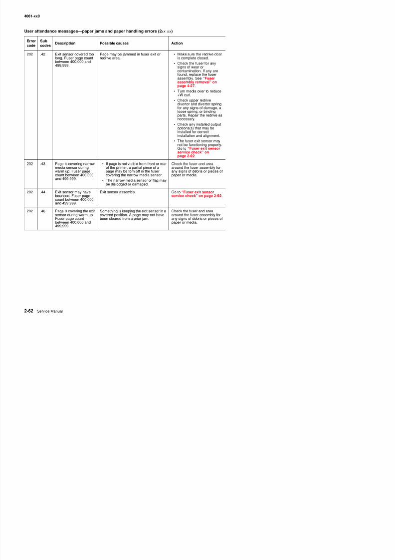
8/13/2019 t644 Service Manual
http://slidepdf.com/reader/full/t644-service-manual 104/423
499,999. signs of wear orcontamination. If any arefound, replace the fuserassembly. See “Fuserassembly removal” onpage 4-27.
• Turn media over to reduce+W curl.
• Check upper redrivediverter and diverter springfor any signs of damage, aloose spring, or bindingparts. Repair the redrive asnecessary.
• Check any installed outputoptions(s) that may beinstalled for correctinstallation and alignment.
• The fuser exit sensor may
not be functioning properly.Go to “Fuser exit sensorservice check” onpage 2-92.
202 .43 Page is covering narrowmedia sensor duringwarm up. Fuser pagecount between 400,000and 499,999.
• If page is not visible from front or rearof the printer, a partial piece of apage may be torn off in the fusercovering the narrow media sensor.
• The narrow media sensor or flag maybe dislodged or damaged.
Check the fuser and areaaround the fuser assembly forany signs of debris or pieces ofpaper or media.
202 .44 Exit sensor may havebounced. Fuser pagecount between 400,000and 499,999.
Exit sensor assembly Go to “Fuser exit sensorservice check” on page 2-92.
202 .46 Page is covering the exitsensor during warm up.Fuser page countbetween 400,000 and499,999.
Something is keeping the exit sensor in acovered position. A page may not havebeen cleared from a prior jam.
Check the fuser and areaaround the fuser assembly forany signs of debris or pieces ofpaper or media.
4061-xx0
202 .50 Paper jam around thefuser exit or redrivearea. Fuser page countstopped at 500 000 to
Page may be jammed in the fuser exit orredrive area. • Make sure the redrive dooris complete closed.• Check the fuser for any
i f
User attendance messages—paper jams and paper handling errors (2xx.xx )
Errorcode
Subcodes
Description Possible causes Action

8/13/2019 t644 Service Manual
http://slidepdf.com/reader/full/t644-service-manual 105/423
stopped at 500,000 topreserve data signs of wear or
contamination. If any arefound, replace the fuserassembly. See “Fuserassembly removal” onpage 4-27.
• Turn media over to reduce+W curl.
• Check upper redrivediverter and diverter springfor any signs of damage, aloose spring, or bindingparts. Repair the redrive asnecessary.
• Check any installed outputoptions(s) that may beinstalled for correctinstallation and alignment.
• The fuser exit sensor may
not be functioning properly.Go to “Fuser exit sensorservice check” onpage 2-92.
202 .51 Page did not cleanly exitfuser or redrive area.Fuser page countstopped at 500,000 topreserve data.
Page may be jammed in fuser exit orredrive area.
• Make sure the redrive dooris complete closed.
• Check the fuser for anysigns of wear orcontamination. If any arefound, replace the fuser
assembly. See “Fuserassembly removal” onpage 4-27.
• Turn media over to reduce+W curl.
• Check upper redrivediverter and diverter springfor any signs of damage, aloose spring, or bindingparts. Repair the redrive asnecessary.
• Check any installed outputoptions(s) that may beinstalled for correctinstallation and alignment.
• The fuser exit sensor maynot be functioning properly
4061-xx0
202 .52 Exit sensor covered toolong. Fuser page countstopped at 500,000 topreserve data.
Page may be jammed in fuser exit orredrive area. • Make sure the redrive dooris complete closed.• Check the fuser for any
signs of wear or
User attendance messages—paper jams and paper handling errors (2xx.xx )
Errorcode
Subcodes
Description Possible causes Action
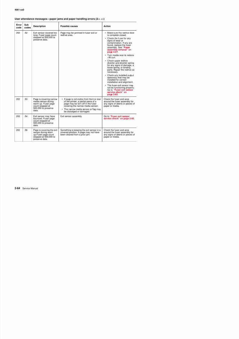
8/13/2019 t644 Service Manual
http://slidepdf.com/reader/full/t644-service-manual 106/423
p ese e data signs of wear orcontamination. If any arefound, replace the fuserassembly. See “Fuserassembly removal” onpage 4-27.
• Turn media over to reduce+W curl.
• Check upper redrivediverter and diverter springfor any signs of damage, aloose spring, or bindingparts. Repair the redrive asnecessary.
• Check any installed outputoptions(s) that may beinstalled for correctinstallation and alignment.
• The fuser exit sensor may
not be functioning properly.Go to “Fuser exit sensorservice check” onpage 2-92.
202 .53 Page is covering narrowmedia sensor duringwarm up. Fuser pagecount stopped at500,000 to preservedata.
• If page is not visible from front or rearof the printer, a partial piece of apage may be torn off in the fusercovering the narrow media sensor.
• The narrow media sensor or flag maybe dislodged or damaged.
Check the fuser and areaaround the fuser assembly forany signs of debris or pieces ofpaper or media.
202 .54 Exit sensor may havebounced. Fuser pagecount stopped at500,000 to preservedata.
Exit sensor assembly. Go to “Fuser exit sensorservice check” on page 2-92.
202 .56 Page is covering the exitsensor during warmup.Fuser page countstopped at 500,000 topreserve data.
Something is keeping the exit sensor in acovered position. A page may not havebeen cleared from a prior jam.
Check the fuser and areaaround the fuser assembly forany signs of debris or pieces ofpaper or media.
4061-xx0
202 .90 Paper jam around theexit or redrive area.Fuser page count is notavailable.
Page may be jammed in fuser exit orredrive area.
• Make sure the redrive dooris complete closed.
• Check the fuser for anysigns of wear or
User attendance messages—paper jams and paper handling errors (2xx.xx )
Errorcode
Subcodes
Description Possible causes Action

8/13/2019 t644 Service Manual
http://slidepdf.com/reader/full/t644-service-manual 107/423
signs of wear orcontamination. If any arefound, replace the fuserassembly. See “Fuserassembly removal” onpage 4-27.
• Turn media over to reduce+W curl.
• Check upper redrivediverter and diverter springfor any signs of damage, aloose spring, or bindingparts. Repair the redrive asnecessary.
• Check any installed outputoptions(s) that may beinstalled for correctinstallation and alignment.
• The fuser exit sensor may
not be functioning properly.Go to “Fuser exit sensorservice check” onpage 2-92.
202 .91 Page did not cleanly exitfuser or redrive area.Fuser page count is notavailable.
Page may be jammed in the fuser exit orredrive area.
• Make sure the redrive dooris complete closed.
• Check the fuser for anysigns of wear orcontamination. If any arefound, replace the fuserassembly. See “Fuserassembly removal” onpage 4-27.
• Turn media over to reduce+W curl.
• Check upper redrivediverter and diverter springfor any signs of damage, aloose spring, or bindingparts. Repair the redrive asnecessary.
• Check any installed outputoptions(s) that may beinstalled for correctinstallation and alignment.
• The fuser exit sensor maynot be functioning properly
4061-xx0
202 .92 Exit sensor covered toolong. Fuser page countis not available.
Page may be jammed in the fuser exit orredrive area.
• Make sure the redrive dooris complete closed.
• Check the fuser for anysigns of wear or
User attendance messages—paper jams and paper handling errors (2xx.xx )
Errorcode
Subcodes
Description Possible causes Action
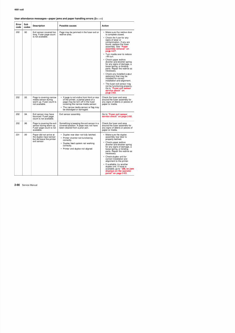
8/13/2019 t644 Service Manual
http://slidepdf.com/reader/full/t644-service-manual 108/423
signs of wear orcontamination. If any arefound, replace the fuserassembly. See “Fuserassembly removal” onpage 4-27.
• Turn media over to reduce+W curl.
• Check upper redrivediverter and diverter springfor any signs of damage, aloose spring, or bindingparts. Repair the redrive asnecessary.
• Check any installed outputoptions(s) that may beinstalled for correctinstallation and alignment.
• The fuser exit sensor may
not be functioning properly.Go to “Fuser exit sensorservice check” onpage 2-92.
202 .93 Page is covering narrowmedia sensor duringwarm up. Fuser count isnot available.
• If page is not visible from front or rearof the printer, a partial piece of apage may be torn off in the fusercovering the narrow media sensor.
• The narrow media sensor or flag maybe dislodged or damaged.
Check the fuser and areaaround the fuser assembly forany signs of debris or pieces ofpaper or media.
202 .94 Exit sensor may havebounced. Fuser pagecount is not available.
Exit sensor assembly. Go to “Fuser exit sensorservice check” on page 2-92.
202 .96 Page is covering the exitsensor during warm up.Fuser page count is notavailable.
Something is keeping the exit sensor in acovered position. A page may not havebeen cleared from a prior jam.
Check the fuser and areaaround the fuser assembly forany signs of debris or pieces ofpaper or media.
231 .00 Paper did not arrive atthe duplex input sensor
but did leave the printerexit sensor.
• Duplex rear door not fully latched.
• Printer diverter not functioningcorrectly.
• Duplex feed system not workingcorrectly.
• Printer and duplex not aligned.
• Make sure the duplexassembly rear door is
properly latched.• Check upper redrive
diverter and diverter springfor any signs of damage, aloose spring, or bindingparts Repair the redrive as
4061-xx0
232 .00 Paper did not clear theduplex input sensor butdid leave the printer exitsensor.
• Duplex rear door not fully latched.
• Printer diverter not functioningcorrectly.
• Duplex feed system not working
• Make sure the duplexassembly rear door isproperly latched.
• Check upper redrive
User attendance messages—paper jams and paper handling errors (2xx.xx )
Errorcode
Subcodes
Description Possible causes Action
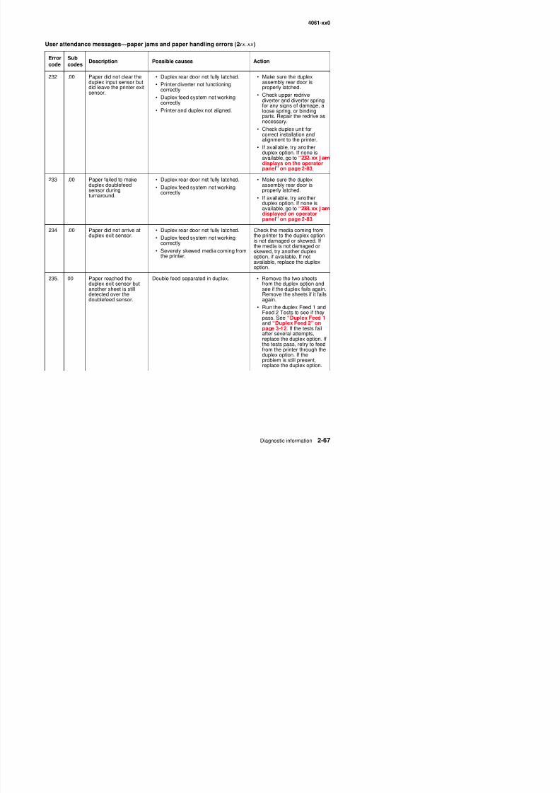
8/13/2019 t644 Service Manual
http://slidepdf.com/reader/full/t644-service-manual 109/423
• Duplex feed system not workingcorrectly.
• Printer and duplex not aligned.
ppdiverter and diverter springfor any signs of damage, aloose spring, or bindingparts. Repair the redrive asnecessary.
• Check duplex unit forcorrect installation andalignment to the printer.
• If available, try anotherduplex option. If none isavailable, go to “232.xx Jamdisplays on the operatorpanel” on page 2-83.
233 .00 Paper failed to makeduplex doublefeedsensor duringturnaround.
• Duplex rear door not fully latched.
• Duplex feed system not workingcorrectly.
• Make sure the duplexassembly rear door isproperly latched.
• If available, try anotherduplex option. If none isavailable, go to “233.xx Jamdisplayed on operatorpanel” on page 2-83.
234 .00 Paper did not arrive atduplex exit sensor.
• Duplex rear door not fully latched.
• Duplex feed system not workingcorrectly.
• Severely skewed media coming fromthe printer.
Check the media coming fromthe printer to the duplex optionis not damaged or skewed. Ifthe media is not damaged orskewed, try another duplexoption, if available. If notavailable, replace the duplex
option.235. 00 Paper reached the
duplex exit sensor butanother sheet is stilldetected over thedoublefeed sensor.
Double feed separated in duplex. • Remove the two sheetsfrom the duplex option andsee if the duplex fails again.Remove the sheets if it failsagain.
• Run the duplex Feed 1 andFeed 2 Tests to see if theypass. See “Duplex Feed 1 and “Duplex Feed 2” onpage 3-12. If the tests failafter several attempts,replace the duplex option. Ifthe tests pass, retry to feedfrom the printer through theduplex option. If theproblem is still present
4061-xx0
236 00 Paper did not leave theduplex exit sensor.
• Duplex jam access tray is not fullylatched.
• Printer PTO not driving duplex feedrolls.
• Make sure the duplex jamaccess tray is installedcorrectly
• Make sure the power takeoff
User attendance messages—paper jams and paper handling errors (2xx.xx )
Errorcode
Subcodes
Description Possible causes Action
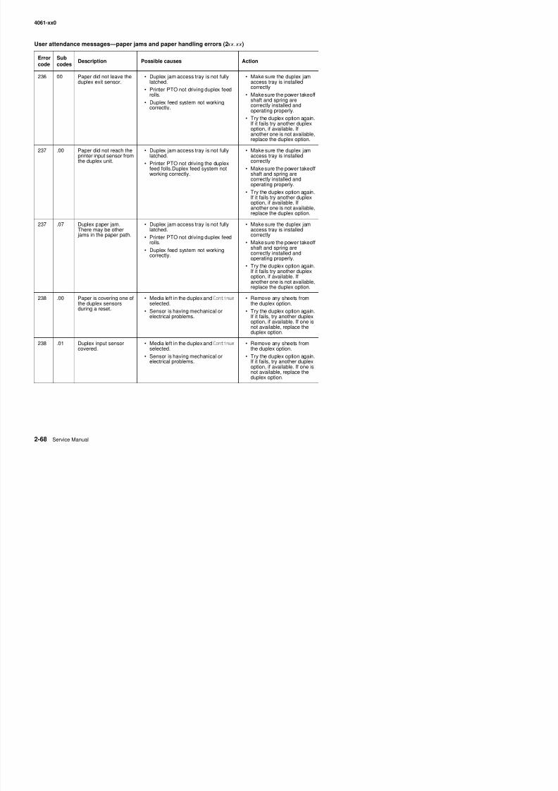
8/13/2019 t644 Service Manual
http://slidepdf.com/reader/full/t644-service-manual 110/423
• Duplex feed system not workingcorrectly.
shaft and spring arecorrectly installed andoperating properly.
• Try the duplex option again.If it fails try another duplexoption, if available. Ifanother one is not available,replace the duplex option.
237 .00 Paper did not reach theprinter input sensor fromthe duplex unit.
• Duplex jam access tray is not fullylatched.
• Printer PTO not driving the duplexfeed folls.Duplex feed system notworking correctly.
• Make sure the duplex jamaccess tray is installedcorrectly
• Make sure the power takeoffshaft and spring arecorrectly installed andoperating properly.
• Try the duplex option again.If it fails try another duplexoption, if available. Ifanother one is not available,replace the duplex option.
237 .07 Duplex paper jam.There may be other jams in the paper path.
• Duplex jam access tray is not fullylatched.
• Printer PTO not driving duplex feedrolls.
• Duplex feed system not workingcorrectly.
• Make sure the duplex jamaccess tray is installedcorrectly
• Make sure the power takeoffshaft and spring arecorrectly installed andoperating properly.
• Try the duplex option again.If it fails try another duplexoption, if available. Ifanother one is not available,replace the duplex option.
238 .00 Paper is covering one ofthe duplex sensorsduring a reset.
• Media left in the duplex and Continueselected.
• Sensor is having mechanical orelectrical problems.
• Remove any sheets fromthe duplex option.
• Try the duplex option again.If it fails, try another duplexoption, if available. If one isnot available, replace the
duplex option.
238 .01 Duplex input sensorcovered.
• Media left in the duplex and Continueselected.
• Sensor is having mechanical or
• Remove any sheets fromthe duplex option.
• Try the duplex option again.
4061-xx0
238 .02 Duplex exit sensorcovered.
• Media left in the duplex and Continue
selected.• Sensor is having mechanical or
electrical problems.
• Remove any sheets fromthe duplex option.
• Try the duplex option again.If it fails, try another duplex
ti if il bl If i
User attendance messages—paper jams and paper handling errors (2xx.xx )
Errorcode
Subcodes
Description Possible causes Action
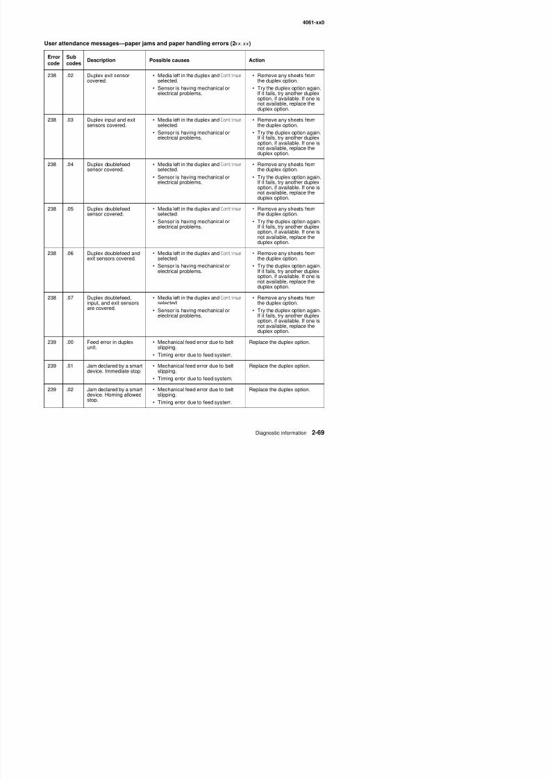
8/13/2019 t644 Service Manual
http://slidepdf.com/reader/full/t644-service-manual 111/423
option, if available. If one isnot available, replace theduplex option.
238 .03 Duplex input and exitsensors covered.
• Media left in the duplex and Continueselected.
• Sensor is having mechanical orelectrical problems.
• Remove any sheets fromthe duplex option.
• Try the duplex option again.If it fails, try another duplexoption, if available. If one isnot available, replace theduplex option.
238 .04 Duplex doublefeedsensor covered.
• Media left in the duplex and Continueselected.
• Sensor is having mechanical orelectrical problems.
• Remove any sheets fromthe duplex option.
• Try the duplex option again.If it fails, try another duplexoption, if available. If one isnot available, replace theduplex option.
238 .05 Duplex doublefeedsensor covered.
• Media left in the duplex and Continueselected.
• Sensor is having mechanical orelectrical problems.
• Remove any sheets fromthe duplex option.
• Try the duplex option again.If it fails, try another duplexoption, if available. If one isnot available, replace theduplex option.
238 .06 Duplex doublefeed andexit sensors covered.
• Media left in the duplex and Continueselected.
• Sensor is having mechanical orelectrical problems.
• Remove any sheets fromthe duplex option.
• Try the duplex option again.If it fails, try another duplexoption, if available. If one isnot available, replace theduplex option.
238 .07 Duplex doublefeed,input, and exit sensorsare covered.
• Media left in the duplex and Continueselected.
• Sensor is having mechanical orelectrical problems.
• Remove any sheets fromthe duplex option.
• Try the duplex option again.If it fails, try another duplexoption, if available. If one is
not available, replace theduplex option.
239 .00 Feed error in duplexunit.
• Mechanical feed error due to beltslipping.
Ti i d t f d t
Replace the duplex option.
4061-xx0
239 .03 Duplex did not senddevice Controlsresponse.
• Mechanical feed error due to beltslipping.
• Timing error due to feed system.
Replace the duplex option.
239 04 Duplex did not send Mechanical feed error due to belt Replace the duplex option
User attendance messages—paper jams and paper handling errors (2xx.xx )
Errorcode
Subcodes
Description Possible causes Action
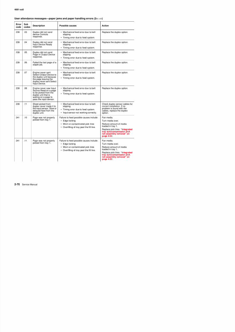
8/13/2019 t644 Service Manual
http://slidepdf.com/reader/full/t644-service-manual 112/423
239 .04 Duplex did not sendInput Device Readyresponse.
• Mechanical feed error due to beltslipping.
• Timing error due to feed system.
Replace the duplex option.
239 .05 Duplex did not sendPage In Output Deviceresponse.
• Mechanical feed error due to beltslipping.
• Timing error due to feed system.
Replace the duplex option.
239 .06 Failed the last page of astaple job.
• Mechanical feed error due to beltslipping.
• Timing error due to feed system.
Replace the duplex option.
239 .07 Engine never sentSelect OUtput Device tothe duplex unit becausethe page leaving theduplex never sent SelectInput Device.
• Mechanical feed error due to beltslipping.
• Timing error due to feed system.
Replace the duplex option.
239 .08 Engine never saw InputSource Read on a pageto be picked from theduplex unit that iswaiting on a page topass the input sensor.
• Mechanical feed error due to beltslipping.
• Timing error due to feed system.
Replace the duplex option.
239 .11 Sheet picked fromduplex never made it tothe input sensor. Slow ordelayed feed from the
duplex unit.
• Mechanical feed error due to beltslipping.
• Timing error due to feed system.
• Input sensor not working correctly.
Check duplex sensor cables forcorrect installation. If noproblem is found with thecables, replace the duplex
option.
241 .10 Page was not properlypicked from tray 1.
Failure to feed possible causes include:
• Edge locking
• Worn or contaminated pick tires
• Overfilling of tray past the fill line.
Fan media.
Turn media over.
Reduce amount of medialoaded in tray 1.
Replace pick tires. “Integratedtray autocompensator pickroll assembly removal” onpage 4-52.
241 .11 Page was not properlypicked from tray 1.
Failure to feed possible causes include:• Edge locking
• Worn or contaminated pick tires
• Overfilling of tray past the fill line
Fan media.Turn media over.
Reduce amount of medialoaded in tray 1.
4061-xx0
241 .12 Page was not properlypicked from tray 1.
Failure to feed possible causes include:
• Edge locking
• Worn or contaminated pick tires
• Overfilling of tray past the fill line
Fan media.
Turn media over.
Reduce amount of medialoaded in tray 1.
User attendance messages—paper jams and paper handling errors (2xx.xx )
Errorcode
Subcodes
Description Possible causes Action
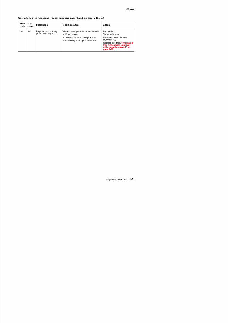
8/13/2019 t644 Service Manual
http://slidepdf.com/reader/full/t644-service-manual 113/423
Overfilling of tray past the fill line.Replace pick tires. “Integratedtray autocompensator pickroll assembly removal” onpage 4-52.
4061-xx0
Service checks
Anytime the system board is replaced, the Configuration ID must be reset in NVRAM. Go to “Configuration ID”on page 3-21.
Review the following information before performing any service checks.
• Paper feed problems (especially paper jams): Go to “Display Log” on page 3-23 and check the printerevent log for indications of repetitive entries that help to isolate a problem to a particular area of the printer
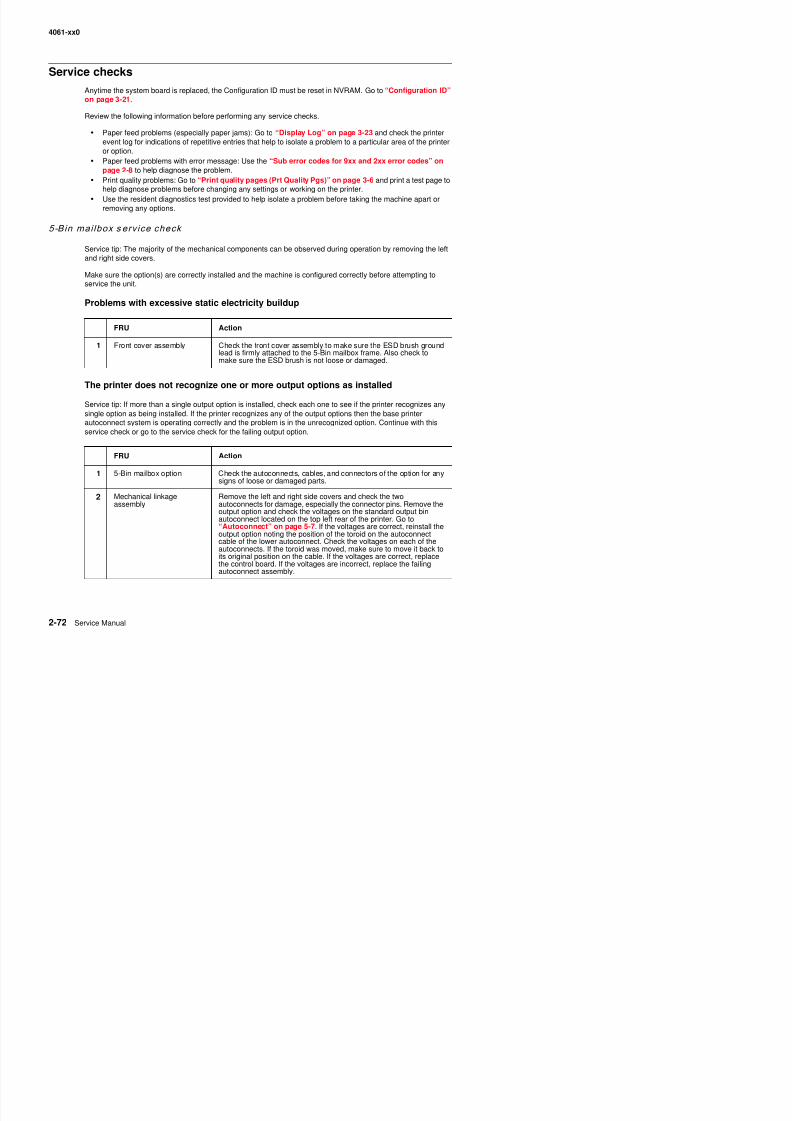
8/13/2019 t644 Service Manual
http://slidepdf.com/reader/full/t644-service-manual 114/423
event log for indications of repetitive entries that help to isolate a problem to a particular area of the printeror option.
• Paper feed problems with error message: Use the “Sub error codes for 9xx and 2xx error codes” onpage 2-8 to help diagnose the problem.
• Print quality problems: Go to “Print quality pages (Prt Quality Pgs)” on page 3-6 and print a test page tohelp diagnose problems before changing any settings or working on the printer.
• Use the resident diagnostics test provided to help isolate a problem before taking the machine apart orremoving any options.
5-Bin mai lbox s erv ice check
Service tip: The majority of the mechanical components can be observed during operation by removing the leftand right side covers.
Make sure the option(s) are correctly installed and the machine is configured correctly before attempting toservice the unit.
Problems with excessive static electricity buildup
The printer does not recognize one or more output options as installed
Service tip: If more than a single output option is installed, check each one to see if the printer recognizes anysingle option as being installed. If the printer recognizes any of the output options then the base printerautoconnect system is operating correctly and the problem is in the unrecognized option. Continue with thisservice check or go to the service check for the failing output option.
FRU Action
1 Front cover assembly Check the front cover assembly to make sure the ESD brush groundlead is firmly attached to the 5-Bin mailbox frame. Also check tomake sure the ESD brush is not loose or damaged.
FRU Action
1 5-Bin mailbox option Check the autoconnects, cables, and connectors of the option for anysigns of loose or damaged parts.
2 Mechanical linkageassembly
Remove the left and right side covers and check the twoautoconnects for damage, especially the connector pins. Remove the
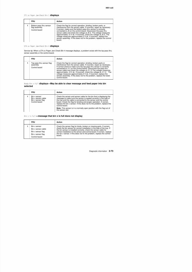
8/13/2019 t644 Service Manual
http://slidepdf.com/reader/full/t644-service-manual 115/423
4061-xx0
Ready—Bin x Full displays and paper feeds into bin x
FRU Action
1 Bin x sensor
Bin x sensor control board
Check the sensor flag for binds. Make sure the sensor flag is not in
an up position. If the sensor flag is operating correctly, replace thebin x sensor. If this does not fix the problem, replace the controlboard.
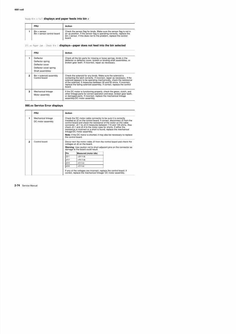
8/13/2019 t644 Service Manual
http://slidepdf.com/reader/full/t644-service-manual 116/423
271.xx Paper Jam - Check Bin 1 displays—paper does not feed into the bin selected
990.xx Service Error displays
FRU Action
1 Deflector
Deflector springDeflector cover
Deflector cover spring
Shaft assemblies
Check all the bin parts for missing or loose springs, binds in the
deflector or deflector cover, broken or binding shaft assemblies, orbroken gear teeth. If incorrect, repair as necessary.
2 Bin x solenoid assemblyControl board
Check the solenoid for any binds. Make sure the solenoid iscontacting the latch correctly. If incorrect, repair as necessary. If thesolenoid appears to be operating mechanically, check the resistanceof the solenoid. It measures between 30 and 50 ohms. If incorrect,replace the failing solenoid assembly. If correct, replace the control
board.3 Mechanical linkage
Motor assembly
If the DC motor is functioning properly, check the gears, clutch, andother linkage parts for correct operation and wear, broken gear teeth,or damaged parts. If incorrect, replace the mechanical linkageassembly/DC motor assembly.
FRU Action1 Mechanical linkage
DC motor assembly
Check the DC motor cable connector to be sure it is correctlyinstalled at J2 on the control board. If correct, disconnect J2 from thecontrol board and check the resistance of the motor on the cableconnector. J2-1 to J2-2 measures between 115 and 135 ohms. Alsocheck J2-1 and J2-4 to the motor case for shorts. If either theresistance is incorrect or a short is found, replace the mechanicallinkage/DC motor assembly.
Note: If the DC motor is shorted, it may also be necessary to replacethe control board.
2 Control board Disconnect the motor cable J2 from the control board and check thevoltages at J2 on the board.
Warning: Use caution not to short adjacent pins on the connector asdamage to the board could result.
4061-xx0
900.xx Erro r co de serv ice ch eck
FRU Action
1 Printer POR Turn the printer off and on several times. If Error Code 900 continues
to display, go to step 2.
2 System board Turn the machine off and on several times, waiting a few minutesbetween power on and power off.
If Error Code 900 continues to display go to step 3
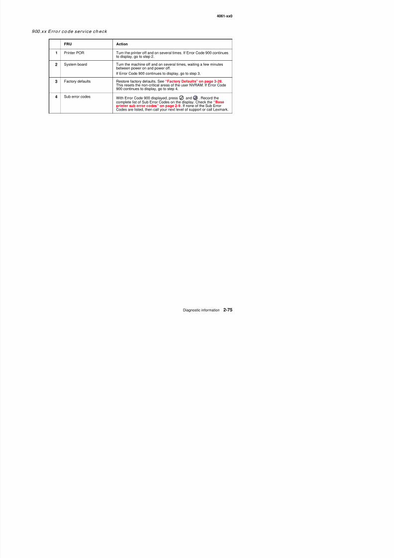
8/13/2019 t644 Service Manual
http://slidepdf.com/reader/full/t644-service-manual 117/423
If Error Code 900 continues to display, go to step 3.
3 Factory defaults Restore factory defaults. See “Factory Defaults” on page 3-28.This resets the non-critical areas of the user NVRAM. If Error Code900 continues to display, go to step 4.
4 Sub error codes With Error Code 900 displayed, press and . Record the
complete list of Sub Error Codes on the display. Check the “Baseprinter sub error codes” on page 2-9. If none of the Sub ErrorCodes are listed, then call your next level of support or call Lexmark.
4061-xx0
927.xx Fan service ch eck
927.xx can be used for the main fan or the cartridge fan.
• Main fan—927.00, 927.01, and 927.03 through 927.07.• Cartridge fan—927.02
Main fan
Service tip: The main fan runs at full speed at the end of POR or when the printer is printing It will only run half
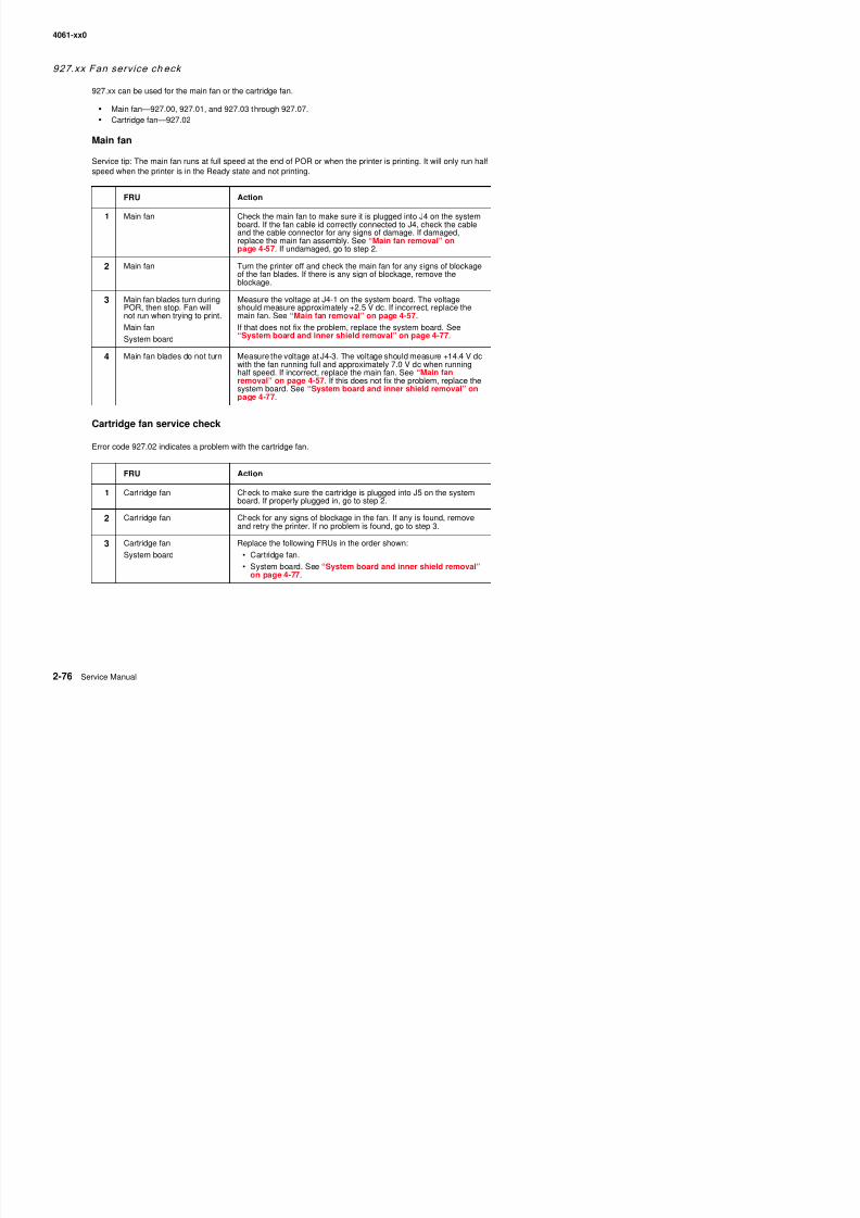
8/13/2019 t644 Service Manual
http://slidepdf.com/reader/full/t644-service-manual 118/423
Service tip: The main fan runs at full speed at the end of POR or when the printer is printing. It will only run halfspeed when the printer is in the Ready state and not printing.
Cartridge fan service check
Error code 927.02 indicates a problem with the cartridge fan.
FRU Action
1 Main fan Check the main fan to make sure it is plugged into J4 on the systemboard. If the fan cable id correctly connected to J4, check the cableand the cable connector for any signs of damage. If damaged,replace the main fan assembly. See “Main fan removal” onpage 4-57. If undamaged, go to step 2.
2 Main fan Turn the printer off and check the main fan for any signs of blockageof the fan blades. If there is any sign of blockage, remove theblockage.
3 Main fan blades turn duringPOR, then stop. Fan will
not run when trying to print.Main fan
System board
Measure the voltage at J4-1 on the system board. The voltageshould measure approximately +2.5 V dc. If incorrect, replace the
main fan. See “Main fan removal” on page 4-57.If that does not fix the problem, replace the system board. See“System board and inner shield removal” on page 4-77.
4 Main fan blades do not turn Measure the voltage at J4-3. The voltage should measure +14.4 V dcwith the fan running full and approximately 7.0 V dc when runninghalf speed. If incorrect, replace the main fan. See “Main fanremoval” on page 4-57. If this does not fix the problem, replace thesystem board. See “System board and inner shield removal” onpage 4-77.
FRU Action
1 Cartridge fan Check to make sure the cartridge is plugged into J5 on the systemboard. If properly plugged in, go to step 2.
2 Cartridge fan Check for any signs of blockage in the fan. If any is found, removeand retry the printer. If no problem is found, go to step 3.
3 Cartridge fan
S t b d
Replace the following FRUs in the order shown:
C t id f
4061-xx0
950.00 thro ugh 950.29 EPROM mismatch fai lure
Warning: When replacing any one of the following components:
• Operator panel assembly (or upper front cover)• System board assembly
• Interconnect card assembly
Only replace one component at a time. Replace the required component and perform a POR before replacing asecond component listed above. If this procedure is not followed, the printer will be rendered inoperable. Neverreplace two or more of the components listed above without a POR after installing each one or the printer will be
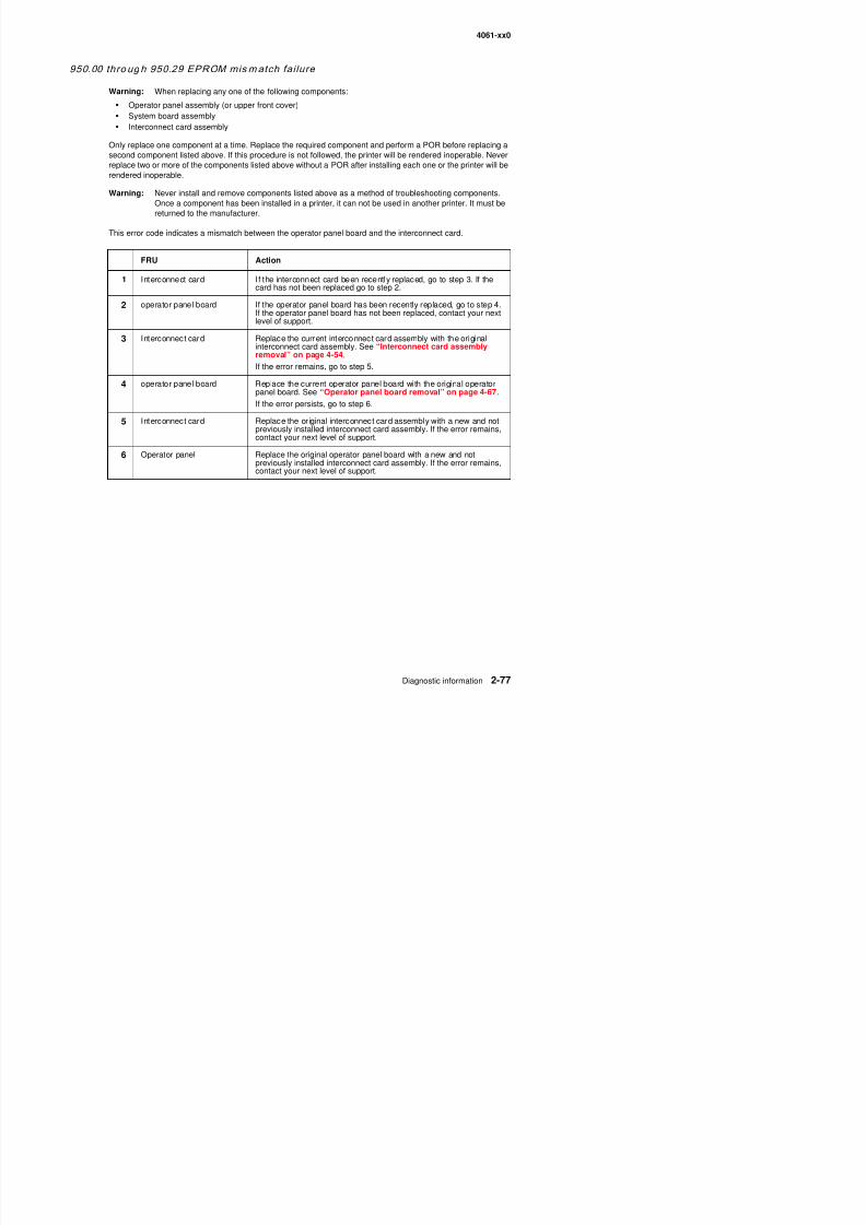
8/13/2019 t644 Service Manual
http://slidepdf.com/reader/full/t644-service-manual 119/423
replace two or more of the components listed above without a POR after installing each one or the printer will berendered inoperable.
Warning: Never install and remove components listed above as a method of troubleshooting components.Once a component has been installed in a printer, it can not be used in another printer. It must bereturned to the manufacturer.
This error code indicates a mismatch between the operator panel board and the interconnect card.
FRU Action
1 Interconnect card If the interconnect card been recently replaced, go to step 3. If thecard has not been replaced go to step 2.
2 operator panel board If the operator panel board has been recently replaced, go to step 4.If the operator panel board has not been replaced, contact your next
level of support.
3 Interconnect card Replace the current interconnect card assembly with the originalinterconnect card assembly. See “Interconnect card assemblyremoval” on page 4-54.
If the error remains, go to step 5.
4 operator panel board Replace the current operator panel board with the original operatorpanel board. See “Operator panel board removal” on page 4-67.
If the error persists, go to step 6.
5 Interconnect card Replace the original interconnect card assembly with a new and notpreviously installed interconnect card assembly. If the error remains,contact your next level of support.
6 Operator panel Replace the original operator panel board with a new and notpreviously installed interconnect card assembly. If the error remains,contact your next level of support.
4061-xx0
950.30 thr oug h 950.60 EPROM m ism atch fai lure
Warning: When replacing any one of the following components:
• Operator panel assembly (or upper front cover)• System board assembly
• Interconnect card assembly
Only replace one component at a time. Replace the required component and perform a POR before replacing asecond component listed above. If this procedure is not followed, the printer will be rendered inoperable. Neverreplace two or more of the components listed above without a POR after installing each one or the printer will be
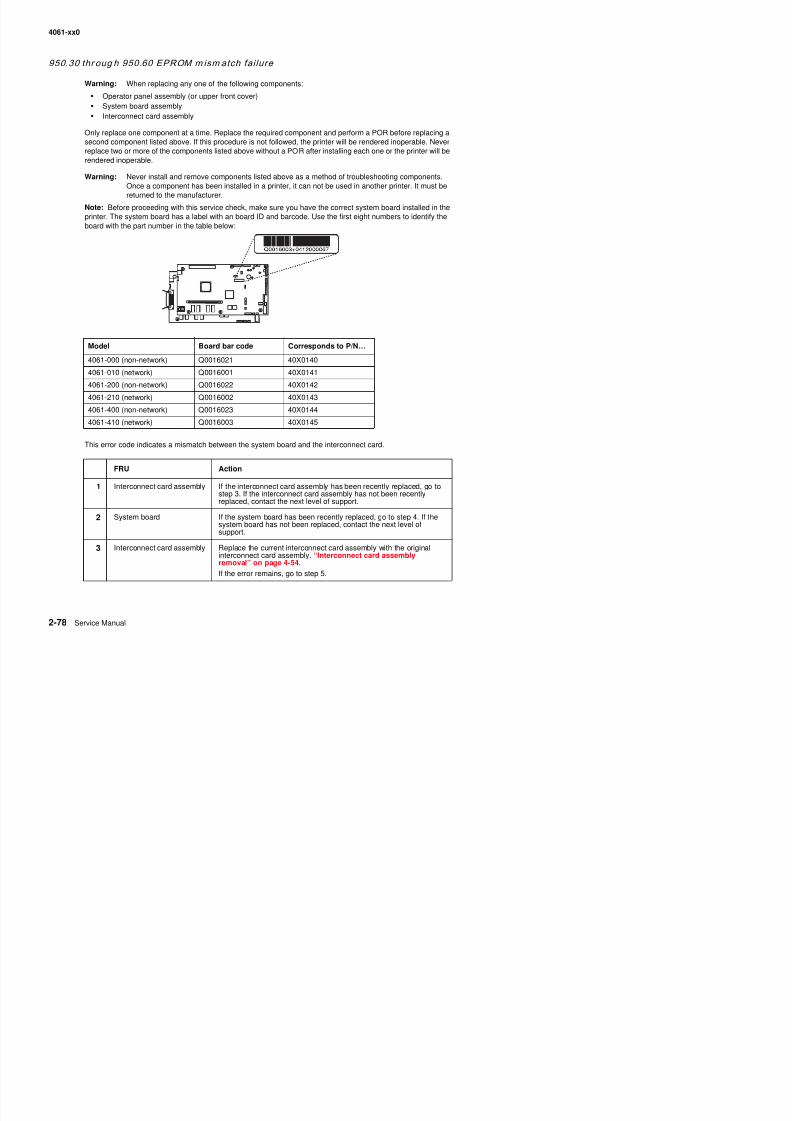
8/13/2019 t644 Service Manual
http://slidepdf.com/reader/full/t644-service-manual 120/423
replace two or more of the components listed above without a POR after installing each one or the printer will berendered inoperable.
Warning: Never install and remove components listed above as a method of troubleshooting components.Once a component has been installed in a printer, it can not be used in another printer. It must bereturned to the manufacturer.
Note: Before proceeding with this service check, make sure you have the correct system board installed in theprinter. The system board has a label with an board ID and barcode. Use the first eight numbers to identify theboard with the part number in the table below:
This error code indicates a mismatch between the system board and the interconnect card.
Model Board bar code Corresponds to P/N…
4061-000 (non-network) Q0016021 40X0140
4061-010 (network) Q0016001 40X0141
4061-200 (non-network) Q0016022 40X01424061-210 (network) Q0016002 40X0143
4061-400 (non-network) Q0016023 40X0144
4061-410 (network) Q0016003 40X0145
FRU Action1 Interconnect card assembly If the interconnect card assembly has been recently replaced, go to
step 3. If the interconnect card assembly has not been recentlyreplaced, contact the next level of support.
4061-xx0
4 System board Replace the current system board with the original system board.See “System board and inner shield removal” on page 4-77.
If the error remains, go to step 6.
5 Interconnect card assembly Replace the original interconnect card assembly with a new and notpreviously installed interconnect card assembly. If the problemremains, contact the next level of support.
6 System board Replace the original system board with a new and not previously
FRU Action
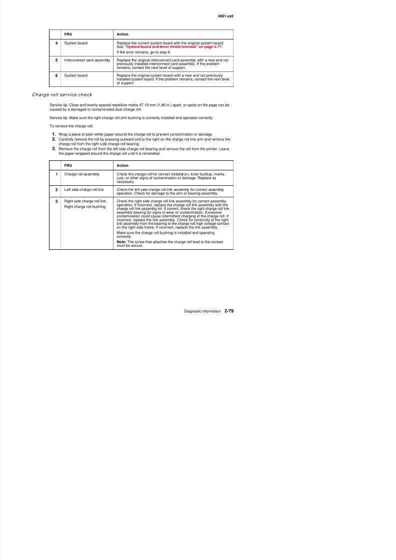
8/13/2019 t644 Service Manual
http://slidepdf.com/reader/full/t644-service-manual 121/423
Charge rol l serv ice check
Service tip: Close and evenly spaced repetitive marks 47.19 mm (1.86 in.) apart, or spots on the page can becaused by a damaged or contaminated dual charge roll.
Service tip: Make sure the right charge roll arm bushing is correctly installed and operates correctly.
To remove the charge roll:
1. Wrap a piece of plain white paper around the charge roll to prevent contamination or damage.2. Carefully remove the roll by pressing outward and to the right on the charge roll link arm and remove the
charge roll from the right side charge roll bearing.
3. Remove the charge roll from the left side charge roll bearing and remove the roll from the printer. Leavethe paper wrapped around the charge roll until it is reinstalled.
6 System board Replace the original system board with a new and not previouslyinstalled system board. If the problem remains, contact the next levelof support.
FRU Action
1 Charge roll assembly Check the charge roll for correct installation, toner buildup, marks,cuts, or other signs of contamination or damage. Replace asnecessary.
2Left side charge roll link Check the left side charge roll link assembly for correct assembly
operation. Check for damage to the arm or bearing assembly.
3 Right side charge roll link
Right charge roll bushing
Check the right side charge roll link assembly for correct assemblyoperation. If incorrect, replace the charge roll link assembly with thecharge roll link assembly kit. If correct, check the right charge roll linkassembly bearing for signs of wear or contamination. Excessivecontamination could cause intermittent charging of the charge roll. Ifincorrect, replace the link assembly. Check for continuity of the rightlink assembly from the bearing to the charge roll high voltage contacton the right side frame. If incorrect, replace the link assembly.
Make sure the charge roll bushing is installed and operating
correctly.Note: The screw that attaches the charge roll lead to the contactmust be secure.
4061-xx0
Cover closed sw i tch/cable serv ice check
FRU Action
1 Toner cartridge Make sure the toner cartridge is correctly installed and that the right
and left cartridge tracks are not loose or broken. Make sure the coverclosed switch activation tab on the toner cartridge is not broken andthat the tab correctly activates the cover closed switch spring.
2 Cover closed switch/cableassembly
Check the cover closed switch for proper mechanical operation. Ifincorrect, repair as necessary. Disconnect the cover closed switch
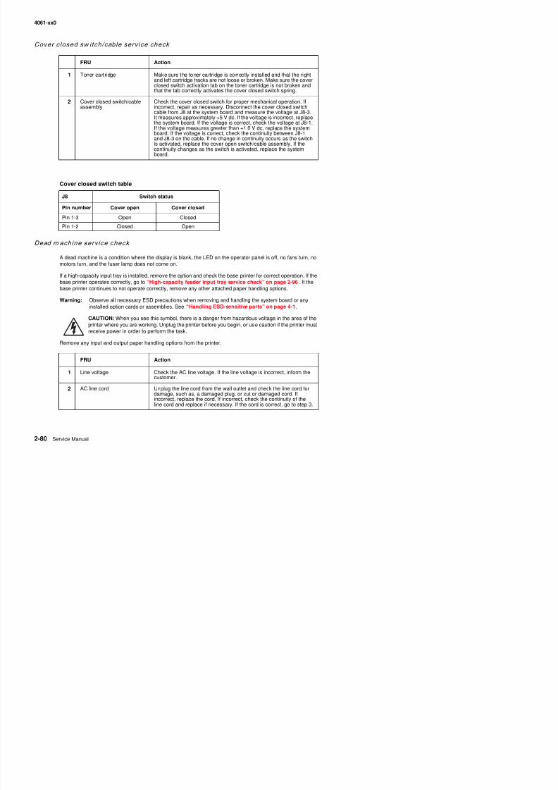
8/13/2019 t644 Service Manual
http://slidepdf.com/reader/full/t644-service-manual 122/423
Dead m achine serv ice check
A dead machine is a condition where the display is blank, the LED on the operator panel is off, no fans turn, nomotors turn, and the fuser lamp does not come on.
If a high-capacity input tray is installed, remove the option and check the base printer for correct operation. If thebase printer operates correctly, go to “High-capacity feeder input tray service check” on page 2-96. If thebase printer continues to not operate correctly, remove any other attached paper handling options.
Warning: Observe all necessary ESD precautions when removing and handling the system board or anyinstalled option cards or assemblies. See “Handling ESD-sensitive parts” on page 4-1.
CAUTION: When you see this symbol, there is a danger from hazardous voltage in the area of theprinter where you are working. Unplug the printer before you begin, or use caution if the printer must
receive power in order to perform the task.Remove any input and output paper handling options from the printer.
asse b y co ect, epa as ecessa y sco ect t e co e c osed s tccable from J8 at the system board and measure the voltage at J8-3.It measures approximately +5 V dc. If the voltage is incorrect, replacethe system board. If the voltage is correct, check the voltage at J8-1.If the voltage measures greater than +1.0 V dc, replace the systemboard. If the voltage is correct, check the continuity between J8-1and J8-3 on the cable. If no change in continuity occurs as the switch
is activated, replace the cover open switch/cable assembly. If thecontinuity changes as the switch is activated, replace the systemboard.
Cover closed switch table
J8 Switch status
Pin number Cover open Cover closedPin 1-3 Open Closed
Pin 1-2 Closed Open
FRU A ti
4061-xx0
3 +5 V dc test point on thesystem board
Check for approximately +5 V dc at the +5 V test point on the systemboard.
Note: Use care not to short adjacent voltage test points.
FRU Action
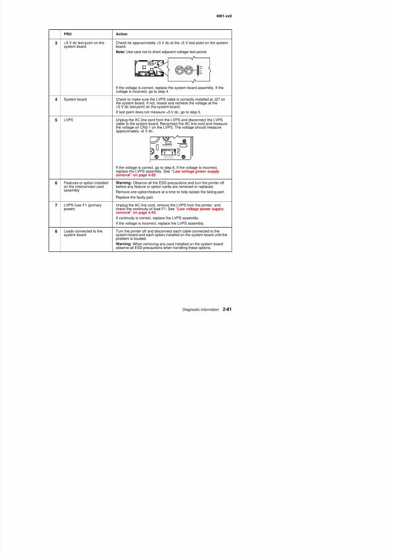
8/13/2019 t644 Service Manual
http://slidepdf.com/reader/full/t644-service-manual 123/423
If the voltage is correct, replace the system board assembly. If thevoltage is incorrect, go to step 4.
4 System board Check to make sure the LVPS cable is correctly installed at J27 onthe system board. If not, reseat and recheck the voltage at the+5 V dc test point on the system board.
If test point does not measure +5 V dc, go to step 5.
5 LVPS Unplug the AC line cord from the LVPS and disconnect the LVPScable to the system board. Reconnect the AC line cord and measurethe voltage on CN2-1 on the LVPS. The voltage should measureapproximately +5 V dc.
If the voltage is correct, go to step 6. If the voltage is incorrect,replace the LVPS assembly. See “Low voltage power supplyremoval” on page 4-55
6 Features or option installedon the interconnect card
assembly
Warning: Observe all the ESD precautions and turn the printer offbefore any feature or option cards are removed or replaced.
Remove one option/feature at a time to help isolate the failing part.Replace the faulty part.
7 LVPS fuse F1 (primarypower)
Unplug the AC line cord, remove the LVPS from the printer, andcheck the continuity of fuse F1. See “Low voltage power supplyremoval” on page 4-55.
If continuity is correct, replace the LVPS assembly.
If the voltage is incorrect, replace the LVPS assembly.
8 Loads connected to the
system board
Turn the printer off and disconnect each cable connected to the
system board and each option installed on the system board until theproblem is located.
Warning: When removing any card installed on the system boardobserve all ESD precautions when handling these options.
4061-xx0
Duplex opt ion serv ice check
Messages displayed when a 23x Duplex Paper Jam displays.
If sheets have been accumulated to be stapled or offset when the jam is detected, the printer alternately flashesthe primary and secondary messages to indicate that all accumulated sheets should not be removed during the
23x Paper Jam
Check Duplex
Leave Job
in Finisher
Primary message Secondary message
8/13/2019 t644 Service Manual
http://slidepdf.com/reader/full/t644-service-manual 124/423
jam clearance procedure. Obviously, if no sheets have accumulated for stapling, then no message flashingoccurs and the primary message is used.
When the secondary message is posted, if accumulated sheets are removed during jam clearance, the printerdoes not reprint the removed sheets. Furthermore, after the printer resumes printing and the print job is
completed, the portion of the job printed after the jam is not stapled.
Duplex paper jams
Duplex does not recognize that the option is installed, or other options below theduplex are installed
Note: Before proceeding with the following service checks, verify the media used in the duplex option meetsspecification and is not dog-eared or damaged in any way. See “Media specifications” on page 1-9.
23x.xx jam code Jam location
231.xx Media did not arrive at the duplex input sensor, but did leave the fuser exitsensor.
232.xx Media did not clear the duplex input sensor, but did leave the printer fuser exitsensor.
233.xx Media failed to make the duplex double feed sensor during turnaround.
234.xx Media did not arrive at the duplex exit sensor.
235.xx A piece of media is over the duplex double feed sensor.
236.xx Media did not leave the duplex exit sensor.
237.xx A duplexed sheet did not reach the printer input sensor.
238.xx r A piece of media is over the duplex sensors during a reset.
FRU Action
1 Autoconnect cables/ connections
Check the top and bottom autoconnect connectors for signs ofdamage. If damaged, replace the duplex option. If not damaged,check the cables are correctly connected to the duplex system boardat J9, J10, J11, and J12. If no problem is found, replace the duplex
option.
4061-xx0
231.xx Jam displays on the operator panel
FRU Action
1 Fuser exit sensor Check the sheet of media is leaving the exit sensor in the fuser and
feeding properly into the duplex option. Check the duplex link forcorrect operation and any signs of damage. If the problem is prior tothe duplex input sensor and in the base machine, repair asnecessary. If the jam occurs in the duplex option prior to the duplexinput sensor, go to step 2.
2 Duplex input sensor If the paper does not reach the duplex input sensor make sure the
8/13/2019 t644 Service Manual
http://slidepdf.com/reader/full/t644-service-manual 125/423
232.xx Jam displays on the operator panel
233.xx Jam displayed on operator panel
2 Duplex input sensor If the paper does not reach the duplex input sensor, make sure thesensor is connected to the duplex system board. If correct, check forany paper or other objects that might cause a paper jam. If none arefound, replace the duplex option assembly.
FRU Action
1 Duplex input sensor If the paper reaches the duplex input sensor, but does not clear thesensor, make sure the sensor is connected to the duplex systemboard. If connected correctly, check for correct operation of thesensor. If a problem is found and cannot be corrected, replace theduplex option assembly. If no problem is found, check for a piece ofpaper or other object in the paper path that might cause a paper jam
over the input sensor. If no problem is found, replace the duplexoption assembly.
FRU Action
1 Duplex double feed sensor If a sheet of paper fails to reach the double feed sensor duringturnaround, check for any signs of paper or other objects that might
cause the paper to jam. If no problem is found, replace the duplexoption assembly.
4061-xx0
Envelope feeder serv ice c heck
Service tip: Check the envelope feeder paper path for any debris, pieces of envelope and so on. If any otheroptions are installed make sure they are operating normally. If only the envelope feeder is failing to operatecorrectly, continue with this service check, otherwise verify the interconnect card is functioning properly.
Service tip: The envelope feeder receives its +5 V dc operating voltage from the +24 V dc bulk at J1-7. If+24 V dc is not present at J1-7, tray 1 is the only tray that is recognized.
Note: If a 260 Paper Jam Check Envelope message displays, check the “Sub error codes for 9xx and 2xxerror codes” on page 2-8.
8/13/2019 t644 Service Manual
http://slidepdf.com/reader/full/t644-service-manual 126/423
Printer does not recognize the envelope feeder as an attached input option
Operator panel displays 260.xx Paper Jam immediately when envelope feed isrequested—POST incomplete
FRU Action
1 Envelope feeder Make sure the envelope feeder is correctly installed and mated to theautoconnect at the front of the printer.
2 Front autoconnect onprinter
Check the connector for signs of damage to the connector orcontacts. If you find damage, replace the damaged cable/connectorassembly. Remove the envelope feeder and check the voltages atthe autoconnect on the front of the printer. If incorrect, check theinterconnect card. If correct, reinstall the envelope feeder andcontinue with step 3.
3Autoconnect on theenvelope feeder
Check for damage to the connector or contacts. If you find damage,replace the damaged cable/connector assembly. Disconnect theautoconnect cable at J1 on the envelope system board and measurethe following voltages:
• J1-3 measures +5 V dc
• J1-5 measures +5 V dc
• J1-7 measures +24 V dc
If any of the voltages are incorrect, replace the autoconnect cable/ connector. If the voltages are correct, replace the envelope systemboard.
FRU Action
1 Pass thru sensor Check for any debris or pieces of envelope over the pass thrusensor. Check for correct installation of the pass thru sensor flag.Make sure the sensor cable is attached to the envelope system
board. Perform an envelope feeder sensor test to check both thesensor and sensor flag.
Note: It may be necessary to use a small tool to actuate the sensorflag because it is located under the front cover. Be careful not todamage the flag.
4061-xx0
Operator panel displays 260.xx Paper Jam after attempted feed but before envelopes areput in the hopper OR the operator panel continues to display Load Envelopes afterenvelopes are placed in the hopper
Service tip: The kick rolls rotate during the attempted feed cycles.
FRU Action
1 Envelope out hoppersensor flag
Check the envelope out sensor flag for damage, correct installationand operation.
If i i l h l f d i
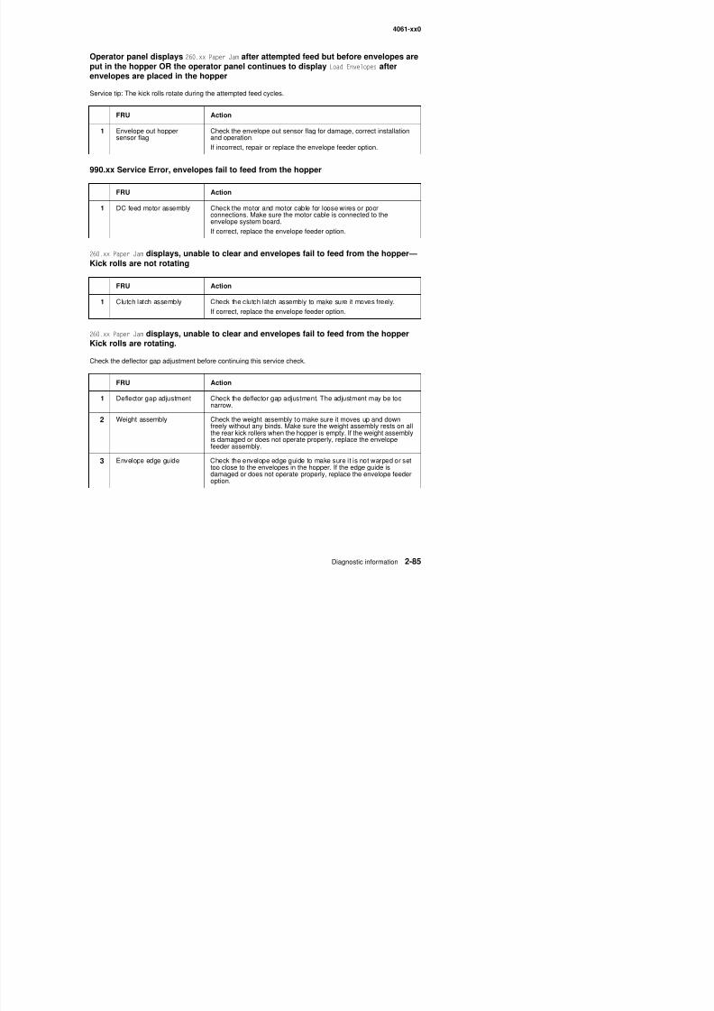
8/13/2019 t644 Service Manual
http://slidepdf.com/reader/full/t644-service-manual 127/423
990.xx Service Error, envelopes fail to feed from the hopper
260.xx Paper Jam displays, unable to clear and envelopes fail to feed from the hopper—
Kick rolls are not rotating
260.xx Paper Jam displays, unable to clear and envelopes fail to feed from the hopper
Kick rolls are rotating.Check the deflector gap adjustment before continuing this service check.
If incorrect, repair or replace the envelope feeder option.
FRU Action
1 DC feed motor assembly Check the motor and motor cable for loose wires or poorconnections. Make sure the motor cable is connected to theenvelope system board.
If correct, replace the envelope feeder option.
FRU Action
1 Clutch latch assembly Check the clutch latch assembly to make sure it moves freely.
If correct, replace the envelope feeder option.
FRU Action
1 Deflector gap adjustment Check the deflector gap adjustment. The adjustment may be toonarrow.
2 Weight assembly Check the weight assembly to make sure it moves up and down
freely without any binds. Make sure the weight assembly rests on allthe rear kick rollers when the hopper is empty. If the weight assemblyis damaged or does not operate properly, replace the envelopefeeder assembly.
3 E l d id Ch k th l d id t k it i t d t
4061-xx0
260.xx Paper Jam displays, envelope stops in feeder paper path
FRU Action
1 Kick rolls/feed rolls/driverolls
Check all the rolls for oil, grease, or other contamination. If you find aproblem, clean the rolls. If this does not correct the problem, replacethe envelope feeder.
2 Deflector gap adjustment Check the deflector gap adjustment. The adjustment may be toonarrow. If the adjustment is correct, replace the envelope feederoption.
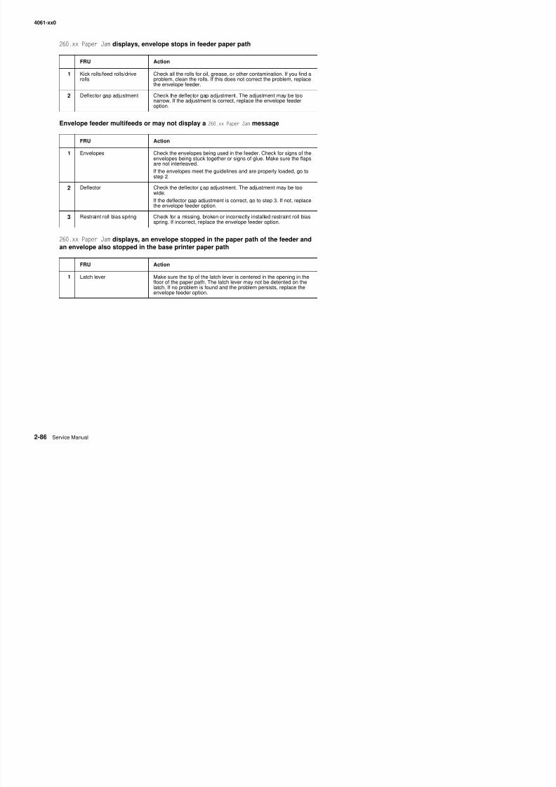
8/13/2019 t644 Service Manual
http://slidepdf.com/reader/full/t644-service-manual 128/423
Envelope feeder multifeeds or may not display a 260.xx Paper Jam message
260.xx Paper Jam displays, an envelope stopped in the paper path of the feeder andan envelope also stopped in the base printer paper path
FRU Action
1 Envelopes Check the envelopes being used in the feeder. Check for signs of theenvelopes being stuck together or signs of glue. Make sure the flapsare not interleaved.
If the envelopes meet the guidelines and are properly loaded, go tostep 2.
2 Deflector Check the deflector gap adjustment. The adjustment may be toowide.
If the deflector gap adjustment is correct, go to step 3. If not, replace
the envelope feeder option.3 Restraint roll bias spring Check for a missing, broken or incorrectly installed restraint roll bias
spring. If incorrect, replace the envelope feeder option.
FRU Action
1 Latch lever Make sure the tip of the latch lever is centered in the opening in thefloor of the paper path. The latch lever may not be detented on thelatch. If no problem is found and the problem persists, replace theenvelope feeder option.
4061-xx0
Fuser serv ice checks
920.xx—Cold fuser service check
Error codes 920.x and 922.xx may display for a cold fuser failure.
Some 920.xx error codes may be cleared by turning the printer on and off and allowing it to complete POR.
CAUTION: There is a danger from hazardous voltage in the area of the printer where you areworking. Unplug the printer before you begin, or use caution if the printer must receive power inorder to perform the task.
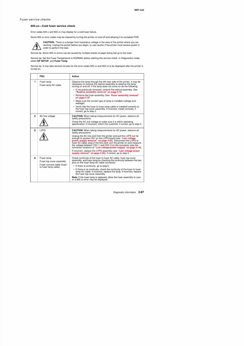
8/13/2019 t644 Service Manual
http://slidepdf.com/reader/full/t644-service-manual 129/423
Service tip: Some 920.xx errors can be caused by multiple sheets of paper being fed up to the fuser.
Service tip: Set the Fuser Temperature to NORMAL before starting this service check. In Diagnostics mode,select EP SETUP, and Fuser Temp.
Service tip: It may take several minutes for the error codes 920.xx and 922.xx to be displayed after the printer isturned on.
FRU Action
1 Fuser lamp
Fuser lamp AC cable
Observe the lamp through the left near side of the printer. It may benecessary to remove the redrive assembly to observe the lampturning on and off. If the lamp does not come on do the following:
• If not previously removed, remove the redrive assembly. See“Redrive assembly removal” on page 4-75.
• Remove the fuser assembly. See “Fuser assembly removal”on page 4-27.
• Make sure the correct type of lamp is installed (voltage andwattage).
• Verify that the fuser to fuser lamp cable is installed correctly tothe fuser top cover assembly. If incorrect, install correctly; ifcorrect, go to step 2.
2 AC line voltage CAUTION: When taking measurements for AC power, observe all
safety precautions.Check the AC line voltage to make sure it is within operatingspecification. If incorrect, inform the customer; if correct, go to step 3.
3 LVPS CAUTION: When taking measurements for AC power, observe allsafety precautions.
Unplug the AC line cord from the printer and pull the LVPS out farenough to access CN1 on the LVPS board (see “Low voltagepower supply removal” on page 4-55). Disconnect the LVPS tofuser AC cable, plug in the line cord, turn the printer on and measurethe voltage between CN1-1 and CN1-3 on the connector (see theconnector locations at “Low voltage power supply” on page 5-10).If incorrect, replace the LVPS assembly (see “Low voltage powersupply removal” on page 4-55); if correct, go to step 4.
4061-xx0
5 LVPS
LVPS to fuser AC cable
CAUTION: When taking measurements for AC power, observe allsafety precautions.
Check the AC line voltage between the pins on the fuser end of theLPVS to fuser AC cable. If the voltage is correct, unplug the ACpower cord from the LVPS cable. If the voltage is correct, unplug theAC power cord from the LVPS, pull the LVPS out far enough to beable to check the voltage between CN-1 and CN1-3 on the LVPSboard. Plug in the power cord, turn the printer on and check thevoltage. If correct, replace the LVPS to fuser AC cable; if incorrect,replace the LVPS assembly.
S S
FRU Action
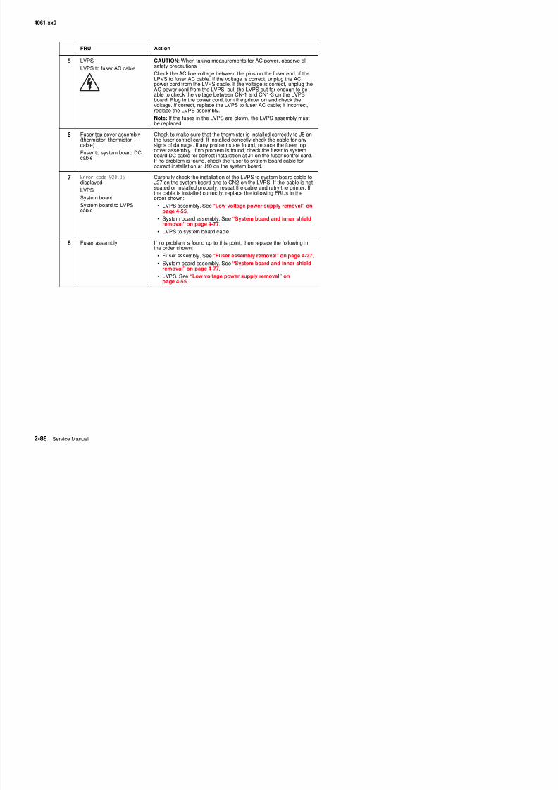
8/13/2019 t644 Service Manual
http://slidepdf.com/reader/full/t644-service-manual 130/423
Note: If the fuses in the LVPS are blown, the LVPS assembly mustbe replaced.
6 Fuser top cover assembly(thermistor, thermistor
cable)Fuser to system board DCcable
Check to make sure that the thermistor is installed correctly to J5 onthe fuser control card. If installed correctly check the cable for any
signs of damage. If any problems are found, replace the fuser topcover assembly. If no problem is found, check the fuser to systemboard DC cable for correct installation at J1 on the fuser control card.If no problem is found, check the fuser to system board cable forcorrect installation at J10 on the system board.
7 Error code 920.06 displayed
LVPS
System board
System board to LVPScable
Carefully check the installation of the LVPS to system board cable toJ27 on the system board and to CN2 on the LVPS. If the cable is notseated or installed properly, reseat the cable and retry the printer. Ifthe cable is installed correctly, replace the following FRUs in theorder shown:
• LVPS assembly. See “Low voltage power supply removal” onpage 4-55.
• System board assembly. See “System board and inner shieldremoval” on page 4-77.
• LVPS to system board cable.
8 Fuser assembly If no problem is found up to this point, then replace the following inthe order shown:
• Fuser assembly. See “Fuser assembly removal” on page 4-27.
• System board assembly. See “System board and inner shieldremoval” on page 4-77.
• LVPS. See “Low voltage power supply removal” onpage 4-55.
4061-xx0
922.xx—Cold fuser check
Error codes 920.xx and 922.xx may display for a cold fuser failure.
Some 920.xx error codes may be cleared by turning the printer on and off and allowing it to complete POR.
CAUTION: There is a danger from hazardous voltage in the area of the printer where you areworking. Unplug the printer before you begin, or use caution if the printer must receive power inorder to perform the task.
Service tip: Set the Fuser Temperature to NORMAL before starting this service check. In Diagnostics mode,
select EP SETUP, and Fuser Temp.
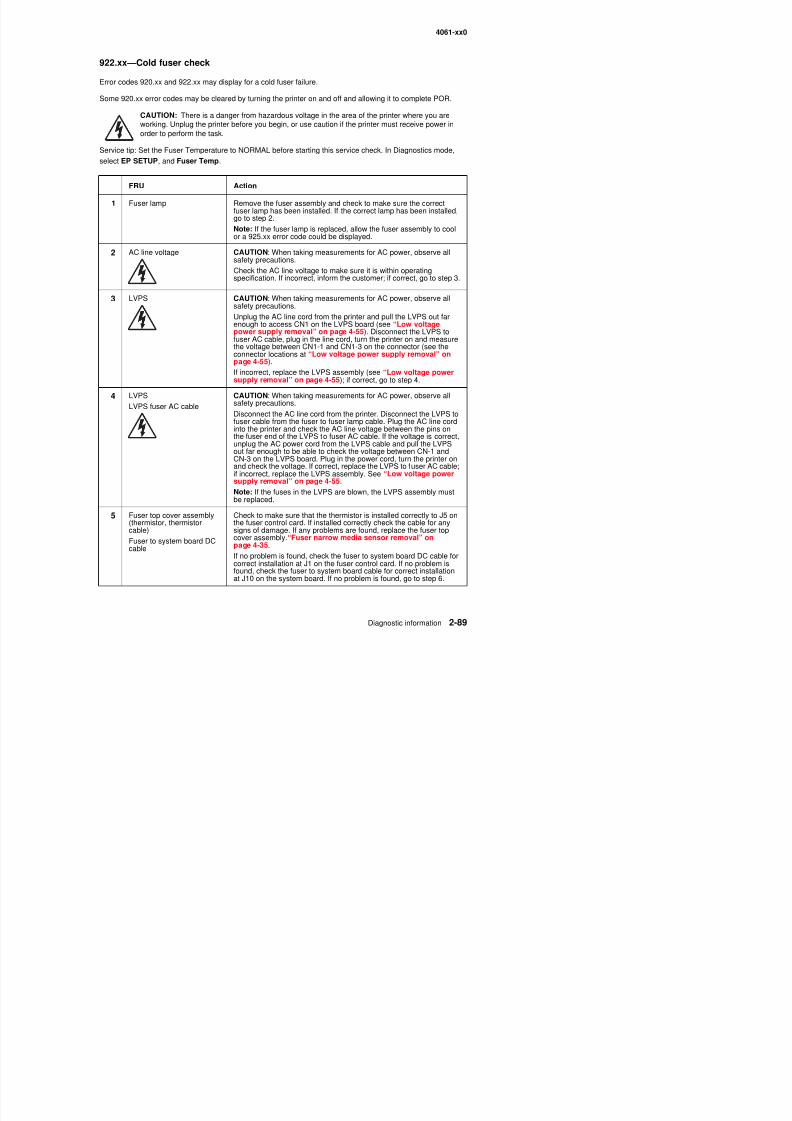
8/13/2019 t644 Service Manual
http://slidepdf.com/reader/full/t644-service-manual 131/423
FRU Action
1 Fuser lamp Remove the fuser assembly and check to make sure the correctfuser lamp has been installed. If the correct lamp has been installed,go to step 2.
Note: If the fuser lamp is replaced, allow the fuser assembly to coolor a 925.xx error code could be displayed.
2 AC line voltage CAUTION: When taking measurements for AC power, observe allsafety precautions.
Check the AC line voltage to make sure it is within operatingspecification. If incorrect, inform the customer; if correct, go to step 3.
3 LVPS CAUTION: When taking measurements for AC power, observe allsafety precautions.
Unplug the AC line cord from the printer and pull the LVPS out farenough to access CN1 on the LVPS board (see “Low voltagepower supply removal” on page 4-55). Disconnect the LVPS tofuser AC cable, plug in the line cord, turn the printer on and measurethe voltage between CN1-1 and CN1-3 on the connector (see theconnector locations at “Low voltage power supply removal” onpage 4-55).
If incorrect, replace the LVPS assembly (see “Low voltage powersupply removal” on page 4-55); if correct, go to step 4.
4 LVPS
LVPS fuser AC cable
CAUTION: When taking measurements for AC power, observe allsafety precautions.
Disconnect the AC line cord from the printer. Disconnect the LVPS tofuser cable from the fuser to fuser lamp cable. Plug the AC line cordinto the printer and check the AC line voltage between the pins onthe fuser end of the LVPS to fuser AC cable. If the voltage is correct,unplug the AC power cord from the LVPS cable and pull the LVPSout far enough to be able to check the voltage between CN-1 andCN-3 on the LVPS board. Plug in the power cord, turn the printer onand check the voltage. If correct, replace the LVPS to fuser AC cable;
if incorrect, replace the LVPS assembly. See “Low voltage powersupply removal” on page 4-55.
Note: If the fuses in the LVPS are blown, the LVPS assembly mustbe replaced.
4061-xx0
923.xx—Hot fuser service check
6 Fuser assembly If no problem is found up to this point, then replace the following inthe order shown:
• Fuser assembly. See “Fuser assembly removal” on page 4-27.
• System board assembly. See “System board and inner shieldremoval” on page 4-77.
• LVPS. See “Low voltage power supply removal” onpage 4-55.
FRU Action
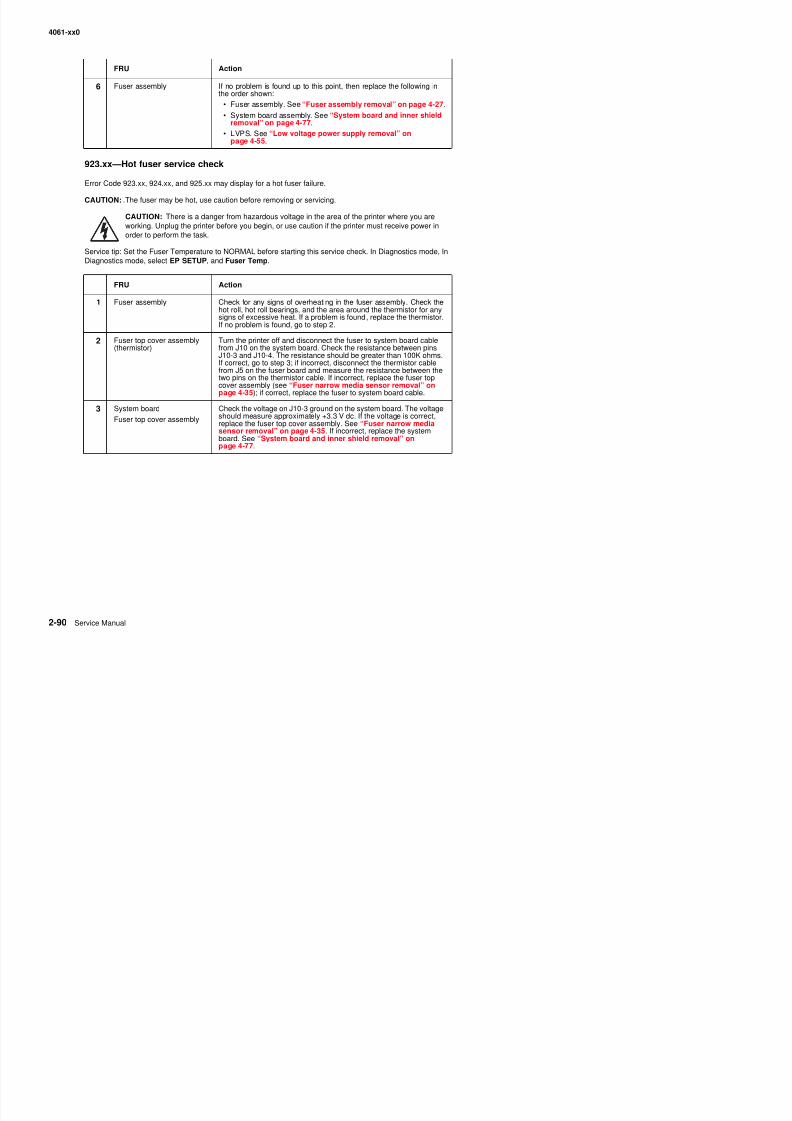
8/13/2019 t644 Service Manual
http://slidepdf.com/reader/full/t644-service-manual 132/423
9 3 ot use se ce c ec
Error Code 923.xx, 924.xx, and 925.xx may display for a hot fuser failure.
CAUTION: .The fuser may be hot, use caution before removing or servicing.
CAUTION: There is a danger from hazardous voltage in the area of the printer where you areworking. Unplug the printer before you begin, or use caution if the printer must receive power inorder to perform the task.
Service tip: Set the Fuser Temperature to NORMAL before starting this service check. In Diagnostics mode, InDiagnostics mode, select EP SETUP, and Fuser Temp.
FRU Action
1 Fuser assembly Check for any signs of overheating in the fuser assembly. Check thehot roll, hot roll bearings, and the area around the thermistor for anysigns of excessive heat. If a problem is found, replace the thermistor.If no problem is found, go to step 2.
2 Fuser top cover assembly(thermistor)
Turn the printer off and disconnect the fuser to system board cablefrom J10 on the system board. Check the resistance between pinsJ10-3 and J10-4. The resistance should be greater than 100K ohms.If correct, go to step 3; if incorrect, disconnect the thermistor cablefrom J5 on the fuser board and measure the resistance between thetwo pins on the thermistor cable. If incorrect, replace the fuser top
cover assembly (see “Fuser narrow media sensor removal” onpage 4-35); if correct, replace the fuser to system board cable.
3 System board
Fuser top cover assembly
Check the voltage on J10-3 ground on the system board. The voltageshould measure approximately +3.3 V dc. If the voltage is correct,replace the fuser top cover assembly. See “Fuser narrow mediasensor removal” on page 4-35. If incorrect, replace the systemboard. See “System board and inner shield removal” onpage 4-77.
4061-xx0
924.xx—Hot fuser service check
Error Code 923.xx, 924.xx, and 925.xx may display for a hot fuser failure.
CAUTION: .The fuser may be hot, use caution before removing or servicing.
CAUTION: There is a danger from hazardous voltage in the area of the printer where you areworking. Unplug the printer before you begin, or use caution if the printer must receive power inorder to perform the task.
Service tip: Set the Fuser Temperature to NORMAL before starting this service check. In Diagnostics mode, InDiagnostics mode, select EP SETUP, and Fuser Temp.
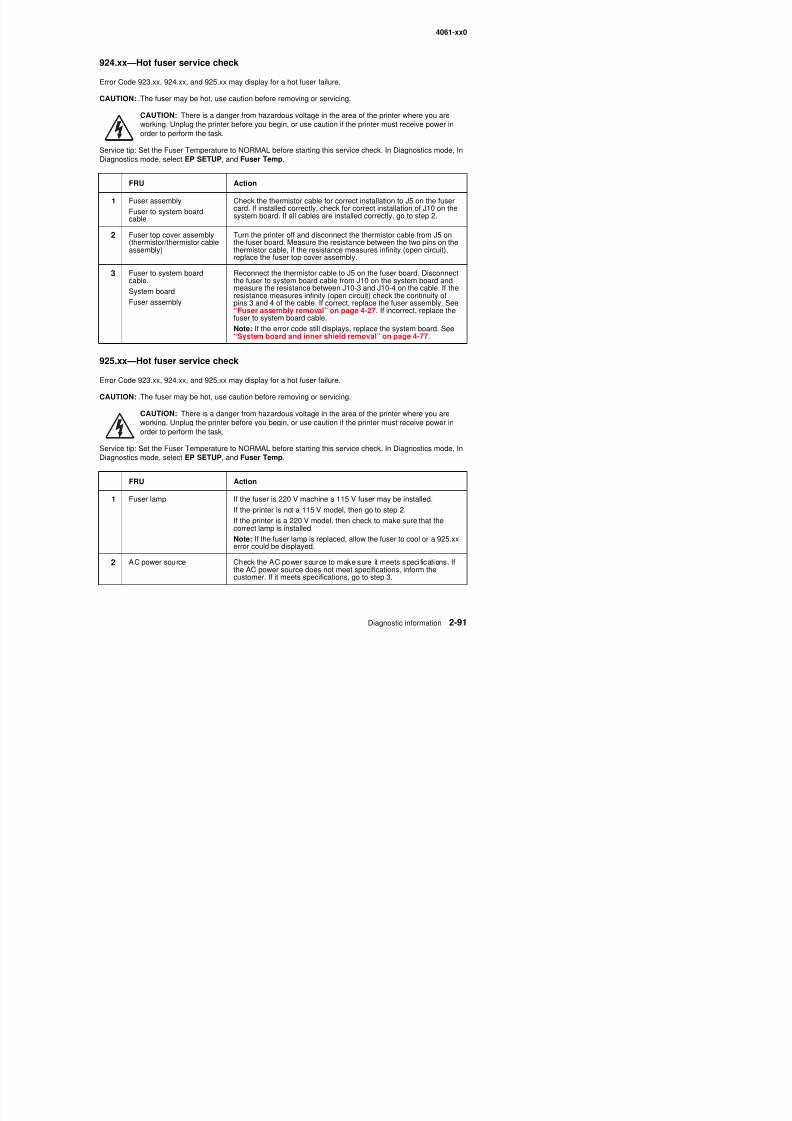
8/13/2019 t644 Service Manual
http://slidepdf.com/reader/full/t644-service-manual 133/423
925.xx—Hot fuser service check
Error Code 923.xx, 924.xx, and 925.xx may display for a hot fuser failure.
CAUTION: .The fuser may be hot, use caution before removing or servicing.
CAUTION: There is a danger from hazardous voltage in the area of the printer where you areworking. Unplug the printer before you begin, or use caution if the printer must receive power inorder to perform the task.
Service tip: Set the Fuser Temperature to NORMAL before starting this service check. In Diagnostics mode, InDiagnostics mode, select EP SETUP, and Fuser Temp.
FRU Action
1 Fuser assembly
Fuser to system boardcable
Check the thermistor cable for correct installation to J5 on the fuser
card. If installed correctly, check for correct installation of J10 on thesystem board. If all cables are installed correctly, go to step 2.
2 Fuser top cover assembly(thermistor/thermistor cableassembly)
Turn the printer off and disconnect the thermistor cable from J5 onthe fuser board. Measure the resistance between the two pins on thethermistor cable, if the resistance measures infinity (open circuit),replace the fuser top cover assembly.
3 Fuser to system boardcable.
System board
Fuser assembly
Reconnect the thermistor cable to J5 on the fuser board. Disconnectthe fuser to system board cable from J10 on the system board andmeasure the resistance between J10-3 and J10-4 on the cable. If the
resistance measures infinity (open circuit) check the continuity ofpins 3 and 4 of the cable. If correct, replace the fuser assembly. See“Fuser assembly removal” on page 4-27. If incorrect, replace thefuser to system board cable.
Note: If the error code still displays, replace the system board. See“System board and inner shield removal” on page 4-77.
FRU Action
1 Fuser lamp If the fuser is 220 V machine a 115 V fuser may be installed.
If th i t i t 115 V d l th t t 2
4061-xx0
Fuser exi t sensor serv ice check
If any of the following codes are displayed there is a potential problem in the area of the exit sensor: 201 00
3 Fuser lamp Turn the printer off and allow the fuser assembly to cool. After thefuser assembly cools down, turn the printer on. If you receive thesame error code, replace the fuser lamp. See “Fuser lampremoval” on page 4-33.
Note: If the fuser lamp is replaced, allow the fuser to cool or a 925.xxerror could be displayed.
FRU Action
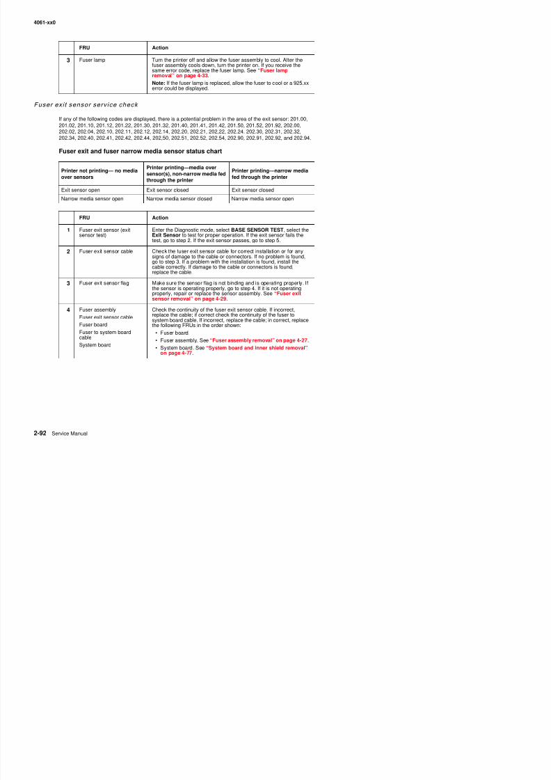
8/13/2019 t644 Service Manual
http://slidepdf.com/reader/full/t644-service-manual 134/423
If any of the following codes are displayed, there is a potential problem in the area of the exit sensor: 201.00,201.02, 201.10, 201.12, 201.22, 201.30, 201.32, 201.40, 201.41, 201.42, 201.50, 201.52, 201.92, 202.00,202.02, 202.04, 202.10, 202.11, 202.12, 202.14, 202.20, 202.21, 202,22, 202.24. 202.30, 202.31, 202.32,202.34, 202.40, 202.41, 202.42, 202.44, 202,50, 202.51, 202.52, 202.54, 202.90, 202.91, 202.92, and 202.94.
Fuser exit and fuser narrow media sensor status chart
Printer not printing— no mediaover sensors
Printer printing—media oversensor(s), non-narrow media fedthrough the printer
Printer printing—narrow mediafed through the printer
Exit sensor open Exit sensor closed Exit sensor closed
Narrow media sensor open Narrow media sensor closed Narrow media sensor open
FRU Action
1 Fuser exit sensor (exitsensor test)
Enter the Diagnostic mode, select BASE SENSOR TEST, select theExit Sensor to test for proper operation. If the exit sensor fails thetest, go to step 2. If the exit sensor passes, go to step 5.
2 Fuser exit sensor cable Check the fuser exit sensor cable for correct installation or for anysigns of damage to the cable or connectors. If no problem is found,go to step 3. If a problem with the installation is found, install the
cable correctly. If damage to the cable or connectors is found,replace the cable.
3 Fuser exit sensor flag Make sure the sensor flag is not binding and is operating properly. Ifthe sensor is operating properly, go to step 4. If it is not operatingproperly, repair or replace the sensor assembly. See “Fuser exitsensor removal” on page 4-29.
4 Fuser assembly
Fuser exit sensor cable
Fuser board
Fuser to system boardcable
System board
Check the continuity of the fuser exit sensor cable. If incorrect,replace the cable; if correct check the continuity of the fuser tosystem board cable. If incorrect, replace the cable; in correct, replacethe following FRUs in the order shown:
• Fuser board.• Fuser assembly. See “Fuser assembly removal” on page 4-27.
• System board. See “System board and inner shield removal”on page 4-77
4061-xx0
5 With the redrive assembly removed from the printer, enter theDiagnostics mode and run the print test from tray 1 (for example,select PRINT TESTS, Tray 1, and Continuous) and observe themedia as it passes over the exit and narrow media sensors. Check
that the sensor flags are operating correctly. If the sensor flags andhardware are operating incorrectly, repair or replace the failingsensor assembly. If no problem is found, check the fuser for anysigns of media in the fuser or any signs of toner or othercontamination. If a problem is found, clean or remove the debris orcontamination.
FRU Action
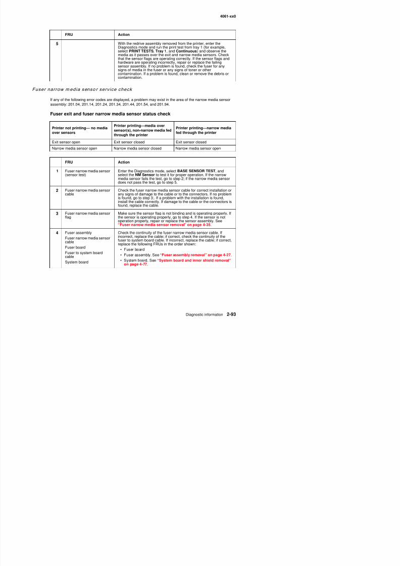
8/13/2019 t644 Service Manual
http://slidepdf.com/reader/full/t644-service-manual 135/423
Fuser narrow media senso r serv ice check
If any of the following error codes are displayed, a problem may exist in the area of the narrow media sensor
assembly: 201.04, 201.14, 201.24, 201.34, 201.44, 201.54, and 201.94.
Fuser exit and fuser narrow media sensor status check
Printer not printing— no mediaover sensors
Printer printing—media oversensor(s), non-narrow media fedthrough the printer
Printer printing—narrow mediafed through the printer
Exit sensor open Exit sensor closed Exit sensor closed
Narrow media sensor open Narrow media sensor closed Narrow media sensor open
FRU Action
1 Fuser narrow media sensor(sensor test)
Enter the Diagnostics mode, select BASE SENSOR TEST, andselect the NM Sensor to test it for proper operation. If the narrowmedia sensor fails the test, go to step 2; if the narrow media sensordoes not pass the test, go to step 5.
2 Fuser narrow media sensor
cable
Check the fuser narrow media sensor cable for correct installation or
any signs of damage to the cable or to the connectors. If no problemis found, go to step 3;. If a problem with the installation is found,install the cable correctly. If damage to the cable or the connectors isfound, replace the cable.
3 Fuser narrow media sensorflag
Make sure the sensor flag is not binding and is operating properly. Ifthe sensor is operating properly, go to step 4. If the sensor is notoperation properly, repair or replace the sensor assembly. See“Fuser narrow media sensor removal” on page 4-35.
4 Fuser assembly
Fuser narrow media sensorcableFuser board
Fuser to system boardcable
Check the continuity of the fuser narrow media sensor cable. Ifincorrect, replace the cable; if correct, check the continuity of the
fuser to system board cable. If incorrect, replace the cable; if correct,replace the following FRUs in the order shown:
• Fuser board
• Fuser assembly. See “Fuser assembly removal” on page 4-27.
4061-xx0
5 With the redrive assembly removed from the printer, enterDiagnostics mode and run the printer test from tray 1 and observethe media as it passes over the exit sensor. Check to see that thesensor flag is operating correctly. If the sensor flag and hardware are
operating incorrectly, repair or replace the failing sensor assembly. Ifno problem is found, check the fuser for any signs of media in thefuser or any signs of toner or other contamination. If a problem isfound, clean or remove the debris or contamination.
FRU Action

8/13/2019 t644 Service Manual
http://slidepdf.com/reader/full/t644-service-manual 136/423
4061-xx0
Fuser solenoid serv ice check
CAUTION: There is a danger from hazardous voltage in the area of the printer where you areworking. Unplug the printer before you begin, or use caution if the printer must receive power inorder to perform the task.
Service tip: Try changing the envelope enhance level setting. A different setting may correct the problem.
Note: Check the fuser envelope conditioner solenoid adjustment as described in the adjustment section “Fusersolenoid adjustment” on page 4-2.
FRU Action
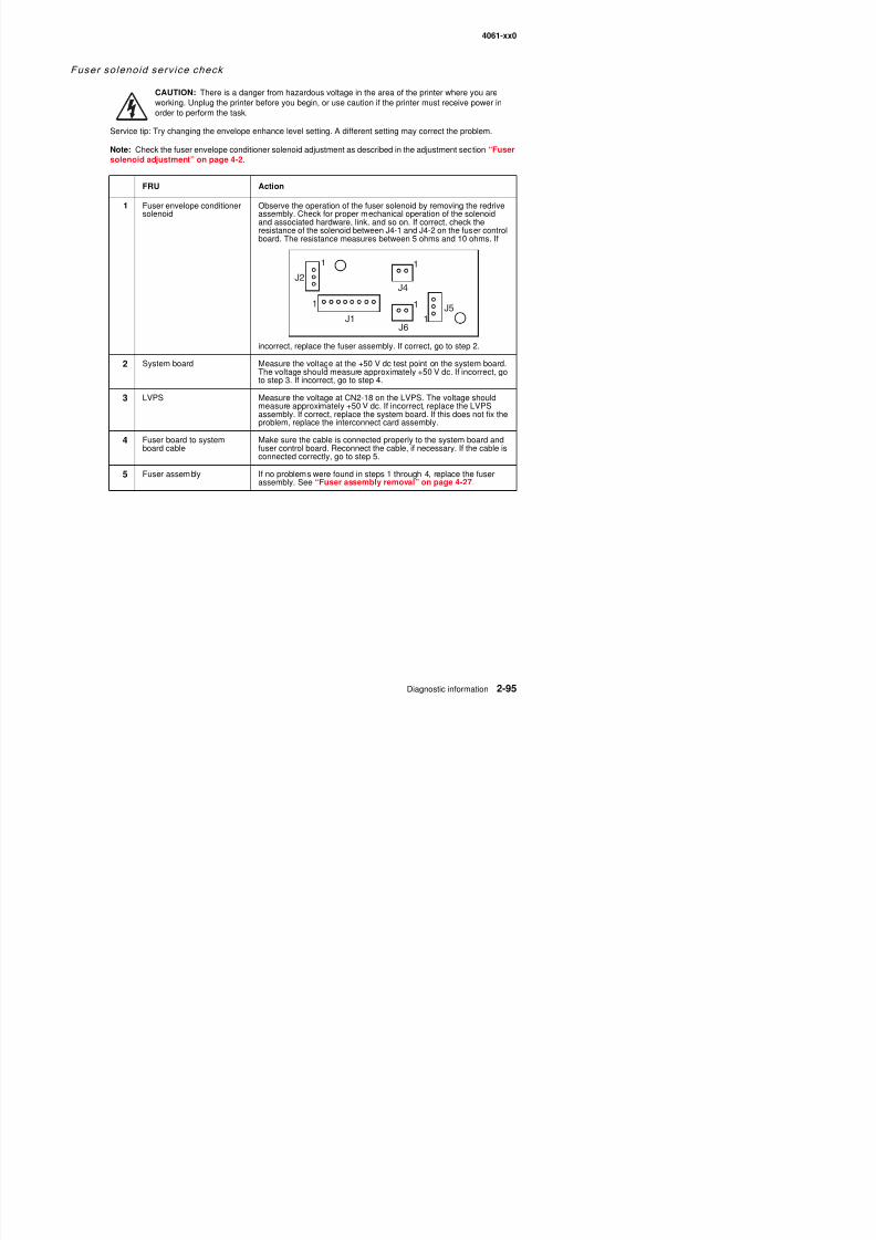
8/13/2019 t644 Service Manual
http://slidepdf.com/reader/full/t644-service-manual 137/423
1 Fuser envelope conditionersolenoid
Observe the operation of the fuser solenoid by removing the redriveassembly. Check for proper mechanical operation of the solenoidand associated hardware, link, and so on. If correct, check the
resistance of the solenoid between J4-1 and J4-2 on the fuser controlboard. The resistance measures between 5 ohms and 10 ohms. If
incorrect, replace the fuser assembly. If correct, go to step 2.
2 System board Measure the voltage at the +50 V dc test point on the system board.The voltage should measure approximately +50 V dc. If incorrect, goto step 3. If incorrect, go to step 4.
3 LVPS Measure the voltage at CN2-18 on the LVPS. The voltage shouldmeasure approximately +50 V dc. If incorrect, replace the LVPSassembly. If correct, replace the system board. If this does not fix theproblem, replace the interconnect card assembly.
4 Fuser board to systemboard cable
Make sure the cable is connected properly to the system board andfuser control board. Reconnect the cable, if necessary. If the cable isconnected correctly, go to step 5.
5 Fuser assembly If no problems were found in steps 1 through 4, replace the fuserassembly. See “Fuser assembly removal” on page 4-27.
J2
1
J1
J6
J4
J51
1
1
1
4061-xx0
High-capaci ty feeder input tray serv ice check
Note: Voltage measurements in the high-capacity feeder input tray service checks must be made with the high-capacity feeder attached to the base printer to obtain accurate results.
Service tip: Be sure the paper size switch is set to the correct paper size setting and the rear paper guides are in
the correct locations for the size of paper installed in the high-capacity feeder tray.
Service tip: Check the other paper sources to be sure they are operating correctly.
The base printer indicates a dead machine condition when the high-capacity inputtray is installed
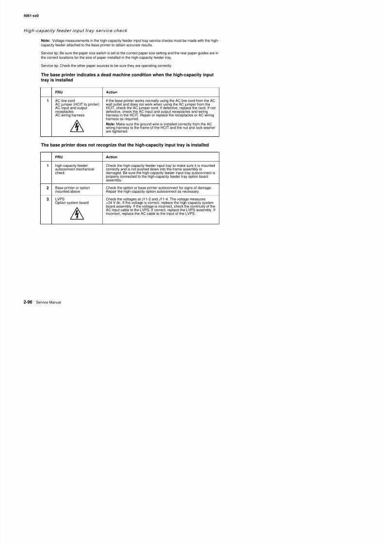
8/13/2019 t644 Service Manual
http://slidepdf.com/reader/full/t644-service-manual 138/423
The base printer does not recognize that the high-capacity input tray is installed
FRU Action
1 AC line cordAC jumper (HCIT to printer)AC input and outputreceptaclesAC wiring harness
If the base printer works normally using the AC line cord from the ACwall outlet and does not work when using the AC jumper from theHCIT, check the AC jumper cord. If defective, replace the cord. If notdefective, check the AC input and output receptacles and wiringharness in the HCIT. Repair or replace the receptacles or AC wiringharness as required.
Note: Make sure the ground wire is installed correctly from the ACwiring harness to the frame of the HCIT and the nut and lock washerare tightened.
FRU Action
1 high-capacity feederautoconnect mechanicalcheck
Check the high-capacity feeder input tray to make sure it is mountedcorrectly and is not pushed down into the frame assembly ordamaged. Be sure the high-capacity feeder input tray autoconnect isproperly connected to the high-capacity feeder tray option boardassembly.
2 Base printer or optionmounted above Check the option or base printer autoconnect for signs of damage.Repair the high-capacity option autoconnect as necessary.
3 LVPSOption system board
Check the voltages at J11-2 and J11-4. The voltage measures+24 V dc, If the voltage is correct, replace the high-capacity systemboard assembly. If the voltage is incorrect, check the continuity of theAC input cable to the LVPS. If correct, replace the LVPS assembly. Ifincorrect, replace the AC cable to the input of the LVPS.
4061-xx0
4 High-capacity feeder optioncontrol board
Check the voltage on J8-1 (green). The voltage measures +24 V dc.If incorrect, check the autoconnect system for any problems.+24 V dc must come from the base printer through the autoconnectsystem to the high-capacity input for the high-capacity feeder to be
recognized. If the voltage is correct, check the voltages at J11-3(red)and J11-4(red). The voltages measure +24 V dc. If correct, replacethe high-capacity feeder option system board. If incorrect, disconnectJ8 from the system board and measure the voltages again. Ifincorrect, check the LVPS cable and the AC internal wiring from theinput appliance receptacle. If incorrect, replace as necessary. Ifcorrect, replace the LVPS. If the voltages are correct, check thestepper motor for shorts from the motor housing to each pin on themotor connector If you find a short between any pin and the motor
FRU Action
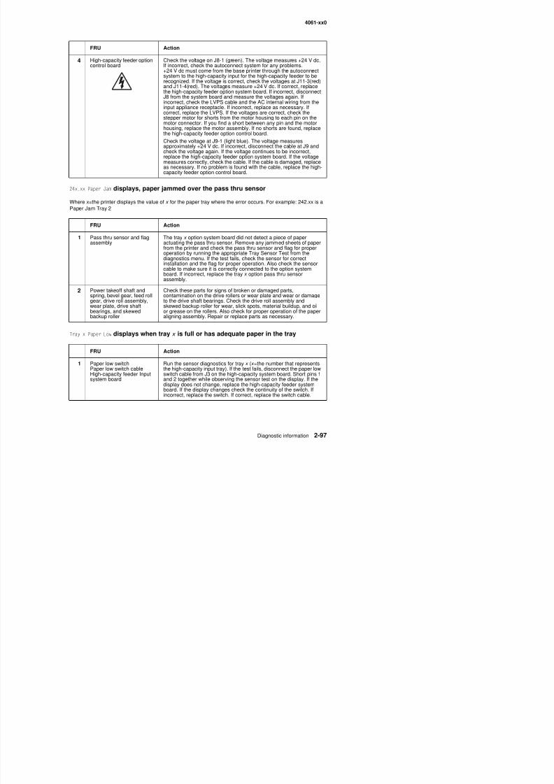
8/13/2019 t644 Service Manual
http://slidepdf.com/reader/full/t644-service-manual 139/423
24x.xx Paper Jam displays, paper jammed over the pass thru sensor
Where x =the printer displays the value of x for the paper tray where the error occurs. For example: 242.xx is a
Paper Jam Tray 2
Tray x Paper Low displays when tray x is full or has adequate paper in the tray
motor connector. If you find a short between any pin and the motorhousing, replace the motor assembly. If no shorts are found, replacethe high-capacity feeder option control board.
Check the voltage at J9-1 (light blue). The voltage measures
approximately +24 V dc. If incorrect, disconnect the cable at J9 andcheck the voltage again. If the voltage continues to be incorrect,replace the high-capacity feeder option system board. If the voltagemeasures correctly, check the cable. If the cable is damaged, replaceas necessary. If no problem is found with the cable, replace the high-capacity feeder option control board.
FRU Action
1 Pass thru sensor and flagassembly
The tray x option system board did not detect a piece of paperactuating the pass thru sensor. Remove any jammed sheets of paperfrom the printer and check the pass thru sensor and flag for properoperation by running the appropriate Tray Sensor Test from thediagnostics menu. If the test fails, check the sensor for correctinstallation and the flag for proper operation. Also check the sensor
cable to make sure it is correctly connected to the option systemboard. If incorrect, replace the tray x option pass thru sensorassembly.
2 Power takeoff shaft andspring, bevel gear, feed rollgear, drive roll assembly,wear plate, drive shaftbearings, and skewedbackup roller
Check these parts for signs of broken or damaged parts,contamination on the drive rollers or wear plate and wear or damageto the drive shaft bearings. Check the drive roll assembly andskewed backup roller for wear, slick spots, material buildup, and oilor grease on the rollers. Also check for proper operation of the paperaligning assembly. Repair or replace parts as necessary.
FRU Action
4061-xx0
Tray x Empty displays when there is paper in the high-capacity feeder input tray
The elevator tray fails to stop at the correct position and continues to drive into thebottom frame
FRU Action
1 Paper out sensor flag Check the paper out sensor flag for correct operation and installation.If correct, replace the high-capacity feeder system board. (The paper
out sensor is mounted on the high-capacity feeder system board.)2 Paper out sensor(on option system board)
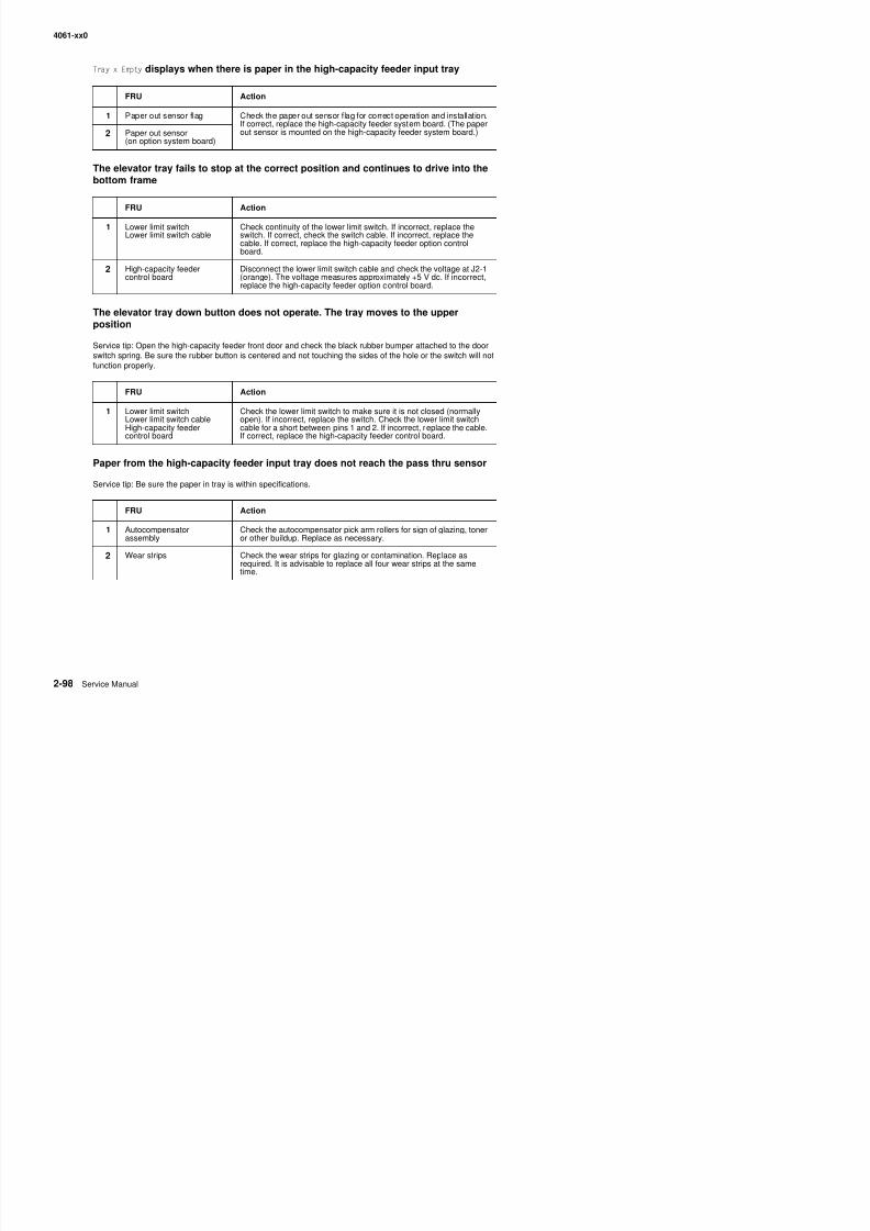
8/13/2019 t644 Service Manual
http://slidepdf.com/reader/full/t644-service-manual 140/423
The elevator tray down button does not operate. The tray moves to the upper
positionService tip: Open the high-capacity feeder front door and check the black rubber bumper attached to the doorswitch spring. Be sure the rubber button is centered and not touching the sides of the hole or the switch will notfunction properly.
Paper from the high-capacity feeder input tray does not reach the pass thru sensor
Service tip: Be sure the paper in tray is within specifications.
FRU Action
1 Lower limit switchLower limit switch cable Check continuity of the lower limit switch. If incorrect, replace theswitch. If correct, check the switch cable. If incorrect, replace thecable. If correct, replace the high-capacity feeder option controlboard.
2 High-capacity feedercontrol board
Disconnect the lower limit switch cable and check the voltage at J2-1(orange). The voltage measures approximately +5 V dc. If incorrect,replace the high-capacity feeder option control board.
FRU Action
1 Lower limit switchLower limit switch cableHigh-capacity feedercontrol board
Check the lower limit switch to make sure it is not closed (normallyopen). If incorrect, replace the switch. Check the lower limit switchcable for a short between pins 1 and 2. If incorrect, replace the cable.If correct, replace the high-capacity feeder control board.
FRU Action
1 Autocompensatorassembly
Check the autocompensator pick arm rollers for sign of glazing, toneror other buildup. Replace as necessary.
2 Wear strips Check the wear strips for glazing or contamination. Replace as
4061-xx0
The elevator tray does not move up or down; the printer recognizes that the option isinstalled
FRU Action
1 DC drive motor high-capacity feeder optionsystem board
Be sure the motor cable is correctly installed at J1 on the board.Check the cables, damaged or loose wires. Disconnect the motor.Check for a short between each pin and the motor housing. If aproblem is found, replace the motor assembly. If no problem is found,measure the resistance between the following pins on the motorcable connector:
Pins 1 (brown) and pin 2 (Yellow)
The resistance measures between approximately 7.5 and 10.5 ohms.
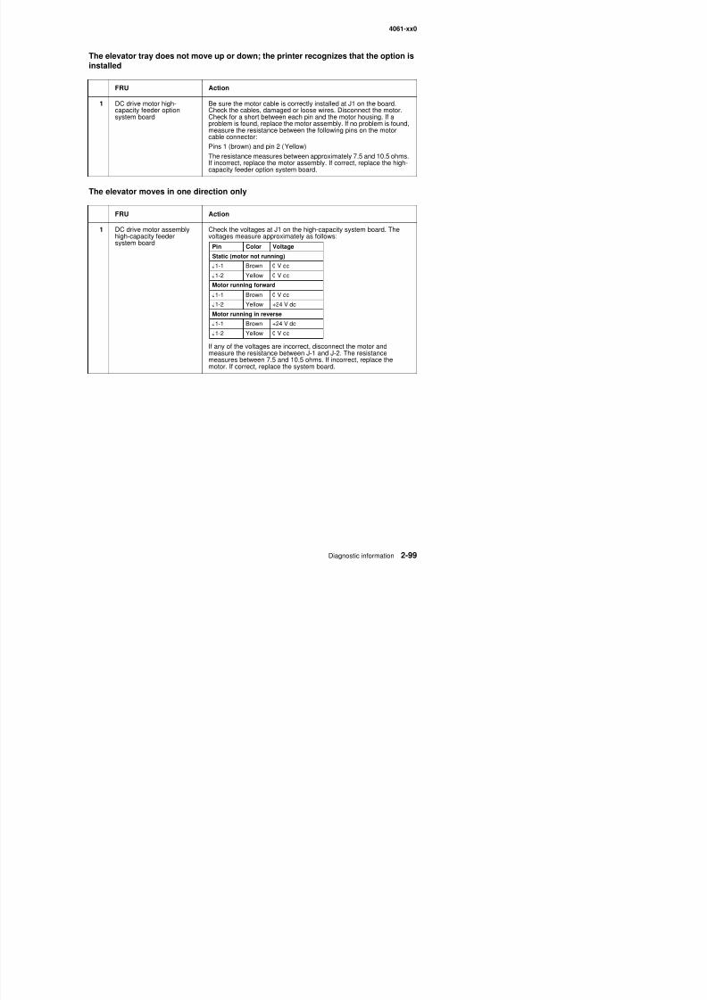
8/13/2019 t644 Service Manual
http://slidepdf.com/reader/full/t644-service-manual 141/423
The elevator moves in one direction only
pp yIf incorrect, replace the motor assembly. If correct, replace the high-capacity feeder option system board.
FRU Action
1 DC drive motor assemblyhigh-capacity feedersystem board
Check the voltages at J1 on the high-capacity system board. Thevoltages measure approximately as follows:
If any of the voltages are incorrect, disconnect the motor andmeasure the resistance between J-1 and J-2. The resistancemeasures between 7.5 and 10.5 ohms. If incorrect, replace themotor. If correct, replace the system board.
Pin Color Voltage
Static (motor not running)
J1-1 Brown 0 V dcJ1-2 Yellow 0 V dc
Motor running forward
J1-1 Brown 0 V dc
J1-2 Yellow +24 V dc
Motor running in reverse
J1-1 Brown +24 V dc
J1-2 Yellow 0 V dc
4061-xx0
Paper size switch not selecting paper size that is selected
FRU Action
1 Paper size switchHigh-capacity feeder option
control board
Check for continuity between the common pin (J5-1) and the pin ofthe paper size selected.
Pin Color Paper size
J5-1 Black Common lead
J5-2 Blue B5
J5-3 Green Executive
J5-4 Yellow A4
J5-5 Orange Letter
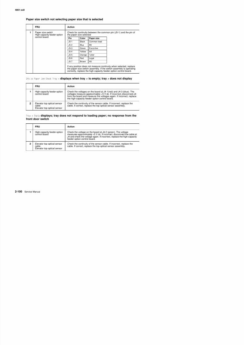
8/13/2019 t644 Service Manual
http://slidepdf.com/reader/full/t644-service-manual 142/423
24x.xx Paper Jam Check Tray x displays when tray x is empty; tray x does not display
Tray x Empty displays; tray does not respond to loading paper; no response from the
front door switch
If any position does not measure continuity when selected, replacethe paper size switch assembly. If the switch assembly is operatingcorrectly, replace the high-capacity feeder option control board.
FRU Action
1 High-capacity feeder optioncontrol board Check the voltages on the board at J4-1(red) and J4-3 (blue). Thevoltages measure approximately +5 V dc. If incorrect, disconnect J4from the board and measure the voltages again. If incorrect, replacethe high-capacity feeder option control board.
2 Elevator top optical sensorcableElevator top optical sensor
Check the continuity of the sensor cable. If incorrect, replace thecable. If correct, replace the top optical sensor assembly.
FRU Action
1 High-capacity feeder optioncontrol board
Check the voltage on the board at J4-2 (green). The voltagemeasures approximately +5 V dc. If incorrect, disconnect the cable atJ4 and check the voltage again. If incorrect, replace the high-capacityfeeder option control board.
2 Elevator top optical sensor
cableElevator top optical sensor
Check the continuity of the sensor cable. If incorrect, replace the
cable. If correct, replace the top optical sensor assembly.
J5 5 Orange Letter
J5-6 Red Legal
J5-7 Brown A5
4061-xx0
Tray x Paper Low displays when the high-capacity feeder input tray is full or hasadequate paper in the tray
FRU Action
1 Paper low switch
Paper low switch cableHigh-capacity feeder optioncontrol board
Run the sensor diagnostics for tray x ( x =the number that representsthe high-capacity input tray).If the test fails, check the voltage at J3-1 (gray). The voltagemeasures approximately +24 V dc. If incorrect, disconnect the paperlow switch cable from J3 and measure the voltage again on J3-1. Ifincorrect, replace the high-capacity feeder option control board. Ifcorrect, check the cable for a short between pins 1 and 2 on thecable. If incorrect, replace the cable. If correct, check the switch for abent or deformed actuator lever or defective switch. If incorrect,
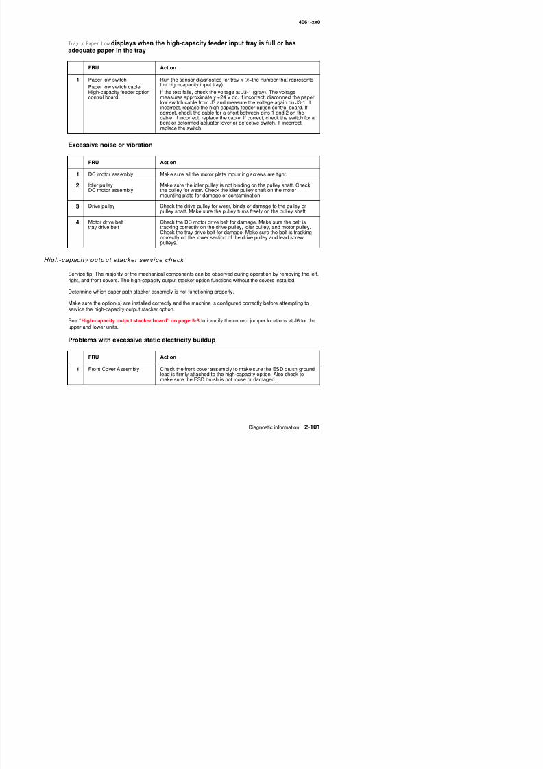
8/13/2019 t644 Service Manual
http://slidepdf.com/reader/full/t644-service-manual 143/423
Excessive noise or vibration
High-capaci ty outp ut stacker serv ice check
Service tip: The majority of the mechanical components can be observed during operation by removing the left,right, and front covers. The high-capacity output stacker option functions without the covers installed.
Determine which paper path stacker assembly is not functioning properly.
Make sure the option(s) are installed correctly and the machine is configured correctly before attempting toservice the high-capacity output stacker option.
See “High-capacity output stacker board” on page 5-8 to identify the correct jumper locations at J6 for the
upper and lower units.
Problems with excessive static electricity buildup
bent or deformed actuator lever or defective switch. If incorrect,replace the switch.
FRU Action
1 DC motor assembly Make sure all the motor plate mounting screws are tight.
2 Idler pulleyDC motor assembly
Make sure the idler pulley is not binding on the pulley shaft. Checkthe pulley for wear. Check the idler pulley shaft on the motormounting plate for damage or contamination.
3 Drive pulley Check the drive pulley for wear, binds or damage to the pulley orpulley shaft. Make sure the pulley turns freely on the pulley shaft.
4 Motor drive belttray drive belt
Check the DC motor drive belt for damage. Make sure the belt istracking correctly on the drive pulley, idler pulley, and motor pulley.Check the tray drive belt for damage. Make sure the belt is trackingcorrectly on the lower section of the drive pulley and lead screwpulleys.
4061-xx0
The printer does not recognize one or more output options as installed
Service tip: If more than a single output option is installed, check each one to see if the printer recognizes anysingle option as installed. If the printer recognizes any of the output options, the base printer autoconnectsystem is operating correctly. The problem is in the unrecognized option. Continue with this service check or goto the service check for the failing output option.
FRU Action
1 High-capacity stackerfeeder
Check the autoconnects, cables, and connectors of the option for anysigns of loose or damaged parts.
2 High-capacity outputstacker/mechanical linkage
Remove the left and right side covers and check all fourautoconnects for damage especially the connector pins Remove the
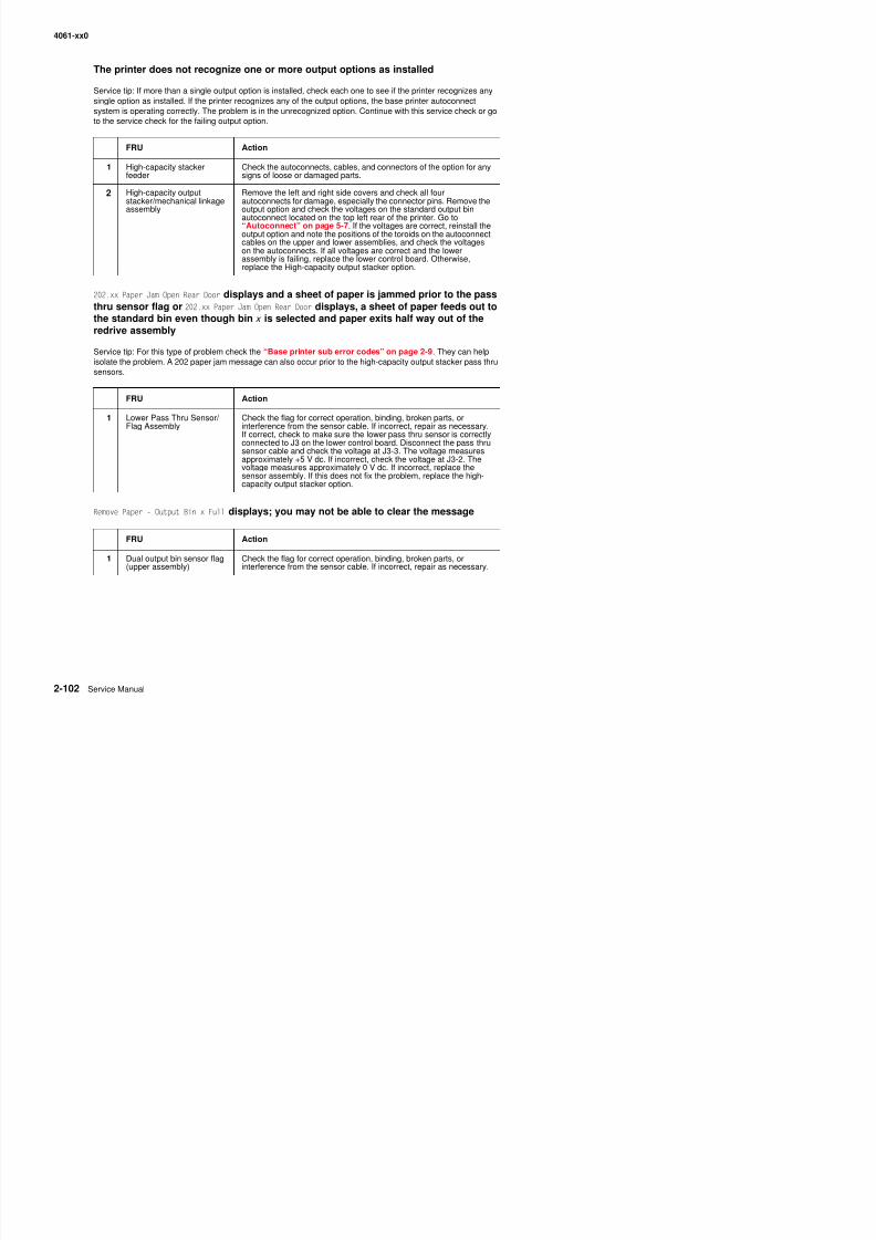
8/13/2019 t644 Service Manual
http://slidepdf.com/reader/full/t644-service-manual 144/423
202.xx Paper Jam Open Rear Door displays and a sheet of paper is jammed prior to the passthru sensor flag or 202.xx Paper Jam Open Rear Door displays, a sheet of paper feeds out tothe standard bin even though bin x is selected and paper exits half way out of the
redrive assemblyService tip: For this type of problem check the “Base printer sub error codes” on page 2-9. They can helpisolate the problem. A 202 paper jam message can also occur prior to the high-capacity output stacker pass thrusensors.
Remove Paper - Output Bin x Full displays; you may not be able to clear the message
stacker/mechanical linkageassembly
autoconnects for damage, especially the connector pins. Remove theoutput option and check the voltages on the standard output binautoconnect located on the top left rear of the printer. Go to“Autoconnect” on page 5-7. If the voltages are correct, reinstall the
output option and note the positions of the toroids on the autoconnectcables on the upper and lower assemblies, and check the voltageson the autoconnects. If all voltages are correct and the lowerassembly is failing, replace the lower control board. Otherwise,replace the High-capacity output stacker option.
FRU Action
1 Lower Pass Thru Sensor/
Flag Assembly
Check the flag for correct operation, binding, broken parts, or
interference from the sensor cable. If incorrect, repair as necessary.If correct, check to make sure the lower pass thru sensor is correctlyconnected to J3 on the lower control board. Disconnect the pass thrusensor cable and check the voltage at J3-3. The voltage measuresapproximately +5 V dc. If incorrect, check the voltage at J3-2. Thevoltage measures approximately 0 V dc. If incorrect, replace thesensor assembly. If this does not fix the problem, replace the high-capacity output stacker option.
FRU Action
1 Dual output bin sensor flag Check the flag for correct operation, binding, broken parts, or
4061-xx0
271.xx Paper Jam - Check Bin x, POST incomplete
FRU Action
1 Upper pass thru sensor f lagassembly
Upper control board
Check the flag for correct operation, binding, broken parts, orinterference from the sensor cable. If incorrect, repair as necessary.
If correct, make sure the lower pass thru sensor is correctlyconnected to J3 on the lower control board. Disconnect the pass thrusensor cable and check the voltage at J3-3. The voltage measuresapproximately +5 V dc. If incorrect, check the voltage at J3-2. Thevoltage measures approximately 0 V dc. If incorrect, replace thesensor assembly. If this does not fix the problem, replace the high-capacity output stacker option.
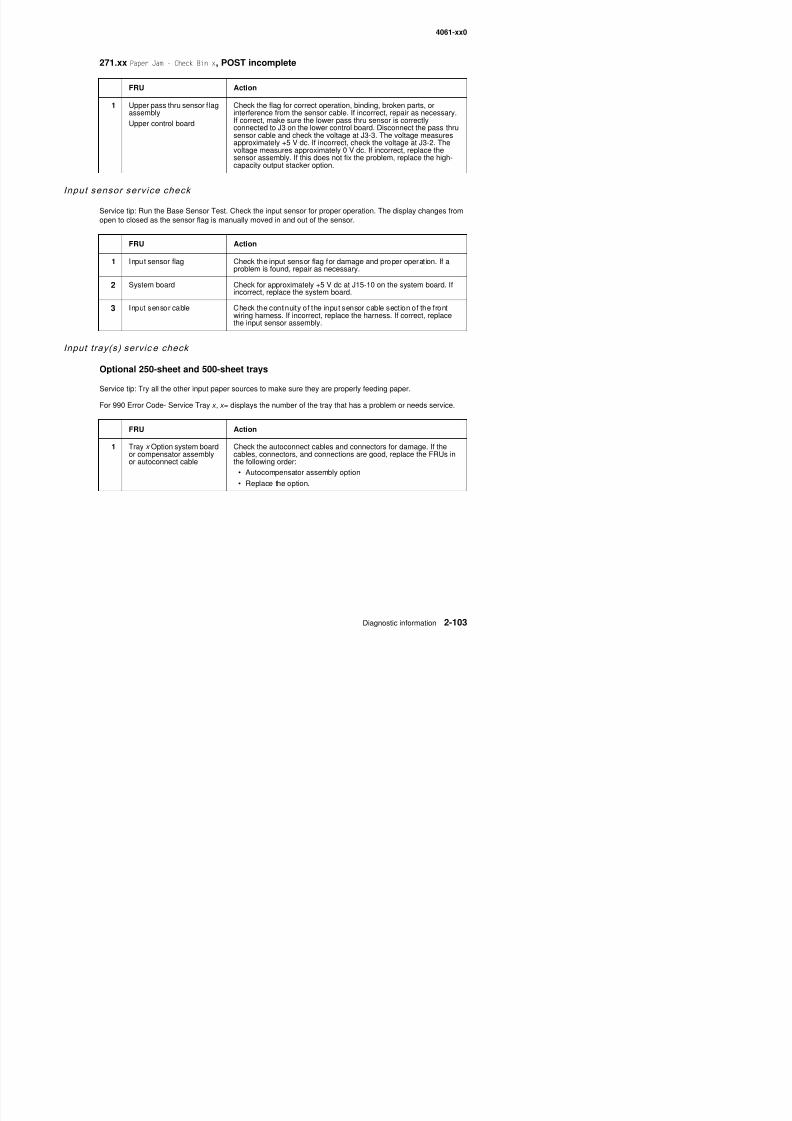
8/13/2019 t644 Service Manual
http://slidepdf.com/reader/full/t644-service-manual 145/423
Input sensor serv ice check
Service tip: Run the Base Sensor Test. Check the input sensor for proper operation. The display changes fromopen to closed as the sensor flag is manually moved in and out of the sensor.
Input tray(s) servic e check
Optional 250-sheet and 500-sheet trays
Service tip: Try all the other input paper sources to make sure they are properly feeding paper.
For 990 Error Code- Service Tray x , x = displays the number of the tray that has a problem or needs service.
FRU Action
1 Input sensor flag Check the input sensor flag for damage and proper operation. If aproblem is found, repair as necessary.
2 System board Check for approximately +5 V dc at J15-10 on the system board. Ifincorrect, replace the system board.
3 Input sensor cable Check the continuity of the input sensor cable section of the frontwiring harness. If incorrect, replace the harness. If correct, replacethe input sensor assembly.
FRU Action
1 Tray x Option system boardor compensator assemblyor autoconnect cable
Check the autoconnect cables and connectors for damage. If thecables, connectors, and connections are good, replace the FRUs inthe following order:
• Autocompensator assembly option
• Replace the option.
4061-xx0
24x.xx Paper Jam displays, paper jammed over the pass thru sensor
(The printer displays the value of x for the paper tray where the error occurs. Example: 241 is a Paper JamTray 1)
FRU Action
1 Pass thru sensor and flagassembly
The tray x option system board did not detect a piece of paperactuating the pass thru sensor. Remove any jammed sheets of paperfrom the printer and check the pass thru sensor and flag for properoperation by running the appropriate Tray Sensor Test from thediagnostics menu. If the test fails, check the sensor for correctinstallation and the flag for proper operation. Also check the sensorcable to make sure it is correctly connected to the option systemboard If incorrect replace the tray x option pass thru sensor
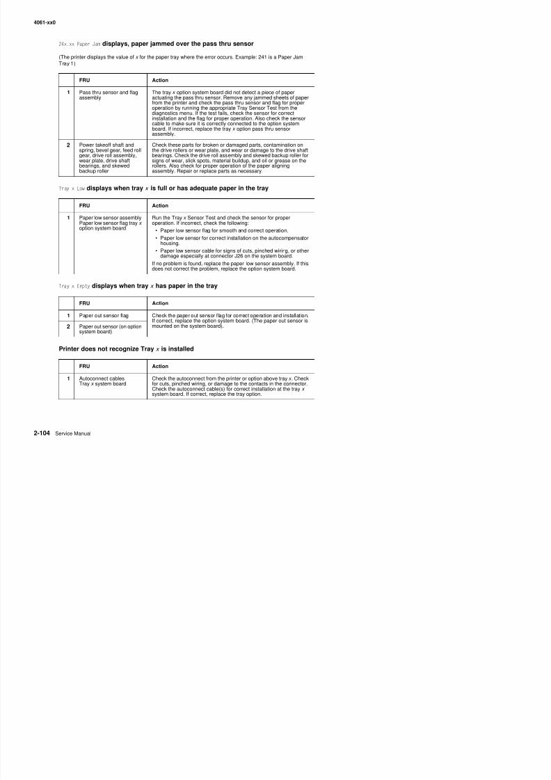
8/13/2019 t644 Service Manual
http://slidepdf.com/reader/full/t644-service-manual 146/423
Tray x Low displays when tray x is full or has adequate paper in the tray
Tray x Empty displays when tray x has paper in the tray
Printer does not recognize Tray x is installed
board. If incorrect, replace the tray x option pass thru sensorassembly.
2 Power takeoff shaft andspring, bevel gear, feed rollgear, drive roll assembly,wear plate, drive shaftbearings, and skewedbackup roller
Check these parts for broken or damaged parts, contamination onthe drive rollers or wear plate, and wear or damage to the drive shaftbearings. Check the drive roll assembly and skewed backup roller forsigns of wear, slick spots, material buildup, and oil or grease on therollers. Also check for proper operation of the paper aligningassembly. Repair or replace parts as necessary.
FRU Action
1 Paper low sensor assemblyPaper low sensor flag tray x option system board
Run the Tray x Sensor Test and check the sensor for properoperation. If incorrect, check the following:
• Paper low sensor flag for smooth and correct operation.
• Paper low sensor for correct installation on the autocompensatorhousing.
• Paper low sensor cable for signs of cuts, pinched wiring, or otherdamage especially at connector J26 on the system board.
If no problem is found, replace the paper low sensor assembly. If this
does not correct the problem, replace the option system board.
FRU Action
1 Paper out sensor flag Check the paper out sensor flag for correct operation and installation.If correct, replace the option system board. (The paper out sensor ismounted on the system board).2 Paper out sensor (on option
system board)
4061-xx0
Paper from Tray x does not reach the pass thru sensor
Service tip: Check the media in tray x to make sure it is within specifications. Some types of labels, foil material,and slick papers can cause misfeeds and slippage of the rollers.
Interconn ect card serv ice check
Warning: When replacing any one of the following components:
FRU Action
1 Autocompensatorassembly
Check the autocompensator pick arm rollers for any sign of glazing,toner or other buildup. Clean or replace as necessary.
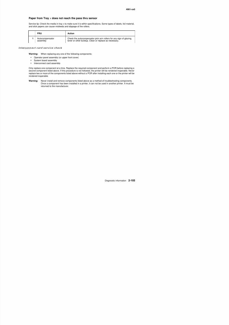
8/13/2019 t644 Service Manual
http://slidepdf.com/reader/full/t644-service-manual 147/423
Warning: When replacing any one of the following components:
• Operator panel assembly (or upper front cover)
• System board assembly• Interconnect card assembly
Only replace one component at a time. Replace the required component and perform a POR before replacing asecond component listed above. If this procedure is not followed, the printer will be rendered inoperable. Neverreplace two or more of the components listed above without a POR after installing each one or the printer will berendered inoperable.
Warning: Never install and remove components listed above as a method of troubleshooting components.Once a component has been installed in a printer, it can not be used in another printer. It must be
returned to the manufacturer.
4061-xx0
Main drive serv ice check
Service tip: Excessive gear or main drive assembly noise is usually caused by a defective motor assembly orsystem board.
Warning: Whenever the gearbox assembly is removed from the machine it must be handled very carefully.
Do not allow any of the gears to come in contact with any metal or other hard surface to avoid geardamage. It is also very important not to let any dirt, paper, staples, or other material come intactwith the grease in the gearbox assembly.
FRU Action
1 Main drive assembly(excessive noise or
Remove the controller board and run a Diagnostic Print Test in thecontinuous mode. Check the main drive assembly for any excessive
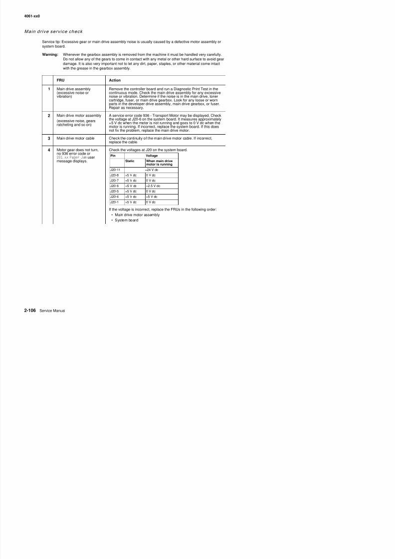
8/13/2019 t644 Service Manual
http://slidepdf.com/reader/full/t644-service-manual 148/423
(excessive noise orvibration)
continuous mode. Check the main drive assembly for any excessivenoise or vibration. Determine if the noise is in the main drive, tonercartridge, fuser, or main drive gearbox. Look for any loose or worn
parts in the developer drive assembly, main drive gearbox, or fuser.Repair as necessary.
2 Main drive motor assembly
(excessive noise, gearsratcheting and so on)
A service error code 936 - Transport Motor may be displayed. Checkthe voltage at J20-6 on the system board. It measures approximately+5 V dc when the motor is not running and goes to 0 V dc when themotor is running. If incorrect, replace the system board. If this doesnot fix the problem, replace the main drive motor.
3 Main drive motor cable Check the continuity of the main drive motor cable. If incorrect,replace the cable.
4 Motor gear does not turn,no 936 error code or201.xx Paper Jam usermessage displays.
Check the voltages at J20 on the system board.
If the voltage is incorrect, replace the FRUs in the following order:
• Main drive motor assembly
• System board
Pin Voltage
Static When main drivemotor is running
J20-11 +24 V dc
J20-8 +5 V dc 0 V dc
J20-7 +5 V dc 0 V dc
J20-6 +5 V dc +2.5 V dc
J20-5 +5 V dc 0 V dc
J20-4 +5 V dc +5 V dc
J20-1 +5 V dc 0 V dc
4061-xx0
Operator panel serv ice check
Note: The operator panel board is a separate FRU and is also part of the upper front cover FRU
Warning: When replacing any one of the following components:
• Operator panel assembly (or upper front cover)
• System board assembly• Interconnect card assembly
Only replace one component at a time. Replace the required component and perform a POR before replacing asecond component listed above. If this procedure is not followed, the printer will be rendered inoperable. Neverreplace two or more of the components listed above without a POR after installing each one or the printer will berendered inoperable.
Warning: Never install and remove components listed above as a method of troubleshooting components
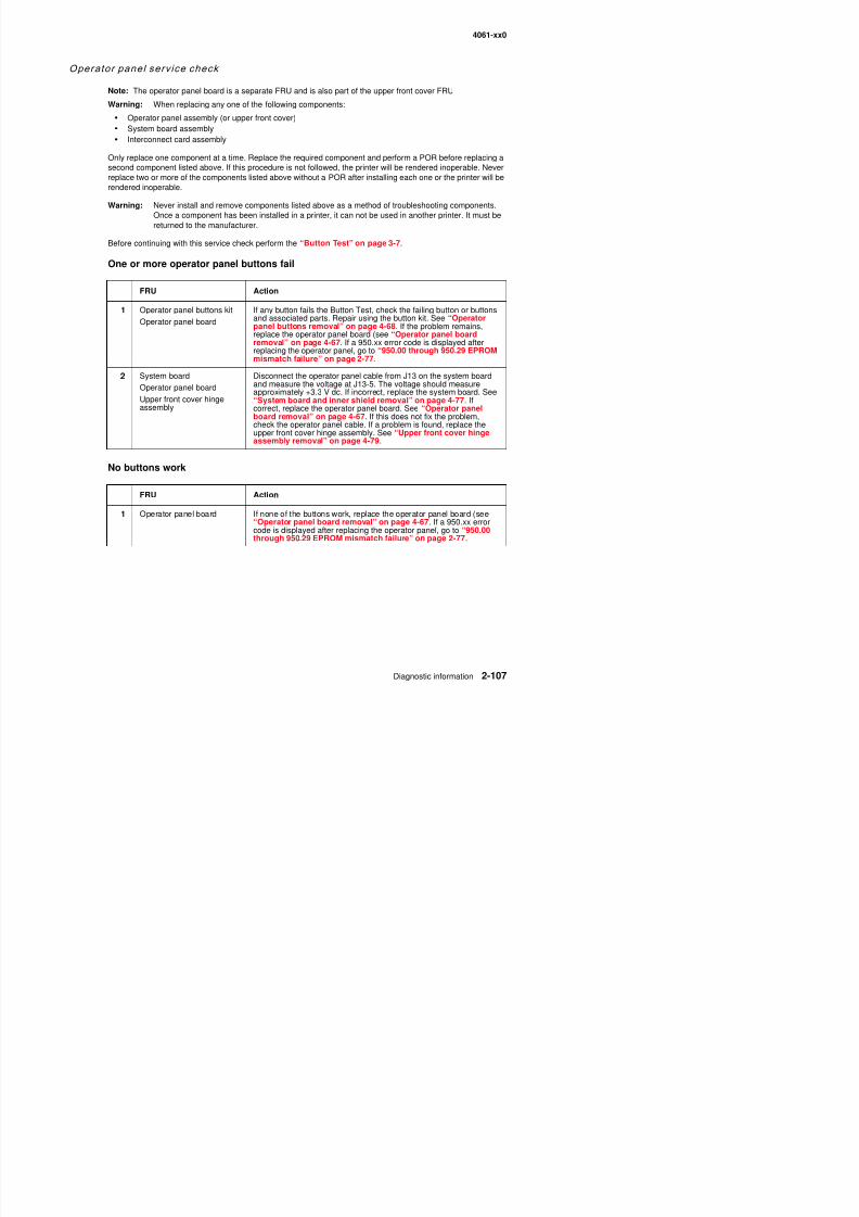
8/13/2019 t644 Service Manual
http://slidepdf.com/reader/full/t644-service-manual 149/423
Warning: Never install and remove components listed above as a method of troubleshooting components.Once a component has been installed in a printer, it can not be used in another printer. It must be
returned to the manufacturer.Before continuing with this service check perform the “Button Test” on page 3-7.
One or more operator panel buttons fail
No buttons work
FRU Action
1 Operator panel buttons kit
Operator panel board
If any button fails the Button Test, check the failing button or buttonsand associated parts. Repair using the button kit. See “Operator
panel buttons removal” on page 4-68. If the problem remains,replace the operator panel board (see “Operator panel boardremoval” on page 4-67. If a 950.xx error code is displayed afterreplacing the operator panel, go to “950.00 through 950.29 EPROMmismatch failure” on page 2-77.
2 System board
Operator panel board
Upper front cover hingeassembly
Disconnect the operator panel cable from J13 on the system boardand measure the voltage at J13-5. The voltage should measureapproximately +3.3 V dc. If incorrect, replace the system board. See“System board and inner shield removal” on page 4-77. Ifcorrect, replace the operator panel board. See “Operator panelboard removal” on page 4-67. If this does not fix the problem,
check the operator panel cable. If a problem is found, replace theupper front cover hinge assembly. See “Upper front cover hingeassembly removal” on page 4-79.
FRU Action
1 Operator panel board If none of the buttons work, replace the operator panel board (see“Operator panel board removal” on page 4-67. If a 950.xx errorcode is displayed after replacing the operator panel, go to “950.00through 950.29 EPROM mismatch failure” on page 2-77.
4061-xx0
Operator panel display
Service tip: The printer has detected a problem with the system board, the operator panel cable (part of theupper front cover hinge assembly), or the operator panel board if POST does not complete, the printer emits 5beeps, and stops in a continuous pattern until the printer is turned off.
Note: If the operator panel is operating properly except for a pel or a few pels missing or broken, run the “PanelTest” on page 3-7 from the hardware tests before continuing with this service check.
FRU Action
1 Operator panel cable Check for proper installation of the cable at the system board (J13)and at the operator panel. Check the continuity of the operator panelcable. If incorrect, replace the upper front cover hinge assembly. See“Upper front cover hinge assembly removal” on page 4-79
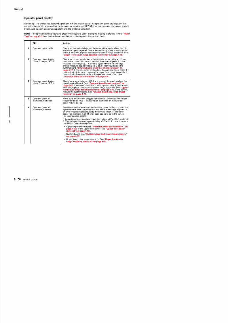
8/13/2019 t644 Service Manual
http://slidepdf.com/reader/full/t644-service-manual 150/423
Upper front cover hinge assembly removal on page 4-79.
2 Operator panel displayblank, 5 beeps, LED off
Check for correct installation of the operator panel cable at J13 onthe system board. If incorrect, reinstall the cable properly. If correct,measure the voltage at J13-2 on the system board. The voltageshould measure approximately +5 V dc. If incorrect, replace thesystem board. “System board and inner shield removal” onpage 4-77. If correct, check continuity of the operator panel cable. Ifthe continuity is incorrect, replace the upper front hinge assembly. Ifthe continuity is correct, replace the operator panel board. See“Operator panel board removal” on page 4-67.
3 Operator panel displayblank, 5 beeps, LED on
Check for ground between J13-4 and ground. If correct, replace theoperator panel board. See “Operator panel board removal” onpage 4-67. If incorrect, check the operator panel cable. If the cable isincorrect, replace the upper front cover hinge assembly. See “Upperfront cover hinge assembly removal” on page 4-79. If the correct,replace the system board. See “System board and inner shieldremoval” on page 4-77.
4 Operator panel alldiamonds, no beeps
Make sure a card is not plugged in backward. This condition causesthe printer to fail POST, displaying all diamonds on the operatorpanel with no beeps.
5 Operator panel alldiamonds, 5 beeps
Remove all the cables except the operator panel cable (J13) from thesystem board. Turn the printer on, and see if a message appears. If
an error message appears, go to the service check for that errorcode. For example, if a 924 error code appears, go to the 924.xx—Hot fuser service check).
If the problem is not resolved check the voltage at Pin J13-1 and J13-3. The voltage measures approximately +3.3 V dc. If correct, replacethe FRUs in the following order:
• Operator panel board (see “Operator panel board removal” onpage 4-67) or the Upper front cover (see “Upper front coverremoval” on page 4-12).
• System board. See “System board and inner shield removal”on page 4-77.
• Upper front cover hinge assembly. See “Upper front coverhinge assembly removal” on page 4-79.
4061-xx0
Options serv ice check
Service tip: When you have a problem with any of the options installed in the options slots on the interconnectcard, switch the non operating option to one of the other option slots to isolate the failure.
Flash Memory Option(s)
Run a copy of the test page and check to see if the option you are checking is listed. The printer does notrecognize the option being installed if the option is not listed. Make sure the memory card is installed correctlyand is not broken or damaged. If the memory card is correctly installed and not broken or damaged then run the“Flash Test” on page 3-19. If the test fails, replace the Flash card. If the problem continues, replace thecontroller board.
DRAM Memory Option(s)
8/13/2019 t644 Service Manual
http://slidepdf.com/reader/full/t644-service-manual 151/423
This service check is the same as the flash memory option service check with the following exception:
Run the “DRAM Test” on page 3-7 from the menu if the SDRAM Memory card is correctly installed and notbroken or damaged. If the test fails, replace the SDRAM card. If the problem continues, replace the controllerboard.
Hard Disk Option
Service tip: These printers support one hard disk option. Make sure only one hard disk option is installed.
Make sure the fixed disk and the fixed disk board are correctly installed. Run the “Quick Disk Test” onpage 3-18 from the Device Test on the Diagnostics menu when a problem is suspected either with the hard disksystem board or with the hard disk.
Note: The Quick Disk Test is a non-destructive test and indicates Pass or Fail. If the test fails, replace the harddisk. If a problem still exists, replace the hard disk board.
The “Disk Test/Clean” on page 3-19 is used to help restore the disk if the disk contains bad data and isunusable. This test is divided into a cleaning and a verifying or testing section.
Warning: This can be a very lengthy test depending on the disk size. This test leaves the hard disk
unformatted. The servicer or user must reformat the disk using the Format Disk Menu operation.This is a destructive type of test. All the data on the disk is destroyed and should not be performedon a known good disk.
Error Code 976.xx - Network Card x (x=Network card 1, 2, or 3)
A 976 error code indicates an unrecoverable software error in network card x . Verify that network card x iscorrectly installed in the socket on the interconnect card and is properly grounded. If you find no problem,contact your next level of support before replacing the network card.
Error Code 977.xx - Network Card x
A 977 error displays when the RIP software detects that a network card is installed in slot x on the interconnect
4061-xx0
Output bin senso r standard tray serv ice check
Service tip: If the output bin standard tray fills up and the bin full sensor fails to post the Remove Paper StandardBin message:
1. Enter the Diagnostics Mode.
2. Select Output Bin Tests.3. Select Sensor Tests.4. Select Standard Bin.5. Check the sensor and flag for proper operation.
If you find no problem with the sensor and flag, continue with the service check.
Service tip: Be sure the flag is correctly installed. The output bin sensor is a normally closed sensor with thesensor flag down Therefore unless the flag is in the up position or out of the sensor slot a Remove Paper
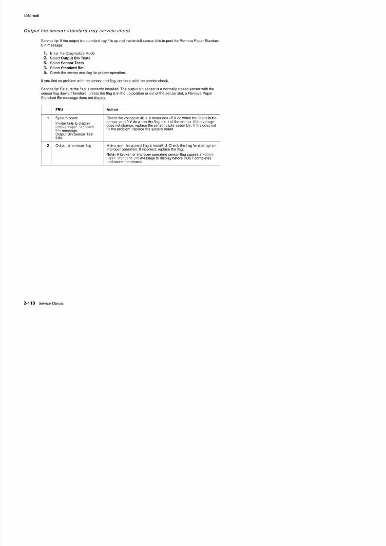
8/13/2019 t644 Service Manual
http://slidepdf.com/reader/full/t644-service-manual 152/423
sensor flag down. Therefore, unless the flag is in the up position or out of the sensor slot, a Remove PaperStandard Bin message does not display.
FRU Action
1 System board
Printer fails to displayRemove Paper StandardBin message.Output Bin Sensor Testfails.
Check the voltage at J6-1. It measures +5 V dc when the flag is in thesensor, and 0 V dc when the flag is out of the sensor. If the voltagedoes not change, replace the sensor cable assembly. If this does notfix the problem, replace the system board.
2 Output bin sensor flag Make sure the correct flag is installed. Check the flag for damage orimproper operation. If incorrect, replace the flag.
Note: A broken or improper operating sensor flag causes a RemovePaper Standard Bin message to display before POST completesand cannot be cleared.
4061-xx0
Output expander serv ice check
Service tip: The majority of the mechanical components can be observed during operation by removing the left,right, and system board covers. The output expander functions without the covers installed.
Make sure the option is correctly installed before attempting to service the unit. No jumpers should be installedat connector J6 on the output expander board.
Problems with excessive static electricity buildup
FRU Action
1 Output expander controlboard cover
Check the output expander control board cover to make sure theESD brush ground lead is firmly attached to the output expanderframe Also make sure the ESD brush is not loose
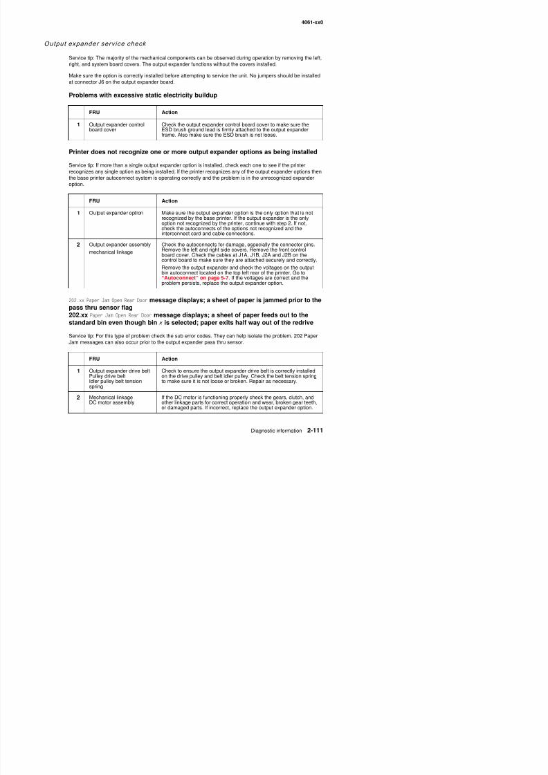
8/13/2019 t644 Service Manual
http://slidepdf.com/reader/full/t644-service-manual 153/423
Printer does not recognize one or more output expander options as being installed
Service tip: If more than a single output expander option is installed, check each one to see if the printerrecognizes any single option as being installed. If the printer recognizes any of the output expander options thenthe base printer autoconnect system is operating correctly and the problem is in the unrecognized expanderoption.
202.xx Paper Jam Open Rear Door message displays; a sheet of paper is jammed prior to thepass thru sensor flag202.xx Paper Jam Open Rear Door message displays; a sheet of paper feeds out to thestandard bin even though bin x is selected; paper exits half way out of the redrive
Service tip: For this type of problem check the sub error codes. They can help isolate the problem. 202 PaperJam messages can also occur prior to the output expander pass thru sensor.
frame. Also make sure the ESD brush is not loose.
FRU Action
1 Output expander option Make sure the output expander option is the only option that is notrecognized by the base printer. If the output expander is the onlyoption not recognized by the printer, continue with step 2. If not,check the autoconnects of the options not recognized and theinterconnect card and cable connections.
2 Output expander assembly
mechanical linkage
Check the autoconnects for damage, especially the connector pins.Remove the left and right side covers. Remove the front controlboard cover. Check the cables at J1A, J1B, J2A and J2B on thecontrol board to make sure they are attached securely and correctly.
Remove the output expander and check the voltages on the outputbin autoconnect located on the top left rear of the printer. Go to“Autoconnect” on page 5-7. If the voltages are correct and theproblem persists, replace the output expander option.
4061-xx0
Remove Paper—Output Bin x displays, POST incomplete, unable to clear the message
271.xx Paper Jam—Check Bin x, POST incomplete
FRU Action
1 Dual output bin sensor flag Check the flag for correct operation, binding, broken parts, orinterference from the sensor cable, If incorrect, repair as necessary.
or replace the output expander option.
FRU Action
1 Pass thru sensor and flagassembly
Check the sensor flag for proper operation. If correct, check to makesure the pass thru sensor cable is correctly connected to J3 on the
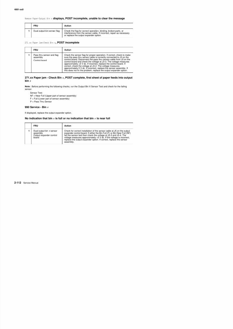
8/13/2019 t644 Service Manual
http://slidepdf.com/reader/full/t644-service-manual 154/423
271.xx Paper jam - Check Bin x , POST complete, first sheet of paper feeds into outputbin x
Note: Before performing the following checks, run the Output Bin X Sensor Test and check for the failing
sensor.Sensor Test:NF = Near Full (Upper part of sensor assembly)F = Full (Lower part of sensor assembly)P = Pass Thru Sensor
990 Service - Bin x
If displayed, replace the output expander option.
No indication that bin x is full or no indication that bin x is near full
assembly
Control board
sure the pass thru sensor cable is correctly connected to J3 on thecontrol board. Disconnect the pass thru sensor cable from J3 on the
control board and check the voltage at J3-3. The voltage measuresapproximately +5 V dc. If incorrect, replace the control board. Ifcorrect, check the voltage at J3-2. The voltage measuresapproximately 0 V dc. If incorrect, replace the sensor assembly. Ifthis does not fix the problem, replace the output expander option.
FRU Action
1 Dual output bin x sensorassemblyOutput expander controlboard
Check for correct installation of the sensor cable at J5 on the outputexpander control board. If either the Bin Full (F) or Bin Near Full (NF)fail the sensor test then check the voltage at J5-3 and J5-4. Thevoltage measures approximately +5 V dc. If the voltage is incorrect,replace the output expander option. If correct, replace the sensorassembly.
4061-xx0
Paper feed servic e check
If you have a 936 Transport Motor Error go to “Main drive service check” on page 2-106.
Autocompensator fails to feed paper Failures occur randomly throughout the stack
FRU Action
1 Alignment assembly Check to ensure the alignment assembly is correctly attached to theleft side frame and the mounting screws are tight. Check thealignment assembly for worn rollers, contaminated rollers, or binds.Replace the alignment assembly if any problem is found.
2 Inner deflector Check the inner paper deflector for correct installation. If the deflectoris bowed or not fitting correctly, replace the deflector.
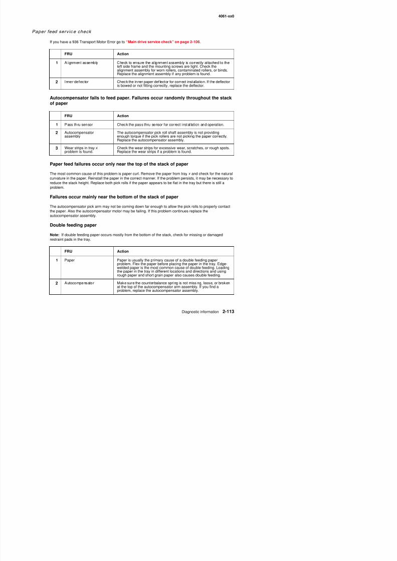
8/13/2019 t644 Service Manual
http://slidepdf.com/reader/full/t644-service-manual 155/423
Autocompensator fails to feed paper. Failures occur randomly throughout the stackof paper
Paper feed failures occur only near the top of the stack of paper
The most common cause of this problem is paper curl. Remove the paper from tray x and check for the naturalcurvature in the paper. Reinstall the paper in the correct manner. If the problem persists, it may be necessary toreduce the stack height. Replace both pick rolls if the paper appears to be flat in the tray but there is still aproblem.
Failures occur mainly near the bottom of the stack of paper
The autocompensator pick arm may not be coming down far enough to allow the pick rolls to properly contactthe paper. Also the autocompensator motor may be failing. If this problem continues replace theautocompensator assembly.
Double feeding paper
Note: If double feeding paper occurs mostly from the bottom of the stack, check for missing or damaged
restraint pads in the tray.
FRU Action
1 Pass thru sensor Check the pass thru sensor for correct instal lation and operation.
2 Autocompensatorassembly
The autocompensator pick roll shaft assembly is not providingenough torque if the pick rollers are not picking the paper correctly.Replace the autocompensator assembly.
3 Wear strips in tray x
problem is found.
Check the wear strips for excessive wear, scratches, or rough spots.
Replace the wear strips if a problem is found.
FRU Action
4061-xx0
Paper fails to feed from the multipurpose tray
The pick roll should make one complete revolution and stop with the flat side down. If the pick roll turns butdoes not pick paper, check the roll for signs of wear, oil or grease on the surface of the pick roll or slickspots. If you find a problem, replace the pick roll assembly. Check to ensure the media that is being fedthrough the multipurpose tray assembly meets recommended paper specifications.
Paper size sensing serv ice check
Before proceeding, check for the correct paper size loaded in the tray and that the tray has been set to acceptthe size paper loaded in the tray.
CN1SW2
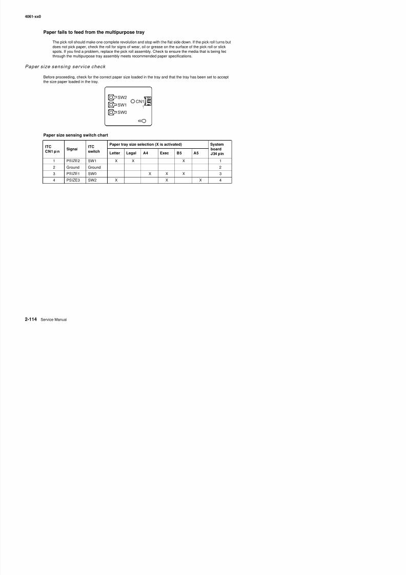
8/13/2019 t644 Service Manual
http://slidepdf.com/reader/full/t644-service-manual 156/423
Paper size sensing switch chart
ITCCN1 pin
SignalITCswitch
Paper tray size selection (X is activated) Systemboard
J34 pinLetter Legal A4 Exec B5 A51 PSIZE2 SW1 X X X 1
2 Ground Ground 2
3 PSIZE1 SW0 X X X 3
4 PSIZE3 SW2 X X X 4
CN1
1
SW1
SW0
4061-xx0
Tray 1 not recognized as being installed; unable to clear Tray 1 Missing message
FRU Action
1 Tray 1 Check Tray 1 for damaged or broken autosize fingers. Check foranything that would prevent the autosize fingers from activating the
paper activate springs and ITC switches.
A 5
B 5 E X E
C L T R
A 4
L G L
SW 2
W1
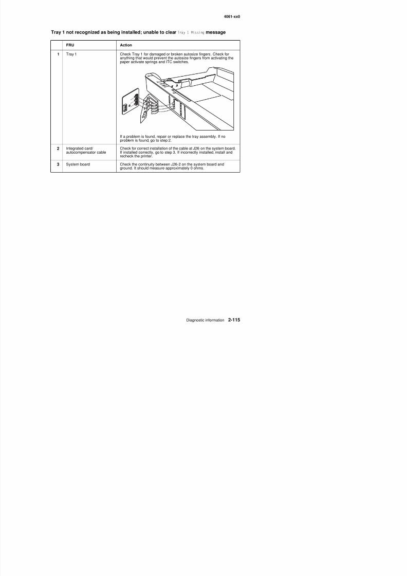
8/13/2019 t644 Service Manual
http://slidepdf.com/reader/full/t644-service-manual 157/423
If a problem is found, repair or replace the tray assembly. If noproblem is found, go to step 2.
2 Integrated card/ autocompensator cable
Check for correct installation of the cable at J26 on the system board.If installed correctly, go to step 3. If incorrectly installed, install andrecheck the printer.
3 System board Check the continuity between J26-2 on the system board andground. It should measure approximately 0 ohms.
SW
SW 0
4061-xx0
The printer does not recognize the paper size selected
FRU Action
1 Back restraintSide restraint
Snap-in plateAutosize sliderAutosize finger
Check all the paper size parts for damage or broken parts. make surethe parts operate correctly. If a problem is found, repair as
necessary. If no problem is found, go to step 2.
2 Switch activate springPaper size sending board
Make sure the switch activate spring is not bent or broken. Replacethe spring if damaged. If the spring is not damaged, go to step 3.
3 System boardITC cable
Set the tray for the paper size that is not recognized and install thetray in the printer. Select the paper size and corresponding paperswitch from table, below.
Pin Signal Static Static ith paper tra in and set to (V dc)
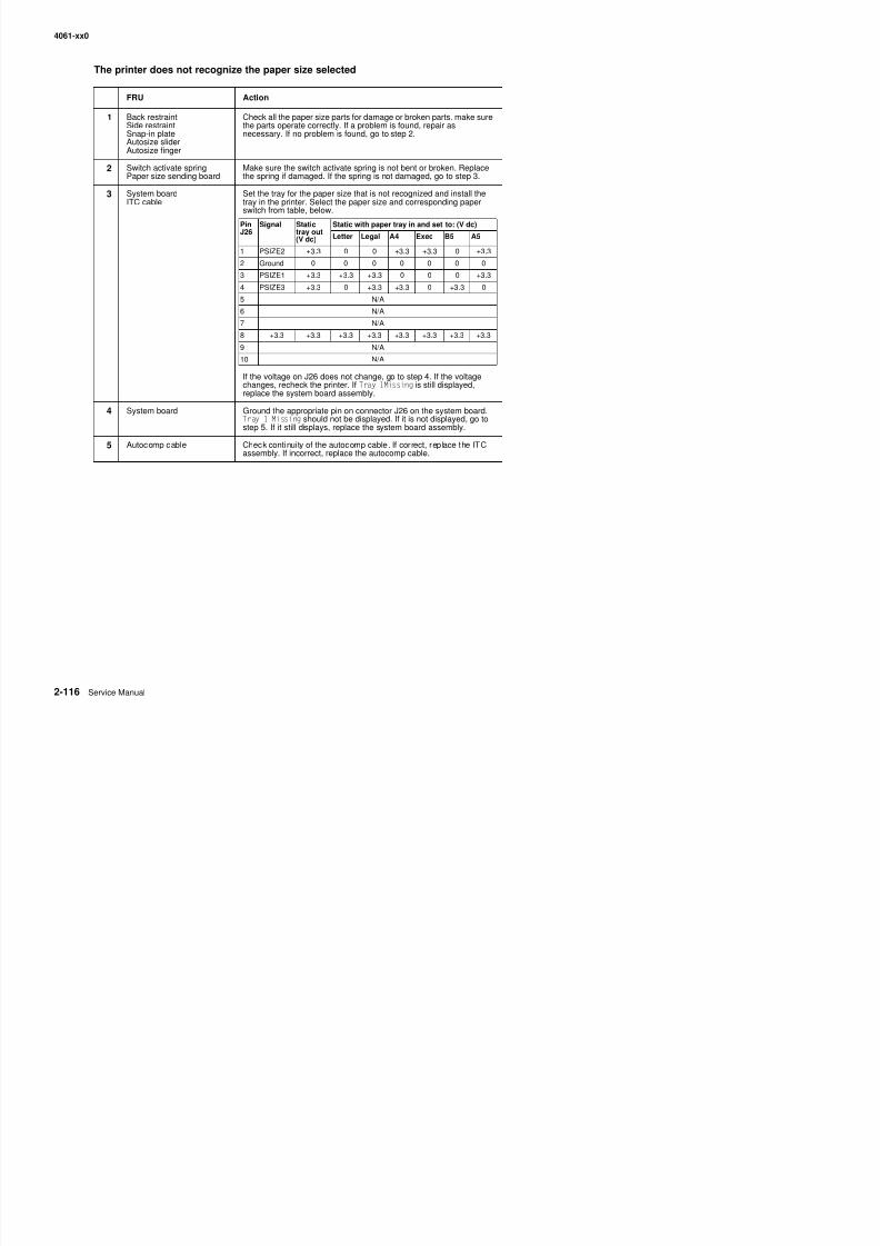
8/13/2019 t644 Service Manual
http://slidepdf.com/reader/full/t644-service-manual 158/423
If the voltage on J26 does not change, go to step 4. If the voltagechanges, recheck the printer. If Tray 1Missing is still displayed,replace the system board assembly.
4 System board Ground the appropriate pin on connector J26 on the system board.Tray 1 Missing should not be displayed. If it is not displayed, go tostep 5. If it still displays, replace the system board assembly.
5 Autocomp cable Check continui ty of the autocomp cable. If correct, replace the ITCassembly. If incorrect, replace the autocomp cable.
PinJ26
Signal Statictray out(V dc)
Static with paper tray in and set to: (V dc)
Letter Legal A4 Exec B5 A51 PSIZE2 +3.3 0 0 +3.3 +3.3 0 +3.3
2 Ground 0 0 0 0 0 0 0
3 PSIZE1 +3.3 +3.3 +3.3 0 0 0 +3.3
4 PSIZE3 +3.3 0 +3.3 +3.3 0 +3.3 0
5 N/A
6 N/A
7 N/A
8 +3.3 +3.3 +3.3 +3.3 +3.3 +3.3 +3.3 +3.39 N/A
10 N/A
4061-xx0
Paral le l port serv ice check
Run the “Parallel Wrap tests” on page 3-8.
Note: The Parallel Wrap Test is designed to check the parallel port hardware by using a wrap plug (P/N1319128) and invoking the Parallel Diagnostic Test. This test helps isolate the printer from the parallel cable andhost. The test provides failure information on the display for approximately three seconds. If the test indicatesthat a problem is detected, replace the controller board.
Print qu al ity serv ice check
Service tip: Before troubleshooting any print quality problems do the following:
• Install another print cartridge if available before proceeding with the service checks.• Use Tray 1 to test for print quality of the base printer.
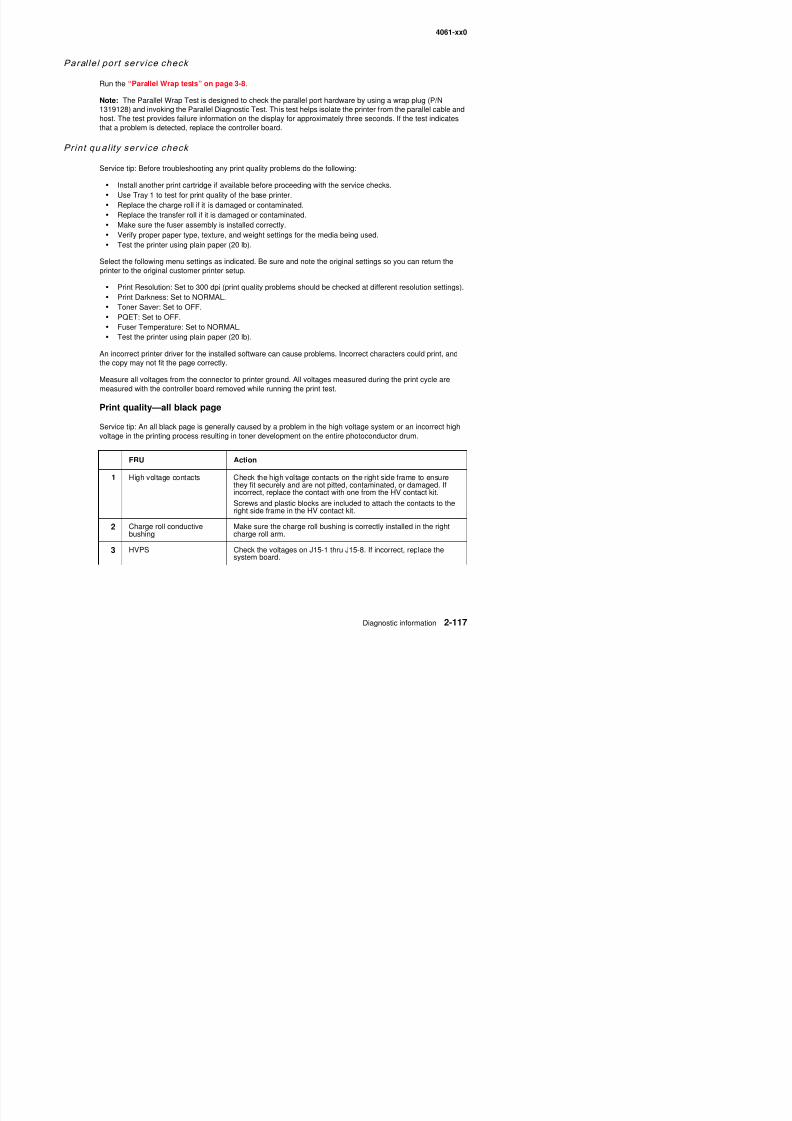
8/13/2019 t644 Service Manual
http://slidepdf.com/reader/full/t644-service-manual 159/423
• Replace the charge roll if it is damaged or contaminated.
• Replace the transfer roll if it is damaged or contaminated.• Make sure the fuser assembly is installed correctly.• Verify proper paper type, texture, and weight settings for the media being used.• Test the printer using plain paper (20 lb).
Select the following menu settings as indicated. Be sure and note the original settings so you can return theprinter to the original customer printer setup.
• Print Resolution: Set to 300 dpi (print quality problems should be checked at different resolution settings).• Print Darkness: Set to NORMAL.
• Toner Saver: Set to OFF.• PQET: Set to OFF.• Fuser Temperature: Set to NORMAL.• Test the printer using plain paper (20 lb).
An incorrect printer driver for the installed software can cause problems. Incorrect characters could print, andthe copy may not fit the page correctly.
Measure all voltages from the connector to printer ground. All voltages measured during the print cycle are
measured with the controller board removed while running the print test.
Print quality—all black page
Service tip: An all black page is generally caused by a problem in the high voltage system or an incorrect highvoltage in the printing process resulting in toner development on the entire photoconductor drum.
FRU Action
1 High voltage contacts Check the high voltage contacts on the right side frame to ensurethey fit securely and are not pitted, contaminated, or damaged. Ifincorrect, replace the contact with one from the HV contact kit.
Screws and plastic blocks are included to attach the contacts to thei ht id f i th HV t t kit
4061-xx0
Print quality—blank page
4 HVPS cable(part of frontharness cable)
System board
Check the continuity of the HVPS cable. If incorrect, replace thecable assembly. If correct, replace the system board.
FRU Action
1 Print cartridge Check the print cartridge for damage, especially the PC drum contacton the cartridge.
2 High voltage contact Check the PC drum contact on the right side frame for damage, PC
FRU Action
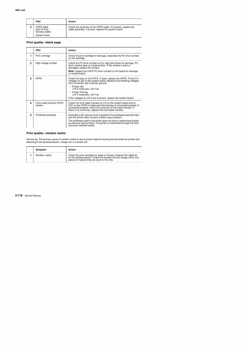
8/13/2019 t644 Service Manual
http://slidepdf.com/reader/full/t644-service-manual 160/423
Print quality—random marks
Service tip: The primary cause of random marks is due to loose material moving around inside the printer andattaching to the photoconductor, charge roll, or transfer roll.
2 High voltage contact Check the PC drum contact on the right side frame for damage, PCdrum contact wear or contamination. If the contact is bent ordamaged, replace the contact.Note: Inspect the HVPS PC drum contact on the board for damageor contamination.
3 HVPS Check the fuse on the HVPS. If open, replace the HVPS. Check thevoltages at J22 on the system board. Measure the following voltagesfrom connector J22 to printer ground:
• Printer IdleJ15-5 measures +24 V dc
• Printer Printing
J15-5 measures +24 V dcIf the voltages at J10-5 are incorrect, replace the system board.
4 Front cable harness HVPSsection
Check the front cable harness at J15 on the system board and atCN1 on the HVPS to make sure the harness is connected properly. Ifconnected properly, check the continuity of the cable harness. Ifthere is no continuity, replace the front cable harness.
5 Printhead assembly Generally a 93 x service error is posted if the printhead assembly failsand the printer does not give a blank copy symptom.
The printhead used in the printer does not have a mechanical shutter
as previous laser printers. The printer is interlocked through the fronttop cover interlock switch.
Symptom Action
1 Random marks Check the print cartridge for loose or foreign material that might beon the photoconductor. Check the transfer roll and charge roll for anypieces of material that are stuck to the rolls
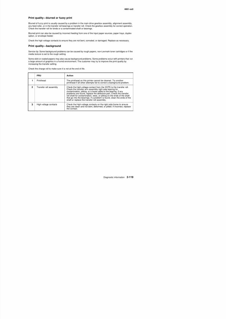
8/13/2019 t644 Service Manual
http://slidepdf.com/reader/full/t644-service-manual 161/423
4061-xx0
4 System board HVPSconnector
Check the following voltages at J15 on the system board. Measurethe voltages from J15 to printer ground.
If J15 1 voltage is incorrect check the continuity of the front harness
FRU Action
Pin J15 Voltage (approximate)
Printer idle
J15-1 0 V dcJ15-2 +4 V dc
J15-4 0 V dc
Printer printing
J15-1 0 V dc to +5 V dc
J15-2 0 V dc to +4 V dc
J15-4 0 V dc to +1.9 V dc
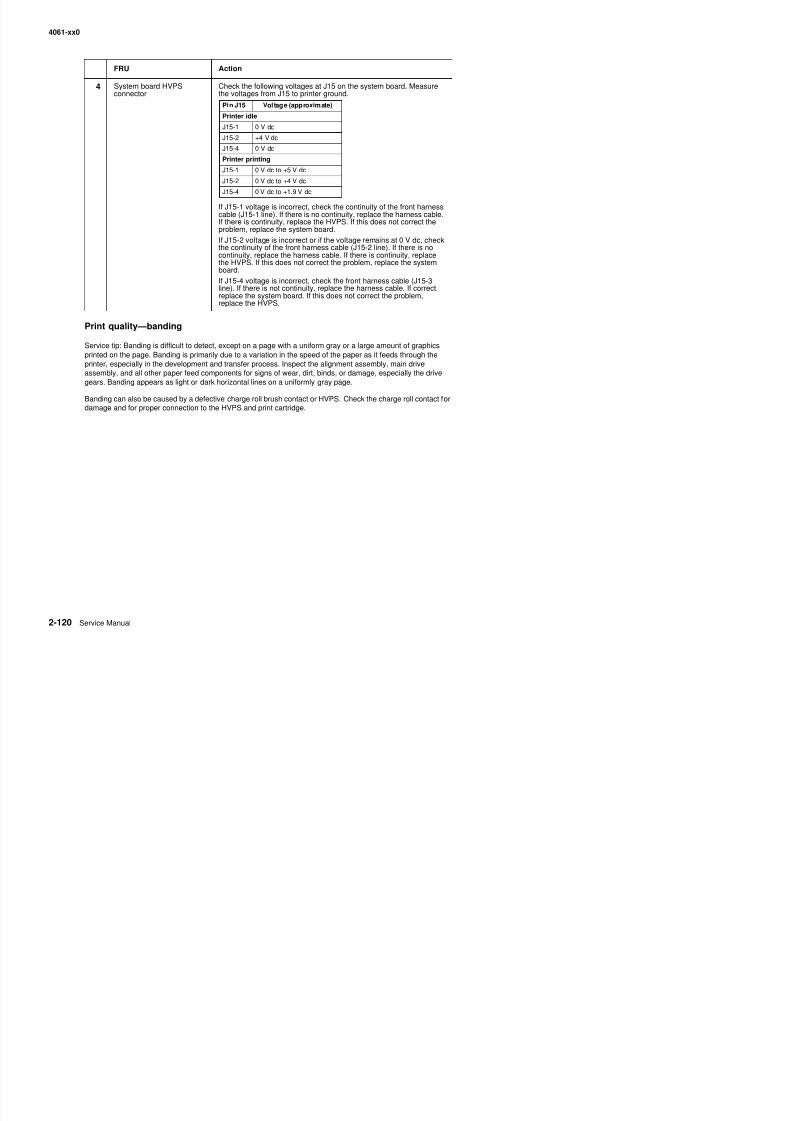
8/13/2019 t644 Service Manual
http://slidepdf.com/reader/full/t644-service-manual 162/423
Print quality—banding
Service tip: Banding is difficult to detect, except on a page with a uniform gray or a large amount of graphicsprinted on the page. Banding is primarily due to a variation in the speed of the paper as it feeds through theprinter, especially in the development and transfer process. Inspect the alignment assembly, main driveassembly, and all other paper feed components for signs of wear, dirt, binds, or damage, especially the drivegears. Banding appears as light or dark horizontal lines on a uniformly gray page.
Banding can also be caused by a defective charge roll brush contact or HVPS. Check the charge roll contact fordamage and for proper connection to the HVPS and print cartridge.
If J15-1 voltage is incorrect, check the continuity of the front harness
cable (J15-1 line). If there is no continuity, replace the harness cable.If there is continuity, replace the HVPS. If this does not correct theproblem, replace the system board.
If J15-2 voltage is incorrect or if the voltage remains at 0 V dc, checkthe continuity of the front harness cable (J15-2 line). If there is nocontinuity, replace the harness cable. If there is continuity, replacethe HVPS. If this does not correct the problem, replace the systemboard.
If J15-4 voltage is incorrect, check the front harness cable (J15-3line). If there is not continuity, replace the harness cable. If correct,replace the system board. If this does not correct the problem,
replace the HVPS.
4061-xx0
Print quality—black bands on outer edges of the page
This print quality problem appears as vertical black bands on one or both sides of the copy and can be wide,narrow, light, or dark.
FRU Action
1 Charge roll counterbalancesprings
If the problem is just on one side of the page, check the charge rollcounterbalance spring on that side. You can check to see if enoughforce is being applied to the charge roll by applying slight downwardpressure with your finger to the charge roll link arm that the spring isattached to while you run a print test sample. See if the problemchanges or goes away. If this fixes or changes the problem, thencheck the springs and charge roll link arm assemblies for binds ordefective parts. Replace as necessary.
2 Charge roll assemblyCharge roll link arm
Check the charge roll for toner buildup or other contamination on theouter edges that correspond to the bands on the page Check the
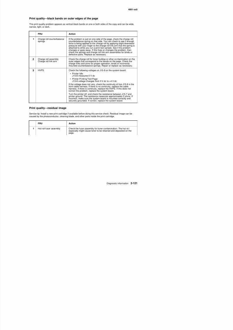
8/13/2019 t644 Service Manual
http://slidepdf.com/reader/full/t644-service-manual 163/423
Print quality—residual image
Service tip: Install a new print cartridge if available before doing this service check. Residual image can be
caused by the photoconductor, cleaning blade, and other parts inside the print cartridge.
Charge roll link arm outer edges that correspond to the bands on the page. Check the
charge links and arms for proper operation, binds or incorrectlymounted counterbalance springs. Repair or replace as necessary.
3 HVPS Check the following voltages at J15-8 on the system board:
• Printer IdleJ15-8 measures 0 V dc
• Printer Printing Test PageJ15-8 voltage changes from 0 V dc to +4 V dc
If the voltage does not vary, check the continuity of line J15-8 in thefront cable harness. If there is no continuity, replace the cable
harness. If there is continuity, replace the HVPS. If this does notcorrect the problem, replace the system board.
Turn the printer off, and check the resistance between J15-7 andprinter ground. The resistance measures approximately 0 ohms. Ifincorrect, make sure the system board is mounted correctly andsecurely grounded. If correct, replace the system board.
FRU Action
1 Hot roll fuser assembly Check the fuser assembly for toner contamination. The hot rollespecially might cause toner to be retained and deposited on thepage.
4061-xx0
Print quality—light print
Service tip: Check the toner saver and print darkness settings first if the print is light.
FRU Action
1 Transfer roll Check the right end of the transfer roll shaft for signs of wear orcontamination. If incorrect, replace the transfer roll.
2 Right side transfer roll armassembly
HVPS
Check the right side transfer roll arm assembly bearing for wear orcontamination. Also make sure the transfer cable is firmly attached tothe bearing. If incorrect, replace the right side transfer arm assembly.Check the connection of the transfer roll assembly cable to thetransformer on the HVPS board. Check the continuity of the cablefrom the bearing to the spade terminal on the cable. If incorrect,replace the right side transfer arm assembly. If correct, replace theHVPS.
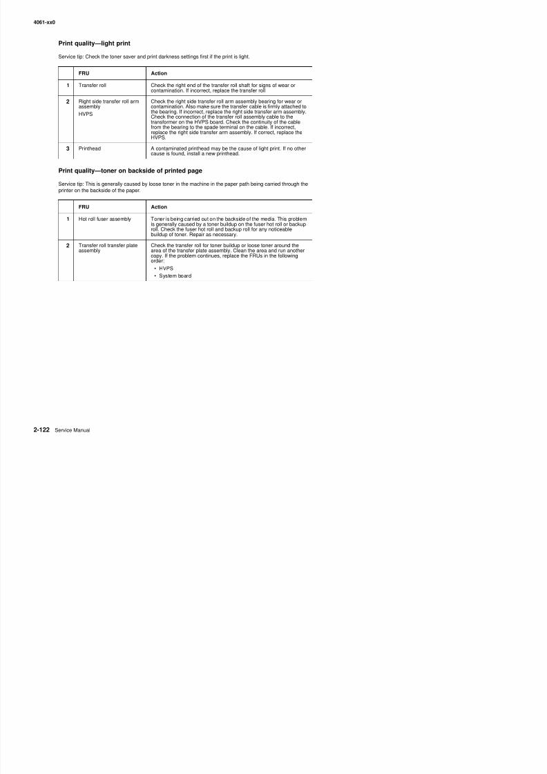
8/13/2019 t644 Service Manual
http://slidepdf.com/reader/full/t644-service-manual 164/423
Print quality—toner on backside of printed page
Service tip: This is generally caused by loose toner in the machine in the paper path being carried through theprinter on the backside of the paper.
3 Printhead A contaminated printhead may be the cause of light print. If no othercause is found, install a new printhead.
FRU Action
1 Hot roll fuser assembly Toner is being carried out on the backside of the media. This problemis generally caused by a toner buildup on the fuser hot roll or backuproll. Check the fuser hot roll and backup roll for any noticeablebuildup of toner. Repair as necessary.
2 Transfer roll transfer plateassembly
Check the transfer roll for toner buildup or loose toner around thearea of the transfer plate assembly. Clean the area and run anothercopy. If the problem continues, replace the FRUs in the followingorder:
• HVPS
• System board
4061-xx0
Printhead serv ice check
CAUTION: The printhead is not a serviceable FRU. Do not disassemble the printhead.
The printhead assembly does not contain any service replaceable parts or components. If service error code930.xx displays, the wrong printhead is installed in the printer. See “Printhead” on page 7-10.
Note: A 201.xx paper jam may also indicate a failing printhead. The paper may have jammed prior to or at theinput sensor. Print the event log and see if 201 or 931 errors are logged.
Service error code Explanation
1 Error code 931.xxNo first HYSNC SignalError Code 932Lost HYSNC
These errors usually indicate a failure in the HYSNC signal to theprinthead. Check the continuity of the cables connected to J2 and J4on the system board. If incorrect, replace the defective cable. Thevoltage at J4-1 measures approximately +5 V dc. If incorrect, replacethe system board. The voltage at J2-7 measures approximately
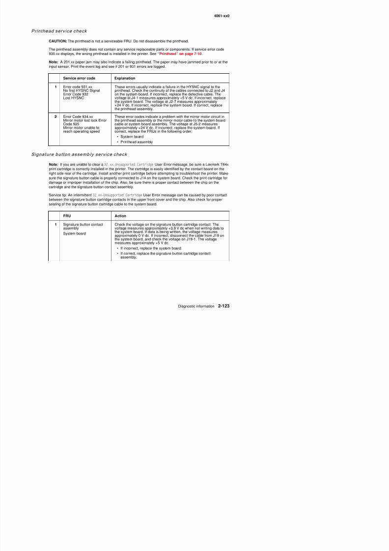
8/13/2019 t644 Service Manual
http://slidepdf.com/reader/full/t644-service-manual 165/423
Signature button assemb ly serv ice check
Note: If you are unable to clear a 32.xx-Unsupported Cartridge User Error message, be sure a Lexmark T64xprint cartridge is correctly installed in the printer. The cartridge is easily identified by the contact board on theright side rear of the cartridge. Install another print cartridge before attempting to troubleshoot the printer. Makesure the signature button cable is properly connected to J14 on the system board. Check the print cartridge fordamage or improper installation of the chip. Also, be sure there is proper contact between the chip on thecartridge and the signature button contact assembly.
Service tip: An intermittent 32.xx-Unsupported Cartridge User Error message can be caused by poor contactbetween the signature button cartridge contacts in the upper front cover and the chip. Also check for properseating of the signature button cartridge cable to the system board.
y g pp y
+24 V dc. If incorrect, replace the system board. If correct, replacethe printhead assembly.
2 Error Code 934.xxMirror motor lost lock ErrorCode 935Mirror motor unable toreach operating speed
These error codes indicate a problem with the mirror motor circuit inthe printhead assembly or the mirror motor cable to the system boardcable or system board assembly. The voltage at J5-2 measuresapproximately +24 V dc. If incorrect, replace the system board. Ifcorrect, replace the FRUs in the following order:
• System board
• Printhead assembly
FRU Action
1 Signature button contactassembly
System board
Check the voltage on the signature button cartridge contact. Thevoltage measures approximately +3.8 V dc when not writing data tothe system board. If data is being written, the voltage measures
approximately 0 V dc. If incorrect, disconnect the cable from J19 onthe system board, and check the voltage on J19-1. The voltagemeasures approximately +5 V dc.
• If incorrect, replace the system board.
4061-xx0
StapleSmart f in isher serv ice check
Note: When removing the stapler mechanism from the option, first remove the staple supply cartridge.
Note: When replacing staples in the supply cartridge, discard any old staples in the cartridge, and replace witha fresh strip.
Problems with static electricity buildup
Printer does not recognize StapleSmart finisher option as being installed
FRU Action
1 Top cover Make sure the brush is attached to the top cover assembly, theground clips are installed, and the brush is grounded.
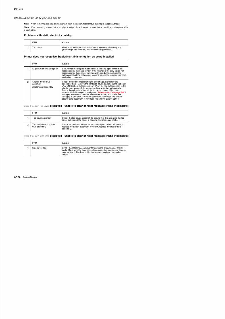
8/13/2019 t644 Service Manual
http://slidepdf.com/reader/full/t644-service-manual 166/423
Close Finisher Top Cover displayed—unable to clear or reset message (POST incomplete)
Close Finisher Side Door displayed—unable to clear or reset message (POST incomplete)
FRU Action
1 StapleSmart finisher option Ensure that the StapleSmart finisher is the only option that is notrecognized by the base printer. If the finisher is the only option notrecognized by the printer, continue with step 2. If not, check theautoconnects of the options not recognized and the interconnect cardand cable connectors.
2 Stapler motor/driveassembly
stapler card assembly
Check the autoconnects for signs of damage, especially theconnector pins. Remove the right side cover, and check the cables at
J1A, J1B (bottom autoconnect), J14A, J14B (top autoconnect) to thestapler card assembly to make sure they are attached securely.Check the voltages at the printer top autoconnect. If incorrect,remove the finisher option, and go to “Autoconnect” on page 5-7. Ifvoltages are correct, reinstall the finisher option, and check thevoltages at J1A and J1B on the connector. If correct, replace thestapler card assembly. If incorrect, replace the stapler option.
FRU Action
1 Top cover assembly Check the top cover assembly to ensure that it is actuating the topcover switch and the cover is opening and closing correctly.
2 Top cover switch staplercard assembly
Check continuity of the stapler top cover open switch. If incorrect,replace the switch assembly. If correct, replace the stapler cardassembly.
FRU Action
4061-xx0
POST incomplete—stapler cycles several times
990.xx Service Error Code—Check Bin x displayed—POST incomplete
• “Step1—During POST the stapler option does not try to home” on page 2-125.• “Step 2—During POST the stapler option tries to home” on page 2-125.
Step1—During POST the stapler option does not try to home
FRU Action
1 Stapler assembly Replace the stapler assembly.
Note: When replacing the stapler assembly, observe the location of
the ground lead from the stapler assembly and the finisher frame.Make sure the ground lead is correctly reattached.

8/13/2019 t644 Service Manual
http://slidepdf.com/reader/full/t644-service-manual 167/423
Replace the stapler option.
Step 2—During POST the stapler option tries to home
Replace the stapler option.
281.xx Paper Jam —paper feeds partway into the standard bin even if finisher is selected
Note: When a 900.xx Service Error is displayed during POST, the failure is usually in the stapler gearboxassembly or stapler cartridge.
Replace the stapler option.
281.xx Paper Jam —The paper may jam at the upper deflector
Replace the stapler option.
281.xx Paper Jam —paper jams into stapler output bin
Replace the stapler option.
282.xx Staple Jam—Check Stapler displays
FRU Action
1 Stapler assembly Check the stapler assembly for broken or damaged parts.
4061-xx0
POST incomplete—Insert Stapler Cartridge displays (cartridge holder is installed andcannot clear message)
When this failure occurs, the following may also occur in the order shown:
• Insert Staple Cartridge displayed.The stapler assembly may cycle or fire a few times.
• 282.xx Stapler Jam displayed.The stapler assembly may try to cycle or fire.
• 990.xx Service - Check Bin 1 displayed.
FRU Action
1 Stapler cartridge holder
Stapler assembly
Before proceeding with the service check, gently try to remove thestapler cartridge holder from the stapler assembly. If the holder is jammed in the stapler assembly:
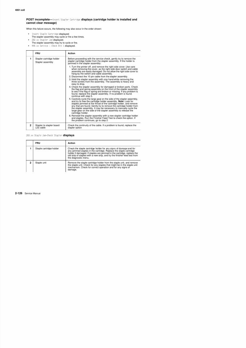
8/13/2019 t644 Service Manual
http://slidepdf.com/reader/full/t644-service-manual 168/423
283.xx Staple Jam—Check Stapler displays
1. Turn the printer off, and remove the right side cover. Use carewhen removing the cover, as the right side door switch and cableassembly are easily damaged. Do not allow the right side cover tohang by the switch and cable assembly.
2. Disconnect the 10 pin cable from the stapler assembly.3. Hold the stapler assembly with one hand while removing the
three screws from the assembly. The assembly is heavy andeasy to drop.
4. Check the stapler assembly for damaged or broken parts. Checkthe flag and spring assembly on the front of the stapler assemblyto see if the flag or spring are broken or missing. If any problem is
found, replace the stapler assembly. If no problem is found,continue with step 5.5. Carefully cycle the large gear on the side of the stapler assembly,
and try to free the cartridge holder assembly. Note: Look forstaples jammed at the throat of the cartridge holder, and removeany that are found. Gently try to remove the cartridge holder fromthe stapler assembly. It may be necessary to manually cycle thelarge gear on the side of the stapler assembly to release thecartridge holder.
6. Reinstall the stapler assembly with a new stapler cartridge holderand staples. Run the Finisher Feed Test to check the option. Ifthe problem continues, go to step 2.
2 Stapler to stapler board(J3) cable
Check the continuity of the cable. If a problem is found, replace thestapler option.
FRU Action
1 Staple cartridge holder Check the staple cartridge holder for any signs of damage and forany jammed staples in the cartridge. Replace the staple cartridgeholder if damaged. If staples are jammed in the cartridge, replace theold strip of staples with a new strip, and try the finisher feed test fromthe diagnostic menu
4061-xx0
Paper feeds into finisher option output tray—Paper is not stapled—Paper does notalign with the right side
Replace the stapler option.
Misalignment of sheets to be stapled
Sheets are transported into output tray but not stapled
FRU Action
1 Left side bail assembly Check the left side bail assembly for any signs of binding, missing, orbroken parts.
2 Stapler gearbox assembly Check the stapler gearbox assembly for correct operation. If theproblem is found, replace the stapler option.
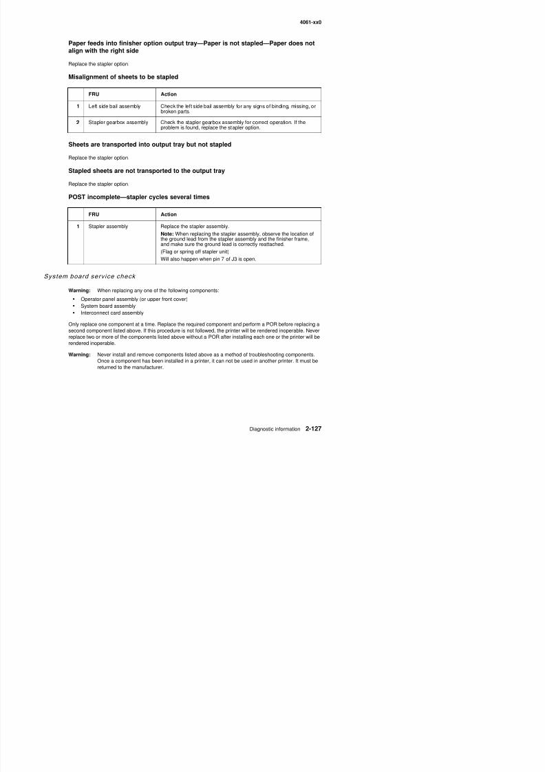
8/13/2019 t644 Service Manual
http://slidepdf.com/reader/full/t644-service-manual 169/423
Replace the stapler option.
Stapled sheets are not transported to the output tray
Replace the stapler option.
POST incomplete—stapler cycles several times
System board serv ice check
Warning: When replacing any one of the following components:
• Operator panel assembly (or upper front cover)• System board assembly• Interconnect card assembly
Only replace one component at a time. Replace the required component and perform a POR before replacing a
second component listed above. If this procedure is not followed, the printer will be rendered inoperable. Neverreplace two or more of the components listed above without a POR after installing each one or the printer will berendered inoperable.
FRU Action
1 Stapler assembly Replace the stapler assembly.
Note: When replacing the stapler assembly, observe the location ofthe ground lead from the stapler assembly and the finisher frame,and make sure the ground lead is correctly reattached.
(Flag or spring off stapler unit)
Will also happen when pin 7 of J3 is open.
4061-xx0
Toner sensor serv ice check
Service tip: Check the print darkness menu setting before checking the toner sensor.
This service check is intended to be used when a 929.xx Service Error displays.
FRU Action1 Developer drive assembly Incorrect operation of the developer drive assembly can cause the
printer to display a 929.xx error code (Toner Sensor). Check thedeveloper drive assembly for correct installation or, any sign of worn,loose, or broken parts.
2 Front harness cable Check the toner sensor portion of the front harness cable to makesure it is properly seated into the toner sensor. If correct at both thesensor and system board (J15), check the continuity of the cable. Ifincorrect, replace the cable.
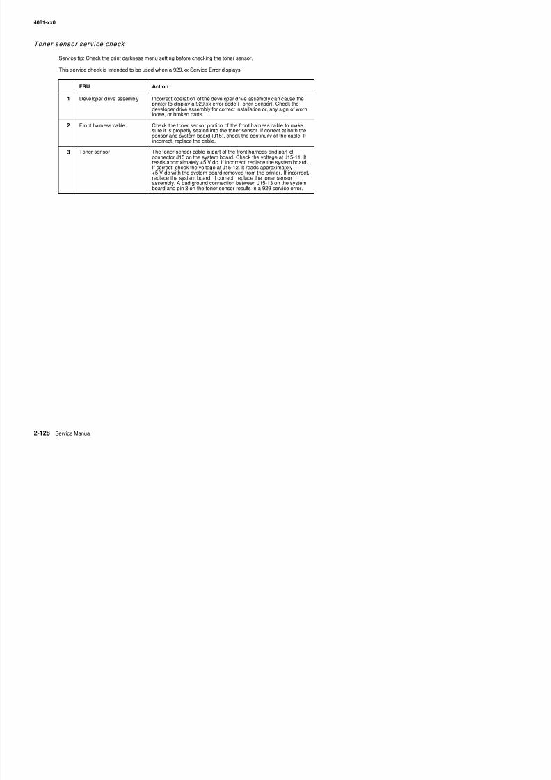
8/13/2019 t644 Service Manual
http://slidepdf.com/reader/full/t644-service-manual 170/423
3 Toner sensor The toner sensor cable is part of the front harness and part ofconnector J15 on the system board. Check the voltage at J15-11. Itreads approximately +5 V dc. If incorrect, replace the system board.If correct, check the voltage at J15-12. It reads approximately+5 V dc with the system board removed from the printer. If incorrect,replace the system board. If correct, replace the toner sensorassembly. A bad ground connection between J15-13 on the systemboard and pin 3 on the toner sensor results in a 929 service error.
4061-xx0
Transfer ro l l serv ice check
Service tip: The transfer roll is 51.02 mm (2.009 inch) circumference. Any print quality problems such as linesthat are spaced 51.02 mm apart indicate you should check the transfer roll for damage and check for toner orforeign material buildup.
Service tip: The transfer roll assembly is part of the maintenance kit and is replaced when an 80 Scheduled
Maintenance displays. Ask the customer if they have replaced the transfer roll recently.
CAUTION: Make sure the printer is unplugged before making any checks on the transfer roll orassociated parts for personal safety and to prevent damage to the printer.
FRU Action
1 Transfer roll assembly Check the transfer roll for toner buildup, surface damage to the roll,
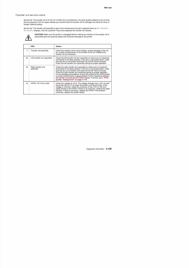
8/13/2019 t644 Service Manual
http://slidepdf.com/reader/full/t644-service-manual 171/423
oil, or other contaminants on the surface of the roll. Replace thetransfer roll as necessary.
2 Left transfer arm assembly Check the left transfer roll arm assembly to make sure it is fastenedand locked in the down position. If the arm is not locked down, makesure the arm is not broken and locks into the EP frame correctly.Check the left transfer arm assembly spring for proper operation.
3 Right transfer armassembly
Check the right transfer arm assembly to make sure it is fastenedand locked in the down position. If the arm is not locked down, makesure the arm is not broken and locks into the EP frame correctly.
Check the right transfer arm assembly spring for proper operation.For any background problems, ensure the contact to the HVPS boardis correct and that there is approximately 0 ohms resistance betweenthe transfer roll shaft and the HVPS contact. If correct, go to “Printquality—background” on page 2-119.
4 HVPS—917 Error code Check the voltage at J15-3. The voltage changes from +24 V dc withthe printer idle to 0 V dc when the printer runs the print test. If thevoltage is incorrect, check the continuity of line J15-3 in the frontcable harness to the HVPS. If there is no continuity, replace the cableharness. If there is continuity, replace the HVPS. If the problemcontinues, replace the system board.
4061-xx0

8/13/2019 t644 Service Manual
http://slidepdf.com/reader/full/t644-service-manual 172/423
4061-xx0
3. Diagnostic aids
This chapter explains the tests and procedures to identify printer failures and verify repairs have corrected theproblem.
Accessing service menusThere are different test menus that can be accessed during POR to identify problems with the printer.
Diagnostics Mode 1. Turn off the printer.2. Press and hold and .
The Diagnostics Mode group contains the settingsand operations used while manufacturing andservicing the printer.
See “Diagnostics mode” on page 3-2 for moreinformation.
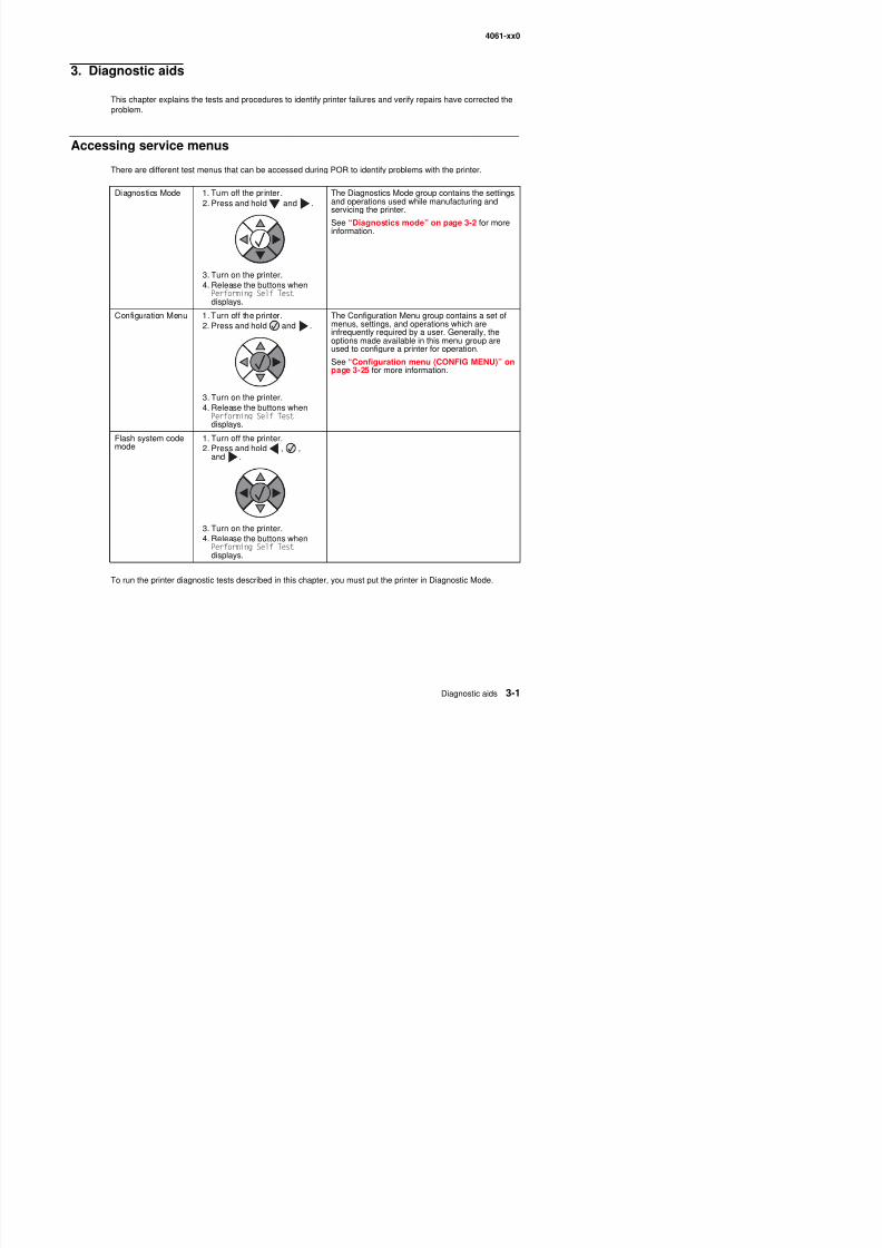
8/13/2019 t644 Service Manual
http://slidepdf.com/reader/full/t644-service-manual 173/423
3. Turn on the printer.4. Release the buttons when
Performing Self Test displays.
Configuration Menu 1. Turn off the printer.2. Press and hold and .
3. Turn on the printer.4. Release the buttons when
Performing Self Test displays.
The Configuration Menu group contains a set ofmenus, settings, and operations which areinfrequently required by a user. Generally, the
options made available in this menu group areused to configure a printer for operation.
See “Configuration menu (CONFIG MENU)” onpage 3-25 for more information.
Flash system codemode 1. Turn off the printer.2. Press and hold , ,and .
3. Turn on the printer.
4. Release the buttons whenPerforming Self Test displays.
4061-xx0
Diagnostics mode
Enter ing Diagnost ics mod e
1. Press and hold and .
2. Turn on the printer.
3. Release the buttons when Performing Self Test displays.
Av ai lable tests
The tests display on the operator panel in the order shown:
Diagnostics mode tests
REGISTRATION S “REGISTRATION” 3 4
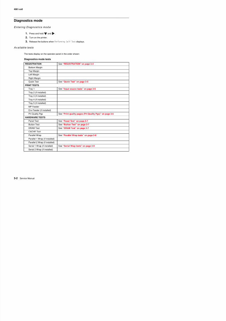
8/13/2019 t644 Service Manual
http://slidepdf.com/reader/full/t644-service-manual 174/423
REGISTRATION See “REGISTRATION” on page 3-4
Bottom Margin
Top Margin
Left Margin
Right Margin
Quick Test See “Quick Test” on page 3-5
PRINT TESTS
Tray 1 See “Input source tests” on page 3-6
Tray 2 (if installed)
Tray 3 (if installed)
Tray 4 (if installed)
Tray 5 (if installed)
MP Feeder
Env Feeder (if installed)
Prt Quality Pgs See “Print quality pages (Prt Quality Pgs)” on page 3-6HARDWARE TESTS
Panel Test See “Panel Test” on page 3-7
Button Test See “Button Test” on page 3-7
DRAM Test See “DRAM Test” on page 3-7
CACHE Test
Parallel Wrap See “Parallel Wrap tests” on page 3-8
Parallel 1 Wrap (if installed)Parallel 2 Wrap (if installed)
Serial 1 Wrap (if instal led) See “Serial Wrap tests” on page 3 9
4061-xx0
DUPLEX TESTS (if installed)
Quick Test See “Quick Test (duplex)” on page 3-9
Top Margin See “Top Margin (duplex)” on page 3-10
Sensor Test See “Sensor Test (duplex)” on page 3-10
Motor Test See “Motor Test (duplex)” on page 3-11Duplex Feed 1 See “Duplex Feed 1” on page 3-12
Duplex Feed 2 See “Duplex Feed 2” on page 3-12
INPUT TRAY TESTS
Feed Tests See “Feed Tests (input tray)” on page 3-13
Sensor Test See “Sensor Test (input tray)” on page 3-13
OUTPUT BIN TESTS
Feed Tests See “Feed Tests (output bins)” on page 3-14
Diagnostics mode tests (continued)
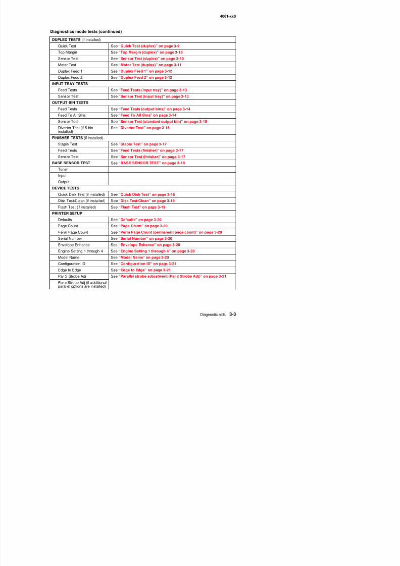
8/13/2019 t644 Service Manual
http://slidepdf.com/reader/full/t644-service-manual 175/423
Feed Tests See Feed Tests (output bins) on page 3-14Feed To All Bins See “Feed To All Bins” on page 3-14
Sensor Test See “Sensor Test (standard output bin)” on page 3-15
Diverter Test (if 5-bininstalled)
See “Diverter Test” on page 3-16
FINISHER TESTS (if installed)
Staple Test See “Staple Test” on page 3-17
Feed Tests See “Feed Tests (finisher)” on page 3-17
Sensor Test See “Sensor Test (finisher)” on page 3-17
BASE SENSOR TEST See “BASE SENSOR TEST” on page 3-18
Toner
Input
Output
DEVICE TESTS
Quick Disk Test (if installed) See “Quick Disk Test” on page 3-18
Disk Test/Clean (if installed) See “Disk Test/Clean” on page 3-19Flash Test (if installed) See “Flash Test” on page 3-19
PRINTER SETUP
Defaults See “Defaults” on page 3-20
Page Count See “Page Count” on page 3-20
Perm Page Count See “Perm Page Count (permanent page count)” on page 3-20
Serial Number See “Serial Number” on page 3-20
Envelope Enhance See “Envelope Enhance” on page 3-20Engine Setting 1 through 4 See “Engine Setting 1 through 4” on page 3-20
M d l N S “M d l N ” 3 20
4061-xx0
EP SETUP
EP Defaults See “EP Defaults” on page 3-22
Fuser Temp See “Fuser Temperature (Fuser Temp)” on page 3-22
Fuser Page Count See “Fuser Page Count” on page 3-22
Warm Up Time See “Warm Up Time” on page 3-22Transfer See “Transfer” on page 3-22
Print Contrast See “Print Contrast” on page 3-22
Charge Roll See “Charge Roll” on page 3-22
Gap Adjust See “Gap Adjust” on page 3-22
EVENT LOG
Display Log See “Display Log” on page 3-23
Print Log See “Print Log” on page 3-23
Diagnostics mode tests (continued)
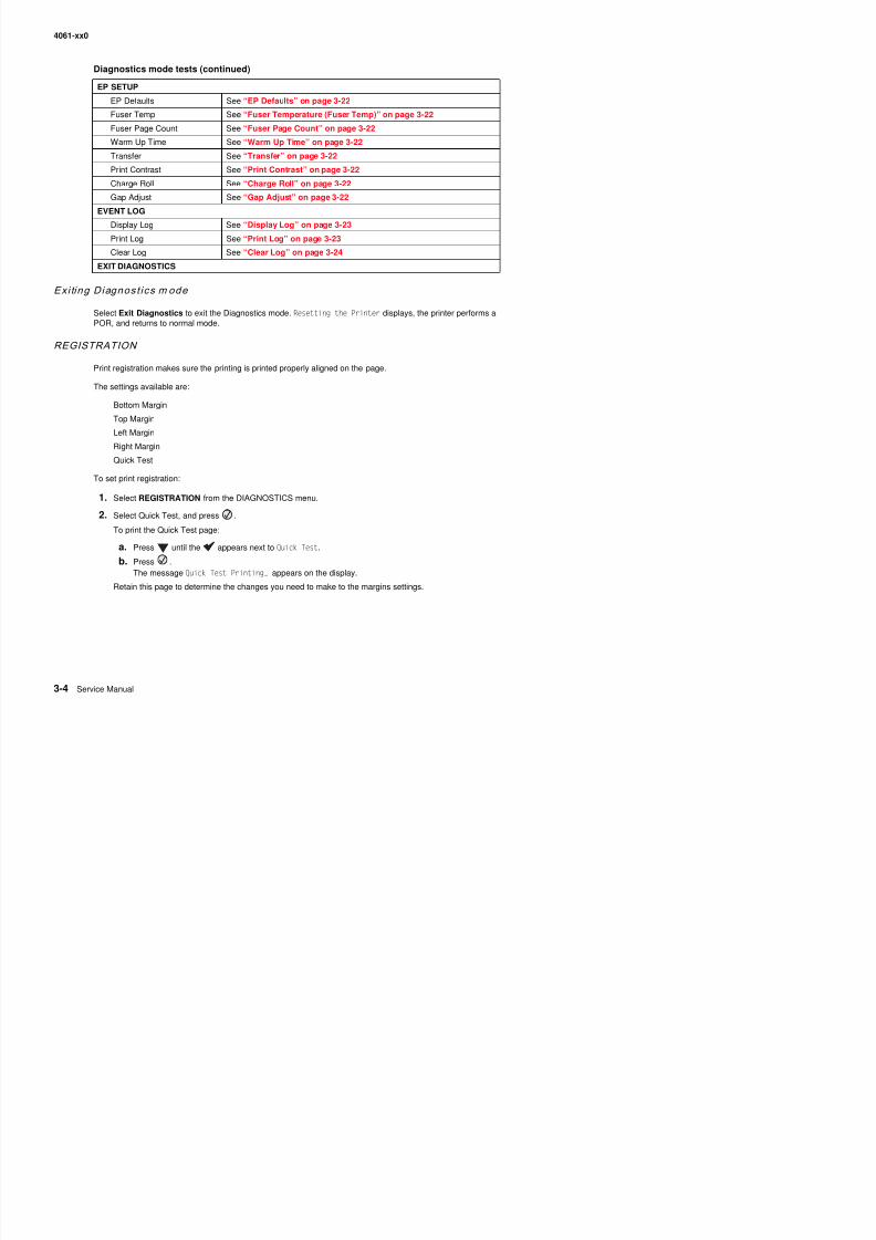
8/13/2019 t644 Service Manual
http://slidepdf.com/reader/full/t644-service-manual 176/423
Exi ting Diagnost ics m ode
Select Exit Diagnostics to exit the Diagnostics mode. Resetting the Printer displays, the printer performs aPOR, and returns to normal mode.
REGISTRATION
Print registration makes sure the printing is printed properly aligned on the page.
The settings available are:
Bottom Margin
Top Margin
Left Margin
Right Margin
Quick Test
To set print registration:
1. Select REGISTRATION from the DIAGNOSTICS menu.
2. Select Quick Test, and press .
To print the Quick Test page:
a. Press until the appears next to Quick Test.
b Press
Print Log See Print Log on page 3 23Clear Log See “Clear Log” on page 3-24
EXIT DIAGNOSTICS
4061-xx0
3. Use or to select the margin setting you need to change, and press .
The Top margin sign/value pair blinks. This indicates it is the margin value being changed.
4. Use to decrease or to increase the offset values, and press to confirm the value.The message Submitting selection displays, and the original REGISTRATION screen appears with the
beside the previously selected margin setting.
The print registration range is:
T=xxx* B=xxx*
L=xxx* R=xxx*
Variable Description Value Direction of change
B= Bottom margin -20 to +20 Each increment causesapproximately 0.55 mm shift in the
bottom margin.
A positive change compresses theimage so it appears to move down
the page and a negative changemoves the image up.
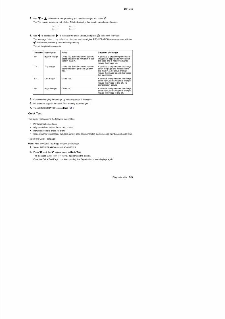
8/13/2019 t644 Service Manual
http://slidepdf.com/reader/full/t644-service-manual 177/423
5. Continue changing the settings by repeating steps 2 through 4.
6. Print another copy of the Quick Test to verify your changes.
7. To exit REGISTRATION, press Back ( ).
Quick Test
The Quick Test contains the following information:
• Print registration settings
• Alignment diamonds at the top and bottom
• Horizontal lines to check for skew
• General printer information, including current page count, installed memory, serial number, and code level.
To print the Quick Test page:
Note: Print the Quick Test Page on letter or A4 paper.
g p g g gg p
T= Top margin -25 to +25 Each increment causesapproximately 4 pels shift (at 600dpi).
A positive change moves the imagedown the page and increases thetop margin. A negative changemoves the image up and decreasesthe top margin.
L= Left margin -25 to +25 A positive change moves the imageto the right, and a negative changemoves the image to the left. Nocompression occurs.
R= Right margin -10 to +10 A positive change moves the imageto the right, and a negative changemoves the image to the left.
8/13/2019 t644 Service Manual
http://slidepdf.com/reader/full/t644-service-manual 178/423
4061-xx0
HARDWARE TESTS
Select the following Hardware Tests from this menu:
• Panel Test
• Button Test
•DRAM Test
• ROM Memory Test
• Parallel Wrap (if available)
• Serial Wrap (if available)
Panel Test
This test automatically toggles each pixel of the operator panel through every contrast level beginning with the
darkest and on to the brightest. This test continues until you press Stop ( ).
B tt T t
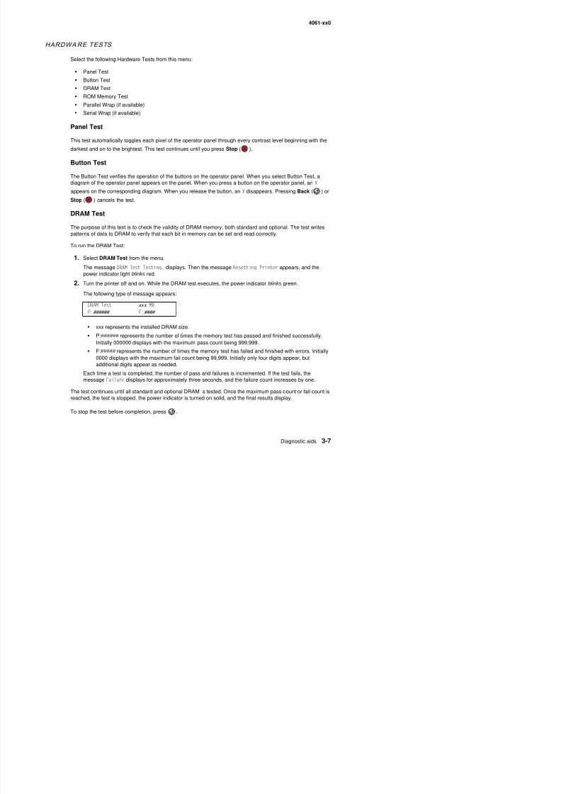
8/13/2019 t644 Service Manual
http://slidepdf.com/reader/full/t644-service-manual 179/423
Button Test
The Button Test verifies the operation of the buttons on the operator panel. When you select Button Test, adiagram of the operator panel appears on the panel. When you press a button on the operator panel, an X
appears on the corresponding diagram. When you release the button, an X disappears. Pressing Back ( ) or
Stop ( ) cancels the test.
DRAM Test
The purpose of this test is to check the validity of DRAM memory, both standard and optional. The test writespatterns of data to DRAM to verify that each bit in memory can be set and read correctly.
To run the DRAM Test:
1. Select DRAM Test from the menu.
The message DRAM Test Testing… displays. Then the message Resetting Printer appears, and thepower indicator light blinks red.
2. Turn the printer off and on. While the DRAM test executes, the power indicator blinks green.
The following type of message appears:
• xxx represents the installed DRAM size.
• P:###### represents the number of times the memory test has passed and finished successfully.
Initially 000000 displays with the maximum pass count being 999,999.• F:##### represents the number of times the memory test has failed and finished with errors. Initially
0000 displays with the maximum fail count being 99,999. Initially only four digits appear, but
DRAM Test xxx MB
P:###### F:####
4061-xx0
CACHE Test
This test is used to verify the printer processor cache.
To run the CACHE Test:
1. Select CACHE TEST from HARDWARE TESTS.
The message CACHE Test Testing… displays. Then the message Resetting Printer appears.2. The printer automatically performs a Power On Reset (POR). While the CACHE test executes, the power
indicator blinks green.The following type of message appears:
• P:###### represents the number of times the cache has passed and finished successfully. Initially000000 displays with the maximum pass count being 999,999.
• F:##### represents the number of times the cache has failed and finished with errors. Initially 0000
CACHE Test x100P:###### F:####
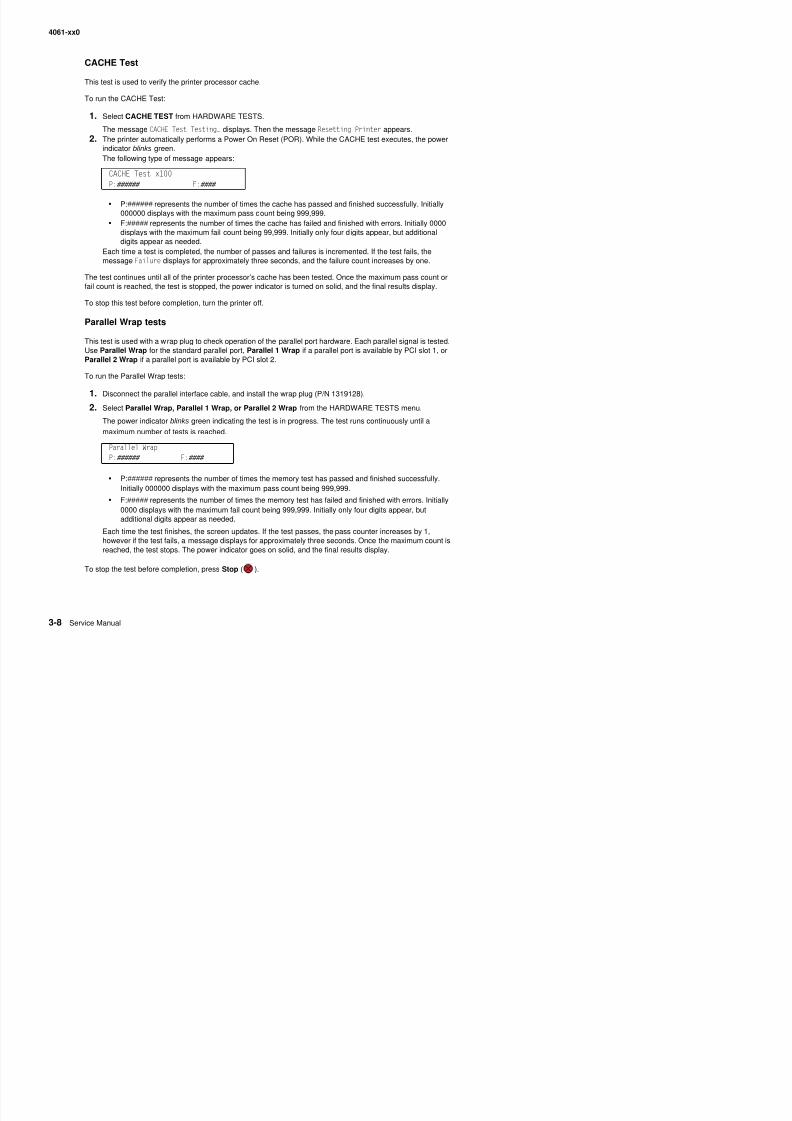
8/13/2019 t644 Service Manual
http://slidepdf.com/reader/full/t644-service-manual 180/423
displays with the maximum fail count being 99,999. Initially only four digits appear, but additionaldigits appear as needed.
Each time a test is completed, the number of passes and failures is incremented. If the test fails, themessage Failure displays for approximately three seconds, and the failure count increases by one.
The test continues until all of the printer processor’s cache has been tested. Once the maximum pass count orfail count is reached, the test is stopped, the power indicator is turned on solid, and the final results display.
To stop this test before completion, turn the printer off.
Parallel Wrap tests
This test is used with a wrap plug to check operation of the parallel port hardware. Each parallel signal is tested.Use Parallel Wrap for the standard parallel port, Parallel 1 Wrap if a parallel port is available by PCI slot 1, orParallel 2 Wrap if a parallel port is available by PCI slot 2.
To run the Parallel Wrap tests:
1. Disconnect the parallel interface cable, and install the wrap plug (P/N 1319128).2. Select Parallel Wrap, Parallel 1 Wrap, or Parallel 2 Wrap from the HARDWARE TESTS menu.
The power indicator blinks green indicating the test is in progress. The test runs continuously until a
maximum number of tests is reached.
• P:###### represents the number of times the memory test has passed and finished successfully.
Initially 000000 displays with the maximum pass count being 999,999.• F:##### represents the number of times the memory test has failed and finished with errors. Initially
0000 di l ith th i f il t b i 999 999 I iti ll l f di it b t
Parallel Wrap
P:###### F:####
4061-xx0
Serial Wrap tests
The serial wrap tests are used to check the operation of the serial port hardware using a wrap plug. Use Serial 1Wrap if a serial port is available through PCI slot 1 and Serial 2 Wrap if the serial port is available through PCIslot 2.
To perform the Serial Wrap tests:
1. Disconnect the serial interface cable, and install the serial wrap plug.
2. Select Serial 1 Wrap or Serial 2 Wrap from HARDWARE TESTS.
The power indicator blinks green indicating the test is in progress. The test runs continuously until a
maximum number of tests is reached.
• P:###### represents the number of times the memory test has passed and finished successfully.Initially 000000 displays with the maximum pass count being 999 999
Serial Wrap…
P:###### F:####
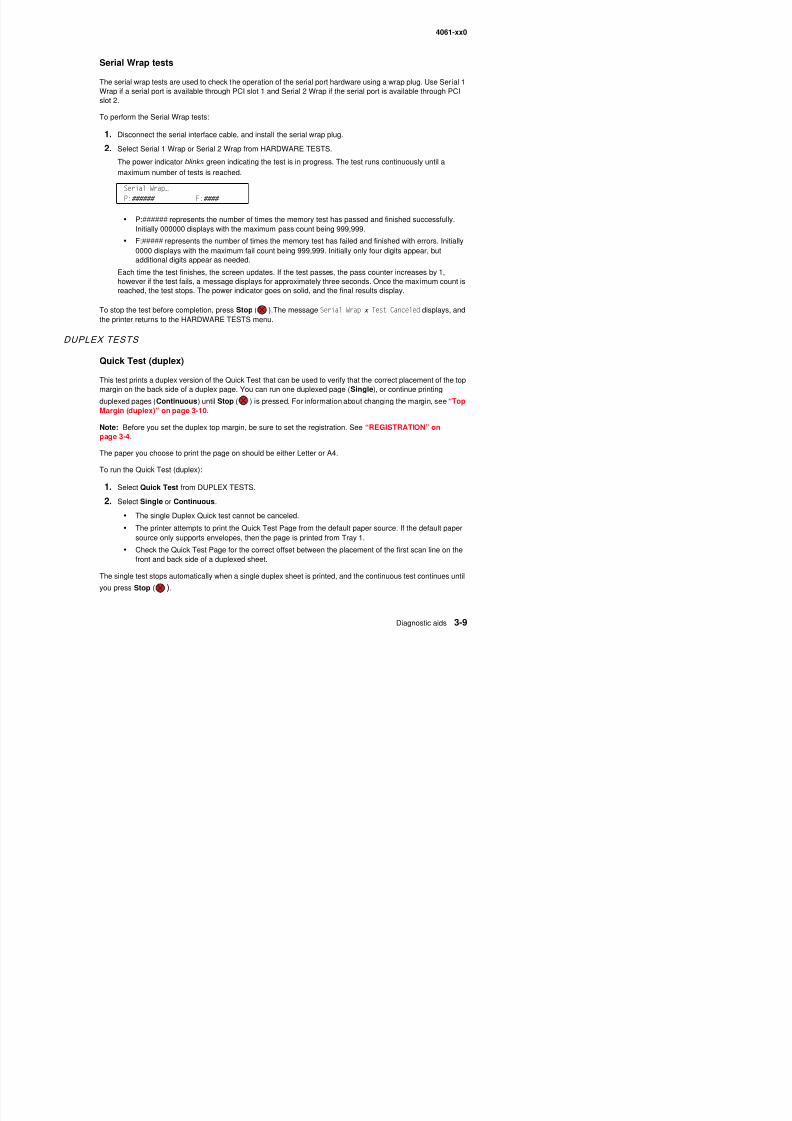
8/13/2019 t644 Service Manual
http://slidepdf.com/reader/full/t644-service-manual 181/423
Initially 000000 displays with the maximum pass count being 999,999.
• F:##### represents the number of times the memory test has failed and finished with errors. Initially0000 displays with the maximum fail count being 999,999. Initially only four digits appear, butadditional digits appear as needed.
Each time the test finishes, the screen updates. If the test passes, the pass counter increases by 1,however if the test fails, a message displays for approximately three seconds. Once the maximum count isreached, the test stops. The power indicator goes on solid, and the final results display.
To stop the test before completion, press Stop ( ).The message Serial Wrap x Test Canceled displays, andthe printer returns to the HARDWARE TESTS menu.
DUPLEX TESTS
Quick Test (duplex)
This test prints a duplex version of the Quick Test that can be used to verify that the correct placement of the topmargin on the back side of a duplex page. You can run one duplexed page (Single), or continue printing
duplexed pages (Continuous) until Stop ( ) is pressed. For information about changing the margin, see “TopMargin (duplex)” on page 3-10.
Note: Before you set the duplex top margin, be sure to set the registration. See “REGISTRATION” onpage 3-4.
The paper you choose to print the page on should be either Letter or A4.
To run the Quick Test (duplex):
1. Select Quick Test from DUPLEX TESTS.
2. Select Single or Continuous.
8/13/2019 t644 Service Manual
http://slidepdf.com/reader/full/t644-service-manual 182/423
4061-xx0
Motor Test (duplex)
This test lets you test the duplex option paper feed drive system, and verify that the power and velocity valuesare acceptable. The duplex runs the DC motor at high speed and low speed, taking an average of the power(PWM) required for each speed and calculating the KE value.
To run the Motor Test (duplex):
1. Select Motor Test from DUPLEX TESTS.
The power indicator light blinks, and the message Motor Test Testing displays.
2. When the motor stops, the results are displayed.
• AA—00 indicates success, and any other value indicates failure.
• BB—average PWM for the high speed portion of the test. The results should be in the range of 20
through 3F inclusively (hex)• CC—average PWM for the low speed portion of the test The results should be in the range of 3A
DUPLEX MOTOR AA BB CC DD EE FF
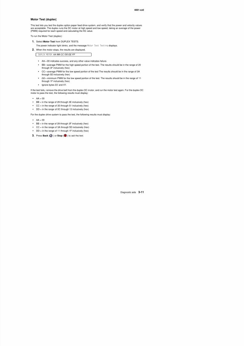
8/13/2019 t644 Service Manual
http://slidepdf.com/reader/full/t644-service-manual 183/423
CC average PWM for the low speed portion of the test The results should be in the range of 3Athrough 5D inclusively (hex)
• DD— minimum PWM for the low speed portion of the test. The results should be in the range of 11through 1F inclusively (hex)
• Ignore bytes EE and FF .
If the test fails, remove the drive belt from the duplex DC motor, and run the motor test again. For the duplex DCmotor to pass the test, the following results must display:
• AA = 00
• BB = in the range of 29 through 3E inclusively (hex)
• CC = in the range of 35 through 51 inclusively (hex)
• DD = in the range of 0C through 13 inclusively (hex)
For the duplex drive system to pass the test, the following results must display:
• AA = 00
• BB = in the range of 29 through 3F inclusively (hex)• CC = in the range of 3A through 5D inclusively (hex)
• DD = in the range of 11 through 1F inclusively (hex)
3. Press Back ( ) or Stop ( ) to exit the test.
4061-xx0
Duplex Feed 1
This test feeds a blank sheet of paper to the duplex paper stop position 1. This test can be run using any of thesupported paper sizes.
To run the Duplex Feed 1 Test:
1. Select Duplex Feed 1 from DUPLEX TESTS.
The power indicator blinks while the paper is feeding, and the message Duplex Feed 1 Feeding…displays.
The message Duplex Feed 1 Clear Paper displays when the paper reaches paper stop position 1, and thepower indicator turns on solid.
2. Remove the media from the duplex unit, and clear the message on the operator panel by pressing
Back ( ) or Stop ( ).
Duplex Feed 2This test feeds a blank sheet of paper to the duplex paper stop position 2 This test can be run using any of the
8/13/2019 t644 Service Manual
http://slidepdf.com/reader/full/t644-service-manual 184/423
This test feeds a blank sheet of paper to the duplex paper stop position 2. This test can be run using any of thesupported paper sizes.
To run the Duplex Feed 2 Test:
1. Select Duplex Feed 2 from DUPLEX TESTS.
The power indicator blinks while the paper is feeding, and the message Duplex Feed 2 Feeding…displays.
The message Duplex Feed 2 Clear Paper displays when the paper reaches the duplex paper stop position2, and the power indicator turns on solid.
2. Remove the media from the duplex unit, and clear the message on the operator panel by pressing
Back ( ) or Stop ( ).
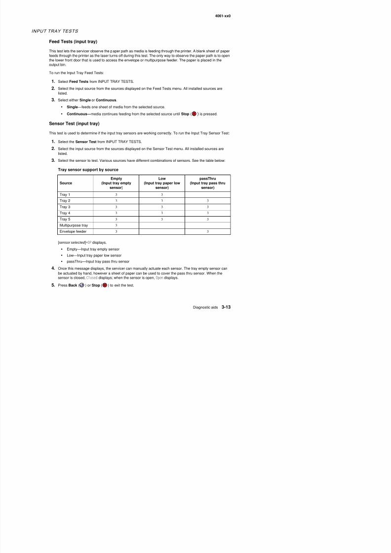
8/13/2019 t644 Service Manual
http://slidepdf.com/reader/full/t644-service-manual 185/423
4061-xx0
OUTPUT BIN TESTS
Feed Tests (output bins)
Use these tests to verify that media can be fed to a specific output bin. Media is fed from the default input sourceto the selected output bin. No information is printed on the media fed to the output bin because the printhead isnot engaged during this test. These tests can use any media size or envelope supported by the printer.
Note: If the Configure Bins printer setting is Link rather than Mailbox, the printer selects its own internal binlinking regardless of which output bin is selected for the feed test.
To run the Feed Tests for the output bins:
1. Select Feed Tests from the OUTPUT BIN TESTS.
2. Select the output bin you want the paper to exit into. The standard bin as well as any output option bininstalled on the printer is shown on the menu. (The output bins are displayed in the order installed on theprinter.)
3. Select either Single or Continuous.
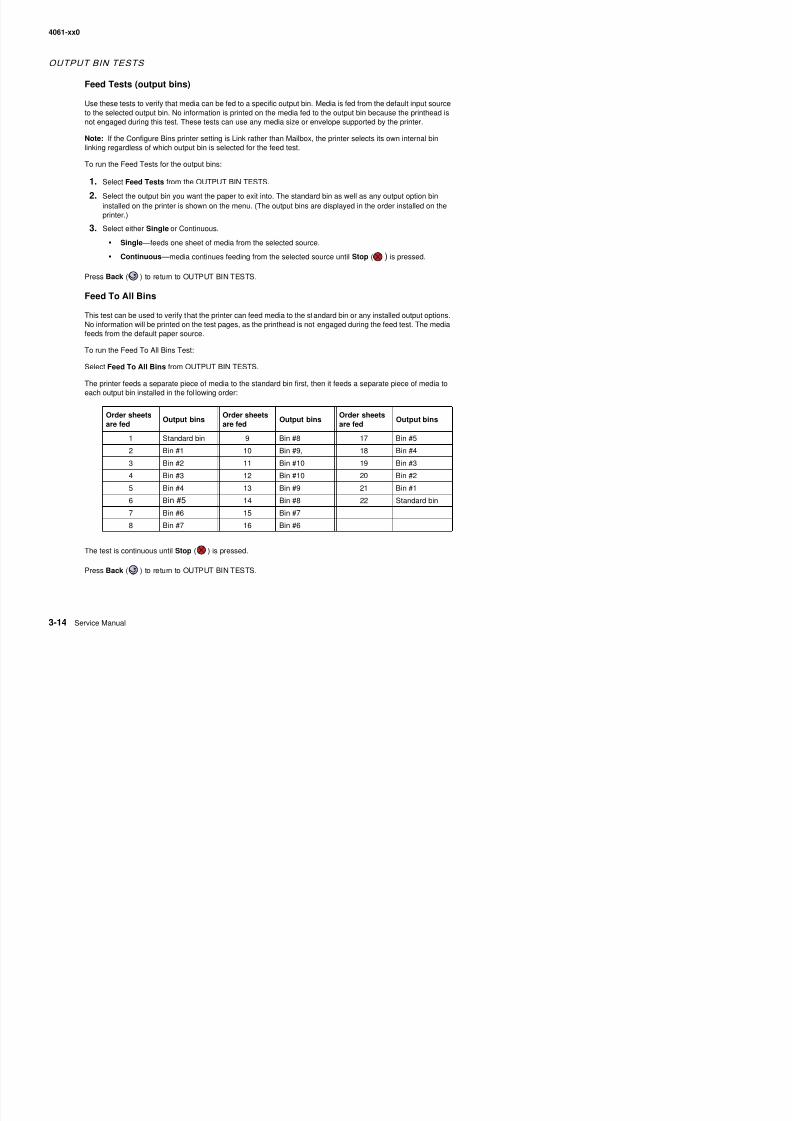
8/13/2019 t644 Service Manual
http://slidepdf.com/reader/full/t644-service-manual 186/423
• Single —feeds one sheet of media from the selected source.
• Continuous —media continues feeding from the selected source until Stop ( ) is pressed.
Press Back ( ) to return to OUTPUT BIN TESTS.
Feed To All Bins
This test can be used to verify that the printer can feed media to the standard bin or any installed output options.No information will be printed on the test pages, as the printhead is not engaged during the feed test. The mediafeeds from the default paper source.
To run the Feed To All Bins Test:
Select Feed To All Bins from OUTPUT BIN TESTS.
The printer feeds a separate piece of media to the standard bin first, then it feeds a separate piece of media toeach output bin installed in the fol lowing order:
Order sheetsare fed
Output binsOrder sheetsare fed
Output binsOrder sheetsare fed
Output bins
1 Standard bin 9 Bin #8 17 Bin #5
2 Bin #1 10 Bin #9, 18 Bin #4
3 Bin #2 11 Bin #10 19 Bin #3
4 Bin #3 12 Bin #10 20 Bin #2
5 Bin #4 13 Bin #9 21 Bin #16 Bin #5 14 Bin #8 22 Standard bin
4061-xx0
Sensor Test (standard output bin)
This test is used to verify if the standard bin sensor is working correctly.
To run the Sensor Test for the standard bin:
1. Select Sensor Test from OUTPUT BIN TESTS.
2. Select Standard Bin from Sensor Tests.3. Select NearFull or Full sensor to test.
The following screen is displayed:
Standard Bin x
Full=Open NearFull=Open
• Full—Bin full sensor
• NearFull—Bin near full sensor
4. Manually actuate the bin sensor by moving the flag in and out of the sensor. The display indicates Open when the flag is out of the sensor and Closed when the flag is in the sensor.
8/13/2019 t644 Service Manual
http://slidepdf.com/reader/full/t644-service-manual 187/423
5. Press Back ( ) or Stop ( ) to exit the test.
Sensor Test (Output Expander)
This test is used to determine whether or not the output bin sensor is working correctly for the output expander,if installed.
1. Select Sensor Test from OUTPUT BIN TESTS.2. Select Output Bin x ( x =number of the output option to be tested) from Sensor Tests.
The following screen is displayed:
Output Bin x
passThru=Open Full=Open NearFull=Open
• passThru—Pass thru sensor
• Full—Bin full sensor
• NearFull—Bin near full sensor3. Manually actuate each of the output expander sensors, and the display by each sensor toggles from Open
to Closed.
4. Press Back ( ) or Stop ( ) to exit the test.
4061-xx0
Sensor Test (high capacity output stacker)
1. Select Sensor Test from OUTPUT BIN TESTS.
2. Select Output Bin x ( x =number of the output option to be tested).
The following screen is displayed:
HC Bin x TP=OPpassThru=Open Full=Open NearFull=Open
• TP—High-capacity top position sensor
• passThru—High-capacity pass thru sensor
• Full—High-capacity bin full sensor (lower part of dual sensor)
• NearFull—High-capacity bin near full sensor (upper part of dual sensor)
3. Manually actuate each of the sensors of the high-capacity stacker, and the display by each sensor togglesfrom Open to Closed.
4. Press Back ( ) or Stop ( ) to exit the test.
Sensor Tests (5-bin mailbox)
8/13/2019 t644 Service Manual
http://slidepdf.com/reader/full/t644-service-manual 188/423
1. Select Sensor Tests from OUTPUT BIN TESTS.
2. Select Output Bin x ( x =number of the output option to be tested).
The following screen is displayed:
Output Bin x
P1=OP P2=OP L=NL
• passThru—5-bin mailbox pass thru sensor shows Open or Closed
• mailboxEmpty—5-bin mailbox empty sensor shows Normal for a normal level, NearFull for nearly full,and Full for full.
3. Manually actuate each of the sensors of the 5-bin mailbox,. The pass thru sensor will indicate Open orClosed and the empty sensor (mailboxEmpty) indicates Normal, NearFull, or Full.
4. Press Back ( ) or Stop ( ) to exit the test.
Diverter TestThis test verifies the functioning of each of the 5-bin mailbox output media diverters. If more than one 5-binmailbox is installed, all installed diverters or tested.
To run the Diverter Test, select Diverter Test from the OUTPUT BIN TESTS. The test runs once and stops.
4061-xx0
FINISHER TESTS
Staple Test
This test verifies the staple mechanism by sending eight sheets of media from the printers default paper sourceand stapling the sheets.
To run the Staple Test:
1. Select Staple Test from FINISHER TESTS.
2. Select the output bin and press .
While the test runs the power indicator blinks and the message Staple Test Running… displays. Duringthe test, no buttons are active and the test cannot be cancelled until the test is complete.
Feed Tests (finisher)
This test is used to verify whether or not media can be fed to a finisher output bin. Eight sheets of blank paperare fed from the default paper source and fed to the finisher output bins.
8/13/2019 t644 Service Manual
http://slidepdf.com/reader/full/t644-service-manual 189/423
Note: This test can be run using any of the paper sizes supported by the printer.
To run the Feed Test, select Feed Tests from FINISHER TESTS. While the feed test runs, the power indicatorblinks, and the message Feed Test Running… displays.
During the test, no buttons are active, and the test cannot be stopped until the test is completed.
Sensor Test (finisher)
This test can be used to verify whether or not the finisher sensors are working correctly.
To run the Finisher Sensor Test:
1. Select Sensor Test from FINISHER TESTS.
2. Select one of the four tests to perform:. Each of the tests displays the individual sensors that can bemanually actuated, and the display shows Open or Closed.
• Staple SensorsCartridge Present sensorStaple Low sensorSelf-priming sensorHome signal sensor
• Cover and Door
Finisher top cover sensorSide door sensor
• Pass and MediaFinisher pass thruMedia sensor
4061-xx0
BASE SENSOR TEST
This test is used to determine if the sensors located inside the printer are working correctly.
To run the Base Sensor Test:
1. Select BASE SENSOR TEST from the DIAGNOSTICS menu.
The following sensors are listed:• Exit—Exit sensor
• Front Door—Front door sensor
• Input—Input sensor
• NarrowMedia—Output (exit) sensor
• Toner Level—Toner level sensor (remove the cartridge and replace to actuate the sensor)
2. Manually actuate the sensors to verify that each sensor switches from Open to Closed.
3. Press Back ( ) or Stop ( ) to exit the test.
C S S
8/13/2019 t644 Service Manual
http://slidepdf.com/reader/full/t644-service-manual 190/423
DEVICE TESTS
Quick Disk Test
This test performs a non-destructive read/write on one block per track on the disk. The test reads one block oneach track, saves the data, and proceeds to write and read four test patterns to the bytes in the block. If theblock is good, the saved data is written back to the disk.
To run the Quick Disk Test:
1. Select Quick Disk Test from DEVICE TESTS.
The power indicator blinks while the test is in progress, and quick Disk Test Testing… displays.
• Quick Disk Test/Test Passed message displays if the test passes, and the power indicator turns onsolid.
• Quick Disk Test/Test Failed message displays if the test failed, and the power indicator turns on
solid.2. Press Back ( ) or Stop ( ) to return to the Device Tests menu.
4061-xx0
Disk Test/Clean
Warning: This test destroys all data on the disk and should not be attempted on a good disk. Also note that thistest may run approximately 1½ hours depending on the disk size.
To run the Disk Test/Clean Test:
1. Select Disk Test/Clean from the Device Tests menu.
Files will be lost/Go or Stop? message displays to warn the user that all contents on the disk will belost.
2. To exit the test immediately and return to the Device Tests menu, press Back ( ) or Stop ( ). To
continue with the test, press .
If is selected, the following screen displays and updates periodically indicating the percentage of testcompleted.
Formatting Disk
1/1 0%
DO NOT POWER OFF
8/13/2019 t644 Service Manual
http://slidepdf.com/reader/full/t644-service-manual 191/423
The power indicator blinks during the test.
Note: The test can NOT be canceled.
3. Once the test is complete, the power indicator turns on solid, and either the message Disk Test/Clean
Test Passed or Disk Test/Clean Failed appears. If the message indicates failure, the disk is unusable.
Flash Test
This test verifies the functioning of the flash device by writing and reading data on the flash to test the flash.
Warning: This test destroys all data on the flash because the flash is unformatted at the end of the test. Toreformat the flash, the servicer or the user must use FORMAT FLASH from the UTILITIES MENU.
To run the Flash Test:
1. Select Flash Test from DEVICE TESTS.
The message Files will be lost/Go or Stop? displays to warn the user that all contents on the flashdevice will be lost.
2. To exit the test immediately and return to the Device Tests menu, press Back ( ) or Stop ( ). To
continue with the test, press .
The power indicator blinks while the test is running, and the message Flash Test Testing… displays.
Once the test is complete, the power indicator turns on solid, and either the message Flash Test TestPassed or Flash Test Test Failed displays.
3. Press Back ( ) or Stop ( ) to return to DEVICE TESTS.
DO NOT POWER OFF
4061-xx0
PRINTER SETUP
Defaults
US/Non-US defaults changes whether the printer uses the US factory defaults or the non-US factory defaults.The settings affected include paper size, envelope size, PCL symbol set, code pages, and units of measure.
Warning: Changing this setting resets the printer to factory defaults, and data may be lost. It cannot be undone.
Page Count
The page count can only be viewed and cannot be changed.
To view the page count:
1. Select Page Count from PRINTER SETUP.
2. Press Back ( ) to return to PRINTER SETUP.
Perm Page Count (permanent page count)
8/13/2019 t644 Service Manual
http://slidepdf.com/reader/full/t644-service-manual 192/423
The permanent page count can only be viewed and cannot be changed.
To view the permanent page count:
1. Select Perm Page Count from PRINTER SETUP.
2. Press Back ( ) to return to PRINTER SETUP.
Serial Number
The serial number can only be viewed and cannot be changed.
To view the serial number:
1. Select Serial number from PRINTER SETUP.
2.Press Back (
) to return to PRINTER SETUP.
Envelope Enhance
This setting affects the level of the fuser solenoid.
To set Envelop Enhance:
1. Select Envelope Enhance from PRINTER SETUP.
2. Select Low, Medium, or High. The default is Medium.
3. Press Back ( ) to return to PRINTER SETUP.
4061-xx0
Configuration ID
The two configuration IDs are used to communicate information about certain areas of the printer that cannot bedetermined using hardware sensors. The configuration IDs are originally set at the factory when the printer ismanufactured, however the servicer may need to reset Configuration ID 1 or Configuration ID 2 whenever youreplace the system board. The IDs consist of eight hexadecimal characters, including 0 through 9 and Athrough F.
Note: When the printer detects a Configuration ID that is not defined or invalid, the following occurs:
• The default standard model Configuration ID is used instead.
• Configuration ID is the only function available in DIAGNOSTICS.
• Unless the menu is in DIAGNOSTICS, Check Config ID displays.
To set the configuration ID:
1. Select Printer Setup from the Diagnostic mode.
2. Select Configuration ID from the Printer Setup menu.Submitting Selection displays, followed by the value for Configuration ID 1.
3 E t th C fi ti ID 1
8/13/2019 t644 Service Manual
http://slidepdf.com/reader/full/t644-service-manual 193/423
3. Enter the Configuration ID 1.
• To select a digit or character to change, press or until the digit or character is underlined.
• To change a digit or character, press to increase or to decrease the value.
• When the last digit is changed, press to validate the Configuration ID 1.
If Invalid ID appears, the entry is discarded, and the previous Configuration ID 1 is displayed on the
screen.If the process is successful, Submitting Selection appears on the display, followed by the currentvalue for Confirguration ID 2.
4. Repeat the steps for entering the Configuration ID, and press .
If the Configuration ID 2 is validated, Submitting Selection appears, and a check ( ) appears next toPrinter Setup.
5. Restart the printer.
Edge to Edge
When this setting is On, the text and graphics are shifted to the physical edges of the paper for all margins.When the setting is Off, the normal margins are restored.
Parallel strobe adjustment (Par x Strobe Adj)
This setting adjusts the amount of time the strobe is sampled in order to determine if the valid data is availableon the parallel port. The range of values are from -4 to 6, and the default is 0 for Par S Strobe Adj,
Par 1 Strobe Adj, and Par 2 Strobe Ad j. After adjustment of 1 increment, the strobe samples 50 ns longer.
4061-xx0
EP SETUP
EP Defaults
This setting is used to restore each printer setting listed in EP SETUP to its factory default value. Sometimes thisis used to help correct print quality problems.
To restore EP Defaults:1. Select EP Defaults from EP SETUP.
2. Select Restore to reset the values to the factory settings, and select Do Not Restore to exit withoutchanging the settings.
Fuser Temperature (Fuser Temp)
This adjustment can be used to help solve some customer problems with paper curl on low grade papers and
problems with letterheads on some types of media.The fuser temperature can be adjusted to: Normal, Lower, Lowest. The default is Normal.
8/13/2019 t644 Service Manual
http://slidepdf.com/reader/full/t644-service-manual 194/423
Fuser Page Count
The fuser page count can only be viewed and cannot be changed.
To view the Fuser Page Count:
1. Select Fuser Page Count from EP SETUP.2. Press Back ( ) to return to PRINTER SETUP.
Warm Up Time
You can change the amount of time the printer warms up before allowing pages to print by changing this settingfrom 0 to 5. The factory sets the warm up at 0 or no warm up time. This time period lets the backup roll heat upand helps reduce curl in some environments.
TransferThe transfer can be adjusted to Low, Medium, or High. The default setting is Medium.
Print Contrast
The print contrast setting controls the developer voltage offset.
The print contrast can be adjusted to Low, Medium, or High. The default setting is Medium.
Charge Roll
4061-xx0
EVENT LOG
Display Log
The event log provides a history of printer errors. It contains the 12 most recent errors that have occurred on theprinter. The most recent error displays in position 1, and the oldest error displays in position 12 (if 12 errors haveoccurred). If an error occurs after the log is full, the oldest error is discarded. Identical errors in consecutive
positions in the log are entered, so there may be repetitions. All 2 xx and 9 xx error messages are stored in theevent log.
To view the event log:
1. Select Display Log from EVENT LOG.
Up to three error codes display at a time. Press or to view additional error codes.
2. Press Back ( ) to return to the EVENT LOG menu.
Print Log
Additional diagnostic information is available when you print the event log from DIAGNOSTICS rather than
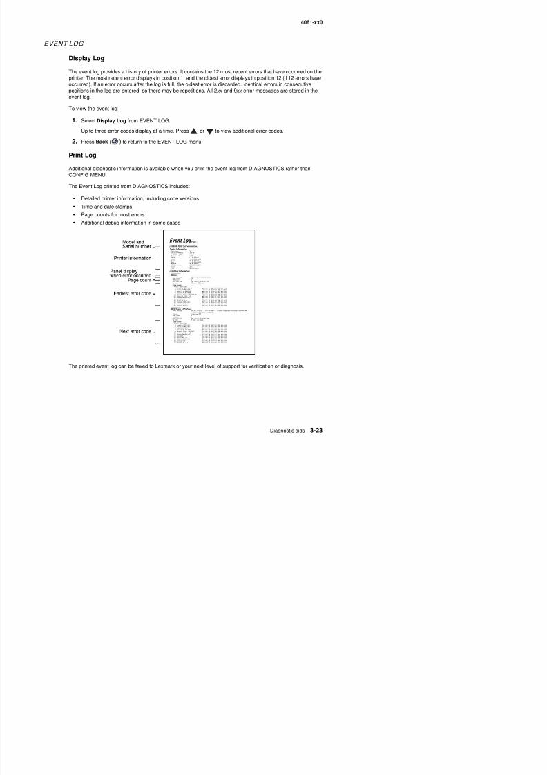
8/13/2019 t644 Service Manual
http://slidepdf.com/reader/full/t644-service-manual 195/423
CONFIG MENU.
The Event Log printed from DIAGNOSTICS includes:
• Detailed printer information, including code versions
• Time and date stamps
• Page counts for most errors• Additional debug information in some cases
4061-xx0
To print the event log:
Select Print Log from EVENT LOG.
Press Back ( ) to return to EVENT LOG.
Clear Log
Use Clear Log to remove the current information in the Event Log. This affects both the viewed log and theprinted log information.
1. Select Clear Log from the Event Log menu.
2. Select YES to clear the Event Log or NO to exit the Clear Log menu. If YES is selected, Deleting EVENTLOG displays on the screen.
Press Back ( ) to return to EVENT LOG.
EXIT DIAGNOSTICS
This selection exits Diagnostics mode and Resetting the Printer displays The printer performs a POR and

8/13/2019 t644 Service Manual
http://slidepdf.com/reader/full/t644-service-manual 196/423
This selection exits Diagnostics mode, and Resetting the Printer displays. The printer performs a POR, andthe printer returns to normal mode.
4061-xx0
Configuration menu (CONFIG MENU)
Entering Con f igurat ion Menu
1. Turn off the printer.
2. Press and hold and .3. Turn on the printer.
4. Release the buttons when Performing Self Test displays.
The message CONFIG MENU displays on the top line of the operator panel.
Avai lable menus
Maint Cnt Value See “Maintenance page count (Maint Cnt Value)” on page 3-25
Reset Maint Cnt See “Maintenance page counter reset (Reset Maint Cnt)” onpage 3-26
Prt Quality Pgs See “Print quality pages (Prt Quality Pgs)” on page 3-26
8/13/2019 t644 Service Manual
http://slidepdf.com/reader/full/t644-service-manual 197/423
Some menus are not available, depending on the configuration of the printer.
Maintenance page c ount (Maint Cnt Value)
Th t l f th i t t i di l d Thi t t k i t A i t j b
t Qua ty gs See t qua ty pages ( t Qua ty gs) o page 3 6
SIZE SENSING See “SIZE SENSING” on page 3-27
Panel Menus See “Panel Menus” on page 3-27
PPDS Emulation See “PPDS Emulation” on page 3-27
Download Emuls See “Download Emuls” on page 3-27
Demo Mode See “Demo Mode” on page 3-27Factory Defaults See “Factory Defaults” on page 3-28
Energy Conserve See “Energy Conserve” on page 3-28
EVENT LOG (print log only) See “EVENT LOG” on page 3-28
Paper Prompts See “Paper Prompts” on page 3-28
Env Prompts See “Env Prompts” on page 3-28
Jobs On Disk See “Jobs On Disk” on page 3-28
Disk Encryption See “Disk Encryption” on page 3-28Font Sharpening See “Font Sharpening” on page 3-29
LCD Brightness See “LCD Brightness” on page 3-29
LCD Contrast See “LCD Contrast” on page 3-29
Exit Config Menu
4061-xx0
To view the maintenance page count:
1. Select Maint Cnt Value from CONFIG MENU.
2. Press to view the value.
Press Back ( ) to return to the main Configuration menu.
Maintenanc e page coun ter reset (Reset Maint Cnt)
After scheduled maintenance, the servicer needs to reset the page counter.
To reset the maintenance page count to zero:
Select Reset Maintenance Count from the Configuration menu.
The message Reset Maint Cnt=Reset displays momentarily. When the reset operation is complete, the menureturns to the Printer Setup Reset Maintenance Count screen.
Print qual i ty pages (Prt Qual i ty Pgs )
8/13/2019 t644 Service Manual
http://slidepdf.com/reader/full/t644-service-manual 198/423
The print quality test pages can be printed from either the Diagnostics mode or Configuration Menu (CONFIGMENU). When printed from the Diagnostic mode, additional information is included, and the print cartridgelockout is bypassed. See “Print quality pages (Prt Quality Pgs)” on page 3-6. Additional configurationinformation may be included on the print quality pages which is not included on the print menu page.
To print the Print Quality Test Pages, select Prt Quality Pgs from CONFIG MENU. The message Printing
Quality Test Pages is displayed.The following is printed:
• Settings from EP SETUP from DIAGNOSTICS:
Fuser temperature, warm up time, transfer, print contrast, and charge roll settings.
• Contents of the EVENT LOG from DIAGNOSTICS.
• Printer configuration information:
Printer serial number, controller code level, engine code level, operator panel code level, smart optioncode levels, font versions, and so on.
Values for the QUALITY MENU settings used to print the pages.
The print quality test consists of four pages. Page one contains a mixture of graphics and text. Pages two andthree only contain graphics. Page four is blank. If duplex is turned on, the pages are duplexed. The Print QualityTest pages are printed in English and must always be printed on letter, legal, or A4 paper.
4061-xx0
SIZE SENSING
This setting controls whether the printer automatically registers the size of paper installed in an input source withsize sensing.
When the setting is Auto, every input option equipped with size sensing hardware automatically registers whatsize media it contains. When the setting is Off, the media size detected by hardware is ignored. The media size
Paper source Size sensing
Tray 1 (integrated) 3
Multipurpose feeder
250-sheet drawer 3
500-sheet drawer 3
2000-sheet drawer 3
250-sheet duplex
500-sheet duplex
Envelope feeder
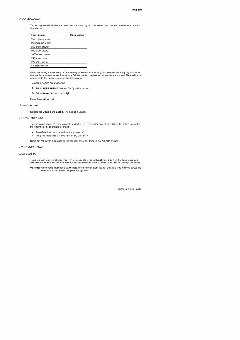
8/13/2019 t644 Service Manual
http://slidepdf.com/reader/full/t644-service-manual 199/423
can be set by the operator panel or the data stream.
To change the size sensing setting:
1. Select SIZE SENSING from the Configuration menu.
2. Select Auto or Off, and press .
Press Back ( ) to exit.
Panel Menu s
Settings are Disable and Enable. The default is Enable.
PPDS Emulat ion
This menu item allows the user to enable or disable PPDS emulation data stream. When this setting is enabled,the following settings are also changed:
• SmartSwitch settings for each port are turned off.
• The printer language is changed to PPDS Emulation.
Users can still switch languages on the operator panel and through the PJL data stream.
Download Emuls
Demo Mo de
8/13/2019 t644 Service Manual
http://slidepdf.com/reader/full/t644-service-manual 200/423
4061-xx0
Font Sharpening
This setting allows a user to set a text point size below which the high frequency screens are used when printingfont data. For example, at the default 24, all text in font sizes 24 and less will use the high frequency screens.The values for this setting range from 0 to 150, and the default value is 24. This setting affects PostScript, PCL,and XL.
To change the value, select Font Sharpening from the CONFIG MENU, and use to decrease the value and
to increase the value. Select to accept the value.
LCD Br ightness
This setting allows the user to increase or decrease the brightness of the operator panel LCD. When the value isincreased, the backlight shines brighter, and when the value is decreased, the backlight is dimmer. The operator
panel responds immediately to the changes. Use to decrease the value and to increase the value. Thevalues range from 1 to 10, and 5 is the default value.
LCD Contrast
When this setting is selected, the operator panel displays a gray bar with a slider representing the values. As the
8/13/2019 t644 Service Manual
http://slidepdf.com/reader/full/t644-service-manual 201/423
e t s sett g s se ected, t e ope ato pa e d sp ays a g ay ba t a s de ep ese t g t e a ues s t evalues are decreased, the bar appears darker, and when the values are increased, the bar appears lighter.Changes to this setting immediately change the operator panel. The range of values is between 1 and 10, andthe default value is 5.
Exi t Conf ig Menu
Press to exit the CONFIG MENU. The message Resetting the Printer displays, and the printer performsa POR and restarts in normal mode.
Additional useful menu locations
User menus are available from the Ready state by pressing Menu ( ).
Hex Trace
To turn Hex Trace on:
1. Press Menu ( ) to display Menus.
2. Press until the appears next to Settings.
3. Press .
4. Press until the appears next to Uti l i ti es Menu.
4061-xx0
Menu sett ings page
You can print a menu settings page to review the default printer settings and to verify your printer options areinstalled correctly.
1. Press Menu ( ) to display Menus.
2. Press until the appears next to Reports.
3. Press .
4. Press until the appears next to Menu Setti ngs Page.
5. Press .
The message Printing Menus Settings appears on the display.
The printer returns to the Ready state after the menu settings page prints.
Print ing menu sett ings page
Note: This test page must be printed on letter, legal, or A4 paper.
8/13/2019 t644 Service Manual
http://slidepdf.com/reader/full/t644-service-manual 202/423
To print the Menu Settings Page:
1. Select the TESTS MENU.
2. Select Print Menus from the TESTS MENU.
The page contains the following information:
• A list of all the printer settings contained in the operator panel menus and their values.
• A list of the installed options and features such as RAM memory cards, optional input paper trays,envelope feeder, duplex option, output bins, flash, or disk.
• Printer information such as serial number, page count, installed RAM, engine code level, RIP code level,envelope feeder code level, tray 1–5 code levels, output bin 1–3 code levels, operator panel code levels,font ROM version, and SRAM availability.
4061-xx0
Theory
Autocom pensator operat ion
The autocompensator is a paper pick device that generates its own normal force. This force generation isinherent in the fundamental design of the pick arm. If light media is used, it picks very gently. If a heavy media is
used, it picks very aggressively. No customer adjustments are necessary, therefore no special trays are neededfor card stock or labels. The gearing in the arm is designed so the input torque from the motor produces amovement about the pivot of the arm. This movement produces a downward force at the pick rolls. The frictionbetween the pick roll and the paper produces a frictional locking condition. If the paper is physically held and notallowed to feed, then the motor stalls. Slippage between the roll and the paper is theoretically impossible. Whenthe motor is energized, the pick rolls are driven down into the stack, increasing the normal force and drive forceuntil the bending strength of the paper is overcome and the paper bends and moves up the dam.
Once this critical threshold is achieved, the normal force remains at a level just high enough to reliably feed thepaper. Rather than having a fixed spring force for feeding all weights of paper like the D-roll, this device has its
own mechanical logic for producing only enough pick energy to feed a single sheet of paper regardless of itsstiffness. High normal force is one of the most significant contributors to double feeding paper. The pick arm iscounterbalanced by an extension spring located on the pick arm to reduce weight in the rest state. This spring isfactory set to exert no more than ten to fifteen grams on the stack. This is as light as can be realistically set andalways guarantee there is some force to start the autocompensating phenomena This spring is not to be
8/13/2019 t644 Service Manual
http://slidepdf.com/reader/full/t644-service-manual 203/423
always guarantee there is some force to start the autocompensating phenomena. This spring is not to beconsidered an adjustment for feeding problems unless it is obvious that the pick arm cannot fall all the way downto the bottom of the tray or has come loose. Poor gear efficiency can cause the arm to generate higher thannormal forces. If the pick assembly is noisy, replacement may be required. The arm must pivot freely through itsfull range of motion. On 500-sheet trays, there are wrap springs located on the pivot arbors of the arm. Thesesprings help prevent the arm from bouncing. If the arm appears to be binding or sticky near the bottom of the
tray, these springs may be the problem. Reducing the tension on the counterbalance spring may be used as atemporary fix to get additional weight at the bottom, until the pick assembly can be replaced. However, thecounterbalance spring is not to be considered an adjustment for feeding problems.
4061-xx0
Auto conn ect system , paper tray opt ions , envelope feeder—electr ical
Autoconnect cabling and connectors
The printer options make electrical connection automatically, requiring no external cables when the option ismechanically installed under the printer. Communication between the option and the base printer stops whenyou remove an option. The printer no longer recognizes the option and deletes associated messages. Each
installed option below the base printer provides an electrical autoconnect to the option attached below it. We donot recommend to attach or “Hot Plug” any options with the base printer power turned on.
Duplex Option
The duplex option interface is a six pin autoconnector that provides a +24 V dc, +24 V dc return, serial interfacetransmit signal, serial interface receive signal, and two ground pins. The duplex option receives the +24 V dcfrom the base printer for the duplex motors and also converts the voltage to +5 V dc for duplex electronics.
Duplex chassis grounding is provided from the printer to the duplex option through a ground spring attached to
the frame and base of the printer. The ground connection is automatically made when the option is installedbelow the printer.
The paper input sensor is located in the rear of the duplex option under the input paper guide. The paper exitsensor is located on the left frame assembly.

8/13/2019 t644 Service Manual
http://slidepdf.com/reader/full/t644-service-manual 204/423
se so s ocated o t e e t a e asse b y
Option microcode
The options are “Smart Options” or options that have a system board. The option system board has amicroprocessor that controls the option mechanism. A software architecture is provided that controls the option
and communicates information such as paper path status, sensor status, motor status, and so on to the baseprinter.
4061-xx0
Print quality troubleshooting
To help isolate print quality problems, print the “Print defects guide” and check for repeating defects. If repeatingdefects are not appearing, print the Print Quality Test Pages.
1. Turn the printer off.2. Hold down and , and turn the printer on.
3. Press until Prt Quality Pgs is selected, and then press .The pages are formatted. The Printing Quality Test Pages message appears, then the pages print. Themessage remains on the operator panel until all the pages print.After the Print Quality Test Pages print, to exit the Config Menu:
4. Press until Exit Config Menu is selected, and then press .The messages Resetting Printer and Performing Self Test appear, and the printer returns to Ready.
If another type of print quality problem exists, see the Troubleshooting chapter in the User’s Guide on thepublications CD.
Problem Action
Print is too light. • The toner may be low. To utilize the remaining toner, remove thet id b i i th h dl ith b th h d With th
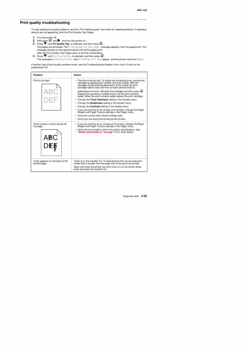
8/13/2019 t644 Service Manual
http://slidepdf.com/reader/full/t644-service-manual 205/423
cartridge by gripping the handles with both hands. With thecartridge arrows pointing downward, firmly shake the printcartridge side-to-side and front-to-back several times to
redistribute the toner. Reinstall the cartridge and then press .Repeat this procedure multiple times until the print remainsfaded. When the print remains faded replace the print cartridge.
• Change the Toner Darkness setting in the Quality menu.• Change the Brightness setting in the Quality menu.
• Change the Contrast setting in the Quality menu.
• If you are printing on an uneven print surface, change the PaperWeight and Paper Texture settings in the Paper menu.
• Verify the correct print media is being used.
• Verify you are using the correct printer drivers.
Toner smears or print comes off
the page.
• If you are printing on an uneven print surface, change the Paper
Weight and Paper Texture settings in the Paper menu.• Verify the print media is within the printer specifications. See
“Media specifications” on page 1-9 for more details.
4061-xx0
Toner fog or background shadingappears on the page.
• Check the print cartridge to make sure it is installed correctly.
• The Toner Darkness setting may be too dark. Change the TonerDarkness setting in the Quality Menu.
• Replace the charge rolls.
• Replace the print cartridge.
Entire page is white. • Make sure the packaging material is removed from the printcartridge.
• Check the print cartridge to be sure it is installed correctly.• The toner may be low. To utilize the remaining toner, remove the
cartridge by gripping the handles with both hands. With thecartridge arrows pointing downward, firmly shake the printcartridge side-to-side and front-to-back several times to
di t ib t th t R i t ll th t id d th
Problem Action
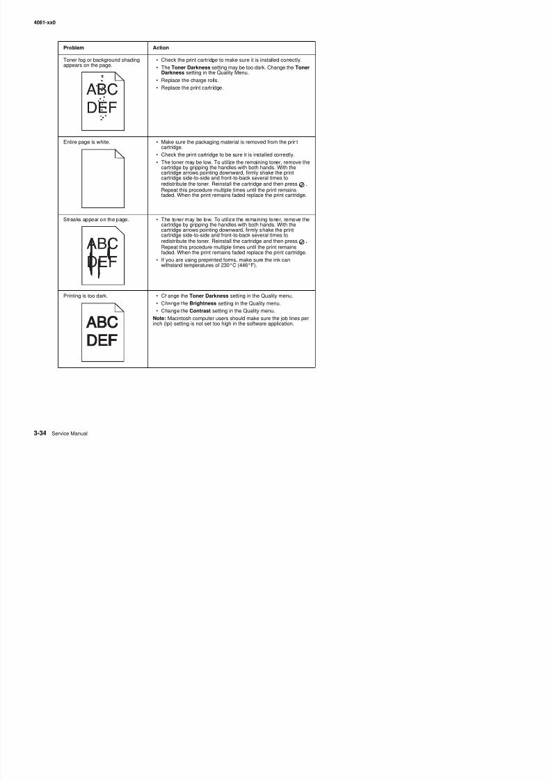
8/13/2019 t644 Service Manual
http://slidepdf.com/reader/full/t644-service-manual 206/423
redistribute the toner. Reinstall the cartridge and then press .Repeat this procedure multiple times until the print remainsfaded. When the print remains faded replace the print cartridge.
Streaks appear on the page. • The toner may be low. To util ize the remaining toner, remove thecartridge by gripping the handles with both hands. With thecartridge arrows pointing downward, firmly shake the printcartridge side-to-side and front-to-back several times toredistribute the toner. Reinstall the cartridge and then press .Repeat this procedure multiple times until the print remainsfaded. When the print remains faded replace the print cartridge.
• If you are using preprinted forms, make sure the ink canwithstand temperatures of 230°C (446°F).
Printing is too dark. • Change the Toner Darkness setting in the Quality menu.
• Change the Brightness setting in the Quality menu.
• Change the Contrast setting in the Quality menu.
Note: Macintosh computer users should make sure the job lines perinch (lpi) setting is not set too high in the software application.
4061-xx0
Characters have jagged or unevenedges.
• Change the Print Resolution setting in the Quality menu to 600dpi, 1200 Image Q, 1200 dpi, or 2400 Image Q.
• Enable Enhance Fine Lines.
See the tables on page “Quality menu operator panel options” onpage 3-36 for more settings information.
• If you are using downloaded fonts, verify the fonts are supportedby the printer, the host computer, and the software application.
• Verify the print media type and print tray type settings match.
• Verify you are using the correct printer drivers.
Part or all of the page is printed inblack.
Check the print cartridge to see if it is installed correctly.
Problem Action
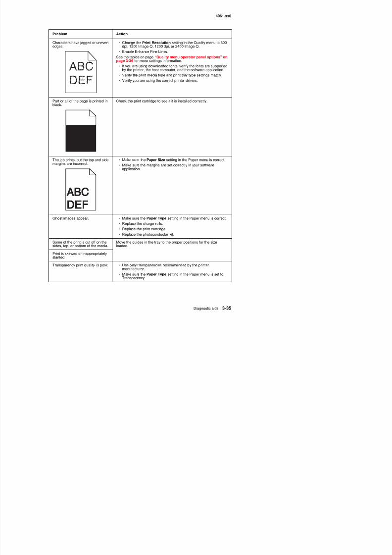
8/13/2019 t644 Service Manual
http://slidepdf.com/reader/full/t644-service-manual 207/423
The job prints, but the top and sidemargins are incorrect.
• Make sure the Paper Size setting in the Paper menu is correct.
• Make sure the margins are set correctly in your softwareapplication.
Ghost images appear. • Make sure the Paper Type setting in the Paper menu is correct.
• Replace the charge rolls.
• Replace the print cartridge.
• Replace the photoconductor kit.
Some of the print is cut off on thesides, top, or bottom of the media. Move the guides in the tray to the proper positions for the sizeloaded.
4061-xx0
The quality menu operator panel options can be adjusted to help improve print quality.
In addition, the Enhance Fine Lines and Gray Correction options can be enabled to improve print quality. Thesesettings are available on the driver and on the printer Embedded Web Server (EWS) interface. For moreinformation about these options, see the driver Help.
Quality menu operator panel options
Menu selection Purpose Values
Print Resolution To select printed output resolution 600 dpi (default setting)
1200 Image Q
1200 dpi2400 Image Q
Toner Darkness Lightens or darkens printed outputand alters toner consumption
1–10 8 is the default setting.
Select a lower number to lighten theprinted output or save toner.
Brightness Adjusts the gray value of printedgraphics and pictures
-6 – +6 0 is the default setting.
Contrast Adjusts the contrast of printedgraphics and pictures
0–5 0 is the default setting.
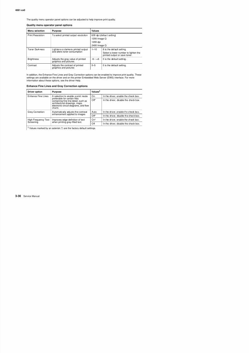
8/13/2019 t644 Service Manual
http://slidepdf.com/reader/full/t644-service-manual 208/423
Enhance Fine Lines and Gray Correction options
Driver option Purpose Values†
Enhance Fine Lines A selection to enable a print mode
preferable for certain filescontaining fine line detail, such asarchitectural drawings, maps,electronic circuit diagrams, and flowcharts
On In the driver, enable the check box.
Off* In the driver, disable the check box.
Gray Correction Automatically adjusts the contrastenhancement applied to images
Auto In the driver, enable the check box.
Off* In the driver, disable the check box.
High Frequency TextScreening
Improves edge definition of textwhen printing gray-filled text.
On* In the driver, enable the check box.
Off In the driver, disable the check box.
† Values marked by an asterisk (*) are the factory default settings.
4061-xx0
Paper feed jams
Access doors and t rays
The following illustration shows the path that print media travels through the printer. The path varies dependingon the input source (trays, multipurpose feeder, envelope feeder) and output bins (finisher, stacker, expander,
mailbox) you are using.27X Paper Jam
200 PaperJam
202 PaperJam
23X PaperJam 260 PaperJam
28X Paper Jam
201 PaperJam
200 PaperJam
202 PaperJam
23X PaperJam
201 PaperJam
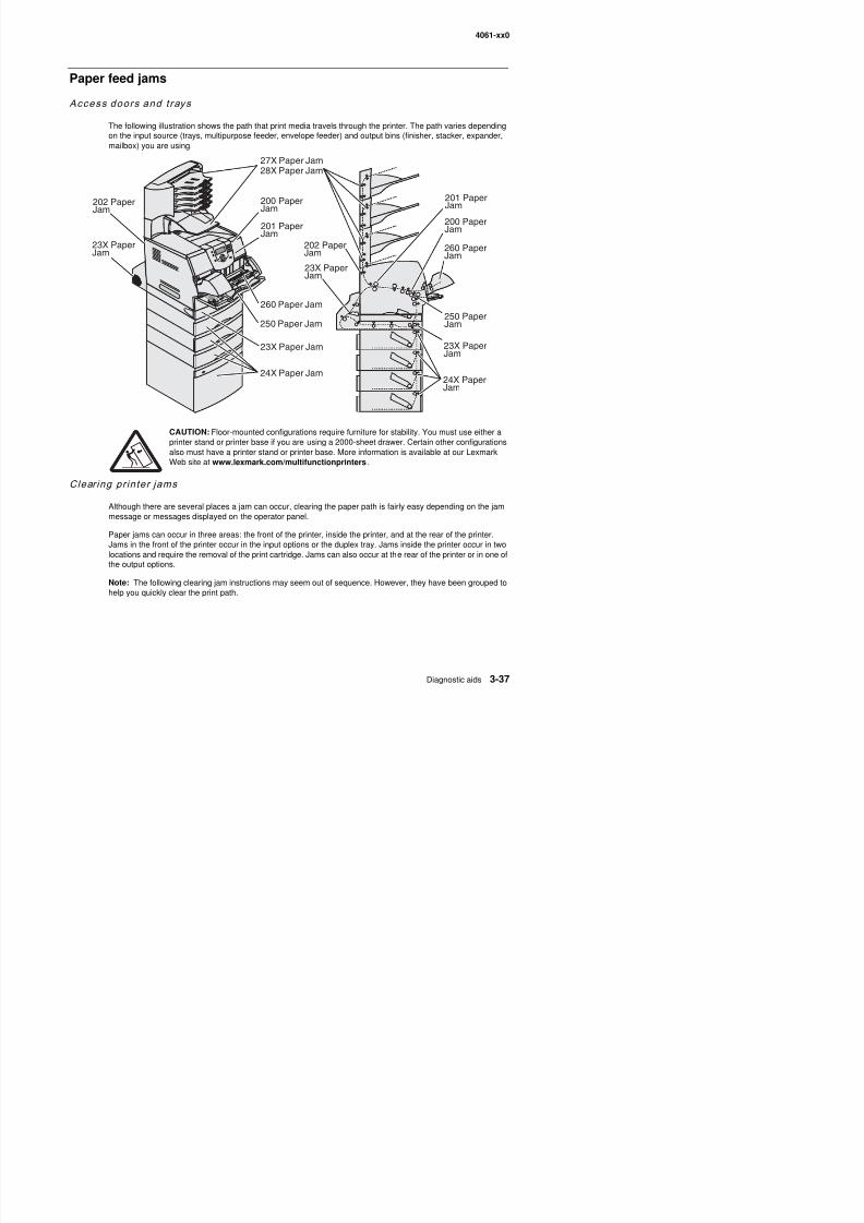
8/13/2019 t644 Service Manual
http://slidepdf.com/reader/full/t644-service-manual 209/423
CAUTION: Floor-mounted configurations require furniture for stability. You must use either a
printer stand or printer base if you are using a 2000-sheet drawer. Certain other configurationsalso must have a printer stand or printer base. More information is available at our LexmarkWeb site at www.lexmark.com/multifunctionprinters .
Clearing printer jams
Although there are several places a jam can occur, clearing the paper path is fairly easy depending on the jammessage or messages displayed on the operator panel.
Paper jams can occur in three areas: the front of the printer, inside the printer, and at the rear of the printer.Jams in the front of the printer occur in the input options or the duplex tray. Jams inside the printer occur in twolocations and require the removal of the print cartridge Jams can also occur at the rear of the printer or in one of
260 Paper Jam
250 Paper Jam
23X Paper Jam
24X Paper Jam
250 PaperJam
24X PaperJam
23X PaperJam
4061-xx0
250 Paper Jam Check MP Feeder
1. Remove the paper from the multipurpose feeder.
2. Flex, fan, and restack the media, and place it into the multipurpose feeder.
3. Load the print media.
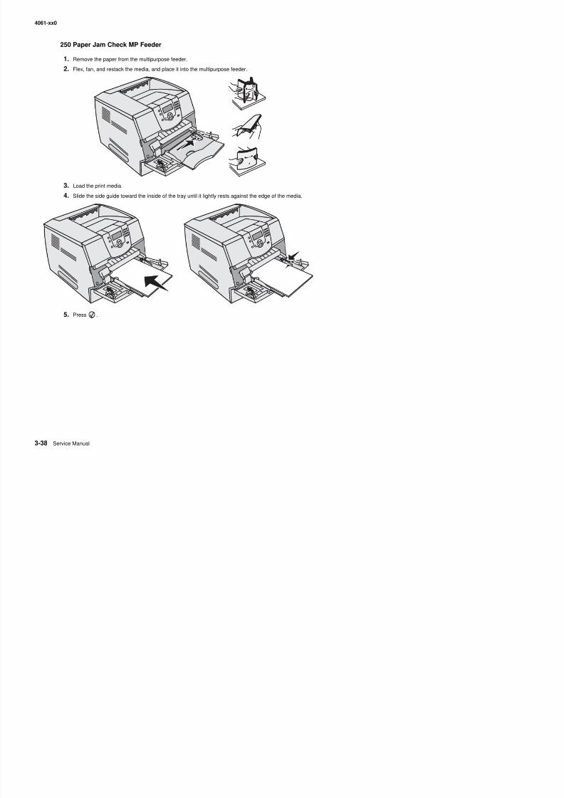
8/13/2019 t644 Service Manual
http://slidepdf.com/reader/full/t644-service-manual 210/423
4. Slide the side guide toward the inside of the tray until it lightly rests against the edge of the media.
5. Press .
4061-xx0
260 Paper Jam Check Env Feeder
The envelope feeder feeds envelopes from the bottom of the stack; the bottom envelope will be the one that is jammed.
1. Lift the envelope weight.
2. Remove all envelopes.
If the jammed envelope has entered the printer and cannot be pulled out, remove the envelope feeder.a. Lift the envelope feeder up out of the printer, and then set it aside.
b. Remove the envelope from the printer.If you cannot remove the envelope, the print cartridge will have to be removed. See “200 and 201Paper Jam Remove Cartridge” on page 3-41 for more information.
c. Reinstall the envelope feeder. Make sure it snaps into place.
3. Flex and stack the envelopes.
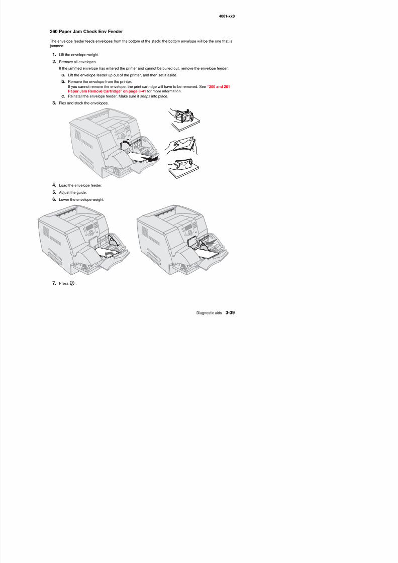
8/13/2019 t644 Service Manual
http://slidepdf.com/reader/full/t644-service-manual 211/423
4. Load the envelope feeder.
5. Adjust the guide.
6. Lower the envelope weight.
4061-xx0
23x and 24x jams
Paper jams in these areas can occur on the incline surface of a tray or across more than one tray. To clear theseareas:
1. Open the printer paper tray, and remove any jammed media.
2. Open the duplex tray.
To remove the media, pull up.
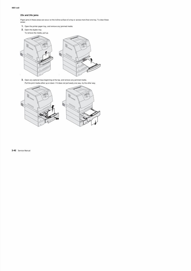
8/13/2019 t644 Service Manual
http://slidepdf.com/reader/full/t644-service-manual 212/423
3. Open any optional trays beginning at the top, and remove any jammed media.
Pull the print media either up or down. If it does not pull easily one way, try the other way.
4061-xx0
4. If you have an optional 2000-sheet feeder, open the front door, press the elevator button (A) to lower thetray, remove the jam, and make sure the stack of print media is neat and aligned.
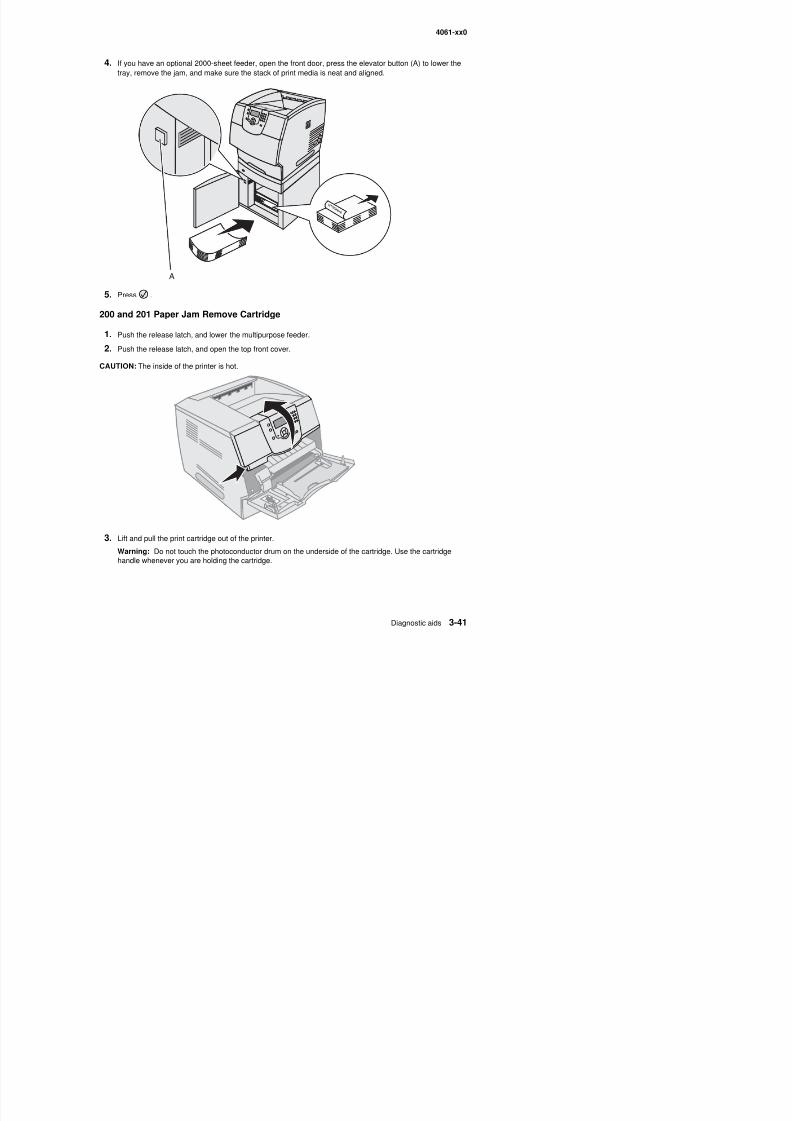
8/13/2019 t644 Service Manual
http://slidepdf.com/reader/full/t644-service-manual 213/423
5. Press .
200 and 201 Paper Jam Remove Cartridge
1. Push the release latch, and lower the multipurpose feeder.
2. Push the release latch, and open the top front cover.
CAUTION: The inside of the printer is hot.
A
4061-xx0
4. Place the print cartridge aside.
Note: Do not leave the cartridge exposed to light for extended periods.
Note: The print media may be covered with unfused toner, which can stain garments and skin.
5. Pull the print media up and toward you.
Warning: If the print media does not move immediately when you pull, stop pulling. You need to accessthe print media from the printer rear door.
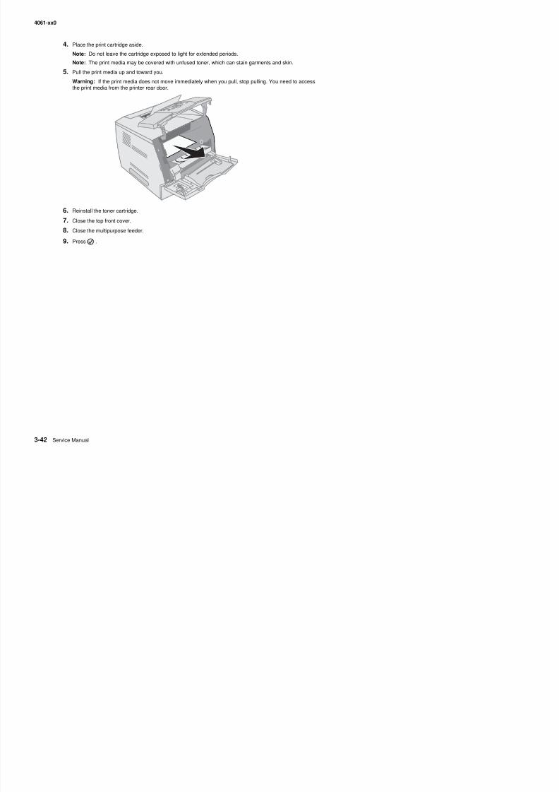
8/13/2019 t644 Service Manual
http://slidepdf.com/reader/full/t644-service-manual 214/423
6. Reinstall the toner cartridge.
7. Close the top front cover.8. Close the multipurpose feeder.
9. Press .
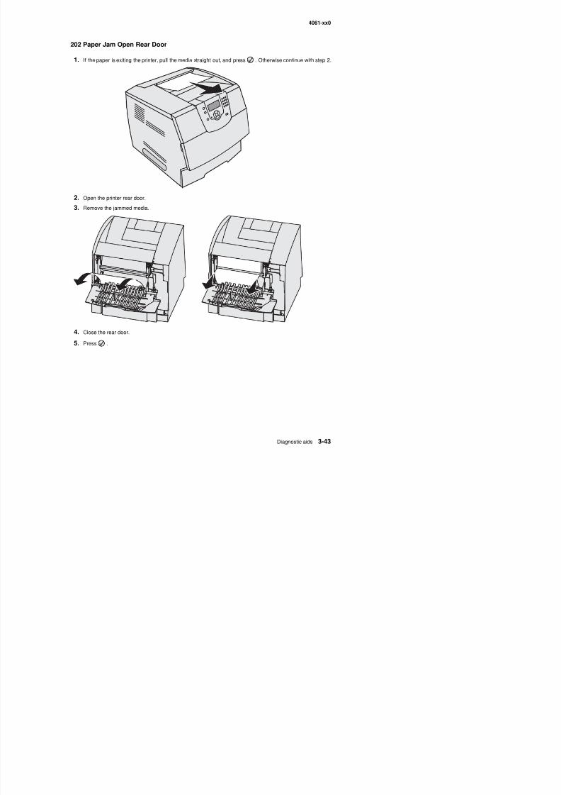
8/13/2019 t644 Service Manual
http://slidepdf.com/reader/full/t644-service-manual 215/423
4061-xx0
23x Paper Jam Open Duplex Rear Door
1. Open the duplex rear door.
2. Remove the jammed media.
Depending on the media location, pull the media either up or down.
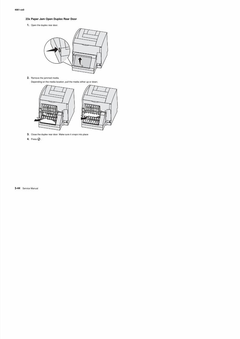
8/13/2019 t644 Service Manual
http://slidepdf.com/reader/full/t644-service-manual 216/423
3. Close the duplex rear door. Make sure it snaps into place.
4. Press .
4061-xx0
270 and 280 Paper Jams
Paper jams in this group have been divided into 27x and 28x groups. If you have an output expander, high-capacity output stacker, or the 5-bin mailbox, see “27x Paper Jam Check Bin x”. If you have a finisher, see“28x Paper Jam Check Finisher”.
27x Paper Jam Check Bin x
To clear a jam in the output expander, high-capacity output stacker, or the 5-bin mailbox:
1. If the paper is exiting into the bin or finisher, pull the media straight out, and press . Otherwise continuewith step 2.
2. Push the output bin rear door latches in toward the center. The rear doors will open and drop down.
Note: If you only have one output option, you may only have one rear door.
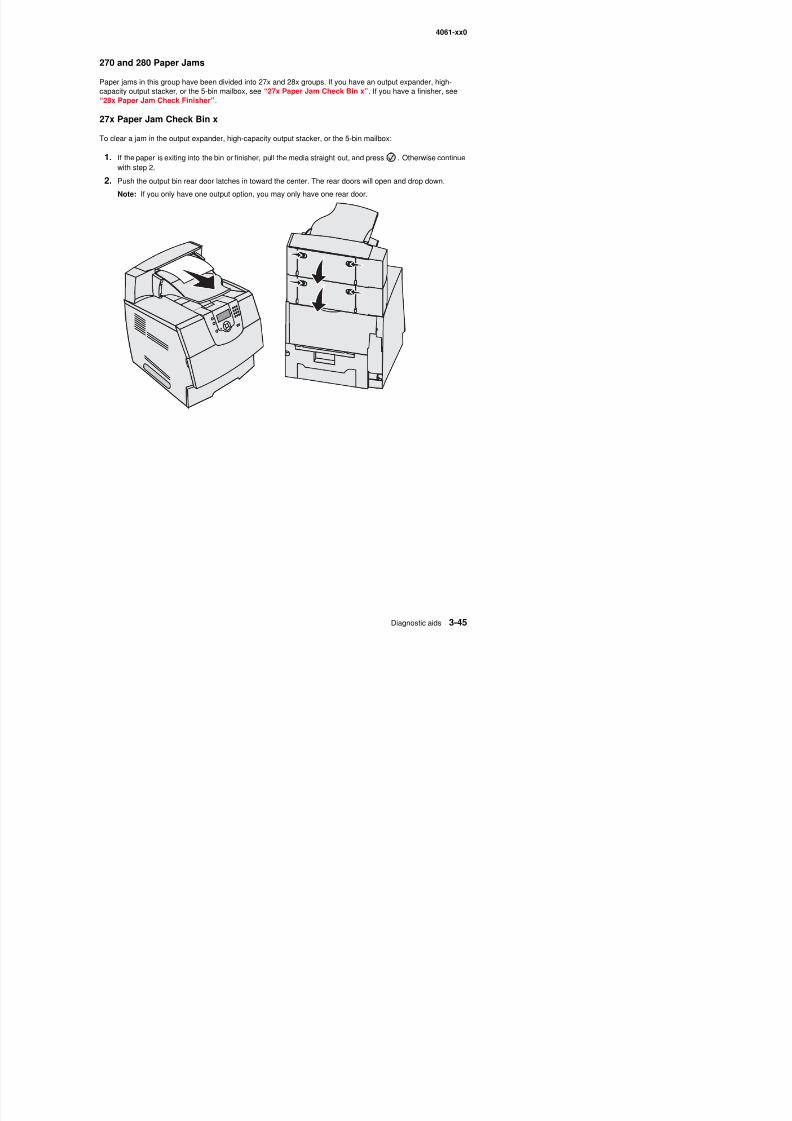
8/13/2019 t644 Service Manual
http://slidepdf.com/reader/full/t644-service-manual 217/423
4061-xx0
3. Remove the jammed media.
4. Close the output bin rear doors, and make sure all doors are secure.
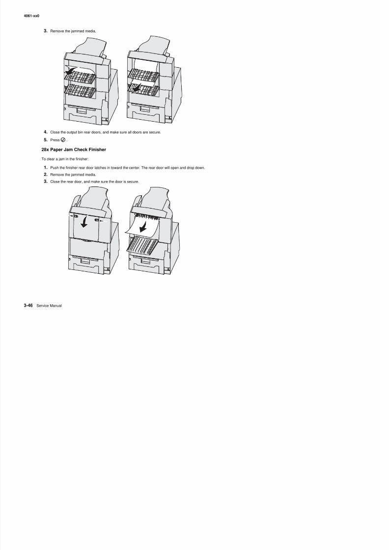
8/13/2019 t644 Service Manual
http://slidepdf.com/reader/full/t644-service-manual 218/423
5. Press .
28x Paper Jam Check Finisher
To clear a jam in the finisher:
1. Push the finisher rear door latches in toward the center. The rear door will open and drop down.
2. Remove the jammed media.
3. Close the rear door, and make sure the door is secure.
4061-xx0
4. Lift the front edge of the finisher output bin cover until it locks into position.
5. Remove the stack of print media.
6. Close the finisher output bin cover.
7. Press .
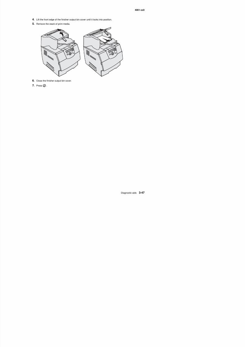
8/13/2019 t644 Service Manual
http://slidepdf.com/reader/full/t644-service-manual 219/423
7. Press .
4061-xx0
Clearing staple jams
A 28x Stapler Jam message indicates staples are jammed in the stapler. This requires removing the staplecartridge holder from the printer.
1. Lift the front edge of the finisher output bin cover until it locks into position.
2. Remove the print media.
3 Press the latch to open the stapler access door
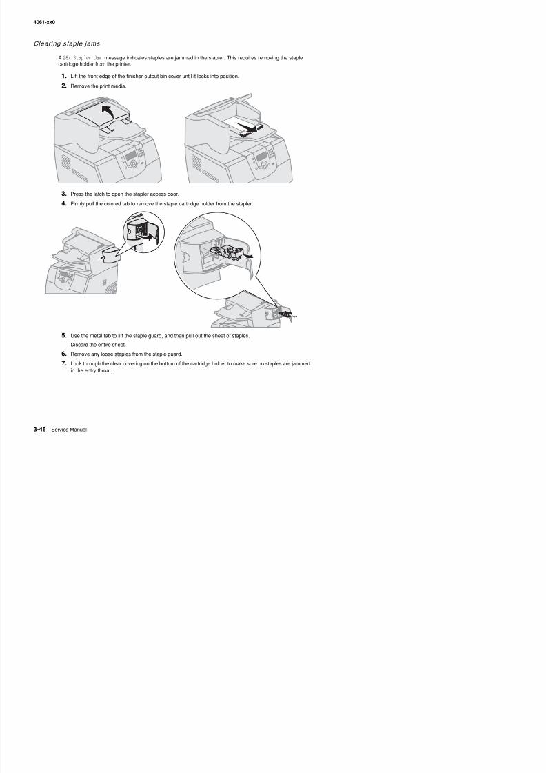
8/13/2019 t644 Service Manual
http://slidepdf.com/reader/full/t644-service-manual 220/423
3. Press the latch to open the stapler access door.
4. Firmly pull the colored tab to remove the staple cartridge holder from the stapler.
5. Use the metal tab to lift the staple guard, and then pull out the sheet of staples.
Discard the entire sheet.
4061-xx0
8. Press down on the staple guard until it snaps securely into place.
9. Push the cartridge holder firmly into the stapler until the cartridge holder clicks into place.
10. Close the stapler access door.11. Close the finisher output bin cover.
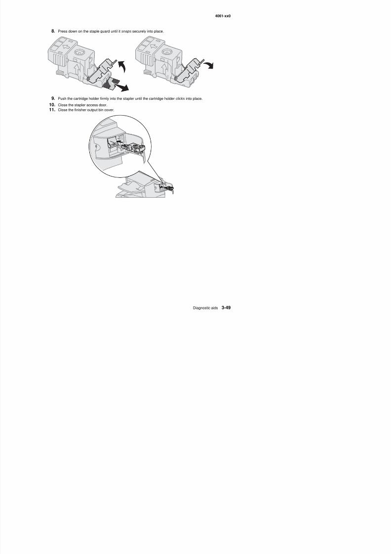
8/13/2019 t644 Service Manual
http://slidepdf.com/reader/full/t644-service-manual 221/423
4061-xx0

8/13/2019 t644 Service Manual
http://slidepdf.com/reader/full/t644-service-manual 222/423
4061-xx0
4. Repair information
Warning: Read the following before handling electronic parts.
Handling ESD-sensitive parts
Many electronic products use parts that are known to be sensitive to electrostatic discharge (ESD). To preventdamage to ESD-sensitive parts, follow the instructions below in addition to all the usual precautions, such asturning off power before removing logic boards:
• Keep the ESD-sensitive part in its original shipping container (a special “ESD bag”) until you are ready toinstall the part into the machine.
• Make the least-possible movements with your body to prevent an increase of static electricity from clothingfibers, carpets, and furniture.
• Put the ESD wrist strap on your wrist. Connect the wrist band to the system ground point. This dischargesany static electricity in your body to the machine.
• Hold the ESD-sensitive part by its edge connector shroud (cover); do not touch its pins. If you are removinga pluggable module, use the correct tool.
• Do not place the ESD-sensitive part on the machine cover or on a metal table; if you need to put down theESD-sensitive part for any reason, first put it into its special bag.
• Machine covers and metal tables are electrical grounds. They increase the risk of damage because theymake a discharge path from your body through the ESD-sensitive part. (Large metal objects can be
8/13/2019 t644 Service Manual
http://slidepdf.com/reader/full/t644-service-manual 223/423
discharge paths without being grounded.)• Prevent ESD-sensitive parts from being accidentally touched by other personnel. Install machine covers
when you are not working on the machine, and do not put unprotected ESD-sensitive parts on a table.
• If possible, keep all ESD-sensitive parts in a grounded metal cabinet (case).• Be extra careful in working with ESD-sensitive parts when cold-weather heating is used, because low
humidity increases static electricity.
4061-xx0
Adjustment procedures
Fuser solenoid adjustm ent
Perform the fuser solenoid adjustment whenever you replace the fuser solenoid. Adjust the fuser solenoid whileinstalled in the printer. Adjust the screw on the eccentric mounted on the solenoid housing to provide an air gapbetween the rear of the solenoid stator and the solenoid armature. The solenoid air gap for all models is 4.5 mm± 0.1 mm.
Gap adjustm ent
The gap adjustment allows you to increase the minimum gap between sheets of paper as they are fed throughthe printer. This adjustment reduces the printer overall performance, such as pages per minute, but can help inreducing the amount of curl of some printed media, thus improving media stacking in the output bin.
1. Enter the Diagnostic Mode.
2. Select Ep Setup from the Diagnostic Menu.3. Select Gap Adjust.
4. The range of the GAP adjustment is 0 to 255. Adjust the gap setting by using to select the value. IfGAP=0 displays, it indicates a factory setting to minimum gap. Select a value and run several copies of themedia that displays a curl problem. It may take several tries before improvement is noticed.
Note: This setting has no effect when duplexing.
8/13/2019 t644 Service Manual
http://slidepdf.com/reader/full/t644-service-manual 224/423
g p g
Printhead assemb ly adjustment
Do the printhead assembly adjustment whenever you remove or replace the printhead assembly or loosen themounting screws.
Install the new printhead with the three mounting screws centered in the slots in the printhead frame assembly.Leave the screws loose enough to allow the printhead assembly to move from side to side within the slots. It isnecessary to perform a registration adjustment before locking down the three printhead mounting screws.
To perform the registration adjustment:
1. Turn the printer off.
2. Press and hold and .
3. Turn the printer on, and release the buttons when Performing Self Test displays.
4. Select Registration from the menu.
5. Select Quick Test Page. The test page should only be printed on letter or A4 paper from Tray 1. TheQuick Test Page consists of alignment diamonds, horizontal lines that can be used for skew adjustment,page count setting, printer serial number code levels, and print registration sett ings.
6. Check the Quick Test Page for any sign of skew by checking the diamonds at the top left and top right ofthe test page for equal distance from the top of the page. If necessary, adjust the left or right printheadmounting screws and check the skew again by running another Quick Test Page. This procedure may take
two or three attempts before you get satisfactory results.7 When you have the correct adjustment gently tighten the printhead mounting screws being careful not to
4061-xx0
Paper al ignm ent assemb ly adjustment
Do the alignment assembly adjustment whenever you replace the alignment assembly. Always print a copy of theQuick Test Page before making any adjustments to the alignment assembly reference adjustment screw. Whenreplacing the alignment assembly, it is necessary to back the reference adjustment screw out far enough toremove the old assembly and install the new one.
• If you are replacing the alignment assembly, go to step A.• If you are only adjusting the reference adjustment screw, go to step B.
Step A
Print a copy of the Quick Test Page and check the margin adjustments printed on the test page. These settingsshould be within the range specified in “REGISTRATION” on page 3-4.
Do the reference adjustment if you are sure the margins are set correctly.
1. Loosen the locknut on the inside rear of the alignment assembly.
2. Remove the two screws holding the alignment assembly to the left side frame.
3. Back the reference adjustment screw out far enough to allow the alignment assembly to be removed fromthe printer. It is not necessary to completely remove the screw.
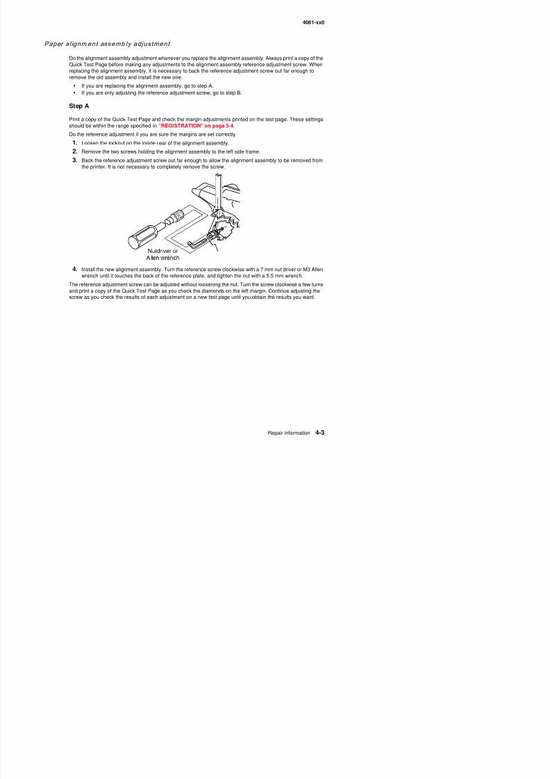
8/13/2019 t644 Service Manual
http://slidepdf.com/reader/full/t644-service-manual 225/423
4. Install the new alignment assembly. Turn the reference screw clockwise with a 7 mm nut driver or M3 Allenwrench until it touches the back of the reference plate, and tighten the nut with a 5.5 mm wrench.
The reference adjustment screw can be adjusted without loosening the nut. Turn the screw clockwise a few turnsand print a copy of the Quick Test Page as you check the diamonds on the left margin. Continue adjusting thescrew as you check the results of each adjustment on a new test page until you obtain the results you want.
4061-xx0
Step B
Print a copy of the Quick Test Page, and check the margin adjustments printed on the test page. These settingsshould be within the range specified in “REGISTRATION” on page 3-4. The reference screw can be adjustedwithout loosening the locknut. Turn the screw a few turns, and print a copy of the Quick Test Page as you checkthe diamonds on the left margin. Continue adjusting the screw as you check the results of each adjustment on anew test page until you obtain the results you want.
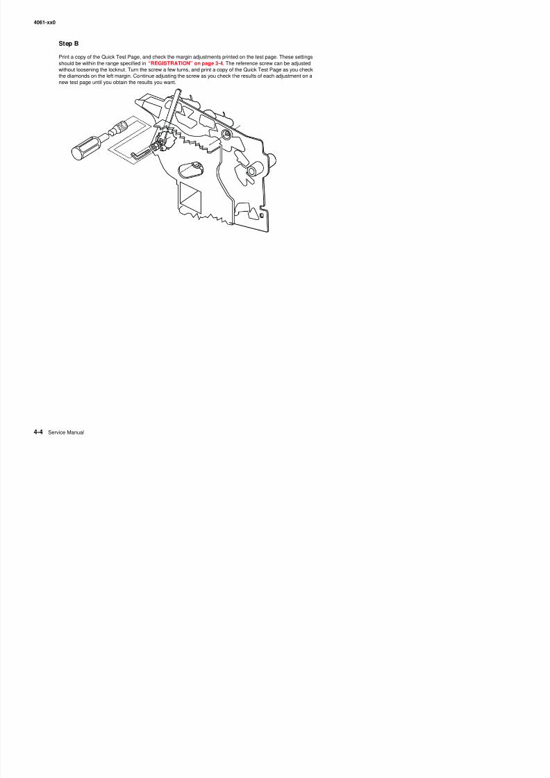
8/13/2019 t644 Service Manual
http://slidepdf.com/reader/full/t644-service-manual 226/423
4061-xx0
Removal procedures
CAUTION: Remove the power cord from the printer or wall outlet before you connect or disconnectany cable or electronic board or assembly for personal safety and to prevent damage to the printer.
CAUTION:Use the handholds on the side of the printer. Make sure your fingers are not under the
printer when you lift or set the printer down.Note: Some removal procedures require removing cable ties. You must replace cable ties during reassembly toavoid pinching wires, obstructing the paper path, or restricting mechanical movement.
Covers removals
Fuser wiper cover assembly removal
1. Squeeze the two latches together, and pull up.
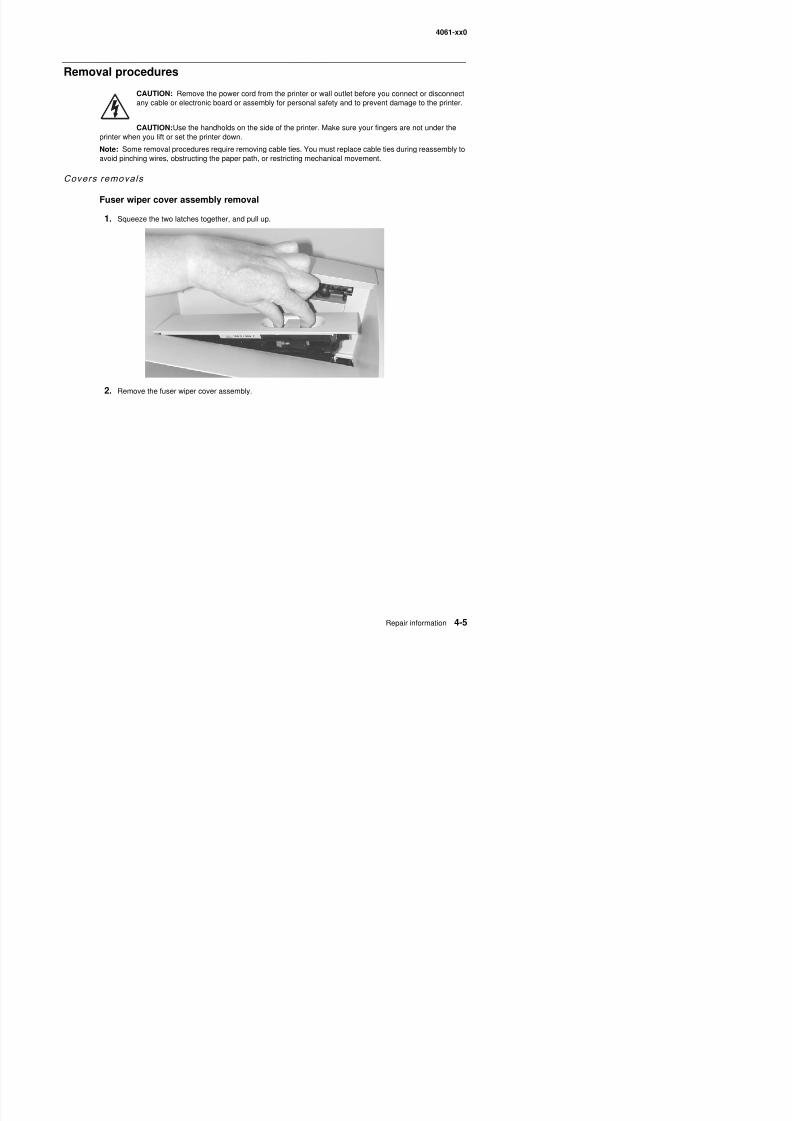
8/13/2019 t644 Service Manual
http://slidepdf.com/reader/full/t644-service-manual 227/423
2. Remove the fuser wiper cover assembly.
4061-xx0
Redrive cap cover removal
1. Pull up on the right side of the redrive cap cover to remove.
2. Remove the redrive cap cover.
Paper support removal
1. Raise the paper support, and lift to release the latches.
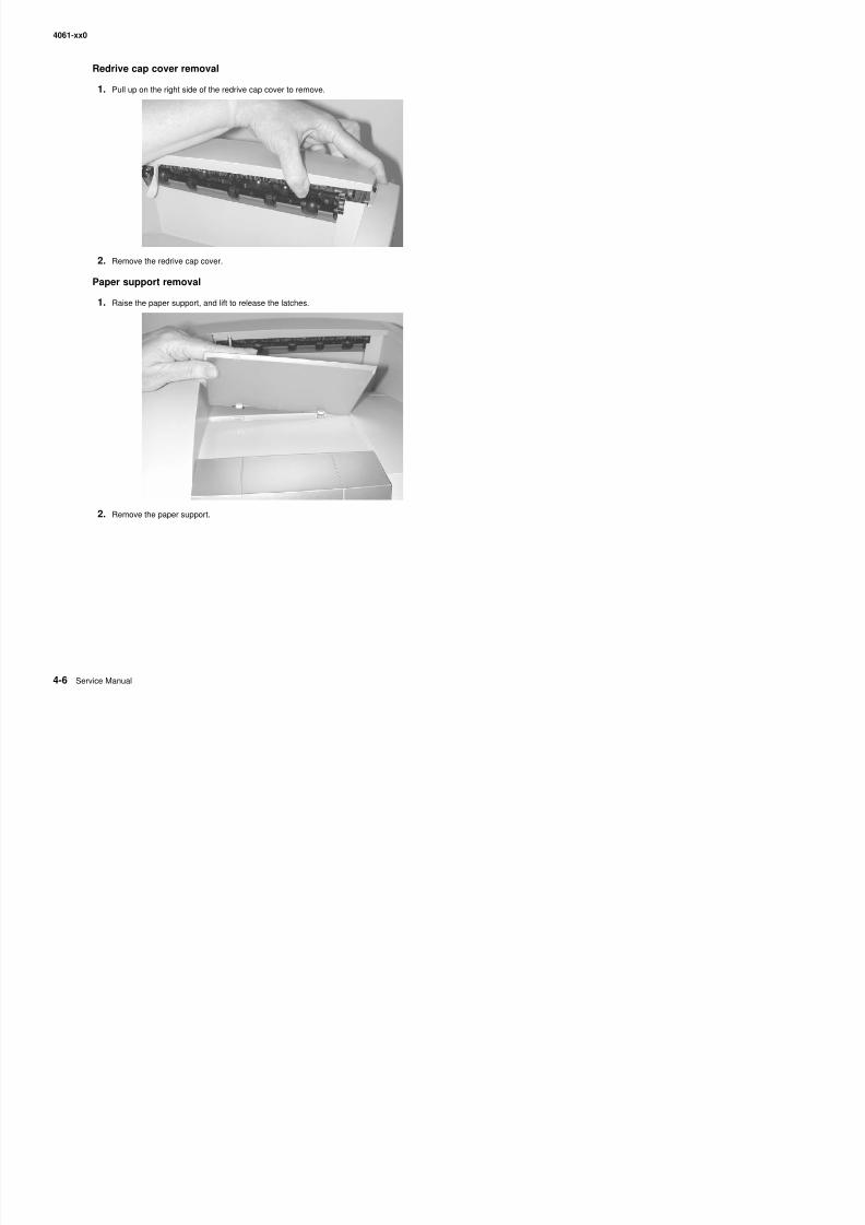
8/13/2019 t644 Service Manual
http://slidepdf.com/reader/full/t644-service-manual 228/423
2. Remove the paper support.
4061-xx0
Left door removal
1. Open the upper and lower front covers.
2. Press the two left door latch buttons (A), and open the left door.
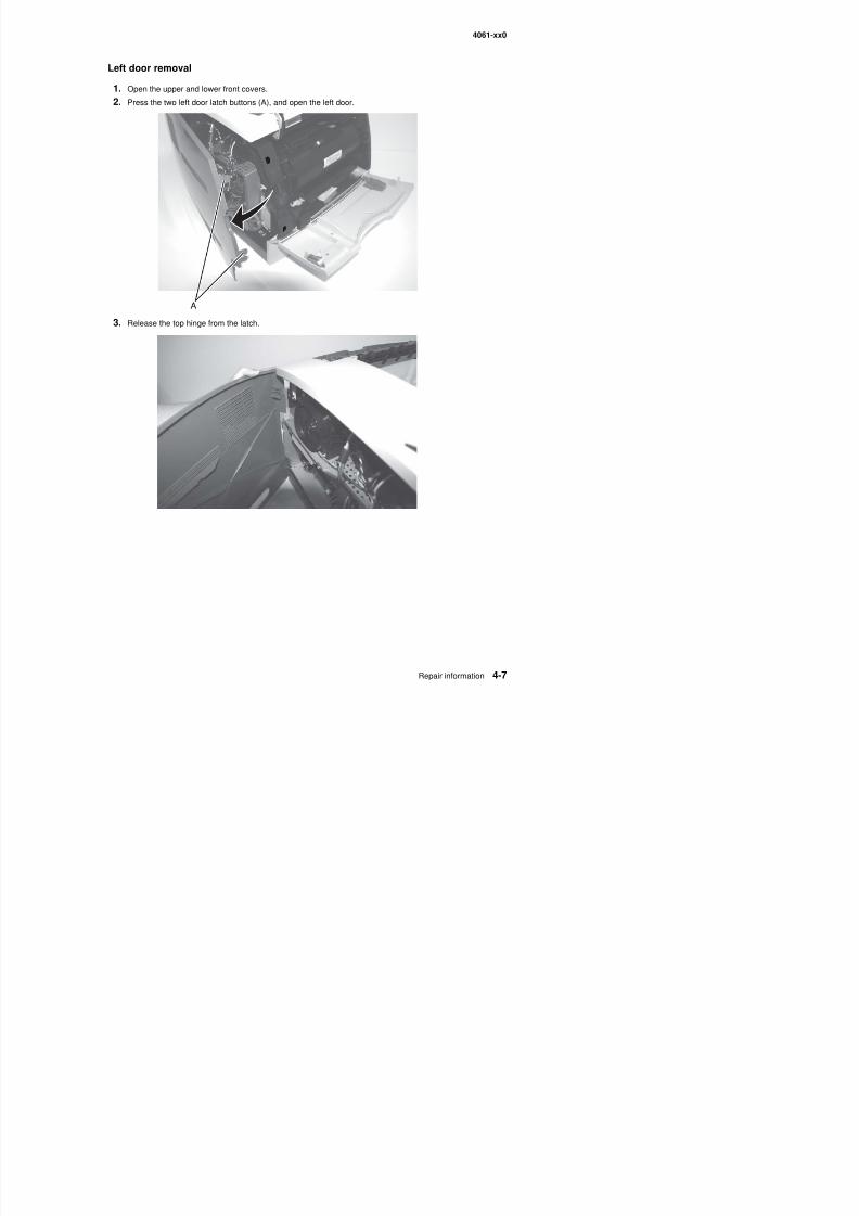
8/13/2019 t644 Service Manual
http://slidepdf.com/reader/full/t644-service-manual 229/423
3. Release the top hinge from the latch.
4061-xx0
4. Lift the door to release the bottom from the pin (B), and remove the door.
Redrive door
1. With the redrive door partially open, lift and free the left side.
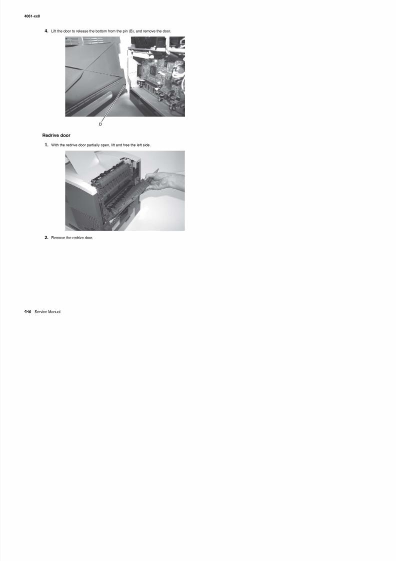
8/13/2019 t644 Service Manual
http://slidepdf.com/reader/full/t644-service-manual 230/423
p y p ,
2. Remove the redrive door.
4061-xx0
Right cover removal
1. Remove the redrive cap. See“Redrive cap cover removal” on page 4-6.
2. Open the upper and lower front covers.
3. Remove the print cartridge.
4. Remove the right front cover mounting screw (A).
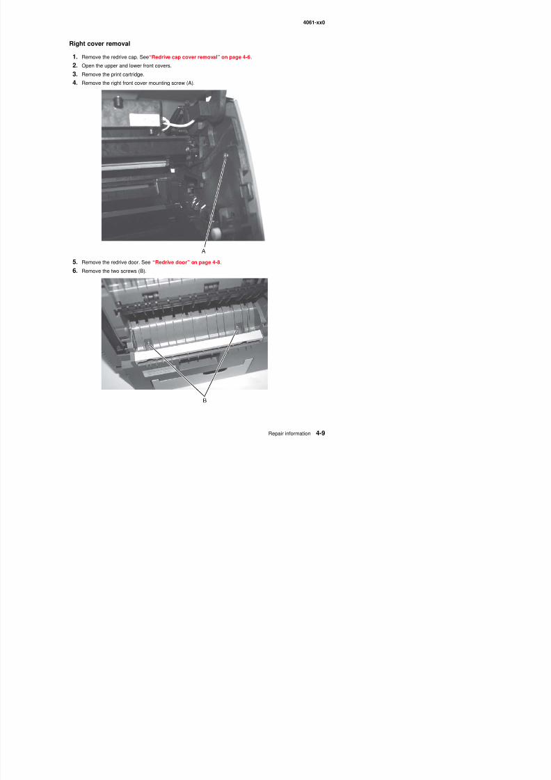
8/13/2019 t644 Service Manual
http://slidepdf.com/reader/full/t644-service-manual 231/423
5. Remove the redrive door. See “Redrive door” on page 4-8.
6. Remove the two screws (B).
4061-xx0
7. Remove the right rear cover mounting screw (C).
8. Press the two latches to remove the redrive assembly.
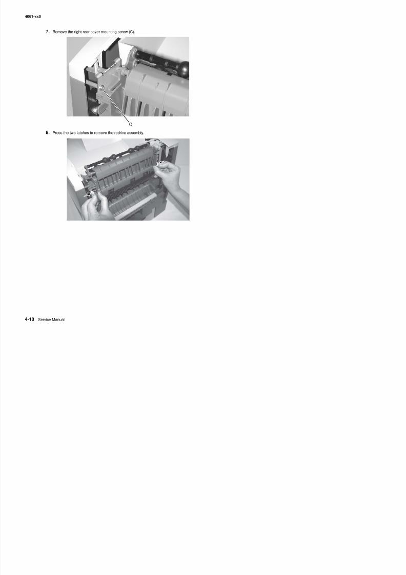
8/13/2019 t644 Service Manual
http://slidepdf.com/reader/full/t644-service-manual 232/423
4061-xx0
9. Press the latch (D) firmly to release the front of the right cover.
10. Pull up and out on the right cover to release the three cover retainers (E) at the bottom.
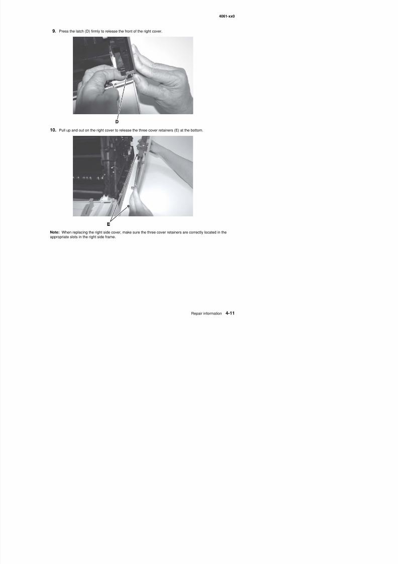
8/13/2019 t644 Service Manual
http://slidepdf.com/reader/full/t644-service-manual 233/423
Note: When replacing the right side cover, make sure the three cover retainers are correctly located in theappropriate slots in the right side frame.
4061-xx0
Upper front cover removal
Warning: When replacing any one of the following components:
• Operator panel assembly (or upper front cover)• System board assembly• Interconnect card assembly
Only replace one component at a time. Replace the required component and perform a POR before replacing a
second component listed above. If this procedure is not followed, the printer will be rendered inoperable. Neverreplace two or more of the components listed above without a POR after installing each one or the printer will berendered inoperable.
Warning: Never install and remove components listed above as a method of troubleshooting components.Once a component has been installed in a printer, it can not be used in another printer. It must bereturned to the manufacturer.
1. Open the lower front cover.
2. Open the upper front cover.
3. Remove the screw (A) holding the upper front cover outer bezel to the hinge.4. Remove the two screws (B) that hold the upper front cover to the hinge assembly.
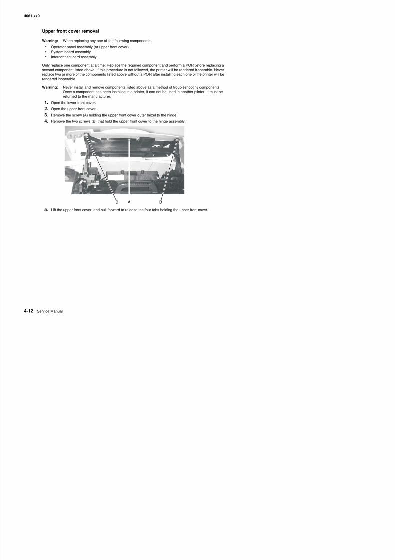
8/13/2019 t644 Service Manual
http://slidepdf.com/reader/full/t644-service-manual 234/423
5. Lift the upper front cover, and pull forward to release the four tabs holding the upper front cover.
4061-xx0
6. Disconnect the cables.
Note: It may be necessary to remove the operator panel cable from the cable clip (C) to be able todisconnect the cable from the operator panel.
7. Remove the upper front cover.
Note: If you are replacing the upper front cover, remove the upper front cover outer bezel and upper frontcover latch. Otherwise, carefully set the upper front cover aside to avoid scratching the bezel or looseningthe latch and spring.
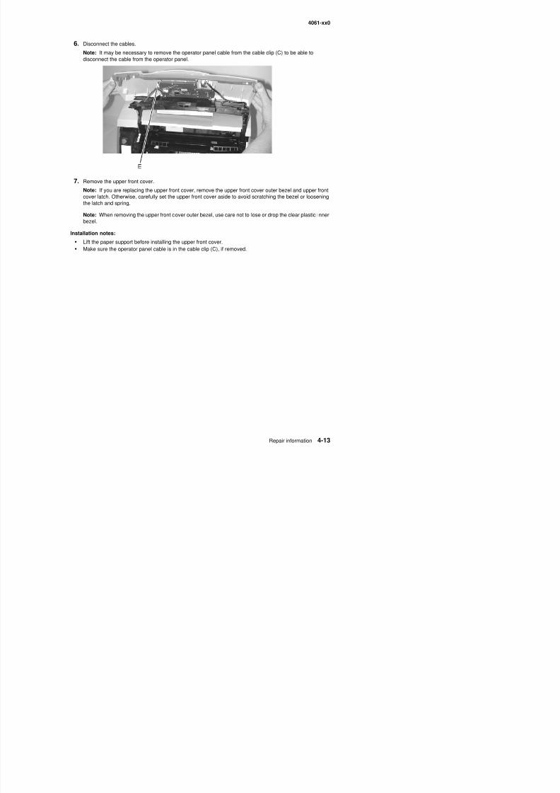
8/13/2019 t644 Service Manual
http://slidepdf.com/reader/full/t644-service-manual 235/423
Note: When removing the upper front cover outer bezel, use care not to lose or drop the clear plastic innerbezel.
Installation notes:
• Lift the paper support before installing the upper front cover.• Make sure the operator panel cable is in the cable clip (C), if removed.
4061-xx0
Upper front cover latch removal
1. Remove the upper front cover.
2. Remove the screw (A) holding the latch and spring to the upper front cover.
Installation note: The spring (B) is installed as shown.
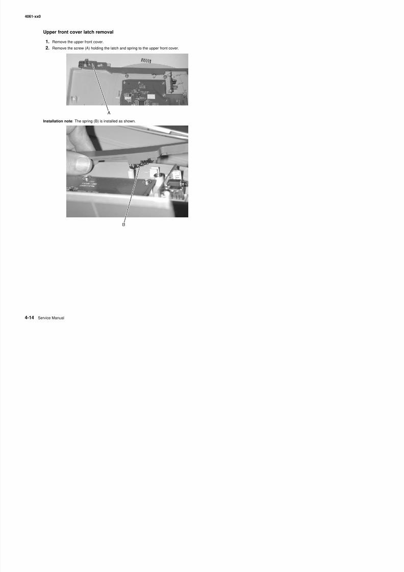
8/13/2019 t644 Service Manual
http://slidepdf.com/reader/full/t644-service-manual 236/423
4061-xx0
Upper front cover outer bezel removal
1. Open the lower front cover.
2. Open the upper front cover.
3. Remove the two small upper front cover outer bezel mounting screws (A).
4 Pull up to remove the outer bezel
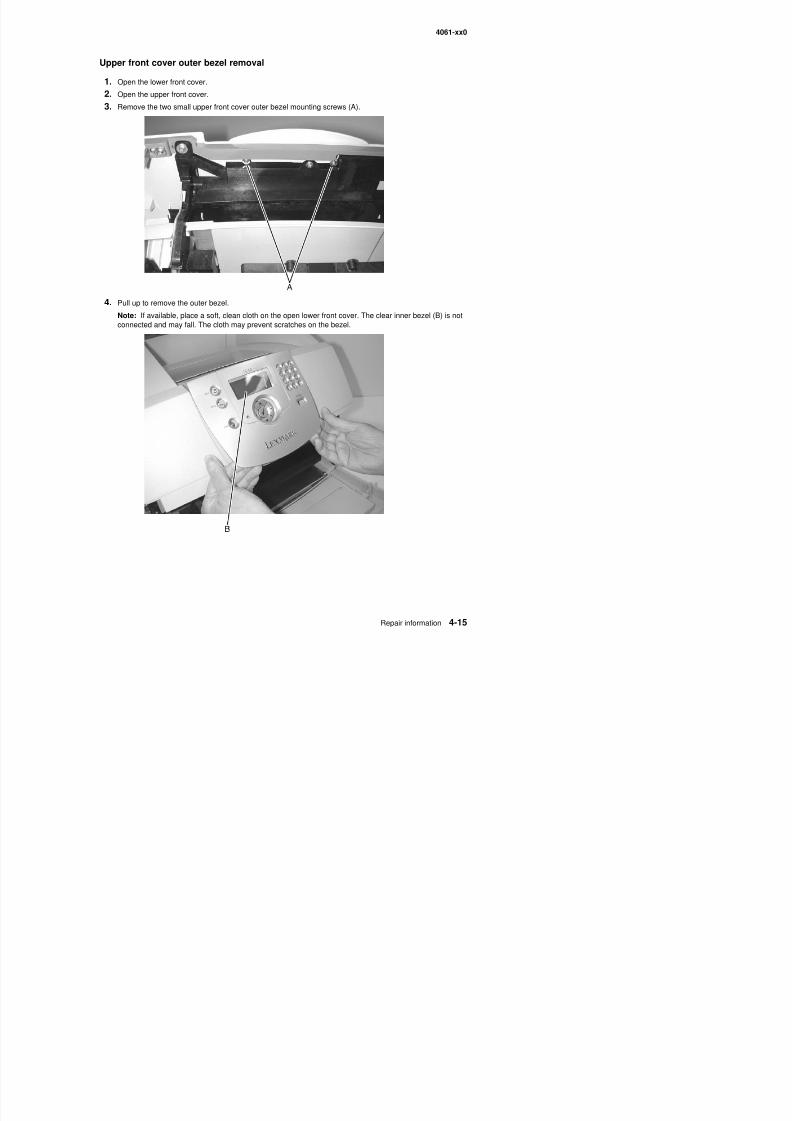
8/13/2019 t644 Service Manual
http://slidepdf.com/reader/full/t644-service-manual 237/423
4. Pull up to remove the outer bezel.
Note: If available, place a soft, clean cloth on the open lower front cover. The clear inner bezel (B) is notconnected and may fall. The cloth may prevent scratches on the bezel.
4061-xx0
Multipurpose feeder/lower front cover assembly removal
1. Open the multipurpose tray to a position that allows the left and right tray hinge slots (A) to align with theD-shape mounting posts (B). Pull upward on each tray hinge to remove the tray from the two mountingposts.
Warning: Be careful not to break or stress the hinges.
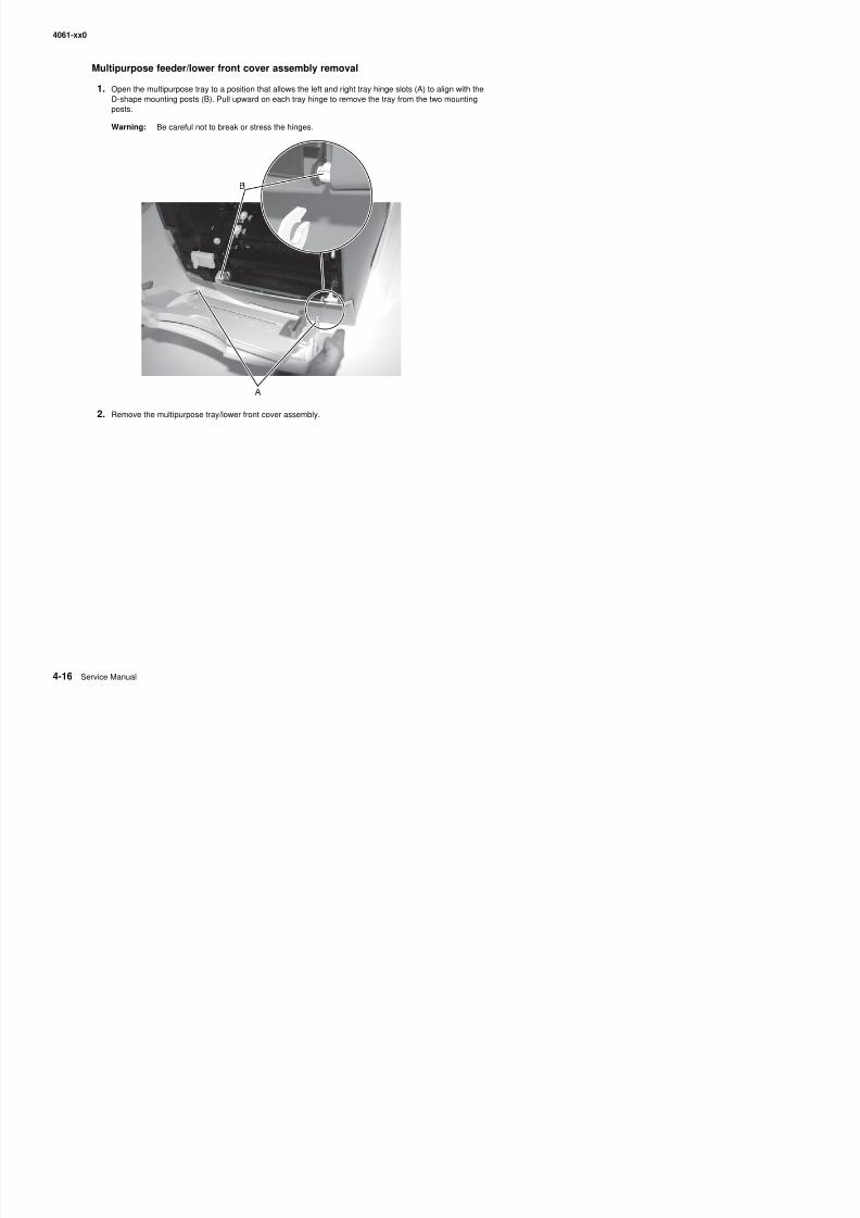
8/13/2019 t644 Service Manual
http://slidepdf.com/reader/full/t644-service-manual 238/423
2. Remove the multipurpose tray/lower front cover assembly.
4061-xx0
Left cover handle holder removal
1. Open the left side cover.
2. Remove the outer system board shield. See “Outer shield removal” on page 4-69.
3. Remove the two screws (A) holding the top of the left handle holder in place.
4. Use the tab (B) to lift out the left handle holder.
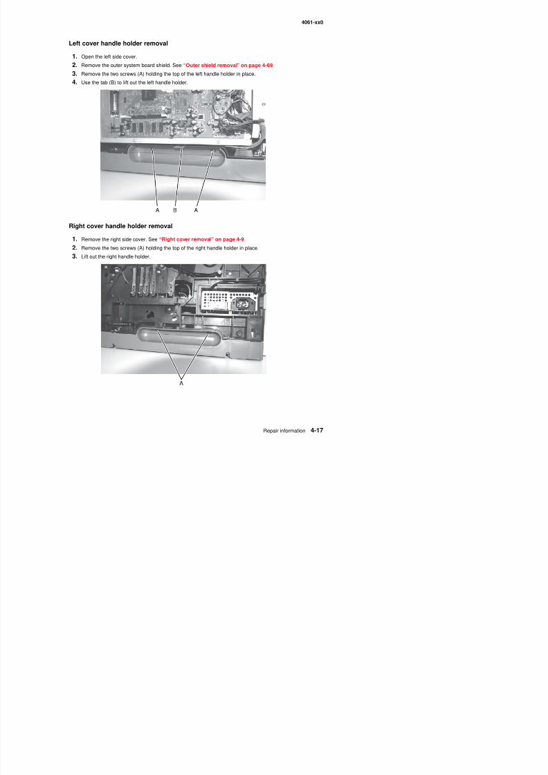
8/13/2019 t644 Service Manual
http://slidepdf.com/reader/full/t644-service-manual 239/423
Right cover handle holder removal
1. Remove the right side cover. See “Right cover removal” on page 4-9.
2. Remove the two screws (A) holding the top of the right handle holder in place.
3. Lift out the right handle holder.
4061-xx0
Left and right frame extensions
1. Remove the toner cartridge.
2. Turn the printer on its back.
3. Remove the two screws (A) holding the right frame extension.
4. Remove the two screws (B) securing the left frame extension.
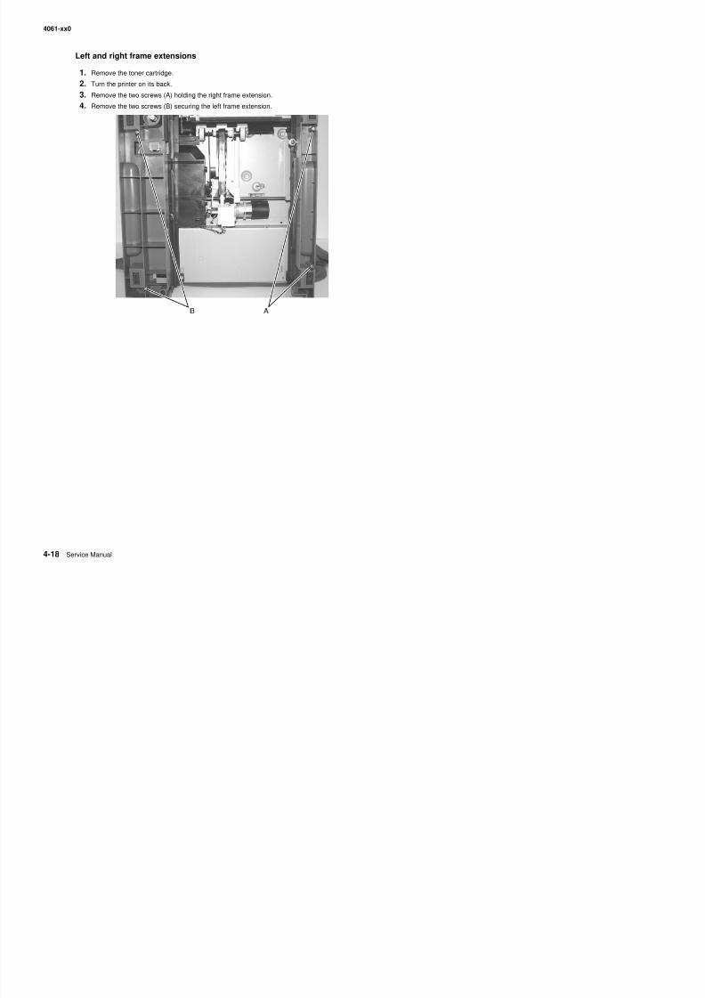
8/13/2019 t644 Service Manual
http://slidepdf.com/reader/full/t644-service-manual 240/423
4061-xx0
Pass thru plate
1. Remove the redrive assembly. See “Redrive assembly removal” on page 4-75.
2. Remove the screw (A) securing the pass thru plate.
3. Carefully remove the plate until it is loose.
4 Remove the fuser to system board DC cable (B) secured through the plate
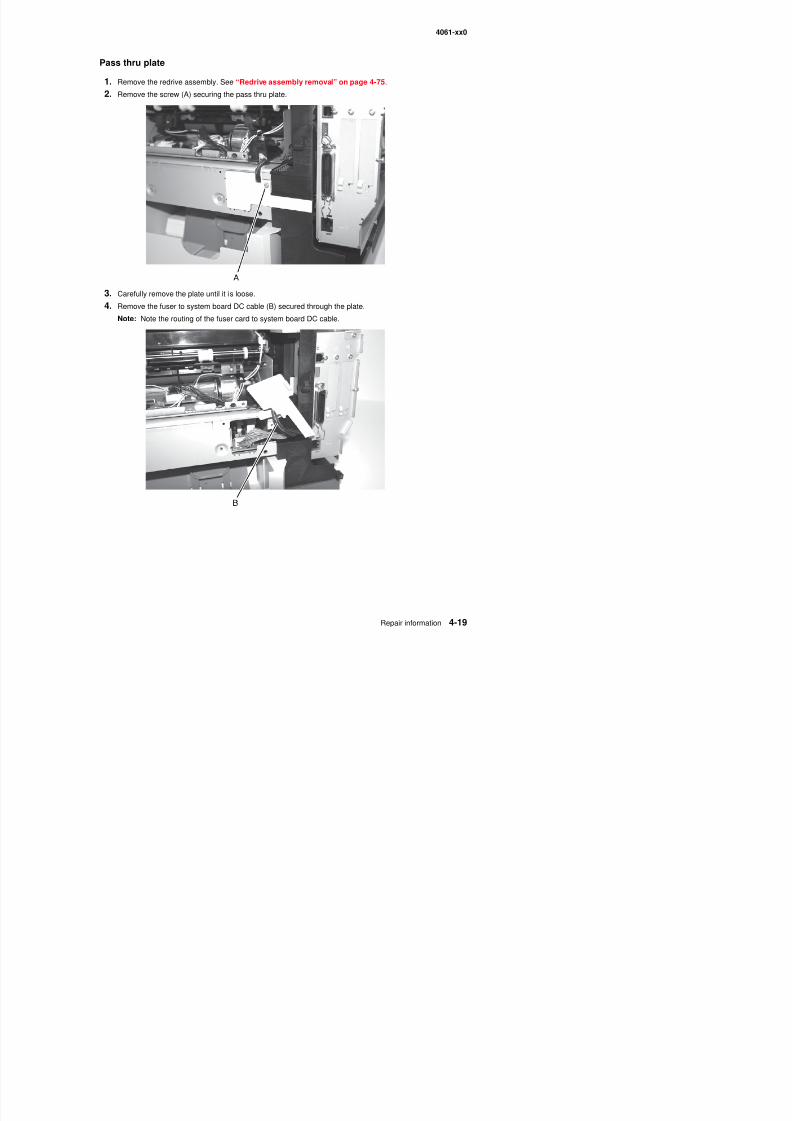
8/13/2019 t644 Service Manual
http://slidepdf.com/reader/full/t644-service-manual 241/423
4. Remove the fuser to system board DC cable (B) secured through the plate.
Note: Note the routing of the fuser card to system board DC cable.
4061-xx0
Laser cover removal
1. Remove the left door. See “Left door removal” on page 4-7.
2. Remove the right cover. See “Right cover removal” on page 4-9.
3. Remove the paper support. See “Paper support removal” on page 4-6.
4. Remove the redrive cap. See “Redrive cap cover removal” on page 4-6.
5. Press the fuser wiper cover latch, and remove the cover.
6. Remove the screw (A) at the rear of the printer and the larger screw (B) at the front on the right side.
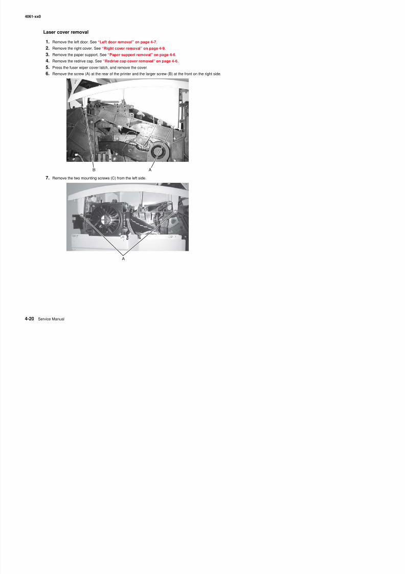
8/13/2019 t644 Service Manual
http://slidepdf.com/reader/full/t644-service-manual 242/423
7. Remove the two mounting screws (C) from the left side.
A
4061-xx0
8. Remove the paper bin full sensor flag from the mounting bracket. See “Paper bin full sensor flagremoval” on page 4-71.
9. Unlatch the front right and front left cover posts, and remove the cover.
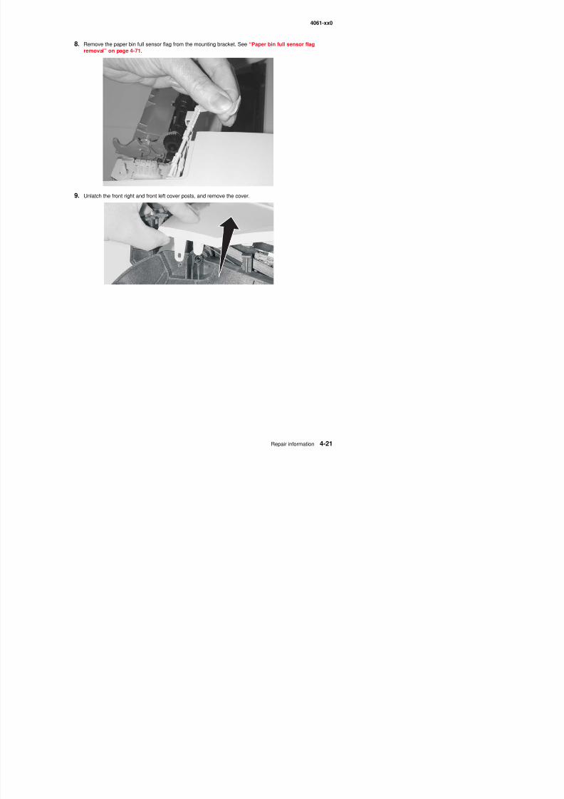
8/13/2019 t644 Service Manual
http://slidepdf.com/reader/full/t644-service-manual 243/423
4061-xx0
Bevel gear removal
1. Open the left door.
2. Remove the inner shield.
3. Remove the gear guard.
4. Remove the power takeoff shaft and spring (A) through the bottom of the printer.
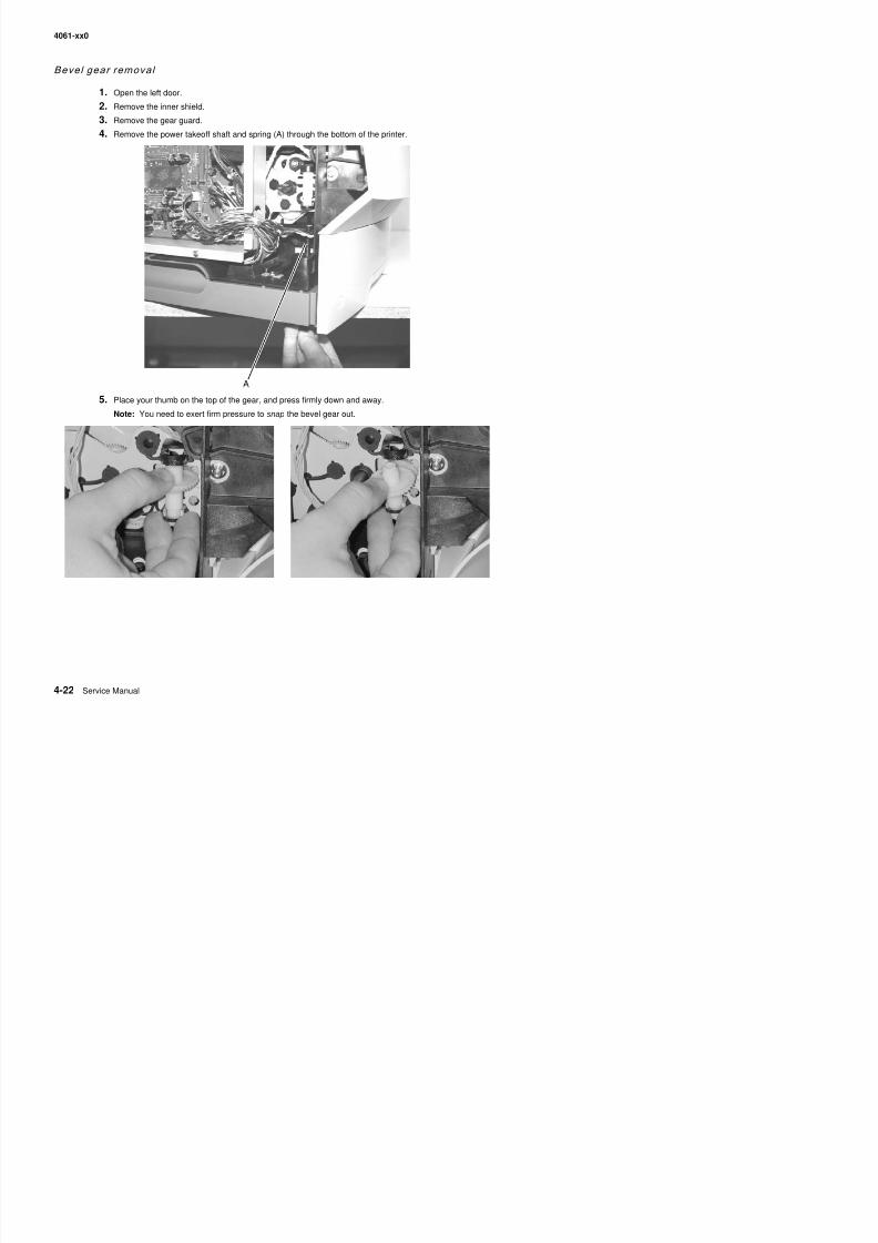
8/13/2019 t644 Service Manual
http://slidepdf.com/reader/full/t644-service-manual 244/423
5. Place your thumb on the top of the gear, and press firmly down and away.
Note: You need to exert firm pressure to snap the bevel gear out.
4061-xx0
Installation
1. Remove any washer that may be present (A) and discard.
2. Lubricate areas (A) that engage the journal (B) with grease from the provided packet.
3. Place the new washer (C) on the bevel gear shaft.
4. Insert the bottom portion and press or pull into position.
Note: You should hear two distinct snaps. If you only hear one, the bevel gear is only partially engagedand you should continue to press until the second snap is heard Very firm pressure is required
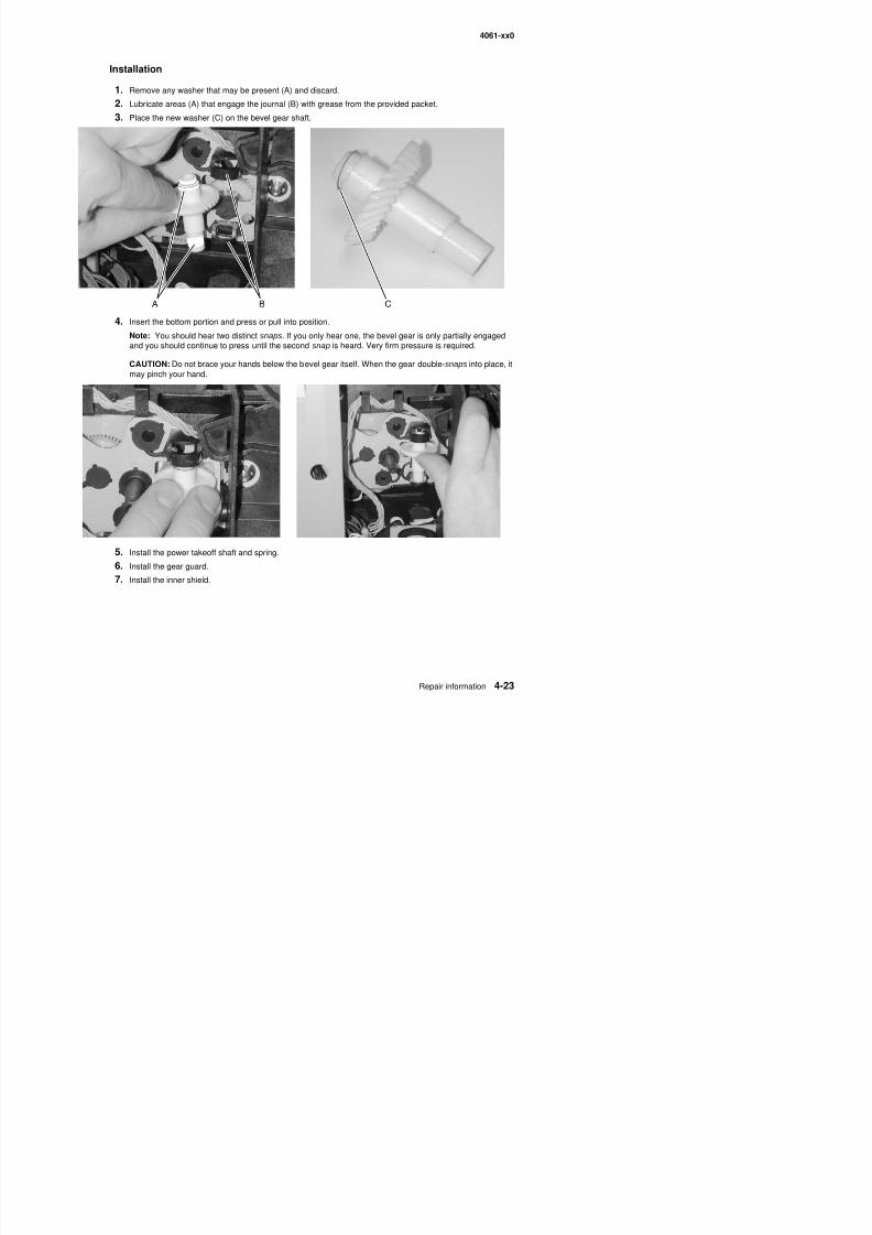
8/13/2019 t644 Service Manual
http://slidepdf.com/reader/full/t644-service-manual 245/423
and you should continue to press until the second snap is heard. Very firm pressure is required.
CAUTION: Do not brace your hands below the bevel gear itself. When the gear double-snaps into place, itmay pinch your hand.
5. Install the power takeoff shaft and spring.
4061-xx0
Cartr idge duct removal
1. Open the left door.
2. Disconnect the printhead laser cable from J2 on the system board.
3. Remove the three screws securing the cartridge duct (A).
Note: It may be necessary to pull the main fan cable (B) up and out of the way to remove the duct.
4. Reconnect the printhead laser cable.
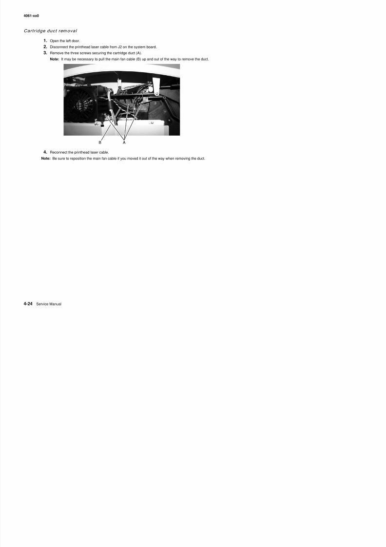
8/13/2019 t644 Service Manual
http://slidepdf.com/reader/full/t644-service-manual 246/423
4. Reconnect the printhead laser cable.
Note: Be sure to reposition the main fan cable if you moved it out of the way when removing the duct.
4061-xx0
Developer drive assembly r emoval
1. Remove the system board and inner shield. See “System board and inner shield removal” onpage 4-77.
2. Remove the two short screws (A) and the one long screw (B) securing the developer drive assembly.
3. Remove the developer drive assembly.
4 R h d l d i l ki S “D l d i l ki l” 26
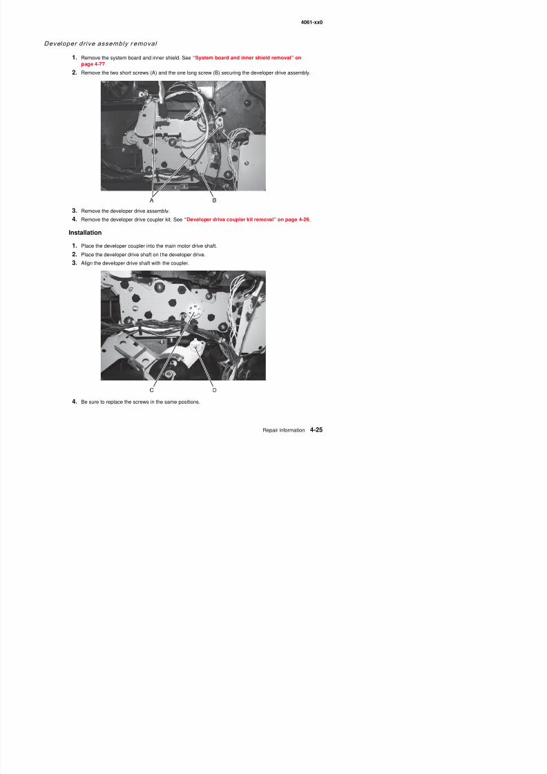
8/13/2019 t644 Service Manual
http://slidepdf.com/reader/full/t644-service-manual 247/423
4. Remove the developer drive coupler kit. See “Developer drive coupler kit removal” on page 4-26.
Installation
1. Place the developer coupler into the main motor drive shaft.
2. Place the developer drive shaft on the developer drive.
3. Align the developer drive shaft with the coupler.
4061-xx0
Developer drive coup ler ki t removal
1. Remove the developer drive. See “Developer drive assembly removal” on page 4-25.
2. Remove the shaft drive and coupler.
ESD cover remov al
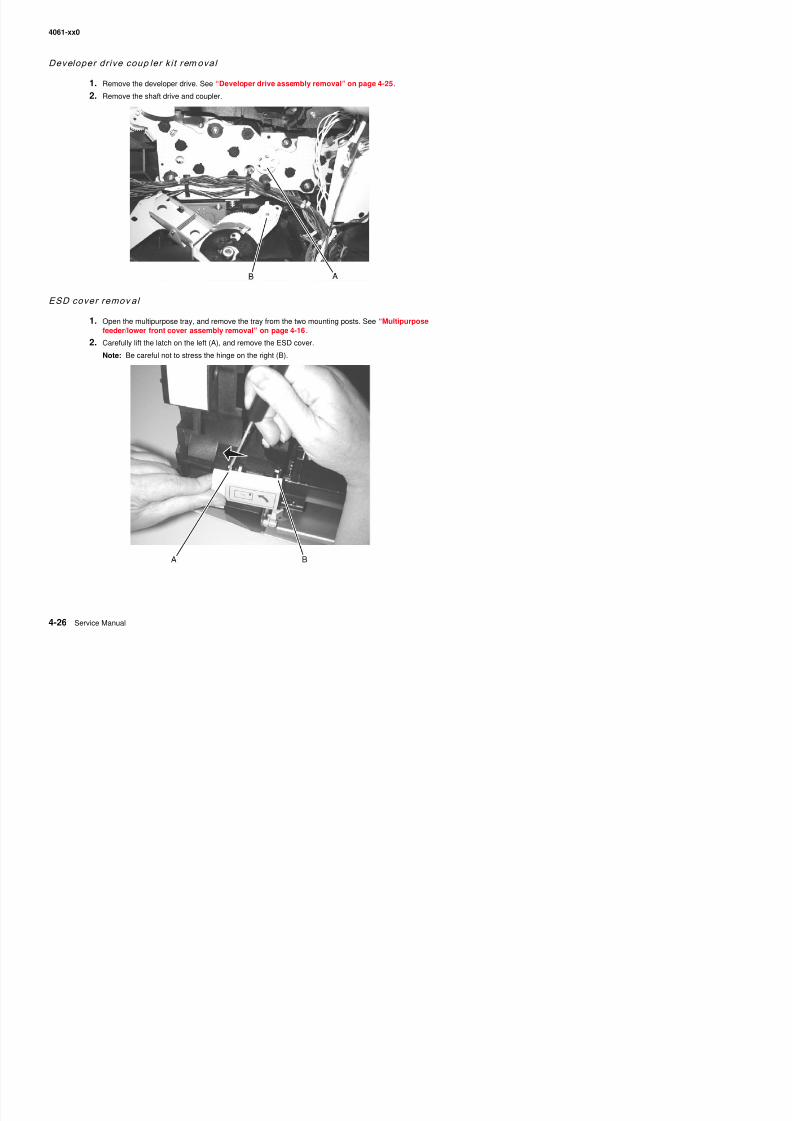
8/13/2019 t644 Service Manual
http://slidepdf.com/reader/full/t644-service-manual 248/423
1. Open the multipurpose tray, and remove the tray from the two mounting posts. See “Multipurposefeeder/lower front cover assembly removal” on page 4-16.
2. Carefully lift the latch on the left (A), and remove the ESD cover.
Note: Be careful not to stress the hinge on the right (B).
4061-xx0
Fuser assemb ly removal
CAUTION: Unplug the printer before you begin.
1. Remove the fuser wick assembly cover. See “Fuser wiper cover assembly removal” on page 4-5.
2. Remove the redrive assembly. See “Redrive assembly removal” on page 4-75.
3. Remove the fuser mounting screws (A).
4. Disconnect the fuser to LVPS AC cable (B) from the fuser lamp connector (C).
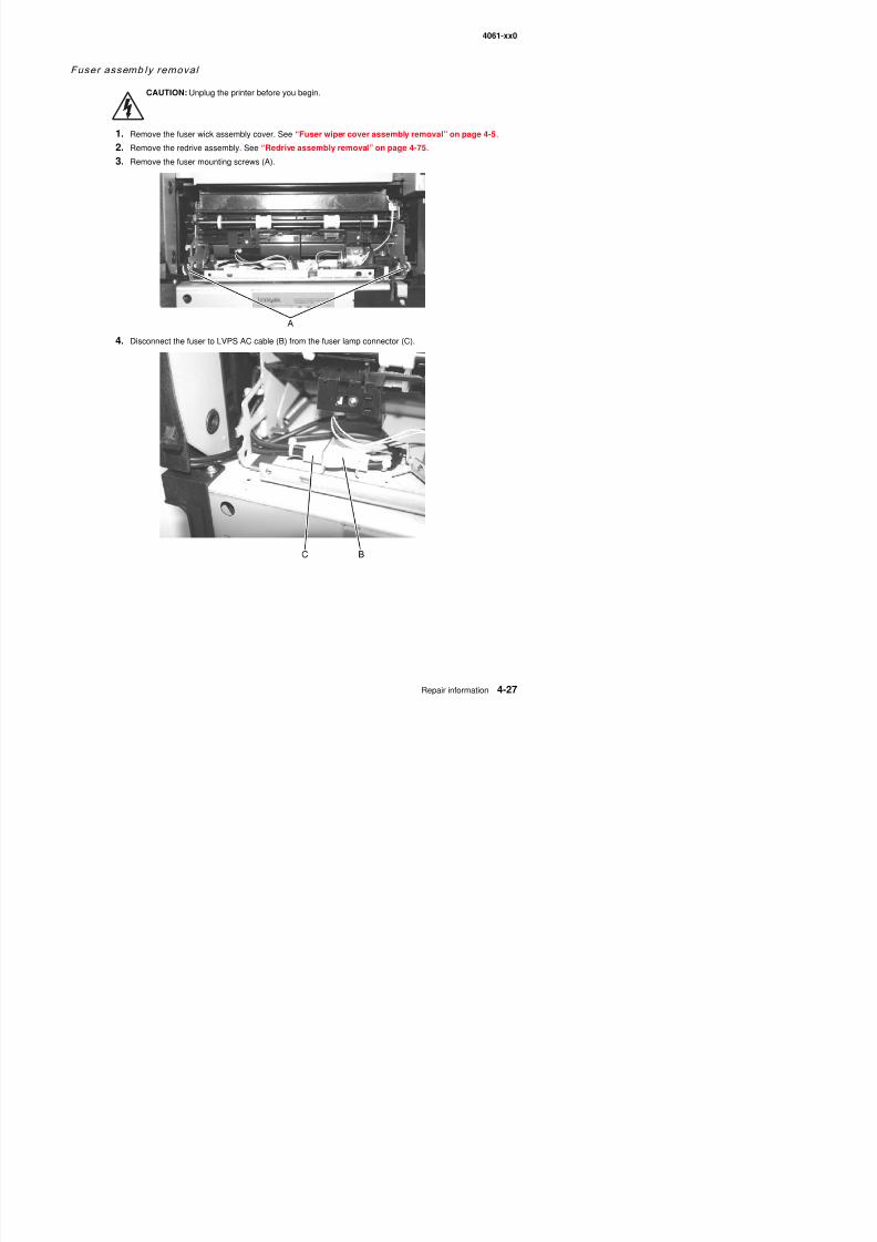
8/13/2019 t644 Service Manual
http://slidepdf.com/reader/full/t644-service-manual 249/423
4061-xx0
5. Disconnect the fuser to system board DC cable (D) from the fuser board.
Note: Be sure to observe the routing of the LVPS to fuser lamp AC and the DC cable.
6. Pull the cables free and remove the fuser.
Installation notes
1. When you reinstall the fuser, be sure to route the fuser to LVPS AC cable (A) through the channel (B) onthe right side frame above the LVPS, under the clip (C) over the LVPS, and through the notch in theframe (D).
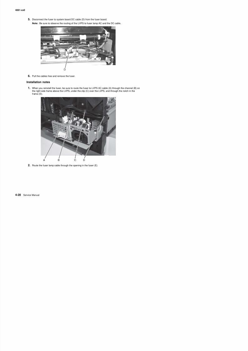
8/13/2019 t644 Service Manual
http://slidepdf.com/reader/full/t644-service-manual 250/423
4061-xx0
3. Connect the fuser to LVPS AC cable to the fuser lamp connector (F) at the LVPS.
Note: Be sure to connect the fuser to system board DC cable after replacing the LVPS.
Fuser exi t senso r remo val
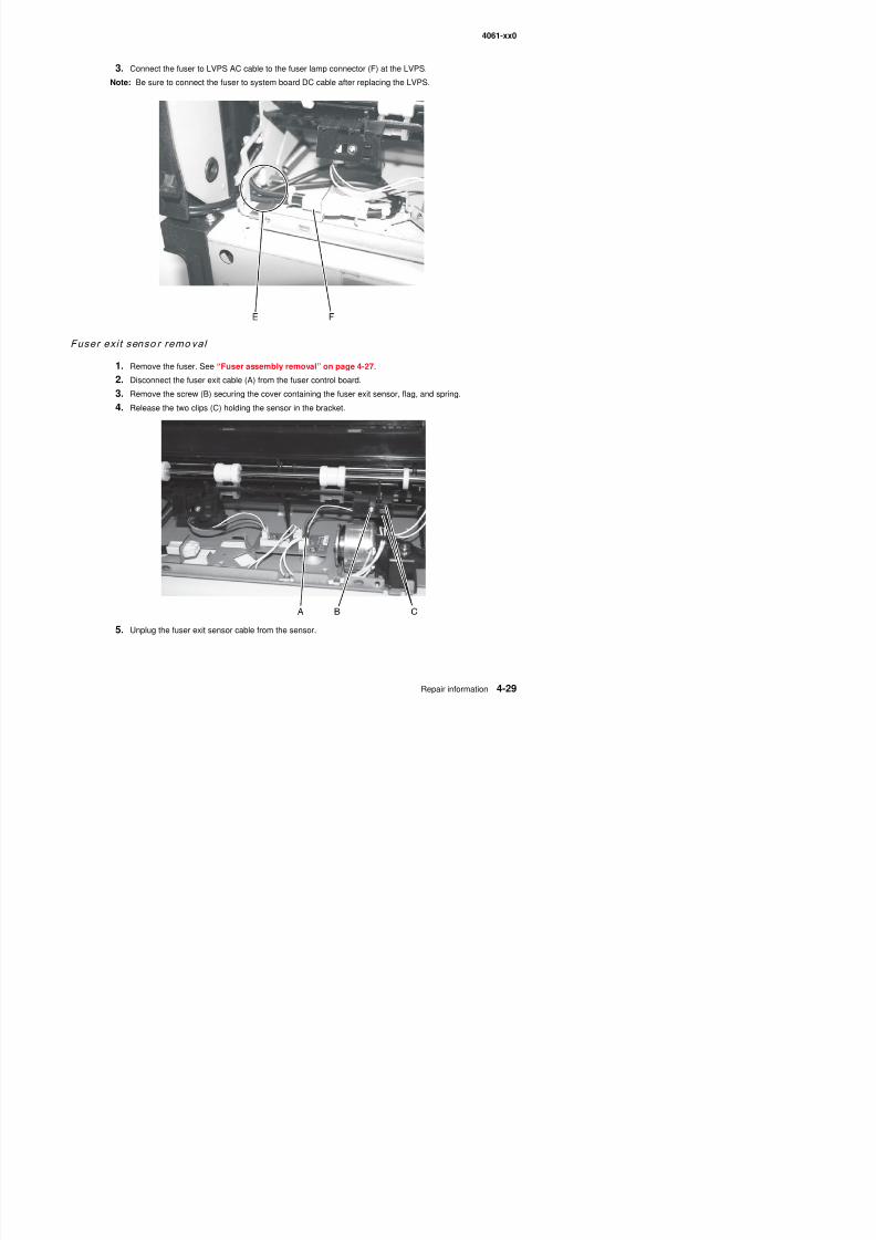
8/13/2019 t644 Service Manual
http://slidepdf.com/reader/full/t644-service-manual 251/423
1. Remove the fuser. See “Fuser assembly removal” on page 4-27.
2. Disconnect the fuser exit cable (A) from the fuser control board.
3. Remove the screw (B) securing the cover containing the fuser exit sensor, flag, and spring.
4. Release the two clips (C) holding the sensor in the bracket.
4061-xx0
Installation
1. Move the fuser exit sensor flag out of the way to clip the sensor securely into the cover.
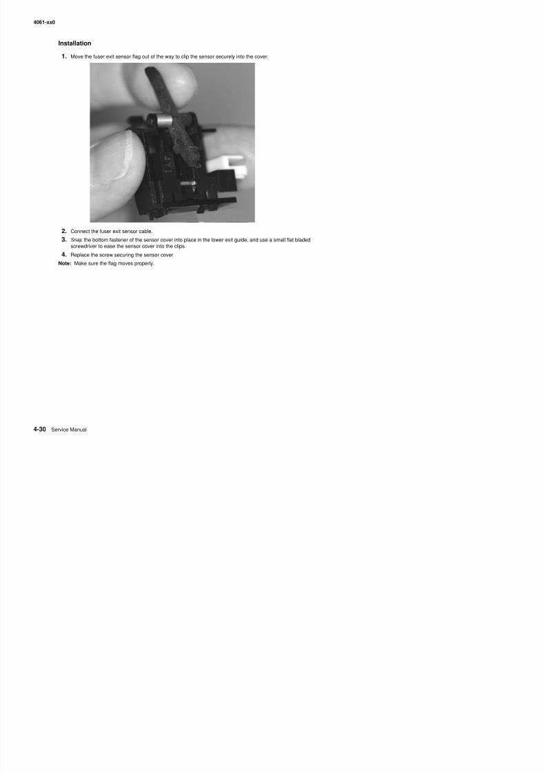
8/13/2019 t644 Service Manual
http://slidepdf.com/reader/full/t644-service-manual 252/423
2. Connect the fuser exit sensor cable.
3. Snap the bottom fastener of the sensor cover into place in the lower exit guide, and use a small flat bladedscrewdriver to ease the sensor cover into the clips.
4. Replace the screw securing the sensor cover.
Note: Make sure the flag moves properly.
4061-xx0
Fuser exit sensor f lag and spring removal
1. Remove the fuser exit sensor. See “Fuser exit sensor removal” on page 4-29.
2. Note the position of the spring (A) in relation to the flag (B).
3. Carefully ease the right arm (C) until the fuser exit sensor cover releases the flag and spring.
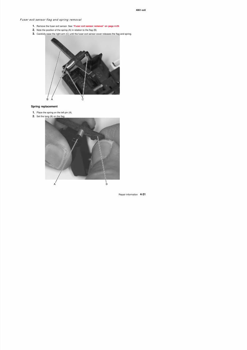
8/13/2019 t644 Service Manual
http://slidepdf.com/reader/full/t644-service-manual 253/423
Spring replacement
1. Place the spring on the left pin (A).
2. Set the tang (B) on the flag.
4061-xx0
3. Rotate the bent end (C) of the spring to add tension, place the pins between the sensor cover arms, andrest the bent end against the sensor cover frame.
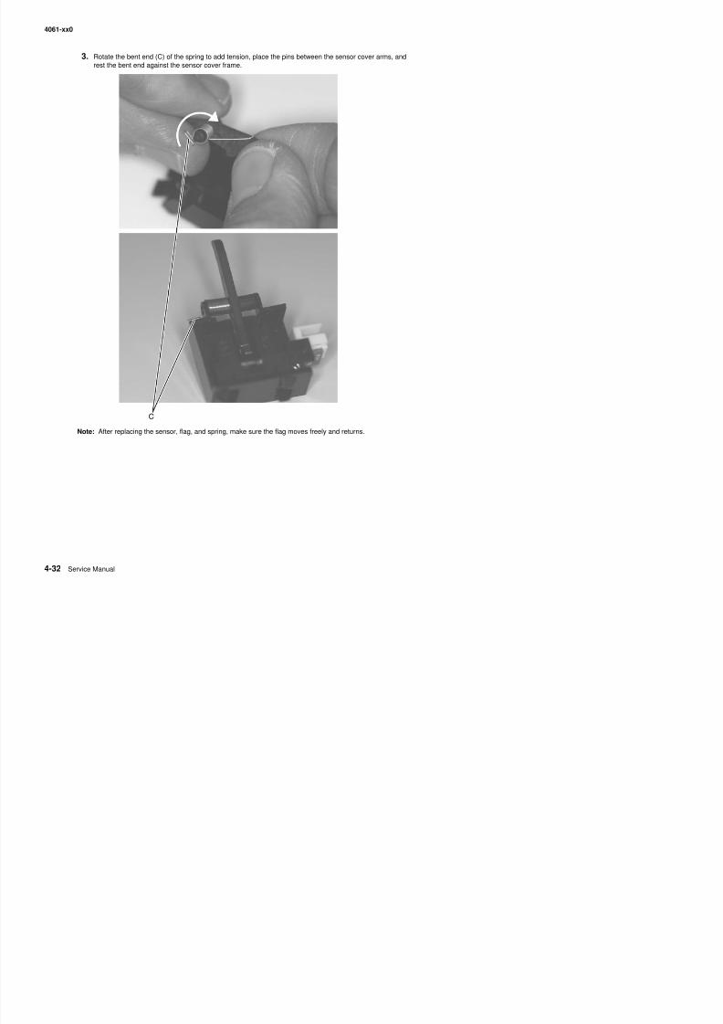
8/13/2019 t644 Service Manual
http://slidepdf.com/reader/full/t644-service-manual 254/423
Note: After replacing the sensor, flag, and spring, make sure the flag moves freely and returns.
4061-xx0
Fuser lamp remov al
CAUTION: The fuser and the fuser lamp may be hot. You may need to allow them to coolbefore handling them.
1. Remove the fuser assembly. See “Fuser assembly removal” on page 4-27.
2. Disconnect the fuser lamp AC cable from the right side of the top cover assembly.3. Remove the two screws (A) from the right side fuser lamp contact cover.
Warning: Take care when removing the screw, as the lamp is under spring tension. When the contact isreleased, damage to the lamp or contact may occur.
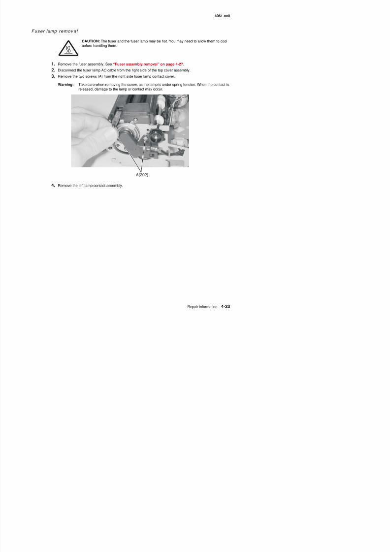
8/13/2019 t644 Service Manual
http://slidepdf.com/reader/full/t644-service-manual 255/423
4. Remove the left lamp contact assembly.
A(202)
4061-xx0
5. Remove the fuser lamp.
Warning: The lamp is under spring tension, and care must be used when removing the lamp from thefuser. Grip the lamp by the ceramic end piece, and remove it from the fuser assembly. Becareful not to touch the glass, as skin oils and acids can reduce the life of the lamp.
Use the following table to identify and install the correct lamp.
Description P/N
Fuser Lamp 115 V 40X0122
F L V
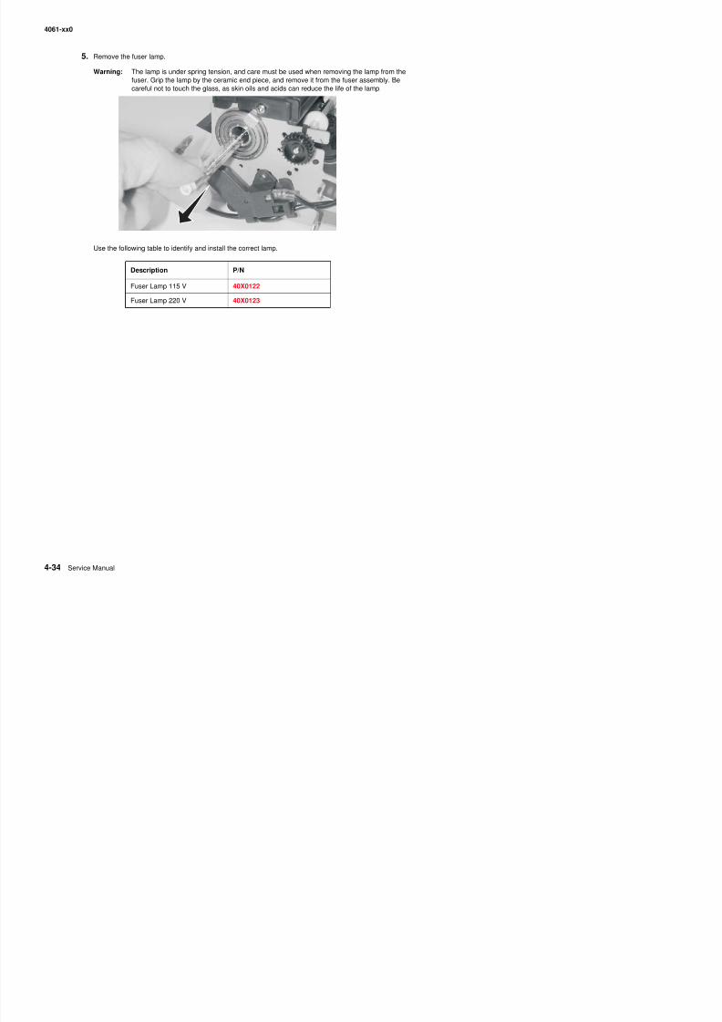
8/13/2019 t644 Service Manual
http://slidepdf.com/reader/full/t644-service-manual 256/423
Fuser Lamp 220 V 40X0123
4061-xx0
Fuser narrow media sensor removal
1. Remove the redrive assembly. See “Redrive assembly removal” on page 4-75.
2. Remove the screw (A) securing the narrow media sensor cover to the fuser.
3. With a thumbnail, release the catches (B) holding the sensor cover to the lower exit guide (C) in place.
Note: You may need to move the narrow media flag out of the way to remove the sensor.
4 Disconnect the fuser narrow media cable at the sensor
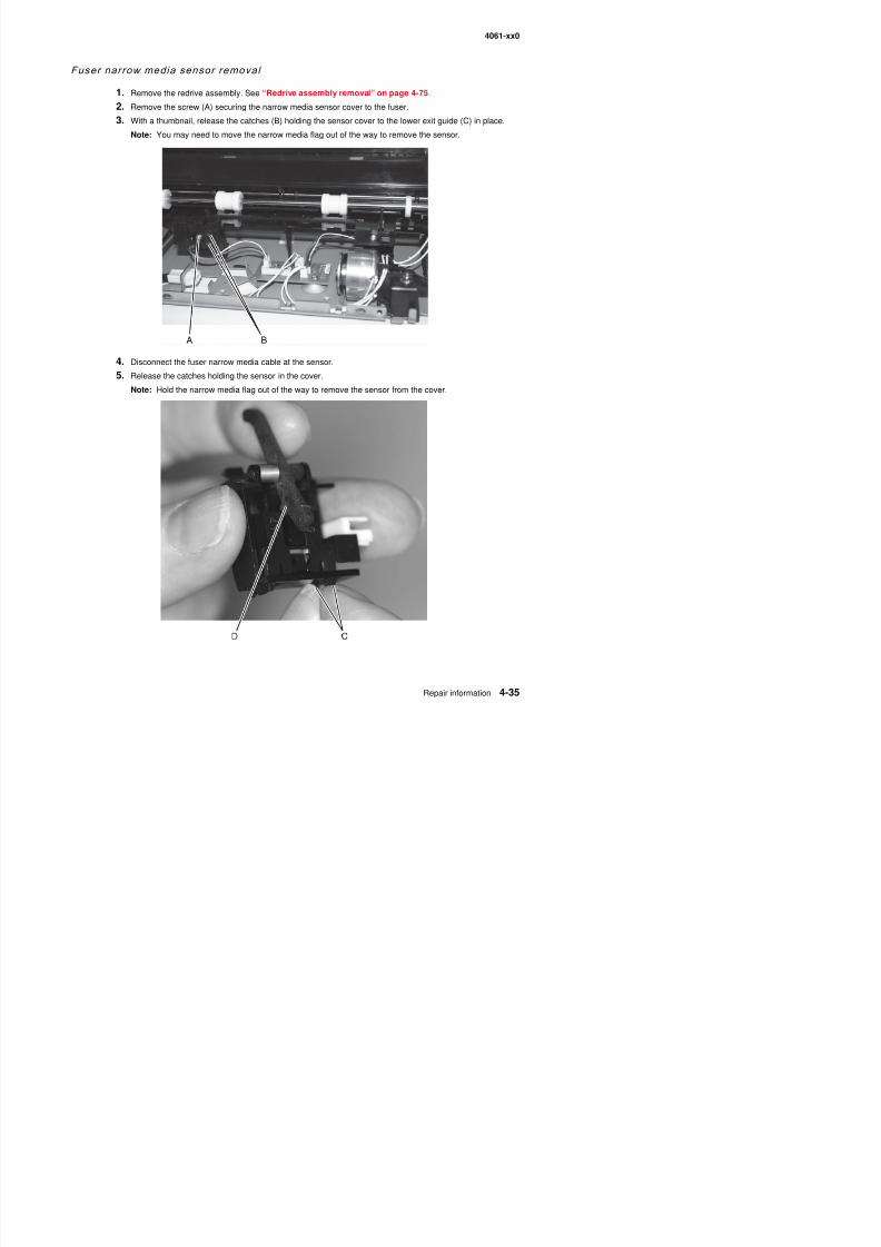
8/13/2019 t644 Service Manual
http://slidepdf.com/reader/full/t644-service-manual 257/423
4. Disconnect the fuser narrow media cable at the sensor.5. Release the catches holding the sensor in the cover.
Note: Hold the narrow media flag out of the way to remove the sensor from the cover.
4061-xx0
Replacement
1. Move the narrow media flag out of the way to clip the sensor securely into the cover.

8/13/2019 t644 Service Manual
http://slidepdf.com/reader/full/t644-service-manual 258/423
2. Connect the fuser narrow media cable.
3. Snap the bottom fastener of the sensor cover into place in the lower exit guide, and rock the cover up untilthe top fastener snaps securely.
4. Replace the screw securing the sensor cover.
4061-xx0
Fuser narrow media f lag and spring removal
1. Remove the fuser narrow media sensor. See “Fuser narrow media sensor removal” on page 4-35.
2. Note the position of the spring (A) in relation to the flag (B).
3. Carefully ease the right arm (C) of the sensor cover just far enough apart to release the flag and spring.
Spring replacement
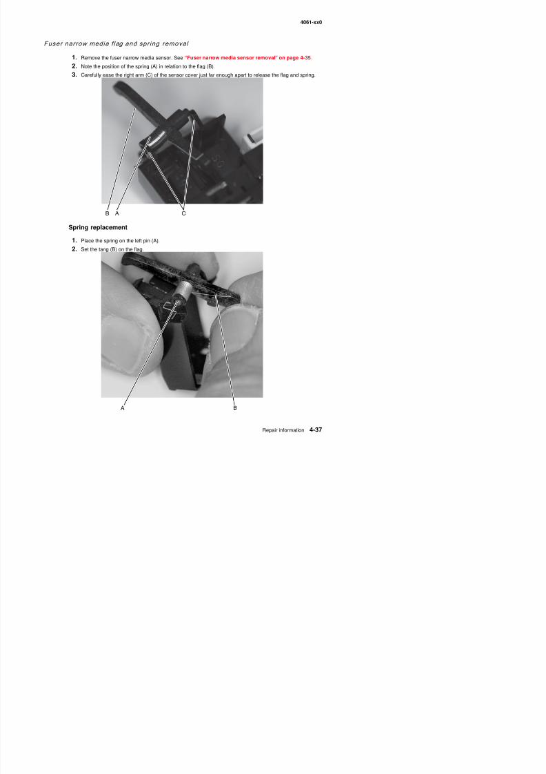
8/13/2019 t644 Service Manual
http://slidepdf.com/reader/full/t644-service-manual 259/423
Spring replacement
1. Place the spring on the left pin (A).
2. Set the tang (B) on the flag.
4061-xx0
3. Rotate the bent end (C) of the spring to add tension, place the pins between the sensor cover arms, andrest the bent end against the sensor cover frame.
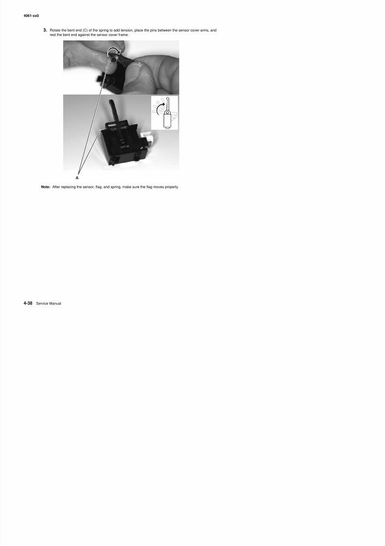
8/13/2019 t644 Service Manual
http://slidepdf.com/reader/full/t644-service-manual 260/423
Note: After replacing the sensor, flag, and spring, make sure the flag moves properly.
A
4061-xx0
Fuser to LVPS AC cable removal
CAUTION: Unplug the printer before you begin.
1. Remove the fuser wick assembly cover. See “Fuser wiper cover assembly removal” on page 4-5.
2. Remove the redrive assembly. See “Redrive assembly removal” on page 4-75.
3. Remove the right side cover. See “Right cover removal” on page 4-9.4. Disconnect the fuser to LVPS AC cable (A) from the fuser lamp connector on the fuser, and remove the
cable through the cable retainer (B) and the lower rectangular opening (C) in the fuser frame.
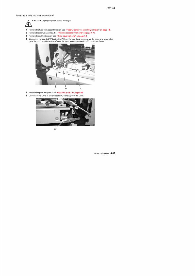
8/13/2019 t644 Service Manual
http://slidepdf.com/reader/full/t644-service-manual 261/423
5. Remove the pass thru plate. See “Pass thru plate” on page 4-19.
6. Disconnect the LVPS to system board DC cable (D) from the LVPS.
4061-xx0
7. Pull the LVPS assembly far enough out from the right side of the printer to disconnect the fuser to LVPSAC cable from the LVPS (E).
Note: The LVPS assembly may be difficult to remove from the printer. Do not use excessive force in theremoval.
8. Remove the fuser to LVPS AC cable.
Installation
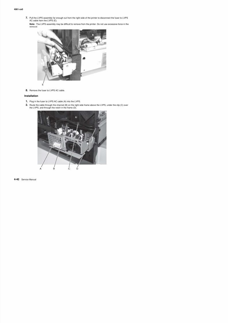
8/13/2019 t644 Service Manual
http://slidepdf.com/reader/full/t644-service-manual 262/423
Installation
1. Plug in the fuser to LVPS AC cable (A) into the LVPS.
2. Route the cable through the channel (B) on the right side frame above the LVPS, under the clip (C) overthe LVPS, and through the notch in the frame (D).
4061-xx0
3. Route the cable through the lower rectangular opening (E).
4. Connect the fuser to LVPS AC cable to the fuser lamp connector (F).
Note: Be sure to connect the fuser to system board DC cable after replacing the LVPS.
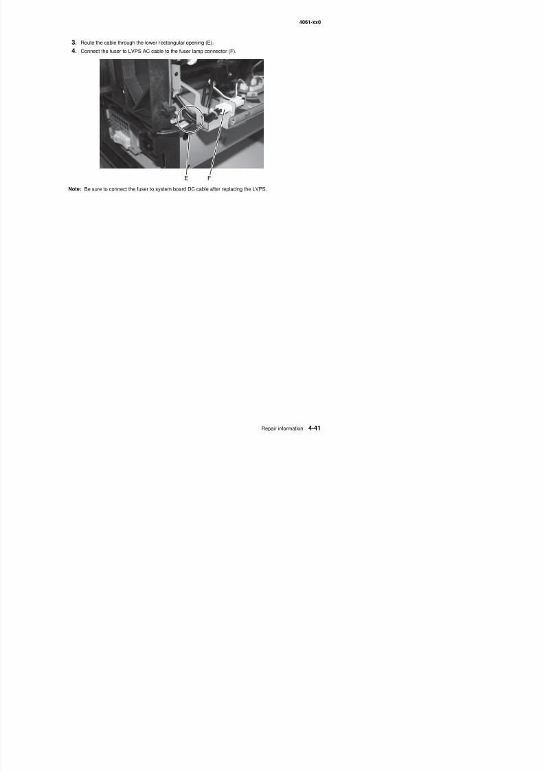
8/13/2019 t644 Service Manual
http://slidepdf.com/reader/full/t644-service-manual 263/423
4061-xx0
Fuser top cover removal
CAUTION: Unplug the printer before you begin.
1. Remove the fuser assembly. See “Fuser assembly removal” on page 4-27.
2. Note the thermistor cable routing (A) and disconnect the thermistor cable at the fuser control board.
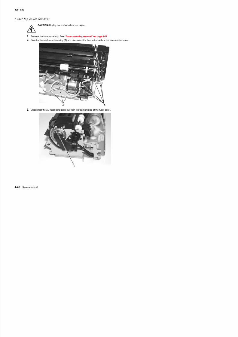
8/13/2019 t644 Service Manual
http://slidepdf.com/reader/full/t644-service-manual 264/423
3. Disconnect the AC fuser lamp cable (B) from the top right side of the fuser cover.
4061-xx0
4. Carefully remove the two screws (C) from the right side of the fuser lamp contact cover (D).
5. Release the latch (E) and remove the cover.
6. Remove the screw (F) on the left side and the screw (G) on the right side that attach the fuser upper coverassembly to the fuser frame.
7. Remove screw (H) that attaches the side fuser lamp contact to the fuser top cover.
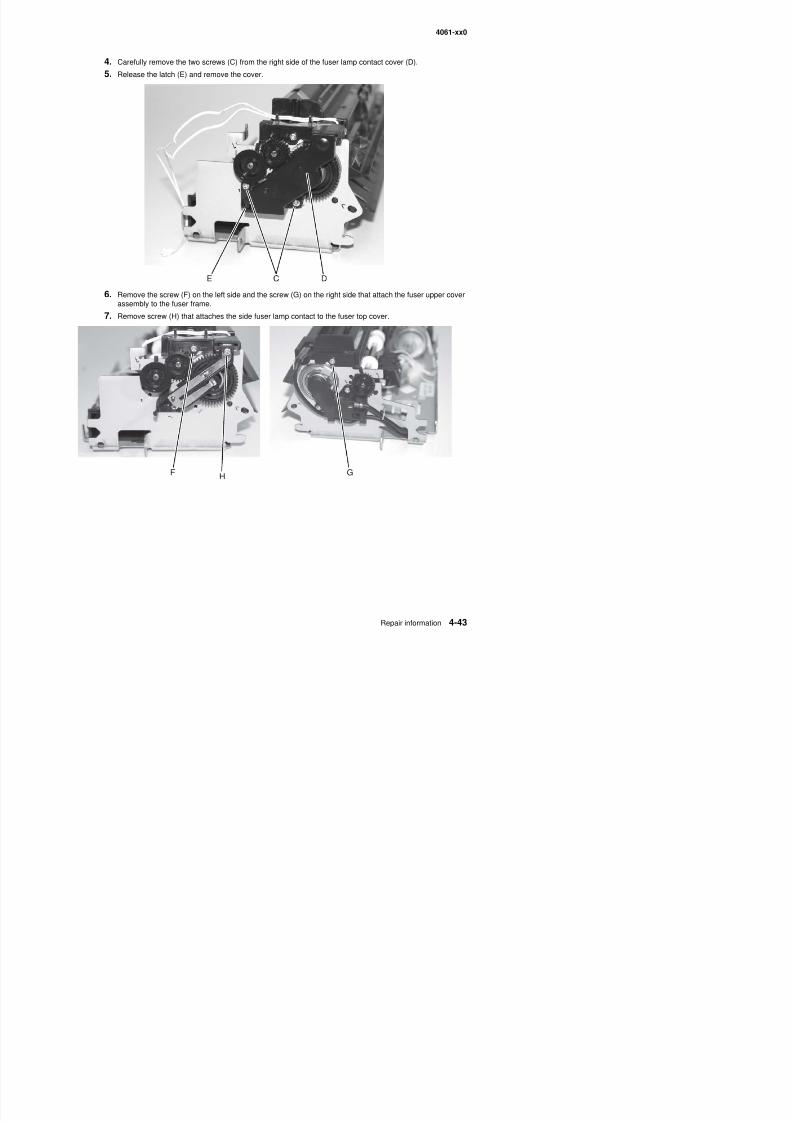
8/13/2019 t644 Service Manual
http://slidepdf.com/reader/full/t644-service-manual 265/423
F GH
4061-xx0
8. Remove the fuser cover.
Fuser transfer plate removal
1. Remove the upper paper deflector. See “Upper paper deflector assembly removal” on page 4-80.
2. Remove the transfer roll. See “Transfer roll assembly removal” on page 4-78.
3. Remove the inner paper deflector. See “Inner paper deflector assembly removal” on page 4-48.
4. Lift the left side of the fuser transfer plate (A), and move the plate to the left to clear the right side from itsmounting.
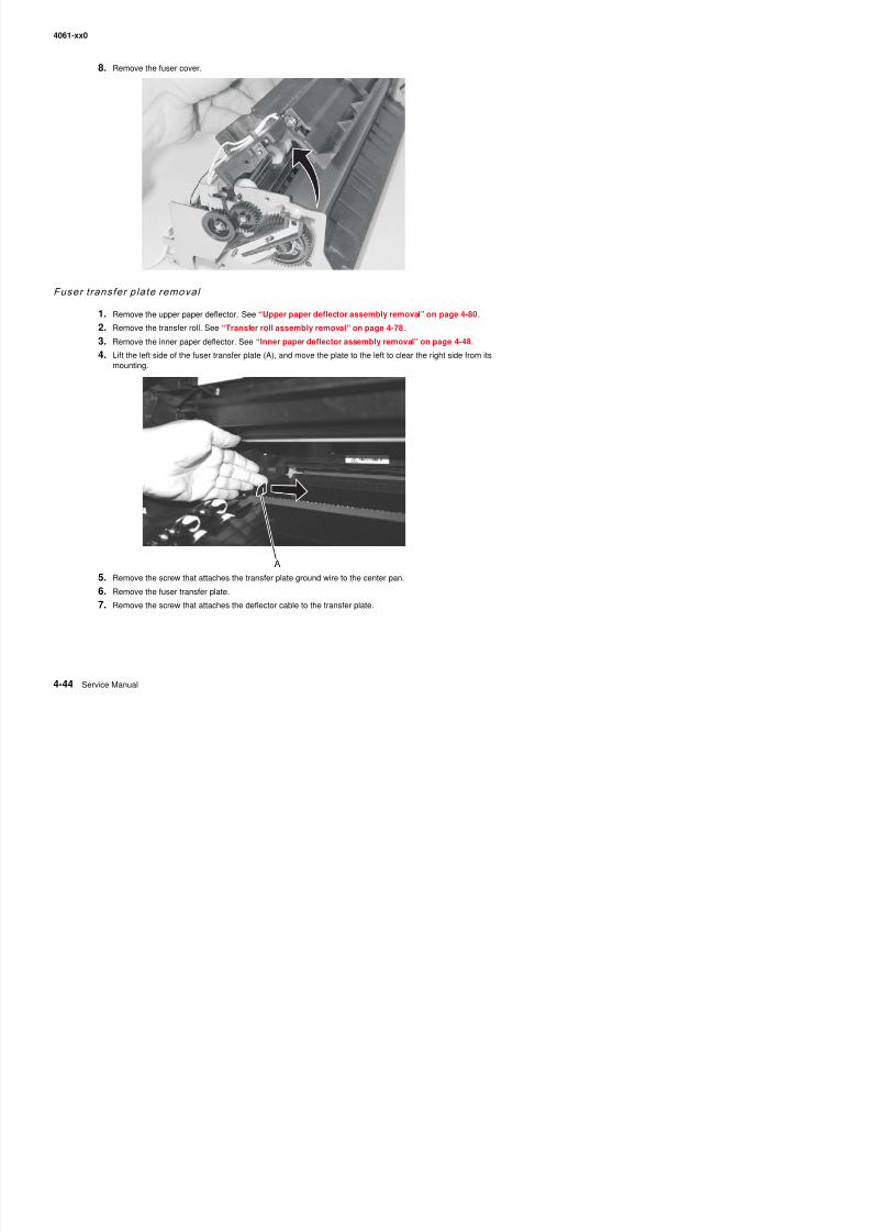
8/13/2019 t644 Service Manual
http://slidepdf.com/reader/full/t644-service-manual 266/423
4061-xx0
Gear release l ink remo val
1. Remove the system board and inner shield. See “System board and inner shield removal” onpage 4-77.
2. Remove the developer drive.
3. Disconnect the gear release link (A) from the hole in charge roll link (B).
Note: Lift the upper front cover to make it easier to remove the link.
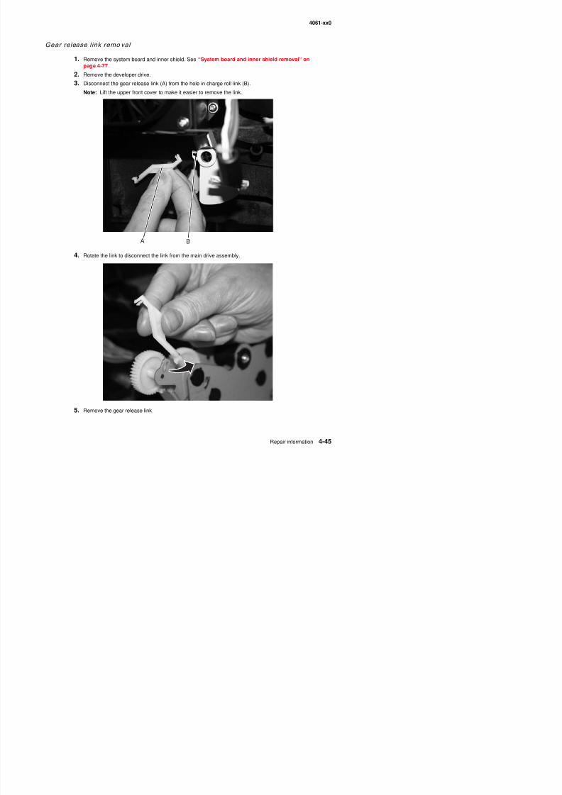
8/13/2019 t644 Service Manual
http://slidepdf.com/reader/full/t644-service-manual 267/423
4. Rotate the link to disconnect the link from the main drive assembly.
4061-xx0
High vol tage power supply remo val
CAUTION: There is a danger from hazardous voltage in the area of the printer where you areworking. Unplug the printer before you begin, or use caution if the printer must receive power inorder to perform the task.
1. Remove the inner paper deflector. See “Inner paper deflector assembly removal” on page 4-48.
2. Remove the right side cover. See “Right cover removal” on page 4-9.
3. Disconnect the HVPS cable from the HVPS at connector (A).
4. Disconnect the transfer roll cable (B) from the HVPS board.
Warning: Use care when disconnecting the cable from the transformer on the HVPS. The cable andconnector can be easily damaged.
A
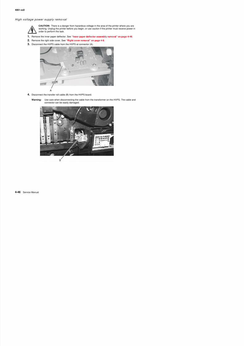
8/13/2019 t644 Service Manual
http://slidepdf.com/reader/full/t644-service-manual 268/423
4061-xx0
5. Remove the HVPS mounting screws (C).
6. Slide the HVPS to the left to release the mounting tab from the center pan, and remove the HVPS.
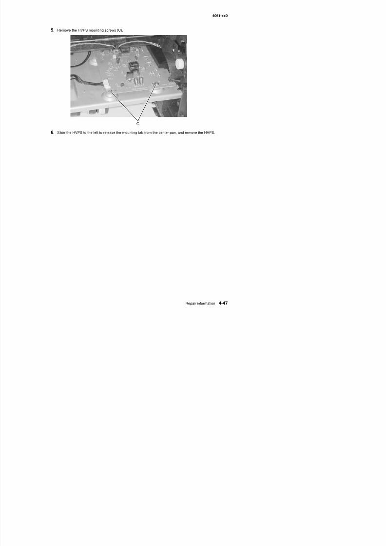
8/13/2019 t644 Service Manual
http://slidepdf.com/reader/full/t644-service-manual 269/423
4061-xx0
Inner paper def lector assemb ly remo val
1. Remove the paper tray.
2. Remove the upper paper deflector assembly. See “Upper paper deflector assembly removal” onpage 4-80.
3. Remove the MPF lower deflector assembly. See “MPF lower paper deflector” on page 4-62.
4. Place the printer on its side.
5. Gently pry the inner paper deflector from the left and right mounting posts (A) located on the bottom of the
printer, and remove the deflector.
6. Disengage the two latches (B) on the upper part of the deflector from the upper edge of the frame (C), andlift to remove.
A
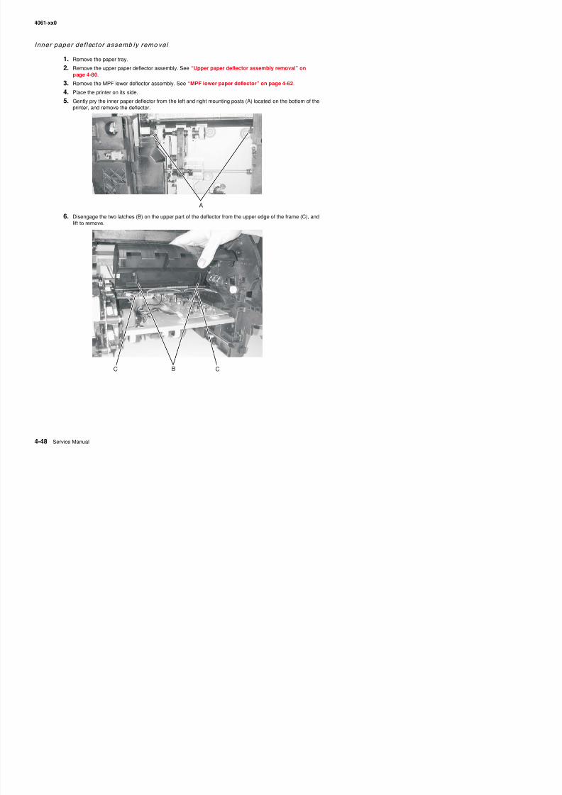
8/13/2019 t644 Service Manual
http://slidepdf.com/reader/full/t644-service-manual 270/423
4061-xx0
Input sensor removal
1. Remove the upper paper deflector. “Upper paper deflector assembly removal” on page 4-80.
2. Loosen the MPF lower front cover. See “Multipurpose feeder/lower front cover assembly removal” onpage 4-16.
3. Remove the inner paper deflector.“Inner paper deflector assembly removal” on page 4-48.
4. Disconnect the input sensor cable (A) from the input sensor (B).
5. Release the input sensor from its mounting, and remove.
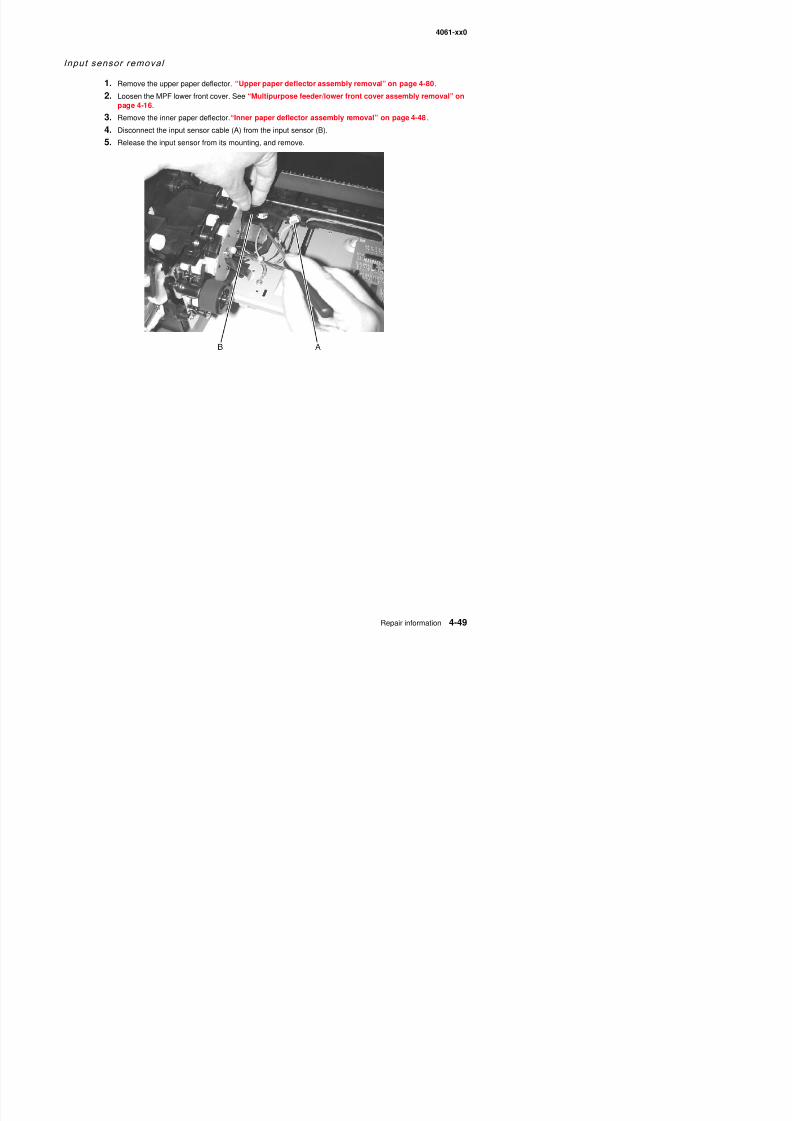
8/13/2019 t644 Service Manual
http://slidepdf.com/reader/full/t644-service-manual 271/423
4061-xx0
Integrated tray autocom pensator assembly remo val
1. Remove the paper tray.
2. Remove the left door. See “Left door removal” on page 4-7.
3. Remove the outer shield. See “Outer shield removal” on page 4-69.
4. Place the printer on its back.
5. Disconnect the autocompensator motor cable (A) from the system board (J24).
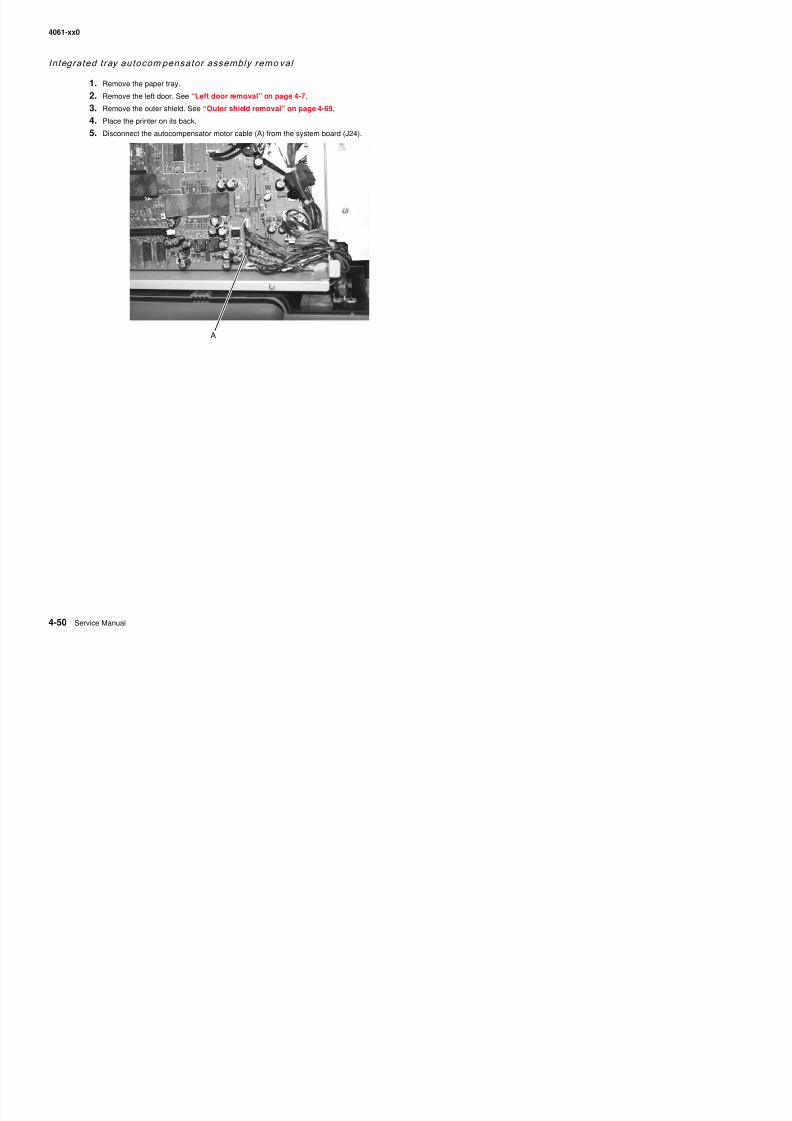
8/13/2019 t644 Service Manual
http://slidepdf.com/reader/full/t644-service-manual 272/423
4061-xx0
6. Locate the integrated tray autocompensator assembly (B) on the bottom of the printer, and disconnect theautocompensator arm bias spring (C).
Note: When you remove the spring, note the larger loop attaches to the side frame.
7. Remove the C-clip (D) that rests against the right side frame from the autocompensator pivot shaft.
8. Disconnect the autocompensator sensor cable (E) from the assembly.
9. Remove the autocompensator assembly mounting screw (F).
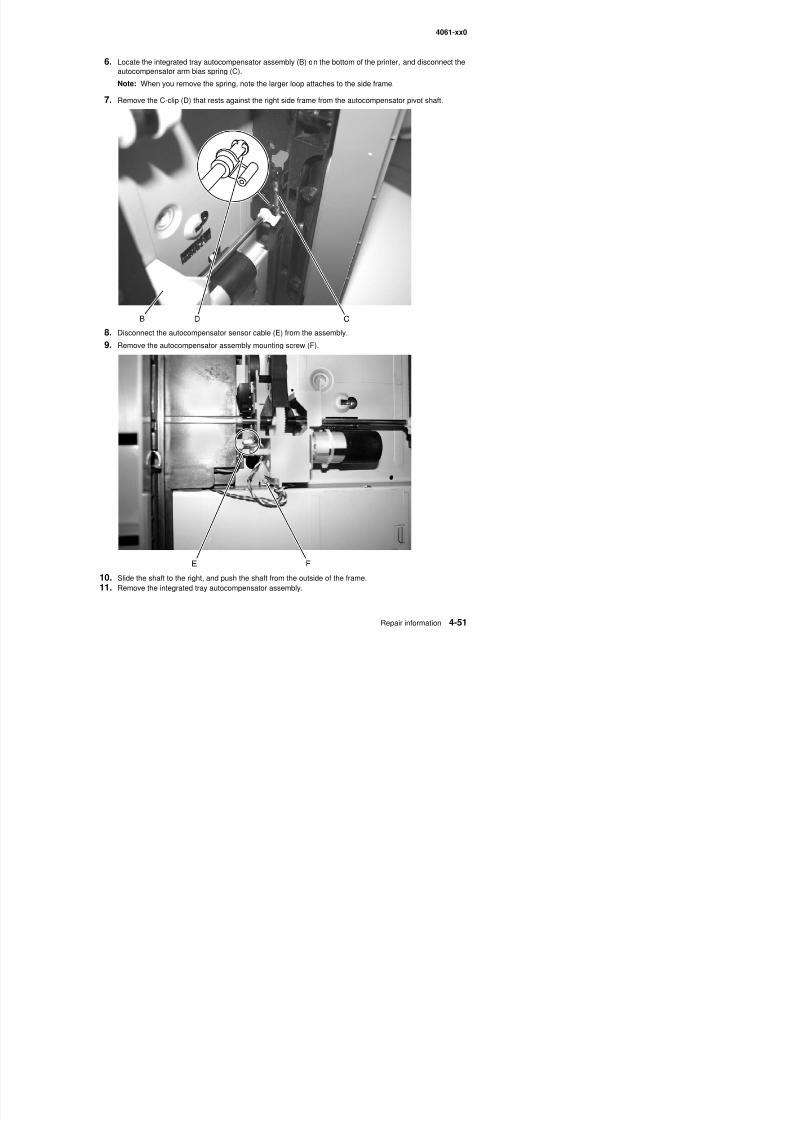
8/13/2019 t644 Service Manual
http://slidepdf.com/reader/full/t644-service-manual 273/423
p y g ( )
4061-xx0
Integrated tray autocomp ensator pick rol l assembly remo val
1. Remove the integrated tray, and look underneath the printer for the autocompensator arm. Pull the armdown.
2. Press on the end of the tab (A) and pull the pick roll off the arm. Repeat this step for the pick roll on theother side. Next, gently release the autocompensator arm. Discard the used pick rolls.
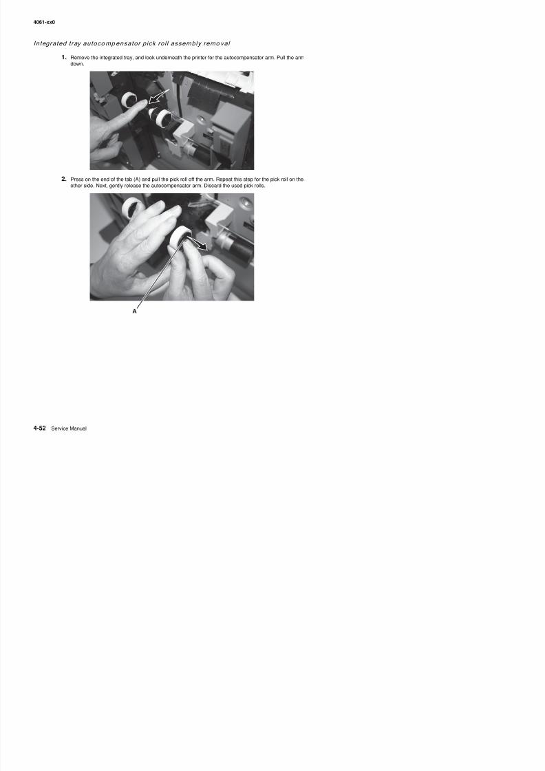
8/13/2019 t644 Service Manual
http://slidepdf.com/reader/full/t644-service-manual 274/423
4061-xx0
Installation
1. Remove the new pick rolls from their packaging.
2. Pull the autocompensator arm down. Locate the recessed area on the pick roll, and align it with the tab onthe arm. There are two arrows on each pick roll. Make sure the bottom arrow faces you as you align therecessed area with the tab.
3. Push the pick roll onto the arm with the tab aligned. Repeat this step on the other side to install the otherpick roll.
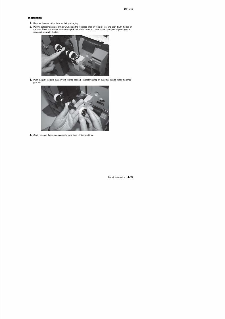
8/13/2019 t644 Service Manual
http://slidepdf.com/reader/full/t644-service-manual 275/423
4. Gently release the autocompensator arm. Insert, integrated tray.
4061-xx0
Interconn ect card assembly remov al
CAUTION: Unplug the printer before you begin.
Warning: When replacing any one of the following components:
• Operator panel assembly (or upper front cover)• System board assembly
• Interconnect card assembly
Only replace one component at a time. Replace the required component and perform a POR before replacing asecond component listed above. If this procedure is not followed, the printer will be rendered inoperable. Neverreplace two or more of the components listed above without a POR after installing each one or the printer will berendered inoperable.
Warning: Never install and remove components listed above as a method of troubleshooting components.Once a component has been installed in a printer, it can not be used in another printer. It must bereturned to the manufacturer.
Warning: Observe all ESD precautions while handling ESD-sensitive parts. See “Handling ESD-sensitiveparts” on page 4-1.
Note: Any time the interconnect card assembly is replaced, the Configuration ID must be reset in NVRAM onthe new interconnect card. Go to “Configuration ID” on page 3-21.
1. Remove any feature or option cards from the interconnect card.
2. Remove the two screws securing the interconnect card.
3. Remove the interconnect card assembly.
8/13/2019 t644 Service Manual
http://slidepdf.com/reader/full/t644-service-manual 276/423
4061-xx0
Low vol tage power supp ly removal
CAUTION: Unplug the printer before you begin.
1. Remove the redrive assembly. See “Redrive assembly removal” on page 4-75.
2. Remove the right side cover. See “Right cover removal” on page 4-9.
3. Remove the pass thru plate. See “Pass thru plate” on page 4-19.
4. Remove the LVPS mounting screws (A) from the rear of the center pan.
5. Disconnect the LVPS to system board cable.
The cable is difficult to disconnect. There are catches (B) that firmly hold latches on the LVPS cardconnector (C).
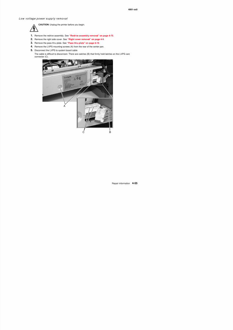
8/13/2019 t644 Service Manual
http://slidepdf.com/reader/full/t644-service-manual 277/423
4061-xx0
6. Pull the LVPS assembly far enough out from the right side of the printer to disconnect the fuser to LVPSAC lamp cable (D).
Warning: The LVPS assembly may be difficult to remove from the printer. Do not use excessive force inthe removal.
7. Remove the low voltage power supply.
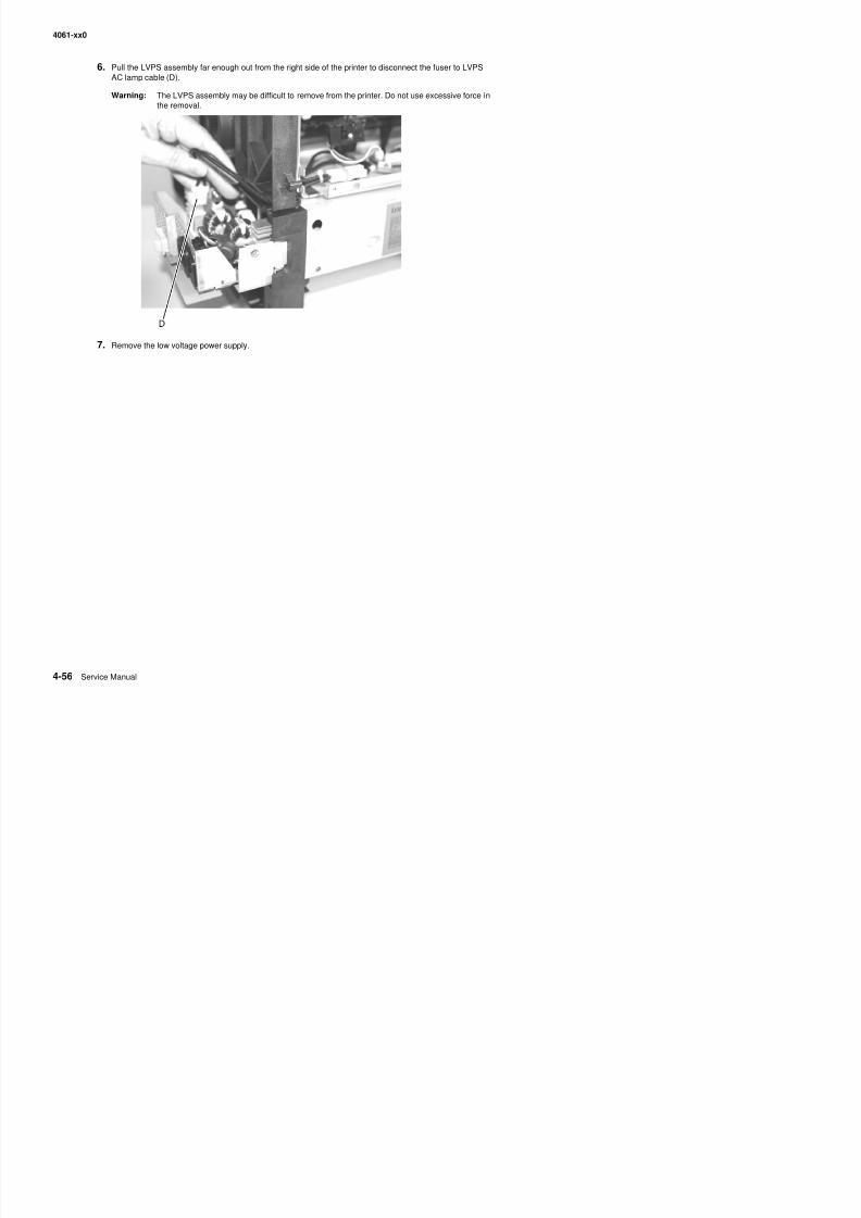
8/13/2019 t644 Service Manual
http://slidepdf.com/reader/full/t644-service-manual 278/423
4061-xx0
Main fan removal
1. Open the left side cover.
2. Remove the outer shield. See “Outer shield removal” on page 4-69.
3. Remove the two screws (A) securing the main fan cap.
4. Remove the main fan cap.
5. Clip the cable tie (B).
Note: Be careful not to damage any of the cables. Note the location of the cable tie for later replacement.
6. Disconnect the main fan to the system board (C) at J4.
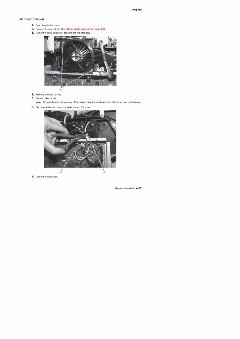
8/13/2019 t644 Service Manual
http://slidepdf.com/reader/full/t644-service-manual 279/423
6. Disconnect the main fan to the system board (C) at J4.
4061-xx0
Installation note: The fan has an orientation marking (D). Be sure to install the fan with the arrow pointing up.
Main drive assembly removal
1. Remove the system board and inner shield. See “System board and inner shield removal” onpage 4-77.
2. Remove the screw securing the gear guard (A).
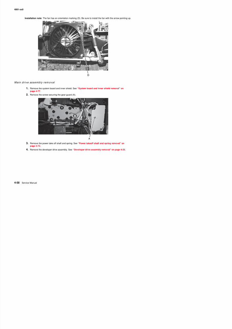
8/13/2019 t644 Service Manual
http://slidepdf.com/reader/full/t644-service-manual 280/423
3. Remove the power take off shaft and spring. See “Power takeoff shaft and spring removal” onpage 4-73.
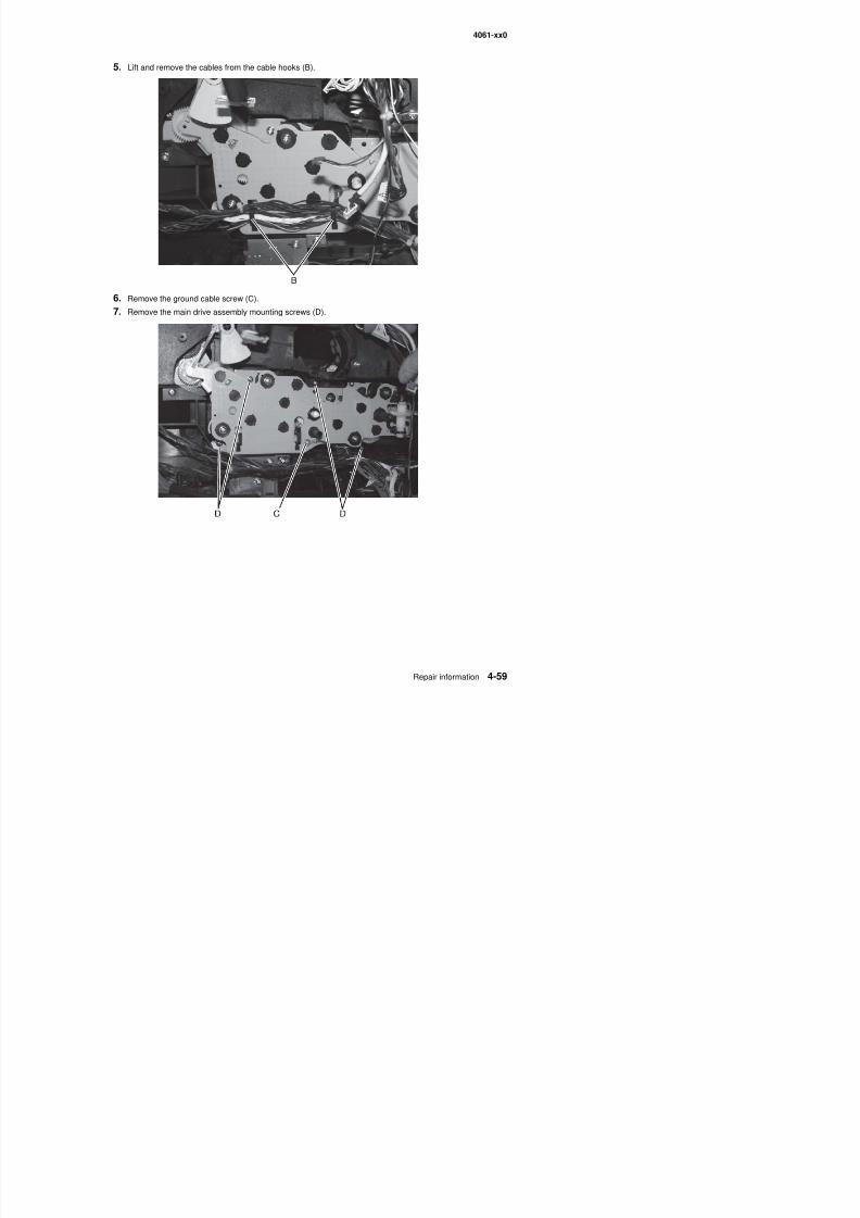
8/13/2019 t644 Service Manual
http://slidepdf.com/reader/full/t644-service-manual 281/423
4061-xx0
8. Disconnect the gear release link (E) from the hole in the charge roll link (F).Note: Lift the upper front cover to make it easier to remove the link.
9. Disconnect the main drive motor cable from the main drive assembly.
10. Remove the main drive assembly.
Warning: Whenever the main drive assembly is removed from the printer it must be handled very carefully.Do not allow any of the gears to come in contact with any metal or other hard surface to avoid geardamage. It is also very important not to let any dirt, paper, staples, or other material come in contactwith the grease in the gears.
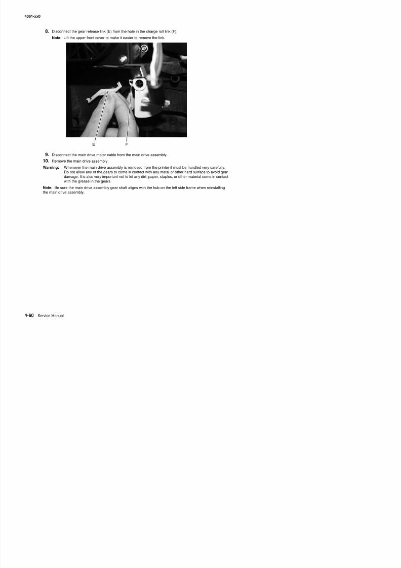
8/13/2019 t644 Service Manual
http://slidepdf.com/reader/full/t644-service-manual 282/423
t t e g ease t e gea s
Note: Be sure the main drive assembly gear shaft aligns with the hub on the left side frame when reinstallingthe main drive assembly.
4061-xx0
MPF arm assembly removal
1. Open the left door.
2. Remove the MPF lower front cover. See “Multipurpose feeder/lower front cover assembly removal”on page 4-16.
3. Remove the MPF lower paper deflector. See “MPF lower paper deflector” on page 4-62.
4. Remove the upper paper deflector. See “Upper paper deflector assembly removal” on page 4-80.
5. Remove the inner paper deflector. See “Inner paper deflector assembly removal” on page 4-48.
6. Remove the MPF solenoid assembly. See “MPF solenoid assembly removal” on page 4-63.
7. Remove the C-clip (A).
8. Remove the washer, and set it aside.
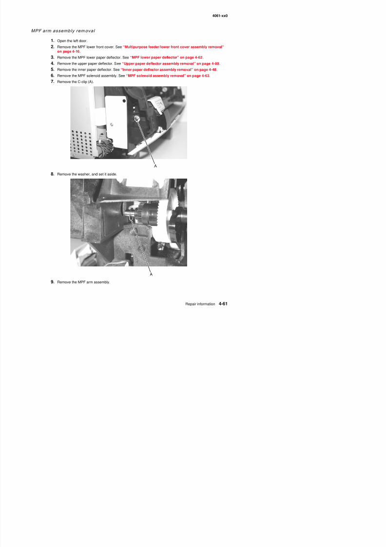
8/13/2019 t644 Service Manual
http://slidepdf.com/reader/full/t644-service-manual 283/423
4061-xx0
Installation note:Note the order of C-clips bushing, and washer when you reinstall.
MPF lower paper def lector
1. Remove the MPF lower cover.
2. Remove the four screws securing the MPF lower paper deflector.
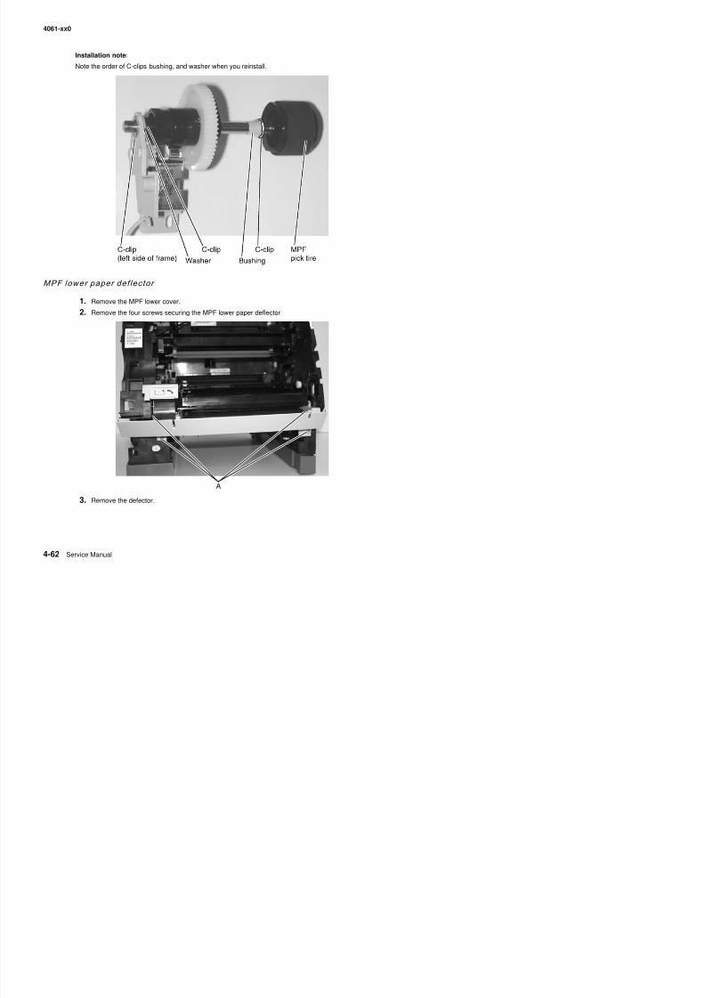
8/13/2019 t644 Service Manual
http://slidepdf.com/reader/full/t644-service-manual 284/423
4061-xx0
MPF pick t i re remov al
1. Remove the upper paper deflector. See “Upper paper deflector assembly removal” on page 4-80.
2. Release the pick roll retaining tab (A), and slide the pick roll off the shaft.
MPF solenoid assemb ly removal
1. Open the left door.
2. Remove the MPF lower front cover. See “Multipurpose feeder/lower front cover assembly removal”4 16
A
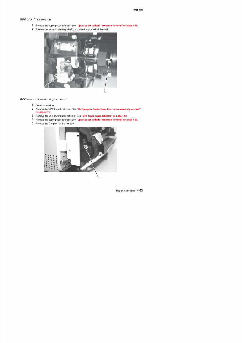
8/13/2019 t644 Service Manual
http://slidepdf.com/reader/full/t644-service-manual 285/423
on page 4-16.
3. Remove the MPF lower paper deflector. See “MPF lower paper deflector” on page 4-62.
4. Remove the upper paper deflector. See “Upper paper deflector assembly removal” on page 4-80.
5. Remove the C-clip (A) on the left side.
4061-xx0
6. Press the clips on the end of the shaft to remove the MPF tires (B).7. Remove the C-clip (C) on the shaft.
8. Remove the bushing (D).
Note: The bushing fits into a detent (E) in the frame of the MPF arm assembly.
BC
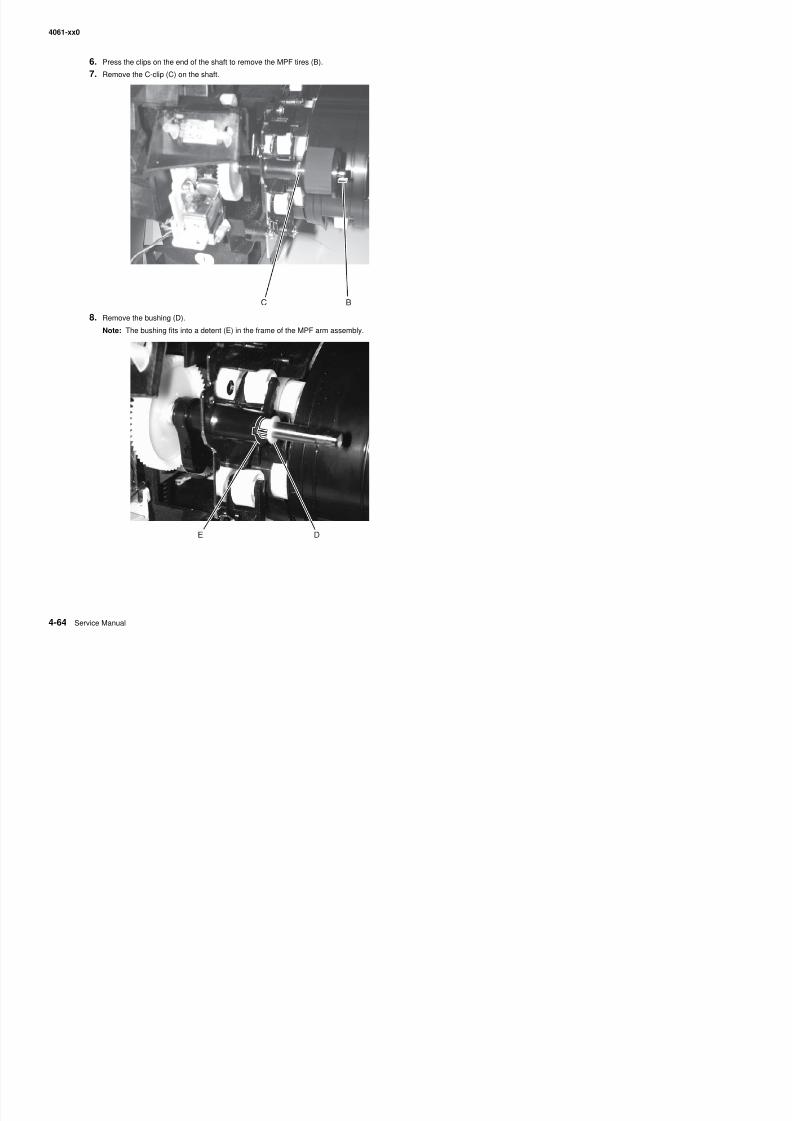
8/13/2019 t644 Service Manual
http://slidepdf.com/reader/full/t644-service-manual 286/423
4061-xx0
9. Loosen the paper alignment screws (F).
10. Remove the C-clip securing the MPF solenoid assembly on the shaft.Note: This C-clip is very difficult to locate and remove.
11. Pull the shaft assembly (G) to the right until the left end of the shaft is clear of the frame, and slide the MPFsolenoid assembly from the shaft.
F
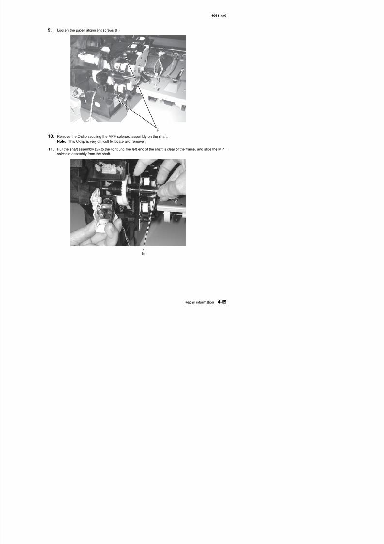
8/13/2019 t644 Service Manual
http://slidepdf.com/reader/full/t644-service-manual 287/423
4061-xx0
Installation note:Be careful not to lose the washer (H) that is between the MPF solenoid assembly and the C-clip. It belongs to theMPF arm assembly.
H
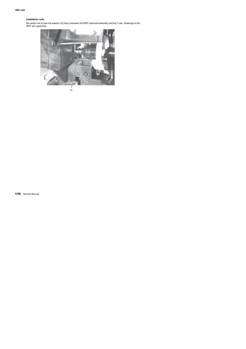
8/13/2019 t644 Service Manual
http://slidepdf.com/reader/full/t644-service-manual 288/423
4061-xx0
Operator panel board removal
Warning: When replacing any one of the following components:
• Operator panel assembly (or upper front cover)• System board assembly• Interconnect card assembly
Only replace one component at a time. Replace the required component and perform a POR before replacing asecond component listed above. If this procedure is not followed, the printer will be rendered inoperable. Never
replace two or more of the components listed above without a POR after installing each one or the printer will berendered inoperable.
Warning: Never install and remove components listed above as a method of troubleshooting components.Once a component has been installed in a printer, it can not be used in another printer. It must bereturned to the manufacturer.
1. Remove the upper front cover. See “Upper front cover removal” on page 4-12.
2. Remove the seven screws (A), and remove the operator panel board.
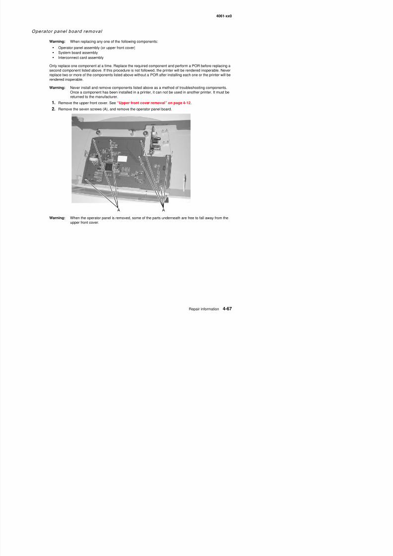
8/13/2019 t644 Service Manual
http://slidepdf.com/reader/full/t644-service-manual 289/423
Warning: When the operator panel is removed, some of the parts underneath are free to fall away from theupper front cover.
4061-xx0
Operator panel buttons removal
The operator panel and navigation buttons are in a single kit.
1. Remove the operator panel board. See “Operator panel board removal” on page 4-67.
2. Remove the functional rubber sheet (A) and the rubber dome sheet (B).
3. The navigation buttons and the select button can be removed by releasing the clips (C) on the back of theupper front cover.
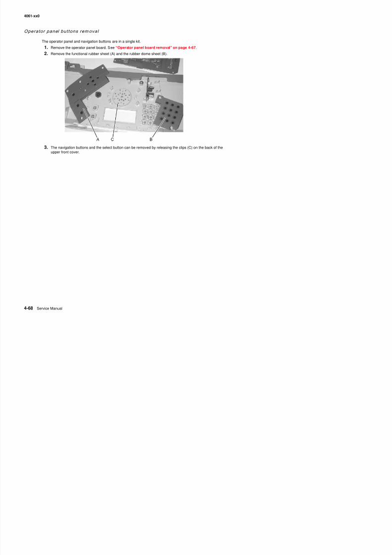
8/13/2019 t644 Service Manual
http://slidepdf.com/reader/full/t644-service-manual 290/423
4061-xx0
Outer shield removal
1. Remove the left door. See “Left door removal” on page 4-7.
2. Loosen the outer shield mounting screws (A), and remove the shield by sliding up.
A(202)
A(202)
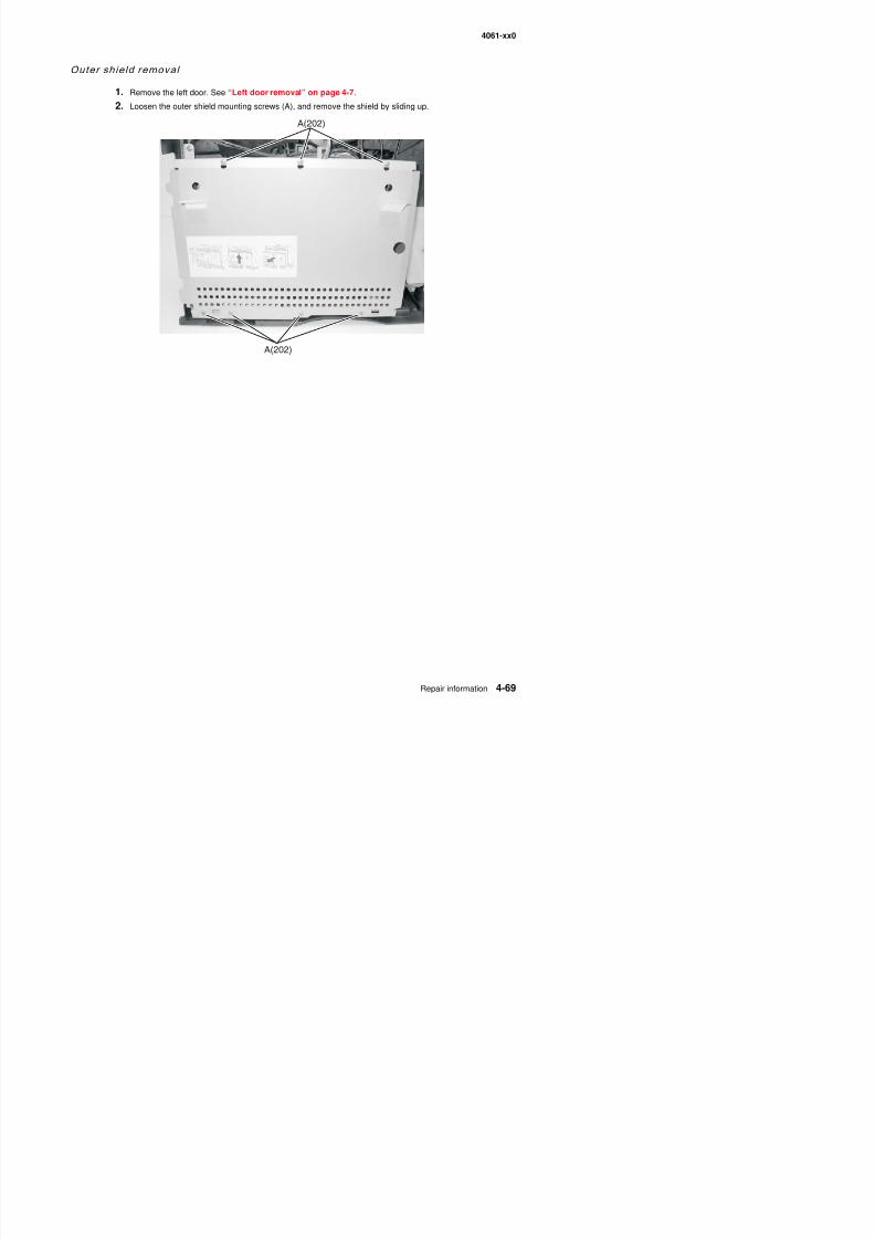
8/13/2019 t644 Service Manual
http://slidepdf.com/reader/full/t644-service-manual 291/423
4061-xx0
Paper al ignment assembly removal
1. Remove the upper paper deflector assembly. See “Upper paper deflector assembly removal” onpage 4-80.
2. Remove the inner paper deflector assembly. See “Inner paper deflector assembly removal” onpage 4-48.
3. Release the input paper sensor from its mounting, and remove.
4. Remove the left door.
5. Remove the paper alignment assembly mounting screws (A).
6. Locate the paper alignment assembly reference adjustment screw (B) through the left frame, and removethe screw.
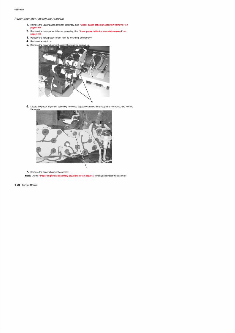
8/13/2019 t644 Service Manual
http://slidepdf.com/reader/full/t644-service-manual 292/423
4061-xx0
Paper bin fu l l sensor f lag removal
1. Remove the left door. See “Left door removal” on page 4-7.
2. Remove the redrive cap. See “Redrive assembly removal” on page 4-75.
3. Remove the fuser wiper cover assembly. See “Fuser wiper cover assembly removal” on page 4-5
4. Remove the mounting screws (A) from the left side.
5. Lift the left corner of the laser cover assembly cover to access the flag.
A
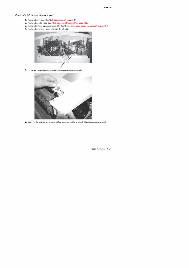
8/13/2019 t644 Service Manual
http://slidepdf.com/reader/full/t644-service-manual 293/423
4061-xx0
Paper size sensing board removal
1. Remove the system board and inner shield. See “System board and inner shield removal” onpage 4-77.
2. Remove the paper size sensing board mounting screw (A).
3. Disconnect the paper size sensing board cable (B) from the board.
4. Remove the paper size sensing board from the latch (C).
5. Remove the paper size sensing board.
C A B
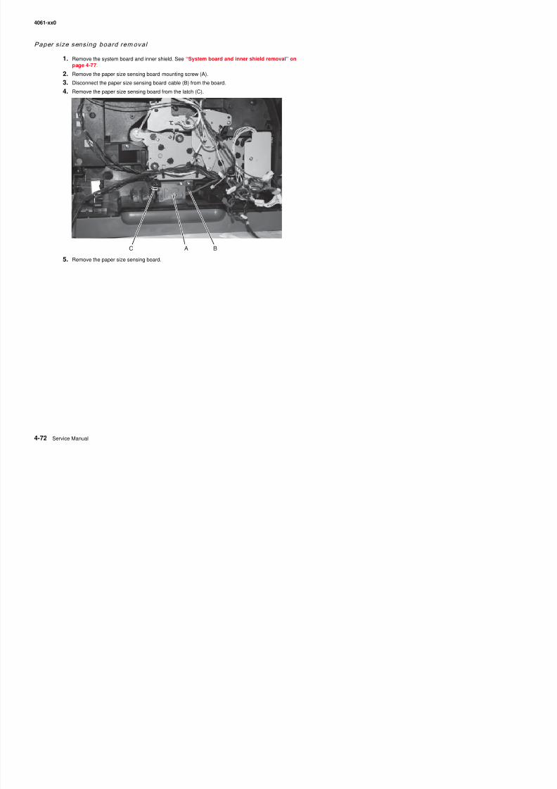
8/13/2019 t644 Service Manual
http://slidepdf.com/reader/full/t644-service-manual 294/423
4061-xx0
Power takeoff shaft and sp ring remov al
Remove the power takeoff shaft and spring (A) through the bottom of the printer.
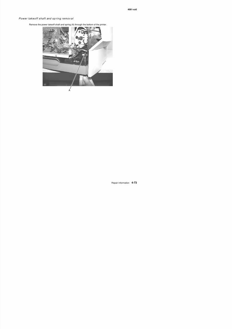
8/13/2019 t644 Service Manual
http://slidepdf.com/reader/full/t644-service-manual 295/423
4061-xx0
Printhead removal
CAUTION: The laser scanning unit is not a serviceable FRU. Replace the entire unit when service is required.
1. Remove the laser cover. See “Laser cover removal” on page 4-20.
2. Disconnect the printhead cable (A) from the printhead assembly.
3. Remove the three printhead mounting screws (B), and remove the printhead.
Note: Do the “Printhead assembly adjustment” on page 4-2 whenever you remove or replace the printheadassembly or loosen the mounting screws.
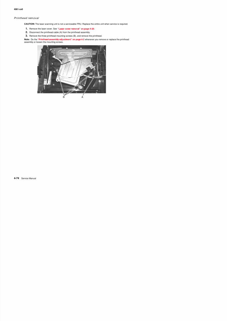
8/13/2019 t644 Service Manual
http://slidepdf.com/reader/full/t644-service-manual 296/423
4061-xx0
Redrive assembly remov al
1. Remove the redrive door assembly.
2. Remove the redrive exit cover.
3. Remove the redrive assembly mounting screws (A).
4. Release the redrive assembly mounting latches (B), and remove the redrive assembly.
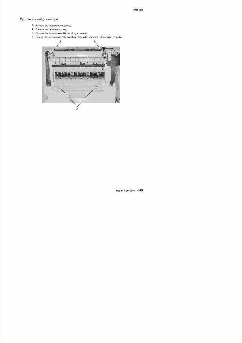
8/13/2019 t644 Service Manual
http://slidepdf.com/reader/full/t644-service-manual 297/423
4061-xx0
Signature button co ntact assembly remo val
1. Remove the print cartridge.
2. Remove the left side door. See “Left door removal” on page 4-7.
3. Remove the right cover. See “Right cover removal” on page 4-9.
4. Remove outer system board shield. See “Outer shield removal” on page 4-69.
5. Disconnect signature button cable from connector J14 on the system board.
6. On models 200/210/400/410, remove the two screws (A) securing the blower duct.
7. Remove the signature button contact assembly mounting screw (B).
8. Remove the assembly signature button contact assembly.
Note: Be sure to route the cable in the same location, as shown (C), when replacing the assembly.
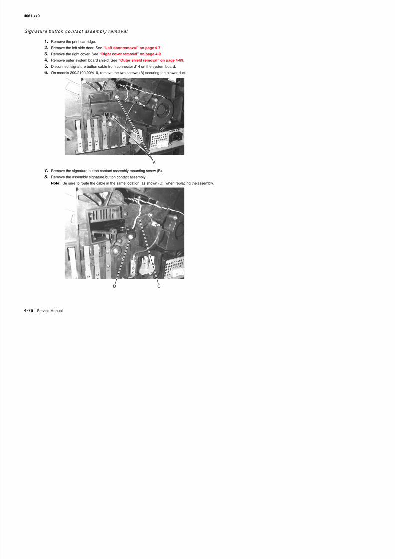
8/13/2019 t644 Service Manual
http://slidepdf.com/reader/full/t644-service-manual 298/423
4061-xx0
System board and inner shield removal
Warning: When replacing any one of the following components:
• Operator panel assembly (or upper front cover)• System board assembly• Interconnect card assembly
Only replace one component at a time. Replace the required component and perform a POR before replacing asecond component listed above. If this procedure is not followed, the printer will be rendered inoperable. Neverreplace two or more of the components listed above without a POR after installing each one or the printer will berendered inoperable.
Warning: Never install and remove components listed above as a method of troubleshooting components.Once a component has been installed in a printer, it can not be used in another printer. It must bereturned to the manufacturer.
Warning: Observe all ESD precautions while handling ESD-sensitive parts. See “Handling ESD-sensitiveparts” on page 4-1.
1. Remove the outer shield. See “Outer shield removal” on page 4-69.
2. Disconnect all cables from the system board.Note: Sometimes cables may be difficult to remove. Be careful not to damage the connectors.
3. Remove all features and options from the interconnect card.
4. Depending on your printer model, remove the two small USB port mounting screws (A), the two parallelport mounting screws (B), and the ethernet port mounting screw (C).
Note: You may not have all these screws in every model.
5. Remove the system board mounting screws, including the screw in the upper left corner (C), the two smallscrews in the center top and bottom (D), and the three screws (E) (on the lower left and top and bottomright).
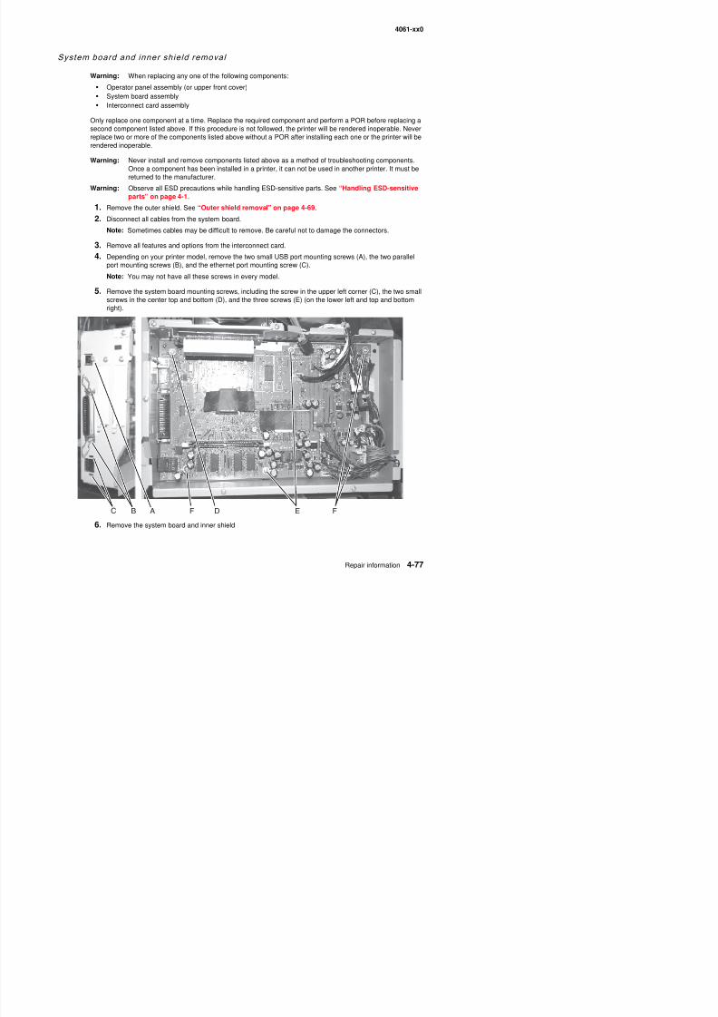
8/13/2019 t644 Service Manual
http://slidepdf.com/reader/full/t644-service-manual 299/423
4061-xx0
Toner senso r removal
1. Remove the right side cover. See “Right cover removal” on page 4-9.
2. Remove the toner sensor mounting screw (A).
3. Disconnect the toner sensor cable, and remove the toner sensor.
Transfer rol l assembly rem oval
Warning: Be careful when handling the transfer roll. Wrap a piece of plain white paper around the charge rollto prevent contamination or damage.
1.Open the upper front cover, and remove the print cartridge.
2. Unsnap the transfer roll assembly from the left pivot arm.
3. Lift the transfer roll assembly toward the left, and remove it from the printer.
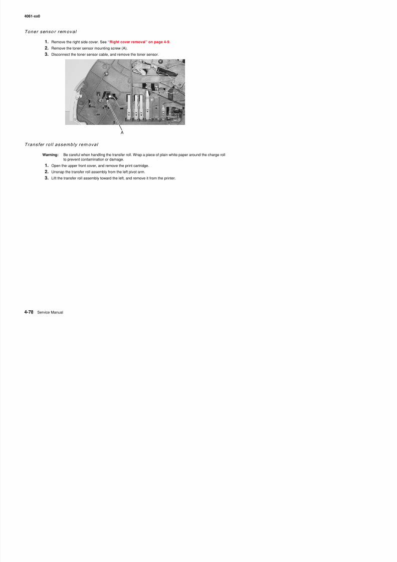
8/13/2019 t644 Service Manual
http://slidepdf.com/reader/full/t644-service-manual 300/423
4061-xx0
Upper front cover hinge assemb ly removal
1. Remove the upper front cover. See “Upper front cover removal” on page 4-12.
2. Remove the laser cover assembly. See “Laser cover removal” on page 4-20.
3. Remove the C-clips (A) from the upper front cover hinge assembly left and right hinge pins, and removethe pins. Note the pin orientation and the C-clip location on the inside of each hinge.
4. Detach the two springs (B) from the upper front cover hinges.
5. Detach spring (C) from the left side of the hinge assembly.
6. Remove the cover closed switch assembly.
7. Disconnect the operator panel cable from the operator panel board.
8. Raise the upper front cover hinge assembly to a position that lets you lift the left pivot arm from themounting bracket (D).
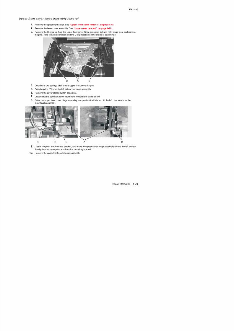
8/13/2019 t644 Service Manual
http://slidepdf.com/reader/full/t644-service-manual 301/423
9. Lift the left pivot arm from the bracket, and move the upper cover hinge assembly toward the left to clearthe right upper cover pivot arm from the mounting bracket.
A BBDC
4061-xx0
Upper paper def lector assembly remo val
1. Either lift the ESD cover out of the way or remove it. See “ESD cover removal” on page 4-26.
Note: The tabs holding the ESD cover are easily stressed or broken.
2. Lift the left side to release the small tab (A) on the left and the MPF flag (B) and slide the upper paperdeflector assembly to the right to unlatch the hooks (C) on the right.
Note: Be careful not to put too much stress on the small tab (A) on the right.
3. Lift to remove the upper paper deflector assembly.
Installation note: Make sure the MPF flag (B) is in place
A B C
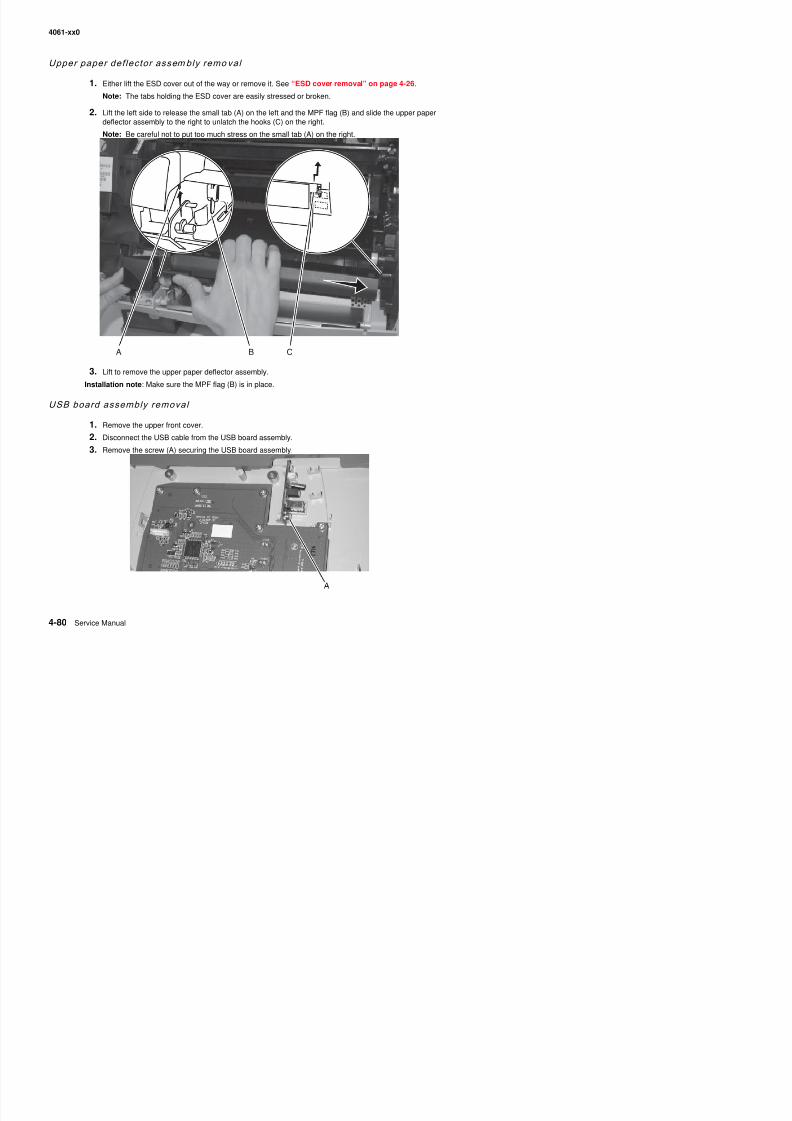
8/13/2019 t644 Service Manual
http://slidepdf.com/reader/full/t644-service-manual 302/423
Installation note: Make sure the MPF flag (B) is in place.
USB board assembly removal
1. Remove the upper front cover.2. Disconnect the USB cable from the USB board assembly.
3. Remove the screw (A) securing the USB board assembly.
4061-xx0
5. Connector locations and connections
Connections
System board
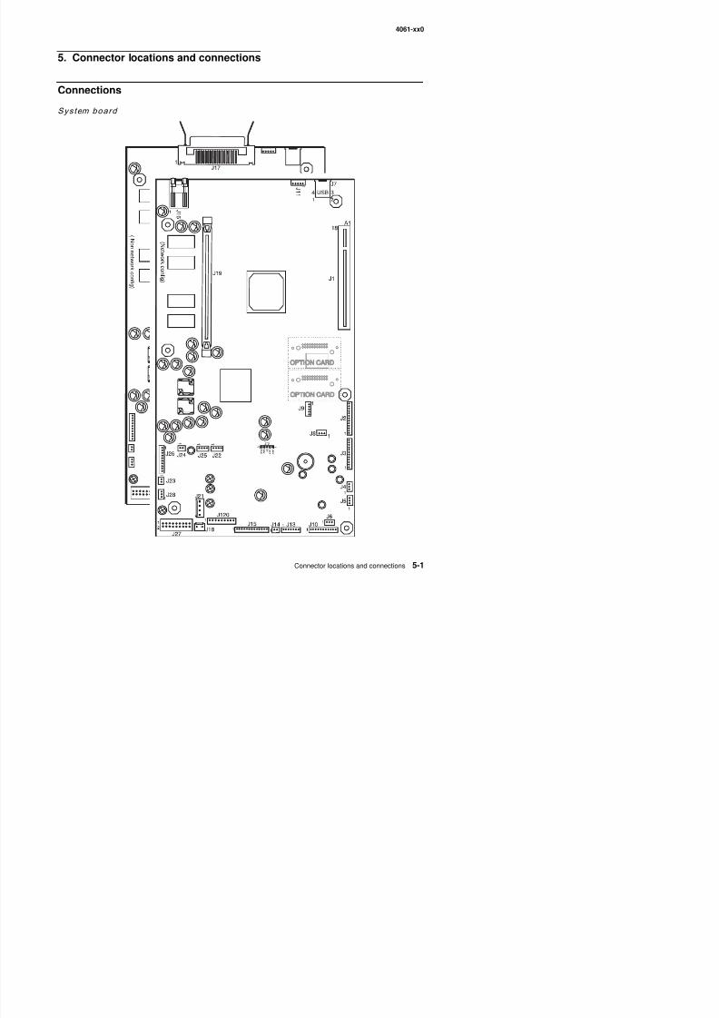
8/13/2019 t644 Service Manual
http://slidepdf.com/reader/full/t644-service-manual 303/423
4061-xx0
System board (see “System board” on page 5-1)
Connector Pin no. Signal
J1 Interconnect card
J2 Printhead (laser cable) 1 VIDEO 1+ CN
2 VIDEO 1- CN
3 Ground
4 LADJ2*
5 VIDEO 0- CN
6 VIDEO 0+ CN
7 Ground
8 +5PHEAD
9 LPOW
10 Ground11 LADJ* CN
12 LPOW FB
13 LENA*
J3 Printhead (HSYNC)/mirror motor 1 Ground
2 HSYNC CN*
3 HSYNC ID
4 +5 V dc5
6
7
8
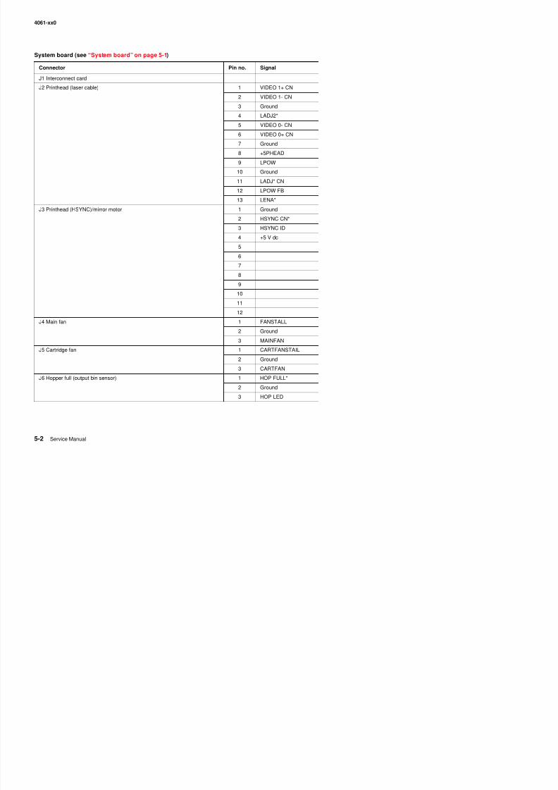
8/13/2019 t644 Service Manual
http://slidepdf.com/reader/full/t644-service-manual 304/423
8
9
10
11
12
J4 Main fan 1 FANSTALL
2 Ground
3 MAINFAN
J5 Cartridge fan 1 CARTFANSTAIL
2 G d
4061-xx0
J7 USB port 1
2
3
4
5
6
7
J8 Cover closed switch 1 Cov Closed
2 Ground
3 +5V dc
J10 Fuser DC 1 NARMEDIA*
2 Ground
3 THERM
4 Ground
5 THUMP
6 +5V dc
7 THUMPRET
8 EXIT SNS*
9 +3.3 V dc10 I2C CLK L5
11 I2C DAT L5
J13 Operator panel 1 I2C DAT
2 +5 V dc
System board (see “System board” on page 5-1)
Connector Pin no. Signal
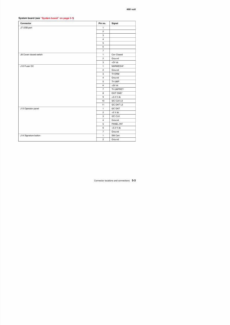
8/13/2019 t644 Service Manual
http://slidepdf.com/reader/full/t644-service-manual 305/423
2 +5 V dc
3 I2C CLK
4 Ground
5 PANEL INT
6 +3.3 V dc
7 Ground
J14 Signature button 1 SM Cart
2 Ground
4061-xx0
J15 HVPS 1 ATSERVO
2 TXENABLE
3 XFR
4 24 V dc switched
5 CHARGE
6 Ground
7 DEV
8 Ground
input sensor 9 INPUTSENSX
10 +5 V dc switched
Cartridge toner wheel sensor 11 +5 V dc
12 TONER WHEELX
13 Ground
J16 Ethernet port 1
2
3
4
5
67
8
9
10
System board (see “System board” on page 5-1)
Connector Pin no. Signal
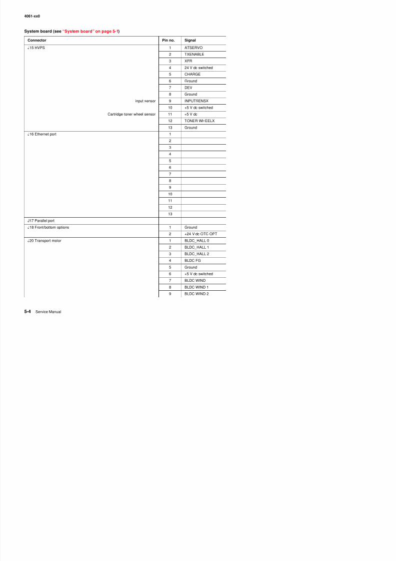
8/13/2019 t644 Service Manual
http://slidepdf.com/reader/full/t644-service-manual 306/423
11
12
13
J17 Parallel port
J18 Front/bottom options 1 Ground
2 +24 V dc OTC OPT
J20 Transport motor 1 BLDC_HALL 0
2 BLDC_HALL 1
3 BLDC HALL 2
4061-xx0
J21 Autoconnect—top 1 Ground
2 +5 V dc fused
3 Ground
4 +24 V dc PTC OPT
J23 MPF pick solenoid 1 MPFPick*
2 +24V dc
J24 Autocomp motor 1 +24 V dc
2 AUTOCOMP*
J25 Autoconnect—bottom/front 1 Ground
2 +24VPTCOPT
J26 Paper size sensor/autocomp motor 1 PSIZE2
2 Ground
3 PSIZE1
4 PSIZE3
5 Ground
6 TRAY1 POUT
7 TRAY1 PLOW*
8 +3.3V dc
9 ENCODER10 +5V dc
J27 LVPS 1 +5 V dc
2 +5 V dc
3 +5 V dc
System board (see “System board” on page 5-1)
Connector Pin no. Signal
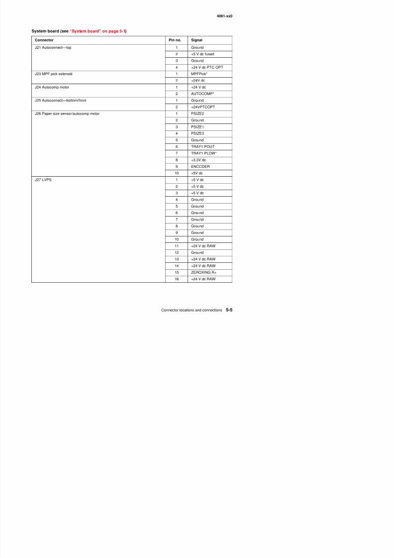
8/13/2019 t644 Service Manual
http://slidepdf.com/reader/full/t644-service-manual 307/423
4 Ground
5 Ground
6 Ground
7 Ground
8 Ground
9 Ground
10 Ground
11 +24 V dc RAW
12 Ground
4061-xx0
J27 LVPS (continued) 17 HEAT
18 HEAT
19 Ground
20 L FAN DRV*
J28 MPF paper out 1 MPF POUT
2 Ground
3 MPF LED
J29 Top options 1 RXD1R
2 Ground
3 TXD1BR
4 Ground
J30 USB host–back 1
2
3
4
5
6
7
USB host—front connection 1 +5 V USBICN2 USB DI–
3 USB DI+
4 Ground
5 Ground
System board (see “System board” on page 5-1)
Connector Pin no. Signal
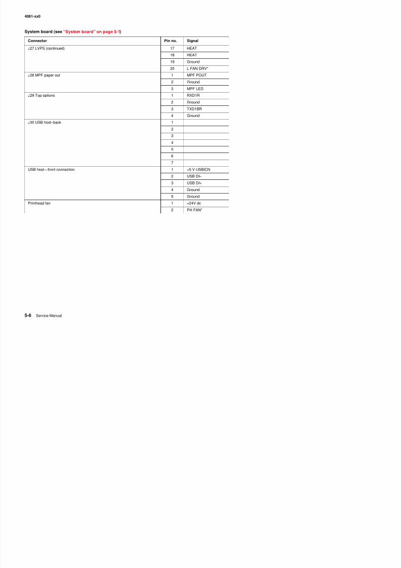
8/13/2019 t644 Service Manual
http://slidepdf.com/reader/full/t644-service-manual 308/423
Printhead fan 1 +24V dc
2 PH FAN*
4061-xx0
Autoconnect
Connector Pin no. Signal (static)
Bottom autoconnect 1 +24 V dc
2 0 V dc
3 +5 V dc
4 0 V dc
5 0 V dc6 0 V dc
Front autoconnect 1 0 V dc
2 0 V dc
3 0 V dc
4 +5 V dc
5 0 V dc
6 +24 V dc
Top autoconnect 1 0 V dc
2 +5 V dc
3 0 V dc
4 0 V dc
5 0 V dc
6 +5 V dc
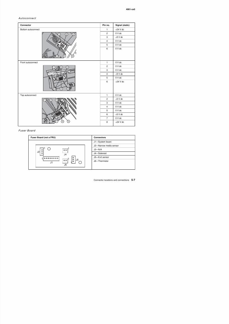
8/13/2019 t644 Service Manual
http://slidepdf.com/reader/full/t644-service-manual 309/423
Fuser Board
6 +5 V dc
7 0 V dc
8 +24 V dc
Fuser Board (not a FRU) Connectors
J1—System board
J2—Narrow media sensor
4061-xx0
High-capaci ty outp ut stacker board
Connector Pin no. Signal
J1AAutoconnect
1 +24 V dc
2 Ground
3 +5 V dc
J1B 1 Prtxdin
2 Ground3 prtrxd
4 Ground
5 N/C
J2AAutoconnect
1 +24 V dc
2 Ground
3 +5 V dc
J2B 1 prtxdout2 Ground
3 prtrxd
4 Ground
J3 Pass thrusensor
1 Ground
2 Paper Present
3 RVsnsr
J4 DC motor 1 mtrout1
2 mtrout2
3 Ground
4 Ground
5 tach +
J6
1
M S
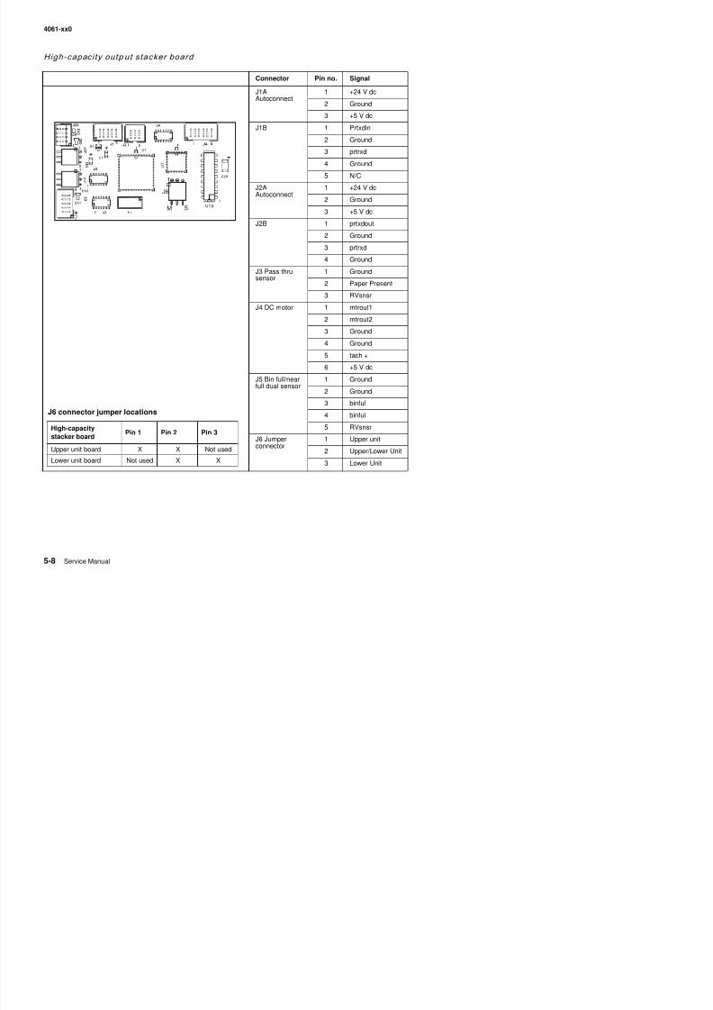
8/13/2019 t644 Service Manual
http://slidepdf.com/reader/full/t644-service-manual 310/423
5 tach +
6 +5 V dc
J5 Bin full/nearfull dual sensor
1 Ground
2 Ground
3 binful
4 binful
5 RVsnsr
J6 Jumperconnector
1 Upper unit
2 Upper/Lower Unit
J6 connector jumper locations
High-capacitystacker board
Pin 1 Pin 2 Pin 3
Upper unit board X X Not used
L i b d N d X X
4061-xx0
High vol tage pow er supp ly
Interconn ect card
Connector CN no. Signal
CN1 System board 1 Developer PWM
2 +24 V dc Return
3 Charge PWM
4 +24 V dc IN
5 TX PWM6 TX Enable
7 TX CUR PWM
8 SVRO OUT
Connector Connector Pin no. Signal
J1 1
J2 1
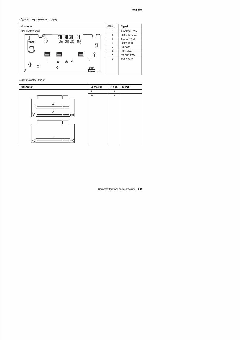
8/13/2019 t644 Service Manual
http://slidepdf.com/reader/full/t644-service-manual 311/423
4061-xx0
Low vol tage power supply
ConnectorCN pin
no.Signal
CN1 Fuser lamp AC 1 AC fuser lamp
2 Not used
3 AC fuser lamp
CN2 DC output 1 +5 V dc
2 +5 V dc3 Ground
4 Ground
5 Ground
6 Ground
7 +24 V dc
8 +24 V dc
9 Heat on
10 +5 V dc
11 +5 V dc
12 Ground
13 Ground
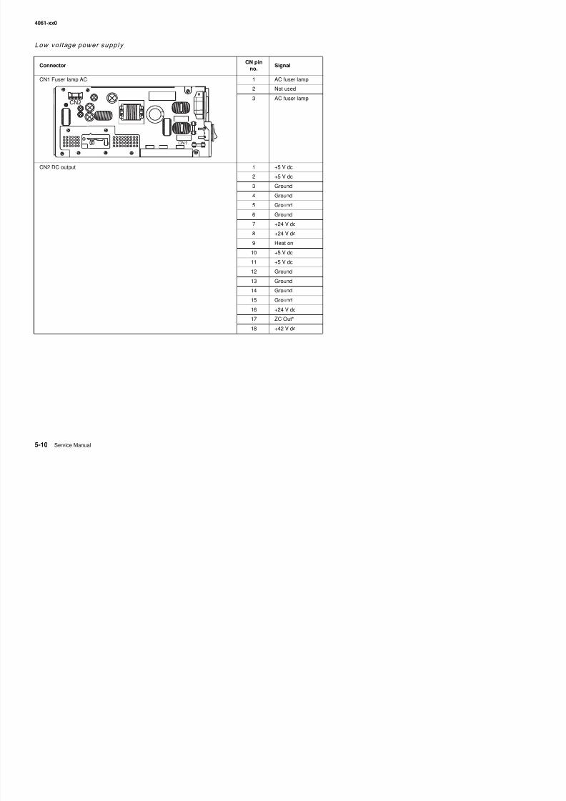
8/13/2019 t644 Service Manual
http://slidepdf.com/reader/full/t644-service-manual 312/423
14 Ground
15 Ground
16 +24 V dc
17 ZC Out*
18 +42 V dc
4061-xx0
Output expander control board
Connector Pin no. Signal
J1AAutoconnect
1 +24 V dc
2 Ground
3 +5 V dc
J1B 1 Prtxdin
2 Ground3 prtrxd
4 Ground
5 N/C
J2AAutoconnect
1 +24 V dc
2 Ground
3 +5 V dc
J2B 1 prtxdout2 Ground
3 prtrxd
4 Ground
J3 Pass thrusensor
1 Ground
2 Paper Present
3 RVsnsr
J4 DC motor 1 mtrout1
2 mtrout2
3 Ground
4 Ground
5 tach +
J6
1
M S
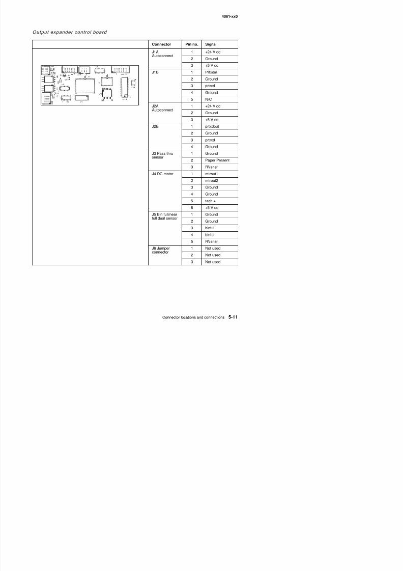
8/13/2019 t644 Service Manual
http://slidepdf.com/reader/full/t644-service-manual 313/423
6 +5 V dc
J5 Bin full/nearfull dual sensor
1 Ground
2 Ground
3 binful
4 binful
5 RVsnsr
J6 Jumperconnector
1 Not used
2 Not used
4061-xx0
StapleSmart f inish er
Connector Pin no. Signal
Staple card assembly J1A Bottomautoconnect
1 +24 V dc
2 Ground
3 +5 V in
J1B Bottomautoconnect
1 rtxdin
2 Ground
3 prtrxd
4 Ground
5 Ground
J2 Feed motor 1 fdmtr1
2 fdmtr2
3 Ground
4 Ground5 tachft
6 5Vptt
J3 Steppermotor
1 stpmtr-
2 stpmtr-
3 stpmtr+
4 stpmtr+
5 crtprsnt-
6 stplow+
7 ‘stpphomo-
8 Ground
9 5Vstpl
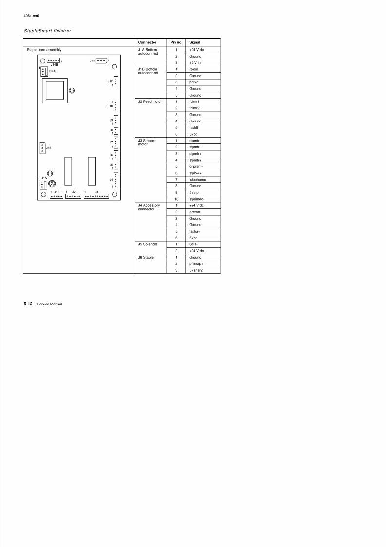
8/13/2019 t644 Service Manual
http://slidepdf.com/reader/full/t644-service-manual 314/423
10 stprimed-
J4 Accessory
connector
1 +24 V dc
2 accmtr-
3 Ground
4 Ground
5 tacha+
6 5Vptt
J5 Solenoid 1 Sol1-
4061-xx0
Staple card assembly (continued) J7 Right sidesensor board
1 Ground
2 Bottom
3 Top
4 Ground
J8 Solenoid 1 Sol2-
2 +24 V dc
J9 Bin emptysensor
1 Ground
2 bnempty-
3 5Vsnsr2
J10 Left sidesensor board
1 Ground
2 full+
3 NRFull+
4 Ground
J12 Pass thrusensor
1 Ground
2 psthruint
3 5Vptt
J13 Cover openswitch
1 +5V dc
2 Ground
3 cvropin-
J14A 1 +24V dc2 Ground
3 5V in
J14B 1 prtxdout
2 Ground
3 prtrxd
Connector Pin no. Signal
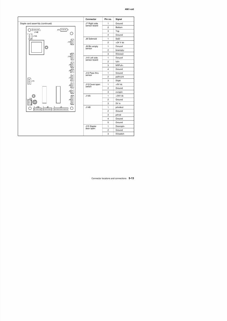
8/13/2019 t644 Service Manual
http://slidepdf.com/reader/full/t644-service-manual 315/423
3 prtrxd
4 Ground
5 GroundJ15 Staplerdoor open
1 Dooropin-
2 Ground
3 5Vswitch
4061-xx0

8/13/2019 t644 Service Manual
http://slidepdf.com/reader/full/t644-service-manual 316/423
4061-xx0
6. Preventive maintenance
This chapter describes procedures for printer preventive maintenance. Following these recommendations canhelp prevent problems and maintain optimum performance.
Safety inspection guide
The purpose of this inspection guide is to aid you in identifying unsafe conditions.
If any unsafe conditions exist, find out how serious the hazard could be and if you can continue before youcorrect the hazard.
Check the following items:
• Damaged, missing, or altered parts, especially in the area of the on/off switch and the power supply.• Damaged, missing, or altered covers, especially in the area of the top cover and the power supply cover.• Possible safety exposure from any non-Lexmark attachments.
Lubrication specifications
No requirements for this printer.
Scheduled maintenance
Maintenance kitThe operator panel displays the message 80 Scheduled Maintenance at each 300K page count interval. It isnecessary to replace the fuser assembly, transfer roller, charge roll, and pick tires at this interval to maintain theprint quality and reliability of the printer. The parts are available as a maintenance kit with the following partnumbers:
Maintenance kits
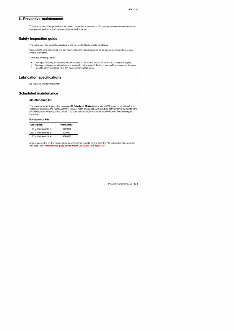
8/13/2019 t644 Service Manual
http://slidepdf.com/reader/full/t644-service-manual 317/423
After replacing the kit, the maintenance count must be reset to zero to clear the “80 Scheduled Maintenance”message. See “Maintenance page count (Maint Cnt Value)” on page 3-25.
Maintenance kits
Description Part number
115 V Maintenance kit 40X0100
220 V Maintenance kit 40X0101
100 V Maintenance kit 40X0197
4061-xx0

8/13/2019 t644 Service Manual
http://slidepdf.com/reader/full/t644-service-manual 318/423
4061-xx0
7. Parts catalog
How to use this parts catalog
The following legend is used in the parts catalog:
• Asm-index: identifies the assembly and the item in the diagram. For example, 3-1 indicates Assembly 3and the item number 1.
• Part number: identifies the unique number that identifies this FRU.• Units/mach: refers to the number of units actually used in the base machine or product.• Units/option: refers to the number of units used in the option and does not include the base machine.• Units/kit or pkg: refers to the number of units packaged together and identified by the part number.• NS: (Not shown) in the Asm-Index column indicates that the part is procurable but is not pictured in the
illustration.• PP: (Parts Packet) in the parts description column indicates the part is contained in a parts packet.
Model information used in the parts catalog.
Asm-Index
Partnumber
Units/mach- OR -
Units/option
Units/kit or
pkg
Description
Model name Configuration Machine type Parts catalog
Lexmark T640 Non-network 4061-000 000
Lexmark T640n Network 4061-010 010
Lexmark T642 Non-network 4061-200 200
Lexmark T642n Network 4061-210 210
Lexmark T644 Non-network 4061-400 400
Lexmark T644n Network 4061-410 410
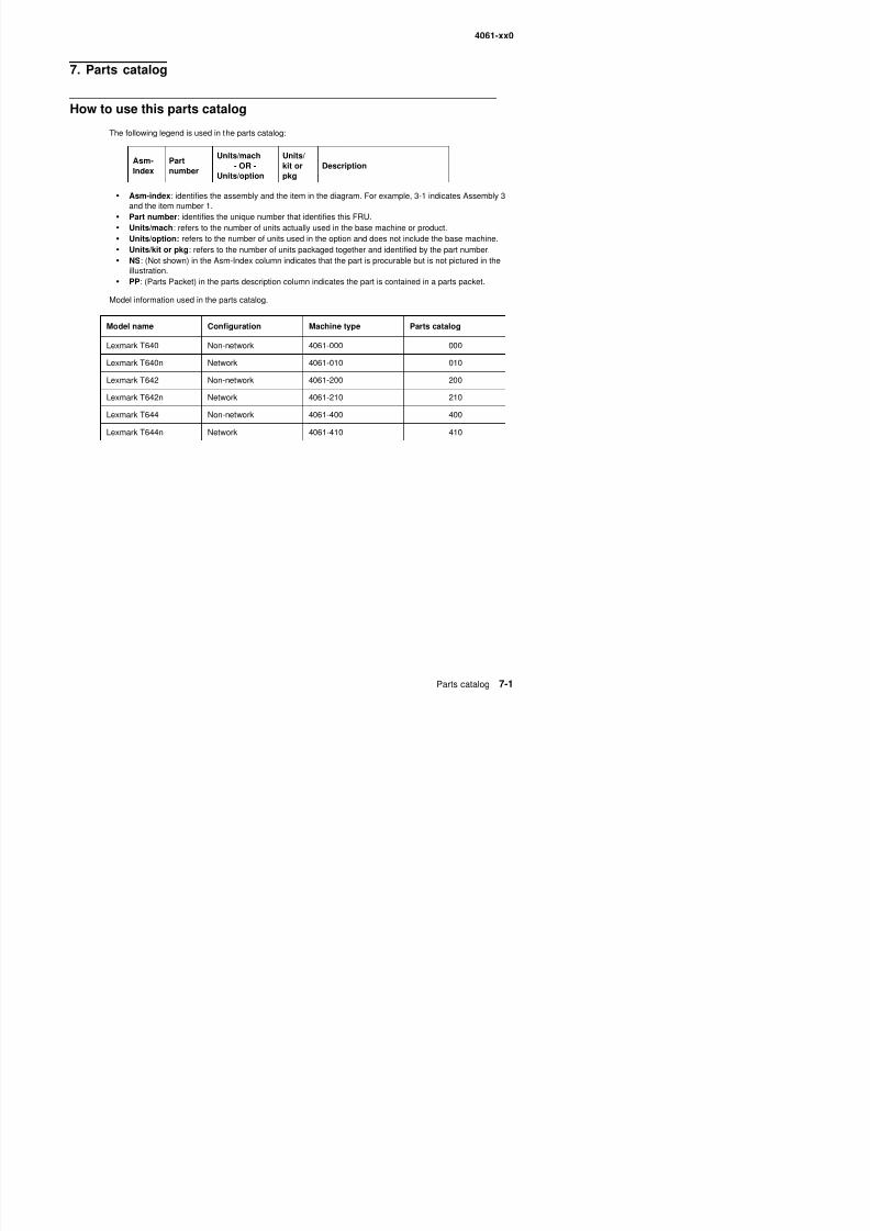
8/13/2019 t644 Service Manual
http://slidepdf.com/reader/full/t644-service-manual 319/423
4061-xx0
Assembly 1: Covers
14
15
13
16
17
3
3
2
5
1
4
4
5
6
6
10
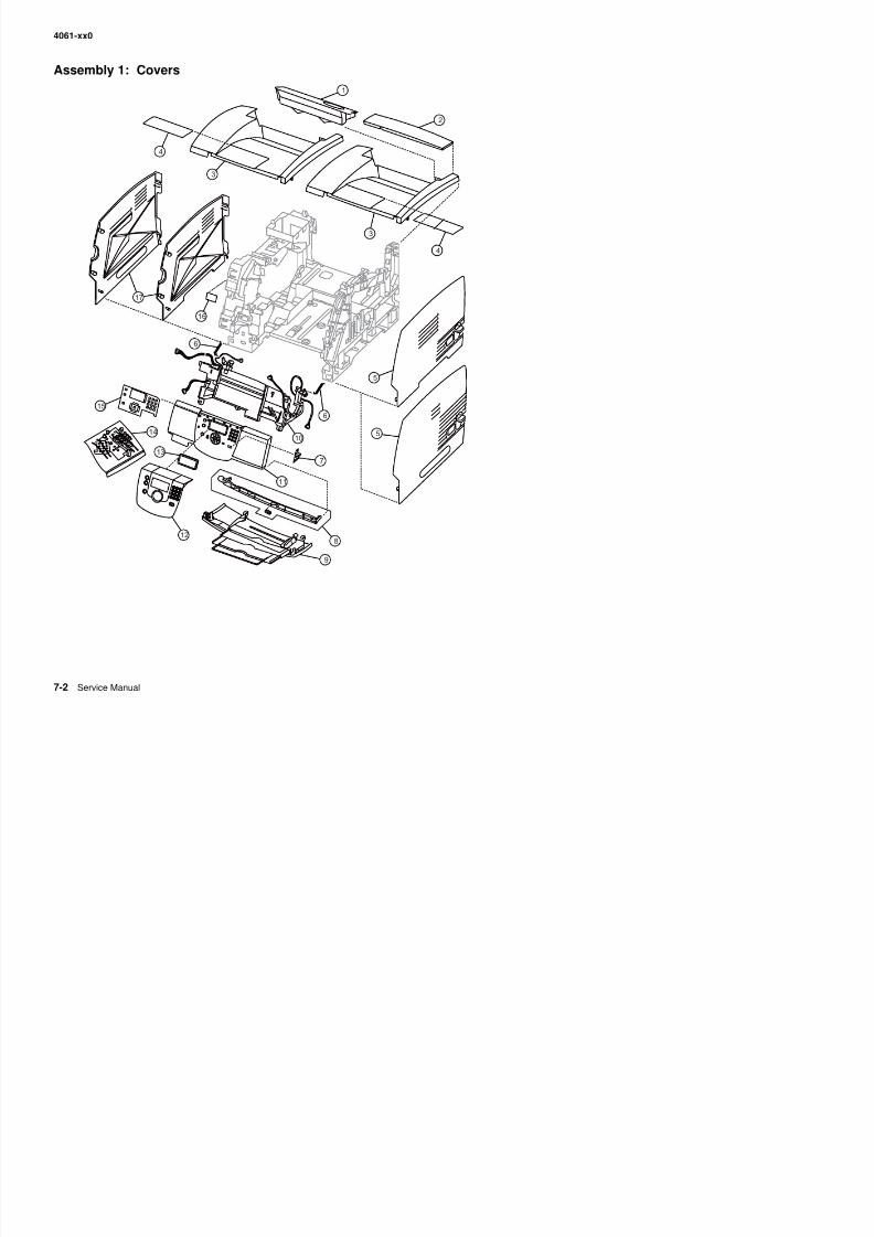
8/13/2019 t644 Service Manual
http://slidepdf.com/reader/full/t644-service-manual 320/423
7
9
812
13
11
4061-xx0
Assembly 1: Covers
Asm-Index
Partnumber
Units/mach
Units/ kitor pkg
Description
1—1 40X0001 1 1 Fuser wiper cover assembly
2 40X0002 1 1 Redrive cap cover assembly
3 40X0003 1 1 Laser cover assembly—250-sheet output, 000/010
3 40X0004 1 1 Laser cover assembly—500-sheet output, 200/210/400/410
4 40X0005 1 1 Paper support
5 40X0007 1 1 Right side cover—250-sheet output, 000/010
5 40X0008 1 1 Right side cover—500-sheet output, 200/210/400/410
6 40X0050 2 1 Counterbalance spring
7 40X0151 1 1 USB board assembly
8 40X0011 1 1 Upper front cover latch kit
9 40X0017 1 1 Lower front cover assembly
10 40X0006 1 1 Upper front cover hinge assembly, includes:
• USB cable (1)• Cover open switch and cable (1)• Left cable cover (1)• Right cable cover (1)• Left hinge spring (1)• Right hinge spring (1)
11 40X0010 1 1 Upper front cover assembly with Lexmark logo, including
• Operator panel board (1)• Stop button (1)• Menu button (1)
• Back button (1)• LED cap (1)• Navigation buttons (4)• Number pad buttons (1)• Navigation select button (1)• Number pad rubber dome sheet (1)• USB board (1)• Functional rubber sheet (1)
12 40X0014 1 1 Operator panel outer bezel with Lexmark logo, T640
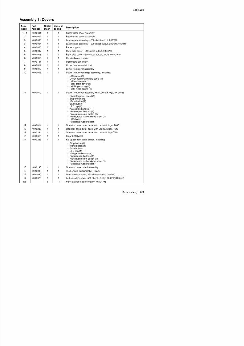
8/13/2019 t644 Service Manual
http://slidepdf.com/reader/full/t644-service-manual 321/423
12 40X0233 1 1 Operator panel outer bezel with Lexmark logo T642
12 40X0234 1 1 Operator panel outer bezel with Lexmark logo T64413 40X0013 1 1 Clear LCD bezel
14 40X0235 1 1 Kit, upper front panel button, including:
• Stop button (1)• Menu button (1)• Back button (1)• LED cap (1)• Navigation buttons (4)• Number pad buttons (1)
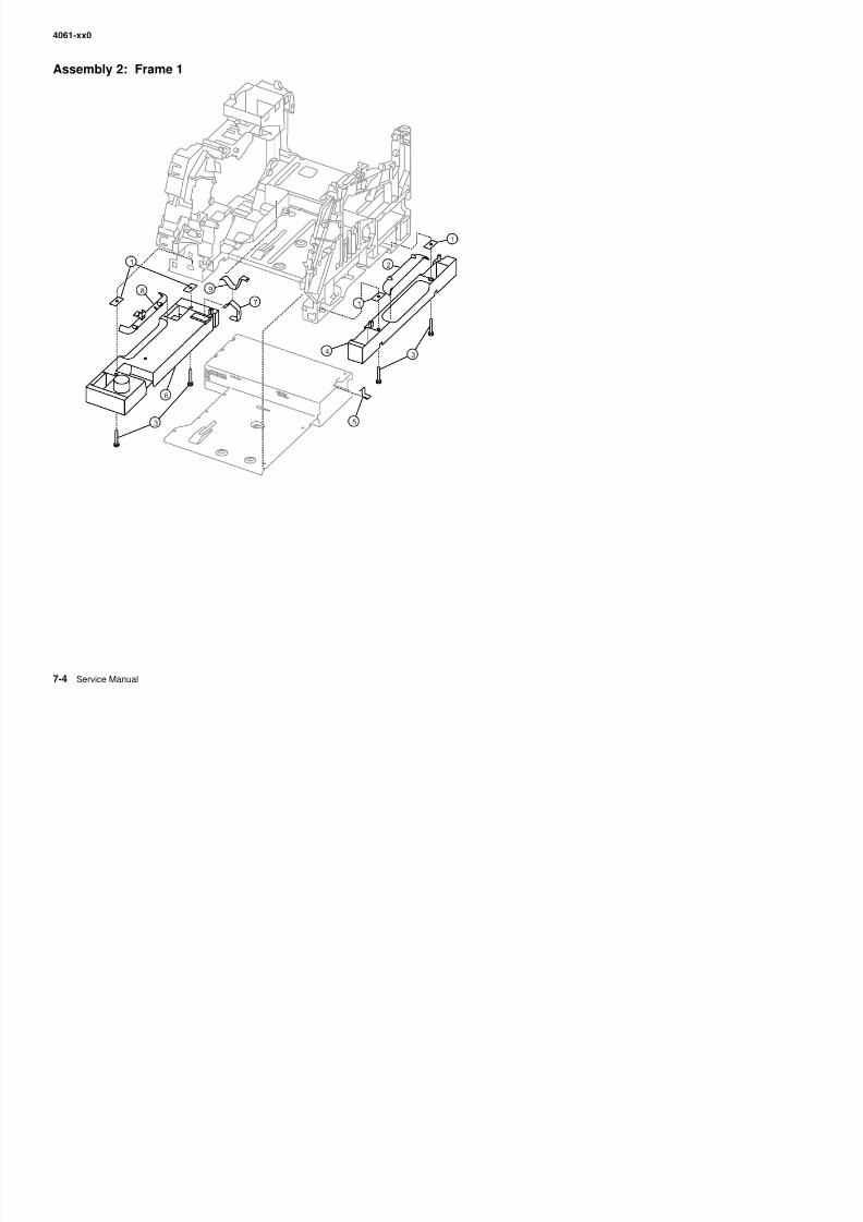
8/13/2019 t644 Service Manual
http://slidepdf.com/reader/full/t644-service-manual 322/423
4061-xx0
Assembly 2: Frame 1
Asm-Index
Partnumber
Units/mach
Units/ kitor pkg
Description
1 40X0065 4 1 Frame extension, nut plate, 200/210/400/410
2 40X0225 1 1 Right side hand holder
3 4 4 Parts packet (PP 40X0165)
4 40X0024 1 1 Right frame extension, 200/210/400/410
5 40X0026 1 1 Right side frame ground contact
6 40X0025 1 1 Left frame extension, 200/210/400/410
7 40X0060 1 1 External ground clip
8 40X0231 1 1 Left side hand holder
9 40X0285 1 1 Frame clip
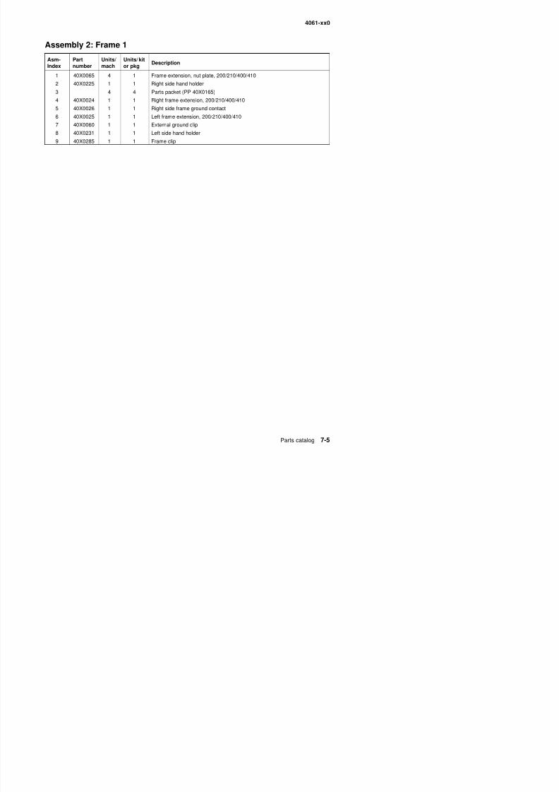
8/13/2019 t644 Service Manual
http://slidepdf.com/reader/full/t644-service-manual 323/423
4061-xx0
Assembly 3: Frame 2
3
10
6
12
17
15
8
14
2
9 5
16
4
11
7
13
18
1
19
20
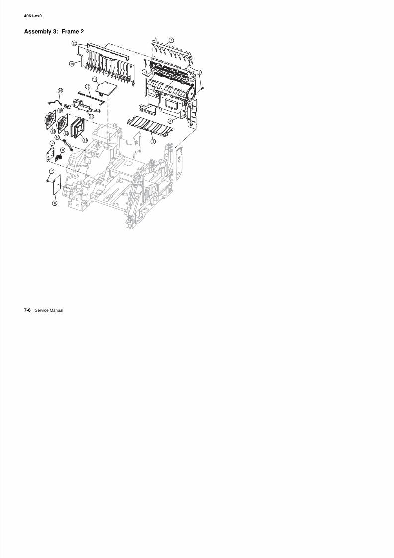
8/13/2019 t644 Service Manual
http://slidepdf.com/reader/full/t644-service-manual 324/423
4061-xx0
Assembly 3: Frame 2
Asm-Index
Partnumber
Units/mach
Units/ kitor pkg
Description
3—1 40X0027 1 1 Upper redrive deflector
2 40X0028 1 1 Upper diverter spring
3 2 2 Parts packet, redrive mounting screws (P/N 40X0253)
4 40X0029 1 1 Redrive assembly—250-sheet in/250 out, 000/010
4 40X0030 1 1 Redrive assembly—500-sheet in/500 out, 200/210/400/410
5 40X0032 1 1 Transfer deflector6 40X0044 1 1 Gear guard
7 3 Parts packet (PP 40X0165)
8 40X0048 1 1 Paper switch activate spring
9 40X0046 1 1 Paper size sensing board assembly
10 40X0049 1 1 Gear release link
11 40X0053 1 1 Main fan with cable—250-sheet output
11 40X0054 1 1 Main fan with cable—500-sheet output
12 40X0212 1 1 Main fan duct, 200/210/400/410
13 40X0211 1 1 Main fan duct, 000/010
14 40X0052 1 1 Standard bin level sensor bracket
15 40X0051 1 1 Standard bin level sensor
16 40X0264 1 1 Standard bin level sensor cable
17 40X0057 1 1 Output paper level flag, 000/010
17 40X0058 1 1 Output paper level flag, 200/210/400/410
18 40X0210 1 1 Main fan cap19 40X0056 1 1 Redrive door assembly 250 sheet 000/010
19 40X0232 1 1 Redrive door assembly 500 sheet 200/210/400/410
20 40X0059 1 1 Extension guide
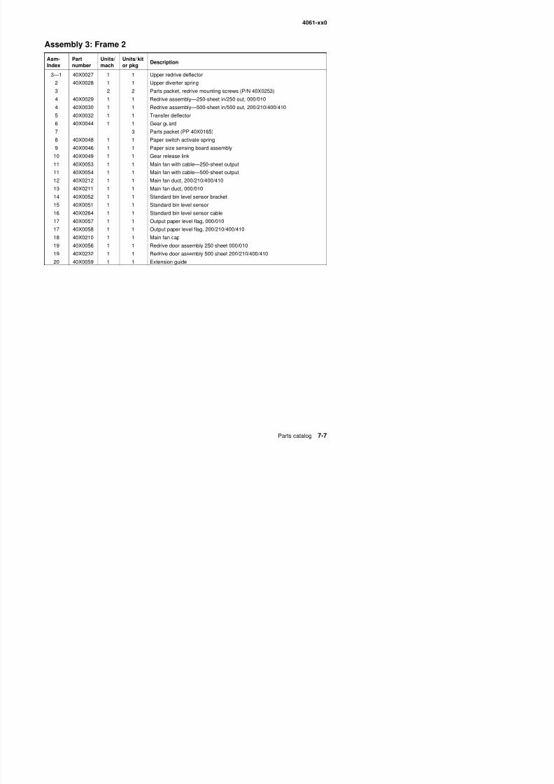
8/13/2019 t644 Service Manual
http://slidepdf.com/reader/full/t644-service-manual 325/423
4061-xx0
Assembly 4: Frame 3
3
11
7
13
18
516
9
15
2
10
6
17
4
814
1
3
6
7611
3
6
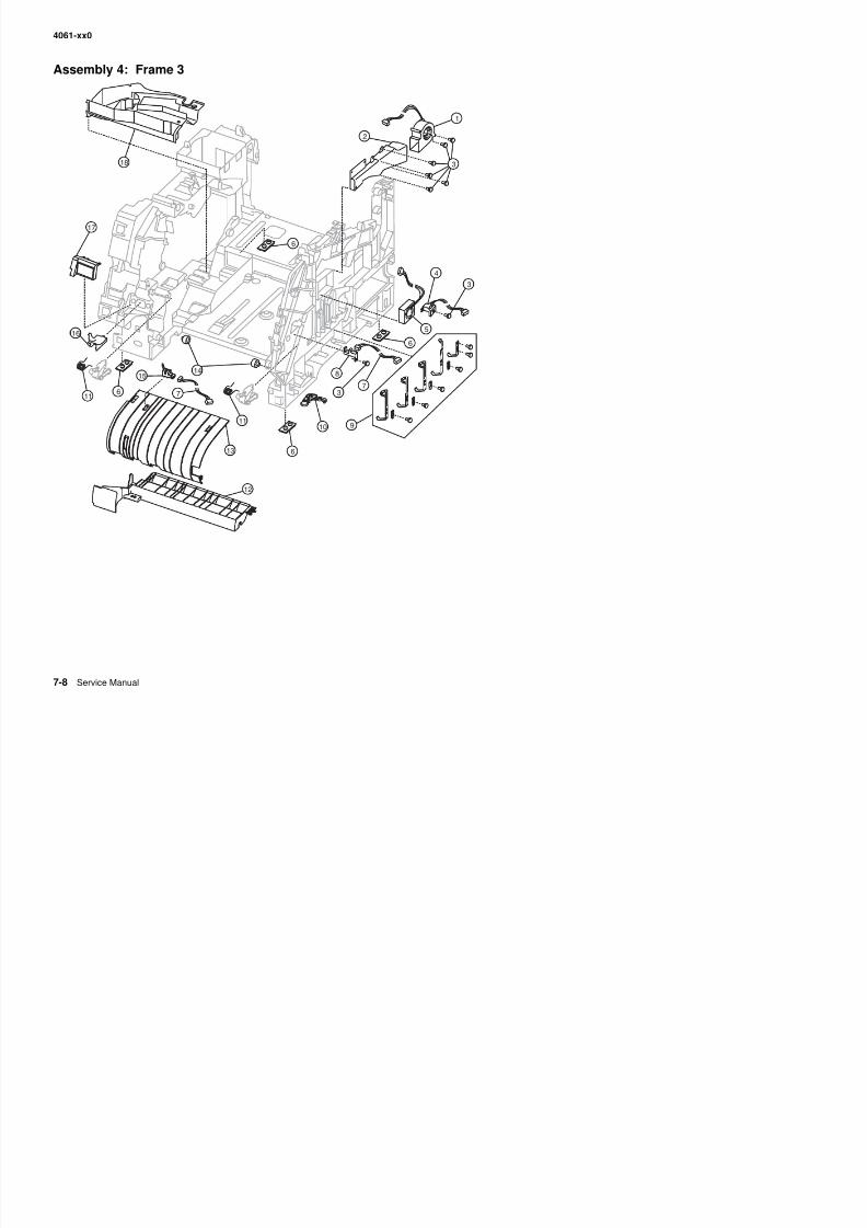
8/13/2019 t644 Service Manual
http://slidepdf.com/reader/full/t644-service-manual 326/423
12
4061-xx0
Assembly 4: Frame 3
Asm-Index
Partnumber
Units/mach
Units/ kitor pkg
Description
4—1 40X0249 1 1 EP DC fan assembly, 200/210/400/410
2 40X0208 1 1 Blower duct, 200/210/400/410
3 1 1 Parts packet (PP 40X0165)
3 1 1 Parts packet (PP 40X0165)
4 40X0034 1 1 Signature button sensor assembly
5 40X0035 1 1 EP DC fan assembly, 000/0106 40X0033 4 1 Machine mounting pad
7 40X0223 1 1 HVPS/input sensor/toner sensor cable assembly
8 40X0036 1 1 Toner sensor assembly
9 40X0306 1 1 High voltage contact kit, including:
• Charge roll contact (1)• Doc/TAR/Dev contact (3)• PC drum contact (1)
• Screw (5)• Screw block (4)
10 40X0213 1 1 Tray bias assembly
11 40X0021 2 1 Cartridge holddown assembly
12 40X0040 1 1 Upper paper feed deflector
13 40X0041 1 1 Inner paper feed deflector, 000/010
13 40X0042 1 1 Inner paper feed deflector, 200/210/400/410
14 40X0039 2 1 Developer support roller
15 40X0043 1 1 Input sensor16 40X0209 1 1 Gear #60 MPF shield
17 40X0045 1 1 ESD shield with label
18 40X0207 1 1 EP duct
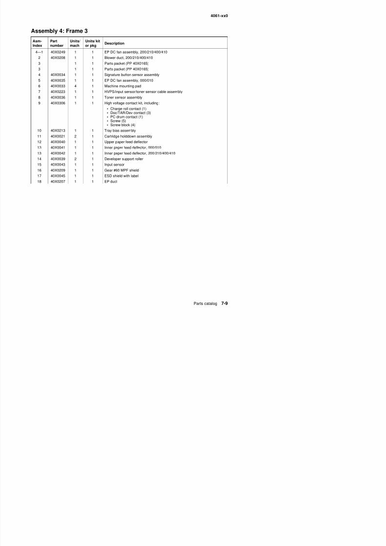
8/13/2019 t644 Service Manual
http://slidepdf.com/reader/full/t644-service-manual 327/423
4061-xx0
Assembly 5: Printhead
1
2
2
3
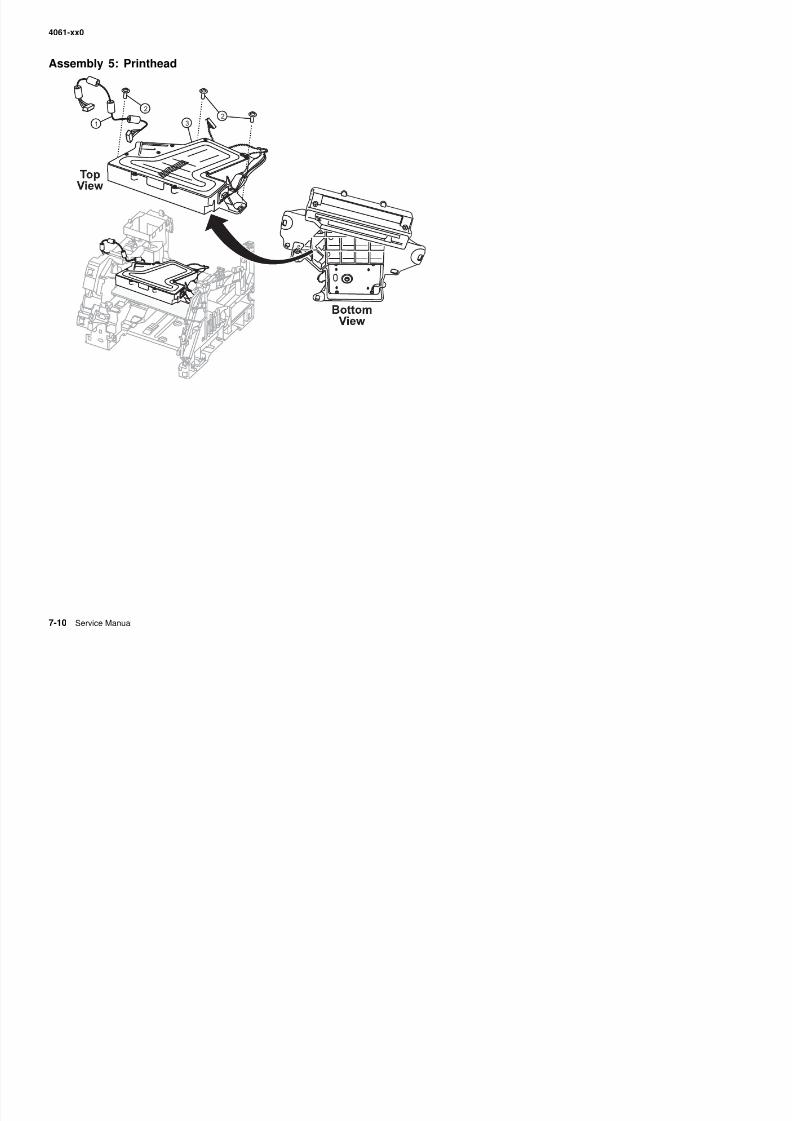
8/13/2019 t644 Service Manual
http://slidepdf.com/reader/full/t644-service-manual 328/423
4061-xx0
Assembly 5: Printhead
Asm-Index
Partnumber
Units/mach
Units/ kitor pkg
Description
4—1 40X0061 1 1 Laser cable assembly
2 Parts packet (printhead mounting screw) (PP 40X0165)
3 40X0062 1 1 Printhead assembly (includes all cables)
CAUTION:The printhead is not a serviceable FRU. Do not disassemble theprinthead.
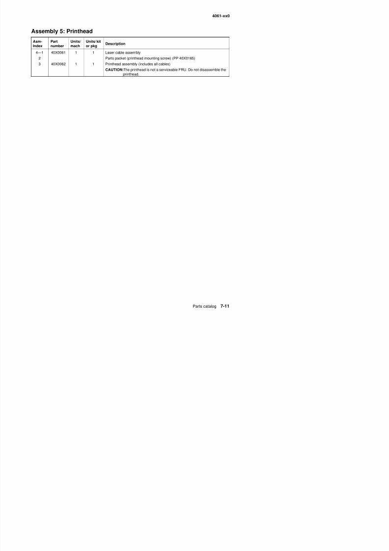
8/13/2019 t644 Service Manual
http://slidepdf.com/reader/full/t644-service-manual 329/423
4061-xx0
Assembly 6: Paper feed—autocompensator
5
3
4
6
2
1
7
1
6
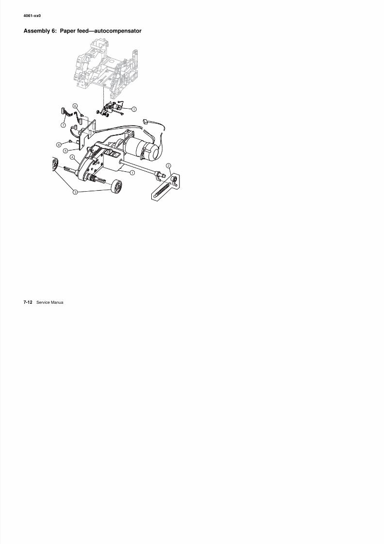
8/13/2019 t644 Service Manual
http://slidepdf.com/reader/full/t644-service-manual 330/423
4061-xx0
Assembly 6: Paper feed—autocompensator
Asm-Index
Partnumber
Units/mach
Units/ kitor pkg
Description
6—1 40X0066 1 1 Pick arm assembly—500-sheet, 200/210/400/410
1 40X0067 1 1 Pick arm assembly—250-sheet, 000/010
2 40X0068 1 1 Parts packet, bellcrank assembly—250-sheet tray, 000/010
• Bellcrank (1)• Spring (1)
2 40X0069 1 1 Parts packet, bellcrank assembly for—500-sheet tray, 200/210/400/410• Bellcrank (1)• Spring (1)
3 40X4308 2 2 Pick roll assembly
4 40X0071 1 1 Paper out flag—250-sheet tray, 000/010
4 40X0072 1 1 Paper out flag—500-sheet tray, 200/210/400/410
5 40X0073 1 1 Paper low/out sensor card assembly
6 Parts packet (hanger) (PP 40X0165)
7 40X0074 1 1 Paper size/autocompensator cable
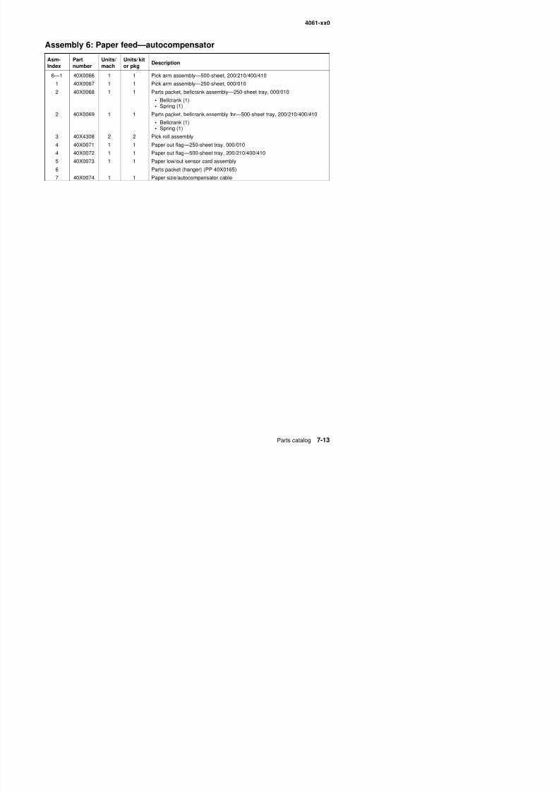
8/13/2019 t644 Service Manual
http://slidepdf.com/reader/full/t644-service-manual 331/423
4061-xx0
Assembly 7: Paper feed—multipurpose feeder
32
4
1
1
5
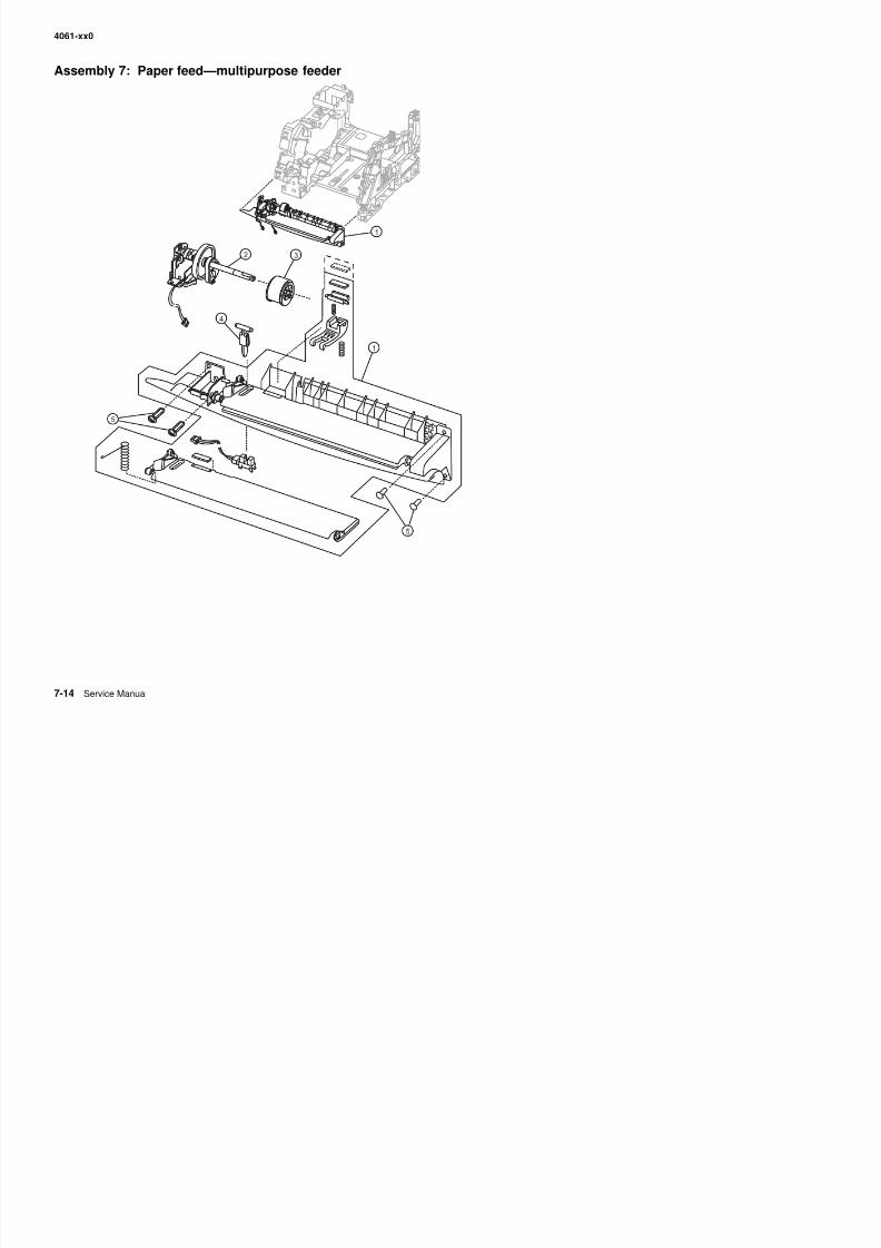
8/13/2019 t644 Service Manual
http://slidepdf.com/reader/full/t644-service-manual 332/423
5
4061-xx0
Assembly 7: Paper feed—multipurpose feeder
Asm-Index
Partnumber
Units/mach
Units/ kitor pkg
Description
7—1 40X0079 1 1 Multipurpose feeder lower deflector assembly
2 40X0310 1 1 Multipurpose feeder pick arm assembly with solenoid
3 40X0076 1 1 Pick roll assembly
4 40X0077 1 1 Multipurpose feeder paper out flag
5 Parts packet (lower deflector mounting screw, 8 mm) (PP 40X0165)
5 Parts packet (lower deflector mounting screw, 12 mm) (PP 40X0165)5 1 1 Parts packet (frame mounting screw) (PP 40X0165)
NS Parts packet (pick roll shaft clip) (PP 40X0165)
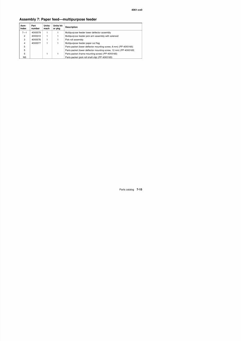
8/13/2019 t644 Service Manual
http://slidepdf.com/reader/full/t644-service-manual 333/423
4061-xx0
Assembly 8: Paper feed—alignment
3
2
1
4
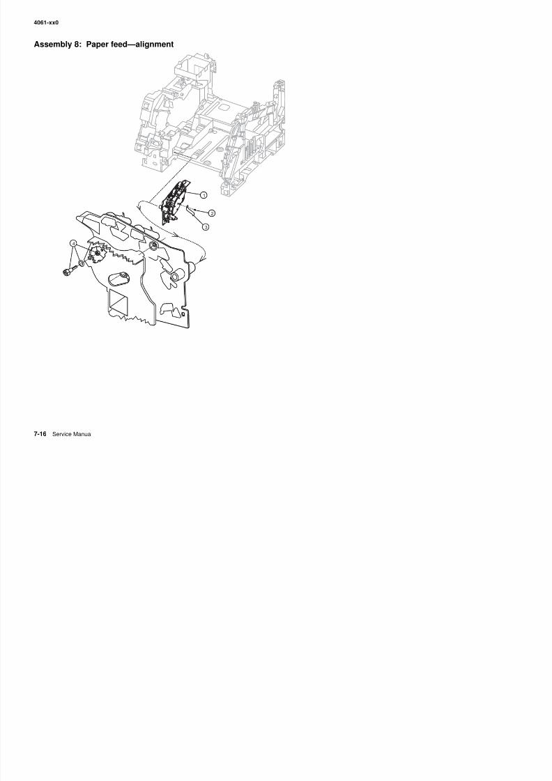
8/13/2019 t644 Service Manual
http://slidepdf.com/reader/full/t644-service-manual 334/423
4061-xx0
Assembly 8: Paper feed—alignment
Asm-Index
Partnumber
Units/mach
Units/ kitor pkg
Description
8—1 40X0084 1 1 Paper feed alignment assembly paper feed
2 Parts packet (clip ref ground mounting screw) (PP 40X0165)
3 40X0085 1 1 Reference ground clip
4 40X0086 Parts packet (reference adjust)
• Screw, paper reference adjust (1)
• Washer, paper reference adjust (1)• Nut, paper reference adjust (1)
NS Parts packet (alignment asm mounting screw) (PP 40X0165)
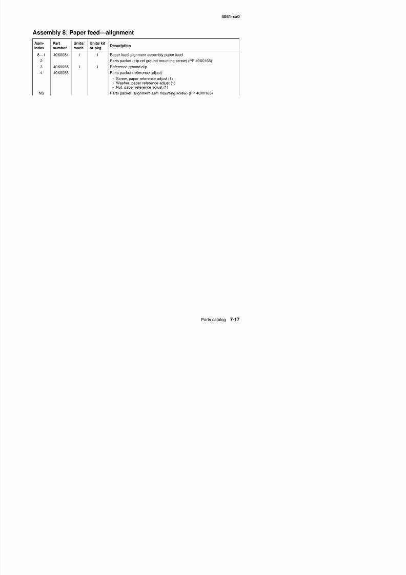
8/13/2019 t644 Service Manual
http://slidepdf.com/reader/full/t644-service-manual 335/423
4061-xx0
Assembly 9: Integrated 250-sheet paper tray
3
7
5
2
6
4
1
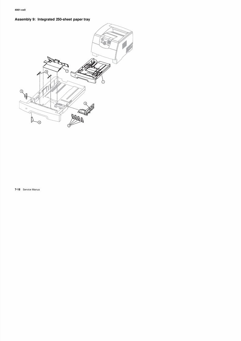
8/13/2019 t644 Service Manual
http://slidepdf.com/reader/full/t644-service-manual 336/423
4061-xx0
Assembly 9: Integrated 250-sheet paper tray
Asm-Index
Partnumber
Units/mach
Units/ kitor pkg
Description
9—1 40X3231 1 1 Integrated 250-sheet tray
2 40X0092 1 1 Side restraint—250-sheet tray
3 40X0093 4 1 Wear strips
4 40X0263 1 1 Pass thru plate—250-sheet tray
5 40X0094 1 1 Wear plate—250-sheet tray
6 40X0105 2 1 Restraint pad7 40X0090 1 1 Back restraint—250-sheet tray
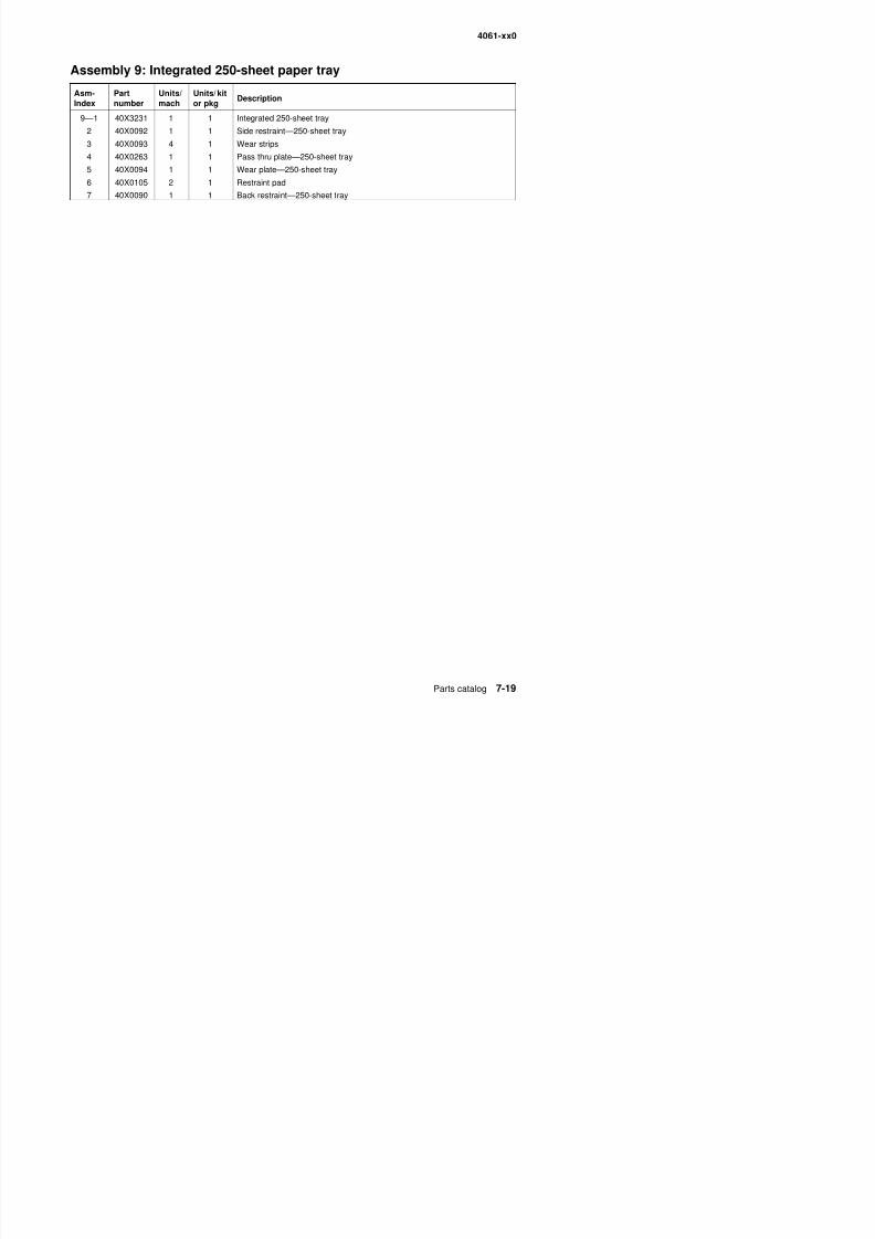
8/13/2019 t644 Service Manual
http://slidepdf.com/reader/full/t644-service-manual 337/423
4061-xx0
Assembly 10: Integrated 500-sheet paper tray
1
7
5
4
6
2
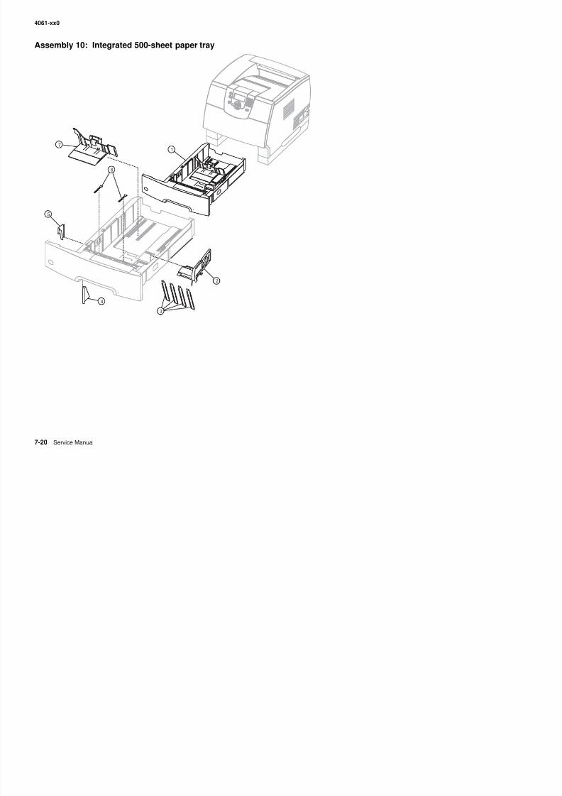
8/13/2019 t644 Service Manual
http://slidepdf.com/reader/full/t644-service-manual 338/423
3
4061-xx0
Assembly 10: Integrated 500-sheet paper tray
Asm-Index
Partnumber
Units/mach
Units/ kitor pkg
Description
10—1 40X4663 1 1 Tray assembly—500-sheet tray
2 40X0099 1 1 Side restraint
3 40X0182 4 1 Wear strip
4 40X0103 1 1 Pass thru plate—500-sheet tray
5 40X0183 1 1 Wear plate—500-sheet tray
6 40X0105 2 1 Restraint pad7 40X0106 1 1 Back restraint
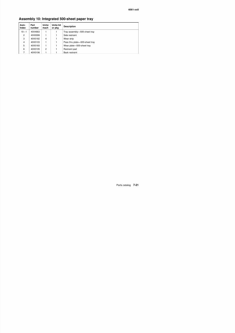
8/13/2019 t644 Service Manual
http://slidepdf.com/reader/full/t644-service-manual 339/423
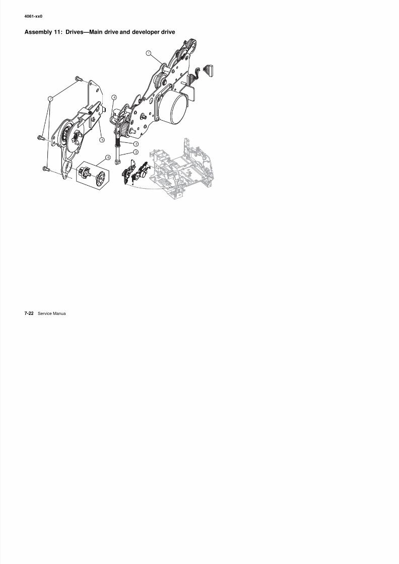
8/13/2019 t644 Service Manual
http://slidepdf.com/reader/full/t644-service-manual 340/423
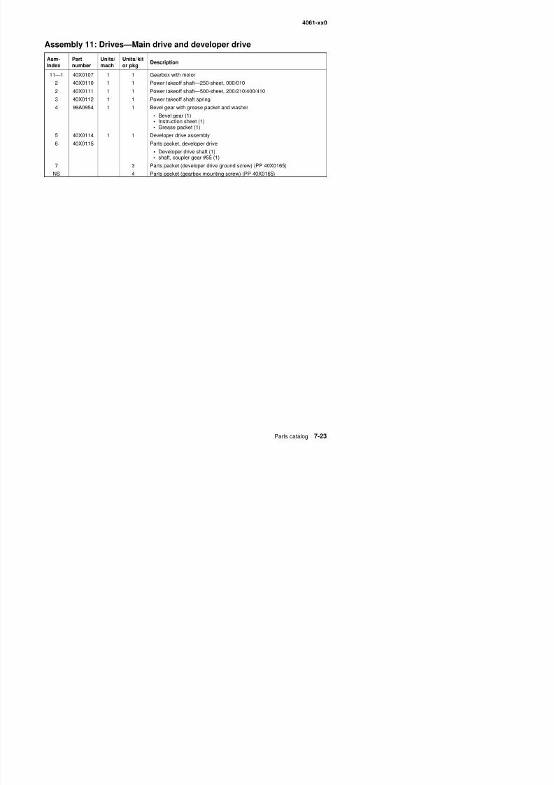
8/13/2019 t644 Service Manual
http://slidepdf.com/reader/full/t644-service-manual 341/423
4061-xx0
Assembly 12: Hot roll fuser
Rear v iew F r ont v i ew
6
10
1
2
3
4
7
11
12
14
9
5
8
8
6
13
9
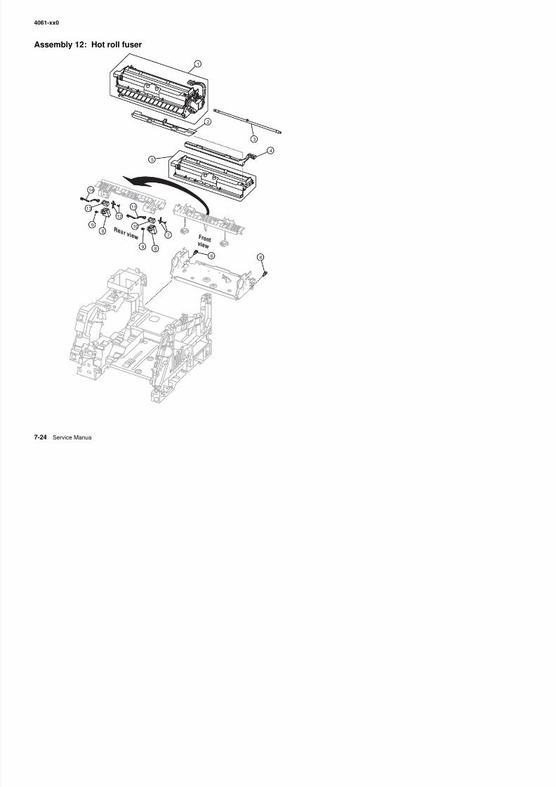
8/13/2019 t644 Service Manual
http://slidepdf.com/reader/full/t644-service-manual 342/423
4061-xx0
Assembly 12: Hot roll fuser
Asm-Index
Partnumber
Units/mach
Units/ kitor pkg
Description
12—1 40X2592 1 1 Fuser assembly w/115 V lamp
1 40X2591 1 1 Fuser assembly w/100 V lamp
1 40X2590 1 1 Fuser assembly w/220 V lamp
2 40X0120 1 1 Fuser wiper cavity cover
3 40X0122 1 1 Fuser lamp, 115V
3 40X0123 1 1 Fuser lamp, 220V4 40X2665 1 1 Oil fuser wiper (black housing)
4 40X2666 1 1 Wax fuser wiper (gray housing)
5 40X0121 1 Fuser cover assembly kit, including:
• Thermistor (1)• Thermostat (1)• Left and right fuser lamp contact assemblies (1)
6 Parts packet (fuser mounting screw) (PP 40X0254))
7 40X0239 1 Exit sensor flag/spring kit, including:• Spring (1)• Flag (1)
8 40X0236 1 1 Exit/narrow media sensor cover
9 Parts packet (PP 40X0165)
10 40X0125 1 1 Exit sensor
11 40X0230 1 1 Exit sensor cable
12 40X0238 1
11
Narrow media flag/spring kit, including:
• Spring• Flag
13 40X0124 1 1 Narrow media sensor
14 40X0229 1 1 Narrow media sensor cable
NS 40X0226 1 1 Fuser AC to fuser lamp cable
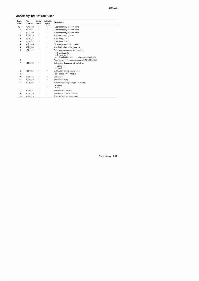
8/13/2019 t644 Service Manual
http://slidepdf.com/reader/full/t644-service-manual 343/423
4061-xx0
Assembly 13: Transfer/charging
3
2
4
1
5
9
8
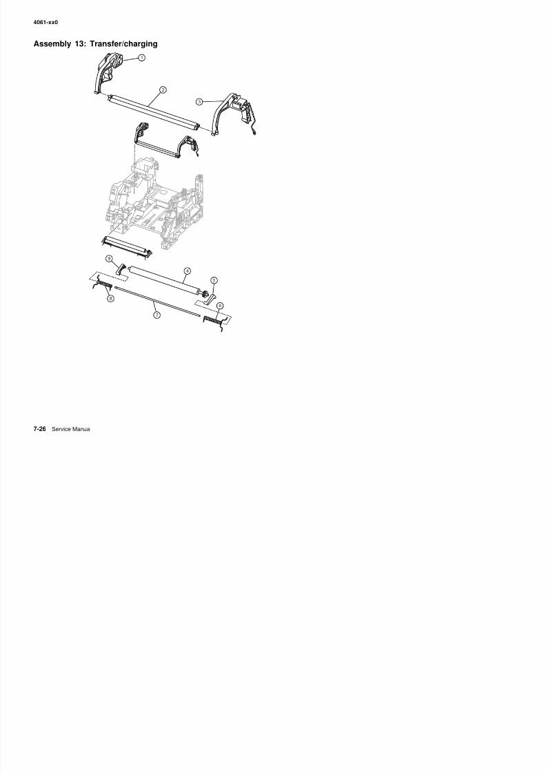
8/13/2019 t644 Service Manual
http://slidepdf.com/reader/full/t644-service-manual 344/423
6
7
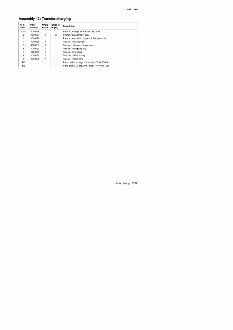
8/13/2019 t644 Service Manual
http://slidepdf.com/reader/full/t644-service-manual 345/423
4061-xx0
Assembly 14: Electronics—power supplies
3
5
2
4
1
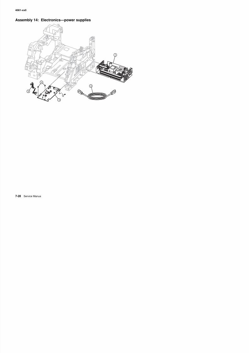
8/13/2019 t644 Service Manual
http://slidepdf.com/reader/full/t644-service-manual 346/423
4061-xx0
Assembly 14: Electronics—power supplies
Asm-Index
Partnumber
Units/mach
Units/ kitor pkg
Description
14—1 56P4232 1 1 LVPS—115 V ac, 000/010
1 56P4233 1 1 LVPS—220 V ac, 000/010
1 56P4234 1 1 LVPS—115 V ac, 200/210/400/410
1 56P4238 1 1 LVPS—220 V ac, 200/210/400/410
2 40X0260 1 1 Power cord set (8 ft right angle, 13 amp)—United States, Canada,Caribbean countries, Colombia, Costa Rica, Dominican Republic,El Salvador, Ecuador, Guatemala, Honduras, Mexico, Nicaragua, Panama,Puerto Rico, Saudi Arabia, Venezuela, and Virgin Islands
2 40X0256 1 1 Power cord set (8 ft right angle)—Bolivia and Peru
2 40X0255 1 1 Power cord set (8 ft right angle)—Argentina
2 40X0257 1 1 Power cord set (8 ft right angle)—Chile, Uruguay
2 40X0258 1 1 Power cord set (8 ft right angle)—Arabic, Austria, Belgium, Bluemark, CIS,Czechoslovakia, Denmark, Finland, France, Germany, Greece, Hungary,Ireland, Italy, Medmark, (1 and 2), Netherlands, Norway, Paraguay, Poland,Portugal, Russia, Slavic countries, Spain, Sweden, Turkey, and UK.
2 40X0293 1 1 Power cord set (8 ft right angle)—Arabic, Austria, Belgium, Bluemark, CIS,Czechoslovakia, Finland, France, Germany, Greece, Hungary, Ireland,Italy, Medmark, (1 and 2), Netherlands, Poland, Portugal, Russia, Slaviccountries, Spain, Turkey, and UK.
2 40X4596 1 1 Power cord set (6 ft right angle)—Brazil
2 40X0301 1 1 Power cord set (8 ft straight)—AS/NZS
2 40X0271 1 1 Power cord set (8 ft straight)—Hong Kong
2 40X0272 1 1 Power cord set (8 ft right angle)—Japan
2 40X0280 1 1 Power cord set (6 ft straight)—Korea
2 40X0303 1 1 Power cord set (8 ft straight)—PRC
2 40X0281 1 1 Power cord set (6 ft right angle)—Taiwan
2 40X0294 1 1 Power cord set (8 ft right angle)—Denmark, Norway, and Sweden
2 40X0295 1 1 Power cord set (8 ft right angle)—Israel
2 40X0304 1 1 Power cord set (8 ft right angle)—Botswana, Lesotho, Namibia, Pakistan,and South Africa
2 40X0305 1 1 Power cord set (8 ft right angle)—Switzerland
3 40X0138 1 1 High voltage power supply
4 1 Parts packet (PP 40X0165)
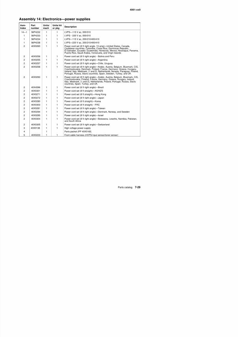
8/13/2019 t644 Service Manual
http://slidepdf.com/reader/full/t644-service-manual 347/423
5 40X0223 1 1 Front cable harness (HVPS/input sensor/toner sensor)
4061-xx0
Assembly 15: Electronics—card assemblies
1
2
3
5
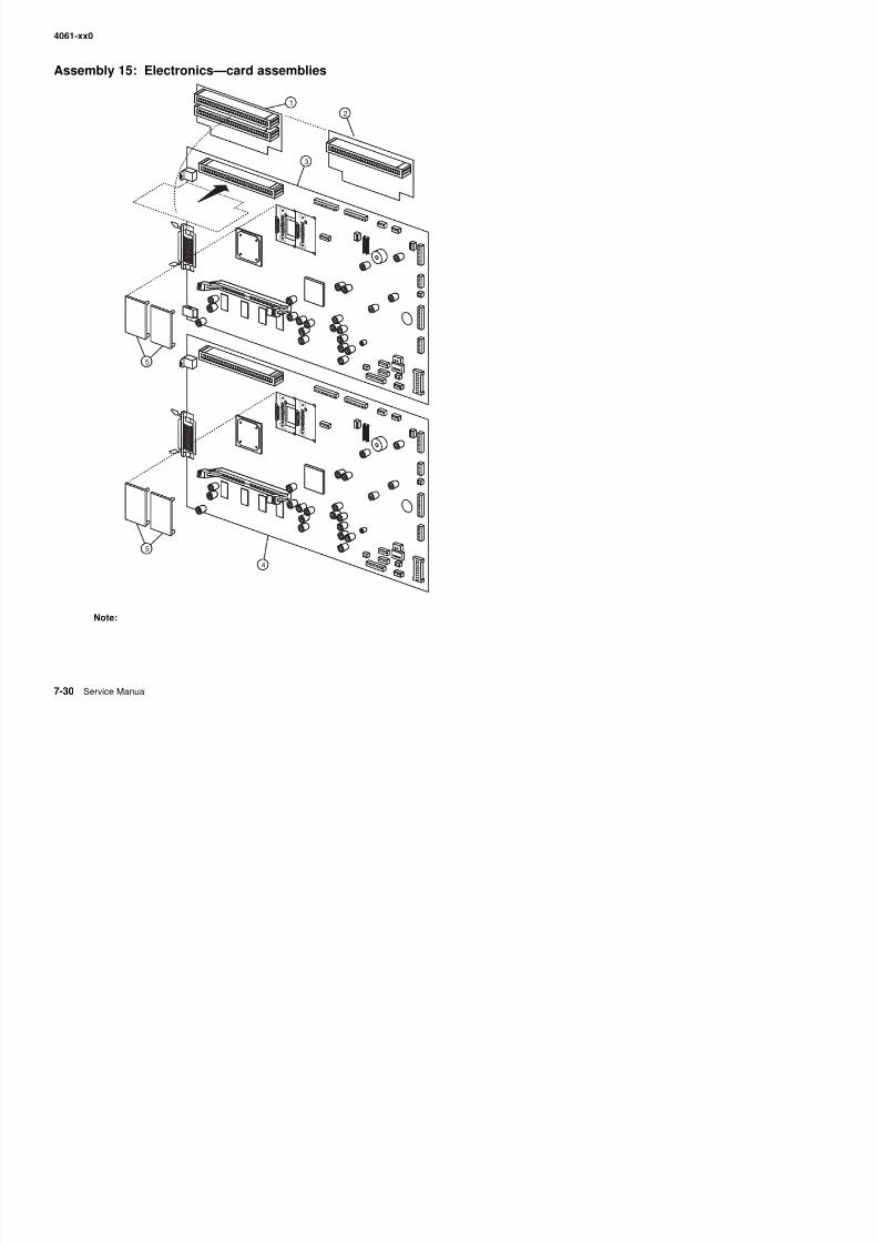
8/13/2019 t644 Service Manual
http://slidepdf.com/reader/full/t644-service-manual 348/423
4
5
4061-xx0
Assembly 15: Electronics—card assemblies
Asm-Index
Partnumber
Units/mach
Units/ kitor pkg
Description
15—1 40X0148 1 1 Interconnect card assembly (2 slot), 200/210/400/410
2 40X0147 1 1 Interconnect card assembly (1 slot), 000/010
3 40X5293 1 1 System board assembly (non-network), 000
3 40X5295 1 1 System board assembly (non-network), 200
3 40X5297 1 1 System board assembly (non-network), 400
4 40X5294 1 1 System board assembly (network), 0104 40X5296 1 1 System board assembly (network), 210
4 40X5298 1 1 System board assembly (network), 410
5 40X3212 1 1 Bar code card assembly
5 40X3378 1 1 IPDS/SCS card assembly
5 40X0199 1 1 PrintCryption card assembly
5 40X0265 1 1 PRESCRIBE card assembly
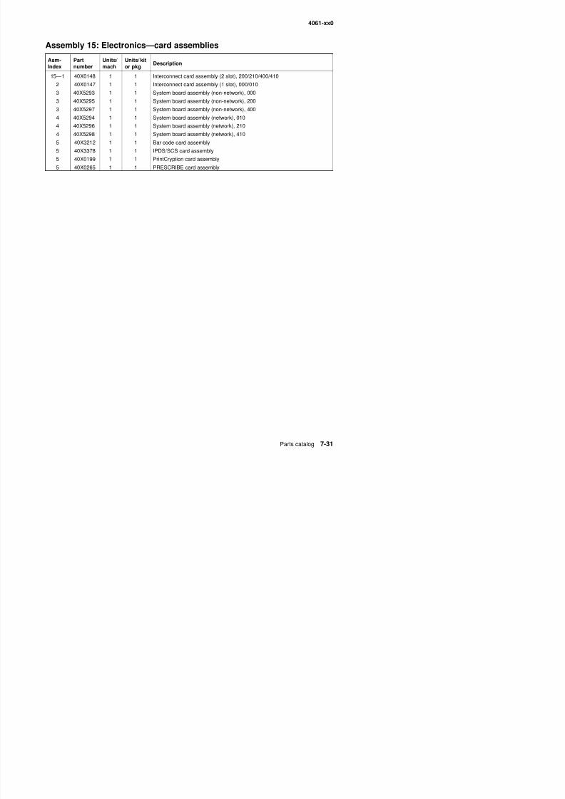
8/13/2019 t644 Service Manual
http://slidepdf.com/reader/full/t644-service-manual 349/423
4061-xx0
Assembly 16: Electronics—shields
5
6
2
1
3
4
7
2
4
2
2
2
2
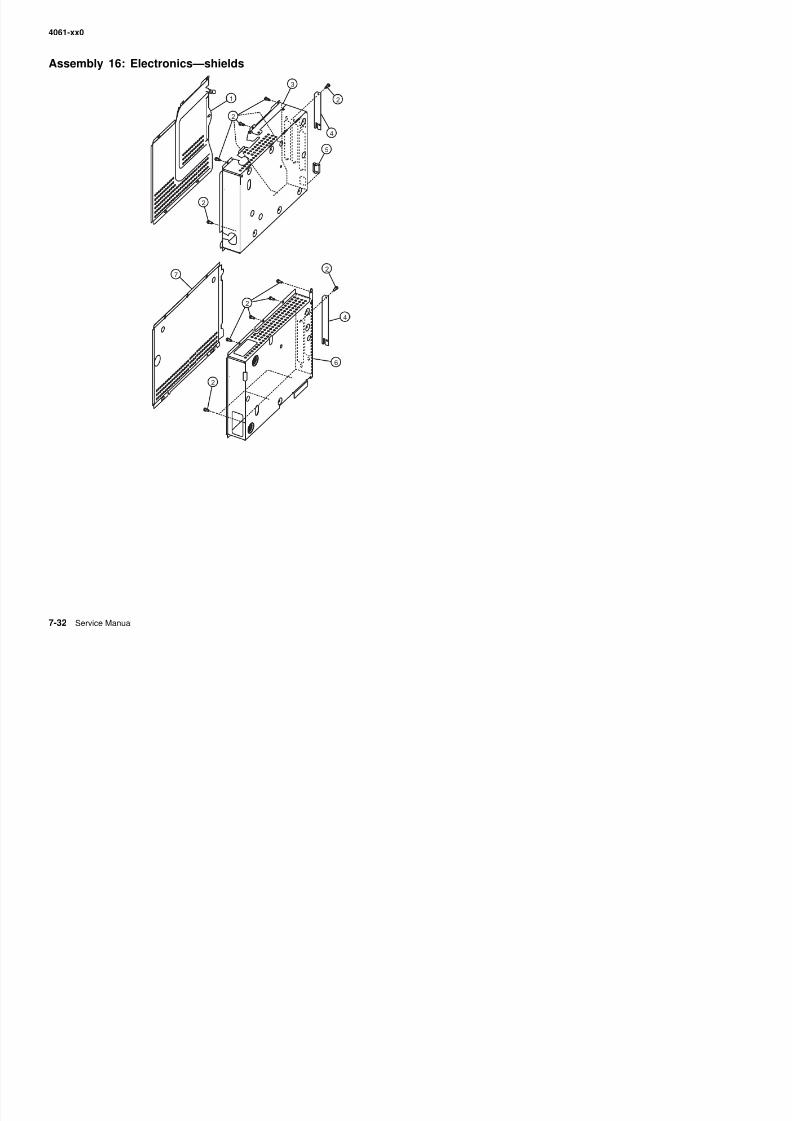
8/13/2019 t644 Service Manual
http://slidepdf.com/reader/full/t644-service-manual 350/423
4061-xx0
Assembly 16: Electronics—shields
Asm-Index
Partnumber
Units/mach
Units/ kitor pkg
Description
16—1 40X0150 1 1 Outer shield—2 slot, 200/210/400/410
2 Parts packet (INA cover mounting screw) (PP 40X0165)
2 Parts packet (outer shield mounting screw) (PP 40X0165)
2 Parts packet (inner shield mounting screw) (PP 40X0165)
3 40X0149 1 1 Inner shield assembly—2 slot, 200/210/400/410
4 40X0153 1 1 INA flat cover (blank)5 40X0152 1 1 Ethernet shield (blank), 010/210/410
6 40X0154 1 1 Inner shield assembly—1 slot. 000/010
7 40X0222 1 1 Outer shield—1 slot, 000/010

8/13/2019 t644 Service Manual
http://slidepdf.com/reader/full/t644-service-manual 351/423
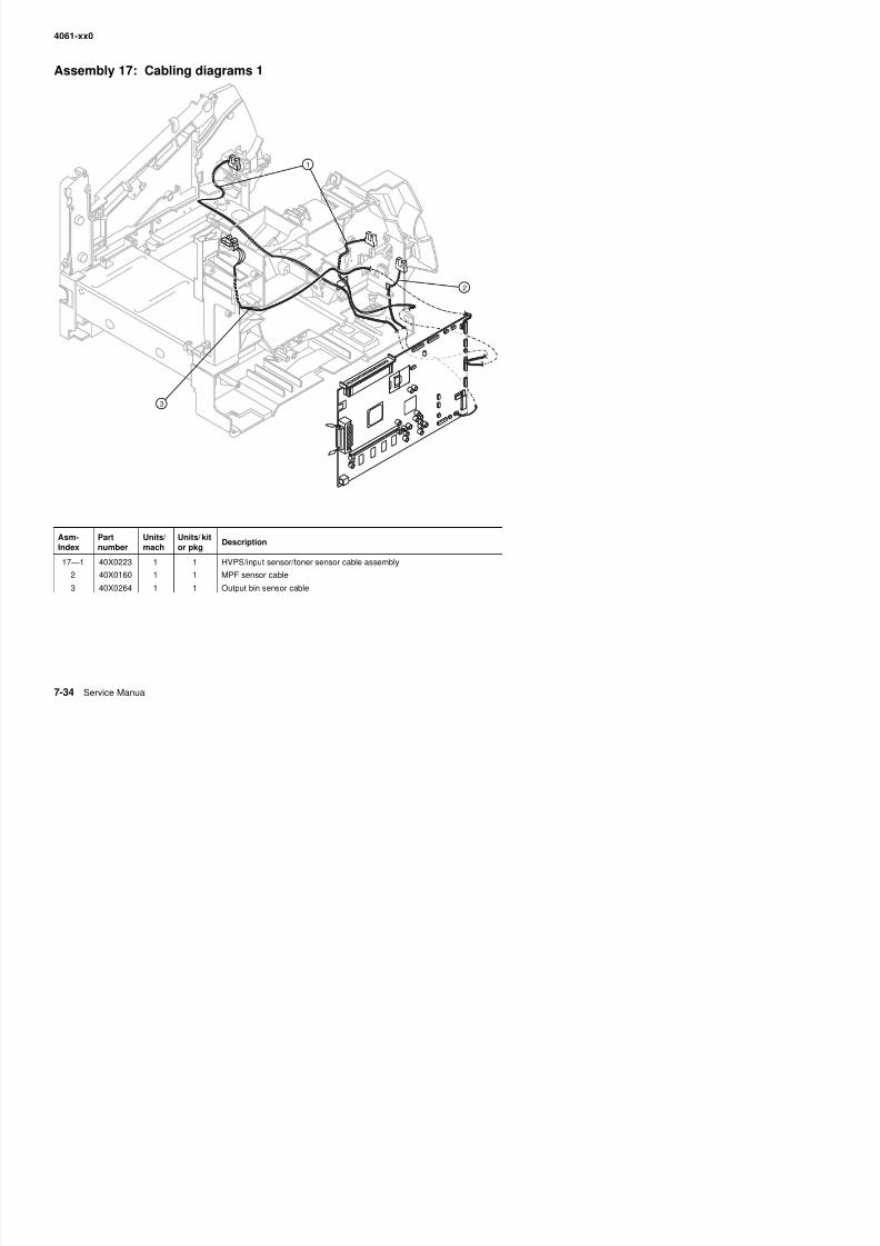
8/13/2019 t644 Service Manual
http://slidepdf.com/reader/full/t644-service-manual 352/423
4061-xx0
Assembly 18: Cabling diagrams 2
2
3
1
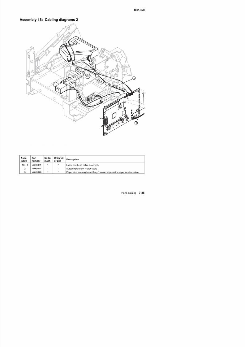
8/13/2019 t644 Service Manual
http://slidepdf.com/reader/full/t644-service-manual 353/423
A P t U it / U it / kit
4061-xx0
Assembly 19: Cabling diagrams 3
3
5
2
4
1
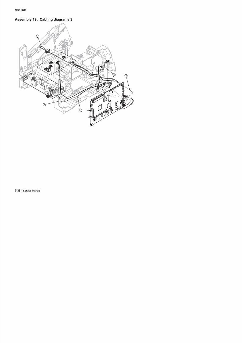
8/13/2019 t644 Service Manual
http://slidepdf.com/reader/full/t644-service-manual 354/423
4061-xx0
Assembly 19: Cabling diagrams 3
Asm-Index
Partnumber
Units/mach
Units/ kitor pkg
Description
19—1 40X0034 1 1 Signature button contact assembly with cable
2 40X0156 1 1 Bottom/front autoconnect cable assembly
3 40X0223 1 1 HVPS/input sensor/toner sensor cable assembly
4 40X0157 1 1 Top autoconnect cable assembly
5 40X0224 1 1 LVPS to system board cable assembly
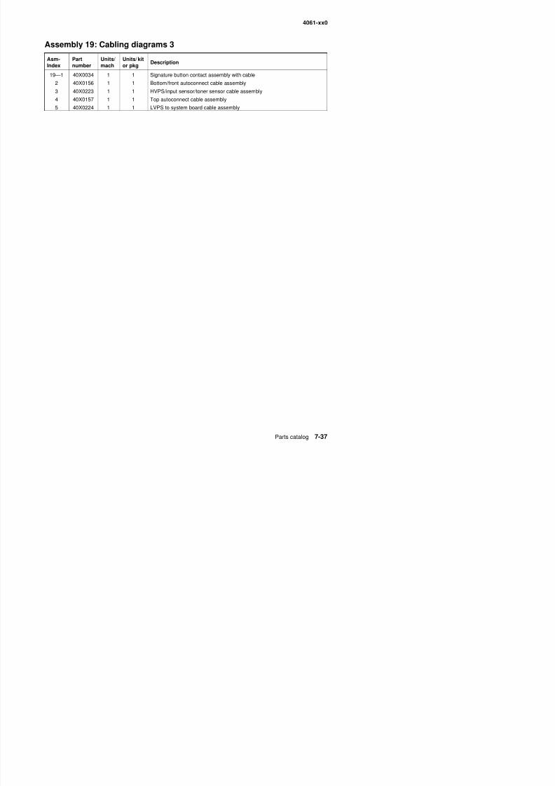
8/13/2019 t644 Service Manual
http://slidepdf.com/reader/full/t644-service-manual 355/423
4061-xx0
Assembly 20: Cabling diagrams 4
34
2
1
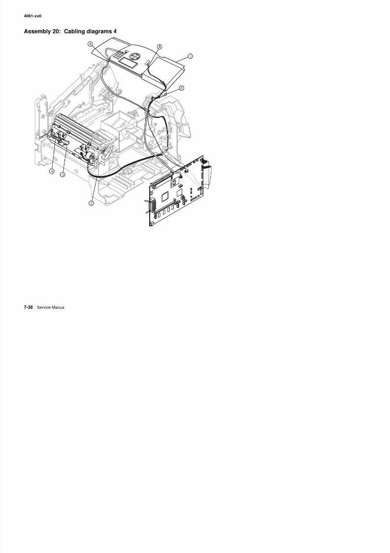
8/13/2019 t644 Service Manual
http://slidepdf.com/reader/full/t644-service-manual 356/423
4061-xx0
Assembly 20: Cabling diagrams 4
Asm-Index
Partnumber
Units/mach
Units/ kitor pkg
Description
20—1 40X0006 1 1 Upper front cover hinge assembly, includes:
• USB cable (A) (1)• Operator panel cable (B) (1)• Cover open switch/cable (C) (1)
2 40X0162 1 1 System board to fuser board cable assembly
3 40X0163 1 1 Fuser AC lamp to LVPS cable assembly
4 40X0226 1 1 Fuser connector (fuser AC to fuser lamp)
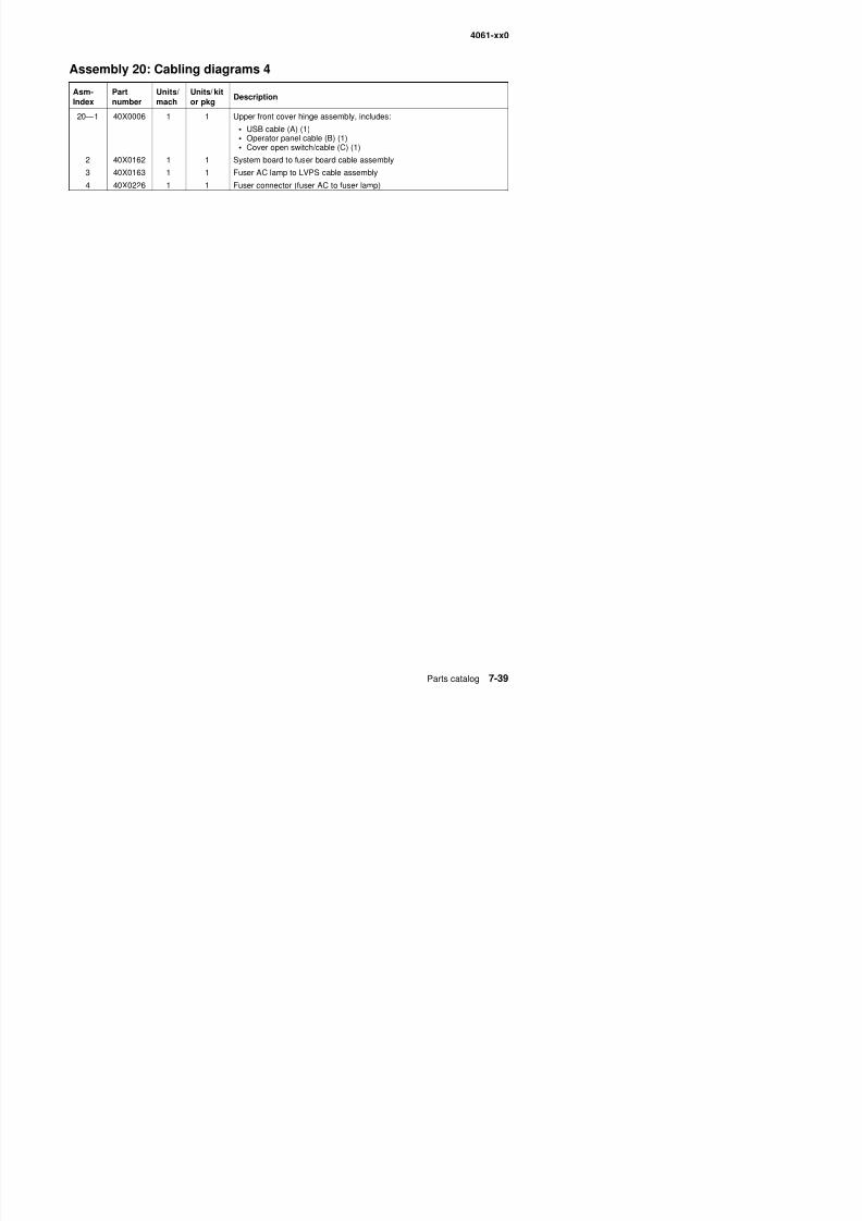
8/13/2019 t644 Service Manual
http://slidepdf.com/reader/full/t644-service-manual 357/423
4061-xx0
Assembly 21: Cabling diagrams 5
1
2
3
3
3
4
5
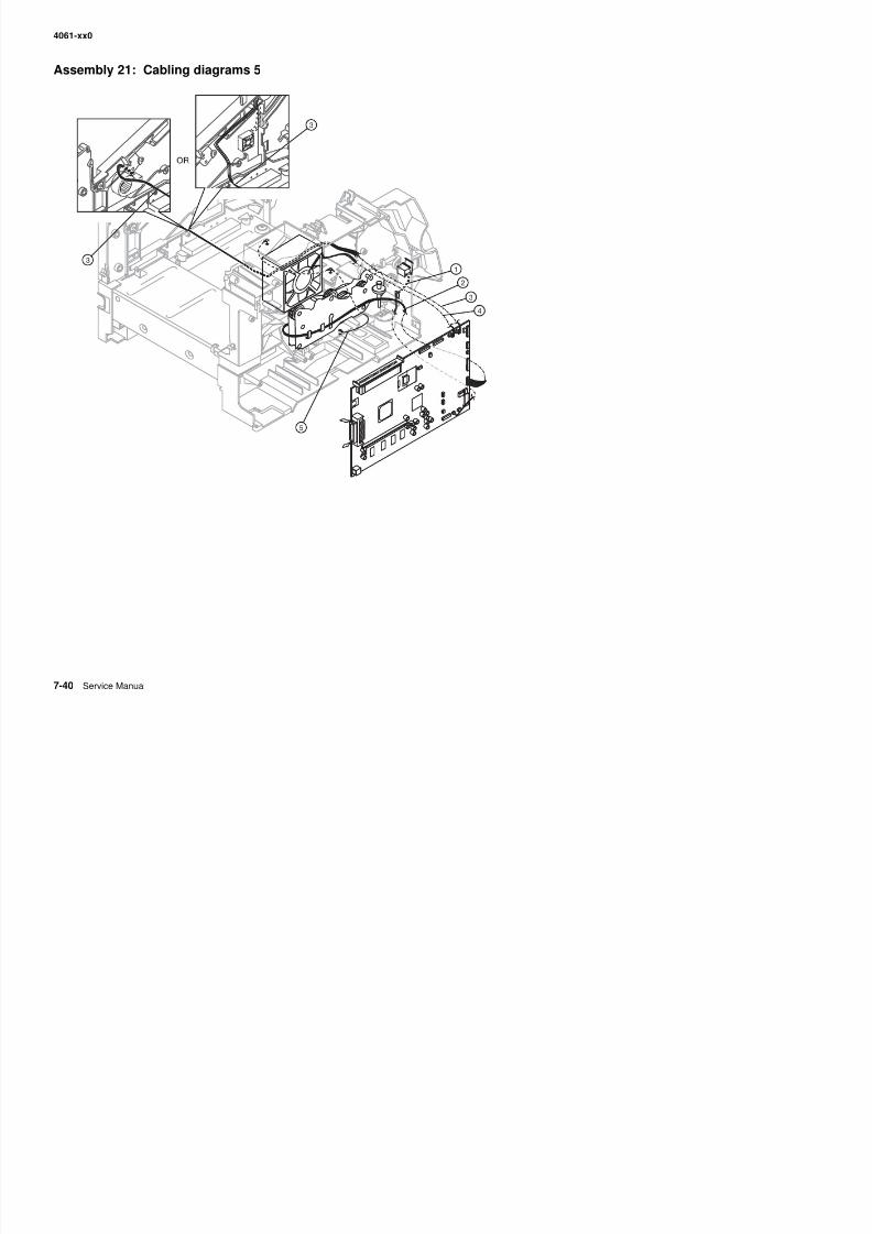
8/13/2019 t644 Service Manual
http://slidepdf.com/reader/full/t644-service-manual 358/423
4061-xx0
Assembly 21: Cabling diagrams 5
Asm-Index
Partnumber
Units/mach
Units/ kitor pkg
Description
21—1 40X0083 1 1 Frame assembly with solenoid and cable
2 40X0159 1 1 Main drive motor cable assembly
3 40X0035 1 1 EP fan with cable—250 sheet, 000/010
3 40X0249 1 1 EP fan with cable—500 sheet, 200/210/400/410
4 40X0053 1 1 Main fan, 250 sheet
4 40X0054 1 1 Main fan, 500 sheet
5 40X0161 1 1 Ground cable
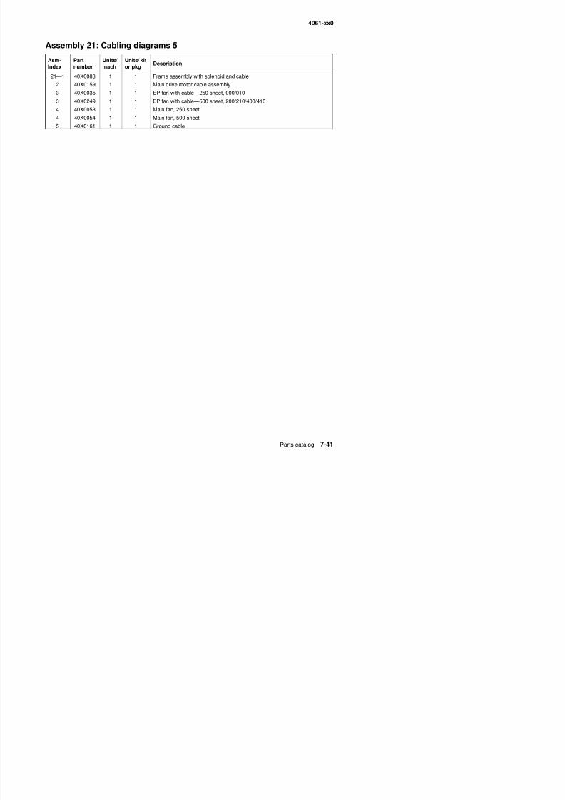
8/13/2019 t644 Service Manual
http://slidepdf.com/reader/full/t644-service-manual 359/423
4061-xx0
Assembly 22: Optional 250-sheet paper drawer
Asm-Index
Partnumber
Units/option
Units/ kitor pkg
Description
22—1 40X3230 1 1 250-sheet paper drawer, complete assembly
2 1 1 Parts packet, screw (switch spring) (PP 99A0263)3 99A0063 1 1 Switch activate spring
4 56P4129 1 1 Paper out arm—250-sheet
3
5
9
2
10
6
4
1
13
12
11
7
8
5
14
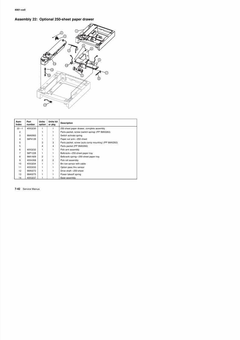
8/13/2019 t644 Service Manual
http://slidepdf.com/reader/full/t644-service-manual 360/423
4 56P4129 1 1 Paper out arm 250 sheet
5 3 3 Parts packet, screw (auto comp mounting) (PP 99A0263)
5 4 4 Parts packet (PP 99A0263)
6 40X3232 1 1 Pick arm assembly
7 56P1228 1 1 Bellcrank—250-sheet paper tray
4061-xx0
Assembly 23: Optional 250-sheet paper tray
Asm-Index
Partnumber
Units/option
Units/ kitor pkg
Description
23—1 40X3231 1 1 Tray assembly, option—250-sheet
2 40X3235 1 1 Side restraint—250-sheet tray
3 56P1279 1 4 Wear strips4 56P4230 1 1 Clip—250-sheet pass thru
5 99A0121 1 1 Pl t 250 h t t
3
7
5
2
6
1
4
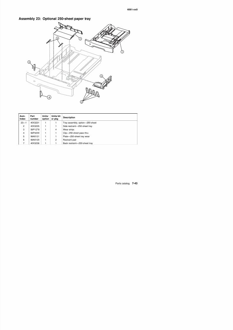
8/13/2019 t644 Service Manual
http://slidepdf.com/reader/full/t644-service-manual 361/423
5 99A0121 1 1 Plate—250-sheet tray wear
6 99A0120 1 2 Restraint pad
7 40X3236 1 1 Back restraint—250-sheet tray
4061-xx0
Assembly 24: Optional 500-sheet paper drawer
Asm-Index
Partnumber
Units/option
Units/ kitor pkg
Description
24—1 40X3243 1 1 Drawer and tray assembly, complete—500-sheet option
2 3 3 Parts packet (auto comp mounting screw) (PP 99A0263)3 40X3246 1 1 Pick arm assembly—500 sheet
4 56P1228 1 1 Bellcrank spring arm
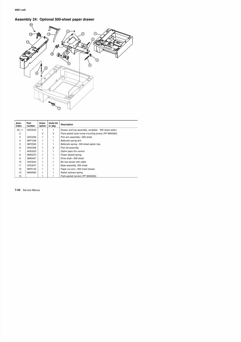
8/13/2019 t644 Service Manual
http://slidepdf.com/reader/full/t644-service-manual 362/423
4 56P1228 1 1 Bellcrank spring arm
5 56P2540 1 1 Bellcrank spring—500-sheet option tray
6 40X4308 1 2 Pick roll assembly
7 40X3233 1 1 Option pass thru sensor
8 99A0275 1 1 Power takeoff spring
4061-xx0
Assembly 25: Optional 500-sheet paper tray
Asm-
Index
Part
number
Units/
option
Units/ kit
or pkg
Description
25—1 40X4663 1 1 Tray assembly—500-sheet
2 56P4137 1 1 Side restraint—500-sheet tray
1
3
7
4
6
2
5
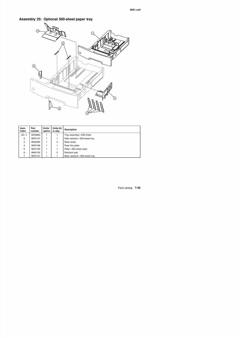
8/13/2019 t644 Service Manual
http://slidepdf.com/reader/full/t644-service-manual 363/423
3 99A0292 1 4 Wear strips
4 56P4196 1 1 Pass thru plate
5 56P4195 1 1 Plate—500-sheet wear
6 99A0120 1 2 Restraint pad
4061-xx0
Assembly 26: Duplex option
Asm-Index Partnumber Units/option Units/ kitor pkg Description
26—1 56P4100 1 1 Duplex assembly.—250-sheet
1 56P4102 1 1 Duplex assembly—500-sheet
1
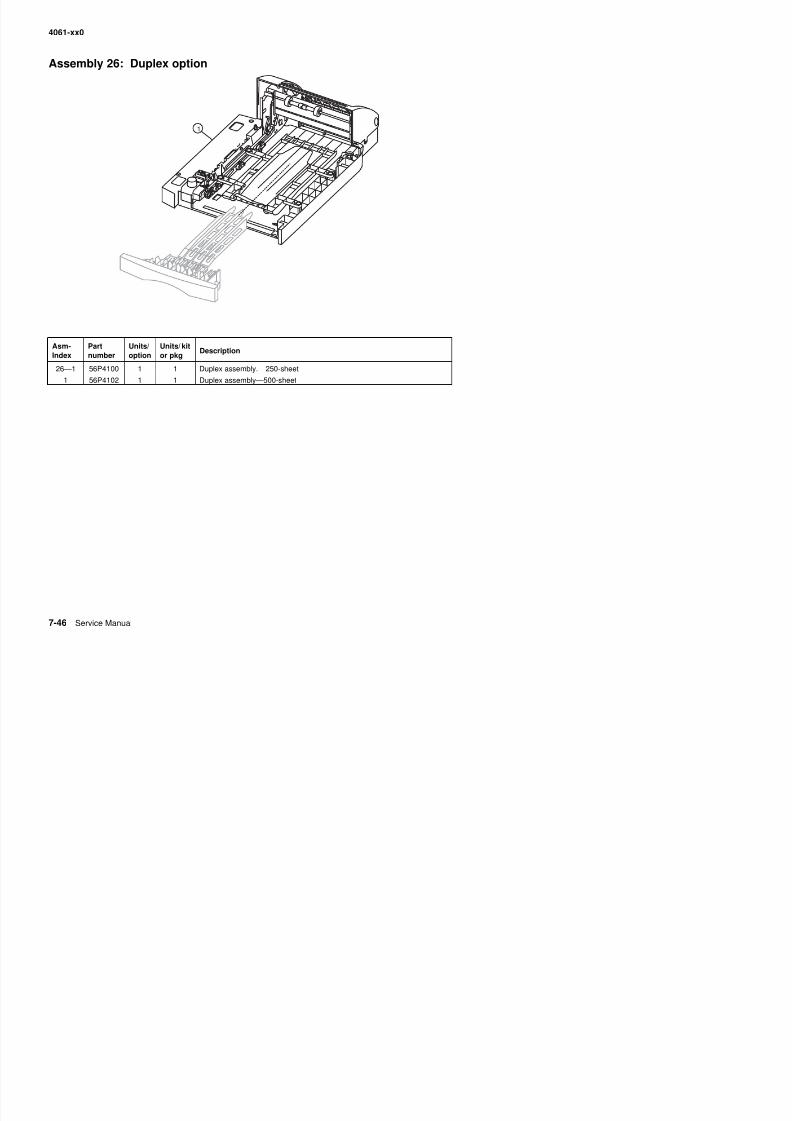
8/13/2019 t644 Service Manual
http://slidepdf.com/reader/full/t644-service-manual 364/423
4061-xx0
Assembly 27: Envelope feeder
Asm-Index
Partnumber
Units/option
Units/ kitor pkg
Description
27—1 40X3248 1 1 Complete envelope option
1

8/13/2019 t644 Service Manual
http://slidepdf.com/reader/full/t644-service-manual 365/423
4061-xx0
Assembly 28: Output expander 1
3
5
2
1
3
3
3
6
4
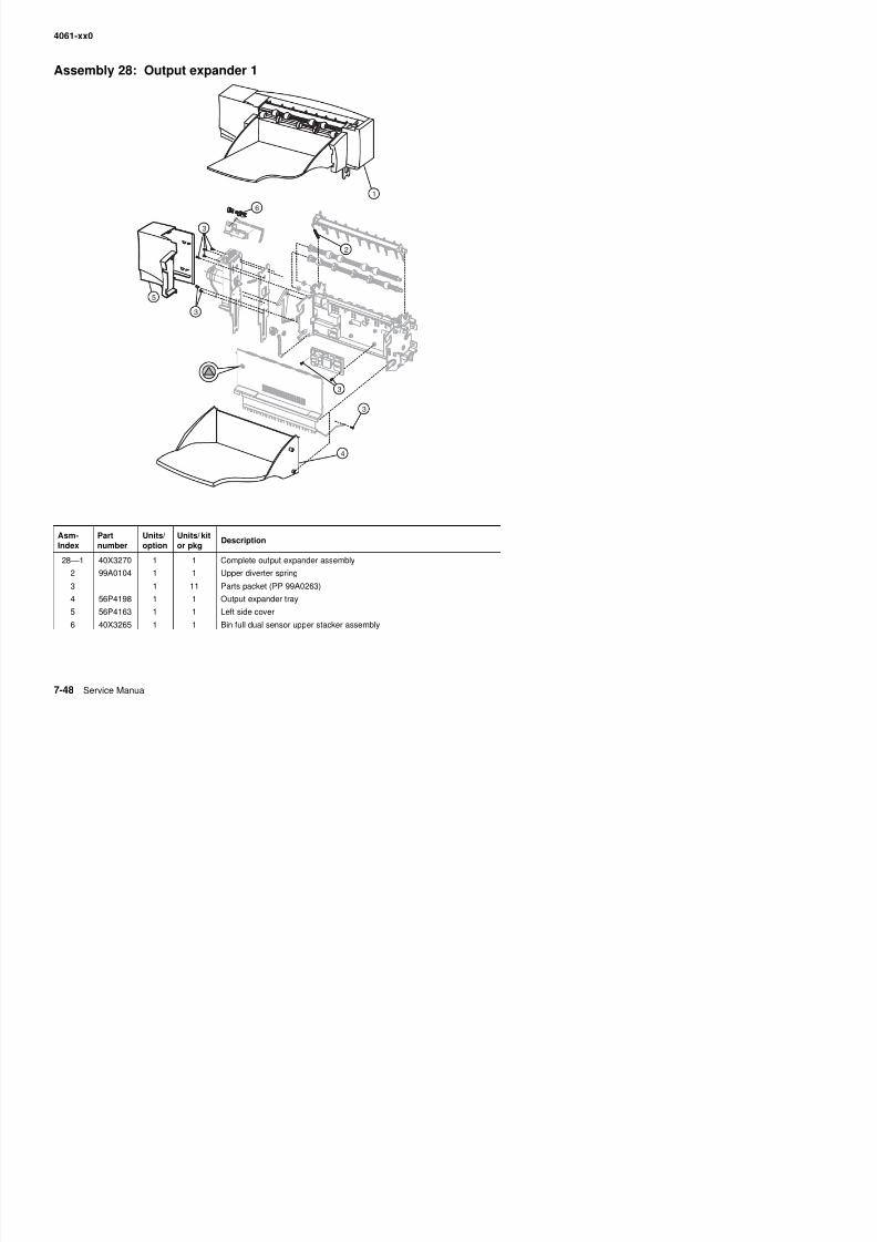
8/13/2019 t644 Service Manual
http://slidepdf.com/reader/full/t644-service-manual 366/423
Asm-Index
Partnumber
Units/option
Units/ kitor pkg
Description
28—1 40X3270 1 1 Complete output expander assembly
4061-xx0
Assembly 29: Output expander 2
Asm-Index
Partnumber
Units/option
Units/ kitor pkg
Description
29—1 40X3267 1 1 Rear access door assembly2 56P4235 1 1 Right side cover
3 Parts packet, screw (PP 99A0263)
3
2
4
1
3
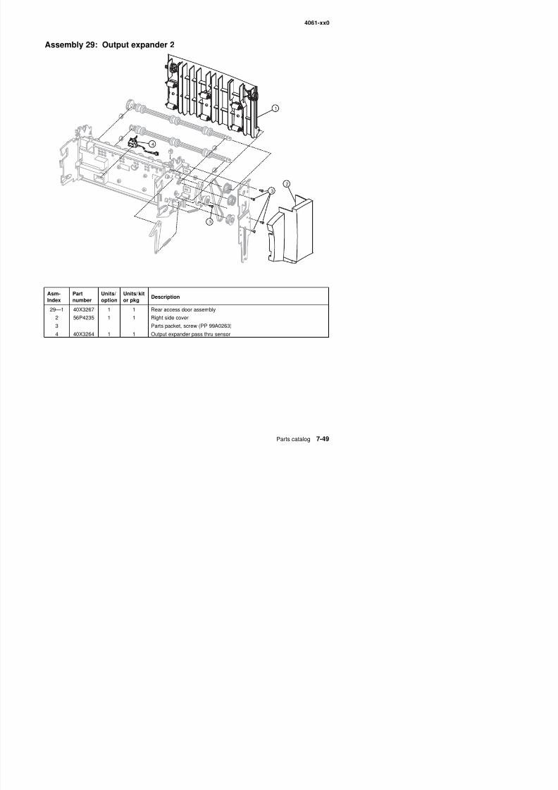
8/13/2019 t644 Service Manual
http://slidepdf.com/reader/full/t644-service-manual 367/423
4 40X3264 1 1 Output expander pass thru sensor
4061-xx0
Assembly 30: High-capacity output expander 1
Asm-I d
Partb
Units/i
Units/ kitk
Description
56
1
8
2
3
3
2
3
3
4
7
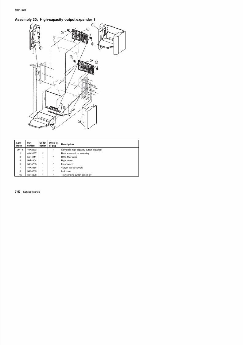
8/13/2019 t644 Service Manual
http://slidepdf.com/reader/full/t644-service-manual 368/423
Index number option or pkgDescription
30—1 40X3263 1 Complete high-capacity output expander
2 40X3267 2 1 Rear access door assembly
3 56P4211 4 1 R d l t h
4061-xx0
Assembly 31: High-capacity output expander 2
Asm-Index
Partnumber
Units/option
Units/ kitor pkg
Description
31—1 99A0104 2 1 Upper diverter spring
2 99A0415 1 1 Swing arm spring
3 31 Parts packet (PP 99A0263)
4 56P4212 1 1 Bin full dual sensor upper stacker assembly flag
5 40X3265 1 1 Bin full dual sensor upper stacker assembly
NS 56P4210 2 1 Output spring
3
5
2
4
1
3
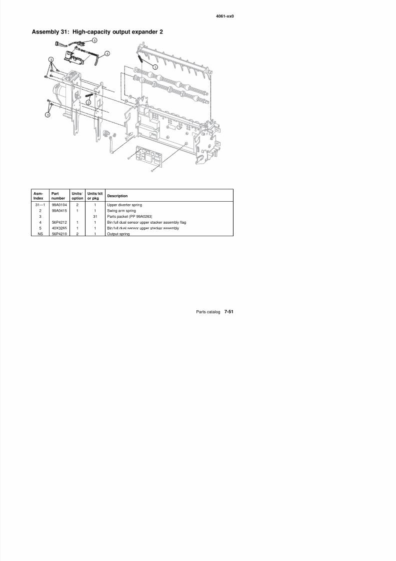
8/13/2019 t644 Service Manual
http://slidepdf.com/reader/full/t644-service-manual 369/423
4061-xx0
Assembly 32: High-capacity output expander 3
1
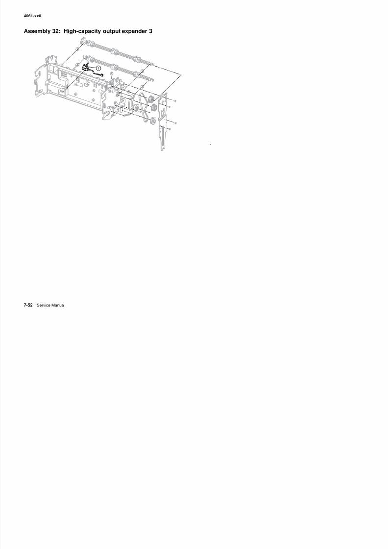
8/13/2019 t644 Service Manual
http://slidepdf.com/reader/full/t644-service-manual 370/423
4061-xx0
Assembly 32: High-capacity output expander 3
Asm-Index
Partnumber
Units/option
Units/ kitor pkg
Description
32—1 40X3264 2 1 Stacker pass thru sensor
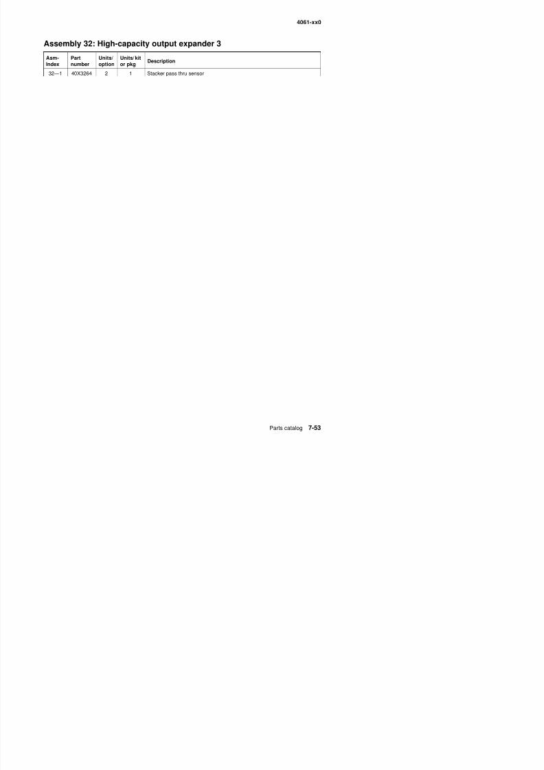
8/13/2019 t644 Service Manual
http://slidepdf.com/reader/full/t644-service-manual 371/423
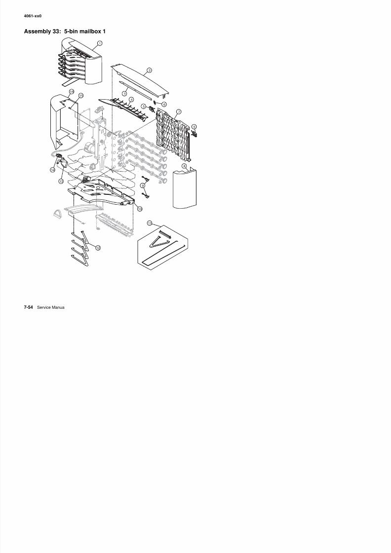
8/13/2019 t644 Service Manual
http://slidepdf.com/reader/full/t644-service-manual 372/423
4061-xx0
Assembly 33: 5-bin mailbox 1
Asm-Index
Partnumber
Units/option
Units/ kitor pkg
Description
33—1 40X3238 1 Complete 5-bin mailbox option
2 56P4176 1 1 Redrive cap cover
3 56P4180 1 1 Wire cover
4 56P4181 1 1 Top bin cover
5 56P4211 2 2 Rear access door latch
6 99A0104 1 1 Upper diverter spring
7 56P4183 1 1 Rear access door
8 56P4178 1 1 Right side cover
9 40X3242 2 1 5-bin mailbox pass thru sensor
10 56P4182 5 1 Paper cap tray
11 56P4191 1 1 5-bin mailbox assembly kit
12 1 1 5-bin mailbox assembly kit, order 56P4191
13 56P4186 5 1 Bin full flag
14 40X3240 5 1 Dual paper height sensor15 Parts packet (board mounting screw) (PP 99A0263)
16 56P4179 1 1 Left side cover
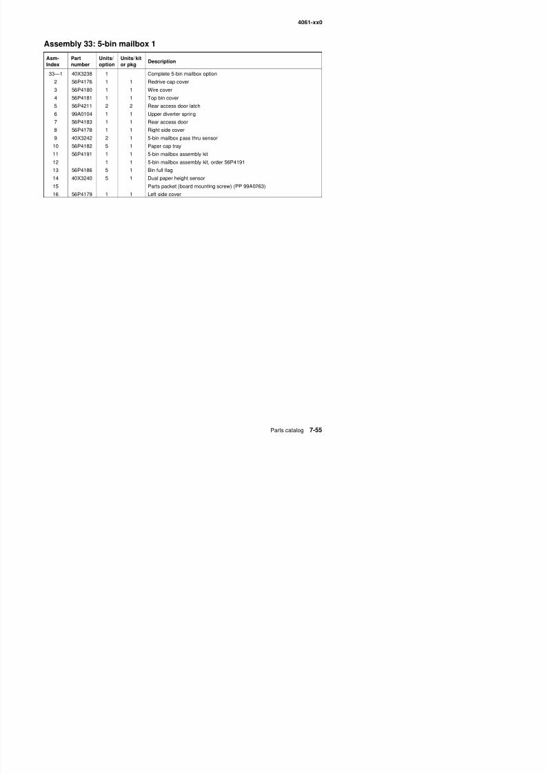
8/13/2019 t644 Service Manual
http://slidepdf.com/reader/full/t644-service-manual 373/423
4061-xx0
Assembly 34: 5-bin mailbox 2
2 1
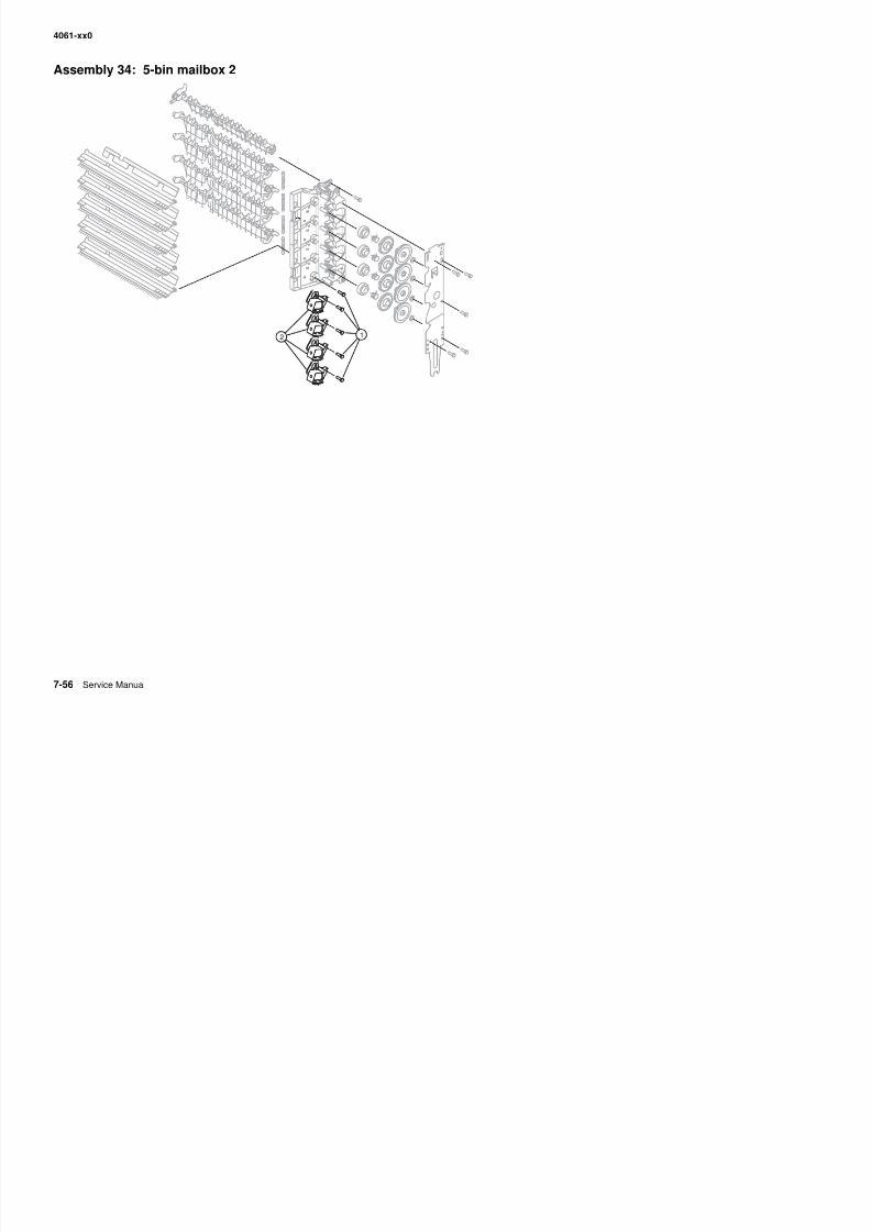
8/13/2019 t644 Service Manual
http://slidepdf.com/reader/full/t644-service-manual 374/423
4061-xx0
Assembly 34 (cont.): 5-bin mailbox 2
Asm-Index
Partnumber
Units/option
Units/ kitor pkg
Description
34—1 12 Parts packet (board mounting screw) (PP 99A0263)
2 40X2061 4 1 Diverter solenoid

8/13/2019 t644 Service Manual
http://slidepdf.com/reader/full/t644-service-manual 375/423
4061-xx0
Assembly 35: High-capacity feeder 1
2
5
3
67
8
1
4
9
10
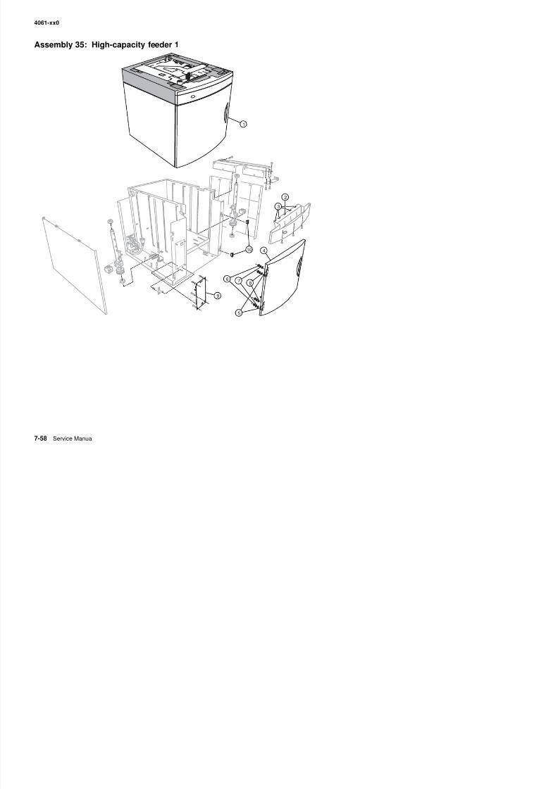
8/13/2019 t644 Service Manual
http://slidepdf.com/reader/full/t644-service-manual 376/423
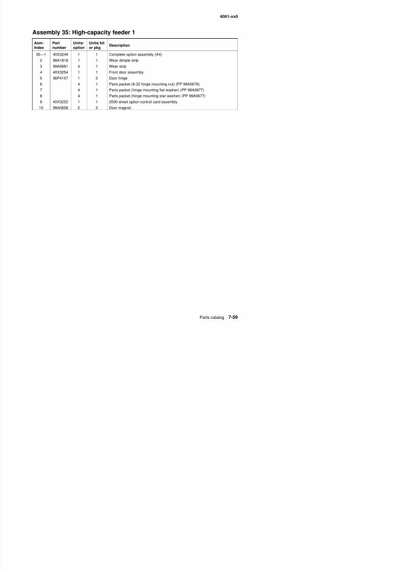
8/13/2019 t644 Service Manual
http://slidepdf.com/reader/full/t644-service-manual 377/423
4061-xx0
Assembly 36: High-capacity feeder 2
3
12
4
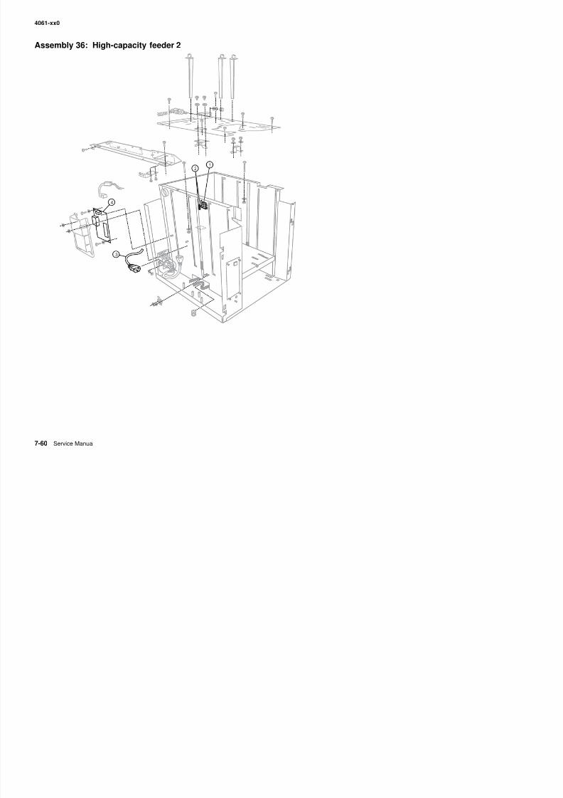
8/13/2019 t644 Service Manual
http://slidepdf.com/reader/full/t644-service-manual 378/423
4061-xx0
Assembly 36: High-capacity feeder 2
Asm-Index
Partnumber
Units/option
Units/ kitor pkg
Description
36—1 99A0654 1 1 Paper low switch
2 Parts packet (nuts) (PP 99A0676)
3 40X3262 1 1 AC external jumper cord
4 40X2669 1 1 Power supply board
8/13/2019 t644 Service Manual
http://slidepdf.com/reader/full/t644-service-manual 379/423
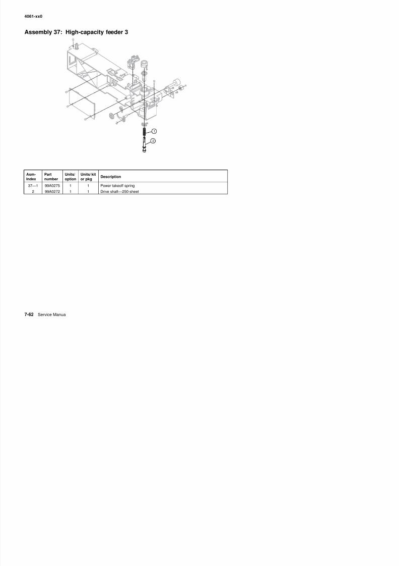
8/13/2019 t644 Service Manual
http://slidepdf.com/reader/full/t644-service-manual 380/423
4061-xx0
Assembly 38: High-capacity feeder 4
Asm-Index
Partnumber
Units/option
Units/ kitor pkg
Description
38—1 3 Parts packet (auto comp assembly mounting screw) (PP 99A0263)
2 40X3255 1 1 Pick arm assembly—2000-sheet
3 40X4308 2 2 Pick roll assembly
4 40X3233 1 1 Option pass thru sensor
3
2
4
1
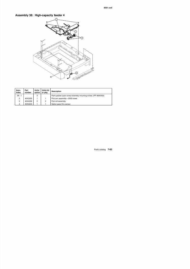
8/13/2019 t644 Service Manual
http://slidepdf.com/reader/full/t644-service-manual 381/423
4061-xx0
Assembly 39: Kiosk—vertical and horizontal paper adapters
2
1
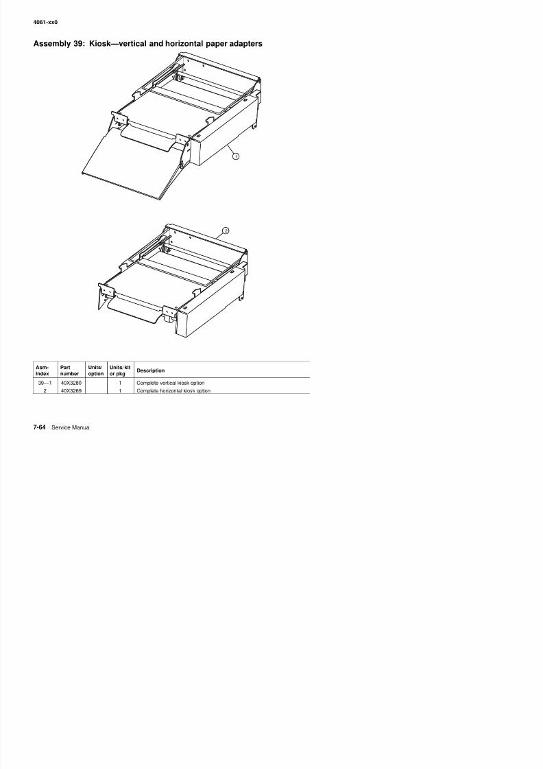
8/13/2019 t644 Service Manual
http://slidepdf.com/reader/full/t644-service-manual 382/423
4061-xx0
Assembly 40: StapleSmart finisher I
Asm-Index
Partnumber
Units/option
Units/ kitor pkg
Description
40—1 40X3273 1 Complete option
2 40X3276 1 1 Rear access door
3 56P4211 2 1 Rear access door latch
4 56P4214 1 1 Right base assembly cover5 56P4216 1 1 Stapler access cover
6 40X3274 1 1 Stapler access door switch assembly
7 40X3277 1 1 Output assembly tray
8 40X1816 1 1 Stacking bail kit
3
7
5
9
2
10
6
4
8
1
3
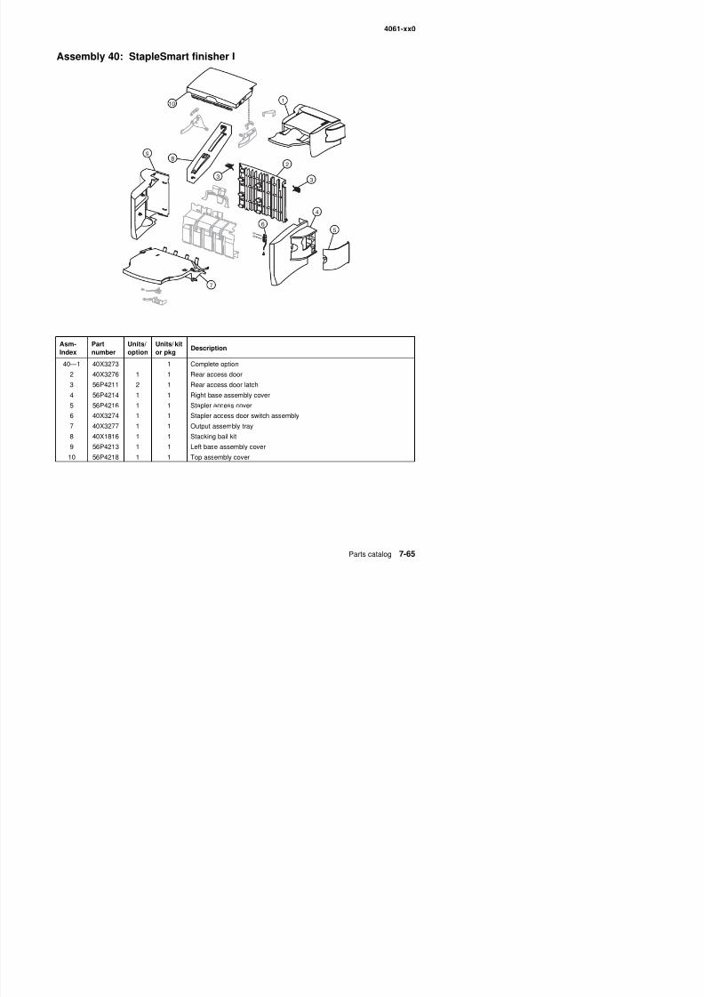
8/13/2019 t644 Service Manual
http://slidepdf.com/reader/full/t644-service-manual 383/423
8 40X1816 1 1 Stacking bail kit
9 56P4213 1 1 Left base assembly cover
4061-xx0
Assembly 41: StapleSmart finisher 2
Asm-Index
Partnumber
Units/option
Units/ kitor pkg
Description
41—1 40X3278 1 1 Stapler assembly
1
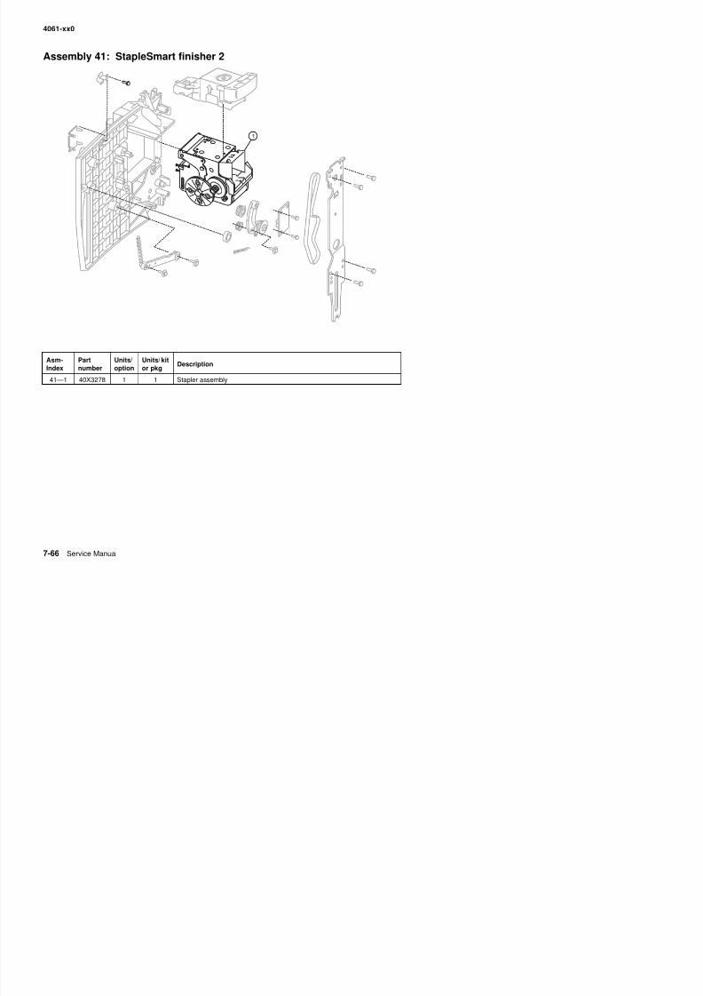
8/13/2019 t644 Service Manual
http://slidepdf.com/reader/full/t644-service-manual 384/423
4061-xx0
Assembly 42: StapleSmart finisher 3
Asm-Index
Partnumber
Units/option
Units/ kitor pkg
Description
42—1 40X3279 1 1 Switch assembly, top cover open
2
1
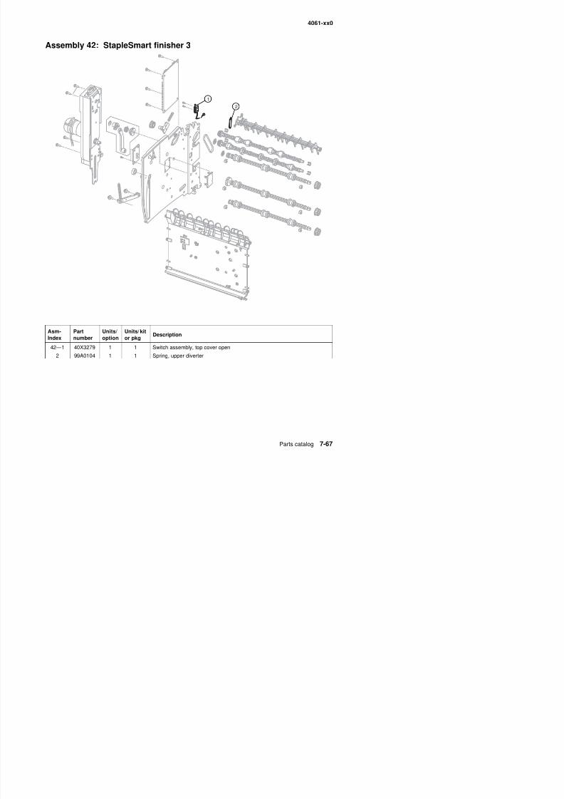
8/13/2019 t644 Service Manual
http://slidepdf.com/reader/full/t644-service-manual 385/423
2 99A0104 1 1 Spring, upper diverter
4061-xx0
Assembly 43: StapleSmart finisher 4
Asm-Index
Partnumber
Units/option
Units/ kitor pkg
Description
43—1 99A2480 1 1 StapleSmart wheels maintenance kit
1
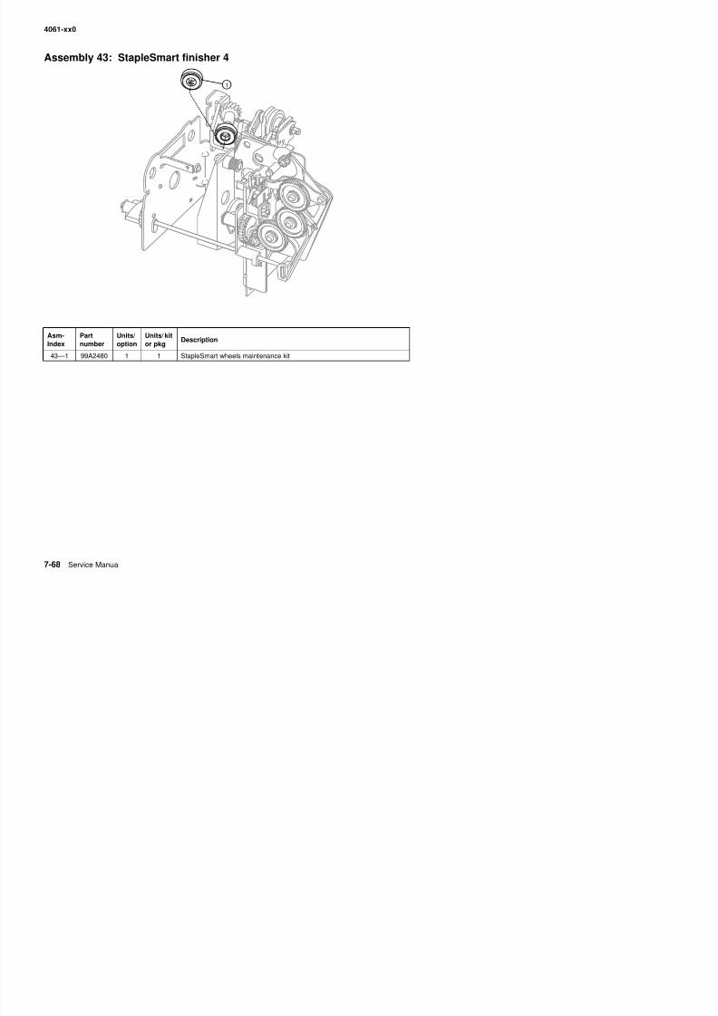
8/13/2019 t644 Service Manual
http://slidepdf.com/reader/full/t644-service-manual 386/423
4061-xx0
Assembly 44: Options
Asm-Index
Partnumber
Units/option
Units/ kitor pkg
Description
NS 40X1508 1 1 128MB memory option
NS 40X1509 1 1 256MB memory option
NS 40X1510 1 1 512MB memory option
NS 40X1564 1 1 32MB Flash card
NS 40X1565 1 1 64MB Flash card
NS 40X3212 1 1 Bar code card assembly
NS 40X3378 1 1 IPDS SCS/Tne card assembly
NS 40X0199 1 1 PrintCryption card assembly
NS 40X0252 1 1 9-pin to 9-pin cable assembly
NS 40X0250 1 1 9-pin to Twinax cable
NS 40X0251 1 1 9-pin to Coax (BNC) cable
NS 40X0265 1 1 PRESCRIBE card assembly
NS 40X0171 1 1 Cartridge shipping package, empty
NS 40X1375 1 1 MarkNet 8000 Fast EthernetNS 40X1376 1 1 MarkNet 8020 Gigabit Ethernet
NS 40X1377 1 1 MarkNet 8030 Fiber Ethernet
NS 40X1378 1 1 MarkNet 8050 wireless, US
NS 40X1562 1 1 MarkNet 8050 wireless, non-US
NS 40X0291 1 1 Parallel 1284-B interface card
NS 40X0290 1 1 RS232C serial interface card
NS 56P4116 1 1 Universal adjustable tray assembly—400-sheet
NS 40X3377 1 1 Forms card assembly
NS 40X1513 1 1 Simplified Chinese font card
NS 40X1514 1 1 Traditional Chinese font card
NS 40X1515 1 1 Korean font card
NS 40X1512 1 1 Japanese font card
NS 40X0179 1 1 Nyogel 744 grease packet
NS 7375084 1 1 Relocation kit—250/250-sheet printer
NS 7375085 1 1 Relocation kit—500/500-sheet printer
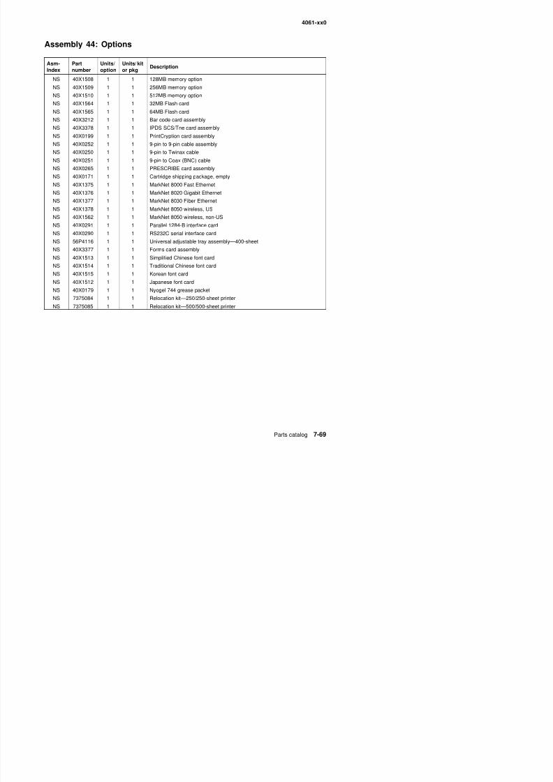
8/13/2019 t644 Service Manual
http://slidepdf.com/reader/full/t644-service-manual 387/423
4061-xx0

8/13/2019 t644 Service Manual
http://slidepdf.com/reader/full/t644-service-manual 388/423
4061-xx0
Appendix A—Options and features A
CAUTION: If you are installing memory or option cards sometime after setting up the printer, turn the printer offand unplug the power cord before continuing.
Installing input options
Order of instal lat ion
Floor-mounted configurations require additional furniture. You must use either a printer stand or printer base ifyou are using a 2000-sheet drawer, a duplex unit and an input option, or more than one input option. If youpurchased an MFP that scans, copies, and faxes, you may need additional furniture. More information isavailable on our Lexmark Web site at www.lexmark.com/multifunction printers.
Install the printer and any options you have purchased in the following order:
CAUTION: If you are installing options after setting up the printer, turn the printer off and unplug the power cordbefore continuing.
• Printer stand or printer base
• 2000-sheet drawer• 250-sheet or 500-sheet drawer• Duplex unit• Printer
CAUTION: The printer requires two people to lift it safely.
For information on installing a printer stand, printer base, or 2000-sheet drawer, see the instructions includedwith the option.
Instal l ing a 250-sheet o r 500-sheet dr awer
Optional drawers attach under the printer and optional duplex unit. The printer automatically recognizes anydrawer that is installed.
A drawer consists of a tray and a support unit. The 250-sheet drawer and the 500-sheet drawer are installed thesame way.
1. Remove the tray from the support unit. Remove all packing material and tape from both the support unit
and the tray.

8/13/2019 t644 Service Manual
http://slidepdf.com/reader/full/t644-service-manual 389/423
4061-xx0
2. Place the support unit on top of any previously installed drawers, or the table or printer cabinet where youplan to use the printer.
The tab (A), round peg (B), and square holes (C) on top of any drawer help you position the support unit sothe edges are aligned properly. Make sure the support unit is securely in place.
3. Attach another optional drawer, a duplex unit, or the printer.
You can attach a label to the trays to indicate the tray number.
A B C
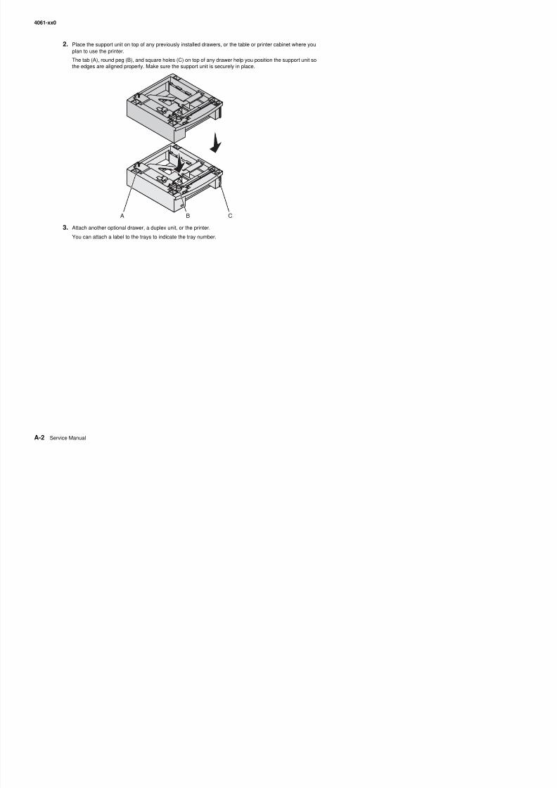
8/13/2019 t644 Service Manual
http://slidepdf.com/reader/full/t644-service-manual 390/423
4061-xx0
Instal l ing a dup lex uni t
The duplex unit attaches under the printer, below the standard tray and above any drawers.Note: Two optional duplex units are available. The 250-sheet duplex unit only works with printers that have a250-sheet standard tray, and the 500-sheet duplex unit only works with printers that have a 500-sheet standardtray. Make sure you have the appropriate duplex unit for the tray size installed in the printer.
1. Place the duplex unit on top of any installed drawers or the table or printer cabinet where you plan to usethe printer.
The tab (A), round peg (B), and square holes (C) on top of any drawer help you position the duplex unit sothe edges are aligned properly. Make sure it is securely in place.
A B C
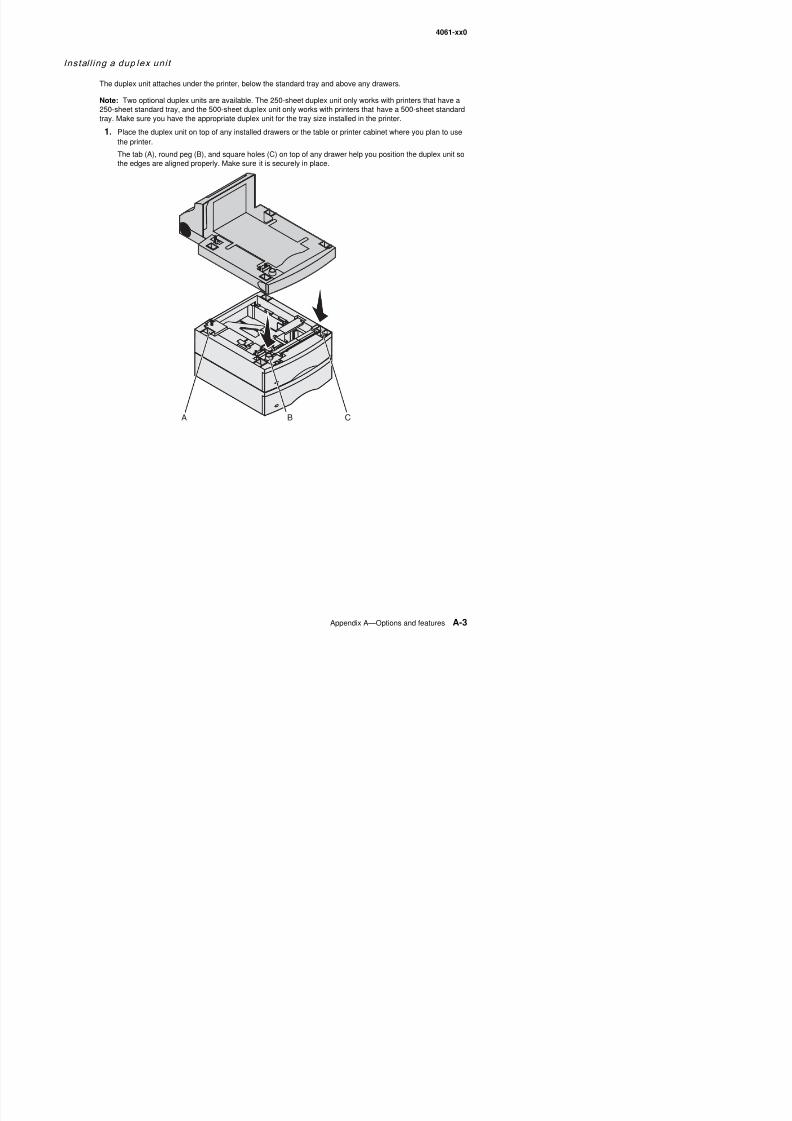
8/13/2019 t644 Service Manual
http://slidepdf.com/reader/full/t644-service-manual 391/423
4061-xx0
Installing memory or option cards
CAUTION: If you are installing memory or option cards sometime after setting up the printer, turn the printer offand unplug the power cord before continuing.
You can customize the printer memory capacity and connectivity by adding optional cards. The instructions inthis section help you install any of the following options:
• Memory cards – Printer memory – Flash memory
• Firmware cards – Bar Code – IPDS and SCS/TNe – PrintCryption
• Other options – Printer hard disk – RS-232 serial interface card – Parallel 1284-C interface card – MarkNet N8000 series internal print servers (also called internal network adapters or INAs)
8/13/2019 t644 Service Manual
http://slidepdf.com/reader/full/t644-service-manual 392/423
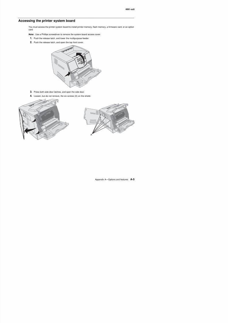
8/13/2019 t644 Service Manual
http://slidepdf.com/reader/full/t644-service-manual 393/423
4061-xx0
5. Slide the shield to the right, and then remove it.
6. Set the shield aside.
Use the illustration to locate the connector for the card you want to install.
Firmware card connector
Memory card connector
Option card connectors
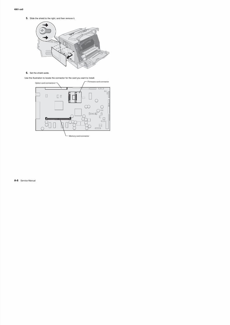
8/13/2019 t644 Service Manual
http://slidepdf.com/reader/full/t644-service-manual 394/423
4061-xx0
Removing or installing a memory card
Removal
1. Remove the system board access cover. (See “Accessing the printer system board” on page A-5.)
Warning: Printer memory cards are easily damaged by static electricity. Touch something metal such asthe printer frame before you touch a memory card.
2. Push the latches away from the card on both ends of the memory card connector.
The memory card moves out of the connector as the latches open.
3. Pull the memory card out of the connector.Avoid touching the connection points along the edge of the card.
4. Place the card into the original packaging.
If you do not have the original packaging, wrap the card in paper, and store it in a box.
5. Close both latches.
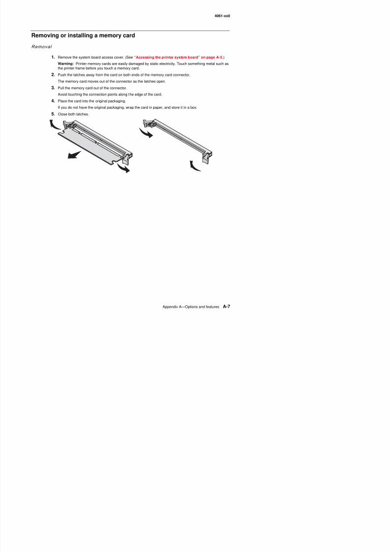
8/13/2019 t644 Service Manual
http://slidepdf.com/reader/full/t644-service-manual 395/423
4061-xx0
Instal lat ion
Note: Printer memory cards designed for other printers may not work with the printer.
1. Remove the system board access cover. (See “Accessing the printer system board” on page A-5.)
Warning: Printer memory cards are easily damaged by static electricity. Touch something metal such asthe printer frame before you touch a memory card.
2. Push open the latches (A) on both ends of the memory card connector.
3. Unpack the memory card.
Avoid touching the connection points along the edge of the card. Save the packaging.
4.Align the notches on the bottom of the card (B) with the notches on the connector (C).
5. Push the memory card firmly into the connector until the latches on either end of the connector snap intoplace.
It may require some force to fully seat the card.
6. Make sure each latch fits over the notch on the end of the card.
Removing or installing a flash memory or firmware card
Removal
1. Remove the system board access cover. (See “Accessing the printer system board” on page A-5.)
Note: If an option card has been installed, you may need to remove the option card before removing theflash memory or firmware card.
2. Squeeze the flash memory or firmware card locking clips.
3. Pull the card out.
AB
C
A
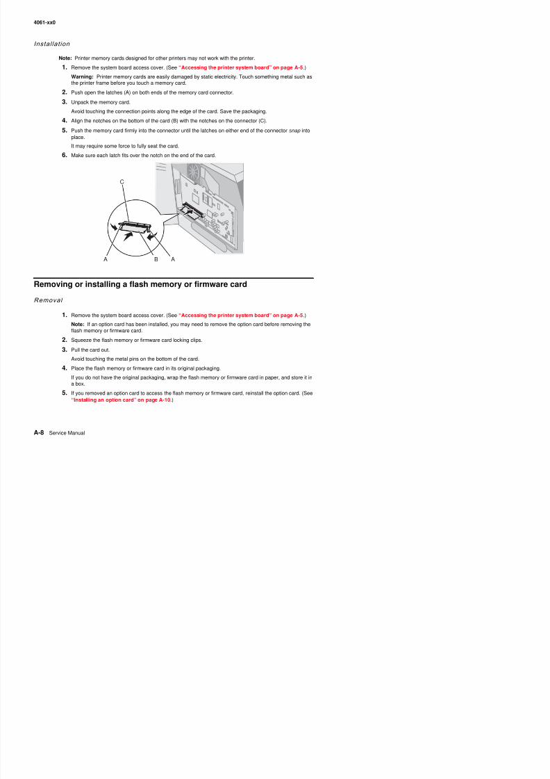
8/13/2019 t644 Service Manual
http://slidepdf.com/reader/full/t644-service-manual 396/423
4061-xx0
Instal lat ion
Note: Flash memory or firmware cards designed for other printers may not work with the printer.
1. Remove the system board access cover. (See “Accessing the printer system board” on page A-5.)
Note: If an option card has been installed, you may need to remove the option card before installing theflash memory or firmware card.
2. Unpack the flash memory or firmware card.
3. Holding the flash memory or firmware card (A) by the locking clips, align the plastic pins on the card withthe holes on the system board.
4. Push the flash memory or firmware card firmly into place, and release the locking clips.
The entire length of the connector (B) on the flash memory or firmware card must touch the system boardand be locked into the connector.
Be careful not to damage the connectors.
A B
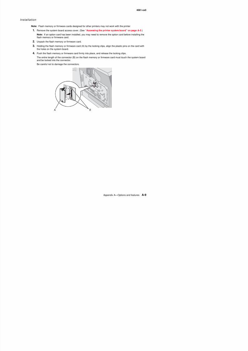
8/13/2019 t644 Service Manual
http://slidepdf.com/reader/full/t644-service-manual 397/423
4061-xx0
Installing an option card
The printer has two connectors that support the following option cards:
• Hard disk with adapter card• MarkNet N8000 series internal print server• RS-232 Serial Interface Card• Parallel 1284-B Interface Card• Coax/Twinax Adapter for SCS
Warning: Option cards are easily damaged by static electricity. Touch something metal such as the printerframe before you touch an option card.
1. Locate the card connectors on the system board.
2. Remove the screw (A) and the cover plate (B), and save them.
If you are installing a tall card, install it in connector 1. If you are installing two short cards on a model withmultiple connectors, use connector 1 first, and then use connector 2.
3. Unpack the card. Save the packaging materials.
4. Align the connection points on the card with the connector on the system board, and push the card firmlyinto the system board connector.
5. Insert the screw saved from the cover plate (or the extra screw shipped with the card).
6. Tighten the screw to secure the card.
A B
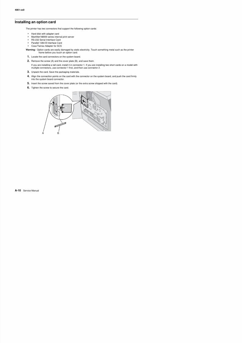
8/13/2019 t644 Service Manual
http://slidepdf.com/reader/full/t644-service-manual 398/423
4061-xx0
Replacing the shield
After you have installed options on the printer system board, follow these steps to reattach the shield and closethe doors.
1. Align the keyholes on the shield with the screws on the frame.
2. Slide the shield down onto the screws.
3. Tighten the six screws (A).
4. Close the side door.
5. Close the top front cover.
6. Close the multipurpose feeder.
Printing and using features
Cancel ing a print jo b
There are several methods for canceling a print job.
• Canceling a job from the printer operator panel. See “Canceling a job from the printer operator panel”on page A-12
• Canceling a job from a computer running Windows. See “Canceling a job from a computer running
Windows” on page A-12. – Canceling a job from the taskbar. – Canceling a job from the desktop
• Canceling a job from a Macintosh computer. See “Canceling a job from a Macintosh computer” onpage A-12. – Canceling a print job from a computer running Mac OS 9.– Canceling a job from a computer running Mac OS X
A
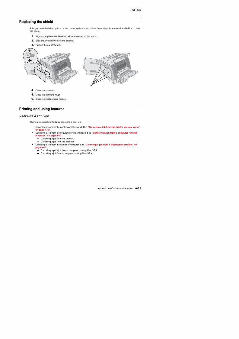
8/13/2019 t644 Service Manual
http://slidepdf.com/reader/full/t644-service-manual 399/423
4061-xx0
Canceling a job from the printer operator panel
If the job is formatting or already printing, and Cancel a Job appears on the first line of the display:
1. Press .
A list of jobs appears.
2. Press until appears next to the job requiring cancellation, and then press .
The message Canceling <filename> appears.
Note: Once a print job is sent, to easily cancel the job, press . The Stopped screen appears. Press
until Cancel a job appears, and then press .
Canceling a job from a computer running Windows
Canceling a job from the taskbar
When you send a job to print, a small printer icon appears in the right corner of the taskbar.
1. Double-click the printer icon.
A list of print jobs appears in the printer window.
2. Select the job you want to cancel.
3. Press the Delete key on the keyboard.
Canceling a job from the desktop
1. Minimize all programs to reveal the desktop.
2. Double-click the My Computer icon.
Note: If you do not have the My Computer icon, you can access the printers folder by selecting Start >
Settings > Control Panel, and then go to step 4.3. Double-click the Printers icon.
A list of available printers appears.
4. Double-click the printer you selected when you sent the job.
A list of print jobs appears in the printer window.
5. Select the job you want to cancel.
6. Press the Delete key on the keyboard.
Canceling a job from a Macintosh computer
Canceling a print job from a computer running Mac OS 9
When you send a job to print, the printer icon for your selected printer appears on the desktop.
1
8/13/2019 t644 Service Manual
http://slidepdf.com/reader/full/t644-service-manual 400/423
4061-xx0
Canceling a job from a computer running Mac OS X
When you send a job to print, the printer icon for your selected printer appears in the dock.
1. Open Applications > Utilities, and then double-click Print Center or Printer Setup.
2. Double-click the printer you are printing to.
3. In the printer window, select the print job you want to cancel.
4. Press Delete.
Print ing the menu sett ings page
You can print a menu settings page to review the default printer settings and to verify the printer options areinstalled correctly.
1. Make sure the printer is on.
2. Press on the operator panel.
3. Press until the appears next to Reports, and then press .
4. Press until the appears next to Menu Settings Page, and then press .
The printer returns to Ready after the page prints.
Print ing a netwo rk setup page
If the printer is attached to a network, print a network setup page on the printer to verify the network connection.This page also provides important information to configure the printer for network printing.
1. Make sure the printer is on.
2. Press on the operator panel.
3. Press until Reports appears, and then press .
4. Press until Network Setup Page appears, and then press .
Note: If an optional MarkNet™ N8000 series internal print server is installed, Print Net1 Setup appearson the display.
5. Check the first section on the network setup page, and confirm that Status is “Connected.”
If Status is “Not Connected,” the LAN drop may not be active, or the network cable may be malfunctioning.Consult a system support person for a solution, and print another network setup page to verify the printer isconnected to the network.
8/13/2019 t644 Service Manual
http://slidepdf.com/reader/full/t644-service-manual 401/423
4061-xx0
Print ing a font samp le lis t
To print samples of the fonts currently available for the printer:
1. Make sure the printer is on and the Ready message appears.
2. Press on the operator panel.
3. Press until the appears next to Reports, and then press .
4. Press until the appears next to Print Fonts, and then press .
5. Press until the appears next to PCL Fonts, PostScript Fonts, or PPDS Fonts, and then
press .The printer returns to Ready after the page prints.
Print ing a directory l is t
A directory listing shows the resources stored in flash memory or on the hard disk. To print a listing:
1. Make sure the printer is on and the Ready message appears.
2. Press on the operator panel.3. Press until the appears next to Reports, and then press .
4. Press until the appears next to Print Directory, and then press .
The printer returns to Ready after the page prints.
Print ing conf ident ia l and held jobs
The term held job refers to any type of print job that can be initiated by the user at the printer. This includes aconfidential job, a verify print job, a reserve print job, a repeat print job, a bookmark, a profile, or a file on a USBflash memory device. When sending a job to the printer, you can specify in the driver that you want the printer tohold the job in memory. Once your job is stored in printer memory, go to the printer, and use the printer operatorpanel to specify what you want to do with your print job.
All confidential and held jobs have a user name associated with them. To access confidential or held jobs, youmust first select the type of job (confidential or held), and then select your user name from the user name list.Once you select your user name, you can print all your confidential jobs or select an individual print job. You canthen choose the number of copies for the print job, or you can delete the print job.
Printing a confidential job
When you send a confidential job to the printer, you must enter a personal identification number (PIN) from thedriver. The PIN must be four digits using the numbers 0–9. The job is held in printer memory until you enter thesame four-digit PIN from the operator panel and choose to print or delete the job. This ensures the job does notprint until you are there to retrieve it. No one else using the printer can print the job without the PIN.
8/13/2019 t644 Service Manual
http://slidepdf.com/reader/full/t644-service-manual 402/423
4061-xx0
4. Enter a User Name and PIN.
5. Send your job to the printer.
Go to the printer when you are ready to retrieve your confidential print job, and follow the <color>At the printer steps.
Macintosh
1. From a word processor, spreadsheet, browser, or other application, select File > Print.
2. In the Copies & Pages or General pop-up menu, select Job Routing.
a. When using Mac OS 9, if Job Routing is not a choice on the pop-up menu, select Plug-inPreferences > Print Time Filters.
b. Turn down the disclosure triangle to the left of Print Time Filters, and select Job Routing.c. In the pop-up menu, select Job Routing.
3. In the radio group, select Confidential Print.
4. Enter a User Name and PIN.
5. Send your job to the printer.
Go to the printer when you are ready to retrieve your confidential print job, and follow the <color>At the printer steps.
At the printer
1. Press until the appears next to Held jobs, and then press .
2. Press until the appears next to your user name, and then press .
3. Press until the appears next to Confidential jobs, and then press .
4. Enter your PIN.
For more information, see “Entering a personal identification number (PIN)” on page A-15.
5. Press until the appears next to the job you want to print, and then press .
Note: After your job prints, it is deleted from printer memory.
Entering a personal identification number (PIN)
After you select your user name and Confidential Job, the Enter PIN screen appears.
1. Use the numeric pad to the right of the display to enter the four-digit PIN associated with your confidential job.
Note: As you enter the PIN, asterisks appear on the display to ensure confidentiality.
If you enter an invalid PIN, the Invalid PIN screen appears.
Press to reenter the PIN, or press until the appears next to Cancel, and then press .
2 P til th t t th j b t t i t d th
8/13/2019 t644 Service Manual
http://slidepdf.com/reader/full/t644-service-manual 403/423
4061-xx0
Printing and deleting held jobs
Held jobs (Verify Print, Reserve Print, or Repeat Print) are printed or deleted from the printer operator panel and
do not require a PIN number.
Verify Print
If you send a Verify Print job, the printer prints one copy and holds the remaining copies you requested in printermemory. Use Verify Print to examine the first copy to see if it is satisfactory before printing the remaining copies.Once all copies are printed, the Verify Print job is automatically deleted from printer memory.
Reserve Print
If you send a Reserve Print job, the printer does not print the job immediately. It stores the job in memory so youcan print the job later. The job is held in memory until you delete it from the Held Jobs menu. Reserve Print jobsmay be deleted if the printer requires extra memory to process additional held jobs.
Repeat Print
If you send a Repeat Print job, the printer prints all requested copies of the job and stores the job in memory soyou can print additional copies later. You can print additional copies as long as the job remains stored inmemory.
Note: Repeat Print jobs are automatically deleted from printer memory when the printer requires extra memory
to process additional held jobs.
Windows
1. From a word processor, spreadsheet, browser, or other application, select File > Print.
2. Click Properties. (If there is no Properties button, click Setup, and then click Properties.)
3. Depending on the operating system, you may have to click the Other Options tab, and then click Print and Hold.
Note: If you have difficulty finding Print and Hold > Held Jobs, click Help, and see the topic Held Jobs orPrint and Hold, then follow the driver instructions.
4. Select the type of held job you want, and then send your job to the printer.
Go to the printer when you are ready to retrieve your confidential print job, and follow the <color>At the printer steps.
Macintosh
1. From a word processor, spreadsheet, browser, or other application, select File > Print.
2. In the Copies & Pages or General pop-up menu, select Job Routing.
a. When using Mac OS 9, if Job Routing is not a choice on the pop-up menu, select Plug-inPreferences > Print Time Filters.
b. Turn down the disclosure triangle to the left of Print Time Filters, and select Job Routing.c. In the pop-up menu, select Job Routing.
3 In the radio group select the type of held job you want enter a user name and then send your job to the
8/13/2019 t644 Service Manual
http://slidepdf.com/reader/full/t644-service-manual 404/423
4061-xx0
At the printer
1. Press until the appears next to Held jobs, and then press .
2. Press until the appears next to your user name, and then press .
3. Press until the appears next to the type of action you want to perform, and then press .
If you selected Print A Job, Delete A Job, or Print Copies, press until the appears next to the job you
want, and then press .
The job will print or be deleted according to the type of print job and action you selected.
Linking trays
Tray linking enables the automatic linking feature for trays when you load the same size and type of print mediain multiple sources. The printer automatically links the trays; when one tray is empty, print media feeds from thenext linked tray.
For example, if you have the same size and type of print media loaded in tray 2 and tray 4, the printer selectsprint media from tray 2 until it becomes empty, and then the printer automatically feeds print media from the nextlinked tray—tray 4.
By linking all trays (standard and optional), you effectively create a single source with a capacity of up to 4,100
sheets.
Make sure you load the same size and type of print media in each tray in order to link the trays.
Set the paper size and type for each tray, to set the paper type or size:
1. Press on the operator panel.
2. Press until the appears next to Paper Menu, and then press .
3. Press until the appears next to Paper Size/Type, and then press .
4. Press until the appears next to Tray <x> Si ze/Type, and then press .
5. Press until the appears next to the paper size you loaded, and then press .
6. Press until the appears next to Tray <x> Size/Type, and then press .
7 Press until the appears next to the paper type you loaded and then press
Print All Delete All
Print A Job Delete A Job
Print Copies
8/13/2019 t644 Service Manual
http://slidepdf.com/reader/full/t644-service-manual 405/423
4061-xx0
Ident i fy ing and l ink ing outpu t bins
There is one standard output bin on all printer models. Depending on the model you selected, your output bin
capacity is 250 or 500 sheets. If you need additional output capacity, there are several optional output binsavailable for your printer.
If you have multiple output bins, you can link them into a single output source. Linking output bins lets the printerautomatically switch output to the next available bin.
Output bins available
The following table provides information on standard and optional output bin capability and connectivity.
Note: Not all output bins support every paper and envelope size.
Output bins
Outputbin name
Each bin accommodates How manycan beinstalled onthe printer
Bin isallowed toconnect with
Illustration of output binPrint media
PrinterModels
Standard
bin
• 250 sheets
(75 g/m2
) of plainpaper• 150 transparencies• 100 labels• 25 envelopes
(75 g/m2)
T640 N/A—one is
standard onthe printerand locatedon top of theprinter
Any of the
options incombinationsas follows inthis column
Standardbin
• 500 sheets(75 g/m2) of plainpaper
• 300 transparencies• 200 labels• 50 envelopes
(75 g/m2)
T642T644
Finisher Sheets of 75 g/m2 of plainpaper (maximum numberof stapled jobs is 40)
T640 500 sheetsT642 750 sheetsT644 750 sheets
T640T642T644
1 1 outputexpanderor 1 5-binmailbox *
High-capacityoutputstacker
• 1850 sheets(75 g/m2) of plainpaperE l ( it
T640T642T644
1 1 outputexpander *
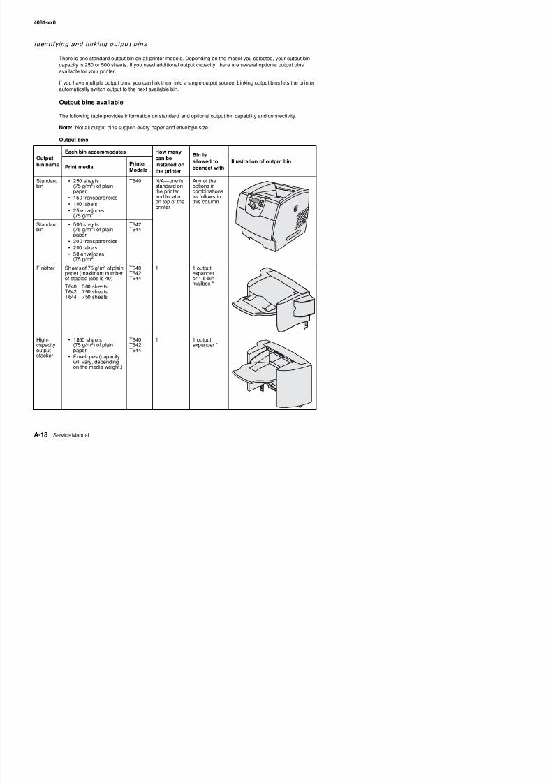
8/13/2019 t644 Service Manual
http://slidepdf.com/reader/full/t644-service-manual 406/423
4061-xx0
Outputexpander
• 650 sheets(75 g/m2) of plainpaper
• 50 envelopes(75 g/m 2)
T640T642T644
3 1 5-binmailbox, 1high-capacityoutput stacker,or 1 finisher *
5-binmailbox
120 sheets(75 g/m2) of plain paperfor each of the five binsfor a total of 600 for allbins
T642T644
2 1 outputexpander or1 finisher *
* See the Setup Guide for information on how to install options in relation to each other.
Output bins (continued)
Outputbin name
Each bin accommodates How many
can beinstalled onthe printer
Bin is
allowed toconnect with
Illustration of output binPrint media
PrinterModels
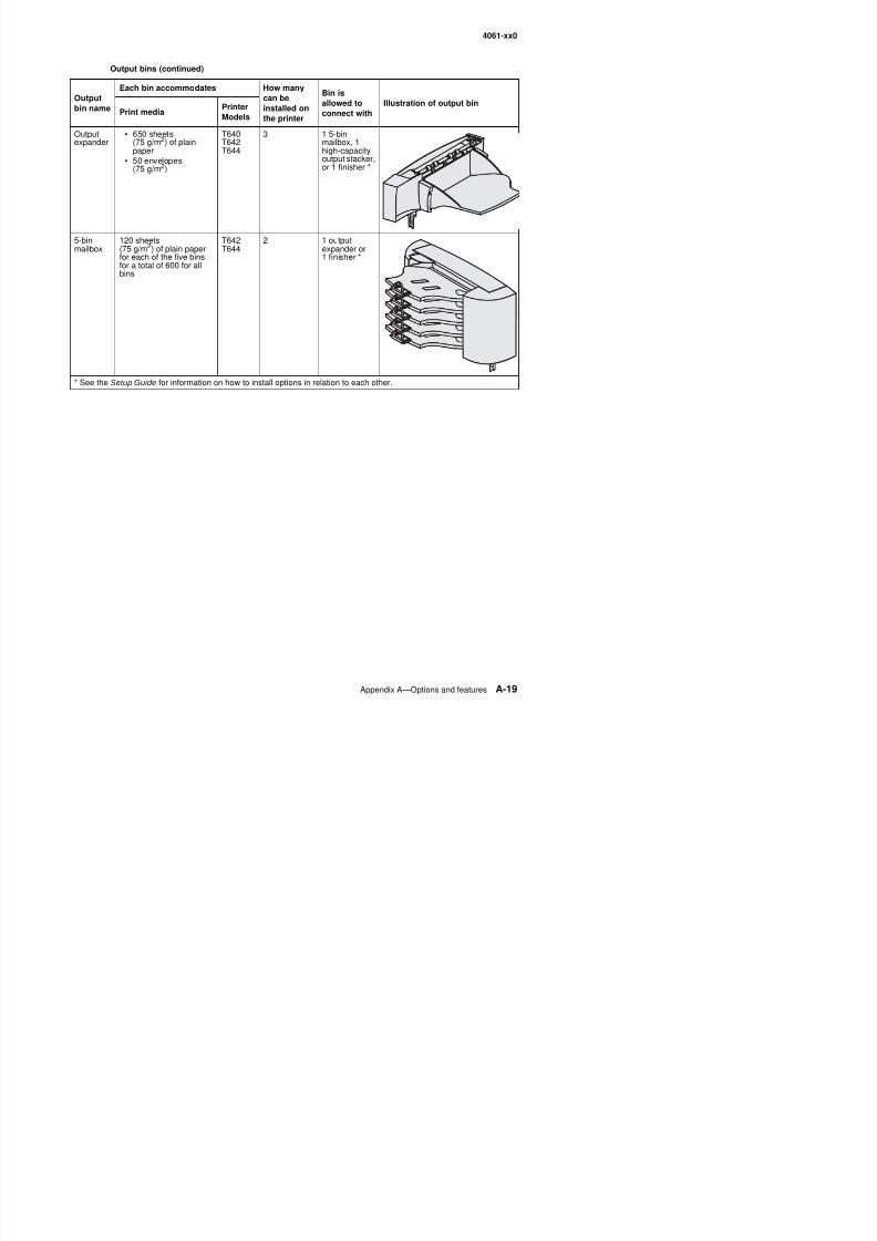
8/13/2019 t644 Service Manual
http://slidepdf.com/reader/full/t644-service-manual 407/423
4061-xx0
Link ing output b ins
Linking output bins lets you create a single output source so the printer can automatically switch output to the
next available bin. You can also set the output type for media such as card stock or envelope sizes that cannotbe sent to an optional output bin. For more information on the values available to configure your output bins,refer to the Menus and Messages Guide.
Note: The bin sequence for linking always starts with the Standard Bin and proceeds from the Bin nearest tothe floor to the Bin farthest from the floor.
To link output bins:
1. Press on the operator panel.
2. Press until the appears next to Paper Menu.
3. Press .
4. Press until the appears next to Bin Setup.
5. Press .
6. Press until the appears next to Configure Bins.
7. Press .
8. Press until the appears next to Link.
9. Press .
The printer returns to the Ready state.
8/13/2019 t644 Service Manual
http://slidepdf.com/reader/full/t644-service-manual 408/423
4061-xx0
Index
Numerics1565 Emul Error Load Emul Option 2-42250-sheet paper drawer, option 7-42250-sheet paper tray, integrated 7-18250-sheet paper tray, option
parts catalog 7-43service check 2-103
2 xx paper jam and paper handing errors 2-44
500-sheet paper drawer, option 7-44500-sheet paper tray, option
parts catalog 7-45service check 2-103
5-bin mailboxoutput sensor test 3-16parts catalog 7-54, 7-56service check 2-72
80 scheduled maintenance 6-1900.xx error code service check 2-75927.xx fan service check 2-76950.00 through 950.29 EPROM mismatch failure 2-77950.30 through 950.60 EPROM mismatch failure 2-789 xx Service error codes 2-8
Aacronyms 1-21adjustments
fuser solenoid 4-2gap adjustment 4-2paper alignment assembly 4-3printhead assembly 4-2
alignment assemblyadjustment 4-3parts catalog 7-16removal 4-70
autocompensator, integrated trayparts catalog 7-12pick roll installation 4-53
removal 4-50autoconnect connections, top 5-7automatic size sensing 8-17automatic tray linking 8-17
Bbevel gear
installation 4-23
upper front cover including buttons 7-3upper front panel button kit 7-3
Ccable diagrams 7-34, 7-35, 7-36, 7-38, 7-40CACHE Test 3-8canceling a print job 8-11Card Stock & Label Guide 1-9
card stock, guidelines 1-19cartridge duct, removal 4-24characteristics, print media 1-16code update 3-1confidential jobs 8-14
entering a PIN 8-14sending 8-14
Configuration ID 3-21configuration menu
accessing 3-1, 3-25
available menus 3-25Demo Mode 3-27Disk Encryption 3-28Download Emuls 3-27Energy Conserve 3-28Env Prompts 3-28EVENT LOG 3-28Factory Defaults 3-28Font Sharpening 3-29Jobs On Disk 3-28LCD Brightness 3-29LCD Contrast 3-29Maint Cnt Value 3-25Panel Menus 3-27Paper Prompts 3-28PPDS Emulation 3-27Prt Quality Pgs 3-26Reset Maint Cnt 3-26SIZE SENSING 3-27
configurations, models 1-3connector locations
autoconnect - top 5-7high voltage power supply (HVPS) 5-9high-capacity output stacker board 5-8interconnect card 5-9low voltage power supply (LVPS) 5-10output expander 5-11
8/13/2019 t644 Service Manual
http://slidepdf.com/reader/full/t644-service-manual 409/423
4061-xx0
Ddefaults
EP defaults 3-22
factory defaults 3-28US/Non-US defaults 3-20deflector
inner paper deflector assembly 4-48MPF lower paper deflector 4-62upper paper deflector assembly 4-80
developer drive assemblyparts 7-22removal 4-25
developer drive coupler kit 4-26diagnostics mode 3-2
accessing 3-1available tests 3-2BASE SENSOR TEST 3-18DEVICE TESTS
Disk Test/Clean 3-19Flash Test 3-19Quick Disk Test 3-18
DUPLEX TESTSDuplex Feed 1 3-12Duplex Feed 2 3-12Motor Test 3-11Quick Test 3-9Sensor Test 3-10Top Margin 3-10
EP SETUPCharge Roll 3-22EP Defaults 3-22Fuser Page Count 3-22
Fuser Temp 3-22Gap Adjust 3-22Print Contrast 3-22Transfer 3-22Warm Up Time 3-22
EVENT LOGClear Log 3-24Display Log 3-23Print Log 3-23
exiting 3-4
FINISHER TESTSFeed Test 3-17Sensor Test 3-17Staple Test 3-17
HARDWARE TESTSButton Test 3-7CACHE Test 3-8
OUTPUT BIN TESTSDiverter Test 3-16Feed Test 3-14
Feed to All Bins 3-14Sensor Tests 3-15PRINT TESTS
input source 3-6Prt Quality Pgs 3-6
PRINTER SETUPConfiguration ID 3-21Defaults 3-20Edge to Edge 3-21engine settings 3-20
Envelope Enhance 3-20Model Name 3-20Page Count 3-20Par x Strobe Adj 3-21Perm Page Count 3-20Serial Number 3-20
REGISTRATION 3-4Diverter Test 3-16DRAM Test 3-7duplex option
parts catalog 7-46service check 2-82
duplex testsDuplex Feed 1 3-12Duplex Feed 2 3-12Motor Test 3-11Quick Test 3-9Sensor Test 3-10Top Margin 3-10
Eenvelope feeder
parts catalog 7-47service check 2-84
envelopes guidelines 1-17EP duct
parts catalog 7-9EPROM mismatch failure 2-77, 2-78error codes 2-8ESD cover 4-26ESD-sensitive parts 4-1event log
clear log (diagnostics mode) 3-24display log (diagnostics mode) 3-23print log (configuration menu) 3-28print log (diagnostics mode) 3-23
8/13/2019 t644 Service Manual
http://slidepdf.com/reader/full/t644-service-manual 410/423
4061-xx0
finisher testsFeed Tests 3-17Sensor Test 3-17
flagfuser exit sensor flag and spring 4-31fuser narrow media flag and spring 4-37paper bin full sensor 4-71
Flash Test 3-19frame extensions 4-18frames, parts catalog 7-4, 7-6, 7-8functional rubber sheet 7-3fuser
connectors 5-7
installation 4-28parts catalog 7-24removals 4-27service check 2-87
fuser board 5-7fuser cover 4-42fuser exit sensor
flag and spring removal 4-31parts catalog 7-25removal 4-29
service check 2-92fuser lamp
parts catalog 7-25removal 4-33
fuser narrow media sensorflag and spring 4-37flag and spring parts catalog 7-25flag and spring removal 4-37parts catalog 7-25service check 2-93
fuser solenoidadjustment 4-2service check 2-95
fuser to LVPS AC cable removal 4-39fuser transfer plate removal 4-44fuser wiper cover assembly
parts catalog 7-3removal 4-5
Ggap adjustment 3-22, 4-2gear release link removal 4-45guidelines for media 1-16
Hhandle
left cover 4-17 7-5
high-capacity feederlocations 5-8parts catalog 7-58, 7-60, 7-62, 7-63
service check 2-96high-capacity output expanderparts catalog 7-50, 7-51
high-capacity output stackeroutput sensor tests 3-16service check 2-101
Iinner paper deflector removal 4-48inner shield
parts catalog 7-32removal 4-77input sensor removal 4-49input sensor tray tests 3-13input source tests 3-6input tray feed test 3-13installation
bevel gear 4-23fuser assembly 4-28fuser exit sensor 4-30
fuser exit sensor spring 4-31fuser narrow media sensor 4-36fuser narrow media spring replacement 4-37pick roll assembly (integrated tray autocompensator)
4-53integrated forms 1-12, 1-15integrated tray autocompensator assembly
parts catalog 7-12removal 4-50
interconnect card
connectors 5-9parts catalog 7-30removal 4-54service check 2-105
IPDS emulationuser message 2-42
Kkiosks, vertical and horizontal paper adapters 7-64
Llabels, guidelines 1-18lamp, fuser 4-33laser cover removal 4-20left cover handle holder removal 4-17left door removal 4-7linking 8-17
8/13/2019 t644 Service Manual
http://slidepdf.com/reader/full/t644-service-manual 411/423
4061-xx0
MMacintosh 8-11, 8-12, 8-15, 8-16main drive assembly
parts catalog 7-22removal 4-58service check 2-106
main fan removal 4-57maintenance
ESD-sensitive parts 4-1lubrication 6-1maintenance kit 6-1preventive 6-1safety inspection guide 6-1
maintenance approach 1-1maintenance kits 6-1menus
accessing service menus 3-1description 2-3printing menu page 3-30
messagescheck device connection messages 2-43service error codes 2-8user attendance messages 2-32user line 2 link messages 2-43user status displays 2-31warning messages (user status displays) 2-31
Model Name 3-20models 1-1, 1-3, 7-1MPF arm assembly 4-61MPF lower paper deflector 4-62MPF solenoid assembly 4-63multipurpose feeder
parts catalog 7-14removal 4-16
Nnarrow media sensor
See fuser narrow media sensor
navigation buttons 2-2network setup page 8-13number pad rubber dome sheet 7-3numeric pad 2-3
Ooperator panel 8-13
board 4-67Button Test 3-7buttons 2-107, 4-68, 7-3description 2-2display 2 108
optionsdescriptions 1-2parts catalog 7-69
service checks 2-109outer shieldparts catalog 7-32removal 4-69
output bin sensor tests5-bin mailbox 3-16high-capacity output stacker 3-16output expander 3-15standard bin 3-15
output bins, identifying 8-18
output expanderoutput sensor test 3-15parts catalog 7-48, 7-49service check 2-111
output expander control board 5-11
Ppackaging 7-69page count
Fuser Page Count 3-22
Page Count 3-20permanent page count 3-20Panel Test 3-7paper and media specifications 1-9paper bin full sensor flag 4-71paper deflector assembly
inner 4-48upper 4-80
paper feed jams200 and 201 Paper Jam Remove Cartridge 3-41202 Paper Jam Open Rear Door 3-4323 x and 24 x jams 3-4023 x Paper Jam Open Duplex Rear Door 3-44250 Paper Jam Check MP Feeder 3-38260 Paper Jam Check Env Feeder 3-39270 and 280 Paper Jams 3-4527 x Paper Jam Check Bin x 3-4528 x Paper Jam Check Finisher 3-46access doors and trays 3-37clearing 3-37
paper jam error codes 2-44paper size sensing board 2-114, 4-72paper support removal 4-6parallel wrap tests 3-8part number index 2-9parts catalog
250 sheet paper drawer option 7-42
8/13/2019 t644 Service Manual
http://slidepdf.com/reader/full/t644-service-manual 412/423
4061-xx0
card assemblies 7-30power supplies 7-28shields 7-32
envelope feeder 7-47frame 7-4, 7-6, 7-8high-capacity feeder 7-58, 7-60, 7-62, 7-63high-capacity output expander 7-50, 7-51hot roll fuser 7-24integrated paper tray—250-sheet 7-18integrated paper tray—500-sheet 7-20kiosk, vertical and horizontal paper adapters 7-64optional 250-sheet paper drawer 7-42optional 250-sheet paper tray 7-43
options 7-69output expander 7-48, 7-49paper feed
alignment 7-16autocompensator 7-12multipurpose feeder 7-14
printhead 7-10StapleSmart finisher 7-65, 7-66, 7-67, 7-68transfer ⁄ charging 7-26
pass thru plate 4-19
pick rolls, integrated tray autocompensator 4-52pick tire
integrated tray autocompensator pick roll 4-52MPF 4-63
PINentering at the printer 8-15entering from the driver 8-14for confidential jobs 8-14
power takeoff shaft and spring 4-73power-on self test (POST) 2-4preventive maintenance 6-1print media
avoiding jams 1-20card stock 1-19characteristics 1-16envelopes 1-17guidelines 1-16labels 1-18sizes 1-9
storing 1-19types 1-11unsatisfactory types 1-16weight 1-12
print qualityservice check 2-117troubleshooting 3-33
i t lit 3 6 3 26
Qquality pages 3-6, 3-26Quick Disk Test 3-18
Quick Test 3-5, 3-9Rredrive assembly
parts catalog 7-6removal 4-75
redrive cap cover removal 4-6redrive door 4-8REGISTRATION 3-4registration 3-4
relocation kit 7-69removalsbevel gear 4-22cartridge duct 4-24covers 4-5
fuser wiper cover assembly 4-5laser cover 4-20left and right frame extensions 4-18left cover handle holder 4-17left door 4-7paper support removal 4-6pass thru plate 4-19redrive cap cover 4-6redrive door 4-8right cover handle holder 4-17right cover removal 4-9upper front cover 4-12upper front cover latch 4-14upper front cover outer bezel 4-15
developer drive assembly 4-25developer drive coupler kit 4-26ESD cover 4-26fuser 4-27fuser cover removal 4-42fuser exit sensor 4-29fuser exit sensor flag and spring 4-31fuser lamp 4-33fuser narrow media flag and spring 4-37fuser narrow media sensor 4-35
fuser to LVPS AC cable 4-39fuser transfer plate 4-44gear release link 4-45high voltage power supply 4-46inner paper deflector assembly 4-48inner shield 4-77input sensor 4-49i t t d t t t bl 4 50
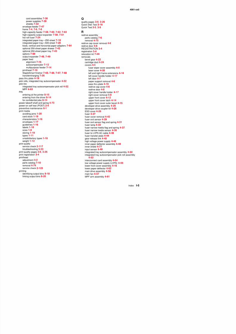
8/13/2019 t644 Service Manual
http://slidepdf.com/reader/full/t644-service-manual 413/423
4061-xx0
MPF pick tire removal 4-63MPF solenoid assembly 4-63MPF ⁄ lower front cover assembly 4-16
operator panel board removal 4-67operator panel buttons 4-68outer shield 4-69paper alignment assembly 4-70paper bin full sensor flag 4-71paper size sensing board 4-72power takeoff shaft and spring 4-73printhead 4-74redrive assembly 4-75signature button contact assembly 4-76
system board 4-77toner sensor 4-78transfer roll assembly 4-78upper front cover hinge assembly 4-79upper paper deflector assembly 4-80USB board assembly 4-80
repeat print 8-16reserve print 8-16right cover handle holder removal 4-17right cover removal 4-9
Ssafety information xviisafety inspection guide 6-1scheduled maintenance 6-1sensors
fuser exit sensor 4-29fuser narrow media sensor 4-35input 4-49output bin sensor, integrated paper tray 2-110
paper bin full 4-71paper size sensing board 4-72toner 4-78
serial number 3-20serial wrap tests 3-9service checks
5-bin mailbox 2-72900.xx error code 2-75927.xx fan 2-76950.00 through 950.29 EPROM mismatch failure 2-77charge roll 2-79cover closed switch/cable 2-80cover open switch/cable 2-80dead machine 2-80duplex option 2-82envelope feeder 2-84fuser 2-87
main fan 2-76operator panel 2-107options 2-109
output bin sensor 2-110output expander 2-111paper feed 2-113paper size sensing board 2-114parallel port 2-117print quality 2-117printhead 2-123signature button assembly 2-123StapleSmart finisher 2-124system board 2-127
toner sensor 2-128transfer roll 2-129service error codes 2-8shield
inner shield 4-77outer 4-69
signature button contact assemblyremoval 4-76
specificationsacoustics 1-8
dimensions 1-6electrical 1-7environment 1-8media 1-9memory configuration 1-5operating clearances 1-5power requirements 1-7print media 1-16resolution 1-4speed and performance 1-4
StapleSmart finisherlocations 5-12parts catalog 7-65, 7-66, 7-67, 7-68service check 2-124
start 2-1strobe adjustment 3-21switch, cover closed 2-80symptoms
base printer 2-5
duplex option 2-6envelope feeder 2-6high-capacity feeder 2-5output expander option 2-6paper trays 2-6StapleSmart finisher 2-7
system boardt 5 1
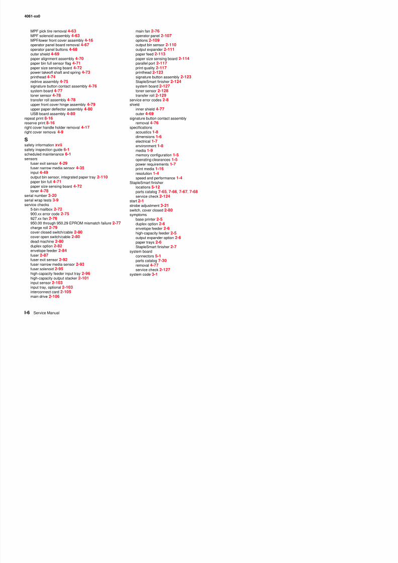
8/13/2019 t644 Service Manual
http://slidepdf.com/reader/full/t644-service-manual 414/423
4061-xx0
Ttheory of operation
autocompensator 3-31
autoconnect cabling and connectors 3-32duplex unit 3-32option microcode 3-32
toner sensor removal 4-78tools 1-20Top Margin
duplex 3-10simplex (front side) 3-4
transfer roll assemblyparts catalog 7-26
removal 4-78service check 2-129
transparencies 1-17tray linking 8-17
Uunique tools 1-20unsatisfactory papers 1-16upper front cover
parts catalog 7-2
removal 4-12upper front cover hinge assembly removal 4-79upper front cover latch removal 4-14upper paper deflector 4-80user attendance messages 2-32user line 2 link messages 2-43user status displays 2-31
Vverify print 8-16
Wwarm up time 3-22warning messages (user status displays) 2-31wiper cover 4-5wrap tests 3-8
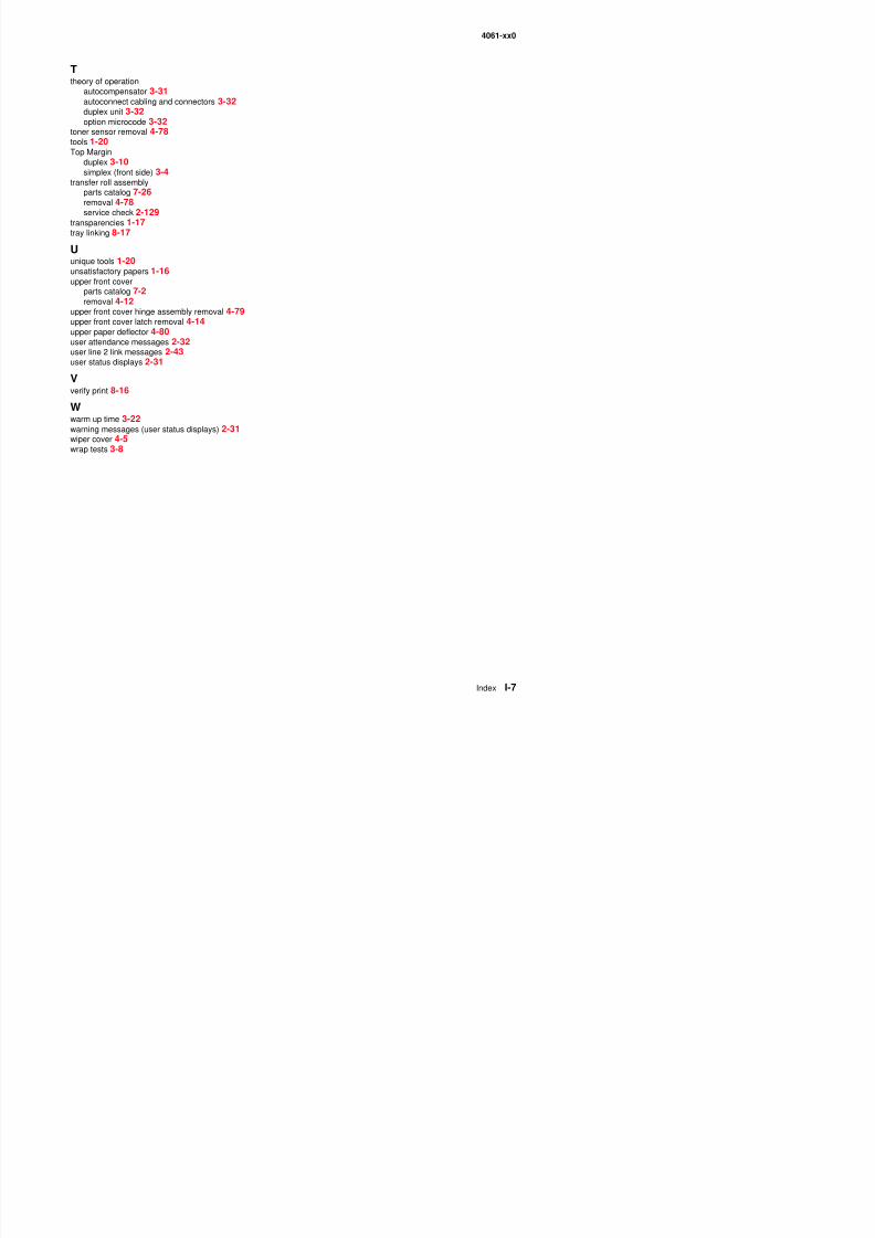
8/13/2019 t644 Service Manual
http://slidepdf.com/reader/full/t644-service-manual 415/423
4061-xx0

8/13/2019 t644 Service Manual
http://slidepdf.com/reader/full/t644-service-manual 416/423
4061-xx0
Part number index
P/N Description Page
1319128 Parallel wrap plug - - - - - - - - - - - - - - - - - - - - - - - - - - - - - - - - - - - - - - - - - - - - - - - - - - - - - - - - -2-117 , 3-840X0001 Fuser wiper cover assembly - - - - - - - - - - - - - - - - - - - - - - - - - - - - - - - - - - - - - - - - - - - - - - - - - - - - - - - 7-340X0002 Redrive cap cover assembly - - - - - - - - - - - - - - - - - - - - - - - - - - - - - - - - - - - - - - - - - - - - - - - - - - - - - - 7-340X0003 Laser cover assembly, 250-sheet output, 000/010 - - - - - - - - - - - - - - - - - - - - - - - - - - - - - - - - - - - - - - - 7-340X0004 Laser cover assembly, 500-sheet output, 200/210/400/410 - - - - - - - - - - - - - - - - - - - - - - - - - - - - - - - - - 7-340X0005 Paper support - - - - - - - - - - - - - - - - - - - - - - - - - - - - - - - - - - - - - - - - - - - - - - - - - - - - - - - - - - - - - - - - - 7-3
40X0006 Upper front cover hinge assembly - - - - - - - - - - - - - - - - - - - - - - - - - - - - - - - - - - - - - - - - - - - - - -7-3 , 7-3940X0007 Right side cover, 250-sheet output, 000/01 - - - - - - - - - - - - - - - - - - - - - - - - - - - - - - - - - - - - - - - - - - - - 7-340X0008 Right side cover, 500-sheet output, 200/210/400/410 - - - - - - - - - - - - - - - - - - - - - - - - - - - - - - - - - - - - - 7-340X0009 TLI/ID/serial number label—blank - - - - - - - - - - - - - - - - - - - - - - - - - - - - - - - - - - - - - - - - - - - - - - - - - - - 7-340X0010 Upper front cover assembly with Lexmark logo - - - - - - - - - - - - - - - - - - - - - - - - - - - - - - - - - - - - - - - - - 7-340X0011 Upper front cover latch kit - - - - - - - - - - - - - - - - - - - - - - - - - - - - - - - - - - - - - - - - - - - - - - - - - - - - - - - - 7-340X0013 Clear LCD bezel - - - - - - - - - - - - - - - - - - - - - - - - - - - - - - - - - - - - - - - - - - - - - - - - - - - - - - - - - - - - - - - 7-340X0015 Operator panel outer bezel with Lexmark logo, T640 - - - - - - - - - - - - - - - - - - - - - - - - - - - - - - - - - - - - - 7-340X0017 Lower front cover assembly - - - - - - - - - - - - - - - - - - - - - - - - - - - - - - - - - - - - - - - - - - - - - - - - - - - - - - - 7-340X0020 Cover, left side door, 250 1-slot, 000/010 - - - - - - - - - - - - - - - - - - - - - - - - - - - - - - - - - - - - - - - - - - - - - 7-340X0021 Cartridge holddown spring - - - - - - - - - - - - - - - - - - - - - - - - - - - - - - - - - - - - - - - - - - - - - - - - - - - - - - - - 7-940X0023 Cover, left side door, 500 2-slot, 200/210 /400/410 - - - - - - - - - - - - - - - - - - - - - - - - - - - - - - - - - - - - - - - 7-340X0024 Right frame extension, 200/210/400/410 - - - - - - - - - - - - - - - - - - - - - - - - - - - - - - - - - - - - - - - - - - - - - - 7-540X0025 Left frame extension, 200/210/400/410 - - - - - - - - - - - - - - - - - - - - - - - - - - - - - - - - - - - - - - - - - - - - - - - 7-540X0026 Contact, RSF ground - - - - - - - - - - - - - - - - - - - - - - - - - - - - - - - - - - - - - - - - - - - - - - - - - - - - - - - - - - - - 7-540X0027 Upper redrive deflector - - - - - - - - - - - - - - - - - - - - - - - - - - - - - - - - - - - - - - - - - - - - - - - - - - - - - - - - - - 7-740X0028 Upper diverter spring - - - - - - - - - - - - - - - - - - - - - - - - - - - - - - - - - - - - - - - - - - - - - - - - - - - - - - - - - - - - 7-740X0029 Redrive assembly, 250 in/250 out, 000/010 - - - - - - - - - - - - - - - - - - - - - - - - - - - - - - - - - - - - - - - - - - - - 7-740X0030 Redrive assembly, 500 in/500 out, 200/210/400/410 - - - - - - - - - - - - - - - - - - - - - - - - - - - - - - - - - - - - - 7-7
40X0032 Transfer deflector - - - - - - - - - - - - - - - - - - - - - - - - - - - - - - - - - - - - - - - - - - - - - - - - - - - - - - - - - - - - - - 7-740X0033 Machine mounting pad - - - - - - - - - - - - - - - - - - - - - - - - - - - - - - - - - - - - - - - - - - - - - - - - - - - - - - - - - - 7-940X0034 Signature button contact assembly with cable - - - - - - - - - - - - - - - - - - - - - - - - - - - - - - - - - - - - - - - - - 7-3740X0034 Signature button sensor assembly - - - - - - - - - - - - - - - - - - - - - - - - - - - - - - - - - - - - - - - - - - - - - - - - - - 7-940X0035 EP DC fan assembly, 000/010 - - - - - - - - - - - - - - - - - - - - - - - - - - - - - - - - - - - - - - - - - - - - - - - - - - - - - 7-940X0035 EP fan with cable—250 sheet, 000/010 - - - - - - - - - - - - - - - - - - - - - - - - - - - - - - - - - - - - - - - - - - - - - - 7-4140X0036 Toner sensor assembly - - - - - - - - - - - - - - - - - - - - - - - - - - - - - - - - - - - - - - - - - - - - - - - - - - - - - - - - - - 7-940X0039 Developer support roller - - - - - - - - - - - - - - - - - - - - - - - - - - - - - - - - - - - - - - - - - - - - - - - - - - - - - - - - - 7-940X0040 Upper paper feed deflector - - - - - - - - - - - - - - - - - - - - - - - - - - - - - - - - - - - - - - - - - - - - - - - - - - - - - - - 7-940X0041 Inner paper feed deflector, 000/010 - - - - - - - - - - - - - - - - - - - - - - - - - - - - - - - - - - - - - - - - - - - - - - - - - 7-9
40X0042 Inner paper feed deflector, 200/210/400/410 - - - - - - - - - - - - - - - - - - - - - - - - - - - - - - - - - - - - - - - - - - - 7-940X0043 Input sensor - - - - - - - - - - - - - - - - - - - - - - - - - - - - - - - - - - - - - - - - - - - - - - - - - - - - - - - - - - - - - - - - - - 7-940X0044 Gear guard - - - - - - - - - - - - - - - - - - - - - - - - - - - - - - - - - - - - - - - - - - - - - - - - - - - - - - - - - - - - - - - - - - - 7-740X0045 ESD shield with label - - - - - - - - - - - - - - - - - - - - - - - - - - - - - - - - - - - - - - - - - - - - - - - - - - - - - - - - - - - - 7-940X0046 Paper size sensing board assembly - - - - - - - - - - - - - - - - - - - - - - - - - - - - - - - - - - - - - - - - - - - - - - - - - 7-740X0046 Paper size sensing board/Tray 1 autocompensator paper out/low cable - - - - - - - - - - - - - - - - - - - - - - - 7-3540X0048 Paper switch activate spring - - - - - - - - - - - - - - - - - - - - - - - - - - - - - - - - - - - - - - - - - - - - - - - - - - - - - - - 7-7
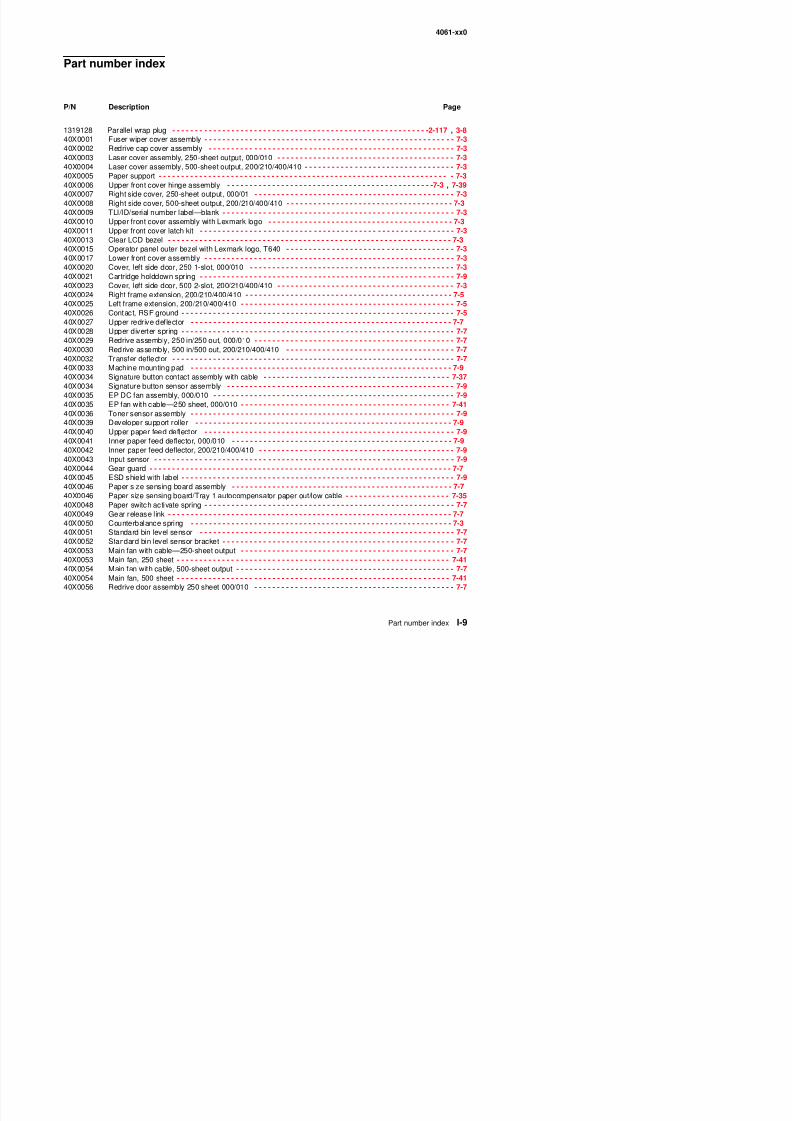
8/13/2019 t644 Service Manual
http://slidepdf.com/reader/full/t644-service-manual 417/423
4061-xx0
40X0057 Output paper level flag, 000/010 - - - - - - - - - - - - - - - - - - - - - - - - - - - - - - - - - - - - - - - - - - - - - - - - - - - - 7-740X0058 Output paper level flag, 200/210/400/410 - - - - - - - - - - - - - - - - - - - - - - - - - - - - - - - - - - - - - - - - - - - - - - 7-740X0059 Extension guide - - - - - - - - - - - - - - - - - - - - - - - - - - - - - - - - - - - - - - - - - - - - - - - - - - - - - - - - - - - - - - - - 7-740X0060 External ground clip
- - - - - - - - - - - - - - - - - - - - - - - - - - - - - - - - - - - - - - - - - - - - - - - - - - - - - - - - - - - - - 7-5
40X0061 Laser cable assembly - - - - - - - - - - - - - - - - - - - - - - - - - - - - - - - - - - - - - - - - - - - - - - - - - - - - - - - - - - 7-1140X0061 Laser printhead cable assembly - - - - - - - - - - - - - - - - - - - - - - - - - - - - - - - - - - - - - - - - - - - - - - - - - - - 7-3540X0062 Printhead assembly (includes all cables) - - - - - - - - - - - - - - - - - - - - - - - - - - - - - - - - - - - - - - - - - - - - - 7-1140X0065 Frame extension, nut plate, 200/210/400/410 - - - - - - - - - - - - - - - - - - - - - - - - - - - - - - - - - - - - - - - - - - - 7-540X0066 Pick arm assembly—500-sheet, 200/210/ 400/410 - - - - - - - - - - - - - - - - - - - - - - - - - - - - - - - - - - - - - - 7-1340X0067 Pick arm assembly—250-sheet, 000/010 - - - - - - - - - - - - - - - - - - - - - - - - - - - - - - - - - - - - - - - - - - - - - 7-1340X0068 Parts packet, bellcrank assembly—250-sheet tray, 000/010 - - - - - - - - - - - - - - - - - - - - - - - - - - - - - - - 7-1340X0069 Parts packet, bellcrank assembly for—500-sheet tray, 200/210/400/410 - - - - - - - - - - - - - - - - - - - - - - - 7-1340X0071 Paper out flag—250-sheet tray, 000/010 - - - - - - - - - - - - - - - - - - - - - - - - - - - - - - - - - - - - - - - - - - - - - 7-13
40X0072 Paper out flag—500-sheet tray, 200/210/400/410 - - - - - - - - - - - - - - - - - - - - - - - - - - - - - - - - - - - - - - - 7-1340X0073 Paper low/out sensor card assembly - - - - - - - - - - - - - - - - - - - - - - - - - - - - - - - - - - - - - - - - - - - - - - - - 7-1340X0074 Autocompensator motor cable - - - - - - - - - - - - - - - - - - - - - - - - - - - - - - - - - - - - - - - - - - - - - - - - - - - - 7-3540X0074 Paper size/autocompensator cable - - - - - - - - - - - - - - - - - - - - - - - - - - - - - - - - - - - - - - - - - - - - - - - - - 7-1340X0076 Pick roll assembly - - - - - - - - - - - - - - - - - - - - - - - - - - - - - - - - - - - - - - - - - - - - - - - - - - - - - - - - - - - - - 7-1540X0077 Multipurpose feeder paper out flag - - - - - - - - - - - - - - - - - - - - - - - - - - - - - - - - - - - - - - - - - - - - - - - - - 7-1540X0079 Multipurpose feeder lower deflector assembly - - - - - - - - - - - - - - - - - - - - - - - - - - - - - - - - - - - - - - - - - 7-1540X0083 Frame assembly with solenoid and cable - - - - - - - - - - - - - - - - - - - - - - - - - - - - - - - - - - - - - - - - - - - - - 7-4140X0084 Paper feed alignment assembly paper feed - - - - - - - - - - - - - - - - - - - - - - - - - - - - - - - - - - - - - - - - - - - 7-1740X0085 Reference ground clip - - - - - - - - - - - - - - - - - - - - - - - - - - - - - - - - - - - - - - - - - - - - - - - - - - - - - - - - - - 7-17
40X0086 Parts packet (reference adjust) - - - - - - - - - - - - - - - - - - - - - - - - - - - - - - - - - - - - - - - - - - - - - - - - - - - - 7-1740X0090 Back restraint—250-sheet tray - - - - - - - - - - - - - - - - - - - - - - - - - - - - - - - - - - - - - - - - - - - - - - - - - - - - 7-1940X0092 Side restraint—250-sheet tray - - - - - - - - - - - - - - - - - - - - - - - - - - - - - - - - - - - - - - - - - - - - - - - - - - - - 7-1940X0093 Wear strips - - - - - - - - - - - - - - - - - - - - - - - - - - - - - - - - - - - - - - - - - - - - - - - - - - - - - - - - - - - - - - - - - - 7-1940X0094 Wear plate—250-sheet tray - - - - - - - - - - - - - - - - - - - - - - - - - - - - - - - - - - - - - - - - - - - - - - - - - - - - - - 7-1940X0099 Side restraint - - - - - - - - - - - - - - - - - - - - - - - - - - - - - - - - - - - - - - - - - - - - - - - - - - - - - - - - - - - - - - - - - 7-2140X0100 115 V Maintenance kit - - - - - - - - - - - - - - - - - - - - - - - - - - - - - - - - - - - - - - - - - - - - - - - - - - - - - - - - - - - 6-140X0101 220 V Maintenance kit - - - - - - - - - - - - - - - - - - - - - - - - - - - - - - - - - - - - - - - - - - - - - - - - - - - - - - - - - - - 6-140X0103 Pass thru plate—500-sheet tray - - - - - - - - - - - - - - - - - - - - - - - - - - - - - - - - - - - - - - - - - - - - - - - - - - - 7-2140X0105 Restraint pad - - - - - - - - - - - - - - - - - - - - - - - - - - - - - - - - - - - - - - - - - - - - - - - - - - - - - - - - - - - - 7-19, 7-21
40X0106 Back restraint - - - - - - - - - - - - - - - - - - - - - - - - - - - - - - - - - - - - - - - - - - - - - - - - - - - - - - - - - - - - - - - - 7-2140X0107 Gearbox with motor - - - - - - - - - - - - - - - - - - - - - - - - - - - - - - - - - - - - - - - - - - - - - - - - - - - - - - - - - - - - 7-2340X0110 Power takeoff shaft—250-sheet, 000/010 - - - - - - - - - - - - - - - - - - - - - - - - - - - - - - - - - - - - - - - - - - - - 7-2340X0111 Power takeoff shaft—500-sheet, 200/210/400/410 - - - - - - - - - - - - - - - - - - - - - - - - - - - - - - - - - - - - - - 7-2340X0112 Power takeoff shaft spring - - - - - - - - - - - - - - - - - - - - - - - - - - - - - - - - - - - - - - - - - - - - - - - - - - - - - - - 7-2340X0114 Developer drive assembly - - - - - - - - - - - - - - - - - - - - - - - - - - - - - - - - - - - - - - - - - - - - - - - - - - - - - - - 7-2340X0115 Parts packet, developer drive - - - - - - - - - - - - - - - - - - - - - - - - - - - - - - - - - - - - - - - - - - - - - - - - - - - - - 7-2340X0120 Fuser wiper cavity cover - - - - - - - - - - - - - - - - - - - - - - - - - - - - - - - - - - - - - - - - - - - - - - - - - - - - - - - - - 7-2540X0121 Fuser cover assembly kit - - - - - - - - - - - - - - - - - - - - - - - - - - - - - - - - - - - - - - - - - - - - - - - - - - - - - - - - 7-2540X0122 Fuser lamp, 115V - - - - - - - - - - - - - - - - - - - - - - - - - - - - - - - - - - - - - - - - - - - - - - - - - - - - - - - - - - - - - 7-2540X0123 Fuser lamp, 220V - - - - - - - - - - - - - - - - - - - - - - - - - - - - - - - - - - - - - - - - - - - - - - - - - - - - - - - - - - - - - 7-2540X0124 Narrow media sensor - - - - - - - - - - - - - - - - - - - - - - - - - - - - - - - - - - - - - - - - - - - - - - - - - - - - - - - - - - - 7-2540X0125 Exit sensor - - - - - - - - - - - - - - - - - - - - - - - - - - - - - - - - - - - - - - - - - - - - - - - - - - - - - - - - - - - - - - - - - - 7-2540X0126 Parts kit, charge roll link asm, left side - - - - - - - - - - - - - - - - - - - - - - - - - - - - - - - - - - - - - - - - - - - - - - - 7-2740X0127 Charge roll assembly - - - - - - - - - - - - - - - - - - - - - - - - - - - - - - - - - - - - - - - - - - - - - - - - - - - - - - - - - - - 7-2740X0129 Parts kit, right side charge roll link assembly - - - - - - - - - - - - - - - - - - - - - - - - - - - - - - - - - - - - - - - - - - 7-2740X0130 T f ll bl 7 27
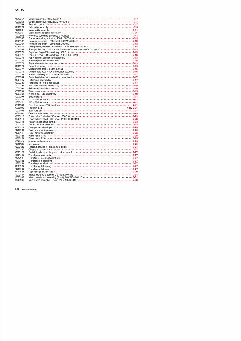
8/13/2019 t644 Service Manual
http://slidepdf.com/reader/full/t644-service-manual 418/423
4061-xx0
40X0150 Outer shield—2 slot, 200/210/400/410 - - - - - - - - - - - - - - - - - - - - - - - - - - - - - - - - - - - - - - - - - - - - - - 7-3340X0151 USB board assembly - - - - - - - - - - - - - - - - - - - - - - - - - - - - - - - - - - - - - - - - - - - - - - - - - - - - - - - - - - - - 7-340X0152 Ethernet shield (blank), 010/210/410 - - - - - - - - - - - - - - - - - - - - - - - - - - - - - - - - - - - - - - - - - - - - - - - - 7-3340X0153 INA flat cover (blank)
- - - - - - - - - - - - - - - - - - - - - - - - - - - - - - - - - - - - - - - - - - - - - - - - - - - - - - - - - - - 7-33
40X0154 Inner shield assembly—1 slot. 000/010 - - - - - - - - - - - - - - - - - - - - - - - - - - - - - - - - - - - - - - - - - - - - - - 7-3340X0156 Bottom/front autoconnect cable assembly - - - - - - - - - - - - - - - - - - - - - - - - - - - - - - - - - - - - - - - - - - - - 7-3740X0157 Top autoconnect cable assembly - - - - - - - - - - - - - - - - - - - - - - - - - - - - - - - - - - - - - - - - - - - - - - - - - - 7-3740X0159 Main drive motor cable assembly - - - - - - - - - - - - - - - - - - - - - - - - - - - - - - - - - - - - - - - - - - - - - - - - - - 7-4140X0160 MPF sensor cable - - - - - - - - - - - - - - - - - - - - - - - - - - - - - - - - - - - - - - - - - - - - - - - - - - - - - - - - - - - - - 7-3440X0161 Ground cable - - - - - - - - - - - - - - - - - - - - - - - - - - - - - - - - - - - - - - - - - - - - - - - - - - - - - - - - - - - - - - - - 7-4140X0162 System board to fuser board cable assembly - - - - - - - - - - - - - - - - - - - - - - - - - - - - - - - - - - - - - - - - - - 7-3940X0163 Fuser AC lamp to LVPS cable assembly - - - - - - - - - - - - - - - - - - - - - - - - - - - - - - - - - - - - - - - - - - - - - 7-3940X0165 Parts packet - - - - - - - - - - - - - - - - - - -7-5 , 7-7, 7-9, 7-11, 7-13, 7-15, 7-17, 7-23, 7-25, 7-27, 7-29, 7-33
40X0171 Cartridge shipping package, empty - - - - - - - - - - - - - - - - - - - - - - - - - - - - - - - - - - - - - - - - - - - - - - - - - 7-6940X0174 Parts packet (cable ties) - - - - - - - - - - - - - - - - - - - - - - - - - - - - - - - - - - - - - - - - - - - - - - - - - - - - - - - - - 7-340X0179 Nyogel 744 grease packet - - - - - - - - - - - - - - - - - - - - - - - - - - - - - - - - - - - - - - - - - - - - - - - - - - - - - - - 7-6940X0182 Wear strip - - - - - - - - - - - - - - - - - - - - - - - - - - - - - - - - - - - - - - - - - - - - - - - - - - - - - - - - - - - - - - - - - - 7-2140X0183 Plate, 500-sheet tray wear - - - - - - - - - - - - - - - - - - - - - - - - - - - - - - - - - - - - - - - - - - - - - - - - - - - - - - - 7-2140X0195 Operator panel board assembly - - - - - - - - - - - - - - - - - - - - - - - - - - - - - - - - - - - - - - - - - - - - - - - - - - - - 7-340X0197 100 V Maintenance kit - - - - - - - - - - - - - - - - - - - - - - - - - - - - - - - - - - - - - - - - - - - - - - - - - - - - - - - - - - - 6-140X0199 PrintCryption card assembly - - - - - - - - - - - - - - - - - - - - - - - - - - - - - - - - - - - - - - - - - - - - - - - - -7-31 , 7-6940X0207 EP duct - - - - - - - - - - - - - - - - - - - - - - - - - - - - - - - - - - - - - - - - - - - - - - - - - - - - - - - - - - - - - - - - - - - - - 7-940X0208 Blower duct, 200/210/400/410 - - - - - - - - - - - - - - - - - - - - - - - - - - - - - - - - - - - - - - - - - - - - - - - - - - - - - 7-9
40X0209 Gear #60 MPF shield - - - - - - - - - - - - - - - - - - - - - - - - - - - - - - - - - - - - - - - - - - - - - - - - - - - - - - - - - - - 7-940X0210 Main fan cap - - - - - - - - - - - - - - - - - - - - - - - - - - - - - - - - - - - - - - - - - - - - - - - - - - - - - - - - - - - - - - - - - - 7-740X0211 Main fan duct, 000/010 - - - - - - - - - - - - - - - - - - - - - - - - - - - - - - - - - - - - - - - - - - - - - - - - - - - - - - - - - - 7-740X0212 Main fan duct, 200/210/400/410 - - - - - - - - - - - - - - - - - - - - - - - - - - - - - - - - - - - - - - - - - - - - - - - - - - - - 7-740X0213 Tray bias assembly - - - - - - - - - - - - - - - - - - - - - - - - - - - - - - - - - - - - - - - - - - - - - - - - - - - - - - - - - - - - - 7-940X0222 Outer shield—1 slot, 000/010 - - - - - - - - - - - - - - - - - - - - - - - - - - - - - - - - - - - - - - - - - - - - - - - - - - - - - 7-3340X0223 HPVS/input sensor/toner sensor cable assembly - - - - - - - - - - - - - - - - - - - - - - - - - - - - - - - 7-9, 7-29, 7-3440X0223 HVPS/input sensor/toner sensor cable assembly - - - - - - - - - - - - - - - - - - - - - - - - - - - - - - - - - - - - - - - 7-3740X0224 LVPS to system board cable assembly - - - - - - - - - - - - - - - - - - - - - - - - - - - - - - - - - - - - - - - - - - - - - - 7-3740X0225 Right side hand holder - - - - - - - - - - - - - - - - - - - - - - - - - - - - - - - - - - - - - - - - - - - - - - - - - - - - - - - - - - - 7-5
40X0226 Fuser AC to fuser lamp cable - - - - - - - - - - - - - - - - - - - - - - - - - - - - - - - - - - - - - - - - - - - - - - - - -7-25 , 7-3940X0229 Narrow media sensor cable - - - - - - - - - - - - - - - - - - - - - - - - - - - - - - - - - - - - - - - - - - - - - - - - - - - - - - 7-2540X0230 Exit sensor cable - - - - - - - - - - - - - - - - - - - - - - - - - - - - - - - - - - - - - - - - - - - - - - - - - - - - - - - - - - - - - 7-2540X0231 Left side hand holder - - - - - - - - - - - - - - - - - - - - - - - - - - - - - - - - - - - - - - - - - - - - - - - - - - - - - - - - - - - - 7-540X0232 Redrive door assembly 500 sheet 200/210/400/410 - - - - - - - - - - - - - - - - - - - - - - - - - - - - - - - - - - - - - - 7-740X0233 Operator panel outer bezel with Lexmark logo T642 - - - - - - - - - - - - - - - - - - - - - - - - - - - - - - - - - - - - - - 7-340X0234 Operator panel outer bezel with Lexmark logo T644 - - - - - - - - - - - - - - - - - - - - - - - - - - - - - - - - - - - - - - 7-340X0235 Kit, upper front panel button - - - - - - - - - - - - - - - - - - - - - - - - - - - - - - - - - - - - - - - - - - - - - - - - - - - - - - - 7-340X0236 Exit/narrow media sensor cover - - - - - - - - - - - - - - - - - - - - - - - - - - - - - - - - - - - - - - - - - - - - - - - - - - - 7-2540X0238 Narrow media flag/spring kit - - - - - - - - - - - - - - - - - - - - - - - - - - - - - - - - - - - - - - - - - - - - - - - - - - - - - - 7-2540X0239 Exit sensor flag/spring kit - - - - - - - - - - - - - - - - - - - - - - - - - - - - - - - - - - - - - - - - - - - - - - - - - - - - - - - - 7-2540X0249 EP DC fan assembly, 200/210/400/410 - - - - - - - - - - - - - - - - - - - - - - - - - - - - - - - - - - - - - - - - - - - - - - - 7-940X0249 EP fan with cable—500 sheet, 200/210/400/410 - - - - - - - - - - - - - - - - - - - - - - - - - - - - - - - - - - - - - - - 7-4140X0250 9-pin to Twinax cable - - - - - - - - - - - - - - - - - - - - - - - - - - - - - - - - - - - - - - - - - - - - - - - - - - - - - - - - - - 7-6940X0251 9-pin to Coax (BNC) cable - - - - - - - - - - - - - - - - - - - - - - - - - - - - - - - - - - - - - - - - - - - - - - - - - - - - - - - 7-6940X0252 9-pin to 9-pin cable assembly - - - - - - - - - - - - - - - - - - - - - - - - - - - - - - - - - - - - - - - - - - - - - - - - - - - - - 7-6940X0253 P t k t d i ti 7 7
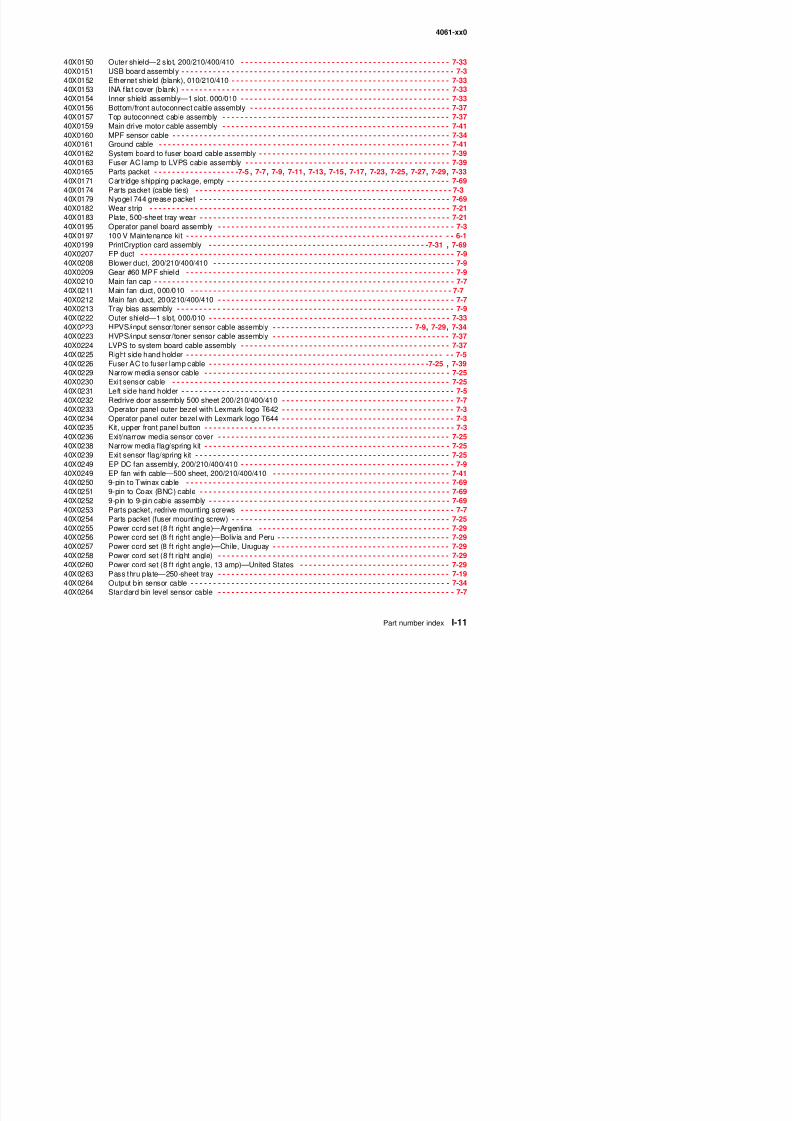
8/13/2019 t644 Service Manual
http://slidepdf.com/reader/full/t644-service-manual 419/423
4061-xx0
40X0265 PRESCRIBE card assembly - - - - - - - - - - - - - - - - - - - - - - - - - - - - - - - - - - - - - - - - - - - - - - - - - 7-31, 7-6940X0271 Power cord set—Hong Kong - - - - - - - - - - - - - - - - - - - - - - - - - - - - - - - - - - - - - - - - - - - - - - - - - - - - - 7-2940X0272 Power cord set—Japan - - - - - - - - - - - - - - - - - - - - - - - - - - - - - - - - - - - - - - - - - - - - - - - - - - - - - - - - - 7-2940X0280 Power cord set (6 ft straight)—Korea
- - - - - - - - - - - - - - - - - - - - - - - - - - - - - - - - - - - - - - - - - - - - - - - - 7-29
40X0281 Power cord set—Taiwan - - - - - - - - - - - - - - - - - - - - - - - - - - - - - - - - - - - - - - - - - - - - - - - - - - - - - - - - 7-2940X0285 Frame clip - - - - - - - - - - - - - - - - - - - - - - - - - - - - - - - - - - - - - - - - - - - - - - - - - - - - - - - - - - - - - - - - - - - - 7-540X0290 RS232C serial interface card - - - - - - - - - - - - - - - - - - - - - - - - - - - - - - - - - - - - - - - - - - - - - - - - - - - - - 7-6940X0291 Parallel 1284-B interface card - - - - - - - - - - - - - - - - - - - - - - - - - - - - - - - - - - - - - - - - - - - - - - - - - - - - - 7-6940X0293 Power cord set (8 ft right angle) - - - - - - - - - - - - - - - - - - - - - - - - - - - - - - - - - - - - - - - - - - - - - - - - - - - 7-2940X0294 Power cord set—Denmark, Norway, and Sweden - - - - - - - - - - - - - - - - - - - - - - - - - - - - - - - - - - - - - - - 7-2940X0295 Power cord set—Israel - - - - - - - - - - - - - - - - - - - - - - - - - - - - - - - - - - - - - - - - - - - - - - - - - - - - - - - - - - 7-2940X0301 Power cord set—AS/NZ - - - - - - - - - - - - - - - - - - - - - - - - - - - - - - - - - - - - - - - - - - - - - - - - - - - - - - - - - 7-2940X0303 Power cord set—PRC - - - - - - - - - - - - - - - - - - - - - - - - - - - - - - - - - - - - - - - - - - - - - - - - - - - - - - - - - - 7-29
40X0304 Power cord set—Botswana, Lesotho, Namibia, Pakistan, and South Africa - - - - - - - - - - - - - - - - - - - - - 7-2940X0305 Power cord set—Switzerland - - - - - - - - - - - - - - - - - - - - - - - - - - - - - - - - - - - - - - - - - - - - - - - - - - - - - 7-2940X0306 High voltage contact kit - - - - - - - - - - - - - - - - - - - - - - - - - - - - - - - - - - - - - - - - - - - - - - - - - - - - - - - - - - 7-940X0310 Multipurpose feeder pick arm assembly with solenoid - - - - - - - - - - - - - - - - - - - - - - - - - - - - - - - - - - - - 7-1540X1375 MarkNet 8000 Fast Ethernet - - - - - - - - - - - - - - - - - - - - - - - - - - - - - - - - - - - - - - - - - - - - - - - - - - - - - - 7-6940X1376 MarkNet 8020 Gigabit Ethernet - - - - - - - - - - - - - - - - - - - - - - - - - - - - - - - - - - - - - - - - - - - - - - - - - - - - 7-6940X1377 MarkNet 8030 Fiber Ethernet - - - - - - - - - - - - - - - - - - - - - - - - - - - - - - - - - - - - - - - - - - - - - - - - - - - - - 7-6940X1378 MarkNet 8050 wireless, US - - - - - - - - - - - - - - - - - - - - - - - - - - - - - - - - - - - - - - - - - - - - - - - - - - - - - - 7-6940X1508 128MB memory option - - - - - - - - - - - - - - - - - - - - - - - - - - - - - - - - - - - - - - - - - - - - - - - - - - - - - - - - - - 7-6940X1509 256MB memory option - - - - - - - - - - - - - - - - - - - - - - - - - - - - - - - - - - - - - - - - - - - - - - - - - - - - - - - - - - 7-69
40X1510 512MB memory option - - - - - - - - - - - - - - - - - - - - - - - - - - - - - - - - - - - - - - - - - - - - - - - - - - - - - - - - - - 7-6940X1512 Japanese font card - - - - - - - - - - - - - - - - - - - - - - - - - - - - - - - - - - - - - - - - - - - - - - - - - - - - - - - - - - - - 7-6940X1513 Simplified Chinese font card - - - - - - - - - - - - - - - - - - - - - - - - - - - - - - - - - - - - - - - - - - - - - - - - - - - - - - 7-6940X1514 Traditional Chinese font card - - - - - - - - - - - - - - - - - - - - - - - - - - - - - - - - - - - - - - - - - - - - - - - - - - - - - 7-6940X1515 Korean font card - - - - - - - - - - - - - - - - - - - - - - - - - - - - - - - - - - - - - - - - - - - - - - - - - - - - - - - - - - - - - - 7-6940X1562 MarkNet 8050 wireless, non-US - - - - - - - - - - - - - - - - - - - - - - - - - - - - - - - - - - - - - - - - - - - - - - - - - - - 7-6940X1564 32MB Flash card - - - - - - - - - - - - - - - - - - - - - - - - - - - - - - - - - - - - - - - - - - - - - - - - - - - - - - - - - - - - - - 7-6940X1565 64MB Flash card - - - - - - - - - - - - - - - - - - - - - - - - - - - - - - - - - - - - - - - - - - - - - - - - - - - - - - - - - - - - - - 7-6940X1816 Stacking bai l kit - - - - - - - - - - - - - - - - - - - - - - - - - - - - - - - - - - - - - - - - - - - - - - - - - - - - - - - - - - - - - - - 7-6540X2061 Diverter solenoid - - - - - - - - - - - - - - - - - - - - - - - - - - - - - - - - - - - - - - - - - - - - - - - - - - - - - - - - - - - - - - 7-57
40X2590 Fuser assembly w/220 V lamp - - - - - - - - - - - - - - - - - - - - - - - - - - - - - - - - - - - - - - - - - - - - - - - - - - - - 7-2540X2591 Fuser assembly w/100 V lamp - - - - - - - - - - - - - - - - - - - - - - - - - - - - - - - - - - - - - - - - - - - - - - - - - - - - 7-2540X2592 Fuser assembly w/115 V lamp - - - - - - - - - - - - - - - - - - - - - - - - - - - - - - - - - - - - - - - - - - - - - - - - - - - - 7-2540X2665 Oil fuser wiper (black housing) - - - - - - - - - - - - - - - - - - - - - - - - - - - - - - - - - - - - - - - - - - - - - - - - - - - - 7-2540X2666 Wax fuser wiper (gray housing) - - - - - - - - - - - - - - - - - - - - - - - - - - - - - - - - - - - - - - - - - - - - - - - - - - - - 7-2540X2669 Power supply board - - - - - - - - - - - - - - - - - - - - - - - - - - - - - - - - - - - - - - - - - - - - - - - - - - - - - - - - - - - - 7-6140X3212 Bar code card assembly - - - - - - - - - - - - - - - - - - - - - - - - - - - - - - - - - - - - - - - - - - - - - - - - - - - - 7-31, 7-6940X3230 250-sheet paper drawer, complete assembly - - - - - - - - - - - - - - - - - - - - - - - - - - - - - - - - - - - - - - - - - - 7-4240X3231 Integrated 250-sheet tray - - - - - - - - - - - - - - - - - - - - - - - - - - - - - - - - - - - - - - - - - - - - - - - - - - - - - - - - 7-1940X3231 Tray assembly, option—250-sheet - - - - - - - - - - - - - - - - - - - - - - - - - - - - - - - - - - - - - - - - - - - - - - - - - 7-4340X3232 Pick arm assembly - - - - - - - - - - - - - - - - - - - - - - - - - - - - - - - - - - - - - - - - - - - - - - - - - - - - - - - - - - - - - 7-4240X3233 Option pass thru sensor - - - - - - - - - - - - - - - - - - - - - - - - - - - - - - - - - - - - - - - - - - - - - - - - 7-42, 7-44, 7-6340X3234 Bin low sensor with cable - - - - - - - - - - - - - - - - - - - - - - - - - - - - - - - - - - - - - - - - - - - - - - - - - - - 7-42, 7-4440X3235 Side restraint—250-sheet tray - - - - - - - - - - - - - - - - - - - - - - - - - - - - - - - - - - - - - - - - - - - - - - - - - - - - 7-4340X3236 Back restraint—250-sheet tray - - - - - - - - - - - - - - - - - - - - - - - - - - - - - - - - - - - - - - - - - - - - - - - - - - - - 7-4340X3237 Base assembly - - - - - - - - - - - - - - - - - - - - - - - - - - - - - - - - - - - - - - - - - - - - - - - - - - - - - - - - - - - - - - - 7-4240X3238 C l t 5 bi i lb ti 7 55
06 0
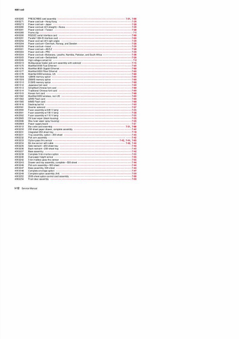
8/13/2019 t644 Service Manual
http://slidepdf.com/reader/full/t644-service-manual 420/423
4061-xx0
40X3255 Pick arm assembly—2000-sheet - - - - - - - - - - - - - - - - - - - - - - - - - - - - - - - - - - - - - - - - - - - - - - - - - - 7-6340X3263 Complete high-capacity output expander - - - - - - - - - - - - - - - - - - - - - - - - - - - - - - - - - - - - - - - - - - - - - 7-5040X3264 Output expander pass thru sensor - - - - - - - - - - - - - - - - - - - - - - - - - - - - - - - - - - - - - - - - - - - - - - - - - 7-4940X3264 Stacker pass thru sensor - - - - - - - - - - - - - - - - - - - - - - - - - - - - - - - - - - - - - - - - - - - - - - - - - - - - - - - - 7-5340X3265 Bin full dual sensor upper stacker assembly - - - - - - - - - - - - - - - - - - - - - - - - - - - - - - - - - - - - - -7-48 , 7-5140X3267 Rear access door assembly - - - - - - - - - - - - - - - - - - - - - - - - - - - - - - - - - - - - - - - - - - - - - - - - - -7-49 , 7-5040X3268 Output tray assembly - - - - - - - - - - - - - - - - - - - - - - - - - - - - - - - - - - - - - - - - - - - - - - - - - - - - - - - - - - 7-5040X3269 Complete horizontal kiosk option - - - - - - - - - - - - - - - - - - - - - - - - - - - - - - - - - - - - - - - - - - - - - - - - - - 7-6440X3270 Complete output expander assembly - - - - - - - - - - - - - - - - - - - - - - - - - - - - - - - - - - - - - - - - - - - - - - - 7-4840X3273 Complete option - - - - - - - - - - - - - - - - - - - - - - - - - - - - - - - - - - - - - - - - - - - - - - - - - - - - - - - - - - - - - - 7-6540X3274 Stapler access door switch assembly - - - - - - - - - - - - - - - - - - - - - - - - - - - - - - - - - - - - - - - - - - - - - - - 7-6540X3276 Rear access door - - - - - - - - - - - - - - - - - - - - - - - - - - - - - - - - - - - - - - - - - - - - - - - - - - - - - - - - - - - - - 7-6540X3277 Output assembly tray - - - - - - - - - - - - - - - - - - - - - - - - - - - - - - - - - - - - - - - - - - - - - - - - - - - - - - - - - - 7-65
40X3278 Stapler assembly - - - - - - - - - - - - - - - - - - - - - - - - - - - - - - - - - - - - - - - - - - - - - - - - - - - - - - - - - - - - - 7-6640X3279 Switch assembly, top cover open - - - - - - - - - - - - - - - - - - - - - - - - - - - - - - - - - - - - - - - - - - - - - - - - - - 7-6740X3280 Complete vertical kiosk option - - - - - - - - - - - - - - - - - - - - - - - - - - - - - - - - - - - - - - - - - - - - - - - - - - - - 7-6440X3377 Forms card assembly - - - - - - - - - - - - - - - - - - - - - - - - - - - - - - - - - - - - - - - - - - - - - - - - - - - - - - - - - - 7-6940X3378 IPDS SCS/Tne card assembly - - - - - - - - - - - - - - - - - - - - - - - - - - - - - - - - - - - - - - - - - - - - - - - - - - - - 7-6940X3378 IPDS/SCS card assembly - - - - - - - - - - - - - - - - - - - - - - - - - - - - - - - - - - - - - - - - - - - - - - - - - - - - - - - 7-3140X4308 Pick roll assembly - - - - - - - - - - - - - - - - - - - - - - - - - - - - - - - - - - - - - - - - - - - - - - - -7-13 , 7-42, 7-44, 7-6340X4596 Power cord set (6 ft right angle) —Brazil - - - - - - - - - - - - - - - - - - - - - - - - - - - - - - - - - - - - - - - - - - - - - 7-2940X4663 Tray assembly—500-sheet tray - - - - - - - - - - - - - - - - - - - - - - - - - - - - - - - - - - - - - - - - - - - - - - -7-21 , 7-4540X5293 System board assembly (non-network), 000 - - - - - - - - - - - - - - - - - - - - - - - - - - - - - - - - - - - - - - - - - - 7-31
40X5294 System board assembly (network), 010 - - - - - - - - - - - - - - - - - - - - - - - - - - - - - - - - - - - - - - - - - - - - - - 7-3140X5295 System board assembly (non-network), 200 - - - - - - - - - - - - - - - - - - - - - - - - - - - - - - - - - - - - - - - - - - 7-3140X5296 System board assembly (network), 210 - - - - - - - - - - - - - - - - - - - - - - - - - - - - - - - - - - - - - - - - - - - - - - 7-3140X5297 System board assembly (non-network), 400 - - - - - - - - - - - - - - - - - - - - - - - - - - - - - - - - - - - - - - - - - - 7-3140X5298 System board assembly (network), 410 - - - - - - - - - - - - - - - - - - - - - - - - - - - - - - - - - - - - - - - - - - - - - - 7-3156P1228 Bellcrank spring arm - - - - - - - - - - - - - - - - - - - - - - - - - - - - - - - - - - - - - - - - - - - - - - - - - - - - - - - - - - - 7-4456P1228 Bellcrank—250-sheet paper tray - - - - - - - - - - - - - - - - - - - - - - - - - - - - - - - - - - - - - - - - - - - - - - - - - - 7-4256P1279 Wear strips - - - - - - - - - - - - - - - - - - - - - - - - - - - - - - - - - - - - - - - - - - - - - - - - - - - - - - - - - - - - - - - - - - 7-4356P2540 Bellcrank spring—500-sheet option tray - - - - - - - - - - - - - - - - - - - - - - - - - - - - - - - - - - - - - - - - - - - - - 7-4456P4100 Duplex assembly.—250-sheet - - - - - - - - - - - - - - - - - - - - - - - - - - - - - - - - - - - - - - - - - - - - - - - - - - - - 7-46
56P4102 Duplex assembly—500-sheet - - - - - - - - - - - - - - - - - - - - - - - - - - - - - - - - - - - - - - - - - - - - - - - - - - - - - 7-4656P4116 Universal adjustable tray assembly—400-sheet - - - - - - - - - - - - - - - - - - - - - - - - - - - - - - - - - - - - - - - - 7-6956P4129 Paper out arm—250-sheet - - - - - - - - - - - - - - - - - - - - - - - - - - - - - - - - - - - - - - - - - - - - - - - - - - - - - - - 7-4256P4137 Side restraint—500-sheet tray - - - - - - - - - - - - - - - - - - - - - - - - - - - - - - - - - - - - - - - - - - - - - - - - - - - - 7-4556P4145 Paper out arm—500-sheet drawer - - - - - - - - - - - - - - - - - - - - - - - - - - - - - - - - - - - - - - - - - - - - - - - - - 7-4456P4147 Back restraint—500-sheet tray - - - - - - - - - - - - - - - - - - - - - - - - - - - - - - - - - - - - - - - - - - - - - - - - - - - - 7-4556P4157 Door hinge - - - - - - - - - - - - - - - - - - - - - - - - - - - - - - - - - - - - - - - - - - - - - - - - - - - - - - - - - - - - - - - - - - 7-5956P4163 Left side cover - - - - - - - - - - - - - - - - - - - - - - - - - - - - - - - - - - - - - - - - - - - - - - - - - - - - - - - - - - - - - - - 7-4856P4176 Redrive cap cover - - - - - - - - - - - - - - - - - - - - - - - - - - - - - - - - - - - - - - - - - - - - - - - - - - - - - - - - - - - - - 7-5556P4178 Right side cover - - - - - - - - - - - - - - - - - - - - - - - - - - - - - - - - - - - - - - - - - - - - - - - - - - - - - - - - - - - - - - 7-5556P4179 Left side cover - - - - - - - - - - - - - - - - - - - - - - - - - - - - - - - - - - - - - - - - - - - - - - - - - - - - - - - - - - - - - - - 7-5556P4180 Wire cover - - - - - - - - - - - - - - - - - - - - - - - - - - - - - - - - - - - - - - - - - - - - - - - - - - - - - - - - - - - - - - - - - - 7-5556P4181 Top bin cover - - - - - - - - - - - - - - - - - - - - - - - - - - - - - - - - - - - - - - - - - - - - - - - - - - - - - - - - - - - - - - - - 7-5556P4182 Paper cap tray - - - - - - - - - - - - - - - - - - - - - - - - - - - - - - - - - - - - - - - - - - - - - - - - - - - - - - - - - - - - - - - 7-5556P4183 Rear access door - - - - - - - - - - - - - - - - - - - - - - - - - - - - - - - - - - - - - - - - - - - - - - - - - - - - - - - - - - - - - 7-5556P4186 Bin full flag - - - - - - - - - - - - - - - - - - - - - - - - - - - - - - - - - - - - - - - - - - - - - - - - - - - - - - - - - - - - - - - - - - 7-5556P4191 5 bi ilb bl kit 7 55
4061 0
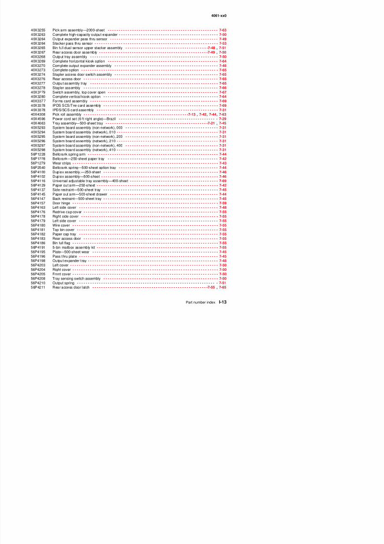
8/13/2019 t644 Service Manual
http://slidepdf.com/reader/full/t644-service-manual 421/423
4061-xx0
56P4211 Rear door latch - - - - - - - - - - - - - - - - - - - - - - - - - - - - - - - - - - - - - - - - - - - - - - - - - - - - - - - - - - - - - - - 7-5056P4212 Bin full dual sensor upper stacker assembly flag - - - - - - - - - - - - - - - - - - - - - - - - - - - - - - - - - - - - - - - - 7-5156P4213 Left base assembly cover - - - - - - - - - - - - - - - - - - - - - - - - - - - - - - - - - - - - - - - - - - - - - - - - - - - - - - - - 7-6556P4214 Right base assembly cover - - - - - - - - - - - - - - - - - - - - - - - - - - - - - - - - - - - - - - - - - - - - - - - - - - - - - - - 7-6556P4216 Stapler access cover - - - - - - - - - - - - - - - - - - - - - - - - - - - - - - - - - - - - - - - - - - - - - - - - - - - - - - - - - - - 7-6556P4218 Top assembly cover - - - - - - - - - - - - - - - - - - - - - - - - - - - - - - - - - - - - - - - - - - - - - - - - - - - - - - - - - - - - 7-6556P4230 Clip—250-sheet pass thru - - - - - - - - - - - - - - - - - - - - - - - - - - - - - - - - - - - - - - - - - - - - - - - - - - - - - - - 7-4356P4232 LVPS—115 V ac, 000/010 - - - - - - - - - - - - - - - - - - - - - - - - - - - - - - - - - - - - - - - - - - - - - - - - - - - - - - - 7-2956P4233 LVPS—220 V ac, 000/010 - - - - - - - - - - - - - - - - - - - - - - - - - - - - - - - - - - - - - - - - - - - - - - - - - - - - - - - 7-2956P4234 LVPS—115 V ac, 200/210/400/410 - - - - - - - - - - - - - - - - - - - - - - - - - - - - - - - - - - - - - - - - - - - - - - - - - 7-2956P4235 Right side cover - - - - - - - - - - - - - - - - - - - - - - - - - - - - - - - - - - - - - - - - - - - - - - - - - - - - - - - - - - - - - - - 7-4956P4238 LVPS—220 V ac, 200/210/400/410 - - - - - - - - - - - - - - - - - - - - - - - - - - - - - - - - - - - - - - - - - - - - - - - - - 7-297375084 Relocation kit—250/250-sheet printer - - - - - - - - - - - - - - - - - - - - - - - - - - - - - - - - - - - - - - - - - - - - - - - 7-69
7375085 Relocation kit—500/500-sheet printer - - - - - - - - - - - - - - - - - - - - - - - - - - - - - - - - - - - - - - - - - - - - - - - 7-6999A0063 Switch activate spring - - - - - - - - - - - - - - - - - - - - - - - - - - - - - - - - - - - - - - - - - - - - - - - - - - - - - 7-42, 7-4499A0104 Spring, upper diverter - - - - - - - - - - - - - - - - - - - - - - - - - - - - - - - - - - - - - - - - - - - - - - - - - - - - - - - - - - 7-6799A0104 Upper diverter spring - - - - - - - - - - - - - - - - - - - - - - - - - - - - - - - - - - - - - - - - - - - - - - - - - - 7-48, 7-51, 7-5599A0120 Restraint pad - - - - - - - - - - - - - - - - - - - - - - - - - - - - - - - - - - - - - - - - - - - - - - - - - - - - - - - - - - - - 7-43, 7-4599A0121 Plate—250-sheet tray wear - - - - - - - - - - - - - - - - - - - - - - - - - - - - - - - - - - - - - - - - - - - - - - - - - - - - - - 7-4399A0263 Parts packet - - - - - - - - - - - - - - - - - - - - - - - - - - - - - - - - - - - - - - - - - - - - - - - - - - - - - - - - 7-42, 7-48, 7-5199A0263 Parts packet (auto comp assembly mounting screw) - - - - - - - - - - - - - - - - - - - - - - - - - - - - - - - - - - - - - 7-6399A0263 Parts packet (auto comp mounting screw) - - - - - - - - - - - - - - - - - - - - - - - - - - - - - - - - - - - - - - - - - - - - 7-4499A0263 Parts packet (board mounting screw) - - - - - - - - - - - - - - - - - - - - - - - - - - - - - - - - - - - - - - - - - - 7-55, 7-57
99A0263 Parts packet (screw) - - - - - - - - - - - - - - - - - - - - - - - - - - - - - - - - - - - - - - - - - - - - - - - - - - - - - - - - - - - 7-4499A0263 Parts packet, screw (auto comp mounting) - - - - - - - - - - - - - - - - - - - - - - - - - - - - - - - - - - - - - - - - - - - - 7-4299A0263 Parts packet, screw (switch spring) - - - - - - - - - - - - - - - - - - - - - - - - - - - - - - - - - - - - - - - - - - - - - - - - - 7-4299A0263 Screw - - - - - - - - - - - - - - - - - - - - - - - - - - - - - - - - - - - - - - - - - - - - - - - - - - - - - - - - - - - - - - - - - - - - - - 7-4999A0272 Drive shaft—250-sheet - - - - - - - - - - - - - - - - - - - - - - - - - - - - - - - - - - - - - - - - - - - - - - - - - - - - 7-42, 7-6299A0275 Power takeoff spring - - - - - - - - - - - - - - - - - - - - - - - - - - - - - - - - - - - - - - - - - - - - - - - - - - 7-42, 7-44, 7-6299A0292 Wear strips - - - - - - - - - - - - - - - - - - - - - - - - - - - - - - - - - - - - - - - - - - - - - - - - - - - - - - - - - - - - - - - - - - 7-4599A0415 Swing arm spring - - - - - - - - - - - - - - - - - - - - - - - - - - - - - - - - - - - - - - - - - - - - - - - - - - - - - - - - - - - - - - 7-5199A0447 Drive shaft—500-sheet - - - - - - - - - - - - - - - - - - - - - - - - - - - - - - - - - - - - - - - - - - - - - - - - - - - - - - - - - 7-4499A0654 Paper low switch - - - - - - - - - - - - - - - - - - - - - - - - - - - - - - - - - - - - - - - - - - - - - - - - - - - - - - - - - - - - - - 7-61
99A0658 Door magnet - - - - - - - - - - - - - - - - - - - - - - - - - - - - - - - - - - - - - - - - - - - - - - - - - - - - - - - - - - - - - - - - - 7-5999A0676 Parts packet (6-32 hinge mounting nut) - - - - - - - - - - - - - - - - - - - - - - - - - - - - - - - - - - - - - - - - - - - - - - 7-5999A0676 Parts packet (nuts) - - - - - - - - - - - - - - - - - - - - - - - - - - - - - - - - - - - - - - - - - - - - - - - - - - - - - - - - - - - - 7-6199A0677 Parts packet (hinge mounting flat washer) - - - - - - - - - - - - - - - - - - - - - - - - - - - - - - - - - - - - - - - - - - - - 7-5999A0677 Parts packet (hinge mounting star washer) - - - - - - - - - - - - - - - - - - - - - - - - - - - - - - - - - - - - - - - - - - - 7-5999A0681 Wear strip - - - - - - - - - - - - - - - - - - - - - - - - - - - - - - - - - - - - - - - - - - - - - - - - - - - - - - - - - - - - - - - - - - - 7-5999A0954 Bevel gear with grease packet - - - - - - - - - - - - - - - - - - - - - - - - - - - - - - - - - - - - - - - - - - - - - - - - - - - - 7-2399A1808 AC external jumper cord - - - - - - - - - - - - - - - - - - - - - - - - - - - - - - - - - - - - - - - - - - - - - - - - - - - - - - - - - 7-6199A1818 Wear dimple str ip - - - - - - - - - - - - - - - - - - - - - - - - - - - - - - - - - - - - - - - - - - - - - - - - - - - - - - - - - - - - - - 7-5999A1929 Bellcrank spring—250-sheet paper tray - - - - - - - - - - - - - - - - - - - - - - - - - - - - - - - - - - - - - - - - - - - - - - 7-4299A2480 StapleSmart wheels maintenance kit - - - - - - - - - - - - - - - - - - - - - - - - - - - - - - - - - - - - - - - - - - - - - - - - 7-68
Print defects guide
Page 1 of 1
8/13/2019 t644 Service Manual
http://slidepdf.com/reader/full/t644-service-manual 422/423
Page 1 of 1
Print defects guide
Note: If the defect appears on the printed side of a single-sided print job, replace the toner cartridge before replacing the fuser.
Replace the fuser
Replace the
transfer roller
Match a set of repeating defects on a print job to the marks on one of the vertical lines. The line that best
matches the defects on the print job indicates which particular part may be causing the defect.
For example, the distance between these two marks represents
a repeating defect that occurs every 28.3 mm (1.11 in.), which
means the charge rollers may need to be replaced.
88.0 mm(3.46 in.)
51.7 mm(2.04 in.)
Replace thecharge rollers
95.2 mm(3.75 in.)
Replace the toner cartridge
47.8 mm(1.88 in.)
96.8 mm(3.81 in.)
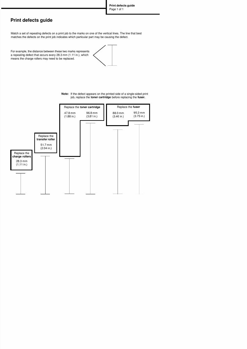
8/13/2019 t644 Service Manual
http://slidepdf.com/reader/full/t644-service-manual 423/423
J 8
J 9
J T 2
1
5
+50V
5V
GND
3.3V
+25V
J 2 5
J 2 2
J 1 0
21
34
6
8
10
5
7
9
11
J 1 3
21
34
65
7
J 1
4 2
1
J 1 5
1213
21
34
6
8
10
5
7
9
11
J 1 8
21
J 2 7
1618
1412
8
4
10
6
2
1517
1311
7
3
9
5
1
J 2 0
21
34
6
8
5
7
9
J 2 1
3 124
J 2 8
2 31
J 2 3
212 1098765431
J 2 6
21
34
21
34
J
5
2 13
J 6 2
1
3
J
4
2 13
J
3
8 12345679101112
J
2
8 1234567910111213
23
1
2 5431
LVPS
AC InletPower
Switch
1
2
CN1
F1
F2250V250V
CN2
+ 5 P H e a d
L P O W
L A D J 2 *
C N
V I D E O 1 +
C N
V I D E O 1 - C
N
V I D E O 0 - C
N
G N D
21
34
2
7 6 5
4 3 1
Printhead
G N D
V I D E O 0 +
C N
Main Fan
2 13
2 13
G N D
M A I N F A N
+ 5 V D C
2
1
3
STD BinSensor
Gnd
21
3
HOP FULL* CN
HOP LED
21
J 2 4
21
34
6
8
10
5
7
9
111213 Cartridge
Sensor
InputSensor
111213
10 9
T102
To Transfer Roll
21
34
6
8
5
7
HVPS
+5.5VDC -SW
DEV B
INSENSOR*
GND
CHARGE B
ATSERVO
TX ENB B
XFR B
+24VDC -SW
GND
GND
+5VDC SW
TONER WHEEL CN
JC1
JC2
JC7JC8
Dr.B
Chg
JC10JC9
TAR
JC5JC6
Dev
JC3JC4
PCD
JC1
MPTSolenoid
+ 2 4 V D C
M P F P i c k *
21
GND
MPFSensor
MPF POUT ON
MPF LED
2 31
8 1234567910111213
8 1234567910111213
L A D J *
C N
G N D
L P O W
F B
L E N A
8 12345679101112
G N D
G N D
G N D
G N D
M M S T A R T *
C N
M M L O C K R *
M M M M R E F
R
CartridgeFan
2 13
2 13
G N D
C A R T F A N
C F A N S T A L L
C N
Toroid
Toroid
Toroid
Toroid
Cover ClosedSwitch
3
21
COV CLOSEGND
+5VDC23
1
12C DAT
OP Panel
+5VDC
GND
PANEL INT
12C CLK
21
34
65
7 21
34
65
7
+3.3VDCGND
4 1235
2 5431
+ 5
V U S B 1
C N
U S B P 1 -
U S B P 1 +
G N D
G N D
Fuser
2
1
+5VSW
GND
Thump
Therm CN
GND
ThumpretExitSens*
NarrowMedia*
21
34
6
8
10
5
7
9
11
21
34
6
8
10
5
7
9
1112C CLK LS
3.3VDC
12C DAT LS
2
1
Gnd Signature
Button
2
1SM Cart
21
34
6
8
5
7
9
Main DriveMotor
2 98765431
BLDC FG
+5VDC FUSED
BLDC WIND 2
GND
V C2 0V C2 1
BLDC HALL 0
BLDC HALL 1BLDC HALL 2
A u t o
C o m p e n s a t o r
M
o t o r
12
21
+ 2 4 V D C
A U T O C O M P
2 1098765431
Paper Low/OutSensor
2 8765431
Auto CompensatorMotor Encoder
109
+ 5 V D C
A C E N C O D E C N
G N D
P S I Z E 2
P S I Z E 1
P S I Z E 3
21
3
21
+ 5 V C D S W I T C H E D
T R A Y 1
P O U T
C N
T R A Y 1
P L O ( * C N
G N D
PaperSize
Switches21
34SW2
SW1
SW0 C N 1
1618
1412
8
4
10
6
2
1517
1311
7
3
9
5
1+5VDC
GND
GND
GND
GND
GND
+24VDC RAW
+24VDC RAW
HEAT
+5VDC
GND
+5VDC
GND
GND
+24VDC RAW
+24VDC RAW
ZEROXING R*
GND
5
G N D
H S Y N C C N *
H S Y N C I D C N
+ 5 V D C
G N D
21
AutoconnectBottom
GND+24VDC PTC OPT
AutoconnectTop
3 124
G N D
+ 2 4 V D C
+ 5 V D C F U S E D
G N D
GND
21
34
TXD1BRGND
RXDIR
21
34 GND
TXD1BR
GND
RXDIR
AutocFront
4321
57 68
321
46 5
321
46 5
20 19 20 19
HEATL FAN DRV*
To J25 [3]
To J25 [3]
To J25 [4]
To J25 [4]
T o
J 2 5
[ 1 ]
T o
J 2 5
[ 1 ]
T o
J 2 5
[ 2 ]
T o
J 2 5
[ 2 ]
To J18 [1] T
o
J 1 8
[ 1 ]
To J18 [2]
T o
J 1 8
[ 2 ]
1618
1412
8
4
10
6
2
1517
1311
7
3
9
5
1
20 19
1
2
DC1 DC2
USB Board
J7
J1USB Device Port
J17
J16
Ethernet
J19
FuserLamp
Lexmark T64x (4061) Wiring diagram