Embed Size (px)
Citation preview
PUBLIC
Copyright © 2018 Rockwell Automation, Inc. All Rights Reserved. 1
T99 - Harmonic SolutionsHarmonic Mitigation, Problems, Limitations and Solutions
PUBLIC Copyright © 2018 Rockwell Automation, Inc. All Rights Reserved. 2
Agenda
Challenges - How do I choose?Solution Strategies
Background on Harmonics
PUBLIC Copyright © 2018 Rockwell Automation, Inc. All Rights Reserved. 3
Agenda
Background on Harmonics
PUBLIC Copyright © 2018 Rockwell Automation, Inc. All Rights Reserved. 4
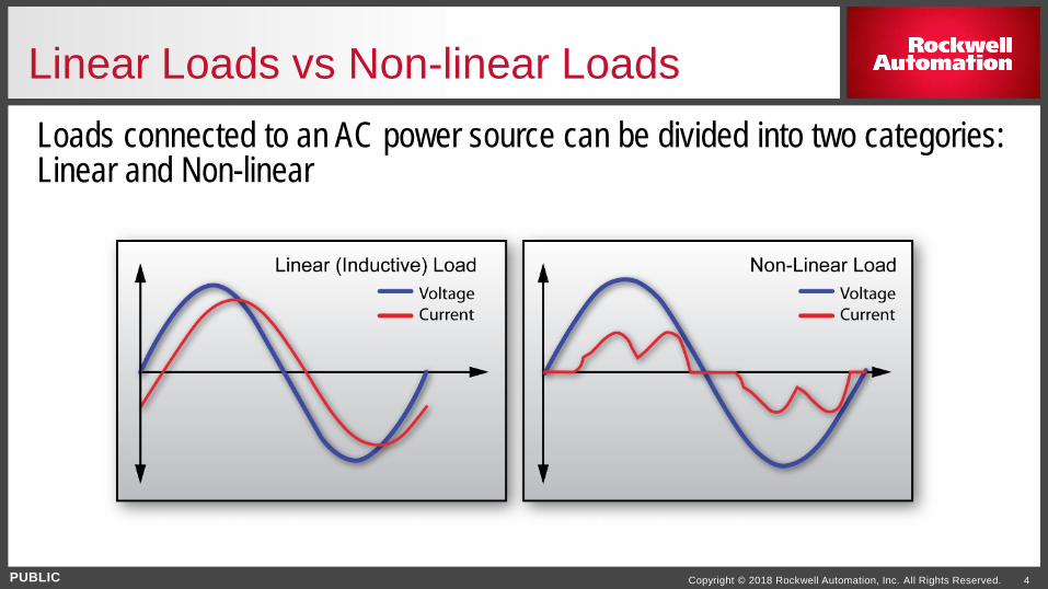
Linear Loads vs Non-linear LoadsLoads connected to an AC power source can be divided into two categories: Linear and Non-linear
Smooth Sine Wave Current Draw “Pulsing” Current Draw
PUBLIC Copyright © 2018 Rockwell Automation, Inc. All Rights Reserved. 5
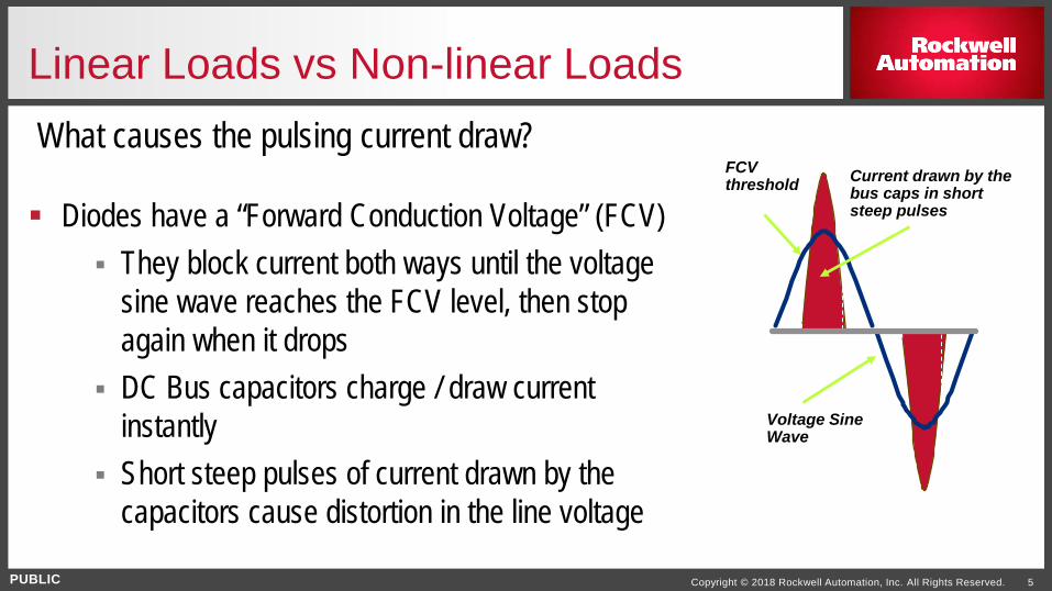
Linear Loads vs Non-linear LoadsWhat causes the pulsing current draw?
Diodes have a “Forward Conduction Voltage” (FCV) They block current both ways until the voltage
sine wave reaches the FCV level, then stop again when it drops
DC Bus capacitors charge / draw current instantly
Short steep pulses of current drawn by the capacitors cause distortion in the line voltage
Voltage Sine Wave
FCV threshold Current drawn by the
bus caps in short steep pulses
PUBLIC Copyright © 2018 Rockwell Automation, Inc. All Rights Reserved. 6
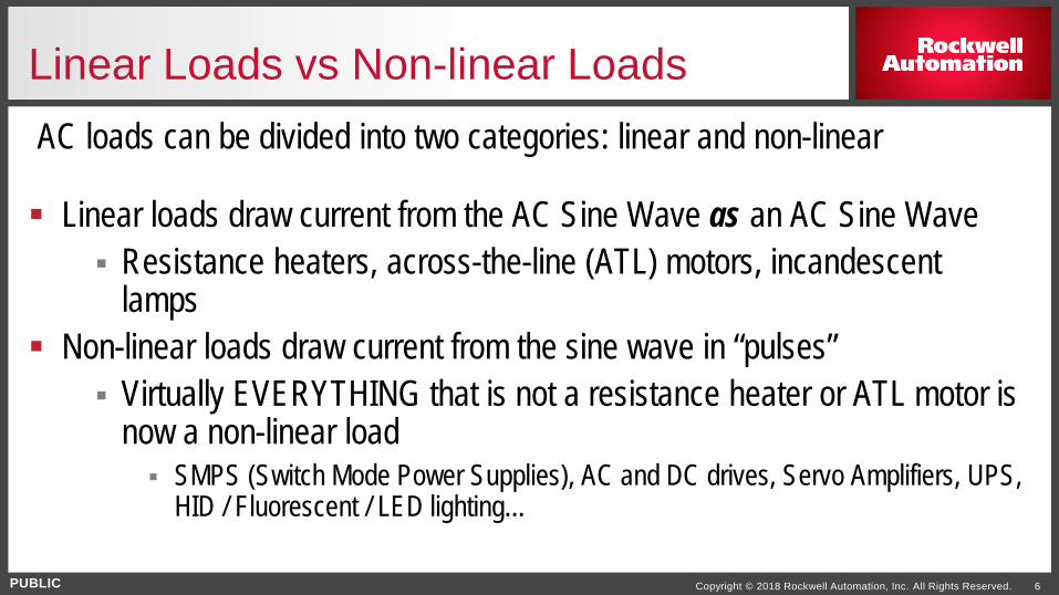
Linear Loads vs Non-linear Loads
Linear loads draw current from the AC Sine Wave as an AC Sine Wave Resistance heaters, across-the-line (ATL) motors, incandescent
lamps Non-linear loads draw current from the sine wave in “pulses”
Virtually EVERYTHING that is not a resistance heater or ATL motor is now a non-linear load SMPS (Switch Mode Power Supplies), AC and DC drives, Servo Amplifiers, UPS,
HID / Fluorescent / LED lighting…
AC loads can be divided into two categories: linear and non-linear
PUBLIC Copyright © 2018 Rockwell Automation, Inc. All Rights Reserved. 7
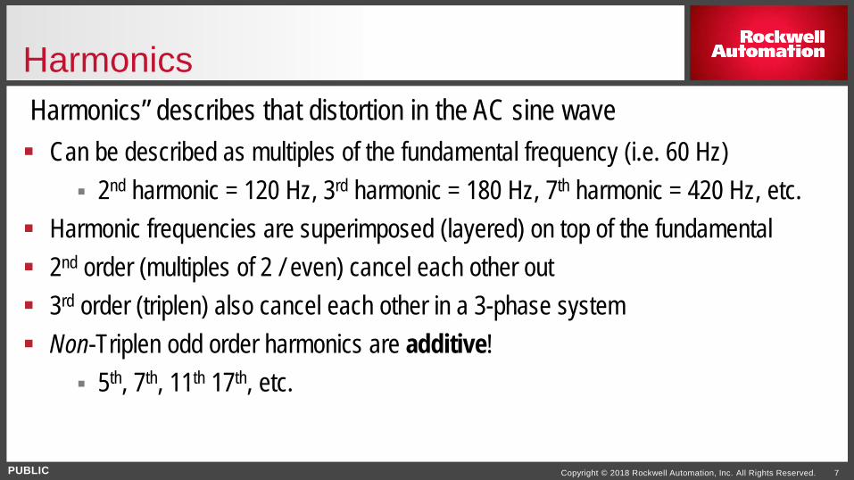
Harmonics
Can be described as multiples of the fundamental frequency (i.e. 60 Hz) 2nd harmonic = 120 Hz, 3rd harmonic = 180 Hz, 7th harmonic = 420 Hz, etc.
Harmonic frequencies are superimposed (layered) on top of the fundamental 2nd order (multiples of 2 / even) cancel each other out 3rd order (triplen) also cancel each other in a 3-phase system Non-Triplen odd order harmonics are additive!
5th, 7th, 11th 17th, etc.
Harmonics” describes that distortion in the AC sine wave
PUBLIC Copyright © 2018 Rockwell Automation, Inc. All Rights Reserved. 8
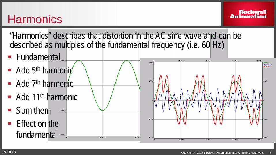
Harmonics“Harmonics” describes that distortion in the AC sine wave and can be described as multiples of the fundamental frequency (i.e. 60 Hz) Fundamental Add 5th harmonic Add 7th harmonic Add 11th harmonic Sum them Effect on the
fundamental
PUBLIC Copyright © 2018 Rockwell Automation, Inc. All Rights Reserved. 9
Why Worry About Harmonics? Harmonics cause additional heating in electrical systems. Increase equipment failure
Due to loss of true sign wave, confused 0 Crossing and other power quality issues Increase the size (aka cost) of required distribution equipment.
Larger Transformers, cables and switch gear to handle the extra harmonic currents Many protective devices assume a 60 Hz sine wave. Too much distortion
can make them less effective, or prone to false trips…(Typical of Power Quality issues)
PUBLIC Copyright © 2018 Rockwell Automation, Inc. All Rights Reserved. 10
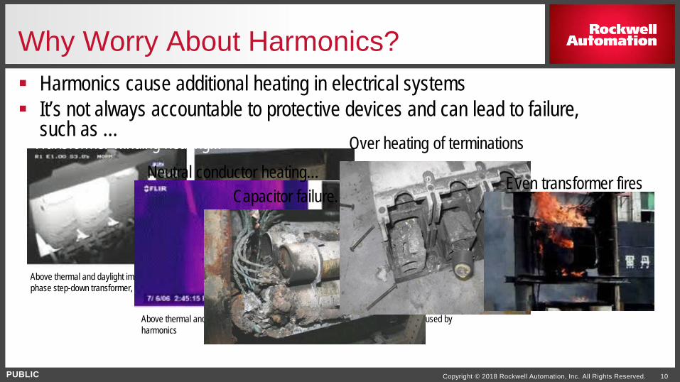
Why Worry About Harmonics? Harmonics cause additional heating in electrical systems It’s not always accountable to protective devices and can lead to failure,
such as …Transformer winding heating…
Above thermal and daylight images show uneven heating in the windings of a three phase step-down transformer, most likely due to harmonics
Neutral conductor heating…
Above thermal and daylight images show overheated neutral wires, proven to be caused by harmonics
Capacitor failure……
Over heating of terminations…
Even transformer fires!…
PUBLIC Copyright © 2018 Rockwell Automation, Inc. All Rights Reserved. 11
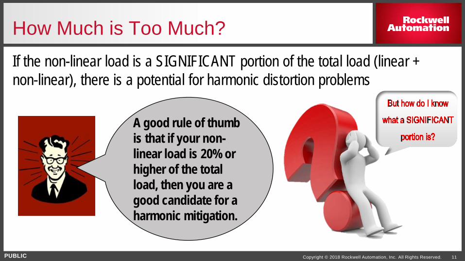
How Much is Too Much?If the non-linear load is a SIGNIFICANT portion of the total load (linear + non-linear), there is a potential for harmonic distortion problems
A good rule of thumb is that if your non-linear load is 20% or higher of the total load, then you are a good candidate for a harmonic mitigation.
PUBLIC Copyright © 2018 Rockwell Automation, Inc. All Rights Reserved. 12
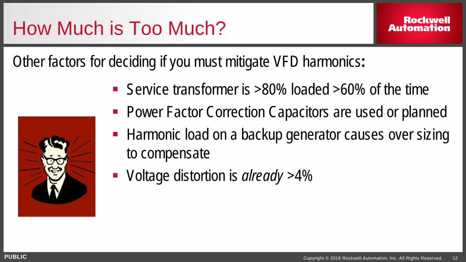
How Much is Too Much?Other factors for deciding if you must mitigate VFD harmonics:
Service transformer is >80% loaded >60% of the time Power Factor Correction Capacitors are used or planned Harmonic load on a backup generator causes over sizing
to compensate Voltage distortion is already >4%
PUBLIC Copyright © 2018 Rockwell Automation, Inc. All Rights Reserved. 13
IEEE - 519
IEEE (Institute of Electrical and Electronic Engineers) published guidelines in 1981 for limits to harmonics and preventing damage to transmission and distribution equipment
Establishes responsibilities for users and utilities to maintain the voltage THD (Total Harmonic Distortion) limits within acceptable levels at the PCC (Point of Common Coupling) Updated in 1992, then again just recently in 2014 Users must limit current distortion in their facility so as to not create voltage THD at the
PCC Utilities must limit voltage distortion going to the PCC by maintaining circuit impedance
PUBLIC Copyright © 2018 Rockwell Automation, Inc. All Rights Reserved. 14
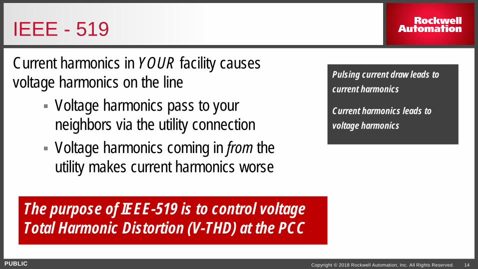
IEEE - 519Current harmonics in YOUR facility causes voltage harmonics on the line
Voltage harmonics pass to your neighbors via the utility connection
Voltage harmonics coming in from the utility makes current harmonics worse
Pulsing current draw leads to current harmonics
Current harmonics leads to voltage harmonics
The purpose of IEEE-519 is to control voltage Total Harmonic Distortion (V-THD) at the PCC
PUBLIC Copyright © 2018 Rockwell Automation, Inc. All Rights Reserved. 15
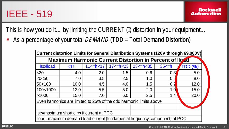
IEEE - 519This is how you do it… by limiting the CURRENT (I) distortion in your equipment… As a percentage of your total DEMAND (TDD = Total Demand Distortion)
Current distortion Limits for General Distribution Systems (120V through 69,000V)
Isc/Iload <11 11<=h<17 17<=h<23 23<=h<35 35<=h TDD (%)<20 4.0 2.0 1.5 0.6 0.3 5.0 20<50 7.0 3.5 2.5 1.0 0.5 8.0 50<100 10.0 4.5 4.0 1.5 0.7 12.0 100<1000 12.0 5.5 5.0 2.0 1.0 15.0 >1000 15.0 7.0 6.0 2.5 1.4 20.0 Even harmonics are limited to 25% of the odd harmonic limits above
Isc=maximum short circuit current at PCCIload=maximum demand load current (fundamental frequency component) at PCC
Maximum Harmonic Current Distortion in Percent of Iload
PUBLIC Copyright © 2018 Rockwell Automation, Inc. All Rights Reserved. 16
Agenda
Solution Strategies
PUBLIC Copyright © 2018 Rockwell Automation, Inc. All Rights Reserved. 17
Strategies - What Do You Do?Mitigate Cumulatively or Mitigate Individually?
Mitigate cumulatively: Deal with the total problem as it exists at the PCC (Point of Common Coupling)
Mitigate individually: Solve harmonics issues at every source, which ultimately avoids the cumulative effects
PUBLIC Copyright © 2018 Rockwell Automation, Inc. All Rights Reserved. 18
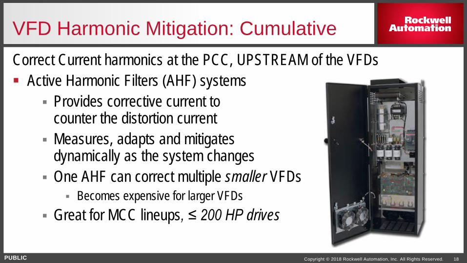
VFD Harmonic Mitigation: CumulativeCorrect Current harmonics at the PCC, UPSTREAM of the VFDs Active Harmonic Filters (AHF) systems
Provides corrective current to counter the distortion current
Measures, adapts and mitigates dynamically as the system changes
One AHF can correct multiple smaller VFDs Becomes expensive for larger VFDs
Great for MCC lineups, ≤ 200 HP drives
PUBLIC Copyright © 2018 Rockwell Automation, Inc. All Rights Reserved. 20
VFD Harmonic Mitigation: IndividualCorrect current harmonics at EACH and every VFD
Line Reactors and / or DC Bus Chokes Passive Harmonic Filters Multi-Pulse Front End Drives Active Front End (AFE) Drives
PUBLIC Copyright © 2018 Rockwell Automation, Inc. All Rights Reserved. 21
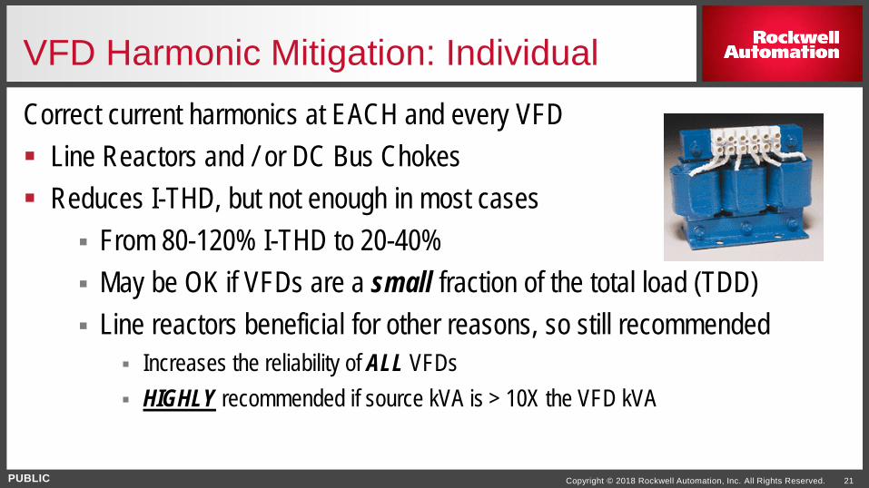
VFD Harmonic Mitigation: IndividualCorrect current harmonics at EACH and every VFD Line Reactors and / or DC Bus Chokes Reduces I-THD, but not enough in most cases
From 80-120% I-THD to 20-40% May be OK if VFDs are a small fraction of the total load (TDD) Line reactors beneficial for other reasons, so still recommended
Increases the reliability of ALL VFDs HIGHLY recommended if source kVA is > 10X the VFD kVA
PUBLIC Copyright © 2018 Rockwell Automation, Inc. All Rights Reserved. 22
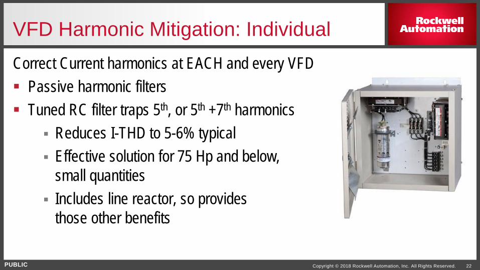
VFD Harmonic Mitigation: IndividualCorrect Current harmonics at EACH and every VFD Passive harmonic filters Tuned RC filter traps 5th, or 5th +7th harmonics
Reduces I-THD to 5-6% typical Effective solution for 75 Hp and below,
small quantities Includes line reactor, so provides
those other benefits
PUBLIC Copyright © 2018 Rockwell Automation, Inc. All Rights Reserved. 23
VFD Harmonic Mitigation: IndividualCorrect Current harmonics at EACH and every VFD; ≥250 HPTwo substrategies:
Multi-Pulse Front End drives 18 pulse (North America), 12 pulse (Europe)
Active Front End (AFE) low harmonic drives
PUBLIC Copyright © 2018 Rockwell Automation, Inc. All Rights Reserved. 24
VFD Harmonic MitigationSummary of mitigation so far: Line Reactors / Bus Chokes
OK for motors ≤ 25 HP and/or small % TDD Passive Harmonic Filters
Effective solution for 75 HP and below, in small quantities Active Harmonic Filters
Good for MCCs and/or multiple motors ≤ 200 HP What about motors ≥250 HP?
PUBLIC Copyright © 2018 Rockwell Automation, Inc. All Rights Reserved. 25
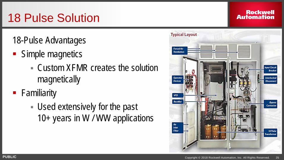
18-Pulse Advantages Simple magnetics
Custom XFMR creates the solution magnetically
Familiarity Used extensively for the past
10+ years in W / WW applications
18 Pulse Solution
PUBLIC Copyright © 2018 Rockwell Automation, Inc. All Rights Reserved. 26
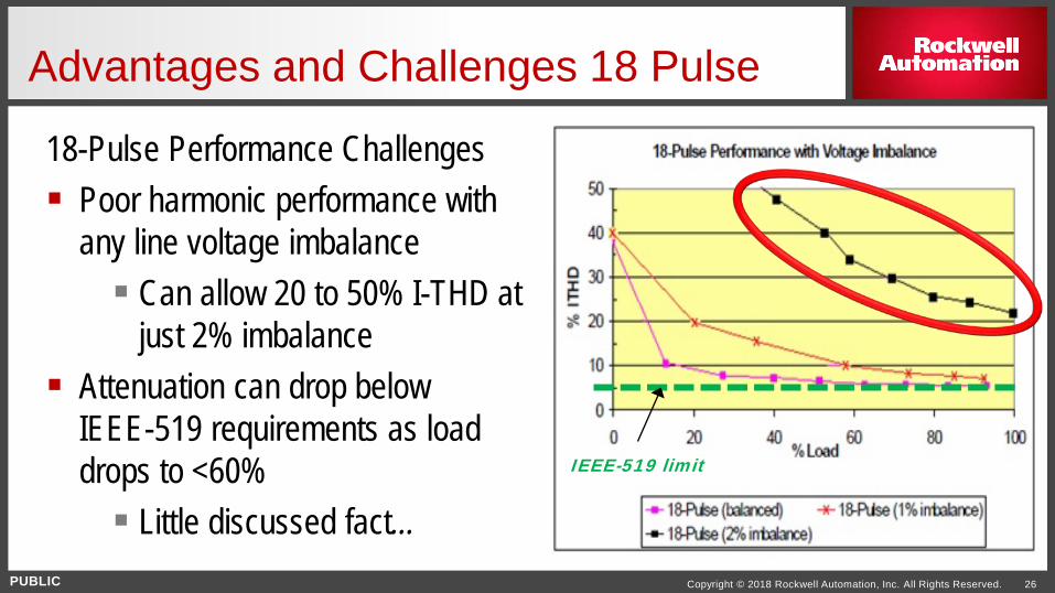
18-Pulse Performance Challenges Poor harmonic performance with
any line voltage imbalance Can allow 20 to 50% I-THD at
just 2% imbalance Attenuation can drop below
IEEE-519 requirements as load drops to <60% Little discussed fact…
Advantages and Challenges 18 Pulse
IEEE-519 limit
PUBLIC Copyright © 2018 Rockwell Automation, Inc. All Rights Reserved. 27
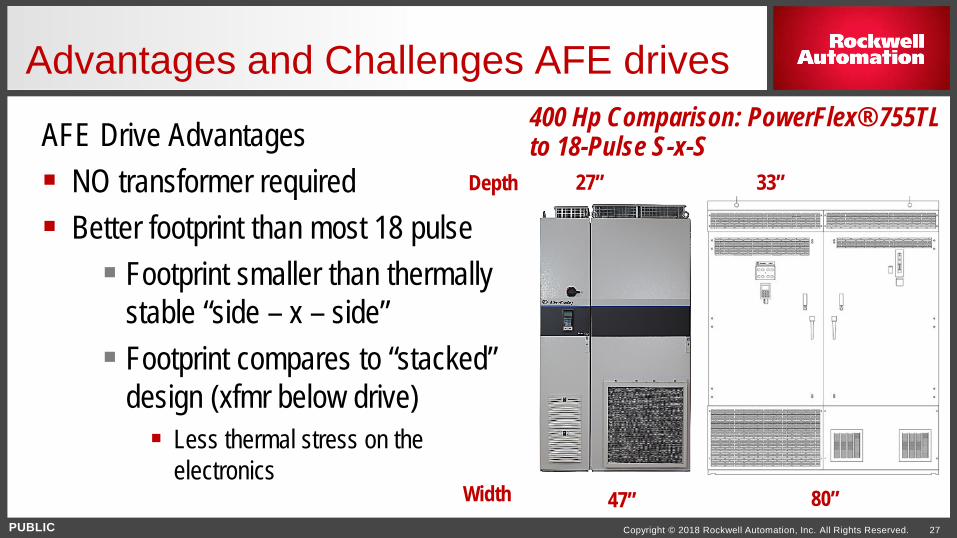
AFE Drive Advantages NO transformer required Better footprint than most 18 pulse Footprint smaller than thermally
stable “side – x – side” Footprint compares to “stacked”
design (xfmr below drive) Less thermal stress on the
electronics
Advantages and Challenges AFE drives400 Hp Comparison: PowerFlex® 755TL to 18-Pulse S-x-S
80”47”
27”Depth 33”
Width
PUBLIC Copyright © 2018 Rockwell Automation, Inc. All Rights Reserved. 28
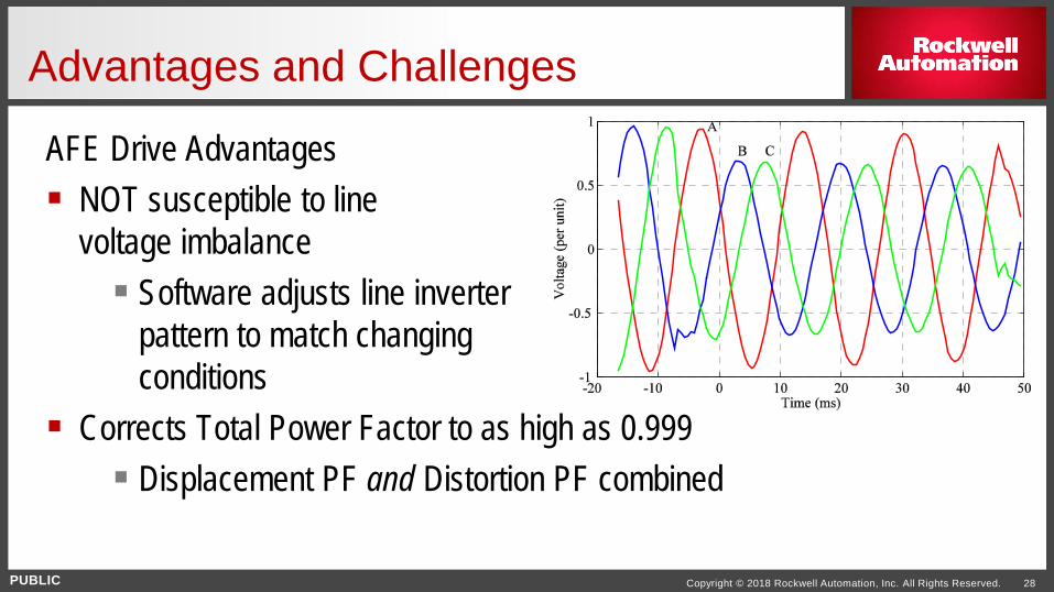
AFE Drive Advantages NOT susceptible to line
voltage imbalance Software adjusts line inverter
pattern to match changing conditions
Corrects Total Power Factor to as high as 0.999 Displacement PF and Distortion PF combined
Advantages and Challenges
PUBLIC Copyright © 2018 Rockwell Automation, Inc. All Rights Reserved. 29
Agenda
Challenges - How do I choose?

PUBLIC Copyright © 2018 Rockwell Automation, Inc. All Rights Reserved. 30
“How do I decide which way to go?” Take all factors into consideration: Size of motors requiring mitigation Quantity of motors requiring mitigation Mounting configurations MCC, control panel, standalone, etc.
Electrical supply Stiff supply, end of line, backup generator, etc
Summary
PUBLIC Copyright © 2018 Rockwell Automation, Inc. All Rights Reserved. 31
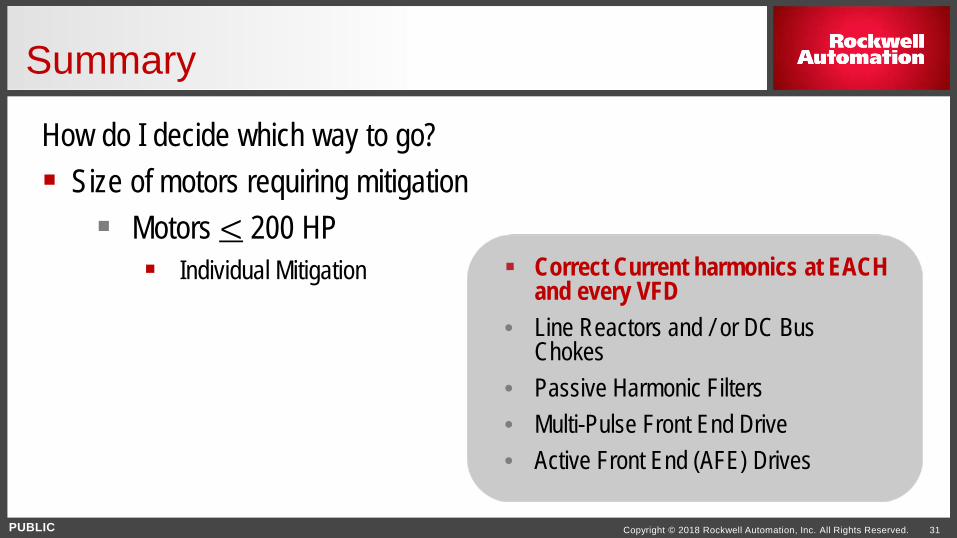
How do I decide which way to go? Size of motors requiring mitigation Motors < 200 HP Individual Mitigation Correct Current harmonics at EACH
and every VFD• Line Reactors and / or DC Bus
Chokes• Passive Harmonic Filters• Multi-Pulse Front End Drive• Active Front End (AFE) Drives
Summary
PUBLIC Copyright © 2018 Rockwell Automation, Inc. All Rights Reserved. 32
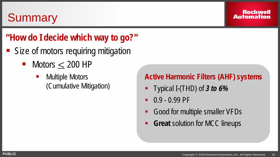
“How do I decide which way to go?” Size of motors requiring mitigation Motors < 200 HP Multiple Motors
(Cumulative Mitigation)
Summary
Active Harmonic Filters (AHF) systems Typical I-(THD) of 3 to 6% 0.9 - 0.99 PF Good for multiple smaller VFDs Great solution for MCC lineups
PUBLIC Copyright © 2018 Rockwell Automation, Inc. All Rights Reserved. 33
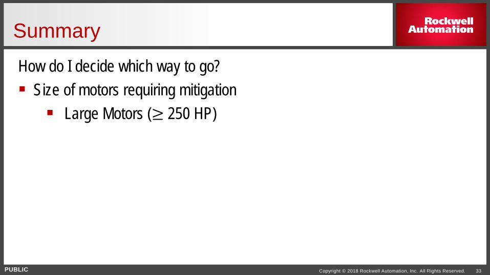
How do I decide which way to go? Size of motors requiring mitigation Large Motors (≥ 250 HP)
Summary
PUBLIC Copyright © 2018 Rockwell Automation, Inc. All Rights Reserved. 34
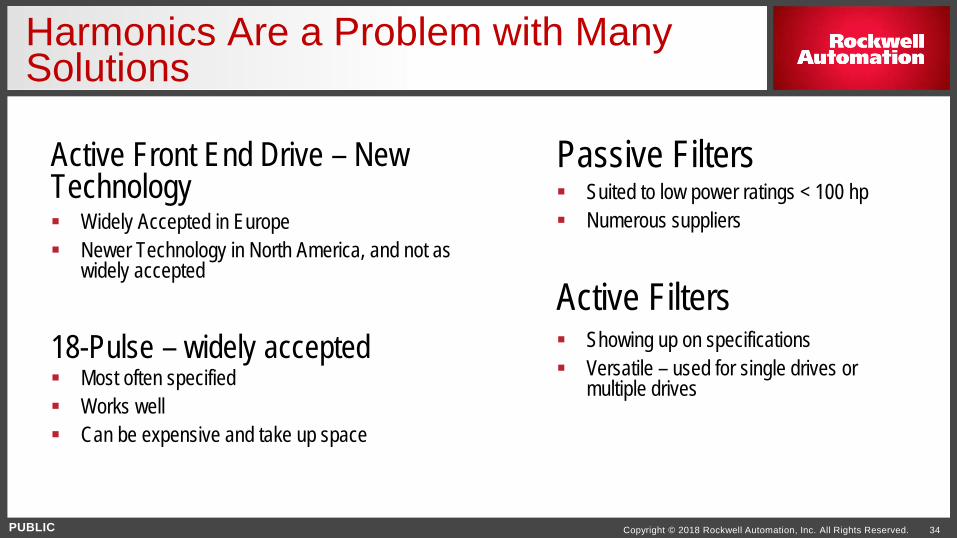
Active Front End Drive – New Technology Widely Accepted in Europe Newer Technology in North America, and not as
widely accepted
Harmonics Are a Problem with Many Solutions
Passive Filters Suited to low power ratings < 100 hp Numerous suppliers
Active Filters Showing up on specifications Versatile – used for single drives or
multiple drives
18-Pulse – widely accepted Most often specified Works well Can be expensive and take up space
www.rockwellautomation.com
PUBLIC
Copyright © 2018 Rockwell Automation, Inc. All Rights Reserved. 35
Thank You!