Embed Size (px)
Citation preview
National Iranian Steel Co.
Baft Steel Complex
DDRR aanndd MMaatteerriiaall HHaannddlliinngg PPllaanntt
PPrroojjeecctt
“Annex I to Employer’s Requirements”
Specification and Data Sheets

Table of Contents Doc No.: TA-143-D00-G-TD006 16-Sep-07 Rev 0
TARA TARH Engineering & Technological Co.
DR & Material Handling Plant Project
Plant Specification and Data Sheets Baft Steel Complex Page 1 of 1
NISCO
Table of Contents
Contents Page
1- General 1
1.1- Safety 2
1.2- Standardization of Equipment 2
1.3- Quality Control, Inspection and Testing 2
1.4- Training 6
1.5- Recommended Spares 7
1.6- Special Tools 8
1.7- Manning 8
1.8- Weights of Plant, Equipment and Materials 8
1.9- Manufacturers 9
1.10- Supervision of Erection 10
1.11- Time Schedule 11
2- Direct Reduction Plant Specification 14
3- Raw Material Handling Plant Specification 40
4- Process and Process Equipment Data Sheets 47
5- Material Handling System Data Sheets 71
6- Fluid System Data Sheets 83
7- Electrical Equipment Data Sheets 105
8- Instrumentation and Control Data Sheets 123
Section 1 Doc No.: TA-143-D00-G-TD006 16-Sep-07 Rev 0
TARA TARH Engineering & Technological Co.
DR & Material Handling Plant Project
Plant Specification and Data Sheets Baft Steel Complex Page 1 of 144
NISCO
1- GENERAL
The Employer intends to construct a direct reduction and a material handling plant in Baft
steel company located near Baft city, in Kerman province.
For this propose, implementation of a direct reduction module with nominal capacity of
800,000 TPY-DRI (+5 mm) and raw material handling plant with nominal capacity of
2,500,000 tonne pellet and lump ore per year shall be in the scope of obligations of the
Contractor for the present Project.
The direct reduction plant and raw material handling plant shall be complete in all respects
and any devices which is not included in the specification but is necessary for proper
operation of equipment and process, shall be considered as included within the specification
whether specifically mentioned in this “Specification and Data sheets” or not.

Section 1 Doc No.: TA-143-D00-G-TD006 16-Sep-07 Rev 0
TARA TARH Engineering & Technological Co.
DR & Material Handling Plant Project
Plant Specification and Data Sheets Baft Steel Complex Page 2 of 144
NISCO
1.1- SAFETY
The Contractor shall ensure that the supplied Plant and Material, equipment, machinery
and apparatus are designed in conformity with all those codes and regulations in normal
usage for the type of equipment and machinery being offered.
The Contractor shall list the steps and special design features included in the design of
the Plant, equipment, machinery and apparatus to ensure that all the safety requirements
has been taken into account.
1.2- STANDARDIZATION OF EQUIPMENT
To reduce the quantity of spares that must be held and to simplify maintenance, the
Contractor shall wherever possible use similar components and sub- assemblies throughout
the Plant supplied under this Contract.
1.3- QUALITY CONTROL, INSPECTION AND TESTING
The Contractor required supplying information to enable the Employer to make assessment
of quality control, inspection and testing policies of the Contractor. Also certain minimum
requirements in this respect have been laid down here.
1.3.1- Tender Information
The Contractor shall submit with his tender a description of the quality control, inspection
and testing procedure currently in use in the Contractor's manufacturing works and those
of his principal Sub- Contractors. This description shall include non-destructive testing
(NDT) facilities, material testing, control of critical welding operations, material
classifications and identification and all test facilities. The Contractor shall submit with
his tender a description of the quality assurance procedure which he intends to adopt for
the Contract Works.
Section 1 Doc No.: TA-143-D00-G-TD006 16-Sep-07 Rev 0
TARA TARH Engineering & Technological Co.
DR & Material Handling Plant Project
Plant Specification and Data Sheets Baft Steel Complex Page 3 of 144
NISCO
1.3.2- Draft Quality Control Procedure
Within one month of the effectiveness of Contract, the Contractor shall submit to the
Employer’s Representative for approval a draft procedure of quality control, inspection
and testing activities which he proposes to perform, together with a program indicating
when these activities are to be carried out. The program of inspection and testing shall be
related to the preliminary program of plant design, manufacture, erection and start-up.
Individual quality assurance procedures shall be proposed for any specialized item of
Plant but standardized procedures may be proposed for common items such as castings,
forging, fabrications, structural steel, fans, pumps, pipe work, valves, tanks, drive units,
ducting, compressors, couplings, bearings, motors, conveyors, switchgear, control gear,
batteries, transformers and instruments. The Employer’s Representative will have the
right to modify or complete the draft quality control procedure whenever the
modifications are supported by the Employer specifications except welding which shall be
according to applicable international standards i.e. UNI, DIN, B.S and applicable
American standards.
1.3.3- Detailed Quality Control Procedure
Within three months of effectiveness of Contract and following approval of the draft
procedure by the Employer’s Representative , the Contractor shall submit to the
Employer’s Representative four copies of the agreed detailed quality assurance
procedure and a detailed program of the inspections and testing to be carried out. This
program shall conform to general Time Schedule of the Contract. In order to achieve a
uniformity of quality assurance procedures, inspection and testing throughout all aspects
of the Contract Works from design to commissioning, the procedure shall be issued by
the Contractor to all members of his quality assurance organization, to all Sub-
Contractors and to all supervising engineers. The document shall also be issued by the
Contractor to the Employer or Employer’s Representatives carrying out inspection
surveillance. The procedure shall not be altered without prior agreement by the
Employer’s Representative but the Contractor shall maintain a complete list of
Section 1 Doc No.: TA-143-D00-G-TD006 16-Sep-07 Rev 0
TARA TARH Engineering & Technological Co.
DR & Material Handling Plant Project
Plant Specification and Data Sheets Baft Steel Complex Page 4 of 144
NISCO
recipients of all issues of the procedure, in order to ensure correct updating by
revisions, which may be so approved.
1.3.4- Reports
The Contractor shall provide reports of all visits made by his quality assurance personnel
and any other inspecting engineers appointed and acting on his behalf. The Contractor
shall fully document all quality assurance checks, inspections and tests carried out in his
own works and those of all Sub-Contractors. Four copies of all such reports and
certificates shall be forwarded to the Employer’s Representative within one week of
testing. Inspections or tests resulting in the discovery of defects, damage or rejections
shall be labeled prominently with a capital 'D' in the top right-hand corner of the first page.
Any discovered damage, defects or rejections which in the Contractor’s view may prevent
satisfactory completion of the Contract Works, or cause delays to program shall be
advised to the Employer by telex or facsimile and be confirmed by written report within
one week. The Contractor shall submit to the Employer, at intervals of not more than four
weeks, a summary of all quality control, inspection and testing activities which have taken
place in the previous four weeks.
1.3.5- Tests at Manufacturers' Works
1.3.5.1- Materials
Materials test and analysis certificates shall be supplied as required by the Employer’s
Representative.
1.3.5.2- Inspection and Witnessed tests
The following shall be witnessed or inspected by the Contractor and as required by the
Employer or the Employer’s Representative:
(a) Check material tests and chemical analysis of each cast or batch of material.
(b) All dimensions.

Section 1 Doc No.: TA-143-D00-G-TD006 16-Sep-07 Rev 0
TARA TARH Engineering & Technological Co.
DR & Material Handling Plant Project
Plant Specification and Data Sheets Baft Steel Complex Page 5 of 144
NISCO
(c) Protective coating when applicable
(d) Joint edge preparation
(e) Weld tests as selected by the Employer’s Representative with magnetic crack or
dye penetrate tests of up to 100% of attachment fillet welds
(f) Plant and equipment performance tests
(g) Transformer, switchgear and electrical equipment tests
(h) Protection for transport and storage.
1.3.5.3. Mechanical Tests & Chemical Analysis
Test pieces shall be branded in the presence of the Contractor and the Employer’s
Representative and for important forgings and castings the position of the pieces
shall be to approval of the Employer’s Representative . Where heat treatment of the
casting or forging is necessary the test piece shall not be removed before the treatment is
carried out.
1.3.5.4. Castings and Forgings
The type and extent of non-destructive examination of castings and forgings at relevant
stages of manufacture will be suggested by the Contractor and approved by the
Employer’s Representative taking into account the service for which the component is
intended.
1.3.5.5. Welding
Welding procedures and tests shall conform to the appropriate A.W.S. Standard. Where
specified welds shall be subjected to an approved crack detection test, for example
dye penetrate or magnetic particle test , the Employer’s Representative may ask for
additional tests at its discretion.
Section 1 Doc No.: TA-143-D00-G-TD006 16-Sep-07 Rev 0
TARA TARH Engineering & Technological Co.
DR & Material Handling Plant Project
Plant Specification and Data Sheets Baft Steel Complex Page 6 of 144
NISCO
1.3.6. Plant and Equipment
Items of Plant and equipment having a definite performance specified either in the
relevant Standard or in the Specifications shall be tested for such performance in the
presence of the Contractor and the Employer’s Representative. Pressure tests shall be
carried out on all pressure-containing components. Where practicable items of associated
equipment which together comprise a complete assembly shall be assembled at the
manufacturer's works and tested to prove the combined performance. Test certificates
shall be supplied for all such tests.
1.3.7. Electrical Plant and Equipment
All electric power, control, supervisory, alarm and communication equipment such
as transformers, switchgear, control gear, motors, batteries, rectifiers, thyristors, electronic
apparatus, telephones and radio equipment (if any), cables and associated materials shall
be tested in accordance with the Employer Specifications particularly in relation to
correct operational functioning, safety and clearances. Type, routine, insulation,
temperature rise and performance tests shall be fully documented and four copies of all
test records and certificates submitted to the Employer’s Representative within one week
of test. Where thyristor control systems (if any) are used the performance tests of the
complete system up to and including the motors shall be witnessed by the Contractor
and the Employer and /or the Employer’s Representative.
1.3.8. Utilities
All Plant, equipment and pipe work shall be tested in accordance with appropriate
ANSI standards, which will be proposed by the Employer’s Representative .
1.4. TRAINING
In order to enable the Employer to properly operate and maintain the Plant, it is necessary to
train the Employer personnel. Training package shall include training of personnel for

Section 1 Doc No.: TA-143-D00-G-TD006 16-Sep-07 Rev 0
TARA TARH Engineering & Technological Co.
DR & Material Handling Plant Project
Plant Specification and Data Sheets Baft Steel Complex Page 7 of 144
NISCO
proper operation and maintenance of equipment .In addition in order to specialize and
familiarize the Employer personnel with the supplied equipment and machinery, the
Contractor shall ensure for the Employer 's personnel a suitable period of staying at his
and/or Sub- Contractor's design and fabrication installations during the relevant stages
of progress of work, in order that they may be made fully aware of design and
construction details to ensure an effective maintenance and operation of the Plant.
Tenderers are required to provide with their offer the proposed training program showing
the extent and periods of training to be provided, places where training will be carried out,
the number, grades of personnel, expected previous experience and educational standard
of the personnel to be trained, etc. Language of training shall be English.
1.5. RECOMMENDED SPARES
The Contractor shall submit with his tender the recommended list for all spare parts relevant
to equipment of the Plant. The spare parts shall be subdivided by the tenderer into the
following categories:
1.5.1. Commissioning Spares
The commissioning spares shall include the spares that according to the experience and
judgment of the tenderer must be available at the Site before commencement of the
commissioning period. These spares will be available for use by the Contractor during this
period, but the Contractor shall replace them at the earliest opportunity at his own expense.
1.5.2. Capital Spares
The capital spares shall include the spares that the tenderer recommends to be kept in
stock at all times because, in the event of the breakage or failure of such item, the time of
repair or replacement would incur serious deterioration of performance.

Section 1 Doc No.: TA-143-D00-G-TD006 16-Sep-07 Rev 0
TARA TARH Engineering & Technological Co.
DR & Material Handling Plant Project
Plant Specification and Data Sheets Baft Steel Complex Page 8 of 144
NISCO
1.5.3. Operating Spares
The operating spares shall include the spares that the tenderer recommends to be kept in
stock to permit systematic replacement in order to maintain the plant in good operating
condition for a period of two years, in normal operation. These spares will not be available
for use by the Contractor during commissioning period. After completion of detailed
design, the Contractor shall furnish to the Employer complete fabrication drawings and
specification for spare parts to enable the Employer to manufacture or procure all the spare
parts from all possible suppliers. The Contractor shall also give the name of the supplier’s
of each and every spare part and shall indicate clearly the single-supplier items (if any).
1.6. SPECIAL TOOLS
The tenderer shall submit with his tender the recommended list for special tools required
for erection, maintenance and operation of the supplied equipment. These tools shall be
provided by the Contractor and will be available for use by the Contractor during erection
and commissioning periods.
1.7. MANNING
The tenderer shall submit with his tender the recommended manning requirements for
staffing all shifts of the Plant. This manning requirement should be given under different
categories such as, maintenance, operation, management, etc. The tenderer shall also specify
the required qualifications, of the personnel and their brief job description.
1.8. WEIGHTS OF PLANT, EQUIPMENT AND MATERIALS
The Contractor shall insert in the table below or any extension required to it a breakdown
of the total weight of the Plant, to be supplied. The breakdown shall conform in general to
the sub-divisions in the Schedule of Prices. Items of plant and equipment such as
miscellaneous motors, pumps, instrumentation and cabling for which it is not practical
to give itemized weights, shall be listed in the table and the overall weight inserted in

Section 1 Doc No.: TA-143-D00-G-TD006 16-Sep-07 Rev 0
TARA TARH Engineering & Technological Co.
DR & Material Handling Plant Project
Plant Specification and Data Sheets Baft Steel Complex Page 9 of 144
NISCO
order to arrive at the total weight of the Plant.
Reference
NumberDescription Weight
1.9. MANUFACTURERS
The Contractor shall insert in the table below and required extensions to it, the names of
the manufacturers of the principal items of equipment which shall include the name of
associated companies and divisions within the Contractor's organization. The table shall
also include the location where the items will be manufactured and tested.

Section 1 Doc No.: TA-143-D00-G-TD006 16-Sep-07 Rev 0
TARA TARH Engineering & Technological Co.
DR & Material Handling Plant Project
Plant Specification and Data Sheets Baft Steel Complex Page 10 of 144
NISCO
ItemName of Supplier, Sub-Supplier
or Associated Firm
Place of Manufacture
and Testing
1.10. SUPERVISION OF ERECTION
The Contractor for fulfilling properly it’s erection obligation shall provide a sufficient
number of competent engineers thoroughly experienced in the erection, operation and
maintenance of apparatus similar to that which will be utilized in this Contract who will
supervise the, erection, carry out Site quality assurance, report on erection progress and
make the tests on completion of erection of the Plant and the subsequent commissioning
and setting to work. The Contractor shall prepare erection instruction manuals giving
detailed instructions for the handling, erection, alignment, tolerances and the subsequent
commissioning and setting to work of all items of the Plant. An adequate number of copies
of these instruction manuals shall be made available to the Contractor's erection supervisors
and six copies shall be supplied to the Employer’s Representative . All levelling, aligning
and bedding onto concrete and walls before grouting shall be carefully checked by
Contractor’s supervisors.

Section 1 Doc No.: TA-143-D00-G-TD006 16-Sep-07 Rev 0
TARA TARH Engineering & Technological Co.
DR & Material Handling Plant Project
Plant Specification and Data Sheets Baft Steel Complex Page 11 of 144
NISCO
1.11- TIME SCHEDULE
1.11.1. Introduction
Contractor shall submit with his tender a program which adequately describes the Contract
Works. As a minimum this program shall comprise the complete time schedule together
with a bar chart, or a network drawn to time scale, which shall show the periods proposed
for basic design, detailed design, material procurement, main stages of manufacture,
assembly and tests in the manufacturer's works, packing and delivery, civil construction
works, erection, testing and commissioning of major items of the Plant, both for Local
Supply and Foreign Supply.
In preparation of time schedule Contractor shall take into account the following:
From Contract Coming into Force up to issuance of take over certificate shall not be more
than 30 months.
1.11.2. Preliminary Program
Within four weeks of Coming into Force of the Contract, the Contractor shall provide the
Employer’s Representative with two CDs and three copies of the following items in draft
proposal form:
- an equipment list
- a program of drawing and data submission which shall conform to the requirements of
relevant specifications and Contract Documents
- a program of supply and erection
- a program of civil construction works
- a program of inspection and testing
- a progress report
The information supplied shall be sufficiently detailed to enable the Employer’s
Representative to ascertain the Contractor's compliance with the dates given in tender
program.

Section 1 Doc No.: TA-143-D00-G-TD006 16-Sep-07 Rev 0
TARA TARH Engineering & Technological Co.
DR & Material Handling Plant Project
Plant Specification and Data Sheets Baft Steel Complex Page 12 of 144
NISCO
It will be used to form a basis for production by the Contractor of an agreed detailed
program for the Contract Works. It will be used to relate the Contract Works to program
of work of others involved in the Contract and the timing of any inspection, progress
control, verification and expediting functions to be carried out by the Employer and/ or the
Employer’s Representative.
1.11.3. Detailed Contract Program
Within eight weeks of Coming into Force of the Contract following discussion and
approval by the Employer’s Representative of preliminary program information, the
Contractor shall provide the Employer’s Representative with two CDs and three copies of
the following items in agreed final form:
- master plant list
- sub-order schedule
- detailed program of supply and erection
-detailed program of drawing and data submission which shall conform to the
requirements of relevant specifications and Contract Documents.
- detailed civil construction program.
- program of inspection and testing
- progress report
Subsequently this information, suitably updated, extended and revised as agreed by the
Employer’s Representative will be provided by the Contractor at regular two-months
intervals throughout the period of the Contract Works.
1.11.4. Shipping Information
Ninety days before dispatch of the first consignment to Site, the Contractor shall provide
a schedule of shipments setting out details of all consignments, weights and sizes,
packaging, markings, number and identification, port of delivery. This information,
Section 1 Doc No.: TA-143-D00-G-TD006 16-Sep-07 Rev 0
TARA TARH Engineering & Technological Co.
DR & Material Handling Plant Project
Plant Specification and Data Sheets Baft Steel Complex Page 13 of 144
NISCO
suitably updated, extended and revised as agreed by the Employer , will be provided by
the Contractor at intervals of not more than four weeks, from the initial issue until
completion of D.D.U Site delivery of all Foreign Supply and D.D.P Site delivery of all
Local Supply items included in the Contract Works.

Section 2 Doc No.: TA-143-D00-G-TD006 16-Sep-07 Rev 0
TARA TARH Engineering & Technological Co.
DR & Material Handling Plant Project
Plant Specification and Data Sheets Baft Steel Complex Page 14 of 144
NISCO
2- DIRECT REDUCTION PLANT SPECIFICATION
2.1- GENERAL DESCRIPTION
In this section a preliminary description of the direct reduction plant will be brought
forward, the plant set-up objective, main, auxiliary, and support systems and their
functions.
The module objective is to produce metallic iron (direct reduced iron, DRI) from iron oxide
material through a gas-based direct reduction process, and then delivering the DRI as feed
material to the steel making plant. The process of iron oxide reduction will be done by
means of reducing gas (CO&H2), which is produced by the so-called reforming of natural
gas (NG, mainly CH4), either by a mixture of carbon dioxide (CO2), and water vapor
(H2O) in a reformer.
The DR. module will be set up with the following general specifications:
- One module with nominal capacity 800,000 TPY-DRI (+5 mm). Pellet coating system is
in the scope of Work in this Project but this module shall be capable to produce the
nominal capacity of 800,000 TPY-DRI (+5 mm) without using coated oxide pellet
- Operating time of the module shall be 8000 hours per year, with 100 t/hr production rate.
As a whole, the DR. module will include but not limited to the following main parts:
1- Oxide material handling system: for transferring iron oxide material in the form of
oxide pellets to the shaft furnaces as specified in Sub Clause 2.3 of this “Specification
and Data sheets”.
2- Product material handling system: for transferring the DRI from the shaft furnace to the
storage bins as specified in Sub Clause 2.4 of this “Specification and Data sheets”.
3- Main part of direct reduction module: in which the direct reduction process will be
performed. In connection with DR module, the units and systems which are
incorporated in which the direct reduction process takes place, may be classified as
follows:

Section 2 Doc No.: TA-143-D00-G-TD006 16-Sep-07 Rev 0
TARA TARH Engineering & Technological Co.
DR & Material Handling Plant Project
Plant Specification and Data Sheets Baft Steel Complex Page 15 of 144
NISCO
- Shaft Furnace: where iron oxide is reduced to metallic iron by high temperature
reducing gas.
- Reformer: where the reducing gas is produced.
- Recuperator: a heat recovery unit where the hot exiting flue gas is utilized for
preheating various gas flows including process gas, natural gas, and combustion air.
- Process Gas System: for transferring the gas flow containing oxidized gas
(CO2&H2O) and natural gas for reforming and recycling back to the reduction shaft
furnace.
- Cooling Gas System: for providing the cooled gas required for cooling zone of the
shaft furnace.
- Combustion/dilution Air System: where the combustion and dilution air required in
the reformer is provided by a series of air blowers.
- Flue Gas System: where the combustion exit gases from the reformer, after being heat
recovered and cleaned, is ejected to the atmosphere through the ejector stack.
4- Civil, Building and Infrastructure: including all buildings with their related
infrastructures and HVAC (Heating, Ventilation and Air-Conditioning) systems.
In addition to the main systems as mentioned above, the following auxiliary systems is
considered in connection with the DR plant.
- Seal gas generation and distribution system.
- Utility and water treatment system including cooling water in top gas scrubber and
cooling gas scrubber, clarification and recycling.
- Dust collection systems.
- Compressed air generation (including both plant air and instrument air) and
distribution system.
- Sewage collection and treatment system.
- Fire detection and fighting system.
- Electrical system (including telecommunication system)
Section 2 Doc No.: TA-143-D00-G-TD006 16-Sep-07 Rev 0
TARA TARH Engineering & Technological Co.
DR & Material Handling Plant Project
Plant Specification and Data Sheets Baft Steel Complex Page 16 of 144
NISCO
- Instrumentation and control system.
- Repair shop
- Laboratory
- Warehouse
- Offices
- Lockers and showers to serve DR and material handling plants.
Cold Briquetting Plant
Due to DRI fine production in DR plant and for making it useable in the arc furnace a cold
briquetting plant shall also be in the Contractor scope of Works.
The capacity of this plant shall be 33,000 tonnes/year and 12 t/h . A screening station shall
be installed after DRI silos and DRI fines shall be handled to briquetting plant by a belt conveyor
by Contractor and necessary bins for fines and binders (such as molasses, hydrated lime, etc.)
storage is in the Contractor's scope of Work in this Project.
The briquettes will be handled to melt shop by truck but necessary stock pile for briquettes
storage is in the Contractor's scope of Work.
Fine particle size will be 0-8 mm and briquette dimensions shall be approximately
44mm
x38mm
x20mm
.
2.2- DIRECT REDUCTION PROCESS DESCRIPTION
Direct reduction process converts iron oxide, in the form of oxide pellets, to highly reduced
product in order to be used in steel making. To accomplish this, the reduction process
utilizes a continuous flow of reducing gas to remove the oxygen from the iron oxide and to
carburize the reduced product.
The reduction process is carried out below the fusion temperature of the feed material. The
reducing gas, a mixture of H2 & CO is produced in the reformer and introduced into the
reduction furnace at controlled temperature and composition. This gas flows up the
Section 2 Doc No.: TA-143-D00-G-TD006 16-Sep-07 Rev 0
TARA TARH Engineering & Technological Co.
DR & Material Handling Plant Project
Plant Specification and Data Sheets Baft Steel Complex Page 17 of 144
NISCO
furnace, heating the descending iron oxide to the reduction temperature. Hydrogen and
carbon monoxide remove the oxygen from the feed, yielding a highly reduced product.
The most significant features of the process are:
1- A steady- state process and uninterrupted flow of reducing gas for the removal of
oxygen from the feed and for carburizing the reduced iron.
2- A gas reforming system, which either uses CO2 and water vapor contained in top gas
and natural gas to produce CO & H2 rich reducing gas without formation of soot.
3- Maximum gas utilization by recycling the top gas from the shaft furnace to the process.
The principal components of plant are the gas reformer for the production of the reducing
gas, and the shaft furnace in which the reduction process takes place. In addition, there are
transportation systems for oxide feed material, and metallized product automatically
controlled from control room and water, gas and other utilities circulation systems.
The shaft furnace is divided into two zones with separate gas systems. The upper zone for
reduction and the lower zone for cooling. The iron oxide material descends from the
reduction furnace charge hopper by gravity through a dynamic gas seal system into
distribution pipes which feed the material into the reduction furnace, thereby maintaining a
uniform profile of material in the furnace. The feed rate to the charge hopper is controlled
by the discharge rate of the product from the bottom of the furnace.
The distribution feed pipes and the furnace geometry must be specifically designed to
maintain a uniform flow of material downward through the refractory-lined furnace. The
shape of the oxide material is not changed during the reduction, as most oxide materials are
normally free of swelling. The metallized material is highly porous, as oxygen is removed
from the ore, and tends to reoxidate. Therefore, the hot metallized material must be cooled
before exposure to the atmosphere to prevent any reoxidation. Most chemical constituents
of the raw material are not affected by direct reduction and remain in the metallized
material, however the gangue constituents will show a percentage increase due to oxygen

Section 2 Doc No.: TA-143-D00-G-TD006 16-Sep-07 Rev 0
TARA TARH Engineering & Technological Co.
DR & Material Handling Plant Project
Plant Specification and Data Sheets Baft Steel Complex Page 18 of 144
NISCO
removal during the reduction process. The final product analysis will therefore depend on
the iron oxide analysis.
The principal part of reforming equipment is the gas reformer which mainly consists of
radiation fire boxes, in which reforming takes place in the reformer tubes.
The gas reformer generates reformed gas. The reformed gas containing hydrogen, carbon
monoxide and some other gases at a controlled temperature and ratio.
The vertical reformer tubes shall be filled of catalysts. These tubes shall be made of high
quality alloy (heat resistant) with spring supports.
The reformer boxes shall be provided gas tight to avoid cold air leakage into the fire boxes.
Two different systems of burners shall be installed in the reformer that are main burners
and auxiliary burners. The task of the auxiliary burners are as follows:
- They are used as pilot burners.
- During start-up, the reformer will be heated up to nearly operating temperature by them.
- The idling condition: these burners keep the reformer at a temperature slightly below
operating temperature. In idling condition, it is necessary to stop gas flow through
reformer tubes and shaft furnace.
In case the tenderer willing to propose an other process (rather than described above) for
DR-module process it should be proposed as an option.
2.3- OXIDE MATERIAL HANDLING SYSTEM
Oxide pellets and lump ore shall be delivered by a belt conveyor to the D.R. module day
bin. A day bin with the capacity of 1800 m3 shall be considered and equipped by two
discharge feeders. Oxide pellets shall be discharged by these feeders to belt conveyors with
the rated capacity of 250 ht and transported to the screening stations for separation of
fines and oversizes. The screened pellets after passing through coating station shall be
transported to D.R. shaft furnance hopper by belt conveyors.
Oxide fine bin elevation shall be suitable for loading the fines to trucks.

Section 2 Doc No.: TA-143-D00-G-TD006 16-Sep-07 Rev 0
TARA TARH Engineering & Technological Co.
DR & Material Handling Plant Project
Plant Specification and Data Sheets Baft Steel Complex Page 19 of 144
NISCO
The Contractor shall construct suitable open storage area for stacking the fines.
The oxide materials belt weighers shall be installed on conveyors at proper places.
A complete remet handling system shall be installed for direct reduction plant. For this
propose, a belt conveyor with the capacity of 170 ht shall handle remet to day bin
discharge conveyor.
A remet hopper and relevant feeder shall be installed in suitable place for remet charging.
2.4- PRODUCT MATERIAL HANDLING SYSTEM
The output from direct reduction furnace shall be transported by a conveyor that includes a
weighing system to measure the outgoing rated capacity 170ht . In emergency situations
DRI shall be piled in an emergency pile. After separation of oversize material in grating
feeder, a diverter gate shall transfer the material to a discharge belt conveyor or to remet
belt conveyor. Belt conveyors shall handle DRI to silos.
The silos consist of four bins with the capacity of 2200 m3 each, totally 8800 m
3. These bins
shall be equipped by two discharging feeders with the capacity of 2x200 ht for each bin.
The reduced materials in silos shall be passivated by inert gas for prevention of explosion
and sticking so the silos shall be equipped with inert gas distribution system.
A storage area shall be constructed for passivation of DRI in case of the operators can't send
DRI to silos. The dimensions of this area shall be approximately 30m
x100m
. All the
necessary equipment and facilities for transferring DRI to this storage area and charging
DRI to product material handling system is in the scope of Work. The silos discharge
material shall be handled to the screen station where the fine is separated and stored in the
bin. The fine shall be handled to the cold briquetting plant by conveyors. The fine bin
discharge chute shall be so designed to have the capability to discharge material on belt
conveyor or in truck.

Section 2 Doc No.: TA-143-D00-G-TD006 16-Sep-07 Rev 0
TARA TARH Engineering & Technological Co.
DR & Material Handling Plant Project
Plant Specification and Data Sheets Baft Steel Complex Page 20 of 144
NISCO
2.5- DEDUSTING SYSTEM OF MATERIAL HANDLING SYSTEM & GAS CLEANING
The Contractor shall provide dedusting system for material handling system of DR plant to
reduce dust emission to a level acceptable to Iranian Environmental Protection Organization
(IEPO) and reduce fire and explosion hazards.
The dedusting system shall be provided at any point dust may be produced during operation
of plant i.e. silos, day bin, transferring points between belt conveyors and screening station.
Provisions shall be made to collect and remove such dust from the operating area and to
clean them before they are discharged into the atmosphere considering high importance of
safety in DR plant.
Contractor shall clearly describe the steps taken to ensure safety of operation of dust
collection and cleaning systems offered.
In addition, a gas cleaning system shall be provided to clean the emission from fume ejector
stack to the level required by IEPO.
The Contractor shall provide disposal facilities for fines captured by the dedusting & gas
cleaning equipment.
2.6- WATER TREATMENT PLANT AND WATER RECIRCULATION SYSTEM
The direct reduction plant water treatment unit and cooling water system shall include, but
not limited to the following systems.
1- Indirect cooling system serving machinery cooling systems.
2- Direct cooling system mainly serving top gas scrubbers, cooling gas scrubbers,
dedusting system, and etc. (contaminated process water cycle equipped with
contaminated cooling tower)
3- Direct cooling system mainly serving reformed gas cooler, seal gas cooler, plate heat
exchangers of machinery cooling water system and etc. (clean process water cycle
equipped with clean cooling tower)
4- Make up water treatment and softening systems.

Section 2 Doc No.: TA-143-D00-G-TD006 16-Sep-07 Rev 0
TARA TARH Engineering & Technological Co.
DR & Material Handling Plant Project
Plant Specification and Data Sheets Baft Steel Complex Page 21 of 144
NISCO
1- Indirect cooling system
Warm water from machine water basin is pumped toward the plate heat exchangers
where warm water is cooled by means of cold water which is prepared in the open loop
cooling system to cool machinery and equipment.
Note: Chlorine content of make up water for machinery process water shall not be higher
than 30 ppm.
2- Direct cooling system (contaminated process water cycle)
Contaminated warm water returning from top gas scrubber and cooling gas scrubber is
routed by gravity toward a clarifier.
Other contaminated warm water such as compressor spray system, drainage from seal
system and slurry from all dedusting systems are collected in the basin and pumped to
the clarifier.
The settled sludge will partially re-circulated while excess sludge will be pumped to the
mud settling pond.
Clarifier overflow is conducted by gravity into hot water basin of contaminated cooling
tower and then pumped to the scrubbers and dedusting systems.
Cold water is collected into cold water basin and pumped to consumers.
Note: Max TSS in clarifier effluent shall be 50 ppm.
3- Direct cooling system (clean process water cycle)
The warm water returning from reformed gas cooler, seal gas cooler and seal gas after
cooler and plate heat exchangers is routed to clean process water cooling tower.
4- Make up water treatment and softening system
Industrial water which is characterized in Employer’s Requirements will be delivered to
the Contractor in battery limits.
Appropriate water shall be produced by water treatment systems from industrial water.
Any water treatment systems supply shall be in the scope of work of the Contractor.

Section 2 Doc No.: TA-143-D00-G-TD006 16-Sep-07 Rev 0
TARA TARH Engineering & Technological Co.
DR & Material Handling Plant Project
Plant Specification and Data Sheets Baft Steel Complex Page 22 of 144
NISCO
Water with appropriate specifications will be used as make up water in the open and
close loop cooling water systems.
Industrial water shall be conducted to Industrial water reservoir and then pumped to the
softeners.
2.7. Electrical Distribution System
2.7.1- MV/MV Transformers
Main characteristics:
Transformer shall be three phase, core type design, oil immersed and outdoor type.
o Standard for design, manufacturing
and test IEC 76
o Standard for loading and guaranteed
overload IEC 354
o Rated power to be defined by tenderer
o Ratio 33± 2x2.5% / 6.9kV
o Tap changer type off load
o Impedance Max. 10%
o Vector Group Dyn11
o Cooling system ONAN / ONAF
o Insulation class A
o Protection of 33 and 6.6 kV terminals IP54
o Accessories IEC standard
2.7.2- 6.6kV switchgear
Main characteristics:
o Type metal clad
o Insulation voltage 7.2 kV
o Duty voltage 6.6 kV
o Short circuit current 31.5 kA – 1sec
o CB’s breaking capacity 31.5 kA
Section 2 Doc No.: TA-143-D00-G-TD006 16-Sep-07 Rev 0
TARA TARH Engineering & Technological Co.
DR & Material Handling Plant Project
Plant Specification and Data Sheets Baft Steel Complex Page 23 of 144
NISCO
o Feeder type for > 1MW SF6/Vacuum-Withdrawable CB
o Feeder type for 1MW Vacuum Contactor withdrawable
type equipt with HRC type fuse
o Rated lightning impulse withstand voltage 60 kV
o Power frequency voltage test (60 sec) 20 kV
o Aux. and control rated voltage 110 V DC
o Degree of protection IP 42
o Complete with digital Multifunction
devices yes (protection, measuring, monitoring)
o Protection function 86, 50, 51, 51N, 27 & others
o Measuring function V, I, F, P, Q, Ph, Qh, PF
2.7.3- MV/LV Transformers (6.6/0.42 kV Transformer)
Main characteristics:
o Ratio 6.6/0.40kV
o Manual off load tap changer ±2 x 2.5%
o Impedance about 6%
o Vector group Dyn11
o Secondary winding neutral Solidly grounded
o Placing Out door
o Accessories IEC standard
o Rating By Tenderer
2.7.4- 400 V Power Center Board
The low voltage distribution switchboard , power center type will be foreseen with metal clad
design, single busbar system, with short circuit and over current trips, complete and fully wired
up to the terminals and with the following operating characteristics :
o Rated voltage 400 V
o Insulating voltage 1000 V
o Short circuit current 50 kA, 1sec
Section 2 Doc No.: TA-143-D00-G-TD006 16-Sep-07 Rev 0
TARA TARH Engineering & Technological Co.
DR & Material Handling Plant Project
Plant Specification and Data Sheets Baft Steel Complex Page 24 of 144
NISCO
o Main bus bar rated current By Tenderer
o CB’s breaking capacity 50 kA
o Installation Indoor
o Protection degree IP42
2.7.5- Low Voltage Motor Control Center (M.C.C.’s)
Refer to Annex III item 3.5.
2.7.6- LV/LV Transformers (Lighting Transformer 400/400-230 V)
Main characteristics:
o Insulating liquid Dry type
o Rating To be defined by tenderer
o Primary voltage 400 V
o Rated secondary voltage 400 V – 230 V
o Impedance about 4%
o Vector group Dyn11
o Secondary winding neutral Solidly grounded
o Manual off load tap changer on Primary
side ± 2 x 2.5%
o Placing Indoor
o Accessories IEC standard
2.7.7- 400 Volt Induction Motors
Refer to Annex III item 3.7.
2.7.8- 6 kV Induction Motors
Refer to Annex III item 3.8.
2.7.9- Neutral grounding resistors (6.6 kV)
For the control of over voltages and earth fault protection of the 6.6kV system, the star point of
secondary side of the 33 / 6.9 kV transformers is grounded via neutral grounding resistor.
Section 2 Doc No.: TA-143-D00-G-TD006 16-Sep-07 Rev 0
TARA TARH Engineering & Technological Co.
DR & Material Handling Plant Project
Plant Specification and Data Sheets Baft Steel Complex Page 25 of 144
NISCO
Main characteristics:
o Rated voltage 6.6/ 3 kV
o Rated current / time By tenderer
o Material stainless steel AISI 304
o Degree of protection IP54
o External surface temperature rise after a
fault to ground 30 °C
General features:
The panel will be divided in a resistor part and a switchboard part.
The switchboard parts consist of:
o A single pole disconnector
o A current transformer, 5P5
2.7.10- 6.6 kV cables and terminals
Main characteristics:
o Cables
Conductor Copper
Insulation type XLPE
Jacket type PVC
Shield Yes
No cracking, UV resistant, No carbon
black, red colored Outer sleeves yes
o Terminals
Type Heat shrinkable
Insulation voltage >7.2 kV
2.7.11- Low voltage and auxiliary cables
Refer to Annex III item 3.10.
Main characteristics:

Section 2 Doc No.: TA-143-D00-G-TD006 16-Sep-07 Rev 0
TARA TARH Engineering & Technological Co.
DR & Material Handling Plant Project
Plant Specification and Data Sheets Baft Steel Complex Page 26 of 144
NISCO
o Conductor copper
o Insulation type XLPE / PVC
o Jacket type PVC
2.7.12- Stand by Diesel Generators
Main characteristics:
o Generators
Rated voltage 400V
Power factor 0.8
Rated voltage 400V
Standard IEC 34-1
Excitation Brushless
Enclosure IP23
Cooling Self ventilated
Speed 750~1500 rpm
Over speed 1.25 rated speed
Winding Star
Heater For winding & Bearing
Insulation class F
Temperature class B
Auto start/stop Yes
o Diesels:
Number of strokes 4
Starter DC motor

Section 2 Doc No.: TA-143-D00-G-TD006 16-Sep-07 Rev 0
TARA TARH Engineering & Technological Co.
DR & Material Handling Plant Project
Plant Specification and Data Sheets Baft Steel Complex Page 27 of 144
NISCO
2.7.13- UPS
Main characteristics:
o Input voltage 400/230 V ± 10%
o Input frequency 50 Hz ± 5%
o Out put voltage 400/230 V ± 2%
o Out put frequency 50 Hz ± 0.5%
o Harmonic content of output 3%
o Efficiency> 90%
o StandardIEC
o With by pass transformer Yes
o Protection degree IP51
o Batteries Ni/Cd, sealed type
o Battery duration 30 minutes
2.7.14- 6.6 kV Bus Ducts
Main characteristics:
o Type Air insulation type
o Conductor material copper
o Enclosure material Steel
o Insulators porcelain brown glazed
o Short circuit 31.5 kA, 1sec
o Degree of protection IP 54
o Rated voltage 7.2 kV
o Peak dynamic current 80 kA
o Ventilation Natural
o Anti vibration facilities Yes
Section 2 Doc No.: TA-143-D00-G-TD006 16-Sep-07 Rev 0
TARA TARH Engineering & Technological Co.
DR & Material Handling Plant Project
Plant Specification and Data Sheets Baft Steel Complex Page 28 of 144
NISCO
2.7.15- Telecom
Main characteristics:
o Back up battery for central unit of
Intercom. System 2 hours duration
o Min. protection degree for peripheral units IP50/IP54
o Paging system shall be included Yes
o Type of mounting Desk/wall mounted
o Load speaker type for paging High watt/volume control
2.7.16-PFC
Main characteristics:
o Rated voltage 6.6 KV, 400V, 3Ph, 50Hz
o Power withstand voltage 7.2 KV, 2.5 KV
o Short circuit current 31.5 KA, 50 KA, 1Sec.
o Control voltage 110V DC
o Standard IEC
o Discharge device <50V, 1min.
o Protection (S.C. and O.C.) H.R.C. Fuses, thermal relay, Unbalance
protection (If needed), etc.
o Protection degree IP54
o Insulation Dry type
2.7.17-Lightning protection and earthing system
Main characteristics:
o Earthing grid resistance 2
o Conductor size (main mesh, bare, buried) 185 mm2
o Conductor type Standard, soft drawn, annealed
copper
o Step & touch voltage Acc. To IEEE80
o Earthing rod size 16mm 3m

Section 2 Doc No.: TA-143-D00-G-TD006 16-Sep-07 Rev 0
TARA TARH Engineering & Technological Co.
DR & Material Handling Plant Project
Plant Specification and Data Sheets Baft Steel Complex Page 29 of 144
NISCO
o Conductor to conductor connection Cad weld
o Above ground conductor PVC insulated
o Testing links shall be provided Yes
o Buildings/structures (Non metallic and high) Lightning rod
o Lighting protection for ordinary non metallic
buildings Faraday cage Method
o Lightning protection conductor Copper belt 5 30 mm
2.8- INSTRUMENTATION AND CONTROL SYSTEM
2.8.1- General
This specification should apply for the instrumentation and control system togetherness
with Engineering Standard, Instrumentation And Control (Annex IV) whether specifically
mentioned or not; and any control device, field equipment and other requirements
concerning the design, material selection, erection, commissioning, etc. should comply
with it.
2.8.2- Scope
Contractor should install an advanced DCS control system, all field instrumentation,
cabling and all necessary accessories for direct reduction plant.
2.8.3- Design Criteria
2.8.3.1- Automation System’s Features
The main general features requested to the automation system, are the following:
High availability (the availability is defined as the ratio between the up-time and the
total operating time)
High reliability (the reliability is defined as the probability that a device will function
without failure over a specified time period or amount of usage)

Section 2 Doc No.: TA-143-D00-G-TD006 16-Sep-07 Rev 0
TARA TARH Engineering & Technological Co.
DR & Material Handling Plant Project
Plant Specification and Data Sheets Baft Steel Complex Page 30 of 144
NISCO
Scalability (the scalability is defined as the possibility to add new part of system or to
increase the performance of the existent systems to comply with the new
requirements)
and from the Hardware point of view are:
High similarity
High redundancy
The design and the implementation of the automation systems for this project should
consider all the above mentioned features.
2.8.3.2- Automation Levels
A complete plant automation system is a sequence of layers, organized into a pyramid
shape, where each level is superimposed to the lower one, starting from the field
instrumentation:
a) Field Instrumentation (level 0)
b) Basic automation and supervision (level 1)
including:
- Reformer control
- Furnace control
- Logic sequences, interlocks, alarms, events
- Closed loop control
- Field signals collection
- MMI mimics, event logging, trends
- Material tracking
c) Process control and optimization (level 2)
including:
Section 2 Doc No.: TA-143-D00-G-TD006 16-Sep-07 Rev 0
TARA TARH Engineering & Technological Co.
DR & Material Handling Plant Project
Plant Specification and Data Sheets Baft Steel Complex Page 31 of 144
NISCO
- Data exchange with basic automation
- Quality tracking and supervision
- Mathematical models calculations
- Technical standard management
- Operating procedures managements
- Production reports
d) Production control (level 3)
- Connection to MIS system
including:
- Production planning
- Production control
- Quality management
- Quality control
- Material management
- Maintenance management
2.8.4- Control system configuration
The proposed control system should be selected according to the section 2 of Engineering
Standard, Instrumentation and Control (Annex IV).
2.8.5- Field Instrumentation And Control Cables
All necessary field instrumentation and cabling should be according to section 6 and 7
of Engineering Standard, Instrumentation And Control (Annex IV).
Section 2 Doc No.: TA-143-D00-G-TD006 16-Sep-07 Rev 0
TARA TARH Engineering & Technological Co.
DR & Material Handling Plant Project
Plant Specification and Data Sheets Baft Steel Complex Page 32 of 144
NISCO
2.9- REPAIR SHOP
2.9.1- Design basis
This section is a typical description of the direct reduction and raw material handling
plants maintenance shop, which has the repair and maintenance facilities to support
operation.
The facilities indicated in this section are selected to carry out most of the normal and
routine maintenance work inside the direct reduction and raw material handling plants.
The tenderers shall complete or revise the list and supply according to their experience
for above mentioned purposes.
The tenderer shall submit specification, type, quantity, and manufacturer of the facilities.
The repair shop consists of the following:
- Mechanical repair shop equipped by 8 tones overhead traveling crane.
- Electrical & instrument workshop
2.9.2- Planning basis
1- Mechanical repair shop:
Assembling and disassembling of equipment, repair of mechanical, hydraulic and
pneumatic components and related piping, fitting, etc.
2- Electrical & instrument workshop:
Repair, inspection and test of electrical and instrumentation equipment.
2.9.3- Equipment list
Mechanical repair shop facilities
- Horizontal hydraulic press
- Hoists

Section 2 Doc No.: TA-143-D00-G-TD006 16-Sep-07 Rev 0
TARA TARH Engineering & Technological Co.
DR & Material Handling Plant Project
Plant Specification and Data Sheets Baft Steel Complex Page 33 of 144
NISCO
- Ratchet lever hoist
- Hydraulic jack
- AC welder
- Hand pallet truck
- Hydraulic equipment
- Upright drilling machine
- Electric floor grinder
- Bench drilling machine
- Jib crane
- One lathe machine
- One hack saw machine
- One heavy duty tube bender
- One TIG and one MIG-MAG welding machine
- One portable vulcanizing device
- One grinding machine
- Set of wrenches, screw drives, pliers, etc
Electrical & instrument workshop facilities
The electrical and instrument workshop is mainly planned to repair, inspect and test
electrical and instrumentation equipment. It’s a totally convened workshop with clean and
controlled atmosphere.
- Cable repair facilities
- Calibration room
Typical test and calibration equipment for onsite instrument testing, and pre-
commissioning. Test and calibration equipment shall be calibrated in the units of

Section 2 Doc No.: TA-143-D00-G-TD006 16-Sep-07 Rev 0
TARA TARH Engineering & Technological Co.
DR & Material Handling Plant Project
Plant Specification and Data Sheets Baft Steel Complex Page 34 of 144
NISCO
measurement selected for the project. All test equipment shall be approved by the
Employer’s Representative.
General Equipment
1) Workbench for Instrument repairing and calibration
2) Printed circuit board check device
3) Combined pneumatic/electronic portable tester
4) Control valve test bench or test rig.
General Electronic/Electrical Test and Calibration Equipment
5) Digital voltmeters (DVM) portable (minimum 3 portable types) with an accuracy of
+/-0.1% of range or better and with a discrimination of 10 uv or better, incorporating an
internal calibration, standardizing feature and 0.1% calibration resistors.
6) Precision milli volt, volt and milliamp, source measuring device.
7) Portable multi meters (analogue).
8) Insulation resistance testers.
9) Stop-watch and relay contact timing device.
10) Dual beam oscilloscope.
11) Portable, variable mA power supply unit (0 to 50 mA Max.).
12) Portable multi meters (digital).
13) Signal generator.
Pressure Testing and Calibration Equipment
14) Portable manually operated hydraulic pump (bucket pump).
15) Low pressure, hand-held pressure pump (range up to 1 bar).
16) Vacuum pump manually operated.
17) Dead weight tester. (Oil, different ranges from 0 ~ 700 kg/Cm2).
18) Dead weight tester. (Air, different ranges from 0 ~ 700 kg/Cm2).
19) Pressure gage comparison test pump.
20) Precision air filter/regulator sets.
21) Glass thermometers (different ranges from -10 ~ 300 bar).
22) Digital pressure calibrator (0 ~ 400 bar).

Section 2 Doc No.: TA-143-D00-G-TD006 16-Sep-07 Rev 0
TARA TARH Engineering & Technological Co.
DR & Material Handling Plant Project
Plant Specification and Data Sheets Baft Steel Complex Page 35 of 144
NISCO
23) Liquid filled manometer (ranges below 10 mbar).
24) U-tube manometer (ranges approx. +/-25 mbar).
25) Precision-inclined manometer (ranges below 10 mbar).
26) Precision-sealed mercury manometer (ranges up to approximately 1000 mbar).
27) Certified test gauges, 0.25% accuracy or better.
28) Portable pneumatic digital calibrator (different ranges from -1 ~ 20 bar).
29) Portable air compressor (If air supply is not available).
Temperature Test and Calibration Equipment
30) Thermostatically controlled temperature bath(s) (oil and antifreeze liquid).
31) Thermostatically controlled oven, for checking cold junction compensation.
32) Sets of standard (precision) mercury in glass thermometers.
33) Precision potentiometer and milli volt generator.
34) Precision Whetstone Bridge incorporating a detachable resistance box where
resistance thermometers will be installed. Accuracy 0.05% on any resistance value.
35) Decade resistance box 0.1% accuracy.
36) Thermocouple simulator
Note:
All test instruments shall be provided with test leads complete with test probes, clips and
distribution terminals.
Electrical workshop facilities, including but not limited to the following:
1- Digital multi meter 3
2- AC/DC clamp on current meter 3
3- Meger (250 ~ 5000 VDC) 2
4- Ground resistance meter 1
5- Phase sequence indicator 2
6- Tacho meter 2
7- Frequency meter 2
8- Cable fault locator 1

Section 2 Doc No.: TA-143-D00-G-TD006 16-Sep-07 Rev 0
TARA TARH Engineering & Technological Co.
DR & Material Handling Plant Project
Plant Specification and Data Sheets Baft Steel Complex Page 36 of 144
NISCO
9- Oil insulation tester 1
10-Soldering 2
11- Schering bridge 1
12- Manual earth (perch) 2
13- General tools 1
2.10- LABORATORY
Contractor shall construct and supply a complete laboratory with all laboratory equipment
for carrying out all required analysis and tests in direct reduction and raw material handling
plants.
The facilities indicated in this section are selected to carry out most of the normal analysis
and tests inside the direct reduction and raw material handling plants.
The tenderer shall complete or revise the list according to his experience for above
mentioned purposes.
The tenderer shall submit specification, type, quantity and manufacturer of the laboratory
equipment.
2.10.1- Laboratory equipment
- Atomic absorption
- Spectrophotometer
- Gas chromatograph
- C. & S. analyzers
- Chamber furnace
- Balances
- Oven
Section 2 Doc No.: TA-143-D00-G-TD006 16-Sep-07 Rev 0
TARA TARH Engineering & Technological Co.
DR & Material Handling Plant Project
Plant Specification and Data Sheets Baft Steel Complex Page 37 of 144
NISCO
- Jaw crusher
- Grinding mill
- Cross beating mill
- Crusher
- Automatic press (compression test for DRI)
- Size analysis device (granulometer laser type)
- Grave and crush tests (for DRI)
- Fast DRI metallization measurement device
- Equipment for DRI characterization (drop number and resistance, bulk density)
2.11- WAREHOUSE
The warehouses of DRP shall be constructed by Contractor.
These warehouses shall have necessary equipment, hardware and software for servicing to
the plant in maintenance and operation time. These warehouses are for storing spare parts,
equipment, chemicals and refractories. Warehouses shall be equipped with shelves, ladders,
railing, platforms, lifts, etc which in a modern warehouses for easy handling is required. At
least one three ton capacity fork lift for general purpose shall be provided. Required No. of
hardware (computers, printers, copy machine, etc) and powerful software for handling the
duty shall be provided. The provide system shall be capable of communication with steel
complex MIS/ERP which in future will be provide by Employer.
2.12- HVAC SYSTEM
2.12.1- General
Outdoor design conditions will be determined according to the operation and climatic condition
at site.
2.12.2- Air conditioning system
Air conditioning system with cooling and heating system shall be used to serve control room,
electrical room, gas analyzer room, laboratory, offices, etc.

Section 2 Doc No.: TA-143-D00-G-TD006 16-Sep-07 Rev 0
TARA TARH Engineering & Technological Co.
DR & Material Handling Plant Project
Plant Specification and Data Sheets Baft Steel Complex Page 38 of 144
NISCO
The equipment shall be capable of maintaining internal conditions according to the ASHRAE
standard for offices and specification of equipment from manufacturer for electric equipment in
control and electrical rooms.
Suitable internal conditions for control room, electrical room and laboratory are 22±2oc and
relative humidity equal 45 to 50%.
The air cooling system, without humidity control for the electrical room and air conditioning
system with humidity control for the control room for PLC equipment shall be considered.
Air systems shall be balanced to the conditions set forth in drawings and specifications and
following items shall be performed:
- Balancing air supply, return and exhaust system.
- Balancing chilled water system.
2.12.3- Heating and ventilation
Heating and ventilation shall be used for warehouses, workshop, locker, shower and suitable
ventilation system shall be provided for all of these spaces are according to ASHRAE or relevant
standard. In heating system for the piping material and flange rating, DIN or equivalent code
shall be applied.
For fans, performance curve showing air volume shall be delivered at various pressure drops.
2.12.4- Specification for HVAC system
Air conditioning equipment should included the following data and specifications.
- Cooling and heating data
- Fresh air rate
- Motor power
- Total heat rejection

Section 2 Doc No.: TA-143-D00-G-TD006 16-Sep-07 Rev 0
TARA TARH Engineering & Technological Co.
DR & Material Handling Plant Project
Plant Specification and Data Sheets Baft Steel Complex Page 39 of 144
NISCO
2.13- FIRE DETECTION AND FIGHTING SYSTEM
2.13.1- Specifications of fire detection and fighting system
Complete fire detection system including fire alarm panel, detectors (fire, smoke, heat, and
explosion), manual fire call, available and visual alarms shall be provided. A complete fire
hazard study shall be done to classify area’s of plant. For more information for fire alarm can
refer to following specification and engineering standards Annex III item 3.18.
Detectors Hydrocarbon gas, Heat, Smoke, Fire,
Explosion
Detectors pilot light Yes
Detectors signal 4~20 mA DC
Detectors calibration 25% and 50% of LEL (lower explosion limit)
Fire alarm panel Generates 24 VDC
Protection degree IP54
Horn silence button Yes
Horn silence for testing & calibration Yes
I/O fault alarm Yes
Panel input 220VAC from UPS
Cables Fire resistant, shielded
Alarm type Audible and Visual
Alarm location Field, fire alarm Panel, Operator console in
control room
Fire alarm panel with battery back up Yes

Section 3 Doc No.: TA-143-D00-G-TD006 16-Sep-07 Rev 0
TARA TARH Engineering & Technological Co.
DR & Material Handling Plant Project
Plant Specification and Data Sheets Baft Steel Complex Page 40 of 144
NISCO
3- RAW MATERIAL HANDLING PLANT SPECIFICATION
3.1- GENERAL DESCRIPTION
For feeding DR plant, pellet as a charging material is required.
For this propose, provision of a raw material handling plant with the capacity of 2,500,000
tonne per year pellet and lump ore (by consideration of future expansion) is one of the
Contractor's obligations.
This plant shall be designed for 7500 hours working time per year with handling rate of
600ht .
The Employer will use oxide pellet and lump ore produced from indigenous ore and some
imported pellets and lump ore, therefore Contractor shall provide truck unloading stations
for unloading pellet and lump ore. Train unloading station isn’t in the scope of Work but
the Contractor shall foreseen suitable location for car tippler in material handling plant
layout , meanwhile the Contractor shall foreseen an optimum manner for pellet conveying
from car tippler to MHP in material handling plant design for future stage.
After trucks unloading, belt conveyors shall handle pellet and lump ore to pellet storage
area.
A combined stacker reclaimer shall be installed in pellet storage area for raw material
stacking and reclaiming.
When the trucks are unloading, the belt conveyors system shall be able to handle raw
material directly to direct reduction module day bin, as well.
As a whole, the raw material handling plant will include but not limited to the following
main parts:
A- Truck unloading station
B- Pellet open storage area equipped with combined stacker reclaimer and yard
conveyor
C- Belt conveyors system
D- Screen, Feeders, Silos, Chutes, Bins and whatever similar equipment

Section 3 Doc No.: TA-143-D00-G-TD006 16-Sep-07 Rev 0
TARA TARH Engineering & Technological Co.
DR & Material Handling Plant Project
Plant Specification and Data Sheets Baft Steel Complex Page 41 of 144
NISCO
In addition to the main systems as mentioned above, the following auxiliary systems shall
be considered in connection with this plant and shall be designed, supplied, erected and
tested by the Contractor:
- Civil, building and infrastructure including all buildings such as substation, control room,
ware house, office, etc. with their related infrastructures and HVAC (Heating, Ventilation
and Air-Conditioning) systems.
- Potable water distribution system.
- Industrial water for spraying over the belt conveyors at conveyor loading and at dust
return in train unloading station and truck unloading station. (if required), based on
Contractor's design.
- Dust collection systems.
- Compressed air generation (including both plant air and instrument air) and distribution
system based on Contractor's design.
- Sewage collection and treatment system.
- Fire detection and fighting system.
- Electrical system(including communication system).
- Instrumentation and control system.
- Warehouse.
3.2- RAW MATERIAL HANDLING PLANT DESCRIPTION
3.2.1- TRUCK UNLOADING STATION
The different kinds of trucks in size and type containing pellets, lump ore, and lime shall
be unloaded in truck unloading station.
The unloading station consists of five substations. Two for flatbed trucks or articulated
lorries and three for dumper trucks (jack bodies). Each of these substations shall have one
unloading unit, in such a way that five trucks can unload their contents simultaneously.

Section 3 Doc No.: TA-143-D00-G-TD006 16-Sep-07 Rev 0
TARA TARH Engineering & Technological Co.
DR & Material Handling Plant Project
Plant Specification and Data Sheets Baft Steel Complex Page 42 of 144
NISCO
For the articulated Lorry or flatbed, two hydraulic truck unloaders shall be installed by
the Contractor. Each of these units shall have unloading hoppers.
The hoppers shall be designed to accept both unloading trucks by hydraulic truck
unloader and trucks with flatbeds. These hoppers shall be equipped with grating network
for avoiding oversize entrance to hoppers.
The Contractor shall provide five hoppers , each hopper capacity 100 cubic meters and
five feeders with the capacity of 300 t/h .
Raw material shall be transferred to storage area by belt conveyors.
The truck road, truck weigher, provision the suitable parking for the trucks and other
relevant facilities are in the Contractor's scope of Work.
3.2.2- PELLET STORAGE AREA EQUIPPED WITH COMBINED STACKER RECLAIMER
A pellet storage area with two piles shall be considered. Dimensions of this area is
350mx96m and maximum height of the piles will be approximately 13m.
Any necessary civil works for construction of pellet storage area is in the Contractor's
scope of Work.
A combined stacker reclaimer with stacking capacity of 1500ht and reclaiming capacity
of 600ht shall be installed in this storage area. The combined stacker reclaimer shall be
able to stacking in and reclaiming from two piles.
3.2.3- BELT CONVEYOR SYSTEM
Raw material shall be transferred from truck unloading station to direct reduction plant
day bin by belt conveyors. Belt conveyor capacity from truck unloading station to stack
piles shall be 1500 t/h and from stack piles to DRP day bin shall be 600 t/h.
Weighers shall be installed on the conveyors where it is necessary.
All necessary cranes and hoists for erection, dismantling and maintenance of equipment
shall be installed.

Section 3 Doc No.: TA-143-D00-G-TD006 16-Sep-07 Rev 0
TARA TARH Engineering & Technological Co.
DR & Material Handling Plant Project
Plant Specification and Data Sheets Baft Steel Complex Page 43 of 144
NISCO
3.3- DEDUSTING SYSTEM OF MATERIAL HANDLING SYSTEM
Industrial dedusting systems to maintain compliance with the laws and regulations of
Iranian Environmental Protection Organization shall be provided for raw material handling
plant.
Dedusting system shall be provided everywhere dust may be produced during operation of
the plant i.e. truck unloading station, transferring points between belt conveyors and
screening station, considering plant operation, dust concentration and particle size.
Safety requirements in collection & cleaning of dust shall be considered and the step taken
to ensure safety of the operation of dedusting system shall be described by the Contractor.
The Contractor shall also provide disposal facilities for dusts collected by the dedusting
system.
3.4- ELECTRICAL DISTRIBUTION
Refer to item 2.7
3.5- INSTRUMENTATION AND CONTROL SYSTEM
3.5.1- General
This specification should apply for the instrumentation and control system togetherness
with Engineering Standard, Instrumentation And Control (Annex IV) whether specifically
mentioned or not; and any control device, field equipment and other requirements
concerning the design, material selection, erection, commissioning, etc. should comply
with it.
3.5.2- Scope
Contractor should install an advanced control system, all field instrumentation, cabling and
all necessary accessories for raw material handling plant.
The control system shall be capable of controlling a car tippler which may be added in
future and necessary installed spares shall be provided in control system.

Section 3 Doc No.: TA-143-D00-G-TD006 16-Sep-07 Rev 0
TARA TARH Engineering & Technological Co.
DR & Material Handling Plant Project
Plant Specification and Data Sheets Baft Steel Complex Page 44 of 144
NISCO
The control system shall be connected to DR plant control system as well.
3.5.3- Design Criteria
3.5.3.1- Automation System’s Features
The main general features requested to the automation system, are the following:
High availability (the availability is defined as the ratio between the up-time and the
total operating time)
High reliability (the reliability is defined as the probability that a device will function
without failure over a specified time period or amount of usage)
Scalability (the scalability is defined as the possibility to add new part of system or to
increase the performance of the existent systems to comply with the new
requirements)
and from the Hardware point of view are:
High similarity
High redundancy
The design and the implementation of the automation systems for this Project should
consider all the above mentioned features.
3.5.3.2- Automation Levels
A complete plant automation system is a sequence of layers, organized into a pyramid
shape, where each level is superimposed to the lower one, starting from the field
instrumentation:
e) Field Instrumentation (level 0)
f) Basic automation and supervision (level 1)
g) Process control and optimization (level 2)
h) Production control (level 3)

Section 3 Doc No.: TA-143-D00-G-TD006 16-Sep-07 Rev 0
TARA TARH Engineering & Technological Co.
DR & Material Handling Plant Project
Plant Specification and Data Sheets Baft Steel Complex Page 45 of 144
NISCO
- Connection to MIS system
including:
- Production planning
- Production control
- Quality management
- Quality control
- Material management
- Maintenance management
3.5.4- Control system configuration
The proposed control system should be selected according to the section 2 of Engineering
Standard, Instrumentation and Control (Annex IV).
3.5.5- Field Instrumentation and Control Cables
All necessary field instrumentation and cabling should be according to section 6 and 7 of
Engineering Standard, Instrumentation and Control (Annex IV).
3.6- WAREHOUSE
The Contractor shall construct a suitable warehouse for the raw material handling plant.
This warehouse shall have necessary equipment, hardware and software to serve the plant in
maintenance and operation period. Warehouses shall be equipped with shelves, ladders,
railing, platforms, lifts, etc which in a modern warehouses for easy handling is required. At
least one three ton capacity fork lift for general purpose shall be provided. Required No. of
hardware (computers, printers, copy machine, etc) and powerful software for handling the
duty shall be provided. The provide system shall be capable of communication with steel
complex MIS/ERP which in future will be provide by Employer.

Section 3 Doc No.: TA-143-D00-G-TD006 16-Sep-07 Rev 0
TARA TARH Engineering & Technological Co.
DR & Material Handling Plant Project
Plant Specification and Data Sheets Baft Steel Complex Page 46 of 144
NISCO
3.7- HEATING, VENTILATION AND AIR CONDITIONING SYSTEM
3.7.1- Air conditioning system
Air conditioning system shall be used to serve control room (material handling pulpit), electrical
room, and offices.
The equipment shall be capable of maintaining internal conditions according to the ASHRAE
standard for offices and specification of equipment from manufacturer for electric equipment in
control and electrical room.
Suitable internal conditions for these spaces is 22±2oc and relative humidity equal 45 to 50%.
The air cooling system, without humidity control for the electrical room and air conditioning
system with humidity control for the control room for PLC equipment shall be considered.
3.7.2- Heating and ventilation
Heating and ventilation shall be used for spare part storage and suitable ventilation system and
minimum quantity of outside air shall be provided according to ASHRAE or relevant standard.
For fans, performance curves showing air volume shall be delivered at various pressure drops.
3.7.3- Specification for HVAC system
For Specification of HVAC system can refer to 2.12.4.
3.8- FIRE DETECTION AND FIGHTING SYSTEM
3.8.1- Specification
For specification of fire detection and fighting system can refer to 2.13.1.

Section 4 Doc No.: TA-143-D00-G-TD006 16-Sep-07 Rev 0
TARA TARH Engineering & Technological Co.
DR & Material Handling Plant Project
Plant Specification and Data Sheets Baft Steel Complex Page 47 of 144
NISCO
4- PROCESS AND PROCESS EQUIPMENT DATA SHEETS
Tenderer shall fill out process data in process data sheets.
Tenderer shall fill out data of offered equipment in data sheets provided hereinafter.
Tenderer shall complete one data sheet for each type of equipment.
Consumptions Data Sheet
The tenderer shall fill out the consumptions table for DR module.
No. Item Unit Tenderer Proposal
1 Oxide pellet t/t DRI (+5mm sponge iron)
2 Natural gas Nm3/hr
3 Nitrogen Nm3/hr
4 Electric power consumption kWh/t DRI (+5mm sponge
iron)
5 Make up water M3/hr
6 Service (plant) comp. air Nm3/hr
7 Instrument Comp. air Nm3/hr

Section 4 Doc No.: TA-143-D00-G-TD006 16-Sep-07 Rev 0
TARA TARH Engineering & Technological Co.
DR & Material Handling Plant Project
Plant Specification and Data Sheets Baft Steel Complex Page 48 of 144
NISCO
Shaft Furnace Data Sheet
- Total weight of reduction furnace excluding
refractories (tonne) ..……...……………………………….…….
- Estimated weights of required refractories
(tonne) …...…..……………………………….…….
- Inside dimension of reduction zone (m)
Height x Diameter …...…..……………………………….…….
- Effective volume of reduction zone (m3) ...…..…………...…………………….…….
- Shell plate thickness (mm) ...…..…………...…………………….…….
- Shell plate material ...…..…………...…………………….…….
- Input rate (tonne/h) ...…..…………...…………………….…….
- Output rate (tonne/h) ...…..…………...…………………….…….
- Temperature of sponge iron at discharge (˚c) ...…..…………...…………………….…….
- Operating temperature (furnace bed) approx.
(˚c) ...…..…………...…………………….…….
- Pressure of reduction gas at entry to the
furnace (ata) ...…..…………...…………………….…….
- Pressure of reduction gas at exit of the furnace
(ata) ...…..…………...…………………….…….
- Temperature of reduction gas at entry to the
furnace (˚c) ...…..…………...…………………….…….
- Gas composition (bustle & top) Approx. (vol
%) ..…..… bustle gas ….…… top gas ………
- H2 ...…..…………...…………………….…….

Section 4 Doc No.: TA-143-D00-G-TD006 16-Sep-07 Rev 0
TARA TARH Engineering & Technological Co.
DR & Material Handling Plant Project
Plant Specification and Data Sheets Baft Steel Complex Page 49 of 144
NISCO
- CO ...…..…………...…………………….…….
- CO2 ...…..…………...…………………….…….
- H2O ...…..…………...…………………….…….
- CH4 ...…..…………...…………………….…….
- N2 ...…..…………...…………………….…….
- Natural gas requirement per tonne of product
(Nm3/tonn) ...…..…………...…………………….…….
- Reduction gas requirement per tonne of
product (Nm3/tonn)
...…..…………...…………………….…….
- Number of reducing gas tuyeres ...…..…………...…………………….…….
- Retention time (reduction and cooling) (hour) ...…..…………...…………………….…….
- Cooling gas system ...…..…………...…………………….…….
...…..…………...…………………….…….
...…..…………...…………………….…….
- Charging system ...…..…………...…………………….…….
...…..…………...…………………….…….
...…..…………...…………………….…….
- Discharging system ...…..…………...…………………….…….
...…..…………...…………………….…….
...…..…………...…………………….…….
- Method of sealing ...…..…………...…………………….…….
...…..…………...…………………….…….

Section 4 Doc No.: TA-143-D00-G-TD006 16-Sep-07 Rev 0
TARA TARH Engineering & Technological Co.
DR & Material Handling Plant Project
Plant Specification and Data Sheets Baft Steel Complex Page 50 of 144
NISCO
...…..…………...…………………….…….
- Level of carbon content (%) ...…..…………...…………………….…….
...…..…………...…………………….…….
...…..…………...…………………….…….
- Method of carbon content control ...…..…………...…………………….…….
...…..…………...…………………….…….
...…..…………...…………………….…….
- Bruden feeder equipment ...…..…………...…………………….…….
...…..…………...…………………….…….
...…..…………...…………………….…….
- Lubrication system type and description ...…..…………...…………………….…….
...…..…………...…………………….…….
...…..…………...…………………….…….
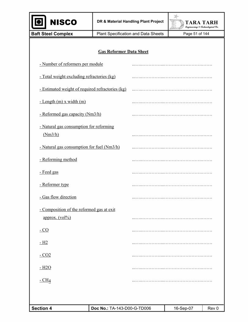
Section 4 Doc No.: TA-143-D00-G-TD006 16-Sep-07 Rev 0
TARA TARH Engineering & Technological Co.
DR & Material Handling Plant Project
Plant Specification and Data Sheets Baft Steel Complex Page 51 of 144
NISCO
Gas Reformer Data Sheet
- Number of reformers per module ...…..…………...…………………….…….
- Total weight excluding refractories (kg) ...…..…………...…………………….…….
- Estimated weight of required refractories (kg) ...…..…………...…………………….…….
- Length (m) x width (m) ...…..…………...…………………….…….
- Reformed gas capacity (Nm3/h) ...…..…………...…………………….…….
- Natural gas consumption for reforming
(Nm3/h) ...…..…………...…………………….…….
- Natural gas consumption for fuel (Nm3/h) ...…..…………...…………………….…….
- Reforming method ...…..…………...…………………….…….
- Feed gas ...…..…………...…………………….…….
- Reformer type ...…..…………...…………………….…….
- Gas flow direction ...…..…………...…………………….…….
- Composition of the reformed gas at exit
approx. (vol%) ...…..…………...…………………….…….
- CO ...…..…………...…………………….…….
- H2 ...…..…………...…………………….…….
- CO2 ...…..…………...…………………….…….
- H2O ...…..…………...…………………….…….
- CH4 ...…..…………...…………………….…….

Section 4 Doc No.: TA-143-D00-G-TD006 16-Sep-07 Rev 0
TARA TARH Engineering & Technological Co.
DR & Material Handling Plant Project
Plant Specification and Data Sheets Baft Steel Complex Page 52 of 144
NISCO
- N2 ...…..…………...…………………….…….
- Operating temperature (˚c) ...…..…………...…………………….…….
- Temperature of preheated feed gas before
reforming (˚c) ...…..…………...…………………….…….
- Temperature of reformed gas at exit (˚c) ...…..…………...…………………….…….
- Pressure of feed gas before reforming (ata) ...…..…………...…………………….…….
- Pressure of reformed gas at exit (ata) ...…..…………...…………………….…….
- Permissible sulphur in feed gas (ppm) ...…..…………...…………………….…….
- Reformer burners fuel ...…..…………...…………………….…….
- Fuel gas mixer type ...…..…………...…………………….…….
- Number and type of burners ...…..…………...…………………….…….
- Main burners ...…..…………...…………………….…….
- Auxiliary burners ...…..…………...…………………….…….
- Capacity of each burner (Gcal/h) ...…..…………...…………………….…….
- Gas consumption of each burner (Nm3/h)
Natural gas + top gas ...…..…………...…………………….…….
- Air consumption of each burner (Nm3/h) ...…..…………...…………………….…….
- Total heat input in normal working condition
(Gcal/h) ...…..…………...…………………….…….
- Number of catalyst tubes ...…..…………...…………………….…….
Section 4 Doc No.: TA-143-D00-G-TD006 16-Sep-07 Rev 0
TARA TARH Engineering & Technological Co.
DR & Material Handling Plant Project
Plant Specification and Data Sheets Baft Steel Complex Page 53 of 144
NISCO
- Material of tubes ...…..…………...…………………….…….
Method of construction ...…..…………...…………………….…….
- Internal diameter of tubes (mm) ...…..…………...…………………….…….
- External diameter of tubes (mm) ...…..…………...…………………….…….
- Tube length (m) ...…..…………...…………………….…….
- Tube life (years) ...…..…………...…………………….…….
- Provision for thermal expansion of tubes ...…..…………...…………………….…….
- Catalyst tubes fixed end ...…..…………...…………………….…….
- Weight of catalyst (kg) ...…..…………...…………………….…….
- Temperature distribution along the tube ...…..…………...…………………….…….
- length (˚c) ...…..…………...…………………….…….
Bottom ...…..…………...…………………….…….
Middle ...…..…………...…………………….…….
Top ...…..…………...…………………….…….
- Catalyst temperature at the tube center line
(˚c) ...…..…………...…………………….…….
Bottom ...…..…………...…………………….…….
Middle ...…..…………...…………………….…….
Top ...…..…………...…………………….…….
- Reformed gas cooler type ...…..…………...…………………….…….

Section 4 Doc No.: TA-143-D00-G-TD006 16-Sep-07 Rev 0
TARA TARH Engineering & Technological Co.
DR & Material Handling Plant Project
Plant Specification and Data Sheets Baft Steel Complex Page 54 of 144
NISCO
- Reformed gas cooler capacity (Nm3/hr) ...…..…………...…………………….…….
Section 4 Doc No.: TA-143-D00-G-TD006 16-Sep-07 Rev 0
TARA TARH Engineering & Technological Co.
DR & Material Handling Plant Project
Plant Specification and Data Sheets Baft Steel Complex Page 55 of 144
NISCO
Fuel Gas Mixer Data Sheet
- Type ……...………………………………………..
- Natural gas input rate ……………………………………….….…...
- Top gas input rate ……...………………………………………..
- Output rate ……...………………………………………..
- Manufacturer ……………………………………….….…...
- Place of manufacture ……...………………………………….…….

Section 4 Doc No.: TA-143-D00-G-TD006 16-Sep-07 Rev 0
TARA TARH Engineering & Technological Co.
DR & Material Handling Plant Project
Plant Specification and Data Sheets Baft Steel Complex Page 56 of 144
NISCO
Recuperator Data Sheet
- Total weight excluding refractories
- Estimated weight of required refractories
- Geometry and dimension
- Heating media
- Preheated gases
- Heating media rate (Nm3/h)
- Preheated gases rate (Nm3/h)
- Heating media temperature (˚c)
Input & Output
- Preheated gases temperature (˚c)
Input & Output
- Number of tubes
- Material of tubes
- Method of construction
- Internal diameter of tubes (mm)
- External diameter of tubes (mm)
- Total tube length (for each type) (m)
- Tube life (year)
- Provision for thermal expansion of tubes
- Shell plate material
- Shell plate thickness
………………………………………………
………………………………………………
………………………………………………
………………………………………………
………………………………………………
………………………………………………
………………………………………….……
………………………………………………
………………………………………………
………………………………………………
………………………………………………
………………………………………………
………………………………………………
………………………………………………
………………………………………………
………………………………………………
………………………………………………
………………………………………………
………………………………………………

Section 4 Doc No.: TA-143-D00-G-TD006 16-Sep-07 Rev 0
TARA TARH Engineering & Technological Co.
DR & Material Handling Plant Project
Plant Specification and Data Sheets Baft Steel Complex Page 57 of 144
NISCO
Top Gas & Cooling Gas System
- Top gas scrubber type …………………………………………….…
- Top gas scrubber capacity (Nm3/hr) ……………………………………….….…...
- Top gas scrubber water quantity (m3/hr) …………………………………………….…
- Top gas scrubber operating pressure (ata) …………………………………………….…
- Top gas scrubber dimension …………………………………………….…
- Top gas scrubber shell thickness (mm) …………………………………………….…
- Process gas mixer type ……...………………………………….…….
- Process gas mist eliminator type ……...………………………………………..
- Process gas mist eliminator capacity
(Nm3/hr)
……………………………………….….…...
- Cooling gas scrubber type ……...………………………………….…….
- Cooling gas scrubber capacity (Nm3/hr) ……...………………………………………..
- Cooling gas scrubber water quantity (m3/hr) ……...………………………………….…….
- Cooling gas scrubber operating pressure
(ata)
……...………………………………………..
- Cooling gas scrubber dimensions ……...………………………………….…….
- Cooling gas scrubber shell thickness (mm) ……...………………………………………..
- Cooling gas mist eliminator type ……………………………………….….…...
- Cooling gas mist eliminator capacity
(Nm3/hr)
……...………………………………….…….
Section 4 Doc No.: TA-143-D00-G-TD006 16-Sep-07 Rev 0
TARA TARH Engineering & Technological Co.
DR & Material Handling Plant Project
Plant Specification and Data Sheets Baft Steel Complex Page 58 of 144
NISCO
Seal, Inert and Purge Gas System
- Brief description of seal, inert, purge gas
system ………….…………………………………….
-Total generated seal gas (Nm3/h) ……………………………………………….
- Total necessary seal gas flow (Nm3/h) …………………………………………….…
- Seal gas cooler capacity (Nm3/h)
- Seal gas cooler water quantity (Nm3/h)
- Seal gas cooler dimensions
……………………………………….….…...
……...………………………………….…….
……...………………………………………..
- Seal gas dryer capacity (Nm3/h) ……………………………………………….
- Seal gas dryer operating pressure (ata) …………………………………………….…
- Seal gas dryer shell thickness (mm) ………………………………………….……
- Number of purge gas tank
- Purge gas tank dimensions …………………………………………….…
- Purge gas tank shell thickness (mm) ……………………………………….….…...
- Number of gas generators …………………………………………….…
- Capacity of each generator (Nm3/h) …………………………………………….…
- Number of inert gas storage tank ……………………………………………..…
- Total capacity of inert storage tank (Nm3) …………………………………………….…

Section 4 Doc No.: TA-143-D00-G-TD006 16-Sep-07 Rev 0
TARA TARH Engineering & Technological Co.
DR & Material Handling Plant Project
Plant Specification and Data Sheets Baft Steel Complex Page 59 of 144
NISCO
Dust Collectors
- Item number …………………………………………..……
- Type and function description …………………………………………..……
- Quantity of dust collected (kg/hr) …………………………………………..……
- Fan rating (Nm3/min) ……………………………………….….…...
- Duct air velocity (m/sec) ……...………………………………….…….
- Unit weight ……...………………………………………..
- Motor rating (kW) ……………………………………….….…...
- Assumed dust load (mg/Nm3) ……...………………………………….…….
- Collected dust discharge and removal
system ……...………………………………………..
- Dust content of exhaust air (mg/Nm3) ……………………………………….….…...
- Type and quantity of nozzles (if any exist) ……………………………………….….…...
- Manufacturer ……...………………………………….…….
- Place of manufacture ……...………………………………………..
- Other details and technical particulars ……………………………………….….…...
Section 4 Doc No.: TA-143-D00-G-TD006 16-Sep-07 Rev 0
TARA TARH Engineering & Technological Co.
DR & Material Handling Plant Project
Plant Specification and Data Sheets Baft Steel Complex Page 60 of 144
NISCO
Bag Filter
- Number of bag filter/system .………………………………………………
- Number of compartments per bag filter .………………………………………………
- Number of bags per compartment .………………………………………………
- Bag diameter (mm) .………………………………………………
- Bag effective length (mm) .………………………………………………
- Over all dimensions of bag filter
a) Length (m)
b) Width (m)
c) Height (m)
.………………………………………………
……………………………………………….
……………………………………………….
- Cladding material .………………………………………………
- Material of filter .………………………………………………
- Max, safe operation temperature )( C .………………………………………………
- Outlet air specification )( 3Nmmg .………………………………………………
- Guaranteed life of bags (years) .………………………………………………
- Number of dust hoppers .………………………………………………
- Slope of sides
(referred to horizontal) (degree) .………………………………………………
- Type of dampers .………………………………………………
- Number of dampers .………………………………………………
Section 4 Doc No.: TA-143-D00-G-TD006 16-Sep-07 Rev 0
TARA TARH Engineering & Technological Co.
DR & Material Handling Plant Project
Plant Specification and Data Sheets Baft Steel Complex Page 61 of 144
NISCO
- Bag cleaning method .………………………………………………
- Describe cycle of cleaning .………………………………………………
- Manufacturer .………………………………………………
- Place of manufacture .………………………………………………

Section 4 Doc No.: TA-143-D00-G-TD006 16-Sep-07 Rev 0
TARA TARH Engineering & Technological Co.
DR & Material Handling Plant Project
Plant Specification and Data Sheets Baft Steel Complex Page 62 of 144
NISCO
Dust Collection Duct System
- Duct diameter (mm) .………………………………………………
- Steel plate quality .………………………………………………
- Plate thickness (mm) .………………………………………………
- Type of dampers .………………………………………………
- Size of dampers ……………………………………….………
-Volume of air entrained when fully
open )(3
hNm .………………………………………………
- Manufacturer .………………………………………………
- Place of manufacture .………………………………………………
- Type of temperature detector .………………………………………………
- Temperature of actuation .………………………………………………

Section 4 Doc No.: TA-143-D00-G-TD006 16-Sep-07 Rev 0
TARA TARH Engineering & Technological Co.
DR & Material Handling Plant Project
Plant Specification and Data Sheets Baft Steel Complex Page 63 of 144
NISCO
Fans of Dust Collection Systems
- No. of fans/system ………………..…………………………..
- Type of fan …………………………………………….
- Manufacturer …………………………………………….
- Place of manufacture …………………………………………….
- Capacity per fan )(3
hNm …………………………………………….
- Working temperature (max.) )( C …………………………………………….
- Static pressure (kpa.gauge) …………………………………………….
- Power required (kW) …………………………………………….
- Fan motor rating (kW) …………………………………………….
- Motor type and speed (rpm) …………………………………………….
- Motor manufacturer …………………………………………….
- Place of manufacturer of motor …………………………………………….
- Weights …………………………………………….
- Noise level (dB) …………………………………………….

Section 4 Doc No.: TA-143-D00-G-TD006 16-Sep-07 Rev 0
TARA TARH Engineering & Technological Co.
DR & Material Handling Plant Project
Plant Specification and Data Sheets Baft Steel Complex Page 64 of 144
NISCO
Dust Conveying System
- Brief description of dust conveying
System …………………………………………….
…………………………………………….
…………………………………………….
…………………………………………….
- Type of dust discharge valves ………………………………………….….
- Capacity of valves )(3
hm ………………………………………….….
- Manufacturer ………………………………………….….
- Place of manufacture …………………………………………….

Section 4 Doc No.: TA-143-D00-G-TD006 16-Sep-07 Rev 0
TARA TARH Engineering & Technological Co.
DR & Material Handling Plant Project
Plant Specification and Data Sheets Baft Steel Complex Page 65 of 144
NISCO
Compressors Data Sheet
- Item No. …………………………………………….…
General:
- Function
No. of units:
In operation
Stand by
……………………………………….….…...
……...………………………………….…….
……...………………………………………..
- Manufacturer ……………………………………………….
- Place of manufacture ………………………………………………
Compressor Characteristics:
- Type ………………………………………………
- No. of stages ………………………………………………
- Fluid handled ………………………………………………
- Suction pressure (kg/cm2) ………………………………………………
- Delivery pressure (kg/cm2) ………………………………………………
- Suction temperature (˚c) ………………………………………………
- Delivery temperature (˚c) ………………………………………………
- Rated capacity (Nm3/hr) ………………………………………………
- Nature of cooling fluid ………………………………………………
- Cooling fluid requirements (Nm3/hr) ………………………………………………
Section 4 Doc No.: TA-143-D00-G-TD006 16-Sep-07 Rev 0
TARA TARH Engineering & Technological Co.
DR & Material Handling Plant Project
Plant Specification and Data Sheets Baft Steel Complex Page 66 of 144
NISCO
- Bearing type ……………………………………….….…...
- Lubrication system ……...………………………………….…….
- Coupling type ……...………………………………………..
- Efficiency at normal operating condition (%) ……………………………………….….…...
- Speed (rpm) ……...………………………………….…….
- Motor power (kW) ……...………………………………………..
Material:
- Casing ……...………………………………………..
- Impeller ……………………………………….….…...
- Shaft ……...………………………………….…….
- Bed plate ……...………………………………………..

Section 4 Doc No.: TA-143-D00-G-TD006 16-Sep-07 Rev 0
TARA TARH Engineering & Technological Co.
DR & Material Handling Plant Project
Plant Specification and Data Sheets Baft Steel Complex Page 67 of 144
NISCO
Fans and Blowers Data Sheet
- Item No. ……...………………………………………..
General: ……………………………………….….…...
- Function ……...………………………………….…….
- No. of units:
In operation
Stand by
……...………………………………………..
……………………………………………….
- Manufacturer ……...………………………………………..
- Place of manufacture ……………………………………….….…...
Characteristics: ……...………………………………….…….
- Type ……...………………………………………..
- Fluid handled ……...………………………………………..
- Total pressure (mm H2O) ……………………………………….….…...
- Suction pressure (mm H2O) ……...………………………………….…….
- Efficiency at rated capacity (%) ……...………………………………………..
- Capacity (Nm3/h) ……...………………………………………..
- Fan speed (rpm) ……………………………………….….…...
- Absorbed power at rated capacity (kW) ……...………………………………….…….
- Noise level (at a distance of one meter from
perimeter of the fan) ……...………………………………………..
- Motor power (kW) ……...………………………………………..

Section 4 Doc No.: TA-143-D00-G-TD006 16-Sep-07 Rev 0
TARA TARH Engineering & Technological Co.
DR & Material Handling Plant Project
Plant Specification and Data Sheets Baft Steel Complex Page 68 of 144
NISCO
Stack Data Sheet
- Dimension .………………………………………………
- Material .………………………………………………
- Total weight excluding refractories .………………………………………………
- Weight of required refractory .………………………………………………

Section 4 Doc No.: TA-143-D00-G-TD006 16-Sep-07 Rev 0
TARA TARH Engineering & Technological Co.
DR & Material Handling Plant Project
Plant Specification and Data Sheets Baft Steel Complex Page 69 of 144
NISCO
Cranes and Hoists Data Sheet
- I.D. No. .………………………………………………
- Function/Location .………………………………………………
- Type .………………………………………………
- Quantity .………………………………………………
- Capacity .………………………………………………
- Manufacturer .………………………………………………
- Place of manufacture .………………………………………………
Section 4 Doc No.: TA-143-D00-G-TD006 16-Sep-07 Rev 0
TARA TARH Engineering & Technological Co.
DR & Material Handling Plant Project
Plant Specification and Data Sheets Baft Steel Complex Page 70 of 144
NISCO
Shaft Furnaces Passenger and Goods Elevators Data Sheet
- Quantity .………………………………………………
- Carrying capacity (kg) .………………………………………………
- Inside cabinet dimensions (m) .………………………………………………
- Power of elevator motor (kW) .………………………………………………
- Speed (m/s) ……………………………………….………
- Lift (m) .………………………………………………
- Number of stops .………………………………………………
- Manufacturer .………………………………………………
- Place of manufacture .………………………………………………
Section 5 Doc No.: TA-143-D00-G-TD006 16-Sep-07 Rev 0
TARA TARH Engineering & Technological Co.
DR & Material Handling Plant Project
Plant Specification and Data Sheets Baft Steel Complex Page 71 of 144
NISCO
5- MATERIAL HANDLING SYSTEM DATA SHEETS
Tenderer shall fill in data of offered equipment in data sheets provided hereinafter.
Tenderer shall complete one datasheet for each type of equipment for raw material handling

Section 5 Doc No.: TA-143-D00-G-TD006 16-Sep-07 Rev 0
TARA TARH Engineering & Technological Co.
DR & Material Handling Plant Project
Plant Specification and Data Sheets Baft Steel Complex Page 72 of 144
NISCO
Combined Stacker Reclaimer Data Sheet
- Design stacking capacity (t/h) ………………………………………………
- Design reclaiming capacity (t/h) ………………………………………………
- Boom length (m) ………………………………………………
- Total weight(t) ……………………………………………....
- Pile ……………………………………………...
- Width
- Height
……………………………………………...
……………………………………………...
Belt Conveyor
- Width (mm) ………………………………………………
- Speed (m/s) ………………………………………………
- Power (kW) ………………………………………………
- Length (m) ………………………………………………
Travel
- Traveling speed (working speed) (m/min) ………………………………………………
- Out of operation traveling speed (m/min) ………………………………………………
- Rail type ………………………………………………
- Wheels diameter (mm) ………………………………………………
- Machine wheels Nr. ………………………………………………

Section 5 Doc No.: TA-143-D00-G-TD006 16-Sep-07 Rev 0
TARA TARH Engineering & Technological Co.
DR & Material Handling Plant Project
Plant Specification and Data Sheets Baft Steel Complex Page 73 of 144
NISCO
- Drive power (kW) ………………………………………………
- Operating wind pressure (kg/m2) ………………………………………………
Bucket Wheel
Type :
- Diameter (mm) ………………………………………………
- Speed (rpm) ………………………………………………
- Power (kW) ………………………………………………

Section 5 Doc No.: TA-143-D00-G-TD006 16-Sep-07 Rev 0
TARA TARH Engineering & Technological Co.
DR & Material Handling Plant Project
Plant Specification and Data Sheets Baft Steel Complex Page 74 of 144
NISCO
Truck Hydraulic Unloader Data Sheet
- Brief description of the system ………………………………………………
………………………………………………
………………………………………………
- Dimensions ………………………………………………
- Capacity (t) ………………………………………………
- Angle of rotation (o) ………………………………………………
- Hydraulic jack pressure ………………………………………………
- Hydraulic cylinder diameter ………………………………………………
- Hydraulic motor power
………………………………………………
- Tipping cycle time
………………………………………………
- Manufacturer
………………………………………………
- Other infromation
………………………………………………

Section 5 Doc No.: TA-143-D00-G-TD006 16-Sep-07 Rev 0
TARA TARH Engineering & Technological Co.
DR & Material Handling Plant Project
Plant Specification and Data Sheets Baft Steel Complex Page 75 of 144
NISCO
Belt Conveyors Data Sheet
- I.D. No.
- Center distance of end pulleys (m)
- Lift (mm)
- Belt width (mm)
- Belt speed (m/s)
- Handling rate (MT/h)
- Material handled
- Drive system and its components type
- Power consumption of conveyors
(including 15% extra power requested by
THE EMPLOYER ) (kW)
- Power installed of conveyors (kW)
- Type of take-up device
- Size of tail and drive pulleys
- Type of belt
- Belt material
……………………………….…………..…
….…………………………….………….…
………………………………...……………
………………………………...……………
………………………….……..……………
……………………………..…………….…
……………………………..…………….…
….………………………..…………………
…………………………………………...…
……………………………………..………
……………………………………...………
…………………………………….…..…...
……...……………………………….….….
……...………………………………….…..

Section 5 Doc No.: TA-143-D00-G-TD006 16-Sep-07 Rev 0
TARA TARH Engineering & Technological Co.
DR & Material Handling Plant Project
Plant Specification and Data Sheets Baft Steel Complex Page 76 of 144
NISCO
Oxide Pellet Coating System Data Sheet
Coating material ………………………………………………
Amount of coating material (kg/t) ………………………………………………
Brief description of coating system ………………………………………………

Section 5 Doc No.: TA-143-D00-G-TD006 16-Sep-07 Rev 0
TARA TARH Engineering & Technological Co.
DR & Material Handling Plant Project
Plant Specification and Data Sheets Baft Steel Complex Page 77 of 144
NISCO
Screen Stations Data Sheet
- I.D. No.
- Function & description of unit
- Type
- Rating (MT/h)
- Method of suspension & vibration
- No. of decks
- Mesh opening & screening area for each
deck
- Drive system type
- Power consumption of screen (kW)
- Time between deck replacements
- Specific materials used (e.g. for wear,
corrosion protection, etc. If any).
…….…………………………………..…...…
………………………………………………..
……….…………………….…………………
……………………………………………….
……………………………………………….
……………………………………………….
……………………………………………….
……………………………………….….…...
……...………………………………….…….
……...………………………………………..
……………………………………….….…...

Section 5 Doc No.: TA-143-D00-G-TD006 16-Sep-07 Rev 0
TARA TARH Engineering & Technological Co.
DR & Material Handling Plant Project
Plant Specification and Data Sheets Baft Steel Complex Page 78 of 144
NISCO
Belt Scales (Weighing System) Data Sheet
- I.D. No
- Function and description of unit
- Capacity & accuracy
- Other technical data
………………………………………………
………………………………………………
………………………………………………
………………………………………………

Section 5 Doc No.: TA-143-D00-G-TD006 16-Sep-07 Rev 0
TARA TARH Engineering & Technological Co.
DR & Material Handling Plant Project
Plant Specification and Data Sheets Baft Steel Complex Page 79 of 144
NISCO
Feeders Data Sheet
- I.D. No.
- Function & description of unit
- No. of units
- Type
- Rating (MT/h)
- Method of suspension
- Feed motion mechanism and particulars, e.g.
stroke length & rate, vibration, amplitude &
frequency, etc. Depending on the design
-Flow rate regulation system
-Installed drive power (kW)
-Manufacturer
-Place of manufacture
………………………………………………
………………………………………………
………………………………………………
……………………………………………….
……………………………………….….…...
……...………………………………….…….
……...………………………………………..
……………………………………….….…...
……...………………………………….…….
……...………………………………………..
……...………………………………………..
……...………………………………………..
……...………………………………………..
……………………………………………….
Section 5 Doc No.: TA-143-D00-G-TD006 16-Sep-07 Rev 0
TARA TARH Engineering & Technological Co.
DR & Material Handling Plant Project
Plant Specification and Data Sheets Baft Steel Complex Page 80 of 144
NISCO
Transfer Towers Data Sheet
- I.D. No. ……………………………………………..…
- Dimensions: base area x height. Approx. (m) ……………………………………………..…
- No. of platforms ……………………………………………..…
- Covers, grating, etc. ……………………………………………..…
Section 5 Doc No.: TA-143-D00-G-TD006 16-Sep-07 Rev 0
TARA TARH Engineering & Technological Co.
DR & Material Handling Plant Project
Plant Specification and Data Sheets Baft Steel Complex Page 81 of 144
NISCO
Diverters Data Sheet
- I.D. No. .………………………………………………
- Function & description of unit .………………………………………………
- Method of actuation
- Specific materials used (e.g. for wear,
corrosion protection, etc. if any)
.………………………………………………
……………………………………….….…...
Section 5 Doc No.: TA-143-D00-G-TD006 16-Sep-07 Rev 0
TARA TARH Engineering & Technological Co.
DR & Material Handling Plant Project
Plant Specification and Data Sheets Baft Steel Complex Page 82 of 144
NISCO
Bins and Hoppers Data Sheet
- I.D. No. .………………………………………………
- Function & description of unit .………………………………………………
- Geometry
- Dimensions & capacity
- Specific materials used (e.g. for wear,
corrosion protection, etc. if any)
.………………………………………………
……………………………………….….…...
……...………………………………….…….

Section 6 Doc No.: TA-143-D00-G-TD006 16-Sep-07 Rev 0
TARA TARH Engineering & Technological Co.
DR & Material Handling Plant Project
Plant Specification and Data Sheets Baft Steel Complex Page 83 of 144
NISCO
6- FLUID SYSTEM DATA SHEET
Design, selection and installation of fluid systems and equipment shall be in accordance with
standards and specification which have been specified in these tender documents. Tenderer shall
fill in data of offered system and equipment in the data sheets provided hereinafter.
Technical specification for the equipment which has not been specified here and is necessary for
reliability of the system shall be specified by the tenderer.

Section 6 Doc No.: TA-143-D00-G-TD006 16-Sep-07 Rev 0
TARA TARH Engineering & Technological Co.
DR & Material Handling Plant Project
Plant Specification and Data Sheets Baft Steel Complex Page 84 of 144
NISCO
Plate heat exchangers
- Manufacturer ………...………………………………...
- Place of manufacturer …………………………………………..
- Number …………………………………………..
- Flow rate of cooling water (m3/hr) …………………………………………..
- Flow rate of cold water (m3/hr) …………………………………………..
- Cooling water inlet/outlet temperature (ºC) …………………………………………..
- Cold water inlet/outlet temperature (ºC) …………………………………………..
- Cooling water pressure drop (kpa) …………………………………………..
- Cold water pressure drop (kpa) …………………………………………..
- Overall heat transfer coefficient (kcal/m2. ºc.h) …………………………………………..
- Overall heat transfer Area (m2) …………………………………………..
- Heat transferred (kW) …………………………………………..
- Fouling factor ..(2
hm ckcal) …………………………………………..
- Surface margin (%) …………………………………………..
- Material
a ) Plate …………………………………………..
b) Gasket ……………………………………….….
c) Frame …………………………………………..

Section 6 Doc No.: TA-143-D00-G-TD006 16-Sep-07 Rev 0
TARA TARH Engineering & Technological Co.
DR & Material Handling Plant Project
Plant Specification and Data Sheets Baft Steel Complex Page 85 of 144
NISCO
Clarifier
- Number of tanks ..................................................................
- Type of tank circular rectangular
- Capacity (m3/h) ..................................................................
- Detention time ..................................................................
- Tank Net volume (m3) ..................................................................
- Design surface load (m3/m
2.h) ..................................................................
- Tank Dimensions (m) ..................................................................
- Slope of Bottom (%) ..................................................................
- Expected effluent suspended solid
concentration (in maximum inlet
suspended solid condition) (mg/l) ..................................................................
- Bridge traveling velocity (m/min) ..................................................................
- Manufacture and place of manufacture ..................................................................
a) bridge structure ..................................................................
b) gear ..................................................................
c) motor ..................................................................
d) scraper ..................................................................
e) wheels ..................................................................
f) weir ..................................................................
g) power transfer system ..................................................................
- bridge length (m) ..................................................................
- width of bridge walk way (cm) ..................................................................
- weir length ..................................................................

Section 6 Doc No.: TA-143-D00-G-TD006 16-Sep-07 Rev 0
TARA TARH Engineering & Technological Co.
DR & Material Handling Plant Project
Plant Specification and Data Sheets Baft Steel Complex Page 86 of 144
NISCO
- time interval between each blow off in
maximum inlet suspended solids (min) ..................................................................
- material ..................................................................
a) tank ..................................................................
b) bridge structure ..................................................................
c) scraper and wheels ..................................................................
d) weir ..................................................................
- protective treatment ..................................................................
a) shot blasting ..................................................................
b) coating ..................................................................
d) description ..................................................................
- Chemical used & quantity ..................................................................

Section 6 Doc No.: TA-143-D00-G-TD006 16-Sep-07 Rev 0
TARA TARH Engineering & Technological Co.
DR & Material Handling Plant Project
Plant Specification and Data Sheets Baft Steel Complex Page 87 of 144
NISCO
Cooling Circuit
- Cooling circuit denomination ..........................................................................
- Acceptable cooling water analysis ..........................................................................
- Water flow rate (m3/h) ..........................................................................
- Water volume in the circuit (m3) ..........................................................................
- Supply water temperature (oC) ..........................................................................
- return water temperature (oC) ..........................................................................
- Supply water pressure (kpa) ..........................................................................
- Expected corrosion rate (mpy) ..........................................................................
- Chemical conditioning system description
for circulation water ………………………………………………..
Section 6 Doc No.: TA-143-D00-G-TD006 16-Sep-07 Rev 0
TARA TARH Engineering & Technological Co.
DR & Material Handling Plant Project
Plant Specification and Data Sheets Baft Steel Complex Page 88 of 144
NISCO
Cooling Towers
- Manufacturer ..........................................................................
- place of manufacturer ..........................................................................
- Preliminary duty of tower (Design condition) ..........................................................................
a) Water flow (m3/h) ..........................................................................
b) Inlet water temperature (oC) ..........................................................................
c) Outlet water temperature (oC) ..........................................................................
- Type of tower ..........................................................................
- Number of cells ..........................................................................
- Lifetime of cooling tower and its auxiliaries ..........................................................................
- Maximum size of largest section ..........................................................................
a) Length ..........................................................................
b) Width ..........................................................................
c) Height ..........................................................................
- Preliminary proposed packing ..........................................................................
a) Type ..........................................................................
b) Material ..........................................................................
c) Depth ..........................................................................
- Casing ..........................................................................
Section 6 Doc No.: TA-143-D00-G-TD006 16-Sep-07 Rev 0
TARA TARH Engineering & Technological Co.
DR & Material Handling Plant Project
Plant Specification and Data Sheets Baft Steel Complex Page 89 of 144
NISCO
a) Material ..........................................................................
b) Protective material ..........................................................................
- Fans ..........................................................................
a) Type ..........................................................................
b) Number of fans ..........................................................................
c) Fan static pressure (mm H2O) ..........................................................................
d) Fan speed (rpm) ..........................................................................
e) Blade material ..........................................................................
- Motors ..........................................................................
a) Manufacturer ..........................................................................
b) Number ..........................................................................
c) Absorbed power (kW) ..........................................................................
d) Rated power (kW) ..........................................................................
e) Speed (rpm) ..........................................................................
f) Electrical supply ..........................................................................
Voltage (V) ..........................................................................
Phase ..........................................................................
Frequency (Hz) ..........................................................................
Frame size ..........................................................................
Section 6 Doc No.: TA-143-D00-G-TD006 16-Sep-07 Rev 0
TARA TARH Engineering & Technological Co.
DR & Material Handling Plant Project
Plant Specification and Data Sheets Baft Steel Complex Page 90 of 144
NISCO
Enclosure ..........................................................................
- Drift eliminators ..........................................................................
a) Material ..........................................................................
b) Expected drift loss (%) ..........................................................................
- Make up water ..........................................................................
a) type ..........................................................................
b) temperature (oC) ..........................................................................
c) pressure (kpa) ..........................................................................
d) expected maximum flow rate (m3/h) ..........................................................................
e) analysis ..........................................................................
- Noise level and spectrum with all fans
working ratio dB(A) ..........................................................................
Section 6 Doc No.: TA-143-D00-G-TD006 16-Sep-07 Rev 0
TARA TARH Engineering & Technological Co.
DR & Material Handling Plant Project
Plant Specification and Data Sheets Baft Steel Complex Page 91 of 144
NISCO
Centrifugal Pumps
- Manufacturer ..........................................................................
- place of manufacturer ..........................................................................
- Type of pump ..........................................................................
- Number of pumps (operating, stand by) ..........................................................................
- Function ..........................................................................
- Liquid ..........................................................................
- Capacity (m3/h) ..........................................................................
- Differential head (m.W.c) ..........................................................................
- Efficiency (%) ..........................................................................
- Absorbed power (kW) ..........................................................................
- Rotating speed (rpm) ..........................................................................
- Motor power and speed (kW, rpm) ..........................................................................
- Impeller type ..........................................................................
- Impeller diameter (min/rated/max) (mm) ..........................................................................
- Seal type ..........................................................................
- Material ..........................................................................
a) Casing ..........................................................................
b) Impeller ..........................................................................
c) Shaft ..........................................................................
Section 6 Doc No.: TA-143-D00-G-TD006 16-Sep-07 Rev 0
TARA TARH Engineering & Technological Co.
DR & Material Handling Plant Project
Plant Specification and Data Sheets Baft Steel Complex Page 92 of 144
NISCO
Chemical Dosing Units
- Manufacturer ..........................................................................
- Place of manufacturer ..........................................................................
- Function ..........................................................................
- Chemical solution preparation tank ..........................................................................
a) Material ..........................................................................
b) Type ..........................................................................
c) Dimensions (m) ..........................................................................
- Mixer ..........................................................................
a) Manufacturer ..........................................................................
b) Mixer type ..........................................................................
c) Absorbed power (kW) ..........................................................................
d) Rotating speed (rpm) ..........................................................................
e) Motor power and speed (kW, rpm) ..........................................................................
f) Propeller/Impeller type, material
& diameter
..........................................................................
g) Shaft and coupling material ..........................................................................
- Dosing pumps ..........................................................................
a) Manufacturer ..........................................................................
b) Place of manufacturer ..........................................................................

Section 6 Doc No.: TA-143-D00-G-TD006 16-Sep-07 Rev 0
TARA TARH Engineering & Technological Co.
DR & Material Handling Plant Project
Plant Specification and Data Sheets Baft Steel Complex Page 93 of 144
NISCO
c) Type ..........................................................................
d) Number (operating , Stand by) ..........................................................................
e) Maximum capacity (lit/hr) ..........................................................................
f) Discharge pressure (kpa) ..........................................................................
g) Motor speed and power (rpm, kW) ..........................................................................
h) Instrument included: Relief valve:
……….. Pressure gage: …………other:
…….….
- Material
Liquid end ..........................................................................
Plunger/Diaphragm ..........................................................................
Packing/Seal ..........................................................................

Section 6 Doc No.: TA-143-D00-G-TD006 16-Sep-07 Rev 0
TARA TARH Engineering & Technological Co.
DR & Material Handling Plant Project
Plant Specification and Data Sheets Baft Steel Complex Page 94 of 144
NISCO
Air Compressors
Manufacturer ………………………………………………..
Place of manufacturer ………………………………………………..
Type ………………………………………………..
Number of compressor (operation, standby) ………………………………………………..
Function ………………………………………………...
Number of stages ………………………………………………..
Capacity (Nm3/h) ………………………………………………..
Working pressure (bar)
Min/Max pressure (bar)
………………………………………………..
………………………………………………...
Efficiency (%) ………………………………………………..
Rotating speed (rpm) ………………………………………………..
Motor
o power and speed (kW, rpm)
o Manufacturer
o Place of manufacturer
o Protection insulation
………………………………………………...
………………………………………………...
………………………………………………...
………………………………………………...
Compression: Oil free, Dry Oil free, liquid injected Oil injected
Cooling type
water cooled Air cooled
Noise level (in 1 m distance)
Material
………………………………………………..
o Air end casing ………………………………………………..
o Rotor ………………………………………………..

Section 6 Doc No.: TA-143-D00-G-TD006 16-Sep-07 Rev 0
TARA TARH Engineering & Technological Co.
DR & Material Handling Plant Project
Plant Specification and Data Sheets Baft Steel Complex Page 95 of 144
NISCO
Air Dryers
Manufacturer ……………………………………………….
Place of manufacturer ……………………………………………….
Air dryer type ……………………………………………….
Number of air dryer (operation, stand by) ……………………………………………….
Function ……………………………………………….
Capacity (Nm3/hr) ……………………………………………….
Min / Max working pressure (bar)
Test pressure (bar)
Dew point of air at the dryer exit (ºC) ……………………………………………….
Regeneration type ( for adsorption type ) ……………………………………………….
Change over cycle ( for adsorption type ) ……………………………………………….
Material ……………………………………………….
o Vessel ……………………………………………….
o Desicant (for adsorption type) ……………………………………………….

Section 6 Doc No.: TA-143-D00-G-TD006 16-Sep-07 Rev 0
TARA TARH Engineering & Technological Co.
DR & Material Handling Plant Project
Plant Specification and Data Sheets Baft Steel Complex Page 96 of 144
NISCO
Air Receivers
Item No. ……………………………………………….
Manufacturer ……………………………………………….
Place of manufacturer ……………………………………………….
Type ……………………………………………….
Number ……………………………………………….
Function ……………………………………………….
Net capacity (m3) ……………………………………………….
Working pressure (bar) ……………………………………………….
Design pressure (bar) ……………………………………………….
Test pressure (bar) ……………………………………………….
Design code ……………………………………………….
Head thickness ……………………………………………….
Shell thickness ……………………………………………….
Dimension
o Height ……………………………………………….
o Diameter ……………………………………………….
Internal lining ……………………………………………….
External coating ……………………………………………….
Insulation type and thickness ……………………………………………….
Material of construction ……………………………………………….

Section 6 Doc No.: TA-143-D00-G-TD006 16-Sep-07 Rev 0
TARA TARH Engineering & Technological Co.
DR & Material Handling Plant Project
Plant Specification and Data Sheets Baft Steel Complex Page 97 of 144
NISCO
Filters
Manufacturer ………………………………………………..
Place of manufacturer ………………………………………………..
Type ………………………………………………..
QTY ………………………………………………..
Function ………………………………………………..
Number of stages ………………………………………………..
Capacity (Nm3/h) ………………………………………………..
Working pressure (bar)
Max pressure (bar)
Drain method (automatic, manual)
Particle removal
………………………………………………..
………………………………………………..
………………………………………………..
………………………………………………..

Section 6 Doc No.: TA-143-D00-G-TD006 16-Sep-07 Rev 0
TARA TARH Engineering & Technological Co.
DR & Material Handling Plant Project
Plant Specification and Data Sheets Baft Steel Complex Page 98 of 144
NISCO
Heating, Ventilation and Air Conditioning System
Data sheet
Contractor shall submit a complete description of heating, ventilation and air conditioning
system offered for the direct reduction plant and raw material handling plant specification of
equipment. Catalogue of equipment shall also be enclosed.

Section 6 Doc No.: TA-143-D00-G-TD006 16-Sep-07 Rev 0
TARA TARH Engineering & Technological Co.
DR & Material Handling Plant Project
Plant Specification and Data Sheets Baft Steel Complex Page 99 of 144
NISCO
Air Conditioning Unit
Location ……………………………………………….
Item number (s) ……………………………………………….
Number of units:
o In operation ……………………………………………….
o Stand-by ……………………………………………….
Type ……………………………………………….
Air Conditioning Unit Characteristics
Heating data ……………………………………………….
o Heating load ……………………………………………….
o Fresh air rate ……………………………………………….
Cooling data ……………………………………………….
o Total cooling load ……………………………………………….
o Fresh air rate ……………………………………………….
Fan data
Capacity ……………………………………………….
Motor power ……………………………………………….
Compressor data
Number ……………………………………………….
Total power of compressors ……………………………………………….
Remote Condenser Characteristics
Total heat rejection ……………………………………………….
Ambient air temp. ……………………………………………….
Condensing temp. ……………………………………………….
Refrigerant ……………………………………………….
Number of fan motor ……………………………………………….
Power of each motor ……………………………………………….

Section 6 Doc No.: TA-143-D00-G-TD006 16-Sep-07 Rev 0
TARA TARH Engineering & Technological Co.
DR & Material Handling Plant Project
Plant Specification and Data Sheets Baft Steel Complex Page 100 of 144
NISCO
Fire Fighting, Detection and Alarm System
Data Sheets
Contractor shall submit a complete description of fire detection, alarm and fighting system
offered for the direct reduction plant and raw material handling plant including specification of
equipment. Catalogue of equipment shall also be enclosed.

Section 6 Doc No.: TA-143-D00-G-TD006 16-Sep-07 Rev 0
TARA TARH Engineering & Technological Co.
DR & Material Handling Plant Project
Plant Specification and Data Sheets Baft Steel Complex Page 101 of 144
NISCO
Fire Alarm
Manufacturer’s name and country:
o Type designation ………………………………………………..
o Detector type ………………………………………………..
o Calibration level of LEL ………………………………………………..
o Fire alarm panel generated voltage ………………………………………………..
o Input voltage ………………………………………………..
o Protection degree ………………………………………………..
o Number of loops ………………………………………………..
o Cable type ………………………………………………..
o Audible alarm type ………………………………………………..
o Visual alarm type ………………………………………………..
o Back up battery duration ………………………………………………..
o Quality ………………………………………………..
Section 6 Doc No.: TA-143-D00-G-TD006 16-Sep-07 Rev 0
TARA TARH Engineering & Technological Co.
DR & Material Handling Plant Project
Plant Specification and Data Sheets Baft Steel Complex Page 102 of 144
NISCO
Fixed fire extinguishing CO2 Cylinder Specifications
Location ………………………………………………..
Number of cylinders ………………………………………………..
Capacity ………………………………………………..
Height ………………………………………………..
Diameter ………………………………………………..
CO2 pressure at 20 °C ………………………………………………..
Test pressure ………………………………………………..

Section 6 Doc No.: TA-143-D00-G-TD006 16-Sep-07 Rev 0
TARA TARH Engineering & Technological Co.
DR & Material Handling Plant Project
Plant Specification and Data Sheets Baft Steel Complex Page 103 of 144
NISCO
Portable Fire Extinguishing (CO2 System)
Item No. ………………………………………………..
Number of unit ………………………………………………..
Gas weight ………………………………………………..
Total weight ………………………………………………..
Cylinder material ………………………………………………..
Hose material ………………………………………………..
Working pressure ………………………………………………..
Discharge duration ………………………………………………..
Discharge distance ………………………………………………..

Section 6 Doc No.: TA-143-D00-G-TD006 16-Sep-07 Rev 0
TARA TARH Engineering & Technological Co.
DR & Material Handling Plant Project
Plant Specification and Data Sheets Baft Steel Complex Page 104 of 144
NISCO
Portable Fire Extinguishing (chemical dry powder)
Item No. ………………………………………………..
Number of unit ………………………………………………..
Total weight ………………………………………………..
Cylinder material ………………………………………………..
Hose material ………………………………………………..
Working pressure ………………………………………………..
Discharge duration ………………………………………………..
Discharge distance ………………………………………………..

Section 7 Doc No.: TA-143-D00-G-TD006 16-Sep-07 Rev 0
TARA TARH Engineering & Technological Co.
DR & Material Handling Plant Project
Plant Specification and Data Sheets Baft Steel Complex Page 105 of 144
NISCO
7. Electrical Equpment Data Sheet
7.1- Medium Voltage Switchgear Cubicle
Plant Unit Number (P.U No.) ………...……………………………………...
Manufacturer’s name and country ………...……………………………………...
Manufacturer’s type designation ………...……………………………………...
GIS or conventional ………...……………………………………...
Indoor or outdoor installation ………...……………………………………...
Number of phases ………...……………………………………...
Number of busbars ………...……………………………………...
Rated voltages …………………………………… kV (r.m.s)
Rated insulation level (at IEC service
conditions): ………………………………………………..
o Rated 1 min. power frequency withstand
voltage …………………………………… kV (r.m.s)
o Rated lightning impulse withstand voltage …………………………………… kV (r.m.s)
Rated normal current of circuits:
o Busbar & bus-section feeder …………………………………… A (r.m.s)
o Trafo feeder …………………………………… A (r.m.s)
o Outgoing feeder …………………………………… A (r.m.s)
o Rated short-time withstand current …………………………………… kA (r.m.s)
Rated duration of short circuit ………………..……..……………………(S)
Rated peak withstand current ……………………………………..kV (peak)
Current transformer type and manufacturer ………...……………………………………...
Current transformer burden and accuracy ………...……………………………………...
Current transformer ratio ………...……………………………………...
Voltage transformer type and manufacturer ………...……………………………………...
Voltage transformer burden and accuracy ………...……………………………………...
Voltage transformer ratio ………...……………………………………...
Ground switch type and manufacturer ………...……………………………………...

Section 7 Doc No.: TA-143-D00-G-TD006 16-Sep-07 Rev 0
TARA TARH Engineering & Technological Co.
DR & Material Handling Plant Project
Plant Specification and Data Sheets Baft Steel Complex Page 106 of 144
NISCO
Ground switch type of mechanism ………...……………………………………...
Ground switch type of interlock ………...……………………………………...
Ground switch number and type of
auxiliary switch ………...……………………………………...
Ground switch type of blade ………...……………………………………...
Type and rating of fuses for voltage ………...……………………………………...
Transformer circuits:
o Primary H.V. fuses ……………….…………………………(A)
o Secondary L.V. fuses ……………….…………………………(A)
Degree of protection for the enclosure and
partitions ………………………………………………..
o For the enclosure ………...……………………………………...
o Between LV+HV compartments ………...……………………………………...
Cubicle weight
o Incoming …………………..………………………(kg)
o Bus-section …………………..………………………(kg)
o Outgoing …………………..………………………(kg)
Cubicle shipping weight including circuit
breaker …………………..………………………(kg)
o Cubicle dimensions (L × W × H) ……………………...……………….….(cm3)
o Earthquake protection (coefficient of g) ………...……………………………………...
Type of metal enclosed switchgear ………...……………………………………...
SF6 gas filling pressure (abs) ………...……………………………………...
Minimum SF6 gas operation pressure (abs) ………...……………………………………...
Gas pressure for alarm ………...……………………………………...
Gas pressure for trip ………...……………………………………...
NOTE: For each type of Switchgear an individual data sheet shall be prepared.

Section 7 Doc No.: TA-143-D00-G-TD006 16-Sep-07 Rev 0
TARA TARH Engineering & Technological Co.
DR & Material Handling Plant Project
Plant Specification and Data Sheets Baft Steel Complex Page 107 of 144
NISCO
7.2- Circuit Breakers & Contactor
Circuit breakers:
Current brekers ………...……………………………………...
Plant Unit Number (P.U No.) ………...……………………………………...
Manufacturer’s name and country ………...……………………………………...
Manufacturer’s designation (Type) ………...……………………………………...
Applicable technical ………...……………………………………...
standards ………...……………………………………...
Type of circuit breaker (SF6 or vacuum) ………...……………………………………...
Mass of complete circuit breaker ………...……………………………………...
Creepage to earth over insulation ………...……………………………………...
Minimum clearances: ………...……………………………………...
o Between phases ………………………………………….(mm)
o Between live parts to earth ………………………………………….(mm)
Overall dimension of the installation ………...……………………………………...
Indoor or outdoor installation ………...……………………………………...
Number of phases ………...……………………………………...
Number of poles ………...……………………………………...
Rated Voltages …………………………...………..kV (r.m.s)
Rated frequency …………………………………………(Hz)
Rated insulation level (at IEC service
conditions): ………...……………………………………...
o Rated 1 min. power frequency withstand
voltage ……………………………...……..kV (r.m.s)
o Rated lightning impulse withstand voltage ……………………………………..kV (peak)
Rated normal current (at IEC service
conditions): ………………………..…………… A (r.m.s)
Rated short-circuit breaking current …………………………………… kA (r.m.s)
Rated duration of short circuit ………………….…………………………(S)
Section 7 Doc No.: TA-143-D00-G-TD006 16-Sep-07 Rev 0
TARA TARH Engineering & Technological Co.
DR & Material Handling Plant Project
Plant Specification and Data Sheets Baft Steel Complex Page 108 of 144
NISCO
Rated line-charging breaking current …………………………………… A (r.m.s)
Rated cable-charging breaking current …………………………………… A (r.m.s)
Rated small- indactive breaking current
First pole to clear factor ………………………………………………..
Rated transient recovery voltage (TRV) for
terminal faults …………………………………… kV (r.m.s)
Rated characteristics for short-line faults …………………………………… kA (r.m.s)
Rated short-circuit making current …………………………………… kA (r.m.s)
Rated out-of- phase breaking current …………………………………… kA (r.m.s)
Rated operating sequence ………...……………………………………...
Rated time quantities: ………...……………………………………...
o Rated opening time ……………………………………..……(ms)
o Rated break time ……………………………………..……(ms)
o Rated closing time ……………………………………..……(ms)
o Rated make time ……………………………………..……(ms)
o Max. Time interval between opening of
first and last phase of three phase circuit-
breaker ……………………………………..……(ms)
o Closing time from energize of close coil
to latching of circuit breaker in fully
closed position ……………………………………..……(ms)
Max. Temperature rise under rated load
condition …………………………………...………(ºC)
Max. Peak value of switching over voltage
when interrupting rated line charging current …………………………………………(kV)
Voltages drop across terminals of a phase at
100 A DC ………………………………………… (mV)
Breaking current (Asymmetrical) ………………………………….………...(A)
Number of NO & NC auxiliary contacts ………...……………………………………...
Section 7 Doc No.: TA-143-D00-G-TD006 16-Sep-07 Rev 0
TARA TARH Engineering & Technological Co.
DR & Material Handling Plant Project
Plant Specification and Data Sheets Baft Steel Complex Page 109 of 144
NISCO
Contactors
Fuse type ………...……………………………………...
Fuse rated voltage ………...……………………………………...
Fuse rated current ………...……………………………………...
Contactor type ………...……………………………………...
Contactor rated voltage ………...……………………………………...
Contactor rated current ………...……………………………………...
NOTE: For each type of Circuit Breaker and contractors an individual data sheet shall be
prepared.
7.3- Transformers
Plant Unit Number (P.U No.) ………….………….…………………………
Manufacture’s name and country ………….………….…………………………
Type and designation ………….………….…………………………
Rated capacity ………….………….…………………………
Number of phases ………….………….…………………………
Frequency ………….………….…………………………
Voltage ratio ………….………….…………………………
Cooling ………….………….…………………………
Temperature Rise at rated capacity ………….………….…………………………
Windings ………….………….…………………………
o H.V.
Rated capacity ………….………….…………………………
Voltage rating ………….………….…………………………
Connection ………….………….…………………………
o L.V.
Voltage rating ………….………….…………………………
Connection ………….………….…………………………
(i) Insulation Levels

Section 7 Doc No.: TA-143-D00-G-TD006 16-Sep-07 Rev 0
TARA TARH Engineering & Technological Co.
DR & Material Handling Plant Project
Plant Specification and Data Sheets Baft Steel Complex Page 110 of 144
NISCO
Power frequency test voltage for 60 Sec.
o On windings:
H.V. Neutral ………….………….…………………………
L.V. Winding ………….………….…………………………
o On bushings:
H.V. Winding ………….………….…………………………
H.V. Neutral ………….………….…………………………
L.V. Winding ………….………….…………………………
Impulses withstand voltage, wave 1.2/50 s
o On windings:
H.V. Winding ………….………….…………………………
L.V. Winding ………….………….…………………………
o On bushings:
H.V. Winding end ………….………….…………………………
H.V. Neutral end ………….………….…………………………
L.V. Winding end ………….………….…………………………
(ii) On load tap changer
Tapping Range ………….………….…………………………
Number of tap steps ………….………….…………………………
(iii) Current transformers installed in the H.V.
Bushings
Number for each phase ………….………….…………………………
Number in the neutral ………….………….…………………………
Current Ratios ………….………….…………………………
Standard ………….………….…………………………
(iv) Item fault level ………….………….…………………………
(v) Vacuum Requirements ………….………….…………………………
(vi)Terminations ………….………….…………………………
H.V. ………….………….…………………………
L.V. ………….………….…………………………

Section 7 Doc No.: TA-143-D00-G-TD006 16-Sep-07 Rev 0
TARA TARH Engineering & Technological Co.
DR & Material Handling Plant Project
Plant Specification and Data Sheets Baft Steel Complex Page 111 of 144
NISCO
(vii) Vector group ………….………….…………………………
NOTE: For each type of transformer an individual data sheet shall be prepared.
7.4- DC Supplies and Equipment Battery
Plant Unit Number (P.U No.) ………….………….…………………………
Manufacturer name/country of origin ………….………….…………………………
Rating of system:
o Nominal supply voltage of system (V) ………….………….…………………………
o Float voltage of battery (V) ………….………….…………………………
o Battery voltage after 10 hour discharge
period (at 25A discharge rating) (V) ………….………….…………………………
Rated discharge capacity:
o Discharge current (250m sec. impulse) ………….………….…………………………
o At 1 hr. rate (Ah) ………….………….…………………………
o At 10 hr. rate (Ah) ………….………….…………………………
Type of cell (i.e.: Lead acid or alkaline) and
designation ………….………….…………………………
Particulars of cells:
o Voltage per cell when float charged (V) ………….………….…………………………
o Voltage per cell at end of 1 hr. discharged
period (V) ………….………….…………………………
o Voltage per cell at end of 10 hr. discharge
period (V) ………….………….…………………………
o Charging current:
Initial (A) ………….………….…………………………
Starting (Max.) (A) ………….………….…………………………
Continuous (A) ………….………….…………………………
o Final voltage per cell when boost
charged (V) ………….………….…………………………

Section 7 Doc No.: TA-143-D00-G-TD006 16-Sep-07 Rev 0
TARA TARH Engineering & Technological Co.
DR & Material Handling Plant Project
Plant Specification and Data Sheets Baft Steel Complex Page 112 of 144
NISCO
o Maximum permissible instant current at
one minute(A) ………….………….…………………………
o Total resistance of battery (Ohm) ………….………….…………………………
Battery and cell arrangement:
o Number of cells ………….………….…………………………
o Number of tiers and cells per tier ………….………….…………………………
o Type of container (plastic, glass or steel) ………….………….…………………………
o Number of cells and method of assembly
per group (Alkaline batteries only) ………….………….…………………………
o Mass of cell complete with electrolyte (kg) ………….………….…………………………
o Maximum mass of largest transportation (state
item if cell not transported complete) (kg) ………….………….…………………………
o Mass of battery and stands as in service (kg) ………….………….…………………………
o Type of positive plate ………….………….…………………………
o Type of negative plate ………….………….…………………………
o Electrolyte specific gravity at 25ºC, when
the cells are fully charged (gr/cm3) ………….………….…………………………
o Complete battery dimension H×W×H ………….………….…………………………
o Expected life of battery (Year) ………….………….…………………………
Battery fuse: (A) ………….………….…………………………
o Manufacturer and type designation ………….………….…………………………
o Rating- amps. (Ah) ………….………….…………………………
7.5- Battery Charger
Plant Unit Number (P.U No.) ………….………….…………………………
Manufacturer name/country of origin ………….………….…………………………
Standard ………….………….…………………………
Input voltage/frequency ………….………….…………………………
Tolerances of input voltage/frequency ………….………….…………………………
Output voltage ………….………….…………………………

Section 7 Doc No.: TA-143-D00-G-TD006 16-Sep-07 Rev 0
TARA TARH Engineering & Technological Co.
DR & Material Handling Plant Project
Plant Specification and Data Sheets Baft Steel Complex Page 113 of 144
NISCO
Output regulation ………….………….…………………………
Output ripple ………….………….…………………………
Protection degree ………….………….…………………………
Max. Charging current ………….………….…………………………
Power rating ………….………….…………………………
Transformer type ………….………….…………………………
Thyristor type ………….………….…………………………
Cooling system ………….………….…………………………
7.6- Lighting
Plant Unit Number (P.U No.) ………….………….…………………………
Manufacture’s name and country ………….………….…………………………
Min. Illumination level (Name of area’s) ………….………….…………………………
Max. Illumination level (Name of area’s) ………….………….…………………………
Protection degree of Indoor/outdoor fixture ………….………….…………………………
Indoor fixture type/Lamp type/rating ………….………….…………………………
Outdoor fixture type/Lamp type/rating ………….………….…………………………
Fixture with capacitor ………….………….…………………………
Power factor of lighting ………….………….…………………………
Max. Noise level of lighting ………….………….…………………………
Fluorescent start system ………….………….…………………………
Socket out let type and rating ………….………….…………………………
Switch type and rating ………….………….…………………………
7.7- Low Voltage AC Switchgear
Plant Unit Number (P.U No.) ………………………………………………
Manufacturer name/country and type
designation ………………………………………………

Section 7 Doc No.: TA-143-D00-G-TD006 16-Sep-07 Rev 0
TARA TARH Engineering & Technological Co.
DR & Material Handling Plant Project
Plant Specification and Data Sheets Baft Steel Complex Page 114 of 144
NISCO
Degree of protection (IEC 144) for indoor/
outdoor boards ………………………………………………
Normal current rating of Busbars ……………….….………………………(A)
Short time current rating of Busbars and
connections ………………………………..(1sec.) (kA)
Short time current rating of outgoing fuse
protected connections ……………...…….……………………(kA)
Type of insulation provided on Busbars and
connections ………..………….……………………(kA)
Whether busbar cross section is graded? ………………………………………………
Method of earthing incoming supply circuit ………………………………………………
Type of protection provided within cubicles
(shutters, insulation cover, etc.) ………………………………………………
Are Busbars sectionalized between
cubicles? ………………………………………………
Are down dropper connections segregated
from incoming/outgoing connections? ………………………………………………
Maximum temperature rise and location
within switch-board, any unit when carrying
rated current. ………………………………………………
Type of insulation or material subjected to
this temperature rise ………………………………………………
Method of neutral earthing ………………………………………………
Applicable technical standard ………………………………………………
Nominal service voltage …………………….………………V (r.m.s)
Rated dynamic current of incomer C.B ………………..….………………kA (peak)
Type and designation ………………………………………………
Rated continuous current of incomer C.B …………………….………………A (r.m.s)
Max. Breaking capacity (symmetrical) of …………………..….……………kA (r.m.s)

Section 7 Doc No.: TA-143-D00-G-TD006 16-Sep-07 Rev 0
TARA TARH Engineering & Technological Co.
DR & Material Handling Plant Project
Plant Specification and Data Sheets Baft Steel Complex Page 115 of 144
NISCO
incomer C.B
7.8- Low Voltage Motor Control Center (MCC)
Plant Unit Number (P.U No.) ………………………………………………
Manufacturer name/country and type
designation ………………………………………………
Degree of protection (IEC 144) for indoor/
outdoor boards ………………………………………………
Normal current rating of Busbars ………………….………………………(A)
Short time current rating of Busbars and
connections ………………………………..(1sec.) (kA)
Short time current rating of outgoing fuse
protected connections ………………….………………………(kA)
Type of insulation provided on Busbars and
connections ………………….…………..…………(kA)
Maximum temperature rise and location
within switch-board, any unit when carrying
rated current. ………………………………………………
Type of insulation or material subjected to
this temperature rise ………………………………………………
Method of neutral earthing ………………………………………………
Applicable technical standard ………………………………………………
Nominal service voltage ………………….….………………V (r.m.s)
Rated dynamic current of incomer C.B …………………....………………kA (peak)
Type and designation ………………………………………………
Rated continuous current of incomer C.B ………………….….………………A (r.m.s)
Max. Breaking capacity (symmetrical) of
incomer C.B ………………….….……………kA (r.m.s)
Type of MCB/MCCB’s ………………………………………………
Type of fuses ………………………………………………
Section 7 Doc No.: TA-143-D00-G-TD006 16-Sep-07 Rev 0
TARA TARH Engineering & Technological Co.
DR & Material Handling Plant Project
Plant Specification and Data Sheets Baft Steel Complex Page 116 of 144
NISCO
Type of contactors ………………………………………………
Type of Bimetal thermal relays ………………………………………………
Type of residual current relays ………………………………………………
Type of motor starters: ………………………………………………
o Direct on line ………………………………………………
o Star/delta ………………………………………………
o Soft start ………………………………………………
7.9- Standby Diesel Generator
Plant Unit Number (P.U No.) ………….………….…………………………
Diesel:
o Manufacturer’s name and country ………….………….…………………………
o Type designation ………….………….…………………………
o Number of cylinders ………….………….…………………………
o Speed ………….………….…………………………
o Type of cooling ………….………….…………………………
o Coupling ………….………….…………………………
o Start-up time from initiation until circuit
breaker closes ………….………….…………………………
o Number of strokes ………….………….…………………………
o Compression ratio ………….………….…………………………
o Efficiency at rated load ………….………….…………………………
o Fuel injection system ………….………….…………………………
o Specific fuel consumption at: (Based on
generator output) ………….………….…………………………
110% of rated output (lit/kWh) ………….………….…………………………
100% of rated output (lit/ kWh) ………….………….…………………………
75% of rated output (lit/ kWh) ………….………….…………………………
10% of rated output (lit/ kWh) ………….………….…………………………
Section 7 Doc No.: TA-143-D00-G-TD006 16-Sep-07 Rev 0
TARA TARH Engineering & Technological Co.
DR & Material Handling Plant Project
Plant Specification and Data Sheets Baft Steel Complex Page 117 of 144
NISCO
o Aspiration (Natural or supercharger) ………….………….…………………………
o Type of fuel ………….………….…………………………
Generator:
o Manufacturers name & country ………….………….…………………………
o Type of Generator ………….………….…………………………
o Apparent power (kVA) ………….………….…………………………
o Rated voltage (kV) ………….………….…………………………
o Rated frequency (Hz) ………….………….…………………………
o Power factor ………….………….…………………………
o Number of poles ………….………….…………………………
o Insulation class ………….………….…………………………
o Temperature rise class ………….………….…………………………
o Winding Connection ………….………… star ……………………
o Star point grounding ………….………….…………………………
o Excitation system ………….………….…………………………
o Auto start ………….………….…………………………
o Auto atop ………….………….…………………………
o Protection system ………….………….…………………………
o Cooling system ………….………….…………………………
o Heating system voltage ………….………….…………………………
o Heating system Monitoring ………….………….…………………………
7.10- Low Voltage Electrical Motors
Plant Unit Number (P.U No.) ……………………………………………..…
Driven equipment ……………………………………………..…
Equipment reference number ……………………………………………..…
Manufacturer ……………………………………………..…
Type ……………………………………………..…
Model number ……………………………………………..…
Frame size ……………………………………………..…

Section 7 Doc No.: TA-143-D00-G-TD006 16-Sep-07 Rev 0
TARA TARH Engineering & Technological Co.
DR & Material Handling Plant Project
Plant Specification and Data Sheets Baft Steel Complex Page 118 of 144
NISCO
Horsepower/kW output(HP/kW) ……………………………………………..…
Confirming standards ……………………………………………..…
Voltage (V) ……………………………………………..…
Frequency(Hz) ……………………………………………..…
Max. Voltage(V) ……………………………………………..…
Min. Voltage(V) ……………………………………………..…
Max. frequency(Hz) ……………………………………………..…
Min. frequency(Hz) ……………………………………………..…
Min. volts for starting(V) ……………………………………………..…
Phases ……………………………………………..…
Starting current not to exceed (%) ……………………………………………..…
Service factor (%) ……………………………………………..…
Full load current (A) ……………………………………………..…
Normal continuous duty (%) ……………………………………………..…
o Short time duty (%) ……………………………………………..…
o Peak duty (30s) (%) ……………………………………………..…
Power frequency withstands (1 min.)(kV) ……………………………………………..…
Insulation class ……………………………………………..…
Temperature rise limited to class ……………………………………………..…
Enclosures ……………………………………………..…
Over speed test for 2 min. (%) ……………………………………………..…
Noise levels(IEC 34-9) ……………………………………………..…
o Indoor(dBA) ……………………………………………..…
o Outdoor (dBA) ……………………………………………..…
Heaters ……………………………………………..…
o Voltage (V) ……………………………………………..…
o Wattage (W) ……………………………………………..…
o Power frequency 1 min. test (V) ……………………………………………..…
NOTE: Individual sheet to be provided for each motor
Section 7 Doc No.: TA-143-D00-G-TD006 16-Sep-07 Rev 0
TARA TARH Engineering & Technological Co.
DR & Material Handling Plant Project
Plant Specification and Data Sheets Baft Steel Complex Page 119 of 144
NISCO
7.11- Medium Voltage Electrical Motors
Plant Unit Number (P.U No.) ……………………………………………..…
Driven Equipment ……………………………………………..…
o Equipment Reference Number ……………………………………………..…
Manufacturer ……………………………………………..…
Type ……………………………………………..…
Model Number ……………………………………………..…
Frame size ……………………………………………..…
Conforming standards ……………………………………………..…
o IEC ……………………………………………..…
o NEMA ……………………………………………..…
o ANS I ……………………………………………..…
Voltage (kV) ……………………………………………..…
Frequency (Hz) ……………………………………………..…
Max. Voltage (V) ……………………………………………..…
Min. Voltage (V) ……………………………………………..…
Max. Frequency (HZ) ……………………………………………..…
Min. Frequency (Hz) ……………………………………………..…
Min. Volts for Starting (V) ……………………………………………..…
Phases ……………………………………………..…
Starting Current not to exceed % of FLC (%) ……………………………………………..…
Rated Output (kW) ……………………………………………..…
Service Factor ……………………………………………..…
Short time duty (%) ……………………………………………..…
Peak duty (%) ……………………………………………..…
Full Load Current (A) ……………………………………………..…
Insulation ……………………………………………..…
o Insulation Class ……………………………………………..…
o Temperature rise Limited to class ……………………………………………..…
Enclosures ……………………………………………..…
Section 7 Doc No.: TA-143-D00-G-TD006 16-Sep-07 Rev 0
TARA TARH Engineering & Technological Co.
DR & Material Handling Plant Project
Plant Specification and Data Sheets Baft Steel Complex Page 120 of 144
NISCO
o (TEFC) ……………………………………………..…
Water-to-Air Coolers ……………………………………………..…
o Water velocity in tubes not to exceed
(m/sec) ……………………………………………..…
o Cooler material with clean fresh water: ……………………………………………..…
Type 1: tube material
tube plate material
header material
……………………………………………..…
……………………………………………..…
Type 2: tube material
tube plate material
header material
……………………………………………..…
……………………………………………..…
Air-to-Air Coolers ……………………………………………..…
Over speed test for 2 min. ……………………………………………..…
Noise Levels (IEC 34-9) ……………………………………………..…
o 250 kW-1.5MW-indoor (dBA)
outdoor (dBA)
……………………………………………..…
……………………………………………..…
o 1.5 MW to 10 MW-indoor (dBA)
outdoor (dBA)
……………………………………………..…
……………………………………………..…
Heaters ……………………………………………..…
o Voltage (V) ……………………………………………..…
o Wattage (W) ……………………………………………..…
o Power Frequency 1 min. test (V) ……………………………………………..…
Requirement for neutral connections for
differential protection ……………………………………………..…
14. Sub transient reactance dX (%) ……………………………………………..…
NOTE: Individual sheet to be provided for each motor
7.12- UPS
Plant Unit Number (P.U No.) ………………………………………………..
Manufacturer / country ………………………………………………..

Section 7 Doc No.: TA-143-D00-G-TD006 16-Sep-07 Rev 0
TARA TARH Engineering & Technological Co.
DR & Material Handling Plant Project
Plant Specification and Data Sheets Baft Steel Complex Page 121 of 144
NISCO
Type designation / Version ………………………………………………..
Rating at Cos =0.8 ………………………………………………..
Input voltage and tolerance ………………………………………………..
Output voltage and tolerance ………………………………………………..
Input frequency and tolerance ………………………………………………..
Output frequency and tolerance ………………………………………………..
Harmonic content of output ………………………………………………..
Efficiency ………………………………………………..
Standard ………………………………………………..
Bay pass transformer ………………………………………………..
Protection degree ………………………………………………..
Batteries type ………………………………………………..
Batteries sealed type ………………………………………………..
Batteries work duration ………………………………………………..
7.13- Tele Communication
Plant Unit Number (P.U No.) ……………………………………………….
Manufacturer’s name and country ……………………………………………….
Type designation ……………………………………………….
Protection degree ……………………………………………….
Mounting type ……………………………………………….
Backup battery duration ……………………………………………….
Paging system load speaker ……………………………………………….
Volume control ……………………………………………….
7.14- PFC
Plant Unit Number (P.U No.) ……………………………………………….
Manufacturer’s name and country ……………………………………………….
Type ……………………………………………….
Voltage ……………………………………………….
Section 7 Doc No.: TA-143-D00-G-TD006 16-Sep-07 Rev 0
TARA TARH Engineering & Technological Co.
DR & Material Handling Plant Project
Plant Specification and Data Sheets Baft Steel Complex Page 122 of 144
NISCO
Power withstand voltage ……………………………………………….
Short circuit current ……………………………………………….
Rated MVAR ……………………………………………….
Control voltage ……………………………………………….
Insulation liquid ……………………………………………….
Regulator system ……………………………………………….
Discharge device residual voltage ……………………………………………….
Protection for short circuit and over current ……………………………………………….
Protection degree ……………………………………………….
7.15- Lightning Protection and earthing system
Plant Unit Number (P.U No.) ……………………………………………….
Max. Earthing grid resistance ……………………………………………….
Max. Earthing rod resistance ……………………………………………….
Max. Step voltage ……………………………………………….
Max. Touch voltage ……………………………………………….
Connection type ……………………………………………….
Conductor burying depth ……………………………………………….
Earthing rod specifications ……………………………………………….
Lightning rod specifications ……………………………………………….
Earthing pit specifications ……………………………………………….
Lighting protection for high non metallic ……………………………………………….
Buildings/structures ……………………………………………….
Lightning protection for ordinary non metallic
Buildings……………………………………………….
Lightning protection conductor ……………………………………………….
Main mesh conductor specifications ……………………………………………….
Branch conductor specifications ……………………………………………….

Section 8 Doc No.: TA-143-D00-G-TD006 16-Sep-07 Rev 0
TARA TARH Engineering & Technological Co.
DR & Material Handling Plant Project
Plant Specification and Data Sheets Baft Steel Complex Page 123 of 144
NISCO
8- INSTRUMENTATION AND CONTROL DATA SHEETS
The following data sheets should be filled in for both direct reduction plant and raw material
handling plant and tenderer should prepare and fill enough datasheets for each type of
instrument and control device for both a.m. plants separately.
8.1- GENERAL
8.1.1- Design Criteria
- How many years the proposed control
system had been in used in direct
reduction plants
………………………………………………
- Manufacturer of control system ………………………………………………
- System redundancy:
- Central processing unit
- Process interface
- Communication components & BUS
- Power supply
……………………………….………Yes/No
……………………………….………Yes/No
……………………………….………Yes/No
……………………………….………Yes/No
- Degree of automation
(Possibility to run in automatic mode)
………………………………………………
……………………………….………Yes/No
- Component selection, individual testing,
worst-case design.
…………………………………….…Yes/No
- Protection against over voltage ……………………………….………Yes/No
- Passive & active protection for
equipments and systems.
…………………………………….…Yes/No
- Low number of contact point, short
circuit proof output.
……………………………………….Yes/No
Section 8 Doc No.: TA-143-D00-G-TD006 16-Sep-07 Rev 0
TARA TARH Engineering & Technological Co.
DR & Material Handling Plant Project
Plant Specification and Data Sheets Baft Steel Complex Page 124 of 144
NISCO
8.1.2- Plant Control and Supervision
- CRT or LCD based control/Eng. Station ………………………………………………
- Diagnostics system:
- Degree of diagnostics (short
explanation)
………………………………………Yes/No
………………………………………………
- Sequence of event recorder: ………………………………………Yes/No
- Resolution
- Number of input signals
………………………………………………
………………………………………………
- Number of control locations
- Local control room
- Remote central control room
………………………………………………
………………………………………………
………………………………………………
- Provision of proper space and
arrangement for future expansion in
the central control room and building
………………………………………Yes/No
8.1.2.1- Remote and Local Control
- CRT/LCD based local control HMI ………………………………………Yes/No
- CRT/LCD based central control HMI ………………………………………Yes/No
- HMI control facilities:
- Start up/shut down
- Mixed operation possibility
- Lube oil and seal oil control facilities
- Alarm handling
………………………………………Yes/No
………………………………………Yes/No
………………………………………Yes/No
………………………………………Yes/No

Section 8 Doc No.: TA-143-D00-G-TD006 16-Sep-07 Rev 0
TARA TARH Engineering & Technological Co.
DR & Material Handling Plant Project
Plant Specification and Data Sheets Baft Steel Complex Page 125 of 144
NISCO
8.1.3- Plant Protection and Safeguarding
- The following consideration for
instruments:
- Dust weather proof
- Flame proof (if necessary)
- Explosion proof (if necessary)
- IP30 for inside the cabin, buildings
- IP54 for indoor installation
- IP65 for outdoor installation
………………………………………Yes/No
………………………………………Yes/No
………………………………………Yes/No
………………………………………Yes/No
………………………………………Yes/No
………………………………………Yes/No
8.1.4- Availability
- Independent manual control facilities
for all automatic systems.
………………………………………Yes/No
- All drives can be operated from at least
two places
………………………………………Yes/No
- Automatic change over facilities for
duplicate drives.
………………………………………Yes/No
- Redundant power supply from two
sources
………………………………………Yes/No
- Self monitoring and self diagnostic
feature
………………………………………Yes/No
- Equipment testing can be carried out on
load
………………………………………Yes/No
- Distributed automation structure ………………………………………Yes/No

Section 8 Doc No.: TA-143-D00-G-TD006 16-Sep-07 Rev 0
TARA TARH Engineering & Technological Co.
DR & Material Handling Plant Project
Plant Specification and Data Sheets Baft Steel Complex Page 126 of 144
NISCO
- Hierarchical subsystem structure
(processing all the functions of the
individual control level in the I/O
section).
………………………………………Yes/No
- Redundant automation functions ………………………………………Yes/No
- Redundant signal distribution ………………………………………Yes/No
- Redundant monitoring & operation ………………………………………Yes/No
- Redundant structure ………………………………………Yes/No
8.2- Field Instrumentation & Alarm System
8.2.1- Instrumentation
- Instrument vendor list is attached ………………………………………Yes/No
- Separation of control and monitoring
field instruments from protection field
instruments
………………………………………Yes/No
- Uniform type, model and manufacturer
of instruments which perform similar
duties
………………………………………Yes/No
8.2.1.1- Temperature Instruments
- Manufacturer ………………………………………………
- Country of origin ………………………………………………
- Type of thermocouples (double,
single, …)
………………………………………………
- Type of thermocouples (K/T/…) ………………………………………………

Section 8 Doc No.: TA-143-D00-G-TD006 16-Sep-07 Rev 0
TARA TARH Engineering & Technological Co.
DR & Material Handling Plant Project
Plant Specification and Data Sheets Baft Steel Complex Page 127 of 144
NISCO
- Suitable protective sheath /well is
provided
………………………………………Yes/No
- Type of local measurements ………………………………………………
- Accuracy ……………………………………………%
- Protection class of indicators and
transmitters
…………………………………………..….
8.2.1.2- Pressure Instrument
- Manufacturer ……………………………………….………
- Country of origin ………………………………………………
- Types of pressure instruments .………………………………………………
- Material of sensor .………………………………………………
- Accuracy .………………………………………………
- Protection class of
indicators/transmitters
.………………………………………………
8.2.1.3- Flow Instrument
- Manufacturer ………………………………………………
- Country of origin ………………………………………………
- Types of flow measurement ………………………………………………
- Material ………………………………………………
- Thickness of orifice edge ………………………………………………
- Accuracy ………………………………………………

Section 8 Doc No.: TA-143-D00-G-TD006 16-Sep-07 Rev 0
TARA TARH Engineering & Technological Co.
DR & Material Handling Plant Project
Plant Specification and Data Sheets Baft Steel Complex Page 128 of 144
NISCO
- Protection class of
indicator/transmitters
………………………………………………
8.2.1.4- Level Instruments
- Manufacturer ………………………………………………
- Country of origin ………………………………………………
- Types of level instruments ………………………………………………
- Material ………………………………………………
- Accuracy ………………………………………………
- Protection class of
indicator/transmitters
………………………………………………
8.2.1.5- Control Valve
- Manufacturer ………………………………………………
- Country of origin ………………………………………………
- Material of valve body ………………………………………………
- Control valve actuators are selected so
that on failure of the operating
medium the valve will automatically
take a safe position
………………………………………Yes/No
- Type of actuator ………………………………………………
- Valve position indication is provided ………………………………………Yes/No
Section 8 Doc No.: TA-143-D00-G-TD006 16-Sep-07 Rev 0
TARA TARH Engineering & Technological Co.
DR & Material Handling Plant Project
Plant Specification and Data Sheets Baft Steel Complex Page 129 of 144
NISCO
- Actuators are sized for positioning the
valve against 1.20 times the Max.
differential pressure
………………………………………………
- Positioner ………………………………………Yes/No
- Limit switch ………………………………………Yes/No
- Torque switch ………………………………………Yes/No
- Hand operated facilities ………………………………………Yes/No
- Control valves are sized for 120% of
normal operating design flow rate
………………………………………Yes/No
- 150% of normal operating design
pressure and temperature
………………………………………Yes/No
- Normal operating point of valve is
60% valve opening position
………………………………………Yes/No
Following tests will be performed:
- Chemical analysis and mechanical test
- Magnetic particle inspection on each body
- Random radiographic inspection on body
- 100% radiographic inspection on welds
- Hydraulic test
- Leak test
- Noise level
………………………………………Yes/No
………………………………………Yes/No
………………………………………Yes/No
………………………………………Yes/No
………………………………………Yes/No
………………………………………Yes/No
………………………………………Yes/No

Section 8 Doc No.: TA-143-D00-G-TD006 16-Sep-07 Rev 0
TARA TARH Engineering & Technological Co.
DR & Material Handling Plant Project
Plant Specification and Data Sheets Baft Steel Complex Page 130 of 144
NISCO
8.2.1.6- Position transducers (encoders)
a- Absolute rotating encoders
- Manufacturer ….…………………………………….…
- Country of origin …………………………………………..
- Resolution …………………………………………..
- Frequency range …………………………………………..
- Rated speed ………………………………..................
- Frequency range …………………………………………..
- Output format …………………………………………..
- Power supply …………………………………………..
b- Incremental encoders
- Manufacturer …………………………………….…….
- Country of origin …………………………………………..
- Resolution …………………………………………..
- Number of pulse …………………………………………..
- Rated speed …………………………………………..
- Frequency range ……..…………………………….….......
- Output format ……………………………………….….
- Power supply …………………………………………..
8.2.1.7- Load cell
- Application …………………………………………..
- Manufacturer …………………………………………..
- Country of origin …………………………………………..
- Type …………………………………………..
- Quantity …………………………………………..

Section 8 Doc No.: TA-143-D00-G-TD006 16-Sep-07 Rev 0
TARA TARH Engineering & Technological Co.
DR & Material Handling Plant Project
Plant Specification and Data Sheets Baft Steel Complex Page 131 of 144
NISCO
- Nominal load …………………………………………..
- Max overload without change of
characteristics …………………………………………..
- Max overload without mechanical damage …………………………………………..
- Class …………………………………………….
- Linearity error in full scale output ……………………………………..……...
- Hysteresis in full scale output ………………………………………….....
- Repeatability in full scale output …………………………………………….
- Calibration accuracy …………………………………………….
- Operating temperature …………………………………………….
- All fittings and accessories
are provided ………………………………….…Yes/No
8.2.1.8- Flame & flammable gas monitoring system
- Complete system for continuous
detection and alarming of combustible
and toxic gases is provided ………………..…………….………Yes/No
- Type of sensor ……………………………………………..
8.2.1.9- Instruments Accessories
- Material …………………………………………..…
- Where conditions for steady
instruments reading are unobtainable
on pressure lines due to pulsations, a
snuffer or pulsation damper is
provided
………………..……………………Yes/No

Section 8 Doc No.: TA-143-D00-G-TD006 16-Sep-07 Rev 0
TARA TARH Engineering & Technological Co.
DR & Material Handling Plant Project
Plant Specification and Data Sheets Baft Steel Complex Page 132 of 144
NISCO
- Where instruments are used for the
measurement of fluids which are
corrosive, seal pots are used.
…………………………………..…Yes/No
- Where in piping containing liquid
with considerable amounts of
entrained solids which may block
lines settling chambers are used.
…….………………………………Yes/No
- Instrument valves:
- Isolating valves
- Test and drain valves
……………………………………Yes/No
……………………………………Yes/No
8.2.1.10- Temp monitoring
Reduction gas temp at furnace entry
Reduction gas temp at furnace exit
Cooling gas temp at furnace entry
Cooling gas temp at furnace exit
Top gas temp at fuel gas mixer entry
Combustion air temp at reformer
entry
Heating media temp at recuperator
entry
Exhaust gas temp from recuperator
………………………………………Yes/No
………………………………………Yes/No
………………………………………Yes/No
………………………………………Yes/No
………………………………………Yes/No
………………………………………Yes/No
………………………………………Yes/No
………………………………………Yes/No
8.2.1.11- Vibration Monitoring
a. Type and location of pick-up
b. No. of pick-up
………………………………………………
………………………………………………
Section 8 Doc No.: TA-143-D00-G-TD006 16-Sep-07 Rev 0
TARA TARH Engineering & Technological Co.
DR & Material Handling Plant Project
Plant Specification and Data Sheets Baft Steel Complex Page 133 of 144
NISCO
8.2.2- Instrument Installation
- Applicable standard for instrument
installation
………………………………………………
8.2.3- Cabling
- Adaptable box between flexible cables
of field devices and permanent armored
cables
………………………………………Yes/No
8.2.4- Measuring Points
a. Analog measuring points:
- Number of pressure measuring point ………………………………………………
- Number of temperature measuring point ………………………………………………
- Number of level measuring point ………………………………………………
- Number of flow measuring point ………………………………………………
b. Number of Discrete measuring points ………………………………………………
8.3- CONTROL SYSTEM
8.3.1- General
- Type of main control system ……………………………………..DCS/PLC
- Type of Aux. plant control system ……………………………………..DCS/PLC
(if different from main)

Section 8 Doc No.: TA-143-D00-G-TD006 16-Sep-07 Rev 0
TARA TARH Engineering & Technological Co.
DR & Material Handling Plant Project
Plant Specification and Data Sheets Baft Steel Complex Page 134 of 144
NISCO
a. Programmable Logic Controller (PLC)
- Manufacturer of PLC ………………………………………………
- Type & model of PLC ………………………………………………
- Type & model of CPU ………………………………………………
- For which main or Aux. plants PLC
has been proposed ………………………………………………
- Modular design of PLC ……………………………………... Yes/No
- CPU and BUS redundancy ……………………………………... Yes/No
- Self diagnostic capability ……………………………………... Yes/No
- CPU functions, all function
according to part 2.3.2.2, of
engineering standard (Annex IV)
……………………………………... Yes/No
- Memory capacity ………………………………………………
- I/O units general features ………………………………………………
- Type of input signals ………………………………………………
- HMI of PLC (CRT/LCD or
conventional panel)
………………………………………………
- Programming device ……………………………………... Yes/No
b. Distributed control system (DCS)
- Manufacturer of DCS ………………………………………………
- Type and model of DCS ………………………………………………
- Number of operator stations ………………………………………………

Section 8 Doc No.: TA-143-D00-G-TD006 16-Sep-07 Rev 0
TARA TARH Engineering & Technological Co.
DR & Material Handling Plant Project
Plant Specification and Data Sheets Baft Steel Complex Page 135 of 144
NISCO
- Number of shift engineer stations ………………………………………………
- Number of engineer and diagnostic
stations
………………………………………………
- Programming device …………………………….…………Yes/No
- Redundancy:
- Main control system
- Data communication system
- HMI parallel redundancy
- Power supply
……………………………….………Yes/No
……………………………….……... Yes/No
……………………………….………Yes/No
…………………………….………... Yes/No
…………………………….…………Yes/No
- Capability of DCS of being
expanded for control and
monitoring of future expansion
…………………………….…………Yes/No
- Spare I/O capacity ………………………………………………
- Installed I/O capacity ………………………………………………
- Diagnostic for hardware and
software
- Operating temperature range
…………..……………………………Yes/No
……………………….…….…………………
- Operating humidity range ………………………..………………………
- Facilities for emergency shut down
of the plant
…………………..……………………Yes/No
- Facilities for monitoring station
common auxiliaries in remote
…………………..……………………Yes/No
Section 8 Doc No.: TA-143-D00-G-TD006 16-Sep-07 Rev 0
TARA TARH Engineering & Technological Co.
DR & Material Handling Plant Project
Plant Specification and Data Sheets Baft Steel Complex Page 136 of 144
NISCO
8.3.2- System Hardware:
a. Data communication
- Data communication standard ……………….………………………………
- Reliable communication by data
protection methods and
acknowledgement of individual
message
……………….………………………Yes/No
- Redundancy of data communication
system
…………………..……………………Yes/No
b. Control stations:
- Independence of control modules
from each other
………………..………………………Yes/No
- Set point and output ramping speeds
to be adjustable through engineering
station or portable maintenance tools
……………..…………………………Yes/No
- Final element fail safe position in case
of control station failure
………………………..………………Yes/No
- Control stations redundancy …………………………………..……Yes/No
- Variety of used control modules (No.
of different types to be used).
………………………………..………………
c. I/O modules variety and functions:
- 4-20 mA inputs/output ……………………………….….……Yes/No
- 1-5 V inputs/outputs ……………………………………..…Yes/No

Section 8 Doc No.: TA-143-D00-G-TD006 16-Sep-07 Rev 0
TARA TARH Engineering & Technological Co.
DR & Material Handling Plant Project
Plant Specification and Data Sheets Baft Steel Complex Page 137 of 144
NISCO
- Thermocouple input with cold
junction compensation
………………………………….……Yes/No
- RTD input …………………………………..……Yes/No
- Pulse input …………………………………..……Yes/No
- Dry contact …………………………………..……Yes/No
- BCD signal ………………………………..………Yes/No
- Direct digital signals from smart
transmitters
…………………………………..……Yes/No
- Serial I/O link & type of them …………………………………..……Yes/No
- Square root extracting …………………………………..……Yes/No
- Noise suppression filtering …………………………………..……Yes/No
- Open or grounded thermocouple
detection
…………………………………..……Yes/No
- Wire break monitoring …………………………………..……Yes/No
- Short circuit proof …………………………………..……Yes/No
- Valid-invalid input ………………………………..………Yes/No
- Over range protection …………………………………..……Yes/No
- Electrical isolation …………………………………..……Yes/No
- Independent interface modules for serial
link, with MIS & other systems
…………………………………..……Yes/No
- Analogue input scan time …………………………………..….….… ms
- Digital input scan time …………………………………..……..… ms
d. HMI:

Section 8 Doc No.: TA-143-D00-G-TD006 16-Sep-07 Rev 0
TARA TARH Engineering & Technological Co.
DR & Material Handling Plant Project
Plant Specification and Data Sheets Baft Steel Complex Page 138 of 144
NISCO
Operator stations (OS): ………………………………………………
- CRT/LCD resolution ………………………………………………
- Type of OS ………………………………………………
- Number of OS/unit ………………………………………………
- Data storage type and capacity ………………………………………………
e. Engineering station (ES):
- CRT/LCD resolution ………………………………………………
- Access to all modules of the system by
engineering work station
……………………………………... Yes/No
- Type of ES ………………………………………………
- No. of engineering stations ………………………………………………
- Modifying configuration data, creating
new video pages or modifying old ones
……………………………………... Yes/No
- Portable configuration device is also
available
………………………………………………
-VCD/DVD writer for E.S. are provided …………………………….………... Yes/No
- Printer type ………………………………………………
- Color graphic capabilities of printers ………………………………………………
- Printers manufacturer and model No. ………………………………………………
- No. of hard copiers ………………………………………………

Section 8 Doc No.: TA-143-D00-G-TD006 16-Sep-07 Rev 0
TARA TARH Engineering & Technological Co.
DR & Material Handling Plant Project
Plant Specification and Data Sheets Baft Steel Complex Page 139 of 144
NISCO
- Type of hard copiers
f. Computers and monitors (for HMI & ES)
- Manufacturer
- Country of origin
- CPU type & speed
- Hard disk, RAM and video RAM type
& size
- Mouse or track ball provided
- CD-ROM /DVD-ROM provided
- Monitor type & size
………………………………………………
……………………………………………….
……………………………………………….
……………………………………………….
……………………………………………….
……………………………………………….
……………………………………………….
………………………………………Yes/No
………………………………………Yes/No
……………………………………………….
g. Alarm system:
- Standard of alarm system sequence
h. Power supply:
…………………………………………….…
- Power supply redundancy ……………………………………... Yes/No
- Monitoring of breakers and failure
alarm
……………………………………... Yes/No
8.3.3- System Software:
- Modular software ……………………………………... Yes/No
- Management and diagnostic routines ……………………………………... Yes/No
Section 8 Doc No.: TA-143-D00-G-TD006 16-Sep-07 Rev 0
TARA TARH Engineering & Technological Co.
DR & Material Handling Plant Project
Plant Specification and Data Sheets Baft Steel Complex Page 140 of 144
NISCO
- Real time operating system and data
base
……………………………………... Yes/No
- HMI operating system ……………………………………...............
- ES operating system ……………………………………...............
8.3.3.1- Control software:
- Mathematical functions ……………………………………... Yes/No
- Logic functions ……………………………………... Yes/No
- Continues control ……………………………………... Yes/No
- PID algorithm modification ……………………………………... Yes/No
- Control loop modes and cascade test
and set
……………………………………... Yes/No
- Automatic adjusting of set points ……………………………………... Yes/No
8.3.4- Monitoring and DAS Functions:
- Indication of analog and digital
controlled or non controlled variables
……………………………………... Yes/No
- Manipulation of control set point and
alarm setting values
……………………………………... Yes/No
- Performing hourly, shift end, daily and
monthly average and historical trends
and logs
……………………………………... Yes/No
- System diagnostic reporting ……………………………………... Yes/No
- Menu display ……………………………………... Yes/No

Section 8 Doc No.: TA-143-D00-G-TD006 16-Sep-07 Rev 0
TARA TARH Engineering & Technological Co.
DR & Material Handling Plant Project
Plant Specification and Data Sheets Baft Steel Complex Page 141 of 144
NISCO
- Over view display ……………………………………... Yes/No
- Group display ……………………………………... Yes/No
- Detail display ……………………………………... Yes/No
- Trend group display ……………………………………... Yes/No
- Single trend display ……………………………………... Yes/No
- Interactive color dynamic control
configuration, process and logic
graphic display
……………………………………... Yes/No
- Alarm summary display ……………………………………... Yes/No
- Alarm processing and display ……………………………………... Yes/No
- System self diagnostic display ……………………………………... Yes/No
- System hardware status display ……………………………………... Yes/No
- Real time trend and curve display ……………………………………... Yes/No
- Report display ……………………………………... Yes/No
- Log sheet display ……………………………………... Yes/No
- Guide message display ……………………………………... Yes/No
- Help message display ……………………………………... Yes/No
- Logs and reports ……………………………………... Yes/No
- The graphic display of variables by bar-
graph which shows deviation value
……………………………………... Yes/No
- Presenting the alarm signals for each
variable at the bottom side of the screen
and showing deviation indication
……………………………………... Yes/No

Section 8 Doc No.: TA-143-D00-G-TD006 16-Sep-07 Rev 0
TARA TARH Engineering & Technological Co.
DR & Material Handling Plant Project
Plant Specification and Data Sheets Baft Steel Complex Page 142 of 144
NISCO
- Measured value for each analog
variable on graphic display
……………………………………... Yes/No
- Status of equipment such as pumps,
on/off valves on graphic display
……………………………………... Yes/No
- Analog and discrete variable alarm on
graphic display
……………………………………... Yes/No
- Commands for turning ON or OFF the
pumps, valves, etc. in operator display
……………………………………... Yes/No
- Setting controller set points and
manipulating of process variables in
manual mode in operator display
……………………………………... Yes/No
- The graphic is programmed based on an
international standard such as ISA
S5.1,S5.3,S5.5 for instrument and
equipment symbols
……………………………………... Yes/No
- Alarm message with tag identification
and time tag and description
……………………………………... Yes/No
- No of different alarm priorities ……………………………………... Yes/No
- Alarm summary display provided ……………………………………... Yes/No
- Group printing ……………………………………... Yes/No
- Event printing ……………………………………... Yes/No
- Sequence reporting ……………………………………... Yes/No
- Sequence of events reporting ……………………………………... Yes/No
- Periodic logging ……………………………………... Yes/No
Section 8 Doc No.: TA-143-D00-G-TD006 16-Sep-07 Rev 0
TARA TARH Engineering & Technological Co.
DR & Material Handling Plant Project
Plant Specification and Data Sheets Baft Steel Complex Page 143 of 144
NISCO
- Shift engineer station functions same as
operator station
……………………………………... Yes/No
- Modifying the scaling and tuning
parameters of controllers by
engineering station
……………………………………... Yes/No
- Modifying configuration during system
operation without interference to other
device or loops by engineering station
……………………………………... Yes/No
8.4- ANALYZER SYSTEM
- Manufacturer ……………………………………………….
- Type ……………………………………………….
- Sensitivity ……………………………………………….
- Accuracy ……………………………………………….
- Time of analysis ……………………………………………….
- Auto calibration facility ……………………………….………Yes/No
8.5- TV CAMERA SYSTEM
- Manufacturer
- Type
- Focus
- Zoom
- Water cooling jacket and air purge are
provided
……………………………………………….
……………………………………….………
……………………………………………….
……………………………………………….
………………………….……………Yes/No
Section 8 Doc No.: TA-143-D00-G-TD006 16-Sep-07 Rev 0
TARA TARH Engineering & Technological Co.
DR & Material Handling Plant Project
Plant Specification and Data Sheets Baft Steel Complex Page 144 of 144
NISCO
8.6- COMMUNICATION TO MANAGEMENT INFORMATION SYSTEM
- All Hardware and software requirements for
communication to MIS system are provided …………………………..………… Yes/No
8.7- OTHER REQUIREMENTS
8.7.1- Documentation
- List of documentation is attached ……………………………………... Yes/No
8.7.2- Test and repair requirements
- Complete set of special tools shall be
submitted for engineer approval
………………………………………. Yes/No
8.7.3- Test
- Factory test shall be done and test report
will be delivered for engineer approvals
……………………………………... Yes/No
8.7.4- Training
-According to section 11.4 of engineering
standards, instrumentation and control
(Annex IV)
……………………………………... Yes/No