Embed Size (px)
Citation preview

Spacecraft Systems and Operations Lab Radio Telescope
Project Plan
Ongo-02c
ClientIowa Space Grant Consortium
Faculty AdviserDr. John P. Basart
Team MembersParikshit Advani (CprE)
Ron Charles (ME)Matthew Fischer (CprE)
LaTasha Mabry (EE)Matt Moore (ME)Temur Safdar (EE)Eric Schares (EE)
Ankur Tandon (CprE)Nicholas Zeitler (CprE)
DISCLAIMER: This document was developed as a part of the requirements of an electrical and computer engineering course at Iowa State University, Ames, Iowa. This document does not constitute a professional engineering design or a professional land surveying document. Although the information is intended to be accurate, the associated students, faculty, and Iowa State University make no claims, promises, or guarantees about the accuracy, completeness, quality, or adequacy of the information. The user of this document shall ensure that any such use does not violate any laws with regard to professional licensing and certification requirements. This use includes any work resulting from this student-prepared document that is required to be under the responsible charge of a licensed engineer or surveyor. This document is copyrighted by the students who produced this document and the associated faculty advisors. No part may be reproduced without the written permission of the senior design course coordinator.
Ongo-02c i Project PlanSSOL Radio Telescope September 23rd, 2005

Table of Contents
List of Figures iii
List of Tables ivList of Definitions v
1 Introduction 1
1.1 Executive Summary 11.2 Acknowledgement 21.3 Problem Statement 21.4 Operating Environment 2
1.5 Intended Users and Uses 31.6 Assumptions and Limitations 31.7 End-Product Description 4
2 Proposed Approach 52.1 Functional Requirements 52.2 Constraint Considerations 92.3 Technology Considerations 92.4 Technical Approach 112.5 Testing Requirements 132.6 Security Considerations 14
2.7 Safety Considerations 152.8 Intellectual Property Considerations 152.9 Commercialization Considerations 15
2.10 Risks and Risk Management 162.11 Milestones and Evaluation 16 2.12 Project Tracking Procedures 21
3 Statement of Work 213.1 Project definition 21
3.2 Technology and implementation considerations and selection 22 3.3 End-product design 26 3.4 End-product implementation 28 3.5 End-product maintenance 31 3.6 End-product testing 33 3.7 End-product documentation 35 3.8 End-product demonstration 35 3.9 Project reporting 36
4.0 Estimated Resources and Schedules 374.1 Estimated Resource Requirement 37
Ongo-02c ii Project PlanSSOL Radio Telescope September 23rd, 2005

4.2 Schedules 40
Ongo-02c iii Project PlanSSOL Radio Telescope September 23rd, 2005

5.0 Project Team Information 42
6.0 Closing Summary 43
7.0 References 44
Ongo-02c iv Project PlanSSOL Radio Telescope September 23rd, 2005

List of Figures
Figure 1– Illustration of declination vFigure 2 – Illustration of right ascension vFigure 3 – Illustration of elevation vFigure 4 – The dish at Fick Observatory 1Figure 5 – Illustration of radio telescope subsystems 4Figure 6 – Raster scan example 7Figure 7 – Mapping example 7Figure 8 – Motor control box front panel 32Figure 9 – Project tasks Gantt chart 40Figure 10 – Project deliverables Gantt chart 10Figure 11 – A piece of the dish in the woods 43
Ongo-02c v Project PlanSSOL Radio Telescope September 23rd, 2005

List of Tables
Table 1 – Milestone importance classification 18Table 2 – Milestone status classification 18Table 3 – Project success criteria 19Table 4 – Fall 2005 milestones 20Table 5 – Fall 2005 personal effort 38Table 6 – Fall 2005 other resource requirements 38Table 7 – Fall 2005 budget 39Table 8 – Team contact information 42Table 9 – References and documents 44
Ongo-02c vi Project PlanSSOL Radio Telescope September 23rd, 2005

List of Definitions
AzimuthThe horizontal angular distance from a reference direction, usually the northern point of the horizon, to the point where a vertical circle through a celestial body intersects the horizon, usually measured clockwise. Sometimes the southern point is used as the reference direction, and the measurement is made clockwise through 360°.
DAQData acquisition. In this case, data acquisition refers to the process of obtaining the measured signal intensity from the radio telescope within the computer program.
DeclinationThe angular distance to a point on a celestial object, measured north or south from the celestial equator (see figure 1.)
ElevationThe distance of a celestial object above the horizon, or the arc of a vertical circle intercepted between it and the horizon; altitude; as, the elevation of the pole, or of a star (see figure 3.)
Ongo-02c vii Project PlanSSOL Radio Telescope September 23rd, 2005
Figure 1. Illustration of declination
Figure 2. Illustration of right ascension
Figure 3. Illustration of elevation

Focal length (FL) Distance from the center of a lens to the focal point.
GUIGraphical user interface. The graphical user interface allows the user to operate a computer program by manipulating graphical elements like buttons and sliders on the computer screen using the mouse and keyboard.
Iris An adjustable opto-mechanical aperture built into a camera that controls the amount of light coming through the lens.
LNALow-noise amplifier. This circuitry is installed on the front end of the dish.
Radio telescopeThe physical assembly at the Fick Observatory. This will also be referred to as the “dish” and “telescope.”
Right ascensionThe angular distance of a celestial body or point on the celestial sphere, measured eastward from the vernal equinox along the celestial equator to the hour circle of the body or point and expressed in degrees or hours (see figure 2.)
Signal to noise ratio (SNR)A measure of signal strength relative to background noise. A successful antenna design maximizes this.
Stub tunerA device that maximizes power from the receiver by impedance matching the load to dissipate losses.
Ongo-02c viii Project PlanSSOL Radio Telescope September 23rd, 2005

1 Introductory material
The following section will introduce the project with the abstract, problem statement, and other background information.
1.1 Executive Summary
The goal of this team continues to be the conversion of an 8.5-meter dish (Figure 4) into a functional radio telescope. The dish is located at the Fick Observatory south of Boone, IA and was dormant and disassembled for 15 years until the Iowa Space Grant Consortium began funding its redeployment as a radio telescope. When the radio telescope is completed, it will provide local scientists and researchers the ability to study and explore space in the radio frequencies.
Early in the project, the main focus was the physical assembly and restoration of the dish and existing equipment, as well as the design of additional equipment needed to convert the dish to a radio telescope. Most of the mechanical design details are now out of the way, and the focus has shifted to the electrical and software systems that will operate the dish as a functional radio telescope. All of the basic electrical subsystems needed to interact with the radio telescope have been identified, designed, and built. However, these systems need to be extensively tested. Some will be repaired, and some will have to be redesigned. Yet overall, the team is closer than ever to completing its goal of creating a usable radio telescope. The primary goal of this semester is to develop the software needed to operate the equipment as an operational hydrogen-spectrum viewing radio telescope. New tasks have also been defined to add more functionality to the system, with the eventual goal of a fully automated control system that would allow users to operate the radio telescope remotely from the ISU campus.
Figure 4. The dish at Fick Observatory
Ongo-02c ix Project PlanSSOL Radio Telescope September 23rd, 2005

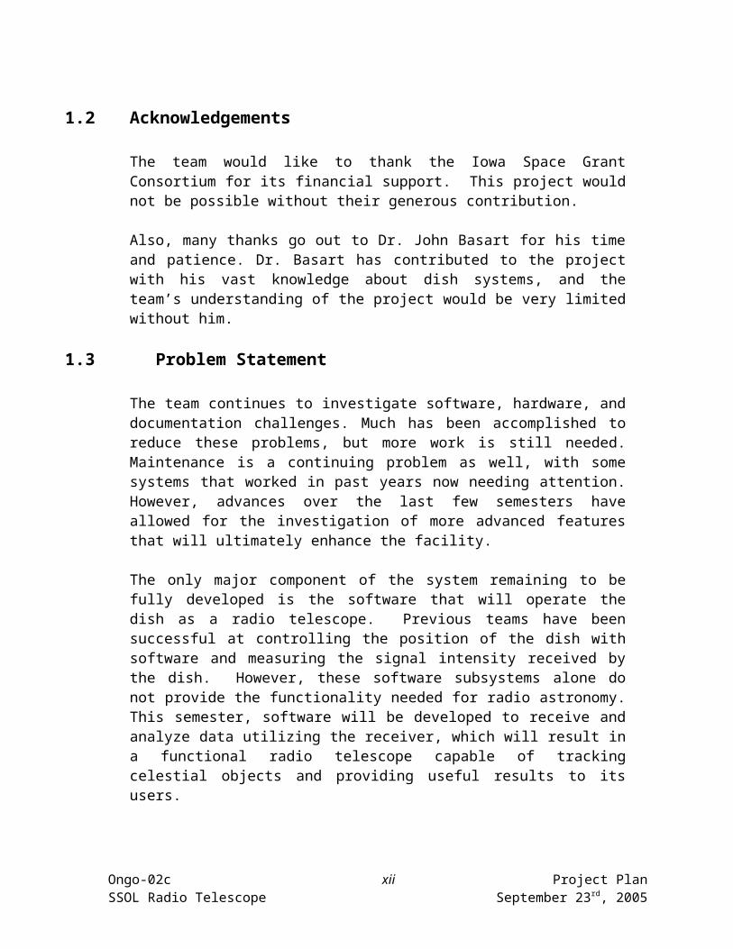
1.2 Acknowledgements
The team would like to thank the Iowa Space Grant Consortium for its financial support. This project would not be possible without their generous contribution.
Also, many thanks go out to Dr. John Basart for his time and patience. Dr. Basart has contributed to the project with his vast knowledge about dish systems, and the team’s understanding of the project would be very limited without him.
1.3 Problem Statement
The team continues to investigate software, hardware, and documentation challenges. Much has been accomplished to reduce these problems, but more work is still needed. Maintenance is a continuing problem as well, with some systems that worked in past years now needing attention. However, advances over the last few semesters have allowed for the investigation of more advanced features that will ultimately enhance the facility.
The only major component of the system remaining to be fully developed is the software that will operate the dish as a radio telescope. Previous teams have been successful at controlling the position of the dish with software and measuring the signal intensity received by the dish. However, these software subsystems alone do not provide the functionality needed for radio astronomy. This semester, software will be developed to receive and analyze data utilizing the receiver, which will result in a functional radio telescope capable of tracking celestial objects and providing useful results to its users.
The radio telescope is made up of electrical, mechanical, and software subsystems. Accurate and complete documentation must be kept as the project progresses this semester. Photos, diagrams, and descriptions will be compiled as new hardware is installed and calibrated. In addition, old documentation will be sorted into useful binders and categories to assist in the location of past records. Software must be well commented so future teams will easily understand and be able to improve upon it.
With the major tasks nearing completion, features that will enhance the operation of the dish have been explored. These features include remote access to allow observers to see the dish and operate the software without being present at Fick Observatory, and automation of the electrical and mechanical systems to allow for start up and shut down of the equipment remotely.
1.4 Operating Environment
The radio telescope is supported by a large gun mount taken from a World War II battleship. This mount is located outdoors and is continuously exposed to Iowa’s
Ongo-02c x Project PlanSSOL Radio Telescope September 23rd, 2005

weather conditions. To maximize the system’s signal-to-noise ratio (SNR), high frequency components of the signal amplification system, such as the low noise amplifier (LNA), must be located near the antenna’s feedhorn. These components must be able to withstand the harsh weather conditions, and as such, a “weather protection box” is used to protect these components. These mechanisms are also vulnerable to lightning, so a coaxial switch has been installed to rectify this problem and disconnect the sensitive computer and receiver systems from the metal structures outside. Similar weather protection strategies have been implemented on all of the outdoor wiring and controls. Finally, the gearboxes have been weatherproofed to protect the electronics that serve the feedback system and to inhibit the formation of ice on the gears, which would render the radio telescope inoperable.
1.5 Intended users and uses
The primary users of the completed radio telescope will be students and faculty of the ISU Department of Physics and Astronomy and those who have access to the Fick Observatory. These users will be learning about or already familiar with the concepts of radio astronomy. They will be capable of understanding and running the computer software that operates the radio telescope.
When completed, the Fick Observatory Radio Telescope will be used to image the radio sky at a frequency of 1420 MHz. This frequency was chosen to match the frequency of a neutral hydrogen atom’s signal, and is useful since hydrogen is the most abundant substance in the universe. Therefore, conducting operations within the 1420 MHz band is ideal for studying the structure of the universe. In addition, 1420 MHz falls in a relatively quiet part of the electromagnetic spectrum, thus making it easy for smaller dishes, like the one at Fick Observatory, to operate.
1.6 Assumptions and Limitations
The following are the assumptions and limitations of this project.
1.6.1 Assumptions
The motors and gearboxes are capable of accurate and precise movement All work done by previous team members has been tested and accurately
documented to provide test results Plans formed by previous team members can and should be followed
1.6.2 Limitations
The beam width of the dish is 2.5 degrees The radio telescope operates at 1420 MHz Astronomers will not be able to pass dish through North azimuthally The dish is limited to a maximum elevation of 86.5 degrees Variable budget set by the Iowa Space Grant Consortium and Dr. Basart
Ongo-02c xi Project PlanSSOL Radio Telescope September 23rd, 2005
Work done by previous team members would be too difficult and time consuming to change, so things must be worked with the way they were done earlier
Some parts can not be completely weatherproofed Existing parabolic reflector, motors, gears, tower, and other large existing
structures are not replaceable. If something does not work right it must be repaired or worked around
Weather conditions limit the work that can be done on the exterior components of the dish
The physical size of the dish and the limits of the selected hardware will limit the ability of the telescope to detect faint signals
1.7 End-Product Description
Upon completion of the radio telescope project, the satellite dish at the Fick Observatory will be a fully functional radio telescope. Students and astronomers alike will be able to use the dish for radio astronomy in the 1420 MHz band. From documentation, students and astronomers will be able to operate the system with minimal difficulties. The system will be controlled by software written in LabVIEW; this software will be able to track objects, control the positioning of the dish, control the receiving hardware and feedback systems, schedule data acquisition, and store the acquired data for later research. Tracking and positioning features will take advantage of a motor control system, which will monitor the dish’s position through a feedback structure. The receiver system will implement a total power radiometer that will have variables such as gain and integration capable of being set by the user through a computer interface. The subsystems that will comprise the radio telescope are illustrated in Figure 5. Ultimately, the system will be remotely controllable over the Internet through a secure connection. The operator will be able to see the dish through a web camera installed at the observatory, and operators will be able to control the dish around the clock due to an installed illumination source. By the end of this project, the dish at Fick Observatory will be a fully functional radio telescope with complete remote operation capabilities. Along with the complete system will be documentation on how to operate all software and hardware needed for operation. Information will be made available about all components of the system also for troubleshooting purposes.
Ongo-02c xii Project PlanSSOL Radio Telescope September 23rd, 2005

Figure 5. Illustration of radio telescope subsystems2 Proposed Approach
2.1 Functional Requirements
The functional requirements define the abilities of the radio telescope. For the project to be successful, all of these general requirements must be achieved:
The antenna will be able to receive, amplify, filter, and capture signals in the frequency range of 1000 MHz – 1800 MHz. This antenna will work specifically at a frequency of 1420 MHz to match the signal from a hydrogen atom.
A data acquisition system will record the intensity of the signal received from the antenna.
A feedback system will provide the real-time azimuth and elevation position of the dish.
Self protection strategies such as limit switches, coax switch, bumpers, and circuit breakers will protect the dish and its operators from control system failure.
The limit switch circuitry will be able to stop the satellite dish before over rotation occurs causing wires and cables to become tangled or destroyed.
The parabolic dish will be able to rotate through 350 degrees in azimuth and tilt through 86.5 degrees in elevation.
The integrity of outdoor hardware and data acquisition will not be compromised by seasonal weather changes.
The software will provide a useful interface for astronomers and students for easy access to raw or processed data.
A operation procedure document will be created to familiarize new users.
A tracking, mapping and raster scan software will be used to collect data.
Ongo-02c xiii Project PlanSSOL Radio Telescope September 23rd, 2005
The following sections outline the specific functional requirements for this semester’s tasks.
2.1.1 Operation Procedure and Instructions
The ultimate goal of this project is to produce a working radio telescope that is capable of providing data for students and astronomers. As such, a standard operating procedure will be created to assist those unfamiliar with Fick Observatory in the basic start-up/shut down tasks that must be performed. This document may be thought of as a “recipe”, and it shall be displayed prominently in the control room.
The document shall also be properly protected against rips, tears, or fading by enclosing it in a protective material such as a laminate. There shall be two versions of the instruction sheet produced; one for users physically standing in Fick Observatory, and one for users who access the radio telescope remotely.
2.1.2 Wind Structure Analysis
The radio telescope dish is a large mechanical structure that stands outside. Weather conditions are a primary concern to the safe operation of the dish system, and one of the most critical of these conditions is wind speed. On windy days, the dish may sway or flex during measurements, introducing errors of unknown magnitude into the data. During strong winds, the dish will be exposed to greater forces if it is faced into the wind rather than upwards. In order to operate the dish safely and with confidence, the effect of wind on the dish structure must be analyzed.
Two mechanical engineering students shall investigate the effect of wind on the dish and determine the wind speed where it is no longer safe to operate the dish. This information will become crucial as the dish begins to collect data, as the smallest variation in dish position could affect the dish’s ability to gather information.
2.1.3 Tracking Software
It is greatly important in the success of the radio telescope project to implement tracking software that tracks a specific point on the celestial sphere. This celestial coordinate system was developed to resemble the global coordinate system used on Earth. As an example, geographers locate Fick Observatory on the global coordinate system at a specific, fixed point of 42ºN (latitude) and 95ºW (longitude). Likewise, astronomers will locate an object on the celestial sphere by its declination and right ascension.
The Earth’s rotation, about its axis, gives the illusion that objects rise above the eastern local horizon, move across the sky, and set below the western local
Ongo-02c xiv Project PlanSSOL Radio Telescope September 23rd, 2005

horizon. Had astronomers located celestial objects by their angular distance above the local horizon (elevation) and their angular distance east of North (azimuth), the objects would not have a specific fixed set of points at which they could always be found. As stated, this would have been due to the Earth’s rotation.
The radio telescope is designed so that it operates on the elevation-azimuth system described above. Thus, the dish must be moved in both elevation and azimuth to track an object in the sky. However, coordinates for celestial objects are given by the celestial coordinate system (right ascension and declination).
Therefore, this tracking software must convert between the two systems, where the objects location will be entered into the computer in a declination and right ascension format. The software will convert that information into a local elevation and azimuth format. The motor control software must then move the dish at the appropriate speed in both elevation and azimuth to maintain a fixed declination and right ascension point, which will change with time.
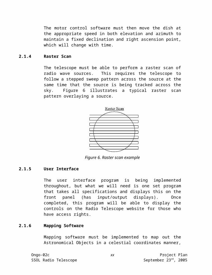
2.1.4 Raster Scan
The telescope must be able to perform a raster scan of radio wave sources. This requires the telescope to follow a stepped sweep pattern across the source at the same time that the source is being tracked across the sky. Figure 6 illustrates a typical raster scan pattern overlaying a source.
Figure 6. Raster scan example
2.1.5 User Interface
The user interface program is being implemented throughout, but what we will need is one set program that takes all specifications and displays this on the front panel (has input/output displays). Once completed, this program will be able to display the controls on the Radio Telescope website for those who have access rights.
2.1.6 Mapping Software
Ongo-02c xv Project PlanSSOL Radio Telescope September 23rd, 2005

Mapping software must be implemented to map out the Astronomical Objects in a celestial coordinates manner, as shown in Figure 7. This will use the tracking software and the raster scan program, and it will enable the dish to collect data from the correct position in the night sky.
Figure 7. Mapping example2.1.7 Web Cameras
Since the radio telescope will be operated remotely, the user will need to visually see the conditions of the dish and tower. Two web cameras will be implemented one for monitoring the dish and one for monitor the control room. The requirements from Dr. Basart for the web camera that will monitor the dish are as follows: • The camera view must be remotely accessible via the Internet or direct modem connection.
• The camera must allow an operator to inspect the dish mount for icing during winter months to prevent damage to the tower and motor control system. In case
Ongo-02c xvi Project PlanSSOL Radio Telescope September 23rd, 2005
of ice build-up, a team member will need to travel to the observatory to de-ice the dish before movement.
• The camera must allow an operator to view the general position of the dish.
• For night operation, the camera must work in low light conditions.
• The camera must output at least one picture per second to be displayed on the new website.
The requirements from Dr. Basart for the web camera that will monitor the control room are as follows:• The camera view must be remotely accessible via the Internet or direct modem connection.
• The camera must allow an operator to view the control panel of the dish. It must be able to see what led are illuminated and the position of the power switch.
2.1.8 Website and Weather Software
Re-designing the radio telescope website is a must for this semester to create new contacts with others in this related field. Dr. Basart is encouraging a user-friendly and very informative website so that personnel seeking information from the project can search quickly or write questions and comments. The project will benefit from a well designed website that has a new look and feel that incorporates dynamic elements.
Some of the dynamic elements may be including live image processing that shows images of the dish. Implementing dynamic scripts will allow people to post questions and comments about the radio telescope project. The website will have weather information, from weather.com, that will restrict personnel from using the radio telescope in conditions that are considered unsafe. These unsafe conditions will be determined by the wind structure analysis mentioned in section 2.1.2 and standards set by Dr. Basart.
2.1.9 Receiver System
The Receiver Library Software’s requirement is to integrate with other software modules, written in LabVIEW, of this project. This software will take data from the receiver over the computer’s serial link then send command to the backend receiver, convert the hexadecimal string data received from the receiver to signal intensity in decimal values, sample the raw signal and save the sampled signal to database.
2.2 Constraint Considerations
Ongo-02c xvii Project PlanSSOL Radio Telescope September 23rd, 2005

The following constraint considerations are limits that must be designed around. Taking these into account from the beginning will lead to a smooth progress and eventual successful project design.
The Iowa Space Grant Consortium sets a variable budget. Existing components such as motors, gears, and the tower are irreplaceable. All the hardware and software needs to be compatible with existing infrastructure. Extreme Iowa weather conditions needs to be under consideration while designing
any system. Broken components must be repaired or worked around. The dish is unable to be positioned to true north. The dish operates with certain level of accuracy. This must be measured and
taken into account when any functional claims are made. The size of the dish and the distance from the dish to the observatory will
inevitably introduce noise into all electrical systems. The signal receiver can measure the radio signal intensity at a maximum rate of
10 times per second. All work done to the radio telescope must be done in a manner which does not
endanger hardware or electrical systems. High intensity lights should be avoided that can interfere with the optical
telescope operation. A new computer rack mount case must fit in the existing equipment rack in the
control room at Fick.
2.3 Technology Considerations
Much of the technology needed by the radio telescope has already been designed or purchased. However, some systems remain that will require additional technology to complete.
2.3.1 Operating Procedure and Instructions
The operating procedure and instructions document will be prepared using Microsoft Word, and it will be protected from rips, tears, or fading by enclosing it in a protective laminate cover.
2.3.2 Wind Structure Analysis
Basic information about the dish and mount, such as height, footprint, reflector type, and range of motion will be collected. With this data, analysis can be carried out on the operation of the dish under wind loads. Textbooks and other reference material shall be consulted to determine the most accurate way of carrying out the investigation.
Ongo-02c xviii Project PlanSSOL Radio Telescope September 23rd, 2005

2.3.3 Tracking Software
Tracking software will be implemented using LabVIEW software to allow for easy integration with the existing software, also written in LabVIEW.
2.3.4 Raster Scan
The raster scan function is a software package that should be incorporated into the tracking software. It will be implemented using LabVIEW software for ease of compatibility with the balance of software modules.
2.3.5 User Interface
The user interface modular software will be implemented using LabVIEW software and will have all implemented software modules incorporated.
2.3.6 Mapping Software
The mapping software function uses the tracking software and is implemented in the Raster Scan program as a software package. It will be implemented using LabVIEW software for the ease of compatibility and control of software modules.
2.3.7 Web Camera
A web camera will enable users who are not physically at Fick Observatory to watch the dish move. Past teams have researched web cameras; however, the price was too high. This semester, a cost-effective solution to Dr. Basart’s functional requirements will be found. The team recommends any of the following web cameras:
1. Logitech QuickCam Fusion, 99.992. Logitech QuickCam Communicate STX, 46.98
Each recommendation complies with the specifications listed in Section 2.1.8. Because two web cameras will be used simultaneously they must be from the same manufacture.
2.3.8 Website and Weather Software
The website and weather software will use HTML software for easy web implementation and design. This language is already understood very well by team members, and will allow for straightforward modeling. The weather portion
Ongo-02c xix Project PlanSSOL Radio Telescope September 23rd, 2005
of the website will utilize an XML feed from weather.com, which provides live weather reports based on zip code.
2.3.9 Receiver System
LabVIEW modules were added to the receiver system software last semester. Modules to turn on and turn off the receiver system will be added to the receiver system software this semester.
2.4 Technical Approach
This semester, the team will focus on several problems, which will need to be resolved based on the criteria established in this section. These tasks will include, among other things, creating a set of instructions for start-up and shut down, redesigning the team website, putting a webcam into service, and implementing the tracking and mapping software.
2.4.1 Operating Procedure and Instructions
The team will systematically walk through the proper steps that should be taken when entering and exiting the observatory. Care will be taken to ensure the safety of both the user and the dish system.
2.4.2 Wind Structure Analysis
Research on the dish structure and wind speed will be conducted with the use of the Internet, textbooks, and other reference materials. Variables such as dish position and wind gusts shall be taken into account.
2.4.3 Tracking Software
Tracking software will be implemented in LabVIEW software. It will convert the right ascension and declination values obtained from the observer to local elevation and azimuth coordinates. It will use the time and these values to track the object in the sky.
2.4.4 Raster Scan
Raster Scan software will be implemented in LabVIEW software. It will use the tracking software and sweep across the sky to collect data. It will use a grid system to show output on a density graph.
Ongo-02c xx Project PlanSSOL Radio Telescope September 23rd, 2005

2.4.5 User Interface
User interface will be implemented using LabVIEW. This program will be able to display the controls on the Radio Telescope website for those who have access rights, allowing them to control the front panel.
2.4.6 Mapping Software
Mapping software will be implemented in LabVIEW software. It will map the object by using right ascension and declination values obtained from the observer. It will use the tracking software to obtain the location of each object and then map out the locations of to obtain an overall object.
2.4.7 Web Camera
The Web cameras will be a major requirement before making the Radio Telescope available for the users on the Internet. Web camera will allow the user to view the radio telescope at any time of the day to monitor both weather and position of the dish and the control room at any instant.
2.4.8 Website and Weather Software
The website will be written in HTML code and will benefit from dynamic elements and features. Some of these features will include simpler layout, current pictures of the telescope, or message boards. Weather information from weather.com will also be included on the website so users can see the current operating conditions of the radio telescope. This portion of the website will use XML code, as it is one of the choice weather.com provides.
2.4.9 Receiver System
Receiver system will be tested in real life using the software designed in the real life. Input from sun, moon, and the stars will be received and tested upon using the receiver system. Software will be designed and implemented to automatically control the receiver for turning it on and off.
Ongo-02c xxi Project PlanSSOL Radio Telescope September 23rd, 2005

2.5 Testing Requirements
2.5.1 Operating Procedure and Instructions
The operating instructions need to be clear and easy for a first-time user to understand. Acronyms and other technical words shall be kept to a minimum. Effectiveness of these instructions shall be verified by a person unfamiliar to Fick Observatory. Successful testing will produce a proper start-up and shut down procedure with no oversights.
2.5.2 Wind Structure Analysis
The analysis results may be demonstrated during a severe weather event or other high-wind incident. The dish may be turned on and attempt data collection in order to verify the degradation of data quality in an unstable environment. However, the weather may be so severe that no team member should attempt to operate the dish for fear of damage to themselves or the dish structure. In this case, the analysis must be trusted and assumed to be correct.
2.5.3 Tracking Software
A member of the radio telescope team will have to be able to track an object’s location when running the motor control software. This will be tested by tracking a known celestial object, such as the sun or a star.
2.5.4 Raster Scan
When running the motor control software a user will be able to scan across an object and collect the given data. This can be tested by scanning a known celestial object, such as the sun or a star and comparing predicted results with actual results.
2.5.5 User Interface
User interface software will be implemented using the LabVIEW and will be tested by controlling the front panel using it. This software will take all specifications from the user and display this on the front panel (has input/output displays). The test will be a success if the results on the front panel and Radio Telescope website match that desired by the user.
2.5.6 Mapping Software
The data should show an image of the collected objects for the current mapping session. This should be tested by using a known celestial object, such as the sun to see if it maps correctly.
Ongo-02c xxii Project PlanSSOL Radio Telescope September 23rd, 2005

2.5.7 Web Camera
Web Cameras will be purchased to fulfill the requirements of periodic still captures and an acceptable view. The cameras will be installed to give the view of control room and the radio telescope as well as the surrounding weather. First the cameras will be tested to ensure that they can see the control room and Radio Telescope with enough detail. Then the cameras will be tested by ensuring that images of the control room and telescope can be streamed over the internet.
2.5.8 Website and Weather Software
The website must be provide useful information and be simple to navigate. To test the website’s functionality, extensive testing will be done by team members to ensure no missing pages or dead links. Also, beta testing will take place to guarantee a person unfamiliar with the project can navigate simply and effectively. Testing must be done to ensure that access of certain pages can be restricted. This will be tested by asking authorized users to create and test accounts. A team member will test if unauthorized users can login into restricted web pages and ensure that unauthorized users can not create accounts.
The weather section of the website will be tested by monitoring the current weather conditions and comparing them to the weather feed. A standard thermometer could also be set up at Fick Observatory to provide verification of the weather data. To ensure that the Radio Telescope can not be used during certain weather conditions the weather conditions will initially be relaxed. Under these relaxed conditions a team member will then test to see if the dish can be used. A successful test will not allow the use of the dish under the set weather conditions. After this initial test is done, the weather conditions will be set to ones determined by Dr. Basart and the wind analysis. After the weather conditions are set to standard, it will be tested to ensure it can work when weather conditions are not in effect.
2.5.9 Receiver System
Last semester the receiver was brought back to the laboratory for testing using a signal generator and an oscilloscope. The output signal was measured which proved the successful receiver operation. Testing of the audio output of the receiver and the speaker system also took place last semester.
This semester, the receiver system will be practically tested at Fick by testing the signals generated by dish. The receiver system software will be used to test the input signals and record the generated output.
Ongo-02c xxiii Project PlanSSOL Radio Telescope September 23rd, 2005

2.6 Security Considerations
There are few security considerations with this project. The equipment is located at the Fick Observatory, which is a highly secure environment that utilizes many locks and an alarm system. Only those who have proper access will be able to work with the telescope.
However, any network-based access to the observatory equipment, whether through a Windows Remote Desktop connection or through the observatory website, will have to be properly configured to prevent unauthorized access to the observatory’s information and resources.
2.7 Safety Considerations
Due to the few intended users of the system, there are few general safety concerns. However, safety must still be considered when working on and operating the dish. The team members shall use scaffolding and work in groups whenever working on the dish, which usually requires being at least 20 feet above the ground. If a problem were to arise, team members can help one another in avoiding injury. Furthermore, care must be taken that power is turned off whenever work is being done on high-voltage electronics in the motor controller or on the dish tower. These voltages are capable of electrocuting a person. Finally, weather must always be considered when working on the dish. The dish and surrounding areas can become slippery when icy or wet. The dish is also prone to being struck by lightening, so care must be taken when deciding to work on the dish. A top priority goal for the beginning of the semester was to implement safety equipment such as; hand rails, permanently mounted ladder, and standard procedures for working on the dish. Upon further investigation of installing a permanently mounted ladder and hand rails the team decided that this needs to be addressed by a more accredited team such as a structural engineering team. This does not conclude that safety not be addressed at all this semester. The team will develop a list of standard procedures for working on the dish. These safety standards will address the following:
• Designated candidates to work on the dish• Guidelines for climbing the dish• Proper use of available safety equipment
2.8 Intellectual Property Considerations
Since this work is customized for one dish in particular, it is not reproducible and therefore there are no intellectual property concerns. In addition radio astronomy is a very cooperative field with researchers often sharing information and technical approaches. This has been the case with Dr. Basart receiving requests for information on this project from other astronomers.
Ongo-02c xxiv Project PlanSSOL Radio Telescope September 23rd, 2005

2.9 Commercialization Considerations
The commercialization considerations on this project are limited since this project is a custom design for an existing radio telescope. Most of the design decisions have been made to utilize unique surplus or scrap materials when available. Furthermore, the physical size of the dish and other limitations make the radio telescope useful for little more than educational purposes. One possible consideration would be the rental of unused telescope time once the dish can be remotely operated. This would help offset some of the operational costs associated with the facility.
2.10 Risks and Risk Management
All projects contain various risks that must be identified and dealt with in order to prevent problems and delays. Proper project risk assessment and planning should be made in order to minimize the delays that may occur because of these risks. A large risk that is associated with the radio telescope project is the possibility that an irreplaceable part may become damaged. This risk would create huge delays in the project and could possibly halt the project indefinitely. Proper planning and care must be taken in order to deal with this problem. Team members must plan ahead and work carefully with the delicate areas of the system. If a part does become damaged, the team shall analyze the situation and determine the best method of solving the problem. These decisions should be made with much care so as to not create further delays. This will also aid in reducing further problems created from making hasty decisions and will reduce the overall delays of the project. The voltages inside the motor control box are at levels of 150V AC. Because of this high voltage, all work done inside the box is done with the box disconnected from power in order to reduce the risk of shock or electrocution.
Another risk to the project is the possibility that a team member will not be able to contribute their share of the work as planned. This can lead to great delays and proper planning must be made to reduce this risk. Proper scheduling is the main issue to work with here. Team members must know what amount of work the other team member’s are capable of performing. Taking into account this information, a carefully made schedule should then be created. The schedule can also be designed to allow each team member some slack time in order to preemptively compensate for these risks. If a delay does occur from a team member not being able to complete their tasks on time, the team should then be able to promptly assess the effects and determine a timely solution before any delay takes place. When accessing the dish tower the main conditions to avoid are severe weather such as rain, snow, windy days, and ice. This will prevent falling from the tower while working. Also team member hold the ladder for each other while accessing the tower. Other risks include unexpected delays in part orders and adverse weather conditions. Most maintenance work on the hardware of the radio telescope is done outdoors at the dish tower.
Ongo-02c xxv Project PlanSSOL Radio Telescope September 23rd, 2005

Adverse weather conditions will therefore have a great affect on the ability of team members to work outdoors. The location of the radio telescope is approximately 20 minutes southwest of Ames, IA. In the event of severe weather, team members may be unable to commute to the work site.
2.11 Milestones and Evaluation
Some of the prerequisite milestones were attained in previous semesters. These are listed as well as milestones to be reached this semester.
2.11.1 Milestones Previously Achieved
The following milestones were achieved in the previous semesters. They were successfully reached and allow the current group to continue making progress towards a working radio telescope.
• The dish had both the azimuth and elevation directional movement capabilities.• The azimuth limit switches and feedback sensors were installed.• The original feedhorn was been tested and installed.• The 1400 MHz transmitter was completely designed and built.• A new waveguide and adapter were designed and fabricated.• The limit switch circuitry was redesigned and tested.• The feedback circuitry was installed and tested.• The receiver was constructed.• The low-noise amplifier was installed and tested.• The outdoor junction boxes and feedback systems were rewired.• Prototype software was able to calculate the dish’s position via the analog input card.• The software was able to detect when the limits were reached.• Prototype motor control software was able to send the appropriate signals to motor control hardware to move the dish in the correct direction and at the correct speed.• A new antenna feed assembly featuring the new waveguide and adapter was installed and tested.• The procedure to calculate tracking coordinates was implemented in software.• The DAQ system was able to acquire data from the receiver.• The dish was accurately zeroed to a given position so tracking software could calculate its real-world position at any given time.• Final specification and beginning implementation of the calibration software.• Final specification and beginning implementation of user interface software.• A coaxial switch was installed and tested.• A new coaxial cable was installed and tested.• All junction boxes are weatherproofed and installed.• The feedback potentiometers are calibrated.• The subreflector was redesigned, fabricated and installed. • The control room computer was placed in a rack-mount case.• Internet connection was established at Fick Observatory. • New azimuth and elevation limit switches were ordered and installed.
Ongo-02c xxvi Project PlanSSOL Radio Telescope September 23rd, 2005

• The receiver system was tested and repaired.
2.11.2 Fall 2005 Milestones
Measurable milestones corresponding to each goal have been set for this semester. The project’s success this semester will be based the degree to which these milestones were reached. The milestones are not all of equal importance, and this must be taken into account when evaluating the success of the project. To account for this, each milestone is assigned a relative importance to the project, as outlined by Table 1.
Table 1: Milestone Importance ClassificationMilestone Importance DescriptionCritical Milestone is a prerequisite for other milestones and must be
achieved by the scheduled completion date. Failure to complete these milestones will be a significant setback and require major project or team restructuring.
Primary Milestone is a major, short-term goal of the project, but failure to accomplish this milestone will not impede successful completion of other goals of the project.
Non-critical Milestone is part of a long-term goal of the project and will assist or be the basis of future milestones. Failure to complete this milestone will result in more work in the future, but will not impede completion of primary milestones.
When assessing the success of the project, each milestone will be evaluated based on how close the team came to reaching it. This will yield a degree of success for that particular milestone. This, combined with the importance of the milestone, will determine if the efforts of the team were adequate. The possible states of each milestone are listed in Table 2
Table 2: Milestone Status ClassificationMilestone status DescriptionReached Milestone reached on schedule and within budgetDelayed Milestone could not be reached within the time constraints, but significant
progress was made. The present strategy may be continued to reach the milestone.
Unreachable Milestone could not be reached because the approach did not work. The milestone may have been technically or financially unfeasible.
Aborted Milestone was deemed no longer necessary to the project and was abandoned.
Ongo-02c xxvii Project PlanSSOL Radio Telescope September 23rd, 2005
To determine overall project success, each milestone’s success and importance will be considered. Table 3 illustrates how the importance of each milestone determines how close the team must come to accomplishing it while still considering the project a success.
Table 3: Project Success CriteriaMilestone Importance
Milestone StatusReached Delayed Unreachable Aborted
CriticalPrimaryNon-critical
Successful - this milestone contributes to a successful project.
Failure - the team made a major failure and compromised the success of the project.
Shortcoming - the team was unable to reach this milestone, but the project overall could still be considered a success.
The team hopes to reach all milestones by the end of the semester, corresponding to complete project success. This means that each milestone should reach the “successful” state by the end of the semester. However, the possibility remains that some goals will fall short of total completion. In that case, the team will have a way of determining the overall project success.
If any of the milestones result in a “failure” state, then it is unlikely that the project will be considered a success at all. This type of failure usually means that the team has invested large amounts of time or money on an unfeasible approach to a problem. It is very difficult to recover from such a major loss of time and productivity. The team’s progress will have been very minimal, so their efforts will appear to have failed. Thus, great attention will be focused on reaching critical milestones.
However, it is possible that the evaluation of some milestones will indicate a “shortcoming” for the semester; in this case, the project will still be viewed as successful. To get an approximation for the overall success of the project, it is necessary to evaluate each milestone that was not reached. For example, if a particular shortcoming was due to the fact that required parts had not yet arrived for an otherwise complete system, the milestone may be considered to be 60% reached, based on the estimates of how much work remains to reach the milestone. On the other hand, if the expectations for a particular milestone were exceeded, the milestone could be considered more than 100% reached. If, for example, the goal was simply to design a solution to a problem, but time permitted the design to be fully implemented, the milestone could be considered 200% reached.
Ongo-02c xxviii Project PlanSSOL Radio Telescope September 23rd, 2005

Overall project success will depend on averaging the success of each milestone. A successful project must have all milestones resolve to a non-failure state. Then, for each shortcoming and successful milestone reached, consideration must be made to the amount of effort invested in reaching that milestone. These efforts shall be used to weight the importance of each milestone. Then, a weighted average of the estimated success of each milestone can be calculated, yielding a quantitative amount for success of the project. These practices will be applied to the Fall 2005 milestones, outlined in Table 4.
Table 4: Fall 2005 MilestonesMilestone Importance
Milestone Description
Critical Investigating the wind structureCriteria for Success: Possible faults in the dish structure or data quality
caused by the disturbance in the signals received by the dish are identified
Primary Greasing the motors and gearboxesCriteria for Success: Motors and gearboxes move smoothly and are free of rust
Primary Mapping softwareCriteria for Success: Astronomers will be able to locate an object on the celestial sphere by its declination and right ascension.
Non-critical Modules for turning on and off the receiver systemCriteria for Success: Receiver system is operated automatically using the
software using the remote accessPrimary Replace the LED’s on the front panel
Criteria for Success: The front panel is visible during the evening even with dim light and poor visibility
Primary Redo labels around each indicatorCriteria for Success: The labels will become more readable by the user
Non-critical Night lighting around the dishCriteria for Success: The dish will be visible even during night time for an
easier view by the userCritical Implementation of the weather software
Criteria for Success: The weather at the observatory will be recorded periodically, and the dish will not be allowed to move if the weather is unsafe
Critical Raster scan softwareCriteria for Success: Tracking software is able to successfully collect data
from an object in the sky.Critical Tracking software
Criteria for Success: Users are able to track a celestial object in real-time.Non-critical Equipment automation
Criteria for Success: Access from anywhere using remote desktop is allowed to all equipment.
2.11.3 Future Milestones
The following milestones should be completed in future semesters.• Testing is performed to ensure that radio telescope is fully functional.
Ongo-02c xxix Project PlanSSOL Radio Telescope September 23rd, 2005
• Fully functional telescope is demonstrated to the project faculty advisor.• The user interface allows the astronomer to enter a schedule of objects to be tracked.• Entire dish functionality is remotely accessible• Multiple users are able to interact with the user interface simultaneously• Point-to-point software is developed that allows the dish to locate the center of a
celestial object
2.12 Project Tracking ProceduresTwo second semester students, Nicholas Zeitler and Eric Schares, are in charge of tracking procedures. This will be primarily done using Microsoft Project. End dates will be recalculated and the Gantt charts will be updated as the statuses of the milestones are changed. This will ensure that the project continues to move smoothly toward completion and will help to make the project successful. Please refer to section 4.2 for the project and deliverable schedules.
3 Statement of Work
This section describes the activities and tasks that comprise the efforts that will be made this semester. The project encompasses aspects of many types of design projects, including actual implementation, product design, process design, calculations, and product simulations. Additionally it is also necessary that the team perform a certain amount of maintenance on the equipment. The work this semester has been divided into the following tasks:
1. Project definition2. Technology implementation considerations and selection3. End-product design4. End-product implementation5. End-product maintenance6. End-product testing7. End-product documentation
The remainder of this section is devoted to describing each of the above tasks in detail. Each task is divided into subtasks, each with a clearly stated objective, approach, result, and when applicable, dependencies on other tasks.
Task 1: Project definitionThis task is composed of two subtasks.
Subtask 1a – Establishment of goalsObjective To establish a list of reachable goals for the present
semester which will help the project move forward in a clear direction
Approach As an ongoing project, the overall goal of the project has remained relatively constant over the years – to produce a useful tool for radio astronomy. However, a list of realistic goals must be established each semester. The goals must be
Ongo-02c xxx Project PlanSSOL Radio Telescope September 23rd, 2005

chosen such that they are accomplishable under the project’s constraints and such that they will help the project reach completion.The team leader and the faculty advisor shall meet at the beginning of the semester to establish this list of goals. The present and future technology demands and projected availability of resources will be weighed to determine which goals are the best choices to set as current semester milestones. The priority of each goal will also be considered such that, in the event of project delays or unforeseen complications, efforts towards less important goals can be scaled back and resources can be reallocated to maintain a maximum rate of progress towards project completion. The goals shall represent an amount of progress that is acceptable to the faculty advisor.
Result The team will be presented with list of goals for the semester which, when completed, will mark adequate progress towards project completion. Documentation of this progress must be properly documented for future use.
Subtask 1b – Constraint identificationObjective To identify the constraints which may affect the successful
completion of the project’s goals.Approach The team leader shall meet with the faculty advisor at the
beginning of the semester to discuss the constraints which will limit or determine the technical approach chosen to reach each of the projects goals. These constraints usually include financial limits, deadlines, and technical limitations.
Result The fundamental constraints affecting the semester’s work effort will be identified and presented to the team. These constraints will be documented for future reference. The initial work on the project will start off in the right direction.
Task 2: Technology and implementation considerations and selectionThis task consists of ten subtasks.
Subtask 2a – Operation Procedures and InstructionsObjective To provide concrete documentation in order to assist users
who are unfamiliar with Fick Observatory in basic start-up/shut down procedures. This document will provide information on both physical and remote access.
Ongo-02c xxxi Project PlanSSOL Radio Telescope September 23rd, 2005

Approach The team shall meet with the faculty advisor and consider the proper steps to start up and shut down the dish and related systems. The faculty advisor and the team members will revise the safety of the procedure, and highlight any necessary safety precautions that need to be taken.
Result The completed document will be protected from the elements and placed in an easily accessible position. Users of Fick Observatory will be less likely to damage the radio telescope systems.
Subtask 2b – Wind Structure AnalysisObjective To determine safe and unsafe operating conditions for the
dish, in which will involve research on the effects of wind speed and weather conditions on the dish system.
Approach The mechanical engineering students will meet the faculty advisor and gather measurements on the dish system. This data will be used to characterize the dish operation as a function of wind speed. Reference materials and relevant coursework will be used to guide the analysis. Details such as gust speed and frequency shall also be taken into consideration.
Result A wind speed will be determined that serves as the cut-off point between safe and unsafe operation of the dish. This information will also be used as the set point to automatically shut down the dish during severe weather.
Subtask 2c – Tracking SoftwareObjective Writing software that will track an object in the sky to
know the exact location at times when the team needs to collect data.
Approach The software student given this task will meet with the faculty advisor and group leader to present the possible ways to design the software to track the object with error correction. Time consumption and reliability will be major factors taken in consideration before code implementation.
Result The group will be able to track the object across the sky in real time. Documentation will be completed to explain the algorithm of the code to help with future troubleshooting.
Subtask 2d – Raster ScanObjective Writing software that will scan the object in the sky and
receive data back from that object.Approach The software student will meet with the faculty advisor and
group leader with a presentation on possible ways to design the user-friendly software that scans the object to collect data. Reliability and time consumption will factor into the proposed implementation of the software.
Ongo-02c xxxii Project PlanSSOL Radio Telescope September 23rd, 2005

Result The data will be collected from each object found in the tracking system and presented in a graph format. Documentation will be completed to explain the algorithm of the code to help with future troubleshooting.
Subtask 2e - User Interface
Objective To design a user interface using LabVIEW to display the controls of the front panel through the Radio Telescope website, allowing the valid user to enter the input values and displaying the correct output.
Approach The computer engineering students will meet the faculty advisor and present the possible ways by which the controls of the front panel can be displayed to the user online through the Radio Telescope website. Once displayed, remote access will be used to control the front panel. An outline of the proposed software will be presented to the faculty advisor. Upon approval, LabVIEW will be used to design the interface. Only the valid users will be allowed to access the control to the front panel. The remote connection should be reliable and fast enough to allow the user to access the front panel using the Radio Telescope website.
Result User interface will be designed to display the controls of the front panel using the Radio Telescope website, where users having access rights to the website will enter the input and receiver the output using remote access.
Subtask 2f – Mapping SoftwareObjective Writing software that will map each objects location in the
sky to present a final larger image.Approach The software student will meet with the faculty advisor and
group leader to present the possible ways that this software can be designed. This user-friendly software will map the given stars. Like the other software, time consumption and reliability will be the major factors considered before the implementation of this software.
Result A mapping graph will be presented after each mapped object. Documentation will be completed to explain the algorithm of the code to help with future troubleshooting.
Subtask 2g - Web Camera
Ongo-02c xxxiii Project PlanSSOL Radio Telescope September 23rd, 2005

Objective To be able to view the control room and dish live when operating remotely, or to monitor the dish while it is not in use.
Approach Web cameras have been selected for use due to their relatively low cost, ease of use, and simplicity in connecting to the Internet. Several web cameras will be considered, and one for each the control room and dish will be chosen based on a group vote. One camera should provide a focused picture of the dish with a viewing angle that shows the dish as large as possible on the screen. The second camera should also provide a focused picture of the control room switches and LED.
Result Users will be able to view the control room and radio telescope without being at Fick, which is a critical part of the overall goal of making the telescope remotely controllable.
Subtask 2h - Website and Weather Software
Objective To redesign the radio telescope group’s website in order to make it more user-friendly and informative.
Approach Various designs and layouts will be considered, and one will ultimately be selected with the group’s input. The website may include project history, team contact information, project documentation, current pictures of the dish, current weather data, and a search function. Each of these features will be considered when selecting a layout.
Result The radio telescope website will be much more attractive and educational. This new website could result in new contacts being made from similar projects around the world.
Subtask 2i – Modules for automated operation of the receiver systemObjective To write software for the turning off and on the receiver
system remotely. This will allow the authorized users to turn-off and turn-on the receiver system through the software developed by the team. The software shall automatically operate the receiver system according to the user’s desire.
Approach The software students will meet the faculty advisor and present the possible ways to design the user-friendly software that could turn-off and turn-on the receiver system. The time consumption and reliability shall be the major factors that will be considered before the implementation.
Ongo-02c xxxiv Project PlanSSOL Radio Telescope September 23rd, 2005

Result Software will be developed that shall automatically turn-off and turn-on the receiver system. The faculty advisor will approve the idea and order the appropriate software for the development of the software.
Subtask 2j – Greasing of the motors and the gearboxes associated with the dishObjective Greasing the motors and the gearboxes before the first
snowfall and the end of the semester. This shall allow the dish to stay rust-free and the users might operate the dish with no resistance.
Approach The mechanical engineering students shall meet the faculty advisor and the team leader to discuss a long-lasting way for the motors and the gearboxes to work properly even during snowfall. The faculty advisor will be notified about the appropriate grease to be used to keep the dish free of rust.
Result Grease will be ordered and the motors will be greased along with the gearboxes to avoid rusting and damage to the dish and its major components.
Task 3: End-product design
This task consists of five subtasks.
Subtask 3a – Operation Procedures and InstructionsObjective To format the operating procedures in a manner that is easily
to read and follow.Approach The various steps that need to be taken to start up or shut
down the dish will be written out, and the most logical order will be determined. In a case where one system is dependent on another, a note will be given to reinforce the importance of following the given order.
Result The instructions will be designed in such a way as to make them easy to understand for a first-time user. This will include grouping similar systems together and fully explaining system dependencies.
Dependency None.
Subtask 3b – Website and Weather SoftwareObjective To reformat the radio telescope website in order to provide a
more accurate, readable, and user-friendly page.
Ongo-02c xxxv Project PlanSSOL Radio Telescope September 23rd, 2005
Approach Various layouts and designs will be considered, with input from the team as well as those outside the radio telescope project. The page will be written in HTML, and the weather retrieval system will use an XML feed from weather.com.
Result The radio telescope website will be more user-friendly and contain useful facts such as contact information, current weather conditions, and project documentation and details.
Dependency Subtask 2g - Web camera The pictures of the dish cannot be acquired until the web camera is purchased and installed. Only then can the live pictures be fed back and displayed on the webpage.
Subtask 3c – Web CamerasObjective To develop the capability to observe the control room and
radio telescope remotely, both when the dish is being used and when it is inactive.
Approach Several web cameras will be considered, and each will be judged based on various features such as resolution, frames per second capability, angle of view, and price. One web camera each will be selected by a group vote for the control room and Radio Telescope. The web cameras must also be approved by Dr. Basart.
Result The web cameras will be located at Fick Observatory and will provide the potential to observe the dish and control room when not physically at Fick.
Dependency None.
Subtask 3d – Receiver SystemObjective To design a software for automatically turning on and
turning off the receiver system while at FICK.Approach Software will be developed using LabVIEW to turn the
receiver on and off. Using this approach, the receiver system will be accessible using the remote access saving user’s time and effort.
Result Software designed for the automated control of the receiver system.
Dependency Subtask 2i – Modules for automated operation of the receiver system
The designed modules should be reliable and user-friendly for easy accessibility. There must be a backup for the software.
Ongo-02c xxxvi Project PlanSSOL Radio Telescope September 23rd, 2005
Subtask 3e – User InterfaceObjective To design the user interface for displaying the front panel
and allowing the valid user to enter the input values through the Radio Telescope website.
Approach Software will be developed using LabVIEW to display the control of the front panel. This will be done using the remote access. The user will be able to view the front panel through the website and will have the access to enter the values and receive the output.
Result Access to the radio telescope control using remote access and the Radio Telescope website.
Dependency Subtask 2e - User InterfaceThe valid users should be allowed to access the control to the front panel. The remote connection should be reliable and fast enough to allow the user to access the front panel using the Radio Telescope website.
Task 4: End-product implementation
This task is composed of eight subtasks.
Subtask 4a – Operation Procedures and InstructionsObjective To provide the proper start-up and shut down procedures to
users unfamiliar with Fick Observatory.Approach The correct method of commencing work on the radio
telescope shall be brainstormed by the group. This system shall include all relevant safety information and be ordered in a manner such that the dish systems will be turned on safely. This document will provide instructions on both physical and remote access, and will be prominently displayed in an easily accessible location. This document shall be periodically revised at the beginning of each semester to reflect any updates in the dish system.
Result Users of the radio telescope will be knowledgeable in the correct start-up and shut down procedures of the dish systems.
Dependency When any modification is made to the dish system, the document must be updated to be kept current.
Ongo-02c xxxvii Project PlanSSOL Radio Telescope September 23rd, 2005

Subtask 4b – Wind Structure AnalysisObjective To apply the results of the wind structure analysis to the
radio telescope structure.Approach The result of the analysis should provide the team with a
good idea of what is an unsafe wind speed to operate the dish. This will be used in the creation of a module that automatically shuts down the dish if that speed is exceeded.
Result The analysis will provide the radio telescope with a valuable safety function, and the dish will be kept out of harm.
Dependency Subtask 2h - Website and weather softwareThe current weather conditions will need to be gathered in order to determine if the operating environment is unsafe.
Subtask 4c – Software development and implementationObjective To develop the new software modules, simulate their proper
operation, and use them on the observatory systemApproach The software will be developed by a small team where each
member will be responsible for his or her own set of modules. Prior to dividing up the work load, each module will be clearly defined in terms of its behavior, input, and output. This will allow each programmer to develop the software independently of one another. If possible, a source control system will be implemented to facilitate concurrent editing of multiple VI’s by the entire team.
Each software team member will be free to program at the site of his/her choice. The existing dish simulation software, developed from previous semesters, will allow the programmer to test the basic operation of each module implemented without running the risk of having the testing done on the actual dish.
The second level of testing will take place at the observatory using the actual radio telescope dish.
As each module is finished, it will be documented using LabVIEW’s built-in documentation features. A current set of working software will always be maintained at the observatory. No software will be allowed to be added to the current software set until it is completely developed and tested
Result A set of all software modules required to meet the functional requirement specified in this document installed and tested
Ongo-02c xxxviii Project PlanSSOL Radio Telescope September 23rd, 2005

on the observatory computer.Dependency Existing motor control software
Subtask 4d – User InterfaceObjective To allow the user to access the radio telescope controls using
the website.Approach The software engineering group will come up with a code
using LabVIEW. This software will allow the user to view the control of the front panel, where the input values can be entered and the output will be displayed. The Radio Telescope website will be used by the valid user to access the front panel control.
Result Radio telescope users will access the control panel using the Radio Telescope website.
Dependency A proper password must be provided to keep the access to the radio telescope limited. The Internet connection speed should be fast enough to access the control panel with no difficulty.
Subtask 4e – Web CamerasObjective To put the selected web cameras into use as a tool for
monitoring the radio telescope and control room.Approach The web camera wills be set up in the control room of Fick
Observatory, and will be connected to the Internet through the control room computer. Access to the web camera will initially require remote access to the control room computer, but will eventually be granted to anyone who views the radio telescope website.
Result The radio telescope is constantly capable of being examined, and the dish can be safely operated remotely.
Dependency None.
Subtask 4f – Website and Weather SoftwareObjective To redesign the radio telescope webpage and improve its
functionality as both an information source and a project ambassador.
Approach Various website designs will be considered and the selected layout will be chosen by the team. The files needed for the
Ongo-02c xxxix Project PlanSSOL Radio Telescope September 23rd, 2005

website will be housed on a computer in the SSOL to facilitate any necessary repair or revision. Weather data will be gathered from weather.com and be displayed on the website.
Result The group website will more accurately reflect what is currently happening with the project, and it will be easier for persons outside the project to become familiar with the work being done. The website will also serve as the project representative and may result in friendships with similar programs from around the world.
Dependency Subtask 2g - Web camerasThe pictures on the new website will have to be provided by the web cameras installed at Fick.
Subtask 4g – Modules for automated operation of the receiver systemObjective To provide an automated system to turn-on and turn-off the
receiver system using a software while at FICK.Approach The group will come up with the proper code to control the
receiver system. The software team will decide the appropriate user-friendly code and provide the users with an easy way of turning the receiver system on and off. The software intended to use will be LabVIEW. It must then be approved by Dr. Basart.
Result Users of the radio telescope will able to operate the receiver system using the automation software while at FICK.
Dependency There must always be a back up for the software in case something goes wrong.
Subtask 4h – Greasing of the motors and the gearboxes associated with the dishObjective To grease the motors and the gearboxes before the end of the
semester and the snowfall to avoid rusting of the major dish components.
Approach The appropriate grease shall be chosen and purchased by the team. The mechanical engineering team shall grease the motors and the gearboxes to provide protection to the dish and its associated components against rusting during the snowfall season. The bearings shall be greased along with the motors and gearboxes for easy motion of the dish while operating.
Ongo-02c xl Project PlanSSOL Radio Telescope September 23rd, 2005

Result Users of the radio telescope will be able to operate the dish easily during the winter season with no rusting around the motors, gearboxes and the dish bearings.
Dependency To avoid the freezing of the motors and the gearboxes, an extra protection must be provided that may be in the form of a protection box.
Task 5: End-product maintenance
This task consists of four subtasks.
Subtask 5a – Upkeep of motor control box Objective To keep the motor control box front panel (Figure 8) in good
working order and ensure its ease of use.Approach LED’s indicator lights in the motor control box front panel
are not uniform color or brightness, and some have burned out completely or are too dim to clearly see in the daytime. These lights will be replaced with new LED’s of uniform color and brightness.
In addition, labels on the motor control box front panel which identify the LED’s, switches, and buttons have worn off or faded over time. These labels were made with permanent marker on aluminum, and have become difficult to read. The team will investigate the possibility of getting an aluminum front panel with labels etched or otherwise permanently affixed to the face.
Result The motor control box will appear more professional to visitors at Fick and will become easier to use, read, and diagnose. The changes and procedures used will be documented. Contact information and other useful information about the manufactory will also be documented for future maintenance.
Ongo-02c xli Project PlanSSOL Radio Telescope September 23rd, 2005

Figure 8. Motor control box front panel
Subtask 5b – Equipment repair and preventative maintenanceObjective To keep all the hardware in running condition. Approach Team members will be assigned tasks during observatory
visits to repair broken equipment as well as maintenance of the equipment. Standard procedures will be drafted for lubricating the motors and gear boxes.
Result By regular maintenance and taking care of broken equipment, the team will ensure round the clock operation of the dish. Any repairs will be documented. Also, standard maintenance procedures will be documented ensure proper maintenance.
Subtask 5c – Modification of existing software to support new hardwareObjective A fully functional radio telescope will have many systems
working together. These systems are being designed and implemented one by one. As a new system is added to the telescope, most of the time existing software needs to be modified to work with it.
Approach Whenever a new system will be ready to add to the existing radio telescope infrastructure, the team will first modify or create the new software to support it. This will be attained by consulting with the software team while designing the new system.
Result This approach will result in systematic upgrade of software
Ongo-02c xlii Project PlanSSOL Radio Telescope September 23rd, 2005

as new systems are being added to the existing infrastructure.
Subtask 5d – Inventory assessment and reduction Objective To free up space and possibly finance some of the team’s
budget by selling off or disposing of pieces of equipment that are no longer in use
Approach The team will go through a detailed process of inventorying the many pieces of old equipment and materials at the observatory. Items found to be no longer needed may be disposed of per ISU inventory disposal procedures or sold to finance the team’s budget.
Result Some of the large amount of unused equipment will be hauled away from the observatory.
Dependency The team does not know the regulations for inventory and this task may not be permissible.
Task 6: End-product testing
This task consists of two subtasks.
Subtask 6a – Mapping and tracking testingObjective To test the accuracy and repeatability of the tracking and
mapping of objects to maximize the correct positions when collecting data.
Approach The mapping and tracking testing will be implemented in two stages by the software group.
The first stage is to get the right location and be able to track the object across the sky in real time.
The second would be that when the object is located and tracked to obtain a map of each individual object to receive an overall object.
Result The successful tracking and mapping of objects in the sky.Dependency Subtask 2d - Raster scan program
Subtask 6b – Dish positioning system testing and adjustmentObjective To test the accuracy and repeatability of the dish positioning
system and fine-tune the calibration parameters to maximize positioning accuracy
Ongo-02c xliii Project PlanSSOL Radio Telescope September 23rd, 2005
Approach The dish positioning system testing will be implemented in several stages by the software team.
The first is to simply measure the exact angles corresponding to the limits of motion on the dish, and adjust the limit switches as necessary to obtain the desired range of motion.
The second test will be to test the repeatability of dish positioning. The positioning software will rely on the calibration system to obtain the current position of the dish based on the feedback signals. The positioning software repeatability can be tested by pointing the dish at local targets such as a pole or a tree and noting their coordinates. The positioning software should be able to switch between targets by entering their measured coordinates in the desired position. It should be verified that the targets are accurately targeted.
The final test of the positioning system will come by measuring the dish’s ability to track objects across the sky. A test will need to be devised to measure how accurately the dish is pointed at a particular astronomical coordinate. A small aperture test pattern mounted near the subreflector could be used to project a shadow on the dish when the dish is aimed directly at the sun. The shadow should remain in a constant place on the dish as the sun moves across the sky.
The design and results of all tests shall be properly documented so that they can be repeated in the future.
Result The successful operation of the dish positioning system will enable the operators to study a certain object in sky.
Dependencies Subtask 2c – Tracking software
Subtask 2d – Raster Scan software
Subtask 2f – Mapping softwareThese software components must be completed before accurate positioning tests can be performed.
Task 7: End-product documentation
This task consists of two subtasks.
Subtask 7a – Creation and organization of new documentationObjective Radio telescope is an ongoing project and every semester
new students join the team and old team members leave. The
Ongo-02c xliv Project PlanSSOL Radio Telescope September 23rd, 2005
only way new students can get technical knowledge of previous semesters’ work is through documentation. Every aspect of the project needs to be well documented.
Approach Whenever a system will be designed or implemented, a team member who worked on it will document it and rest of the members will proof-read it.
Result A very well documented project that can be easily understood through documentation.
Subtask 7b – Assessment and reorganization of existing documentationObjective As the project grows in complexity, some documents need to
be revised, and some need to be written in an entirely different fashion.
Approach Whenever a requirement about a system changes and the documentation already exists, it will be revised by the person who has undertaken the design or implementation of that system.
Result Documents with latest information about the systems.
Task 8: End-product demonstration
This task consists of two subtasks.
Subtask 8a – Demonstration planningObjective Plan for demonstration of the project in advance so that it
can be done on time perform as expected.Approach All the deadlines will be strictly adhered to in order to
ensure a good demonstration. The team will be split into sub-teams to accomplish the assigned tasks.
Result Planning will lead to a successful project demonstration.
Subtask 8b – Demonstration of end product for faculty advisorObjective At the end of semester, all sub-teams must demonstrate their
work to their faculty advisor so the performance of the team may be evaluated.
Approach The team will test all the hardware and software systems in advance so that the demonstration proceeds smoothly. The team leader will make sure the team is working in a proper manner to finish all the work in specified time so that demonstration may take place.
Ongo-02c xlv Project PlanSSOL Radio Telescope September 23rd, 2005

Result Faculty advisor will be aware of the progress made during the semester.
Task 9: Project reporting
This task consists of four subtasks.
Subtask 9a – Project Plan developmentObjective The project plan will be developed so the team can set goals to
achieve in the semester.Approach The team will brainstorm about what needs to be done during
the semester, and will set goals after consultations with the faculty advisor.
Result Development of project plan will save team from wasting time doing something that is not a priority.
Subtask 9b – Status report developmentObjective The status report will serve as a document explaining which
goals set in the project plan were actually achieved during the semester. It will also explain what kind of hardships the team faced, and what advice can they provide to new members.
Approach Near the end of the semester, the team will document their accomplishments, assess the status of the project, and identify systems that need more work.
Result This document will explain the progress made during the current semester and will serve as a guideline for future team members.
Subtask 9c – Industrial review panel presentationObjective The team will present their project to an industrial review
panel in order to demonstrate their efficiency in explaining what knowledge they have acquired while working on the project. This presentation will also give the team practice in explaining a technical project.
Approach All team members will present the section of the project they worked on, and a presentation will be created in Microsoft PowerPoint.
Result The team will acquire valuable experience in presenting technical information to people not familiar with the project.
Subtask 9d – Weekly reporting
Ongo-02c xlvi Project PlanSSOL Radio Telescope September 23rd, 2005
Objective The advisor will keep track of the team’s progress, as well as the progress of individual members throughout the semester. Reporting will also help keep the team current on the progress made by fellow team members.
Approach All the team members will update their logs explaining the work they have done on the project. The team leader will forward these logs every week to the project coordinator.
Result The team will remain focused on their goals, and the team members, faculty advisor, and senior design coordinator will stay informed on the weekly progress of the project.
4.0 Estimated Resources and Schedules
This project has a variable budget because of its dependence on outside donations from team advisor. A large time commitment is expected by each of the team members to complete project goals of a fully functional radio telescope.
4.1 Estimated Resource Requirement
This project will exceed the $150 dollar allotted budget for senior design projects, but the additional funding will be made available through the project client and advisor. This complicated project will require a great deal of effort from each of the team members.
4.1.1 Personal Effort Budget
The team consists of 3 students in EE/CPRE 492, 3 students in ENGR 466, and 3 students in EE/CPRE 491. The team has been broken into CPRE, EE, and ME subgroups. The 492 students work in conjunction with the 466 students. The entire team meets weekly for progress reports, planning meetings, and before any trips to the observatory.
Each task heading corresponds to the tasks outlined in Section 3, Statement of Work. The personal effort budget is listed in Table 5. Table 6 shows the other resources used for the semester.
Table 5: Fall 2005 Personal EffortMember Tasks Total
1 2 3 4 5 6 7 8 9Nicholas Zeitler 5 7 21 34 15 20 19 4 33 158Eric Schares 0 14 19 13 17 18 14 5 24 124
Ongo-02c xlvii Project PlanSSOL Radio Telescope September 23rd, 2005
Temur Safdar 0 16 20 12 14 17 16 3 25 123Parikshit Advani 0 9 13 29 15 24 9 5 19 123LaTasha Mabry 0 7 10 25 16 22 8 3 21 112Ankur Tandon 0 8 12 10 12 18 9 4 20 93Matt Fischer 0 8 15 24 15 21 11 4 19 117Ron Charles 0 5 7 13 11 13 12 2 16 79Matt Moore 0 5 8 11 10 15 9 2 16 76Semester Total 5 79 125 171 125 168 107 32 193 1005 Previous Hours 5884Total 6889
Table 6: Fall 2005 Other Resource RequirementsItem Team Hours Other Hours CostPrevious School Session $3,797.67Scaffold Rent 10 $75.0030’ Radio Tower 1 DonatedMileage 30 $200.00 Total: 30 11 $4,072.67
Ongo-02c xlviii Project PlanSSOL Radio Telescope September 23rd, 2005

4.1.2 Financial Budget
The source of the team’s budget is from the Iowa Space Grant Consortium through NASA grants. Other funding is from the ECE department and the team’s advisor Dr. John P. Basart, Professor, Iowa State University. The team has spent a considerable amount of money to pay for the recently completed receiver system. The budget can be seen in Table 7.
Table 7: Fall 2005 BudgetItem W/O Labor With LaborParts and Materials: Previous School Sessions $4,460.25 $4,460.25Logitech QuickCam Communicate STX Web Camera $46.98 $46.98Logitech QuickCam Fusion Web Camera $99.99 $99.99Mileage $200.00 $200.00 Subtotal: $4,807.22 $4,807.22
Labor at $15.00/hr Previous School Session $39,842.13Nicholas Zeitler $2,370.00Eric Schares $1,860.00Temur Safdar $1,845.00Parikshit Advani $1,845.00LaTasha Mabry $1,680.00Ankur Tandon $1,395.00Matt Fischer $1,755.00Ron Charles $1,185.00Matt Moore $1,140.00 Subtotal: $4,720.25 $15,075.00 Total $4,720.25 $54,917.13
Ongo-02c xlix Project PlanSSOL Radio Telescope September 23rd, 2005
4.2 Schedules
The two sets of schedules are that of the project tasks and milestones to be reached and the deliverables required for the class.
4.2.1 Project Tasks
Each entry in the following chart (Figure 9) corresponds to the tasks outlined in Section 3.1, statement of Work. These match the milestones for this semester.
Figure 9. Project tasks Gantt chart
Ongo-02c l Project PlanSSOL Radio Telescope September 23rd, 2005

4.2.1 Project Deliverables
The project deliverables schedule (Figure 10) contains the elements of the project that must be turned in for credit and their due dates. The schedule also shows each deliverable work length and the expected time of work on each.
Figure 10. Project deliverables Gantt chart
5. Project Team InformationThis table provides the team members’ personal information.
Table 8: Team contact informationClient Advisor
Iowa Space Grant ConsortiumWilliam J. Byrd2271 Howe Hall, 2365Ames, IA 50011Phone: (515) 294-3106 Fax: (515) 294-3361Email: [email protected]
Dr. John P. Basart2271 Howe Hall, 2348 Iowa State UniversityAmes, IA 50011Phone: (515) 294-8487Fax: (515)294-3361Email: [email protected]
Second Semester StudentsSafdar, Temur (EE)4701 Steinbeck #13Ames, IA 50014Phone: (515) 441-1326Email: [email protected]
Schares, Eric (EE)630 South 4th Street #27Ames, IA 50014Phone: (515) 291-0390Email: [email protected]
Zeitler, Nicholas (CPRE)207 Stanton Ave # 3Ames, IA 50014Phone: (309)721-4556Email: [email protected]
First Semester StudentsAdvani, Parikshit (CPRE)1202 Scott Avenue
Charles, Ron (ME)141 Campus Ave # 2
Ongo-02c li Project PlanSSOL Radio Telescope September 23rd, 2005
Ames, IA 50014Phone: (515)441-0945Email: [email protected]
Ames, IA 50014Phone: (515)292-4458Email: [email protected]
Fischer, Matthew (CPRE)2519 Chamberlain #414Ames, IA 50014Phone: (515)441-1574Email: [email protected]
Mabry, Latasha (EE)7214 Frederiksen CtAmes, IA 50010Phone: (314)583-9936Email: [email protected]
Moore, Matt (ME)121 Howard Ave #203Ames, IA 50014Phone: (319)981-4895Email: [email protected]
Tandon, Ankur (CprE)4533 Steinbeck # 3Ames, IA 50014Phone: (515)441-1881Email: [email protected]
6 Closing Summary
The project has come a long way since its humble beginning (see Figure 11). The improvements achieved up to this semester are bringing the team much closer to a useful radio astronomy tool. In the previous semesters, the team has repaired many incomplete and faulty past works. The motor control software is an example of this, where the software has been developed to run the positioning of the dish with problems. More features have been added to the motor control circuitry. The positioning feedback has been mapped and current sources will be installed to enable the computer feedback system for positioning of the dish. The limit switch system prevents the dish from being maneuvered beyond its range of motion. The project is very close to producing a working radio telescope.
The project has employed a broad variety of skills from a wide range of students. Skills such as astronomy, systems engineering, software engineering, electrical engineering, mechanical engineering, and radio frequency engineering are some of those necessary to complete a project of this magnitude. With many diverse engineering applications needed to complete this project, any student will have a rewarding and real-world experience working on the radio telescope.
Ongo-02c lii Project PlanSSOL Radio Telescope September 23rd, 2005

Figure 11. A piece of the dish in the woods.
7 References
Table 9 outlines the references and technical documents used for this project.
Table 9: References and documentsTechnical Advisor
Specialty Contact Information
Dr. Basart Project advisor [email protected]
Technical DocumentsNational Instruments Lab VIEW user manual
Software programming
http://www.ni.com/pdf/manuals/320999d.pdf
Previous Project documentation
Technical design and specifications
http://cosmos.ssol.iastate.edu/RadioTel/documents.html
Ongo-02c liii Project PlanSSOL Radio Telescope September 23rd, 2005