Embed Size (px)
Citation preview
Section 05 TRANSMISSIONSubsection 01 (TABLE OF CONTENTS)
MMR2003-065_05_01ATOC.FM 05-01-1
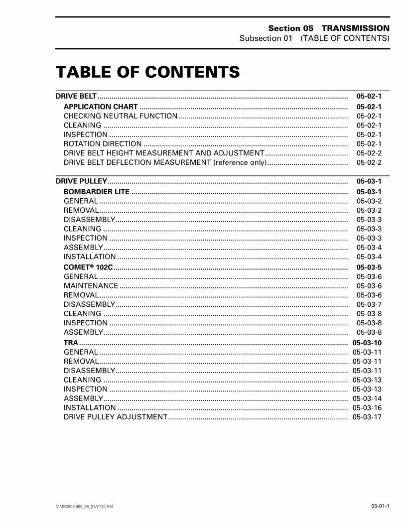
TABLE OF CONTENTS 0DRIVE BELT............................................................................................................................ 05-02-1
APPLICATION CHART ....................................................................................................... 05-02-1
CHECKING NEUTRAL FUNCTION.................................................................................... 05-02-1CLEANING ......................................................................................................................... 05-02-1INSPECTION ...................................................................................................................... 05-02-1ROTATION DIRECTION ..................................................................................................... 05-02-1DRIVE BELT HEIGHT MEASUREMENT AND ADJUSTMENT......................................... 05-02-2DRIVE BELT DEFLECTION MEASUREMENT (reference only)........................................ 05-02-2
DRIVE PULLEY....................................................................................................................... 05-03-1
BOMBARDIER LITE ........................................................................................................... 05-03-1
GENERAL ........................................................................................................................... 05-03-2REMOVAL........................................................................................................................... 05-03-2DISASSEMBLY................................................................................................................... 05-03-3CLEANING ......................................................................................................................... 05-03-3INSPECTION ...................................................................................................................... 05-03-3ASSEMBLY......................................................................................................................... 05-03-4INSTALLATION .................................................................................................................. 05-03-4COMET® 102C.................................................................................................................... 05-03-5
GENERAL ........................................................................................................................... 05-03-6MAINTENANCE ................................................................................................................. 05-03-6REMOVAL........................................................................................................................... 05-03-6DISASSEMBLY................................................................................................................... 05-03-7CLEANING ......................................................................................................................... 05-03-8INSPECTION ...................................................................................................................... 05-03-8ASSEMBLY......................................................................................................................... 05-03-8TRA..................................................................................................................................... 05-03-10
GENERAL ........................................................................................................................... 05-03-11REMOVAL........................................................................................................................... 05-03-11DISASSEMBLY................................................................................................................... 05-03-11CLEANING ......................................................................................................................... 05-03-13INSPECTION ...................................................................................................................... 05-03-13ASSEMBLY......................................................................................................................... 05-03-14INSTALLATION .................................................................................................................. 05-03-16DRIVE PULLEY ADJUSTMENT......................................................................................... 05-03-17
Section 05 TRANSMISSIONSubsection 01 (TABLE OF CONTENTS)
05-01-2 MMR2003-065_05_01ATOC.FM
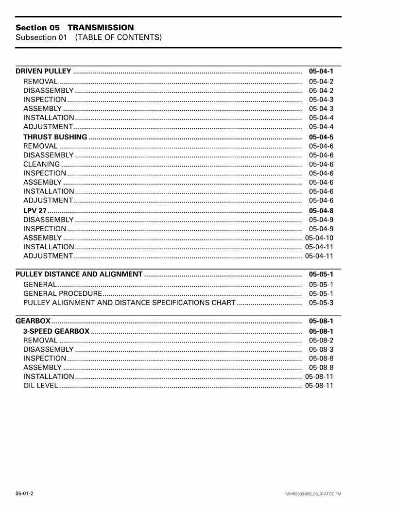
DRIVEN PULLEY .................................................................................................................... 05-04-1
REMOVAL ........................................................................................................................... 05-04-2DISASSEMBLY ................................................................................................................... 05-04-2INSPECTION....................................................................................................................... 05-04-3ASSEMBLY ......................................................................................................................... 05-04-3INSTALLATION................................................................................................................... 05-04-4ADJUSTMENT.................................................................................................................... 05-04-4THRUST BUSHING ............................................................................................................ 05-04-5
REMOVAL ........................................................................................................................... 05-04-6DISASSEMBLY ................................................................................................................... 05-04-6CLEANING .......................................................................................................................... 05-04-6INSPECTION....................................................................................................................... 05-04-6ASSEMBLY ......................................................................................................................... 05-04-6INSTALLATION................................................................................................................... 05-04-6ADJUSTMENT.................................................................................................................... 05-04-6LPV 27 ................................................................................................................................. 05-04-8
DISASSEMBLY ................................................................................................................... 05-04-9INSPECTION....................................................................................................................... 05-04-9ASSEMBLY ......................................................................................................................... 05-04-10INSTALLATION................................................................................................................... 05-04-11ADJUSTMENT.................................................................................................................... 05-04-11
PULLEY DISTANCE AND ALIGNMENT ................................................................................ 05-05-1
GENERAL............................................................................................................................ 05-05-1GENERAL PROCEDURE..................................................................................................... 05-05-1PULLEY ALIGNMENT AND DISTANCE SPECIFICATIONS CHART ................................. 05-05-3
GEARBOX............................................................................................................................... 05-08-1
3-SPEED GEARBOX ........................................................................................................... 05-08-1
REMOVAL ........................................................................................................................... 05-08-2DISASSEMBLY ................................................................................................................... 05-08-3INSPECTION....................................................................................................................... 05-08-8ASSEMBLY ......................................................................................................................... 05-08-8INSTALLATION................................................................................................................... 05-08-11OIL LEVEL ........................................................................................................................... 05-08-11
Section 05 TRANSMISSIONSubsection 02 (DRIVE BELT)
MMR2003-054_05_02A.FM 05-02-1
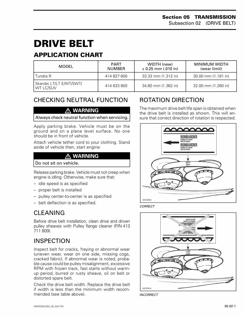
DRIVE BELT 0APPLICATION CHART
CHECKING NEUTRAL FUNCTION
Apply parking brake. Vehicle must be on theground and on a plane level surface. No oneshould be in front of vehicle.Attach vehicle tether cord to your clothing. Standaside of vehicle then, start engine.
Release parking brake. Vehicle must not creep whenengine is idling. Otherwise, make sure that:– idle speed is as specified– proper belt is installed– pulley center-to-center is as specified– belt deflection is as specified.
CLEANINGBefore drive belt installation, clean drive and drivenpulley sheaves with Pulley flange cleaner (P/N 413711 809).
INSPECTIONInspect belt for cracks, fraying or abnormal wear(uneven wear, wear on one side, missing cogs,cracked fabric). If abnormal wear is noted, proba-ble cause could be pulley misalignment, excessiveRPM with frozen track, fast starts without warm-up period, burred or rusty sheave, oil on belt ordistorted spare belt.Check the drive belt width. Replace the drive beltif width is less than the minimum width recom-mended (see table above).
ROTATION DIRECTIONThe maximum drive belt life span is obtained whenthe drive belt is installed as shown. This will en-sure that correct direction of rotation is respected.
CORRECT
INCORRECT
MODEL PARTNUMBER
WIDTH (new)± 0.25 mm (.010 in)
MINIMUM WIDTH(wear limit)
Tundra R 414 827 600 33.33 mm (1.312 in) 30.00 mm (1.181 in)
Skandic LT/LT E/WT/SWT/WT LC/SUV 414 633 800 34.60 mm (1.362 in) 32.00 mm (1.260 in)
� WARNING
Always check neutral function when servicing.
� WARNING
Do not sit on vehicle.
�������
�������
Section 05 TRANSMISSIONSubsection 02 (DRIVE BELT)
05-02-2 MMR2003-054_05_02A.FM
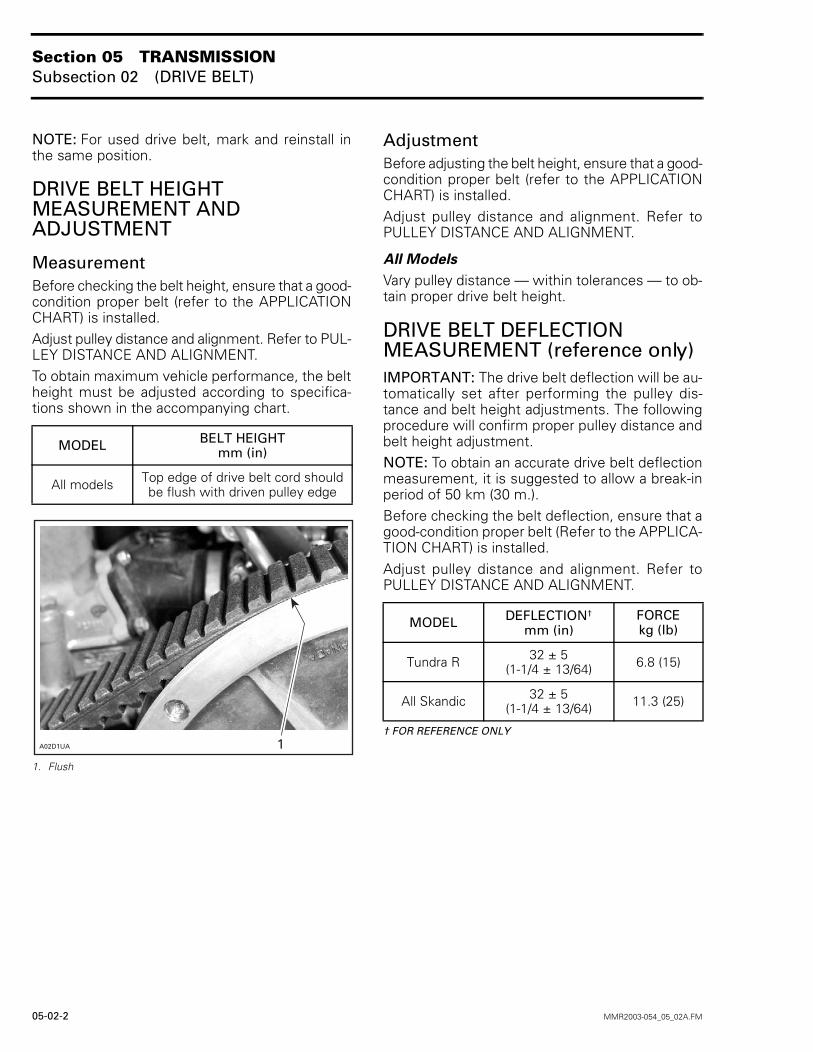
NOTE: For used drive belt, mark and reinstall inthe same position.
DRIVE BELT HEIGHT MEASUREMENT AND ADJUSTMENT
MeasurementBefore checking the belt height, ensure that a good-condition proper belt (refer to the APPLICATIONCHART) is installed.Adjust pulley distance and alignment. Refer to PUL-LEY DISTANCE AND ALIGNMENT.To obtain maximum vehicle performance, the beltheight must be adjusted according to specifica-tions shown in the accompanying chart.
1. Flush
AdjustmentBefore adjusting the belt height, ensure that a good-condition proper belt (refer to the APPLICATIONCHART) is installed.Adjust pulley distance and alignment. Refer toPULLEY DISTANCE AND ALIGNMENT.
All Models
Vary pulley distance — within tolerances — to ob-tain proper drive belt height.
DRIVE BELT DEFLECTION MEASUREMENT (reference only)IMPORTANT: The drive belt deflection will be au-tomatically set after performing the pulley dis-tance and belt height adjustments. The followingprocedure will confirm proper pulley distance andbelt height adjustment.NOTE: To obtain an accurate drive belt deflectionmeasurement, it is suggested to allow a break-inperiod of 50 km (30 m.).Before checking the belt deflection, ensure that agood-condition proper belt (Refer to the APPLICA-TION CHART) is installed.Adjust pulley distance and alignment. Refer toPULLEY DISTANCE AND ALIGNMENT.
† FOR REFERENCE ONLY
MODEL BELT HEIGHTmm (in)
All models Top edge of drive belt cord shouldbe flush with driven pulley edge
��������
MODEL DEFLECTION†
mm (in)FORCEkg (lb)
Tundra R 32 ± 5(1-1/4 ± 13/64) 6.8 (15)
All Skandic 32 ± 5(1-1/4 ± 13/64) 11.3 (25)
Section 05 TRANSMISSIONSubsection 02 (DRIVE BELT)
MMR2003-054_05_02A.FM 05-02-3
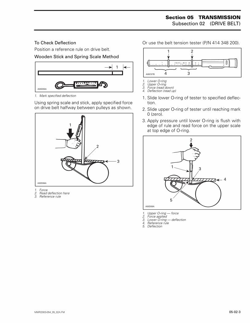
To Check DeflectionPosition a reference rule on drive belt.
Wooden Stick and Spring Scale Method
1. Mark specified deflection
Using spring scale and stick, apply specified forceon drive belt halfway between pulleys as shown.
1. Force2. Read deflection here3. Reference rule
Or use the belt tension tester (P/N 414 348 200).
1. Lower O-ring2. Upper O-ring3. Force (read down)4. Deflection (read up)
1. Slide lower O-ring of tester to specified deflec-tion.
2. Slide upper O-ring of tester until reaching mark0 (zero).
3. Apply pressure until lower O-ring is flush withedge of rule and read force on the upper scaleat top edge of O-ring.
1. Upper O-ring — force2. Force applied3. Lower O-ring — deflection4. Reference rule5. Deflection
������
�
A00D06A
1
2
3
�
������ �
�
A00D08A
2
1 3
4
5
Section 05 TRANSMISSIONSubsection 03 (DRIVE PULLEY)
MMR2003-055_05_03A.FM 05-03-1
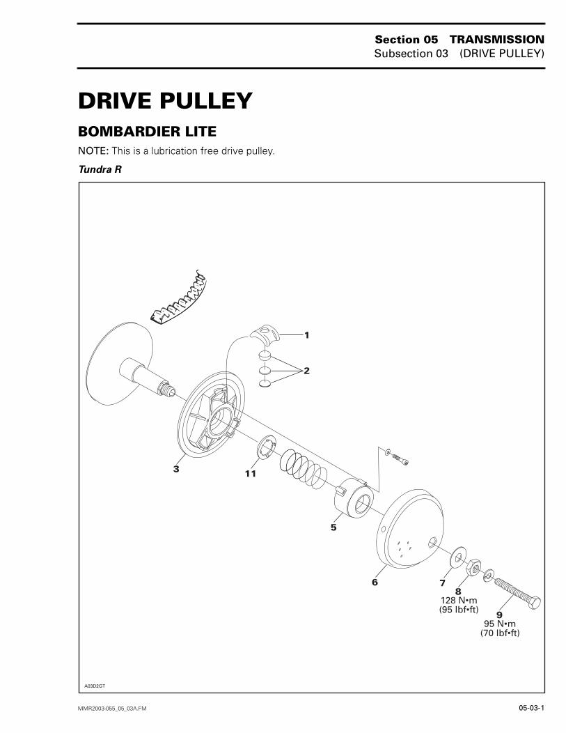
DRIVE PULLEY 0BOMBARDIER LITENOTE: This is a lubrication free drive pulley.
Tundra R
1
2
3
5
6 78
9
11
128 N•m(95 lbf•ft)
95 N•m(70 lbf•ft)
A03D2GT
Section 05 TRANSMISSIONSubsection 03 (DRIVE PULLEY)
05-03-2 MMR2003-055_05_03A.FM
GENERALSome drive pulley components (return spring, cali-bration disk) can be changed to improve vehicleperformance in high altitude regions. A service bul-letin will give information about calibration accord-ing to altitude.CAUTION: Such modifications should only beperformed by experienced mechanics sincethey can greatly affect vehicle performance.
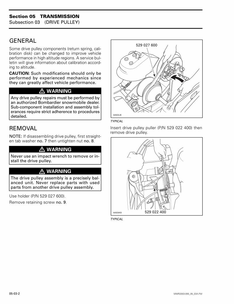
REMOVALNOTE: If disassembling drive pulley, first straight-en tab washer no. 7 then untighten nut no. 8.
Use holder (P/N 529 027 600).Remove retaining screw no. 9.
TYPICAL
Insert drive pulley puller (P/N 529 022 400) thenremove drive pulley.
TYPICAL
� WARNING
Any drive pulley repairs must be performed byan authorized Bombardier snowmobile dealer.Sub-component installation and assembly tol-erances require strict adherence to proceduresdetailed.
� WARNING
Never use an impact wrench to remove or in-stall the drive pulley.
� WARNING
The drive pulley assembly is a precisely bal-anced unit. Never replace parts with usedparts from another drive pulley assembly.
A05D0JB
529 027 600
������ ����������
Section 05 TRANSMISSIONSubsection 03 (DRIVE PULLEY)
MMR2003-055_05_03A.FM 05-03-3
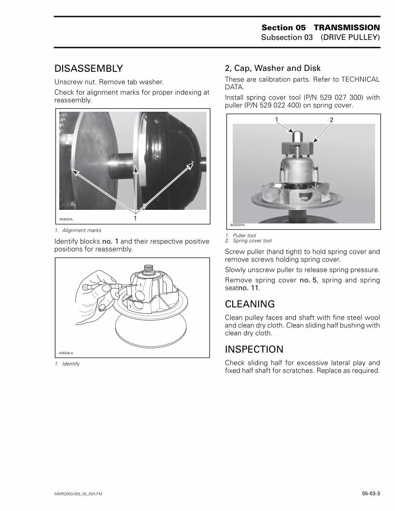
DISASSEMBLYUnscrew nut. Remove tab washer.Check for alignment marks for proper indexing atreassembly.
1. Alignment marks
Identify blocks no. 1 and their respective positivepositions for reassembly.
1. Identify
2, Cap, Washer and DiskThese are calibration parts. Refer to TECHNICALDATA.Install spring cover tool (P/N 529 027 300) withpuller (P/N 529 022 400) on spring cover.
1. Puller tool2. Spring cover tool
Screw puller (hand tight) to hold spring cover andremove screws holding spring cover.Slowly unscrew puller to release spring pressure.Remove spring cover no. 5, spring and springseatno. 11.
CLEANINGClean pulley faces and shaft with fine steel wooland clean dry cloth. Clean sliding half bushing withclean dry cloth.
INSPECTIONCheck sliding half for excessive lateral play andfixed half shaft for scratches. Replace as required.
A03D2IA 1
A05D0LA
1
1
A03D2HA
21
Section 05 TRANSMISSIONSubsection 03 (DRIVE PULLEY)
05-03-4 MMR2003-055_05_03A.FM
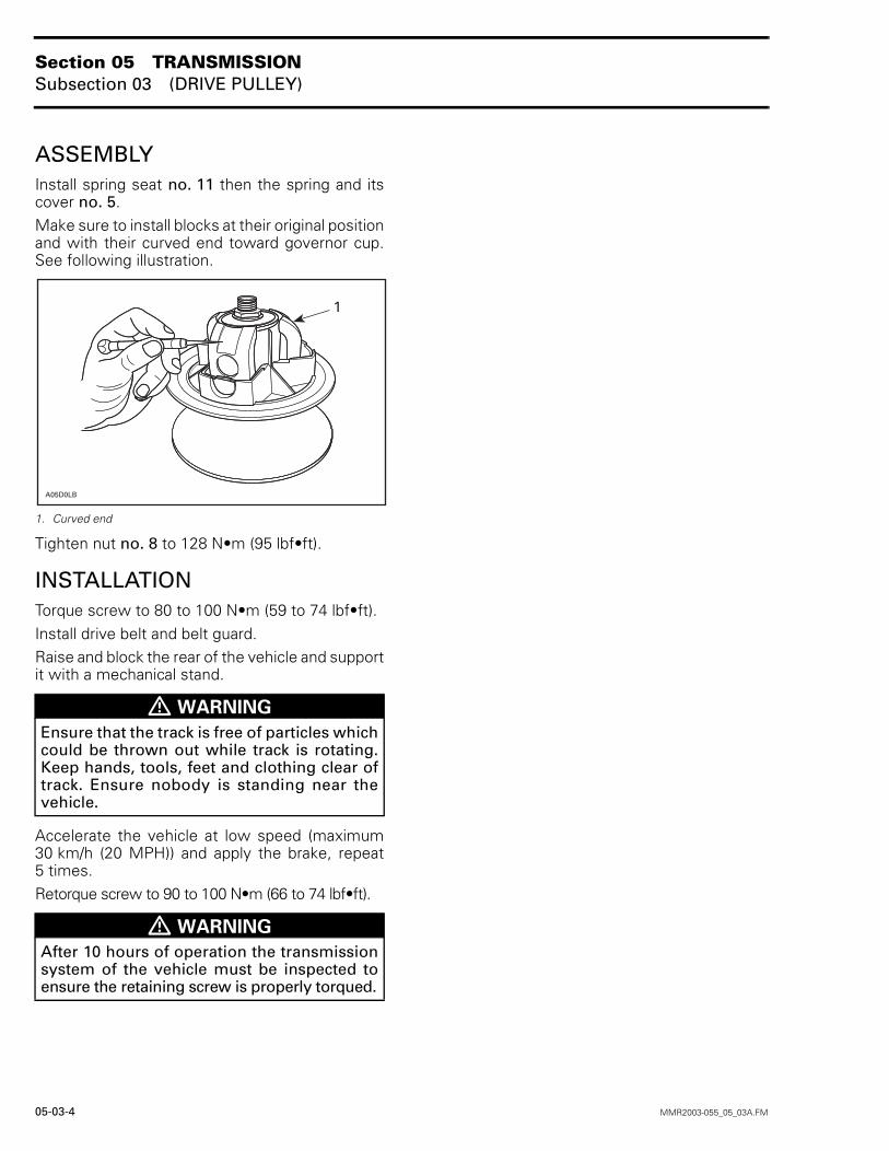
ASSEMBLYInstall spring seat no. 11 then the spring and itscover no. 5.Make sure to install blocks at their original positionand with their curved end toward governor cup.See following illustration.
1. Curved end
Tighten nut no. 8 to 128 N•m (95 lbf•ft).
INSTALLATIONTorque screw to 80 to 100 N•m (59 to 74 lbf•ft).Install drive belt and belt guard.Raise and block the rear of the vehicle and supportit with a mechanical stand.
Accelerate the vehicle at low speed (maximum30 km/h (20 MPH)) and apply the brake, repeat5 times.Retorque screw to 90 to 100 N•m (66 to 74 lbf•ft).
� WARNING
Ensure that the track is free of particles whichcould be thrown out while track is rotating.Keep hands, tools, feet and clothing clear oftrack. Ensure nobody is standing near thevehicle.
� WARNING
After 10 hours of operation the transmissionsystem of the vehicle must be inspected toensure the retaining screw is properly torqued.
������
�
Section 05 TRANSMISSIONSubsection 03 (DRIVE PULLEY)
MMR2003-055_05_03A.FM 05-03-5
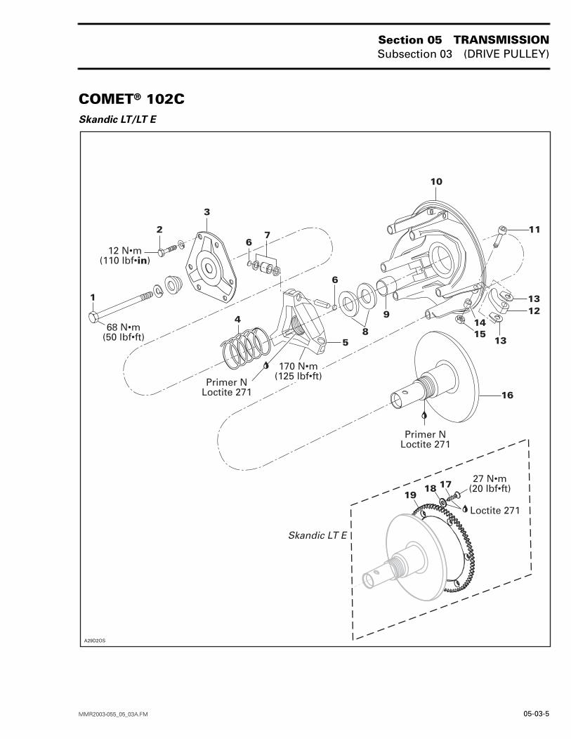
COMET® 102CSkandic LT/LT E
�
� ��
�
�
�
��
�
�
�
�
�
�������
�
������������������
����������������
� ����������������
�� �!����"#� �!�� �
�� �!����"#� �!�� �
����������
�� � � ����
�����������
�"#� �!�� �
Section 05 TRANSMISSIONSubsection 03 (DRIVE PULLEY)
05-03-6 MMR2003-055_05_03A.FM
GENERALSome drive pulley components can be changed toimprove vehicle performance in high altitude re-gions. A Service Bulletin will give informationabout calibration according to altitude.CAUTION: Such modifications should only beperformed by experience mechanics since theycan greatly affect vehicle performance.
MAINTENANCE
Cam Arm Pivot NutAt first 10-hour (500 km) cam arm pivot nuts no. 15have to be retighten.To do so, loosen one turn all cover screws no. 2.Retighten to 5.6 N•m (50 lbf•in) maximum all threepivot nuts no. 15. Make sure cam arms no. 12 canstill move on their pivot bolts no. 11.Retighten cover screws no. 2 to 12 N•m (110lbf•in). Proceed with one screw per tower in a criss-cross sequence then, remaining three screws.
Cam Arm BushingCam arm bushings no. 14 have to be replaced ev-ery 3000 km (2000 m.).With drive pulley still installed on crankshaft, re-move one cam arm no. 12 at a time. Install partsincluded in Cam Arm Kit. Proceed with remainingcam arms.Loosen one turn all cover screws no. 2.Retighten to 5.6 N•m (50 lbf•in) maximum allthree pivot nuts no. 15. Make sure cam armsno. 12 can still move on their pivot bolts no. 11.Retighten cover screws no. 2 to 12 N•m (110 lbf•in).Proceed with one screw per tower in a criss-crosssequence then, remaining three screws.
REMOVAL
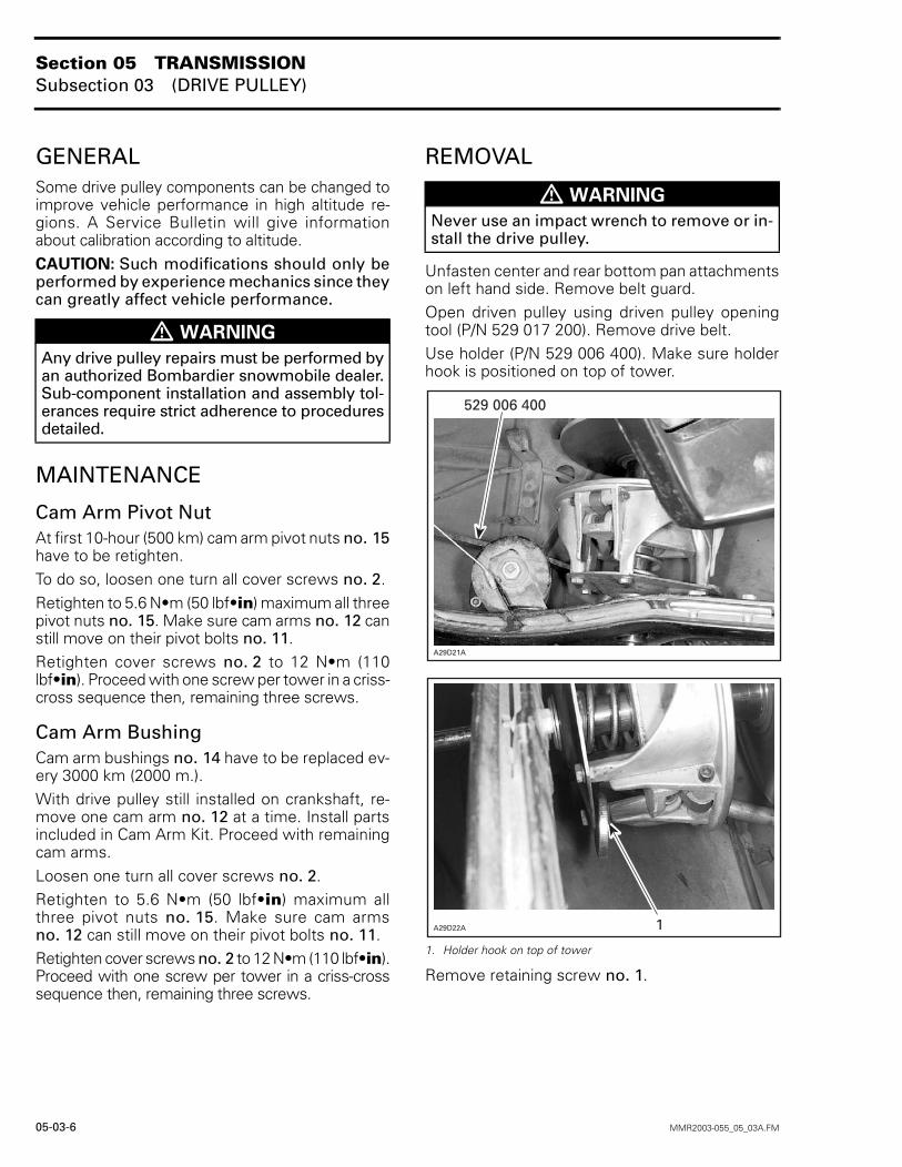
Unfasten center and rear bottom pan attachmentson left hand side. Remove belt guard.Open driven pulley using driven pulley openingtool (P/N 529 017 200). Remove drive belt.Use holder (P/N 529 006 400). Make sure holderhook is positioned on top of tower.
1. Holder hook on top of tower
Remove retaining screw no. 1.
� WARNING
Any drive pulley repairs must be performed byan authorized Bombardier snowmobile dealer.Sub-component installation and assembly tol-erances require strict adherence to proceduresdetailed.
� WARNING
Never use an impact wrench to remove or in-stall the drive pulley.
����������
�������
��������
Section 05 TRANSMISSIONSubsection 03 (DRIVE PULLEY)
MMR2003-055_05_03A.FM 05-03-7
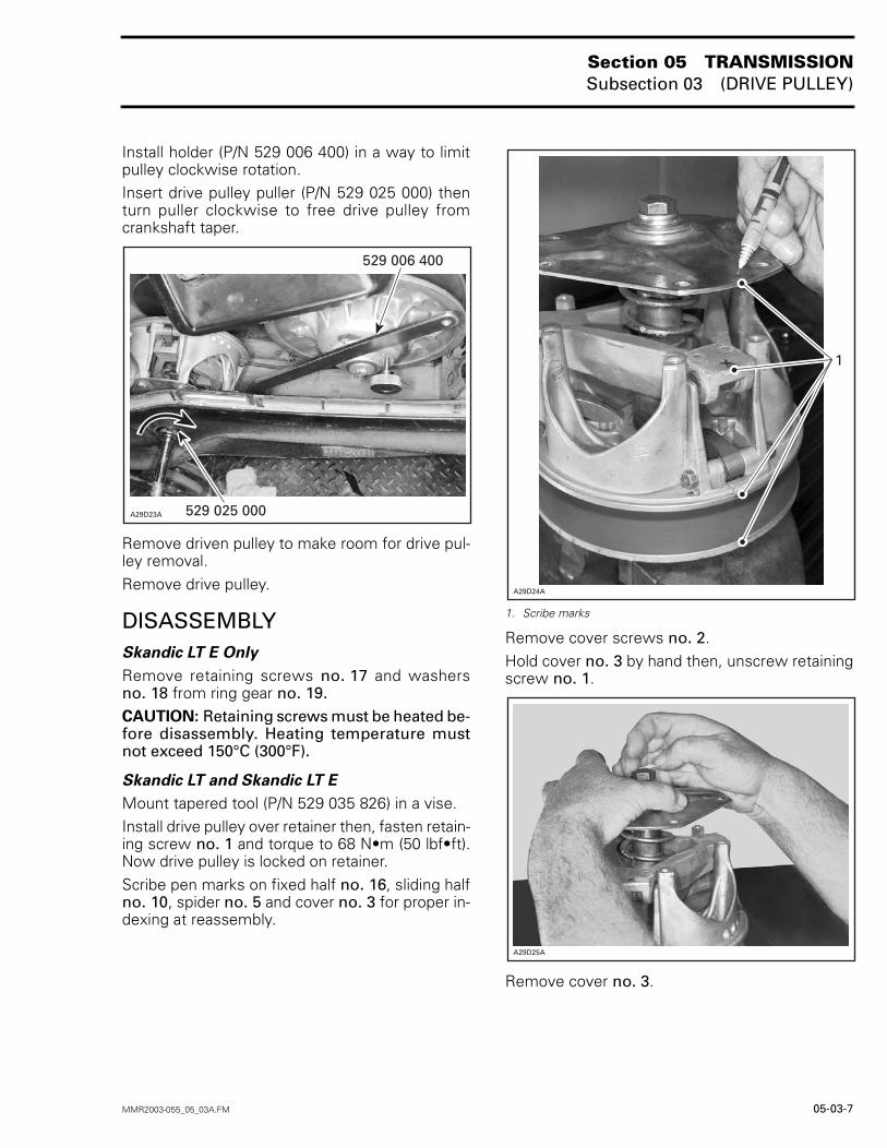
Install holder (P/N 529 006 400) in a way to limitpulley clockwise rotation.Insert drive pulley puller (P/N 529 025 000) thenturn puller clockwise to free drive pulley fromcrankshaft taper.
Remove driven pulley to make room for drive pul-ley removal.Remove drive pulley.
DISASSEMBLYSkandic LT E Only
Remove retaining screws no. 17 and washersno. 18 from ring gear no. 19.CAUTION: Retaining screws must be heated be-fore disassembly. Heating temperature mustnot exceed 150°C (300°F).
Skandic LT and Skandic LT E
Mount tapered tool (P/N 529 035 826) in a vise.Install drive pulley over retainer then, fasten retain-ing screw no. 1 and torque to 68 N•m (50 lbf•ft).Now drive pulley is locked on retainer.Scribe pen marks on fixed half no. 16, sliding halfno. 10, spider no. 5 and cover no. 3 for proper in-dexing at reassembly.
1. Scribe marks
Remove cover screws no. 2.Hold cover no. 3 by hand then, unscrew retainingscrew no. 1.
Remove cover no. 3.
���������������
����������
�
�������
������
Section 05 TRANSMISSIONSubsection 03 (DRIVE PULLEY)
05-03-8 MMR2003-055_05_03A.FM
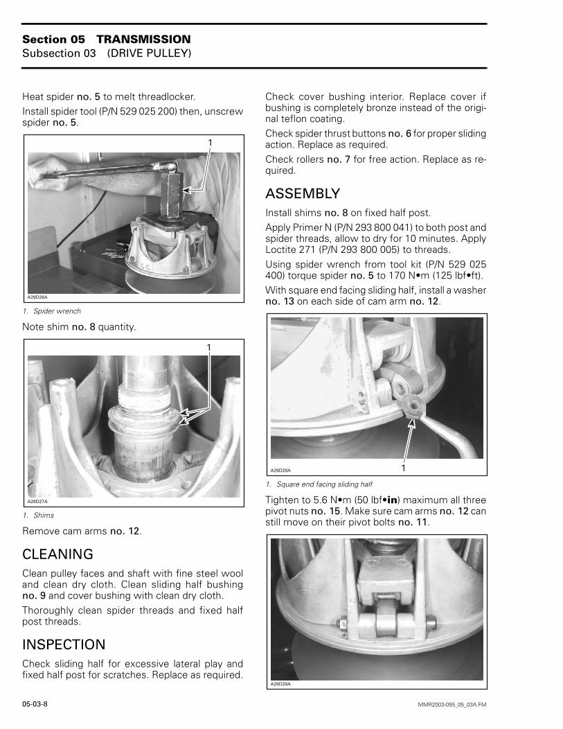
Heat spider no. 5 to melt threadlocker.Install spider tool (P/N 529 025 200) then, unscrewspider no. 5.
1. Spider wrench
Note shim no. 8 quantity.
1. Shims
Remove cam arms no. 12.
CLEANINGClean pulley faces and shaft with fine steel wooland clean dry cloth. Clean sliding half bushingno. 9 and cover bushing with clean dry cloth.Thoroughly clean spider threads and fixed halfpost threads.
INSPECTIONCheck sliding half for excessive lateral play andfixed half post for scratches. Replace as required.
Check cover bushing interior. Replace cover ifbushing is completely bronze instead of the origi-nal teflon coating.Check spider thrust buttons no. 6 for proper slidingaction. Replace as required.Check rollers no. 7 for free action. Replace as re-quired.
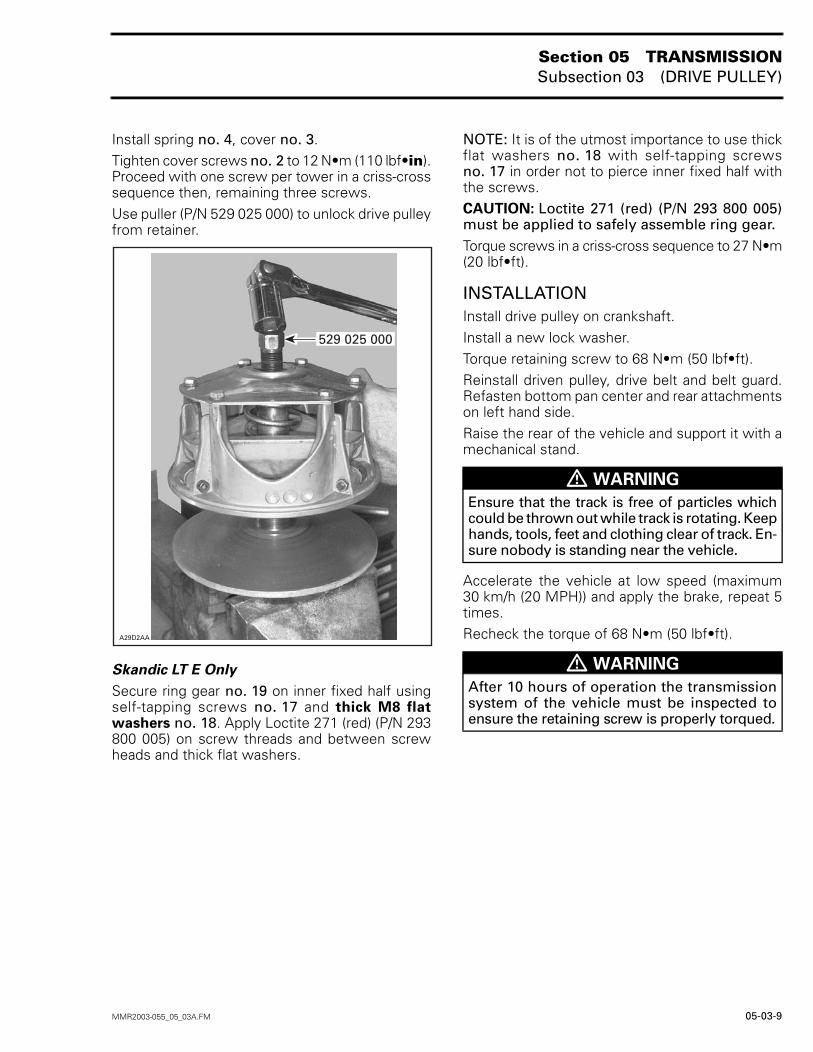
ASSEMBLYInstall shims no. 8 on fixed half post.Apply Primer N (P/N 293 800 041) to both post andspider threads, allow to dry for 10 minutes. ApplyLoctite 271 (P/N 293 800 005) to threads.Using spider wrench from tool kit (P/N 529 025400) torque spider no. 5 to 170 N•m (125 lbf•ft).With square end facing sliding half, install a washerno. 13 on each side of cam arm no. 12.
1. Square end facing sliding half
Tighten to 5.6 N•m (50 lbf•in) maximum all threepivot nuts no. 15. Make sure cam arms no. 12 canstill move on their pivot bolts no. 11.
�
�������
�
����� �
��������
�������
Section 05 TRANSMISSIONSubsection 03 (DRIVE PULLEY)
MMR2003-055_05_03A.FM 05-03-9
Install spring no. 4, cover no. 3.Tighten cover screws no. 2 to 12 N•m (110 lbf•in).Proceed with one screw per tower in a criss-crosssequence then, remaining three screws.Use puller (P/N 529 025 000) to unlock drive pulleyfrom retainer.
Skandic LT E Only
Secure ring gear no. 19 on inner fixed half usingself-tapping screws no. 17 and thick M8 flatwashers no. 18. Apply Loctite 271 (red) (P/N 293800 005) on screw threads and between screwheads and thick flat washers.
NOTE: It is of the utmost importance to use thickflat washers no. 18 with self-tapping screwsno. 17 in order not to pierce inner fixed half withthe screws.CAUTION: Loctite 271 (red) (P/N 293 800 005)must be applied to safely assemble ring gear.Torque screws in a criss-cross sequence to 27 N•m(20 lbf•ft).
INSTALLATIONInstall drive pulley on crankshaft.Install a new lock washer.Torque retaining screw to 68 N•m (50 lbf•ft).Reinstall driven pulley, drive belt and belt guard.Refasten bottom pan center and rear attachmentson left hand side.Raise the rear of the vehicle and support it with amechanical stand.
Accelerate the vehicle at low speed (maximum30 km/h (20 MPH)) and apply the brake, repeat 5times.Recheck the torque of 68 N•m (50 lbf•ft).�������
���������
� WARNING
Ensure that the track is free of particles whichcould be thrown out while track is rotating. Keephands, tools, feet and clothing clear of track. En-sure nobody is standing near the vehicle.
� WARNING
After 10 hours of operation the transmissionsystem of the vehicle must be inspected toensure the retaining screw is properly torqued.
Section 05 TRANSMISSIONSubsection 03 (DRIVE PULLEY)
05-03-10 MMR2003-055_05_03A.FM
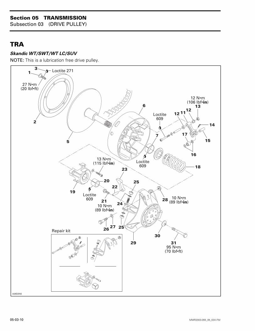
TRASkandic WT/SWT/WT LC/SUV
NOTE: This is a lubrication free drive pulley.
�������
� ���������������
�"#� �!�� �
�
�
��
�
������������������
�
��
�
�
�
�"#� �!���
����������������
��
��
�� �����������������
�
�
�
��
��
�"#� �!���
�� �� ��
��
�
������
� ���������
$!%& ��' �
�"#� �!���
�����������������
�
�
Section 05 TRANSMISSIONSubsection 03 (DRIVE PULLEY)
MMR2003-055_05_03A.FM 05-03-11
GENERALSome drive pulley components (return spring,ramp) can be changed to improve vehicle perfor-mance in high altitude regions. A Service Bulletinwill give information about calibration according toaltitude.CAUTION: Such modifications should only beperformed by experienced mechanics sincethey can greatly affect vehicle performance. Ver-ify spring specifications before installation. Donot only refer to the spring color code.NOTE: TRA drive pulley stands for Total RangeAdjustable drive pulley.
REMOVAL
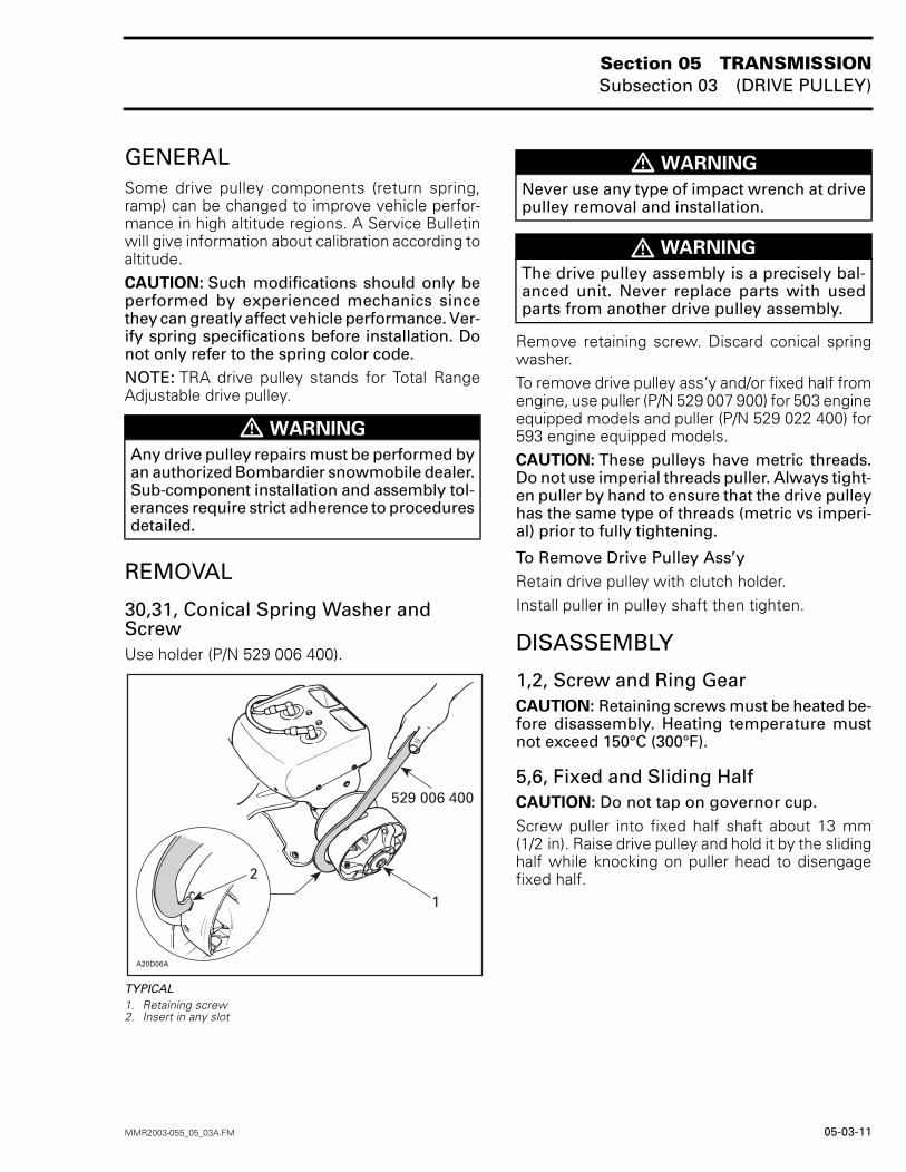
30,31, Conical Spring Washer and ScrewUse holder (P/N 529 006 400).
TYPICAL1. Retaining screw 2. Insert in any slot
Remove retaining screw. Discard conical springwasher.To remove drive pulley ass’y and/or fixed half fromengine, use puller (P/N 529 007 900) for 503 engineequipped models and puller (P/N 529 022 400) for593 engine equipped models.CAUTION: These pulleys have metric threads.Do not use imperial threads puller. Always tight-en puller by hand to ensure that the drive pulleyhas the same type of threads (metric vs imperi-al) prior to fully tightening.
To Remove Drive Pulley Ass’yRetain drive pulley with clutch holder.Install puller in pulley shaft then tighten.
DISASSEMBLY
1,2, Screw and Ring GearCAUTION: Retaining screws must be heated be-fore disassembly. Heating temperature mustnot exceed 150°C (300°F).
5,6, Fixed and Sliding HalfCAUTION: Do not tap on governor cup.Screw puller into fixed half shaft about 13 mm(1/2 in). Raise drive pulley and hold it by the slidinghalf while knocking on puller head to disengagefixed half.
� WARNING
Any drive pulley repairs must be performed byan authorized Bombardier snowmobile dealer.Sub-component installation and assembly tol-erances require strict adherence to proceduresdetailed.
A20D06A
2
529 006 400
1
� WARNING
Never use any type of impact wrench at drivepulley removal and installation.
� WARNING
The drive pulley assembly is a precisely bal-anced unit. Never replace parts with usedparts from another drive pulley assembly.
Section 05 TRANSMISSIONSubsection 03 (DRIVE PULLEY)
05-03-12 MMR2003-055_05_03A.FM
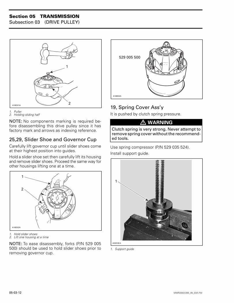
1. Puller2. Holding sliding half
NOTE: No components marking is required be-fore disassembling this drive pulley since it hasfactory mark and arrows as indexing reference.
25,29, Slider Shoe and Governor CupCarefully lift governor cup until slider shoes comeat their highest position into guides.Hold a slider shoe set then carefully lift its housingand remove slider shoes. Proceed the same way forother housings lifting one at a time.
1. Hold slider shoes2. Lift one housing at a time
NOTE: To ease disassembly, forks (P/N 529 005500) should be used to hold slider shoes prior toremoving governor cup.
19, Spring Cover Ass’yIt is pushed by clutch spring pressure.
Use spring compressor (P/N 529 035 524).Install support guide.
1. Support guide
A16D01A
1
2
A16D02A
1
2
� WARNING
Clutch spring is very strong. Never attempt toremove spring cover without the recommend-ed tools.
A16B02A
529 005 500
�
���(�
Section 05 TRANSMISSIONSubsection 03 (DRIVE PULLEY)
MMR2003-055_05_03A.FM 05-03-13
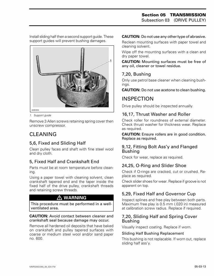
Install sliding half then a second support guide. Thesesupport guides will prevent bushing damages.
1. Support guide
Remove 3 Allen screws retaining spring cover thenunscrew compressor.
CLEANING
5,6, Fixed and Sliding HalfClean pulley faces and shaft with fine steel wooland dry cloth.
5, Fixed Half and Crankshaft EndParts must be at room temperature before clean-ing.Using a paper towel with cleaning solvent, cleancrankshaft tapered end and the taper inside thefixed half of the drive pulley, crankshaft threadsand retaining screw threads.
CAUTION: Avoid contact between cleaner andcrankshaft seal because damage may occur.Remove all hardened oil deposits that have bakedon crankshaft and pulley tapered surfaces withcoarse or medium steel wool and/or sand paperno. 600.
CAUTION: Do not use any other type of abrasive.Reclean mounting surfaces with paper towel andcleaning solvent.Wipe off the mounting surfaces with a clean anddry paper towel.CAUTION: Mounting surfaces must be free ofany oil, cleaner or towel residue.
7,20, BushingOnly use petrol base cleaner when cleaning bush-ings.CAUTION: Do not use acetone to clean bushing.
INSPECTIONDrive pulley should be inspected annually.
16,17, Thrust Washer and RollerCheck roller for roundness of external diameter.Check thrust washer for thickness wear. Replaceas required.CAUTION: Ensure rollers are in good condition.Replace as required.
9,12, Fitting Bolt Ass’y and Flanged BushingCheck for wear, replace as required.
24,25, O-Ring and Slider ShoeCheck if O-rings are cracked, cut or crushed. Re-place as required.Check slider shoes for wear. Replace if groove is notapparent on top.
5,29, Fixed Half and Governor CupInspect splines and free play between both parts.Maximum free play is 0.5 mm (.020 in) measuredat calibration screw radius. Replace if required.
7,20, Sliding Half and Spring Cover BushingVisually inspect coating. Replace if worn.
Sliding Half Bushing ReplacementThis bushing is not replacable. If worn out, replacesliding half ass’y.
� WARNING
This procedure must be performed in a well-ventilated area.
���)�
�
Section 05 TRANSMISSIONSubsection 03 (DRIVE PULLEY)
05-03-14 MMR2003-055_05_03A.FM
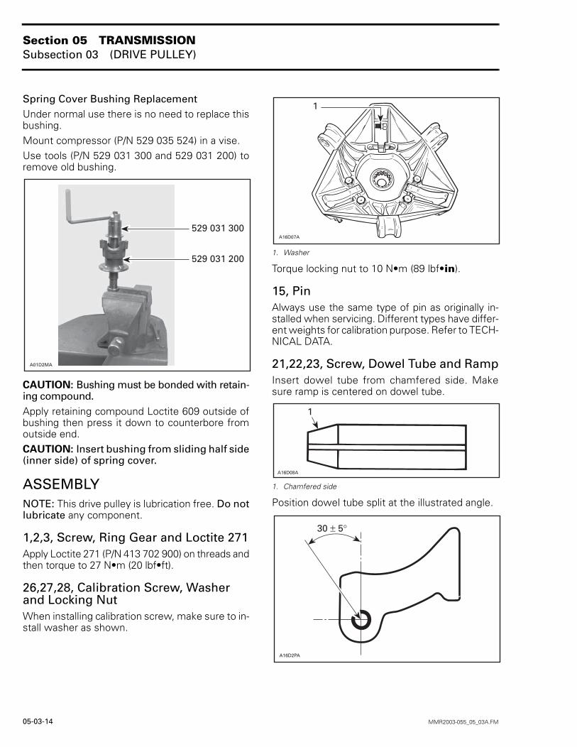
Spring Cover Bushing ReplacementUnder normal use there is no need to replace thisbushing.Mount compressor (P/N 529 035 524) in a vise.Use tools (P/N 529 031 300 and 529 031 200) toremove old bushing.
CAUTION: Bushing must be bonded with retain-ing compound.Apply retaining compound Loctite 609 outside ofbushing then press it down to counterbore fromoutside end.CAUTION: Insert bushing from sliding half side(inner side) of spring cover.
ASSEMBLYNOTE: This drive pulley is lubrication free. Do notlubricate any component.
1,2,3, Screw, Ring Gear and Loctite 271Apply Loctite 271 (P/N 413 702 900) on threads andthen torque to 27 N•m (20 lbf•ft).
26,27,28, Calibration Screw, Washer and Locking NutWhen installing calibration screw, make sure to in-stall washer as shown.
1. Washer
Torque locking nut to 10 N•m (89 lbf•in).
15, PinAlways use the same type of pin as originally in-stalled when servicing. Different types have differ-ent weights for calibration purpose. Refer to TECH-NICAL DATA.
21,22,23, Screw, Dowel Tube and RampInsert dowel tube from chamfered side. Makesure ramp is centered on dowel tube.
1. Chamfered side
Position dowel tube split at the illustrated angle.
A01D2MA
529 031 300
529 031 200
A16D07A
1
�������
�
A16D2PA
30 ± 5°
Section 05 TRANSMISSIONSubsection 03 (DRIVE PULLEY)
MMR2003-055_05_03A.FM 05-03-15
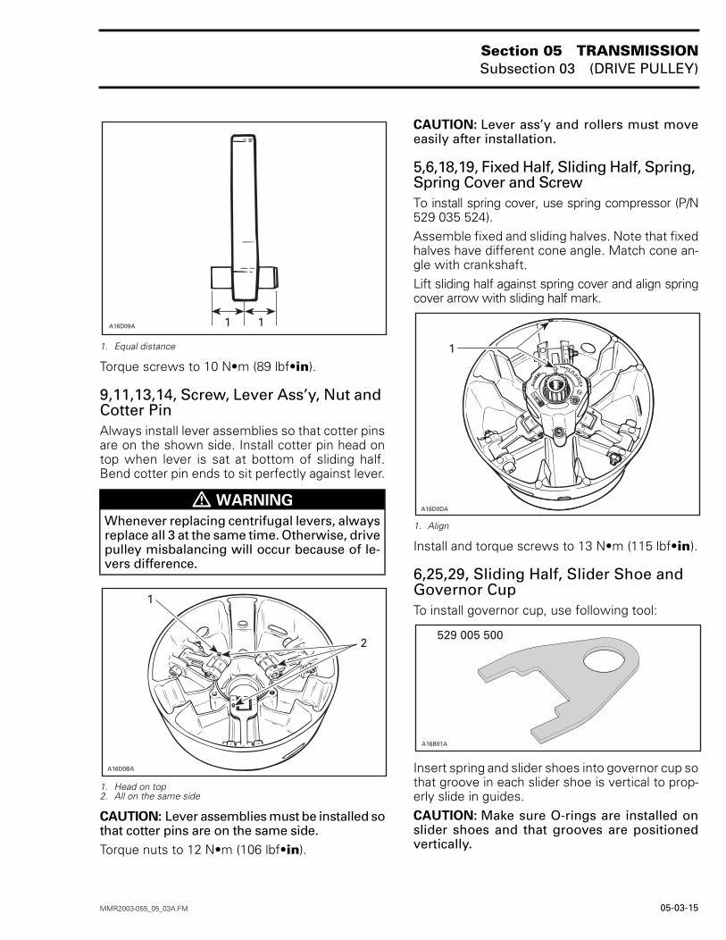
1. Equal distance
Torque screws to 10 N•m (89 lbf•in).
9,11,13,14, Screw, Lever Ass’y, Nut and Cotter PinAlways install lever assemblies so that cotter pinsare on the shown side. Install cotter pin head ontop when lever is sat at bottom of sliding half.Bend cotter pin ends to sit perfectly against lever.
1. Head on top2. All on the same side
CAUTION: Lever assemblies must be installed sothat cotter pins are on the same side.Torque nuts to 12 N•m (106 lbf•in).
CAUTION: Lever ass’y and rollers must moveeasily after installation.
5,6,18,19, Fixed Half, Sliding Half, Spring, Spring Cover and ScrewTo install spring cover, use spring compressor (P/N529 035 524).Assemble fixed and sliding halves. Note that fixedhalves have different cone angle. Match cone an-gle with crankshaft.Lift sliding half against spring cover and align springcover arrow with sliding half mark.
1. Align
Install and torque screws to 13 N•m (115 lbf•in).
6,25,29, Sliding Half, Slider Shoe and Governor CupTo install governor cup, use following tool:
Insert spring and slider shoes into governor cup sothat groove in each slider shoe is vertical to prop-erly slide in guides.CAUTION: Make sure O-rings are installed onslider shoes and that grooves are positionedvertically.
� WARNING
Whenever replacing centrifugal levers, alwaysreplace all 3 at the same time. Otherwise, drivepulley misbalancing will occur because of le-vers difference.
A16D09A 11
�������
�
�
�������
�
�������
��������
Section 05 TRANSMISSIONSubsection 03 (DRIVE PULLEY)
05-03-16 MMR2003-055_05_03A.FM
Install fork (P/N 529 005 500) into slider shoe groovesto maintain them for governor cup installation. Pro-ceed on 3 set of slider shoes.
Make sure to align governor cup arrow with slidinghalf and fixed half mark.NOTE: If fixed half has no mark, align governorcup mark with segment no. 1 of inner half. Seg-ments are identified on engine side.
1. Align
Carefully slide governor cup into sliding half. Alignmark of governor cup with mark of fixed half.Remove forks and push governor cup so that itssplines engage with fixed half shaft splines.CAUTION: Make sure splines of both parts arefully engaged.
INSTALLATION
Clean mounting surfaces as described in CLEANINGabove.
Drive Pulley Ass’yThe following installation procedure must be strict-ly adhered to.Install drive pulley on crankshaft extension.Install a new conical spring washer with its con-cave side towards drive pulley then install screw.
Use holder. See removal procedure.Torque screw to 90 to 100 N•m (66 to 74 lbf•ft).Install drive belt and guard.Raise the rear of the vehicle and support it with amechanical stand.
Accelerate the vehicle at low speed (maximum30 km/h (20 MPH) and apply the brake, repeat 5times.Recheck the torque of 90 to 100 N•m (66 to 74 lbf•ft).
A16B02A
529 005 500
A16D0EA
1
� WARNING
Do not apply anti-seize or any lubricant oncrankshaft and drive pulley tapers.
� WARNING
Never use any type of impact wrench at drivepulley removal and installation.
� WARNING
Never substitute conical spring washer and/orscrew with jobber ones. Always use Bombardiergenuine parts for this particular case.
� WARNING
Ensure that the track is free of particles whichcould be thrown out while track is rotating.Keep hands, tools, feet and clothing clear oftrack. Ensure nobody is standing near the vehi-cle.
� WARNING
After 10 hours of operation the transmissionsystem of the vehicle must be inspected to en-sure the retaining screw is properly torqued.
Section 05 TRANSMISSIONSubsection 03 (DRIVE PULLEY)
MMR2003-055_05_03A.FM 05-03-17
DRIVE PULLEY ADJUSTMENTThe drive pulley is factory calibrated to transmitmaximum engine power at a predefined RPM. Fac-tors such as ambient temperature, altitude or sur-face condition may vary this critical engine RPMthus affecting snowmobile efficiency.This adjustable drive pulley allows setting maxi-mum engine RPM in the vehicle to maintain max-imum power.Calibration screws should be adjusted so that actu-al maximum engine RPM in vehicle matches withthe maximum horsepower RPM given in TECHNI-CAL DATA.NOTE: Use precision digital tachometer for en-gine RPM adjustment.NOTE: The adjustment has an effect on high RPMonly.To adjust, modify ramp end position by turning cal-ibration screws.
26,28,29, Calibration Screw, Locking Nut and Governor CupCalibration screw has a notch on top of its head.
1. Notch
Governor cup has 6 positions numbered 2 to 6.Note that in position 1 there is no stamped num-ber (due to its location on casting).See TECHNICAL DATA for original setting.
1. Position 1 (not numbered)
Each number modifies maximum engine RPM byabout 200 RPM.Lower numbers decrease engine RPM in steps of200 RPM and higher numbers increase it in stepsof 200 RPM.Example:Calibration screw is set at position 3 and is changedto position 5. So maximum engine RPM is increasedby about 400 RPM.
To Adjust:Just loosen locking nut enough to pull calibrationscrew partially out and adjust to desired position.Do not completely remove the locking nut. Torquelocking nuts to 10 N•m (89 lbf•in).CAUTION: Do not completely remove calibra-tion screw otherwise its inside washer will falloff.CAUTION: Always adjust all 3 calibration screwsand make sure they are all set at the same num-ber.
1. Loosen just enough to permit rotating of calibration screw
A16D0FA
1
�����*�
�
A16D0HA
1
Section 05 TRANSMISSIONSubsection 04 (DRIVEN PULLEY)
MMR2003-056_05_04A.FM 05-04-1
DRIVEN PULLEY 0Tundra R
����+�
���������������
�
�
�
�,� -.! /!�0�� #&,� �
�
�
�
�
�
�
�
���������������
Section 05 TRANSMISSIONSubsection 04 (DRIVEN PULLEY)
05-04-2 MMR2003-056_05_04A.FM
NOTE: Driven pulley components (support, cam,shoes, etc.) can be serviced without removing thewhole driven pulley from chaincase. Refer to thefollowing procedures but neither remove brakecaliper nor open chaincase for those cases.
REMOVALTo remove driven pulley from chaincase, follow thisprocedure.Remove guard and drive belt from vehicle.Remove brake support from chaincase with brakeass’y.Free countershaft support from support clamp.
ChaincaseOpen chaincase and drain oil. Unlock and removeupper sprocket.The following is required to have enough space toremove driven pulley from chaincase:Loosen steering column upper retaining screws.Disconnect carburetor boots from intake manifoldand air intake silencer.Disconnect impulse hose from engine.Disconnect oil injection supply line at injectionpump and plug line to prevent draining.Remove screws retaining rear engine support tochassis.Tip engine forward just enough to allow driven pul-ley removal from chaincase. Block in this position.NOTE: In some cases, chaincase retaining screwsmight have to be loosened to allow pivoting ofchaincase. In this case, note position of alignmentshims. In addition, air intake silencer and oil injec-tion reservoir might have to be slightly moved toget enough space to pull driven pulley.Remove bearing cone.Knock driven pulley shaft with a plastic hammerand pull driven pulley out.
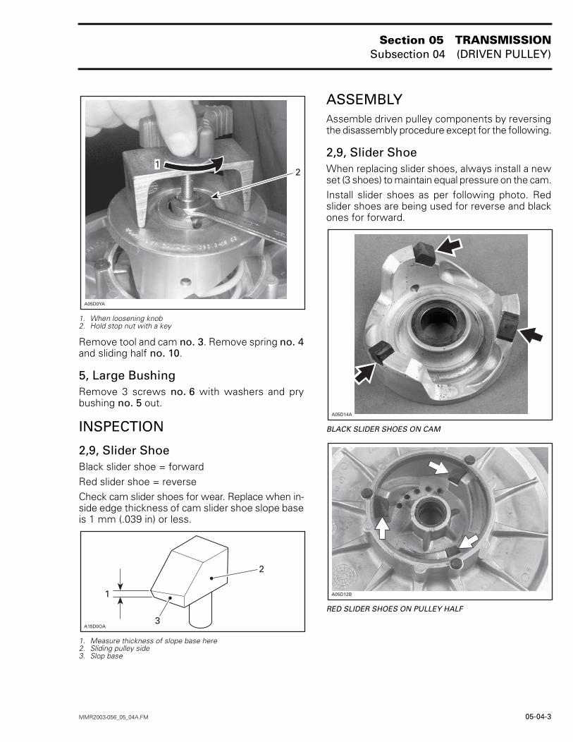
DISASSEMBLYTo disassemble driven pulley, driven pulley springcompressor (P/N 529 035 300) must be used. Seefollowing procedure.Position stop nut 13 mm (1/2 in) from threaded rodend, as shown in the next photo.
A. 13 mm (1/2 in)
Install driven pulley spring compressor (P/N 529035 300). Fully tighten the 13 mm (1/2 in) exposedthreads in driven pulley. Tighten stop nut. Tightentool knob to compress spring then remove roll pinno. 2.
Step : Tighten stop nutStep : Tighten knob to compress springStep : Remove roll pin
Once roll pin has been removed, loosen knob untilspring pressure is completely released.
� WARNING
To avoid injuries always hold stop nut with akey when loosening knob, as shown in the nextphoto.
A05D0WA
A
2
A05D0XB
1
3
123
Section 05 TRANSMISSIONSubsection 04 (DRIVEN PULLEY)
MMR2003-056_05_04A.FM 05-04-3
1. When loosening knob2. Hold stop nut with a key
Remove tool and cam no. 3. Remove spring no. 4and sliding half no. 10.
5, Large BushingRemove 3 screws no. 6 with washers and prybushing no. 5 out.
INSPECTION
2,9, Slider Shoe Black slider shoe = forwardRed slider shoe = reverseCheck cam slider shoes for wear. Replace when in-side edge thickness of cam slider shoe slope baseis 1 mm (.039 in) or less.
1. Measure thickness of slope base here2. Sliding pulley side3. Slop base
ASSEMBLYAssemble driven pulley components by reversingthe disassembly procedure except for the following.
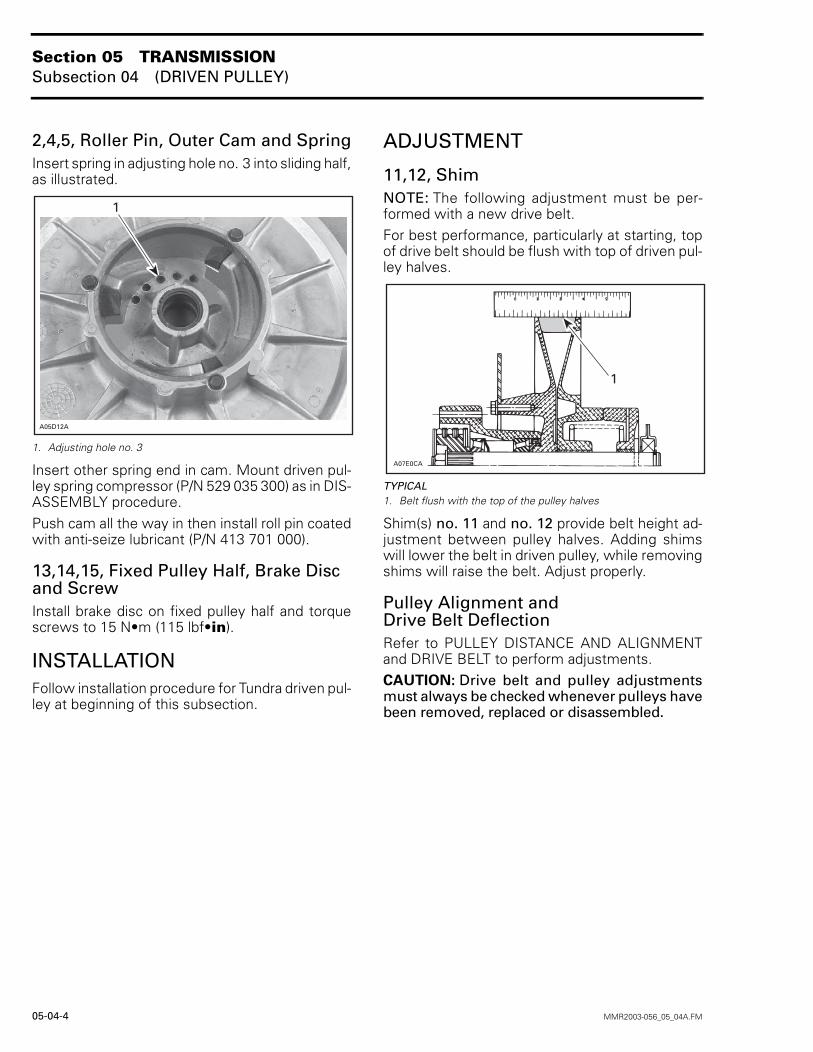
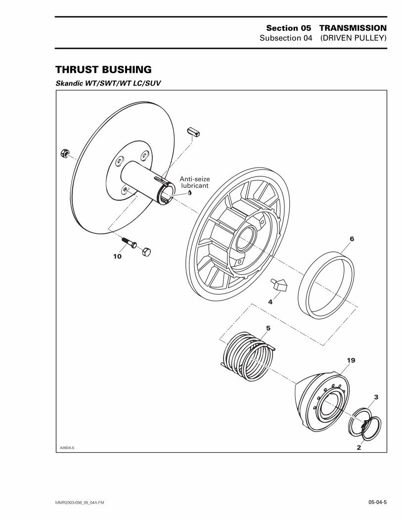
2,9, Slider ShoeWhen replacing slider shoes, always install a newset (3 shoes) to maintain equal pressure on the cam.Install slider shoes as per following photo. Redslider shoes are being used for reverse and blackones for forward.
BLACK SLIDER SHOES ON CAM
RED SLIDER SHOES ON PULLEY HALF
1
A05D0YA
2
2
1
A15D0OA3
������
A05D12B
Section 05 TRANSMISSIONSubsection 04 (DRIVEN PULLEY)
05-04-4 MMR2003-056_05_04A.FM
2,4,5, Roller Pin, Outer Cam and SpringInsert spring in adjusting hole no. 3 into sliding half,as illustrated.
1. Adjusting hole no. 3
Insert other spring end in cam. Mount driven pul-ley spring compressor (P/N 529 035 300) as in DIS-ASSEMBLY procedure.Push cam all the way in then install roll pin coatedwith anti-seize lubricant (P/N 413 701 000).
13,14,15, Fixed Pulley Half, Brake Disc and ScrewInstall brake disc on fixed pulley half and torquescrews to 15 N•m (115 lbf•in).
INSTALLATIONFollow installation procedure for Tundra driven pul-ley at beginning of this subsection.
ADJUSTMENT
11,12, ShimNOTE: The following adjustment must be per-formed with a new drive belt.For best performance, particularly at starting, topof drive belt should be flush with top of driven pul-ley halves.
TYPICAL1. Belt flush with the top of the pulley halves
Shim(s) no. 11 and no. 12 provide belt height ad-justment between pulley halves. Adding shimswill lower the belt in driven pulley, while removingshims will raise the belt. Adjust properly.
Pulley Alignment andDrive Belt DeflectionRefer to PULLEY DISTANCE AND ALIGNMENTand DRIVE BELT to perform adjustments.CAUTION: Drive belt and pulley adjustmentsmust always be checked whenever pulleys havebeen removed, replaced or disassembled.
A05D12A
1
�� (���
�
Section 05 TRANSMISSIONSubsection 04 (DRIVEN PULLEY)
MMR2003-056_05_04A.FM 05-04-5
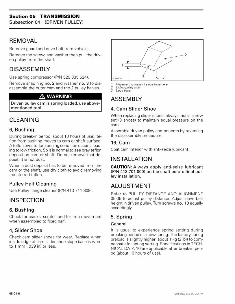
THRUST BUSHINGSkandic WT/SWT/WT LC/SUV
�������
�,� -.! /!�0�� #&,�
�
�
�
�
�
�
Section 05 TRANSMISSIONSubsection 04 (DRIVEN PULLEY)
05-04-6 MMR2003-056_05_04A.FM
REMOVALRemove guard and drive belt from vehicle.Remove the screw, and washer then pull the driv-en pulley from the shaft.
DISASSEMBLYUse spring compressor (P/N 529 035 524).Remove snap ring no. 2 and washer no. 3 to dis-assemble the outer cam and the 2 pulley halves.
CLEANING
6, BushingDuring break-in period (about 10 hours of use), te-flon from bushing moves to cam or shaft surface.A teflon over teflon running condition occurs, lead-ing to low friction. So it is normal to see gray teflondeposit on cam or shaft. Do not remove that de-posit, it is not dust.When a dust deposit has to be removed from thecam or the shaft, use dry cloth to avoid removingtransferred teflon.
Pulley Half CleaningUse Pulley flange cleaner (P/N 413 711 809).
INSPECTION
6, BushingCheck for cracks, scratch and for free movementwhen assembled to fixed half.
4, Slider ShoeCheck cam slider shoes for wear. Replace wheninside edge of cam slider shoe slope base is wornto 1 mm (.039 in) or less.
1. Measure thickness of slope base here2. Sliding pulley side 3. Slope base
ASSEMBLY
4, Cam Slider ShoeWhen replacing slider shoes, always install a newset (3 shoes) to maintain equal pressure on thecam.Assemble driven pulley components by reversingthe disassembly procedure.
19, CamCoat cam interior with anti-seize lubricant.
INSTALLATIONCAUTION: Always apply anti-seize lubricant(P/N 413 701 000) on the shaft before final pul-ley installation.
ADJUSTMENTRefer to PULLEY DISTANCE AND ALIGNMENT05-05 to adjust pulley distance. Adjust drive beltheight in driven pulley. Turn screws no. 10 equallyaccordingly.
5, SpringGeneralIt is usual to experience spring setting duringbreaking period of a new spring. The factory springpreload is slightly higher (about 1 kg (2 lb)) to com-pensate for spring setting. Specifications in TECH-NICAL DATA 10 are applicable after break-in peri-od (about 10 hours of use).
� WARNING
Driven pulley cam is spring loaded, use above-mentioned tool.
2
1
A15D0OA3
Section 05 TRANSMISSIONSubsection 04 (DRIVEN PULLEY)
MMR2003-056_05_04A.FM 05-04-7
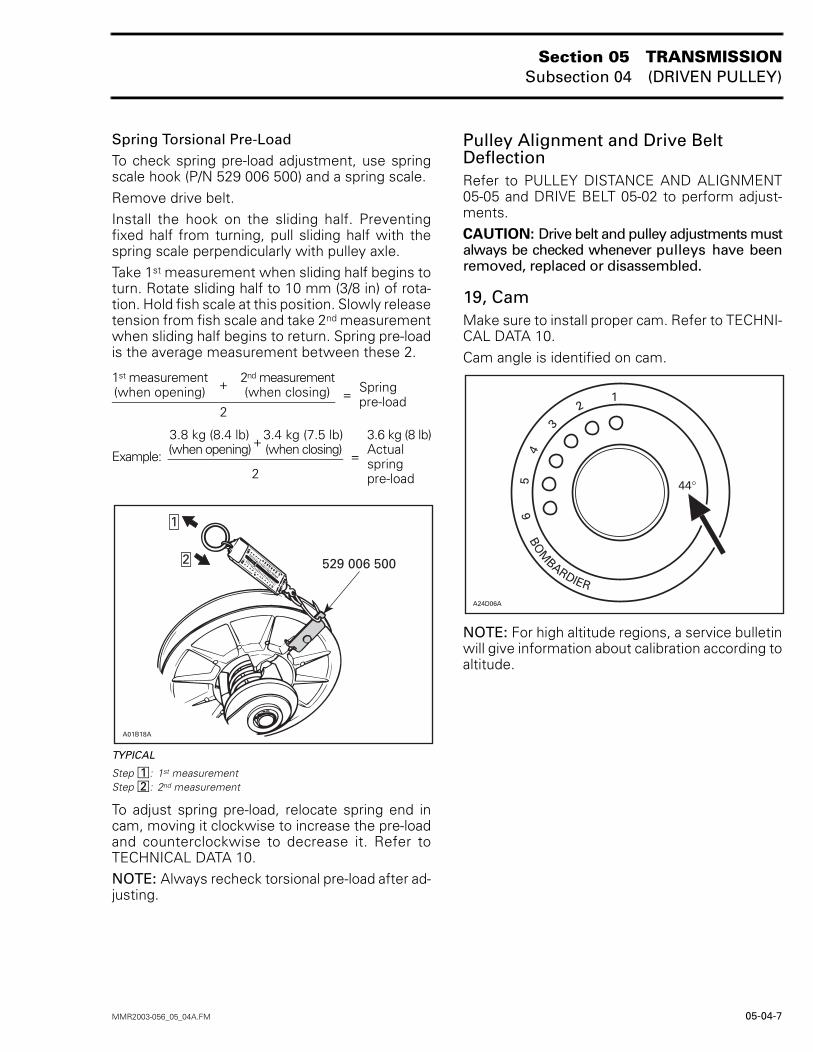
Spring Torsional Pre-LoadTo check spring pre-load adjustment, use springscale hook (P/N 529 006 500) and a spring scale.Remove drive belt.Install the hook on the sliding half. Preventingfixed half from turning, pull sliding half with thespring scale perpendicularly with pulley axle.Take 1st measurement when sliding half begins toturn. Rotate sliding half to 10 mm (3/8 in) of rota-tion. Hold fish scale at this position. Slowly releasetension from fish scale and take 2nd measurementwhen sliding half begins to return. Spring pre-loadis the average measurement between these 2.
TYPICAL
Step : 1st measurement Step : 2nd measurement
To adjust spring pre-load, relocate spring end incam, moving it clockwise to increase the pre-loadand counterclockwise to decrease it. Refer toTECHNICAL DATA 10.NOTE: Always recheck torsional pre-load after ad-justing.
Pulley Alignment and Drive Belt DeflectionRefer to PULLEY DISTANCE AND ALIGNMENT05-05 and DRIVE BELT 05-02 to perform adjust-ments.CAUTION: Drive belt and pulley adjustments mustalways be checked whenever pulleys have beenremoved, replaced or disassembled.
19, CamMake sure to install proper cam. Refer to TECHNI-CAL DATA 10.Cam angle is identified on cam.
NOTE: For high altitude regions, a service bulletinwill give information about calibration according toaltitude.
1st measurement(when opening) + 2nd measurement
(when closing) = Spring pre-load
2
Example:
3.8 kg (8.4 lb)(when opening)+
3.4 kg (7.5 lb)(when closing) =
3.6 kg (8 lb)Actualspring pre-load2
529 006 500
A01B18A
1
2
12
BOM
BARDIER
65
43
21
44°
A24D06A
Section 05 TRANSMISSIONSubsection 04 (DRIVEN PULLEY)
05-04-8 MMR2003-056_05_04A.FM
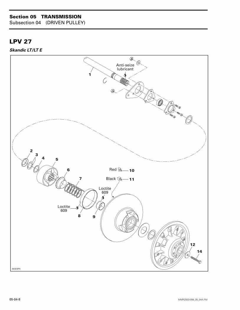
LPV 27Skandic LT/LT E
�����
�,� -.! /!�0�� #&,�
�
��
�
�
�
� �
�"#� �!���
�"#� �!���
$!1
��&#'
�
�
Section 05 TRANSMISSIONSubsection 04 (DRIVEN PULLEY)
MMR2003-056_05_04A.FM 05-04-9
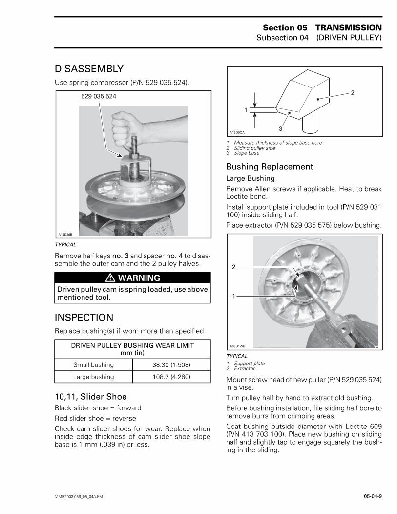
DISASSEMBLYUse spring compressor (P/N 529 035 524).
TYPICAL
Remove half keys no. 3 and spacer no. 4 to disas-semble the outer cam and the 2 pulley halves.
INSPECTIONReplace bushing(s) if worn more than specified.
10,11, Slider ShoeBlack slider shoe = forwardRed slider shoe = reverseCheck cam slider shoes for wear. Replace wheninside edge thickness of cam slider shoe slopebase is 1 mm (.039 in) or less.
1. Measure thickness of slope base here2. Sliding pulley side 3. Slope base
Bushing ReplacementLarge BushingRemove Allen screws if applicable. Heat to breakLoctite bond.Install support plate included in tool (P/N 529 031100) inside sliding half.Place extractor (P/N 529 035 575) below bushing.
TYPICAL1. Support plate2. Extractor
Mount screw head of new puller (P/N 529 035 524)in a vise.Turn pulley half by hand to extract old bushing.Before bushing installation, file sliding half bore toremove burrs from crimping areas.Coat bushing outside diameter with Loctite 609(P/N 413 703 100). Place new bushing on slidinghalf and slightly tap to engage squarely the bush-ing in the sliding.
� WARNING
Driven pulley cam is spring loaded, use abovementioned tool.
DRIVEN PULLEY BUSHING WEAR LIMITmm (in)
Small bushing 38.30 (1.508)
Large bushing 108.2 (4.260)
529 035 524
A15D36B
2
1
A15D0OA3
A03D1WB
2
1
Section 05 TRANSMISSIONSubsection 04 (DRIVEN PULLEY)
05-04-10 MMR2003-056_05_04A.FM
ASSEMBLY
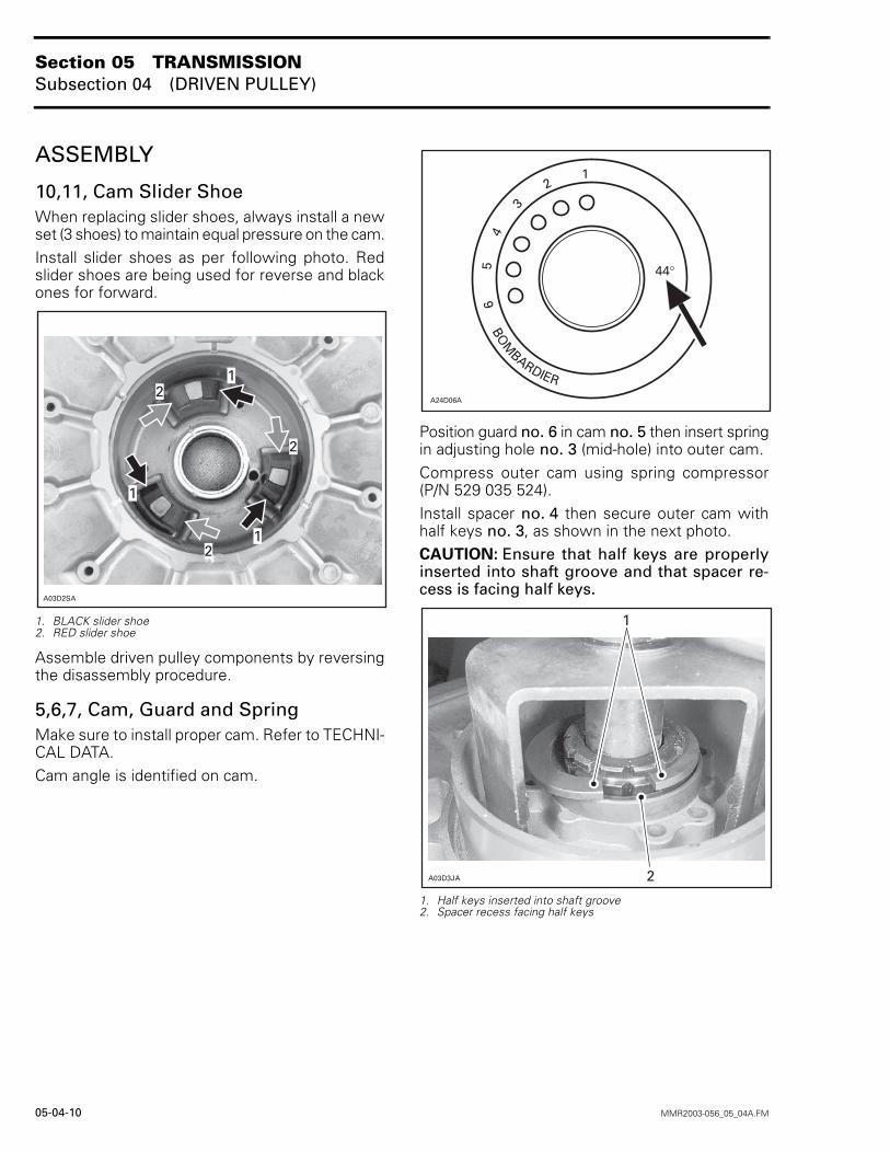
10,11, Cam Slider ShoeWhen replacing slider shoes, always install a newset (3 shoes) to maintain equal pressure on the cam.Install slider shoes as per following photo. Redslider shoes are being used for reverse and blackones for forward.
1. BLACK slider shoe2. RED slider shoe
Assemble driven pulley components by reversingthe disassembly procedure.
5,6,7, Cam, Guard and SpringMake sure to install proper cam. Refer to TECHNI-CAL DATA.Cam angle is identified on cam.
Position guard no. 6 in cam no. 5 then insert springin adjusting hole no. 3 (mid-hole) into outer cam.Compress outer cam using spring compressor(P/N 529 035 524).Install spacer no. 4 then secure outer cam withhalf keys no. 3, as shown in the next photo.CAUTION: Ensure that half keys are properlyinserted into shaft groove and that spacer re-cess is facing half keys.
1. Half keys inserted into shaft groove2. Spacer recess facing half keys
A03D2SA
1
2
2
2
1
1
BOM
BARDIER
65
43
21
44°
A24D06A
A03D3JA
1
2
Section 05 TRANSMISSIONSubsection 04 (DRIVEN PULLEY)
MMR2003-056_05_04A.FM 05-04-11
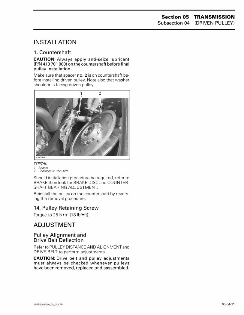
INSTALLATION
1, CountershaftCAUTION: Always apply anti-seize lubricant(P/N 413 701 000) on the countershaft before finalpulley installation.Make sure that spacer no. 2 is on countershaft be-fore installing driven pulley. Note also that washershoulder is facing driven pulley.
TYPICAL1. Spacer2. Shoulder on this side
Should installation procedure be required, refer toBRAKE then look for BRAKE DISC and COUNTER-SHAFT BEARING ADJUSTMENT.Reinstall the pulley on the countershaft by revers-ing the removal procedure.
14, Pulley Retaining ScrewTorque to 25 N•m (18 lbf•ft).
ADJUSTMENT
Pulley Alignment andDrive Belt DeflectionRefer to PULLEY DISTANCE AND ALIGNMENT andDRIVE BELT to perform adjustments.CAUTION: Drive belt and pulley adjustmentsmust always be checked whenever pulleyshave been removed, replaced or disassembled.
����2�
��
Section 05 TRANSMISSIONSubsection 05 (PULLEY DISTANCE AND ALIGNMENT)
MMR2003-057_05_05A.FM 05-05-1
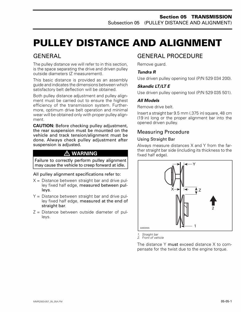
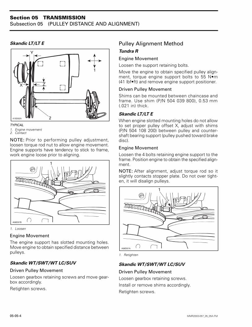
PULLEY DISTANCE AND ALIGNMENT 0GENERALThe pulley distance we will refer to in this section,is the space separating the drive and driven pulleyoutside diameters (Z measurement).This basic distance is provided as an assemblyguide and indicates the dimensions between whichsatisfactory belt deflection will be obtained.Both pulley distance adjustment and pulley align-ment must be carried out to ensure the highestefficiency of the transmission system. Further-more, optimum drive belt operation and minimalwear will be obtained only with proper pulley align-ment.CAUTION: Before checking pulley adjustment,the rear suspension must be mounted on thevehicle and track tension/alignment must bedone. Always check pulley adjustment aftersuspension is adjusted.
All pulley alignment specifications refer to:X = Distance between straight bar and drive pul-
ley fixed half edge, measured between pul-leys.
Y = Distance between straight bar and drive pul-ley fixed half edge, measured at the end ofstraight bar.
Z = Distance between outside diameter of pul-leys.
GENERAL PROCEDURERemove guard.
Tundra R
Use driven pulley opening tool (P/N 529 034 200).
Skandic LT/LT E
Use driven pulley opening tool (P/N 529 035 501).
All Models
Remove drive belt.Insert a straight bar 9.5 mm (.375 in) square, 48 cm(19 in) long or the proper alignment bar into theopened driven pulley.
Measuring ProcedureUsing Straight BarAlways measure distances X and Y from the far-ther straight bar side (including its thickness to thefixed half edge).
1. Straight bar2. Front of vehicle
The distance Y must exceed distance X to com-pensate for the twist due to the engine torque.
� WARNING
Failure to correctly perform pulley alignmentmay cause the vehicle to creep forward at idle.
A00D0WA1
2
ZX
Y
Section 05 TRANSMISSIONSubsection 05 (PULLEY DISTANCE AND ALIGNMENT)
05-05-2 MMR2003-057_05_05A.FM
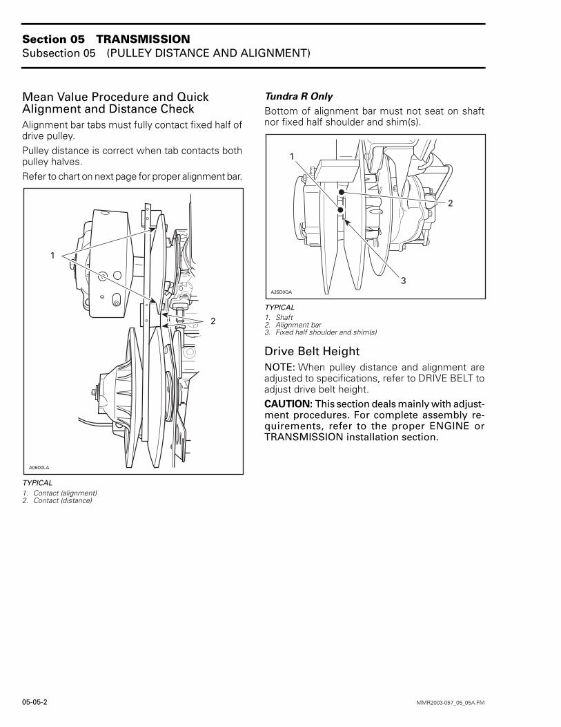
Mean Value Procedure and Quick Alignment and Distance CheckAlignment bar tabs must fully contact fixed half ofdrive pulley.Pulley distance is correct when tab contacts bothpulley halves.Refer to chart on next page for proper alignment bar.
TYPICAL1. Contact (alignment)2. Contact (distance)
Tundra R Only
Bottom of alignment bar must not seat on shaftnor fixed half shoulder and shim(s).
TYPICAL1. Shaft2. Alignment bar3. Fixed half shoulder and shim(s)
Drive Belt HeightNOTE: When pulley distance and alignment areadjusted to specifications, refer to DRIVE BELT toadjust drive belt height.CAUTION: This section deals mainly with adjust-ment procedures. For complete assembly re-quirements, refer to the proper ENGINE orTRANSMISSION installation section.
A06D0LA
1
2
A25D0QA
3
1
2
Section 05 TRANSMISSIONSubsection 05 (PULLEY DISTANCE AND ALIGNMENT)
MMR2003-057_05_05A.FM 05-05-3
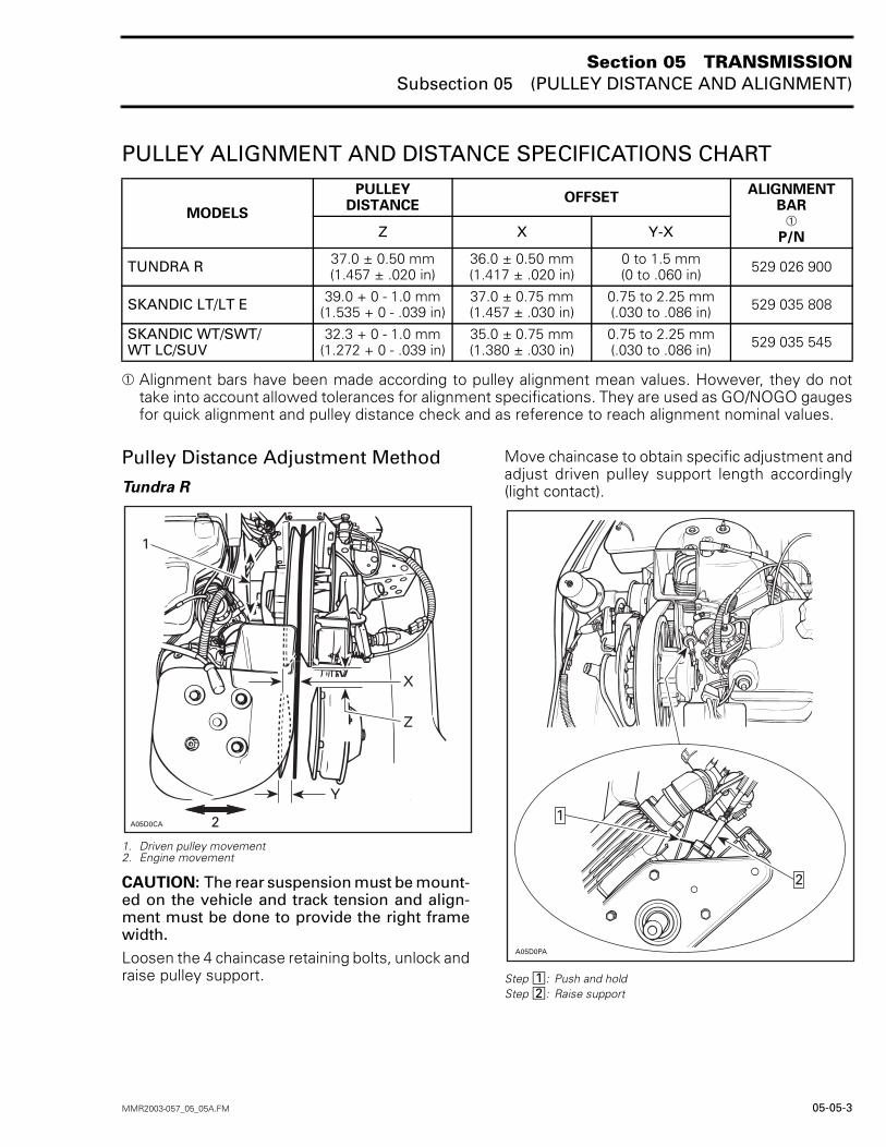
PULLEY ALIGNMENT AND DISTANCE SPECIFICATIONS CHART
➀ Alignment bars have been made according to pulley alignment mean values. However, they do nottake into account allowed tolerances for alignment specifications. They are used as GO/NOGO gaugesfor quick alignment and pulley distance check and as reference to reach alignment nominal values.
Pulley Distance Adjustment Method
Tundra R
1. Driven pulley movement2. Engine movement
CAUTION: The rear suspension must be mount-ed on the vehicle and track tension and align-ment must be done to provide the right framewidth.Loosen the 4 chaincase retaining bolts, unlock andraise pulley support.
Move chaincase to obtain specific adjustment andadjust driven pulley support length accordingly(light contact).
Step : Push and holdStep : Raise support
MODELS
PULLEYDISTANCE
OFFSETALIGNMENT
BAR➀
P/NZ X Y-X
TUNDRA R 37.0 ± 0.50 mm(1.457 ± .020 in)
36.0 ± 0.50 mm(1.417 ± .020 in)
0 to 1.5 mm(0 to .060 in) 529 026 900
SKANDIC LT/LT E 39.0 + 0 - 1.0 mm(1.535 + 0 - .039 in)
37.0 ± 0.75 mm(1.457 ± .030 in)
0.75 to 2.25 mm(.030 to .086 in) 529 035 808
SKANDIC WT/SWT/WT LC/SUV
32.3 + 0 - 1.0 mm(1.272 + 0 - .039 in)
35.0 ± 0.75 mm(1.380 ± .030 in)
0.75 to 2.25 mm(.030 to .086 in) 529 035 545
3
4
������
�
�
5
A05D0PA
2
1
12
Section 05 TRANSMISSIONSubsection 05 (PULLEY DISTANCE AND ALIGNMENT)
05-05-4 MMR2003-057_05_05A.FM
Skandic LT/LT E
TYPICAL1. Engine movement2. Contact
NOTE: Prior to performing pulley adjustment,loosen torque rod nut to allow engine movement.Engine supports have tendency to stick to frame,work engine loose prior to aligning.
1. Loosen
Engine MovementThe engine support has slotted mounting holes.Move engine to obtain specified distance betweenpulleys.
Skandic WT/SWT/WT LC/SUV
Driven Pulley MovementLoosen gearbox retaining screws and move gear-box accordingly.Retighten screws.
Pulley Alignment MethodTundra R
Engine MovementLoosen the support retaining bolts.Move the engine to obtain specified pulley align-ment, torque engine support bolts to 55 N•m(41 lbf•ft) and remove engine support positioner.
Driven Pulley MovementShims can be mounted between chaincase andframe. Use shim (P/N 504 039 800), 0.53 mm(.021 in) thick.
Skandic LT/LT E
When engine slotted mounting holes do not allowto set proper pulley offset X, adjust with shims(P/N 504 108 200) between pulley and counter-shaft bearing support (pulley pushed toward brakedisc).
Engine MovementLoosen the 4 bolts retaining engine support to theframe. Position engine to obtain the specified align-ment.NOTE: After alignment, adjust torque rod so itslightly contacts stopper plate. Do not over tight-en, it will disalign pulleys.
1. Retighten
Skandic WT/SWT/WT LC/SUV
Driven Pulley MovementLoosen gearbox retaining screws.Install or remove shims accordingly. Retighten screws.
������
3
4 5
�
�
����� �
�
����� �
�
Section 05 TRANSMISSIONSubsection 08 (GEARBOX)
MMR2003-066_05_08A.FM 05-08-1
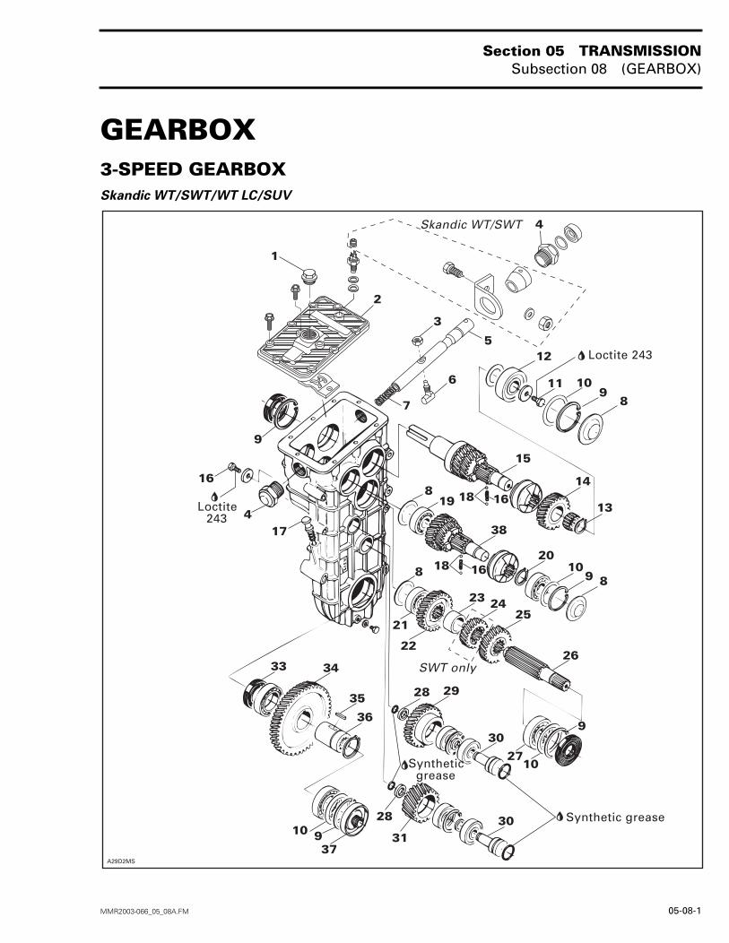
GEARBOX 03-SPEED GEARBOXSkandic WT/SWT/WT LC/SUV
�����6�
�
�
�
��
��
��
���
��
�� ��
�
��
���
�
�
��
�
��
���
�
��
�
��
����
�
�
�����
��
�
�
��
��
�
�
��
���������
��������
��
�
�
�
�
�
��������
�� �������������
�� ������������
����� �������
Section 05 TRANSMISSIONSubsection 08 (GEARBOX)
05-08-2 MMR2003-066_05_08A.FM
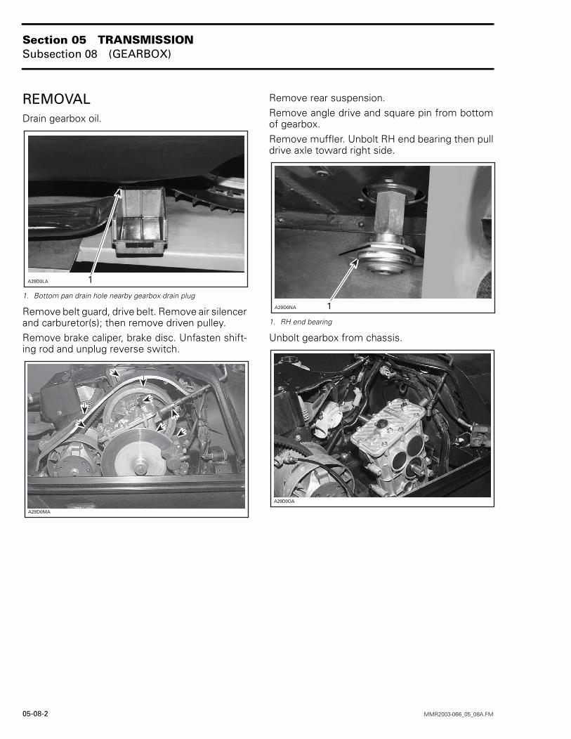
REMOVALDrain gearbox oil.
1. Bottom pan drain hole nearby gearbox drain plug
Remove belt guard, drive belt. Remove air silencerand carburetor(s); then remove driven pulley.Remove brake caliper, brake disc. Unfasten shift-ing rod and unplug reverse switch.
Remove rear suspension.Remove angle drive and square pin from bottomof gearbox.Remove muffler. Unbolt RH end bearing then pulldrive axle toward right side.
1. RH end bearing
Unbolt gearbox from chassis.
������� �
A29D0MA
������� �
�������
Section 05 TRANSMISSIONSubsection 08 (GEARBOX)
MMR2003-066_05_08A.FM 05-08-3
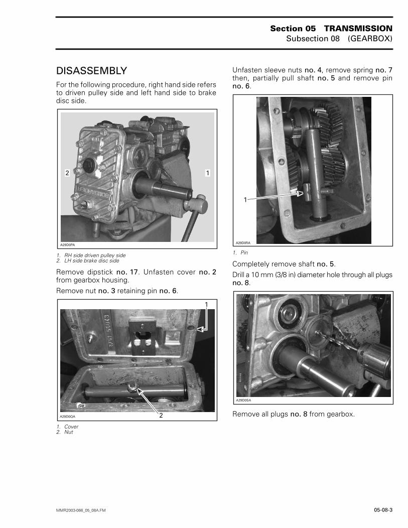
DISASSEMBLYFor the following procedure, right hand side refersto driven pulley side and left hand side to brakedisc side.
1. RH side driven pulley side2. LH side brake disc side
Remove dipstick no. 17. Unfasten cover no. 2from gearbox housing.Remove nut no. 3 retaining pin no. 6.
1. Cover2. Nut
Unfasten sleeve nuts no. 4, remove spring no. 7then, partially pull shaft no. 5 and remove pinno. 6.
1. Pin
Completely remove shaft no. 5.Drill a 10 mm (3/8 in) diameter hole through all plugsno. 8.
Remove all plugs no. 8 from gearbox.
�������
��
�����7�
�
�
�����$�
�
�������
Section 05 TRANSMISSIONSubsection 08 (GEARBOX)
05-08-4 MMR2003-066_05_08A.FM
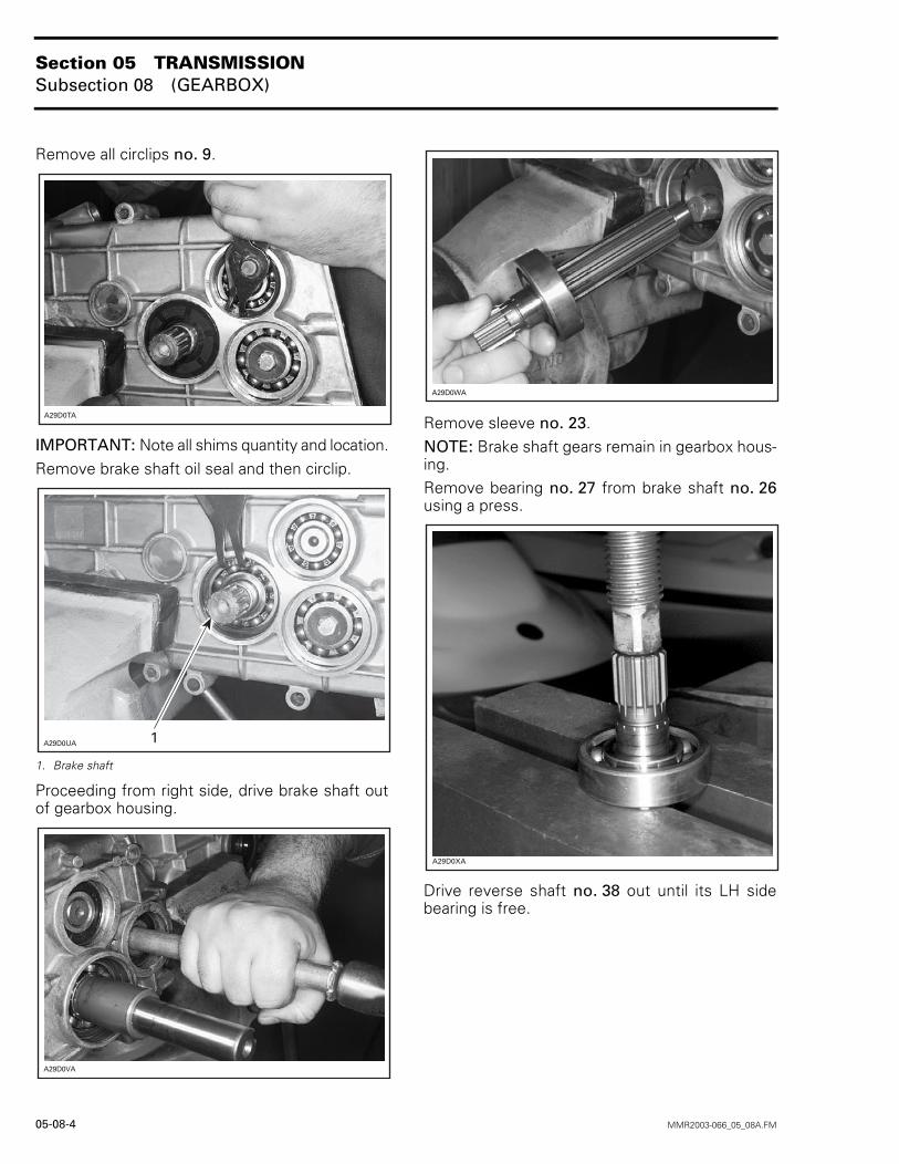
Remove all circlips no. 9.
IMPORTANT: Note all shims quantity and location.Remove brake shaft oil seal and then circlip.
1. Brake shaft
Proceeding from right side, drive brake shaft outof gearbox housing.
Remove sleeve no. 23.NOTE: Brake shaft gears remain in gearbox hous-ing.Remove bearing no. 27 from brake shaft no. 26using a press.
Drive reverse shaft no. 38 out until its LH sidebearing is free.
�����8�
A29D0UA 1
�����9�
�����:�
�����4�
Section 05 TRANSMISSIONSubsection 08 (GEARBOX)
MMR2003-066_05_08A.FM 05-08-5
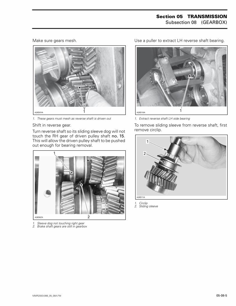
Make sure gears mesh.
1. These gears must mesh as reverse shaft is driven out
Shift in reverse gear.Turn reverse shaft so its sliding sleeve dog will nottouch the RH gear of driven pulley shaft no. 15.This will allow the driven pulley shaft to be pushedout enough for bearing removal.
1. Sleeve dog not touching right gear2. Brake shaft gears are still in gearbox
Use a puller to extract LH reverse shaft bearing.
1. Extract reverse shaft LH side bearing
To remove sliding sleeve from reverse shaft, firstremove circlip.
1. Circlip2. Sliding sleeve
A29D0YA 1
�����5�
�
�
A29D10A1
�������
�
�
Section 05 TRANSMISSIONSubsection 08 (GEARBOX)
05-08-6 MMR2003-066_05_08A.FM
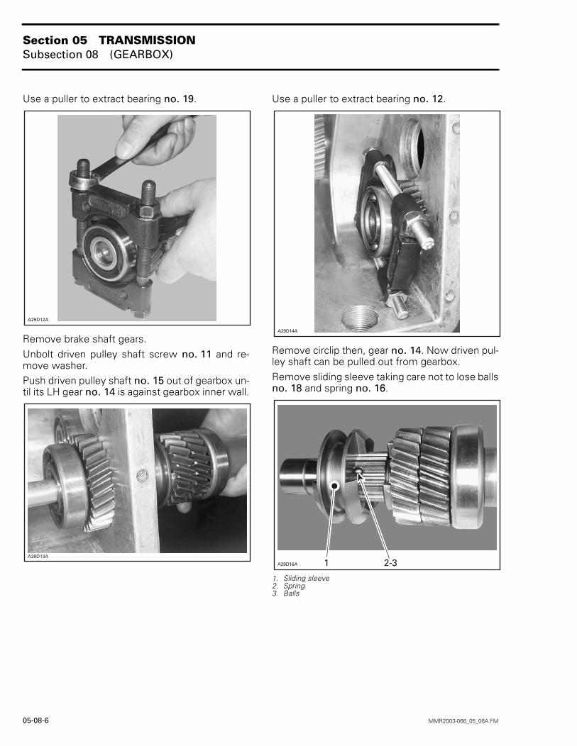
Use a puller to extract bearing no. 19.
Remove brake shaft gears.Unbolt driven pulley shaft screw no. 11 and re-move washer.Push driven pulley shaft no. 15 out of gearbox un-til its LH gear no. 14 is against gearbox inner wall.
Use a puller to extract bearing no. 12.
Remove circlip then, gear no. 14. Now driven pul-ley shaft can be pulled out from gearbox.Remove sliding sleeve taking care not to lose ballsno. 18 and spring no. 16.
1. Sliding sleeve2. Spring3. Balls
�������
������
�������
������� �-�
Section 05 TRANSMISSIONSubsection 08 (GEARBOX)
MMR2003-066_05_08A.FM 05-08-7
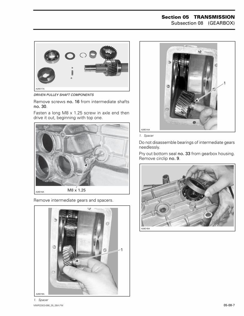
DRIVEN PULLEY SHAFT COMPONENTS
Remove screws no. 16 from intermediate shaftsno. 30.Fasten a long M8 x 1.25 screw in axle end thendrive it out, beginning with top one.
Remove intermediate gears and spacers.
1. Spacer
1. Spacer
Do not disassemble bearings of intermediate gearsneedlessly.Pry out bottom seal no. 33 from gearbox housing.Remove circlip no. 9.
����� �
A29D18A M8 x 1.25
�������
�
�������
�
�������
Section 05 TRANSMISSIONSubsection 08 (GEARBOX)
05-08-8 MMR2003-066_05_08A.FM
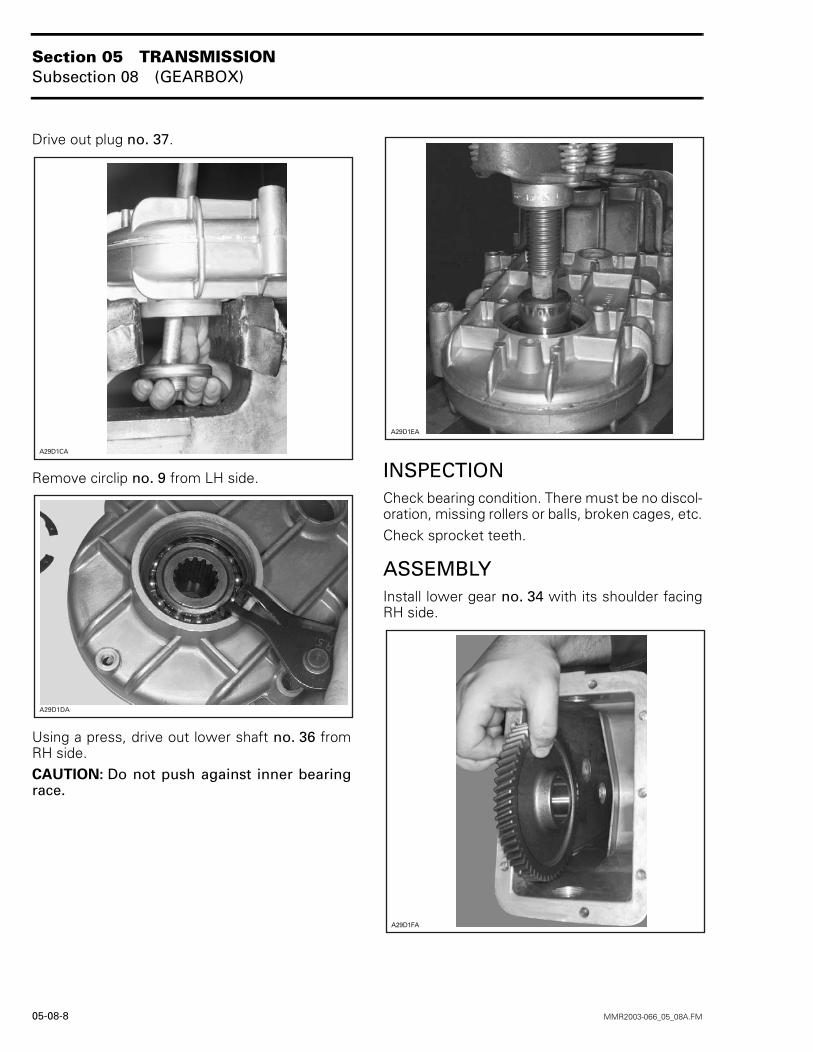
Drive out plug no. 37.
Remove circlip no. 9 from LH side.
Using a press, drive out lower shaft no. 36 fromRH side.CAUTION: Do not push against inner bearingrace.
INSPECTIONCheck bearing condition. There must be no discol-oration, missing rollers or balls, broken cages, etc.Check sprocket teeth.
ASSEMBLYInstall lower gear no. 34 with its shoulder facingRH side.
�������
�������
�����(�
�����)�
Section 05 TRANSMISSIONSubsection 08 (GEARBOX)
MMR2003-066_05_08A.FM 05-08-9
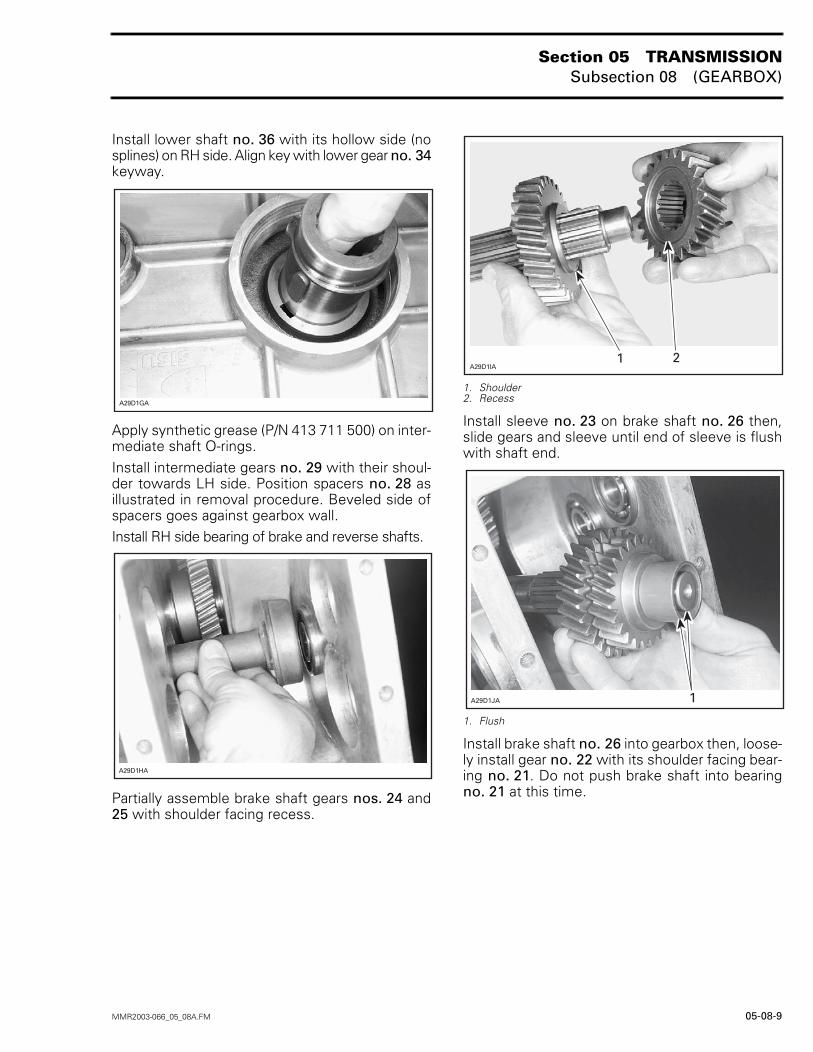
Install lower shaft no. 36 with its hollow side (nosplines) on RH side. Align key with lower gear no. 34keyway.
Apply synthetic grease (P/N 413 711 500) on inter-mediate shaft O-rings.Install intermediate gears no. 29 with their shoul-der towards LH side. Position spacers no. 28 asillustrated in removal procedure. Beveled side ofspacers goes against gearbox wall.Install RH side bearing of brake and reverse shafts.
Partially assemble brake shaft gears nos. 24 and25 with shoulder facing recess.
1. Shoulder2. Recess
Install sleeve no. 23 on brake shaft no. 26 then,slide gears and sleeve until end of sleeve is flushwith shaft end.
1. Flush
Install brake shaft no. 26 into gearbox then, loose-ly install gear no. 22 with its shoulder facing bear-ing no. 21. Do not push brake shaft into bearingno. 21 at this time.
�����*�
�����2�
�����;�� �
A29D1JA 1
Section 05 TRANSMISSIONSubsection 08 (GEARBOX)
05-08-10 MMR2003-066_05_08A.FM
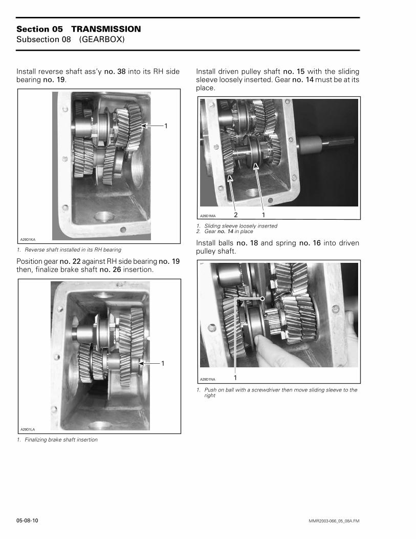
Install reverse shaft ass’y no. 38 into its RH sidebearing no. 19.
1. Reverse shaft installed in its RH bearing
Position gear no. 22 against RH side bearing no. 19then, finalize brake shaft no. 26 insertion.
1. Finalizing brake shaft insertion
Install driven pulley shaft no. 15 with the slidingsleeve loosely inserted. Gear no. 14 must be at itsplace.
1. Sliding sleeve loosely inserted2. Gear no. 14 in place
Install balls no. 18 and spring no. 16 into drivenpulley shaft.
1. Push on ball with a screwdriver then move sliding sleeve to the right
�������
�
�������
�
�����6� ��
������� �
Section 05 TRANSMISSIONSubsection 08 (GEARBOX)
MMR2003-066_05_08A.FM 05-08-11
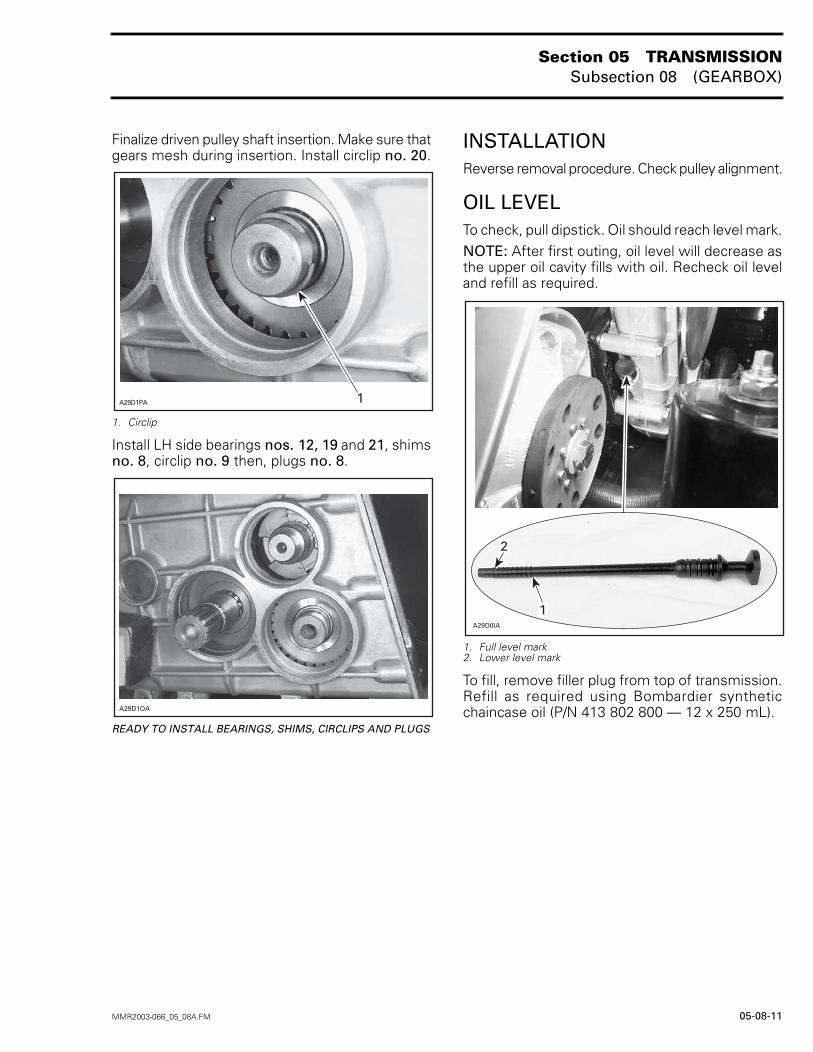
Finalize driven pulley shaft insertion. Make sure thatgears mesh during insertion. Install circlip no. 20.
1. Circlip
Install LH side bearings nos. 12, 19 and 21, shimsno. 8, circlip no. 9 then, plugs no. 8.
READY TO INSTALL BEARINGS, SHIMS, CIRCLIPS AND PLUGS
INSTALLATIONReverse removal procedure. Check pulley alignment.
OIL LEVELTo check, pull dipstick. Oil should reach level mark.NOTE: After first outing, oil level will decrease asthe upper oil cavity fills with oil. Recheck oil leveland refill as required.
1. Full level mark 2. Lower level mark
To fill, remove filler plug from top of transmission.Refill as required using Bombardier syntheticchaincase oil (P/N 413 802 800 — 12 x 250 mL).
A29D1PA 1
A29D1OA
�����;�
�
�