Embed Size (px)
Citation preview

90-10164040 1203- 1 -Printed in U.S.A.
175XR2 Jet DriveInstallation Manual
NOTICE to INSTALLERAfter Completing Installation, These Instruc-tions Should Be Placed with the Product for theOwner’s Future Use.
NOTICE to COMMISSIONING DEALER
Pre-delivery Preparation Instructions Must BePerformed Before Delivering Boat to the Prod-uct Owner.
NOTICE to INSTALLER
The United States Coast Guard does not havea method to determine the maximum recom-mended horsepower for Inboard Jet Boats.Therefore, it is the responsibility of the boatmanufacturer to install the Mercury Jet Drive, aswell as any other Jet Drive model, in a boat whichhas been determined to be of suitable size,weight, construction, and hull configuration forthe power chosen. The Mercury Jet Drive, in par-ticular, brings a new level of performance to thejet boat category and is capable of propellingmany hulls at speeds exceeding 50 miles perhour.
In selecting the proper Jet Drive package for aparticular application, please consider the over-all performance capability of the craft. Your boatmay react to and handle differently with each JetDrive model.
PLEASE carefully test and evaluate the over-all handling characteristics of the boat pack-age before distribution for sale.
If you have application or installation questions,please contact your Mercury Marine OEM SalesCoordinator. The Sales Coordinator will arrangeto provide the necessary assistance.
Please assess your boat’s performance com-pletely before making the Jet Drive model selec-tion. Safe boating is good for everyone.
2003 Mercury MarineThe following are registered trademarks of Brunswick Corpora-tion: AutoBlend, Force, Jet-Prop, Mariner, Merc, MerCathode,MerCruiser, Mercury, Mercury Marine, Quicksilver, RideGuide,Sport Jet, and Thruster.
Table of ContentsPage
General Information 2. . . . . . . . . . . . . . . . . . . . . . . . . Notice to Installer 2. . . . . . . . . . . . . . . . . . . . . . . . .
Installation Products 2. . . . . . . . . . . . . . . . . . . . . Torque Specifications 2. . . . . . . . . . . . . . . . . . . . . Serial Number Decal Location 3. . . . . . . . . . . . . . Corrosion Protection 3. . . . . . . . . . . . . . . . . . . . . .
Installation Requirements 3. . . . . . . . . . . . . . . . . . . . Battery/Battery Cables 3. . . . . . . . . . . . . . . . . . . . Boat Construction 4. . . . . . . . . . . . . . . . . . . . . . . . Engine Compartment Ventilation 4. . . . . . . . . . . . Exhaust System 4. . . . . . . . . . . . . . . . . . . . . . . . . . Fuel Delivery System 5. . . . . . . . . . . . . . . . . . . . . Instrumentation 5. . . . . . . . . . . . . . . . . . . . . . . . . . . Wiring Diagrams 6. . . . . . . . . . . . . . . . . . . . . . . . . . Impeller Selection 7. . . . . . . . . . . . . . . . . . . . . . . . Remote Control and Cables 7. . . . . . . . . . . . . . . . Steering Helm and Cable 7. . . . . . . . . . . . . . . . . .
Mercury Jet Drive Hull Dimensions 175XR2 8. . . . . Installing Jet Pump 10. . . . . . . . . . . . . . . . . . . . . . . . .
Steering Cable Adjustment 12. . . . . . . . . . . . . . . . Shift Cable Adjustment 13. . . . . . . . . . . . . . . . . . .
Bilge Siphon Feature 15. . . . . . . . . . . . . . . . . . . . . . . Installing Bilge Siphon 15. . . . . . . . . . . . . . . . . . . .
Water By-Pass System 15. . . . . . . . . . . . . . . . . . . . . Installing Powerhead 16. . . . . . . . . . . . . . . . . . . . . . .
Battery Connection 17. . . . . . . . . . . . . . . . . . . . . . Throttle Cable Adjustment 18. . . . . . . . . . . . . . . . Oil Injection System 18. . . . . . . . . . . . . . . . . . . . . . Bleeding Air from Oil Injection Pump 19. . . . . . . Adjusting Oil Injection Pump 19. . . . . . . . . . . . . .
Turn-Key Start Feature 20. . . . . . . . . . . . . . . . . . . . . . Trim Plate Adjustment 20. . . . . . . . . . . . . . . . . . . . . . Pre-delivery Inspection 21. . . . . . . . . . . . . . . . . . . . . .

!
- 2 -
General Information
Notice to InstallerThroughout this publication, Warnings and Cautions(accompanied by the International Hazard Symbol)are used to alert the installer to special instructionsconcerning a particular service or operation that maybe hazardous if performed incorrectly or carelessly.–– Observe Them Carefully!
These Safety Alerts, alone, cannot eliminate the haz-ards that they signal. Strict compliance to these spe-cial instructions when performing the service, pluscommon sense operation, are major accident pre-vention measures.
! WARNINGHazards or unsafe practices which COULD resultin severe personal injury or death.
! CAUTIONHazards or unsafe practices which could result inminor personal injury or product or propertydamage.
IMPORTANT: Indicates information or instruc-tions that are necessary for proper installationand/or operation.
This installation manual has been written and pub-lished by the service department of Mercury Marineto aid installers when installing the products de-scribed herein.
It is assumed that these personnel are familiar withthe installation procedures of these products, or likeor similar products manufactured and marketed byMercury Marine. Also, that they have been trained inthe recommended installation procedures of theseproducts which includes the use of mechanics’ com-mon hand tools and the special Mercury Marine orrecommended tools from other suppliers.
We could not possibly know of and advise the marinetrade of all conceivable procedures by which an in-stallation might be performed and of the possible haz-ards and/or results of each method. We have not un-dertaken any such wide evaluation. Therefore,anyone who uses an installation procedure and/ortool, which is not recommended by the manufacturer,first must completely satisfy himself that neither hisnor the product’s safety will be endangered by the in-stallation procedure selected.
All information, illustrations, and specifications con-tained in this manual are based on the latest productinformation available at time of publication. As re-quired, revisions to this manual will be sent to all OEMboat companies.
INSTALLATION PRODUCTS
Loctite 271 92-823089--1Liquid Neoprene 92-25711--2Dielectric Grease 92-823506--1Perfect Seal 92-34227--1Special Lube 101 92-13872A1
Torque SpecificationsNOTE: Tighten all fasteners, not listed, securely.
10 mm Fasteners(Powerhead to Pump) 47 Nm (35 lb. ft)
Reverse Stop Screw 14 Nm (120 lb. in.)
Forward Stop Screw 14 Nm (120 lb. in.)
Ride Plate to Pump Screws 8.5 Nm (75 lb. in.)
Drive Housing Cover to DriveHousing fasteners 47 Nm (35 lb. ft.)

- 3 -
Serial Number Decal LocationA serial number decal is located on the side of the fly-wheel cover and on top of the cylinder block.
19XX
XX
OGXXXXXX
OGXXXXXX
b
cd
a
28238
a - Engine Serial Numberb - Model Yearc - Year Manufacturedd - Certified Europe
IMPORTANT: The Pump Unit Serial Numbersticker must be taken out of the envelope affixedto the pump unit and applied to the flywheel coverdecal.
The engine serial number and pump serial numberare different and unique. The engine serial number islocated aft of the flywheel cover. The pump unit serialnumber is stamped in a plug located above the shiftcable hole on the starboard side of the pump housing.
e
175
28237e - Pump Unit Serial Number
Corrosion ProtectionThis power package is equipped with anodes to helpprotect it from galvanic corrosion under moderateconditions. See the Operator’s Manual for location ofanodes.
Installation RequirementsIMPORTANT: The Jet Drive is considered anINBOARD engine. The boat it is installed in mustmeet industry standards (ABYC, NMMA, etc.),federal standards and Coast Guard regulationsfor INBOARD engine installations
Battery/Battery CablesIMPORTANT: Boating industry standards (ABYC,NMMA, etc.), federal standards and Coast Guardregulations must be adhered to when installingbattery. Be sure battery cable installation meetsthe pull test requirements and that positive bat-tery terminal is properly insulated in accordancewith regulations.
IMPORTANT: Engine electrical system is negative(–) ground. It is recommended (required in somestates) that battery be installed in an enclosedcase. Refer to regulations for your area.
1. Select a battery that meets all of the followingspecifications:
a. 12-volt marine type.
b. 670 Marine Cranking Amps (MCA) or520 Cold Cranking Amps (CCA) minimum.
c. Reserve capacity rating of at least 100 min-utes.
2. Select proper size positive (+) and negative (–)battery cables using chart. Battery should be lo-cated as close to engine as possible.
IMPORTANT: Terminals must be soldered tocable ends to ensure good electrical contact. Useelectrical grade (resin flux) solder only. Do notuse acid flux solder, as it may cause corrosionand a subsequent failure.
Cable Length Cable GaugeUp to 1.1 m (3-1/2 ft) 4 (25mm2)1.1 - 1.8 m (3-1/2 - 6 ft) 2 (35mm2)1.8-2.3 m (6 - 7-1/2 ft) 1 (50mm2)2.3-2.9 m (7-1/2 - 9-1/2 ft) 0 (50mm2)2.9-3.7 m (9-1/2 - 12 ft) 00 (70mm2)3.7- 4.6 m (12 - 15 ft) 000 (95mm2)4.6 - 5.8 m (15 - 19 ft) 0000 (120mm2)

- 4 -
Boat ConstructionIMPORTANT: All applicable U.S. Coast Guard reg-ulations for INBOARD engines must be compliedwith, when constructing engine compartment.
Care must be exercised in the design andconstruction of the engine compartment. Seamsmust be located so that any rain water or splash,which may leak through the seams, is directed awayfrom the engine and carburetor cover. Also, thepassenger compartment drainage system should notbe routed directly to the engine compartment. Waterthat runs on or is splashed in the carburetor covermay enter the engine and cause serious damageto internal engine parts.
IMPORTANT: Mercury Marine will not honor anywarranty claim for engine damage as a result ofwater entry.
Engine Compartment VentilationEngine compartment must be designed to provide asufficient volume of air for engine breathing and alsomust vent off any fumes in engine compartment inaccordance with industry standards (ABYC, NMMA,etc.), federal standards and U.S. Coast Guard regula-tions for inboard engines. Pressure differential (out-side engine compartment versus inside engine com-partment) should not exceed 51 mm (2 in.) of water(measured with a manometer) at maximum air flowrate.
Engine Compartment Specifications
Model Engine Air Require-ments at Wide Open
Throttle
Physical EngineVolume*
175XR2 487 ft.3/min.(0.230 m3/sec.)
1.33 ft.3(38 L)
* Physical engine volume is used in flotation calculations and isrepresentative of the amount of flotation the engine provides.
For serviceability, it is recommended that an addi-tional 152 mm (6 in) minimum (per side) of clearancebe allowed between powerhead and engine compart-ment walls.
Exhaust SystemIMPORTANT: It is the responsibility of the boatmanufacturer, or installing dealer, to properlylocate the engine. Improper installation mayallow water to enter the exhaust manifold andcombustion chambers and severely damage theengine. Damage caused by water in the enginewill not be covered by Mercury Marine LimitedWarranty, unless this damage is the result ofdefective part(s).
The engine must be properly located to ensure thatwater will not enter the engine through the exhaustsystem. Determine the correct engine height by tak-ing measurements (a) and (b), with boat at rest in thewater and maximum load aboard. Subtract (b) from(a) to find (c). If (c) is less than specified in chart, boatconstruction must be altered to properly lower water-line relative to exhaust elbow.
a
b
d
c
a - From Waterline to Top of Transomb - From Highest Point on Exhaust Manifold to Top of Transomc - (a) minus (b) = (c)d - Waterline at Rest (at Maximum Load)
Model c = (a) minus (b)
175XR2 (c) must be 203 mm (8 in.) ormore.

- 5 -
Fuel Delivery System
! WARNINGBoating standards (NMMA, ABYC, etc.), federalstandards and U. S. Coast Guard regulations forINBOARD engines must be adhered to wheninstalling fuel delivery system. Failure to complycould result in severe personal injury or death.
! CAUTIONRemove plastic plug from fuel inlet fitting. Attachfuel line to fuel fitting with U.S. Coast Guardapproved hose clamp. Inspect for fuel leaks.
1. Fuel tank should be mounted below carburetorlevel (if possible) or gravity feed may cause car-buretor fuel inlet needles to unseat, and floodingmay result.
2. Fuel pickup should be at least 25 mm (1 in.) fromthe bottom of the fuel tank to prevent picking upimpurities.
3. Fuel lines used must be U.S. Coast Guard ap-proved (USCG type A1), fittings and lines mustnot be smaller than 8 mm (5/16 in.) I.D.
4. On installations requiring long lines or numerousfittings, larger size lines should be used.
5. Fuel line should be installed free of stress andfirmly secured to prevent vibration and/or chafing.
6. Sharp bends in fuel line should be avoided.
7. A flexible fuel line must be used to connect fuelline to engine fuel pump to absorb deflectionwhen engine is running.
8. A primer bulb is not necessary with this applica-tion. If a primer bulb is used, it must be U.S. CoastGuard approved for inboard engine applications.
Instrumentation
! CAUTIONIf a fused accessory panel is to be used, it is rec-ommended that a separate circuit (properlyfused) be used from the battery to the fuse panelwith sufficient wire size to handle the intendedcurrent load.
NOTE: The charging system on these engines is ca-pable of producing 12 amps maximum charge at3500 RPM. The electrical load of the boat should notexceed this capacity.
We recommend the use of Mercury Precision orQuicksilver Instrumentation and Wiring Harnesses.Refer to Mercury Precision Parts Accessories Guidefor selection.
If other than Mercury Precision or Quicksilver electri-cal accessories are to be used, it is good practice touse waterproof ignition components (ignition switch,lanyard stop switch, etc.). A typical jet boat of this na-ture will see water splashed on these components.Therefore, precautions must be taken to avoid igni-tion failure due to shorting out of ignition components.
! WARNINGSudden stopping of engine (shorting ignitioncomponents) while boat is underway will causeloss of steering control due to loss of thrust. Thisloss of steering control may cause property dam-age, personal injury or death.
A warning horn must be incorporated in the wiringharness (see wiring diagram) to alert the user of anoverheat, low oil condition or oil pump failure.
IMPORTANT: If a warning horn system is notinstalled by the boat manufacturer, MercuryMarine will not honor any warranty claims forengine damage as a result of overheating or lackof engine oil.
Route instrumentation wiring harness back to engine,making sure that harness does not rub or get pinched.If an extension harness is required, be sure to secureconnection properly. Fasten harnesses to boat atleast every 460 mm (18 in), using appropriatefasteners.

a - Temperature Gaugeb - Key Switchc - Tachometer Gauged - Emergency Stop Switche - Tachometer Harness (P/N 84-86396A8) (Not Included With Key/Choke Harness Kit)f - Connect Wires Together With Screw and Hex Nut (2 Places) Apply Liquid Neoprene to Connections and Slide Rubber Sleeve Over Each Connection.g - To Neutral Start Safety Switch In Remote Control Box
P Liquid Neoprene
Dielectric GreaseT
h - Speedometer Gauge
(Included With Gauge)Temperature Sender
i - Overheat/low oil horn
a
b
c
d
e f
g
h
i
- 6 -
Wiring DiagramsINSTRUMENTATION, TYPICAL INSTALLATION SHOWN
REFER TO GAUGE MANUFACTURER’S INSTRUCTIONS FOR SPECIFIC CONNECTIONS.
- 7 -
Impeller SelectionIMPORTANT: Installed impeller must allow engineto run in its specified maximum wide openthrottle RPM range.
The jet drive comes equipped with a standard stain-less steel impeller which allows the engine to operatein its specified operating range.
If a different impeller is installed in place of the stan-dard impeller, it is the responsibility of the installer toensure engine RPM remains in specified range. Spe-cified engine WOT RPM range is listed in Operationand Maintenance Manual attached to the engine.
Remote Control and CablesTo ensure proper shift and throttle operation, we rec-ommend the use of the Jet Drive Remote Control(P/N 850696). This remote control has been qualifiedby Mercury Marine to be used with the Jet Drive andprovides the following required features:
• Start in gear protection
• Neutral RPM limit at 2,000 RPMNote: This applies to dual lever remote con-trols as well as single lever remote controls
• High strength mechanism to accommodateloads transmitted to the remote control
• Shift cable travel of 76 mm �3 mm (3 in. �1/8)
• Ability to use 40 series shift cable
If a remote control other than the Jet Drive RemoteControl (P/N 850696) is used, the remote controlmust meet the above criteria as well as the design cri-teria outlined in the ABYC manual pertaining to Mini-Jet Boats (Standard P-23).
SHIFT CABLE
The shift cable to be used MUST MEET the followingcriteria:
• 40-Series Cable
• 40 Series bulkhead fitting at output end
• Allow for a minimum of 76 mm (3 in.) of travel.
• A means of attaching and locking the cable tothe shift cable bracket (provided).
• Cable end at pump must allow for a 1/4-28thread adaptor, clevis pin and cotter pin (allprovided) to connect cable to the reversegate.
• Protected against water intrusion and/or cor-rosion as the cable end (at the pump) is sub-mersed in water with the boat at rest.
A cable bellows is provided with the cable (P/N64-858342A_). Follow installation procedures forproper sealing of cable.
The shift cable end (at the pump) is submersed inwater. It should be sealed against water intrusion,protected against corrosion and be able to withstandthe shift loads imparted on it by the reverse gate.
Follow shift cable adjustment procedure for properadjustment.
THROTTLE CABLE
The throttle cable must have one end compatible withthe control box. The other end must have Mercurystyle connectors.
Follow throttle cable adjustment procedures forproper adjustment.
Steering Helm and CableSTEERING HELM
The steering helm must limit steering cable travel to88.9 ± 2.5 mm (3-1/2 in. ± 1/8).
! WARNINGFailure to limit steering cable travel at the helm,could pre-load the cable resulting in prematurefailure of a steering component, causing loss ofsteering. This loss of steering could cause prop-erty damage, personal injury or death.
STEERING CABLE
The steering cable to be used MUST MEET the fol-lowing criteria:
• 60 Series Steering Cable
• 60 Series bulkhead fitting at output end
• Allow for a minimum of 95.3 mm (3-3/4in.) oftravel.
• Cable end at pump must allow for a 5/16 in.threaded adaptor shouldered thru-bolt andlocknut to connect the cable to the steeringarm.
• A means of attaching and locking the cable tothe steering cable bracket (provided).
• Protected against water intrusion and/or cor-rosion as the cable end (at the pump) is sub-mersed in water with the boat at rest.

- 8 -
• The steering cable should be able to with-stand the steering loads imparted on it by therudder.
A cable bellows is provided with the cable (P/N64-835457A_). Follow installation procedures forproper sealing of cable.
A locking tab is provided by Mercury to be used witha cable having threads and locknuts located 287 mm(11.31 in.) from cable end at pump with cable at cen-ter of travel.
Follow steering cable adjustment procedure forproper adjustment.
Mercury Jet Drive HullDimensions 175XR 2
HULL OPENING CUT OUTThe pump to powerhead opening in the hull is themost important factor to consider in a Jet Drive instal-lation. There are three areas of concern:
1. Location (a) of the pump to powerhead hull cut outrelative to the boat bottom for proper ride plateseal fit.
2. Dimensional control of the cutout - corner radii(b), straightness (c) and size (d) for proper grom-met installation, and corner radii (e) for ride plateseal fit.
3. Flatness and thickness of the area around the hullcut out for proper grommet sealing (see drawingon next page).
1 1/16 +/– 1/16
3/4 +/– 1/167 1/16 +/– 1/16
16 1/4 +/– 1/16
14 11/16 +/– 1/16
14 5/16 +/– 1/16
2 9/16 +/– 1/16
12 1/8 +/– 1/16
3 13/16 +/– 1/16
3 5/8 +/– 1/16
b - Corner Radiic and d - Size and Straightness
a - Location
Tunnel Dimensions (in inches)
a
b
c
e
a
a
d
cd
28249
4.07 � .06
a
e - Corner Radii for Ride Plate

Mounting Flange ThicknessSpecifications
1 Inch Minimum Flange Width
Recommended Flange Flatness: 0.030 Inch Maximum Between Reference Points
AA
Section A-A
1/2
1/2
1/2
1/2
1 1/2 Inch Dia. Hole Saw
GO NO GO
Max. Size Min. Size
a - Location Pins in Hull Moldb - Flange Flatness Specificationc - Go – No Go Gauge for Thickness
3/8”+0.050–0.030
Use Grommet P/N:
25-820663-375
1/4” +0.050–0.030 25-820663-250
28250
a
b
c
a a
a
- 9 -
METHODS OF CONTROLLING LOCATION ANDSIZEIf the tunnel area in the plug is correct, the boat bot-tom mold should repeat and reproduce the tunnelarea which will aid the cut out process.
A reference area for the cut out can be produced onthe plug and bottom mold as a raised area or a cuttingguide.
Location pins (a) that would project into the internalhull area could simplify the cut out process.
These location pin holes could allow the use of a 1-1/2inch diameter hole saw to cut the four corner radii anduse of a reciprocating saw or router template to con-nect the four holes.
CHECKING MOUNTING FLANGE THICKNESSAND FLATNESSUse a flat plate that will contact the flange at the refer-ence points (b) and a .030 in. feeler gauge to checkflatness.
Additional sanding and / or resin / filler may be re-quired to maintain the flatness specification.
A simple slotted go / no go gauge (c) will check theflange thickness.
- 10 -
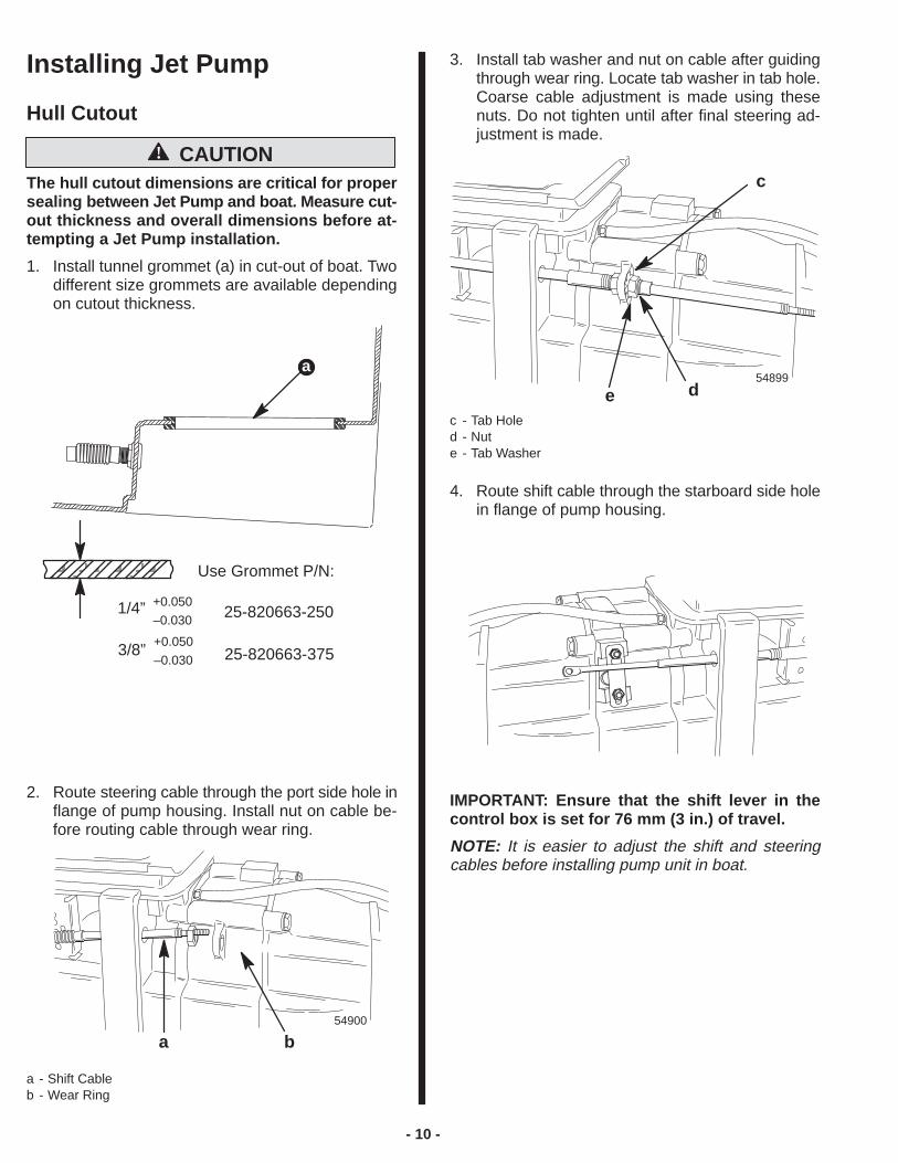
Installing Jet Pump
Hull Cutout
! CAUTIONThe hull cutout dimensions are critical for propersealing between Jet Pump and boat. Measure cut-out thickness and overall dimensions before at-tempting a Jet Pump installation.
1. Install tunnel grommet (a) in cut-out of boat. Twodifferent size grommets are available dependingon cutout thickness.
a
ÀÀÀÀÀÀÀÀÀÀÀÀÀÀÀÀÀÀÀÀÀÀÀÀ
1/4” +0.050
–0.030
3/8” +0.050
–0.030
Use Grommet P/N:
25-820663-250
25-820663-375
2. Route steering cable through the port side hole inflange of pump housing. Install nut on cable be-fore routing cable through wear ring.
54900
a b
a - Shift Cableb - Wear Ring
3. Install tab washer and nut on cable after guidingthrough wear ring. Locate tab washer in tab hole.Coarse cable adjustment is made using thesenuts. Do not tighten until after final steering ad-justment is made.
54899
c
dec - Tab Holed - Nute - Tab Washer
4. Route shift cable through the starboard side holein flange of pump housing.
IMPORTANT: Ensure that the shift lever in thecontrol box is set for 76 mm (3 in.) of travel.
NOTE: It is easier to adjust the shift and steeringcables before installing pump unit in boat.

- 11 -
5. Spray soapy water on tunnel grommet, both sidefoam exhaust seals, ride plate seal and sides ofboat tunnel.
a
b
cd
a - Tunnel Grommetb - Boat Tunnelc - Foam Exhaust Seals (One Each Side)d - Ride Plate Seal
NOTE: When installing pump in tunnel, be surecables are below tunnel grommet flange on pump toprevent pinching of cables between pump and boat.
6. Install jet pump by pushing unit through openingin tunnel grommet. Ride plate seal should fit snugin boat tunnel without any gaps along perimeter.
b a
a - Jet Pumpb - Tunnel Grommet
7. Install gasket and cover (d) on jet pump. Alignholes in cover with locating pins in housing andsecure with four (4) M10 x 1.5 nuts .
NOTE: Before torquing fasteners, check side ex-haust seals and ride plate seal for proper fit in tunnel.
8. Torque nuts to 47 Nm (35 lb ft).
b
a
a - Gasket and Coverb - M10 x 1.5 Nuts (4)

- 12 -
Steering Cable Adjustment1. Slide bellows assembly over cable and thread on
cable completely. Do Not tighten.
54456
2. Thread cable end adaptor on steering cable 14turns (to allow for adjustment).
! WARNINGCable end adaptor must be installed a minimumof nine (9) turns. Failure to install cable end adap-tor on steering cable a minimum of nine (9) turnscould result in loss of steering control of boat,personal injury, or death.
54902
a
a - Cable End Adaptor
3. Center rudder assembly on nozzle.
4. Center steering wheel by turning wheel lock tolock and positioning wheel midway betweenlocks.
5. Adjust cable end adaptor until thru-hole in adap-tor lines up with threaded hole in steering arm.This is the steering cable fine adjustment. Cableend adaptor MUST be installed on steering cablea minimum of nine (9) turns.
6. Attach steering cable to steering arm with bolt,washer and locknut. Torque nut to 20.3 Nm (180lb in.).
54902
a
b
c
d
e
f
a - Bellows Nutb - Forward Stopc - Boltd - Locknute - Flat Washerf - Cable Nuts
7. Tighten cable nuts.
8. Check steering adjustment to ensure that thehelm limits cable travel for maximum left and rightturns. Correct if required.
9. Secure cable nut with tab washer.
10. Apply Perfect Seal to end threads and cable con-duit end.
Perfect Seal19
19
- 13 -
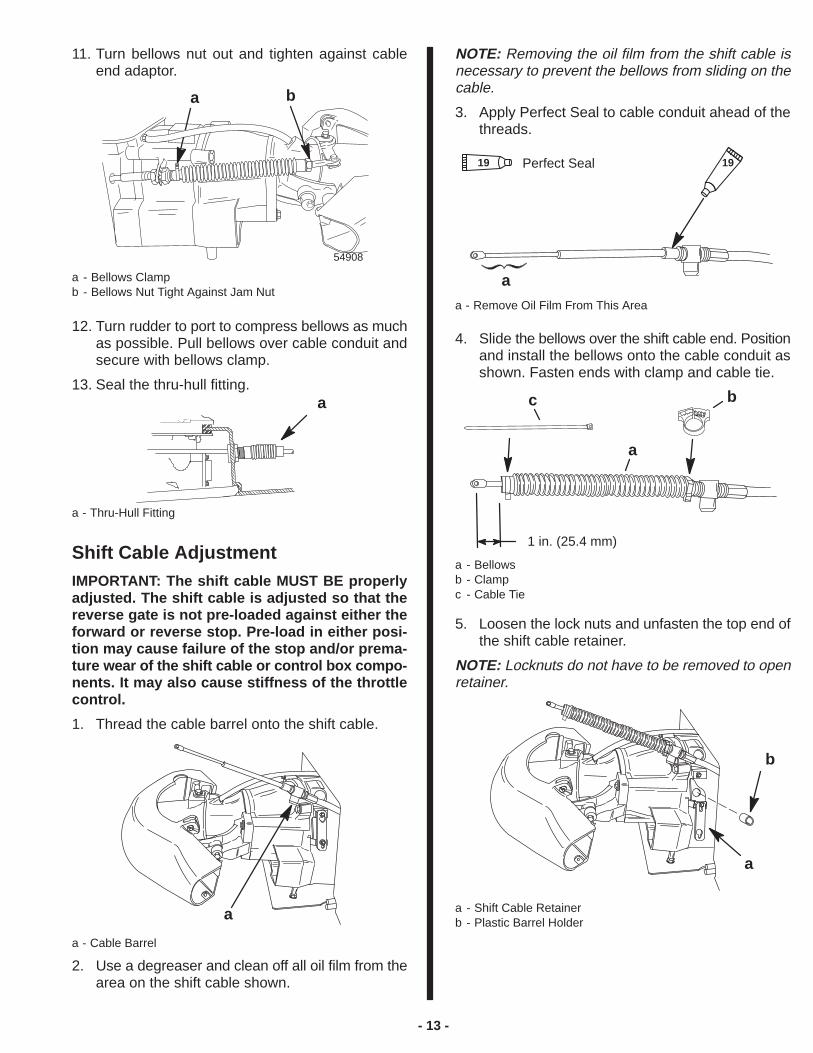
11. Turn bellows nut out and tighten against cableend adaptor.
54908
a b
a - Bellows Clampb - Bellows Nut Tight Against Jam Nut
12. Turn rudder to port to compress bellows as muchas possible. Pull bellows over cable conduit andsecure with bellows clamp.
13. Seal the thru-hull fitting.a
a - Thru-Hull Fitting
Shift Cable AdjustmentIMPORTANT: The shift cable MUST BE properlyadjusted. The shift cable is adjusted so that thereverse gate is not pre-loaded against either theforward or reverse stop. Pre-load in either posi-tion may cause failure of the stop and/or prema-ture wear of the shift cable or control box compo-nents. It may also cause stiffness of the throttlecontrol.
1. Thread the cable barrel onto the shift cable.
a
a - Cable Barrel
2. Use a degreaser and clean off all oil film from thearea on the shift cable shown.
NOTE: Removing the oil film from the shift cable isnecessary to prevent the bellows from sliding on thecable.
3. Apply Perfect Seal to cable conduit ahead of thethreads.
a
19Perfect Seal19
a - Remove Oil Film From This Area
4. Slide the bellows over the shift cable end. Positionand install the bellows onto the cable conduit asshown. Fasten ends with clamp and cable tie.
1 in. (25.4 mm)
bc
a
a - Bellowsb - Clampc - Cable Tie
5. Loosen the lock nuts and unfasten the top end ofthe shift cable retainer.
NOTE: Locknuts do not have to be removed to openretainer.
a
b
a - Shift Cable Retainerb - Plastic Barrel Holder
- 14 -
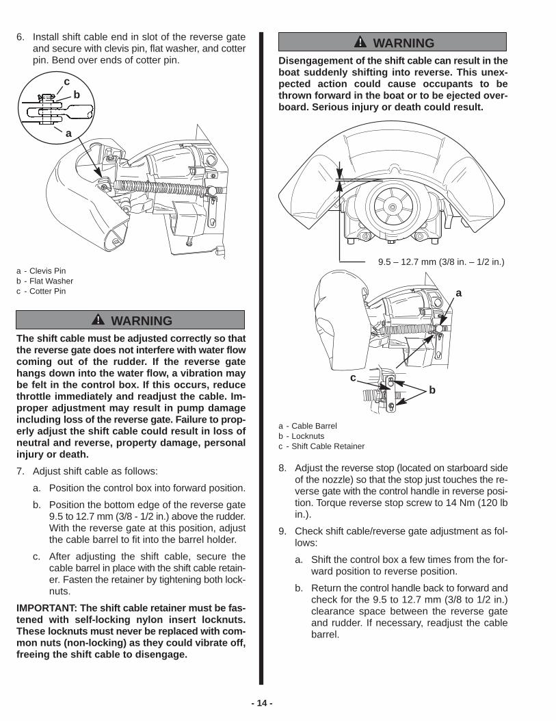
6. Install shift cable end in slot of the reverse gateand secure with clevis pin, flat washer, and cotterpin. Bend over ends of cotter pin.
b
a
c
a - Clevis Pinb - Flat Washerc - Cotter Pin
! WARNINGThe shift cable must be adjusted correctly so thatthe reverse gate does not interfere with water flowcoming out of the rudder. If the reverse gatehangs down into the water flow, a vibration maybe felt in the control box. If this occurs, reducethrottle immediately and readjust the cable. Im-proper adjustment may result in pump damageincluding loss of the reverse gate. Failure to prop-erly adjust the shift cable could result in loss ofneutral and reverse, property damage, personalinjury or death.
7. Adjust shift cable as follows:
a. Position the control box into forward position.
b. Position the bottom edge of the reverse gate9.5 to 12.7 mm (3/8 - 1/2 in.) above the rudder.With the reverse gate at this position, adjustthe cable barrel to fit into the barrel holder.
c. After adjusting the shift cable, secure thecable barrel in place with the shift cable retain-er. Fasten the retainer by tightening both lock-nuts.
IMPORTANT: The shift cable retainer must be fas-tened with self-locking nylon insert locknuts.These locknuts must never be replaced with com-mon nuts (non-locking) as they could vibrate off,freeing the shift cable to disengage.
! WARNINGDisengagement of the shift cable can result in theboat suddenly shifting into reverse. This unex-pected action could cause occupants to bethrown forward in the boat or to be ejected over-board. Serious injury or death could result.
9.5 – 12.7 mm (3/8 in. – 1/2 in.)
a
bc
a - Cable Barrelb - Locknutsc - Shift Cable Retainer
8. Adjust the reverse stop (located on starboard sideof the nozzle) so that the stop just touches the re-verse gate with the control handle in reverse posi-tion. Torque reverse stop screw to 14 Nm (120 lbin.).
9. Check shift cable/reverse gate adjustment as fol-lows:
a. Shift the control box a few times from the for-ward position to reverse position.
b. Return the control handle back to forward andcheck for the 9.5 to 12.7 mm (3/8 to 1/2 in.)clearance space between the reverse gateand rudder. If necessary, readjust the cablebarrel.

- 15 -
10. Seal the thru-hull fitting to prevent any waterleaks.
a
a - Steering Cable Thru-Hull Fitting
Bilge Siphon FeatureThe Jet Drive incorporates an automatic bilge siphon-ing feature. The bilge siphon is working whenever theengine is running above idle speeds. Maximum per-formance of the bilge siphon is realized above 3,000RPM. A hose is attached to the jet pump nozzle. Thehose is routed to the engine compartment and placedin the bilge. Water exiting the nozzle creates a suctionor vacuum in the hose creating the bilge siphon,drawing water out of the boat.
Installing Bilge SiphonUncoil siphon hose from clamp on exhaust manifold.Hose should remain attached to clamp on manifold.Loop siphon hose over clamp on exhaust manifold.Place siphon hose in bilge.
b
28237
c
db - Siphon Breakc - Manifold Clampd - Pick Up Screen
The siphon break must be located above the waterline. The siphon break has a .020 in. hole which mustbe kept open.
! WARNINGFailure to locate siphon break above the waterline and keep hole open could result in water en-tering the bilge through the siphon system caus-ing property damage, personal injury or death.
Water By-Pass SystemThe water by-pass system is designed to improvepowerhead cooling at idle speed.
1. Locate the water by-pass components (pro-vided).
cb
a
a - Thru-Hull Fittingb - Brass Nutc - Hose Clamp
IMPORTANT: The thru-hull fitting must be cor-rectly positioned in the boat transom asinstructed in Step 3.
2. Cut the cable tie and uncoil the water by-passhose.
a
a - Water By-Pass Hose
3. Select the mounting location for the thru-hull fit-ting as follows:
A
2 in. (50 mm) Minimum
Top View ofTransom
A
Back Viewof Transom
• The thru-hull fitting must be mounted in eitherside of the transom within the zones marked A.
• The thru-hull fitting must be located a Minimum of50 mm (2 in.) above the water line when boat isat its maximum load.
• The water by-pass hose must slope down to-wards the thru-hull fitting at a minimum rate of 25 mm (1 in.) drop per 12 inches (300 mm) ofhose.
• The thru-hull fitting should be positioned so thewater spray will be pointed downward.
- 16 -
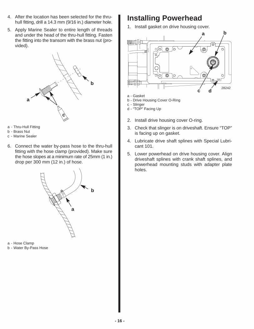
4. After the location has been selected for the thru-hull fitting, drill a 14.3 mm (9/16 in.) diameter hole.
5. Apply Marine Sealer to entire length of threadsand under the head of the thru-hull fitting. Fastenthe fitting into the transom with the brass nut (pro-vided).
a
b
c
a - Thru-Hull Fittingb - Brass Nutc - Marine Sealer
6. Connect the water by-pass hose to the thru-hullfitting with the hose clamp (provided). Make surethe hose slopes at a minimum rate of 25mm (1 in.)drop per 300 mm (12 in.) of hose.
a
b
a - Hose Clampb - Water By-Pass Hose
Installing Powerhead1. Install gasket on drive housing cover.
a b
c28242
da - Gasketb - Drive Housing Cover O-Ringc - Slingerd - “TOP” Facing Up
2. Install drive housing cover O-ring.
3. Check that slinger is on driveshaft. Ensure “TOP”is facing up on gasket.
4. Lubricate drive shaft splines with Special Lubri-cant 101.
5. Lower powerhead on drive housing cover. Aligndriveshaft splines with crank shaft splines, andpowerhead mounting studs with adapter plateholes.
- 17 -
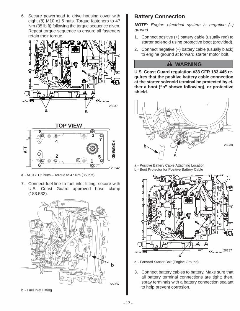
6. Secure powerhead to drive housing cover witheight (8) M10 x1.5 nuts. Torque fasteners to 47Nm (35 lb ft) following the torque sequence given.Repeat torque sequence to ensure all fastenersretain their torque.
TOP VIEW�������
���
37
51
2
4
8
628242
28237
a a
a - M10 x 1.5 Nuts – Torque to 47 Nm (35 lb ft)
7. Connect fuel line to fuel inlet fitting, secure withU.S. Coast Guard approved hose clamp(183.532).
b
55087
b - Fuel Inlet Fitting
Battery ConnectionNOTE: Engine electrical system is negative (–)ground.
1. Connect positive (+) battery cable (usually red) tostarter solenoid using protective boot (provided).
2. Connect negative (–) battery cable (usually black)to engine ground at forward starter motor bolt.
! WARNINGU.S. Coast Guard regulation #33 CFR 183.445 re-quires that the positive battery cable connectionat the starter solenoid terminal be protected by ei-ther a boot (“b” shown following), or protectiveshield.
a
b 28238
a - Positive Battery Cable Attaching Locationb - Boot Protector for Positive Battery Cable
c28237
c - Forward Starter Bolt (Engine Ground)
3. Connect battery cables to battery. Make sure thatall battery terminal connections are tight; then,spray terminals with a battery connection sealantto help prevent corrosion.
- 18 -
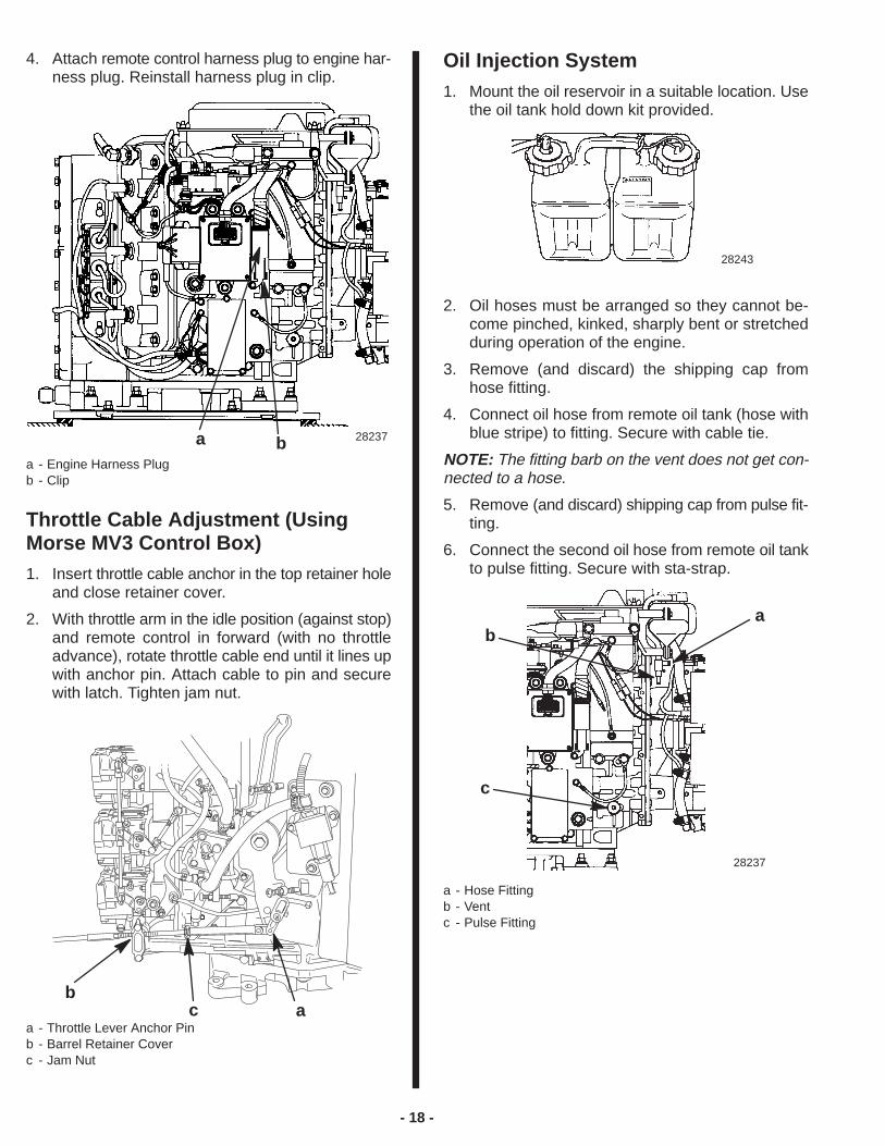
4. Attach remote control harness plug to engine har-ness plug. Reinstall harness plug in clip.
a 28237ba - Engine Harness Plugb - Clip
Throttle Cable Adjustment (UsingMorse MV3 Control Box)1. Insert throttle cable anchor in the top retainer hole
and close retainer cover.
2. With throttle arm in the idle position (against stop)and remote control in forward (with no throttleadvance), rotate throttle cable end until it lines upwith anchor pin. Attach cable to pin and securewith latch. Tighten jam nut.
ab
ca - Throttle Lever Anchor Pinb - Barrel Retainer Coverc - Jam Nut
Oil Injection System1. Mount the oil reservoir in a suitable location. Use
the oil tank hold down kit provided.
28243
2. Oil hoses must be arranged so they cannot be-come pinched, kinked, sharply bent or stretchedduring operation of the engine.
3. Remove (and discard) the shipping cap fromhose fitting.
4. Connect oil hose from remote oil tank (hose withblue stripe) to fitting. Secure with cable tie.
NOTE: The fitting barb on the vent does not get con-nected to a hose.
5. Remove (and discard) shipping cap from pulse fit-ting.
6. Connect the second oil hose from remote oil tankto pulse fitting. Secure with sta-strap.
ab
c
28237
a - Hose Fittingb - Ventc - Pulse Fitting
- 19 -
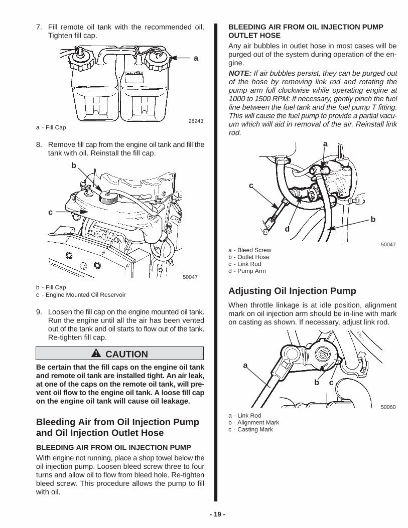
7. Fill remote oil tank with the recommended oil.Tighten fill cap.
a
28243a - Fill Cap
8. Remove fill cap from the engine oil tank and fill thetank with oil. Reinstall the fill cap.
50047
b
c
b - Fill Capc - Engine Mounted Oil Reservoir
9. Loosen the fill cap on the engine mounted oil tank.Run the engine until all the air has been ventedout of the tank and oil starts to flow out of the tank.Re-tighten fill cap.
! CAUTIONBe certain that the fill caps on the engine oil tankand remote oil tank are installed tight. An air leak,at one of the caps on the remote oil tank, will pre-vent oil flow to the engine oil tank. A loose fill capon the engine oil tank will cause oil leakage .
Bleeding Air from Oil Injection Pumpand Oil Injection Outlet Hose
BLEEDING AIR FROM OIL INJECTION PUMPWith engine not running, place a shop towel below theoil injection pump. Loosen bleed screw three to fourturns and allow oil to flow from bleed hole. Re-tightenbleed screw. This procedure allows the pump to fillwith oil.
BLEEDING AIR FROM OIL INJECTION PUMPOUTLET HOSEAny air bubbles in outlet hose in most cases will bepurged out of the system during operation of the en-gine.NOTE: If air bubbles persist, they can be purged outof the hose by removing link rod and rotating thepump arm full clockwise while operating engine at1000 to 1500 RPM: If necessary, gently pinch the fuelline between the fuel tank and the fuel pump T fitting.This will cause the fuel pump to provide a partial vacu-um which will aid in removal of the air. Reinstall linkrod.
50047
b
c
a
d
a - Bleed Screw b - Outlet Hose c - Link Rod d - Pump Arm
Adjusting Oil Injection PumpWhen throttle linkage is at idle position, alignmentmark on oil injection arm should be in-line with markon casting as shown. If necessary, adjust link rod.
50060
a
b c
a - Link Rodb - Alignment Markc - Casting Mark

- 20 -
Turn-Key Start FeatureThe Jet Drive utilizes an automatic enrichner to starta cold engine. The enrichner is controlled by the ECM(Electronic Control Module). There are no adjust-ments for the Turn Key Start Feature.
IMPORTANT: The Turn Key Start relies on closedthrottle plates at idle. Ensure throttle plates arefully closed at idle.
Trim Plate AdjustmentThe Jet Drive trim plate is factory set for general ap-plications. Should a particular boat experience por-poising problems, the trim plate can be adjusted asfollows:
1. Loosen both jam nuts on trim plate (one starboardand one port).
aa - Jam Nut with Washer (Two: One On Each Side)
2. Turn both screws the exact same number ofturns. Tighten both jam nuts against trim plate.The distance from top of nut to bottom of bossshould be equal on both sides.
! WARNINGAdjusting the trim plate may affect boat handling(steering). Overly sensitive steering or reducedturning ability could result from trim plate adjust-ments. Boat handling characteristics also varywith the load distribution in the boat. Use cautionafter adjusting: check for acceptable handlingcharacteristics under all loading conditions. Fail-ure to adequately test the boat could result in in-adequate steering control resulting in propertydamage, personal injury or death.

- 21 -
Pre-delivery Inspection Not Check/Applicable Adjust CHECK BEFORE RUNNING
� � Water hose connection/torqued
� � Cover plate & adaptor platefasteners torqued
� � Battery charged & secure
� � All electrical connections tight
� � All fuel connections tight
� � Throttle, shift, & steering adjustedcorrectly and fasteners torqued
� � Shift cable adjusted to keepreverse gate 9.5 to 12.7 mm (3/8-1/2 in.) aboverudder in forward w/ slack pulledout of cable
� � Carb throttle shutters open & close completely
� � Pump housing oil level full(See Owner’s Manual)
� � Oil injection reservoir full and bled
� � Warning system operational
On the water test
� � Starter neutral safety switchoperational
� � Lanyard stop switch operational
� � All gauges read properly
� � No fuel or oil leaks
� � No water leaks
� � No exhaust leaks
� � Ignition timing set to specs
� � Idle:____________RPM
� � Idle mixture adjusted
On the water test (continued)
Not Check/Applicable Adjust
� � Forward-Neutral-Reverseoperational
� � Steering operational throughoutentire range
� � Acceleration test
� � WOT:___________RPM
� � Boat handling
Post water test
� � No fuel, oil, water or exhaustleaks
� � Re-torque adapter plate fasteners
� � Re-check shift cable adjustment. Readjust as necessary