Embed Size (px)
Citation preview

CCP-4800 Cerebrum 1U 48 button hardware control panel
Operation manual

Hercules 28
NL-5126 RK Gilze
The Netherlands
Phone: +31 161 850 450
Fax: +31 161 850 499
E-mail: [email protected]
Web: www.axon.tv
WARNING: TO REDUCE THE RISK OF FIRE OR
ELECTRICAL SHOCK, DO NOT EXPOSE THIS
APPLIANCE TO RAIN OR MOISTURE
OPERATION MANUAL
CCP-4800

3
● ALWAYS disconnect your entire system from the AC mains before cleaning any component. The product
frame (SFR18 or SFR04) must be terminated with three-conductor AC mains power cord that includes an
earth ground connection. To prevent shock hazard, all three connections must always be used.
● NEVER use flammable or combustible chemicals for cleaning components.
● NEVER operate this product if any cover is removed.
● NEVER wet the inside of this product with any liquid.
● NEVER pour or spill liquids directly onto this unit.
● NEVER block airflow through ventilation slots.
● NEVER bypass any fuse.
● NEVER replace any fuse with a value or type other than those specified.
● NEVER attempt to repair this product. If a problem occurs, contact your local Axon distributor.
● NEVER expose this product to extremely high or low temperatures.
● NEVER operate this product in an explosive atmosphere.
Warranty: Axon warrants their products according to the warranty policy as described in the general terms.
That means that Axon Digital Design BV can only warrant the products as long as the serial numbers are not
removed.
Copyright © 2001 – 2013 AXON Digital Design B.V.
Date created: 19-09-2012
Date last revised: 12-02-2014
Axon, the Axon logo and Synapse are trademarks of Axon Digital Design B.V.
This product complies with the requirements of the product family standards for audio, video, audio-visual
entertainment lighting control apparatus for professional use as mentioned below.
EN60950
EN55103-1: 1996
EN55103-2: 1996
Safety
Emission
Immunity
Axon Digital Design
CCP-4800
Tested To Comply
With FCC Standards
FOR HOME OR OFFICE USE
This device complies with part 15 of the FCC Rules
Operation is subject to the following two conditions:
(1) This device may cause harmful interference, and
(2) This device must accept any interference received, including
interference that may cause undesired operation.

4
Table of Contents
Introduction to Cerebrum 5 An Introduction to Cerebrum 5 Key Cerebrum features 5 Configuration 6 Monitoring workflow & events 6
The CCP-4800 control panel 7 Introduction 7 Features 7
Configuration 8 Initial configuration 8 Dipswitch settings 8 Configuration Method 8 Cerebrum Controlled 8 Default IP address 9 Adding the panel to Cerebrum 9 Configuring functionality on the panel 11 Creating a CPF file 11 Controlling an Enumerated object of a Synapse card 12 Creating a button that will navigate to a different menu 12 Standalone 13 Default IP address 14 Configuration 15 SynCross Router Settings 16 Button Setting 16
Firmware upgrade 18 Operation 18
Specifications 20

5
1 Introduction to Cerebrum
An Introduction to Cerebrum
In modern broadcasting, the multi-platform delivery and multi-
purpose repackaging of materials demand that you master a
diversity of workflows. AXON’s Cerebrum software application
makes the implementation of multiple video and audio signal paths
easier, more efficient and cost-effective than ever. Cerebrum
provides comprehensive tools to configure,monitor and maintain
not only the complete range of Synapse products, but also a wide
variety of other devices.
The result is that you, and limitless numbers of users, can take total
control over multiple and complex routines. Ultimately, you can
make your work flow how you want it to flow.
Please visit the AXON Digital Design Website at www.axon.tv to
obtain the latest information on our new products and updates.
Key Cerebrum
features
Cerebrum is a Windows-based application whose advanced
functionality and broad range of features make life easier. The
brains behind your many and varied workflows, Cerebrum allows
users to remotely:
Configure… a complex workflow in a short space of time.
Manage & Report… events using hierarchical system status.
Control… devices via an intuitive, user-friendly graphical
interface.
Maintain… a workflow over its lifetime.
Cerebrum employs Ethernet communication to each device in your
chosen workflow, providing the ability to both configure and
monitor devices at local and remote sites. It uses an SQL database
to record, view and archive historical workflow events as well as
stores the user-definable aspects of each device’s configuration.
This database can also be redeployed for the user’s own
requirements via ODBC or similar interface.
The application allows up to 64 user-groups to be defined. For each
group the level of access can be restricted, not only to program
functionality but also to control access of individual settings on
specific devices. Limitless users can be added and assigned to one
of these groups, each with their own unique password. This ensures
that Cerebrum can be used in operations where conditional access is
required, and as an administrative tool.

6
Configuration Within its clear, intuitive interface Cerebrum provides you with the
tools to configure your workflow with speed and ease. Each device
is represented by one, or more, graphical dialogue interfaces, which
are shown automatically in the Control view when the device is
selected. These provide a clear idea of the function and signal flow
within the module, and make clear what effect the setting has on the
signal path. Visualisations for some devices, such as Synapse
Aspect Ratio Converters, are given for the output display. If you
need further clarification of function a view to the manual for the
selected card is always available.
You can save the configuration of a device as a template file, or to
the clipboard, and quickly copy it to other selected devices in the
workflow. Using Cerebrum’s Compare function, the settings and
status of a device of the same type can be compared, with any
differences highlighted. To ease some aspects of configuration, and
to make monitoring of the system more applicable to each user’s
particular application, additional data can be added about the
location, channel and/or service the device is providing. There is
also a free-form notes field for all other critical information.
Monitoring
workflow & events Cerebrum provides a multitude of ways to let you accurately track
events within your workflows. Each device in your workflow is
shown in the System view, and displays its current and historical
status using an icon. Cerebrum actively monitors each device to
check for its current status. The status of each device is passed to a
parent node within the System view and a hierarchical status of your
complete workflow is shown using a single icon. This is also
reflected in the application’s optional Status Bar, and in the System
Icon Tray, when the application is either obscured or minimised.
The System view can be alphanumerically sorted by the network
address, user name, card type or one of the user defined data items
such as Channel, Service, Room or Bay.
Each event occurring for a device being monitored (Synapse,
SNMP or Router) is logged to the database and shown in the Event
Log. A status priority can be assigned to each event to determine
whether an alarm or warning action should be triggered. Each state
of a device’s status can be configured by the system administrator to
reflect the severity of the event, plus the method by which the
warning or error should be cleared (either manually or automatically
on a good event state) allowing the status to really reflect the
condition of a users system.
The Event Log window can be filtered using different criteria.
Additional user data can be stored with each event, such
as the cause/reason for the related warning or error.
Cerebrum allows limits to be set for the size of the Alarm Log table
in the SQL database allowing the user to keep historical records for
the activity of the system.

7
4 The CCP-4800 control panel
Introduction The CCP-4800 Cerebrum control panel is a 1U rack mount panel
with 48 tactile buttons.
Features
The CCP4800 can operate in two modes. Default the panel can be
used in a Cerebrum controlled system. Secondly the panel can be
used as a dedicated router control panel. When being used in default setup the panel provides a hardware panel
control surface for a Cerebrum control system. The panel is
configured in the same way as the software panels in the Cerebrum
system using the Cerebrum Form Designer application. All devices
connected to the Cerebrum server can be controlled or viewed from
this physical surface. The panel can be configured to work with a
number of ‘pages’ which can be linked together to form a logical,
quick and user friendly interface.
Also the panel can be used as a standalone control panel. In this
case the panel will be configured to control the SynCross routers
directly by means of the SWP08 protocol. Cerebrum is used to
assign functions to each of the buttons.
The unit is powered with an internal PSU unit. The rear of the unit
has two IEC power inlets allowing for a redundant PSU in critical
applications. The unit has an earth or grounding stud by the side of
the inlets.
The unit uses its inbuilt 100Base-T Ethernet connector to connect to
the Cerebrum server over either a local or wide area network. The
unit can be configured to use either DHCP or manually assigned IP
addresses. As with other Axon devices when used in manual IP
assignment mode the address, sub-net mask and gateway can be
assigned using the configuration mode of the panel.

8
5 Configuration
Initial configuration
When powering on the CCP-4800 panel and connecting it to a
network, all the buttons start blinking.
1 2 3
25
4
26
5
27
6
28
7
29
8
30
9
31
10
32
11
33
12
34
13
35
14
36
15
37
16
38 39 40
17 18 19
41
20
42
21
43
22
44
23
45
24
46 47 48
Dipswitch settings The DIP switches are used to setup the operation mode of the panel.
The operation modes are Cerebrum controlled or standalone.
Another function of the dipswitches is to select the application
firmware upgrade and IP address mode.
Configuration Method
Poles 3, 6, 7 and 8 are being used. The rest of the poles need to be
in OFF state.
Pole 3 is used for IP address mode selection:
OFF: User-defined IP address
ON: Default IP address
Pole 6, 7 and 8 are all set to ON for CCP mode
Pole 6,7 are set to ON and Pole 8 is set to OFF for Probel mode
Cerebrum
Controlled To use the CCP with Cerebrum, please check that the dipswitches 6,
7 and 8 are set to on.
The default IP address of the panels is 192.168.0.100. To change the
IP address you need to do this follow these actions:
Start-up Cerebrum and go to View Engineering Configure
Cerebrum Hardware. The following pop-up screen will appear.
1 2 3 4 5 6 7 8
ON
OFF
9
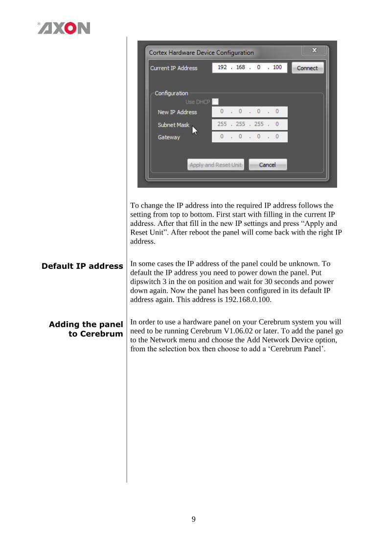
To change the IP address into the required IP address follows the
setting from top to bottom. First start with filling in the current IP
address. After that fill in the new IP settings and press “Apply and
Reset Unit”. After reboot the panel will come back with the right IP
address.
Default IP address In some cases the IP address of the panel could be unknown. To
default the IP address you need to power down the panel. Put
dipswitch 3 in the on position and wait for 30 seconds and power
down again. Now the panel has been configured in its default IP
address again. This address is 192.168.0.100.
Adding the panel to Cerebrum
In order to use a hardware panel on your Cerebrum system you will
need to be running Cerebrum V1.06.02 or later. To add the panel go
to the Network menu and choose the Add Network Device option,
from the selection box then choose to add a ‘Cerebrum Panel’.

10
Define the IP address of the panel that you are adding to the system
and also the home page cpf file that you want the panel to display
first. You can also specify an initial settings file that can hold
variables for this instance of the panel. In this way you can have
multiple panels using the same cpf files but perhaps changing
different destinations of the router, or different Synapse devices
depending on their location.
The check box for redundant PSU is not used in case of the
CCP4800.
When you have finished choosing the options press Add to
continue. The panel should now appear at the correct IP address in
the System View of Cerebrum, as shown in the following
screenshot:
When this panel is selected in the System View the control tab of
the Device View should show a mimic of what the panel is
currently displaying if it is on-line. This is displayed in the

11
following picture as well:
This mimic will also work, so pressing a button on the mimic is the
same as pressing a button on the real panel, so the functionality of
the panel can be tested without being near the physical device if
required.
The Monitoring tab, in the same way as all other devices within
Cerebrum, shows a historical log of the status events for this panel.
These include PSU monitoring and communication status events.
Configuring functionality on
the panel
The CCP4800 panel works in the same way as the Control view in
Cerebrum. The Software panels use CLF's (Cerebrum Layout Files)
to define the functionality and the information shown to the user,
whereas the Hardware panels use a CPF's (Cerebrum Panel Files) to
define the same. These files are created by the Cerebrum Designer
in the same way as the CLFs.
Creating a CPF file To create a CPF for defining functionality to a CCP4800 control
panel, first make sure the Cerebrum designer is installed onto your
system. If this has not been done, re-run the Cerebrum installation
and press the modify button when prompted, then choose the
Cerebrum designer option to add this to your system. When the
designer is installed then invoke this from the desktop/program files
shortcut.
To create a new or blank CPF file then go to the File menu and
select New Hardware Panel. A blank template will appear
looking like the CCP4800 panel. This file should be saved in the
Cerebrum\Forms\Hardware Panels folder (or sub folder)
There are two ways to design functionality onto the panel, if you are
familiar with the Cerebrum system then you can add functionality
manually using the Update Editor, or if you are less familiar with
the system you can use the System View to 'drag and drop'
functionality onto the buttons from the devices in the system.
To work with the System View you have to join the Designer as a
client onto your Cerebrum system whilst it is connected to your
network. To do this ensure the Cerebrum application is running and
has the Client connections enabled (Configuration Cerebrum
Configuration CorLink Enable Client connections), you
should ideally give the Corlink server a unique name and if you are
using more than one Cerebrum system on your network then it
should have a unique multicast address.

12
When the client connections has been enabled you will be able to
join the designer onto the system by choosing the File Log On
To Server option and giving a valid user and password (default
User: Admin, Password: Cerebrum), if successfully connected to
the system the bottom left of the status bar should show Connected
in green text. The System View will also show the network devices
in the same way as they are shown in the main Cerebrum
application.
Controlling an Enumerated
object of a Synapse card
If you want to control an enumerated object of a Synapse card from
the CCP4800, firstly select the card in the system view you want to
control, this will then show a list of objects in the bottom half of the
System View, then you can find the Control object required and
then you can drag from this half of the view to the button/s required.
For example: if you want to turn the program keyer of a HDK100
on and off with two buttons from the CCP4800, first find the card in
the system, then in the Control group of objects locate the object
called Prgm-Key, click on the plus symbol to the left hand side of
this object to reveal the states this object has, then select the first
two states 'Off' and 'On' and then drag them onto the first two
buttons of the CPF file opened for editing. This will assign a
template that will control this specific instance of the HDK100 and
turn the Keyer On and Off with the two buttons.
If you are making a generic CPF file for controlling multiple
HDK100 cards then you would use the ACP Cards tab in the
System View then find the card type required, then select the
software version of the card required. This then shows the objects
available again, however when the object states are dragged onto
the panel it will expect two Panel Variables to be set to target the
card (IP_ADDRESS and SLOT).
Creating a button that will navigate
to a different
menu
In order to create a panel which gives the user a choice of different
functionality from the same panel, you can create separate CPF files
to create the functionality required and then link them together by
adding functionality to a button to change the panel the CCP4800 is
using. An example of this is shown in the Example panel files
supplied with the installation, the file Example.cpf has three buttons
that link to other CPF files, if you select the first button then you
will see in the update editor a GUI event was created and in this
event a GUI set action was added that changed the file being used as
Example Presets.cpf.
To use this on a CPF of your own, you can either add the event and
action manually or copy the button from this example and paste it
onto your own CPF file to the button required, changing the file it is
calling and the button text from the initial configuration of the
button. Don't forget to give the user a way to get back to the
main/home menu.

13
Standalone When the dipswitches 6 and 7 are set to on and switch 8 to off the
panel will act as a standalone router panel. This panel can be used to
control all SynCross router variants.
The default IP address of the panels is 192.168.0.100. To change the
IP address you need to do this follow these actions:
Start-up Cerebrum and go to View Engineering Configure
Cerebrum Hardware. The following pop-up screen will appear.
To change the IP address into the required IP address follows the
setting from top to bottom. First start with filling in the current IP
address. After that fill in the new IP settings and press “Apply and
Reset Unit”. After reboot the panel will come back with the right IP
address.

14
When using the standlone more, please make sure the GXP880 (the
Syncross crosspoint card) CtrlMode is set to SWP08 over
TCP.
Default IP address In some cases the IP address of the panel could be unknown. To
default the IP address you need to power down the panel. Put
dipswitch 3 in the on position and wait for 30 seconds and power
down again. Now the panel has been configured in its default IP
address again. This address is 192.168.0.100.
When the connection has been made with the panel an extra button
will popup. This button will enable the user to set the functionality
of the buttons in standalone mode. When the Standalone button is
pressed the following screen will appear.
This popup screen will show the buttons available on the physical
panel.

15
When you start changing the configuration of the panel start with
reading the current configuration of the panel. When this is the first
setup of the panel this is not needed. Pressing the Download/Read
button will read the current settings stored within the panel. These
settings will be shown on the panel buttons. When a new setup has
been made button Upload/Save needs to be used. Pressing this
button will upload the new configuration to the panel.
Configuration In this group box the IP settings of the panel can be made. The
panel can be used in DHCP mode and manual mode. When used in
manual mode the IP settings can be setup up below the DHCP
check box. When these IP settings need to be applied to the panel,
press Apply and reset Unit. When all changes needs to de discarded
press cancel and all settings will fall back to the state they originally
where.

16
SynCross Router
Settings
To connect the panel to a SynCross router you need to make the
panel aware of the existence of the SynCross Router. To do this all
details need to be filled in. Because the panel will be in the same
network only the IP address, port number, number of sources and
number of destinations.
The SynCross routers always will be connected to the port number
7800.
Button Setting Below the “Physical” buttons on the popup screen you will be able
to set the function of the buttons. The choices are Unassigned,
sources, destinations and take.
When a button is chosen the function dropdown menu will show
what the current function of the button is. Select a button which
function needs to be altered. Within the Button Setting groupbox
you need to choose a function.
If as function destinations or sources is chosen also the dropdown
for the value will appear. With the value dropdown menu you will
be able to set a destination or source number.
The Take button will give the button take functionality. This button
only can be used once.

17
If the new setup is ok it can be uploaded to the panel. To make this
effective the Upload/Save needs to be used. Pressing this button will
upload the new configuration to the panel.
18
6 Firmware upgrade
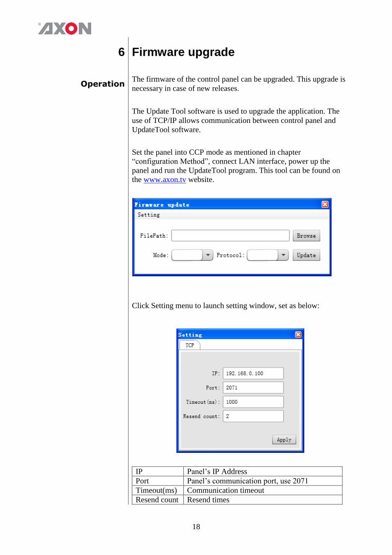
Operation The firmware of the control panel can be upgraded. This upgrade is
necessary in case of new releases.
The Update Tool software is used to upgrade the application. The
use of TCP/IP allows communication between control panel and
UpdateTool software.
Set the panel into CCP mode as mentioned in chapter
“configuration Method”, connect LAN interface, power up the
panel and run the UpdateTool program. This tool can be found on
the www.axon.tv website.
Click Setting menu to launch setting window, set as below:
IP Panel’s IP Address
Port Panel’s communication port, use 2071
Timeout(ms) Communication timeout
Resend count Resend times

19
Click the Apply button and then close the setting window.
In main window, set as below:
FilePath Select .bin file of panel application
Mode Select Tcp
Protocol Select Ccpp
Click the Update button to start programming. The application will
show as below.
Wait until program completes.

20
After the upload of the new software the panel will automatically
restart. Now the new application will be running.
7 Specifications
Dimensions Height 44mm (1.73”) (1RU)
Width (including front panel) 483 mm (19”)
Depth (including front panel and DC
connector)
171mm (6.73”)
Width (excluding front panel) 450 mm (17.71”)
Depth (excluding front panel, including
DC connector)
121mm (4,67”)
Weight Weight (excluding power adapter) ~2.5 kg
Power AC 100–240V AC, Frequency: 50/60 Hz
3W
Miscellaneous Operating temperature 0º to 40º C environmental temperature (32º to 104º
F)
Storage temperature -20º to 70 º environmental temperature (-4º to 158º
F)