Embed Size (px)
Citation preview

Adopted: January 1, 2001 12-ii Revised:
TABLE OF CONTENTS CHAPTER 12
EROSION PREVENTION AND SEDIMENT CONTROL NUMBER SECTION PAGE 12.1 PURPOSE 12-1 12.2 OVERVIEW OF EPSC ORDINANCE AND REQUIREMENTS 12-1 12.3 SENSITIVE FEATURE IDENTIFICATION 12-2 12.4 EPSC PLAN DEVELOPMENT STANDARDS 12-2 12.5 EROSION PREVENTION MEASURES 12-4 12.5.1 Surface Roughening 12-4 12.5.2 Bench Terracing 12-5 12.5.3 Temporary Seeding 12-6 12.5.4 Mulching 12-6 12.5.5 Erosion Control Blankets and Turf Reinforcement Mats 12-7 12.5.6 Final Stabilization 12-9 12.5.6.1 Topsoiling 12-9 12.5.6.2 Permanent Seeding and Planting of Grasses 12-9
12.5.6.3 Sodding 12-9 12.5.7 Riprap or Aggregate 12-10 12.5.8 Outlet Protection 12-13 12.5.9 Dust Control 12-16 12.6 TEMPORARY SEDIMENT CONTROL MEASURES 12-17 12.6.1 Storage Volumes and Maintenance Schedules 12-17 12.6.2 Temporary Sediment Basins 12-20
12.6.3 Multipurpose Basins 12-23

Adopted: January 1, 2001 12-iiii Revised:
TABLE OF CONTENTS (cont.)
CHAPTER 12
EROSION PREVENTION AND SEDIMENT CONTROL NUMBER SECTION PAGE 12.6.4 Temporary Sediment Trap 12-24
12.6.5 Silt Fence 12-25
12.6.6 Rock Ditch Check 12-25
12.6.7 Stabilized Construction Entrances 12-26
12.6.8 Storm Drain Inlet Protection 12-27
12.6.9 Vegetated Filter Strips 12-29 12.7 RUNOFF CONTROL & CONVEYANCE MEASURES 12-30
12.7.1 Pipe Slope Drains 12-30
12.7.2 Temporary Stream Crossing 12-31
12.7.3 Runoff Control Measures 12-34 12.7.4 Construction Dewatering 12-36
12.7.5 Level Spreader 12-37
12.7.6 Stone Bag Check in Small Ditch 12-38
12.8 DESIGN AIDS 12-39 12.8.1 Characteristic Settling Velocity and Eroded Particle Size 12-39 12.8.2 Sediment Pond Design Aids 12-41 12.8.3 Rock Ditch Checks Design Aids 12-42 12.8.4 Silt Fence Design Aids 12-45 12.8.5 Sediment Trap Design Aids 12-46

Adopted: January 1, 2001 12-iiiiii Revised:
TABLE OF CONTENTS (cont.)
CHAPTER 12
EROSION PREVENTION AND SEDIMENT CONTROL Supplemental Sections PAGE SECTION A EROSION PREVENTION &SEDIMENT CONTROL BMP SELECTIONPROCESS, SUGGESTED USES, & GUIDELINES 12-49 SECTION B JEFFERSON COUNTY RAINFALL AND UNIVERSAL SOIL LOSS EQUATION INFORMATION 12-53 SECTION C JEFFERSON COUNTY SOIL INFORMATION 12-57 SECTION D EXHIBITS 12-63 SECTION E EROSION CONTROL BLANKETS & TURF
REINFORCEMENT MATS 12-81

Adopted: January 1, 2001 12-iivv Revised:
CHAPTER 12
EROSION PREVENTION AND SEDIMENT CONTROL SUPPLEMENTAL SECTION D
EXHIBITS EXHIBIT TITLE PAGE 12-1 BENCH TERRACES 12-64 12-2 MAXIMUM DEPTH OF FLOW FOR RIPRAP
LINED CHANNELS 12-65 12-3 DISTRIBUTION OF BOUNDARY SHEAR AROUND
WETTED PERIMETER OF TRAPEZOIDAL CHANNEL 12-66 12-4 ANGLE OF REPOSE FOR RIPRAP STONES 12-67 12-5 RATIO OF CRITICAL SHEAR STRESS ON SIDES TO
CRITICAL SHEAR STRESS TO BOTTOM 12-68 12-6 MINIMUM TAILWATER CONDITION 12-69 12-7 MAXIMUM TAILWATER CONDITION 12-70 12-8 SEDIMENT BASIN 12-71 12-9 SEDIMENT TRAP 12-73 12-10 VEGETATED FILTER STRIPS 12-75 12-11 PIPE SLOPE DRAIN 12-76 12-12 DIKES AND SWALES 12-77 12-13 DEWATERING OPERATIONS FOR PUMPING TO A
VEGETATED BUFFER ZONE 12-78 12-14 DETAIL FOR DEWATERING OUTLET STRUCTURE 12-79 12-15 TYPICAL LEVEL SPREADER 12-80

Adopted: January 1, 2001 12-1 Revised:
CHAPTER 12 EROSION PREVENTION AND SEDIMENT CONTROL
12.1 PURPOSE OF THIS CHAPTER
This chapter of the MSD Design Manual provides the user with the tools to meet the requirements of the Jefferson County Erosion Prevention and Sediment Control (EPSC) Ordinance. Some of the information contained in this chapter, such as the application forms, checklists, and the Sensitive Feature GIS application are available in digital format and can be downloaded from www.msdlouky.org.
This chapter also establishes requirements to be used when preparing plans for minimizing soil erosion and sedimentation during and after construction of any land development, improvement or retrofit project. Guidelines on how to select and design EPSC Best Management Practices (BMPs) for specific construction activities have been developed in accordance with several references from across the country.
12.2 OVERVIEW OF EPSC ORDINANCE AND REQUIREMENTS
The EPSC Ordinance requires that an EPSC plan be developed and be approved by MSD. A Site Disturbance Permit should also be obtained from MSD prior to initiating construction on land disturbing activities that are in excess of 5,000 square feet or require a building permit as directed by a General Permit.
The Ordinance also establishes standards for the design of EPSC plans to minimize the adverse impact and offsite degradation that may result from construction site runoff.
There are two types of EPSC plans that may be required as part of an application for approval of a land disturbing activity: Concept EPSC plans and Detailed EPSC plans.
• Concept EPSC plans are required only for those land disturbing activities subject to a
Type I review and containing sensitive features as identified by the permittee after a site visit. The concept EPSC plan shall contain the information required by the MSD Preliminary Plan Checklist, including a narrative description of how the delineated Sensitive Features will be protected when conducting the proposed land-disturbing activity. Submit the Checklist with the conceptual EPSC plans for review and approval.
• Detailed EPSC plans are required at the construction plan stage for all land disturbing
activities subject to both Type I and Type II review. The detailed EPSC plan shall contain the information required by the MSD EPSC Detailed Construction Plan Checklist, and if Sensitive Features are identified, a narrative description of how the delineated Sensitive Features will be protected when conducting the proposed land-disturbing activity must be included on the plans. Submit the MSD EPSC Detailed Construction Plan Checklist with the detailed EPSC plans for review and approval.

Adopted: January 1, 2001 12-2 Revised:
12.3 SENSITIVE FEATURE IDENTIFICATION
Sensitive Features include land containing any one the following features:
• Local Regulatory Conveyance Zone/ Regulatory Flood Plain as defined by local ordinance.
• Stream corridors (including blue line and intermittent) as mapped by United States Geological Survey.
• Karst features with a well-defined surface opening (such as a cave, sinkhole, vadose shaft or other karst anomaly).
• Lakes and impoundments. • Jurisdictional wetlands as determined by the US Army Corps of Engineers. • Slopes greater than 20%. • “Erodible” and “severely erodible” soils as determined by the Natural Resources
Conservation Service. • Sites with the potential to drain storm water directly into a sensitive feature listed
above (including any designated buffer area for that feature) or into a designated greenway.
12.4 EPSC PLAN DEVELOPMENT STANDARDS
EPSC plans shall be developed to achieve an 80% design removal efficiency goal. Simply applied, when a site is completely denuded of vegetation, the structural and nonstructural EPSC measures are designed to trap 80% of the total suspended solids (TSS) that are generated by the site. The design storm event associated with this level of control is the 10-year 24-hour SCS Type II storm event. SCS procedures should be used to determine runoff amounts. It is important to note that when a BMP is designed for this event, the BMP will have a greater trapping efficiency for more frequent events (i.e. 2-year storm).
Each EPSC Plan must delineate the following elements:
• All Sensitive Features • Potential sources of sediment that may potentially leave the site • The location and depth of all structural and non-structural BMPs necessary to
achieve the 80% design removal efficiency goaland protect the Sensitive Features • Installation and maintenance of required BMPs • The sequencing of construction activities to be utilized on the project
The following non-structural site management practices shall be utilized on the plans when feasible:
• Minimize site disturbance to preserve and maintain existing vegetative cover;

Adopted: January 1, 2001 12-3 Revised:
• Limit the number of temporary access points to the site for land disturbing activities;
• Phase and sequence construction activities; • Locate temporary and permanent soil disposal areas, haul roads and construction
staging areas to minimize erosion, sediment transport and disturbance to existing vegetation.
Detailed EPSC plans shall comply with the following specific standards and review criteria:
• Sediment Tracking Control. Stabilized construction entrances shall be located
and utilized at all points of ingress/egress on a construction site. The transfer of soil, mud and dust onto public rights-of-ways shall be prevented.
• Construction Dewatering Operations. Whenever construction dewatering operations are required on a site, they shall be conducted according to the specifications set forth in the MSD Design Manual, Standard Specifications and Standard Drawings.
• Crossings of waterways during construction shall be minimized and approved by MSD. Encroachment into stream buffers, riparian areas and wetlands shall be avoided.
• Topsoil shall be stockpiled and preserved from erosion or dispersal both during and after site grading operations.
• Temporary Stabilization Measures. Where construction or land disturbance activity will or has temporarily ceased on any portion of a site, temporary site stabilization measures shall be required as soon as practicable, but no later than 14 calendar days after the activity has ceased.
• Final Stabilization. Final Stabilization of the site shall be required within 14 calendar days of construction completion.
• Temporary Structural Controls installed during construction shall be designed to accomplish maximum stabilization and control of erosion and sedimentation, and shall be installed, maintained, and removed according to the specifications set forth in the MSD Design Manual, Standard Specifications and Standard Drawings. All temporary structural controls shall function as designed when controlling the peak runoff resulting from the storm event identified in the MSD Design Manual, Standard Specifications and Standard Drawings.
• All Permanent Structural Controls, including drainage facilities such as channels, storm sewer inlets, and detention basins, shall be designed according to the standards set forth in the MSD Design Manual, Standard Specifications and Standard Drawings.
To encourage the development and testing of alternative EPSC BMPs, alternative management practices that are not included in the MSD Design Manual, Standard Specifications and Standard Drawings may be allowed upon review and approval. To use an alternative BMP, submit substantial evidence that the proposed measure will perform at least equivalent to a currently approved control contained in the MSD Design Manual,

Adopted: January 1, 2001 12-4 Revised:
Standard Specifications and Standard Drawings. Evidence may include, but is not limited to, peer-review by a panel of licensed professional engineers and research results as reported in professional journals or other literature.
If MSD finds the alternative BMP has failed or is inadequate to contain sediment onsite, the alternative BMP shall be removed and replaced with a BMP approved by MSD and found in the MSD Design Manual, Standard Specifications and Standard Drawings.
12.5 EROSION PREVENTION MEASURES
Erosion prevention measures shall be used during and after construction site preparation in order to safely convey clean water to storm drains or adequate watercourses. One or more measures should be utilized as appropriate during the project's construction phase. Such measures may include but are not limited to: phasing and construction sequencing, surface roughening, temporary seeding, mulching, matting, and geotextile blankets. Each of these measures is discussed in the sections to follow.
In addition to site-specific erosion control measures, the grading plan should include the following general measures as a minimum:
• The finished cut and fill slopes to be vegetated should not be steeper 3H:1V. • Cuts or fills should not be so close to property lines as to endanger adjoining
property without adequately protecting such properties against erosion, sedimentation, slippage, settlement, subsidence, or other damages.
• Subsurface drainage should be provided in areas having a high water table to intercept seepage that would affect slope stability, bearing strength or create undesirable wetness.
• No fill shall be placed where it can slide or wash onto another property. • Fill shall not be placed adjacent to channel banks where it can create bank failure,
reduce the capacity of the stream, or result in downstream sediment deposition. • All borrow and disposal areas should be included as part of the grading plan. • Adequate channels and floodways should be provided to safely convey increased
runoff from the developed area to an adequate outlet without causing significant channel aggradation, degradation, or increased off-site flooding.
• The site should be graded to direct flows to appropriate controls.
12.5.1 Surface Roughening
Introduction Surface roughening is the creation of horizontal grooves, depressions, or steps that run parallel to the contour of the land. The following surface roughening measures are approved for use: tracking (driving a crawler tractor up and down a slope, leaving the cleat imprints parallel to the slope contour) as shown in Standard Drawing EC-04-00; stair-step grading as shown in Standard Drawing

Adopted: January 1, 2001 12-5 Revised:
EC-05-00; and, slope grooving (using disks, spring harrows, or teeth on the bucket of a front-end loader) as shown in Standard Drawing EC-06-00.
Design Criteria
Cut slopes with a gradient steeper than 3H:1V but less than 2H:1V should be stair-step graded or groove cut. Stair-step grading works well with soils containing large amounts of small rock. Stairs should be wide enough to work with standard earth moving equipment. Grooving can be done by any implement that can be safely operated on the slope, including those described above. Grooves should not be less than 3 inches deep or more than 15 inches apart.
Fill slopes with a gradient steeper than 3H:1V but less than 2H:1V should be compacted every 9 inches of depth. The face of the slope should consist of loose, uncompacted fill 4 to 6 inches deep that can be left rough or can be grooved as described above, if necessary.
Any cut or filled slope that will be maintained should have a gradient less than 3H:1V and in no case greater than 2H:1V. Such a slope can be roughened with shallow grooves parallel to the slope contour by using normal tilling. Grooves should be close together (less than 10 inches) and not less than 1 inch deep.
12.5.2 Bench Terracing
Introduction Bench terraces are permanent earth embankments or ridges constructed along the face of a slope at regular intervals creating a stair step effect. Bench terraces reduce slope lengths and direct surface to stable outlets. The proper orientation of a bench terrace is shown in Exhibit 12-1 in Supplemental Section D of this chapter. Design Criteria
Bench terraces are designed for highly erodible, steep slopes ranging from 3:1 to 1.5:1, and should not be constructed on slopes with sandy or rocky soils. They are effective only where there are suitable runoff outlets such as grassed waterways, level spreaders or piped outlets. The design of a bench terrace system involves proper spacing and location. Terrace spacing is expressed as the vertical distance between the channels of successive terraces. For each terrace, the spacing is the vertical distance from the top of the hill to the bottom of the channel, commonly known as the vertical interval or VI. Although the horizontal spacing is useful in determining row arrangement, the VI is more convenient for terrace layout and construction. Terrace spacing is expressed by the emperical formula
VI = aS + b
Adopted: January 1, 2001 12-6 Revised:
Where:
VI = vertical interval between consecutive terraces in ft., a = constant for geographical location (0.5 for Louisville), b = constant for soil erodibility (1 for erodible conditions, 2 for
resistant soils with good ground cover), and S = average land slope in percent
The horizontal interval HI or bench width can be calculated by the formula
HI = VI x 100/S
Where: HI = horizontal interval of each terrace in ft.,
VI = vertical interval between consecutive terraces in ft., and S = average land slope in percent.
12.5.3 Temporary Seeding
Introduction
The purpose of temporary seeding is to reduce erosion and sedimentation by stabilizing disturbed areas that would otherwise lay bare for long periods of time before they are worked or stabilized. Temporary seeding is also used where permanent vegetation growth is not necessary or appropriate.
Design Criteria
Any disturbed areas that will not be worked for 14 days or more must have temporary cover applied by the 14th day. Seeded areas should be covered with mulch to provide protection from the weather. If the vegetation does not grow quickly or thick enough to prevent erosion, the area should be re-seeded as soon as possible. Seeded areas should be kept adequately moist. Irrigate the seeded area if normal rainfall is not adequate for the germination and growth of seedlings. Water seeded areas at controlled rates that are less than the rate at which the soil can absorb water to prevent runoff. Runoff of irrigation water wastes water and fuel and can cause erosion itself. Seed selection should be based on the requirements of the MSD Standard Specifications.
12.5.4 Mulching
Introduction
Mulching is a temporary soil stabilization erosion control method where materials such as grass, hay, wood chips, wood fibers, or straw are placed on the soil surface. In addition to stabilizing soils, mulching can enhance the absorption of

Adopted: January 1, 2001 12-7 Revised:
water by the soil, reduce evaporation losses, regulate soil temperatures and reduce the speed of storm water runoff over an area.
Design Criteria
Erosion control mulching may be used on level areas, slopes up to 50%, and in waterways with caution. Where soil is highly erodible, nets should only be used in connection with organic mulch, such as straw and wood fiber.
Mulch is an effective ground cover when the establishment of vegetation is improbable due to severe weather conditions (winter conditions), poor soil, or steep slopes.
12.5.5 Erosion Control Blankets and Turf Reinforcement Mats
Introduction
A variety of Rolled Erosion Control Products (RECPs) are available for the stabilization of seeded slopes and channel banks. MSD distinguishes between the different types of products using two categories: Erosion Control Blankets (ECBs) and Turf Reinforcement Mats (TRMs).
ECBs and TRMs are preferred alternatives to traditional hard channel protection such as concrete, riprap, gabions and revetment mattresses. These products improve the quality of stormwater discharges by creating a stronger, vegetated armorment that filters the flow, allows infiltration, and provides wildlife habitat. The proper orientation of netting and matting is shown in Standard Drawing EC-07-00.
ECBs are used for the temporary stabilization of soil immediately following seeding until the vegetative cover has grown and become well established. They provide temporary protection because they degrade over time as the vegetation becomes established. Some products are effective for a few months while others degrade slowly and are effective for a few years.
TRMs are nondegradable products that enhance the ability of living plants to stabilize soils. They bind with roots to reinforce the soil matrix. TRMs are used in situations where vegetation alone will not hold a slope or stream bank. TRMs enable us to use “green” solutions in many areas where only “hard” solutions such as riprap or concrete linings were viable in the past.
Design Criteria for ECBs and TRMs
When designing a permanent conveyance (as described in Chapter 10 of this Design Manual) with a grassed or vegetative lining, the design should address the bare condition prior to vegetation being established. A geotextile lining may be

Adopted: January 1, 2001 12-8 Revised:
applied to protect the conveyance during this period. It is important to use both the tractive force and the permissible velocity methods to determine the level of protection that is required.
The design of ECBs and TRMs is based on the anticipated shear stresses and maximum flow velocities the fabric will encounter. Once the design shear stresses and maximum flow velocities are known, a corresponding ECB or TRM that meets the conditions may be selected from the list of approved ECB and TRM products. This list is found in Supplemental Section E in this chapter and on the MSD web page.
The following variables are required to determine the maximum velocity in a channel for a 10-year 24-hour storm event.
• Design peak flow rate value in cubic feet per second (cfs) for the 10-year 24-
hour storm,
• Channel dimensions designed to carry the peak flow rate. For simplicity, all channels will be assumed to be trapezoidal in shape,
• Channel bed slope,
• Manning’s channel roughness coefficient (n) of the TRM or ECB or final
vegetation, and
• Normal channel flow depth (dn) based on peak flow rate and channel dimensions.
The governing equation for maximum velocity is Manning’s Equation:
V= (1.49 / n) *R 2/3 * S 1/2
Where: V = maximum velocity (ft/sec) n = Manning’s channel roughness coefficient R = Hydraulic radius of the flow based on dn (ft) S = Channel bed slope (ft/ft)
The governing equation for maximum channel shear stress is:
τ = γ dn S
Where: τ = maximum shear stress (lbs/ft2) γ = unit weight of water = 62.4 lbs/ft3
dn = normal channel flow depth (ft) S = channel bed slope (ft/ft)
Adopted: January 1, 2001 12-9 Revised:
12.5.6 Final Stabilization
12.5.6.1 Topsoiling
When and Where to Use It
Topsoil should be used when vegetative stabilization is used, where soils are dense or impermeable, or where mulching and fertilizers alone cannot improve soil quality.
Design Criteria
Stockpiling of topsoil onsite requires good planning and construction sequencing so the stockpiles will not obstruct other operations. If topsoil is to be stockpiled, the use of temporary seeding, mulching or silt fence to control erosion should be considered.
12.5.6.2 Permanent Seeding and Planting of Grasses
Design Criteria
The use of native species is preferred when selecting vegetation. Seedbed preparation, seed type, application rate, fertilizer rate and planting windows should be designed according to the MSD Standard Specifications.
12.5.6.3 Sodding
When and Where to Use It
Sodding is appropriate for any graded or cleared area that may erode, and where a permanent, long-lived plant cover is immediately needed. Examples of where sodding can be used are yards, buffer zones, stream banks, dikes, swales, slopes, outlets, level spreaders and filter strips.
Design Criteria
Sodding should be installed per MSD Standard Specifications as shown in Standard Drawing EC-08-00. Sodding should not be used on slopes steeper than 2H:1V, unless the sodding is to be mowed, then it should not be placed on slopes greater than 3H:1V.

Adopted: January 1, 2001 12-10 Revised:
12.5.7 Riprap or Aggregate
Introduction
Riprap is a permanent, erosion-resistant channel lining aggregate consisting of large, loose, angular stone with a filter fabric or granular underlining. The purpose of riprap is to:
• Protect the soil from the erosive force of concentrated runoff; and • Slow runoff velocities while enhancing the potential for infiltration.
The purpose of the filter fabric or granular underlining is to prevent undermining of the riprap layer by the migration of soil particles under seepage forces through the riprap.
When and Where to Use It
The preferred method of slope and channel protection is the use of vegetation. If vegetation cannot withstand the design flows, ECBs and TRMs (see Section 12.5.5) are the preferred and suggested method of protection. When conditions are too severe for vegetation and TRMs, riprap may be used for erosion control and protection. Riprap may be used, as appropriate, at storm drain outlets, on channel banks and/or bottoms, drop structures, at the toe of slopes, and in transitions from concrete channels to vegetated channels. Table 12-1 lists several KTC sizes of coarse aggregates along with the corresponding stone diameter.
Table 12-1. Coarse Aggregates Aggregate Size (KTC Size No.)
Mean Spherical Diameter (d50) (inches)
1 3.5 2 2.5 23 2.5 3 2.0 357 2.0 4 1.5 467 1.5 5 1.0 57 1.0 610 1.0 67 0.75 68 0.75 710 0.75 78 0.50 8 0.375
Adopted: January 1, 2001 12-11 Revised:
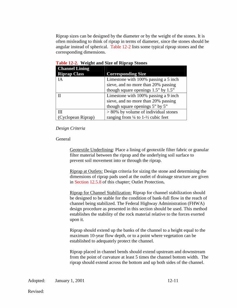
Riprap sizes can be designed by the diameter or by the weight of the stones. It is often misleading to think of riprap in terms of diameter, since the stones should be angular instead of spherical. Table 12-2 lists some typical riprap stones and the corresponding dimensions.
Table 12-2. Weight and Size of Riprap Stones Channel Lining Riprap Class
Corresponding Size
IA Limestone with 100% passing a 5 inch sieve, and no more than 20% passing though square openings 1.5” by 1.5”
II Limestone with 100% passing a 9 inch sieve, and no more than 20% passing though square openings 5” by 5”
III (Cyclopean Riprap)
> 80% by volume of individual stones ranging from ¼ to 1-½ cubic feet
Design Criteria
General
Geotextile Underlining: Place a lining of geotextile filter fabric or granular filter material between the riprap and the underlying soil surface to prevent soil movement into or through the riprap.
Riprap at Outlets: Design criteria for sizing the stone and determining the dimensions of riprap pads used at the outlet of drainage structure are given in Section 12.5.8 of this chapter; Outlet Protection.
Riprap for Channel Stabilization: Riprap for channel stabilization should be designed to be stable for the condition of bank-full flow in the reach of channel being stabilized. The Federal Highway Administration (FHWA) design procedure as presented in this section should be used. This method establishes the stability of the rock material relative to the forces exerted upon it.
Riprap should extend up the banks of the channel to a height equal to the maximum 10-year flow depth, or to a point where vegetation can be established to adequately protect the channel.
Riprap placed in channel bends should extend upstream and downstream from the point of curvature at least 5 times the channel bottom width. The riprap should extend across the bottom and up both sides of the channel.
Adopted: January 1, 2001 12-12 Revised:
Freeboard and Height of Bank: For riprap and other lined channels, the height of channel lining above the water surface should be based on the size of the channel, the flow velocity, the curvature, inflows, wind action, flow regulation, etc.
The designer shall obtain a minimum freeboard for placement of riprap relative to the top of bank from Chapter 10.
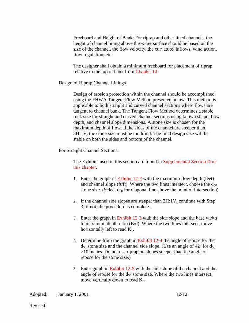
Design of Riprap Channel Linings
Design of erosion protection within the channel should be accomplished using the FHWA Tangent Flow Method presented below. This method is applicable to both straight and curved channel sections where flows are tangent to channel bank. The Tangent Flow Method determines a stable rock size for straight and curved channel sections using known shape, flow depth, and channel slope dimensions. A stone size is chosen for the maximum depth of flow. If the sides of the channel are steeper than 3H:1V, the stone size must be modified. The final design size will be stable on both the sides and bottom of the channel.
For Straight Channel Sections:
The Exhibits used in this section are found in Supplemental Section D of this chapter.
1. Enter the graph of Exhibit 12-2 with the maximum flow depth (feet)
and channel slope (ft/ft). Where the two lines intersect, choose the d50 stone size. (Select d50 for diagonal line above the point of intersection)
2. If the channel side slopes are steeper than 3H:1V, continue with Step
3; if not, the procedure is complete.
3. Enter the graph in Exhibit 12-3 with the side slope and the base width to maximum depth ratio (B/d). Where the two lines intersect, move horizontally left to read K1.
4. Determine from the graph in Exhibit 12-4 the angle of repose for the d50 stone size and the channel side slope. (Use an angle of 42o for d50 >10 inches. Do not use riprap on slopes steeper than the angle of repose for the stone size.)
5. Enter graph in Exhibit 12-5 with the side slope of the channel and the angle of repose for the d50 stone size. Where the two lines intersect, move vertically down to read K2.

Adopted: January 1, 2001 12-13 Revised:
6. Compute d50 x K1/K2 = d50 to determine the correct size stone for the
bottom and side slopes of straight sections of channel.
12.5.8 Outlet Protection
Introduction
Outlet protection dissipates the energy of concentrated storm water flows thereby reducing erosion or scouring at storm water outlets and paved channel sections. In addition, outlet protection lowers the potential for downstream erosion. This type of protection can be achieved through a variety of techniques, including permanent turf reinforcement mats (TRMs), stone or riprap, concrete aprons, and paved sections.
Design Criteria
The design of lined aprons at the outlets of pipes and paved channel sections applies to the immediate area or reach below the pipe or channel and does not apply to continuous rock linings of channels or streams. Notably, pipe or channel outlets at the top of cut slopes or on slopes steeper than 10% should not be protected using just outlet protection. This causes re-concentration of the flow that results in large velocities when the flow leaves the apron. Outlet protection should be designed according to the following criteria:
Round Pipe Flowing Full:
1. Tailwater Depth: The tailwater depth immediately below the pipe
outlet must be determined for the design capacity of the pipe. The depth may be determined using Manning's Equation. If the tailwater depth is less than ½ the diameter of the outlet pipe, it should be classified as a Minimum Tailwater Condition. If the tailwater depth is greater than ½ the pipe diameter, it should be classified as a Maximum Tailwater Condition. Pipes which outlet onto flat areas with no defined channel may be assumed to have a Minimum Tailwater Condition.
2. Apron Length: The required apron length, La, according to the
tailwater condition, should be determined from the appropriate graphs provided in the following exhibits found in Supplemental Section D of this chapter:
Minimum Tailwater Condition - Use Exhibit 12-6 Maximum Tailwater Condition - Use Exhibit 12-7
3. Apron Width: When the pipe discharges directly into a well-defined
channel, the apron should extend across the channel bottom and up the

Adopted: January 1, 2001 12-14 Revised:
channel banks to an elevation one foot above the maximum tailwater depth or to the top of the bank (whichever is less). If the pipe discharges onto a flat area with no defined channel the width of the apron should be determined as follows:
• The upstream end of the apron, adjacent to the pipe, should have a
width three times the diameter of the outlet pipe (3D).
• For a Minimum Tailwater Condition, the downstream end of the apron should have a width equal to the pipe diameter plus the length of the apron (D + La).
• For a Maximum Tailwater Condition, the downstream end should
have a width equal to the pipe diameter plus 0.4 times the length of the apron (D +0.4* La).
4. Bottom Grade: The apron shall be constructed with no slope along its
length (0% grade). The downstream invert elevation of the apron should be equal to the elevation of the invert of the receiving channel. There shall be no overfall at the end of the apron.
5. Side Slopes: If the pipe discharges into a well-defined channel, the
receiving side slopes of the channel should not be steeper than 3H: 1V.
6. Alignment: The apron should be located so there are no bends in the horizontal alignment.
7. Materials:
• The preferred apron lining shall be with an appropriate permanent
turf reinforcement matting (TRM). The shear stress and maximum velocity should be calculated to determine which type of TRM is applicable for the situation (see Section 12.5.5).
• When conditions are too severe for TRMs the apron may be lined
with riprap, grouted riprap, concrete, or gabion baskets. The median-sized stone for riprap should be determined from the curves in Exhibit 12-6 and 12-7 according to the tailwater condition. The gradation, quality, and placement of riprap should conform to the requirements presented in Section 12.5.7.
8. Filter Cloth: In all cases, filter cloth should be placed between the
riprap and the underlying soil to prevent soil movement into and through the riprap. The material must meet or exceed the physical properties for filter cloth found in the requirements presented in Section 12.5.7.

Adopted: January 1, 2001 12-15 Revised:
Paved Channel Outlets (Standard Drawing DD-05-00):
1. The flow velocity at the outlet of paved channels flowing at design
capacity must not exceed the permissible velocity of receiving unprotected grass-lined channels as provided in Table 12-3.
2. The paved channel end should merge smoothly with the receiving
channel section with no overfall at the end of the paved section. When the bottom width of the paved channel is narrower than the bottom width of the receiving channel, a transition section should be provided with a maximum side divergence of 1 in 3F with;
F = V
(gd)0.5 Where: F = Froude number
V = Velocity at beginning of transition (ft./sec.) d = Depth of flow at beginning of transition (ft.) g = Acceleration due to gravity, (32.2 ft./sec.2)
3. Bends or curves in the horizontal alignment at the transition are not
allowed unless the Froude number (F) is 1.0 or less, or the section is specifically designed for turbulent flow.
Table 12-3. Maximum Permissible Velocities For Unprotected Grass Lined Channels Channel Slope Lining Velocity
(ft./sec.)** 0 – 5 %
Bermuda Grass KY-31 Tall Fescue Kentucky Bluegrass Reed Canarygrass Grass-legume Mixture Lespedeza Sericea Small Grains Temporary Vegetation
8 7 7 7 5 3.5 3.5 3.5
5- 10 %
Bermuda Grass KY-31 Tall Fescue Kentucky Bluegrass Reed Canarygrass
7 6 6 6

Adopted: January 1, 2001 12-16 Revised:
Grass-legume mixture Lespedeza Sericea Small Grains Temporary Vegetation
4 Not Recommended Not Recommended Not Recommended
Greater than 10%
Bermuda Grass KY-31 Tall Fescue Kentucky Bluegrass Reed Canarygrass Grass-legume mixture Lespedeza Sericea Small Grains Temporary Vegetation
6 5 5 5 Not Recommended Not Recommended Not Recommended Not Recommended
*Allow velocities over 5 ft/sec only where good cover and maintenance will be provided.
**For highly erodible soils, decrease permissible velocities by 25%.
Source: Elementary Soil and Water Engineering, Shwab et. al.
12.5.9 DUST CONTROL
Introduction
Wind erosion can occur when the surface soil is loose and dry, vegetation is sparse or absent, the wind is sufficiently strong, and when construction traffic disturbs the soil. Wind erodes soils and transports the sediment offsite in the form of fugitive dust, where it may be washed into receiving water bodies by the next rainstorm.
Fugitive dust is a nuisance for neighbors. It settles on automobiles, structures and windows and finds its way into homes. It also can make breathing difficult (for those with respiratory problems) and becomes a safety problem when it blinds motorists, equipment operators and laborers.
Dust control methods should be utilized whenever there are offsite impacts, such as periods of drought, and implemented until final stabilization is reached.
Design Criteria
There are many methods to control dust on construction sites including:

Adopted: January 1, 2001 12-17 Revised:
• Vegetative Cover - For disturbed areas not subject to traffic, vegetation
provides the most practical method of dust control.
• Mulch - Offers a fast, effective means of controlling dust.
• Sprinkling Water – Used on haul roads and other traffic routes as dust control.
• Spray-on-Adhesive - Latex emulsions, or resin in water can be sprayed onto mineral soils to prevent their blowing away and reduce dust caused by traffic.
• Calcium Chloride - May be applied by mechanical spreaders as loose, dry
granules or flakes at a rate that keeps the surface moist but not so high as to cause water pollution or plant damage.
• Barriers - Broad, wind, or sediment fences can control air currents and
blowing soil. These fences prevent erosion by obstructing the wind near the ground stopping the soil from blowing offsite. Barriers are not a substitute for permanent stabilization. Perennial grass and strands of existing trees may also serve as wind barriers.
Spray exposed soil areas only with approved dust control agents as indicated in the MSD Standard Specifications.
12.6 TEMPORARY SEDIMENT CONTROL MEASURES
MSD emphasizes erosion prevention in EPSC plans. However, there are always instances where erosion cannot be prevented. For these situations, temporary sediment controls must be implemented to control the migration of eroded sediment off site. The following sediment control measures are applicable as temporary practices for use during construction. One or more of the measures should be utilized as appropriate during the project's construction phase. A discussion of the planned measures will be required during the Preliminary Plan Review phase for sites containing sensitive features.
12.6.1 Storage Volumes and Maintenance Schedules
Calculating the appropriate sediment storage volume is very important in sediment basin and sediment trap design. This volume is the storage occupied by the sediment deposited over the given design period. Design periods may be the life of the basin, or the time between scheduled clean outs. Using computed sediment yields from the Universal Soil Loss Equation (USLE), along with the sediment bulk density, the sediment storage volume can be calculated by
43,560*WYV D
S =

Adopted: January 1, 2001 12-18 Revised:
where VS is the sediment storage volume (acre-feet), YD is the sediment deposited over the design period (pounds), and W is the weight density (bulk density) of the deposited sediment (lbs./ft3). W can be found from soil survey data (usually given in grams/cm3) or by the equation
ssmmcc PWPWPWW ++=
where Wc, Wm, and Ws are unit weights of clay, silt, and sand in (lbs./ft3) taken from Table 12-4, and Pc, Pm, and Ps are the primary soil matrix percent clay, silt, and sand as listed in soil survey (used as a decimal).
Table 12-4. Unit Weight Values of Basin Sediment Type of Basin Operation Wc
(#/ft3) Wm (#/ft3)
Ws (#/ft3)
Sediment always submerged (Wet Pond)
26 70 97
Basin normally empty (Dry Pond) 40 72 97
R Factors and EI Values
When designing for sediment storage volume, the sediment deposited over the design period YD, must be calculated. This value can be obtained by converting the sediment yield calculated by the Universal Soil Loss Equation (USLE) into pounds of sediment.
One of the variables used in the USLE is the R factor. R is the factor in the USLE that accounts for the damaging effects of rainfall. The R factor indicates the erositivity of the rainfall, not the average annual precipitation in a locality. The R factor is defined as the number of erosion index (EI) values in a normal year’s rain. The EI index value of a given storm is equal to the kinetic energy of the storm (hundreds of foot-tons per acre) times its maximum 30-minute intensity (inches/hour). The EI values of individual storms may be summed to get an EI value for a month, six, months, or for any period of time. When EI values are summed and averaged over a period of years, they become R factors.
The distribution of EI values become important when soil losses need to be calculated for a period of time less than one year, such as a construction season. The distribution of the EI values over a known period of time is used to calculate an R factor for that time period. Table 1 in Supplemental Section B of this chapter shows the distribution of EI values for Jefferson County as a percentage of the R factor for Jefferson County. MSD requires a minimum EI value of 50 for any construction period.
Adopted: January 1, 2001 12-19 Revised:
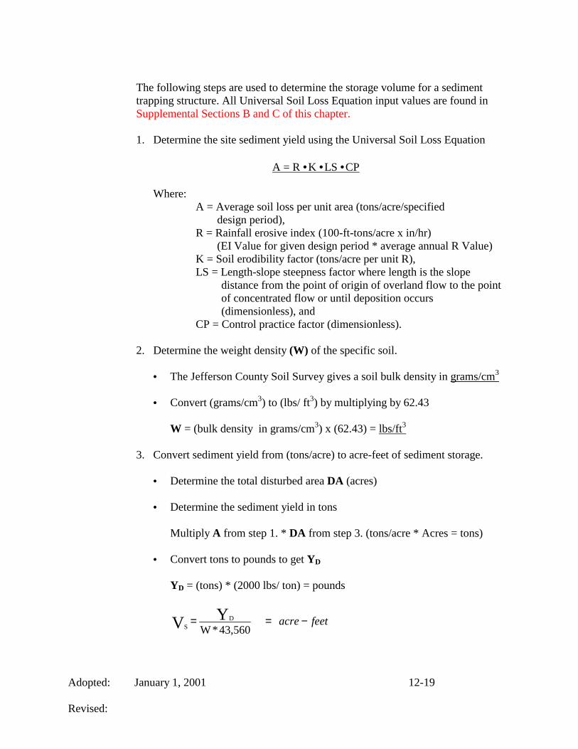
The following steps are used to determine the storage volume for a sediment trapping structure. All Universal Soil Loss Equation input values are found in Supplemental Sections B and C of this chapter.
1. Determine the site sediment yield using the Universal Soil Loss Equation
A = R •K •LS •CP
Where: A = Average soil loss per unit area (tons/acre/specified
design period), R = Rainfall erosive index (100-ft-tons/acre x in/hr)
(EI Value for given design period * average annual R Value) K = Soil erodibility factor (tons/acre per unit R), LS = Length-slope steepness factor where length is the slope
distance from the point of origin of overland flow to the point of concentrated flow or until deposition occurs (dimensionless), and
CP = Control practice factor (dimensionless).
2. Determine the weight density (W) of the specific soil.
• The Jefferson County Soil Survey gives a soil bulk density in grams/cm3
• Convert (grams/cm3) to (lbs/ ft3) by multiplying by 62.43
W = (bulk density in grams/cm3) x (62.43) = lbs/ft3
3. Convert sediment yield from (tons/acre) to acre-feet of sediment storage.
• Determine the total disturbed area DA (acres)
• Determine the sediment yield in tons
Multiply A from step 1. * DA from step 3. (tons/acre * Acres = tons)
• Convert tons to pounds to get YD
YD = (tons) * (2000 lbs/ ton) = pounds
feetacre −==43,560*WYV D
S

Adopted: January 1, 2001 12-20 Revised:
4. The designer can now determine what level the required sediment storage
corresponds to, and require a clean out marking stake to be installed at this elevation. The contractor shall be required to clean out the basin or trap when this level is reached. Or the designer can simply state that based on the calculations, the basin or trap will be required to be cleaned out on a time period basis such as weeks, months or years.
12.6.2 TEMPORARY SEDIMENT BASIN
Introduction
Basins shall be designed to have an 80% design removal efficiency goal for total suspended solids (TSS) in the inflow. Drop inlet spillways, pipe spillways, rock fill outlets and weir spillways may be used for the design of the principal spillway. Typical sediment basin schematics are Exhibits 12-8A and 12-8B in Supplemental Section D of this chapter.
When and Where to Use It
Temporary sediment basins should be used on sites where 5 or more acres are disturbed. A temporary sediment basin shall not be built in wetlands, any active or live streams, or in Waters of Commonwealth (defined to be all annual or perennial water bodies designated by a solid or dashed blue-line on USGS 7.5-minute quadrangle maps). Temporary sediment basins shall be utilized until the contributing flow areas to the basin have undergone final stabilization.
Design Criteria
• Dam Safety –Design criteria such as those used by the USDA Soil
Conservation Service (previously the Natural Resources Conservation Service), U.S. Army Corps of Engineers and the Dam Safety and Floodplain Compliance Section of the Kentucky Division of Water must be followed.
• Safety, Signage, and Fencing - Ponds, which are readily accessible to
populated areas, should incorporate all possible safety precautions. The inside pond slopes shall be no steeper than 3H:1V.
• General Design Criteria -The design aids located in Section 12.8.2 of this
chapter shall be used to properly size the sediment basin. Sedimot III, SEDCAD and other computer models may also be utilized.
• Riser Structure Design- The outlet riser shall be properly designed to meet the
discharge capacity of the 10-year 24-hour storm.

Adopted: January 1, 2001 12-21 Revised:
Flow control devices can operate as either open channel flow, in which the flow has a free water surface, or pipe flow in which the flow is in a closed conduit. In either situation, an increase in head on a structure increases the discharge flow rate through the structure.
The stage discharge relationship for basin outlet structures is controlled by weir, orifice or pipe flow. A given riser spillway can have a variety of stage discharge relationships depending on the head. When the water level is just above a riser crest (a very low head on the riser), the riser crest acts like a weir, and flow is weir controlled. As the water level in the basin increases, water begins flowing in from all sides including directly above the inlet, and the inlet begins to act like an orifice. As the head continues to increase, the outlet eventually begins to flow full, and pipe flow dictates. To determine which of the three flow mechanisms is controlling at a particular water level in the basin, all three equations should be utilized at each level. The minimum flow for a given stage indicates the actual discharge from the basin and the flow mechanism that is controlling at that water level.
Weir Flow:
HLCQ 23
=
Where Q is the discharge (cfs), C is the weir coefficient (dependent upon units and weir shape but C is typically between 3.0 and 3.2), L is the weir length (feet), which is the total length over which flow crosses the weir (L = circumference of a pipe for circular drop inlets), and H is the water head (feet).
Orifice Flow:
( )gHaCQ 2 21
/=
Where Q is the discharge (cfs), C’ is the orifice coefficient (C’ = 0.6 for sharp-edged orifices), a is the cross sectional area of the orifice (ft2), g = 32.2 ft/sec2, and H is the head on the orifice (feet).
Pipe Flow:
( )( ) 2
1
21
1
2 '
LKKK
gHaQ
cbe +++
=

Adopted: January 1, 2001 12-22 Revised:
Where Q is the discharge (cfs), a is the cross sectional area of the pipe (ft2), g = 32.2 ft/sec2, H’ is the head (feet) defined as the distance from the water surface in the basin to a point 0.6 D above the invert of the outlet barrel where D is the outlet barrel diameter in feet (See Figure 6), Ke and Kb depend on the configuration of the pipe entrance and bend (typical values are Ke = 1.0 and Kb = 0.5), Kc is the head loss coefficient due to friction (Kc = 5087*n2 / D4/3 where n = Manning’s roughness coefficient of the barrel and D is the barrel diameter in inches), L is the total length of the pipe (feet)
Other required design criteria are as follows:
a. Minimum Drainage Area - 5 acres b. Maximum Drainage Area - 150 acres c. 80% design removal efficiency goal for TSS. d. The required draw down time of the basin will be the time to detain flows
to meet the 80% design removal efficiency. In many cases this will result in a draw down time longer than 36-hours.
e. Basin Shape - the effective flow length should be at least twice the effective flow width ( L=2W minimum).
f. Sediment Volume Storage Accounted For In Design Volume g. Outlet Riser and Barrel Requirements
1. Discharge Capacity - 10-year 24-hour storm. 2. Minimum Outlet Pipe Diameter of 8-inches. 3. Required 6-inch low flow orifice at bottom of riser structure. 4. Perforations and orifi shall be designed to keep the 2-year and 10-
year 24-hour storm disturbed-state peak flow rates from the basin less than or equal to the pre-disturbance peak flow rates.
5. Anti-Vortex Device / Trash Rack Required. 6. Minimum one-foot elevation difference from top of riser to crest of
the emergency spillway. 7. Sediment Volume Storage Accounted For In Design Volume.
h. Embankment Requirements 1. Maximum Upstream Slope – 3H:1V. 2. Maximum Downstream Slope – 3H:1V. 3. Freeboard - 12-inch minimum. 4. Antiseep collars are required on all penetrations through the dam. 5. Typical dam height to top width dimensions are provided below in
Table 12-5.
Table 12-5. Sediment Basin Width/Height Relationship Dam Height (Ft) Top Width (Ft) < 10 8 11-14 9 15-19 10 20-25 12

Adopted: January 1, 2001 12-23 Revised:
i. Emergency Spillway Requirements 1. Shall be designed to discharge a flow equal to the design overflow of
the 100-year 6-hour storm post-development discharge. 2. Shall have a minimum one-foot of freeboard from the 100-year 6-hour
storm water surface elevation to the top of the dam.
12.6.3 Multipurpose Basins
Introduction
Multipurpose basins are permanent detention basins that are designed for use as temporary sediment basins during the construction phase of a project.
Design Criteria
Two spillway configurations are commonly used in the life of a multipurpose basin. The first configuration is the sediment basin spillway, which is typically a CMP riser and RCP barrel configuration. When conversion of the spillway is required, this configuration makes the most sense because the riser section can be removed and the barrel section can be utilized as part of the spillway for the detention basin.
For steps on the design of the principal and emergency spillways for multipurpose basins, refer to Chapter 10. Design the sediment basin principal spillway to reduce the construction-phase conditions to pre-development levels for the 2 and 10-year 24-hour storm events. Design the emergency spillway to pass and provide flow reduction for the 100-year 6-hour storm permanent detention basin using post-development conditions.
Design the principal spillway for the permanent detention basin to reduce post-development flows to pre-development flows for the 2 and 10-year 6-hour storm events as described in Chapter 10. Design the emergency spillway to pass and provide flow reduction for the 100-year detention basin using post-development conditions.
When the sediment pond phase has expired, the temporary riser structure shall be removed and the permanent structure shall be installed. The basin shall be cleaned of deposited sediment and re-graded to meet the permanent basin contours if necessary.
General Design Criteria
a. Minimum Freeboard for both basin phases is 1 ft. b. Design must include maintenance accessibility and responsibility.

Adopted: January 1, 2001 12-24 Revised:
c. Provide erosion protection for the emergency spillway and channel
protection for the receiving channel. d. Storage, discharge, and routing calculations for the 2-, 10-, and 100-year
storm events must be submitted for review. e. Multipurpose basins shall be fully discharged within 36 hours after the
storm event unless specifically approved by MSD. f. Multipurpose basins shall be the first item of construction.
12.6.4 Temporary Sediment Trap
Introduction
A temporary sediment trap is formed by excavating a pond or by placing an earthen embankment across a low area or drainage swale. An outlet or spillway is constructed using stones or aggregate to slow the release of runoff. The trap retains the runoff long enough to allow most of the silt to settle out. Sediment traps shall be designed to have an 80% design removal efficiency goal of the total suspended solids (TSS) in the inflow. Temporary sediment trap details are Exhibits 12-9A and 12-9B in Supplemental Section D of this chapter.
Design Criteria
A sediment trap may be formed completely by excavation or by construction of a compacted embankment. The outlet should be a rock fill weir/spillway section, with the area below the weir acting as a filter for sediment and the upper area as the overflow spillway depth. To complete the design of the temporary sediment trap:
• Determine the required sediment storage volume.
• Determine the bottom and top surface area of the sediment storage volume
using 3H:1V side slope from the bottom of the trap.
• Determine the total trap dimensions by adding the depth required for the 10-year, 24-hour design storm above the surface of the sediment storage volume, while not exceeding 3H:1V side slopes.
• General Design Criteria – the design aids located in Section 12.8.5 of this
chapter shall be used to properly size the sediment trap. Sedimot III, SEDCAD and other computer models may also be utilized.
• Other design requirements are as follows:
a. Maximum Drainage Area - 5 acres b. Maximum Design Life - 18 months

Adopted: January 1, 2001 12-25 Revised:
c. 80% design removal efficiency goal for TSS d. Basin Shape - The flow length should be 2 times the flow width. e. Embankment Requirements:
1. Maximum Dam Height - 5 feet. 2. Maximum Stone Height – 3.5 feet. 3. Minimum Rock Bottom Width – 3 feet. 4. Discharge and treatment capacity for the 10-year 24-hour storm
event.
12.6.5 Silt Fence
Introduction
A silt fence is a temporary measure for sediment control. It shall be designed to have an 80% design removal efficiency goal of the total suspended solids (TSS) in the inflow. Silt Fence consists of posts with filter fabric stretched across the posts and a wire support fence. The lower edge of the fence is vertically trenched and covered by compacted backfill. Typical silt fence details, with and without reinforcement, are shown in Standard Drawings EF-09-01 and EF-10-01.
Design Criteria
• Maximum sheet or overland flow path length to the fence is 100 feet. • Maximum slope steepness (normal [perpendicular] to fence line) 2H:1V. • No concentrated flows greater than 0.5 cfs and not placed across channels. • General Design Criteria - The design aids located in Section 12.8.4 of this
chapter shall be used to properly design silt fence. • Other design requirements are as follows:
a. 80% design removal efficiency goal for TSS b. Maximum Slope Length - 100 feet c. Maximum Slope Gradient – 2H:1V d. Minimum Installed Fence Height - 18 inches e. Maximum Installed Fence Height - 24 inches f. Minimum Post Bury Depth – 18 inches g. Maximum Reinforced Fence Post Spacing - 6 feet h. Maximum Non-reinforced Post Spacing - 6 feet
12.6.6 Rock Ditch Check
Introduction
A rock ditch check is a small, temporary or permanent rock fill dam constructed across a drainage ditch, swale, or channel to lower the speed of concentrated flows. Rock ditch checks shall be designed to have an 80% design removal

Adopted: January 1, 2001 12-26 Revised:
efficiency goal of the total suspended solids (TSS) in the inflow. A typical rock ditch check section is shown in Standard Drawing EB-03-00.
Design Criteria
• Rock ditch checks should be used only in small open channels. The checks
should not be placed in Waters of the Commonwealth (unless approved by State Authorities). The center section of the rock ditch check should be lower than the edges.
• Spacing varies with the bed slope of the ditch. The maximum spacing
between the rock checks should be such that the toe of the upstream check is at the same elevation as the top of the downstream check.
• In the case of grass-lined ditches and swales, ditch checks should be removed
when the grass has matured sufficiently to protect the ditch or swale unless the slope of the swale is greater than 4%. The area beneath the ditch checks should be seeded and mulched immediately after dam removal. Geotextile filter fabric shall be installed under all rock fill.
• General Design Criteria - The Design Aids located in Section 12.8.3 of this
chapter shall be used to properly design rock ditch checks.
• Other design requirements are as follows: a. 80% design removal efficiency goal for TSS b. Maximum Drainage Area – 5 acres c. Maximum Height - 2 feet
• If the rock ditch check is not properly sized, the flow will overtop the
structure and the Trapping Efficiency is assumed to be 0% when this failure takes place.
12.6.7 Stabilized Construction Entrances
Introduction
A stabilized construction entrance is a temporary stone-stabilized pad located at points of vehicular ingress and egress on a construction site to reduce the amount of mud, dirt, rocks, etc. transported onto public roads by motor vehicles equipment and runoff. A diagram of a typical temporary gravel construction entrance is shown in Standard Drawing ER-01-01.
When and Where to Use It
Stabilized construction entrances should be used whenever repetitive traffic will be leaving a construction site and be moving directly onto a public road.

Adopted: January 1, 2001 12-27 Revised:
Construction entrances provide an area where mud can be removed from vehicle tires before entering a public road.
If the action of the vehicle traveling over the gravel pad is not sufficient to remove the majority of the mud, then the tires must be washed before the vehicle enters a public road. If washing is used, provisions must be made to intercept the wash water and trap the sediment before it is carried offsite. Washdown facilities shall be required as directed by MSD. Washdown areas, in general, must be established with crushed gravel and drain into a sediment trap or sediment basin. Construction entrances should be used in conjunction with the stabilization of construction roads to reduce the amount of mud picked up by vehicles. Limiting traffic from the site in wet conditions is another means of controlling mud on streets.
Design Criteria
The General Design Criteria are:
a. Minimum Entrance Dimensions
1. Thickness - 6 inches 2. Width of entrance area - 24 feet 3. Length – 100 feet or required length for 10 tire revolutions
b. Material - KTC stone size No.2, No.3 or larger. Non-woven geotextile
fabric is required to underlie the stone.
12.6.8 Storm Drain Inlet Protection
Introduction
Storm drain inlet protection can be achieved by placing a temporary filtering device around any inlet to trap sediment. This mechanism prevents sediment from entering inlet structures. Additionally, it serves to prevent the silting-in of inlets, storm drainage systems, or receiving channels.
Four different materials/methods that can be used to provide inlet protection are: filter fabric, block and gravel, gravel and stone with a wire mesh filter, and stone bags. Straw bales are not permitted for this purpose because of plugging. In addition, excavating immediately around the drop inlet and using gravel to restrict sediment flow can also be used to protect the inlet. Typical diagrams for each of these filter types are: Filter Fabric Inlet Protection Standard Drawing EF-01-01, Block and Gravel Drop Inlet Protection Standard Drawing EF-13-00, Gravel and Wire Mesh Inlet Sediment Filter Standard Drawing EF-14-00, and Stone Bag Inlet Protection Standard Drawing EF-03-01.

Adopted: January 1, 2001 12-28 Revised:
Storm drain inlet protection is not meant for use in drainage areas exceeding one (1) acre or for large concentrated storm water flows. Inlet protection is to be used as a last resort for sediment control when no other means are practical.
Design Criteria
Inlet protection shall be avoided on roadways due to the potential of ponding and street flooding. Inlet protection may be installed prior to the construction of roads however, once the sub base is laid, the inlet protection shall be removed.
Inlet protection is required on all inlets that have outfalls that bypass sediment trapping structures and directly discharge off-site. General design criteria for each of the materials/methods of inlet protection are provided below.
• Filter fabric is used for inlet protection when storm water flows are relatively
small (0.5 cfs or less) with low velocities and where the inlet drains a relatively flat area (slopes no greater than 5%). This practice cannot be used where inlets are paved or where inlets receive concentrated flows, such as in streets or highway medians.
Filter Fabric inlet protection shall be designed to have an 80% design removal efficiency goal of the total suspended solids (TSS) in the inflow. The design aids located in Section 12.8.4 shall be used to properly design silt fence.
• Block and gravel filters can be used where heavy flows and higher velocities
are expected and where an overflow capacity is necessary to prevent excessive ponding around the structure.
Block and gravel inlet protection shall be designed to have an 80% design removal efficiency goal of the total suspended solids (TSS) in the inflow. The design aids located in Section 12.8.3 shall be used to properly design silt fence.
• Gravel and mesh filters can be used where heavy concentrated flows are
expected and subject to disturbance by site traffic. Gravel and mesh filters should not be used where ponding around the structure might cause excessive inconvenience or damage to adjacent structures and unprotected areas. Gravel and mesh filters have no overflow mechanism, therefore ponding is likely, especially if sediment is not removed regularly. Gravel and mesh filters must never be used where overflow may endanger an exposed fill slope.
Gravel and mesh filters shall be designed to have an 80% design removal efficiency goal of the total suspended solids (TSS) in the inflow. The design aids located in Section 12.8.3 shall be used to properly design silt fence.

Adopted: January 1, 2001 12-29 Revised:
• Stone bag inlet protection is used when storm water flows are relatively small
(0.5 cfs or less) with low velocities and where the inlet drains a relatively flat area (slopes no greater than 5%). The immediate land area around the inlet should be relatively flat (less than 1% slope).
Stone bag inlet protection shall be designed to have an 80% design removal efficiency goal of the total suspended solids (TSS) in the inflow. The design aids located in Section 12.8.3 shall be used to properly design silt fence.
12.6.9 Vegetated Filter Strips
Introduction
Vegetated Filter Strips (VFS) are zones of vegetation through which sediment and pollutant-laden runoff are directed before being discharged to a concentrated flow channel. Proper orientation of VFS is shown in Exhibit 12-10 in Supplemental Section D.
Design Criteria
In the design of VFS, the designer must select a vegetation type, a ground slope, filter strip width, and strip length. To be effective, VFS should be located on the contour perpendicular to the general direction of flow. Vegetation should be selected to be dense, turf-forming grass in order to minimize water channelization. The designer should never assume that natural vegetation is adequate for VFS. A ponding area shall be constructed at the leading edge of the VFS for bedload deposition.
The design process for VFS requires a series of detailed equations found in Design Hydrology and Sedimentology for Small Catchments, Hann et. al. 1994: pages 359-375. Software packages such as SEDIMOTII, or SEDCAD should be utilized to determine trapping efficiencies for VFS.
• The General Design Criteria to Design Filter Length are:
a) Select a vegetation type.
b) Select the design life and maximum allowable sediment deposition. A
design life 10 years and deposition of 0.5 feet is recommended.
c) Estimate the long-term sediment yield entering the filter strip and a 10-year 24-hour design single-storm sediment yield.

Adopted: January 1, 2001 12-30 Revised:
d) Determine desired Trapping Efficiency- 80% design removal efficiency
goal of the total suspended solids (TSS) in the inflow.
e) Estimate the filter length necessary to prevent deposition within the filter greater than 0.5 feet. (Assume filter width is equal to disturbed area width but no smaller than 15 ft.)
f) Use the filter length to calculate Trapping Efficiency for the design storm.
g) Repeat (d) and (e) until the lengths match.
• Minimum Ground Slope = 1% • Maximum Ground Slope = 10%
12.7 RUNOFF CONTROL AND CONVEYANCE MEASURES
The following flow control measures are applicable as temporary and/or permanent practices for use during construction.
12.7.1 Pipe Slope Drains
Introduction
Pipe slope drains reduce the risk of erosion by discharging concentrated runoff from the top to the bottom of slopes. Pipe slope drains can be temporary or permanent depending on installation and material used. A typical pipe slope drain layout is shown in Exhibit 12-11 in Supplemental Section D of this chapter.
When and Where to Use It
Pipe slope drains are used when it is necessary for water to flow down a slope without causing erosion, especially before a slope has been stabilized or before permanent drainage structures are installed. Temporary pipe slope drains, usually flexible tubing or conduit, may be installed prior to construction of permanent drainage structures. Permanent slope drains shall be buried beneath the ground surface. The inlets and outlets of a pipe slope drain shall be stabilized with flared end sections, Erosion Control Blankets (ECBs), Turf Reinforcement Mats (TRMs) or riprap. The soil around the pipe entrance should be fully compacted to prevent bypassing and undercutting of the structure. The soil at the discharge end of the pipe should be stabilized along the bottom of any swales that lead to sediment trapping structures or other stabilized areas.
Design Criteria
• The capacity should handle a 10-year, 24-hour storm peak flow.
Adopted: January 1, 2001 12-31 Revised:
• The maximum drainage area allowed per pipe is 2 acres. • The inlet section should be securely connected to the slope drain and have
watertight connecting bands. • Slope drains sections should be securely fastened together, have gasket
watertight fittings, and be securely anchored properly into the soil. • Diversion channels should direct runoff to slope drains. The height of the dike
should be at least 1-foot higher than the top of the inlet pipe and be compacted around the pipe with an anti-seep device.
• The area below the outlet must be properly stabilized with ECBs, TRMs, riprap or other applicable stabilization technique.
• If the pipe slope drain is conveying sediment-laden water, direct all flows into the sediment trapping facility.
• Permanent slope drains should be buried beneath the soil surface a minimum 1.5 feet.
12.7.2 Temporary Stream Crossing
Introduction
A temporary stream crossing is a bridge or culvert across a stream or watercourse for short-term use by construction vehicles and heavy equipment. A stream crossing provides a means for construction vehicles to cross-streams or watercourses without moving sediment to streams, damaging the streambed or channel, or causing flooding. A typical layout for a temporary stream low water crossing is shown in Standard Drawing ER-02-01.
Prior to constructing a temporary stream crossing, the owner/person financially responsible for the project must submit an Application for Permit to Construct Across or Along a Stream to the Kentucky Division of Water (KDOW). Temporary stream crossings require a Section 404 Permit from the Army Corps of Engineers that is subject to Section 401 Water Quality Certification from KDOW. If the crossing creates more than 200 linear feet of fill or more than 1/3 acre of fill, an Individual Permit may be necessary instead of a Nationwide Permit.
When feasible, one should always attempt to minimize or eliminate the need to cross-streams. Temporary stream crossings are a direct source of pollution; therefore, every effort should be made to use an alternate method (e.g., longer detour), when feasible. When it becomes necessary to cross a stream, a well-planned approach will minimize the damage to the stream bank and reduce erosion. The design of temporary stream crossings requires knowledge of the design flows and other information; therefore, the services of a professional engineer to deal with specific state and local requirements should be considered. The specific loads and the stream conditions will dictate what types of stream crossing to employ.
Adopted: January 1, 2001 12-32 Revised:
Design Criteria
Temporary Bridge Crossing
• Structures may be designed in various configurations. However, the materials used to construct the bridge must be able to withstand the anticipated heavy loading of the construction traffic.
• Crossing Alignment - The temporary waterway crossing shall be at right
angles to the stream. Where approach conditions dictate, the crossing may vary 15o from a line drawn perpendicular to the centerline of the stream at the intended crossing location. However every effort shall be taken to install the crossing perpendicular to the stream. All fill materials associated with the roadway approach shall be limited to a maximum height of two feet above the existing flood plain elevation.
• A water diverting structure such as a dike or swale shall be constructed
(across the roadway on both roadway approaches) 50 feet (maximum) on either side of the waterway crossing. This will prevent roadway surface runoff from directly entering the waterway. The 50 feet is measured from the top of the waterway bank. The flow captured in these dikes and swales shall be directed to a sediment trapping structure. If the roadway approach is constructed with a reverse grade away from the waterway, a separate diverting structure is not required.
• Appropriate perimeter controls such as silt fences, must be employed when
necessary along banks of stream parallel to the same.
• All crossings shall have one traffic lane. The minimum width shall be 12 feet with a maximum width of 20 feet.
Temporary Culvert Crossing
• Limit the width of fill to that only necessary for the actual crossing.
• Where culverts are installed, coarse aggregate of clean shot limestone roc,
riprap and or concrete with KTC No.3 stone or greater will be used to form the crossing.
• Clean shot rock and/or riprap may be used as fill for crossings that will be in
place for 6 to 12 months. A concrete cap shall be constructed over the rock for crossings that will be in place for more than 12 months.
• The depth of stone cover over the culvert shall be equal to ½ the diameter of
the culvert or 12 inches; whichever is greater but no greater than 18 inches. To protect the sides of the stone from erosion, riprap shall be used.

Adopted: January 1, 2001 12-33 Revised:
• The culvert crossing shall be large enough to convey the flow from a two-year
frequency storm without appreciably altering the stream flow characteristics. A qualified professional must design the structure.
• The maximum number of pipes as possible should be placed within the stream
banks with a maximum spacing of 12 inches between pipes.
• The minimum-sized pipe culvert that may be used is 24 inches.
• All culverts shall be strong enough to support their cross-sectional area under the maximum expected heavy equipment loads.
• The length of the culvert shall be adequate to extend the full width of the
crossing, including side slopes.
• The slope of the culvert shall be at least 0.25 feet per foot.
• Crossing Alignment – A temporary culvert crossing shall be at right angles to the stream. Where approach conditions dictate, the crossing may vary 15o from a line drawn perpendicular to the centerline of the stream at the intended crossing location. However every effort shall be taken to install the crossing perpendicular to the stream. All fill materials associated with the roadway approach shall be limited to a maximum height of two feet above the existing flood plain elevation.
• The approaches to the structure shall consist of stone pads meeting the
following specifications:
1. Clean stone or concrete fill only 2. Minimum thickness: 6 inches 5. Minimum width: equal to the width of the structure 6. 20-ft minimum approach length
• A water diverting structure such as a dike or swale shall be constructed
(across the roadway on both roadway approaches) 50 feet (maximum) on either side of the waterway crossing. This will prevent roadway surface runoff from directly entering the waterway. The 50 feet is measured from the top of the waterway bank. The flow captured in these dikes and swales shall be directed to a sediment trapping structure. If the roadway approach is constructed with a reverse grade away from the waterway, a separate diverting structure is not required.
• A temporary culvert crossing should be in place no longer than 24 months.
Adopted: January 1, 2001 12-34 Revised:
12.7.3 RUNOFF CONVEYANCE MEASURES
Introduction
Dikes and berms (ridges of compacted soil) and swales (excavated depressions) are used to divert upslope runoff from crossing areas where there is a high risk of erosion. Runoff conveyance structures may be used as temporary clean water diversions, temporary sediment laden diversions, or permanent clean water diversions. Runoff control measures can be either temporary or permanent storm water control structures. Typical cross sections for dikes and swales are shown in Exhibit 12-12 in Supplemental Section D of this chapter.
When and Where to Use It
Runoff conveyance measures are generally built around the perimeter of a construction site before any major disturbing activity takes place. When constructed along the upslope perimeter of a disturbed or high-risk area (though not necessarily all the way around it), clean water diversions prevent clear water runoff from flowing over unprotected down slope areas. Sediment laden diversions located on the downslope side of a disturbed or high-risk area will prevent sediment-laden runoff from leaving the site before sediment is properly removed. For short slopes, runoff control measures at the top of the slope reduce the amount of runoff reaching the disturbed area. For longer slopes, several dikes or swales are placed across the slope at intervals. This practice reduces the amount of runoff that accumulates on the face of the slope and carries the runoff safely down the slope. In all cases, runoff is guided to sediment trapping areas or a stabilized outfall before release.
Runoff conveyance measures are used in areas of overland flow. Runoff channeled by dikes or swales should be directed to an adequate sediment trapping structure or stabilized outfall. Care should be taken to provide enough channel slope for drainage but not too much slope to cause erosion due to high runoff flow speed. Temporary runoff control measures may remain in place as long as 12 to 18 months (with proper stabilization). Dikes or swales should remain in place until the area they were built to protect is permanently stabilized.
Permanent controls should be designed to handle runoff after construction is complete; should be permanently stabilized; and should be inspected and maintained on a regular basis. Refer to Chapter 10 for temporary and permanent diversion channel stabilization requirements.
Design Criteria
Dikes and Berms
Adopted: January 1, 2001 12-35 Revised:
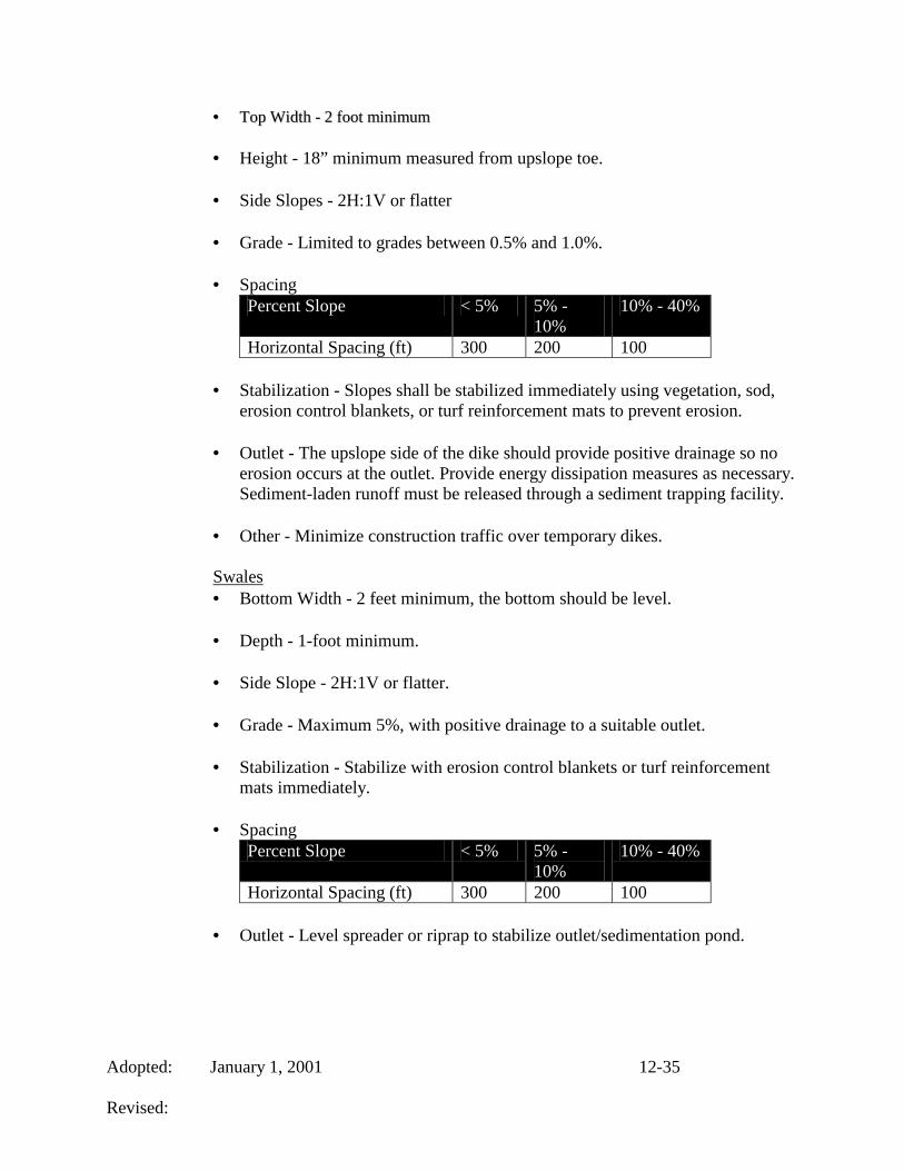
•• TToopp WWiiddtthh -- 22 ffoooott mmiinniimmuumm
• Height - 18” minimum measured from upslope toe.
• Side Slopes - 2H:1V or flatter
• Grade - Limited to grades between 0.5% and 1.0%.
• Spacing Percent Slope < 5% 5% -
10% 10% - 40%
Horizontal Spacing (ft) 300 200 100
• Stabilization - Slopes shall be stabilized immediately using vegetation, sod, erosion control blankets, or turf reinforcement mats to prevent erosion.
• Outlet - The upslope side of the dike should provide positive drainage so no
erosion occurs at the outlet. Provide energy dissipation measures as necessary. Sediment-laden runoff must be released through a sediment trapping facility.
• Other - Minimize construction traffic over temporary dikes.
Swales • Bottom Width - 2 feet minimum, the bottom should be level.
• Depth - 1-foot minimum.
• Side Slope - 2H:1V or flatter.
• Grade - Maximum 5%, with positive drainage to a suitable outlet.
• Stabilization - Stabilize with erosion control blankets or turf reinforcement
mats immediately.
• Spacing Percent Slope < 5% 5% -
10% 10% - 40%
Horizontal Spacing (ft) 300 200 100
• Outlet - Level spreader or riprap to stabilize outlet/sedimentation pond.

Adopted: January 1, 2001 12-36 Revised:
12.7.4 Construction Dewatering
Introduction
Construction dewatering involves removing stormwater or ground water from bore pits, trenches, and other excavations on the construction site. Usually this removal involves the pumping of this water to an appropriate receiving area. Direct pumping to lakes and streams is illegal and must be avoided.
Design Criteria
The pump utilized for dewatering purposes must be properly sized. Each pump has its own unique rating curve; therefore it is not feasible to list them in this chapter. The pump rating curve is used to calculate pump design flows based on head loss through the pump system.
The sediment-laden groundwater should be pumped directly to
• A sediment control structure (i.e.; sediment basin or sediment trap); • An infiltration trench; or • A vegetated buffer strip or zone.
Pumping to a Sediment Control Structure: • It is recommended that sediment basins or temporary sediment traps receive
sediment-laden water from bore pits and trenches. This will ensure that the 80% trapping efficiency goal will be upheld. Special care should be taken to ensure that the pumping of this water does not cause the sediment control structure to fail. Also, care should be taken at the outlet of the hose from the pump to ensure that erosion does not occur due to high concentrated flows.
Pumping to an Infiltration Trench: • An infiltration trench is a shallow, excavated trench back-filled with stone to
form a reservoir. This reservoir may contain subsurface drainage pipe or just stone. This trench allows water to filter through the stone and then be diverted to a suitable discharge point. The soils and the depth to the water table must be suitable for this sort of de-watering. Typical trench depths range from 2 to 8 feet. The stone fill material consists of washed aggregate 1.5 to 3 inches in diameter.
Pumping to a Vegetated Buffer Zone: • Buffer zones are capable of filtering sediment-laden water. One option is to
pump the water to a discharge device that will evenly spread the water over a wooded or vegetated buffer zone. An appropriate buffer zone can be determined from Section 12.6.9 of this chapter.

Adopted: January 1, 2001 12-37 Revised:
• A plan and profile for dewatering operations with pumping to a vegetated buffer zone is provided in Exhibit 12-13 in Supplemental Section D of this chapter.
• A detail for an outlet structure to the buffer zone is provided in Exhibit 12-14
in Supplemental Section D of this chapter. This discharge device uses Schedule 40 PVC pipes. The discharge hose from the pump is connected to a flow diffuser constructed using PVC pipe. The diffuser pipes are capped at the ends and the water is discharged through evenly spaced holes drilled into the diffuser. The size and length of the diffuser and the size and spacing of the holes are dependent upon the flow capacity of the pump being used for the de-watering process. The following recommended pipe sizes, pipe lengths, hole sizes, and hole spacing are based on pump discharge rates for pumps of 5 HP and less.
12.7.5 Level Spreader
Introduction
A level spreader is a permanent outlet for dikes and diversions consisting of an excavated channel constructed at zero grade across a slope that converts concentrated runoff to sheet flow and releases it onto areas stabilized by existing vegetation. Sediment-laden waters should not be directed towards level spreaders. A typical layout for a level spreader is shown in Exhibit 12-15 in Supplemental Section D of this chapter.
When and Where to Use It
Level spreaders should be constructed on undisturbed areas that are stabilized by existing vegetation and where concentrated flows are anticipated to occur.
Diversion channels call for a stable outlet for concentrated storm water flows. The level spreader can be used for this purpose provided the runoff is relatively free of sediment. If properly constructed, the level spreader will significantly reduce the velocity of concentrated storm water and spread it uniformly over a stable undisturbed area.
Particular care must be taken during construction to ensure that the lower lip of the structure is level. If there are any depressions in the lip, flow will tend to concentrate at these points and erosion will occur, resulting in failure of the outlet. This problem may be avoided by using a grade board, a gravel lip or geotextile fabric over which the runoff must flow when exiting the spreader. Regular maintenance is essential for this practice.

Adopted: January 1, 2001 12-38 Revised:
Design Criteria
• The grade of the channel transition for the last 20 feet before entering the level
spreader should be less than or equal to 1%. The crest of the overflow is level (0 % grade) to ensure uniform spreading of runoff.
• The lip of the level spreader shall consist of a permanent Turf Reinforcement
Mat (TRM) able withstand 5-lbs./ft shear stress. The TRM should extend 10 feet below the lip and be buried at least 6 inches within the spreader, and extend at least 12 inches beyond the lip on the outside of the spreader.
• The spreader dimensions will be determined by estimating the flow expected
from the 10-year, 24-hour design storm (Q10). The maximum flow into the spreader should not exceed 30 cfs. Acceptable level spreader design dimensions versus flow rates are shown in Table 12-6.
Table 12-6. Level Spreader Flow Relationships Q10 CFS
Minimum Entrance Width
Minimum Depth
Minimum End Width
Minimum Length
0-10 10 ft. 0.5 ft. 3 ft. 10 ft. 10-20 16 ft. 0.6 ft. 3 ft. 20 ft. 20-30 24 ft. 0.7 ft. 3 ft. 30 ft.
• The width of the spreader should be at least 6 feet.
• The depth of the spreader as measured from the lip should be at least 0.5 feet
and it should be uniform across the entire length.
• The slope of the undisturbed outlet should not exceed 10 %.
12.7.6 Stone Bag Check Dam in Small Ditch
Introduction
Stone bag checks can reduce flow velocities in small man-made swales and ditches, which reduces the erosive potential of the flow and also promotes sediment deposition. A typical layout for a stone bag check in a small ditch is shown in Standard Drawing EF-12-01.
When and Where to Use It

Adopted: January 1, 2001 12-39 Revised:
Stone bag checks are to be placed in front and rear yard swales only. Stone bag check dams should not be built in wetlands, any active or live streams, and in

Adopted: January 1, 2001 12-40 Revised:
Waters of Commonwealth. Waters of the Commonwealth are defined to be all annual or perennial water bodies designated by a solid or dashed blue-line on USGS 7.5-minute quadrangle maps.
Stone bag check dams are applicable in situations where flow velocities are too high causing channel scour. They should not be used as a primary sediment-trapping device. They should be used as velocity checks only as a short-term temporary solution.
Specific conditions for use include new diversion ditches that will not or cannot be stabilized for several days, and temporary diversion channels that are eroding due to high flow rates or steep slopes.
Design Criteria
The bags shall be filled with KTC No. 57 stone. The check shall span the banks of the ditch or swale. The height of the check on the stream centerline should equal the height of flow for the 2-year 24-hour storm event. Bags should be placed on the bank to a height at least 6 inches higher than the center of the check.
Space stone bag check dams such that the crest of the downstream check is at the same elevation of the toe of the check located immediately upstream. Show the designed spacing on the EPSC plans.
12.8 ENGINEERING AIDS AND DESIGN GUIDELINES FOR SEDIMENT CONTROLS
This section presents design aids that were developed for use in designing four types of sediment control structures; sediment basins (Section 12.6.2), sediment traps (Section 12.6.4), silt fences (Section 12.6.5), and rock ditch checks (Section 12.6.6) for Jefferson County Kentucky. The methodology used in developing these design aids is discussed in detail in Supplemental Section E of this chapter of the Design Manual. These design aids will each be briefly described and then examples will be used to demonstrate their use in realistic problems. First, however, a common feature of each design aid, settling velocity, will be discussed.
12.8.1 Characteristic Settling Velocity and Eroded Particle Size
A common feature of each of the design aids is that a characteristic settling velocity for the eroded soil must be obtained. For Jefferson County conditions, this velocity corresponds to an eroded size such that 15% of the sediment has particles smaller than the size specified. The procedure for empirically estimating eroded size distributions is best described by Hayes et. al (1996). The characteristic settling velocity corresponds to an eroded particle diameter that is referred to as D15. This diameter represents the point on the eroded particle size distribution curve where 15% of the particles (by weight) are equal to or smaller

Adopted: January 1, 2001 12-41 Revised:
than this size. Estimated eroded size distributions for Jefferson County soils using an adaptation of the method described by Foster et al. (1985) were developed. The procedure uses the primary particle size information reported by the USDA Soil Conservation Service (SCS) as part of county soil surveys. This procedure may be used with USDA Soil Survey Data or site specific soil boring data. Other procedures are given by Haan et.al. (1994) for physically based estimating procedures. If D15 is less than 0.01 mm, then settling velocity based upon a simplified form of Stokes Law is:
Vs = 2.81d2 (1)
Where Vs is settling velocity in ft/sec and d is diameter in mm. If D15 is greater than or equal to 0.01 mm, then settling velocity should be found using
log10Vs = -0.34246 (log10d)2 + 0.98912 (log10d) - 0.33801 (2)
Where Vs, is settling velocity in ft/sec and d is particle diameter in mm (Wilson et al., 1982). The characteristic settling velocity can be obtained using Figure 12.1 and the eroded particle size (D15) for soils found in Jefferson County, which is provided in Supplemental Section D.
It is important to remember that the eroded size distribution is the most critical parameter in sizing sediment controls. The eroded size distributions vary greatly from primary particle size distributions that are often determined as a result of soil strength investigations for construction purposes. Primary particle sizes will yield erroneous results and should not be used. The user should note that D15 is often smaller for coarse textured (more sandy soils) because of the reduced clay content and the lack of aggregation.
Table 12-7. Soil Classification by Texture Jefferson County Soil
Classification by General Texture
Texture Coarse Medium Fine
Soil Type Sandy Loam Silt Loam Clay Loam

Adopted: January 1, 2001 12-42 Revised:
Figure 12.1. Characteristic Settling Velocity as a Function of Eroded Particle Diameter
12.8.2 Sediment Basin Design Aids
Figure 12.2 plots the basin ratio (qpo/AV15) versus percentage of trapping efficiency. For basins, the ratio is defined by:
Basin Ratio = qpo/AV15 (3)
Where: qpo = peak outflow rate from the basin (cfs), A =surface area of the
pond at riser crest (acres), V15 = (from Figure 12.1) characteristic settling velocity (fps), of the characteristic D15 eroded particle (mm).
Figure 12.2 is for soils classed as either coarse (sandy loam), medium (silt loam), or fine (clay loam) as shown in Table 12-8. The ratio should be less than or equal to the curve value at any given trapping efficiency. For example, at 80% trapping efficiency, the basin ratio equals 2.0E5 as shown in Figure 12.2. If the basin ratio qpo/AV15 intersects the curve at a point having a trapping efficiency less than the desired value, the design is inadequate and must be revised. Basin Ratios above the design curves are not recommended for any application of the design aids. Constraints for use of Figure 12.2 are:
1.00E-07
1.00E-06
1.00E-05
1.00E-04
1.00E-03
1.00E-02
1.00E-01
1.00E+00
0.001 0.01 0.1 1
Eroded Particle Diameter D15 (mm)
Settl
ing
Velo
city
V15
(ft/s
ec)

Adopted: January 1, 2001 12-43 Revised:
• Watershed area less than or equal to 30 acres • Overland slope less than or equal to 20 % • Outlet diameter less than or equal to 6 feet
1.00E+03
1.00E+04
1.00E+05
1.00E+06
1.00E+07
55 60 65 70 75 80 85 90 95 100
Trapping Efficiency (%)
Bas
in R
atio
Figure 12.2. Design Aid for Estimating Trapping Efficiency of Sediment Basins.
12.8.3 Rock Ditch Check Design Aids
Design aids for rock ditch checks were developed similarly to those for ponds. Again, the D15 eroded particle size is used for the calculation of the characteristic settling velocity. The ratio for ditch checks is defined by:
Ditch Check Ratio=Sq(1-b) /aV15 (4)
Where: S = channel slope (%),
q = flow through the check (cfs/ft), V15 = (from Figure 12.1) characteristic settling velocity (fps),
of the characteristic D15 eroded particle (mm).
Coefficients a and Exponent b can be interpolated from Table 12-8 (Haan et.al. (1994) pg. 151).
Table 12-8. Stone Flow Coefficient a and Exponent b

Adopted: January 1, 2001 12-44 Revised:
D50 = rock ditch check average stone diameter in meters.
dl = average flow length through the rock ditch check in meters.
If the check overtops, the trapping efficiency is assumed to be zero. Figures 12.3a, 12.3b, and 12.3c can be used for estimating trapping efficiency of rock ditch checks. Table 12-8 provides guidance to determine which plot is appropriate.
Ditch Check Ratios above the design curves are not recommended for any application of the design aids. Constraints for the use of Figures 12.3a, 12.3b, and 12.3c are:
• Watershed area is less than or equal to 5 acres • Overland flow length is less than or equal to 500 feet • Overland slope is less than or equal to 15 % • Maximum depth of the ditch is less than or equal to 6 feet
Stone D50 Exponent dl= 1m dl = 2m dl = 3m(m) b Coefficient a Coefficient aCoefficient a0.01 0.6371 9.40 6.05 4.600.02 0.6540 7.40 4.65 3.550.03 0.6589 6.40 4.08 3.080.04 0.6609 5.85 3.65 2.800.05 0.6624 5.40 3.35 2.600.06 0.6635 5.05 3.15 2.400.08 0.6644 4.50 2.85 2.200.09 0.6648 4.28 2.70 2.100.10 0.6651 4.13 2.60 2.050.20 0.6662 3.20 2.05 1.570.30 0.6664 2.80 1.75 1.300.40 0.6665 2.50 1.55 1.160.50 0.6666 2.30 1.40 1.08
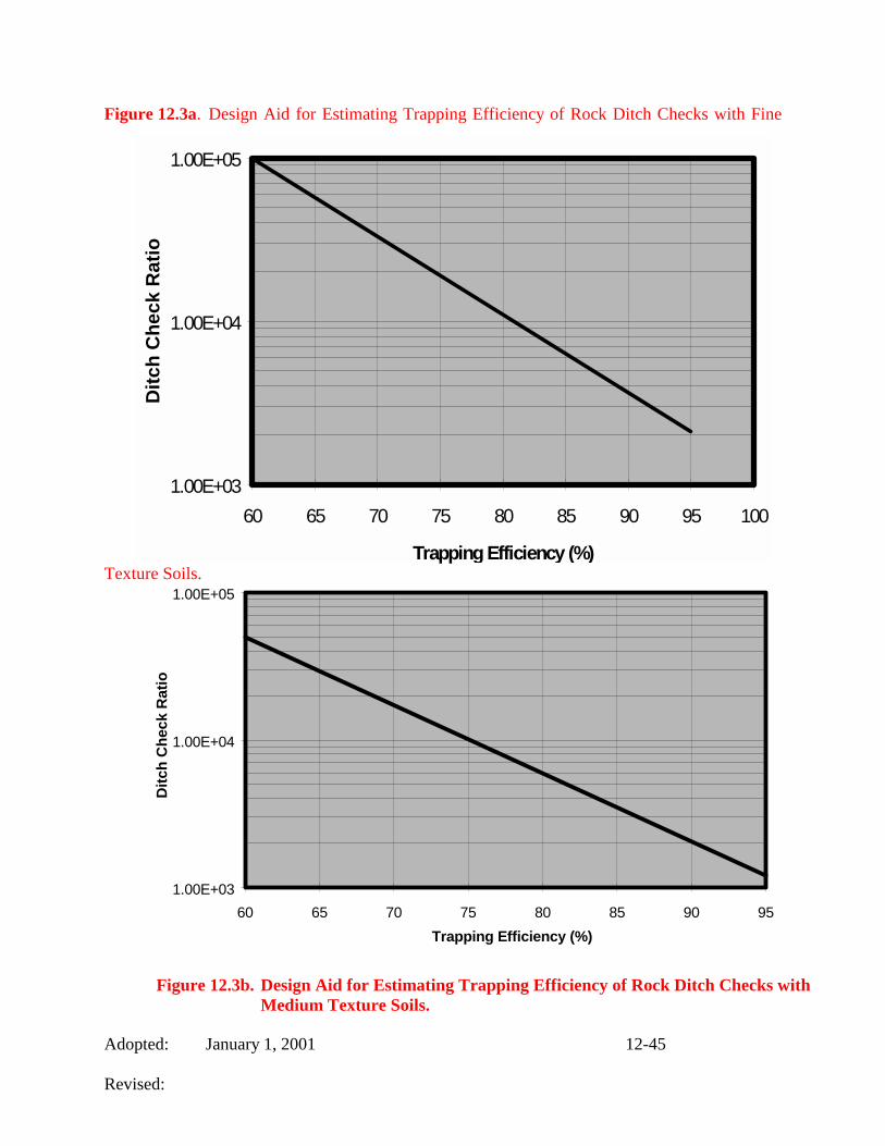
Adopted: January 1, 2001 12-45 Revised:
Figure 12.3a. Design Aid for Estimating Trapping Efficiency of Rock Ditch Checks with Fine
Texture Soils.
1.00E+03
1.00E+04
1.00E+05
60 65 70 75 80 85 90 95Trapping Efficiency (%)
Ditc
h C
heck
Rat
io
Figure 12.3b. Design Aid for Estimating Trapping Efficiency of Rock Ditch Checks with Medium Texture Soils.
1.00E+03
1.00E+04
1.00E+05
60 65 70 75 80 85 90 95 100
Trapping Efficiency (%)
Ditc
h C
heck
Rat
io
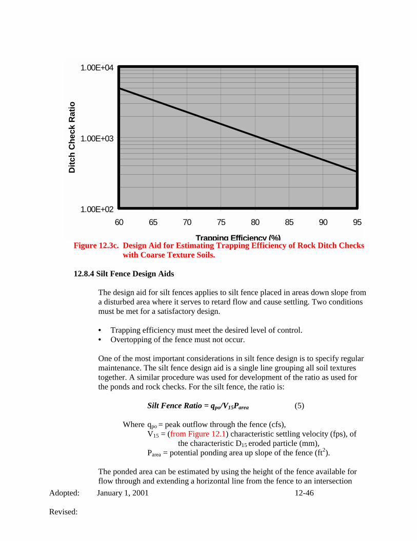
Adopted: January 1, 2001 12-46 Revised:
Figure 12.3c. Design Aid for Estimating Trapping Efficiency of Rock Ditch Checks with Coarse Texture Soils.
12.8.4 Silt Fence Design Aids
The design aid for silt fences applies to silt fence placed in areas down slope from a disturbed area where it serves to retard flow and cause settling. Two conditions must be met for a satisfactory design.
• Trapping efficiency must meet the desired level of control. • Overtopping of the fence must not occur.
One of the most important considerations in silt fence design is to specify regular maintenance. The silt fence design aid is a single line grouping all soil textures together. A similar procedure was used for development of the ratio as used for the ponds and rock checks. For the silt fence, the ratio is:
Silt Fence Ratio = qpo/V15Parea (5)
Where qpo = peak outflow through the fence (cfs),
V15 = (from Figure 12.1) characteristic settling velocity (fps), of the characteristic D15 eroded particle (mm),
Parea = potential ponding area up slope of the fence (ft2).
The ponded area can be estimated by using the height of the fence available for flow through and extending a horizontal line from the fence to an intersection
1.00E+02
1.00E+03
1.00E+04
60 65 70 75 80 85 90 95
Trapping Efficiency (%)
Ditc
h C
heck
Rat
io
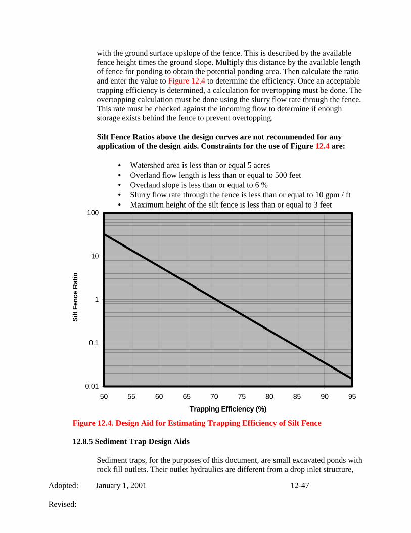
Adopted: January 1, 2001 12-47 Revised:
with the ground surface upslope of the fence. This is described by the available fence height times the ground slope. Multiply this distance by the available length of fence for ponding to obtain the potential ponding area. Then calculate the ratio and enter the value to Figure 12.4 to determine the efficiency. Once an acceptable trapping efficiency is determined, a calculation for overtopping must be done. The overtopping calculation must be done using the slurry flow rate through the fence. This rate must be checked against the incoming flow to determine if enough storage exists behind the fence to prevent overtopping.
Silt Fence Ratios above the design curves are not recommended for any application of the design aids. Constraints for the use of Figure 12.4 are:
• Watershed area is less than or equal 5 acres • Overland flow length is less than or equal to 500 feet • Overland slope is less than or equal to 6 % • Slurry flow rate through the fence is less than or equal to 10 gpm / ft • Maximum height of the silt fence is less than or equal to 3 feet
0.01
0.1
1
10
100
50 55 60 65 70 75 80 85 90 95
Trapping Efficiency (%)
Silt
Fenc
e R
atio
Figure 12.4. Design Aid for Estimating Trapping Efficiency of Silt Fence
12.8.5 Sediment Trap Design Aids
Sediment traps, for the purposes of this document, are small excavated ponds with rock fill outlets. Their outlet hydraulics are different from a drop inlet structure,

Adopted: January 1, 2001 12-48 Revised:
thus the design aid is slightly different. Trapping efficiencies for sediment traps are plotted in Figure 12.5 as a function of the sediment trap ratio:
Sediment Trap Ratio = qpo/A/V15 (6)
Where qpo = peak outflow (cfs),
A = surface area at the elevation equal to the bottom of the rock fill outlet (acres),
V15 = (from Figure 12.1) characteristic settling velocity (fps), of the characteristic D15 eroded particle (mm).
Figure 12.5 is for soils classed as either coarse (sandy loam), medium (silt loam), or fine (clay loam) as shown in Table 12-8. The ratio should be less than or equal to the curve value at any desired trapping efficiency.
Sediment Trap Ratios above the design curves are not recommended for any application of the design aids. Constraints for the use of Figure 12.5 are:
• Watershed area less than or equal to 5 acres • Overland slope less than or equal to 20% • Rock fill diameter greater than 0.2 ft and less than 0.6 ft. • Rock fill height less than 5 ft. • Top width of rock fill between 2 and 4 ft. • Maximum Side slopes 1:1 to 1.5:1.
Figure 12.5. Design Aid for Estimating Trapping Efficiency of Sediment Traps.
1.00E+03
1.00E+04
1.00E+05
1.00E+06
1.00E+07
50 55 60 65 70 75 80 85 90 95
Trapping Efficiency (%)
Sedi
men
t Tra
p R
atio

Adopted: January 1, 2001 12-49 Revised:
SUPPLEMENTAL SECTIONS CHAPTER 12

Adopted: January 1, 2001 12-50 Revised:
DDEESSIIGGNN MMAANNUUAALL CCHHAAPPTTEERR 1122
SSUUPPPPLLEEMMEENNTTAALL SSEECCTTIIOONN AA
EERROOSSIIOONN PPRREEVVEENNTTIIOONN && SSEEDDIIMMEENNTT CCOONNTTRROOLL BBMMPP SSEELLEECCTTIIOONN
PPRROOCCEESSSSEESS,, SSUUGGGGEESSTTEEDD UUSSEESS,, && GGUUIIDDEELLIINNEESS

::
BMP Suggested Uses
EErroossiioonn PPrreevveennttiioonn MMeeaassuurreess
BMP DDeessiiggnn MMaannuuaall
SSeeccttiioonn SSllooppee
PPrrootteeccttiioonn WWaatteerrwwaayy PPrrootteeccttiioonn
SSuurrffaaccee PPrrootteeccttiioonn
EEnncclloosseedd DDrraaiinnaaggee
LLaarrggee FFllaatt AArreeaass
BBoorrrrooww AArreeaass
AAddjjaacceenntt PPrrooppeerrttiieess
EErroossiioonn PPrreevveennttiioonn MMeeaassuurreess
1122..55
X
X
X
X
X
X
X
SSuurrffaaccee RRoouugghheenniinngg
1122..55..11
X
X
BBeenncchh TTeerrrraacciinngg
1122..55..22
X
X
TTeemmppoorraarryy SSeeeeddiinngg
1122..55..33
X
X
X
X
X
MMuullcchhiinngg
1122..55..44
X
X
X
EErroossiioonn CCoonnttrrooll BBllaannkkeettss aanndd TTuurrff RReeiinnffoorrcceemmeenntt MMaattss
1122..55..55
X
X
X
X
SSeeeeddiinngg// FFiinnaall VVeeggeettaatteedd SSttaabbiilliizzaattiioonn
1122..55..66
X
X
X
X
TTooppssooiilliinngg
1122..55..66..11
X
X
PPeerrmmaanneenntt SSeeeeddiinngg aanndd PPllaannttiinngg ooff GGrraasssseess
1122..55..66..22
X
X
X
X
PPeerrmmaanneenntt GGrroouunndd CCoovveerr PPllaannttss
1122..55..66..33
X
X
X
SSooddddiinngg
1122..55..66..44
X
X
X
X
RRiipprraapp oorr AAggggrreeggaattee
1122..55..77
X
X
X
OOuuttlleett PPrrootteeccttiioonn
1122..55..88
X
X
X
DDuusstt CCoonnttrrooll
1122..55..99
X
X
X
12-50

::
BMP SUGGESTED USES
TTeemmppoorraarryy SSeeddiimmeenntt CCoonnttrrooll MMeeaassuurreess
BBMMPP DDeessiiggnn MMaannuuaall
SSeeccttiioonn SSllooppee
PPrrootteeccttiioonn WWaatteerrwwaayy PPrrootteeccttiioonn
SSuurrffaaccee PPrrootteeccttiioonn
EEnncclloosseedd DDrraaiinnaaggee
LLaarrggee FFllaatt AArreeaass
BBoorrrrooww AArreeaass
AAddjjaacceenntt PPrrooppeerrttiieess
TTeemmppoorraarryy SSeeddiimmeenntt CCoonnttrrooll SSttrruuccttuurreess
1122..66
X
X
X
X
X
X
X
SSttoorraaggee VVoolluummeess aanndd MMaaiinntteennaannccee SScchheedduulleess
1122..66..11
X
X
X
SSeeddiimmeenntt BBaassiinn
1122..66..22
X
X
X
X
MMuullttiippuurrppoossee BBaassiinn
1122..66..33
X
X
.X
X
TTeemmppoorraarryy SSeeddiimmeenntt TTrraapp
1122..66..44
X
X
X
SSiilltt FFeennccee
1122..66..55
X
X
X
RRoocckk DDiittcchh CChheecckk
1122..66..66
X
X
SSttaabbiilliizzeedd CCoonnssttrruuccttiioonn EEnnttrraannccee
1122..66..77
X
X
SSttoorrmm DDrraaiinn IInnlleett PPrrootteeccttiioonn
1122..66..88
X
X
X
VVeeggeettaatteedd FFiilltteerr SSttrriippss
1122..66..99
X
X
12-51

::
BMP SUGGESTED USES
RRuunnooffff CCoonnttrrooll aanndd CCoonnvveeyyaannccee MMeeaassuurreess
BMP DDeessiiggnn MMaannuuaall
SSeeccttiioonn SSllooppee
PPrrootteeccttiioonn WWaatteerrwwaayy PPrrootteeccttiioonn
SSuurrffaaccee PPrrootteeccttiioonn
EEnncclloosseedd DDrraaiinnaaggee
LLaarrggee FFllaatt AArreeaass
BBoorrrrooww AArreeaass
AAddjjaacceenntt PPrrooppeerrttiieess
PPiippee SSllooppee DDrraaiinnss
1122..77..11
X
X
TTeemmppoorraarryy SSttrreeaamm CCrroossssiinngg
1122..77..22
X
X
X
RRuunnooffff CCoonnttrrooll MMeeaassuurreess
1122..77..33
X
X
X
CCoonnssttrruuccttiioonn DDee--wwaatteerriinngg
1122..77..44
X
X
X
X
LLeevveell SSpprreeaaddeerr
1122..77..55
X
X
X
SSttoonnee BBaagg CChheecckk DDaamm iinn SSmmaallll DDiittcchh
1122..77..66
X
X
X
12-52

::
DESIGN MANUAL CHAPTER 12
SSUUPPPPLLEEMMEENNTTAALL SSEECCTTIIOONN BB
JJEEFFFFEERRSSOONN CCOOUUNNTTYY RRAAIINNFFAALLLL &&
UUNNIIVVEERRSSAALL SSOOIILL LLOOSSSS EEQQUUAATTIIOONN IINNFFOORRMMAATTIIOONN
Adopted: January 1, 2001 12-53 Revised:

::
Rainfall Data
TTaabbllee 11.. DDiissttrriibbuuttiioonn ooff RRaaiinnffaallll EErroossiioonn IInnddeexx ((EEII CCuurrvveess)) ffoorr JJeeffffeerrssoonn CCoouunnttyy
DDaattee EEII CCuurrvvee NNuummbbeerr
JJaannuuaarryy 11 00..00 JJaannuuaarryy 1155 11..00 FFeebbrruuaarryy 11 33..00 FFeebbrruuaarryy 1155 66..00 MMaarrcchh 11 99..00 MMaarrcchh 1155 1122..00 AApprriill 11 1166..00 AApprriill 1155 2211..00 MMaayy 11 2266..00 MMaayy 1155 3311..00 JJuunnee 11 3377..00 JJuunnee 1155 4433..00 JJuullyy 11 5500..00 JJuullyy 1155 5577..00 AAuugguusstt 11 6644..00 AAuugguusstt 1155 7711..00 SSeepptteemmbbeerr 11 7777..00 SSeepptteemmbbeerr 1155 8811..00 OOccttoobbeerr 11 8855..00 OOccttoobbeerr 1155 8888..00 NNoovveemmbbeerr 11 9911..00 NNoovveemmbbeerr 1155 9933..00 DDeecceemmbbeerr 11 9955..00 DDeecceemmbbeerr 1155 9977..00 JJaannuuaarryy 11 110000..00
MMiinniimmuumm VVaalluuee ttoo bbee uusseedd iiss 5500 AAvveerraaggee AAnnnnuuaall RR FFaaccttoorr == 117755
12-54

::
TTaabbllee 22.. UUnniivveerrssaall SSooiill LLoossss EEqquuaattiioonn CCPP FFaaccttoorrss
CCoonnddiittiioonn CCPP FFaaccttoorr
BBaarree SSooiill 11..00 CCoommppaacctteedd RRoooott RRaakkeedd SSooiill 11..22 CCoommppaacctteedd BBuullllddoozzeerr SSccrraappeedd SSooiill 11..22 FFrreesshh UUnnpprreeppaarreedd SSeeeeddbbeedd 00..6644 TTeemmppoorraarryy SSeeeeddiinngg 00--6600 DDaayyss 00..4400 TTeemmppoorraarryy SSeeeeddiinngg AAfftteerr 6600 DDaayyss 00..0055 PPeerrmmaanneenntt SSeeeeddiinngg 22--1122 MMoonntthhss 00..0055 BBrruusshh 00..3355 EErroossiioonn CCoonnttrrooll BBllaannkkeettss 00..0011--00..1100
12-55

::
TTaabbllee 33.. UUnniivveerrssaall SSooiill LLoossss EEqquuaattiioonn LLSS FFaaccttoorrss %% SSllooppee LLeennggtthh iinn FFeeeett
SSllooppee 2200 5500 7755 110000 112200 115500 220000 225500 330000 335500 440000 445500 550000 660000 770000 880000 990000 11000000 00..55 00..11 00..11 00..11 00..11 00..11 00..11 00..1111 00..111144 00..1122 00..1122 00..1133 00..1133 00..1133 00..113377 00..114411 00..114455 00..114488 00..115522
11..00 00..11 00..1111 00..1122 00..1133 00..1144 00..1144 00..1155 00..1155 00..1177 00..1188 00..1199 00..2200 00..2200 00..2222 00..2233 00..2244 00..2255 00..2255
22..00 00..1122 00..1166 00..1188 00..2200 00..2211 00..2222 00..2244 00..2266 00..2277 00..2299 00..00 00..3311 00..3322 00..3344 00..3366 00..3377 00..3388 00..4400
33..00 00..1177 00..2233 00..2266 00..2288 00..3300 00..3322 00..3355 00..3377 00..3388 00..4411 00..4433 00..4455 00..4466 00..4499 00..5511 00..5533 00..5555 00..5577
44..00 00..2211 00..3300 00..3355 00..4400 00..4433 00..4477 00..5522 00..5577 00..6622 00..6666 00..6699 00..7733 00..7766 00..8811 00..8877 00..9911 00..9966 11..0000
55..00 00..2233 00..3377 00..4466 00..5533 00..5588 00..6655 00..7755 00..8844 00..9922 11..0000 11..0077 11..1133 11..1199 11..3311 11..4411 11..5511 11..6600 11..6699
66..00 00..3300 00..4477 00..5588 00..6677 00..7733 00..8822 00..9955 11..0066 11..1166 11..2255 11..3344 11..4422 11..5500 11..6644 11..7788 11..9900 22..0011 22..1122
77..00 00..3366 00..5588 00..7711 00..8822 00..9900 11..0011 11..1166 11..3300 11..4422 11..5544 11..6655 11..7755 11..8844 22..0022 22..1188 22..3333 22..4477 22..6600
88..00 00..4444 00..7700 00..8855 00..9999 11..0088 11..2211 11..4400 11..5566 11..7711 11..8855 11..9988 22..1100 22..2211 22..4422 22..6622 22..8800 22..9977 33..1133
99..00 00..5522 00..8822 11..0011 11..1177 11..2288 11..4433 11..6655 11..8855 22..0033 22..1199 22..3344 22..4488 22..6622 22..8877 33..1100 33..3311 33..5522 33..7711
1100..00 00..6611 00..9966 11..1188 11..3366 11..5500 11..6677 11..9933 22..1166 22..3377 22..5566 22..7744 22..9900 33..0066 33..3355 33..6622 33..8877 44..1100 44..3333
1111..00 00..7700 11..1111 11..3366 11..5588 11..7733 11..9933 22..2233 22..4499 22..7733 22..9955 33..1166 33..3355 33..5533 33..8877 44..1188 44..4466 44..7744 44..9999
1122..00 00..8800 11..2277 11..5566 11..8800 11..9977 22..2211 22..5555 22..6655 33..1122 33..3377 33..6600 33..8822 44..0033 44..4422 44..7777 55..1100 55..4411 55..7700
1133..00 00..9911 11..4444 11..7766 22..0044 22..2233 22..5500 22..8888 33..2233 33..5533 33..8822 44..0088 44..3333 44..5566 55..0000 55..4400 55..7777 66..1122 66..4466
1144..00 11..0022 11..6622 11..9988 22..2299 22..5511 22..8811 33..2244 33..6622 33..9977 44..2299 44..5588 44..8866 55..1133 55..6622 66..0077 66..4499 66..8888 77..2255
1155..00 11..1144 11..8811 22..2211 22..5566 22..8800 33..1133 33..6622 44..0044 44..4433 44..7799 55..1122 55..4433 55..7722 66..2277 66..7777 77..2244 77..6688 88..0099
1166..00 11..2266 22..0000 22..4455 22..8833 33..1111 33..4477 44..0011 44..4488 44..9911 55..3311 55..6677 66..0022 66..3344 66..9955 77..5511 88..0022 88..5511 88..9977
1177..00 11..4400 22..2211 22..7711 33..1133 33..4422 33..8833 44..4422 44..9944 55..4422 55..8855 66..2266 66..6644 77..0000 77..6666 88..2288 88..8855 99..3399 99..8899
1188..00 11..5533 22..4422 22..9977 33..4433 33..7766 44..2200 44..8855 55..4433 55..9944 66..4422 66..8866 77..2288 77..6688 88..4411 99..0088 99..7711 1100..33 1100..99
1199..00 11..6677 22..6655 33..2244 33..7755 44..1100 44..5599 55..3300 55..9933 66..4499 77..0011 77..5500 77..9955 88..3388 99..1188 99..9922 1100..66 1111..33 1111..99
2200..00 11..8822 22..8888 33..5533 44..0077 44..4466 44..9999 55..7766 66..4455 77..0066 77..6633 88..1155 88..6655 99..1122 1100..00 1100..77 1111..55 1122..22 1122..99
2255..00 22..6633 44..1166 55..11 55..8899 66..4455 77..2211 88..3333 99..3311 1100..22 1111..00 1111..88 1122..55 1133..22 1144..44 1155..66 1166..77 1177..77 1188..66
3333..33 44..2222 66..6677 88..1177 99..4444 1100..33 1111..66 1133..44 1144..99 1166..44 1177..77 1188..99 2200..00 2211..11 2233..11 2255..00 2266..77 2288..33 2299..99
4400..00 55..6655 88..9944 88..9944 1122..77 1133..99 1155..55 1177..99 2200 2211..99 2233..77 2255..33 2266..88 2288..33 3311..00 3333..55 3355..88 3388..00 4400..00
5500..00 77..9977 1122..66 1122..66 1177..88 1199..55 2211..88 2255..22 2288..22 3300..99 3333..33 3355..66 3377..88 3399..99 4433..77 4477..22 5500..44 5533..55 5566..44
6666..66 1111..99 1188..99 1188..99 2266..77 2299..22 3322..77 3377..77 4422..22 4466..22 4499..99 5533..33 5566..66 5599..66 6655..33 7700..55 7755..44 8800..00 8844..33
110000..00 1188..99 2299..99 2299..99 4422..22 4466..33 5511..77 5599..77 6666..88 7733..22 7799..00 8844..55 8899..66 9944..55 110033.. 111122 112200 112266 113344
12-56

::
DDEESSIIGGNN MMAANNUUAALL CCHHAAPPTTEERR 1122
SSUUPPPPLLEEMMEENNTTAALL SSEECCTTIIOONN CC
JJEEFFFFEERRSSOONN CCOOUUNNTTYY SSOOIILL IINNFFOORRMMAATTIIOONN

::
Adopted: January 1, 2001 12-57 Revised:

::
SSooiillss IInnffoorrmmaattiioonn aanndd EErrooddeedd SSiizzee DDiissttrriibbuuttiioonnss ffoorr
JJeeffffeerrssoonn CCoouunnttyy,, KKeennttuucckkyy..
PERCENT FINER FOR SPECIFIED PARTICLE DIAMETERS ____________________________________________________________________ SOIL SERIES -HYDROLOGIC SOIL GROUP ____________________________________________________________________ Percent Finer Than DEPTH K D15 1.4 1.0 0.063 0.044 0.038 0.004 0.003 0.001 (in) (mm) (mm) ____________________________________________________________________ASHTON –HSG B 0-9 0.32 0.0063 100.0 91.9 73.5 56.0 53.1 5.5 3.4 0.0 9-44 0.0053 100.0 91.9 73.4 64.9 62.9 8.0 5.1 0.0 44-80 0.0065 100.0 85.2 51.5 42.5 42.5 7.5 4.9 0.0 BEASLEY –HSG C 0-7 0.43 0.0048 100.0 87.4 58.6 53.8 52.7 11.7 8.0 0.0 7-29 0.0043 100.0 85.3 51.6 48.2 47.5 13.9 9.8 0.0 29-50 0.0046 100.0 80.9 37.3 35.5 35.5 13.7 9.8 0.0 CAPTINA –HSG C 0-9 0.43 0.0066 100.0 93.3 78.0 55.6 51.8 4.4 2.7 0.0 9-25 0.0055 100.0 89.1 64.2 57.0 56.1 8.4 5.4 0.0 25-39 0.0063 100.0 83.9 47.2 39.7 39.7 8.7 5.8 0.0 39-58 0.0079 100.0 81.5 39.1 30.3 30.3 8.5 5.8 0.0 58-80 0.0754 100.0 72.9 11.0 8.0 8.0 12.9 9.8 0.0 CORYDON –HSG D 0-9 0.43 0.0052 100.0 87.3 58.4 53.2 52.6 9.9 6.5 0.0 9-15 0.0048 100.0 84.9 50.5 47.6 47.4 12.1 8.3 0.0 CRIDER –HSG B 0-12 0.32 0.0054 100.0 93.1 77.4 67.1 64.4 7.3 4.6 0.0 12-38 0.0052 100.0 91.5 72.0 64.2 62.1 9.0 5.8 0.0 38-50 0.0239 100.0 75.1 18.1 15.5 15.5 13.1 9.8 0.0 50-96 0.0037 100.0 80.7 36.7 35.6 35.6 16.2 11.7 0.0 DICKSON -HSG C 0- 7 0.43 0.0058 100.0 92.4 74.9 61.5 58.8 6.4 4.0 0.0 7-25 0.0054 100.0 92.4 75.1 65.4 63.1 7.5 4.7 0.0 25-45 0.0054 100.0 91.3 71.4 63.1 61.4 8.0 5.1 0.0 45-65 0.0052 100.0 82.1 41.3 38.6 38.6 11.8 8.3 0.0 DUNNING -HSG D 0-15 0.37 0.0050 100.0 89.3 64.9 58.7 57.1 10.5 7.0 0.0 15-72 0.0045 100.0 83.7 46.4 44.5 44.5 13.3 9.3 0.0 ELK -HSG B 0-9 0.37 0.0053 100.0 88.8 63.3 56.8 55.8 9.1 5.9 0.0 9-42 0.0054 100.0 91.3 71.4 63.1 61.4 8.0 5.1 0.0 42-69 0.0061 100.0 85.4 51.9 44.7 44.7 8.2 5.4 0.0
12-58

::
____________________________________________________________________ SOIL SERIES -HYDROLOGIC SOIL GROUP ____________________________________________________________________ Percent Finer Than DEPTH K D15 1.4 1.0 0.063 0.044 0.038 0.004 0.003 0.001 (in) (mm) (mm) ____________________________________________________________________ ENNIS -HSG B 0-10 0.24 0.0083 100.0 85.6 52.7 34.7 34.6 5.7 3.6 0.0 10-60 0.0080 100.0 83.3 45.3 32.6 32.6 7.3 4.9 0.0 FAIRMOUNT -HSG D 0-11 0.24 0.0044 100.0 83.1 44.4 43.0 43.0 13.9 9.8 0.0 11-17 0.0045 100.0 83.7 46.4 44.5 44.5 13.3 9.3 0.0 GINAT -HSG D 0-9 0.43 0.0058 100.0 89.4 65.2 54.8 53.7 7.2 4.5 0.0 9-23 0.0054 100.0 88.3 61.7 55.4 54.6 9.0 5.8 0.0 23-48 0.0052 100.0 90.0 67.0 60.0 58.5 9.3 6.0 0.0 48-74 0.0052 100.0 90.0 67.0 60.0 58.5 9.3 6.0 0.0 74-80 0.0056 100.0 90.9 70.1 60.1 58.4 7.3 4.6 0.0 GUTHRIE -HSG D 0-8 0.43 0.0059 100.0 94.3 81.1 64.8 60.6 5.5 3.4 0.0 8-32 0.0054 100.0 92.4 75.1 65.4 63.1 7.5 4.7 0.0 32-53 0.0055 100.0 90.4 68.6 60.2 59.0 7.8 4.9 0.0 53-68 0.0055 100.0 89.5 65.6 57.9 56.9 8.2 5.2 0.0 HOLSTON -HSG B 0-8 0.28 0.0079 100.0 87.1 57.5 37.7 37.3 5.4 3.4 0.0 8-44 0.0071 100.0 83.7 46.3 35.9 35.9 7.7 5.2 0.0 44-75 0.0073 100.0 81.2 38.1 31.0 31.0 9.1 6.3 0.0 HUNTINGTON -HSG B 0-11 0.32 0.0057 100.0 89.6 65.9 56.6 55.6 7.5 4.7 0.0 11-64 0.0057 100.0 89.6 65.9 56.6 55.6 7.5 4.7 0.0 64-74 0.0079 100.0 84.2 48.0 34.0 34.0 6.7 4.4 0.0 LAKIN -HSG A 0-11 0.17 0.0379 100.0 94.8 83.0 16.1 15.0 1.2 0.8 0.0 11-60 0.0441 100.0 92.9 76.6 14.5 14.1 1.7 1.1 0.0 60-80 0.0449 100.0 97.1 90.5 10.7 9.8 0.6 0.4 0.0 LAWRENCE -HSG C 0-10 0.43 0.0057 100.0 93.7 79.2 65.0 61.4 6.1 3.8 0.0 10-25 0.0053 100.0 91.8 72.9 64.6 62.6 8.2 5.2 0.0 25-50 0.0053 100.0 91.8 72.9 64.6 62.6 8.2 5.2 0.0 50-75 0.0049 100.0 87.9 60.3 55.1 53.9 11.2 7.6 0.0 LINDSIDE -HSG C 0-8 0.32 0.0052 100.0 90.0 67.0 60.0 58.5 9.3 6.0 0.0 8-44 0.0054 100.0 90.0 67.1 59.3 58.1 8.2 5.2 0.0 44-60 0.0065 100.0 84.7 49.7 41.0 41.0 7.9 5.2 0.0
12-59
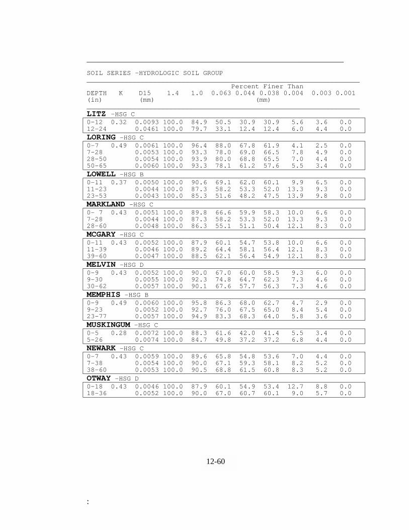
::
________________________________________________________________ SOIL SERIES -HYDROLOGIC SOIL GROUP ____________________________________________________________________ Percent Finer Than DEPTH K D15 1.4 1.0 0.063 0.044 0.038 0.004 0.003 0.001 (in) (mm) (mm) ____________________________________________________________________ LITZ -HSG C 0-12 0.32 0.0093 100.0 84.9 50.5 30.9 30.9 5.6 3.6 0.0 12-24 0.0461 100.0 79.7 33.1 12.4 12.4 6.0 4.4 0.0 LORING -HSG C 0-7 0.49 0.0061 100.0 96.4 88.0 67.8 61.9 4.1 2.5 0.0 7-28 0.0053 100.0 93.3 78.0 69.0 66.5 7.8 4.9 0.0 28-50 0.0054 100.0 93.9 80.0 68.8 65.5 7.0 4.4 0.0 50-65 0.0060 100.0 93.3 78.1 61.2 57.6 5.5 3.4 0.0 LOWELL -HSG B 0-11 0.37 0.0050 100.0 90.6 69.1 62.0 60.1 9.9 6.5 0.0 11-23 0.0044 100.0 87.3 58.2 53.3 52.0 13.3 9.3 0.0 23-53 0.0043 100.0 85.3 51.6 48.2 47.5 13.9 9.8 0.0 MARKLAND -HSG C 0- 7 0.43 0.0051 100.0 89.8 66.6 59.9 58.3 10.0 6.6 0.0 7-28 0.0044 100.0 87.3 58.2 53.3 52.0 13.3 9.3 0.0 28-60 0.0048 100.0 86.3 55.1 51.1 50.4 12.1 8.3 0.0 MCGARY -HSG C 0-11 0.43 0.0052 100.0 87.9 60.1 54.7 53.8 10.0 6.6 0.0 11-39 0.0046 100.0 89.2 64.4 58.1 56.4 12.1 8.3 0.0 39-60 0.0047 100.0 88.5 62.1 56.4 54.9 12.1 8.3 0.0 MELVIN -HSG D 0-9 0.43 0.0052 100.0 90.0 67.0 60.0 58.5 9.3 6.0 0.0 9-30 0.0055 100.0 92.3 74.8 64.7 62.3 7.3 4.6 0.0 30-62 0.0057 100.0 90.1 67.6 57.7 56.3 7.3 4.6 0.0 MEMPHIS -HSG B 0-9 0.49 0.0060 100.0 95.8 86.3 68.0 62.7 4.7 2.9 0.0 9-23 0.0052 100.0 92.7 76.0 67.5 65.0 8.4 5.4 0.0 23-77 0.0057 100.0 94.9 83.3 68.3 64.0 5.8 3.6 0.0 MUSKINGUM -HSG C 0-5 0.28 0.0072 100.0 88.3 61.6 42.0 41.4 5.5 3.4 0.0 5-26 0.0074 100.0 84.7 49.8 37.2 37.2 6.8 4.4 0.0 NEWARK -HSG C 0-7 0.43 0.0059 100.0 89.6 65.8 54.8 53.6 7.0 4.4 0.0 7-38 0.0054 100.0 90.0 67.1 59.3 58.1 8.2 5.2 0.0 38-60 0.0053 100.0 90.5 68.8 61.5 60.8 8.3 5.2 0.0 OTWAY –HSG D 0-18 0.43 0.0046 100.0 87.9 60.1 54.9 53.4 12.7 8.8 0.0 18-36 0.0052 100.0 90.0 67.0 60.7 60.1 9.0 5.7 0.0
12-60
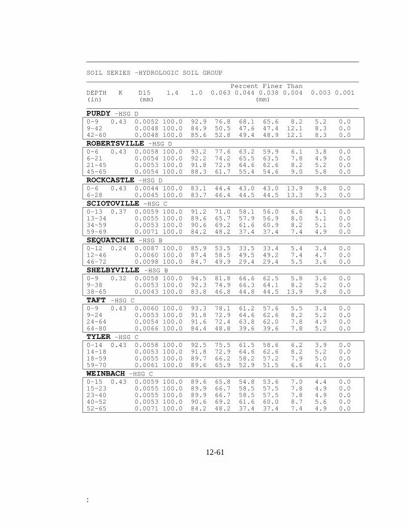
::
____________________________________________________________________ SOIL SERIES -HYDROLOGIC SOIL GROUP ____________________________________________________________________ Percent Finer Than DEPTH K D15 1.4 1.0 0.063 0.044 0.038 0.004 0.003 0.001 (in) (mm) (mm) ____________________________________________________________________ PURDY -HSG D 0-9 0.43 0.0052 100.0 92.9 76.8 68.1 65.6 8.2 5.2 0.0 9-42 0.0048 100.0 84.9 50.5 47.6 47.4 12.1 8.3 0.0 42-60 0.0048 100.0 85.6 52.8 49.4 48.9 12.1 8.3 0.0 ROBERTSVILLE -HSG D 0-6 0.43 0.0058 100.0 93.2 77.6 63.2 59.9 6.1 3.8 0.0 6-21 0.0054 100.0 92.2 74.2 65.5 63.5 7.8 4.9 0.0 21-45 0.0053 100.0 91.8 72.9 64.6 62.6 8.2 5.2 0.0 45-65 0.0054 100.0 88.3 61.7 55.4 54.6 9.0 5.8 0.0 ROCKCASTLE -HSG D 0-6 0.43 0.0044 100.0 83.1 44.4 43.0 43.0 13.9 9.8 0.0 6-28 0.0045 100.0 83.7 46.4 44.5 44.5 13.3 9.3 0.0 SCIOTOVILLE -HSG C 0-13 0.37 0.0059 100.0 91.2 71.0 58.1 56.0 6.6 4.1 0.0 13-34 0.0055 100.0 89.6 65.7 57.9 56.9 8.0 5.1 0.0 34-59 0.0053 100.0 90.6 69.2 61.6 60.9 8.2 5.1 0.0 59-69 0.0071 100.0 84.2 48.2 37.4 37.4 7.4 4.9 0.0 SEQUATCHIE -HSG B 0-12 0.24 0.0087 100.0 85.9 53.5 33.5 33.4 5.4 3.4 0.0 12-46 0.0060 100.0 87.4 58.5 49.5 49.2 7.4 4.7 0.0 46-72 0.0098 100.0 84.7 49.9 29.4 29.4 5.5 3.6 0.0 SHELBYVILLE -HSG B 0-9 0.32 0.0058 100.0 94.5 81.8 66.6 62.5 5.8 3.6 0.0 9-38 0.0053 100.0 92.3 74.9 66.3 64.1 8.2 5.2 0.0 38-65 0.0043 100.0 83.8 46.8 44.8 44.5 13.9 9.8 0.0 TAFT -HSG C 0-9 0.43 0.0060 100.0 93.3 78.1 61.2 57.6 5.5 3.4 0.0 9-24 0.0053 100.0 91.8 72.9 64.6 62.6 8.2 5.2 0.0 24-64 0.0054 100.0 91.6 72.4 63.8 62.0 7.8 4.9 0.0 64-80 0.0066 100.0 84.4 48.8 39.6 39.6 7.8 5.2 0.0 TYLER -HSG C 0-14 0.43 0.0058 100.0 92.5 75.5 61.5 58.6 6.2 3.9 0.0 14-18 0.0053 100.0 91.8 72.9 64.6 62.6 8.2 5.2 0.0 18-59 0.0055 100.0 89.7 66.2 58.2 57.2 7.9 5.0 0.0 59-70 0.0061 100.0 89.6 65.9 52.9 51.5 6.6 4.1 0.0 WEINBACH -HSG C 0-15 0.43 0.0059 100.0 89.6 65.8 54.8 53.6 7.0 4.4 0.0 15-23 0.0055 100.0 89.9 66.7 58.5 57.5 7.8 4.9 0.0 23-40 0.0055 100.0 89.9 66.7 58.5 57.5 7.8 4.9 0.0 40-52 0.0053 100.0 90.6 69.2 61.6 60.0 8.7 5.6 0.0 52-65 0.0071 100.0 84.2 48.2 37.4 37.4 7.4 4.9 0.0
12-61

::
_________________________________________________________________ SOIL SERIES -HYDROLOGIC SOIL GROUP ____________________________________________________________________ Percent Finer Than DEPTH K D15 1.4 1.0 0.063 0.044 0.038 0.004 0.003 0.001 (in) (mm) (mm) ____________________________________________________________________ WESTMORELAND -HSG ZZ 0-7 0.99 0.0058 100.0 90.1 67.6 56.5 55.1 7.0 4.4 0.0 7-36 0.0062 100.0 85.0 50.6 42.9 42.9 8.2 5.4 0.0 36-49 0.0081 100.0 82.7 43.3 31.2 31.2 7.6 5.2 0.0 WHEELING -HSG B 0-14 0.37 0.0069 100.0 90.8 69.7 48.9 46.6 5.0 3.1 0.0 14-60 0.0067 100.0 85.1 50.9 40.7 40.7 7.2 4.7 0.0 60-72 0.0255 100.0 87.5 59.1 17.5 17.5 3.4 2.2 0.0 WOOLPER -HSG C 0-6 0.37 0.0052 100.0 90.0 67.0 60.0 58.5 9.3 6.0 0.0 6-15 0.0047 100.0 86.9 57.0 52.6 51.6 12.2 8.4 0.0 15-65 0.0043 100.0 85.3 51.6 48.2 47.5 13.9 9.8 0.0 ZANESVILLE -HSG C 0-7 0.43 0.0052 100.0 90.6 69.1 61.8 60.0 9.3 6.0 0.0 7-28 0.0053 100.0 91.8 72.9 64.6 62.6 8.2 5.2 0.0 28-39 0.0055 100.0 89.7 66.2 58.2 57.2 7.9 5.0 0.0 39-60 0.0079 100.0 81.5 39.1 30.3 30.3 8.5 5.8 0.0 ZIPP -HSG D 0-6 0.28 0.0047 100.0 88.5 62.1 56.4 54.9 12.1 8.3 0.0 6-36 0.0044 100.0 87.3 58.2 53.3 52.0 13.3 9.3 0.0 36-60 0.0046 100.0 85.7 53.1 49.6 48.9 12.7 8.8 0.0
12-62

::
DDEESSIIGGNN MMAANNUUAALL CCHHAAPPTTEERR 1122
SSUUPPPPLLEEMMEENNTTAALL SSEECCTTIIOONN DD
EEXXHHIIBBIITTSS Adopted: January 1, 2001 12-63 Revised:

::
EXHIBIT 12-1BENCH TERRACESFOR URBAN AREASLouisville and Jefferson County
Metropolitan Sewer District EFFECTIVE DATE: JANUARY 1, 2001
EQUATION FOR HORIZONTAL AND VERTICAL INTERVALS
VI = VERTICAL INTERVAL BETWEEN TERRACESHI = HORIZONTAL INTERVAL BETWEEN TERRACESS = AVERAGE LAND SLOPE IN PERCENT
WITH GOOD COVER. b = 1 FOR ERODIBLE CONDITION
DIRECT WATER TOSTABLE OUTLET
REVERSE SLOPE
BENCH TERRACES
SHI = VI X 100
WHERE a = 0.5 FOR LOUISVILLEVI = aS+b
2 FOR RESISTANT SOILS
HIAVERAGE LAND SLOPE = S
LEVEL ORVI

::
EXHIBIT 12-2MAXIMUM DEPTH OF FLOW FOR RIPRAPLINED CHANNELSLouisville and Jefferson County
Metropolitan Sewer District EFFECTIVE DATE: JANUARY 1, 2001
50
0.25
0.5
0.75
1.0
1.5
2.0
d RIPRAP SIZE, FEET
20
5.0
2.0
0.5
0.2
0.20.050.02
MA
XIM
UM
DEP
TH O
F FL
OW
, FEE
T
CHANNEL SLOPE, FEET/FOOT
0.10.01
10
1.0
0.1
MAXIMUM DEPTH OF FLOW FOR RIPRAP LINED CHANNELS

::
EXHIBIT 12-3DISTRIBUTION OF BOUNDARY SHEAR AROUNDWETTED PERIMETER OF TRAPAZOIDAL CHANNELLouisville and Jefferson County
Metropolitan Sewer District EFFECTIVE DATE: JANUARY 1, 2001
4:1
1.5:12:1
3:1
DISTRIBUTION OF BOUNDARY SHEAR AROUND WETTED PERIMETEROF TRAPAZOIDAL CHANNEL
1K
0.6
1.2
1.1
1.0
0.9
.08
0.7
0.5
1086420
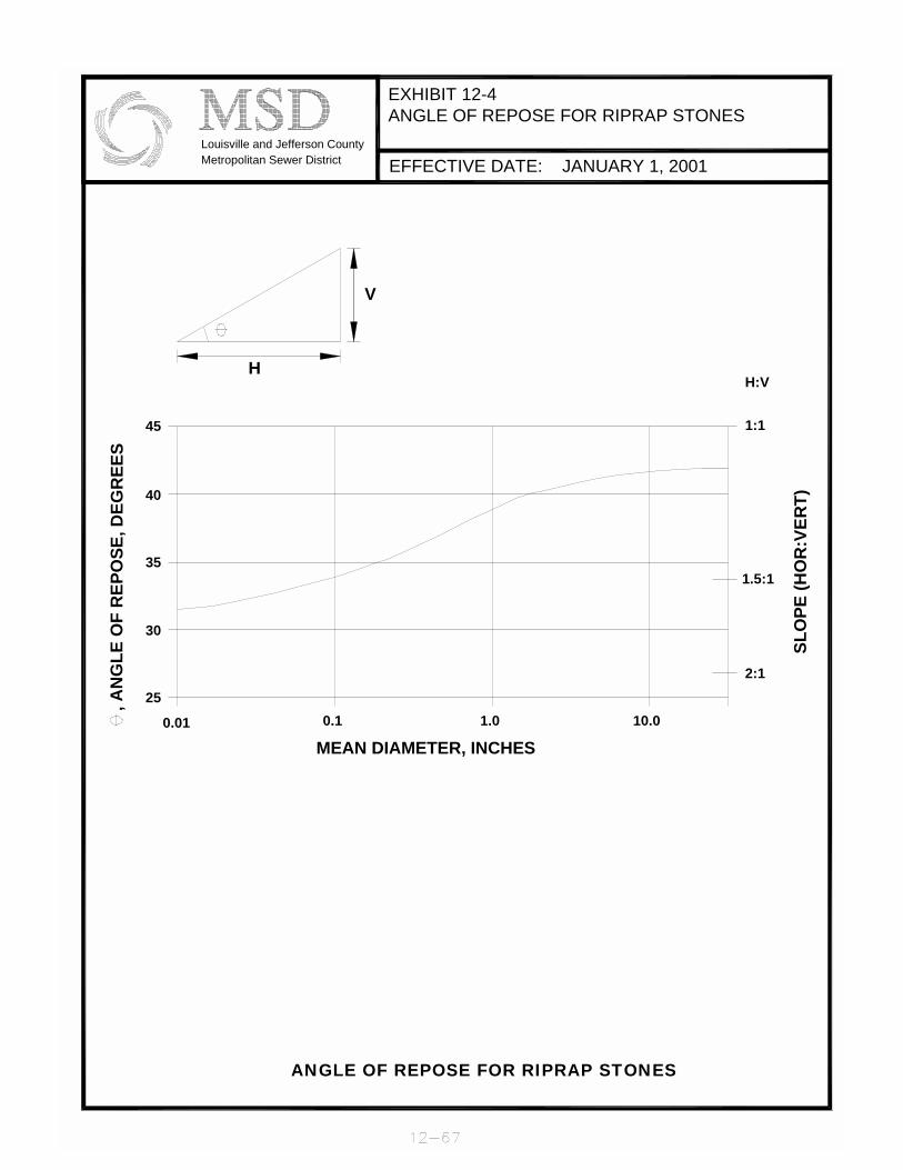
::
EXHIBIT 12-4ANGLE OF REPOSE FOR RIPRAP STONES
Louisville and Jefferson CountyMetropolitan Sewer District EFFECTIVE DATE: JANUARY 1, 2001
ANGLE OF REPOSE FOR RIPRAP STONES
MEAN DIAMETER, INCHES
, AN
GLE
OF
REP
OSE
, DEG
REE
S
0.01
25
40
35
30
0.1
45
H
V
10.01.0
2:1
1.5:1
SLO
PE (H
OR
:VER
T)
H:V
1:1

::
EXHIBIT 12-5RATIO OF CRITICAL SHEAR STRESS ON SIDESTO CRITICAL SHEAR STRESS ON BOTTOMLouisville and Jefferson County
Metropolitan Sewer District EFFECTIVE DATE: JANUARY 1, 2001
H:V1:1
ANGLE OF REPOSE45
40
35
30
25
20
1086
4
3
2.5
2
1.5
AN
GLE
OF
SID
E SL
OPE
, DEG
REE
S
2K
RATIO OF CRITICAL SHEAR ON SIDES TO CRITICAL SHEAR ON BOTTOM
0.4 0.6 0.8 1.00
5
10
15
20
25
30
35
40
45
0 0.2

::
EXHIBIT 12-6MINIMUM TAIL WATER CONDITION
Louisville and Jefferson CountyMetropolitan Sewer District EFFECTIVE DATE: JANUARY 1, 2001
L =
APR
ON
LEN
GTH
, (FE
ET)
D =
OU
TLET
PIP
E D
IAM
ETER
, (IN
CH
ES)
d =
MED
IAN
STO
NE
SIZE
, (FE
ET)
2 M
INO
UTL
ETPI
PED
IAM
ETER
,
PIPE
OU
TLET
TO
FLA
T A
REA
WIT
H N
O D
EFIN
ED C
HA
NN
EL:
MIN
IMUM
LEN
GTH
OF A
PRON
, L ,
FEET
REC
OM
MEN
DED
MIN
d =
6"
DIS
CH
AR
GE,
FT
/ S
EC
wMINIMUM TAILWATER CONDITION (T < 0.5 DIAMETER)DESIGN OF OUTLET PROTECTION FROM A ROUND PIPE FLOWING FULL
4 3 2 1
50 dRIPRAP SIZE, FEET
1000
500
200
100
5020
10
80
70
60
50
90
530
20 10 0
3
40

::
EXHIBIT 12-7MAXIMUM TAILWATER CONDITION
Louisville and Jefferson CountyMetropolitan Sewer District EFFECTIVE DATE: JANUARY 1, 2001
d =
MED
IAN
STO
NE S
IZE,
(FEE
T)D
= O
UTL
ET P
IPE
DIAM
ETER
, (IN
CHES
)L
= A
PRO
N LE
NG
TH, (
FEET
)
20
MINIMUM LENGTH O
F APRON, L , F
EET
ao
+ 0.
4 L
L
1O
UTL
ETPI
PED
IAM
ETER
,
D =
1.5
TIM
ES T
HE
MAX
IMUM
STO
NE
DIA
MET
ER B
UT N
OT
LESS
TH
AN 6
INCH
ES
PIPE
OU
TLET
TO
FLA
T A
REA
WIT
H N
O D
EFIN
ED C
HAN
NEL:
120
110
100
REC
OM
MEN
DED
MIN
d =
6"
3D
ISC
HA
RG
E, F
T /
SEC
wMAXIMUM TAILWATER CONDITION (T < 0.5 DIAMETER)DESIGN OF OUTLET PROTECTION FROM A ROUND PIPE FLOWING FULL
3 2 1
50 dRIPRAP SIZE, FEET
1000
500
200
100
5020
10
80
70
60
50
90
5
30
10 0 3
40

::
EXHIBIT 12-8SEDIMENT BASIN
PAGE 1
Louisville and Jefferson CountyMetropolitan Sewer District EFFECTIVE DATE: JANUARY 1, 2001
REQUIRED 6" LOW FLOW ORIFICE
PERFORATED RISER
RISER CREST
SPILLWAYCREST OF EMERGENCY
DESIGN ELEVATIONS WITH REQUIRED EMERGENCY SPILLWAY
LOW FLOW ORIFICEREQUIRED 6"
R
RISER PIPE DETAIL
d
RHdh
X
STORAGE VOLUMESEDIMENT
SEDIMENT CLEANOUT POINT
DESIGN HIGH WATER
MIN. 1.0'
MIN. 1.0'
d
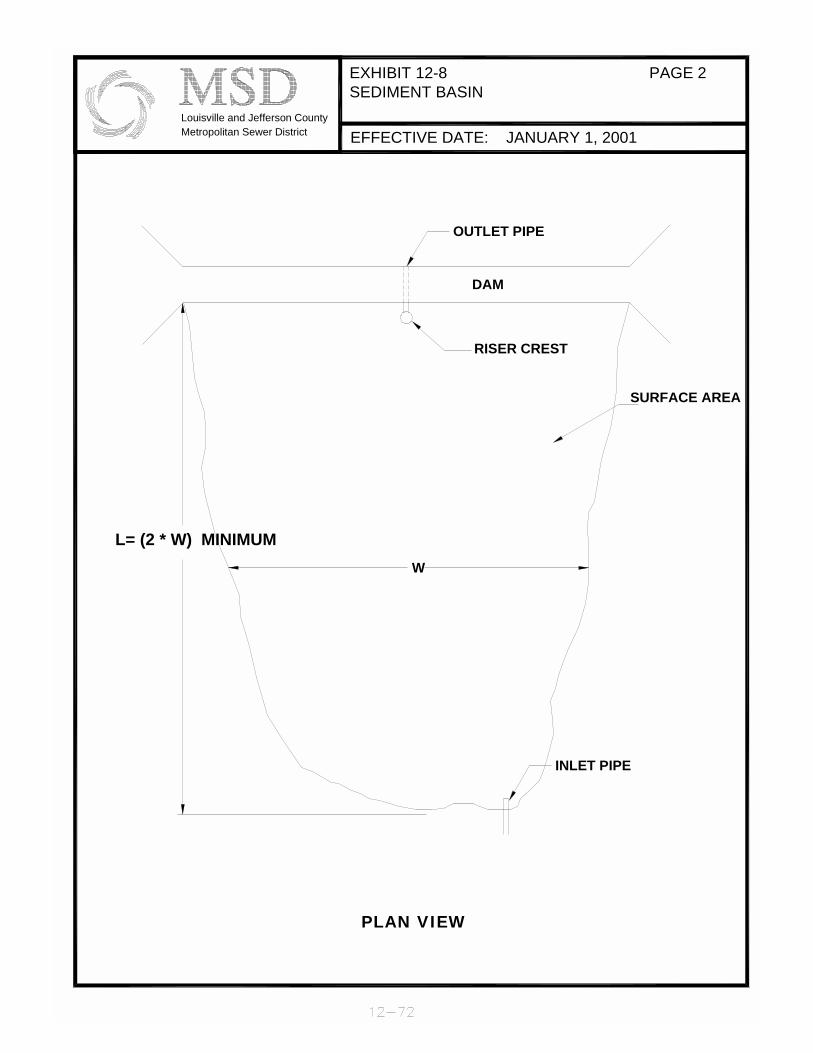
::
EXHIBIT 12-8SEDIMENT BASIN
PAGE 2
Louisville and Jefferson CountyMetropolitan Sewer District EFFECTIVE DATE: JANUARY 1, 2001
INLET PIPE
L= (2 * W) MINIMUM
PLAN VIEW
W
RISER CREST
DAM
OUTLET PIPE
SURFACE AREA
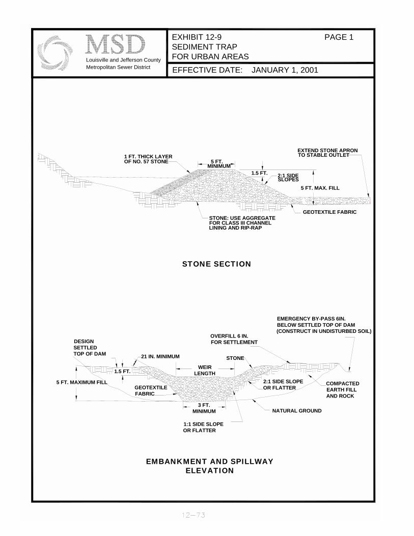
::
EXHIBIT 12-9SEDIMENT TRAPFOR URBAN AREAS
PAGE 1
Louisville and Jefferson CountyMetropolitan Sewer District EFFECTIVE DATE: JANUARY 1, 2001
2:1 SIDE SLOPEOR FLATTER
NATURAL GROUND
EMERGENCY BY-PASS 6IN. BELOW SETTLED TOP OF DAM (CONSTRUCT IN UNDISTURBED SOIL)
SLOPES2:1 SIDE
STONE SECTION
5 FT. MAXIMUM FILL
DESIGN SETTLEDTOP OF DAM
EMBANKMENT AND SPILLWAY ELEVATION
WEIR LENGTH
3 FT. MINIMUM
1:1 SIDE SLOPEOR FLATTER
21 IN. MINIMUM
GEOTEXTILE FABRIC
1.5 FT.
STONE
OVERFILL 6 IN.FOR SETTLEMENT
OF NO. 57 STONE1 FT. THICK LAYER
1.5 FT.
LINING AND RIP-RAPFOR CLASS III CHANNELSTONE: USE AGGREGATE
MINIMUM5 FT.
COMPACTED EARTH FILL AND ROCK
GEOTEXTILE FABRIC
5 FT. MAX. FILL
TO STABLE OUTLETEXTEND STONE APRON

::
EXHIBIT 12-9SEDIMENT TRAP
PAGE 2
Louisville and Jefferson CountyMetropolitan Sewer District EFFECTIVE DATE: JANUARY 1, 2001
SURFACE AREA
STONE APRON
L= (2 * W) Minimum
PLAN VIEW
W
SPILLWAY
5 FT. MINIMUM2:1 SIDESLOPES
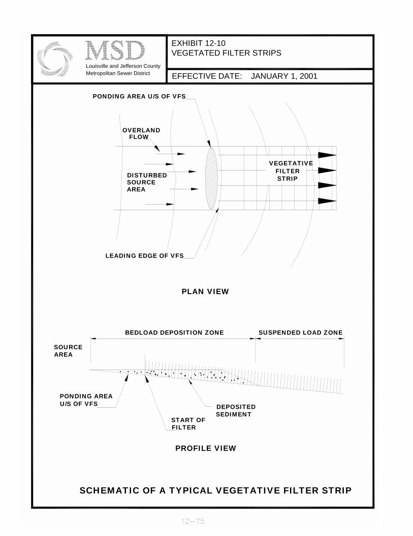
::
EXHIBIT 12-10VEGETATED FILTER STRIPS
Louisville and Jefferson CountyMetropolitan Sewer District EFFECTIVE DATE: JANUARY 1, 2001
SUSPENDED LOAD ZONE
FILTERVEGETATIVE
SCHEMATIC OF A TYPICAL VEGETATIVE FILTER STRIP
U/S OF VFSPONDING AREA
SOURCEAREA
PROFILE VIEW
PLAN VIEW
BEDLOAD DEPOSITION ZONE
START OF FILTER
DEPOSITEDSEDIMENT
DISTURBEDSOURCE
LEADING EDGE OF VFS
AREA
PONDING AREA U/S OF VFS
FLOWOVERLAND
STRIP

::
EXHIBIT 12-11PIPE SLOPE DRAIN
Louisville and Jefferson CountyMetropolitan Sewer District EFFECTIVE DATE: JANUARY 1, 2001
FILL (ISLAND)
TYPICAL PIPE SLOPE DRAIN LAYOUT
3:1
ISLAND OVER INLET
COMPACTEDTOP OF HAND-
LEVEL SECTION
DIVERSION
DIVERSION
GROUNDNATURAL
CHANNEL
MIN
.1'
TOP OF4' MIN.
1.5'
MIN
. 3:1
4' MIN.
PIPECORRUGATEDPLASTIC
OUTLETSTABILIZE
10' SPACING
HOLD-DOWN STAKES
INLET
4' MIN.DIVERSIONDIKE
0.5' MIN.
1.5' MIN.

::
EXHIBIT 12-12DIKES AND SWALES
Louisville and Jefferson CountyMetropolitan Sewer District EFFECTIVE DATE: JANUARY 1, 2001
1' MIN.
1' MIN.
2' MIN.
SWALE
SWALE SPACING = 100', 200', OR 300'DEPENDING ON SLOPE
GRASS OR STABLE LINING
LEVEL BOTTOM
2
2' MIN.
1
2' MIN.
8' MIN.
2' MIN.
DIKE SPACING = 100', 200', OR
DIKE MATERIAL COMPACTED90% STANDARD PROCTOR
300' DEPENDING ON GRADE
DIKE
18" MIN.
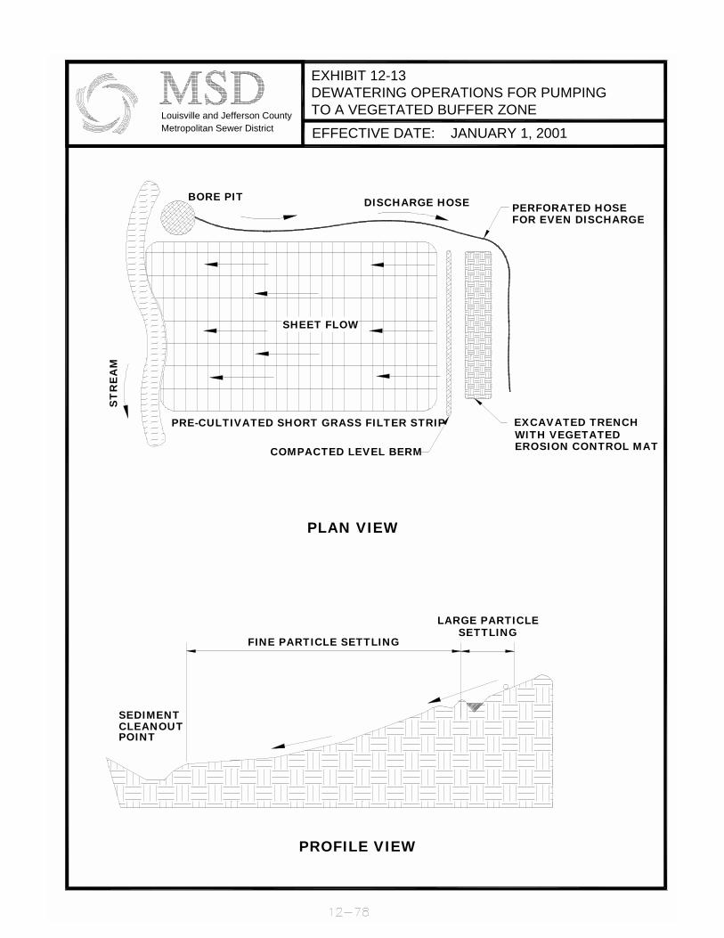
::
EXHIBIT 12-13DEWATERING OPERATIONS FOR PUMPINGTO A VEGETATED BUFFER ZONELouisville and Jefferson County
Metropolitan Sewer District EFFECTIVE DATE: JANUARY 1, 2001
LARGE PARTICLE
EROSION CONTROL MATWITH VEGETATEDEXCAVATED TRENCH
FOR EVEN DISCHARGEPERFORATED HOSE
CLEANOUTSEDIMENT
POINT
PROFILE VIEW
FINE PARTICLE SETTLING
PLAN VIEW
SETTLING
ST
RE
AM
SHEET FLOW
COMPACTED LEVEL BERM
PRE-CULTIVATED SHORT GRASS FILTER STRIP
BORE PIT DISCHARGE HOSE
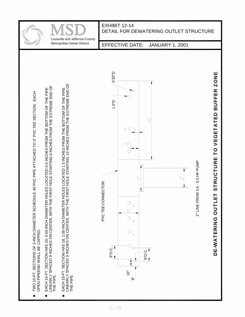
::
EXHIBIT 12-14DETAIL FOR DEWATERING OUTLET STRUCTURE
Louisville and Jefferson CountyMetropolitan Sewer District EFFECTIVE DATE: JANUARY 1, 2001
LIN
EAR
LY S
PAC
ED 9
INC
HES
ON
CEN
TER
, WIT
H T
HE
FIR
ST H
OLE
STA
RTI
NG
10
INC
HES
FR
OM
TH
E EX
TREM
E EN
D O
FEA
CH
15-
FT. S
ECTI
ON
HAS
18,
1.0
0-IN
CH
DIA
MET
ER H
OLE
S LO
CAT
ED 1
.5 IN
CH
ES F
RO
M T
HE
BOTT
OM
OF
THE
PIPE
LIN
EAR
LY S
PAC
ED 9
INC
HES
ON
CEN
TER
, WIT
H T
HE
FIR
ST H
OLE
STA
RTI
NG
8 IN
CH
ES F
RO
M T
HE
EXTR
EME
END
OF
EAC
H 1
5-FT
. SEC
TIO
N H
AS 2
0, 0
.50-
INC
H D
IAM
ETER
HO
LES
LOC
ATED
0.5
INC
HES
FR
OM
TH
E BO
TTO
M O
F TH
E PI
PE
TWO
15-
FT. S
ECTI
ON
S O
F 3-
INC
H D
IAM
ETER
SC
HED
ULE
40
PVC
PIP
E AT
TAC
HED
TO
3" P
VC T
EE S
ECTI
ON
. EA
CH
THE
PIPE
.
OPE
N P
IPEE
ND
SH
ALL
BE C
APPE
D.
THE
PIPE
.
8"10
"
PVC
TEE
-CO
NN
ECTO
R
9"O
.C.
9"O
.C.
1.0"
D0.
50"D
DE
-WA
TE
RIN
G O
UT
LET
ST
RU
CT
UR
E T
O V
EG
ET
AT
ED
BU
FFE
R Z
ON
E
2" L
INE
FRO
M 3
.5 -
5.0
HP
PUM
P

::
EXHIBIT 12-15TYPICAL LEVEL SPREADER LAYOUT
Louisville and Jefferson CountyMetropolitan Sewer District EFFECTIVE DATE: JANUARY 1, 2001
STABLE UNDISTURBEDOUTLET AREA(MAXIMUM SLOPE-10%)
PERSPECTIVE VIEW
SECTION A-A
LEVEL LIPOF SPREADER
FLOW
EXTEND BLANKETOVER LIP(12 IN. MIN.)
PERMANENT TRMBURY 6 IN. MIN.
OVERFLOW
WATER LEVEL6 IN. MIN.DEPTH
ENTRANCE
WIDTH A
LEVEL SPREADER LIP
A
DIVERSION CHANNEL
DIVERSIONBERM
FLOW
STABILIZEDSLOPE
END
WID
TH
LENGTH
TRANSITION TOZERO GRADE

::
DDEESSIIGGNN MMAANNUUAALL CCHHAAPPTTEERR 1122
SSUUPPPPLLEEMMEENNTTAALL SSEECCTTIIOONN EE
EERROOSSIIOONN CCOONNTTRROOLL BBLLAANNKKEETTSS &&
TTUURRFF RREEIINNFFOORRCCEEMMEENNTT MMAATTSS Adopted: January 1, 2001 12-81

::
Revised:
::
EErroossiioonn CCoonnttrrooll BBllaannkkeettss
AA lliisstt ooff EECCBB pprroodduuccttss ffoorr eeaacchh ooff tthhee ffoolllloowwiinngg ccllaasssseess aanndd ttyyppeess iiss ggiivveenn iinn tthhee MMSSDD SSttaannddaarrdd SSppeecciiffiiccaattiioonnss..
TTeemmppoorraarryy EErroossiioonn CCoonnttrrooll BBllaannkkeett ((EECCBB)) --CCllaassss II && IIII FFoorr aannyy EECCBB tthhaatt hhaass nneettttiinngg aattttaacchheedd,, tthhee nneettttiinngg sshhaallll bbee pphhoottooddeeggrraaddaabbllee aanndd//oorr bbiiooddeeggrraaddaabbllee aass ssppeecciiffiieedd ffoorr tthhaatt CCllaassss aanndd ttyyppee ooff EECCBB.. TThhee wweeiigghhtt ooff tthhee nneettttiinngg sshhaallll nnoott eexxcceeeedd 1155%% ooff tthhee ttoottaall bbllaannkkeett wweeiigghhtt.. •• CCllaassss II:: SShhoorrtt--tteerrmm DDeeggrraaddaabbllee PPrroodduuccttss –– DDeeffiinneedd aass pprroodduuccttss ccoommppoosseedd
pprriimmaarriillyy ooff bbiioollooggiiccaallllyy,, pphhoottoocchheemmiiccaallllyy oorr ootthheerrwwiissee ddeeggrraaddaabbllee ccoonnssttiittuueennttss wwiitthh lloonnggeevviittyy ooff aapppprrooxxiimmaatteellyy 11 yyeeaarr.. NNoonn--oorrggaanniicc,, pphhoottooddeeggrraaddaabbllee oorr bbiiooddeeggrraaddaabbllee nneettttiinngg iiss aalllloowweedd..
UUrrbbaann-- EEiitthheerr nneetttteedd wwiitthh bbiiooddeeggrraaddaabbllee mmaatteerriiaall oorr nnoonn--nneetttteedd,, uusseedd iinn uurrbbaann
aanndd rreessiiddeennttiiaall aarreeaass wwhheerree tthhee ssllooppeess ddoo nnoott eexxcceeeedd 44HH::11VV.. NNoo mmiinniimmuumm sshheeaarr ssttrreessss rreeqquuiirreedd,, bbuutt tthhee mmiinniimmuumm mmaatt tthhiicckknneessss aalllloowweedd iiss 99mmmm ((33//88 iinncchh)).. TThhee pprroodduucctt sshhoouulldd bbee ccaappaabbllee ooff wwiitthhssttaannddiinngg mmooddeerraattee ffoooott ttrraaffffiicc wwiitthhoouutt tteeaarriinngg oorr ppuunnccttuurriinngg.. NNoott ttoo bbee uusseedd iinn cchhaannnneellss..
TTyyppee AA-- MMaaxxiimmuumm PPrroodduucctt PPeerrmmiissssiibbllee SShheeaarr SSttrreessss ((00 -- 11..00 llbb//fftt22))::
AA nneetttteedd pprroodduucctt ffoorr uussee oonn ssllooppeess 22..55HH::11VV aanndd ffllaatttteerr wwhheerree tthhee ccaallccuullaatteedd ddeessiiggnn sshheeaarr ssttrreessss iiss 11..00 llbb//fftt22 oorr lleessss.. NNoott ttoo bbee uusseedd iinn cchhaannnneellss..
TTyyppee BB-- MMaaxxiimmuumm PPrroodduucctt PPeerrmmiissssiibbllee SShheeaarr SSttrreessss ((11..00 -- 22..00 llbb//fftt22))::
DDoouubbllee nneetttteedd,, uusseedd oonn ssllooppeess 22HH::11VV oorr ffllaatttteerr oorr,, iinn cchhaannnneellss wwhheerree tthhee ccaallccuullaatteedd ddeessiiggnn sshheeaarr ssttrreessss iiss 22..00 llbb//fftt22 oorr lleessss..
•• CCllaassss IIII:: LLoonngg--tteerrmm DDeeggrraaddaabbllee PPrroodduuccttss-- ddeeffiinneedd aass pprroodduuccttss ccoommppoosseedd pprriimmaarriillyy ooff bbiioollooggiiccaallllyy,, pphhoottoocchheemmiiccaallllyy oorr ootthheerrwwiissee ddeeggrraaddaabbllee ccoonnssttiittuueennttss wwiitthh aa lloonnggeevviittyy ooff uupp ttoo 55 yyeeaarrss..
TTyyppee AA--MMaaxxiimmuumm PPrroodduucctt PPeerrmmiissssiibbllee SShheeaarr SSttrreessss ((00 -- 11..00 llbb//fftt22))::
FFoorr uussee oonn ssllooppeess 33HH::11VV oorr,, iinn cchhaannnneellss wwhheerree tthhee ccaallccuullaatteedd ddeessiiggnn sshheeaarr ssttrreessss iiss 11..00 llbb//fftt22 oorr lleessss ffllaatttteerr JJuuttee ffaabbrriicc uusseedd ffoorr eerroossiioonn mmaattss sshhaallll bbee aa wwoovveenn ffaabbrriicc ooff aa uunniiffoorrmm ooppeenn wweeaavvee ooff ssiinnggllee jjuuttee yyaarrnn..
TTyyppee BB-- MMaaxxiimmuumm PPrroodduucctt PPeerrmmiissssiibbllee SShheeaarr SSttrreessss ((00 -- 22..00 llbb//fftt22))::
FFoorr uussee oonn ssllooppeess 22HH::11VV oorr ffllaatttteerr oorr,, iinn cchhaannnneellss wwhheerree tthhee ccaallccuullaatteedd ddeessiiggnn sshheeaarr ssttrreessss iiss 22..00 llbb//fftt22 oorr lleessss.. NNoonn--oorrggaanniicc,, pphhoottooddeeggrraaddaabbllee oorr bbiiooddeeggrraaddaabbllee nneettttiinngg iiss aalllloowweedd..
TTyyppee CC-- MMaaxxiimmuumm PPrroodduucctt PPeerrmmiissssiibbllee SShheeaarr SSttrreessss ((00 -- 22..00 llbb//fftt22)):: FFoorr uussee iinn eennvviirroonnmmeennttaallllyy sseennssiittiivvee aarreeaass oonn ssllooppeess 22HH::11VV oorr ffllaatttteerr oorr,, iinn cchhaannnneellss wwhheerree tthhee ccaallccuullaatteedd ddeessiiggnn sshheeaarr ssttrreessss iiss 22..00 llbb//fftt22 oorr lleessss.. OOnnllyy oorrggaanniicc ffiibbeerr wwoovveenn mmaattss aarree aalllloowweedd wwiitthh aa mmaaxxiimmuumm ooppeenniinngg ooff 1122 mmmm ((11//22 iinncchh))..
12-82

::
TTuurrff RReeiinnffoorrcceemmeenntt MMaattss
MMSSDD AApppprroovveedd CCllaassss IIIIII TTRRMM pprroodduuccttss aanndd tthheeiirr pphhyyssiiccaall pprrooppeerrttiieess aarree iiddeennttiiffiieedd iinn tthhee MMSSDD SSttaannddaarrdd SSppeecciiffiiccaattiioonnss..
•• CCllaassss IIIIII:: NNoonn--ddeeggrraaddaabbllee PPrroodduuccttss-- ddeeffiinneedd aass pprroodduuccttss ccoommppoosseedd ooff nnoonn--
ddeeggrraaddaabbllee ccoonnssttiittuueennttss wwiitthh aann uunnlliimmiitteedd lloonnggeevviittyy..
TTyyppee AA-- MMaaxxiimmuumm PPrroodduucctt PPeerrmmiissssiibbllee SShheeaarr SSttrreessss ((00 –– 66..00 llbb//fftt22)):: AA TTRRMM mmaatt ffoorr uussee oonn ssllooppeess 22HH::11VV oorr ffllaatttteerr oorr,, iinn cchhaannnneellss wwhheerree tthhee ccaallccuullaatteedd ddeessiiggnn sshheeaarr ssttrreessss iiss 66..00 llbb//fftt22 oorr lleessss..
TTyyppee BB-- MMaaxxiimmuumm PPrroodduucctt PPeerrmmiissssiibbllee SShheeaarr SSttrreessss ((66..00 -- 88..00 llbb//fftt22))::
AA TTRRMM mmaatt ffoorr uussee oonn ssllooppeess 11HH::11VV oorr ffllaatttteerr oorr,, iinn cchhaannnneellss wwhheerree tthhee ccaallccuullaatteedd ddeessiiggnn sshheeaarr ssttrreessss iiss 88..00 llbb//fftt22 oorr lleessss..
TTyyppee CC-- MMaaxxiimmuumm PPrroodduucctt PPeerrmmiissssiibbllee SShheeaarr SSttrreessss ((88..00 -- 1100..00 llbb//fftt22))::
AA TTRRMM mmaatt ffoorr uussee oonn ssllooppeess 11HH::11VV oorr sstteeeeppeerr oorr,, iinn cchhaannnneellss wwhheerree tthhee ccaallccuullaatteedd ddeessiiggnn sshheeaarr ssttrreessss iiss 1100..00 llbb//fftt22 oorr lleessss..
12-83

::
MMSSDD AApppprroovveedd EErroossiioonn CCoonnttrrooll BBllaannkkeettss
MMSSDD AApppprroovveedd EECCBB PPrroodduuccttss,, CCllaassss II,, UUrrbbaann
PPrroodduuccttss MMaannuuffaaccttuurreerr EEaarrtthh--GGuuaarrdd EEaarrtthh--GGuuaarrdd HHPP 9900 BBoonn TTeerrrraa EENNCC22 BBoonn TTeerrrraa EENNCCSS22 BBoonn TTeerrrraa EENNSS22 BBoonn TTeerrrraa EECCSS 11000000--0011 EErroossiioonn CCoonnttrrooll SSyysstteemmss SS115500BBNN NNoorrtthh AAmmeerriiccaann GGrreeeenn SSCC115500BBNN NNoorrtthh AAmmeerriiccaann GGrreeeenn
MMSSDD AApppprroovveedd EECCBB PPrroodduuccttss,, CCllaassss II,, TTyyppee AA
PPrroodduuccttss MMaannuuffaaccttuurreerr CCuurrlleexx EExxcceellssiioorr AAmmeerriiccaann EExxcceellssiioorr CCuurrlleexx EExxcceellssiioorr IIII AAmmeerriiccaann EExxcceellssiioorr CCuurrlleexx HHiigghh VVeelloocciittyy AAmmeerriiccaann EExxcceellssiioorr QQuuiicckkGGrraassss AAmmeerriiccaann EExxcceellssiioorr CCSS22 BBoonnTTeerrrraa SS11 BBoonnTTeerrrraa SS22 BBoonnTTeerrrraa EECCSS HHiigghh VVeelloocciittyy EExxcceellssiioorr EErroossiioonn CCoonnttrrooll SSyysstteemmss EECCSS HHiigghh VVeelloocciittyy SSttrraaww EErroossiioonn CCoonnttrrooll SSyysstteemmss EECCSS SSttaannddaarrdd EExxcceellssiioorr EErroossiioonn CCoonnttrrooll SSyysstteemmss EECCSS SSttaannddaarrdd SSttrraaww EErroossiioonn CCoonnttrrooll SSyysstteemmss EEaarrtthh--LLoocckk IIBB EErroossiioonn CCoonnttrrooll SSyysstteemmss CC112255BBNN NNoorrtthh AAmmeerriiccaann GGrreeeenn SS7755 NNoorrtthh AAmmeerriiccaann GGrreeeenn SS7755BBNN NNoorrtthh AAmmeerriiccaann GGrreeeenn SS115500 NNoorrtthh AAmmeerriiccaann GGrreeeenn SS115500BBNN NNoorrtthh AAmmeerriiccaann GGrreeeenn SSCC115500 NNoorrtthh AAmmeerriiccaann GGrreeeenn SSCC115500BBNN NNoorrtthh AAmmeerriiccaann GGrreeeenn EExxcceellssiioorr PPPPSS XXCCEELL RReegguullaarr RR11 PPPPSS XXCCEELL SSuuppeerriioorr SS22 PPPPSS EEXXCCEELL SSuuppeerr DDuuttyy SSDD33 PPPPSS VVeerrddyyooll HHiigghh VVeelloocciittyy EERROO--MMAATT VVeerrddyyooll AAllaabbaammaa,, IInncc.. VVeerrddyyooll HHiigghh VVeelloocciittyy EExxcceellssiioorr VVeerrddyyooll AAllaabbaammaa,, IInncc.. VVeerryyddooll SSttaannddaarrdd EERROO--MMAATT VVeerrddyyooll AAllaabbaammaa,, IInncc.. VVeerrddyyooll SSttaannddaarrdd EExxcceellssiioorr VVeerrddyyooll AAllaabbaammaa,, IInncc..
12-84

::
MMSSDD AApppprroovveedd EErroossiioonn CCoonnttrrooll BBllaannkkeettss
MMSSDD AApppprroovveedd EECCBB PPrroodduuccttss,, CCllaassss II,, TTyyppee BB
PPrroodduuccttss MMaannuuffaaccttuurreerr CCuurrlleexx EExxcceellssiioorr IIII AAmmeerriiccaann EExxcceellssiioorr CCuurrlleexx HHiigghh VVeelloocciittyy AAmmeerriiccaann EExxcceellssiioorr CCSS22 BBoonnTTeerrrraa SS22 BBoonnTTeerrrraa EECCSS HHiigghh VVeelloocciittyy EExxcceellssiioorr EErroossiioonn CCoonnttrrooll SSyysstteemmss EECCSS HHiigghh VVeelloocciittyy SSttrraaww EErroossiioonn CCoonnttrrooll SSyysstteemmss EECCSS EEaarrtthhlloocckk EErroossiioonn CCoonnttrrooll SSyysstteemmss EEaarrtthh--LLoocckk IIBB EErroossiioonn CCoonnttrrooll SSyysstteemmss SS115500 NNoorrtthh AAmmeerriiccaann GGrreeeenn SSCC115500 NNoorrtthh AAmmeerriiccaann GGrreeeenn XXCCEELL SSuuppeerriioorr SS22 PPPPSS EEXXCCEELL SSuuppeerr DDuuttyy SSDD33 PPPPSS VVeerrddyyooll HHiigghh VVeelloocciittyy EERROO--MMAATT VVeerrddyyooll AAllaabbaammaa,, IInncc.. VVeerrddyyooll HHiigghh VVeelloocciittyy EExxcceellssiioorr VVeerrddyyooll AAllaabbaammaa,, IInncc..
MMSSDD AApppprroovveedd EECCBB PPrroodduuccttss,, CCllaassss IIII,, TTyyppee BB
PPrroodduuccttss MMaannuuffaaccttuurreerr CC22 BBoonnTTeerrrraa CCPP 22 BBoonnTTeerrrraa CC112255 NNoorrtthh AAmmeerriiccaann GGrreeeenn CC335500 NNoorrtthh AAmmeerriiccaann GGrreeeenn
MMSSDD AApppprroovveedd EECCBB PPrroodduuccttss,, CCllaassss IIII,, TTyyppee CC
PPrroodduuccttss MMaannuuffaaccttuurreerr DDeekkoowweeee 770000 BBeellttoonn IInndduussttrriieess DDeekkoowweeee 990000 BBeellttoonn IInndduussttrriieess CCFF77 BBoonnTTeerrrraa CCFF99 BBoonnTTeerrrraa BBiiooDD--MMaatt 7700 RRooLLaannkkaa
12-85

::
MSD Approved Turf Reinforcement Mats
Turf Reinforcement Mat, Class III, Type A Physical Properties
EENNGGLLIISSHH VVAALLUUEESS11 PPRROOPPEERRTTYY TEST METHOD MMAARRVV
MMeecchhaanniiccaall TTeennssiillee SSttrreennggtthh AASSTTMM DD5500335522 114455 xx 111100 llbb//fftt TTeennssiillee EElloonnggaattiioonn AASSTTMM DD5500335522 5500%% ((mmaaxx)) TTeennssiillee SSttrreennggtthh @@ 1100%% EElloonnggaattiioonn
AASSTTMM DD5500335522 110000 xx 7700 llbb//fftt
EEnndduurraannccee UUVV RReessiissttaannccee @@ 11000000 hhrrss
AASSTTMM DD44335555 8800%%
PPhhyyssiiccaall MMaassss PPeerr UUnniitt AArreeaa AASSTTMM DD55226611 88..00 oozz//yydd22 TThhiicckknneessss33 AASSTTMM DD11777777 00..3355 iinn MMooiissttuurree AAbbssoorrppttiioonn AASSTTMM DD557700 00..0011%% ((mmaaxx)) GGrroouunndd CCoovveerr FFaaccttoorr44 LLiigghhtt PPrroojjeeccttiioonn
AAnnaallyyssiiss 6600%%
NNootteess::
11 VVaalluueess ffoorr mmaacchhiinnee aanndd ccrroossss mmaacchhiinnee ddiirreeccttiioonnss,, rreessppeeccttiivveellyy,, uunnddeerr ddrryy oorr ssaattuurraatteedd ccoonnddiittiioonnss.. MMiinniimmuumm aavveerraaggee rroollll vvaalluueess aarree ccaallccuullaatteedd aass tthhee ttyyppiiccaall mmiinnuuss ttwwoo ssttaannddaarrdd ddeevviiaattiioonnss.. SSttaattiissttiiccaallllyy,, iitt yyiieellddss aa 9977..77%% ddeeggrreeee ooff ccoonnffiiddeennccee tthhaatt aannyy ssaammpplleess ttaakkeenn ffrroomm qquuaalliittyy aassssuurraannccee tteessttiinngg wwiillll eexxcceeeedd tthhee vvaalluuee rreeppoorrtteedd.. 22 FFoorrmmeerrllyy tteesstt mmeetthhoodd AASSTTMM DD11668822.. 33 MMooddiiffiieedd AASSTTMM DD11777777 uussiinngg 66”” PPrreessssuurree PPllaattee aanndd 00..22 kkPPAA 44 GGrroouunndd CCoovveerr FFaaccttoorr rreepprreesseennttss ““%% sshhaaddee”” ffrroomm LLuummiittee LLiigghhtt PPrroojjeeccttiioonn TTeesstt..
MMSSDD AApppprroovveedd TTRRMM PPrroodduuccttss,, CCllaassss IIIIII,, TTyyppee AA
PPrroodduuccttss MMaannuuffaaccttuurreerr PPeecc MMaatt AAmmeerriiccaann EExxcceellssiioorr TTeennssaarr TTBB 11000000 TTeennssaarr EEaarrtthh TTeecchhnnoollooggiieess,, IInncc.. MMiirraaffii TTMM--88 NNiiccoolloonn MMiirraaffii PP330000 NNoorrtthh AAmmeerriiccaann GGrreeeenn CCoonntteecchh CC--4455 SSyynntthheettiicc IInndduussttrriieess LLaannddlloocckk TTRRMM 443355 SSyynntthheettiicc IInndduussttrriieess EEnnkkaammaatt 77001100 AAkkzzoo IInndduussttrriiaall SSyysstteemmss CCoo..
12-86
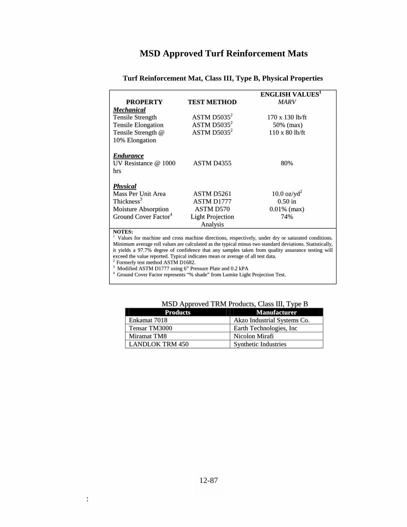
::
MSD Approved Turf Reinforcement Mats
Turf Reinforcement Mat, Class III, Type B, Physical Properties
EENNGGLLIISSHH VVAALLUUEESS11 PPRROOPPEERRTTYY TTEESSTT MMEETTHHOODD MMAARRVV
MMeecchhaanniiccaall TTeennssiillee SSttrreennggtthh AASSTTMM DD5500335522 117700 xx 113300 llbb//fftt TTeennssiillee EElloonnggaattiioonn AASSTTMM DD5500335522 5500%% ((mmaaxx)) TTeennssiillee SSttrreennggtthh @@ 1100%% EElloonnggaattiioonn
AASSTTMM DD5500335522 111100 xx 8800 llbb//fftt
EEnndduurraannccee UUVV RReessiissttaannccee @@ 11000000 hhrrss
AASSTTMM DD44335555 8800%%
PPhhyyssiiccaall MMaassss PPeerr UUnniitt AArreeaa AASSTTMM DD55226611 1100..00 oozz//yydd22 TThhiicckknneessss33 AASSTTMM DD11777777 00..5500 iinn MMooiissttuurree AAbbssoorrppttiioonn AASSTTMM DD557700 00..0011%% ((mmaaxx)) GGrroouunndd CCoovveerr FFaaccttoorr44 LLiigghhtt PPrroojjeeccttiioonn
AAnnaallyyssiiss 7744%%
NNOOTTEESS:: 11 VVaalluueess ffoorr mmaacchhiinnee aanndd ccrroossss mmaacchhiinnee ddiirreeccttiioonnss,, rreessppeeccttiivveellyy,, uunnddeerr ddrryy oorr ssaattuurraatteedd ccoonnddiittiioonnss.. MMiinniimmuumm aavveerraaggee rroollll vvaalluueess aarree ccaallccuullaatteedd aass tthhee ttyyppiiccaall mmiinnuuss ttwwoo ssttaannddaarrdd ddeevviiaattiioonnss.. SSttaattiissttiiccaallllyy,, iitt yyiieellddss aa 9977..77%% ddeeggrreeee ooff ccoonnffiiddeennccee tthhaatt aannyy ssaammpplleess ttaakkeenn ffrroomm qquuaalliittyy aassssuurraannccee tteessttiinngg wwiillll eexxcceeeedd tthhee vvaalluuee rreeppoorrtteedd.. TTyyppiiccaall iinnddiiccaatteess mmeeaann oorr aavveerraaggee ooff aallll tteesstt ddaattaa.. 22 FFoorrmmeerrllyy tteesstt mmeetthhoodd AASSTTMM DD11668822.. 33 MMooddiiffiieedd AASSTTMM DD11777777 uussiinngg 66”” PPrreessssuurree PPllaattee aanndd 00..22 kkPPAA
44 GGrroouunndd CCoovveerr FFaaccttoorr rreepprreesseennttss ““%% sshhaaddee”” ffrroomm LLuummiittee LLiigghhtt PPrroojjeeccttiioonn TTeesstt..
MMSSDD AApppprroovveedd TTRRMM PPrroodduuccttss,, CCllaassss IIIIII,, TTyyppee BB PPrroodduuccttss MMaannuuffaaccttuurreerr
EEnnkkaammaatt 77001188 AAkkzzoo IInndduussttrriiaall SSyysstteemmss CCoo.. TTeennssaarr TTMM33000000 EEaarrtthh TTeecchhnnoollooggiieess,, IInncc MMiirraammaatt TTMM88 NNiiccoolloonn MMiirraaffii LLAANNDDLLOOKK TTRRMM 445500 SSyynntthheettiicc IInndduussttrriieess
12-87
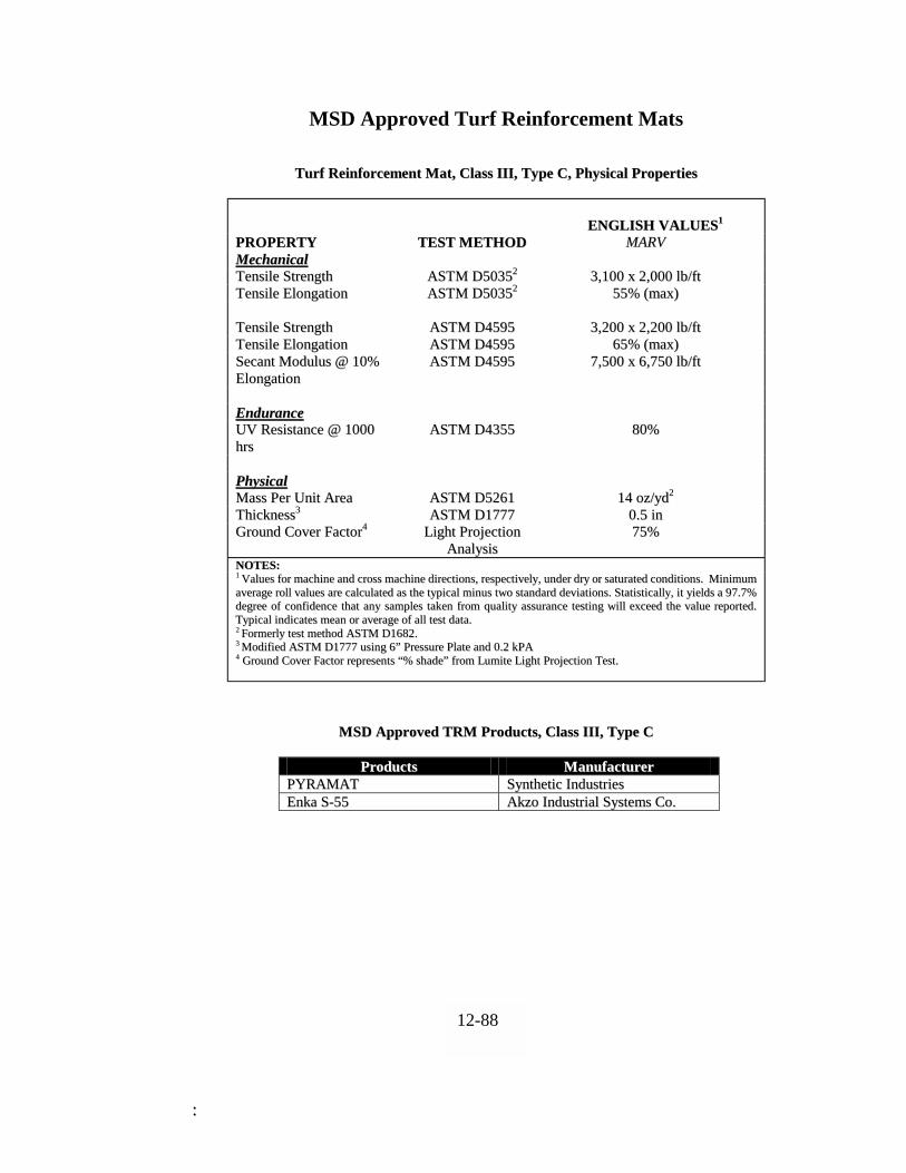
::
MSD Approved Turf Reinforcement Mats
TTuurrff RReeiinnffoorrcceemmeenntt MMaatt,, CCllaassss IIIIII,, TTyyppee CC,, PPhhyyssiiccaall PPrrooppeerrttiieess
EENNGGLLIISSHH VVAALLUUEESS11
PPRROOPPEERRTTYY TTEESSTT MMEETTHHOODD MMAARRVV MMeecchhaanniiccaall TTeennssiillee SSttrreennggtthh AASSTTMM DD5500335522 33,,110000 xx 22,,000000 llbb//fftt TTeennssiillee EElloonnggaattiioonn AASSTTMM DD5500335522 5555%% ((mmaaxx)) TTeennssiillee SSttrreennggtthh AASSTTMM DD44559955 33,,220000 xx 22,,220000 llbb//fftt TTeennssiillee EElloonnggaattiioonn AASSTTMM DD44559955 6655%% ((mmaaxx)) SSeeccaanntt MMoodduulluuss @@ 1100%% EElloonnggaattiioonn
AASSTTMM DD44559955 77,,550000 xx 66,,775500 llbb//fftt
EEnndduurraannccee UUVV RReessiissttaannccee @@ 11000000 hhrrss
AASSTTMM DD44335555 8800%%
PPhhyyssiiccaall MMaassss PPeerr UUnniitt AArreeaa AASSTTMM DD55226611 1144 oozz//yydd22 TThhiicckknneessss33 AASSTTMM DD11777777 00..55 iinn GGrroouunndd CCoovveerr FFaaccttoorr44 LLiigghhtt PPrroojjeeccttiioonn
AAnnaallyyssiiss 7755%%
NNOOTTEESS:: 11 VVaalluueess ffoorr mmaacchhiinnee aanndd ccrroossss mmaacchhiinnee ddiirreeccttiioonnss,, rreessppeeccttiivveellyy,, uunnddeerr ddrryy oorr ssaattuurraatteedd ccoonnddiittiioonnss.. MMiinniimmuumm aavveerraaggee rroollll vvaalluueess aarree ccaallccuullaatteedd aass tthhee ttyyppiiccaall mmiinnuuss ttwwoo ssttaannddaarrdd ddeevviiaattiioonnss.. SSttaattiissttiiccaallllyy,, iitt yyiieellddss aa 9977..77%% ddeeggrreeee ooff ccoonnffiiddeennccee tthhaatt aannyy ssaammpplleess ttaakkeenn ffrroomm qquuaalliittyy aassssuurraannccee tteessttiinngg wwiillll eexxcceeeedd tthhee vvaalluuee rreeppoorrtteedd.. TTyyppiiccaall iinnddiiccaatteess mmeeaann oorr aavveerraaggee ooff aallll tteesstt ddaattaa.. 22 FFoorrmmeerrllyy tteesstt mmeetthhoodd AASSTTMM DD11668822.. 33 MMooddiiffiieedd AASSTTMM DD11777777 uussiinngg 66”” PPrreessssuurree PPllaattee aanndd 00..22 kkPPAA
44 GGrroouunndd CCoovveerr FFaaccttoorr rreepprreesseennttss ““%% sshhaaddee”” ffrroomm LLuummiittee LLiigghhtt PPrroojjeeccttiioonn TTeesstt..
MMSSDD AApppprroovveedd TTRRMM PPrroodduuccttss,, CCllaassss IIIIII,, TTyyppee CC
PPrroodduuccttss MMaannuuffaaccttuurreerr PPYYRRAAMMAATT SSyynntthheettiicc IInndduussttrriieess EEnnkkaa SS--5555 AAkkzzoo IInndduussttrriiaall SSyysstteemmss CCoo..
12-88