Embed Size (px)
Citation preview


xStack® DGS-3620 Series Layer 3 Managed Stackable Gigabit Switch CLI Reference Guide
II
Table of Contents Chapter 1 Using the Command Line Interface............................................................................. 1 Chapter 2 Basic Management Commands .................................................................................. 9
Chapter 3 802.1X Commands.................................................................................................... 32
Chapter 4 Access Authentication Control (AAC) Commands .................................................... 57
Chapter 5 Access Control List (ACL) Commands.................................................................... 100
Chapter 6 Access Control List (ACL) Egress Commands ....................................................... 128 Chapter 7 ARP Commands...................................................................................................... 147
Chapter 8 ARP Spoofing Prevention Commands .................................................................... 154
Chapter 9 Asymmetric VLAN Commands ................................................................................ 156
Chapter 10 Auto Configuration Commands ............................................................................... 158
Chapter 11 Bidirectional Forwarding Detection (BFD) Commands ........................................... 160
Chapter 12 Border Gateway Protocol (BGP) Commands ......................................................... 165 Chapter 13 BPDU Attack Protection Commands....................................................................... 224
Chapter 14 Cable Diagnostics Commands ................................................................................ 229
Chapter 15 CFM Commands ..................................................................................................... 232
Chapter 16 Command List History Commands ......................................................................... 268
Chapter 17 Command Logging Commands .............................................................................. 271
Chapter 18 Common Unicast Routing Commands .................................................................... 273 Chapter 19 Compound Authentication Commands ................................................................... 287
Chapter 20 Debug Software Commands ................................................................................... 297
Chapter 21 DHCP Local Relay Commands ............................................................................... 368
Chapter 22 DHCP Relay Commands ........................................................................................ 372
Chapter 23 DHCP Server Commands ....................................................................................... 390
Chapter 24 DHCP Server Screening Commands ...................................................................... 413 Chapter 25 DHCPv6 Relay Commands ..................................................................................... 425
Chapter 26 DHCPv6 Server Commands ................................................................................... 432
Chapter 27 Digital Diagnostic Monitoring (DDM) Commands ................................................... 447
Chapter 28 Distance Vector Multicast Routing Protocol (DVMRP) Commands ........................ 454
Chapter 29 D-Link License Management System (DLMS) Commands .................................... 460 Chapter 30 Domain Name System (DNS) Relay Commands ................................................... 462
Chapter 31 Domain Name System (DNS) Resolver Commands .............................................. 467
Chapter 32 DoS Attack Prevention Commands......................................................................... 474
Chapter 33 D-Link Unidirectional Link Detection (DULD) Commands ...................................... 478
Chapter 34 Ethernet Ring Protection Switching (ERPS) Commands ........................................ 480
Chapter 35 Energy Efficient Ethernet (EEE) Commands .......................................................... 489 Chapter 36 External Alarm Commands ..................................................................................... 491
Chapter 37 FDB Commands ...................................................................................................... 493

xStack® DGS-3620 Series Layer 3 Managed Stackable Gigabit Switch CLI Reference Guide
III
Chapter 38 File System Management Commands .................................................................... 502
Chapter 39 Filter Commands ..................................................................................................... 512
Chapter 40 Flex Link Commands .............................................................................................. 515 Chapter 41 FTP Client Commands ............................................................................................ 518
Chapter 42 Gratuitous ARP Commands .................................................................................... 526
Chapter 43 Internet Group Management Protocol (IGMP) Commands..................................... 531
Chapter 44 IGMP Proxy Commands ......................................................................................... 539
Chapter 45 IGMP Snooping Commands ................................................................................... 544
Chapter 46 IGMP Snooping Multicast (ISM) VLAN Commands ................................................ 563 Chapter 47 IP Interface Commands .......................................................................................... 574
Chapter 48 IP Multicasting Commands ..................................................................................... 584
Chapter 49 IP Route Filter Commands ...................................................................................... 589
Chapter 50 IP Routing Commands ............................................................................................ 608
Chapter 51 IP Tunnel Commands ............................................................................................. 621
Chapter 52 IPv6 NDP Commands ............................................................................................. 631 Chapter 53 IP-MAC-Port Binding (IMPB) Commands ............................................................... 639
Chapter 54 Japanese Web-based Access Control (JWAC) Commands ................................... 669
Chapter 55 Jumbo Frame Commands ....................................................................................... 693
Chapter 56 LACP Configuration Commands ............................................................................. 696
Chapter 57 Layer 2 Protocol Tunneling (L2PT) Commands ...................................................... 698
Chapter 58 Limited Multicast IP Address Commands ............................................................... 702 Chapter 59 Link Aggregation Commands .................................................................................. 711
Chapter 60 LLDP Commands .................................................................................................... 716
Chapter 61 LLDP Data Center Bridging Exchange Protocol (LLDP-DCBX) Commands .......... 739
Chapter 62 Loopback Detection Commands ............................................................................. 743
Chapter 63 Loopback Interface Commands .............................................................................. 750 Chapter 64 MAC Notification Commands .................................................................................. 753
Chapter 65 MAC-based Access Control Commands ................................................................ 758
Chapter 66 MD5 Configuration Commands ............................................................................... 774
Chapter 67 Mirror Commands.................................................................................................... 777
Chapter 68 MLD Proxy Commands ........................................................................................... 783
Chapter 69 MLD Snooping Commands ..................................................................................... 788 Chapter 70 MLD Snooping Multicast (MSM) VLAN Commands ............................................... 805
Chapter 71 Modify Login Banner and Prompt Commands ........................................................ 816
Chapter 72 Multicast Listener Discovery (MLD) Commands ..................................................... 820
Chapter 73 Network Load Balancing (NLB) Commands ........................................................... 825
Chapter 74 Network Management Commands .......................................................................... 831
Chapter 75 Network Monitoring Commands .............................................................................. 848 Chapter 76 Network Time Protocol (NTP) Commands .............................................................. 872
Chapter 77 OAM Commands ..................................................................................................... 888

xStack® DGS-3620 Series Layer 3 Managed Stackable Gigabit Switch CLI Reference Guide
IV
Chapter 78 Open Shortest Path First (OSPF) Command List ................................................... 895
Chapter 79 OSPFv3 Commands ............................................................................................... 917
Chapter 80 Packet Storm Commands ....................................................................................... 936 Chapter 81 Password Recovery Commands ............................................................................. 942
Chapter 82 Protocol Independent Multicast (PIM) Commands ................................................. 945
Chapter 83 PIM6-SM Commands .............................................................................................. 963
Chapter 84 Policy Route Commands ......................................................................................... 987
Chapter 85 Port Security Commands ........................................................................................ 991
Chapter 86 Power over Ethernet (PoE) Commands .................................................................. 999 Chapter 87 Power Saving Commands ..................................................................................... 1004
Chapter 88 Precision Time Protocol (PTP) Commands .......................................................... 1010
Chapter 89 Priority Flow Control (PFC) Commands ................................................................ 1028
Chapter 90 Protocol VLAN Commands ................................................................................... 1032
Chapter 91 Quality of Service (QoS) Commands .................................................................... 1038
Chapter 92 Q-in-Q Commands ................................................................................................ 1056 Chapter 93 Reboot Schedule Commands ............................................................................... 1070
Chapter 94 Routing Information Protocol (RIP) Commands .................................................... 1073
Chapter 95 RIPng Commands ................................................................................................. 1078
Chapter 96 RSPAN Commands............................................................................................... 1083
Chapter 97 Safeguard Engine Commands .............................................................................. 1089
Chapter 98 SD Card Management commands ........................................................................ 1091 Chapter 99 Secure File Transfer Protocol (SFTP) Commands ............................................... 1099
Chapter 100 sFlow Commands.................................................................................................. 1102
Chapter 101 Single IP Management Commands ...................................................................... 1113
Chapter 102 SNMPv1/v2/v3 Commands ................................................................................... 1122
Chapter 103 Spanning Tree Protocol (STP) commands ........................................................... 1141 Chapter 104 SSH Commands.................................................................................................... 1154
Chapter 105 SSL Commands .................................................................................................... 1166
Chapter 106 Stacking Commands ............................................................................................. 1174
Chapter 107 Static MAC-based VLAN Commands ................................................................... 1182
Chapter 108 Static Multicast Route Commands ........................................................................ 1185
Chapter 109 Subnet VLAN Commands ..................................................................................... 1188 Chapter 110 Super VLAN and Sub-VLAN Commands .............................................................. 1193
Chapter 111 Surveillance VLAN Commands ............................................................................. 1199
Chapter 112 Switch Port Commands ......................................................................................... 1205
Chapter 113 System Severity Commands ................................................................................. 1209
Chapter 114 Tech Support Commands ..................................................................................... 1211
Chapter 115 Time and SNTP Commands ................................................................................. 1214 Chapter 116 Traffic Segmentation Commands .......................................................................... 1221
Chapter 117 UDP Helper Commands ........................................................................................ 1223

xStack® DGS-3620 Series Layer 3 Managed Stackable Gigabit Switch CLI Reference Guide
V
Chapter 118 Unicast Reverse Path Forwarding (URPF) Commands ........................................ 1229
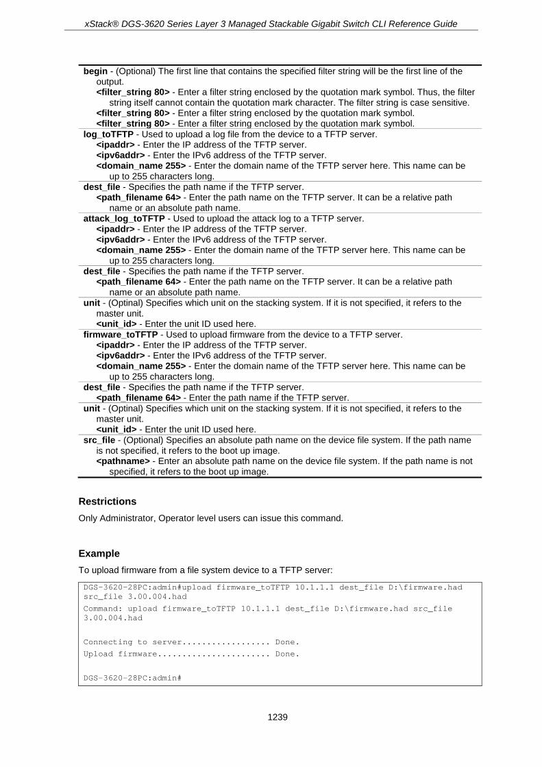
Chapter 119 Utility Commands .................................................................................................. 1234
Chapter 120 Virtual Router Redundancy Protocol (VRRP) Commands .................................... 1260 Chapter 121 VLAN Commands.................................................................................................. 1268
Chapter 122 VLAN Counter Commands .................................................................................... 1285
Chapter 123 VLAN Trunking Commands .................................................................................. 1290
Chapter 124 Voice VLAN Commands ....................................................................................... 1294
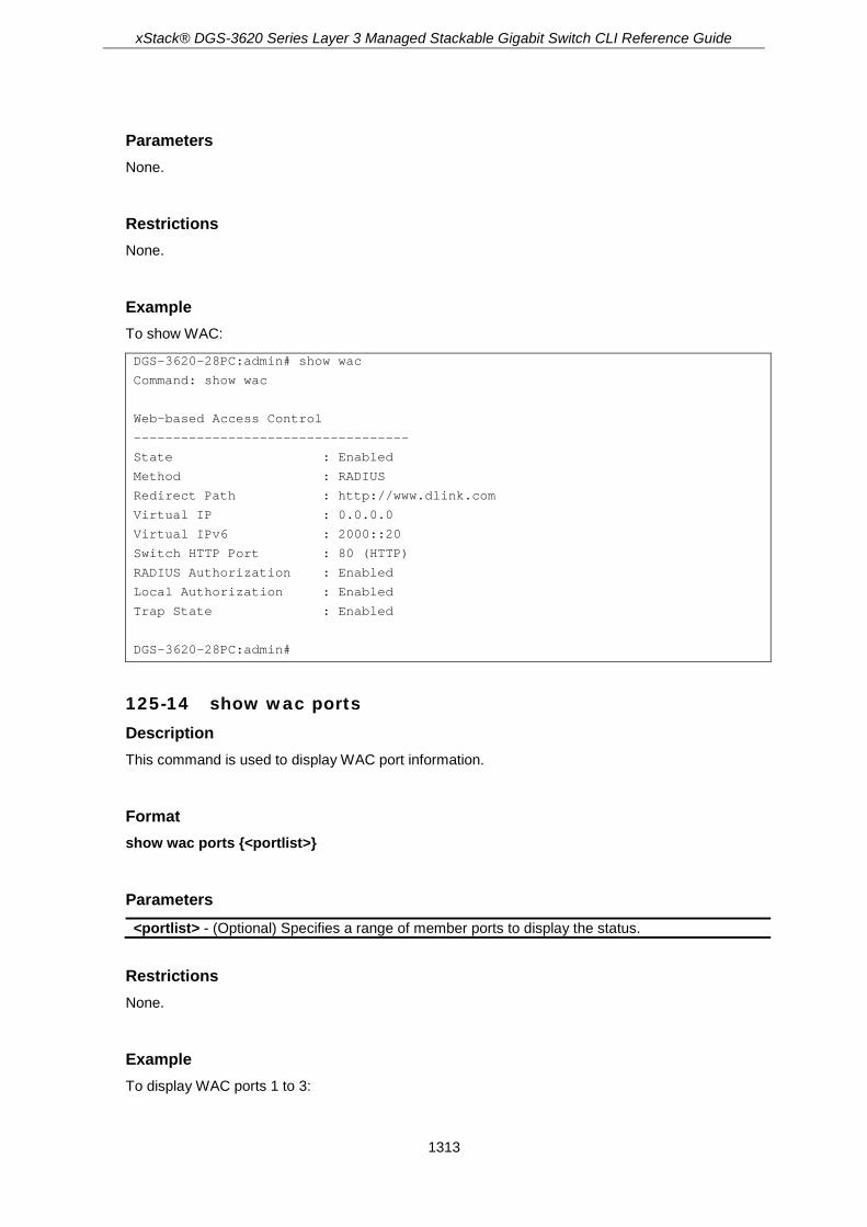
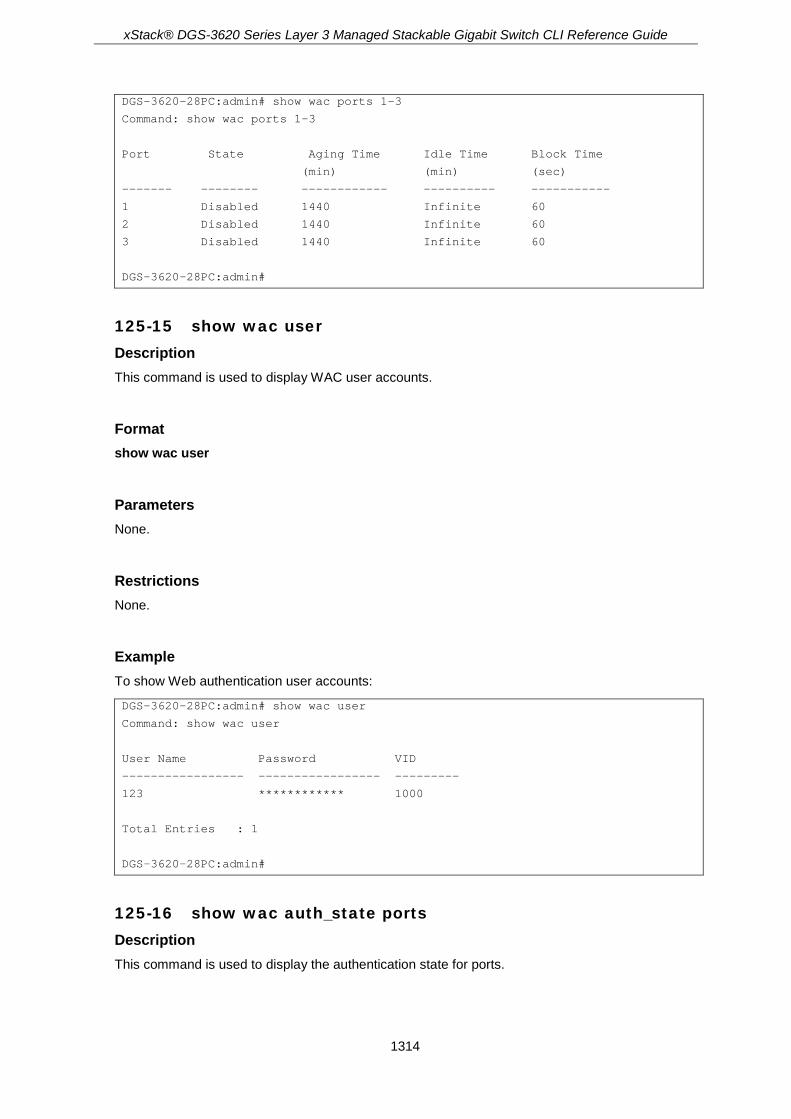
Chapter 125 Web-based Access Control (WAC) Commands ................................................... 1304
Chapter 126 Weighted Random Early Detection (WRED) Commands ..................................... 1319 Appendix A Password Recovery Procedure ............................................................................. 1326
Appendix B System Log Entries ............................................................................................... 1328
Appendix C Trap Entries ........................................................................................................... 1354
Appendix D RADIUS Attributes Assignment ............................................................................. 1362
Appendix E IETF RADIUS Attributes Support .......................................................................... 1365

xStack® DGS-3620 Series Layer 3 Managed Stackable Gigabit Switch CLI Reference Guide
1
Chapter 1 Using the Command Line Interface
The DGS-3620 Layer 3 stackable Gigabit Ethernet switch series are members of the D-Link xStack® family. Ranging from 10/100/1000Mbps edge switches to core gigabit switches, the xStack® switch family has been future-proof designed to provide a stacking architecture with fault tolerance, flexibility, port density, robust security and maximum throughput with a user-friendly management interface for the networking professional.
The Switch can be managed through the Switch’s serial port, Telnet, SNMP or the Web-based management agent. The Command Line Interface (CLI) can be used to configure and manage the Switch via the serial port or Telnet interfaces.
This manual provides a reference for all of the commands contained in the CLI. Every command will be introduced in terms of purpose, format, description, parameters, and examples. Configuration and management of the Switch via the Web-based management agent are discussed in the Web UI Reference Guide. For detailed information on installing hardware please also refer to the Harware Installation Guide.
1-1 Accessing the Switch via the Serial Port The Switch’s serial port’s default settings are as follows:
• 115200 baud
• no parity
• 8 data bits
• 1 stop bit
A computer running a terminal emulation program capable of emulating a VT-100 terminal and a serial port configured as above is then connected to the Switch’s serial port via an RJ-45 to RS-232 DB-9 convertor cable.
With the serial port properly connected to a management computer, the following screen should be visible.
DGS-3620-28PC Gigabit Ethernet Switch
Command Line Interface
Firmware: Build 3.00.004
Copyright(C) 2017 D-Link Corporation. All rights reserved.
UserName:
There is no initial username or password. Just press the Enter key twice to display the CLI input cursor − DGS-3620-28PC:admin#. This is the command line where all commands are input.

xStack® DGS-3620 Series Layer 3 Managed Stackable Gigabit Switch CLI Reference Guide
2
1-2 Setting the Switch’s IP Address Each Switch must be assigned its own IP Address, which is used for communication with an SNMP network manager or other TCP/IP application (for example BOOTP, TFTP). The Switch’s default IP address is 10.90.90.90. You can change the default Switch IP address to meet the specification of your networking address scheme.
The Switch is also assigned a unique MAC address by the factory. This MAC address cannot be changed, and can be found on the initial boot console screen – shown below.
Boot Procedure V1.00.016
-------------------------------------------------------------------------------
Power On Self Test ........................................ 100 %
MAC Address : 78-54-2E-88-99-77
H/W Version : A1
Please Wait, Loading V3.00.004 Runtime Image ............. 100 %
UART init ................................................. 100 %
Starting runtime image
Press any key to login...
The Switch’s MAC address can also be found in the Web management program on the Device Information (Basic Settings) window on the Configuration menu.
The IP address for the Switch must be set before it can be managed with the Web-based manager. The Switch IP address can be automatically set using BOOTP or DHCP protocols, in which case the actual address assigned to the Switch must be known.
Starting at the command line prompt, enter the commands config ipif System ipaddress xxx.xxx.xxx.xxx/yyy.yyy.yyy.yyy. Where the x’s represent the IP address to be assigned to the IP interface named System and the y’s represent the corresponding subnet mask.
Alternatively, you can enter config ipif System ipaddress xxx.xxx.xxx.xxx/z. Where the x’s represent the IP address to be assigned to the IP interface named System and the z represents the corresponding number of subnets in CIDR notation.
The IP interface named System on the Switch can be assigned an IP address and subnet mask which can then be used to connect a management station to the Switch’s Telnet or Web-based management agent
DGS-3620-28PC:admin# config ipif System ipaddress 10.24.22.100/255.0.0.0
Command: config ipif System ipaddress 10.24.22.100/8
Success.
DGS-3620-28PC:admin#

xStack® DGS-3620 Series Layer 3 Managed Stackable Gigabit Switch CLI Reference Guide
3
In the above example, the Switch was assigned an IP address of 10.24.22.100 with a subnet mask of 255.0.0.0. The system message Success indicates that the command was executed successfully. The Switch can now be configured and managed via Telnet, SNMP MIB browser and the CLI or via the Web-based management agent using the above IP address to connect to the Switch.
There are a number of helpful features included in the CLI. Entering the ? command will display a list of all of the top-level commands.
DGS-3620-28PC:admin#?
Command: ?
..
?
cable_diag ports
cd
cfm dm
cfm linktrace
cfm lm
cfm lock md
cfm loopback
change drive
clear
clear address_binding dhcp_snoop binding_entry ports
clear address_binding nd_snoop binding_entry ports
clear arptable
clear attack_log
clear bgp
clear bgp dampening
clear bgp flap_statistics
clear cfm dm
clear cfm lm
clear cfm pkt_cnt
clear counters
CTRL+C ESC q Quit SPACE n Next Page ENTER Next Entry a All
When entering a command without its required parameters, the CLI will prompt you with a Next possible completions: message.
DGS-3620-28PC:admin#config account
Command: config account
Next possible completions:
<username 15>
DGS-3620-28PC:admin#
In this case, the command config account was entered with the parameter <username>. The CLI will then prompt to enter the <username> with the message, Next possible completions:. Every command in the CLI has this feature, and complex commands have several layers of parameter prompting.
xStack® DGS-3620 Series Layer 3 Managed Stackable Gigabit Switch CLI Reference Guide
4
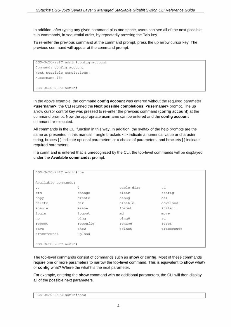
In addition, after typing any given command plus one space, users can see all of the next possible sub-commands, in sequential order, by repeatedly pressing the Tab key.
To re-enter the previous command at the command prompt, press the up arrow cursor key. The previous command will appear at the command prompt.
DGS-3620-28PC:admin#config account
Command: config account
Next possible completions:
<username 15>
DGS-3620-28PC:admin#
In the above example, the command config account was entered without the required parameter <username>, the CLI returned the Next possible completions: <username> prompt. The up arrow cursor control key was pressed to re-enter the previous command (config account) at the command prompt. Now the appropriate username can be entered and the config account command re-executed.
All commands in the CLI function in this way. In addition, the syntax of the help prompts are the same as presented in this manual − angle brackets < > indicate a numerical value or character string, braces { } indicate optional parameters or a choice of parameters, and brackets [ ] indicate required parameters.
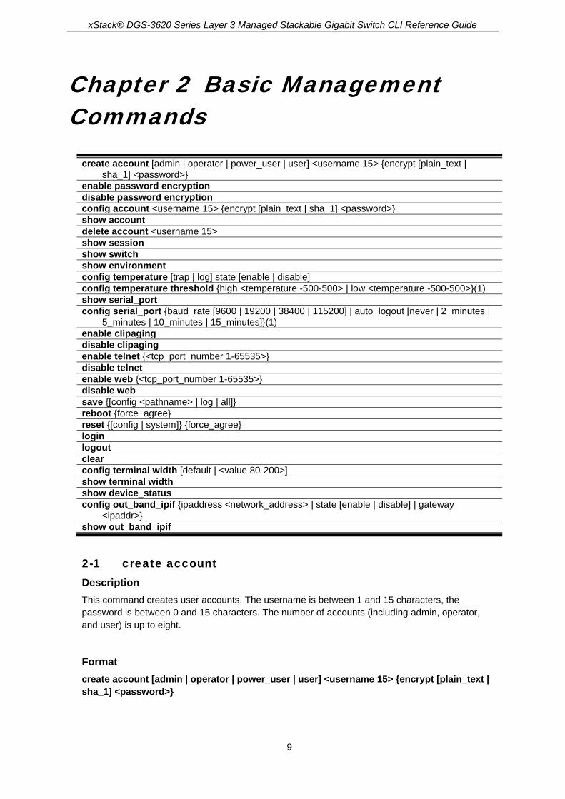
If a command is entered that is unrecognized by the CLI, the top-level commands will be displayed under the Available commands: prompt.
DGS-3620-28PC:admin#the
Available commands:
.. ? cable_diag cd
cfm change clear config
copy create debug del
delete dir disable download
enable erase format install
login logout md move
no ping ping6 rd
reboot reconfig rename reset
save show telnet traceroute
traceroute6 upload
DGS-3620-28PC:admin#
The top-level commands consist of commands such as show or config. Most of these commands require one or more parameters to narrow the top-level command. This is equivalent to show what? or config what? Where the what? is the next parameter.
For example, entering the show command with no additional parameters, the CLI will then display all of the possible next parameters.
DGS-3620-28PC:admin#show

xStack® DGS-3620 Series Layer 3 Managed Stackable Gigabit Switch CLI Reference Guide
5
Command: show
Next possible completions:
802.1p 802.1x aaa access_profile
account accounting acct_client address_binding
arp_spoofing_prevention arpentry asymmetric_vlan
attack_log auth_client auth_diagnostics
auth_session_statistics auth_statistics authen
authen_enable authen_login authen_policy authentication
authorization autoconfig bandwidth_control bfd
bgp boot_file bpdu_protection
broadcast_ping_reply cfm command
command_history community_encryption config
cpu current_config ddm device_status
dhcp dhcp_local_relay dhcp_relay dhcp_server
dhcpv6 dhcpv6_relay dhcpv6_server dlms
dnsr dos_prevention dot1v_protocol_group
dscp duld dvmrp ecmp
egress_access_profile egress_flow_meter environment
erps error ethernet_oam external_alarm
fdb filter flow_meter gratuitous_arp
greeting_message gvrp hol_prevention host_name
igmp igmp_proxy igmp_snooping ip
ip_tunnel ipfdb ipif
ipif_ipv6_link_local_auto ipmc ipmroute
iproute ipv6 ipv6route jumbo_frame
jwac l2protocol_tunnel lacp_port led
limited_multicast_addr link_aggregation lldp
lldp_dcbx lldp_med log log_save_timing
log_software_module loopback loopdetect
mac_based_access_control mac_based_access_control_local
mac_based_vlan mac_notification max_mcast_group
mcast_filter_profile md5 mirror
mld mld_proxy mld_snooping multicast
multicast_fdb name_server nlb ospf
ospfv3 out_band_ipif packet password_recovery
per_queue pfc pim pim-ssm
pim6 poe policy_route port
port_group port_security port_security_entry
port_vlan ports power_saving private_vlan
ptp pvid qinq radius
rcp reboot rip ripng
rmon route route_map router_ports
rspan safeguard_engine scheduling
scheduling_mechanism serial_port session
sflow sftp sim snmp
sntp ssh ssl stack_device
stack_information stacking_mode storage_media_info
stp sub_vlan subnet_vlan super_vlan
surveillance_vlan switch syslog system_severity
tacacs tech_support telnet terminal
tftp time time_range traffic

xStack® DGS-3620 Series Layer 3 Managed Stackable Gigabit Switch CLI Reference Guide
6
traffic_segmentation trap trusted_host
udp_helper utilization vlan vlan_precedence
vlan_translation vlan_translation_profile vlan_trunk
voice_vlan vrrp wac wred
DGS-3620-28PC:admin#
In the above example, all of the possible next parameters for the show command are displayed. At the next command prompt, the up arrow was used to re-enter the show command, followed by the account parameter. The CLI then displays the user accounts configured on the Switch.
1-3 Command Syntax Symbols The following symbols are used to describe how command entries are made and values and arguments are specified in this manual. The online help contained in the CLI and available through the console interface uses the same syntax.
Note: All commands are case-sensitive. Be sure to disable Caps Lock or any other unwanted function that changes text case.
Syntax Description
angle brackets < > Encloses a variable or value. Users must specify the variable or value. For example, in the syntax
create ipif <ipif_name 12> {<network_address>} <vlan_name 32> {secondary | state [enable | disable] | proxy_arp [enable | disable] {local [enable | disable]}}
users must supply an IP interface name for <ipif_name 12> and a VLAN name for <vlan_name 32> when entering the command. DO NOT TYPE THE ANGLE BRACKETS.
square brackets [ ] Encloses a required value or list of required arguments. Only one value or argument must be specified. For example, in the syntax
create account [admin | operator | power_user | user] <username 15> {encrypt [plain_text | sha_1] <password>}
users must specify either the admin-, operator-, power_user-level or user-level account when entering the command. DO NOT TYPE THE SQUARE BRACKETS.
vertical bar | Separates mutually exclusive items in a list. For example, in the syntax
reset {[config | system]} {force_agree}
users may choose config or system in the command. DO NOT TYPE THE VERTICAL BAR.
braces { } Encloses an optional value or a list of optional arguments. One or more values or arguments can be specified. For example, in the syntax
reset {[config | system]} {force_agree}
users may choose config or system in the command. DO NOT TYPE THE BRACES.
parentheses ( ) Indicates at least one or more of the values or arguments in the preceding syntax enclosed by braces must be specified. For example,

xStack® DGS-3620 Series Layer 3 Managed Stackable Gigabit Switch CLI Reference Guide
7
in the syntax
config dhcp_relay {hops <int 1-16> | time <sec 0-65535>}(1)
users have the option to specify hops or time or both of them. The "(1)" following the set of braces indicates at least one argument or value within the braces must be specified. DO NOT TYPE THE PARENTHESES.
ipif <ipif_name 12>
metric <value 1-31>
12 means the maximum length of the IP interface name.
1-31 means the legal range of the metric value.
1-4 Line Editing Keys Keys Description
Delete Delete character under cursor and shift remainder of line to left.
Backspace Delete character to left of cursor and shift remainder of line to left.
CTRL+R Toggle on and off. When toggled on, inserts text and shifts previous
text to right.
Up Arrow Repeats the previously entered command. Each time the up arrow is pressed, the command previous to that displayed appears. This way it is possible to review the command history for the current session. Use the down arrow to progress sequentially forward through the command history list.
Down Arrow The down arrow will display the next command in the command history entered in the current session. This displays each command sequentially as it was entered. Use the up arrow to review previous commands.
Left Arrow Move cursor to left.
Right Arrow Move cursor to right
Tab Help user to select appropriate token.
The screen display pauses when the show command output reaches the end of the page.
1-5 Multiple Page Display Control Keys Keys Description
Space Displays the next page.
CTRL+C Stops the display of remaining pages when multiple pages are to be displayed.
ESC Stops the display of remaining pages when multiple pages are to be displayed.
n Displays the next page.
p Displays the previous page.
q Stops the display of remaining pages when multiple pages are to be displayed.

xStack® DGS-3620 Series Layer 3 Managed Stackable Gigabit Switch CLI Reference Guide
8
r Refreshes the pages currently displayed.
a Displays the remaining pages without pausing between pages.
Enter Displays the next line or table entry.
xStack® DGS-3620 Series Layer 3 Managed Stackable Gigabit Switch CLI Reference Guide
9
Chapter 2 Basic Management Commands
create account [admin | operator | power_user | user] <username 15> {encrypt [plain_text | sha_1] <password>}
enable password encryption disable password encryption config account <username 15> {encrypt [plain_text | sha_1] <password>} show account delete account <username 15> show session show switch show environment config temperature [trap | log] state [enable | disable] config temperature threshold {high <temperature -500-500> | low <temperature -500-500>}(1) show serial_port config serial_port {baud_rate [9600 | 19200 | 38400 | 115200] | auto_logout [never | 2_minutes |
5_minutes | 10_minutes | 15_minutes]}(1) enable clipaging disable clipaging enable telnet {<tcp_port_number 1-65535>} disable telnet enable web {<tcp_port_number 1-65535>} disable web save {[config <pathname> | log | all]} reboot {force_agree} reset {[config | system]} {force_agree} login logout clear config terminal width [default | <value 80-200>] show terminal width show device_status config out_band_ipif {ipaddress <network_address> | state [enable | disable] | gateway
<ipaddr>} show out_band_ipif
2-1 create account Description This command creates user accounts. The username is between 1 and 15 characters, the password is between 0 and 15 characters. The number of accounts (including admin, operator, and user) is up to eight.
Format create account [admin | operator | power_user | user] <username 15> {encrypt [plain_text | sha_1] <password>}

xStack® DGS-3620 Series Layer 3 Managed Stackable Gigabit Switch CLI Reference Guide
10
Parameters admin - Specifies the name of the admin account. operator - Specifies the name of the operator account. power_user - Specifies a power user level account. The power user level is lower than the
operator level and higher than the user level. user - Specifies the name of the user account. <username 15> - Enter a username of up to 15 characters. encrypt - Specifies the encryption used.
plain_text - Specifies the password in plain text form. sha_1 - Specifies the password in SHA-1 encrypted form. <password> - The password for the user account. The length of a password in plain-text form
and encrypted form are different. For a plain-text form password, the password must be a minimum of 0 characters and a maximum of 15 characters. For an encrypted form password, the length is fixed to 35 bytes long. The password is case-sensitive.
Restrictions Only Administrator-level users can issue this command.
Example To create the Administrator-level user “dlink”:
DGS-3620-28PC:admin#create account admin dlink
Command: create account admin dlink
Enter a case-sensitive new password:****
Enter the new password again for confirmation:****
Success.
DGS-3620-28PC:admin#
To create the Operator-level user “Sales”:
DGS-3620-28PC:admin##create account operator Sales
Command: create account operator Sales
Enter a case-sensitive new password:****
Enter the new password again for confirmation:****
Success.
DGS-3620-28PC:admin#
To create the User-level user “System”:
DGS-3620-28PC:admin##create account user System
Command: create account user System
Enter a case-sensitive new password:****
Enter the new password again for confirmation:****
Success.
DGS-3620-28PC:admin#
xStack® DGS-3620 Series Layer 3 Managed Stackable Gigabit Switch CLI Reference Guide
11
2-2 enable password encryption Description The user account configuration information will be stored in the configuration file, and can be applied to the system later. If the password encryption is enabled, the password will be in encrypted form when it is stored in the configuration file. When password encryption is disabled, the password will be in plain text form when it is stored in the configuration file. However, if the created user account directly uses the encrypted password, the password will still be in the encrypted form.
Format enable password encryption
Parameters None.
Restrictions Only Administrator-level users can issue this command.
Example To enable password encryption:
DGS-3620-28PC:admin#enable password encryption
Command: enable password encryption
Success.
DGS-3620-28PC:admin#
2-3 disable password encryption Description The user account configuration information will be stored in the configuration file, and can be applied to the system later. If the password encryption is enabled, the password will be in encrypted form when it is stored in the configuration file. When password encryption is disabled, the password will be in plain text form when it is stored in the configuration file. However, if the created user account directly uses the encrypted password, the password will still be in the encrypted form.
Format disable password encryption
Parameters None.
xStack® DGS-3620 Series Layer 3 Managed Stackable Gigabit Switch CLI Reference Guide
12
Restrictions Only Administrator-level users can issue this command.
Example To disable password encryption:
DGS-3620-28PC:admin#disable password encryption
Command: disable password encryption
Success.
DGS-3620-28PC:admin#
2-4 config account Description When the password information is not specified in the command, the system will prompt the user to input the password interactively. For this case, the user can only input the plain text password.
If the password is present in the command, the user can select to input the password in the plain text form or in the encrypted form. The encryption algorithm is based on SHA-1.
Format config account <username 15> {encrypt [plain_text | sha_1] <password>}
Parameters <username 15> - Enter the name of the account. The account must already be defined. encrypt - (Optional) Specifies the encryption type, plain_text or sha_1.
plain_text - Specifies the password in plain text form. For the plain text form, passwords must have a minimum of 0 and a maximum of 15 characters. The password is case-sensitive
sha_1 - Specifies the password in the SHA-1 encrypted form. For the encrypted form password, the length is fixed to 35 bytes long. The password is case-sensitive.
<password> - Enter the password.
Restrictions Only Administrator-level users can issue this command.
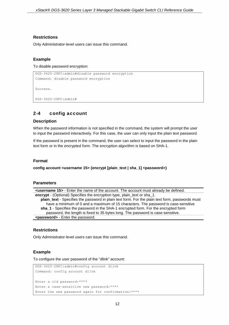
Example To configure the user password of the “dlink” account:
DGS-3620-28PC:admin#config account dlink
Command: config account dlink
Enter a old password:****
Enter a case-sensitive new password:****
Enter the new password again for confirmation:****
xStack® DGS-3620 Series Layer 3 Managed Stackable Gigabit Switch CLI Reference Guide
13
Success.
DGS-3620-28PC:admin#
To configure the user password of the “administrator” account:
DGS-3620-28PC:admin#config account administrator encrypt sha_1 *@&NWoZK3kTsExUV00Ywo1G5jlUKKv+toYg
Command: config account administrator encrypt sha_1 *@&NWoZK3kTsExUV00Ywo1G5jlUKKv+toYg
Success.
DGS-3620-28PC:admin#
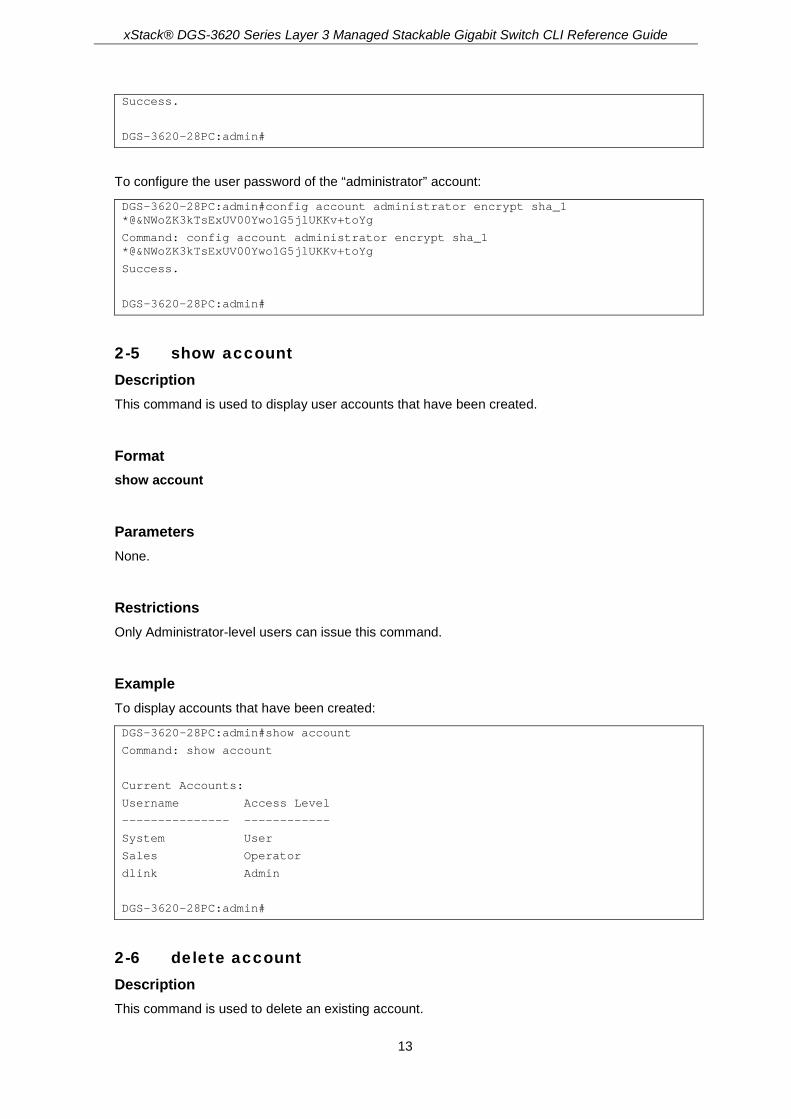
2-5 show account Description This command is used to display user accounts that have been created.
Format show account
Parameters None.
Restrictions Only Administrator-level users can issue this command.
Example To display accounts that have been created:
DGS-3620-28PC:admin#show account
Command: show account
Current Accounts:
Username Access Level
--------------- ------------
System User
Sales Operator
dlink Admin
DGS-3620-28PC:admin#
2-6 delete account Description This command is used to delete an existing account.

xStack® DGS-3620 Series Layer 3 Managed Stackable Gigabit Switch CLI Reference Guide
14
Format delete account <username 15>
Parameters <username 15> - Enter the name of the user who will be deleted.
Restrictions Only Administrator-level users can issue this command. One active admin user must exist.
Example To delete the user account “System”:
DGS-3620-28PC:admin#delete account System
Command: delete account System
Success.
DGS-3620-28PC:admin#
2-7 show session Description This command is used to display a list of current users which are logged in to CLI sessions.
Format show session
Parameters None.
Restrictions Only Administrators and Operators can issue this command.
Example To display accounts a list of currently logged-in users:
DGS-3620-28PC:admin#show session
Command: show session
ID Live Time From Level User
-- ------------ ------------ ----- --------------------
8 23:37:42.270 Serial Port admin Anonymous

xStack® DGS-3620 Series Layer 3 Managed Stackable Gigabit Switch CLI Reference Guide
15
Total Entries: 1
CTRL+C ESC q Quit SPACE n Next Page p Previous Page r Refresh
2-8 show switch Description This command is used to display the switch information.
Format show switch
Parameters None.
Restrictions None.
Example To display the switch information:
DGS-3620-28PC:admin# show switch
Command: show switch
Device Type : DGS-3620-28PC Gigabit Ethernet Switch
Unit ID : 1
MAC Address : 00-DE-BE-14-00-01
IP Address : 10.0.101.254 (Manual)
VLAN Name : vlan101
Subnet Mask : 255.255.255.0
Default Gateway : 0.0.0.0
Boot PROM Version : Build 1.00.016
Firmware Version : Build 3.00.003
Hardware Version : A1
Firmware Type : SI
Serial Number : dfhndslkfds;l//,.\'122po25463682
System Name :
System Location :
System Uptime : 0 days, 0 hours, 46 minutes, 22 seconds
System Contact :
Spanning Tree : Disabled
GVRP : Disabled
IGMP Snooping : Disabled
MLD Snooping : Disabled
RIP : Disabled
PIM : Disabled

xStack® DGS-3620 Series Layer 3 Managed Stackable Gigabit Switch CLI Reference Guide
16
OSPF : Enabled
VLAN Trunk : Disabled
Telnet : Enabled (TCP 23)
Web : Enabled (TCP 80)
SNMP : Disabled
SSL Status : Disabled
SSH Status : Disabled
802.1X : Disabled
Jumbo Frame : Off
CLI Paging : Enabled
MAC Notification : Disabled
Port Mirror : Enabled
SNTP : Disabled
DHCP Relay : Disabled
DNSR Status : Disabled
VRRP : Disabled
HOL Prevention State : Enabled
Syslog Global State : Disabled
Single IP Management : Disabled
Password Encryption Status : Disabled
DNS Resolver : Disabled
DGS-3620-28PC:admin#
2-9 show environment Description This command is used to display the device’s internal and external power, internal temperature, and fan status.
Format show environment
Parameters None.
Restrictions None.
Example To display the switch hardware and fan status:
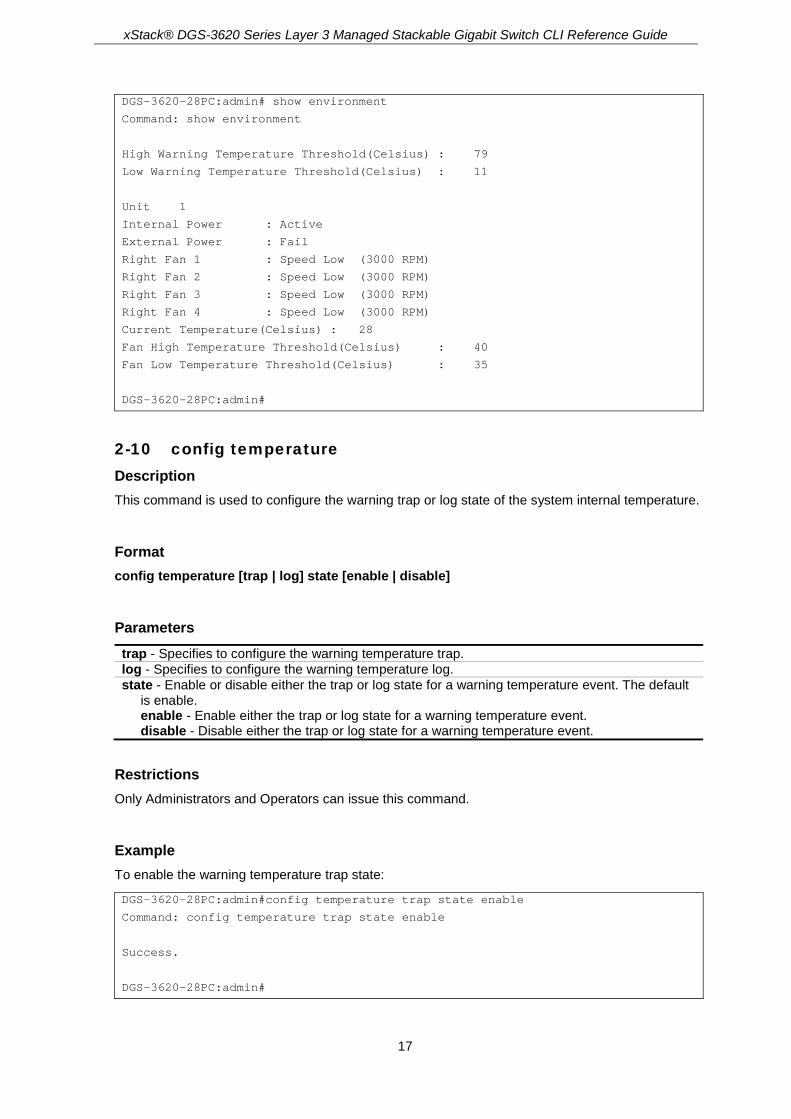
xStack® DGS-3620 Series Layer 3 Managed Stackable Gigabit Switch CLI Reference Guide
17
DGS-3620-28PC:admin# show environment
Command: show environment
High Warning Temperature Threshold(Celsius) : 79
Low Warning Temperature Threshold(Celsius) : 11
Unit 1
Internal Power : Active
External Power : Fail
Right Fan 1 : Speed Low (3000 RPM)
Right Fan 2 : Speed Low (3000 RPM)
Right Fan 3 : Speed Low (3000 RPM)
Right Fan 4 : Speed Low (3000 RPM)
Current Temperature(Celsius) : 28
Fan High Temperature Threshold(Celsius) : 40
Fan Low Temperature Threshold(Celsius) : 35
DGS-3620-28PC:admin#
2-10 config temperature Description This command is used to configure the warning trap or log state of the system internal temperature.
Format config temperature [trap | log] state [enable | disable]
Parameters trap - Specifies to configure the warning temperature trap. log - Specifies to configure the warning temperature log. state - Enable or disable either the trap or log state for a warning temperature event. The default
is enable. enable - Enable either the trap or log state for a warning temperature event. disable - Disable either the trap or log state for a warning temperature event.
Restrictions Only Administrators and Operators can issue this command.
Example To enable the warning temperature trap state:
DGS-3620-28PC:admin#config temperature trap state enable
Command: config temperature trap state enable
Success.
DGS-3620-28PC:admin#

xStack® DGS-3620 Series Layer 3 Managed Stackable Gigabit Switch CLI Reference Guide
18
To enable the warning temperature log state:
DGS-3620-28PC:admin#config temperature log state enable
Command: config temperature log state enable
Success.
DGS-3620-28PC:admin#
2-11 config temperature threshold Description This command is used to configure the warning temperature high threshold or low threshold. When temperature is above the high threshold or below the low threshold, SW will send alarm traps or keep the logs.
Format config temperature threshold {high <temperature -500-500> | low <temperature -500-500>}(1)
Parameters high - Specifies the high threshold value. The high threshold must bigger than the low threshold.
<temperature -500-500> - Enter the high threshold value. This value must be between -500 and 500.
low - Specifies the low threshold value. <temperature -500-500> - Enter the low threshold value. This value must be between -500
and 500.
Restrictions Only Administrators and Operators can issue this command.
Example To configure a warming temperature threshold high of 80:
DGS-3620-28PC:admin#config temperature threshold high 80
Command: config temperature threshold high 80
Success.
DGS-3620-28PC:admin#
2-12 show serial_port Description This command is used to display the current console port setting.

xStack® DGS-3620 Series Layer 3 Managed Stackable Gigabit Switch CLI Reference Guide
19
Format show serial_port
Parameters None.
Restrictions None.
Example To display the console port setting:
DGS-3620-28PC:admin#show serial_port
Command: show serial_port
Baud Rate : 115200
Data Bits : 8
Parity Bits : None
Stop Bits : 1
Auto-Logout : 10 mins
DGS-3620-28PC:admin#
2-13 config serial_port Description This command is used to configure the serial bit rate that will be used to communicate with the management host and the auto logout time for idle connections.
Format config serial_port {baud_rate [9600 | 19200 | 38400 | 115200] | auto_logout [never | 2_minutes | 5_minutes | 10_minutes | 15_minutes]}(1)
Parameters baud_rate - Specifies the baud rate value. The default baud rate is 115200.
9600 - Specifies a baud rate of 9600. 19200 - Specifies a baud rate of 19200. 38400 - Specifies a baud rate of 38400. 115200 - Specifies a baud rate of 115200.
auto_logout - Specifies the timeout value. The default timeout is 10_minutes. never - Specifies to never timeout. 2_minutes - Specifies when the idle value is over 2 minutes, the device will auto logout. 5_minutes - Specifies when the idle value over 5 minutes, the device will auto logout. 10_minutes - Specifies when the idle value is over 10 minutes, the device will auto logout. 15_minutes - Specifies when the idle value is over 15 minutes, the device will auto logout.

xStack® DGS-3620 Series Layer 3 Managed Stackable Gigabit Switch CLI Reference Guide
20
Restrictions Only Administrators and Operators can issue this command.
Example To configure the baud rate:
DGS-3620-28PC:admin# config serial_port baud_rate 9600
Command: config serial_port baud_rate 9600
Success.
DGS-3620-28PC:admin#
2-14 enable clipaging Description This command is used to enable pausing of the screen display when show command output reaches the end of the page. The default setting is enabled.
Format enable clipaging
Parameters None.
Restrictions Only Administrators and Operators can issue this command.
Example To enable pausing of the screen display when show command output reaches the end of the page:
DGS-3620-28PC:admin#enable clipaging
Command: enable clipaging
Success.
DGS-3620-28PC:admin#
2-15 disable clipaging Description This command is used to disable pausing of the screen display when show command output reaches the end of the page. The default setting is enabled.

xStack® DGS-3620 Series Layer 3 Managed Stackable Gigabit Switch CLI Reference Guide
21
Format disable clipaging
Parameters None.
Restrictions Only Administrators and Operators can issue this command.
Example To disable pausing of the screen display when show command output reaches the end of the page:
DGS-3620-28PC:admin#disable clipaging
Command: disable clipaging
Success.
DGS-3620-28PC:admin#
2-16 enable telnet Description This command is used to enable Telnet and configure a port number. The default setting is enabled and the port number is 23.
Format enable telnet {<tcp_port_number 1-65535>}
Parameters <tcp_port_number 1-65535> - (Optional) Specifies the TCP port number. TCP ports are
numbered between 1 and 65535. The “well-known” TCP port for the Telnet protocol is 23.
Restrictions Only Administrators and Operators can issue this command.
Example To enable Telnet and configure a port number:
DGS-3620-28PC:admin#enable telnet 23
Command: enable telnet 23
Success.
DGS-3620-28PC:admin#
xStack® DGS-3620 Series Layer 3 Managed Stackable Gigabit Switch CLI Reference Guide
22
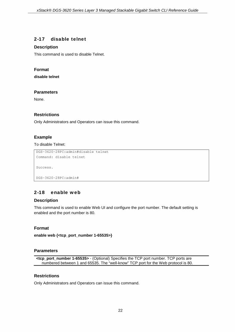
2-17 disable telnet Description This command is used to disable Telnet.
Format disable telnet
Parameters None.
Restrictions Only Administrators and Operators can issue this command.
Example To disable Telnet:
DGS-3620-28PC:admin#disable telnet
Command: disable telnet
Success.
DGS-3620-28PC:admin#
2-18 enable web Description This command is used to enable Web UI and configure the port number. The default setting is enabled and the port number is 80.
Format enable web {<tcp_port_number 1-65535>}
Parameters <tcp_port_number 1-65535> - (Optional) Specifies the TCP port number. TCP ports are
numbered between 1 and 65535. The “well-know” TCP port for the Web protocol is 80.
Restrictions Only Administrators and Operators can issue this command.

xStack® DGS-3620 Series Layer 3 Managed Stackable Gigabit Switch CLI Reference Guide
23
Example To enable HTTP and configure port number:
DGS-3620-28PC:admin#enable web 80
Command: enable web 80
Note: SSL will be disabled if web is enabled.
Success.
DGS-3620-28PC:admin#
2-19 disable web Description This command is used to disable Web UI.
Format disable web
Parameters None.
Restrictions Only Administrators and Operators can issue this command.
Example To disable HTTP:
DGS-3620-28PC:admin#disable web
Command: disable web
Success.
DGS-3620-28PC:admin#
2-20 save Description This command is used to save the current configuration or log in non-volatile RAM.
Format save {[config <pathname> | log | all]}

xStack® DGS-3620 Series Layer 3 Managed Stackable Gigabit Switch CLI Reference Guide
24
Parameters config - (Optional) Specifies to save configuration.
<pathname> - Enter the path name of the indicated configuration log - (Optional) Specifies to save log. all - (Optional) Specifies to save changes to currently active configuration and save logs.
Note: If no keyword is specified, all changes will be saved to bootup configuration file.
Restrictions Only Administrators and Operators can issue this command.
Example To save the current configuration to the bootup configuration file:
DGS-3620-28PC:admin#save
Command: save
Saving all configurations to NV-RAM.......... Done.
DGS-3620-28PC:admin#
To save the current configuration to destination file, named 1:
DGS-3620-28PC:admin#save config 1
Command: save config 1
Saving all configurations to NV-RAM.......... Done.
DGS-3620-28PC:admin#
To save a log to NV-RAM:
DGS-3620-28PC:admin#save log
Command: save log
Saving all system logs to NV-RAM............. Done.
DGS-3620-28PC:admin#
To save all the configurations and logs to NV-RAM:
DGS-3620-28PC:admin#save all
Command: save all
Saving configuration and logs to NV-RAM...... Done.
DGS-3620-28PC:admin#

xStack® DGS-3620 Series Layer 3 Managed Stackable Gigabit Switch CLI Reference Guide
25
2-21 reboot Description This command is used to restart the switch.
Format reboot {force_agree}
Parameters force_agree – (Optional) Specifies to immediately execute the reboot command without further
confirmation.
Restrictions Only Administrator-level users can issue this command.
Example To restart the switch:
DGS-3620-28PC:admin#reboot
Command: reboot
Are you sure you want to proceed with the system reboot?(y/n)
Please wait, the switch is rebooting…
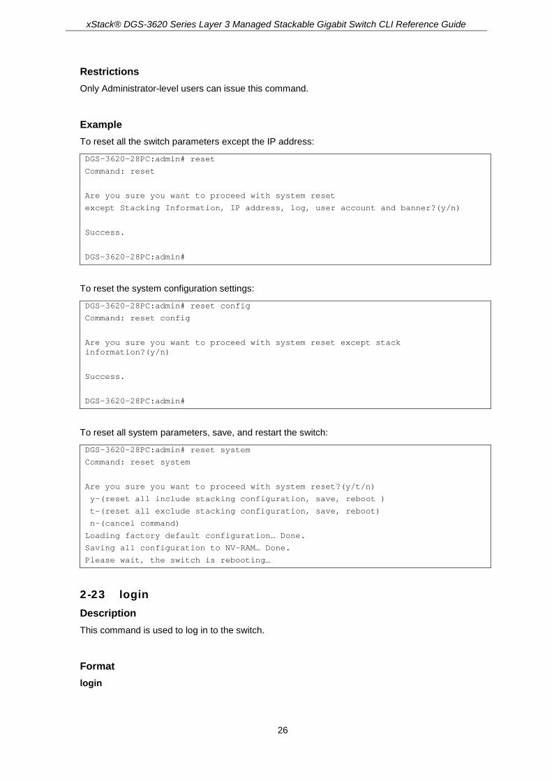
2-22 reset Description This command is used to reset all switch parameters to the factory defaults.
Format reset {[config | system]} {force_agree}
Parameters config - (Optional) Specifies this keyword and all parameters are reset to default settings.
However, the device will neither save nor reboot. system - (Optional) Specifies this keyword and all parameters are reset to default settings. Then
the switch will do factory reset, save, and reboot. force_agree - (Optional) Specifies and the reset command will be executed immediately without
further confirmation.
Note: If no keyword is specified, all parameters will be reset to default settings except IP
address, user account, and history log, but the device will neither save nor reboot.
xStack® DGS-3620 Series Layer 3 Managed Stackable Gigabit Switch CLI Reference Guide
26
Restrictions Only Administrator-level users can issue this command.
Example To reset all the switch parameters except the IP address:
DGS-3620-28PC:admin# reset
Command: reset
Are you sure you want to proceed with system reset
except Stacking Information, IP address, log, user account and banner?(y/n)
Success.
DGS-3620-28PC:admin#
To reset the system configuration settings:
DGS-3620-28PC:admin# reset config
Command: reset config
Are you sure you want to proceed with system reset except stack information?(y/n)
Success.
DGS-3620-28PC:admin#
To reset all system parameters, save, and restart the switch:
DGS-3620-28PC:admin# reset system
Command: reset system
Are you sure you want to proceed with system reset?(y/t/n)
y-(reset all include stacking configuration, save, reboot )
t-(reset all exclude stacking configuration, save, reboot)
n-(cancel command)
Loading factory default configuration… Done.
Saving all configuration to NV-RAM… Done.
Please wait, the switch is rebooting…
2-23 login Description This command is used to log in to the switch.
Format login

xStack® DGS-3620 Series Layer 3 Managed Stackable Gigabit Switch CLI Reference Guide
27
Parameters None.
Restrictions None.
Example To login to the switch:
DGS-3620-28PC:admin#login
Command: login
UserName:
2-24 logout Description This command is used to log out of the switch.
Format logout
Parameters None.
Restrictions None.
Example To logout of the switch:
DGS-3620-28PC:admin#logout
Command: logout
***********
* Logout *
***********
DGS-3620-28PC Gigabit Ethernet Switch
Command Line Interface
Firmware: Build 3.00.004
Copyright(C) 2017 D-Link Corporation. All rights reserved.

xStack® DGS-3620 Series Layer 3 Managed Stackable Gigabit Switch CLI Reference Guide
28
UserName:
2-25 clear Description This command is used to clear the terminal screen.
Format clear
Parameters None.
Restrictions None.
Example To clear the terminal screan:
DGS-3620-28PC:admin#clear
Command: clear
2-26 config terminal width Description This command is used to configure the terminal width.
Format config terminal width [default | <value 80-200>]
Parameters default - Specifies the default terminal width value. <value 80-200> - Enter a terminal width value between 80 and 200 characters. The default value
is 80.
Restrictions None.
Example To configure the terminal width:
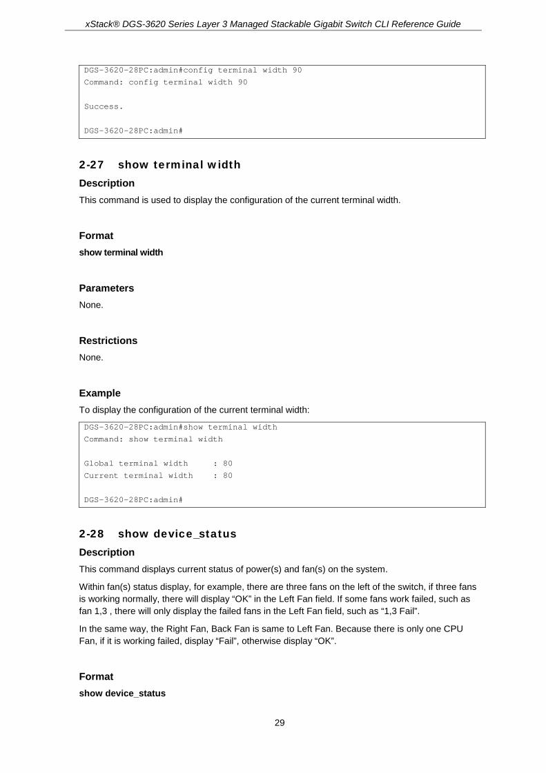
xStack® DGS-3620 Series Layer 3 Managed Stackable Gigabit Switch CLI Reference Guide
29
DGS-3620-28PC:admin#config terminal width 90
Command: config terminal width 90
Success.
DGS-3620-28PC:admin#
2-27 show terminal width Description This command is used to display the configuration of the current terminal width.
Format show terminal width
Parameters None.
Restrictions None.
Example To display the configuration of the current terminal width:
DGS-3620-28PC:admin#show terminal width
Command: show terminal width
Global terminal width : 80
Current terminal width : 80
DGS-3620-28PC:admin#
2-28 show device_status Description This command displays current status of power(s) and fan(s) on the system.
Within fan(s) status display, for example, there are three fans on the left of the switch, if three fans is working normally, there will display “OK” in the Left Fan field. If some fans work failed, such as fan 1,3 , there will only display the failed fans in the Left Fan field, such as “1,3 Fail”.
In the same way, the Right Fan, Back Fan is same to Left Fan. Because there is only one CPU Fan, if it is working failed, display “Fail”, otherwise display “OK”.
Format show device_status

xStack® DGS-3620 Series Layer 3 Managed Stackable Gigabit Switch CLI Reference Guide
30
Parameters None.
Restrictions None.
Example To show device status, the number 1, 2, 3 etc represent the fan number:
DGS-3620-28PC:admin# show device_status
Command: show device_status
Unit 1:
Internal Power: Active
External Power: Fail
Right Fan : 2 Fail
Unit 2:
Internal Power: Active
External Power: Fail
Right Fan : OK
DGS-3620-28PC:admin#
2-29 config out_band_ipif Description This command is used to configure the out of band management port settings.
Format config out_band_ipif {ipaddress <network_address> | state [enable | disable] | gateway <ipaddr>} (1)
Parameters ipaddress - Specifies the IP address of the interface. The parameter must include the mask.
<network_address> - Enter the IP address of the interface. The parameter must include the mask.
state – Specifies the interface status. enable - Specifies to enable the interface. disable - Specifies to disable the interface.
gateway - Specifies the gateway IP address of the out-of-band management network. <ipaddr> - Enter the gateway IP address.
Restrictions Only Administrators, Operators and Power-Users can issue this command.

xStack® DGS-3620 Series Layer 3 Managed Stackable Gigabit Switch CLI Reference Guide
31
Example To disable the out-of-band management state:
DGS-3620-28PC:admin#config out_band_ipif state disable
Command: config out_band_ipif state disable
Success.
DGS-3620-28PC:admin#
2-30 show out_band_ipif Description This command is used to display the current configurations of special out-of-band management interfaces.
Format show out_band_ipif
Parameters None.
Restrictions None.
Example To display the configuration of out-of-band management interfaces:
DGS-3620-28PC:admin#show out_band_ipif
Command: show out_band_ipif
Status : Enable
IP Address : 192.168.0.1
Subnet Mask : 255.255.255.0
Gateway : 0.0.0.0
Link Status : LinkDown
DGS-3620-28PC:admin#

xStack® DGS-3620 Series Layer 3 Managed Stackable Gigabit Switch CLI Reference Guide
32
Chapter 3 802.1X Commands
enable 802.1x disable 802.1x create 802.1x user <username 15> delete 802.1x user <username 15> show 802.1x user config 802.1x auth_protocol [local | radius_eap] show 802.1x {[auth_state | auth_configuration] ports {<portlist>}} config 802.1x capability ports [<portlist> | all] [authenticator | none] config 802.1x fwd_pdu ports [<portlist> | all] [enable | disable] config 802.1x fwd_pdu system [enable | disable] config 802.1x auth_parameter ports [<portlist> | all] [default | {direction [both | in] | port_control
[force_unauth | auto | force_auth] | quiet_period <sec 0-65535> | tx_period <sec 1-65535> | supp_timeout <sec 1-65535> | server_timeout <sec 1-65535> | max_req <value 1-10> | reauth_period <sec 1-65535> | max_users [<value 1-448> | no_limit] | enable_reauth [enable | disable]}(1)]
config 802.1x authorization attributes radius [enable | disable] config 802.1x init [port_based ports [<portlist> | all] | mac_based ports [<portlist> | all]
{mac_address <macaddr>}] config 802.1x max_users [<value 1-448> | no_limit] config 802.1x reauth [port_based ports [<portlist> | all] |mac_based ports [<portlist> | all]
{mac_address <macaddr>}] create 802.1x guest_vlan <vlan_name 32> delete 802.1x guest_vlan <vlan_name 32> config 802.1x guest_vlan ports [<portlist> | all] state [enable | disable] show 802.1x guest_vlan config 802.1x trap state [enable | disable] config radius add <server_index 1-3> [<server_ip> |<ipv6addr>] [key <password 32> |
encryption_key <password 56>] [default | {auth_port <udp_port_number 1-65535> | acct_port <udp_port_number 1-65535> | timeout <sec 1-255> | retransmit <int 1-20>}]
config radius delete <server_index 1-3> config radius <server_index 1-3> {ipaddress [<server_ip> |<ipv6addr>] | [key <password 32> |
encryption_key <password 56>] | auth_port [<udp_port_number 1-65535> | default] | acct_port [<udp_port_number 1-65535> | default] | timeout [<sec 1-255> | default] | retransmit [<int 1-20> | default]}
show radius show auth_statistics {ports <portlist>} show auth_diagnostics {ports <portlist>} show auth_session_statistics {ports <portlist>} show auth_client show acct_client
3-1 enable 802.1x Description This command is used to enable the 802.1X function.
Format enable 802.1x

xStack® DGS-3620 Series Layer 3 Managed Stackable Gigabit Switch CLI Reference Guide
33
Parameters None.
Restrictions Only Administrators, Operators and Power-Users can issue this command.
Example To enable the 802.1X function:
DGS-3620-28PC:admin#enable 802.1x
Command: enable 802.1x
Success.
DGS-3620-28PC:admin#
3-2 disable 802.1x Description This command is used to disable the 802.1X function.
Format disable 802.1x
Parameters None.
Restrictions Only Administrators, Operators and Power-Users can issue this command.
Example To disable the 802.1Xfunction:
DGS-3620-28PC:admin#disable 802.1x
Command: disable 802.1x
Success.
DGS-3620-28PC:admin#

xStack® DGS-3620 Series Layer 3 Managed Stackable Gigabit Switch CLI Reference Guide
34
3-3 create 802.1x user Description This command is used to create an 802.1X user.
Format create 802.1x user <username 15>
Parameters <username 15> - Enter to add a user name.
Restrictions Only Administrators, Operators and Power-Users can issue this command.
Example To create a user named “ctsnow”:
DGS-3620-28PC:admin#create 802.1x user ctsnow
Command: create 802.1x user ctsnow
Enter a case-sensitive new password:
Enter the new password again for confirmation:
Success.
DGS-3620-28PC:admin#
3-4 delete 802.1x user Description This command is used to delete a specified user.
Format delete 802.1x user <username 15>
Parameters <username 15> - Enter to delete a user name.
Restrictions Only Administrators, Operators and Power-Users can issue this command.

xStack® DGS-3620 Series Layer 3 Managed Stackable Gigabit Switch CLI Reference Guide
35
Example To delete the user named “Tiberius”:
DGS-3620-28PC:admin#delete 802.1x user Tiberius
Command: delete 802.1x user Tiberius
Success.
DGS-3620-28PC:admin#
3-5 show 802.1x user Description This command is used to display 802.1X local user account information.
Format show 802.1x user
Parameters None.
Restrictions None.
Example To display 802.1X user information:
DGS-3620-28PC:admin#show 802.1x user
Command: show 802.1x user
Current Accounts:
Username Password
--------------- ------------
ctsnow gallinari
Total Entries : 1
DGS-3620-28PC:admin#
3-6 config 802.1x auth_protocol Description This command is used to configure the 802.1X authentication protocol.

xStack® DGS-3620 Series Layer 3 Managed Stackable Gigabit Switch CLI Reference Guide
36
Format config 802.1x auth_protocol [local | radius_eap]
Parameters local - Specifiy the authentication protocol as local. radius_eap - Specifies the authentication protocol as RADIUS EAP.
Restrictions Only Administrators, Operators and Power-Users can issue this command.
Example To configure the 802.1X RADIUS EAP:
DGS-3620-28PC:admin#config 802.1x auth_protocol radius_eap
Command: config 802.1x auth_protocol radius_eap
Success.
DGS-3620-28PC:admin#
3-7 show 802.1x Description This command is used to display the 802.1X state or configurations.
Format show 802.1x {[auth_state | auth_configuration] ports {<portlist>}}
Parameters auth_state - (Optional) Specifies to display the 802.1X authentication state of some or all ports. auth_configuration - (Optional) Specifies to display 802.1X configuration of some or all ports. ports - (Optional) Specifies a range of ports to be displayed.
<portlist> - Enter a range of ports to be displayed.
Restrictions None.
Example To display 802.1X information:
DGS-3620-28PC:admin#show 802.1x
Command: show 802.1x
802.1X : Disabled

xStack® DGS-3620 Series Layer 3 Managed Stackable Gigabit Switch CLI Reference Guide
37
Authentication Protocol : RADIUS_EAP
Forward EAPOL PDU : Disabled
Max User : 448
RADIUS Authorization : Enabled
DGS-3620-28PC:admin#
To display the 802.1x state for ports 1 to 5:
DGS-3620-28PC:admin# show 802.1x auth_state ports 1-4
Command: show 802.1x auth_state ports 1-4
Status: A – Authorized; U – Unauthorized; (P): Port-Based 802.1X Pri: Priority
Port MAC Address Auth PAE State Backend Status VID Pri
VID State
----- -------------------- ------- -------------- ---------- ------ ----- -----
1 00-00-00-00-00-01 10 Authenticated Idle A 4004 3
1 00-00-00-00-00-02 10 Authenticated Idle A 1234 -
1 00-00-00-00-00-04 30 Authenticating Response U - -
2 - (P) - Authenticating Request U - -
3 - (P) - Connecting Idle U - -
4 - (P) - Held Fail U - -
Total Authenticating Hosts: 3
Total Authenticated Hosts : 2
DGS-3620-28PC:admin#
To display the 802.1x configuration for port 1:
DGS-3620-28PC:admin# show 802.1x auth_configuration ports 1:1
Command: show 802.1x auth_configuration ports 1:1
Port number : 1:1
Capability : None
AdminCrlDir : Both
OpenCrlDir : Both
Port Control : Auto
QuietPeriod : 60 Seconds
TxPeriod : 30 Seconds
SuppTimeout : 30 Seconds
ServerTimeout : 30 Seconds
MaxReq : 2 Times
ReAuthPeriod : 3600 Seconds
ReAuthenticate : Disabled
Forward EAPOL PDU On Port : Enabled
Max User On Port : 10
DGS-3620-28PC:admin#

xStack® DGS-3620 Series Layer 3 Managed Stackable Gigabit Switch CLI Reference Guide
38
3-8 config 802.1x capability ports Description This command is used to configure port capability.
Format config 802.1x capability ports [<portlist> | all] [authenticator | none]
Parameters <portlist> - Enter a range of ports to be configured. all - Specifies to configure all ports. authenticator - The port that wishes to enforce authentication before allowing access to services
that are accessible via that port adopts the authenticator role. none – Disable authentication on specified port.
Restrictions Only Administrators, Operators and Power-Users can issue this command.
Example To configure port capability for ports 1 to 10:
DGS-3620-28PC:admin#config 802.1x capability ports 1-10 authenticator
Command: config 802.1x capability ports 1-10 authenticator
Success.
DGS-3620-28PC:admin#
3-9 config 802.1x fwd_pdu ports Description This command is used to configure the 802.1X PDU forwarding state on specific ports of the switch.
Format config 802.1x fwd_pdu ports [<portlist> | all] [enable | disable]
Parameters <portlist> - Enter a range of ports to be configured. all - Specifies all ports. enable - Enable the 802.1X PDU forwarding state. disable - Disable the 802.1X PDU forwarding state.

xStack® DGS-3620 Series Layer 3 Managed Stackable Gigabit Switch CLI Reference Guide
39
Restrictions Only Administrators, Operators and Power-Users can issue this command.
Example To configure the 802.1X PDU forwarding state on ports 1 to 2:
DGS-3620-28PC:admin#config 802.1x fwd_pdu ports 1-2 enable
Command: config 802.1x fwd_pdu ports 1-2 enable
Success.
DGS-3620-28PC:admin#
3-10 config 802.1x fwd_pdu system Description This command is used to configure the 802.1X PDU forwarding state.
Format config 802.1x fwd_pdu system [enable | disable]
Parameters enable - Enable the 802.1X PDU forwarding state. disable - Disable the 802.1X PDU forwarding state.
Restrictions Only Administrators, Operators and Power-Users can issue this command.
Example To configure the 802.1X PDU forwarding state:
DGS-3620-28PC:admin#config 802.1x fwd_pdu system enable
Command: config 802.1x fwd_pdu system enable
Success.
DGS-3620-28PC:admin#
3-11 config 802.1x auth_parameter ports Description This command is used to configure the parameters that control the operation of the authenticator associated with a port.

xStack® DGS-3620 Series Layer 3 Managed Stackable Gigabit Switch CLI Reference Guide
40
Format config 802.1x auth_parameter ports [<portlist> | all] [default | {direction [both | in] | port_control [force_unauth | auto | force_auth] | quiet_period <sec 0-65535> | tx_period <sec 1-65535> | supp_timeout <sec 1-65535> | server_timeout <sec 1-65535> | max_req <value 1-10> | reauth_period <sec 1-65535> | max_users [<value 1-448> | no_limit] | enable_reauth [enable | disable]}(1)]
Parameters <portlist> - Enter a range of ports to be configured. all - Specifies to configure all ports. default - Set all parameters to the default value. direction - (Optional) Set the direction of access control.
both - For bidirectional access control. in - For ingress access control.
port_control - (Optional) Force a specific port to be unconditionally authorized or unauthorized by setting the parameter of port_control to be force_authorized or force_unauthorized. Besides, the controlled port will reflect the outcome of authentication if port_control is auto. force_auth - The port transmits and receives normal traffic without 802.1X-based
authentication of the client. auto - The port begins in the unauthorized state, and relays authentication messages between
the client and the authentication server. force_unauth - The port will remain in the unauthorized state, ignoring all attempts by the
client to authenticate. quiet_period - (Optional) The initialization value of the quietWhile timer. The default value is 60 s
and can be any value from 0 to 65535. <sec 0-65535> - The quiet period value must be between 0 an 65535 seconds.
tx_period - (Optional) The initialization value of the txWhen timer. The default value is 30 s and can be any value from 1 to 65535. <sec 1-65535> - The transmit period value must be between 1 an 65535 seconds.
supp_timeout - (Optional) The initialization value of the aWhile timer when timing out the supplicant. Its default value is 30 s and can be any value from 1 to 65535. <sec 1-65535> - The timeout value must be between 1 an 65535 seconds.
server_timeout - (Optional) The initialization value of the aWhile timer when timing out the authentication server. Its default value is 30 and can be any value from 1 to 65535. <sec 1-65535> - The server timeout value must be between 1 an 65535 seconds.
max_req - (Optional) The maximum number of times that the authenitcation PAE state machine will retransmit an EAP Request packet to the supplicant. Its default value is 2 and can be any number from 1 to 10. <value 1-10> - The maximum require number must be between 1 and 10.
reauth_period - (Optional) It's a non-zero number of seconds, which is used to be the re-authentication timer. The default value is 3600. <sec 1-65535> - The reauthentication period value must be between 1 an 65535 seconds.
max_users - (Optional) Set the maximum number of users between 1 and 448. <value 1-448> - The maximum users value must be between 1 and 448. no_limit - Set an unlimited number of users.
enable_reauth - (Optional) Enable or disable the re-authentication mechanism for a specific port. enable - Enable the re-authentication mechanism for a specific port. disable - Disable the re-authentication mechanism for a specific port.
Restrictions Only Administrators, Operators and Power-Users can issue this command.

xStack® DGS-3620 Series Layer 3 Managed Stackable Gigabit Switch CLI Reference Guide
41
Example To configure the parameters that control the operation of the authenticator associated with a port:
DGS-3620-28PC:admin# config 802.1x auth_parameter ports 1-20 direction both
Command: config 802.1x auth_parameter ports 1-20 direction both
Success.
DGS-3620-28PC:admin#
3-12 config 802.1x authorization attributes radius Description This command is used to enable or disable the acceptation of an authorized configuration. (To configure that attributes, regarding VLAN, 802.1p, ACL and Ingress/Egress Bandwidth, please refer to the Appendix section at the end of this document.)
Format config 802.1x authorization attributes radius [enable | disable]
Parameters enable - The authorization attributes such as VLAN, 802.1p default priority, and ACL assigned by
the RADUIS server will be accepted if the global authorization status is enabled. The default state is enabled.
disable - The authorization attributes assigned by the RADUIS server will not be accepted.
Restrictions Only Administrators, Operators and Power-Users can issue this command.
Example To configure the 802.1X state of acceptation of an authorized configuration:
DGS-3620-28PC:admin#config 802.1x authorization attributes radius enable
Command: config 802.1x authorization attributes radius enable
Success.
DGS-3620-28PC:admin#
3-13 config 802.1x init Description This command is used to initialize the authentication state machine of some or all.

xStack® DGS-3620 Series Layer 3 Managed Stackable Gigabit Switch CLI Reference Guide
42
Format config 802.1x init [port_based ports [<portlist> | all] | mac_based ports [<portlist> | all] {mac_address <macaddr>}]
Parameters port_based ports - Used to configure authentication in port-based mode.
<portlist> - Enter a range of ports to be configured. all - Specifies to configure all ports.
mac_based ports - To configure authentication in host-based 802.1X mode. <portlist> - Enter a range of ports to be configured. all - Specifies to configure all ports.
mac_address - (Optional) Specifies the MAC address of the host. <macaddr> - Enter the MAC address here.
Restrictions Only Administrators, Operators and Power-Users can issue this command.
Example To initialize the authentication state machine of some or all:
DGS-3620-28PC:admin# config 802.1x init port_based ports all
Command: config 802.1x init port_based ports all
Success.
DGS-3620-28PC:admin#
3-14 config 802.1x max_users Description This command is used to configure the 802.1X maximum number of users of the system.
Format config 802.1x max_users [<value 1-448> | no_limit]
Parameters <value 1-448> - Enter the maximum number of users. no_limit - Specifies an unlimited number of users.
Restrictions Only Administrators, Operators and Power-Users can issue this command.
Example To configure the 820.1X maximum numbers of the system:

xStack® DGS-3620 Series Layer 3 Managed Stackable Gigabit Switch CLI Reference Guide
43
DGS-3620-28PC:admin# config 802.1x max_users 2
Command: config 802.1x max_users 2
Success.
DGS-3620-28PC:admin#
3-15 config 802.1x reauth Description This command is used to reauthenticate the device connected with the port. During the reauthentication period, the port status remains authorized until failed reauthentication.
Format config 802.1x reauth [port_based ports [<portlist> | all] |mac_based ports [<portlist> | all] {mac_address <macaddr>}]
Parameters port_based ports - The switch passes data based on its authenticated port.
<portlist> - Enter a range of ports to be configured. all - Specifies to configure all ports.
mac_based ports - The switch passes data based on the MAC address of authenticated RADIUS client. <portlist> - Enter a range of ports to be configured. all - Specifies to configure all ports.
mac_address - (Optional) Specifies the MAC address of the authenticated RADIUS client. <macaddr> - Enter the MAC address here.
Restrictions Only Administrators, Operators and Power-Users can issue this command.
Example To reauthenticate the device connected with the port:
DGS-3620-28PC:admin# config 802.1x reauth port_based ports all
Command: config 802.1x reauth port_based ports all
Success.
DGS-3620-28PC:admin#
3-16 create 802.1x guest_vlan Description This command is used to assign a static VLAN to be a guest VLAN. The specific VLAN which is assigned to a guest VLAN must already exist. The specific VLAN which is assigned to the guest VLAN can’t be deleted.

xStack® DGS-3620 Series Layer 3 Managed Stackable Gigabit Switch CLI Reference Guide
44
Format create 802.1x guest_vlan <vlan_name 32>
Parameters <vlan_name 32> - Enter the static VLAN to be a guest VLAN.
Restrictions Only Administrators, Operators and Power-Users can issue this command.
Example To assign a static VLAN to be a guest VLAN:
DGS-3620-28PC:admin# create 802.1x guest_vlan guestVLAN
Command: create 802.1x guest_vlan guestVLAN
Success.
DGS-3620-28PC:admin#
3-17 delete 802.1x guest_vlan Description This command is used to delete a guest VLAN setting, but not to delete the static VLAN itself.
Format delete 802.1x guest_vlan <vlan_name 32>
Parameters <vlan_name 32> - Enter the guest VLAN name.
Restrictions Only Administrators, Operators and Power-Users can issue this command.
Example To delete a guest VLAN configuration:
DGS-3620-28PC:admin# delete 802.1x guest_vlan guestVLAN
Command: delete 802.1x guest_vlan guestVLAN
Success.
DGS-3620-28PC:admin#

xStack® DGS-3620 Series Layer 3 Managed Stackable Gigabit Switch CLI Reference Guide
45
3-18 config 802.1x guest_vlan ports Description This command is used to configure a guest VLAN setting.
Format config 802.1x guest_vlan ports [<portlist> | all] state [enable | disable]
Parameters <portlist> - Enter a range of ports to be configured. all - Specifies to configure all ports. state - Specifies the guest VLAN port state of the configured ports.
enable - Join the guest VLAN. disable - Remove from guest VLAN.
Restrictions Only Administrators, Operators and Power-Users can issue this command.
Example To configure a guest VLAN setting for ports 1 to 8:
DGS-3620-28PC:admin# config 802.1x guest_vlan ports 1-8 state enable
Command: config 802.1x guest_vlan ports 1-8 state enable
Warning, The ports are moved to Guest VLAN.
Success.
DGS-3620-28PC:admin#
3-19 show 802.1x guest_vlan Description This command is used to display guest VLAN information.
Format show 802.1x guest_vlan
Parameters None.

xStack® DGS-3620 Series Layer 3 Managed Stackable Gigabit Switch CLI Reference Guide
46
Restrictions None.
Example To display guest VLAN information:
DGS-3620-28PC:admin#show 802.1x guest_vlan
Command: show 802.1x guest_vlan
Guest Vlan Setting
-----------------------------------------------------------
Guest vlan : guest
Enable guest vlan ports : 1-10
DGS-3620-28PC:admin#
3-20 config radius add Description This command is used to add a new RADIUS server. The server with a lower index has higher authenticative priority.
Format config radius add <server_index 1-3> [<server_ip> |<ipv6addr>] [key <password 32> | encryption_key <password 56>] [default | {auth_port <udp_port_number 1-65535> | acct_port <udp_port_number 1-65535> | timeout <sec 1-255> | retransmit <int 1-20>}]
Parameters <server_index 1-3> - Enter the RADIUS server index. <server_ip> - Enter the IP address of the RADIUS server. <ipv6add> - Specifies the IPv6 address used. key - Specifies the key pre-negotiated between switch and the RADIUS server. It is used to
encrypt user’s authentication data before being transmitted over the Internet. The maximum length of the key is 32. <passwd 32> - The maximum length of the password is 32 characters long.
encryption_key - (Optional) Specifies the key pre-negotiated between the switch and the RADIUS server. It is used to encrypt the user’s authentication data before being transmitted over the Internet. <password 56> - Enter the enryption key.
default - Sets the auth_port to be 1812 and acct_port to be 1813. auth_port - Specifies the UDP port number which is used to transmit RADIUS authentication
data between the switch and the RADIUS server.The range is 1 to 65535. <udp_port_number 1-65535> - The authentication port value must be between 1 and 65535.
acct_port - Specifies the UDP port number which is used to transmit RADIUS accounting statistics between the switch and the RADIUS server. The range is 1 to 65535. <udp_port_number 1-65535> - The accounting statistics value must be between 1 and
65535. timeout - Specifies the time, in seconds ,for waiting server reply. The default value is 5 seconds.
<int 1-255> - The timeout value must be between 1 and 255. retransmit - Specifies the count for re-transmit. The default value is 2.
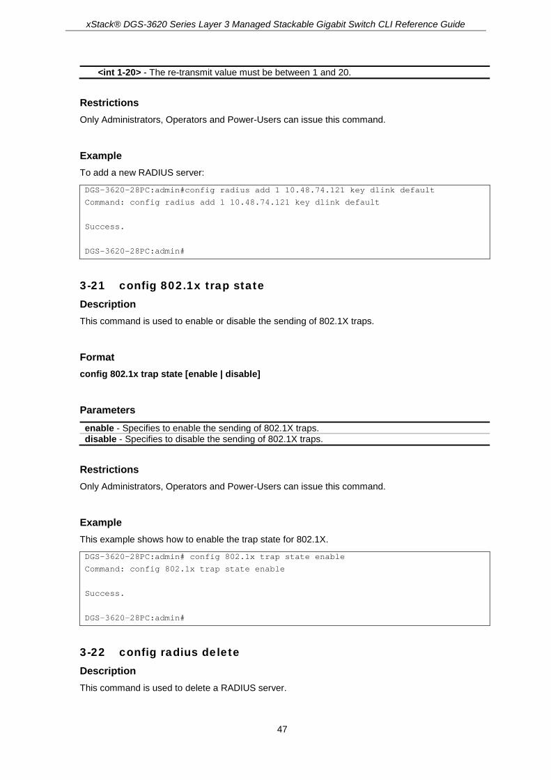
xStack® DGS-3620 Series Layer 3 Managed Stackable Gigabit Switch CLI Reference Guide
47
<int 1-20> - The re-transmit value must be between 1 and 20.
Restrictions Only Administrators, Operators and Power-Users can issue this command.
Example To add a new RADIUS server:
DGS-3620-28PC:admin#config radius add 1 10.48.74.121 key dlink default
Command: config radius add 1 10.48.74.121 key dlink default
Success.
DGS-3620-28PC:admin#
3-21 config 802.1x trap state Description This command is used to enable or disable the sending of 802.1X traps.
Format config 802.1x trap state [enable | disable]
Parameters enable - Specifies to enable the sending of 802.1X traps. disable - Specifies to disable the sending of 802.1X traps.
Restrictions Only Administrators, Operators and Power-Users can issue this command.
Example This example shows how to enable the trap state for 802.1X.
DGS-3620-28PC:admin# config 802.1x trap state enable
Command: config 802.1x trap state enable
Success.
DGS-3620-28PC:admin#
3-22 config radius delete Description This command is used to delete a RADIUS server.

xStack® DGS-3620 Series Layer 3 Managed Stackable Gigabit Switch CLI Reference Guide
48
Format config radius delete <server_index 1-3>
Parameters <server_index 1-3> - Enter the RADIUS server index. The range is from 1 to 3.
Restrictions Only Administrators, Operators and Power-Users can issue this command.
Example To delete a RADIUS server:
DGS-3620-28PC:admin#config radius delete 1
Command: config radius delete 1
Success.
DGS-3620-28PC:admin#
3-23 config radius Description This command is used to configure a RADIUS server.
Format config radius <server_index 1-3> {ipaddress [<server_ip> |<ipv6addr>] | [key <password 32> | encryption_key <password 56>] | auth_port [<udp_port_number 1-65535> | default] | acct_port [<udp_port_number 1-65535> | default] | timeout [<sec 1-255> | default] | retransmit [<int 1-20> | default]}
Parameters <server_index 1-3> - Enter the RADIUS server index. ipaddress - Specifies the IP address of the RADIUS server.
<server_ip> - Enter the RADIUS server IP address here. <ipv6addr> - Enter the IPv6 address here.
key - Specifies the key pre-negotiated between the switch and the RADIUS server. It is used to encrypt user’s authentication data before being transmitted over the Internet. The maximum length of the key is 32. <passwd 32> - Enter the key pre-negotiated between the switch and the RADIUS server. It is
used to encrypt user’s authentication data before being transmitted over the Internet. The maximum length of the key is 32.
encryption_key - (Optional) Specifies the key pre-negotiated between the switch and the RADIUS server. It is used to encrypt the user’s authentication data before being transmitted over the Internet. <password 56> - Enter the enryption key.
auth_port - Specifies the UDP port number which is used to transmit RADIUS authentication data between the switch and the RADIUS server. The default is 1812.

xStack® DGS-3620 Series Layer 3 Managed Stackable Gigabit Switch CLI Reference Guide
49
<udp_port_number 1-65535> - The authentication port value must be between 1 and 65535. default - Specifies to use the default value.
acct_port - Specifies the UDP port number which is used to transmit RADIUS accounting statistics between the switch and the RADIUS server. The default is 1813. <udp_port_number 1-65535> - The accounting statistics value must be between 1 and
65535. default - Specifies to use the default value.
timeout - Specifies the time in seconds for waiting for a server reply. The default value is 5 seconds. <int 1-255> - Enter the time in seconds for waiting for a server reply. The timeout value must
be between 1 and 255. The default value is 5 seconds. default - Specifies to use the default value.
retransmit - Specifies the count for re-transmission. The default value is 2. <int 1-20> - The re-transmit value must be between 1 and 20. default - Specifies to use the default value.
Restrictions Only Administrators, Operators and Power-Users can issue this command.
Example To configure a RADIUS server:
DGS-3620-28PC:admin#config radius 1 ipaddress 10.48.74.121 key dlink
Command: config radius 1 ipaddress 10.48.74.121 key dlink
Success.
DGS-3620-28PC:admin#
3-24 show radius Description This command is used to display RADIUS server configurations.
Format show radius
Parameters None.
Restrictions None.
Example To display RADIUS server configurations:
DGS-3620-28PC:admin#show radius

xStack® DGS-3620 Series Layer 3 Managed Stackable Gigabit Switch CLI Reference Guide
50
Command: show radius
Index 1
IP Address : 192.168.69.1
Auth-Port : 1812
Acct-Port : 1813
Timeout : 5
Retransmit : 2
Key : 123456
Total Entries : 1
DGS-3620-28PC:admin#
3-25 show auth_statistics Description This command is used to display authenticator statistics information
Format show auth_statistics {ports <portlist>}
Parameters ports - (Optional) Specifies a range of ports to be displayed.
<portlist> - Enter a range of ports to be displayed.
Restrictions None.
Example To display authenticator statistics information for port 3:
DGS-3620-28PC:admin# show auth_statistics ports 3
Command: show auth_statistics ports 3
Auth VID :100
MAC Address :00-00-00-00-00-03
Port number : 3
EapolFramesRx 0
EapolFramesTx 6
EapolStartFramesRx 0
EapolReqIdFramesTx 6
EapolLogoffFramesRx 0
EapolReqFramesTx 0
EapolRespIdFramesRx 0
EapolRespFramesRx 0

xStack® DGS-3620 Series Layer 3 Managed Stackable Gigabit Switch CLI Reference Guide
51
InvalidEapolFramesRx 0
EapLengthErrorFramesRx 0
LastEapolFrameVersion 0
LastEapolFrameSource 00-00-00-00-00-03
CTRL+C ESC q Quit SPACE n Next Page p Previous Page r Refresh
3-26 show auth_diagnostics Description This command is used to display authenticator diagnostics information.
Format show auth_diagnostics {ports <portlist>}
Parameters ports - (Optional) Specifies a range of ports to be displayed.
<portlist> - Enter a range of ports to be displayed.
Restrictions None.
Example To display authenticator diagnostics information for port 3:
DGS-3620-28PC:admin# show auth_diagnostics ports 3
Command: show auth_diagnostics ports 3
Auth VID 100
MAC Address 00-00-00-00-00-03
Port number : 1
EntersConnecting 20
EapLogoffsWhileConnecting 0
EntersAuthenticating 0
SuccessWhileAuthenticating 0
TimeoutsWhileAuthenticating 0
FailWhileAuthenticating 0
ReauthsWhileAuthenticating 0
EapStartsWhileAuthenticating 0
EapLogoffWhileAuthenticating 0
ReauthsWhileAuthenticated 0
EapStartsWhileAuthenticated 0
EapLogoffWhileAuthenticated 0
BackendResponses 0
BackendAccessChallenges 0
BackendOtherRequestsToSupplicant 0

xStack® DGS-3620 Series Layer 3 Managed Stackable Gigabit Switch CLI Reference Guide
52
BackendNonNakResponsesFromSupplicant 0
BackendAuthSuccesses 0
BackendAuthFails 0
CTRL+C ESC q Quit SPACE n Next Page p Previous Page r Refresh
3-27 show auth_session_statistics Description This command is used to display authenticator session statistics information.
Format show auth_session_statistics {ports <portlist>}
Parameters ports - (Optional) Specifies a range of ports to be displayed.
<portlist> - Enter a range of ports to be displayed.
Restrictions None.
Example To display authenticator session statistics information for port 1:
DGS-3620-28PC:admin# show auth_session_statistics ports 3
Command: show auth_session_statistics ports 3
Auth VID : 100
MAC Address : 00-00-00-00-00-03
Port number : 3
SessionOctetsRx 0
SessionOctetsTx 0
SessionFramesRx 0
SessionFramesTx 0
SessionId
SessionAuthenticMethod Remote Authentication Server
SessionTime 0
SessionTerminateCause SupplicantLogoff
SessionUserName
CTRL+C ESC q Quit SPACE n Next Page p Previous Page r Refresh
3-28 show auth_client Description This command is used to display authentication client information.

xStack® DGS-3620 Series Layer 3 Managed Stackable Gigabit Switch CLI Reference Guide
53
Format show auth_client
Parameters None.
Restrictions None.
Example To display authentication client information:
DGS-3620-28PC:admin# show auth_client
Command: show auth_client
radiusAuthClient ==>
radiusAuthClientInvalidServerAddresses 0
radiusAuthClientIdentifier D-Link
radiusAuthServerEntry ==>
radiusAuthServerIndex :1
radiusAuthServerAddress 0.0.0.0
radiusAuthClientServerPortNumber X
radiusAuthClientRoundTripTime 0
radiusAuthClientAccessRequests 0
radiusAuthClientAccessRetransmissions 0
radiusAuthClientAccessAccepts 0
radiusAuthClientAccessRejects 0
radiusAuthClientAccessChallenges 0
radiusAuthClientMalformedAccessResponses 0
radiusAuthClientBadAuthenticators 0
radiusAuthClientPendingRequests 0
radiusAuthClientTimeouts 0
radiusAuthClientUnknownTypes 0
radiusAuthClientPacketsDropped 0
radiusAuthClient ==>
radiusAuthClientInvalidServerAddresses 0
radiusAuthClientIdentifier D-Link
radiusAuthServerEntry ==>
radiusAuthServerIndex :2
radiusAuthServerAddress 0.0.0.0

xStack® DGS-3620 Series Layer 3 Managed Stackable Gigabit Switch CLI Reference Guide
54
radiusAuthClientServerPortNumber X
radiusAuthClientRoundTripTime 0
radiusAuthClientAccessRequests 0
radiusAuthClientAccessRetransmissions 0
radiusAuthClientAccessAccepts 0
radiusAuthClientAccessRejects 0
radiusAuthClientAccessChallenges 0
radiusAuthClientMalformedAccessResponses 0
radiusAuthClientBadAuthenticators 0
radiusAuthClientPendingRequests 0
radiusAuthClientTimeouts 0
radiusAuthClientUnknownTypes 0
radiusAuthClientPacketsDropped 0
radiusAuthClient ==>
radiusAuthClientInvalidServerAddresses 0
radiusAuthClientIdentifier D-Link
radiusAuthServerEntry ==>
radiusAuthServerIndex :3
radiusAuthServerAddress 0.0.0.0
radiusAuthClientServerPortNumber X
radiusAuthClientRoundTripTime 0
radiusAuthClientAccessRequests 0
radiusAuthClientAccessRetransmissions 0
radiusAuthClientAccessAccepts 0
radiusAuthClientAccessRejects 0
radiusAuthClientAccessChallenges 0
radiusAuthClientMalformedAccessResponses 0
radiusAuthClientBadAuthenticators 0
radiusAuthClientPendingRequests 0
radiusAuthClientTimeouts 0
radiusAuthClientUnknownTypes 0
radiusAuthClientPacketsDropped 0
DGS-3620-28PC:admin#
3-29 show acct_client Description This command is used to display account client information
Format show acct_client
Parameters None.

xStack® DGS-3620 Series Layer 3 Managed Stackable Gigabit Switch CLI Reference Guide
55
Restrictions None.
Example To display account client information:
DGS-3620-28PC:admin# show acct_client
Command: show acct_client
radiusAcctClient ==>
radiusAcctClientInvalidServerAddresses 0
radiusAcctClientIdentifier D-Link
radiusAuthServerEntry ==>
radiusAccServerIndex : 1
radiusAccServerAddress 0.0.0.0
radiusAccClientServerPortNumber X
radiusAccClientRoundTripTime 0
radiusAccClientRequests 0
radiusAccClientRetransmissions 0
radiusAccClientResponses 0
radiusAccClientMalformedResponses 0
radiusAccClientBadAuthenticators 0
radiusAccClientPendingRequests 0
radiusAccClientTimeouts 0
radiusAccClientUnknownTypes 0
radiusAccClientPacketsDropped 0
radiusAcctClient ==>
radiusAcctClientInvalidServerAddresses 0
radiusAcctClientIdentifier D-Link
radiusAuthServerEntry ==>
radiusAccServerIndex : 2
radiusAccServerAddress 0.0.0.0
radiusAccClientServerPortNumber X
radiusAccClientRoundTripTime 0
radiusAccClientRequests 0
radiusAccClientRetransmissions 0
radiusAccClientResponses 0
radiusAccClientMalformedResponses 0
radiusAccClientBadAuthenticators 0
radiusAccClientPendingRequests 0
radiusAccClientTimeouts 0
radiusAccClientUnknownTypes 0
radiusAccClientPacketsDropped 0

xStack® DGS-3620 Series Layer 3 Managed Stackable Gigabit Switch CLI Reference Guide
56
radiusAcctClient ==>
radiusAcctClientInvalidServerAddresses 0
radiusAcctClientIdentifier D-Link
radiusAuthServerEntry ==>
radiusAccServerIndex : 3
radiusAccServerAddress 0.0.0.0
radiusAccClientServerPortNumber X
radiusAccClientRoundTripTime 0
radiusAccClientRequests 0
radiusAccClientRetransmissions 0
radiusAccClientResponses 0
radiusAccClientMalformedResponses 0
radiusAccClientBadAuthenticators 0
radiusAccClientPendingRequests 0
radiusAccClientTimeouts 0
radiusAccClientUnknownTypes 0
radiusAccClientPacketsDropped 0
DGS-3620-28PC:admin#

xStack® DGS-3620 Series Layer 3 Managed Stackable Gigabit Switch CLI Reference Guide
57
Chapter 4 Access Authentication Control (AAC) Commands
enable authen_policy disable authen_policy show authen_policy enable authen_policy_encryption disable authen_policy_encryption create authen_login method_list_name <string 15> config authen_login [default | method_list_name <string 15>] method {tacacs | xtacacs | tacacs+
| radius | server_group <string 15> | local | none}(1) delete authen_login method_list_name <string 15> show authen_login [default | method_list_name <string 15> | all] create authen_enable method_list_name <string 15> config authen_enable [default | method_list_name <string 15>] method {tacacs | xtacacs |
tacacs+ | radius | server_group <string 15> | local_enable | none}(1) delete authen_enable method_list_name <string 15> show authen_enable [default | method_list_name <string 15> | all] config authen application [console | telnet | ssh | http | all] [login | enable] [default |
method_list_name <string 15>] show authen application create authen server_group <string 15> config authen server_group [tacacs | xtacacs | tacacs+ | radius | <string 15>] [add | delete]
server_host <ipaddr> protocol [tacacs | xtacacs | tacacs+ | radius] delete authen server_group <string 15> show authen server_group {<string 15>} create authen server_host <ipaddr> protocol [tacacs | xtacacs | tacacs+ | radius] {port <int 1-
65535> | [key [<key_string 254> | none] | encryption_key <key_string 344>] | timeout <int 1-255> | retransmit <int 1-20>}
config authen server_host <ipaddr> protocol [tacacs | xtacacs | tacacs+ | radius] {port <int 1-65535> | [key [<key_string 254> | none] | encryption_key <key_string 344>] | timeout <int 1-255> | retransmit <int 1-20>}(1)
delete authen server_host <ipaddr> protocol [tacacs | xtacacs | tacacs+ | radius] show authen server_host config authen parameter response_timeout <int 0-255> config authen parameter attempt <int 1-255> show authen parameter enable admin config admin local_enable {encrypt [plain_text | sha_1] <password>} create aaa server_group <string 15> config aaa server_group [tacacs | xtacacs | tacacs+ | radius | group_name <string 15>] [add |
delete] server_host <ipaddr> protocol [tacacs | xtacacs | tacacs+ | radius] delete aaa server_group <string 15> delete aaa server_host <ipaddr> protocol [tacacs | xtacacs | tacacs+ | radius] show aaa show aaa server_group {<string 15>} show aaa server_host enable aaa_server_password_encryption disable aaa_server_password_encryption config accounting [default | method_list_name <string 15>] method {tacacs+ | radius |

xStack® DGS-3620 Series Layer 3 Managed Stackable Gigabit Switch CLI Reference Guide
58
server_group <string 15> | none} config accounting service [network | shell | system] state [enable {[radius_only |
method_list_name <string 15> | default_method_list]} | disable] config accounting service command {administrator | operator | power_user | user}
[method_list_name <string> | none] create accounting method_list_name <string 15> delete accounting method_list_name <string 15> show accounting [default | method_list_name <string 15> | all] show accounting service create radius server_host <ipaddr> {auth_port <int 1-65535> | acct_port <int 1-65535> | [key
[<key_string 254> | none] | encryption_key <key_string 344>] | timeout <int 1-255> | retransmit <int 1-20>}
config radius server_host <ipaddr> {auth_port <int 1-65535> | acct_port <int 1-65535> | [key [<key_string 254> | none] | encryption_key <key_string 344>] | timeout <int 1-255> | retransmit <int 1-20>}
config radius source_ipif [<ipif_name 12> {<ipaddr> | <ipv6addr>} | none] show radius source_ipif create tacacs server_host <ipaddr> {port <int 1-65535> | timeout <int 1-255> | retransmit <int 1-
20>} config tacacs server_host <ipaddr> {port <int 1-65535> | timeout <int 1-255> | retransmit <int 1-
20>} create tacacs+ server_host <ipaddr> {port <int 1-65535> | [key [<key_string 254> | none] |
encryption_key <key_string 344>] | timeout <int 1-255>} config tacacs+ server_host <ipaddr> {port <int 1-65535> | [key [<key_string 254> | none] |
encryption_key <key_string 344>] | timeout <int 1-255>} create xtacacs server_host <ipaddr> {port <int 1-65535> | timeout <int 1-255> | retransmit <int 1-
20>} config xtacacs server_host <ipaddr> {port <int 1-65535> | timeout <int 1-255> | retransmit <int 1-
20>} config tacacs source_ipif [<ipif_name 12> {<ipaddr>} | none] show tacacs source_ipif
The TACACS / XTACACS / TACACS+ / RADIUS commands allows secure access to the Switch using the TACACS / XTACACS / TACACS+ / RADIUS protocols. When a user logs in to the Switch or tries to access the administrator level privilege, he or she is prompted for a password. If TACACS / XTACACS / TACACS+ / RADIUS authentication is enabled on the Switch, it will contact a TACACS / XTACACS / TACACS+ / RADIUS server to verify the user. If the user is verified, he or she is granted access to the Switch.
There are currently three versions of the TACACS security protocol, each a separate entity. The Switch’s software supports the following versions of TACACS:
1. TACACS (Terminal Access Controller Access Control System) —Provides password checking and authentication, and notification of user actions for security purposes utilizing via one or more centralized TACACS servers, utilizing the UDP protocol for packet transmission.
2. Extended TACACS (XTACACS) — An extension of the TACACS protocol with the ability to provide more types of authentication requests and more types of response codes than TACACS. This protocol also uses UDP to transmit packets.
3. TACACS+ (Terminal Access Controller Access Control System plus) — Provides detailed access control for authentication for network devices. TACACS+ is facilitated through Authentication commands via one or more centralized servers. The TACACS+ protocol encrypts all traffic between the Switch and the TACACS+ daemon, using the TCP protocol to ensure reliable delivery.

xStack® DGS-3620 Series Layer 3 Managed Stackable Gigabit Switch CLI Reference Guide
59
The Switch also supports the RADIUS protocol for authentication using the Access Authentication Control commands. RADIUS or Remote Authentication Dial In User Server also uses a remote server for authentication and can be responsible for receiving user connection requests, authenticating the user and returning all configuration information necessary for the client to deliver service through the user. RADIUS may be facilitated on this Switch using the commands listed in this section.
In order for the TACACS / XTACACS / TACACS+ / RADIUS security function to work properly, a TACACS / XTACACS / TACACS+ / RADIUS server must be configured on a device other than the Switch, called a server host and it must include usernames and passwords for authentication. When the user is prompted by the Switch to enter usernames and passwords for authentication, the Switch contacts the TACACS / XTACACS / TACACS+ / RADIUS server to verify, and the server will respond with one of three messages:
The server verifies the username and password, and the user is granted normal user privileges on the Switch. The server will not accept the username and password and the user is denied access to the Switch.
The server doesn’t respond to the verification query. At this point, the Switch receives the timeout from the server and then moves to the next method of verification configured in the method list.
The Switch has four built-in server groups, one for each of the TACACS, XTACACS, TACACS+ and RADIUS protocols. These built-in server groups are used to authenticate users trying to access the Switch. The users will set server hosts in a preferable order in the built-in server group and when a user tries to gain access to the Switch, the Switch will ask the first server host for authentication. If no authentication is made, the second server host in the list will be queried, and so on. The built-in server group can only have hosts that are running the specified protocol. For example, the TACACS server group can only have TACACS server hosts.
The administrator for the Switch may set up five different authentication techniques per user-defined method list (TACACS / XTACACS / TACACS+ / RADIUS / local / none) for authentication. These techniques will be listed in an order preferable, and defined by the user for normal user authentication on the Switch, and may contain up to eight authentication techniques. When a user attempts to access the Switch, the Switch will select the first technique listed for authentication. If the first technique goes through its server hosts and no authentication is returned, the Switch will then go to the next technique listed in the server group for authentication, until the authentication has been verified or denied, or the list is exhausted.
Note: User granted access to the Switch will be granted normal user privileges on the
Switch. To gain access to admin level privileges, the user must enter the enable admin command and then enter a password, which was previously configured by the administrator of the Switch.
Note: TACACS, XTACACS and TACACS+ are separate entities and are not compatible.
The Switch and the server must be configured exactly the same, using the same protocol. (For example, if the Switch is set up for TACACS authentication, so must be the host server.)
4-1 enable authen_policy Description This command is used to enable system access authentication policy. When enabled, the device will adopt the login authentication method list to authenticate the user for login, and adopt the enable authentication mothod list to authenticate the enable password for promoting the user‘s privilege to Administrator level.
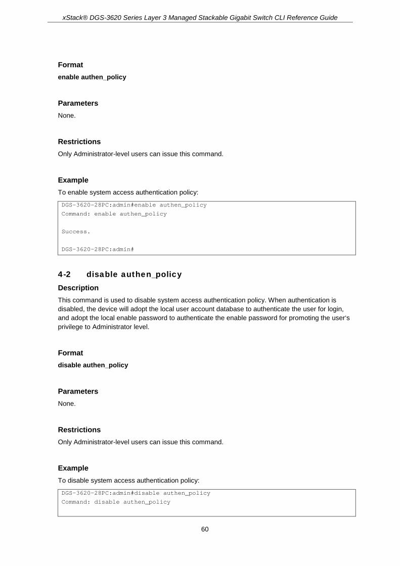
xStack® DGS-3620 Series Layer 3 Managed Stackable Gigabit Switch CLI Reference Guide
60
Format enable authen_policy
Parameters None.
Restrictions Only Administrator-level users can issue this command.
Example To enable system access authentication policy:
DGS-3620-28PC:admin#enable authen_policy
Command: enable authen_policy
Success.
DGS-3620-28PC:admin#
4-2 disable authen_policy Description This command is used to disable system access authentication policy. When authentication is disabled, the device will adopt the local user account database to authenticate the user for login, and adopt the local enable password to authenticate the enable password for promoting the user‘s privilege to Administrator level.
Format disable authen_policy
Parameters None.
Restrictions Only Administrator-level users can issue this command.
Example To disable system access authentication policy:
DGS-3620-28PC:admin#disable authen_policy
Command: disable authen_policy

xStack® DGS-3620 Series Layer 3 Managed Stackable Gigabit Switch CLI Reference Guide
61
Success.
DGS-3620-28PC:admin#
4-3 show authen_policy Description This command is used to display whether system access authentication policy is enabled or disabled.
Format show authen_policy
Parameters None.
Restrictions Only Administrator-level users can issue this command.
Example To display system access authentication policy:
DGS-3620-28PC:admin#show authen_policy
Command: show authen_policy
Authentication Policy : Disabled
Authentication Policy Encryption: Disabled
DGS-3620-28PC:admin#
4-4 enable authen_policy_encryption Description This command is used to enable the authentication policy encryption. When enabled, TACACS+ and RADIUS key will be in the encrypted form.
Format enable authen_policy_encryption
Parameters None.

xStack® DGS-3620 Series Layer 3 Managed Stackable Gigabit Switch CLI Reference Guide
62
Restrictions Only Administrator-level users can issue this command.
Example To enable the authentication policy encryption:
DGS-3620-28PC:admin#enable authen_policy_encryption
Command: enable authen_policy_encryption
Success.
DGS-3620-28PC:admin#
4-5 disable authen_policy_encryption Description This command is used to disable the authentication policy encryption. When disabled, TACACS+ and RADIUS key will be in the plain text form.
Format disable authen_policy_encryption
Parameters None.
Restrictions Only Administrator-level users can issue this command.
Example To disable the authentication policy encryption:
DGS-3620-28PC:admin#disable authen_policy_encryption
Command: disable authen_policy_encryption
Success.
DGS-3620-28PC:admin#
4-6 create authen_login method_list_name Description This command is used to create a user-defined method list of authentication methods for user login. The maximum supported number of the login method lists is eight.

xStack® DGS-3620 Series Layer 3 Managed Stackable Gigabit Switch CLI Reference Guide
63
Format create authen_login method_list_name <string 15>
Parameters <string 15> - Enter the user-defined method list name.
Restrictions Only Administrator-level users can issue this command.
Example To create a user-defined method list for user login:
DGS-3620-28PC:admin#create authen_login method_list_name login_list_1
Command: create authen_login method_list_name login_list_1
Success.
DGS-3620-28PC:admin#
4-7 config authen_login Description This command is used to configure a user-defined or default method list of authentication methods for user login. The sequence of methods will affect the authentication result. For example, if the sequence is TACACS+ first, then TACACS and local, when a user trys to login, the authentication request will be sent to the first server host in the TACACS+ built-in server group. If the first server host in the TACACS+ group is missing, the authentication request will be sent to the second server host in the TACACS+ group, and so on. If all server hosts in the TACACS+ group are missing, the authentication request will be sent to the first server host in the TACACS group. If all server hosts in a TACACS group are missing, the local account database in the device is used to authenticate this user. When a user logs in to the device successfully while using methods like TACACS/XTACACS/TACACS+/RADIUS built-in or user-defined server groups or none, the “user” privilege level is assigned only. If a user wants to get admin privilege level, the user must use the “enable admin” command to promote his privilege level. But when the local method is used, the privilege level will depend on this account privilege level stored in the local device.
Format config authen_login [default | method_list_name <string 15>] method {tacacs | xtacacs | tacacs+ | radius | server_group <string 15> | local | none}(1)
Parameters default – Specifies the default method list of authentication methods. method_list_name - Specifies the user-defined method list of authentication methods.
<string 15> - Enter the user-defined method list of authentication methods. The method list name can be up to 15 characters long.
method - Choose the desired authentication method:

xStack® DGS-3620 Series Layer 3 Managed Stackable Gigabit Switch CLI Reference Guide
64
tacacs - Specifies authentication by the built-in server group TACACS. xtacacs - Specifies authentication by the built-in server group XTACACS. tacacs+ - Specifies authentication by the built-in server group TACACS+. radius - Specifies authentication by the built-in server group RADIUS. server_group - Specifies authentication by the user-defined server group.
<string 15> - Enter authentication by the user-defined server group. The server group value can be up to 15 characters long.
local - Specifies authentication by local user account database in the device. none - Specifies no authentication.
Restrictions Only Administrator-level users can issue this command.
Example To configure a user-defined method list for user login:
DGS-3620-28PC:admin#config authen_login method_list_name login_list_1 method tacacs+ tacacs local
Command: config authen_login method_list_name login_list_1 method tacacs+ tacacs local
Success.
DGS-3620-28PC:admin#
4-8 delete authen_login method_list_name Description This command is used to delete a user-defined method list of authentication methods for user login.
Format delete authen_login method_list_name <string 15>
Parameters <string 15> - Enter the user-defined method list name.
Restrictions Only Administrator-level users can issue this command.
Example To delete a user-defined method list for user login:
DGS-3620-28PC:admin#delete authen_login method_list_name login_list_1
Command: delete authen_login method_list_name login_list_1
Success.

xStack® DGS-3620 Series Layer 3 Managed Stackable Gigabit Switch CLI Reference Guide
65
DGS-3620-28PC:admin#
4-9 show authen_login Description This command is used to display the method list of authentication methods for user login.
Format show authen_login [default | method_list_name <string 15> | all]
Parameters default – Specifies to display the default method list for user login. method_list_name - Specifies the user-defined method list for user login.
<string 15> - Enter the user-defined method list for user login. The method list name can be up to 15 characters long.
all – Specifies to display all method lists for user login.
Restrictions Only Administrator-level users can issue this command.
Example To display a user-defined method list for user login:
DGS-3620-28PC:admin#show authen_login method_list_name login_list_1
Command: show authen_login method_list_name login_list_1
Method List Name Priority Method Name Comment
---------------- -------- --------------- ------------------
login_list_1 1 tacacs+ Built-in Group
2 tacacs Built-in Group
3 mix_1 User-defined Group
4 local Keyword
DGS-3620-28PC:admin#
4-10 create authen_enable method_list_name Description This command is used to create a user-defined method list of authentication methods for promoting a user's privilege to Admin level. The maximum supported number of the enable method lists is eight.
Format create authen_enable method_list_name <string 15>

xStack® DGS-3620 Series Layer 3 Managed Stackable Gigabit Switch CLI Reference Guide
66
Parameters <string 15> - Enter the user-defined method list name.
Restrictions Only Administrator-level users can issue this command.
Example To create a user-defined method list for promoting a user's privilege to Admin level:
DGS-3620-28PC:admin#create authen_enable method_list_name enable_list_1
Command: create authen_enable method_list_name enable_list_1
Success.
DGS-3620-28PC:admin#
4-11 config authen_enable Description This command is used to configure a user-defined or default method list of authentication methods for promoting a user's privilege to Admin level. The sequence of methods will effect the authencation result. For example, if the sequence is TACACS+ first, then TACACS and local_enable, when a user tries to promote a user's privilege to Admin level, the authentication request will be sent to the first server host in the TACACS+ built-in server group. If the first server host in the TACACS+ group is missing, the authentication request will be sent to the second server host in the TACACS+ group, and so on. If all server hosts in the TACACS+ group are missing, the authentication request will be sent to the first server host in the TACACS group. If all server hosts in the TACACS group are missing, the local enable password in the device is used to authenticate this user’s password. The local enable password in the device can be configured by the CLI command config admin local_enable.
Format config authen_enable [default | method_list_name <string 15>] method {tacacs | xtacacs | tacacs+ | radius | server_group <string 15> | local_enable | none}(1)
Parameters default - Specifies the default method list of authentication methods. method_list_name - Specifies the user-defined method list of authentication methods.
<string 15> - Enter the user-defined method list of authentication methods. The method list name can be up to 15 characters long.
method - Choose the desired authentication method: tacacs - Specifies authentication by the built-in server group TACACS. xtacacs - Specifies authentication by the built-in server group XTACACS. tacacs+ - Specifies authentication by the built-in server group TACACS+. radius - Specifies authentication by the built-in server group RADIUS. server_group - Specifies authentication by the user-defined server group.
<string 15> - Enter authentication by the user-defined server group. The server group value can be up to 15 characters long.

xStack® DGS-3620 Series Layer 3 Managed Stackable Gigabit Switch CLI Reference Guide
67
local_enable - Specifies authentication by local enable password in the device. none - Specifies no authentication.
Restrictions Only Administrator-level users can issue this command.
Example To configure a user-defined method list for promoting a user's privilege to Admin level:
DGS-3620-28PC:admin#config authen_enable method_list_name enable_list_1 method tacacs+ tacacs local_enable
Command: config authen_ enable method_list_name enable_list_1 method tacacs+ tacacs local_enable
Success.
DGS-3620-28PC:admin#
4-12 delete authen_enable method_list_name Description This command is used to delete a user-defined method list of authentication methods for promoting a user's privilege to Administrator level.
Format delete authen_enable method_list_name <string 15>
Parameters <string 15> - Enter the user-defined method list name.
Restrictions Only Administrator-level users can issue this command.
Example To delete a user-defined method list for promoting a user's privilege to Admin level:
DGS-3620-28PC:admin#delete authen_enable method_list_name enable_list_1
Command: delete authen_enable method_list_name enable_list_1
Success.
DGS-3620-28PC:admin#

xStack® DGS-3620 Series Layer 3 Managed Stackable Gigabit Switch CLI Reference Guide
68
4-13 show authen_enable Description This command is used to display the method list of authentication methods for promoting a user's privilege to Administrator level.
Format show authen_enable [default | method_list_name <string 15> | all]
Parameters default - Specifies to display the default method list for promoting a user's privilege to
Administrator level. method_list_name - Specifies the user-defined method list for promoting a user's privilege to
Administrator level. <string 15> - Enter the user-defined method list for a promoting a user's privilege to
Administrator level . The method list name value can be up to 15 characters long. all - Specifies to display all method lists for promoting a user's privilege to Administrator level.
Restrictions Only Administrator-level users can issue this command.
Example To display all method lists for promoting a user's privilege to Administrator level:
DGS-3620-28PC:admin#show authen_enable all
Command: show authen_enable all
Method List Name Priority Method Name Comment
---------------- -------- --------------- ------------------
default 1 local_enable Keyword
enable_list_1 1 tacacs+ Built-in Group
2 tacacs Built-in Group
3 mix_1 User-defined Group
4 loca_enable Keyword
enable_list_2 1 tacacs+ Built-in Group
2 radius Built-in Group
Total Entries : 3
DGS-3620-28PC:admin#
4-14 config authen application Description This command is used to configure login or enable method list for all or the specified application.

xStack® DGS-3620 Series Layer 3 Managed Stackable Gigabit Switch CLI Reference Guide
69
Format config authen application [console | telnet | ssh | http | all] [login | enable] [default | method_list_name <string 15>]
Parameters console - Specifies an application: console. telnet - Specifies an application: Telnet. ssh - Specifies an application: SSH. http - Specifies an application: Web. all - Specifies all applications: console, Telnet, SSH, and Web. login - Specifies the method list of authentication methods for user login. enable - Specifies the method list of authentication methods for promoting user privilege to
Administrator level. default - Specifies the default method list. method_list_name - Specifies the user-defined method list name.
<string 15> - Enter the user-defined method list name. The method list name value can be up to 15 characters long.
Restrictions Only Administrator-level users can issue this command.
Example To configure the login method list for Telnet:
DGS-3620-28PC:admin#config authen application telnet login method_list_name login_list_1
Command: config authen application telnet login method_list_name login_list_1
Success.
DGS-3620-28PC:admin#
4-15 show authen application Description This command is used to display the login/enable method list for all applications.
Format show authen application
Parameters None.
Restrictions Only Administrator-level users can issue this command.

xStack® DGS-3620 Series Layer 3 Managed Stackable Gigabit Switch CLI Reference Guide
70
Example To display the login and enable method list for all applications:
DGS-3620-28PC:admin#show authen application
Command: show authen application
Application Login Method List Enable Method List
----------- ----------------- ------------------
Console default default
Telnet login_list_1 default
SSH default default
HTTP default default
DGS-3620-28PC:admin#
4-16 create authen server_group Description This command is used to create a user-defined authentication server group. The maximum supported number of server groups including built-in server groups is eight. Each group consists of eight server hosts as maximum.
Format create authen server_group <string 15>
Parameters <string 15> - Enter the user-defined server group name.
Restrictions Only Administrator-level users can issue this command.
Example To create a user-defined authentication server group:
DGS-3620-28PC:admin#create authen server_group mix_1
Command: create authen server_group mix_1
Success.
DGS-3620-28PC:admin#
4-17 config authen server_group Description This command is used to add or remove an authentication server host to or from the specified server group. Built-in server group tacacs, xtacacs, tacacs+, and RADIUS accept the server host with the same protocol only, but user-defined server group can accept server hosts with different

xStack® DGS-3620 Series Layer 3 Managed Stackable Gigabit Switch CLI Reference Guide
71
protocols. The server host must be created first by using the CLI command create authen server_host.
Format config authen server_group [tacacs | xtacacs | tacacs+ | radius | <string 15>] [add | delete] server_host <ipaddr> protocol [tacacs | xtacacs | tacacs+ | radius]
Parameters tacacs - Specifies the built-in server group TACACS. xtacacs - Specifies the built-in server group XTACACS. tacacs+ - Specifies the built-in server group TACACS+. radius – Specifies the built-in server group RADIUS. <string 15> - Enter a user-defined server group. add - Specifies to add a server host to a server group. delete - Specifies to remove a server host from a server group. server_host - Specifies the server host’s IP address.
<ipaddr> - Enter the server host’s IP address. protocol - Specifies the server host’s type of authentication protocol.
tacacs - Specifies the server host’s authentication protocol TACACS. xtacacs - Specifies the server host’s authentication protocol XTACACS. tacacs+ - Specifies the server host’s authentication protocol TACACS+. radius - Specifies the server host’s authentication protocol RADIUS.
Restrictions Only Administrator-level users can issue this command.
Example To add an authentication server host to a server group:
DGS-3620-28PC:admin#config authen server_group mix_1 add server_host 10.1.1.222 protocol tacacs+
Command: config authen server_group mix_1 add server_host 10.1.1.222 protocol tacacs+
Success.
DGS-3620-28PC:admin#
4-18 delete authen server_group Description This command is used to delete a user-defined authentication server group.
Format delete authen server_group <string 15>

xStack® DGS-3620 Series Layer 3 Managed Stackable Gigabit Switch CLI Reference Guide
72
Parameters <string 15> - Enter the user-defined server group name.
Restrictions Only Administrator-level users can issue this command.
Example To delete a user-defined authentication server group:
DGS-3620-28PC:admin#delete authen server_group mix_1
Command: delete authen server_group mix_1
Success.
DGS-3620-28PC:admin#
4-19 show authen server_group Description This command is used to display the authentication server groups.
Format show authen server_group {<string 15>}
Parameters <string 15> - (Optional) Specifies the built-in or user-defined server group name.
Restrictions Only Administrator-level users can issue this command.
Example To display all authentication server groups:
DGS-3620-28PC:admin#show authen server_group
Command: show authen server_group
Group Name IP Address Protocol
--------------- --------------- --------
mix_1 10.1.1.222 TACACS+
radius 10.1.1.224 RADIUS
tacacs 10.1.1.225 TACACS
tacacs+ 10.1.1.226 TACACS+
xtacacs 10.1.1.227 XTACACS
Total Entries : 5

xStack® DGS-3620 Series Layer 3 Managed Stackable Gigabit Switch CLI Reference Guide
73
DGS-3620-28PC:admin#
4-20 create authen server_host Description This command is used to create an authentication server host. When an authentication server host is created, the IP address and protocol are the index. That means more than one authentication protocol service can be run on the same physical host. The maximum supported number of server hosts is 16.
Format create authen server_host <ipaddr> protocol [tacacs | xtacacs | tacacs+ | radius] {port <int 1-65535> | [key [<key_string 254> | none] | encryption_key <key_string 344>] | timeout <int 1-255> | retransmit <int 1-20>}
Parameters <ipaddr> - Enter the server host’s IP address. protocol - Specifies the server host’s type of authentication protocol.
tacacs - Specifies the server host’s authentication protocol TACACS. xtacacs - Specifies the server host’s authentication protocol XTACACS. tacacs+ - Specifies the server host’s authentication protocol TACACS+. radius - Specifies the server host’s authentication protocol RADIUS.
port - (Optional) Specifies the port number of the authentication protocol for the server host. The default value for TACACS/XTACACS/TACACS+ is 49. The default value for RADIUS is 1812. <int 1-65535> - Enter the port number of the authentication protocol for the server host. The
default value for TACACS/XTACACS/TACACS+ is 49. The default value for RADIUS is 1812. The port number must be between 1 and 65535.
key - (Optional) Specifies the key for TACACS+ and RADIUS authentication. <key_string 254> - Enter the key for TACACS+ and RADIUS authenticaiton. If the value is
null, no encryption will apply. This value is meaningless for TACACS and XTACACS. none - No encryption for TACACS+ and RADIUS authenticaiton. This value is meaningless
for TACACS and XTACACS. encryption_key - (Optional) Specifies the encrypted form key string for TACACS+ and RADIUS
authentication. This value is meaningless for TACACS and XTACACS. The encryption algorithm is based on DES. <key_string 344> - Enter the encrypted form key string for TACACS+ and RADIUS
authentication. timeout - (Optional) Specifies the time in seconds for waiting for a server reply. The default value
is 5 seconds. <int 1-255> - Enter the time in seconds for waiting for a server reply. The default value is 5
seconds. The timeout value must be between 1 and 255 seconds. retransmit - (Optional) Specifies the count for re-transmit. This value is meaningless for
TACACS+. The default value is 2. <int 1-20> - Enter the count for re-transmit. This value is meaningless for TACACS+. The
default value is 2. The re-transmit value must be between 1 and 20.
Restrictions Only Administrator-level users can issue this command.

xStack® DGS-3620 Series Layer 3 Managed Stackable Gigabit Switch CLI Reference Guide
74
Example To create a TACACS+ authentication server host with a listening port number of 15555 and a timeout value of 10 seconds:
DGS-3620-28PC:admin#create authen server_host 10.1.1.222 protocol tacacs+ port 15555 key "123" timeout 10
Command: create authen server_host 10.1.1.222 protocol tacacs+ port 15555 key "123" timeout 10
Success.
DGS-3620-28PC:admin#
4-21 config authen server_host Description This command is used to configure an authentication server host.
Format config authen server_host <ipaddr> protocol [tacacs | xtacacs | tacacs+ | radius] {port <int 1-65535> | [key [<key_string 254> | none] | encryption_key <key_string 344>] | timeout <int 1-255> | retransmit <int 1-20>}(1)
Parameters <ipaddr> - Enter the server host’s IP address. protocol - Specifies the server host’s type of authentication protocol.
tacacs - Specifies the server host’s authentication protocol TACACS. xtacacs - Specifies the server host’s authentication protocol XTACACS. tacacs+ - Specifies the server host’s authentication protocol TACACS+. radius - Specifies the server host’s authentication protocol RADIUS.
port - Specifies the port number of the authentication protocol for the server host. The default value for TACACS/XTACACS/TACACS+ is 49. The default value for RADIUS is 1812. <int 1-65535> - Enter the port number of the authentication protocol for the server host. The
default value for TACACS/XTACACS/TACACS+ is 49. The default value for RADIUS is 1812. The port number must be between 1 and 65535.
key - Specifies the key for TACACS+ and RADIUS authentication. <key_string 254> - Enter the key for TACACS+ and RADIUS authentication. If the value is
null, no encryption will apply. This value is meaningless for TACACS and XTACACS. none - Specifies no encryption for TACACS+ and RADIUS authentication. This value is
meaningless for TACACS and XTACACS. encryption_key - (Optional) Specifies the encrypted form key string for TACACS+ and RADIUS
authentication. This value is meaningless for TACACS and XTACACS. The encryption algorithm is based on DES. <key_string 344> - Enter the encrypted form key string for TACACS+ and RADIUS
authentication. timeout - Specifies the time in seconds for waiting for a server reply. The default value is 5
seconds. <int 1-255> - Enter the time in seconds for waiting for a server reply. The default value is 5
seconds. The timeout value must be between 1 and 255 seconds. retransmit - Specifies the count for re-transmit. This value is meaningless for TACACS+. The
default value is 2. <int 1-20> - Enter the count for re-transmit. This value is meaningless for TACACS+. The
default value is 2. The re-transmit value must be between 1 and 20.

xStack® DGS-3620 Series Layer 3 Managed Stackable Gigabit Switch CLI Reference Guide
75
Restrictions Only Administrator-level users can issue this command.
Example To configure a TACACS+ authentication server host’s key value:
DGS-3620-28PC:admin#config authen server_host 10.1.1.222 protocol tacacs+ key "abc123"
Command: config authen server_host 10.1.1.222 protocol tacacs+ key "abc123"
Success.
DGS-3620-28PC:admin#
4-22 delete authen server_host Description This command is used to delete an authentication server host.
Format delete authen server_host <ipaddr> protocol [tacacs | xtacacs | tacacs+ | radius]
Parameters <ipaddr> - Enter the server host’s IP address. protocol - Specifies the server host’s type of authentication protocol.
tacacs - Specifies the server host’s authentication protocol TACACS. xtacacs - Specifies the server host’s authentication protocol XTACACS. tacacs+ - Specifies the server host’s authentication protocol TACACS+. radius - Specifies the server host’s authentication protocol RADIUS.
Restrictions Only Administrator-level users can issue this command.
Example To delete an authentication server host:
DGS-3620-28PC:admin#delete authen server_host 10.1.1.222 protocol tacacs+
Command: delete authen server_host 10.1.1.222 protocol tacacs+
Success.
DGS-3620-28PC:admin#

xStack® DGS-3620 Series Layer 3 Managed Stackable Gigabit Switch CLI Reference Guide
76
4-23 show authen server_host Description This command is used to display authentication server hosts.
Format show authen server_host
Parameters None.
Restrictions Only Administrator-level users can issue this command.
Example To display all authentication server hosts:
DGS-3620-28PC:admin#show authen server_host
Command: show authen server_host
IP Address Protocol Port Timeout Retransmit Key
--------------- -------- ----- ------- ---------- -----------------------
10.1.1.222 TACACS+ 15555 10 ------ 123
Total Entries : 1
DGS-3620-28PC:admin#
4-24 config authen parameter response_timeout Description This command is used to configure the amount of time waiting for users to input on the console and Telnet applications.
Format config authen parameter response_timeout <int 0-255>
Parameters <int 0-255> - Enter the amount of time for user input on console or Telnet. 0 means there is no
time out. The default value is 30 seconds.
Restrictions Only Administrator-level users can issue this command.

xStack® DGS-3620 Series Layer 3 Managed Stackable Gigabit Switch CLI Reference Guide
77
Example To configure 60 seconds for user to input:
DGS-3620-28PC:admin#config authen parameter response_timeout 60
Command: config authen parameter response_timeout 60
Success.
DGS-3620-28PC:admin#
4-25 config authen parameter attempt Description This command is used to configure the maximum attempts for users trying to login or promote the privilege on console or Telnet applications. If the failure value is exceeded, connection or access will be locked.
Format config authen parameter attempt <int 1-255>
Parameters <int 1-255> - Enter the amount of attempts for users trying to login or promote the privilege on
console or Telnet. The default value is 3.
Restrictions Only Administrator-level users can issue this command.
Example To configure the maximum attempts for users trying to login or promote the privilege to be 9:
DGS-3620-28PC:admin#config authen parameter attempt 9
Command: config authen parameter attempt 9
Success.
DGS-3620-28PC:admin#
4-26 show authen parameter Description This command is used to display the authentication parameters.
Format show authen parameter

xStack® DGS-3620 Series Layer 3 Managed Stackable Gigabit Switch CLI Reference Guide
78
Parameters None.
Restrictions Only Administrator-level users can issue this command.
Example To display the authentication parameters:
DGS-3620-28PC:admin# show authen parameter
Command: show authen parameter
Response Timeout : 60 seconds
User Attempts : 9
DGS-3620-28PC:admin#
4-27 enable admin Description This command is used to promote the "user" privilege level to "admin" level. When the user enters this command, the authentication method RADIUS, TACACS, XTACAS, TACACS+, user-defined server groups, local enable, or none will be used to authenticate the user. Because TACACS, XTACACS and RADIUS don't support the enable function by themselves, if a user wants to use either one of these three protocols to enable authentication, the user must create a special account on the server host first, which has a username enable and then configure its password as the enable password to support the "enable" function. This command cannot be used when authentication policy is disabled.
Format enable admin
Parameters None.
Restrictions None.
Example To enable administrator lever privilege:
DGS-3620-28PC:admin# enable admin
Password:********

xStack® DGS-3620 Series Layer 3 Managed Stackable Gigabit Switch CLI Reference Guide
79
DGS-3620-28PC:admin#
4-28 config admin local_enable Description This command is used to configure the local enable password for the enable command. When the user chooses the local_enable method to promote the privilege level, the enable password of the local device is needed.
Format config admin local_enable {encrypt [plain_text | sha_1] <password>}
Parameters encrypt - (Optional) Specifies the encryption method used.
plain_text - Specifies that the password will be in the plain text form. sha_1 - Specifies that the password will be in the SHA-1 encrypted form.
<password> - Enter the password. Plain text password must be between 0 and 15 characters. The length of SHA-1 encrypted passwords are fixed to 35 bytes long and the password is case-sensitive.
Restrictions Only Administrator-level users can issue this command.
Example To configure the administrator password:
DGS-3620-28PC:admin#config admin local_enable
Command: config admin local_ebable
Enter the old password:
Enter the case-sensitive new password:******
Enter the new password again for confirmation:******
Success.
DGS-3620-28PC:admin#
4-29 create aaa server_group Description This command is used to create a group of user-defined AAA servers. The maximum number of supported server groups, including the built-in server groups, is 8. Each group can have a maximum of 8 server hosts.
Format create aaa server_group <string 15>

xStack® DGS-3620 Series Layer 3 Managed Stackable Gigabit Switch CLI Reference Guide
80
Parameters <string 15> - Enter the user-defined server group name.
Restrictions Only Administrator level can issue this command.
Example To create a user-defined AAA server group called “mix_1”:
DGS-3620-28PC:admin#create aaa server_group mix_1
Command: create aaa server_group mix_1
Success.
DGS-3620-28PC:admin#
4-30 config aaa server_group Description This command is used to add or remove an AAA server host to or from the specified server group. The built-in TACACS, XTACACS, TACACS+, and RADIUS server groups only accept server hosts with the same protocol, but a user-defined server group can accept server hosts with different protocols.
Format config aaa server_group [tacacs | xtacacs | tacacs+ | radius | group_name <string 15>] [add | delete] server_host <ipaddr> protocol [tacacs | xtacacs | tacacs+ | radius]
Parameters tacacs - Specifies the built-in TACACS server group. xtacacs - Specifies the built-in XTACACS server group. tacacs+ - Specifies the built-in TACACS+ server group. radius - Specifies the built-in RADIUS server group. group_name - Specifies a user-defined server group.
<string 15> - Enter the name of the server group. add - Add a server host to the server group. delete - Remove a server host to the server group. server_host - Specifies the server host.
<ipaddr> - Enter the IP address of the server host. protocol - Specifies the server host protocol.
tacacs - Specifies the server host using TACACS protocol. xtacacs - Specifies the server host using XTACACS protocol. tacacs+ - Specifies the server host using TACACS+ protocol. radius - Specifies the server host using RADIUS protocol.
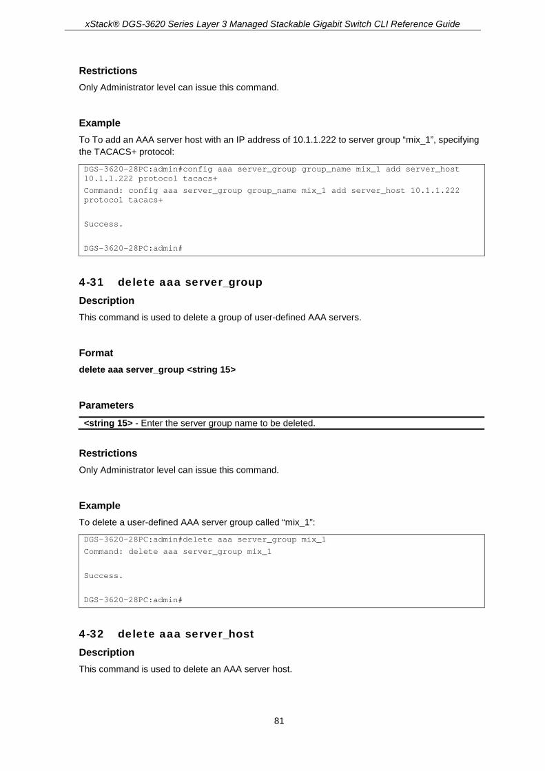
xStack® DGS-3620 Series Layer 3 Managed Stackable Gigabit Switch CLI Reference Guide
81
Restrictions Only Administrator level can issue this command.
Example To To add an AAA server host with an IP address of 10.1.1.222 to server group “mix_1”, specifying the TACACS+ protocol:
DGS-3620-28PC:admin#config aaa server_group group_name mix_1 add server_host 10.1.1.222 protocol tacacs+
Command: config aaa server_group group_name mix_1 add server_host 10.1.1.222 protocol tacacs+
Success.
DGS-3620-28PC:admin#
4-31 delete aaa server_group Description This command is used to delete a group of user-defined AAA servers.
Format delete aaa server_group <string 15>
Parameters <string 15> - Enter the server group name to be deleted.
Restrictions Only Administrator level can issue this command.
Example To delete a user-defined AAA server group called “mix_1”:
DGS-3620-28PC:admin#delete aaa server_group mix_1
Command: delete aaa server_group mix_1
Success.
DGS-3620-28PC:admin#
4-32 delete aaa server_host Description This command is used to delete an AAA server host.

xStack® DGS-3620 Series Layer 3 Managed Stackable Gigabit Switch CLI Reference Guide
82
Format delete aaa server_host <ipaddr> protocol [tacacs | xtacacs | tacacs+ | radius]
Parameters <ipaddr> - Enter the IP address of the server host. protocol – Specifies the protocol.
tacacs – Specifies TACACS server host. xtacacs - Specifies XTACACS server host. tacacs+ - Specifies TACACS+ server host. radius - Specifies RADIUS server host.
Restrictions Only Administrator level can issue this command.
Example To tacacs | xtacacs | tacacs+| delete an AAA server host, with an IP address of 10.1.1.222, that is running the TACACS+ protocol:
DGS-3620-28PC:admin#delete aaa server_host 10.1.1.222 protocol tacacs+
Command: delete aaa server_host 10.1.1.222 protocol tacacs+
Success.
DGS-3620-28PC:admin#
4-33 show aaa Description This command is used to display AAA global configuration.
Format show aaa
Parameters None.
Restrictions None.
Example To display AAA global configuration:

xStack® DGS-3620 Series Layer 3 Managed Stackable Gigabit Switch CLI Reference Guide
83
DGS-3620-28PC:admin#show aaa
Command: show aaa
Authentication Policy: Enabled
Accounting Network Service State: AAA Method
Accounting Network Service Method: acc_telnet
Accounting Shell Service State: RADIUS Only
Accounting Shell Service Method:
Accounting System Service State: Disabled
Accounting System Service Method:
Accounting Admin Command Service Method:
Accounting Operator Command Service Method:
Accounting PowerUser Command Service Method:
Accounting User Command Service Method:
Authentication Policy Encryption: Enabled
DGS-3620-28PC:admin#
4-34 show aaa server_group Description This command is used to display the groups of AAA servers groups.
Format show aaa server_group {<string 15>}
Parameters <string 15> - (Optional) Specifies the built-in or user-defined server group name.
Restrictions Only Administrator level can issue this command.
Example To display all AAA server groups:

xStack® DGS-3620 Series Layer 3 Managed Stackable Gigabit Switch CLI Reference Guide
84
DGS-3620-28PC:admin#show aaa server_group
Command: show aaa server_group
Group Name IP Address Protocol
--------------- --------------------------------------- --------
mix_1 --------------------------------------- --------
radius --------------------------------------- --------
tacacs --------------------------------------- --------
tacacs+ --------------------------------------- --------
xtacacs --------------------------------------- --------
Total Entries : 5
DGS-3620-28PC:admin#
4-35 show aaa server_host Description This command is used to display the AAA server hosts.
Format show aaa server_host
Parameters None.
Restrictions Only Administrator level can issue this command.
Example To display all AAA server hosts:
DGS-3620-28PC:admin#show aaa server_host
Command: show aaa server_host
IP Address Protocl Port Acct Time Retry Key
Port out
-------------------- ------- ----- ----- ---- ----- ---------------------------
10.1.1.222 RADIUS 15555 1813 10 2 ******
Total Entries : 1
DGS-3620-28PC:admin#

xStack® DGS-3620 Series Layer 3 Managed Stackable Gigabit Switch CLI Reference Guide
85
4-36 enable aaa_server_password_encryption Description This command is used to enable AAA server password encryption.
Format enable aaa_server_password_encryption
Parameters None.
Restrictions Only Administrator level can issue this command.
Example To enable AAA server password encryption:
DGS-3620-28PC:admin#enable aaa_server_password_encryption
Command: enable aaa_server_password_encryption
Success.
DGS-3620-28PC:admin#
4-37 disable aaa_server_password_encryption Description This command is used to disable AAA server password encryption.
Format disable aaa_server_password_encryption
Parameters None.
Restrictions Only Administrator level can issue this command.
Example To disable AAA server password encryption:

xStack® DGS-3620 Series Layer 3 Managed Stackable Gigabit Switch CLI Reference Guide
86
DGS-3620-28PC:admin#disable aaa_server_password_encryption
Command: disable aaa_server_password_encryption
Success.
DGS-3620-28PC:admin#
4-38 config accounting Description This command is used to configure a user-defined or default method list of accounting methods.
Format config accounting [default | method_list_name <string 15>] method {tacacs+ | radius | server_group <string 15> | none}
Parameters default - Specifies the default method list of accounting methods. method_list_name - Specifies the user-defined method list of accounting methods.
<string 15> - Enter the user-defined method list name here. This name can be up to 15 characters long.
method - Specifies the accounting method used. tacacs+ - Specifies to use the built-in server group 'tacacs+'. radius - Specifies to use the built-in server group 'radius'. server_group - Specifies the user-defined server group. If the group contains 'tacacs' or
'xtacacs' server, it will be skipped in accounting. <string 15> - Enter the user-defined server group name here. This name can be up to 15
characters long. none - Specifies no accounting.
Restrictions Only Administrator level users can issue this command.
Example To configure a user-defined method list called “shell_acct”, that specifies a sequence of the built-in “tacacs+” server group, followed by the “radius” server group for accounting service on switch:
DGS-3620-28PC:admin#config accounting method_list_name shell_acct method tacacs+ radius
Command: config accounting method_list_name shell_acct method tacacs+ radius
Success.
DGS-3620-28PC:admin#

xStack® DGS-3620 Series Layer 3 Managed Stackable Gigabit Switch CLI Reference Guide
87
4-39 config accounting service Description This command is used to configure the state of the specified RADIUS accounting service.
Format config accounting service [network | shell | system] state [enable {[radius_only | method_list_name <string 15> | default_method_list]} | disable]
Parameters network - Specifies that when enabled, the Switch will send informational packets to a remote
RADIUS server when 802.1X, WAC and JWAC port access control events occur on the Switch. By default, the service is disabled.
shell - Specifies that when enabled, the Switch will send informational packets to a remote RADIUS server when a user either logs in, logs out or times out on the Switch, using the console, Telnet, or SSH. By default, the service is disabled.
system - Specifies that when enabled, the Switch will send informational packets to a remote RADIUS server when system events occur on the Switch, such as a system reset or system boot. By default, the service is disabled.
state - Specifies the state of the accounting service. enable - Enable the specified accounting service.
radius_only - Specifies that the accounting service should only use the RADIUS group specified by the config radius add <server_index 1-3> [<server_ip> | <ipv6addr>]” command.
method_list_name - Specifies that the accounting service should use the AAA user-defined method list specified by the “create accounting method_list_name <string 15>” command. <string 15> - Enter the method list name used here. This name can be up to 15
characters long. default_method_list - Specifies that the accounting service should use the AAA default
method list. disable - Disable the specified accounting service.
Restrictions Only Administrators, Operators and Power-Users can issue this command.
Example To configure the state of the RADIUS accounting service shell to enable:
DGS-3620-28PC:admin# config accounting service shell state enable
Command: config accounting service shell state enable
Success
DGS-3620-28PC:admin#
4-40 config accounting service command Description This command is used to configure the state of the specified accounting service.

xStack® DGS-3620 Series Layer 3 Managed Stackable Gigabit Switch CLI Reference Guide
88
Format config accounting service command {administrator | operator | power_user | user} [method_list_name <string> | none]
Parameters administrator - (Optional) Specifies the accounting service for all administrator level commands. operator - (Optional) Specifies the accounting service for all operator level commands. power_user - (Optional) Specifies the accounting service for all power-user level commands. user - (Optional) Specifies the accounting service for all user level commands. method_list_name - Specifies the accounting service by the AAA user-defined method list.
Note: The accounting command only supports the TACACS+ server. The other servers that exist in the method list will be skipped. <string> - Enter the method list name used here. none - Specifies to disable accounting services for the specified command level.
Restrictions Only Administrators, Operators and Power-Users can issue this command.
Example To configure the AAA accounting methodlist “admin_acct” for accounting to all administrator commands:
DGS-3620-28PC:admin#config accounting service command administrator method_list_name admin_acct
Command: config accounting service command administrator method_list_name admin_acct
Success.
DGS-3620-28PC:admin#
4-41 create accounting method_list_name Description This command is used to create a user-defined method list of accounting methods.
Format create accounting method_list_name <string 15>
Parameters <string 15> - Enter the name of the user-defined method list here. This name can be up to 15
characters long.
Restrictions Only Administrator level users can issue this command.

xStack® DGS-3620 Series Layer 3 Managed Stackable Gigabit Switch CLI Reference Guide
89
Example To create a user-defined accounting method list called “shell_acct”:
DGS-3620-28PC:admin#create accounting method_list_name shell_acct
Command: create accounting method_list_name shell_acct
Success.
DGS-3620-28PC:admin#
4-42 delete accounting method_list_name Description This command is used to delete a user-defined method list of accounting methods.
Format delete accounting method_list_name <string 15>
Parameters <string 15> - Enter the name of the user-defined method list here. This name can be up to 15
characters long.
Restrictions Only Administrator level users can issue this command.
Example To delete the user-defined accounting method list called “shell_acct” from switch:
DGS-3620-28PC:admin#delete accounting method_list_name shell_acct
Command: delete accounting method_list_name shell_acct
Success.
DGS-3620-28PC:admin#
4-43 show accounting Description This command is used to display the method list of accounting methods on switch.
Format show accounting [default | method_list_name <string 15> | all]

xStack® DGS-3620 Series Layer 3 Managed Stackable Gigabit Switch CLI Reference Guide
90
Parameters default - Displays the user-defined list of default accounting methods. method_list_name - Displays the user-defined list of specific accounting methods.
<string 15> - Enter the user-defined method list name here. This name can be up to 15 characters long.
all - Displays all accounting method lists on switch.
Restrictions Only Administrator level users can issue this command.
Example To display the user-defined accounting method list called “shell_acct”:
DGS-3620-28PC:admin#show accounting method_list_name shell_acct
Command: show accounting method_list_name shell_acct
Method List Name Priority Method Name Comment
---------------- -------- --------------- ------------------
shell_acct 1 none Keyword
DGS-3620-28PC:admin#
4-44 show accounting service Description This command is used to display RADIUS accounting service information.
Format show accounting service
Parameters None.
Restrictions None.
Example To display accounting service information:
DGS-3620-28PC:admin#show accounting service
Command: show accounting service
Accounting State
-------------------
Network : Disabled

xStack® DGS-3620 Series Layer 3 Managed Stackable Gigabit Switch CLI Reference Guide
91
Shell : Disabled
System : Disabled
DGS-3620-28PC:admin#
4-45 create radius server_host Description This command is used to create an RADIUS server host.
Format create radius server_host <ipaddr> {auth_port <int 1-65535> | acct_port <int 1-65535> | [key [<key_string 254> | none] | encryption_key <key_string 344>] | timeout <int 1-255> | retransmit <int 1-20>}
Parameters <ipaddr> - Enter the IP address of the server host. auth_port - (Optional) Specifies the port of the RADIUS authentication.
<int 1-65535> - Enter the value between 1 and 65535. The default value is 1812. acct_port - (Optional) Specifies the port of the RAIDUS accounting.
<int 1-65535> - Enter the value between 1 and 65535. The default value is 1813. key - (Optional) Specifies the key for RADIUS.
<key_string 254> - Enter the plain text key string for RADIUS. none - No encryption for RADIUS.
encryption_key - (Optional) The encrypted form key string for RADIUS. The encryption algorithm is based on DES. <key_string 344> - Etner the string with maximum 344 characters.
timeout - (Optional) Specifies the time in second to wait for the server to reply. <int 1-255> - Enter the value between 1 and 255. The default value is 5.
retransmit - (Optional) Specifies the count for re-transmissions. <int 1-20> - Enter the value between 1 and 20. The default value is 2.
Restrictions Only Administrator level can issue this command.
Example To create an RADIUS server host:
DGS-3620-28PC:admin#create radius server_host 10.1.1.222 auth_port 15555 timeout 10
Command: create radius server_host 10.1.1.222 auth_port 15555 timeout 10
Key is empty for TACACS+ or RADIUS.
Success.
DGS-3620-28PC:admin#

xStack® DGS-3620 Series Layer 3 Managed Stackable Gigabit Switch CLI Reference Guide
92
4-46 config radius server_host Description This command is used to configure the RADIUS server host.
Format config radius server_host <ipaddr> {auth_port <int 1-65535> | acct_port <int 1-65535> | [key [<key_string 254> | none] | encryption_key <key_string 344>] | timeout <int 1-255> | retransmit <int 1-20>}
Parameters <ipaddr> - Enter the IP address of the server host. auth_port - (Optional) Specifies the port of the RADIUS authentication.
<int 1-65535> - Enter the value between 1 and 65535. The default value is 1812. acct_port - (Optional) Specifies the port of the RAIDUS accounting.
<int 1-65535> - Enter the value between 1 and 65535. The default value is 1813. key - (Optional) Specifies the key for RADIUS.
<key_string 254> - Enter the plain text key string for RADIUS. none - No encryption for RADIUS.
encryption_key - (Optional) The encrypted form key string for RADIUS. The encryption algorithm is based on DES. <key_string 344> - Etner the string with maximum 344 characters.
timeout - (Optional) Specifies the time in second to wait for the server to reply. <int 1-255> - Enter the value between 1 and 255. The default value is 5.
retransmit - (Optional) Specifies the count for re-transmissions. <int 1-20> - Enter the value between 1 and 20. The default value is 2.
Restrictions Only Administrator level can issue this command.
Example To configure the RADIUS server host:
DGS-3620-28PC:admin#config radius server_host 10.1.1.222 key "abc123"
Command: config radius server_host 10.1.1.222 key "abc123"
Success.
DGS-3620-28PC:admin#
4-47 config radius source_ipif Description This command is used to specify source interface for all outgoing RADIUS packets.
Format config radius source_ipif [<ipif_name 12> {<ipaddr> | <ipv6addr>} | none]

xStack® DGS-3620 Series Layer 3 Managed Stackable Gigabit Switch CLI Reference Guide
93
Parameters <ipif_name 12> - Enter the IP interface name used here. <ipaddr> - Enter the IPv4 address used here. <ipv6addr> - Enter the IPv6 address used here. none - Specifies to revert to the default route table for all outgoing RADIUS packet.
Restrictions Only Administrator level can issue this command.
Example To specify an interface as the source interface for all outgoing RADIUS packets.
DGS-3620-28PC:admin#config radius source_ipif if_v200
Command: config radius source_ipif if_v200
Success.
DGS-3620-28PC:admin#
4-48 show radius source_ipif Description This command is used to display specified source interface for all outgoing RADIUS packets.
Format show radius source_ipif
Parameters None.
Restrictions Only Administrator level can issue this command.
Example To display specified source interface for all outgoing RADIUS packets.
DGS-3620-28PC:admin#show radius source_ipif
Command: show radius source_ipif
IP Interface : if_v200
IPv4 Address : None
IPv6 Address : None
DGS-3620-28PC:admin#

xStack® DGS-3620 Series Layer 3 Managed Stackable Gigabit Switch CLI Reference Guide
94
4-49 create tacacs server_host Description This command is used to create a TACACS server host.
Format create tacacs server_host <ipaddr> {port <int 1-65535> | timeout <int 1-255> | retransmit <int 1-20>}
Parameters <ipaddr> - Enter the IP address of the server host. port - (Optional) The port number of the TACACS server host.
<int 1-65535> - Enter the value between 1 and 65535. The default value is 49. timeout - (Optional) Specifies the time in second to wait for the server to reply.
<int 1-255> - Enter the value between 1 and 255. The default value is 5. retransmit - (Optional) Specifies the count for re-transmissions.
<int 1-20> - Enter the value between 1 and 20. The default value is 2.
Restrictions Only Administrator level can issue this command.
Example To create a TACACS server host:
DGS-3620-28PC:admin#create tacacs server_host 10.1.1.223 port 15555 timeout 10
Command: create tacacs server_host 10.1.1.223 port 15555 timeout 10
Success.
DGS-3620-28PC:admin#
4-50 config tacacs server_host Description This command is used to configure a TACACS server host.
Format config tacacs server_host <ipaddr> {port <int 1-65535> | timeout <int 1-255> | retransmit <int 1-20>}
Parameters <ipaddr> - Enter the IP address of the server host. port - (Optional) The port number of the TACACS server host.
<int 1-65535> - Enter the value between 1 and 65535. The default value is 49.
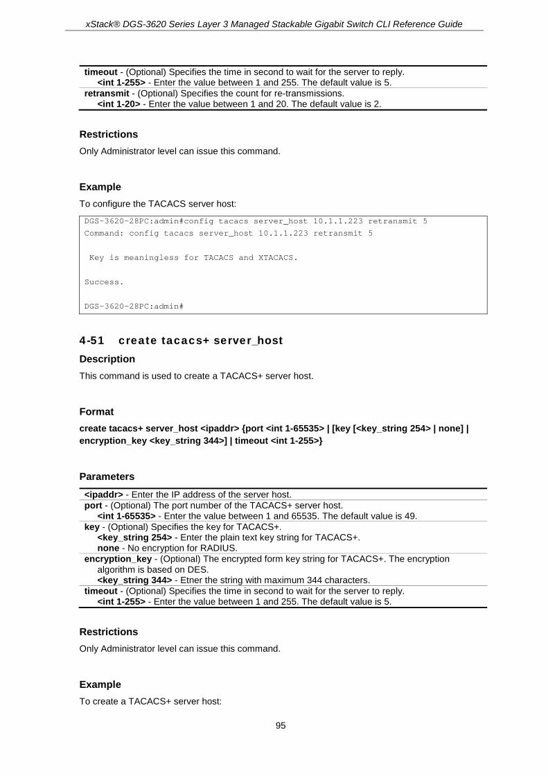
xStack® DGS-3620 Series Layer 3 Managed Stackable Gigabit Switch CLI Reference Guide
95
timeout - (Optional) Specifies the time in second to wait for the server to reply. <int 1-255> - Enter the value between 1 and 255. The default value is 5.
retransmit - (Optional) Specifies the count for re-transmissions. <int 1-20> - Enter the value between 1 and 20. The default value is 2.
Restrictions Only Administrator level can issue this command.
Example To configure the TACACS server host:
DGS-3620-28PC:admin#config tacacs server_host 10.1.1.223 retransmit 5
Command: config tacacs server_host 10.1.1.223 retransmit 5
Key is meaningless for TACACS and XTACACS.
Success.
DGS-3620-28PC:admin#
4-51 create tacacs+ server_host Description This command is used to create a TACACS+ server host.
Format create tacacs+ server_host <ipaddr> {port <int 1-65535> | [key [<key_string 254> | none] | encryption_key <key_string 344>] | timeout <int 1-255>}
Parameters <ipaddr> - Enter the IP address of the server host. port - (Optional) The port number of the TACACS+ server host.
<int 1-65535> - Enter the value between 1 and 65535. The default value is 49. key - (Optional) Specifies the key for TACACS+.
<key_string 254> - Enter the plain text key string for TACACS+. none - No encryption for RADIUS.
encryption_key - (Optional) The encrypted form key string for TACACS+. The encryption algorithm is based on DES. <key_string 344> - Etner the string with maximum 344 characters.
timeout - (Optional) Specifies the time in second to wait for the server to reply. <int 1-255> - Enter the value between 1 and 255. The default value is 5.
Restrictions Only Administrator level can issue this command.
Example To create a TACACS+ server host:
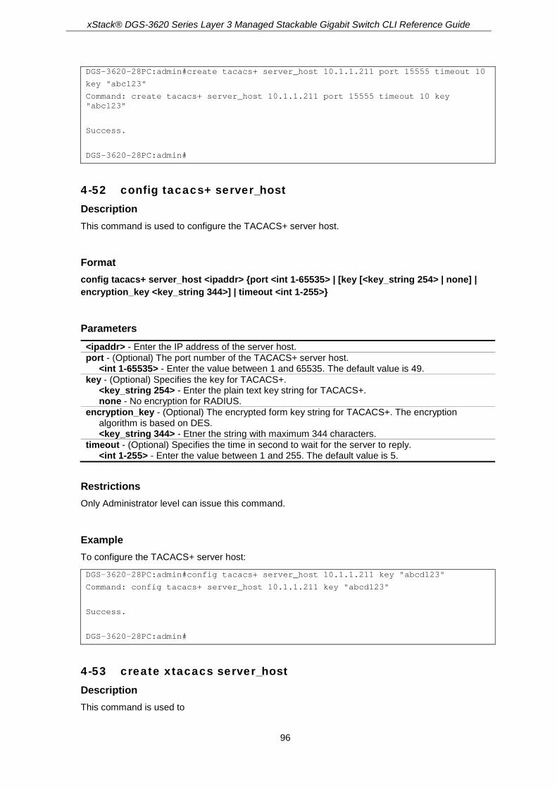
xStack® DGS-3620 Series Layer 3 Managed Stackable Gigabit Switch CLI Reference Guide
96
DGS-3620-28PC:admin#create tacacs+ server_host 10.1.1.211 port 15555 timeout 10
key "abc123"
Command: create tacacs+ server_host 10.1.1.211 port 15555 timeout 10 key "abc123"
Success.
DGS-3620-28PC:admin#
4-52 config tacacs+ server_host Description This command is used to configure the TACACS+ server host.
Format config tacacs+ server_host <ipaddr> {port <int 1-65535> | [key [<key_string 254> | none] | encryption_key <key_string 344>] | timeout <int 1-255>}
Parameters <ipaddr> - Enter the IP address of the server host. port - (Optional) The port number of the TACACS+ server host.
<int 1-65535> - Enter the value between 1 and 65535. The default value is 49. key - (Optional) Specifies the key for TACACS+.
<key_string 254> - Enter the plain text key string for TACACS+. none - No encryption for RADIUS.
encryption_key - (Optional) The encrypted form key string for TACACS+. The encryption algorithm is based on DES. <key_string 344> - Etner the string with maximum 344 characters.
timeout - (Optional) Specifies the time in second to wait for the server to reply. <int 1-255> - Enter the value between 1 and 255. The default value is 5.
Restrictions Only Administrator level can issue this command.
Example To configure the TACACS+ server host:
DGS-3620-28PC:admin#config tacacs+ server_host 10.1.1.211 key "abcd123"
Command: config tacacs+ server_host 10.1.1.211 key "abcd123"
Success.
DGS-3620-28PC:admin#
4-53 create xtacacs server_host Description This command is used to
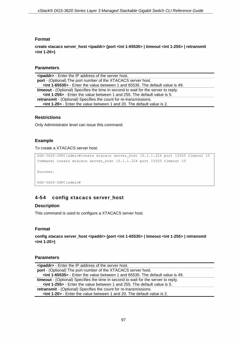
xStack® DGS-3620 Series Layer 3 Managed Stackable Gigabit Switch CLI Reference Guide
97
Format create xtacacs server_host <ipaddr> {port <int 1-65535> | timeout <int 1-255> | retransmit <int 1-20>}
Parameters <ipaddr> - Enter the IP address of the server host. port - (Optional) The port number of the XTACACS server host.
<int 1-65535> - Enter the value between 1 and 65535. The default value is 49. timeout - (Optional) Specifies the time in second to wait for the server to reply.
<int 1-255> - Enter the value between 1 and 255. The default value is 5. retransmit - (Optional) Specifies the count for re-transmissions.
<int 1-20> - Enter the value between 1 and 20. The default value is 2.
Restrictions Only Administrator level can issue this command.
Example To create a XTACACS server host:
DGS-3620-28PC:admin#create xtacacs server_host 10.1.1.224 port 15555 timeout 10
Command: create xtacacs server_host 10.1.1.224 port 15555 timeout 10
Success.
DGS-3620-28PC:admin#
4-54 config xtacacs server_host Description This command is used to configure a XTACACS server host.
Format config xtacacs server_host <ipaddr> {port <int 1-65535> | timeout <int 1-255> | retransmit <int 1-20>}
Parameters <ipaddr> - Enter the IP address of the server host. port - (Optional) The port number of the XTACACS server host.
<int 1-65535> - Enter the value between 1 and 65535. The default value is 49. timeout - (Optional) Specifies the time in second to wait for the server to reply.
<int 1-255> - Enter the value between 1 and 255. The default value is 5. retransmit - (Optional) Specifies the count for re-transmissions.
<int 1-20> - Enter the value between 1 and 20. The default value is 2.
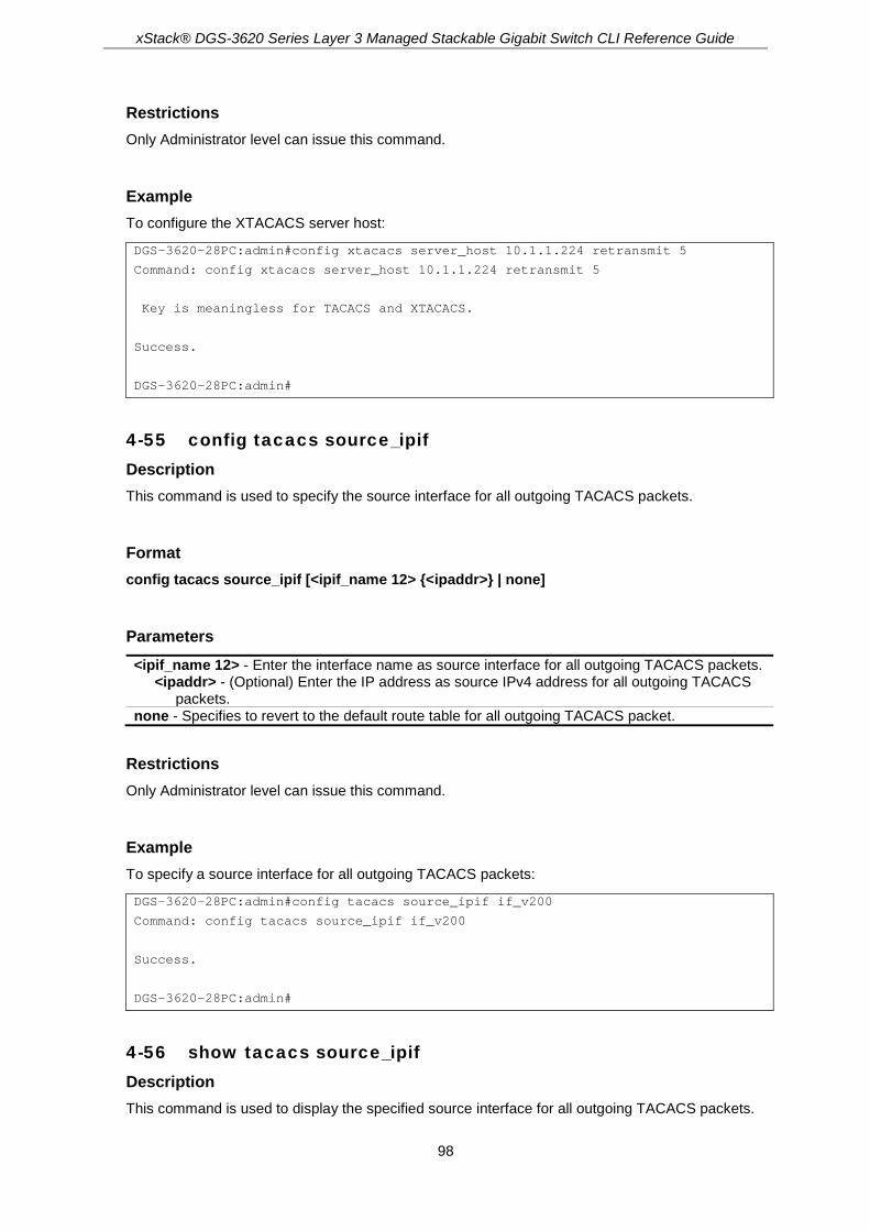
xStack® DGS-3620 Series Layer 3 Managed Stackable Gigabit Switch CLI Reference Guide
98
Restrictions Only Administrator level can issue this command.
Example To configure the XTACACS server host:
DGS-3620-28PC:admin#config xtacacs server_host 10.1.1.224 retransmit 5
Command: config xtacacs server_host 10.1.1.224 retransmit 5
Key is meaningless for TACACS and XTACACS.
Success.
DGS-3620-28PC:admin#
4-55 config tacacs source_ipif Description This command is used to specify the source interface for all outgoing TACACS packets.
Format config tacacs source_ipif [<ipif_name 12> {<ipaddr>} | none]
Parameters <ipif_name 12> - Enter the interface name as source interface for all outgoing TACACS packets.
<ipaddr> - (Optional) Enter the IP address as source IPv4 address for all outgoing TACACS packets.
none - Specifies to revert to the default route table for all outgoing TACACS packet.
Restrictions Only Administrator level can issue this command.
Example To specify a source interface for all outgoing TACACS packets:
DGS-3620-28PC:admin#config tacacs source_ipif if_v200
Command: config tacacs source_ipif if_v200
Success.
DGS-3620-28PC:admin#
4-56 show tacacs source_ipif Description This command is used to display the specified source interface for all outgoing TACACS packets.

xStack® DGS-3620 Series Layer 3 Managed Stackable Gigabit Switch CLI Reference Guide
99
Format show tacacs source_ipif
Parameters None.
Restrictions Only Administrator level can issue this command.
Example To display the specified source interface for all outgoing TACACS packets.
DGS-3620-28PC:admin#show tacacs source_ipif
Command: show tacacs source_ipif
IP Interface : if_v200
IPv4 Address : None
DGS-3620-28PC:admin#

xStack® DGS-3620 Series Layer 3 Managed Stackable Gigabit Switch CLI Reference Guide
100
Chapter 5 Access Control List (ACL) Commands
create access_profile profile_id <value 1-6> profile_name <name 1-32> [ethernet {vlan {<hex
0x0-0x0fff>} | source_mac <macmask 000000000000-ffffffffffff> | destination_mac <macmask 000000000000-ffffffffffff> | 802.1p | ethernet_type}(1) | ip {vlan {<hex 0x0-0x0fff>} | source_ip_mask <netmask> | destination_ip_mask <netmask> | dscp | [icmp {type | code} | igmp {type} | tcp {src_port_mask <hex 0x0-0xffff> | dst_port_mask <hex 0x0-0xffff> | flag_mask [all | {urg | ack | psh | rst | syn | fin}]} | udp {src_port_mask <hex 0x0-0xffff> | dst_port_mask <hex 0x0-0xffff>} | protocol_id_mask <hex 0x0-0xff> {user_define_mask <hex 0x0-0xffffffff>}]}(1) | packet_content_mask {offset_chunk_1 <value 0-31> <hex 0x0-0xffffffff> | offset_chunk_2 <value 0-31> <hex 0x0-0xffffffff> | offset_chunk_3 <value 0-31> <hex 0x0-0xffffffff> | offset_chunk_4 <value 0-31> <hex 0x0-0xffffffff>}(1) | ipv6 {class | flowlabel | source_ipv6_mask <ipv6mask> | destination_ipv6_mask <ipv6mask> | [tcp {src_port_mask <hex 0x0-0xffff> | dst_port_mask <hex 0x0-0xffff>} | udp {src_port_mask <hex 0x0-0xffff> | dst_port_mask <hex 0x0-0xffff>} | icmp {type | code}]}(1)]
delete access_profile [profile_id <value 1-6> | profile_name <name 1-32> | all] config access_profile [profile_id <value 1-6> | profile_name <name 1-32>] [add access_id
[auto_assign | <value 1-256>] [ethernet {[vlan <vlan_name 32> | vlan_id <vlanid 1-4094>] {mask <hex 0x0-0x0fff>} | source_mac <macaddr> {mask <macmask>} | destination_mac <macaddr> {mask <macmask>} | 802.1p <value 0-7> | ethernet_type <hex 0x0-0xffff>}(1) | ip {[vlan <vlan_name 32> | vlan_id <vlanid 1-4094>] {mask <hex 0x0-0x0fff>} | source_ip <ipaddr> {mask <netmask>} | destination_ip <ipaddr> {mask <netmask>} | dscp<value 0-63> | [icmp {type <value 0-255> | code <value 0-255>} | igmp {type <value 0-255>} | tcp {src_port <value 0-65535> {mask <hex 0x0-0xffff>} | dst_port <value 0-65535> {mask <hex 0x0-0xffff>} | flag [all | {urg | ack | psh | rst | syn | fin}]} | udp {src_port <value 0-65535> {mask <hex 0x0-0xffff>} | dst_port <value 0-65535> {mask <hex 0x0-0xffff>}} | protocol_id <value 0-255> {user_define <hex 0x0-0xffffffff> {mask <hex 0x0-0xffffffff>}}]}(1) | packet_content {offset_chunk_1 <hex 0x0-0xffffffff> {mask <hex 0x0-0xffffffff>} | offset_chunk_2 <hex 0x0-0xffffffff> {mask <hex 0x0-0xffffffff>} | offset_chunk_3 <hex 0x0-0xffffffff> {mask <hex 0x0-0xffffffff>} | offset_chunk_4 <hex 0x0-0xffffffff> {mask <hex 0x0-0xffffffff>}}(1) | ipv6 {class <value 0-255> | flowlabel <hex 0x0-0xfffff> | source_ipv6 <ipv6addr> {mask<ipv6mask>} | destination_ipv6 <ipv6addr> {mask <ipv6mask>} | [tcp {src_port<value 0-65535> {mask <hex 0x0-0xffff>} | dst_port <value 0-65535> {mask <hex0x0-0xffff>}} | udp {src_port <value 0-65535> {mask <hex 0x0-0xffff>} | dst_port <value 0-65535> {mask <hex 0x0-0xffff>}} | icmp {type<value 0-255> | code <value 0-255>}]}(1)] [port [<portlist> | all] | vlan_based [vlan <vlan_name 32> | vlan_id <vlanid 1-4094>]] [permit {priority <value 0-7> {replace_priority} | [replace_dscp_with <value 0-63> | replace_tos_precedence_with <value 0-7>] | counter [enable | disable] | urpf_state_check [enable | disable]} | mirror {group_id <value 1-4>} | redirect egress_port <port> | deny] {time_range <range_name 32>} | delete access_id <value 1-256>]
show access_profile {[profile_id <value 1-6> | profile_name <name 1-32>]} config time_range <range_name 32> [hours start_time <time hh:mm:ss> end_time <time
hh:mm:ss> weekdays <daylist> | delete] show time_range show current_config access_profile delete cpu access_profile [profile_id <value 1-5> | all] create cpu access_profile profile_id <value 1-5> [ethernet {vlan | source_mac <macmask
000000000000-ffffffffffff> | destination_mac <macmask 000000000000-ffffffffffff> | 802.1p | ethernet_type}(1) | ip {vlan | source_ip_mask <netmask> | destination_ip_mask <netmask> | dscp | [icmp {type | code} | igmp {type} | tcp {src_port_mask <hex 0x0-0xffff> | dst_port_mask <hex 0x0-0xffff> | flag_mask [all | {urg | ack | psh | rst | syn | fin}]} | udp {src_port_mask <hex 0x0-0xffff> | dst_port_mask <hex 0x0-0xffff>} | protocol_id_mask <hex 0x0-0xff> {user_define_mask <hex 0x0-0xffffffff>}]}(1) | packet_content_mask {offset_0-15 <hex 0x0-

xStack® DGS-3620 Series Layer 3 Managed Stackable Gigabit Switch CLI Reference Guide
101
0xffffffff> <hex 0x0-0xffffffff> <hex 0x0-0xffffffff> <hex 0x0-0xffffffff> | offset_16-31 <hex 0x0-0xffffffff> <hex 0x0-0xffffffff> <hex 0x0-0xffffffff> <hex 0x0-0xffffffff> | offset_32-47 <hex 0x0-0xffffffff> <hex 0x0-0xffffffff> <hex 0x0-0xffffffff> <hex 0x0-0xffffffff> | offset_48-63 <hex 0x0-0xffffffff> <hex 0x0-0xffffffff> <hex 0x0-0xffffffff> <hex 0x0-0xffffffff> | offset_64-79 <hex 0x0-0xffffffff> <hex 0x0-0xffffffff> <hex 0x0-0xffffffff> <hex 0x0-0xffffffff>}(1) | ipv6 {class | flowlabel | source_ipv6_mask <ipv6mask> | destination_ipv6_mask <ipv6mask>}(1)]
config cpu access_profile profile_id <value 1-5> [add access_id [auto_assign | <value 1-100>] [ethernet {[vlan <vlan_name 32> | vlan_id <vlanid 1-4094>] | source_mac <macaddr> | destination_mac <macaddr> | 802.1p <value 0-7> | ethernet_type <hex 0x0-0xffff>} | ip {[vlan <vlan_name 32> | vlan_id <vlanid 1-4094>] | source_ip <ipaddr> | destination_ip <ipaddr> | dscp <value 0-63> | [icmp {type <value 0-255> | code <value 0-255>} | igmp {type <value 0-255>} | tcp {src_port <value 0-65535> | dst_port <value 0-65535> | flag [all | {urg | ack | psh | rst | syn | fin}]} | udp {src_port <value 0-65535> | dst_port <value 0-65535>} | protocol_id <value 0-255> {user_define <hex 0x0-0xffffffff>}]} | packet_content {offset_0-15 <hex 0x0-0xffffffff> <hex 0x0-0xffffffff> <hex 0x0-0xffffffff> <hex 0x0-0xffffffff> | offset_16-31 <hex 0x0-0xffffffff> <hex 0x0-0xffffffff> <hex 0x0-0xffffffff> <hex 0x0-0xffffffff> | offset_32-47 <hex 0x0-0xffffffff> <hex 0x0-0xffffffff> <hex 0x0-0xffffffff> <hex 0x0-0xffffffff> | offset_48-63 <hex 0x0-0xffffffff> <hex 0x0-0xffffffff> <hex 0x0-0xffffffff> <hex 0x0-0xffffffff> | offset_64-79 <hex 0x0-0xffffffff> <hex 0x0-0xffffffff> <hex 0x0-0xffffffff> <hex 0x0-0xffffffff>} | ipv6 {class <value 0-255> | flowlabel <hex 0x0-0xfffff> | source_ipv6 <ipv6addr> | destination_ipv6 <ipv6addr>}] port [<portlist> | all] [permit | deny] {time_range <range_name 32>} | delete access_id <value 1-100>]
show cpu access_profile {profile_id <value 1-5>} enable cpu_interface_filtering disable cpu_interface_filtering config flow_meter [profile_id <value 1-6> | profile_name <name 1-32>] access_id <value 1-256>
[rate [<value 0-1048576>] {burst_size [<value 0-131072>]} rate_exceed [drop_packet | remark_dscp <value 0-63>] | tr_tcm cir <value 0-1048576> {cbs <value 0-131072>} pir <value 0-1048576> {pbs <value 0-131072>} {[color_blind | color_aware]} {conform [permit | replace_dscp <value 0-63>] {counter [enable | disable]}} exceed [permit {replace_dscp <value 0-63>} | drop] {counter [enable | disable]} violate [permit {replace_dscp <value 0-63>} | drop] {counter [enable | disable]} | sr_tcm cir <value 0-1048576> cbs <value 0-131072> ebs <value 0-131072> {[color_blind | color_aware]} {conform [permit | replace_dscp <value 0-63>] {counter [enable | disable]}} exceed [permit {replace_dscp <value 0-63>} | drop] {counter [enable | disable]} violate [permit {replace_dscp <value 0-63>} | drop] {counter [enable | disable]} | delete]
show flow_meter {[profile_id <value 1-6> | profile_name <name 1-32>] {access_id <value 1-256>}}
5-1 create access_profile profile_id Description This command is used to create access list profiles.
Format create access_profile profile_id <value 1-6> profile_name <name 1-32> [ethernet {vlan {<hex 0x0-0x0fff>} | source_mac <macmask 000000000000-ffffffffffff> | destination_mac <macmask 000000000000-ffffffffffff> | 802.1p | ethernet_type}(1) | ip {vlan {<hex 0x0-0x0fff>} | source_ip_mask <netmask> | destination_ip_mask <netmask> | dscp | [icmp {type | code} | igmp {type} | tcp {src_port_mask <hex 0x0-0xffff> | dst_port_mask <hex 0x0-0xffff> | flag_mask [all | {urg | ack | psh | rst | syn | fin}]} | udp {src_port_mask <hex 0x0-0xffff> | dst_port_mask <hex 0x0-0xffff>} | protocol_id_mask <hex 0x0-0xff> {user_define_mask <hex 0x0-0xffffffff>}]}(1) | packet_content_mask {offset_chunk_1 <value 0-31> <hex 0x0-0xffffffff> | offset_chunk_2 <value 0-31> <hex 0x0-0xffffffff> | offset_chunk_3 <value 0-31> <hex 0x0-0xffffffff> | offset_chunk_4 <value 0-31> <hex 0x0-0xffffffff>}(1) | ipv6 {class |

xStack® DGS-3620 Series Layer 3 Managed Stackable Gigabit Switch CLI Reference Guide
102
flowlabel | source_ipv6_mask <ipv6mask> | destination_ipv6_mask <ipv6mask> | [tcp {src_port_mask <hex 0x0-0xffff> | dst_port_mask <hex 0x0-0xffff>} | udp {src_port_mask <hex 0x0-0xffff> | dst_port_mask <hex 0x0-0xffff>} | icmp {type | code}]}(1)]
Parameters <value 1-6> - Enter the profile ID between 1 and 6. The lower the profile ID, the higher the
priority. profile_name - Specifies a profile name.
<name 1-32> - The maximum length is 32 characters. ethernet - Specifies an Ethernet access control list rule.
vlan - Specifies a VLAN mask. Only the last 12 bits of the mask will be considered. <hex 0x0-0x0fff> - (Optional) Specifies a VLAN mask.
source_mac - Specifies the source MAC mask. <macmask 000000000000-ffffffffffff> - Enter the source MAC mask.
destination_mac - Specifies the destination MAC mask. <macmask 000000000000-ffffffffffff> - Enter the destination MAC mask.
802.1p - Speciy the 802.1p priority tag mask. ethernet_type - Specifies the Ethernet type.
ip - Specifies an IP access control list rule. vlan - Specifies a VLAN mask. Only the last 12 bits of the mask will be considered.
<hex 0x0-0x0fff> - (Optional) Specifies a VLAN mask. source_ip_mask - Specifies an IP source submask.
<netmask> - Enter an IP source submask. destination_ip_mask - Specifies an IP destination submask.
<netmask> - Enter an IP destination submask. dscp - Specifies the DSCP mask. icmp - Specifies that the rule applies to ICMP traffic.
type - (Optional) Specifies the ICMP packet type. code - (Optional) Specifies the ICMP code.
igmp - Specifies that the rule applies to IGMP traffic. type - (Optional) Specifies the IGMP packet type.
tcp - Specifies that the rule applies to TCP traffic. src_port_mask - (Optional) Specifies the TCP source port mask.
<hex 0x0-0xffff> - Enter the TCP source port mask. dst_port_mask - (Optional) Specifies the TCP destination port mask.
<hex 0x0-0xffff> - Enter the TCP destination port mask. flag_mask - (Optional) Specifies the TCP flag field mask.
all – Specifies to check all paramenters below. urg - (Optional) Specifies Urgent Pointer field significant. ack - (Optional) Specifies Acknowledgment field significant. psh - (Optional) Specifies Push Function. rst - (Optional) Specifies to reset the connection. syn - (Optional) Specifies to synchronize sequence numbers. fin - (Optional) No more data from sender.
udp - Specifies that the rule applies to UDP traffic. src_port_mask - (Optional) Specifies the UDP source port mask.
<hex 0x0-0xffff> - Enter the UDP source port mask. dst_port_mask - (Optional) Specifies the UDP destination port mask.
<hex 0x0-0xffff> - Enter the UDP destination port mask. protocol_id_mask - Specifies that the rule applies to the IP protocol ID traffic.
<hex 0x0-0xff> - Enter that the rule applies to the IP protocol ID traffic. user_define_mask - (Optional) Specifies the rule applies to the IP protocol ID, and the mask
option behind the IP header length is 20 bytes. <hex 0x0-0xffffffff> - Enter the L4 part mask.
packet_content_mask - A maximum of six offsets can be specified. Each offset defines one byte of data which is identified as a single UDF field. The offset reference is also configurable. It can be defined to start at the end of the tag, the end of the Ethernet type, or the end of the IP header.

xStack® DGS-3620 Series Layer 3 Managed Stackable Gigabit Switch CLI Reference Guide
103
offset_chunk_1 - Specifies the offset chunk 1 that allows users to examine the specified offset_chunks within a packet at one time and specifies the frame content offset and mask. <value 0-31> - Enter the offset chunk 1 value here. This value must be between 0 and 31. <hex 0x0-0xffffffff> - Enter the offset chunk 1 mask value here.
offset_chunk_2 - Specifies the offset chunk 2 that allows users to examine the specified offset_chunks within a packet at one time and specifies the frame content offset and mask. <value 0-31> - Enter the offset chunk 2 value here. This value must be between 0 and 31. <hex 0x0-0xffffffff> - Enter the offset chunk 2 mask value here.
offset_chunk_3 - Specifies the offset chunk 3 that allows users to examine the specified offset_chunks within a packet at one time and specifies the frame content offset and mask. <value 0-31> - Enter the offset chunk 3 value here. This value must be between 0 and 31. <hex 0x0-0xffffffff> - Enter the offset chunk 3 mask value here.
offset_chunk_4 - Specifies the offset chunk 4 that allows users to examine the specified offset_chunks within a packet at one time and specifies the frame content offset and mask. <value 0-31> - Enter the offset chunk 4 value here. This value must be between 0 and 31. <hex 0x0-0xffffffff> - Enter the offset chunk 4 mask value here.
ipv6 - Specifies the IPv6 filtering mask. class - Specifies the IPv6 class mask. flowlabel - Specifies the IPv6 flow label mask. source_ipv6_mask - Specifies the IPv6 source IP mask.
<ipv6mask> - Enter the IPv6 source IP mask. destination_ipv6_mask - Specifies the IPv6 destination IP mask.
<ipv6mask> - Enter the IPv6 destination IP mask. tcp - Specifies that the rule applies to TCP traffic.
src_port_mask - (Optional) Specifies the TCP source port mask. <hex 0x0-0xffff> - Enter the TCP source port mask.
dst_port_mask - (Optional) Specifies the TCP destination port mask. <hex 0x0-0xffff> - Enter the TCP destination port mask.
udp - Specifies that the rule applies to UDP traffic. src_port_mask - (Optional) Specifies the TCP source port mask.
<hex 0x0-0xffff> - Enter the TCP source port mask. dst_port_mask - (Optional) Specifies the TCP destination port mask.
<hex 0x0-0xffff> - Enter the TCP destination port mask. icmp - Specifies that the rule applies to ICMP traffic.
type - (Optional) Specifies the ICMP packet type. code - (Optional) Specifies the ICMP code.
Restrictions Only Administrators, Operators and Power-Users can issue this command.
Example To create access list profiles:
DGS-3620-28PC:admin#create access_profile profile_id 1 profile_name 1 ethernet vlan source_mac FF-FF-FF-FF-FF-FF destination_mac 00-00-00-FF-FF-FF 802.1p ethernet_type
Command: create access_profile profile_id 1 profile_name 1 ethernet vlan source_mac FF-FF-FF-FF-FF-FF destination_mac 00-00-00-FF-FF-FF 802.1p ethernet_type
Success.
DGS-3620-28PC:admin#
DGS-3620-28PC:admin#create access_profile profile_id 2 profile_name 2 ip vlan source_ip_mask 255.255.255.255 destination_ip_mask 255.255.255.0 dscp icmp

xStack® DGS-3620 Series Layer 3 Managed Stackable Gigabit Switch CLI Reference Guide
104
Command: create access_profile profile_id 2 profile_name 2 ip vlan source_ip_mask 255.255.255.255 destination_ip_mask 255.255.255.0 dscp icmp
Success.
DGS-3620-28PC:admin#
5-2 delete access_profile Description This command is used to delete access list profiles.
Format delete access_profile [profile_id <value 1-6> | profile_name <name 1-32> | all]
Parameters profile_id - Specifies the index of the access list profile.
<value 1-6> - Enter the index of the access list profile. Enter a value between 1 and 6. profile_name - Specifies the profile name.
<name 1-32> - Enter the profile name. The maximum length is 32 characters. all - Specifies the whole access list profile to delete.
Restrictions Only Administrators, Operators and Power-Users can issue this command.
Example To delete access list profiles:
DGS-3620-28PC:admin#delete access_profile profile_id 1
Command: delete access_profile profile_id 1
Success.
DGS-3620-28PC:admin#
5-3 config access_profile Description This command is used to configure access list entries.
Format config access_profile [profile_id <value 1-6> | profile_name <name 1-32>] [add access_id [auto_assign | <value 1-256>] [ethernet {[vlan <vlan_name 32> | vlan_id <vlanid 1-4094>] {mask <hex 0x0-0x0fff>} | source_mac <macaddr> {mask <macmask>} | destination_mac <macaddr> {mask <macmask>} | 802.1p <value 0-7> | ethernet_type <hex 0x0-0xffff>}(1) | ip {[vlan <vlan_name 32> | vlan_id <vlanid 1-4094>] {mask <hex 0x0-0x0fff>} | source_ip
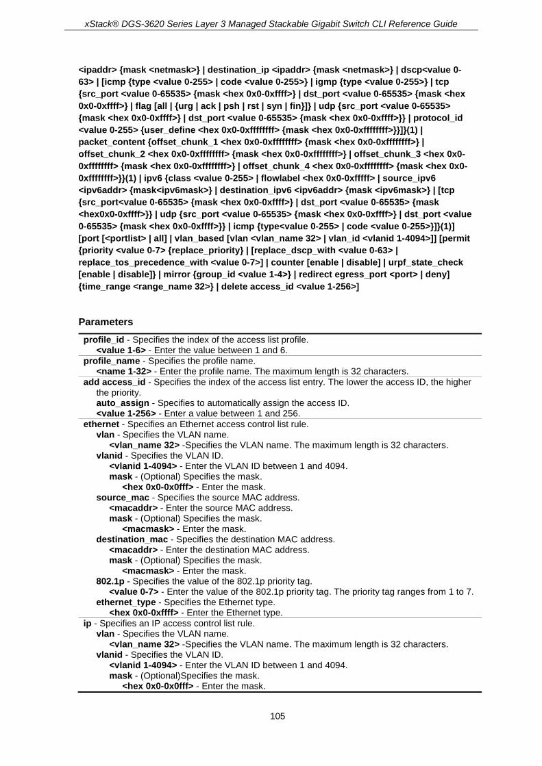
xStack® DGS-3620 Series Layer 3 Managed Stackable Gigabit Switch CLI Reference Guide
105
<ipaddr> {mask <netmask>} | destination_ip <ipaddr> {mask <netmask>} | dscp<value 0-63> | [icmp {type <value 0-255> | code <value 0-255>} | igmp {type <value 0-255>} | tcp {src_port <value 0-65535> {mask <hex 0x0-0xffff>} | dst_port <value 0-65535> {mask <hex 0x0-0xffff>} | flag [all | {urg | ack | psh | rst | syn | fin}]} | udp {src_port <value 0-65535> {mask <hex 0x0-0xffff>} | dst_port <value 0-65535> {mask <hex 0x0-0xffff>}} | protocol_id <value 0-255> {user_define <hex 0x0-0xffffffff> {mask <hex 0x0-0xffffffff>}}]}(1) | packet_content {offset_chunk_1 <hex 0x0-0xffffffff> {mask <hex 0x0-0xffffffff>} | offset_chunk_2 <hex 0x0-0xffffffff> {mask <hex 0x0-0xffffffff>} | offset_chunk_3 <hex 0x0-0xffffffff> {mask <hex 0x0-0xffffffff>} | offset_chunk_4 <hex 0x0-0xffffffff> {mask <hex 0x0-0xffffffff>}}(1) | ipv6 {class <value 0-255> | flowlabel <hex 0x0-0xfffff> | source_ipv6 <ipv6addr> {mask<ipv6mask>} | destination_ipv6 <ipv6addr> {mask <ipv6mask>} | [tcp {src_port<value 0-65535> {mask <hex 0x0-0xffff>} | dst_port <value 0-65535> {mask <hex0x0-0xffff>}} | udp {src_port <value 0-65535> {mask <hex 0x0-0xffff>} | dst_port <value 0-65535> {mask <hex 0x0-0xffff>}} | icmp {type<value 0-255> | code <value 0-255>}]}(1)] [port [<portlist> | all] | vlan_based [vlan <vlan_name 32> | vlan_id <vlanid 1-4094>]] [permit {priority <value 0-7> {replace_priority} | [replace_dscp_with <value 0-63> | replace_tos_precedence_with <value 0-7>] | counter [enable | disable] | urpf_state_check [enable | disable]} | mirror {group_id <value 1-4>} | redirect egress_port <port> | deny] {time_range <range_name 32>} | delete access_id <value 1-256>]
Parameters profile_id - Specifies the index of the access list profile.
<value 1-6> - Enter the value between 1 and 6. profile_name - Specifies the profile name.
<name 1-32> - Enter the profile name. The maximum length is 32 characters. add access_id - Specifies the index of the access list entry. The lower the access ID, the higher
the priority. auto_assign - Specifies to automatically assign the access ID. <value 1-256> - Enter a value between 1 and 256.
ethernet - Specifies an Ethernet access control list rule. vlan - Specifies the VLAN name.
<vlan_name 32> -Specifies the VLAN name. The maximum length is 32 characters. vlanid - Specifies the VLAN ID.
<vlanid 1-4094> - Enter the VLAN ID between 1 and 4094. mask - (Optional) Specifies the mask.
<hex 0x0-0x0fff> - Enter the mask. source_mac - Specifies the source MAC address.
<macaddr> - Enter the source MAC address. mask - (Optional) Specifies the mask.
<macmask> - Enter the mask. destination_mac - Specifies the destination MAC address.
<macaddr> - Enter the destination MAC address. mask - (Optional) Specifies the mask.
<macmask> - Enter the mask. 802.1p - Specifies the value of the 802.1p priority tag.
<value 0-7> - Enter the value of the 802.1p priority tag. The priority tag ranges from 1 to 7. ethernet_type - Specifies the Ethernet type.
<hex 0x0-0xffff> - Enter the Ethernet type. ip - Specifies an IP access control list rule.
vlan - Specifies the VLAN name. <vlan_name 32> -Specifies the VLAN name. The maximum length is 32 characters.
vlanid - Specifies the VLAN ID. <vlanid 1-4094> - Enter the VLAN ID between 1 and 4094. mask - (Optional)Specifies the mask.
<hex 0x0-0x0fff> - Enter the mask.

xStack® DGS-3620 Series Layer 3 Managed Stackable Gigabit Switch CLI Reference Guide
106
source_ip - Specifies an IP source address. <ipaddr> - Enter an IP source address. mask - (Optional) Specifies the mask.
<netmask> - Enter the mask. destination_ip - Specifies an IP destination address.
<ipaddr> - Enter an IP destination address. mask - (Optional) Specifies the mask.
<netmask> - Enter the mask. dscp - Specifies the value of DSCP.
<value 0-63> - Enter the value of DSCP. The DSCP value ranges from 0 to 63. icmp - Specifies the ICMP.
type - (Optional) Specifies that the rule will apply to the ICMP Type traffic value. <value 0-255> - Enter the value between 0 and 255.
code - (Optional) Specifies that the rule will apply to the ICMP Code traffic value. <value 0-255> - Enter the value between 0 and 255.
igmp - Specifies the IGMP. type - (Optional) Specifies that the rule will apply to the IGMP Type traffic value.
<value 0-255> - Enter the value between 0 and 255. tcp - Specifies TCP.
src_port - (Optional) Specifies that the rule will apply to a range of TCP source ports. <value 0-65535> - Enter the value between 0 and 65535.
mask - (Optional) Specifies the mask. <hex 0x0-0xffff> - Enter the mask.
dst_port - (Optional) Specifies that the rule will apply to a range of TCP destination ports. <value 0-65535> - Enter the value between 0 and 65535.
mask - (Optional) Specifies the mask. <hex 0x0-0xffff> - Enter the mask.
flag - Specifies the TCP flag field value. all – Specifies to check all paramenters below. urg - (Optional) Specifies Urgent Pointer field significant. ack - (Optional) Specifies Acknowledgment field significant. psh - (Optional) Specifies Push Function. rst - (Optional) Specifies to reset the connection. syn - (Optional) Specifies to synchronize sequence numbers. fin - (Optional) No more data from sender.
udp - Specifies UDP. src_port - (Optional) Specifies the UDP source port range.
<value 0-65535> - Enter the value between 0 and 65535. mask - (Optional) Specifies the mask.
<hex 0x0-0xffff> - Enter the mask. dst_port - (Optional) Specifies the UDP destination port range.
<value 0-65535> - Enter the value between 0 and 65535. mask - (Optional) Specifies the mask.
<hex 0x0-0xffff> - Enter the mask. protocol_id - Specifies that the rule will apply to the value of IP protocol ID traffic.
<value 0-255> - Enter the value between 0 and 255. user_define - (Optional) Specifies that the rule will apply to the IP protocol ID and that the
mask options behind the IP header, which has a length of 4 bytes. <hex 0x0-0xffffffff> - Enter that the rule will apply to the IP protocol ID and that the mask
options behind the IP header, which has a length of 4 bytes. mask - (Optional) Specifies the mask.
<hex 0x0-0xffffffff> - Enter the mask. packet_content - Specifies the packet content for the user defined mask.
offset_chunk_1 - Specifies the contents of the offset trunk 1 to be monitored. <hex 0x0-0xffffffff> - Enter the contents of the offset trunk 1 to be monitored here. mask - Specifies an additional mask for each field.
<hex 0x0-0xffffffff> - Enter the additional mask value used here. offset_chunk_2 - Specifies the contents of the offset trunk 2 to be monitored.
<hex 0x0-0xffffffff> - Enter the contents of the offset trunk 2 to be monitored here. mask - Specifies an additional mask for each field.

xStack® DGS-3620 Series Layer 3 Managed Stackable Gigabit Switch CLI Reference Guide
107
<hex 0x0-0xffffffff> - Enter the additional mask value used here. offset_chunk_3 - Specifies the contents of the offset trunk 3 to be monitored.
<hex 0x0-0xffffffff> - Enter the contents of the offset trunk 3 to be monitored here. mask - Specifies an additional mask for each field.
<hex 0x0-0xffffffff> - Enter the additional mask value used here. offset_chunk_4 - Specifies the contents of the offset trunk 4 to be monitored.
<hex 0x0-0xffffffff> - Enter the contents of the offset trunk 4 to be monitored here. mask - Specifies an additional mask for each field.
<hex 0x0-0xffffffff> - Enter the additional mask value used here. ipv6 - Specifies that the rule applies to IPv6 fields.
class - Specifies the value of the IPv6 class. <value 0-255> - Enter the value between 0 and 255.
flowlabel - Specifies the value of the IPv6 flow label. <hex 0x0-0xfffff> - Enter the value of the IPv6 flow label.
source_ipv6 - Specifies the value of the IPv6 source address. <ipv6addr> - Enter the value of the IPv6 source address. mask - (Optional) Specifies the mask.
<ipv6mask> - Enter the mask. destination_ipv6 - Specifies the value of the IPv6 destination address.
<ipv6addr> - Enter the value of the IPv6 destination address. mask - (Optional) Specifies the mask.
<ipv6mask> - Enter the mask. tcp - Specifies TCP. src_port - (Optional) Specifies the TCP source port range.
<value 0-65535> - Enter the value between 0 and 65535. mask - (Optional) Specifies the mask.
<hex 0x0-0xffff> - Enter the mask. dst_port - (Optional) Specifies the TCP destination port range.
<value 0-65535> - Enter the value between 0 and 65535. mask - (Optional) Specifies the mask.
<hex 0x0-0xffff> - Enter the mask. udp - Specifies UDP. src_port - (Optional) Specifies the UDP source port range.
<value 0-65535> - Enter the value between 0 and 65535. mask - (Optional) Specifies the mask.
<hex 0x0-0xffff> - Enter the mask. dst_port - (Optional) Specifies the UDP destination port range.
<value 0-65535> - Enter the value between 0 and 65535. mask - Specifies the mask.
<hex 0x0-0xffff> - Enter the mask. icmp - Specifies that the rule applies to the value of ICMP traffic.
type - Specifies that the rule applies to the value of ICMP type traffic. <value 0-255> - Enter the ICMP type value used here. This value must be between 0
and 255. code - Specifies that the rule applies to the value of ICMP code traffic.
<value 0-255> - Enter the ICMP code value used here. This value must be between 0 and 255.
port - The access profile rule may be defined for each port on the switch. The port list is specified by listing the lowest switch number and the beginning port number on that switch, separated by a colon. <portlist> - Enter a list of ports. all - Specifies that the access rule will apply to all ports.
vlan_based - Specifies the VLAN-based ACL rule. There are two conditions: this rule will apply to all ports and packets must belong to the configured VLAN. It can be specified by VLAN name or VLAN ID. vlan - Specifies the VLAN name.
<vlan_name 32> - Enter the VLAN name. The maximum length is 32 characters. vlan_id - Specifies the VLAN ID.
<vlanid 1-4094> - Enter the VLAN ID between 1 and 4094. permit - Specifies the packets that match the access profile are permit by the switch.

xStack® DGS-3620 Series Layer 3 Managed Stackable Gigabit Switch CLI Reference Guide
108
priority - (Optional) Specifies the packets that match the access profile are remap the 802.1p priority tag field by the switch. <value 0-7> - Enter the value between 0 and 7.
replace_priority - (Optional) Specifies the packets that match the access profile remarking the 802.1p priority tag field by the switch.
replace_dscp_with - (Optional) Specifies the DSCP of the packets that match the access profile are modified according to the value. <value 0-63> - Enter the value between 0 and 63.
replace_tos_precedence_with - (Optional) Specifies that the IP precedence of the outgoing packet is changed with the new value. If used without an action priority, the packet is sent to the default TC. <value 0-7> - Enter the value between 0 and 7.
counter - (Optional) Specifies whether the ACL counter feature will be enabled or disabled. enable - Specifies whether the ACL counter feature is enabled. If the rule is not bound with
the flow meter, all matching packets are counted. If the rule is bound with the flow meter, then the “counter” is overridden.
disable - Specifies whether the ACL counter feature is disabled. The default option is disabled.
urpf_state_check - (Optional) Specifies if the incoming packet is determined to be dropped by the URPF and ACL check option. enable - Specifies to match the permit entry in ACL. The URPF action to drop the packet is
ignored. This is the default option. disable - Specifies to match the permit entry in ACL. The URPF action to drop the packet is
honored. mirror - Specifies that packets matching the access profile are copied to the mirror port. group_id - Specifies the group ID used.
<value 1-4> - Enter the group ID used here. This value must be between 1 and 4. Redirect - Specifies that packets matching the access rule will be redirected to the outgoing
interface. egress_port – The port that the packet will be redirected to. <port> - Enter the number of the redirect port.
deny - Specifies the packets that match the access profile are filtered by the switch. time_range - (Optional) Specifies the name of this time range entry.
<range_name 32> - Enter the name of this time range entry. The maximum length is 32 characters.
delete access_id - Specifies to delete the access ID. <value 1-256> - Enter the value between 1 and 256.
Restrictions Only Administrators, Operators and Power-Users can issue this command.
Example To configure an access list entry:
DGS-3620-28PC:admin#config access_profile profile_id 1 add access_id 1 ip vlan default source_ip 20.2.2.3 destination_ip 10.1.1.252 dscp 3 icmp port 1 permit
Command: config access_profile profile_id 1 add access_id 1 ip vlan default source_ip 20.2.2.3 destination_ip 10.1.1.252 dscp 3 icmp port 1 permit
Success.
DGS-3620-28PC:admin#

xStack® DGS-3620 Series Layer 3 Managed Stackable Gigabit Switch CLI Reference Guide
109
5-4 show access_profile Description This command is used to display the current access list table.
Format show access_profile {[profile_id <value 1-6> | profile_name <name 1-32>]}
Parameters profile_id - (Optional) Specifies the index of the access list profile.
<value 1-6> - Enter the profile ID between 1 and 6. profile_name - (Optional) Specifies the name of the access list profile.
<name 1-32> - Enter the profile name between 1 and 32.
Restrictions None.
Example To display the current access list table:
DGS-3620-28PC:admin#show access_profile
Command: show access_profile
Access Profile Table
Total User Set Rule Entries : 2
Total Used HW Entries : 3
Total Available HW Entries : 1533
==============================================================================
Profile ID: 1 Profile name: EtherACL Type: Ethernet
Mask on
VLAN : 0xFFF
802.1p
Ethernet Type
Available HW Entries : 255
------------------------------------------------------------------------------
Rule ID : 1 Ports: 1
Match on
VLAN ID : 1
802.1p : 7
Ethernet Type : 0xFFFF
Action:
Permit

xStack® DGS-3620 Series Layer 3 Managed Stackable Gigabit Switch CLI Reference Guide
110
URPF State Check: Enabled
(Replaced)Priority : 7
Replace ToS Precedence : 7
==============================================================================
==============================================================================
Profile ID: 2 Profile name: IPv4ACL Type: IPv4
Mask on
VLAN : 0xFFF
DSCP
ICMP
Type
Code
Available HW Entries : 254
------------------------------------------------------------------------------
Rule ID : 1 Ports: 1
Match on
VLAN ID : 1
DSCP : 63
ICMP
Type : 255
Code : 255
Action:
Permit
URPF State Check: Enabled
(Replaced)Priority : 7
Replace ToS Precedence : 7
==============================================================================
DGS-3620-28PC:admin#
Note: “Total User Set Entries” indicates the total number of ACL rules created by the
user. “Total Used HW Entries” indicates the total number of hardware entries used in the device. “Available HW Entries” indicates the total number of available hardware entries in the device.
To display an access profile that supports an entry mask for each rule:
DGS-3620-28PC:admin#show access_profile profile_id 3
Command: show access_profile profile_id 3
Access Profile Table
==============================================================================
Profile ID: 3 Profile name: IPv6ACL Type: IPv6

xStack® DGS-3620 Series Layer 3 Managed Stackable Gigabit Switch CLI Reference Guide
111
Mask on
Class
Flow Label
TCP
Available HW Entries : 255
------------------------------------------------------------------------------
Rule ID : 1 Ports: 1
Match on
Class : 255
Flow Label : 0xFFFFF
TCP
Action:
Permit
URPF State Check: Enabled
(Replaced)Priority : 7
Replace ToS Precedence : 7
==============================================================================
DGS-3620-28PC:admin#
To display the packet content mask profile for the profile with an ID of 4:
DGS-3620-28PC:admin#show access_profile profile_id 4
Command: show access_profile profile_id 4
Access Profile Table
==============================================================================
Profile ID: 4 Profile name: PCACL Type: User Defined
Mask on
offset_chunk_1 : 1 value : 0x00000000
offset_chunk_2 : 2 value : 0x00000000
offset_chunk_3 : 3 value : 0x00000000
offset_chunk_4 : 4 value : 0x00000000
Available HW Entries : 254
------------------------------------------------------------------------------
Rule ID : 1 Ports: 1
Match on
offset_chunk_1 : 1 value : 0x00000001 Mask : 0x00000005
offset_chunk_2 : 2 value : 0x00000002 Mask : 0x00000006
offset_chunk_3 : 3 value : 0x00000003 Mask : 0x00000007
offset_chunk_4 : 4 value : 0x00000000 Mask : 0x00000008
Action:
Permit

xStack® DGS-3620 Series Layer 3 Managed Stackable Gigabit Switch CLI Reference Guide
112
URPF State Check: Enabled
(Replaced)Priority : 7
Replace ToS Precedence : 7
==============================================================================
DGS-3620-28PC:admin#
5-5 config time_range Description This command is used to define a specific range of time to activate a function on the Switch by specifying which time range in a day and which days in a week are covered in the time range. Note that the specified time range is based on SNTP time or configured time. If this time is not available, then the time range will not be met.
Format config time_range <range_name 32> [ hours start_time < hh:mm:ss> end_time< hh:mm:ss> weekdays <daylist> | delete]
Parameters <range_name 32> - Enter the name of the time range settings. hours start_time - Specifies the starting time in a day. (24-hr time). For example, 19:00 means
7PM. 19 is also acceptable. The start_time must be smaller than the end_time. < hh:mm:ss> - Enter the time.
end_time - Specifies the ending time in a day. (24-hr time) < hh:mm:ss> - Enter the time.
weekdays - Specifies the list of days contained in the time range. Use a dash to define a period of days. Use a comma to separate specific days. For example, mon-fri (Monday to Friday)
sun, mon, fri (Sunday, Monday, and Friday) <daylist> - Enter a list of days.
delete - Delete a time range profile. When a time range profile has been associated with ACL entries, the deletion of this time range profile will fail.
Restrictions Only Administrators, Operators and Power-Users can issue this command.
Example To configure the range of time to activate a function on the switch:
DGS-3620-28PC:admin#config time_range testdaily hours start_time 12:0:0 end_time 13:0:0 weekdays mon,fri
Command: config time_range testdaily hours start_time 12:0:0 end_time 13:0:0 weekdays mon,fri
Success.
DGS-3620-28PC:admin#

xStack® DGS-3620 Series Layer 3 Managed Stackable Gigabit Switch CLI Reference Guide
113
5-6 show time_range Description This command is used to display current time range settings.
Format show time_range
Parameters None.
Restrictions None.
Example To display current time range setting:
DGS-3620-28PC:admin#show time_range
Command: show time_range
Time Range Information
-------------------------
Range Name : testdaily
Weekdays : Mon,Fri
Start Time : 12:00:00
End Time : 13:00:00
Total Entries :1
DGS-3620-28PC:admin#
5-7 show current_config access_profile Description This command is used to display the ACL part of the current configuration, when logged in with user level privileges. The overall current configuration can be displayed by using the show config command, which is accessible with administrator level privileges.
Format show current_config access_profile
Parameters None.

xStack® DGS-3620 Series Layer 3 Managed Stackable Gigabit Switch CLI Reference Guide
114
Restrictions None.
Example To display the ACL part of the current configuration:
DGS-3620-28PC:admin#show current_config access_profile
Command: show current_config access_profile
#-----------------------------------------------------------------------------
# ACL
create access_profile profile_id 1 profile_name EtherACL ethernet vlan 0xFFF 802.1p ethernet_type
config access_profile profile_id 1 add access_id 1 ethernet vlan_id 1 802.1p 7 ethernet_type 0xFFFF port 1 permit priority 7 replace_priority replace_tos 7 urpf_state_check enable
create access_profile profile_id 2 profile_name IPv4ACL ip vlan dscp icmp type code
config access_profile profile_id 2 add access_id 1 ip vlan_id 1 dscp 63 icmp type 255 code 255 port 1 permit priority 7 replace_priority replace_tos 7 urpf_state_check enable
create access_profile profile_id 3 profile_name IPv6ACL ipv6 class flowlabel tcp
config access_profile profile_id 3 add access_id 1 ipv6 class 255 flowlabel 0xFFFFF tcp port 1 permit priority 7 replace_priority replace_tos 7 urpf_state_check enable
create access_profile profile_id 4 profile_name PCACL packet_content_mask offset_chunk_1 1 0x0 offset_chunk_2 2 0x0 offset_chunk_3 3 0x0 offset_chunk_4 4 0x0
config access_profile profile_id 4 add access_id 1 packet_content offset_chunk_1 0x1 mask 0x5 offset_chunk_2 0x2 mask 0x6 offset_chunk_3 0x3 mask 0x7 offset_chunk_4 0x4 mask 0x8 port 1 permit priority 7 replace_priority replace_tos 7 urpf_state_check enable
#-----------------------------------------------------------------------------
DGS-3620-28PC:admin#
5-8 delete cpu access_profile Description This command is used to delete CPU access list profiles.
Format delete cpu access_profile [profile_id <value 1-5> | all]
Parameters profile_id - Specifies the index of the access list profile.
<value 1-5> - Enter the value between 1 and 5.

xStack® DGS-3620 Series Layer 3 Managed Stackable Gigabit Switch CLI Reference Guide
115
all - Specifies to delete all the access list profiles.
Restrictions Only Administrators, Operators and Power-Users can issue this command.
Example To delete access list rules:
DGS-3620-28PC:admin#delete cpu access_profile profile_id 3
Command: delete cpu access_profile profile_id 3
Success.
DGS-3620-28PC:admin#
5-9 create cpu access_profile profile_id Description This command is used to create CPU access list profiles.
Format create cpu access_profile profile_id <value 1-5> [ethernet {vlan | source_mac <macmask 000000000000-ffffffffffff> | destination_mac <macmask 000000000000-ffffffffffff> | 802.1p | ethernet_type}(1) | ip {vlan | source_ip_mask <netmask> | destination_ip_mask <netmask> | dscp | [icmp {type | code} | igmp {type} | tcp {src_port_mask <hex 0x0-0xffff> | dst_port_mask <hex 0x0-0xffff> | flag_mask [all | {urg | ack | psh | rst | syn | fin}]} | udp {src_port_mask <hex 0x0-0xffff> | dst_port_mask <hex 0x0-0xffff>} | protocol_id_mask <hex 0x0-0xff> {user_define_mask <hex 0x0-0xffffffff>}]}(1) | packet_content_mask {offset_0-15 <hex 0x0-0xffffffff> <hex 0x0-0xffffffff> <hex 0x0-0xffffffff> <hex 0x0-0xffffffff> | offset_16-31 <hex 0x0-0xffffffff> <hex 0x0-0xffffffff> <hex 0x0-0xffffffff> <hex 0x0-0xffffffff> | offset_32-47 <hex 0x0-0xffffffff> <hex 0x0-0xffffffff> <hex 0x0-0xffffffff> <hex 0x0-0xffffffff> | offset_48-63 <hex 0x0-0xffffffff> <hex 0x0-0xffffffff> <hex 0x0-0xffffffff> <hex 0x0-0xffffffff> | offset_64-79 <hex 0x0-0xffffffff> <hex 0x0-0xffffffff> <hex 0x0-0xffffffff> <hex 0x0-0xffffffff>}(1) | ipv6 {class | flowlabel | source_ipv6_mask <ipv6mask> | destination_ipv6_mask <ipv6mask>}(1)]
Parameters <value 1-5> - Enter a value between 1 and 5. ethernet - Specifies an Ethernet CPU access control list rule.
vlan - Specifies a VLAN mask. source_mac - Specifies the source MAC mask.
<macmask000000000000-ffffffffffff> - Enter the source MAC mask. destination_mac - Specifies the destination MAC mask.
<macmask 000000000000-ffffffffffff> - Enter the destination MAC mask. 802.1p - Specifies the 802.1p priority tag mask. ethernet_type - Specifies the Ethernet type mask.
ip - Specifies an IP CPU access control list rule. vlan - Specifies a VLAN mask. source_ip_mask - Specifies an IP source submask.
<netmask> - Enter an IP source submask.

xStack® DGS-3620 Series Layer 3 Managed Stackable Gigabit Switch CLI Reference Guide
116
destination_ip_mask - Specifies an IP destination submask. <netmask> - Enter an IP destination submask.
dscp - Specifies the DSCP mask. icmp - Specifies that the rule applies to ICMP traffic.
type - (Optional) Specifies the ICMP packet type. code - (Optional) Specifies the ICMP code.
igmp - Specifies that the rule applies to IGMP traffic. type - (Optional) Specifies the IGMP packet type.
tcp - Specifies that the rule applies to TCP traffic. src_port_mask - (Optional) Specifies the TCP source port mask.
<hex 0x0-0xffff> - Enter the TCP source port mask. dst_port_mask - (Optional) Specifies the TCP destination port mask.
<hex 0x0-0xffff> - Enter the TCP destination port mask. flag_mask - (Optional) Specifies the TCP flag field mask.
all – Specifies to check all paramenters below. urg - (Optional) Specifies Urgent Pointer field significant. ack - (Optional) Specifies Acknowledgment field significant. psh - (Optional) Specifies Push Function. rst - (Optional) Specifies to reset the connection. syn - (Optional) Specifies to synchronize sequence numbers. fin - (Optional) No more data from sender.
udp - Specifies that the rule applies to UDP traffic. src_port_mask - (Optional) Specifies the UDP source port mask.
<hex 0x0-0xffff> - Enter the UDP source port mask. dst_port_mask - (Optional) Specifies the UDP destination port mask.
<hex 0x0-0xffff> - Enter the UDP destination port mask. protocol_id_mask - Specifies that the rule applies to the IP protocol ID traffic.
<hex 0x0-0xff> - Enter that the rule applies to the IP protocol ID traffic. user_define_mask - (Optional) Specifies the L4 part mask
<hex 0x0-0xffffffff> - Enter the L4 part mask packet_content_mask - Specifies the packet content mask.
offset_0-15 - Specifies the mask for packet bytes 0-15. <hex 0x0-0xffffffff> - Enter the mask for packet bytes 0-3. <hex 0x0-0xffffffff> - Enter the mask for packet bytes 4-7. <hex 0x0-0xffffffff> - Enter the mask for packet bytes 8-11. <hex 0x0-0xffffffff> - Enter the mask for packet bytes 12-15.
offset_16-31 - Specifies the mask for packet bytes 16-31. <hex 0x0-0xffffffff> - Enter the mask for packet bytes 16-19. <hex 0x0-0xffffffff> - Enter the mask for packet bytes 20-23. <hex 0x0-0xffffffff> - Enter the mask for packet bytes 24-27. <hex 0x0-0xffffffff> - Enter the mask for packet bytes 28-31.
offset_32-47 - Specifies the mask for packet bytes 32-47 <hex 0x0-0xffffffff> - Enter the mask for packet bytes 32-35. <hex 0x0-0xffffffff> - Enter the mask for packet bytes 36-39. <hex 0x0-0xffffffff> - Enter the mask for packet bytes 40-43. <hex 0x0-0xffffffff> - Enter the mask for packet bytes 44-47.
offset_48-63 - Specifies the mask for packet bytes 48-63. <hex 0x0-0xffffffff> - Enter the mask for packet bytes 48-51. <hex 0x0-0xffffffff> - Enter the mask for packet bytes 52-55. <hex 0x0-0xffffffff> - Enter the mask for packet bytes 56-59. <hex 0x0-0xffffffff> - Enter the mask for packet bytes 60-63.
offset_64-79 - Specifies the mask for packet bytes 64-79. <hex 0x0-0xffffffff> - Enter the mask for packet bytes 64-67. <hex 0x0-0xffffffff> - Enter the mask for packet bytes 68-71. <hex 0x0-0xffffffff> - Enter the mask for packet bytes 72-75. <hex 0x0-0xffffffff> - Enter the mask for packet bytes 76-79.
ipv6 - Specifies the IPv6 mask. class - Specifies the IPv6 class mask. flowlabel - Specifies the IPv6 flow label mask. source_ipv6_mask - Specifies the IPv6 source IP mask.

xStack® DGS-3620 Series Layer 3 Managed Stackable Gigabit Switch CLI Reference Guide
117
<ipv6mask> - Enter the IPv6 source IP mask. destination_ipv6_mask - Specifies the IPv6 destination IP mask.
<ipv6mask> - Enter the IPv6 destination IP mask.
Restrictions Only Administrators, Operators and Power-Users can issue this command.
Example To create CPU access list profiles:
DGS-3620-28PC:admin#create cpu access_profile profile_id 1 ethernet vlan
Command: create cpu access_profile profile_id 1 ethernet vlan
Success.
DGS-3620-28PC:admin#create cpu access_profile profile_id 2 ip source_ip_mask 255.255.255.255
Command: create cpu access_profile profile_id 2 ip source_ip_mask 255.255.255.25
5
Success.
DGS-3620-28PC:admin#
5-10 config cpu access_profile profile_id Description This command is used to configure CPU access list entries.
Format config cpu access_profile profile_id <value 1-5> [add access_id [auto_assign | <value 1-100>] [ethernet {[vlan <vlan_name 32> | vlan_id <vlanid 1-4094>] | source_mac <macaddr> | destination_mac <macaddr> | 802.1p <value 0-7> | ethernet_type <hex 0x0-0xffff>} | ip {[vlan <vlan_name 32> | vlan_id <vlanid 1-4094>] | source_ip <ipaddr> | destination_ip <ipaddr> | dscp <value 0-63> | [icmp {type <value 0-255> | code <value 0-255>} | igmp {type <value 0-255>} | tcp {src_port <value 0-65535> | dst_port <value 0-65535> | flag [all | {urg | ack | psh | rst | syn | fin}]} | udp {src_port <value 0-65535> | dst_port <value 0-65535>} | protocol_id <value 0-255> {user_define <hex 0x0-0xffffffff>}]} | packet_content {offset_0-15 <hex 0x0-0xffffffff> <hex 0x0-0xffffffff> <hex 0x0-0xffffffff> <hex 0x0-0xffffffff> | offset_16-31 <hex 0x0-0xffffffff> <hex 0x0-0xffffffff> <hex 0x0-0xffffffff> <hex 0x0-0xffffffff> | offset_32-47 <hex 0x0-0xffffffff> <hex 0x0-0xffffffff> <hex 0x0-0xffffffff> <hex 0x0-0xffffffff> | offset_48-63 <hex 0x0-0xffffffff> <hex 0x0-0xffffffff> <hex 0x0-0xffffffff> <hex 0x0-0xffffffff> | offset_64-79 <hex 0x0-0xffffffff> <hex 0x0-0xffffffff> <hex 0x0-0xffffffff> <hex 0x0-0xffffffff>} | ipv6 {class <value 0-255> | flowlabel <hex 0x0-0xfffff> | source_ipv6 <ipv6addr> | destination_ipv6 <ipv6addr>}] port [<portlist> | all] [permit | deny] {time_range <range_name 32>} | delete access_id <value 1-100>]

xStack® DGS-3620 Series Layer 3 Managed Stackable Gigabit Switch CLI Reference Guide
118
Parameters <value 1-5> - Enter the index of the CPU access list profile. add access_id - Specifies the index of an access list entry to add. The range of this value is 1 to
100. auto_assign - Specifies to automatically assign the access ID. <value 1-100> - Enter an access ID between 1 and 100.
ethernet - Specifies an Ethernet CPU access control list rule. vlan - Specifies the VLAN name.
<vlan_name 32> -Specifies the VLAN name. The maximum length is 32 characters. vlanid - Specifies the VLAN ID.
<vlanid 1-4094> - Enter the VLAN ID between 1 and 4094. source_mac - Specifies the source MAC address.
<macaddr> - Enter the source MAC address. destination_mac - Specifies the destination MAC address.
<macaddr> - Enter the destination MAC address. 802.1p - Specifies the value of the 802.1p priority tag.
<value 0-7> - Enter the value of the 802.1p priority tag. The priority tag ranges from 1 to 7. ethernet_type - Specifies the Ethernet type.
<hex 0x0-0xffff> - Enter the Ethernet type. ip - Specifies an IP access control list rule.
vlan - Specifies the VLAN name. <vlan_name 32> -Specifies the VLAN name. The maximum length is 32 characters.
vlanid - Specifies the VLAN ID. <vlanid 1-4094> - Enter the VLAN ID between 1 and 4094.
source_ip - Specifies an IP source address. <ipaddr> - Enter an IP source address.
destination_ip - Specifies an IP destination address. <ipaddr> - Enter an IP destination address.
dscp - Specifies the value of DSCP. <value 0-63> - Enter the value of DSCP. The DSCP value ranges from 0 to 63.
icmp - Specifies the ICMP. type - (Optional) Specifies that the rule will apply to the ICMP Type traffic value.
<value 0-255> - Enter the value between 0 and 255. code - (Optional) Specifies that the rule will apply to the ICMP Code traffic value.
<value 0-255> - Enter the value between 0 and 255. igmp - Specifies the IGMP.
type - (Optional) Specifies that the rule will apply to the IGMP Type traffic value. <value 0-255> - Enter the value between 0 and 255.
tcp - Specifies TCP. src_port - (Optional) Specifies that the rule will apply to a range of TCP source ports.
<value 0-65535> - Enter the value between 0 and 65535. dst_port - (Optional) Specifies that the rule will apply to a range of TCP destination ports.
<value 0-65535> - Enter the value between 0 and 65535. flag - Specifies the TCP flag field value.
all – Specifies to check all paramenters below. urg - (Optional) Specifies Urgent Pointer field significant. ack - (Optional) Specifies Acknowledgment field significant. psh - (Optional) Specifies Push Function. rst - (Optional) Specifies to reset the connection. syn - (Optional) Specifies to synchronize sequence numbers. fin - (Optional) No more data from sender.
udp - Specifies UDP. src_port - (Optional) Specifies the UDP source port range.
<value 0-65535> - Enter the value between 0 and 65535. dst_port - (Optional) Specifies the UDP destination port range.
<value 0-65535> - Enter the value between 0 and 65535. protocol_id - Specifies that the rule will apply to the value of IP protocol ID traffic.
<value 0-255> - Enter the value between 0 and 255. user_define - (Optional) Specifies that the rule will apply to the IP protocol ID and that the

xStack® DGS-3620 Series Layer 3 Managed Stackable Gigabit Switch CLI Reference Guide
119
mask options behind the IP header, which has a length of 4 bytes. <hex 0x0-0xffffffff> - Enter that the rule will apply to the IP protocol ID and that the mask
options behind the IP header , which has a length of 4 bytes. packet_content - Specifies that the access control list rule will be set to packet content.
offset_0-15 - Specifies the mask for packet bytes 0-15. <hex 0x0-0xffffffff> - Enter the mask for packet bytes 0-3. <hex 0x0-0xffffffff> - Enter the mask for packet bytes 4-7. <hex 0x0-0xffffffff> - Enter the mask for packet bytes 8-11. <hex 0x0-0xffffffff> - Enter the mask for packet bytes 12-15.
offset_16-31 - Specifies the mask for packet bytes 16-31. <hex 0x0-0xffffffff> - Enter the mask for packet bytes 16-19. <hex 0x0-0xffffffff> - Enter the mask for packet bytes 20-23. <hex 0x0-0xffffffff> - Enter the mask for packet bytes 24-27. <hex 0x0-0xffffffff> - Enter the mask for packet bytes 28-31.
offset_32-47 - Specifies the mask for packet bytes 32-47 <hex 0x0-0xffffffff> - Enter the mask for packet bytes 32-35. <hex 0x0-0xffffffff> - Enter the mask for packet bytes 36-39. <hex 0x0-0xffffffff> - Enter the mask for packet bytes 40-43. <hex 0x0-0xffffffff> - Enter the mask for packet bytes 44-47.
offset_48-63 - Specifies the mask for packet bytes 48-63. <hex 0x0-0xffffffff> - Enter the mask for packet bytes 48-51. <hex 0x0-0xffffffff> - Enter the mask for packet bytes 52-55. <hex 0x0-0xffffffff> - Enter the mask for packet bytes 56-59. <hex 0x0-0xffffffff> - Enter the mask for packet bytes 60-63.
offset_64-79 - Specifies the mask for packet bytes 64-79. <hex 0x0-0xffffffff> - Enter the mask for packet bytes 64-67. <hex 0x0-0xffffffff> - Enter the mask for packet bytes 68-71. <hex 0x0-0xffffffff> - Enter the mask for packet bytes 72-75. <hex 0x0-0xffffffff> - Enter the mask for packet bytes 76-79.
ipv6 - Specifies that the rule applies to IPv6 fields. class - Specifies the value of the IPv6 class.
<value 0-255> - Enter the value between 0 and 255. flowlabel - Specifies the value of the IPv6 flow label.
<hex 0x0-0xfffff> - Enter the value of the IPv6 flow label. source_ipv6 - Specifies the value of the IPv6 source address.
<ipv6addr> - Enter the value of the IPv6 source address. destination_ipv6 - Specifies the value of the IPv6 destination address.
<ipv6addr> - Enter the value of the IPv6 destination address. port - Specifies the port number to configure.
<portlist> - Enter a list of ports. all - Specifies to configure all ports.
permit - Specifies the packets that match the access profile are permitted by the switch. deny - Specifies the packets that match the access profile are filtered by the switch. time_range - (Optional) Specifies the name of this time range entry.
<range_name 32> - Enter the name of this time range entry. The maximum length is 32 characters.
delete access_id - Specifies to delete the access ID. <value 1-100> - Enter the value between 1 and 100.
Restrictions Only Administrators, Operators and Power-Users can issue this command.
Example To configure access list entry:
DGS-3620-28PC:admin#config cpu access_profile profile_id 1 add access_id 1 ethernet vlan default port 1-3 deny

xStack® DGS-3620 Series Layer 3 Managed Stackable Gigabit Switch CLI Reference Guide
120
Command: config cpu access_profile profile_id 1 add access_id 1 ethernet vlan default port 1-3 deny
Success.
DGS-3620-28PC:admin#
5-11 show cpu access_profile Description This command is used to display the current CPU access list table.
Format show cpu access_profile {profile_id <value 1-5>}
Parameters profile_id - (Optional) Specifies the index of an access list profile.
<value 1-5> - Enter value between 1 and 5.
Restrictions None.
Example To display the current CPU access list table:
DGS-3620-28PC:admin#show cpu access_profile
Command: show cpu access_profile
CPU Interface Filtering State: Disabled
CPU Interface Access Profile Table
Total Unused Rule Entries : 496
Total Used Rule Entries : 4
==============================================================================
Profile ID: 1 Type: Ethernet
Mask on
VLAN : 0xFFF
802.1p
Ethernet Type
Unused Rule Entries: 99
------------------------------------------------------------------------------
Rule ID : 1 Ports: 1
Match on

xStack® DGS-3620 Series Layer 3 Managed Stackable Gigabit Switch CLI Reference Guide
121
VLAN ID : 1
802.1p : 7
Ethernet Type : 0xFFFF
Action:
Permit
==============================================================================
==============================================================================
Profile ID: 2 Type: IPv4
Mask on
VLAN : 0xFFF
DSCP
ICMP
Type
Code
Unused Rule Entries: 99
------------------------------------------------------------------------------
Rule ID : 1 Ports: 1
Match on
VLAN ID : 1
DSCP : 63
ICMP
Type : 255
Code : 255
Action:
Permit
==============================================================================
==============================================================================
Profile ID: 3 Type: IPv6
Mask on
Class
Flow Label
Unused Rule Entries: 99
------------------------------------------------------------------------------
Rule ID : 1 Ports: 1
Match on
Class : 255
Flow Label : 0xFFFFF
Action:
Permit

xStack® DGS-3620 Series Layer 3 Managed Stackable Gigabit Switch CLI Reference Guide
122
==============================================================================
==============================================================================
Profile ID: 4 Type: User Defined
Mask on
Offset 0-15 : 0x00000000 0x00000000 0x00000000 0x00000000
Offset 16-31 : 0x00000000 0x00000000 0x00000000 0x00000000
Offset 32-47 : 0x00000000 0x00000000 0x00000000 0x00000000
Offset 48-63 : 0x00000000 0x00000000 0x00000000 0x00000000
Offset 64-79 : 0x00000000 0x00000000 0x00000000 0x00000000
Unused Rule Entries: 99
------------------------------------------------------------------------------
Rule ID : 1 Ports: 1
Match on
Offset 0-15 : 0x00000000 0x00000000 0x00000000 0x00000000
Offset 16-31 : 0x00000000 0x00000000 0x00000000 0x00000000
Offset 32-47 : 0x00000000 0x00000000 0x00000000 0x00000000
Offset 48-63 : 0x00000000 0x00000000 0x00000000 0x00000000
Offset 64-79 : 0x00000000 0x00000000 0x00000000 0x00000000
Action:
Permit
==============================================================================
DGS-3620-28PC:admin#
5-12 enable cpu_interface_filtering Description This command is used to enable CPU interface filtering.
Format enable cpu_interface_filtering
Parameters None.
Restrictions Only Administrators, Operators and Power-Users can issue this command.
Example To enable CPU interface filtering:

xStack® DGS-3620 Series Layer 3 Managed Stackable Gigabit Switch CLI Reference Guide
123
DGS-3620-28PC:admin#enable cpu_interface_filtering
Command: enable cpu_interface_filtering
Success.
DGS-3620-28PC:admin#
5-13 disable cpu_interface_filtering Description This command is used to disable CPU interface filtering.
Format disable cpu_interface_filtering
Parameters None.
Restrictions Only Administrators, Operators and Power-Users can issue this command.
Example To disable CPU interface filtering:
DGS-3620-28PC:admin#disable cpu_interface_filtering
Command: disable cpu_interface_filtering
Success.
DGS-3620-28PC:admin#
5-14 config flow_meter Description This command is used to configure the flow-based metering function. The metering function supports three modes: single rate two color, single rate three color, and two rate three color. The access rule must be created before the parameters of this function can be applied. For the single rate two color mode, users may set the preferred bandwidth for this rule, in Kbps, and once the bandwidth has been exceeded, overflowing packets will either be dropped or remarked DSCP, depending on the user configuration. For single rate three color mode, users need to specify the committed rate, in Kbps, the committed burst size, and the excess burst size. For the two rate three color mode, users need to specify the committed rate in Kbps, the committed burst size, the peak rate and the peak burst size. The green color packet will be treated as the conforming action, the yellow color packet will be treated as the exceeding action, and the red color packet will be treated as the violating action.

xStack® DGS-3620 Series Layer 3 Managed Stackable Gigabit Switch CLI Reference Guide
124
The replace DSCP action can be performed on packets that conform (GREEN) and packets that do not conform (YELLOW and RED). If drop YELLOW/RED is selected, the action to replace the DSCP will not take effect. The color mapping for both “single rate three color” and “two rate three color” mode follow RFC 2697 and RFC 2698 in the color-blind situation.
Format config flow_meter [profile_id <value 1-6> | profile_name <name 1-32>] access_id <value 1-256> [rate [<value 0-1048576>] {burst_size [<value 0-131072>]} rate_exceed [drop_packet | remark_dscp <value 0-63>] | tr_tcm cir <value 0-1048576> {cbs <value 0-131072>} pir <value 0-1048576> {pbs <value 0-131072>} {[color_blind | color_aware]} {conform [permit | replace_dscp <value 0-63>] {counter [enable | disable]}} exceed [permit {replace_dscp <value 0-63>} | drop] {counter [enable | disable]} violate [permit {replace_dscp <value 0-63>} | drop] {counter [enable | disable]} | sr_tcm cir <value 0-1048576> cbs <value 0-131072> ebs <value 0-131072> {[color_blind | color_aware]} {conform [permit | replace_dscp <value 0-63>] {counter [enable | disable]}} exceed [permit {replace_dscp <value 0-63>} | drop] {counter [enable | disable]} violate [permit {replace_dscp <value 0-63>} | drop] {counter [enable | disable]} | delete]
Parameters profile_id - Specifies the index of the access list profile.
<value 1-6> - Enter the value between 1 and 6. profile_name - Specifies the name of the profile.
<name 1-32> - Enter the name of the profile. The maximum length is 32 characters. access_id - Specifies the index of the access list entry.
<value 1-256> - Enter the value between 1 and 256. rate - Specifies the rate for single rate two color mode. Specifies the committed bandwidth in
Kbps for the flow. <value 0-1048576>- Specifies the value between 0 and 1048576.
burst_size - (Optional) Specifies the burst size for the single rate two color mode. The unit is Kbyte. <value 0-131072> - Enter the value between 0 and 131072.
rate_exceed - Specifies the action for packets that exceed the committed rate in single rate two color mode. The action can be specified as one of the following: drop_packet - Drop the packet immediately. remark_dscp - Mark the packet with a specified DSCP. The packet is set to drop for packets
with a high precedence. <value 0-63> - Enter the value between 0 and 63.
tr_tcm - Specifies the “two-rate three-color mode.” cir -Specifies the Committed Information Rate. The unit is Kbps. CIR should always be equal
or less than PIR. <value 0-1048576> - Enter the value between 0 and 1048576.
cbs - (Optional) Specifies the Committed Burst Size. The unit is Kbyte. <value 0-131072> - Enter the value between 0 and 131072.
pir - Specifies the Peak information Rate. The unit is Kbps. PIR should always be equal to or greater than CIR. <value 0-1048576> - Enter the value between 0 and 1048576.
pbs - (Optional) Specifies the Peak Burst Size. The unit is Kbyte. <value 0-131072> - Enter the value between 0 and 131072.
color_blind - Specifies the meter mode as color-blind. The default is color-blind mode. color_aware - Specifies the meter mode as color-aware. The final color of the packet is
determined by the initial color of the packet and the metering result. conform - (Optional) This field denotes the green packet flow. Green packet flows may have their
DSCP field rewritten to a value stated in this field. Users may also choose to count green packets by using counter parameter.
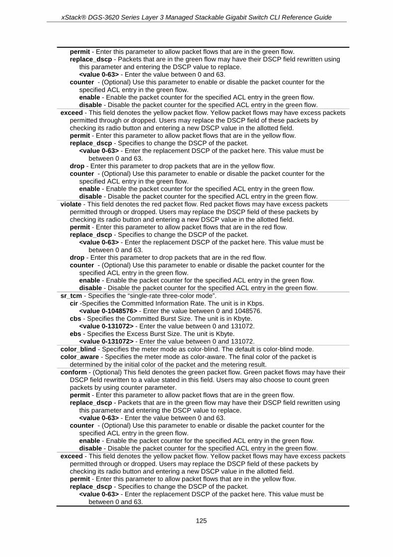
xStack® DGS-3620 Series Layer 3 Managed Stackable Gigabit Switch CLI Reference Guide
125
permit - Enter this parameter to allow packet flows that are in the green flow. replace_dscp - Packets that are in the green flow may have their DSCP field rewritten using
this parameter and entering the DSCP value to replace. <value 0-63> - Enter the value between 0 and 63.
counter - (Optional) Use this parameter to enable or disable the packet counter for the specified ACL entry in the green flow. enable - Enable the packet counter for the specified ACL entry in the green flow. disable - Disable the packet counter for the specified ACL entry in the green flow.
exceed - This field denotes the yellow packet flow. Yellow packet flows may have excess packets permitted through or dropped. Users may replace the DSCP field of these packets by checking its radio button and entering a new DSCP value in the allotted field. permit - Enter this parameter to allow packet flows that are in the yellow flow. replace_dscp - Specifies to change the DSCP of the packet.
<value 0-63> - Enter the replacement DSCP of the packet here. This value must be between 0 and 63.
drop - Enter this parameter to drop packets that are in the yellow flow. counter - (Optional) Use this parameter to enable or disable the packet counter for the
specified ACL entry in the green flow. enable - Enable the packet counter for the specified ACL entry in the green flow. disable - Disable the packet counter for the specified ACL entry in the green flow.
violate - This field denotes the red packet flow. Red packet flows may have excess packets permitted through or dropped. Users may replace the DSCP field of these packets by checking its radio button and entering a new DSCP value in the allotted field. permit - Enter this parameter to allow packet flows that are in the red flow. replace_dscp - Specifies to change the DSCP of the packet.
<value 0-63> - Enter the replacement DSCP of the packet here. This value must be between 0 and 63.
drop - Enter this parameter to drop packets that are in the red flow. counter - (Optional) Use this parameter to enable or disable the packet counter for the
specified ACL entry in the green flow. enable - Enable the packet counter for the specified ACL entry in the green flow. disable - Disable the packet counter for the specified ACL entry in the green flow.
sr_tcm - Specifies the “single-rate three-color mode”. cir -Specifies the Committed Information Rate. The unit is in Kbps.
<value 0-1048576> - Enter the value between 0 and 1048576. cbs - Specifies the Committed Burst Size. The unit is in Kbyte.
<value 0-131072> - Enter the value between 0 and 131072. ebs - Specifies the Excess Burst Size. The unit is Kbyte.
<value 0-131072> - Enter the value between 0 and 131072. color_blind - Specifies the meter mode as color-blind. The default is color-blind mode. color_aware - Specifies the meter mode as color-aware. The final color of the packet is
determined by the initial color of the packet and the metering result. conform - (Optional) This field denotes the green packet flow. Green packet flows may have their
DSCP field rewritten to a value stated in this field. Users may also choose to count green packets by using counter parameter. permit - Enter this parameter to allow packet flows that are in the green flow. replace_dscp - Packets that are in the green flow may have their DSCP field rewritten using
this parameter and entering the DSCP value to replace. <value 0-63> - Enter the value between 0 and 63.
counter - (Optional) Use this parameter to enable or disable the packet counter for the specified ACL entry in the green flow. enable - Enable the packet counter for the specified ACL entry in the green flow. disable - Disable the packet counter for the specified ACL entry in the green flow.
exceed - This field denotes the yellow packet flow. Yellow packet flows may have excess packets permitted through or dropped. Users may replace the DSCP field of these packets by checking its radio button and entering a new DSCP value in the allotted field. permit - Enter this parameter to allow packet flows that are in the yellow flow. replace_dscp - Specifies to change the DSCP of the packet.
<value 0-63> - Enter the replacement DSCP of the packet here. This value must be between 0 and 63.

xStack® DGS-3620 Series Layer 3 Managed Stackable Gigabit Switch CLI Reference Guide
126
drop - Enter this parameter to drop packets that are in the yellow flow. counter - (Optional) Use this parameter to enable or disable the packet counter for the
specified ACL entry in the green flow. enable - Enable the packet counter for the specified ACL entry in the green flow. disable - Disable the packet counter for the specified ACL entry in the green flow.
violate - This field denotes the red packet flow. Red packet flows may have excess packets permitted through or dropped. Users may replace the DSCP field of these packets by checking its radio button and entering a new DSCP value in the allotted field. permit - Enter this parameter to allow packet flows that are in the red flow. replace_dscp - Specifies to change the DSCP of the packet.
<value 0-63> - Enter the replacement DSCP of the packet here. This value must be between 0 and 63.
drop - Enter this parameter to drop packets that are in the red flow. counter - (Optional) Use this parameter to enable or disable the packet counter for the
specified ACL entry in the green flow. enable - Enable the packet counter for the specified ACL entry in the green flow. disable - Disable the packet counter for the specified ACL entry in the green flow.
delete - Use this parameter to delete the specified flow meter.
Restrictions Only Administrators, Operators and Power-Users can issue this command.
Example To configure a two rate, three color flow meter:
DGS-3620-28PC:admin#config flow_meter profile_id 1 access_id 1 tr_tcm cir 1000 cbs 200 pir 2000 pbs 200 conform replace_dscp 21 exceed drop violate permit
Command: config flow_meter profile_id 1 access_id 1 tr_tcm cir 1000 cbs 200 pir 2000 pbs 200 conform replace_dscp 21 exceed drop violate permit
Success.
DGS-3620-28PC:admin#
To replace DSCP action changed to perform on conform (green) and unconform (yellow and red) packets:
DGS-3620-28PC:admin# config flow_meter profile_id 1 access_id 1 tr_tcm cir 1000 cbs 200 pir 2000 pbs 200 exceed permit replace_dscp 21 violate permit replace_dscp 21
Command: config flow_meter profile_id 1 access_id 1 tr_tcm cir 1000 cbs 200 pir 2000 pbs 200 exceed permit replace_dscp 21 violate permit replace_dscp 21
Success.
DGS-3620-28PC:admin#
5-15 show flow_meter Description This command is used to display the flow meter table.

xStack® DGS-3620 Series Layer 3 Managed Stackable Gigabit Switch CLI Reference Guide
127
Format show flow_meter {[profile_id <value 1-6> | profile_name <name 1-32>] {access_id <value 1-256>}}
Parameters profile_id - (Optional) Specifies the profile ID.
<value 1-6> - Enter the profile ID. Enter a value between 1 and 6. profile_name - (Optional) Specifies the name of the profile.
<name 1-32> - Enter the name of the profile. The maximum length is 32 characters. access_id - (Optional) Specifies the access ID.
<value 1-256> - Enter the access ID. Enter a value between 1 and 256.
Restrictions None.
Example To display the flow meter configuration:
DGS-3620-28PC:admin#show flow_meter
Command: show flow_meter
Flow Meter Information
------------------------------------------------------------------------------
Profile ID:1 Aceess ID:1 Mode : trTCM / ColorBlind
CIR(Kbps):1000 CBS(Kbyte):200 PIR(Kbps):2000 PBS(Kbyte):200
Action:
Conform : Permit Counter: Disabled
Exceed : Permit Replace DSCP: 21 Counter: Disabled
Violate : Permit Replace DSCP: 21 Counter: Disabled
------------------------------------------------------------------------------
Total Entries: 1
DGS-3620-28PC:admin#

xStack® DGS-3620 Series Layer 3 Managed Stackable Gigabit Switch CLI Reference Guide
128
Chapter 6 Access Control List (ACL) Egress Commands
create egress_access_profile profile_id <value 1-4> profile_name <name 1-32> [ethernet {vlan {<hex 0x0-0x0fff>} | source_mac <macmask 000000000000-ffffffffffff> | destination_mac <macmask 000000000000-ffffffffffff> | 802.1p | ethernet_type} | ip {vlan {<hex 0x0-0x0fff>} | source_ip_mask <netmask> | destination_ip_mask <netmask> |dscp | [icmp {type | code} | igmp {type} | tcp {src_port_mask <hex 0x0-0xffff> | dst_port_mask <hex 0x0-0xffff> | flag_mask [all | {urg | ack | psh | rst | syn | fin}]} | udp {src_port_mask <hex 0x0-0xffff> | dst_port_mask <hex 0x0-0xffff>} | protocol_id_mask <hex 0x0-0xff> {user_define_mask <hex 0x0-0xffffffff>}]} | ipv6 {class | source_ipv6_mask <ipv6mask> | destination_ipv6_mask <ipv6mask> | [tcp {src_port_mask <hex 0x0-0xffff> | dst_port_mask <hex 0x0-0xffff>} | udp {src_port_mask <hex 0x0-0xffff> | dst_port_mask <hex 0x0-0xffff>} | icmp {type | code}]}]
delete egress_access_profile [profile_id <value 1-4> | profile_name <name 1-32> | all] config egress_access_profile [profile_id <value 1-4> | profile_name <name 1-32>] [add
access_id [auto_assign | <value 1-128>] [ethernet {[vlan <vlan_name 32> | vlan_id <vlanid 1-4094>] {mask <hex 0x0-0x0fff>} | source_mac <macaddr> {mask <macmask>} | destination_mac <macaddr> {mask <macmask>} | 802.1p <value 0-7> | ethernet_type <hex 0x0-0xffff> | mirror} | ip {[vlan <vlan_name 32> | vlan_id <vlanid 1-4094>] {mask <hex 0x0-0x0fff>} | source_ip <ipaddr> {mask <netmask>} | destination_ip <ipaddr> {mask <netmask>} | dscp <value 0-63> | [icmp {type <value 0-255> | code <value 0-255>} | igmp {type <value 0-255>} | tcp {src_port <value 0-65535> {mask <hex 0x0-0xffff>} | dst_port <value 0-65535> {mask <hex 0x0-0xffff>} | flag [all | {urg | ack | psh | rst | syn | fin}]} | udp {src_port <value 0-65535> {mask <hex 0x0-0xffff>} | dst_port <value 0-65535> {mask <hex 0x0-0xffff>}} | protocol_id <value 0-255> {user_define <hex 0x0-0xffffffff> {mask <hex 0x0-0xffffffff>}}] | mirror} | ipv6 {class <value 0-255> | source_ipv6 <ipv6addr> {mask <ipv6mask>} | destination_ipv6 <ipv6addr> {mask <ipv6mask>} | [tcp {src_port <value 0-65535> {mask <hex 0x0-0xffff>} | dst_port <value 0-65535> {mask <hex 0x0-0xffff>}} | udp {src_port <value 0-65535> {mask<hex 0x0-0xffff>} | dst_port <value 0-65535> {mask <hex 0x0-0xffff>}} | icmp {type <value 0-255> | code <value 0-255>}] | mirror}] [vlan_based [vlan <vlan_name 32> | vlan_id <vlanid 1-4094>] | port_group [id<value 1-64> | name <name 16>] | port <port>] [permit {replace_priority_with <value 0-7> | replace_dscp_with <value 0-63> | replace_vlan_id_with <value 1-4094> | counter [enable | disable]} | deny] {time_range <range_name 32>} | delete access_id <value 1-128>]
show egress_access_profile {[profile_id <value 1-4> | profile_name <name 1-32>]} show current_config egress_access_profile config egress_flow_meter [profile_id <value 1-4> | profile_name <name 1-32>] access_id <value
1-128> [rate <value 0-1048576> {burst_size <value 0-131072>} rate_exceed [drop_packet | remark_dscp <value 0-63>] | tr_tcm cir <value 0-1048576> {cbs <value 0-131072>} pir <value 0-1048576> {pbs <value 0-131072>} {[color_blind | color_aware]} {conform [permit | replace_dscp <value 0-63>] {counter [enable | disable]}} exceed [permit {replace_dscp <value 0-63>} | drop] {counter [enable | disable]} violate [permit {replace_dscp <value 0-63>} | drop] {counter [enable | disable]} | sr_tcm cir <value 0-1048576> cbs <value 0-131072> ebs <value 0-131072> {[color_blind | color_aware]} {conform [permit | replace_dscp <value 0-63>] {counter [enable | disable]}} exceed [permit {replace_dscp <value 0-63>} | drop] {counter [enable | disable]} violate [permit {replace_dscp <value 0-63>} | drop] {counter [enable | disable]} | delete]
show egress_flow_meter {[profile_id <value 1-4> | profile_name <name 1-32>] {access_id <value1-128>}}
create port_group id <value 1-64> name <name 16> config port_group [id <value 1-64> | name <name 16>] [add | delete] [<portlist> | all] delete port_group [id <value 1-64> | name <name 16>] show port_group {id <value 1-64> | name <name 16>}

xStack® DGS-3620 Series Layer 3 Managed Stackable Gigabit Switch CLI Reference Guide
129
6-1 create egress_access_profile Description This command is used to create an egress access list profile. For example, for some hardware, it may be invalid to specify destination IPv6 address and source IPv6 address at the same time. The user will be prompted for these limitations.
Format create egress_access_profile profile_id <value 1-4> profile_name <name 1-32> [ethernet {vlan {<hex 0x0-0x0fff>} | source_mac <macmask 000000000000-ffffffffffff> | destination_mac <macmask 000000000000-ffffffffffff> | 802.1p | ethernet_type} | ip {vlan {<hex 0x0-0x0fff>} | source_ip_mask <netmask> | destination_ip_mask <netmask> | dscp | [icmp {type | code} | igmp {type} | tcp {src_port_mask <hex 0x0-0xffff> | dst_port_mask <hex 0x0-0xffff> | flag_mask [all | {urg | ack | psh | rst | syn | fin}]} | udp {src_port_mask <hex 0x0-0xffff> | dst_port_mask <hex 0x0-0xffff>} | protocol_id_mask <hex 0x0-0xff> {user_define_mask <hex 0x0-0xffffffff>}]} | ipv6 {class | source_ipv6_mask <ipv6mask> | destination_ipv6_mask <ipv6mask> | [tcp {src_port_mask <hex 0x0-0xffff> | dst_port_mask <hex 0x0-0xffff>} | udp {src_port_mask <hex 0x0-0xffff> | dst_port_mask <hex 0x0-0xffff>} | icmp {type | code}]}]
Parameters profile_id - Specifies the index of the egress access list profile. The lower the profile ID, the
higher the priority. <value 1-4> - Enter the profile ID used here. This value must be between 1 and 4.
profile_name - The name of the profile must be specified. The maximum length is 32 characters. <name 1-32> - Enter the profile name used here. This name can be up to 32 characters long.
ethernet - Specifies this is an Ethernet mask. vlan - (Optional) Specifies a VLAN mask.
<hex 0x0-0x0fff> - Enter the VLAN mask used here. source_mac - (Optional) Specifies the source MAC mask.
<macmask 000000000000-ffffffffffff> - Enter the source MAC mask used here. destination_mac - (Optional) Specifies the destination MAC mask.
<macmask 000000000000-ffffffffffff> - Enter the destination MAC mask used here. 802.1p - (Optional) Specifies 802.1p priority tag mask. ethernet_type - (Optional) Specifies the Ethernet type mask.
ip - Specifies this is an IPv4 mask. vlan - (Optional) Specifies a VLAN mask.
<hex 0x0-0x0fff> - Enter the VLAN mask used here. source_ip_mask - (Optional) Specifies a source IP address mask.
<netmask> - Enter the source network mask used here. destination_ip_mask - (Optional) Specifies a destination IP address mask.
<netmask> - Enter the destination network mask used here. dscp - (Optional) Specifies the DSCP mask. icmp - (Optional) Specifies that the rule applies to ICMP traffic.
type - Specifies the type of ICMP traffic. code - Specifies the code of ICMP traffic.
igmp - (Optional) Specifies that the rule applies to IGMP traffic. type - Specifies the type of IGMP traffic.
tcp - (Optional) Specifies that the rule applies to TCP traffic. src_port_mask - Specifies the TCP source port mask.
<hex 0x0-0xffff> - Enter the TCP source port mask value here. dst_port_mask - Specifies the TCP destination port mask.
<hex 0x0-0xffff> - Enter the TCP source port mask value here. flag_mask - (Optional) Specifies the TCP flag field mask.

xStack® DGS-3620 Series Layer 3 Managed Stackable Gigabit Switch CLI Reference Guide
130
all - Specifies that the TCP flag field mask will be set to 'all'. urg - Specifies that the TCP flag field mask will be set to 'urg'. ack - Specifies that the TCP flag field mask will be set to 'ack'. psh - Specifies that the TCP flag field mask will be set to 'psh'. rst - Specifies that the TCP flag field mask will be set to 'rst'. syn - Specifies that the TCP flag field mask will be set to 'syn'. fin - Specifies that the TCP flag field mask will be set to 'fin'.
udp - (Optional) Specifies that the rule applies to UDP traffic. src_port_mask - Specifies the UDP source port mask.
<hex 0x0-0xffff> - Enter the UDP source port mask value here. dst_port_mask - Specifies the UDP destination port mask.
<hex 0x0-0xffff> - Enter the UDP destination port mask value here. protocod_id_mask - (Optional) Specifies that the rule applies to IP protocol ID traffic.
<hex 0x0-0xff> - Enter the protocol ID mask value here. user_define_mask - (Optional) Specifies that the rule applies to the IP protocol ID, and that
the mask option behind the IP header length is 20 bytes. <hex 0x0-0xffffffff> - Enter the user-defined mask value here.
ipv6 - (Optional) Specifies this is an IPv6 mask. class - (Optional) Specifies the IPv6 class. source_ipv6_mask - (Optional) Specifies an IPv6 source sub-mask.
<ipv6mask> - Enter the IPv6 source sub-mask value here. destination_ipv6_mask - Specifies an IPv6 destination sub-mask.
<ipv6mask> - Enter the IPv6 destination sub-mask value here. tcp - (Optional) Specifies that the following parameter are application to the TCP
configuration. src_port_mask - Specifies an IPv6 Layer 4 TCP source port mask.
<hex 0x0-0xffff> - Enter the Ipv6 TCP source port mask value here. dst_port_mask - Specifies an IPv6 Layer 4 TCP destination port mask.
<hex 0x0-0xffff> - Enter the Ipv6 TCP destination port mask value here. udp - (Optional) Specifies that the following parameter are application to the UDP
configuration. src_port_mask - Specifies an IPv6 Layer 4 UDP source port mask.
<hex 0x0-0xffff> - Enter the Ipv6 UDP source port mask value here. dst_port_mask - Specifies an IPv6 Layer 4 UDP destination port mask.
<hex 0x0-0xffff> - Enter the Ipv6 UDP destination port mask value here. icmp - (Optional) Specifies that the rule applies to ICMP traffic.
type - Specifies the type of ICMP traffic. code - Specifies the code of ICMP traffic.
Restrictions Only Administrators, Operators and Power-Users can issue this command.
Example To create an egress access list profile with the name “eap-eth-bc” and assign the profile ID to be 1:
DGS-3620-28PC:admin# create egress_access_profile profile_id 1 profile_name eap-eth-bc ethernet source_mac FF-FF-FF-FF-FF-FF
Command: create egress_access_profile profile_id 1 profile_name eap-eth-bc ethernet source_mac FF-FF-FF-FF-FF-FF
DGS-3620-28PC:admin#

xStack® DGS-3620 Series Layer 3 Managed Stackable Gigabit Switch CLI Reference Guide
131
6-2 delete egress_access_profile Description Delete egress access profile command can only delete the profile which is created by egress ACL module.
Format delete egress_access_profile [profile_id <value 1-4> | profile_name <name 1-32> | all]
Parameters profile_id - Specifies the index of the egress access list profile.
<value 1-4> - Enter the profile ID used here. This value must be between 1 and 4. profile_name - Specifies the name of the profile. The maximum length is 32 characters.
<name 1-32> - Enter the profile name used here. This name can be up to 32 characters long. all - Specifies that the whole egress access list profile will be deleted.
Restrictions Only Administrators, Operators and Power-Users can issue this command.
Example To delete egress access list profile ID 1:
DGS-3620-28PC:admin# delete egress_access_profile profile_id 1
Command: delete egress_access_profile profile_id 1
Success.
DGS-3620-28PC:admin#
6-3 config egress_access_profile Description This command is used to configure egress access list entries.
Format config egress_access_profile [profile_id <value 1-4> | profile_name <name 1-32>] [add access_id [auto_assign | <value 1-128>] [ethernet {[vlan <vlan_name 32> | vlan_id <vlanid 1-4094>] {mask <hex 0x0-0x0fff>} | source_mac <macaddr> {mask <macmask>} | destination_mac <macaddr> {mask <macmask>} | 802.1p <value 0-7> | ethernet_type <hex 0x0-0xffff> | mirror} | ip {[vlan <vlan_name 32> | vlan_id <vlanid 1-4094>] {mask <hex 0x0-0x0fff>} | source_ip <ipaddr> {mask <netmask>} | destination_ip <ipaddr> {mask <netmask>} | dscp <value 0-63> | [icmp {type <value 0-255> | code <value 0-255>} | igmp {type <value 0-255>} | tcp {src_port <value 0-65535> {mask <hex 0x0-0xffff>} | dst_port <value 0-65535> {mask <hex 0x0-0xffff>} | flag [all | {urg | ack | psh | rst | syn | fin}]} | udp {src_port <value 0-65535> {mask <hex 0x0-0xffff>} | dst_port <value 0-65535> {mask <hex 0x0-0xffff>}} | protocol_id <value 0-255> {user_define <hex 0x0-0xffffffff> {mask <hex 0x0-0xffffffff>}}] |

xStack® DGS-3620 Series Layer 3 Managed Stackable Gigabit Switch CLI Reference Guide
132
mirror} | ipv6 {class <value 0-255> | source_ipv6 <ipv6addr> {mask <ipv6mask>} | destination_ipv6 <ipv6addr> {mask <ipv6mask>} | [tcp {src_port <value 0-65535> {mask <hex 0x0-0xffff>} | dst_port <value 0-65535> {mask <hex 0x0-0xffff>}} | udp {src_port <value 0-65535> {mask<hex 0x0-0xffff>} | dst_port <value 0-65535> {mask <hex 0x0-0xffff>}} | icmp {type <value 0-255> | code <value 0-255>}] | mirror}] [vlan_based [vlan <vlan_name 32> | vlan_id <vlanid 1-4094>] | port_group [id<value 1-64> | name <name 16>] | port <port>] [permit {replace_priority_with <value 0-7> | replace_dscp_with <value 0-63> | replace_vlan_id_with <value 1-4094> | counter [enable | disable]} | deny] {time_range <range_name 32>} | delete access_id <value 1-128>]
Parameters profile_id - Specifies the index of the egress access list profile.
<value 1-4> - Enter the profile ID used here. This value must be between 1 and 4. profile_name - Specifies the name of the profile.
<name 1-32> - Enter the profile name here. This name can be up to 32 characters long. add - Specifies to add a profile or rule. access_id - Specifies the index of the access list entry. If the auto_assign option is selected, the
access ID is automatically assigned. The lower the access ID, the higher the priority. auto assign - Specifies that the access ID will be configured automatically.
<value 1-128> - Enter the access ID used here. This value must be between 1 and 128. ethernet - Specifies an Ethernet egress ACL rule.
vlan - (Optional) Specifies the VLAN name. <vlan_name 32> - Enter the VLAN name used for this configuration here. This name can
be up to 32 characters long. vlanid - Specifies a VLAN ID.
<vlanid 1-4094> - Enter the VLAN ID used for this congfiguration here. This value must be between 1 and 4094.
mask - (Optional) Specifies the mask used. <hex 0x0-x0fff> - Enter the mask value used here.
source_mac - (Optional) Specifies the source MAC address. <macaddr> - Enter the source MAC address used here. mask - Specifies that source MAC mask used.
<macmask> - Enter the source MAC mask value here. destination_mac - Specifies the destination MAC address.
<macaddr> - Enter the destination MAC address used here. mask - Specifies that destination MAC mask used.
<macmask> - Enter the destination MAC mask value here. 802.1p - (Optional) Specifies the value of the 802.1p priority tag. The priority tag ranges from
1 to 7. <value 0-7> - Enter the 802.1p priority tag used here.
ethernet_type - (Optional) Specifies the Ethernet type. <hex 0x0-0xffff> - Enter the Ethernet type mask used here.
mirror - Specifies that only the mirrored packet can be matched. ip - Specifies an IP egress ACL rule.
vlan - (Optional) Specifies the VLAN name. <vlan_name 32> - Enter the VLAN name used for this configuration here. This name can
be up to 32 characters long. vlanid - Specifies a VLAN ID.
<vlanid 1-4094> - Enter the VLAN ID used for this congfiguration here. This value must be between 1 and 4094.
mask - (Optional) Specifies the mask used. <hex 0x0-x0fff> - Enter the mask value used here.
source_ip - (Optional) Specifies an IP source address. <ipaddr> - Enter the source IP address used here. mask - Specifies the source IP address used here.
<netmask> - Enter the source network mask here. destination_ip - (Optional) Specifies an IP destination address.

xStack® DGS-3620 Series Layer 3 Managed Stackable Gigabit Switch CLI Reference Guide
133
<ipaddr> - Enter the destination IP address used here. mask - Specifies the destination IP address used here.
<netmask> - Enter the destination network mask here. dscp - (Optional) Specifies the value of DSCP. The DSCP value ranges from 0 to 63.
<value 0-63> - Enter the DSCP value used here. This value must be between 0 and 63. icmp - (Optional) Specifies that the following parameters configured will apply to the ICMP
configuration. type - Specifies that the rule will apply to the ICMP type traffic value.
<value 0-255> - Enter the ICMP traffic type value here. This value must be between 0 and 255.
code - Specifies that the rule will apply to the ICMP code traffic value. <value 0-255> - Enter the ICMP code traffic value here. This value must be between 0
and 255. igmp - (Optional) Specifies that the following parameters configured will apply to the IGMP
configuration. type - Specifies that the rule will apply to the IGMP type traffic value.
<value 0-255> - Enter the IGMP type traffic value here. This value must be between 0 and 255.
tcp - (Optional) Specifies that the following parameters configured will apply to the TCP configuration. src_port - Specifies that the rule will apply to a range of TCP source ports.
<value 0-65535> - Enter the source port value here. This value must be between 0 and 65535.
mask - Specifies the TCP source port mask here. <hex 0x0-0xffff> - Enter the TCP source port mask value here.
dst_port - Specifies that the rule will apply to a range of TCP destination ports. <value 0-65535> - Enter the destination port value here. This value must be between 0
and 65535. mask - Specifies the TCP destination port mask here.
<hex 0x0-0xffff> - Enter the TCP destination port mask value here. flag - (Optional) Specifies the TCP flag fields.
all - Specifies that the TCP flag field will be set to 'all'. urg - Specifies that the TCP flag field will be set to 'urg'. ack - Specifies that the TCP flag field will be set to 'ack'. psh - Specifies that the TCP flag field will be set to 'psh'. rst - Specifies that the TCP flag field will be set to 'rst'. syn - Specifies that the TCP flag field will be set to 'syn'. fin - Specifies that the TCP flag field will be set to 'fin'.
udp - (Optional) Specifies that the following parameters configured will apply to the UDP configuration. src_port - Specifies the UDP source port range.
<value 0-65535> - Enter the UDP source port range value here. mask - Specifies the UDP source port mask here.
<hex 0x0-0xffff> - Enter the UDP source port mask value here. dst_port - Specifies the UDP destination port range.
<value 0-65535> - Enter the UDP destination port range value here. mask - Specifies the UDP destination port mask here.
<hex 0x0-0xffff> - Enter the UDP destination port mask value here. protocol_id - (Optional) Specifies that the rule will apply to the value of IP protocol ID traffic.
<value 0-255> - Enter the protocol ID used here. This value must be between 0 and 255. user_define - (Optional) Specifies that the rule will apply to the IP protocol ID and that the
mask options behind the IP header, which has a length of 20 bytes. <hex 0x0-0xffffffff> - Enter the user-defined mask value here. mask - Specifies the user-defined mask here.
<hex 0x0-0xffffffff> - Enter the user-defined mask value here. mirror - Specifies that only the mirrored packet can be matched.
ipv6 - Specifies the rule applies to IPv6 fields. class - (Optional) Specifies the value of IPv6 class.
<value 0-255> - Enter the IPv6 class value here. This value must be between 0 and 255. source_ipv6 - (Optional) Specifies the value of IPv6 source address.
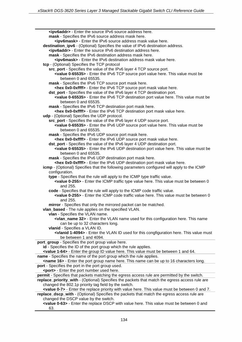
xStack® DGS-3620 Series Layer 3 Managed Stackable Gigabit Switch CLI Reference Guide
134
<ipv6addr> - Enter the source IPv6 source address here. mask - Specifies the IPv6 source address mask here.
<ipv6mask> - Enter the IPv6 source address mask value here. destination_ipv6 - (Optional) Specifies the value of IPv6 destination address.
<ipv6addr> - Enter the source IPv6 destination address here. mask - Specifies the IPv6 destination address mask here.
<ipv6mask> - Enter the IPv6 destination address mask value here. tcp - (Optional) Specifies the TCP protocol
src_port - Specifies the value of the IPv6 layer 4 TCP source port. <value 0-65535> - Enter the IPv6 TCP source port value here. This value must be
between 0 and 65535. mask - Specifies the IPv6 TCP source port mask here.
<hex 0x0-0xffff> - Enter the IPv6 TCP source port mask value here. dst_port - Specifies the value of the IPv6 layer 4 TCP destination port.
<value 0-65535> - Enter the IPv6 TCP destination port value here. This value must be between 0 and 65535.
mask - Specifies the IPv6 TCP destination port mask here. <hex 0x0-0xffff> - Enter the IPv6 TCP destination port mask value here.
udp - (Optional) Specifies the UDP protocol. src_port - Specifies the value of the IPv6 layer 4 UDP source port.
<value 0-65535> - Enter the IPv6 UDP source port value here. This value must be between 0 and 65535.
mask - Specifies the IPv6 UDP source port mask here. <hex 0x0-0xffff> - Enter the IPv6 UDP source port mask value here.
dst_port - Specifies the value of the IPv6 layer 4 UDP destination port. <value 0-65535> - Enter the IPv6 UDP destination port value here. This value must be
between 0 and 65535. mask - Specifies the IPv6 UDP destination port mask here.
<hex 0x0-0xffff> - Enter the IPv6 UDP destination port mask value here. icmp - (Optional) Specifies that the following parameters configured will apply to the ICMP
configuration. type - Specifies that the rule will apply to the ICMP type traffic value.
<value 0-255> - Enter the ICMP traffic type value here. This value must be between 0 and 255.
code - Specifies that the rule will apply to the ICMP code traffic value. <value 0-255> - Enter the ICMP code traffic value here. This value must be between 0
and 255. mirror - Specifies that only the mirrored packet can be matched.
vlan_based - The rule applies on the specified VLAN. vlan - Specifies the VLAN name.
<vlan_name 32> - Enter the VLAN name used for this configuration here. This name can be up to 32 characters long.
vlanid - Specifies a VLAN ID. <vlanid 1-4094> - Enter the VLAN ID used for this congfiguration here. This value must
be between 1 and 4094. port_group - Specifies the port group value here.
id - Specifies the ID of the port group which the rule applies. <value 1-64> - Enter the group ID value here. This value must be between 1 and 64.
name - Specifies the name of the port group which the rule applies. <name 16> - Enter the port group name here. This name can be up to 16 characters long.
port - Specifies the port in the port group used. <port> - Enter the port number used here.
permit - Specifies that packets matching the egress access rule are permitted by the switch. replace_priority_with - (Optional) Specifies the packets that match the egress access rule are
changed the 802.1p priority tag field by the switch. <value 0-7> - Enter the replace priority with value here. This value must be between 0 and 7.
replace_dscp_with - (Optional) Specifies the packets that match the egress access rule are changed the DSCP value by the switch. <value 0-63> - Enter the replace DSCP with value here. This value must be between 0 and
63.

xStack® DGS-3620 Series Layer 3 Managed Stackable Gigabit Switch CLI Reference Guide
135
replace_vlan_id_with - (Optional) Specifies the VLAN ID to replace the outer VLAN ID of the matched packets. <value 1-4094> - Enter the replacement VLAN ID here. This value must be between 1 and
4094. counter - (Optional) Specifies whether the ACL counter feature is enabled or disabled. This
parameter is optional. The default option is disabled. If the rule is not bound with the flow_meter, all matching packets are counted. If the rule is bound with the flow_meter, then the “counter” is overridden. enable - Specifies that the ACL counter feature will be enabled. disable - Specifies that the ACL counter feature will be disabled.
deny - Specifies the packets that match the egress access rule are filtered by the switch. time_range - (Optional) Specifies the name of the time range entry.
<range_name 32> - Enter the time range value here. This name can be up to 32 characters long.
delete - Specifies to delete a profile or rule. access_id - Specifies the index of the access list entry. If the auto_assign option is selected, the
access ID is automatically assigned. <value 1-128> - Enter the access ID used here. This value must be between 1 and 128.
Restrictions Only Administrators, Operators and Power-Users can issue this command.
Example To configure a port-base egress access rule that when the packet go out switch which match the specified source IP, DSCP and destination IP field, it will not be dropped:
DGS-3620-28PC:admin# config egress_access_profile profile_id 2 add access_id auto_assign ip source_ip 10.0.0.1 dscp 25 destination_ip 10.90.90.90 port_group id 1 permit
Command: config egress_access_profile profile_id 2 add access_id auto_assign ip source_ip 10.0.0.1 dscp 25 destination_ip 10.90.90.90 port_group id 1 permit
Success.
DGS-3620-28PC:admin#
To configure a vlan-base egress access rule that when the packet go out switch which match the specified source MAC field, it will be dropped:
DGS-3620-28PC:admin# config egress_access_profile profile_id 2 add access_id 1 ethernet source_mac 11-22-33-44-55-66 vlan_based vlan_id 1 deny
Command: config egress_access_profile profile_id 2 add access_id 1 ethernet source_mac 11-22-33-44-55-66 vlan_based vlan_id 1 deny
Success.
DGS-3620-28PC:admin#
6-4 show egress_access_profile Description This command is used to display current egress access list table.

xStack® DGS-3620 Series Layer 3 Managed Stackable Gigabit Switch CLI Reference Guide
136
Format show egress_access_profile {[profile_id <value 1-4> | profile_name <name 1-32>]}
Parameters profile_id - (Optional) Specifies the index of the egress access list profile.
<value 1-4> - Enter the profile ID here. This value must be between 1 and 4. profile_name - (Optional) Specifies the name of the profile. The maximum length is 32
characters. <name 1-32> - Enter the profile name here. This name can be up to 32 characters long.
If no parameter is specified, will show the all egress access profile.
Restrictions None.
Example To display current egress access list table:
DGS-3620-28PC:admin# show egress_access_profile
Command: show egress_access_profile
Egress Access Profile Table
Total User Set Rule Entries : 3
Total Used Hardware Entries : 3
Total Available Hardware Entries : 253
================================================================================
Profile ID: 1 Profile name: 1 Type: Ethernet
Mask on
Source MAC : FF-FF-FF-FF-FF-FF
Available Hardware Entries : 127
--------------------------------------------------------------------------------
Rule ID : 1 Port group: -
Match on
VLAN ID : 1
Source MAC : 00-00-00-00-00-01
Action:
Permit
================================================================================
===============================================================================

xStack® DGS-3620 Series Layer 3 Managed Stackable Gigabit Switch CLI Reference Guide
137
=
Profile ID: 2 Profile name: 2 Type: IPv4
Mask on
Source IP : 255.255.255.255
Destination IP : 255.255.255.255
DSCP
Available Hardware Entries : 126
--------------------------------------------------------------------------------
Rule ID : 1 (auto assign) Port group: 1
Match on
Source IP : 10.0.0.2
Destination IP : 10.90.90.90
DSCP : 25
Action:
Permit
--------------------------------------------------------------------------------
Rule ID : 2 (auto assign) Port group: 1
Match on
Source IP : 10.0.0.1
Destination IP : 10.90.90.90
DSCP : 25
Action:
Permit
Matched Count : 0 packets
================================================================================
DGS-3620-28PC:admin#
The following example displays an egress access profile that supports an entry mask for each rule:

xStack® DGS-3620 Series Layer 3 Managed Stackable Gigabit Switch CLI Reference Guide
138
DGS-3620-28PC:admin# show egress_access_profile profile_id 1
Command: show egress_access_profile profile_id 1
Egress Access Profile Table
================================================================================
Profile ID: 1 Profile name: 1 Type: Ethernet
Mask on
Source MAC : FF-FF-FF-FF-FF-FF
Available Hardware Entries : 127
--------------------------------------------------------------------------------
Rule ID : 1 Port group: -
Match on
VLAN ID : 1
Source MAC : 00-00-00-00-00-01
Action:
Permit
================================================================================
DGS-3620-28PC:admin#
6-5 show current_config egress_access_profile Description This command is used to display the egress ACL part of current configuration in user level of privilege.
The overall current configuration can be displayed by “show config” command which is accessible in administrator level of privilege.
Format show current_config egress_access_profile
Parameters None.
Restrictions None.
Example To display current configuration of egress access list table:

xStack® DGS-3620 Series Layer 3 Managed Stackable Gigabit Switch CLI Reference Guide
139
DGS-3620-28PC:admin# show current_config egress_access_profile
Command: show current_config egress_access_profile
#-------------------------------------------------------------------------------
# Egress ACL
create egress_access_profile profile_id 1 profile_name 1 ethernet source_mac FF-
FF-FF-FF-FF-FF
config egress_access_profile profile_id 1 add access_id 1 ethernet source_mac 00
-00-00-00-00-01 vlan_based vlan_id 1 permit
create egress_access_profile profile_id 2 profile_name 2 ip source_ip_mask 255.2
55.255.255 destination_ip_mask 255.255.255.255 dscp
config egress_access_profile profile_id 2 add access_id auto_assign ip source_ip
10.0.0.2 destination_ip 10.90.90.90 dscp 25 port_group id 1 permit counter enable
config egress_access_profile profile_id 2 add access_id auto_assign ip source_ip
10.0.0.1 destination_ip 10.90.90.90 dscp 25 port_group id 1 permit
#-------------------------------------------------------------------------------
DGS-3620-28PC:admin#
6-6 config egress_flow_meter Description This command is used to configure the packet flow-based metering based on an egress access profile and rule.
Format config egress_flow_meter [profile_id <value 1-4> | profile_name <name 1-32>] access_id <value 1-128> [rate <value 0-1048576> {burst_size <value 0-131072>} rate_exceed [drop_packet | remark_dscp <value 0-63>] | tr_tcm cir <value 0-1048576> {cbs <value 0-131072>} pir <value 0-1048576> {pbs <value 0-131072>} {[color_blind | color_aware]} {conform [permit | replace_dscp <value 0-63>] {counter [enable | disable]}} exceed [permit {replace_dscp <value 0-63>} | drop] {counter [enable | disable]} violate [permit {replace_dscp <value 0-63>} | drop] {counter [enable | disable]} | sr_tcm cir <value 0-1048576> cbs <value 0-131072> ebs <value 0-131072> {[color_blind | color_aware]} {conform [permit | replace_dscp <value 0-63>] {counter [enable | disable]}} exceed [permit {replace_dscp <value 0-63>} | drop] {counter [enable | disable]} violate [permit {replace_dscp <value 0-63>} | drop] {counter [enable | disable]} | delete]
Parameters profile_id - Specifies the profile ID.

xStack® DGS-3620 Series Layer 3 Managed Stackable Gigabit Switch CLI Reference Guide
140
<value 1-4> - Enter the profile ID used here. This value must be between 1 and 4. profile_name - Specifies the name of the profile.
<name 1-32> - Enter the profile name used here. This name can be up to 32 characters long. access_id - Specifies the access ID.
<value 1-128> - Enter the access ID used here. This value must be between 1 and 128. rate - Specifies the rate for single rate two-color mode.
<value 0-1048576> - Enter the rate for single rate two-color mode here. This value must be between 0 and 1048576.
burst_size - (Optional) Specifies the burst size for the single rate “two color” mode. The unit is Kbytes. <value 0-131072> - Enter the burst size value here. This value must be between 0 and
131072. rate_exceed - This specifies the action for packets that exceed the committed rate in single rate
“two color” mode. The action can be specified as one of the following: drop_packet - Drop the packet immediately. remark_dscp - Mark the packet with a specified DSCP. The packet is set to have the higher
drop precedence. <value 0-63> - Enter the remark DSCP value here. This value must be between 0 and 63.
tr_tcm - Specifies the “two rate three color mode”. cir - Specifies the two rate three color mode used.
<value 0-1048576> - Enter the two rate three color mode value here. This value must be between 0 and 1048576.
cbs - (Optional) Specifies the “Committed Burst Size”. The unit is Kbytes. That is to say, 1 means 1Kbytes. This parameter is an optional parameter. The default value is 4*1024. <value 0-131072> - Enter the comitted burst size value here. This value must be between
0 and 131072. pir - Specifies the “Peak Information Rate”. The unit is in Kbps. PIR should always be equal to
or greater than CIR. <value 0-1048576> - Enter the peak information rate value here. This value must be
between 0 and 1048576. pbs - (Optional) Specifies the “Peak Burst Size”. The unit is in Kbytes.
<value 0-131072> - Enter the peak burst size value here. This value must be between 0 and 131072.
color_blind - (Optional) Specifies the meter mode to be color-blind. The default is color-blind mode.
color_aware - (Optional) Specifies the meter mode to be color-aware. When this code is specified, user could set the “in-coming packet color” by using command “config color_aware”. The final color of packet is determined by the initial color of packet and the metering result.
conform - (Optional) Specifies the action when packet is in “green color”. permit - Permit the packet. replace_dscp - Changes the DSCP of the packet.
<value 0-63> - Enter the replace DSCP value here. This value must be between 0 and 63. counter - (Optional) Specifies the ACL counter. This is optional. The default is “disable”. The
resource may be limited so that a counter cannot be turned on. Counters will be cleared when the function is disabled. enable - Specifies that the ACL counter parameter will be enabled. disable - Specifies that the ACL counter parameter will be disabled.
exceed - Specifies the action when packet is in “yellow color”. permit - (Optional) Permit the packet. replace_dscp - Changes the DSCP of the packet.
<value 0-63> - Enter the DSCP replace value here. This value must be between 0 and 63. drop - Drops the packet. counter - (Optional) Specifies the ACL counter. This is optional. The default is “disable”. The
resource may be limited so that a counter cannot be turned on. Counters will be cleared when the function is disabled. enable - Specifies that the ACL counter parameter will be enabled. disable - Specifies that the ACL counter parameter will be disabled.
violate - Specifies the action when packet is in “red color”. permit - Permit the packet.

xStack® DGS-3620 Series Layer 3 Managed Stackable Gigabit Switch CLI Reference Guide
141
replace_dscp - (Optional) Changes the DSCP of the packet. <value 0-63> - Enter the DSCP replace value here. This value must be between 0 and 63.
drop - Drops the packet. counter - (Optional) Specifies the ACL counter. This is optional. The default is “disable”. The
resource may be limited so that a counter cannot be turned on. Counters will be cleared when the function is disabled. enable - Specifies that the ACL counter parameter will be enabled. disable - Specifies that the ACL counter parameter will be disabled.
sr_tcm - Specifies the “single rate three color mode”. cir - Specifies the single rate three color mode used.
<value 0-1048576> - Enter the single rate three color mode value here. This value must be between 0 and 1048576.
cbs - Specifies the “committed burst size”. The unit is Kbytes. <value 0-131072> - Enter the committed burst size value here. This value must be
between 0 and 131072. ebs - Specifies the “Excess Burst Size”. The unit is Kbytes.
<value 0-131072> - Enter the excess burst size value here. This value must be between 0 and 131072.
color_blind - (Optional) Specifies the meter mode to be color-blind. The default is color-blind mode.
color_aware - (Optional) Specifies the meter mode to be color-aware. When this code is specified, user could set the “in-coming packet color” by using command “config color_aware”. The final color of packet is determined by the initial color of packet and the metering result.
conform - (Optional) Specifies the action when packet is in “green color”. permit - (Optional) Permit the packet. replace_dscp - Changes the DSCP of the packet.
<value 0-63> - Enter the replace DSCP value here. This value must be between 0 and 63. counter - (Optional) Specifies the ACL counter. This is optional. The default is “disable”. The
resource may be limited so that a counter cannot be turned on. Counters will be cleared when the function is disabled. enable - Specifies that the ACL counter parameter will be enabled. disable - Specifies that the ACL counter parameter will be disabled.
exceed - Specifies the action when packet is in “yellow color”. permit - Permit the packet. replace_dscp - (Optional) Changes the DSCP of the packet.
<value 0-63> - Enter the DSCP replace value here. This value must be between 0 and 63. drop - Drops the packet. counter - (Optional) Specifies the ACL counter. This is optional. The default is “disable”. The
resource may be limited so that a counter cannot be turned on. Counters will be cleared when the function is disabled. enable - Specifies that the ACL counter parameter will be enabled. disable - Specifies that the ACL counter parameter will be disabled.
violate - Specifies the action when packet is in “red color”. permit - Permit the packet. replace_dscp - (Optional) Changes the DSCP of the packet.
<value 0-63> - Enter the DSCP replace value here. This value must be between 0 and 63. drop - Drops the packet. counter - (Optional) Specifies the ACL counter. This is optional. The default is “disable”. The
resource may be limited so that a counter cannot be turned on. Counters will be cleared when the function is disabled. enable - Specifies that the ACL counter parameter will be enabled. disable - Specifies that the ACL counter parameter will be disabled.
delete - Delete the specified “flow_meter”.
Restrictions Only Administrators, Operators and Power-Users can issue this command.
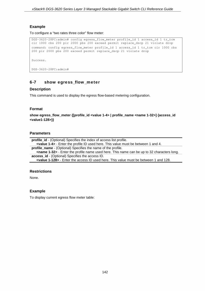
xStack® DGS-3620 Series Layer 3 Managed Stackable Gigabit Switch CLI Reference Guide
142
Example To configure a “two rates three color” flow meter:
DGS-3620-28PC:admin# config egress_flow_meter profile_id 1 access_id 1 tr_tcm cir 1000 cbs 200 pir 2000 pbs 200 exceed permit replace_dscp 21 violate drop
command: config egress_flow_meter profile_id 1 access_id 1 tr_tcm cir 1000 cbs 200 pir 2000 pbs 200 exceed permit replace_dscp 21 violate drop
Success.
DGS-3620-28PC:admin#
6-7 show egress_flow_meter Description This command is used to display the egress flow-based metering configuration.
Format show egress_flow_meter {[profile_id <value 1-4> | profile_name <name 1-32>] {access_id <value1-128>}}
Parameters profile_id - (Optional) Specifies the index of access list profile.
<value 1-4> - Enter the profile ID used here. This value must be between 1 and 4. profile_name - (Optional) Specifies the name of the profile.
<name 1-32> - Enter the profile name used here. This name can be up to 32 characters long. access_id - (Optional) Specifies the access ID.
<value 1-128> - Enter the access ID used here. This value must be between 1 and 128.
Restrictions None.
Example To display current egress flow meter table:
xStack® DGS-3620 Series Layer 3 Managed Stackable Gigabit Switch CLI Reference Guide
143
DGS-3620-28PC:admin# show egress_flow_meter
Command: show egress_flow_meter
Flow Meter Information:
------------------------
Profile ID : 1 Access ID : 1 Mode : trTcm / color-blind
CIR:1000(Kbps) CBS:2000(Kbyte) PIR:2000(Kbps) PBS:2000(Kbyte)
Actions:
Conform : Permit Replace DSCP : 11 Counter : enable
Exceed : Permit Replace DSCP : 22 Counter : enable
Violate : Drop
Profile ID : 1 Access ID : 1 Mode : srTcm / color-blind
CIR:2500(Kbps) CBS:2000(Kbyte) EBS:3500(Kbyte)
Actions:
Conform : Permit Counter : enable
Exceed : Permit Replace DSCP: 33 Counter : enable
Violate : Drop
Total Entries: 2
DGS-3620-28PC:admin#
6-8 create port_group id Description This command is used to create a port group.
Format create port_group id <value 1-64> name <name 16>
Parameters id - Specifies the port group ID.
<value 1-64> - Enter the port group ID here. This value must be between 1 and 64. name - Specifies the port group name.
<name 16> - Enter the port group name here. This name can be up to 16 characters long.
Restrictions Only Administrators and Operators can issue this command.
Example To create a port group:

xStack® DGS-3620 Series Layer 3 Managed Stackable Gigabit Switch CLI Reference Guide
144
DGS-3620-28PC:admin# create port_group id 2 name group2
Command: create port_group id 2 name group2
Success.
DGS-3620-28PC:admin#
6-9 config port_group Description This command is used to add or delete a port list to a port group.
Format config port_group [id <value 1-64> | name <name 16>] [add | delete] [<portlist> | all]
Parameters id - Specifies the port group ID.
<value 1-64> - Enter the port group ID used here. This value must be between 1 and 64. name - Specifies the port group name.
<name 16> - Enter the port group name here. This name can be up to 16 characters long. add - Add a port list to this port group. delete - Delete a port list from this port group. <portlist> - Enter a list of ports used for the configuration here. all - Specifies that all the ports will be used for this configuration.
Restrictions Only Administrators and Operators can issue this command.
Example Add port list “1-3” to the port group which ID is “2”:
DGS-3620-28PC:admin# config port_group id 2 add 1-3
Command: config port_group id 2 add 1:1-1:3
Success.
DGS-3620-28PC:admin#
6-10 delete port_group Description This command is used to delete port group.
Format delete port_group [id <value 1-64> | name <name 16>]

xStack® DGS-3620 Series Layer 3 Managed Stackable Gigabit Switch CLI Reference Guide
145
Parameters id - Specifies the port group ID.
<value 1-64> - Enter the port group ID used here. This value must be between 1 and 64. name - Specifies the port group name.
<name 16> - Enter the port group name here. This name can be up to 16 characters long.
Restrictions Only Administrators and Operators can issue this command.
Example To delete the port group which ID is “2”:
DGS-3620-28PC:admin# delete port_group id 2
Command: delete port_group id 2
Success.
DGS-3620-28PC:admin#
6-11 show port_group Description This command is used to display the port group information.
Format show port_group {id <value 1-64> | name <name 16>}
Parameters id - (Optional) Specifies the port group ID.
<value 1-64> - Enter the port group ID used here. This value must be between 1 and 64. name - (Optional) Specifies the port group name.
<name 16> - Enter the port group name here. This name can be up to 16 characters long. If not specified parameter, will show all the port group.
Restrictions Only Administrators and Operators can issue this command.
Example To show all the port group information:
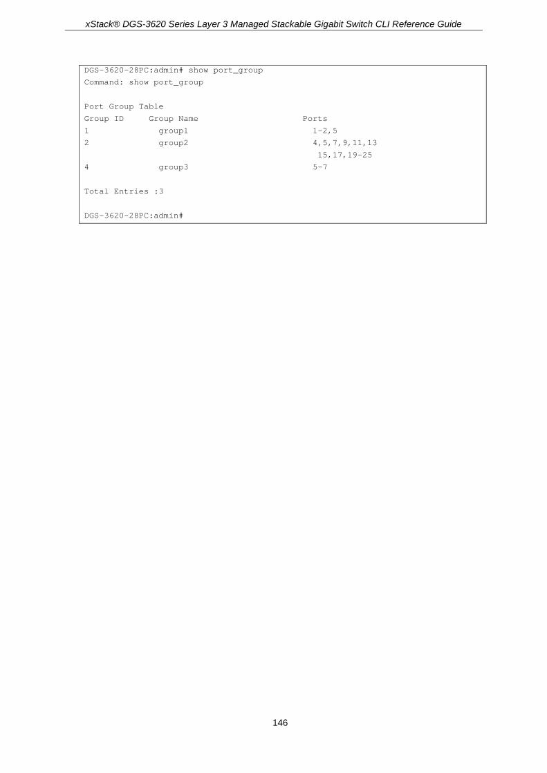
xStack® DGS-3620 Series Layer 3 Managed Stackable Gigabit Switch CLI Reference Guide
146
DGS-3620-28PC:admin# show port_group
Command: show port_group
Port Group Table
Group ID Group Name Ports
1 group1 1-2,5
2 group2 4,5,7,9,11,13
15,17,19-25
4 group3 5-7
Total Entries :3
DGS-3620-28PC:admin#

xStack® DGS-3620 Series Layer 3 Managed Stackable Gigabit Switch CLI Reference Guide
147
Chapter 7 ARP Commands
create arpentry <ipaddr> <macaddr> delete arpentry [<ipaddr> | all] config arpentry <ipaddr> <macaddr> config arpentry force_aging_addr [add | delete] <ipaddr> show arpentry {ipif <ipif_name 12> | ipaddress <ipaddr> | static | mac_address <macaddr>} show arpentry force_aging_addr clear arptable show ipfdb {[ip_address <ipaddr> | interface <ipif_name 12> | port <port>]} config arp_aging time <min 0-65535> config arp_retry times <value 0-4>
7-1 create arpentry Description This command is used to enter an IP address and the corresponding MAC address into the switch’s ARP table.
Format create arpentry <ipaddr> <macaddr>
Parameters <ipaddr> - The IP address of the end node or station. <macaddr> - The MAC address corresponding to the IP address above.
Restrictions Only Administrators, Operators and Power-Users can issue this command.
Example To create a static ARP entry for the IP address 10.48.74.121 and MAC address 00:50:BA:00:07:36:
DGS-3620-28PC:admin#create arpentry 10.48.74.121 00-50-BA-00-07-36
Command: create arpentry 10.48.74.121 00-50-BA-00-07-36
Success.
DGS-3620-28PC:admin#
7-2 delete arpentry Description This command is used to delete an ARP entry, made using the create arpentry command above, by specifying either the IP address of the entry or all. Specifying all deletes all static and dynamic ARP entries.

xStack® DGS-3620 Series Layer 3 Managed Stackable Gigabit Switch CLI Reference Guide
148
Format delete arpentry [<ipaddr> | all]
Parameters <ipaddr> - The IP address of the end node or station. all - Delete all ARP entries
Restrictions Only Administrators, Operators and Power-Users can issue this command.
Example To delete an entry of IP address 10.48.74.121 from the ARP table:
DGS-3620-28PC:admin#delete arpentry 10.48.74.121
Command: delete arpentry 10.48.74.121
Success.
DGS-3620-28PC:admin#
7-3 config arpentry Description This command is used to configure the IP address and MAC address of a static entry in the ARP table.
Format config arpentry <ipaddr> <macaddr>
Parameters <ipaddr> - The IP address of the end node or station. <macaddr> - The MAC address corresponding to the IP address above.
Restrictions Only Administrators, Operators and Power-Users can issue this command.
Example To configure a static ARP entry for the IP address 10.48.74.121 and MAC address 00:50:BA:00:07:36:
DGS-3620-28PC:admin#config arpentry 10.48.74.121 00-50-BA-00-07-36
Command: config arpentry 10.48.74.121 00-50-BA-00-07-36

xStack® DGS-3620 Series Layer 3 Managed Stackable Gigabit Switch CLI Reference Guide
149
Success.
DGS-3620-28PC:admin#
7-4 config arpentry force_aging_addr Description This command is used to to configure the force aging gateway address in the ARP table.
Format config arpentry force_aging_addr [add | delete] <ipaddr>
Parameters add - Specifies to add a new entry. delete - Specifies to remove an existing entry. <ipaddr> - Enter the IP address of the gateway here.
Restrictions Only Administrators, Operators and Power-Users can issue this command.
Example This example shows how to add a force aging ARP entry of gateway10.48.74.12.
DGS-3620-28PC:admin#config arpentry force_aging_addr add 10.48.74.12
Command: config arpentry force_aging_addr add 10.48.74.12
Success.
DGS-3620-28PC:admin#
7-5 show arpentry Description This command is used to display the Address Resolution Protocol (ARP) table. Filter the display by IP address, interface name, static entries or mac_address.
Format show arpentry {ipif <ipif_name 12> | ipaddress <ipaddr> | static | mac_address <macaddr>}
Parameters ipif - The name of the IP interface the end node or station for which the ARP table entry was
made, resides on. <ipif_name 12> - Enter the IP interface name. The maximum length is 12 characters.

xStack® DGS-3620 Series Layer 3 Managed Stackable Gigabit Switch CLI Reference Guide
150
ipaddress - The IP address of the end node or station. <ipaddr> - Enter the IP address.
static - Displays the static entries to the ARP table. mac_address - Displays the ARP entry by MAC address.
<macaddr> - Enter the MAC address.
Note: If no parameter is specified, all ARP entries will be displayed.
Restrictions None.
Example To display the ARP table:
DGS-3620-28PC:admin# show arpentry
Command: show arpentry
ARP Aging Time : 20
Interface IP Address MAC Address Type
------------- --------------- ----------------- ---------------
System 10.0.0.0 FF-FF-FF-FF-FF-FF Local/Broadcast
System 10.90.90.90 00-01-02-03-04-00 Local
System 10.255.255.255 FF-FF-FF-FF-FF-FF Local/Broadcast
Total Entries: 3
DGS-3620-28PC:admin#
7-6 show arpentry force_aging_addr Description This command is used to display the force aging entry in the ARP table.
Format show arpentry force_aging_addr
Parameters None.
Restrictions None.

xStack® DGS-3620 Series Layer 3 Managed Stackable Gigabit Switch CLI Reference Guide
151
Example This example shows how to display the force aging address in the ARP table.
DGS-3620-28PC:admin#show arpentry force_aging_addr
Command: show arpentry force_aging_addr
ARP Force Aging Address:
Interface IP Address MAC Address Type
------------- --------------- ----------------- ---------------
------------ 10.48.74.12 ----------------- ------
Total Entries: 1
DGS-3620-28PC:admin#
7-7 clear arptable Description This command is used to remove dynamic entries from the ARP table. Static ARP entries are not affected.
Format clear arptable
Parameters None.
Restrictions Only Administrators, Operators and Power-Users can issue this command.
Example To remove the dynamic entries from the ARP table:
DGS-3620-28PC:admin#clear arptable
Command: clear arptable
Success.
DGS-3620-28PC:admin#
7-8 show ipfdb Description This command is used to display the IP address forwarding table on the Switch.

xStack® DGS-3620 Series Layer 3 Managed Stackable Gigabit Switch CLI Reference Guide
152
Format show ipfdb {[ip_address <ipaddr> | interface <ipif_name 12> | port <port>]}
Parameters ip_address - (Optional) Specifies the IP address of the forwarding table.
<ipaddr> - Enter the IP address to be displayed. interface - (Optional) Specifies the interface name of the forwarding table.
<ipif_name 12> - Enter the interface name here. This name can be up to 12 characters long. port - (Optional) Specifies the port to be displayed.
<port> - Enter the port number to be displayed.
Restrictions None.
Example To display the IP address forwarding table on the Switch:
DGS-3620-28PC:admin# show ipfdb
Command: show ipfdb
Interface IP Address Port Learned
------------ ---------------- --------- ---------
Total Entries: 0
DGS-3620-28PC:admin#
7-9 config arp_aging time Description This command is used to set the maximum amount of time, in minutes, that an ARP entry can remain in the switch’s ARP table, without being accessed, before it is dropped from the table.
Format config arp_aging time <min 0-65535>
Parameters <min 0-65535> - The ARP age-out time, in minutes. The default is 20 minutes. The range is 0 to
65535 minutes.
Restrictions Only Administrators, Operators and Power-Users can issue this command.

xStack® DGS-3620 Series Layer 3 Managed Stackable Gigabit Switch CLI Reference Guide
153
Example To configure the ARP aging time:
DGS-3620-28PC:admin#config arp_aging time 30
Command: config arp_aging time 30
Success.
DGS-3620-28PC:admin#
7-10 config arp_retry times Description This command is used to configure the ARP retry times.
Format config arp_retry times <value 0-4>
Parameters <value 0-4> - Enter the ARP retry times value here. This value must be between 0 and 4.
Entering 0 will only send one ARP request without any retries. By default, this value is 4.
Restrictions Only Administrators, Operators and Power-Users can issue this command.
Example This example shows how to configure the ARP retry times value.
DGS-3620-28PC:admin#config arp_retry times 2
Command: config arp_retry times 2
Success.
DGS-3620-28PC:admin#
xStack® DGS-3620 Series Layer 3 Managed Stackable Gigabit Switch CLI Reference Guide
154
Chapter 8 ARP Spoofing Prevention Commands
config arp_spoofing_prevention [add gateway_ip <ipaddr> gateway_mac <macaddr> ports
[<portlist> | all] | delete gateway_ip <ipaddr>] show arp_spoofing_prevention
8-1 config arp_spoofing_prevention Description The user can configure the spoofing prevention entry to prevent spoofing of MAC for the protected gateway. When an entry is created, those ARP packets whose sender IP matches the gateway IP of an entry, but either its sender MAC field or source MAC field does not match the gateway MAC of the entry will be dropped by the system.
Format config arp_spoofing_prevention [add gateway_ip <ipaddr> gateway_mac <macaddr> ports [<portlist> | all] | delete gateway_ip <ipaddr>]
Parameters add gateway_ip - Specifies a gateway IP to be added.
<ipaddr> - Enter the IP address. gateway_mac - Specifies a gateway MAC to be configured.
<macaddr> - Enter the MAC address. ports – Specifies the ports.
<portlist> - Enter a range of ports to be configured. all - Specifies all ports to be configured.
delete gateway_ip - Specifies a gateway IP to be deleted. <ipaddr> - Enter the IP address.
Restrictions Only Administrators, Operators and Power-Users can issue this command.
Example To configure the prevent IP spoofing attack:
DGS-3620-28PC:admin# config arp_spoofing_prevention add gateway_ip 10.254.254.251 gateway_mac 00-00-00-11-11-11 ports 1:1-1:2
Command: config arp_spoofing_prevention add gateway_ip 10.254.254.251 gateway_mac 00-00-00-11-11-11 ports 1:1-1:2
Success.
DGS-3620-28PC:admin#

xStack® DGS-3620 Series Layer 3 Managed Stackable Gigabit Switch CLI Reference Guide
155
8-2 show arp_spoofing_prevention Description This command is used to display the ARP spoofing prevention status.
Format show arp_spoofing_prevention
Parameters None.
Restrictions None.
Example To display the ARP spoofing prevention status:
DGS-3620-28PC:admin#show arp_spoofing_prevention
Command: show arp_spoofing_prevention
Gateway IP Gateway MAC Ports
------------------ ------------------- --------------------
192.168.0.1 00-00-00-00-00-01 1:1-1:28
Total Entries: 1
DGS-3620-28PC:admin#

xStack® DGS-3620 Series Layer 3 Managed Stackable Gigabit Switch CLI Reference Guide
156
Chapter 9 Asymmetric VLAN Commands
enable asymmetric_vlan disable asymmetric_vlan show asymmetric_vlan
9-1 enable asymmetric_vlan Description This command is used to enable the asymmetric VLAN function..
Format enable asymmetric_vlan
Parameters None.
Restrictions Only Administrators, Operators and Power-Users can issue this command.
Example To enable asymmetric VLAN setting:
DGS-3620-28PC:admin# enable asymmetric_vlan
Command: enable asymmetric_vlan
Success.
DGS-3620-28PC:admin#
9-2 disable asymmetric_vlan Description This command is used to disable the asymmetric VLAN function.
Format disable asymmetric_vlan

xStack® DGS-3620 Series Layer 3 Managed Stackable Gigabit Switch CLI Reference Guide
157
Parameters None.
Restrictions Only Administrators, Operators and Power-Users can issue this command.
Example To disable asymmetric VLAN setting:
DGS-3620-28PC:admin# disable asymmetric_vlan
Command: disable asymmetric_vlan
Success.
DGS-3620-28PC:admin#
9-3 show asymmetric_vlan Description This command is used to display the asymmetric VLAN function.
Format show asymmetric_vlan
Parameters None.
Restrictions None.
Example To display asymmetric VLAN:
DGS-3620-28PC:admin# show asymmetric_vlan
Command: show asymmetric_vlan
Asymmetric Vlan : Disabled
DGS-3620-28PC:admin#
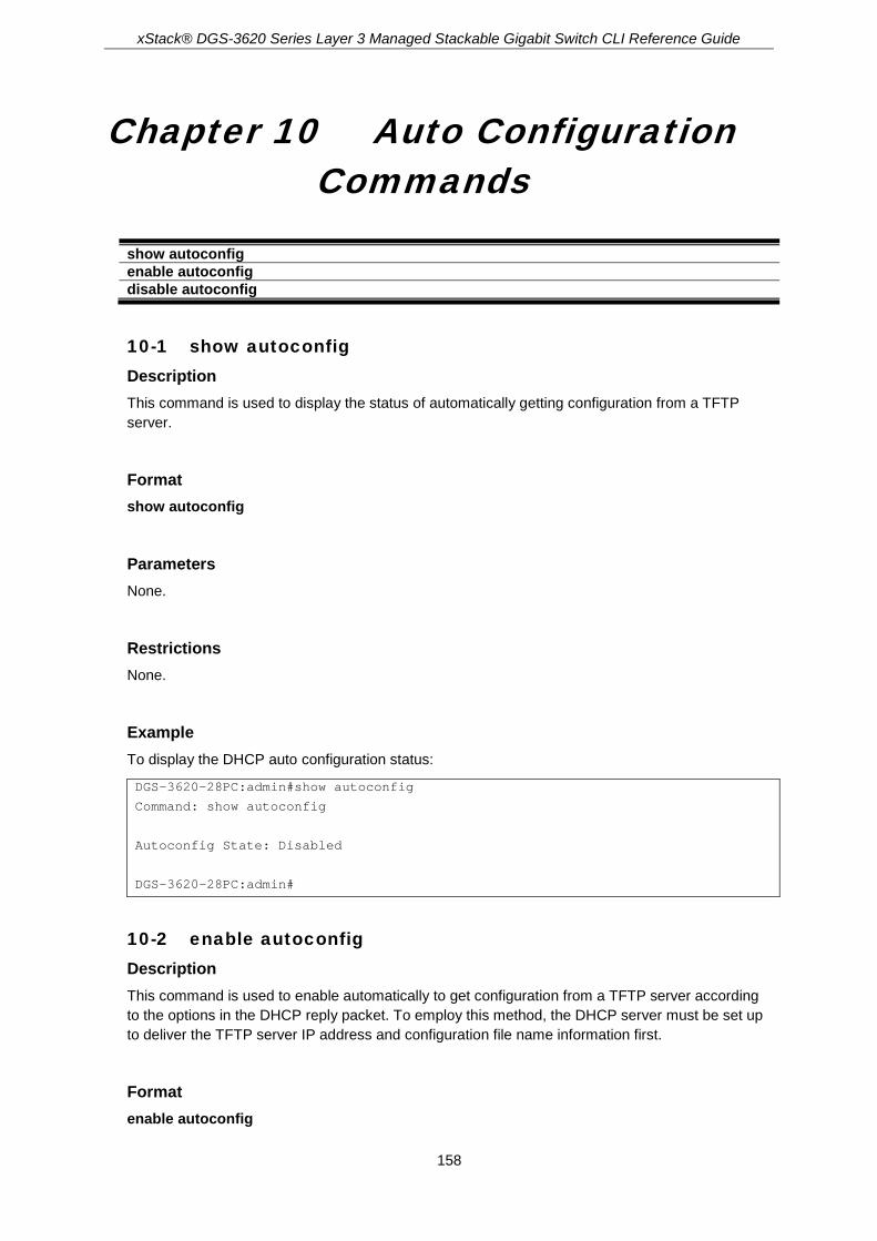
xStack® DGS-3620 Series Layer 3 Managed Stackable Gigabit Switch CLI Reference Guide
158
Chapter 10 Auto Configuration Commands
show autoconfig enable autoconfig disable autoconfig
10-1 show autoconfig Description This command is used to display the status of automatically getting configuration from a TFTP server.
Format show autoconfig
Parameters None.
Restrictions None.
Example To display the DHCP auto configuration status:
DGS-3620-28PC:admin#show autoconfig
Command: show autoconfig
Autoconfig State: Disabled
DGS-3620-28PC:admin#
10-2 enable autoconfig Description This command is used to enable automatically to get configuration from a TFTP server according to the options in the DHCP reply packet. To employ this method, the DHCP server must be set up to deliver the TFTP server IP address and configuration file name information first.
Format enable autoconfig

xStack® DGS-3620 Series Layer 3 Managed Stackable Gigabit Switch CLI Reference Guide
159
Parameters None.
Restrictions Only Administrators and Operators can issue this command.
Example To enable DHCP auto configuration status:
DGS-3620-28PC:admin#enable autoconfig
Command: enable autoconfig
Success.
DGS-3620-28PC:admin#
10-3 disable autoconfig Description This command is used to disable automatically to get configuration from a TFTP server.
Format disable autoconfig
Parameters None.
Restrictions Only Administrators and Operators can issue this command.
Example To disable the DHCP auto configuration status:
DGS-3620-28PC:admin#disable autoconfig
Command: disable autoconfig
Success.
DGS-3620-28PC:admin#

xStack® DGS-3620 Series Layer 3 Managed Stackable Gigabit Switch CLI Reference Guide
160
Chapter 11 Bidirectional Forwarding Detection (BFD) Commands
enable bfd disable bfd config bfd [ipif <ipif_name 12> | all] {min_tx_interval <millisecond 50-1000> | min_rx_interval
<millisecond 50-1000> | multiplier <value 3-99> | slow_time <millisecond 1000-3000>} show bfd {ipif <ipif_name 12>} show bfd neighbor {ipif <ipif_name 12> | ipaddress <ipaddr> | protocol [ospf | vrrp] | details}
11-1 enable bfd Description This command is used to enable the BFD global state on the Switch.
Format enable bfd
Parameters None
Restrictions Only Administrators, Operators and Power-Users can issue this command.
Example This example show how to enable the BFD global state.
DGS-3620-28PC:admin# enable bfd
Command: enable bfd
Success.
DGS-3620-28PC:admin#
11-2 disable bfd Description This command is used to disable the BFD global state on the Switch.

xStack® DGS-3620 Series Layer 3 Managed Stackable Gigabit Switch CLI Reference Guide
161
Format disable bfd
Parameters None
Restrictions Only Administrators, Operators and Power-Users can issue this command.
Example This example show how to disable the BFD global state.
DGS-3620-28PC:admin# disable bfd
Command: disable bfd
Success.
DGS-3620-28PC:admin#
11-3 config bfd Description This command is used to configure the BFD parameters on the Switch.
Format config bfd [ipif <ipif_name 12> | all] {min_tx_interval <millisecond 50-1000> | min_rx_interval <millisecond 50-1000> | multiplier <value 3-99> | slow_time <millisecond 1000-3000>}
Parameters ipif - Specifies the name of the IP interface.
<ipif_name 12> - Enter the name of the IP interface. This name can be up to 12 characters long.
all - Specifies that all the IP interfaces will be used. min_tx_interval - (Optional) Specifies the desired minimum transmit interval value.
<millisecond 50-1000> - Enter the minimum transmit interval value here. This value must be between 50 and 1000 milliseconds.
min_rx_interval - (Optional) Specifies the required minimum receive interval value. <millisecond 50-1000> - Enter the minimum receive interval value here. This value must be
between 50 and 1000 milliseconds. multiplier - (Optional) Specifies the BFD detection time multiplier value.
<value 3-99> - Enter the BFD detection time multiplier value here. This value must be between 3 and 99.
slow_time - (Optional) Specifies the BFD slow time value. <millisecond 1000-3000> - Enter the BFD slow time value here. This value must be between
1000 and 3000 milliseconds.

xStack® DGS-3620 Series Layer 3 Managed Stackable Gigabit Switch CLI Reference Guide
162
Restrictions Only Administrators, Operators and Power-Users can issue this command.
Example This example show how to configure the desired minimum TX interval value to 100 milliseconds and detection time multiplier to 5 on the interface System.
DGS-3620-28PC:admin# config bfd ipif System min_tx_interval 100 multiplier 5
Command: config bfd ipif System min_tx_interval 100 multiplier 5
Success.
DGS-3620-28PC:admin#
11-4 show bfd Description This command is used to display the BFD information on the Switch.
Format show bfd {ipif <ipif_name 12>}
Parameters ipif - (Optional) Specifies the IP interface to display.
<ipif_name 12> - Enter the IP interface's name here. This name can be up to 12 characters long.
Restrictions None.
Example This example show how to display the BFD information.

xStack® DGS-3620 Series Layer 3 Managed Stackable Gigabit Switch CLI Reference Guide
163
DGS-3620-28PC:admin# show bfd
Command: show bfd
BFD Global State : Disabled
BFD Interface Setting
MinTxInt - Desired Minimum TX Interval
MinRxInt - Required Minimum RX Interval
Interface Name MinTxInt(ms) MinRxInt(ms) Multiplier Slow time(ms)
--------------- ------------ ------------ ---------- -------------
System 100 50 5 1000
Total Entries: 1
DGS-3620-28PC:admin#
11-5 show bfd neighbor Description This command is used to display the BFD neighbor information on the Switch.
Format show bfd neighbor {ipif <ipif_name 12> | ipaddress <ipaddr> | protocol [ospf | vrrp] | details}
Parameters ipif - (Optional) Specifies the IP interface to display.
<ipif_name 12> - Enter the IP interface's name here. This name can be up to 12 characters long.
ipaddress - (Optional) Specifies to display the BFD neighbor information of the specified IP address. <ipaddr> - Enter the IP address used here.
protocol - (Optional) Specifies to display the BFD neighbor information of the specified protocol owner. ospf - Specifies to display OSPF BFD neighbor information. vrrp - Specifies to display VRRP BFD neighbor information.
details - (Optional) Specifies to display more detailed BFD neighbor information.
Restrictions None.
Examples This example show how to display the BFD neighbors:

xStack® DGS-3620 Series Layer 3 Managed Stackable Gigabit Switch CLI Reference Guide
164
DGS-3620-28PC:admin# show bfd neighbor
Command: show bfd neighbor
BFD Neighbor Table
Local Discr : Local Discriminator
Remote Discr: Remote Discriminator
Neighbor Local Remote Detect
Address Interface Name Discr Discr Time(ms) Status
--------------- -------------- ------ ------ -------- ----------
10.0.0.3 System 1 1 100 UP
10.0.0.2 System 2 1 50 UP
Total Entries: 2
DGS-3620-28PC:admin#
This example show how to display detailed information of BFD neighbors registered by OSPF.
DGS-3620-28PC:admin# show bfd neighbor protocol ospf details
Command: show bfd neighbor protocol ospf details
BFD Neighbor Table
Local Discr : Local Discriminator
Remote Discr: Remote Discriminator
Neighbor Local Remote Detect
Address Interface Name Discr Discr Time(ms) Status
--------------- -------------- ------ ------ -------- ----------
18.0.0.1 System 1 7 900 Up
Local Diagnostic : No Diagnostic
Pool Bit : Not set
Remote Minimum RX Interval : 300 ms
Remote Minimum TX Interval : 300 ms
Remote Multiplier : 3
Register Protocol : OSPF VRRP
Total Entries: 1
DGS-3620-28PC:admin#

xStack® DGS-3620 Series Layer 3 Managed Stackable Gigabit Switch CLI Reference Guide
165
Chapter 12 Border Gateway Protocol (BGP) Commands
enable bgp disable bgp create bgp <as_number 1-4294967295> delete bgp <as_number 1-4294967295> config bgp router_id <ipaddr> config bgp synchronization [enable | disable] config bgp enforce_first_as [enable | disable] create bgp aggregate_address [<network_address> | ipv6 <ipv6_networkaddr>] {summary_only
| as_set} delete bgp aggregate_address [[<network_address> | all] | ipv6 [<ipv6_networkaddr> | all]] show bgp aggregate_address {[<network_address> | ipv6 {<ipv6_networkaddr>}]} create bgp network [<network_address> | ipv6 <ipv6_networkaddr>] {route_map <map_name
16>} config bgp network [<network_address> | ipv6 <ipv6_networkaddr>] [route_map <map_name
16> | clear_routemap] delete bgp network [[<network_address> | all] | ipv6 [<ipv6_networkaddr> | all]] show bgp network {[<network_address> | ipv6 {<ipv6_networkaddr>}]} config bgp timer holdtime <sec 0-65535> keepalive <sec 0-65535> config bgp {always_compare_med [disable | enable] | deterministic_med [disable | enable] |
default_local_preference <uint 0-4294967295> | bestpath {as_path_ignore [disable | enable] | compare_routerid [disable | enable] | med_confed [disable | enable] | med_missing_as_worst [disable | enable] | compare_confed_aspath [disable | enable]}(1)}(1)
config bgp dampening {[ipv4 | ipv6] unicast} [route_map <map_name 16> | clear_routemap | {state [enable | disable] | half_life <value 1-45> | reuse <value 1-20000> | suppress <value 1-20000> | max_suppress_time <value 1-255> | un_reachability_half_life <value 1-45>}]
show bgp dampening {[ipv4 | ipv6] unicast} config bgp peer_group <peer_group_name 16> [remote_as <as_number 0-4294967295> | [add |
delete] [<ipaddr> | <ipv6addr>]] create bgp neighbor [[<ipaddr> | <ipv6addr>] [remote_as <as_number 1-4294967295> |
peer_group <peer_group_name 16>] | peer_group <peer_group_name 16>] delete bgp neighbor [<ipaddr> | <ipv6addr> | peer_group <peer_group_name 16> | all] config bgp neighbor [[[<ipaddr> | peer_group <peer_group_name 16>] [description <desc 80> |
clear_description | password <password 25> | clear_password]] | <ipv6addr> [description <desc 80> | clear_description]]
config bgp neighbor session [<ipaddr> | <ipv6addr> | peer_group <peer_group_name 16>] [{[ipv4 | ipv6] unicast} activity | state] [enable | disable]
config bgp neighbor general [<ipaddr> | <ipv6addr> | peer_group <peer_group_name 16>] [{ebgp_multihop <value 1-255> | weight [<value 0-65535> | default] | update_source [add | delete] ipif <ipif_name 12> | send_community [standard | none] | next_hop_self [enable | disable] | soft_reconfiguration_inbound [enable | disable] | remove_private_as [enable | disable] | allowas_in [enable {<value 1-10>} | disable] | default_originate [enable {route_map <map_name 16>} | disable]} | [ipv4 | ipv6] unicast {send_community [standard | none] | next_hop_self [enable | disable] | soft_reconfiguration_inbound [enable | disable] | remove_private_as [enable | disable] | allowas_in [enable {<value 1-10>} | disable] | default_originate [enable {route_map <map_name 16>} | disable]}]
config bgp neighbor timer [<ipaddr> | <ipv6addr> | peer_group <peer_group_name 16>] {advertisement_interval [<sec 0-600> | default] | [keepalive <sec 0-65535> holdtime <sec 0-65535> | default_keepalive_holdtime] | as_origination_interval [<sec 1-600> | default] | connect [<sec 1-65535> | default]}
config bgp neighbor route_reflector_client [<ipaddr> | <ipv6addr> | peer_group

xStack® DGS-3620 Series Layer 3 Managed Stackable Gigabit Switch CLI Reference Guide
166
<peer_group_name 16>] {[ipv4 | ipv6] unicast} state [enable | disable] config bgp neighbor map [<ipaddr> | <ipv6addr> | peer_group <peer_group_name 16>] {[ipv4 |
ipv6] unicast} {unsuppress_map [add | delete] <map_name 16> | route_map [in | out] [add | delete] <map_name 16>}
config bgp neighbor filter [<ipaddr> | <ipv6addr> | peer_group <peer_group_name 16>] {[ipv4 | ipv6] unicast} {filter_list [in | out] [add | delete] <list_name 16> | prefix_list [in | out] [add | delete] <list_name 16> | capability_orf_prefix_list [receive | send | both | none]}
show bgp peer_group {<peer_group_name 16>} config bgp route_reflector cluster_id <ipaddr> config bgp client_to_client_reflection [enable | disable] config bgp confederation identifier <as_number 0-4294967295> config bgp confederation peers [add | delete] <aspath_list> clear bgp [all | neighbor_addr [<ipaddr> | <ipv6addr>] | as <as_number 1-4294967295> |
peer_group <peer_group_name 16> | external] {[ipv4 | ipv6] unicast soft {[in {prefix_filter} | out]}}
clear bgp dampening {[ipv4 unicast {[<ipaddr> | <network_address>]} | [<ipaddr> | <network_address>] | ipv6 unicast {[<ipv6addr> | <ipv6_networkaddr>]}]}
create bgp as_path access_list <list_name 16> config bgp as_path access_list <list_name 16> [add | delete] <regexp_str 80> [deny | permit] delete bgp as_path access_list [list_name <list_name 16> | all] show bgp as_path access_list {<list_name 16>} create bgp community_list [standard | expanded] <list_name 16> config bgp community_list [standard <list_name 16> [add | delete] {internet | local_as |
no_advertise | no_export | community_set <community_set 80>}(1) [deny | permit] | expanded <list_name 16> [add | delete] <regexp_str 80> [deny | permit]]
delete bgp community_list [list_name <list_name 16> | all] show bgp community_list {<list_name 16>} show bgp route {[[regexp <desc 80> | inconsistent_as | cidr_only | filter_list <list_name 16> |
route_map <map_name 16> | community {community_set <community_set 80> | local_as | no_advertise | no_export | internet} {exact_match} | community_list <list_name 16> {exact_match} | ipaddress <ipaddr> | network <network_address> {longer_prefixes} | prefix_list <list_name 16>] | ipv6 unicast {[regexp <desc 80> | inconsistent_as | filter_list <list_name 16> | route_map <map_name 16> | community {community_set <community_set80> | local_as | no_advertise | no_export | internet} {exact_match} | community_list <list_name 16> {exact_match} | ipv6_address <ipv6addr> | ipv6_network <ipv6_networkaddr> {longer_prefixes} | ipv6_prefix_list <list_name 16>]} | ipv4 unicast {[regexp <desc 80> | inconsistent_as | cidr_only | filter_list <list_name 16> | route_map <map_name 16> | community {community_set <community_set 80> | local_as | no_advertise | no_export | internet} {exact_match} | community_list <list_name 16> {exact_match} | ipaddress <ipaddr> | network <network_address> {longer_prefixes} | prefix_list <list_name 16>]}]
show bgp neighbors {[<ipaddr> | <ipv6addr>] {[{[ipv4 | ipv6] unicast} [advertised_routes | received_routes | routes | received_prefix_filter] | statistics]}}
show bgp dampened_routes {[ipv4 | ipv6] unicast} show bgp flap_statistics {[ipv4 | ipv6] unicast} show bgp {summary {[ipv4 | ipv6 ] unicast}} show bgp reflection {[ipv4 | ipv6] unicast} show bgp confederation config bgp trap [peer_established | peer_idle | all] [enable | disable] show bgp trap_state config bgp scan_timer [<sec 5-60> | default] config bgp aggregate_next_hop_check [enable | disable] config bgp fast_external_fallover [enable | disable] config bgp neighbor maximum_prefix [<ipaddr> | <ipv6addr> | peer_group <peer_group_name
16>] [<value 1-12000> {<value 1-100>} {warning_only} | ipv4 unicast <value 1-12000> {<value 1-100>} {warning_only} | ipv6 unicast <value 1-6000> {<value 1-100>} {warning_only}]
clear bgp flap_statistics {[ipv4 unicast {[<ipaddr> | <network_address>]} | [<ipaddr> |

xStack® DGS-3620 Series Layer 3 Managed Stackable Gigabit Switch CLI Reference Guide
167
<network_address>] | ipv6 unicast {[<ipv6addr> | <ipv6_networkaddr>]}]}
12-1 enable bgp Description This command is used to enable the BGP protocol. By enabling the BGP protocol, all the previous configurations will be applied to the protocol kernel and start. By default, BGP is disabled.
Format enable bgp
Parameters None.
Restrictions Only Administrators, Operators and Power-Users can issue this command. (EI Mode Only Command)
Example To enable BGP protocol:
DGS-3620-28PC:admin# enable bgp
Command: enable bgp
Success.
DGS-3620-28PC:admin#
12-2 disable bgp Description This command is used to disable the BGP protocol. By disabling the BGP protocol, all peers will be disconnected and dynamic routes will be deleted. All the static configurations however will be reserved. If BGP enables again, the previous configurations can be re-applied.
Format disable bgp
Parameters None.
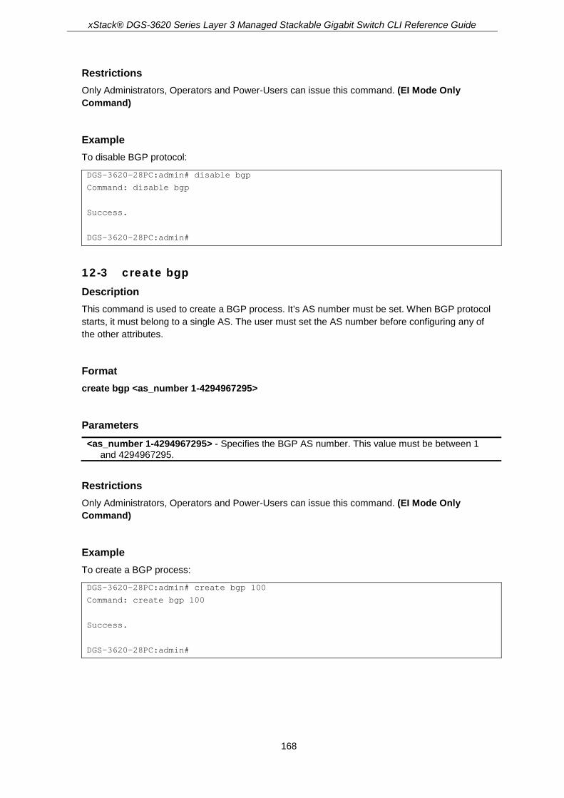
xStack® DGS-3620 Series Layer 3 Managed Stackable Gigabit Switch CLI Reference Guide
168
Restrictions Only Administrators, Operators and Power-Users can issue this command. (EI Mode Only Command)
Example To disable BGP protocol:
DGS-3620-28PC:admin# disable bgp
Command: disable bgp
Success.
DGS-3620-28PC:admin#
12-3 create bgp Description This command is used to create a BGP process. It’s AS number must be set. When BGP protocol starts, it must belong to a single AS. The user must set the AS number before configuring any of the other attributes.
Format create bgp <as_number 1-4294967295>
Parameters <as_number 1-4294967295> - Specifies the BGP AS number. This value must be between 1
and 4294967295.
Restrictions Only Administrators, Operators and Power-Users can issue this command. (EI Mode Only Command)
Example To create a BGP process:
DGS-3620-28PC:admin# create bgp 100
Command: create bgp 100
Success.
DGS-3620-28PC:admin#

xStack® DGS-3620 Series Layer 3 Managed Stackable Gigabit Switch CLI Reference Guide
169
12-4 delete bgp Description This command is used to delete the BGP process. The AS number must be specified. When the BGP process is deleted, all peer and route information from BGP will be deleted. Route entries redistributed from BGP must also be canceled.
Format delete bgp <as_number 1-4294967295>
Parameters <as_number 1-4294967295> - Specifies the BGP AS number. This value must be between 1
and 4294967295.
Restrictions Only Administrators, Operators and Power-Users can issue this command. (EI Mode Only Command)
Example To create a BGP process:
DGS-3620-28PC:admin# delete bgp 100
Command: delete bgp 100
Success.
DGS-3620-28PC:admin#
12-5 config bgp router_id Description This command is used to configure the BGP process’s router ID. The address of a loopback interface is preferred to as an IP address on a physical interface because the loopback interface is more effective than a fixed interface as an identifier because there is no physical link to go down.
The user must specify a unique router ID within the network. This command will reset all active BGP peering sessions.
When a router ID is not configured, the router ID is selected by the following rules:
1. If a loopback interface is configured, the router ID is set to the IP address of the loopback. 2. If multiple loopback interfaces are configured, the loopback with the highest IP address is
used. 3. If no loopback interface is configured, the router ID is set to the highest IP address on a
physical interface. Note: One newly created interface whose address may be preferred to be the router ID according to the rules above, but, it will not be chosen to be router ID immediately. Only when the router ID is set to zero or when recreating a BGP instance, the new interface may be selected as the BGP router ID.

xStack® DGS-3620 Series Layer 3 Managed Stackable Gigabit Switch CLI Reference Guide
170
Format config bgp router_id <ipaddr>
Parameters <ipaddr> - An ID to identify a BGP router. If it is set to zero the router ID will be automatically
determined. The default value is the highest IP address on a physical interface.
Restrictions Only Administrators, Operators and Power-Users can issue this command. (EI Mode Only Command)
Example To configure the BGP process’s router ID:
DGS-3620-28PC:admin# config bgp router_id 10.10.10.1
Command: config bgp router_id 10.10.10.1
Success
DGS-3620-28PC:admin#
12-6 config bgp synchronization Description This command is used to configure the BGP synchronization ability. Usually, a BGP speaker does not advertise a route to an external neighbor unless that route is local or exists in the IGP. By default, synchronization between BGP and the IGP is turned off to allow the BGP to advertise a network route without waiting for route validation from the IGP. This feature allows routers and access servers within an Autonomous System to have the route before BGP makes it available to other autonomous systems.
Format config bgp synchronization [enable | disable]
Parameters enable - Specifies to enable synchronization. disable - Specifies to disable synchronization. By default, this setting is disabled.
Restrictions Only Administrators, Operators and Power-Users can issue this command. (EI Mode Only Command)

xStack® DGS-3620 Series Layer 3 Managed Stackable Gigabit Switch CLI Reference Guide
171
Example To enable the BGP process’ synchronization ability:
DGS-3620-28PC:admin# config bgp synchronization enable
Command: config bgp synchronization enable
Success
DGS-3620-28PC:admin#
12-7 config bgp enforce_first_as Description This command is used to enforce the neighbor’s AS as the first AS in the AS list.
When the setting is enabled, any updates received from an external neighbor, that does not have the neighbor’s configured Autonomous System (AS) at the beginning of the AS_PATH in the received update, will be denied. Enabling this feature adds to the security of the BGP network by not allowing traffic from unauthorized systems.
Format config bgp enforce_first_as [enable | disable]
Parameters enable - Enables the enforce first AS setting. disable - Disables the enforce first AS setting. The default setting is disabled.
Restrictions Only Administrators, Operators and Power-Users can issue this command. (EI Mode Only Command)
Example To enable the BGP process’s enforce_first_as ability:
DGS-3620-28PC:admin# config bgp enforce_first_as enable
Command: config bgp enforce_first_as enable
Success
DGS-3620-28PC:admin#
12-8 create bgp aggregate_address Description This command is used to create an aggregate entry in the Border Gateway Protocol (BGP) database.

xStack® DGS-3620 Series Layer 3 Managed Stackable Gigabit Switch CLI Reference Guide
172
Using the aggregate_address command with no keywords will create an aggregate entry in the BGP routing table, if any more specific BGP routes are available that fall within the specified range. The aggregate route will be advertised as coming from your Autonomous System and will have the atomic aggregate attribute set to indicate that information might be missing. That is, the original AS path associated with more specific routes will be lost. The atomic aggregate attribute is set unless you specify the as_set keyword.
Using the as_set keyword will create an aggregate entry, but the path advertised for this route will include an AS set consisting of all AS that are contained in all paths that are being summarized. Do not use continually withdrawn and updated as autonomous system path reachability information for the summarized routes changes.
Using the summary_only keyword will create an aggregate route but suppresses advertisements of more specific routes to all neighbors. If you want to suppress only advertisements to certain neighbors, you may use the neighbor prefix_list command.
Format create bgp aggregate_address [<network_address> | ipv6 <ipv6_networkaddr>] {summary_only | as_set}
Parameters <network_address> - Specifies the IPv4 network address that will be aggregated. ipv6 – Specifies the IPv6 network address that will be aggregated.
<ipv6_networkaddr> - Enter the IPv6 network address that will be aggregated here. summary_only - (Optional) Specifies that more specific routes will not be advertised. as_set - (Optional) Generates an Autonomous System set path information.
Restrictions Only Administrators, Operators and Power-Users can issue this command. (EI Mode Only Command)
Example To create an aggregate route of which the network address is 10.0.0.0/8, suppress more-specific routes:
DGS-3620-28PC:admin# create bgp aggregate_address 10.0.0.0/8 summary_only
Command: create bgp aggregate_address 10.0.0.0/8 summary_only
Success.
DGS-3620-28PC:admin#
12-9 delete bgp aggregate_address Description This command is used to delete an aggregate entry in a Border Gateway Protocol (BGP) database.

xStack® DGS-3620 Series Layer 3 Managed Stackable Gigabit Switch CLI Reference Guide
173
Format delete bgp aggregate_address [[<network_address> | all] | ipv6 [<ipv6_networkaddr> | all]]
Parameters <network_address> - Specifies the IPv4 aggregated network to be deleted. all – Specifies that all IPv4 aggregated networks will be deleted.. ipv6 – Specifies the IPv6 network address of the entry that will be deleted.
<ipv6_networkaddr> - Enter the IPv6 network address used here. all – Specifies that all IPv6 aggregated networks will be deleted.
Restrictions Only Administrators, Operators and Power-Users can issue this command. (EI Mode Only Command)
Example To delete an aggregate_route of which the network address is 10.0.0.0/8:
DGS-3620-28PC:admin# delete bgp aggregate_address 10.0.0.0/8
Command: delete bgp aggregate_address 10.0.0.0/8
Success.
DGS-3620-28PC:admin#
12-10 show bgp aggregate_address Description This command is used to show the aggregate entries in the Border Gateway Protocol (BGP) database.
Format show bgp aggregate_address {[<network_address> | ipv6 {<ipv6_networkaddr>}]}
Parameters <network_address> - (Optional) Specifies the IP aggregated network address. ipv6 – (Optional) Specifies the IPv6 aggregated network address.
<ipv6_networkaddr> - Enter the IPv6 aggregated network address used here. If the specific network address is not specified, all aggregated addresses of IPv4 or IPv6 will be
displayed.
Restrictions None. (EI Mode Only Command)

xStack® DGS-3620 Series Layer 3 Managed Stackable Gigabit Switch CLI Reference Guide
174
Example To display an aggregate route of 10.0.0.0/8:
DGS-3620-28PC:admin# show bgp aggregate_address 10.0.0.0/8
Command: show bgp aggregate_address 10.0.0.0/8
Network Address Options
------------------ ----------------------
10.0.0.0/8 summary_only, as_set
Total Aggregate Address Number: 1.
DGS-3620-28PC:admin#
12-11 create bgp network Description This command is used to specify the network advertised by the Border Gateway Protocol (BGP). BGP networks can be learned from connected routes, from dynamic routing, and from static route sources.
Format create bgp network [<network_address> | ipv6 <ipv6_networkaddr>] {route_map <map_name 16>}
Parameters <network_address> - Represents the local network that BGP will advertise. ipv6 – Specifies the local IPv6 network that BGP will advertise.
<ipv6_networkaddr> - Enter the IPv6 network address here. route_map - (Optional) Specifies the route map to be applied to the advertised networks. If not
specified, all networks are advertised. <map_name 16> - Enter the route map name here. This name can be up to 16 characters
long.
Restrictions Only Administrators, Operators and Power-Users can issue this command. (EI Mode Only Command)
Example Setup network 10.108.0.0/16 to be included in the BGP updates:
DGS-3620-28PC:admin# create bgp network 10.108.0.0/16
Command: create bgp network 10.108.0.0/16
Success.
DGS-3620-28PC:admin#

xStack® DGS-3620 Series Layer 3 Managed Stackable Gigabit Switch CLI Reference Guide
175
12-12 config bgp network Description This command is used to configure the attribute associated with the network advertised by the Border Gateway Protocol (BGP).
Format config bgp network [<network_address> | ipv6 <ipv6_networkaddr>] [route_map <map_name 16> | clear_routemap]
Parameters <network_address> - Represents the local IPv4 network that BGP will advertise. ipv6 – Specifies the local IPv6 network that BGP will advertise.
<ipv6_networkaddr> - Enter the IPv6 network address here. route_map - Specifies the route map applied to the advertised networks.
<map_name 16> - Enter the route map name here. This name can be up to 16 characters long.
clear_routemap - Removes the route map applied to the network.
Restrictions Only Administrators, Operators and Power-Users can issue this command. (EI Mode Only Command)
Example Change the network 10.108.0.0/16 to clear a route map:
DGS-3620-28PC:admin# config bgp network 10.108.0.0/16 clear_routemap
Command: config bgp network 10.108.0.0/16 clear_routemap
Success.
DGS-3620-28PC:admin#
12-13 delete bgp network Description This command is used to delete the networks advertised by the Border Gateway Protocol (BGP).
Format delete bgp network [[<network_address> | all] | ipv6 [<ipv6_networkaddr> | all]]
Parameters <network_address> - Specifies the IPv4 network address of the entry that will be deleted. all – Specifies to delete all IPv4 BGP networks. ipv6 – Specifies the IPv6 network address of the entry that will be deleted.

xStack® DGS-3620 Series Layer 3 Managed Stackable Gigabit Switch CLI Reference Guide
176
<ipv6_networkaddr> - Enter the IPv6 network address here. all – Specifies to delete all IPv6 BGP networks.
Restrictions Only Administrators, Operators and Power-Users can issue this command. (EI Mode Only Command)
Example To delete network 10.108.0.0/16 to be advertised in the BGP updates:
DGS-3620-28PC:admin# delete bgp network 10.108.0.0/16
Command: delete bgp network 10.108.0.0/16
Success.
DGS-3620-28PC:admin#
12-14 show bgp network Description This command is used to show the networks advertised by the Border Gateway Protocol (BGP).
Format show bgp network {[<network_address> | ipv6 {<ipv6_networkaddr>}]}
Parameters <network_address> - (Optional) Enter the local IPv4 network address that BGP will advertise. ipv6 - (Optional) Specifies the local IPv6 network address that BGP will advertise.
<ipv6_networkaddr> - Enter the local IPv6 network address that BGP will advertise. If the specific network address is not specified, all network addresses of IPv4 or IPv6 will be
displayed.
Restrictions None. (EI Mode Only Command)
Example To show network 10.108.0.0/16 advertised in the BGP updates:

xStack® DGS-3620 Series Layer 3 Managed Stackable Gigabit Switch CLI Reference Guide
177
DGS-3620-28PC:admin# show bgp network 10.108.0.0/16
Command: show bgp network 10.108.0.0/16
Network Address Route Map
--------------- ----------------
10.108.0.0/16
Total Network Number: 1
DGS-3620-28PC:admin#
12-15 config bgp timer Description This command is used to configure the BGP protocol timer. The hold time needs to be at least three times that of the keepalive time. If the timer is specified for specific neighbors, then the neighbor specific timer will take effect.
Format config bgp timer holdtime <sec 0-65535> keepalive <sec 0-65535>
Parameters holdtime - The system will declare a peer as dead if a keepalive message is received that is
more than the hold time. The default value is 180 seconds. If the holdtime is set to zero, then the holdtime will never expire. If the two routers that build a BGP connection have a different hold time, then the smaller hold time will be used. If the timer is specified for specific neighbors, then the neighbor specific timer will take effect. The hold time needs to be at least three times that of the keepalive timer. <sec 0-65535> - Enter the hold time value used here. This value must be between 0 and
65535. keepalive - This specifies the interval at which keepalive messages are sent to its peer. If the
keepalive value is set to zero, then the keepalive message will not be sent out. The default value is 60 seconds. If the two routers that build a BGP connection have a different keepalive timer, then the smaller keepalive timer will be used. If the timer is specified for specific neighbors, then the neighbor specific timer will take effect. <sec 0-65535> - Enter the keep-alive time value used here. This value must be between 0
and 65535.
Restrictions Only Administrators, Operators and Power-Users can issue this command. (EI Mode Only Command)
Example This command is used to configure the BGP hold and keepalive timer:

xStack® DGS-3620 Series Layer 3 Managed Stackable Gigabit Switch CLI Reference Guide
178
DGS-3620-28PC:admin# config bgp timer holdtime 360 keepalive 120
Command: config bgp timer holdtime 360 keepalive 120
Success.
DGS-3620-28PC:admin#
12-16 config bgp Description This command is used to configure the BGP best path selection related setting. MED is a metric assigned to tell the external router how to choose a route. By default, MED is used to determine the route that is advertised by the same AS.
The BGP deterministic med command can be configured to enforce a deterministic comparison of the MED values between all the paths received from within the same Autonomous System
Default local preference:
By default, a BGP router will send the default local preference with the routes. It can be overwritten if the local preference is set by the route map. For the received route, the local preference received with the route will be used in the best path selection. This local preference will be overwrite if the local preference is ingress set by the route map.
For the local routes, the default local preference will be used for them in the best path selection
Best path selection process:
The following is the steps that the BGP will use to select the best path among BGP routes:
1. Prefer the path that has the largest weight. 2. If the routes have the same weight, use the route with the highest local preference. 3. If the routes have the same local preference, prefer the route that was originated by BGP
on this router. Originated from network command > from redistribute command> from aggregate command.
4. If no route was originated, prefer the route with the shortest AS path. 5. If all paths are of the same AS length, prefer the route with lowest origin code (IGP < EGP
< INCOMPLETE). 6. If the origin codes are the same, prefer the path with the lowest Multi Exit Discriminator. 7. If the MEDs are the same, prefer external paths over internal paths. EBGP
>Confederation>IBGP. 8. Prefer the path through the closest IGP neighbor. 9. Prefer the path that was received first (the oldest one). 10. Prefer the path with the lowest BGP Router ID. 11. Prefer to the routes advertised by the BGP speaker with a lower BGP identifier value. 12. Prefer to the routes advertised by the BGP speaker with lower peer address.
Format config bgp {always_compare_med [disable | enable] | deterministic_med [disable | enable] | default_local_preference <uint 0-4294967295> | bestpath {as_path_ignore [disable | enable] | compare_routerid [disable | enable] | med_confed [disable | enable] | med_missing_as_worst [disable | enable] | compare_confed_aspath [disable | enable]}(1)}(1)

xStack® DGS-3620 Series Layer 3 Managed Stackable Gigabit Switch CLI Reference Guide
179
Parameters always_compare_med - (Optional) Enable or disable the comparison of the Multi Exit
Discriminator (MED) for paths from the neighbors in different Autonomous Systems. By default this setting is disabled. enable - Specifies that the 'always compare MED' option will be enabled. disable - Specifies that the 'always compare MED' option will be disabled.
deterministic_med - (Optional) Enable or disable to enforce the deterministic comparison of the Multi Exit Discriminator (MED) for paths received from the neighbors within the same Autonomous System. By default this setting is disabled. enable - Specifies that the 'deterministic MED' option will be enabled. disable - Specifies that the 'deterministic MED' option will be disabled.
default_local_preference - (Optional) Specifies the default local preference value. The default value is 100. <uint 0-4294967295> - Enter the default local preference value here. This value must be
between 0 and 4294967295. bestpath - (Optional) Specifies the best path value to be used. as_path_ignore - (Optional) If enabled, the BGP process will ignore the AS path in the path
selection process. By default this value is disabled. enable - Specifies that the 'AS path ignore' option will be enabled. disable - Specifies that the 'AS path ignore' option will be disabled.
compare_routerid - (Optional) If enabled, the BGP process will include the router ID in the path selection process. Similar routes are compared and the route with the lowest router ID is selected. By default this value is disabled. enable - Specifies that the 'compare router ID' option will be enabled. disable - Specifies that the 'compare router ID' option will be disabled.
med_confed - (Optional) If enabled, the BGP process will compare the MED for the routes that are received from confederation peers. For routes that have an external AS in the path, the comparison does not occur. By default this value is disabled. enable - Specifies that the 'MED confed' option will be enabled. disable - Specifies that the 'MED confed' option will be disabled.
med_missing_as_worst - (Optional) If enabled, the BGP process will assign a value of infinity to routes that are missing the Multi Exit Discriminator (MED) attribute. If disabled, the BGP process will assign a value of zero to routes that are missing the Multi Exit Discriminator (MED) attribute, causing this route to be choosed as the best path. By default this value is disabled. enable - Specifies that the 'MED missing AS worst' option will be enabled. disable - Specifies that the 'MED missing AS worst' option will be disabled.
compare_confed_aspath - (Optional) If enabled, the BGP process will compare the confederation AS path length of the routes received. The shorter the confederation AS path length, the better the route is. By default this value is disabled. enable - Specifies that the 'compare confed AS path' option will be enabled. disable - Specifies that the 'compare confed AS path' option will be disabled.
Restrictions Only Administrators, Operators and Power-Users can issue this command. (EI Mode Only Command)
Example This command shows how to disable the comparison of the Multi Exit Discriminator (MED):

xStack® DGS-3620 Series Layer 3 Managed Stackable Gigabit Switch CLI Reference Guide
180
DGS-3620-28PC:admin# config bgp always_compare_med disable
Command: config bgp always_compare_med disable
Success.
DGS-3620-28PC:admin#
12-17 config bgp dampening Description The purpose of this command is to eliminate the dampening of routes and thus to avoid unstable networks caused by flapping routes. The following describes the way how it is achieved.
If a prefix is removed or is added, BGP will add a penalty on the route of 1000; if an attribute of received route changes, BGP will add a penalty on the route of 500.
Suppose that the half-life is configured to be 15min, the re-use value will be 800, and the suppress value will be 1500.
1. When a route flaps (from up to down), add the penalty by 1000.Since the penalty is smaller than the suppress value, BGP will work normally. It will send a withdraw message (an update message) to the neighbors.
2. The penalty of the route will decrease as time elapses. Here we assume that it pass 7.5 minutes, then the penalty of the route is 1000-500*7.5/15=750.
3. If another flap occurs (the route change from down to up) then the penalty of the route will be 1750 which is larger than the suppress value, and the route will be dampened. BGP will not send an update message for this status change.
4. When the penalty of the route decreases and become smaller than the re-use value (800), the route will not be dampened and the update message will be sent again.
If both IPv4 unicast and IPv6 unicast are not specified, the setting is for IPv4 unicast.
Note: If the dampening ability is enabled and there are one or more dampened routes, the dampened routes will be released to be the normal state immediately after we disable the dampening function.
Format config bgp dampening {[ipv4 | ipv6] unicast} [route_map <map_name 16> | clear_routemap | {state [enable | disable] | half_life <value 1-45> | reuse <value 1-20000> | suppress <value 1-20000> | max_suppress_time <value 1-255> | un_reachability_half_life <value 1-45>}(1)]
Parameters ipv4 unicast - Specifies to configure the IPv4 unicast address family. ipv6 unicast - Specifies to configure the IPv6 unicast address family. route_map - The route_map here is to set the dampening to be criterial.
<map_name 16> - Enter the route map name here. This name can be up to 16 characters long.
clear_routemap - This option will withdraw the route_map configuration.

xStack® DGS-3620 Series Layer 3 Managed Stackable Gigabit Switch CLI Reference Guide
181
state - (Optional) Specifies the BGP dampening function’s state. enable - Specifies that the BGP dampening function's state will be enabled. disable - Specifies that the BGP dampening function's state will be disabled.
half_life - (Optional) Specifies the time (in minute) after which the penalty of the reachable routes will be down, by half. The default setting is 15 minutes. <value 1-45> - Enter the half life value here. This value must be between 1 and 45 minutes.
reuse - (Optional) If the penalty for a flapping route decreases enough to fall below this value, the route is unsuppressed. The default setting is 750. <value 1-20000> - Enter the re-use value used here. This value must be between 1 and
20000. suppress - (Optional) A route is suppressed when its penalty exceeds this limit. The default
setting is 2000. <value 1-20000> - Enter the surpress value used here. This value must be between 1 and
20000. max_suppress_time - (Optional) Maximum time (in minutes) a route can be suppressed. The
default setting is 45 minutes. <min 1-255> - Enter the maximum suppress time value here. This value must be between 1
and 255 minutes. un_reachablity_half_life - (Optional) Specifies the time (in minute) after which the penalty of the
unreachable routes will be down, by half. The default setting is 15 minutes. <value 1-45> - Enter the the time after which the penalty of the unreachable routes will be
down, by half here. This value must be between 1 and 45 minutes.
Restrictions Only Administrators, Operators and Power-Users can issue this command. (EI Mode Only Command)
Example This command shows how to disable the dampening function:
DGS-3620-28PC:admin# config bgp dampening state disable
Command: config bgp dampening state disable
Success.
DGS-3620-28PC:admin# show bgp dampening
Command: show bgp dampening
BGP Dampening State :Disabled
BGP Dampening Route_Map :dmp1
Half-life Time :15 mins
Reuse Value :500
Suppress Value :900
MAX Suppress Time :60 mins
Unreachable route's Half-life :15 mins
DGS-3620-28PC:admin# show bgp route
Command: show bgp route
BGP Local Router ID is 20.90.90.90
Status codes: s suppressed, d damped, h history, * valid, > best, i - internal
Origin codes: i - IGP, e - EGP, ? - incomplete
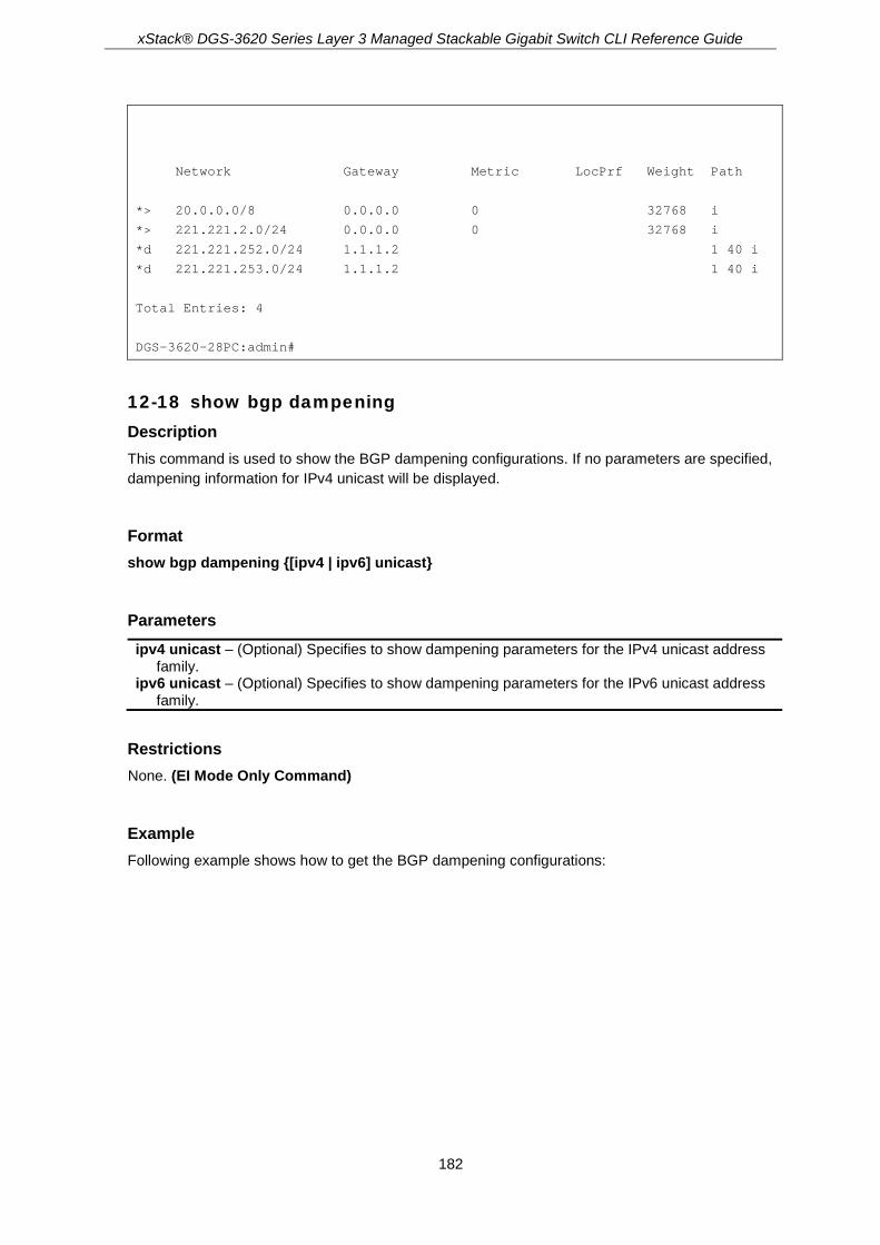
xStack® DGS-3620 Series Layer 3 Managed Stackable Gigabit Switch CLI Reference Guide
182
Network Gateway Metric LocPrf Weight Path
*> 20.0.0.0/8 0.0.0.0 0 32768 i
*> 221.221.2.0/24 0.0.0.0 0 32768 i
*d 221.221.252.0/24 1.1.1.2 1 40 i
*d 221.221.253.0/24 1.1.1.2 1 40 i
Total Entries: 4
DGS-3620-28PC:admin#
12-18 show bgp dampening Description This command is used to show the BGP dampening configurations. If no parameters are specified, dampening information for IPv4 unicast will be displayed.
Format show bgp dampening {[ipv4 | ipv6] unicast}
Parameters ipv4 unicast – (Optional) Specifies to show dampening parameters for the IPv4 unicast address
family. ipv6 unicast – (Optional) Specifies to show dampening parameters for the IPv6 unicast address
family.
Restrictions None. (EI Mode Only Command)
Example Following example shows how to get the BGP dampening configurations:

xStack® DGS-3620 Series Layer 3 Managed Stackable Gigabit Switch CLI Reference Guide
183
DGS-3620-28PC:admin# show bgp dampening
Command: show bgp dampening
BGP Dampening State :Enabled
BGP Dampening Route_Map :dmp1
Half-life Time :15 minutes
Reuse Value :750
Suppress Value :2000
MAX Suppress Time :45 minutes
Unreachable route's Half-life :15 mins
DGS-3620-28PC:admin#
12-19 config bgp peer_group Description This command is used to configure the BGP peer group. The purpose of the neighbor peer group is to simplify the BGP neighbor configuration. The command is used to add an IP or to delete an IP from a BGP peer group. The peer group must be created using the “create neighbor peer group” command. The members must all be internal or external. If all the members of the BGP peer group are external, they are allowed to have different AS numbers. There are two kinds of the peer groups.
For the first kind or peer group, the remote AS is not set; members must be created as neighbors before it can be added to the peer group. When we configure the peer group’s remote AS behind this, the member’s remote AS will not change. For the second kind of peer group, the peer group has set a remote AS number. A member can be added to the peer group even if the member didn’t have an AS number before. In this situation, the system will create a neighbor for the peer group’s remote AS automatically. The member’s remote AS will change to the configured peer group’s remote AS, but the others’ will not change, which is created as a neighbor before added to the peer group.
If a BGP peer belongs to a peer group, some attributes or actions can only be configured from the peer group. The following is a list of them: capability_orf_prefix_list, next_hop_self, route_reflector_client, send_community, soft_reconfiguration_inbound, remove_private_as, allowas_in, holdtime, keepalive, unsuppress_map, default_originate, filter_list for out direction, route_map for out direction, prefix_list for out direction.
On the contrary, some attributes or actions are allowed to be configured from both the peer group and the member. If they are configured from the member, the setting will overwrite the setting configured from the peer group.
Other attribute that can be set from an individual peer are as follows: description, filter_list for in direction, route_map for in direction, prefix_list for in direction, ebgp_multihop, session state, session activity, weight.
As for the above attributes, setting the attribute of a peer group will automatically affect the setting for individual peers in the peer group.
For session state, if the peer group is configure to disable, all the members can’t set to enable. For session activity, can’t set the peer group to disable.
As for the description attribute, setting the peer group will not affect the setting for an individual peer.

xStack® DGS-3620 Series Layer 3 Managed Stackable Gigabit Switch CLI Reference Guide
184
After this command is executed, all peers belonging to this peer group, which are generated with no indicated AS number, will change their AS number to the same value as the peer group’s, stop and restarted values. If the peer group remote AS has a value of zero, it means “no remote_as”, and members that are generated with no indicated AS number will be deleted.
Format config bgp peer_group <peer_group_name 16> [remote_as <as_number 0-4294967295> | [add | delete] [<ipaddr> | <ipv6addr>]]
Parameters <peer_group_name 16> - This is the name of the BGP peer group. This name can be up to 16
characters long. remote_as - The number of autonomous systems to which the peer group belongs to.
<as_number 0-4294967295> - Enter the remote AS value here. This value must be between 0 and 4294967295.
add - Specifies to add an IP address. delete - Specifies to delete an IP address. <ipaddr> - Enter the IPv4 address to be added or deleted here. <ipv6addr> - Enter the IPv6 address to be added or deleted here.
Restrictions Only Administrators, Operators and Power-Users can issue this command. (EI Mode Only Command)
Example To delete a member from the peer group named local:
DGS-3620-28PC:admin# config bgp peer_group local delete 10.2.2.2
Command: config bgp peer_group local delete 10.2.2.2
Success.
DGS-3620-28PC:admin#
To set a peer group named local remote_as to 50:
DGS-3620-28PC:admin# config bgp peer_group local remote_as 50
Command: config bgp peer_group local remote_as 50
Success.
DGS-3620-28PC:admin#
12-20 create bgp neighbor Description The command is used to create a BGP neighbor. Either a single router or a peer group can be created as neighbor.

xStack® DGS-3620 Series Layer 3 Managed Stackable Gigabit Switch CLI Reference Guide
185
If the created neighbor has a single IP address, the remote AS must be specified. A peer group must be specified of which this BGP speaking neighbor belongs to, and in this condition, a remote AS must be specified to the peer group first.
If the created neighbor is a peer group, then the remote AS cannot be specified here. The remote AS must specified by using the “config peer_group remote_as” command.
Format create bgp neighbor [[<ipaddr> | <ipv6addr>] [remote_as <as_number 1-4294967295> | peer_group <peer_group_name 16>] | peer_group <peer_group_name 16>]
Parameters <ipaddr> - Enter the IPv4 address of the BGP speaking neighbor here. <ipv6addr> - Enter the IPv6 address of the BGP speaking neighbor here. remote_as - The number of Autonomous Systems to which the neighbor belongs.
<as_number 1-4294967295> - Enter the remote AS number here. This value must be between 1 and 4294967295.
peer_group - Specifies the peer group to be created and added as a neighbor. <peer_group_name 16> - Enter the peer group name here. This name can be up to 16
characters long. peer_group - Specifies the peer group to be created and added as a neighbor.
<peer_group_name 16> - Enter the peer group name here. This name can be up to 16 characters long.
Restrictions Only Administrators, Operators and Power-Users can issue this command. (EI Mode Only Command)
Example To create a neighbor peer whose address is 10.10.10.2:
DGS-3620-28PC:admin# create bgp neighbor 10.10.10.2 remote_as 10
Command: create bgp neighbor 10.10.10.2 remote_as 10
Success.
DGS-3620-28PC:admin#
12-21 delete bgp neighbor Description This command is used to delete the BGP neighbor.
Format delete bgp neighbor [<ipaddr> | <ipv6addr> | peer_group <peer_group_name 16> | all]

xStack® DGS-3620 Series Layer 3 Managed Stackable Gigabit Switch CLI Reference Guide
186
Parameters <ipaddr> - Specifies the IPv4 address of the neighbor that will be deleted. <ipv6addr> - Specifies the IPv6 address of the neighbor that will be deleted. peer_group - Specifies the peer group that will be deleted as a neighbor.
<peer_group_name 16> - Enter the peer group name here. This name can be up to 16 characters long.
all - Delete all BGP neighbors, including individual peers and peer groups.
Restrictions Only Administrators, Operators and Power-Users can issue this command. (EI Mode Only Command)
Example To delete a neighbor whose address is 10.10.10.2:
DGS-3620-28PC:admin# delete bgp neighbor 10.10.10.2
Command: delete bgp neighbor 10.10.10.2
Success.
DGS-3620-28PC:admin#
12-22 config bgp neighbor Description This command is used to configure the BGP neighbor’s description or password attribute.
Format config bgp neighbor [[[<ipaddr> | peer_group <peer_group_name 16>] [description <desc 80> | clear_description | password <password 25> | clear_password]] | <ipv6addr> [description <desc 80> | clear_description]]
Parameters <ipaddr> - Specifies the IP address of the neighbor to be configured. peer_group - Specifies the peer group to be configured.
<peer_group_name 16> - Enter the peer group name here. This name can be up to 16 characters long.
description - Associate a description with a neighbor. By default, the description is not specified. <desc 80> - Enter the description value used here. This value can be up to 80 characters
long. clear_description - Removes the neighbor’s description. password - Specifies to set the MD5 authentication password when a TCP connection between
BGP neighbors are established. When BGP neighbors are created, password aren’t set by default. <password 25> - Enter the password used here. This password can be up to 25 characters
long. clear_password - Specifies to clear the MD5 authentication password when a TCP connection
between BGP neighbors are established. <ipv6addr> - Enter the IPv6 address used here.
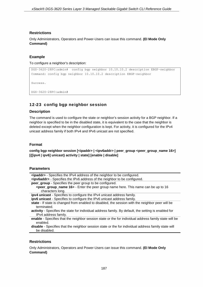
xStack® DGS-3620 Series Layer 3 Managed Stackable Gigabit Switch CLI Reference Guide
187
Restrictions Only Administrators, Operators and Power-Users can issue this command. (EI Mode Only Command)
Example To configure a neighbor’s description:
DGS-3620-28PC:admin# config bgp neighbor 10.10.10.2 description EBGP-neighbor
Command: config bgp neighbor 10.10.10.2 description EBGP-neighbor
Success.
DGS-3620-28PC:admin#
12-23 config bgp neighbor session Description The command is used to configure the state or neighbor’s session activity for a BGP neighbor. If a neighbor is specified to be in the disabled state, it is equivalent to the case that the neighbor is deleted except when the neighbor configuration is kept. For activity, it is configured for the IPv4 unicast address family if both IPv4 and IPv6 unicast are not specified.
Format config bgp neighbor session [<ipaddr> | <ipv6addr> | peer_group <peer_group_name 16>] [{[ipv4 | ipv6] unicast} activity | state] [enable | disable]
Parameters <ipaddr> - Specifies the IPv4 address of the neighbor to be configured. <ipv6addr> - Specifies the IPv6 address of the neighbor to be configured. peer_group - Specifies the peer group to be configured.
<peer_group_name 16> - Enter the peer group name here. This name can be up to 16 characters long.
ipv4 unicast - Specifies to configure the IPv4 unicast address family. ipv6 unicast - Specifies to configure the IPv6 unicast address family. state - If state is changed from enabled to disabled, the session with the neighbor peer will be
terminated. activity - Specifies the state for individual address family. By default, the setting is enabled for
IPv4 address family. enable - Specifies that the neighbor session state or the for individual address family state will be
enabled. disable - Specifies that the neighbor session state or the for individual address family state will
be disabled.
Restrictions Only Administrators, Operators and Power-Users can issue this command. (EI Mode Only Command)

xStack® DGS-3620 Series Layer 3 Managed Stackable Gigabit Switch CLI Reference Guide
188
Example This example will shut down all the neighbors that are contained in the peer group “Campus”:
DGS-3620-28PC:admin# config bgp neighbor session peer_group Campus state disable
Command: config bgp neighbor session peer_group Campus state disable
Success.
DGS-3620-28PC:admin#
This example shuts down the activity state of the neighbor 10.90.90.90:
DGS-3620-28PC:admin# config bgp neighbor session 10.90.90.90 activity disable
Command: config bgp neighbor session 10.90.90.90 activity disable
Success.
DGS-3620-28PC:admin#
12-24 config bgp neighbor general Description This command is used to configure the BGP neighbor’s general setting.
ebgp_multihop: This specifies the TTL of the BGP packet sent to the neighbor. If it is specified as 1, it will have a restriction that the neighbor must be directly connected to it.
weight: This specifies the weight that will be associated to the routes learned from the specified neighbor. The route with highest weight will be chosen as the preferred route. If the route map sets weight to a route, then this route map specified weight will override the weight specified by the BGP neighbor’s command. Weight is an attribute which is specified in the ingress direction, and is not an attribute to be advertised with the route. It is used to specify preference to routes received from a neighbor over another neighbor.
soft_reconfiguration_inbound: If the setting is enabled, the route updates sent from the specified neighbor will be stored. This storage is required for inbound soft reconfiguration. When a soft reset is requested for inbound sessions, the session will not be torn down, but the inbound routing table will be cleared. It needs to be rebuilt. If the soft reconfiguration inbound is enabled, then the routing table can be rebuilt based on the stored route update information. If the soft reconfiguration inbound is disabled, then the local router will send the route refresh requests to the neighbor to ask for the route refresh.
next_hop_self: If the next_hop_self option is enabled, the router will set the next_hop to itself when it advertises the routes to the specific neighbor. If the next_hop_self option is disabled, the next_hop attributes will not be changed. The behavior described here will be overridden by the set next hop statement if route map is applied to the neighbor in the out direction.
remove_private_as: The private Autonomous System numbers are from 64512 to 65535. If this setting is set to enable, the private AS number in AS path attribute of the BGP update packets will be dropped.
allowas_in: The BGP router will do AS path loop checks for the received BGP update packet. If the BGP router’s self AS appears in the AS path, it is identified as a loop and the packet will be discarded. If the allow-as setting is enabled, the BGP router’s self AS is allowed in the AS path list.

xStack® DGS-3620 Series Layer 3 Managed Stackable Gigabit Switch CLI Reference Guide
189
default_originate: If this setting is enabled, it will allow a BGP speaker (the local router) to send the default route 0.0.0.0/0 to a neighbor to use as the default route. If route map is specified, the default route will be injected if the route map contains a match IP address statement. If this setting is disabled, no default route will be sent to the neighbor. The default setting is disabled.
By default, if both the IPv4 unicast and IPv6 unicast are not specified, the setting is for the IPv4 unicast address family for those parameters supporting the IPv4 and IPv6 unicast address family.
Format config bgp neighbor general [<ipaddr> | <ipv6addr> | peer_group <peer_group_name 16>] [{ebgp_multihop <value 1-255> | weight [<value 0-65535> | default] | update_source [add | delete] ipif <ipif_name 12> | send_community [standard | none] | next_hop_self [enable | disable] | soft_reconfiguration_inbound [enable | disable] | remove_private_as [enable | disable] | allowas_in [enable {<value 1-10>} | disable] | default_originate [enable {route_map <map_name 16>} | disable]} | [ipv4 | ipv6] unicast {send_community [standard | none] | next_hop_self [enable | disable] | soft_reconfiguration_inbound [enable | disable] | remove_private_as [enable | disable] | allowas_in [enable {<value 1-10>} | disable] | default_originate [enable {route_map <map_name 16>} | disable]}]
Parameters <ipaddr> - Specifies the IPv4 address of the neighbor to be configured. <ipv6addr> - Specifies the IPv6 address of the neighbor to be configured. peer_group - Specifies the peer group to be configured.
<peer_group_name 16> - Enter the peer group name here. This name can be up to 16 characters long.
ebgp_multihop - (Optional) Specifies the TTL of BGP packet sent to the neighbor. For an EBGP neighbor the default setting is 1. This means only direct connected neighbors are allowed. <value 1-255> - Enter the EBGP multi-hop value used here. This value must be between 1
and 255. weight - (Optional) The valid range is from 0 to 65535. If this is not specified, the routes learned
through another BGP peer will have a default weight of 0. Routes sourced by the local router have a weight of 32768. It cannot be changed. value <0-65535> - Enter the weight value used here. This value must be between 0 and
65535. default - Specifies that the default weight value will be used.
update_source - (Optional) Specifies an interface to be used by BGP sessions for the TCP connection. By default, this parameter is not set. add - Specifies to add an interface. delete - Specifies to delete an interface.
ipif - (Optional) Specifies the IP interface name used. <ipif_name 12> - Enter the IP interface name used here. This name can be up to 12
characters long. send_community - (Optional) This specifies the communities attribute to be sent to the BGP
neighbor. standard - Only standard communities will be sent. none - No communities will be sent. The default value is none.
next_hop_self - (Optional) Enable or disable the next hop self attribute. By default, this setting is disabled. enable - Specifies that the next-hop-self attribute will be enabled. disable - Specifies that the next-hop-self attribute will be disabled.
soft_reconfiguration_inbound - (Optional) Specifies to enable or disable the inbound soft reconfiguration function. By default, this setting is disabled. enable - Specifies that the soft re-configuration inbound option will be enabled. disable - Specifies that the soft re-configuration inbound option will be disabled.

xStack® DGS-3620 Series Layer 3 Managed Stackable Gigabit Switch CLI Reference Guide
190
remove_private_as - (Optional) If this setting is set to enable, the private AS number in the AS path attribute of the BGP update packets will be dropped. By default, the setting is disabled. enable - Specifies that the 'remove private AS' option will be enabled. disable - Specifies that the 'remove private AS' option will be disabled.
allowas_in - (Optional) If the allow_as setting is enabled, the BGP router’s self AS is allowed in the AS path list. By default, the allow_as setting is disabled. If no number is supplied, the default value of 3 times is used. enable - Specifies that the allow AS-in option will be enabled. <value 1-10> - Enter the allow AS-in value used here. This value must be between 1 and 10. disable - Specifies that the allow AS-in option will be disabled.
default_originate - (Optional) Specifies to enable or disable the default originate function. By default, this setting is disabled. enable - Specifies that the default originate function will be enabled.
route_map - Specifies the route map name. <map_name 16> - Enter the route map name here. This name can be up to 16
characters long. disable - Specifies that the default originate function will be disabled.
ipv4 unicast - Specifies to configure the IPv4 unicast address family. ipv6 unicast - Specifies to configure the IPv6 unicast address family.
Restrictions Only Administrators, Operators and Power-Users can issue this command. (EI Mode Only Command)
Example This example shows how to configure the EBGP multi-hop to 2:
DGS-3620-28PC:admin# config bgp neighbor general 10.100.200.1 ebgp_multihop 2
Command: config bgp neighbor general 10.100.200.1 ebgp_multihop 2
Success.
DGS-3620-28PC:admin#
12-25 config bgp neighbor timer Description This command is used to configure the BGP neighbor’s timer attribute.
advertisement_interval: If an advertised route is flapping, this usually occurs when an interface is unstable, a lot of UPDATE and WITHDRAWN messages will be sent. One method to control the flooding of these messages is to set a minimum advertisement interval.
Format config bgp neighbor timer [<ipaddr> | <ipv6addr> | peer_group <peer_group_name 16>] {advertisement_interval [<sec 0-600> | default] | [keepalive <sec 0-65535> holdtime <sec 0-65535> | default_keepalive_holdtime] | as_origination_interval [<sec 1-600> | default] | connect [<sec 1-65535> | default]}

xStack® DGS-3620 Series Layer 3 Managed Stackable Gigabit Switch CLI Reference Guide
191
Parameters <ipaddr> - Specifies the IPv4 address of the neighbor to be configured. <ipv6addr> - Specifies the IPv6 address of the neighbor to be configured. peer_group - Specifies the peer group to be configured.
<peer_group_name 16> - Enter the peer group name here. This name can be up to 16 characters long.
advertisement_interval - (Optional) It specifies the interval at which the BGP process sends update messages to its peer. If this value is set to zero, the update or withdrawn message will be sent immediately. The default value for IBGP peers is 5 seconds and for EBGP peers it is 30 seconds. When it is specified to default, the neighbor specific advertisement interval setting will be returned to the default setting. <sec 0-600> - Enter the advertisement interval value here. This value must be between 0 and
600 seconds. default - Specifies that the advertisement interval will be set to default.
keepalive - (Optional) This specifies the interval at which a keepalive message is sent to its peers. If the two routers, that build BGP connection, have different keepalive timers, the smaller keepalive timer will be used. If the keepalive is set to zero, then the keepalive message will not be sent out. By default, the timer is not specified. This neighbor specific setting will follow the global setting. <sec 0-65535> - Enter the keep alive value here. This value must be between 0 and 65535.
holdtime - (Optional) The system will declare a peer as dead if not receiving a keepalive message until the hold time. If two routers, that builded a BGP connection, have different hold times, the smaller hold time will be used. If the holdtime is zero, then the holdtime will never expire. It is recommended that the holdtime value is 3 times that of keepalive timer. By default, the timer is not specified. This neighbor specific setting will follow the global setting. <sec 0-65535> - Enter the hold time value here. This value must be between 0 and 65535.
default_keepalive_holdtime - (Optional) Clear the specification of the neighbor specific holdtime and keepalive setting.
as_origination_interval - (Optional) Minimum interval between the sending AS origination routing updates. The valid value is from 1 to 600. The default setting is 15 seconds. <sec 1-600> - Enter the AS original interval value here. This value must be between 1 and
600. default - Specifies that the default AS original interval value will be used.
connect - (Optional) Minimum interval BGP sends TCP connect requests to the peer after a TCP connection fail happens. The default setting is 120 seconds. <sec 1-65535> - Enter the minimum interval BGP sends TCP connect requests to the peer
after a TCP connection fail happens value here. This value must be between 1 and 65535. default - Specifies that the default connect value will be used.
Restrictions Only Administrators, Operators and Power-Users can issue this command. (EI Mode Only Command)
Example This example shows how to configure the advertisement interval to 20 seconds:
DGS-3620-28PC:admin# config bgp neighbor timer peer_group Campus advertisement_interval 20
Command: config bgp neighbor timer peer_group Campus advertisement_interval 20
Success.
DGS-3620-28PC:admin#

xStack® DGS-3620 Series Layer 3 Managed Stackable Gigabit Switch CLI Reference Guide
192
12-26 config bgp neighbor route_reflector_client Description This command is used to configure the BGP’s neighbor of the route reflector client. When the route reflector client is defined and the router reflection is enabled, the BGP router will act as the route reflector. The reflector and its client form a cluster. In a cluster, all the members must be iBGP connections with the reflector and vice versa. The reflector is the representative of the cluster. For the reflector, the iBGP connection is established by the “create bgp neighbor” command and the corresponding neighbor must be specified as the client by this command. For the client, the iBGP connection is established by the “create bgp neighbor” command.
When the router is in reflection mode, the router will exchange information with client neighbors in the reflection way and with the remaining neighbor in the ordinary way.
When the router is in non-reflection mode, the router will exchange information with all the neighbors in the non-reflection way.
An AS can have multiple clusters, and a cluster can have more than one reflector for redundancy purposes.
By default, if both the IPv4 unicast and IPv6 unicast options are not specified, the setting is for the IPv4 unicast address family.
Format config bgp neighbor route_reflector_client [<ipaddr> | <ipv6addr> | peer_group <peer_group_name 16>] {[ipv4 | ipv6] unicast} state [enable | disable]
Parameters <ipaddr> - Specifies the IPv4 address of the neighbor to be configured. <ipv6addr> - Specifies the IPv6 address of the neighbor to be configured. peer_group - Specifies the peer group to be configured.
<peer_group_name 16> - Enter the peer group name here. This name can be up to 16 characters long.
ipv4 unicast - Specifies to configure the IPv4 unicast address family. ipv6 unicast - Specifies to configure the IPv6 unicast address family. state - The specified neighbor will become the router reflector client. By default, this state is
disabled. enable - Specifies that the neighbor will become the router reflector client. disable - Specifies that the neighbor will not become the router reflector client.
Restrictions Only Administrators, Operators and Power-Users can issue this command. (EI Mode Only Command)
Example This example shows how to add a neighbor as the route reflector client:

xStack® DGS-3620 Series Layer 3 Managed Stackable Gigabit Switch CLI Reference Guide
193
DGS-3620-28PC:admin# config bgp neighbor route_reflector_client 10.10.10.2 state enable
Command: config bgp neighbor route_reflector_client 10.10.10.2 state enable
Success.
DGS-3620-28PC:admin#
12-27 config bgp neighbor map Description The command is used to configure the route map related setting for a BGP neighbor. When a route map is applied by the route_map command, it enforces the route policy. When it is applied by the unsuppress_map command, the suppressed route which matches the permit rule will be unsuppressed. It provides a manipulation of routers per neighbor. If a route map is configured relating to a BGP neighbor but the route map doesn’t exist, it means deny any. If the route map exists but has no filter entry defined, it will permit all. By default, if both the IPv4 unicast and IPv6 unicast options are not specified, the setting is for the IPv4 unicast address family.
Format config bgp neighbor map [<ipaddr> | <ipv6addr> | peer_group <peer_group_name 16>] {[ipv4 | ipv6] unicast} {unsuppress_map [add | delete] <map_name 16> | route_map [in | out] [add | delete] <map_name 16>}
Parameters <ipaddr> - Specifies the IPv4 address of the neighbor to be configured. <ipv6addr> - Specifies the IPv6 address of the neighbor to be configured. peer_group - Specifies the peer group to be configured.
<peer_group_name 16> - Enter the peer group name here. This name can be up to 16 characters long.
ipv4 unicast - Specifies to configure the IPv4 unicast address family. ipv6 unicast - Specifies to configure the IPv6 unicast address family. unsuppress_map - (Optional) Name of a route map used to selectively advertise routers
previously suppressed by the aggregate_address command. add - Specifies that a route map will be added. delete - Specifies that a route map will be deleted. <map_name 16> - Enter the unsurpress map name here. This name can be up to 16
characters long. route_map - (Optional) Specifies the route map to be applied to the incoming or outgoing routes.
in - Specifies the incoming routes from the neighbor. out - Specifies the outgoing routes sent to the peer. add - Specifies that a route map will be added. delete - Specifies that a route map will be deleted. <map_name 16> - Enter the route map name here. This name can be up to 16 characters
long.
Restrictions Only Administrators, Operators and Power-Users can issue this command. (EI Mode Only Command)

xStack® DGS-3620 Series Layer 3 Managed Stackable Gigabit Switch CLI Reference Guide
194
Example This example shows how to configure the unsuppress map of peer group “Campus” to Profile1:
DGS-3620-28PC:admin# config bgp neighbor map peer_group Campus unsuppress_map add Profile1
Command: config bgp neighbor map peer_group Campus unsuppress_map add Profile1
Success.
DGS-3620-28PC:admin#
12-28 config bgp neighbor filter Description The command is used to configure the filter related setting for a BGP neighbor.
filter_list: If the filter_list doesn’t exist or does exist but have no filter entry, it means deny any.
prefix_list: If the prefix_list doesn’t exist, it means deny any. If the prefix_list does exist but have no filter entry defined, it will permit all.
capability_orf_prefix_list: BGP Outbound Route Filter Capability allows one BGP router to install its configured inbound prefix_list filter on to the remote BGP router. This is used for reducing the amount of unwanted routing updates from the remote peer.
By default, if both the IPv4 unicast and IPv6 unicast options are not specified, the setting is for the IPv4 unicast address family.
Format config bgp neighbor filter [<ipaddr> | <ipv6addr> | peer_group <peer_group_name 16>] {[ipv4 | ipv6] unicast} {filter_list [in | out] [add | delete] <list_name 16> | prefix_list [in | out] [add | delete] <list_name 16> | capability_orf_prefix_list [receive | send | both | none]}
Parameters <ipaddr> - Specifies the IPv4 address of the neighbor to be configured. <ipv6addr> - Specifies the IPv6 address of the neighbor to be configured. peer_group- Specifies the peer group to be configured.
<peer_group_name 16> - Enter the peer group name here. This name can be up to 16 characters long.
ipv4 unicast - Specifies to configure the IPv4 unicast address family. ipv6 unicast - Specifies to configure the IPv6 unicast address family. filter_list - (Optional) Specifies the name of an as_path access_list to be applied as a filter. The
filtering can be applied to incoming routes or outgoing routes. in - Specifies that the filter specified will be used for incoming traffic. out - Specifies that the filter specified will be used for outgoing traffic. add - Specifies that a filter list will be added. delete - Specifies that a filter list will be deleted.
<list_name 16> - Enter the filter list name here. This name can be up to 16 characters long.
prefix_list - (Optional) Specifies the name of a prefix_list to be applied as a filter. The filtering can be applied to incoming routes or outgoing routes. in - Specifies that the filter specified will be used for incoming traffic. out - Specifies that the filter specified will be used for outgoing traffic.

xStack® DGS-3620 Series Layer 3 Managed Stackable Gigabit Switch CLI Reference Guide
195
add - Specifies that a filter list will be added. delete - Specifies that a filter list will be deleted.
<list_name 16> - Enter the prefic list name here. This name can be up to 16 characters long.
capability_orf_prefix_list - (Optional) Used to configure an outbound route filter prefix list capability. It can be sent with the following values: receive - Enables the ORF prefix list capability in the receiving direction. The local router will
install the prefix filter list notified by the remote router. send - Enables the ORF prefix list capability in the sending direction. The local router will
notify the remote router for the ORF prefix list capability. both - Enables the ORF prefix list capability in both received and send directions. none - Disable the ORF prefix list capability in both received and send directions.
Restrictions Only Administrators, Operators and Power-Users can issue this command. (EI Mode Only Command)
Example This example shows how to configure the BGP neighbor ingress filter list for the peer group “Campus” to List1:
DGS-3620-28PC:admin# config bgp neighbor filter peer_group Campus filter_list in add List1
Command: config bgp neighbor filter peer_group Campus filter_list in add List1
Success.
DGS-3620-28PC:admin#
12-29 show bgp peer_group Description The command is used to show the information of the BGP peer group.
Format show bgp peer_group {<peer_group_name 16>}
Parameters peer_group - (Optional) Name of the BGP peer group. The length is up to 16 bytes.
<peer_group_name 16> - Enter the BGP peer group name here. This name can be up to 16 characters long.
It means to display all the BGP peer groups’ information that doesn’t specify the peer group name.
Restrictions None. (EI Mode Only Command)
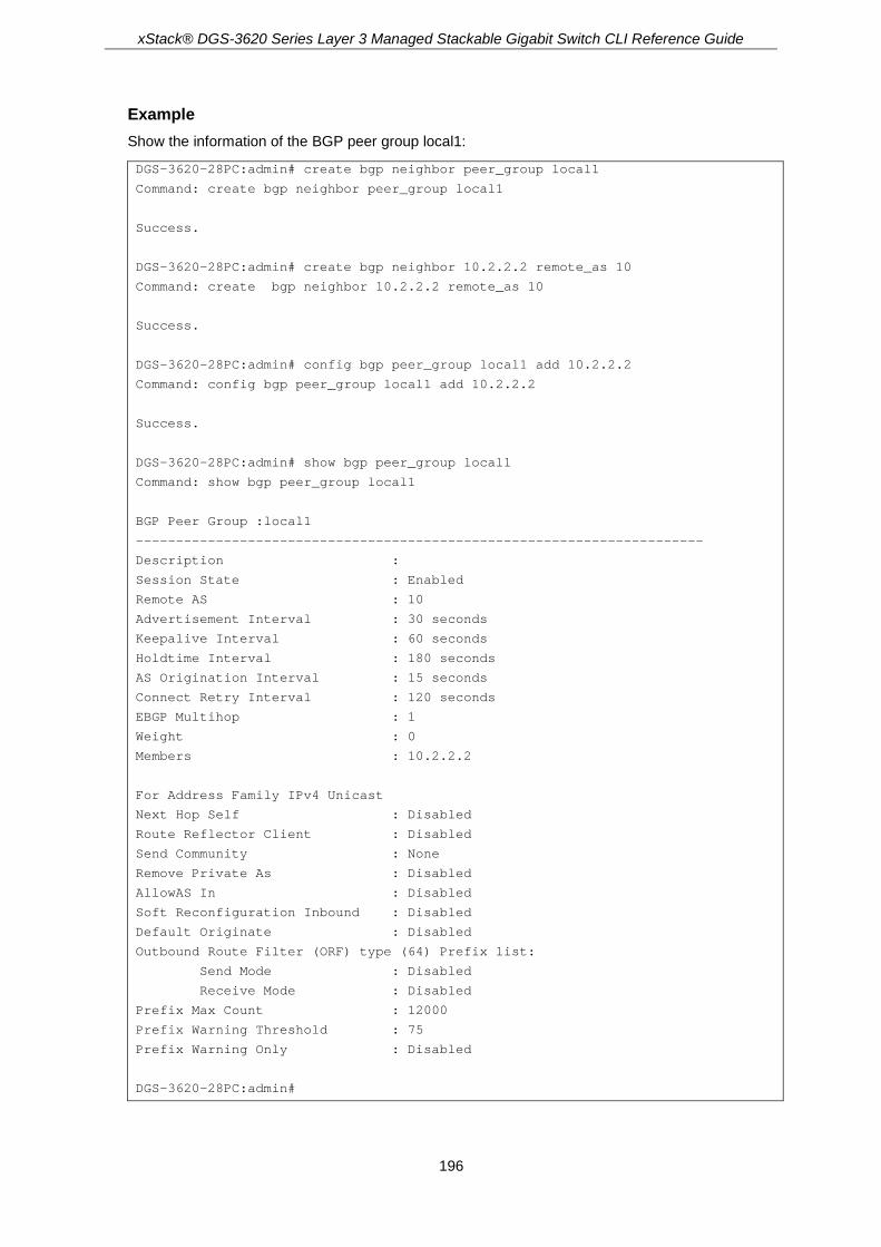
xStack® DGS-3620 Series Layer 3 Managed Stackable Gigabit Switch CLI Reference Guide
196
Example Show the information of the BGP peer group local1:
DGS-3620-28PC:admin# create bgp neighbor peer_group local1
Command: create bgp neighbor peer_group local1
Success.
DGS-3620-28PC:admin# create bgp neighbor 10.2.2.2 remote_as 10
Command: create bgp neighbor 10.2.2.2 remote_as 10
Success.
DGS-3620-28PC:admin# config bgp peer_group local1 add 10.2.2.2
Command: config bgp peer_group local1 add 10.2.2.2
Success.
DGS-3620-28PC:admin# show bgp peer_group local1
Command: show bgp peer_group local1
BGP Peer Group :local1
-----------------------------------------------------------------------
Description :
Session State : Enabled
Remote AS : 10
Advertisement Interval : 30 seconds
Keepalive Interval : 60 seconds
Holdtime Interval : 180 seconds
AS Origination Interval : 15 seconds
Connect Retry Interval : 120 seconds
EBGP Multihop : 1
Weight : 0
Members : 10.2.2.2
For Address Family IPv4 Unicast
Next Hop Self : Disabled
Route Reflector Client : Disabled
Send Community : None
Remove Private As : Disabled
AllowAS In : Disabled
Soft Reconfiguration Inbound : Disabled
Default Originate : Disabled
Outbound Route Filter (ORF) type (64) Prefix list:
Send Mode : Disabled
Receive Mode : Disabled
Prefix Max Count : 12000
Prefix Warning Threshold : 75
Prefix Warning Only : Disabled
DGS-3620-28PC:admin#

xStack® DGS-3620 Series Layer 3 Managed Stackable Gigabit Switch CLI Reference Guide
197
12-30 config bgp route_reflector cluster_id Description This command is used to configure the BGP process’s global attribute. The route reflector and its clients together form a cluster. When a single route reflector is deployed in a cluster, the cluster is identified by the router ID of the route reflector.
When the cluster ID is 0.0.0.0, the cluster is identified by the router ID. Otherwise, the cluster is identified by the cluster ID.
The BGP cluster_id command is used to assign a cluster ID to a route reflector when the cluster has one or more route reflectors. Multiple route reflectors are deployed in a cluster to increase redundancy and to avoid a single point of failure. When multiple route reflectors are configured in a cluster, they must be configured with the same cluster ID. This allows all route reflectors in the cluster to recognize updates from peers in the same cluster and reduces the number of updates that needs to be stored in BGP routing tables.
This command is only required for the reflector and not the client.
Format config bgp route_reflector cluster_id <ipaddr>
Parameters cluster_id - Specifies the IP address of the cluster ID. Setting the cluster ID to 0.0.0.0 will
remove specifications of the cluster ID. The default value is 0.0.0.0. <ipaddr> - Enter the cluster ID's IP address here.
Restrictions Only Administrators, Operators and Power-Users can issue this command. (EI Mode Only Command)
Example This example shows how to configure the cluster ID:
DGS-3620-28PC:admin# config bgp route_reflector cluster_id 10.100.200.1
Command: config bgp route_reflector cluster_id 10.100.200.1
Success.
DGS-3620-28PC:admin#
12-31 config bgp client_to_client_reflection Description This command is used to configure the BGP client to client reflection setting. If the reflection is disabled, then the router will not reflect routes from the route reflect client to other route reflect clients, but it will still send routes received from a non-reflecting client to a reflecting client.

xStack® DGS-3620 Series Layer 3 Managed Stackable Gigabit Switch CLI Reference Guide
198
Format config bgp client_to_client_reflection [enable | disable]
Parameters enable - The reflector will operate in reflector mode. disable - The reflector will operate in non-reflector mode.
Restrictions Only Administrators, Operators and Power-Users can issue this command. (EI Mode Only Command)
Example This example shows how to disable the client to client reflection:
DGS-3620-28PC:admin# config bgp client_to_client_reflection disable
Command: config bgp client_to_client_reflection disable
Success.
DGS-3620-28PC:admin#
12-32 config bgp confederation identifier Description This command is used to configure the BGP confederation. A confederation, which is represented by an AS, is a group of the sub AS.
A confederation can be used to reduce the internal BGP (iBGP) mesh by dividing a large single AS into multihop sub AS. External peers interact with the confederation as if it is a single AS.
Each sub AS is fully meshed within itself and it has connections to other sub AS within the confederation. The next hop, Multi Exit Discriminator (MED), and local preference information is preserved throughout the confederation, allowing you to retain a single Interior Gateway Protocol (IGP) for all the autonomous systems.
Format config bgp confederation identifier <as_number 0-4294967295>
Parameters <as_number 0-4294967295> - Autonomous System numbers which we use to specify a BGP
confederation. If it is set to zero, the BGP confederation number is deleted. By default, this setting is zero. This value must be between 0 and 4294967295.
Restrictions Only Administrators, Operators and Power-Users can issue this command. (EI Mode Only Command)

xStack® DGS-3620 Series Layer 3 Managed Stackable Gigabit Switch CLI Reference Guide
199
Example To create a confederation, AS number is 20:
DGS-3620-28PC:admin# config bgp confederation identifier 20
Command: config bgp confederation identifier 20
Success.
DGS-3620-28PC:admin#
12-33 config bgp confederation peers Description The command is used to configure multiple adjacent Autonomous Systems in a confederation. The Autonomous Systems specified in this command are visible internally to the confederation. Each Autonomous System is fully meshed within itself or configures route reflector.
Format config bgp confederation peers [add | delete] <aspath_list>
Parameters peers - Specifies that a peer will be added or deleted.
add - Specifies that a peer will be added. delete - Specifies that a peer will be deleted. <aspath_list> - Enter the AS number for BGP peers that will belong to the confederation
here.
Restrictions Only Administrators, Operators and Power-Users can issue this command. (EI Mode Only Command)
Example To add two confederation peers, AS number are 50000 and 50001:
DGS-3620-28PC:admin# config bgp confederation peers add 50000,50001
Command: config bgp confederation peers add 50000,50001
Success.
DGS-3620-28PC:admin#
12-34 clear bgp Description This command is used to initiate a hard reset or a soft reset for a connection. If a soft reset is applied to the inbound session, the session will not be rebuilded but the local inbound routing table

xStack® DGS-3620 Series Layer 3 Managed Stackable Gigabit Switch CLI Reference Guide
200
will be cleared and needs to be rebuilt. If a soft reconfiguration inbound is enabled, then the routing table can be rebuilt based on the stored route updates information. If a soft reconfiguration inbound is disabled, then the local router will send the route refresh request to the neighbor to ask for the route refresh. When the inbound session is to soft reset with the prefix filter option, and capability_orf_prefix_list is enabled in the send direction, then the local BGP will send ‘clear the routing table’, and notify the remote neighbor for the prefix_filter. This is a way to notify the neighbor of the prefix filter whenever a change is made to the prefix filter. By default, if both the IPv4 unicast and IPv6 unicast are not specified, the IPv4 unicast address family will be reset. If no IP/IPv6 address or IP/IPv6 network are specified, the dampening information for the entire routing table of the IPv4 unicast or IPv6 unicast address family will be cleared. If both the IPv4 unicast and IPv6 unicast are not specified, the dampening information for the IPv4 unicast routing table will be cleared.
Format clear bgp [all | neighbor_addr [<ipaddr> | <ipv6addr>] | as <as_number 1-4294967295> | peer_group <peer_group_name 16> | external] {[ipv4 | ipv6] unicast soft {[in {prefix_filter} | out]}}
Parameters all - Specifies that all current BGP sessions will be reset. neighbor_addr - Specifies to reset the session with the specified neighbor.
<ipaddr> - Enter the IPv4 address used for this configuration here. <ipv6addr> - Enter the IPv6 address used for this configuration here.
as - Specifies to reset sessions with BGP peers in the specified Autonomous System. <as_number 1-4294967295> - Enter the AS number used here. This value must be between
1 and 4294967295. peer_group - Specifies to reset a peer group.
<peer_group_name 16> - Enter the peer group name here. This name can be up to 16 characters long.
external - All eBGP sessions will be reset. ipv4 unicast - Specifies to soft reset the IPv4 unicast address family. ipv6 unicast - Specifies to soft reset the IPv6 unicast address family. soft - (Optional) Initiates a soft reset. Does not tear down the session.
in - Initiates inbound reconfiguration. If neither in nor out keywords are specified, both inbound and outbound sessions are reset. prefix_filter - The local site configured prefix filter will be notified to the remote neighbor
when inbound soft reset is applied. out - Initiates outbound reconfiguration.
Restrictions Only Administrators, Operators and Power-Users can issue this command. (EI Mode Only Command)
Example To reset all Border Gateway Protocol (BGP) connections:

xStack® DGS-3620 Series Layer 3 Managed Stackable Gigabit Switch CLI Reference Guide
201
DGS-3620-28PC:admin# clear bgp all
Command: clear bgp all
Success.
DGS-3620-28PC:admin#
12-35 clear bgp dampening Description This command clears the route dampening information stored in the routing table. If no IP/IPv6 address or IP/IPv6 network is specified, the dampening information for the entire routing table of the IPv4 unicast or IPv6 unicast address family will be cleared. If both the IPv4 unicast and IPv6 unicast options are not specified, the dampening information for the IPv4 unicast routing table will be cleared.
Format clear bgp dampening {[ipv4 unicast {[<ipaddr> | <network_address>]} | [<ipaddr> | <network_address>] | ipv6 unicast {[<ipv6addr> | <ipv6_networkaddr>]}]}
Parameters ipv4 unicast - (Optional) Specifies to clear the dampening information for the IPv4 unicast
address family. <ipaddr> - Enter the IPv4 address used here. <network_address> - Enter the IPv4 network address here.
ipv6 unicast - (Optional) Specifies to clear the dampening information for the IPv6 unicast address family. <ipv6addr> - Enter the IPv6 address used here. <ipv6_networkaddr> - Enter the IPv6 network address here.
Restrictions Only Administrators, Operators and Power-Users can issue this command. (EI Mode Only Command)
Example To clear route dampening information for network 192.168.10.0/24 and free suppressed routes:
DGS-3620-28PC:admin# clear bgp dampening 192.168.10.0/24
Command: clear bgp dampening 192.168.10.0/24
Success.
DGS-3620-28PC:admin#

xStack® DGS-3620 Series Layer 3 Managed Stackable Gigabit Switch CLI Reference Guide
202
12-36 create bgp as_path access_list Description The command is used to create an Autonomous System path access list. You can apply an Autonomous System path access lists to both inbound and outbound routes exchanged by a BGP peer session.
Format create bgp as_path access_list <list_name 16>
Parameters access_list - Specifies the AS path access list name.
<list_name 16> - Enter the AS path access list name here. This name can be up to 16 characters long.
Restrictions Only Administrators, Operators and Power-Users can issue this command. (EI Mode Only Command)
Example The following example creates an Autonomous System path access list:
DGS-3620-28PC:admin# create bgp as_path access_list test
Command: create bgp as_path access_list test
Success.
DGS-3620-28PC:admin#
12-37 config bgp as_path access_list Description This command is used to configure matching rules for an Autonomous System path access list using regular expressions.
Format config bgp as_path access_list <list_name 16> [add | delete] <regexp_str 80> [deny | permit]
Parameters access_list - Specifies the AS path access list name.
<list_name 16> - Enter the AS path access list name here. This name can be up to 16 characters long.
add - Specifies to add a matching rule. delete - Specifies to delete a matching rule. <reg_express> - Regular expression that defines the as_path filter.

xStack® DGS-3620 Series Layer 3 Managed Stackable Gigabit Switch CLI Reference Guide
203
deny - Denies advertisement based on matching conditions. permit - Permits advertisement based on matching conditions.
Restrictions Only Administrators, Operators and Power-Users can issue this command. (EI Mode Only Command)
Example This example configures a matching rule for an AS path access list:
DGS-3620-28PC:admin# create bgp as_path access_list test
Command: create bgp as_path access_list test
Success.
DGS-3620-28PC:admin# config bgp as_path access_list test add (_64[6-9][0-9][0-9]_|_65[0-9][0-9][0-9]_) deny
Command: config bgp as_path access_list test add (_64[6-9][0-9][0-9]_|_65[0-9][0-9][0-9]_) deny
Success.
DGS-3620-28PC:admin# config bgp as_path access_list test add .* permit
Command: config bgp as_path access_list test add .* permit
Success.
DGS-3620-28PC:admin#
12-38 delete bgp as_path access_list Description This command is used to delete an Autonomous System path access list.
Format delete bgp as_path access_list [list_name <list_name 16> | all]
Parameters list_name - Specifies the AS path access list name.
<list_name 16> - Enter the AS path access list name here. This name can be up to 16 characters long.
all - Specifies that all the AS path lists will be used.
Restrictions Only Administrators, Operators and Power-Users can issue this command. (EI Mode Only Command)

xStack® DGS-3620 Series Layer 3 Managed Stackable Gigabit Switch CLI Reference Guide
204
Example This example deletes a matching rule for an AS path access list:
DGS-3620-28PC:admin# delete bgp as_path access_list list_name test
Command: delete bgp as_path access_list list_name test
Success.
DGS-3620-28PC:admin#
12-39 show bgp as_path access_list Description This command displays the Autonomous System path’s access list. If a specific access list is not specified, all AS path access lists will be displayed.
Format show bgp as_path access_list {<list_name 16>}
Parameters access_list - Specifies the AS path access list name.
<list_name 16> - (Optional) Enter the AS path access list name here. This name can be up to 16 characters long.
Restrictions None. (EI Mode Only Command)
Example This example displays an AS path access list:
DGS-3620-28PC:admin# show bgp as_path access_list 1
Command: show bgp as_path access_list 1
BGP AS Path Access List : 1
deny (_64[6-9][0-9][0-9]_|_65[0-9][0-9][0-9]_)
permit 33
Total Filter Entries: 2
Total AS Path Access List Number: 1
DGS-3620-28PC:admin#
12-40 create bgp community_list Description This command is used to create a BGP community list.
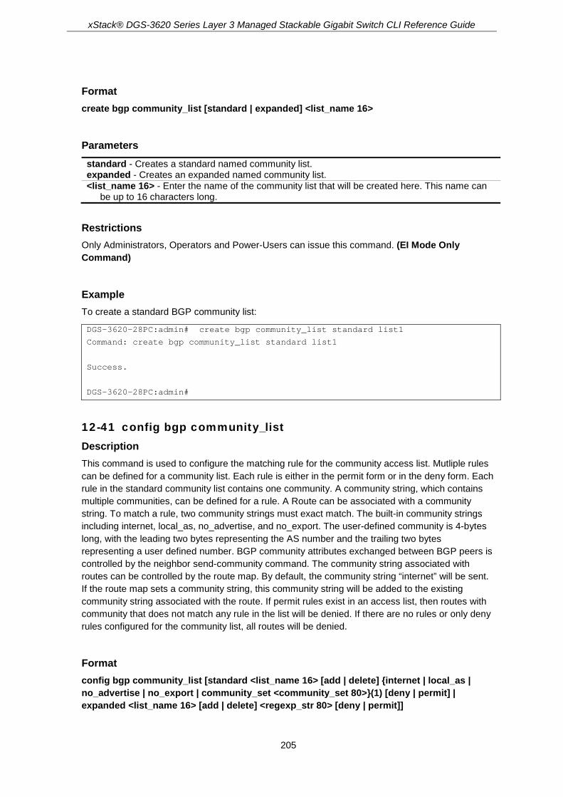
xStack® DGS-3620 Series Layer 3 Managed Stackable Gigabit Switch CLI Reference Guide
205
Format create bgp community_list [standard | expanded] <list_name 16>
Parameters standard - Creates a standard named community list. expanded - Creates an expanded named community list. <list_name 16> - Enter the name of the community list that will be created here. This name can
be up to 16 characters long.
Restrictions Only Administrators, Operators and Power-Users can issue this command. (EI Mode Only Command)
Example To create a standard BGP community list:
DGS-3620-28PC:admin# create bgp community_list standard list1
Command: create bgp community_list standard list1
Success.
DGS-3620-28PC:admin#
12-41 config bgp community_list Description This command is used to configure the matching rule for the community access list. Mutliple rules can be defined for a community list. Each rule is either in the permit form or in the deny form. Each rule in the standard community list contains one community. A community string, which contains multiple communities, can be defined for a rule. A Route can be associated with a community string. To match a rule, two community strings must exact match. The built-in community strings including internet, local_as, no_advertise, and no_export. The user-defined community is 4-bytes long, with the leading two bytes representing the AS number and the trailing two bytes representing a user defined number. BGP community attributes exchanged between BGP peers is controlled by the neighbor send-community command. The community string associated with routes can be controlled by the route map. By default, the community string “internet” will be sent. If the route map sets a community string, this community string will be added to the existing community string associated with the route. If permit rules exist in an access list, then routes with community that does not match any rule in the list will be denied. If there are no rules or only deny rules configured for the community list, all routes will be denied.
Format config bgp community_list [standard <list_name 16> [add | delete] {internet | local_as | no_advertise | no_export | community_set <community_set 80>}(1) [deny | permit] | expanded <list_name 16> [add | delete] <regexp_str 80> [deny | permit]]
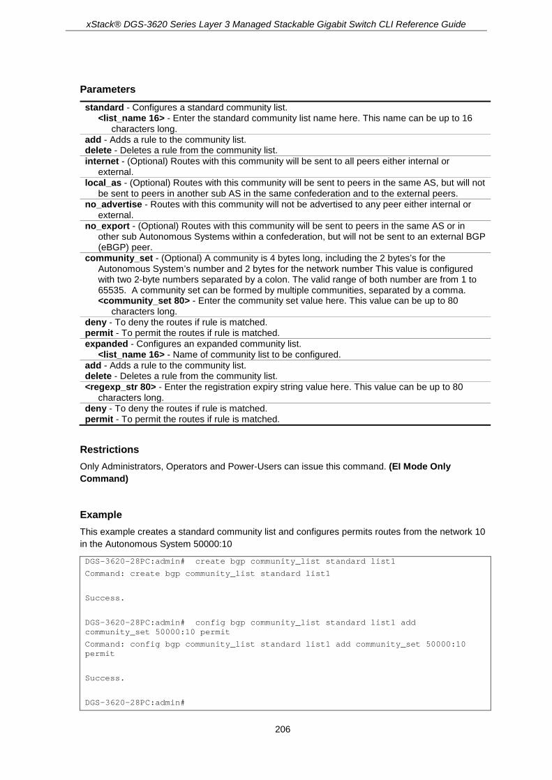
xStack® DGS-3620 Series Layer 3 Managed Stackable Gigabit Switch CLI Reference Guide
206
Parameters standard - Configures a standard community list.
<list_name 16> - Enter the standard community list name here. This name can be up to 16 characters long.
add - Adds a rule to the community list. delete - Deletes a rule from the community list. internet - (Optional) Routes with this community will be sent to all peers either internal or
external. local_as - (Optional) Routes with this community will be sent to peers in the same AS, but will not
be sent to peers in another sub AS in the same confederation and to the external peers. no_advertise - Routes with this community will not be advertised to any peer either internal or
external. no_export - (Optional) Routes with this community will be sent to peers in the same AS or in
other sub Autonomous Systems within a confederation, but will not be sent to an external BGP (eBGP) peer.
community_set - (Optional) A community is 4 bytes long, including the 2 bytes’s for the Autonomous System’s number and 2 bytes for the network number This value is configured with two 2-byte numbers separated by a colon. The valid range of both number are from 1 to 65535. A community set can be formed by multiple communities, separated by a comma. <community_set 80> - Enter the community set value here. This value can be up to 80
characters long. deny - To deny the routes if rule is matched. permit - To permit the routes if rule is matched. expanded - Configures an expanded community list.
<list_name 16> - Name of community list to be configured. add - Adds a rule to the community list. delete - Deletes a rule from the community list. <regexp_str 80> - Enter the registration expiry string value here. This value can be up to 80
characters long. deny - To deny the routes if rule is matched. permit - To permit the routes if rule is matched.
Restrictions Only Administrators, Operators and Power-Users can issue this command. (EI Mode Only Command)
Example This example creates a standard community list and configures permits routes from the network 10 in the Autonomous System 50000:10
DGS-3620-28PC:admin# create bgp community_list standard list1
Command: create bgp community_list standard list1
Success.
DGS-3620-28PC:admin# config bgp community_list standard list1 add community_set 50000:10 permit
Command: config bgp community_list standard list1 add community_set 50000:10 permit
Success.
DGS-3620-28PC:admin#

xStack® DGS-3620 Series Layer 3 Managed Stackable Gigabit Switch CLI Reference Guide
207
12-42 delete bgp community_list Description This command is used to delete a BGP community list.
Format delete bgp community_list [list_name <list_name 16> | all]
Parameters list_name - Specifies the name of the community list to be deleted.
<list_name 16> - Enter the community list name here. This name can be up to 16 characters long.
all - Specifies that all the community lists will be used.
Restrictions Only Administrators, Operators and Power-Users can issue this command. (EI Mode Only Command)
Example This example deletes the community list named as list1:
DGS-3620-28PC:admin# delete bgp community_list list_name test1
Command: delete bgp community_list list_name test1
Success.
DGS-3620-28PC:admin#
12-43 show bgp community_list Description This command is used to show a BGP community list.
Format show bgp community_list {<list_name 16>}
Parameters community_list - Specifies the name of community list to be displayed.
<list_name 16> - (Optional) Enter the community list name here. This name can be up to 16 characters long.
Restrictions None. (EI Mode Only Command)

xStack® DGS-3620 Series Layer 3 Managed Stackable Gigabit Switch CLI Reference Guide
208
Example This example displays the community list name as list1:
DGS-3620-28PC:admin# create bgp community_list standard list1
Command: create bgp community_list standard list1
Success.
DGS-3620-28PC:admin# config bgp community_list standard list1 add community_set 50000:10 permit
Command: config bgp community_list standard list1 add community_set 50000:10 permit
Success.
DGS-3620-28PC:admin# show bgp community_list list1
Command: show bgp community_list list1
Community List Name: list1
--------------------------------
Type : standard
permit : 50000:10
DGS-3620-28PC:admin#
12-44 show bgp route Description This command is used to display route entries in the Border Gateway Protocol (BGP) routing table
Format show bgp route {[[regexp <desc 80> | inconsistent_as | cidr_only | filter_list <list_name 16> | route_map <map_name 16> | community {community_set <community_set 80> | local_as | no_advertise | no_export | internet} {exact_match} | community_list <list_name 16> {exact_match} | ipaddress <ipaddr> | network <network_address> {longer_prefixes} | prefix_list <list_name 16>] | ipv6 unicast {[regexp <desc 80> | inconsistent_as | filter_list <list_name 16> | route_map <map_name 16> | community {community_set <community_set80> | local_as | no_advertise | no_export | internet} {exact_match} | community_list <list_name 16> {exact_match} | ipv6_address <ipv6addr> | ipv6_network <ipv6_networkaddr> {longer_prefixes} | ipv6_prefix_list <list_name 16>]} | ipv4 unicast {[regexp <desc 80> | inconsistent_as | cidr_only | filter_list <list_name 16> | route_map <map_name 16> | community {community_set <community_set 80> | local_as | no_advertise | no_export | internet} {exact_match} | community_list <list_name 16> {exact_match} | ipaddress <ipaddr> | network <network_address> {longer_prefixes} | prefix_list <list_name 16>]}]
Parameters regexp - (Optional) Display routes matching the AS path regular expression.
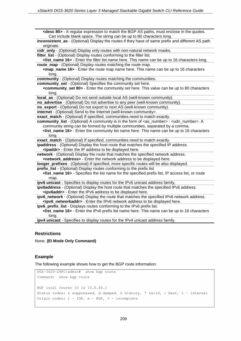
xStack® DGS-3620 Series Layer 3 Managed Stackable Gigabit Switch CLI Reference Guide
209
<desc 80> - A regular expression to match the BGP AS paths, must enclose in the quotes. Can include blank space. The string can be up to 80 characters long.
inconsistent_as - (Optional) Display the routes if they have of same prefix and different AS path originate.
cidr_only - (Optional) Display only routes with non-natural network masks. filter_list - (Optional) Display routes conforming to the filter list.
<list_name 16> - Enter the filter list name here. This name can be up to 16 characters long. route_map - (Optional) Display routes matching the route map.
<map_name 16> - Enter the route map name here. This name can be up to 16 characters long.
community - (Optional) Display routes matching the communities. community_set - (Optional) Specifies the community set here.
<community_set 80> - Enter the community set here. This value can be up to 80 characters long.
local_as - (Optional) Do not send outside local AS (well-known community). no_advertise - (Optional) Do not advertise to any peer (well-known community). no_export - (Optional) Do not export to next AS (well-known community). internet - (Optional) Send to the Internet (well-known community>. exact_match - (Optional) If specified, communities.need to match exactly. community_list - (Optional) A community is in the form of <as_number> : <udn_number>. A
community string can be formed by multiple communities, separated by a comma. <list_name 16> - Enter the community list name here. This name can be up to 16 characters
long. exact_match - (Optional) If specified, communities.need to match exactly. ipaddress - (Optional) Display the host route that matches the specified IP address.
<ipaddr> - Enter the IP address to be displayed here. network - (Optional) Display the route that matches the specified network address.
<network_address> - Enter the network address to be displayed here. longer_prefixes - (Optional) If specified, more specific routes will be also displayed. prefix_list - (Optional) Display routes conforming to the prefix list
<list_name 16> - Specifies the list name for the specified prefix list, IP access list, or route map.
ipv6 unicast - Specifies to display routes for the IPv6 unicast address family. ipv6address - (Optional) Display the host route that matches the specified IPv6 address.
<ipv6addr> - Enter the IPv6 address to be displayed here. ipv6_network - (Optional) Display the route that matches the specified IPv6 network address.
<ipv6_networkaddr> - Enter the IPv6 network address to be displayed here. ipv6_prefix_list - Displays routes conforming to the IPv6 prefix list.
<list_name 16> - Enter the IPv6 prefix list name here. This name can be up to 16 characters long.
ipv4 unicast - Specifies to display routes for the IPv4 unicast address family.
Restrictions None. (EI Mode Only Command)
Example The following example shows how to get the BGP route information:
DGS-3620-28PC:admin# show bgp route
Command: show bgp route
BGP local router ID is 10.0.40.1
Status codes: s suppressed, d damped, h history, * valid, > best, i - internal
Origin codes: i - IGP, e - EGP, ? – incomplete

xStack® DGS-3620 Series Layer 3 Managed Stackable Gigabit Switch CLI Reference Guide
210
Network Gateway Metric LocPrf Weight Path
*> 10.10.10.0/24 172.16.10.1 0 0 300 10 i
*> 10.10.20.0/24 172.16.10.1 0 0 300 10 i
* 10.20.10.0/24 172.16.10.1 0 0 300 10 i
*dh 30.10.1.1/24 172.3.3.2 100 50 200 20 i
Total Entries :4
DGS-3620-28PC:admin# show bgp route cidr_only
Command: show bgp route cidr_only
BGP local router ID is 172.16.73.131
Status codes: s suppressed, d damped, h history, * valid, > best, i - internal
Origin codes: i - IGP, e - EGP, ? – incomplete
Network Gateway Metric LocPrf Weight Path
*> 192.0.0.0/8 172.16.72.24 0 1878 200 ?
*> 172.16.0.0/14 172.16.72.30 0 108 200 ?
Total Entries :2
DGS-3620-28PC:admin# show bgp route community_list communitylist
Command: show bgp route community_list ommunitylist
BGP local router ID is 192.168.32.1
Status codes: s suppressed, d damped, h history, * valid, > best, i - internal
Origin codes: i - IGP, e - EGP, ? – incomplete
Network Gateway Metric LocPrf Weight Path
* i10.3.0.0/16 10.0.22.1 0 100 1800 1239 ?
*>i10.3.0.0/16 10.0.16.1 0 100 1800 1239 ?
* i10.6.0.0/16 10.0.22.1 0 100 1800 690 568 ?
Total Entries :3
DGS-3620-28PC:admin# show bgp route filter_list filter_list_one
Command: show bgp route filter_list filter_list_one
BGP local router ID is 172.16.72.24
Status codes: s suppressed, d damped, h history, * valid, > best, i - internal
Origin codes: i - IGP, e - EGP, ? – incomplete
Network Gateway Metric LocPrf Weight Path
* 172.16.0.0/24 172.16.72.30 0 109 108 ?
* 172.16.1.0/24 172.16.72.30 0 109 108 ?
* 172.16.11.0/24 172.16.72.30 0 109 108 ?
* 172.16.14.0/24 172.16.72.30 0 109 108 ?
* 172.16.15.0/24 172.16.72.30 0 109 108 ?
* 172.16.16.0/24 172.16.72.30 0 109 108 ?

xStack® DGS-3620 Series Layer 3 Managed Stackable Gigabit Switch CLI Reference Guide
211
Total Entries :6
DGS-3620-28PC:admin# show bgp route regexp “108$”
Command: show bgp route regexp “108$”
BGP local router ID is 172.16.72.24
Status codes: s suppressed, d damped, h history, * valid, > best, i - internal
Origin codes: i - IGP, e - EGP, ? – incomplete
Network Gateway Metric LocPrf Weight Path
s 172.16.0.0/24 172.16.72.30 0 109 108 ?
s 172.16.0.0/24 172.16.72.31 0 109 108 ?
* 172.16.1.0/24 172.16.72.30 0 109 108 ?
* 172.16.11.0/24 172.16.72.30 0 109 108 ?
* 172.16.14.0/24 172.16.72.30 0 109 108 ?
* 172.16.15.0/24 172.16.72.30 0 109 108 ?
* 172.16.16.0/24 172.16.72.30 0 109 108 ?
Total Entries :7
DGS-3620-28PC:admin# show bgp route inconsistent_as
Command: show bgp route inconsistent_as
BGP local router ID is 172.16.72.24
Status codes: s suppressed, d damped, h history, * valid, > best, i - internal
Origin codes: i - IGP, e - EGP, ? – incomplete
Network Gateway Metric LocPrf Weight Path
* 172.16.1.0/24 172.16.72.30 0 109 108 i
172.16.72.21 0 110 101 i
* 172.16.11.0/24 172.16.72.30 0 109 108 i
172.16.72.10 0 104 105 i
172.16.72.10 0 104 103 i
Total Entries :2
DGS-3620-28PC:admin# show bgp route network 2.2.2.0/24
Command: show bgp route network 2.2.2.0/24
BGP routing table entry for 2.2.2.0/24
Paths:(1 available, best #1, table: Default_IP_Routing_Table.)
Not advertised to any peer.
as path is:Local
next hop is:0.0.0.0 ,from 0.0.0.0 (local router_id is:192.168.1.1)
origin IGP, metric 100, localpref 0, weight 32768, sourced, best
Community: no_advertise
DGS-3620-28PC:admin#

xStack® DGS-3620 Series Layer 3 Managed Stackable Gigabit Switch CLI Reference Guide
212
12-45 show bgp neighbors Description This command is used to display BGP and TCP connections with the BGP neighbor or routing table entries containing a BGP neighbor. To display BGP and TCP connection information for neighbor sessions, or routing table entries with BGP neighbor. For BGP, this includes detailed neighbor attribute, capability, path, and prefix information. For TCP, this includes statistics related to BGP neighbor session establishment and maintenance. If both the IPv4 unicast and IPv6 unicast are not specified, information for the IPv4 unicast will be displayed.
Format show bgp neighbors {[<ipaddr> | <ipv6addr>] {[{[ipv4 | ipv6] unicast} [advertised_routes | received_routes | routes | received_prefix_filter] | statistics]}}
Parameters neighbors - Detailed information about TCP and BGP neighbor connections.
<ipaddr> - (Optional) Enter the IPv4 address used for the configuration here. <ipv6addr> - (Optional) Enter the IPv6 address used for the configuration here.
ipv4 unicast - (Optional) Specifies to display routes for the IPv4 unicast address family. ipv6 unicast - (Optional) Specifies to display routes for the IPv6 unicast address family. advertised_routes - (Optional) Displays the routes advertised to a BGP neighbor. received_routes - (Optional) Displays the routes received from this neighbor. routes - (Optional) Displays routes in the routing table learned from the neighbor. received_prefix_filter - (Optional) Displays the prefix filter information that is received from a
BGP neighbor. statistics - (Optional) Displays the statistical information learned.
Restrictions None. (EI Mode Only Command)
Example To show the BGP neighbor or routes relative to one neighbor:
DGS-3620-28PC:admin# show bgp neighbor 10.10.10.2
Command: show bgp neighbors 10.10.10.2
BGP neighbor: 10.10.10.2 (Internal Peer)
-----------------------------------------------
Session State : Enabled
Remote AS : 1111
Remote Router ID : 3.3.3.3
BGP State : Established (UP for 00:19:12)
Hold Time : 9 Seconds
Keepalive Interval : 3 Seconds
Advertisement Interval : 5 Seconds
AS Origination Interval : 15 Seconds
Connect Retry Interval : 120 Seconds
EBGP Multihop : 255
Weight : 0

xStack® DGS-3620 Series Layer 3 Managed Stackable Gigabit Switch CLI Reference Guide
213
For Address Family IPv4 Unicast
IPv4 Unicast : Advertised and Received
Next Hop Self : Disabled
Remove Private As : Disabled
AllowAS In : Disabled
Soft Reconfiguration Inbound : Disabled
Send Community : None
Default Originate : Disabled
Outbound Route Filter (ORF) type (64) Prefix list:
Send Mode : Disabled
Receive Mode : Disabled
Prefix Max Count : 12000
Prefix Warning Threshold : 75
Prefix Warning Only : Disabled
DGS-3620-28PC:admin# show bgp neighbor 172.16.232.178 advertised_routes
Command: show bgp neighbor 172.16.232.178 advertised_routes
BGP local router ID is 172.16.232.181
Status codes: s suppressed, d damped, h history, * valid, > best, i - internal
Origin codes: i - IGP, e - EGP, ? - incomplete
Network Gateway Metric LocPrf Weight Path
*>i 10.0.0.0/24 172.16.232.179 0 100 0 ?
*> 10.20.2.0/24 0.0.0.0 0 32768 i
Total Entries :2
DGS-3620-28PC:admin# show bgp neighbor 172.16.232.178 received_routes
Command: show bgp neighbor 172.16.232.178 received_routes
BGP local router ID is 172.16.232.181
Status codes: s suppressed, d damped, h history, * valid, > best, i - internal
Origin codes: i - IGP, e - EGP, ? - incomplete
Network Gateway Metric LocPrf Weight Path
*>i10.0.0.0/24 172.16.232.179 0 100 0 ?
*> 10.20.2.0/24 0.0.0.0 0 32768 i
Total Entries :2
DGS-3620-28PC:admin# show bgp neighbors 172.16.232.178 received_prefix_filter
Command: show bgp neighbors 172.16.232.178 received_prefix_filter
Ip prefix-list 172.16.232.181: 1 entries
Seq 5 deny 10.0.0.0/8 le 32
Total Entries :1
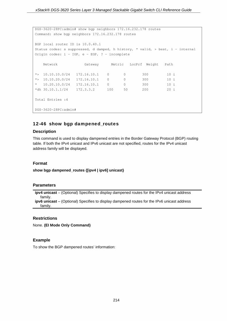
xStack® DGS-3620 Series Layer 3 Managed Stackable Gigabit Switch CLI Reference Guide
214
DGS-3620-28PC:admin# show bgp neighbors 172.16.232.178 routes
Command: show bgp neighbors 172.16.232.178 routes
BGP local router ID is 10.0.40.1
Status codes: s suppressed, d damped, h history, * valid, > best, i - internal
Origin codes: i - IGP, e - EGP, ? – incomplete
Network Gateway Metric LocPrf Weight Path
*> 10.10.10.0/24 172.16.10.1 0 0 300 10 i
*> 10.10.20.0/24 172.16.10.1 0 0 300 10 i
* 10.20.10.0/24 172.16.10.1 0 0 300 10 i
*dh 30.10.1.1/24 172.3.3.2 100 50 200 20 i
Total Entries :4
DGS-3620-28PC:admin#
12-46 show bgp dampened_routes Description This command is used to display dampened entries in the Border Gateway Protocol (BGP) routing table. If both the IPv4 unicast and IPv6 unicast are not specified, routes for the IPv4 unicast address family will be displayed.
Format show bgp dampened_routes {[ipv4 | ipv6] unicast}
Parameters ipv4 unicast – (Optional) Specifies to display dampened routes for the IPv4 unicast address
family. ipv6 unicast – (Optional) Specifies to display dampened routes for the IPv6 unicast address
family.
Restrictions None. (EI Mode Only Command)
Example To show the BGP dampened routes’ information:
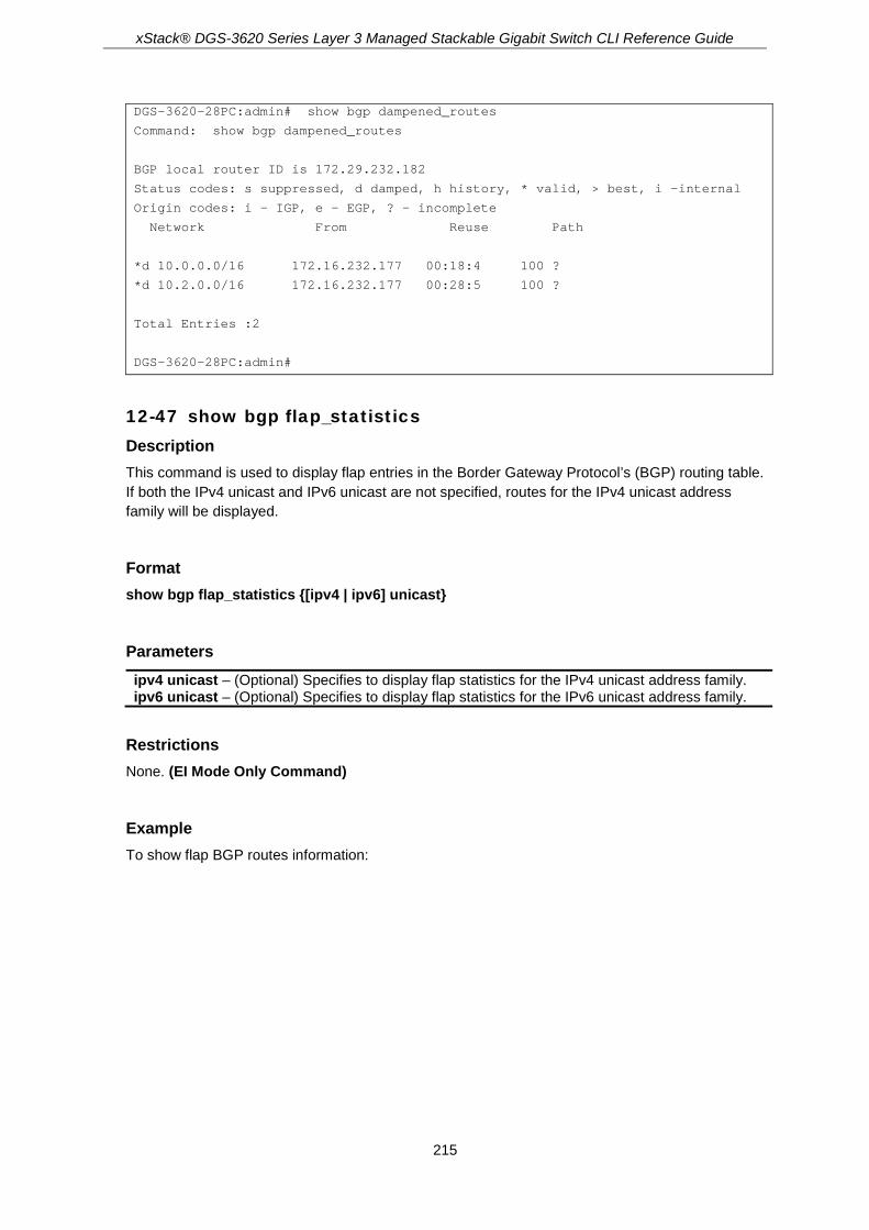
xStack® DGS-3620 Series Layer 3 Managed Stackable Gigabit Switch CLI Reference Guide
215
DGS-3620-28PC:admin# show bgp dampened_routes
Command: show bgp dampened_routes
BGP local router ID is 172.29.232.182
Status codes: s suppressed, d damped, h history, * valid, > best, i -internal
Origin codes: i - IGP, e - EGP, ? - incomplete
Network From Reuse Path
*d 10.0.0.0/16 172.16.232.177 00:18:4 100 ?
*d 10.2.0.0/16 172.16.232.177 00:28:5 100 ?
Total Entries :2
DGS-3620-28PC:admin#
12-47 show bgp flap_statistics Description This command is used to display flap entries in the Border Gateway Protocol’s (BGP) routing table. If both the IPv4 unicast and IPv6 unicast are not specified, routes for the IPv4 unicast address family will be displayed.
Format show bgp flap_statistics {[ipv4 | ipv6] unicast}
Parameters ipv4 unicast – (Optional) Specifies to display flap statistics for the IPv4 unicast address family. ipv6 unicast – (Optional) Specifies to display flap statistics for the IPv6 unicast address family.
Restrictions None. (EI Mode Only Command)
Example To show flap BGP routes information:

xStack® DGS-3620 Series Layer 3 Managed Stackable Gigabit Switch CLI Reference Guide
216
DGS-3620-28PC:admin# show bgp flap_statistics
Command:show bgp flap_statistics
BGP local router ID is 172.29.232.182
Status codes: s suppressed, d damped, h history, * valid, > best, i –internal
Origin codes: i - IGP, e - EGP, ? – incomplete
Network From Flaps Duration Reuse Path
*d 10.0.0.0/16 172.29.232.177 4 00:13:31 00:18:10 100 ?
*d 10.2.0.0/16 172.29.232.177 4 00:02:45 00:28:20 100 i
Total Entries :2
DGS-3620-28PC:admin#
12-48 show bgp Description This command is used to display BGP configuration and summary of the BGP status. If both the IPv4 unicast and IPv6 unicast are not specified, summary information for the IPv4 unicast address family will be displayed.
Format show bgp {summary {[ipv4 | ipv6 ] unicast}}
Parameters summary - (Optional) Specifies that the summary of the BGP status will be included in the
display. ipv4 unicast - Specifies to display summary information for IPv4 unicast. ipv6 unicast - Specifies to display summary information for IPv6 unicast.
Restrictions None. (EI Mode Only Command)
Example This example displays the BGP setting:
DGS-3620-28PC:admin# show bgp
Command: show bgp
BGP Global State : Disabled
Version : 4
BGP Router Identifier : 10.90.90.90
Synchronization : Enabled
Enforce First AS : Enabled
Local AS number : 100
Scan Time : 60
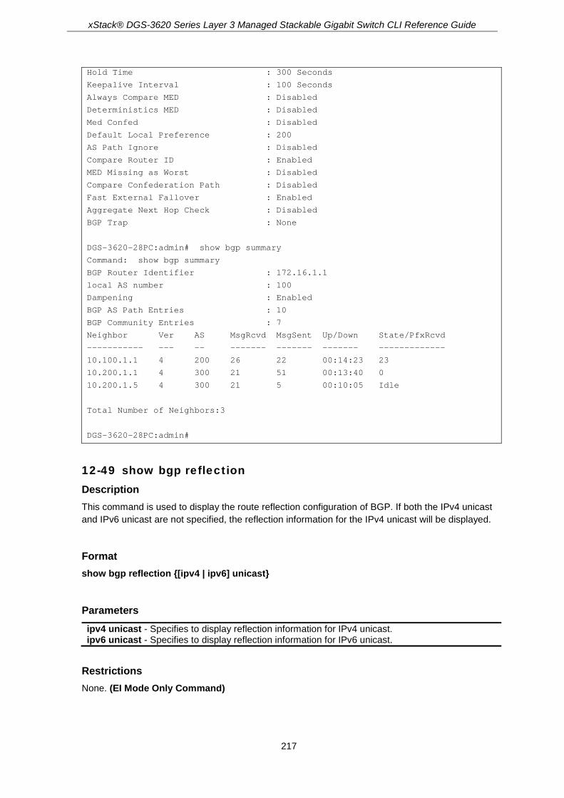
xStack® DGS-3620 Series Layer 3 Managed Stackable Gigabit Switch CLI Reference Guide
217
Hold Time : 300 Seconds
Keepalive Interval : 100 Seconds
Always Compare MED : Disabled
Deterministics MED : Disabled
Med Confed : Disabled
Default Local Preference : 200
AS Path Ignore : Disabled
Compare Router ID : Enabled
MED Missing as Worst : Disabled
Compare Confederation Path : Disabled
Fast External Fallover : Enabled
Aggregate Next Hop Check : Disabled
BGP Trap : None
DGS-3620-28PC:admin# show bgp summary
Command: show bgp summary
BGP Router Identifier : 172.16.1.1
local AS number : 100
Dampening : Enabled
BGP AS Path Entries : 10
BGP Community Entries : 7
Neighbor Ver AS MsgRcvd MsgSent Up/Down State/PfxRcvd
----------- --- -- ------- ------- ------- -------------
10.100.1.1 4 200 26 22 00:14:23 23
10.200.1.1 4 300 21 51 00:13:40 0
10.200.1.5 4 300 21 5 00:10:05 Idle
Total Number of Neighbors:3
DGS-3620-28PC:admin#
12-49 show bgp reflection Description This command is used to display the route reflection configuration of BGP. If both the IPv4 unicast and IPv6 unicast are not specified, the reflection information for the IPv4 unicast will be displayed.
Format show bgp reflection {[ipv4 | ipv6] unicast}
Parameters ipv4 unicast - Specifies to display reflection information for IPv4 unicast. ipv6 unicast - Specifies to display reflection information for IPv6 unicast.
Restrictions None. (EI Mode Only Command)

xStack® DGS-3620 Series Layer 3 Managed Stackable Gigabit Switch CLI Reference Guide
218
Example This example displays the BGP reflection setting:
DGS-3620-28PC:admin# show bgp reflection
Command: show bgp reflection
Client to Client Reflection State : Disabled
Cluster ID : 0.0.0.0
Router Reflector Client:
10.1.1.20
10.1.1.30
DGS-3620-28PC:admin#
12-50 show bgp confederation Description This command is used to display the confederation configuration of BGP.
Format show bgp confederation
Parameters None.
Restrictions None. (EI Mode Only Command)
Example This example displays the BGP confederation setting:
DGS-3620-28PC:admin# show bgp confederation
Command: show bgp confederation
BGP as number : 65501
Confederation identifier : 10
Confederation Peer : 65502,65503
Neighbor list:
IP address Remote AS number
--------------- --------------------
192.168.1.1 65502
192.168.1.2 65503
192.168.1.3 65501
DGS-3620-28PC:admin#

xStack® DGS-3620 Series Layer 3 Managed Stackable Gigabit Switch CLI Reference Guide
219
12-51 config bgp trap Description This command is used to configure the BGP trap state.
Format config bgp trap [peer_established | peer_idle | all] [enable | disable]
Parameters peer_established - Enable or disable the sending of the peer established trap. This default value
is disabled. peer_idle - Enable or disable the sending of the peer idle trap. This default value is disabled. all - Enable or disable the sending of both the peer idle and established trap. This default value is
disabled. enable - Specifies that the trap feature will be enabled. disable - Specifies that the trap feature will be disabled.
Restrictions Only Administrators, Operators and Power-Users can issue this command. (EI Mode Only Command)
Example This example disables the BGP peer idle trap state:
DGS-3620-28PC:admin# config bgp trap peer_idle disable
Command: config bgp trap peer_idle disable
Success.
DGS-3620-28PC:admin#
12-52 show bgp trap_state Description This command is used to show the BGP trap state.
Format show bgp trap_state
Parameters None.
Restrictions None. (EI Mode Only Command)

xStack® DGS-3620 Series Layer 3 Managed Stackable Gigabit Switch CLI Reference Guide
220
Example This example displays the BGP trap state:
DGS-3620-28PC:admin# show bgp trap_state
Command: show bgp trap_state
BGP Trap State :
BGP Peer Established : Enabled
BGP Peer Idle : Enabled
DGS-3620-28PC:admin#
12-53 config bgp scan_timer Description This command is used to configure the BGP scan timer value. BGP will check the next hop whether it is reachable from the BGP route before the timer expires.
Format config bgp scan_timer [<sec 5-60> | default]
Parameters <sec 5-60> - Set the BGP scan timer value from 5 to 60 seconds. Default is 60 seconds default - Set the BGP scan timer to the default value.
Restrictions Only Administrators, Operators and Power-Users can issue this command. (EI Mode Only Command)
Example This example configures the BGP scan timer to 30 seconds:
DGS-3620-28PC:admin# config bgp scan_timer 30
Command: config bgp scan_timer 30
Success.
DGS-3620-28PC:admin#
12-54 config bgp aggregate_next_hop_check Description This command is used to configure the BGP aggregated routes’ next hop check. Only the routes with the same next hop attribute can be aggregated if the BGP aggregate next hop check is enabled.

xStack® DGS-3620 Series Layer 3 Managed Stackable Gigabit Switch CLI Reference Guide
221
Format config bgp aggregate_next_hop_check [enable | disable]
Parameters enable - Specifies that the BGP aggregate next hop check will be enabled. disable - Specifies that the BGP aggregate next hop check will be disabled.
Restrictions Only Administrators, Operators and Power-Users can issue this command. (EI Mode Only Command)
Example This is an example of configuring the BGP aggregate next hop check:
DGS-3620-28PC:admin# config bgp aggregate_next_hop_check enable
Command: config bgp aggregate_next_hop_check enable
Success.
DGS-3620-28PC:admin#
12-55 config bgp fast_external_fallover Description This command configures a Border Gateway Protocol (BGP) routing process to immediately reset its external BGP peer sessions if the link used to reach these peers goes down,
Format config bgp fast_external_fallover [enable | disable]
Parameters enable - To enable BGP fast external fallover flag. Default is enabled. disable - To disable BGP fast external fallover.
Restrictions Only Administrators, Operators and Power-Users can issue this command. (EI Mode Only Command)
Example This example disables BGP fast external fallver:

xStack® DGS-3620 Series Layer 3 Managed Stackable Gigabit Switch CLI Reference Guide
222
DGS-3620-28PC:admin# config bgp fast_external_fallover disable
Command: config bgp fast_external_fallover disable
Success.
DGS-3620-28PC:admin#
12-56 config bgp neighbor maximum_prefix Description This command is used to configure the BGP neighbor maximum prefix.
Format config bgp neighbor maximum_prefix [<ipaddr> | <ipv6addr> | peer_group <peer_group_name 16>] [<value 1-12000> {<value 1-100>} {warning_only} | ipv4 unicast <value 1-12000> {<value 1-100>} {warning_only} | ipv6 unicast <value 1-6000> {<value 1-100>} {warning_only}]
Parameters <ipaddr> - Specifies the IPv4 address of the neighbor to be configured. <ipv6addr> - Specifies the IPv6 address of the neighbor to be configured. peer_group - Specifies the peer group to be configured.
<peer_group_name 16> - Enter the peer group name here. This name can be up to 16 characters long.
<value 1-12000> - Maximum number of prefixes allowed from the specified neighbor. The default is 12000.
<value 1-100> - (Optional) Integer specifying at what percentage the maximum prefix limit that the router starts to generate a warning message. The range is from 1 to 100; the default is 75.
warning_only - (Optional) Allows the router to generate a log message when the maximum prefix limit is exceeded, instead of terminating the peering session.
ipv4 unicast - Specifies to configure the IPv4 unicast address family. ipv6 unicast - Specifies to configure the IPv6 unicast address family.
Restrictions Only Administrators, Operators and Power-Users can issue this command. (EI Mode Only Command)
Example This example sets the maximum number of prefixes that will be accepted from the neighbor 192.168.1.1 to 5000, when 50 percent of the maximum prefix limit has been reached. This will display a warning message:
DGS-3620-28PC:admin# config bgp neighbor maximum_prefix 192.168.1.1 5000 50
Command: config bgp neighbor maximum_prefix 192.168.1.1 5000 50
Success.
DGS-3620-28PC:admin#

xStack® DGS-3620 Series Layer 3 Managed Stackable Gigabit Switch CLI Reference Guide
223
12-57 clear bgp flap_statistics Description The command is used to clear the accumulated penalties for routes that have been received on a router that has BGP dampening enabled. If no IP/IPv6 address or IP/IPv6 network are specified, flap statistics of the IPv4 unicast or IPv6 unicast address family are cleared for all routes. If both the IPv4 unicast and IPv6 unicast are not specified, flap statistics of IPv4 unicast are cleared.
Format clear bgp flap_statistics {[ipv4 unicast {[<ipaddr> | <network_address>]} | [<ipaddr> | <network_address>] | ipv6 unicast {[<ipv6addr> | <ipv6_networkaddr>]}]}
Parameters ipv4 unicast – (Optional) Specifies to clear the dampening information for the IPv4 unicast
address family. <ipaddr> - Enter the IPv4 address used here. <network_address> - Enter the IPv4 network address here.
ipv6 unicast – (Optional) Specifies to clear the dampening information for the IPv6 unicast address family. <ipv6addr> - Enter the IPv6 address used here. <ipv6_networkaddr> - Enter the IPv6 network address here.
Restrictions Only Administrators, Operators and Power-Users can issue this command. (EI Mode Only Command)
Example This is an example to clear the route dampening flap statistics of network 192.168.1.0/24:
DGS-3620-28PC:admin# clear bgp flap_statistics 192.168.1.0/24
Command: clear bgp flap_statistics 192.168.1.0/24
Success.
DGS-3620-28PC:admin#

xStack® DGS-3620 Series Layer 3 Managed Stackable Gigabit Switch CLI Reference Guide
224
Chapter 13 BPDU Attack Protection Commands
config bpdu_protection ports [<portlist> | all] {state [enable | disable] | mode [drop | block |
shutdown]}(1) config bpdu_protection recovery_timer [<sec 60-1000000> | infinite] config bpdu_protection [trap | log] [none | attack_detected | attack_cleared | both] enable bpdu_protection disable bpdu_protection show bpdu_protection {ports {<portlist>}}
13-1 config bpdu_protection ports Description This command is used to configure port state and mode for BPDU protection.
Format config bpdu_protection ports [<portlist> | all] {state [enable | disable] | mode [drop | block | shutdown]} (1)
Parameters <portlist> - Enter a range of ports to be configured. all - Specifies to set all ports in the system. state - Specifies the BPDU protection state. The default state is disabled.
enable - Enable the BPDU protection state. disable - Disable the BPDU protection state.
mode - Specifies the BPDU protection mode. The default mode is shutdown. drop - Specifies to drop all received BPDU packets when the port enters the under attack
state. block - Specifies to drop all packets (include BPDU and normal packets) when the port enters
the under attack state. shutdown- Specifies to shut down the port when the port enters the under attack state.
Note: Only shutdown mode will make port link down, If the port status is Err-disabled but port link is up, please check “show ports err-disabled” command for the reason.
Restrictions Only Administrators, Operators and Power-Users can issue this command.
Example To configure port state to enable and drop mode:

xStack® DGS-3620 Series Layer 3 Managed Stackable Gigabit Switch CLI Reference Guide
225
DGS-3620-28PC:admin#config bpdu_protection ports 1 state enable mode drop
Command: config bpdu_protection ports 1 state enable mode drop
Success.
DGS-3620-28PC:admin#
13-2 config bpdu_protection recovery_timer Description When a port enters the under attack state, it can be disabled or blocked based on the configuration. The state can be recovered manually or by the auto recovery mechanism. This command is used to configure the auto-recovery timer. To manually recover the port, the user needs to disable and re-enable the port.
Format config bpdu_protection recovery_timer [<sec 60-1000000> | infinite]
Parameters <sec 60-1000000> - Enter the timer (in seconds) used by the Auto-recovery mechanism to
recover the port. The valid range is 60 to 1000000. Auto-recovery time is 60 seconds by default.
infinite - Specifies the port will not be auto recovered.
Restrictions Only Administrators, Operators and Power-Users can issue this command.
Example To configure the BPDU protection recovery timer to 120 seconds for the entire switch:
DGS-3620-28PC:admin#config bpdu_protection recovery_timer 120
Command: config bpdu_protection recovery_timer 120
Success.
DGS-3620-28PC:admin#
13-3 config bpdu_protection Description This command is used to configure the BPDU protection trap state or log state.
Format config bpdu_protection [trap | log] [none | attack_detected | attack_cleared | both]

xStack® DGS-3620 Series Layer 3 Managed Stackable Gigabit Switch CLI Reference Guide
226
Parameters trap - Specifies the trap state. log - Specifies the log state. none - Specifies neither attack_detected nor attack_cleared is trapped or logged. attack_detected - Specifies events will be logged or trapped when the BPDU attacks is detected. attack_cleared - Specifies events will be logged or trapped when the BPDU attacks is cleared. both - Specifies the events of attack_detected and attack_cleared shall be trapped or logged.
Restrictions Only Administrators, Operators and Power-Users can issue this command.
Example To configure the BPDU protection trap state as both for the entire switch:
DGS-3620-28PC:admin#config bpdu_protection trap both
Command: config bpdu_protection trap both
Success.
DGS-3620-28PC:admin#
13-4 enable bpdu_protection Description This command is used to enable BPDU protection globally for the entire switch.
Format enable bpdu_protection
Parameters None.
Restrictions Only Administrators, Operators and Power-Users can issue this command.
Example To enable BPDU protection for the entire switch:
DGS-3620-28PC:admin#enable bpdu_protection
Command: enable bpdu_protection
Success.
DGS-3620-28PC:admin#

xStack® DGS-3620 Series Layer 3 Managed Stackable Gigabit Switch CLI Reference Guide
227
13-5 disable bpdu_protection Description This command is used to disable BPDU protection globally for the entire switch.
Format disable bpdu_protection
Parameters None.
Restrictions Only Administrators, Operators and Power-Users can issue this command.
Example To disable BPDU protection:
DGS-3620-28PC:admin#disable bpdu_protection
Command: disable bpdu_protection
Success.
DGS-3620-28PC:admin#
13-6 show bpdu_protection Description This command is used to display BPDU protection global configuration or per port configuration and current status.
Format show bpdu_protection {ports {<portlist>}}
Parameters ports - (Optional) Specifies all ports to be displayed.
<portlist> - (Optional) Specifies a range of ports to be displayed.
Restrictions None.
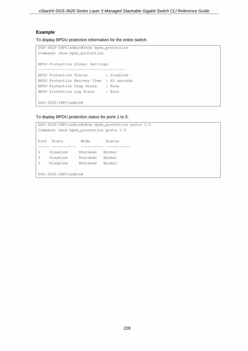
xStack® DGS-3620 Series Layer 3 Managed Stackable Gigabit Switch CLI Reference Guide
228
Example To display BPDU protection information for the entire switch:
DGS-3620-28PC:admin#show bpdu_protection
Command: show bpdu_protection
BPDU Protection Global Settings
---------------------------------------
BPDU Protection Status : Disabled
BPDU Protection Recover Time : 60 seconds
BPDU Protection Trap State : None
BPDU Protection Log State : Both
DGS-3620-28PC:admin#
To display BPDU protection status for ports 1 to 3:
DGS-3620-28PC:admin#show bpdu_protection ports 1-3
Command: show bpdu_protection ports 1-3
Port State Mode Status
----- ----------- ---------- -----------
1 Disabled Shutdown Normal
2 Disabled Shutdown Normal
3 Disabled Shutdown Normal
DGS-3620-28PC:admin#

xStack® DGS-3620 Series Layer 3 Managed Stackable Gigabit Switch CLI Reference Guide
229
Chapter 14 Cable Diagnostics Commands
cable_diag ports [<portlist> | all]
14-1 cable_diag ports Description This command is used to test copper cabling.
For 10/100Based-TX link speed RJ45 cables, two pairs of cables will be diagnosed.
For 1000Base-T link speed RJ45 cables, four pairs of cables will be diagnosed.
The type of cable errors can be open, short, or crosstalk.
• Open means that the cable in the error pair does not have a connection at the specified position.
• Short means that the cables in the error pair has a short problem at the specified position.
• Crosstalk means that the cable in the error pair has a crosstalk problem at the specified position.
For Gigabit Ethernet ports:
• Where the link partner is powered on with no errors and the link is up, this command can detect the cable length.
• Where the link partner is powered on with errors, this command can detect whether the error is open, short, or crosstalk. In this case this command can also detect the distance of the error.
• Where the link partner is powered down with no errors and the link is down, this command can detect the cable length.
• When the link partner is powered down with errors, this command can detect whether the error is open, short, or crosstalk. In this case this command can also detect the distance of the error.
• When there is no link partner with no errors, this command cannot detect the cable length.
• When there is no link partner with errors, this command can detect whether the error is open, short, or crosstalk. In this case this command can also detect the distance of the error.
The Cable length range that can be detected is as follows:
• Smaller than 50m (<50m)
• Between 50m and 80m (50m~80m)

xStack® DGS-3620 Series Layer 3 Managed Stackable Gigabit Switch CLI Reference Guide
230
• Between 80m and 100m (80m~100m)
• Greater than 100m (>100m)
Note: This test will consume a low number of packets. Since this test is for copper cable,
the port with fiber cable will be skipped from the test.
Format cable_diag ports [<portlist> | all]
Parameters <portlist> - Enter a range of ports to be configured. all – Specifies to set all ports in the system.
Restrictions None.
Example To test the cable on ports 1 to 4, and 8:

xStack® DGS-3620 Series Layer 3 Managed Stackable Gigabit Switch CLI Reference Guide
231
DGS-3620-28PC:admin# cable_diag ports 1:1-1:10,1:21
Command: cable_diag ports 1:1-1:10,1:21
Perform Cable Diagnostics ...
Port Type Link Status Test Result Cable Length (M)
------ ---------- ------------- ---------------------------- ------------
1:1 1000BASE-T Link Up OK 65
1:2 1000BASE-T Link Up OK -
1:3 1000BASE-T Link Down Shutdown 25
1:4 1000BASE-T Link Down Shutdown -
1:5 1000BASE-T Link Down Unknown -
1:6 1000BASE-T Link Down Pair 1 Crosstalk at 30M -
Pair 2 Crosstalk at 30M
Pair 3 OK at 110M
Pair 4 OK at 110M
1:7 1000BASE-T Link Down NO Cable -
1:8 1000BASE-T Link Down Pair 1 Open at 16M -
Pair 2 Open at 16M
Pair 3 OK at 50M
Pair 4 OK at 50M
1:9 1000BASE-T Link Down Pair 1 Short at 5M -
Pair 2 Short at 5M
Pair 3 OK at 110M
Pair 4 OK at 110M
1:10 1000BASE-T Link Down Pair 1 Unknown -
Pair 2 Short at 5M
Pair 3 OK at 110M
Pair 4 OK at 110M
1:21 1000BASE-X Link Up Unknown -
DGS-3620-28PC:admin#
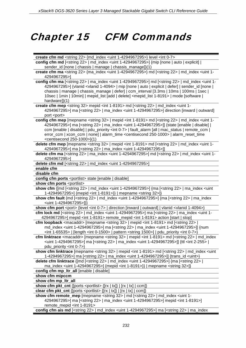
xStack® DGS-3620 Series Layer 3 Managed Stackable Gigabit Switch CLI Reference Guide
232
Chapter 15 CFM Commands
create cfm md <string 22> {md_index <uint 1-4294967295>} level <int 0-7> config cfm md [<string 22> | md_index <uint 1-4294967295>] {mip [none | auto | explicit] |
sender_id [none | chassis | manage | chassis_manage]}(1) create cfm ma <string 22> {ma_index <uint 1-4294967295>} md [<string 22> | md_index <uint 1-
4294967295>] config cfm ma [<string 22> | ma_index <uint 1-4294967295>] md [<string 22> | md_index <uint 1-
4294967295>] {vlanid <vlanid 1-4094> | mip [none | auto | explicit | defer] | sender_id [none | chassis | manage | chassis_manage | defer] | ccm_interval [3.3ms | 10ms | 100ms | 1sec | 10sec | 1min | 10min] | mepid_list [add | delete] <mepid_list 1-8191> | mode [software | hardware]}(1)
create cfm mep <string 32> mepid <int 1-8191> md [<string 22> | md_index <uint 1-4294967295>] ma [<string 22> | ma_index <uint 1-4294967295>] direction [inward | outward] port <port>
config cfm mep [mepname <string 32> | mepid <int 1-8191> md [<string 22> | md_index <uint 1-4294967295>] ma [<string 22> | ma_index <uint 1-4294967295>]] {state [enable | disable] | ccm [enable | disable] | pdu_priority <int 0-7> | fault_alarm [all | mac_status | remote_ccm | error_ccm | xcon_ccm | none] | alarm_time <centisecond 250-1000> | alarm_reset_time <centisecond 250-1000>}(1)
delete cfm mep [mepname <string 32> | mepid <int 1-8191> md [<string 22> | md_index <uint 1-4294967295>] ma [<string 22> | ma_index <uint 1-4294967295>]]
delete cfm ma [<string 22> | ma_index <uint 1-4294967295>] md [<string 22> | md_index <uint 1-4294967295>]
delete cfm md [<string 22> | md_index <uint 1-4294967295>] enable cfm disable cfm config cfm ports <portlist> state [enable | disable] show cfm ports <portlist> show cfm {[md [<string 22> | md_index <uint 1-4294967295>] {ma [<string 22> | ma_index <uint
1-4294967295>] {mepid <int 1-8191>}} | mepname <string 32>]} show cfm fault {md [<string 22> | md_index <uint 1-4294967295>] {ma [<string 22> | ma_index
<uint 1-4294967295>]}} show cfm port <port> {level <int 0-7> | direction [inward | outward] | vlanid <vlanid 1-4094>} cfm lock md [<string 22> | md_index <uint 1-4294967295>] ma [<string 22> | ma_index <uint 1-
4294967295>] mepid <int 1-8191> remote_mepid <int 1-8191> action [start | stop] cfm loopback <macaddr> [mepname <string 32> | mepid <int 1-8191> md [<string 22> |
md_index <uint 1-4294967295>] ma [<string 22> | ma_index <uint 1-4294967295>]] {num <int 1-65535> | [length <int 0-1500> | pattern <string 1500>] | pdu_priority <int 0-7>}
cfm linktrace <macaddr> [mepname <string 32> | mepid <int 1-8191> md [<string 22> | md_index <uint 1-4294967295>] ma [<string 22> | ma_index <uint 1-4294967295>]] {ttl <int 2-255> | pdu_priority <int 0-7>}
show cfm linktrace [mepname <string 32> | mepid <int 1-8191> md [<string 22> | md_index <uint 1-4294967295>] ma [<string 22> | ma_index <uint 1-4294967295>]] {trans_id <uint>}
delete cfm linktrace {[md [<string 22> | md_index <uint 1-4294967295>] {ma [<string 22> | ma_index <uint 1-4294967295>] {mepid <int 1-8191>}} | mepname <string 32>]}
config cfm mp_ltr_all [enable | disable] show cfm mipccm show cfm mp_ltr_all show cfm pkt_cnt {[ports <portlist> {[rx | tx]} | [rx | tx] | ccm]} clear cfm pkt_cnt {[ports <portlist> {[rx | tx]} | [rx | tx] | ccm]} show cfm remote_mep [mepname <string 32> | md [<string 22> | md_index <uint 1-
4294967295>] ma [<string 22> | ma_index <uint 1-4294967295>] mepid <int 1-8191>] remote_mepid <int 1-8191>
config cfm ais md [<string 22> | md_index <uint 1-4294967295>] ma [<string 22> | ma_index

xStack® DGS-3620 Series Layer 3 Managed Stackable Gigabit Switch CLI Reference Guide
233
<uint 1-4294967295>] mepid <int 1-8191> {period [1sec | 1min] | level <int 0-7> | state [enable | disable]}
config cfm lock md [<string 22> | md_index <uint 1-4294967295>] ma [<string 22> | ma_index <uint 1-4294967295>] mepid <int 1-8191> {period [1sec | 1min] | level <int 0-7> | state [enable | disable]}
config cfm trap [ais | lock] state [enable | disable] cfm dm <macaddr> [mepname <string 32> | mepid <int 1-8191> md [<string 22> | md_index <uint
1-4294967295>] ma [<string 22> | ma_index <uint 1-4294967295>]] {period:interval [100ms:1sec | 1sec:10sec | 10sec:1min] | percentile <int 0-100> | pdu_priority <int 0-7>}
cfm lm <macaddr> [mepname <string 32> | mepid <int 1-8191> md [<string 22> | md_index <uint 1-4294967295>] ma [<string 22> | ma_index <uint 1-4294967295>]] {period [100ms | 1sec | 10sec] | pdu_priority <int 0-7>}
clear cfm dm {[mepname <string 32> | mepid <int 1-8191> md [<string 22> | md_index <uint 1-4294967295>] ma [<string 22> | ma_index <uint 1-4294967295>]]} {[results | statistics]}
clear cfm lm {[mepname <string 32> | mepid <int 1-8191> md [<string 22> | md_index <uint 1-4294967295>] ma [<string 22> | ma_index <uint 1-4294967295>]]} {[results | statistics]}
config cfm dm [mepname <string 32> | mepid <int 1-8191> md [<string 22> | md_index <uint 1-4294967295>] ma [<string 22> | ma_index <uint 1-4294967295>]] state [enable | disable]
config cfm lm [mepname <string 32> | mepid <int 1-8191> md [<string 22> | md_index <uint 1-4294967295>] ma [<string 22> | ma_index <uint 1-4294967295>]] state [enable | disable]
show cfm dm [mepname <string 32> | mepid <int 1-8191> md [<string 22> | md_index <uint 1-4294967295>] ma [<string 22> | ma_index <uint 1-4294967295>]]
show cfm lm [mepname <string 32> | mepid <int 1-8191> md [<string 22> | md_index <uint 1-4294967295>] ma [<string 22> | ma_index <uint 1-4294967295>]]
15-1 create cfm md Description This command is used to create a CFM maintenance domain.
Format create cfm md <string 22> {md_index <uint 1-4294967295>} level <int 0-7>
Parameters <string 22> - Enter the maintenance domain name used here. This name can be up to 22
characters long. md_index - Specifies the maintenance domain index used.
<uint 1-4294967295> - Enter the maintenace domain index value used here. This value must be between 1 and 4294967295.
level - Specifies the maintenance domain level. <int 0-7> - Enter the maintenance domain level from 0 to 7.
Restrictions Only Administrators, Operators and Power-Users can issue this command. (EI Mode Only Command)
Example To create a CFM maintenance domain called “op_domain” and assign a maintenance domain level of “2”:
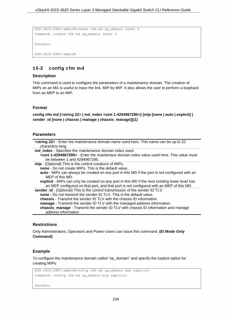
xStack® DGS-3620 Series Layer 3 Managed Stackable Gigabit Switch CLI Reference Guide
234
DGS-3620-28PC:admin#create cfm md op_domain level 2
Command: create cfm md op_domain level 2
Success.
DGS-3620-28PC:admin#
15-2 config cfm md Description This command is used to configure the parameters of a maintenance domain. The creation of MIPs on an MA is useful to trace the link, MIP by MIP. It also allows the user to perform a loopback from an MEP to an MIP.
Format config cfm md [<string 22> | md_index <uint 1-4294967295>] {mip [none | auto | explicit] | sender_id [none | chassis | manage | chassis_manage]}(1)
Parameters <string 22> - Enter the maintenance domain name used here. This name can be up to 22
characters long. md_index - Specifies the maintenance domain index used.
<uint 1-4294967295> - Enter the maintenace domain index value used here. This value must be between 1 and 4294967295.
mip - (Optional) This is the control creations of MIPs. none - Do not create MIPs. This is the default value. auto - MIPs can always be created on any port in this MD if the port is not configured with an
MEP of this MD. explicit - MIPs can only be created on any port in this MD if the next existing lower level has
an MEP configured on that port, and that port is not configured with an MEP of this MD. sender_id - (Optional) This is the control transmission of the sender ID TLV.
none - Do not transmit the sender ID TLV. This is the default value. chassis - Transmit the sender ID TLV with the chassis ID information. manage - Transmit the sender ID TLV with the managed address information. chassis_manage - Transmit the sender ID TLV with chassis ID information and manage
address information.
Restrictions Only Administrators, Operators and Power-Users can issue this command. (EI Mode Only Command)
Example To configure the maintenance domain called “op_domain” and specify the explicit option for creating MIPs:
DGS-3620-28PC:admin#config cfm md op_domain mip explicit
Command: config cfm md op_domain mip explicit
Success.

xStack® DGS-3620 Series Layer 3 Managed Stackable Gigabit Switch CLI Reference Guide
235
DGS-3620-28PC:admin#
15-3 create cfm ma Description This command is used to create a maintenance association. Different MAs in a MD must have different MA Names. Different MAs in different MDs may have the same MA Name.
Format create cfm ma <string 22> {ma_index <uint 1-4294967295>} md [<string 22> | md_index <uint 1-4294967295>]
Parameters <string 22> - Enter the maintenance association name used here. This name can be up to 22
characters long. ma_index - Specifies the maintenance association index used.
<uint 1-4294967295> - Enter the maintenance association index value used here. This value must be between 1 and 4294967295.
md - Specifies the maintenance domain name. <string 22> - Enter the maintenance domain name. The maximum length is 22 characters.
md_index - Specifies the maintenance domain index used. <uint 1-4294967295> - Enter the maintenance domain index value used here. This value
must be between 1 and 4294967295.
Restrictions Only Administrators, Operators and Power-Users can issue this command. (EI Mode Only Command)
Example To create a maintenance association called “op1” and assign it to the maintenance domain “op_domain”:
DGS-3620-28PC:admin#create cfm ma op1 md op_domain
Command: create cfm ma op1 md op_domain
Success.
DGS-3620-28PC:admin#
15-4 config cfm ma Description This command is used to configure the parameters of a maintenance association. The MEP list specified for an MA can be located in different devices. MEPs must be created on the ports of these devices explicitly. An MEP will transmit a CCM packet periodically across the MA. The receiving MEP will verify these received CCM packets from the other MEPs against this MEP list for the configuration integrity check.

xStack® DGS-3620 Series Layer 3 Managed Stackable Gigabit Switch CLI Reference Guide
236
Format config cfm ma [<string 22> | ma_index <uint 1-4294967295>] md [<string 22> | md_index <uint 1-4294967295>] {vlanid <vlanid 1-4094> | mip [none | auto | explicit | defer] | sender_id [none | chassis | manage | chassis_manage | defer] | ccm_interval [3.3ms | 10ms | 100ms | 1sec | 10sec | 1min | 10min] | mepid_list [add | delete] <mepid_list 1-8191> | mode [software | hardware]}(1)
Parameters <string 22> - Enter the maintenance association name. The maximum length is 22 characters. ma_index - Specifies the maintenance association index used.
<uint 1-4294967295> - Enter the maintenance association index value used here. This value must be between 1 and 4294967295.
md - Specifies the maintenance domain name. <string 22> - Enter the maintenance domain name. The maximum length is 22 characters.
md_index - Specifies the maintenance domain index used. <uint 1-4294967295> - Enter the maintenance domain index value used here. This value
must be between 1 and 4294967295. vlanid - (Optional) Specifies the VLAN Identifier. Different MAs must be associated with different
VLANs. <vlanid 1-4094> - Enter the VLAN ID between 1 and 4094.
mip - (Optional) This is the control creation of MIPs. none - Do not create MIPs. auto - MIPs can always be created on any port in this MA if that port is not configured with an
MEP of that MA. explicit - MIPs can be created on any ports in this MA only if the next existing lower level has
an MEP configured on that port, and that port is not configured with an MEP of this MA. defer - Inherit the setting configured for the maintenance domain that this MA is associated
with. This is the default value. sender_id - (Optional) This is the control transmission of the sender ID TLV.
none - Do not transmit the sender ID TLV. chassis - Transmit the sender ID TLV with the chassis ID information. manage - Transmit the sender ID TLV with the manage address information. chassis_manage - Transmit the sender ID TLV with the chassis ID information and the
manage address information. defer - Inherit the setting configured for the maintenance domain that this MA is associated
with. ccm_interval - (Optional) Specifies the CCM interval.
3.3ms - 3.3 milliseconds. Only work in CFM hardware mode. 10ms - 10 milliseconds. Only works in CFM hardware mode. 100ms - 100 milliseconds. Not recommended in CFM software mode. 1sec - One second. 10sec - Ten seconds. This is the default value. 1min - One minute. 10min - Ten minutes.
mepid_list - (Optional) Specifies the MEPIDs contained in the maintenance association. add - Add MEPID(s). delete - Delete MEPID(s).
<mepid_list 1-8191> - Enter the MEPIDs contained in the maintenance association. The range of the MEPID is 1 to 8191.
mode - (Optional) Specifies the mode of the MA. software - Specifies that the MA will work in the CFM software mode. This is the default
value. hardware - Specifies that the MA will work in the CFM hardware mode.

xStack® DGS-3620 Series Layer 3 Managed Stackable Gigabit Switch CLI Reference Guide
237
Restrictions Only Administrators, Operators and Power-Users can issue this command. (EI Mode Only Command)
Example To configure the parameters of a maintenance association:
DGS-3620-28PC:admin#config cfm ma op1 md op_domain vlanid 1 ccm_interval 1sec
Command: config cfm ma op1 md op_domain vlanid 1 ccm_interval 1sec
Success.
DGS-3620-28PC:admin#
15-5 create cfm mep Description This command is used to create an MEP entry. Different MEPs in the same MA must have a different MEPID. To put MD name, MA name, and MEPID together identifies an MEP. Different MEPs on the same device must have a different MEP name. Before creating an MEP, its MEPID should be configured in the MA’s MEPID list.
Format create cfm mep <string 32> mepid <int 1-8191> md [<string 22> | md_index <uint 1-4294967295>] ma [<string 22> | ma_index <uint 1-4294967295>] direction [inward | outward] port <port>
Parameters <string 32> - Enter the MEP name used here. It is unique among all MEPs configured on the
device. The name can be up to 32 characters long. mepid - Specifies the MEP MEPID. It should be configured in the MA’s MEPID list.
<int 1-8191> - Enter the MEP MEPID between 1 and 8191. md - Specifies the maintenance domain name.
<string 22> - Enter the maintenance domain name. The maximum length is 22 characters. md_index - Specifies the maintenance domain index.
<uint 1-4294967295> - Enter the maintenance domain index value here. This value must be between 1 and 4294967295.
ma - Specifies the maintenance association name. <string 22> - Enter the maintenance association name. The maximum length is 22
characters. ma_index - Specifies the maintenance association index.
<uint 1-4294967295> - Enter the maintenance association index value here. This value must be between 1 and 4294967295.
direction - Specifies the MEP direction. inward - Inward facing (up) MEP. outward - Outward facing (down) MEP.
port - Specifies the port number. This port should be a member of the MA’s associated VLAN. <port> - Enter a port.
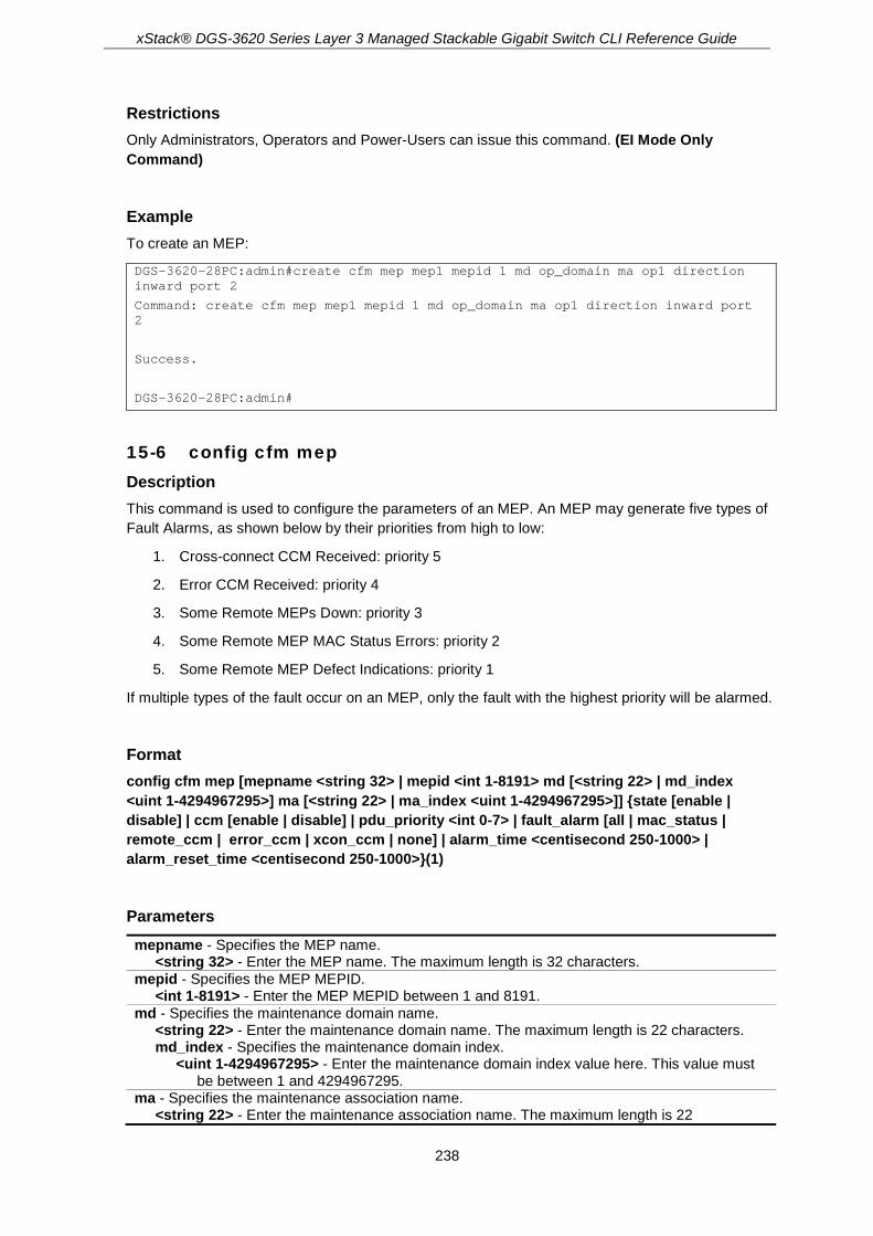
xStack® DGS-3620 Series Layer 3 Managed Stackable Gigabit Switch CLI Reference Guide
238
Restrictions Only Administrators, Operators and Power-Users can issue this command. (EI Mode Only Command)
Example To create an MEP:
DGS-3620-28PC:admin#create cfm mep mep1 mepid 1 md op_domain ma op1 direction inward port 2
Command: create cfm mep mep1 mepid 1 md op_domain ma op1 direction inward port 2
Success.
DGS-3620-28PC:admin#
15-6 config cfm mep Description This command is used to configure the parameters of an MEP. An MEP may generate five types of Fault Alarms, as shown below by their priorities from high to low:
1. Cross-connect CCM Received: priority 5
2. Error CCM Received: priority 4
3. Some Remote MEPs Down: priority 3
4. Some Remote MEP MAC Status Errors: priority 2
5. Some Remote MEP Defect Indications: priority 1
If multiple types of the fault occur on an MEP, only the fault with the highest priority will be alarmed.
Format config cfm mep [mepname <string 32> | mepid <int 1-8191> md [<string 22> | md_index <uint 1-4294967295>] ma [<string 22> | ma_index <uint 1-4294967295>]] {state [enable | disable] | ccm [enable | disable] | pdu_priority <int 0-7> | fault_alarm [all | mac_status | remote_ccm | error_ccm | xcon_ccm | none] | alarm_time <centisecond 250-1000> | alarm_reset_time <centisecond 250-1000>}(1)
Parameters mepname - Specifies the MEP name.
<string 32> - Enter the MEP name. The maximum length is 32 characters. mepid - Specifies the MEP MEPID.
<int 1-8191> - Enter the MEP MEPID between 1 and 8191. md - Specifies the maintenance domain name.
<string 22> - Enter the maintenance domain name. The maximum length is 22 characters. md_index - Specifies the maintenance domain index.
<uint 1-4294967295> - Enter the maintenance domain index value here. This value must be between 1 and 4294967295.
ma - Specifies the maintenance association name. <string 22> - Enter the maintenance association name. The maximum length is 22

xStack® DGS-3620 Series Layer 3 Managed Stackable Gigabit Switch CLI Reference Guide
239
characters. ma_index - Specifies the maintenance association index.
<uint 1-4294967295> - Enter the maintenance association index value here. This value must be between 1 and 4294967295.
state - Specifies the MEP administrative state. The default is disable. enable - Enable MEP. disable - Disable MEP.
ccm - Specifies the CCM transmission state. The default is disable. enable - Enable the CCM transmission. disable - Disable the CCM transmission.
pdu_priority - The 802.1p priority is set in the CCM and the LTM messages transmitted by the MEP. The default value is 7. <int 0-7> - Enter the value between 0 and 7.
fault_alarm - This is the control types of the fault alarms sent by the MEP. The default value is none. all - All types of fault alarms will be sent. mac_status - Only the fault alarms whose priority is equal to or higher than “Some Remote
MEP MAC Status Errors” are sent. remote_ccm - Only the fault alarms whose priority is equal to or higher than “Some Remote
MEPs Down” are sent. error_ccm - Only the fault alarms whose priority is equal to or higher than “Error CCM
Received” are sent. xcon_ccm - Only the fault alarms whose priority is equal to or higher than “Cross-connect
CCM Received” are sent. none - No fault alarm is sent.
alarm_time - Specifies the time that a defect must exceed before the fault alarm can be sent. The unit is centiseconds. The default value is 250. <centisecond 250-1000> - Enter the time that a defect must exceed before the fault alarm
can be sent. The unit is centiseconds. The range is 250 to 1000. alarm_reset_time - Specifies the dormant duration time before a defect is triggered before the
fault can be re-alarmed. The unit is centiseconds. The default value is 1000. <centisecond 250-1000> - Enter the dormant duration time before a defect is triggered before
the fault can be re-alarmed. The unit is centiseconds. The range is 250 to 1000.
Restrictions Only Administrators, Operators and Power-Users can issue this command. (EI Mode Only Command)
Example To configure the parameters of an MEP:
DGS-3620-28PC:admin#config cfm mep mepname mep1 state enable ccm enable
Command: config cfm mep mepname mep1 state enable ccm enable
Success.
DGS-3620-28PC:admin#
15-7 delete cfm mep Description This command is used to delete a previously created MEP.

xStack® DGS-3620 Series Layer 3 Managed Stackable Gigabit Switch CLI Reference Guide
240
Format delete cfm mep [mepname <string 32> | mepid <int 1-8191> md [<string 22> | md_index <uint 1-4294967295>] ma [<string 22> | ma_index <uint 1-4294967295>]]
Parameters mepname - Specifies the MEP name.
<string 32> - Enter the MEP name. The maximum length is 32 characters. mepid - Specifies the MEP MEPID.
<int 1-8191> - Enter the MEP MEPID between 1 and 8191. md - Specifies the maintenance domain name.
<string 22> - Enter the maintenance domain name. The maximum length is 22 characters. md_index - Specifies the maintenance domain index.
<uint 1-4294967295> - Enter the maintenance domain index value here. This value must be between 1 and 4294967295.
ma - Specifies the maintenance association name. <string 22> - Enter the maintenance association name. The maximum length is 22
characters. ma_index - Specifies the maintenance association index.
<uint 1-4294967295> - Enter the maintenance association index value here. This value must be between 1 and 4294967295.
Restrictions Only Administrators, Operators and Power-Users can issue this command. (EI Mode Only Command)
Example To delete a previously created MEP:
DGS-3620-28PC:admin#delete cfm mep mepname mep1
Command: delete cfm mep mepname mep1
Success.
DGS-3620-28PC:admin#
15-8 delete cfm ma Description This command is used to delete a created maintenance association.
Format delete cfm ma [<string 22> | ma_index <uint 1-4294967295>] md [<string 22> | md_index <uint 1-4294967295>]
Parameters <string 22> - Enter the maintenance association name. The maximum length is 22 characters. ma_index - Specifies the maintenance association index.

xStack® DGS-3620 Series Layer 3 Managed Stackable Gigabit Switch CLI Reference Guide
241
<uint 1-4294967295> - Enter the maintenance association index value here. This value must be between 1 and 4294967295.
md - Specifies the maintenance domain name. <string 22> - Enter the maintenance domain name. The maximum length is 22 characters. md_index - Specifies the maintenance domain index.
<uint 1-4294967295> - Enter the maintenance domain index value here. This value must be between 1 and 4294967295.
Restrictions Only Administrators, Operators and Power-Users can issue this command. (EI Mode Only Command)
Example To delete a created maintenance association:
DGS-3620-28PC:admin#delete cfm ma op1 md op_domain
Command: delete cfm ma op1 md op_domain
Success.
DGS-3620-28PC:admin#
15-9 delete cfm md Description This command is used to delete a previously created maintenance domain. When the command is executing, all the MEPs and maintenance associations created in the maintenance domain will be deleted automatically.
Format delete cfm md [<string 22> | md_index <uint 1-4294967295>]
Parameters <string 22> - Enter the maintenance domain name. The maximum length is 22 characters. md_index - Specifies the maintenance domain index.
<uint 1-4294967295> - Enter the maintenance domain index value here. This value must be between 1 and 4294967295.
Restrictions Only Administrators, Operators and Power-Users can issue this command. (EI Mode Only Command)
Example To delete a previously created maintenance domain:
DGS-3620-28PC:admin#delete cfm md op_domain
Command: delete cfm md op_domain

xStack® DGS-3620 Series Layer 3 Managed Stackable Gigabit Switch CLI Reference Guide
242
Success.
DGS-3620-28PC:admin#
15-10 enable cfm Description This command is used to enable the CFM globally.
Format enable cfm
Parameters None.
Restrictions Only Administrators, Operators and Power-Users can issue this command. (EI Mode Only Command)
Example To enable the CFM globally:
DGS-3620-28PC:admin#enable cfm
Command: enable cfm
Success.
DGS-3620-28PC:admin#
15-11 disable cfm Description This command is used to disable the CFM globally.
Format disable cfm
Parameters None.

xStack® DGS-3620 Series Layer 3 Managed Stackable Gigabit Switch CLI Reference Guide
243
Restrictions Only Administrators, Operators and Power-Users can issue this command. (EI Mode Only Command)
Example To disable the CFM globally:
DGS-3620-28PC:admin#disable cfm
Command: disable cfm
Success.
DGS-3620-28PC:admin#
15-12 config cfm ports Description This command is used to enable or disable the CFM function on a per-port basis. By default, the CFM function is disabled on all ports. If the CFM is disabled on a port:
• MIPs are never created on that port.
• MEPs can still be created on that port, and the configuration can be saved.
• MEPs created on that port can never generate or process CFM PDUs. If the user issues a Loopback or Link trace test on those MEPs, it will prompt the user to inform them that the CFM function is disabled on that port
Format config cfm ports <portlist> state [enable | disable]
Parameters <portlist> - Enter the logical port list. state - Specifies the CFM function status.
enable - Specifies to enable the CFM function. disable - Specifies to disable the CFM function.
Restrictions Only Administrators, Operators and Power-Users can issue this command. (EI Mode Only Command)
Example To enable the CFM function on ports 2 to 5:
DGS-3620-28PC:admin#config cfm ports 2-5 state enable
Command: config cfm ports 2-5 state enable
Success.

xStack® DGS-3620 Series Layer 3 Managed Stackable Gigabit Switch CLI Reference Guide
244
DGS-3620-28PC:admin#
15-13 show cfm ports Description This command is used to display the CFM state of specified ports.
Format show cfm ports <portlist>
Parameters <portlist> - Enter the logical port list.
Restrictions None. (EI Mode Only Command)
Example To display the CFM state for ports 3 to 6:
DGS-3620-28PC:admin#show cfm ports 3-6
Command: show cfm ports 3-6
Port State
----- -------
3 Enabled
4 Enabled
5 Enabled
6 Enabled
DGS-3620-28PC:admin#
15-14 show cfm Description This command is used to display the CFM configuration.
Format show cfm {[md [<string 22> | md_index <uint 1-4294967295>] {ma [<string 22> | ma_index <uint 1-4294967295>] {mepid <int 1-8191>}} | mepname <string 32>]}
Parameters md - (Optional) Specifies the maintenance domain name.
<string 22> - Enter the maintenance domain name. The maximum length is 22 characters.

xStack® DGS-3620 Series Layer 3 Managed Stackable Gigabit Switch CLI Reference Guide
245
md_index - Specifies the maintenance domain index. <uint 1-4294967295> - Enter the maintenance domain index value here. This value must
be between 1 and 4294967295. ma - (Optional) Specifies the maintenance association name.
<string 22> - Enter the maintenance association name. The maximum length is 22 characters.
ma_index - Specifies the maintenance association index. <uint 1-4294967295> - Enter the maintenance association index value here. This value
must be between 1 and 4294967295. mepid - (Optional) Specifies the MEPID.
<int 1-8191> - Enter the MEP MEPID between 1 and 8191. mepname - (Optional) Specifies the MEP name.
<string 32> - Enter the MEP name. The maximum length is 32 characters.
Restrictions None. (EI Mode Only Command)
Example To display the CFM configuration:
DGS-3620-28PC:admin# show cfm
Command: show cfm
CFM State: Enabled
AIS Trap State: Disabled
LCK Trap State: Disabled
MD Index MD Name Level
---------- ---------------------- -----
1 cu-domain 5
2 op-domain 3
111 111 2
DGS-3620-28PC:admin#
15-15 show cfm fault Description This command is used to display all the fault conditions detected by the MEPs contained in the specified MA or MD. The display provides the overview of the fault status by MEPs.
Format show cfm fault {md [<string 22> | md_index <uint 1-4294967295>] {ma [<string 22> | ma_index <uint 1-4294967295>]}}
Parameters md - (Optional) Specifies the maintenance domain name.
<string 22> - Enter the maintenance domain name. The maximum length is 22 characters. md_index - Specifies the maintenance domain index.

xStack® DGS-3620 Series Layer 3 Managed Stackable Gigabit Switch CLI Reference Guide
246
<uint 1-4294967295> - Enter the maintenance domain index value here. This value must be between 1 and 4294967295.
ma - (Optional) Specifies the maintenance association name. <string 22> - Enter the maintenance association name. The maximum length is 22
characters. ma_index - Specifies the maintenance association index.
<uint 1-4294967295> - Enter the maintenance association index value here. This value must be between 1 and 4294967295.
Restrictions None. (EI Mode Only Command)
Example To display the MEPs that have faults:
DGS-3620-28PC:admin#show cfm fault
Command: show cfm fault
MD Name MA Name MEPID Status AIS Status LCK Status
----------- ----------- ----- ---------------------- ------------ ------------
op_domain op1 1 Error CCM Received Normal Normal
DGS-3620-28PC:admin#
15-16 show cfm port Description This command is used to display MEPs and MIPs created on a port.
Format show cfm port <port> {level <int 0-7> | direction [inward | outward] | vlanid <vlanid 1-4094>}
Parameters <port> - Enter the port number. level - (Optional) Specifies the maintenance domain level. If not specified, all levels are shown.
<int 0-7> - Enter the value between 0 and 7. direction - (Optional) Specifies the MEP direction.
inward - Specifies inward facing MEP. outward - Specifies outward facing MEP.
vlanid - (Optional) Specifies the VLAN identifier. If not specified, all VLANs are displayed. <vlanid 1-4094> - Enter the VLAN ID between 1 and 4094.
Restrictions None. (EI Mode Only Command)
Example To display a CFM port:

xStack® DGS-3620 Series Layer 3 Managed Stackable Gigabit Switch CLI Reference Guide
247
DGS-3620-28PC:admin#show cfm port 1
Command: show cfm port 1
MAC Address: 00-05-78-82-32-01
MD Name MA Name MEPID Level Direction VID
----------- ---------- ------- ------- --------- ---
op_domain op1 1 2 inward 2
cust_domain cust1 8 4 inward 2
serv_domain serv2 MIP 3 2
DGS-3620-28PC:admin#
15-17 cfm lock md Description This command is used to start/stop cfm management lock. This command will result in the MEP sends a LCK PDU to client level MEP.
Format cfm lock md [<string 22> | md_index <uint 1-4294967295>] ma [<string 22> | ma_index <uint 1-4294967295>] mepid <int 1-8191> remote_mepid <int 1-8191> action [start | stop]
Parameters md - Specifies the maintenance domain name.
<string 22> - Enter the maintenance domain name here. This name can be up to 22 characters long.
md_index – Specifies the MD index value used. <uint 1-4294967295> - Enter the MD index value used here. This value must be between
1 and 4294967295. ma - Specifies the maintenance association name.
<string 22> - Enter the maintenance association name here. This name can be up to 22 characters long.
ma_index – Specifies the MA index value used. <uint 1-4294967295> - Enter the MA index value used here. This value must be between
1 and 4294967295. mepid - The MEP ID in the MD which sends LCK frame.
<int 1-8191> - Enter the MEP ID value here. This value must be between 1 and 8191. remote_mepid - The peer MEP is the target of management action.
<int 1-8191> - Enter the remote MEP ID used here. This value must be between 1 and 8191. action - Specifies to start or to stop the management lock function.
start - Specifies to start the management lock function. stop - Specifies to stop the management lock function.
Restrictions Only Administrators, Operators and Power-Users can issue this command. (EI Mode Only Command)

xStack® DGS-3620 Series Layer 3 Managed Stackable Gigabit Switch CLI Reference Guide
248
Example To start management lock:
DGS-3620-28PC:admin# cfm lock md op-domain ma op-ma mepid 1 remote_mepid 2 action start
Command: cfm lock md op-domain ma op-ma mepid 1 remote_mepid 2 action start
Success.
DGS-3620-28PC:admin#
15-18 cfm loopback Description This command is used to start a CFM loopback test. Press Ctrl+C to exit the loopback test. The MAC address represents the destination MEP or MIP that can be reached by this MAC address. The MEP represents the source MEP to initiate the loopback message.
Format cfm loopback <macaddr> [mepname <string 32> | mepid <int 1-8191> md [<string 22> | md_index <uint 1-4294967295>] ma [<string 22> | ma_index <uint 1-4294967295>]] {num <int 1-65535> | [length <int 0-1500> | pattern <string 1500>] | pdu_priority <int 0-7>}
Parameters <macaddr> - Enter the destination MAC address. mepname - Specifies the MEP name.
<string 32> - Enter the MEP name. The maximum length is 32 characters. mepid - (Optional) Specifies the MEPID.
<int 1-8191> - Enter the MEP MEPID between 1 and 8191. md - (Optional) Specifies the maintenance domain name.
<string 22> - Enter the maintenance domain name. The maximum length is 22 characters. md_index – Specifies the MD index value used.
<uint 1-4294967295> - Enter the MD index value used here. This value must be between 1 and 4294967295.
ma - (Optional) Specifies the maintenance association name. <string 22> - Enter the maintenance association name. The maximum length is 22
characters. ma_index – Specifies the MA index value used.
<uint 1-4294967295> - Enter the MA index value used here. This value must be between 1 and 4294967295.
num - (Optional) Specifies the number of LBMs to be sent. The default value is 4. <int 1-65535> - Enter the value between 1 and 65535.
length - (Optional) Specifies the payload length of the LBM to be sent. The default is 0. <int 0-1500> - Enter the value between 0 and 1500.
pattern - (Optional) Specifies an amount of data to be included in a Data TLV, along with an indication whether the Data TLV is to be included. <string 1500> - Enter the pattern value used here. This value can be up to 1500 characters
long. pdu_priority - (Optional) Specifies the 802.1p priority to be set in the transmitted LBMs. If not
specified, it uses the same priority as CCMs and LTMs sent by the MA <int 0-7> - Enter the value between 0 and 7.

xStack® DGS-3620 Series Layer 3 Managed Stackable Gigabit Switch CLI Reference Guide
249
Restrictions None. (EI Mode Only Command)
Example To start a CFM loopback test:
DGS-3620-28PC:admin# cfm loopback 00-02-03-04-12-19 mepname op-mep1
Command: cfm loopback 00-02-03-04-12-19 mepname op-mep1
Reply from 00-02-03-04-12-19: bytes=0 time<10ms
Reply from 00-02-03-04-12-19: bytes=0 time<10ms
Reply from 00-02-03-04-12-19: bytes=0 time<10ms
Reply from 00-02-03-04-12-19: bytes=0 time<10ms
CFM loopback statistics for 00-02-03-04-12-19:
Packets: Sent=4, Received=4, Lost=0(0% loss).
DGS-3620-28PC:admin#
15-19 cfm linktrace Description This command is used to issue a CFM link track message.
Format cfm linktrace <macaddr> [mepname <string 32> | mepid <int 1-8191> md [<string 22> | md_index <uint 1-4294967295>] ma [<string 22> | ma_index <uint 1-4294967295>]] {ttl <int 2-255> | pdu_priority <int 0-7>}
Parameters <macaddr> - Enter the destination MAC address. mepname - Specifies the MEP name.
<string 32> - Enter the MEP name. The maximum length is 32 characters. mepid - (Optional) Specifies the MEPID.
<int 1-8191> - Enter the MEP MEPID between 1 and 8191. md - (Optional) Specifies the maintenance domain name.
<string 22> - Enter the maintenance domain name. The maximum length is 22 characters. md_index – Specifies the MD index value used.
<uint 1-4294967295> - Enter the MD index value used here. This value must be between 1 and 4294967295.
ma - (Optional) Specifies the maintenance association name. <string 22> - Enter the maintenance association name. The maximum length is 22
characters. ma_index – Specifies the MA index value used.
<uint 1-4294967295> - Enter the MA index value used here. This value must be between 1 and 4294967295.
ttl - (Optional) Specifies the link trace message TTL value. The default value is 64. <int 2-255> - Enter the link trace message TTL value. Enter a value between 2 and 255.
pdu_priority - (Optional) Specifies the 802.1p priority to be set in the transmitted LBMs. If not specified, it uses the same priority as CCMs and LTMs sent by the MA.

xStack® DGS-3620 Series Layer 3 Managed Stackable Gigabit Switch CLI Reference Guide
250
<int 0-7> - Enter the 802.1p priority to be set in the transmitted LBMs. If not specified, it uses the same priority as CCMs and LTMs sent by the MA. Enter a value between 0 and 7.
Restrictions None. (EI Mode Only Command)
Example To transmit a LTM:
DGS-3620-28PC:admin#cfm linktrace 00-01-02-03-04-05 mepname mep1
Command: cfm linktrace 00-01-02-03-04-05 mepname mep1
Transaction ID: 26
Success.
DGS-3620-28PC:admin#
15-20 show cfm linktrace Description This command is used to display the link trace responses. The maximum linktrace responses a device can hold is 128.
Format show cfm linktrace [mepname <string 32> | mepid <int 1-8191> md [<string 22> | md_index <uint 1-4294967295>] ma [<string 22> | ma_index <uint 1-4294967295>]] {trans_id <uint>}
Parameters mepname - Specifies the MEP name.
<string 32> - Enter the MEP name. The maximum length is 32 characters. mepid - (Optional) Specifies the MEPID.
<int 1-8191> - Enter the MEP MEPID between 1 and 8191. md - (Optional) Specifies the maintenance domain name.
<string 22> - Enter the maintenance domain name. The maximum length is 22 characters. md_index - Specifies the maintenance domain index.
<uint 1-4294967295> - Enter the maintenance domain index value here. This value must be between 1 and 4294967295.
ma - (Optional) Specifies the maintenance association name. <string 22> - Enter the maintenance association name. The maximum length is 22
characters. ma_index - Specifies the maintenance association index.
<uint 1-4294967295> - Enter the maintenance association index value here. This value must be between 1 and 4294967295.
trans_id - (Optional) The identifier of the transaction to be displayed. <uint> - The identifier of the transaction to be displayed.
Restrictions None. (EI Mode Only Command)

xStack® DGS-3620 Series Layer 3 Managed Stackable Gigabit Switch CLI Reference Guide
251
Example To display a CFM linktrace reply:
DGS-3620-28PC:admin#show cfm linktrace mepname mep1
Command: show cfm linktrace mepname mep1
Trans ID Source MEP Destination
-------- ------------- ------------------
26 mep1 XX-XX-XX-XX-XX-XX
DGS-3620-28PC:admin#
To display a CFM linktrace reply:
DGS-3620-28PC:admin# show cfm linktrace mepname mep trans_id 0
Command: show cfm linktrace mepname mep trans_id 0
Transaction ID: 0
From MEP mep to 00-15-72-20-91-09
Start Time : 2010-12-31 00:51:49
Hop MEPID Ingress MAC Address Egress MAC Address Forwarded Relay Action
--- ----- ------------------- ------------------- --------- ------------
1 - 00-00-00-00-00-00 00-01-02-00-01-14 Yes FDB
2 2 00-15-72-20-91-14 00-15-72-20-91-09 No Hit
DGS-3620-28PC:admin#
15-21 delete cfm linktrace Description This command is used to delete the stored link trace response data that have been initiated by the specified MEP.
Format delete cfm linktrace {[md [<string 22> | md_index <uint 1-4294967295>] {ma [<string 22> | ma_index <uint 1-4294967295>] {mepid <int 1-8191>}} | mepname <string 32>]}
Parameters md - (Optional) Specifies the maintenance domain name.
<string 22> - Enter the maintenance domain name. The maximum length is 22 characters. md_index – Specifies the MD index value used.
<uint 1-4294967295> - Enter the MD index value used here. This value must be between 1 and 4294967295.
ma - (Optional) Specifies the maintenance association name. <string 22> - Enter the maintenance association name. The maximum length is 22
characters. ma_index – Specifies the MA index value used.
<uint 1-4294967295> - Enter the MA index value used here. This value must be

xStack® DGS-3620 Series Layer 3 Managed Stackable Gigabit Switch CLI Reference Guide
252
between 1 and 4294967295. mepid - (Optional) Specifies the MEPID.
<int 1-8191> - Enter the MEP MEPID between 1 and 8191. mepname - (Optional) Specifies the MEP name.
<string 32> - Enter the MEP name. The maximum length is 32 characters.
Restrictions None. (EI Mode Only Command)
Example To delete the CFM link trace reply:
DGS-3620-28PC:admin#delete cfm linktrace mepname mep1
Command: delete cfm linktrace mepname mep1
Success.
DGS-3620-28PC:admin#
15-22 config cfm mp_ltr_all Description This command is to enable or disable the "all MPs reply LTRs" function. This function is for test purposes. According to IEEE 802.1ag, a Bridge replies with one LTR to an LTM. This command can make all MPs on the LTM’s forwarding path reply with LTRs, no matter whether they are on a Bridge or not.
Format config cfm mp_ltr_all [enable | disable]
Parameters enable - Enable this feature. disable - Disable this feature.
Restrictions Only Administrators, Operators and Power-Users can issue this command. (EI Mode Only Command)
Example To enable the all-MPs-reply-to-LTR function:
DGS-3620-28PC:admin#config cfm mp_ltr_all enable
Command: config cfm mp_ltr_all enable
Success.

xStack® DGS-3620 Series Layer 3 Managed Stackable Gigabit Switch CLI Reference Guide
253
DGS-3620-28PC:admin#
15-23 show cfm mipccm Description This command is used to display the MIP CCM database entries. All entries in the MIP CCM database will be displayed. An MIP CCM entry is similar to an FDB which keeps the forwarding port information of a MAC entry.
Format show cfm mipccm
Parameters None.
Restrictions None. (EI Mode Only Command)
Example To display the MIP CCM database entries:
DGS-3620-28PC:admin#show cfm mipccm
Command: show cfm mipccm
MA VID MAC Address Port
------------------------ ---- -------------------- -------
opma 1 XX-XX-XX-XX-XX-XX-XX 2
opma 1 XX-XX-XX-XX-XX-XX-XX 3
Total: 2
DGS-3620-28PC:admin#
15-24 show cfm mp_ltr_all Description This command is used to display the current configuration of the "all MPs reply LTRs" function. This command is for test purposes.
Format show cfm mp_ltr_all
Parameters None.

xStack® DGS-3620 Series Layer 3 Managed Stackable Gigabit Switch CLI Reference Guide
254
Restrictions None. (EI Mode Only Command)
Example To display the configuration of the all-MPs-reply-to-LTR function:
DGS-3620-28PC:admin#show cfm mp_ltr_all
Command: show cfm mp_ltr_all
All MPs reply LTRs: Disabled
DGS-3620-28PC:admin#
15-25 show cfm pkt_cnt Description This command is used to display the CFM packet’s RX/TX counters.
Format show cfm pkt_cnt {[ports <portlist> {[rx | tx]} | [rx | tx] | ccm]}
Parameters ports - (Optional) Specifies the port counters to display. If not specified, all ports will be
displayed. <portlist> - Enter a list of ports. rx - (Optional) Display the RX counter. If not specified, both the RX and TX counters will be
displayed. tx - (Optional) Display the TX counter. If not specified, both the RX and TX counters will be
displayed. rx - (Optional) Display the RX counter. If not specified, both the RX and TX counters will be
displayed. tx - (Optional) Display the TX counter. If not specified, both the RX and TX counters will be
displayed. ccm - (Optional) Display the CCM RX counters.
Restrictions None. (EI Mode Only Command)
Example To display CFM packet RX/TX counters for ports 1 to 2:
DGS-3620-28PC:admin#show cfm pkt_cnt ports 1-2
Command: show cfm pkt_cnt ports 1-2
CFM RX Statistics
------------------------------------------------------------------------------

xStack® DGS-3620 Series Layer 3 Managed Stackable Gigabit Switch CLI Reference Guide
255
Port AllPkt CCM LBR LBM LTR LTM VidDrop OpcoDrop
----- -------- -------- -------- --------- ------ ------- -------- --------
All 0 0 0 0 0 0 0 0
1 0 0 0 0 0 0 0 0
2 0 0 0 0 0 0 0 0
CFM TX Statistics
----------------------------------------------------------
Port AllPkt CCM LBR LBM LTR LTM
----- -------- -------- -------- --------- ------ -------
All 0 0 0 0 0 0
1 0 0 0 0 0 0
2 0 0 0 0 0 0
DGS-3620-28PC:admin#
15-26 clear cfm pkt_cnt Description This command is used to clear the CFM packet’s RX/TX counters.
Format clear cfm pkt_cnt {[ports <portlist> {[rx | tx]} | [rx | tx] | ccm]}
Parameters ports - (Optional) Specifies the port counters to clear. If not specified, all ports will be cleared.
<portlist> - Enter a list of ports. rx - (Optional) Clear the RX counter. If not specified, both the RX and TX counters will be
cleared. tx - (Optional) Clear the TX counter. If not specified, both the RX and TX counters will be
cleared. rx - (Optional) Clear the RX counter. If not specified, both the RX and TX counters will be
cleared. tx - (Optional) Clear the TX counter. If not specified, both the RX and TX counters will be cleared. ccm - (Optional) Clear The CCM RX counters.
Restrictions Only Administrators, Operators and Power-Users can issue this command. (EI Mode Only Command)
Example To clear all the CFM packet RX/TX counters:
DGS-3620-28PC:admin#clear cfm pkt_cnt
Command: clear cfm pkt_cnt
Success.

xStack® DGS-3620 Series Layer 3 Managed Stackable Gigabit Switch CLI Reference Guide
256
DGS-3620-28PC:admin#
To clear the CFM packet CCM counters:
DGS-3620-28PC:admin#clear cfm pkt_cnt ccm
Command: clear cfm pkt_cnt ccm
Success.
DGS-3620-28PC:admin#
15-27 show cfm remote_mep Description This command is used to display CFM remote MEP information.
Format show cfm remote_mep [mepname <string 32> | md [<string 22> | md_index <uint 1-4294967295>] ma [<string 22> | ma_index <uint 1-4294967295>] mepid <int 1-8191>] remote_mepid <int 1-8191>
Parameters mepname - Specifies the MEP name.
<string 32> - Enter the MEP name. The maximum length is 32 characters. md - Specifies the maintenance domain name.
<string 22> - Enter the maintenance domain name. The maximum length is 22 characters. md_index - Specifies the maintenance domain index.
<uint 1-4294967295> - Enter the maintenance domain index value here. This value must be between 1 and 4294967295.
ma - Specifies the maintenance association name. <string 22> - Enter the maintenance association name. The maximum length is 22
characters. ma_index - Specifies the maintenance association index.
<uint 1-4294967295> - Enter the maintenance association index value here. This value must be between 1 and 4294967295.
mepid - Specifies the MEPID. <int 1-8191> - Enter the MEP MEPID between 1 and 8191.
remote_mepid - Specifies the remote MEPID. <int 1-8191> - Enter the remote MEPID between 1 and 8191.
Restrictions None. (EI Mode Only Command)
Example To display CFM remote MEP information:
DGS-3620-28PC:admin#show cfm remote_mep mepname mep1 remote_mepid 2
Command: show cfm remote_mep mepname mep1 remote_mepid 2

xStack® DGS-3620 Series Layer 3 Managed Stackable Gigabit Switch CLI Reference Guide
257
Remote MEPID : 2
MAC Address : 00-11-22-33-44-02
Status : OK
RDI : Yes
Port State : Blocked
Interface Name : Down
Last CCM Serial Number : 1000
Send Chassis ID : 00-11-22-33-44-00
Sender Management Address: SNMP-UDP-IPv4 10.90.90.90:161
Detect Time : 2013-08-30 02:59:52
DGS-3620-28PC:admin#
15-28 config cfm ais md Description This command is used to configure the parameters of the AIS function on a MEP.
Format config cfm ais md [<string 22> | md_index <uint 1-4294967295>] ma [<string 22> | ma_index <uint 1-4294967295>] mepid <int 1-8191> {period [1sec | 1min] | level <int 0-7> | state [enable | disable]}
Parameters md - Specifies the maintenance domain name.
<string 22> - Enter the maintenance domain name. The maximum length is 22 characters. md_index - Specifies the maintenance domain index.
<uint 1-4294967295> - Enter the maintenance domain index value here. This value must be between 1 and 4294967295.
ma - Specifies the maintenance association name. <string 22> - Enter the maintenance association name. The maximum length is 22
characters. ma_index - Specifies the maintenance association index.
<uint 1-4294967295> - Enter the maintenance association index value here. This value must be between 1 and 4294967295.
mepid - Specifies the MEPID. <int 1-8191> - Enter the MEP MEPID between 1 and 8191.
period - (Optional) Specifies the transmitting interval of the AIS PDU. 1sec - Specifies that the transmitting interval period will be set to 1 second. 1min - Specifies that the transmitting interval period will be set to 1 minute.
level - (Optional) Specifies the client level ID to which the MEP sends AIS PDU. The default client MD level is the MD level that the most immediate client layer MIPs and MEPs exist on. <int 0-7> - Enter the client level ID used here. This value must be between 0 and 7.
state - (Optional) Specifies the AIS function state used. enable - Specifies that AIS function state will be enabled. disable - Specifies that AIS function state will be disabled.
Restrictions Only Administrators, Operators and Power-Users can issue this command. (EI Mode Only Command)

xStack® DGS-3620 Series Layer 3 Managed Stackable Gigabit Switch CLI Reference Guide
258
Example To configure the AIS function so that it is enabled and has a client level of 5:
DGS-3620-28PC:admin# config cfm ais md op-domain ma op-ma mepid 1 state enable level 5
Command: config cfm ais md op-domain ma op-ma mepid 1 state enable level 5
Success.
DGS-3620-28PC:admin#
15-29 config cfm lock md Description This command is used to configure the parameters of the LCK function on a MEP.
Format config cfm lock md [<string 22> | md_index <uint 1-4294967295>] ma [<string 22> | ma_index <uint 1-4294967295>] mepid <int 1-8191> {period [1sec | 1min] | level <int 0-7> | state [enable | disable]}
Parameters md - Specifies the maintenance domain name.
<string 22> - Enter the maintenance domain name. The maximum length is 22 characters. md_index - Specifies the maintenance domain index.
<uint 1-4294967295> - Enter the maintenance domain index value here. This value must be between 1 and 4294967295.
ma - Specifies the maintenance association name. <string 22> - Enter the maintenance association name. The maximum length is 22
characters. ma_index - Specifies the maintenance association index.
<uint 1-4294967295> - Enter the maintenance association index value here. This value must be between 1 and 4294967295.
mepid - Specifies the MEPID. <int 1-8191> - Enter the MEP MEPID between 1 and 8191.
period - (Optional) Specifies the transmitting interval of the LCK PDU. 1sec - Specifies that the transmitting interval period will be set to 1 second. 1min - Specifies that the transmitting interval period will be set to 1 minute.
level - (Optional) Specifies the client level ID to which the MEP sends LCK PDU. The default client MD level is the MD level that the most immediate client layer MIPs and MEPs exist on. <int 0-7> - Enter the client level ID used here. This value must be between 0 and 7.
state - (Optional) Specifies the LCK function state used. enable - Specifies that LCK function state will be enabled. disable - Specifies that LCK function state will be disabled.
Restrictions Only Administrators, Operators and Power-Users can issue this command. (EI Mode Only Command)

xStack® DGS-3620 Series Layer 3 Managed Stackable Gigabit Switch CLI Reference Guide
259
Example To configure the LCK function state as enabled and specify a client level of 5:
DGS-3620-28PC:admin# config cfm lock md op-domain ma op-ma mepid 1 state enable level 5
Command: config cfm lock md op-domain ma op-ma mepid 1 state enable level 5
Success.
DGS-3620-28PC:admin#
15-30 config cfm trap Description This command is used to configure the state of the CFM trap.
Format config cfm trap [ais | lock] state [enable | disable]
Parameters ais - Specifies the AIS trap status to be configured. If the trap status of AIS is enabled, a trap will
be sent out when an ETH-AIS event occurs or clears. lock - Specifies the LCK trap status that to be configured. If the trap status of LCK is enabled, a
trap will be sent out wnen an ETH-LCK event occurs or clears. state – Specifies the state of the CFM trap.
enable – Enable the CFM trap state. This is the default. disable – Disable the CFM trap state.
Restrictions Only Administrators, Operators and Power-Users can issue this command. (EI Mode Only Command)
Example
DGS-3620-28PC:admin#config cfm trap ais state enable
Command: config cfm trap ais state enable
Success.
DGS-3620-28PC:admin#
15-31 cfm dm Description This command is used to start a frame delay measurement test on an MEP. It will result in the MEP periodically sending a DMM message to a remote MEP in the diagnostic interval. The system will calculate the Frame Delay (FD) and Frame Delay Variation (FDV) based on the received DMR

xStack® DGS-3620 Series Layer 3 Managed Stackable Gigabit Switch CLI Reference Guide
260
messages and the percentile of the frame delay measurement test. To calculate the FDV, continuous received DMR frames are needed.
Users can abort the frame delay measurement test by disable frame delay measurement function on the MEP.
Format cfm dm <macaddr> [mepname <string 32> | mepid <int 1-8191> md [<string 22> | md_index <uint 1-4294967295>] ma [<string 22> | ma_index <uint 1-4294967295>]] {period:interval [100ms:1sec | 1sec:10sec | 10sec:1min] | percentile <int 0-100> | pdu_priority <int 0-7>}
Parameters <macaddr> - Enter the destination MAC address. mepname - Specifies the MEP name.
<string 32> - Enter the MEP name. This name can be up to 32 characters long. mepid - Specifies the MEP ID.
<int 1-8191> - Enter the MEP ID. This value must be between 1 and 8191. md - Specifies the Maintenance Domain name.
<string 22> - Enter the Maintenance Domain name. This name can be up to 22 characters long.
md_index - Specifies the Maintenance Domain index. <uint 1-4294967295> - Enter the Maintenance Domain index. This value must be between 1
and 4294967295. ma - Specifies the Maintenance Association name.
<string 22> - Enter the Maintenance Association name. This name can be up to 22 characters long.
ma_index - Specifies the Maintenance Association index. <uint 1-4294967295> - Enter the Maintenance Association index.
period:interval - Specifies the transmission period of DMM message and the diagnostic interval. 100ms:1sec - Specifies the transmission period of 100 milliseconds and the diagnostic
interval is one second. 1sec:10sec - Specifies the transmission period of one second and the diagnostic interval is
ten seconds. This is the default value. 10sec:1min - Specifies the transmission period of ten seconds and the diagnostic interval is
one minute. percentile - Specifies the percentile of frame delay and frame delay variation measurement.
<int 0-100> - Enter the percentile of frame delay and frame delay variation measurement. This value must be between 1 and 100.
pdu_priority - Specifies the 802.1p priority which is set in the DMM message transmitted by the MEP. <int 0-7> - Enter the 802.1p priority which is set in the DMM message transmitted by the
MEP. This value must be between 1 and 7.
Restrictions Only Administrators, Operators and Power-Users can issue this command. (EI Mode Only Command)
Example To start a frame delay measurement test:

xStack® DGS-3620 Series Layer 3 Managed Stackable Gigabit Switch CLI Reference Guide
261
DGS-3620-28PC:admin#cfm dm 00-01-02-03-04-05 mepname mep1 period:interval 1sec:10sec percentile 75 pdu_priority 7
Command: cfm dm 00-01-02-03-04-05 mepname mep1 period:interval 1sec:10sec percentile 75 pdu_priority 7
Success.
DGS-3620-28PC:admin#
15-32 cfm lm Description This command is used to start a frame loss measurement test.
Format cfm lm <macaddr> [mepname <string 32> | mepid <int 1-8191> md [<string 22> | md_index <uint 1-4294967295>] ma [<string 22> | ma_index <uint 1-4294967295>]] {period [100ms | 1sec | 10sec] | pdu_priority <int 0-7>}
Parameters <macaddr> - Enter the destination MAC address. mepname - Specifies the MEP name.
<string 32> - Enter the MEP name. This name can be up to 32 characters long. mepid - Specifies the MEP ID.
<int 1-8191> - Enter the MEP ID. This value must be between 1 and 8191. md - Specifies the Maintenance Domain name.
<string 22> - Enter the Maintenance Domain name. This name can be up to 22 characters long.
md_index - Specifies the Maintenance Domain index. <uint 1-4294967295> - Enter the Maintenance Domain index. This value must be between 1
and 4294967295. ma - Specifies the Maintenance Association name.
<string 22> - Enter the Maintenance Association name. This name can be up to 22 characters long.
ma_index - Specifies the Maintenance Association index. <uint 1-4294967295> - Enter the Maintenance Association index.
period - (Optional) Specifies the transmission period of LMM message. 100ms - Specifies that the transmission period will be 100ms. 1sec - Specifies that the transmission period will be 1sec. 10sec - Specifies that the transmission period will be 10sec.
pdu_priority - (Optional) Specifies the 802.1p priority which is set in the DMM message transmitted by the MEP. <int 0-7> - Enter the 802.1p priority which is set in the DMM message transmitted by the
MEP. This value must be between 1 and 7.
Restrictions Only Administrators, Operators and Power-Users can issue this command. (EI Mode Only Command)

xStack® DGS-3620 Series Layer 3 Managed Stackable Gigabit Switch CLI Reference Guide
262
Example To start a frame loss measurement test:
DGS-3620-28PC:admin#cfm lm 00-01-02-03-04-05 mepname mep1 period 1s pdu_priority 7
Command: cfm lm 00-01-02-03-04-05 mepname mep1 period 1sec pdu_priority 7
Success.
DGS-3620-28PC:admin#
15-33 clear cfm dm Description This command is used to clear the frame delay measurement information.
Format clear cfm dm {[mepname <string 32> | mepid <int 1-8191> md [<string 22> | md_index <uint 1-4294967295>] ma [<string 22> | ma_index <uint 1-4294967295>]]} {[results | statistics]}
Parameters mepname - (Optional) Specifies the MEP name.
<string 32> - Enter the MEP name. This name can be up to 32 characters long. mepid - (Optional) Specifies the MEP ID.
<int 1-8191> - (Optional) Enter the MEP ID. This value must be between 1 and 8191. md - (Optional) Specifies the Maintenance Domain name.
<string 22> - Enter the Maintenance Domain name. This name can be up to 22 characters long.
md_index - (Optional) Specifies the Maintenance Domain index. <uint 1-4294967295> - Enter the Maintenance Domain index. This value must be between 1
and 4294967295. ma - (Optional) Specifies the Maintenance Association name.
<string 22> - Enter the Maintenance Association name. This name can be up to 22 characters long.
ma_index - (Optional) Specifies the Maintenance Association index. <uint 1-4294967295> - Enter the Maintenance Association index.
results - (Optional) Specifies to clear the stored frame delay measurement results. If none of them is specified, both of them are cleared.
statistics - (Optional) Specifies to clear the stored the statistics of ETH-DM frames (DMM, DMR). If none of them is specified, both of them are cleared.
Restrictions Only Administrators, Operators and Power-Users can issue this command.
Example To clear the frame delay measurement information.

xStack® DGS-3620 Series Layer 3 Managed Stackable Gigabit Switch CLI Reference Guide
263
DGS-3620-28PC:admin#clear cfm dm mepname mep1
Command: clear cfm dm mepname mep1
Success.
DGS-3620-28PC:admin#
15-34 clear cfm lm Description This command is used to clear the frame loss measurement information.
Format clear cfm lm {[mepname <string 32> | mepid <int 1-8191> md [<string 22> | md_index <uint 1-4294967295>] ma [<string 22> | ma_index <uint 1-4294967295>]]} {[results | statistics]}
Parameters mepname - (Optional) Specifies the MEP name.
<string 32> - Enter the MEP name. This name can be up to 32 characters long. mepid - (Optional) Specifies the MEP ID.
<int 1-8191> - Enter the MEP ID. This value must be between 1 and 8191. md - (Optional) Specifies the Maintenance Domain name.
<string 22> - Enter the Maintenance Domain name. This name can be up to 22 characters long.
md_index - (Optional) Specifies the Maintenance Domain index. <uint 1-4294967295> - Enter the Maintenance Domain index. This value must be between 1
and 4294967295. ma - (Optional) Specifies the Maintenance Association name.
<string 22> - Enter the Maintenance Association name. This name can be up to 22 characters long.
ma_index - (Optional) Specifies the Maintenance Association index. <uint 1-4294967295> - Enter the Maintenance Association index.
results - (Optional) Specifies to clear the stored frame loss measurement results. If none of them is specified, both of them are cleared.
statistics - (Optional) Specifies to clear the stored statistics of ETH-LM frames (LMM, LMR). If none of them is specified, both of them are cleared.
Restrictions Only Administrators, Operators and Power-Users can issue this command.
Example To clear the frame loss measurement information.
DGS-3620-28PC:admin#clear cfm lm mepname mep1
Command: clear cfm lm mepname mep1
Success.
DGS-3620-28PC:admin#

xStack® DGS-3620 Series Layer 3 Managed Stackable Gigabit Switch CLI Reference Guide
264
15-35 config cfm dm Description This command is used to configure the parameters of frame delay measurement function.
Format config cfm dm [mepname <string 32> | mepid <int 1-8191> md [<string 22> | md_index <uint 1-4294967295>] ma [<string 22> | ma_index <uint 1-4294967295>]] state [enable | disable]
Parameters mepname - Specifies the MEP name.
<string 32> - Enter the MEP name. This name can be up to 32 characters long. mepid - Specifies the MEP ID.
<int 1-8191> - Enter the MEP ID. This value must be between 1 and 8191. md - Specifies the Maintenance Domain name.
<string 22> - Enter the Maintenance Domain name. This name can be up to 22 characters long.
md_index - Specifies the Maintenance Domain index. <uint 1-4294967295> - Enter the Maintenance Domain index. This value must be between 1
and 4294967295. ma - Specifies the Maintenance Association name.
<string 22> - Enter the Maintenance Association name. This name can be up to 22 characters long.
ma_index - Specifies the Maintenance Association index. <uint 1-4294967295> - Enter the Maintenance Association index.
state - Specifies the administrative state of frame delay measurement function on the MEP. enable - Specifies that the frame delay measurement function will be enabled. disable - Specifies that the frame delay measurement function will be disabled.
Restrictions Only Administrators, Operators and Power-Users can issue this command. (EI Mode Only Command)
Example To configure the administrative state of frame delay measurement function as enabled:
DGS-3620-28PC:admin#config cfm dm mepname mep1 state enable
Command: config cfm dm mepname mep1 state enable
Success.
DGS-3620-28PC:admin#
15-36 config cfm lm Description This command is used to configure the parameters of frame loss measurement function.

xStack® DGS-3620 Series Layer 3 Managed Stackable Gigabit Switch CLI Reference Guide
265
Format config cfm lm [mepname <string 32> | mepid <int 1-8191> md [<string 22> | md_index <uint 1-4294967295>] ma [<string 22> | ma_index <uint 1-4294967295>]] state [enable | disable]
Parameters mepname - Specifies the MEP name.
<string 32> - Enter the MEP name. This name can be up to 32 characters long. mepid - Specifies the MEP ID.
<int 1-8191> - Enter the MEP ID. This value must be between 1 and 8191. md - Specifies the Maintenance Domain name.
<string 22> - Enter the Maintenance Domain name. This name can be up to 22 characters long.
md_index - Specifies the Maintenance Domain index. <uint 1-4294967295> - Enter the Maintenance Domain index. This value must be between 1
and 4294967295. ma - Specifies the Maintenance Association name.
<string 22> - Enter the Maintenance Association name. This name can be up to 22 characters long.
ma_index - Specifies the Maintenance Association index. <uint 1-4294967295> - Enter the Maintenance Association index.
state - Specifies the administrative state of frame loss measurement function on the MEP. enable - Specifies that the frame loss measurement function will be enabled. disable - Specifies that the frame loss measurement function will be disabled.
Restrictions Only Administrators, Operators and Power-Users can issue this command. (EI Mode Only Command)
Example To configure the administrative state of frame loss measurement function as enabled:
DGS-3620-28PC:admin#config cfm lm mepname mep1 state enable
Command: config cfm lm mepname mep1 state enable
Success.
DGS-3620-28PC:admin#
15-37 show cfm dm Description This command is used to show the frame delay measurement information.
Format show cfm dm [mepname <string 32> | mepid <int 1-8191> md [<string 22> | md_index <uint 1-4294967295>] ma [<string 22> | ma_index <uint 1-4294967295>]]

xStack® DGS-3620 Series Layer 3 Managed Stackable Gigabit Switch CLI Reference Guide
266
Parameters mepname - Specifies the MEP name.
<string 32> - Enter the MEP name. This name can be up to 32 characters long. mepid - Specifies the MEP ID.
<int 1-8191> - Enter the MEP ID. This value must be between 1 and 8191. md - Specifies the Maintenance Domain name.
<string 22> - Enter the Maintenance Domain name. This name can be up to 22 characters long.
md_index - Specifies the Maintenance Domain index. <uint 1-4294967295> - Enter the Maintenance Domain index. This value must be between 1
and 4294967295. ma - Specifies the Maintenance Association name.
<string 22> - Enter the Maintenance Association name. This name can be up to 22 characters long.
ma_index - Specifies the Maintenance Association index. <uint 1-4294967295> - Enter the Maintenance Association index.
Restrictions None. (EI Mode Only Command)
Example To display the frame delay measurement information.
DGS-3620-28PC:admin#show cfm dm mepname mep1
Command: show cfm dm mepname mep1
State : Enabled
DMM Tansmitted : 0
DMR Received : 0
DMM Received : 0
DMR Transmitted : 0
Period:
ID MAC Address Status Interval PCT Pri FD nanosec FDV nanosec Start Time
--- ----------------- ------- -------- --- --- ---------- ----------- ---------
3 00-01-02-03-04-05 Running 100ms:1s 75 7 0 0 2013-01-01
18:00:00
2 00-01-02-03-04-05 Success 1s:10s 50 7 1434343 2232 2013-01-01
14:00:00
1 00-01-02-03-04-05 Failed 10s:1min 75 1 0 0 2013-01-01
12:00:00
DGS-3620-28PC:admin#
15-38 show cfm lm Description This command is used to show the frame loss measurement information.

xStack® DGS-3620 Series Layer 3 Managed Stackable Gigabit Switch CLI Reference Guide
267
Format show cfm lm [mepname <string 32> | mepid <int 1-8191> md [<string 22> | md_index <uint 1-4294967295>] ma [<string 22> | ma_index <uint 1-4294967295>]]
Parameters mepname - Specifies the MEP name.
<string 32> - Enter the MEP name. This name can be up to 32 characters long. mepid - Specifies the MEP ID.
<int 1-8191> - Enter the MEP ID. This value must be between 1 and 8191. md - Specifies the Maintenance Domain name.
<string 22> - Enter the Maintenance Domain name. This name can be up to 22 characters long.
md_index - Specifies the Maintenance Domain index. <uint 1-4294967295> - Enter the Maintenance Domain index. This value must be between 1
and 4294967295. ma - Specifies the Maintenance Association name.
<string 22> - Enter the Maintenance Association name. This name can be up to 22 characters long.
ma_index - Specifies the Maintenance Association index. <uint 1-4294967295> - Enter the Maintenance Association index.
Restrictions None. (EI Mode Only Command)
Example To display the frame loss measurement information.
DGS-3620-28PC:admin#show cfm lm mepname mep1
Command: show cfm lm mepname mep1
State : Enabled
LMM Tansmitted : 61
LMR Received : 0
LMM Received : 0
LMR Transmitted : 0
ID MAC Address Status Period Pri Far-End Near-End Start Time
--- ----------------- ------- ------ --- ------- -------- -------------------
1 00-01-02-03-04-05 Failed 1sec 7 0 0 2000-01-15 22:46:33
DGS-3620-28PC:admin#

xStack® DGS-3620 Series Layer 3 Managed Stackable Gigabit Switch CLI Reference Guide
268
Chapter 16 Command List History Commands
? {<Command>} show command_history config command_history <value 1-40>
16-1 ? Description This command is used to display all of the commands available, on the current login account level, through the Command Line Interface (CLI).
Format ? {<Command>}
Parameters <Command> – (Optional) Enter a command.
Note: If no command is specified, the system will display all commands of the
corresponding user level.
Restrictions None.
Example To display all commands:
DGS-3620-28PC:admin#?
Command: ?
..
?
cable_diag ports
cd
cfm linktrace
cfm loopback
clear
clear address_binding dhcp_snoop binding_entry ports
clear arptable
clear attack_log
clear cfm pkt_cnt
clear counters

xStack® DGS-3620 Series Layer 3 Managed Stackable Gigabit Switch CLI Reference Guide
269
clear dhcp binding
clear dhcp conflict_ip
clear ethernet_oam ports
clear fdb
clear historical_counters ports
clear igmp_snooping data_driven_group
clear igmp_snooping statistic counter
clear jwac auth_state
clear log
clear mac_based_access_control auth_state
CTRL+C ESC q Quit SPACE n Next Page ENTER Next Entry a All
To display the syntax for “config account”:
DGS-3620-28PC:admin#? config account
Command: ? config account
Command: config account
Usage: <username> {encrypt [plain_text| sha_1] <password>}
Description: Used to configure user accounts.
DGS-3620-28PC:admin#
16-2 show command_history Description This command is used to display the command history.
Format show command_history
Parameters None.
Restrictions None.
Example To display the command history:
DGS-3620-28PC:admin# show command_history
Command: show command_history
?
?
show traffic_segmentation 1-6
config traffic_segmentation 1-6 forward_list 7-8

xStack® DGS-3620 Series Layer 3 Managed Stackable Gigabit Switch CLI Reference Guide
270
config radius delete 1
config radius add 1 10.48.74.121 key dlink default
config 802.1x reauth port_based ports all
config 802.1x init port_based ports all
config 802.1x auth_mode port_based
config 802.1x auth_parameter ports 1-50 direction both
config 802.1x capability ports 1-5 authenticator
show 802.1x auth_configuration ports 1
show 802.1x auth_state ports 1-5
enable 802.1x
show 802.1x auth_state ports 1-5
show igmp_snooping
enable igmp_snooping
DGS-3620-28PC:admin#
16-3 config command_history Description This command is used to configure the number of commands that the switch can record. The switch can keep records for the last 40 (maximum) commands you entered.
Format config command_history <value 1-40>
Parameters <value 1-40> – Enter the number of commands (1 to 40) that the switch can record. The default
value is 25.
Restrictions Only Administrators, Operators and Power-Users can issue this command.
Example To configure the number of commands the switch can record to the last 20 commands:
DGS-3620-28PC:admin#config command_history 20
Command: config command_history 20
Success.
DGS-3620-28PC:admin#

xStack® DGS-3620 Series Layer 3 Managed Stackable Gigabit Switch CLI Reference Guide
271
Chapter 17 Command Logging Commands
enable command logging disable command logging show command logging
17-1 enable command logging Description The enable command logging command is used to enable the command logging function.
Note: When the switch is under the booting procedure and the procedure of downloading the configuration to execute immediately, all configuration commands should not be logged. When the user is under AAA authentication, the user name should not changed if user uses “enable admin” command to replace its privilege.
Format enable command logging
Parameters None.
Restrictions Only Administrator-level users can issue this command.
Example To enable the command logging function:
DGS-3620-28PC:admin# enable command logging
Command: enable command logging
Success.
DGS-3620-28PC:admin#
17-2 disable command logging Description The disable command logging command is used to disable the command logging function.

xStack® DGS-3620 Series Layer 3 Managed Stackable Gigabit Switch CLI Reference Guide
272
Format disable command logging
Parameters None.
Restrictions Only Administrator-level users can issue this command.
Example To disable the command logging:
DGS-3620-28PC:admin# disable command logging
Command: disable command logging
Success.
DGS-3620-28PC:admin#
17-3 show command logging Description This command displays the switch’s general command logging configuration status.
Format show command logging
Parameters None.
Restrictions Only Administrators and Operators can issue this command.
Example To show the command logging configuration status:
DGS-3620-28PC:admin# show command logging
Command: show command logging
Command Logging State : Disabled
DGS-3620-28PC:admin#

xStack® DGS-3620 Series Layer 3 Managed Stackable Gigabit Switch CLI Reference Guide
273
Chapter 18 Common Unicast Routing Commands
config route preference [static | default | rip | ospfIntra | ospfInter | ospfExt1 | ospfExt2 | ebgp |
ibgp] <value 1-999> show route preference {[local | static | default | rip | ospf | ospfIntra | ospfInter | ospfExt1 |
ospfExt2 | ebgp | ibgp]} create route redistribute dst ospf src [local | static | rip | bgp] {mettype [1 | 2] | metric <value 0-
16777214> | route_map <map_name 16>} config route redistribute dst ospf src [local | static | rip | bgp] {mettype [1 | 2] | metric <value 0-
16777214> | [route_map <map_name 16> | no_route_map]} create route redistribute dst rip src [local | static | bgp | ospf [all | internal | external | type_1 |
type_2 | inter+e1 | inter+e2]] {metric <value 0-16> | route_map <map_name 16>} config route redistribute dst rip src [local | static | bgp | ospf [all | internal | external | type_1 |
type_2 | inter+e1 | inter+e2]] {metric <value 0-16> | [route_map <map_name 16> | no_route_map]}
delete route redistribute dst rip src [local | static | ospf | bgp] create route redistribute dst bgp src [local | static | rip | ospf [all | internal | external | type_1 |
type_2 | inter+e1 | inter+e2]] {metric <uint 0-4294967295> | route_map <map_name 16>} config route redistribute dst bgp src [local | static | rip | ospf [all | internal | external | type_1 |
type_2 | inter+e1 | inter+e2]] {metric <uint 0-4294967295> | [route_map <map_name 16> | no_route_map]}
show route redistribute show route redistribute dst rip {src [local | static | ospf | bgp]} delete route redistribute dst bgp src [local | static | rip | ospf] delete route redistribute dst ospf src [local | static | rip | bgp] show route redistribute dst bgp {src [local | static | rip | ospf]} show route redistribute dst ospf {src [local | static | rip | bgp]}
18-1 config route preference Description This command is used to configure the route type preference. The route with smaller preference has higher priority. The preference for local routes is fixed to 0.
Format config route preference [static | default | rip | ospfIntra | ospfInter | ospfExt1 | ospfExt2 | ebgp | ibgp] <value 1-999>
Parameters static - Configure the preference of static route. default - Configure the preference of default route. rip - Configure the preference of RIP route. ospfIntra - Configure the preference of OSPF intra-area route. ospfInter - Configure the preference of OSPF inter-area route. ospfExt1 - Configure the preference of OSPF external type-1 route. ospfExt2 - Configure the preference of OSPF external type-2 route. ebgp - Configure the preference of BGP AS-external route. (EI Mode Only Parameter)

xStack® DGS-3620 Series Layer 3 Managed Stackable Gigabit Switch CLI Reference Guide
274
ibgp - Configure the preference of BGP AS-internal route. (EI Mode Only Parameter) <value 1-999> - Enter the route preference value here. This value must be between 1 and 999.
Restrictions Only Administrators, Operators and Power-Users can issue this command.
Example To configure the route preference for static routes to 70:
DGS-3620-28PC:admin# config route preference static 70
Command: config route preference static 70
Success.
DGS-3620-28PC:admin#
18-2 show route preference Description This command is used to display the route preference of each route type.
Format show route preference {[local | static | default | rip | ospf | ospfIntra | ospfInter | ospfExt1 | ospfExt2 | ebgp | ibgp]}
Parameters local - (Optional) Specifies to display the preference of local route. static - (Optional) Specifies to display the preference of static route. default - (Optional) Specifies to display the preference of default route. rip - (Optional) Specifies to display the preference of RIP route. ospf - (Optional) Specifies to display the preference of all types of OSPF route. ospfIntra - (Optional) Specifies to display the preference of OSPF intra-area route. ospfInter - (Optional) Specifies to display the preference of OSPF inter-area route. ospfExt1 - (Optional) Specifies to display the preference of OSPF external type-1 route. ospfExt2 - (Optional) Specifies to display the preference of OSPF external type-2 route. ebgp - (Optional) Specifies to display the preference of BGP AS-external route. (EI Mode Only
Parameter) ibgp - (Optional) Specifies to display the preference of BGP AS-internal route. (EI Mode Only
Parameter)
Restrictions None.
Example To display the route preference for all route types:

xStack® DGS-3620 Series Layer 3 Managed Stackable Gigabit Switch CLI Reference Guide
275
DGS-3620-28PC:admin#show route preference
Command: show route preference
Route Preference Settings
Protocol Preference
---------- ----------
RIP 100
Static 60
Default 1
Local 0
OSPF Intra 80
OSPF Inter 90
OSPF ExtT1 110
OSPF ExtT2 115
EBGP 70
IBGP 130
DGS-3620-28PC:admin#
18-3 create route redistribute dst ospf src Description This command is used to redistribute the routing information from other routing protocols to OSPF.
Format create route redistribute dst ospf src [local | static | rip | bgp] {mettype [1 | 2] | metric <value 0-16777214> | route_map <map_name 16>}
Parameters local - To redistribute the local routes to OSPF. static - To redistribute static routes to OSPF. rip - To redistribute the RIP routes to OSPF. bgp - To redistribute the BGP routes to OSPF. (EI Mode Only Parameter) mettype - (Optional) Allows the selection of one of two methods for calculating the metric value.
1 calculates the metric (for other routing protocols to OSPF) by adding the destination’s interface cost to the metric entered in the Metric field. 2 uses the metric entered in the Metric field without change. This field applies only when the destination field is OSPF. If the metric type is not specified, it will be type 2. 1 - Specifies that the method type value will be set to 1. 2 - Specifies that the method type value will be set to 2.
metric - (Optional) Specifies the metric for the redistributed routes. If it is not specified or specified as 0, the redistributed routes will be associated with the default metric 20. <value 0-16777214> - Enter the metric value used here. This value can be between 0 and
16777214. route_map - Specifies a route map which will be used as the criteria to determine whether to
redistribute specific routes. <map_name 16> - Enter the route map name. This name can be up to 16 characters long.

xStack® DGS-3620 Series Layer 3 Managed Stackable Gigabit Switch CLI Reference Guide
276
Restrictions Only Administrators, Operators and Power-Users can issue this command.
Example To add route redistribution to OSPF:
DGS-3620-28PC:admin# create route redistribute dst ospf src rip
Command: create route redistribute dst ospf src rip
Success.
DGS-3620-28PC:admin#
18-4 config route redistribute dst ospf src Description This command is used to update the metric to be associated with the redistributed routes from a specific protocol to OSPF protocol.
Format config route redistribute dst ospf src [local | static | rip | bgp] {mettype [1 | 2] | metric <value 0-16777214> | [route_map <map_name 16> | no_route_map]}
Parameters local - To redistribute the local routes to OSPF static - To redistribute the static routes to OSPF. rip - To redistribute RIP routes to OSPF bgp - To redistribute BGP routes to OSPF. (EI Mode Only Parameter) mettype - (Optional) Allows the selection of one of two methods for calculating the metric value.
1 calculates the metric (for other routing protocols to OSPF) by adding the destination’s interface cost to the metric entered in the Metric field. 2 uses the metric entered in the Metric field without change. This field applies only when the destination field is OSPF. If the metric type is not specified, it will be type 2. 1 - Specifies that the method type value will be set to 1. 2 - Specifies that the method type value will be set to 2.
metric - (Optional) Specifies the metric for the redistributed routes. If it is not specified or specified as 0, the redistributed routes will be associated with the default metric 20. <value 0-16777214> - Enter the metric value used here. This value can be between 0 and
16777214. route_map - Specifies a route map which will be used as the criteria to determine whether to
redistribute specific routes. <map_name 16> - Enter the route map name. This name can be up to 16 characters long. no_route_map - Specifies to withdraw the route map setting.
Restrictions Only Administrators, Operators and Power-Users can issue this command.

xStack® DGS-3620 Series Layer 3 Managed Stackable Gigabit Switch CLI Reference Guide
277
Example To configure route redistributions:
DGS-3620-28PC:admin# config route redistribute dst ospf src rip mettype 1 metric 2
Command: config route redistribute dst ospf src rip mettype 1 metric 2
Succuss.
DGS-3620-28PC:admin#
18-5 create route redistribute dst rip src Description This command is used to redistribute routing information from other routing protocols to RIP. When the metric is specified as 0, the metric in the original route will become the metric of the redistributed RIP routes transparently. If the metric of the original route is greater than 16, the route will be not redistributed.
Format create route redistribute dst rip src [local | static | bgp | ospf [all | internal | external | type_1 | type_2 | inter+e1 | inter+e2]] {metric <value 0-16> | route_map <map_name 16>}
Parameters local - To redistribute local routes to RIP. static - To redistribute static routes to RIP. bgp - To redistribute BGP routes to RIP. (EI Mode Only Parameter) ospf - To redistribute OSPF routes to RIP.
all - To redistribute both OSPF AS-internal and OSPF AS-external routes to RIP. internal - To redistribute only the OSPF AS-internal routes. external - To redistribute only the OSPF AS-external routes, including type-1 and type-2
routes. type_1 - To redistribute only the OSPF AS-external type-1 routes. type_2 - To redistribute only the OSPF AS-external type-2 routes. inter+e1 - To redistribute only the OSPF AS-external type-1 and OSPF AS-internal routes. inter+e2 - To redistribute only the OSPF AS-external type-2 and OSPF AS-internal routes.
metric - (Optional) Specifies the RIP route metric value for the redistributed routes. <value 0-16> - Enter the metric value used here. This value must be between 0 and 16.
route_map - Specifies a route map which will be used as the criteria to determine whether to redistribute specific routes. <map_name 16> - Enter the route map name. This name can be up to 16 characters long.
Restrictions Only Administrators, Operators and Power-Users can issue this command.
Example To add route redistribution settings:

xStack® DGS-3620 Series Layer 3 Managed Stackable Gigabit Switch CLI Reference Guide
278
DGS-3620-28PC:admin# create route redistribute dst rip src ospf all metric 2
Command: create route redistribute dst rip src ospf all metric 2
Success.
DGS-3620-28PC:admin#
18-6 config route redistribute dst rip src Description This command is used to update the metric to be associated with the redistributed routes from a specific protocol to RIP protocol.
Format config route redistribute dst rip src [local | static | bgp | ospf [all | internal | external | type_1 | type_2 | inter+e1 | inter+e2]] {metric <value 0-16> | [route_map <map_name 16> | no_route_map]}
Parameters local - To redistribute local routes to RIP. static - To redistribute static routes to RIP. bgp - To redistribute BGP routes to RIP. (EI Mode Only Parameter) ospf - To redistribute OSPF routes to RIP.
all - To redistribute both OSPF AS-internal and OSPF AS-external routes to RIP. internal - To redistribute only the OSPF AS-internal routes. external - To redistribute only the OSPF AS-external routes, including type-1 and type-2
routes. type_1 - To redistribute only the OSPF AS-external type-1 routes. type_2 - To redistribute only the OSPF AS-external type-2 routes. inter+e1 - To redistribute only the OSPF AS-external type-1 and OSPF AS-internal routes. inter+e2 - To redistribute only the OSPF AS-external type-2 and OSPF AS-internal routes.
metric - (Optional) Specifies the RIP metric value for the redistributed routes. <value 0-16> - Enter the metric value used here. This value must be between 0 and 16.
route_map - Specifies a route map which will be used as the criteria to determine whether to redistribute specific routes. <map_name 16> - Enter the route map name. This name can be up to 16 characters long. no_route_map - Specifies to withdraw the route map setting.
Restrictions Only Administrators, Operators and Power-Users can issue this command.
Example To configure route redistributions:

xStack® DGS-3620 Series Layer 3 Managed Stackable Gigabit Switch CLI Reference Guide
279
DGS-3620-28PC:admin# config route redistribute dst rip src ospf internal
Command: config route redistribute dst rip src ospf internal
Success.
DGS-3620-28PC:admin#
18-7 delete route redistribute dst rip src Description This command is used to delete the route redistribute configuration on the Switch. It specifies to not redistribute other routing protocols to RIP.
Format delete route redistribute dst rip src [local | static | ospf | bgp]
Parameters src - Specifies the source protocol.
static - To not redistribute static routes. local - To not redistribute local routes. ospf - To not redistribute OSPF routes. bgp - To not redistribute BGP routes. (EI Mode Only Parameter)
Restrictions Only Administrators, Operators and Power-Users can issue this command.
Example To delete route redistribution settings:
DGS-3620-28PC:admin# delete route redistribute dst rip src static
Command: delete route redistribute dst rip src static
Success.
DGS-3620-28PC:admin#
18-8 create route redistribute dst bgp src Description This command is used to redistribute routing information from other routing protocols to BGP.
Format create route redistribute dst bgp src [local | static | rip | ospf [all | internal | external | type_1 | type_2 | inter+e1 | inter+e2]] {metric <uint 0-4294967295> | route_map <map_name 16>}

xStack® DGS-3620 Series Layer 3 Managed Stackable Gigabit Switch CLI Reference Guide
280
Parameters local - To redistribute local routes to BGP. static - To redistribute static routes to BGP. rip - To redistribute RIP routes to BGP. ospf - To redistribute OSPF routes to BGP.
all - To redistribute both OSPF AS-internal and OSPF AS-external routes to BGP. internal - To redistribute only the OSPF AS-internal routes. external - To redistribute only the OSPF AS-external routes, including type-1 and type-2
routes. type_1 - To redistribute only the OSPF AS-external type-1 routes. type_2 - To redistribute only the OSPF AS-external type-2 routes. inter+e1 - To redistribute only the OSPF AS-external type-1 and OSPF AS-internal routes. inter+e2 - To redistribute only the OSPF AS-external type-2 and OSPF AS-internal routes.
metric - (Optional) Specifies the BGP metric value for the redistributed routes. <value 0-4294967295> - Enter the metric value used here. This value must be between 0 and
4294967295. route_map - (Optional) Specifies a route map which will be used as the criteria to determine
whether to redistribute specific routes. <map_name 16> - Enter the route map name used here. This name can be up to 16
characters long.
Restrictions Only Administrators, Operators and Power-Users can issue this command. (EI Mode Only Command)
Example To add route redistribution settings:
DGS-3620-28PC:admin# create route redistribute dst bgp src ospf all metric 2
Command: create route redistribute dst bgp src ospf all metric 2
Success.
DGS-3620-28PC:admin#
18-9 config route redistribute dst bgp src Description This command updates the metric to be associated with the redistributed routes from a specific protocol to BGP protocol.
Format config route redistribute dst bgp src [local | static | rip | ospf [all | internal | external | type_1 | type_2 | inter+e1 | inter+e2]] {metric <uint 0-4294967295> | [route_map <map_name 16> | no_route_map]}
Parameters local - To redistribute local routes to BGP. static - To redistribute static routes to BGP.
xStack® DGS-3620 Series Layer 3 Managed Stackable Gigabit Switch CLI Reference Guide
281
rip - To redistribute RIP routes to BGP. ospf - To redistribute OSPF routes to BGP.
all - To redistribute both OSPF AS-internal and OSPF AS-external routes to BGP. internal - To redistribute only the OSPF AS-internal routes. external - To redistribute only the OSPF AS-external routes, including type-1 and type-2
routes. type_1 - To redistribute only the OSPF AS-external type-1 routes. type_2 - To redistribute only the OSPF AS-external type-2 routes. inter+e1 - To redistribute only the OSPF AS-external type-1 and OSPF AS-internal routes. inter+e2 - To redistribute only the OSPF AS-external type-2 and OSPF AS-internal routes.
metric - (Optional) Specifies the BGP metric value for the redistributed routes. <value 0-4294967295> - Enter the metric value used here. This value must be between 0 and
4294967295. route_map - (Optional) Specifies a route map which will be used as the criteria to determine
whether to redistribute specific routes. <map_name 16> - Enter the route map name used here. This name can be up to 16
characters long. no_route_map - Specifies to withdraw the route map setting.
Restrictions Only Administrators, Operators and Power-Users can issue this command. (EI Mode Only Command)
Example To add route redistribution settings:
DGS-3620-28PC:admin# config route redistribute dst bgp src ospf all metric 2
Command: config route redistribute dst bgp src ospf all metric 2
Success.
DGS-3620-28PC:admin#
18-10 show route redistribute Description This command is used to display the route redistribution settings on the Switch.
Format show route redistribute
Parameters None
Restrictions None.

xStack® DGS-3620 Series Layer 3 Managed Stackable Gigabit Switch CLI Reference Guide
282
Example To display route redistributions:
DGS-3620-28PC:admin#show route redistribute
Command: show route redistribute
Route Redistribution Settings
Source Destination Type Metric RouteMapName
Protocol Protocol
-------- ------------ -------- ------------ ------------
RIP OSPF Type-2 20 N/A
Total Entries : 1
DGS-3620-28PC:admin#
18-11 show route redistribute dst rip Description This command is used to display the route redistribution settings on the Switch. It displays the redistribution with the target protocol RIP.
Format show route redistribute dst rip {src [local | static | ospf | bgp]}
Parameters src - (Optional) Specifies the source protocol.
static - Display the redistribution with the source static. local - Display the redistribution with the source local. ospf - Display the redistribution with the source OSPF. bgp - Display the redistribution with the source BGP. (EI Mode Only Parameter)
If no parameter is specified, the system will display all route redistributions.
Restrictions None.
Example To display route redistributions:

xStack® DGS-3620 Series Layer 3 Managed Stackable Gigabit Switch CLI Reference Guide
283
DGS-3620-28PC:admin#show route redistribute dst rip
Command: show route redistribute dst rip
Route Redistribution Settings
Source Destination Type Metric RouteMapName
Protocol Protocol
-------- ------------ -------- ------ ------------
OSPF RIP ExtType2 3 N/A
STATIC RIP All 5 N/A
LOCAL RIP All 4 N/A
Total Entries : 3
DGS-3620-28PC:admin#
18-12 delete route redistribute dst bgp src Description This command is used to delete the route redistribute configuration on the Switch. It specifies to not redistribute other routing protocols to BGP.
Format delete route redistribute dst bgp src [local | static | rip | ospf]
Parameters src - Specifies the source protocol.
local - To not redistribute local routes. static - To not redistribute static routes. rip - To not redistribute RIP routes. ospf - To not redistribute OSPF routes.
Restrictions Only Administrators, Operators and Power-Users can issue this command. (EI Mode Only Command)
Example To delete route redistribution settings:
DGS-3620-28PC:admin#delete route redistribute dst bgp src static
Command: delete route redistribute dst bgp src static
Success.
DGS-3620-28PC:admin#

xStack® DGS-3620 Series Layer 3 Managed Stackable Gigabit Switch CLI Reference Guide
284
18-13 delete route redistribute dst ospf src Description This command is used to delete the route redistribute configuration on the Switch. It specifies to not redistribute other routing protocols to OSPF.
Format delete route redistribute dst ospf src [local | static | rip | bgp]
Parameters src - Specifies the source protocol.
local - To not redistribute local routes. static - To not redistribute static routes. rip - To not redistribute RIP routes. bgp - To not redistribute BGP routes. (EI Mode Only Parameter)
Restrictions Only Administrators, Operators and Power-Users can issue this command.
Example To delete route redistribution settings:
DGS-3620-28PC:admin# delete route redistribute dst ospf src static
Command: delete route redistribute dst ospf src static
Success.
DGS-3620-28PC:admin#
18-14 show route redistribute dst bgp Description This command is used to display the route redistribution settings on the Switch. It displays the redistribution with the target protocol BGP.
Format show route redistribute dst bgp {src [local | static | rip | ospf]}
Parameters src - (Optional) Specifies the source protocol.
local - Display the redistribution with the source local. static - Display the redistribution with the source static. rip - Display the redistribution with the source RIP. ospf - Display the redistribution with the source OSPF.
If no parameter is specified, the system will display all route redistributions.

xStack® DGS-3620 Series Layer 3 Managed Stackable Gigabit Switch CLI Reference Guide
285
Restrictions None. (EI Mode Only Command)
Example To display route redistributions:
DGS-3620-28PC:admin#show route redistribute dst bgp
Command: show route redistribute dst bgp
Route Redistribution Settings
Source Destination Type Metric RouteMapName
Protocol Protocol
-------- ------------ -------- ------ ------------
Total Entries : 0
DGS-3620-28PC:admin#
18-15 show route redistribute dst ospf Description This command is used to display the route redistribution settings on the Switch. It displays the redistribution with the target protocol OSPF.
Format show route redistribute dst ospf {src [local | static | rip | bgp]}
Parameters src - (Optional) Specifies the source protocol.
local - Display the redistribution with the source local. static - Display the redistribution with the source static. rip - Display the redistribution with the source RIP. bgp - Display the redistribution with the source BGP. (EI Mode Only Parameter)
If no parameter is specified, the system will display all route redistributions.
Restrictions None.
Example To display route redistributions:
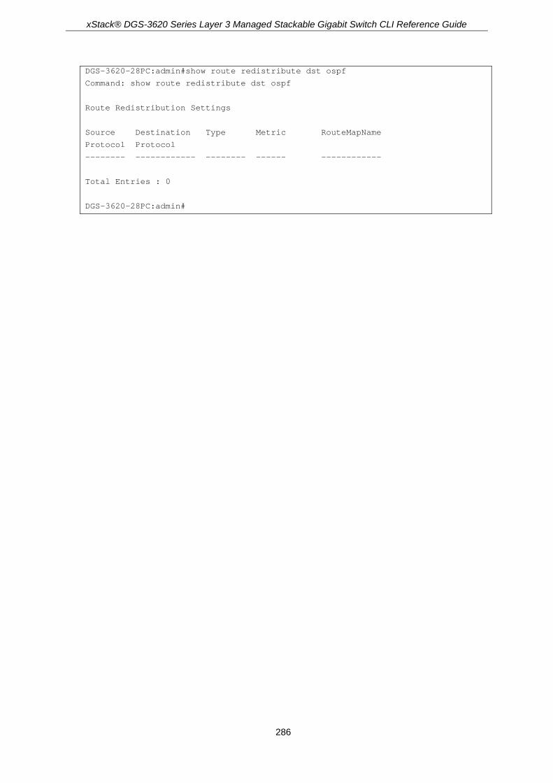
xStack® DGS-3620 Series Layer 3 Managed Stackable Gigabit Switch CLI Reference Guide
286
DGS-3620-28PC:admin#show route redistribute dst ospf
Command: show route redistribute dst ospf
Route Redistribution Settings
Source Destination Type Metric RouteMapName
Protocol Protocol
-------- ------------ -------- ------ ------------
Total Entries : 0
DGS-3620-28PC:admin#
xStack® DGS-3620 Series Layer 3 Managed Stackable Gigabit Switch CLI Reference Guide
287
Chapter 19 Compound Authentication Commands
create authentication guest_vlan [vlan <vlan_name 32> | vlanid <vlanid 1-4094>] delete authentication guest_vlan [vlan <vlan_name 32> | vlanid <vlanid 1-4094>] config authentication guest_vlan [vlan <vlan_name 32> | vlanid <vlanid 1-4094>] [add | delete]
ports [<portlist> | all] config authentication mac_format {case [lowercase | uppercase] | delimiter {[hyphen | colon |
dot | none] | number [1 | 2 | 5]}(1)}(1) config authentication ports [<portlist> | all] {auth_mode [port_based | host_based {vlanid
<vid_list> state [enable | disable]}] | multi_authen_methods [none | any | dot1x_impb | impb_jwac | impb_wac | mac_impb]}(1)
show authentication show authentication guest_vlan show authentication mac_format show authentication ports {<portlist>} enable authorization attributes disable authorization attributes show authorization config authentication server failover [local | permit | block]
19-1 create authentication guest_vlan Description This command is used to assign a static VLAN to be a guest VLAN. The specific VLAN which is assigned to be a guest VLAN must already exist. The specific VLAN which is assigned to be a guest VLAN can’t be deleted.
Format create authentication guest_vlan [vlan <vlan_name 32> | vlanid <vlanid 1-4094>]
Parameters vlan - Specifies the guest VLAN by VLAN name.
<vlan_name 32> - Enter the guest VLAN by VLAN name. The VLAN name can be up to 32 characters long.
vlanid - Specifies the guest VLAN by VLAN ID. <vlanid 1-4094> - Enter the guest VLAN by VLAN ID. The VLAN ID value must be between 1
and 4094.
Restrictions Only Administrators, Operators and Power-Users can issue this command.

xStack® DGS-3620 Series Layer 3 Managed Stackable Gigabit Switch CLI Reference Guide
288
Example To assign a static VLAN to be a guest VLAN:
DGS-3620-28PC:admin#create authentication guest_vlan vlan guestVLAN
Command: create authentication guest_vlan vlan guestVLAN
Success.
DGS-3620-28PC:admin#
19-2 delete authentication guest_vlan Description This command is used to delete a guest VLAN setting, but not a static VLAN. All ports which are enabled as guest VLANs will move to the original VLAN after deleting the guest VLAN.
Format delete authentication guest_vlan [vlan <vlan_name 32> | vlanid <vlanid 1-4094>]
Parameters vlan - Specifies the guest VLAN by VLAN name.
<vlan_name 32> - Enter the guest VLAN by VLAN name. The VLAN name can be up to 32 characters long.
vlanid - Specifies the guest VLAN by VLAN ID. <vlanid 1-4094> - Enter the guest VLAN by VLAN ID. The VLAN ID value must be between 1
and 4094.
Restrictions Only Administrators, Operators and Power-Users can issue this command.
Example To delete a guest VLAN setting:
DGS-3620-28PC:admin#delete authentication guest_vlan vlan guestVLAN
Command: delete authentication guest_vlan vlan guestVLAN
Success.
DGS-3620-28PC:admin#
19-3 config authentication guest_vlan Description This command is used to assign or remove ports to or from a guest VLAN.

xStack® DGS-3620 Series Layer 3 Managed Stackable Gigabit Switch CLI Reference Guide
289
Format config authentication guest_vlan [vlan <vlan_name 32> | vlanid <vlanid 1-4094>] [add | delete] ports [<portlist> | all ]
Parameters vlan - Specifies the guest VLAN name.
<vlan_name 32> - Enter the guest VLAN name. The VLAN name can be up to 32 characters long.
vlanid - Specifies the guest VLAN VID. <vlanid 1-4094> - Enter the guest VLAN VID. The VLAN ID value must be between 1 and
4094. add - Specifies to add a port list to the guest VLAN. delete - Specifies to delete a port list from the guest VLAN. ports - Specifies a port or range of ports to configure.
<portlist> - Enter a range of ports to configure. all - Specifies to configure all ports.
Restrictions Only Administrators, Operators and Power-Users can issue this command.
Example To configure authentication for all ports for a guest VLAN called “gv”:
DGS-3620-28PC:admin#config authentication guest_vlan vlan gv add ports all
Command: config authentication guest_vlan vlan gv add ports all
Success.
DGS-3620-28PC:admin#
19-4 config authentication mac_format Description This command will set the MAC address format that will be used for authentication username via the RADIUS server.
Format config authentication mac_format {case [lowercase | uppercase] | delimiter {[hyphen | colon | dot | none] | number [1 | 2 | 5]}(1)}(1)
Parameters case - (Optional) Specifies the case format used.
lowercase - Specifies using the lowercase format, the RADIUS authentication username will be formatted as: aa-bb-cc-dd-ee-ff.
uppercase - Specifies using the uppercase format, the RADIUS authentication username will be formatted as: AA-BB-CC-DD-EE-FF.
delimiter - (Optional) Specifies the delimiter format used.

xStack® DGS-3620 Series Layer 3 Managed Stackable Gigabit Switch CLI Reference Guide
290
hyphen - Specifies using the “-“ as delimiter, the format is: AA-BB-CC-DD-EE-FF colon - Specifies using the “:“ as delimiter, the format is: AA:BB:CC:DD:EE:FF dot - Specifies using the “.“ as delimiter, the format is: AA.BB.CC.DD.EE.FF none - Specifies not using any delimiter, the format is: AABBCCDDEEFF
number - (Optional) Specifies the delimiter number used. 1 - Single delimiter, the format is: AABBCC.DDEEFF 2 - Double delimiter, the format is: AABB.CCDD.EEFF 5 - Multiple delimiter, the format is: AA.BB.CC.DD.EE.FF
Restrictions Only Administrators, Operators and Power-Users can issue this command.
Example To configure the MAC address format to IETF style:
DGS-3620-28PC:admin#config authentication mac_format case uppercase delimiter hyphen number 5
Command: config authentication mac_format case uppercase delimiter hyphen number 5
Success.
DGS-3620-28PC:admin#
19-5 config authentication ports Description This command is used to configure authorization mode and authentication method on ports.
Format config authentication ports [<portlist> | all] {auth_mode [port_based | host_based {vlanid <vid_list> state [enable | disable]}] | multi_authen_methods [none | any | dot1x_impb | impb_jwac | impb_wac | mac_impb]}(1)
Parameters <portlist> - Enter a port or range of ports to configure. all - Specifies to configure all ports. auth_mode - (Optional) The authorization mode is port-based or host-based.
port-based - If one of the attached hosts pass the authentication, all hosts on the same port will be granted access to the network. If the user fails the authorization, this port will keep trying the next authentication.
host-based - Specifies to allow every user to be authenticated individually. vlanid - (Optional) Specifies the VLAN ID used for this configuration.
<vid_list> - Enter the VLAN ID used for this configuration here. state - (Optional) Specifies whether the authorization mode will be enabled or disabled.
enable - Specifies that the authorization mode will be enabled. disable - Specifies that the authorization mode will be disabled.
multi_authen_methods - (Optional) Specifies the method for compound authentication. none - Specifies that compound authentication is not enabled. any - Specifies if any of the authentication methods (802.1X, MAC, and JWAC/WAC) pass,

xStack® DGS-3620 Series Layer 3 Managed Stackable Gigabit Switch CLI Reference Guide
291
then pass. dot1x_impb - Dot1x will be verified first, and then IMPB will be verified. Both authentications
need to be passed. impb_jwac - JWAC will be verified first, and then IMPB will be verified. Both authentications
need to be passed. impb_wac - WAC will be verified first, and then IMPB will be verified. Both authentications
need to be passed. mac_impb - MAC will be verified first, and then IMPB will be verified. Both authentications
need to be passed.
Restrictions Only Administrators, Operators and Power-Users can issue this command.
Example The following example sets the authentication mode of all ports to host-based:
DGS-3620-28PC:admin#config authentication ports all auth_mode host_based
Command: config authentication ports all auth_mode host_based
Success.
DGS-3620-28PC:admin#
The following example sets the compound authentication method of all ports to “any”:
DGS-3620-28PC:admin#config authentication ports all multi_authen_methods any
Command: config authentication ports all multi_authen_methods any
Success.
DGS-3620-28PC:admin#
19-6 show authentication Description This command is used to display the authentication failover configuration.
Format show authentication
Parameters None.
Restrictions None.

xStack® DGS-3620 Series Layer 3 Managed Stackable Gigabit Switch CLI Reference Guide
292
Example To display the authentication failover configuration:
DGS-3620-28PC:admin#show authentication
Command: show authentication
Authentication Server Failover: Block.
DGS-3620-28PC:admin#
19-7 show authentication guest_vlan Description This command is used to display guest VLAN information.
Format show authentication guest_vlan
Parameters None.
Restrictions None.
Example To display the guest VLAN setting:
DGS-3620-28PC:admin#show authentication guest_vlan
Command: show authentication guest_vlan
Guest VLAN VID :
Guest VLAN Member Ports:
Total Entries: 0
DGS-3620-28PC:admin#
19-8 show authentication mac_format Description This command is used to display the authentication MAC format setting.
Format show authentication mac_format

xStack® DGS-3620 Series Layer 3 Managed Stackable Gigabit Switch CLI Reference Guide
293
Parameters None.
Restrictions None.
Example To display the authentication MAC format setting:
DGS-3620-28PC:admin#show authentication mac_format
Command: show authentication mac_format
Case : Uppercase
Delimiter : None
Delimiter Number : 5
DGS-3620-28PC:admin#
19-9 show authentication ports Description This command is used to display the authentication method and authorization mode on ports.
Format show authentication ports {<portlist>}
Parameters <portlist> - (Optional) Specifies to display compound authentication on specific port(s).
Restrictions None.
Example To display the authentication settings for ports 1 to 3:

xStack® DGS-3620 Series Layer 3 Managed Stackable Gigabit Switch CLI Reference Guide
294
DGS-3620-28PC:admin#show authentication ports 1-3
Command: show authentication ports 1-3
Port Methods Auth Mode Authentication VLAN(s)
---- -------------- ----------- ----------------------
1 None Host-based
2 None Host-based
3 None Host-based
DGS-3620-28PC:admin#
19-10 enable authorization attributes Description This command is used to enable the authorization global state.
Format enable authorization attributes
Parameters None.
Restrictions Only Administrators, Operators and Power-Users can issue this command.
Example To enable the authorization global state:
DGS-3620-28PC:admin#enable authorization attributes
Command: enable authorization attributes
Success.
DGS-3620-28PC:admin#
19-11 disable authorization attributes Description This command is used to disable the authorization global state.
Format disable authorization attributes

xStack® DGS-3620 Series Layer 3 Managed Stackable Gigabit Switch CLI Reference Guide
295
Parameters None.
Restrictions Only Administrators, Operators and Power-Users can issue this command.
Example To disable the authorization global state:
DGS-3620-28PC:admin#disable authorization attributes
Command: disable authorization attributes
Success.
DGS-3620-28PC:admin#
19-12 show authorization Description This command is used to display the authorization status.
Format show authorization
Parameters None.
Restrictions None.
Example To display the authorization status:
DGS-3620-28PC:admin#show authorization
Command: show authorization
Authorization for Atributes: Enabled
DGS-3620-28PC:admin#
19-13 config authentication server failover Description This command is used to configure the authentication server failover function. When authentication server fails, administrator can configure to:

xStack® DGS-3620 Series Layer 3 Managed Stackable Gigabit Switch CLI Reference Guide
296
* Use the local database to authenticate the client. The switch will resort to using the local database to authenticate the client. If the client fails on local authentication, the client is regarded as un-authenticated, otherwise, it authenticated.
* Pass authentication. The client is always regarded as authenticated. If guest VLAN is enabled, clients will stay on the guest VLAN, otherwise, they will stay on the original VLAN.
* Block the client (default setting). The client is always regarded as un-authenticated.
Format config authentication server failover [local | permit | block]
Parameters local - Specifies to use the local database to authenticate the client. permit - Specifies that the client is always regarded as authenticated. block - Specifies to block the client. This is the default setting.
Restrictions Only Administrators, Operators and Power-Users can issue this command.
Example To set the authentication server failover state:
DGS-3620-28PC:admin#config authentication server failover local
Command: config authentication server failover local
Success.
DGS-3620-28PC:admin#

xStack® DGS-3620 Series Layer 3 Managed Stackable Gigabit Switch CLI Reference Guide
297
Chapter 20 Debug Software Commands
debug address_binding [event | dhcp | all] state [enable | disable] no debug address_binding debug error_log [dump | clear | upload_toTFTP <ipaddr> <path_filename 64>] debug buffer [utilization | dump | clear | upload_toTFTP <ipaddr> <path_filename 64>] debug output [module <module_list> | all] [buffer | console] debug config error_reboot [enable | disable] debug config state [enable | disable] debug show error_reboot state debug stp clear counter {ports [<portlist> | all]} debug stp config ports [<portlist> | all] [event | bpdu | state_machine | all] state [disable | brief |
detail] debug stp show counter {ports [<portlist> | all]} debug stp show flag {ports <portlist>} debug stp show information debug stp state [disable | enable] debug ospf [neighbor_state_change | interface_state_change {dr_bdr_selection} | lsa {all |
originating | installing | receiving | flooding} (1) | packet {all | receiving | sending} (1) | retransmission | spf {all | intra | inter | extern} (1) | timer | virtual_link | route | redistribution] state [enable | disable]
debug ospf clear counter {packet | neighbor | spf} debug ospf log state [enable | disable] debug ospf show counter {packet | neighbor | spf} debug ospf show detail external_link debug ospf show detail net_link debug ospf show detail rt_link debug ospf show detail summary_link debug ospf show detail type7_link debug ospf show flag debug ospf show log state debug ospf show redistribution debug ospf show request_list debug ospf show summary_list debug ospf state [enable | disable] debug vrrp [vr_state_change | packet [all | {receiving | sending}(1)] | mac_addr_update |
interface_change | timers] state [enable | disable] debug vrrp clear counter debug vrrp log state [enable | disable] debug vrrp show counter debug vrrp show flag debug vrrp show log state debug vrrp state [enable | disable] debug bgp show flag debug bgp all flag [enable | disable] debug bgp fsm_event [enable | disable] debug bgp packet [{open | update | keepalive | notify | refresh | capability}(1) | all] [in | out]
[enable | disable] debug bgp error state [enable | disable] debug bgp show global_info debug bgp show peer {ipv6 unicast} debug bgp show peer_group {ipv6 unicast}

xStack® DGS-3620 Series Layer 3 Managed Stackable Gigabit Switch CLI Reference Guide
298
debug bgp show network {ipv6 unicast} debug bgp show aggregate {ipv6 unicast} debug bgp show damp {ipv6 unicast} debug bgp show interface_info debug bgp show as_path_access_list debug bgp show bgp_timer debug bgp show community_list debug bgp show redist_info debug bgp router_map [enable | disable] debug bgp access_list [enable | disable] debug bgp prefix_list [enable | disable] debug bgp state [enable | disable] debug dhcpv6_client state enable debug dhcpv6_client state disable debug dhcpv6_client output [buffer | console] debug dhcpv6_client packet {all | receiving | sending} state [enable | disable] debug dhcpv6_relay state enable debug dhcpv6_relay state disable debug dhcpv6_relay hop_count state [enable | disable] debug dhcpv6_relay output [buffer | console] debug dhcpv6_relay packet {all | receiving | sending} state [enable | disable] debug dhcpv6_server packet [all | receiving | sending] state [enable | disable] debug dhcpv6_server state disable debug dhcpv6_server state enable debug pim ssm no debug pim ssm debug ripng flag [{interface | packet [all | rx | tx] | route} | all] state [enable | disable] debug ripng show flag debug ripng state disable debug ripng state enable debug routefilter show [prefix_list | access_list | route_map | ipv6_prefix_list | ipv6_access_list] debug show status {module <module_list>} debug super_vlan state [enable | disable] debug show address_binding binding_state_table [nd_snooping | dhcpv6_snooping] debug show error ports box_id [<value 1-12> | all] {sio1 | sio2} debug show jwac auth_info debug show packet ports box_id [<value 1-12> | all] {sio1 | sio2} debug show cpu utilization debug ntp level <value 0-255>
20-1 debug address_binding Description This command is used to start the IMPB debug when the IMPB module receives an ARP/IP packet or a DHCP packet.
Format debug address_binding [event | dhcp | all] state [enable | disable]
Parameters event - To print out the debug messages when IMPB module receives ARP/IP packets. dhcp - To print out the debug messages when the IMPB module receives the DHCP packets.

xStack® DGS-3620 Series Layer 3 Managed Stackable Gigabit Switch CLI Reference Guide
299
all - Print out all debug messages. state - Specifies the state of the address binding debugging option.
enable - Specifies that the address binding debugging option will be enabled. disable - Specifies that the address binding debugging option will be disabled.
Restrictions Only Administrator level users can issue this command.
Example To print out all debug IMPB messages:
DGS-3620-28PC:admin# debug address_binding all state enable
Command: debug address_binding all state enable
Success.
DGS-3620-28PC:admin#
20-2 no debug address_binding Description This command is used to stop the IMPB debug starting when the IMPB module receives an ARP/IP packet or a DHCP packet.
Format no debug address_binding
Parameters None.
Restrictions Only Administrator level users can issue this command.
Example To stop IMPB debug: starting when the IMPB module receives an ARP/IP or DHCP packet:
DGS-3620-28PC:admin# no debug address_binding
Command: no debug address_binding
Success.
DGS-3620-28PC:admin#

xStack® DGS-3620 Series Layer 3 Managed Stackable Gigabit Switch CLI Reference Guide
300
20-3 debug error_log Description Use this command to dump, clear or upload the software error log to a TFTP server.
Format debug error_log [dump | clear | upload_toTFTP <ipaddr> <path_filename 64>]
Parameters dump - Display the debug message of the debug log. clear - Clear the debug log. upload_toTFTP - Upload the debug log to a TFTP server specified by IP address.
<ipaddr> - Specifies the IPv4 address of the TFTP server. <path_filename 64> - The pathname specifies the DOS pathname on the TFTP server. It can
be a relative pathname or an absolute pathname. This value can be up to 64 characters long.
Restrictions Only Administrator level users can issue this command.
Example To dump the error log:
DGS-3620-28PC:admin# debug error_log dump
Command: debug error_log dump
**************************************************************************
# debug log: 1
# firmware version: Build 3.00.004
# level: CPU exception
# clock: 437453880 ms
# time : 2000-01-08 05:55:40
======================== CPU EXCEPTION ========================
Current Task = IP-Tic Stack Pointer = 4CFEA7A0
---------------------------CP0 Registers-----------------------
Status : 1000FC01 Interrupt enable Normal level
Cause : 00000008 TLB exception (load or instruction fetch)
EPC : 80A0297C Addr : 00000008
Stack : 4CFEA7A0 Return : 80A02938
------------------------normal registers-----------------------
$0( $0) : 00000000 at( $1) : FFFFFFFE v0( $2) : 00000000 v1( $3) : 00000001
a0( $4) : 00000000 a1( $5) : 4825B4A8 a2( $6) : 00000001 a3( $7) : 00000001
t0( $8) : 814D7FCC t1( $9) : 0000FC00 t2($10) : 828100C4 t3($11) : 00000017
t4($12) : 828100BC t5($13) : 4CFEA430 t6($14) : 82810048 t7($15) : 00000000
s0($16) : 4825D94A s1($17) : 4825D890 s2($18) : 4825D949 s3($19) : 4825D946
s4($20) : 00000000 s5($21) : 00000008 s6($22) : 81800000 s7($23) : 00090000
t8($24) : 00000000 t9($25) : FFFFFFC0 k0($26) : 00000000 k1($27) : 00000000

xStack® DGS-3620 Series Layer 3 Managed Stackable Gigabit Switch CLI Reference Guide
301
gp($28) : 8180ADA0 sp($29) : 4CFEA7A0 fp($30) : 00000001 ra($31) : 80A02938
------------------------- TASK STACKTRACE ------------------------
->81150A58
->809B346C
->809E1DEC
->809D7E6C
->80A038CC
->80A033B0
->80A0297C
To clear the error log:
DGS-3620-28PC:admin# debug error_log clear
Command: debug error_log clear
Success.
DGS-3620-28PC:admin#
To upload the error log to TFTP server:
DGS-3620-28PC:admin# debug error_log upload_toTFTP 10.0.0.90 debug-log.txt
Command: debug error_log upload_toTFTP 10.0.0.90 debug-log.txt
Connecting to server................... Done.
Upload configuration................... Done.
DGS-3620-28PC:admin#
20-4 debug buffer Description Use this command to show the debug buffer’s state, or dump, clear, or upload the debug buffer to a TFTP server.
Note: When selecting to output to the debug buffer and there are debug messages being outputted, the system memory pool will be used as the debug buffer. The functions which will use the system memory pool resource may fail to execute command such as download and upload firmware, or save configuration. If you want to execute these commands successfully, please use the command “debug buffer clear” to release the system’s memory pool resources manually first.
Format debug buffer [utilization | dump | clear | upload_toTFTP <ipaddr> <path_filename 64>]
Parameters utilization - Display the debug buffer’s state.
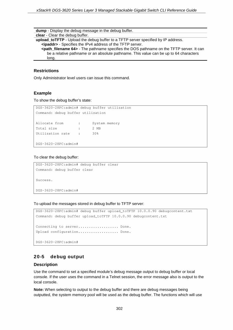
xStack® DGS-3620 Series Layer 3 Managed Stackable Gigabit Switch CLI Reference Guide
302
dump - Display the debug message in the debug buffer. clear - Clear the debug buffer. upload_toTFTP - Upload the debug buffer to a TFTP server specified by IP address.
<ipaddr> - Specifies the IPv4 address of the TFTP server. <path_filename 64> - The pathname specifies the DOS pathname on the TFTP server. It can
be a relative pathname or an absolute pathname. This value can be up to 64 characters long.
Restrictions Only Administrator level users can issue this command.
Example To show the debug buffer’s state:
DGS-3620-28PC:admin# debug buffer utilization
Command: debug buffer utilization
Allocate from : System memory
Total size : 2 MB
Utilization rate : 30%
DGS-3620-28PC:admin#
To clear the debug buffer:
DGS-3620-28PC:admin# debug buffer clear
Command: debug buffer clear
Success.
DGS-3620-28PC:admin#
To upload the messages stored in debug buffer to TFTP server:
DGS-3620-28PC:admin# debug buffer upload_toTFTP 10.0.0.90 debugcontent.txt
Command: debug buffer upload_toTFTP 10.0.0.90 debugcontent.txt
Connecting to server................... Done.
Upload configuration................... Done.
DGS-3620-28PC:admin#
20-5 debug output Description Use the command to set a specified module’s debug message output to debug buffer or local console. If the user uses the command in a Telnet session, the error message also is output to the local console.
Note: When selecting to output to the debug buffer and there are debug messages being outputted, the system memory pool will be used as the debug buffer. The functions which will use

xStack® DGS-3620 Series Layer 3 Managed Stackable Gigabit Switch CLI Reference Guide
303
the system memory pool resource may fail to execute command such as download and upload firmware, or save configuration. If you want to execute these commands successfully, please use the command “debug buffer clear” to release the system’s memory pool resources manually first.
Format debug output [module <module_list> | all] [buffer | console]
Parameters module - Specifies the module list.
<module_list> - Enter the module list here. all - Control output method of all modules.
buffer - Direct the debug message of the module output to debug buffer(default). console - Direct the debug message of the module output to local console.
Restrictions Only Administrator level users can issue this command.
Example To set all module debug message outputs to local console:
DGS-3620-28PC:admin# debug output all console
Command: debug output all console
Success.
DGS-3620-28PC:admin#
20-6 debug config error_reboot Description This command is used to set if the switch needs to be rebooted when a fatal error occurs. When the error occurs, the watchdog timer will be disabled by the system first, and then all debug information will be saved in NVRAM. If the error_reboot is enabled, the watchdog shall be enabled after all information is stored into NVRAM.
Format debug config error_reboot [enable | disable]
Parameters enable - Need reboot switch when fatal error happens. This is the default value. disable - Do not need reboot switch when fatal error happens, system will hang-up for debug and
enter the debug shell mode for debug.
Restrictions Only Administrator level users can issue this command.

xStack® DGS-3620 Series Layer 3 Managed Stackable Gigabit Switch CLI Reference Guide
304
Example To set the switch to not need a reboot when a fatal error occurs:
DGS-3620-28PC:admin# debug config error_reboot disable
Command: debug config error_reboot disable
Success.
DGS-3620-28PC:admin#
20-7 debug config state Description Use the command to set the state of the debug.
Format debug config state [enable | disable]
Parameters enable - Enable the debug state. disable - Disable the debug state.
Restrictions Only Administrator level users can issue this command.
Example To set the debug state to disabled:
DGS-3620-28PC:admin# debug config state disable
Command: debug config state disable
Success.
DGS-3620-28PC:admin#
20-8 debug show error_reboot state Description Use the command to show the error reboot status.
Format debug show error_reboot state
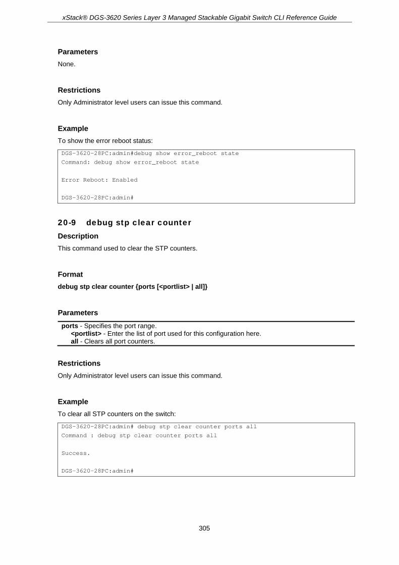
xStack® DGS-3620 Series Layer 3 Managed Stackable Gigabit Switch CLI Reference Guide
305
Parameters None.
Restrictions Only Administrator level users can issue this command.
Example To show the error reboot status:
DGS-3620-28PC:admin#debug show error_reboot state
Command: debug show error_reboot state
Error Reboot: Enabled
DGS-3620-28PC:admin#
20-9 debug stp clear counter Description This command used to clear the STP counters.
Format debug stp clear counter {ports [<portlist> | all]}
Parameters ports - Specifies the port range.
<portlist> - Enter the list of port used for this configuration here. all - Clears all port counters.
Restrictions Only Administrator level users can issue this command.
Example To clear all STP counters on the switch:
DGS-3620-28PC:admin# debug stp clear counter ports all
Command : debug stp clear counter ports all
Success.
DGS-3620-28PC:admin#

xStack® DGS-3620 Series Layer 3 Managed Stackable Gigabit Switch CLI Reference Guide
306
20-10 debug stp config ports Description This command used to configure per-port STP debug level on the specified ports.
Format debug stp config ports [<portlist> | all] [event | bpdu | state_machine | all] state [disable | brief | detail]
Parameters ports - Specifies the STP port range to debug.
<portlist> - Enter the list of port used for this configuration here. all - Specifies to debug all ports on the switch.
event - Debug the external operation and event processing. bpdu - Debug the BPDU’s that have been received and transmitted. state_machine - Debug the state change of the STP state machine. all - Debug all of the above. state - Specifies the state of the debug mechanism.
disable - Disables the debug mechanism. brief - Sets the debug level to brief. detail - Sets the debug level to detail.
Restrictions Only Administrator level users can issue this command.
Example To configure all STP debug flags to brief level on all ports:
DGS-3620-28PC:admin# debug stp config ports all all state brief
Command: debug stp config ports all all state brief
Success.
DGS-3620-28PC:admin#
20-11 debug stp show counter Description This command used to display the STP counters.
Format debug stp show counter {ports [<portlist> | all]}
Parameters ports - (Optional) Specifies the STP ports for display.
<portlist> - Enter the list of port used for this configuration here.
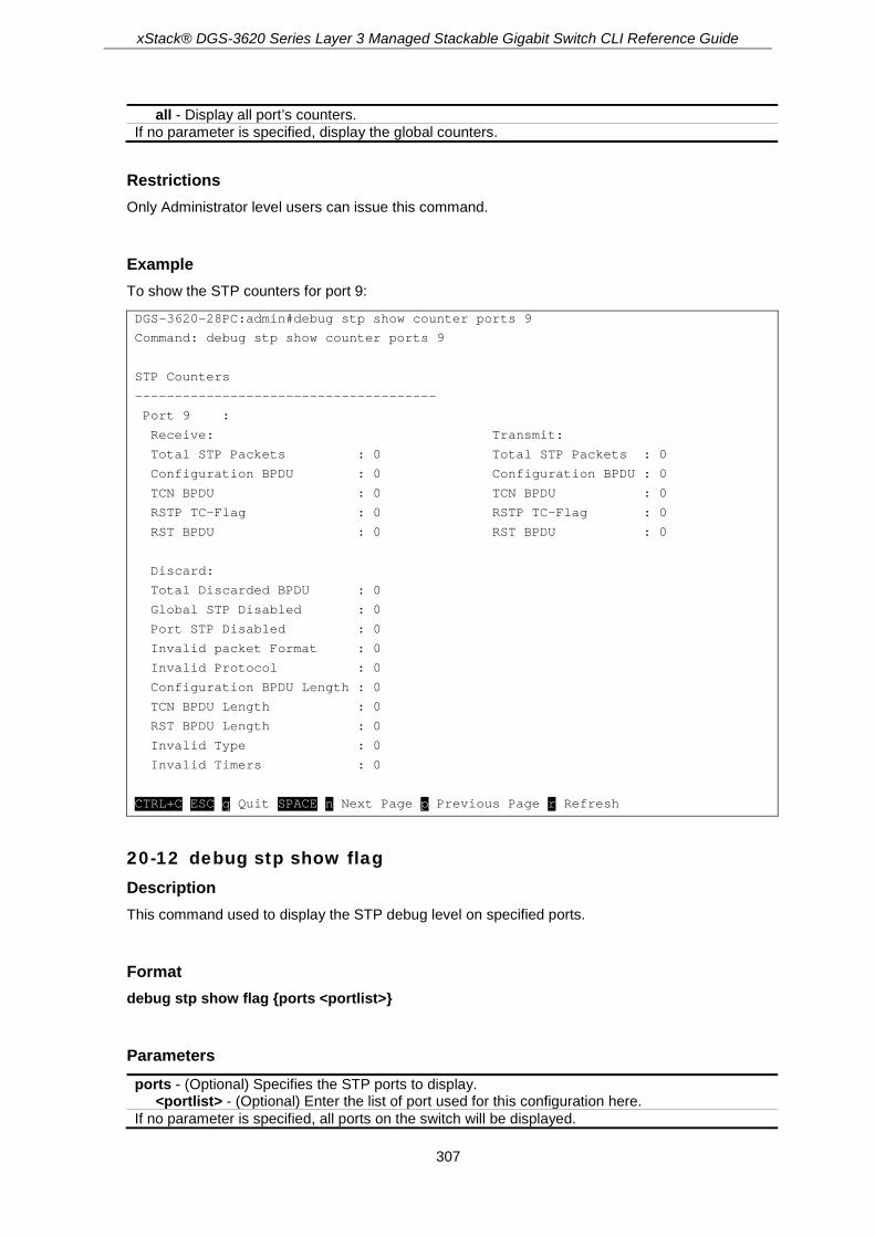
xStack® DGS-3620 Series Layer 3 Managed Stackable Gigabit Switch CLI Reference Guide
307
all - Display all port’s counters. If no parameter is specified, display the global counters.
Restrictions Only Administrator level users can issue this command.
Example To show the STP counters for port 9:
DGS-3620-28PC:admin#debug stp show counter ports 9
Command: debug stp show counter ports 9
STP Counters
--------------------------------------
Port 9 :
Receive: Transmit:
Total STP Packets : 0 Total STP Packets : 0
Configuration BPDU : 0 Configuration BPDU : 0
TCN BPDU : 0 TCN BPDU : 0
RSTP TC-Flag : 0 RSTP TC-Flag : 0
RST BPDU : 0 RST BPDU : 0
Discard:
Total Discarded BPDU : 0
Global STP Disabled : 0
Port STP Disabled : 0
Invalid packet Format : 0
Invalid Protocol : 0
Configuration BPDU Length : 0
TCN BPDU Length : 0
RST BPDU Length : 0
Invalid Type : 0
Invalid Timers : 0
CTRL+C ESC q Quit SPACE n Next Page p Previous Page r Refresh
20-12 debug stp show flag Description This command used to display the STP debug level on specified ports.
Format debug stp show flag {ports <portlist>}
Parameters ports - (Optional) Specifies the STP ports to display.
<portlist> - (Optional) Enter the list of port used for this configuration here. If no parameter is specified, all ports on the switch will be displayed.

xStack® DGS-3620 Series Layer 3 Managed Stackable Gigabit Switch CLI Reference Guide
308
Restrictions Only Administrator level users can issue this command.
Example To display the debug STP levels on all ports:
DGS-3620-28PC:admin# debug stp show flag
Command: debug stp show flag
Global State: Enabled
Port Index Event flag BPDU Flag State Machine Flag
---------- ---------- --------- ------------------
1 Detail Brief Disable
2 Detail Brief Disable
3 Detail Brief Disable
4 Detail Brief Disable
5 Detail Brief Disable
6 Detail Brief Disable
7 Detail Brief Disable
8 Detail Brief Disable
9 Detail Brief Disable
10 Detail Brief Disable
11 Detail Brief Disable
12 Detail Brief Disable
DGS-3620-28PC:admin#
20-13 debug stp show information Description This command used to display STP detailed information, such as the hardware tables, the STP state machine, etc.
Format debug stp show information
Parameters None.
Restrictions Only Administrator level users can issue this command.

xStack® DGS-3620 Series Layer 3 Managed Stackable Gigabit Switch CLI Reference Guide
309
Example To show STP debug information:
DGS-3620-28PC:admin# debug stp show information
Command: debug stp show information
Spanning Tree Debug Information:
----------------------------------------
Port Status In Hardware Table:
Instance 0:
Port 1 :BLK Port 2 :BLK Port 3 :BLK Port 4 :BLK Port 5 :BLK Port 6 :BLK
Port 7 :FOR Port 8 :BLK Port 9 :BLK Port 10:BLK Port 11:BLK Port 12:BLK
Instance 1:
Port 1 :BLK Port 2 :BLK Port 3 :BLK Port 4 :BLK Port 5 :BLK Port 6 :BLK
Port 7 :FOR Port 8 :BLK Port 9 :BLK Port 10:BLK Port 11:BLK Port 12:BLK
--------------------------------------
Root Priority And Times :
Instance 0:
Designated Root Bridge : 32768/00-01-02-03-04-00
External Root Cost : 0
Regional Root Bridge : 32768/00-01-02-03-04-00
Internal Root Cost : 0
Designated Bridge : 32768/00-01-02-03-04-00
Designated Port : 0
Message Age : 0
Max Age : 20
Forward Delay : 15
Hello Time : 2
Instance 1:
Regional Root Bridge : 32769/00-01-02-03-04-00
Internal Root Cost : 0
Designated Bridge : 32769/00-01-02-03-04-00
Designated Port : 0
Remaining Hops : 20
--------------------------------------
Designated Priority And Times:
Instance 0:
Port 1 :
Designated Root Bridge : 0 /00-00-00-00-00-00
External Root Cost : 0
Regional Root Bridge : 0 /00-00-00-00-00-00
Internal Root Cost : 0
Designated Bridge : 0 /00-00-00-00-00-00
Designated Port : 0
Message Age : 0
Max Age : 20
Forward Delay : 15
Hello Time : 2
Instance 1:
Port 1 :
Regional Root Bridge : 0 /00-00-00-00-00-00

xStack® DGS-3620 Series Layer 3 Managed Stackable Gigabit Switch CLI Reference Guide
310
Internal Root Cost : 0
Designated Bridge : 0 /00-00-00-00-00-00
Designated Port : 0
Remaining Hops : 20
DGS-3620-28PC:admin#
20-14 debug stp state Description This command is used to enable or disable the STP debug state.
Format debug stp state [enable | disable]
Parameters state - Specifies the STP debug state.
enable - Enable the STP debug state. disable - Disable the STP debug state.
Restrictions Only Administrator level users can issue this command.
Example To configure the STP debug state to enable, and then disable the STP debug state:
DGS-3620-28PC:admin# debug stp state enable
Command: debug stp state enable
Success.
DGS-3620-28PC:admin# debug stp state disable
Command: debug stp state disable
Success.
DGS-3620-28PC:admin#
20-15 debug ospf Description This command is used to enable or disable OSPF debug flags.

xStack® DGS-3620 Series Layer 3 Managed Stackable Gigabit Switch CLI Reference Guide
311
Format debug ospf [neighbor_state_change | interface_state_change {dr_bdr_selection} | lsa {all | originating | installing | receiving | flooding} (1) | packet {all | receiving | sending} (1) | retransmission | spf {all | intra | inter | extern} (1) | timer | virtual_link | route | redistribution] state [enable | disable]
Parameters neighbor_state_change - The state of the OSPF neighbor state change debug. interface_state_change - The state of the OSPF interface state change debug. dr_bdr_selection - (Optional) Used to include or exclude debug information for DR/BDR
selection. lsa - The state of the designated debug flag.
all - (Optional) Specifies to set all LSA debug flags. originating - (Optional) Specifies to set LSA originating debug flag. installing - (Optional) Specifies to set LSA installing debug flag. receiving - (Optional) Specifies to set LSA receiving debug flag. flooding - (Optional) Specifies to set LSA flooding debug flag.
packet - The state of the designated debug flag. all - (Optional) Specifies to set all packet debug flags. receiving - (Optional) Specifies to set packet receiving debug flag. sending - (Optional) Specifies to set packet sending debug flag.
retransmission - The state of the OSPF retransmission debug flag. spf - The state of the designated debug flag.
all - (Optional) Specifies to set all SPF debug flags. intra - (Optional) Specifies to set intra-area SPF debug flag. inter - (Optional) Specifies to set inter-area SPF debug flag. extern - (Optional) Specifies to set AS external SPF debug flag.
timer - The state of the OSPF timer debug flag. virtual_link - The state of the OSPF virtual link debug flag. route - The state of OSPF route debug flag. redistribution - The state of OSPF redistribution debug flag. state - Specifies to set the OSPF debug flags state.
enable - Specifies that the OSPF debug flags state will be enabled. disable - Specifies that the OSPF debug flags state will be disabled.
Restrictions Only Administrator level users can issue this command.
Example To enable OSPF neighbor state change debug:
DGS-3620-28PC:admin# debug ospf neighbor_state_change state enable
Command: debug ospf neighbor_state_change state enable
Success.
DGS-3620-28PC:admin#
To enable OSPF interface state change debug:

xStack® DGS-3620 Series Layer 3 Managed Stackable Gigabit Switch CLI Reference Guide
312
DGS-3620-28PC:admin# debug ospf interface_state_change state enable
Command: debug ospf interface_state_change state enable
Success.
DGS-3620-28PC:admin#
To enable all OSPF LSA debug flags:
DGS-3620-28PC:admin# debug ospf lsa all state enable
Command: debug ospf lsa all state enable
Success.
DGS-3620-28PC:admin#
To enable all OSPF packet debug flags:
DGS-3620-28PC:admin# debug ospf packet all state enable
Command: debug ospf packet all state enable
Success.
DGS-3620-28PC:admin#
To enable OSPF retransmission debug flag:
DGS-3620-28PC:admin# debug ospf retransmission state enable
Command: debug ospf retransmission state enable
Success.
DGS-3620-28PC:admin#
To enable all OSPF SPF debug flags:
DGS-3620-28PC:admin# debug ospf spf all state enable
Command: debug ospf spf all state enable
Success.
DGS-3620-28PC:admin#
20-16 debug ospf clear counter Description This command is used to reset the OSPF statistic counters.
Format debug ospf clear counter {packet | neighbor | spf}

xStack® DGS-3620 Series Layer 3 Managed Stackable Gigabit Switch CLI Reference Guide
313
Parameters packet - (Optional) Specifies to reset the OSPF packet counter. neighbor - (Optional) Specifies to reset the OSPF neighbor event counter. spf - (Optional) Specifies to reset the OSPF SPF event counter. If the parameter is not specified, all OSPF counters will be cleared.
Restrictions Only Administrator level users can issue this command.
Example To clear all OSPF statistic counters:
DGS-3620-28PC:admin# debug ospf clear counter
Command: debug ospf clear counter
Success.
DGS-3620-28PC:admin#
20-17 debug ospf log state Description This command is used to enable or disable the OSPF debug log.
Format debug ospf log state [enable | disable]
Parameters state - Specifies the state of the OSPF debug log.
enable - Specifies that the OSPF debug log state will be enabled. disable - Specifies that the OSPF debug log state will be disabled.
Restrictions Only Administrator level users can issue this command.
Example To enable the OSPF debug log:
DGS-3620-28PC:admin# debug ospf log state enable
Command: debug ospf log state enable
Success.
DGS-3620-28PC:admin#

xStack® DGS-3620 Series Layer 3 Managed Stackable Gigabit Switch CLI Reference Guide
314
20-18 debug ospf show counter Description This command is used to display OSPF statistic counters.
Format debug ospf show counter {packet | neighbor | spf}
Parameters packet - (Optional) Specifies to display the OSPF packet counter. neighbor - (Optional) Specifies to display the OSPF neighbor event counter. spf - (Optional) Specifies to display the OSPF SPF event counter. If the parameter is not specified, all OSPF counters will be displayed.
Restrictions Only Administrator level users can issue this command.
Example To show all OSPF statistic counters:
DGS-3620-28PC:admin# debug ospf show counter
Command: debug ospf show counter
OSPF Debug Statistic Counters
Packet Receiving:
Total : 30
Hello : 30
DD : 0
LSR : 0
LSU : 0
LSAck : 0
Drop : 0
Auth Fail : 0
Packet Sending:
Total : 59
Hello : 59
DD : 0
LSR : 0
LSU : 0
LSAck : 0
Neighbor State:
Change : 0
SeqMismatch : 0
SPF Calculation:

xStack® DGS-3620 Series Layer 3 Managed Stackable Gigabit Switch CLI Reference Guide
315
Intra : 0
Inter : 0
Extern : 0
DGS-3620-28PC:admin#
20-19 debug ospf show detail external_link Description This command is used to display all AS external LSAs with detail information.
Format debug ospf show detail external_link
Parameters None.
Restrictions Only Administrator level users can issue this command.
Example To display all AS external LSAs with detail information:
DGS-3620-28PC:admin#debug ospf show detail external_link
Command: debug ospf show detail external_link
OSPF Phase2 External Link:
===========
AREA 0.0.0.0:
AS-External LSA:
Link-State ID: 192.168.205.0
Advertising Router: 1.1.1.1
LS Age: 10 Seconds
Options: 0x2
.... ...0 = 0 Bit Isn't Set
.... ..1. = E: ExternalRoutingCapability
.... .0.. = MC: NOT Multicast Capable
.... 0... = N/P: NSSA Bit
...0 .... = EA: Not Support Rcv And Fwd EA_LSA
..0. .... = DC: Not Support Handling Of Demand Circuits
.0.. .... = O: O Bit Isn't Set
0... .... = 7 Bit Isn't Set
LS Sequence Number: 0x80000001
Length: 36
Netmask: 255.255.255.0

xStack® DGS-3620 Series Layer 3 Managed Stackable Gigabit Switch CLI Reference Guide
316
Metric: 20
Forwarding Address: 10.90.90.101
External Route Tag: 0
Internal Field:
Del_flag: 0x0 I_ref_count: 0 Seq: 0x80000001 Csum: 0xd08e
Rxtime: 384 Txtime: 0 Orgage: 0
Current Time: 394
DGS-3620-28PC:admin#
20-20 debug ospf show detail net_link Description This command is used to display all Network LSAs with detail information.
Format debug ospf show detail net_link
Parameters None.
Restrictions Only Administrator level users can issue this command.
Example To display all Network LSAs with detail information:
DGS-3620-28PC:admin#debug ospf show detail net_link
Command: debug ospf show detail net_link
OSPF Phase2 NET Link:
===========
AREA 0.0.0.0:
Network LSA:
Link-State ID: 10.90.90.123
Netmask: 255.0.0.0
Advertising Router: 10.90.90.91
LS Age: 109 Seconds
Options: 0x2
.... ...0 = 0 Bit Isn't Set
.... ..1. = E: ExternalRoutingCapability
.... .0.. = MC: NOT Multicast Capable
.... 0... = N/P: NSSA Bit
...0 .... = EA: Not Support Rcv And Fwd EA_LSA
..0. .... = DC: Not Support Handling Of Demand Circuits
.0.. .... = O: O Bit Isn't Set
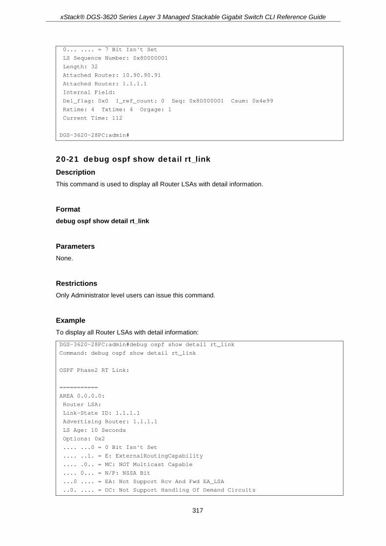
xStack® DGS-3620 Series Layer 3 Managed Stackable Gigabit Switch CLI Reference Guide
317
0... .... = 7 Bit Isn't Set
LS Sequence Number: 0x80000001
Length: 32
Attached Router: 10.90.90.91
Attached Router: 1.1.1.1
Internal Field:
Del_flag: 0x0 I_ref_count: 0 Seq: 0x80000001 Csum: 0x4e99
Rxtime: 4 Txtime: 4 Orgage: 1
Current Time: 112
DGS-3620-28PC:admin#
20-21 debug ospf show detail rt_link Description This command is used to display all Router LSAs with detail information.
Format debug ospf show detail rt_link
Parameters None.
Restrictions Only Administrator level users can issue this command.
Example To display all Router LSAs with detail information:
DGS-3620-28PC:admin#debug ospf show detail rt_link
Command: debug ospf show detail rt_link
OSPF Phase2 RT Link:
===========
AREA 0.0.0.0:
Router LSA:
Link-State ID: 1.1.1.1
Advertising Router: 1.1.1.1
LS Age: 10 Seconds
Options: 0x2
.... ...0 = 0 Bit Isn't Set
.... ..1. = E: ExternalRoutingCapability
.... .0.. = MC: NOT Multicast Capable
.... 0... = N/P: NSSA Bit
...0 .... = EA: Not Support Rcv And Fwd EA_LSA
..0. .... = DC: Not Support Handling Of Demand Circuits

xStack® DGS-3620 Series Layer 3 Managed Stackable Gigabit Switch CLI Reference Guide
318
.0.. .... = O: O Bit Isn't Set
0... .... = 7 Bit Isn't Set
LS Sequence Number: 0x80000002
Length: 36
Flags: 0x0
.... ...0 = B: Not Area Border Router
.... ..0. = E: Not AS Boundary Router
.... .0.. = V: Not Virtual Link Endpoint
Number Of Links: 1
Type: Transit ID: 10.90.90.123 Data: 10.90.90.91 Metric: 1
Internal Field:
Del_flag: 0x0 I_ref_count: 0 Seq: 0x80000002 Csum: 0xd81d
Rxtime: 5 Txtime: 0 Orgage: 0
Current Time: 15
DGS-3620-28PC:admin#
20-22 debug ospf show detail summary_link Description This command is used to display all Summary LSAs with detail information.
Format debug ospf show detail summary_link
Parameters None.
Restrictions Only Administrator level users can issue this command.
Example To display all Summary LSAs with detail information:
DGS-3620-28PC:admin#debug ospf show detail summary_link
Command: debug ospf show detail summary_link
OSPF Phase2 Summary Link:
===========
AREA 0.0.0.0:
Summary LSA:
Link-State ID: 20.1.1.0
Advertising Router: 10.90.90.91
LS Age: 10 Seconds
Options: 0x2
.... ...0 = 0 Bit Isn't Set

xStack® DGS-3620 Series Layer 3 Managed Stackable Gigabit Switch CLI Reference Guide
319
.... ..1. = E: ExternalRoutingCapability
.... .0.. = MC: NOT Multicast Capable
.... 0... = N/P: NSSA Bit
...0 .... = EA: Not Support Rcv And Fwd EA_LSA
..0. .... = DC: Not Support Handling Of Demand Circuits
.0.. .... = O: O Bit Isn't Set
0... .... = 7 Bit Isn't Set
LS Sequence Number: 0x80000001
Length: 28
Netmask: 255.255.255.0
Metric: 1
Internal Field:
Del_flag: 0x0 I_ref_count: 0 Seq: 0x80000001 Csum: 0x8f9c
Rxtime: 246 Txtime: 246 Orgage: 1
Current Time: 255
DGS-3620-28PC:admin#
20-23 debug ospf show detail type7_link Description This command is used to display all type-7 LSAs with detail information.
Format debug ospf show detail type7_link
Parameters None.
Restrictions Only Administrator level users can issue this command.
Example To display all type-7 LSAs with detail information:
DGS-3620-28PC:admin#debug ospf show detail type7_link
Command: debug ospf show detail type7_link
OSPF Phase2 NSSA-External Link:
===========
AREA 0.0.0.1:
NSSA-External LSA:
Link-State ID: 0.0.0.0
Advertising Router: 10.90.90.91
LS Age: 855 Seconds

xStack® DGS-3620 Series Layer 3 Managed Stackable Gigabit Switch CLI Reference Guide
320
Options: 0x2
.... ...0 = 0 Bit Isn't Set
.... ..1. = E: ExternalRoutingCapability
.... .0.. = MC: NOT Multicast Capable
.... 0... = N/P: NSSA Bit
...0 .... = EA: Not Support Rcv And Fwd EA_LSA
..0. .... = DC: Not Support Handling Of Demand Circuits
.0.. .... = O: O Bit Isn't Set
0... .... = 7 Bit Isn't Set
LS Sequence Number: 0x80000002
Length: 36
Netmask: 0.0.0.0
Metric: 0
Forwarding Address: 0.0.0.0
External Route Tag: 0
Internal Field:
Del_flag: 0x0 I_ref_count: 0 Seq: 0x80000002 Csum: 0x77be
Rxtime: 2301 Txtime: 0 Orgage: 0
Current Time: 3156
DGS-3620-28PC:admin#
20-24 debug ospf show flag Description This command is used to display the OSPF debug flag setting.
Format debug ospf show flag
Parameters None.
Restrictions Only Administrator level users can issue this command.
Example To show the current OSPF debug flag setting:
DGS-3620-28PC:admin# debug ospf show flag
Command: debug ospf show flag
Global State: Enabled
Current OSPF Flags Setting:
Neighbor State Change

xStack® DGS-3620 Series Layer 3 Managed Stackable Gigabit Switch CLI Reference Guide
321
Interface State Change
LSA Originating
LSA Operating
LSA Receiving
LSA Flooding
Packet Receiving
Packet Sending
Retransmission
Timer
DR Selection
Route
Redistribution
Virtual Link
SPF Intra
SPF Inter
SPF Extern
DGS-3620-28PC:admin#
20-25 debug ospf show log state Description This command is used to display the OSPF debug log state.
Format debug ospf show log state
Parameters None.
Restrictions Only Administrator level users can issue this command.
Example To display the debug OSPF log state:
DGS-3620-28PC:admin# debug ospf show log state
Command: debug ospf show log state
OSPF Log State : Enabled
DGS-3620-28PC:admin#
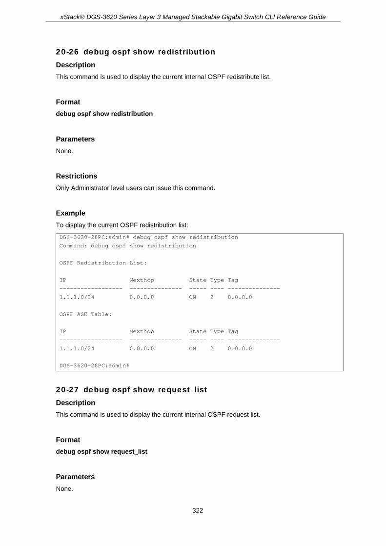
xStack® DGS-3620 Series Layer 3 Managed Stackable Gigabit Switch CLI Reference Guide
322
20-26 debug ospf show redistribution Description This command is used to display the current internal OSPF redistribute list.
Format debug ospf show redistribution
Parameters None.
Restrictions Only Administrator level users can issue this command.
Example To display the current OSPF redistribution list:
DGS-3620-28PC:admin# debug ospf show redistribution
Command: debug ospf show redistribution
OSPF Redistribution List:
IP Nexthop State Type Tag
------------------ --------------- ----- ---- ---------------
1.1.1.0/24 0.0.0.0 ON 2 0.0.0.0
OSPF ASE Table:
IP Nexthop State Type Tag
------------------ --------------- ----- ---- ---------------
1.1.1.0/24 0.0.0.0 ON 2 0.0.0.0
DGS-3620-28PC:admin#
20-27 debug ospf show request_list Description This command is used to display the current internal OSPF request list.
Format debug ospf show request_list
Parameters None.

xStack® DGS-3620 Series Layer 3 Managed Stackable Gigabit Switch CLI Reference Guide
323
Restrictions Only Administrator level users can issue this command.
Example To display the current OSPF request list:
DGS-3620-28PC:admin# debug ospf show request_list
Command: debug ospf show request_list
OSPF Request List:
Area 0.0.0.0:
Circuit: 1.1.1.1
Neighbor: 90.2.0.1 IP: 1.1.1.2
LSID: 192.194.134.0 RTID: 90.2.0.1
LSID: 192.194.135.0 RTID: 90.2.0.1
LSID: 192.194.136.0 RTID: 90.2.0.1
LSID: 192.194.137.0 RTID: 90.2.0.1
LSID: 192.194.138.0 RTID: 90.2.0.1
DGS-3620-28PC:admin#
20-28 debug ospf show summary_list Description This command is used to display the current internal OSPF summary list.
Format debug ospf show summary_list
Parameters None.
Restrictions Only Administrator level users can issue this command.
Example To display the current OSPF summary list:

xStack® DGS-3620 Series Layer 3 Managed Stackable Gigabit Switch CLI Reference Guide
324
DGS-3620-28PC:admin# debug ospf show summary_list
Command: debug ospf show summary_list
OSPF Summary List:
Area 0.0.0.0:
Circuit: 1.1.1.1
Neighbor: 90.2.0.1 IP: 1.1.1.2
LSID: 1.1.1.1 RTID: 1.1.1.1
Circuit: 2.2.2.1
Circuit: 10.1.1.6
DGS-3620-28PC:admin#
20-29 debug ospf state Description This command is used to set the OSPF debug global state.
Format debug ospf state [enable | disable]
Parameters state - Specifies the OSPF debug global state.
enable - Specifies that the OSPF debug global state will be enabled. disable - Specifies that the OSPF debug global state will be disabled.
Restrictions Only Administrator level users can issue this command.
Example To enable the OSPF debug global state:

xStack® DGS-3620 Series Layer 3 Managed Stackable Gigabit Switch CLI Reference Guide
325
DGS-3620-28PC:admin# debug ospf state enable
Command: debug ospf state enable
Success.
DGS-3620-28PC:admin# debug ospf show flag
Command: debug ospf show flag
Global State: Enabled
Current OSPF Flags Setting:
Neighbor State Change
DGS-3620-28PC:admin#
20-30 debug vrrp Description This command is used to set VRRP debug flags.
Format debug vrrp [vr_state_change | packet [all | {receiving | sending}(1)] | mac_addr_update | interface_change | timers] state [enable | disable]
Parameters vr_state_change - Specifies the state of the VRRP change debug flag. packet - Specifies to set the VRRP packet flags.
all - Specifies to set VRRP all packet debug flags. receiving - (Optional) Specifies to set the VRRP packet receiving flag. sending - (Optional) Specifies to set the VRRP packet sending flag.
mac_addr_update - Specifies the state of VRRP MAC debug flag. interface_change - Specifies the state of VRRP interface debug flag. timers - Specifies the state of VRRP timer's debug flag. state - Specifies the state of the configured VRRP debug flag.
enable - Specifies that the configured VRRP debug flag will be enabled. disable - Specifies that the configured VRRP debug flag will be disabled.
Restrictions Only Administrator level users can issue this command.
Example To enable the VRRP virtual router state change debug flag:

xStack® DGS-3620 Series Layer 3 Managed Stackable Gigabit Switch CLI Reference Guide
326
DGS-3620-28PC:admin# debug vrrp vr_state_change state enable
Command: debug vrrp vr_state_change state enable
Success.
DGS-3620-28PC:admin#
To enable all VRRP packet debug flags:
DGS-3620-28PC:admin# debug vrrp packet all state enable
Command: debug vrrp packet all state enable
Success.
DGS-3620-28PC:admin#
To enable VRRP virtual MAC address update debug flag:
DGS-3620-28PC:admin# debug vrrp mac_addr_update state enable
Command: debug vrrp mac_addr_update state enable
Success.
DGS-3620-28PC:admin#
To enable VRRP interface state change debug flag:
DGS-3620-28PC:admin# debug vrrp interface_change state enable
Command: debug vrrp interface_change state enable
Success.
DGS-3620-28PC:admin#
To enable VRRP timer debug flag:
DGS-3620-28PC:admin# debug vrrp timers state enable
Command: debug vrrp timers state enable
Success.
DGS-3620-28PC:admin#
20-31 debug vrrp clear counter Description This command is used to reset the VRRP debug statistic counters.

xStack® DGS-3620 Series Layer 3 Managed Stackable Gigabit Switch CLI Reference Guide
327
Format debug vrrp clear counter
Parameters None.
Restrictions Only Administrator level users can issue this command.
Example To clear VRRP statistic counters:
DGS-3620-28PC:admin# debug vrrp clear counter
Command: debug vrrp clear counter
Success
DGS-3620-28PC:admin#
20-32 debug vrrp log state Description This command is used to enable or disable the VRRP debug log state.
Format debug vrrp log state [enable | disable]
Parameters state - Specifies the state of the VRRP log. The default setting is disabled.
enable - Specifies that the VRRP log state will be enabled. disable - Specifies that the VRRP log state will be disabled.
Restrictions Only Administrator level users can issue this command.
Example To enable the VRRP debug log state:
DGS-3620-28PC:admin# debug vrrp log state enable
Command: debug vrrp log state enable
Success.
DGS-3620-28PC:admin#

xStack® DGS-3620 Series Layer 3 Managed Stackable Gigabit Switch CLI Reference Guide
328
20-33 debug vrrp show counter Description This command is used to display the VRRP debug statistic counters.
Format debug vrrp show counter
Parameters None.
Restrictions Only Administrator level users can issue this command.
Example To display VRRP statistic counters:
DGS-3620-28PC:admin# debug vrrp show counter
Command: debug vrrp show counter
VRRP debug statistic counters
Received ADV : 9
Drop : 52
Auth fail : 0
Sent ADV : 0
DGS-3620-28PC:admin#
20-34 debug vrrp show flag Description This command is used to display VRRP debug flag settings.
Format debug vrrp show flag
Parameters None.
Restrictions Only Administrator level users can issue this command.

xStack® DGS-3620 Series Layer 3 Managed Stackable Gigabit Switch CLI Reference Guide
329
Example To display VRRP debug flag settings:
DGS-3620-28PC:admin#debug vrrp show flag
Command: debug vrrp show flag
Global State: Disabled
Current VRRP debug level setting:
virtual router state change
packet receiving
packet sending
mac address update
interface change
timer
DGS-3620-28PC:admin#
20-35 debug vrrp show log state Description The command is used to display the VRRP debug log state.
Format debug vrrp show log state
Parameters None.
Restrictions Only Administrator level users can issue this command.
Example To display the VRRP debug log state:
DGS-3620-28PC:admin# debug vrrp show log state
Command: debug vrrp show log state
VRRP Debug Log State: Disabled
DGS-3620-28PC:admin#

xStack® DGS-3620 Series Layer 3 Managed Stackable Gigabit Switch CLI Reference Guide
330
20-36 debug vrrp state Description The command is used to enable or disable the VRRP debug state.
Format debug vrrp state [enable | disable]
Parameters state - Specifies the state of the VRRP debug state. The default setting is disabled.
enable - Specifies that the VRRP debug state will be enabled. disable - Specifies that the VRRP debug state will be disabled.
Restrictions Only Administrator level users can issue this command.
Example To enable the VRRP debug state:
DGS-3620-28PC:admin# debug vrrp state enable
Command: debug vrrp state enable
Success.
DGS-3620-28PC:admin#
20-37 debug bgp show flag Description This command is used for displaying current BGP debugging flags’ setting.
Format debug bgp show flag
Parameters None.
Restrictions Only Administrator-level users can issue this command. (EI Mode Only Command)
Example Show BGP debug flag:

xStack® DGS-3620 Series Layer 3 Managed Stackable Gigabit Switch CLI Reference Guide
331
DGS-3620-28PC:admin# debug bgp show flag
Command: debug bgp show flag
Current BGP flags setting:
Peer FSM Event Disable
OPEN Packet Receive Disable
OPEN Packet Send Disable
UPDATE Packet Receive Disable
UPDATE Packet Send Disable
KEEPALIVE Packet Receive Disable
KEEPALIVE Packet Send Disable
NOTIFY Packet Receive Disable
NOTIFY Packet Send Disable
REFRESH Packet Receive Disable
REFRESH Packet Send Disable
CAPABILITY Packet Receive Disable
CAPABILITY Packet Send Disable
Route MAP Disable
Access List Disable
Prefix List Disable
ERROR Information Disable
DGS-3620-28PC:admin#
20-38 debug bgp all flag Description This command is used for setting all BGP debugging flags to disable or enable.
Format debug bgp all flag [enable | disable]
Parameters enable - Enable the BGP debug function. disable - Disable the BGP debug function.
Restrictions Only Administrator-level users can issue this command. (EI Mode Only Command)
Example Configure all BGP debug flags’ state to enable:

xStack® DGS-3620 Series Layer 3 Managed Stackable Gigabit Switch CLI Reference Guide
332
DGS-3620-28PC:admin# debug bgp all flag enable
Command: debug bgp all flag enable
Success.
DGS-3620-28PC:admin#
20-39 debug bgp fsm_event Description This command is used for setting the flag of debugging information about peer FSM Event.
Format debug bgp fsm_event [enable | disable]
Parameters enable - Enable the BGP debug function. disable - Disable the BGP debug function.
Restrictions Only Administrator-level users can issue this command. (EI Mode Only Command)
Example Configure BGP peer FSM event debug flag to enable:
DGS-3620-28PC:admin# debug bgp fsm_event enable
Command: debug bgp fsm_event enable
Success.
DGS-3620-28PC:admin#
Output Examples: After BGP peer FSM event debug flag to enable, it may print following information.
BGP: 10.1.1.1-10.2.2.2, [FSM] State Change: Idle -> Connect.
BGP: 10.1.1.1-10.2.2.2, [FSM] Hold-Timer Expiry.
BGP: 10.1.1.1-10.2.2.2, [FSM] State: Open, Event: 3.
20-40 debug bgp packet Description This command is used for setting the flag of debugging information about different type of BGP packets’ receiving and sending.

xStack® DGS-3620 Series Layer 3 Managed Stackable Gigabit Switch CLI Reference Guide
333
Format debug bgp packet [{open | update | keepalive | notify | refresh | capability}(1) | all] [in | out] [enable | disable]
Parameters open - (Optional) Specifies that 'open' information will be displayed. update - (Optional) Specifies that 'update' information will be displayed. keepalive - (Optional) Specifies that 'keepalive' information will be displayed. notify - (Optional) Specifies that 'notify' information will be displayed. refresh - (Optional) Specifies that 'refresh' information will be displayed. capability - (Optional) Specifies that 'capability' information will be displayed. all - (Optional) Specifies that all information will be displayed. in - Specifies that the incoming information will be displayed. out - Specifies that the outgoing information will be displayed. enable - Enable the BGP debug function. disable - Disable the BGP debug function.
Restrictions Only Administrator-level users can issue this command. (EI Mode Only Command)
Example Configure BGP to display debugging information after received update packet:
DGS-3620-28PC:admin# debug bgp packet all in enable
Command: debug bgp packet all in enable
Success.
DGS-3620-28PC:admin#
Output Examples: After BGP peer FSM event debug flag to enable, it may print following information.
BGP:Peer:<10.1.1.10> RCV OPEN, version:<4>,remote-as:<40>, HoldTime:<180>,RID:<16.0.0.1>
BGP:Peer:<10.1.1.10> RCV KEEPALIVE.
BGP:Peer:<10.1.1.10> RCV UPDATE, withdraw: <21.0.0.0/8>,<22.0.0.0/8>,<23.0.0.0/8>, <24.0.0.0/8>,<25.0.0.0/8>...
BGP:Peer:<10.1.1.10> RCV UPDATE,attr:<Orign:i,As-path:10,Next-hop:10.1.1.10,Med:5>, NLRI: <21.0.0.0/8>,<22.0.0.0/8>
BGP:Peer:<10.1.1.10> RCV NOTIFYCATION,Code:<OPEN Message Error.>,SubCode:<Bad Peer AS.>
BGP:Peer:<10.1.1.10> RCV REFRESH,afi:<1>,safi:<1>
BGP:Peer:<10.1.1.10> RCV Capability Action:Set,Code: GRST ,Length:2

xStack® DGS-3620 Series Layer 3 Managed Stackable Gigabit Switch CLI Reference Guide
334
20-41 debug bgp error state Description This command is use for setting the flag of debugging information about BGP Error not need send BGP NOTIFICATION.
Format debug bgp error state [enable | disable]
Parameters enable - Enable the BGP debug function. disable - Disable the BGP debug function.
Restrictions Only Administrator-level users can issue this command. (EI Mode Only Command)
Example Configure BGP to enable error debug flag:
DGS-3620-28PC:admin# debug bgp error state enable
Command: debug bgp error state enable
Success.
DGS-3620-28PC:admin#
Output Examples: After configure BGP to enable error debug flag, it may print following information when error happens.
BGP: 10.1.1.1-10.2.2.2, NHop Validate: Invalid NHop address 250.3.0.0/8 received.
BGP: Hold-Timer: Invalid Peer.
20-42 debug bgp show global_info Description This command is used for displaying global information of current BGP instance.
Format debug bgp show global_info
Parameters None.

xStack® DGS-3620 Series Layer 3 Managed Stackable Gigabit Switch CLI Reference Guide
335
Restrictions Only Administrator-level users can issue this command. (EI Mode Only Command)
Example Configure BGP to show global information:
DGS-3620-28PC:admin# debug bgp show global_info
Command: debug bgp show global_info
Following is the information for global debugging:
---------------------------------------------------
AS Number : 100
Router ID : 194.17.0.2
Cluster ID : 123.123.123.123
Confed ID : 0
Confederation Peers :
Fast External Fallover : Disabled
Dampening Ability : Disabled
Client to Client Ability : Enabled
Cluster Peers : 0.0.0.0, 0.0.0.0, peer1
Aggregate Next_Hop_Check : Disabled
Default Local Preference : 100
Default Holdtime : 40
Default Keepalive : 10
Scan Time : 60
BGP Active Flags:
BGP_AF_CFLAG_SYNCHRONIZATION
BGP_AF_CFLAG_NETWORK_SYNC
BGP Active Redist-Flags for IPv4 Unicast:
BGP Trap : None
DGS-3620-28PC:admin#
20-43 debug bgp show peer Description This command is used for displaying information of all peers in BGP protocol DB.
Format debug bgp show peer {ipv6 unicast}
Parameters ipv6 unicast – (Optional) Specifies to debug the IPv6 unicast address family.

xStack® DGS-3620 Series Layer 3 Managed Stackable Gigabit Switch CLI Reference Guide
336
Restrictions Only Administrator-level users can issue this command. (EI Mode Only Command)
Example Configure BGP to show all peers’ information:
DGS-3620-28PC:admin# debug bgp show peer
Command: debug bgp show peer
BGP neighbor: 10.10.10.2 (Internal Peer)
-----------------------------------------------
Session State: Enabled
Session Activity: Enabled
Peer Group: NULL
Remote AS: 1
Local AS:10
Remote Router ID:192.168.252.252
BGP State: Established ( UP for 00:24:25)
Hold Time (Configured): 180 Seconds
Hold Time(Current Used): 180 Seconds
Keepalive Interval (Configured): 60 Seconds
Keepalive Interval(Current Used): 60 Seconds
Advertisement Interval(Configured): 5 Seconds
Advertisement Interval(Current Used): 5 Seconds
AS Origination Interval (Configured) : 0 Seconds
AS Origination Interval (Current Used) : 15 Seconds
Connect Retry Interval (Configured) : 0 Seconds
Connect Retry Interval (Current Used) : 120 Seconds
EBGP Multihop : 2
Weight: 100
Next Hop Self: Disabled
Remove Private AS: Disabled
Allowas In: Disabled
Address Family IPv4 Unicast
IPv4 Unicast: None
Soft Reconfiguration Inbound: Enabled
Community Sent to this Neighbor: None
Default Originate: Enabled
Incoming Update Prefix List: prelist1
Incoming Update Filter List: ASlist1
Route Map for Outgoing Routes: routemap1
Unsuppress Route Map: us_routmp1
Outbound Route Filter (ORF) type (64) Prefix list:
Send Mode : Disabled
Receive Mode : Disabled
Pass Word:
Prefix Count: 0
Send Prefix Count: 0
Prefix Max Count: 12000
Prefix Warning Threshold: 75
Prefix Max Warning: Disabled

xStack® DGS-3620 Series Layer 3 Managed Stackable Gigabit Switch CLI Reference Guide
337
DGS-3620-28PC:admin#
20-44 debug bgp show peer_group Description This command is used for displaying current peer group’s configuration in BGP protocol stack.
Format debug bgp show peer_group {ipv6 unicast}
Parameters ipv6 unicast – (Optional) Specifies to debug the IPv6 unicast address family.
Restrictions Only Administrator-level users can issue this command. (EI Mode Only Command)
Example Configure BGP to show peer group’s configuration:

xStack® DGS-3620 Series Layer 3 Managed Stackable Gigabit Switch CLI Reference Guide
338
DGS-3620-28PC:admin# debug bgp show peer_group
Command: debug bgp show peer_group
BGP Peer Group :tt
-------------------------------------------------------
Session State : Enabled
Session Activity : Enabled
Members : None
Remote AS : Not Set
Holdtime Interval : 180 seconds
Keepalive Interval : 60 seconds
Advertisement Interval : 0 seconds
AS Origination Interval : 0 Seconds
Connect Retry Interval : 0 Seconds
EBGP Multihop : 1
Weight : 0
Next Hop Self : Disabled
Remove Private As : Disabled
Allowas In : Disabled
Soft Reconfiguration Inbound : Disabled
Community Sent to this Neighbor : None
Default Originate : Disabled
Capability 0rf Prefix List : None
Pass Word:
Prefix Max Count: 12000
Prefix Warning Threshold: 75
Prefix Max Warning: Disabled
DGS-3620-28PC:admin#
20-45 debug bgp show network Description This command is used for displaying current network’s configuration in BGP protocol stack.
Format debug bgp show network {ipv6 unicast}
Parameters ipv6 unicast – (Optional) Specifies to debug the IPv6 unicast address family.
Restrictions Only Administrator-level users can issue this command. (EI Mode Only Command)
Example Configure BGP to show network information:

xStack® DGS-3620 Series Layer 3 Managed Stackable Gigabit Switch CLI Reference Guide
339
DGS-3620-28PC:admin# debug bgp show network
Command: debug bgp show network
Network Route Map
------------- -----------
192.168.0.0/8 NULL
172.16.0.0/16 map1
Total Entries :2
DGS-3620-28PC:admin#
20-46 debug bgp show aggregate Description This command is used for displaying current aggregate’s configuration in BGP protocol stack.
Format debug bgp show aggregate {ipv6 unicast}
Parameters ipv6 unicast – (Optional) Specifies to debug the IPv6 unicast address family.
Restrictions Only Administrator-level users can issue this command. (EI Mode Only Command)
Example Configure BGP to show aggregate information:
DGS-3620-28PC:admin# debug bgp show aggregate
Command: debug bgp show aggregate
Network Summary Only AS Set Suppress Count
------------- ------------ ------ -------------
192.168.0.0/8 YES NO 0
172.16.0.0/16 NO NO 2
Total Entries :2
DGS-3620-28PC:admin#
20-47 debug bgp show damp Description This command is used for displaying current dampening configuration and corresponding dynamic information in BGP protocol stack.

xStack® DGS-3620 Series Layer 3 Managed Stackable Gigabit Switch CLI Reference Guide
340
Format debug bgp show damp {ipv6 unicast}
Parameters ipv6 unicast – (Optional) Specifies to debug the IPv6 unicast address family.
Restrictions Only Administrator-level users can issue this command. (EI Mode Only Command)
Example Configure BGP to show current dampening information:
DGS-3620-28PC:admin# debug bgp show damp
Command: debug bgp show damp
Route Map : NULL
Reach Half Life Time is : 900 seconds
Reuse Value : 750
Suppress Value : 2000
MAX Suppress Time : 3600 seconds
Unreach Half Life Time is : 900 seconds
Reuse Index Size : 1024
Reuse List Size : 256
Reuse Offset : 19
Current dampened routes:
Damp Reuse List Info:
reuse_index index ptr penalty flap start_time t_updated suppress_time evt
show BGP Damp no reuse list info: 0
index ptr penalty flap start_time t_updated suppress_time evt
BGP Damp Decay List Info:
decay array size is 90.
Index Value
----- -----
1 1
2 0.969663
3 0.940247
4 0.911722
5 0.884064
6 0.857244
7 0.831238
8 0.806021
9 0.781569
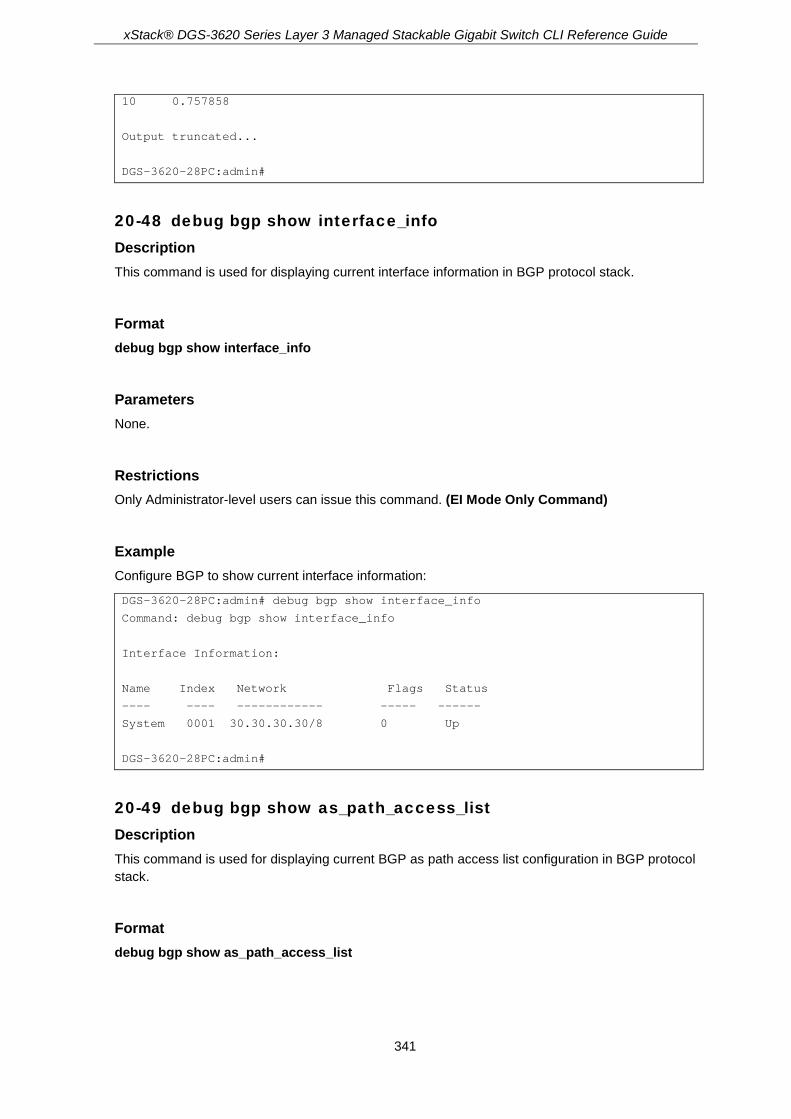
xStack® DGS-3620 Series Layer 3 Managed Stackable Gigabit Switch CLI Reference Guide
341
10 0.757858
Output truncated...
DGS-3620-28PC:admin#
20-48 debug bgp show interface_info Description This command is used for displaying current interface information in BGP protocol stack.
Format debug bgp show interface_info
Parameters None.
Restrictions Only Administrator-level users can issue this command. (EI Mode Only Command)
Example Configure BGP to show current interface information:
DGS-3620-28PC:admin# debug bgp show interface_info
Command: debug bgp show interface_info
Interface Information:
Name Index Network Flags Status
---- ---- ------------ ----- ------
System 0001 30.30.30.30/8 0 Up
DGS-3620-28PC:admin#
20-49 debug bgp show as_path_access_list Description This command is used for displaying current BGP as path access list configuration in BGP protocol stack.
Format debug bgp show as_path_access_list

xStack® DGS-3620 Series Layer 3 Managed Stackable Gigabit Switch CLI Reference Guide
342
Parameters None.
Restrictions Only Administrator-level users can issue this command. (EI Mode Only Command)
Example Configure BGP to show current BGP as_path access_list information:
DGS-3620-28PC:admin# debug bgp show as_path_access_list
Command: debug bgp show as_path_access_list
BGP AS Path Access List 1
deny (_64[6-9][0-9][0-9]_|_65[0-9][0-9][0-9]_)
permit 33
Total Entries: 1
DGS-3620-28PC:admin#
20-50 debug bgp show bgp_timer Description This command is used for displaying current BGP timer chain information in BGP protocol stack.
Format debug bgp show bgp_timer
Parameters None.
Restrictions Only Administrator-level users can issue this command. (EI Mode Only Command)
Example Configure BGP to show current BGP timer chain information.

xStack® DGS-3620 Series Layer 3 Managed Stackable Gigabit Switch CLI Reference Guide
343
DGS-3620-28PC:admin# debug bgp show bgp_timer
Command: debug bgp show bgp_timer
BGP timer Link:
Node Time Func
---- ---- ------
08B108D0 0001 00675AF4
08B1AC70 0016 0065F4F4
08B1ACA8 0017 0065F5CC
08B37DCC 0029 0065F4F4
08B37E04 0030 0065F5CC
032821BC 0035 00662840
08B1AC54 0135 0065F40C
08B37DB0 0148 0065F40C
DGS-3620-28PC:admin#
20-51 debug bgp show community_list Description This command is used for displaying current community list configuration in protocol stack.
Format debug bgp show community_list
Parameters None.
Restrictions Only Administrator-level users can issue this command. (EI Mode Only Command)
Example Configure BGP to show current community list information:
DGS-3620-28PC:admin# debug bgp show community_list
Command: debug bgp show community_list
Community list:1 standard
permit 50000:100
DGS-3620-28PC:admin#
20-52 debug bgp show redist_info Description This command is used for displaying current BGP redistribution information.

xStack® DGS-3620 Series Layer 3 Managed Stackable Gigabit Switch CLI Reference Guide
344
Format debug bgp show redist_info
Parameters None.
Restrictions Only Administrator-level users can issue this command. (EI Mode Only Command)
Example Configure BGP to show current BGP redistribution information:
DGS-3620-28PC:admin# debug bgp show redist_info
Command: debug bgp show redist_info
Last redistribution count summary:
Type Route_count_rib total_count Time(msec)
------ ---------------- --------------- ---------
OSPF 0 0 0
RIP 0 0 0
STATIC 0 0 0
LOCAL 7 0 0
Redistributed routes summary:
Network Type Next_hop
------- ---- -------------
1.10.0.1/32 LOCAL 0.0.0.0
1.10.0.2/32 LOCAL 0.0.0.0
1.10.0.3/32 LOCAL 0.0.0.0
DGS-3620-28PC:admin#
20-53 debug bgp router_map Description This command is used for setting route_map debugging flags to disable or enable. If this flag is enable, route-map permit or deny in BGP module will be displayed.
Format debug bgp router_map [enable | disable]
Parameters enable - Enable the route_map debug function. disable - Disable the route_map debug function.

xStack® DGS-3620 Series Layer 3 Managed Stackable Gigabit Switch CLI Reference Guide
345
Restrictions Only Administrator-level users can issue this command. (EI Mode Only Command)
Example Configure routemap debug flags’ state to enable:
DGS-3620-28PC:admin# debug bgp router_map enable
Command: debug bgp router_map enable
Success.
DGS-3620-28PC:admin# config bgp neighbor map 15.0.0.1 route_map in add map1
Command: config bgp neighbor map 15.0.0.1 route_map in add map1
Success.
DGS-3620-28PC:admin#
Output Examples: After configure BGP to enable route map debug flag, it may print following information when route map applied.
route_map:<map1>,apply bgp neighbor:<13.0.0.1> MATCH.
route_map:<map1>,apply bgp static route:<32.0.0.0/8> Not MATCH.
20-54 debug bgp access_list Description This command is used for setting access_list debugging flags to disable or enable. If this flag is enable, access list permit or deny in BGP module will be displayed
Format debug bgp access_list [enable | disable]
Parameters enable - Enable the access_list debug function. disable - Disable the access_list debug function.
Restrictions Only Administrator-level users can issue this command. (EI Mode Only Command)
Example Configure access list debug flags’ state to enable:

xStack® DGS-3620 Series Layer 3 Managed Stackable Gigabit Switch CLI Reference Guide
346
DGS-3620-28PC:admin# debug bgp access_list enable
Command: debug bgp access_list enable
Success.
DGS-3620-28PC:admin#
Output Examples: After configure BGP to enable access list debug flag, it may print following information when access list applied.
access_list:<ac1>,apply bgp neighbor:<19.0.0.1> MATCH.
20-55 debug bgp prefix_list Description This command is used for setting prefix_list debugging flags to disable or enable. If this flag is enable, prefix list permit or deny in BGP module will be displayed.
Format debug bgp prefix_list [enable | disable]
Parameters enable - Enable the prefix_list debug function. disable - Disable the prefix_list debug function.
Restrictions Only Administrator-level users can issue this command. (EI Mode Only Command)
Example Configure prefix list debug flags’ state to enable:
DGS-3620-28PC:admin# debug bgp prefix_list enable
Command: debug bgp prefix_list enable
Success.
DGS-3620-28PC:admin#
Output Examples: After configure BGP to enable prefix list debug flag, it may print following information when prefix list applied.
Prefix_list:<list1>,apply bgp neighbor:<15.0.0.1> MATCH.

xStack® DGS-3620 Series Layer 3 Managed Stackable Gigabit Switch CLI Reference Guide
347
20-56 debug bgp state Description This command is used to set the global state of BGP debug function.
Format debug bgp state [enable | disable]
Parameters enable - Specifies to enable the debug function of BGP. disable - Specifies to disable the debug function of BGP.
Restrictions Only Administrator-level users can issue this command. (EI Mode Only Command)
Example To enable the debug function of BGP:
DGS-3620-28PC:admin#debug bgp state enable
Command: debug bgp state enable
Success.
DGS-3620-28PC:admin#
20-57 debug dhcpv6_client state enable Description This command is used to enable the DHCPv6 client Debug function.
Format debug dhcpv6_client state enable
Parameters None.
Restrictions Only Administrator-level users can issue this command.
Example To enabled DHCPv6 client debug function:

xStack® DGS-3620 Series Layer 3 Managed Stackable Gigabit Switch CLI Reference Guide
348
DGS-3620-28PC:admin# debug dhcpv6_client state enable
Command: debug dhcpv6_client state enable
Success.
DGS-3620-28PC:admin#
20-58 debug dhcpv6_client state disable Description This command is used to disable the DHCPv6 client Debug function.
Format debug dhcpv6_client state enable
Parameters None.
Restrictions Only Administrator-level users can issue this command.
Example To disabled DHCPv6 client debug function:
DGS-3620-28PC:admin# debug dhcpv6_client state disable
Command: debug dhcpv6_client state disable
Success.
DGS-3620-28PC:admin#
20-59 debug dhcpv6_client output Description Used to set debug message to output to buffer or console.
Format debug dhcpv6_client output [buffer | console]
Parameters buffer - Let the debug message output to buffer. console - Let the debug message output to console.

xStack® DGS-3620 Series Layer 3 Managed Stackable Gigabit Switch CLI Reference Guide
349
Restrictions Only Administrator-level users can issue this command.
Example To set debug information to output to console:
DGS-3620-28PC:admin# debug dhcpv6_client output console
Command: debug dhcpv6_client output console
Success.
DGS-3620-28PC:admin#
20-60 debug dhcpv6_client packet Description Used to enable or disable debug information flag for DHCPv6 client packet, including packet receiving and sending.
Format debug dhcpv6_client packet {all | receiving | sending} state [enable | disable]
Parameters all - (Optional) Set packet receiving and sending debug flags. receiving - (Optional) Set packet receiving debug flag. sending - (Optional) Set packet sending debug flag. state - Specifies that the designated flags will be enabled or disabled.
enable - Enable the designated flags. disable - Disable the designated flags.
Restrictions Only Administrator-level users can issue this command.
Example To enable dhcpv6_client packet sending debug:
DGS-3620-28PC:admin# debug dhcpv6_client packet sending state enable
Command: debug dhcpv6_client packet sending state enable
Success.
DGS-3620-28PC:admin#

xStack® DGS-3620 Series Layer 3 Managed Stackable Gigabit Switch CLI Reference Guide
350
20-61 debug dhcpv6_relay state enable Description This command is used to enable the DHCPv6 relay Debug function.
Format debug dhcpv6_relay state enable
Parameters None.
Restrictions Only Administrator-level users can issue this command.
Example To enabled DHCPv6 relay debug function:
DGS-3620-28PC:admin# debug dhcpv6_relay state enable
Command: debug dhcpv6_relay state enable
Success.
DGS-3620-28PC:admin#
20-62 debug dhcpv6_relay state disable Description This command is used to disable the DHCPv6 relay Debug function.
Format debug dhcpv6_relay state disable
Parameters None.
Restrictions Only Administrator-level users can issue this command.
Example To disabled DHCPv6 relay debug function:

xStack® DGS-3620 Series Layer 3 Managed Stackable Gigabit Switch CLI Reference Guide
351
DGS-3620-28PC:admin# debug dhcpv6_relay state disable
Command: debug dhcpv6_relay state disable
Success.
DGS-3620-28PC:admin#
20-63 debug dhcpv6_relay hop_count state Description This command is used to enable or disable debug information flag about the hop count.
Format debug dhcpv6_relay hop_count state [enable | disable]
Parameters state - Specifies the hop count debugging state.
enable - Specifies that the hop count state will be enabled. disable - Specifies that the hop count state will be disabled.
Restrictions Only Administrator-level users can issue this command.
Example To enable debug information flag about the hop count:
DGS-3620-28PC:admin# debug dhcpv6_relay hop_count state enable
Command: debug dhcpv6_relay hop_count state enable
Success.
DGS-3620-28PC:admin#
20-64 debug dhcpv6_relay output Description Used to set debug message to output to buffer or console.
Format debug dhcpv6_relay output [buffer | console]
Parameters output - Specifies the location of the debug message output.
buffer - Let the debug message output to buffer.

xStack® DGS-3620 Series Layer 3 Managed Stackable Gigabit Switch CLI Reference Guide
352
console - Let the debug message output to console.
Restrictions Only Administrator-level users can issue this command.
Example To set debug information to output to console:
DGS-3620-28PC:admin# debug dhcpv6_relay output console
Command: debug dhcpv6_relay output console
Success.
DGS-3620-28PC:admin#
20-65 debug dhcpv6_relay packet Description Used to enable or disable debug information flag for DHCPv6 relay packet, including packet receiving and sending.
Format debug dhcpv6_relay packet {all | receiving | sending} state [enable | disable]
Parameters all - (Optional) Set packet receiving and sending debug flags. receiving - (Optional) Set packet receiving debug flag. sending - (Optional) Set packet sending debug flag. state - Specifies if the designated flags function will be enabled or disabled.
enable - Enable the designated flags. disable - Disable the designated flags.
Restrictions Only Administrator-level users can issue this command.
Example To enabled DHCPv6 relay packet sending debug:
DGS-3620-28PC:admin# debug dhcpv6_relay packet sending state enable
Command: debug dhcpv6_relay packet sending state enable
Success.
DGS-3620-28PC:admin#
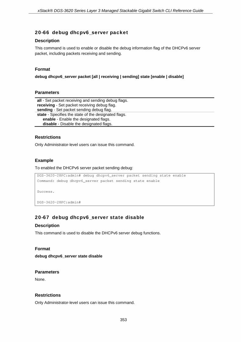
xStack® DGS-3620 Series Layer 3 Managed Stackable Gigabit Switch CLI Reference Guide
353
20-66 debug dhcpv6_server packet Description This command is used to enable or disable the debug information flag of the DHCPv6 server packet, including packets receiving and sending.
Format debug dhcpv6_server packet [all | receiving | sending] state [enable | disable]
Parameters all - Set packet receiving and sending debug flags. receiving - Set packet receiving debug flag. sending - Set packet sending debug flag. state - Specifies the state of the designated flags.
enable - Enable the designated flags. disable - Disable the designated flags.
Restrictions Only Administrator-level users can issue this command.
Example To enabled the DHCPv6 server packet sending debug:
DGS-3620-28PC:admin# debug dhcpv6_server packet sending state enable
Command: debug dhcpv6_server packet sending state enable
Success.
DGS-3620-28PC:admin#
20-67 debug dhcpv6_server state disable Description This command is used to disable the DHCPv6 server debug functions.
Format debug dhcpv6_server state disable
Parameters None.
Restrictions Only Administrator-level users can issue this command.

xStack® DGS-3620 Series Layer 3 Managed Stackable Gigabit Switch CLI Reference Guide
354
Example To disabled the DHCPv6 server debug function:
DGS-3620-28PC:admin# debug dhcpv6_server state disable
Command: debug dhcpv6_server state disable
Success.
DGS-3620-28PC:admin#
20-68 debug dhcpv6_server state enable Description This command is used to enable the DHCPv6 server debug functions.
Format debug dhcpv6_server state enable
Parameters None.
Restrictions Only Administrator-level users can issue this command.
Example To enabled the DHCPv6 server debug function:
DGS-3620-28PC:admin# debug dhcpv6_server state enable
Command: debug dhcpv6_server state enable
Success.
DGS-3620-28PC:admin#
20-69 debug pim ssm Description This command is used to enable the PIM-SSM debug function.
Format debug pim ssm

xStack® DGS-3620 Series Layer 3 Managed Stackable Gigabit Switch CLI Reference Guide
355
Parameters None.
Restrictions Only Administrator-level users can issue this command.
Example To enable the PIM-SSM debug function:
DGS-3620-28PC:admin# debug pim ssm
Command: debug pim ssm
Success.
DGS-3620-28PC:admin#
Once the PIM-SSM debug enabled, the debug information maybe outputted.
DGS-3620-28PC:admin# PIM_SSM, 6 Dec 2012 15:37:22 IGMP Group Record Type 2 for group 232.1.1.1 from 192.168.2.14 on n101, ignored.
Output truncated...
20-70 no debug pim ssm Description This command is used to disable the PIM-SSM debug function.
Format no debug pim ssm
Parameters None.
Restrictions Only Administrator-level users can issue this command.
Example To disable the PIM-SSM debug function:
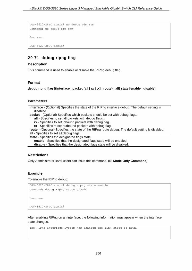
xStack® DGS-3620 Series Layer 3 Managed Stackable Gigabit Switch CLI Reference Guide
356
DGS-3620-28PC:admin# no debug pim ssm
Command: no debug pim ssm
Success.
DGS-3620-28PC:admin#
20-71 debug ripng flag Description This command is used to enable or disable the RIPng debug flag.
Format debug ripng flag [{interface | packet [all | rx | tx] | route} | all] state [enable | disable]
Parameters interface - (Optional) Specifies the state of the RIPng interface debug. The default setting is
disabled. packet - (Optional) Specifies which packets should be set with debug flags.
all - Specifies to set all packets with debug flags. rx - Specifies to set inbound packets with debug flag. tx - Specifies to set outbound packets with debug flag.
route - (Optional) Specifies the state of the RIPng route debug. The default setting is disabled. all - Specifies to set all debug flags. state - Specifies the designated flags state.
enable - Specifies that the designated flags state will be enabled. disable - Specifies that the designated flags state will be disabled.
Restrictions Only Administrator-level users can issue this command. (EI Mode Only Command)
Example To enable the RIPng debug:
DGS-3620-28PC:admin# debug ripng state enable
Command: debug ripng state enable
Success.
DGS-3620-28PC:admin#
After enabling RIPng on an interface, the following information may appear when the interface state changes.
The RIPng interface System has changed the link state to down.

xStack® DGS-3620 Series Layer 3 Managed Stackable Gigabit Switch CLI Reference Guide
357
20-72 debug ripng show flag Description This command is used to display the RIPng debug flag setting.
Format debug ripng show flag
Parameters None.
Restrictions Only Administrator-level users can issue this command. (EI Mode Only Command)
Example To show the current RIPng debug flag setting:
DGS-3620-28PC:admin# debug ripng show flag
Command: debug ripng show flag
Current RIPng debug level setting:
Packet Receiving
Packet Sending
Route
Interface State Change
DGS-3620-28PC:admin#
20-73 debug ripng state disable Description This command is used to disable the RIPng debug state.
Format debug ripng state disable
Parameters None.
Restrictions Only Administrator-level users can issue this command. (EI Mode Only Command)

xStack® DGS-3620 Series Layer 3 Managed Stackable Gigabit Switch CLI Reference Guide
358
Example To disable RIPng debug globally:
DGS-3620-28PC:admin# debug ripng state disable
Command: debug ripng state disable
Success.
DGS-3620-28PC:admin#
20-74 debug ripng state enable Description This command is used to enable the RIPng debug state.
Format debug ripng state enable
Parameters None.
Restrictions Only Administrator-level users can issue this command. (EI Mode Only Command)
Example To enable RIPng debug globally:
DGS-3620-28PC:admin# debug ripng state enable
Command: debug ripng state enable
Success.
DGS-3620-28PC:admin#
20-75 debug routefilter show Description This command is used to display route filter information in kernel, including prefix list, access list, and route map.
Format debug routefilter show [prefix_list | access_list | route_map | ipv6_prefix_list | ipv6_access_list]

xStack® DGS-3620 Series Layer 3 Managed Stackable Gigabit Switch CLI Reference Guide
359
Parameters prefix_list - Specifies to display IPv4 prefix list debug information. access_list - Specifies to display IPv4 access list debug information. route_map - Specifies to display route map debug information. ipv6_prefix_list - Specifies to display IPv6 prefix list debug information. ipv6_access_list - Specifies to display IPv6 access list debug information.
Restrictions Only Administrator-level users can issue this command.
Example To display route filter information in kernel:

xStack® DGS-3620 Series Layer 3 Managed Stackable Gigabit Switch CLI Reference Guide
360
DGS-3620-28PC:admin# debug routefilter show route_map
Command: debug routefilter show route_map
route-map 123,r_id:1
Sequence 1, type:1
Match clauses:
as-path (as-path filter): list1
community list1 exact
ip next-hop prefix-list 123
ip address prefix-list 123
metric 4294967294
ipv6 address prefix-list abc
ipv6 next-hop prefix-list abc
Set clauses:
Sequence 10, type:0
Match clauses:
Set clauses:
Sequence 100, type:1
Match clauses:
Set clauses:
Sequence 500, type:0
Match clauses:
Set clauses:
Sequence 1000, type:0
Match clauses:
Set clauses:
Sequence 5000, type:1
Match clauses:
Set clauses:
Sequence 10000, type:1
Match clauses:
Set clauses:
Sequence 65535, type:0
Match clauses:
Set clauses:
route-map ~!@#$%^&*()_+~!@,r_id:2
Sequence 10, type:0
Match clauses:
Set clauses:
Sequence 65535, type:0
Match clauses:
metric 4294967294
ipv6 next-hop 1::1
ipv6 address abc0
Set clauses:
DGS-3620-28PC:admin#
20-76 debug show status Description Show the debug handler state and the specified module’s debug status.

xStack® DGS-3620 Series Layer 3 Managed Stackable Gigabit Switch CLI Reference Guide
361
If the input module list is empty, the states of all registered modules which support debug module will be shown.
Format debug show status {module <module_list>}
Parameters module – (Optional) Specifies the module list.
<module_list> - Enter the module list here.
Restrictions Only Administrator-level users can issue this command.
Example To show the specified module’s debug state:
Prompt# debug show status module MSTP
Command: debug show status module MSTP
Debug Global State : Enable
MSTP : Enable
Prompt#
To show the debug state:
Prompt# debug show status
Command: debug show status
Debug Global State: Enable
MSTP : Disabled
IMPB : Disabled
DHCPv6_CLIENT : Disabled
DHCPv6_RELAY : Disabled
OSPFV2 : Disabled
VRRP : Disabled
RIPNG : Disabled
ERPS : Disabled
DHCPv6_SERVER : Disabled
Prompt#
20-77 debug super_vlan state Description This command is used to enable or disable the super VLAN Debug Function.

xStack® DGS-3620 Series Layer 3 Managed Stackable Gigabit Switch CLI Reference Guide
362
Format debug super_vlan state [enable | disable]
Parameters state - Specifies the super VLAN debug function state.
enable - Specifies that the super VLAN debug function will be enabled. disable - Specifies that the super VLAN debug function will be disabled.
Restrictions Only Administrator-level users can issue this command.
Example To disable the super VLAN Debug Function:
DGS-3620-28PC:admin# debug super_vlan state disable
Command: debug super_vlan state disable
Success.
DGS-3620-28PC:admin#
After enabling super VLAN debug, the following information may appear when receive an ARP packet form sub VLAN.
The ARP request packet received from sub vlan 200.
20-78 debug show address_binding binding_state_table Description This command is used to display the binding state of the entries in the binding state table.
Format debug show address_binding binding_state_table [nd_snooping | dhcpv6_snooping]
Parameters nd_snooping - Specifies to debug ND Snooping bound addresses in the binding state table. dhcpv6_snooping - Specifies to debug DHCPv6 Snooping bound addresses in the binding state
table.
Restrictions Only Administrator-level users can issue this command.
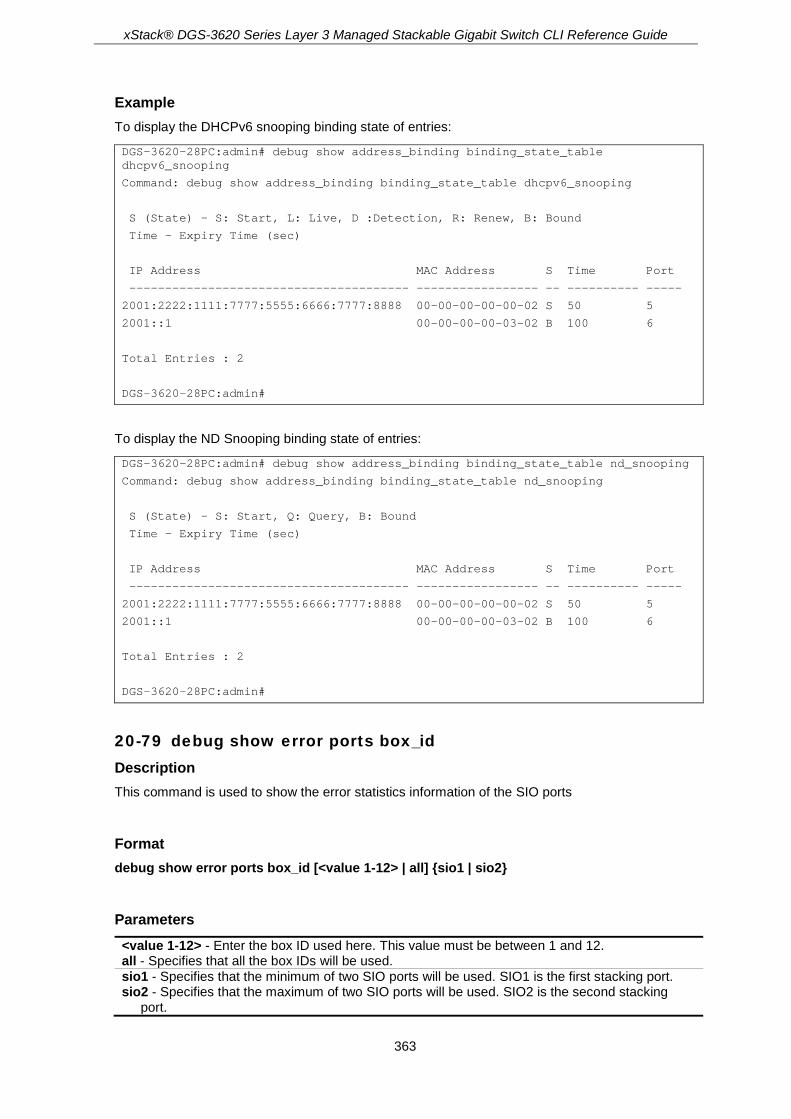
xStack® DGS-3620 Series Layer 3 Managed Stackable Gigabit Switch CLI Reference Guide
363
Example To display the DHCPv6 snooping binding state of entries:
DGS-3620-28PC:admin# debug show address_binding binding_state_table dhcpv6_snooping
Command: debug show address_binding binding_state_table dhcpv6_snooping
S (State) - S: Start, L: Live, D :Detection, R: Renew, B: Bound
Time - Expiry Time (sec)
IP Address MAC Address S Time Port
--------------------------------------- ----------------- -- ---------- -----
2001:2222:1111:7777:5555:6666:7777:8888 00-00-00-00-00-02 S 50 5
2001::1 00-00-00-00-03-02 B 100 6
Total Entries : 2
DGS-3620-28PC:admin#
To display the ND Snooping binding state of entries:
DGS-3620-28PC:admin# debug show address_binding binding_state_table nd_snooping
Command: debug show address_binding binding_state_table nd_snooping
S (State) - S: Start, Q: Query, B: Bound
Time - Expiry Time (sec)
IP Address MAC Address S Time Port
--------------------------------------- ----------------- -- ---------- -----
2001:2222:1111:7777:5555:6666:7777:8888 00-00-00-00-00-02 S 50 5
2001::1 00-00-00-00-03-02 B 100 6
Total Entries : 2
DGS-3620-28PC:admin#
20-79 debug show error ports box_id Description This command is used to show the error statistics information of the SIO ports
Format debug show error ports box_id [<value 1-12> | all] {sio1 | sio2}
Parameters <value 1-12> - Enter the box ID used here. This value must be between 1 and 12. all - Specifies that all the box IDs will be used. sio1 - Specifies that the minimum of two SIO ports will be used. SIO1 is the first stacking port. sio2 - Specifies that the maximum of two SIO ports will be used. SIO2 is the second stacking
port.

xStack® DGS-3620 Series Layer 3 Managed Stackable Gigabit Switch CLI Reference Guide
364
Restrictions Only Administrator-level users can issue this command.
Example To show error statistics information of the SIO port:
DGS-3620-28PC:admin#debug show error ports box_id all sio1
Command: debug show error ports box_id all sio1
Box ID 1 SIO 1:
RX Frames TX Frames
--------- ---------
CRC Error 0 Excessive Deferral 0
Undersize 0 CRC Error 0
Oversize 0 Late Collision 0
Fragment 0 Excessive Collision 0
Jabber 0 Single Collision 0
Buffer Full Drop 0 Collision 0
Symbol Error 0 STP Drop 0
Multicast Drop 0 HOL DROP 0
VLAN Ingress Drop 0 COS0 HOL DROP 0
STP Drop 0 COS1 HOL DROP 0
MTU Drop 0 COS2 HOL DROP 0
COS3 HOL DROP 0
COS4 HOL DROP 0
COS5 HOL DROP 0
COS6 HOL DROP 0
COS7 HOL DROP 0
CTRL+C ESC q Quit SPACE n Next Page ENTER Next Entry a All
20-80 debug show jwac auth_info Description This command is used to show debug information of JWAC.
Format debug show jwac auth_info
Parameters None.
Restrictions Only Administrators, Operators and Power-Users can issue this command.

xStack® DGS-3620 Series Layer 3 Managed Stackable Gigabit Switch CLI Reference Guide
365
Example To display debug information of JWAC:
DGS-3620-28PC:admin#debug show jwac auth_info
Command: debug show jwac auth_info
ACL Index Bitmap DB (jwac_db_acl_bmp):
00 00 00 00 00 00 00 00 00 00 00 00 00 00 00 00 00 00 00 00
00 00 00 00 00 00 00 00 00 00 00 00 00 00 00 00 00 00 00 00
00 00 00 00 00 00 00 00 00 00 00
Internal TCP Port Number (jwac_internal_port_bitmap):
FF FF FF FF FF FF FF FF FF FF FF FF FF FF FF FF FF FF FF FF
FF FF FF FF FF FF FF FF FF FF FF FF FF FF FF FF FF FF FF FF
FF FF FF FF FF FF FF FF FF FF FF FF FF FF FF FF FF FF FF FF
FF FF FF FF FF FF FF FF FF FF FF FF FF FF FF FF FF FF FF FF
FF FF FF FF FF FF FF FF FF FF FF FF FF FF FF FF FF FF FF FF
FF FF FF FF FF FF FF FF FF FF FF FF FF FF FF FF FF FF FF FF
FF FF FF FF FF FF FF FF
Connection DB:
No Host
Current AUTH DB (_jwac_db_nodes):
No Host
Ports AUTH Info: (_jwac_db_nodes)
port mac state last_bytes authing_cnt authed_cnt
----- ------------------ -------- ---------- ----------- -----------
JWAC Web data (jwac_web_auth_result_list):
CTRL+C ESC q Quit SPACE n Next Page ENTER Next Entry a All
20-81 debug show packet ports box_id Description This command is used to show the packet statistics information of the SIO ports.
Format debug show packet ports box_id [<value 1-12> | all] {sio1 | sio2}
Parameters <value 1-12> - Enter the box ID used here. This value must be between 1 and 12. all - Specifies that all the box IDs will be used. sio1 - Specifies that the minimum of two SIO ports will be used. SIO1 is the first stacking port. sio2 - Specifies that the maximum of two SIO ports will be used. SIO2 is the second stacking
port.
Restrictions Only Administrator-level users can issue this command.
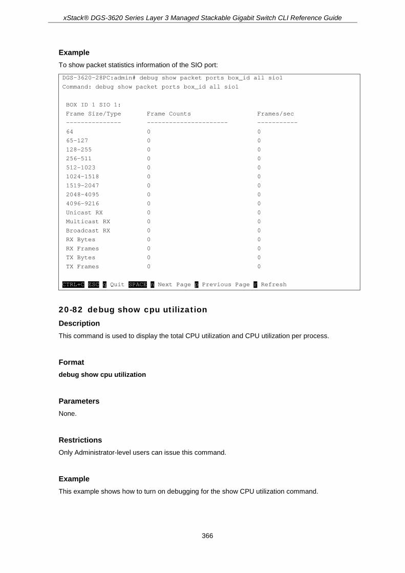
xStack® DGS-3620 Series Layer 3 Managed Stackable Gigabit Switch CLI Reference Guide
366
Example To show packet statistics information of the SIO port:
DGS-3620-28PC:admin# debug show packet ports box_id all sio1
Command: debug show packet ports box_id all sio1
BOX ID 1 SIO 1:
Frame Size/Type Frame Counts Frames/sec
--------------- ---------------------- -----------
64 0 0
65-127 0 0
128-255 0 0
256-511 0 0
512-1023 0 0
1024-1518 0 0
1519-2047 0 0
2048-4095 0 0
4096-9216 0 0
Unicast RX 0 0
Multicast RX 0 0
Broadcast RX 0 0
RX Bytes 0 0
RX Frames 0 0
TX Bytes 0 0
TX Frames 0 0
CTRL+C ESC q Quit SPACE n Next Page p Previous Page r Refresh
20-82 debug show cpu utilization Description This command is used to display the total CPU utilization and CPU utilization per process.
Format debug show cpu utilization
Parameters None.
Restrictions Only Administrator-level users can issue this command.
Example This example shows how to turn on debugging for the show CPU utilization command.

xStack® DGS-3620 Series Layer 3 Managed Stackable Gigabit Switch CLI Reference Guide
367
DGS-3620-28PC:admin# debug show cpu utilization
Command: debug show cpu utilization
Five seconds - 14 % One minute - 14 % Five minutes - 14 %
Process Name 5Sec 1Min 5Min
----------------- ------ ------ ------
OS_UTIL 84 % 86 % 86 %
bcmL2X.0 8 % 7 % 7 %
bcmCNTR.0 2 % 2 % 2 %
MAUMIB_TASK 1 % 1 % 1 %
GBIC_Pooling 1 % 0 % 0 %
FAN_Pooling 1 % 0 % 0 %
DGS-3620-28PC:admin#
20-83 debug ntp level Description This command is used to to set NTP debug function.
Format debug ntp level <value 0-255>
Parameters <value 0-255> - 0 will disable debug message and increasing this value will get more detailed
debug message.
Restrictions Only Administrators, Operators and Power-Users can issue this command.
Example DGS-3620-28PC:admin#debug ntp level 1
Command: debug ntp level 1
Success.
DGS-3620-28PC:admin#

xStack® DGS-3620 Series Layer 3 Managed Stackable Gigabit Switch CLI Reference Guide
368
Chapter 21 DHCP Local Relay Commands
config dhcp_local_relay vlan <vlan_name 32> state [enable | disable] config dhcp_local_relay vlan vlanid <vlan_id 1-4094> state [enable | disable] enable dhcp_local_relay disable dhcp_local_relay show dhcp_local_relay
21-1 config dhcp_local_relay vlan Description This command is used to enable or disable the DHCP local relay function for a specified VLAN. By default, the switch will not broadcast DHCP packets on any VLAN for which a DHCP relay is configured. DHCP packets will be intercepted, and only be relayed to the servers specified in the dhcp_relay command. This is done to minimise the risk with rogue DHCP servers. Enabling the dhcp_local_relay feature will restore the broadcast behaviour, and cause DHCP packets also to be broadcasted on the specified VLAN.
Note: When “dhcp_local_relay” is enabled, the switch will automatically add DHCP option 82, and the source MAC and gateway in the packet will remain unchanged.
Format config dhcp_local_relay vlan <vlan_name 32> state [enable | disable]
Parameters <vlan_name 32> - Enter the name of the VLAN to be enabled for DHCP local relay. state - Enable or disable DHCP local relay for a specified VLAN.
enable - Enable DHCP local relay for a specified VLAN. disable - Disable DHCP local relay for a specified VLAN.
Restrictions Only Administrators, Operators and Power-Users can issue this command.
Example To enable DHCP local relay for the default VLAN:
DGS-3620-28PC:admin#config dhcp_local_relay vlan default state enable
Command: config dhcp_local_relay vlan default state enable
Success.
DGS-3620-28PC:admin#

xStack® DGS-3620 Series Layer 3 Managed Stackable Gigabit Switch CLI Reference Guide
369
21-2 config dhcp_local_relay vlan vlanid Description This command is used to enable or disable the DHCP local relay function for a specified VLAN ID.
Format config dhcp_local_relay vlan vlanid <vlan_id 1-4094> state [enable | disable]
Parameters vlanid - Specifies the VLAN ID used to enabled DHCP local relay.
<vlan_id 1-4094> - Enter the VLAN ID used here. This value must be between 1 and 4094. state - Enable or disable DHCP local relay for a specified VLAN.
enable - Enable DHCP local relay for a specified VLAN. disable - Disable DHCP local relay for a specified VLAN.
Restrictions Only Administrators, Operators and Power-Users can issue this command.
Example To enable DHCP local relay for the default VLAN:
DGS-3620-28PC:admin#config dhcp_local_relay vlan vlanid 1 state enable
Command: config dhcp_local_relay vlan vlanid 1 state enable
Success.
DGS-3620-28PC:admin#
21-3 enable dhcp_local_relay Description This command is used to globally enable the DHCP local relay function on the switch.
Format enable dhcp_local_relay
Parameters None.
Restrictions Only Administrators, Operators and Power-Users can issue this command.
Example To enable the DHCP local relay function:

xStack® DGS-3620 Series Layer 3 Managed Stackable Gigabit Switch CLI Reference Guide
370
DGS-3620-28PC:admin#enable dhcp_local_relay
Command: enable dhcp_local_relay
Success.
DGS-3620-28PC:admin#
21-4 disable dhcp_local_relay Description This command is used to globally disable the DHCP local relay function on the switch.
Format disable dhcp_local_relay
Parameters None.
Restrictions Only Administrators, Operators and Power-Users can issue this command.
Example To disable the DHCP local relay function:
DGS-3620-28PC:admin#disable dhcp_local_relay
Command: disable dhcp_local_relay
Success.
DGS-3620-28PC:admin#
21-5 show dhcp_local_relay Description This command is used to display the current DHCP local relay configuration on the switch.
Format show dhcp_local_relay
Parameters None.
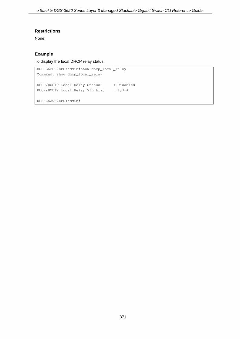
xStack® DGS-3620 Series Layer 3 Managed Stackable Gigabit Switch CLI Reference Guide
371
Restrictions None.
Example To display the local DHCP relay status:
DGS-3620-28PC:admin#show dhcp_local_relay
Command: show dhcp_local_relay
DHCP/BOOTP Local Relay Status : Disabled
DHCP/BOOTP Local Relay VID List : 1,3-4
DGS-3620-28PC:admin#

xStack® DGS-3620 Series Layer 3 Managed Stackable Gigabit Switch CLI Reference Guide
372
Chapter 22 DHCP Relay Commands
config dhcp_relay {hops <int 1-16> | time <sec 0-65535>}(1) config dhcp_relay add ipif <ipif_name 12> <ipaddr> config dhcp_relay delete ipif <ipif_name 12> <ipaddr> config dhcp_relay option_60 add string < multiword 255> relay <ipaddr> [exact-match | partial-
match] config dhcp_relay option_60 default [relay <ipaddr> | mode [relay | drop]] config dhcp_relay option_60 delete [string < multiword 255> {relay <ipaddr>} | ipaddress
<ipaddr> | all | default {<ipaddr>}] config dhcp_relay option_60 state [enable | disable] config dhcp_relay option_61 add [mac_address <macaddr> | string < desc_long 255>] [relay
<ipaddr> | drop] config dhcp_relay option_61 default [relay <ipaddr> | drop] config dhcp_relay option_61 delete [mac_address <macaddr> | string <desc_long 255> | all] config dhcp_relay option_61 state [enable | disable] config dhcp_relay option_82 check [enable | disable] config dhcp_relay option_82 circuit_id [default | user_define <string 32> | vendor6] config dhcp_relay option_82 policy [replace | drop | keep] config dhcp_relay option_82 remote_id [default | user_define <string 32>] config dhcp_relay option_82 state [enable | disable] enable dhcp_relay disable dhcp_relay show dhcp_relay {ipif <ipif_name 12>} show dhcp_relay option_60 {[string < multiword 255> | ipaddress <ipaddr> | default]} show dhcp_relay option_61 config dhcp_relay ports [<portlist> | all] state [enable | disable] show dhcp_relay ports {<portlist>} config dhcp_relay unicast [enable | disable]
Note: The DHCP relay commands include all the commands defined in the BOOTP relay
command section. If this DHCP relay command set is supported in your system, the BOOTP relay commands can be ignored.
Note: The system supporting DHCP relay will accept BOOTP relay commands in the config file but not allow input from the console screen, and these BOOTP relay commands setting from the config file will be saved as DHCP relay commands while the save command is performed.
22-1 config dhcp_relay Description This command is used to configure the DHCP relay feature of the switch.
Format config dhcp_relay {hops <int 1-16> | time <sec 0-65535>}(1)

xStack® DGS-3620 Series Layer 3 Managed Stackable Gigabit Switch CLI Reference Guide
373
Parameters hops - Specifies the maximum number of router hops that the DHCP/BOOTP packets can cross.
The range is 1 to 16. The default value is 4. <int 1-16> - Enter the maximum number of router hops that the DHCP/BOOTP packets can
cross. The maximum number of hops value must be between 1 and 16. time - Specifies the minimum time in seconds within which the switch must relay the
DHCP/BOOTP request. If this time is larger than the DHCP packet’s time, the switch will drop the DHCP/BOOTP packet. The range is 0 to 65535. The default value is 0. <sec 0-65535> - Enter the minimum time in seconds within which the switch must relay the
DHCP/BOOTP request. The minimum time value must be between 0 and 65535 seconds.
Restrictions Only Administrators, Operators and Power-Users can issue this command.
Example To configure the DHCP relay:
DGS-3620-28PC:admin#config dhcp_relay hops 4 time 2
Command: config dhcp_relay hops 4 time 2
Success.
DGS-3620-28PC:admin#
22-2 config dhcp_relay add ipif Description This command is used to add an IP destination address to the switch’s DHCP relay table.
Note: Adding a server to which DHCP packets will be relayed, will cause the switch to intercept DHCP packets on the specified VLAN, and relay them directly to the specified server. DHCP packets will not be broadcast on the VLAN. To restore broadcast functionality, see the “dhcp_local_relay” command
Format config dhcp_relay add ipif <ipif_name 12> <ipaddr>
Parameters <ipif_name 12> - Enter the name of the IP interface which contains the IP address below. <ipaddr> - Enter the DHCP/BOOTP server IP address.
Restrictions Only Administrators, Operators and Power-Users can issue this command.

xStack® DGS-3620 Series Layer 3 Managed Stackable Gigabit Switch CLI Reference Guide
374
Example To add an IP destination address to the switch’s DHCP relay table:
DGS-3620-28PC:admin#config dhcp_relay add ipif System 10.43.21.12
Command: config dhcp_relay add ipif System 10.43.21.12
Success.
DGS-3620-28PC:admin#
22-3 config dhcp_relay delete ipif Description This command is used to delete an IP destination address from the switch’s DHCP relay table.
Format config dhcp_relay delete ipif <ipif_name 12> <ipaddr>
Parameters <ipif_name 12> - Enter the name of the IP interface which contains the IP address below. <ipaddr> - Enter the DHCP/BOOTP server IP address.
Restrictions Only Administrators, Operators and Power-Users can issue this command.
Example To delete an IP destination address from the switch’s DHCP relay table:
DGS-3620-28PC:admin#config dhcp_relay delete ipif System 10.43.21.12
Command: config dhcp_relay delete ipif System 10.43.21.12
Success.
DGS-3620-28PC:admin#
22-4 config dhcp_relay option_60 add string Description This command is used to configure the Option 60 relay rules. Note that different strings can be specified with the same relay server, and the same string can be specified with multiple relay servers. The system will relay the packet to all the matching servers.
Format config dhcp_relay option_60 add string <multiword 255> relay <ipaddr> [exact-match | partial-match]

xStack® DGS-3620 Series Layer 3 Managed Stackable Gigabit Switch CLI Reference Guide
375
Parameters < multiword 255> - Enter a string. relay - Specifies a relay server IP address.
<ipaddr> - Enter the IP address here. exact-match - The Option 60 string in the packet must fully match the specified string. partial-match - The Option 60 string in the packet only need partially match the specified string.
Restrictions Only Administrators, Operators and Power-Users can issue this command.
Example To configure DHCP Option 60 to decide to relay which DHCP server:
DGS-3620-28PC:admin#config dhcp_relay option_60 add string “abc” relay 10.90.90.1 exact-match
Command: config dhcp_relay option_60 add string “abc” relay 10.90.90.1 exact-match
Success.
DGS-3620-28PC:admin#
22-5 config dhcp_relay option_60 default Description This command is used to configure DHCP relay Option 60 default relay servers. When there are no match servers found for the packet based on Option 60, the relay servers will be determined by the default relay server setting. When drop is specified, the packet with no matching rules found will be dropped without further processing. If the setting is no- drop, then the packet will be processed further based on Option 61. The final relay servers will be the union of Option 60 default relay servers and the relay servers determined by Option 61.
Format config dhcp_relay option_60 default [relay <ipaddr> | mode [relay | drop]]
Parameters relay - Specifies a relay server IP for the packet that has matching Option 60 rules.
<ipaddr> - Enter the server IP address here. mode - Specifies the mode to relay or drop packets.
relay - The packet will be relayed based on the relay rules. drop - Specifies to drop the packet that has no matching Option 60 rules.
Restrictions Only Administrators, Operators and Power-Users can issue this command.

xStack® DGS-3620 Series Layer 3 Managed Stackable Gigabit Switch CLI Reference Guide
376
Example To configure a DHCP Option 60 default drop action:
DGS-3620-28PC:admin#config dhcp_relay option_60 default mode drop
Command: config dhcp_relay option_60 default mode drop
Success.
DGS-3620-28PC:admin#
22-6 config dhcp_relay option_60 delete Description This command is used to delete a DHCP Option 60 entry. When all is specified, all rules excluding the default rules are deleted.
Format config dhcp_relay option_60 delete [string < multiword 255> {relay <ipaddr>} | ipaddress <ipaddr> | all | default {<ipaddr>}]
Parameters string - Delete all the entries whose string is equal to the string specified if the IP address is not
specified. <multiword 255> - The string value can be up to 255 characters long.
relay - (Optional) Delete one entry, whose string and IP address are equal to the string and IP address specified by the user. <ipaddr> - Enter the IP address here.
ipaddress - Delete all the entries whose IP address are equal to the specified IP address. <ipaddr> - Enter the IP address here.
all - Specifies to have all rules, excluding the default rules, deleted. default - Delete the default relay IP address that is specified by the user.
<ipaddr> - (Optional) Enter the IP address here.
Restrictions Only Administrators, Operators and Power-Users can issue this command.
Example To delete a DHCP Option 60 entry:
DGS-3620-28PC:admin# config dhcp_relay option_60 delete string "abc" relay 10.90.90.1
Command: config dhcp_relay option_60 delete string "abc" relay 10.90.90.1
Success.
DGS-3620-28PC:admin#

xStack® DGS-3620 Series Layer 3 Managed Stackable Gigabit Switch CLI Reference Guide
377
22-7 config dhcp_relay option_60 state Description This command is used to decide whether DHCP relay will process the DHCP Option 60 or not. When Option 60 is enabled, if the packet does not have Option 60, then the relay servers cannot be determined based on Option 60. The relay servers will be determined based on either Option 61 or per IPIF configured servers.
Format config dhcp_relay option_60 state [enable | disable]
Parameters enable - Specifies to enable the DHCP relay function to use option 60 rules to relay DHCP
packets. disable - Specifies to disable the DHCP relay function from using option 60 rules to relay DHCP
packets.
Restrictions Only Administrators, Operators and Power-Users can issue this command.
Example To configure the DHCP Option 60 state:
DGS-3620-28PC:admin#config dhcp_relay option_60 state enable
Command: config dhcp_relay option_60 state enable
Success.
DGS-3620-28PC:admin#
22-8 config dhcp_relay option_61 add Description This command adds a rule to determine the relay server based on Option 61. The match rule can be based on either MAC address or a user-specified string. Only one relay server can be specified for a MAC address or a string. If relay servers are determined based on Option 60, and one relay server is determined based on Option 61, the final relay servers will be the union of these two sets of the servers.
Format config dhcp_relay option_61 add [mac_address <macaddr> | string <desc_long 255>] [relay <ipaddr> | drop]
Parameters mac_address - Specifies the client’s client-ID, which is the hardware address of the client.

xStack® DGS-3620 Series Layer 3 Managed Stackable Gigabit Switch CLI Reference Guide
378
<macaddr> - Enter the client’s client-ID, which is the MAC address of the client. string - Specifies the client’s client-ID, which is specified by administrator.
<desc_long 255> - Enter the client’s client-ID, which is specified by administrator The client-ID string can be up to 255 characters long.
relay - Specifies to relay the packet to an IP address. <ipaddr> - Enter to relay the packet to an IP address by entering the IP address here.
drop - Specifies to drop the packet.
Restrictions Only Administrators, Operators and Power-Users can issue this command.
Example To configure DHCP Option 61 to decide how to process DHCP packets:
DGS-3620-28PC:admin#config dhcp_relay option_61 add mac_address 00-11-22-33-44-55 drop
Command: config dhcp_relay option_61 add mac_address 00-11-22-33-44-55 drop
Success.
DGS-3620-28PC:admin#
22-9 config dhcp_relay option_61 default Description This command is used to determine the rule to process those packets that have no Option 61 matching rules. The default default-rule is drop.
Format config dhcp_relay option_61 default [relay <ipaddr> | drop]
Parameters relay - Specifies to relay the packet that has no option matching 61 matching rules to an IP
address. <ipaddr> - Enter the IP address here.
drop - Specifies to drop the packet that have no Option 61 matching rules.
Restrictions Only Administrators, Operators and Power-Users can issue this command.
Example To configure the DHCP Option 61 default action to drop:

xStack® DGS-3620 Series Layer 3 Managed Stackable Gigabit Switch CLI Reference Guide
379
DGS-3620-28PC:admin#config dhcp_relay option_61 default drop
Command: config dhcp_relay option_61 default drop
Success.
DGS-3620-28PC:admin#
22-10 config dhcp_relay option_61 delete Description This command is used to delete Option 61 rules.
Format config dhcp_relay option_61 delete [mac_address <macaddr> | string <desc_long 255> | all]
Parameters mac_address - The entry with the specified MAC address will be deleted
<macaddr> - Enter the MAC address here. string - The entry with the specified string will be deleted.
<desc_long 255> - The string value can be up to 255 characters long. all - All rules excluding the default rule will be deleted.
Restrictions Only Administrators, Operators and Power-Users can issue this command.
Example To delete a DHCP Option 61 entry:
DGS-3620-28PC:admin#config dhcp_relay option_61 delete mac_address 00-11-22-33-44-55
Command: config dhcp_relay option_61 delete mac_address 00-11-22-33-44-55
Success.
DGS-3620-28PC:admin#
22-11 config dhcp_relay option_61 state Description This command is used to decide whether DHCP relay will process the DHCP Option 61 or not. When Option 61 is enabled, if the packet does not have Option 61, then the relay servers cannot be determined based on Option 61. If the relay servers are determined based on Option 60 or Option 61, then per IPIF configured servers will be ignored. If the relay servers are not determined either by Option 60 or Option 61, then per IPIF configured servers will be used to determine the relay servers.

xStack® DGS-3620 Series Layer 3 Managed Stackable Gigabit Switch CLI Reference Guide
380
Format config dhcp_relay option_61 state [enable | disable]
Parameters enable - Specifies to enable the DHCP relay function to use option 61 rules to relay DHCP
packets. disable - Specifies to disable the DHCP relay function to use option 61 rules to relay DHCP
packets.
Restrictions Only Administrators, Operators and Power-Users can issue this command.
Example To configure the state of DHCP relay Option 61:
DGS-3620-28PC:admin#config dhcp_relay option_61 state enable
Command: config dhcp_relay option_61 state enable
Success.
DGS-3620-28PC:admin#
22-12 config dhcp_relay option_82 check Description This command is used to configure the checking mechanism of the DHCP relay agent information Option 82 of the switch.
Format config dhcp_relay option_82 check [enable | disable]
Parameters enable - When the state is enabled, for a packet coming from the client side, the packet should
not have the Option 82 field. If the packet has this option field, it will be dropped. disable - The default setting is disabled.
Restrictions Only Administrators, Operators and Power-Users can issue this command.
Example To configure the checking mechanism of the DHCP relay agent information Option 82:
DGS-3620-28PC:admin#config dhcp_relay option_82 check disable
Command: config dhcp_relay option_82 check disable

xStack® DGS-3620 Series Layer 3 Managed Stackable Gigabit Switch CLI Reference Guide
381
Success.
DGS-3620-28PC:admin#
22-13 config dhcp_relay option_82 circuit_id Description This command is used to configure the DHCP relay option 82 circuit ID.
Format config dhcp_relay option_82 circuit_id [default | user_define <string 32> | vendor6]
Parameters default - Specifies that the original format of the circuit ID will be used. The original format is as
follows: a. b. c. d. e. f. g. 1 0x6 0 4 VLAN Module ID Port ID 1 byte 1 byte 1 byte 1 byte 2 bytes 1 byte 1 byte
a. Sub-option type (1 means circuit ID) b. Length, it should be 6. c. Circuit ID’s sub-option, it should be 0. d. Sub-option’s length, it should be 4 e. VLAN ID (S-VID) f. Module ID, for standalone switch, it is 0; for stacking switch, it is the box ID that
assigned by stacking. g. Port ID: port number of each box.
user_define – Specifies that a user-defined circuit ID will be used. The format is as follows: a. b. c. d. e. 2 n+2 1 n user define 1 byte 1 byte 1 byte 1 byte Max. 32 bytes
<desc 32> - Enter the user-defined ID. Space is allowed in the string. vendor6 – Specifies to use the vendor 6 specific circuit ID format. The format is as follows:
a. b. c. d. e. f. g. h. i. 1 n System
name - Module
ID / Port ID - CVID
1 byte 1 byte 0-128 bytes
1 byte 1 byte 1 byte 1-2 bytes
1 byte 1-4 bytes
a. Sub-option type (1 means circuit ID) b. Length: Total lengths of all follow fields. c. System name. d. Separator character e. Module ID f. Separator character. g. Port ID: port number h. Separator character i. CVID(Client VLAN ID)
Restrictions Only Administrators, Operators and Power-Users can issue this command.

xStack® DGS-3620 Series Layer 3 Managed Stackable Gigabit Switch CLI Reference Guide
382
Example To configure the ciruit ID as vendor 6:
DGS-3620-28PC:admin# config dhcp_relay option_82 circuit_id vendor6
Command: config dhcp_relay option_82 circuit_id vendor6
Success.
DGS-3620-28PC:admin#
22-14 config dhcp_relay option_82 policy Description This option takes effect only when the check status is disabled. The relay agent does this operation because the packet cannot contain two Option 82s. The default setting is replace.
Format config dhcp_relay option_82 policy [replace | drop | keep]
Parameters replace - Replace the existing option 82 field in the packet. drop - Specifies to discard if the packet has the Option 82 field. If the packet, that comes from the
client side, contains an Option 82 value, then the packet will be dropped. If the packet, that comes from the client side doesn’t contain an Option 82 value, then insert it's own Option 82 value into the packet.
keep - Specifies to retain the existing Option 82 field in the packet. The default setting is replace. If the packet, that comes from the client side, and contains an Option 82 value, then keep the old Option 82 value. If the packet, that comes from the client side, doesn’t contain an Option 82 value, then insert it's own Option 82 value into the packet.
Restrictions Only Administrators, Operators and Power-Users can issue this command.
Example To configure the policy of DHCP relay agent information Option 82:
DGS-3620-28PC:admin# config dhcp_relay option_82 policy replace
Command: config dhcp_relay option_82 policy replace
Success
DGS-3620-28PC:admin#
22-15 config dhcp_relay option_82 remote_id Description This command is used to configure the remote ID string of the DHCP relay agent information Option 82 of the Switch.

xStack® DGS-3620 Series Layer 3 Managed Stackable Gigabit Switch CLI Reference Guide
383
Format config dhcp_relay option_82 remote_id [default | user_define <string 32>]
Parameters default - Use the switch’s system MAC address as remote ID. user_define - Use the user-defined string as remote ID. Space characters are allowed in the
string. <string 32> - The user-defined string can be up to 32 characters long.
Restrictions Only Administrators, Operators and Power-Users can issue this command.
Example To configure the remote ID string of the DHCP relay agent information Option 82:
DGS-3620-28PC:admin#config dhcp_relay option_82 remote_id user_define D-Link Switch
Command: config dhcp_relay option_82 remote_id user_define D-Link Switch
Success.
DGS-3620-28PC:admin#
22-16 config dhcp_relay option_82 state Description This command is used to configure the state of the DHCP relay agent information Option 82 of the switch. The default settings is disabled.
Format config dhcp_relay option_82 state [enable | disable]
Parameters enable - When the state is enabled, the DHCP packet will be inserted with the Option 82 field
before being relayed to server. The DHCP packet will be processed based on the behavior defined in the check and policy setting.
disable - When the state is disabled, the DHCP packet will be relayed directly to the server without further check and processing of the packet.
Restrictions Only Administrators, Operators and Power-Users can issue this command.

xStack® DGS-3620 Series Layer 3 Managed Stackable Gigabit Switch CLI Reference Guide
384
Example To configure the state of the DHCP relay agent information Option 82:
DGS-3620-28PC:admin#config dhcp_relay option_82 state enable
Command: config dhcp_relay option_82 state enable
Success.
DGS-3620-28PC:admin#
22-17 enable dhcp_relay Description This command is used to enable the DHCP relay function on the switch.
Format enable dhcp _relay
Parameters None.
Restrictions Only Administrators, Operators and Power-Users can issue this command.
Example To enable the DHCP relay function:
DGS-3620-28PC:admin#enable dhcp_relay
Command: enable dhcp_relay
Success.
DGS-3620-28PC:admin#
22-18 disable dhcp_relay Description This command is used to disable the DHCP relay function on the switch.
Format disable dhcp _relay
Parameters None.

xStack® DGS-3620 Series Layer 3 Managed Stackable Gigabit Switch CLI Reference Guide
385
Restrictions Only Administrators, Operators and Power-Users can issue this command.
Example To disable the DHCP relay function:
DGS-3620-28PC:admin#disable dhcp_relay
Command: disable dhcp_relay
Success.
DGS-3620-28PC:admin#
22-19 show dhcp_relay Description This command is used to display the current DHCP relay configuration.
Format show dhcp_relay {ipif <ipif_name 12>}
Parameters ipif – (Optional) Specifies the IP interface name.
<ipif_name 12> - Enter the IP interface name. The IP interface name can be up to 12 characters long.
Note: If no parameter is specified, the system will display all DHCP relay configurations.
Restrictions None.
Example To display the DHCP relay status:
DGS-3620-28PC:admin#show dhcp_relay
Command: show dhcp_relay
DHCP/BOOTP Relay Status : Disabled
DHCP/BOOTP Relay Unicast Status : Disabled
DHCP/BOOTP Hops Count Limit : 4
DHCP/BOOTP Relay Time Threshold : 0
DHCP Vendor Class Identifier Option 60 State: Disabled
DHCP Client Identifier Option 61 State: Disabled

xStack® DGS-3620 Series Layer 3 Managed Stackable Gigabit Switch CLI Reference Guide
386
DHCP Relay Agent Information Option 82 State : Disabled
DHCP Relay Agent Information Option 82 Check : Disabled
DHCP Relay Agent Information Option 82 Policy : Replace
DHCP Relay Agent Information Option 82 Remote ID : default
DHCP Relay Agent Information Option 82 Circuit ID : default
Interface Server 1 Server 2 Server 3 Server 4
------------ --------------- --------------- --------------- ---------------
DGS-3620-28PC:admin#
22-20 show dhcp_relay option_60 Description This command is used to display the DHCP relay option 60 entries.
Format show dhcp_relay option_60 {[string <multiword 255> | ipaddress <ipaddr> | default]}
Parameters string - (Optional) Display the entry whose string equals the string specified.
<multiword 255> - The string can be up to 255 characters long. ipaddress - (Optional) Display the entry whose IP ipaddress equals the specified IP address.
<ipaddr> - Enter the IP address here. default - (Optional) Display the default behaviour of DHCP relay option 60.
Note: If no parameter is specified, all DHCP option 60 entries will be displayed.
Restrictions None.
Example To display the DHCP option 60 entries:
DGS-3620-28PC:admin#show dhcp_relay option_60
Command: show dhcp_relay option_60
Default Processing Mode: Drop
Default Servers:
10.90.90.100
10.90.90.101
10.90.90.102
Matching Rules:

xStack® DGS-3620 Series Layer 3 Managed Stackable Gigabit Switch CLI Reference Guide
387
String Match Type IP Address
------- --------- ---------
abc Exact Match 10.90.90.1
abcde Partial Match 10.90.90.2
abcdefg Exact Match 10.90.90.3
Total Entries: 3
DGS-3620-28PC:admin#
22-21 show dhcp_relay option_61 Description This command is used to display all the DHCP relay option 61 rules.
Format show dhcp_relay option_61
Parameters None.
Restrictions None.
Example To display the DHCP option 61 entries:
DGS-3620-28PC:admin#show dhcp_relay option_61
Command: show dhcp_relay option_61
Default Relay Rule:Drop
Matching Rules:
Client-ID Type Relay Rule
----------- ---- ---------
abc String Drop
abcde String 10.90.90.1
00-11-22-33-44-55 MAC Address Drop
Total Entries: 3
DGS-3620-28PC:admin#

xStack® DGS-3620 Series Layer 3 Managed Stackable Gigabit Switch CLI Reference Guide
388
22-22 config dhcp_relay ports Description This command is used to configure the state of the DHCP relay function for each port.
Format config dhcp_relay ports [<portlist> | all] state [enable | disable]
Parameters <portlist> - Enter the list of ports, used for this configuration, here. all - Specifies that all the ports will be used for this configuration. state - Specifies the state of the DHCP relay function for each port.
enable - Specifies that the DHCP relay function, for the specified port(s), will be enabled. disable - Specifies that the DHCP relay function, for the specified port(s), will be disabled.
Restrictions Only Administrators, Operators and Power-Users can issue this command.
Example To enable the DHCP relay function on ports 1 to 3:
DGS-3620-28PC:admin#config dhcp_relay ports 1:1-1:3 state enable
Command: config dhcp_relay ports 1:1-1:3 state enable
Success.
DGS-3620-28PC:admin#
22-23 show dhcp_relay ports Description This command is used to show the DHCP relay port configuration.
Format show dhcp_relay ports {<portlist>}
Parameters <portlist> - (Optional) Enter the list of ports, used for this display, here. If no parameter is specified, information for all ports will be displayed.
Restrictions None.

xStack® DGS-3620 Series Layer 3 Managed Stackable Gigabit Switch CLI Reference Guide
389
Example To display the DHCP relay state of ports 1 to 10:
DGS-3620-28PC:admin#show dhcp_relay ports 1:1-1:10
Command: show dhcp_relay ports 1:1-1:10
Port DHCP Relay State
---- ----------------
1:1 Enabled
1:2 Enabled
1:3 Enabled
1:4 Enabled
1:5 Enabled
1:6 Enabled
1:7 Enabled
1:8 Enabled
1:9 Enabled
1:10 Enabled
Total Entries : 10
DGS-3620-28PC:admin#
22-24 config dhcp_relay unicast Description This command is used to Configure the state for processing DHCP unicast packets from client.
Format config dhcp_relay unicast [enable | disable]
Parameters enable - DHCP unicast packet will be processed by DHCP relay and local relay function. This is
the default value. disable - DHCP relay/local relay function will not process DHCP unicast packet.
Restrictions Only Administrators, Operators and Power-Users can issue this command.
Example To disable the DHCP relay and local relay agent to process the DHCP unicast packet:
DGS-3620-28PC:admin#config dhcp_relay unicast disable
Command: config dhcp_relay unicast disable
Success.
DGS-3620-28PC:admin#

xStack® DGS-3620 Series Layer 3 Managed Stackable Gigabit Switch CLI Reference Guide
390
Chapter 23 DHCP Server Commands
create dhcp excluded_address begin_address <ipaddr> end_address <ipaddr> delete dhcp excluded_address [begin_address <ipaddr> end_address <ipaddr> | all] show dhcp excluded_address create dhcp pool <pool_name 12> delete dhcp pool [<pool_name 12> | all] config dhcp pool network_addr <pool_name 12> <network_address> config dhcp pool domain_name <pool_name 12> {<domain_name 64>} config dhcp pool dns_server <pool_name 12> {<ipaddr> {<ipaddr> {<ipaddr>}}} config dhcp pool netbios_name_server <pool_name 12> {<ipaddr> {<ipaddr> {<ipaddr>}}} config dhcp pool netbios_node_type <pool_name 12> [broadcast | peer_to_peer | mixed |
hybrid] config dhcp pool default_router <pool_name 12> {<ipaddr> {<ipaddr> {<ipaddr>}}} config dhcp pool lease <pool_name 12> [<day 0-365> <hour 0-23> <minute 0-59> | infinite] config dhcp pool boot_file <pool_name 12> {<file_name 64>} config dhcp pool next_server <pool_name 12> {<ipaddr>} config dhcp ping_packets <number 0-10> config dhcp ping_timeout <millisecond 10-2000> create dhcp pool manual_binding <pool_name 12> <ipaddr> hardware_address <macaddr>
{type [ethernet | ieee802]} delete dhcp pool manual_binding <pool_name 12> [<ipaddr> | all] clear dhcp binding [<pool_name 12> [<ipaddr> | all] | all] show dhcp binding {<pool_name 12>} show dhcp pool {<pool_name 12>} show dhcp pool manual_binding {<pool_name 12>} enable dhcp_server disable dhcp_server show dhcp_server clear dhcp conflict_ip [<ipaddr> | all] show dhcp conflict_ip {<ipaddr>} create dhcp option_profile <profile_name 12> config dhcp option_profile <profile_name 12> [add option <value 1-254> [string <multiword
255> | hex <string 254>] | delete option <value 1-254>] delete dhcp option_profile <profile_name 12> show dhcp option_profile {<profile_name 12>} config dhcp pool option_profile <pool_name 12> [add | delete] <profile_name 12>
23-1 create dhcp excluded_address Description This command is used to create a DHCP server exclude address. The DHCP server assumes that all IP addresses in a DHCP pool subnet are available for assigning to DHCP clients. Use this command to specify the IP address that the DHCP server should not assign to clients. This command can be used multiple times in order to define multiple groups of excluded addresses.
Format create dhcp excluded_address begin_address <ipaddr> end_address <ipaddr>

xStack® DGS-3620 Series Layer 3 Managed Stackable Gigabit Switch CLI Reference Guide
391
Parameters begin_address - Specifies the starting address of the IP address range.
<ipaddr> - Enter the starting address of the IP address range. end_address - Specifies the ending address of the IP address range.
<ipaddr> - Enter the ending address of the IP address range.
Restrictions Only Administrators, Operators and Power-Users can issue this command.
Example To specify the IP address that DHCP server should not assign to clients:
DGS-3620-28PC:admin#create dhcp excluded_address begin_address 10.10.10.1 end_address 10.10.10.10
Command: create dhcp excluded_address begin_address 10.10.10.1 end_address 10.10.10.10
Success.
DGS-3620-28PC:admin#
23-2 delete dhcp excluded_address Description This command is used to delete a DHCP server exclude address.
Format delete dhcp excluded_address [begin_address <ipaddr> end_address <ipaddr> | all]
Parameters begin_address - Specifies the starting address of the IP address range.
<ipaddr> - Enter the starting address of the IP address range. end_address - Specifies the ending address of the IP address range.
<ipaddr> - Enter the ending address of the IP address range. all - Specifies to delete all IP addresses.
Restrictions Only Administrators, Operators and Power-Users can issue this command.
Example To delete a DHCP server exclude address:
DGS-3620-28PC:admin#delete dhcp excluded_address begin_address 10.10.10.1 end_address 10.10.10.10

xStack® DGS-3620 Series Layer 3 Managed Stackable Gigabit Switch CLI Reference Guide
392
Command: delete dhcp excluded_address begin_address 10.10.10.1 end_address 10.10.10.10
Success.
DGS-3620-28PC:admin#
23-3 show dhcp excluded_address Description This command is used to display the groups of IP addresses which are excluded from being a legal assigned IP address.
Format show dhcp excluded_address
Parameters None.
Restrictions None.
Example To display the DHCP server excluded addresses:
DGS-3620-28PC:admin#show dhcp excluded_address
Command: show dhcp excluded_address
Index Begin Address End Address
----- ------------- --------------
1 192.168.0.1 192.168.0.100
2 10.10.10.10 10.10.10.11
Total Entries : 2
DGS-3620-28PC:admin#
23-4 create dhcp pool Description This command is used to create a DHCP pool by specifying a name. After creating a DHCP pool, use other DHCP pool configuration commands to configure parameters for the pool.
Format create dhcp pool <pool_name 12>

xStack® DGS-3620 Series Layer 3 Managed Stackable Gigabit Switch CLI Reference Guide
393
Parameters <pool_name 12> - Enter the name of the DHCP pool.
Restrictions Only Administrators, Operators and Power-Users can issue this command.
Example To create a DHCP pool:
DGS-3620-28PC:admin#create dhcp pool nyknicks
Command: create dhcp pool nyknicks
Success.
DGS-3620-28PC:admin#
23-5 delete dhcp pool Description This command is used to delete a DHCP pool.
Format delete dhcp pool [<pool_name 12> | all]
Parameters <pool_name 12> - Enter the name of the DHCP pool. all - Specifies to delete all the DHCP pools.
Restrictions Only Administrators, Operators and Power-Users can issue this command.
Example To delete a DHCP pool:
DGS-3620-28PC:admin#delete dhcp pool nyknicks
Command: delete dhcp pool nyknicks
Success.
DGS-3620-28PC:admin#

xStack® DGS-3620 Series Layer 3 Managed Stackable Gigabit Switch CLI Reference Guide
394
23-6 config dhcp pool network_addr Description This command is used to specify the network for the DHCP pool. The addresses in the network are free to be assigned to the DHCP client. The prefix length specifies the number of bits that comprise the address prefix. The prefix is an alternative way of specifying the network mask of the client. The prefix length must be preceded by a forward slash (/). When the DHCP server receives a request from the client, the server will automatically find a pool to allocate the address. If the request is relayed to the server by the intermediate device, the server will match the gateway IP address carried in the packet against the network of each DHCP pool. The pool which has the longest match will be selected. If the request packet is not through relay, then the server will match the IP address of the IPIF that received the request packet against the network of each DHCP pool.
Format config dhcp pool network_addr <pool_name 12> <network_address>
Parameters <pool_name 12> - Enter the DHCP pool name. <network_address> - Enter the IP address that the DHCP server may assign to clients.
Restrictions Only Administrators, Operators and Power-Users can issue this command.
Example To configure the address range of the DHCP address pool:
DGS-3620-28PC:admin#config dhcp pool network_addr nyknicks 10.10.10.0/24
Command: config dhcp pool network_addr nyknicks 10.10.10.0/24
Success.
DGS-3620-28PC:admin#
23-7 config dhcp pool domain_name Description This command is used to specify the domain name for the client if the server allocates the address for the client from this pool. The domain name configured here will be used as the default domain name by the client. By default, the domain name is empty. If the domain name is empty, the domain name information will not be provided to the client.
Format config dhcp pool domain_name <pool_name 12> {<domain_name 64>}

xStack® DGS-3620 Series Layer 3 Managed Stackable Gigabit Switch CLI Reference Guide
395
Parameters <pool_name 12> - Enter the DHCP pool name. <domain_name 64> - (Optional) Specifies the domain name of the client.
Restrictions Only Administrators, Operators and Power-Users can issue this command.
Example To configure the domain name option of the DHCP pool:
DGS-3620-28PC:admin#config dhcp pool domain_name nyknicks nba.com
Command: config dhcp pool domain_name nyknicks nba.com
Success.
DGS-3620-28PC:admin#
23-8 config dhcp pool dns_server Description This command is used to specify the IP address of a DNS server that is available to a DHCP client. Up to three IP addresses can be specified on one command line. If DNS server is not specified, the DNS server information will not be provided to the client. If this command is input twice for the same pool, the second command will overwrite the first command.
Format config dhcp pool dns_server <pool_name 12> {<ipaddr> {<ipaddr> {<ipaddr>}}}
Parameters <pool_name 12> - Enter the DHCP pool name. <ipaddr> - (Optional) Specifies the IP address of the DNS server. Up to three IP addresses can
be specified on one command line.
Restrictions Only Administrators, Operators and Power-Users can issue this command.
Example To configure the DNS server’s IP address:
DGS-3620-28PC:admin#config dhcp pool dns_server nyknicks 10.10.10.1
Command: config dhcp pool dns_server nyknicks 10.10.10.1
Success.
DGS-3620-28PC:admin#

xStack® DGS-3620 Series Layer 3 Managed Stackable Gigabit Switch CLI Reference Guide
396
23-9 config dhcp pool netbios_name_server Description This command is used to specify the NetBIOS WINS server that is available to a Microsoft DHCP client. Up to three IP addresses can be specified on one command line.
Windows Internet Naming Service (WINS) is a name resolution service that Microsoft DHCP clients use to correlate host names to IP addresses within a general grouping of networks. If a NetBIOS name server is not specified, the NetBIOS name server information will not be provided to the client. If this command is input twice for the same pool, the second command will overwrite the first command.
Format config dhcp pool netbios_name_server <pool_name 12> {<ipaddr> {<ipaddr> {<ipaddr>}}}
Parameters <pool_name 12> - Enter the DHCP pool name. <ipaddr> - (Optional) Specifies the IP address of the WINS server. Up to three IP addresses can
be specified on one command line.
Restrictions Only Administrators, Operators and Power-Users can issue this command.
Example To configure a WINS server IP address:
DGS-3620-28PC:admin#config dhcp pool netbios_name_server knicks 10.10.10.1
Command: config dhcp pool netbios_name_server knicks 10.10.10.1
Success.
DGS-3620-28PC:admin#
23-10 config dhcp pool netbios_node_type Description This command is used to specify the NetBIOS node type for a Microsoft DHCP client.
The NetBIOS node type for Microsoft DHCP clients can be one of four settings: broadcast, peer-to-peer, mixed, or hybrid. Use this command to configure a NetBIOS over TCP/IP device that is described in RFC 1001/1002. By default, the NetBIOS node type is broadcast.
Format config dhcp pool netbios_node_type <pool_name 12> [broadcast | peer_to_peer | mixed | hybrid]
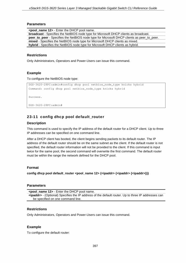
xStack® DGS-3620 Series Layer 3 Managed Stackable Gigabit Switch CLI Reference Guide
397
Parameters <pool_name 12> - Enter the DHCP pool name. broadcast - Specifies the NetBIOS node type for Microsoft DHCP clients as broadcast. peer_to_peer - Specifies the NetBIOS node type for Microsoft DHCP clients as peer_to_peer. mixed - Specifies the NetBIOS node type for Microsoft DHCP clients as mixed. hybrid - Specifies the NetBIOS node type for Microsoft DHCP clients as hybrid.
Restrictions Only Administrators, Operators and Power-Users can issue this command.
Example To configure the NetBIOS node type:
DGS-3620-28PC:admin#config dhcp pool netbios_node_type knicks hybrid
Command: config dhcp pool netbios_node_type knicks hybrid
Success.
DGS-3620-28PC:admin#
23-11 config dhcp pool default_router Description This command is used to specify the IP address of the default router for a DHCP client. Up to three IP addresses can be specified on one command line.
After a DHCP client has booted, the client begins sending packets to its default router. The IP address of the default router should be on the same subnet as the client. If the default router is not specified, the default router information will not be provided to the client. If this command is input twice for the same pool, the second command will overwrite the first command. The default router must be within the range the network defined for the DHCP pool.
Format config dhcp pool default_router <pool_name 12> {<ipaddr> {<ipaddr> {<ipaddr>}}}
Parameters <pool_name 12> - Enter the DHCP pool name. <ipaddr> - (Optional) Specifies the IP address of the default router. Up to three IP addresses can
be specified on one command line.
Restrictions Only Administrators, Operators and Power-Users can issue this command.
Example To configure the default router:
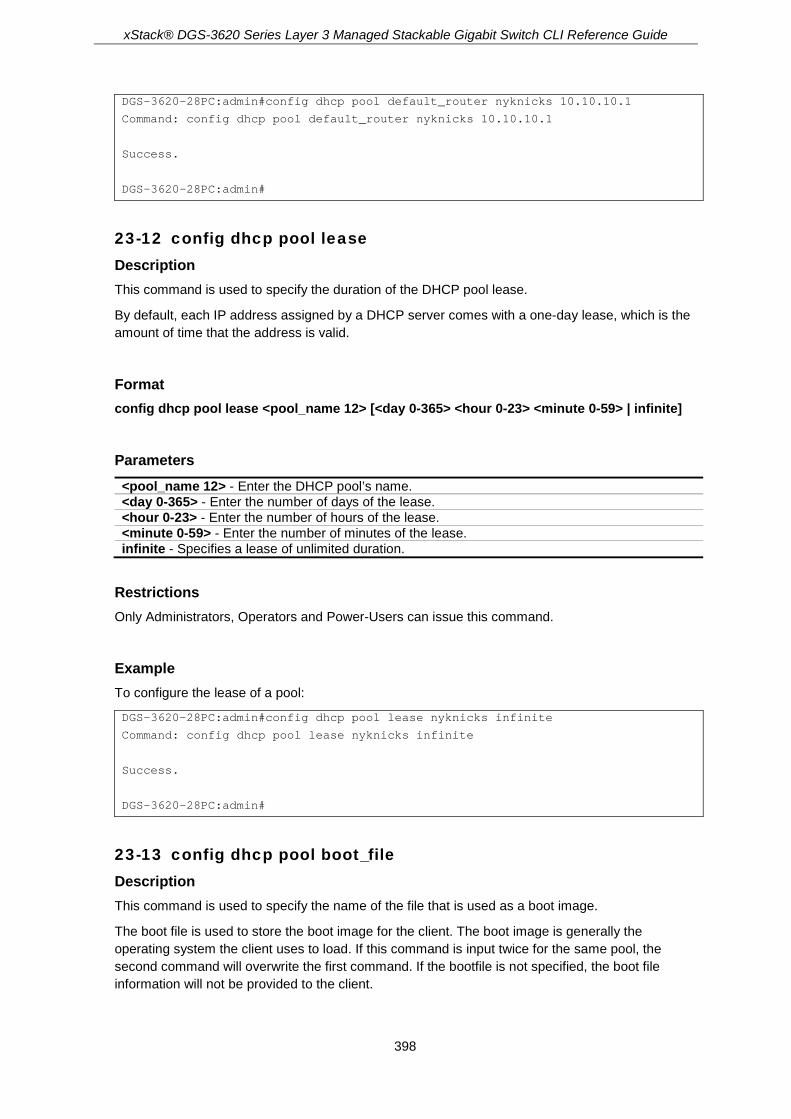
xStack® DGS-3620 Series Layer 3 Managed Stackable Gigabit Switch CLI Reference Guide
398
DGS-3620-28PC:admin#config dhcp pool default_router nyknicks 10.10.10.1
Command: config dhcp pool default_router nyknicks 10.10.10.1
Success.
DGS-3620-28PC:admin#
23-12 config dhcp pool lease Description This command is used to specify the duration of the DHCP pool lease.
By default, each IP address assigned by a DHCP server comes with a one-day lease, which is the amount of time that the address is valid.
Format config dhcp pool lease <pool_name 12> [<day 0-365> <hour 0-23> <minute 0-59> | infinite]
Parameters <pool_name 12> - Enter the DHCP pool’s name. <day 0-365> - Enter the number of days of the lease. <hour 0-23> - Enter the number of hours of the lease. <minute 0-59> - Enter the number of minutes of the lease. infinite - Specifies a lease of unlimited duration.
Restrictions Only Administrators, Operators and Power-Users can issue this command.
Example To configure the lease of a pool:
DGS-3620-28PC:admin#config dhcp pool lease nyknicks infinite
Command: config dhcp pool lease nyknicks infinite
Success.
DGS-3620-28PC:admin#
23-13 config dhcp pool boot_file Description This command is used to specify the name of the file that is used as a boot image.
The boot file is used to store the boot image for the client. The boot image is generally the operating system the client uses to load. If this command is input twice for the same pool, the second command will overwrite the first command. If the bootfile is not specified, the boot file information will not be provided to the client.

xStack® DGS-3620 Series Layer 3 Managed Stackable Gigabit Switch CLI Reference Guide
399
Format config dhcp pool boot_file <pool_name 12> {<file_name 64>}
Parameters <pool_name 12> - Enter the DHCP pool name. <file_name 64> - (Optional) Specifies the file name of the boot image.
Restrictions Only Administrators, Operators and Power-Users can issue this command.
Example To configure the boot file:
DGS-3620-28PC:admin#config dhcp pool boot_file engineering boot.had
Command: config dhcp pool boot_file engineering boot.had
Success.
DGS-3620-28PC:admin#
23-14 config dhcp pool next_server Description This command is used by the DHCP client boot process, typically a TFTP server. If next server information is not specified, it will not be provided to the client. If this command is input twice for the same pool, the second command will overwrite the first command.
Format config dhcp pool next_server <pool_name 12> {<ipaddr>}
Parameters <pool_name 12> - Enter the DHCP pool name. <ipaddr> - (Optional) Specifies the IP address of the next server.
Restrictions Only Administrators, Operators and Power-Users can issue this command.
Example To configure the next server:
DGS-3620-28PC:admin#config dhcp pool next_server engineering 192.168.0.1
Command: config dhcp pool next_server engineering 192.168.0.1
Success.

xStack® DGS-3620 Series Layer 3 Managed Stackable Gigabit Switch CLI Reference Guide
400
DGS-3620-28PC:admin#
23-15 config dhcp ping_packets Description This command is used to specify the number of ping packets the DHCP server sends to an IP address before assigning this address to a requesting client.
By default, the DHCP server pings a pool address twice before assigning the address to a DHCP client. If the ping is unanswered, the DHCP server assumes (with a high probability) that the address is not in use and assigns the address to the requesting client. If the ping is answered, the server will discard the current IP address and try another IP address.
Format config dhcp ping_packets <number 0-10>
Parameters <number 0-10> - Enter the number of ping packets. 0 means there is no ping test. The default
value is 2.
Restrictions Only Administrators, Operators and Power-Users can issue this command.
Example To configure ping packets:
DGS-3620-28PC:admin#config dhcp ping_packets 4
Command: config dhcp ping_packets 4
Success.
DGS-3620-28PC:admin#
23-16 config dhcp ping_timeout Description This command is used to specify the amount of time the DHCP server must wait before timing out a ping packet.
By default, the DHCP server waits 100 milliseconds before timing out a ping packet.
Format config dhcp ping_timeout <millisecond 10-2000>
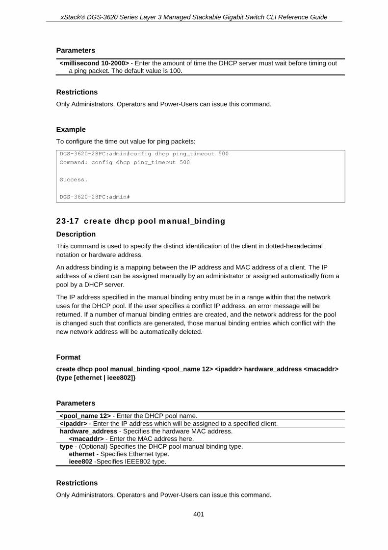
xStack® DGS-3620 Series Layer 3 Managed Stackable Gigabit Switch CLI Reference Guide
401
Parameters <millisecond 10-2000> - Enter the amount of time the DHCP server must wait before timing out
a ping packet. The default value is 100.
Restrictions Only Administrators, Operators and Power-Users can issue this command.
Example To configure the time out value for ping packets:
DGS-3620-28PC:admin#config dhcp ping_timeout 500
Command: config dhcp ping_timeout 500
Success.
DGS-3620-28PC:admin#
23-17 create dhcp pool manual_binding Description This command is used to specify the distinct identification of the client in dotted-hexadecimal notation or hardware address.
An address binding is a mapping between the IP address and MAC address of a client. The IP address of a client can be assigned manually by an administrator or assigned automatically from a pool by a DHCP server.
The IP address specified in the manual binding entry must be in a range within that the network uses for the DHCP pool. If the user specifies a conflict IP address, an error message will be returned. If a number of manual binding entries are created, and the network address for the pool is changed such that conflicts are generated, those manual binding entries which conflict with the new network address will be automatically deleted.
Format create dhcp pool manual_binding <pool_name 12> <ipaddr> hardware_address <macaddr> {type [ethernet | ieee802]}
Parameters <pool_name 12> - Enter the DHCP pool name. <ipaddr> - Enter the IP address which will be assigned to a specified client. hardware_address - Specifies the hardware MAC address.
<macaddr> - Enter the MAC address here. type - (Optional) Specifies the DHCP pool manual binding type.
ethernet - Specifies Ethernet type. ieee802 -Specifies IEEE802 type.
Restrictions Only Administrators, Operators and Power-Users can issue this command.

xStack® DGS-3620 Series Layer 3 Managed Stackable Gigabit Switch CLI Reference Guide
402
Example To configure manual bindings:
DGS-3620-28PC:admin#create dhcp pool manual_binding engineering 10.10.10.1 hardware_address 00-80-C8-02-02-02 type ethernet
Command: create dhcp pool manual_binding engineering 10.10.10.1 hardware_address 00-80-C8-02-02-02 type ethernet
Success.
DGS-3620-28PC:admin#
23-18 delete dhcp pool manual_binding Description This command is used to delete DHCP server manual binding.
Format delete dhcp pool manual_binding <pool_name 12> [<ipaddr> | all]
Parameters <pool_name 12> - Enter the DHCP pool name. <ipaddr> - Enter the IP address which will be assigned to a specified client. all - Specifies to delete all IP addresses.
Restrictions Only Administrators, Operators and Power-Users can issue this command.
Example To delete DHCP server manual binding:
DGS-3620-28PC:admin#delete dhcp pool manual_binding engineering 10.10.10.1
Command: delete dhcp pool manual_binding engineering 10.10.10.1
Success.
DGS-3620-28PC:admin#
23-19 clear dhcp binding Description This command is used to clear a binding entry or all binding entries in a pool or clears all binding entries in all pools. Note that this command will not clear the dynamic binding entry which matches a manual binding entry.

xStack® DGS-3620 Series Layer 3 Managed Stackable Gigabit Switch CLI Reference Guide
403
Format clear dhcp binding [<pool_name 12> [<ipaddr> | all] | all]
Parameters <pool_name 12> - Enter the DHCP pool name to clear.
<ipaddr> - Enter the IP address to clear. all - Specifies to clear all IP addresses for the specified pool.
all - Specifies to clear all binding entries in all pools
Restrictions Only Administrators, Operators and Power-Users can issue this command.
Example To clear dynamic binding entries in the pool named “engineering”:
DGS-3620-28PC:admin#clear dhcp binding engineering 10.20.3.4
Command: clear dhcp binding engineering 10.20.3.4
Success.
DGS-3620-28PC:admin#
23-20 show dhcp binding Description This command is used to display dynamic binding entries.
Format show dhcp binding {<pool_name 12>}
Parameters <pool_name 12> - (Optional) Specifies a DHCP pool name.
Restrictions None.
Example To display dynamic binding entries for “engineering”:
DGS-3620-28PC:admin#show dhcp binding engineering
Command: show dhcp binding engineering
Pool Name IP Addresss Hardware Address Type Status Lifetime
------------ -------------- ------------------ -------- ------- ---------

xStack® DGS-3620 Series Layer 3 Managed Stackable Gigabit Switch CLI Reference Guide
404
engineering 192.168.0.1 00-80-C8-08-13-88 Ethernet Manual 86400
engineering 192.168.0.2 00-80-C8-08-13-99 Ethernet Automatic 86400
engineering 192.168.0.3 00-80-C8-08-13-A0 Ethernet Automatic 86400
engineering 192.168.0.4 00-80-C8-08-13-B0 Ethernet Automatic 86400
Total Entries: 4
DGS-3620-28PC:admin#
23-21 show dhcp pool Description This command is used to display the information for DHCP pool. If pool name is not specified, information for all pools will be displayed.
Format show dhcp pool {<pool_name 12>}
Parameters <pool_name 12> - (Optional) Specifies the DHCP pool name.
Restrictions None.
Example To display the current DHCP pool information for “pool1”:
DGS-3620-28PC:admin# show dhcp pool pool1
Command: show dhcp pool pool1
Pool Name :pool1
Network Address :
Domain Name :
DNS Server :
NetBIOS Name Server :
NetBIOS Node Type :NOT SET
Default Router :
Pool Lease :1 Days, 0 Hours, 0 Minutes
Boot File :
Next Server :
Option Profile :
Total Entries: 1
DGS-3620-28PC:admin#

xStack® DGS-3620 Series Layer 3 Managed Stackable Gigabit Switch CLI Reference Guide
405
23-22 show dhcp pool manual_binding Description This command is used to display the configured manual binding entries.
Format show dhcp pool manual_binding {<pool_name 12>}
Parameters <pool_name 12> - (Optional) Specifies the DHCP pool name.
Restrictions None.
Example To display the configured manual binding entries:
DGS-3620-28PC:admin#show dhcp pool manual_binding
Command: show dhcp pool manual_binding
Pool Name IP Address Hardware Address Type
------------ ------------- ------------------ --------
p1 192.168.0.1 00-80-C8-08-13-88 Ethernet
p1 192.168.0.2 00-80-C8-08-13-99 Ethernet
Total Entries : 2
DGS-3620-28PC:admin#
23-23 enable dhcp_server Description This command is used to enable the DHCP server function.
If DHCP relay is enabled, DHCP server cannot be enabled. The opposite is also true. For Layer 2 switches, if DHCP client is enabled on the only interface, then DHCP server cannot be enabled. For layer 3 switches, when the System interface is the only interface then can DHCP client be enabled. If the DHCP client is enabled, then the DHCP server cannot be enabled.
Format enable dhcp_server
Parameters None.

xStack® DGS-3620 Series Layer 3 Managed Stackable Gigabit Switch CLI Reference Guide
406
Restrictions Only Administrators, Operators and Power-Users can issue this command.
Example To enable DHCP server:
DGS-3620-28PC:admin#enable dhcp_server
Command: enable dhcp_server
Success.
DGS-3620-28PC:admin#
23-24 disable dhcp_server Description This command is used to disable the DHCP server function on the switch.
Format disable dhcp_server
Parameters None.
Restrictions Only Administrators, Operators and Power-Users can issue this command.
Example To disable the Switch’s DHCP server:
DGS-3620-28PC:admin#disable dhcp_server
Command: disable dhcp_server
Success.
DGS-3620-28PC:admin#
23-25 show dhcp_server Description This command is used to display the current DHCP server configuration.
Format show dhcp_server

xStack® DGS-3620 Series Layer 3 Managed Stackable Gigabit Switch CLI Reference Guide
407
Parameters None.
Restrictions None.
Example To display the DHCP server status:
DGS-3620-28PC:admin#show dhcp_server
Command: show dhcp_server
DHCP Server Global State: Disabled
Ping Packet Number : 2
Ping Timeout : 100 ms
DGS-3620-28PC:admin#
23-26 clear dhcp conflict_ip Description This command is used to clear an entry or all entries from the conflict IP database.
Format clear dhcp conflict_ip [<ipaddr> | all]
Parameters <ipaddr> - Enter the IP address to be cleared. all - Specifies that all IP addresses will be cleared.
Restrictions None.
Example To clear an IP address 10.20.3.4 from the conflict database:
DGS-3620-28PC:admin#clear dhcp conflict_ip 10.20.3.4
Command: clear dhcp conflict_ip 10.20.3.4
Success.
DGS-3620-28PC:admin#
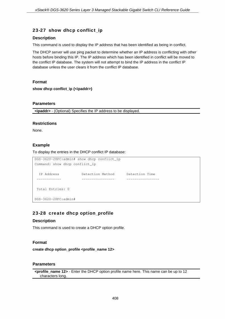
xStack® DGS-3620 Series Layer 3 Managed Stackable Gigabit Switch CLI Reference Guide
408
23-27 show dhcp conflict_ip Description This command is used to display the IP address that has been identified as being in conflict.
The DHCP server will use ping packet to determine whether an IP address is conflicting with other hosts before binding this IP. The IP address which has been identified in conflict will be moved to the conflict IP database. The system will not attempt to bind the IP address in the conflict IP database unless the user clears it from the conflict IP database.
Format show dhcp conflict_ip {<ipaddr>}
Parameters <ipaddr> - (Optional) Specifies the IP address to be displayed.
Restrictions None.
Example To display the entries in the DHCP conflict IP database:
DGS-3620-28PC:admin# show dhcp conflict_ip
Command: show dhcp conflict_ip
IP Address Detection Method Detection Time
------------ ---------------- ----------------
Total Entries: 0
DGS-3620-28PC:admin#
23-28 create dhcp option_profile Description This command is used to create a DHCP option profile.
Format create dhcp option_profile <profile_name 12>
Parameters <profile_name 12> - Enter the DHCP option profile name here. This name can be up to 12
characters long.

xStack® DGS-3620 Series Layer 3 Managed Stackable Gigabit Switch CLI Reference Guide
409
Restrictions Only Administrators, Operators and Power-Users can issue this command.
Example To create a DHCP option profile:
DGS-3620-28PC:admin#create dhcp option_profile profile1
Command: create dhcp option_profile profile1
Success.
DGS-3620-28PC:admin#
23-29 config dhcp option_profile Description This command is used to configure an option to and from a DHCP server option profile.
Format config dhcp option_profile <profile_name 12> [add option <value 1-254> [string <multiword 255> | hex <string 254>] | delete option <value 1-254>]
Parameters <profile_name 12> - Enter the DHCP server option profile name here. This name can be up to
12 characters long. add - Specifies to add an option to the DHCP server option profile. option - Specifies the option value used.
<value 1-254> - Enter the option value used here. This must be between 1 and 254. string - Specifies the character string associated with the option.
<multiword 255> - Enter the option association string here. This can be up to 255 characters long.
hex - Specifies the hexadecimal value of the option string. <string 254> - Enter the hexadecimal value of the option string here. This can be up to 254
hexadecimal characters long. delete - Specifies to delete an option from the DHCP server option profile. option - Specifies the option value used.
<value 1-254> - Enter the option value used here. This must be between 1 and 254.
Restrictions Only Administrators, Operators and Power-Users can issue this command.
Example To add option 69 using HEX format:
DGS-3620-28PC:admin#config dhcp option_profile profile1 add option 69 hex c0a800fe
Command: config dhcp option_profile profile1 add option 69 hex c0a800fe

xStack® DGS-3620 Series Layer 3 Managed Stackable Gigabit Switch CLI Reference Guide
410
Success.
DGS-3620-28PC:admin#
To add option 72 using string format:
DGS-3620-28PC:admin#config dhcp option_profile profile1 add option 72 string "192.168.0.254"
Command: config dhcp option_profile profile1 add option 72 string "192.168.0.254"
Success.
DGS-3620-28PC:admin#
To delete DHCP option profile option 69:
DGS-3620-28PC:admin#config dhcp option_profile profile1 delete option 69
Command: config dhcp option_profile profile1 delete option 69
Success.
DGS-3620-28PC:admin#
23-30 delete dhcp option_profile Description This command is used to delete a DHCP option profile.
Format delete dhcp option_profile <profile_name 12>
Parameters <profile_name 12> - Enter the DHCP server option profile name here. This name can be up to
12 characters long.
Restrictions Only Administrators, Operators and Power-Users can issue this command.
Example To delete a DHCP option profile.
DGS-3620-28PC:admin#delete dhcp option_profile profile1
Command: delete dhcp option_profile profile1
Success.
DGS-3620-28PC:admin#

xStack® DGS-3620 Series Layer 3 Managed Stackable Gigabit Switch CLI Reference Guide
411
23-31 show dhcp option_profile Description This command is used to display the current DHCP option profile configuration.
Format show dhcp option_profile {<profile_name 12>}
Parameters <profile_name 12> - (Optional) Enter the DHCP server option profile name here. This name can
be up to 12 characters long. If no parameter is specified, the system will display all DHCP option profile configurations.
Restrictions None.
Example To display the current DHCP option profile configuration.
DGS-3620-28PC:admin#show dhcp option_profile
Command: show dhcp option_profile
DHCP Option Profile Name : profile1
Option Type Value
------ ------ ------------------------------------------------------------
69 hex c0a800fe
72 string 192.168.0.254
Total Entries: 1
DGS-3620-28PC:admin#
23-32 config dhcp pool option_profile Description This command is used to apply an option profile to a specific DHCP pool.
Format config dhcp pool option_profile <pool_name 12> [add | delete] <profile_name 12>
Parameters <pool_name 12> - Enter the DHCP pool name here. This name can be up to 12 characters long. add - Specifies to add an option profile to a DHCP pool, configured on this switch.

xStack® DGS-3620 Series Layer 3 Managed Stackable Gigabit Switch CLI Reference Guide
412
delete - Specifies to delete an option profile from a DHCP pool, configured on this switch. <profile_name 12> - Enter the DHCP server option profile name here. This name can be up to
12 characters long.
Restrictions Only Administrators, Operators and Power-Users can issue this command.
Example To add an option profile for DHCP profile1 in pool1:
DGS-3620-28PC:admin#config dhcp pool option_profile pool1 add profile1
Command: config dhcp pool option_profile pool1 add profile1
Success.
DGS-3620-28PC:admin#
To delete an option profile from a DHCP pool:
DGS-3620-28PC:admin#config dhcp pool option_profile pool1 delete profile1
Command: config dhcp pool option_profile pool1 delete profile1
Success.
DGS-3620-28PC:admin#

xStack® DGS-3620 Series Layer 3 Managed Stackable Gigabit Switch CLI Reference Guide
413
Chapter 24 DHCP Server Screening Commands
config filter dhcp_server [add permit server_ip <ipaddr> {client_mac <macaddr>} ports [<portlist> | all] | delete permit server_ip <ipaddr> {client_mac <macaddr>} ports [<portlist> | all] | ports [<portlist> | all] state [enable | disable] | illegal_server_log_suppress_duration [1min | 5min | 30min]]
config filter dhcp_server log [enable | disable] config filter dhcp_server trap [enable | disable] show filter dhcp_server create filter dhcpv6_server permit sip <ipv6addr> ports [<portlist> | all] config filter dhcpv6_server log [enable | disable] config filter dhcpv6_server ports [<portlist> | all] state [enable | disable] config filter dhcpv6_server trap [enable | disable] show filter dhcpv6_server delete filter dhcpv6_server permit sip <ipv6addr> create filter icmpv6_ra_all_node permit sip <ipv6addr> ports [<portlist> | all] config filter icmpv6_ra_all_node log [enable | disable] config filter icmpv6_ra_all_node ports [<portlist> | all] state [enable | disable] config filter icmpv6_ra_all_node trap [enable | disable] show filter icmpv6_ra_all_node delete filter icmpv6_ra_all_node permit sip <ipv6addr>
24-1 config filter dhcp_server Description This command has two purposes: to specify to filter all DHCP server packets on the specific port and to specify to allow some DHCP server packets with pre-defined server IP addresses and client MAC addresses. With this function, we can restrict the DHCP server to service specific DHCP clients. This is useful when two DHCP servers are present on the network; one of them can provide the private IP address and the other can provide the public IP address.
Enabling filter DHCP server port state will create one access profile and create one access rule per port (UDP port = 67). Filter commands in this file will share the same access profile. Addition of a permit DHCP entry will create one access profile and create one access rule. Filter commands in this file will share the same access profile.
Format config filter dhcp_server [add permit server_ip <ipaddr> {client_mac <macaddr>} ports [<portlist> | all] | delete permit server_ip <ipaddr> {client_mac <macaddr>} ports [<portlist> | all] | ports [<portlist> | all] state [enable | disable] | illegal_server_log_suppress_duration [1min | 5min | 30min]]
Parameters add permit server_ip - Specifies the IP address of the DHCP server to be permitted.
<ipaddr> - Enter the IP address. client_mac - (Optional) Specifies the MAC address of the DHCP client.

xStack® DGS-3620 Series Layer 3 Managed Stackable Gigabit Switch CLI Reference Guide
414
<macaddr> - Enter the MAC address. ports - Specifies the ports.
<portlist> - Enter the range of ports to be configured. all - Specifies to configure all ports.
delete permit server_ip - Specifies the delete permit server IP address. <ipaddr> - Enter the IP address. client_mac - (Optional) Specifies the MAC address of the DHCP client.
<macaddr> - Enter the MAC address. ports - Specifies the ports.
<portlist> - Enter the range of ports to be configured. all - Specifies to configure all ports.
ports - Specifies the ports. <portlist> - Enter the range of ports to be configured. all - Specifies to configure all ports. state - Specifies the port status.
enable - Enable the state. disable - Disable the state.
illegal_server_log_suppress_duration - Specifies the illegal server log suppression duration. 1min - Specifies an illegal server log suppression duration of 1 minute. 5min - Specifies an illegal server log suppression duration of 5 minutes. 30min - Specifies an illegal server log suppression duration of 30 minutes.
Restrictions Only Administrators, Operators and Power-Users can issue this command.
Example To add an entry from the DHCP server/client filter list in the switch’s database:
DGS-3620-28PC:admin#config filter dhcp_server add permit server_ip 10.1.1.1 client_mac 00-00-00-00-00-01 port 1-26
Command: config filter dhcp_server add permit server_ip 10.1.1.1 client_mac 00-00-00-00-00-01 port 1-26
Success.
DGS-3620-28PC:admin#
To configure the filter DHCP server state:
DGS-3620-28PC:admin#config filter dhcp_server ports 1-10 state enable
Command: config filter dhcp_server ports 1-10 state enable
Success.
DGS-3620-28PC:admin#
24-2 config filter dhcp_server log Description This command is used to enable or disable the log for a DHCP server filter event.

xStack® DGS-3620 Series Layer 3 Managed Stackable Gigabit Switch CLI Reference Guide
415
Format config filter dhcp_server log [enable | disable]
Parameters enable – Specifies to enable the log for a DHCP server filter event. disable – Specifies to disable the log for a DHCP server filter event.
Restrictions Only Administrators, Operators and Power-Users can issue this command.
Example To enable the log for a DHCP server filter event:
DGS-3620-28PC:admin#config filter dhcp_server log enable
Command: config filter dhcp_server log enable
Success.
DGS-3620-28PC:admin#
24-3 config filter dhcp_server trap Description This command is used to enable or disable the trap for a DHCP server filter event.
Format config filter dhcp_server trap [enable | disable]
Parameters enable – Specifies to enable the trap for a DHCP server filter event. disable – Specifies to disable the trap for a DHCP server filter event.
Restrictions Only Administrators, Operators and Power-Users can issue this command.
Example To enable the trap for a DHCP server filter event:
DGS-3620-28PC:admin#config filter dhcp_server trap enable
Command: config filter dhcp_server trap enable
Success.
DGS-3620-28PC:admin#

xStack® DGS-3620 Series Layer 3 Managed Stackable Gigabit Switch CLI Reference Guide
416
24-4 show filter dhcp_server Description This command is used to display the DHCP server/client filter list created on the switch.
Format show filter dhcp_server
Parameters None.
Restrictions None.
Example To display the DHCP server/client filter list created on the switch:
DGS-3620-28PC:admin#show filter dhcp_server
Command: show filter dhcp_server
Enabled Ports: 1,28
Trap State: Enabled
Log State: Enabled
Illegal Server Log Suppress Duration:1 minutes
Permit DHCP Server/Client Table:
Server IP Address Client MAC Address Port
----------------- ------------------ --------------------
Total Entries: 0
DGS-3620-28PC:admin#
24-5 create filter dhcpv6_server permit sip Description This command used to create a permit entry. The specific DHCPv6 server packets, with the source IPv6 address, will be forwarded on the specified port(s).
Format create filter dhcpv6_server permit sip <ipv6addr> ports [<portlist> | all]

xStack® DGS-3620 Series Layer 3 Managed Stackable Gigabit Switch CLI Reference Guide
417
Parameters <ipv6addr> - Specifies the source address of the entry which will be created into the Filter
DHCPv6 server forward list. ports - Specifies the list of ports used for this configuration.
<portlist> - Enter the list of ports, used for this configuration, here. all - Specifies that all ports will be used for this configuration.
Restrictions Only Administrators, Operators and Power-Users can issue this command.
Example To create a Filter DHCPv6 server permit entry on port 5:
DGS-3620-28PC:admin#create filter dhcpv6_server permit sip 2200::5 ports 1:5
Command: create filter dhcpv6_server permit sip 2200::5 ports 1:5
Success.
DGS-3620-28PC:admin#
24-6 config filter dhcpv6_server log Description This command is used to enable or disable the Filter DHCPv6 server log state.
Format config filter dhcpv6_server log [enable | disable]
Parameters enable - Specifies that the log for the Filter DHCPv6 server will be enabled. The log for Filter
DHCPv6 server will be generated. disable - Specifies that the log for the Filter DHCPv6 server will be disabled.
Restrictions Only Administrators, Operators and Power-Users can issue this command.
Example To enable the Filter DHCPv6 Server log state:
DGS-3620-28PC:admin#config filter dhcpv6_server log enable
Command: config filter dhcpv6_server log enable
Success.
DGS-3620-28PC:admin#

xStack® DGS-3620 Series Layer 3 Managed Stackable Gigabit Switch CLI Reference Guide
418
24-7 config filter dhcpv6_server ports Description This command is used to configure the state of filter DHCPv6 server packets on the switch. The filter DHCPv6 server function is used to filter the DHCPv6 server packets on the specific port(s) and receive the trust packets from the specific source. This feature can be protected network usable when a malicious host sends the DHCPv6 server packets.
Format config filter dhcpv6_server ports [<portlist> | all] state [enable | disable]
Parameters <portlist> - Enter the list of ports, used for this configuration, here. all - Specifies that all ports will be used for this configuration. state - Specifies whether the port’s filter DHCPv6 server function is enabled or disabled.
enable - Specifies that the filter option is enabled. disable - Specifies that the filter option is disabled.
Restrictions Only Administrators, Operators and Power-Users can issue this command.
Example To configure the filter DHCPv6 server state to enabled for ports 1 to 8:
DGS-3620-28PC:admin#config filter dhcpv6_server ports 1:1-1:8 state enable
Command: config filter dhcpv6_server ports 1:1-1:8 state enable
Success.
DGS-3620-28PC:admin#
24-8 config filter dhcpv6_server trap Description This command is used to enable or disable the filter DHCPv6 server trap state.
Format config filter dhcpv6_server trap [enable | disable]
Parameters enable - Specifies that the trap for the filter DHCPv6 server will be enabled. The trap for filter
DHCPv6 server will be sent out. disable - Specifies that the trap for the filter DHCPv6 server will be disabled.

xStack® DGS-3620 Series Layer 3 Managed Stackable Gigabit Switch CLI Reference Guide
419
Restrictions Only Administrators, Operators and Power-Users can issue this command.
Example To enable the filter DHCPv6 server trap state:
DGS-3620-28PC:admin#config filter dhcpv6_server trap enable
Command: config filter dhcpv6_server trap enable
Success.
DGS-3620-28PC:admin#
24-9 show filter dhcpv6_server Description This command is used to display the filter DHCPv6 server information.
Format show filter dhcpv6_server
Parameters None.
Restrictions None.
Example To display filter DHCPv6 server information:
DGS-3620-28PC:admin#show filter dhcpv6_server
Command: show filter dhcpv6_server
Enabled ports:1:1-1:8
Trap State: Enabled
Log State: Enabled
Permit Source Address Table:
Source IP Address Port
--------------------------------------- ---------------
2200::5 1:5
Total Entries:1
DGS-3620-28PC:admin#

xStack® DGS-3620 Series Layer 3 Managed Stackable Gigabit Switch CLI Reference Guide
420
24-10 delete filter dhcpv6_server permit sip Description This command is used to delete a filter DHCPv6 server permit entry.
Format delete filter dhcpv6_server permit sip <ipv6addr>
Parameters <ipv6addr> - Enter the source IPv6 address of the entry here.
Restrictions Only Administrators, Operators and Power-Users can issue this command.
Example To delete permit entry from the filter DHCPv6 server forward list:
DGS-3620-28PC:admin#delete filter dhcpv6_server permit sip 2200::4
Command: delete filter dhcpv6_server permit sip 2200::4
Success.
DGS-3620-28PC:admin#
24-11 create filter icmpv6_ra_all_node permit sip Description This command is used to create a filter ICMPv6 RA All-nodes permit entry.
Format create filter icmpv6_ra_all_node permit sip <ipv6addr> ports [<portlist> | all]
Parameters <ipv6addr> - Enter the source address of entry which will be created into the Filter ICMPv6 RA
All-nodes forward list here. state - Specifies whether the port’s filter DHCPv6 server function is enabled or disabled.
enable - Specifies that the filter option is enabled. disable - Specifies that the filter option is disabled.
Restrictions Only Administrators, Operators and Power-Users can issue this command.

xStack® DGS-3620 Series Layer 3 Managed Stackable Gigabit Switch CLI Reference Guide
421
Example To create a filter ICMPv6 RA All-nodes permit entry on port 5:
DGS-3620-28PC:admin#create filter icmpv6_ra_all_node permit sip 2200::5 ports 1:5
Command: create filter icmpv6_ra_all_node permit sip 2200::5 ports 1:5
Success.
DGS-3620-28PC:admin#
24-12 config filter icmpv6_ra_all_node log Description This command is used to enable or disable the filter ICMPv6 RA All-nodes log state.
Format config filter icmpv6_ra_all_node log [enable | disable]
Parameters enable - Specifies that the log for the filter ICMPv6 RA will be enabled. The log for filter ICMPv6
RA all-nodes will be generated. disable - Specifies that the log for the filter ICMPv6 RA will be disabled.
Restrictions Only Administrators, Operators and Power-Users can issue this command.
Example To enable the filter ICMPv6 RA all-nodes log state:
DGS-3620-28PC:admin#config filter icmpv6_ra_all_node log enable
Command: config filter icmpv6_ra_all_node log enable
Success.
DGS-3620-28PC:admin#
24-13 config filter icmpv6_ra_all_node ports Description This command is used to configure the state of the filter ICMPv6 RA all-nodes packets on the switch. The filter ICMPv6 RA all-nodes function is used to filter the ICMPv6 RA all-nodes packets on the specific port(s) and receive the trust packets from the specific source. This feature can be protected network usable when a malicious host sends ICMPv6 RA all-nodes packets.
Note: It only needs to filter the packet of which the destination address is the all-nodes multicast address (FF02::1).

xStack® DGS-3620 Series Layer 3 Managed Stackable Gigabit Switch CLI Reference Guide
422
Format config filter icmpv6_ra_all_node ports [<portlist> | all] state [enable | disable]
Parameters <portlist> - Enter the list of ports, used for this configuration, here. all - Specifies that all ports will be used for this configuration. state - Specifies whether the port’s filter ICMPv6 RA all-nodes packets function is enabled or
disabled. enable - Specifies that the filter ICMPv6 RA all-nodes packets function is be enabled. disable - Specifies that the filter ICMPv6 RA all-nodes packets function is be disabled.
Restrictions Only Administrators, Operators and Power-Users can issue this command.
Example To configure the filter ICMPv6 RA all-nodes state to enabled for ports 1 to 8:
DGS-3620-28PC:admin#config filter icmpv6_ra_all_node ports 1:1-1:8 state enable
Command: config filter icmpv6_ra_all_node ports 1:1-1:8 state enable
Success.
DGS-3620-28PC:admin#
24-14 config filter icmpv6_ra_all_node trap Description This command is used to enable or disable the filter ICMPv6 RA all-nodes trap state. If the ICMPv6 RA all-nodes server trap state is disabled, no trap will be sent out.
Format config filter icmpv6_ra_all_node trap [enable | disable]
Parameters enable - Specifies that the trap for the filter ICMPv6 RA all-nodes will be enabled. The trap for
filter ICMPv6 RA all-nodes will be sent out. disable - Specifies that the trap for the filter ICMPv6 RA all-nodes will be disabled.
Restrictions Only Administrators, Operators and Power-Users can issue this command.
Example To enable the filter ICMPv6 RA all-nodes trap state:

xStack® DGS-3620 Series Layer 3 Managed Stackable Gigabit Switch CLI Reference Guide
423
DGS-3620-28PC:admin#config filter icmpv6_ra_all_node trap enable
Command: config filter icmpv6_ra_all_node trap enable
Success.
DGS-3620-28PC:admin#
24-15 show filter icmpv6_ra_all_node Description This command is used to display the filter ICMPv6 RA all-nodes information.
Format show filter icmpv6_ra_all_node
Parameters None.
Restrictions None.
Example To display filter ICMPv6 RA all-nodes information:
DGS-3620-28PC:admin#show filter icmpv6_ra_all_node
Command: show filter icmpv6_ra_all_node
Enabled ports:1:1-1:8
Trap State: Enabled
Log State: Enabled
Permit Source Address Table:
Source IP Address Port
--------------------------------------- ---------------
2200::5 1:5
Total Entries:1
DGS-3620-28PC:admin#
24-16 delete filter icmpv6_ra_all_node permit sip Description This command is used to delete a filter ICMPv6 RA all-nodes permit entry.

xStack® DGS-3620 Series Layer 3 Managed Stackable Gigabit Switch CLI Reference Guide
424
Format delete filter icmpv6_ra_all_node permit sip <ipv6addr>
Parameters <ipv6addr> - Enter the source IPv6 address of the entry which will be deleted in the filter ICMPv6
RA all-nodes forward list.
Restrictions Only Administrators, Operators and Power-Users can issue this command.
Example To delete permit entry from the filter ICMPv6 RA all-nodes forward list:
DGS-3620-28PC:admin#delete filter icmpv6_ra_all_node permit sip 2200::4
Command: delete filter icmpv6_ra_all_node permit sip 2200::4
Success.
DGS-3620-28PC:admin#

xStack® DGS-3620 Series Layer 3 Managed Stackable Gigabit Switch CLI Reference Guide
425
Chapter 25 DHCPv6 Relay Commands
enable dhcpv6_relay disable dhcpv6_relay config dhcpv6_relay hop_count <value 1-32> config dhcpv6_relay [add | delete] ipif <ipif_name 12> <ipv6addr> config dhcpv6_relay ipif [<ipif_name 12> | all] state [enable | disable] show dhcpv6_relay {ipif <ipif_name 12>} config dhcpv6_relay option_37 {state [enable | disable] | check [enable | disable] | remote_id
[default | cid_with_user_define <desc 128>| user_define <desc 128>]}(1)
25-1 enable dhcpv6_relay Description This command is used to enable the DHCPv6 relay function on the Switch.
Format enable dhcpv6_relay
Parameters None.
Restrictions Only Administrators, Operators and Power-Users can issue this command.
Example To configure the DHCPv6 relay global state to enable:
DGS-3620-28PC:admin# enable dhcpv6_relay
Command: enable dhcpv6_relay
Success.
DGS-3620-28PC:admin#
25-2 disable dhcpv6_relay Description This command is used to disable the DHCPv6 relay function on the Switch.

xStack® DGS-3620 Series Layer 3 Managed Stackable Gigabit Switch CLI Reference Guide
426
Format disable dhcpv6_relay
Parameters None.
Restrictions Only Administrators, Operators and Power-Users can issue this command.
Example To configure the DHCPv6 relay global state to disable:
DGS-3620-28PC:admin# disable dhcpv6_relay
Command: disable dhcpv6_relay
Success.
DGS-3620-28PC:admin#
25-3 config dhcpv6_relay hop_count Description Configure the DHCPv6 relay hop_count of the switch.
Format config dhcpv6_relay hop_count <value 1-32>
Parameters hop_count - Specifies the number of relay agents that have relayed this message. The default
value is 4. <value 1-32> - Enter the hop count number here. This value must be between 1 and 32.
Restrictions Only Administrators, Operators and Power-Users can issue this command.
Example To configure the maximum hops of a DHCPv6 relay packet could be transferred to 4:
DGS-3620-28PC:admin# config dhcpv6_relay hop_count 4
Command: config dhcpv6_relay hop_count 4
Success.
DGS-3620-28PC:admin#

xStack® DGS-3620 Series Layer 3 Managed Stackable Gigabit Switch CLI Reference Guide
427
25-4 config dhcpv6_relay Description The command could add/delete an IPv6 address which is a destination to forward (relay) DHCPv6 packets.
Format config dhcpv6_relay [add | delete] ipif <ipif_name 12> <ipv6addr>
Parameters add - Add an IPv6 destination to the DHCPv6 relay table. delete - Delete an IPv6 destination from the DHCPv6 relay table ipif - The name of the IP interface in which DHCPv6 relay is to be enabled.
<ipif_name 12> - Enter the IP interface name here. This name can be up to 12 characters long.
<ipv6addr> - The DHCPv6 server IP address.
Restrictions Only Administrators, Operators and Power-Users can issue this command.
Example To add a DHCPv6 server to the relay table:
DGS-3620-28PC:admin# config dhcpv6_relay add ipif System 2001:DB8:1234:0:218:FEFF:FEFB:CC0E
Command: config dhcpv6_relay add ipif System 2001:DB8:1234:0:218:FEFF:FEFB:CC0E
Success.
DGS-3620-28PC:admin#
25-5 config dhcpv6_relay ipif Description The command is used to configure the DHCPv6 relay state of one specific interface or all interfaces.
Format config dhcpv6_relay ipif [<ipif_name 12> | all] state [enable | disable]
Parameters ipif - Specifies the name of the IP interface.
<ipif_name 12> - Enter the IP interface name used here. This name can be up to 12 characters long.

xStack® DGS-3620 Series Layer 3 Managed Stackable Gigabit Switch CLI Reference Guide
428
all - Specifies that all the configured IP interfaces wil be used.. state - Specifies if the DHCPv6 relay state will be enabled or disabled.
enable - Choose this parameter to enable the DHCPv6 relay state of the interface. disable - Choose this parameter to disable the DHCPv6 relay state of the interface.
Restrictions Only Administrators, Operators and Power-Users can issue this command.
Example To configure the DHCPv6 relay state of the System interface to enable:
DGS-3620-28PC:admin# config dhcpv6_relay ipif System state enable
Command: config dhcpv6_relay ipif System state enable
Success.
DGS-3620-28PC:admin#
25-6 show dhcpv6_relay Description This command will display the current DHCPv6 relay configuration of all interfaces, or if an IP interface name is specified, the DHCPv6 relay configuration for that IP interface.
Format show dhcpv6_relay {ipif <ipif_name 12>}
Parameters ipif - (Optional) The name of the IP interface for which to display the current DHCPv6 relay
configuration. <ipif_name 12> - Enter the IP interface name used here. This name can be up to 12
characters long. If no IP interface is specified, all configured DHCPv6 relay interfaces are displayed.
Restrictions None.
Example To show the DHCPv6 relay configuration of all interfaces:

xStack® DGS-3620 Series Layer 3 Managed Stackable Gigabit Switch CLI Reference Guide
429
DGS-3620-28PC:admin#show dhcpv6_relay
Command: show dhcpv6_relay
DHCPv6 Relay Global State : Disabled
DHCPv6 Hops Count Limit : 4
DHCPv6 Relay Information Option 37 State : Disabled
DHCPv6 Relay Information Option 37 Check : Disabled
DHCPv6 Relay Information Option 37 Remote ID Type : Default
DHCPv6 Relay Information Option 37 Remote ID :
---------------------------------------------------------------
IP Interface : System
DHCPv6 Relay Status : Enabled
Server Address :
IP Interface : Interface1
DHCPv6 Relay Status : Enabled
Server Address :
Total Entries : 2
DGS-3620-28PC:admin#
To show the DHCPv6 relay configuration of System interface:
DGS-3620-28PC:admin#show dhcpv6_relay ipif System
Command: show dhcpv6_relay ipif System
DHCPv6 Relay Global State : Disabled
DHCPv6 Hops Count Limit : 4
DHCPv6 Relay Information Option 37 State : Disabled
DHCPv6 Relay Information Option 37 Check : Disabled
DHCPv6 Relay Information Option 37 Remote ID Type : Default
DHCPv6 Relay Information Option 37 Remote ID :
---------------------------------------------------------------
IP Interface : System
DHCPv6 Relay Status : Enabled
Server Address :
DGS-3620-28PC:admin#
25-7 config dhcpv6_relay option_37 Description This command is used to configure the processing of Option 37 for the DHCPv6 relay function.
When the DHCPv6 relay Option 37 is enabled, the DHCP packet will be inserted with the Option 37 field before being relayed to server. The DHCP packet will be processed based on the behavior defined in the check and remote ID type setting. When the state is disabled, the DHCP packet will be relayed directly to server without further checks and inserted with the Option 37.

xStack® DGS-3620 Series Layer 3 Managed Stackable Gigabit Switch CLI Reference Guide
430
Format config dhcpv6_relay option_37 {state [enable | disable] | check [enable | disable] | remote_id [default | cid_with_user_define <desc 128>| user_define <desc 128>]}(1)
Parameters state - Specifies the DHCPv6 relay Option 37 state.
enable - When the state is enabled, the DHCP packet will be inserted with the Option 37 field before being relayed to server.
disable - When the state is disabled, the DHCP packet will be relayed directly to server without further checks and inserted with the Option 37.
check - Specifies that packets coming from client side should or should not have the Option 37 field. If client originating packets have the Option 37 field set they will be dropped. enable - Specifies that the check option is enabled. disable - Specifies that the check option is disabled.
remote_id - Specifies the content in the Remote ID. default - Specifies that the remote ID will contain the VLAN ID, Module, Port, and System
MAC address of the device. cid_with_user_define - Specifies that the remote ID will contain the VLAN ID, Module, Port,
and a user defined string. <desc 128> - Enter the CID user defined string here. This can be up to 128 characters
long. user_define - Specifies that the remote ID will be a user defined string.
<desc 128> - Enter the user defined string here. This can be up to 128 characters long.0
Restrictions Only Administrators, Operators and Power-Users can issue this command.
Example To enable the state of the DHCPv6 Option 37:
DGS-3620-28PC:admin#config dhcpv6_relay option_37 state enable
Command: config dhcpv6_relay option_37 state enable
Success.
DGS-3620-28PC:admin#
To enable the DHCPv6 Option 37 check:
DGS-3620-28PC:admin#config dhcpv6_relay option_37 check enable
Command: config dhcpv6_relay option_37 check enable
Success.
DGS-3620-28PC:admin#
To set the remote ID as default:

xStack® DGS-3620 Series Layer 3 Managed Stackable Gigabit Switch CLI Reference Guide
431
DGS-3620-28PC:admin#config dhcpv6_relay option_37 remote_id default
Command: config dhcpv6_relay option_37 remote_id default
Success.
DGS-3620-28PC:admin#
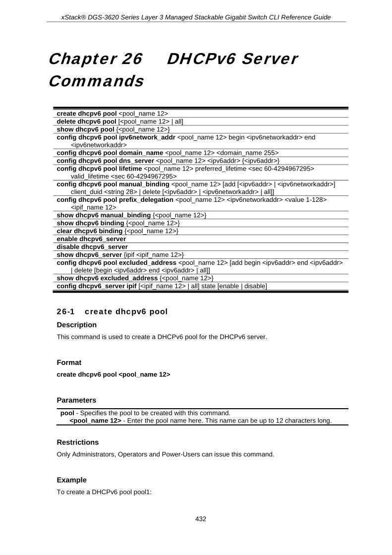
xStack® DGS-3620 Series Layer 3 Managed Stackable Gigabit Switch CLI Reference Guide
432
Chapter 26 DHCPv6 Server Commands
create dhcpv6 pool <pool_name 12> delete dhcpv6 pool [<pool_name 12> | all] show dhcpv6 pool {<pool_name 12>} config dhcpv6 pool ipv6network_addr <pool_name 12> begin <ipv6networkaddr> end
<ipv6networkaddr> config dhcpv6 pool domain_name <pool_name 12> <domain_name 255> config dhcpv6 pool dns_server <pool_name 12> <ipv6addr> {<ipv6addr>} config dhcpv6 pool lifetime <pool_name 12> preferred_lifetime <sec 60-4294967295>
valid_lifetime <sec 60-4294967295> config dhcpv6 pool manual_binding <pool_name 12> [add [<ipv6addr> | <ipv6networkaddr>]
client_duid <string 28> | delete [<ipv6addr> | <ipv6networkaddr> | all]] config dhcpv6 pool prefix_delegation <pool_name 12> <ipv6networkaddr> <value 1-128>
<ipif_name 12> show dhcpv6 manual_binding {<pool_name 12>} show dhcpv6 binding {<pool_name 12>} clear dhcpv6 binding {<pool_name 12>} enable dhcpv6_server disable dhcpv6_server show dhcpv6_server {ipif <ipif_name 12>} config dhcpv6 pool excluded_address <pool_name 12> [add begin <ipv6addr> end <ipv6addr>
| delete [begin <ipv6addr> end <ipv6addr> | all]] show dhcpv6 excluded_address {<pool_name 12>} config dhcpv6_server ipif [<ipif_name 12> | all] state [enable | disable]
26-1 create dhcpv6 pool Description This command is used to create a DHCPv6 pool for the DHCPv6 server.
Format create dhcpv6 pool <pool_name 12>
Parameters pool - Specifies the pool to be created with this command.
<pool_name 12> - Enter the pool name here. This name can be up to 12 characters long.
Restrictions Only Administrators, Operators and Power-Users can issue this command.
Example To create a DHCPv6 pool pool1:

xStack® DGS-3620 Series Layer 3 Managed Stackable Gigabit Switch CLI Reference Guide
433
DGS-3620-28PC:admin# create dhcpv6 pool pool1
Command : create dhcpv6 pool pool1
success
DGS-3620-28PC:admin#
26-2 delete dhcpv6 pool Description This command is used to delete one or all DHCPv6 pools.
Format delete dhcpv6 pool [<pool_name 12> | all]
Parameters pool - Specifies the DHCPv6 pool to be removed.
<pool_name 12> - Enter the DHCPv6 pool name to be removed here. This name can be up to 12 characters long.
all - Specifies that all the DHCPv6 pools will be removed.
Restrictions Only Administrators, Operators and Power-Users can issue this command.
Example To delete the DHCPv6 pool by specifying the pool name pool1:
DGS-3620-28PC:admin# delete dhcpv6 pool pool1
Command: delete dhcpv6 pool pool1
Success.
DGS-3620-28PC:admin#
26-3 show dhcpv6 pool Description This command is used to display one or all DHCPv6 pools configuration.
Format show dhcpv6 pool {<pool_name 12>}
Parameters pool – Specifies the DHCPv6 pool to be displayed.

xStack® DGS-3620 Series Layer 3 Managed Stackable Gigabit Switch CLI Reference Guide
434
<pool_name 12> - (Optional) Enter the DHCPv6 pool name to be displayed here. This name can be up to 12 characters long.
If no parameters are specified, all the DHCPv6 pools will be displayed.
Restrictions None.
Example To show the DHCPv6 pool by specifying the pool name pool1:
DGS-3620-28PC:admin# show dhcpv6 pool pool1
Command: show dhcpv6 pool pool1
Pool Name : pool1
Begin Network Address : 2000::1/64
End Network Address : 2000::200/64
Domain Name : domain.com
DNS Server Address : 2000::ff
: 2000::fe
Preferred Lifetime : 604800 (sec)
Valid Lifetime : 2592000 (sec)
Total Pool Entries: 1
DGS-3620-28PC:admin#
26-4 config dhcpv6 pool ipv6network_addr Description This command is used to configure the range of IPv6 network addresses for the DHCPv6 pool. The IPv6 addresses in the range are free to be assigned to any DHCPv6 client. When the DHCPv6 server receives a request from the client, the server will automatically find an available pool to allocate an IPv6 address.
The begin_networkaddr and end_networkaddr must observer some rules as followed:
The prefix of the begin_networkaddr and end_networkaddr are not consistence, otherwise, the switch will print an error message: The prefix of begin_networkaddr and end_networkaddr must be consistence.(e.g.: the begin_networkaddr is 2000::1/64, and the end_networkaddr is 3000::100/64)
The begin address must not be large than end address, otherwise, the switch will print an error message: The begin IPv6 address must be lower than or equal to the end IPv6 address.(e.g.: the begin_networkaddr is 2000::200/64, and the end_networkaddr is 2000::100/64)
There must not be intersection between the IPv6 address ranges of two pools, otherwise, the Switch will print an error message: IPv6network address collision. (e.g.: pool1: 2000::1/64 --- 2000::100/64, pool2: 2000::50/64 --- 2000::200/64)
The IPv6 network address can’t be Link-local address and Multicast address, otherwise, the Switch will print an error message: “The IPv6 network address can’t be Link-local address or Multicast address. “ (e.g.:: pool1: FE80::1/64 --- FE80::100/64, pool2: FE80::200/64 --- FE80::300/64

xStack® DGS-3620 Series Layer 3 Managed Stackable Gigabit Switch CLI Reference Guide
435
Format config dhcpv6 pool ipv6network_addr <pool_name 12> begin <ipv6networkaddr> end <ipv6networkaddr>
Parameters <pool_name 12> - Enter the DHCPv6 pool name used here. This name can be up to 12
characters long. begin - Specifies the beginning IPv6 network address of the DHCPv6 pool.
<ipv6networkaddr> - Enter the beginning IPv6 network address of the DHCPv6 pool here. end - Specifies the ending IPv6 network address of the DHCPv6 pool.
<ipv6networkaddr> - Enter the ending IPv6 network address of the DHCPv6 pool here.
Restrictions Only Administrators, Operators and Power-Users can issue this command.
Example To configure the range of ipv6network address for the DHCPv6 pool pool1:
DGS-3620-28PC:admin# config dhcpv6 pool ipv6network_addr pool1 begin 2000::1/64 end 2000::32/64
Command: config dhcpv6 pool ipv6network_addr pool1 begin 2000::1/64 end 2000::32/64
success
DGS-3620-28PC:admin#
26-5 config dhcpv6 pool domain_name Description This command is used to configure the domain name for the DHCPv6 pool of the Switch. The domain name configured here will be used as the default domain name by the client.
By default, the domain name is empty. If domain name is empty, the domain name information will not be provided to the client.
Format config dhcpv6 pool domain_name <pool_name 12> <domain_name 255>
Parameters <pool_name 12> - Enter the DHCPv6 pool name used here. This name can be up to 12
characters long. <domain_name 255> - Enter the domain name used here. This name can be up to 255
characters long.
Restrictions Only Administrators, Operators and Power-Users can issue this command.

xStack® DGS-3620 Series Layer 3 Managed Stackable Gigabit Switch CLI Reference Guide
436
Example To configure the domain name for the DHCPv6 pool pool1:
DGS-3620-28PC:admin# config dhcpv6 pool domain_name pool1 dlink.com
Command: config dhcpv6 pool domain_name pool1 dlink.com
Success.
DGS-3620-28PC:admin#
26-6 config dhcpv6 pool dns_server Description This command is used to configure the DNS server’s IPv6 addresses for a specific DHCPv6 pool. Users may add up to two DNS Server addresses. If DNS server is not specified, the DNS server information will not be provided to the client. Users could delete a DNS server address in the method of setting the DNS server address to zero.
Format config dhcpv6 pool dns_server <pool_name 12> <ipv6addr> {<ipv6addr>}
Parameters <pool_name 12> - Enter the DHCPv6 pool name used here. This name can be up to 12
characters long. <ipv6addr> - Enter the primary DNS Server IPv6 address used for this pool here. <ipv6addr> - (Optional) Enter the secondary DNS Server IPv6 address used for this pool here.
Restrictions Only Administrators, Operators and Power-Users can issue this command.
Example To configure the DNS server address for a DHCPv6 pool:
DGS-3620-28PC:admin# config dhcpv6 pool dns_server pool1 2000::200 2000::201
Command: config dhcpv6 pool dns_server pool1 2000::200 2000::201
Success.
DGS-3620-28PC:admin#
26-7 config dhcpv6 pool lifetime Description This command is used to configure the preferred-lifetime and valid-lifetime of IPv6 address within a DHCPv6 pool.

xStack® DGS-3620 Series Layer 3 Managed Stackable Gigabit Switch CLI Reference Guide
437
Preferred lifetime - the length of time that a valid address is preferred (i.e., the time until deprecation). When the preferred lifetime expires, the address becomes deprecated.
Valid lifetime - the length of time an address remains in the valid state (i.e., the time until invalidation). When the valid lifetime expires, the address becomes invalid.
The valid lifetime must be greater than or equal to the preferred lifetime.
Format config dhcpv6 pool lifetime <pool_name 12> preferred_lifetime <sec 60-4294967295> valid_lifetime <sec 60-4294967295>
Parameters <pool_name 12> - Enter the DHCPv6 pool name used here. This name can be up to 12
characters long. preferred_lifetime - Specifies the length of time that a valid address is preferred to.
<sec 60-4294967295> - Enter the preferred lifetime value here. This value must be between 60 and 4294967295 seconds.
valid_lifetime - Specifies the length of time an address remains in the valid state. <sec 60-4294967295> - Enter the valid lifetime value here. This value must be between 60
and 4294967295 seconds.
Restrictions Only Administrators, Operators and Power-Users can issue this command.
Example To configure the preferred-lifetime and valid-lifetime for the DHCPv6 pool:
DGS-3620-28PC:admin# config dhcpv6 pool lifetime pool1 preferred_lifetime 80 valid_lifetime 100
Command: config dhcpv6 pool lifetime pool1 preferred_lifetime 80 valid_lifetime 100
Success.
DGS-3620-28PC:admin#
26-8 config dhcpv6 pool manual_binding Description This command is used to configure a DHCPv6 pool manual binding entry. An address binding is a mapping between the IPv6 address and DUID (A DHCPv6 Unique Identifier for a DHCPv6 participant) of a client. The IPv6 address specified in the manual binding entry must be in the range of the DHCPv6 pool.
Format config dhcpv6 pool manual_binding <pool_name 12> [add [<ipv6addr> | <ipv6networkaddr>] client_duid <string 28> | delete [<ipv6addr> | <ipv6networkaddr> | all]]
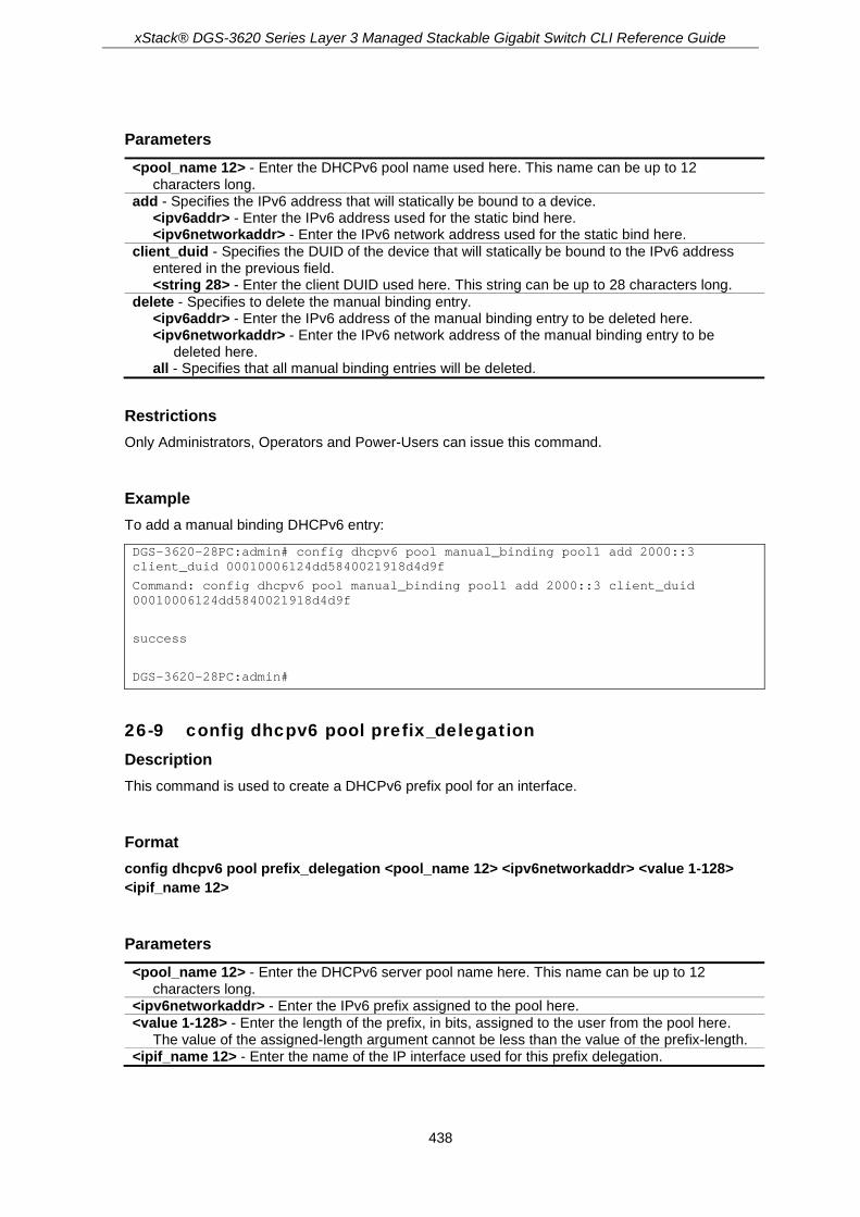
xStack® DGS-3620 Series Layer 3 Managed Stackable Gigabit Switch CLI Reference Guide
438
Parameters <pool_name 12> - Enter the DHCPv6 pool name used here. This name can be up to 12
characters long. add - Specifies the IPv6 address that will statically be bound to a device.
<ipv6addr> - Enter the IPv6 address used for the static bind here. <ipv6networkaddr> - Enter the IPv6 network address used for the static bind here.
client_duid - Specifies the DUID of the device that will statically be bound to the IPv6 address entered in the previous field. <string 28> - Enter the client DUID used here. This string can be up to 28 characters long.
delete - Specifies to delete the manual binding entry. <ipv6addr> - Enter the IPv6 address of the manual binding entry to be deleted here. <ipv6networkaddr> - Enter the IPv6 network address of the manual binding entry to be
deleted here. all - Specifies that all manual binding entries will be deleted.
Restrictions Only Administrators, Operators and Power-Users can issue this command.
Example To add a manual binding DHCPv6 entry:
DGS-3620-28PC:admin# config dhcpv6 pool manual_binding pool1 add 2000::3 client_duid 00010006124dd5840021918d4d9f
Command: config dhcpv6 pool manual_binding pool1 add 2000::3 client_duid 00010006124dd5840021918d4d9f
success
DGS-3620-28PC:admin#
26-9 config dhcpv6 pool prefix_delegation Description This command is used to create a DHCPv6 prefix pool for an interface.
Format config dhcpv6 pool prefix_delegation <pool_name 12> <ipv6networkaddr> <value 1-128> <ipif_name 12>
Parameters <pool_name 12> - Enter the DHCPv6 server pool name here. This name can be up to 12
characters long. <ipv6networkaddr> - Enter the IPv6 prefix assigned to the pool here. <value 1-128> - Enter the length of the prefix, in bits, assigned to the user from the pool here.
The value of the assigned-length argument cannot be less than the value of the prefix-length. <ipif_name 12> - Enter the name of the IP interface used for this prefix delegation.

xStack® DGS-3620 Series Layer 3 Managed Stackable Gigabit Switch CLI Reference Guide
439
Restrictions Only Administrators, Operators and Power-Users can issue this command.
Example To create a DHCPv6 prefix pool prefixpool1 for interface System:
DGS-3620-28PC:admin#config dhcpv6 pool prefix_delegation prefixpool1 1111::/48 64 System
Command: config dhcpv6 pool prefix_delegation prefixpool1 1111::/48 64 System
Success.
DGS-3620-28PC:admin#
26-10 show dhcpv6 manual_binding Description This command will display the manual binding entries for the selected or all DHCPv6 pools.
Format show dhcpv6 manual_binding {<pool_name 12>}
Parameters <pool_name 12> - (Optional) Enter the DHCPv6 pool name used here. This name can be up to
12 characters long. If no parameter is specified, then all the entries will be displayed.
Restrictions None.
Example To display the manual binding entries of the DHCPv6 pool:

xStack® DGS-3620 Series Layer 3 Managed Stackable Gigabit Switch CLI Reference Guide
440
DGS-3620-28PC:admin# show dhcpv6 manual_binding
Command: show dhcpv6 manual_binding
Pool Name :net100
Entry 1
IPv6 Address: 3000:100:1::ABCD
DUID : 00030006001572200700
Pool Name :net91
Entry 1
IPv6 Address: 3000:91:1::100
DUID : 00030006aabbcc000000
Entry 2
IPv6 Address: 3000:91:1::101
DUID : 00030006aabbcc000001
Total Entries: 3
DGS-3620-28PC:admin#
26-11 show dhcpv6 binding Description This command is used to show the DHCPv6 dynamic binding information. Entering the command without the pool name will display all information regarding DHCPv6 dynamic binding on the switch. This command only displays the dynamic binding information, not including manual binding information.
Format show dhcpv6 binding {<pool_name 12>}
Parameters <pool_name 12> - (Optional) Enter the DHCPv6 pool name used here. This name can be up to
12 characters long.
Restrictions None.
Example To display the DHCPv6 dynamic binding information on the Switch:

xStack® DGS-3620 Series Layer 3 Managed Stackable Gigabit Switch CLI Reference Guide
441
DGS-3620-28PC:admin# show dhcpv6 binding
Command: show dhcpv6 binding
Pool Name: net90 IPv6 Address: 3000:90:1::7
DUID : 0003000600cd14517000
Preferred(s): 120 Valid(s): 240
Pool Name: net100-2 IPv6 Address: 3000:100:1::1
DUID : 00030006001572200300
Preferred(s): 120 Valid(s): 240
Total Entries : 2
DGS-3620-28PC:admin#
26-12 clear dhcpv6 binding Description This command is used to clear the DHCPv6 dynamic binding information.
Format clear dhcpv6 binding {<pool_name 12>}
Parameters <pool_name 12> - (Optional) Enter the DHCPv6 pool name used here. This name can be up to
12 characters long.
Restrictions Only Administrators, Operators and Power-Users can issue this command.
Example To clear the DHCPv6 dynamic binding information on the Switch:
DGS-3620-28PC:admin# clear dhcpv6 binding
Command: clear dhcpv6 binding
Success.
DGS-3620-28PC:admin#
26-13 enable dhcpv6_server Description This command is used to enable the DHCPv6 server function on the Switch

xStack® DGS-3620 Series Layer 3 Managed Stackable Gigabit Switch CLI Reference Guide
442
Format enable dhcpv6_server
Parameters None.
Restrictions Only Administrators, Operators and Power-Users can issue this command.
Example To configure the DHCPv6 server global state to enable:
DGS-3620-28PC:admin# enable dhcpv6_server
Command: enable dhcpv6_server
Success.
DGS-3620-28PC:admin#
26-14 disable dhcpv6_server Description This command is used to disable the DHCPv6 server function on the Switch
Format disable dhcpv6_server
Parameters None.
Restrictions Only Administrators, Operators and Power-Users can issue this command.
Example To configure the DHCPv6 server global state to disable:
DGS-3620-28PC:admin# disable dhcpv6_server
Command: disable dhcpv6_server
Success.
DGS-3620-28PC:admin#

xStack® DGS-3620 Series Layer 3 Managed Stackable Gigabit Switch CLI Reference Guide
443
26-15 show dhcpv6_server Description This command is used to display the DHCPv6 server setting.
Format show dhcpv6_server {ipif <ipif_name 12>}
Parameters ipif - (Optional) Specifies the IP interface name to be displayed.
<ipif_name 12> - Enter the IP interface name to be displayed here. This name can be up to 12 characters long.
Restrictions None.
Example To display the DHCPv6 server setting:
DGS-3620-28PC:admin# show dhcpv6_server
Command: show dhcpv6_server
DHCPv6 Server Global State: Disabled
---------------------------------------------------------------
IP Interface : System
DHCPv6 Server State : Enabled
IP Interface : ipif1
DHCPv6 Server State : Enabled
Total Entries : 2
DGS-3620-28PC:admin#
26-16 config dhcpv6 pool excluded_address Description This command is used to configure the reserved IPv6 addresses on the DHCPv6 server.
Format config dhcpv6 pool excluded_address <pool_name 12> [add begin <ipv6addr> end <ipv6addr> | delete [begin <ipv6addr> end <ipv6addr> | all]]
Parameters <pool_name 12> - Enter the DHCPv6 pool name used here. This name can be up to 12

xStack® DGS-3620 Series Layer 3 Managed Stackable Gigabit Switch CLI Reference Guide
444
characters long. add - Specifies to add an excluded address range for a specified pool.
begin - Specifies the beginning IPv6 address of the range of IPv6 addresses to be excluded from the DHCPv6 pool. <ipv6addr> - Enter the beginning IPv6 address used here.
end - Specifies the ending IPv6 address of the range of IPv6 addresses to be excluded from the DHCPv6 pool. <ipv6addr> - Enter the ending IPv6 address used here.
delete - Specifies to delete one or all excluded address ranges of a specified pool. begin - Specifies the beginning IPv6 address of the range of IPv6 addresses to be excluded
from the DHCPv6 pool. <ipv6addr> - Enter the beginning IPv6 address used here.
end - Specifies the ending IPv6 address of the range of IPv6 addresses to be excluded from the DHCPv6 pool. <ipv6addr> - Enter the ending IPv6 address used here.
all - Specifies to delete all excluded address ranges of a specified pool.
Restrictions Only Administrators, Operators and Power-Users can issue this command.
Example To add the IPv6 addresses range that DHCPv6 server should not assign to clients:
DGS-3620-28PC:admin# config dhcpv6 pool excluded_address pool1 add begin 2000::3 end 2000::8
Command: config dhcpv6 pool excluded_address pool1 add begin 2000::3 end 2000::8
Success.
DGS-3620-28PC:admin#
26-17 show dhcpv6 excluded_address Description This command is used to display the groups of IPv6 addresses which are excluded from the legal assigned IPv6 address
Format show dhcpv6 excluded_address {<pool_name 12>}
Parameters <pool_name 12> - (Optional) Enter the DHCPv6 pool name used here. This name can be up to
12 characters long.
Restrictions None.

xStack® DGS-3620 Series Layer 3 Managed Stackable Gigabit Switch CLI Reference Guide
445
Example To display the excluded address information:
DGS-3620-28PC:admin# show dhcpv6 excluded_address
Command: show dhcpv6 excluded_address
Pool Name: net100
Range 1
Begin Address: 3000:110:1::1
End Address : 3000:110:1::7
Range 2
Begin Address: 3000:110:1::9
End Address : 3000:110:1::9
Range 3
Begin Address: 3000:110:1::11
End Address : 3000:110:1::11
Range 4
Begin Address: 3000:110:1::13
End Address : 3000:110:1::13
Total Entries : 5
DGS-3620-28PC:admin#
26-18 config dhcpv6_server ipif Description This command is used to configure the DHCPv6 Server state per interface.
Format config dhcpv6_server ipif [<ipif_name 12> | all] state [enable | disable]
Parameters ipif - Specifies the IP interface used.
<ipif_name 12> - Enter the IP interface name used. This name can be up to 12 characters long.
all - Specifies that all the IP interfaces will used. state - Specifies the DHCPv6 server state for the specified interface.
enable - Specifies that the DHCPv6 server state for the specified interface will be enabled. disable - Specifies that the DHCPv6 server state for the specified interface will be disabled.
Restrictions Only Administrators, Operators and Power-Users can issue this command.
Example To configure the DHCPv6 Server state of System Interface to enable:
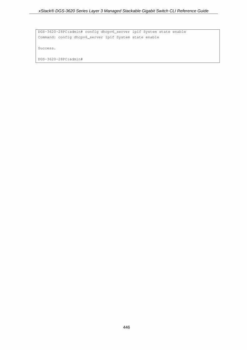
xStack® DGS-3620 Series Layer 3 Managed Stackable Gigabit Switch CLI Reference Guide
446
DGS-3620-28PC:admin# config dhcpv6_server ipif System state enable
Command: config dhcpv6_server ipif System state enable
Success.
DGS-3620-28PC:admin#

xStack® DGS-3620 Series Layer 3 Managed Stackable Gigabit Switch CLI Reference Guide
447
Chapter 27 Digital Diagnostic Monitoring (DDM) Commands
config ddm [trap | log] [enable | disable] config ddm ports [<portlist> | all] [[temperature_threshold {high_alarm <degrees> | low_alarm
<degrees> | high_warning <degrees> | low_warning <degrees>} | voltage_threshold {high_alarm <voltage> | low_alarm <voltage> | high_warning <voltage> | low_warning <voltage>} | bias_current_threshold {high_alarm <milliampere> | low_alarm <milliampere> | high_warning <milliampere> | low_warning <milliampere>} | tx_power_threshold {high_alarm <mw_or_dbm> | low_alarm <mw_or_dbm> | high_warning <mw_or_dbm> | low_warning <mw_or_dbm>} | rx_power_threshold {high_alarm <mw_or_dbm> | low_alarm <mw_or_dbm> | high_warning <mw_or_dbm> | low_warning <mw_or_dbm>}] | {state [enable | disable] | shutdown [alarm | warning | none]}]
show ddm show ddm ports {<portlist>} [status | configuration] config ddm power_unit [mw | dbm]
27-1 config ddm Description The command configures the DDM log and trap action when encountering an exceeding alarm or warning thresholds event.
Format config ddm [trap | log] [enable | disable]
Parameters trap - Specifies whether to send traps, when the operating parameter exceeds the corresponding
threshold. The DDM trap is disabled by default. log - Specifies whether to send a log, when the operating parameter exceeds the corresponding
threshold. The DDM log is enabled by default. enable - Specifies to enable the log or trap sending option. disable - Specifies to disable the log or trap sending option.
Restrictions Only Administrators and Operators can issue this command.
Example To configure DDM log state to enable:
xStack® DGS-3620 Series Layer 3 Managed Stackable Gigabit Switch CLI Reference Guide
448
DGS-3620-28PC:admin#config ddm log enable
Command: config ddm log enable
Success.
DGS-3620-28PC:admin#
To configure DDM trap state to enable:
DGS-3620-28PC:admin#config ddm trap enable
Command: config ddm trap enable
Success.
DGS-3620-28PC:admin#
27-2 config ddm ports Description The command is used to configure the DDM settings of the specified ports.
Format config ddm ports [<portlist> | all] [[temperature_threshold {high_alarm <degrees> | low_alarm <degrees> | high_warning <degrees> | low_warning <degrees>} | voltage_threshold {high_alarm <voltage> | low_alarm <voltage> | high_warning <voltage> | low_warning <voltage>} | bias_current_threshold {high_alarm <milliampere> | low_alarm <milliampere> | high_warning <milliampere> | low_warning <milliampere>} | tx_power_threshold {high_alarm <mw_or_dbm> | low_alarm <mw_or_dbm> | high_warning <mw_or_dbm> | low_warning <mw_or_dbm>} | rx_power_threshold {high_alarm <mw_or_dbm> | low_alarm <mw_or_dbm> | high_warning <mw_or_dbm> | low_warning <mw_or_dbm>}] | {state [enable | disable] | shutdown [alarm | warning | none]}]
Parameters <portlist> - Enter the range of ports to be configured here. all - Specifies that all the optic ports’ operating parameters will be configured. temperature_threshold - Specifies the threshold of the optic module’s temperature in
centigrade. At least one parameter shall be specified for this threshold. high_alarm - (Optional) Specifies the high threshold for the alarm. When the operating
parameter rises above this value, the action associated with the alarm is taken. <degrees> - Enter the high threshold alarm value used here.
low_alarm - (Optional) Specifies the low threshold for the alarm. When the operating parameter falls below this value, the action associated with the alarm is taken. <degrees> - Enter the low threshold alarm value used here.
high_warning - (Optional) Specifies the high threshold for the warning. When the operating parameter rises above this value, the action associated with the warning is taken. <degrees> - Enter the high threshold warning value here.
low_warning - (Optional) Specifies the low threshold for the warning. When the operating parameter falls below this value, the action associated with the warning is taken. <degrees> - Enter the low threshold warning value here.
voltage_threshold - Specifies the threshold of optic module’s voltage. high_alarm - (Optional) Specifies the high threshold for the alarm. When the operating
parameter rises above this value, the action associated with the alarm is taken.

xStack® DGS-3620 Series Layer 3 Managed Stackable Gigabit Switch CLI Reference Guide
449
<voltage> - Enter the high threshold alarm value used here. low_alarm - (Optional) Specifies the low threshold for the alarm. When the operating
parameter falls below this value, the action associated with the alarm is taken. <voltage> - Enter the low threshold alarm value used here.
high_warning - (Optional) Specifies the high threshold for the warning. When the operating parameter rises above this value, the action associated with the warning is taken. <voltage> - Enter the high threshold warning value here.
low_warning - (Optional) Specifies the low threshold for the warning. When the operating parameter falls below this value, the action associated with the warning is taken. <voltage> - Enter the low threshold warning value here.
bias_current_threshold - Specifies the threshold of the optic module’s bias current. high_alarm - (Optional) Specifies the high threshold for the alarm. When the operating
parameter rises above this value, the action associated with the alarm is taken. <milliampere> - Enter the high threshold alarm value used here.
low_alarm - (Optional) Specifies the low threshold for the alarm. When the operating parameter falls below this value, the action associated with the alarm is taken. <milliampere> - Enter the low threshold alarm value used here.
high_warning - (Optional) Specifies the high threshold for the warning. When the operating parameter rises above this value, the action associated with the warning is taken. <milliampere> - Enter the high threshold warning value here.
low_warning - (Optional) Specifies the low threshold for the warning. When the operating parameter falls below this value, the action associated with the warning is taken. <milliampere> - Enter the low threshold warning value here.
tx_power_threshold - Specifies the threshold of the optic module’s output power. high_alarm - (Optional) Specifies the high threshold for the alarm. When the operating
parameter rises above this value, the action associated with the alarm is taken. <mw_or_dbm> - Enter the high threshold alarm value used here.
low_alarm - (Optional) Specifies the low threshold for the alarm. When the operating parameter falls below this value, the action associated with the alarm is taken. <mw_or_dbm> - Enter the low threshold alarm value used here.
high_warning - (Optional) Specifies the high threshold for the warning. When the operating parameter rises above this value, the action associated with the warning is taken. <mw_or_dbm> - Enter the high threshold warning value here.
low_warning - (Optional) Specifies the low threshold for the warning. When the operating parameter falls below this value, the action associated with the warning is taken. <mw_or_dbm> - Enter the low threshold warning value here.
rx_power_threshold - Specifies the threshold of optic module’s received power. high_alarm - (Optional) Specifies the high threshold for the alarm. When the operating
parameter rises above this value, the action associated with the alarm is taken. <mw_or_dbm> - Enter the high threshold alarm value used here.
low_alarm - (Optional) Specifies the low threshold for the alarm. When the operating parameter falls below this value, the action associated with the alarm is taken. <mw_or_dbm> - Enter the low threshold alarm value used here.
high_warning - (Optional) Specifies the high threshold for the warning. When the operating parameter rises above this value, the action associated with the warning is taken. <mw_or_dbm> - Enter the high threshold warning value here.
low_warning - (Optional) Specifies the low threshold for the warning. When the operating parameter falls below this value, the action associated with the warning is taken. <mw_or_dbm> - Enter the low threshold warning value here.
state - (Optional) Specifies the DDM state to enable or disable. If the state is disabled, no DDM action will take effect. enable - Specifies to enable the DDM state. disable - Specifies to disable the DDM state.
shutdown - (Optional) Specifies whether or not to shutdown the port when the operating parameter exceeds the corresponding alarm threshold or warning threshold. alarm - Shutdown the port when the configured alarm threshold range is exceeded. warning - Shutdown the port when the configured warning threshold range is exceeded. none - The port will never shutdown regardless if the threshold ranges are exceeded or not.

xStack® DGS-3620 Series Layer 3 Managed Stackable Gigabit Switch CLI Reference Guide
450
Restrictions Only Administrators and Operators can issue this command.
Example To configure the port 21’s temperature threshold:
DGS-3620-28PC:admin#config ddm ports 1:21 temperature_threshold high_alarm 84.9555 low_alarm -10 high_warning 70 low_warning 2.25251
Command: config ddm ports 1:21 temperature_threshold high_alarm 84.9555 low_alarm -10 high_warning 70 low_warning 2.25251
Success.
DGS-3620-28PC:admin#
To configure the port 21’s voltage threshold:
DGS-3620-28PC:admin#config ddm ports 1:21 voltage_threshold high_alarm 4.25 low_alarm 2.5 high_warning 3.5 low_warning 3
Command: config ddm ports 1:21 voltage_threshold high_alarm 4.25 low_alarm 2.5 high_warning 3.5 low_warning 3
Success.
DGS-3620-28PC:admin#
To configure the port 21’s bias current threshold:
DGS-3620-28PC:admin#config ddm ports 1:21 bias_current_threshold high_alarm 7.25 low_alarm 0.004 high_warning 0.5 low_warning 0.008
Command: config ddm ports 1:21 bias_current_threshold high_alarm 7.25 low_alarm 0.004 high_warning 0.5 low_warning 0.008
Success.
DGS-3620-28PC:admin#
To configure the port 21’s transmit power threshold:
DGS-3620-28PC:admin#config ddm ports 1:21 tx_power_threshold high_alarm 0.625 low_alarm 0.006 high_warning 0.55 low_warning 0.008
Command: config ddm ports 1:21 tx_power_threshold high_alarm 0.625 low_alarm 0.006 high_warning 0.55 low_warning 0.008
Success.
DGS-3620-28PC:admin#
To configure the port 21’s receive power threshold:

xStack® DGS-3620 Series Layer 3 Managed Stackable Gigabit Switch CLI Reference Guide
451
DGS-3620-28PC:admin#config ddm ports 1:21 rx_power_threshold high_alarm 4.55 low_alarm 0.01 high_warning 3.5 low_warning 0.03
Command: config ddm ports 1:21 rx_power_threshold high_alarm 4.55 low_alarm 0.01 high_warning 3.5 low_warning 0.03
Success.
DGS-3620-28PC:admin#
To configure port 21’s actions associate with the alarm:
DGS-3620-28PC:admin#config ddm ports 1:21 state enable shutdown alarm
Command: config ddm ports 1:21 state enable shutdown alarm
Success.
DGS-3620-28PC:admin#
27-3 show ddm Description This command is used to display the DDM global settings.
Format show ddm
Parameters None.
Restrictions None.
Example To display the DDM global settings:
DGS-3620-28PC:admin#show ddm
Command: show ddm
DDM Log : Enabled
DDM Trap : Disabled
DDM Tx/Rx Power Unit : mw
DGS-3620-28PC:admin#

xStack® DGS-3620 Series Layer 3 Managed Stackable Gigabit Switch CLI Reference Guide
452
27-4 show ddm ports Description This command is used to show the current operating DDM parameters and configuration values of the optic module of the specified ports. There are two types of thresholds: the administrative configuration and the operation configuration threshold. For the optic port, when a particular threshold was configured by user, it will be shown in this command with a tag indicating that it is a threshold that user configured, else it would be the threshold read from the optic module that is being inserted.
Format show ddm ports {<portlist>} [status | configuration]
Parameters <portlist> - (Optional) Enter the range of ports to be displayed here. status - Specifies that the operating parameter will be displayed. configuration - Specifies that the configuration values will be displayed.
Restrictions None.
Example To display ports 21-22’s operating parameters:
DGS-3620-28PC:admin#show ddm ports 1:21-1:22 status
Command: show ddm ports 1:21-1:22 status
Port Temperature Voltage Bias-Current TX-Power RX-Power
(in Celsius) (V) (mA) (mW) (mW)
------- ------------- ---------- -------------- ---------- ------------
1:21 21.5 2.5 50 3 4
1:22 - - - - -
CTRL+C ESC q Quit SPACE n Next Page p Previous Page r Refresh
To display port 21’s configuration:

xStack® DGS-3620 Series Layer 3 Managed Stackable Gigabit Switch CLI Reference Guide
453
DGS-3620-28PC:admin#show ddm ports 1:21 configuration
Command: show ddm ports 1:21 configuration
Port: 1:21
--------------------------------------------
DDM State : Enabled
Shutdown : Alarm
Threshold Temperature Voltage Bias-Current TX-Power RX-Power
(in Celsius) (V) (mA) (mW) (mW)
------------- ------------ ------------ ------------ ------------ ------------
High Alarm 84.9555(A) 4.2500(A) 7.2500(A) 0.6250(A) 4.5500(A)
Low Alarm -10.0000(A) 2.5000(A) 0.0040(A) 0.0060(A) 0.0100(A)
High Warning 70.0000(A) 3.5000(A) 0.5000(A) 0.5500(A) 3.5000(A)
Low Warning 2.2525(A) 3.0000(A) 0.0080(A) 0.0080(A) 0.0300(A)
A means that the threshold is administratively configured.
DGS-3620-28PC:admin#
27-5 config ddm power_unit Description The command is used to configure the unit of DDM TX and RX power.
Format config ddm power_unit [mw | dbm]
Parameters mw - Specifies the DDM TX and RX power unit as mW. dbm - Specifies the DDM TX and RX power unit as dBm.
Restrictions Only Administrators and Operators can issue this command.
Example To configure the DDM TX and RX power unit as dBm:
DGS-3620-28PC:admin#config ddm power_unit dbm
Command: config ddm power_unit dbm
Success.
DGS-3620-28PC:admin#

xStack® DGS-3620 Series Layer 3 Managed Stackable Gigabit Switch CLI Reference Guide
454
Chapter 28 Distance Vector Multicast Routing Protocol (DVMRP) Commands
config dvmrp [ipif <ipif_name 12> | all] {metric <value 1-31> | probe <sec 1-65535> | neighbor_timeout <sec 1-65535> | state [enable | disable]}(1)
enable dvmrp disable dvmrp show dvmrp {ipif <ipif_name 12>} show dvmrp neighbor {ipif <ipif_name 12> | ipaddress <network_address>} show dvmrp nexthop {ipaddress <network_address> | ipif <ipif_name 12>} show dvmrp routing_table {ipaddress <network_address>}
28-1 config dvmrp Description This command is used to configure DVMRP configurations.
Format config dvmrp [ipif <ipif_name 12> | all] {metric <value 1-31> | probe <sec 1-65535> | neighbor_timeout <sec 1-65535> | state [enable | disable]}(1)
Parameters ipif - Specifies the IP interface name used.
<ipif_name 12> - Enter the IP interface name used here. This name can be up to 12 characters long.
all - Specifies that all the IP interfaces will be used. metric - (Optional) Allows the assignment of a DVMRP route cost to the above IP interface. A
DVMRP route cost is a relative number that represents the real cost of using this route in the construction of a multicast delivery tree. It is similar to, but not defined as, the hop count in RIP. <value 1-31> - Enter the metric value used here. This value must be between 1 and 31. The
default value is 1. probe - (Optional) Specifies the time in seconds between the DVMRP Probe message
transmissions. <sec 1-65535> - Enter the probe value used here. This value must be between 1 and 65535
seconds. The default value is 10 seconds. neighbor_timeout - (Optional) Specifies the time period for DVMRP will hold Neithbor Router
reports before issuing poison route messages. <sec 1-65535> - Enter the neighbor timeout value used here. This value must be between 1
and 65535 seconds. The default value is 35 seconds. state - (Optional) Specifies the DVMRP state of the IP interface.
enable - Specifies that DVMRP of the specified IP interface will be enabled. disable - Specifies that DVMRP of the specified IP interface will be disabled.

xStack® DGS-3620 Series Layer 3 Managed Stackable Gigabit Switch CLI Reference Guide
455
Restrictions Only Administrators, Operators and Power-Users can issue this command. (EI Mode Only Command)
Example To configure DVMRP configurations of IP interface called ‘System’:
DGS-3620-28PC:admin# config dvmrp ipif System neighbor_timeout 30 metric 1 probe 5
Command: config dvmrp ipif System neighbor_timeout 30 metric 1 probe 5
Success
DGS-3620-28PC:admin#
28-2 enable dvmrp Description This command is used to enable the DVMRP global state on the Switch.
Format enable dvmrp
Parameters None.
Restrictions Only Administrators, Operators and Power-Users can issue this command. (EI Mode Only Command)
Example To enable DVMRP:
DGS-3620-28PC:admin# enable dvmrp
Command: enable dvmrp
Success.
DGS-3620-28PC:admin#
28-3 disable dvmrp Description This command is used to disable the DVMRP global state on the Switch.

xStack® DGS-3620 Series Layer 3 Managed Stackable Gigabit Switch CLI Reference Guide
456
Format disable dvmrp
Parameters None.
Restrictions Only Administrators, Operators and Power-Users can issue this command. (EI Mode Only Command)
Example To disable DVMRP:
DGS-3620-28PC:admin# disable dvmrp
Command: disable dvmrp
Success.
DGS-3620-28PC:admin#
28-4 show dvmrp Description This command is used to display DVMRP configurations.
Format show dvmrp {ipif <ipif_name 12>}
Parameters ipif - (Optional) Specifies the IP interface name used for the display.
<ipif_name 12> - Enter the IP interface name used for the display here. This name can be up to 12 characters long.
If no parameter is specified, then all the IP interfaces will be displayed.
Restrictions None. (EI Mode Only Command)
Example To display DVMRP configurations:

xStack® DGS-3620 Series Layer 3 Managed Stackable Gigabit Switch CLI Reference Guide
457
DGS-3620-28PC:admin#show dvmrp
Command: show dvmrp
DVMRP Global State : Disabled
Interface IP Address Neighbor Timeout Probe Metric State
------------ ----------------- ---------------- ----- ------ --------
System 192.168.69.123 35 10 1 Disabled
Total Entries: 1
DGS-3620-28PC:admin#
28-5 show dvmrp neighbor Description This command is used to display the DVMRP neighbor table.
Format show dvmrp neighbor {ipif <ipif_name 12> | ipaddress <network_address>}
Parameters ipif - (Optional) Specifies the IP interface name used for the display.
<ipif_name 12> - Enter the IP interface name used for the display here. This name can be up to 12 characters long.
ipaddress - (Optional) Specifies the IP address and netmask of the destination used. <network_address> - Enter the IP address and netmask of the destination used here.
If no parameter is specified, the system will display the whole DVMRP neighbor table.
Restrictions None. (EI Mode Only Command)
Example To display DVMRP neighbor table:
DGS-3620-28PC:admin# show dvmrp neighbor
Command: show dvmrp neighbor
DVMRP Neighbor Address Table
Interface Neighbor Address Generation ID Expire Time
--------------- ---------------- ------------- -----------
System 10.48.74.123 86 32
Total Entries : 1
DGS-3620-28PC:admin#

xStack® DGS-3620 Series Layer 3 Managed Stackable Gigabit Switch CLI Reference Guide
458
28-6 show dvmrp nexthop Description This command is used to display the DVMRP routing next hop table.
Format show dvmrp nexthop {ipaddress <network_address> | ipif <ipif_name 12>}
Parameters ipaddress - (Optional) Specifies the IP address and netmask of the destination used.
<network_address> - Enter the IP address and netmask of the destination used here. ipif - (Optional) Specifies the IP interface name used for the display.
<ipif_name 12> - Enter the IP interface name used for the display here. This name can be up to 12 characters long.
If no parameter is specified, the system will display all the DVMRP routing next hop tables.
Restrictions None. (EI Mode Only Command)
Example To display DVMRP routing next hop table:
DGS-3620-28PC:admin# show dvmrp nexthop
Command: show dvmrp nexthop
DVMRP Routing Next Hop Table
Source Address/NetMask Interface Name Type
---------------------- --------------- ------
10.0.0.0/8 ip2 Leaf
10.0.0.0/8 ip3 Leaf
20.0.0.0/8 System Leaf
20.0.0.0/8 ip3 Leaf
30.0.0.0/8 System Leaf
30.0.0.0/8 ip2 Leaf
Total Entries : 6
DGS-3620-28PC:admin#
28-7 show dvmrp routing_table Description This command is used to display the DVMRP routing table.
Format show dvmrp routing_table {ipaddress <network_address>}

xStack® DGS-3620 Series Layer 3 Managed Stackable Gigabit Switch CLI Reference Guide
459
Parameters ipaddress - (Optional) Specifies the IP address and netmask of the destination used.
<network_address> - Enter the IP address and netmask of the destination used here. If no parameter is specified, the system will display the whole DVMRP routing table.
Restrictions None. (EI Mode Only Command)
Example To display DVMRP routing table:
DGS-3620-28PC:admin# show dvmrp routing_table
Command: show dvmrp routing_table
DVMRP Routing Table
Source Address/Netmask Upstream Neighbor Metric Learned Interface Expire
---------------------- ----------------- ------ ------- ---------- ------
10.0.0.0/8 10.90.90.90 2 Local System -
20.0.0.0/16 20.1.1.1 2 Local ip2 -
30.0.0.0/24 30.1.1.1 2 Local ip3 -
Total Entries : 3
DGS-3620-28PC:admin#
xStack® DGS-3620 Series Layer 3 Managed Stackable Gigabit Switch CLI Reference Guide
460
Chapter 29 D-Link License Management System (DLMS) Commands
install dlms activation_code <string 25> {unit <unit_id 1-12>} show dlms license
29-1 install dlms activation_code
Description This command is used to install an activation code. The activation code is a set of codes which activates functions on the switch.
Format install dlms activation_code <string 25> {unit <unit_id 1-12>}
Parameters <string 25> Specifies an activation code. The length should be 25 string characters unit - Specifies the unit to display.
<unit_id 1-12> Specifies the switch in the switch stack.
Restrictions Only Administrator level users can issue this command.
Example To input a legal activation code:
DGS-3620-28PC:admin# install dlms activation_code xBc7vNWsSpchuQkGZsTfPwcfa
Command: install dlms activation_code xBc7vNWsSpchuQkGZsTfPwcfa
Success.
Please reboot the device to active the license.
DGS-3620-28PC:admin#

xStack® DGS-3620 Series Layer 3 Managed Stackable Gigabit Switch CLI Reference Guide
461
29-2 show dlms license
Description This command will display the license information.
Format show dlms license {unit <unit_id>}
Parameters unit - Specifies the unit to display.
<unit_id> Specifies the switch in the switch stack.
Restrictions None.
Example To display license information: DGS-3620-28PC:admin# show dlms license
Command: show dlms license
Device Default License : EI
DGS-3620-28PC:admin#

xStack® DGS-3620 Series Layer 3 Managed Stackable Gigabit Switch CLI Reference Guide
462
Chapter 30 Domain Name System (DNS) Relay Commands
config dnsr [[primary | secondary] nameserver <ipaddr> | [add | delete] static <domain_name 32>
<ipaddr>] enable dnsr {[cache | static]} disable dnsr {[cache | static]} show dnsr {static}
30-1 config dnsr Description This command is used to add or delete a static entry into the Switch’s DNS resolution table, or set up the relay server.
Format config dnsr [[primary | secondary] nameserver <ipaddr> | [add | delete] static <domain_name 32> <ipaddr>]
Parameters primary - Specifies to indicate that the IP address below is the address of the primary DNS
server. secondary - Specifies to indicate that the IP address below is the address of the secondary DNS
server. nameserver - Specifies the IP address of the DNS nameserver.
<ipaddr> - Enter the IP address of the DNS nameserver. add - Specifies to add the DNS relay function. delete - Specifies to delete the DNS relay function. static - Specifies the domain name of the entry.
<domain_name32> - Enter the domain name. <ipaddr> - Enter the IP address of the entry.
Restrictions Only Administrators, Operators and Power-Users can issue this command.
Example To set IP address 10.24.22.5 as the primary DNS server:
DGS-3620-28PC:admin# config dnsr primary nameserver 10.24.22.5
Command: config dnsr primary nameserver 10.24.22.5
Success.

xStack® DGS-3620 Series Layer 3 Managed Stackable Gigabit Switch CLI Reference Guide
463
DGS-3620-28PC:admin#
To add the entry “dns1” with IP address 10.24.22.5 to the DNS static table:
DGS-3620-28PC:admin#config dnsr add static dns1 10.24.22.5
Command: config dnsr add static dns1 10.24.22.5
Success.
DGS-3620-28PC:admin#
To delete the entry “dns1” with IP address 10.24.22.5 from the DNS static table:
DGS-3620-28PC:admin#config dnsr delete static dns1 10.24.22.5
Command: config dnsr delete static dns1 10.24.22.5
Success.
DGS-3620-28PC:admin#
30-2 enable dnsr Description This command is used to enable DNS relay.
Format enable dnsr {[cache | static]}
Parameters cache - Specifies to enable the cache lookup for the DNS relay on the switch. static - Specifies to enable the static table lookup for the DNS relay on the switch.
Restrictions Only Administrators, Operators and Power-Users can issue this command.
Example To enable DNS relay:
DGS-3620-28PC:admin#enable dnsr
Command: enable dnsr
Success.
DGS-3620-28PC:admin#
To enable cache lookup for DNS relay:

xStack® DGS-3620 Series Layer 3 Managed Stackable Gigabit Switch CLI Reference Guide
464
DGS-3620-28PC:admin#enable dnsr cache
Command: enable dnsr cache
Success.
DGS-3620-28PC:admin#
To enable static table lookup for DNS relay:
DGS-3620-28PC:admin#enable dnsr static
Command: enable dnsr static
Success.
DGS-3620-28PC:admin#
30-3 disable dnsr Description This command is used to disable DNS relay on the switch.
Format disable dnsr {[cache | static]}
Parameters cache - (Optional) Specifies to disable the cache lookup for the DNS relay on the switch. static - (Optional) Specifies to disable the static table lookup for the DNS relay on the switch.
Restrictions Only Administrators, Operators and Power-Users can issue this command.
Example To disable the status of DNS relay:
DGS-3620-28PC:admin#disable dnsr
Command: disable dnsr
Success.
DGS-3620-28PC:admin#
To disable cache lookup for DNS relay:
DGS-3620-28PC:admin#disable dnsr cache
Command: disable dnsr cache
Success.

xStack® DGS-3620 Series Layer 3 Managed Stackable Gigabit Switch CLI Reference Guide
465
DGS-3620-28PC:admin#
To disable static table lookup for DNS relay:
DGS-3620-28PC:admin#disable dnsr static
Command: disable dnsr static
Success.
DGS-3620-28PC:admin#
30-4 show dnsr Description This command is used to display the current DNS relay configuration and static entries.
Format show dnsr {static}
Parameters static - (Optional) Specifies to display the static entries in the DNS relay table. If this parameter is
omitted, the entire DNS relay table will be displayed.
Restrictions None.
Example To display the DNS relay status:

xStack® DGS-3620 Series Layer 3 Managed Stackable Gigabit Switch CLI Reference Guide
466
DGS-3620-28PC:admin#show dnsr
Command: show dnsr
DNSR Status : Disabled
Primary Name Server : 0.0.0.0
Secondary Name Server : 0.0.0.0
DNSR Cache Status : Disabled
DNSR Static Table Status : Disabled
DNS Relay Static Table
Domain Name IP Address
----------------------------------------- ---------------
www.123.com.tw 10.12.12.123
Total Entries: 1
DGS-3620-28PC:admin#

xStack® DGS-3620 Series Layer 3 Managed Stackable Gigabit Switch CLI Reference Guide
467
Chapter 31 Domain Name System (DNS) Resolver Commands
config name_server add [<ipaddr> | <ipv6addr>] {primary} config name_server delete [<ipaddr> | <ipv6addr>] {primary} config name_server timeout <second 1-60> show name_server create host_name <name 255> [<ipaddr> | <ipv6addr>] delete host_name [<name 255> | all] show host_name {static | dynamic} enable dns_resolver disable dns_resolver
31-1 config name_server add Description This command is used to add a DNS resolver name server to the Switch.
Format config name_server add [<ipaddr> | <ipv6addr>] {primary}
Parameters <ipaddr> - Enter the DNS Resolver name server IPv4 address used here. <ipv6addr> - Enter the DNS Resolver name server IPv6 address used here. primary – (Optional) Specifies that the name server is a primary name server.
Restrictions Only Administrators, Operators and Power-Users can issue this command.
Example To add DNS Resolver primary name server 10.10.10.10:
DGS-3620-28PC:admin# config name_server add 10.10.10.10 primary
Command: config name_server add 10.10.10.10 primary
Success.
DGS-3620-28PC:admin#
xStack® DGS-3620 Series Layer 3 Managed Stackable Gigabit Switch CLI Reference Guide
468
31-2 config name_server delete Description This command is used to delete a DNS resolver name server from the Switch.
Format config name_server delete [<ipaddr> | <ipv6addr>] {primary}
Parameters <ipaddr> - Enter the DNS Resolver name server IPv4 address used here. <ipv6addr> - Enter the DNS Resolver name server IPv6 address used here. primary – (Optional) Specifies that the name server is a primary name server.
Restrictions Only Administrators, Operators and Power-Users can issue this command.
Example To delete DNS Resolver name server 10.10.10.1:
DGS-3620-28PC:admin# config name_server delete 10.10.10.10
Command: config name_server delete 10.10.10.10
Success.
DGS-3620-28PC:admin#
31-3 config name_server timeout Description This command is used to configure the timeout value of a DNS Resolver name server.
Format config name_server timeout <second 1-60>
Parameters timeout - Specifies the maximum time waiting for a responce from a specified name server.
<second 1-60> - Enter the timeout value used here. This value must be between 1 and 60 seconds.
Restrictions Only Administrators, Operators and Power-Users can issue this command.

xStack® DGS-3620 Series Layer 3 Managed Stackable Gigabit Switch CLI Reference Guide
469
Example To configure DNS Resolver name server time out to 10 seconds:
DGS-3620-28PC:admin# config name_server timeout 10
Command: config name_server timeout 10
Success.
DGS-3620-28PC:admin#
31-4 show name_server Description This command is used to display the current DNS Resolver name servers and name server time out on the Switch.
Format show name_server
Parameters None.
Restrictions None.
Example To display the current DNS Resolver name servers and name server time out:
DGS-3620-28PC:admin# show name_server
Command: show name_server
Name Server Time Out: 3 seconds
Static Name Server Table:
Server IP Address Priority
--------------------- --------------
20.20.20.20 Secondary
10.1.1.1 Primary
Dynamic Name Server Table:
Server IP Address Priority
--------------------- --------------
10.48.74.122 Primary
DGS-3620-28PC:admin#

xStack® DGS-3620 Series Layer 3 Managed Stackable Gigabit Switch CLI Reference Guide
470
31-5 create host_name Description This command is used to create the static host name entry of the Switch.
Format create host_name <name 255> [<ipaddr> | <ipv6addr>]
Parameters <name 255> - Enter the hostname used here. This name can be up to 255 characters long. <ipaddr> - Enter the host IPv4 address used here. <ipv6addr> - Enter the host IPv6 address used here.
Restrictions Only Administrators, Operators and Power-Users can issue this command.
Example To create static host name “www.example.com”:
DGS-3620-28PC:admin# create host_name www.example.com 10.10.10.10
Command: create host_name www.example.com 10.10.10.10
Success.
DGS-3620-28PC:admin#
31-6 delete host_name Description This command is used to delete the static or dynamic host name entries of the Switch.
Format delete host_name [<name 255> | all]
Parameters <name 255> - Enter the hostname used here. This name can be up to 255 characters long. all - Specifies that all the hostnames will be deleted.
Restrictions Only Administrators, Operators and Power-Users can issue this command.
Example To delete the static host name entry “www.example.com”:

xStack® DGS-3620 Series Layer 3 Managed Stackable Gigabit Switch CLI Reference Guide
471
DGS-3620-28PC:admin# delete host_name www.example.com
Command: delete host_name www.example.com
Success.
DGS-3620-28PC:admin#
31-7 show host_name Description This command is used to display the current host name.
Format show host_name {static | dynamic}
Parameters static – (Optional) Specifies to display the static host name entries. dynamic – (Optional) Specifies to display the dynamic host name entries.
Restrictions None.
Example To display the static and dynamic host name entries:
DGS-3620-28PC:admin#show host_name
Command: show host_name
Static Host Name Table
Host Name : www.example1.com
IP Address : 20.20.20.20
IPv6 Address : 3000::1
Host Name : www.example2.com
IP Address : 10.10.10.10
IPv6 Address : 1000::1
Host Name : www.example3.com
IP Address : 4.4.4.4
Host Name : www.example4.com
IPv6 Address : 4000::1
Total Static Entries: 4
Dynamic Host Name Table

xStack® DGS-3620 Series Layer 3 Managed Stackable Gigabit Switch CLI Reference Guide
472
Total Dynamic Entries: 0
DGS-3620-28PC:admin#
31-8 enable dns_resolver Description This command is used to enable the DNS Resolver state of the Switch.
Format enable dns_resolver
Parameters None.
Restrictions Only Administrators, Operators and Power-Users can issue this command.
Example To configure the DNS Resolver state to enabled:
DGS-3620-28PC:admin# enable dns_resolver
Command: enable dns_resolver
Success.
DGS-3620-28PC:admin#
31-9 disable dns_resolver Description This command is used to disable the DNS Resolver state of the Switch.
Format disable dns_resolver
Parameters None.
Restrictions Only Administrators, Operators and Power-Users can issue this command.
xStack® DGS-3620 Series Layer 3 Managed Stackable Gigabit Switch CLI Reference Guide
473
Example To configure the DNS Resolver state to disabled:
DGS-3620-28PC:admin# disable dns_resolver
Command: disable dns_resolver
Success.
DGS-3620-28PC:admin#

xStack® DGS-3620 Series Layer 3 Managed Stackable Gigabit Switch CLI Reference Guide
474
Chapter 32 DoS Attack Prevention Commands
config dos_prevention dos_type [{land_attack | blat_attack | tcp_null_scan | tcp_xmasscan | tcp_synfin | tcp_syn_srcport_less_1024 | ping_death_attack | tcp_tiny_frag_attack} | all] {action [drop] | state [enable | disable]}(1)
config dos_prevention log [enable | disable] config dos_prevention trap [enable | disable] show dos_prevention {land_attack | blat_attack | tcp_null_scan | tcp_xmasscan | tcp_synfin |
tcp_syn_srcport_less_1024 | ping_death_attack | tcp_tiny_frag_attack}
32-1 config dos_prevention dos_type Description This command is used to configure the prevention of each DoS attacks. The packet matching will be done by hardware. For a specific type of attack, the content of the packet will be matched against a specific pattern.
Format config dos_prevention dos_type [{land_attack | blat_attack | tcp_null_scan | tcp_xmasscan | tcp_synfin | tcp_syn_srcport_less_1024 | ping_death_attack | tcp_tiny_frag_attack} | all] {action [drop] | state [enable | disable]}(1)
Parameters land_attack - (Optional) Specifies that the DoS attack prevention type will be set to prevent
LAND attacks. blat_attack - (Optional) Specifies that the DoS attack prevention type will be set to prevent BLAT
attacks. tcp_null_scan - (Optional) Specifies that the DoS attack prevention type will be set to prevent
TCP Null Scan attacks. tcp_xmasscan - (Optional) Specifies that the DoS attack prevention type will be set to prevent
TCP Xmas Scan attacks. tcp_synfin - (Optional) Specifies that the DoS attack prevention type will be set to prevent TCP
SYN FIN attacks. tcp_syn_srcport_less_1024 - (Optional) Specifies that the DoS attack prevention type will be
set to prevent TCP SYN Source Port Less 1024 attacks. ping_death_attack - (Optional) Specifies that the DoS attack prevention type will be set to
prevent Ping of Death attacks. tcp_tiny_frag_attack - (Optional) Specifies that the DoS attack prevention type will be set to
prevent TCP Tiny Frag attacks. all - Specifies that the DoS attack prevention type will be set to prevent all attacks. action - (Optional) Specifies the action that the DoS Prevention function will take.
drop - Specifies to drop all matched DoS attack packets. state - (Optional) Specifies the DoS Attack Prevention state.
enable - Specifies that the DoS Attack Prevention state will be enabled. disable - Specifies that the DoS Attack Prevention state will be disabled.

xStack® DGS-3620 Series Layer 3 Managed Stackable Gigabit Switch CLI Reference Guide
475
Restrictions Only Administrators, Operators and Power-Users can issue this command.
Example To configure land attack and blat attack prevention, the action is drop:
DGS-3620-28PC:admin#config dos_prevention dos_type land_attack blat_attack action drop state enable
Command: config dos_prevention dos_type land_attack blat_attack action drop state enable
Success.
DGS-3620-28PC:admin#
32-2 config dos_prevention log Description This command is used to enable or disable the DoS prevention log state.
Format config dos_prevention log [enable | disable]
Parameters enable - Specifies to enable the DoS prevention log state. disable - Specifies to disable the DoS prevention log state.
Restrictions Only Administrators, Operators and Power-Users can issue this command.
Example To enable the DoS prevention log:
DGS-3620-28PC:admin#config dos_prevention log enable
Command: config dos_prevention log enable
Success.
DGS-3620-28PC:admin#
32-3 config dos_prevention trap Description This command is used to enable or disable the DoS prevention trap state.

xStack® DGS-3620 Series Layer 3 Managed Stackable Gigabit Switch CLI Reference Guide
476
Format config dos_prevention trap [enable | disable]
Parameters enable - Specifies to enable the DoS prevention trap state. disable - Specifies to disable the DoS prevention trap state.
Restrictions Only Administrators, Operators and Power-Users can issue this command.
Example To enable the DoS prevention trap:
DGS-3620-28PC:admin#config dos_prevention trap disable
Command: config dos_prevention trap disable
Success.
DGS-3620-28PC:admin#
32-4 show dos_prevention Description This command is used to display DoS prevention information.
Format show dos_prevention {land_attack | blat_attack | tcp_null_scan | tcp_xmasscan | tcp_synfin | tcp_syn_srcport_less_1024 | ping_death_attack | tcp_tiny_frag_attack}
Parameters land_attack - (Optional) Specifies that only DoS LAND attack information will be displayed. blat_attack - (Optional) Specifies that only DoS BLAT attack information will be displayed. tcp_null_scan - (Optional) Specifies that only DoS TCP Null Scan attack information will be
displayed. tcp_xmasscan - (Optional) Specifies that only DoS TCP Xmas Scan attack information will be
displayed. tcp_synfin - (Optional) Specifies that only DoS TCP SYN FIN attack information will be
displayed. tcp_syn_srcport_less_1024 - (Optional) Specifies that only DoS TCP SYN Source Port Less
than 1024 attack information will be displayed. ping_death_attack - (Optional) Specifies that only DoS Ping of Death attack information will be
displayed. tcp_tiny_frag_attack - (Optional) Specifies that only DoS TCP Tiny Frag attack information will
be displayed.
Restrictions None.

xStack® DGS-3620 Series Layer 3 Managed Stackable Gigabit Switch CLI Reference Guide
477
Example To display DoS prevention information:
DGS-3620-28PC:admin#show dos_prevention
Command: show dos_prevention
Trap:Disabled Log:Enabled Function Version : 1.01
DoS Type State Action Frame Counts
-------------------------- -------- ---------------- ------------
Land Attack Enabled Drop -
Blat Attack Enabled Drop -
TCP Null Scan Disabled Drop -
TCP Xmas Scan Disabled Drop -
TCP SYNFIN Disabled Drop -
TCP SYN SrcPort Less 1024 Disabled Drop -
Ping of Death Attack Disabled Drop -
TCP Tiny Fragment Attack Disabled Drop -
CTRL+C ESC q Quit SPACE n Next Page p Previous Page r Refresh
To display DoS prevention information of Land Attack:
DGS-3620-28PC:admin#show dos_prevention land_attack
Command: show dos_prevention land_attack
DoS Type : Land Attack
State : Disabled
Action : Drop
Frame Counts : -
DGS-3620-28PC:admin#
To display DoS prevention information of Blat Attack:
DGS-3620-28PC:admin#show dos_prevention blat_attack
Command: show dos_prevention blat_attack
DoS Type : Blat Attack
State : Disabled
Action : Drop
Frame Counts : -
DGS-3620-28PC:admin#

xStack® DGS-3620 Series Layer 3 Managed Stackable Gigabit Switch CLI Reference Guide
478
Chapter 33 D-Link Unidirectional Link Detection (DULD) Commands
config duld ports [<portlist> | all] {state [enable | disable] | mode [shutdown | normal] | discovery_time <sec 5-65535>}
show duld ports {<portlist>}
33-1 config duld ports Description The command used to configure unidirectional link detection on ports.
Unidirectional link detection provides discovery mechanism based on 802.3ah to discovery its neighbor. If the OAM discovery can complete in configured discovery time, it concludes the link is bidirectional. Otherwise, it starts detecting task to detect the link status.
Format config duld ports [<portlist> | all] {state [enable | disable] | mode [shutdown | normal] | discovery_time <sec 5-65535>}
Parameters ports - Specifies a range of ports to be used.
<portlist> - Enter the list of ports used for this configuration here. all – Specifies that all the ports will be used for this configuration.
state - (Optional) Specifies these ports unidirectional link detection status. The default state is disabled. enable - Specifies that the unidirectional link detection status will be enabled. disable - Specifies that the unidirectional link detection status will be disabled.
mode - (Optional) Specifies the mode the unidirectional link detection will be set to. shutdown - If any unidirectional link is detected, disable the port and log an event. normal - Only log an event when a unidirectional link is detected.
discovery_time - (Optional) Specifies these ports neighbor discovery time. If the discovery is timeout, the unidirectional link detection will start. The default discovery time is 5 seconds. <sec 5-65535> - Enter the discovery time value here. This value must be between 5 and
65535.
Restrictions Only Administrators, Operators and Power-Users can issue this command.
Example To enable unidirectional link detection on port 1:
DGS-3620-28PC:admin# config duld ports 1 state enable

xStack® DGS-3620 Series Layer 3 Managed Stackable Gigabit Switch CLI Reference Guide
479
Commands: config duld ports 1 state enable
Success
DGS-3620-28PC:admin#
33-2 show duld ports Description This command is used to show unidirectional link detection information.
Format show duld ports {<portlist>}
Parameters ports - (Optional) Specifies a range of ports to be display.
<portlist> - Enter the list of ports to be displayed here. If no ports are specified, all the ports will be displayed.
Restrictions None.
Example To show ports 1-4 unidirectional link detection information:
DGS-3620-28PC:admin#config duld ports 1:1-1:2,1:4 state enable
Command: config duld ports 1:1-1:2,1:4 state enable
Success.
DGS-3620-28PC:admin#show duld ports 1:1-1:4
Command: show duld ports 1:1-1:4
Port Admin State Oper Status Mode Link Status Discovery Time(Sec)
----- ----------- ----------- -------- -------------- -------------------
1:1 Enabled Disabled Normal Unknown 5
1:2 Enabled Disabled Normal Unknown 5
1:3 Disabled Disabled Normal Unknown 5
1:4 Enabled Disabled Normal Unknown 5
DGS-3620-28PC:admin#

xStack® DGS-3620 Series Layer 3 Managed Stackable Gigabit Switch CLI Reference Guide
480
Chapter 34 Ethernet Ring Protection Switching (ERPS) Commands
enable erps disable erps create erps raps_vlan <vlanid 1-4094> delete erps raps_vlan <vlanid 1-4094> config erps raps_vlan <vlanid 1-4094> [state [enable | disable] | ring_mel <value 0-7> | ring_port
[west [<port> | virtual_channel] | east [<port> | virtual_channel]] | rpl_port [west | east | none] | rpl_owner [enable | disable] | protected_vlan [add | delete] vlanid <vidlist> | sub_ring raps_vlan <vlanid 1-4094> tc_propagation state [enable | disable] | [add | delete] sub_ring raps_vlan <vlanid 1-4094> | revertive [enable | disable] | timer {holdoff_time <millisecond 0-10000> | guard_time <millisecond 10-2000> | wtr_time <min 1-12>}]
config erps log [enable | disable] config erps trap [enable | disable] show erps {raps_vlan <vlanid 1-4094> {sub_ring}}
34-1 enable erps Description This command is used to enable the global ERPS function on the Switch. When both the global state and the specified ring ERPS state are enabled, the specified ring will be activated.
The global ERPS function cannot be enabled, when any ERPS ring on the device is enabled and the integrity of any ring parameter is not available. For each ring that has the ring state enabled, the following integrity will be checked when ERPS is enabled:
1. R-APS VLAN is created.
2. The Ring port is a tagged member port of the R-APS VLAN.
3. The RPL port is specified if the RPL owner is enabled.
4. The RPL port is not a virtual channel.
5. The Ring port is the master port if it belongs to a link aggregation group.
The default state is disabled.
Format enable erps
Parameters None.

xStack® DGS-3620 Series Layer 3 Managed Stackable Gigabit Switch CLI Reference Guide
481
Restrictions Only Administrators, Operators and Power-Users can issue this command.
Example To enable ERPS:
DGS-3620-28PC:admin#enable erps
Command: enable erps
Success.
DGS-3620-28PC:admin#
34-2 disable erps Description This command is used to disable the ERPS function on the switch.
Format disable erps
Parameters None. The ERPS is disabled by default.
Restrictions Only Administrators, Operators and Power-Users can issue this command.
Example To disable ERPS:
DGS-3620-28PC:admin#disable erps
Command: disable erps
Success.
DGS-3620-28PC:admin#
34-3 create erps raps_vlan Description This command is used to create an R-APS VLAN on the switch. There should be only one R-APS VLAN used to transfer R-APS messages. Note that the R-APS VLAN must already have been created by the create vlan command.

xStack® DGS-3620 Series Layer 3 Managed Stackable Gigabit Switch CLI Reference Guide
482
Format create erps raps_vlan <vlanid 1-4094>
Parameters <vlanid 1-4094> - Enter the VLAN which will be the R-APS VLAN.
Restrictions Only Administrators, Operators and Power-Users can issue this command.
Example To create an ERPS RAPS VLAN:
DGS-3620-28PC:admin#create erps raps_vlan 4094
Command: create erps raps_vlan 4094
Success.
DGS-3620-28PC:admin#
34-4 delete erps raps_vlan Description This command is used to delete an R-APS VLAN on the switch. When an R-APS VLAN is deleted, all parameters related to this R-APS VLAN will also be deleted. This command can only be issued when ERPS is disabled.
Format delete erps raps_vlan <vlanid 1-4094>
Parameters <vlanid 1-4094> - Enter the VLAN which will be the R-APS VLAN.
Restrictions Only Administrators, Operators and Power-Users can issue this command.
Example To delete an R-APS VLAN:
DGS-3620-28PC:admin#delete erps raps_vlan 4094
Command: delete erps raps_vlan 4094
Success.
DGS-3620-28PC:admin#

xStack® DGS-3620 Series Layer 3 Managed Stackable Gigabit Switch CLI Reference Guide
483
34-5 config erps raps_vlan Description This command is used to set the R-APS VLAN parameters. The ring_mel command is used to configure the ring MEL for an R-APS VLAN. The ring MEL is one field in the R-APS PDU. Note that if CFM (Connectivity Fault Management) and ERPS are used at the same time, R-APS PDU is one of a suite of Ethernet OAM PDU. The behavior for forwarding of R-APS PDU should follow the Ethernet OAM. If the ring MEL is not higher than the highest MEL of the MEPs on the ring ports, the R-APS PDU cannot be forwarded on the ring.
The ring_port command is used to configure the port that participates in the ERPS ring. Restrictions apply for ports that are included in a link aggregation group. A link aggregation group can be configured as a ring port by specifying the master port of the link aggregation port. Only the master port can be specified as a ring port. If the specified link aggregation group is eliminated, the master port retains its ring port status. If the ring port is configured on a virtual channel, the ring that the port is connected to will be considered as a sub-ring.
Note that modifying the ring port number may not take effect immediately when ERPS function is enabled. The ring will run protocol by old configuration if follow conditions are not satisfied:
1. The Ring port is a tagged member port of the R-APS VLAN.
2. The RPL port is not a virtual channel.
3. The Ring port is the master port if it belongs to a link aggregation group.
The rpl command is used to configure the RPL port and the RPL owner.
RPL port - Specifies one of the R-APS VLAN ring ports as the RPL port. To remove an RPL port from an R-APS VLAN, use the none designation for rpl_port.
RPL owner - Specifies the node as the RPL owner.
Note that modifying the RPL port and RPL owner may not take effect immediately when the ERPS function is enabled. The ring will run the protocol by the old configuration if the following conditions are not satisfied:
1. The RPL port is specified if the RPL owner is enabled.
2. The RPL port is not a virtual channel.
The protected_vlan command is used to configure the VLANs that are protected by the ERPS function.
The R-APS VLAN cannot be the protected VLAN. The protected VLAN can be one that has already been created, or it can be used for a VLAN that has not yet been created.
The timer commands are used to configure the protocol timers:
xStack® DGS-3620 Series Layer 3 Managed Stackable Gigabit Switch CLI Reference Guide
484
Holdoff timer - Hold-off timer is used to filter out intermittent link faults when link failure occurs. This timer is used during the protection switching process when link failure occurs. When a ring node detects a link’s failure, it will start the hold off timer. It will report the link failure event (R-APS BPDU with SF flag) after the link failure is confirmed within this period of time.
Guard timer - Guard timer is used to prevent ring nodes from receiving outdated R-APS messages. This timer is used during the protection switching process when link failure recovers. When the link node detects that the link failure is recovered, it will report the link failure recovery event (R-APS PDU with NR flag) and start the guard timer before the guard timer expires, all received R-APS messages are ignored by this ring node. Therefore, the blocking state of the recovered link will not be recovered within this period of time. This time should be greater than the maximum expected forwarding delay for which one R-APS message circles around the ring.
WTR timer - WTR timer is used to prevent frequent operation of the protection switch due to an intermittent defect. This timer is used during the protection switching process when a link failure recovers. This timer is only used by the RPL owner. When the RPL owner in protection state receives R-APS PDU with an NR flag, it will start the WTR timer. The RPL owner will block the original unblocked RPL port and start to send R-APS PDU with an RB flag after the link recovery is confirmed within this period of time.
Format config erps raps_vlan <vlanid 1-4094> [state [enable | disable] | ring_mel <value 0-7> | ring_port [west [<port> | virtual_channel] | east [<port> | virtual_channel]] | rpl_port [west | east | none] | rpl_owner [enable | disable] | protected_vlan [add | delete] vlanid <vidlist> | sub_ring raps_vlan <vlanid 1-4094> tc_propagation state [enable | disable] | [add | delete] sub_ring raps_vlan <vlanid 1-4094> | revertive [enable | disable] | timer {holdoff_time <millisecond 0-10000> | guard_time <millisecond 10-2000> | wtr_time <min 1-12>}]
Parameters <vlanid 1-4094> - The VLAN ID associated with the R-APS VLAN. state - Specifies the ERPS R-APS VLAN state.
enable - Specifies that the ERPS R-APS VLAN state will be enabled. disable - Specifies that the ERPS R-APS VLAN state will be disabled.
ring_mel - Specifies the ring MEL of the R-APS function. The default ring MEL is 1. <value 0-7> - Enter a value between 0 and 7.
ring_port - Specifies a port participating in the ERPS ring. west - Specifies the port as the west ring port.
<port> - Enter a port. virtual_channel - Specifies the port as a west port on the virtual channel.
east - Specifies the port as the east ring port. <port> - Enter a port. virtual_channel - Specifies the port as an east port on the virtual channel.
rpl_port - By default, the node has no RPL port. west - Specifies the west ring port as the RPL port. east - Specifies the east ring port as the RPL port. none - No RPL port on this node.
rpl_owner - By default, the RPS owner is disabled. enable - Specifies the device as an RPL owner node. disable - This node is not an RPL owner.
protected_vlan - Specifies VLANs that are protected by the ERPS function. The R-APS VLAN cannot be the protected VLAN. The protected VLAN can be one that has already been created, or it can be used for a VLAN that has not yet been created. add - Add VLANs to the protected VLAN group delete - Delete VLANs from the protected VLAN group.

xStack® DGS-3620 Series Layer 3 Managed Stackable Gigabit Switch CLI Reference Guide
485
vlanid - Specifies a VLAN ID list. <vidlist> - Enter a range of VLAN IDs.
sub_ring - Specifies the sub-ring configuration. raps_vlan - Specifies the R-APS VLAN.
<vlanid> - Enter the R-APS VLAN ID used here. tc_propagation - Specifies to configure the state of the topology change propagation for
the sub-ring. state - Specifies the propagation state of the topology change for the sub-ring.
enable - Enable the propagation state of the topology change for the sub-ring. disable - Disable the propagation state of the topology change for the sub-ring.
add - Specifies the add a topology change propagation rule. sub_ring - Specifies the sub-ring configuration information.
raps_vlan - Specifies the R-APS VLAN <vlanid> - Enter the R-APS VLAN ID used here.
delete - Specifies the delete a topology change propagation rule. sub_ring - Specifies the sub-ring configuration information.
raps_vlan - Specifies the R-APS VLAN. <vlanid> - Enter the R-APS VLAN ID used here.
revertive - Specifies the revertive mode state. enable - Specifies that the revertive mode will be enabled. disable - Specifies that the revertive mode will be disabled.
timer - Configure the ERPS timers for a specific R-APS VLAN. holdoff_time - Specifies the holdoff time of the R-APS function.
<millisecond 0-10000> - Enter the time between 0 and 10000. The default hold off time is 0 milliseconds.
guard_time - Specifies the guard time of the R-APS function. <millisecond 10-2000> - Enter the time between 10 and 2000. The default guard time is
500 milliseconds. wtr_time - Specifies the WTR time of the R-APS function.
<min 1-12> - Enter the time between 1 and 12. The default WTR time is 5 minutes.
Restrictions Only Administrators, Operators and Power-Users can issue this command.
Example To set the R-APS west ring port parameter to 5:
DGS-3620-28PC:admin#config erps raps_vlan 4094 ring_port west 5
Command: config erps raps_vlan 4094 ring_port west 5
Success.
DGS-3620-28PC:admin#
To set the R-APS east ring port parameter to 7:
DGS-3620-28PC:admin#config erps raps_vlan 4094 ring_port east 7
Command: config erps raps_vlan 4094 ring_port east 7
Success.
DGS-3620-28PC:admin#
To set the R-APS RPL parameter:

xStack® DGS-3620 Series Layer 3 Managed Stackable Gigabit Switch CLI Reference Guide
486
DGS-3620-28PC:admin#config erps raps_vlan 4094 rpl_port west
Command: config erps raps_vlan 4094 rpl_port west
Success.
DGS-3620-28PC:admin#config erps raps_vlan 4094 rpl_owner enable
Command: config erps raps_vlan 4094 rpl_owner enable
Success.
DGS-3620-28PC:admin#
To set the R-APS protected VLAN parameter:
DGS-3620-28PC:admin#config erps raps_vlan 4094 protected_vlan add vlanid 10-20
Command: config erps raps_vlan 4094 protected_vlan add vlanid 10-20
Success.
DGS-3620-28PC:admin#
To set the R-APS timer parameter:
DGS-3620-28PC:admin#config erps raps_vlan 4094 timer holdoff_time 100 guard_time 1000 wtr_time 10
Command: config erps raps_vlan 4094 timer holdoff_time 100 guard_time 1000 wtr_time 10
Success.
DGS-3620-28PC:admin#
34-6 config erps log Description This command is used to configure the ERPS log state.
Format config erps log [enable | disable]
Parameters enable - Enable the log state. The default value is disabled. disable - Disable the log state.
Restrictions Only Administrators, Operators and Power-Users can issue this command.

xStack® DGS-3620 Series Layer 3 Managed Stackable Gigabit Switch CLI Reference Guide
487
Example To set the log state:
DGS-3620-28PC:admin#config erps log enable
Command: config erps log enable
Success.
DGS-3620-28PC:admin#
34-7 config erps trap Description This command is used to configure trap state of ERPS events.
Format config erps trap [enable | disable]
Parameters trap - Specifies to enable or disable the ERPS trap state.
enable - Enter enable to enable the trap state. disable - Enter disable to disable the trap state. The default value is disabled.
Restrictions Only Administrators, Operators and Power-Users can issue this command.
Example To configure the trap state of the ERPS:
DGS-3620-28PC:admin# config erps trap enable
Command: config erps trap enable
Success.
DGS-3620-28PC:admin#
34-8 show erps Description This command is used to display ERPS configuration and operation information. The port state of the ring port may be as Forwarding, Blocking, or Signal Fail. Forwarding indicates that traffic is able to be forwarded. Blocking indicates that traffic is blocked by ERPS and a signal failure is not detected on the port. Signal Fail indicates that a signal failure is detected on the port and traffic is blocked by ERPS.

xStack® DGS-3620 Series Layer 3 Managed Stackable Gigabit Switch CLI Reference Guide
488
Format show erps {raps_vlan <vlanid 1-4094> {sub_ring}}
Parameters raps_vlan - (Optional) Specifies the R-APS VLAN.
<vlanid 1-4094> - Enter the R-APS VLAN ID used here. sub_ring - (Optional) Display the sub-ring configuration information.
Restrictions None.
Example To display ERPS information:
DGS-3620-28PC:admin#show erps
Command: show erps
Global Status : Enabled
Log Status : Enabled
Trap Status : Disabled
------------------------------------
R-APS VLAN : 4094
ERPS Status : Disabled
Admin West Port : 1:5
Operational West Port : 1:5 (Forwarding)
Admin East Port : 1:7
Operational East Port : 1:7 (Forwarding)
Admin RPL Port : West port
Operational RPL Port : West port
Admin Owner : Enabled
Operational Owner : Enabled
Protected VLANs : 10-20
Ring MEL : 1
Holdoff Time : 100 milliseconds
Guard Time : 1000 milliseconds
WTR Time : 10 minutes
Revertive mode : Enabled
Current Ring State : -
------------------------------------
Total Rings: 1
DGS-3620-28PC:admin#

xStack® DGS-3620 Series Layer 3 Managed Stackable Gigabit Switch CLI Reference Guide
489
Chapter 35 Energy Efficient Ethernet (EEE) Commands
config eee ports [<portlist> | all] state [enable | disable] show eee ports {<portlist>}
Note: This feature is only available on hardware version A1 and later.
35-1 config eee ports Description This command is used to enable or disable the EEE function on the specified port(s) on the Switch.
Format config eee ports [<portlist> | all] state [enable | disable]
Parameters <portlist> - Enter a range of ports to be configured. all - Specifies to configure all ports. state - Specifies the EEE state. The default is disabled.
enable - Enable the EEE function for the specified port(s). disable - Disable the EEE function for the specified port(s).
Restrictions Only Administrators and Operators can issue this command.
Example To enable the EEE state on ports 1:2-1:5:
DGS-3620-28PC:admin#config eee ports 1:2-1:5 state enable
Command: config eee ports 1:2-1:5 state enable
Success.
DGS-3620-28PC:admin#
35-2 show eee ports Description This command is used to display the EEE function state on the specified port(s).

xStack® DGS-3620 Series Layer 3 Managed Stackable Gigabit Switch CLI Reference Guide
490
Format show eee ports {<portlist>}
Parameters <portlist> - (Optional) Specifies a list of ports to be displayed.
Restrictions None.
Example To display the EEE state:
DGS-3620-28PC:admin#show eee ports 1:1-1:6,1:9
Command: show eee ports 1:1-1:6,1:9
Port State
--------- -----------
1:1 Disabled
1:2 Enabled
1:3 Enabled
1:4 Enabled
1:5 Enabled
1:6 Disabled
1:9 Disabled
DGS-3620-28PC:admin#

xStack® DGS-3620 Series Layer 3 Managed Stackable Gigabit Switch CLI Reference Guide
491
Chapter 36 External Alarm Commands
config external_alarm {unit <unit_id>} channel <value 1-2> message <sentence 1-128> show external_alarm {unit <unitlist>}
36-1 config external_alarm Description This command is used to configure external alarm message for a channel.
The source of alarm is located outside of the switch. They are monitored via pre-defined connection channels, with each channel representing a specific alarm event. This command allows the user to define the alarm event associated with each channel.
Format config external_alarm {unit <unit_id>} channel <value 1-2> message <sentence 1-128>
Parameters unit - Specifies the unit to display.
<unit_id> - Specifies the switch in the switch stack. channel - Specifies which channel is selected to configure.
<value 1-2> - Enter the value of the channel number to be used here. message - Alarm messages to display on console, log and trap.
<sentence 1-128> - Enter up to 128 characters here for the message to be displayed.
Restrictions Only Administrators, Operators and Power-Users can issue this command.
Example To configure an alarm message for channel 1 of unit 2:
DGS-3620-28PC:admin# config external_alarm unit 2 channel 1 message External Alarm: UPS is exhausted!
Command: config external_alarm unit 2 channel 1 message External Alarm: UPS is exhausted!
Success.
DGS-3620-28PC:admin#

xStack® DGS-3620 Series Layer 3 Managed Stackable Gigabit Switch CLI Reference Guide
492
36-2 show external_alarm Description This command is used to display the real-time status of external alarm.
Format show external_alarm {unit <unitlist>}
Parameters unit - Specifies the unit(s) to display.
<unitlist> - Enter the number of the unit(s) here.
Restrictions None.
Example To display the real-time status of external alarm when the switch is not support stacking:
DGS-3620-28PC:admin# show external_alarm
Command: show external_alarm
Unit Channel Status Message
------ --------- -------- --------------------------------------------
1 1 Normal External Alarm 1
1 2 Normal External Alarm 2
DGS-3620-28PC:admin#

xStack® DGS-3620 Series Layer 3 Managed Stackable Gigabit Switch CLI Reference Guide
493
Chapter 37 FDB Commands
create fdb <vlan_name 32> <macaddr> [port <port> | drop] create fdb vlanid <vidlist> <macaddr> [port <port> | drop] create multicast_fdb <vlan_name 32> <macaddr> config multicast_fdb <vlan_name 32> <macaddr> [add | delete] <portlist> config fdb aging_time <sec 10-1000000> config multicast vlan_filtering_mode [vlanid <vidlist> | vlan <vlan_name 32> | all]
[forward_all_groups | forward_unregistered_groups | filter_unregistered_groups] config fdb vlan_learning [<vlan_name 32> | vlanid <vidlist>] state [enable | disable] delete fdb <vlan_name 32> <macaddr> clear fdb [vlan <vlan_name 32> | port <port> | all] show multicast_fdb {[vlan <vlan_name 32> | vlanid <vidlist>] | mac_address <macaddr>} show fdb {[port <port> | vlan <vlan_name 32> | vlanid <vidlist> | mac_address <macaddr> | static
| aging_time | security] | vlan_learning [<vlan_name 32> | vlanid < vidlist >] } show multicast vlan_filtering_mode {[vlanid <vidlist> | vlan <vlan_name 32>]}
37-1 create fdb Description This command is used to make an entry into the switch’s unicast MAC address forwarding database.
Format create fdb <vlan_name 32> <macaddr> [port <port> | drop]
Parameters <vlan_name 32> - Enter a VLAN name associated with a MAC address. The maximum length is
32 characters. <macaddr> - Enter the MAC address to be added to the static forwarding table. port - The switch will always forward traffic to the specified device through this port.
<port> - Enter the port number corresponding to the MAC destination address. drop - Specifies to have the switch drop traffic.
Restrictions Only Administrators, Operators and Power-Users can issue this command.
Example To create an unicast MAC forwarding:
DGS-3620-28PC:admin#create fdb default 00-00-00-00-01-02 port 1:5
Command: create fdb default 00-00-00-00-01-02 port 1:5
Success.
DGS-3620-28PC:admin#

xStack® DGS-3620 Series Layer 3 Managed Stackable Gigabit Switch CLI Reference Guide
494
37-2 create fdb vlanid Description This command is used to create an entry into the switch’s unicast MAC address forwarding database using the VLAN ID.
Format create fdb vlanid <vidlist> <macaddr> [port <port> | drop]
Parameters <vidlist> - Enter the VLAN ID used here. <macaddr> - Enter the MAC address to be added to the static forwarding table. port - The switch will always forward traffic to the specified device through this port.
<port> - Enter the port number corresponding to the MAC destination address. drop - Specifies to have the switch drop traffic.
Restrictions Only Administrators, Operators and Power-Users can issue this command.
Example To create an unicast MAC forwarding:
DGS-3620-28PC:admin#create fdb vlanid 1 00-11-22-33-44-55 port 1:5
Command: create fdb vlanid 1 00-11-22-33-44-55 port 1:5
Success.
DGS-3620-28PC:admin#
37-3 create multicast_fdb Description This command is used to make an entry into the switch’s multicast MAC address forwarding database.
Format create multicast_fdb <vlan_name 32> <macaddr>
Parameters <vlan_name 32> - Enter the name of the VLAN on which the MAC address resides. The
maximum length is 32 characters. <macaddr> - Enter the multicast MAC address to be added to the static forwarding table here.
Addresses in the range 01-80-C2-XX-XX-XX are reserved addresses. 01-00-5E-XX-XX-XX is reserved for IPv4 multicast MAC addresses and 33-33-XX-XX-XX is reserved for IPv6 multicast MAC addresses.

xStack® DGS-3620 Series Layer 3 Managed Stackable Gigabit Switch CLI Reference Guide
495
Restrictions Only Administrators, Operators and Power-Users can issue this command.
Example To create multicast MAC forwarding:
DGS-3620-28PC:admin# create multicast_fdb default 01-00-00-00-01-01
Command: create multicast_fdb default 01-00-00-00-01-01
Success.
DGS-3620-28PC:admin#
37-4 config multicast_fdb Description This command is used to configure the multicast MAC address forwarding table.
Format config multicast_fdb <vlan_name 32> <macaddr> [add | delete] <portlist>
Parameters <vlan_name 32> - Enter the name of the VLAN on which the MAC address resides. The
maximum name length is 32 characters. <macaddr> - Enter the MAC address that will be added or deleted to the forwarding table. add - Specifies to add ports. delete - Specifies to delete ports. <portlist> - Specifies a range of ports to be configured.
Restrictions Only Administrators, Operators and Power-Users can issue this command.
Example To add multicast MAC forwarding:
DGS-3620-28PC:admin# config multicast_fdb default 01-00-00-00-01-01 add 1-5
Command: config multicast_fdb default 01-00-00-00-01-01 add 1-5
Success.
DGS-3620-28PC:admin#

xStack® DGS-3620 Series Layer 3 Managed Stackable Gigabit Switch CLI Reference Guide
496
37-5 config fdb aging_time Description This command is used to set the age-out timer for the switch’s dynamic unicast MAC address forwarding tables.
Format config fdb aging_time <sec 10-1000000>
Parameters <sec 10-1000000> - Enter the time in seconds that a dynamically learned MAC address will
remain in the switch’s MAC address forwarding table without being accessed, before being dropped from the database. The range of the value is 10 to 1000000. The default value is 300.
Restrictions Only Administrators, Operators and Power-Users can issue this command.
Example To configure MAC address aging time:
DGS-3620-28PC:admin#config fdb aging_time 300
Command: config fdb aging_time 300
Success.
DGS-3620-28PC:admin#
37-6 config multicast vlan_filtering_mode Description This command is used to configure the multicast packet filtering mode for VLANs.
Format config multicast vlan_filtering_mode [vlanid <vidlist> | vlan <vlan_name 32> | all] [forward_all_groups | forward_unregistered_groups | filter_unregistered_groups]
Parameters vlanid - Specifies the VLAN ID list to set.
<vidlist> - Enter the VLAN ID list to set. vlan - Specifies the VLAN to set.
<vlan_name 32> - The maximum length is 32 characters. all - Specifies to set all VLANs. forward_all_groups - Specifies that all multicast groups will be forwarded based on the VLAN. forward_unregistered_groups - Specifies the registered group forwarded based on the register
table and unregistered group forwarded based on the VLAN. This is the default. filter_unregistered_groups - Specifies the registered group forwarded based on the register

xStack® DGS-3620 Series Layer 3 Managed Stackable Gigabit Switch CLI Reference Guide
497
table and unregistered group filtered.
Restrictions Only Administrators, Operators and Power-Users can issue this command.
Example To configure the the multicast packet filtering mode for all VLANs:
DGS-3620-28PC:admin#config multicast vlan_filtering_mode all forward_unregistered_groups
Command: config multicast port filtering_mode all forward_unregistered_groups
Success.
DGS-3620-28PC:admin#
37-7 config fdb vlan_learning Description This command is used to enable or disable FDB learning state based on VLAN.
Format config fdb vlan_learning [<vlan_name 32> | vlanid <vidlist>] state [enable | disable]
Parameters vlanid - Specifies the VLAN ID list to set.
<vidlist> - Enter the VLAN ID list to set. vlan - Specifies the VLAN to set.
<vlan_name 32> - The maximum length is 32 characters. enable - Enable vlan learning. disable – Disable vlan learning.
Restrictions Only Administrators and Operators can issue this command.
Example To disable FDB learning on the VLAN 1:
DGS-3620-28PC:admin#config fdb vlan_learning vlanid 1 state disable
Command: config fdb vlan_learning vlanid 1 state disable
Success.
DGS-3620-28PC:admin#

xStack® DGS-3620 Series Layer 3 Managed Stackable Gigabit Switch CLI Reference Guide
498
37-8 delete fdb Description This command is used to delete a permanent FDB entry.
Format delete fdb <vlan_name 32> <macaddr>
Parameters <vlan_name 32> - Enter the name of the VLAN on which the MAC address resides. The
maximum length is 32 characters. <macaddr> - Enter the MAC address to be deleted from the static forwarding table.
Restrictions Only Administrators, Operators and Power-Users can issue this command.
Example To delete a permanent FDB entry:
DGS-3620-28PC:admin#delete fdb default 00-00-00-00-01-02
Command: delete fdb default 00-00-00-00-01-02
Success.
DGS-3620-28PC:admin#
37-9 clear fdb Description This command is used to clear the switch’s forwarding database of all dynamically learned MAC addresses.
Format clear fdb [vlan <vlan_name 32> | port <port> | all ]
Parameters vlan - Specifies the name of the VLAN on which the MAC address resides.
<vlan_name 32> - The maximum length is 32 characters. port - Specifies the port number corresponding to the dynamically learned MAC address.
<port> - Enter the port number corresponding to the dynamically learned MAC address. all - Specifies to clear all VLANs and ports.
Restrictions Only Administrators, Operators and Power-Users can issue this command.

xStack® DGS-3620 Series Layer 3 Managed Stackable Gigabit Switch CLI Reference Guide
499
Example To clear all FDB dynamic entries:
DGS-3620-28PC:admin#clear fdb all
Command: clear fdb all
Success.
DGS-3620-28PC:admin#
37-10 show multicast_fdb Description This command is used to display the contents of the switch’s multicast forwarding database.
Format show multicast_fdb {[vlan <vlan_name 32> | vlanid <vidlist>] | mac_address <macaddr>}
Parameters vlan - (Optional) Specifies the name of the VLAN on which the MAC address resides.
<vlan_name 32> - The maximum length is 32 characters. vlanid – (Optional) Specifies the VLAN ID on which the MAC address resides.
<vidlist> - Enter the VLAN ID used here. mac_address - (Optional) Specifies a MAC address, for which FDB entries will be displayed.
<macaddr> - Enter a MAC address, for which FDB entries will be displayed.
Note: If no parameter is specified, all multicast FDB entries will be displayed.
Restrictions None.
Example To display multicast MAC address table:
DGS-3620-28PC:admin#show multicast_fdb
Command: show multicast_fdb
VLAN Name : default
MAC Address : 01-00-00-00-01-01
Egress Ports : 1-5,26
Mode : Static
Total Entries : 1

xStack® DGS-3620 Series Layer 3 Managed Stackable Gigabit Switch CLI Reference Guide
500
DGS-3620-28PC:admin#
37-11 show fdb Description This command is used to display the current unicast MAC address forwarding database.
Format show fdb {[port <port> | vlan <vlan_name 32> | vlanid <vidlist> | mac_address <macaddr> | static | aging_time | security] | vlan_learning { [<vlan_name 32> | vlanid < vidlist >] }
Parameters port - (Optional) Specifies the entries for one port.
<port> - Enter the entries for one port. vlan - (Optional) Specifies to display the entries for a specific VLAN.
<vlan_name 32> - The maximum length is 32 characters. vlanid - (Optional) Specifies to display the entries by VLAN ID list.
<vidlist> - Enter to display the entries by VLAN ID list. mac_address - (Optional) Specifies the MAC address.
<macaddr> - Enter the MAC address. static - (Optional) Specifies to display all permanent entries. aging_time - Specifies to display the unicast MAC address aging time. security – Specifies to display entries that are created by the security module. vlan_learning - Displays the FDB VLAN learning state. If no parameter is specified, all of existed
VLANs learning state will be displayed. <vlan_name 32> - The maximum length is 32 characters. vlanid - (Optional) Specifies to display the entries by VLAN ID list. <vidlist> - Enter to display the entries by VLAN ID list.
Note: If no parameter is specified, all unicast FDB entries will be displayed.
Restrictions None.
Example To display unicast MAC address table:
DGS-3620-28PC:admin#show fdb
Command: show fdb
Unicast MAC Address Aging Time = 300
VID VLAN Name MAC Address Port Type Status
---- -------------------------------- ----------------- ----- ------- -------
1 default 00-00-00-00-01-02 2 Static Forward
1 default 78-54-2E-88-99-77 CPU Self Forward
Total Entries: 2

xStack® DGS-3620 Series Layer 3 Managed Stackable Gigabit Switch CLI Reference Guide
501
DGS-3620-28PC:admin#
37-12 show multicast vlan_filtering_mode Description This command is used to display the multicast packet filtering mode for VLANs.
Format show multicast vlan_filtering_mode {[vlanid <vidlist> | vlan <vlan_name 32>]}
Parameters vlanid - (Optional) Specifies to display the entries by VLAN ID list.
<vidlist> - Enter to display the entries by VLAN ID list. vlan - (Optional) Specifies to display the entries for a specific VLAN.
<vlan_name 32> - The maximum length is 32 characters.
Restrictions None.
Example To show multicast filtering mode for ports:
DGS-3620-28PC:admin#show multicast vlan_filtering_mode
Command: show multicast filtering_mode
VLAN ID/VLAN Name Multicast Filter Mode
------------------------------- -----------------------------
default forward_unregistered_groups
DGS-3620-28PC:admin#
xStack® DGS-3620 Series Layer 3 Managed Stackable Gigabit Switch CLI Reference Guide
502
Chapter 38 File System Management Commands
show storage_media_info {[unit <unit_id> | all]} md {{unit <unit_id>} <drive_id>} <pathname> rd {{unit <unit_id>} <drive_id>} <pathname> cd {<pathname>} dir {{unit <unit_id>} <drive_id>} {<pathname>} rename {{unit <unit_id>} <drive_id>} <pathname> <filename> erase {{unit <unit_id>} <drive_id>} <pathname> format {unit <unit_id>} <drive_id> {[fat16 | fat32]} {<label_name>} del {{unit <unit_id>} <drive_id>} <pathname> {recursive} move {{unit <unit_id>} <drive_id>} <pathname> {{unit <unit_id>} <drive_id>} <pathname> copy {{unit <unit_id>} <drive_id>} <pathname> {{unit <unit_id>} <drive_id>} <pathname> change drive {unit <unit_id>} <drive_id>
38-1 show storage_media_info Description This command is used to display storage media information.
Format show storage_media_info {[unit <unit_id> | all]}
Parameters unit - Specifies the unit ID in the stacking system. If not specified, it refers to the master unit.
<unit_id> - Enter the unit ID value here. all – Specifies that all the units, in the stacking system’s storage media information will be
displayed.
Restrictions None.
Example To display storage media information:
DGS-3620-28PC:admin#show storage_media_info
Command: show storage_media_info
Unit Drive Media Type Size Label FS Type Version
---- ----- ---------- -------- ----------- ------- -------
1 c: Flash 123 MB FFS
DGS-3620-28PC:admin#

xStack® DGS-3620 Series Layer 3 Managed Stackable Gigabit Switch CLI Reference Guide
503
38-2 md Description This command is used to create a directory.
Format md {{unit <unit_id>} <drive_id>} <pathname>
Parameters unit - Specifies the unit ID in the stacking system. If not specified, it refers to the master unit.
<unit_id> - Enter the unit ID value here. <drive_id> - Specifies the drive ID. If not specified, it refers to the current drive.
<pathname> - Enter the directory to be created. The path name can be specified either as a full path name or partial name. For a partial path name, it indicates the directory is in the current directory.
Restrictions Only Administrators and Operators can issue this command.
Example To create a directory:
DGS-3620-28PC:admin#md c:/abc
Command: md c:/abc
Success.
DGS-3620-28PC:admin#
38-3 rd Description This command is used to remove a directory. If there are files and directories still existing in the directory, this command will fail and return an error message.
Format rd {{unit <unit_id>} <drive_id>} <pathname>
Parameters unit - Specifies the unit ID in the stacking system. If not specified, it refers to the master unit.
<unit_id> - Enter the unit ID value here. <drive_id> - Specifies the drive ID. If not specified, it refers to the current drive.
<pathname> - Enter the directory to be removed. The path name can be specified either as a full path name or partial name. For a partial path name, it indicates the file is in the current

xStack® DGS-3620 Series Layer 3 Managed Stackable Gigabit Switch CLI Reference Guide
504
directory.
Restrictions Only Administrators and Operators can issue this command.
Example To delete an empty directory:
DGS-3620-28PC:admin#rd c:/abc
Command: rd c:/abc
Success.
DGS-3620-28PC:admin#
38-4 cd Description This command is used to change the current directory. The user can change the current directory to another drive using this command. The current drive and current directory will be displayed if the <pathname> is not specified.
Format cd {<pathname>}
Parameters <pathname> - (Optional) Specifies the directory to be changed. The path name can be specified
either as a full path name or partial name. For a partial path name, it indicates the file is in the current directory.
Restrictions None.
Example To change a work directory:
DGS-3620-28PC:admin#cd d1
Command: cd d1
Current work directory: “c:/d1”
DGS-3620-28PC:admin#

xStack® DGS-3620 Series Layer 3 Managed Stackable Gigabit Switch CLI Reference Guide
505
38-5 dir Description This command is used to list all of the files located in a directory of a drive. If a path name is specified, then all of the files in the specified drive will be displayed. If none of the parameters are specified, the files in the current directory will be displayed. If a user lists the system directory, the used space will be shown.
Format dir {{unit <unit_id>} <drive_id>} {<pathname>}
Parameters unit - Specifies the unit ID in the stacking system. If not specified, it refers to the master unit.
<unit_id> - Enter the unit ID value here. <drive_id> - Specifies the drive ID. If not specified, it refers to the current drive.
<pathname> - (Optional) Specifies the directory to be listed. The path name can be specified either as a full path name or partial name. For a partial path name, it indicates the file is in the current directory. The drive ID also included in this parameter, for example: d:/config/bootup.cfg.
Restrictions None.
Example To list a directory:
DGS-3620-28PC:admin#dir
Command: dir
Directory of c:/
Idx Info Attr Size Update Time Name
--- ------- ---- -------- -------------------- ----
1 RUN(*) -rw- 4796564 2000/01/22 03:52:03 runtime.had
2 CFG(*) -rw- 24120 2000/01/22 23:22:58 config.cfg
3 CFG(b) -rw- 24120 2000/01/23 06:59:39 1
4 d--- 2000/01/23 22:52:50 system
30608 KB total (25700 KB free)
(*) –with boot up info (b) –with backup info
DGS-3620-28PC:admin#
To list a system directory:
DGS-3620-28PC:admin#dir c:/system
Command: dir c:/system
System reserved directory. Used space 89KB.
xStack® DGS-3620 Series Layer 3 Managed Stackable Gigabit Switch CLI Reference Guide
506
DGS-3620-28PC:admin#
38-6 rename Description This command is used to rename a file or a directory in the file system. The pathname specifies the file (in path form) to be renamed and the file name specifies the new file name. If the path name is not a full path, then it refers to a path under the current directory for the drive. The renamed file will stay in the same directory.
Format rename {{unit <unit_id>} <drive_id>} <pathname> <filename>
Parameters unit - Specifies the unit ID in the stacking system. If not specified, it refers to the master unit.
<unit_id> - Enter the unit ID value here. <drive_id> - Specifies the drive ID. If not specified, it refers to the current drive.
<pathname> - Enter the file (in path form) to be renamed. <filename> - Enter the new name of the file.
Restrictions Only Administrators and Operators can issue this command.
Example To rename a file or directory:
DGS-3620-28PC:admin#rename run.had run1.had
Command: rename run.had run1.had
Success.
DGS-3620-28PC:admin#
38-7 erase Description This command is used to delete a file stored in the file system. The system will prompt if the target file is a bootup image/configuration or the last image.
Format erase {{unit <unit_id>} <drive_id>} <pathname>
Parameters unit - Specifies the unit ID in the stacking system. If not specified, it refers to the master unit.

xStack® DGS-3620 Series Layer 3 Managed Stackable Gigabit Switch CLI Reference Guide
507
<unit_id> - Enter the unit ID value here. <drive_id> - Specifies the drive ID. If not specified, it refers to the current drive.
<pathname> - Enter the file to be deleted. If it is specified in the associated form, then it is related to the current directory.
Restrictions Only Administrators and Operators can issue this command.
Example To delete a file:
DGS-3620-28PC:admin#erase cfg
Command: erase cfg
Are you sure to remove the boot up Configuration from this device? (y/n)y
Success.
DGS-3620-28PC:admin#
38-8 format Description This command is used to format a specific drive.
Format format {unit <unit_id>} <drive_id> {[fat16 | fat32]} {<label_name>}
Parameters unit - Specifies the unit ID in the stacking system. If not specified, it refers to the master unit.
<unit_id> - Enter the unit ID value here. <drive_id> - Specifies the drive ID.
fat16 - (Optional) Specifies that the drive will be formatted to support a FAT16 file system. fat32 - (Optional) Specifies that the drive will be formatted to support a FAT32 file system. <label_name> - (Optional) Enter the label name used for this drive here.
Restrictions Only Administrators and Operators can issue this command.
Example To format media:

xStack® DGS-3620 Series Layer 3 Managed Stackable Gigabit Switch CLI Reference Guide
508
DGS-3620-28PC:admin#format d: fat32
Command: format d: fat32
Formatting........................... Done!
DGS-3620-28PC:admin#
38-9 del Description This command is used to delete a file. It is also used to delete a directory and its contents. The system will prompt if the target file is a bootup image/configuration or the last image.
Format del {{unit <unit_id>} <drive_id>} <pathname> {recursive}
Parameters unit - Specifies the unit ID in the stacking system. If not specified, it refers to the master unit.
<unit_id> - Enter the unit ID value here. <drive_id> - Specifies the drive ID. If not specified, it refers to the current drive.
<pathname> - Enter the file or directory to be deleted. If it is specified in the associated form, then it is related to the current directory.
recursive - (Optional) Used on the directory, to delete a directory and its contents even if it is not empty.
Restrictions Only Administrators and Operators can issue this command.
Example To delete a file:
DGS-3620-28PC:admin#del cfg
Command: del cfg
Are you sure to remove the boot up Configuration from this device? (y/n)y
Success.
DGS-3620-28PC:admin#
To delete a a directory with the parameter “recursive”:
DGS-3620-28PC:admin# del d1 recursive
Command: del d1 recursive
Success.
DGS-3620-28PC:admin#

xStack® DGS-3620 Series Layer 3 Managed Stackable Gigabit Switch CLI Reference Guide
509
38-10 move Description This command is used to move a file around the file system. Note that when a file is moved, it can be specified whether to be renamed at the same time.
Format move {{unit <unit_id>} <drive_id>} <pathname> {{unit <unit_id>} <drive_id>} <pathname>
Parameters unit - Specifies the unit ID in the stacking system. If not specified, it refers to the master unit.
<unit_id> - Enter the unit ID value here. <drive_id> - Specifies the drive ID. If not specified, it refers to the current drive.
<pathname> - Enter the file to be moved. The path name can be specified either as a full path name or partial name. For a partial path name, it indicates the file is in the current directory.
unit - Specifies the unit ID in the stacking system. If not specified, it refers to the master unit. <unit_id> - Enter the unit ID value here. <drive_id> - Specifies the drive ID. If not specified, it refers to the current drive.
<pathname> - Enter the new path where the file will be moved. The path name can be specified either as a full path name or partial name. For a partial path name, it indicates the file is in the current directory.
Restrictions Only Administrators and Operators can issue this command.
Example To move a file or directory:
DGS-3620-28PC:admin#move c:/log.txt c:/abc/log1.txt
Command: move c:/log.txt c:/abc/log1.txt
Success.
DGS-3620-28PC:admin#
38-11 copy Description This command is used to copy a file to another file in the file system.
Format copy {{unit <unit_id>} <drive_id>} <pathname> {{unit <unit_id>} <drive_id>} <pathname>

xStack® DGS-3620 Series Layer 3 Managed Stackable Gigabit Switch CLI Reference Guide
510
Parameters unit - Specifies the unit ID in the stacking system. If not specified, it refers to the master unit.
<unit_id> - Enter the unit ID value here. <drive_id> - Specifies the drive ID. If not specified, it refers to the current drive. <pathname> - Enter the file to be copied. If it is specified in the associated form, then it is
related to the current directory. unit - Specifies the unit ID in the stacking system. If not specified, it refers to the master unit.
<unit_id> - Enter the unit ID value here. <drive_id> - Specifies the drive ID. If not specified, it refers to the current drive. <pathname> - Enter the file to copy to. If it is specified in the associated form, then it is
related to the current directory
Restrictions Only Administrators and Operators can issue this command.
Example To copy a file:
DGS-3620-28PC:admin#copy c:/log.txt c:/log1.txt
Command: copy c:/log.txt c:/log1.txt
Copying............................ Done!
DGS-3620-28PC:admin#
38-12 change drive Description This command is used to change the current drive.
Format change drive {unit <unit_id>} <drive_id>
Parameters unit - (Optional) Specifies a unit ID if in the stacking system. If not specified, it refers to the
master unit. <unit_id> - Enter the unit ID here.
<drive_id> - Specifies the drive ID. The format of drive_id is ‘c:’, or ‘d:’.
Restrictions None.
Example To display the storage media’s information:

xStack® DGS-3620 Series Layer 3 Managed Stackable Gigabit Switch CLI Reference Guide
511
DGS-3620-28PC:admin# change drive unit 3 c:
Command: change drive unit 3 c:
Current work directory: "/unit3:/c:".
DGS-3620-28PC:admin#

xStack® DGS-3620 Series Layer 3 Managed Stackable Gigabit Switch CLI Reference Guide
512
Chapter 39 Filter Commands
config filter extensive_netbios [<portlist> | all] state [enable | disable] show filter extensive_netbios config filter netbios [<portlist> | all] state [enable | disable] show filter netbios
39-1 config filter extensive_netbios Description This command is used to configure the switch to deny NetBIOS packets over 802.3 frames on the network. Enabling the filterNetBIOS packets over 802.3 frames will create one access profile and one access rule per port automatically. Filter commands in this file will share the same access profile.
Format config filter extensive_netbios [<portlist> | all] state [enable | disable]
Parameters <portlist> - Enter the port or range of ports to configure. all - Specifies to configure all ports. state - Specifies the status of the filter to block the NetBIOS packets over 802.3 frames.
enable - Enable the filter to block the NetBIOS packets over 802.3 frames. disable - Disable the filter to block the NetBIOS packets over 802.3 frames.
Restrictions Only Administrators, Operators and Power-Users can issue this command.
Example To configure the extensive NetBIOS filter state on ports 1 to 10:
DGS-3620-28PC:admin#config filter extensive_netbios 1-10 state enable
Command: config filter extensive_netbios 1-10 state enable
Success.
DGS-3620-28PC:admin#
39-2 show filter extensive_netbios Description This command is used to display the extensive NetBIOS filter state on the switch.

xStack® DGS-3620 Series Layer 3 Managed Stackable Gigabit Switch CLI Reference Guide
513
Format show filter extensive_netbios
Parameters None.
Restrictions None.
Example To display the extensive NetBIOS filter state on the switch:
DGS-3620-28PC:admin#show filter extensive_netbios
Command: show filter extensive_netbios
Enabled Ports: 1:1-1:3
DGS-3620-28PC:admin#
39-3 config filter netbios Description This command is used to configure the Switch to deny NetBIOS packets on the network. Enabling of the filter NetBIOS state will create one access profile and three access rules per port automatically (UDP ports 137 and138 and TCP port 139). Filter commands in this file will share the same access profile.
Format config filter netbios [<portlist> | all] state [enable | disable]
Parameters <portlist> - Enter the port or range of ports to configure. all - Specifies to configure all ports. state - Specifies the status of the filter to block NetBIOS packets.
enable - Enable the filter to block NetBIOS packets. disable - Disable the filter to block NetBIOS packets.
Restrictions Only Administrators, Operators and Power-Users can issue this command.
Example To configure the NetBIOS filter state:
DGS-3620-28PC:admin#config filter netbios 1-10 state enable

xStack® DGS-3620 Series Layer 3 Managed Stackable Gigabit Switch CLI Reference Guide
514
Command: config filter netbios 1:1-1:10 state enable
Success.
DGS-3620-28PC:admin#
39-4 show filter netbios Description This command is used to display the NetBIOS filter state on the switch.
Format show filter netbios
Parameters None.
Restrictions None.
Example To display the NetBIOS filter state:
DGS-3620-28PC:admin#show filter netbios
Command: show filter netbios
Enabled Ports: 1:1-1:3
DGS-3620-28PC:admin#

xStack® DGS-3620 Series Layer 3 Managed Stackable Gigabit Switch CLI Reference Guide
515
Chapter 40 Flex Link Commands
create flex_link group_id <value> primary_port <port> backup_port <port> delete flex_link group_id <value> show flex_link {group_id <value>}
40-1 create flex_link group_id Description This command is used to create a flex link group.
A link aggregation group can be configured as a primary/backup port by specifying the master port of the link aggregation group. Only the master port can be specified as a primary/backup port. If the specified link aggregation group is eliminated, the master port retains its primary/backup port status.
Format create flex_link group_id <value> primary_port <port> backup_port <port>
Parameters group_id - Specifies the Flex Link group ID.
<value> - Enter the group ID here. primary_port - Specifies the port or master port in link aggregation group which acts as primary
port. <port> - Enter the port number used here.
backup_port - Specifies the port or master port in link aggregation group which acts as backup port. <port> - Enter the port number used here.
Restrictions Only Administrators, Operators and Power-Users can issue this command.
Example To create the Flex Link with group id=1:
DGS-3620-28PC:admin#create flex_link group_id 1 primary_port 1 backup_port 2
Command: create flex_link group_id 1 primary_port 1 backup_port 2
Success.
DGS-3620-28PC:admin#

xStack® DGS-3620 Series Layer 3 Managed Stackable Gigabit Switch CLI Reference Guide
516
40-2 delete flex_link group_id Description This command is used to delete a flexlink group.
Format delete flex_link group_id <value>
Parameters group_id - Specifies the Flex Link group ID.
<value> - Enter the group ID here.
Restrictions Only Administrators, Operators and Power-Users can issue this command.
Example To create the Flex Link with group id=1:
DGS-3620-28PC:admin# delete flex_link group_id 1
Command: delete flex_link group_id 1
Success.
DGS-3620-28PC:admin#
40-3 show flex_link Description This command is used to display flex_link configuration information.
Format show flex_link {group_id <value>}
Parameters group_id - Specifies the flex link group to display.
If no group is specified, the configuration for all groups will be displayed. <value> - Enter the group ID here.
Restrictions All-level users can issue this command.
Example To display flex_link settings:
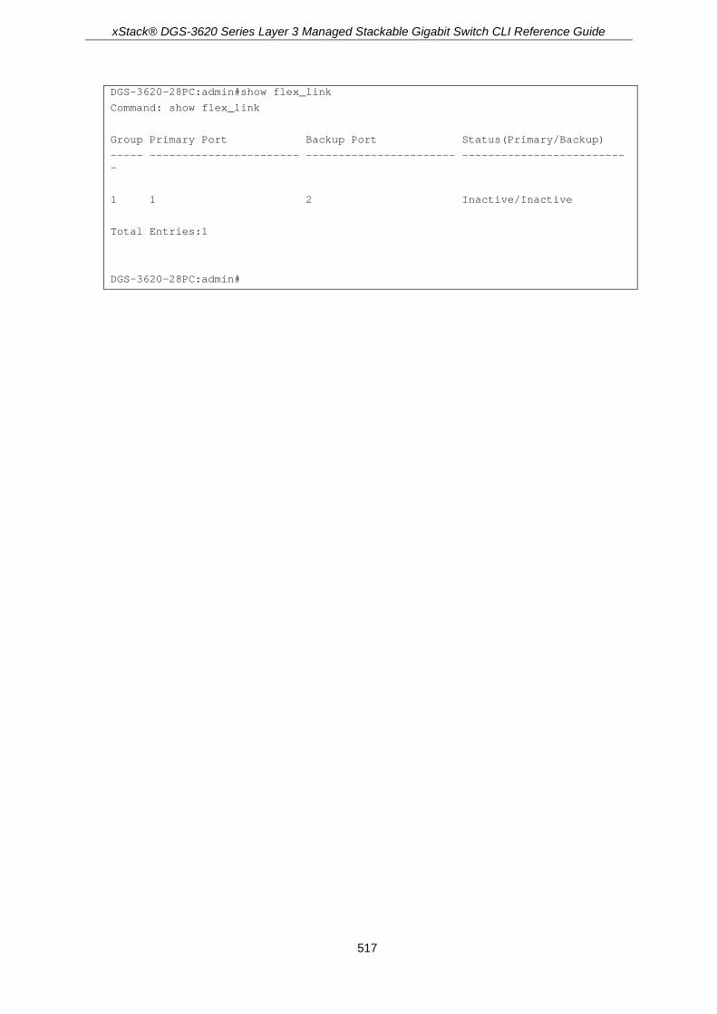
xStack® DGS-3620 Series Layer 3 Managed Stackable Gigabit Switch CLI Reference Guide
517
DGS-3620-28PC:admin#show flex_link
Command: show flex_link
Group Primary Port Backup Port Status(Primary/Backup)
----- ----------------------- ----------------------- --------------------------
1 1 2 Inactive/Inactive
Total Entries:1
DGS-3620-28PC:admin#

xStack® DGS-3620 Series Layer 3 Managed Stackable Gigabit Switch CLI Reference Guide
518
Chapter 41 FTP Client Commands
download cfg_fromFTP [[<ipaddr> | <ipv6addr>] {tcp_port <tcp_port_number 1-65535>} src_file
<path_filename 64> | ftp: <string 128>] {[unit <unit_id> | all]} {dest_file <path_filename 64>} download firmware_fromFTP [[<ipaddr> | <ipv6addr>] {tcp_port <tcp_port_number 1-65535>}
src_file <path_filename 64> | ftp: <string 128>] {[unit <unit_id> | all]} {dest_file <path_filename 64> {boot_up}}
upload attack_log_toFTP [[<ipaddr> | <ipv6addr>] {tcp_port <tcp_port_number 1-65535>} dest_file <path_filename 64> | ftp: <string 128>] {unit <unit_id>}
upload cfg_toFTP [[<ipaddr> | <ipv6addr>] {tcp_port <tcp_port_number 1-65535>} dest_file <path_filename 64> | ftp: <string 128>] {unit <unit_id>} {src_file <path_filename 64>} {[include | exclude | begin] <filter_string 80> {<filter_string 80> {<filter_string 80>}} {[include | exclude | begin] <filter_string 80> {<filter_string 80> {<filter_string 80>}} {[include | exclude | begin] <filter_string 80> {<filter_string 80> {<filter_string 80>}}}}}
upload firmware_toFTP [[<ipaddr> | <ipv6addr>] {tcp_port <tcp_port_number 1-65535>} dest_file <path_filename 64> | ftp: <string 128>] {unit <unit_id>} {src_file <pathname 64>}
upload log_toFTP [[<ipaddr> | <ipv6addr>] {tcp_port <tcp_port_number 1-65535>} dest_file <path_filename 64> | ftp: <string 128>]
41-1 download cfg_fromFTP Description This command is used to download a configuration file from an FTP server.
Format download cfg_fromFTP [[<ipaddr> | <ipv6addr>] {tcp_port <tcp_port_number 1-65535>} src_file <path_filename 64> | ftp: <string 128>] {[unit <unit_id> | all]} {dest_file <path_filename 64>}
Parameters <ipaddr> - Enter the IPv4 address of the FTP server here. <ipv6addr> - Enter the IPv6 address of the FTP server here. tcp_port - (Optional) Specifies the TCP port number used for the FTP connection.
<tcp_port_number 1-65535> - Enter the TCP port number here. This value must be between 1 and 65535.
src_file - Specifies the source file's name and path. <path_filename 64> - Enter the source file's name and path here. This can be up to 64
characters long. ftp: - Specifies the FTP connection details.
<string 128> - Enter the FTP connection details here. For example, john:[email protected]:21/image/cfg.txt.
unit - (Optional) Specifies the switch stacking unit's ID. <unit_id> - Enter the switch stacking unit's ID here. all - Specifies that all the switch units in the stack will be used.
dest_file - (Optional) Specifies the destination file name and path. <path_filename 64> - Enter the destination file name and path here. This can be up to 64
characters long.

xStack® DGS-3620 Series Layer 3 Managed Stackable Gigabit Switch CLI Reference Guide
519
Restrictions Only Administrators can issue this command.
Examples This example shows how to download the configuration file from an FTP server.
DGS-3620-28PC:admin# download cfg_fromFTP 10.54.71.1 cfg01.txt 1
Command: download cfg_fromFTP 10.54.71.1 cfg01.txt 1
Connecting to server................... Done.
User(Anonymous): john
Pass:******
Download configuration................. Done.
DGS-3620-28PC:admin#
This example shows how to download the configuration file from an FTP server using a string.
DGS-3620-28PC:admin# download cfg_fromFTP ftp: john:[email protected]:21/cfg.txt 2
Command: download cfg_fromFTP ftp: john:[email protected]:21/cfg.txt 2
Connecting to server................... Done.
Download configuration................. Done.
DGS-3620-28PC:admin#
41-2 download firmware_fromFTP Description This command is used to download a firmware image file from the FTP server.
Format download firmware_fromFTP [[<ipaddr> | <ipv6addr>] {tcp_port <tcp_port_number 1-65535>} src_file <path_filename 64> | ftp: <string 128>] {[unit <unit_id> | all]} {dest_file <path_filename 64> {boot_up}}
Parameters <ipaddr> - Enter the IPv4 address of the FTP server here. <ipv6addr> - Enter the IPv6 address of the FTP server here. tcp_port - (Optional) Specifies the TCP port number used for the FTP connection.
<tcp_port_number 1-65535> - Enter the TCP port number here. This value must be between 1 and 65535.
src_file - Specifies the source file's name and path. <path_filename 64> - Enter the source file's name and path here. This can be up to 64
characters long. ftp: - Specifies the FTP connection details.
<string 128> - Enter the FTP connection details here. For example,

xStack® DGS-3620 Series Layer 3 Managed Stackable Gigabit Switch CLI Reference Guide
520
john:[email protected]:21/image/cfg.txt. unit - (Optional) Specifies the switch stacking unit's ID.
<unit_id> - Enter the switch stacking unit's ID here. all - Specifies that all the switch units in the stack will be used.
dest_file - (Optional) Specifies the destination file name and path. <path_filename 64> - Enter the destination file name and path here. This can be up to 64
characters long. boot_up - (Optional) Specifies that the firmware will be used as the boot-up firmware after the
download was completed successfully.
Restrictions Only Administrators can issue this command.
Examples This example shows how to download a firmware file from an FTP server.
DGS-3620-28PC:admin# download firmware_fromFTP 10.54.71.1 tcp_port 21 px.had
Command: download firmware_fromFTP 10.54.71.1 tcp_port 21 px.had
Connecting to server................... Done.
User(Anonymous): john
Pass:******
Download firmware...................... Done. Do not power off!
Please wait, programming flash......... Done.
DGS-3620-28PC:admin#
This example shows how to download a firmware form an FTP server using a string.
DGS-3620-28PC:admin# download firmware_fromFTP ftp: john:[email protected]:21/image/px.had
Command: download firmware_fromFTP ftp: john:[email protected]:21/image/px.had
Connecting to server................... Done.
Download firmware...................... Done. Do not power off!
Please wait, programming flash......... Done.
DGS-3620-28PC:admin#
41-3 upload attack_log_toFTP Description This command is used to upload the attack log from the Switch to an FTP server.
Format upload attack_log_toFTP [[<ipaddr> | <ipv6addr>] {tcp_port <tcp_port_number 1-65535>} dest_file <path_filename 64> | ftp: <string 128>] {unit <unit_id>}

xStack® DGS-3620 Series Layer 3 Managed Stackable Gigabit Switch CLI Reference Guide
521
Parameters <ipaddr> - Enter the IPv4 address of the FTP server here. <ipv6addr> - Enter the IPv6 address of the FTP server here. tcp_port - (Optional) Specifies the TCP port number used for the FTP connection.
<tcp_port_number 1-65535> - Enter the TCP port number here. This value must be between 1 and 65535.
dest_file - Specifies the destination file name and path. <path_filename 64> - Enter the destination file name and path here. This can be up to 64
characters long. ftp: - Specifies the FTP connection details.
<string 128> - Enter the FTP connection details here. For example, john:[email protected]:21/image/cfg.txt.
unit - (Optional) Specifies the switch stacking unit's ID. <unit_id> - Enter the switch stacking unit's ID here. all - Specifies that all the switch units in the stack will be used.
Restrictions Only Administrators and Operators can issue this command.
Examples This example shows how to upload the attack log to an FTP server.
DGS-3620-28PC:admin# upload attack_log_toFTP 10.90.90.15 log.txt
Command: upload attack_log_toFTP 10.90.90.15 log.txt
Connecting to server................... Done.
User(Anonymous): john
Pass:******
Upload Log............................. Done.
DGS-3620-28PC:admin#
This example shows how to upload the attack log to an FTP server using a string.
DGS-3620-28PC:admin# upload attack_log_toFTP ftp: john:[email protected]:21/log.txt
Command: upload attack_log_toFTP ftp: john:[email protected]:21/log.txt
Connecting to server................... Done.
Upload log............................. Done.
DGS-3620-28PC:admin#
41-4 upload cfg_toFTP Description This command is used to upload a configuration file from the Switch to an FTP server.

xStack® DGS-3620 Series Layer 3 Managed Stackable Gigabit Switch CLI Reference Guide
522
Format upload cfg_toFTP [[<ipaddr> | <ipv6addr>] {tcp_port <tcp_port_number 1-65535>} dest_file <path_filename 64> | ftp: <string 128>] {unit <unit_id>} {src_file <path_filename 64>} {[include | exclude | begin] <filter_string 80> {<filter_string 80> {<filter_string 80>}} {[include | exclude | begin] <filter_string 80> {<filter_string 80> {<filter_string 80>}} {[include | exclude | begin] <filter_string 80> {<filter_string 80> {<filter_string 80>}}}}}
Parameters <ipaddr> - Enter the IPv4 address of the FTP server here. <ipv6addr> - Enter the IPv6 address of the FTP server here. tcp_port - (Optional) Specifies the TCP port number used for the FTP connection.
<tcp_port_number 1-65535> - Enter the TCP port number here. This value must be between 1 and 65535.
dest_file - Specifies the destination file name and path. <path_filename 64> - Enter the destination file name and path here. This can be up to 64
characters long. ftp: - Specifies the FTP connection details.
<string 128> - Enter the FTP connection details here. For example, john:[email protected]:21/image/cfg.txt.
unit - (Optional) Specifies the switch stacking unit's ID. <unit_id> - Enter the switch stacking unit's ID here. all - Specifies that all the switch units in the stack will be used.
src_file – (Optional) Specifies the source file's name and path. <path_filename 64> - Enter the source file's name and path here. This can be up to 64
characters long. include – (Optional) Specifies to include a filter string. exclude - (Optional) Specifies to exclude a filter string. begin - (Optional) Specifies to use a filter string that begins with the string specified.
<filter_string 80> - Enter the filter string used here.
Restrictions Only Administrators and Operators can issue this command.
Examples This example shows how to upload the configuration file to an FTP server in the interactive mode.
DGS-3620-28PC:admin# upload cfg_toFTP 10.90.90.15 cfg.txt
Command: upload cfg_toFTP 10.90.90.15 cfg.txt
Connecting to server................... Done.
User(Anonymous): john
Password:******
Upload configuration................... Done.
DGS-3620-28PC:admin#
This example shows how to upload the configuration file to an FTP server using a string.
DGS-3620-28PC:admin# download cfg_fromFTP ftp: john:[email protected]:21/cfg/ cfg.txt config_id 2
Command: download cfg_fromFTP ftp: john:[email protected]:21/cfg/cfg.txt config_id 2

xStack® DGS-3620 Series Layer 3 Managed Stackable Gigabit Switch CLI Reference Guide
523
Connecting to server................... Done.
Download configuration................. Done.
DGS-3620-28PC:admin#
This example shows how to upload the configuration file to an FTP server using a string and the filter expression.
DGS-3620-28PC:admin# download cfg_fromFTP ftp: john:[email protected]:21/cfg/cfg.txt config_id 2 include “VLAN” “ipif” exclude “fdb”
Command: download cfg_fromFTP ftp: john:[email protected]:21/cfg/cfg.txt config_id 2 include “VLAN” “ipif” exclude “fdb”
Connecting to server................... Done.
Download configuration................. Done.
DGS-3620-28PC:admin#
41-5 upload firmware_toFTP Description This command is used to upload a firmware from the Switch to an FTP server.
Format upload firmware_toFTP [[<ipaddr> | <ipv6addr>] {tcp_port <tcp_port_number 1-65535>} dest_file <path_filename 64> | ftp: <string 128>] {unit <unit_id>} {src_file <pathname 64>}
Parameters <ipaddr> - Enter the IPv4 address of the FTP server here. <ipv6addr> - Enter the IPv6 address of the FTP server here. tcp_port - (Optional) Specifies the TCP port number used for the FTP connection.
<tcp_port_number 1-65535> - Enter the TCP port number here. This value must be between 1 and 65535.
dest_file - Specifies the destination file name and path. <path_filename 64> - Enter the destination file name and path here. This can be up to 64
characters long. ftp: - Specifies the FTP connection details.
<string 128> - Enter the FTP connection details here. For example, john:[email protected]:21/image/cfg.txt.
unit - (Optional) Specifies the switch stacking unit's ID. <unit_id> - Enter the switch stacking unit's ID here. all - Specifies that all the switch units in the stack will be used.
src_file – (Optional) Specifies the source file's name and path. <path_filename 64> - Enter the source file's name and path here. This can be up to 64
characters long.
Restrictions Only Administrators and Operators can issue this command.

xStack® DGS-3620 Series Layer 3 Managed Stackable Gigabit Switch CLI Reference Guide
524
Example This example shows how to upload a firmware file from the Switch to an FTP server.
DGS-3620-28PC:admin# upload firmware_toFTP ftp: john:[email protected]:21/image/image.had 260b11.had
Command: upload firmware_toFTP ftp: john:[email protected]:21/image/image.had 260b11.had
Connecting to server................... Done.
Upload firmware........................ Done.
DGS-3620-28PC:admin#
41-6 upload log_toFTP Description This command is used to upload a log file from the Switch to an FTP server.
Format upload log_toFTP [[<ipaddr> | <ipv6addr>] {tcp_port <tcp_port_number 1-65535>} dest_file <path_filename 64> | ftp: <string 128>]
Parameters <ipaddr> - Enter the IPv4 address of the FTP server here. <ipv6addr> - Enter the IPv6 address of the FTP server here. tcp_port - (Optional) Specifies the TCP port number used for the FTP connection.
<tcp_port_number 1-65535> - Enter the TCP port number here. This value must be between 1 and 65535.
dest_file - Specifies the destination file name and path. <path_filename 64> - Enter the destination file name and path here. This can be up to 64
characters long. ftp: - Specifies the FTP connection details.
<string 128> - Enter the FTP connection details here. For example, john:[email protected]:21/image/cfg.txt.
Restrictions Only Administrators and Operators can issue this command.
Examples This example shows how to upload the log file to an FTP server.
DGS-3620-28PC:admin# upload log_toFTP 10.90.90.15 d:/log.txt
Command: upload log_toFTP 10.90.90.15 d:/log.txt
Connecting to server................... Done.
User(Anonymous): john
Pass:******
Upload log............................. Done.

xStack® DGS-3620 Series Layer 3 Managed Stackable Gigabit Switch CLI Reference Guide
525
DGS-3620-28PC:admin#
This example shows how to upload the log file to an FTP server using a string.
DGS-3620-28PC:admin# upload log_toFTP ftp: john:[email protected]:21/log/log.txt
Command: upload log_toFTP ftp: john:[email protected]:21/log/log.txt
Connecting to server................... Done.
Upload log............................. Done.
DGS-3620-28PC:admin#

xStack® DGS-3620 Series Layer 3 Managed Stackable Gigabit Switch CLI Reference Guide
526
Chapter 42 Gratuitous ARP Commands
enable gratuitous_arp {ipif <ipif_name 12>} {trap | log}(1) disable gratuitous_arp {ipif <ipif_name 12>} {trap | log}(1) config gratuitous_arp learning [enable | disable] config gratuitous_arp send dup_ip_detected [enable | disable] config gratuitous_arp send ipif_status_up [enable | disable] config gratuitous_arp send periodically ipif <ipif_name 12> interval <value 0-65535> show gratuitous_arp {ipif <ipif_name 12>}
42-1 enable gratuitous_arp Description This command is used to enable the gratuitous ARP trap and log state. The switch can trap and log the IP conflict event to inform the administrator.
Format enable gratuitous_arp {ipif <ipif_name 12>} {trap | log}(1)
Parameters ipif - (Optional) The interface name of the L3 interface.
<ipif_name 12> - Enter the interface name. The maximum length is 12 characters. trap - Specifies trap. The trap is disabled by default. log - Specifies log. The even log is enabled by default.
Restrictions Only Administrators, Operators and Power-Users can issue this command.
Example To enable the gratuitous ARP trap and log state:
DGS-3620-28PC:admin#enable gratuitous_arp ipif System trap log
Command: enable gratuitous_arp ipif System trap log
Success.
DGS-3620-28PC:admin#
42-2 disable gratuitous_arp Description This command is used to disable the gratuitous ARP trap and log state.

xStack® DGS-3620 Series Layer 3 Managed Stackable Gigabit Switch CLI Reference Guide
527
Format disable gratuitous_arp {ipif <ipif_name 12>} {trap | log}(1)
Parameters ipif - (Optional) The interface name of the L3 interface.
<ipif_name 12> - Enter the interface name. The maximum length is 12 characters. trap - Specifies trap. The trap is disabled by default. log - Specifies log. The even log is enabled by default.
Restrictions Only Administrators, Operators and Power-Users can issue this command.
Example To disable the gratuitous ARP trap and log state:
DGS-3620-28PC:admin#disable gratuitous_arp ipif System trap log
Command: disable gratuitous_arp ipif System trap log
Success.
DGS-3620-28PC:admin#
42-3 config gratuitous_arp learning Description This command is used to enable or disable learning of ARP entries in the ARP cache based on the received gratuitous ARP packets.
Format config gratuitous_arp learning [enable | disable]
Parameters enable - Enable learning of ARP entries based on the received gratuitous ARP packets. disable - Disable learning of ARP entries based on the received gratuitous ARP packets.
Restrictions Only Administrators, Operators and Power-Users can issue this command.
Example To enable learning of ARP entries in the ARP cache based on the received gratuitous ARP packets:
DGS-3620-28PC:admin# config gratuitous_arp learning enable

xStack® DGS-3620 Series Layer 3 Managed Stackable Gigabit Switch CLI Reference Guide
528
Command: config gratuitous_arp learning enable
Success.
DGS-3620-28PC:admin#
42-4 config gratuitous_arp send dup_ip_detected Description This command is used to enable or disable the sending of gratuitous ARP requests when a duplicate IP address is detected. By default, the state is disabled. For this command, duplicate IP detected means that the system received an ARP request packet that is sent by an IP address that matches the system’s own IP address. In this case, the system knows that somebody out there is using an IP address that conflicts with that of the system. In order to reclaim the correct host of this IP address, the system can send out the gratuitous ARP request packet for this duplicate IP address.
Format config gratuitous_arp send dup_ip_detected [enable | disable]
Parameters enable - Enable the sending of gratuitous ARP requests when a duplicate IP is detected. disable - Disable the sending of gratuitous ARP requests when a duplicate IP is detected.
Restrictions Only Administrators, Operators and Power-Users can issue this command.
Example To enable the sending of gratuitous ARP requests when a duplicate IP address is detected:
DGS-3620-28PC:admin#config gratuitous_arp send dup_ip_detected enable
Command: config gratuitous_arp send dup_ip_detected enable
Success.
DGS-3620-28PC:admin#
42-5 config gratuitous_arp send ipif_status_up Description This command is used to enable or disable the sending of gratuitous ARP requests when the IP interface status becomes up. This is used to automatically announce the interface’s IP address to other nodes. By default, the state is disabled. When the state is enabled and IP interface is linked up, one gratuitous ARP packet will be broadcast.

xStack® DGS-3620 Series Layer 3 Managed Stackable Gigabit Switch CLI Reference Guide
529
Format config gratuitous_arp send ipif_status_up [enable | disable]
Parameters enable - Enable the sending of gratuitous ARP requests when the IPIF status becomes up. disable - Disable the sending of gratuitous ARP requests when the IPIF status becomes up.
Restrictions Only Administrators, Operators and Power-Users can issue this command.
Example To enable the sending of gratuitous ARP requests when the IP interface status becomes up:
DGS-3620-28PC:admin#config gratuitous_arp send ipif_status_up enable
Command: config gratuitous_arp send ipif_status_up enable
Success.
DGS-3620-28PC:admin#
42-6 config gratuitous_arp send periodically ipif Description This command is used to configure the interval for the periodical sending of gratuitous ARP request packets.
Format config gratuitous_arp send periodically ipif <ipif_name 12> interval <value 0-65535>
Parameters <ipif_name 12> - Enter the interface name of the L3 interface. The maximum length is 12
characters. interval - The periodically send gratuitous ARP interval time, in seconds.
<value 0-65535> - Enter the value between 0 and 65535. 0 (zero) means not to send gratuitous ARP request packets periodically. By default, the interval is 0 (zero).
Restrictions Only Administrators, Operators and Power-Users can issue this command.
Example To configure the gratuitous ARP interval to 5 for the IPIF System:
DGS-3620-28PC:admin#config gratuitous_arp send periodically ipif System interval 5
Command: config gratuitous_arp send periodically ipif System interval 5

xStack® DGS-3620 Series Layer 3 Managed Stackable Gigabit Switch CLI Reference Guide
530
Success.
DGS-3620-28PC:admin#
42-7 show gratuitous_arp Description This command is used to display gratuitous ARP configuration.
Format show gratuitous_arp {ipif <ipif_name 12>}
Parameters ipif - (Optional) The interface name of the L3 interface.
<ipif_name 12> - Enter the interface name. The maximum length is 12 characters.
Restrictions None.
Example To display the gratuitous ARP configuration:
DGS-3620-28PC:admin#show gratuitous_arp
Command: show gratuitous_arp
Send on IPIF Status Up : Disabled
Send on Duplicate IP Detected : Disabled
Gratuitous ARP Learning : Disabled
IP Interface Name : System
Gratuitous ARP Trap : Disabled
Gratuitous ARP Log : Enabled
Gratuitous ARP Periodical Send Interval : 0
Total Entries: 1
DGS-3620-28PC:admin#

xStack® DGS-3620 Series Layer 3 Managed Stackable Gigabit Switch CLI Reference Guide
531
Chapter 43 Internet Group Management Protocol (IGMP) Commands
config igmp [ipif <ipif_name 12> | all] {version <value 1-3> | query_interval <sec 1-31744> | max_response_time <sec 1-25> | robustness_variable <value 1-7> | last_member_query_interval <value 1-25> | state [enable | disable]} (1)
show igmp {ipif <ipif_name 12>} show igmp group {group <group> | ipif <ipif_name 12>} config igmp check_subscriber_source_network [ipif <ipif_name 12> | all] [enable | disable] show igmp check_subscriber_source_network {ipif <ipif_name 12>} create igmp static_group ipif <ipif_name 12> group <ipaddr> delete igmp static_group ipif <ipif_name 12> [group <ipaddr> | all] show igmp static_group {ipif <ipif_name 12>}
43-1 config igmp Description This command is used to configure IGMP on the Switch.
Format config igmp [ipif <ipif_name 12> | all] {version <value 1-3> | query_interval <sec 1-31744> | max_response_time <sec 1-25> | robustness_variable <value 1-7> | last_member_query_interval <value 1-25> | state [enable | disable]} (1)
Parameters ipif - Specifies the IP interface name used for this configuration.
<ipif_name 12> - Enter the IP interface name used for this configuration here. This name can be up to 12 characters long.
all - Specifies that all the IP interfaces will be used. version - (Optional) Specifies the IGMP version used.
<value 1-3> - Enter the IGMP version number used here. This value must be between 1 and 3. The default value is 3.
query_interval - (Optional) Specifies the time in seconds between general query transmissions. <sec 1-31744> - Enter the query interval time here. This value must be between 1 and 31744
seconds. The default value is 125. max_response_time - (Optional) Specifies the maximum time in seconds to wait for reports from
members. <sec 1-25> - Enter the maximum response time here. This value must be between 1 and 25
seconds. The default value is 10. robustness_variable - (Optional) Specifies the permitted packet loss that guarantees IGMP.
<value 1-7> - Enter the robustness variable here. This value must be between 1 and 7. The default value is 2.
last_member_query_interval - (Optional) Specifies the maximum Response Time inserted into the Group-Specific Queries that are sent in response to Leave Group messages, which is also the amount of time between Group-Specific Query messages.

xStack® DGS-3620 Series Layer 3 Managed Stackable Gigabit Switch CLI Reference Guide
532
<value 1-25> - Enter the last member query interval value here. This value must be between 1 and 25. The default value is 1.
state - (Optional) Specifies the IGMP state on a router interface. enable - Specifies that the IGMP state will be enabled. disable - Specifies that the IGMP state will be disabled.
Restrictions Only Administrators, Operators and Power-Users can issue this command.
Example To enable IGMP version 1 for the IP interface “System”:
DGS-3620-28PC:admin# config igmp ipif System version 1 state enable
Command: config igmp ipif System version 1 state enable
Success.
DGS-3620-28PC:admin#
To configure IGMPv2 for all IP interfaces:
DGS-3620-28PC:admin# config igmp all version 2
Command: config igmp all version 2
Success.
DGS-3620-28PC:admin#
43-2 show igmp Description This command is used to display the IGMP configuration.
Format show igmp {ipif <ipif_name 12>}
Parameters ipif - (Optional) Specifies the IP interface name used for this configuration.
<ipif_name 12> - Enter the IP interface name used for this configuration here. This name can be up to 12 characters long.
all - Specifies that all the IP interfaces will be used. If no parameter is specified, the system will display all IGMP configurations.
Restrictions None.
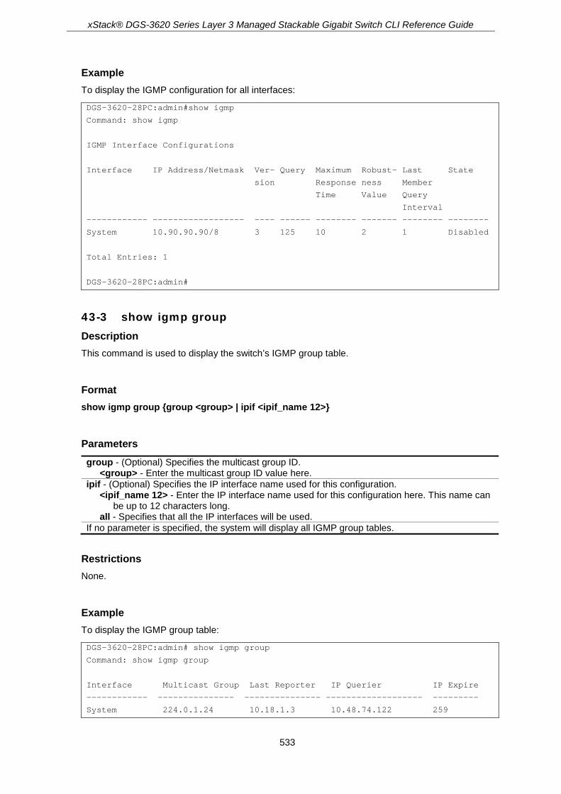
xStack® DGS-3620 Series Layer 3 Managed Stackable Gigabit Switch CLI Reference Guide
533
Example To display the IGMP configuration for all interfaces:
DGS-3620-28PC:admin#show igmp
Command: show igmp
IGMP Interface Configurations
Interface IP Address/Netmask Ver- Query Maximum Robust- Last State
sion Response ness Member
Time Value Query
Interval
------------ ------------------ ---- ------ -------- ------- -------- --------
System 10.90.90.90/8 3 125 10 2 1 Disabled
Total Entries: 1
DGS-3620-28PC:admin#
43-3 show igmp group Description This command is used to display the switch’s IGMP group table.
Format show igmp group {group <group> | ipif <ipif_name 12>}
Parameters group - (Optional) Specifies the multicast group ID.
<group> - Enter the multicast group ID value here. ipif - (Optional) Specifies the IP interface name used for this configuration.
<ipif_name 12> - Enter the IP interface name used for this configuration here. This name can be up to 12 characters long.
all - Specifies that all the IP interfaces will be used. If no parameter is specified, the system will display all IGMP group tables.
Restrictions None.
Example To display the IGMP group table:
DGS-3620-28PC:admin# show igmp group
Command: show igmp group
Interface Multicast Group Last Reporter IP Querier IP Expire
------------ --------------- --------------- ------------------- ---------
System 224.0.1.24 10.18.1.3 10.48.74.122 259

xStack® DGS-3620 Series Layer 3 Managed Stackable Gigabit Switch CLI Reference Guide
534
System 224.0.1.41 10.1.43.252 10.48.74.122 259
System 224.0.1.149 10.20.63.11 10.48.74.122 259
Total Entries : 3
DGS-3620-28PC:admin#
43-4 config igmp check_subscriber_source_network Description This command is used to configure the flag that determines whether or not to check the subscriber source IP when an IGMP report or leave message is received. When this command is enabled on an interface, any IGMP report or leave messages received by the interface will be checked to determine whether its source IP is in the same network as the interface. If the check failed for a received report or leave message, the message won’t be processed by IGMP protocol. If the check is disabled, the IGMP report or leave message with any source IP will be processed by the IGMP protocol.
Format config igmp check_subscriber_source_network [ipif <ipif_name 12> | all] [enable | disable]
Parameters ipif - Specifies the IP interface name used for this configuration.
<ipif_name 12> - Enter the IP interface name used for this configuration here. This name can be up to 12 characters long.
all - Specifies that all the IP interfaces will be used. enable - Specifies that the check state will be enabled. disable - Specifies that the check state will be disabled.
Restrictions Only Administrators, Operators and Power-Users can issue this command.
Example To enable the checking of subscriber source IP addresses when an IGMP report or leave message is received on the interface called ‘System’:
DGS-3620-28PC:admin# config igmp check_subscriber_source_network ipif System enable
Command: config igmp check_subscriber_source_network ipif System enable
Success.
DGS-3620-28PC:admin#
43-5 show igmp check_subscriber_source_network Description This command is used to display the status of the IGMP report/leave message source IP check.

xStack® DGS-3620 Series Layer 3 Managed Stackable Gigabit Switch CLI Reference Guide
535
Format show igmp check_subscriber_source_network {ipif <ipif_name 12>}
Parameters ipif – (Optional) Specifies the IP interface name used for this configuration.
<ipif_name 12> - Enter the IP interface name used for this configuration here. This name can be up to 12 characters long.
If no parameter is specified, the system will display all interfaces.
Restrictions None.
Example To show the status of the check subscriber for the received IGMP report/leave messages on interface “n20”:
DGS-3620-28PC:admin# show igmp check_subscriber_source_network ipif n20
Command: show igmp check_subscriber_source_network ipif n20
Interface IP Address/Netmask Check Subscriber Source Network
------------ ------------------ -------------------------------
n20 20.1.1.1/8 Disabled
Total Entries: 1
DGS-3620-28PC:admin#
To show the status of the check subscriber for the received IGMP report/leave messages on all interfaces:
DGS-3620-28PC:admin# show igmp check_subscriber_source_network
Command: show igmp check_subscriber_source_network
Interface IP Address/Netmask Check Subscriber Source Network
------------ ------------------ -------------------------------
System 10.90.90.90/8 Enabled
n1 1.1.1.1/8 Disabled
n11 11.1.1.1/8 Disabled
n20 20.1.1.1/8 Disabled
n100 100.3.2.2/8 Disabled
Total Entries: 5
DGS-3620-28PC:admin#

xStack® DGS-3620 Series Layer 3 Managed Stackable Gigabit Switch CLI Reference Guide
536
43-6 create igmp static_group Description This command is used to create an IGMP static group on the Switch.
Format create igmp static_group ipif <ipif_name 12> group <ipaddr>
Parameters ipif – Specifies the IP interface name used for this configuration.
<ipif_name 12> - Enter the IP interface name used for this configuration here. This name can be up to 12 characters long.
group - Specifies the multicast IP address used. <ipaddr> - Enter the multicast IP address used here.
Restrictions Only Administrators, Operators and Power-Users can issue this command.
Example To create an IGMP static group, with the multicast IP address 225.0.0.2 on the IP interface “System”:
DGS-3620-28PC:admin# create igmp static_group ipif System group 225.0.0.2
Command: create igmp static_group ipif System group 225.0.0.2
Success.
DGS-3620-28PC:admin#
43-7 delete igmp static_group Description This command is used to delete IGMP static group(s) on the switch.
Format delete igmp static_group ipif <ipif_name 12> [group <ipaddr> | all]
Parameters ipif – Specifies the IP interface name used for this configuration.
<ipif_name 12> - Enter the IP interface name used for this configuration here. This name can be up to 12 characters long.
group - Specifies the multicast IP address used. <ipaddr> - Enter the multicast IP address used here. all – Specifies that all the multicast IP addresses will be deleted.

xStack® DGS-3620 Series Layer 3 Managed Stackable Gigabit Switch CLI Reference Guide
537
Restrictions Only Administrators, Operators and Power-Users can issue this command.
Example To delete the IGMP static group, with the multicast IP address 225.0.0.2 on the IP interface “System”.
DGS-3620-28PC:admin# delete igmp static_group ipif System group 225.0.0.2
Command: delete igmp static_group ipif System group 225.0.0.2
Success.
DGS-3620-28PC:admin#
To delete all IGMP static groups on the IP interface “n2”.
DGS-3620-28PC:admin# delete igmp static_group ipif n2 all
Command: delete igmp static_group ipif n2 all
Success.
DGS-3620-28PC:admin#
43-8 show igmp static_group Description This command is used to display IGMP static groups on the Switch.
Format show igmp static_group {ipif <ipif_name 12>}
Parameters ipif – (Optional) Specifies the IP interface name used for this configuration.
<ipif_name 12> - Enter the IP interface name used for this configuration here. This name can be up to 12 characters long.
Restrictions None.
Example To display all IGMP static groups on the interface “n20”:

xStack® DGS-3620 Series Layer 3 Managed Stackable Gigabit Switch CLI Reference Guide
538
DGS-3620-28PC:admin# show igmp static_group ipif n20
Command: show igmp static_group ipif n20
Interface Multicast Group
------------ ---------------
n20 239.0.0.3
Total Entries: 1
DGS-3620-28PC:admin#
To display all IGMP static groups on all interfaces:
DGS-3620-28PC:admin# show igmp static_group
Command: show igmp static_group
Interface Multicast Group
------------ ---------------
System 225.0.0.1
System 225.0.0.2
n20 239.0.0.3
Total Entries: 3
DGS-3620-28PC:admin#

xStack® DGS-3620 Series Layer 3 Managed Stackable Gigabit Switch CLI Reference Guide
539
Chapter 44 IGMP Proxy Commands
enable igmp_proxy disable igmp_proxy config igmp_proxy downstream_if [add | delete] vlan [<vlan_name 32> | vlanid <vidlist>] config igmp_proxy upstream_if {vlan [<vlan_name 32> | vlanid <vlanid 1-4094>] | router_ports
[add | delete] <portlist> | source_ip <ipaddr> | unsolicited_report_interval <sec 0-25>}(1) show igmp_proxy {group}
44-1 enable igmp_proxy Description This command is used to enable the IGMP proxy on the switch.
Format enable igmp_proxy
Parameters None.
Restrictions Only Administrators, Operators and Power-Users can issue this command.
Example To enable the IGMP proxy:
DGS-3620-28PC:admin#enable igmp_proxy
Command: enable igmp_proxy
Success.
DGS-3620-28PC:admin#
44-2 disable igmp_proxy Description This command is used to disable the IGMP proxy on the switch.
Format disable igmp_proxy

xStack® DGS-3620 Series Layer 3 Managed Stackable Gigabit Switch CLI Reference Guide
540
Parameters None.
Restrictions Only Administrators, Operators and Power-Users can issue this command.
Example To disable the IGMP proxy:
DGS-3620-28PC:admin#disable igmp_proxy
Command: disable igmp_proxy
Success.
DGS-3620-28PC:admin#
44-3 config igmp_proxy downstream_if Description This command is used to configure the IGMP proxy downstream interfaces. The IGMP proxy plays the server role on the downstream interfaces. The downstream interface must be an IGMP-snooping enabled VLAN.
Format config igmp_proxy downstream_if [add | delete] vlan [<vlan_name 32> | vlanid <vidlist>]
Parameters add - Specifies to add a downstream interface. delete - Specifies to delete a downstream interface . vlan – Specifies the VLAN by name or ID.
<vlan_name 32> - Enter a name of VLAN which will be added to or deleted from the IGMP proxy downstream interface. The maximum length is 32 characters.
vlanid - Specifies a list of VLAN IDs to be added to or deleted from the IGMP proxy downstream interface. <vidlist> - Enter a list of VLAN IDs which will be added to or deleted from the IGMP proxy
downstream interface.
Restrictions Only Administrators, Operators and Power-Users can issue this command.
Example To configure the IGMP proxy’s downstream interface:
DGS-3620-28PC:admin#config igmp_proxy downstream_if add vlan vlanid 2-7

xStack® DGS-3620 Series Layer 3 Managed Stackable Gigabit Switch CLI Reference Guide
541
Command: config igmp_proxy downstream_if add vlan vlanid 2-7
Success.
DGS-3620-28PC:admin#
44-4 config igmp_proxy upstream_if Description This command is used to configure the setting for the IGMP proxy’s upstream interface. The IGMP proxy plays the host role on the upstream interface. It will send IGMP report packets to the router port.
The source IP address determines the source IP address to be encoded in the IGMP protocol packet.
If the router port is empty, the upstream will send the IGMP protocol packet to all member ports on the upstream interface.
Format config igmp_proxy upstream_if {vlan [<vlan_name 32> | vlanid <vlanid 1-4094>] | router_ports [add | delete] <portlist> | source_ip <ipaddr> | unsolicited_report_interval <sec 0-25>} (1)
Parameters vlan - Specifies the VLAN for the upstream interface.
<vlan_name 32> - Enter a VLAN name between 1 and 32 characters. vlanid - Specifies the VLAN ID for the upstream interface.
<1-4094> - Enter the VLAN ID between 1 and 4094. router_ports - Specifies a list of ports that are connected to multicast-enabled routers.
add - Specifies to add the router ports. delete - Specifies to delete the router ports. <portlist> - Enter a range of ports to be configured.
source_ip - Specifies the source IP address of the upstream protocol packet. If it is not specified, zero IP address will be used as the protocol source IP address. <ipaddr> - Enter the IP address.
unsolicited_report_interval - Specifies the time between repetitions of the host's initial report of membership in a group. The default is 10 seconds. If set to 0, only one report packet is sent. <sec 0-25> - Enter the time between 0 and 25 seconds.
Restrictions Only Administrators, Operators and Power-Users can issue this command.
Example To configure the router port of IGMP proxy’s upstream interface:
DGS-3620-28PC:admin#config igmp_proxy upstream_if vlan default router_ports add 3
Command: config igmp_proxy upstream_if vlan default router_ports add 3

xStack® DGS-3620 Series Layer 3 Managed Stackable Gigabit Switch CLI Reference Guide
542
Success.
DGS-3620-28PC:admin#
44-5 show igmp_proxy Description This command displays IGMP proxy configuration information or group information on the switch. The display status item means group entry is determined by whether or not the chip is inserted.
Format show igmp_proxy {group}
Parameters group - (Optional) Specifies the group information.
Note: If the group is not specified, the IGMP proxy configuration will be displayed.
Restrictions None.
Example To display IGMP proxy information:
DGS-3620-28PC:admin#show igmp_proxy
Command: show igmp_proxy
IGMP Proxy Global State : Enabled
Upstream Interface
VLAN ID : 1
Dynamic Router Ports : 1-4
Static Router Ports : 5-6
Unsolicited Report Interval : 10
Source IP Address : 0.0.0.0
Downstream Interface
VLAN List : 2-4
DGS-3620-28PC:admin#
To display the IGMP proxy’s group information:
DGS-3620-28PC:admin#show igmp_proxy group
Command: show igmp_proxy group

xStack® DGS-3620 Series Layer 3 Managed Stackable Gigabit Switch CLI Reference Guide
543
Dest-V : The destination VLAN.
A : Active
I : Inactive
Dest IP Source IP Dest-V Member Ports Status
----------- ------------- ------ ---------------- ---------
224.2.2.2 NULL 4 3,6 A
2 2-4 I
227.3.1.5 NULL 2 2,5,8 I
3 5,7,9 A
Total Entries: 2
DGS-3620-28PC:admin#

xStack® DGS-3620 Series Layer 3 Managed Stackable Gigabit Switch CLI Reference Guide
544
Chapter 45 IGMP Snooping Commands
config igmp_snooping [vlan_name <vlan_name 32> | vlanid <vlanid_list> | all] {state [enable |
disable] | topology_changes_notification [ignore | process] | fast_leave [enable | disable] | proxy_reporting {state [enable | disable] | source_ip <ipaddr>}}(1)
config igmp_snooping querier [vlan_name <vlan_name 32> | vlanid <vlanid_list> | all] {query_interval <sec 1-65535> | max_response_time <sec 1-25> | robustness_variable <value 1-7> | last_member_query_interval <sec 1-25> | state [enable | disable] | version <value 1-3>}(1)
config router_ports [<vlan_name 32> | vlanid <vlanid_list>] [add |delete] <portlist> config router_ports_forbidden [<vlan_name 32> | vlanid <vlanid_list>] [add | delete] <portlist> enable igmp_snooping disable igmp_snooping show igmp_snooping {[vlan <vlan_name 32> | vlanid <vlanid_list>]} show igmp_snooping group {[vlan <vlan_name 32> | vlanid <vlanid_list> | ports <portlist>]
{<ipaddr>}} config igmp_snooping rate_limit [ports <portlist> | vlanid <vlanid_list>] [<value 1-1000> |
no_limit] show igmp_snooping rate_limit [ports <portlist> | vlanid <vlanid_list>] create igmp_snooping static_group [vlan <vlan_name 32> | vlanid <vlanid_list>] <ipaddr> config igmp_snooping static_group [vlan <vlan_name 32> | vlanid <vlanid_list>] <ipaddr> [add |
delete] <portlist> delete igmp_snooping static_group [vlan <vlan_name 32> | vlanid <vlanid_list>] <ipaddr> show igmp_snooping static_group {[vlan <vlan_name 32> | vlanid <vlanid_list>] <ipaddr>} show igmp_snooping statistic counter [vlan <vlan_name 32> | vlanid <vlanid_list> | ports
<portlist>] clear igmp_snooping statistics counter show igmp_snooping forwarding {[vlan <vlan_name 32> | vlanid <vlanid_list>]} show router_ports [vlan <vlan_name 32> | vlanid <vlanid_list> | all] {[static | dynamic | forbidden]} config igmp access_authentication ports [all | <portlist>] state [enable {[auth_accounting |
auth_only | accounting_only]} | disable] show igmp access_authentication ports [all | <portlist>]
45-1 config igmp_snooping Description This command is used to configure IGMP snooping on the switch.
Format config igmp_snooping [vlan_name <vlan_name 32> | vlanid <vlanid_list> | all] {state [enable | disable] | topology_changes_notification [ignore | process] | fast_leave [enable | disable] | proxy_reporting {state [enable | disable] | source_ip <ipaddr>}}(1)
Parameters vlan_name - Specifies the name of the VLAN for which IGMP snooping is to be configured.
<vlan_name 32> - Enter the VLAN name. The maximum length is 32 characters. vlanid - Specifies the VLAN ID list.

xStack® DGS-3620 Series Layer 3 Managed Stackable Gigabit Switch CLI Reference Guide
545
<vlanid_list> - Enter the VLAN ID list. all - Specifies to configure all VLANs.
state - Enable or disable IGMP snooping for the chosen VLAN. enable - Enable IGMP snooping for the chosen VLAN. disable - Disable IGMP snooping for the chosen VLAN.
topology_changes_notification - Specifies that IGMP snooping should be aware of link-layer topology changes caused by Spanning Tree operation or not. ignore – Specifies that IGMP snooping will ignore link-layer topology changes caused by
Spanning Tree operation. The General Query won’t be sent on the same domain of link-layer topology changes.
process – Specifies that IGMP snooping will process link-layer topology changes caused by Spanning Tree operation. The General Query will be sent on the same domain of link-layer topology changes.
fast_leave - Enable or disable the IGMP snooping fast leave function. If enabled, the membership is immediately removed when the system receive the IGMP leave message. enable - Enable the IGMP snooping fast leave function. disable - Disable the IGMP snooping fast leave function.
proxy_reporting - Specifies the proxy reporting option. state - Specifies the proxy reporting state.
enable - Specifies that the proxy reporting option will be enabled. disable - Specifies that the proxy reporting option will be disabled.
source_ip - Specifies the source IP address used. <ipaddr> - Enter the source IP addres used here.
Restrictions Only Administrators, Operators and Power-Users can issue this command.
Example To configure IGMP snooping:
DGS-3620-28PC:admin#config igmp_snooping vlan_name default state enable fast_leave enable
Command: config igmp_snooping vlan_name default state enable fast_leave enable
Success.
DGS-3620-28PC:admin#
45-2 config igmp_snooping querier Description This command is used to configure the IGMP snooping querier.
Format config igmp_snooping querier [vlan_name <vlan_name 32> | vlanid <vlanid_list> | all] {query_interval <sec 1-65535> | max_response_time <sec 1-25> | robustness_variable <value 1-7> | last_member_query_interval <sec 1-25> | state [enable | disable] | version <value 1-3>} (1)

xStack® DGS-3620 Series Layer 3 Managed Stackable Gigabit Switch CLI Reference Guide
546
Parameters vlan_name - Specifies the name of the VLAN for which IGMP snooping querier is to be
configured. <vlan_name 32> - Enter the VLAN name. The maximum length is 32 characters.
vlanid - Specifies the VLAN ID list. <vlanid_list> - Enter the VLAN ID list.
all - Specifies to configure all VLANs and VLAN IDs. query_interval - Specifies the amount of time in seconds between general query transmissions.
<sec 1-65535> - Enter the amount of time in seconds between general query transmissions. The default setting is 125 seconds.
max_response_time - Specifies the maximum time in seconds to wait for reports from members. <sec 1-25> - Enter the maximum time in seconds to wait for reports from members. The
default setting is 10 seconds. robustness_variable - Provides fine-tuning to allow for expected packet loss on a subnet. The
value of the robustness variable is used in calculating the following IGMP message intervals: 1. Group member interval—Amount of time that must pass before a multicast router
decides there are no more members of a group on a network. This interval is calculated as follows: (robustness variable x query interval) + (1 x query response interval).
2. Other querier present interval—Amount of time that must pass before a multicast router decides that there is no longer another multicast router that is the querier. This interval is calculated as follows: (robustness variable x query interval) + (0.5 x query response interval).
3. Last member query count—Number of group-specific queries sent before the router assumes there are no local members of a group. The default number is the value of the robustness variable.
<value 1-7> - Enter the value between 1 and 7. Increase the value if you expect a subnet to be lossy. The robustness variable is set to 2 by default.
last_member_query_interval - Specifies the maximum amount of time between group-specific query messages, including those sent in response to leave-group messages. You might lower this interval to reduce the amount of time it takes a router to detect the loss of the last member of a group. <sec 1-25> - Enter the time between 1 and 25 seconds.
state - If the state is enable, it allows the switch to be selected as a IGMP Querier (sends IGMP query packets). If the state is disabled, then the switch can not play the role as a querier. Note that if the Layer 3 router connected to the switch provides only the IGMP proxy function but does not provide the multicast routing function, then this state must be configured as disabled. Otherwise, if the Layer 3 router is not selected as the querier, it will not send the IGMP query packet. Since it will not also send the multicast-routing protocol packet, the port will be timed out as a router port. enable - Allows the switch to be selected as an IGMP Querier (sends IGMP query packets). disable - When disabled, the switch can not play the role as a querier.
version - Specifies the version of IGMP packet that will be sent by this port. If a IGMP packet
received by the interface has a version higher than the specified version, this packet will be forward from the router's ports or VLAN flooding. <value 1-3> - Enter the values between 1 and 3.
Restrictions Only Administrators, Operators and Power-Users can issue this command.
Example To configure the IGMP snooping querier:
DGS-3620-28PC:admin#config igmp_snooping querier vlan_name default query_interval 125 state enable

xStack® DGS-3620 Series Layer 3 Managed Stackable Gigabit Switch CLI Reference Guide
547
Command: config igmp_snooping querier vlan_name default query_interval 125 state enable
Success.
DGS-3620-28PC:admin#
45-3 config router_ports Description This command is used to designate a range of ports as being connected to multicast-enabled routers. This will ensure that all packets with such a router as its destination will reach the multicast-enabled router, regardless of protocol.
Format config router_ports [<vlan_name 32> | vlanid <vlanid_list>] [add | delete] <portlist>
Parameters <vlan_name 32> - Enter the name of the VLAN on which the router port resides. vlanid - Specifies the VLAN ID list.
<vlanid_list> - Enter the VLAN ID list. add - Specifies to add the router ports. delete - Specifies to delete the router ports. <portlist> - Enter a range of ports to be configured.
Restrictions Only Administrators, Operators and Power-Users can issue this command.
Example To set up static router ports:
DGS-3620-28PC:admin#config router_ports default add 1-10
Command: config router_ports default add 1-10
Success.
DGS-3620-28PC:admin#
45-4 config router_ports_forbidden Description This command is used to designate a range of ports as being not connected to multicast-enabled routers. This ensures that the forbidden router port will not propagate routing packets out.
xStack® DGS-3620 Series Layer 3 Managed Stackable Gigabit Switch CLI Reference Guide
548
Format config router_ports_forbidden [<vlan_name 32> | vlanid <vlanid_list>] [add | delete] <portlist>
Parameters <vlan_name 32> - Enter the name of the VLAN on which the router port resides. vlanid - Specifies the VLAN ID list.
<vlanid_list> - Enter the VLAN ID list. add - Specifies to add the router ports. delete - Specifies to delete the router ports. <portlist> - Enter a range of ports to be configured.
Restrictions Only Administrators, Operators and Power-Users can issue this command.
Example To set up port range 1 to 7 to be forbidden router ports of the default VLAN:
DGS-3620-28PC:admin#config router_ports_forbidden default add 1-7
Command: config router_ports_forbidden default add 1-7
Success.
DGS-3620-28PC:admin#
45-5 enable igmp_snooping Description This command allows you to enable IGMP snooping on the switch.
Format enable igmp_snooping
Parameters None.
Restrictions Only Administrators, Operators and Power-Users can issue this command.
Example To enable IGMP snooping on the switch:
DGS-3620-28PC:admin#enable igmp_snooping
Command: enable igmp_snooping

xStack® DGS-3620 Series Layer 3 Managed Stackable Gigabit Switch CLI Reference Guide
549
Success.
DGS-3620-28PC:admin#
45-6 disable igmp_snooping Description This command is used to disable IGMP snooping on the switch. IGMP snooping can be disabled only if IP multicast routing is not being used. Disabling IGMP snooping allows all IGMP and IP multicast traffic to flood within a given IP interface.
Format disable igmp_snooping
Parameters None.
Restrictions Only Administrators, Operators and Power-Users can issue this command.
Example To disable IGMP snooping:
DGS-3620-28PC:admin#disable igmp_snooping
Command: disable igmp_snooping
Success.
DGS-3620-28PC:admin#
45-7 show igmp_snooping Description This command is used to display the current IGMP snooping configuration on the switch.
Format show igmp_snooping {[vlan <vlan_name 32> | vlanid <vlanid_list>]}
Parameters vlan - (Optional) Specifies the name of the VLAN to display the IGMP snooping configuration.
<vlan_name 32> - Enter the name of the VLAN. The maximum length is 32 characters. vlanid - (Optional) Specifies the VLAN ID to display the IGMP snooping configuration.
<vlanid_list> - Enter a range of VLAN IDs.

xStack® DGS-3620 Series Layer 3 Managed Stackable Gigabit Switch CLI Reference Guide
550
Note: If no parameter is specified, the system will display all current IGMP snooping
configuration.
Restrictions None.
Example To show IGMP snooping:
DGS-3620-28PC:admin# show igmp_snooping
Command: show igmp_snooping
IGMP Snooping Global State : Enabled
VLAN Name : default
Query Interval : 80
Max Response Time : 8
Robustness Value : 3
Last Member Query Interval : 2
Querier State : Enabled
Querier Role : Querier
Querier IP : 10.90.90.1
Querier Expiry Time : 0 secs
State : Enabled
Topology Changes Notification : Process
Fast Leave : Enabled
Rate Limit(pkt/sec) : No Limitation
Proxy Reporting : Disabled
Proxy Reporting Source IP : 0.0.0.0
Version : 3
Total Entries: 1
DGS-3620-28PC:admin#
45-8 show igmp_snooping group Description This command is used to display the current IGMP snooping group configuration on the switch.
Format show igmp_snooping group {[vlan <vlan_name 32> | vlanid <vlanid_list> | ports <portlist>] {<ipaddr>}}
Parameters vlan - (Optional) Specifies the name of the VLAN for which you want to view IGMP snooping

xStack® DGS-3620 Series Layer 3 Managed Stackable Gigabit Switch CLI Reference Guide
551
group configuration information. <vlan_name 32>SpecifiesEnter the VLAN name. The maximum length is 32 characters.
vlanid - (Optional) Specifies the ID of the VLAN for which to view IGMP snooping group information. <vlanid_list> - Enter the VLAN ID list.
ports - (Optional) Specifies the list of ports for which to view IGMP snooping group information. <portlist> - Enter a range of ports to be configured.
<ipaddr> - (Optional) Specifies the group IP address for which to view IGMP snooping group information.
Note: If no parameter is specified, the system will display all of the current IGMP
snooping group information on the switch.
Restrictions None.
Example To display IGMP snooping groups:
DGS-3620-28PC:admin#show igmp_snooping group
Command: show igmp_snooping group
Source/Group : NULL / 224.106.0.211
VLAN Name/VID : default/1
Member Ports : 1
UP Time : 223
Expiry Time : 37
Filter Mode : EXCLUDE
Source/Group : NULL / 234.54.163.75
VLAN Name/VID : default/1
Member Ports : 1
UP Time : 223
Expiry Time : 37
Filter Mode : EXCLUDE
Source/Group : 110.56.32.100 / 235.10.160.5
VLAN Name/VID : default/1
Member Ports : 2
UP Time : 221
Expiry Time : 10
Filter Mode : EXCLUDE
Total Entries : 3
DGS-3620-28PC:admin#

xStack® DGS-3620 Series Layer 3 Managed Stackable Gigabit Switch CLI Reference Guide
552
45-9 config igmp_snooping rate_limit Description This command is used to configure the upper limit per second for ingress IGMP control packets.
Format config igmp_snooping rate_limit [ports <portlist> | vlanid <vlanid_list>] [<value 1-1000> | no_limit]
Parameters ports - Specifies a range of ports to be configured.
<portlist> - Enter a range of ports to be configured. vlanid - Specifies a range of VLANs to be configured.
<vlanid_list> - Enter the VLAN ID list. <value 1-1000> - Enter the rate of IGMP control packets that the switch can process on a
specific port/VLAN. The rate is specified in packet per second. The packets that exceed the limited rate will be dropped.
no_limit - The default setting is no limit.
Restrictions Only Administrators, Operators and Power-Users can issue this command.
Example To configure the IGMP snooping rate limit for ports 1-2 to have no limit:
DGS-3620-28PC:admin#config igmp_snooping rate_limit ports 1-2 no_limit
Command: config igmp_snooping rate_limit ports 1-2 no_limit
Success.
DGS-3620-28PC:admin#
45-10 show igmp_snooping rate_limit Description This command is used to display the IGMP snooping rate limit setting.
Format show igmp_snooping rate_limit [ports <portlist> | vlanid <vlanid_list>]
Parameters ports - Specifies a range of ports to be displayed.
<portlist> - Enter a range of ports to be displayed. vlanid - Specifies a range of VLANs to be displayed.
<vlanid_list> - Enter the VLAN ID list.

xStack® DGS-3620 Series Layer 3 Managed Stackable Gigabit Switch CLI Reference Guide
553
Restrictions None.
Example To display the IGMP snooping rate limit for ports 1-2:
DGS-3620-28PC:admin# show igmp_snooping rate_limit ports 2:1
Command: show igmp_snooping rate_limit ports 2:1
Port Rate Limit(pkt/sec)
-------- --------------------
1:1 No Limit
Total Entries: 1
DGS-3620-28PC:admin#
45-11 create igmp_snooping static_group Description This command allows users to create an IGMP snooping static group. Member ports can be added to the static group. The static member and the dynamic member port form the member ports of a group. The static group will only take effect when IGMP snooping is enabled on the VLAN. For those static member ports, the device needs to emulate the IGMP protocol operation to the querier, and forward the traffic destined to the multicast group to the member ports. For a layer 3 device, the device is also responsible to route the packet destined for this specific group to static member ports. The static member port will only affect V2 IGMP operation. The Reserved IP multicast address 224.0.0.X must be excluded from the configured group.The VLAN must be created first before a static group can be created.
Format create igmp_snooping static_group [vlan <vlan_name 32> | vlanid <vlanid_list>] <ipaddr>
Parameters vlan - Specifies the name of the VLAN on which the router port resides.
<vlan_name 32> - Enter the VLAN name. The maximum length is 32 characters. vlanid - Specifies the VLAN ID list.
<vlanid_list> - Enter the VLAN ID list. <ipaddr> - Enter the multicast group IP address (for Layer 3 switch).
Restrictions Only Administrators, Operators and Power-Users can issue this command.
Example To create an IGMP snooping static group on default VLAN, group 239.1.1.1:

xStack® DGS-3620 Series Layer 3 Managed Stackable Gigabit Switch CLI Reference Guide
554
DGS-3620-28PC:admin#create igmp_snooping static_group vlan default 239.1.1.1
Command: create igmp_snooping static_group vlan default 239.1.1.1
Success.
DGS-3620-28PC:admin#
45-12 config igmp_snooping static_group Description This command is used to configure an IGMP snooping static group on the switch. When a port is configured as a static member port, the IGMP protocol will not operate on this port. Therefore, suppose that a port is a dynamic member port learned by IGMP. If this port is configured as a static member later, then the IGMP protocol will stop operating on this port. The IGMP protocol will resume once this port is removed from static member ports. The static member port will only affect V2 IGMP operation.
Format config igmp_snooping static_group [vlan <vlan_name 32> | vlanid <vlanid_list>] <ipaddr> [add | delete] <portlist>
Parameters vlan - Specifies the name of the VLAN on which the static group resides.
<vlan_name 32> - Enter the VLAN name. The maximum length is 32 characters. vlanid - Specifies the ID of the VLAN on which the static group resides.
<vlanid_list> - Enter the VLAN ID list. <ipaddr> - Enter the multicast group IP address (for Layer 3 switch). add - Specifies to add the member ports. delete - Specifies to delete the member ports. <portlist> - Enter a range of ports to be configured.
Restrictions Only Administrators, Operators and Power-Users can issue this command.
Example To add port 9 to 10 to be IGMP snooping static member ports for group 239.1.1.1 on default VLAN:
DGS-3620-28PC:admin#config igmp_snooping static_group vlan default 239.1.1.1 add 9-10
Command: config igmp_snooping static_group vlan default 239.1.1.1 add 9-10
Success.
DGS-3620-28PC:admin#

xStack® DGS-3620 Series Layer 3 Managed Stackable Gigabit Switch CLI Reference Guide
555
45-13 delete igmp_snooping static_group Description This command is used to delete an IGMP snooping static group on the switch. The deletion of an IGMP snooping static group will not affect the IGMP snooping dynamic member ports for a group.
Format delete igmp_snooping static_group [vlan <vlan_name 32> | vlanid <vlanid_list>] <ipaddr>
Parameters vlan - Specifies the name of the VLAN on which the router port resides.
<vlan_name 32> - Enter the VLAN name. The maximum length is 32 characters. vlanid - Specifies the VLAN ID list on which the router port resides.
<vlanid_list> - Enter the VLAN ID list. <ipaddr> - Enter the multicast group IP address (for Layer 3 switch).
Restrictions Only Administrators, Operators and Power-Users can issue this command.
Example To delete an IGMP snooping static group from the default VLAN, group 239.1.1.1:
DGS-3620-28PC:admin#delete igmp_snooping static_group vlan default 239.1.1.1
Command: delete igmp_snooping static_group vlan default 239.1.1.1
Success.
DGS-3620-28PC:admin#
45-14 show igmp_snooping static_group Description This command is used to display the IGMP snooping static multicast group.
Format show igmp_snooping static_group {[vlan <vlan_name 32> | vlanid <vlanid_list>] <ipaddr>}
Parameters vlan - Specifies the name of the VLAN on which the router port resides.
<vlan_name 32> - Enter the VLAN name. The maximum length is 32 characters. vlanid - Specifies the VLAN ID list on which the router port resides.
<vlanid_list> - Enter the VLAN ID list. <ipaddr> - Enter the multicast group IP address (for Layer 3 switch).

xStack® DGS-3620 Series Layer 3 Managed Stackable Gigabit Switch CLI Reference Guide
556
Restrictions None.
Example To display all the IGMP snooping static groups:
DGS-3620-28PC:admin#show igmp_snooping static_group
Command: show igmp_snooping static_group
VLAN ID/Name IP Address Static Member Ports
--------------------------------------- -------------- --------------------
1/default 239.1.1.1 9-10
Total Entries : 1
DGS-3620-28PC:admin#
45-15 show igmp_snooping statistic counter Description This command is used to display the IGMP snooping statistics counter for IGMP protocol packets that are transmitted or received by the switch since IGMP snooping was enabled.
Format show igmp_snooping statistic counter [vlan <vlan_name 32> | vlanid <vlanid_list> | ports <portlist>]
Parameters vlan - Specifies a VLAN to be displayed.
<vlan_name 32> - Enter the VLAN name. The maximum length is 32 characters. vlanid - Specifies a list of VLANs to be displayed.
<vlanid_list> - Enter the VLAN ID list. ports – Specifies a list of ports to be displayed.
<portlist> - Enter a list of ports.
Restrictions None.
Example To display the IGMP snooping statistics counter for port 1:
DGS-3620-28PC:admin#show igmp_snooping statistic counter ports 1
Command: show igmp_snooping statistic counter ports 1
Port # : 1
--------------------------------------------------
Group Number : 0

xStack® DGS-3620 Series Layer 3 Managed Stackable Gigabit Switch CLI Reference Guide
557
Receive Statistics
Query
IGMP v1 Query : 0
IGMP v2 Query : 0
IGMP v3 Query : 0
Total : 0
Dropped By Rate Limitation : 0
Dropped By Multicast VLAN : 0
Report & Leave
IGMP v1 Report : 0
IGMP v2 Report : 0
IGMP v3 Report : 0
IGMP v2 Leave : 0
Total : 0
Dropped By Rate Limitation : 0
Dropped By Max Group Limitation : 0
Dropped By Group Filter : 0
Dropped By Multicast VLAN : 0
Transmit Statistics
Query
IGMP v1 Query : 0
IGMP v2 Query : 0
IGMP v3 Query : 8
Total : 8
Report & Leave
IGMP v1 Report : 0
IGMP v2 Report : 0
IGMP v3 Report : 0
IGMP v2 Leave : 0
Total : 0
Total Entries : 1
DGS-3620-28PC:admin#
45-16 clear igmp_snooping statistics counter Description This command is used to clear the IGMP snooping statistics counter on the switch.
Format clear igmp_snooping statistics counter
Parameters None.

xStack® DGS-3620 Series Layer 3 Managed Stackable Gigabit Switch CLI Reference Guide
558
Restrictions Only Administrators, Operators and Power-Users can issue this command.
Example To clear the IGMP snooping statistic counter:
DGS-3620-28PC:admin#clear igmp_snooping statistics counter
Command: clear igmp_snooping statistics counter
Success.
DGS-3620-28PC:admin#
45-17 show igmp_snooping forwarding Description This command is used to display the switch’s current IGMP snooping forwarding table. It provides an easy way for users to check the list of ports that the multicast group comes from in terms of specific sources. The packets come from the source VLAN. They will be forwarded to the forwarding ports.
Format show igmp_snooping forwarding {[vlan <vlan_name 32> | vlanid <vlanid_list>]}
Parameters vlan - (Optional) Specifies a VLAN to be displayed.
<vlan_name 32> - Enter the VLAN name. The maximum length is 32 characters. vlanid - (Optional) Specifies a list of VLANs to be displayed.
<vlanid_list> - Enter the VLAN ID list.
Note: If no parameter is specified, the system will display all current IGMP snooping
forwarding table entries of the switch.
Restrictions None.
Example To display all IGMP snooping forwarding entries located on the switch:
DGS-3620-28PC:admin#show igmp_snooping forwarding
Command: show igmp_snooping forwarding
VLAN Name : default
Source IP : 10.90.90.114
Multicast Group: 225.0.0.0
Port Member : 2,7

xStack® DGS-3620 Series Layer 3 Managed Stackable Gigabit Switch CLI Reference Guide
559
VLAN Name : default
Source IP : 10.90.90.10
Multicast Group: 225.0.0.1
Port Member : 2,5
Total Entries : 2
DGS-3620-28PC:admin#
45-18 show router_ports Description This command is used to display the current router ports on the switch.
Format show router_ports [vlan <vlan_name 32> | vlanid <vlanid_list> | all] {[static | dynamic | forbidden]}
Parameters vlan - Specifies the name of the VLAN on which the router port resides.
<vlan_name 32> - Enter the VLAN name. The maximum length is 32 characters. vlanid - Specifies the ID of the VLAN on which the router port resides.
<vlanid_list> - Enter the VLAN ID list. all – Specifies that all the VLAN’s will be displayed.
static - (Optional) Display router ports that have been statically configured. dynamic - (Optional) Display router ports that have been dynamically registered. forbidden - (Optional) Display forbidden router ports that have been statically configured.
Note: If no parameter is specified, the system will display all the current router ports on
the Switch.
Restrictions None.
Example To display the router ports on the default VLAN:

xStack® DGS-3620 Series Layer 3 Managed Stackable Gigabit Switch CLI Reference Guide
560
DGS-3620-28PC:admin#show router_ports vlan default
Command: show router_ports vlan default
VLAN Name : default
Static Router Port :
Dynamic Router Port :
Router IP :
Forbidden Router Port :
Total Entries: 1
DGS-3620-28PC:admin#
45-19 config igmp access_authentication ports Description This command is used to enable or disable the IGMP Access Control function for the specified ports. If the IGMP Access Control function is enabled and the Switch receives an IGMP JOIN message, the Switch will send the access request to the RADIUS server for authentication.
Format config igmp access_authentication ports [all | <portlist>] state [enable {[auth_accounting | auth_only | accounting_only]} | disable]
Parameters all - Specifies all ports to be configured. <portlist> - Enter a range of ports to be configured. state - Specifies the state of the RADIUS authentication function on the specified ports.
enable - Enable the RADIUS authentication function on the specified ports. auth_accounting - Specifies that after the client authenticated, accounting messages will
be sent to the RADIUS server. This is the default option. auth_only - Specifies that after the client authenticated, accounting messages will not be
sent to the RADIUS server. accounting_only - Specifies that authentication is not needed. If the client joins a group,
accounting messages will be sent to the RADIUS server. disable - Disable the RADIUS authentication function on the specified ports.
Restrictions Only Administrators, Operators and Power-Users can issue this command.
Example To enable IGMP Access Control for all ports:

xStack® DGS-3620 Series Layer 3 Managed Stackable Gigabit Switch CLI Reference Guide
561
DGS-3620-28PC:admin#config igmp access_authentication ports all state enable
Command: config igmp access_authentication ports all state enable
Success.
DGS-3620-28PC:admin#
45-20 show igmp access_authentication ports Description This command is used to display the current IGMP Access Control configuration.
Format show igmp access_authentication ports [all | <portlist>]
Parameters all - Specifies all ports to be displayed. <portlist> - Enter a range of ports to be displayed.
Restrictions None.
Example To display the IGMP Access Control status for ports 1-4:
DGS-3620-28PC:admin#show igmp access_authentication ports 1:1-1:4
Command: show igmp access_authentication ports 1:1-1:4
Port State
----- ---------
1:1 Auth_accounting
1:2 Disabled
1:3 Disabled
1:4 Disabled
DGS-3620-28PC:admin#
To display the IGMP Access Control status for all ports:
DGS-3620-28PC:admin#show igmp access_authentication ports all
Command: show igmp access_authentication ports all
Port State
----- ---------
1:1 Auth_accounting
1:2 Disabled
1:3 Disabled
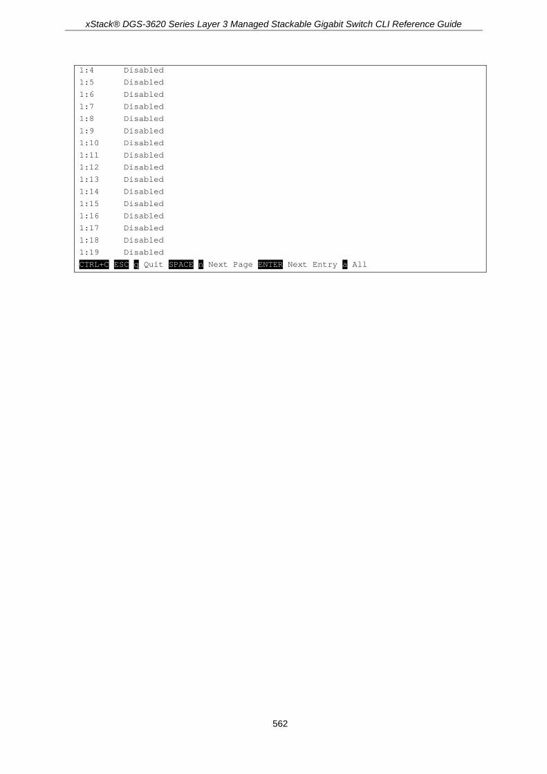
xStack® DGS-3620 Series Layer 3 Managed Stackable Gigabit Switch CLI Reference Guide
562
1:4 Disabled
1:5 Disabled
1:6 Disabled
1:7 Disabled
1:8 Disabled
1:9 Disabled
1:10 Disabled
1:11 Disabled
1:12 Disabled
1:13 Disabled
1:14 Disabled
1:15 Disabled
1:16 Disabled
1:17 Disabled
1:18 Disabled
1:19 Disabled
CTRL+C ESC q Quit SPACE n Next Page ENTER Next Entry a All

xStack® DGS-3620 Series Layer 3 Managed Stackable Gigabit Switch CLI Reference Guide
563
Chapter 46 IGMP Snooping Multicast (ISM) VLAN Commands
create igmp_snooping multicast_vlan <vlan_name 32> <vlanid 2-4094> {remap_priority [<value
0-7> | none] {replace_priority}} config igmp_snooping multicast_vlan <vlan_name 32> {[add | delete] [member_port <portlist> |
[source_port <portlist> | untag_source_port <portlist>] | tag_member_port <portlist>] | state [enable | disable] | replace_source_ip [<ipaddr> | none] | remap_priority [<value 0-7> | none] {replace_priority}}(1)
create igmp_snooping multicast_vlan_group_profile <profile_name 1-32> config igmp_snooping multicast_vlan_group_profile <profile_name 1-32> [add | delete]
<mcast_address_list> delete igmp_snooping multicast_vlan_group_profile [profile_name <profile_name 1-32> | all] show igmp_snooping multicast_vlan_group_profile {<profile_name 1-32>} config igmp_snooping multicast_vlan_group <vlan_name 32> [add | delete] profile_name
<profile_name 1-32> show igmp_snooping multicast_vlan_group {<vlan_name 32>} delete igmp_snooping multicast_vlan <vlan_name 32> enable igmp_snooping multicast_vlan disable igmp_snooping multicast_vlan show igmp_snooping multicast_vlan {<vlan_name 32>} config igmp_snooping multicast_vlan forward_unmatched [disable | enable] config igmp_snooping multicast_vlan auto_assign_vlan [enable | disable]
46-1 create igmp_snooping multicast_vlan Description This command is used to create an IGMP snooping multicast VLAN and implements relevant parameters as specified. More than one multicast VLAN can be configured. Newly created IGMP snooping multicast VLANs must use a unique VLAN ID and name, i.e. they cannot use the VLAN ID or name of any existing 802.1Q VLAN. Also keep in mind the following conditions: multicast VLANs cannot be configured or displayed using 802.1Q VLAN commands and the multicast VLAN snooping function co-exists with the 802.1Q VLAN snooping function.
Format create igmp_snooping multicast_vlan <vlan_name 32> <vlanid 2-4094> {remap_priority [<value 0-7> | none] {replace_priority}}
Parameters <vlan_name 32> - Enter the name of the multicast VLAN to be created. Each multicast VLAN is
given a name that can be up to 32 characters. <vlanid 2-4094> - Enter the VLAN ID of the multicast VLAN to be created. The range is from 2 to
4094. remap_priority - (Optional) Specifies the remap priority that will be used.
<value 0-7> - Enter the remap priority (0 to 7) to be associated with the data traffic to be

xStack® DGS-3620 Series Layer 3 Managed Stackable Gigabit Switch CLI Reference Guide
564
forwarded on the multicast VLAN. none - If none is specified, the packet’s original priority will be used. The default setting is
none. replace_priority - (Optional) Specifies that the packet’s priority will be changed by the switch,
based on the remap priority. This flag will only take effect when the remap priority is set.
Restrictions Only Administrators, Operators and Power-Users can issue this command.
Example To create an IGMP snooping multicast VLAN with the VLAN name mv1 and the VID 2:
DGS-3620-28PC:admin#create igmp_snooping multicast_vlan mv1 2
Command: create igmp_snooping multicast_vlan mv1 2
Success.
DGS-3620-28PC:admin#
46-2 config igmp_snooping multicast_vlan Description This command is used to configure IGMP snooping multicast VLAN parameters. The member port list and source port list cannot overlap. However, the member port of one multicast VLAN can overlap with another multicast VLAN. The multicast VLAN must be created first using the create igmp_snooping multicast_vlan command before the multicast VLAN can be configured.
Format config igmp_snooping multicast_vlan <vlan_name 32> {[add | delete] [member_port <portlist> | [source_port <portlist> | untag_source_port <portlist>] | tag_member_port <portlist>] | state [enable | disable] | replace_source_ip [<ipaddr> | none] | remap_priority [<value 0-7> | none] {replace_priority}}(1)
Parameters <vlan_name 32> - Enter the name of the multicast VLAN to be configured. Each multicast VLAN
is given a name that can be up to 32 characters. add - Specifies to add a port. delete - Specifies to delete a port. member_port - Specifies member port of the multicast VLAN. The specified range of ports will
become untagged members of the multicast VLAN. <portlist> - Enter a range of ports to be configured.
source_port - Specifies source port where the multicast traffic is entering the Switch. <portlist> - Enter a range of ports to be configured.
untag_source_port - Specifies the untagged source port where the multicast traffic is entering the Switch. The PVID of the untagged source port is automatically changed to the multicast VLAN. Source ports must be either tagged or untagged for any single multicast VLAN, i.e. both types cannot be members of the same multicast VLAN <portlist> - Enter a range of ports to be configured.
tag_member_port - Specifies the tagged member port of the multicast VLAN. <portlist> - Enter a range of ports to be configured.

xStack® DGS-3620 Series Layer 3 Managed Stackable Gigabit Switch CLI Reference Guide
565
state - (Optional) Specifies if the multicast VLAN for a chosen VLAN should be enabled or disabled. enable - Enable multicast VLAN for the chosen VLAN. disable - Disable multicast VLAN for the chosen VLAN.
replace_source_ip - With the IGMP snooping function, the IGMP report packet sent by the host will be forwarded to the source port. Before forwarding of the packet, the source IP address in the join packet needs to be replaced by this IP address. If none is specified, the source IP address will use “0” IP address. <ipaddr> - Enter the IP address here. none - Specifies that the source IP address will not be replaced.
remap_priority - Specifies the remap priority here. <value 0-7> - The remap priority value (0 to 7) to be associated with the data traffic to be
forwarded on the multicast VLAN. none - If none is specified, the packet’s original priority is used. The default setting is none.
replace_priority - (Optional) Specifies that the packet priority will be changed to the remap priority, but only if remap priority is set.
Restrictions Only Administrators, Operators and Power-Users can issue this command.
Example To configure an IGMP snooping multicast VLAN with the name “v1”, make ports 1 and 3 members of the VLAN, and set the state to enable:
DGS-3620-28PC:admin#config igmp_snooping multicast_vlan v1 add member_port 1,3 state enable
Command: config igmp_snooping multicast_vlan v1 add member_port 1,3 state enable
Success.
DGS-3620-28PC:admin#
46-3 create igmp_snooping multicast_vlan_group_profile Description This command is used to create a multicast group profile. The profile name for IGMP snooping must be unique.
Format create igmp_snooping multicast_vlan_group_profile <profile_name 1-32>
Parameters <profile_name 1-32> - Specifies the multicast VLAN profile name. The maximum length is 32
characters.
Restrictions Only Administrators, Operators and Power-Users can issue this command.

xStack® DGS-3620 Series Layer 3 Managed Stackable Gigabit Switch CLI Reference Guide
566
Example To create an IGMP snooping multicast group profile with the name “Knicks”:
DGS-3620-28PC:admin#create igmp_snooping multicast_vlan_group_profile Knicks
Command: create igmp_snooping multicast_vlan_group_profile Knicks
Success.
DGS-3620-28PC:admin#
46-4 config igmp_snooping multicast_vlan_group_profile Description This command is used to configure an IGMP snooping multicast group profile on the switch and to add or delete multicast addresses for a profile.
Format config igmp_snooping multicast_vlan_group_profile <profile_name 1-32> [add | delete] <mcast_address_list>
Parameters <profile_name 32> - Enter the multicast VLAN profile name. The maximum length is 32
characters. add - Specifies to add a multicast address list to this multicast VLAN profile. delete - Specifies to delete a multicast address list from this multicast VLAN profile.
<mcast_address_list> - Enter a multicast address list. This can be a continuous single multicast address, such as 225.1.1.1, 225.1.1.3, 225.1.1.8, a multicast address range, such as 225.1.1.1-225.2.2.2, or both types, such as 225.1.1.1, 225.1.1.18-225.1.1.20.
Restrictions Only Administrators, Operators and Power-Users can issue this command.
Example To add the single multicast address 225.1.1.1 and multicast range 225.1.1.10-225.1.1.20 to the IGMP snooping multicast VLAN profile named “Knicks”:
DGS-3620-28PC:admin#config igmp_snooping multicast_vlan_group_profile Knicks add 225.1.1.1, 225.1.1.10-225.1.1.20
Command: config igmp_snooping multicast_vlan_group_profile Knicks add 225.1.1.1, 225.1.1.10-225.1.1.20
Success.
DGS-3620-28PC:admin#
xStack® DGS-3620 Series Layer 3 Managed Stackable Gigabit Switch CLI Reference Guide
567
46-5 delete igmp_snooping multicast_vlan_group_profile Description This command is used to delete an existing IGMP snooping multicast group profile on the switch.
Format delete igmp_snooping multicast_vlan_group_profile [profile_name <profile_name 1-32> | all]
Parameters profile_name - Specifies the multicast VLAN group profile name. The maximum length is 32
characters. <profile_name 1-32> - The profile file can be up to 32 characters long. all - Specifies to delete all the profiles.
If no parameter is specified, the system will display all multicast VLAN group profiles.
Restrictions Only Administrators, Operators and Power-Users can issue this command.
Example To delete an IGMP snooping multicast group profile named “Knicks”:
DGS-3620-28PC:admin#delete igmp_snooping multicast_vlan_group_profile profile_name Knicks
Command: delete igmp_snooping multicast_vlan_group_profile profile_name Knicks
Success.
DGS-3620-28PC:admin#
46-6 show igmp_snooping multicast_vlan_group_profile Description This command is used to display an IGMP snooping multicast group profile.
Format show igmp_snooping multicast_vlan_group_profile {<profile_name 1-32>}
Parameters <profile_name 1-32> - (Optional) Specifies the multicast VLAN profile name. The maximum
length is 32 characters.
If no parameter is specified, the system will display all multicast VLAN group profiles.

xStack® DGS-3620 Series Layer 3 Managed Stackable Gigabit Switch CLI Reference Guide
568
Restrictions None.
Example To display all IGMP snooping multicast VLAN profiles:
DGS-3620-28PC:admin#show igmp_snooping multicast_vlan_group_profile
Command: show igmp_snooping multicast_vlan_group_profile
Profile Name Multicast Addresses
----------------------- --------------------------------
Knicks 234.1.1.1 - 238.244.244.244
239.1.1.1 - 239.2.2.2
customer 224.19.62.34 - 224.19.162.200
Total Entries : 2
DGS-3620-28PC:admin#
46-7 config igmp_snooping multicast_vlan_group Description This command is used to configure the multicast group which will be learned with the specific multicast VLAN. There are two cases that need to be considered. For the first case, suppose that a multicast group is not configured and multicast VLANs do not have overlapped member ports. That means the join packets received by the member port will only be learned with the multicast VLAN that this port belongs to. If not, which is the second case, the join packet will be learned with the multicast VLAN that contains the destination multicast group. If the destination multicast group of the join packet can not be classified into any multicast VLAN that this port belongs to, then the join packet will be learned with the natural VLAN of the packet. Please note that the same profile can not overlap different multicast VLANs. Multiple profiles can be added to a multicast VLAN, however.
Format config igmp_snooping multicast_vlan_group <vlan_name 32> [add | delete] profile_name <profile_name 1-32>
Parameters <vlan_name 32> - Enter the name of the multicast VLAN to be configured. Each multicast VLAN
is given a name that can be up to 32 characters. add - Specifies to associate a profile to a multicast VLAN. delete - Specifies to de-associate a profile from a multicast VLAN.
profile_name - Specifies the multicast VLAN profile name. The maximum length is 32 characters. <profile_name> - The profile name can be up to 32 characters long.
Restrictions Only Administrators, Operators and Power-Users can issue this command.

xStack® DGS-3620 Series Layer 3 Managed Stackable Gigabit Switch CLI Reference Guide
569
Example To add an IGMP snooping profile to a multicast VLAN group with the name “v1”:
DGS-3620-28PC:admin#config igmp_snooping multicast_vlan_group v1 add profile_name channel_1
Command: config igmp_snooping multicast_vlan_group v1 add profile_name channel_1
Success.
DGS-3620-28PC:admin#
46-8 show igmp_snooping multicast_vlan_group Description This command allows group profile information for a specific multicast VLAN to be displayed.
Format show igmp_snooping multicast_vlan_group {<vlan_name 32>}
Parameters <vlan_name 32> - (Optional) Specifies the name of the group profile’s multicast VLAN to be
displayed.
If no parameter is specified, the system will display all multicast VLAN groups.
Restrictions None.
Example To display all IGMP snooping multicast VLANs’group profile information:
DGS-3620-28PC:admin#show igmp_snooping multicast_vlan_group
Command: show igmp_snooping multicast_vlan_group
VLAN Name VLAN ID Multicast Group Profiles
------------------------------- ------- ---------------------------------
test2 20
test1 100
DGS-3620-28PC:admin#
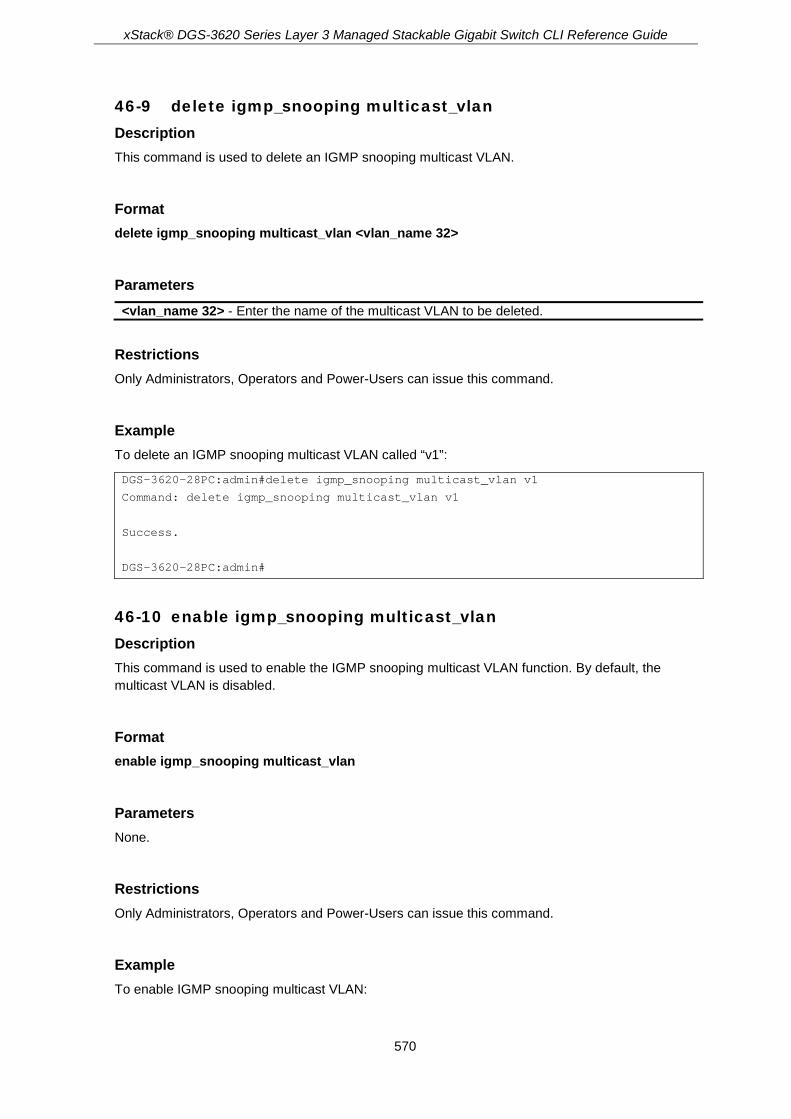
xStack® DGS-3620 Series Layer 3 Managed Stackable Gigabit Switch CLI Reference Guide
570
46-9 delete igmp_snooping multicast_vlan Description This command is used to delete an IGMP snooping multicast VLAN.
Format delete igmp_snooping multicast_vlan <vlan_name 32>
Parameters <vlan_name 32> - Enter the name of the multicast VLAN to be deleted.
Restrictions Only Administrators, Operators and Power-Users can issue this command.
Example To delete an IGMP snooping multicast VLAN called “v1”:
DGS-3620-28PC:admin#delete igmp_snooping multicast_vlan v1
Command: delete igmp_snooping multicast_vlan v1
Success.
DGS-3620-28PC:admin#
46-10 enable igmp_snooping multicast_vlan Description This command is used to enable the IGMP snooping multicast VLAN function. By default, the multicast VLAN is disabled.
Format enable igmp_snooping multicast_vlan
Parameters None.
Restrictions Only Administrators, Operators and Power-Users can issue this command.
Example To enable IGMP snooping multicast VLAN:

xStack® DGS-3620 Series Layer 3 Managed Stackable Gigabit Switch CLI Reference Guide
571
DGS-3620-28PC:admin#enable igmp_snooping multicast_vlan
Command: enable igmp_snooping multicast_vlan
Success.
DGS-3620-28PC:admin#
46-11 disable igmp_snooping multicast_vlan Description This command is used to disable the IGMP snooping multicast VLAN function. By default, the multicast VLAN is disabled.
Format disable igmp_snooping multicast_vlan
Parameters None.
Restrictions Only Administrators, Operators and Power-Users can issue this command.
Example To disable IGMP snooping multicast VLAN:
DGS-3620-28PC:admin#disable igmp_snooping multicast_vlan
Command: disable igmp_snooping multicast_vlan
Success.
DGS-3620-28PC:admin#
46-12 show igmp_snooping multicast_vlan Description This command allows information for a specific multicast VLAN to be displayed.
Format show igmp_snooping multicast_vlan {<vlan_name 32>}
Parameters <vlan_name 32> - (Optional) Specifies the name of the multicast VLAN to be displayed.

xStack® DGS-3620 Series Layer 3 Managed Stackable Gigabit Switch CLI Reference Guide
572
If no parameter is specified, the system will display all multicast VLANs.
Restrictions None.
Example To display all IGMP snooping multicast VLANs:
DGS-3620-28PC:admin# show igmp_snooping multicast_vlan
Command: show igmp_snooping multicast_vlan
IGMP Multicast VLAN Global State : Enabled
IGMP Multicast VLAN Forward Unmatched : Disabled
IGMP Multicast VLAN Auto Assign VLAN : Enabled
VLAN Name :4094
VID :4094
Member(Untagged) Ports :2:20-2:21
Tagged Member Ports :
Source Ports :2:22
Untagged Source Ports :
Status :Enabled
Replace Source IP :4.4.4.4 (User Configure)
Remap Priority :7 (Replaced)
Total Entries: 1
DGS-3620-28PC:admin#
46-13 config igmp_snooping multicast_vlan forward_unmatched Description This command is used to configure the forwarding mode for IGMP snooping multicast VLAN unmatched packets. When the switch receives an IGMP snooping packet, it will match the packet against the multicast profile to determine which multicast VLAN to associate with. If the packet does not match all profiles, the packet will be forwarded or dropped based on this setting. By default, the packet will be dropped.
Format config igmp_snooping multicast_vlan forward_unmatched [disable | enable]
Parameters enable - The packet will be flooded on the VLAN. disable - The packet will be dropped.

xStack® DGS-3620 Series Layer 3 Managed Stackable Gigabit Switch CLI Reference Guide
573
Restrictions Only Administrators, Operators and Power-Users can issue this command.
Example To configure the forwarding mode for IGMP snooping multicast VLAN unmatched packets:
DGS-3620-28PC:admin#config igmp_snooping multicast_vlan forward_unmatched enable
Command: config igmp_snooping multicast_vlan forward_unmatched enable
Success.
DGS-3620-28PC:admin#
46-14 config igmp_snooping multicast_vlan auto_assign_vlan Description This command is used to enable or disable the assignment of IGMP control packets to the right ISM VLAN. If auto assign VLAN is enabled, the Switch will check for group matching with multicast VLAN profiles of which the ingress port belongs to. If there is a match, the result is "in profile" and the matching multicast VLAN will be set as a packet VLAN. If this function is disabled, the Switch will do VID checking, and afterwards, if the group does not match the current profile binding, the Switch will drop this packet.
Format config igmp_snooping multicast_vlan auto_assign_vlan [enable | disable]
Parameters enable - Specifies to enable the auto assign VLAN function. disable - Specifies to disable the auto assign VLAN function.
Restrictions Only Administrators, Operators and Power-Users can issue this command.
Example To enable the auto assign VLAN function of multicast VLAN:
DGS-3620-28PC:admin#config igmp_snooping multicast_vlan auto_assign_vlan enable
Command: config igmp_snooping multicast_vlan auto_assign_vlan enable
Success.
DGS-3620-28PC:admin#
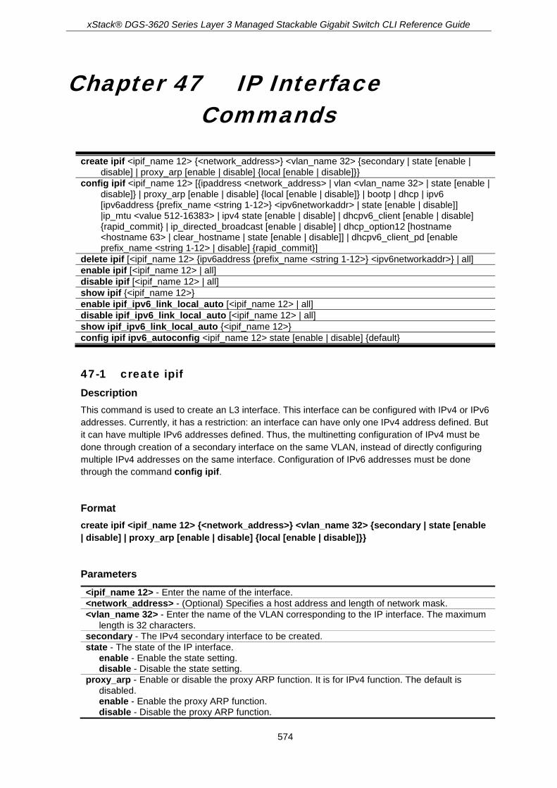
xStack® DGS-3620 Series Layer 3 Managed Stackable Gigabit Switch CLI Reference Guide
574
Chapter 47 IP Interface Commands
create ipif <ipif_name 12> {<network_address>} <vlan_name 32> {secondary | state [enable |
disable] | proxy_arp [enable | disable] {local [enable | disable]}} config ipif <ipif_name 12> [{ipaddress <network_address> | vlan <vlan_name 32> | state [enable |
disable]} | proxy_arp [enable | disable] {local [enable | disable]} | bootp | dhcp | ipv6 [ipv6address {prefix_name <string 1-12>} <ipv6networkaddr> | state [enable | disable]] |ip_mtu <value 512-16383> | ipv4 state [enable | disable] | dhcpv6_client [enable | disable] {rapid_commit} | ip_directed_broadcast [enable | disable] | dhcp_option12 [hostname <hostname 63> | clear_hostname | state [enable | disable]] | dhcpv6_client_pd [enable prefix_name <string 1-12> | disable] {rapid_commit}]
delete ipif [<ipif_name 12> {ipv6address {prefix_name <string 1-12>} <ipv6networkaddr>} | all] enable ipif [<ipif_name 12> | all] disable ipif [<ipif_name 12> | all] show ipif {<ipif_name 12>} enable ipif_ipv6_link_local_auto [<ipif_name 12> | all] disable ipif_ipv6_link_local_auto [<ipif_name 12> | all] show ipif_ipv6_link_local_auto {<ipif_name 12>} config ipif ipv6_autoconfig <ipif_name 12> state [enable | disable] {default}
47-1 create ipif Description This command is used to create an L3 interface. This interface can be configured with IPv4 or IPv6 addresses. Currently, it has a restriction: an interface can have only one IPv4 address defined. But it can have multiple IPv6 addresses defined. Thus, the multinetting configuration of IPv4 must be done through creation of a secondary interface on the same VLAN, instead of directly configuring multiple IPv4 addresses on the same interface. Configuration of IPv6 addresses must be done through the command config ipif.
Format create ipif <ipif_name 12> {<network_address>} <vlan_name 32> {secondary | state [enable | disable] | proxy_arp [enable | disable] {local [enable | disable]}}
Parameters <ipif_name 12> - Enter the name of the interface. <network_address> - (Optional) Specifies a host address and length of network mask. <vlan_name 32> - Enter the name of the VLAN corresponding to the IP interface. The maximum
length is 32 characters. secondary - The IPv4 secondary interface to be created. state - The state of the IP interface.
enable - Enable the state setting. disable - Disable the state setting.
proxy_arp - Enable or disable the proxy ARP function. It is for IPv4 function. The default is disabled. enable - Enable the proxy ARP function. disable - Disable the proxy ARP function.

xStack® DGS-3620 Series Layer 3 Managed Stackable Gigabit Switch CLI Reference Guide
575
local - (Optional) This setting controls whether the system provides the proxy reply for the ARP packets destined for IP address located on the same interface as the received interface. When proxy ARP is enabled for an interface, the system will do the proxy reply for the ARP packets destined for an IP address located on a different interface. For ARP packets destined for an IP address located on the same interface, the system will check this setting to determine whether to reply. The default is disabled. enable - Enable the local setting. disable - Disable the local setting.
Restrictions Only Administrators, Operators and Power-Users can issue this command.
Example To create an IP interface petrovic1:
DGS-3620-28PC:admin#create ipif petrovic1 100.1.1.2/16 VLAN598
Command: create ipif petrovic1 100.1.1.2/16 VLAN598
Success.
DGS-3620-28PC:admin#
47-2 config ipif Description Configure the parameters for an L3 interface. For IPv4, only the system interface can be specified for the way to get the IP address. If the mode is set to BOOTP or DHCP, then the IPv4 address will be obtained through the operation of protocols. The manual configuration of the IP address will be of no use. If the mode is configured to BOOTP or DHCP first, and then the user configures IP address later, the mode will be changed to manual configured mode. For IPv6, multiple addresses can be defined on the same L3 interface. For IPv4, multi-netting must be done by creation of a secondary interface. Note that an IPv6 address is not allowed to be configured on a secondary interface.
Format config ipif <ipif_name 12> [{ipaddress <network_address> | vlan <vlan_name 32> | state [enable | disable]} | proxy_arp [enable | disable] {local [enable | disable]} | bootp | dhcp | ipv6 [ipv6address {prefix_name <string 1-12>} <ipv6networkaddr> | state [enable | disable]] |ip_mtu <value 512-16383> | ipv4 state [enable | disable] | dhcpv6_client [enable | disable] {rapid_commit} | ip_directed_broadcast [enable | disable] | dhcp_option12 [hostname <hostname 63> | clear_hostname | state [enable | disable]] | dhcpv6_client_pd [enable prefix_name <string 1-12> | disable] {rapid_commit}]
Parameters ipif - Specifies the IP interface configured.
<ipif_name 12> - Enter the name of the IP interface used here. This name can be up to 12 characters long. The default interface is 'System'.
ipaddress - (Optional) The IP address and netmask of the IP interface to be created. <network_address> - Enter the address and mask information using the traditional format

xStack® DGS-3620 Series Layer 3 Managed Stackable Gigabit Switch CLI Reference Guide
576
(for example, 10.1.2.3/255.0.0.0 or in CIDR format, 10.1.2.3/8). vlan - (Optional) The name of the VLAN corresponding to the IP interface.
<vlan_name 32> - Enter the VLAN name. The maximum length is 32 characters. state - Enable or disable the IP interface.
enable - Enable the IP interface. disable - Disable the IP interface.
proxy_arp - (Optional) Enable or disable the proxy ARP. This is for the IPv4 function. The default is disabled. enable - Enable the proxy ARP. disable - Disable the proxy ARP.
local - (Optional) This setting controls whether the system provides the proxy reply for the ARP packets destined for IP addresses located in the same interface as the received interface. When proxy ARP is enabled for an interface, the system will do the proxy reply for the ARP packets destined for IP addresses located on a different interface. For ARP packets destined for IP address located on the same interface, the system will check this setting to determine whether to reply. The default is disabled. enable - Enable the local proxy ARP function. disable - Disable the local proxy ARP function.
bootp - Allows the selection of the BOOTP protocol for the assignment of an IP address to the switch’s System IP interface.
dhcp - Allows the selection of the DHCP protocol for the assignment of an IP address to the switch’s System.
ipv6 - The following are IPv6-related parameters. ipv6address - The IPv6 address and subnet prefix of the IPV6 address to be created.
prefix_name - Specifies the IPv6 prefix name. <string 1-12> - Enter the IPv6 prefix name. This name can be up to 12 characters long.
<ipv6networkaddr> - The IPv6 address and subnet prefix of the IPV6 address to be created.
state - Enable or disable the IPv6 state of the IP interface. enable - Enable the IPv6 state of the IP interface. disable - Disable the IPv6 state of the IP interface.
ip_mtu - Specifies the IP Layer MTU value used. <value 512-16383> - Enter the IP Layer MTU value used here. The value must be between
512 and 16383. Note: This value is for hardware forwarding only. ipv4 state - The state of the IPv4 interface.
enable - Enable the IPv4 state of the IP interface. disable - Disable the IPv4 state of the IP interface.
dhcpv6_client - Specifies the DHCPv6 client state of the interface. enable - Specifies that the DHCPv6 client state of the interface will be enabled. disable - Specifies that the DHCPv6 client state of the interface will be disabled. rapid_commit - (Optional) Specifies to allow the two-message exchange method for address
assignment. ip_directed_broadcast - Specifies the IP directed-broadcast state of the interface.
enable - Specifies that the IP directed-broadcast state of the interface will be enabled. disable - Specifies that the IP directed-broadcast state of the interface will be disabled.
dhcp_option12 - (Optional) Specifies to configure the DHCP Option 12 parameters. hostname - Specifies the host name to be inserted in the DHCPDISCOVER and
DHCPREQUEST message. <hostname 63> - Enter the host name here. This name must start and end with a letter or
a number. Only letters, digits, and hyphens are allowed as interior characters. This name can be up to 63 characters long.
clear_hostname - Specifies to clear the host name setting. If a host name is empty, the system name will be used to encode Option 12. The length of the system is more than 63 characters. The superfluous characters will be truncated. If the system name is also empty, then the product model name will be used to encode Option 12.
state - Specifies to enable or disable the insertion of the Option 12 information in the DHCPDISCOVER and DHCPREQUEST messages. enable - Specifies to enable the insertion of the Option 12 information in the
DHCPDISCOVER and DHCPREQUEST messages. disable - Specifies to disable the insertion of the Option 12 information in the

xStack® DGS-3620 Series Layer 3 Managed Stackable Gigabit Switch CLI Reference Guide
577
DHCPDISCOVER and DHCPREQUEST messages. dhcpv6_client_pd - Specifies the DHCPv6 client PD configuration.
enable - Specifies to enable the DHCPv6 client PD state of the interface. prefix_name - Specifies an alias name for the prefix requested from the delegation router. If
disable the DHCPv6 client PD the name will be automatic clear. <string 1-12> - Enter the prefix alias name. This name can be up to 12 characters long.
disable - Specifies to disable the DHCPv6 client PD state of the interface. rapid_commit - (Optional) Specifies to allow the two-message exchange method for prefix
assignment.
Restrictions Only Administrators, Operators and Power-Users can issue this command.
Example To configure the System IP interface:
DGS-3620-28PC:admin#config ipif System vlan v1
Command: config ipif System vlan v1
Success.
DGS-3620-28PC:admin#
47-3 delete ipif Description This command is used to delete an interface or an IPv6 address.
Format delete ipif [<ipif_name 12> {ipv6address {prefix_name <string 1-12>} <ipv6networkaddr>} | all]
Parameters <ipif_name 12> - The name of the interface.
ipv6address - (Optional) The IPv6 network address to be deleted. prefix_name - Specifies the IPv6 prefix name.
<string 1-12> - Enter the IPv6 prefix name. This name can be up to 12 characters long. <ipv6networkaddr> - The IPv6 network address to be deleted.
all - All IP interfaces except the System IP interface will be deleted.
Restrictions Only Administrators, Operators and Power-Users can issue this command.
Example To delete interface petrovic1:
DGS-3620-28PC:admin#delete ipif petrovic1

xStack® DGS-3620 Series Layer 3 Managed Stackable Gigabit Switch CLI Reference Guide
578
Command: delete ipif petrovic1
Success.
DGS-3620-28PC:admin#
47-4 enable ipif Description This command is used to enable the state for an IPIF. When the state is enabled, the IPv4 processing will be started when an IPv4 address is configured on the IPIF. The IPv6 processing will be started when an IPv6 address is explicitly configured on the IPIF.
Format enable ipif [<ipif_name 12> | all]
Parameters <ipif_name 12> - The name of the interface. all - All of the IP interfaces.
Restrictions Only Administrators, Operators and Power-Users can issue this command.
Example To enable the state for interface petrovic1:
DGS-3620-28PC:admin#enable ipif petrovic1
Command: enable ipif petrovic1
Success.
DGS-3620-28PC:admin#
47-5 disable ipif Description This command is used to disable the state of an interface.
Format disable ipif [<ipif_name 12> | all]
Parameters <ipif_name 12> - The name of the interface.

xStack® DGS-3620 Series Layer 3 Managed Stackable Gigabit Switch CLI Reference Guide
579
all - All of the IP interfaces.
Restrictions Only Administrators, Operators and Power-Users can issue this command.
Example To disable the state for an interface:
DGS-3620-28PC:admin#disable ipif petrovic1
Command: disable ipif petrovic1
Success.
DGS-3620-28PC:admin#
47-6 show ipif Description This command is used to display IP interface settings.
Format show ipif {<ipif_name 12>}
Parameters <ipif_name 12> - (Optional) The name of the interface.
Restrictions None.
Example To display IP interface settings:
DGS-3620-28PC:admin# show ipif
Command: show ipif
IP Interface : System
VLAN Name : default
Interface Admin State : Enabled
IPv4 Address : 10.90.100.100/16 (Manual) Primary
Proxy ARP : Disabled (Local : Disabled)
IP Directed Broadcast : Disabled
IPv4 State : Enabled
IPv6 SLAAC state : Disabled (Default Router: Disabled)
DHCPv6 Client State : Disabled (Rapid commit : Disabled)
DHCPv6 Client PD State : Disabled (Rapid commit : Disabled)

xStack® DGS-3620 Series Layer 3 Managed Stackable Gigabit Switch CLI Reference Guide
580
IPv6 Link-Local Address : FE80::2CD:8FF:FE65:B00/128
IPv6 Global Unicast Address : 2001::1000/64 (Manual)
IPv6 State : Enabled
IP MTU : 1500
DHCP Option12 State : Disabled
DHCP Option12 Host Name :
IP Interface : mgmt_ipif
Status : Enabled
IP Address : 192.168.0.1
Subnet Mask : 255.255.255.0
Gateway : 0.0.0.0
Link Status : Link Down
Total Entries: 2
DGS-3620-28PC:admin#
47-7 enable ipif_ipv6_link_local_auto Description This command is used to enable the auto configuration of link local address when there are no IPv6 addresses explicitly configured. When an IPv6 address is explicitly configured, the link local address will be automatically configured, and the IPv6 processing will be started. When there is no IPv6 address explicitly configured, by default, link local address is not configured and the IPv6 processing will be disabled. By enabling this automatic configuration, the link local address will be automatically configured and IPv6 processing will be started.
Format enable ipif_ipv6_link_local_auto [<ipif_name 12> | all]
Parameters <ipif_name 12> - The name of the interface. all - All of the IP interfaces.
Restrictions Only Administrators, Operators and Power-Users can issue this command.
Example To enable the automatic configuration of link local address for an interface:
DGS-3620-28PC:admin#enable ipif_ipv6_link_local_auto interface1
Command: enable ipif_ipv6_link_local_auto interface1
Success.
DGS-3620-28PC:admin#

xStack® DGS-3620 Series Layer 3 Managed Stackable Gigabit Switch CLI Reference Guide
581
47-8 disable ipif_ipv6_link_local_auto Description This command is used to disable the auto configuration of link local address when no IPv6 address is explicitly configured.
Format disable ipif_ipv6_link_local_auto [<ipif_name 12> | all]
Parameters <ipif_name 12> - The name of the interface. all - All of the IP interfaces.
Restrictions Only Administrators, Operators and Power-Users can issue this command.
Example To disable the automatic configuration of link local address for an interface:
DGS-3620-28PC:admin#disable ipif_ipv6_link_local_auto interface1
Command: disable ipif_ipv6_link_local_auto interface1
Success.
DGS-3620-28PC:admin#
47-9 show ipif_ipv6_link_local_auto Description This command is used to display the link local address automatic configuration state.
Format show ipif_ipv6_link_local_auto {<ipif_name 12>}
Parameters <ipif_name 12> - (Optional) The name of the interface.
Restrictions Only Administrators, Operators and Power-Users can issue this command.

xStack® DGS-3620 Series Layer 3 Managed Stackable Gigabit Switch CLI Reference Guide
582
Example To display the link local address automatic configuration state:
DGS-3620-28PC:admin#show ipif_ipv6_link_local_auto
Command: show ipif_ipv6_link_local_auto
IPIF: System Automatic Link Local Address: Disabled
DGS-3620-28PC:admin#
47-10 config ipif ipv6_autoconfig Description This command is used to enable or disable automatic configuration of the IPv6 address using stateless auto-configuration.
This command is only available for the VLAN IPv6 interface (IPv6 is enabled on the VLAN interface). By default the auto-configuration option is disabled.
When enabling this configuration, the interface enables IPv6 processing and a router advertisement containing an assigned global address prefix will be received on this interface from an IPv6 router. The resulting address that is a combination of the prefix and the interface identifier will be assigned to the interface.
When disabling this configuration, the obtained global unicast address will be removed from the interface.
If the default option is specified, it will accord the received router advertisement to insert a default route to the IPv6 routing table. The type of this default route is SLAAC. It has a higher route preference than the dynamic default route which learnt from RIPng, OSPFv3, or BGP+. The static default route has higher route preference than it.
Format config ipif ipv6_autoconfig <ipif_name 12> state [enable | disable] {default}
Parameters <ipif_name 12> - Enter the IP interface's name that will be configured here. This name can be up
12 characters long. state - Specifies the IPv6 automatic configuration's state.
enable - Specifies to enable IPv6 automatic configuration. disable - Specifies to disable IPv6 automatic configuration.
default - (Optional) Specifies that if a default router is selected on this interface, the default keyword causes a default route to be installed using that default router. The default keyword can be specified on only one interface.
Restrictions Only Administrators, Operators and Power-Users can issue this command.

xStack® DGS-3620 Series Layer 3 Managed Stackable Gigabit Switch CLI Reference Guide
583
Example This example shows how to configure the state of the automatic configuration of the IPv6 address for the System IP interface.
DGS-3620-28PC:admin# config ipif ipv6_autoconfig System state enable
Command: config ipif ipv6_autoconfig System state enable
Success.
DGS-3620-28PC:admin#

xStack® DGS-3620 Series Layer 3 Managed Stackable Gigabit Switch CLI Reference Guide
584
Chapter 48 IP Multicasting Commands
show ipmc {ipif <ipif_name 12> | protocol [inactive | dvmrp | pim]} show ipmc cache {group <group>} {ipaddress <network_address>} show ipmc statistics counter {igmp | pim | dvmrp} {ipif <ipif_name 12>} clear ipmc statistics counter {igmp | pim | dvmrp}
48-1 show ipmc Description This command is used to display the IP Multicast interface table.
Format show ipmc {ipif <ipif_name 12> | protocol [inactive | dvmrp | pim]}
Parameters ipif - (Optional) Specifies the IP interface name used.
<ipif_name 12> - Enter the IP interface name used here. This name can be up to 12 characters long.
protocol - (Optional) Specifies which kind of routing protocol interface table will be displayed. inactive - Specifies that the protocol display will be inactive. dvmrp - Specifies that the DVMRP protocol will be displayed. pim - Specifies that the PIM protocol will be displayed.
If no parameter is specified, the system will display all IP multicast interfaces.
Restrictions None.
Example To display the IP Multicast interface table:

xStack® DGS-3620 Series Layer 3 Managed Stackable Gigabit Switch CLI Reference Guide
585
DGS-3620-28PC:admin#show ipmc
Command: show ipmc
Interface Name IP Address Multicast Routing
--------------- --------------- -----------------
System 10.90.90.90 INACT
n1 1.3.2.3 PIM-SM
n2 2.3.2.3 PIM-SM-DM
n3 3.3.2.3 PIM-DM
n4 4.3.2.3 DVMRP
Total Entries : 5
DGS-3620-28PC:admin#
48-2 show ipmc cache Description This command is used to display the IP multicast forwarding cache.
Format show ipmc cache {group <group>} {ipaddress <network_address>}
Parameters group - (Optional) Specifies the multicast group.
<group> - Enter the multicast group used here. ipaddress - (Optional) Specifies the IP address used.
<network_address> - Enter the IP address used here.
If no parameter is specified, the system will display all IP multicast forwarding cache entries.
Restrictions None.
Example To display the IP multicast forwarding cache:

xStack® DGS-3620 Series Layer 3 Managed Stackable Gigabit Switch CLI Reference Guide
586
DGS-3620-28PC:admin#show ipmc cache
Command: show ipmc cache
IP Multicast Forwarding Table
Multicast Source Upstream Expire Routing
Group Address/Netmask Neighbor Time Protocol
--------------- ---------------------- --------------- ------ ---------
224.1.1.1 10.48.74.121/8 10.48.75.63 30 DVMRP
224.1.1.1 20.48.74.25/8 20.48.75.25 20 PIM-DM
224.1.2.3 10.48.75.3/8 10.48.76.6 30 DVMRP
Total Entries : 3
DGS-3620-28PC:admin#
48-3 show ipmc statistics counter Description This command is used to display the received and sent multicast packet statistics counters according to the message type.
Format show ipmc statistics counter {igmp | pim | dvmrp} {ipif <ipif_name 12>}
Parameters igmp - (Optional) Specifies to display both sent and received IGMP packets counters. pim - (Optional) Specifies to display both sent and received PIM packets counters. dvmrp - (Optional) Specifies to display both sent and received DVMRP packets counters. ipif - (Optional) Specifies the IP interface to display.
<ipif_name 12> - Enter the IP interface's name here. This name can be up to 12 characters long.
Restrictions None.
Example This example shows how to display the multicast protocol packets counters on the Switch.

xStack® DGS-3620 Series Layer 3 Managed Stackable Gigabit Switch CLI Reference Guide
587
DGS-3620-28PC:admin# show ipmc statistics counter
Command: show ipmc statistics counter
IGMP Packets Counter
Received Sent
IGMP Query v1/v2/v3 0/0/0 0/0/0
IGMP Report v1/v2/v3 0/0/0 0/0/0
IGMP Leave 0 0
Unknown IGMP 0 0
PIM Packets Counter
Received Sent
PIM Hello 0 0
PIM Register 0 0
PIM Register-Stop 0 0
PIM Join/Prune 0 0
PIM Bootstrap 0 0
PIM Assert 0 0
PIM Graft 0 0
PIM Graft-Ack 0 0
PIM C-RP-Adv 0 0
PIM State Refresh 0 0
Unknown PIM 0 0
DVMRP Packets Counter
Received Sent
DVMRP Probe 0 0
DVMRP Report 0 0
DVMRP Prune 0 0
DVMRP Graft 0 0
DVMRP Graft-Ack 0 0
Unknown DVMRP 0 0
DGS-3620-28PC:admin#
48-4 clear ipmc statistics counter Description This command is used to clear the multicast protocol packet statistics counters on the Switch.
Format clear ipmc statistics counter {igmp | pim | dvmrp}
Parameters igmp - (Optional) Specifies to clear IGMP packets counters. pim - (Optional) Specifies to clear PIM packets counters. dvmrp - (Optional) Specifies to clear DVMRP packets counters.

xStack® DGS-3620 Series Layer 3 Managed Stackable Gigabit Switch CLI Reference Guide
588
Restrictions Only Administrators, Operators and Power-Users can issue this command.
Example This example shows how to clear all multicast protocol packet statistics counters.
DGS-3620-28PC:admin# clear ipmc statistics counter
Command: clear ipmc statistics counter
Success.
DGS-3620-28PC:admin#

xStack® DGS-3620 Series Layer 3 Managed Stackable Gigabit Switch CLI Reference Guide
589
Chapter 49 IP Route Filter Commands
create ip prefix_list <list_name 16> config ip prefix_list <list_name 16> [[add | delete] {sequence <value 1-65535>}
<network_address> {ge <value 1-32>} {le <value 1-32>} [deny | permit] | [description <desc 80> | clear_description]]
delete ip prefix_list [list_name <list_name 16> | all] show ip prefix_list {<list_name 16>} create ip standard access_list <list_name 16> config ip standard access_list <list_name 16> [add | delete] <network_address> [deny | permit] delete ip standard access_list [list_name <list_name 16> | all] show ip standard access_list {<list_name 16>} clear ip prefix_list counter [<list_name 16> {<network_address>} | all] create route_map <map_name 16> config route_map <map_name 16> [[add | delete] sequence <value 1-65535> {[deny | permit]} |
sequence <value 1-65535> [match [add | delete] [as_path <list_name 16> | community_list <list_name 16> {exact} | ip [next_hop | address] {prefix_list} <list_name 16> | metric <uint 0-4294967294> | ipv6 [next_hop | address] {prefix_list} <list_name 16> | route_type [internal | external | type_1 | type_2] | interface <ipif_name 12> | route_source <list_name 16>] | set [add | delete] [next_hop [<ipaddr> | peer_address] | metric <uint 0-4294967294> | local_preference <uint 0-4294967295> | weight <value 0-65535> | as_path <aspath_list> | community {community_set <community_set 80> | internet | no_export | no_advertise | local_as} {additive} | origin [egp | igp | incomplete] | dampening <min 1-45> <value 1-20000> <value 1-20000> <min 1-255> <min 1-45> | ipv6 next_hop <ipv6addr> | metric_type [type_1 | type_2]]]]
delete route_map [map_name <map_name 16> {all_seqence} | all] show route_map {<map_name 16>} create ipv6 prefix_list <list_name 16> create ipv6 standard access_list <list_name 16> config ipv6 prefix_list <list_name 16> [[add | delete] {sequence <value 1-65535>}
<ipv6_networkaddr> {ge <value 1-128>} {le <value 1-128>} [deny | permit] | [description <desc 80> | clear_description]]
config ipv6 standard access_list <list_name 16> [add | delete] <ipv6_networkaddr> [deny | permit]
show ipv6 prefix_list {<list_name 16>} show ipv6 standard access_list {<list_name 16>} clear ipv6 prefix_list counter [<list_name 16> {<ipv6_networkaddr>} | all] delete ipv6 prefix_list [list_name <list_name 16> | all] delete ipv6 standard access_list [list_name <list_name 16> | all]
49-1 create ip prefix_list Description This command is used to create an IP prefix list that can be further applied to routes as a filter list.
Format create ip prefix_list <list_name 16>

xStack® DGS-3620 Series Layer 3 Managed Stackable Gigabit Switch CLI Reference Guide
590
Parameters <list_name 16> - Specifies the name to identify the prefix list.
Restrictions Only Administrators, Operators and Power-Users can issue this command.
Example To creates one IP prefix list named 1:
DGS-3620-28PC:admin# create ip prefix_list 1
Command: create ip prefix_list 1
Success.
DGS-3620-28PC:admin#
49-2 config ip prefix_list Description This command defines the rule entry for an IP route prefix list.
A prefix list can have multiple rule entries; each is represented by a sequence number. The rule with the lower sequence number will be evaluated first. If the sequence number is not specified for the defined rule entry, the sequence number will be automatically given. The automatically given sequence number will be a multiple of 5. Therefore, if the defined rule is the first rule in the prefix list, the automatically given sequence number will be 5. If the defined rule is not the first rule in the prefix list, the sequence number will be the number that is a multiple of 5 and larger than the largest sequence number of an existing rule in the prefix list.
A prefix list consists of an IP address and a bit mask. The bit mask is entered as a number from 1 to 32. An implicit denial is applied to traffic that does not match any prefix list entry.
The IP route prefix list rule entry is defined to either permit or deny specific routes. Prefix lists are configured to match an exact prefix length or a prefix range. The prefix list is processed using an exact match when neither the ge nor le keyword is entered. If only the ge value is entered, the range is the value entered for the ge ge-length argument to a full 32-bit length. If only the le value is entered, the range is from the value entered for the network/length argument to the le le-length argument. If both the ge ge-length and le le-length keywords and arguments are entered, the range falls between the values used for the ge-length and le-length arguments.
The following formula is a restriction for the specified ge-length and le-length.
network/length < ge ge-length < le le-length <= 32
As an example, if the configured network address is 10.1.2.3/16, only the route 10.1.0.0/16 will match the rule. The route 10.1.2.0/24 will not match the rule.
As another example, if 10.1.0.0/16 ge 24 is configured, then the route 10.1.0.0/16 will not match the rule. The route 10.1.2.0/24 will match the rule. The route 10.1.2.3/32 will also match the rule.

xStack® DGS-3620 Series Layer 3 Managed Stackable Gigabit Switch CLI Reference Guide
591
Format config ip prefix_list <list_name 16> [[add | delete] {sequence <value 1-65535>} <network_address> {ge <value 1-32>} {le <value 1-32>} [deny | permit] | [description <desc 80> | clear_description]]
Parameters <list_name 16> - Specifies the name for the prefix list. add - Specifies to add a rule entry. delete - Specifies to delete a rule entry. sequence - (Optional) Specifies the sequence number for the rule entry.
<value 1-65535> - Enter the sequence number for the rule entry here. This value must be between 1 and 65535.
<network_address> - Specifies the network address used. ge - (Optional) Specifies the minimum prefix length to be matched.
<value 1-32> - Enter the 'ge' value used here. This value must be between 1 and 32. le - (Optional) Specifies the maximum prefix length to be matched.
<value 1-32> - Enter the 'le' value used here. This value must be between 1 and 32. deny - Specifies that the network will be denied. permit - Specifies that the network will be permitted. description - Specifies the description for the prefix list used.
<desc 80> - Enter the description used here. This value can be up to 80 characters long. clear_description - Specifies that the description for the prefix list will be cleared.
Restrictions Only Administrators, Operators and Power-Users can issue this command.
Example The following example configures a prefix list 1 to permit routes from the 10.0.0.0/8 network that have a mask length that is less than or equal to 24 bits:
DGS-3620-28PC:admin# config ip prefix_list 1 add 10.0.0.0/8 le 24 permit
Command: config ip prefix_list 1 add 10.0.0.0/8 le 24 permit
Success.
DGS-3620-28PC:admin#
49-3 delete ip prefix_list Description This command is used to delete the IP prefix list
Format delete ip prefix_list [list_name <list_name 16> | all]
Parameters list_name - Specifies the prefix list name that will be deleted.

xStack® DGS-3620 Series Layer 3 Managed Stackable Gigabit Switch CLI Reference Guide
592
<list_name 16> - Enter the prefix list name that will be deleted here. This name must be 16 characters long.
all - Specifies that all the entries will be deleted.
Restrictions Only Administrators, Operators and Power-Users can issue this command.
Example To delete an IP prefix list named “list1”:
DGS-3620-28PC:admin# delete ip prefix_list list_name list1
Command: delete ip prefix_list list_name list1
Success.
DGS-3620-28PC:admin#
49-4 show ip prefix_list Description This command is used to show an IP prefix list.
Format show ip prefix_list {<list_name 16>}
Parameters <list_name 16> - (Optional) Enter the prefix list name that will be displayed here. This name
must be 16 characters long.
Restrictions None.
Example This example shows an IP prefix list named ”list1”:
DGS-3620-28PC:admin# show ip prefix_list list1
Command: show ip prefix_list list1
IP Prefix list: list1
Description:
Total Rule Number:1
sequence 5 permit 10.0.0.0/8 le 24
DGS-3620-28PC:admin#

xStack® DGS-3620 Series Layer 3 Managed Stackable Gigabit Switch CLI Reference Guide
593
49-5 create ip standard access_list Description This command is used to create an access list used to filter routes.
Format create ip standard access_list <list_name 16>
Parameters <list_name 16> - Enter the name of the access list used here. This name can be up to 16
characters long.
Restrictions Only Administrators, Operators and Power-Users can issue this command.
Example To create an access list named “List1”:
DGS-3620-28PC:admin# create ip standard access_list List1
Command: create ip standard access_list List1
Success.
DGS-3620-28PC:admin#
49-6 config ip standard access_list Description This command is used to configure an access list to add or delete an entry.
Format config ip standard access_list <list_name 16> [add | delete] <network_address> [deny | permit]
Parameters <list_name 16> - Enter the name of the access list used here. This name can be up to 16
characters long. add - Specifies to add a network address in the access list. delete - Specifies to delete a network address from the access list. <network_address> - Specifies the network address that will work as the filter condition for the
access list. deny - Specifies that the network matched will be denied. permit - Specifies that the network matched will be permitted.

xStack® DGS-3620 Series Layer 3 Managed Stackable Gigabit Switch CLI Reference Guide
594
Restrictions Only Administrators, Operators and Power-Users can issue this command.
Example This example configures access list “List1” to add one entry:
DGS-3620-28PC:admin# config ip standard access_list List1 add 10.10.10.0/24 permit
Command: config ip standard access_list List1 add 10.10.10.0/24 permit
Success.
DGS-3620-28PC:admin#
49-7 delete ip standard access_list Description This command is used to delete an access list used from the route filters.
Format delete ip standard access_list [list_name <list_name 16> | all]
Parameters list_name - Specifies the name of the access list used.
<list_name 16> - Enter the name of the access list used here. This name can be up to 16 characters long.
all - Specifies that all the access list will be deleted.
Restrictions Only Administrators, Operators and Power-Users can issue this command.
Example To delete an access list with the name ”List1”:
DGS-3620-28PC:admin# delete ip standard access_list list_name List1
Command: delete ip standard access_list list_name List1
Success.
DGS-3620-28PC:admin#
49-8 show ip standard access_list Description This command is used to display the information of an access list.

xStack® DGS-3620 Series Layer 3 Managed Stackable Gigabit Switch CLI Reference Guide
595
Format show ip standard access_list {<list_name 16>}
Parameters <list_name 16> - (Optional) Enter the name of the access list used here. This name can be up to
16 characters long. If no parameter is specified, all access lists on the Switch will be displayed.
Restrictions None.
Example To display the information of an access list named “List1”:
DGS-3620-28PC:admin#show ip standard access_list List1
Command: show ip standard access_list List1
IP standard Access_list: List1
Total entries number : 1
filter : permit 10.1.1.1/8
DGS-3620-28PC:admin#
49-9 clear ip prefix_list counter Description This command is used to clear prefix list hit counters. The hit count is a value indicating the number of matches to a specific prefix list entry.
Format clear ip prefix_list counter [<list_name 16> {<network_address>} | all]
Parameters <list_name 16> - Enter the name of the prefix list from which the hit count is to be cleared. This
name can be up to 16 characters long. <network_address> - (Optional) Enter the IPv4 network address used here that will be used to
clear the hit count. all - Specifies that all the prefix list counters will be cleared.
Restrictions Only Administrators, Operators and Power-Users can issue this command.

xStack® DGS-3620 Series Layer 3 Managed Stackable Gigabit Switch CLI Reference Guide
596
Example To clear prefix list counters for the prefix list named “first_list” that matches the 192.168.10.0/24 prefix:
DGS-3620-28PC:admin# clear ip prefix_list counter first_list 192.168.10.0/24
Command: clear ip prefix_list counter first_list 192.168.10.0/24
Success.
DGS-3620-28PC:admin#
49-10 create route_map Description This command is used to create a route map.
Format create route_map <map_name 16>
Parameters <map_name 16> - Enter the route map name used here. This name can be up to 16 characters
long.
Restrictions Only Administrators, Operators and Power-Users can issue this command.
Example To create a route map named “map1”:
DGS-3620-28PC:admin# create route_map map1
Command: create route_map map1
Success.
DGS-3620-28PC:admin#
49-11 config route_map Description This command is used to configure the route map. A route map can have multiple rule entries, each with a different sequence number. When creating a route map, a sequence ID of 10 will be added to the route map. If the sequence number is not specified, it will be automatically given. The automatically given sequence number will be a multiple of 10. If neither permit nor deny is specified, permit is implied.

xStack® DGS-3620 Series Layer 3 Managed Stackable Gigabit Switch CLI Reference Guide
597
Format config route_map <map_name 16> [[add | delete] sequence <value 1-65535> {[deny | permit]} | sequence <value 1-65535> [match [add | delete] [as_path <list_name 16> | community_list <list_name 16> {exact} | ip [next_hop | address] {prefix_list} <list_name 16> | metric <uint 0-4294967294> | ipv6 [next_hop | address] {prefix_list} <list_name 16> | route_type [internal | external | type_1 | type_2] | interface <ipif_name 12> | route_source <list_name 16>] | set [add | delete] [next_hop [<ipaddr> | peer_address] | metric <uint 0-4294967294> | local_preference <uint 0-4294967295> | weight <value 0-65535> | as_path <aspath_list> | community {community_set <community_set 80> | internet | no_export | no_advertise | local_as} {additive} | origin [egp | igp | incomplete] | dampening <min 1-45> <value 1-20000> <value 1-20000> <min 1-255> <min 1-45> | ipv6 next_hop <ipv6addr> | metric_type [type_1 | type_2]]]]
Parameters <map_name 16> - Enter the route map name used here. This name can be up to 16 characters
long. add - Specifies to add a sequence entry. delete - Specifies to remove a sequence entry. sequence - Specifies the sequence number for the route map rule.
<value 1-65535> - Enter the sequence number used here. This value must be between 1 and 65535.
deny - (Optional) Specifies to deny the route if the rule is matched. permit - (Optional) Specifies to permit the route if the rule is matched. sequence - Specifies the sequence number for the route map rule.
<value 1-65535> - Enter the sequence number used here. This value must be between 1 and 65535.
match - Specifies to check if the sequence entry matches. add - Specifies the entry or the set to add. delete - Specifies the entry or the set to delete.
as_path - Specifies to match the AS path of the route against the AS path list. The AS path list specified here needs to be a sub-list of the AS path list associated with the route. <list_name 16> - Enter the AS path name used here. This name can be up to 16 characters
long. community_list - Specifies to match the community of the route against the community string.
<list_name 16> - Enter the community list name used here. This name can be up to 16 characters long.
exact - (Optional) Specifies that all of the communities and only those communities specified must be present.
ip - Specifies to match the IPv4 route according to the access list. next_hop - Specifies to match the next hop of the IPv4 route according to the access list. address - Specifies to match the IPv4 route according to the access list. prefix_list - (Optional) Specifies to match the IPv4 route according to the prefix list.
<list_name 16> - Enter the prefix list name used here. This name can be up to 16 characters long.
metric - Specifies to match the metric of the route. <uint 0-4294967294> - Enter the metric value used here. This value must be between 0 and
4294967294. ipv6 - Specifies to match the route according to the IPv6 access list.
next_hop - Specifies to match the next hop of the route according to the IPv6 access list. address - Specifies to match the route according to the IPv6 access list. prefix_list - (Optional) Specifies to match the route according to the IPv6 prefix list.
<list_name 16> - Enter the prefix list name used here. This name can be up to 16 characters long.
route_type - Specifies to match the type of the imported route. internal - Specifies an OSPF AS-internal route. external - Specifies an OSPF AS-external route, including type-1 and type-2.

xStack® DGS-3620 Series Layer 3 Managed Stackable Gigabit Switch CLI Reference Guide
598
type_1 - Specifies an OSPF AS-external type-1 route. type_2 - Specifies an OSPF AS-external type-2 route.
interface - Specifies to match the outgoing interface of the imported route. <ipif_name 12> - Enter the outgoing interface name. This name can be up to 12 characters
long. route_source - Specifies to match the source of the imported route.
<list_name 16> - Enter the route source name. This name can be up to 16 characters long. set - Specifies to define the conditions for redistributing routes from one routing protocol into
another. add - Specifies the set to add. delete - Specifies the set to delete.
next_hop - Specifies the IPv4 next hop attribute. <ipaddr> - Specifies the IPv4 address to set. peer_address - This will take effect for both the ingress and egress directions. When set to
next_hop to peer address, for ingress direction, the next hop will be set to the neighbor peer address. For egress direction, the next hop associated with the route in the packet will be the neighbor peer address.
metric - Specifies to set the metric. <uint 0-4294967294> - Enter the metric value used here. This value must be between 0 and
4294967294. local_preference - Specifies to set the local preference for the matched route.
<uint 0-4294967295> - Enter the local preference value used here. This value must be between 0 and 4294967295.
weight - Set the weight for the matched routes. It will overwrite the weight specified by the neighbor weight command for the routes received from the neighbor. If weight is neither specified by the neighbor weight command nor set by the route map, then routes learned through another BGP peer have a default weight of 0. This will only take effect for ingress direction. <value 0-65535> - Enter the weight value used here. This value must be between 0 and
65535. as_path - Specifies an AS path list which is used to prepend the AS list.
<aspath_list> - Enter the AS path list value used here. community - Specifies a community to be used or to be appended to the original communities of
the route. community_set - Specifies a community set used.
<community_set 80> - Enter the community set value used here. This value can be up to 80 characters long.
internet - Specifies that routes with this community will be sent to all peers either internal or external.
no_export - Specifies that routes with this community will be sent to peers in the same AS or in other sub autonomous systems within a confederation, but will not be sent to an external BGP (eBGP) peer.
no_advertise - Specifies that routes with this community will not be advertised to any peer either internal or external.
local_as - Specifies that routes with this community will be sent to peers in the same AS, but will not be sent to peers in other sub-AS's in the same confederation and to the external peers.
additive - (Optional) Specifies that the community string will be appended to the original community string. If not specified, the specified community string will replace the original community string.
origin - Specifies to set the origin for the route. egp - Specifies that the origin for the route will be set to EGP. igp - Specifies that the origin for the route will be set to IGP. incomplete - Specifies that the origin for the route will be set to 'incomplete'.
dampening - Specifies the dampening timer and parameter used. <min 1-45> - Enter the dampening time used here. This value must be between 1 and 45
minutes. <value 1-20000> - Enter the dampening parameter value here. This value must be beteen 1
and 20000. <value 1-20000> - Enter the dampening parameter value here. This value must be beteen 1

xStack® DGS-3620 Series Layer 3 Managed Stackable Gigabit Switch CLI Reference Guide
599
and 20000. <min 1-255> - Enter the dampening time used here. This value must be between 1 and 255
minutes. <min 1-45> - Enter the dampening time used here. This value must be between 1 and 45
minutes. ipv6 next_hop - Specifies the IPv6 next hop attribute.
<ipv6addr> - Specifies the IPv6 address to set. metric_type - Specifies to set the metric type of the imported route.
type_1 - Specifies an OSPF AS-external type-1. type_2 - Specifies an OSPF AS-external type-2.
Restrictions Only Administrators, Operators and Power-Users can issue this command.
Example To configure a route map named “map1” and add one sequence ID of 20 to the route map:
DGS-3620-28PC:admin# config route_map map1 add sequence 20
Command: config route_map map1 add sequence 20
Success.
DGS-3620-28PC:admin#
To configure the route map to set the metric and to set the dampening parameters:
DGS-3620-28PC:admin# config route_map map1 sequence 10 set add metric 50
Command: config route_map map1 sequence 10 set add metric 50
Success.
DGS-3620-28PC:admin# config route_map map1 sequence 10 set add dampening 15 750 2000 60 15
Command: config route_map map1 sequence 10 set add dampening 15 750 2000 60 15
Success.
DGS-3620-28PC:admin#
49-12 delete route_map Description This command is used to delete a route map configuration.
Format delete route_map [map_name <map_name 16> {all_seqence} | all]
Parameters map_name - Specifies the route map name used.

xStack® DGS-3620 Series Layer 3 Managed Stackable Gigabit Switch CLI Reference Guide
600
<map_name 16> - Enter the route map name used here. This name can be up to 16 characters long.
all_seqence - (Optional) Specifies that all sequence entries will be removed from the route map. all - Specifies to delete all route maps.
Restrictions Only Administrators, Operators and Power-Users can issue this command.
Example To delete the route map named “map1”:
DGS-3620-28PC:admin# delete route_map map_name map1
Command: delete route_map map_name map1
Success.
DGS-3620-28PC:admin#
49-13 show route_map Description This command is used to display the route map configuration.
Format show route_map {<map_name 16>}
Parameters <map_name 16> - Enter the route map name used here. This name can be up to 16 characters
long.
Restrictions None.
Example To show the route map named “map1”:

xStack® DGS-3620 Series Layer 3 Managed Stackable Gigabit Switch CLI Reference Guide
601
DGS-3620-28PC:admin# show route_map map1
Command: show route_map map1
route_map : map1
--------------------------
sequence : 10 (Permit)
Match clauses:
access_list : ac_list1
Set clauses:
metric : 50
DGS-3620-28PC:admin#
49-14 create ipv6 prefix_list Description This command is used to create an IPv6 prefix list.
Format create ipv6 prefix_list <list_name 16>
Parameters <list_name 16> - Enter the IPv6 prefix list name here. This name can be up to 16 characters
long.
Restrictions Only Administrators, Operators and Power-Users can issue this command.
Example This example shows how to create one IPv6 prefix list named 1.
DGS-3620-28PC:admin# create ipv6 prefix_list 1
Command: create ipv6 prefix_list 1
Success.
DGS-3620-28PC:admin#
49-15 create ipv6 standard access_list Description This command is used to create an IPv6 access list used to filter routes.
Format create ipv6 standard access_list <list_name 16>

xStack® DGS-3620 Series Layer 3 Managed Stackable Gigabit Switch CLI Reference Guide
602
Parameters <list_name 16> - Enter the IPv6 standard access list name here. This name can be up to 16
characters long.
Restrictions Only Administrators, Operators and Power-Users can issue this command.
Example This example shows how to create an IPv6 access list named “List1”.
DGS-3620-28PC:admin# create ipv6 standard access_list List1
Command: create ipv6 standard access_list List1
Success.
DGS-3620-28PC:admin#
49-16 config ipv6 prefix_list Description This command is used to configure an IPv6 prefix list by adding or deleting a prefix list entry or adding or deleting the description of the prefix list.
A prefix list can have multiple rule entries. Each is represented by a sequence number. The rule with the lower sequence number will be evaluated first. If the sequence number is not specified for the defined rule entry, the sequence number will be automatically given. The automatically given sequence number will be a multiple of 5. Therefore, if the defined rule is the first rule in the prefix list, the automatically given sequence number will be 5. If the defined rule is not the first rule in the prefix list, the sequence number will be the number that is a multiple of 5 and larger than the largest sequence number of an existing rule in the prefix list.
A prefix list consists of an IPv6 address and a bit mask. The bit mask is entered as a number from 1 to 128. An implicit denial is applied to traffic that does not match any prefix list entry.
The IPv6 route prefix list rule entry is defined to either permit or deny specific routes.
Prefix lists are configured to match an exact prefix length or a prefix range. The prefix list is processed using an exact match when neither the ge nor le keyword is entered. If only the ge value is entered, the range is the value entered for the ge ge-length argument to a full 128-bit length. If only the le value is entered, the range is from the value entered for the network/length argument to the le le-length argument. If both the ge ge-length and le le-length keywords and arguments are entered, the range falls between the values used for the ge-length and le-length arguments.
Format config ipv6 prefix_list <list_name 16> [[add | delete] {sequence <value 1-65535>} <ipv6_networkaddr> {ge <value 1-128>} {le <value 1-128>} [deny | permit] | [description <desc 80> | clear_description]]

xStack® DGS-3620 Series Layer 3 Managed Stackable Gigabit Switch CLI Reference Guide
603
Parameters <list_name 16> - Enter the prefix list name here. This name can be up to 16 characters long. add - Specifies to add a rule entry. delete - Specifies to delete a rule entry. sequence - (Optional) Specifies the sequence number for the rule entry.
<value 1-65535> - Enter the sequence number here. This value must be between 1 and 65535.
<ipv6_networkaddr> - Enter the IPv6 network address here. ge - (Optional) Specifies the minimum prefix length to be matched.
<value 1-128> - Enter the minimum prefix length value here. This value must be between 1 and 128.
le - (Optional) Specifies the maximum prefix length to be matched. <value 1-128> - Enter the maximum prefix length value here. This value must be between 1
and 128. deny - Specifies to deny the specified network. permit - Specifies to permit the specified network. description - Specifies the description for the prefix list.
<desc 80> - Enter the description for the specified prefix list here. This description can be up to 80 characters long.
clear_description - Specifies to clear the description for the prefix list.
Restrictions Only Administrators, Operators and Power-Users can issue this command.
Example This example shows how to configure a prefix list 1 to permit routes from the 2000::/64 network that have a mask length that is less than or equal to 80 bits.
DGS-3620-28PC:admin# config ipv6 prefix_list 1 add 2000::/64 le 80 permit
Command: config ipv6 prefix_list 1 add 2000::/64 le 80 permit
Success.
DGS-3620-28PC:admin#
49-17 config ipv6 standard access_list Description This command is used to configure an IPv6 access list to add or delete an entry.
Format config ipv6 standard access_list <list_name 16> [add | delete] <ipv6_networkaddr> [deny | permit]
Parameters <list_name 16> - Enter the access list name here. This name can be up to 16 characters long. add - Specifies to add the IPv6 network address to the access list. delete - Specifies to delete the IPv6 network address from the access list. <ipv6_networkaddr> - Enter the IPv6 network address here.

xStack® DGS-3620 Series Layer 3 Managed Stackable Gigabit Switch CLI Reference Guide
604
deny - Specifies to deny matched networks. permit - Specifies to permit matched networks.
Restrictions Only Administrators, Operators and Power-Users can issue this command.
Example This example shows how to configure the IPv6 access list “List1” to add one entry.
DGS-3620-28PC:admin# config ipv6 standard access_list List1 add 3000::/64 permit
Command: config ipv6 standard access_list List1 add 3000::/64 permit
Success.
DGS-3620-28PC:admin#
49-18 show ipv6 prefix_list Description This command is used to display an IPv6 prefix list.
Format show ipv6 prefix_list {<list_name 16>}
Parameters <list_name 16> - (Optional) Enter the prefix list's name that will be displayed. This name can be
up to 16 characters long. If no parameter is specified, all prefix lists will be displayed.
Restrictions None.
Example This example shows how to display all IPv6 prefix lists on this Switch.

xStack® DGS-3620 Series Layer 3 Managed Stackable Gigabit Switch CLI Reference Guide
605
DGS-3620-28PC:admin#show ipv6 prefix_list
Command: show ipv6 prefix_list
IPv6 Prefix list: ipv6
Description:
Total Rule Number: 1
sequence 5 permit 2000::/64 le 80
Total IPv6 Prefix Number: 1
DGS-3620-28PC:admin#
49-19 show ipv6 standard access_list Description This command is used to display the information of the IPv6 access list.
Format show ipv6 standard access_list {<list_name 16>}
Parameters <list_name 16> - (Optional) Enter the access list's name that will be displayed. This name can be
up to 16 characters long. If no parameter is specified, all access lists will be displayed.
Restrictions None.
Example This example shows how to display all the IPv6 access list on this Switch.
DGS-3620-28PC:admin#show ipv6 standard access_list
Command: show ipv6 standard access_list
IPv6 standard Access_list: List1
Total entries number: 1
filter: permit 3000::/64
Total Access_list number: 1
DGS-3620-28PC:admin#
49-20 clear ipv6 prefix_list counter Description This command is used to clear IPv6 prefix list hit counters. The hit count is a value indicating the number of matches to a specific prefix list entry.

xStack® DGS-3620 Series Layer 3 Managed Stackable Gigabit Switch CLI Reference Guide
606
Format clear ipv6 prefix_list counter [<list_name 16> {<ipv6_networkaddr>} | all]
Parameters <list_name 16> - Enter the prefix list's name that will be cleared here. This name can be up to 16
characters long. <ipv6_networkaddr> - Enter the IPv6 network address used here. all - Specifies that all prefix list counters will be cleared.
Restrictions Only Administrators, Operators and Power-Users can issue this command.
Example This example shows how to clear all IPv6 prefix list counters
DGS-3620-28PC:admin# clear ipv6 prefix_list counter all
Command: clear ipv6 prefix_list counter all
Success.
DGS-3620-28PC:admin#
49-21 delete ipv6 prefix_list Description This command is used to delete an IPv6 prefix list.
Format delete ipv6 prefix_list [list_name <list_name 16> | all]
Parameters list_name - Specifies the prefix list's name that will be deleted.
<list_name 16> - Enter the prefix list's name here. This name can be up to 16 characters long.
all - Specifies that all IPv6 prefix lists will be deleted.
Restrictions Only Administrators, Operators and Power-Users can issue this command.
Example This example shows how to delete an IPv6 prefix list named “ipv6”.

xStack® DGS-3620 Series Layer 3 Managed Stackable Gigabit Switch CLI Reference Guide
607
DGS-3620-28PC:admin# delete ipv6 prefix_list list_name ipv6
Command: delete ipv6 prefix_list list_name ipv6
Success.
DGS-3620-28PC:admin#
49-22 delete ipv6 standard access_list Description This command is used to delete an IPv6 access list identified by the access list name.
Format delete ipv6 standard access_list [list_name <list_name 16> | all]
Parameters list_name - Specifies the access list's name that will be deleted.
<list_name 16> - Enter the access list's name here. This name can be up to 16 characters long.
all - Specifies that all the IPv6 access lists will be deleted.
Restrictions Only Administrators, Operators and Power-Users can issue this command.
Example This example shows how to delete an IPv6 access list with the name ”List1”.
DGS-3620-28PC:admin# delete ipv6 standard access_list list_name List1
Command: delete ipv6 standard access_list list_name List1
Success.
DGS-3620-28PC:admin#

xStack® DGS-3620 Series Layer 3 Managed Stackable Gigabit Switch CLI Reference Guide
608
Chapter 50 IP Routing Commands
create iproute [default | <network_address>] [<ipaddr> {<metric 1-65535>} {[primary | backup |
weight <value 1-4>]} | null0 | ip_tunnel <tunnel_name 12>] delete iproute [default | <network_address>] [<ipaddr> | null0 | ip_tunnel <tunnel_name 12>] show iproute {[<network_address> | <ipaddr>]} {[static | rip | ospf | bgp | hardware]} create ipv6route [default | <ipv6networkaddr>] [[<ipif_name 12> <ipv6addr> | <ipv6addr>]
{<metric 1-65535>} {[primary | backup]} | ip_tunnel <tunnel_name 12>] delete ipv6route [[default | <ipv6networkaddr>] [<ipif_name 12> <ipv6addr> | <ipv6addr> |
ip_tunnel <tunnel_name 12>] | all] show ipv6route {[<ipv6networkaddr> | <ipv6addr>]} {[static | ripng | ospfv3 | bgp | hardware]} enable ecmp ospf disable ecmp ospf config ecmp algorithm {ip_destination | [ip_source| crc_low | crc_high] | tcp_udp_port} (1) show ecmp algorithm create ipv6route redistribute dst ripng src [local | static | ospfv3] {metric <value 0-16>} config ipv6route redistribute dst ripng src [local | static | ospfv3] {metric <value 0-16>} delete ipv6route redistribute dst ripng src [local | static | ospfv3] create ipv6route redistribute dst ospfv3 src [local | static | ripng] {mettype [1 | 2] | metric <value
1-16777214>} config ipv6route redistribute dst ospfv3 src [local | static | ripng] {mettype [1 | 2] | metric <value
1-16777214>} delete ipv6route redistribute dst ospfv3 src [local | static | ripng]
50-1 create iproute Description This command is used to create an IP route entry in the Switch’s IP routing table. “Primary” and “backup” are mutually exclusive. Users can select only one when creating one new route. If a user sets neither of these, the system will try to set the new route first by primary and second by backup and not set this route to be a multipath route.
Format create iproute [default | <network_address>] [<ipaddr> {<metric 1-65535>} {[primary | backup | weight <value 1-4>]} | null0 | ip_tunnel <tunnel_name 12>]
Parameters default - Specifies to create a default IP route entry. <network_address> - The IP address and netmask of the IP interface that is the destination of
the route. Specifies the address and mask information using the traditional format (for example, 10.1.2.3/255.0.0.0 or in CIDR format, 10.1.2.3/8).
<ipaddr> - Specifies the IP address for the next hop router. <metric 1-65535> - (Optional) The default setting is 1.That is, the default hop cost is 1. primary - (Optional) Specifies the route as the primary route to the destination. backup - (Optional) Specifies the route as the backup route to the destination. If the route is
not specified as the primary route or the backup route, then it will be auto-assigned by the system. The first created is the primary, the second created is the backup.

xStack® DGS-3620 Series Layer 3 Managed Stackable Gigabit Switch CLI Reference Guide
609
weight - (Optional) Specifies the weight value of the IP route. <value 1-4> - Enter the weight value used here. This value must be between 1 and 4.
null0 - Specifies the null interface as the next hop. ip_tunnel - Specifies the IP tunnel used. (EI Mode Only Parameter)
<tunnel_name 12> - Enter the IP tunnel name used here. This name can be up to 12 characters long.
Restrictions Only Administrators, Operators and Power-Users can issue this command.
Example To add a default route with a nexthop of 10.48.74.21:
DGS-3620-28PC:admin#create iproute default 10.48.74.121
Command: create iproute default 10.48.74.121
Success.
DGS-3620-28PC:admin#
50-2 delete iproute Description This command is used to delete an IP route entry from the Switch’s IP routing table.
Format delete iproute [default | <network_address>] [<ipaddr> | null0 | ip_tunnel <tunnel_name 12>]
Parameters default - Specifies to delete a default IP route entry. <network_address> - The IP address and netmask of the IP interface that is the destination of
the route. Specifies the address and mask information using the traditional format (for example, 10.1.2.3/255.0.0.0 or in CIDR format, 10.1.2.3/8).
<ipaddr> - Specifies the IP address for the next hop router. null0 - Specifies the null interface as the next hop. ip_tunnel - Specifies the IP tunnel used. (EI Mode Only Parameter)
<tunnel_name 12> - Enter the IP tunnel name used here. This name can be up to 12 characters long.
Restrictions Only Administrators, Operators and Power-Users can issue this command.
Example To delete a default route from the routing table:
DGS-3620-28PC:admin#delete iproute default 10.48.74.121
Command: delete iproute default 10.48.74.121

xStack® DGS-3620 Series Layer 3 Managed Stackable Gigabit Switch CLI Reference Guide
610
Success.
DGS-3620-28PC:admin#
50-3 show iproute Description This command is used to display the Switch’s current IP routing table.
Format show iproute {[<network_address> | <ipaddr>]} {[static | rip | ospf | bgp | hardware]}
Parameters <network_address> - (Optional) Specifies the destination network address of the route want to
be displayed. <ipaddr> - (Optional) Specifies the destination IP address of the route want to be displayed. The
longest prefix matched route will be displayed. static - (Optional) Specifies to display only static routes. One static route may be active or
inactive. Note: Active or inactive means the device detected a physical link failure (link down). rip - (Optional) Specifies to display only RIP routes. ospf - (Optional) Specifies to display only OSPF routes. bgp - (Optional) Specifies to display only BGP routes. (EI Mode Only Parameter) hardware - (Optional) Specifies to display only the routes that have been written into the chip.
Restrictions None.
Example To display the contents of the IP routing table:
DGS-3620-28PC:admin#show iproute
Command: show iproute
Routing Table
IP Address/Netmask Gateway Interface Cost Protocol
------------------ --------------- ------------ -------- --------
10.0.0.0/8 0.0.0.0 System 1 Local
Total Entries : 1
DGS-3620-28PC:admin#

xStack® DGS-3620 Series Layer 3 Managed Stackable Gigabit Switch CLI Reference Guide
611
50-4 create ipv6route Description This command is used to create an IPv6 static route in the Switch’s IP routing table. If the next hop is a global address, it is not necessary to indicate the interface name. If the next hop is a link local address, then the interface name must be specified.
Format create ipv6route [default | <ipv6networkaddr>] [[<ipif_name 12> <ipv6addr> | <ipv6addr>] {<metric 1-65535>} {[primary | backup]} | ip_tunnel <tunnel_name 12>]
Parameters default - Specifies the default route. <ipv6networkaddr> - Specifies the destination network for the route. <ipif_name 12> <ipv6addr> - Specifies the interface for the route. <ipv6addr> - Specifies the next hop address for this route. <metric 1-65535> - (Optional) The default setting is 1. primary - (Optional) Specifies the route as the primary route to the destination. backup - (Optional) Specifies the route as the backup route to the destination. If the route is not
specified as the primary route or the backup route, then it will be auto-assigned by the system. The first created is the primary, the second created is the backup.
ip_tunnel - Specifies the IPv6 tunnel name used. (EI Mode Only Parameter) <tunnel_name 12> - Enter the IPv6 tunnel name used here. This name can be up to 12
characters long.
Restrictions Only Administrators, Operators and Power-Users can issue this command.
Example To create an IPv6 default route:
DGS-3620-28PC:admin#create ipv6route default System FEC0::5
Command: create ipv6route default System FEC0::5
Success.
DGS-3620-28PC:admin#
50-5 delete ipv6route Description This command is used to delete an IPv6 static route from the Switch’s IP routing table. If the next hop is a global address, it is not necessary to indicate the interface name. If the next hop is a link local address, then the interface name must be specified.

xStack® DGS-3620 Series Layer 3 Managed Stackable Gigabit Switch CLI Reference Guide
612
Format delete ipv6route [[default | <ipv6networkaddr>] [<ipif_name 12> <ipv6addr> | <ipv6addr> | ip_tunnel <tunnel_name 12>] | all]
Parameters default - Specifies the default route. <ipv6networkaddr> - Specifies the IPv6 network address. <ipif_name 12> <ipv6addr> - Specifies the IP interface name. <ipv6addr> - Specifies the next hop address for the IPv6 route ip_tunnel - Specifies the IPv6 tunnel name used. (EI Mode Only Parameter)
<tunnel_name 12> - Enter the IPv6 tunnel name used here. This name can be up to 12 characters long.
all - All created static routes will be deleted.
Restrictions Only Administrators, Operators and Power-Users can issue this command.
Example To delete an IPv6 static route:
DGS-3620-28PC:admin#delete ipv6route default System FEC0::5
Command: delete ipv6route default System FEC0::5
Success.
DGS-3620-28PC:admin#
50-6 show ipv6route Description This command is used to display the Switch’s current IPv6 routing table.
Format show ipv6route {[<ipv6networkaddr> | <ipv6addr>]} {[static | ripng | ospfv3 | bgp | hardware]}
Parameters <ipv6networkaddr> - (Optional) Specifies the IPv6 destination network address of the route. <ipv6addr> - (Optional) Specifies the IPv6 address. static - (Optional) Specifies the static route entries. ripng - (Optional) Specifies the RIPng route entries. (EI Mode Only Parameter) ospfv3 - (Optional) Specifies the OSPFv3 route entries. (EI Mode Only Parameter) bgp - (Optional) Specifies the BGP route entries. (EI Mode Only Parameter) hardware - (Optional) Specifies the route entries which have been written into hardware table.
Restrictions None.

xStack® DGS-3620 Series Layer 3 Managed Stackable Gigabit Switch CLI Reference Guide
613
Example To display IPv6 route(s):
DGS-3620-28PC:admin#show ipv6route
Command: show ipv6route
IPv6 Prefix: ::/0 Protocol: Static Metric: 1
Next Hop : FEC0::5 IPIF : System
Total Entries: 1
DGS-3620-28PC:admin#
50-7 enable ecmp ospf Description This command is used to activate the OSPF ECMP function.
Format enable ecmp ospf
Parameters None.
Restrictions Only Administrators, Operators and Power-Users can issue this command.
Example To enable the OSPF ECMP function:
DGS-3620-28PC:admin# enable ecmp ospf
Command: enable ecmp ospf
Success.
DGS-3620-28PC:admin#
50-8 disable ecmp ospf Description This command is used to disable the OSPF ECMP function.

xStack® DGS-3620 Series Layer 3 Managed Stackable Gigabit Switch CLI Reference Guide
614
Format disable ecmp ospf
Parameters None.
Restrictions Only Administrators, Operators and Power-Users can issue this command.
Example To disable the OSPF ECMP function:
DGS-3620-28PC:admin# disable ecmp ospf
Command: disable ecmp ospf
Success.
DGS-3620-28PC:admin#
50-9 config ecmp algorithm Description This command is used to configure the ECMP route load-balancing algorithm.
Format config ecmp algorithm {ip_destination | [ip_source| crc_low | crc_high] | tcp_udp_port} (1)
Parameters ip_destination - (Optional) Specifies that the ECMP algorithm will include the destination IP. It is
set by default. ip_source - (Optional) Specifies that the ECMP algorithm will include the lower 5 bits of the
source IP. This attribution is mutually exclusive with crc_low and crc_high. If it is set, crc_low and crc_high will be excluded. It is not set by default.
crc_low - (Optional) Specifies that the ECMP algorithm will include the lower 5 bits of the CRC. This attribution is mutually exclusive with crc_high and ip_source. If it is set, crc_high and ip_source will be excluded. It is set by default.
crc_high - (Optional) Specifies that the ECMP algorithm will include the upper 5 bits of the CRC. This attribution is mutually exclusive with ip_source and crc_low. If it is set, crc_low and ip_source will be excluded. It is not set by default.
tcp_udp_port - (Optional) Specifies that the ECMP algorithm will include the TCP or UDP port. It is not set by default.
Restrictions Only Administrators, Operators and Power-Users can issue this command.

xStack® DGS-3620 Series Layer 3 Managed Stackable Gigabit Switch CLI Reference Guide
615
Example To set the ECMP hash algorithm:
DGS-3620-28PC:admin# config ecmp algorithm ip_destination ip_source
Command: config ecmp algorithm ip_destination ip_source
Success.
DGS-3620-28PC:admin#
50-10 show ecmp algorithm Description This command is used to display the ECMP related settings.
Format show ecmp algorithm
Parameters None.
Restrictions None.
Example To show current ECMP related settings:
DGS-3620-28PC:admin#show ecmp algorithm
Command: show ecmp algorithm
ECMP for OSPF : Enabled
ECMP Load Balance Algorithm :
Destination IP : used.
Source IP : not used.
CRC_Low : used.
CRC_High : not used.
TCP_UDP_Port : not used.
DGS-3620-28PC:admin#
50-11 create ipv6route redistribute dst ripng src Description This command is used to create RIPng route redistribution to import routes from other routing domain into RIPng routing domain.

xStack® DGS-3620 Series Layer 3 Managed Stackable Gigabit Switch CLI Reference Guide
616
Format create ipv6route redistribute dst ripng src [local | static | ospfv3] {metric <value 0-16>}
Parameters localSpecifiesRedistribute local routes into RIPng. static - Redistribute static routes into RIPng. ospfv3 - Redistribute OSPFv3 routes into RIPng. metric - (Optional) Specifies the RIPng route metric for the redistributed routes. When the metric
value is 0, the metric in the original route will become the metric of the redistributed RIPng route transparently. If the metric of the original route is equal or greater than 16, the route will be not redistributed. <value 0-16> - Enter the value between 0 and 16.
Restrictions Only Administrators, Operators and Power-Users can issue this command. (EI Mode Only Command)
Example To create RIPng route redistribution:
DGS-3620-28PC:admin#create ipv6route redistribute dst ripng src local
Command: create ipv6route redistribute dst ripng src local
Success.
DGS-3620-28PC:admin#
50-12 config ipv6route redistribute dst ripng src Description This command is used to configure the metric to be associated with the redistributed routes imported from a specified protocol to RIPng protocol.
Format config ipv6route redistribute dst ripng src [local | static | ospfv3] {metric <value 0-16>}
Parameters localSpecifiesRedistribute local routes into RIPng. static - Redistribute static routes into RIPng. ospfv3 - Redistribute OSPFv3 routes into RIPng. metric - (Optional) Specifies the RIPng route metric for the redistributed routes. When the metric
value is 0, the metric in the original route will become the metric of the redistributed RIPng route transparently. If the metric of the original route is equal or greater than 16, the route will be not redistributed. <value 0-16> - Enter the value between 0 and 16.

xStack® DGS-3620 Series Layer 3 Managed Stackable Gigabit Switch CLI Reference Guide
617
Restrictions Only Administrators, Operators and Power-Users can issue this command. (EI Mode Only Command)
Example To configure the RIPng route redistribution:
DGS-3620-28PC:admin#config ipv6route redistribute dst ripng src local metric 6
Command: config ipv6route redistribute dst ripng src local metric 6
Success.
DGS-3620-28PC:admin#
50-13 delete ipv6route redistribute dst ripng src Description This command is used to remove RIPng route redistribution to stop importing routes from other routing domain into RIPng domain.
Format delete ipv6route redistribute dst ripng src [local | static | ospfv3]
Parameters local - Specifies not to redistribute local routes into RIPng. static - Specifies not to redistribute static routes into RIPng. ospfv3 - Specifies not to redistribute OSPFv3 routes into RIPng.
Restrictions Only Administrators, Operators and Power-Users can issue this command. (EI Mode Only Command)
Example To remove the RIPng route redistribution:
DGS-3620-28PC:admin#delete ipv6route redistribute dst ripng src local
Command: delete ipv6route redistribute dst ripng src local
Success.
DGS-3620-28PC:admin#

xStack® DGS-3620 Series Layer 3 Managed Stackable Gigabit Switch CLI Reference Guide
618
50-14 create ipv6route redistribute dst ospfv3 src Description This command is used to create a new IPv6 route redistribution to import route of other protocol into OSPFv3.
Format create ipv6route redistribute dst ospfv3 src [local | static | ripng] {mettype [1 | 2] | metric <value 1-16777214>}
Parameters src - Specifies the source protocol.
local - Specifies to redistribute local routes into OSPFv3. static - Specifies to redistribute static routes into OSPFv3. ripng - Specifies to redistribute RIPng routes into OSPFv3.
mettype - (Optional) Specifies the selection of one of two methods for calculating the metric value. 1 - Specifies to calculate the metric (for other routing protocols into OSPFv3) by adding the
destination’s interface cost to the metric entered in the Metric field. 2 - Specifies to use the metric entered in the Metric field without change. The default value is
type 2. metric - (Optional) Specifies the metric for the redistributed routes.
<value 1-16777214> - Enter the metric for the redistributed routes. This value must be between 1 and 16777214. The default value is 20.
Restrictions Only Administrators, Operators and Power-Users can issue this command. (EI Mode Only Command)
Example To create OSPFv3 route redistribution:
DGS-3620-28PC:admin#create ipv6route redistribute dst ospfv3 src static
Command: create ipv6route redistribute dst ospfv3 src static
Success.
DGS-3620-28PC:admin#
50-15 config ipv6route redistribute dst ospfv3 src Description This command is used to change the settings of the IPv6 route redistribution to import route of other protocol into OSPFv3.

xStack® DGS-3620 Series Layer 3 Managed Stackable Gigabit Switch CLI Reference Guide
619
Format config ipv6route redistribute dst ospfv3 src [local | static | ripng] {mettype [1 | 2] | metric <value 1-16777214>}
Parameters src - Specifies the source protocol.
local - Specifies to redistribute local routes into OSPFv3. static - Specifies to redistribute static routes into OSPFv3. ripng - Specifies to redistribute RIPng routes into OSPFv3.
mettype - (Optional) Specifies the selection of one of two methods for calculating the metric value. 1 - Specifies to calculate the metric (for other routing protocols into OSPFv3) by adding the
destination’s interface cost to the metric entered in the Metric field. 2 - Specifies to use the metric entered in the Metric field without change. The default value is
type 2. metric - (Optional) Specifies the metric for the redistributed routes.
<value 1-16777214> - Enter the metric for the redistributed routes. This value must be between 1 and 16777214. The default value is 20.
Restrictions Only Administrators, Operators and Power-Users can issue this command. (EI Mode Only Command)
Example To change the metric of OSPFv3 route redistribution:
DGS-3620-28PC:admin#config ipv6route redistribute dst ospfv3 src static mettype1 metric 100
Command: config ipv6route redistribute dst ospfv3 src static mettype 1 metric 100
Success.
DGS-3620-28PC:admin#
50-16 delete ipv6route redistribute dst ospfv3 src Description This command is used to remove the IPv6 route redistribution to stop importing route of other protocol into OSPFv3.
Format delete ipv6route redistribute dst ospfv3 src [local | static | ripng]
Parameters src - Specifies the source protocol.
local - Specifies to stop redistributing local routes into OSPFv3. static - Specifies to stop redistributing static routes into OSPFv3.

xStack® DGS-3620 Series Layer 3 Managed Stackable Gigabit Switch CLI Reference Guide
620
ripng - Specifies to stop redistributing RIPng routes into OSPFv3.
Restrictions Only Administrators, Operators and Power-Users can issue this command. (EI Mode Only Command)
Example To remove OSPFv3 route redistribution:
DGS-3620-28PC:admin#delete ipv6route redistribute dst ospfv3 src static
Command: delete ipv6route redistribute dst ospfv3 src static
Success.
DGS-3620-28PC:admin#
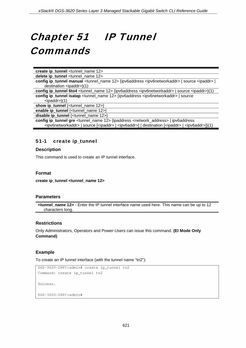
xStack® DGS-3620 Series Layer 3 Managed Stackable Gigabit Switch CLI Reference Guide
621
Chapter 51 IP Tunnel Commands
create ip_tunnel <tunnel_name 12> delete ip_tunnel <tunnel_name 12> config ip_tunnel manual <tunnel_name 12> {ipv6address <ipv6networkaddr> | source <ipaddr> |
destination <ipaddr>}(1) config ip_tunnel 6to4 <tunnel_name 12> {ipv6address <ipv6networkaddr> | source <ipaddr>}(1) config ip_tunnel isatap <tunnel_name 12> {ipv6address <ipv6networkaddr> | source
<ipaddr>}(1) show ip_tunnel {<tunnel_name 12>} enable ip_tunnel {<tunnel_name 12>} disable ip_tunnel {<tunnel_name 12>} config ip_tunnel gre <tunnel_name 12> {ipaddress <network_address> | ipv6address
<ipv6networkaddr> | source [<ipaddr> | <ipv6addr>] | destination [<ipaddr> | <ipv6addr>]}(1)
51-1 create ip_tunnel Description This command is used to create an IP tunnel interface.
Format create ip_tunnel <tunnel_name 12>
Parameters <tunnel_name 12> - Enter the IP tunnel interface name used here. This name can be up to 12
characters long.
Restrictions Only Administrators, Operators and Power-Users can issue this command. (EI Mode Only Command)
Example To create an IP tunnel interface (with the tunnel name “tn2”):
DGS-3620-28PC:admin# create ip_tunnel tn2
Command: create ip_tunnel tn2
Success.
DGS-3620-28PC:admin#

xStack® DGS-3620 Series Layer 3 Managed Stackable Gigabit Switch CLI Reference Guide
622
51-2 delete ip_tunnel Description This command is used to delete an IP tunnel interface.
Format delete ip_tunnel <tunnel_name 12>
Parameters <tunnel_name 12> - Enter the IP tunnel interface name used here. This name can be up to 12
characters long.
Restrictions Only Administrators, Operators and Power-Users can issue this command. (EI Mode Only Command)
Example To delete an IP tunnel interface (with the tunnel name “tn2”):
DGS-3620-28PC:admin# delete ip_tunnel tn2
Command: delete ip_tunnel tn2
Success.
DGS-3620-28PC:admin#
51-3 config ip_tunnel manual Description This command is used to configure an IPv6 manual tunnel. If this tunnel has previously been configured in another mode, the tunnel’s information will still exist in the database. However, whether the tunnel’s former information is invalid or not, will depend on the current mode.
IPv6 Manual tunnels are simple point-to-point tunnels that can be used within a site or between sites.
Format config ip_tunnel manual <tunnel_name 12> {ipv6address <ipv6networkaddr> | source <ipaddr> | destination <ipaddr>}(1)
Parameters <tunnel_name 12> - Enter the IP tunnel interface name used here. This name can be up to 12
characters long. ipv6address - (Optional) Specifies the IPv6 address assigned to the IPv6 tunnel interface. IPv6
processing becomes enabled on the IPv6 tunnel interface when an IPv6 address is configured. The IPv6 address is not connected with the tunnel source or the destination IPv4

xStack® DGS-3620 Series Layer 3 Managed Stackable Gigabit Switch CLI Reference Guide
623
address. <ipv6networkaddr> - Enter the IPv6 address used here.
source - (Optional) Specifies the source IPv4 address of the IPv6 tunnel interface. It is used as the source address for packets in the IPv6 tunnel. <ipaddr> - Enter the IPv4 source address used here.
destination - (Optional) Specifies the destination IPv4 address of the IPv6 tunnel interface. It is used as the destination address for packets in the IPv6 tunnel. It is not required for 6to4 and ISATAP tunnels. <ipaddr> - Enter the IPv4 destination address used here.
Restrictions Only Administrators, Operators and Power-Users can issue this command. (EI Mode Only Command)
Example To configure an IPv6 manual tunnel (Tunnel name is “tn2”, Tunnel source IPv4 address is 1.0.0.1, Tunnel destination IPv4 address is 1.0.0.2, Tunnel IPv6 address is 2001::1/64):
DGS-3620-28PC:admin# config ip_tunnel manual tn2 source 1.0.0.1 destination 1.0.0.2
Command: config ip_tunnel manual tn2 source 1.0.0.1 destination 1.0.0.2
Success.
DGS-3620-28PC:admin# config ip_tunnel manual tn2 ipv6address 2001::1/64
Command: config ip_tunnel manual tn2 ipv6address 2001::1/64
Success.
DGS-3620-28PC:admin#
51-4 config ip_tunnel 6to4 Description This command is used to configure an existing IPv6 tunnel as an IPv6 6to4 tunnel on the switch. If this tunnel has previously been configured in another mode, the tunnel’s information will still exist in the database. However, whether the tunnel’s former information is invalid or not will depend on the current mode. A maximum of one IPv6 6to4 tunnel can exist on the system.
IPv6 6to4 tunnels are point-to-multipoint tunnels that can be used to connect isolated IPv6 sites. Each IPv6 site has at least one connection to a shared IPv4 network and this IPv4 network could be the global Internet or a corporate backbone. The key requirement is that each site has a globally unique IPv4 address, which is used to construct a 48-bit globally unique 6to4 IPv6 prefix (starting with the prefix 2002::/16).
Format config ip_tunnel 6to4 <tunnel_name 12> {ipv6address <ipv6networkaddr> | source <ipaddr>}(1)

xStack® DGS-3620 Series Layer 3 Managed Stackable Gigabit Switch CLI Reference Guide
624
Parameters <tunnel_name 12> - Enter the IP tunnel interface name used here. This name can be up to 12
characters long. ipv6address - (Optional) Specifies the IPv6 address assigned to this IPv6 tunnel interface. IPv6
processing will be enabled on this IPv6 tunnel interface as soon as its IPv6 address is configured. The 32 bits following the initial 2002::/16 prefix correspond to an IPv4 address assigned to the tunnel source. <ipv6networkaddr> - Enter the IPv6 address used here.
source - (Optional) Specifies the IPv4 source address for a packet sent to the remote end of the 6to4 tunnel. The IPv4 destination address for the packet is derived from the IPv6 destination address of the remote destination, which is in the format of a 6to4 address. The address is derived by extracting the 4-octets immediately following the IPv6 destination address's 2002::/16 prefix. For example, a 6to4 address, 2002:c0a8:0001::/48 will be extracted to 192.168.0.1. Any IPv6 address that begins with the 2002::/16 prefix is known as a 6to4 address <ipaddr> - Enter the IPv4 source address used here.
Restrictions Only Administrators, Operators and Power-Users can issue this command. (EI Mode Only Command)
Example To configure an IPv6 6to4 tunnel (Tunnel name is “tn2”, Tunnel source IPv4 address is 10.0.0.1, Tunnel IPv6 address is 2002:a00:1::1/64):
DGS-3620-28PC:admin# config ip_tunnel 6to4 tn2 source 10.0.0.1
Command: config ip_tunnel 6to4 tn2 source 10.0.0.1
Success.
DGS-3620-28PC:admin# config ip_tunnel 6to4 tn2 ipv6address 2002:a00:1::1/64
Command: config ip_tunnel 6to4 tn2 ipv6address 2002:a00:1::1/64
Success.
DGS-3620-28PC:admin#
51-5 config ip_tunnel isatap Description This command is used to configure an existing IPv6 tunnel as an IPv6 ISATAP tunnel on the switch. If this tunnel has previously been configured in another mode, the tunnel’s information will still exist in the database. However, whether the tunnel’s former information is valid or not will depend on the current mode. IPv6 ISATAP tunnels are point-to-multipoint tunnels that can be used to connect systems within a site. An IPv6 ISATAP address is a well-defined unicast address that includes a 64-bit unicast IPv6 prefix (it can be either link-local or global prefixes), a 32-bit value 0000:5EFE/0200:5EFE and a 32-bit tunnel source IPv4 address.

xStack® DGS-3620 Series Layer 3 Managed Stackable Gigabit Switch CLI Reference Guide
625
Format config ip_tunnel isatap <tunnel_name 12> {ipv6address <ipv6networkaddr> | source <ipaddr>}(1)
Parameters <tunnel_name 12> - Enter the IP tunnel interface name used here. This name can be up to 12
characters long. ipv6address - (Optional) Specifies the IPv6 address assigned to this IPv6 tunnel interface. IPv6
processing will be enabled on the IPv6 tunnel interface when an IPv6 address is configured. The last 32 bits of the IPv6 ISATAP address correspond to an IPv4 address assigned to the tunnel source. <ipv6networkaddr> - Enter the IPv6 address used here.
source - (Optional) Specifies the source IPv4 address of this IPv6 tunnel interface. It is used as the source address for packets in the IPv6 tunnel. The tunnel destination IPv4 address is extracted from the last 32 bits of the remote tunnel endpoint’s IPv6 ISATAP address. <ipaddr> - Enter the source IPv4 address used here.
Restrictions Only Administrators, Operators and Power-Users can issue this command. (EI Mode Only Command)
Example To configure an IPv6 ISATAP tunnel (Tunnel name is “tn2”, Tunnel source IPv4 address is 10.0.0.1, Tunnel IPv6 address is 2001::5efe:a00:1/64):
DGS-3620-28PC:admin# config ip_tunnel isatap tn2 source 10.0.0.1
Command: config ip_tunnel isatap tn2 source 10.0.0.1
Success.
DGS-3620-28PC:admin# config ip_tunnel isatap tn2 ipv6address 2001::5efe:a00:1/64
Command: config ip_tunnel isatap tn2 ipv6address 2001::5efe:a00:1/64
Success.
DGS-3620-28PC:admin#
51-6 show ip_tunnel Description This command is used to show one or all IP tunnel interfaces’ information.
Format show ip_tunnel {<tunnel_name 12>}

xStack® DGS-3620 Series Layer 3 Managed Stackable Gigabit Switch CLI Reference Guide
626
Parameters <tunnel_name 12> - (Optional) Enter the IP tunnel interface name used here. This name can be
up to 12 characters long.
Restrictions None. (EI Mode Only Command)
Example To show an IP tunnel interface’s information (Tunnel name is “tn2”):
DGS-3620-28PC:admin# show ip_tunnel tn2
Command: show ip_tunnel tn2
Tunnel Interface : tn2
Interface Admin State : Enabled
Tunnel Mode : Manual
IPv6 Global Unicast Address : 2000::1/64
Tunnel Source : 1.0.0.1
Tunnel Destination : 1.0.0.2
DGS-3620-28PC:admin#
51-7 enable ip_tunnel Description This command is used to enable a single specified IP tunnel or all IP tunnels on the Switch.
Format enable ip_tunnel {<tunnel_name 12>}
Parameters <tunnel_name 12> - (Optional) Enter the IP tunnel interface name used here. This name can be
up to 12 characters long.
Restrictions Only Administrators, Operators and Power-Users can issue this command. (EI Mode Only Command)
Example To enable an IP tunnel interface (Tunnel name is “tn2”):

xStack® DGS-3620 Series Layer 3 Managed Stackable Gigabit Switch CLI Reference Guide
627
DGS-3620-28PC:admin# enable ip_tunnel tn2
Command: enable ip_tunnel tn2
Success.
DGS-3620-28PC:admin#
51-8 disable ip_tunnel Description This command is used to disable a single specified IP tunnel or all IP tunnels on the Switch.
Format disable ip_tunnel {<tunnel_name 12>}
Parameters <tunnel_name 12> - (Optional) Enter the IP tunnel interface name used here. This name can be
up to 12 characters long.
Restrictions Only Administrators, Operators and Power-Users can issue this command. (EI Mode Only Command)
Example To disable an IP tunnel interface (Tunnel name is “tn2”):
DGS-3620-28PC:admin# disable ip_tunnel tn2
Command: disable ip_tunnel tn2
Success.
DGS-3620-28PC:admin#
51-9 config ip_tunnel gre Description This command is used to configure an existing tunnel as a GRE tunnel (IPv6/IPv4-in-IPv4 or IPv6/IPv4-in-IPv6) on the switch. If this tunnel has been configured in another mode before, the tunnel’s information will still exist in the database. However, whether the tunnel’s former information is valid or not, depends on the current mode.
GRE tunnel are simple point-to-point tunnels that can be used within a site or between sites.
When a user wants to configure a GRE IPv6/IPv4-in-IPv4 tunnel, both the source and destination address must be IPv4 addresses because the delivery protocol is the IPv4 protocol. If the source and destination address type are not consistent, then the GRE tunnel will not work.

xStack® DGS-3620 Series Layer 3 Managed Stackable Gigabit Switch CLI Reference Guide
628
When a user wants to configure a GRE IPv6/IPv4-in-IPv6 tunnel, both the source and destination address must be IPv6 addresses because the delivery protocol is the IPv6 protocol. If the source and destination address type are not consistent then the GRE tunnel will not work.
Format config ip_tunnel gre <tunnel_name 12> {ipaddress <network_address> | ipv6address <ipv6networkaddr> | source [<ipaddr> | <ipv6addr>] | destination [<ipaddr> | <ipv6addr>]}(1)
Parameters <tunnel_name 12> - Enter the IP tunnel interface name used here. This name can be up to 12
characters long. ipaddress - (Optional) Specifies the IPv4 address assigned to the GRE tunnel interface. IPv4
processing will be enabled on the IPv4 tunnel interface when an IPv4 address is configured. This IPv4 address is not connected with the tunnel source or destination IPv4 address. <network_address> - Enter the IPv4 network address used here.
ipv6address - (Optional) Specifies the IPv6 address assigned to the GRE tunnel interface. IPv6 processing will be enabled on the IPv6 tunnel interface when an IPv6 address is configured. This IPv6 address is not connected with the tunnel source or destination IPv4 address. <ipv6networkaddr> - Enter the IPv6 network address used here.
source - (Optional) Specifies the source IPv4 or IPv6 address of the GRE tunnel interface. It is used as the source address for packets in the tunnel. The address type that will be used depends on the Delivery Protocol. The address type used at both the source and destination must be consistent, otherwise, the GRE tunnel will not work. <ipaddr> - Enter the IPv4 source address used here. <ipv6addr> - Enter the IPv6 source address used here.
destination - (Optional) Specifies the destination IPv4 or IPv6 address of the GRE tunnel interface. It is used as the destination address for packets in the tunnel. The address type that will be used depends on the Delivery Protocol. The address type used at both the source and destination must be consistent, otherwise, the GRE tunnel will not work. <ipaddr> - Enter the IPv4 destination address used here. <ipv6addr> - Enter the IPv6 destination address used here.
Restrictions Only Administrators, Operators and Power-Users can issue this command. (EI Mode Only Command)
Example To configure a GRE tunnel (tunnel with: the name “tn1”, the delivery protocol as IPv4, tunnel source the IPv4 address 1.0.0.1, the tunnel destination IPv4 address i1.0.0.2, the GRE tunnel interface’s IPv6 address 2001::1/64, and the GRE tunnel interface’s IPv4 address 2.0.0.1/8):

xStack® DGS-3620 Series Layer 3 Managed Stackable Gigabit Switch CLI Reference Guide
629
DGS-3620-28PC:admin# config ip_tunnel gre tn1 source 1.0.0.1 destination 1.0.0.2
Command: config ip_tunnel gre tn1 source 1.0.0.1 destination 1.0.0.2
Success.
DGS-3620-28PC:admin# config ip_tunnel gre tn1 ipaddress 2.0.0.1/8 ipv6address 2001::1/64
Command: config ip_tunnel gre tn1 ipaddress 2.0.0.1/8 ipv6address 2001::1/64
Success.
DGS-3620-28PC:admin#
To display the configuration of a GRE tunnel interface named “tn1”:
DGS-3620-28PC:admin# show ip_tunnel tn1
Command: show ip_tunnel tn1
Tunnel Interface : tn1
Interface Admin State : Enabled
Tunnel Mode : GRE
Ipv4 Address : 2.0.0.1/8
IPv6 Global Unicast Address : 2001::1/64
Tunnel Source : 1.0.0.1
Tunnel Destination : 1.0.0.2
DGS-3620-28PC:admin#
To configure a GRE tunnel (tunnel with: the name “tn2”, the delivery protocol IPv6, tunnel source the IPv6 address 2000::1, the tunnel destination IPv6 address 2000::2, the GRE tunnel interface’s IPv6 address 3001::1/64, the GRE tunnel interface’s IPv4 address 3.0.0.1/8):
DGS-3620-28PC:admin# config ip_tunnel gre tn2 source 2000::1 destination 2000::2
Command: config ip_tunnel gre tn2 source 2000::1 destination 2000::2
Success.
DGS-3620-28PC:admin# config ip_tunnel gre tn2 ipaddress 3.0.0.1/8
Command: config ip_tunnel gre tn2 ipaddress 3.0.0.1/8
Success.
DGS-3620-28PC:admin# config ip_tunnel gre tn2 ipv6address 3001::1/64
Command: config ip_tunnel gre tn2 ipv6address 3001::1/64
Success.
DGS-3620-28PC:admin#
To display the configuration of a GRE tunnel interface named “tn2”:

xStack® DGS-3620 Series Layer 3 Managed Stackable Gigabit Switch CLI Reference Guide
630
DGS-3620-28PC:admin# show ip_tunnel tn2
Command: show ip_tunnel tn2
Tunnel Interface : tn2
Interface Admin State : Enabled
Tunnel Mode : GRE
Ipv4 Address : 3.0.0.1/8
IPv6 Global Unicast Address : 3001::1/64
Tunnel Source : 2000::1
Tunnel Destination : 2000::2
DGS-3620-28PC:admin#
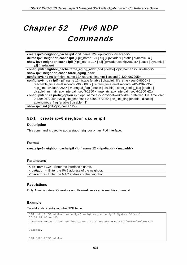
xStack® DGS-3620 Series Layer 3 Managed Stackable Gigabit Switch CLI Reference Guide
631
Chapter 52 IPv6 NDP Commands
create ipv6 neighbor_cache ipif <ipif_name 12> <ipv6addr> <macaddr> delete ipv6 neighbor_cache ipif [<ipif_name 12> | all] [<ipv6addr> | static | dynamic | all] show ipv6 neighbor_cache ipif [<ipif_name 12> | all] [ipv6address <ipv6addr> | static | dynamic |
all] {hardware} config ipv6 neighbor_cache force_aging_addr [add | delete] <ipif_name 12> <ipv6addr> show ipv6 neighbor_cache force_aging_addr config ipv6 nd ns ipif <ipif_name 12> retrans_time <millisecond 0-4294967295> config ipv6 nd ra ipif <ipif_name 12> {state [enable | disable] | life_time <sec 0-9000> |
reachable_time <millisecond 0-3600000> | retrans_time <millisecond 0-4294967295> | hop_limit <value 0-255> | managed_flag [enable | disable] | other_config_flag [enable | disable] | min_rtr_adv_interval <sec 3-1350> | max_rtr_adv_interval <sec 4-1800>}(1)
config ipv6 nd ra prefix_option ipif <ipif_name 12> <ipv6networkaddr> {preferred_life_time <sec 0-4294967295> | valid_life_time <sec 0-4294967295> | on_link_flag [enable | disable] | autonomous_flag [enable | disable]}(1)
show ipv6 nd {ipif <ipif_name 12>}
52-1 create ipv6 neighbor_cache ipif Description This command is used to add a static neighbor on an IPv6 interface.
Format create ipv6 neighbor_cache ipif <ipif_name 12> <ipv6addr> <macaddr>
Parameters <ipif_name 12> - Enter the interface’s name. <ipv6addr> - Enter the IPv6 address of the neighbor. <macaddr> - Enter the MAC address of the neighbor.
Restrictions Only Administrators, Operators and Power-Users can issue this command.
Example To add a static entry into the NDP table:
DGS-3620-28PC:admin#create ipv6 neighbor_cache ipif System 3ffc::1 00:01:02:03:04:05
Command: create ipv6 neighbor_cache ipif System 3FFC::1 00-01-02-03-04-05
Success.
DGS-3620-28PC:admin#

xStack® DGS-3620 Series Layer 3 Managed Stackable Gigabit Switch CLI Reference Guide
632
52-2 delete ipv6 neighbor_cache ipif Description This command is used to delete a neighbor cache entry or static neighbor cache entries from the address cache or all address cache entries on this IP interface. Both static and dynamic entries can be deleted.
Format delete ipv6 neighbor_cache ipif [<ipif_name 12> | all] [<ipv6addr> | static | dynamic | all]
Parameters <ipif_name 12> - Enter the IPv6 interface name. all - Specifies all IPv6 interfaces. <ipv6addr> - Enter the IPv6 address of the neighbor. static - Specifies to delete the IPv6 static entries. dynamic - Specifies to delete the IPv6 dynamic entries. all - Specifies all IPv6 entries, including static and dynamic, to be deleted.
Restrictions Only Administrators, Operators and Power-Users can issue this command.
Example To delete the neighbor cache.entry for IPv6 address 3ffc::1 on the IP interface “System”:
DGS-3620-28PC:admin#delete ipv6 neighbor_cache ipif System 3ffc::1
Command: delete ipv6 neighbor_cache ipif System 3FFC::1
Success.
DGS-3620-28PC:admin#
52-3 show ipv6 neighbor_cache ipif Description This command is used to display the neighbor cache entry for the specified interface. Users can display a specific entry, all static entries, all dynamic entries, or all entries.
Format show ipv6 neighbor_cache ipif [<ipif_name 12> | all] [ipv6address <ipv6addr> | static | dynamic | all ] {hardware}
Parameters <ipif_name 12> - Enter the IPv6 interface name. all - Specifies all the IPv6 interface names.

xStack® DGS-3620 Series Layer 3 Managed Stackable Gigabit Switch CLI Reference Guide
633
ipv6address - Specifies the IPv6 address of the neighbor. <ipv6addr> - Enter the IPv6 address
static - Specifies to display the IPv6 static neighbor cache entries. dynamic - Specifies to display the IPv6 dynamic entries. all - Specifies to display all IPv6 addresses, static and dynamic. hardware - (Optional) Specifies to display all the neighbor cache entries which were written into
the hardware table.
Restrictions None.
Example To display all neighbor cache entries for the IP interface “System”:
DGS-3620-28PC:admin#show ipv6 neighbor_cache ipif System all
Command: show ipv6 neighbor_cache ipif System all
FE80::215:72FF:FE36:104 State: Reachable
MAC Address : 00-15-72-36-01-04 Port : 1:21
Interface : System VID : 1
Total Entries: 1
DGS-3620-28PC:admin#
52-4 config ipv6 neighbor_cache force_aging_addr Description This command is used to configure an IPv6 force aging address in the neighbor cache.
Format config ipv6 neighbor_cache force_aging_addr [add | delete] <ipif_name 12> <ipv6addr>
Parameters add - Specifies to add a new entry. delete - Specifies to delete an existing entry. <ipif_name 12> - Enter the IPv6 interface name here. This name can be up to 12 characters
long. <ipv6addr> - Enter the neighbor’s IPv6 address here.
Restrictions Only Administrators, Operators and Power-Users can issue this command.
Example This example shows how to add a force aging entry for IPv6 address 3FFC::1 on the IP interface “System”.

xStack® DGS-3620 Series Layer 3 Managed Stackable Gigabit Switch CLI Reference Guide
634
DGS-3620-28PC:admin#config ipv6 neighbor_cache force_aging_addr add System 3FFC::1
Command: config ipv6 neighbor_cache force_aging_addr add System 3FFC::1
Success.
DGS-3620-28PC:admin#
52-5 show ipv6 neighbor_cache force_aging_addr Description This command is used to display the IPv6 force aging address in the neighbor cache.
Format show ipv6 neighbor_cache force_aging_addr
Parameters None.
Restrictions None.
Example This example shows how to display all the neighbor cache entries for the IP interface “System”.
DGS-3620-28PC:admin# show ipv6 neighbor_cache force_aging_addr
Command: show ipv6 neighbor_cache force_aging_addr
IPv6 Neighbor Cache Force Aging Address:
10::1 State: No Cache
MAC Address : NA Port : NA
Interface : System VID : 1
10::3 State: No Cache
MAC Address : NA Port : NA
Interface : System VID : 1
Total Entries: 2
DGS-3620-28PC:admin#
52-6 config ipv6 nd ns ipif Description This command is used to configure the NS retransmit time of a specified interface.

xStack® DGS-3620 Series Layer 3 Managed Stackable Gigabit Switch CLI Reference Guide
635
Format config ipv6 nd ns ipif <ipif_name 12> retrans_time <millisecond 0-4294967295>
Parameters <ipif_name 12> - Enter the name of the interface. The maximum length is 12 characters. retrans_time - Specifies the neighbor solicitation’s retransmit timer in milliseconds. It has the
same value as ra retrans_time in the config ipv6 nd ra command. If one is configured, the other will change too. <millisecond 0-4294967295> - Enter the neighbor solicitation’s retransmit timer in
milliseconds. It has the same value as ra retrans_time in the config ipv6 nd ra command. If one is configured, the other will change too. The value is between 0 and 4294967295 milliseconds.
Restrictions Only Administrators, Operators and Power-Users can issue this command.
Example To configure the NS retransmit time of a specified interface:
DGS-3620-28PC:admin#config ipv6 nd ns ipif System retrans_time 400
Command: config ipv6 nd ns ipif System retrans_time 400
Success.
DGS-3620-28PC:admin#
52-7 config ipv6 nd ra ipif Description This command is used to configure the RA parameters of a specified interface.
Format config ipv6 nd ra ipif <ipif_name 12> {state [enable | disable] | life_time <sec 0-9000> | reachable_time <millisecond 0-3600000> | retrans_time <millisecond 0-4294967295> | hop_limit <value 0-255> | managed_flag [enable | disable] | other_config_flag [enable | disable] | min_rtr_adv_interval <sec 3-1350> | max_rtr_adv_interval <sec 4-1800>}(1)
Parameters <ipif_name 12> - Enter the name of the interface. state - Specifies the router advertisement status.
enable - Enable the router advertisement state. disable - Disable the router advertisement state.
life_time - Specifies the lifetime of the router as the default router, in seconds. <sec 0-9000> - Enter the time between 0 and 9000 seconds.
reachable_time - Specifies the amount of time that a node can consider a neighboring node reachable after receiving a reachability confirmation in millisecond.

xStack® DGS-3620 Series Layer 3 Managed Stackable Gigabit Switch CLI Reference Guide
636
<millisecond 0-3600000> - Enter the time between 0 and 3600000 milliseconds. retrans_time - Specifies the amount of time between retransmissions of router advertisement
message in millisecond, and the router advertisement packet will take it to host. <millisecond 0-4294967295> - Enter the time between 0 and 4294967295 milliseconds.
hop_limit - Specifies the default value of the hop limit field in the IPv6 header for packets sent by hosts that receive this RA message. <value 0-255> - Enter the value between 0 and 255.
managed_flag - Specifies to enable or disable the function. enable - When set to enable, it indicates that hosts receiving this RA must use a stateful
address configuration protocol to obtain an address, in addition to the addresses derived from the stateless address configuration.
disable - Set to disable to stop hosts receiving the RA from using a stateful address configuration to obtain an address.
other_config_flag - Specifies to enable or disable the function. enable - When set to enable, it indicates that hosts receiving this RA must use a stateful
address configuration protocol to obtain on-address configuration information. disable - Set to disable to stop hosts receiving this RA from using a stateful address
configuration protocol to obtain on-address configuration information. min_rtr_adv_interval - Specifies the minimum time allowed between sending unsolicited
multicast Router Advertisements from the interface, in seconds. It must be no less than 3 seconds and no greater than .75 * MaxRtrAdvInterval. The default is 0.33 * MaxRtrAdvInterval. <sec 3-1350> - Enter the time between 3 and 1350 seconds.
max_rtr_adv_interval - Specifies the maximum time allowed between sending unsolicited multicast Router Advertisements from the interface, in seconds. It must be no less than 4 seconds and no greater than 1800 seconds. The default is 600 seconds. <sec 4-1800> - Enter the time between 4 and 1800 seconds.
Restrictions Only Administrators, Operators and Power-Users can issue this command.
Example To configure the RA state as enabled and the life_time of the “tiberius” interface to be 1000 seconds:
DGS-3620-28PC:admin#config ipv6 nd ra ipif tiberius state enable life_time 1000
Command: config ipv6 nd ra ipif tiberius state enable life_time 1000
Success.
DGS-3620-28PC:admin#
52-8 config ipv6 nd ra prefix_option ipif Description This command is used to configure the prefix option for the router advertisement function.
Format config ipv6 nd ra prefix_option ipif <ipif_name 12> <ipv6networkaddr> {preferred_life_time <sec 0-4294967295> | valid_life_time <sec 0-4294967295> | on_link_flag [enable | disable] | autonomous_flag [enable | disable]}(1)

xStack® DGS-3620 Series Layer 3 Managed Stackable Gigabit Switch CLI Reference Guide
637
Parameters <ipif_name 12> - Enter the name of the interface. The maximum length is 12 characters. <ipv6networkaddr> - Enter the IPv6 network address. preferred_life_time - Specifies the number in seconds that an address, based on the specified
prefix using the stateless address configuration, remains in preferred state. <sec 0-4294967295> - Enter the time between 0 and 4294967295 seconds. For an infinite
valid lifetime the value can be set to 4294967295. valid_life_time - Specifies the number of seconds that an address, based on the specified prefix,
using the stateless address configuration, remains valid. <sec 0-4294967295> - Enter the time between 0 and 4294967295 seconds. For an infinite
valid lifetime the value can be set to 4294967295. on_link_flag - Specifies to enable or disable the function.
enable - Setting this field to enable will denote, within the IPv6 packet, that the IPv6 prefix configured here is assigned to this link-local network. Once traffic has been successfully sent to these nodes with this specific IPv6 prefix, the nodes will be considered reachable on the link-local network.
disable - When set to disable, the addresses implied by the specified prefix are not available on the link where the RA message is received.
autonomous_flag - Specifies to enable or disable the function. enable - Setting this field to enable will denote that this prefix may be used to autoconfigure
IPv6 addresses on the link-local network. disable - When set to disable, the specified prefix will not be used to create an autonomous
address configuration.
Restrictions Only Administrators, Operators and Power-Users can issue this command.
Example To configure the value of the preferred_life_time of prefix option to be 1000 seconds for the prefix 3ffe:501:ffff:100::/64, which is the prefix of the ip1 interface:
DGS-3620-28PC:admin#config ipv6 nd ra prefix_option ipif ip1 3ffe:501:ffff:100::/64 preferred_life_time 1000
Command: config ipv6 nd ra prefix_option ipif ip1 3ffe:501:ffff:100::/64 preferred_life_time 1000
Success.
DGS-3620-28PC:admin#
52-9 show ipv6 nd Description This command is used to display IPv6 Neighbor Discover related configuration.
Format show ipv6 nd {ipif <ipif_name 12>}
Parameters ipif - (Optional) Specifies the interface name.

xStack® DGS-3620 Series Layer 3 Managed Stackable Gigabit Switch CLI Reference Guide
638
<ipif_name 12> - Enter the interface name. The maximum length is 12 characters.
Note: If no IP interface is specified, the IPv6 ND related configuration of all interfaces will
be displayed.
Restrictions Only Administrators, Operators and Power-Users can issue this command.
Example To display IPv6 Neighbor Discover related configuration:
DGS-3620-28PC:admin#show ipv6 nd ipif System
Command: show ipv6 nd ipif System
Interface Name : System
Hop Limit : 64
NS Retransmit Time : 400 (ms)
Router Advertisement : Disabled
RA Max Router AdvInterval : 600 (sec)
RA Min Router AdvInterval : 198 (sec)
RA Router Life Time : 1800 (sec)
RA Reachable Time : 1200000 (ms)
RA Retransmit Time : 400 (ms)
RA Managed Flag : Disabled
RA Other Configuration Flag : Disabled
Prefix Preferred Valid OnLink Autonomous
1000:A111:B111:C111::/64 604800 2592000 Enabled Enabled
DGS-3620-28PC:admin#

xStack® DGS-3620 Series Layer 3 Managed Stackable Gigabit Switch CLI Reference Guide
639
Chapter 53 IP-MAC-Port Binding (IMPB) Commands
create address_binding ip_mac ipaddress <ipaddr> mac_address <macaddr> {ports[<portlist>|
all ]} create address_binding ip_mac ipv6address <ipv6addr> mac_address <macaddr> {ports
[<portlist> | all]} config address_binding ip_mac ports [<portlist> | all] {arp_inspection [strict | loose | disable] |
ip_inspection [enable | disable] | nd_inspection [enable | disable] | protocol [ipv4 | ipv6 | all] | allow_zeroip [enable | disable] | forward_dhcppkt [enable | disable] | stop_learning_threshold <int 0-500>}(1)
config address_binding ip_mac ipaddress <ipaddr> mac_address <macaddr> {ports [<portlist> | all]}
config address_binding ip_mac ipv6address <ipv6addr> mac_address <macaddr> {ports [<portlist> | all]}
delete address_binding blocked [all | vlan_name <vlan_name> mac_address <macaddr>] delete address_binding ip_mac [all | ipaddress <ipaddr> mac_address <macaddr> | ipv6address
<ipv6addr> mac_address <macaddr>] show address_binding {ports {<portlist>}} show address_binding blocked [all | vlan_name <vlan_name> mac_address <macaddr>] show address_binding ip_mac [all | [[ipaddress <ipaddr> | ipv6address <ipv6addr>]
{mac_address <macaddr>} | mac_address <macaddr>]] enable address_binding trap_log disable address_binding trap_log enable address_binding dhcp_snoop {[ipv6 | all]} disable address_binding dhcp_snoop {[ipv6 | all]} clear address_binding dhcp_snoop binding_entry ports [<portlist> | all] {[ipv6 | all]} show address_binding dhcp_snoop {max_entry {ports <portlist>}} show address_binding dhcp_snoop binding_entry {port <port>} show address_binding dhcp_snoop limit_rate {ports <portlist>} config address_binding dhcp_snoop max_entry ports [<portlist> | all] limit [<value 1-50> |
no_limit] {ipv6} config address_binding recover_learning ports [<portlist> | all] enable address_binding nd_snoop disable address_binding nd_snoop config address_binding nd_snoop ports [<portlist> | all] max_entry [<value 1-50> | no_limit] show address_binding nd_snoop {ports <portlist>} show address_binding nd_snoop binding_entry {port <port>} clear address_binding nd_snoop binding_entry ports [<portlist> | all] config address_binding dhcp_snoop_entry filename <path_filename 64> {autosave [enable |
disable]} enable address_binding roaming disable address_binding roaming download address_binding snoop_entry_fromTFTP [<ipaddr> | <ipv6addr> | <domain_name
255>] filename <path_filename 64> upload address_binding snoop_entry_toTFTP [<ipaddr> | <ipv6addr> | <domain_name 255>]
filename <path_filename 64> save dhcp_snoop_entry config address_binding dhcp snooping ports [<portlist> | all] limit [rate <value 1-2048> mode
[drop | shutdown] | no_limit] config address_binding dhcp snooping recovery_timer [<sec 60-1000000> | infinite] download address_binding snoop_entry_fromFTP [<ipaddr> {tcp_port <tcp_port_number 1-
65535>} filename <path_filename 64> | ftp: <string

xStack® DGS-3620 Series Layer 3 Managed Stackable Gigabit Switch CLI Reference Guide
640
user:pasword@ipaddr:tcpport/path_filename>] upload address_binding snoop_entry_toFTP [<ipaddr> {tcp_port <tcp_port_number 1-65535>}
filename <path_filename 64> | ftp: <string user:pasword@ipaddr:tcpport/path_filename>]
53-1 create address_binding ip_mac ipaddress Description This command is used to create an IP-MAC-Port binding entry.
Format create address_binding ip_mac ipaddress <ipaddr> mac_address <macaddr> {ports[<portlist>| all ]}
Parameters <ipaddr> - Enter the IP address. mac_address - Specifies the MAC address.
<macaddr> - Enter the MAC address here. ports - (Optional) Configure the portlist or all ports.
<portlist> - Enter a range of ports to be configured. all - Specifies to apply to all the ports.
Restrictions Only Administrators, Operators and Power-Users can issue this command.
Example To create address binding on the switch:
DGS-3620-28PC:admin#create address_binding ip_mac ipaddress 10.1.1.1 mac_address 00-00-00-00-00-11
Command: create address_binding ip_mac ipaddress 10.1.1.1 mac_address 00-00-00-00-00-11
Success.
DGS-3620-28PC:admin#
53-2 create address_binding ip_mac ipv6address Description This command is used to create an IP-MAC-Port binding entry using IPv6.
Format create address_binding ip_mac ipv6address <ipv6addr> mac_address <macaddr> {ports [<portlist> | all]}

xStack® DGS-3620 Series Layer 3 Managed Stackable Gigabit Switch CLI Reference Guide
641
Parameters <ipv6addr> - Enter the IPv6 address. mac_address - Specifies the MAC address.
<macaddr> - Enter the MAC address here. ports - (Optional) Configure the portlist or all ports.
<portlist> - Enter a range of ports to be configured. all - Specifies to apply to all the ports.
Restrictions Only Administrators, Operators and Power-Users can issue this command.
Example To create a static IPv6 IMPB entry that binds the IPv6 address fe80::240:5ff:fe00:28 to the MAC address 00-00-00-00-00-11:
DGS-3620-28PC:admin# create address_binding ip_mac ipv6address fe80::240:5ff:fe00:28 mac_address 00-00-00-00-00-11
Command: create address_binding ip_mac ipv6address fe80::240:5ff:fe00:28 mac_address 00-00-00-00-00-11
Success.
DGS-3620-28PC:admin#
53-3 config address_binding ip_mac ports Description This command is used to configure the per port state of IP-MAC-Port binding in the switch. If a port has been configured as group member of an aggregated link, then it can not enable its IP-MAC-Port binding function. When the binding check state is enabled, for IP packet and ARP packet received by this port, the switch will check whether the the IP address and MAC address match the binding entries. The packets will be dropped if they do not match. For this function, the switch can operate in ARP Inspection and IP Inspection.
ARP Inspection: All ARP packets will be checked while ARP Inspection is enabled. The legal ARP packets will be forwarded, while the illegal ARP packets will be dropped.
IP Inspection: All IP packets will be checked while IP Inspection is enabled. The legal IP packets will be forwarded, while the illegal IP packets will be dropped. When IP Inspection is enabled, and ARP Inspection is disabled, all non-IP packets (L2 packets, ARP…) will be forwarded by default.
Format config address_binding ip_mac ports [<portlist> | all] {arp_inspection [strict | loose | disable] | ip_inspection [enable | disable] | nd_inspection [enable | disable] | protocol [ipv4 | ipv6 | all] | allow_zeroip [enable | disable] | forward_dhcppkt [enable | disable] | stop_learning_threshold <int 0-500>}(1)
Parameters <portlist> - Enter a range of ports to configure.

xStack® DGS-3620 Series Layer 3 Managed Stackable Gigabit Switch CLI Reference Guide
642
all - Specifies to configure all ports. arp_inspection - (Optional) Specifies that when the ARP inspection function is enabled, the legal
ARP packets wil be forwarded, while the illegal packets will be dropped. strict - Specifies that in this mode, all packets are dropped by default until a legal ARP or IP
packet is detected. loose - Specifies that in this mode, all packets are forwarded by default until an illegal ARP or
broadcast IP packet is detected. disable - Disable the ARP inspection function. The default value is disable.
ip_inspection - (Optional) Specifies the IP inspection function state. enable - Specifies to enable the IP inspection function. The legal IP packets will be forwarded,
while the illegal IP packets will be dropped. disable - Specifies to disable the IP inspection function. The default value is disable.
nd_inspection - Specifies the ports’ ND inspection state. enable - Specifies to enable the ND inspection function. The legal ND packets will be
forwarded, while the illegal packets will be dropped. disable - Specifies to disable the ND inspection function. The default value is disabled.
protocol - (Optional) Specifies the IP protocoal of the packets that will be checked. ipv4 - Specifies that only IPv4 packets will be checked. ipv6 - Specifies that only IPv6 packets will be checked. all - Specifies that both IPv4 and IPv6 packets will be checked.
allow_zeroip - (Optional) Specifies whether to allow ARP packets with SIP address 0.0.0.0. enable - If 0.0.0.0 is not configured in the binding list, when it is set to enabled, the ARP
packet with this source IP address 0.0.0.0 will be allowed. disable - When set to disable, this option does not affect the IP-MAC-port binding IP
Inspection. forward_dhcppkt - (Optional) By default, the DHCP packets with broadcast DA will be flooded.
enable - This setting is effective when DHCP snooping is enabled because the DHCP packet which has been trapped to CPU needs to be forwarded by the software. This setting controls the forwarding behaviour under this situation.
disable - When set to disable, the broadcast DHCP packets received by the specified port will not be forwarded.
stop_learning_threshold - (Optional) Enter the stop learning threshold value here. <int 0-500> - The stop learning threshold value must be between 0 and 500.
Restrictions Only Administrators, Operators and Power-Users can issue this command.
Example To configure port 1 to be enabled for address binding:
DGS-3620-28PC:admin# config address_binding ip_mac ports 1 arp_inspection strict ip_inspection enable protocol ipv4
Command: config address_binding ip_mac ports 1 arp_inspection strict ip_inspection enable protocol ipv4
Success.
DGS-3620-28PC:admin#
53-4 config address_binding ip_mac ipaddress Description This command is used to update an address binding entry.

xStack® DGS-3620 Series Layer 3 Managed Stackable Gigabit Switch CLI Reference Guide
643
Format config address_binding ip_mac ipaddress <ipaddr> mac_address <macaddr> {ports [<portlist>| all ]}
Parameters <ipaddr> - Enter the IP address. mac_address - Specifies the MAC address.
<macaddr> - Enter the MAC address here. ports - (Optional) Configure the portlist to apply, if ports are not configured, then it will apply to all
ports. <portlist> - Enter the list of ports to apply. all - Specifies to apply to all the ports.
Restrictions Only Administrators, Operators and Power-Users can issue this command.
Example To configure an address binding entry:
DGS-3620-28PC:admin#config address_binding ip_mac ipaddress 10.1.1.1 mac_address 00-00-00-00-00-11
Command: config address_binding ip_mac ipaddress 10.1.1.1 mac_address 00-00-00-00-00-11
Success.
DGS-3620-28PC:admin#
53-5 config address_binding ip_mac ipv6address Description This command is used to update an address binding entry using IPv6.
Format config address_binding ip_mac ipv6address <ipv6addr> mac_address <macaddr> {ports [<portlist> | all]}
Parameters ipv6address - Specifies the IPv6 address used.
<ipv6addr> - Enter the IPv6 address used here. mac_address - Specifies the MAC address.
<macaddr> - Enter the MAC address here. ports - (Optional) Configure the portlist to apply, if ports are not configured, then it will apply to all
ports. <portlist> - Enter the list of ports to apply. all - Specifies to apply to all the ports.

xStack® DGS-3620 Series Layer 3 Managed Stackable Gigabit Switch CLI Reference Guide
644
Restrictions Only Administrators, Operators and Power-Users can issue this command.
Example To configure a static IPv6 IMPB entry so that that IPv6 address fe80::240:5ff:fe00:28 is bound to the MAC address 00-00-00-00-00-11:
DGS-3620-28PC:admin# config address_binding ip_mac ipv6address fe80::240:5ff:fe00:28 mac_address 00-00-00-00-00-11
Command: config address_binding ip_mac ipv6address fe80::240:5ff:fe00:28 mac_address 00-00-00-00-00-11
Success.
DGS-3620-28PC:admin#
53-6 delete address_binding blocked Description This command is used to delete a blocked entry. It specifies the address database that the system has automatically learned and blocked.
Format delete address_binding blocked [all | vlan_name <vlan_name> mac_address <macaddr>]
Parameters all - Specifies that all the blocked MAC addresses will be used. vlan_name - Specifies the name of the VLAN that the blocked MAC address belongs to.
<vlan_name> - Enter the VLAN name used here. mac_address - Specifies the MAC address of the blocked MAC address.
<macaddr> - Enter the MAC address used here.
Restrictions Only Administrators, Operators and Power-Users can issue this command.
Example To delete the blocked MAC address 00-00-00-00-00-11, which belongs to the VLAN named “v31”:
DGS-3620-28PC:admin# delete address_binding blocked vlan_name v31 mac_address 00-00-00-00-00-11
Command: delete address_binding blocked vlan_name v31 mac_address 00-00-00-00-00-11
Success.
DGS-3620-28PC:admin#

xStack® DGS-3620 Series Layer 3 Managed Stackable Gigabit Switch CLI Reference Guide
645
53-7 delete address_binding ip_mac Description This command is used to delete an IMPB entry.
Format delete address_binding ip_mac [all | ipaddress <ipaddr> mac_address <macaddr> | ipv6address <ipv6addr> mac_address <macaddr>]
Parameters all - Specifies that all the MAC addresses will be used. vlan_name - Specifies the name of the VLAN that the MAC address belongs to.
<vlan_name> - Enter the VLAN name used here. mac_address - Specifies the MAC address of the IMPB entry.
<macaddr> - Enter the MAC address of the IMPB entry here. ipv6address - Specifies the IPv6 address of the IMPB entry.
<ipv6addr> - Enter the IPv6 address of the IMPB entry here. mac_address - Specifies the MAC address of the IMPB entry.
<macaddr> - Enter the MAC address of the IMPB entry here.
Restrictions Only Administrators, Operators and Power-Users can issue this command.
Example To delete an IMPB entry that binds the IP address 10.0.0.0.1 to the MAC address 00-00-00-00-00-11:
DGS-3620-28PC:admin# delete address_binding ip_mac ipaddress 10.0.0.1 mac_address 00-00-00-00-00-11
Command: delete address_binding ip_mac ipaddress 10.0.0.1 mac_address 00-00-00-00-00-11
Success.
DGS-3620-28PC:admin#
To delete a static ipv6 IMPB entry that binds the IPv6 address fe80::240:5ff:fe00:28 to the MAC address 00-00-00-00-00-11:
DGS-3620-28PC:admin# delete address_binding ip_mac ipv6address fe80::240:5ff:fe00:28 mac_address 00-00-00-00-00-11
Command: delete address_binding ip_mac ipv6address fe80::240:5ff:fe00:28 mac_address 00-00-00-00-00-11
Success.
DGS-3620-28PC:admin#

xStack® DGS-3620 Series Layer 3 Managed Stackable Gigabit Switch CLI Reference Guide
646
53-8 show address_binding Description This command is used to display address binding information.
Format show address_binding {ports {<portlist>}}
Parameters ports – (Optional) Specifies to display the state of IP MAC port binding for all ports.
<portlist> - Enter the list of ports for the display here.
Restrictions None.
Example To display address binding information:
DGS-3620-28PC:admin#show address_binding
Command: show address_binding
Roaming state : Enabled
Trap/Log : Disabled
DHCP Snoop(IPv4) : Disabled
DHCP Snoop(IPv6) : Disabled
ND Snoop : Disabled
Autosave state : Enabled
Save Filename : dhcpsnp.cfg
Function Version : 3.96
DGS-3620-28PC:admin#
To display address binding information for ports 1 to 10:
DGS-3620-28PC:admin#show address_binding ports 1:1-1:10
Command: show address_binding ports 1:1-1:10
ARP:ARP Inspection IP:IP Inspection ND:ND Inspection Prot:Protocol
Port ARP IP ND Prot Zero IP DHCP Packet Stop Learning
Threshold/Mode
----- -------- -------- -------- ---- --------- ----------- --------------
1:1 Disabled Disabled Disabled All Not Allow Forward 500/Normal
1:2 Disabled Disabled Disabled All Not Allow Forward 500/Normal
1:3 Disabled Disabled Disabled All Not Allow Forward 500/Normal
1:4 Disabled Disabled Disabled All Not Allow Forward 500/Normal
1:5 Disabled Disabled Disabled All Not Allow Forward 500/Normal
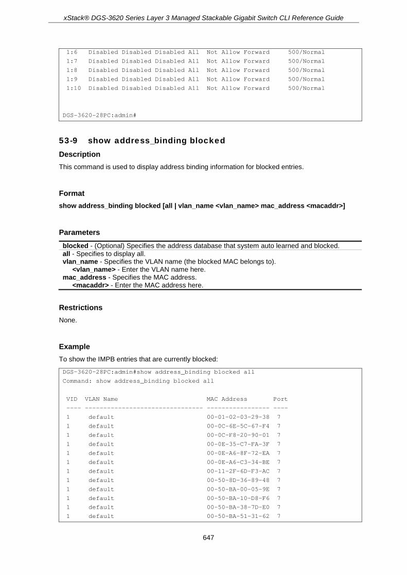
xStack® DGS-3620 Series Layer 3 Managed Stackable Gigabit Switch CLI Reference Guide
647
1:6 Disabled Disabled Disabled All Not Allow Forward 500/Normal
1:7 Disabled Disabled Disabled All Not Allow Forward 500/Normal
1:8 Disabled Disabled Disabled All Not Allow Forward 500/Normal
1:9 Disabled Disabled Disabled All Not Allow Forward 500/Normal
1:10 Disabled Disabled Disabled All Not Allow Forward 500/Normal
DGS-3620-28PC:admin#
53-9 show address_binding blocked Description This command is used to display address binding information for blocked entries.
Format show address_binding blocked [all | vlan_name <vlan_name> mac_address <macaddr>]
Parameters blocked - (Optional) Specifies the address database that system auto learned and blocked. all - Specifies to display all. vlan_name - Specifies the VLAN name (the blocked MAC belongs to).
<vlan_name> - Enter the VLAN name here. mac_address - Specifies the MAC address.
<macaddr> - Enter the MAC address here.
Restrictions None.
Example To show the IMPB entries that are currently blocked:
DGS-3620-28PC:admin#show address_binding blocked all
Command: show address_binding blocked all
VID VLAN Name MAC Address Port
---- -------------------------------- ----------------- ----
1 default 00-01-02-03-29-38 7
1 default 00-0C-6E-5C-67-F4 7
1 default 00-0C-F8-20-90-01 7
1 default 00-0E-35-C7-FA-3F 7
1 default 00-0E-A6-8F-72-EA 7
1 default 00-0E-A6-C3-34-BE 7
1 default 00-11-2F-6D-F3-AC 7
1 default 00-50-8D-36-89-48 7
1 default 00-50-BA-00-05-9E 7
1 default 00-50-BA-10-D8-F6 7
1 default 00-50-BA-38-7D-E0 7
1 default 00-50-BA-51-31-62 7
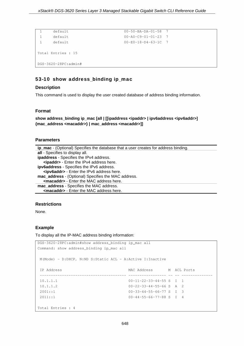
xStack® DGS-3620 Series Layer 3 Managed Stackable Gigabit Switch CLI Reference Guide
648
1 default 00-50-BA-DA-01-58 7
1 default 00-A0-C9-01-01-23 7
1 default 00-E0-18-D4-63-1C 7
Total Entries : 15
DGS-3620-28PC:admin#
53-10 show address_binding ip_mac Description This command is used to display the user created database of address binding information.
Format show address_binding ip_mac [all | [[ipaddress <ipaddr> | ipv6address <ipv6addr>] {mac_address <macaddr>} | mac_address <macaddr>]]
Parameters ip_mac - (Optional) Specifies the database that a user creates for address binding. all - Specifies to display all. ipaddress - Specifies the IPv4 address.
<ipaddr> - Enter the IPv4 address here. ipv6address - Specifies the IPv6 address.
<ipv6addr> - Enter the IPv6 address here. mac_address - (Optional) Specifies the MAC address.
<macaddr> - Enter the MAC address here. mac_address - Specifies the MAC address.
<macaddr> - Enter the MAC address here.
Restrictions None.
Example To display all the IP-MAC address binding information:
DGS-3620-28PC:admin#show address_binding ip_mac all
Command: show address_binding ip_mac all
M(Mode) - D:DHCP, N:ND S:Static ACL - A:Active I:Inactive
IP Address MAC Address M ACL Ports
--------------------------------------- ----------------- -- -- --------------
10.1.1.1 00-11-22-33-44-55 S I 1
10.1.1.2 00-22-33-44-55-66 S A 2
2001::1 00-33-44-55-66-77 S I 3
2011::1 00-44-55-66-77-88 S I 4
Total Entries : 4

xStack® DGS-3620 Series Layer 3 Managed Stackable Gigabit Switch CLI Reference Guide
649
DGS-3620-28PC:admin#
To display the IMPB entry by IP address and MAC address:
DGS-3620-28PC:admin# show address_binding ip_mac ipaddress 10.1.1.1 mac_address 00-00-00-00-00-11
Command: show address_binding ip_mac ipaddress 10.1.1.1 mac_address 00-00-00-00-00-11
M(Mode) – D:DHCP,N:ND,S:Static ACL - A:Active I:Inactive
IP Address MAC Address M ACL Ports
--------------------------------------- ----------------- -- -- --------------
10.1.1.1 00-00-00-00-00-11 S I 1,3,5,7,8
Total Entries : 1
DGS-3620-28PC:admin#
53-11 enable address_binding trap_log Description This command is used to send trap and log messages when an address binding module detects illegal IP and MAC addresses.
Format enable address_binding trap_log
Parameters None.
Restrictions Only Administrators, Operators and Power-Users can issue this command.
Example To enable the address binding trap and log:
DGS-3620-28PC:admin#enable address_binding trap_log
Command: enable address_binding trap_log
Success.
DGS-3620-28PC:admin#

xStack® DGS-3620 Series Layer 3 Managed Stackable Gigabit Switch CLI Reference Guide
650
53-12 disable address_binding trap_log Description This command is used to disable address binding trap logs.
Format disable address_binding trap_log
Parameters None.
Restrictions Only Administrators, Operators and Power-Users can issue this command.
Example To disable the address binding trap and log:
DGS-3620-28PC:admin#disable address_binding trap_log
Command: disable address_binding trap_log
Success.
DGS-3620-28PC:admin#
53-13 enable address_binding dhcp_snoop Description This command is used to enable the address binding DHCP snooping mode. By default, DHCP snooping is disabled. If a user enables DHCP snooping, all address binding disabled ports will function as server ports (the switch will learn IP addresses through server ports (by DHCP OFFER and DHCP ACK packets)). Note that the DHCP discover packet can not be passed through the user ports if the ‘forward_dhcppkt’ function is disabled on this port.
The auto-learned IP-MAC-Port binding entry will be mapped to a specific source port based on the MAC address learning function. This entry will be created as an binding entry for this specific port. Each entry is associated with a lease time. When the lease time expires, the expired entry will be removed from this port. The auto-learned binding entry can be moved from one port to another port if the DHCP snooping function has learned that the MAC address has moved to a different port.
Consider the case in which a binding entry learned by DHCP snooping conflicts with the statically configured entry. This means that the binding relation is in conflict. For example, if IP A is binded with MAC X by static configuration, suppose that the binding entry learned by DHCP snooping is IP A binded by MAC Y, then there is a conflict. When the DHCP snooping learned entry is binded with the static configured entry, then the DHCP snooping learned entry will not be created.
Consider the other conflict case, when the DHCP snooping learned a binding entry, and the same IP-MAC-Port binding pair has been statically configured. If the learned information is consistent with the statically configured entry, then the auto-learned entry will not be created. If the entry is

xStack® DGS-3620 Series Layer 3 Managed Stackable Gigabit Switch CLI Reference Guide
651
statically configured in ARP table, then the auto learned entry will not be created. If the entry is statically configured on one port and the entry is auto-learned on another port, then the auto-learned entry will not be created either.
Format enable address_binding dhcp_snoop {[ipv6 | all]}
Parameters ipv6 – (Optional) Specifies that the address used is an IPv6 address. all – (Optional) Specifies that all IP addresses will be used.
Restrictions Only Administrators, Operators and Power-Users can issue this command.
Example To enable the address binding DHCP snooping mode:
DGS-3620-28PC:admin#enable address_binding dhcp_snoop
Command: enable address_binding dhcp_snoop
Success.
DGS-3620-28PC:admin#
53-14 disable address_binding dhcp_snoop Description This command is used to disable address binding DHCP snooping. When DHCP snooping is disabled, all of the auto-learned binding entries will be removed.
Format disable address_binding dhcp_snoop {[ipv6 | all]}
Parameters ipv6 – (Optional) Specifies that the address used is an IPv6 address. all – Specifies that all IP addresses will be used.
Restrictions Only Administrators, Operators and Power-Users can issue this command.
Example To disable the address binding DHCP snooping mode:

xStack® DGS-3620 Series Layer 3 Managed Stackable Gigabit Switch CLI Reference Guide
652
DGS-3620-28PC:admin#disable address_binding dhcp_snoop
Command: disable address_binding dhcp_snoop
Success.
DGS-3620-28PC:admin#
53-15 clear address_binding dhcp_snoop binding_entry ports Description This command is used to clear the address binding entries learned for the specified ports.
Format clear address_binding dhcp_snoop binding_entry ports [<portlist> | all] {[ipv6 | all]}
Parameters <portlist> - Enter the list of ports to clear the DHCP-snoop learned entry. all - Specifies to clear the address binding entries learned for all ports. ipv6 – (Optional) Specifies that the address used is an IPv6 address. all – Specifies that all IPv6 addresses will be used.
Restrictions Only Administrators, Operators and Power-Users can issue this command.
Example To clear the address binding entries for ports 1 to 3:
DGS-3620-28PC:admin# clear address_binding dhcp_snoop binding_entry ports 1-3
Command: clear address_binding dhcp_snoop binding_entry ports 1-3
Success.
DGS-3620-28PC:admin#
53-16 show address_binding dhcp_snoop Description This command is used to display DHCP snooping information.
Format show address_binding dhcp_snoop {max_entry {ports <portlist>}}
Parameters max_entry - (Optional) Specifies to display the maximum number of entries.

xStack® DGS-3620 Series Layer 3 Managed Stackable Gigabit Switch CLI Reference Guide
653
ports - (Optional) Specifies a range of ports. <portlist> - Enter a range of ports to be displayed.
Restrictions None.
Example To display address binding DHCP snooping:
DGS-3620-28PC:admin#show address_binding dhcp_snoop
Command: show address_binding dhcp_snoop
DHCP Snoop(IPv4) : Disabled
DHCP Snoop(IPv6) : Disabled
DGS-3620-28PC:admin#
To display the address binding DHCP snooping maximum entries on port 1 to 10:
DGS-3620-28PC:admin#show address_binding dhcp_snoop max_entry ports 1-10
Command: show address_binding dhcp_snoop max_entry ports 1-10
Port Max Entry Max IPv6 Entry
---- --------- --------------
1 No Limit No Limit
2 10 No Limit
3 20 No Limit
4 No Limit No Limit
5 No Limit No Limit
6 No Limit No Limit
7 No Limit No Limit
8 No Limit No Limit
9 No Limit No Limit
10 No Limit No Limit
DGS-3620-28PC:admin#
53-17 show address_binding dhcp_snoop binding_entry Description This command is used to display DHCP snooping information of a specific binding entry.
Format show address_binding dhcp_snoop binding_entry {port <port>}
Parameters port - (Optional) Specifies a port on which to display the binding entry.

xStack® DGS-3620 Series Layer 3 Managed Stackable Gigabit Switch CLI Reference Guide
654
<port> - Enter the port number here.
Restrictions None.
Example To display the DHCP snooping binding entries:
DGS-3620-28PC:admin# show address_binding dhcp_snoop binding_entry
Command: show address_binding dhcp_snoop binding_entry
S (Status) - A: Active, I: Inactive
Time - Left Time (sec)
IP Address MAC Address S LT(sec) Port
--------------------------------------- ----------------- -- ---------- -----
10.62.58.35 00-0B-5D-05-34-0B A 35964 1
10.33.53.82 00-20-c3-56-b2-ef I 2590 2
2001:2222:1111:7777:5555:6666:7777:8888 00-00-00-00-00-02 I 50 5
2001::1 00-00-00-00-03-02 A 100 6
Total entries : 4
DGS-3620-28PC:admin#
Note: “Inactive” indicates that the entry is currently inactive due to port link down.
53-18 show address_binding dhcp_snoop limit_rate Description This command is used to display the DHCP snooping limit rate entries.
Format show address_binding dhcp_snoop limit_rate {ports <portlist>}
Parameters port – (Optional) Specifies the port used for this configuration.
<port> - Enter the port number used here.
Restrictions None.
Example To display the DHCP snooping limit rate entries on ports 1 to 10:

xStack® DGS-3620 Series Layer 3 Managed Stackable Gigabit Switch CLI Reference Guide
655
DGS-3620-28PC:admin# show address_binding dhcp_snoop limit_rate ports 1:1-1:10
Command: show address_binding dhcp_snoop limit_rate ports 1:1-1:10
Port Rate Limit (pps) Action
------ ---------------- ---------
1:1 No Limit -
1:2 No Limit -
1:3 No Limit -
1:4 No Limit -
1:5 No Limit -
1:6 No Limit -
1:7 No Limit -
1:8 No Limit -
1:9 No Limit -
1:10 No Limit -
DGS-3620-28PC:admin#
53-19 config address_binding dhcp_snoop max_entry ports Description This command is used to specifiy the maximum number of entries which can be learned by the specified ports. By default, the per port maximum entry is no limit.
Format config address_binding dhcp_snoop max_entry ports [<portlist> | all] limit [<value 1-50> | no_limit] {ipv6}
Parameters <portlist> - Enter the list of ports to configure maximum number of entries. all - Specifies all the ports to configure maximum number of entries. limit - Specifies the maximum number of entries which can be learned by the specified ports.
<value 1-50> - Enter a maximum limit between 1 and 50. no_limit - Specifies an unlimited number of entries.
ipv6 – (Optional) Specifies that the configuration is for IPv6 DHCP Snooping.
Restrictions Only Administrators, Operators and Power-Users can issue this command.
Example To set the maximum number of entries that ports 1 to 3 can learn to 10:
DGS-3620-28PC:admin#config address_binding dhcp_snoop max_entry ports 1-3 limit 10
Command: config address_binding dhcp_snoop max_entry ports 1-3 limit 10
Success.

xStack® DGS-3620 Series Layer 3 Managed Stackable Gigabit Switch CLI Reference Guide
656
DGS-3620-28PC:admin#
53-20 config address_binding recover_learning ports Description This command is used to recover port learning.
Format config address_binding recover_learning ports [<portlist> | all]
Parameters <portlist> - Enter the list of ports to recover learning. all - Specifies to recover learning for all ports.
Restrictions Only Administrators, Operators and Power-Users can issue this command.
Example To configure ports 1 to 3 to recover learning:
DGS-3620-28PC:admin#config address_binding recover_learning ports 1-3
Command: config address_binding recover_learning ports 1-3
Success.
DGS-3620-28PC:admin#
53-21 enable address_binding nd_snoop Description This command is used to enable ND snooping on the Switch.
Format enable address_binding nd_snoop
Parameters None.
Restrictions Only Administrators, Operators and Power-Users can issue this command.

xStack® DGS-3620 Series Layer 3 Managed Stackable Gigabit Switch CLI Reference Guide
657
Example To enable the ND snooping function on the Switch:
DGS-3620-28PC:admin# enable address_binding nd_snoop
Command: enable address_binding nd_snoop
Success.
DGS-3620-28PC:admin#
53-22 disable address_binding nd_snoop Description This command is used to disable ND snooping on the Switch.
Format disable address_binding nd_snoop
Parameters None.
Restrictions Only Administrators, Operators and Power-Users can issue this command.
Example To disable the DHCPv6 snooping function on the Switch:
DGS-3620-28PC:admin# disable address_binding nd_snoop
Command: disable address_binding nd_snoop
Success.
DGS-3620-28PC:admin#
53-23 config address_binding nd_snoop ports Description This command is used to specify the maximum number of entries that can be learned with ND snooping.
Format config address_binding nd_snoop ports [<portlist> | all] max_entry [<value 1-50> | no_limit]

xStack® DGS-3620 Series Layer 3 Managed Stackable Gigabit Switch CLI Reference Guide
658
Parameters ports - Specifies the list of ports used for this configuration.
<portlist> - Enter the list of ports used for this configuration here. all - Specifies that all the ports will be usd for this configuration.
max_entry - Specifies the maximum number of entries. <value 1-50> - Enter the maximum number of entries used here. This value must be between
1 and 50. no_limit - Specifies that the maximum number of learned entries is unlimited.
Restrictions Only Administrators, Operators and Power-Users can issue this command.
Example To specify that a maximum of 10 entries can be learned by ND snooping on ports 1–3:
DGS-3620-28PC:admin# config address_binding nd_snoop ports 1-3 max_entry 10
Command: config address_binding nd_snoop ports 1-3 max_entry 10
Success.
DGS-3620-28PC:admin#
53-24 show address_binding nd_snoop Description This command is used to display the status of ND snooping on the Switch.
Format show address_binding nd_snoop {ports <portlist>}
Parameters ports – (Optional) Specifies the list of ports used for this display.
<portlist> - Enter the list of ports used for this display here.
Restrictions None.
Example To show the ND snooping state:
DGS-3620-28PC:admin# show address_binding nd_snoop
Command: show address_binding nd_snoop
ND Snoop : Enabled
DGS-3620-28PC:admin#

xStack® DGS-3620 Series Layer 3 Managed Stackable Gigabit Switch CLI Reference Guide
659
To show the ND snooping maximum entry information for ports 1-5:
DGS-3620-28PC:admin#show address_binding nd_snoop ports 1:1-1:5
Command: show address_binding nd_snoop ports 1:1-1:5
Port Max Entry
---- ---------
1:1 No Limit
1:2 No Limit
1:3 No Limit
1:4 No Limit
1:5 No Limit
DGS-3620-28PC:admin#
53-25 show address_binding nd_snoop binding_entry Description This command is used to show the ND snooping binding entries on the Switch.
Format show address_binding nd_snoop binding_entry {port <port>}
Parameters port - (Optional) Specifies a port used for this display.
<port> - Enter the port number used for this display here.
Restrictions None.
Example To display the ND snooping binding entry:
DGS-3620-28PC:admin# show address_binding nd_snoop binding_entry
Command: show address_binding nd_snoop binding_entry
S (Status) - A: Active, I: Inactive
Time - Left Time (sec)
IP Address MAC Address S LT(sec) Port
----------------------------------------- ------------------ -- -------- ----
2001:2222:1111:7777:5555:6666:7777:8888 00-00-00-00-00-02 I 50 5
2001::1 00-00-00-00-03-02 A 100 6
Total Entries : 2
DGS-3620-28PC:admin#

xStack® DGS-3620 Series Layer 3 Managed Stackable Gigabit Switch CLI Reference Guide
660
53-26 clear address_binding nd_snoop binding_entry ports Description This command is used to clear the ND snooping entries on specified ports.
Format clear address_binding nd_snoop binding_entry ports [<portlist> | all]
Parameters ports - Specifies the list of ports that you would like to clear the ND snoop learned entry.
<portlist> - Enter the list of port used here. all - Clear all ND snooping learned entries.
Restrictions Only Administrators, Operators and Power-Users can issue this command.
Example To clear ND snooping entry on ports 1-3:
DGS-3620-28PC:admin# clear address_binding nd_snoop binding_entry ports 1-3
Command: clear address_binding nd_snoop binding_entry ports 1-3
Success.
DGS-3620-28PC:admin#
53-27 config address_binding dhcp_snoop_entry filename Description This command is used to configure the autosave state of DHCPv4 Snooping binding entries.
Note: This feature is only supported on devices that support external memory (e.g. SD
card).
Format config address_binding dhcp_snoop_entry filename <path_filename 64> {autosave [enable | disable]}
Parameters <path_filename 64> - Enter the pathname, on the device's file system, to autosave the DHCPv4
Snooping binding entries. autosave - (Optional) Specifies the auto-save state.
enable - Specifies that the auto-save feature will be enabled. disable - Specifies that the auto-save feature will be disabled.
xStack® DGS-3620 Series Layer 3 Managed Stackable Gigabit Switch CLI Reference Guide
661
Restrictions Only Administrators, Operators and Power-Users can issue this command.
Example To enable the auto-save option:
DGS-3620-28PC:admin#config address_binding dhcp_snoop_entry file save_dhcp.cfg autosave enable
Command: config address_binding dhcp_snoop_entry filename save_dhcp.cfg autosave enable
Success.
DGS-3620-28PC:admin#
53-28 enable address_binding roaming Description This command is used to enable IMPB roaming. When IMPB roaming is enabled, the dynamic authenticated MAC address which learned through DHCP/ND snooping on specific port can change to another port if it detects (1) a new DHCP process belong to same IP and MAC address or (2) a new DAD process belong to same IP and MAC.
Format enable address_binding roaming
Parameters None.
Restrictions Only Administrators, Operators and Power-Users can issue this command.
Example To enable IMPB roaming:
DGS-3620-28PC:admin#enable address_binding roaming
Command: enable address_binding roaming
Success.
DGS-3620-28PC:admin#

xStack® DGS-3620 Series Layer 3 Managed Stackable Gigabit Switch CLI Reference Guide
662
53-29 disable address_binding roaming Description This command is used to disable IMPB roaming. When disabled, all dynamic entries learned through DHCP/ND snooping on a specific port will not have chance to change to the learning port, even if the switch detects that the client already changed ports. In other words, the MAC address, learned at port 1, will not have chance to change to port 2 until the IMPB entry aged out.
Note: For an inactive entry, whether the roaming state is enabled or not, it detects whether a new ARP or IP packet belongs to the same IP address from other ports. The inactive entry will change the port and set state to active.
Format disable address_binding roaming
Parameters None.
Restrictions Only Administrators, Operators and Power-Users can issue this command.
Example To disable IMPB roaming:
DGS-3620-28PC:admin#disable address_binding roaming
Command: disable address_binding roaming
Success.
DGS-3620-28PC:admin#
53-30 download address_binding snoop_entry_fromTFTP Description This command is used to download DHCPv4 Snooping binding entries by TFTP.
Format download address_binding snoop_entry_fromTFTP [<ipaddr> | <ipv6addr> | <domain_name 255>] filename <path_filename 64>
Parameters <ipaddr> - Enter the IPv4 address of the TFTP server here. <ipv6addr> - Enter the IPv6 address of the TFTP server here. <domain_name 255> - Enter the domain name of the TFTP server here. This name can be up to
255 characters long.

xStack® DGS-3620 Series Layer 3 Managed Stackable Gigabit Switch CLI Reference Guide
663
filename - Specifies the path of the file to the TFTP server. <path_filename 64> - Enter the file path, to the TFTP server, here.
Restrictions Only Administrators, Operators and Power-Users can issue this command.
Example To download the DHCP snooping binding table:
DGS-3620-28PC:admin#download address_binding snoop_entry_fromTFTP 10.90.90.6 filename impb.cfg
Command: download address_binding snoop_entry_fromTFTP 10.90.90.6 filename impb.cfg
Connecting to server................... Done.
Download DHCP Snooping Entry................ Done.
DGS-3620-28PC:admin#
53-31 upload address_binding snoop_entry_toTFTP Description This command is used to upload DHCPv4 Snooping binding entries by TFTP.
Format upload address_binding snoop_entry_toTFTP [<ipaddr> | <ipv6addr> | <domain_name 255>] filename <path_filename 64>
Parameters <ipaddr> - Enter the IPv4 address of the TFTP server here. <ipv6addr> - Enter the IPv6 address of the TFTP server here. <domain_name 255> - Enter the domain name of the TFTP server here. This name can be up to
255 characters long. filename - Specifies the path of the file located on the TFTP server.
<path_filename 64> - Enter the file path, located on the TFTP server, here.
Restrictions Only Administrators, Operators and Power-Users can issue this command.
Example To upload the DHCP snooping binding table:
DGS-3620-28PC:admin#upload address_binding snoop_entry_toTFTP 10.90.90.6 filename impb.cfg
Command: upload address_binding snoop_entry_toTFTP 10.90.90.6 filename impb.cfg
Connecting to server................... Done.

xStack® DGS-3620 Series Layer 3 Managed Stackable Gigabit Switch CLI Reference Guide
664
Upload DHCP Snooping Entry.................. Done.
DGS-3620-28PC:admin#
53-32 save dhcp_snoop_entry Description This command is used to save the DHCPv4 Snooping binding entries.
Format save dhcp_snoop_entry
Parameters None.
Restrictions Only Administrators, Operators and Power-Users can issue this command.
Example To backup the binding entries:
DGS-3620-28PC:admin#save dhcp_snoop_entry
Command: save dhcp_snoop_entry
Success.
DGS-3620-28PC:admin#
53-33 config address_binding dhcp snooping ports Description This command is used to configure the DHCP snooping rate limit state.
Format config address_binding dhcp snooping ports [<portlist> | all] limit [rate {<value 1-2048> mode [drop | shutdown]} | no_limit]
Parameters <portlist> - Specifies list of ports to be configured. all - Specifies to configure all ports. limit - Specifies the reate limit.
rate - The number of DHCP messages that an interface can receive per second. <value 1-2048> - (Optional) Enter the value between 1 and 2048. mode - (Optional) Specifies the DHCP protection mode. The default is shutdown.

xStack® DGS-3620 Series Layer 3 Managed Stackable Gigabit Switch CLI Reference Guide
665
drop - Drop all the above rate limit DHCP packets when the port enters the under attack state.
shutdown - Shut down the port when the port enters the under attack state. no_limit – Disable DHCP snooping rate limiting. This is the default.
Restrictions Only Administrators, Operators and Power-Users can issue this command.
Example To configure limit 10pps DHCP packet on port 1:
DGS-3620-28PC:admin# config address_binding dhcp snooping ports 1:1 limit rate 10 mode drop
Command: config address_binding dhcp snooping ports 1:1 limit rate 10 mode drop
Success.
DGS-3620-28PC:admin#
53-34 config address_binding dhcp snooping recovery_timer Description This command is used to configure the auto recovery timer value.
Format config address_binding dhcp snooping recovery_timer [<sec 60-1000000> | infinite]
Parameters <sec 60-1000000> - Enter a value between 60 and 1000000 for the time interval used by the
auto-recovery mechanism. infinite - Specifies that the port cannot be auto-recovered.
Restrictions Only Administrators, Operators and Power-Users can issue this command.
Example To configure the auto-recovery time as 1000 seconds:
DGS-3620-28PC:admin# config address_binding dhcp snooping recovery_timer 1000
Command: config address_binding dhcp snooping recovery_timer 1000
Success.
DGS-3620-28PC:admin#

xStack® DGS-3620 Series Layer 3 Managed Stackable Gigabit Switch CLI Reference Guide
666
53-35 download address_binding snoop_entry_fromFTP Description This command is used to download the DHCPv4 snooping binding entries from an FTP server.
Format download address_binding snoop_entry_fromFTP [<ipaddr> {tcp_port <tcp_port_number 1-65535>} filename <path_filename 64> | ftp: <string user:pasword@ipaddr:tcpport/path_filename>]
Parameters <ipaddr> - Enter the IPv4 address of the FTP server here. tcp_port - (Optional) Specifies the TCP port number for the FTP connection.
<tcp_port_number 1-65535> - Enter the TCP port number used here. This value must be between 1 and 65535.
filename - Specifies the file name and path that will be downloaded. <path_filename 64> - Enter the file name and path here. This can be up to 64 characters
long. ftp: - Specifies the FTP connection details.
<string user:pasword@ipaddr:tcpport/path_filename> - Enter the FTP connection details here. For example, john:[email protected]:21/image/dhcpsnp.cfg.
Restrictions Only Administrators, Operators and Power-Users can issue this command.
Examples This example show how to download the DHCP snooping binding table by FTP.
DGS-3620-28PC:admin# download address_binding snoop_entry_fromFTP 10.0.0.1 tcp_port 21 filename impb.cfg
Command: download address_binding snoop_entry_fromFTP 10.0.0.1 tcp_port 21 filename impb.cfg
Connecting to server................... Done.
User(Anonymous): john
Pass:******
Download DHCPv4 Snooping binding table................. Done.
Success.
DGS-3620-28PC:admin#
This example show how to download the DHCP snooping binding table by FTP using a string.

xStack® DGS-3620 Series Layer 3 Managed Stackable Gigabit Switch CLI Reference Guide
667
DGS-3620-28PC:admin#download address_binding snoop_entry_fromFTP ftp: Tony:[email protected]:21/cfg/dhccpsnp.cfg
Command: download address_binding snoop_entry_fromFTP ftp: john:[email protected]:21/cfg/dhccpsnp.cfg
Connecting to server................... Done.
Download DHCPv4 Snooping binding table................. Done.
Success.
DGS-3620-28PC:admin#
53-36 upload address_binding snoop_entry_toFTP Description This command is used to upload the DHCPv4 snooping binding entries to an FTP server.
Format upload address_binding snoop_entry_toFTP [<ipaddr> {tcp_port <tcp_port_number 1-65535>} filename <path_filename 64> | ftp: <string user:pasword@ipaddr:tcpport/path_filename>]
Parameters <ipaddr> - Enter the IPv4 address of the FTP server here. tcp_port - (Optional) Specifies the TCP port number for the FTP connection.
<tcp_port_number 1-65535> - Enter the TCP port number used here. This value must be between 1 and 65535.
filename - Specifies the file name and path that will be uploaded. <path_filename 64> - Enter the file name and path here. This can be up to 64 characters
long. ftp: - Specifies the FTP connection details.
<string user:pasword@ipaddr:tcpport/path_filename> - Enter the FTP connection details here. For example, john:[email protected]:21/image/dhcpsnp.cfg.
Restrictions Only Administrators, Operators and Power-Users can issue this command.
Examples This example show how to upload the DHCP snooping binding table by FTP.

xStack® DGS-3620 Series Layer 3 Managed Stackable Gigabit Switch CLI Reference Guide
668
DGS-3620-28PC:admin# upload address_binding snoop_entry_fromFTP 10.0.0.1 tcp_port 21 filename impb.cfg
Command: upload address_binding snoop_entry_fromFTP 10.0.0.1 tcp_port 21 filename impb.cfg
Connecting to server................... Done.
User(Anonymous): john
Pass:******
Upload DHCPv4 Snooping binding table................. Done.
Success.
DGS-3620-28PC:admin#
This example show how to upload the DHCP snooping binding table by FTP using a string.
DGS-3620-28PC:admin# upload address_binding snoop_entry_fromFTP ftp: john:[email protected]:21/cfg/dhccpsnp.cfg
Command: upload address_binding snoop_entry_fromFTP ftp: john:[email protected]:21/cfg/dhccpsnp.cfg
Connecting to server................... Done.
Upload DHCPv4 Snooping binding table................. Done.
Success.
DGS-3620-28PC:admin#

xStack® DGS-3620 Series Layer 3 Managed Stackable Gigabit Switch CLI Reference Guide
669
Chapter 54 Japanese Web-based Access Control (JWAC) Commands
enable jwac disable jwac enable jwac redirect disable jwac redirect enable jwac forcible_logout disable jwac forcible_logout enable jwac udp_filtering disable jwac udp_filtering enable jwac quarantine_server_monitor disable jwac quarantine_server_monitor config jwac quarantine_server_error_timeout <sec 5-300> config jwac [quarantine_server_url <string 128> | clear_quarantine_server_url] config jwac redirect {destination [quarantine_server | jwac_login_page] | delay_time <sec 0-
10>}(1) config jwac virtual_ip <ipaddr> {url [<string 128> | clear]} config jwac update_server [add | delete] ipaddress <network_address> {[tcp_port <port_number
1-65535> | udp_port <port_number 1-65535>]} config jwac switch_http_port <tcp_port_number 1-65535> {[http | https]} config jwac ports [<portlist> | all] {state [enable | disable] | max_authenticating_host <value 0-
100> | aging_time [infinite | <min 1-1440>] | idle_time [infinite | <min 1-1440>] | block_time [<sec 0-300>]}(1)
config jwac radius_protocol [local | eap_md5 | pap | chap | ms_chap | ms_chapv2] create jwac user <username 15> {vlan <vlanid 1-4094>} config jwac user <username 15> {vlan <vlanid 1-4094>} delete jwac [user <username 15> | all_users] show jwac user show jwac show jwac auth_state ports {<portlist>} show jwac update_server show jwac ports {<portlist>} clear jwac auth_state [ports [all | <portlist>] {authenticated | authenticating | blocked} | mac_addr
<macaddr>] config jwac authenticate_page [japanese | english] show jwac authenticate_page config jwac authentication_page element [japanese | english] [default | page_title <desc 128> |
login_window_title <desc 32> | user_name_title <desc 16> | password_title <desc 16> | logout_window_title <desc 32> | notification_line <value 1-5> <desc 128>]
config jwac authorization attributes {radius [enable | disable] | local [enable | disable]}(1)
54-1 enable jwac Description This command is used to enable the Japanese Web-based access control (JWAC) function. JWAC and WAC are mutually exclusive functions. That is, they can not be enabled at the same time.

xStack® DGS-3620 Series Layer 3 Managed Stackable Gigabit Switch CLI Reference Guide
670
Using the JWAC function, PC users need to pass two stages of authentication. The first stage is to do the authentication with the quarantine server and the second stage is the authentication with the switch. For the second stage, the authentication is similar to WAC, except that there is no port VLAN membership change by JWAC after a host passes authentication. The RADIUS server will share the server configuration defined by the 802.1X command set.
Format enable jwac
Parameters None.
Restrictions Only Administrators, Operators and Power-Users can issue this command.
Example To enable JWAC:
DGS-3620-28PC:admin#enable jwac
Command: enable jwac
Success.
DGS-3620-28PC:admin#
54-2 disable jwac Description This command is used to disable JWAC.
Format disable jwac
Parameters None.
Restrictions Only Administrators, Operators and Power-Users can issue this command.
Example To disable JWAC:

xStack® DGS-3620 Series Layer 3 Managed Stackable Gigabit Switch CLI Reference Guide
671
DGS-3620-28PC:admin#disable jwac
Command: disable jwac
Success.
DGS-3620-28PC:admin#
54-3 enable jwac redirect Description This command is used to enable JWAC redirect. When redirect quarantine_server is enabled, the unauthenticated host will be redirected to a quarantine server when it tries to access a random URL. When redirect jwac_login_page is enabled, the unauthenticated host will be redirected to the jwac_login_page on the Switch to finish authentication.
Format enable jwac redirect
Parameters None.
Restrictions Only Administrators, Operators and Power-Users can issue this command.
Example To enable JWAC redirect:
DGS-3620-28PC:admin#enable jwac redirect
Command: enable jwac redirect
Success.
DGS-3620-28PC:admin#
54-4 disable jwac redirect Description This command is used to disable JWAC redirect. When redirect is disabled, only access to quarantine_server and the jwac_login_page from an unauthenticated host is allowed, all other Web access will be denied.
Format disable jwac redirect

xStack® DGS-3620 Series Layer 3 Managed Stackable Gigabit Switch CLI Reference Guide
672
Parameters None.
Restrictions Only Administrators, Operators and Power-Users can issue this command.
Example To disable JWAC redirect:
DGS-3620-28PC:admin#disable jwac redirect
Command: disable jwac redirect
Success.
DGS-3620-28PC:admin#
54-5 enable jwac forcible_logout Description This command is used to enable JWAC forcible logout. When enabled, a Ping packet from an authenticated host to the JWAC Switch with TTL=1 will be regarded as a logout request, and the host will be moved back to unauthenticated state.
Format enable jwac forcible_logout
Parameters None.
Restrictions Only Administrators, Operators and Power-Users can issue this command.
Example To enable JWAC forcible logout:
DGS-3620-28PC:admin#enable jwac forcible_logout
Command: enable jwac forcible_logout
Success.
DGS-3620-28PC:admin#

xStack® DGS-3620 Series Layer 3 Managed Stackable Gigabit Switch CLI Reference Guide
673
54-6 disable jwac forcible_logout Description This command is used to disable JWAC forcible logout.
Format disable jwac forcible_logout
Parameters None.
Restrictions Only Administrators, Operators and Power-Users can issue this command.
Example To disable JWAC forcible logout:
DGS-3620-28PC:admin#disable jwac forcible_logout
Command: disable jwac forcible_logout
Success.
DGS-3620-28PC:admin#
54-7 enable jwac udp_filtering Description This command is used to enable the JWAC UDP filtering function. When UDP filtering is enabled, all UDP and ICMP packets except DHCP and DNS packets from unauthenticated hosts will be dropped.
Format enable jwac udp_filtering
Parameters None.
Restrictions Only Administrators, Operators and Power-Users can issue this command.
Example To enable JWAC UDP filtering:

xStack® DGS-3620 Series Layer 3 Managed Stackable Gigabit Switch CLI Reference Guide
674
DGS-3620-28PC:admin#enable jwac udp_filtering
Command: enable jwac udp_filtering
Success.
DGS-3620-28PC:admin#
54-8 disable jwac udp_filtering Description This command is used to disable JWAC UDP filtering.
Format disable jwac udp_filtering
Parameters None.
Restrictions Only Administrators, Operators and Power-Users can issue this command.
Example To disable JWAC UDP filtering:
DGS-3620-28PC:admin#disable jwac udp_filtering
Command: disable jwac udp_filtering
Success.
DGS-3620-28PC:admin#
54-9 enable jwac quarantine_server_monitor Description This command is used to enable the JWAC quarantine server monitor. When enabled, the JWAC switch will monitor the quarantine server to ensure the server is okay. If the switch detects no quarantine server, it will redirect all unauthenticated HTTP accesses to the JWAC Login Page forcibly if the redirect is enabled and the redirect destination is configured to be quarantine server.
Format enable jwac quarantine_server_monitor
Parameters None.

xStack® DGS-3620 Series Layer 3 Managed Stackable Gigabit Switch CLI Reference Guide
675
Restrictions Only Administrators, Operators and Power-Users can issue this command.
Example To enable JWAC quarantine server monitoring:
DGS-3620-28PC:admin#enable jwac quarantine_server_monitor
Command: enable jwac quarantine_server_monitor
Success.
DGS-3620-28PC:admin#
54-10 disable jwac quarantine_server_monitor Description This command is used to disable JWAC quarantine server monitoring.
Format disable jwac quarantine_server_monitor
Parameters None.
Restrictions Only Administrators, Operators and Power-Users can issue this command.
Example To disable JWAC quarantine server monitoring:
DGS-3620-28PC:admin#disable jwac quarantine_server_monitor
Command: disable jwac quarantine_server_monitor
Success.
DGS-3620-28PC:admin#
54-11 config jwac quarantine_server_error_timeout Description This command is used to set the quarantine server error timeout. When the quarantine server monitor is enabled, the JWAC switch will periodically check if the quarantine works okay. If the switch does not receive any response from quarantine server during the configured error timeout, the switch then regards it as not working properly.
xStack® DGS-3620 Series Layer 3 Managed Stackable Gigabit Switch CLI Reference Guide
676
Format config jwac quarantine_server_error_timeout <sec 5-300>
Parameters <sec 5-300> - Enter the error timeout interval.
Restrictions Only Administrators, Operators and Power-Users can issue this command.
Example To set the quarantine server error timeout:
DGS-3620-28PC:admin#config jwac quarantine_server_error_timeout 60
Command: config jwac quarantine_server_error_timeout 60
Success.
DGS-3620-28PC:admin#
54-12 config jwac Description This command is used to configure the quarantine server URL. If the redirection is enabled and the redirection destination is a quarantine server, when a HTTP request from an unauthenticated host which is not headed to a quarantine server reaches the Switch, the Switch will handle this HTTP packet and send back a message to the host to make it access the quarantine server with the configured URL. When the PC connected to the specified URL, the quarantine server will request the PC user to input the user name and password to authenticate.
Note: If the quarantine server is linked to the JWAC enabled port on the switch, it must
be added to the static FDB correctly before it can work properly.
Format config jwac [quarantine_server_url <string 128> | clear_quarantine_server_url]
Parameters quarantine_server_url - Specifies the entire URL of the authentication page on the quarantine
server. <string 128> - Enter the entire URL of the authentication page on the quarantine server. The
quarantine server URL can be up to 128 characters long. clear_quarantine_server_url - Specifies to clear the current quarantine server URL.

xStack® DGS-3620 Series Layer 3 Managed Stackable Gigabit Switch CLI Reference Guide
677
Restrictions Only Administrators, Operators and Power-Users can issue this command.
Example To configure the quarantine server URL:
DGS-3620-28PC:admin#config jwac quarantine_server_url http://10.90.90.88/authpage.html
Command: config jwac quarantine_server_url http://10.90.90.88/authpage.html
Success.
DGS-3620-28PC:admin#
54-13 config jwac redirect Description This command is used to configure redirect destination and delay time before an unauthenticated host is redirected to the quarantine server or the JWAC login web page. The unit of delay time is seconds. 0 means no delaying the redirect.
Format config jwac redirect {destination [quarantine_server | jwac_login_page] | delay_time <sec 0-10>}(1)
Parameters destination - Specifies the destination which the unauthenticated host will be redirected to.
quarantine_server - Specifies the unauthenticated host will be redirected to the quarantine_server.
jwac_login_page - Specifies the unauthenticated host will be redirected to the jwac_login_page.
delay_time - Specifies the time interval after which the unauthenticated host will be redirected. <sec 0-10> - Enter the time interval after which the unauthenticated host will be redirected.
The delay time must be between 0 and 10 seconds.
Restrictions Only Administrators, Operators and Power-Users can issue this command.
Example To configure JWAC redirect destination to JWAC login web page and a delay time of 5 seconds:
DGS-3620-28PC:admin#config jwac redirect destination jwac_login_page delay_time 5
Command: config jwac redirect_ destination jwac_login_page delay_time 5
Success.

xStack® DGS-3620 Series Layer 3 Managed Stackable Gigabit Switch CLI Reference Guide
678
DGS-3620-28PC:admin#
54-14 config jwac virtual_ip Description This command is used to configure JWAC virtual IP addresses used to accept authentication requests from an unauthenticated host. The virtual IP of JWAC is used to accept authentication request from unauthenticated host. Only requests sent to this IP will get correct responses. This IP does not respond to ARP requests or ICMP packets.
Format config jwac virtual_ip <ipaddr> {url [<string 128> | clear]}
Parameters <ipaddr> - Enter the IP address of the virtual IP. url - (Optional) Specifies the URL of the virtual IP.
<string 128> - Enter the URL of the virtual IP. clear - Clear the URL of the virtual IP.
Restrictions Only Administrators, Operators and Power-Users can issue this command.
Example To configure a JWAC virtual IP address of 1.1.1.1 to accept authentication requests from an unauthenticated host:
DGS-3620-28PC:admin#config jwac virtual_ip 1.1.1.1
Command: config jwac virtual_ip 1.1.1.1
Success.
DGS-3620-28PC:admin#
54-15 config jwac update_server Description This command is used to add or delete a server network address to which the traffic from an unauthenticated client host will not be blocked by the JWAC Switch. Any servers running ActiveX need to be able to have access to accomplish authentication. Before the client passes authentication, it should be added to the Switch with its IP address. For example, the client may need to access update.microsoft.com or some sites of the Anti-Virus software companies to check whether the OS or Anti-Virus software of the client are the latest; and so IP addresses of update.microsoft.com and of Anti-Virus software companies need to be added in the Switch.

xStack® DGS-3620 Series Layer 3 Managed Stackable Gigabit Switch CLI Reference Guide
679
Format config jwac update_server [add | delete] ipaddress <network_address> {[tcp_port <port_number 1-65535> | udp_port <port_number 1-65535>]}
Parameters add - Specifies to add a network address to which the traffic will not be blocked. Up to 100
network addresses can be added. delete - Specifies to delete a network address to which the traffic will not be blocked. ipaddress - Specifies the network address to add or delete.
<network_address> - Enter the network address here. tcp_port - (Optional) Specifies a TCP port number between 1 and 65535.
<port_number 1-65535> - Enter a TCP port value between 1 and 65535. udp_port - (Optional) Specifies a UDP port number between 1 and 65535.
<port_number 1-65535> - Enter a UDP port value between 1 and 65535.
Restrictions Only Administrators, Operators and Power-Users can issue this command.
Example To configure servers the PC may need to connect to in order to complete JWAC authentication:
DGS-3620-28PC:admin#config jwac update_server add ipaddress 10.90.90.109/24
Command: config jwac update_server add ipaddress 10.90.90.109/24
Update Server 10.90.90.0/24 is added.
Success.
DGS-3620-28PC:admin#
54-16 config jwac switch_http_port Description This command is used to configure the TCP port which the JWAC switch listens to. This port number is used in the second stage of the authentication. PC users will connect to the page on the switch to input the user name and password. If not specified, the default port number is 80. If no protocol is specified, the protocol is HTTP.
Format config jwac switch_http_port <tcp_port_number 1-65535> {[http | https]}
Parameters <tcp_port_number 1-65535> - Enter a TCP port which the JWAC switch listens to and uses to
finish the authenticating process. http - (Optional) Specifies the JWAC run HTTP protocol on this TCP port. https - (Optional) Specifies the JWAC run HTTPS protocol on this TCP port.

xStack® DGS-3620 Series Layer 3 Managed Stackable Gigabit Switch CLI Reference Guide
680
Restrictions Only Administrators, Operators and Power-Users can issue this command.
Example To configure the TCP port which the JWAC switch listens to:
DGS-3620-28PC:admin#config jwac switch_http_port 8888 http
Command: config jwac switch_http_port 8888 http
Success.
DGS-3620-28PC:admin#
54-17 config jwac ports Description This command is used to configure port state of JWAC.
Format config jwac ports [<portlist> | all] {state [enable | disable] | max_authenticating_host <value 0-100> | aging_time [infinite | <min 1-1440>] | idle_time [infinite | <min 1-1440>] | block_time [<sec 0-300>]}(1)
Parameters <portlist> - Enter a port range for setting the JWAC state. all - Specifies to configure all switch ports’ JWAC state. state - Specifies the port state of JWAC.
enable - Specifies to enable the JWAC port state. disable - Specifies to disable the JWAC port state.
max_authenticating_host - Specifies the maximum number of hosts that can process authentication on each port at the same time. The default value is 100. <value 0-100> - Enter the maximum number of authenticating hosts, between 0 and 100.
aging_time - Specifies a time period during which an authenticated host will keep in authenticated state. infinite - Specifies to indicate the authenticated host on the port will never ageout. <min 1-1440> - Enter an aging time between 1 and 1440 minutes. The default value is 1440
minutes. idle_time - If there is no traffic during idle time, the host will be moved back to unauthenticated
state. infinite - Specifies to indicate the idle state of the authenticated host on the port will never be
checked. The default value is infinite. <min 1-1440> - Enter an idle time between 1 and 1440 minutes.
block_time - If a host fails to pass the authentication, it will be blocked for a period specified by the blocking time.The default value is 60 seconds. <sec 0-300> - Enter a blocking time value between 0 and 300.
Restrictions Only Administrators, Operators and Power-Users can issue this command.

xStack® DGS-3620 Series Layer 3 Managed Stackable Gigabit Switch CLI Reference Guide
681
Example To configure the JWAC port state:
DGS-3620-28PC:admin#config jwac ports 1-9 state enable
Command: config jwac ports 1-9 state enable
Success.
DGS-3620-28PC:admin#
54-18 config jwac radius_protocol Description This command is used to specify the RADIUS protocol used by JWAC to complete RADIUS authentication.
Format config jwac radius_protocol [local | eap_md5 | pap | chap | ms_chap | ms_chapv2]
Parameters local - Specifies the JWAC switch uses the local user DB to complete the authentication. eap_md5 - Specifies the JWAC switch uses EAP MD5 to communicate with the RADIUS server. pap - Specifies the JWAC switch uses PAP to communicate with the RADIUS server. chap - Specifies the JWAC switch uses CHAP to communicate with the RADIUS server. ms_chap - Specifies the JWAC switch uses MS-CHAP to communicate with the RADIUS server. ms_chapv2 - Specifies the JWAC switch uses MS-CHAPv2 to communicate with the RADIUS
server.
Restrictions Only Administrators, Operators and Power-Users can issue this command.
Example To configure the RADIUS protocol used by JWAC:
DGS-3620-28PC:admin# config jwac radius_protocol ms_chapv2
Command: config jwac radius_protocol ms_chapv2
Success.
DGS-3620-28PC:admin#
54-19 create jwac user Description This command creates JWAC users in the local database. When “local” is chosen while configuring the JWAC RADIUS protocol, the local database will be used.

xStack® DGS-3620 Series Layer 3 Managed Stackable Gigabit Switch CLI Reference Guide
682
Format create jwac user <username 15> {vlan <vlanid 1-4094>}
Parameters <username 15> - Enter the user name to be created. vlan - (Optional) Specifies the target VLAN ID for the authenticated host which uses this user
account to pass authentication. <vlanid 1-4094> - Enter the target VLAN ID for the authenticated host which uses this user
account to pass authentication. The VLAN ID value must be between 1 and 4094.
Restrictions Only Administrators, Operators and Power-Users can issue this command.
Example To create a JWAC user in the local DB:
DGS-3620-28PC:admin# create jwac user 112233
Command: create jwac user 112233
Enter a case-sensitive new password:***
Enter the new password again for confirmation:***
Success.
DGS-3620-28PC:admin#
54-20 config jwac user Description This command configures a JWAC user.
Format config jwac user <username 15> {vlan <vlanid 1-4094>}
Parameters <username 15> - Enter the user name to be configured. vlan - (Optional) Specifies the target VLAN ID for the authenticated host which uses this user
account to pass authentication. <vlanid 1-4094> - Enter the target VLAN ID for the authenticated host which uses this user
account to pass authentication. The VLAN ID value must be between 1 and 4094.
Restrictions Only Administrators, Operators and Power-Users can issue this command.

xStack® DGS-3620 Series Layer 3 Managed Stackable Gigabit Switch CLI Reference Guide
683
Example To configure a JWAC user:
DGS-3620-28PC:admin#config jwac user 112233
Command: config jwac user 112233
Enter a old password:***
Enter a case-sensitive new password:***
Enter the new password again for confirmation:***
Success.
DGS-3620-28PC:admin#
54-21 delete jwac Description This command is used to delete JWAC users from the local database.
Format delete jwac [user <username 15> | all_users]
Parameters user - Specifies the user name to be deleted.
<username 15> - Enter the user name to be deleted. The user name can be up to 15 characters long.
all_users - Specifies all user accounts in the local database will be deleted.
Restrictions Only Administrators, Operators and Power-Users can issue this command.
Example To delete a JWAC user from the local database:
DGS-3620-28PC:admin#delete jwac user 112233
Command: delete jwac user 112233
Success.
DGS-3620-28PC:admin#
54-22 show jwac user Description This command is used to display JWAC users in the local database.

xStack® DGS-3620 Series Layer 3 Managed Stackable Gigabit Switch CLI Reference Guide
684
Format show jwac user
Parameters None.
Restrictions None.
Example To display the current JWAC local users:
DGS-3620-28PC:admin#show jwac user
Command: show jwac user
Current Accounts:
Username Password VID
---------------- --------------- ---------
123 w 1
rer -
Total Entries:2
DGS-3620-28PC:admin#
54-23 show jwac Description This command is used to display the JWAC configuration settings.
Format show jwac
Parameters None.
Restrictions None.
Example To display the current JWAC configuration:

xStack® DGS-3620 Series Layer 3 Managed Stackable Gigabit Switch CLI Reference Guide
685
DGS-3620-28PC:admin#show jwac
Command: show jwac
State : Disabled
Enabled Ports :
Virtual IP/URL : 0.0.0.0/-
Switch HTTP Port : 80 (HTTP)
UDP Filtering : Enabled
Forcible Logout : Enabled
Redirect State : Enabled
Redirect Delay Time : 1 Seconds
Redirect Destination : Quarantine Server
Quarantine Server :
Q-Server Monitor : Disabled
Q-Server Error Timeout : 30 Seconds
RADIUS Auth-Protocol : PAP
RADIUS Authorization : Enabled
Local Authorization : Enabled
Function Version : 2.11
DGS-3620-28PC:admin#
54-24 show jwac auth_state ports Description This command is used to display information for JWAC client hosts.
Format show jwac auth_state ports {<portlist>}
Parameters <portlist> - (Optional) Specifies a port range to show the JWAC authentication entries.
Note: If no port is specified, the JWAC authentication state will be displayed for all ports.
Restrictions None.
Example To display JWAC authentication entries for ports 1 to 2:
DGS-3620-28PC:admin#show jwac auth_state ports 1-2
Command: show jwac auth_state ports 1-2
Pri:Priority. State – A:Authenticated. B:Bloacked. -:Authenticating
Time – Aging Time/Idle Time for authenticated entries.

xStack® DGS-3620 Series Layer 3 Managed Stackable Gigabit Switch CLI Reference Guide
686
Port MAC Address State VID Pri Time IP User Name
----- ----------------- -- ---- -- -------- ------------------- --------------
1 00-00-00-00-00-42 - - - 4 - -
1 00-00-12-34-56-02 - - - 21 - -
2 00-00-DF-12-E5-6A - - - 24 - -
2 00-03-38-10-28-01 - - - 13 - -
Total Authenticating Hosts : 4
Total Authenticated Hosts : 0
Total Blocked Hosts : 0
DGS-3620-28PC:admin#
54-25 show jwac update_server Description This command is used to display the JWAC update server.
Format show jwac update_server
Parameters None.
Restrictions None.
Example To display the JWAC update server:
DGS-3620-28PC:admin#show jwac update_server
Command: show jwac update_server
Index IP TCP/UDP Port State
----- ------------------ ------ ---- -------
1 172.18.0.0/21 TCP 1 Active
2 172.18.0.0/21 TCP 2 Active
3 172.18.0.0/21 TCP 3 Active
DGS-3620-28PC:admin#
54-26 show jwac ports Description This command is used to display the port configuration of JWAC.
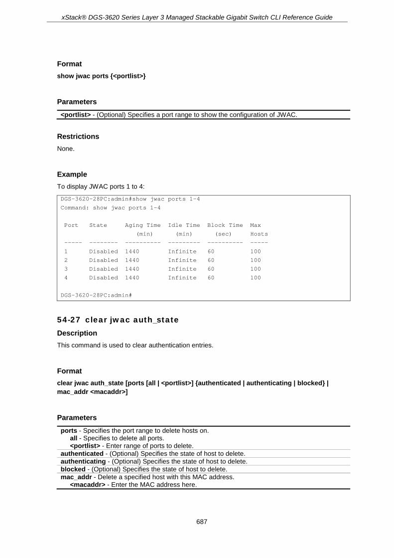
xStack® DGS-3620 Series Layer 3 Managed Stackable Gigabit Switch CLI Reference Guide
687
Format show jwac ports {<portlist>}
Parameters <portlist> - (Optional) Specifies a port range to show the configuration of JWAC.
Restrictions None.
Example To display JWAC ports 1 to 4:
DGS-3620-28PC:admin#show jwac ports 1-4
Command: show jwac ports 1-4
Port State Aging Time Idle Time Block Time Max
(min) (min) (sec) Hosts
----- -------- ---------- --------- ---------- -----
1 Disabled 1440 Infinite 60 100
2 Disabled 1440 Infinite 60 100
3 Disabled 1440 Infinite 60 100
4 Disabled 1440 Infinite 60 100
DGS-3620-28PC:admin#
54-27 clear jwac auth_state Description This command is used to clear authentication entries.
Format clear jwac auth_state [ports [all | <portlist>] {authenticated | authenticating | blocked} | mac_addr <macaddr>]
Parameters ports - Specifies the port range to delete hosts on.
all - Specifies to delete all ports. <portlist> - Enter range of ports to delete.
authenticated - (Optional) Specifies the state of host to delete. authenticating - (Optional) Specifies the state of host to delete. blocked - (Optional) Specifies the state of host to delete. mac_addr - Delete a specified host with this MAC address.
<macaddr> - Enter the MAC address here.

xStack® DGS-3620 Series Layer 3 Managed Stackable Gigabit Switch CLI Reference Guide
688
Restrictions Only Administrators, Operators and Power-Users can issue this command.
Example To delete authentication entries:
DGS-3620-28PC:admin#clear jwac auth_state ports all blocked
Command: clear jwac auth_state ports all blocked
Success.
DGS-3620-28PC:admin#
54-28 config jwac authenticate_page Description This command is used by administrators to decide which authenticate page to use.
Format config jwac authenticate_page [japanese | english]
Parameters japanese - Specifies to change to the Japanese page. english - Specifies to change to the English page. This is the default page.
Restrictions Only Administrators, Operators and Power-Users can issue this command.
Example To customize the authenticate page:
DGS-3620-28PC:admin#config jwac authenticate_page japanese
Command: config jwac authenticate_page japanese
Success.
DGS-3620-28PC:admin#
54-29 show jwac authenticate_page Description This command is used to display the element mapping of the customized authenticate page.

xStack® DGS-3620 Series Layer 3 Managed Stackable Gigabit Switch CLI Reference Guide
689
Format show jwac authenticate_page
Parameters None.
Restrictions None.
Example To display the element mapping of the customized authenticate page:
DGS-3620-28PC:admin#show jwac authenticate_page
Command: show jwac authenticate_page
Current Page : English Version
English Page Element
-----------------------------------------------------------
Page Title :
Login Window Title : Authentication Login
User Name Title : User Name
Password Title : Password
Logout Window Title : Logout from the network
Notification :
Japanese Page Element
-----------------------------------------------------------
Page Title :
Login Window Title : 社内 LAN 認証ログイン
User Name Title : ユーザ ID
Password Title : パスワード
CTRL+C ESC q Quit SPACE n Next Page ENTER Next Entry a All
54-30 config jwac authentication_page element Description This command is used by administrators to customize the JWAC authenticate page.
Format config jwac authentication_page element [japanese | english] [default | page_title <desc 128> | login_window_title <desc 32> | user_name_title <desc 16> | password_title <desc 16> | logout_window_title <desc 32> | notification_line <value 1-5> <desc 128>]

xStack® DGS-3620 Series Layer 3 Managed Stackable Gigabit Switch CLI Reference Guide
690
Parameters japanese - Specifies to change to the Japanese page. english - Specifies to change to the English page. default - Specifies to reset the page element to default. page_title - Specifies the title of the authenticate page.
<desc 128> - Enter the title of the authenticate page. The page title description can be up to 128 characters long.
login_window_title - Specifies the login window title of the authenticate page. <desc 32> - Enter the login window title of the authenticate page. The login window title
description can be up to 32 characters long. user_name_title - Specifies the user name title of the authenticate page.
<desc 16> - Enter the user name title of the authenticate page. The user name title description can be up to 16 characters long.
password_title - Specifies the password title of the authenticate page. <desc 16> - Enter the password title of the authenticate page. The password title description
can be up to 16 characters long. logout_window_title - Specifies the logout windown title mapping of the authenticate page.
<desc 32> - Enter the logout windown title mapping of the authenticate page. The logout window title description can be up to 32 characters long.
notification_line - Specifies this parameter to set the notification information by line in authentication Web pages. <value 1-5> - Enter a notification line value between 1 and 5. <desc 128> - Enter a notification line description up to 128 characters long.
Restrictions Only Administrators, Operators and Power-Users can issue this command.
Example To customize the authenticate page:
DGS-3620-28PC:admin# config jwac authentication_page element japanese page_title ディーリンクジャパン株式会社
Command: config jwac authentication_page element japanese page_title ディーリン
クジャパン株式会社
Success.
DGS-3620-28PC:admin# config jwac authentication_page element japanese login_window_title JWAC 认证
Command: config jwac authentication_page element japanese login_window_title JWAC 认证
Success.
DGS-3620-28PC:admin# config jwac authentication_page element japanese user_name_title ユーザ名
Command: config jwac authentication_page element japanese user_name_title ユーザ
名
Success.
DGS-3620-28PC:admin# config jwac authentication_page element japanese password_title パスワード

xStack® DGS-3620 Series Layer 3 Managed Stackable Gigabit Switch CLI Reference Guide
691
Command: config jwac authentication_page element japanese password_title パスワー
ド
Success.
DGS-3620-28PC:admin# config jwac authentication_page element japanese logout_window_title ログアウト
Command: config jwac authentication_page element japanese logout_window_title ログアウト
Success.
DGS-3620-28PC:admin#
54-31 config jwac authorization attributes Description This command is used to enable or disable acceptation of authorized configuration. When the authorization is enabled for JWAC’s RADIUS, the authorized data assigned by the RADUIS server will be accepted if the global authorization network is enabled. When the authorization is enabled for JWAC’s local, the authorized data assigned by the local database will be accepted.
Format config jwac authorization attributes {radius [enable | disable] | local [enable | disable]}(1)
Parameters radius - If specified to enable, the authorized data assigned by the RADUIS server will be
accepted if the global authorization network is enabled.The default state is enabled. enable - Specifies to enable authorized data assigned by the RADUIS server to be accepted. disable - Specifies to disable authorized data assigned by the RADUIS server from being
accepted. local - If specified to enable, the authorized data assigned by the local database will be accepted
if the global authorization network is enabled. The default state is enabled. enable - Specifies to enable authorized data assigned by the local database to be accepted. disable - Specifies to disable authorized data assigned by the local database from being
accepted.
Restrictions Only Administrators, Operators and Power-Users can issue this command.
Example To disable the configuration authorized from the local database:
DGS-3620-28PC:admin#config jwac authorization attributes local disable
Command: config jwac authorization attributes local disable
Success.

xStack® DGS-3620 Series Layer 3 Managed Stackable Gigabit Switch CLI Reference Guide
692
DGS-3620-28PC:admin#

xStack® DGS-3620 Series Layer 3 Managed Stackable Gigabit Switch CLI Reference Guide
693
Chapter 55 Jumbo Frame Commands
enable jumbo_frame disable jumbo_frame config jumbo_frame ports [<portlist> | all] state [enable | disable] show jumbo_frame {<portlist>}
55-1 enable jumbo_frame Description This command is used to enable support of Jumbo Frames.
Format enable jumbo_frame
Parameters None.
Restrictions Only Administrators, Operators and Power-Users can issue this command.
Example To enable Jumbo Frames:
DGS-3620-28PC:admin#enable jumbo_frame
Command: enable jumbo_frame
DGS-3620-28PC:admin#
55-2 disable jumbo_frame Description This command is used to disable support of Jumbo Frames.
Format disable jumbo_frame
Parameters None.
xStack® DGS-3620 Series Layer 3 Managed Stackable Gigabit Switch CLI Reference Guide
694
Restrictions Only Administrators, Operators and Power-Users can issue this command.
Example To disable Jumbo Frames:
DGS-3620-28PC:admin#disable jumbo_frame
Command: disable jumbo_frame
Success.
DGS-3620-28PC:admin#
55-3 config jumbo_frame ports Description This command is used to configure the jumbo frame state on specified ports.
Format config jumbo_frame ports [<portlist> | all] state [enable | disable]
Parameters <portlist> - Enter the list of ports used for this configuration here. all - Specifies that all the ports will be used for this configuration. state - Specifies the jumbo frame state to be applied to a range of ports specified.
enable - Specifies that the jumbo frame state will be enabled. disable - Specifies that the jumbo frame state will be disabled.
Restrictions Only Administrators, Operators and Power-Users can issue this command.
Example To enable jumbo frames on ports 1:1-1:5:
DGS-3620-28PC:admin# config jumbo_frame ports 1:1-1:5 state enable
Command: config jumbo_frame ports 1:1-1:5 state enable
Success.
DGS-3620-28PC:admin#
55-4 show jumbo_frame Description This command is used to display Jumbo Frames.

xStack® DGS-3620 Series Layer 3 Managed Stackable Gigabit Switch CLI Reference Guide
695
Format show jumbo_frame {<portlist>}
Parameters <portlist> - (Optional) Enter the list of ports to be displayed here.
Restrictions None.
Example To display Jumbo Frames for port 1 to 5:
DGS-3620-28PC:admin#show jumbo_frame 1-5
Command: show jumbo_frame 1-5
Jumbo Frame Global State : Disabled
Maximum Jumbo Frame Size : 1536 Bytes
Port Jumbo Frame State
------- --------------------
1 Enabled
2 Enabled
3 Enabled
4 Enabled
5 Enabled
DGS-3620-28PC:admin#
xStack® DGS-3620 Series Layer 3 Managed Stackable Gigabit Switch CLI Reference Guide
696
Chapter 56 LACP Configuration Commands
config lacp_port <portlist> {mode [active | passive] | lacp_timeout [short | long]} show lacp_port {<portlist>}
56-1 config lacp_port Description This command is used to configure per-port LACP mode.
Format config lacp_port <portlist> {mode [active | passive] | lacp_timeout [short | long]}
Parameters <portlist> - Enter a range of ports to be configured. mode - (Optional) Specifies the port mode.
active - Specifies the mode as active. passive - Specifies the mode as passive.
lacp_timeout - Specifies the LACP timeout mode. short - Specifies that there will be 3 seconds before LACP invalidating received LACPDU
information and there will be 1 second between LACP PDU periodic transmissions when using Short Timeouts.
long - Specifies that there will be 90 seconds before LACP invalidating received LACPDU information and there will be 30 seconds between LACP PDU periodic transmissions when using Long Timeouts.
Restrictions Only Administrators, Operators and Power-Users can issue this command.
Example To configure port LACP mode for ports 1 to 3:
DGS-3620-28PC:admin#config lacp_port 1-3 mode active
Command: config lacp_port 1-3 mode active
Success.
DGS-3620-28PC:admin#
56-2 show lacp_port Description This command is used to display per-port LACP mode.
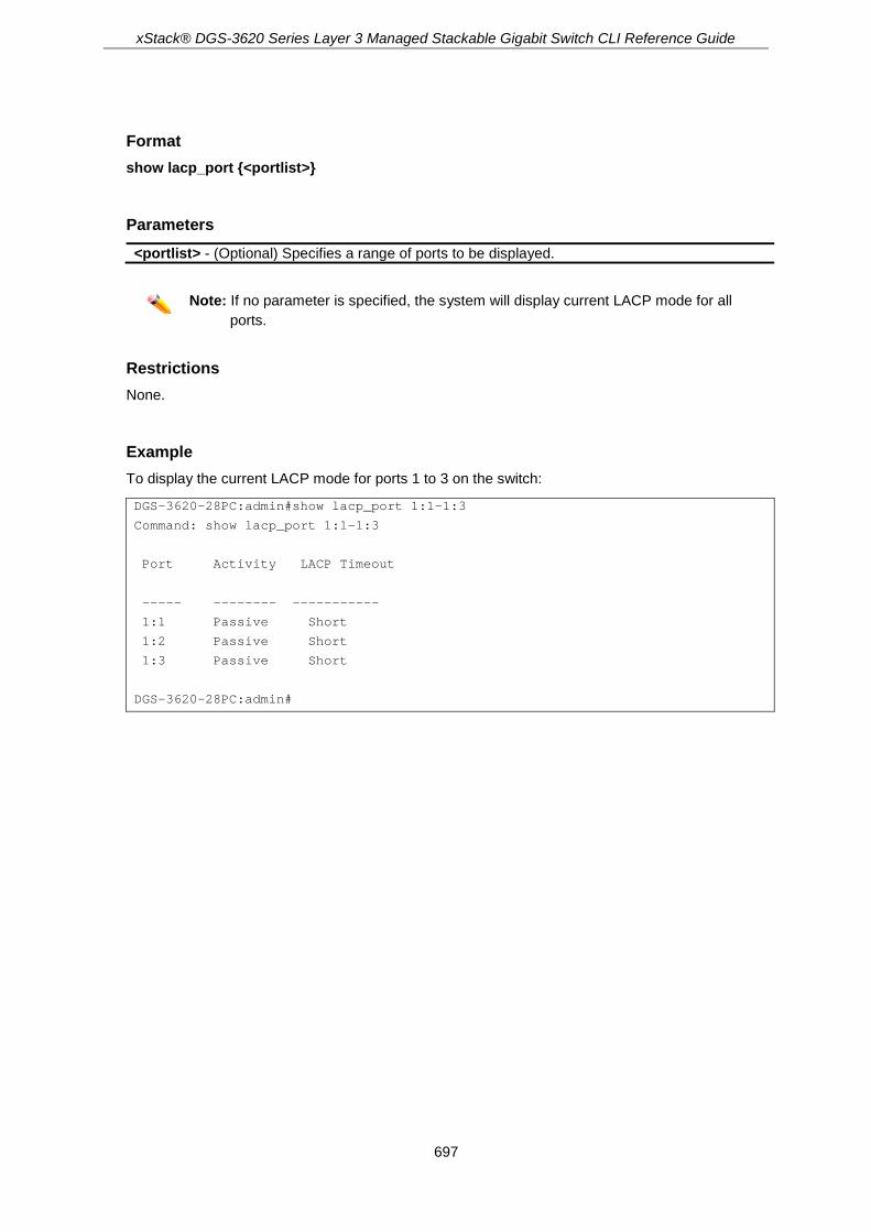
xStack® DGS-3620 Series Layer 3 Managed Stackable Gigabit Switch CLI Reference Guide
697
Format show lacp_port {<portlist>}
Parameters <portlist> - (Optional) Specifies a range of ports to be displayed.
Note: If no parameter is specified, the system will display current LACP mode for all
ports.
Restrictions None.
Example To display the current LACP mode for ports 1 to 3 on the switch:
DGS-3620-28PC:admin#show lacp_port 1:1-1:3
Command: show lacp_port 1:1-1:3
Port Activity LACP Timeout
----- -------- -----------
1:1 Passive Short
1:2 Passive Short
1:3 Passive Short
DGS-3620-28PC:admin#

xStack® DGS-3620 Series Layer 3 Managed Stackable Gigabit Switch CLI Reference Guide
698
Chapter 57 Layer 2 Protocol Tunneling (L2PT) Commands
config l2protocol_tunnel ports [<portlist> | all] type [uni tunneled_protocol [{stp | gvrp | protocol_mac [01-00-0C-CC-CC-CC | 01-00-0C-CC-CC-CD]}(1) | all] {threshold <value 0-65535>} | nni | none]
show l2protocol_tunnel {[uni | nni]} enable l2protocol_tunnel disable l2protocol_tunnel
57-1 config l2protocol_tunnel ports Description This command is used to configure Layer 2 protocol tunneling on ports.
Layer 2 protocol tunneling is used to tunnel Layer 2 protocol packet.
If a Layer 2 protocol is tunnel-enabled on an UNI, once received the PDU on this port, the multicast destination address of the PDU will be replaced by Layer 2 protocol tunneling multicast address. The Layer 2 protocol tunneling multicast address for STP is 01-05-5D-00-00-00, for GVRP is 01-05-5D-00-00-21, for Layer 2 protocols MAC 01-00-0C-CC-CC-CC is 01-05-5D-00-00-10 and for protocol MAC 01-00-0C-CC-CC-CD is 01-05-5D-00-00-11.
When QinQ is enabled, an S-TAG will be added to the Layer 2 PDU too. The S-TAG is assigned according QinQ VLAN configuration.
Format config l2protocol_tunnel ports [<portlist> | all] type [uni tunneled_protocol [{stp | gvrp | protocol_mac [01-00-0C-CC-CC-CC | 01-00-0C-CC-CC-CD]}(1) | all] {threshold <value 0-65535>} | nni | none]
Parameters ports -Specifies the ports on which the Layer 2 protocol tunneling will be configured.
<portlist> - Enter a list of ports to be configured here. all - Specifies to use this configuration on all the ports.
type - Specifies the type of the ports. uni - Specifies the port is UNI port tunneled_protocol - Specifies tunneled protocols on this UNI port. If specified all, all tunnel-able
Layer 2 protocols will be tunneled on this port. stp - (Optional) Specifies to use the STP protocol. gvrp - (Optional) Specifies to use the GVRP protocol. protocol_mac - (Optional) Specifies which protocol MAC address to use.
01-00-0C-CC-CC-CC - Specifies to use this protocol MAC address. 01-00-0C-CC-CC-CD - Specifies to use this protocol MAC address.
all - Specifies to use all the MAC addresses. threshold - (Optional) Specifies the drop threshold for packets-per-second accepted on this UNI
port. The port drops the PDU if the protocol’s threshold is exceeded. The range of the threshold value is 0 to 65535 (packet/second). The value 0 means no limit. By default, the value is 0.

xStack® DGS-3620 Series Layer 3 Managed Stackable Gigabit Switch CLI Reference Guide
699
<value 0-65535> - Enter the threshold packets-per-seconds value here. This value must be between 0 and 65535.
nni - Specifies the port is NNI port none - Disables tunnel on it. By default, a port is none port.
Restrictions Only Administrators, Operators and Power-Users can issue this command.
Example To configure the STP tunneling on ports 1-4:
DGS-3620-28PC:admin# config l2protocol_tunnel ports 1-4 type uni tunneled_protocol stp
Command: config l2protocol_tunnel ports 1-4 type uni tunneled_protocol stp
Success.
DGS-3620-28PC:admin#
57-2 show l2protocol_tunnel Description This command is used to show Layer 2 protocol tunneling information.
Format show l2protocol_tunnel {[uni | nni]}
Parameters uni - (Optional) Specifies show UNI detail information, include tunneled and dropped PDU
statistic. nni - (Optional) Specifies show NNI detail information, include de-capsulated Layer 2 PDU
statistic.
Restrictions None.
Example To show Layer 2 protocol tunneling information summary:

xStack® DGS-3620 Series Layer 3 Managed Stackable Gigabit Switch CLI Reference Guide
700
DGS-3620-28PC:admin# show l2protocol_tunnel
Command: show l2protocol_tunnel
Global State: Enabled
UNI Ports: 1:1-1:2
NNI Ports: 1:3-1:4
DGS-3620-28PC:admin#
To show Layer 2 protocol tunneling detail information on UNI ports:
DGS-3620-28PC:admin# show l2protocol_tunnel uni
Command: show l2protocol_tunnel uni
UNI Tunneled Threshold
Port Protocol (packet/sec)
---- ----------------- ------------
1:1 STP 10
GVRP 10
01-00-0C-CC-CC-CC 10
1:2 STP 20
GVRP 20
01-00-0C-CC-CC-CC 20
1:3 STP 0
1:4 STP 0
DGS-3620-28PC:admin#
To show Layer 2 protocol tunneling detail information on NNI ports:
DGS-3620-28PC:admin# show l2protocol_tunnel nni
Command: show l2protocol_tunnel nni
NNI Protocol
Port
---- --------------------
1:1 STP
GVRP
01-00-0C-CC-CC-CC
01-00-0C-CC-CC-CD
1:2 STP
GVRP
01-00-0C-CC-CC-CC
01-00-0C-CC-CC-CD
DGS-3620-28PC:admin#
57-3 enable l2protocol_tunnel Description Used to enable the Layer 2 protocol tunneling function.

xStack® DGS-3620 Series Layer 3 Managed Stackable Gigabit Switch CLI Reference Guide
701
Format enable l2protocol_tunnel
Parameters None.
Restrictions Only Administrators, Operators and Power-Users can issue this command.
Example To enable the Layer 2 protocol tunneling function:
DGS-3620-28PC:admin# enable l2protocol_tunnel
Command: enable l2protocol_tunnel
Success.
DGS-3620-28PC:admin#
57-4 disable l2protocol_tunnel Description Used to disable the Layer 2 protocol tunneling function.
Format disable l2protocol_tunnel
Parameters None.
Restrictions Only Administrators, Operators and Power-Users can issue this command.
Example To disable the Layer 2 protocol tunneling function:
DGS-3620-28PC:admin# disable l2protocol_tunnel
Command: disable l2protocol_tunnel
Success.
DGS-3620-28PC:admin#

xStack® DGS-3620 Series Layer 3 Managed Stackable Gigabit Switch CLI Reference Guide
702
Chapter 58 Limited Multicast IP Address Commands
create mcast_filter_profile {[ipv4 | ipv6]} profile_id <value 1-60> profile_name <name 32> config mcast_filter_profile [profile_id <value 1-60> | profile_name <name 32>] {profile_name
<name 32> | [add | delete] <mcast_address_list>}(1) config mcast_filter_profile ipv6 [profile_id <value 1-60> | profile_name <name 32>]
{profile_name <name 32> | [add | delete] <mcastv6_address_list>}(1) delete mcast_filter_profile {[ipv4 | ipv6]} [profile_id [<value 1-60> | all] | profile_name <name 32>] show mcast_filter_profile {[ipv4 | ipv6]} {[profile_id <value 1-60> | profile_name <name 32>]} config limited_multicast_addr [ports <portlist> | vlanid <vlanid_list>] {[ipv4 | ipv6]} {[add
[profile_id <value 1-60> | profile_name <name 32>] | delete [profile_id <value 1-60> | profile_name <name 32> | all]] | access [permit | deny]}(1)
show limited_multicast_addr [ ports <portlist> | vlanid <vlanid_list>] {[ipv4 | ipv6]} config max_mcast_group [ports <portlist> | vlanid <vlanid_list>] {[ipv4 | ipv6]} {max_group
[<value 1-1024> | infinite] | action [drop | replace]} (1) show max_mcast_group [ports <portlist> | vlanid <vlanid_list>] {[ipv4 | ipv6]}
58-1 create mcast_filter_profile Description This command is used to create a multicast address profile. If the IPv4 or IPv6 option is not specified, IPv4 is implied.
Format create mcast_filter_profile {[ipv4 | ipv6]} profile_id <value 1-60> profile_name <name 32>
Parameters ipv4 – (Optional) Specifies to add an IPv4 multicast profile. ipv6 – (Optional) Specifies to add an IPv6 multicast profile. profile_id – Specifies the ID of the profile.
<value 1-60> - The profile ID range must be from 1 to 60 profile_name - Provides a meaningful description for the profile.
<name 32> - The profile name can be up to 32 characters long.
Restrictions Only Administrators, Operators and Power-Users can issue this command.
Example To create a multicast address profile named MOD:
DGS-3620-28PC:admin#create mcast_filter_profile profile_id 2 profile_name MOD
Command: create mcast_filter_profile profile_id 2 profile_name MOD
Success.
xStack® DGS-3620 Series Layer 3 Managed Stackable Gigabit Switch CLI Reference Guide
703
DGS-3620-28PC:admin#
58-2 config mcast_filter_profile Description This command is used to modify the profile name, add or delete a range of previously defined multicast IP addresses to or from the profile.
Format config mcast_filter_profile [profile_id <value 1-60> | profile_name <name 32>] {profile_name <name 32> | [add | delete] <mcast_address_list>}(1)
Parameters profile_id - Specifies the ID of the profile.
<value 1-60> - The profile ID must be between 1 and 60. profile_name - Specifies the name of the profile.
<name 32> - The profile name can be up to 32 characters long. profile_name –Specifies a new name of the profile.
<name 32> - The profile name can be up to 32 characters long. add - Specifies to add a range of multicast IP addresses. delete - Specifies to delete a range of multicast IP addresses.
<mcast_address_list> - List of the multicast addresses to be added to or deleted from the profile. Either specifiy a single multicast IP address or a range of multicast addresses using a hyphen.
Restrictions Only Administrators, Operators and Power-Users can issue this command.
Example To add a range of multicast addresses to a profile:
DGS-3620-28PC:admin#config mcast_filter_profile profile_id 2 add 225.1.1.1 – 225.1.1.100
Command: config mcast_filter_profile profile_id 2 add 225.1.1.1 – 225.1.1.100
Success.
DGS-3620-28PC:admin#
58-3 config mcast_filter_profile ipv6 Description This command is used to add or delete a range of previously defined IPv6 multicast IP addresses to or from the profile.

xStack® DGS-3620 Series Layer 3 Managed Stackable Gigabit Switch CLI Reference Guide
704
Format config mcast_filter_profile ipv6 [profile_id <value 1-60> | profile_name <name 32>] {profile_name <name 32> | [add | delete] <mcastv6_address_list>}(1)
Parameters profile_id - Specifies the ID of the profile.
<value 1-60> - The profile ID must be between 1 and 60. profile_name - Specifies the name of the profile.
<name 32> - The profile name can be up to 32 characters long. profile_name –Specifies a new name of the profile.
<name 32> - The profile name can be up to 32 characters long. add - Specifies to add a range of multicast IP addresses. delete - Specifies to delete a range of multicast IP addresses.
<mcastv6_address_list> - List of the IPv6 multicast addresses to be added to or deleted from the profile. Either specifiy a single IPv6 multicast IP address or a range of IPv6 multicast addresses using a hyphen.
Restrictions Only Administrators, Operators and Power-Users can issue this command.
Example To add the IPv6 multicast address range FF0E::100:0:0:20 – FF0E::100:0:0:22 to profile ID 3:
DGS-3620-28PC:admin#config mcast_filter_profile ipv6 profile_id 3 add FF0E::100:0:0:20 – FF0E::100:0:0:22
Command: config mcast_filter_profile ipv6 profile_id 3 add FF0E::100:0:0:20 – FF0E::100:0:0:22
Success.
DGS-3620-28PC:admin#
58-4 delete mcast_filter_profile Description This command is used to delete a multicast address profile. If the IPv4 or IPv6 option is not specified, IPv4 is implied.
Format delete mcast_filter_profile {[ipv4 | ipv6]} [profile_id [<value 1-60> | all] | profile_name <name 32>]
Parameters ipv4 – (Optional) Specifies to delete an IPv4 multicast profile. ipv6 – (Optional) Specifies to delete an IPv6 multicast profile. profile_id - Specifies the ID of the profile. The range is from 1 to 60.
<value 1-60> - The profile ID must be between 1 and 60. all - All multicast address profiles will be deleted.
xStack® DGS-3620 Series Layer 3 Managed Stackable Gigabit Switch CLI Reference Guide
705
profile_name - Specifies a profile based on the profile name. <name 32> - The profile name can be up to 32 characters long.
Restrictions Only Administrators, Operators and Power-Users can issue this command.
Example To delete a multicast profile with a profile ID of 3:
DGS-3620-28PC:admin#delete mcast_filter_profile profile_id 3
Command: delete mcast_filter_profile profile_id 3
Success.
DGS-3620-28PC:admin#
To delete a multicast profile with a profile named MOD:
DGS-3620-28PC:admin#delete mcast_filter_profile profile_name MOD
Command: delete mcast_filter_profile profile_name MOD
Success.
DGS-3620-28PC:admin#
58-5 show mcast_filter_profile Description This command is used to display defined multicast address profiles. If the IPv4 or IPv6 option is not specified, IPv4 is implied.
Format show mcast_filter_profile {[ipv4 | ipv6]} {[profile_id <value 1-60> | profile_name <name 32>]}
Parameters ipv4 - (Optional) Specifies to display an IPv4 multicast profile. ipv6 - (Optional) Specifies to display an IPv6 multicast profile. profile_id - (Optional) Specifies the ID of the profile. If both profile_id and profile_name are not
specified, all profiles will be displayed. <value 1-60> - The profile ID must be between 1 and 60.
profile_name - (Optional) Specifies to display a profile based on the profile name. If both profile_id and profile_name are not specified, all profiles will be displayed. <name 32> - The profile name can be up the 32 characters long.
Restrictions None.

xStack® DGS-3620 Series Layer 3 Managed Stackable Gigabit Switch CLI Reference Guide
706
Example To display all the defined multicast address profiles:
DGS-3620-28PC:admin#show mcast_filter_profile
Command: show mcast_filter_profile
Profile ID Name Multicast Addresses
---------- --------------------------- -----------------------------
1 MOD 234.1.1.1 – 238.244.244.244
234.1.1.1 – 238.244.244.244
2 customer 224.19.62.34 – 224.19.162.200
Total Entries: 2
DGS-3620-28PC:admin#
58-6 config limited_multicast_addr Description This command is used to configure the multicast address filtering function on a port or VLAN. When there are no profiles specified with a port or VLAN, the limited function is not effective. When the function is configured on a port or VLAN, it limits the multicast group operated by the IGMP/MLD snooping function and layer 3 function. If the IPv4 or IPv6 option is not specified, IPv4 is implied.
Format config limited_multicast_addr [ports <portlist> | vlanid <vlanid_list>] {[ipv4 | ipv6]} {[add [profile_id <value 1-60> | profile_name <name 32>] | delete [profile_id <value 1-60> | profile_name <name 32> | all]] | access [permit | deny]}(1)
Parameters ports - Specifies a range of ports to configure the multicast address filtering function.
<portlist> - Enter a range of ports to be configured. vlanid - Specifies the VLAN ID of the VLAN that the multicast address filtering function will be
configured on. <vlanid_list> - Enter the VLAN ID of the VLAN that the multicast address filtering functions
will be configured on here. ipv4 - (Optional) Specifies the IPv4 multicast profile. ipv6 - (Optional) Specifies the IPv6 multicast profile. add - (Optional) Add a multicast address profile to a port or VLAN.
profile_id - (Optional) Specifies a profile ID to be added to or deleted from the port or VLAN. <value 1-60> - The profile ID must be between 1 and 60.
profile_name - (Optional) Specifies a profile name to be added to or deleted from the port or VLAN. <name 32> - The profile name can be up to 32 characters long.
delete - (Optional) Delete a multicast address profile from a port or VLAN. profile_id - (Optional) Specifies a profile ID to be added to or deleted from the port or VLAN.
<value 1-60> - The profile ID must be between 1 and 60. profile_name - (Optional) Specifies a profile name to be added to or deleted from the port or
VLAN. <name 32> - The profile name can be up to 32 characters long.
access - (Optional) Specifies whether the access is permit or deny.

xStack® DGS-3620 Series Layer 3 Managed Stackable Gigabit Switch CLI Reference Guide
707
permit - Specifies that the packets that match the addresses defined in the profiles will be permitted.
deny - Specifies that the packets that match the addresses defined in the profiles will be denied.
Restrictions Only Administrators, Operators and Power-Users can issue this command.
Example To add multicast address profile 2 to ports 1 and 3:
DGS-3620-28PC:admin#config limited_multicast_addr ports 1,3 add profile_id 2
Command: config limited_multicast_addr ports 1,3 add profile_id 2
Success.
DGS-3620-28PC:admin#
58-7 show limited_multicast_addr Description This command is used to display a multicast address range by ports or by VLANs. When the function is configured on a port or VLAN, it limits the multicast group operated by the IGMP/MLD snooping function and layer 3 function. If the IPv4 or IPv6 option is not specified, IPv4 is implied.
Format show limited_multicast_addr [ ports <portlist> | vlanid <vlanid_list>] {[ipv4 | ipv6]}
Parameters ports - Specifies a range of ports to show the limited multicast address configuration.
<portlist> - Enter a range of ports to be displayed. vlanid - Specifies the VLAN ID of VLANs that require information displaying about the multicast
address filtering function. <vlanid_list> - Enter the VLAN ID of the VLAN here.
ipv4 - (Optional) Specifies to display the IPv4 multicast profile associated with the port or VLAN. ipv6 - (Optional) Specifies to display the IPv6 multicast profile associated with the port or VLAN.
Restrictions None.
Example To display the limited multicast address range on VLAN 1:
DGS-3620-28PC:admin#show limited_multicast_addr vlanid 1
Command: show limited_multicast_addr vlanid 1
VLAN : 1

xStack® DGS-3620 Series Layer 3 Managed Stackable Gigabit Switch CLI Reference Guide
708
Access : Deny
Profile ID Name Multicast Addresses
----------- ----------- -----------------------------
1 customer 224.19.62.34 – 224.19.162.200
DGS-3620-28PC:admin#
To display the limited multicast address range on ports 1 and 3:
DGS-3620-28PC:admin#show limited_multicast_addr ports 1,3
Command: show limited_multicast_addr ports 1,3
Port : 1
Access : Deny
Profile ID Name Multicast Addresses
----------- ----------- -----------------------------
1 customer 224.19.62.34 – 224.19.162.200
Port : 3
Access : Deny
Profile ID Name Multicast Addresses
----------- ---------------- -----------------------------
1 customer 224.19.62.34 – 224.19.162.200
DGS-3620-28PC:admin#
58-8 config max_mcast_group Description This command is used to configure the maximum number of multicast groups a port or VLAN can join. If the IPv4 or IPv6 option is not specified, IPv4 is implied. When the joined groups for a port or a VLAN have reached the maximum number, the newly learned group will be dropped if the action is specified as drop. The newly learned group will replace the oldest group if the action is specified as replace.
Format config max_mcast_group [ports <portlist> | vlanid <vlanid_list>] {[ipv4 | ipv6]} {max_group [<value 1-1024> | infinite] | action [drop | replace]} (1)
Parameters ports - Specifies a range of ports to configure the maximum multicast group.
<portlist> - Enter a range of ports to be configured. vlanid - Specifies the VLAN ID to configure the maximum multicast group.
<vlanid_list> - Enter the VLAN ID of the VLAN here.

xStack® DGS-3620 Series Layer 3 Managed Stackable Gigabit Switch CLI Reference Guide
709
ipv4 - (Optional) Specifies that the maximum number of IPv4 learned addresses should be limited.
ipv6 - (Optional) Specifies that the maximum number of IPv6 learned addresses should be limited.
max_group - (Optional) Specifies the maximum number of the multicast groups. <value 1-1024> - The range is from 1 to 1024 or infinite. infinite - Infinite is the default setting.
action - (Optional) Specifies the action for handling newly learned groups when the register is full. drop - The new group will be dropped. replace - The new group will replace the oldest group in the register table.
Restrictions Only Administrators, Operators and Power-Users can issue this command.
Example To configure the maximum number of multicast groups that ports 1 and 3 can join to 100:
DGS-3620-28PC:admin# config max_mcast_group ports 1, 3 max_group 100
Command: config max_mcast_group ports 1, 3 max_group 100
Success.
DGS-3620-28PC:admin#
58-9 show max_mcast_group Description This command is used to display the maximum number of multicast groups that a port or VLAN can join. If the IPv4 or IPv6 option is not specified, IPv4 is implied.
Format show max_mcast_group [ports <portlist> | vlanid <vlanid_list>] {[ipv4 | ipv6]}
Parameters ports - Specifies a range of ports to display the maximum number of multicast groups.
<portlist> - Enter a range of ports to be displayed. vlanid - Specifies the VLAN ID for displaying the maximum number of multicast groups.
<vlanid_list> - Enter the VLAN ID of the VLAN here. ipv4 - (Optional) Specifies to display the maximum number of IPv4 learned addresses. ipv6 - (Optional) Specifies to display the maximum number of IPv6 learned addresses.
Restrictions None.
Example To display the maximum number of multicast groups for ports 1-2:

xStack® DGS-3620 Series Layer 3 Managed Stackable Gigabit Switch CLI Reference Guide
710
DGS-3620-28PC:admin# show max_mcast_group ports 1-2
Command: show max_mcast_group ports 1-2
Port Max Multicast Group Number Action
----- --------------------------- ---------
1 Infinite Drop
2 Infinite Drop
Total Entries : 2
DGS-3620-28PC:admin#

xStack® DGS-3620 Series Layer 3 Managed Stackable Gigabit Switch CLI Reference Guide
711
Chapter 59 Link Aggregation Commands
create link_aggregation group_id <value 1-32> {type [lacp | static]} delete link_aggregation group_id <value 1-32> config link_aggregation group_id <value 1-32> {master_port <port> | ports <portlist> | state
[enable | disable] | trap [enable | disable]}(1) config link_aggregation algorithm [mac_source | mac_destination | mac_source_dest |
ip_source | ip_destination | ip_source_dest | l4_src_port | l4_dest_port | l4_src_dest_port] show link_aggregation {group_id <value 1-32> | algorithm}
59-1 create link_aggregation group_id Description This command is used to create a link aggregation group.
Format create link_aggregation group_id <value 1-32> {type [lacp | static]}
Parameters <value 1-32> - Enter the group ID. The group number identifies each of the groups. The switch
allows up to 32 link aggregation groups to be created. type - (Optional) Specifies the group type belongs to static or LACP. If type is not specified, the
default is the static type. lacp - Specifies the group type as LACP. static - Specifies the group type as static.
Restrictions Only Administrators, Operators and Power-Users can issue this command.
Example To create a link aggregation group:
DGS-3620-28PC:admin#create link_aggregation group_id 1 type lacp
Command: create link_aggregation group_id 1 type lacp
Success
DGS-3620-28PC:admin#
59-2 delete link_aggregation group_id Description This command is used to delete a previously configured link aggregation group.

xStack® DGS-3620 Series Layer 3 Managed Stackable Gigabit Switch CLI Reference Guide
712
Format delete link_aggregation group_id <value 1-32>
Parameters <value 1-32> - Enter the group ID.
Restrictions Only Administrators, Operators and Power-Users can issue this command.
Example To delete a link aggregation group:
DGS-3620-28PC:admin#delete link_aggregation group_id 3
Command: delete link_aggregation group_id 3
Success.
DGS-3620-28PC:admin#
59-3 config link_aggregation group_id Description This command allows you to configure a link aggregation group that was created with the create link_aggregation command above.
Format config link_aggregation group_id <value 1-32> {master_port <port> | ports <portlist> | state [enable | disable] | trap [enable | disable]}(1)
Parameters <value 1-32> - Enter the group ID. The group number identifies each of the groups. The switch
allows up to 32 link aggregation groups to be configured. master_port - Specifies which port (by port number) of the link aggregation group will be the
master port. All of the ports in a link aggregation group will share the port configuration with the master port. <port> - Enter the master port ID.
ports - Specifies a range of ports that will belong to the link aggregation group. The port list should include the master port. <portlist> - Enter a range of ports to be configured.
state - Enable or disable the specified link aggregation group. If LACP group state is enabled and the group type is LACP, the ports’ state machine will start. enable - Enable the specified link aggregation group. disable - Disable the specified link aggregation group.
trap - Specifies the trap status for a link aggregation group. enable - Specifies that Link Up and Link Down notifications are enabled for this link
aggregation group.

xStack® DGS-3620 Series Layer 3 Managed Stackable Gigabit Switch CLI Reference Guide
713
disable - Specifies that Link Up and Link Down notifications are disabled for link aggregation group. By default, the trap status for a link aggregation group is disabled.
Restrictions Only Administrators, Operators and Power-Users can issue this command.
Example To configure a link aggregation group, group-id 1, master port 7, member ports 5-7:
DGS-3620-28PC:admin#config link_aggregation group_id 1 master_port 7 ports 5-7
Command: config link_aggregation group_id 1 master_port 7 ports 5-7
Success.
DGS-3620-28PC:admin#
59-4 config link_aggregation algorithm Description This command is used to configure the part of the packet examined by the switch when selecting the egress port for transmitting load-sharing data.
If the load sharing algorithm is based on IP information and the packet is a non-IP packet, it will be based on the source MAC.
If the load sharing algorithm is based on L4 information and the packet is not a TCP/UDP packet:
1) If the packet is a non-IP packet, it will be based on the source MAC.
2) If the packet is an IP packet, it will use the default value of "0" for the TCP/UDP port. It means that if it is not a TCP/UDP IP packet, it will deal with it the same as way as the TCP/UDP packets, but just the TCP/UDP value is 0.
Format config link_aggregation algorithm [mac_source | mac_destination | mac_source_dest | ip_source | ip_destination | ip_source_dest | l4_src_port | l4_dest_port | l4_src_dest_port]
Parameters mac_source - Indicates that the switch should examine the MAC source address. mac_destination - Indicates that the switch should examine the MAC destination address. mac_source_dest - Indicates that the switch should examine the MAC source and destination
address. ip_source - Indicate that the switch should examine the IP source address. ip_destination - Indicate that the switch should examine the IP destination address. ip_source_dest - Indicate that the switch should examine the IP source and destination address. l4_src_port - Indicate that the switch should examine the Layer 4 source port. l4_dest_port - Indicate that the switch should examine the Layer 4 destination port. l4_src_dest_port - Indicate that the switch should examine the Layer 4 source and destination
port.

xStack® DGS-3620 Series Layer 3 Managed Stackable Gigabit Switch CLI Reference Guide
714
Restrictions Only Administrators, Operators and Power-Users can issue this command.
Example To configure the link aggregation algorithm to mac-source-dest:
DGS-3620-28PC:admin#config link_aggregation algorithm mac_source_dest
Command: config link_aggregation algorithm mac_source_dest
Success.
DGS-3620-28PC:admin#
59-5 show link_aggregation Description This command is used to display the current link aggregation configuration of the switch.
Format show link_aggregation {group_id <value 1-32> | algorithm}
Parameters group_id - (Optional) Specifies the group ID. The group number identifies each of the groups.
<value 1-32> - The switch supports up to 32 link aggregation groups. algorithm - (Optional) Specifies the display of link aggregation by the algorithm in use by that
group.
Note: If no parameter is specified, the system will display all the link aggregation
information.
Restrictions None.
Example To display the current link aggregation configuration when link aggregation is enabled:
DGS-3620-28PC:admin#show link_aggregation
Command: show link_aggregation
Link Aggregation Algorithm = IP-Source
Group ID : 1
Type : LACP
Master Port : 1:5
Member Port : 1:5-1:8
Active Port :

xStack® DGS-3620 Series Layer 3 Managed Stackable Gigabit Switch CLI Reference Guide
715
Status : Enabled
Flooding Port :
Trap : Enabled
Total Entries : 1
DGS-3620-28PC:admin#
To display the current link aggregation configuration when link aggregation is disabled:
DGS-3620-28PC:admin#show link_aggregation
Command: show link_aggregation
Link Aggregation Algorithm = IP-Source
Group ID : 1
Type : LACP
Master Port : 1:5
Member Port : 1:5-1:8
Active Port :
Status : Disabled
Flooding Port :
Trap : Enabled
Total Entries : 1
DGS-3620-28PC:admin#

xStack® DGS-3620 Series Layer 3 Managed Stackable Gigabit Switch CLI Reference Guide
716
Chapter 60 LLDP Commands
enable lldp disable lldp config lldp [message_tx_interval <sec 5-32768> | message_tx_hold_multiplier <int 2-10> |
tx_delay <sec 1-8192> | reinit_delay <sec 1-10>] show lldp config lldp forward_message [enable | disable] config lldp notification_interval <sec 5-3600> config lldp ports [<portlist> | all] [notification [enable | disable] | admin_status [tx_only | rx_only |
tx_and_rx | disable] | mgt_addr [ipv4 <ipaddr> | ipv6 <ipv6addr>] [enable | disable] | basic_tlvs [[{all} | {port_description | system_name | system_description | system_capabilities}] [enable | disable] | port_Id_subtype [mac_address | local]] | dot1_tlv_pvid [enable | disable] | dot1_tlv_protocol_vid [vlan [all | <vlan_name 32>] | vlanid <vidlist>] [enable | disable] | dot1_tlv_vlan_name [vlan [all | <vlan_name 32>] | vlanid <vidlist>] [enable | disable] | dot1_tlv_protocol_identity [all | {eapol | lacp | gvrp | stp}] [enable | disable] | dot3_tlvs [{all} | {mac_phy_configuration_status | link_aggregation | power_via_mdi | maximum_frame_size}] [enable | disable]]
show lldp ports {<portlist>} config lldp_med fast_start repeat_count <value 1-10> config lldp_med log state [enable | disable] config lldp_med notification topo_change ports [<portlist> | all] state [enable | disable] config lldp_med ports [<portlist> | all] med_transmit_capabilities [all | {capabilities |
network_policy | power_pse | inventory}(1)] state [enable | disable] show lldp_med ports {<portlist>} show lldp_med show lldp_med local_ports {<portlist>} show lldp_med remote_ports {<portlist>} show lldp local_ports {<portlist>} {mode [brief | normal | detailed]} show lldp mgt_addr {[ipv4 <ipaddr> | ipv6 <ipv6addr>]} show lldp remote_ports {<portlist>} {mode [brief | normal | detailed]} show lldp statistics show lldp statistics ports {<portlist>}
60-1 enable lldp Description This command is used to enable LLDP. This is a global control for the LLDP function. When this function is enabled, the switch can start to transmit LLDP packets and receive and process the LLDP packets. The specific function of each port will depend on the per port LLDP setting. For the advertisement of LLDP packets, the switch announces the information to its neighbor through ports. For the receiving of LLDP packets, the switch will learn the information from the LLDP packets advertised from the neighbor in the neighbor table.The default state for LLDP is disabled.
Format enable lldp
Parameters None.

xStack® DGS-3620 Series Layer 3 Managed Stackable Gigabit Switch CLI Reference Guide
717
Restrictions Only Administrators, Operators and Power-Users can issue this command.
Example To enable LLDP:
DGS-3620-28PC:admin#enable lldp
Command: enable lldp
Success.
DGS-3620-28PC:admin#
60-2 disable lldp Description This command is used to disable LLDP. The switch will stop the sending and receiving of LLDP advertisement packets.
Format disable lldp
Parameters None.
Restrictions Only Administrators, Operators and Power-Users can issue this command.
Example To disable LLDP:
DGS-3620-28PC:admin#disable lldp
Command: disable lldp
Success.
DGS-3620-28PC:admin#
60-3 config lldp Description This command is used to configure LLDP timer values. The message TX interval controls how often active ports retransmit advertisements to their neighbors. The message TX hold multiplier is a multiplier on the msgTxInterval that is used to compute the TTL value of txTTL in an LLDPDU.

xStack® DGS-3620 Series Layer 3 Managed Stackable Gigabit Switch CLI Reference Guide
718
The TTL will be carried in the LLDPDU packet. The lifetime will be the minimum of 65535 and (message_tx_interval * message_tx_hold_multiplier). On the partner switch, when the time-to-live for a given advertisement expires, the advertised data is deleted from the neighbor switch’s MIB. The TX delay is used to change the minimum time (delay-interval) any LLDP port will delay advertising successive LLDP advertisements due to a change in LLDP MIB content. The TX delay defines the minimum interval between sending of LLDP messages due to the constantly changing MIB content. A re-enabled LLDP port will wait for the reinit delay after the last disable command before reinitializing.
Format config lldp [message_tx_interval <sec 5-32768> | message_tx_hold_multiplier <int 2-10> | tx_delay <sec 1-8192> | reinit_delay <sec 1-10>]
Parameters message_tx_interval - Specifies the message TX interval between consecutive transmissions of
LLDP advertisements on any given port. <sec 5-32768> - The range is from 5 to 32768 seconds. The default setting is 30 seconds.
message_tx_hold_multiplier - Specifies the message TX hold multiplier. <int 2-10> - Enter the range is from 2 to 10. The default setting is 4.
tx_delay - Specifies the TX delay time. <sec 1-8192> - Enter the range is from 1 to 8192 seconds. The default setting is 2 seconds.
Note: txDelay should be less than or equal to 0.25 * msgTxInterval. reinit_delay - Specifies the reinit delay time.
<sec 1-10> - Enter the range is from 1 to 10 seconds. The default setting is 2 seconds.
Restrictions Only Administrators, Operators and Power-Users can issue this command.
Example To change the packet transmission interval:
DGS-3620-28PC:admin#config lldp message_tx_interval 30
Command: config lldp message_tx_interval 30
Success.
DGS-3620-28PC:admin#
To change the multiplier value:
DGS-3620-28PC:admin#config lldp message_tx_hold_multiplier 3
Command: config lldp message_tx_hold_multiplier 3
Success.
DGS-3620-28PC:admin#
To configure the delay-interval interval:
xStack® DGS-3620 Series Layer 3 Managed Stackable Gigabit Switch CLI Reference Guide
719
DGS-3620-28PC:admin#config lldp tx_delay 8
Command: config lldp tx_delay 8
Success.
DGS-3620-28PC:admin#
To change the re-initialization delay interval to five seconds:
DGS-3620-28PC:admin#config lldp reinit_delay 5
Command: config lldp reinit_delay 5
Success.
DGS-3620-28PC:admin#
60-4 show lldp Description This command is used to display LLDP.
Format show lldp
Parameters None.
Restrictions None.
Example To display LLDP:
DGS-3620-28PC:admin#show lldp
Command: show lldp
LLDP System Information
Chassis ID Subtype : MAC Address
Chassis ID : 00-11-22-33-44-55
System Name :
System Description : Gigabit Ethernet Switch
System Capabilities : Repeater, Bridge
LLDP Configurations
LLDP Status : Disabled
LLDP Forward Status : Disabled
Message TX Interval : 30

xStack® DGS-3620 Series Layer 3 Managed Stackable Gigabit Switch CLI Reference Guide
720
Message TX Hold Multiplier: 4
ReInit Delay : 2
TX Delay : 2
Notification Interval : 5
DGS-3620-28PC:admin#
60-5 config lldp forward_message Description This command is used to configure LLDP forwarding messages. When LLDP is disabled and LLDP forward message is enabled, the received LLDPDU packet will be forwarded. The default state is disabled.
Format config lldp forward_message [enable | disable]
Parameters enable - Enable LLDP forwarding messages. disable - Disable LLDP forwarding messages.
Restrictions Only Administrators, Operators and Power-Users can issue this command.
Example To enable LLDP forwarding messages:
DGS-3620-28PC:admin#config lldp forward_message enable
Command: config lldp forward_message enable
Success.
DGS-3620-28PC:admin#
60-6 config lldp notification_interval Description This command is used to configure LLDP timer values. This will globally change the interval between successive LLDP change notifications generated by the switch.
Format config lldp notification_interval <sec 5-3600>

xStack® DGS-3620 Series Layer 3 Managed Stackable Gigabit Switch CLI Reference Guide
721
Parameters <sec 5-3600> - Enter the notification interval range is from 5 to 3600 seconds. The default setting
is 5 seconds.
Restrictions Only Administrators, Operators and Power-Users can issue this command.
Example To change the notification interval to 10 seconds:
DGS-3620-28PC:admin#config lldp notification_interval 10
Command: config lldp notification_interval 10
Success.
DGS-3620-28PC:admin#
60-7 config lldp ports Description Use this command to configure LLDP options by port. Enable or disable each port for sending change notification to configured SNMP trap receiver(s) if an LLDP data change is detected in an advertisement received on the port from an LLDP neighbor. The definition of change includes new available information, information timeout, information update. And the changed type includes any data update /insert/remove.
The admin status options enable to control which ports participate in LLDP traffic and whether the participating ports allow LLDP traffic in only one direction or in both directions.
The config management address command specifies whether system’s IP address needs to be advertised from the specified port. For layer 3 devices, each managed address can be individually specified. The management addresses that are added in the list will be advertised in the LLDP from the specified interface, associated with each management address. The interface for that management address will be also advertised in the if-index form.
An active LLDP port on the switch always includes the mandatory data in its outbound advertisements. And there are four optional data that can be configured for an individual port or group of ports to exclude one or more of these data types from outbound LLDP advertisements. The mandatory data type include four basic types of information (end of LLDPDU TLV, chassis ID TLV, port ID TLV, and Time to Live TLV). The mandatory type cannot be disabled. There are also five data types which can be optionally selected. They are port_description, system_name, system_description, system_capability, and port_Id_subtype.
Configure an individual port or group of ports to exclude one or more of IEEE 802.1 Organizationally port vlan ID TLV data types from outbound LLDP advertisements.
Configure an individual port or group of ports to exclude one or more of IEEE 802.1 Organizationally port and protocol VLAN ID TLV data types from outbound LLDP advertisements.
Configure an individual port or group of ports to exclude one or more of IEEE 802.1 Organizationally VLAN name TLV data types from outbound LLDP advertisements.
Configure an individual port or group of ports to exclude one or more of IEEE 802.1 Organizationally protocol identity TLV data types from outbound LLDP advertisements. This TLV

xStack® DGS-3620 Series Layer 3 Managed Stackable Gigabit Switch CLI Reference Guide
722
optional data type indicates whether the corresponding Local System's Protocol Identity instance will be transmitted on the port. The Protocol Identity TLV provides a way for stations to advertise protocols that are important to the operation of the network. Spanning Tree Protocol, the Link Aggregation Control Protocol, and numerous vendor proprietary variations are responsible for maintaining the topology and connectivity of the network. If EAPOL, GVRP, STP (including MSTP), and LACP protocol identity are enabled on this port and it is enabled to be advertised, then this protocol identity will be advertised.
Format config lldp ports [<portlist> | all] [notification [enable | disable] | admin_status [tx_only | rx_only | tx_and_rx | disable] | mgt_addr [ipv4 <ipaddr> | ipv6 <ipv6addr>] [enable | disable] | basic_tlvs [[{all} | {port_description | system_name | system_description | system_capabilities}] [enable | disable] | port_Id_subtype [mac_address | local]] | dot1_tlv_pvid [enable | disable] | dot1_tlv_protocol_vid [vlan [all | <vlan_name 32>] | vlanid <vidlist>] [enable | disable] | dot1_tlv_vlan_name [vlan [all | <vlan_name 32>] | vlanid <vidlist>] [enable | disable] | dot1_tlv_protocol_identity [all | {eapol | lacp | gvrp | stp}] [enable | disable] | dot3_tlvs [{all} | {mac_phy_configuration_status | link_aggregation | power_via_mdi | maximum_frame_size}] [enable | disable]]
Parameters <portlist> - Enter a range of ports to be configured. all - Specifies to set all the ports on the system. notification - Enable or disable the SNMP trap notification of LLDP data changes detected on
advertisements received from neighbor devices. The default notification state is disabled. enable - Enable the SNMP trap notification of LLDP data changes detected on
advertisements received from neighbor devices. disable - Disable the SNMP trap notification of LLDP data changes detected on
advertisements received from neighbor devices. admin_status - Select the desired administrative per port state. The default per port state is
tx_and_rx. tx_only - Configure the specified port(s) to transmit LLDP packets, but block inbound LLDP
packets from neighbor devices. rx_only - Configure the specified port(s) to receive LLDP packets from neighbors, but block
outbound packets to neighbors. tx_and_rx - Configure the specified port(s) to both transmit and receive LLDP packets. disable - Disable LLDP packet transmit and receive on the specified port(s).
mgt_address - The port types specified for advertising indicated management address instance. ipv4 - Specifies the IP address of IPv4.
<ipaddr> - Enter the IP address of IPv4. ipv6 - Specifies the IP address of IPv6.
<ipv6addr> - Enter the IP address of IPv6. enable - Enable port(s) specified for advertising indicated management address instance. disable - Disable port(s) specified for advertising indicated management address instance.
basic_tlvs - Configure an individual port or group of ports to exclude one or more of optional TLV data types from outbound LLDP advertisements. all - (Optional) Configure all four TLV data types listed below. port_description - (Optional) This TLV optional data type indicates that LLDP agent should
transmit “Port Description TLV” on the port. The default state is disabled. system_name - (Optional) This TLV optional data type includes indicates that LLDP agent
should transmit “System Name TLV.” The default state is disabled. system_description - (Optional) This TLV optional data type includes indicates that LLDP
agent should transmit “System Description TLV.” The default state is disabled. system_capabilities - (Optional) This TLV optional data type includes indicates that LLDP
agent should transmit “System Capabilities TLV.” The system capability will indicate

xStack® DGS-3620 Series Layer 3 Managed Stackable Gigabit Switch CLI Reference Guide
723
whether the device provides repeater, bridge, or router function, and whether the provided functions are currently enabled. The default state is disabled.
enable - Enable configuration of an individual port or group of ports to exclude one or more of optional TLV data types from outbound LLDP advertisements.
disable - Disable configuration of an individual port or group of ports to exclude one or more of optional TLV data types from outbound LLDP advertisements.
port_Id_subtype - Specifies the subtype of the port ID TLV. mac_address - Specifies the subtype of the port ID TLV using the MAC address. local - Specifies the subtype of the port ID TLV using the local port number.
dot1_tlv_pvid - This TLV optional data type determines whether the IEEE 802.1 organizationally defined port VLAN ID TLV transmission is allowed on a given LLDP transmission capable port. The default state is disabled. enable - Enable port VLAN ID TLV transmission on a given LLDP transmission capable port. disable - Disable port VLAN ID TLV transmission on a given LLDP transmission capable port.
dot1_tlv_protocol_vid - This TLV optional data type determines whether the IEEE 802.1 organizationally defined port and protocol VLAN ID TLV transmission is allowed on a given LLDP transmission capable port. The default state is disabled. vlan - (Optional) Specifies a VLAN to be transmitted.
all - (Optional) Specifies that all VLAN names will be transmitted. <vlan_name 32> - (Optional) Specifies a VLAN name to be transmitted.
vlanid - (Optional) Specifies a VLAN ID list to be transmitted. <vidlist> - Enter a VLAN ID list to be transmitted.
enable - Enable configuration of an individual port or group of ports to exclude one or more of IEEE 802.1 Organizationally port and protocol VLAN ID TLV data types from outbound LLDP advertisements.
disable - Disable configuration of an individual port or group of ports to exclude one or more of IEEE 802.1 Organizationally port and protocol VLAN ID TLV data types from outbound LLDP advertisements.
dot1_tlv_vlan_name - This TLV optional data type indicates whether the corresponding Local System’s VLAN name instance will be transmitted on the port. If a port is associated with multiple VLANs, those enabled VLAN ID will be advertised. The default state is disabled. vlan - (Optional) Specifies a VLAN to be transmitted.
all - (Optional) Specifies that all VLAN names will be transmitted. <vlan_name 32> - (Optional) Specifies a VLAN name to be transmitted.
vlanid - (Optional) Specifies a VLAN ID list to be transmitted. <vidlist> - Enter a VLAN ID list to be transmitted.
enable - Enable configuration of an individual port or group of ports to exclude one or more of IEEE 802.1 Organizationally VLAN name TLV data types from outbound LLDP advertisements.
disable - Disable configuration of an individual port or group of ports to exclude one or more of IEEE 802.1 Organizationally VLAN name TLV data types from outbound LLDP advertisements.
dot1_tlv_protocol_identity - This TLV optional data type indicates whether the corresponding Local System's Protocol Identity instance will be transmitted on the port. The Protocol Identity TLV provides a way for stations to advertise protocols that are important to the operation of the network, such as Spanning Tree Protocol, the Link Aggregation Control Protocol, and numerous vendor proprietary variations which are responsible for maintaining the topology and connectivity of the network. If EAPOL, GVRP, STP (including MSTP), and LACP protocol identity are enabled on this port and enabled to be advertised, then the protocol identity will be advertised. The default state is disabled. all - Advertise all of the protocols lists below. eapol - (Optional) Advertise EAPOL. lacp - (Optional) Advertise LACP. gvrp - (Optional) Advertise GVRP. stp - (Optional) Advertise STP. enable - Enable configuration an individual port or group of ports to exclude one or more of
IEEE 802.1 Organizationally protocol identity TLV data types from outbound LLDP advertisements.
disable - Disable configuration an individual port or group of ports to exclude one or more of IEEE 802.1 Organizationally protocol identity TLV data types from outbound LLDP

xStack® DGS-3620 Series Layer 3 Managed Stackable Gigabit Switch CLI Reference Guide
724
advertisements. dot3_tlvs - An individual port or group of ports to exclude one or more of IEEE 802.3
Organizationally Specific TLV data types from outbound LLDP advertisements. all – (Optional) Configure all of the TLV optional data types below. mac_phy_configuration_status - (Optional) This TLV optional data type indicates that LLDP
agent should transmit “MAC/PHY configuration/status TLV.” This type indicates it is possible for two ends of an IEEE 802.3 link to be configured with different duplex and/or speed settings and still establish some limited network connectivity. More precisely, the information includes whether the port supports the auto-negotiation function, whether the function is enabled, the auto-negotiated advertised capability, and the operational MAU type. The default state is disabled.
link_aggregation - (Optional) This TLV optional data type indicates that LLDP agent should transmit “Link Aggregation TLV.” This type indicates the current link aggregation status of IEEE 802.3 MACs. More precisely, the information should include whether the port is capable of doing link aggregation, whether the port is aggregated in an aggregated link, and the aggregated port ID. The default state is disabled.
power_via_mdi - (Optional) This TLV optional data type indicates that LLDP agent should transmit 'Power via MDI TLV'. The default state is disabled.
maximum_frame_size - (Optional) This TLV optional data type indicates that LLDP agent should transmit “Maximum-frame-size TLV.” The default state is disabled.
enable - Enable the configuration of an individual port or group of ports to exclude one or more of IEEE 802.3 Organizationally Specific TLV data types from outbound LLDP advertisements.
disable - Disable the configuration of an individual port or group of ports to exclude one or more of IEEE 802.3 Organizationally Specific TLV data types from outbound LLDP advertisements.
Restrictions Only Administrators, Operators and Power-Users can issue this command.
Example To change the SNMP notification state of ports 1 to 5 to enable:
DGS-3620-28PC:admin#config lldp ports 1-5 notification enable
Command: config lldp ports 1-5 notification enable
Success.
DGS-3620-28PC:admin#
To configure the mode of ports 1 to 5 to transmit and receive:
DGS-3620-28PC:admin#config lldp ports 1-5 admin_status tx_and_rx
Command: config lldp ports 1-5 admin_status tx_and_rx
Success.
DGS-3620-28PC:admin#
To enable ports 1 to 5 to manage address entries:
DGS-3620-28PC:admin#config lldp ports 1-5 mgt_addr ipv4 192.168.254.10 enable
Command: config lldp ports 1-5 mgt_addr ipv4 192.168.254.10 enable
xStack® DGS-3620 Series Layer 3 Managed Stackable Gigabit Switch CLI Reference Guide
725
Success.
DGS-3620-28PC:admin#
To exclude the system name TLV from the outbound LLDP advertisements for all ports:
DGS-3620-28PC:admin#config lldp ports all basic_tlvs system_name enable
Command: config lldp ports all basic_tlvs system_name enable
Success.
DGS-3620-28PC:admin#
To exclude the VLAN name TLV from the outbound LLDP advertisements for all ports:
DGS-3620-28PC:admin#config lldp ports all dot1_tlv_pvid enable
Command: config lldp ports all dot1_tlv_pvid enable
Success.
DGS-3620-28PC:admin#
To exclude the port and protocol VLAN ID TLV from the outbound LLDP advertisements for all ports:
DGS-3620-28PC:admin#config lldp ports all dot1_tlv_protocol_vid vlanid 1-3 enable
Command: config lldp ports all dot1_tlv_protocol_vid vlanid 1-3 enable
Success.
DGS-3620-28PC:admin#
To exclude the VLAN name TLV from the outbound LLDP advertisements for all ports:
DGS-3620-28PC:admin#config lldp ports all dot1_tlv_vlan_name vlanid 1-3 enable
Command: config lldp ports all dot1_tlv_vlan_name vlanid 1-3 enable
Success.
DGS-3620-28PC:admin#
To exclude the protocol identity TLV from the outbound LLDP advertisements for all ports:
DGS-3620-28PC:admin#config lldp ports all dot1_tlv_protocol_identity all enable
Command: config lldp ports all dot1_tlv_protocol_identity all enable
Success.
DGS-3620-28PC:admin#

xStack® DGS-3620 Series Layer 3 Managed Stackable Gigabit Switch CLI Reference Guide
726
To exclude the MAC/PHY configuration/status TLV from the outbound LLDP advertisements for all ports:
DGS-3620-28PC:admin#config lldp ports all dot3_tlvs mac_phy_configuration_status enable
Command: config lldp ports all dot3_tlvs mac_phy_configuration_status enable
Success.
DGS-3620-28PC:admin#
60-8 show lldp ports Description This command is used to display LLDP per port configuration for advertisement options.
Format show lldp ports {<portlist>}
Parameters <portlist> - (Optional) Specifies the ports to be displayed.
Note: When a port list is not specified, information for all ports will be displayed.
Restrictions None.
Example To display LLDP TLV option port 1:

xStack® DGS-3620 Series Layer 3 Managed Stackable Gigabit Switch CLI Reference Guide
727
DGS-3620-28PC:admin#show lldp ports 1
Command: show lldp ports 1
Port ID : 1
--------------------------------------------------------------
Admin Status : TX_and_RX
Notification Status : Disabled
Advertised TLVs Option :
Port Description Disabled
System Name Disabled
System Description Disabled
System Capabilities Disabled
Enabled Management Address
(None)
Port VLAN ID Disabled
Enabled Port_and_Protocol_VLAN_ID
(None)
Enabled VLAN Name
(None)
Enabled Protocol Identity
(None)
MAC/PHY Configuration/Status Disabled
Link Aggregation Disabled
Maximum Frame Size Disabled
DGS-3620-28PC:admin#
60-9 config lldp_med fast_start repeat_count Description This command is used to configure the fast start repeat count. When an LLDP-MED Capabilities TLV is detected for an MSAP identifier not associated with an existing LLDP remote system MIB, the application layer shall start the fast start mechanism and set the ‘medFastStart’ timer to ‘medFastStartRepeatCount’ times 1. The default value is 4.
Format config lldp_med fast_start repeat_count <value 1-10>
Parameters <value 1-10> - Enter a fast start repeat count value between 1 and 10. The default value is 4.
Restrictions Only Administrators and Operators can issue this command.
Example To configure a LLDP-MED fast start repeat count of 5:

xStack® DGS-3620 Series Layer 3 Managed Stackable Gigabit Switch CLI Reference Guide
728
DGS-3620-28PC:admin#config lldp_med fast_start repeat_count 5
Command: config lldp_med fast_start repeat_count 5
Success.
DGS-3620-28PC:admin#
60-10 config lldp_med log state Description This command is used to configure the log state of LLDP-MED events.
Format config lldp_med log state [enable | disable]
Parameters enable - Enable the log state for LLDP-MED events. disable - Disable the log state for LLDP-MED events. The default is disabled.
Restrictions Only Administrators and Operators can issue this command.
Example To enable the log state of LLDP-MED events:
DGS-3620-28PC:admin#config lldp_med log state enable
Command: config lldp_med log state enable
Success.
DGS-3620-28PC:admin#
60-11 config lldp_med notification topo_change ports Description This command is used to enable or disable each port for sending topology change notification to configured SNMP trap receiver(s) if an endpoint device is removed or moved to another port. The default state is disabled.
Format config lldp_med notification topo_change ports [<portlist> | all] state [enable | disable]
Parameters <portlist> - Enter a range of ports to be configured.

xStack® DGS-3620 Series Layer 3 Managed Stackable Gigabit Switch CLI Reference Guide
729
all - Specifies to set all ports in the system. state - Enable or disable the SNMP trap notification of topology change detected state.
enable - Enable the SNMP trap notification of topology change detected. disable - Disable the SNMP trap notification of topology change detected. The default
notification state is disabled.
Restrictions Only Administrators and Operators can issue this command.
Example To enable topology change notification on ports 1 to 2:
DGS-3620-28PC:admin#config lldp_med notification topo_change ports 1-2 state enable
Command: config lldp_med notification topo_change ports 1-2 state enable
Success.
DGS-3620-28PC:admin#
60-12 config lldp_med ports Description This command is used to enable or disable transmitting LLDP-MED TLVs. It effectively disables LLDP-MED on a per-port basis by disabling transmission of TLV capabilities. In this case, the remote table’s objects in the LLDP-MED MIB corresponding to the respective port will not be populated.
Format config lldp_med ports [<portlist> | all] med_transmit_capabilities [all | {capabilities | network_policy | power_pse | inventory}(1)] state [enable | disable]
Parameters <portlist> - Enter a range of ports to be configured. all - Specifies to set all ports in the system. med_transit_capabilities - Select to send the LLDP-MED TLV capabilities specified. all - Select to send capabilities, network policy, and inventory. capabilities – (Optional) Specifies that the LLDP agent should transmit “LLDP-MED capabilities
TLV.” If a user wants to transmit LLDP-MED PDU, this TLV type should be enabled. Otherwise, this port cannot transmit LLDP-MED PDU.
network_policy - (Optional) Specifies that the LLDP agent should transmit “LLDP-MED network policy TLV.”
power_pse - This TLV type indicates that LLDP agent should transmit 'LLDP-MED extended Power via MDI TLV' if local device is PSE device.
inventory - (Optional) Specifies that the LLDP agent should transmit “LLDP-MED inventory TLV.” state - Enable or disable the transmitting of LLDP-MED TLVs.
enable - Enable the transmitting of LLDP-MED TLVs. disable - Disable the transmitting of LLDP-MED TLVs.

xStack® DGS-3620 Series Layer 3 Managed Stackable Gigabit Switch CLI Reference Guide
730
Restrictions Only Administrators and Operators can issue this command.
Example To enable transmitting of all capabilities on ports 1 to 2:
DGS-3620-28PC:admin#config lldp_med ports 1-2 med_transmit_capabilities all state enable
Command: config lldp_med ports 1-2 med_transmit_capabilities all state enable
Success.
DGS-3620-28PC:admin#
60-13 show lldp_med ports Description This command is used to display LLDP-MED per port configuration for advertisement options.
Format show lldp_med ports {<portlist>}
Parameters <portlist> - Enter a range of ports to be displayed.
Note: When a port list is not specified, information for all ports will be displayed.
Restrictions None.
Example To display LLDP-MED configuration information for port 1:
DGS-3620-28PC:admin#show lldp_med ports 1
Command: show lldp_med ports 1
Port ID : 1
------------------------------------------------------------
Topology Change Notification Status : Enabled
LLDP-MED Capabilities TLV : Enabled
LLDP-MED Network Policy TLV : Enabled
LLDP-MED Inventory TLV : Enabled

xStack® DGS-3620 Series Layer 3 Managed Stackable Gigabit Switch CLI Reference Guide
731
DGS-3620-28PC:admin#
60-14 show lldp_med Description This command is used to display the switch’s general LLDP-MED configuration status.
Format show lldp_med
Parameters None.
Restrictions None.
Example To display the switch’s general LLDP-MED configuration status:
DGS-3620-28PC:admin#show lldp_med
Command: show lldp_med
LLDP-MED System Information:
Device Class : Network Connectivity Device
Hardware Revision : A1
Firmware Revision : 1.00.016
Software Revision : 3.00.004
Serial Number : PVWO1B5000005
Manufacturer Name : D-Link
Model Name : DGS-3620-28PC Gigabit Ethernet S
Asset ID :
PoE Device Type : PSE Device
PoE PSE Power Source : Primary
LLDP-MED Configuration:
Fast Start Repeat Count : 4
LLDP-MED Log State:Disabled
DGS-3620-28PC:admin#

xStack® DGS-3620 Series Layer 3 Managed Stackable Gigabit Switch CLI Reference Guide
732
60-15 show lldp_med local_ports Description This command is used to display the per-port LLDP-MED information currently available for populating outbound LLDP-MED advertisements.
Format show lldp_med local_ports {<portlist>}
Parameters <portlist> - Enter a range of ports to be displayed.
Note: When a port list is not specified, information for all ports will be displayed.
Restrictions None.
Example To display LLDP-MED information currently available for populating outbound LLDP-MED advertisements for port 1:
DGS-3620-28PC:admin#show lldp_med local_ports 1
Command: show lldp_med local_ports 1
Port ID : 1
-----------------------------------------------------------------
LLDP-MED Capabilities Support:
Capabilities :Support
Network Policy :Support
Location Identification :Not Support
Extended Power Via MDI PSE :Support
Extended Power Via MDI PD :Not Support
Inventory :Support
Network Policy:
None
Extended Power Via MDI:
None
DGS-3620-28PC:admin#
60-16 show lldp_med remote_ports Description This command is used to display LLDP-MED information learned from neighbors.

xStack® DGS-3620 Series Layer 3 Managed Stackable Gigabit Switch CLI Reference Guide
733
Format show lldp_med remote_ ports {<portlist>}
Parameters <portlist> - (Optional) Specifies a range of ports to be displayed.
Note: When a port list is not specified, information for all ports will be displayed.
Restrictions None.
Example To display remote entry information:
DGS-3620-28PC:admin#show lldp_med remote_ports 1
Command: show lldp_med remote_ports 1
Port ID : 1
----------------------------------------------------------------------------
Remote Entities Count : 1
Entity 1
Chassis ID Subtype : MAC Address
Chassis ID : 00-01-02-03-04-00
Port ID Subtype : Net Address
Port ID : 172.18.10.11
LLDP-MED capabilities:
LLDP-MED Device Class: Endpoint Device Class III
LLDP-MED Capabilities Support:
Capabilities : Support
Network Policy : Support
Location Identification : Support
Extended Power Via MDI : Support
Inventory : Support
LLDP-MED Capabilities Enabled:
Capabilities : Enabled
Network Policy : Enabled
Location Identification : Enabled
Extended Power Via MDI : Enabled
Inventory : Enabled
Network Policy:
Application Type : Voice
VLAN ID :
Priority :
DSCP :

xStack® DGS-3620 Series Layer 3 Managed Stackable Gigabit Switch CLI Reference Guide
734
Unknown : True
Tagged :
Application Type : Softphone Voice
VLAN ID : 200
Priority : 7
DSCP : 5
Unknown : False
Tagged : True
Location Identification:
Location Subtype: CoordinateBased
Location Information :
Location Subtype: CivicAddress
Location Information :
Extended Power Via MDI
Power Device Type: PD Device
Power Priority : High
Power Source : From PSE
Power Request : 8 Watts
Inventory Management:
Hardware Revision :
Firmware Revision :
Software Revision :
Serial Number :
Manufacturer Name :
Model Name :
Asset ID :
DGS-3620-28PC:admin#
60-17 show lldp local_ports Description This command is used to display the per-port information currently available for populating outbound LLDP advertisements.
Format show lldp local ports {<portlist>} {mode [brief | normal | detailed]}
Parameters <portlist> - (Optional) Specifies the ports to be displayed. When a port list is not specified,
information for all ports will be displayed. mode - (Optional) Select the mode: brief, normal, or detailed.
brief - Specifies to display the information in brief mode. normal - Specifies to display the information in normal mode. This is the default display mode. detailed - Specifies to display the information in detailed mode.

xStack® DGS-3620 Series Layer 3 Managed Stackable Gigabit Switch CLI Reference Guide
735
Restrictions None.
Example To display LLDP local port information for port 1:
DGS-3620-28PC:admin#show lldp local_ports 1
Command: show lldp local_ports 1
Port ID : 1
-----------------------------------------------------------------------------
Port ID Subtype : Local
Port ID : 1/1
Port Description : D-Link DGS-3620-28PC R3.00.T00
Port 1 on Unit 1
Port PVID : 1
Management Address Count : 1
PPVID Entries Count : 0
VLAN Name Entries Count : 1
Protocol Identity Entries Count : 0
MAC/PHY Configuration/Status : (See Detail)
Link Aggregation : (See Detail)
Maximum Frame Size : 1536
DGS-3620-28PC:admin#
60-18 show lldp mgt_addr Description This command is used to display the LLDP management address.
Format show lldp mgmt_addr {[ipv4 <ipaddr> | ipv6 <ipv6addr>]}
Parameters ipv4 - (Optional) Specifies the IPv4 address of the LLDP managament address entry.
<ipaddr> - Enter the IPv4 address of the LLDP managament address entry. ipv6 - (Optional) Specifies the IPv6 address of the LLDP managament address entry.
<ipv6addr> - Enter the IPv6 address of the LLDP managament address entry.
Restrictions None.
Example To display the LLDP management address:

xStack® DGS-3620 Series Layer 3 Managed Stackable Gigabit Switch CLI Reference Guide
736
DGS-3620-28PC:admin#show lldp mgt_addr
Command: show lldp mgt_addr
Address 1 :
------------------------------------------------------
Subtype : IPv4
Address : 10.19.72.38
IF Type : Unknown
OID : 1.3.6.1.4.1.171.10.114.1.1
Advertising Ports :
Total Entries : 1
DGS-3620-28PC:admin#
60-19 show lldp remote_ ports Description This command is used to display the information learned from the neighbor parameters.
Format show lldp remote_ports {<portlist>} {mode [brief | normal | detailed]}
Parameters <portlist> - (Optional) Specifies the ports to be displayed. When a port list is not specified,
information for all ports will be displayed. mode - (Optional) Select the mode: brief, normal, or detailed.
brief - Specifies to display the information in brief mode. normal - Specifies to display the information in normal mode. This is the default display mode. detailed - Specifies to display the information in detailed mode.
Restrictions None.
Example To display LLDP information for remote ports 1 and 2:
DGS-3620-28PC:admin#show lldp remote_ports 1-2
Command: show lldp remote_ports 1-2
Remote Entities Count : 0
DGS-3620-28PC:admin#

xStack® DGS-3620 Series Layer 3 Managed Stackable Gigabit Switch CLI Reference Guide
737
60-20 show lldp statistics Description This command is used to display an overview of neighbor detection activity on the switch.
Format show lldp statistics
Parameters None.
Restrictions None.
Example To display LLDP statistics:
DGS-3620-28PC:admin#show lldp statistics
Command: show lldp statistics
Last Change Time : 3648
Number of Table Insert : 0
Number of Table Delete : 0
Number of Table Drop : 0
Number of Table Ageout : 0
DGS-3620-28PC:admin#
60-21 show lldp statistics ports Description This command is used to display LLDP statistic information for individual ports.
Format show lldp statistics ports {<portlist>}
Parameters <portlist> - (Optional) Specifies the ports to be displayed.
Note: When a port list is not specified, information for all ports will be displayed.

xStack® DGS-3620 Series Layer 3 Managed Stackable Gigabit Switch CLI Reference Guide
738
Restrictions None.
Example To display LLDP statistic information for port 1:
DGS-3620-28PC:admin#show lldp statistics ports 1
Command: show lldp statistics ports 1
Port ID : 1
---------------------------------------------
LLDPStatsTXPortFramesTotal : 0
LLDPStatsRXPortFramesDiscardTotal : 0
LLDPStatsRXPortFramesErrors : 0
LLDPStatsRXPortFramesTotal : 0
LLDPStatsRXPortTLVsDiscardedTotal : 0
LLDPStatsRXPortTLVsUnrecognizedTotal : 0
LLDPStatsRXPortAgeoutsTotal : 0
DGS-3620-28PC:admin#

xStack® DGS-3620 Series Layer 3 Managed Stackable Gigabit Switch CLI Reference Guide
739
Chapter 61 LLDP Data Center Bridging Exchange Protocol (LLDP-DCBX) Commands
config lldp_dcbx ports [<portlist> | all] tlv-select [all | {pfc-configuration}] state [enable | disable] show lldp_dcbx ports <portlist> show lldp_dcbx local_ports <portlist> show lldp_dcbx remote_ports <portlist>
61-1 config lldp_dcbx ports Description This command is used to specify which optional Type-Length-Value settings (TLVs) in the LLDP DCBX management set will be transmitted and encapsulated in the LLDPDUs and sent to neighbor devices.
Format config lldp_dcbx ports [<portlist> | all] tlv-select [all | {pfc-configuration}] state [enable | disable]
Parameters ports - Specifies the ports that will be used for this configuration.
<portlist> - Enter the list of ports that will be used for this configuration here. all - Specifies that all ports will be used for this configuration.
tlv-select - Specifies to transmit the selected TLV. all - Specifies to transmit all TLVs. pfc-configuration - (Optional) Specifies that the LLDP agent should transmit the PFC
configuration TLV. state - Specifies the LLDP DCBX state.
enable - Specifies that the LLDP DCBX state will be enabled. disable - Specifies that the LLDP DCBX state will be disabled.
Restrictions Only Administrators, Operators and Power-Users can issue this command.
Example This example shows how to enable transmitting all LLDP-DCBX TLVs on all ports.
DGS-3620-28PC:admin# config lldp_dcbx ports all tlv-select all state enable
Command: config lldp_dcbx ports all tlv-select all state enable
Success.

xStack® DGS-3620 Series Layer 3 Managed Stackable Gigabit Switch CLI Reference Guide
740
DGS-3620-28PC:admin#
61-2 show lldp_dcbx ports Description This command is used to display the LLDP-DCBX per-port configuration for advertisement options.
Format show lldp_dcbx ports <portlist>
Parameters <portlist> - Enter the list of ports that will be displayed here.
Restrictions None.
Example This example shows how to display the LLDP-DCBX port configuration for port 1.
DGS-3620-28PC:admin# show lldp_dcbx ports 1:1
Command: show lldp_dcbx ports 1:1
Port ID : 1:1
LLDP-DCBX Priority-based Flow Control Configuration TLV : Enabled
DGS-3620-28PC:admin#
61-3 show lldp_dcbx local_ports Description This command is used to display the per-port information currently available for populating outbound LLDP-DCBX advertisements.
Format show lldp_dcbx local_ports <portlist>
Parameters <portlist> - Enter the list of ports that will be displayed here.
Restrictions None.

xStack® DGS-3620 Series Layer 3 Managed Stackable Gigabit Switch CLI Reference Guide
741
Example This example shows how to display local port LLDP-DCBX information for port 1.
DGS-3620-28PC:admin# show lldp_dcbx local_ports 1:1
Command: show lldp_dcbx local_ports 1:1
Port ID : 1:1
PFC Basic Configuration
Willing : Disabled
MBC : Disabled
PFC capability : 8
PFC Enable
priority0 : Disabled
priority1 : Disabled
priority2 : Disabled
priority3 : Disabled
priority4 : Disabled
priority5 : Disabled
priority6 : Disabled
priority7 : Disabled
DGS-3620-28PC:admin#
61-4 show lldp_dcbx remote_ports Description This command is used to display each physical interface’s information currently learned from the neighbor.
Format show lldp_dcbx remote_ports <portlist>
Parameters <portlist> - Enter the list of ports that will be displayed here.
Restrictions None.
Example This example shows how to display remote entry information for port 1.
DGS-3620-28PC:admin# show lldp_dcbx remote_ports 1:1
Command: show lldp_dcbx remote_ports 1:1
Port ID : 1:1

xStack® DGS-3620 Series Layer 3 Managed Stackable Gigabit Switch CLI Reference Guide
742
PFC Basic Configuration
Willing : Disabled
MBC : Disabled
PFC capability : 8
PFC Enable
priority0 : Disabled
priority1 : Disabled
priority2 : Disabled
priority3 : Disabled
priority4 : Disabled
priority5 : Disabled
priority6 : Disabled
priority7 : Disabled
DGS-3620-28PC:admin#

xStack® DGS-3620 Series Layer 3 Managed Stackable Gigabit Switch CLI Reference Guide
743
Chapter 62 Loopback Detection Commands
config loopdetect {recover_timer [0 | <sec 60-1000000>] | interval <sec 1-32767> | mode [port-
based | vlan-based]}(1) config loopdetect ports [<portlist> | all] state [enable | disable] enable loopdetect disable loopdetect show loopdetect show loopdetect ports {<portlist>} config loopdetect trap [none | loop_detected | loop_cleared | both] config loopdetect log state [enable | disable] config loopdetect vlan [<vid_list> | all] state [enable | disable]
62-1 config loopdetect Description This command is used to set up the loop-back detection function (LBD) for the entire switch.
Format config loopdetect {recover_timer [0 | <sec 60-1000000>] | interval <sec 1-32767> | mode [port-based | vlan-based]}(1)
Parameters recover_timer - The time interval (in seconds) used by the Auto-Recovery mechanism to decide
how long to check if the loop status is gone. The default value is 60. 0 - Zero is a special value which means to disable the auto-recovery mechanism, hence, the
user needs to recover the disabled port back manually. <sec 60-1000000> - Enter a value between 60 and 1000000.
interval - The time interval (in seconds) at which device transmits all the CTP (Configuration Test Protocol) packets to detect the loop-back event. The default setting is 10. <sec 1-32767> - Specifies the valid range between 1 and 32767.
mode - Choose the loop-detection operation mode. port-based - In the port-based mode, the port will be shut-down (disabled) when detecting a
loop. vlan-based - In VLAN-based mode, the port cannot forward packets of the VLAN that detects
a loop.
Restrictions Only Administrators, Operators and Power-Users can issue this command.
Example To set a recover time of 0 and an interval of 20 in VLAN-based mode:

xStack® DGS-3620 Series Layer 3 Managed Stackable Gigabit Switch CLI Reference Guide
744
DGS-3620-28PC:admin#config loopdetect recover_timer 0 interval 20 mode vlan-based
Command: config loopdetect recover_timer 0 interval 20 mode vlan-based
Success.
DGS-3620-28PC:admin#
62-2 config loopdetect ports Description This command is used to set up the loop-back detection function for the ports on the switch.
Format config loopdetect ports [<portlist> | all] state [enable | disable]
Parameters <portlist> - Enter a range of ports to be configured. all - To set all ports in the system, use the all parameter. state – Specifies the status.
enable - Enable loop-detect for the ports specified in the port list. disable - Disable loop-detect for the ports specified in the port list. The default is disabled.
Restrictions Only Administrators, Operators and Power-Users can issue this command.
Example To set up loop-back detection:
DGS-3620-28PC:admin#config loopdetect ports 1-5 state enable
Command: config loopdetect ports 1-5 state enable
Success.
DGS-3620-28PC:admin#
62-3 enable loopdetect Description This command is used to allow the loop detection function to be globally enabled on the switch. The default value is disabled.
Format enable loopdetect

xStack® DGS-3620 Series Layer 3 Managed Stackable Gigabit Switch CLI Reference Guide
745
Parameters None.
Restrictions Only Administrators, Operators and Power-Users can issue this command.
Example To enable loop detection:
DGS-3620-28PC:admin#enable loopdetect
Command: enable loopdetect
Success.
DGS-3620-28PC:admin#
62-4 disable loopdetect Description This command allows the loop detection function to be globally disabled on the switch. The default value is disabled.
Format disable loopdetect
Parameters None.
Restrictions Only Administrators, Operators and Power-Users can issue this command.
Example To disable loop detection:
DGS-3620-28PC:admin#disable loopdetect
Command: disable loopdetect
Success.
DGS-3620-28PC:admin#

xStack® DGS-3620 Series Layer 3 Managed Stackable Gigabit Switch CLI Reference Guide
746
62-5 show loopdetect Description This command is used to display the switch’s current loop detection configuration.
Format show loopdetect
Parameters None.
Restrictions None.
Example To display the switch’s current loop detection configuration:
DGS-3620-28PC:admin#show loopdetect
Command: show loopdetect
LBD Global Settings
---------------------------
Status : Disabled
Mode : Port-based
Interval : 10 sec
Recover Time : 60 sec
Trap State : None
Enabled VLANs : 1-4094
Log State : Enabled
Function Version : v4.05
DGS-3620-28PC:admin#
62-6 show loopdetect ports Description This command is used to display the switch’s current per-port loop detection configuration and status.
Format show loopdetect ports {<portlist>}
Parameters <portlist> - (Optional) Specifies a range of ports to be displayed.

xStack® DGS-3620 Series Layer 3 Managed Stackable Gigabit Switch CLI Reference Guide
747
Restrictions None.
Example To display the loop detection state of ports 1 to 9 in port-based mode:
DGS-3620-28PC:admin#show loopdetect ports 1-9
Command: show loopdetect ports 1-9
Port Loopdetect State Loop Status
------ ------------------ ----------
1 Enabled Normal
2 Enabled Normal
3 Enabled Normal
4 Enabled Normal
5 Enabled Loop!
6 Enabled Normal
7 Enabled Loop!
8 Enabled Normal
9 Enabled Normal
DGS-3620-28PC:admin#
To display loop detection state of ports 1 to 9 under VLAN-based mode:
DGS-3620-28PC:admin#show loopdetect ports 1-9
Command: show loopdetect ports 1-9
Port Loopdetect State Loop VLAN
------ ------------------ ----------
1 Enabled None
2 Enabled None
3 Enabled None
4 Enabled None
5 Enabled 2
6 Enabled None
7 Enabled 2
8 Enabled None
9 Enabled None
DGS-3620-28PC:admin#
62-7 config loopdetect trap Description This command is used to configure the trap mode. A loop detected trap is sent when the loop condition is detected and a loop cleared trap is sent when the loop condition is cleared.

xStack® DGS-3620 Series Layer 3 Managed Stackable Gigabit Switch CLI Reference Guide
748
Format config loopdetect trap [none | loop_detected | loop_cleared | both]
Parameters none - Trap will not be sent for both cases. loop_detected - Trap is sent when the loop condition is detected loop_cleared - Trap is sent when the loop condition is cleared. both - Trap will be sent for both cases.
Restrictions Only Administrators, Operators and Power-Users can issue this command.
Example To configure a trap:
DGS-3620-28PC:admin#config loopdetect trap both
Command: config loopdetect trap both
Success.
DGS-3620-28PC:admin#
62-1 config loopdetect log state Description This command is used to configure the log state for LBD. The default value is enabled.
Format config loopdetect log state [enable | disable]
Parameters state - Specifies the LBD log feature's state.
enable - Specifies that the LBD log feature will be enabled. disable - Specifies that the LBD log feature will be disabled.
Restrictions Only Administrators, Operators and Power-Users can issue this command.
Example To enable the log state for LBD:
DGS-3620-28PC:admin# config loopdetect log state enable
Command: config loopdetect log state enable

xStack® DGS-3620 Series Layer 3 Managed Stackable Gigabit Switch CLI Reference Guide
749
Success.
DGS-3620-28PC:admin#
62-1 config loopdetect vlan Description This command is used to setup the loop-back detection function for the VLANs on VLAN-based mode.
Format config loopdetect vlan [<vid_list> | all] state [enable | disable]
Parameters vlan - Specifies the VLAN(s).
<vid_list> - Enter the VLAN list. all - Specifies that all VLANs will be used for this configuration.
state - Specifies whether the LBD function should be enabled or disabled on the VLANs specified. enable - Specifies that the LBD function will be enabled. disable - Specifies that the LBD function will be disabled.
Restrictions Only Administrators, Operators and Power-Users can issue this command.
Example To enable the LBD function on VLANs 2 to 5:
DGS-3620-28PC:admin#config loopdetect vlan 2-5 state enable
Command: config loopdetect vlan 2-5 state enable
Success.
DGS-3620-28PC:admin#

xStack® DGS-3620 Series Layer 3 Managed Stackable Gigabit Switch CLI Reference Guide
750
Chapter 63 Loopback Interface Commands
create loopback ipif <ipif_name 12> {<network_address>} {state [enable | disable]} config loopback ipif <ipif_name 12> [{ipaddress <network_address> | state [enable | disable]}(1)] show loopback ipif {<ipif_name 12>} delete loopback ipif [<ipif_name 12> | all]
63-1 create loopback ipif Description This command is used to create a loopback interface on the Switch.
Format create loopback ipif <ipif_name 12> {<network_address>} {state [enable | disable]}
Parameters <ipif_name 12> - Enter the IP interface name used for this configuration here. This name can be
up to 12 characters long. <network_address> - (Optional) Enter the IPv4 network address of the loopback interface here.
It specifies a host address and length of network mask. state - (Optional) Specifies the state of the loopback interface.
enable - Specifies that the loopback interface state will be enabled. disable - Specifies that the loopback interface state will be disabled.
Restrictions Only Administrators, Operators and Power-Users can issue this command.
Example To create one loopback interface named loopback1 with subnet address 20.1.1.1/8 and enable the admin state:
DGS-3620-28PC:admin# create loopback ipif loopback1 20.1.1.1/8 state enable
Command: create loopback ipif loopback1 20.1.1.1/8 state enable
Success.
DGS-3620-28PC:admin#
63-2 config loopback ipif Description This command is used to configure the loopback interface parameters.

xStack® DGS-3620 Series Layer 3 Managed Stackable Gigabit Switch CLI Reference Guide
751
Format config loopback ipif <ipif_name 12> [{ipaddress <network_address> | state [enable | disable]}(1)]
Parameters <ipif_name 12> - Enter the IP interface name used for this configuration here. This name can be
up to 12 characters long. ipaddress – (Optional) Specifies the IPv4 network address of the loopback interface. <network_address> - Enter the IPv4 network address of the loopback interface here. It specifies
a host address and length of network mask. state - (Optional) Specifies the state of the loopback interface.
enable - Specifies that the loopback interface state will be enabled. disable - Specifies that the loopback interface state will be disabled.
Restrictions Only Administrators, Operators and Power-Users can issue this command.
Example To configure the loopback interface named loopback1 with subnet address 10.0.0.1/8:
DGS-3620-28PC:admin# config loopback ipif loopback1 ipaddress 10.0.0.1/8
Command: config loopback ipif loopback1 ipaddress 10.0.0.1/8
Success.
DGS-3620-28PC:admin#
63-3 show loopback ipif Description This command is used to display the information of the loopback interface.
Format show loopback ipif {<ipif_name 12>}
Parameters <ipif_name 12> - (Optional) Enter the IP interface name used for this configuration here. This
name can be up to 12 characters long.
Restrictions None.

xStack® DGS-3620 Series Layer 3 Managed Stackable Gigabit Switch CLI Reference Guide
752
Example To show the information of the loopback interface named loopback1:
DGS-3620-28PC:admin#show loopback ipif loopback1
Command: show loopback ipif loopback1
Loopback Interface : loopback1
Interface Admin State : Enabled
IPv4 Address : 192.168.69.1/24 (Manual)
Total Entries : 1
DGS-3620-28PC:admin#
63-4 delete loopback ipif Description This command is used to delete a loopback interface.
Format delete loopback ipif [<ipif_name 12> | all]
Parameters <ipif_name 12> - Enter the IP interface name used for this configuration here. This name can be
up to 12 characters long. all – Specifies that all the IP loopback interfaces will be deleted.
Restrictions Only Administrators, Operators and Power-Users can issue this command.
Example To delete the loopback interface named loopback1:
DGS-3620-28PC:admin# delete loopback ipif loopback1
Command: delete loopback ipif loopback1
Success.
DGS-3620-28PC:admin#

xStack® DGS-3620 Series Layer 3 Managed Stackable Gigabit Switch CLI Reference Guide
753
Chapter 64 MAC Notification Commands
enable mac_notification disable mac_notification config mac_notification {interval <sec 1-2147483647> | historysize <int 1-500>}(1) config mac_notification ports [<portlist> | all] [enable | disable] show mac_notification show mac_notification ports {<portlist>}
64-1 enable mac_notification Description This command is used to enable the trap notification for newly learned and cleared MAC addresses on the Switch.
Format enable mac_notification
Parameters None.
Restrictions Only Administrators and Operators can issue this command.
Example To enable the MAC notification function:
DGS-3620-28PC:admin#enable mac_notification
Command: enable mac_notification
Success.
DGS-3620-28PC:admin#
64-2 disable mac_notification Description This command is used to disable the trap notification for newly learned and cleared MAC addresses on the Switch.

xStack® DGS-3620 Series Layer 3 Managed Stackable Gigabit Switch CLI Reference Guide
754
Format disable mac_notification
Parameters None.
Restrictions Only Administrators and Operators can issue this command.
Example To disable the MAC notification function:
DGS-3620-28PC:admin#disable mac_notification
Command: disable mac_notification
Success.
DGS-3620-28PC:admin#
64-3 config mac_notification Description This command is used to configure the switch’s MAC address table notification global settings.
Format config mac_notification {interval <sec 1-2147483647> | historysize <int 1-500>}(1)
Parameters interval - Specifies the time interval in seconds to trigger the notification.
<sec 1-2147483647> - Enter between 1 second and 2147483647 seconds. historysize - Specifies the entries of new learned MAC to trigger the notification.
<int 1-500> - Enter up to 500 entries.
Restrictions Only Administrators and Operators can issue this command.
Example To configure the switch’s MAC address table notification global settings:

xStack® DGS-3620 Series Layer 3 Managed Stackable Gigabit Switch CLI Reference Guide
755
DGS-3620-28PC:admin#config mac_notification interval 1 historysize 500
Command: config mac_notification interval 1 historysize 500
Success.
DGS-3620-28PC:admin#
64-4 config mac_notification ports Description This command is used to configure the port’s MAC address table notification status settings.
Format config mac_notification ports [<portlist> | all] [enable | disable]
Parameters <portlist> - Specifiy a range of ports to be configured. all - Specifies to set all ports in the system. enable - Specifies to enable the port’s MAC address table notification. disable - Specifies to disable the port’s MAC address table notification.
Restrictions Only Administrators and Operators can issue this command.
Example To enable MAC address table notification for Port 7:
DGS-3620-28PC:admin#config mac_notification ports 7 enable
Command: config mac_notification ports 7 enable
Success.
DGS-3620-28PC:admin#
64-5 show mac_notification Description This command is used to display the switch’s MAC address table notification global settings.
Format show mac_notification
Parameters None.

xStack® DGS-3620 Series Layer 3 Managed Stackable Gigabit Switch CLI Reference Guide
756
Restrictions None.
Example To show the switch’s MAC address table notification global settings:
DGS-3620-28PC:admin#show mac_notification
Command: show mac_notification
Global MAC Notification Settings
State : Enabled
Interval : 1
History Size : 500
DGS-3620-28PC:admin#
64-6 show mac_notification ports Description This command is used to display the port’s MAC address table notification status settings.
Format show mac_notification ports {<portlist>}
Parameters <portlist> - (Optional) Specifies a range of ports to be configured.
Restrictions None.
Example To display the MAC address table notification status settings of all ports:

xStack® DGS-3620 Series Layer 3 Managed Stackable Gigabit Switch CLI Reference Guide
757
DGS-3620-28PC:admin#show mac_notification ports
Command: show mac_notification ports
Port # MAC Address Table Notification State
------ ------------------------------------
1 Disabled
2 Disabled
3 Disabled
4 Disabled
5 Disabled
6 Disabled
7 Disabled
8 Disabled
9 Disabled
10 Disabled
DGS-3620-28PC:admin#

xStack® DGS-3620 Series Layer 3 Managed Stackable Gigabit Switch CLI Reference Guide
758
Chapter 65 MAC-based Access Control Commands
enable mac_based_access_control disable mac_based_access_control config mac_based_access_control password <passwd 16> config mac_based_access_control method [local | radius] config mac_based_access_control guest_vlan ports <portlist> config mac_based_access_control ports [<portlist> | all] {state [enable | disable] | aging_time
[infinite | <min 1-1440>] | block_time <sec 0-300> | max_users [<value 1-4000> | no_limit]}(1) create mac_based_access_control [guest_vlan <vlan_name 32> | guest_vlanid <vlanid 1-
4094>] delete mac_based_access_control [guest_vlan <vlan_name 32> | guest_vlanid < vlanid 1-
4094>] clear mac_based_access_control auth_state [ports [all | <portlist>] | mac_addr <macaddr>] create mac_based_access_control_local mac <macaddr> {[vlan <vlan_name 32> | vlanid
<vlanid 1-4094>]} config mac_based_access_control_local mac <macaddr> [vlan <vlan_name 32> | vlanid
<vlanid 1-4094> | clear_vlan] config mac_based_access_control max_users [<value 1-4000> | no_limit] config mac_based_access_control authorization attributes {radius [enable | disable] | local
[enable | disable]}(1) delete mac_based_access_control_local [mac <macaddr> | vlan <vlan_name 32> | vlanid
<vlanid 1-4094>] show mac_based_access_control auth_state ports {<portlist>} show mac_based_access_control {ports {<portlist>}} show mac_based_access_control_local {[mac <macaddr> | vlan <vlan_name 32> | vlanid
<vlanid 1-4094>]} config mac_based_access_control log state [enable | disable] config mac_based_access_control trap state [enable | disable] config mac_based_access_control password_type [manual_string | client_mac_address]
65-1 enable mac_based_access_control Description This command is used to enable the MAC-based access control function.
Format enable mac_based_access_control
Parameters None.
Restrictions Only Administrators, Operators and Power-Users can issue this command.
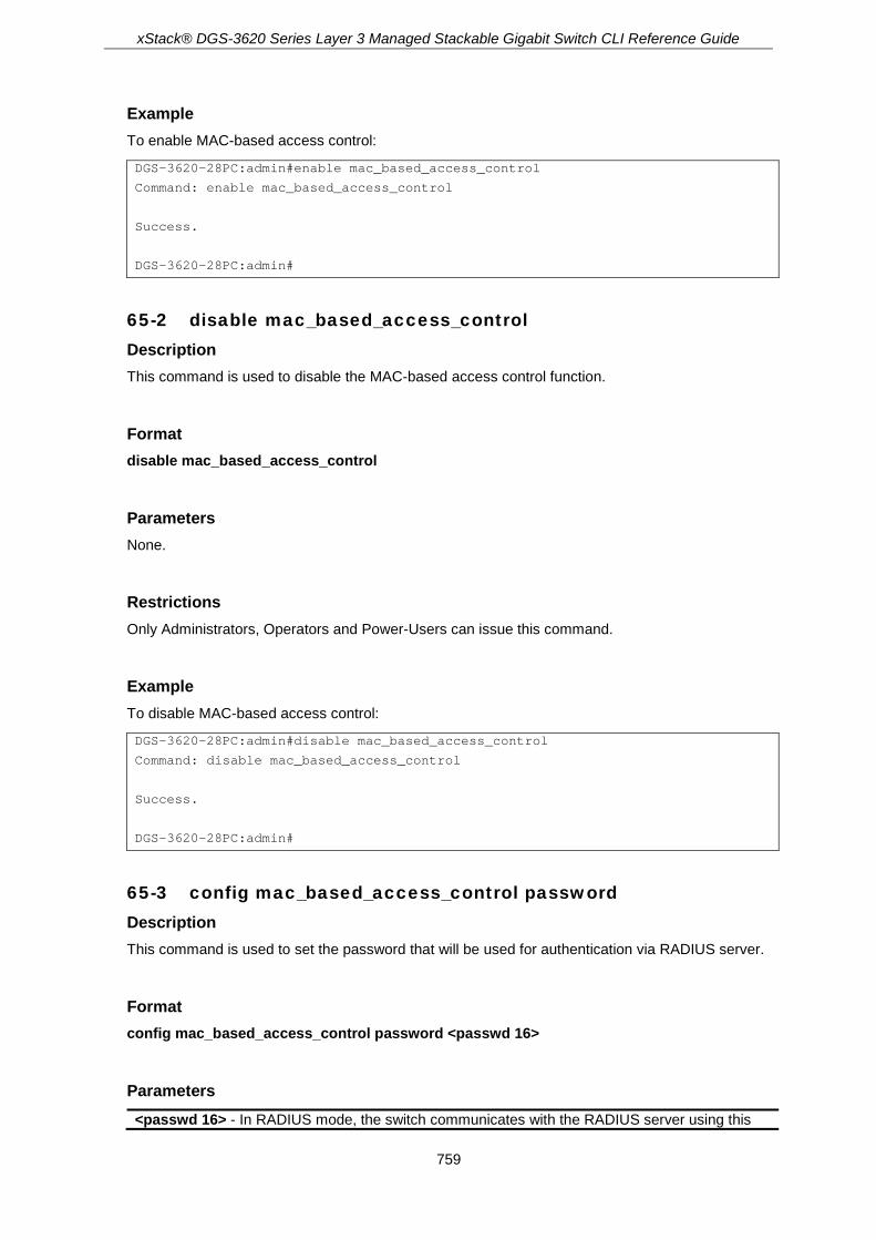
xStack® DGS-3620 Series Layer 3 Managed Stackable Gigabit Switch CLI Reference Guide
759
Example To enable MAC-based access control:
DGS-3620-28PC:admin#enable mac_based_access_control
Command: enable mac_based_access_control
Success.
DGS-3620-28PC:admin#
65-2 disable mac_based_access_control Description This command is used to disable the MAC-based access control function.
Format disable mac_based_access_control
Parameters None.
Restrictions Only Administrators, Operators and Power-Users can issue this command.
Example To disable MAC-based access control:
DGS-3620-28PC:admin#disable mac_based_access_control
Command: disable mac_based_access_control
Success.
DGS-3620-28PC:admin#
65-3 config mac_based_access_control password Description This command is used to set the password that will be used for authentication via RADIUS server.
Format config mac_based_access_control password <passwd 16>
Parameters <passwd 16> - In RADIUS mode, the switch communicates with the RADIUS server using this

xStack® DGS-3620 Series Layer 3 Managed Stackable Gigabit Switch CLI Reference Guide
760
password. The maximum length of the key is 16 characters.
Restrictions Only Administrators, Operators and Power-Users can issue this command.
Example To configure the password “rosebud” that will be used for authentication via RADIUS server:
DGS-3620-28PC:admin#config mac_based_access_control password rosebud
Command: config mac_based_access_control password rosebud
Success.
DGS-3620-28PC:admin#
65-4 config mac_based_access_control method Description This command is used to authenticate via a local database or a RADIUS server.
Format config mac_based_access_control method [local | radius]
Parameters local - Specifies to authenticate via local database. radius - Specifies to authenticate via RADIUS server.
Restrictions Only Administrators, Operators and Power-Users can issue this command.
Example To configure the MAC-based access control method as local:
DGS-3620-28PC:admin#config mac_based_access_control method local
Command: config mac_based_access_control method local
Success.
DGS-3620-28PC:admin#
65-5 config mac_based_access_control guest_vlan ports Description This command is used to put the specified port in guest VLAN mode. For those ports not contained in the port list, they are in non-guest VLAN mode.For detailed information about the operation of

xStack® DGS-3620 Series Layer 3 Managed Stackable Gigabit Switch CLI Reference Guide
761
guest VLAN mode, please see the description for configuring the MAC-based access control port command.
Format config mac_based_access_control guest_vlan ports <portlist>
Parameters <portlist> - When a port is configured as gurest VLAN member port, this port will move to guest
VLAN if it’s MAC-based access control state is enable.
Restrictions Only Administrators, Operators and Power-Users can issue this command.
Example To configure the MAC-based access control guest VLAN membership for port 1 to 8:
DGS-3620-28PC:admin# config mac_based_access_control guest_vlan ports 1-8
Command: config mac_based_access_control guest_vlan ports 1-8
Success.
DGS-3620-28PC:admin#
65-6 config mac_based_access_control ports Description This command is used to configure the MAC-based access control setting. When the MAC-based access control function is enabled for a port, and the port is not a MAC-based access control guest VLAN member, the user who is attached to this port will not be forwarded unless the user passes the authentication. A user that does not pass the authentication will not be serviced by the switch. If the user passes the authentication, the user will be able to forward traffic operated under the assigned VLAN.
When the MAC-based access control function is enabled for a port, and the port is a MAC-based access control guest VLAN member, the port(s) will be removed from the original VLAN(s) member ports, and added to MAC-based access control guest VLAN member ports. Before the authentication process starts, the user is able to forward traffic under the guest VLAN. After the authentication process, the user will be able to access the assigned VLAN.
If the port authorize mode is port based mode, when the port has been moved to the authorized VLAN, the subsequent users will not be authenticated again. They will operate in the current authorized VLAN. If the port authorize mode is host based mode, then each user will be authorized individually and be capable of getting its own assigned VLAN.

xStack® DGS-3620 Series Layer 3 Managed Stackable Gigabit Switch CLI Reference Guide
762
Format config mac_based_access_control ports [<portlist> | all] {state [enable | disable] | aging_time [infinite | <min 1-1440>] | block_time <sec 0-300> | max_users [<value 1-4000> | no_limit]}(1)
Parameters <portlist> - Enter a range of ports to configure the MAC-based access control settings all - Specifies to select all the ports. state - Specifies whether the MAC-based access control function is enabled or disabled.
enable - Specifies to enable the MAC-based access control function. disable - Specifies to disable the MAC-based access control function.
aging_time - Specifies a time period during which an authenticated host will be kept in the authenticated state. When the aging time is timed-out, the host will be moved back to unauthenticated state. infinite - Specifies an unlimited aging time. <min 1-1440> - Enter the age-out time, in minutes, between 1 and 1440.
block_time - Specifies the blocking time, in seconds, between 0 and 300. <second 0-300> - Enter the blocking time. The blocking time value must be between 0 and
300 seconds. max_users - Specifies the number of maximum users. The default value is 1024 users.
<value 1-4000> - Enter the maximum number of users between 1 and 4000. no_limit - Specifies an unlimited number of users.
Restrictions Only Administrators, Operators and Power-Users can issue this command.
Example To configure the port state for ports 1 to 8:
DGS-3620-28PC:admin# config mac_based_access_control ports 1-8 state enable
Command: config mac_based_access_control ports 1-8 state enable
Success.
DGS-3620-28PC:admin#
65-7 create mac_based_access_control Description This command is used to create a MAC-based access control guest VLAN.
Format create mac_based_access_control [guest_vlan <vlan_name 32> | guest_vlanid <vlanid 1-4094>]
Parameters guest_vlan - Specifies the name of the guest VLAN.

xStack® DGS-3620 Series Layer 3 Managed Stackable Gigabit Switch CLI Reference Guide
763
<vlan_name 32> - Enter the name of the guest VLAN. The guest VLAN name can be up to 32 characters long.
guest_vlanid - Specifies the VLAN ID of the guest VLAN. <vlanid 1-4094> - Enter the VLAN ID of the guest VLAN. The guest VLAN ID must be
between 1 and 4094.
Restrictions Only Administrators, Operators and Power-Users can issue this command.
Example To create a MAC-based access control guest VLAN:
DGS-3620-28PC:admin#create mac_based_access_control guest_vlan default
Command: create mac_based_access_control guest_vlan default
Success.
DGS-3620-28PC:admin#
65-8 delete mac_based_access_control Description This command is used to delete MAC-based access control guest VLANs.
Format delete mac_based_access_control [guest_vlan <vlan_name 32> | guest_vlanid < vlanid 1-4094>]
Parameters guest_vlan - Specifies the name of the guest VLAN.
<vlan_name 32> - Enter the name of the guest VLAN. The guest VLAN name can be up to 32 characters long.
guest_vlanid - Specifies the VLAN ID of the guest VLAN. <vlanid 1-4094> - Enter the VLAN ID of the guest VLAN. The guest VLAN ID must be
between 1 and 4094.
Restrictions Only Administrators, Operators and Power-Users can issue this command.
Example To delete a MAC-based access control guest VLAN:
DGS-3620-28PC:admin#delete mac_based_access_control guest_vlan default
Command: delete mac_based_access_control guest_vlan default
Success.

xStack® DGS-3620 Series Layer 3 Managed Stackable Gigabit Switch CLI Reference Guide
764
DGS-3620-28PC:admin#
65-9 clear mac_based_access_control auth_state Description This command is used to clear the authentication state of a user (or port). The port (or the user) will return to un-authenticated state. All the timers associated with the port (or the user) will be reset.
Format clear mac_based_access_control auth_state [ports [all | <portlist>] | mac_addr <macaddr>]
Parameters ports - Specifies the port range to clear the authentication state.
all - Specifies all ports. <portlist> - Enter a range of ports.
mac_addr - Specifies to clear a specified host authentication state. <macaddr> - Enter the MAC address here.
Restrictions Only Administrators, Operators and Power-Users can issue this command.
Example To clear the authentication state of all ports:
DGS-3620-28PC:admin#clear mac_based_access_control auth_state ports all
Command: clear mac_based_access_control auth_state ports all
Success.
DGS-3620-28PC:admin#
65-10 create mac_based_access_control_local mac Description This command is used to create a database entry.
Format create mac_based_access_control_local mac <macaddr> {[vlan <vlan_name 32> | vlanid <vlanid 1-4094>]}
Parameters <macaddr> - Enter the MAC address that access accepts by local mode. vlan - (Optional) If the MAC address is authorized, the port will be assigned to this VLAN.
<vlan_name 32> - Enter a VLAN name up to 32 characters long.
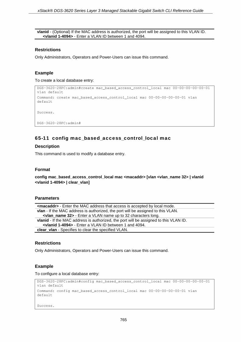
xStack® DGS-3620 Series Layer 3 Managed Stackable Gigabit Switch CLI Reference Guide
765
vlanid - (Optional) If the MAC address is authorized, the port will be assigned to this VLAN ID. <vlanid 1-4094> - Enter a VLAN ID between 1 and 4094.
Restrictions Only Administrators, Operators and Power-Users can issue this command.
Example To create a local database entry:
DGS-3620-28PC:admin#create mac_based_access_control_local mac 00-00-00-00-00-01 vlan default
Command: create mac_based_access_control_local mac 00-00-00-00-00-01 vlan default
Success.
DGS-3620-28PC:admin#
65-11 config mac_based_access_control_local mac Description This command is used to modify a database entry.
Format config mac_based_access_control_local mac <macaddr> [vlan <vlan_name 32> | vlanid <vlanid 1-4094> | clear_vlan]
Parameters <macaddr> - Enter the MAC address that access is accepted by local mode. vlan - If the MAC address is authorized, the port will be assigned to this VLAN.
<vlan_name 32> - Enter a VLAN name up to 32 characters long. vlanid - If the MAC address is authorized, the port will be assigned to this VLAN ID.
<vlanid 1-4094> - Enter a VLAN ID between 1 and 4094. clear_vlan - Specifies to clear the specified VLAN.
Restrictions Only Administrators, Operators and Power-Users can issue this command.
Example To configure a local database entry:
DGS-3620-28PC:admin#config mac_based_access_control_local mac 00-00-00-00-00-01 vlan default
Command: config mac_based_access_control_local mac 00-00-00-00-00-01 vlan default
Success.

xStack® DGS-3620 Series Layer 3 Managed Stackable Gigabit Switch CLI Reference Guide
766
DGS-3620-28PC:admin#
65-12 config mac_based_access_control max_users Description This command is used to configure the MAC-based access control maximum number of authorized users.
Format config mac_based_access_control max_users [<value 1-4000> | no_limit]
Parameters <value 1-4000> - Enter the maximum number of authorized users. no_limit - Specifies an unlimited number of authorized users.
Restrictions Only Administrators, Operators and Power-Users can issue this command.
Example To configure the MAC-based access control maximum number of authorized users:
DGS-3620-28PC:admin#config mac_based_access_control max_users 2
Command: config mac_based_access_control max_users 2
Success.
DGS-3620-28PC:admin#
65-13 config mac_based_access_control authorization attributes Description This command is used to enable or disable the acceptance of an authorized configuration. When authorization is enabled for MAC-based access controls with RADIUS authentication, the authorized attributes (for example VLAN, 802.1p default priority, and ACL) assigned by the RADUIS server will be accepted if the global authorization status is enabled. When authorization is enabled for MAC-based access controls with local authentication, the authorized attributes assigned by the local database will be accepted.
Format config mac_based_access_control authorization attributes {radius [enable | disable] | local [enable | disable]}(1)

xStack® DGS-3620 Series Layer 3 Managed Stackable Gigabit Switch CLI Reference Guide
767
Parameters radius - Specifies to enable or disable the authorized attributes assigned by the RADIUS server
that will be accepted. enable - If specified to enable, the authorized attributes (for example VLAN, 802.1p default
priority, and ACL) assigned by the RADIUS server will be accepted if the global authorization status is enabled. The default state is enabled.
disable - If specified to disable, the authorized attributes (for example VLAN, 802.1p default priority, and ACL) assigned by the RADIUS server will not be accepted even if the global authorization status is enabled.
local - Specifies to enable to disable the authorized attributes assigned by the local database. enable - If specified to enable, the authorized attributes assigned by the local database will be
accepted if the global authorization status is enabled. The default state is enabled. disable - If specified to disable, the authorized attributes assigned by the local database will
not be accepted even if the global authorization status is enabled.
Restrictions Only Administrators, Operators and Power-Users can issue this command.
Example To disable the configuration authorized from the local database:
DGS-3620-28PC:admin#config mac_based_access_control authorization attributes local disable
Command: config mac_based_access_control authorization attributes local disable
Success.
DGS-3620-28PC:admin#
65-14 delete mac_based_access_control_local Description This command is used to delete a database entry
Format delete mac_based_access_control_local [mac <macaddr> | vlan <vlan_name 32> | vlanid <vlanid 1-4094>]
Parameters mac - Delete database by this MAC address.
<macaddr> - Enter the MAC address here. vlan - Delete database by this VLAN name.
<vlan_name 32> - Enter a VLAN name up to 32 characters long. vlanid - Delete database by this VLAN ID.
<vlanid 1-4094> - Enter a VLAN ID value must be between 1 and 4094.
Restrictions Only Administrators, Operators and Power-Users can issue this command.
xStack® DGS-3620 Series Layer 3 Managed Stackable Gigabit Switch CLI Reference Guide
768
Example To delete a MAC-based access control local by MAC address:
DGS-3620-28PC:admin#delete mac_based_access_control_local mac 00-00-00-00-00-01
Command: delete mac_based_access_control_local mac 00-00-00-00-00-01
Success.
DGS-3620-28PC:admin#
To delete a MAC-based access control local by VLAN name:
DGS-3620-28PC:admin#delete mac_based_access_control_local vlan default
Command: delete mac_based_access_control_local vlan default
Success.
DGS-3620-28PC:admin#
65-15 show mac_based_access_control auth_state ports Description This command is used to display MAC-based access control authentication MAC information.
Format show mac_based_access_control auth_state ports {<portlist>}
Parameters <portlist> - (Optional) Specifies the ports to display.
Restrictions None.
Example To display MAC-based access control authentication MAC information:

xStack® DGS-3620 Series Layer 3 Managed Stackable Gigabit Switch CLI Reference Guide
769
DGS-3620-28PC:admin# show mac_based_access_control auth_state ports
Command: show mac_based_access_control auth_state ports
(P): Port-based Prio: Priority
Port MAC Address Original State VID Prio Aging Time/
RX VID Block Time
------ -------------------- ---- -------------- ---- ---- -----------
1 00-00-00-00-00-01 1 Authenticated - 6 1439
1 00-00-12-00-03-00 1 Blocked - - 286
3 00-00-00-00-00-02(P) 1 Authenticated - 6 1440
Total Authenticating Hosts : 0
Total Authenticated Hosts : 2
Total Blocked Hosts : 1
DGS-3620-28PC:admin#
65-16 show mac_based_access_control Description This command is used to display MAC-based access control information.
Format show mac_based_access_control {ports {<portlist>}}
Parameters ports - (Optional) Specifies to display the MAC-based access control port state.
<portlist> - Enter a range of ports to be displayed.
Restrictions None.
Example To display MAC-based access control information:
DGS-3620-28PC:admin#show mac_based_access_control
Command: show mac_based_access_control
MAC-based Access Control
------------------------------------
State : Disabled
Method : Local
Password Type : Manual String
Password : default
Max User : No Limit

xStack® DGS-3620 Series Layer 3 Managed Stackable Gigabit Switch CLI Reference Guide
770
Guest VLAN :
Guest VLAN Member Ports:
RADIUS Authorization : Enabled
Local Authorization : Enabled
Trap State : Enabled
Log State : Enabled
DGS-3620-28PC:admin#
To display MAC-based access control information for ports 1 to 4:
DGS-3620-28PC:admin#show mac_based_access_control ports 1-4
Command: show mac_based_access_control ports 1-4
Port State Aging Time Block Time Max User
(min) (sec)
----- -------- ---------- --------- --------
1 Disabled 1440 300 1024
2 Disabled 1440 300 1024
3 Disabled 1440 300 1024
4 Disabled 1440 300 1024
DGS-3620-28PC:admin#
65-17 show mac_based_access_control_local Description This command is used to display MAC-based access control local data.
Format show mac_based_access_control_local {[mac <macaddr> | vlan <vlan_name 32> | vlanid <vlanid 1-4094>]}
Parameters mac - (Optional) Display MAC-based access control local databases by this MAC address.
<macaddr> - Enter the MAC address here. vlan - (Optional) Specifies the VLAN.
<vlan_name 32> - Enter the VLAN name up to 32 characters long. vlanid - (Optional) Specifies the VLAN ID.
<vlanid 1-4094> - Enter the VLAN ID value between 1 and 4094.
Restrictions None.
Example To display MAC-based access control local data:

xStack® DGS-3620 Series Layer 3 Managed Stackable Gigabit Switch CLI Reference Guide
771
DGS-3620-28PC:admin#show mac_based_access_control_local
Command: show mac_based_access_control_local
MAC Address VID
----------------- ------
00-00-00-00-00-01 1
Total Entries:1
DGS-3620-28PC:admin#
To display MAC-based access control local data by MAC address:
DGS-3620-28PC:admin#show mac_based_access_control_local mac 00-00-00-00-00-01
Command: show mac_based_access_control_local mac 00-00-00-00-00-01
MAC Address VID
----------------- ------
00-00-00-00-00-01 1
Total Entries:1
DGS-3620-28PC:admin#
To display MAC-based access control local data by VLAN:
DGS-3620-28PC:admin#show mac_based_access_control_local vlan default
Command: show mac_based_access_control_local vlan default
MAC Address VID
----------------- ------
00-00-00-00-00-01 1
Total Entries: 1
DGS-3620-28PC:admin#
65-18 config mac_based_access_control log state Description This command is used to enable or disable the generating of MAC-based Access Control logs.
Format config mac_based_access_control log state [enable | disable]
Parameters state - Specifies the log state for MAC-based Access Control.
enable - Specifies that the log for MAC-based Access Control will be enabled. disable - Specifies that the log for MAC-based Access Control will be disabled.

xStack® DGS-3620 Series Layer 3 Managed Stackable Gigabit Switch CLI Reference Guide
772
Restrictions Only Administrators, Operators and Power-Users can issue this command.
Example To disable the log state for MAC-based Access Control:
DGS-3620-28PC:admin# config mac_based_access_control log state disable
Command: config mac_based_access_control log state disable
Success.
DGS-3620-28PC:admin#
65-19 config mac_based_access_control trap state Description This command is used to enable or disable the sending of MAC-based Access Control traps.
Format config mac_based_access_control trap state [enable | disable]
Parameters state - Specifies the trap state for MAC-based Access Control.
enable - Specifies that the trap state for MAC-based Access Control will be enabled. disable - Specifies that the trap state for MAC-based Access Control will be disabled.
Restrictions Only Administrators, Operators and Power-Users can issue this command.
Example To enable the trap state for MAC-based Access Control:
DGS-3620-28PC:admin# config mac_based_access_control trap state enable
Command: config mac_based_access_control trap state enable
Success.
DGS-3620-28PC:admin#
65-20 config mac_based_access_control password_type Description This command is used to configure the type of RADIUS authentication password for MAC-based Access Control.

xStack® DGS-3620 Series Layer 3 Managed Stackable Gigabit Switch CLI Reference Guide
773
Format config mac_based_access_control password_type [manual_string | client_mac_address]
Parameters manual_string - Specifies to use the same string as password for all clients do RADIUS
authentication, the string can be configured by using the command “config mac_based_access_control password”.
client_mac_address - Specifies to use the client’s MAC address as the password for RADIUS authentication. The MAC address format can be configured by using the command “config authentication mac_format”.
Restrictions Only Administrators, Operators and Power-Users can issue this command.
Example To configure the MAC-based Access Control using client’s MAC address as authentication password:
DGS-3620-28PC:admin# config mac_based_access_control password_type client_mac_address
Command: config mac_based_access_control password_type client_mac_address
Success.
DGS-3620-28PC:admin#
To configure the MAC-based Access Control using “manual_string” as authentication password:
DGS-3620-28PC:admin# config mac_based_access_control password_type manual_string
Command: config mac_based_access_control password_type manual_string
Success.
DGS-3620-28PC:admin#

xStack® DGS-3620 Series Layer 3 Managed Stackable Gigabit Switch CLI Reference Guide
774
Chapter 66 MD5 Configuration Commands
config md5 key <key_id 1-255> <password 16> create md5 key <key_id 1-255> <password 16> delete md5 key <key_id 1-255> show md5 {key <key_id 1-255>}
66-1 config md5 key Description This command is used to configure an MD5 key and password. The MD5 configuration allows for the entry of a 16 character Message Digest - version 5 (MD5) key which can be used to authenticate every packet exchanged between OSPF routers. It is used as a security mechanism to limit the exchange of network topology information to the OSPF routing domain.
Format config md5 key <key_id 1-255> <password 16>
Parameters key - Specifies that the MD5 key will be configured.
<key_id 1-255> - Enter the MD5 key used here. This key must be between 1 and 255. <password 16> - Enter an alphanumeric string of between 1 and 16, case-sensitive
characters, used to generate the Message Digest which is in turn is used to authenticate OSPF packets within the OSPF routing domain.
Restrictions Only Administrators and Operators can issue this command.
Example To configure an MD5 key and password:
DGS-3620-28PC:admin# config md5 key 1 dlink
Command: config md5 key 1 dlink
Success.
DGS-3620-28PC:admin#
66-2 create md5 key Description This command is used to create an MD5 key table.

xStack® DGS-3620 Series Layer 3 Managed Stackable Gigabit Switch CLI Reference Guide
775
Format create md5 key <key_id 1-255> <password 16>
Parameters key - Specifies that the MD5 key will be created.
<key_id 1-255> - Enter the MD5 key used here. This key must be between 1 and 255. <password 16> - Enter an alphanumeric string of between 1 and 16, case-sensitive
characters, used to generate the Message Digest which is in turn is used to authenticate OSPF packets within the OSPF routing domain.
Restrictions Only Administrators and Operators can issue this command.
Example To create an MD5 key table:
DGS-3620-28PC:admin# create md5 key 1 dlink
Command: create md5 key 1 dlink
Success.
DGS-3620-28PC:admin#
66-3 delete md5 key Description This command is used to delete an MD5 key table.
Format delete md5 key <key_id 1-255>
Parameters key - Specifies that the MD5 key will be removed.
<key_id 1-255> - Enter the MD5 key used here. This key must be between 1 and 255.
Restrictions Only Administrators and Operators can issue this command.
Example To delete an MD5 key table:

xStack® DGS-3620 Series Layer 3 Managed Stackable Gigabit Switch CLI Reference Guide
776
DGS-3620-28PC:admin# delete md5 key 1
Command: delete md5 key 1
Success.
DGS-3620-28PC:admin#
66-4 show md5 Description This command is used to display the MD5 key table.
Format show md5 {key <key_id 1-255>}
Parameters key - (Optional) Specifies that the MD5 key will be displayed.
<key_id 1-255> - Enter the MD5 key used here. This key must be between 1 and 255. If no parameter is specified, the system will display the MD5 key table.
Restrictions None.
Example To display the MD5 key table:
DGS-3620-28PC:admin#show md5
Command: show md5
MD5 Key Table Configurations
Key-ID Key
------ ----------
1 dlink
Total Entries: 1
DGS-3620-28PC:admin#
xStack® DGS-3620 Series Layer 3 Managed Stackable Gigabit Switch CLI Reference Guide
777
Chapter 67 Mirror Commands
create mirror group_id <value 1-4> config mirror port <port> {[add | delete] source [ports <portlist> | vlan vlan_id <vid_list>] [rx | tx |
both]} config mirror group_id <value 1-4> {target_port <port> | [add | delete] source [ports <portlist> |
vlan vlan_id <vid_list>] [rx | tx | both] | state [enable | disable]}(1) delete mirror group_id <value 1-4> enable mirror disable mirror show mirror {group_id <value 1-4>}
67-1 create mirror group_id Description This command used to create a mirror group. If the mirror group has existed, do nothing and return success.
Format create mirror group_id <value 1-4>
Parameters <value 1-4> - Enter the mirror group ID used here. This value must be between 1 and 4.
Restrictions Only Administrators and Operators can issue this command.
Example Create mirror group 3:
DGS-3620-28PC:admin# create mirror group_id 3
Command: create mirror group_id 3
Success.
DGS-3620-28PC:admin#
67-2 config mirror port Description This command is used to allow a range of ports to have all of their traffic also sent to a target port − where a network sniffer or other device can monitor the network traffic. In addition, you can specify that only traffic received by, sent by or both is mirrored to the target port.

xStack® DGS-3620 Series Layer 3 Managed Stackable Gigabit Switch CLI Reference Guide
778
Format config mirror port <port> {[add | delete] source [ports <portlist> | vlan vlan_id <vid_list>] [rx | tx | both]}
Parameters <port> - Enter the port that will receive the packets duplicated at the mirror port. add - (Optional) Specifies the mirror entry to be added. delete - (Optional) Specifies the mirror entry to be deleted. source ports - (Optional) Specifies the ports that will be mirrored. All packets entering and
leaving the source port can be duplicated in the mirror port. <portlist> - Enter a range of ports to be configured.
vlan - (Optional) Specifies a range of VLANs to be configured as sources. All ingress packets with the specified VLAN ID will be mirrored. vlan_id - Specifies the VLAN ID that will be used for this configuration.
<vid_list> - Enter the VLAN ID list that will be used here. rx - (Optional) Allow the mirroring of only packets received (flowing into) the port or ports in the
port list. tx - (Optional) Allow the mirroring of only packets sent (flowing out of) the port or ports in the port
list. both - (Optional) Mirror all the packets received or sent by the port or ports in the port list.
Restrictions Only Administrators and Operators can issue this command.
Example To add mirroring target port 6 and the source ports 1 to 5 rx and tx packets:
DGS-3620-28PC:admin#config mirror port 6 add source ports 1-5 both
Command: config mirror port 6 add source ports 1-5 both
Success.
DGS-3620-28PC:admin#
67-3 config mirror group_id Description This command used to configure mirror group’s parameters. It can configure mirror group’s target port, state and source ports. The mirror group target port can’t be a member of all mirror groups’ source ports. Each mirror group’s target port can be the same port. But each mirror group’s source ports can’t overlap.
Format config mirror group_id <value 1-4> {target_port <port> | [add | delete] source [ports <portlist> | vlan vlan_id <vid_list>] [rx | tx | both] | state [enable | disable]}(1)

xStack® DGS-3620 Series Layer 3 Managed Stackable Gigabit Switch CLI Reference Guide
779
Parameters <value 1-4> - Enter the mirror group ID used here. This value must be between 1 and 4. target_port - (Optional) Specifies the port that will receive the packets duplicated at the mirror
port. <port> - Enter the target port number used here.
add - (Optional) Specifies the mirror source ports to be add. delete - (Optional) Specifies the mirror source ports to be delete source - (Optional) Specifies the source ports used. ports - (Optional) Specifies the list of ports used as source ports.
<portlist> - Enter the list of ports to be used as the source ports here. vlan - (Optional) Specifies the VLANs that will be used as the source VLANs.
vlan_id - Specifies the VLAN ID that will be used as the source VLAN. <vid_list> - Enter the VLAN ID list that will be used here. Note: This will be shared with
Ingress ACL entries. rx - (Optional) Specifies that only the received packets on the mirror group source ports will be
mirrored to the mirror group target port. tx - (Optional) Specifies that only the sent packets on the mirror group source ports will be
mirrored to the mirror group target port. both - (Optional) Specifies that both the received and sent packets on the mirror group source
ports will be mirrored to the mirror group target port. state - (Optional) Specifies the mirror group state to enable or disable the mirror group function.
enable - Specifies that the mirror group state will be enabled. disable - Specifies that the mirror group state will be disabled.
Restrictions Only Administrators and Operators can issue this command.
Example Configure mirror group 2 with state enable and add source ports 1:4-1:9:
DGS-3620-28PC:admin# config mirror group_id 2 state enable add source ports 1:4-1:9 both
Command: config mirror group_id 2 state enable add source ports 1:4-1:9 both
Success.
DGS-3620-28PC:admin#
67-4 delete mirror group_id Description This command is used to delete a mirror group on the Switch.
Format delete mirror group_id <value 1-4>
Parameters <value 1-4> - Enter the mirror group ID used here. This value must be between 1 and 4.

xStack® DGS-3620 Series Layer 3 Managed Stackable Gigabit Switch CLI Reference Guide
780
Restrictions Only Administrators and Operators can issue this command.
Example To delete mirror group 3:
DGS-3620-28PC:admin# delete mirror group_id 3
Command: delete mirror group_id 3
Success.
DGS-3620-28PC:admin#
67-5 enable mirror Description This command, combined with the disable mirror command below, allows you to enable or disable mirror function without having to modify the mirror session configuration.
Note: If the target port hasn’t been set, enable mirror will not take effect.
Format enable mirror
Parameters None.
Restrictions Only Administrators and Operators can issue this command.
Example To enable mirroring configurations:
DGS-3620-28PC:admin#enable mirror
Command: enable mirror
Success.
DGS-3620-28PC:admin#

xStack® DGS-3620 Series Layer 3 Managed Stackable Gigabit Switch CLI Reference Guide
781
67-6 disable mirror Description This command, combined with the enable mirror command above, allows you to enable or disable mirror function without having to modify the mirror session configuration.
Format disable mirror
Parameters None.
Restrictions Only Administrators and Operators can issue this command.
Example To disable mirroring configurations:
DGS-3620-28PC:admin#disable mirror
Command: disable mirror
Success.
DGS-3620-28PC:admin#
67-7 show mirror Description This command is used to display the current mirroring configuration on the switch.
Format show mirror {group_id <value 1-4>}
Parameters group_id – (Optional) Specifies the group ID used for this display.
<value 1-4> - Enter the group ID used for this display here. This value must be between 1 and 4.
Restrictions None.

xStack® DGS-3620 Series Layer 3 Managed Stackable Gigabit Switch CLI Reference Guide
782
Example To display mirroring configuration:
DGS-3620-28PC:admin#show mirror
Command: show mirror
Mirror Global State: Enabled
Group ID : 1
State : Enabled
Target Port : 1:1
Source Ports
RX : 1:2-1:3
TX : 1:2-1:3
Source VLANs
RX : 2-3
DGS-3620-28PC:admin#

xStack® DGS-3620 Series Layer 3 Managed Stackable Gigabit Switch CLI Reference Guide
783
Chapter 68 MLD Proxy Commands
enable mld_proxy disable mld_proxy config mld_proxy downstream_if [add | delete] vlan [<vlan_name 32> | vlanid <vidlist>] config mld_proxy upstream_if {vlan [<vlan_name 32> | vlanid <vlanid 1-4094>] | router_ports
[add | delete] <portlist> | source_ip <ipv6addr> | unsolicited_report_interval <sec 0-25>}(1) show mld_proxy {group}
68-1 enable mld_proxy Description This command is used to enable the MLD proxy on the switch.
Format enable mld_proxy
Parameters None.
Restrictions Only Administrators, Operators and Power-Users can issue this command.
Example To enable the MLD proxy:
DGS-3620-28PC:admin#enable mld_proxy
Command: enable mld_proxy
Success.
DGS-3620-28PC:admin#
68-2 disable mld_proxy Description This command is used to disable the MLD proxy on the switch.
Format disable mld_proxy
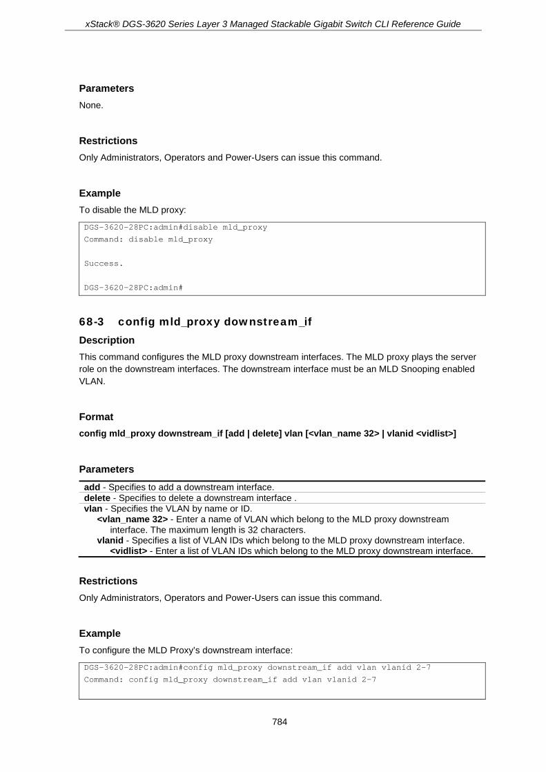
xStack® DGS-3620 Series Layer 3 Managed Stackable Gigabit Switch CLI Reference Guide
784
Parameters None.
Restrictions Only Administrators, Operators and Power-Users can issue this command.
Example To disable the MLD proxy:
DGS-3620-28PC:admin#disable mld_proxy
Command: disable mld_proxy
Success.
DGS-3620-28PC:admin#
68-3 config mld_proxy downstream_if Description This command configures the MLD proxy downstream interfaces. The MLD proxy plays the server role on the downstream interfaces. The downstream interface must be an MLD Snooping enabled VLAN.
Format config mld_proxy downstream_if [add | delete] vlan [<vlan_name 32> | vlanid <vidlist>]
Parameters add - Specifies to add a downstream interface. delete - Specifies to delete a downstream interface . vlan - Specifies the VLAN by name or ID.
<vlan_name 32> - Enter a name of VLAN which belong to the MLD proxy downstream interface. The maximum length is 32 characters.
vlanid - Specifies a list of VLAN IDs which belong to the MLD proxy downstream interface. <vidlist> - Enter a list of VLAN IDs which belong to the MLD proxy downstream interface.
Restrictions Only Administrators, Operators and Power-Users can issue this command.
Example To configure the MLD Proxy’s downstream interface:
DGS-3620-28PC:admin#config mld_proxy downstream_if add vlan vlanid 2-7
Command: config mld_proxy downstream_if add vlan vlanid 2-7

xStack® DGS-3620 Series Layer 3 Managed Stackable Gigabit Switch CLI Reference Guide
785
Success.
DGS-3620-28PC:admin#
68-4 config mld_proxy upstream_if Description This command is used to configure the setting for the MLD proxy’s upstream interface. The MLD proxy plays the host role on the upstream interface. It will send MLD report packets to the router port. The source IP address determines the source IP address to be encoded in the MLD protocol packet. If the router port is empty, the upstream will send the MLD protocol packet to all member ports on the upstream interface.
Format config mld_proxy upstream_if {vlan [<vlan_name 32> | vlanid <vlanid 1-4094>] | router_ports [add | delete] <portlist> | source_ip <ipv6addr> | unsolicited_report_interval <sec 0-25>}(1)
Parameters vlan - Specifies the VLAN for the upstream interface.
<vlan_name 32> - Enter a VLAN name between 1 and 32 characters. vlanid - Specifies the VLAN ID for the upstream interface.
<vlanid 1-4094> - Enter the VLAN ID between 1 and 4094. router_ports - Specifies a list of ports that are connected to multicast-enabled routers.
add - Specifies to add the router ports. delete - Specifies to delete the router ports. <portlist> - Enter a range of ports to be configured.
source_ip - Specifies the source IPv6 address of the upstream protocol packet. If it is not specified, zero IP address will be used as the protocol source IP address. <ipv6addr>> - Enter the IPv6 address.
unsolicited_report_interval - Specifies the time between repetitions of the host's initial report of membership in a group. The default is 10 seconds. If set to 0, only one report packet is sent. <sec 0-25> - Enter the time between 0 and 25 seconds.
Restrictions Only Administrators, Operators and Power-Users can issue this command.
Example To configure the router port of MLD proxy’s upstream interface:
DGS-3620-28PC:admin#config mld_proxy upstream_if vlan default router_ports add 3
Command: config mld_proxy upstream_if vlan default router_ports add 3
Success.
DGS-3620-28PC:admin#

xStack® DGS-3620 Series Layer 3 Managed Stackable Gigabit Switch CLI Reference Guide
786
68-5 show mld_proxy Description This command is used to display the MLD proxy’s configuration or group information. The display status item means group entry is determined by whether or not the chip has been inserted.
Format show mld_proxy {group}
Parameters group - (Optional) Specifies the group information.
Note: If the group is not specified, the MLD proxy configuration will be displayed.
Restrictions None.
Example To display the MLD proxy’s information:
DGS-3620-28PC:admin#show mld_proxy
Command: show mld_proxy
MLD Proxy Global State : Enabled
Upstream Interface
VLAN ID : 1
Dynamic Router Ports : 1-4
Static Router Ports : 5-6
Unsolicited Report Interval : 10
Source IP Address : ::
Downstream Interface
VLAN List : 2-4
DGS-3620-28PC:admin#
To display the MLD proxy’s group information:
DGS-3620-28PC:admin#show mld_proxy group
Command: show mld_proxy group
Source : NULL
Group : FF1E::0202
Downstream VLAN : 4
Member Ports : 3,6
Status : Active
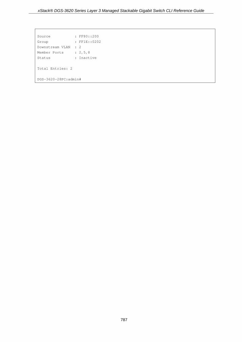
xStack® DGS-3620 Series Layer 3 Managed Stackable Gigabit Switch CLI Reference Guide
787
Source : FF80::200
Group : FF1E::0202
Downstream VLAN : 2
Member Ports : 2,5,8
Status : Inactive
Total Entries: 2
DGS-3620-28PC:admin#

xStack® DGS-3620 Series Layer 3 Managed Stackable Gigabit Switch CLI Reference Guide
788
Chapter 69 MLD Snooping Commands
config mld_snooping [vlan_name <vlan_name 32> | vlanid <vlanid_list> | all] {state [enable |
disable] | topology_changes_notification [ignore | process] | fast_done [enable | disable] | proxy_reporting {state [enable | disable]| source_ip <ipv6addr>}}(1)
config mld_snooping rate_limit [ports <portlist> | vlanid <vlanid_list>] [<value 1-1000> | no_limit] show mld_snooping rate_limit [ports <portlist> | vlanid <vlanid_list>] create mld_snooping static_group [vlan <vlan_name 32> | vlanid <vlanid_list>] <ipv6addr> config mld_snooping static_group [vlan <vlan_name 32> | vlanid <vlanid_list>] <ipv6addr> [add
| delete] <portlist> delete mld_snooping static_group [vlan <vlan_name 32> | vlanid <vlanid_list>] <ipv6addr> show mld_snooping static_group {[vlan <vlan_name 32> | vlanid <vlanid_list>] <ipv6addr>} show mld_snooping statistic counter [vlan <vlan_name 32> | vlanid <vlanid_list> | ports
<portlist>] clear mld_snooping statistics counter config mld_snooping querier [vlan_name <vlan_name 32> | vlanid <vlanid_list> | all]
{query_interval <sec 1-65535> | max_response_time <sec 1-25> | robustness_variable <value 1-7> | last_listener_query_interval <sec 1-25> | state [enable | disable] | version <value 1-2>}(1)
config mld_snooping mrouter_ports [vlan <vlan_name 32> | vlanid <vlanid_list>] [add | delete] <portlist>
config mld_snooping mrouter_ports_forbidden [vlan <vlan_name 32> | vlanid <vlanid_list>] [add | delete] <portlist>
enable mld_snooping disable mld_snooping show mld_snooping {[vlan <vlan_name 32> | vlanid <vlanid_list >]} show mld_snooping group {[vlan <vlan_name 32> | vlanid <vlanid_list> | ports <portlist>]
{<ipv6addr>}} show mld_snooping mrouter_ports [vlan <vlan_name 32> | vlanid <vlanid_list> | all] {[static |
dynamic | forbidden]} show mld_snooping forwarding {[vlan <vlan_name 32> | vlanid <vlanid_list>]}
69-1 config mld_snooping Description This command is used to configure MLD snooping on the switch.
Format config mld_snooping [vlan_name <vlan_name 32> | vlanid <vlanid_list> | all] {state [enable | disable] | topology_changes_notification [ignore | process] | fast_done [enable | disable] | proxy_reporting {state [enable | disable]| source_ip <ipv6addr>}}(1)
Parameters vlan_name - Specifies the name of the VLAN for which MLD snooping is to be configured.
<vlan_name 32> - Enter the VLAN name. The maximum length is 32 characters. vlanid - Specifies the VLAN ID list.
<vlanid_list> - Enter the VLAN ID list.

xStack® DGS-3620 Series Layer 3 Managed Stackable Gigabit Switch CLI Reference Guide
789
all - Specifies to configure all VLANs. state - Enable or disable MLD snooping for the chosen VLAN.
enable - Enable MLD snooping for the chosen VLAN. disable - Disable MLD snooping for the chosen VLAN.
topology_changes_notification - Specifies that MLD snooping should be aware of link-layer topology changes caused by the Spanning Tree operation or not. ignore - Specifies that MLD snooping will ignore link-layer topology changes caused by the
Spanning Tree operation. The General Query won’t be sent on the same domain of link-layer topology changes.
process - Specifies that MLD snooping will process link-layer topology changes caused by the Spanning Tree operation. The General Query will be sent on the same domain of link layer topology changes.
fast_done - Enable or disable the MLD snooping fast leave function. If enabled, the membership is immediately removed when the system receive the MLD leave message. enable - Enable the MLD snooping fast leave function. disable - Disable the MLD snooping fast leave function.
proxy_reporting - Specifies that the proxy reporting function will be configured. state - Specifies the state of the proxy reporting function.
enable - Specifies that the proxy reporting function will be enabled. disable - Specifies that the proxy reporting function will be disabled.
source_ip - Specifies the source IPv6 address used. <ipv6addr> - Enter the source IPv6 address used here.
Restrictions Only Administrators, Operators and Power-Users can issue this command.
Example To configure MLD snooping:
DGS-3620-28PC:admin#config mld_snooping vlan_name default state enable
Command: config mld_snooping vlan_name default state enable
Success.
DGS-3620-28PC:admin#
69-2 config mld_snooping rate_limit Description This command is used to configure the upper limit per second for ingress MLD control packets.
Format config mld_snooping rate_limit [ports <portlist> | vlanid <vlanid_list>] [<value 1-1000> | no_limit]
Parameters ports - Specifies a range of ports to be configured.
<portlist> - Enter a range of ports to be configured. vlanid - Specifies a range of VLANs to be configured.
<vlanid_list> - Enter the VLAN ID list.

xStack® DGS-3620 Series Layer 3 Managed Stackable Gigabit Switch CLI Reference Guide
790
<value 1-1000> - Enter the rate limit of MLD control packet that the switch can process on a specific port/VLAN. The rate is specified in packet per second. The packet that exceeds the limited rate will be dropped.
no_limit - The default setting is no limit.
Restrictions Only Administrators, Operators and Power-Users can issue this command.
Example To configure the MLD snooping packet rate limit on port 1 for 100:
DGS-3620-28PC:admin#config mld_snooping rate_limit ports 1 100
Command: config mld_snooping rate_limit ports 1 100
Success.
DGS-3620-28PC:admin#
69-3 show mld_snooping rate_limit Description This command is used to display the MLD snooping rate limit setting.
Format show mld_snooping rate_limit [ports <portlist> | vlanid <vlanid_list>]
Parameters ports - Specifies a range of ports to be displayed.
<portlist> - Enter a range of ports to be displayed. vlanid - Specifies a range of VLANs to be displayed.
<vlanid_list> - Enter the VLAN ID list.
Restrictions None.
Example To display the MLD snooping packet rate limit for ports 1 to 2:
DGS-3620-28PC:admin# show mld_snooping rate_limit ports 2:1-2:2
Command: show mld_snooping rate_limit ports 2:1-2:2
Port Rate Limit(pkt/sec)
-------- --------------------
2:1 No Limit
2:2 No Limit

xStack® DGS-3620 Series Layer 3 Managed Stackable Gigabit Switch CLI Reference Guide
791
Total Entries: 2
DGS-3620-28PC:admin#
69-4 create mld_snooping static_group Description This command is used to create an MLD snooping multicast static group. Member ports can be added to the static group. The static member and the dynamic member port form the member ports of a group.
The static group will only take effect when MLD snooping is enabled on the VLAN. For those static member ports, the device needs to emulate the MLD protocol operation to the querier, and forward the traffic destined to the multicast group to the member ports. For a layer 3 device, the device is also responsible to route the packet destined for this specific group to static member ports. The static member port will only affect V2 MLD operation. The Reserved IP multicast addresses FF0x::/16 must be excluded from the configured group. The VLAN must be created first before a static group can be created.
Format create mld_snooping static_group [vlan <vlan_name 32> | vlanid <vlanid_list>] <ipv6addr>
Parameters vlan - Specifies the name of the VLAN on which the static group resides.
<vlan_name 32> - Enter the VLAN name. The maximum length is 32 characters. vlanid - Specifies the VLAN ID list.
<vlanid_list> - Enter the VLAN ID list. <ipv6addr> - Enter the multicast group IPv6 address.
Restrictions Only Administrators, Operators and Power-Users can issue this command.
Example To create an MLD snooping static group on vlan1, group FF1E::1:
DGS-3620-28PC:admin#create mld_snooping static_group vlan vlan1 FF1E::1
Command: create mld_snooping static_group vlan vlan1 FF1E::1
Success.
DGS-3620-28PC:admin#
69-5 config mld_snooping static_group Description This command is used to configure an MLD snooping static group on the switch. When a port is configured as a static member port, the MLD protocol will not operate on this port. Therefore, suppose that a port is a dynamic member port learned by MLD. If this port is configured as a static

xStack® DGS-3620 Series Layer 3 Managed Stackable Gigabit Switch CLI Reference Guide
792
member later, then the MLD protocol will stop operating on this port. The MLD protocol will resume once this port is removed from static member ports. The static member port will only affect V1 MLD operation.
Format config mld_snooping static_group [vlan <vlan_name 32> | vlanid <vlanid_list>] <ipv6addr> [add | delete] <portlist>
Parameters vlan - Specifies the name of the VLAN on which the static group resides.
<vlan_name 32> - Enter the VLAN name. The maximum length is 32 characters. vlanid - Specifies the ID of the VLAN on which the static group resides.
<vlanid_list> - Enter the VLAN ID list. <ipv6addr> - Enter the multicast group IPv6 address. add - Specifies to add the member ports. delete - Specifies to delete the member ports. <portlist> - Enter a range of ports to be configured.
Restrictions Only Administrators, Operators and Power-Users can issue this command.
Example To add ports 9 to 10 from MLD Snooping static member ports for group FF1E::1 on default VLAN:
DGS-3620-28PC:admin#config mld_snooping static_group vlan default FF1E::1 delete 9-10
Command: config mld_snooping static_group vlan default FF1E::1 delete 9-10
Success.
DGS-3620-28PC:admin#
69-6 delete mld_snooping static_group Description This command is used to delete an MLD snooping static group on the switch. The deletion of an MLD snooping static group will not affect the MLD snooping dynamic member ports for a group.
Format delete mld_snooping static_group [vlan <vlan_name 32> | vlanid <vlanid_list>] <ipv6addr>
Parameters vlan - Specifies the name of the VLAN on which the static group resides.
<vlan_name 32> - Enter the VLAN name. The maximum length is 32 characters. vlanid - Specifies the ID of the VLAN on which the static group resides.
<vlanid_list> - Enter the VLAN ID list.

xStack® DGS-3620 Series Layer 3 Managed Stackable Gigabit Switch CLI Reference Guide
793
<ipv6addr> - Enter the multicast group IPv6 address.
Restrictions Only Administrators, Operators and Power-Users can issue this command.
Example To delete an MLD snooping static group from the default VLAN, group FF1E::1:
DGS-3620-28PC:admin#delete mld_snooping static_group vlan default FF1E::1
Command: delete mld_snooping static_group vlan default FF1E::1
Success.
DGS-3620-28PC:admin#
69-7 show mld_snooping static_group Description This command is used to display the MLD snooping static groups.
Format show mld_snooping static_group {[vlan <vlan_name 32> | vlanid <vlanid_list>] <ipv6addr>}
Parameters vlan - (Optional) Specifies the name of the VLAN on which the static group resides.
<vlan_name 32> - Enter the VLAN name. The maximum length is 32 characters. vlanid - (Optional) Specifies the ID of the VLAN on which the static group resides.
<vlanid_list> - Enter the VLAN ID list. <ipv6addr> - (Optional) Specifies the multicast group IPv6 address. If no parameter is specified, the system will display all MLD snooping static groups.
If no parameter is specified, the system will display all MLD snooping static groups.
Restrictions None.
Example To display all the MLD snooping static groups:
DGS-3620-28PC:admin#show mld_snooping static_group
Command: show mld_snooping static_group
VLAN ID/Name IP Address Static Member Ports
------------- --------------- ---------------------
1/default FF1E::1 9-10
Total Entries : 1

xStack® DGS-3620 Series Layer 3 Managed Stackable Gigabit Switch CLI Reference Guide
794
DGS-3620-28PC:admin#
69-8 show mld_snooping statistic counter Description This command is used to display the MLD snooping statistics counters for MLD protocol packets that are transmitted or received by the switch since MLD snooping was enabled.
Format show mld_snooping statistic counter [vlan <vlan_name 32> | vlanid <vlanid_list> | ports <portlist>]
Parameters vlan - Specifies a VLAN to be displayed.
<vlan_name 32> - Enter the VLAN name. The maximum length is 32 characters. vlanid - Specifies a list of VLANs to be displayed.
<vlanid_list> - Enter the VLAN ID list. ports – Specifies a list of ports to be displayed.
<portlist> - Enter a list of ports.
Restrictions None.
Example To display the MLD snooping statistics counters on port 1:

xStack® DGS-3620 Series Layer 3 Managed Stackable Gigabit Switch CLI Reference Guide
795
DGS-3620-28PC:admin#show mld_snooping statistic counter ports 1
Command: show mld_snooping statistic counter ports 1
Port # : 1
--------------------------------------------------
Group Number : 0
Receive Statistics
Query
MLD v1 Query : 0
MLD v2 Query : 0
Total : 0
Dropped By Rate Limitation : 0
Dropped By Multicast VLAN : 0
Report & Done
MLD v1 Report : 0
MLD v2 Report : 0
MLD v1 Done : 0
Total : 0
Dropped By Rate Limitation : 0
Dropped By Max Group Limitation : 0
Dropped By Group Filter : 0
Dropped By Multicast VLAN : 0
Transmit Statistics
Query
MLD v1 Query : 0
MLD v2 Query : 0
Total : 0
Report & Done
MLD v1 Report : 0
MLD v2 Report : 0
MLD v1 Done : 0
Total : 0
Total Entries : 1
DGS-3620-28PC:admin#
69-9 clear mld_snooping statistics counter Description This command is used to clear the MLD snooping statistics counters.
Format clear mld_snooping statistics counter

xStack® DGS-3620 Series Layer 3 Managed Stackable Gigabit Switch CLI Reference Guide
796
Parameters None.
Restrictions Only Administrators, Operators and Power-Users can issue this command.
Example To clear the MLD snooping statistics counters:
DGS-3620-28PC:admin#clear mld_snooping statistics counter
Command: clear mld_snooping statistics counter
Success.
DGS-3620-28PC:admin#
69-10 config mld_snooping querier Description This command is used to configure the time, in seconds, between general query transmissions, the maximum time to wait for reports from listeners, and the permitted packet loss that guarantees MLD snooping.
Format config mld_snooping querier [vlan_name <vlan_name 32> | vlanid <vlanid_list> | all] {query_interval <sec 1-65535> | max_response_time <sec 1-25> | robustness_variable <value 1-7> | last_listener_query_interval <sec 1-25> | state [enable | disable] | version <value 1-2>} (1)
Parameters vlan_name - Specifies the name of the VLAN for which MLD snooping querier is to be
configured. <vlan_name 32> - Enter the VLAN name. The maximum length is 32 characters.
vlanid - Specifies the ID of the VLAN for which MLD snooping querier is to be configured. <vlanid_list> - Enter the VLAN ID list.
all - Specifies all VLANs for which MLD snooping querier is to be configured. query_interval - Specifies the amount of time in seconds between general query transmissions.
<sec 1-65535> - Enter the amount of time in seconds between general query transmissions. The default setting is 125 seconds.
max_response_time - Specifies the maximum time in seconds to wait for reports from members. <sec 1-25> - Enter the maximum time in seconds to wait for reports from members. The
default setting is 10 seconds. robustness_variable - Provides fine-tuning to allow for expected packet loss on a subnet. The
value of the robustness variable is used in calculating the following MLD message intervals: 1. Group member interval—Amount of time that must pass before a multicast router
decides there are no more members of a group on a network. This interval is calculated as follows: (robustness variable x query interval) + (1 x query response interval).

xStack® DGS-3620 Series Layer 3 Managed Stackable Gigabit Switch CLI Reference Guide
797
2. Other querier present interval—Amount of time that must pass before a multicast router decides that there is no longer another multicast router that is the querier. This interval is calculated as follows: (robustness variable x query interval) + (0.5 x query response interval).
3. Last member query count—Number of group-specific queries sent before the router assumes there are no local members of a group. The default number is the value of the robustness variable.
<value 1-7> - Enter the value between 1 and 7. Increase the value if you expect a subnet to be lossy. The robustness variable is set to 2 by default.
last_member_query_interval - Specifies the maximum amount of time between group-specific query messages, including those sent in response to leave-group messages. You might lower this interval to reduce the amount of time it takes a router to detect the loss of the last member of a group. <sec 1-25> - Enter the time between 1 and 25 seconds.
state - This allows the switch to be specified as an MLD Querier (sends MLD query packets) or a Non-Querier (does not send MLD query packets). Set to enable or disable. enable - Allows the switch to be selected as an MLD Querier (sends MLD query packets). disable - When disabled, the switch can not play the role as a querier.
version - Specifies the version of MLD packet that will be sent by this port. If a MLD packet received by the interface has a version higher than the specified version, this packet will be forward from router ports or VLAN flooding. <value 1-2> - Enter the values between 1 and 2.
Restrictions Only Administrators, Operators and Power-Users can issue this command.
Example To configure the MLD snooping querier:
DGS-3620-28PC:admin#config mld_snooping querier vlan_name default query_interval 125 state enable
Command: config mld_snooping querier vlan_name default query_interval 125 state enable
Success.
DGS-3620-28PC:admin#
69-11 config mld_snooping mrouter_ports Description This command allows users to designate a range of ports as being connected to multicast-enabled routers. This will ensure that all packets with such a router as its destination will reach the multicast-enabled router, regardless of protocol.
Format config mld_snooping mrouter_ports [vlan <vlan_name 32> | vlanid <vlanid_list>] [add | delete] <portlist>

xStack® DGS-3620 Series Layer 3 Managed Stackable Gigabit Switch CLI Reference Guide
798
Parameters vlan - Specifies the name of the VLAN on which the router port resides.
<vlan_name 32> - Enter the name of the VLAN on which the router port resides. The maximum length is 32 characters.
vlanid - Specifies the ID of the VLAN on which the router port resides. <vlanid_list> - Enter a list of VLAN IDs.
add - Specifies to add router ports. delete - Specifies to delete router ports. <portlist> - Enter a range of ports to be configured.
Restrictions Only Administrators, Operators and Power-Users can issue this command.
Example To set up static router ports:
DGS-3620-28PC:admin#config mld_snooping mrouter_ports vlan default add 1-10
Command: config mld_snooping mrouter_ports vlan default add 1-10
Success.
DGS-3620-28PC:admin#
69-12 config mld_snooping mrouter_ports_forbidden Description This command allows you to designate a range of ports as being not connected to multicast-enabled routers. This ensures that the forbidden router port will not propagate routing packets out.
Format config mld_snooping mrouter_ports_forbidden [vlan <vlan_name 32> | vlanid <vlanid_list>] [add | delete] <portlist>
Parameters vlan - Specifies the name of the VLAN on which the router port resides.
<vlan_name 32> - Enter the name of the VLAN on which the router port resides. The maximum length is 32 characters.
vlanid - Specifies the ID of the VLAN on which the router port resides. <vlanid_list> - Enter a list of VLAN IDs.
add - Specifies to add router ports. delete - Specifies to delete router ports. <portlist> - Enter a range of ports to be configured.
Restrictions Only Administrators, Operators and Power-Users can issue this command.

xStack® DGS-3620 Series Layer 3 Managed Stackable Gigabit Switch CLI Reference Guide
799
Example To set up ports as forbidden router port:
DGS-3620-28PC:admin#config mld_snooping mrouter_ports_forbidden vlan default add 1-10
Command: config mld_snooping mrouter_ports_forbidden vlan default add 1-10
Success.
DGS-3620-28PC:admin#
69-13 enable mld_snooping Description This command is used to enable MLD snooping on the switch.
Format enable mld_snooping
Parameters None.
Restrictions Only Administrators, Operators and Power-Users can issue this command.
Example To enable MLD snooping on the switch:
DGS-3620-28PC:admin#enable mld_snooping
Command: enable mld_snooping
Success.
DGS-3620-28PC:admin#
69-14 disable mld_snooping Description This command is used to disable MLD snooping on the switch. MLD snooping can be disabled only if IPv6 multicast routing is not being used. Disabling MLD snooping allows all MLD and IPv6 multicast traffic to flood within a given IPv6 interface.
Format disable mld_snooping

xStack® DGS-3620 Series Layer 3 Managed Stackable Gigabit Switch CLI Reference Guide
800
Parameters None.
Restrictions Only Administrators, Operators and Power-Users can issue this command.
Example To disable MLD snooping on the switch:
DGS-3620-28PC:admin#disable mld_snooping
Command: disable mld_snooping
Success.
DGS-3620-28PC:admin#
69-15 show mld_snooping Description This command is used to display the current MLD snooping configuration on the switch.
Format show mld_snooping {[vlan <vlan_name 32> | vlanid <vlanid_list>]}
Parameters vlan - (Optional) Specifies the name of the VLAN for which to view the MLD snooping
configuration. <vlan_name 32> - Enter the name of the VLAN. The maximum length is 32 characters.
vlanid - (Optional) Specifies the ID of the VLAN for which to view the MLD snooping configuration. <vlanid_list> - Enter a list of VLAN IDs.
Note: If no parameter is specified, the system will display all current MLD snooping
configurations.
Restrictions None.
Example To display MLD snooping:
DGS-3620-28PC:admin# show mld_snooping
Command: show mld_snooping
MLD Snooping Global State : Enabled

xStack® DGS-3620 Series Layer 3 Managed Stackable Gigabit Switch CLI Reference Guide
801
VLAN Name : default
Query Interval : 80
Max Response Time : 8
Robustness Value : 3
Last Listener Query Interval : 2
Querier State : Enabled
Querier Role : Querier
Querier IP : FE80::2CC:FF:FE11:2233
Querier Expiry Time : 0 secs
State : Enabled
Topology Changes Notification : Process
Fast Done : Enabled
Rate Limit(pkt/sec) : No Limitation
Proxy Reporting : Disabled
Proxy Reporting Source IP : ::
Version : 2
Total Entries: 1
DGS-3620-28PC:admin#
69-16 show mld_snooping group Description This command is used to display the current MLD snooping group information on the switch.
Format show mld_snooping group {[vlan <vlan_name 32> | vlanid <vlanid_list> | ports <portlist>] {<ipv6addr>}}
Parameters vlan - (Optional) Specifies the name of the VLAN for which to view MLD snooping group
information. If VLAN and ports and IP address are not specified, the system will display all current MLD snooping group information. <vlan_name 32> - Specifies the VLAN name. The maximum length is 32 characters.
vlanid - (Optional) Specifies the ID of the VLAN for which to view MLD snooping group information. <vlanid_list> - Enter the VLAN ID list.
ports - (Optional) Specifies the list of port for which to view MLD snooping group information. <portlist> - Enter a range of ports to be displayed.
<ipv6addr> - (Optional) Specifies the group IPv6 address for which to view MLD snooping group information.
If no parameter is specified, the system will display all MLD snooping groups on the switch.
Restrictions None.

xStack® DGS-3620 Series Layer 3 Managed Stackable Gigabit Switch CLI Reference Guide
802
Example To display the MLD snooping group:
DGS-3620-28PC:admin#show mld_snooping group
Command: show mld_snooping group
Source/Group : 2001::1/FE1E::1
VLAN Name/VID :default/1
Member Ports : 1-2
UP Time : 26
Expiry Time : 258
Filter Mode : INCLUDE
Source/Group : 2002::2/FE1E::1
VLAN Name/VID: : default/1
Member Ports : 3
UP Time : 29
Expiry Time : 247
Filter Mode : EXCLUDE
Source/Group : NULL/FE1E::2
VLAN Name/VID : default/1
Member Ports : 4-5
UP Time : 40
Expiry Time : 205
Filter Mode : EXCLUDE
Total Entries : 3
DGS-3620-28PC:admin#
69-17 show mld_snooping mrouter_ports Description This command is used to display the router ports on the switch.
Format show mld_snooping mrouter_ports [vlan <vlan_name 32> | vlanid <vlanid_list> | all] {[static | dynamic | forbidden]}
Parameters vlan - Specifies the name of the VLAN on which the router port resides.
<vlan_name 32> - Enter the name of the VLAN on which the router port resides. The maximum length is 32 characters.
vlanid - Specifies the ID of the VLAN on which the router port resides. <vlanid_list> - Enter a list of VLAN IDs.
all - Specifies all VLANs on which the router port resides. static - (Optional) Display router ports that have been statically configured. dynamic - (Optional) Display router ports that have been dynamically learned. forbidden - (Optional) Display forbidden router ports that have been statically configured.

xStack® DGS-3620 Series Layer 3 Managed Stackable Gigabit Switch CLI Reference Guide
803
Note: If no parameter is specified, the system will display all router ports on the Switch.
Restrictions None.
Example To display router ports:
DGS-3620-28PC:admin#show mld_snooping mrouter_ports all
Command: show mld_snooping mrouter_ports all
VLAN Name : default
Static Router Port :
Dynamic Router Port :
Router IP :
Forbidden Router Port :
Total Entries: 1
DGS-3620-28PC:admin#
69-18 show mld_snooping forwarding Description This command is used to display the switch’s current MLD snooping forwarding table. It provides an easy way for users to check the list of ports that the multicast group comes from specific sources will be forwarded to. The packet comes from the source VLAN. They will be forwarded to the forwarding ports.
Format show mld_snooping forwarding {[vlan <vlan_name 32> | vlanid <vlanid_list>]}
Parameters vlan - (Optional) Specifies the name of the VLAN for which to view MLD snooping forwarding
table information. <vlan_name 32> - Specifies the VLAN name. The maximum length is 32 characters.
vlanid - (Optional) Specifies the ID of the VLAN for which to view MLD snooping forwarding table information. <vlanid_list> - Enter the VLAN ID list.
Note: If no parameter is specified, the system will display all currently configured MLD
snooping forwarding entries.

xStack® DGS-3620 Series Layer 3 Managed Stackable Gigabit Switch CLI Reference Guide
804
Restrictions None.
Example To display all MLD snooping forwarding entries located on the switch:
DGS-3620-28PC:admin#show mld_snooping forwarding
Command: show mld_snooping forwarding
VLAN Name : default
Source IP : 2001::1
Multicast Group: FE1E::1
Port Member : 2,7
VLAN Name : default
Source IP : 2001::1
Multicast Group: FE1E::2
Port Member : 5
Total Entries: 2
DGS-3620-28PC:admin#

xStack® DGS-3620 Series Layer 3 Managed Stackable Gigabit Switch CLI Reference Guide
805
Chapter 70 MLD Snooping Multicast (MSM) VLAN Commands
create mld_snooping multicast_vlan <vlan_name 32> <vlanid 2-4094> {remap_priority [<value
0-7> | none] {replace_priority}} config mld_snooping multicast_vlan <vlan_name 32> {[add | delete] [member_port <portlist> |
[source_port <portlist> | untag_source_port <portlist>] | tag_member_port <portlist>] | state [enable | disable] | replace_source_ipv6 [<ipv6addr> | none] | remap_priority [<value 0-7> | none] {replace_priority}}(1)
create mld_snooping multicast_vlan_group_profile <profile_name 1-32> config mld_snooping multicast_vlan_group_profile <profile_name 1-32> [add | delete]
<mcastv6_address_list> delete mld_snooping multicast_vlan_group_profile [profile_name <profile_name 1-32> | all] show mld_snooping multicast_vlan_group_profile {<profile_name 1-32>} config mld_snooping multicast_vlan_group <vlan_name 32> [add | delete] profile_name
<profile_name 1-32> show mld_snooping multicast_vlan_group {<vlan_name 32>} delete mld_snooping multicast_vlan <vlan_name 32> enable mld_snooping multicast_vlan disable mld_snooping multicast_vlan show mld_snooping multicast_vlan {<vlan_name 32>} config mld_snooping multicast_vlan forward_unmatched [disable | enable] config mld_snooping multicast_vlan auto_assign_vlan [enable | disable]
70-1 create mld_snooping multicast_vlan Description This command is used to create an MLD snooping multicast VLAN and implements relevant parameters as specified. More than one multicast VLAN can be configured. Newly created MLD snooping multicast VLANs must use a unique VLAN ID and name, i.e. they cannot use the VLAN ID or name of any existing 802.1q VLAN. Also keep in mind the following conditions: multicast VLANs cannot be configured or displayed using 802.1Q VLAN commands and the multicast VLAN snooping function co-exists with the 802.1q VLAN snooping function.
Format create mld_snooping multicast_vlan <vlan_name 32> <vlanid 2-4094> {remap_priority [<value 0-7> | none] {replace_priority}}
Parameters <vlan_name 32> - Enter the name of the multicast VLAN to be created. Each multicast VLAN is
given a name that can be up to 32 characters. <vlanid 2-4094> - Enter the VLAN ID of the multicast VLAN to be created. The range is from 2 to
4094. remap_priority - (Optional) Specifies the remap priority here.
<value 0-7> - Enter the remap priority (0 to 7) to be associated with the data traffic to be

xStack® DGS-3620 Series Layer 3 Managed Stackable Gigabit Switch CLI Reference Guide
806
forwarded on the multicast VLAN. none - If none is specified, the packet’s original priority will be used. The default setting is
none. replace_priority - (Optional) Specifies that the packet’s priority will be changed by the switch,
based on the remap priority. This flag will only take effect when the remap priority is set.
Restrictions Only Administrators, Operators and Power-Users can issue this command.
Example To create an MLD snooping multicast VLAN with the VLAN name mv1 and the VID 2:
DGS-3620-28PC:admin#create mld_snooping multicast_vlan mv1 2
Command: create mld_snooping multicast_vlan mv1 2
Success.
DGS-3620-28PC:admin#
70-2 config mld_snooping multicast_vlan Description This command is used to configure MLD snooping multicast VLAN parameters. The member port list and source port list cannot overlap. However, the member port of one multicast VLAN can overlap with another multicast VLAN. The multicast VLAN must be created first using the create mld_snooping multicast_vlan command before the multicast VLAN can be configured.
Format config mld_snooping multicast_vlan <vlan_name 32> {[add | delete] [member_port <portlist> | [source_port <portlist> | untag_source_port <portlist>] | tag_member_port <portlist>] | state [enable | disable] | replace_source_ipv6 [<ipv6addr> | none] | remap_priority [<value 0-7> | none] {replace_priority}}(1)
Parameters <vlan_name 32> - Enter the name of the multicast VLAN to be configured. Each multicast VLAN
is given a name that can be up to 32 characters. add - Specifies to add a port. delete - Specifies to delete a port. member_port - Specifies member port of the multicast VLAN. The specified range of ports will
become untagged members of the multicast VLAN. <portlist> - Enter a range of ports to be configured.
source_port - Specifies source port where the multicast traffic is entering the Switch. <portlist> - Enter a range of ports to be configured.
untag_source_port - Specifies the untagged source port where the multicast traffic is entering the Switch. The PVID of the untagged source port is automatically changed to the multicast VLAN. Source ports must be either tagged or untagged for any single multicast VLAN, i.e. both types cannot be members of the same multicast VLAN <portlist> - Enter a range of ports to be configured.
tag_member_port - Specifies the tagged member port of the multicast VLAN. <portlist> - Enter a range of ports to be configured.

xStack® DGS-3620 Series Layer 3 Managed Stackable Gigabit Switch CLI Reference Guide
807
state - Specifies if the multicast VLAN for a chosen VLAN should be enabled or disabled. enable - Enable multicast VLAN for the chosen VLAN. disable - Disable multicast VLAN for the chosen VLAN.
replace_source_ipv6 - With the MLD snooping function, the MLD report packet sent by the host will be forwarded to the source port. Before forwarding of the packet, the source IP address in the join packet needs to be replaced by this IP address. If none is specified, the source IP address will use :: ip address <ipv6addr> - Enter the IP address here. none - Specifies that the source IP address will not be replaced.
remap_priority - Specifies the remap priority here. <value 0-7> - The remap priority value (0 to 7) to be associated with the data traffic to be
forwarded on the multicast VLAN. none - If none is specified, the packet’s original priority is used. The default setting is none.
replace_priority - (Optional) Specifies that the packet priority will be changed to the remap priority, when remap priority is set.
Restrictions Only Administrators, Operators and Power-Users can issue this command.
Example To configure an MLD snooping multicast VLAN with the name “v1”, make ports 1 and 3 members of the VLAN, and set the state to enable:
DGS-3620-28PC:admin#config mld_snooping multicast_vlan v1 add member_port 1,3 state enable
Command: config mld_snooping multicast_vlan v1 add member_port 1,3
state enable
Success.
DGS-3620-28PC:admin#
70-3 create mld_snooping multicast_vlan_group_profile Description This command is used to create a multicast group profile. The profile name for MLD snooping must be unique.
Format create mld_snooping multicast_vlan_group_profile <profile_name 1-32>
Parameters <profile_name 1-32> - Enter the multicast VLAN profile name. The maximum length is 32
characters.
Restrictions Only Administrators, Operators and Power-Users can issue this command.
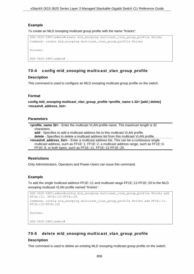
xStack® DGS-3620 Series Layer 3 Managed Stackable Gigabit Switch CLI Reference Guide
808
Example To create an MLD snooping multicast group profile with the name “Knicks”:
DGS-3620-28PC:admin#create mld_snooping multicast_vlan_group_profile Knicks
Command: create mld_snooping multicast_vlan_group_profile Knicks
Success.
DGS-3620-28PC:admin#
70-4 config mld_snooping multicast_vlan_group_profile Description This command is used to configure an MLD snooping multicast group profile on the switch.
Format config mld_snooping multicast_vlan_group_profile <profile_name 1-32> [add | delete] <mcastv6_address_list>
Parameters <profile_name 32> - Enter the multicast VLAN profile name. The maximum length is 32
characters. add - Specifies to add a multicast address list to this multicast VLAN profile. delete - Specifies to delete a multicast address list from this multicast VLAN profile.
<mcastv6_address_list> - Enter a multicast address list. This can be a continuous single multicast address, such as FF1E::1, FF1E::2, a multicast address range, such as FF1E::3-FF1E::9, or both types, such as FF1E::11, FF1E::12-FF1E::20.
Restrictions Only Administrators, Operators and Power-Users can issue this command.
Example To add the single multicast address FF1E::11 and multicast range FF1E::12-FF1E::20 to the MLD snooping multicast VLAN profile named “Knicks”:
DGS-3620-28PC:admin#config mld_snooping multicast_vlan_group_profile Knicks add FF1E::11, FF1E::12-FF1E::20
Command: config mld_snooping multicast_vlan_group_profile Knicks add FF1E::11, FF1E::12-FF1E::20
Success.
DGS-3620-28PC:admin#
70-5 delete mld_snooping multicast_vlan_group_profile Description This command is used to delete an existing MLD snooping multicast group profile on the switch.

xStack® DGS-3620 Series Layer 3 Managed Stackable Gigabit Switch CLI Reference Guide
809
Format delete mld_snooping multicast_vlan_group_profile [profile_name <profile_name 1-32> | all]
Parameters profile_name - Specifies the multicast VLAN group profile name. The maximum length is 32
characters. <profile_name 1-32> - Enter the multicast VLAN group profile name. The profile name can be
up to 32 characters long. all - Specifies to delete all the profiles.
Restrictions Only Administrators, Operators and Power-Users can issue this command.
Example To delete an MLD snooping multicast group profile named “Knicks”:
DGS-3620-28PC:admin#delete mld_snooping multicast_vlan_group_profile profile_name Knicks
Command: delete mld_snooping multicast_vlan_group_profile profile_name Knicks
Success.
DGS-3620-28PC:admin#
70-6 show mld_snooping multicast_vlan_group_profile Description This command is used to display an MLD snooping multicast group profile.
Format show mld_snooping multicast_vlan_group_profile {<profile_name 1-32>}
Parameters <profile_name 1-32> - (Optional) Specifies the multicast VLAN profile name. The maximum
length is 32 characters.
If no parameter is specified, the system will display all multicast VLAN group profiles.
Restrictions None.
Example To display all MLD snooping multicast VLAN profiles:

xStack® DGS-3620 Series Layer 3 Managed Stackable Gigabit Switch CLI Reference Guide
810
DGS-3620-28PC:admin#show mld_snooping multicast_vlan_group_profile
Command: show mld_snooping multicast_vlan_group_profile
Profile Name Multicast Addresses
----------------------- --------------------------------
rock FF1E::1
FF1E::10-FF1E::20
Total Entries : 1
DGS-3620-28PC:admin#
70-7 config mld_snooping multicast_vlan_group Description This command is used to configure the multicast group which will be learned with the specific multicast VLAN. There are two cases that need to be considered. For the first case, suppose that a multicast group is not configured and multicast VLANs do not have overlapped member ports. That means the join packets received by the member port will only be learned with the multicast VLAN that this port belongs to. If not, which is the second case, the join packet will be learned with the multicast VLAN that contains the destination multicast group. If the destination multicast group of the join packet can not be classified into any multicast VLAN that this port belongs to, then the join packet will be learned with the natural VLAN of the packet. Please note that the same profile can not overlap different multicast VLANs. Multiple profiles can be added to a multicast VLAN, however.
Format config mld_snooping multicast_vlan_group <vlan_name 32> [add | delete] profile_name <profile_name 1-32>
Parameters <vlan_name 32> - Enter the name of the multicast VLAN to be configured. Each multicast VLAN
is given a name that can be up to 32 characters. add - Specifies to associate a profile to a multicast VLAN. delete - Specifies to de-associate a profile from a multicast VLAN.
profile_name - Specifies the multicast VLAN profile name. The maximum length is 32 characters. <profile_name 1-32> - Enter the multicast VLAN profile name. The profile name can be up to
32 characters long.
Restrictions Only Administrators, Operators and Power-Users can issue this command.
Example To add an MLD snooping profile to a multicast VLAN group with the name “v1”:
DGS-3620-28PC:admin#config mld_snooping multicast_vlan_group v1 add profile_name channel_1
Command: config mld_snooping multicast_vlan_group v1 add profile_name channel_1
Success.

xStack® DGS-3620 Series Layer 3 Managed Stackable Gigabit Switch CLI Reference Guide
811
DGS-3620-28PC:admin#
70-8 show mld_snooping multicast_vlan_group Description This command allows group profile information for a specific multicast VLAN to be displayed.
Format show mld_snooping multicast_vlan_group {<vlan_name 32>}
Parameters <vlan_name 32> - (Optional) Specifies the name of the group profile’s multicast VLAN to be
displayed.
If no parameter is specified, the system will display all multicast VLAN groups on the switch.
Restrictions None.
Example To display all MLD snooping multicast VLANs’ group profile information:
DGS-3620-28PC:admin#show mld_snooping multicast_vlan_group
Command: show mld_snooping multicast_vlan_group
VLAN Name VLAN ID Multicast Group Profiles
------------------------------- ------- ---------------------------------
test2 20
test1 100
DGS-3620-28PC:admin#
70-9 delete mld_snooping multicast_vlan Description This command is used to delete an MLD snooping multicast VLAN.
Format delete mld_snooping multicast_vlan <vlan_name 32>

xStack® DGS-3620 Series Layer 3 Managed Stackable Gigabit Switch CLI Reference Guide
812
Parameters <vlan_name 32> - Enter the name of the multicast VLAN to be deleted.
Restrictions Only Administrators, Operators and Power-Users can issue this command.
Example To delete an MLD snooping multicast VLAN called “v1”:
DGS-3620-28PC:admin#delete mld_snooping multicast_vlan v1
Command: delete mld_snooping multicast_vlan v1
Success.
DGS-3620-28PC:admin#
70-10 enable mld_snooping multicast_vlan Description This command is used to enable the MLD snooping multicast VLAN function. By default, the multicast VLAN is disabled.
Format enable mld_snooping multicast_vlan
Parameters None.
Restrictions Only Administrators, Operators and Power-Users can issue this command.
Example To enable MLD snooping multicast VLAN:
DGS-3620-28PC:admin#enable mld_snooping multicast_vlan
Command: enable mld_snooping multicast_vlan
Success.
DGS-3620-28PC:admin#

xStack® DGS-3620 Series Layer 3 Managed Stackable Gigabit Switch CLI Reference Guide
813
70-11 disable mld_snooping multicast_vlan Description This command is used to disable the MLD snooping multicast VLAN function. By default, the multicast VLAN is disabled.
Format disable mld_snooping multicast_vlan
Parameters None.
Restrictions Only Administrators, Operators and Power-Users can issue this command.
Example To disable MLD snooping multicast VLAN:
DGS-3620-28PC:admin#disable mld_snooping multicast_vlan
Command: disable mld_snooping multicast_vlan
Success.
DGS-3620-28PC:admin#
70-12 show mld_snooping multicast_vlan Description This command allows information for a specific multicast VLAN to be displayed.
Format show mld_snooping multicast_vlan {<vlan_name 32>}
Parameters <vlan_name 32> - (Optional) Specifies the name of the multicast VLAN to be displayed.
If no parameter is specified, the system will display all multicast VLANs on the switch.
Restrictions None.

xStack® DGS-3620 Series Layer 3 Managed Stackable Gigabit Switch CLI Reference Guide
814
Example To display all MLD snooping multicast VLANs:
DGS-3620-28PC:admin# show mld_snooping multicast_vlan
Command: show mld_snooping multicast_vlan
MLD Multicast VLAN Global State : Enabled
MLD Multicast VLAN Forward Unmatched : Disabled
MLD Multicast VLAN Auto Assign VLAN : Enabled
VLAN Name :4094
VID :4094
Member(Untagged) Ports :2:20-2:21
Tagged Member Ports :
Source Ports :
Untagged Source Ports :2:22
Status :Enabled
Replace Source IP :FE80::1:1 (User Configure)
Remap Priority :6 (Replaced)
Total Entries: 1
DGS-3620-28PC:admin#
70-13 config mld_snooping multicast_vlan forward_unmatched Description This command is used to configure the forwarding mode for MLD snooping multicast VLAN unmatched packets. When the switch receives an MLD snooping packet, it will match the packet against the multicast profile to determine which multicast VLAN to associate with. If the packet does not match all profiles, the packet will be forwarded in the natural VLAN of the packet, or dropped based on this setting. By default, the packet will be dropped.
Format config mld_snooping multicast_vlan forward_unmatched [disable | enable]
Parameters enable - The packet will be flooded on the VLAN. disable - The packet will be dropped.
Restrictions Only Administrators, Operators and Power-Users can issue this command.
Example To configure the forwarding mode for MLD snooping multicast VLAN unmatched packets:

xStack® DGS-3620 Series Layer 3 Managed Stackable Gigabit Switch CLI Reference Guide
815
DGS-3620-28PC:admin#config mld_snooping multicast_vlan forward_unmatched enable
Command: config mld_snooping multicast_vlan forward_unmatched enable
Success.
DGS-3620-28PC:admin#
70-14 config mld_snooping multicast_vlan auto_assign_vlan Description This command is used to enable or disable the MLD snopping multicast VLAN automatic assignment feature.
Format config mld_snooping multicast_vlan auto_assign_vlan [enable | disable]
Parameters enable - Specifies to enable the MLD snooping multicast VLAN automatic assignment feature. disable - Specifies to disable the MLD snooping multicast VLAN automatic assignment feature.
Restrictions Only Administrators, Operators and Power-Users can issue this command.
Example To enable the MLD snooping multicast VLAN automatic assignment feature:
DGS-3620-28PC:admin#config mld_snooping multicast_vlan auto_assign_vlan enable
Command: config mld_snooping multicast_vlan auto_assign_vlan enable
Success.
DGS-3620-28PC:admin#

xStack® DGS-3620 Series Layer 3 Managed Stackable Gigabit Switch CLI Reference Guide
816
Chapter 71 Modify Login Banner and Prompt Commands
config greeting_message {default} show greeting_message config command_prompt [<string 16> | username | default]
71-1 config greeting_message Description This command is used to modify the login banner.
Format config greeting_message {default}
Parameters default – (Optional) Adding this parameter to the config greeting_message command will return
the greeting message (banner) to its original factory default entry.
Restrictions • When users issue the “reset” command, the modified banner will remain in tact. Yet,
issuing the “reset system” will return the banner to its original default value.
• The maximum character capacity for the banner is 24 lines with 80 characters per line.
• In the following example, Ctrl+W will save the modified banner only to the DRAM. Users must enter the “save” command to save this entry to the Flash memory.
• Only Administrators and Operators can issue this command.
Example To edit the banner:
DGS-3620-28PC:admin#config greeting_message
Command: config greeting_message
Greeting Messages Editor
================================================================================
DGS-3620-28PC Gigabit Ethernet Switch
Command Line Interface
Firmware: Build 3.00.004

xStack® DGS-3620 Series Layer 3 Managed Stackable Gigabit Switch CLI Reference Guide
817
Copyright(C) 2017 D-Link Corporation. All rights reserved.
================================================================================
<Function Key> <Control Key>
Ctrl+C Quit without save left/right/
Ctrl+W Save and quit up/down Move cursor
Ctrl+D Delete line
Ctrl+X Erase all setting
Ctrl+L Reload original setting
-------------------------------------------------------------------------------
71-2 show greeting_message Description This command is used to display the currently configured greeting message on the switch.
Format show greeting_message
Parameters None.
Restrictions Only Administrators and Operators can issue this command.
Example To display the currently configured greeting message:

xStack® DGS-3620 Series Layer 3 Managed Stackable Gigabit Switch CLI Reference Guide
818
DGS-3620-28PC:admin#show greeting_message
Command: show greeting_message
================================================================================
DGS-3620-28PC Gigabit Ethernet Switch
Command Line Interface
Firmware: Build 3.00.004
Copyright(C) 2017 D-Link Corporation. All rights reserved.
================================================================================
DGS-3620-28PC:admin#
71-3 config command_prompt Description This command is used to modify the command prompt. The current command prompt consists of four parts: “product name” + “:” + ”user level” + ”#” (e.g. “DGS-3620-28PC:admin#”). This command is used to modify the first part (1. “product name”) with a string consisting of a maximum of 16 characters, or to be replaced with the users’ login user name.
Format config command_prompt [<string 16> | username | default]
Parameters <string 16> - Enter the new command prompt string of no more than 16 characters.

xStack® DGS-3620 Series Layer 3 Managed Stackable Gigabit Switch CLI Reference Guide
819
username - Specifies the command to set the login username as the command prompt. default - Specifies the command to return the command prompt to its original factory default
value.
Restrictions When users issue the “reset” command, the current command prompt will remain in tact. Issuing the “reset system” will return the command prompt to its original factory default value.
Only Administrators and Operators can issue this command.
Example To edit the command prompt:
DGS-3620-28PC:admin#config command_prompt HQ0001
Command: config command_prompt HQ0001
Success.
HQ0001:admin#

xStack® DGS-3620 Series Layer 3 Managed Stackable Gigabit Switch CLI Reference Guide
820
Chapter 72 Multicast Listener Discovery (MLD) Commands
config mld [ipif <ipif_name 12> | all] {query_interval <sec 1-31744> | max_response_time <sec 1-25> | robustness_variable <value 2-7> | last_listener_query_interval <sec 1-25> | version <value 1-2> | state [enable | disable]} (1)
show mld {ipif <ipif_name 12>} show mld group {ipif <ipif_name 12> | group <ipv6addr>}
72-1 config mld Description This command is used to configure MLD on the Switch.
Format config mld [ipif <ipif_name 12> | all] {query_interval <sec 1-31744> | max_response_time <sec 1-25> | robustness_variable <value 2-7> | last_listener_query_interval <sec 1-25> | version <value 1-2> | state [enable | disable]} (1)
Parameters ipif - Specifies the IP interface name used for this configuration.
<ipif_name 12> - Enter the IP interface name used here. This name can be up to 12 characters long.
all - Specifies that all the IP interfaces will be used. query_interval - (Optional) Specifies the time in seconds between the general query
transmissions. <sec 1-31744> - Enter the general query interval value used here. This value must be
between 1 and 31744 seconds. The default value is 125 seconds. max_response_time - (Optional) Specifies the maximum time in seconds to wait for reports from
listeners. <sec 1-25> - Enter the maximum response time value used here. The value must be between
1 and 25 seconds. The default value is 10 seconds. robustness_variable - (Optional) Specifies the permitted packet loss that guarantees the MLD.
<value 2-7> - Enter the robustness variable value used here. This value must be between 2 and 7. The default value is 2.
last_listener_query_interval - (Optional) Specifies the maximum response time inserted into the Multicast address specific query sent in response to 'done group' messages. This is also the amount of time between Multicast address specific query messages. <sec 1-25> - Enter the last listener query interval value used here. This value must be
between 1 and 25 seconds. The default value is 1 second. version - (Optional) Specifies the MLD version number.
<value 1-2> - Enter the MLD version number used here. This number must be between 1 and 2. The default value is 2.
state - (Optional) Specifies the MLD state for the specified route interface. enable - Specifies that the MLD state for the specified interface will be enabled. disable - Specifies that the MLD state for the specified interface will be disabled.

xStack® DGS-3620 Series Layer 3 Managed Stackable Gigabit Switch CLI Reference Guide
821
Restrictions Only Administrators, Operators and Power-Users can issue this command.
Example To configure the MLD on the IP interface “System”:
DGS-3620-28PC:admin# config mld ipif System version 1 state enable
Command: config mld ipif System version 1 state enable
Success.
DGS-3620-28PC:admin#
To configure the MLD version to v1 on all IP interfaces:
DGS-3620-28PC:admin# config mld all version 1
Command: config mld all version 1
Success.
DGS-3620-28PC:admin#
To configure the MLD last listener query interval to 10 seconds on all interfaces:
DGS-3620-28PC:admin# config mld all last_listener_query_interval 10
Command: config mld all last_listener_query_interval 10
Success.
DGS-3620-28PC:admin#
72-2 show mld Description This command is used to display the MLD configurations on the Switch.
Format show mld {ipif <ipif_name 12>}
Parameters ipif – (Optional) Specifies the IP interface name used for this configuration.
<ipif_name 12> - Enter the IP interface name used here. This name can be up to 12 characters long.
If no parameter is specified, the system will display all MLD configurations.
Restrictions None.

xStack® DGS-3620 Series Layer 3 Managed Stackable Gigabit Switch CLI Reference Guide
822
Example To display the MLD configurations on all interfaces:
DGS-3620-28PC:admin# show mld
Command: show mld
MLD Interface Configurations
MRT = Maximum Response Time, LLQI = Last Listener Query Interval
Interface Version Query MRT Robustness LLQI State
---------- ------ ------ ---- ---------- ----- --------
System 2 125 10 2 1 Disabled
n10 2 125 10 2 1 Enabled
n11 2 125 10 2 1 Disabled
n12 2 125 10 2 1 Disabled
Total Entries: 4
DGS-3620-28PC:admin#
To display the MLD configurations for interface “Interface1”:
DGS-3620-28PC:admin#show mld ipif Interface1
Command: show mld ipif Interface1
MLD Interface Details
Interface : Interface1
IPv6 Link-Local Address : FE80::123D:34AC/128
Querier : -
Status : Disabled
Version : 2
Query Interval : 125 sec
Max Response Time : 10 sec
Robustness : 2
Last Listener Query Interval: 1 sec
Last Listener Query Count : 2
Startup Query Count : 2
Startup Query Interval : 31 sec
Total Entries: 1
DGS-3620-28PC:admin#
72-3 show mld group Description This command is used to display the MLD group member table.

xStack® DGS-3620 Series Layer 3 Managed Stackable Gigabit Switch CLI Reference Guide
823
Format show mld group {ipif <ipif_name 12> | group <ipv6addr>}
Parameters ipif – (Optional) Specifies the IP interface name used for this configuration.
<ipif_name 12> - Enter the IP interface name used here. This name can be up to 12 characters long.
group - (Optional) Specifies the IPv6 multicast group address used. <ipv6addr> - Enter the IPv6 multicast group address used here.
If no parameter is specified, the system will display all MLD configurations.
Restrictions None.
Example To display all the MLD group member information on the switch, the “Expiry” uses second as the unit:
DGS-3620-28PC:admin# show mld group
Command: show mld group
Interface Multicast Group Expiry
------------ ----------------- -----
System FF1E::100:0:0:20 260
n10 FF1E::1001:1234 255
n20 FF1E::2AC4:0:452 260
n10 FF1E::5A3D:11:23C1 260
Total Entries : 4
DGS-3620-28PC:admin#
To display all the MLD group member information of interface “n10”, the “Expiry” uses second as the unit:
DGS-3620-28PC:admin# show mld group ipif n10
Command: show mld group ipif n10
Interface Multicast Group Expiry
------------ ------------------ -----
n10 FF1E::1001:1234 255
n10 FF1E::5A3D:11:23C1 260
Total Entries : 2
DGS-3620-28PC:admin#

xStack® DGS-3620 Series Layer 3 Managed Stackable Gigabit Switch CLI Reference Guide
824
To display the group source address list for interface “n10” with the group address “FF1E::100:0:20”, the “Expiry” uses second as the unit:
DGS-3620-28PC:admin# show mld group ipif n10 group FF1E::100:0:20
Command: show mld group ipif n10 group FF1E::100:0:20
MLD Group Details
Interface : n10
Multicast Group : FF1E::100:0:20
Last Reporter : FE80::2345:FE39
Up Time : 00:00:32
Expiry Time : 00:30:02
Filter Mode : Exclude
V1 Host Time : 0 sec
Source List Table:
Source Address Expiry
----------------- -------
2001::1234:EF23 10
Total Source Entries: 1
Total Entries: 1
DGS-3620-28PC:admin#
To display all the MLD group member information for multicast group “FF1E::1001:1234”, the “Expiry” uses second as the unit:
DGS-3620-28PC:admin# show mld group group FF1E::1001:1234
Command: show mld group group FF1E::1001:1234
Interface Multicast Group Expiry
------------ ------------------ -----
n10 FF1E::1001:1234 215
n11 FF1E::1001:1234 200
n20 FF1E::1001:1234 240
Total Entries : 3
DGS-3620-28PC:admin#

xStack® DGS-3620 Series Layer 3 Managed Stackable Gigabit Switch CLI Reference Guide
825
Chapter 73 Network Load Balancing (NLB) Commands
create nlb multicast_fdb [<vlan_name 32> | vlanid <vlanid 1-4094>] <macaddr> delete nlb multicast_fdb [<vlan_name 32> | vlanid <vlanid 1-4094>] <macaddr> config nlb multicast_fdb [<vlan_name 32> | vlanid <vlanid 1-4094>] <macaddr> [add | delete]
<portlist> show nlb fdb create nlb unicast_fdb <macaddr> config nlb unicast_fdb <macaddr> [add | delete] <portlist> delete nlb unicast_fdb <macaddr>
73-1 create nlb multicast_fdb Description This command is used to create the Switch’s NLB multicast FDB entry. The network load balancing command set is used to support the Microsoft server load balancing application where multiple servers can share the same IP address and MAC address. The requests from clients will be forwarded to all servers, but will only be processed by one of them. In multicast mode, the client use the multicast MAC address as the destination MAC to reach the server. Regarding of the mode, this destination MAC is the named the shared MAC. The server uses its own MAC address (rather than the shared MAC) as the source MAC address of the reply packet.
Format create nlb multicast_fdb [<vlan_name 32> | vlanid <vlanid 1-4094>] <macaddr>
Parameters <vlan_name 32> - Enter the VLAN name of the NLB multicast FDB entry here. This name can be
up to 32 characters long. vlanid - Specifies the VLAN ID used.
<vlanid 1-4094> - Enter the VLAN ID used here. <macaddr> - Specifies the MAC address of the NLB multicast FDB entry to be created.
Restrictions Only Administrators, Operators and Power-Users can issue this command.
Example To create a NLB multicast FDB entry:

xStack® DGS-3620 Series Layer 3 Managed Stackable Gigabit Switch CLI Reference Guide
826
DGS-3620-28PC:admin# create nlb multicast_fdb default 03-bf-01-01-01-01
Command: create nlb multicast_fdb default 03-bf-01-01-01-01
Success.
DGS-3620-28PC:admin#
73-2 delete nlb multicast_fdb Description This command is used to delete the Switch’s NLB multicast FDB entry.
Format delete nlb multicast_fdb [<vlan_name 32> | vlanid <vlanid 1-4094>] <macaddr>
Parameters <vlan_name 32> - Enter the VLAN name of the NLB multicast FDB entry here. This name can be
up to 32 characters long. vlanid - Specifies the VLAN ID used.
<vlanid 1-4094> - Enter the VLAN ID used here. <macaddr> - Specifies the MAC address of the NLB multicast FDB entry to be deleted.
Restrictions Only Administrators, Operators and Power-Users can issue this command.
Example To delete NLB multicast FDB entry:
DGS-3620-28PC:admin# delete nlb multicast_fdb default 03-bf-01-01-01-01
Command: delete nlb multicast_fdb default 03-bf-01-01-01-01
Success.
DGS-3620-28PC:admin#
73-3 config nlb multicast_fdb Description This command is used to configure the Switch’s NLB multicast FDB entry.
Format config nlb multicast_fdb [<vlan_name 32> | vlanid <vlanid 1-4094>] <macaddr> [add | delete] <portlist>
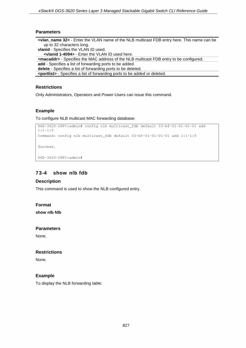
xStack® DGS-3620 Series Layer 3 Managed Stackable Gigabit Switch CLI Reference Guide
827
Parameters <vlan_name 32> - Enter the VLAN name of the NLB multicast FDB entry here. This name can be
up to 32 characters long. vlanid - Specifies the VLAN ID used.
<vlanid 1-4094> - Enter the VLAN ID used here. <macaddr> - Specifies the MAC address of the NLB multicast FDB entry to be configured. add - Specifies a list of forwarding ports to be added. delete - Specifies a list of forwarding ports to be deleted. <portlist> - Specifies a list of forwarding ports to be added or deleted.
Restrictions Only Administrators, Operators and Power-Users can issue this command.
Example To configure NLB multicast MAC forwarding database:
DGS-3620-28PC:admin# config nlb multicast_fdb default 03-bf-01-01-01-01 add 1:1-1:5
Command: config nlb multicast_fdb default 03-bf-01-01-01-01 add 1:1-1:5
Success.
DGS-3620-28PC:admin#
73-4 show nlb fdb Description This command is used to show the NLB configured entry.
Format show nlb fdb
Parameters None.
Restrictions None.
Example To display the NLB forwarding table:

xStack® DGS-3620 Series Layer 3 Managed Stackable Gigabit Switch CLI Reference Guide
828
DGS-3620-28PC:admin# show nlb fdb
Command: show nlb fdb
MAC Address VLAN ID Egress Ports
----------------- ---------- ---------------------------------------------
00-00-00-00-00-01 ---- ----
02-BF-01-01-01-01 ---- ----
01-00-00-00-00-01 1 ----
Total Entries :3
DGS-3620-28PC:admin#
73-5 create nlb unicast_fdb Description This command is used to create the NLB unicast FDB entry.
Format create nlb unicast_fdb <macaddr>
Parameters <macaddr> - Enter the MAC address of the NLB unicast FDB entry to be created.
Restrictions Only Administrators, Operators and Power-Users can issue this command.
Example To create an NLB unicast MAC forwarding entry, for the product that support the VLAN information on the unicast forwarding:
DGS-3620-28PC:admin#create nlb unicast_fdb 02-bf-01-01-01-01
Command: create nlb unicast_fdb 02-BF-01-01-01-01
Success.
DGS-3620-28PC:admin#
73-6 config nlb unicast_fdb Description This command is used to add or delete the forwarding ports for the specified NLB unicast FDB entry.

xStack® DGS-3620 Series Layer 3 Managed Stackable Gigabit Switch CLI Reference Guide
829
Format config nlb unicast_fdb <macaddr> [add | delete] <portlist>
Parameters <macaddr> - Enter the MAC address of the NLB unicast FDB entry to be configured. add - Specifies to add the ports. delete - Specifies to delete the ports. <portlist> - Enter a list of forwarding ports to be added or removed.
Restrictions Only Administrators, Operators and Power-Users can issue this command.
Example To configure NLB unicast FDB entry, for the product that support the VLAN information on the unicast forwarding:
DGS-3620-28PC:admin#config nlb unicast_fdb 02-BF-01-01-01-01 add 1:1-1:5
Command: config nlb unicast_fdb 02-BF-01-01-01-01 add 1:1-1:5
Success.
DGS-3620-28PC:admin#
73-7 delete nlb unicast_fdb Description This command is used to delete the NLB unicast FDB entry.
Format delete nlb unicast_fdb <macaddr>
Parameters <macaddr> - Enter the MAC address of the NLB unicast FDB entry to be deleted.
Restrictions Only Administrators, Operators and Power-Users can issue this command.
Example To delete the NLB unicast FDB entry, for the product that support the VLAN information on the unicast forwarding:

xStack® DGS-3620 Series Layer 3 Managed Stackable Gigabit Switch CLI Reference Guide
830
DGS-3620-28PC:admin#delete nlb unicast_fdb 02-bf-01-01-01-01
Command: delete nlb unicast_fdb 02-BF-01-01-01-01
Success.
DGS-3620-28PC:admin#

xStack® DGS-3620 Series Layer 3 Managed Stackable Gigabit Switch CLI Reference Guide
831
Chapter 74 Network Management Commands
enable snmp disable snmp show snmp create trusted_host [<ipaddr> | <ipv6addr> | network <network_address> | ipv6_prefix
<ipv6networkaddr>] {snmp | telnet | ssh | http | https | ping} config trusted_host [<ipaddr> | <ipv6addr> | network <network_address> | ipv6_prefix
<ipv6networkaddr>] [add | delete] {snmp | telnet | ssh | http | https | ping | all} delete trusted_host [ipaddr <ipaddr> | ipv6address <ipv6addr> | network <network_address>|
ipv6_prefix <ipv6networkaddr> | all] show trusted_host config snmp system_name <sw_name> config snmp system_location <sw_location> config snmp system_contact <sw_contact> enable snmp traps disable snmp traps enable snmp authenticate_traps disable snmp authenticate_traps enable snmp linkchange_traps disable snmp linkchange_traps show snmp traps {linkchange_traps {ports <portlist>}} config snmp linkchange_traps ports [all | <portlist>] [enable | disable] config snmp coldstart_traps [enable | disable] config snmp warmstart_traps [enable | disable] config trap source_ipif [<ipif_name 12> {<ipaddr> | <ipv6addr>} | none] show trap source_ipif config rmon trap {rising_alarm [enable | disable] | falling_alarm [enable | disable]} show rmon
74-1 enable snmp Description This command is used to enable the SNMP function. When SNMP function is disabled, the network manager will not be able to access SNMP MIB objects. The device will not send traps or notification to network manager either.
Format enable snmp
Parameters None.
Restrictions Only Administrators and Operators can issue this command.

xStack® DGS-3620 Series Layer 3 Managed Stackable Gigabit Switch CLI Reference Guide
832
Example To enable SNMP:
DGS-3620-28PC:admin#enable snmp
Command: enable snmp
Success.
DGS-3620-28PC:admin#
74-2 disable snmp Description This command is used to disable the SNMP function. When SNMP function is disabled, the network manager will not be able to access SNMP MIB objects. The device will not send traps or notification to network manager either.
Format disable snmp
Parameters None. By default, SNMP is disabled.
Restrictions Only Administrators and Operators can issue this command.
Example To disable SNMP:
DGS-3620-28PC:admin#disable snmp
Command: disable snmp
Success.
DGS-3620-28PC:admin#
74-3 show snmp Description This command is used to display SNMP status.
Format show snmp

xStack® DGS-3620 Series Layer 3 Managed Stackable Gigabit Switch CLI Reference Guide
833
Parameters None.
Restrictions None.
Example To display SNMP:
DGS-3620-28PC:admin# show snmp
Command: show snmp
System Name :
System Location :
System Contact :
SNMP Trap : Enabled
SNMP State : Disabled
SNMP UDP Port : 161
DGS-3620-28PC:admin#
74-4 create trusted_host Description This command is used to create the trusted host. The switch allows you to specify up to 30 IP addresses (or IP ranges) that are allowed to manage the switch via in-band SNMP or Telnet based management software. These IP addresses must be members of the Management VLAN. If no IP addresses are specified, then there is nothing to prevent any IP address from accessing the switch, provided the user knows the Username and Password.
Format create trusted_host [<ipaddr> | <ipv6addr> | network <network_address> | ipv6_prefix <ipv6networkaddr>] {snmp | telnet | ssh | http | https | ping}
Parameters <ipaddr> - Enter the IP address of the trusted host. <ipv6addr> - Enter the IPv6 address of the trusted host. network - Specifies the network address of the trusted network. The form of network address is
xxx.xxx.xxx.xxx/y. <network_address> - Enter the network address of the trusted network. The form of network
address is xxx.xxx.xxx.xxx/y. ipv6_prefix - Specifies the IPv6 network address of the trusted network.
<ipv6networkaddr> - Enter the IPv6 network address of the trusted network. snmp - (Optional) Specifies the trusted host for SNMP. telnet - (Optional) Specifies the trusted host for Telnet. ssh - (Optional) Specifies the trusted host for SSH.

xStack® DGS-3620 Series Layer 3 Managed Stackable Gigabit Switch CLI Reference Guide
834
http - (Optional) Specifies the trusted host for HTTP. https - (Optional) Specifies the trusted host for HTTPs. ping - (Optional) Specifies the trusted host for Ping.
Note: If no management method is specified, the IP (range) can access the Switch
through any method.
Restrictions Only Administrators and Operators can issue this command.
Example To create a trusted host:
DGS-3620-28PC:admin#create trusted_host 10.48.74.121
Command: create trusted_host 10.48.74.121
Success.
DGS-3620-28PC:admin#
74-5 config trusted_host Description This command is used to configure the access interfaces for the trusted host.
Format config trusted_host [<ipaddr> | <ipv6addr> | network <network_address> | ipv6_prefix <ipv6networkaddr>] [add | delete] {snmp | telnet | ssh | http | https | ping | all}
Parameters <ipaddr> - Enter the IP address of the trusted host. <ipv6addr> - Enter the IPv6 address of the trusted host. network - Specifies the network address of the trusted network. The form of network address is
xxx.xxx.xxx.xxx/y. <network_address> - Enter the network address of the trusted network. The form of network
address is xxx.xxx.xxx.xxx/y. ipv6_prefix - Specifies the IPv6 network address of the trusted network.
<ipv6networkaddr> - Enter the IPv6 network address of the trusted network. add - Allow to manage applications for a trusted host. delete - Prevent from managing applications for a trusted host. snmp - (Optional) Specifies the trusted host for SNMP. telnet - (Optional) Specifies the trusted host for Telnet. ssh - (Optional) Specifies the trusted host for SSH. http - (Optional) Specifies the trusted host for HTTP. https - (Optional) Specifies the trusted host for HTTPs. ping - (Optional) Specifies the trusted host for Ping. all - Specifies the trusted host for all applications.

xStack® DGS-3620 Series Layer 3 Managed Stackable Gigabit Switch CLI Reference Guide
835
Restrictions Only Administrators and Operators can issue this command.
Example To configure the trusted host:
DGS-3620-28PC:admin#config trusted_host 10.48.74.121 add ssh telnet
Command: config trusted_host 10.48.74.121 add ssh telnet
Success.
DGS-3620-28PC:admin#
74-6 delete trusted_host Description This command is used to delete a trusted host entry.
Format delete trusted_host [ipaddr <ipaddr> | ipv6address <ipv6addr> | network <network_address> | ipv6_prefix <ipv6networkaddr> | all]
Parameters ipaddr - Specifies the IP address of the trusted host.
<ipaddr> - Enter the IP address of the trusted host. ipv6address - Specifies the IPv6 address of the trusted host.
<ipv6addr> - Enter the IPv6 address of the trusted host. network - Specifies the network address of the trusted network. The form of network address is
xxx.xxx.xxx.xxx/y. <network_address> - Enter the network address of the trusted network. The form of network
address is xxx.xxx.xxx.xxx/y. ipv6_prefix - Specifies the IPv6 network address of the trusted network.
<ipv6networkaddr> - Enter the IPv6 network address of the trusted network. all - Specifies that all trusted hosts will be deleted.
Restrictions Only Administrators and Operators can issue this command.
Example To delete a trusted host:
DGS-3620-28PC:admin#delete trusted_host ipaddr 10.48.74.121
Command: delete trusted_host ipaddr 10.48.74.121
Success.
DGS-3620-28PC:admin#

xStack® DGS-3620 Series Layer 3 Managed Stackable Gigabit Switch CLI Reference Guide
836
74-7 show trusted_host Description This command is used to display the trusted hosts.
Format show trusted_host
Parameters None.
Restrictions None.
Example To display trusted hosts:
DGS-3620-28PC:admin#show trusted_host
Command: show trusted_host
Management Stations
IP Address Access Interface
----------------------------------------------------------------------------
10.48.93.100
10.51.17.1
10.50.95.90
Total Entries : 3
DGS-3620-28PC:admin#
74-8 config snmp system_name Description This command is used to configure the SNMP system name of the switch.
Format config snmp system_name <sw_name>
Parameters <sw_name> - Enter an SNMP system name for the switch. A maximum of 255 characters is
allowed.

xStack® DGS-3620 Series Layer 3 Managed Stackable Gigabit Switch CLI Reference Guide
837
Restrictions Only Administrators and Operators can issue this command.
Example To configure the switch SNMP name for “DGS-3620-28PC Gigabit Ethernet Switch”:
DGS-3620-28PC:admin# config snmp system_name DGS-3620-28PC Gigabit Ethernet Switch
Command: config snmp system_name DGS-3620-28PC Gigabit Ethernet Switch
Success.
DGS-3620-28PC:admin#
74-9 config snmp system_location Description This command is used to enter a description of the SNMP system location of the switch. A maximum of 255 characters can be used.
Format config snmp system_location <sw_location>
Parameters <sw_location> - Enter an SNMP system location for the switch. A maximum of 255 characters is
allowed.
Restrictions Only Administrators and Operators can issue this command.
Example To configure the switch location for “HQ 5F”:
DGS-3620-28PC:admin#config snmp system_location HQ 5F
Command: config snmp system_location HQ 5F
Success.
DGS-3620-28PC:admin#
xStack® DGS-3620 Series Layer 3 Managed Stackable Gigabit Switch CLI Reference Guide
838
74-10 config snmp system_contact Description This command is used to enter the name and/or other information to identify an SNMP system contact person who is responsible for the switch. A maximum of 255 characters can be used.
Format config snmp system_contact <sw_contact>
Parameters <sw_contact> - Enter an SNMP system contact person. A maximum of 255 characters is
allowed.
Restrictions Only Administrators and Operators can issue this command.
Example To configure the switch contact to “MIS Department IV”:
DGS-3620-28PC:admin#config snmp system_contact "MIS Department IV"
Command: config snmp system_contact "MIS Department IV"
Success.
DGS-3620-28PC:admin#
74-11 enable snmp traps Description This command is used to enable SNMP trap support on the switch.
Format enable snmp traps
Parameters None.
Restrictions Only Administrators and Operators can issue this command.
Example To enable SNMP trap support:

xStack® DGS-3620 Series Layer 3 Managed Stackable Gigabit Switch CLI Reference Guide
839
DGS-3620-28PC:admin#enable snmp traps
Command: enable snmp traps
Success.
DGS-3620-28PC:admin#
74-12 disable snmp traps Description This command is used to disable SNMP trap support on the switch.
Format disable snmp traps
Parameters None.
Restrictions Only Administrators and Operators can issue this command.
Example To prevent SNMP traps from being sent from the switch:
DGS-3620-28PC:admin#disable snmp traps
Command: disable snmp traps
Success.
DGS-3620-28PC:admin#
74-13 enable snmp authenticate_traps Description This command is used to enable SNMP authentication failure trap support.
Format enable snmp authenticate_traps
Parameters None.
xStack® DGS-3620 Series Layer 3 Managed Stackable Gigabit Switch CLI Reference Guide
840
Restrictions Only Administrators and Operators can issue this command.
Example To enable SNMP authentication trap support:
DGS-3620-28PC:admin#enable snmp authenticate_traps
Command: enable snmp authenticate_traps
Success.
DGS-3620-28PC:admin#
74-14 disable snmp authenticate_traps Description This command is used to disable SNMP authentication failure trap support.
Format disable snmp authenticate_traps
Parameters None.
Restrictions Only Administrators and Operators can issue this command.
Example To disable SNMP authentication trap support:
DGS-3620-28PC:admin#disable snmp authenticate_traps
Command: disable snmp authenticate_traps
Success.
DGS-3620-28PC:admin#
74-15 enable snmp linkchange_traps Description This command is used to enable SNMP linkchange trap support.
Format enable snmp linkchange_traps

xStack® DGS-3620 Series Layer 3 Managed Stackable Gigabit Switch CLI Reference Guide
841
Parameters None.
Restrictions Only Administrators and Operators can issue this command..
Example To enable SNMP linkchange trap support:
DGS-3620-28PC:admin#enable snmp linkchange_traps
Command: enable snmp linkchange_traps
Success.
DGS-3620-28PC:admin#
74-16 disable snmp linkchange_traps Description This command is used to disable SNMP linkchange trap support.
Format disable snmp linkchange_traps
Parameters None.
Restrictions Only Administrators and Operators can issue this command.
Example To disable SNMP linkchange trap support:
DGS-3620-28PC:admin#disable snmp linkchange_traps
Command: disable snmp linkchange_traps
Success.
DGS-3620-28PC:admin#

xStack® DGS-3620 Series Layer 3 Managed Stackable Gigabit Switch CLI Reference Guide
842
74-17 config snmp linkchange_traps ports Description This command is used to configure the sending of linkchange traps and per port control for sending of change traps.
Format config snmp linkchange_traps ports [all | <portlist>] [enable | disable]
Parameters all - Specifies all ports. <portlist> - Enter a port or range of ports. enable - Enable sending of the link change trap for this port. disable - Disable sending of the link change trap for this port.
Restrictions Only Administrators and Operators can issue this command.
Example To enable SNMP linkchange traps for ports 1 to 4:
DGS-3620-28PC:admin#config snmp linkchange_traps ports 1-4 enable
Command: config snmp linkchange_traps ports 1-4 enable
Success.
DGS-3620-28PC:admin#
74-18 show snmp traps Description This command is used to display the SNMP trap state.
Format show snmp traps {linkchange_traps {ports <portlist>}}
Parameters linkchange_traps - (Optional) Specifies to display the status of linkchange traps. ports - (Optional) Specifies a port or port range.
<portlist> - Enter a port or port range.
Restrictions None.

xStack® DGS-3620 Series Layer 3 Managed Stackable Gigabit Switch CLI Reference Guide
843
Example To display SNMP traps:
DGS-3620-28PC:admin#show snmp traps
Command: show snmp traps
SNMP Traps : Enabled
Authenticate Trap : Enabled
Linkchange Traps : Enabled
Coldstart Traps : Enabled
Warmstart Traps : Enabled
DGS-3620-28PC:admin#
To display SNMP linkchange traps:
DGS-3620-28PC:admin#show snmp traps linkchange_traps
Command: show snmp traps linkchange_traps
Linkchange Traps : Enabled
Port 1 : Enabled
Port 2 : Enabled
Port 3 : Enabled
Port 4 : Enabled
Port 5 : Enabled
Port 6 : Enabled
Port 7 : Enabled
Port 8 : Enabled
Port 9 : Enabled
Port 10: Enabled
Port 11: Enabled
Port 12: Enabled
Port 13: Enabled
Port 14: Enabled
Port 15: Enabled
Port 16: Enabled
Port 17: Enabled
Port 18: Enabled
Port 19: Enabled
Port 20: Enabled
CTRL+C ESC q Quit SPACE n Next Page ENTER Next Entry a All
74-19 config snmp coldstart_traps Description This command is used to configure the trap state for coldstart events.
Format config snmp coldstart_traps [enable | disable]

xStack® DGS-3620 Series Layer 3 Managed Stackable Gigabit Switch CLI Reference Guide
844
Parameters enable - Enable traps for coldstart events. The default state is enabled. disable - Disable traps for coldstart events.
Restrictions Only Administrators and Operators can issue this command.
Example To enable traps for coldstart events:
DGS-3620-28PC:admin#config snmp coldstart_traps enable
Command: config snmp coldstart_traps enable
Success.
DGS-3620-28PC:admin#
74-20 config snmp warmstart_traps Description This command is used to configure the trap state for warmstart events.
Format config snmp warmstart_traps [enable | disable]
Parameters enable - Enable traps for warmstart events. The default state is enabled. disable - Disable traps for warmstart events.
Restrictions Only Administrators and Operators can issue this command.
Example To enable traps for warmstart events:
DGS-3620-28PC:admin#config snmp warmstart_traps enable
Command: config snmp warmstart_traps enable
Success.
DGS-3620-28PC:admin#

xStack® DGS-3620 Series Layer 3 Managed Stackable Gigabit Switch CLI Reference Guide
845
74-21 config trap source_ipif Description This command is used to force change the ipif information in trap messages. By default, trap messages will carry the information of the ipif they belong to.
Format config trap source_ipif [<ipif_name 12> {<ipaddr> | <ipv6addr>} | none]
Parameters <ipif_name 12> - Enter the IP interface name. If only this parameter is specified, the IPv4
address and the smallest IPv6 address of ipif_name will be used as source IP addresses. <ipaddr> - (Optional) Specifies the IPv4 address. <ipv6addr> - (Optional) Specifies the IPv6 address. none - Specifies to clear the configured source IP interface.
Restrictions Only Administrators and Operators can issue this command.
Example To configure the trap source IP interface:
DGS-3620-28PC:admin#config trap source_ipif inter4
Command: config trap source_ipif inter4
Success.
DGS-3620-28PC:admin#
To clear the configured trap source IP interface:
DGS-3620-28PC:admin#config trap source_ipif none
Command: config trap source_ipif none
Success.
DGS-3620-28PC:admin#
74-22 show trap source_ipif Description This command is used to display the trap source IP interface.
Format show trap source_ipif

xStack® DGS-3620 Series Layer 3 Managed Stackable Gigabit Switch CLI Reference Guide
846
Parameters None.
Restrictions None.
Example To display the trap source IP interface:
DGS-3620-28PC:admin#show trap source_ipif
Command: show trap source_ipif
Trap Source IP Interface Configuration:
IP Interface : ipif4
IPv4 Address : None
IPv6 Address : 3000::52
DGS-3620-28PC:admin#
74-23 config rmon trap Description This command is used to configure the trap state for RMON events.
Format config rmon trap {rising_alarm [enable | disable] | falling_alarm [enable | disable]}
Parameters rising_alarm - (Optional) Specifies the trap state for rising alarm. The default state is enabled.
enable - Enable the trap state for rising alarm. disable - Disable the trap state for rising alarm.
falling_alarm - (Optional) Specifies the trap state for falling alarm. The default state is enabled. enable - Enable the trap state for falling alarm. disable - Disable the trap state for falling alarm.
Restrictions Only Administrators and Operators can issue this command.
Example To disable the trap state for RMON:
DGS-3620-28PC:admin#config rmon trap rising_alarm disable
Command: config rmon trap rising_alarm disable

xStack® DGS-3620 Series Layer 3 Managed Stackable Gigabit Switch CLI Reference Guide
847
Success.
DGS-3620-28PC:admin#
74-24 show rmon Description This command is used to display RMON related settings.
Format show rmon
Parameters None.
Restrictions None.
Example To display current RMON settings:
DGS-3620-28PC:admin#show rmon
Command: show rmon
RMON Rising Alarm Trap : Enabled
RMON Falling Alarm Trap : Enabled
DGS-3620-28PC:admin#

xStack® DGS-3620 Series Layer 3 Managed Stackable Gigabit Switch CLI Reference Guide
848
Chapter 75 Network Monitoring Commands
show packet ports <portlist> | groups < grouplist >] show error ports <portlist> | groups < grouplist >] show utilization [ ports {<portlist>} | groups {< grouplist >}] show utilization cpu show utilization dram {unit <unit_id>} show utilization flash {unit <unit_id>} clear counters {ports <portlist>} | groups < grouplist >} clear log show log {[index <value_list> | severity {module <module_list>} {emergency | alert | critical | error |
warning | notice | informational | debug | <level_list 0-7>} | module <module_list>]} show log_save_timing show log_software_module config log_save_timing [time_interval <min 1-65535> | on_demand | log_trigger] enable syslog disable syslog show syslog config syslog host [<index 1-4> | all] {severity [emergency | alert | critical | error | warning | notice
| informational | debug| <level 0-7>] | facility [local0 | local1 | local2 | local3 | local4 | local5 | local6 | local7] | udp_port <udp_port_number> | ipaddress [<ipaddr> | <ipv6addr>] | state [enable | disable]}(1)
create syslog host <index 1-4> ipaddress [<ipaddr> | <ipv6addr>] {severity [emergency | alert | critical | error | warning | notice | informational | debug | <level 0-7>] | facility [local0 | local1 | local2 | local3 | local4 | local5 | local6 | local7] | udp_port <udp_port_number> | state [enable | disable]}
delete syslog host [<index 1-4> | all] show syslog host {<index 1-4>} config syslog source_ipif [<ipif_name 12> {<ipaddr> | <ipv6addr>} | none] show syslog source_ipif show attack_log {unit <unit_id 1-12>} {index <value_list>} clear attack_log {[unit <unit_id 1-12> | all]} show cpu port {[l2 | l3 {[unicast | multicast]} |type [lacp | stp | gvrp | erps | cfm | 802.1x | lldp | oam
| stacking | ctp | ospfv2 | ospfv3 | rip | ripng | bgp | vrrp | igmp | mld | pim-ipv4 | pim-ipv6 | dvmrp | reserved_ipv4_ipmc | reserved_ipv6_ipmc | unknown_ipv4_ipmc | unknown_ipv6_ipmc | arp | icmp | ndp | icmpv6 | sntp | dns | tftp | rcp | telnet | dhcp | dhcpv6 | udp-helper]]}
clear cpu port
75-1 show packet ports Description This command is used to display statistics about the packets sent and received by the switch for a range of ports or LAG groups.
Format show packet [ ports <portlist> | groups < grouplist >]

xStack® DGS-3620 Series Layer 3 Managed Stackable Gigabit Switch CLI Reference Guide
849
Parameters ports - Specifies a range of ports to be configured. The start and end of the port list range are
separated by a dash. <portlist> - Enter a port or range of ports to be displayed.
<grouplist> - Specifies a range of LAG groups to be displayed. The beginning and the end of the LAG group list range are separated by a dash. eg: 3-4 specifies all of the LAG groups whose index is between 3 and 4. <grouplist> - Enter a number of a group to be displayed.
Restrictions None.
Example To display the packets analysis for port 21: (Note: For some series that is not support counter for “1519-1522”, “1519-2047”, “2048-4095” and “4096-9216”, there will not display the four counters.)
DGS-3620-28PC:admin#show packet ports 21
Command: show packet ports 21
Port number : 21
Frame Size/Type Frame Counts Frames/sec
--------------- ---------------------- -----------
64 2503 48
65-127 803 10
128-255 290 6
256-511 292 1
512-1023 256 2
1024-1518 565 0
1519-1522 0 0
1519-2047 0 0
2048-4095 0 0
4096-9216 0 0
Unicast RX 643 2
Multicast RX 1345 39
Broadcast RX 1886 25
RX Bytes 480192 6569
RX Frames 3874 67
TX Bytes 923900 0
TX Frames 835 0
CTRL+C ESC q Quit SPACE n Next Page p Previous Page r Refresh
Note: For XG port, there is no support counter for receiving 1519-1522 byte packet.
To display the packets analysis for LAG group 1: (Note: For some series that is not support counter for “1519-1522”, “1519-2047”, “2048-4095” and “4096-9216”, there will not display the four counters.)
DGS-3620-28PC:admin#show packet groups 1

xStack® DGS-3620 Series Layer 3 Managed Stackable Gigabit Switch CLI Reference Guide
850
Command: show packet groups 1
Group Number : 1
Frame Size/Type Frame Counts Frames/sec
--------------- ---------------------- -----------
64 22140 54
65-127 10459 13
128-255 3360 3
256-511 1506 0
512-1023 919 0
1024-1518 719 0
1519-1522 0 0
1519-2047 0 0
2048-4095 0 0
4096-9216 0 0
Unicast RX 2193 0
Multicast RX 14619 14
Broadcast RX 20791 56
RX Bytes 3972004 5221
RX Frames 37603 70
TX Bytes 1147852 0
TX Frames 1500 0
CTRL+C ESC q Quit SPACE n Next Page p Previous Page r Refresh
75-2 show error ports Description This command is used to display error statistics for a range of ports and a range of LAG groups..
Format show error [ ports <portlist> | groups < grouplist >]
Parameters ports - Specifies a range of ports to be configured. The start and end of the port list range are
separated by a dash. <portlist> - Enter a port or range of ports to be displayed.
groups - Specifies a range of LAG groups to be displayed. The beginning and the end of the LAG group list range are separated by a dash. eg: 3-4 specifies all of the LAG groups whose index is between 3 and 4. <grouplist> - Enter a number of a group to be displayed.
Restrictions None.
Example To display the errors of port 21:

xStack® DGS-3620 Series Layer 3 Managed Stackable Gigabit Switch CLI Reference Guide
851
DGS-3620-28PC:admin#show error ports 21
Command: show error ports 21
Port number : 21
RX Frames TX Frames
--------- ---------
CRC Error 0 Excessive Deferral 0
Undersize 0 CRC Error 0
Oversize 0 Late Collision 0
Fragment 0 Excessive Collision 0
Jabber 0 Single Collision 0
Symbol Error 0 Collision 0
Buffer Full Drop 0 STP Drop 0
ACL Drop 0 HOL Drop 0
Multicast Drop 0 COS0 HOL Drop 0
VLAN Ingress Drop 0 COS1 HOL Drop 0
Invalid IPv6 0 COS2 HOL Drop 0
STP Drop 0 COS3 HOL Drop 0
Storm and FDB Discard 0 COS4 HOL Drop 0
MTU Drop 0 COS5 HOL Drop 0
COS6 HOL Drop 0
COS7 HOL Drop 0
CTRL+C ESC q Quit SPACE n Next Page p Previous Page r Refresh
To display the errors statistics for LAG group 1:
DGS-3620-28PC:admin# show error groups 1
Command: show error groups 1
Group number : 1
RX Error Type Frames Counts
---------------------- ----------------------
CRC Error 0
Undersize 0
Oversize 0
Fragment 0
Jabber 0
Symbol Error 0
Buffer Full Drop 0
ACL Drop 0
Multicast Drop 0
VLAN Ingress Drop 0
Invalid IPv6 0
STP Drop 0
Storm and FDB Discard 0
MTU Drop 0
TX Error Type Frames Counts
---------------------- ----------------------
Excessive Deferral 0

xStack® DGS-3620 Series Layer 3 Managed Stackable Gigabit Switch CLI Reference Guide
852
CRC Error 0
Late Collision 0
Excessive Collision 0
Single Collision 0
Collision 0
STP Drop 0
HOL Drop 0
COS0 HOL Drop 0
COS1 HOL Drop 0
COS2 HOL Drop 0
COS3 HOL Drop 0
COS4 HOL Drop 0
COS5 HOL Drop 0
COS6 HOL Drop 0
COS7 HOL Drop 0
DGS-3620-28PC:admin#
75-3 show utilization Description This command is used to display real-time port utilization or CPU statistics.
Format show utilization [ ports {<portlist>} | groups {< grouplist >}]
Parameters ports - Specifies to show port utilization statistics. The range of ports to be displayed is optional.
If the parameter portlist is not specified, utilization statistics for all of the ports will be displayed. <portlist> - Enter a range of ports to be displayed.
groups - Specifies to show group utilization statistics. The range of LAG groups to be displayed is optional. The beginning and the end of the LAG group list range are separated by a dash. eg: 3-4 specifies all of the LAG groups whose index is between 3 and 4. If the parameter grouplist is not specified, utilization statistics for all of the LAG groups will be displayed. <grouplist> - Enter a number of a group to be displayed.
Restrictions None.
Example To display port utilization:
DGS-3620-28PC:admin#show utilization ports
Command: show utilization ports
Port TX/sec RX/sec Util Port TX/sec RX/sec Util

xStack® DGS-3620 Series Layer 3 Managed Stackable Gigabit Switch CLI Reference Guide
853
----- ---------- ---------- ---- ----- ---------- ---------- ----
1 0 0 0 21 0 53 1
2 0 0 0 22 0 0 0
3 0 0 0 23 0 0 0
4 0 0 0 24 0 0 0
5 0 0 0 25 0 0 0
6 0 0 0 26 0 0 0
7 0 0 0 27 0 0 0
8 0 0 0 28 0 0 0
9 0 0 0
10 0 0 0
11 0 0 0
12 0 0 0
13 0 0 0
14 0 0 0
15 0 0 0
16 0 0 0
17 0 0 0
18 0 0 0
19 0 0 0
20 0 0 0
CTRL+C ESC q Quit SPACE n Next Page p Previous Page r Refresh
To show the LAG group utilization:
DGS-3620-28PC:admin# show utilization groups
Command: show utilization groups
Group TX/sec RX/sec Util Group TX/sec RX/sec Util
----- ---------- ---------- ---- ----- ---------- ---------- ----
1 0 0 0 21 0 0 0
2 0 0 0 22 0 0 0
3 0 0 0 23 0 0 0
4 0 0 0 24 0 0 0
5 0 0 0 25 0 0 0
6 0 0 0 26 0 0 0
7 0 0 0 27 0 0 0
8 0 0 0 28 0 0 0
9 0 0 0 29 0 0 0
10 0 0 0 30 0 0 0
11 0 0 0 31 0 0 0
12 0 0 0 32 0 0 0

xStack® DGS-3620 Series Layer 3 Managed Stackable Gigabit Switch CLI Reference Guide
854
13 0 0 0
14 0 0 0
15 0 0 0
16 0 0 0
17 0 0 0
18 0 0 0
19 0 0 0
20 0 0 0
CTRL+C ESC q Quit SPACE n Next Page p Previous Page r Refresh
75-4 show utilization cpu Description This command is used to display real-time CPU utilization statistics.
Format show utilization cpu
Parameters cpu - Specifies to display real-time port statistics.
Restrictions None.
Example To display CPU utilization:
DGS-3620-28PC:admin#show utilization cpu
Command: show utilization cpu
CPU Utilization
-------------------------------------------------------------------------------
Five seconds - 15 % One minute - 17 % Five minutes - 17 %
CTRL+C ESC q Quit SPACE n Next Page p Previous Page r Refresh
75-5 show utilization dram Description This command is used to display real-time DRAM utilization statistics.
Format show utilization dram {unit <unit_id>}

xStack® DGS-3620 Series Layer 3 Managed Stackable Gigabit Switch CLI Reference Guide
855
Parameters unit - Specifies which unit on the stacking system. If it is not specified, it refers to the master unit.
<unit_id> - Enter the unit ID used here.
Restrictions None.
Example To display DRAM utilization:
DGS-3620-28PC:admin# show utilization dram
Command: show utilization dram
DRAM utilization :
Total DRAM : 262144 KB
Used DRAM : 119586 KB
Utilization : 45%
CTRL+C ESC q Quit SPACE n Next Page p Previous Page r Refresh
75-6 show utilization flash Description This command is used to display real-time Flash utilization statistics.
Format show utilization flash {unit <unit_id>}
Parameters unit - Specifies which unit on the stacking system. If it is not specified, it refers to the master unit.
<unit_id> - Enter the unit ID used here.
Restrictions None.
Example To display Flash utilization:
DGS-3620-28PC:admin#show utilization flash
Command: show utilization flash
Unit 1 Flash Memory Utilization :
Total Flash : 126253 KB
Used Flash : 8271 KB

xStack® DGS-3620 Series Layer 3 Managed Stackable Gigabit Switch CLI Reference Guide
856
Utilization : 6 %
CTRL+C ESC q Quit SPACE n Next Page p Previous Page r Refresh
75-7 clear counters Description This command is used to clear the switch’s statistics counters.
Format clear counters {ports <portlist> | groups < grouplist >}
Parameters ports - (Optional) Specifies a range of ports to be configured. The port list is specified by listing
the lowest switch number and the beginning port number on that switch, separated by a colon. Then highest switch number, and the highest port number of the range (also separated by a colon) are specified. The beginning and the end of the port list range are separated by a dash. <portlist> - Enter a range of ports to be configured.
group - (Optional) Specifies a range of LAG group. The beginning and the end of the LAG group list range are separated by a dash. If no parameter is specified, system will clear counter for all of the ports and statistics for all LAG group will also be cleared automatically. <grouplist> - Enter a number of a group to be displayed.
Note: If no parameter is specified, the system will clear statistics counters for all ports.
Restrictions Only Administrators, Operators and Power-Users can issue this command.
Example To clear the switch’s statistics counters for ports 1:7 to 1:9:
DGS-3620-28PC:admin#clear counters ports 7-9
Command: clear counters ports 7-9
Success.
DGS-3620-28PC:admin#
75-8 clear log Description This command is used to clear the switch’s history log.
Format clear log
xStack® DGS-3620 Series Layer 3 Managed Stackable Gigabit Switch CLI Reference Guide
857
Parameters None.
Restrictions Only Administrators and Operators can issue this command.
Example To clear the switch’s history log:
DGS-3620-28PC:admin#clear log
Command: clear log
Success
DGS-3620-28PC:admin#
75-9 show log Description This command is used to display the switch history log.
Format show log {[index <value_list> | severity {module <module_list>} {emergency | alert | critical | error | warning | notice | informational | debug | <level_list 0-7>} | module <module_list>]}
Parameters index - (Optional) Specifies to display the history log between two values.
<value_list> - Enter to display the history log between two values. For example, show log index 1-5 will display the history log from 1 to 5.
severity - (Optional) Specifies the severity level: emergency, alert, critical, error, warning, notice, informational, or debug. module – (Optional) Specifies the modules to be displayed. The module can be obtained by
the show log_software_module command. Use commas to separate multiple modules. <module_list> - Enter the modules to be displayed.
emergency - (Optional) Specifies severity level 0. alert - (Optional) Specifies severity level 1. critical - (Optional) Specifies severity level 2. error - (Optional) Specifies severity level 3. warning - (Optional) Specifies severity level 4. notice - (Optional) Specifies severity level 5. informational - (Optional) Specifies severity level 6. debug - (Optional) Specifies severity level 7. <level_list 0-7> - (Optional) Specifies a list of severity levels to be displayed. If more than one
severty level, separate them by comma. The level numbers are from 0 to 7. module - Specifies the modules to be displayed. The module can be obtained by the show
log_software_module command. Use commas to separate multiple modules. <module_list> - Enter the modules to be displayed.

xStack® DGS-3620 Series Layer 3 Managed Stackable Gigabit Switch CLI Reference Guide
858
Note: If no parameter is specified, all history log entries will be displayed.
Restrictions None.
Example To display the switch history log:
DGS-3620-28PC:admin#show log index 1-5
Command: show log index 1-5
Index Date Time Level Log Text
----- ---------- -------- ------- --------------------------------------------
3 2000-03-01 00:26:51 INFO(6) Successful login through Console (Username: Anonymous)
2 2000-03-01 00:26:49 CRIT(2) System started up
1 2000-03-01 00:26:49 CRIT(2) System warm start
DGS-3620-28PC:admin#
75-10 show log_save_timing Description This command is used to display the method to save log.
Format show log_save_log_timing
Parameters None.
Restrictions None.
Example To display the method to save log:
DGS-3620-28PC:admin#show log_save_timing
Command: show log_save_timing
Saving Log Method: On_demand
xStack® DGS-3620 Series Layer 3 Managed Stackable Gigabit Switch CLI Reference Guide
859
DGS-3620-28PC:admin#
75-11 show log_software_module Description This command is used to display the protocols or applications that support the enhanced log.
Format show log_software_module
Parameters None.
Restrictions None.
Example To display the the protocols or applications that support the enhanced log:
DGS-3620-28PC:admin#show log_software_module
Command: show log_software_module
CFM_EXT DHCPv6_CLIENT DHCPv6_RELAY DHCPv6_SERVER
ERPS ERROR_LOG MSTP OSPFV2
VRRP
DGS-3620-28PC:admin#
75-12 config log_save_timing Description This command is used to set the method to save log.
Format config log_save_timing [time_interval <min 1-65535> | on_demand | log_trigger]
Parameters time_interval - Specifies to save log to Flash every xxx minutes. If no log occurs in this period,
nothing will be saved. <min 1-65535> - Enter the time between 1 and 65535 minutes.
on_demand - Specifies to save log to Flash whenever the user types "save log" or "save all". This is the default.
log_trigger - Specifies to save log to Flash whenever log arrives.

xStack® DGS-3620 Series Layer 3 Managed Stackable Gigabit Switch CLI Reference Guide
860
Restrictions Only Administrators and Operators can issue this command..
Example To configure method to save log as on demand:
DGS-3620-28PC:admin# config log_save_timing on_demand
Command: config log_save_timing on_demand
Success.
DGS-3620-28PC:admin#
75-13 enable syslog Description This command is used to globally enable syslog to send log messages to a remote server.
Format enable syslog
Parameters None.
Restrictions Only Administrators and Operators can issue this command.
Example To enable syslog to send a message:
DGS-3620-28PC:admin#enable syslog
Command: enable syslog
Success
DGS-3620-28PC:admin#
75-14 disable syslog Description This command is used to disable syslog from sending a message.
Format disable syslog

xStack® DGS-3620 Series Layer 3 Managed Stackable Gigabit Switch CLI Reference Guide
861
Parameters None.
Restrictions Only Administrators and Operators can issue this command.
Example To disable syslog sending a message:
DGS-3620-28PC:admin#disable syslog
Command: disable syslog
Success
DGS-3620-28PC:admin#
75-15 show syslog Description This command is used to display the syslog protocol global state.
Format show syslog
Parameters None.
Restrictions None.
Example To display the syslog protocol global state:
DGS-3620-28PC:admin#show syslog
Command: show syslog
Syslog Global State: Enabled
DGS-3620-28PC:admin#

xStack® DGS-3620 Series Layer 3 Managed Stackable Gigabit Switch CLI Reference Guide
862
75-16 config syslog host Description This command is used to configure the syslog host configuration.
Format config syslog host [<index 1-4> | all] {severity [emergency | alert | critical | error | warning | notice | informational | debug| <level 0-7>] | facility [local0 | local1 | local2 | local3 | local4 | local5 | local6 | local7] | udp_port <udp_port_number> | ipaddress [<ipaddr> | <ipv6addr>] | state [enable | disable]}(1)
Parameters <index 1-4> - Enter the host index. all - Specifies all hosts. severity - (Optional) Specifies the severity level supported: emergency, alert, critical, error,
warning, notice, informational, or debug. emergency - Specifies emergency messages. alert - Specifies alert messages. critical - Specifies critical messages. error - Specifies error messages. warning - Specifies warning messages. notice - Specifies notice messages. informational - Specifies informational messages. debug - Specifies debug messages. <level 0-7> - Enter a level between 0 and 7.
facility - Some of the operating system daemons and processes have been assigned facility values. Processes and daemons that have not been explicitly assigned a facility may use any of the"local use" facilities or they may use the "user-level" facility. Those facilities that have been designated are shown in the following: local0 - User-defined facility. local1 - User-defined facility. local2 - User-defined facility. local3 - User-defined facility. local4 - User-defined facility. local5 - User-defined facility. local6 - User-defined facility. local7 - User-defined facility.
udp_port - Specifies the UDP port number. <udp_port_number> - Enter the UDP port number.
ipaddress - Specifies the IPv4 address or IPv6 address of the host. <ipaddr> - Enter the IPv4 address of the host. <ipv6addr> - Enter the IPv6 address of the host.
state - The syslog protocol has been used for the transmission of event notification messages across networks to host. This option enables or disables the host to receive such messages. enable - Enable the host to receive messages. disable - Disable the host to receive messages.
Restrictions Only Administrators and Operators can issue this command.
Example To configure the syslog host configuration:

xStack® DGS-3620 Series Layer 3 Managed Stackable Gigabit Switch CLI Reference Guide
863
DGS-3620-28PC:admin# config syslog host all severity informational facility local0
Command: config syslog host all severity informational facility local0
Success.
DGS-3620-28PC:admin#
75-17 create syslog host Description This command is used to create a new syslog host.
Format create syslog host <index 1-4> ipaddress [<ipaddr> | <ipv6addr>] {severity [emergency | alert | critical | error | warning | notice | informational | debug | <level 0-7>] | facility [local0 | local1 | local2 | local3 | local4 | local5 | local6 | local7] | udp_port <udp_port_number> | state [enable | disable]}
Parameters <index 1-4> - Enter the host index. ipaddress - Specifies the IPv4 address or IPv6 address of the host.
<ipaddr> - Enter the IPv4 address of the host. <ipv6addr> - Enter the IPv6 address of the host.
severity - (Optional) Specifies the severity level supported: emergency, alert, critical, error, warning, notice, informational, or debug. emergency - Specifies emergency messages. alert - Specifies alert messages. critical - Specifies critical messages. error - Specifies error messages. warning - Specifies warning messages. notice - Specifies notice messages. informational - Specifies informational messages. debug - Specifies debug messages. <level 0-7> - Enter a level between 0 and 7.
facility - Some of the operating system daemons and processes have been assigned facility values. Processes and daemons that have not been explicitly assigned a facility may use any of the"local use" facilities or they may use the "user-level" facility. Those facilities that have been designated are shown in the following: local0 - User-defined facility. local1 - User-defined facility. local2 - User-defined facility. local3 - User-defined facility. local4 - User-defined facility. local5 - User-defined facility. local6 - User-defined facility. local7 - User-defined facility.
udp_port - Specifies the UDP port number. <udp_port_number> - Enter the UDP port number.
state - The syslog protocol has been used for the transmission of event notification messages across networks to host. This option enables or disables the host to receive such messages. enable - Enable the host to receive messages. disable - Disable the host to receive messages.

xStack® DGS-3620 Series Layer 3 Managed Stackable Gigabit Switch CLI Reference Guide
864
Restrictions Only Administrators and Operators can issue this command.
Example To create a new syslog host:
DGS-3620-28PC:admin# create syslog host 1 ipaddress 10.1.1.1
Command: create syslog host 1 ipaddress 10.1.1.1
Success.
DGS-3620-28PC:admin#
75-18 delete syslog host Description This command is used to delete syslog host(s).
Format delete syslog host [<index 1-4> | all]
Parameters <inex 1-4> - Enter the host index. all - Specifies all hosts.
Restrictions Only Administrators and Operators can issue this command.
Example To delete a syslog host:
DGS-3620-28PC:admin#delete syslog host 4
Command: delete syslog host 4
Success
DGS-3620-28PC:admin#
75-19 show syslog host Description This command is used to display syslog host configurations.

xStack® DGS-3620 Series Layer 3 Managed Stackable Gigabit Switch CLI Reference Guide
865
Format show syslog host {<index 1-4>}
Parameters <index 1-4> - (Optional) Specifies the host index. If no parameter is specified, all hosts will be
displayed.
Restrictions None.
Example To display syslog host configurations:
DGS-3620-28PC:admin#show syslog host
Command: show syslog host
Syslog Global State: Disabled
Host 1
IP Address : 10.1.1.2
Severity : Warning
Facility : Local10
UDP port : 514
Status : Disabled
Host 2
IP Address : 3000:501:100:ffff:101:202:303:1
Severity : Emergency
Facility : Local10
UDP port : 514
Status : Disabled
Total Entries : 2
DGS-3620-28PC:admin#
75-20 config syslog source_ipif Description This command is used to force change the ipif information in syslogs. By default, syslogs will carry the information of the ipif they belong to.
Format config syslog source_ipif [<ipif_name 12> {<ipaddr> | <ipv6addr>} | none]

xStack® DGS-3620 Series Layer 3 Managed Stackable Gigabit Switch CLI Reference Guide
866
Parameters <ipif_name 12> - Enter the IP interface name. If only this parameter is specified, the IPv4
address and the smallest IPv6 address of ipif_name will be used as source IP addresses. <ipaddr> - (Optional) Specifies the IP4 address. <ipv6addr> - (Optional) Specifies the IPv6 global address. none - Specifies to clear the configured source IP interface.
Restrictions Only Administrators and Operators can issue this command.
Example To configure the syslog source IP interface:
DGS-3620-28PC:admin#config syslog source_ipif Sysetm
Command: config syslog source_ipif System
Success.
DGS-3620-28PC:admin#
To clear the configured source IP interface for syslog:
DGS-3620-28PC:admin#config syslog source_ipif none
Command: config syslog source_ipif none
Success.
DGS-3620-28PC:admin#
75-21 show syslog source_ipif Description This command is used to display the syslog source IP interface.
Format show syslog source_ipif
Parameters None.
Restrictions None.
Example To display the syslog source interface:

xStack® DGS-3620 Series Layer 3 Managed Stackable Gigabit Switch CLI Reference Guide
867
DGS-3620-28PC:admin#show syslog source_ipif
Command: show syslog source_ipif
Syslog Source IP Interface Configuration:
IP Interface : System
IPv4 Address : None
IPv6 Address : None
DGS-3620-28PC:admin#
75-22 show attack_log Description This command is used to display the switch’s attack log.
Format show attack_log {unit <unit_id 1-12>} {index <value_list>}
Parameters unit - (Optional) Specifies the switch unit used.
<unit_id 1-12> - Enter the switch unit ID here. This value must be between 1 and 12. If unit ID is not specified, then this unit will be referred to as the master unit.
index - (Optional) Specifies the list of index of the entries that need to be displayed. <value_list> - Enter the list of index of the entries that need to be displayed. For example,
show attack_log index 1-5 will display the attack log messages from 1 to 5.
Note: If no parameter is specified, all entries in the attack log will be displayed.
Restrictions None.
Example To display the switch’s attack log:
DGS-3620-28PC:admin#show attack_log index 1-3
Command: show attack_log index 1-3
Index Date Time Level Log Text
----- ---------- -------- -------- ----------------------------------------------
3 2009-12-26 14:15:45 WARN(4) Port security violation mac addrss 00-18-F3-10-94-89 on locking address full port 28
2 2009-12-26 14:15:45 WARN(4) Port security violation mac addrss 00-18-F3-10-94-89 on locking address full port 28
1 2009-12-26 14:15:45 WARN(4) Port security violation mac addrss 00-18-F3-10-94-89 on locking address full port 28

xStack® DGS-3620 Series Layer 3 Managed Stackable Gigabit Switch CLI Reference Guide
868
DGS-3620-28PC:admin#
75-23 clear attack_log Description This command is used to clear the switch’s attack log.
Format clear attack_log {[unit <unit_id 1-12> | all]}
Parameters unit - (Optional) Specifies the switch unit to be cleared.
<unit_id 1-12> - Enter the switch unit ID here. This value must be between 1 and 12. If unit ID is not specified, then this unit will be referred to as the master unit.
All – Specifies that all the switch unit’s attack log will be cleared.
Restrictions Only Administrators and Operators can issue this command.
Example To clear the switch’s attack log:
DGS-3620-28PC:admin# clear attack_log
Command: clear attack_log
Success.
DGS-3620-28PC:admin#
75-24 show cpu port Description This command is use to show statistics for Layer 2 or Layer 3 control packets that are trapped to the CPU.
Format show cpu port {[l2 | l3 {[unicast | multicast]} |type [lacp | stp | gvrp | erps | cfm | 802.1x | lldp | oam | stacking | ctp | ospfv2 | ospfv3 | rip | ripng | bgp | vrrp | igmp | mld | pim-ipv4 | pim-ipv6 | dvmrp | reserved_ipv4_ipmc | reserved_ipv6_ipmc | unknown_ipv4_ipmc | unknown_ipv6_ipmc | arp | icmp | ndp | icmpv6 | sntp | dns | tftp | rcp | telnet | dhcp | dhcpv6 | udp-helper]]}

xStack® DGS-3620 Series Layer 3 Managed Stackable Gigabit Switch CLI Reference Guide
869
Parameters l2 - (Optional) Specifies to display statistic counters of Layer 2 control packets. l3 - (Optional) Specifies to display statistic counters of Layer 3 control packets.
unicast - Specifies to display statistic counters of Layer 3 unicast routing and Layer 3 application control packets.
multicast - Specifies to display statistic counters of Layer 3 multicast routing control packets. type - (Optional) Specifies the type of packet that will be displayed. The protocol subtype will be
displayed. lacp - Specifies to display packet type LACP. stp - Specifies to display packet type STP. gvrp - Specifies to display packet type GVRP. erps - Specifies to display packet type ERPS. cfm - Specifies to display packet type CFM. 802.1x - Specifies to display packet type 802.1X. lldp - Specifies to display packet type LLDP. oam - Specifies to display packet type OAM. stacking - Specifies to display packet type Stacking. ctp - Specifies to display packet type CTP. ospfv2 - Specifies to display packet type OSPFv2. ospfv3 - Specifies to display packet type OSPFv3. (EI Mode Only Parameter) rip - Specifies to display packet type RIP. ripng - Specifies to display packet type RIPng. (EI Mode Only Parameter) bgp - Specifies to display packet type BGP. (EI Mode Only Parameter) vrrp - Specifies to display packet type VRRP. igmp - Specifies to display packet type IGMP. mld - Specifies to display packet type MLD. pim-ipv4 - Specifies to display packet type PIM-IPv4. pim-ipv6 - Specifies to display packet type PIM-IPv6. (EI Mode Only Parameter) dvmrp - Specifies to display packet type DVMRP. (EI Mode Only Parameter) reserved_ipv4_ipmc - Specifies to display packet type reserved IPv4 IPMC. reserved_ipv6_ipmc - Specifies to display packet type reserved IPv6 IPMC. unknown_ipv4_ipmc - Specifies to display packet type unknown IPv4 IPMC. unknown_ipv6_ipmc - Specifies to display packet type unknown IPv6 IPMC. arp - Specifies to display packet type ARP. icmp - Specifies to display packet type ICMP. ndp - Specifies to display packet type NDP. icmpv6 - Specifies to display packet type ICMPv6. sntp - Specifies to display packet type SNTP. dns - Specifies to display packet type DNS. tftp - Specifies to display packet type TFTP. rcp - Specifies to display packet type RCP. telnet - Specifies to display packet type TELNET. dhcp - Specifies to display packet type DHCP. dhcpv6 - Specifies to display packet type DHCPv6. udp-helper - Specifies to display packet type UDP-Helper.
Restrictions None.
Example To display statistics of all Layer 3 control packets:
DGS-3620-28PC:admin#show cpu port l3
Command: show cpu port l3
Type PPS Total Drop

xStack® DGS-3620 Series Layer 3 Managed Stackable Gigabit Switch CLI Reference Guide
870
------------------- ---------- ----------- -----------
OSPFv2 0 0 0
OSPFv3 0 0 0
RIP 0 0 0
RIPng 0 0 0
BGP 0 0 0
DHCP 0 0 0
DHCPv6 0 0 0
IGMP 0 0 0
MLD 0 0 0
PIM-IPv4 0 0 0
PIM-IPv6 0 0 0
DVMRP 0 0 0
Reserved-IPv4-IPMC 0 0 0
Reserved-IPv6-IPMC 0 0 0
Unknown-IPv4-IPMC 0 0 0
Unknown-IPv6-IPMC 0 0 0
ARP 0 95 0
ICMP 0 0 0
NDP 0 0 0
ICMPv6 0 0 0
SNTP 0 0 0
DNS 0 0 0
TFTP 0 0 0
RCP 0 0 0
Telnet 0 0 0
UDP-Helper 0 0 0
VRRP 0 0 0
DGS-3620-28PC:admin#
To display statistics of all Layer 3 multicast routing control packets:
DGS-3620-28PC:admin#show cpu port l3 multicast
Command: show cpu port l3 multicast
Type PPS Total Drop
------------------- ---------- ----------- -----------
IGMP 0 0 0
MLD 0 0 0
PIM-IPv4 0 0 0
PIM-IPv6 0 0 0
DVMRP 0 0 0
Reserved-IPv4-IPMC 0 0 0
Reserved-IPv6-IPMC 0 0 0
Unknown-IPv4-IPMC 0 0 0
Unknown-IPv6-IPMC 0 0 0
DGS-3620-28PC:admin#
To display statistics of OSPFv2 packets:

xStack® DGS-3620 Series Layer 3 Managed Stackable Gigabit Switch CLI Reference Guide
871
DGS-3620-28PC:admin#show cpu port type ospfv2
Command: show cpu port type ospfv2
Type PPS Total Drop
------------------- ---------- ----------- -----------
OSPFv2 0 0 0
Hello - 0 -
DD - 0 -
LSR - 0 -
LSU - 0 -
LSAck - 0 -
DGS-3620-28PC:admin#
75-25 clear cpu port Description This command is use to reset all counters for Layer 2 and Layer 3 control packets that are trapped to the CPU.
Format clear cpu port
Parameters None.
Restrictions None.
Example To clear all counters for all packets:
DGS-3620-28PC:admin#clear cpu port
Command: clear cpu port
Success.
DGS-3620-28PC:admin#

xStack® DGS-3620 Series Layer 3 Managed Stackable Gigabit Switch CLI Reference Guide
872
Chapter 76 Network Time Protocol (NTP) Commands
config ntp access_group add [default | <ipaddr> | <network_address> | <ipv6addr> | <ipv6networkaddr>] {ignore | noserve | notrust | version | nopeer | noquery | nomodify}
config ntp access_group delete [default | <ipaddr> | <network_address> | <ipv6addr> | <ipv6networkaddr>]
config ntp authentication state [enable | disable] config ntp authentication key add <key_id> md5 <string 32> config ntp authentication key delete <key_id> config ntp control_key [<key_id> | clear] config ntp ipif <ipif_name 12> state [enable | disable] config ntp master_stratum <value 0-15> config ntp max_associations <value 1-64> config ntp peer add [<ipaddr> | <ipv6addr>] {version <int 1-4> | key <key_id> | prefer | min_poll
<value 3-6> | max_poll <value 4-17>} config ntp peer delete [<ipaddr> | <ipv6addr>] config ntp request_key [<key_id> | clear] config ntp server add [<ipaddr> | <ipv6addr>] {version <int 1-4> | key <key_id> | prefer | min_poll
<value 3-16> | max_poll <value 4-17>} config ntp server delete [<ipaddr> | <ipv6addr>] config ntp trusted_key <key_id> config ntp update-calendar state [enable | disable] enable ntp disable ntp show ntp show ntp associations {detail} show ntp status
76-1 config ntp access_group add Description
This command is used to add the NTP access group.
Format
config ntp access_group add [default | <ipaddr> | <network_address> | <ipv6addr> | <ipv6networkaddr>] {ignore | noserve | notrust | version | nopeer | noquery | nomodify}
Parameters
default - Specifies to always include the default entry (address 0.0.0.0, mask 0.0.0.0) as the lowest priority in the list. For IPv6 list, the entry is :: with mask ::.
<ipaddr> - Enter the IPv4 address in dot-decimal notation as the address of a host. <network_address> - Enter the network address of the access group. The format of the network
address is xxx.xxx.xxx.xxx/y. <ipv6addr> - Enter the IPv6 address of the access group. <ipv6networkaddr> - Enter the IPv6 address and subnet prefix of the access group. ignore - (Optional) Specifies to deny packets of all kinds, including NTP control queries. noserve - (Optional) Specifies to deny all packets except NTP control queries. notrust - (Optional) Specifies to deny packets that are not cryptographically authenticated. If the

xStack® DGS-3620 Series Layer 3 Managed Stackable Gigabit Switch CLI Reference Guide
873
config ntp authentication state command is enabled, the authentication is required for all packets that might mobilize an association. If the config ntp authentication state command is disabled but notrust is not specified, an association can be mobilized whether it is authenticated or not. If the config ntp authentication state command is disabled and notrust is specified, the authentication is required for the specified address/mask range.
version - (Optional) Specifies to deny packets that do not match the current NTP version. nopeer - (Optional) Specifies to deny packets that might mobilize an association unless it is
authenticated. This includes broadcast, symmetric-active and manycast server packets when a configured association does not exist. This flag does not apply to packets that do not attempt to mobilize an association.
noquery - (Optional) Specifies to deny all NTP control queries. nomodify - (Optional) Specifies to deny NTP control queries which attempt to modify the state of
the server such as run time reconfiguration. Queries which return information are permitted.
Restriction
Only Administrators, Operators and Power Users can issue this command.
Examples
To add an NTP access group:
DGS-3620-28PC:admin# config ntp access_group add default nopeer
Command: config ntp access_group add default nopeer
Success.
DGS-3620-28PC:admin#
76-2 config ntp access_group delete Description
This command is used to delete the NTP access group.
Format
config ntp access_group delete [default | <ipaddr> | <network_address> | <ipv6addr> | <ipv6networkaddr>]
Parameters
default - Specifies to always include the default entry (address 0.0.0.0, mask 0.0.0.0) as the lowest priority in the list. For IPv6 list, the entry is :: with mask ::.
<ipaddr> - Enter the IPv4 address in dot-decimal notation as the address of a host. <network_address> - Enter the network address of the access group. The format of the network
address is xxx.xxx.xxx.xxx/y. <ipv6addr> - Enter the IPv6 address of the access group. <ipv6networkaddr> - Enter the IPv6 address and subnet prefix of the access group.
Restriction
Only Administrators, Operators and Power Users can issue this command.

xStack® DGS-3620 Series Layer 3 Managed Stackable Gigabit Switch CLI Reference Guide
874
Examples
To delete an NTP access group:
DGS-3620-28PC:admin# config ntp access_group delete 192.43.244.18
Command: config ntp access_group delete 192.43.244.18
Success.
DGS-3620-28PC:admin#
76-3 config ntp authentication state Description
This command is used to enable or disable the NTP authentication.
Format
config ntp authentication state [enable | disable]
Parameters
enable - Specifies to enable the NTP authentication. This is the default value. disable - Specifies to disable the NTP authentication.
Restriction
Only Administrators, Operators and Power Users can issue this command.
Examples
To enable NTP authentication:
DGS-3620-28PC:admin# config ntp authentication state enable
Command: config ntp authentication state enable
Success.
DGS-3620-28PC:admin#
76-4 config ntp authentication key add Description
This command is used to add the authentication key for the NTP authentication.
Format
config ntp authentication key add <key_id> md5 <string 32>

xStack® DGS-3620 Series Layer 3 Managed Stackable Gigabit Switch CLI Reference Guide
875
Parameters
<key_id> - Enter the key ID of MD5 to be used here. The value is between 1 and 255. md5 - Specifies to use the MD5 algorithm.
<string 32> - Enter the MD5 key with a maximum of 32 characters.
Restriction
Only Administrators, Operators and Power Users can issue this command.
Examples
To add an NTP authentication key:
DGS-3620-28PC:admin# config ntp authentication key add 42 md5 aNiceKey
Command: config ntp authentication key add 42 md5 aNiceKey
Success.
DGS-3620-28PC:admin#
76-5 config ntp authentication key delete Description
This command is used to delete the authentication key for the NTP authentication.
Format
config ntp authentication key delete <key_id>
Parameters
<key_id> - Enter the key ID of MD5 to be used here. The value is between 1 and 255.
Restriction
Only Administrators, Operators and Power Users can issue this command.
Examples
To delete an NTP authentication key:
DGS-3620-28PC:admin# config ntp authentication key delete 42
Command: config ntp authentication key delete 42
Success.
DGS-3620-28PC:admin#

xStack® DGS-3620 Series Layer 3 Managed Stackable Gigabit Switch CLI Reference Guide
876
76-6 config ntp control key Description
This command is used to specify the key ID for the NTP control message which uses the standard protocol defined in RFC 1305. The ntpq utility program is used to monitor NTP daemon operations and determine performance. It uses the standard NTP mode 6 control message formats defined in Appendix B of RFC 1305. The same formats are used in NTPv4, although some of the variable names have changed and new ones added. The description used here is for the NTPv4 variables.
The program can be run either in interactive mode or controlled using command line arguments. Requests to read and write arbitrary variables can be assembled, with raw and pretty-printed output options being available. The ntpq can also obtain and print a list of peers in a common format by sending multiple queries to the server.
If one or more request options are included in the command line when ntpq is executed, each of the requests will be sent to the NTP servers running on each of the hosts given as command line arguments, or on localhost by default. If no request options are given, ntpq will attempt to read commands from the standard input and execute these on the NTP server running on the first host given on the command line, again defaulting to localhost when no other host is specified. Ntpq will prompt for commands if the standard input is a terminal device.
Ntpq uses NTP mode 6 packets to communicate with the NTP server, and hence can be used to query any compatible server on the network which permits it. Note that since NTP is a UDP protocol this communication will be somewhat unreliable, especially over large distances in terms of network topology.
Format
config ntp control_key [<key_id> | clear]
Parameters
<key_id> - Enter the key ID to be used here. clear - Specifies to remove the control key.
Restriction
Only Administrators, Operators and Power Users can issue this command.
Examples
To configure the NTP control key:
DGS-3620-28PC:admin# config ntp control_key 42
Command: config ntp control_key 42
Success.
DGS-3620-28PC:admin#

xStack® DGS-3620 Series Layer 3 Managed Stackable Gigabit Switch CLI Reference Guide
877
76-7 config ntp ipif Description
This command is used to enable or disable an interface to receive NTP packets.
Format
config ntp ipif <ipif_name 12> state [enable | disable]
Parameters
<ipif_name 12> - Enter the name of IP interface to recive NTP packets. state - Specifies the state of the interface to receive NTP packets.
enable - Specifies to enable the receiving of NTP packets.This is the default value. disable - Specifies to disable the receiving of NTP packets.
Restriction
Only Administrators, Operators and Power Users can issue this command.
Examples
To disable the IP interface, IP20, to recive NTP packets:
DGS-3620-28PC:admin# config ntp ipif IP20 state disable
Command: config ntp ipif IP20 state disable
Success.
DGS-3620-28PC:admin#
76-8 config ntp master_stratum Description
This command is used to configure the system clock (RTC) as an NTP master clock to which peers synchronize themselves when an external NTP source is not available. Because the implementation of NTP does not directly support the attached radio or atomic clocks, the router is normally synchronized, directly or indirectly, to an external system that has such a clock. In a network without Internet connectivity, such a time source may not be available. This command is used in such cases. If the system has NTP master stratum configured, and it cannot reach any clock with a lower stratum number, the system will claim to be synchronized at the configured stratum number, and other systems will be willing to synchronize to it via NTP.
Format
config ntp master_stratum <value 0-15>
Parameters
master_strutum – the stratum value of master NTP server that the system will claim to be

xStack® DGS-3620 Series Layer 3 Managed Stackable Gigabit Switch CLI Reference Guide
878
synchronized. <value 0-15> - Enter the stratum value of master NTP server that the system will claim to be
synchronized. The larger value is for the lower accuracy. 0 is used to clear.
Restriction
Only Administrators, Operators and Power Users can issue this command.
Examples
To configure a router as an NTP master clock to which peers may synchronize:
DGS-3620-28PC:admin# config ntp master_stratum 8
Command: config ntp master_stratum 8
Success.
DGS-3620-28PC:admin#
76-9 config ntp max_associations Description
This command is used to configure the maximum number of NTP peers and clients on the Switch. This command is used to avoide the Switch is overwhelmed by huge numbers of NTP synchronization requests or allows large numbers of devices to synchronize with the Switch for an NTP master server.
Format
config ntp max_associations <value 1-64>
Parameters
<value 1-64> - Enter the maximum number of NTP peers and clients limited on the Switch.
Restriction
Only Administrators, Operators and Power Users can issue this command.
Examples
To configure the maximum number of NTP peers and clients on the Switch as 20:
DGS-3620-28PC:admin# config ntp max_associations 20
Command: config ntp max_associations 20
Success.
DGS-3620-28PC:admin#

xStack® DGS-3620 Series Layer 3 Managed Stackable Gigabit Switch CLI Reference Guide
879
76-10 config ntp peer add Description
This command is used to add the software clock to synchronize a peer or to be synchronized by a peer. It allows a device to synchronize with a peer. The prefer keyword can reduce switching between peers.
Format
config ntp peer add [<ipaddr> | <ipv6addr>] {version <int 1-4> | key <key_id> | prefer | min_poll <value 3-6> | max_poll <value 4-17>}
Parameters
<ipaddr> - Enter the IPv4 address of the NTP peer. <ipv6addr> - Enter the IPv6 address of the NTP peer. version - (Optional) Specifies a version.
<int 1-4> - Enter the NTP version. The default value is 4. key - (Optional) Specifies to define an authentication key.
<key_id> - Enter the key ID between 1 and 255. prefer - (Optional) Specifies to be the preferred peer to provide synchronization. min_poll - (Optional) Specifies the minimum poll interval between NTP messages.
<value 3-6> - Specifies the minimum poll value between 3 (2 to the power of 3 equals 8 seconds) and 6 (2 to the power of 6 equals 64 seconds). The default value is 6.
max_poll - (Optional) Specifies the maximum poll interval between NTP messages as a power of two. <value 4-17> - Specifies the maximum poll interval between 4 (2 to the power of 4 equals 16
seconds) and 17 (2 to the power of 17 equals 131072 seconds which is 36 hours). The default value is 10 (2 to the power of 10 equals 1024 seconds).
Restriction
Only Administrators, Operators and Power Users can issue this command.
Examples
To configure a Switch to allow its software clock to be synchronized with the clock of the peer at IP address 192.168.22.33 using NTP version 3:
DGS-3620-28PC:admin#config ntp peer add 192.168.22.33 version 3
Command: config ntp peer add 192.168.22.33 version 3
Success.
DGS-3620-28PC:admin#
76-11 config ntp peer delete Description
This command is used to delete the software clock to synchronize a peer or to be synchronized by a peer.

xStack® DGS-3620 Series Layer 3 Managed Stackable Gigabit Switch CLI Reference Guide
880
Format
config ntp peer delete [<ipaddr> | <ipv6addr>]
Parameters
<ipaddr> - Enter the IPv4 address of the NTP peer. <ipv6addr> - Enter the IPv6 address of the NTP peer.
Restriction
Only Administrators, Operators and Power Users can issue this command.
Examples
To delete the clock of the peer at IP address 192.168.22.33:
DGS-3620-28PC:admin# config ntp peer delete 192.168.22.33
Command: config ntp peer delete 192.168.22.33
Success.
DGS-3620-28PC:admin#
76-12 config ntp request_key Description
This command is used to Specifies the key ID for NTP mode 7 packets (the ntpdc utility program).
ntpdc is used to query the daemon about its current state and to request changes in that state. The program may be run either in interactive mode or controlled using command line arguments. Extensive state and statistics information is available through the ntpdc interface. In addition, nearly all the configuration options which can be specified at startup using ntpd's configuration file may also be specified at run time using ntpdc.
If one or more request options are included on the command line when ntpdc is executed, each of the requests will be sent to the NTP servers running on each of the hosts given as command line arguments, or on localhost by default. If no request options are given, ntpdc will attempt to read commands from the standard input and execute these on the NTP server running on the first host given on the command line, again defaulting to localhost when no other host is specified. ntpdc will prompt for commands if the standard input is a terminal device.
ntpdc uses NTP mode 7 packets to communicate with the NTP server, and hence can be used to query any compatible server on the network which permits it. Note that since NTP is a UDP protocol this communication will be somewhat unreliable, especially over large distances in terms of network topology. ntpdc makes no attempt to retransmit requests, and will time requests out if the remote host is not heard from within a suitable timeout time.
Format
config ntp request_key [<key_id> | clear]

xStack® DGS-3620 Series Layer 3 Managed Stackable Gigabit Switch CLI Reference Guide
881
Parameters
<key_id> - Enter the key ID to be used by NTP mode 7 packets to communicate with the NTP server.
clear - Specifies to remove the request key.
Restriction
Only Administrators, Operators and Power Users can issue this command.
Examples
To configure a request key:
DGS-3620-28PC:admin# config ntp request_key 42
Command: config ntp request_key 42
Success.
DGS-3620-28PC:admin#
76-13 config ntp server add Description
This command is used to add the software clock to be synchronized by an NTP time server.
Format
config ntp server add [<ipaddr> | <ipv6addr>] {version <int 1-4> | key <key_id> | prefer | min_poll <value 3-16> | max_poll <value 4-17>}
Parameters
<ipaddr> - Enter the IPv4 address of the NTP server. <ipv6addr> - Enter the IPv6 address of the NTP peer. version - (Optional) Specifies a version.
<int 1-4> - Enter the NTP version. The default value is 4. key - (Optional) Specifies to define an authentication key.
<key_id> - Enter the key ID between 1 and 255. prefer - (Optional) Specifies to be the preferred server for synchronization. min_poll - (Optional) Specifies the minimum poll interval between NTP messages.
<value 3-6> - Specifies the minimum poll value between 3 (2 to the power of 3 equals 8 seconds) and 6 (2 to the power of 6 equals 64 seconds). The default value is 6.
max_poll - (Optional) Specifies the maximum poll interval between NTP messages as a power of two. <value 4-17> - Specifies the maximum poll interval between 4 (2 to the power of 4 equals 16
seconds) and 17 (2 to the power of 17 equals 131072 seconds which is 36 hours). The default value is 10 (2 to the power of 10 equals 1024 seconds).
Restriction
Only Administrators, Operators and Power Users can issue this command.

xStack® DGS-3620 Series Layer 3 Managed Stackable Gigabit Switch CLI Reference Guide
882
Examples
To configure the NTP server, 192.168.1.1, to synchronize the time with the Switch using NTP version 2:
DGS-3620-28PC:admin# config ntp server add 192.168.1.1 version 2
Command: config ntp server add 192.168.1.1 version 2
Success.
DGS-3620-28PC:admin#
76-14 config ntp server delete Description
This command is used to delete the NTP time server.
Format
config ntp server delete [<ipaddr> | <ipv6addr>]
Parameters
<ipaddr> - Enter the IPv4 address of the NTP server. <ipv6addr> - Enter the IPv6 address of the NTP server.
Restriction
Only Administrators, Operators and Power Users can issue this command.
Examples
To delete the NTP time server, 192.168.1.1:
DGS-3620-28PC:admin# config ntp server delete 192.168.1.1
Command: config ntp server delete 192.168.1.1
Success.
DGS-3620-28PC:admin#
76-15 config ntp trusted_key Description
This command is used to specify the key ID which is trusted for the purposes of authenticating peers with symmetric key cryptography.
If authentication is enabled, use this command to define one or more key numbers (corresponding to the keys defined with the ntp authentication-key command) that a peer NTP system must provide in its NTP packets, in order for this system to synchronize to it. This function provides protection against accidentally synchronizing the system to a system that is not trusted, because the other system must know the correct authentication key.

xStack® DGS-3620 Series Layer 3 Managed Stackable Gigabit Switch CLI Reference Guide
883
The authentication procedure for time transfer require that both the local and remote NTP servers employ the same key ID and secret for this purpose.
Format
config ntp trusted_key <key_id>
Parameters
<key_id> - Enter the key ID to be trusted for the purposes of authenticating peers with symmetric key cryptography.
Restriction
Only Administrators, Operators and Power Users can issue this command.
Examples
To configure a trusted key:
DGS-3620-28PC:admin# config ntp trusted_key 42
Command: config ntp trusted_key 42
Success.
DGS-3620-28PC:admin#
76-16 config ntp update-calendar state Description
This command is used to enable or disable the periodical updating of the hardware clock (calendar) from an NTP time source.
Format
config ntp update-calendar state [enable | disable]
Parameters
enable - Specifies to enable the periodical updating. disable - Specifies to disable the periodical updating.
Restriction
Only Administrators, Operators and Power Users can issue this command.
Examples
To periodically update the hardware clock from the NTP time source:

xStack® DGS-3620 Series Layer 3 Managed Stackable Gigabit Switch CLI Reference Guide
884
DGS-3620-28PC:admin# config ntp update-calendar state enable
Command: config ntp update-calendar state enable
Success.
DGS-3620-28PC:admin#
76-17 enable ntp Description
This command is used to enable the NTP service.
Format
enable ntp
Parameters
None.
Restriction
Only Administrators, Operators and Power Users can issue this command.
Examples
To enable NTP:
DGS-3620-28PC:admin# enable ntp
Command: enable ntp
Success.
DGS-3620-28PC:admin#
76-18 disable ntp Description
This command is used to disable the NTP service.
Format
disable ntp
Parameters
None.

xStack® DGS-3620 Series Layer 3 Managed Stackable Gigabit Switch CLI Reference Guide
885
Restriction
Only Administrators, Operators and Power Users can issue this command.
Examples
To disable NTP:
DGS-3620-28PC:admin# disable ntp
Command: disable ntp
Success.
DGS-3620-28PC:admin#
76-19 show ntp Description
This command is used to display the NTP configuration.
Format
show ntp
Parameters None.
Restriction
None.
Examples
To display the NTP configuration:

xStack® DGS-3620 Series Layer 3 Managed Stackable Gigabit Switch CLI Reference Guide
886
DGS-3620-28PC:admin# show ntp
Command: show ntp
NTP State :Enabled
Authentication State:Enabled
NTP Update Calendar :Enabled
NTP Max Association :20
NTP Access Group List:
Access Group Address Deny Flag
------------------------------------------- ----------------------------------
default NoModify NoQuery NoPeer
------------------------------------------- ----------------------------------
NTP Key List:
Key ID Key Type Trusted Key Value
------ -------- ------- ----------------------------------------
42 MD5 Yes aNiceKey
------ -------- ------- ----------------------------------------
NTP Control Key ID:42
NTP Request Key ID:42
DGS-3620-28PC:admin#
76-20 show ntp associations Description
This command is used to show the status of NTP associations.
Format
show ntp associations {detail}
Parameters
detail - (Optional) Specifies to display the detailed information about each NTP association.
Restriction
None.
Examples
To display the NTP associations:

xStack® DGS-3620 Series Layer 3 Managed Stackable Gigabit Switch CLI Reference Guide
887
DGS-3620-28PC:admin# show ntp associations
Command: show ntp associations
Remote Local St Poll Reach Delay Offset Disp
=======================================================================
=172.16.22.44 0.0.0.0 16 1024 0 0.00000 0.000000 3.99217
+192.168.22.33 0.0.0.0 16 1024 0 0.00000 0.000000 3.99217
+ Symmetric active, - Symmetric passive, = Client, * System Peer
DGS-3620-28PC:admin#
76-21 show ntp status Description
This command is used to show the status of NTP.
Format
show ntp status
Parameters None.
Restriction
None.
Examples
To display the status of NTP:
DGS-3620-28PC:admin# show ntp status
Command: show ntp status
Leap Indicator: Unsynchronized
Stratum: 16
Precision: -10
Root Distance: 0.00000 s
Root Dispersion: 0.00496 s
Reference ID: [INIT]
Reference Time: 00000000.00000000 Thu, Feb 7 2036 6:28:16.000
System Flags: Auth Monitor NTP Kernel Stats
Jitter: 0.000000 s
Stability: 0.000 ppm
Auth Delay: 0.000000 s
DGS-3620-28PC:admin#

xStack® DGS-3620 Series Layer 3 Managed Stackable Gigabit Switch CLI Reference Guide
888
Chapter 77 OAM Commands
config ethernet_oam ports [<portlist> | all] [mode [active | passive] | state [enable | disable] | link_monitor [error_symbol {threshold <range 0-4294967295> | window <millisecond 1000-60000> | notify_state [enable | disable]}(1) | error_frame {threshold <range 0-4294967295> | window <millisecond 1000-60000> | notify_state [enable | disable]}(1) | error_frame_seconds {threshold <range 1-900> | window <millisecond 10000-900000> | notify_state [enable | disable]}(1) | error_frame_period {threshold <range 0-4294967295> | window <number 148810-100000000> | notify_state [enable | disable]}(1)] | critical_link_event [dying_gasp | critical_event] notify_state [enable | disable] | remote_loopback [start | stop] | received_remote_loopback [process | ignore]]
show ethernet_oam ports {<portlist>} [status | configuration | statistics | event_log {index <value_list>}]
clear ethernet_oam ports [<portlist> | all] [event_log | statistics]
77-1 config ethernet_oam ports Description This command is used to configure Ethernet OAM. The parameter to configure port Ethernet OAM mode operates in active or passive mode. The following two actions are allowed by ports in active mode, but disallowed by ports in passive mode: Initiate OAM discovery and start or stop remote loopback. Note: When a port is OAM-enabled, changing the OAM mode will cause the OAM discovery to be re-started.
The command used to enable or disable port’s Ethernet OAM function. The parameter enabling a port’s OAM will cause the port to start OAM discovery. If a port’s is active, it initiates the discovery. Otherwise it reacts to the discovery received from peer. Disabling a port’s OAM will cause the port to send out a dying gasp event to peers and then disconnect the established OAM link.
The link monitoring parameter is used to configure port Ethernet OAM link monitoring error symbols. The link monitoring function provides a mechanism to detect and indicate link faults under a variety of conditions. OAM monitors the statistics on the number of frame errors as well as the number of coding symbol errors. When the number of symbol errors is equal to or greater than the specified threshold in a period and the event notification state is enabled, it generates an error symbol period event to notify the remote OAM peer. The Ethernet OAM link monitoring error frames parameter provides a mechanism to detect and indicate link faults under a variety of conditions. OAM monitors the counter on the number of frame errors as well as the number of coding symbol errors. When the number of frame errors is equal to or greater than the specified threshold in a period and the event notification state is enabled, it generates an error frame event to notify the remote OAM peer.
The link event parameter configures the capability of the Ethernet OAM critical link event. If the capability for an event is disabled, the port will never send out the corresponding critical link event. The command is used to configure the client to process or to ignore the received Ethernet OAM remote loopback command. In remote loopback mode, all user traffic will not be processed. Ignoring the received remote loopback command will prevent the port from entering remote loopback mode.
Format config ethernet_oam ports [<portlist> | all] [mode [active | passive] | state [enable | disable] | link_monitor [error_symbol {threshold <range 0-4294967295> | window <millisecond 1000-

xStack® DGS-3620 Series Layer 3 Managed Stackable Gigabit Switch CLI Reference Guide
889
60000> | notify_state [enable | disable]} (1) | error_frame {threshold <range 0-4294967295> | window <millisecond 1000-60000> | notify_state [enable | disable]} (1) | error_frame_seconds {threshold <range 1-900> | window <millisecond 10000-900000> | notify_state [enable | disable]} (1) | error_frame_period {threshold <range 0-4294967295> | window <number 148810-100000000> | notify_state [enable | disable]}(1)] | critical_link_event [dying_gasp | critical_event] notify_state [enable | disable] | remote_loopback [start | stop] | received_remote_loopback [process | ignore]]
Parameters <portlist> - Used to specify a range of ports to be configured. all - Used to specify all ports are to be configured. mode - Specifies the operation mode. The default mode is active.
active - Specifies to operate in active mode. passive - Specifies to operate in passive mode.
state - Specifies the OAM function status. enable - Specifies to enable the OAM function. disable - Specifies to disable the OAM function.
link_monitor - Used to detect and indicate link faults under a variety of conditions. error_symbol - Used to generate an error symbol period event to notify the remote OAM
peer. threshold - Specifies the number of symbol errors in the period that is required to be equal
to or greater than in order for the event to be generated. The default value of threshold is 1 symbol error. <range 0-4294967295> - Enter the range from 0 to 4294967295.
window - The range is 1000 to 60000 ms. The default value is 1000ms. <millisecond 1000-60000> -The range is 1000 to 60000 ms.
notify_state - Specifies the event notification status. The default state is enable. enable -Specifies to enable event notification. disable -Specifies to disable event notification.
error_frame - Specifies the error frame. threshold - Specifies a threshold range.
<range 0-4294967295> - Enter a threshold range between 0 and 4294967295. window - The range is 1000 to 60000 ms. The default value is 1000ms.
<millisecond 1000-60000> - The range is 1000 to 60000 ms. notify_state - Specifies the event notification status. The default state is enable.
enable - Specifies to enable event notification. disable - Specifies to disable event notification.
error_frame_seconds - Specifies error fram time. threshold - Specifies a threshold range between 1 and 900.
<range 1-900> -Specifies a threshold range between 1 and 900. window - The range is 1000 to 900000 ms.
<millisecond 10000-900000> - The range is 1000 to 900000 ms. notify_state - Specifies the event notification status. The default state is enable.
enable - Specifies to enable event notification. disable - Specifies to disable event notification.
error_frame_period - Specifies error frame period. threshold - Specifies a threshold range between 0 and 4294967295.
<range 0-4294967295> -Enter a threshold range between 0 and 4294967295. window - The range is 148810 to 100000000 ms.
<number 148810-100000000> - The range is 148810 to 100000000 ms. notify_state - Specifies the event notification status. The default state is enable.
enable - Specifies to enable event notification. disable - Specifies to disable event notification.
critical_link_event –Specifies critical link event. dying_gasp - An unrecoverable local failure condition has occurred. critical_event - An unspecified critical event has occurred. notify_state - Specifies the event notification status. The default state is enable.

xStack® DGS-3620 Series Layer 3 Managed Stackable Gigabit Switch CLI Reference Guide
890
enable - Specifies to enable event notification. disable - Specifies to disable event notification.
remote_loopback - Specifies remote loop. start - If start is specified, it will request the peer to change to the remote loopback mode. stop - If stop is specified, it will request the peer to change to the normal operation mode.
received_remote_loopback - Specifies receive remote loop-back. process - Specifies to process the received Ethernet OAM remote loopback command. ignore - Specifies to ignore the received Ethernet OAM remote loopback command. The
default method is”ignore”.
Restrictions Only Administrators, Operators and Power-Users can issue this command.
Example To configure Ethernet OAM on ports 1 to 2 in active mode:
DGS-3620-28PC:admin#config ethernet_oam ports 1-2 mode active
Command: config ethernet_oam ports 1-2 mode active
Success.
DGS-3620-28PC:admin#
To enable Ethernet OAM on port 1:
DGS-3620-28PC:admin#config ethernet_oam ports 1 state enable
Command: config ethernet_oam ports 1 state enable
Success.
DGS-3620-28PC:admin#
To configure the error symbol threshold to 2 and period to 1000ms for port 1:
DGS-3620-28PC:admin#config ethernet_oam ports 1 link_monitor error_symbol threshold 2 window 1000 notify_state enable
Command: config ethernet_oam ports 1 link_monitor error_symbol threshold 2 window 1000 notify_state enable
Success.
DGS-3620-28PC:admin#
To configure the error frame threshold to 2 and period to 1000 ms for port 1:
DGS-3620-28PC:admin#config ethernet_oam ports 1 link_monitor error_frame threshold 2 window 1000 notify_state enable
Command: config ethernet_oam ports 1 link_monitor error_frame threshold 2 window 1000 notify_state enable
Success.

xStack® DGS-3620 Series Layer 3 Managed Stackable Gigabit Switch CLI Reference Guide
891
DGS-3620-28PC:admin#
To configure the error frame seconds threshold to 2 and period to 10000 ms for port 1:
DGS-3620-28PC:admin#config ethernet_oam ports 1 link_monitor error_frame_seconds threshold 2 window 10000 notify_state enable
Command: config ethernet_oam ports 1 link_monitor error_frame_seconds threshold 2 window 10000 notify_state enable
Success.
DGS-3620-28PC:admin#
To configure the error frame threshold to10 and period to 1000000 ms for port 1:
DGS-3620-28PC:admin#config ethernet_oam ports 1 link_monitor error_frame_period threshold 10 window 1000000 notify_state enable
Command: config ethernet_oam ports 1 link_monitor error_frame_period threshold 10 window 1000000 notify_state enable
Success.
DGS-3620-28PC:admin#
To configure a dying gasp event for port 1:
DGS-3620-28PC:admin#config ethernet_oam ports 1 critical_link_event dying_gasp notify_state enable
Command: config ethernet_oam ports 1 critical_link_event dying_gasp notify_state enable
Success.
DGS-3620-28PC:admin#
To start remote loopback on port 1:
DGS-3620-28PC:admin#config ethernet_oam ports 1 remote_loopback start
Command: config ethernet_oam ports 1 remote_loopback start
Success.
DGS-3620-28PC:admin#
To configure the method of processing the received remote loopback command as “process” on port 1:
DGS-3620-28PC:admin#config ethernet_oam ports 1 received_remote_loopback process
Command: config ethernet_oam ports 1 received_remote_loopback process
Success.
DGS-3620-28PC:admin#

xStack® DGS-3620 Series Layer 3 Managed Stackable Gigabit Switch CLI Reference Guide
892
77-2 show ethernet_oam ports Description This command is used to display Ethernet OAM information, including status, configuration, statistics, and event log, on specified ports.
The status information includes:
(1) OAM administration status: enabled or disabled.
(2) OAM operation status. It maybe the below value:
Disable: OAM is disabled on this port. LinkFault: The link has detected a fault and is transmitting OAMPDUs with a link fault
indication. PassiveWait: The port is passive and is waiting to see if the peer device is OAM capable. ActiveSendLocal: The port is active and is sending local information. SendLocalAndRemote: The local port has discovered the peer but has not yet accepted or
rejected the configuration of the peer. SendLocalAndRemoteOk: The local device agrees the OAM peer entity. PeeringLocallyRejected: The local OAM entity rejects the remote peer OAM entity. PeeringRemotelyRejected: The remote OAM entity rejects the local device. Operational: The local OAM entity learns that both it and the remote OAM entity have
accepted the peering. NonOperHalfDuplex: Since Ethernet OAM functions are not designed to work completely over
half-duplex port. This value indicates Ethernet OAM is enabled but the port is in half-duplex operation.
(3) OAM mode: passive or active.
(4) Maximum OAMPDU size: The largest OAMPDU that the OAM entity supports. OAM entities exchange maximum OAMPDU sizes and negotiate to use the smaller of the two maximum OAMPDU sizes between the peers.
(5) OAM configuration revision: The configuration revision of the OAM entity as reflected in the latest OAMPDU sent by the OAM entity. The config revision is used by OAM entities to indicate that configuration changes have occurred, which might require the peer OAM entity to re-evaluate whether OAM peering is allowed.
(6) OAM mode change.
(7) OAM Functions Supported: The OAM functions supported on this port. These functions include:
• Unidirectional: It indicates that the OAM entity supports the transmission of OAMPDUs on links that are operating in unidirectional mode (traffic flowing in one direction only).
• Loopback: It indicates that the OAM entity can initiate and respond to loopback commands. • Link Monitoring: It indicates that the OAM entity can send and receive Event Notification
OAMPDUs. • Variable: It indicates that the OAM entity can send and receive variable requests to monitor
the attribute value as described in the IEEE 802.3 Clause 30 MIB.
The event log displays Ethernet OAM event log information. The switch can buffer 1000 event logs. The event log is different from sys-log as it provides more detailed information than sys-log. Each OAM event will be recorded in both OAM event log and syslog.

xStack® DGS-3620 Series Layer 3 Managed Stackable Gigabit Switch CLI Reference Guide
893
Format show ethernet_oam ports {<portlist>} [status | configuration | statistics | event_log {index <value_list>}]
Parameters <portlist> - (Optional) Specifies the range of ports to display. status - Specifies to display the Ethernet OAM status. configuration - Specifies to display the Ethernet OAM configuration. statistics - Specifies to display Ethernet OAM statistics. event_log - Specifies to display the Ethernet OAM event log information.
index - (Optional) Specifies an index range to display. <value_list> - (Optional) Specifies an index range to display.
Restrictions None.
Example To display Ethernet OAM statistics information for port 1:
DGS-3620-28PC:admin#show ethernet_oam ports 1 statistics
Command: show ethernet_oam ports 1 statistics
Port 1
------------------------------------------------------------
Information OAMPDU TX : 0
Information OAMPDU RX : 0
Unique Event Notification OAMPDU TX : 0
Unique Event Notification OAMPDU RX : 0
Duplicate Event Notification OAMPDU TX: 0
Duplicate Event Notification OAMPDU RX: 0
Loopback Control OAMPDU TX : 0
Loopback Control OAMPDU RX : 0
Variable Request OAMPDU TX : 0
Variable Request OAMPDU RX : 0
Variable Response OAMPDU TX : 0
Variable Response OAMPDU RX : 0
Organization Specific OAMPDUs TX : 0
Organization Specific OAMPDUs RX : 0
Unsupported OAMPDU TX : 0
Unsupported OAMPDU RX : 0
Frames Lost Due To OAM : 0
DGS-3620-28PC:admin#
77-3 clear ethernet_oam ports Description This command is used to clear Ethernet OAM information.

xStack® DGS-3620 Series Layer 3 Managed Stackable Gigabit Switch CLI Reference Guide
894
Format clear ethernet_oam ports [<portlist> | all] [event_log | statistics]
Parameters <portlist> - Enter a range of Ethernet OAM ports to be cleared. all - Specifies to clear all Ethernet OAM ports. event_log - Specifies to clear Ethernet OAM event log information. statistics - Specifies to clear Ethernet OAM statistics.
Restrictions Only Administrators, Operators and Power-Users can issue this command.
Example To clear port 1 OAM statistics:
DGS-3620-28PC:admin#clear ethernet_oam ports 1 statistics
Command: clear ethernet_oam ports 1 statistics
Success.
DGS-3620-28PC:admin#
To clear port 1 OAM events:
DGS-3620-28PC:admin#clear ethernet_oam ports 1 event_log
Command: clear ethernet_oam ports 1 event_log
Success.
DGS-3620-28PC:admin#

xStack® DGS-3620 Series Layer 3 Managed Stackable Gigabit Switch CLI Reference Guide
895
Chapter 78 Open Shortest Path First (OSPF) Command List
config ospf [ipif <ipif_name 12> | all] {area <area_id> | priority <value> | hello_interval <sec 1-
65535> | dead_interval <sec 1-65535> | authentication [none | simple <password 8> | md5 <key_id 1-255>] | metric <value 1-65535> | state [enable | disable] | passive [enable | disable] | distribute_list_in [access_list <list_name16> | none] | network [point-to-point | broadcast] | bfd [enable | disable]}(1)
create ospf aggregation <area_id> <network_address> lsdb_type [summary {advertise [enable | disable]} | nssa_ext {advertise [enable | disable]}]
config ospf aggregation <area_id> <network_address> lsdb_type [summary {advertise [enable | disable]} | nssa_ext {advertise [enable | disable]}]
delete ospf aggregation <area_id> <network_address> lsdb_type [summary | nssa_ext] show ospf aggregation {<area_id>} create ospf area <area_id> type [normal | [stub | nssa {translate [enable | disable]}]
{stub_summary [enable | disable] | metric <value 0-65535>}] config ospf area <area_id> type [normal | [stub | nssa {translate [enable | disable]}]
{stub_summary [enable | disable] | metric <value 0-65535>}] delete ospf area <area_id> show ospf area {<area_id>} create ospf host_route <ipaddr> {area <area_id> | metric <value 1-65535>} config ospf host_route <ipaddr> {area <area_id> | metric <value 1-65535>}(1) delete ospf host_route <ipaddr> show ospf host_route {<ipaddr>} config ospf router_id <ipaddr> create ospf virtual_link <area_id> <neighbor_id> {hello_interval <sec 1-65535> | dead_interval
<sec 1-65535> | authentication [none | simple <password 8> | md5 <key_id 1-255>]} config ospf virtual_link <area_id> <neighbor_id> {hello_interval <sec 1-65535> | dead_interval
<sec 1-65535> | authentication [none | simple <password 8> | md5 <key_id 1-255>]}(1) delete ospf virtual_link <area_id> <neighbor_id> show ospf virtual_link {<area_id> <neighbor_id>} enable ospf show ospf {[ipif <ipif_name 12> | all]} disable ospf show ospf lsdb {area <area_id> | advertise_router <ipaddr> | type [rtrlink | netlink | summary |
assummary | asextlink | nssa_ext | stub]} show ospf neighbor {<ipaddr>} show ospf virtual_neighbor {<area_id> <neighbor_id>} config ospf default-information {originate [always | default | none] | mettype [1 | 2] | metric
<value 1-65535>}(1)
78-1 config ospf Description This command is used to configure the OSPF interface settings.

xStack® DGS-3620 Series Layer 3 Managed Stackable Gigabit Switch CLI Reference Guide
896
Format config ospf [ipif <ipif_name 12> | all] {area <area_id> | priority <value> | hello_interval <sec 1-65535> | dead_interval <sec 1-65535> | authentication [none | simple <password 8> | md5 <key_id 1-255>] | metric <value 1-65535> | state [enable | disable] | passive [enable | disable] | distribute_list_in [access_list <list_name16> | none] | network [point-to-point | broadcast] | bfd [enable | disable]}(1)
Parameters ipif - Specifies the name of the IP interface.
<ipif_name 12> - Enter the IP interface name here. This name can be up to 12 characters long.
all - Specifies that all the IP interfaces will be used. area - (Optional) Specifies the area to which the interface is assigned. An Area ID is a 32-bit
number in the form of an IP address (xxx.xxx.xxx.xxx) that uniquely identifies the OSPF area in the OSPF domain. <area_id> - Enter the area ID used here.
priority - (Optional) Specifies the priority value for the Designated Router election. If a Router Priority of 0 is set, the Switch cannot be elected as the DR for the network. <value> - Enter the priority value used here.
hello_interval - (Optional) Allows the specification of the interval between the transmission of OSPF Hello packets, in seconds. Between 1 and 65535 seconds can be specified. The Hello Interval, Dead Interval, Authorization Type, and Authorization Key should be the same for all routers on the same network. <sec 1-65535> - Enter the hello packet interval value here. This value must be between 1 and
65535 seconds. dead_interval - (Optional) Allows the specification of the length of time between the receipt of
Hello packets from a neighbor router before the selected area declares that router down. An interval between 1 and 65535 seconds can be specified. The Dead Interval must be evenly divisable by the Hello Interval. <sec 1-65535> - Enter the dead packet interval value here. This value must be between 1 and
65535 seconds. authentication - (Optional) Specifies that authentication value.
none - Specifies that the authentication value will be set to none. simple - Specifies that a simple text password must be specified.
<password 8> - Enter the simple text password value here. md5 - Specifies that the authentication will be set to use an MD5 key ID.
<key_id 1-255> - Enter the MD5 key used here. This key must be between 1 and 255. metric - (Optional) Specifies the interface metric used.
<value 1-65535> - Enter the metric value here. This value must be between 1 and 65535. state - (Optional) Specifies the OSPF interface state here.
enable - Specifies that the state will be set to enabled. disable - Specifies that the state will be set to disabled.
passive - (Optional) Specifies whether the designated entry to be a passive interface or not. When the interface is specified to be passive, OSPF protocol packets will neither be sent out or received. enable - Specifies that the passive interface will be enabled. disable - Specifies that the passive interface will be disabled.
distribute_list_in - (Optional) Specifies the inbound route filter on the OSPF interface. access_list - Specifies to use an IP standard access list to filter receiving OSPF routes. If the
access list does not exist, this can be configured successfully. The function will not take effective until the access list was created. There is an implicit deny all rule at the end of the access list. It will deny the received packets that does not match any previous rules. <list_name 16> - Enter the access list name. This name can be up to 16 characters long.
none - Specifies not to filter received OSPF routes. network - (Optional) Specifies the network type of OSPF interface (loopback interface does not
support this parameter). point-to-point - Specifies to set the network type of designated interfaces to point_to_point.

xStack® DGS-3620 Series Layer 3 Managed Stackable Gigabit Switch CLI Reference Guide
897
broadcast - Specifies to set the network type of designated interfaces to broadcast. This is the default option.
bfd - (Optional) Specifies the status of the Bidirectional Forwarding Detection (BFD) function on the OSPF interface. enable - Specifies to enable the BFD function. All neighbors on this interface will use BFD to
detect link failure. disable - Specifies to disable the BFD function.
Restrictions Only Administrators, Operators and Power-Users can issue this command.
Example To configure OSPF interface settings:
DGS-3620-28PC:admin# config ospf ipif System priority 2 hello_interval 20 metric 2 state enabled
Command: config ospf ipif System priority 2 hello_interval 20 metric 2 state enabled
Success.
DGS-3620-28PC:admin#
78-2 create ospf aggregation Description This command is used to create an OSPF area aggregation entry.
Format create ospf aggregation <area_id> <network_address> lsdb_type [summary {advertise [enable | disable]} | nssa_ext {advertise [enable | disable]}]
Parameters <area_id> - A 32-bit number in the form of an IP address (xxx.xxx.xxx.xxx) that uniquely
identifies the OSPF area in the OSPF domain. <network_address> - The IP address that uniquely identifies the network that corresponds to
the OSPF Area. The network address format is 'IP address/prefix length'. lsdb_type - Specifies the Link-State Database (LSDB) type of address aggregation.
summary - Specifies the LSDB type as summary. advertise - (Optional) Allows for the advertisement of the summary LSDB.
enable - Specifies that the advertisement trigger will be enabled. disable - Specifies that the advertisement trigger will be disabled.
nssa_ext - Specifies the LSDB type as a Not-So-Stub Area External Route (NSSA EXT). advertise - (Optional) Allows for the advertisement of aggregated NSSA external route.
enable - Specifies that the advertisement trigger will be enabled. disable - Specifies that the advertisement trigger will be disabled.
Restrictions Only Administrators, Operators and Power-Users can issue this command.

xStack® DGS-3620 Series Layer 3 Managed Stackable Gigabit Switch CLI Reference Guide
898
Example To create OSPF area aggregation settings:
DGS-3620-28PC:admin# create ospf aggregation 10.1.1.1 192.168.0.0/16 lsdb_type summary
Command: create ospf aggresgation 10.1.1.1 192.168.0.0/16 lsdb_type summary
Success.
DGS-3620-28PC:admin#
78-3 config ospf aggregation Description This command is used to configure the OSPF area aggregation settings.
Format config ospf aggregation <area_id> <network_address> lsdb_type [summary {advertise [enable | disable]} | nssa_ext {advertise [enable | disable]}]
Parameters <area_id> - A 32-bit number in the form of an IP address (xxx.xxx.xxx.xxx) that uniquely
identifies the OSPF area in the OSPF domain. <network_address> - The IP address that uniquely identifies the network that corresponds to
the OSPF Area. The network address format is 'IP address/prefix length'. lsdb_type - Specifies the Link-State Database (LSDB) type of address aggregation.
summary - Specifies the LSDB type as summary. advertise - (Optional) Allows for the advertisement of the summary LSDB.
enable - Specifies that the advertisement trigger will be enabled. disable - Specifies that the advertisement trigger will be disabled.
nssa_ext - Specifies the LSDB type as a Not-So-Stub Area External Route (NSSA EXT). advertise - (Optional) Allows for the advertisement of aggregated NSSA external route.
enable - Specifies that the advertisement trigger will be enabled. disable - Specifies that the advertisement trigger will be disabled.
Restrictions Only Administrators, Operators and Power-Users can issue this command.
Example To configure the OSPF area aggregation settings:

xStack® DGS-3620 Series Layer 3 Managed Stackable Gigabit Switch CLI Reference Guide
899
DGS-3620-28PC:admin# config ospf aggregation 10.1.1.1 10.48.76.122/16 lsdb_type summary advertise enabled
Command: config ospf aggregation 10.1.1.1 10.48.76.122/16 lsdb_type summary advertise enabled
Success.
DGS-3620-28PC:admin#
78-4 delete ospf aggregation Description This command is used to delete an OSPF area aggregation configuration.
Format delete ospf aggregation <area_id> <network_address> lsdb_type [summary | nssa_ext]
Parameters <area_id> - A 32-bit number in the form of an IP address (xxx.xxx.xxx.xxx) that uniquely
identifies the OSPF area in the OSPF domain. <network_address> - The IP address that uniquely identifies the network that corresponds to
the OSPF Area. The network address format is 'IP address/prefix length'. lsdb_type - Specifies the LSDB type.
summary - Specifies the LSDB type as summary. nssa_ext - Specifies the LSDB type as NSSA EXT.
Restrictions Only Administrators, Operators and Power-Users can issue this command.
Example To delete an OSPF area aggregation settings:
DGS-3620-28PC:admin# delete ospf aggregation 10.1.1.1 10.48.76.122/16 lsdb_type summary
Command: delete ospf aggregation 10.1.1.1 10.48.76.122/16 lsdb_type summary
Success.
DGS-3620-28PC:admin#
78-5 show ospf aggregation Description This command is used to display the current OSPF aggregation table.
Format show ospf aggregation {<area_id>}

xStack® DGS-3620 Series Layer 3 Managed Stackable Gigabit Switch CLI Reference Guide
900
Parameters <area_id> - (Optional) Enter the area ID used here.
Restrictions None.
Example To display OSPF aggregation settings:
DGS-3620-28PC:admin#show ospf aggregation
Command: show ospf aggregation
OSPF Area Aggregation Settings
Area ID Aggregated LSDB Advertise
Network Address Type
--------------- ------------------ -------- ---------
0.0.0.0 10.90.0.0/16 Summary Enabled
0.0.0.0 10.90.0.0/17 Summary Enabled
0.0.0.0 10.90.64.0/18 Summary Enabled
Total Entries : 3
DGS-3620-28PC:admin#
78-6 create ospf area Description This command is used to create an OSPF area. OSPF allows collections of contiguous networks and hosts to be grouped together. Such a group, together with the routers having interfaces to any one of the included networks, is called an area.
Format create ospf area <area_id> type [normal | [stub | nssa {translate [enable | disable]}] {stub_summary [enable | disable] | metric <value 0-65535>}]
Parameters <area_id> - Enter the OSPF area ID used here. type - Specifies the OSPF area operation type. In some Autonomous Systems, the majority of
the topological database may consist of AS external advertisements. An OSPF AS external advertisement is usually flooded throughout the entire AS. However, OSPF allows certain areas to be configured as "stub areas". AS external advertisements are not flooded into/throughout stub areas; routing to AS external destinations in these areas is based on a (per-area) default only. This reduces the topological database size, and therefore the memory requirements, for a stub area's internal routers. normal - Specifies that the OSPF area type will be set to normal.
xStack® DGS-3620 Series Layer 3 Managed Stackable Gigabit Switch CLI Reference Guide
901
stub - Specifies that the OSPF area type will be set to STUB. nssa - Specifies that the OSPF area type will be set to NSSA. translate - (Optional) Specifies whether translation will be enabled or disabled.
enable - Specifies that the translate option will be enabled. disable - Specifies that the translate option will be disabled.
stub_summary - (Optional) Specifies whether the summary LSA is effective for this area. enable - Specifies that the STUB summary option will be enabled. disable - Specifies that the STUB summary option will be disabled.
metric - (Optional) Specifies the metric (1 - 65535; 0 for auto cost) of this area. <value 0-65535> - Enter the metric value used here. This value must be between 0 and
65535.
Restrictions Only Administrators, Operators and Power-Users can issue this command.
Example To create an OSPF area:
DGS-3620-28PC:admin# create ospf area 10.48.74.122 type stub stub_summary enabled metric 1
Command: create ospf area 10.48.74.122 type stub stub_summary enabled metric 1
Success.
DGS-3620-28PC:admin#
78-7 config ospf area Description This command is used to configure an OSPF area’s settings.
Format config ospf area <area_id> type [normal | [stub | nssa {translate [enable | disable]}] {stub_summary [enable | disable] | metric <value 0-65535>}]
Parameters <area_id> - Enter the OSPF area ID used here. type - Specifies the OSPF area operation type. In some Autonomous Systems, the majority of
the topological database may consist of AS external advertisements. An OSPF AS external advertisement is usually flooded throughout the entire AS. However, OSPF allows certain areas to be configured as "stub areas". AS external advertisements are not flooded into/throughout stub areas; routing to AS external destinations in these areas is based on a (per-area) default only. This reduces the topological database size, and therefore the memory requirements, for a stub area's internal routers. normal - Specifies that the OSPF area type will be set to normal. stub - Specifies that the OSPF area type will be set to STUB. nssa - Specifies that the OSPF area type will be set to NSSA. translate - (Optional) Specifies whether translation will be enabled or disabled.
enable - Specifies that the translate option will be enabled. disable - Specifies that the translate option will be disabled.

xStack® DGS-3620 Series Layer 3 Managed Stackable Gigabit Switch CLI Reference Guide
902
stub_summary - (Optional) Specifies whether the summary LSA is effective for this area. enable - Specifies that the STUB summary option will be enabled. disable - Specifies that the STUB summary option will be disabled.
metric - (Optional) Specifies the metric (1 - 65535; 0 for auto cost) of this area. <value 0-65535> - Enter the metric value used here. This value must be between 0 and
65535.
Restrictions Only Administrators, Operators and Power-Users can issue this command.
Example To configure an OSPF area’s settings:
DGS-3620-28PC:admin# config ospf area 10.48.74.122 type stub stub_summary enabled metric 1
Command: config ospf area 10.48.74.122 type stub stub_summary enabled metric 1
Success.
DGS-3620-28PC:admin#
78-8 delete ospf area Description This command is used to delete an OSPF area.
Format delete ospf area <area_id>
Parameters <area_id> - Enter the OSPF area ID used here.
Restrictions Only Administrators, Operators and Power-Users can issue this command.
Example To delete an OSPF area:
DGS-3620-28PC:admin# delete ospf area 10.48.74.122
Command: delete ospf area 10.48.74.122
Success.
DGS-3620-28PC:admin#

xStack® DGS-3620 Series Layer 3 Managed Stackable Gigabit Switch CLI Reference Guide
903
78-9 show ospf area Description This command is used to display an OSPF area’s configuration.
Format show ospf area {<area_id>}
Parameters <area_id> - (Optional) Enter the OSPF area ID used here.
Restrictions None.
Example To display OSPF area’s configuration:
DGS-3620-28PC:admin# show ospf area
Command: show ospf area
OSPF Area Settings
Area ID Type Stub Import Summary LSA Stub Default Cost Translate
--------------- ------ ----------------------- ----------------- ---------
0.0.0.0 Normal None None None
1.1.1.1 Normal None None None
4.4.4.4 Normal None None None
5.5.5.5 Stub Enabled 1 None
Total Entries : 4
DGS-3620-28PC:admin#
78-10 create ospf host_route Description This command is used to create an OSPF host route.
Format create ospf host_route <ipaddr> {area <area_id> | metric <value 1-65535>}
Parameters <ipaddr> - Enter the host’s IP address used here. area - (Optional) Specifies a 32-bit number in the form of an IP address (xxx.xxx.xxx.xxx) that
uniquely identifies the OSPF area in the OSPF domain.

xStack® DGS-3620 Series Layer 3 Managed Stackable Gigabit Switch CLI Reference Guide
904
<area_id> - Enter the area ID value here. metric - (Optional) Specifies a metric that will be advertised.
<value 1-65535> - Enter the metric value used here. This value must be between 1 and 65535.
Restrictions Only Administrators, Operators and Power-Users can issue this command.
Example To create an OSPF host route:
DGS-3620-28PC:admin# create ospf host_route 10.48.74.122 area 10.1.1.1 metric 2
Command: create ospf host_route 10.48.74.122 area 10.1.1.1 metric 2
Success.
DGS-3620-28PC:admin#
78-11 config ospf host_route Description This command is used to configure an OSPF host route.
Format config ospf host_route <ipaddr> {area <area_id> | metric <value 1-65535>}(1)
Parameters <ipaddr> - Enter the host’s IP address used here. area - (Optional) Specifies a 32-bit number in the form of an IP address (xxx.xxx.xxx.xxx) that
uniquely identifies the OSPF area in the OSPF domain. <area_id> - Enter the area ID value here.
metric - (Optional) Specifies a metric that will be advertised. <value 1-65535> - Enter the metric value used here. This value must be between 1 and
65535.
Restrictions Only Administrators, Operators and Power-Users can issue this command.
Example To configure an OSPF host route:
DGS-3620-28PC:admin# config ospf host_route 10.48.74.122 area 10.1.1.1 metric 2
Command: config ospf host_route 10.48.74.122 area 10.1.1.1 metric 2
Success.
DGS-3620-28PC:admin#

xStack® DGS-3620 Series Layer 3 Managed Stackable Gigabit Switch CLI Reference Guide
905
78-12 delete ospf host_route Description This command is used to delete an OSPF host route.
Format delete ospf host_route <ipaddr>
Parameters <ipaddr> - Enter the host’s IP address used here.
Restrictions Only Administrators, Operators and Power-Users can issue this command.
Example To delete an OSPF host route:
DGS-3620-28PC:admin# delete ospf host_route 10.48.74.122
Command: delete ospf host_route 10.48.74.122
Success.
DGS-3620-28PC:admin#
78-13 show ospf host_route Description This command is used to display the current OSPF host route table.
Format show ospf host_route {<ipaddr>}
Parameters <ipaddr> - (Optional) Enter the host’s IP address used here.
Restrictions None.
Example To display the OSPF host route settings:

xStack® DGS-3620 Series Layer 3 Managed Stackable Gigabit Switch CLI Reference Guide
906
DGS-3620-28PC:admin# show ospf host_route
Command: show ospf host_route
OSPF Host Route Settings
Host Address Metric Area ID
--------------- ------ ---------------
10.48.73.21 2 10.1.1.1
10.48.74.122 1 10.1.1.1
Total Entries : 2
DGS-3620-28PC:admin#
78-14 config ospf router_id Description The command is used to configure the router ID for the switch. Each switch that is configured to run OSPF must have a unique router ID.
Format config ospf router_id <ipaddr>
Parameters <ipaddr> - Enter the router's IP address here.
Restrictions Only Administrators, Operators and Power-Users can issue this command.
Example To configure the router ID for the switch:
DGS-3620-28PC:admin# config ospf router_id 10.48.74.122
Command: config ospf router_id 10.48.74.122
Success.
DGS-3620-28PC:admin#
78-15 create ospf virtual_link Description This command is used to create an OSPF virtual link.

xStack® DGS-3620 Series Layer 3 Managed Stackable Gigabit Switch CLI Reference Guide
907
Format create ospf virtual_link <area_id> <neighbor_id> {hello_interval <sec 1-65535> | dead_interval <sec 1-65535> | authentication [none | simple <password 8> | md5 <key_id 1-255>]}
Parameters <area_id> - Specifies a 32-bit number in the form of an IP address (xxx.xxx.xxx.xxx) that
uniquely identifies the OSPF area in the OSPF domain. <neighbor_id> - Specifies the OSPF router ID for the remote area. This is a 32-bit number in
the form of an IP address (xxx.xxx.xxx.xxx) that uniquely identifies the remote area’s Area Border Router. This is the router ID of the neighbor router.
hello_interval - (Optional) Allows the specification of the interval between the transmission of OSPF Hello packets, in seconds. The Hello Interval, Dead Interval, Authorization Type, and Authorization Key should be the same for all routers on the same network. <sec 1-65535> - Enter the hello packet interval used here. This value must be between 1 and
65535. dead_interval - (Optional) Allows the specification of the length of time between the receipt of
Hello packets from a neighbor router before the selected area declares that router down. An interval between 1 and 65535 seconds can be specified. The Dead Interval must be evenly divisable by the Hello Interval. <sec 1-65535> - Enter the dead packet interval used here. This value must be between 1 and
65535. authentication - (Optional) Specifies the authentication type used.
none - Specifies that the authentication type will be set to none. simple - Specifies that a simple text password will be used in the authentication.
<password 8> - Enter the simple text password value here. This value can be up to 8 characters long.
md5 - Specifies that an MD5 key ID will be used for the authentication. <key_id 1-255> - Enter the MD5 key ID value used here. This value can be between 1 and
255.
Restrictions Only Administrators, Operators and Power-Users can issue this command.
Example To create a virtual link to another ABR:
DGS-3620-28PC:admin# create ospf virtual_link 10.1.1.12 20.1.1.1 hello_interval 10
Command: create ospf virtual_link 10.1.1.12 20.1.1.1 hello_interval 10
Success.
DGS-3620-28PC:admin#
78-16 config ospf virtual_link Description This command is used to configure the OSPF virtual link.

xStack® DGS-3620 Series Layer 3 Managed Stackable Gigabit Switch CLI Reference Guide
908
Format config ospf virtual_link <area_id> <neighbor_id> {hello_interval <sec 1-65535> | dead_interval <sec 1-65535> | authentication [none | simple <password 8> | md5 <key_id 1-255>]} (1)
Parameters <area_id> - Specifies a 32-bit number in the form of an IP address (xxx.xxx.xxx.xxx) that
uniquely identifies the OSPF area in the OSPF domain. <neighbor_id> - Specifies the OSPF router ID for the remote area. This is a 32-bit number in
the form of an IP address (xxx.xxx.xxx.xxx) that uniquely identifies the remote area’s Area Border Router. This is the router ID of the neighbor router.
hello_interval - (Optional) Allows the specification of the interval between the transmission of OSPF Hello packets, in seconds. The Hello Interval, Dead Interval, Authorization Type, and Authorization Key should be the same for all routers on the same network. <sec 1-65535> - Enter the hello packet interval used here. This value must be between 1 and
65535. dead_interval - (Optional) Allows the specification of the length of time between the receipt of
Hello packets from a neighbor router before the selected area declares that router down. An interval between 1 and 65535 seconds can be specified. The Dead Interval must be evenly divisable by the Hello Interval. <sec 1-65535> - Enter the dead packet interval used here. This value must be between 1 and
65535. authentication - (Optional) Specifies the authentication type used.
none - Specifies that the authentication type will be set to none. simple - Specifies that a simple text password will be used in the authentication.
<password 8> - Enter the simple text password value here. This value can be up to 8 characters long.
md5 - Specifies that an MD5 key ID will be used for the authentication. <key_id 1-255> - Enter the MD5 key ID value used here. This value can be between 1 and
255.
Restrictions Only Administrators, Operators and Power-Users can issue this command.
Example To configure the OSPF virtual link:
DGS-3620-28PC:admin# config ospf virtual_link 10.1.1.2 20.1.1.1 hello_interval 10
Command: config ospf virtual_link 10.1.1.2 20.1.1.1 hello_interval 10
Success.
DGS-3620-28PC:admin#
78-17 delete ospf virtual_link Description This command is used to delete an OSPF virtual link.

xStack® DGS-3620 Series Layer 3 Managed Stackable Gigabit Switch CLI Reference Guide
909
Format delete ospf virtual_link <area_id> <neighbor_id>
Parameters <area_id> - Specifies a 32-bit number in the form of an IP address (xxx.xxx.xxx.xxx) that
uniquely identifies the OSPF area in the OSPF domain. <neighbor_id> - Specifies the OSPF router ID for the remote area. This is a 32-bit number in
the form of an IP address (xxx.xxx.xxx.xxx) that uniquely identifies the remote area’s Area Border Router. This is the router ID of the neighbor router.
Restrictions Only Administrators, Operators and Power-Users can issue this command.
Example To delete an OSPF virtual link:
DGS-3620-28PC:admin# delete ospf virtual_link 10.1.1.12 20.1.1.1
Command: delete ospf virtual_link 10.1.1.12 20.1.1.1
Success.
DGS-3620-28PC:admin#
78-18 show ospf virtual_link Description This command is used to display the current OSPF virtual interface configuration.
Format show ospf virtual_link {<area_id> <neighbor_id>}
Parameters <area_id> - (Optional) Specifies a 32-bit number in the form of an IP address (xxx.xxx.xxx.xxx)
that uniquely identifies the OSPF area in the OSPF domain. <neighbor_id> - (Optional) The OSPF router ID for the remote area. This is a 32-bit number in
the form of an IP address (xxx.xxx.xxx.xxx) that uniquely identifies the remote area’s Area Border Router. This is the router ID of the neighbor router.
If no parameter is specified, the system will display all current OSPF virtual interface configuration.
Restrictions None.
Example To display the current OSPF virtual interface configuration:

xStack® DGS-3620 Series Layer 3 Managed Stackable Gigabit Switch CLI Reference Guide
910
DGS-3620-28PC:admin#show ospf virtual_link
Command: show ospf virtual_link
Virtual Interface Configuration
Transit Virtual Hello Dead Authentication Link
Area ID Neighbor Router Interval Interval Status
--------------- --------------- -------- -------- -------------- ------
4.4.4.4 1.1.1.1 10 60 MD5 Up
4.4.4.4 6.6.6.6 10 250 Simple Down
Total Entries : 2
DGS-3620-28PC:admin#
78-19 enable ospf Description This command is used to enable OSPF on the switch.
Format enable ospf
Parameters None.
Restrictions Only Administrators, Operators and Power-Users can issue this command.
Example To enable OSPF on the switch:
DGS-3620-28PC:admin# enable ospf
Command: enable ospf
Success.
DGS-3620-28PC:admin#
78-20 show ospf Description This command is used to display the current OSPF settings on the switch.

xStack® DGS-3620 Series Layer 3 Managed Stackable Gigabit Switch CLI Reference Guide
911
Format show ospf {[ipif <ipif_name 12> | all]}
Parameters ipif - (Optional) Specifies the IP interface name.
<ipif_name 12> - Enter the IP interface name here. This name can be up to 12 characters long.
all - (Optional) Specifies that all the IP interfaces will be displayed. If no parameter is specified, the system will display the current OSPF settings.
Restrictions None.
Example To display the current OSPF state:
DGS-3620-28PC:admin# show ospf
Command: show ospf
OSPF Router ID : 10.90.90.90 (Auto selected)
State : Enabled
OSPF Interface Settings
Interface IP Address Area ID State Link Metric
Status
------------ ------------------ --------------- -------- --------- ---------
System 10.90.90.90/8 0.0.0.0 Disabled Link Down 1
Total Entries : 1
OSPF Area Settings
Area ID Type Stub Import Summary LSA Stub Default Cost Translate
--------------- ------ ----------------------- ----------------- ---------
0.0.0.0 Normal None None None
10.0.0.0 Normal None None None
10.0.0.1 NSSA Enabled 1 Disabled
10.0.0.2 Stub Enabled 1 None
Total Entries : 4
Virtual Interface Configuration
Transit Virtual Hello Dead Authentication Link
Area ID Neighbor Router Interval Interval Status
--------------- --------------- -------- -------- -------------- ------
10.0.0.0 10.0.0.1 10 60 None Down

xStack® DGS-3620 Series Layer 3 Managed Stackable Gigabit Switch CLI Reference Guide
912
Total Entries : 1
OSPF Area Aggregation Settings
Area ID Aggregated LSDB Advertise
Network Address Type
--------------- ------------------ -------- ---------
10.0.0.2 10.0.0.0/8 Summary Enabled
Total Entries : 1
OSPF Host Route Settings
Host Address Metric Area ID
--------------- ------ ---------------
10.90.91.90 1 0.0.0.0
Total Entries : 1
DGS-3620-28PC:admin#
78-21 disable ospf Description This command is used to disable OSPF on the switch.
Format disable ospf
Parameters None.
Restrictions Only Administrators, Operators and Power-Users can issue this command.
Example To disable OSPF on the switch:
DGS-3620-28PC:admin# disable ospf
Command: disable ospf
Success.
DGS-3620-28PC:admin#
xStack® DGS-3620 Series Layer 3 Managed Stackable Gigabit Switch CLI Reference Guide
913
78-22 show ospf lsdb Description This command is used to display the OSPF Link State Database (LSDB).
Format show ospf lsdb {area <area_id> | advertise_router <ipaddr> | type [rtrlink | netlink | summary | assummary | asextlink | nssa_ext | stub]}
Parameters area - (Optional) Specifies a 32-bit number in the form of an IP address (xxx.xxx.xxx.xxx) that
uniquely identifies the OSPF area in the OSPF domain. <area_id> - Enter the area ID used here.
advertise_router - (Optional) Specifies the IP address of the advertising router. <ipaddr> - Enter the advertising router's IP address here.
type - (Optional) Specifies the type of link displayed. rtrlink - Specifies the type to be displayed as router link. netlink - Specifies the type to be displayed as network link. summary - Specifies the type to be displayed as summary. assummary - Specifies the type to be displayed as AS summary. asextlink - Specifies the type to be displayed as AS external link. nssa_ext - Specifies the type to be displayed as NSSA external information. stub - Specifies the type to be displayed as STUB link.
Restrictions None.
Example To display the link state database of OSPF:
DGS-3620-28PC:admin# show ospf lsdb
Command: show ospf lsdb
Area ID LSDB Advertising Link State Cost Sequence
Type Router ID ID Number
------------- ---------- ------------ ------------ ---- ----------------
0.0.0.0 RTRLink 50.48.75.73 50.48.75.73 * 0x80000002
0.0.0.0 Summary 50.48.75.73 10.0.0.0/8 1 0x80000001
1.0.0.0 RTRLink 50.48.75.73 50.48.75.73 * 0x80000001
1.0.0.0 Summary 50.48.75.73 40.0.0.0/8 1 0x80000001
1.0.0.0 Summary 50.48.75.73 50.0.0.0/8 1 0x80000001
0.0.0.0 ASExtLink 50.48.75.73 1.2.0.0/16 20 0x80000001
Total Entries : 6
DGS-3620-28PC:admin#

xStack® DGS-3620 Series Layer 3 Managed Stackable Gigabit Switch CLI Reference Guide
914
78-23 show ospf neighbor Description This command is used to display the OSPF-neighbor information on a per-interface basis.
Format show ospf neighbor {<ipaddr>}
Parameters <ipaddr> - (Optional) Specifies the IP address of the neighbor router. If no parameter is specified, the system will display all OSPF neighbor information.
Restrictions None.
Example To display OSPF neighbor information:
DGS-3620-28PC:admin# show ospf neighbor
Command: show ospf neighbor
IP Address of Router ID of Neighbor Neighbor
Neighbor Neighbor Priority State
--------------- --------------- -------- -------------
10.48.74.122 10.2.2.2 1 Initial
Total Entries : 1
DGS-3620-28PC:admin#
78-24 show ospf virtual_neighbor Description This command is used to display the OSPF-neighbor information of OSPF virtual links.
Format show ospf virtual_neighbor {<area_id> <neighbor_id>}
Parameters <area_id> - (Optional) Specifies a 32-bit number in the form of an IP address (xxx.xxx.xxx.xxx)
that uniquely identifies the OSPF area in the OSPF domain. <neighbor_id> - (Optional) Specifies the OSPF router ID for the remote area. This is a 32-bit
number in the form of an IP address (xxx.xxx.xxx.xxx) that uniquely identifies the remote area’s Area Border Router.
If no parameter is specified, the system will display all OSPF virtual-link neighbor information.

xStack® DGS-3620 Series Layer 3 Managed Stackable Gigabit Switch CLI Reference Guide
915
Restrictions None.
Example To display OSPF virtual-link neighbor information:
DGS-3620-28PC:admin# show ospf virtual_neighbor
Command: show ospf virtual_neighbor
Transit Router ID of IP Address of Virtual Neighbor
Area ID Virtual Neighbor Virtual Neighbor State
--------------- ---------------- ---------------- ----------------
10.1.1.1 10.2.3.4 10.48.74.111 Exchange
Total Entries : 1
DGS-3620-28PC:admin#
78-25 config ospf default-information Description This command is used to set the status of originating the OSPF default external route.
Format config ospf default-information {originate [always | default | none] | mettype [1 | 2] | metric <value 1-65535>}(1)
Parameters originate - Specifies the status of originating default information.
always - Specifies that the external default route will be originated, whether a default route exists or not.
default - Specifies that the external default route will be originated only when one default route already exists.
none - Specifies that the external default route will never be originated. mettype - Specifies the type of LSA that contains the default external route imported into OSPF.
1 - Specifies that the default external route will be calculated using the metric by adding the interface cost to the metric entered in the metric field.
2 - Specifies that the default external route will be calculated using the metric entered in the metric field without change.
metric - Specifies the metric used by the originating default external route. <value 1-65535> - Enter the metric used by the originating default external route. This value
must be between 1 and 65535.
Restrictions Only Administrators, Operators and Power-Users can issue this command.

xStack® DGS-3620 Series Layer 3 Managed Stackable Gigabit Switch CLI Reference Guide
916
Example To set the status of originating the OSPF default external route:
DGS-3620-28PC:admin#config ospf default-information originate always
Command: config ospf default-information originate always
Success.
DGS-3620-28PC:admin#

xStack® DGS-3620 Series Layer 3 Managed Stackable Gigabit Switch CLI Reference Guide
917
Chapter 79 OSPFv3 Commands
enable ospfv3 disable ospfv3 show ospfv3 {[ipif <ipif_name 12> | all]} config ospfv3 router_id <ipaddr> create ospfv3 area <area_id> type [normal | stub {stub_summary [enable | disable] | metric
<value 0-65535>}] delete ospfv3 area <area_id> config ospfv3 area <area_id> type [normal | stub {stub_summary [enable | disable] | metric
<value 0-65535>}] show ospfv3 area {<area_id>} create ospfv3 aggregation <area_id> <ipv6networkaddr> advertise [enable | disable] delete ospfv3 aggregation <area_id> <ipv6networkaddr> config ospfv3 aggregation <area_id> <ipv6networkaddr> advertise [enable | disable] show ospfv3 aggregation {<area_id>} show ospfv3 lsdb {area <area_id> | type [rtrlink | netlink | inter_area_prefix | inter_area_router |
asextlink | link_lsa | intra_area_prefix]} show ospfv3 neighbor {<neighbor_id> ipif <ipif_name 12>} show ospfv3 virtual_neighbor {<area_id> <neighbor_id>} config ospfv3 [ipif <ipif_name 12> | all] {area <area_id> | priority <value 0-255> | hello_interval
<sec 1-65535> | dead_interval <sec 1-65535> | instance <value 0-255> | metric <value 1-65535>| state [enable | disable] | passive [enable | disable]} (1)
create ospfv3 virtual_link <area_id> <neighbor_id> {hello_interval <sec 1-65535> | dead_interval <sec 1-65535> | instance <value 0-255>}
config ospfv3 virtual_link <area_id> <neighbor_id> {hello_interval <sec 1-65535> | dead_interval <sec 1-65535> | instance <value 0-255>} (1)
delete ospfv3 virtual_link <area_id> <neighbor_id> show ospfv3 virtual_link {<area_id> <neighbor_id>}
79-1 enable ospfv3 Description This command is used to enable OSPFv3 on the Switch.
Format enable ospfv3
Parameters None.
Restrictions Only Administrators, Operators and Power-Users can issue this command. (EI Mode Only Command)

xStack® DGS-3620 Series Layer 3 Managed Stackable Gigabit Switch CLI Reference Guide
918
Example To enable OSPFv3:
DGS-3620-28PC:admin# enable ospfv3
Command: enable ospfv3
Success.
DGS-3620-28PC:admin#
79-2 disable ospfv3 Description This command is used to disable OSPFv3 on the Switch.
Format disable ospfv3
Parameters None.
Restrictions Only Administrators, Operators and Power-Users can issue this command. (EI Mode Only Command)
Example To disable OSPFv3:
DGS-3620-28PC:admin# disable ospfv3
Command: disable ospfv3
Success.
DGS-3620-28PC:admin#
79-3 show ospfv3 Description This command is used to display the OSPFv3 configurations or OSPFv3 interfaces information.
Format show ospfv3 {[ipif <ipif_name 12> | all]}
xStack® DGS-3620 Series Layer 3 Managed Stackable Gigabit Switch CLI Reference Guide
919
Parameters ipif - (Optional) Specifies the OSPFv3 IP interface name used.
<ipif_name 12> - Enter the OSPFv3 IP interface name used here. This name can be up to 12 characters long.
all - (Optional) Specifies that all the OSPFv3 IP interfaces will be used.
Restrictions None. (EI Mode Only Command)
Example To display OSPFv3 configurations or interfaces information:
DGS-3620-28PC:admin# show ospfv3
Command: show ospfv3
OSPFv3 Router ID: 1.1.1.1
State : Enabled
OSPFv3 Interface Settings
Interface Area ID State Link Metric Instance ID
Status
------------ --------------- -------- --------- --------- -----------
System 0.0.0.0 Disabled Link Up 10 0
Total Entries: 1
OSPFv3 Area Settings
Area ID Type Stub Import Summary LSA Stub Default Cost
--------------- ------ ----------------------- -----------------
0.0.0.0 Normal None None
Total Entries: 1
Virtual Interface Configuration
Transit Virtual Hello Dead Instance ID Link
Area ID Neighbor Router Interval Interval Status
--------------- --------------- -------- -------- ----------- ------
Total Entries: 0
OSPFv3 Area Aggregation Settings
Area ID Aggregated LSDB Advertise
Network Address Type
--------------- ------------------------------------------- -------- ---------
Total Entries: 0

xStack® DGS-3620 Series Layer 3 Managed Stackable Gigabit Switch CLI Reference Guide
920
DGS-3620-28PC:admin# show ospfv3 all
Command: show ospfv3 all
Interface Name: System Link Local Address: FE80::201:2FF:FE03:400 (Link Up)
Network Medium Type: Broadcast Metric: 10
Area ID: 0.0.0.0 Administrative State: Disabled
Priority: 1 DR State: Down
DR ID: None Backup DR ID: None
Hello Interval: 10 Dead Interval: 40
Transmit Delay: 1 Retransmit Time: 5
Passive Mode: Disabled Instance ID: 0
Total Entries: 1
DGS-3620-28PC:admin# show ospfv3 ipif System
Command: show ospfv3 ipif System
Interface Name: System Link Local Address: FE80::201:2FF:FE03:400 (Link Up)
Network Medium Type: Broadcast Metric: 10
Area ID: 0.0.0.0 Administrative State: Disabled
Priority: 1 DR State: Down
DR ID: None Backup DR ID: None
Hello Interval: 10 Dead Interval: 40
Transmit Delay: 1 Retransmit Time: 5
Passive Mode: Disabled Instance ID: 0
Total Entries: 1
DGS-3620-28PC:admin#
79-4 config ospfv3 router_id Description This command is used to configure the OSPFv3 router ID.
Format config ospfv3 router_id <ipaddr>
Parameters <ipaddr> - Specifies that the user may enter a 32-bit number in the form of an IPv4 address that
uniquely identifies the router in the OSPFv3 domain. Setting it to be 0.0.0.0 means auto-selected. The Switch will select the largest IPv4 address among the IP interfaces to be the router ID. The default for the OSPFv3 router ID is 0.0.0.0 (auto-selected). Only by executing this command, can the OSPFv3 router ID be changed.
xStack® DGS-3620 Series Layer 3 Managed Stackable Gigabit Switch CLI Reference Guide
921
Restrictions Only Administrators, Operators and Power-Users can issue this command. (EI Mode Only Command)
Example To set OSPFv3 router ID:
DGS-3620-28PC:admin# config ospfv3 router_id 1.1.1.1
Command: config ospfv3 router_id 1.1.1.1
Success.
DGS-3620-28PC:admin#
79-5 create ospfv3 area Description This command is used to create an OSPFv3 area.
Format create ospfv3 area <area_id> type [normal | stub {stub_summary [enable | disable] | metric <value 0-65535>}]
Parameters <area_id> - Specifies the OSPFv3 area’s ID. It is a 32-bit number in the form of an IPv4 address
that uniquely identifies the OSPFv3 area in the OSPFv3 domain. type - Specifies the OSPFv3 area mode of operation. There are two types:
normal - Specifies that the OSPFv3 area will be created as a normal area. stub - Specifies that the OSPFv3 area will be created as a stub area.
stub_summary - (Optional) Specifies the OSPFv3 stub area to import inter-area prefix LSA advertisements or not. enable - Import inter-area prefix LSA into this stub area. disable - Do not import inter-area prefix LSA into this stub area.
metric - (Optional) Specifies the default cost of OSPFv3 stub area. <value 0-65535> - Enter the metric value used here. This value must be between 0 and
65535. The default value is 1.
Restrictions Only Administrators, Operators and Power-Users can issue this command. (EI Mode Only Command)
Example To create OSPFv3 areas:

xStack® DGS-3620 Series Layer 3 Managed Stackable Gigabit Switch CLI Reference Guide
922
DGS-3620-28PC:admin# create ospfv3 area 1.1.1.1 type normal
Command: create ospfv3 area 1.1.1.1 type normal
Success.
DGS-3620-28PC:admin# create ospfv3 area 2.2.2.2 type stub stub_summary enable
Command: create ospfv3 area 2.2.2.2 type stub stub_summary enable
Success.
DGS-3620-28PC:admin#
79-6 delete ospfv3 area Description This command is used to delete an OSPFv3 area. The backbone area (0.0.0.0) can not be deleted.
Format delete ospfv3 area <area_id>
Parameters <area_id> - Enter the OSPFv3 area’s ID here. It is a 32-bit number in the form of an IPv4
address that uniquely identifies the OSPFv3 area in the OSPFv3 domain.
Restrictions Only Administrators, Operators and Power-Users can issue this command. (EI Mode Only Command)
Example To delete an OSPFv3 area:
DGS-3620-28PC:admin# delete ospfv3 area 1.1.1.1
Command: delete ospfv3 area 1.1.1.1
Success.
DGS-3620-28PC:admin#
79-7 config ospfv3 area Description This command is used to configure an OSPFv3 area. The backbone area (0.0.0.0) can not be configured to be stub area.

xStack® DGS-3620 Series Layer 3 Managed Stackable Gigabit Switch CLI Reference Guide
923
Format config ospfv3 area <area_id> type [normal | stub {stub_summary [enable | disable] | metric <value 0-65535>}]
Parameters <area_id> - Specifies the OSPFv3 area’s ID. It is a 32-bit number in the form of an IPv4 address
that uniquely identifies the OSPFv3 area in the OSPFv3 domain. type - Specifies the OSPFv3 area mode of operation. There are two types:
normal - Specifies that the OSPFv3 area will be configured as a normal area. stub - Specifies that the OSPFv3 area will be configured as a stub area.
stub_summary - (Optional) Specifies the OSPFv3 stub area to import inter-area prefix LSA advertisements or not. enable - Import inter-area prefix LSA into this stub area. disable - Do not import inter-area prefix LSA into this stub area.
metric - (Optional) Specifies the default cost of OSPFv3 stub area. <value 0-65535> - Enter the metric value used here. This value must be between 0 and
65535. The default value is 1.
Restrictions Only Administrators, Operators and Power-Users can issue this command. (EI Mode Only Command)
Example To configure an OSPFv3 area:
DGS-3620-28PC:admin# config ospfv3 area 2.2.2.2 type normal
Command: config ospfv3 area 2.2.2.2 type normal
Success.
DGS-3620-28PC:admin#
79-8 show ospfv3 area Description This command is used to display OSPFv3 area configurations or information.
Format show ospfv3 area {<area_id>}
Parameters <area_id> - (Optional) Specifies the OSPFv3 area’s ID. It is a 32-bit number in the form of an
IPv4 address that uniquely identifies the OSPFv3 area in the OSPFv3 domain.
Restrictions None. (EI Mode Only Command)

xStack® DGS-3620 Series Layer 3 Managed Stackable Gigabit Switch CLI Reference Guide
924
Example To display OSPFv3 areas:
DGS-3620-28PC:admin# show ospfv3 area
Command: show ospfv3 area
OSPFv3 Area Settings
Area ID Type Stub Import Summary LSA Stub Default Cost
--------------- ------ ----------------------- -----------------
0.0.0.0 Normal None None
2.2.2.2 Normal None None
Total Entries: 2
DGS-3620-28PC:admin# show ospfv3 area 0.0.0.0
Command: show ospfv3 area 0.0.0.0
Area ID: 0.0.0.0 Area Type: Normal
SPF Algorithm Runs For Area 0.0.0.0: 1 time
Number Of LSA In This Area: 2 Checksum Sum: 0x0
Number Of ABR In This Area: 0 Number Of ASBR In This Area: 0
Total Entries: 1
DGS-3620-28PC:admin#
79-9 create ospfv3 aggregation Description This command is used to create an OSPFv3 area aggregation.
Format create ospfv3 aggregation <area_id> <ipv6networkaddr> advertise [enable | disable]
Parameters <area_id> - Specifies the OSPFv3 area’s ID. It is a 32-bit number in the form of an IPv4 address
that uniquely identifies the OSPFv3 area in the OSPFv3 domain. <ipv6networkaddr> - Specifies the IPv6 network address of the aggregation. advertise - Specifies whether the OSPFv3 ABR will use this aggregation to aggregate the intra-
area routes or not. enable - Specifies that the OSPFv3 ABR will use this aggregation to aggregate the intra-area
routes when it advertises these routes to another area. disable - Specifies that the OSPFv3 ABR will not use this aggregation to aggregate the intra-
area routes when it advertises these routes to another area.

xStack® DGS-3620 Series Layer 3 Managed Stackable Gigabit Switch CLI Reference Guide
925
Restrictions Only Administrators, Operators and Power-Users can issue this command. (EI Mode Only Command)
Example To create an OSPFv3 area aggregation:
DGS-3620-28PC:admin# create ospfv3 aggregation 2.2.2.2 2000::/16 advertise enable
Command: create ospfv3 aggregation 2.2.2.2 2000::/16 advertise enable
Success.
DGS-3620-28PC:admin#
79-10 delete ospfv3 aggregation Description This command is used to delete an OSPFv3 area aggregation.
Format delete ospfv3 aggregation <area_id> <ipv6networkaddr>
Parameters <area_id> - Specifies the OSPFv3 area’s ID. It is a 32-bit number in the form of an IPv4 address
that uniquely identifies the OSPFv3 area in the OSPFv3 domain. <ipv6networkaddr> - Specifies the IPv6 network address of the aggregation.
Restrictions Only Administrators, Operators and Power-Users can issue this command. (EI Mode Only Command)
Example To delete an OSPFv3 area aggregation:
DGS-3620-28PC:admin# delete ospfv3 aggregation 2.2.2.2 2000::/16
Command: delete ospfv3 aggregation 2.2.2.2 2000::/16
Success.
DGS-3620-28PC:admin#
79-11 config ospfv3 aggregation Description This command is used to configure an OSPFv3 area aggregation.

xStack® DGS-3620 Series Layer 3 Managed Stackable Gigabit Switch CLI Reference Guide
926
Format config ospfv3 aggregation <area_id> <ipv6networkaddr> advertise [enable | disable]
Parameters <area_id> - Specifies the OSPFv3 area’s ID. It is a 32-bit number in the form of an IPv4 address
that uniquely identifies the OSPFv3 area in the OSPFv3 domain. <ipv6networkaddr> - Specifies the IPv6 network address of the aggregation. advertise - Specifies whether the OSPFv3 ABR will use this aggregation to aggregate the intra-
area routes or not. enable - Specifies that the OSPFv3 ABR will use this aggregation to aggregate the intra-area
routes when it advertises these routes to another area. disable - Specifies that the OSPFv3 ABR will not use this aggregation to aggregate the intra-
area routes when it advertises these routes to another area.
Restrictions Only Administrators, Operators and Power-Users can issue this command. (EI Mode Only Command)
Example To configure an OSPFv3 area aggregation:
DGS-3620-28PC:admin# config ospfv3 aggregation 2.2.2.2 2000::/16 advertise disable
Command: config ospfv3 aggregation 2.2.2.2 2000::/16 advertise disable
Success.
DGS-3620-28PC:admin#
79-12 show ospfv3 aggregation Description This command is used to display OSPFv3 area aggregation configurations.
Format show ospfv3 aggregation {<area_id>}
Parameters <area_id> - (Optional) Specifies the OSPFv3 area’s ID. It is a 32-bit number in the form of an
IPv4 address that uniquely identifies the OSPFv3 area in the OSPFv3 domain.
Restrictions None. (EI Mode Only Command)

xStack® DGS-3620 Series Layer 3 Managed Stackable Gigabit Switch CLI Reference Guide
927
Example To display OSPFv3 area aggregations:
DGS-3620-28PC:admin# show ospfv3 aggregation
Command: show ospfv3 aggregation
OSPFv3 Area Aggregation Settings
Area ID Aggregated LSDB Advertise
Network Address Type
--------------- ------------------------------------------- -------- ---------
1.1.1.1 1000::/16 Summary Disabled
2.2.2.2 2000::/16 Summary Disabled
Total Entries: 2
DGS-3620-28PC:admin# show ospfv3 aggregation 2.2.2.2
Command: show ospfv3 aggregation 2.2.2.2
OSPFv3 Area Aggregation Settings
Area ID Aggregated LSDB Advertise
Network Address Type
--------------- ------------------------------------------- -------- ---------
2.2.2.2 2000::/16 Summary Disabled
Total Entries: 1
DGS-3620-28PC:admin#
79-13 show ospfv3 lsdb Description This command is used to display OSPFv3 Link-State Database.
Format show ospfv3 lsdb {area <area_id> | type [rtrlink | netlink | inter_area_prefix | inter_area_router | asextlink | link_lsa | intra_area_prefix]}
Parameters area - (Optional) Specifies that only the LSAs that belong to this area will be displayed.
<area_id> - Enter the area ID used here. type - (Optional) Specifies that only this type of LSAs will be displayed and detail information for
these LSAs will be displayed at the same time. rtrlink - Specifies that the Router LSA will be displayed. netlink - Specifies that the Network LSA will be displayed. inter_area_prefix - Specifies that the Inter-Area-Prefix LSA will be displayed. inter_area_router - Specifies that the Inter-Area-Router LSA will be displayed. asextlink - Specifies that the AS external LSA will be displayed. link_lsa - Specifies that the Link LSA will be displayed.

xStack® DGS-3620 Series Layer 3 Managed Stackable Gigabit Switch CLI Reference Guide
928
intra_area_prefix - Specifies that the Intra-Area-Prefix LSA will be displayed.
Restrictions None. (EI Mode Only Command)
Example To display OSPFv3 Link-State Database:
DGS-3620-28PC:admin# show ospfv3 lsdb
Command: show ospfv3 lsdb
Router LSA (Area 0.0.0.0)
Link State ID ADV Router Age Seq# Link
0.0.0.0 2.2.2.2 696 0x80000003 0
Link LSA (Interface System)
Link State ID ADV Router Age Seq# Prefix
0.0.0.1 2.2.2.2 696 0x80000003 1
Intra-Area-Prefix LSA (Area 0.0.0.0)
Link State ID ADV Router Age Seq# Ref LSA Type
0.0.0.1 2.2.2.2 684 0x80000004 0x2001
Total Entries: 3
DGS-3620-28PC:admin# show ospfv3 lsdb type rtrlink
Command: show ospfv3 lsdb type rtrlink
LS Age: 782
LS Type: Router-LSA
Link State ID: 0.0.0.0
Advertising Router: 2.2.2.2
LS Seq Number: 0x80000003
Checksum: 0xED3A
Length: 24
Flags: 0x0: - - - -
Options: 0x13: - R - - E V6
Total Entries: 1
DGS-3620-28PC:admin#
79-14 show ospfv3 neighbor Description This command is used to display OSPFv3 neighbor information.
Format show ospfv3 neighbor {<neighbor_id> ipif <ipif_name 12>}

xStack® DGS-3620 Series Layer 3 Managed Stackable Gigabit Switch CLI Reference Guide
929
Parameters <neighbor_id> - (Optional) Specifies the ID of the neighbor. ipif - (Optional) Specifies the IP interface where the neighbor is built.
<ipif_name 12> - Enter the IP interface name used here. This name can be up to 12 characters long.
Restrictions None. (EI Mode Only Command)
Example To display OSPFv3 neighbor:
DGS-3620-28PC:admin# show ospfv3 neighbor
Command: show ospfv3 neighbor
Router ID of Interface Neighbor Neighbor
Neighbor Name Priority State
--------------- ------------ -------- -------------
10.10.10.10 System 1 Full
20.20.20.20 ip1 10 Full
Total Entries: 2
DGS-3620-28PC:admin# show ospfv3 neighbor 10.10.10.10 ipif System
Command: show ospfv3 neighbor 10.10.10.10 ipif System
Neighbor ID: 10.10.10.10 Interface Name: System
Neighbor Options: 19 Neighbor Priority: 255
Neighbor State: Full State Changes: 6 times
Interface ID: 1
DGS-3620-28PC:admin#
79-15 show ospfv3 virtual_neighbor Description This command is used to display OSPFv3 virtual neighbor information.
Format show ospfv3 virtual_neighbor {<area_id> <neighbor_id>}
Parameters <area_id> - (Optional) Specifies the transit area where the virtual neighbor is built. <neighbor_id> - (Optional) Specifies the ID of the virtual neighbor. If none of the parameters are
set, all the virtual neighbors will be displayed.

xStack® DGS-3620 Series Layer 3 Managed Stackable Gigabit Switch CLI Reference Guide
930
Restrictions None. (EI Mode Only Command)
Example To display OSPFv3 virtual neighbor:
DGS-3620-28PC:admin# show ospfv3 virtual_neighbor
Command: show ospfv3 virtual_neighbor
Transit Router ID Of Virtual Neighbor
Area ID Virtual Neighbor State
--------------- ---------------- ----------------
1.1.1.1 30.30.30.30 Full
Total Entries: 1
DGS-3620-28PC:admin# show ospfv3 virtual_neighbor 6.6.6.6 20.20.20.20
Command: show ospfv3 virtual_neighbor 6.6.6.6 20.20.20.20
Transit Area ID: 6.6.6.6
Virtual Neighbor ID: 20.20.20.20
Virtual Neighbor Options: 19
Virtual Neighbor State: Full State Changes: 9 times
Total Entries: 1
DGS-3620-28PC:admin#
79-16 config ospfv3 Description This command is used to configure an OSPFv3 interface.
Format config ospfv3 [ipif <ipif_name 12> | all] {area <area_id> | priority <value 0-255> | hello_interval <sec 1-65535> | dead_interval <sec 1-65535> | instance <value 0-255> | metric <value 1-65535>| state [enable | disable] | passive [enable | disable]} (1)
Parameters ipif - Specifies the OSPFv3 IP interface name used.
<ipif_name 12> - Enter the OSPFv3 IP interface name used here. This name can be up to 12 characters long.
all - Specifies that all the OSPFv3 IP interfaces will be used. area - (Optional) Specifies a 32-bit number in the form of an IPv4 address that uniquely identifies
the OSPFv3 area in the OSPFv3 domain. <area_id> - Enter the area ID used here.
priority - (Optional) Specifies the priority used in the election of the Designated Router (DR). <value 0-255> - Enter the priority value used here. This value must be between 0 and 255.
The default value is 1.

xStack® DGS-3620 Series Layer 3 Managed Stackable Gigabit Switch CLI Reference Guide
931
hello_interval - (Optional) Specifies to allow the specification of the interval between the transmission of OSPFv3 Hello packets, in seconds. The hello interval and dead interval should be the same for all routers on the same link. <sec 1-65535> - Enter the hello interval value here. This value must be between 1 and 65535
seconds. The default value is 10 seconds. dead_interval - (Optional) Specifies to allow the specification of the length of time between the
receipt of Hello packets from a neighbor router before the selected area declares that router down. The Dead Interval must be evenly divisible by the hello interval. <sec 1-65535> - Enter the dead interval value used here. This value must be between 1 and
65535 seconds. The default value is 40 seconds. instance - (Optional) Specifies the instance ID of the interface.
<value 0-255> - Enter the instance ID used here. This value must be between 0 and 255. The default value is 0.
metric - (Optional) Specifies the field that allows the entry that is the representative of the OSPFv3 cost of reaching the selected OSPFv3 interface. <value 1-65535> - Enter the metric value used here. This value must be between 1 and
65535. The default value is 10. state - (Optional) Specifies to enable or disable this interface to run OSPFv3.
enable - Specifies that the OSPFv3 state, for this interface, will be enabled. disable - Specifies that the OSPFv3 state, for this interface, will be disabled.
passive - (Optional) Specifies that the user may select Active or Passive for this OSPFv3 interface. Active interfaces actively advertise OSPFv3 to routers on other Intranets that are not part of this specific OSPFv3 group. Passive interfaces will not advertise to any other routers than those within its OSPFv3 intranet. When this field is disabled, it denotes an active interface. enable - Specifies that the passive state will be enabled. disable - Specifies that the passive state will be disabled.
Restrictions Only Administrators, Operators and Power-Users can issue this command. (EI Mode Only Command)
Example To configure an OSPFv3 interface:
DGS-3620-28PC:admin# config ospfv3 ipif System area 0.0.0.0 priority 100 hello_interval 20 dead_interval 60 instance 1 metric 20 state enable passive disable
Command: config ospfv3 ipif System area 0.0.0.0 priority 100 hello_interval 20 dead_interval 60 instance 1 metric 20 state enable passive disable
Success.
DGS-3620-28PC:admin#
79-17 create ospfv3 virtual_link Description This command is used to create an OSPFv3 virtual link.
Format create ospfv3 virtual_link <area_id> <neighbor_id> {hello_interval <sec 1-65535> | dead_interval <sec 1-65535> | instance <value 0-255>}

xStack® DGS-3620 Series Layer 3 Managed Stackable Gigabit Switch CLI Reference Guide
932
Parameters <area_id> - Specifies a 32-bit number in the form of an IPv4 address that uniquely identifies the
OSPFv3 area in the OSPFv3 domain. This area is the transit area where the virtual link is built.
<neighbor_id> - Specifies a 32-bit number in the form of an IPv4 address that uniquely identifies the OSPFv3 virtual neighbor in the OSPFv3 domain.
hello_interval - (Optional) Specifies to allow the specification of the interval between the transmission of OSPFv3 Hello packets. The hello interval and dead interval should be the same for all routers on the same link. <sec 1-65535> - Enter the hello interval value used here. This value must be between 1 and
65535 seconds. The default value is 10 seconds. dead_interval - (Optional) Specifies to allow the specification of the length of time between the
receipt of Hello packets from a neighbor router before the selected area declares that router down. The Dead Interval must be evenly divisible by the hello interval. <sec 1-65535> - Enter the dead interval value used here. This value must be between 1 and
65535 seconds. The default value is 60 seconds. instance - (Optional) Specifies the instance ID on the virtual link.
<value 0-255> - Enter the instance ID value here. This value must be between 0 and 255. The default value is 0.
Restrictions Only Administrators, Operators and Power-Users can issue this command. (EI Mode Only Command)
Example To create OSPFv3 virtual link:
DGS-3620-28PC:admin# create ospfv3 virtual_link 1.1.1.1 60.60.60.60
Command: create ospfv3 virtual_link 1.1.1.1 60.60.60.60
Success.
DGS-3620-28PC:admin#
79-18 config ospfv3 virtual_link Description This command is used to configure an OSPFv3 virtual link.
Format config ospfv3 virtual_link <area_id> <neighbor_id> {hello_interval <sec 1-65535> | dead_interval <sec 1-65535> | instance <value 0-255>} (1)
Parameters <area_id> - Specifies a 32-bit number in the form of an IPv4 address that uniquely identifies the
OSPFv3 area in the OSPFv3 domain. This area is the transit area where the virtual link is built.
<neighbor_id> - Specifies a 32-bit number in the form of an IPv4 address that uniquely identifies

xStack® DGS-3620 Series Layer 3 Managed Stackable Gigabit Switch CLI Reference Guide
933
the OSPFv3 virtual neighbor in the OSPFv3 domain. hello_interval - (Optional) Specifies to allow the specification of the interval between the
transmission of OSPFv3 hello packets. The hello interval and dead interval should be the same for all routers on the same link. <sec 1-65535> - Enter the hello interval value used here. This value must be between 1 and
65535 seconds. The default value is 10 seconds. dead_interval - (Optional) Specifies to allow the specification of the length of time between the
receipt of hello packets from a neighbor router before the selected area declares that router down. The dead interval must be evenly divisible by the hello interval. <sec 1-65535> - Enter the dead interval value used here. This value must be between 1 and
65535 seconds. The default value is 60 seconds. instance - (Optional) Specifies the instance ID on the virtual link.
<value 0-255> - Enter the instance ID value here. This value must be between 0 and 255. The default value is 0.
Restrictions Only Administrators, Operators and Power-Users can issue this command. (EI Mode Only Command)
Example To configure an OSPFv3 virtual link:
DGS-3620-28PC:admin# config ospfv3 virtual_link 1.1.1.1 60.60.60.60 hello_interval 20 dead_interval 80 instance 1
Command: config ospfv3 virtual_link 1.1.1.1 60.60.60.60 hello_interval 20 dead_interval 80 instance 1
Success.
DGS-3620-28PC:admin#
79-19 delete ospfv3 virtual_link Description This command is used to delete an OSPFv3 virtual link.
Format delete ospfv3 virtual_link <area_id> <neighbor_id>
Parameters <area_id> - Specifies a 32-bit number in the form of an IPv4 address that uniquely identifies the
OSPFv3 area in the OSPFv3 domain. This area is the transit area where the virtual link is built.
<neighbor_id> - Specifies a 32-bit number in the form of an IPv4 address that uniquely identifies the OSPFv3 virtual neighbor in the OSPFv3 domain.
Restrictions Only Administrators, Operators and Power-Users can issue this command. (EI Mode Only Command)

xStack® DGS-3620 Series Layer 3 Managed Stackable Gigabit Switch CLI Reference Guide
934
Example To delete an OSPFv3 virtual link:
DGS-3620-28PC:admin# delete ospfv3 virtual_link 1.1.1.1 60.60.60.60
Command: delete ospfv3 virtual_link 1.1.1.1 60.60.60.60
Success.
DGS-3620-28PC:admin#
79-20 show ospfv3 virtual_link Description This command is used to display OSPFv3 virtual link configurations. If no parameters are set, all the virtual links will be displayed.
Format show ospfv3 virtual_link {<area_id> <neighbor_id>}
Parameters <area_id> - (Optional) Specifies a 32-bit number in the form of an IPv4 address that uniquely
identifies the OSPFv3 area in the OSPFv3 domain. This area is the transit area where the virtual link is built.
<neighbor_id> - (Optional) Specifies a 32-bit number in the form of an IPv4 address that uniquely identifies the OSPFv3 virtual neighbor in the OSPFv3 domain.
Restrictions None. (EI Mode Only Command)
Example To display an OSPFv3 virtual link:
DGS-3620-28PC:admin# show ospfv3 virtual_link
Command: show ospfv3 virtual_link
Virtual Interface Configuration
Transit Virtual Hello Dead Instance ID Link
Area ID Neighbor Router Interval Interval Status
--------------- --------------- -------- -------- ----------- ------
1.1.1.1 60.60.60.60 10 60 0 Down
1.1.1.1 70.70.70.70 10 60 0 Down
Total Entries: 2
DGS-3620-28PC:admin# show ospfv3 virtual_link 1.1.1.1 60.60.60.60

xStack® DGS-3620 Series Layer 3 Managed Stackable Gigabit Switch CLI Reference Guide
935
Command: show ospfv3 virtual_link 1.1.1.1 60.60.60.60
Transit Area ID: 1.1.1.1 Virtual Neighbor Router ID: 60.60.60.60
Hello Interval: 10 Dead Interval: 60
Transmit Delay: 1 Retransmit Time: 5
Instance ID: 0
Virtual Link Status: Down
Total Entries: 1
DGS-3620-28PC:admin#

xStack® DGS-3620 Series Layer 3 Managed Stackable Gigabit Switch CLI Reference Guide
936
Chapter 80 Packet Storm Commands
config traffic control [<portlist> | all] {broadcast [enable | disable] | multicast [enable | disable] |
unicast [enable | disable] | action [drop | shutdown] | [threshold <value 0-255000> | {broadcast_threshold <value 0-255000> | multicast_threshold <value 0-255000> | unicast_threshold <value 0-255000>}] | countdown [<min 0> | <min 3-30> | disable] | time_interval <sec 5-600>}
config traffic control auto_recover_time [<min 0> | <min 1-65535>] config traffic control log state [enable | disable] config traffic trap [none | storm_occurred | storm_cleared | both] show traffic control {<portlist>} {[broadcast | multicast | unicast]}
80-1 config traffic control Description This command is used to configure broadcast/multicast/unicast storm control. The broadcast storm control commands provide a hardware storm control mechanism only. These packet storm control commands include hardware and software mechanisms to provide shutdown, recovery, and trap notification functions.
Format config traffic control [<portlist> | all] {broadcast [enable | disable] | multicast [enable | disable] | unicast [enable | disable] | action [drop | shutdown] | [threshold <value 0-255000> | {broadcast_threshold <value 0-255000> | multicast_threshold <value 0-255000> | unicast_threshold <value 0-255000>}] | countdown [<min 0> | <min 3-30> | disable] | time_interval <sec 5-600>}
Parameters <portlist> - Enter a range of ports to be configured. all - Specifies all ports are to be configured. broadcast - Specifies the broadcast storm status.
enable - Enable broadcast storm control. disable - Disable broadcast storm control.
multicast - Specifies the multicast storm status. enable - Enable multicast storm control. disable - Disable multicast storm control.
unicast - Specifies the unknown unicast packet storm status. enable - Enable unknown unicast packet storm control (only support drop action). disable - Disable unknown unicast packet storm control.
action - Specifies the action. drop - This is implemented in hardware. shutdown - This is implemented in software. If this is chosen, threshold, countdown, and
time_interval also need to be configured. threshold - The upper threshold at which the specified storm control will turn on. This is the number of broadcast/multicast/unknown unicast packets per second received by the
switch that will trigger the storm traffic control measure. It must be an unsigned integer. <value 0-255000> - Enter the value between 0 and 255000.

xStack® DGS-3620 Series Layer 3 Managed Stackable Gigabit Switch CLI Reference Guide
937
broadcast_threshold - Specifies the upper threshold, at which point the specified storm control is triggered. The value is the number of broadcast packets per second received by the switch that will trigger the storm traffic control measure. The threshold is expressed as PPS (packets per second) and must be an unsigned integer. <value 0-255000> - Enter the broadcast threshold value. This value must be between 0 and
255000. multicast_threshold - Specifies the upper threshold, at which point the specified storm control is
triggered. The value is the number of multicast packets per second received by the switch that will trigger the storm traffic control measure. The threshold is expressed as PPS (packets per second) and must be an unsigned integer. <value 0-255000> - Enter the multicast threshold value. This value must be between 0 and
255000. unicast_threshold - Specifies the upper threshold, at which point the specified storm control is
triggered. The value is the number of unicast packets per second received by the switch that will trigger the storm traffic control measure. The threshold is expressed as PPS (packets per second) and must be an unsigned integer. <value 0-255000> - Enter the unicast threshold value. This value must be between 0 and
255000. countdown - The timer for shutdown mode. When a port enters a shutdown RX state, and if this
times out, the port will shut down the port forever. The default is 0 minutes. <min 0> - Zero is the disable forever state. <min 3-30> - Enter a value between 3 and 30 minutes. disable – Specifies that when the action is shutdown and the countdown is disabled, when the
Switch detects a storm, it will shutdown the port directly. time_interval - The sampling interval of received packet counts. This parameter is meaningless
for dropping packets is selected as action. <value 5-600> - Enter the value between 5 and 600.
Restrictions Only Administrators, Operators and Power-Users can issue this command.
Example To configure traffic control and state:
DGS-3620-28PC:admin#config traffic control 1-10 broadcast enable action shutdown threshold 640 time_interval 10
Command: config traffic control 1-10 broadcast enable action shutdown threshold 640 time_interval 10
Success.
DGS-3620-28PC:admin#
80-2 config traffic control auto_recover_time Description This command is used to configure the traffic auto recover time that allowed for a port to recover from shutdown forever status. The time allowed for auto recovery from shutdown for a port. The default value is 0, so no auto recovery is possible; the port remains in shutdown forever mode. This requires manual entry of the CLI command “config ports [ <portlist> | all ] state enable" to return the port to a forwarding state. The default value is 0, which means disable auto recover mode, shutdown forever.

xStack® DGS-3620 Series Layer 3 Managed Stackable Gigabit Switch CLI Reference Guide
938
Format config traffic control auto_recover_time [<min 0> | <min 1-65535>]
Parameters <min 0> - Enter the automatic recovery time used here. This value will specifies the time to be 0
otherwise known as 'no recovery mode'. <min 1-65535> - Enter the automatic recovery time used here. This value must be between 1
and 65535 minutes.
Restrictions Only Administrators, Operators and Power-Users can issue this command.
Example To configure the auto recover time to 5 minutes:
DGS-3620-28PC:admin# config traffic control auto_recover_time 5
Command: config traffic control auto_recover_time 5
Success.
DGS-3620-28PC:admin#
80-3 config traffic control log state Description This command is used to configure the traffic control log state. When the log state is enabled, traffic control states are logged when a storm occurs and when a storm is cleared. If the log state is disabled, traffic control events are not logged.
The log state is only applicable for shutdown mode. Since shutdown mode only support broadcast and multicast storm control, doesn’t support unicast storm control. The log only generate for broadcast and multicast storm control.
Format config traffic control log state [enable | disable]
Parameters state - Specifies the traffic control log state.
enable - Specifies that traffic control state will be logged when a storm occurs. disable - Specifies that the traffic control state will be disabled.
Restrictions Only Administrators, Operators and Power-Users can issue this command.

xStack® DGS-3620 Series Layer 3 Managed Stackable Gigabit Switch CLI Reference Guide
939
Example To configure the traffic log state on the Switch:
DGS-3620-28PC:admin# config traffic control log state enable
Command: config traffic control log state enable
Success.
DGS-3620-28PC:admin#
80-4 config traffic trap Description This command is used to configure whether storm control notification will be generated or not while traffic storm events are detected by a SW traffic storm control mechanism.
Note: A traffic control trap is active only when the control action is configured as
shutdown. If the control action is drop there will no traps issue while storm event is detected.
Format config traffic trap [none | storm_occurred | storm_cleared | both]
Parameters none - No notification will be generated when storm event is detected or cleared. storm_occurred - A notification will be generated when a storm event is detected. storm_cleared - A notification will be generated when a storm event is cleared. both - A notification will be generated both when a storm event is detected and cleared.
Restrictions Only Administrators, Operators and Power-Users can issue this command.
Example To configure a traffic control trap:
DGS-3620-28PC:admin#config traffic trap both
Command: config traffic trap both
Success.
DGS-3620-28PC:admin#
80-5 show traffic control Description This command is used to display current traffic control settings.

xStack® DGS-3620 Series Layer 3 Managed Stackable Gigabit Switch CLI Reference Guide
940
Format show traffic control {<portlist>} {[broadcast | multicast | unicast]}
Parameters <portlist> - (Optional) Specifies a range of ports to be shown. broadcast - (Optional) Displays the information about traffic control for broadcast packets. multicast - (Optional) Displays the information about traffic control for multicast packets. unicast - (Optional) Displays the information about traffic control for unicast packets.
Note: If no parameter is specified, the system will display all port packet storm control
configurations.
Restrictions None.
Example To display the traffic control for ports 1 to 3:
DGS-3620-28PC:admin#show traffic control 1:1-1:3
Command: show traffic control 1:1-1:3
Traffic Control Trap : [None]
Traffic Control Log : Enabled
Traffic Control Auto Recover Time: 0 Minutes
Port Broadcast/ Multicast/ Unicast/ Action Count Time Shutdown
Threshold Threshold Threshold down Interval Forever
---- --------- --------- --------- -------- -------- --------- --------
1:1 Disabled Disabled Disabled drop 0 5
131072 131072 131072
1:2 Disabled Disabled Disabled drop 0 5
131072 131072 131072
1:3 Disabled Disabled Disabled drop 0 5
131072 131072 131072
DGS-3620-28PC:admin#
To display the traffic control broadcast for ports 1 to 3:
DGS-3620-28PC:admin#show traffic control 1:1-1:3 broadcast
Command: show traffic control 1:1-1:3 broadcast
Port Status Threshold(pps) Current(pps)
---- --------------- -------------- -----------------
1:1 Link Down 131072 0
1:2 Link Down 131072 0
1:3 Link Down 131072 0
xStack® DGS-3620 Series Layer 3 Managed Stackable Gigabit Switch CLI Reference Guide
941
DGS-3620-28PC:admin#

xStack® DGS-3620 Series Layer 3 Managed Stackable Gigabit Switch CLI Reference Guide
942
Chapter 81 Password Recovery Commands
enable password_recovery disable password_recovery show password_recovery
81-1 enable password_recovery Description This command is used to enable the password recovery mode.
Note: The configuration does not take effect until saved.
Format enable password_recovery
Parameters None.
Restrictions Only Administrator-level users can issue this command.
Example To enable the password recovery mode:
DGS-3620-28PC:admin# enable password_recovery
Command: enable password_recovery
Success.
DGS-3620-28PC:admin#
81-2 disable password_recovery Description This command is used to disable the password recovery mode.
Note: The configuration does not take effect until saved.
Format disable password_recovery

xStack® DGS-3620 Series Layer 3 Managed Stackable Gigabit Switch CLI Reference Guide
943
Parameters None.
Restrictions Only Administrator-level users can issue this command.
Example To disable the password recovery mode:
DGS-3620-28PC:admin# disable password_recovery
Command: disable password_recovery
Success.
DGS-3620-28PC:admin#
81-3 show password_recovery Description The command is used to display the password recovery state. The displayed content includes both the running configuration and the NV-RAM configuration.
When the password recovery state is enabled a user can reboot the switch and enter into the Password Recovery mode. Otherwise, if the Password Recovery state is disabled a user will not be able to enter into the special recovery mode.
Note: Only the NV-RAM configuration will take effect when the switch restarts next time, the running configuration does not take effect until saved. That means the password recovery is determined by the state stored in the NV-RAM and take effect at the next time switch start up. The Running Configuration is the current configured state of the password recovery, it will lost without save, or become the NV-RAM configuration if save the configurations.
Format show password_recovery
Parameters None.
Restrictions Only Administrator-level users can issue this command.
Example To display the password recovery state:

xStack® DGS-3620 Series Layer 3 Managed Stackable Gigabit Switch CLI Reference Guide
944
DGS-3620-28PC:admin# show password_recovery
Command: show password_recovery
Running Configuration : Disabled
NV-RAM Configuration : Enabled
DGS-3620-28PC:admin#

xStack® DGS-3620 Series Layer 3 Managed Stackable Gigabit Switch CLI Reference Guide
945
Chapter 82 Protocol Independent Multicast (PIM) Commands
config pim [[ipif <ipif_name 12> | all] {hello <sec 1-18724> | jp_interval <sec 1-18724> | state [enable | disable] | mode [dm | sm | sm-dm] | dr_priority <uint 0-4294967294> | passive [enable | disable]}(1) | register_probe_time <value 1-127> | register_suppression_time <value 3-255>]
enable pim disable pim show pim neighbor {ipif <ipif_name 12> | ipaddress <network_address>} show pim {ipif <ipif_name 12>} config pim cbsr [ipif <ipif_name 12> {priority [-1 | <value 0-255>]} | hash_masklen <value 0-32> |
bootstrap_period <value 1-255>] show pim cbsr {ipif <ipif_name 12>} config pim crp {holdtime <value 0-255> | priority <value 0-255> | wildcard_prefix_cnt [0 | 1]} (1) create pim crp group <network_address> rp <ipif_name 12> delete pim crp group <network_address> show pim crp config pim last_hop_spt_switchover [never | immediately] show pim ipmroute create pim static_rp group <network_address> rp <ipaddr> delete pim static_rp group <network_address> show pim static_rp show pim rpset {group <group>} create pim register_checksum_include_data rp_address <ipaddr> delete pim register_checksum_include_data rp_address <ipaddr> show pim register_checksum_include_data_rp_list config pim-ssm {state [enable | disable] | group_range [default | <network_address>]} (1) show pim-ssm show pim passive {ipif <ipif_name 12>}
82-1 config pim Description This command is used to configure the PIM settings.
Format config pim [[ipif <ipif_name 12> | all] {hello <sec 1-18724> | jp_interval <sec 1-18724> | state [enable | disable] | mode [dm | sm | sm-dm] | dr_priority <uint 0-4294967294> | passive [enable | disable]}(1) | register_probe_time <value 1-127> | register_suppression_time <value 3-255>]
Parameters ipif - Specifies the IP interface name.
<ipif_name 12> - Enter the IP interface name used here. This name can be up to 12
xStack® DGS-3620 Series Layer 3 Managed Stackable Gigabit Switch CLI Reference Guide
946
characters long. all - Specifies that all the IP interfaces will be used.
hello - (Optional) Specifies the time between issuing hello packets to find neighboring routers. <sec 1-18724> - Enter the hello time value here. This value must be between 1 and 18724
seconds. The default value is 30 seconds. jp_interval - (Optional) Specifies the interval between transmitting (flooding to all interfaces)
multicast messages to downstream routers, and automatically ‘pruning’ a branch from the multicast delivery tree. This interval also determines the time interval the router uses to automatically remove prune information from a branch of a multicast delivery tree and begin to flood multicast messages to all branches of that delivery tree. These two actions are equivalent. The default is 60 seconds. <sec 1-18724> - Enter the join/prune interval value here. This value must be between 1 and
18724 seconds. state - (Optional) Specifies to allow the PIM function to be disabled or enabled for the above IP
interface. The default is disabled. enable - Specifies that the PIM function will be enabled. disable - Specifies that the PIM function will be disabled.
mode - (Optional) Specifies the multicast protocol mode used. – dense mode or sparse mode, or sm-dm mode. The default value is dense mode. dm - Specifies that the multicast protocol mode will be set to dense mode. sm - Specifies that the multicast protocol mode will be set to sparse mode. sm-dm - Specifies that the multicast protocol mode will be set to sparse-dense mode.
dr_priority - (Optional) Specifies the priority for DR election. <uint 0-4294967294> - Enter the DR priority value used here. This value must be between 0
and 4294967294. By default, this value is 1. passive - Specifies whether the interface operates in the PIM passive mode or not.
enable - Specifies that the PIM passive mode will be enabled. disable - Specifies that the PIM passive mode will be disabled. This is the default option.
register_probe_time - Specifies the register probe time. The default value is 5 sec. <value 1-127> - Enter the register probe time value here. This value must be between 1 and
127. register_suppression_time - Specifies the register supression time. The default value is 60 sec.
<value 3-255> - Enter the register suppression time value here. This value must be between 3 and 255.
Restrictions Only Administrators, Operators and Power-Users can issue this command.
Example To configure PIM configurations of IP interface System:
DGS-3620-28PC:admin# config pim ipif System hello 35 jp_interval 70 state enable
Command: config pim ipif System hello 35 jp_interval 70 state enable
Success.
DGS-3620-28PC:admin#
82-2 enable pim Description This command is used to enable PIM on the switch.

xStack® DGS-3620 Series Layer 3 Managed Stackable Gigabit Switch CLI Reference Guide
947
Format enable pim
Parameters None.
Restrictions Only Administrators, Operators and Power-Users can issue this command.
Example To enable PIM:
DGS-3620-28PC:admin# enable pim
Command: enable pim
Success.
DGS-3620-28PC:admin#
82-3 disable pim Description This command is used to disable PIM on the switch.
Format disable pim
Parameters None.
Restrictions Only Administrators, Operators and Power-Users can issue this command.
Example To disable PIM:
DGS-3620-28PC:admin# disable pim
Command: disable pim
Success.
DGS-3620-28PC:admin#

xStack® DGS-3620 Series Layer 3 Managed Stackable Gigabit Switch CLI Reference Guide
948
82-4 show pim neighbor Description This command is used to display the current PIM neighbor router table.
Format show pim neighbor {ipif <ipif_name 12> | ipaddress <network_address>}
Parameters ipif - (Optional) Specifies the name of the IP interface for which you want to display the current
PIM neighbor router table. <ipif_name 12> - Enter the IP interface name used here. This name can be up to 12
characters long. ipaddress - (Optional) Specifies the IP address and netmask of the destination.
<network_address> - Enter the destination IP address used here. If no parameter is specified, the system will display all the PIM neighbor addresses in the table.
Restrictions None.
Example To display PIM neighbor address table:
DGS-3620-28PC:admin# show pim neighbor
Command: show pim neighbor
PIM Neighbor Address Table
Interface Name Neighbor Address Expired Time
--------------- ---------------- ------------
System 10.48.74.122 5
Total Entries : 1
DGS-3620-28PC:admin#
82-5 show pim Description This command is used to display the current PIM configuration.
Format show pim {ipif <ipif_name 12>}

xStack® DGS-3620 Series Layer 3 Managed Stackable Gigabit Switch CLI Reference Guide
949
Parameters ipif - (Optional) Specifies the name of the IP interface used to display the PIM configuration.
<ipif_name 12> - Enter the IP interface name used here. This name can be up to 12 characters long.
If no parameter is specified, the system will display all the PIM configurations of all IP interfaces.
Restrictions None.
Example To display PIM configurations of IP interface System:
DGS-3620-28PC:admin# show pim
Command: show pim
PIM Global State : Enabled
Last Hop SPT Switchover : Never
Register Probe Time : 5
Register Suppression Time : 60
PIM Interface Table
Designated Hello J/P
Interface IP Address Router Interval Interval Mode State
---------- ------------------ --------------- -------- -------- ----- --------
System 10.90.90.101/8 10.90.90.101 35 70 DM Enabled
Total Entries : 1
DGS-3620-28PC:admin#
82-6 config pim cbsr Description This command is used to set the priority, hash mask length, and bootstrap period of the candidate bootstrap (C-BSR) router per interface.
Format config pim cbsr [ipif <ipif_name 12> {priority [-1 | <value 0-255>]} | hash_masklen <value 0-32> | bootstrap_period <value 1-255>]
Parameters ipif - Specifies the IP interface used for this configuration.
<ipif_name 12> - Enter the IP interface name used here. This name can be up to 12 characters long.
priority - (Optional) Specifies to set the C-BSR priority. The lower value indicates lower priority. The default value is -1. Note that only one interface can be the C-BSR in one device. -1 - Specifies that the interface will be disable to be the BSR. <value 0-255> - Enter the C-BSR priority value used here. This value must be between 0 and
xStack® DGS-3620 Series Layer 3 Managed Stackable Gigabit Switch CLI Reference Guide
950
255. hash_masklen - Enter a hash mask length, which will be used with the IP address of the
candidate RP and the multicast group address, to calculate the hash algorithm used by the router to determine which CRP on the PIM-SM enabled network will be the RP. <value 0-32> - Enter the hash mask lenght value here. This value must be between 0 and 32.
The default value is 30 seconds. bootstrap_period - Specifies the interval between originating Bootstrap message.
<value 1-255> - Enter the bootstrap period value used here. This value must be between 1 and 255. The default value is 60 seconds.
Restrictions Only Administrators, Operators and Power-Users can issue this command.
Example To configure the C-BSR for the System interface :
DGS-3620-28PC:admin# config pim cbsr ipif System priority 255
Command: config pim cbsr ipif System priority 255
Success.
DGS-3620-28PC:admin#
82-7 show pim cbsr Description This command is used to list the candidate bootstrap router related information.
Format show pim cbsr {ipif <ipif_name 12>}
Parameters ipif - Specifies the IP interface used for this configuration.
<ipif_name 12> - Enter the IP interface name used here. This name can be up to 12 characters long.
If no parameter is specified, the system will display all C-BSR configurations.
Restrictions None.
Example To display the C-BSR settings:
DGS-3620-28PC:admin# show pim cbsr
Command: show pim cbsr
PIM Candidate-BSR Table
xStack® DGS-3620 Series Layer 3 Managed Stackable Gigabit Switch CLI Reference Guide
951
C-BSR Hash Mask Len : 30
C-BSR Bootstrap Period : 60
Interface IP Address Priority
------------ ------------------ -------------
System 11.52.33.3/8 -1 (Disabled)
Total Entries: 1
DGS-3620-28PC:admin#
82-8 config pim crp Description This command is used to set the candidate rendezvous point (RP) related parameters.
Format config pim crp {holdtime <value 0-255> | priority <value 0-255> | wildcard_prefix_cnt [0 | 1]} (1)
Parameters holdtime - (Optional) This field is used to set the time Candidate RP (CRP) advertisements are
valid on the PIM-SM enabled network. If CRP advertisements are not received by the BSR within this time frame, the CRP is removed from the list of candidates. An entry of 0 will send out one advertisement that states to the BSR that it should be immediately removed from CRP status on the PIM-SM network. <value 0-255> - Enter the hold time for the RP here. This value must be between 0 and 255.
The default value is 150 seconds. priority - (Optional) Specifies the priority used for RP election. This priority value will be included
in the router’s CRP advertisements. A lower value means a higher priority, yet, if there is a tie for the highest priority, the router having the higher IP address will become the RP. <value 0-255> - Enter the priority value used here. This value must be between 0 and 255.
The default value is 192. wildcard_prefix_cnt - (Optional) Specifies the Prefix Count value of the wildcard address
(224.0.0.0/24) to be choosed. The default vaule is 0. 0 - Specifies that the wildcard prefix count value will be set to 0. 1 - Specifies that the wildcard prefix count value will be set to 1.
Restrictions Only Administrators, Operators and Power-Users can issue this command.
Example To configure the candidate rendezvous point (RP) holdtime, priority and wildcard prefix count:
DGS-3620-28PC:admin# config pim crp holdtime 150 priority 192 wildcard_prefix_cnt 0
Command: config pim crp holdtime 150 priority 192 wildcard_prefix_cnt 0

xStack® DGS-3620 Series Layer 3 Managed Stackable Gigabit Switch CLI Reference Guide
952
Success.
DGS-3620-28PC:admin#
82-9 create pim crp group Description This command is used to add a multicast group range into a C-RP serve list for PIM-SM.
Format create pim crp group <network_address> rp <ipif_name 12>
Parameters group - Specifies the multicast group address for this Switch to become a Candidate RP. This
address must be a class D address. <network_address> - Enter the group network address used here.
rp - Specifies that the interface will act as C-RP for the group. <ipif_name 12> - Enter the IP interface name used here. This name can be up to 12
characters long.
Restrictions Only Administrators, Operators and Power-Users can issue this command.
Example To add a multicast group range into a C-RP server list:
DGS-3620-28PC:admin# create pim crp group 224.1.2.3/32 rp System
Command: create pim crp group 224.1.2.3/32 rp System
Success.
DGS-3620-28PC:admin#
82-10 delete pim crp group Description This command is used to delete a multicast group range from the C-RP server list.
Format delete pim crp group <network_address>
Parameters group - Specifies the multicast group address for this switch to be removed from being a
Candidate RP. This address must be a class D address. <network_address> - Enter the multicast group network address used here.

xStack® DGS-3620 Series Layer 3 Managed Stackable Gigabit Switch CLI Reference Guide
953
Restrictions Only Administrators, Operators and Power-Users can issue this command.
Example To delete a multicast group range from the C-RP server list:
DGS-3620-28PC:admin# delete pim crp group 224.1.2.3/32
Command: delete pim crp group 224.1.2.3/32
Success.
DGS-3620-28PC:admin#
82-11 show pim crp Description This command is used to list all the candidate rendezvous point (C-RP) related information.
Format show pim crp
Parameters None.
Restrictions None.
Example To list all the candidate rendezvous point (C-RP) related information:
DGS-3620-28PC:admin# show pim crp
Command: show pim crp
PIM Candidate-RP Table
C-RP Holdtime : 150
C-RP Priority : 192
C-RP Wildcard Prefix Count : 0
Group Interface
------------------ ------------------
224.0.0.0/4 System
Total Entries: 1

xStack® DGS-3620 Series Layer 3 Managed Stackable Gigabit Switch CLI Reference Guide
954
DGS-3620-28PC:admin#
82-12 config pim last_hop_spt_switchover Description This command is used by the last hop router to decide whether to receive the multicast data from the shared tree or switch over to the shortest path tree. When the switchover mode is set to be never, the last hop router will always receive the multicast data from the shared tree. When the mode is set to immediately, the last hop router will always receive the multicast data from the shortest path tree.
Format config pim last_hop_spt_switchover [never | immediately]
Parameters never - Specifies that the router will always receive multicast data from the shared tree. immediately - Specifies that the router will always receive multicast data from shortest path tree.
Restrictions Only Administrators, Operators and Power-Users can issue this command.
Example Set the SPT-switchover mode to never:
DGS-3620-28PC:admin# config pim last_hop_spt_switchover never
Command: config pim last_hop_spt_switchover never
Success.
DGS-3620-28PC:admin#
82-13 show pim ipmroute Description This command is used to list all the entries of multicast routing, includes (*,G), (S,G) and (S,G,rpt).
Format show pim ipmroute
Parameters None.

xStack® DGS-3620 Series Layer 3 Managed Stackable Gigabit Switch CLI Reference Guide
955
Restrictions None.
Example To list all the entries of multicast routing:
DGS-3620-28PC:admin# show pim ipmroute
Command: show pim ipmroute
PIM IP Multicast Route Table
UA = Upstream AssertTimer
AM = Assert Metric
AMPref = Assert MetricPref
ARB = Assert RPTBit
Group Address Source Address UA AM AMPref ARB Flag Type Mode
---------------- ----------------- ---- ---- ------ ---- ---- ------- ----
225.0.0.0 12.90.90.90/32 0 0 0 0 RPT (*.G) ASM
225.0.0.1 12.90.90.90/32 0 0 0 0 RPT (*.G) ASM
225.0.0.5 12.90.90.90/32 0 0 0 0 RPT (*.G) ASM
225.7.7.5 12.90.90.90/32 0 0 0 0 RPT (*.G) ASM
226.0.0.0 12.90.90.90/32 0 0 0 0 RPT (*.G) ASM
227.0.0.3 12.90.90.90/32 0 0 0 0 RPT (*.G) ASM
232.0.0.0 12.90.90.114/32 0 0 0 0 SPT (S.G) SSM
239.255.255.250 12.90.90.90/32 0 0 0 0 RPT (*.G) ASM
Total Entries: 8
DGS-3620-28PC:admin#
82-14 create pim static_rp group Description This command is used to create a static RP.
Format create pim static_rp group <network_address> rp <ipaddr>
Parameters group - Specifies to assign the multicast group address for this static RP.
<network_address> - Enter the multicast group address used here. rp - Specifies the IP address used by this static RP.
<ipaddr> - Enter the IP address used here.
Restrictions Only Administrators, Operators and Power-Users can issue this command.

xStack® DGS-3620 Series Layer 3 Managed Stackable Gigabit Switch CLI Reference Guide
956
Example To create a static RP:
DGS-3620-28PC:admin# create pim static_rp group 239.1.1.0/24 rp 10.52.33.18
Command: create pim static_rp group 239.1.1.0/24 rp 10.52.33.18
Success.
DGS-3620-28PC:admin#
82-15 delete pim static_rp group Description This command is used to delete a static RP.
Format delete pim static_rp group <network_address>
Parameters group - Specifies the multicast group address that will removed from the static RP.
<network_address> - Enter the multicast group address used here.
Restrictions Only Administrators, Operators and Power-Users can issue this command.
Example To delete a static RP:
DGS-3620-28PC:admin# delete pim static_rp group 224.1.2.0/24
Command: delete pim static_rp group 224.1.2.0/24
Success.
DGS-3620-28PC:admin#
82-16 show pim static_rp Description This command is used to list all the static RP settings.
Format show pim static_rp

xStack® DGS-3620 Series Layer 3 Managed Stackable Gigabit Switch CLI Reference Guide
957
Parameters None.
Restrictions None.
Example To list all the static RP settings:
DGS-3620-28PC:admin# show pim static_rp
Command: show pim static_rp
PIM Static RP Table
Group RP Address
------------------ ------------------
224.1.2.0/24 10.52.33.4
239.1.1.0/24 10.52.33.18
Total Entries: 2
DGS-3620-28PC:admin#
82-17 show pim rpset Description This command is used to list all the RPset information.
Format show pim rpset {group <group>}
Parameters group – Specifies the group address to display the chosen rendezvous point (RP) information.
<group> - Enter the group address here.
Restrictions None.
Examples This example shows how to list all the RPset information:
DGS-3620-28PC:admin# show pim rpset
Command: show pim rpset
PIM RP-Set Table
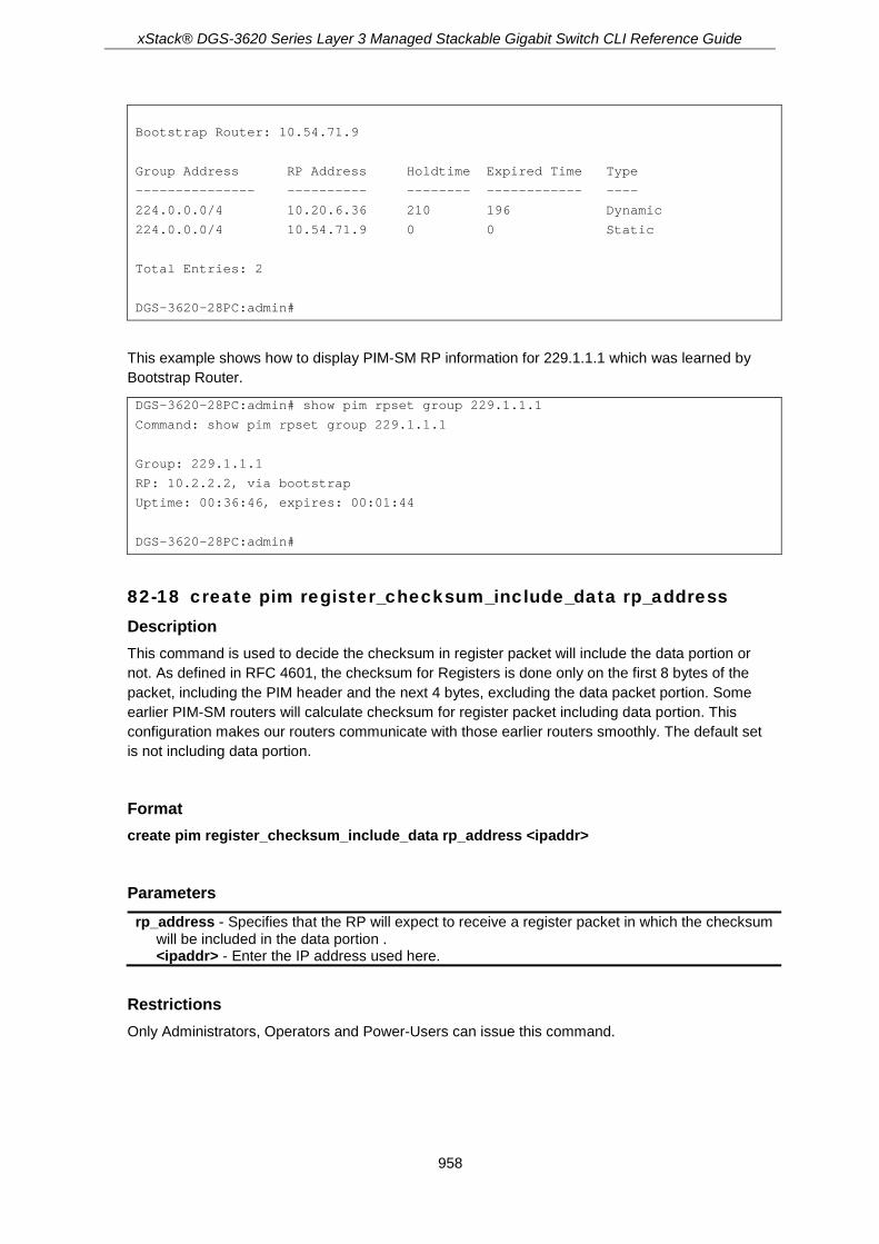
xStack® DGS-3620 Series Layer 3 Managed Stackable Gigabit Switch CLI Reference Guide
958
Bootstrap Router: 10.54.71.9
Group Address RP Address Holdtime Expired Time Type
--------------- ---------- -------- ------------ ----
224.0.0.0/4 10.20.6.36 210 196 Dynamic
224.0.0.0/4 10.54.71.9 0 0 Static
Total Entries: 2
DGS-3620-28PC:admin#
This example shows how to display PIM-SM RP information for 229.1.1.1 which was learned by Bootstrap Router.
DGS-3620-28PC:admin# show pim rpset group 229.1.1.1
Command: show pim rpset group 229.1.1.1
Group: 229.1.1.1
RP: 10.2.2.2, via bootstrap
Uptime: 00:36:46, expires: 00:01:44
DGS-3620-28PC:admin#
82-18 create pim register_checksum_include_data rp_address Description This command is used to decide the checksum in register packet will include the data portion or not. As defined in RFC 4601, the checksum for Registers is done only on the first 8 bytes of the packet, including the PIM header and the next 4 bytes, excluding the data packet portion. Some earlier PIM-SM routers will calculate checksum for register packet including data portion. This configuration makes our routers communicate with those earlier routers smoothly. The default set is not including data portion.
Format create pim register_checksum_include_data rp_address <ipaddr>
Parameters rp_address - Specifies that the RP will expect to receive a register packet in which the checksum
will be included in the data portion . <ipaddr> - Enter the IP address used here.
Restrictions Only Administrators, Operators and Power-Users can issue this command.

xStack® DGS-3620 Series Layer 3 Managed Stackable Gigabit Switch CLI Reference Guide
959
Example To create an entry for a specific RP in which the checksum in the registered packet will include the data portion:
DGS-3620-28PC:admin# create pim register_checksum_include_data rp_address 24.1.2.3
Command: create pim register_checksum_include_data rp_address 24.1.2.3
Success.
DGS-3620-28PC:admin#
82-19 delete pim register_checksum_include_data rp_address Description This command is used to delete the register checksum including the data for the specific RP address.
Format delete pim register_checksum_include_data rp_address <ipaddr>
Parameters rp_address - Specifies the RP address that will be removed from the checksum, including the
data portion list. <ipaddr> - Enter the RP address used here.
Restrictions Only Administrators, Operators and Power-Users can issue this command.
Example To delete the register checksum including the data for the specific RP address:
DGS-3620-28PC:admin# delete pim register_checksum_include_data rp_address 10.54.71.9
Command: delete pim register_checksum_include_data rp_address 10.54.71.9
Success.
DGS-3620-28PC:admin#
82-20 show pim register_checksum_include_data_rp_list Description This command is used to list all the RPs of the registered checksum, including the data.

xStack® DGS-3620 Series Layer 3 Managed Stackable Gigabit Switch CLI Reference Guide
960
Format show pim register_checksum_include_data_rp_list
Parameters None.
Restrictions None.
Example To list all the RPs of the registered checksum, including the data:
DGS-3620-28PC:admin# show pim register_checksum_include_data_rp_list
Command: show pim register_checksum_include_data_rp_list
PIM Register Checksum Include Data
RP Address
------------------
24.0.0.0
24.1.2.3
Total Entries: 2
DGS-3620-28PC:admin#
82-21 config pim-ssm Description This command is used to enable the SSM (Source-Specific Multicast) service model in PIM-SM on the switch. The PIM-SSM function will take active only when SSM service model and PIM-SM state both enabled.
Format config pim-ssm {state [enable | disable] | group_range [default | <network_address>]} (1)
Parameters state - (Optional) Specifies to enable or disable the SSM service model on the Switch.
enable - Specifies that the SSM service model will be enabled. disable - Specifies that the SSM service model will be disabled.
group_range - (Optional) Specifies the group address range for the SSM service in IPv4. default - The default indicates that the group address range is 232.0.0.0/8. <network_address> - Enter the group address range for the SSM service here.

xStack® DGS-3620 Series Layer 3 Managed Stackable Gigabit Switch CLI Reference Guide
961
Restrictions Only Administrators, Operators and Power-Users can issue this command.
Example To configure PIM-SSM state and group range:
DGS-3620-28PC:admin# config pim-ssm state enable group_range default
Command: config pim-ssm state enable group_range default
Success.
DGS-3620-28PC:admin#
82-22 show pim-ssm Description This command is used to list all PIM-SSM protocol related information.
Format show pim-ssm
Parameters None.
Restrictions None.
Example To display PIM-SSM state and group range:
DGS-3620-28PC:admin# show pim-ssm
Command: show pim-ssm
SSM Service Model State : Enabled
SSM Group : 232.0.0.0/8
DGS-3620-28PC:admin#
82-23 show pim passive Description This command is used to display PIM interface passive mode.

xStack® DGS-3620 Series Layer 3 Managed Stackable Gigabit Switch CLI Reference Guide
962
Format show pim passive {ipif <ipif_name 12>}
Parameters ipif - (Optional) Specifies the IP interface name.
<ipif_name 12> - Enter the IP interface name. This name can be up to 12 characters long.
Restrictions None.
Example To display PIM interface passive mode for all interfaces:
DGS-3620-28PC:admin#show pim passive
Command: show pim passive
Interface Passive
------------ --------
System Disabled
Total Entries: 1
DGS-3620-28PC:admin#
xStack® DGS-3620 Series Layer 3 Managed Stackable Gigabit Switch CLI Reference Guide
963
Chapter 83 PIM6-SM Commands
config pim6 [ipif <ipif_name 12> | all] {hello_interval <sec 0-18000> | triggered_hello_delay <sec 0-60> | propagation_delay <sec 0-32> | override_interval <sec 0-65> | jp_interval <sec 0-18000> | dr_priority <uint 0-4294967294> | bsr_border [disable | enable] | stub_interface [disable | enable] | state [enable | disable]} (1)
show pim6 {ipif <ipif_name 12>} config pim6 cbsr {ipif <ipif_name 12> state [enable | disable] | priority <value 0-255> |
hash_masklen <value 0-128>} (1) show pim6 cbsr config pim6 crp [rp <ipif_name 12> | all] {priority <value 0-255> | interval <sec 1-16383>} (1) create pim6 crp group <ipv6networkaddr> rp <ipif_name 12> delete pim6 crp group <ipv6networkaddr> enable pim6 disable pim6 config pim6 last_hop_spt_switchover [never | immediately] show pim6 neighbor {ipif <ipif_name 12>} show pim6 mroute {group <ipv6addr> {source <ipv6addr>}} create pim6 static_rp group <ipv6networkaddr> rp <ipv6addr> {override_dynamic} delete pim6 static_rp group <ipv6networkaddr> config pim6 embedded_rp state [enable | disable] show pim6 crp show pim6 static_rp show pim6 rpset config pim6 register_checksum_calculate [include_data | not_include_data] config pim6 register_probe_time <sec 1-127> config pim6 register_suppression_time <sec 3-65535> config pim6 keepalive_period <sec 120-65535> show pim6 mroute s_g {rpt} {group <ipv6addr> source <ipv6addr> {ipif <ipif_name 12>}} show pim6 mroute star_g {group <ipv6addr> {ipif <ipif_name 12>}}
83-1 config pim6 Description This command is used to set the PIM6 multicast protocol state and some related parameters in the protocol on some interface.
Format config pim6 [ipif <ipif_name 12> | all] {hello_interval <sec 0-18000> | triggered_hello_delay <sec 0-60> | propagation_delay <sec 0-32> | override_interval <sec 0-65> | jp_interval <sec 0-18000> | dr_priority <uint 0-4294967294> | bsr_border [disable | enable] | stub_interface [disable | enable] | state [enable | disable]} (1)
Parameters ipif - Specifies the IP interface used for this configuration.
<ipif_name 12> - Enter the IP interface name used here. This name can be up to 12 characters long.
all - Specifies that all the IP interfaces will be used. hello_interval - (Optional) Specifies the time between transmits hello packets to find neighboring

xStack® DGS-3620 Series Layer 3 Managed Stackable Gigabit Switch CLI Reference Guide
964
routers. A value of zero represents an ‘infinite’ interval, and indicates that periodic PIM6 Hello message should not be sent on this interface. <sec 0-18000> - Enter the hello packet interval value here. This value must be between 0 and
18000 seconds. The default value is 30 seconds. triggered_hello_delay - (Optional) Specifies the maximum time before the router sends a
triggered PIM Hello message on the specified interface. A value of zero has no special meaning and indicates that triggered PIM6 Hello message should always be sent immediately. <sec 0-60> - Enter the triggered hello delay value here. This value must be between 0 and 60
seconds. The default value is 5 seconds. propagation_delay - (Optional) Specifies the expected propagation delay between the PIM6
routers on this network or link. <sec 0-32> - Enter the propagation delay value here. This value must be between 0 and 32
seconds. The default value is 1 second. override_interval - (Optional) Specifies the value this router inserts into the Override_Interval
field of the LAN Prune Delay option in the PIM6 Hello messages. When overriding a prune, PIM6 routers pick random time duration up to the value of this object. <sec 0-65> - Enter the override interval value used here. This value must be between 0 and
65 seconds. The default value is 3 seconds. jp_interval - (Optional) Specifies the frequency at which this router sends PIM6 Join/Prune
messages on this PIM6 interface. A value of zero represents an ‘infinite’ interval, and indicates that periodic PIM6 Join/Prune messages should not be sent on this interface. <sec 0-18000> - Enter the Join/Prune interval value used here. This value must be between 0
and 18000 seconds. The default value is 60 seconds. dr_priority - (Optional) Specifies the Designated Router Priority value inserted into the DR
Priority option in PIM6 Hello message transmitted on this interface. Numerically higher values for this parameter indicate higher priorities. <uint 0-4294967294> - Enter the Designated Router priority value used here. This value must
be between 0 and 4294967294. The default value is 1. bsr_border - (Optional) Specifies whether or not this interface is a PIM6 domain border. If this
interface configures a border, which will prevent bootstrap router (BSR) messages from being sent or received through it. By default, an interface is not PIM6 domain border. disable - Specifies that this interface is not a PIM6 domain border. enable - Specifies that this interface is a PIM6 domain border.
stub_interface - (Optional) Specifies whether this interface is a stub interface. If this interface configures a stub interface, then no PIM6 packets are sent out this interface, and any received PIM6 packets are ignored. By default, an interface is not stub interface. When enabled, it is a security measure for interfaces towards untrusted hosts. It protects the PIM router from forged PIM messages on the interface. disable - Specifies that this interface is not a stub interface. enable - Specifies that this interface is a stub interface.
state - (Optional) Allows the PIM6 to be disabled or enabled for the above IPv6 interface. By default, the PIM6 protocol state is disabled on an interface. enable - Specifies that PIM6 is enabled. disable - Specifies that PIM6 is disabled.
Restrictions Only Administrators, Operators and Power-Users can issue this command. (EI Mode Only Command)
Example To set the jp_interval to 60 seconds, the hello_interval to 60 seconds and enable the PIM6 state for interface “n10”:
DGS-3620-28PC:admin# config pim6 ipif n10 jp_interval 60 hello_interval 60 state enable
Command: config pim6 ipif n10 jp_interval 60 hello_interval 60 state enable
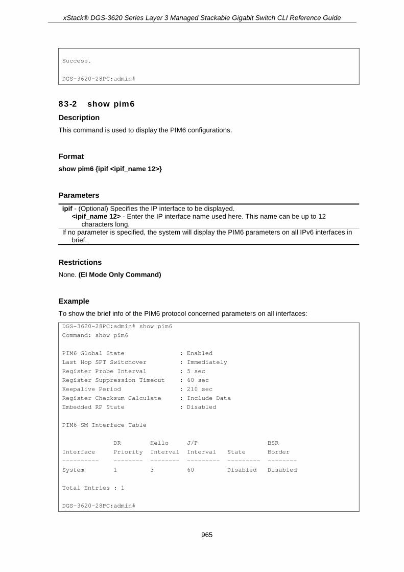
xStack® DGS-3620 Series Layer 3 Managed Stackable Gigabit Switch CLI Reference Guide
965
Success.
DGS-3620-28PC:admin#
83-2 show pim6 Description This command is used to display the PIM6 configurations.
Format show pim6 {ipif <ipif_name 12>}
Parameters ipif - (Optional) Specifies the IP interface to be displayed.
<ipif_name 12> - Enter the IP interface name used here. This name can be up to 12 characters long.
If no parameter is specified, the system will display the PIM6 parameters on all IPv6 interfaces in brief.
Restrictions None. (EI Mode Only Command)
Example To show the brief info of the PIM6 protocol concerned parameters on all interfaces:
DGS-3620-28PC:admin# show pim6
Command: show pim6
PIM6 Global State : Enabled
Last Hop SPT Switchover : Immediately
Register Probe Interval : 5 sec
Register Suppression Timeout : 60 sec
Keepalive Period : 210 sec
Register Checksum Calculate : Include Data
Embedded RP State : Disabled
PIM6-SM Interface Table
DR Hello J/P BSR
Interface Priority Interval Interval State Border
---------- -------- -------- --------- --------- --------
System 1 3 60 Disabled Disabled
Total Entries : 1
DGS-3620-28PC:admin#

xStack® DGS-3620 Series Layer 3 Managed Stackable Gigabit Switch CLI Reference Guide
966
To show the detailed info of the PIM6 protocol concerned parameters on the interface “System”:
DGS-3620-28PC:admin# show pim6 ipif System
Command: show pim6 ipif System
Interface Name : System
Interface Link-Local Address : FE80::200:FF:FE26:6666
Interface Global Address : 2103::1
PIM6 Mode : SM
State : Enabled
Designated Router : FE80::207:E9FF:FACC
Designated Router Priority : 1
Designated Router Priority Enabled : True
Hello Interval : 30 sec
Triggered Hello Interval : 5 sec
Hello Holdtime : 105 sec
Join Prune Interval : 60 sec
Join Prune Holdtime : 210 sec
LAN Delay Enabled : True
Propagation Delay : 1 sec
Override Interval : 3 sec
Effective Propagation Delay : 1 sec
Effective Override Interval : 3 sec
Join Suppression Enabled : True
Bidirectional Capable : False
BSR Domain Border : Disabled
Stub Interface : Disabled
DGS-3620-28PC:admin#
83-3 config pim6 cbsr Description This command is used to set the parameters concerned with the candidate bootstrap router.
Format config pim6 cbsr {ipif <ipif_name 12> state [enable | disable] | priority <value 0-255> | hash_masklen <value 0-128>} (1)
Parameters ipif - (Optional) Specifies the IP interface used in this configuration.
<ipif_name 12> - Enter the IP interface name used here. This name can be up to 12 characters long.
state - (Optional) Specifies whether the input interface can be a C-BSR or not. enable - Specifies that the input interface will be a C-BSR. disable - Specifies that the input interface will not be a C-BSR.
priority - (Optional) Specifies the C-BSR priority value. <value 0-255> - Enter the C-BSR priority value here. This value must be between 0 and 255.
The default value is 64. hash_masklen - (Optional) Specifies the length (in bits) of the mask. It makes use of a hash
function for the case where a group range has multiple RPs with the same priority.

xStack® DGS-3620 Series Layer 3 Managed Stackable Gigabit Switch CLI Reference Guide
967
<value 0-128> - Enter the length of the mask value here. This value must be between 0 and 128. The default value is 126.
Restrictions Only Administrators, Operators and Power-Users can issue this command. (EI Mode Only Command)
Example To configure the C-BSR on the interface “System”:
DGS-3620-28PC:admin# config pim6 cbsr ipif System state enable priority 64 hash_masklen 126
Command: config pim6 cbsr ipif System state enable priority 64 hash_masklen 126
Success.
DGS-3620-28PC:admin#
83-4 show pim6 cbsr Description This command is used to display the candidate bootstrap router information.
Format show pim6 cbsr
Parameters None.
Restrictions None. (EI Mode Only Command)
Example To show C-BSR settings on the switch:
DGS-3620-28PC:admin# show pim6 cbsr
Command: show pim6 cbsr
PIM6 Candidate-BSR Information
---------------------------------------------
C-BSR Interface Name : System
C-BSR Priority : 64
C-BSR Hash Mask Len : 126
DGS-3620-28PC:admin#

xStack® DGS-3620 Series Layer 3 Managed Stackable Gigabit Switch CLI Reference Guide
968
83-5 config pim6 crp Description This command is used to set the candidate rendezvous point (RP) related parameters.
Format config pim6 crp [rp <ipif_name 12> | all] {priority <value 0-255> | interval <sec 1-16383>} (1)
Parameters rp - Specifies the RP IP interface used.
<ipif_name 12> - Enter the RP IP interface name used here. This name can be up to 12 characters long.
all - Specifies that all the RP IP interfaces will be used. priority - (Optional) Specifies the RP priority value that will be used in the election process. The
lower the value, the higher the priority. <value 0-255> - Enter the RP priority value used here. This value must be between 0 and
255. The default value is 192. interval - (Optional) Specifies the C-RP advertisement interval in seconds.
<sec 1-16383> - Enter the C-RP advertisement interval value here. This value must be betwee 1 and 16383 seconds. The default value is 60 seconds.
Restrictions Only Administrators, Operators and Power-Users can issue this command. (EI Mode Only Command)
Example To set the C-RP priority and the interval on the interface “System”:
DGS-3620-28PC:admin# config pim6 crp rp System priority 60 interval 60
Command: config pim6 crp rp System priority 60 interval 60
Success.
DGS-3620-28PC:admin#
83-6 create pim6 crp group Description This command is used to add a multicast group range into a C-RP serve list.
Format create pim6 crp group <ipv6networkaddr> rp <ipif_name 12>
Parameters group - Specifies the IPv6 group address range served by the RP.
<ipv6networkaddr> - Enter the IPv6 network address used here.
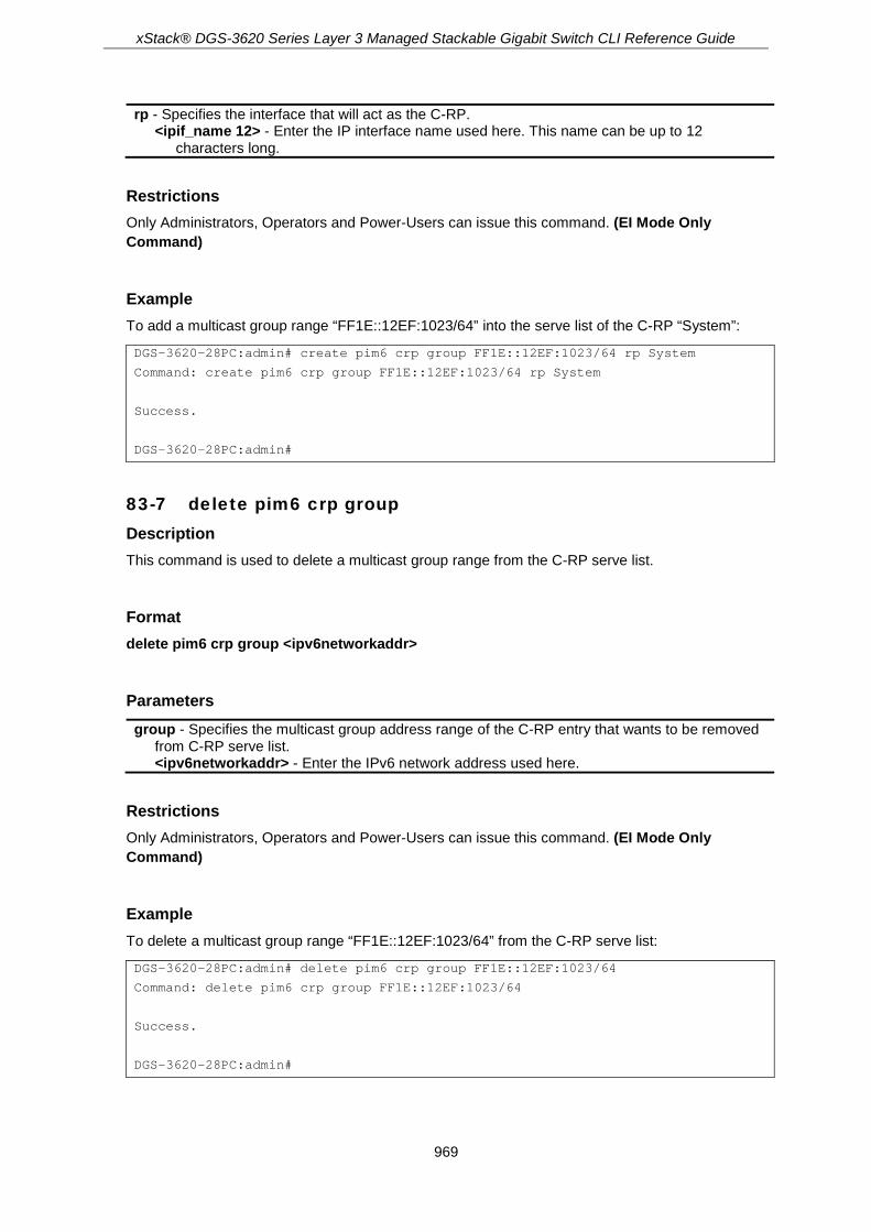
xStack® DGS-3620 Series Layer 3 Managed Stackable Gigabit Switch CLI Reference Guide
969
rp - Specifies the interface that will act as the C-RP. <ipif_name 12> - Enter the IP interface name used here. This name can be up to 12
characters long.
Restrictions Only Administrators, Operators and Power-Users can issue this command. (EI Mode Only Command)
Example To add a multicast group range “FF1E::12EF:1023/64” into the serve list of the C-RP “System”:
DGS-3620-28PC:admin# create pim6 crp group FF1E::12EF:1023/64 rp System
Command: create pim6 crp group FF1E::12EF:1023/64 rp System
Success.
DGS-3620-28PC:admin#
83-7 delete pim6 crp group Description This command is used to delete a multicast group range from the C-RP serve list.
Format delete pim6 crp group <ipv6networkaddr>
Parameters group - Specifies the multicast group address range of the C-RP entry that wants to be removed
from C-RP serve list. <ipv6networkaddr> - Enter the IPv6 network address used here.
Restrictions Only Administrators, Operators and Power-Users can issue this command. (EI Mode Only Command)
Example To delete a multicast group range “FF1E::12EF:1023/64” from the C-RP serve list:
DGS-3620-28PC:admin# delete pim6 crp group FF1E::12EF:1023/64
Command: delete pim6 crp group FF1E::12EF:1023/64
Success.
DGS-3620-28PC:admin#

xStack® DGS-3620 Series Layer 3 Managed Stackable Gigabit Switch CLI Reference Guide
970
83-8 enable pim6 Description This command is used to enable the PIM global state for IPv6 network.
Format enable pim6
Parameters None.
Restrictions Only Administrators, Operators and Power-Users can issue this command. (EI Mode Only Command)
Example To enable PIM global state for IPv6 network:
DGS-3620-28PC:admin# enable pim6
Command: enable pim6
Success.
DGS-3620-28PC:admin#
83-9 disable pim6 Description This command is used to disable the PIM global state for IPv6 network.
Format disable pim6
Parameters None.
Restrictions Only Administrators, Operators and Power-Users can issue this command. (EI Mode Only Command)
Example To disable PIM-SM for IPv6 network:

xStack® DGS-3620 Series Layer 3 Managed Stackable Gigabit Switch CLI Reference Guide
971
DGS-3620-28PC:admin# disable pim6
Command: disable pim6
Success.
DGS-3620-28PC:admin#
83-10 config pim6 last_hop_spt_switchover Description This command is used on the last hop router to decide whether to receive the multicast data from the shared tree or switch over to the shortest path tree.
Format config pim6 last_hop_spt_switchover [never | immediately]
Parameters last_hop_spt_switchover - Specifies the SPT switchover mode on the last-hop switch.
never - Specifies that the mode will never switch to SPT. This is the default value. immediately - Specifies that the mode will immediately switch to SPT.
Restrictions Only Administrators, Operators and Power-Users can issue this command. (EI Mode Only Command)
Example To set the SPT-switchover mode to never:
DGS-3620-28PC:admin# config pim6 last_hop_spt_switchover never
Command: config pim6 last_hop_spt_switchover never
Success.
DGS-3620-28PC:admin#
83-11 show pim6 neighbor Description This command is used to list all neighbors learned by the PIM6 on the switch.
Format show pim6 neighbor {ipif <ipif_name 12>}
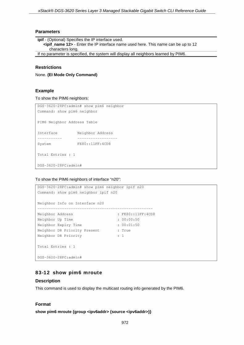
xStack® DGS-3620 Series Layer 3 Managed Stackable Gigabit Switch CLI Reference Guide
972
Parameters ipif - (Optional) Specifies the IP interface used.
<ipif_name 12> - Enter the IP interface name used here. This name can be up to 12 characters long.
If no parameter is specified, the system will display all neighbors learned by PIM6.
Restrictions None. (EI Mode Only Command)
Example To show the PIM6 neighbors:
DGS-3620-28PC:admin# show pim6 neighbor
Command: show pim6 neighbor
PIM6 Neighbor Address Table
Interface Neighbor Address
----------- ------------------
System FE80::11FF:4CD8
Total Entries : 1
DGS-3620-28PC:admin#
To show the PIM6 neighbors of interface “n20”:
DGS-3620-28PC:admin# show pim6 neighbor ipif n20
Command: show pim6 neighbor ipif n20
Neighbor Info on Interface n20
----------------------------------------------------
Neighbor Address : FE80::11FF:4CD8
Neighbor Up Time : 00:00:50
Neighbor Expiry Time : 00:01:50
Neighbor DR Priority Present : True
Neighbor DR Priority : 1
Total Entries : 1
DGS-3620-28PC:admin#
83-12 show pim6 mroute Description This command is used to display the multicast routing info generated by the PIM6.
Format show pim6 mroute {group <ipv6addr> {source <ipv6addr>}}

xStack® DGS-3620 Series Layer 3 Managed Stackable Gigabit Switch CLI Reference Guide
973
Parameters group - (Optional) Specifies the IPv6 multicast group address.
<ipv6addr> - Enter the IPv6 multicast group address used here. source - (Optional) Specifies the IPv6 source address. If this parameter is chosen, the (S, G) or
(S, G, rpt) entries will be displayed; otherwise the (*, G) entries will be displayed. <ipv6addr> - Enter the IPv6 source address used here.
If no parameter is specified, the system will display all IPv6 multicast routing entries.
Restrictions None. (EI Mode Only Command)
Example To show the whole IPv6 multicast routing table generated on the switch:
DGS-3620-28PC:admin# show pim6 mroute
Command: show pim6 mroute
Total (*,G) Entries : 1
Total (S,G) Entries : 2
Total (S,G,rpt) Entries: 1
Group : FF13::100
Source : * Upstream: n1
Outgoing : n10 n30
Group : FF13::100
Source : 2001::1111 Upstream: n2
Outgoing: n10
Group : FF13::102
Source : 2001::3F6D Upstream: n2
Outgoing: n20
Group : FF13::100
Source : 2001::1111 rpt, Upstream: n1
RP Address: 3FFE:10:10::153
Outgoing : -
Total Entries: 4
DGS-3620-28PC:admin#
You can check the detailed info for a specific multicasting routing entry by specifying the options in the command. To show the detailed info of the multicast routing entries for a specific group, you should specify the group address.
DGS-3620-28PC:admin# show pim6 mroute group FF13::100
Command: show pim6 mroute group FF13::100

xStack® DGS-3620 Series Layer 3 Managed Stackable Gigabit Switch CLI Reference Guide
974
(*, G) Entry for group FF13::100
---------------------------------------------
RP Address : 3FFE:10:10::153
Upstream : n1
Upstream State : Joined
RPF Neighbor : FE80::68FE
Local Member : n30
Assert Lost : -
Assert Won : -
Outgoing : n10 n30
(S, G) Entry for group FF13::100
---------------------------------------------
Source : 2001::1111 Upstream: n2
Outgoing: n10
Source : 2001::1111 rpt, Upstream: n1
Outgoing: -
Source : 2001::3F6D Upstream: n2
Outgoing: n20
Total Entries: 4
DGS-3620-28PC:admin#
To show the detailed info of the multicast routing entries for the specific (S,G), you should specify the group address and the source address.
DGS-3620-28PC:admin# show pim6 mroute group FF13::100 source 2001::1111
Command: show pim6 mroute group FF13::100 source 2001::1111
(S, G) Entry for group FF13::100 source 2001::1111
---------------------------------------------
RPT Bit : False
Upstream : n2
Upstream State : Joined
RPF Neighbor : FE80::12ED
SPT Bit : True
Keepalive Timer : 60 sec
Register State : Prune
Register-Stop Timer : 10 sec
Local Member : n30
Assert Lost : n20
Assert Won : n10
Outgoing : n10 n30
RPT Bit : True
RP Address : 3FFE:10:10::153
Upstream : n1
Upstream State : RPT not joined
RPF Neighbor : FE80::68FE

xStack® DGS-3620 Series Layer 3 Managed Stackable Gigabit Switch CLI Reference Guide
975
Override Timer : 3 sec
Pruned : n10
Outgoing : -
Total Entries: 2
DGS-3620-28PC:admin#
83-13 create pim6 static_rp group Description This command is used to create a static RP. Generally a static RP can’t override a dynamic RP. If the option ‘override_dynamic’ is chosen, the static RP will override any dynamically learned RP.
Format create pim6 static_rp group <ipv6networkaddr> rp <ipv6addr> {override_dynamic}
Parameters group - Specifies the multicast group network address for this static RP.
<ipv6networkaddr> - Enter the IPv6 group network address used here. rp - Specifies the IPv6 address to this static RP.
<ipv6addr> - Enter the IPv6 address used here. override_dynamic - (Optional) Specifies that the static RP will override the dynamically learned
RP.
Restrictions Only Administrators, Operators and Power-Users can issue this command. (EI Mode Only Command)
Example To create a static RP:
DGS-3620-28PC:admin# create pim6 static_rp group FF1E::/64 rp 3000::12
Command: create pim6 static_rp group FF1E::/64 rp 3000::12
Success.
DGS-3620-28PC:admin#
83-14 delete pim6 static_rp group Description This command is used to delete a static RP.
Format delete pim6 static_rp group <ipv6networkaddr>

xStack® DGS-3620 Series Layer 3 Managed Stackable Gigabit Switch CLI Reference Guide
976
Parameters group - Specifies the multicast group network address which will be removed from the static RP.
<ipv6networkaddr> - Enter the IPv6 network address used here.
Restrictions Only Administrators, Operators and Power-Users can issue this command. (EI Mode Only Command)
Example To delete a static RP:
DGS-3620-28PC:admin# delete pim6 static_rp group FF1E::/64
Command: delete pim6 static_rp group FF1E::/64
Success.
DGS-3620-28PC:admin#
83-15 config pim6 embedded_rp state Description This command is used to set the state of the embedded RP.
Format config pim6 embedded_rp state [enable | disable]
Parameters state - Specifies the embedded RP support in the PIM6 state.
enable - Specifies that embedded RP support will be enabled. disable - Specifies that embedded RP support will be disabled.
Restrictions Only Administrators, Operators and Power-Users can issue this command. (EI Mode Only Command)
Example To enable the embedded RP state:
DGS-3620-28PC:admin# config pim6 embedded_rp state enable
Command: config pim6 embedded_rp state enable
Success.
DGS-3620-28PC:admin#

xStack® DGS-3620 Series Layer 3 Managed Stackable Gigabit Switch CLI Reference Guide
977
83-16 show pim6 crp Description This command is used to list all candidate rendezvous point (RP) related information.
Format show pim6 crp
Parameters None.
Restrictions None. (EI Mode Only Command)
Example To show the C-RP information:
DGS-3620-28PC:admin# show pim6 crp
Command: show pim6 crp
PIM6 Candidate-RP Table
Group Interface Priority Interval
------------------ ------------- --------- ---------
FF1E:90::/64 System 192 150
Total Entries: 1
DGS-3620-28PC:admin#
83-17 show pim6 static_rp Description This command is used to list all static RP settings.
Format show pim6 static_rp
Parameters None.

xStack® DGS-3620 Series Layer 3 Managed Stackable Gigabit Switch CLI Reference Guide
978
Restrictions None. (EI Mode Only Command)
Example To show the static RP:
DGS-3620-28PC:admin# show pim6 static_rp
Command: show pim6 static_rp
PIM6 Static RP Table
---------------------------------------------
Group : FF1E:9B::/64
RP Address : 3000::1
Override Dynamic : True
Group : FF1E:9C::/64
RP Address : 3000::5
Override Dynamic : False
Total Entries: 2
DGS-3620-28PC:admin#
83-18 show pim6 rpset Description This command is used to list the entire active RP information.
Format show pim6 rpset
Parameters None.
Restrictions None. (EI Mode Only Command)
Example To show the entire active RP information:
DGS-3620-28PC:admin# show pim6 rpset
Command: show pim6 rpset
Bootstrap Router: 2008::1
PIM6 RP-Set Table

xStack® DGS-3620 Series Layer 3 Managed Stackable Gigabit Switch CLI Reference Guide
979
-----------------------------------------
Group : FF3D::/64
RP Address : 2008::10F2
Hold Time : 210 sec
Expired Time : 196 sec
Type : Dynamic
Group : FF3D::/64
RP Address : 3008::2DEF
Override Dynamic : False
Type : Static
Total Entries: 2
DGS-3620-28PC:admin#
83-19 config pim6 register_checksum_calculate Description This command is used to decide the checksum in register packet will include the data portion or not. As defined in RFC 4601, the checksum for Registers is done only on the first 8 bytes of the packet, including the PIM header and the next 4 bytes, excluding the data packet portion. Some earlier PIM6-SM routers will calculate checksum for register packet including data portion. This configuration makes our routers communicate with those earlier routers smoothly. The default set is not including data portion.
Format config pim6 register_checksum_calculate [include_data | not_include_data]
Parameters register_checksum_calculate - Specifies the register packet checksum calculating mechanism.
include_data - When calculate the checksum in IPv6 PIM register packet, the data portion will be included.
not_include_data - When calculate the checksum in IPv6 PIM register packet, the data portion won’t be included.
Restrictions Only Administrators, Operators and Power-Users can issue this command. (EI Mode Only Command)
Example To specify the switch calculates the register packet checksum including data portion:
DGS-3620-28PC:admin# config pim6 register_checksum_calculate include_data
Command: config pim6 register_checksum_calculate include_data
Success.

xStack® DGS-3620 Series Layer 3 Managed Stackable Gigabit Switch CLI Reference Guide
980
DGS-3620-28PC:admin#
83-20 config pim6 register_probe_time Description This command is used to configure the PIM6-SM register probe time.
Format config pim6 register_probe_time <sec 1-127>
Parameters register_probe_time - Specifies the time before the Register-Stop Timer (RST) expires when a
DR may send a Null-Register to the RP to cause it to resend a Register-Stop message. <sec 1-127> - Enter the register probe time value here. This value must be between 1 and
127 seconds. The default value is 5 seconds.
Restrictions Only Administrators, Operators and Power-Users can issue this command. (EI Mode Only Command)
Example To configure the register probe time to be 20 seconds:
DGS-3620-28PC:admin# config pim6 register_probe_time 20
Command: config pim6 register_probe_time 20
Success.
DGS-3620-28PC:admin#
83-21 config pim6 register_suppression_time Description This command is used to configure the PIM6-SM register suppression time. This is the period during which a PIM Designated Router (DR) stops sending Register-encapsulated data to the Rendezvous Point (RP) after receiving a Register-Stop message.
Format config pim6 register_suppression_time <sec 3-65535>
Parameters register_suppression_time - Specifies the period during which a PIM DR stops sending
Register-encapsulated data to the RP after receiving a Register-Stop message. <sec 3-65535> - Enter the register suppression time value here. This value must be between
3 and 65535 seconds. The default value is 60 seconds.

xStack® DGS-3620 Series Layer 3 Managed Stackable Gigabit Switch CLI Reference Guide
981
Restrictions Only Administrators, Operators and Power-Users can issue this command. (EI Mode Only Command)
Example To configure the PIM6-SM register suppression time to be 120 seconds:
DGS-3620-28PC:admin# config pim6 register_suppression_time 120
Command: config pim6 register_suppression_time 120
Success.
DGS-3620-28PC:admin#
83-22 config pim6 keepalive_period Description This command is used to configure the PIM6-SM multicast routing entry Keepalive Timer. This is the period during which the PIM router will maintain (S, G) state in the absence of explicit (S, G) local membership or (S, G) join messages received to maintain it.
Format config pim6 keepalive_period <sec 120-65535>
Parameters keepalive_period - Specifies the period during which the PIM router will maintain (S, G) state in
the absence of explicit (S, G) local membership or (S, G) join messages received to maintain it. <sec 120-65535> - Enter the keep-alive period value here. This value must be between 120
and 65535 seconds. The default value is 210 seconds.
Restrictions Only Administrators, Operators and Power-Users can issue this command. (EI Mode Only Command)
Example To configure the multicast routing keepalive period to be 220 seconds:
DGS-3620-28PC:admin# config pim6 keepalive_period 220
Command: config pim6 keepalive_period 220
Success.
DGS-3620-28PC:admin#

xStack® DGS-3620 Series Layer 3 Managed Stackable Gigabit Switch CLI Reference Guide
982
83-23 show pim6 mroute s_g Description This command is used to display the multicast routing information for (S, G) or (S, G, rpt) entries generated by PIM6.
Format show pim6 mroute s_g {rpt} {group <ipv6addr> source <ipv6addr> {ipif <ipif_name 12>}}
Parameters rpt - (Optional) Specifies the (S, G, rpt) entry. group - (Optional) Specifies the IPv6 multicast group address.
<ipv6addr> - Enter the IPv6 multicast group address used here. source - (Optional) Specifies the source IPv6 interface network address.
<ipv6addr> - Enter the IPv6 interface network address used here. ipif - Specifies the IPv6 interface name.
<ipif_name 12> - Enter the IPv6 interface name here. This name can be up to 12 characters long.
If no parameter is specified, the switch will display all the (S, G) route entries in the IPv6 multicast routing table in brief.
If only specified parameter {rpt}, the switch will display all the (S, G, rpt) route entries in the IPv6 multicast routing table in brief.
Restrictions None. (EI Mode Only Command)
Example To show all (S, G) route entries generated on the switch:
DGS-3620-28PC:admin# show pim6 mroute s_g
Command: show pim6 mroute s_g
(S, G) Entry Table
------------------------
Group : FF13::100
Source : 2001::1111
Group : FF13::100
Source : 2001::2222
Group : FF13::200
Source : 2001::1111
Group : FF13::300
Source : 2001::1111
Total Entries: 4
DGS-3620-28PC:admin#

xStack® DGS-3620 Series Layer 3 Managed Stackable Gigabit Switch CLI Reference Guide
983
Check the detailed information for a specific multicasting route entry by specifying the options in the command. To show the detailed information of the multicast route entries of the specific group and source address.
DGS-3620-28PC:admin# show pim6 mroute s_g group FF13::100 source 2001::1111
Command: show pim6 mroute s_g group FF13::100 source 2001::1111
Group Address : FF13::100
Source Address : 2001::1111
Uptime : 150 sec
Upstream Join State : Joined
Upstream Join Timer : 20 sec
Upstream Neighbor : FE80::12ED
RPF Interface : n20
RPF Next Hop : FE80::12ED
RPF Route Protocol : OSPF
RPF Route Address : 3FFE:10:10::147
RPF Route Prefix Length : 64
RPF Route Metric Pref : 110
RPF Route Metric : 3
SPT Bit : True
Keepalive Timer : 60 sec
DR Register State : NoInfo
DR Register Stop Timer : 0 sec
DGS-3620-28PC:admin#
To show the detailed information on a downstream interface of the multicast routing entry (S, G), specify the group address, source address and the interface name.
DGS-3620-28PC:admin# show pim6 mroute s_g group FF13::100 source 2001::1111 ipif n20
Command: show pim6 mroute s_g group FF13::100 source 2001::1111 ipif n20
Group Address : FF13::100
Source Address : 2001::1111
Interface Name : n20
Uptime : 150 sec
Have Local Membership : False
Join Prune State : Join
Prune Pending Timer : 0 sec
Join Expiry Timer : 10 sec
Assert State : NoInfo
Assert Timer : 0 sec
Assert Winner Address : -
Assert Winner Metric Pref : 0
Assert Winner Metric : 0
DGS-3620-28PC:admin#
To show the whole IPv6 multicast routing table of (S, G, rpt) generated on the switch:

xStack® DGS-3620 Series Layer 3 Managed Stackable Gigabit Switch CLI Reference Guide
984
DGS-3620-28PC:admin# show pim6 mroute s_g rpt
Command: show pim6 mroute s_g rpt
(S, G, rpt) Entry Table
------------------------
Group : FF13::100
Source : 2001::1111
RP Address : 3FFE:10:10::153
Group : FF13::100
Source : 2001::2222
RP Address : 3FFE:10:10::153
Group : FF13::200
Source : 2001::1111
RP Address : 3FFE:10:10::153
Group : FF13::300
Source : 2001::1111
RP Address : 3FFE:10:10::153
Total Entries: 4
DGS-3620-28PC:admin#
Check the detailed information for a specific multicasting routing entry by specifying the options in the command. To show the detailed information of a multicast route entry (S, G, rpt), specify the group address and the source address.
DGS-3620-28PC:admin# show pim6 mroute s_g rpt group FF13::100 source 2001::1111
Command: show pim6 mroute s_g rpt group FF13::100 source 2001::1111
Group Address : FF13::100
Source Address : 2001::1111
Uptime : 150 sec
Upstream Prune State : RPT not joined
Upstream Override Timer : 0 sec
DGS-3620-28PC:admin#
To show the detailed information on a downstream interface of the multicast routing entry (S, G, rpt), specify the group address, source address and interface name.
DGS-3620-28PC:admin# show pim6 mroute s_g rpt group FF13::100 source 2001::1111 ipif n20
Command: show pim6 mroute s_g rpt group FF13::100 source 2001::1111 ipif n20
Group Address : FF13::100
Source Address : 2001::1111
Interface Name : n20
Uptime : 150 sec
Have Local Membership : False
Join Prune State : Prune

xStack® DGS-3620 Series Layer 3 Managed Stackable Gigabit Switch CLI Reference Guide
985
Prune Pending Timer : 0 sec
Prune Expiry Timer : 15 sec
DGS-3620-28PC:admin#
83-24 show pim6 mroute star_g Description This command is used to display the multicast routing information for (*, G) entries generated by PIM6. Users can get detailed info of the routing entries by choosing the options in the command.
Format show pim6 mroute star_g {group <ipv6addr> {ipif <ipif_name 12>}}
Parameters group - (Optional) Specifies the IPv6 multicast group address.
<ipv6addr> - Enter the IPv6 multicast group address used here. ipif - (Optional) Specifies the IPv6 interface name.
<ipif_name 12> - Enter the IPv6 interface name used here. This name can be up to 12 characters long.
If no parameter is specified, the switch will display all (*, G) entries of the IPv6 multicast routing table in brief.
Restrictions None. (EI Mode Only Command)
Example To show the whole IPv6 multicast routing table of (*, G) generated on the switch:
DGS-3620-28PC:admin# show pim6 mroute star_g
Command: show pim6 mroute star_g
(*, G) Entry Table
-------------------------
Group : FF13::100
Upstream : n2
RP Address : 3FFE:10:10::153
Group : FF13::101
Upstream : n2
RP Address : 3FFE:10:10::153
Group : FF13::102
Upstream : n2
RP Address : 3FFE:10:10::153
Total Entries: 3

xStack® DGS-3620 Series Layer 3 Managed Stackable Gigabit Switch CLI Reference Guide
986
DGS-3620-28PC:admin#
Check the detailed information for a specific multicasting routing entry by specifying the options in the command. To show the detailed information of the multicast routing entries for a specific group, specify the group address.
DGS-3620-28PC:admin# show pim6 mroute star_g group FF13::100
Command: show pim6 mroute star_g group FF13::100
Group Address : FF1E::100
Uptime : 150 sec
RP Address : 3FFE:10:10::153
RP Is Local : False
Upstream Join State : Joined
Upstream Join Timer : 20 sec
Upstream Neighbor : FE80::68FE
RPF Next Hop : FE80::68FE
RPF Route Protocol : OSPF
RPF Route Address : 3FF5::147
RPF Route Prefix Length : 64
RPF Route Metric Preference : 110
RPF Route Metric : 3
DGS-3620-28PC:admin#
To show the detailed information on a downstream interface of the multicast routing entries (*, G), specify the group address and the interface name.
DGS-3620-28PC:admin# show pim6 mroute star_g group FF13::100 ipif n10
Command: show pim6 mroute star_g group FF13::100 ipif n10
Group Address : FF1E::100
Interface Name : n10
Uptime : 150 sec
Have Local Membership : True
Join Prune State : Join
Prune Pending Timer : 0 sec
Join Expiry Timer : 10 sec
Assert State : NoInfo
Assert Timer : 0 sec
Assert Winner Address : -
Assert Winner Metric Pref : 0
Assert Winner Metric : 0
DGS-3620-28PC:admin#

xStack® DGS-3620 Series Layer 3 Managed Stackable Gigabit Switch CLI Reference Guide
987
Chapter 84 Policy Route Commands
create policy_route name <policyroute_name 32> delete policy_route name <policyroute_name 32> config policy_route name <policyroute_name 32> acl profile_id <value 1-6> access_id <value 1-
256> nexthop <ipaddr> state [enable | disable] {route_preference [default | pbr]} show policy_route
84-1 create policy_route name Description This command is used to create a policy route and define the rule’s name.
Format create policy_route name <policyroute_name 32>
Parameters <policyroute_name 32> - The policy route name. The maximum length is 32 characters.
Restrictions Only Administrators, Operators and Power-Users can issue this command.
Example To create a policy route named “danilo”:
DGS-3620-28PC:admin#create policy_route name danilo
Command: create policy_route name danilo
Success.
DGS-3620-28PC:admin#
84-2 delete policy_route name Description This command is used to delete a policy route.
Format delete policy_route name <policyroute_name 32>

xStack® DGS-3620 Series Layer 3 Managed Stackable Gigabit Switch CLI Reference Guide
988
Parameters <policyroute_name 32> - The policy route name. The maximum length is 32 characters.
Restrictions Only Administrators, Operators and Power-Users can issue this command.
Example To delete a policy route named “duhon”:
DGS-3620-28PC:admin#delete policy_route name duhon
Command: delete policy_route name duhon
Success.
DGS-3620-28PC:admin#
84-3 config policy_route name Description This command allows users to configure the different fields for a policy route entry. Users can set the state of a policy route to enable or disable.
• The user must create an ACL rule. If the ACL rule does not exist, the system will display an error message.
• If the ACL rule action is drop, these packets will not forward and the policy route will not be implemented.
• When a packet passes from the policy route, its TTL will decrease by 1.
• If a user deletes an ACL rule that is linked to a policy rule, the system will display an error message.
Format config policy_route name <policyroute_name 32> acl profile_id <value 1-6> access_id <value 1-256> nexthop <ipaddr> state [enable | disable] {route_preference [default | pbr]}
Parameters <policyroute_name 32> - The policy route name. The maximum length is 32 characters. acl profile_id - The ACL profile ID.
<value 1-6>- Specifies the value between 1 and 6. access_id - The ACL access ID.
<value 1-256> - Specifies the value between 1 and 256. nexthop - The next hop IP address.
<ipaddr> - Specifies the IP address. state - Activate or deactivate this rule.
enable - Activate this rule. disable - Deactivate this rule.
route_preference - (Optional) Specifies the priority of this policy route. By default, the policy route has higher priority than the routing table, including local, default, static, and dynamic

xStack® DGS-3620 Series Layer 3 Managed Stackable Gigabit Switch CLI Reference Guide
989
routes. The one that has the higher priority should be used to check the traffic first. default - Specifies that the policy base route has lower priority than the route in the routing
table. pbr - Specifies that the policy base route has higher priority than the route in the routing table.
Restrictions Only Administrators, Operators and Power-Users can issue this command.
Example To configure all packets which match ACL rule profile ID=1 and access ID=1, and then route to 20.1.1.100:
DGS-3620-28PC:admin#config policy_route name danillo acl profile_id 1 access_id 1 nexthop 20.1.1.100 state enable
Command: config policy_route name danillo acl profile_id 1 access_id 1 nexthop 20.1.1.100 state enable
Success.
DGS-3620-28PC:admin#
84-4 show policy_route Description This command is used to display the switch’s current policy route rules.
Format show policy_route
Parameters None.
Restrictions None.
Example To display the switch’s current policy route rules:

xStack® DGS-3620 Series Layer 3 Managed Stackable Gigabit Switch CLI Reference Guide
990
DGS-3620-28PC:admin#show policy_route
Command: show policy_route
Policy Routing Table
---------------------
Name Pro- Access Next Hop State Route
file ID Pre-
ID ference
-------------------------------- ----- ------ --------------- -------- -------
route 1 1 192.168.69.1 Enabled PBR
Total Entries: 1
DGS-3620-28PC:admin#

xStack® DGS-3620 Series Layer 3 Managed Stackable Gigabit Switch CLI Reference Guide
991
Chapter 85 Port Security Commands
config port_security ports [<portlist> | all] [{admin_state [enable | disable] | max_learning_addr
<max_lock_no 0-3328> | action [drop | shutdown] | lock_address_mode [permanent | deleteontimeout | deleteonreset]}(1) | {vlan [<vlan_name 32> | vlanid <vidlist>] max_learning_addr [<max_lock_no 0-3328> | no_limit]}(1)]
config port_security system max_learning_addr [<max_lock_no 1-3328> | no_limit] config port_security vlan [<vlan_name 32> | vlanid <vidlist>] max_learning_addr [<max_lock_no
0-3328> | no_limit] delete port_security_entry [vlan <vlan_name 32> | vlanid <vlanid 1-4094>] mac_address
<macaddr> clear port_security_entry {ports [<portlist> | all] | {[vlan <vlan_name 32> | vlanid <vidlist>]}} show port_security_entry {ports {<portlist>} {[vlan <vlan_name 32> | vlanid <vidlist>]}} show port_security {ports {<portlist>} {[vlan <vlan_name 32> | vlanid <vidlist>]}} config port_security log state [enable | disable] config port_security trap state [enable | disable]
85-1 config port_security ports Description This command is used to set the port’s state, maximum supported MAC address entries, the default entry type, and set the maximum port-security entries that can be learned with a specific VLAN on a specific port. There are four levels of limitations on the learned entry number, for the entire system, for a port, for a VLAN, and for specific VLAN on a port. If any limitation is exceeded, the new entry will be discarded.
Format config port_security ports [<portlist> | all] [{admin_state [enable | disable] | max_learning_addr <max_lock_no 0-3328> | action [drop | shutdown] | lock_address_mode [permanent | deleteontimeout | deleteonreset]}(1) | {vlan [<vlan_name 32> | vlanid <vidlist>] max_learning_addr [<max_lock_no 0-3328> | no_limit]}(1)]
Parameters <portlist> - Enter a range of ports to be configured. all - Specifies that all ports will be configured. admin_state - Allow the port security to be enabled or disabled for the ports specified in the port
list. The default setting is disabled. enable - Enable port security for the ports specified in the port list. disable - Disable port security for the ports specified in the port list.
max_learning_addr - Specifies the maximum of MAC address entries that can be learned on this port. If the value is set to 0, it means that no user can get authorized by the port security function on this port. If the setting is smaller than the number of current learned entries on the port, the command will be rejected. The default value is 32. <max_lock_no 0-3328> - Enter the value between 0 and 3328.
action - Specifies the action that will be taken when the number of secure MAC addresses, learned on the port, reaches the maximum limit. drop - Specifies that when the number of secure MAC addresses reaches the maximum

xStack® DGS-3620 Series Layer 3 Managed Stackable Gigabit Switch CLI Reference Guide
992
learned on the port, new entries will be dropped. This is the default setting. shutdown - Specifies that when the number of secure MAC addresses reaches the maximum
learned on the port, the port will be shut down and enter the error-disabled state immediately. The port state is recovered only by enabling the port manually. The shutdown action only applies to port-level security settings.
lock_address_mode - Indicate locking address mode. The default mode is deleteonreset. permanent - The address will never be deleted unless the user removes it manually or the
VLAN of the entry is removed or the port are removed from the VLAN, or port security is disabled on the port where the address resides.
deleteontimeout - The locked addresses can be aged out after aging timer expires. deleteonreset - This address will be removed if the switch is reset or reboots. The cases
under which the permanent entries are deleted also apply to the deleteonreset entries vlan - (Optional) Specifies the VLAN to limit the address learning.
<vlan_name 32> - Enter the name of the VLAN. The maximum length is 32 characters. vlanid - Specifies a list of VLANs by VLAN ID to limit the address learning.
<vidlist> - Enter a list of VLAN ID. max_learning_addr - (Optional) Specifies the maximum of MAC address entries that can be
learned on this port. If the value is set to 0, it means that no user can get authorized by the port security function on this port. If the setting is smaller than the number of current learned entries on the port, the command will be rejected. The default value is 32. <max_lock_no 0-3328> - Enter the value between 0 and 3328. no_limit - Specifies no limitation on the number of entries.
Restrictions Only Administrators, Operators and Power-Users can issue this command.
Example To configure port security:
DGS-3620-28PC:admin#config port_security ports 6 admin_state enable max_learning_addr 10 lock_address_mode permanent
Command: config port_security ports 6 admin_state enable max_learning_addr 10 lock_address_mode permanent
Success.
DGS-3620-28PC:admin#
To configure a port security setting:
DGS-3620-28PC:admin#config port_security ports 1 vlan vlanid 1 max_learning_addr 16
Command: config port_security ports 1 vlan vlanid 1 max_learning_addr 16
Success.
DGS-3620-28PC:admin#
85-2 config port_security system max_learning_addr Description This command is used to set the maximum number of MAC address entries that can be authorized system wide. There are four levels of limitations on the learned entry number, for the entire system,

xStack® DGS-3620 Series Layer 3 Managed Stackable Gigabit Switch CLI Reference Guide
993
for a port, for a VLAN, and for specific VLAN on a port. If any limitation is exceeded, the new entry will be discarded. The setting for system level max learned users must be greater than the total of the max learned users allowed on all ports.
Format config port_security system max_learning_addr [<max_lock_no 1-3328> | no_limit]
Parameters <max_lock_no 1-3328> - Enter the maximum number of MAC address entries that can be
learned by the system. If the setting is smaller than the number of current learned entries on all enabled ports, the command will be rejected.
no_limit - By default, the number above is set to no limit.
Restrictions Only Administrators, Operators and Power-Users can issue this command.
Example To configure the maximum number of port security entries to 256:
DGS-3620-28PC:admin# config port_security system max_learning_addr 256
Command: config port_security system max_learning_addr 256
Success.
DGS-3620-28PC:admin#
85-3 config port_security vlan Description This command sets the maximum number of MAC address entries that can be learned on a specific VLAN. There are four levels of limitations on the learned entry number, for the entire system, for a port, for a VLAN, and for specific VLAN on a port. If any limitation is exceeded, the new entry will be discarded.
Format config port_security vlan [<vlan_name 32> | vlanid <vidlist>] max_learning_addr [<max_lock_no 0-3328> | no_limit]
Parameters <vlan_name 32> - Enter the VLAN by name. The maximum length is 32 characters. vlanid - Specifies a list of VLANs by VLAN ID.
<vidlist> - Enter the VLAN ID. max_learning_addr - Specifies the maximum number of MAC address entries that can be
learned with this VLAN. If this parameter is set to 0, it means that no user can get authorization on this VLAN. If the setting is smaller than the number of current learned entries on the VLAN, the command will be rejected.

xStack® DGS-3620 Series Layer 3 Managed Stackable Gigabit Switch CLI Reference Guide
994
<max_lock_no 0-3328> - Enter the value between 0 and 3328. no_limit - Specifies the default value is no limit.
Restrictions Only Administrators, Operators and Power-Users can issue this command.
Example To configure the maximum number of entries that can be learned at 64:
DGS-3620-28PC:admin#config port_security vlan vlanid 1 max_learning_addr 64
Command: config port_security vlan vlanid 1 max_learning_addr 64
Success.
DGS-3620-28PC:admin#
85-4 delete port_security_entry Description This command is used to delete a port security entry by VLAN, VLAN ID, and MAC address.
Format delete port_security_entry [vlan <vlan_name 32> | vlanid <vlanid 1-4094>] mac_address <macaddr>
Parameters vlan - Specifies the VLAN by name.
<vlan_name 32> - Enter the VLAN name. The maximum length is 32 characters. vlanid - Specifies a list of VLANs by VLAN ID.
<vlanid 1-4094> - Enter the VLAN ID. This value must be between 1 and 4094. mac_address - Specifies the MAC address of the entry.
<macaddr> - Enter the MAC address of the entry.
Restrictions Only Administrators, Operators and Power-Users can issue this command.
Example To delete the port security entry with a MAC address of 00-01-30-10-2c-c7 on the default VLAN:
DGS-3620-28PC:admin#delete port_security_entry vlan default mac_address 00-01-30-10-2C-C7
Command: delete port_security_entry vlan default mac_address 00-01-30-10-2C-C7
Success.
DGS-3620-28PC:admin#

xStack® DGS-3620 Series Layer 3 Managed Stackable Gigabit Switch CLI Reference Guide
995
85-5 clear port_security_entry Description This command is used to clear the MAC entries learned from the specified port(s) or VLAN(s) for the port security function.
Format clear port_security_entry {ports [<portlist> | all] | {[vlan <vlan_name 32> | vlanid <vidlist>]}}
Parameters ports - (Optional) The port-security entries learned on the specified port will be cleared.
<portlist> - Enter a range of ports to be configured. all - All the port-security entries learned by the system will be cleared.
vlan - (Optional) The port-security entries learned on the specified VLANs will be cleared. <vlan_name 32> - Enter the VLAN name. The maximum length is 32 characters.
vlanid - (Optional) Specifies a list of VLANs by VLAN ID. <vidlist> - Enter a list of the VLAN IDs.
Restrictions Only Administrators, Operators and Power-Users can issue this command.
Example To clear port security entry for port 6:
DGS-3620-28PC:admin#clear port_security_entry port 6
Command: clear port_security_entry port 6
Success.
DGS-3620-28PC:admin#
85-6 show port_security_entry Description This command is used to display a port security entry.
Format show port_security_entry {ports {<portlist>} {[vlan <vlan_name 32> | vlanid <vidlist>]}}
Parameters ports - (Optional) Specifies a range of ports to be displayed.
<portlist> - Enter a range of ports to be displayed. vlan - (Optional) Specifies a VLAN to display its entry.
<vlan_name 32> - Enter the VLAN name. The maximum length is 32 characters. vlanid - (Optional) Specifies a VLAN list to display its entry.
<vidlist> - Enter a list of the VLAN IDs.

xStack® DGS-3620 Series Layer 3 Managed Stackable Gigabit Switch CLI Reference Guide
996
Restrictions None.
Example To display a port security entry:
DGS-3620-28PC:admin#show port_security_entry
Command: show port_security_entry
MAC Address VID Port Lock Mode
----------------- --- ---- ----------
00-00-00-00-00-01 1 25 DeleteOnTimeout
Total Entry Number: 1
DGS-3620-28PC:admin#
85-7 show port_security Description This command is used to display the port security related information of the switch ports including the port security admin state, the maximum number of learning addresses, and the lock mode.
Format show port_security {ports {<portlist>} {[vlan <vlan_name 32> | vlanid <vidlist>]}}
Parameters ports - (Optional) Specifies a range of ports to be displayed.
<portlist> - Enter a range of ports to be displayed. vlan - (Optional) Specifies a VLAN to display its configuration.
<vlan_name 32> - Enter the VLAN name. The maximum length is 32 characters. vlanid - (Optional) Specifies a VLAN list to display the configuration.
<vidlist> - Enter a list of the VLAN IDs.
Restrictions None.
Example To display the global configuration of port security:
DGS-3620-28PC:admin#show port_security
Command: show port_security
Port Security Trap State : Disabled

xStack® DGS-3620 Series Layer 3 Managed Stackable Gigabit Switch CLI Reference Guide
997
Port Security Log State : Disabled
System Maximum Address : No Limit
VLAN Configuration (Only VLANs with limitation are displayed)
VID VLAN Name Max. Learning Addr.
---- -------------------------------- ------------------
1 default 64
2 TstVLAN 8
DGS-3620-28PC:admin#
To display the port security information of switch ports 1 to 6:
DGS-3620-28PC:admin#show port_security ports 1-6
Command: show port_security ports 1:1-1:6
Port State Lock Address Mode Max. Learning Addr. Action
----- -------- ----------------- ------------------- --------
1:1 Disabled DeleteOnReset 32 Drop
16 VID: 1
1:2 Disabled DeleteOnReset 32 Drop
1:3 Disabled DeleteOnReset 32 Drop
1:4 Disabled DeleteOnReset 32 Drop
1:5 Disabled DeleteOnReset 32 Drop
1:6 Enabled Permanent 10 Drop
DGS-3620-28PC:admin#
85-8 config port_security log state Description This command is used to enable or disable the port security log.
Format config port_security log state [enable | disable]
Parameters enable - Specifies to enable the port security log. disable - Specifies to disable the port security log.
Restrictions Only Administrators, Operators and Power-Users can issue this command.
Example To enable the port security log:

xStack® DGS-3620 Series Layer 3 Managed Stackable Gigabit Switch CLI Reference Guide
998
DGS-3620-28PC:admin#config port_security log state enable
Command: config port_security log state enable
Success.
DGS-3620-28PC:admin#
85-9 config port_security trap state Description This command is used to enable or disable the port security trap.
Format config port_security trap state [enable | disable]
Parameters enable - Specifies to enable the port security trap. disable - Specifies to disable the port security trap.
Restrictions Only Administrators, Operators and Power-Users can issue this command.
Example To enable the port security trap:
DGS-3620-28PC:admin#config port_security trap state enable
Command: config port_security trap state enable
Success.
DGS-3620-28PC:admin#

xStack® DGS-3620 Series Layer 3 Managed Stackable Gigabit Switch CLI Reference Guide
999
Chapter 86 Power over Ethernet (PoE) Commands
config poe ports [all | <portlist>] {state [enable | disable] | [time_range <range_name 32> | clear_time_range] | priority [critical | high | low] | power_limit [class_0 | class_1 | class_2 | class_3 | user_define <value 1000-35000>]}
config poe system {units [<unitlist> | all]} {power_limit <value 37-760> | power_disconnect_method [deny_next_port | deny_low_priority_port] | legacy_pd [enable | disable]}
show poe ports {<portlist>} show poe system {units <unitlist>}
86-1 config poe ports Description This command is used to configure the PoE port settings.
Note: This command is only available to Switches in the DGS-3620 Series that support
Power over Ethernet.
Note: If the switch failed to supply power to the IEEE 802.3at PD (Powered Device), then
(1) check if the PD connected to the port supports the IEEE 802.3at standard or (2) manually configure the corresponding port’s power limit value to 30 Watts using the config poe ports [all | <portlist>] power_limit user_define 30000 command.
Format config poe ports [all | <portlist>] {state [enable | disable] | [time_range <range_name 32> | clear_time_range] | priority [critical | high | low] | power_limit [class_0 | class_1 | class_2 | class_3 | user_define <value 1000-35000>]}
Parameters ports - Specifies the list of port used for this configuration.
all - Specifies that all the ports will be used for this configuration. <portlist> - Enter the list of ports, used for this configuration, here.
state - (Optional) Specifies whether power will be supplied to the powered device connected to this port or not. enable - Specifies that PoE will be enabled of the specifies port(s). disable - Specifies that PoE will be disabled of the specifies port(s).
time_range - (Optional) Specifies the time range that applies to the port of the PoE. If the time range is configured, the power can only be supplied during the period specified by the time range. <range_name 32> - Enter the the time range name used here. This name can be up to 32
characters long. clear_time_range - Specifies that the time range will be removed.
priority - (Optional) Port priority determines the priority the system attempts to supply the power

xStack® DGS-3620 Series Layer 3 Managed Stackable Gigabit Switch CLI Reference Guide
1000
to the port. There are three levels of priority that can be selected, critical, high, and low. When multiple ports happen to have the same level of priority, the port ID will be used to determine the priority. The lower port ID has higher priority. The setting of priority will affect the ordering of supplying power. Whether the disconnect method is set to deny low priority port, priority of port will be used by the system to manage the power supply to the ports. critical - Specifies that the priority value will be set to critical. high - Specifies that the priority value will be set to high. low - Specifies that the priority value will be set to low.
power_limit - (Optional) Specifies the per-port power limit. If a port exceeds its power limit, it will be shut down. Based on the industry standard, 802.3af, there are 4 kinds of PD classes, class 0, class 1, class 2, and class 3. The power consumption ranges for them are 0.44~12.95W, 0.44~3.84W, 3.84~6.49W, and 6.49~12.95W respectively. The four pre-defined settings are for the users’ convenience: The following is the power limit applied to the port for these four classes. For each class, the power limit is a little more than the power consumption range for the class. This takes the factor of the power loss on cable into account. class_0 - Specifies that the power limit will be set to 15400mW. class_1 - Specifies that the power limit will be set to 4000mW. class_2 - Specifies that the power limit will be set to 7000mW. class_3 - Specifies that the power limit will be set to 15400mW. user_define - Specifies the user defined power limit value here.
<value 1000-35000> - Enter the user defined port limit value used here. This value must be between 1000 and 35000mW. Other than the four pre-defined settings, the users can directly specify any value that the chip supports. Normally, the minimum setting is 1000mW, and the maximum setting is 15400mW for 802.3af and greater or equal to 35000mW for 802.3at.
Restrictions Only Administrators, Operators and Power-Users can issue this command.
Example To configure the PoE port:
DGS-3620-28PC:admin# config poe ports 1:1-1:4 state enable priority critical power_limit class_1
Command: config poe ports 1:1-1:4 state enable priority critical power_limit class_1
Success.
DGS-3620-28PC:admin#
86-2 config poe system Description This command is used to configure the parameters for the PoE system-wise function
Note: This command is only available to Switches in the DGS-3620 Series that support Power over Ethernet.
Format config poe system {units [<unitlist> | all]} {power_limit <value 37-760> | power_disconnect_method [deny_next_port | deny_low_priority_port] | legacy_pd [enable | disable]}

xStack® DGS-3620 Series Layer 3 Managed Stackable Gigabit Switch CLI Reference Guide
1001
Parameters units - (Optional) Specifies the unit list that will be configured.
<unitlist> - Enter the unit list, used for this configuration, here. all - Specifies that all the units will be used for this configuration.
power_limit - (Optional) Specifies the power budget of the PoE system. <value 37-760> - Enter the power budger limit value here. This value must be between 37
and 760. power_disconnect_method - (Optional) Specifies the disconnection method that will be used
when the power budget is running out. When the system attempts to supply power to a new port, if the power budget is insufficient to do this, the PoE controller will initiate a port disconnection procedure to prevent overloading the power supply. The controller uses one of the following two ways to perform the disconnection procedure. deny_next_port - First in first service, the new port will not be powered up. If the power
consumption exceeds the power budget, the port beginning with the maximum number will be denied regardless of its priority. If the disconnect method is set to deny the next port, the power provision will not utilize the system’s maximum power. There is a 19W safety margin. That is, when the system has only 19W remaining, this power cannot be utilized.
deny_low_priority_port - If there are ports that supplied power, that have a priority lower than the new port, the port with the lowest priority will be disconnected. This process will stop until enough power is released for the new port. Note that if the disconnect method is set to deny low priority port, then the power provision can utilize the system’s maximum power.
legacy_pd - (Optional) Specifies the legacy PDs detection status. enable - Specifies that the legacy PDs detection status will be enabled. disable - Specifies that the legacy PDs detection status will be disabled and can’t detect the
legacy PDs signal.
Restrictions Only Administrators, Operators and Power-Users can issue this command.
Example To configure the PoE system-wise setting:
DGS-3620-28PC:admin#config poe system power_limit 250 power_disconnect_method deny_low_priority_port
Command: config poe system power_limit 250 power_disconnect_method deny_low_priority_port
Success.
DGS-3620-28PC:admin#
86-3 show poe ports Description This command is used to display the settings and actual values of the PoE port.
Note: This command is only available to Switches in the DGS-3620 Series that support Power over Ethernet.

xStack® DGS-3620 Series Layer 3 Managed Stackable Gigabit Switch CLI Reference Guide
1002
Format show poe ports {<portlist>}
Parameters ports - (Optional) Specifies the list of ports to be displayed here.
<portlist> - Enter the list of ports, used for the display, here. If no parameter is specified, the system will display the status for all the ports.
Restrictions None.
Example To display PoE port configurations on port 1 to 6:
DGS-3620-28PC:admin# show poe ports 1:1-1:6
Command: show poe ports 1:1-1:6
Port State Priority Power Limit(mW) Time Range
Class Power(mW) Voltage(decivolt) Current(mA)
Status
===============================================================================
1:1 Enabled Critical 4000 (Class 1)
0 0 0 0
OFF : Interim state during line detection
1:2 Enabled Critical 4000 (Class 1)
0 0 0 0
OFF : Interim state during line detection
1:3 Enabled Critical 4000 (Class 1)
0 0 0 0
OFF : Interim state during line detection
1:4 Enabled Critical 4000 (Class 1)
0 0 0 0
OFF : Interim state during line detection
1:5 Enabled Low 7000 (User-defined)
0 0 0 0
OFF : Interim state during line detection
1:6 Enabled Low 7000 (User-defined)
0 0 0 0
OFF : Interim state during line detection
DGS-3620-28PC:admin#
86-4 show poe system Description This command is used to display the settings and actual values of the whole PoE system.
Note: This command is only available to Switches in the DGS-3620 Series that support Power over Ethernet.
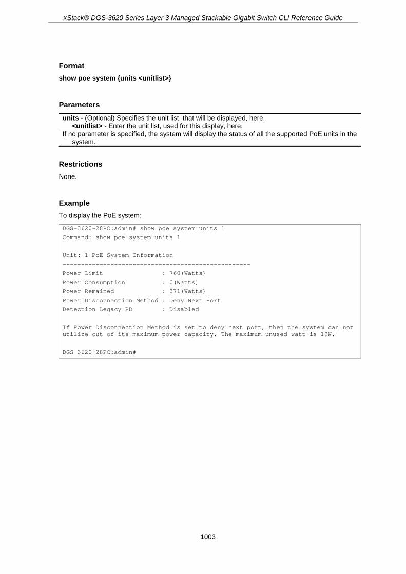
xStack® DGS-3620 Series Layer 3 Managed Stackable Gigabit Switch CLI Reference Guide
1003
Format show poe system {units <unitlist>}
Parameters units - (Optional) Specifies the unit list, that will be displayed, here.
<unitlist> - Enter the unit list, used for this display, here. If no parameter is specified, the system will display the status of all the supported PoE units in the
system.
Restrictions None.
Example To display the PoE system:
DGS-3620-28PC:admin# show poe system units 1
Command: show poe system units 1
Unit: 1 PoE System Information
---------------------------------------------------
Power Limit : 760(Watts)
Power Consumption : 0(Watts)
Power Remained : 371(Watts)
Power Disconnection Method : Deny Next Port
Detection Legacy PD : Disabled
If Power Disconnection Method is set to deny next port, then the system can not utilize out of its maximum power capacity. The maximum unused watt is 19W.
DGS-3620-28PC:admin#

xStack® DGS-3620 Series Layer 3 Managed Stackable Gigabit Switch CLI Reference Guide
1004
Chapter 87 Power Saving Commands
config power_saving mode {length_detection | link_detection | led | port | hibernation} [enable | disable]
config power_saving hibernation [[add | delete] time_range <range_name 32> | clear_time_range]
config power_saving led [[add | delete] time_range <range_name 32> | clear_time_range] config power_saving port [<portlist> | all] [[add | delete] time_range <range_name 32> |
clear_time_range] show power_saving {length_detection | link_detection | led | port | hibernation} config led state [enable | disable] show led
87-1 config power_saving mode Description This command is used to set the power saving state.
For link detection and length detection function, they apply to the ports with copper media. If the power saving link detection state is enabled, the power is saved by following mechanism:
• When no links are detected on the port, the port will automatically turn off and will only wake up the second a single link pulse is sent. While the port is turned off, a simple energy-detect circuit will continuously monitor energy on the cable. The moment energy is detected; the port will turn on fully as to the IEEE specification’s requirements. The power saving function is performed while no link is detected and it will not affect the port capabilities while the link is up.
• When a link is detected on the port, for a shorter cable, the power consumption will be reduced by lowering the signal amplitude, since the signal attenuation is proportional to the cable length. The port will adjust the power based on the cable length and still maintain error free applications from both sides of the link. This mechanism is only available using the hardware support cable diagnostics function.
If the power saving state of port is disabled, all power saving schedules of port will not take effect.
If the power saving state of port LED is disabled, all power saving schedules of port LED will not take effect.
If the power saving state of system hibernation is disabled, all power saving schedules of system hibernation will not take effect.
Format config power_saving mode {length_detection | link_detection | led | port | hibernation} [enable | disable]
Parameters length_detection - (Optional) Specifies the power saving length detection state. link_detection - (Optional) Specifies the link detection state.

xStack® DGS-3620 Series Layer 3 Managed Stackable Gigabit Switch CLI Reference Guide
1005
Led - (Optional) Specifies to configure the power saving state of port LED. port - (Optional) Specifies to configure the power saving state of port. hibernation - (Optional) Specifies to configure the power saving state of system hibernation. enable - Specifies to enable power saving state. disable - Specifies to disable power saving state.
Restrictions Only Administrators and Operators can issue this command.
Example To enable the power saving state of port, hibernation:
DGS-3620-28PC:admin#config power_saving mode port hibernation enable
Command: config power_saving mode port hibernation enable
Success.
DGS-3620-28PC:admin#
87-2 config power_saving hibernation Description This command is used to add or delete the power saving schedule on system hibernation. When the system enters hibernation mode, the Switch changes to a low power state and is idle. It shuts down all the ports, and all network function does not work. Only the console connection will work via the RS232 port.
Format config power_saving hibernation [[add | delete] time_range <range_name 32> | clear_time_range]
Parameters add - Specifies to add a time range. delete - Specifies to delete a time range. time_range - Specifies the name of the time range.
<range_name32> - Enter a name for maximum 32 characters. clear_time_range - Specifies to clear all the time range of system hibernation.
Restrictions Only Administrators and Operators can issue this command.
Example To add a time range named “range_1” on system hibernation:

xStack® DGS-3620 Series Layer 3 Managed Stackable Gigabit Switch CLI Reference Guide
1006
DGS-3620-28PC:admin#config power_saving hibernation add time_range range_1
Command: config power_saving hibernation add time_range range_1
Success.
DGS-3620-28PC:admin#
87-3 config power_saving led Description This command is used to add or delete the power saving schedule on the LED of all ports. When any schedule is up, all port’s LED will be turned off even device’s LED working on PoE mode.
Note: The port LED admin state (configured using the command ‘config led state’) gets high priority. If the port LED admin state is disabled, all ports’ LED will always be turned off. Currently only three time ranges are supported.
Format config power_saving led [[add | delete] time_range <range_name 32> | clear_time_range]
Parameters add - Specifies to add a time range. delete - Specifies to delete a time range. time_range - Specifies the name of the time range.
<range_name32> - Enter a name for maximum 32 characters. clear_time_range - Specifies to clear all the time range of port LED.
Restrictions Only Administrators and Operators can issue this command.
Example To add a time range named “range_1” on port LED:
DGS-3620-28PC:admin#config power_saving led add time_range range_1
Command: config power_saving led add time_range range_1
Success.
DGS-3620-28PC:admin#
87-4 config power_saving port Description This command is used to add or delete the power saving schedule on the port. When any schedule is up, the specific port will be shut down (disabled).
Note: The port’s admin state has high priority. If the port’s admin state is disabled, the specific port will always be shut down (disabled). Currently only three time ranges are supported.

xStack® DGS-3620 Series Layer 3 Managed Stackable Gigabit Switch CLI Reference Guide
1007
Format config power_saving port [<portlist> | all] [[add | delete] time_range <range_name 32> | clear_time_range]
Parameters <portlist> - Enter a range of ports. all - Specifies all ports. add - Specifies to add a time range. delete - Specifies to delete a time range. time_range - Specifies the name of the time range.
<range_name32> - Enter a name for maximum 32 characters. clear_time_range - Specifies to clear all the time range of port.
Restrictions Only Administrators and Operators can issue this command.
Example To add a time range named “range_1” on port 1:
DGS-3620-28PC:admin#config power_saving port 1:1 add time_range range_1
Command: config power_saving port 1:1 add time_range range_1
Success.
DGS-3620-28PC:admin#
To delete a time range named “range_2” on port 1:
DGS-3620-28PC:admin#config power_saving port 1:1 delete time_range range_2
Command: config power_saving port 1:1 delete time_range range_2
Success.
DGS-3620-28PC:admin#
87-5 show power_saving Description This command is used to display the current state of power saving.
Format show power_saving {length_detection | link_detection | led | port | hibernation}
Parameters length_detection - (Optional) Display the length detection configuration of power saving. link_detection - (Optional) Display the link detection configuration of power saving.

xStack® DGS-3620 Series Layer 3 Managed Stackable Gigabit Switch CLI Reference Guide
1008
led - (Optional) Display the port LED configuration of power saving. port - (Optional) Display the port configuration of power saving. hibernation - (Optional) Display the system hibernation configuration of power saving. If no parameter is specified, all configurations of power saving will be displayed.
Restrictions None.
Example To display the power saving function setting:
DGS-3620-28PC:admin#show power_saving
Command: show power_saving
Function Version: 3.00
Link Detection State: Enabled
Length Detection State: Disabled
Power Saving Configuration On System Hibernation
----------------------------------------------------
State: Disabled
Power Saving Configuration On Port LED
------------------------------------------
State: Disabled
Power Saving Configuration On Port
------------------------------------------
State: Disabled
DGS-3620-28PC:admin#
87-6 config led state Description This command is used to configure the LED admin state of all ports. When the port LED admin state is disabled, the LEDs of all ports are turned off. If the port LED admin state is enabled, the port LEDs are controlled by the ports' link status.
Format config led state [enable | disable]
Parameters enable - Specifies to enable the LED admin state of all ports. disable - Specifies to disable the LED admin state of all ports.

xStack® DGS-3620 Series Layer 3 Managed Stackable Gigabit Switch CLI Reference Guide
1009
Restrictions Only Administrators and Operators can issue this command.
Example To disable the LED admin state:
DGS-3620-28PC:admin#config led state disable
Command: config led state disable
Success.
DGS-3620-28PC:admin#
87-7 show led Description This command is used to display the setting of all port’s LED admin state.
Format show led
Parameters None.
Restrictions None.
Example To display the setting of all port’s LED admin state:
DGS-3620-28PC:admin#show led
Command: show led
Port LED State: Enabled
DGS-3620-28PC:admin#

xStack® DGS-3620 Series Layer 3 Managed Stackable Gigabit Switch CLI Reference Guide
1010
Chapter 88 Precision Time Protocol (PTP) Commands
enable ptp disable ptp config ptp mode [boundary | p2p_transparent | e2e_transparent] config ptp transport protocol [ethernet | udp] config ptp clock domain_number <value 0-127> {unit <unit_id 1-12>} {domain_name <string 1-
32>} config ptp boundary {priority1 <value 0-255> | priority2 <value 0-255>}(1) config ptp ports [<portlist> | all] state [enable | disable] config ptp boundary ports [<portlist> | all] {announce [interval <sec 1-16> | timeout <value 2-
10>] | sync_interval [half_second | <sec 1-2>] | delay_req_interval <value 0-5> | pdelay_req_interval <sec 1-32> | delay_mechanism [e2e | p2p]}(1)
config ptp p2p_transparent ports [<portlist> | all] pdelay_req_interval <sec 1-32> show ptp show ptp clock show ptp clock parent show ptp ports [<portlist> | all] show ptp boundary {ports [<portlist> | all]} show ptp p2p_transparent ports [<portlist> | all] show ptp foreign_master_records ports [<portlist> | all]
88-1 enable ptp Description This command is used to enable the PTP function globally. The device will enter the P2P-transparent clock mode when the PTP global state is enabled. The PTP function can only work when both the global PTP state and the per port PTP state are enabled.
When the stacking mode is enabled and the member ports of a trunk group exists in different stack units, the PTP function will:
1. Execute normally when the sending and receiving of PTP messages are to member ports that are on the same stack unit.
2. Execute abnormally, when the sending and receiving of PTP messages are to member ports that are on different stack units.
Format enable ptp
Parameters None.

xStack® DGS-3620 Series Layer 3 Managed Stackable Gigabit Switch CLI Reference Guide
1011
Restrictions Only Administrators, Operators and Power-Users can issue this command.
Example To enable the PTP function globally:
DGS-3620-28PC:admin# enable ptp
Command: enable ptp
Success.
DGS-3620-28PC:admin#
88-2 disable ptp Description This command is used to disable the PTP function globally. When the PTP function is disabled, all switch ports will forward the PTP packets according to the multicast filtering configuration.
Format disable ptp
Parameters None.
Restrictions Only Administrators, Operators and Power-Users can issue this command.
Example To disable the PTP function globally:
DGS-3620-28PC:admin# disable ptp
Command: disable ptp
Success.
DGS-3620-28PC:admin#
88-3 config ptp mode Description This command is used to configure the PTP device type of the switch. The switch supports three PTP device types, which the user can set globally.
A Boundry Clock:
xStack® DGS-3620 Series Layer 3 Managed Stackable Gigabit Switch CLI Reference Guide
1012
• Has multiple Precision Time Protocol (PTP) ports in a domain and maintains the timescale used in the domain.
• Can serve as the time source and can synchronize with another clock. • Device type can choose to use the delay request-response mechanism or the peer delay
mechanism to measure the propagation delay between the PTP ports.
A clock that provides Precision Time Protocol (PTP) event transit time information also provides corrections for the propagation delay of the link. The link, in this case, is connected to the port that is receiving the PTP event messages. Ports on peer-to-peer transparent clocks use the peer delay mechanism to calculate the propagation delay between PTP ports.
An End-to-End Transparent Clock supports the use of an end-to-end delay measurement mechanism between the slave clock and the master clock. Ports on end-to-end transparent clocks are independent of propagation delay mechanisms.
Format config ptp mode [boundary | p2p_transparent | e2e_transparent]
Parameters boundary - Specifies the Switch as a Boundary Clock. p2p_transparent - Specifies the Switch as a Peer-to-Peer Transparent Clock. e2e_transparent - Specifies the Switch as an End-to-End Transparent Clock.
Restrictions Only Administrators, Operators and Power-Users can issue this command.
Example To specify the switch as a peer-to-peer transparent clock:
DGS-3620-28PC:admin# config ptp mode p2p_transparent
Command: config ptp mode p2p_transparent
Success.
DGS-3620-28PC:admin#
88-4 config ptp transport protocol Description This command is used to specify the transport protocol that will be used for the communication path.
Format config ptp transport protocol [ethernet | udp]
xStack® DGS-3620 Series Layer 3 Managed Stackable Gigabit Switch CLI Reference Guide
1013
Parameters ethernet - Specifies the transport protocol of PTP as IEEE802.3 Ethernet. udp - Specifies the transport protocol of PTP as UDP over IPv4.
Restrictions Only Administrators, Operators and Power-Users can issue this command.
Example To specify the transport protocol of PTP as IEEE802.3 Ethernet frames:
DGS-3620-28PC:admin# config ptp transport protocol ethernet
Command: config ptp transport protocol ethernet
Success.
DGS-3620-28PC:admin#
88-5 config ptp clock domain_number Description This command is used to configure the PTP clock common attribute of the domain number. The domain number is used to identify the PTP domain that the PTP clock is working on. If the domain number of the received PTP message is not identical to the domain number of the local device, the PTP message shall be forwarded according to the multicast filtering configuration.
Format config ptp clock domain_number <value 0-127> {unit <unit_id 1-12>} {domain_name <string 1-32>}
Parameters domain_number - Specifies the domain attribute of the local clock. All PTP messages, data sets,
state machines, and all other PTP entities are always associated with a particular domain number. <value 0-127> - Enter the domain number used here. This value must be between 0 and 127.
The default value is 0. unit - (Optional) specifies the domain number for a specified unit. If not specified, the domain
configurations applies to the local unit. If the unit is not present, the configuration is ignored. <unit_id 1-12> - Enter the unit ID used here. This value must be between 1 and 12.
domain_name - (Optional) Specifies the domain name for a specified domain number. <string 1-32> - Enter the domain name used here. This name can be up to 32 characters
long.
Restrictions Only Administrators, Operators and Power-Users can issue this command.

xStack® DGS-3620 Series Layer 3 Managed Stackable Gigabit Switch CLI Reference Guide
1014
Example To configure the domain number of the PTP clock as 1 and assign a domain name of internal_domain on the local unit, when the stacking mode is disabled:
DGS-3620-28PC:admin# config ptp clock domain_number 1 domain_name internal_domain
Command: config ptp clock domain_number 1 domain_name internal_domain
Success.
DGS-3620-28PC:admin#
To configure the domain number of the PTP clock as 1 and assign a domain name of internal_domain for the unit 1, when the stacking mode is enabled.
DGS-3620-28PC:admin#config ptp clock domain_number 1 unit 1 domain_name internal_domain
Command: config ptp clock domain_number 1 unit 1 domain_name internal_domain
Success.
DGS-3620-28PC:admin#
88-6 config ptp boundary Description This command is used to configure the PTP boundary clock attributes and requires at least one parameter to execute.
Format config ptp boundary {priority1 <value 0-255> | priority2 <value 0-255>}(1)
Parameters priority1 - (Optional) Specifies that the priority 1 attribute is used in the execution of the best
master clock algorithm. Lower values take precedence. <value 0-255> - Enter the priority 1 value used here. This value must be between 0 and 255.
priority2 - (Optional) Specifies that the priority 2 attribute is used in the execution of the best master clock algorithm. Lower values take precedence. In the event that the operation of the BMC algorithm fails to order the clocks based on the values of priority1, the clock’s class, and the clock’s accuracy; the priority2 attribute will allow the creation of lower values compared to the other devices. <value 0-255> - Enter the priority 2 value used here. This value must be between 0 and 255.
Restrictions Only Administrators, Operators and Power-Users can issue this command.
Example To configure the priority1 value of the boundary clock as 127:
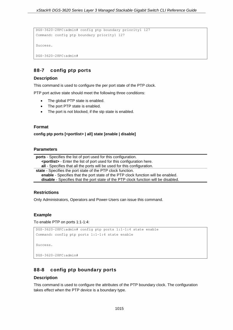
xStack® DGS-3620 Series Layer 3 Managed Stackable Gigabit Switch CLI Reference Guide
1015
DGS-3620-28PC:admin# config ptp boundary priority1 127
Command: config ptp boundary priority1 127
Success.
DGS-3620-28PC:admin#
88-7 config ptp ports Description This command is used to configure the per port state of the PTP clock.
PTP port active state should meet the following three conditions:
• The global PTP state is enabled. • The port PTP state is enabled. • The port is not blocked, if the stp state is enabled.
Format config ptp ports [<portlist> | all] state [enable | disable]
Parameters ports - Specifies the list of port used for this configuration.
<portlist> - Enter the list of port used for this configuration here. all - Specifies that all the ports will be used for this configuration.
state - Specifies the port state of the PTP clock function. enable - Specifies that the port state of the PTP clock function will be enabled. disable - Specifies that the port state of the PTP clock function will be disabled.
Restrictions Only Administrators, Operators and Power-Users can issue this command.
Example To enable PTP on ports 1:1-1:4:
DGS-3620-28PC:admin# config ptp ports 1:1-1:4 state enable
Command: config ptp ports 1:1-1:4 state enable
Success.
DGS-3620-28PC:admin#
88-8 config ptp boundary ports Description This command is used to configure the attributes of the PTP boundary clock. The configuration takes effect when the PTP device is a boundary type.

xStack® DGS-3620 Series Layer 3 Managed Stackable Gigabit Switch CLI Reference Guide
1016
Format config ptp boundary ports [<portlist> | all] {announce [interval <sec 1-16> | timeout <value 2-10>] | sync_interval [half_second | <sec 1-2>] | delay_req_interval <value 0-5> | pdelay_req_interval <sec 1-32> | delay_mechanism [e2e | p2p]}(1)
Parameters ports - Specifies the list of port used for this configuration.
<portlist> - Enter the list of port used for this configuration here. all - Specifies that all the ports will be used for this configuration.
announce - (Optional) Specifies that the announce options will be configured. interval - Specifies the mean time interval between successive announce messages. In line
with the IEEE 1588 protocol, the value of the announce interval is represented as the logarithm to the base 2 of this time measured in seconds. If the input is not allowed, then the input is automatically adjusted to allow the bigger and closest value. The value of the announce interval should be uniform throughout a domain. If the announce interval of one port changes, the announce interval of all the ports must be changed automatically to be consistent. <sec 1-16> - Enter the interval value used here. This value must be between 1 and 16
seconds. timeout - Specifies the announce interval number that has to pass without receiving an
Announce message before the occurrence of the ANNOUNCE_RECEIPT_TIMEOUT_EXPIRES event. This value multiplied by the announce interval value is equal to the interval time of the announce receipt timeout. The value of the interval time of the announce receipt timeout should be uniform throughout a domain. If the value of one port is changed, the value of all ports must be changed automatically to be consistent. <value 2-10> - Enter the timeout value used here. This value must be between 2 and 10
seconds. sync_interval - (Optional) Specifies the mean time interval between successive Sync messages.
half_second - Specifies that the syncronization interval will be set to half a second. <sec 1-2> - Enter the syncronization interval value used here. This value must be between 1
and 2. delay_req_interval - (Optional) Specifies the permitted mean time interval between successive
delay request messages which are sent by a slave to a specific port on the master. This mean time interval value is determined and advertised by a master. <value 0-5> - Enter the delay required interval value used here. This value must be between 0
and 5. pdelay_req_interval - (Optional) Specifies the permitted mean time interval between successive
pdelay_request messages. <sec 1-32> - Enter the permitted mean time interval value used here. This value must be
between 1 and 32 seconds. delay_mechanism - (Optional) Specifies the mechanism for measuring the propagation delay
time of an event message. e2e - E2E indicates that the port is configured to use the delay request-response mechanism. p2p - P2P indicates that the port is configured to use the peer delay mechanism.
Restrictions Only Administrators, Operators and Power-Users can issue this command.
Example To configure the announce interval attribute of ports 1-4 to 3 seconds:

xStack® DGS-3620 Series Layer 3 Managed Stackable Gigabit Switch CLI Reference Guide
1017
DGS-3620-28PC:admin# config ptp boundary ports 1:1-1:4 announce interval 3
Command: config ptp boundary ports 1:1-1:4 announce interval 3
The announce interval is automatically adjusted to 4.
Success.
DGS-3620-28PC:admin#
To configure the announce timeout attribute of ports 1-4 to 4 seconds, which is about 4*Announce interval:
DGS-3620-28PC:admin# config ptp boundary ports 1:1-1:4 announce timeout 4
Command: config ptp boundary ports 1:1-1:4 announce timeout 4
Success.
DGS-3620-28PC:admin#
To configure the sync_interval attribute of the all the PTP ports to 2 seconds:
DGS-3620-28PC:admin# config ptp boundary ports all sync_interval 2
Command: config ptp boundary ports all sync_interval 2
Success.
DGS-3620-28PC:admin#
If the sync_interval is 0.5 seconds, then the delay_req_interval attribute of the all PTP ports is configured as 0.
DGS-3620-28PC:admin# config ptp boundary ports all delay_req_interval 0
Command: config ptp boundary ports all delay_req_interval 0
Success.
DGS-3620-28PC:admin#
To configure the pdelay_req_interval attribute of the all PTP ports as 5 seconds:
DGS-3620-28PC:admin# config ptp boundary ports all pdelay_req_interval 5
Command: config ptp boundary ports all pdelay_req_interval 5
The pdelay_req interval is automatically adjusted to 8.
Success.
DGS-3620-28PC:admin#
To configure the delay_mechanism attribute of the all the PTP ports as P2P:

xStack® DGS-3620 Series Layer 3 Managed Stackable Gigabit Switch CLI Reference Guide
1018
DGS-3620-28PC:admin# config ptp boundary ports all delay_mechanism p2p
Command: config ptp boundary ports all delay_mechanism p2p
Success.
DGS-3620-28PC:admin#
88-9 config ptp p2p_transparent ports Description This command is used to configure the pdelay_request message attribute for the message interval of the P2P transparent clock.
Format config ptp p2p_transparent ports [<portlist> | all] pdelay_req_interval <sec 1-32>
Parameters ports - Specifies the list of port used for this configuration.
<portlist> - Enter the list of port used for this configuration here. all - Specifies that all the ports will be used for this configuration.
pdelay_req_interval - Specifies the permitted mean time interval between successive messages. <sec 1-32> - Enter the permitted mean time interval value used here. This value must be
between 1 and 32.
Restrictions Only Administrators, Operators and Power-Users can issue this command.
Example To configure the pdelay_req_interval attribute of all the PTP ports to 4 seconds:
DGS-3620-28PC:admin# config ptp p2p_transparent ports all pdelay_req_interval 4
Command: config ptp p2p_transparent ports all pdelay_req_interval 4
Success.
DGS-3620-28PC:admin#
88-10 show ptp Description This command is used to display the configured attributes of PTP on the switch.
Format show ptp

xStack® DGS-3620 Series Layer 3 Managed Stackable Gigabit Switch CLI Reference Guide
1019
Parameters None.
Restrictions None.
Example To show the global PTP configuration:
DGS-3620-28PC:admin# show ptp
Command: show ptp
PTP State Setting : Enabled
PTP Mode Setting : Boundary Clock
PTP Transport Protocol Setting : UDP
PTP Clock Domain Number Setting : 0
PTP Clock Domain Name Setting : Internal Domain
DGS-3620-28PC:admin#
88-11 show ptp clock Description This command is used to display the active attributes of the PTP clock.
Format show ptp clock
Parameters None.
Restrictions None.
Example To show the active attributes of the boundary clock:

xStack® DGS-3620 Series Layer 3 Managed Stackable Gigabit Switch CLI Reference Guide
1020
DGS-3620-28PC:admin# show ptp clock
Command: show ptp clock
PTP State : Enabled
PTP Clock Mode : Boundary Clock
PTP Transport Protocol : UDP
PTP Clock Domain Number : 1
PTP Clock Domain Name : internal_domain
PTP Clock Identity : ACDE48FFFE6789AB
PTP Priority 1 : 128
PTP Priority 2 : 128
PTP Clock Class : 187
PTP Steps Removed : 2
PTP Last Offset : +130ns
PTP Mean Path Delay : 1 second
PTP Enabled Ports : 1:1-1:4, 2:1-2:4
DGS-3620-28PC:admin#
To show the properties of the Peer-to-Peer transparent clock:
DGS-3620-28PC:admin# show ptp clock
Command: show ptp clock
PTP State : Enabled
PTP Clock Mode : Peer-to-Peer Transparent Clock
PTP Transport Protocol : UDP
PTP Clock Domain Number : 1
PTP Clock Domain Name : internal_domain
PTP Clock Delay Mechanism : P2P
PTP Clock Identity : ACDE48FFFE6789AC
PTP Enabled Ports : 1:1-1:4, 2:1-2:4
DGS-3620-28PC:admin#
To show the properties of the boundary clock of all stacking devices, when the stacking mode is enabled:
DGS-3620-28PC:admin# show ptp clock
Command: show ptp clock
Box ID: 1
PTP State : Enabled
PTP Clock Mode : Boundary Clock
PTP Transport Protocol : UDP
PTP Clock Domain Number : 1
PTP Clock Domain Name : internal_domain
PTP Clock Identity : ACDE4823456789AB
PTP Priority 1 : 128
PTP Priority 2 : 128
PTP Clock Class : 187

xStack® DGS-3620 Series Layer 3 Managed Stackable Gigabit Switch CLI Reference Guide
1021
PTP Steps Removed : 2
PTP Last Offset : +110 ns
PTP Mean Path Delay : 120 second
PTP Enabled Ports : 1:1-1:4
Box ID: 2
PTP State : Enabled
PTP Clock Mode : Boundary Clock
PTP Transport Protocol : UDP
PTP Clock Domain Number : 1
PTP Clock Domain Name : internal_domain
PTP Clock Identity : ACDE482345678910
PTP Priority 1 : 128
PTP Priority 2 : 128
PTP Clock Class : 187
PTP Steps Removed : 3
PTP Last Offset : +130ns
PTP Mean Path Delay : 140 second
PTP Enabled Ports : 2:1-2:4
DGS-3620-28PC:admin#
88-12 show ptp clock parent Description This command is used to display the active attributes of the PTP parent clock.
Format show ptp clock parent
Parameters None.
Restrictions None.
Example To show the active attributes of the boundary clock parent:

xStack® DGS-3620 Series Layer 3 Managed Stackable Gigabit Switch CLI Reference Guide
1022
DGS-3620-28PC:admin# show ptp clock parent
Command: show ptp clock parent
PTP Parent Port Identity : ACDE48FFFE6789AB
PTP Parent Port Number : 3
PTP Grandmaster Identity : ACDE48FFFE9789AD
PTP Grandmaster Clock Class : 13
PTP Grandmaster Clock Accuracy : 100ns
PTP Grandmaster Priority 1 : 120
PTP Grandmaster Priority 2 : 127
DGS-3620-28PC:admin#
The display of the active attributes of the boundary clock parent when the synchronization does not complete:
DGS-3620-28PC:admin# show ptp clock parent
Command: show ptp clock parent
The boundary clock has not completed synchronization.
DGS-3620-28PC:admin#
The display of the active attributes of the boundary clock parent when the boundary clock is the grandmaster clock:
DGS-3620-28PC:admin# show ptp clock parent
Command: show ptp clock parent
The grandmaster clock does not have this attribute.
DGS-3620-28PC:admin#
To show the parent and grandmaster properties of the transparent clock:
DGS-3620-28PC:admin# show ptp clock parent
Command: show ptp clock parent
The transparent clock does not have this attribute.
DGS-3620-28PC:admin#
To show the active attributes of the boundary clock parent of all stacking devices, when the stacking mode is enabled.

xStack® DGS-3620 Series Layer 3 Managed Stackable Gigabit Switch CLI Reference Guide
1023
DGS-3620-28PC:admin# show ptp clock parent
Command: show ptp clock parent
Box ID: 1
PTP Parent Port Identity : ACDE4823456789AB
PTP Parent Port Number : 3
PTP Grandmaster Identity : ACDE4823659789AD
PTP Grandmaster Clock Class : 13
PTP Grandmaster Clock Accuracy : 100ns
PTP Grandmaster Priority 1 : 120
PTP Grandmaster Priority 2 : 127
Box ID: 2
PTP Parent Port Identity : ACDE482345678910
PTP Parent Port Number : 5
PTP Grandmaster Identity : ACDE4823659789AD
PTP Grandmaster Clock Class : 13
PTP Grandmaster Clock Accuracy : 100ns
PTP Grandmaster Priority 1 : 120
PTP Grandmaster Priority 2 : 127
DGS-3620-28PC:admin#
88-13 show ptp ports Description This command is used to display the active attributes of the special PTP ports on the switch.
Format show ptp ports [<portlist> | all]
Parameters ports - Specifies the list of port used for this display.
<portlist> - Enter the list of port used for this display here. all - Specifies that all the ports will be used for this display.
Restrictions None.
Example To show the active attributes for special ports 1:1-1:4 of the boundary clock:

xStack® DGS-3620 Series Layer 3 Managed Stackable Gigabit Switch CLI Reference Guide
1024
DGS-3620-28PC:admin# show ptp ports 1:1-1:4
Command: show ptp ports 1:1-1:4
The active attributes:
DM : Delay Mechanism
AI : Announce Interval
ART : Announce Receipt Timeout
SI : Synchronization Interval
DRIM: Delay_Request Interval-Master
DRIS: Delay_Request Interval-Slave
PDRI: Pdelay_Request Interval
PMPD: Peer Mean Path Delay
Port Role DM AI ART SI DRIM DRIS PDRI PMPD State
1:1 Master P2P 2 8 1 1 2 4 1 Enabled
1:2 Slave E2E 1 8 0.5 2 8 8 0 Enabled
1:3 Master P2P 2 8 1 8 4 8 1 Enabled
1:4 Master P2P 2 8 1 32 16 16 0 Enabled
DGS-3620-28PC:admin#
To show the active attributes for special ports 1:1-1:4 of the p2p-transparent clock:
DGS-3620-28PC:admin# show ptp ports 1:1-1:4
Command: show ptp ports 1:1-1:4
The active attributes:
PDRI : Pdelay_Request Interval
PMPD : Peer Mean Path Delay
Port PDRI PMPD State
1:1 4 1 Enabled
1:2 8 0 Disabled
1:3 8 1 Enabled
1:4 16 1 Enabled
DGS-3620-28PC:admin#
88-14 show ptp boundary Description This command is used to display the configured attributes of the boundary clock or the configured attributes of the boundary clock’s special ports.
Format show ptp boundary {ports [<portlist> | all]}

xStack® DGS-3620 Series Layer 3 Managed Stackable Gigabit Switch CLI Reference Guide
1025
Parameters ports – (Optional) Specifies the list of port used for this display.
<portlist> - Enter the list of port used for this display here. all - Specifies that all the ports will be used for this display.
Restrictions None.
Example To show the configured attributes of the boundary clock:
DGS-3620-28PC:admin# show ptp boundary
Command: show ptp boundary
PTP Priority1 Setting : 128
PTP Priority2 Setting : 127
DGS-3620-28PC:admin#
To show the configured attributes of special ports 1:1-1:4 of the boundary clock:
DGS-3620-28PC:admin# show ptp boundary ports 1:1-1:4
Command: show ptp boundary ports 1:1-1:4
The attribute configurations of the ports of boundary:
DM : Delay Mechanism
AI : Announce Interval
CART : The Coefficient of Announce Receipt Timeout
SI : Synchronization Interval
EDRI : The Exponent of Delay_Request Interval
PDRI : Pdelay_Request Interval
Port DM AI CART SI EDRI PDRI State
1:1 P2P 2 3 1 1 8 Enabled
1:2 E2E 1 2 0.5 0 16 Enabled
1:3 P2P 2 5 1 2 8 Enabled
1:4 P2P 2 6 1 4 4 Enabled
DGS-3620-28PC:admin#
88-15 show ptp p2p_transparent ports Description This command is used to display the configured attributes of the P2P transparent clock’s special ports.
Format show ptp p2p_transparent ports [<portlist> | all]

xStack® DGS-3620 Series Layer 3 Managed Stackable Gigabit Switch CLI Reference Guide
1026
Parameters ports - Specifies the list of port used for this display.
<portlist> - Enter the list of port used for this display here. all - Specifies that all the ports will be used for this display.
Restrictions None.
Example To show the configured attributes of special ports 1:1-1:4 of the p2p_transparent clock:
DGS-3620-28PC:admin# show ptp p2p_transparent ports 1:1-1:4
Command: show ptp p2p_transparent ports 1:1-1:4
The attribute configuration of the p2p_transparent ports:
PDRI : Pdelay_Request Interval
Port PDRI State
1:1 8 Enabled
1:2 16 Enabled
1:3 8 Enabled
1:4 4 Disabled
DGS-3620-28PC:admin#
88-16 show ptp foreign_master_records ports Description This command is used to display the current foreign master data set records of the boundary clock’s special ports.
Format show ptp foreign_master_records ports [<portlist> | all]
Parameters ports - Specifies the list of port used for this display.
<portlist> - Enter the list of port used for this display here. all - Specifies that all the ports will be used for this display.
Restrictions None.

xStack® DGS-3620 Series Layer 3 Managed Stackable Gigabit Switch CLI Reference Guide
1027
Example To show the current records of the foreign master data set for special ports 1:1-1:3 of the boundary clock:
DGS-3620-28PC:admin#show ptp foreign_master_records ports all
Command: show ptp foreign_master_records ports all
FM Port Identity : The clock identity of the Foreign Master Port
FM Port Number : The port number of the Foreign Master Port
FM Announce Messages : The numbers of Foreign Master announce messages
Port FM Port Identity FM Port Number FM Announce Messages
1:1 001655fffe200000 1:7 4
2:1 001655fffe200000 1:8 4
DGS-3620-28PC:admin#

xStack® DGS-3620 Series Layer 3 Managed Stackable Gigabit Switch CLI Reference Guide
1028
Chapter 89 Priority Flow Control (PFC) Commands
config pfc {ports [<portlist> | all]} [enable | disable] {cos [<cos_id_list> | all]} config pfc willing {ports [<portlist> | all]} [enable | disable] show pfc {<portlist>} clear pfc counters {<portlist>} [rx | tx | both]
89-1 config pfc Description This command is used to configure the 10G ports’ Priority Flow Control (PFC) capability.
Format config pfc {ports [<portlist> | all]} [enable | disable] {cos [<cos_id_list> | all]}
Parameters ports - (Optional) Specifies the 10G ports that will be used for this configuration.
<portlist> - Enter the 10G ports that will be used for this configuration here. all - Specifies that all the 10G ports will be used for this configuration.
enable - Specifies to enable the PFC function. disable - Specifies to disable the PFC function. cos - (Optional) Specifies CoS priority that will be used with the PFC.
<cos_id_list> - Enter the CoS ID list here. all - Specifies that all the COS priority options will be used.
Restrictions Only Administrators, Operators and Power-Users can issue this command.
Example This example shows how to enable PFC on priority 2 for port 26.
DGS-3620-28PC:admin#config pfc ports 1:26 enable cos 2
Command: config pfc ports 1:26 enable cos 2
Success.
DGS-3620-28PC:admin#

xStack® DGS-3620 Series Layer 3 Managed Stackable Gigabit Switch CLI Reference Guide
1029
89-2 config pfc willing Description This command is used to turn on the DCBX PFC willing option which indicates that the local 10G port is willing to accept the PFC configuration from a remote system. Data Center Bridging eXchange Protocol (DCBX) is used by DCB devices to exchange configuration information with directly connected peers. The protocol may also be used for misconfiguration detection and for configuration of the peer. The willing mode indicates that the local 10G port has been administratively configured to accept configuration from the remote device.
Format config pfc willing {ports [<portlist> | all]} [enable | disable]
Parameters ports - (Optional) Specifies the 10G ports that will be used for this configuration.
<portlist> - Enter the 10G ports that will be used for this configuration here. all - Specifies that all the 10G ports will be used for this configuration.
enable - Specifies to enable the PFC willing capability option. disable - Specifies to disable the PFC willing capability option.
Restrictions Only Administrators, Operators and Power-Users can issue this command.
Example This example shows how to enable the PFC willing option for port 26.
DGS-3620-28PC:admin#config pfc willing ports 1:26 enable
Command: config pfc willing ports 1:26 enable
Success.
DGS-3620-28PC:admin#
89-3 show pfc Description This command is used to display priority-based flow control information of an interface.
Format show pfc {<portlist>}
Parameters <portlist> - (Optional) Enter the 10G port list that will be displayed here. If no port is specified, all 10G ports’ information will be displayed.

xStack® DGS-3620 Series Layer 3 Managed Stackable Gigabit Switch CLI Reference Guide
1030
Restrictions None.
Example This example shows how to display PFC infomation on all the ports.
DGS-3620-28PC:admin#show pfc
Command: show pfc
Port PFC Admin PFC On Oper PFC On Will- Rx PFC Tx PFC
Cap. Priorities Priorities ing Frame(s) Frame(s)
--------------------------- ---------------- --------------------------
1:1 8 Off 0 0
1:2 8 Off 0 0
1:3 8 Off 0 0
1:4 8 Off 0 0
1:5 8 Off 0 0
1:6 8 Off 0 0
1:7 8 Off 0 0
1:8 8 Off 0 0
1:9 8 Off 0 0
1:10 8 Off 0 0
1:11 8 Off 0 0
1:12 8 Off 0 0
1:13 8 Off 0 0
1:14 8 Off 0 0
1:15 8 Off 0 0
1:16 8 Off 0 0
1:17 8 Off 0 0
1:18 8 Off 0 0
1:19 8 Off 0 0
1:20 8 Off 0 0
1:21 8 Off 0 0
1:22 8 Off 0 0
1:23 8 Off 0 0
1:24 8 Off 0 0
1:25 8 Off 0 0
1:26 8 (2) On 0 0
DGS-3620-28PC:admin#
89-4 clear pfc counters Description This command is used to clear the PFC counters of the specified interface(s).
Format clear pfc counters {<portlist>} [rx | tx | both]

xStack® DGS-3620 Series Layer 3 Managed Stackable Gigabit Switch CLI Reference Guide
1031
Parameters <portlist> - (Optional) Enter the 10G port list that will be used for this configuration here. rx - Specifies to clear the received PFC frames counters. tx - Specifies to clear the transmitted PFC frames counters. both - Specifies to clear both the received and transmitted PFC frames counters.
Restrictions Only Administrators, Operators and Power-Users can issue this command.
Example This example shows how to clear transmitted PFC frames counters on port 26.
DGS-3620-28PC:admin#clear pfc counters 1:26 tx
Command: clear pfc counters 1:26 tx
Success.
DGS-3620-28PC:admin#
xStack® DGS-3620 Series Layer 3 Managed Stackable Gigabit Switch CLI Reference Guide
1032
Chapter 90 Protocol VLAN Commands
create dot1v_protocol_group group_id <int 1-16> {group_name <name 32>} config dot1v_protocol_group [group_id <int 1-16> | group_name <name 32>] [add protocol
[ethernet_2 | ieee802.3_snap | ieee802.3_llc] <protocol_value> | delete protocol [ethernet_2 | ieee802.3_snap | ieee802.3_llc] <protocol_value>]
delete dot1v_protocol_group [group_id <int 1-16> | group_name <name 32> | all] show dot1v_protocol_group {[group_id <int 1-16> | group_name <name 32>]} config port dot1v ports [<portlist> | all] [add protocol_group [group_id <int 1-16> | group_name
<name 32>] [vlan <vlan_name 32> | vlanid <id>] {priority <value 0-7>} | delete protocol_group [group_id <int 1-16> | all]]
show port dot1v {ports <portlist>}
90-1 create dot1v_protocol_group Description This command is used to create a protocol group for the protocol VLAN function.
Format create dot1v_protocol_group group_id <int 1-16> {group_name <name 32>}
Parameters group_id - Specifies the ID of the protocol group which is used to identify a set of protocols.
<int 1-16> - The ID range is between 1 and 16. group_name - Specifies the name of the protocol group.
<name 32> - Enter the name of the protocol group. The maximum length is 32 characters.
Restrictions Only Administrators, Operators and Power-Users can issue this command.
Example To create a protocol group:
DGS-3620-28PC:admin#create dot1v_protocol_group group_id 4 group_name General_Group
Command: create dot1v_protocol_group group_id 4 group_name General_Group
Success.
DGS-3620-28PC:admin#

xStack® DGS-3620 Series Layer 3 Managed Stackable Gigabit Switch CLI Reference Guide
1033
90-2 config dot1v_protocol_group Description This command is used to add a protocol to a protocol group. The selection of a protocol can be a pre-defined protocol type or a user defined protocol.
Format config dot1v_protocol_group [group_id <int 1-16> | group_name <name 32>] [add protocol [ethernet_2 | ieee802.3_snap | ieee802.3_llc] <protocol_value> | delete protocol [ethernet_2 | ieee802.3_snap | ieee802.3_llc] <protocol_value>]
Parameters group_id - Specifies the ID of the protocol group which is used to identify a set of protocols.
<id 1-16> - The ID range is between 1 and 16. group_name - Specifies the name of the protocol group.
<name 32> - Enter the name of the protocol group. The maximum length is 32 characters. add protocol - Specifies the protocol to be added. Depending on the frame type, the octet string
will have one of the following values below. The form of the input is 0x0 to 0xffff. ethernet_2 - This is a 16-bit (2-octet) hex value. Example: IPv4 is 800, IPv6 is 86dd, ARP is
806, etc. ieee802.3_snap - This is a 16-bit (2-octet) hex value. Example: IPv4 is 800, IPv6 is 86dd,
ARP is 806, etc. ieee802.3_llc - This is the 2-octet IEEE 802.2 Link Service Access Point (LSAP) pair: first
octet for Destination Service Access Point (DSAP) and second octet for Source. <protocol_value> - Enter the protocol value used to identify a protocol of the frame type. The
form of the input is 0x0 to 0xffff. Depending on the frame type, the octet string will have one of the following values: For Ethernet II, this is a 16-bit (2-octet) hex value. For example, IPv4 is 800, IPv6 is 86dd, ARP is 806, etc. For IEEE802.3 SNAP, this is this is a 16-bit (2-octet) hex value. For IEEE802.3 LLC, this is the 2-octet IEEE 802.2 Link Service Access Point (LSAP) pair. The first octet is for Destination Service Access Point (DSAP) and the second octet is for Source.
delete protocol - Specifies the protocol to be deleted. Depending on the frame type, the octet string will have one of the following values below. The form of the input is 0x0 to 0xffff. ethernet_2 - This is a 16-bit (2-octet) hex value. Example: IPv4 is 800, IPv6 is 86dd, ARP is
806, etc. ieee802.3_snap - This is a 16-bit (2-octet) hex value. Example: IPv4 is 800, IPv6 is 86dd,
ARP is 806, etc. ieee802.3_llc - This is the 2-octet IEEE 802.2 Link Service Access Point (LSAP) pair: first
octet for Destination Service Access Point (DSAP) and second octet for Source. <protocol_value> - Enter the protocol value used to identify a protocol of the frame type. The
form of the input is 0x0 to 0xffff. Depending on the frame type, the octet string will have one of the following values: For Ethernet II, this is a 16-bit (2-octet) hex value. For example, IPv4 is 800, IPv6 is 86dd, ARP is 806, etc. For IEEE802.3 SNAP, this is this is a 16-bit (2-octet) hex value. For IEEE802.3 LLC, this is the 2-octet IEEE 802.2 Link Service Access Point (LSAP) pair. The first octet is for Destination Service Access Point (DSAP) and the second octet is for Source.
Restrictions Only Administrators, Operators and Power-Users can issue this command.
Example To add a protocol IPv6 to protocol group 4:

xStack® DGS-3620 Series Layer 3 Managed Stackable Gigabit Switch CLI Reference Guide
1034
DGS-3620-28PC:admin# config dot1v_protocol_group group_id 4 add protocol ethernet_2 86dd
Command: config dot1v_protocol_group group_id 4 add protocol ethernet_2 86dd
Success.
DGS-3620-28PC:admin#
To delete a protocol IPv6 from protocol group ID 4:
DGS-3620-28PC:admin# config dot1v_protocol_group_group_id 4 delete protocol ethernet_2 86dd
Command: config dot1v_protocol_group group_id 4 delete protocol ethernet_2 86dd
Success.
DGS-3620-28PC:admin#
90-3 delete dot1v_protocol_group Description This command is used to delete a protocol group.
Format delete dot1v_protocol_group [group_id <int 1-16> | group_name <name 32> | all]
Parameters group_id - Specifies the group ID to be deleted.
<int 1-16> - Enter the group ID to be deleted. group_name - Specifies the name of the protocol group to be deleted.
<name 32> - Enter the name of the protocol group to be deleted. The maximum length is 32 characters.
all - Specifies to delete all protocol groups.
Restrictions Only Administrators, Operators and Power-Users can issue this command.
Example To delete protocol group ID 4:
DGS-3620-28PC:admin# delete dot1v_protocol_group group_id 4
Command: delete dot1v_protocol_group group_id 4
Success.
DGS-3620-28PC:admin#
90-4 show dot1v_protocol_group Description This command is used to display the protocols defined in protocol groups.

xStack® DGS-3620 Series Layer 3 Managed Stackable Gigabit Switch CLI Reference Guide
1035
Format show dot1v_protocol_group {[group_id <int 1-16> | group_name <name 32>]}
Parameters group_id - (Optional) Specifies the group ID to be displayed.
<int 1-16> - Enter the group ID to be displayed. group_name - (Optional) Specifies the name of the protocol group.
<name 32> - Enter the name of the protocol group. The maximum length is 32 characters.
Note: If no parameter is specified, all configured protocol groups will be displayed
Restrictions None.
Example To display protocol group ID 4:
DGS-3620-28PC:admin# show dot1v_protocol_group group_id 4
Command: show dot1v_protocol_group group_id 4
Protocol Protocol Frame Type Protocol
Group ID Group Name Value
--------- --------------- ------------ ------------
4 General Group EthernetII 86dd
Total Entries: 1
DGS-3620-28PC:admin#
90-5 config port dot1v ports Description This command is used to assign the VLAN for untagged packets ingress from the portlist based on the protocol group configured. This assignment can be removed by using the delete protocol_group option.
When priority is not specified in the command, the port default prority will be the priority for those untagged packets classified by the protocol VLAN.
Format config port dot1v ports [<portlist> | all] [add protocol_group [group_id <int 1-16> | group_name <name 32>] [vlan <vlan_name 32> | vlanid <id>] {priority <value 0-7>} | delete protocol_group [group_id <int 1-16> | all]]

xStack® DGS-3620 Series Layer 3 Managed Stackable Gigabit Switch CLI Reference Guide
1036
Parameters <portlist> - Enter a range of ports to apply this command. all - Specifies all ports. add protocol_group - Specifies to add a protocol group.
group_id - Specifies the group ID of the protocol group. <int 1-16>- Specifies the group ID of the protocol group.
group_name - Specifies the name of the protocol group. <name 32> - Enter the name of the protocol group. The maximum length is 32 characters.
vlan - Specifies the VLAN that is to be associated with this protocol group on this port. <vlan_name 32> - Enter the VLAN that is to be associated with this protocol group on this
port. The maximum length is 32 characters. vlanid - Specifies the VLAN ID.
<id> - Enter the VLAN ID. priority - Specifies the priority to be associated with the packet which has been classified to the
specified VLAN by the protocol. <value 0-7> - Enter a value between 0 and 7.
delete protocol_group - Specifies to delete a protocol group. group_id – Specifies the group ID to be deleted.
<int 1-16> - Enter the group ID. all – Specifies all groups.
Restrictions Only Administrators, Operators and Power-Users can issue this command.
Example To configure the group ID 4 on port 3 to be associated with VLAN 2:
DGS-3620-28PC:admin# config port dot1v ports 3 add protocol_group group_id 4 vlan VLAN2
Command: config port dot1v ports 3 add protocol_group group_id 4 vlan VLAN2
Success.
DGS-3620-28PC:admin#
90-6 show port dot1v Description This command is used to display the VLAN to be associated with untagged packets ingressed from a port based on the protocol group.
Format show port dot1v {ports <portlist>}
Parameters ports - (Optional) Specifies a range of ports to be displayed.
<portlist> - Enter a range of ports to be displayed.
Note: If no parameter is specified, information for all ports will be displayed.

xStack® DGS-3620 Series Layer 3 Managed Stackable Gigabit Switch CLI Reference Guide
1037
Restrictions None.
Example To display the protocol VLAN information for ports 1 to 2:
DGS-3620-28PC:admin# show port dot1v ports 1:1-1:2
Command: show port dot1v ports 1:1-1:2
Port: 1:1
Protocol Group ID VLAN Name Protocol Priority
------------------- --------------------------------- -----------------
1 default -
Port: 1:2
Protocol Group ID VLAN Name Protocol Priority
------------------- --------------------------------- -----------------
1 default 1
Total Entries : 2
DGS-3620-28PC:admin#

xStack® DGS-3620 Series Layer 3 Managed Stackable Gigabit Switch CLI Reference Guide
1038
Chapter 91 Quality of Service (QoS) Commands
config bandwidth_control [<portlist> | all] {rx_rate [no_limit | <value 8-10240000> | percent
<value 1-100>] | tx_rate [no_limit | <value 8-10240000> | percent <value 1-100>]} show bandwidth_control {<portlist>} config per_queue bandwidth_control {ports [<portlist> | all]} <cos_id_list> {{min_rate [no_limit |
<value 8-10240000> | percent <value 1-100>]} max_rate [no_limit | <value 8-10240000> | percent <value 1-100>]}
show per_queue bandwidth_control {<portlist>} config scheduling {ports [<portlist> | all]} <class_id 0-7> [strict | weight <value 1-127>] config scheduling_mechanism {ports [<portlist> | all]} [strict | wrr] show scheduling {<portlist>} show scheduling_mechanism {<portlist>} config 802.1p user_priority {ports [<portlist> | all]} <priority 0-7> <class_id 0-7> show 802.1p user_priority {<portlist>} config 802.1p default_priority [<portlist> | all] <priority 0-7> show 802.1p default_priority {<portlist>} enable hol_prevention disable hol_prevention show hol_prevention config dscp trust [<portlist>|all] state [enable | disable] show dscp trust {<portlist>} config dscp map [<portlist> | all] [ dscp_priority <dscp_list> to <priority 0-7> | dscp_dscp
<dscp_list> to <dscp 0-63>] show dscp map { <portlist> } [dscp_priority | dscp_dscp] {dscp <dscp_list>} show 802.1p queue statistics port <port>
91-1 config bandwidth_control Description This command is used to set the maximum limit for port bandwidth.
Format config bandwidth_control [<portlist> | all] {rx_rate [no_limit | <value 8-10240000> | percent <value 1-100>] | tx_rate [no_limit | <value 8-10240000> | percent <value 1-100>]}
Parameters <portlist> - Enter a range of ports to be configured. all - Specifies all ports. rx_rate - (Optional) Specifies the limitation of receive data rate.
no_limit - Specifies to indicate there is no limit on port rx bandwidth. <value 8-10240000> - Enter an integer value from 8 to 10240000 to set a maximum limit in
Kbits/sec. The specified bandwidth limit may be equaled but not exceeded. This exact logical limit or token value is hardware determined.
percent – Specifies the RX percentage rate value. <value 1-100> - Enter the percentage rate value here. This value must be between 1 and 100
percent.

xStack® DGS-3620 Series Layer 3 Managed Stackable Gigabit Switch CLI Reference Guide
1039
tx_rate - (Optional) Specifies the limitation of transmit data rate. no_limit - Specifies to indicate there is no limit on port tx bandwidth. <value 8-10240000> - Enter an integer value from 8 to 10240000 to set a maximum limit in
Kbits/sec. The specified bandwidth limit may be equaled but not exceeded. This exact logical limit or token value is hardware determined.
percent – Specifies the TX percentage rate value. <value 1-100> - Enter the percentage rate value here. This value must be between 1 and 100
percent.
Restrictions Only Administrators, Operators and Power-Users can issue this command.
Examples This example shows how to configure the port bandwidth.
DGS-3620-28PC:admin#config bandwidth_control 1-10 tx_rate 1024
Command: config bandwidth_control 1-10 tx_rate 1024
Success.
DGS-3620-28PC:admin#
This example shows how to configure the TX bandwidth rate on ports 1 to 10 to be 10%.
DGS-3620-28PC:admin# config bandwidth_control 1:1-1:10 tx_rate percent 10
Command: config bandwidth_control 1:1-1:10 tx_rate percent 10
Success.
DGS-3620-28PC:admin#
91-2 show bandwidth_control Description This command is used to display the port bandwidth configurations. The bandwidth can also be assigned by the RADIUS server through the authentication process. If the RADIUS server has assigned the bandwidth, then the RADIUS-assigned bandwidth will be the effective bandwidth.
Format show bandwidth_control {<portlist>}
Parameters <portlist> - (Optional) Specifies a range of ports to be displayed.
Note: If no parameter is specified, the system will display all port bandwidth
configurations.

xStack® DGS-3620 Series Layer 3 Managed Stackable Gigabit Switch CLI Reference Guide
1040
Restrictions None.
Example To display the port bandwidth control table for ports 1 to 2:
DGS-3620-28PC:admin#show bandwidth_control 1-2
Command: show bandwidth_control 1-2
Bandwidth Control Table
Port RX Rate TX Rate Effective RX Effective TX
(Kbit/sec) (Kbit/sec) (Kbit/sec) (Kbit/sec)
---- ---------- ---------- ---------------- ----------------
1 No Limit No Limit No Limit No Limit
2 No Limit No Limit No Limit No Limit
DGS-3620-28PC:admin#
91-3 config per_queue bandwidth_control Description This command is used to set the bandwidth control for each specific egress queue on specified ports. The maximum rate limits the bandwidth. When specified, packets transmitted from the queue will not exceed the specified limit even if extra bandwidth is available. The specification of maximum rate is effective regardless of whether the queue is operating in strict or Shaped Deficit Weighted Round Robin (SDWRR) mode.
Format config per_queue bandwidth_control {ports [<portlist> | all]} <cos_id_list> {{min_rate [no_limit | <value 8-10240000> | percent <value 1-100>]} max_rate [no_limit | <value 8-10240000> | percent <value 1-100>]}
Parameters ports - (Optional) Specifies a range of ports to be configured.
<portlist> - Enter a range of ports to be configured. all - Specifies to set all ports in the system. If no parameter is specified, the system will set all
the ports. <cos_id_list> - Enter a list of priority queues. min_rate - Specifies that one of the parameters below will be applied to the minimum rate that
the class specified above will be allowed to transmit packets at. no_limit - Indicates there is no limit on egress queue of specified port bandwidth. <value 8-10240000> - Enter an integer value from 8 to 10240000 to set a minimum limit in
Kbits/sec. The specified bandwidth limit may be equaled but not exceeded. The exact logical limit or token value is hardware determined.
percent – Specifies the minimum percentage rate value.

xStack® DGS-3620 Series Layer 3 Managed Stackable Gigabit Switch CLI Reference Guide
1041
<value 1-100> - Enter the percentage rate value here. This value must be between 1 and 100 percent.
max_rate - Specifies one of the parameters below will be applied to the maximum rate that the class specified above will be allowed to transmit packets at. no_limit - Indicates there is no limit on egress queue of specified port bandwidth. <value 8-10240000> - Enter an integer value from 8 to 10240000 to set a maximum limit in
Kbits/sec. The specified bandwidth limit may be equaled but not exceeded. The exact logical limit or token value is hardware determined.
percent – Specifies the maximum percentage rate value. <value 1-100> - Enter the percentage rate value here. This value must be between 1 and 100
percent.
Restrictions Only Administrators, Operators and Power-Users can issue this command.
Example To configure the maximum rate to be 100 on queue 1 for ports 1 to 10:
DGS-3620-28PC:admin#config per_queue bandwidth_control ports 1:1-1:10 1 max_rate 100
Command: config per_queue bandwidth_control ports 1:1-1:10 1 max_rate 100
Granularity: TX: 8. Actual Rate: MAX: 96.
Success.
DGS-3620-28PC:admin#
91-4 show per_queue bandwidth_control Description This command is used to display the bandwidth control setting of per egress queue for each port.
Format show per_queue bandwidth_control {<portlist>}
Parameters <portlist> - (Optional) Specifies a range of ports to be displayed.
Restrictions None
Example To display the port bandwidth control table for port 1:
DGS-3620-28PC:admin#show per_queue bandwidth_control 1
Command: show per_queue bandwidth_control 1

xStack® DGS-3620 Series Layer 3 Managed Stackable Gigabit Switch CLI Reference Guide
1042
Queue Bandwidth Control Table On Port: 1
Queue Min Rate(Kbit/sec) Max Rate(Kbit/sec)
0 No Limit No Limit
1 No Limit No Limit
2 64 1024
3 64 No Limit
4 No Limit No Limit
5 No Limit No Limit
6 No Limit No Limit
7 No Limit No Limit
DGS-3620-28PC:admin#
91-5 config scheduling Description This command is used to configure the traffic scheduling mechanism for each CoS queue.
Format config scheduling {ports [<portlist> | all]} <class_id 0-7> [strict | weight <value 1-127>]
Parameters ports - (Optional) Specifies the range of ports to be configured.
<portlist> - Enter the list of ports here. all - Specifies that all the ports will be used.
<class_id 0-7> - Specifies the 8 hardware priority queues that the config scheduling command will apply to. The eight hardware priority queues are identified by a number from 0 to 7 with the 0 queue being the lowest priority.
strict - Specifies that the queue will operate in strict mode. weight - Specifies the weight value for weighted round robin. The queue will operate in WRR
mode if the port mode is WRR. It will operate in strict mode if the port mode is strict. <value 1-127> - Enter the weight value here. This value must be between 1 and 127.
Restrictions Only Administrators, Operators and Power-Users can issue this command.
Example To configure the traffic scheduling on CoS queue 0 with a maximum packet value of 10:
DGS-3620-28PC:admin#config scheduling 0 weight 10
Command: config scheduling 0 weight 10
Success.
DGS-3620-28PC:admin#

xStack® DGS-3620 Series Layer 3 Managed Stackable Gigabit Switch CLI Reference Guide
1043
To configure the traffic scheduling on CoS queue 1, with a weight value of 25, on port 1:10:
DGS-3620-28PC:admin# config scheduling ports 1:10 1 weight 25
Command: config scheduling ports 1:10 1 weight 25
Success.
DGS-3620-28PC:admin#
91-6 config scheduling_mechanism Description This command is used to configure the traffic scheduling mechanism for each CoS queue.
Format config scheduling_mechanism {ports [<portlist> | all]} [strict | wrr]
Parameters ports - (Optional) Specifies the range of ports to be configured.
<portlist> - Enter the list of ports here. all - Specifies that all the ports will be used.
strict - Specifies that all the queues will operate in strict mode. wrr - Specifies that each queue will operate based on their weight settings.
Restrictions Only Administrators, Operators and Power-Users can issue this command.
Example To configure the traffic scheduling mechanism for each CoS queue:
DGS-3620-28PC:admin# config scheduling_mechanism strict
Command: config scheduling_mechanism strict
Success.
DGS-3620-28PC:admin#
To configure the traffic scheduling mechanism for the CoS queue on port 1:1:
DGS-3620-28PC:admin# config scheduling_mechanism ports 1:1 strict
Command: config scheduling_mechanism ports 1:1 strict
Success.
DGS-3620-28PC:admin#

xStack® DGS-3620 Series Layer 3 Managed Stackable Gigabit Switch CLI Reference Guide
1044
91-7 show scheduling Description This command is used to display the current traffic scheduling parameters.
Format show scheduling {<portlist>}
Parameters <portlist> - (Optional) Specifies the range of ports to be displayed.
Restrictions None.
Example To display the traffic scheduling parameters for each CoS queue:
DGS-3620-28PC:admin#show scheduling
Command: show scheduling
QOS Output Scheduling On Port: 1:1
Class ID Weight
-------- ------
Class-0 1
Class-1 2
Class-2 3
Class-3 4
Class-4 5
Class-5 6
Class-6 7
Class-7 8
QOS Output Scheduling On Port: 1:2
Class ID Weight
-------- ------
Class-0 1
Class-1 2
Class-2 3
Class-3 4
Class-4 5
Class-5 6
CTRL+C ESC q Quit SPACE n Next Page ENTER Next Entry a All
To display the traffic scheduling parameters for each CoS queue on port 1:1.
DGS-3620-28PC:admin#show scheduling 1
Command: show scheduling 1

xStack® DGS-3620 Series Layer 3 Managed Stackable Gigabit Switch CLI Reference Guide
1045
QOS Output Scheduling On Port: 1
Class ID Weight
-------- ------
Class-0 1
Class-1 2
Class-2 3
Class-3 4
Class-4 5
Class-5 6
Class-6 7
Class-7 8
DGS-3620-28PC:admin#
91-8 show scheduling_mechanism Description This command is used to display the traffic scheduling mechanism.
Format show scheduling_mechanism {<portlist>}
Parameters <portlist> - (Optional) Specifies a range of ports to be displayed.
Restrictions None.
Example To display the scheduling mechanism for all ports:
DGS-3620-28PC:admin#show scheduling_mechanism
Command: show scheduling_mechanism
Port Mode
----- ------
1 Strict
2 Strict
3 Strict
4 Strict
5 Strict
6 Strict
7 Strict
8 Strict
9 Strict
10 Strict
CTRL+C ESC q Quit SPACE n Next Page ENTER Next Entry a All

xStack® DGS-3620 Series Layer 3 Managed Stackable Gigabit Switch CLI Reference Guide
1046
To show the scheduling mechanism on ports 1-10:
DGS-3620-28PC:admin#show scheduling_mechanism 1-10
Command: show scheduling_mechanism 1-10
Port Mode
----- ------
1 Strict
2 Strict
3 Strict
4 Strict
5 Strict
6 Strict
7 Strict
8 Strict
9 Strict
10 Strict
DGS-3620-28PC:admin#
91-9 config 802.1p user_priority Description This command is used to configure the way by which the switch will map an incoming packet, based on its 802.1p user priority, to one of the eight available hardware priority queues on the switch. The switch’s default is to map the following incoming 802.1p user priority values to the eight hardware priority queues. The suggested mapping is shown in the following table. Users can change this mapping by specifying the 802.1p user priority to assign to the <class_id>.
Priority in Frames Priority Queue of ASIC Remark
0 2 Mid-Low
1 0 Lowest
2 1 Lowest
3 3 Mid-Low
4 4 Mid-High
5 5 Mid-High
6 6 Highest
7 7 Highest
Format config 802.1p user_priority {ports [<portlist> | all]} <priority 0-7> <class_id 0-7>
Parameters ports - (Optional) Specifies that port used for this configuration.
portlist - Specifies the range of ports to be configured.

xStack® DGS-3620 Series Layer 3 Managed Stackable Gigabit Switch CLI Reference Guide
1047
all - Specifies that all the ports will be used for this configuration. <priority 0-7> - Enter the 802.1p user priority to associate with the <class_id> (the number of the
hardware queue). <class_id 0-7> - Enter the number of the switch’s hardware priority queue. The switch has eight
hardware priority queues available. They are numbered between 0 (the lowest priority) and 7 (the highest priority).
Restrictions Only Administrators, Operators and Power-Users can issue this command.
Example To configure an 802.1p user priority of 1 map to class ID of 3:
DGS-3620-28PC:admin#config 802.1p user_priority 1 3
Command: config 802.1p user_priority 1 3
Success.
DGS-3620-28PC:admin#
91-10 show 802.1p user_priority Description This command is used to display 802.1p user priority.
Format show 802.1p user_priority {<portlist>}
Parameters <portlist> - (Optional) Specifies the range of ports to be configured.
Restrictions None.
Example To display the 802.1p user priority:
DGS-3620-28PC:admin#show 802.1p user_priority
Command: show 802.1p user_priority
QoS Class of Traffic
Port 1
Priority-0 -> <Class-2>
Priority-1 -> <Class-0>
Priority-2 -> <Class-1>

xStack® DGS-3620 Series Layer 3 Managed Stackable Gigabit Switch CLI Reference Guide
1048
Priority-3 -> <Class-3>
Priority-4 -> <Class-4>
Priority-5 -> <Class-5>
Priority-6 -> <Class-6>
Priority-7 -> <Class-7>
Port 2
Priority-0 -> <Class-2>
Priority-1 -> <Class-0>
Priority-2 -> <Class-1>
Priority-3 -> <Class-3>
Priority-4 -> <Class-4>
Priority-5 -> <Class-5>
Priority-6 -> <Class-6>
Priority-7 -> <Class-7>
DGS-3620-28PC:admin#
91-11 config 802.1p default_priority Description This command is used to specify default priority for untagged packets received on a port of the switch.
Format config 802.1p default_priority [<portlist> | all ] <priority 0-7>
Parameters <portlist> - Enter a range of ports for which the default priority is to be configured. That is, a
range of ports for which all untagged packets received will be assigned the priority specified below. The beginning and end of the port list range are separated by a dash.
all - Specifies that the command applies to all ports on the switch. <priority 0-7> - Enter a priority value (0 to 7) to assign to untagged packets received by the
switch or a range of ports on the switch.
Restrictions Only Administrators, Operators and Power-Users can issue this command.
Example To configure an 802.1p default priority settings of 5 on all Switch ports:
DGS-3620-28PC:admin#config 802.1p default_priority all 5
Command: config 802.1p default_priority all 5
Success.
DGS-3620-28PC:admin#

xStack® DGS-3620 Series Layer 3 Managed Stackable Gigabit Switch CLI Reference Guide
1049
91-12 show 802.1p default_priority Description This command is used to display the current default priority settings on the switch. The default priority can also be assigned by the RADIUS server through the authentication process. Authentication with the RADIUS server can be either per port or per user. For per port authentication, the priority assigned by the RADIUS server will be the default priority of the effective port. For per user authentication, the priority assigned by RADIUS will not be the effective port default priority, as the will priority associated with MAC address will be assigned. Note that only devices supporting MAC-based VLANs can provide per user authentication.
Format show 802.1p default_priority {<portlist>}
Parameters <portlist> - (Optional) Specifies a range of ports to be displayed.
Note: If no parameter is specified, the system will display all ports with 802.1p default
priority.
Restrictions None.
Example To display 802.1p default priority for ports 1 to 4:
DGS-3620-28PC:admin#show 802.1p default_priority 1-4
Command: show 802.1p default_priority 1-4
Port Priority Effective Priority
---- ----------- ------------------
1 0 0
2 0 0
3 0 0
4 0 0
DGS-3620-28PC:admin#
91-13 enable hol_prevention Description This command is used to enable head of line prevention on the switch.
Format enable hol_prevention

xStack® DGS-3620 Series Layer 3 Managed Stackable Gigabit Switch CLI Reference Guide
1050
Parameters None.
Restrictions Only Administrators, Operators and Power-Users can issue this command.
Example To enable HOL prevention on the switch:
DGS-3620-28PC:admin#enable hol_prevention
Command: enable hol_prevention
Success.
DGS-3620-28PC:admin#
91-14 disable hol_prevention Description This command is used to disable head of line prevention on the switch.
Format disable hol_prevention
Parameters None.
Restrictions Only Administrators, Operators and Power-Users can issue this command.
Example To disable HOL prevention on the switch:
DGS-3620-28PC:admin#disable hol_prevention
Command: disable hol_prevention
Success.
DGS-3620-28PC:admin#

xStack® DGS-3620 Series Layer 3 Managed Stackable Gigabit Switch CLI Reference Guide
1051
91-15 show hol_prevention Description This command is used to display the head of line prevention state on the switch.
Format show hol_prevention
Parameters None.
Restrictions None.
Example To display HOL prevention state on the switch:
DGS-3620-28PC:admin#show hol_prevention
Command: show hol_prevention
Device HOL Prevention State: Enabled
DGS-3620-28PC:admin#
91-16 config dscp trust Description This command is used to enable or disable the DSCP trust state on specified ports.
Format config dscp trust [<portlist>|all] state [enable | disable]
Parameters <portlist> - Specifies a range of ports to be displayed. all - Specifies that the command will apply to all ports on the switch. state - Enables/disables DSCP trust. By default, DSCP trust is disabled.
Restrictions Only Administrators and Operators can issue this command.
Example To enable DSCP trust on ports 1:1-1:8:

xStack® DGS-3620 Series Layer 3 Managed Stackable Gigabit Switch CLI Reference Guide
1052
DGS-3620-28PC:admin#config dscp trust 1:1-1:8 state enable
Command: config dscp trust 1:1-1:8 state enable
Success.
DGS-3620-28PC:admin#
91-17 show dscp trust Description This command is used to display the DSCP trust state.
Format show dscp trust {<portlist>}
Parameters <portlist> - A range of ports to display. If not specifying any ports, the DSCP trust status for all
ports on the switch will be displayed.
Restrictions Only Administrator, Operator level users can issue this command.
Example To enable DSCP trust on ports 1:1-1:8:
DGS-3620-28PC:admin#show dscp trust 1:1-1:8
Command: show dscp trust 1:1-1:8
Port DSCP-Trust
---- ----------
1:1 Disabled
1:2 Disabled
1:3 Disabled
1:4 Disabled
1:5 Disabled
1:6 Disabled
1:7 Disabled
1:8 Disabled
DGS-3620-28PC:admin#
91-18 config dscp map Description This command is used to configure the mapping of DSCP to a priority.
xStack® DGS-3620 Series Layer 3 Managed Stackable Gigabit Switch CLI Reference Guide
1053
Format config dscp map [<portlist> | all] [ dscp_priority <dscp_list> to <priority 0-7> | dscp_dscp <dscp_list> to <dscp 0-63>]
Parameters <portlist> - A range of ports to display. If not specifying any ports, the DSCP trust status for all
ports on the switch will be displayed. all - Specifies that the command applies to all ports on the switch. dscp_priority - Specifies a list of DSCP values to be mapped to a specific priority.
<dscp_list> - Enter the dscp list number here. <priority 0-7> - Specifies the result priority of a mapping.
dscp_dscp - Specifies a list of DSCP values to be mapped to a specific DSCP. <dscp_list> - Enter the dscp list number here. <dscp 0-63> - Specifies the result DSCP of mapping.
Restrictions Only Administrator, Operator level users can issue this command.
Example In the case of a product supporting per-port DSCP mapping configuration, to configure the mapping of DSCP priority 1 to priority 1:
DGS-3620-28PC:admin#config dscp map 1:1-1:8 dscp_priority 1 to 1
Command: config dscp map 1:1-1:8 dscp_priority 1 to 1
Success.
DGS-3620-28PC:admin#
In the case of a product supporting global DSCP mapping configuration, to configure the global mapping of DSCP priority 1 to priority 1:
DGS-3620-28PC:admin#config dscp map dscp_priority 1 to 1
Command: config dscp map dscp_priority 1 to 1
Success.
DGS-3620-28PC:admin#
91-19 show dscp map Description This command is used to display the DSCP map configuration parameters.
Format show dscp map {<portlist>} [dscp_priority | dscp_dscp] {dscp <dscp_list>}

xStack® DGS-3620 Series Layer 3 Managed Stackable Gigabit Switch CLI Reference Guide
1054
Parameters <portlist> - The range of ports to display. If no parameter is specified, the DSCP mapping for all
ports will be displayed. dscp_priority - Specifies the list of DSCP values to be mapped to a specific priority. dscp_dscp - Specifies the list of DSCP values to be mapped to a specific DSCP. dscp - This specifies the DSCP value that will be mapped.
<dscp_list> - Enter the dscp list number here.
Restrictions Only Administrators and Operators can issue this command.
Example In the case of a product supporting per port configuration.,To show the DSCP map configuration on port 1:1.
DGS-3620-28PC:admin#show dscp map 1 dscp_priority
Command: show dscp map 1:1 dscp_priority
DSCP to 802.1p Priority Mapping:
Port 1:1
DSCP 0-7 is mapped to 0
DSCP 8-15 is mapped to 1
DSCP 16-23 is mapped to 2
DSCP 24-31 is mapped to 3
DSCP 32-39 is mapped to 4
DSCP 40-47 is mapped to 5
DSCP 48-55 is mapped to 6
DSCP 56-63 is mapped to 7
In the case of a product only supporting global configuration. To show the DSCP map configuration:
DGS-3620-28PC:admin#show dscp map 1 dscp_dscp
Command: show dscp map 1:1 dscp_dscp
DSCP to DSCP Mapping:
--------------------------------------------------------------
Port 1:1 | 0 1 2 3 4 5 6 7 8 9
-----------+--------------------------------------------------
0 | 0 1 2 3 4 5 6 7 8 9
1 | 10 11 12 13 14 15 16 17 18 19
2 | 20 21 22 23 24 25 26 27 28 29
3 | 30 31 32 33 34 35 36 37 38 39
4 | 40 41 42 43 44 45 46 47 48 49
5 | 50 51 52 53 54 55 56 57 58 59
6 | 60 61 62 63
--------------------------------------------------------------
DGS-3620-28PC:admin#

xStack® DGS-3620 Series Layer 3 Managed Stackable Gigabit Switch CLI Reference Guide
1055
91-20 show 802.1p queue statistics Description This command is used to display the per queue counters for each port..
Format show 802.1p queue statistics port <port>
Parameters <port> - Specifies the port to be displayed.
Restrictions All-level users can issue this command.
Example To display the per queue counters for port 1:
DGS-3620-28PC:admin#show 802.1p queue statistics port 1
Command: show 802.1p queue statistics port 1:1
Notes:
(1)Min Bandwidth: minimum bandwidth setting, associated with per queue bandwidth control, if user doesn't configure it, the min bandwidth will be 0.
(2)Max Bandwidth: maximum bandwidth setting, associated with per queue bandwidth control, if user doesn't configure it, the max bandwidth will be the current port's link speed.
Queue Min Bandwidth Packets/sec Total packets Drop packets
Max Bandwidth Bytes/sec Total Bytes Drop Bytes
-------------------------------------------------------------------------------
0 0 0 0 0
0 0 0 0
-------------------------------------------------------------------------------
1 0 0 0 0
0 0 0 0
-------------------------------------------------------------------------------
2 0 0 0 0
0 0 0 0
-------------------------------------------------------------------------------
3 0 0 0 0
0 0 0 0
-------------------------------------------------------------------------------
4 0 0 0 0
0 0 0 0
-------------------------------------------------------------------------------
5 0 0 0 0
0 0 0 0
-------------------------------------------------------------------------------
CTRL+C ESC q Quit SPACE n Next Page p Previous Page r Refresh

xStack® DGS-3620 Series Layer 3 Managed Stackable Gigabit Switch CLI Reference Guide
1056
Chapter 92 Q-in-Q Commands
enable qinq disable qinq show qinq config qinq ports [<portlist> | all] {role [uni | nni] | missdrop [enable | disable] | outer_tpid <hex
0x1-0xffff> | use_inner_priority [enable | disable] | add_inner_tag [<hex 0x1-0xffff> | disable] | [add | delete] vlan_translation_profile <profile_id>}(1)
config qinq inner_tpid <hex 0x1-0xffff> show qinq inner_tpid show qinq ports {<portlist>} create vlan_translation ports [<portlist> | all ] [add cvid <vidlist> svid <vlanid 1-4094> | replace
outer_vid <vlanid 1-4094> {inner_vid <vlanid 1-4094>} svid <vlanid 1-4094> {cvid <vlanid 1-4094>}] {priority <priority 0-7>}
delete vlan_translation ports [<portlist> | all] {outer_vid <vidlist> {inner_vid <vlanid 1-4094>}} show vlan_translation {[ports <portlist> | cvid <vidlist>]} create vlan_translation_profile <profile_id> config vlan_translation_profile <profile_id> add rule_id {<rule_id>} [add svid <vlanid 1-4094>
{priority <priority 0-7>} classify {source_mac <macaddr> {sa_mask <macmask>} | destination_mac <macaddr> {da_mask <macmask>} | source_ipv4 <ipaddr> {sip_mask <netmask>} | destination_ipv4 <ipaddr> {dip_mask <netmask>} | outer_vid <vidlist> | 802.1p <priority 0-7> | ip_protocol <value 0-255> | l4_src_port <value 1-65535> | l4_dest_port <value 1-65535>} | replace svid <vlanid 1-4094> {priority <priority 0-7>} classify outer_vid <vlanid 1-4094> {source_mac <macaddr> {sa_mask <macmask>} | destination_mac <macaddr> {da_mask <macmask>} | source_ipv4 <ipaddr> {sip_mask <netmask>} | destination_ipv4 <ipaddr> {dip_mask <netmask>} | 802.1p <priority 0-7> | ip_protocol <value 0-255> | l4_src_port <value 1-65535> | l4_dest_port <value 1-65535>}]
show vlan_translation_profile {<profile_id_list>} delete vlan_translation_profile [<profile_id> | all] {rule_id [<rule_id_list> | all]}
92-1 enable qinq Description This command is used to enable Q-in-Q. When Q-in-Q is enabled, all network port roles will be NNI ports and the outer TPID will be set according to the user’s configuration. All existing static VLANs will run as S-VLAN. All dynamic learned L2 addresses will be cleared. All dynamic registered VLAN entries will be cleared. GVRP will be disabled. To run GVRP on the switch, the administrator should enable GVRP manually. In Q-in-Q mode, GVRP protocol will employ the reserve address 01-80-C2-00-00-0D. The default setting of Q-in-Q is disabled.
Format enable qinq
Parameters None.
Restrictions Only Administrators, Operators and Power-Users can issue this command.
xStack® DGS-3620 Series Layer 3 Managed Stackable Gigabit Switch CLI Reference Guide
1057
Example To enable Q-in-Q:
DGS-3620-28PC:admin#enable qinq
Command: enable qinq
Success.
DGS-3620-28PC:admin#
92-2 disable qinq Description This command is used to disable Q-in-Q. When Q-in-Q is disabled, all dynamic learned L2 addresses will be cleared, all dynamic registered VLAN entries will be cleared, and GVRP will be disabled. To run GVRP on the switch, the administrator should enable GVRP manually.
Format disable qinq
Parameters None.
Restrictions Only Administrators, Operators and Power-Users can issue this command.
Example To disable Q-in-Q:
DGS-3620-28PC:admin#disable qinq
Command: disable qinq
Success.
DGS-3620-28PC:admin#
92-3 show qinq Description This command is used to display the global Q-in-Q status.
Format show qinq

xStack® DGS-3620 Series Layer 3 Managed Stackable Gigabit Switch CLI Reference Guide
1058
Parameters None.
Restrictions None.
Example To display Q-in-Q:
DGS-3620-28PC:admin#show qinq
Command: show qinq
QinQ Status : Enabled
DGS-3620-28PC:admin#
92-4 config qinq ports Description This command is used to configure Q-in-Q port parameters on this Switch.
Format config qinq ports [<portlist> | all] {role [uni | nni] | missdrop [enable | disable] | outer_tpid <hex 0x1-0xffff> | use_inner_priority [enable | disable] | add_inner_tag [<hex 0x1-0xffff> | disable] | [add | delete] vlan_translation_profile <profile_id>}(1)
Parameters <portlist> - Enter a range of ports to configure. all - Specifies to configure all ports. role - Specifies the port role in Q-in-Q mode.
uni - The port is connecting to the customer network. nni - The port is connecting to the service provider network.
missdrop - Enable or disable the tagged packet drop that does not match any assignment rule in the VLAN translation and Q-in-Q profile. enable - Enable miss drop of ports. disable - Disable miss drop of ports.
outer_tpid - Specifies the outer-TPID of a port. <hex 0x1-0xffff> - Enter the outer-TPID of a port.
use_inner_priority - Specifies whether to use the priority in the C-VLAN tag as the priority in the S-VLAN tag. By default, the setting is disabled. enable - Specifies that the use of the inner priority will be enabled. disable - Specifies that the use of the inner priority will be disabled.
add_inner_tag - Specifies whether to add inner tag for ingress untagged packets. If set, the inner tag will be added for the ingress untagged packets and, therefore, the packets that egress to the NNI port will be double tagged. <hex 0x1-0xffff> - Enter the inner tag value here. disable - Specifies that only the s-tag will be added for ingress untagged packets.

xStack® DGS-3620 Series Layer 3 Managed Stackable Gigabit Switch CLI Reference Guide
1059
add - Specifies to add a VLAN translation profile. delete - Specifies to delete a VLAN translation profile. vlan_translation_profile - Specifies the VLAN translation profile ID.
<profile_id> - Enter the VLAN translation profile ID.
Restrictions Only Administrators, Operators and Power-Users can issue this command.
Example To configure ports 1 to 4 as NNI ports and set the TPID to 0x88A8:
DGS-3620-28PC:admin#config qinq ports 1-4 role nni outer_tpid 0x88a8
Command: config qinq ports 1-4 role nni outer_tpid 0x88a8
Success.
DGS-3620-28PC:admin#
92-5 config qinq inner_tpid Description The command is used to configure the inner TPID of the system. The inner TPID is used to decide if the ingress packet is c-tagged. Inner tag TPID is per system configurable. This command is used in the ‘per-system’ TPID configuration.
Format config qinq inner_tpid <hex 0x1-0xffff>
Parameters <hex 0x1-0xffff> - Enter the Inner-TPID of the system used here.
Restrictions Only Administrators, Operators and Power-Users can issue this command.
Example To configure the inner TPID in the system to 0x9100:
DGS-3620-28PC:admin# config inner_tpid 0x9100
Command: config inner_tpid 0x9100
Success.
DGS-3620-28PC:admin#

xStack® DGS-3620 Series Layer 3 Managed Stackable Gigabit Switch CLI Reference Guide
1060
92-6 show qinq inner_tpid Description This command is used to display the inner TPID of the system.
Format show qinq inner_tpid
Parameters None.
Restrictions None.
Example To display the inner TPID of the system:
DGS-3620-28PC:admin#show qinq inner_tpid
Command: show qinq inner_tpid
Inner TPID: 0x8100
DGS-3620-28PC:admin#
92-7 show qinq ports Description This command is used to display the Q-in-Q configuration of ports.
Format show qinq ports {<portlist>}
Parameters <portlist> - (Optional) Specifies a range of ports to be displayed.
Note: If no parameter specified, the system will display port information for all ports.
Restrictions None.

xStack® DGS-3620 Series Layer 3 Managed Stackable Gigabit Switch CLI Reference Guide
1061
Example To display the Q-in-Q mode for ports 1 to 2:
DGS-3620-28PC:admin#show qinq ports 1-2
Command: show qinq ports 1-2
Port ID: 1
---------------------------------------------------------
Role: NNI
Miss Drop: Disabled
Outer Tpid: 0x8100
Use Inner Priority: Disabled
Add Inner Tag: Disabled
Port ID: 2
---------------------------------------------------------
Role: NNI
Miss Drop: Disabled
Outer Tpid: 0x8100
Use Inner Priority: Disabled
Add Inner Tag: Disabled
DGS-3620-28PC:admin#
92-8 create vlan_translation ports Description This command is used to create translation relationships between C-VLAN and S-VLAN. This setting will not be effective when QinQ mode is disabled.
The UNI port role support two types of VLAN translation :
1:1 VLAN translation that matches the customer VLAN ID and replaces the customer VLAN ID with the service-provider VLAN ID.
VLAN translation add rule that matches the customer VLAN ID list and add the specified service-provider VLAN ID.
The NNI port role supports three types of VLAN translation :
1:1 VLAN translation that matches the outer VLAN ID and replaces the original outer VLAN ID with new outer VLAN ID.
2:1 VLAN translation that matches the outer VLAN ID and inner VLAN ID, and replaces the original outer VLAN ID with new outer VLAN ID.
2:2 VLAN translation that matches the outer VLAN ID and inner VLAN ID, and replaces the original outer VLAN ID and inner VLAN ID with new outer VLAN ID and inner VLAN ID.
The 1:1 VLAN translation rule can take effect on both UNI and NNI port roles. When the port role is changed, the 1:1 VLAN translation rule will be changed to work according to the current port role.
At UNI port, the ingress C-VLAN tagged packets will be translated to S-VLAN tagged packets by adding or replacing according to the configured rule, S-VLAN Tag of egress packets at this port will be recovered to C-VLAN Tag or be striped.

xStack® DGS-3620 Series Layer 3 Managed Stackable Gigabit Switch CLI Reference Guide
1062
Format create vlan_translation ports [<portlist> | all ] [add cvid <vidlist> svid <vlanid 1-4094> | replace outer_vid <vlanid 1-4094> {inner_vid <vlanid 1-4094>} svid <vlanid 1-4094> {cvid <vlanid 1-4094>}] {priority <priority 0-7>}
Parameters <portlist> - Enter a range of ports on which the C-VLAN will be translated to S-VLAN. all - Specifies to configure all ports. add cvid - Specifies to add a S-tag before C-tag for incoming packets with a specific CVID.
<vidlist> - Enter the CVID (or list) to be matched for incoming packets. svid - Specifies the SVID of the S-tag to be added or replaced to the packets.
<vlanid 1-4094> - Enter the SVID between 1 and 4094. outer_vid - The matched VLAN ID: Service provider VLAN ID on NNI port, or Customer VLAN ID
on UNI port. inner_vid - The matched inner VLAN ID of the double tag. priority - (Optional) Specifies a 802.1p priority of the S-Tag between 0 and 7. If the priority is not
specified, the 802.1p priority of the S-Tag will be assigned by the port’s default priority or the priority in the C-tag. <priority 0-7> - Enter a 802.1p priority of the S-Tag between 0 and 7.
Restrictions Only Administrators, Operators can issue this command, QinQ must be enabled.
Example To replace the C-tag by the S-tag with SVID 200. If the inner priority use is enabled, the priority will be copied from the C-tag, otherwise, the priority will be the port’s default priority. The incoming packet with CVID 20:
DGS-3620-28PC:admin#create vlan_translation ports 1 replace cvid 20 svid 200
Command: create vlan_translation ports 1 replace cvid 20 svid 200
Success.
DGS-3620-28PC:admin#
To add S-tag with SVID 300 and 802.1p priority 5, if incoming packet with CVID 30:
DGS-3620-28PC:admin#create vlan_translation ports 1 add cvid 30 svid 300 priority 5
Command: create vlan_translation ports 1 add cvid 30 svid 300 priority 5
Success.
DGS-3620-28PC:admin#
To Replace double tag of which outer VID is 1000 and inner VID is 10, with new SVID 2000 and new CVID 20.
DGS-3620-28PC:admin# create vlan_translation ports 1 replace outer_vid 1000

xStack® DGS-3620 Series Layer 3 Managed Stackable Gigabit Switch CLI Reference Guide
1063
inner_vid 10 svid 2000 cvid 20
Command: create vlan_translation ports 1 replace outer_vid 1000 inner_vid 10 svid 2000 cvid 20
Success.
DGS-3620-28PC:admin#
92-9 delete vlan_translation ports Description This command is used to delete translation relationships between C-VLAN and S-VLAN.
Format delete vlan_translation ports [<portlist> | all] {outer_vid <vidlist> {inner_vid <vlanid 1-4094>}}
Parameters <portlist> - Enter the ports to be deleted. all - Specifies to delete all ports. outer_vid - The matched VLAN ID: Service provider VLAN ID on NNI port, or Customer VLAN ID
on UNI port. <vidlist> - Enter a range of VLAN IDs.
inner_vid - The matched inner VLAN ID of the double tag. <vlanid 1-4094> - Enter the inner VLAN ID between 1 and 4094.
Restrictions Only Administrators, Operators and Power-Users can issue this command.
Example To delete a VLAN translation rule on ports 21:
DGS-3620-28PC:admin#delete vlan_translation ports 21 outer_vid 1
Command: delete vlan_translation ports 21 outer_vid 1
Success.
DGS-3620-28PC:admin#
92-10 show vlan_translation Description This command is used to display existing C-VLAN based VLAN translation rules.
Format show vlan_translation {[ports <portlist> | cvid <vidlist>]}

xStack® DGS-3620 Series Layer 3 Managed Stackable Gigabit Switch CLI Reference Guide
1064
Parameters ports - Specifies to display the C-VLAN based VLAN translation rules of the ports.
<portlist> - Enter a range of ports to be displayed. cvid - Specifies to display the rules for the specified CVIDs.
<vidlist> - Enter a range of VLAN IDs.
Restrictions None.
Example To display VLAN translation for ports 1 and 2:
DGS-3620-28PC:admin#show vlan_translation ports 1-2
Command: show vlan_translation ports 1-2
Port CVID SVID Action Priority
----- ----- ----- ------- --------
1 10 100 Add 4
1 20 100 Add 5
1 30 200 Add 6
2 10 100 Add 7
2 20 100 Add 1
Total Entries: 5
DGS-3620-28PC:admin#
92-11 create vlan_translation_profile Description This command is used to create a flow-based VLAN translation profile. Multiple flow-based VLAN translation rules can be specified for a profile.
Format create vlan_translation_profile <profile_id>
Parameters <profile_id> - Specifies the profile ID for the profile.
Restrictions Only Administrators, Operators and Power-Users can issue this command.

xStack® DGS-3620 Series Layer 3 Managed Stackable Gigabit Switch CLI Reference Guide
1065
Example To create a VLAN translation profile:
DGS-3620-28PC:admin#create vlan_translation_profile 2
Command: create vlan_translation_profile 2
Success.
DGS-3620-28PC:admin#
92-12 config vlan_translation_profile Description This command is used to create a flow-based QinQ translation rule of a profile.
Format config vlan_translation_profile <profile_id> add rule_id {<rule_id>} [add svid <vlanid 1-4094> {priority <priority 0-7>} classify {source_mac <macaddr> {sa_mask <macmask>} | destination_mac <macaddr> {da_mask <macmask>} | source_ipv4 <ipaddr> {sip_mask <netmask>} | destination_ipv4 <ipaddr> {dip_mask <netmask>} | outer_vid <vidlist> | 802.1p <priority 0-7> | ip_protocol <value 0-255> | l4_src_port <value 1-65535> | l4_dest_port <value 1-65535>} | replace svid <vlanid 1-4094> {priority <priority 0-7>} classify outer_vid <vlanid 1-4094> {source_mac <macaddr> {sa_mask <macmask>} | destination_mac <macaddr> {da_mask <macmask>} | source_ipv4 <ipaddr> {sip_mask <netmask>} | destination_ipv4 <ipaddr> {dip_mask <netmask>} | 802.1p <priority 0-7> | ip_protocol <value 0-255> | l4_src_port <value 1-65535> | l4_dest_port <value 1-65535>}]
Parameters <profile_id> - Specifies the profile ID number to be configured. add - Specifies to add a tag for the assigned S-VLAN before the Outer-VLAN tag. If there is an S-
TAG in the packet, this rule will not take effect. rule_id - Specifies the rule ID to be added to the profile. If the rule ID is not specified, it will be
assigned automatically. <rule_id> - Enter the rule ID used here.
add - Specifies to add a tag for the assigned S-VLAN before the Outer-VLAN tag. If there is an S-TAG in the packet, this rule will not take effect.
svid - Specifies the S-VLAN ID to be assigned to the matched packet. <vlanid 1-4094> - Enter the S-VLAN ID used here. This value must be between 1 and 4094.
priority - Specifies to assign the 802.1p priority of the S-Tag. If the priority is not specified, the 802.1p priority of S-Tag will be assigned by the default procedure. <priority 0-7> - Enter the 802.1p priority value here. This value must be between 0 and 7.
classify - Specifies the classification. source_mac - Specifies the source MAC address or MAC address range for the match.
<macaddr> - Enter the source MAC address or range here. sa_mask - Specifies the source MAC address mask.
<macmask> - Enter the source MAC address mask here. destination_mac - Specifies the destination MAC address or MAC address range for the match.
<macaddr> - Enter the destination MAC address or range here. da_mask - Specifies the destination MAC address mask.
<macmask> - Enter the destination MAc address mask here. source_ipv4 - Specifies the source IPv4 address or IPv4 subnet for the match.
<ipaddr> - Enter the source IPv4 address or subnet here.

xStack® DGS-3620 Series Layer 3 Managed Stackable Gigabit Switch CLI Reference Guide
1066
sip_mask - Specifies the source IPv4 address mask used. <netmask> - Enter the source IPv4 address mask used here.
destination_ipv4 - Specifies the destination IPv4 address or IPv4 subnet for the match. <ipaddr> - Enter the destination IPv4 address or subnet here.
dip_mask - Specifies the destination IPv4 address mask used. <netmask> - Enter the destination IPv4 address mask used here.
outer_vid - Specifies the packet’s outer-VID for the match. <vidlist> - Enter the packet's outer-VID used here.
802.1p - Specifies the packet’s 802.1p priority for the match. <priority 0-7> - Enter the packet's 802.1p priority value used here. This value must be
between 0 and 7. ip_protocol - Specifies that the IP protocol will be used.
<value 0-255> - Enter the IP protocol value used here. This value must be between 0 and 255.
l4_src_port - Specifies the Layer 4 source port ID for the match. <value 1-65535> - Enter the Layer 4 source port ID used here. This value must be between 1
and 65535. l4_dest_port - Specifies the Layer 4 destination port ID for the match.
<value 1-65535> - Enter the Layer 4 destination port ID used here. This value must be between 1 and 65535.
replace - Specifies to replace the outer-VLAN ID in the tag by the SVID. If there is no TAG in the packet, this rule will not take effect.
svid - Specifies the S-VLAN ID to be assigned to the matched packet. <vlanid 1-4094> - Enter the S-VLAN ID used here. This value must be between 1 and 4094.
priority - Specifies to assign the 802.1p priority of the S-Tag. If the priority is not specified, the 802.1p priority of S-Tag will be assigned by the default procedure. <priority 0-7> - Enter the 802.1p priority value used here. This value must be between 0 and
7. classify - Specifies the classification. outer_vid - Specifies the packet’s outer-VID for the match.
<vlanid 1-4094> - Enter the packet's outer-VID used here. This value must be between 1 and 4094.
source_mac - Specifies the source MAC address or MAC address range for the match. <macaddr> - Enter the source MAC address or range here.
sa_mask - Specifies the source MAC address mask. <macmask> - Enter the source MAC address mask here.
destination_mac - Specifies the destination MAC address or MAC address range for the match. <macaddr> - Enter the destination MAC address or range here.
da_mask - Specifies the destination MAC address mask. <macmask> - Enter the destination MAc address mask here.
source_ipv4 - Specifies the source IPv4 address or IPv4 subnet for the match. <ipaddr> - Enter the source IPv4 address or subnet here.
sip_mask - Specifies the source IPv4 address mask used. <netmask> - Enter the source IPv4 address mask used here.
destination_ipv4 - Specifies the destination IPv4 address or IPv4 subnet for the match. <ipaddr> - Enter the destination IPv4 address or subnet here.
dip_mask - Specifies the destination IPv4 address mask used. <netmask> - Enter the destination IPv4 address mask used here.
802.1p - Specifies the packet’s 802.1p priority for the match. <priority 0-7> - Enter the packet's 802.1p priority value used here. This value must be
between 0 and 7. ip_protocol - Specifies that the IP protocol will be used.
<value 0-255> - Enter the IP protocol value used here. This value must be between 0 and 255.
l4_src_port - Specifies the Layer 4 source port ID for the match. <value 1-65535> - Enter the Layer 4 source port ID used here. This value must be between 1
and 65535. l4_dest_port - Specifies the Layer 4 destination port ID for the match.
<value 1-65535> - Enter the Layer 4 destination port ID used here. This value must be

xStack® DGS-3620 Series Layer 3 Managed Stackable Gigabit Switch CLI Reference Guide
1067
between 1 and 65535.
Restrictions Only Administrators, Operators and Power-Users can issue this command.
Example To create profile 2’s rule 3, which assigns the S-VLAN 100 to the outer VIDs 1-1000 and adds the assigned S-VLAN:
DGS-3620-28PC:admin#create vlan_translation_profile 2
Command: create vlan_translation_profile 2
Success.
DGS-3620-28PC:admin#config vlan_translation_profile 2 add rule_id 3 add svid 100 classify outer_vid 1-1000
Command: config vlan_translation_profile 2 add rule_id 3 add svid 100 classify outer_vid 1-1000
Success.
DGS-3620-28PC:admin#
To add an S-Tag which the S-VID is 100 to the ingress packets of Port 3 if packet’s C-VID is 10, MAC_SA is 00:00:00:11:22:33, Ether-type is 0x8000, SIP is 10.10.10.10, Priority is 2, and port number of IPv4 is 1813:
DGS-3620-28PC:admin#create vlan_translation_profile 3
Command: create vlan_translation_profile 3
Success.
DGS-3620-28PC:admin#config qinq ports 1:3 add vlan_translation_profile 3
Command: config qinq ports 1:3 add vlan_translation_profile 3
Success.
DGS-3620-28PC:admin#config vlan_translation_profile 3 add rule_id 4 add svid 100 classify source_mac 00-00-00-11-22-33 source_ipv4 10.10.10.10 802.1p 2 ip_protocol 0 l4_dest_port 1813 outer_vid 10
Command: config vlan_translation_profile 3 add rule_id 4 add svid 100 classify source_mac 00-00-00-11-22-33 source_ipv4 10.10.10.10 802.1p 2 ip_protocol 0 l4_dest_port 1813 outer_vid 10
Success.
DGS-3620-28PC:admin#
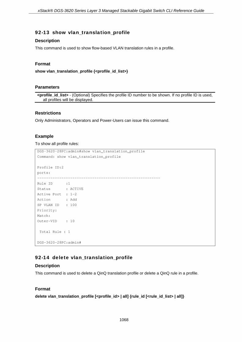
xStack® DGS-3620 Series Layer 3 Managed Stackable Gigabit Switch CLI Reference Guide
1068
92-13 show vlan_translation_profile Description This command is used to show flow-based VLAN translation rules in a profile.
Format show vlan_translation_profile {<profile_id_list>}
Parameters <profile_id_list> - (Optional) Specifies the profile ID number to be shown. If no profile ID is used,
all profiles will be displayed.
Restrictions Only Administrators, Operators and Power-Users can issue this command.
Example To show all profile rules:
DGS-3620-28PC:admin#show vlan_translation_profile
Command: show vlan_translation_profile
Profile ID:2
ports:
--------------------------------------------------------
Rule ID :1
Status : ACTIVE
Active Port : 1-2
Action : Add
SP VLAN ID : 100
Priority:
Match:
Outer-VID : 10
Total Rule : 1
DGS-3620-28PC:admin#
92-14 delete vlan_translation_profile Description This command is used to delete a QinQ translation profile or delete a QinQ rule in a profile.
Format delete vlan_translation_profile [<profile_id> | all] {rule_id [<rule_id_list> | all]}

xStack® DGS-3620 Series Layer 3 Managed Stackable Gigabit Switch CLI Reference Guide
1069
Parameters <profile_id> - Specifies the profile ID number to be deleted. all - Specifies that all profiles will be deleted. rule_id - (Optional) Specifies the rule ID range that will be deleted. If the rule ID is not specified,
all rules of the profile will be deleted at first, and then the profile will be deleted. <rule_id_list> - Enter the rule ID range used here. all - Specifies that all rules will be deleted.
Restrictions Only Administrators, Operators and Power-Users can issue this command.
Example To delete VLAN translation profile ID 2:
DGS-3620-28PC:admin#delete vlan_translation_profile 2
Command: delete vlan_translation_profile 2
Success.
DGS-3620-28PC:admin#
To delete a QinQ rule with an ID of 3 from profile 2:
DGS-3620-28PC:admin#delete vlan_translation_profile 2 rule_id 3
Command: delete vlan_translation_profile 2 rule_id 3
Success.
DGS-3620-28PC:admin#

xStack® DGS-3620 Series Layer 3 Managed Stackable Gigabit Switch CLI Reference Guide
1070
Chapter 93 Reboot Schedule Commands
config reboot schedule [in <min 1-43200> | at <end_time hh:mm> {<date ddmthyyyy>}]
{save_before_reboot} show reboot schedule delete reboot schedule
93-1 config reboot schedule Description This command is used to configure reboot time and save parameters for the reboot schedule on the Switch.
There are three parameters setting here. Users can configure the reboot time in two ways. The first way is to configure the reboot after a specific interval time and the other way is to configure the reboot at a specific date and time.
The third parameter determines whether to save the configuration or not before the reboot. The reboot schedule won’t be saved to the configuration file. After a reboot or shutdown, the reboot schedule will be deleted automatically. Even when the system is saved by using the save command, the configuration of the reboot schedule also won't be saved.
Format config reboot schedule [in <min 1-43200> | at <end_time hh:mm> {<date ddmthyyyy>}] {save_before_reboot}
Parameters in - Specifies that the reboot will start after this time interval has passed.
<min 1-43200> - Enter the time value used here. This value must be between 1 and 43200 minutes.
at - Specifies that the reboot will take place on the specified time and date. If the date is not specified, the reboot takes place at the specified time on the current day if the specified time is later than the current time or on the next day if the specified time is earlier than the current time. <end_time hh:mm> - Enter the time here. Enter the two-digit hour (hh) value followed by a
colon (:) and then enter the two-digit minute (mm) value. <date ddmthyyyy> - (Optional) Enter the date here. The date format is ddmthyyyy.
save_before_reboot - (Optional) Specifies that the device will first save all configurations before initiating the reboot.
Restrictions Only Administrators, Operators and Power-Users can issue this command.

xStack® DGS-3620 Series Layer 3 Managed Stackable Gigabit Switch CLI Reference Guide
1071
Examples This example shows how to reboot the device after 10 minutes and not to save the configuration before doing so.
DGS-3620-28PC:admin# config reboot schedule in 10
Command: config reboot schedule in 10
Success.
DGS-3620-28PC:admin#
This example shows how to reboot the device at 1 September 2013 23:00 and save all configurations before rebooting.
DGS-3620-28PC:admin# config reboot schedule at 23:00 01sep2013 save_before_reboot
Command: config reboot schedule at 23:00 01sep2013 save_before_reboot
Success.
DGS-3620-28PC:admin#
93-2 show reboot schedule Description This command is used to display the reboot schedule status.
Format show reboot schedule
Parameters None.
Restrictions None.
Example This example shows how to display the reboot schedule status.

xStack® DGS-3620 Series Layer 3 Managed Stackable Gigabit Switch CLI Reference Guide
1072
DGS-3620-28PC:admin# show reboot schedule
Command: show reboot schedule
Reboot Schedule Settings
---------------------------
Reboot schedule at 1 Sep 2013 23:00:00 (in 26234 minutes)
Save before reboot: Yes
DGS-3620-28PC:admin#
93-3 delete reboot schedule Description This command is used to delete the reboot schedule.
Format delete reboot schedule
Parameters None.
Restrictions None.
Example This example shows how to delete the reboot schedule.
DGS-3620-28PC:admin# delete reboot schedule
Command: delete reboot schedule
Success.
DGS-3620-28PC:admin#

xStack® DGS-3620 Series Layer 3 Managed Stackable Gigabit Switch CLI Reference Guide
1073
Chapter 94 Routing Information Protocol (RIP) Commands
enable rip config rip [ipif <ipif_name 12> | all] {authentication [enable <password 16> | disable] | tx_mode
[disable | v1_only | v1_compatible | v2_only] | rx_mode [v1_only | v2_only | v1_or_v2 | disable] | state [enable | disable] | distribute_list_in [access_list <list_name 16> | none]}(1)
config rip timers {update <sec 1-65535> | timeout <sec 1-65535> | garbage_collection <sec 1-65535>}(1)
disable rip show rip {ipif <ipif_name 12>}
94-1 enable rip Description This command is used to enable RIP for the switch. The default setting is disabled.
Format enable rip
Parameters None.
Restrictions Only Administrators, Operators and Power-Users can issue this command.
Example To enable RIP:
DGS-3620-28PC:admin# enable rip
Command: enable rip
Success.
DGS-3620-28PC:admin#
94-2 config rip Description This command is used to configure the RIP settings for one or more IP interfaces.

xStack® DGS-3620 Series Layer 3 Managed Stackable Gigabit Switch CLI Reference Guide
1074
Format config rip [ipif <ipif_name 12> | all] {authentication [enable <password 16> | disable] | tx_mode [disable | v1_only | v1_compatible | v2_only] | rx_mode [v1_only | v2_only | v1_or_v2 | disable] | state [enable | disable] | distribute_list_in [access_list <list_name 16> | none]}(1)
Parameters ipif_name - Specifies the IP interface name used for this configuration.
<ipif_name 12> - Enter the IP interface name used here. This name can be up to 12 characters long.
all - Specifies that all the IP interfaces will be used in this configuration. authentication - (Optional) Specifies to set the state of authentication.
enable - Specifies that the authentication state will be enabled. <password 16> - When the authentication state is enabled, enter the password used here.
This value can be up to 16 characters long. disable - Specifies that the authentication state will be disabled.
tx_mode - (Optional) Specifies the RIP transmission mode. disable - Specifies to prevent the transmission of RIP packets. v1_only - Specifies that only RIP version 1 format packets will be transmitted. v1_compatible - Specifies to transmit RIP version 2 format packets to the broadcast address. v2_only - Specifies that only RIP version 2 format packets will be transmitted.
rx_mode - (Optional) Specifies the RIP receive mode. v1_only - Specifies to receive RIP version 1 format packets. v2_only - Specifies to receive RIP version 2 format packets. v1_or_v2 - Specifies to receive both v1 and v2 packet. disable - Specifies that the receiving of RIP packets will be prevented.
state - (Optional) Specifies that the RIP state will be enabled or disabled. If the state is disabled, then RIP packets will not be either transmitted or received by the interface. The network configured on this interface will not be in the RIP database. enable - Specifeies that the RIP state will be enabled. disable - Specifeies that the RIP state will be disabled.
distribute_list_in - (Optional) Specifies the inbound route filter on the RIP interface. access_list - Specifies to use an IP standard access list to filter received RIP routes. If the
access list does not exist, the user can configure this successfully, but the function will not take effective until the user created the access list. There is an implicit deny all rule at the end of the access list. It will deny the receiving packets that does not match any previous rules. <list_name 16> - Enter the access list name. This name can be up to 16 characters long.
none - Specifies not to filter received RIP routes.
Restrictions Only Administrators, Operators and Power-Users can issue this command.
Example To change the RIP receive mode for the IP interface System:

xStack® DGS-3620 Series Layer 3 Managed Stackable Gigabit Switch CLI Reference Guide
1075
DGS-3620-28PC:admin# config rip ipif System rx_mode v1_only
Command: config rip ipif System rx_mode v1_only
Success.
DGS-3620-28PC:admin#
94-3 config rip timers Description This command is used to configure RIP timers.
Format config rip timers {update <sec 1-65535> | timeout <sec 1-65535> | garbage_collection <sec 1-65535>}(1)
Parameters update - (Optional) Specifies the value of the rate at which RIP updates are sent.
<sec 1-65535> - Enter the update value used here. This value must be between 1 and 65535 seconds.
timeout - (Optional) Specifies the value of the time after which a RIP route is declared to be invalid. <sec 1-65535> - Enter the timeout value used here. This value must be between 1 and 65535
seconds. garbage_collection - (Optional) Specifies the value of the time for which a RIP route will be kept
before it is removed from routing table. <sec 1-65535> - Enter the garbage collection value used here. This value must be between 1
and 65535 seconds.
Restrictions Only Administrators, Operators and Power-Users can issue this command.
Example To configure the RIP timers:
DGS-3620-28PC:admin# config rip timers update 60 timeout 360 garbage_collection 240
Command: config rip timers update 60 timeout 360 garbage_collection 240
Success.
DGS-3620-28PC:admin#
94-4 disable rip Description This command is used to disable RIP for the switch.
xStack® DGS-3620 Series Layer 3 Managed Stackable Gigabit Switch CLI Reference Guide
1076
Format disable rip
Parameters None.
Restrictions Only Administrators, Operators and Power-Users can issue this command.
Example To disable RIP:
DGS-3620-28PC:admin# disable rip
Command: disable rip
Success.
DGS-3620-28PC:admin#
94-5 show rip Description This command is used to display the RIP configuration for one or all the IP interfaces.
Format show rip {ipif <ipif_name 12>}
Parameters ipif - (Optional) Specifies the IP interface name used for this configuration.
<ipif_name 12> - Enter the IP interface name used here. This name can be up to 12 characters long.
If no parameter is specified, the system will display RIP configuration and statistics for all the IP interface.
Restrictions None.
Example To display RIP configuration and statistics for all IP interface.

xStack® DGS-3620 Series Layer 3 Managed Stackable Gigabit Switch CLI Reference Guide
1077
DGS-3620-28PC:admin#show rip
Command: show rip
RIP Global State : Enabled
Update Time : 120 seconds
Timeout Time : 300 seconds
Garbage Collection Time : 150 seconds
RIP Interface Settings
Interface IP Address TX Mode RX Mode Authen- State
tication
------------- ------------------ ---------- ------------- ---------- -----
System 2.2.2.2/8 V1 Comp. V1 or V2 Enabled Disabled
n40 40.0.0.2/16 V1 Comp. V1 or V2 Enabled Enabled
n90 90.0.0.2/16 V1 Comp. V1 or V2 Enabled Enabled
n100 100.0.0.2/16 V1 Comp. V1 or V2 Enabled Enabled
Total Entries : 4
DGS-3620-28PC:admin#

xStack® DGS-3620 Series Layer 3 Managed Stackable Gigabit Switch CLI Reference Guide
1078
Chapter 95 RIPng Commands
enable ripng disable ripng show ripng {ipif <ipif_name 12>} config ripng {method [no_horizon | split_horizon | poison_reverse] | update <sec 5-65535> |
expire <sec 1-65535> | garbage_collection <sec 1-65535>} (1) config ripng ipif [<ipif_name 12> | all] {state [enable | disable] | metric <value 1-15>} (1)
95-1 enable ripng Description This command is used to enable RIPng globally for the Switch.
Format enable ripng
Parameters None.
Restrictions Only Administrators, Operators and Power-Users can issue this command. (EI Mode Only Command)
Example To enable RIPng globally:
DGS-3620-28PC:admin# enable ripng
Command: enable ripng
Success.
DGS-3620-28PC:admin#
95-2 disable ripng Description This command is used to disable RIPng globally for the Switch.
Format disable ripng

xStack® DGS-3620 Series Layer 3 Managed Stackable Gigabit Switch CLI Reference Guide
1079
Parameters None.
Restrictions Only Administrators, Operators and Power-Users can issue this command. (EI Mode Only Command)
Example To disable RIPng globally:
DGS-3620-28PC:admin# disable ripng
Command: disable ripng
Success.
DGS-3620-28PC:admin#
95-3 show ripng Description This command is used to display the RIPng state on all or specified interfaces.
Format show ripng {ipif <ipif_name 12>}
Parameters ipif - (Optional) Specifies the RIPng IP interface name to be displayed.
<ipif_name 12> - Enter the RIPng IP interface name to be displayed here. This name can be up to 12 characters long.
Restrictions None. (EI Mode Only Command)
Example To display RIPng configurations:

xStack® DGS-3620 Series Layer 3 Managed Stackable Gigabit Switch CLI Reference Guide
1080
DGS-3620-28PC:admin# show ripng
Command: show ripng
Global State: Enabled
Method: Split Horizon
Update Time: 30 seconds
Expire Time: 180 seconds
Garbage Collection Time: 120 seconds
Interface State Metric
-----------------------------------------------------
System Disabled 15
i15 Enabled 1
i30 Enabled 1
i100 Disabled 1
Total Entries : 4
IPv6 Route Redistribution Settings
Source Destination Type Metric
Protocol Protocol
-------- ------------ -------- ------------
Total Entries: 0
DGS-3620-28PC:admin#
95-4 config ripng Description This command is used to configure the RIPng algorithm and timer.
Format config ripng {method [no_horizon | split_horizon | poison_reverse] | update <sec 5-65535> | expire <sec 1-65535> | garbage_collection <sec 1-65535>} (1)
Parameters method - (Optional) Specifies the method used.
no_horizon - Specifies to configure not use any horizon. split_horizon - Specifies to configure use a basic split horizon. poison_reverse - Specifies to configure to use a split horizon with poison reverse.
update - (Optional) Specifies the value of the update timer. <sec 5-65535> - Enter the update timer value used here. This value must be between 5 and
65535 seconds. expire - (Optional) Specifies the interval when the update expires.
<sec 1-65535> - Enter the expire value used here. This value must be between 1 and 65535 seconds.
garbage_collection - (Optional) Specifies the value of the garbage-collection timer. <sec 1-65535> - Enter the garbage-collection timer value used here. This value must be

xStack® DGS-3620 Series Layer 3 Managed Stackable Gigabit Switch CLI Reference Guide
1081
between 1 and 65535 seconds.
Restrictions Only Administrators, Operators and Power-Users can issue this command. (EI Mode Only Command)
Example To configure the RIPng method as poison reverse:
DGS-3620-28PC:admin# config ripng method poison_reverse
Command: config ripng method poison_reverse
Success.
DGS-3620-28PC:admin#
95-5 config ripng ipif Description This command is used to specify the RIPng state and metric value for one or all interfaces
Format config ripng ipif [<ipif_name 12> | all] {state [enable | disable] | metric <value 1-15>} (1)
Parameters ipif - Specifies the RIPng IP interface name to be configured.
<ipif_name 12> - Enter the RIPng IP interface name to be configured here. This name can be up to 12 characters long.
all - Specifies that all the RIPng IP interfaces will be used. state - (Optional) Specifies the RIPng state of the specified IP interface.
enable - Specifies that the RIPng state on the specified interface will be enabled. disable - Specifies that the RIPng state on the specified interface will be disabled.
metric - (Optional) Specifies the cost value of an interface. The RIPng route that was learned from the interface will add this value as a new route metric. <value 1-15> - Enter the metric value used here. This value must be between 1 and 15. The
default value is 1.
Restrictions Only Administrators, Operators and Power-Users can issue this command. (EI Mode Only Command)
Example To enable the RIPng interface state:

xStack® DGS-3620 Series Layer 3 Managed Stackable Gigabit Switch CLI Reference Guide
1082
DGS-3620-28PC:admin# config ripng ipif System state enable
Command: config ripng ipif System state enable
Success.
DGS-3620-28PC:admin#

xStack® DGS-3620 Series Layer 3 Managed Stackable Gigabit Switch CLI Reference Guide
1083
Chapter 96 RSPAN Commands
enable rspan disable rspan create rspan vlan [vlan_name <vlan_name> | vlan_id <vlanid 1-4094>] delete rspan vlan [vlan_name <vlan_name> | vlan_id <vlanid 1-4094>] config rspan vlan [vlan_name <vlan_name> | vlan_id <vlanid 1-4094>] [redirect [add | delete]
ports <portlist> | source {[mirror_group_id <value 1-4> | [add | delete] ports <portlist> [rx | tx | both]]}]
show rspan {[vlan_name <vlan_name> | vlan_id <vlanid 1-4094>]}
96-1 enable rspan Description This command is used to enable RSPAN globally.
Format enable rspan
Parameters None.
Restrictions Only Administrators and Operators can issue this command.
Example To enable RSPAN globally:
DGS-3620-28PC:admin#enable rspan
Command: enable rspan
Success.
DGS-3620-28PC:admin#
96-2 disable rspan Description This command is used to disable RSPAN globally.
Format disable rspan

xStack® DGS-3620 Series Layer 3 Managed Stackable Gigabit Switch CLI Reference Guide
1084
Parameters None.
Restrictions Only Administrators and Operators can issue this command.
Example To disable the RSPAN globally:
DGS-3620-28PC:admin#disable rspan
Command: disable rspan
Success.
DGS-3620-28PC:admin#
96-3 create rspan vlan Description This command is used to create an RSPAN VLAN. Up to 16 RSPAN VLANs can be created.
Format create rspan vlan [vlan_name <vlan_name> | vlan_id <vlanid 1-4094>]
Parameters vlan_name - Create the RSPAN VLAN by VLAN name.
<vlan_name> - Enter the VLAN name. vlan_id - Create the RSPAN VLAN by VLAN ID.
<vlanid 1-4094> - Enter the VLAN ID between 1 and 4094.
Restrictions Only Administrators and Operators can issue this command.
Example To create an RSPAN VLAN entry by VLAN name “v2”:
DGS-3620-28PC:admin#create rspan vlan vlan_name v2
Command: create rspan vlan vlan_name v2
Success.
DGS-3620-28PC:admin#

xStack® DGS-3620 Series Layer 3 Managed Stackable Gigabit Switch CLI Reference Guide
1085
To create an RSPAN VLAN entry by VLAN ID “3”:
DGS-3620-28PC:admin#create rspan vlan vlan_id 3
Command: create rspan vlan vlan_id 3
Success.
DGS-3620-28PC:admin#
96-4 delete rspan vlan Description This command is used to delete an RSPAN VLAN.
Format delete rspan vlan [vlan_name <vlan_name> | vlan_id <vlanid 1-4094>]
Parameters vlan_name - Specifies the RSPAN VLAN by VLAN name.
<vlan_name> - Enter the VLAN name. vlan_id - Specifies the RSPAN VLAN by VLAN ID.
<vlanid 1-4094> - Enter the VLAN ID between 1 and 4094.
Restrictions Only Administrators and Operators can issue this command.
Example To delete an RSPAN VLAN entry by VLAN name “v2”:
DGS-3620-28PC:admin#delete rspan vlan vlan_name v2
Command: delete rspan vlan vlan_name v2
Success.
DGS-3620-28PC:admin#
To delete an RSPAN VLAN entry by VLAN ID “3”:
DGS-3620-28PC:admin#delete rspan vlan vlan_id 3
Command: delete rspan vlan vlan_id 3
Success.
DGS-3620-28PC:admin#

xStack® DGS-3620 Series Layer 3 Managed Stackable Gigabit Switch CLI Reference Guide
1086
96-5 config rspan vlan Description This command is used by the source switch to configure the source setting for the RSPAN VLAN. The redirect command is used by the intermediate or last switch to configure the output port of the RSPAN VLAN packets, and makes sure that the RSPAN VLAN packets can egress to the redirect ports. In addition, the VLAN setting must be correctly configured to make the RSPAN VLAN work correctly. That is, for the intermediate switch, the redirect port must be a tagged member port of the RSPAN VLAN. For the last switch, the redirect port must be either a tagged member port or an untagged member port of the RSPAN VLAN based on the users’ requirements. If untagged membership is specified, the RSPAN VLAN tag will be removed. The redirect function will only work when RSPAN is enabled. Multiple RSPAN VLANs can be configured with the redirect setting at the same time.
Format config rspan vlan [vlan_name <vlan_name> | vlan_id <vlanid 1-4094>] [redirect [add | delete] ports <portlist> | source {[mirror_group_id <value 1-4> | [add | delete] ports <portlist> [rx | tx | both]]}]
Parameters vlan_name - Specifies the RSPAN VLAN by VLAN name.
<vlan_name> - Enter the VLAN name. vlan_id - Specifies the RSPAN VLAN by VLAN ID.
<vlanid 1-4094> - Enter the VLAN ID between 1 and 4094. redirect - Specifies output port list for the RSPAN VLAN packets. If the redirect port is a Link
Aggregation port, the Link Aggregation behavior will apply to the RSPAN packets. add - Specifies to add the redirect port. delete - Specifies to delete the redirect port.
ports - Specifies the output port list to add to or delete from the RSPAN packets. <portlist> - Enter a range of ports to be configured.
source - If the ports are not specified by this command, the source of RSPAN will come from the source specified by the mirror command or the flow-based source specified by an ACL. mirror_group_id - The mirror group identify that specify which mirror session used for
RSPAN source function. If the mirror group is not specified when configuring the mirror ports, the mirror group 1 will be the default group. <value 1-4> - Enter the mirror group ID value here. This value must be between 1 and 4.
add - (Optional) Specifies to add source ports. delete - (Optional) Specifies to delete source ports.
ports - (Optional) Specifies source port list to add to or delete from the RSPAN source. <portlist> - Enter a range of ports to be configured. rx - (Optional) Specifies to only monitor ingress packets. tx - (Optional) Specifies to only monitor egress packets. both - (Optional) Specifies to monitor both ingress and egress packets.
Restrictions Only Administrators and Operators can issue this command.
Example To configure an RSPAN source entry without source target port:

xStack® DGS-3620 Series Layer 3 Managed Stackable Gigabit Switch CLI Reference Guide
1087
DGS-3620-28PC:admin#config rspan vlan vlan_name vlan2 source add ports 2-5 rx
Command: config rspan vlan vlan_name vlan2 source add ports 2-5 rx
Success.
DGS-3620-28PC:admin#
To configure an RSPAN source entry for per flow RSPAN, without any source ports:
DGS-3620-28PC:admin#config rspan vlan vlan_id 2 source
Command: config rspan vlan vlan_id 2 source
Success.
DGS-3620-28PC:admin#
To configure RSPAN redirect for “vlan2” to ports 18 and 19:
DGS-3620-28PC:admin#config rspan vlan vlan_name vlan2 redirect add ports 18-19
Command: config rspan vlan vlan_name vlan2 redirect add ports 18-19
Success.
DGS-3620-28PC:admin#
96-6 show rspan Description This command is used to display RSPAN configuration.
Format show rspan {[vlan_name <vlan_name> | vlan_id <vlanid 1-4094>]}
Parameters vlan_name - Specifies the RSPAN VLAN by VLAN name.
<vlan_name> - Enter the VLAN name. vlan_id - Specifies the RSPAN VLAN by VLAN ID.
<vlanid 1-4094> - Enter the VLAN ID between 1 and 4094.
Restrictions None.
Example To display specific RSPAN settings:
DGS-3620-28PC:admin# show rspan vlan_id 63
Command: show rspan vlan_id 63
RSPAN : Enabled

xStack® DGS-3620 Series Layer 3 Managed Stackable Gigabit Switch CLI Reference Guide
1088
RSPAN VLAN ID : 63
-------------------
Mirror Group ID : 1
Target Port : 1:1
Source Ports
RX : 1:2-1:5
TX : 1:2-1:5
Redirect Ports : 1:9-1:12
Total RSPAN VLAN : 1
DGS-3620-28PC:admin#
To display all RSPAN settings:
DGS-3620-28PC:admin# show rspan
Command: show rspan
RSPAN: Enabled
RSPAN VLAN ID: 1
--------------------
Mirror Group ID : 1
Target Port : 1:1
Source Port
RX : 1:2-1:3
TX : 1:2-1:3
Source VLAN
RX : 2-3
RSPAN VLAN ID: 2
--------------------
Redirect Ports : 1:6-1:10
RSPAN VLAN ID: 3
----------------------
Redirect Ports : 1:6-1:10
Total RSPAN VLAN :3
DGS-3620-28PC:admin#

xStack® DGS-3620 Series Layer 3 Managed Stackable Gigabit Switch CLI Reference Guide
1089
Chapter 97 Safeguard Engine Commands
config safeguard_engine {state [enable | disable] | utilization {rising <value 20-100> | falling <value 20-100>} (1)| trap_log [enable | disable] | mode [strict | fuzzy]} (1)
show safeguard_engine
97-1 config safeguard_engine Description This command is used to configure the safeguard engine for the system.
Format config safeguard_engine {state [enable | disable] | utilization {rising <value 20-100> | falling <value 20-100>} (1)| trap_log [enable | disable] | mode [strict | fuzzy]} (1)
Parameters state - (Optional) Configure the safeguard engine state to enable or disable.
enable - Configure the safeguard engine state to enable. disable - Configure the safeguard engine state to disable.
utilization - (Optional) Configure the safeguard engine threshold. rising - (Optional) Configure the utilization rising threshold. The range is between 20%-100%.
If the CPU utilization is over the rising threshold, the switch enters exhausted mode. <value 20-100> - Configure the utilization rising threshold. The range is between 20%-
100%. falling - (Optional) Configure the utilization falling threshold. The range is between 20%-
100%. If the CPU utilization is lower than the falling threshold, the switch enters normal mode. <value 20-100> - Configure the utilization falling threshold. The range is between 20%-
100%. If the CPU utilization is lower than the falling threshold, the switch enters normal mode.
trap_log - (Optional) Configure the state of the safeguard engine related to the trap/log mechanism to enable or disable. enable - If set to enable, trap and log will be active while the safeguard engine current mode
is changed. disable - If set to disable, the current mode change will not trigger trap and log events.
mode - (Optional) Determines the controlling method of broadcast traffic. There are two modes, strict and fuzzy. strict - In strict, the switch will stop receiving all ‘ARP not to me’ packets (the protocol address
of the target in the ARP packet is the Switch itself). That means no matter what reasons cause the high CPU utilization (may not be caused by ARP storm), the Switch reluctantly processes any ’ARP not to me’ packets in exhausted mode.
fuzzy - In fuzzy mode, the switch will adjust the bandwidth dynamically depending on some reasonable algorithm.
Restrictions Only Administrators, Operators and Power-Users can issue this command.

xStack® DGS-3620 Series Layer 3 Managed Stackable Gigabit Switch CLI Reference Guide
1090
Example To configure the safeguard engine:
DGS-3620-28PC:admin#config safeguard_engine state enable utilization rising 50 falling 30 trap_log enable
Command: config safeguard_engine state enable utilization rising 50 falling 30 trap_log enable
Success.
DGS-3620-28PC:admin#
97-2 show safeguard_engine Description This command is used to display safeguard engine information.
Format show safeguard_engine
Parameters None.
Restrictions None.
Example To display safeguard engine information:
DGS-3620-28PC:admin#show safeguard_engine
Command: show safeguard_engine
Safeguard Engine State : Disabled
Safeguard Engine Current Status : Normal Mode
===================================================
CPU Utilization Information:
Rising Threshold : 30%
Falling Threshold : 20%
Trap/Log State : Disabled
Mode : Fuzzy
DGS-3620-28PC:admin#
Note: The safeguard engine current status has two modes: exhausted and normal mode.

xStack® DGS-3620 Series Layer 3 Managed Stackable Gigabit Switch CLI Reference Guide
1091
Chapter 98 SD Card Management commands
create backup [config | log] time_range <range_name 32> filename <pathname> {state [enable | disable]}
config backup [config | log] time_range <range_name 32> filename < pathname > state [enable | disable]
delete backup [config | log] [all | time_range <range_name 32> {filename < pathname >} ] show backup {config | log} create execute_config time_range <range_name 32> config < pathname > {state [enable |
disable] | [increment | reset]} config execute_config time_range <range_name 32> config <pathname> {state [enable |
disable] | [increment | reset} delete execute_config [all | time_range <range_name 32> { config <pathname>}] show execute_config execute config <pathname> {increment}
98-1 create backup Description This command is used to create a schedule to backup the configuration or log to file system.
Format create backup [config | log] time_range <range_name 32> filename <pathname> {state [enable | disable]}
Parameters config - Backup the configuration on schedule. log - Backup the log on schedule. time_range - The time range for the scheduled backup of the configuration or log.
<range_name 32> - Enter the name of this time range entry. The maximum length is 32 characters.
Filename - The backup filename of the configuration or log. <pathname> - Enter the path name of backup filename of the configuration or log.
State - Enable or disable the scheduled backup when schedule is created. If “state” is not specified, the schedule will be disabled. enable - Configure the scheduled backup state to enable. disable - Configure the scheduled backup state to disable.
Restrictions Only Administrators, Operators can issue this command.
Example To create a backup schedule on time range” range_1”:

xStack® DGS-3620 Series Layer 3 Managed Stackable Gigabit Switch CLI Reference Guide
1092
DGS-3620-28PC:admin#create backup config time_range range_1 filename bk-config-1
Command: create backup config time_range range_1 filename bk-config-1
Success.
DGS-3620-28PC:admin#
To create a backup schedule on time range” range_2”:
DGS-3620-28PC:admin#create backup log time_range range_2 filename bk-config-2 state enable
Command: create backup log time_range range_2 filename bk-config-2 state enable
Exceeded maximum number (15) of schedules for backup configuration or log.
DGS-3620-28PC:admin#
98-2 config backup Description This command is used to enable or disable a schedule backup.
Format config backup [config | log] time_range <range_name 32> filename <pathname> state [enable | disable]
Parameters config - Backup the configuration on schedule. log - Backup the log on schedule. time_range - The time range for the scheduled backup of the configuration or log.
<range_name 32> - Enter the name of this time range entry. The maximum length is 32 characters.
Filename - The backup filename of the configuration or log. <pathname> - Enter the path name of backup filename of the configuration or log.
State - Enable or disable the scheduled backup when schedule is created. If “state” is not specified, the schedule will be disabled. enable - Configure the scheduled backup state to enable. disable - Configure the scheduled backup state to disable.
Restrictions Only Administrators, Operators can issue this command.
Example To enable a backup schedule on time range” range_1”
DGS-3620-28PC:admin#config backup log time_range range_1 filename bk-des-log state enable
Command: config backup log time_range range_1 filename bk-des-log state enable

xStack® DGS-3620 Series Layer 3 Managed Stackable Gigabit Switch CLI Reference Guide
1093
Success.
DGS-3620-28PC:admin#
To enable a backup schedule on time range” range_2”
DGS-3620-28PC:admin#config backup log time_range range_2 filename bk-des-log state enable
Command: config backup log time_range range_2 filename bk-des-log state enable
The entry does not exist.
DGS-3620-28PC:admin#
98-3 delete backup Description This command is used to delete schedule backup for configuration or log.
Note: If a non-existed entry is specified to be deleted, a success message will be
feedback.
Format delete backup [config | log] [all | time_range <range_name 32>{filename <pathname>}]
Parameters config - Backup the configuration on schedule. log - Backup the log on schedule. all - Specifies to delete all scheduled backup, include configuration and log. time_range - The time range for scheduled backup the configuration or log.
<range_name 32> - Enter the name of this time range entry. The maximum length is 32 characters.
Filename - The backup filename of the configuration or log. <pathname> - Enter the path name of backup filename of the configuration or log.
Restrictions Only Administrators, Operators can issue this command.
Example To delete all of scheduled backup for configuration and log.
DGS-3620-28PC:admin#delete backup config all
Command: delete backup config all
Success.
DGS-3620-28PC:admin#

xStack® DGS-3620 Series Layer 3 Managed Stackable Gigabit Switch CLI Reference Guide
1094
98-4 show backup Description This command is used to show the created schedule backup.
Format show backup { config | log }
Parameters config - specified “config” to display all of scheduled backup for configuration. log - specified “log” to display all of scheduled backup for log.
If no parameter is specified, all the backup schedules for both configuration and log shall be displayed.
Restrictions None.
Example To show all schedule backup:
DGS-3620-28PC:admin# show backup
Command: show backup
Backup Schedule Entry 1
Time Range : range_1
Type : log
Filename : log-1
State : Enabled
Backup Schedule Entry 2
Time Range : range_2
Type : configuration
Filename : config-1
State : Disabled
Total Entries:2
DGS-3620-28PC:admin#
98-5 create execute_config Description This command is used to create a schedule to execute the configuration on file system.

xStack® DGS-3620 Series Layer 3 Managed Stackable Gigabit Switch CLI Reference Guide
1095
Format create execute_config time_range <range_name 32> config <pathname> {state [enable | disable] | [increment | reset ]}
Parameters time_range - The time range for the configuration to be executed.
<range_name 32> - Enter the name of this time range entry. The maximum length is 32 characters.
config - The filename of the configuration on file system. <pathname> - Enter the path name of the configuration.
state- Enable or disable the scheduled execution when schedule is created. If “state” is not specified, the schedule will be disabled. enable - Configure the state of scheduled execution to enable. disable - Configure the state of scheduled execution to disable.
increment - The current configuration will not be reset before execute the configuration. reset - The current configuration will be reset before execute the configuration.
Restrictions Only Administrators can issue this command.
Example To create a schedule execute:
DGS-3620-28PC:admin#create execute_config time_range range-1 config vlan-config state enable increment
Command: create execute_config time_range range-1 config vlan-config state enable increment
Success.
DGS-3620-28PC:admin#
98-6 config execute_config Description This command is used to configure configuration state or execute method of a schedule execution.
Format config execute_config time_range <range_name 32> config <pathname> {state [enable | disable] | [increment | reset ]}
Parameters time_range - The time range for the configuration to be executed.
<range_name 32> - Enter the name of this time range entry. The maximum length is 32 characters.
config - The filename of the configuration on file system. <pathname> - Enter the path name of the configuration.
state- Enable or disable the scheduled execution when schedule is created. If “state” is not

xStack® DGS-3620 Series Layer 3 Managed Stackable Gigabit Switch CLI Reference Guide
1096
specified, the schedule will be disabled. enable - Configure the state of scheduled execution to enable. disable - Configure the state of scheduled execution to disable.
increment - The current configuration will not be reset before execute the configuration. reset - The current configuration will be reset before execute the configuration.
Restrictions Only Administrators can issue this command.
Example To configure a scheduled execution:
DGS-3620-28PC:admin#config execute_config time_range range_1 config system-config state enable increment
Command: config execute_config time_range range_1 config system-config state enable increment
Success.
DGS-3620-28PC:admin#
98-7 delete execute_config Description This command is used to delete the schedule of execute configuration.
Format delete execute_config [all | time_range <range_name 32> {config <pathname>}]
Parameters all - Specifies to delete all the schedule of the executed configuration. time_range - The time range of scheduld executions that needs to be deleted.
<range_name 32> - Enter the name of this time range entry. The maximum length is 32 characters.
config - The filename of the configuration on file system. <pathname> - Enter the path name of the configuration.
Restrictions Only Administrators can issue this command.
Example Delete all the schedule of execute configuration:
DGS-3620-28PC:admin#delete execute_config all
Command: delete execute_config all
Success.
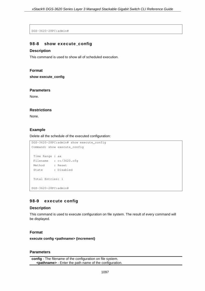
xStack® DGS-3620 Series Layer 3 Managed Stackable Gigabit Switch CLI Reference Guide
1097
DGS-3620-28PC:admin#
98-8 show execute_config Description This command is used to show all of scheduled execution.
Format show execute_config
Parameters None.
Restrictions None.
Example Delete all the schedule of the executed configuration:
DGS-3620-28PC:admin# show execute_config
Command: show execute_config
Time Range : aa
Filename : c:/3620.cfg
Method : Reset
State : Disabled
Total Entries: 1
DGS-3620-28PC:admin#
98-9 execute config Description This command is used to execute configuration on file system. The result of every command will be displayed.
Format execute config <pathname> {increment}
Parameters config - The filename of the configuration on file system.
<pathname> - Enter the path name of the configuration.

xStack® DGS-3620 Series Layer 3 Managed Stackable Gigabit Switch CLI Reference Guide
1098
increment - If this option is null, the current configuration will be reset before execute the configuration. If this option is available, the current configuration will not be reset before execute the configuration.
Restrictions Only Administrators can issue this command.
Example To load and execute a configuration:
DGS-3620-28PC:admin#execute config config-vlan-0
Command: execute config config-vlan-0
Read configuration config-vlan-0 failure.
Fail!
DGS-3620-28PC:admin#
To load and execute a configuration:
DGS-3620-28PC:admin#execute config config-vlan-1 increment
Command: execute config config-vlan-1 increment
Success.
DGS-3620-28PC:admin#config temperature threshold high 79
Command: config temperature threshold high 79
Success.
DGS-3620-28PC:admin#config temperature threshold low 11
Command: config temperature threshold low 11
Failure.
DGS-3620-28PC:admin#config temperature trap state enable
Command: config temperature trap state enable
Success.
DGS-3620-28PC:admin#config temperature log state enable
Command: config temperature log state enable
Success.
DGS-3620-28PC:admin#

xStack® DGS-3620 Series Layer 3 Managed Stackable Gigabit Switch CLI Reference Guide
1099
Chapter 99 Secure File Transfer Protocol (SFTP) Commands
enable sftp server disable sftp server config sftp server {timeout <sec 30-600>}(1) show sftp server
99-1 enable sftp server Description This command is used to enable the SFTP function globally. SFTP over SSH2 is a remotely secure file transfer protocol providing security on all file operations. SFTP server runs as a subsystem of SSH server. SSH server is required to be enabled before enabling SFTP server.
Format enable sftp server
Parameters None.
Restrictions Only Administrators, Operators and Power-Users can issue this command.
Example To enable SFTP server globally.
DGS-3620-28PC:admin#enable sftp server
Command: enable sftp server
Success.
DGS-3620-28PC:admin#
99-2 disable sftp server Description This command is used to disable the SFTP server function globally. All active SFTP sessions will be disturbed after executing this command. SFTP server runs as a subsystem of the SSH server. Disabling SSH server will also disturb all SFTP session.
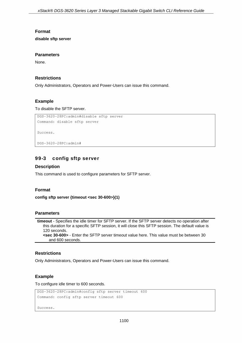
xStack® DGS-3620 Series Layer 3 Managed Stackable Gigabit Switch CLI Reference Guide
1100
Format disable sftp server
Parameters None.
Restrictions Only Administrators, Operators and Power-Users can issue this command.
Example To disable the SFTP server.
DGS-3620-28PC:admin#disable sftp server
Command: disable sftp server
Success.
DGS-3620-28PC:admin#
99-3 config sftp server Description This command is used to configure parameters for SFTP server.
Format config sftp server {timeout <sec 30-600>}(1)
Parameters timeout - Specifies the idle timer for SFTP server. If the SFTP server detects no operation after
this duration for a specific SFTP session, it will close this SFTP session. The default value is 120 seconds. <sec 30-600> - Enter the SFTP server timeout value here. This value must be between 30
and 600 seconds.
Restrictions Only Administrators, Operators and Power-Users can issue this command.
Example To configure idle timer to 600 seconds.
DGS-3620-28PC:admin#config sftp server timeout 600
Command: config sftp server timeout 600
Success.

xStack® DGS-3620 Series Layer 3 Managed Stackable Gigabit Switch CLI Reference Guide
1101
DGS-3620-28PC:admin#
99-4 show sftp server Description This command is used to show the parameters of the SFTP server.
Format show sftp server
Parameters None.
Restrictions None.
Example To show the parameters of the SFTP server.
DGS-3620-28PC:admin#show sftp server
Command: show sftp server
The SFTP Server Configuration
Protocol Version : 3
State : Enabled
Session Idle Timeout : 600 sec
DGS-3620-28PC:admin#
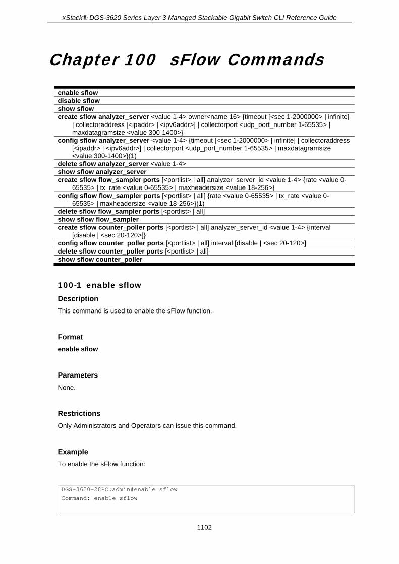
xStack® DGS-3620 Series Layer 3 Managed Stackable Gigabit Switch CLI Reference Guide
1102
Chapter 100 sFlow Commands
enable sflow disable sflow show sflow create sflow analyzer_server <value 1-4> owner<name 16> {timeout [<sec 1-2000000> | infinite]
| collectoraddress [<ipaddr> | <ipv6addr>] | collectorport <udp_port_number 1-65535> | maxdatagramsize <value 300-1400>}
config sflow analyzer_server <value 1-4> {timeout [<sec 1-2000000> | infinite] | collectoraddress [<ipaddr> | <ipv6addr>] | collectorport <udp_port_number 1-65535> | maxdatagramsize <value 300-1400>}(1)
delete sflow analyzer_server <value 1-4> show sflow analyzer_server create sflow flow_sampler ports [<portlist> | all] analyzer_server_id <value 1-4> {rate <value 0-
65535> | tx_rate <value 0-65535> | maxheadersize <value 18-256>} config sflow flow_sampler ports [<portlist> | all] {rate <value 0-65535> | tx_rate <value 0-
65535> | maxheadersize <value 18-256>}(1) delete sflow flow_sampler ports [<portlist> | all] show sflow flow_sampler create sflow counter_poller ports [<portlist> | all] analyzer_server_id <value 1-4> {interval
[disable | <sec 20-120>]} config sflow counter_poller ports [<portlist> | all] interval [disable | <sec 20-120>] delete sflow counter_poller ports [<portlist> | all] show sflow counter_poller
100-1 enable sflow Description This command is used to enable the sFlow function.
Format enable sflow
Parameters None.
Restrictions Only Administrators and Operators can issue this command.
Example To enable the sFlow function:
DGS-3620-28PC:admin#enable sflow
Command: enable sflow

xStack® DGS-3620 Series Layer 3 Managed Stackable Gigabit Switch CLI Reference Guide
1103
Success.
DGS-3620-28PC:admin#
100-2 disable sflow Description This command is used to disable the sFlow function.
Format disable sflow
Parameters None.
Restrictions Only Administrators and Operators can issue this command.
Example To disable the sFlow function:
DGS-3620-28PC:admin#disable sflow
Command: disable sflow
Success.
DGS-3620-28PC:admin#
100-3 show sflow Description This command is used to display sFlow information.
Format show sflow
Parameters None.
Restrictions Only Administrators, Operators and Power-Users can issue this command.

xStack® DGS-3620 Series Layer 3 Managed Stackable Gigabit Switch CLI Reference Guide
1104
Example To display the sFlow information:
DGS-3620-28PC:admin#show sflow
Command: show sflow
sFlow Version : V5
sFlow Address : 10.90.90.90
sFlow AddressV6: FE80::201:2FF:FE03:400
sFlow State : Enabled
DGS-3620-28PC:admin#
100-4 create sflow analyzer_server Description This command is used to create the sFlow flow sampler ports.
Format create sflow analyzer_server <value 1-4> owner<name 16> {timeout [<sec 1-2000000> | infinite] | collectoraddress [<ipaddr> | <ipv6addr>] | collectorport <udp_port_number 1-65535> | maxdatagramsize <value 300-1400>}
Parameters <value 1-4> - Enter a value between 1 and 4. owner - Specifies the entity making use of this sflow analyzer server. When owner is set or
modified, the timeout value will become 400 automatically. <name 16> - Enter the entity making use of this sflow analyzer server. When owner is set or
modified, the timeout value will become 400 automatically. timeout - (Optional) Specifies the length of time before the server is timed out. When the
analyzer server times out, all of the flow samplers and counter pollers associated with this analyzer server will be deleted. If not specified, its default value is 400. If it is specified as infinite, the server will never time out. <sec 1-2000000> - Enter the time out value, in seconds, between 1 and 2000000. infinite - Specifies to never time out.
collectoraddress - (Optional) Specifies the IP address of the analyzer server. <ipaddr> - Enter the IP address of the analyzer server. If not specified, the address will be
0.0.0.0, which means that the entry will be inactive. <ipv6addr> - Enter the IPv6 address of the analyzer server.
collectorport - (Optional) Specifies the destination UDP port for sending the sFlow datagrams. <udp_port_number 1-65535> - Enter the destination UDP port for sending the sFlow
datagrams. If not specified, the default value is 6343. maxdatagramsize - (Optional) Specifies the maximum number of data bytes that can be packed
in a single sample datagram. <value 300-1400> - Enter the maximum number of data bytes that can be packed in a single
sample datagram. If not specified, the default value is 1400.
Restrictions Only Administrators and Operators can issue this command.

xStack® DGS-3620 Series Layer 3 Managed Stackable Gigabit Switch CLI Reference Guide
1105
Example To create an sFlow analyzer server named “monitor”:
DGS-3620-28PC:admin#create sflow analyzer_server 1 owner monitor
Command: create sflow analyzer_server 1 owner monitor
Success.
DGS-3620-28PC:admin#
100-5 config sflow analyzer_server Description This command is used to configure the sFlow analyzer server information. More than one collector with the same IP address can be specified if the UDP port numbers are unique.
Format config sflow analyzer_server <value 1-4> {timeout [<sec 1-2000000> | infinite] | collectoraddress [<ipaddr> | <ipv6addr>] | collectorport <udp_port_number 1-65535> | maxdatagramsize <value 300-1400>}(1)
Parameters <value 1-4> - Enter the analyser server ID used here. This value must be between 1 and 4. The
switch supports 4 different analyser servers at the same time. Each sampler or poller can select a server ID (1, 2, 3, or 4) to send the samples.
timeout - (Optional) Specifies the time (in seconds) remaining before the sample is released and stops sampling. When the analyzer_server times out, all of the flow_samplers and counter_pollers associated with this analyzer_server will be deleted. If it is specified as infinite, the server will never be timeout. <sec 1-2000000> - Enter the time out value, in seconds, between 1 and 2000000. infinite - Specifies to never time out.
collectoraddress - (Optional) Specifies the IP address of the server. <ipaddr> - Enter the IP address of the server. If set to 0, sFlow packets will not be sent to this
server. <ipv6addr> - Specifies the IPv6 used.
collectorport - (Optional) Specifies the destination port for sending sflow datagrams. <udp_port_number 1-65535> - Enter the destination port for sending sflow datagrams. The
number is between 1 and 65535. maxdatagramsize - (Optional) Specifies the maximum number of data bytes that can be packed
in a single sample datagram. <value 300-1400> - Enter the maximum number of data bytes that can be packed in a single
sample datagram. The values is between 300 and 1400.
Restrictions Only Administrators and Operators can issue this command.
Example To configure the sFlow analyzer server information:
DGS-3620-28PC:admin#config sflow analyzer_server 1 collectoraddress 10.90.90.9

xStack® DGS-3620 Series Layer 3 Managed Stackable Gigabit Switch CLI Reference Guide
1106
Command: config sflow analyzer_server 1 collectoraddress 10.90.90.9
Success.
DGS-3620-28PC:admin#
100-6 delete sflow analyzer_server Description This command is used to delete the sFlow analyzer server.
Format delete sflow analyzer_server <value 1-4>
Parameters <value 1-4> - Enter a value between 1 and 4.
Restrictions Only Administrators and Operators can issue this command.
Example To delete the sFlow analyzer server 1:
DGS-3620-28PC:admin#delete sflow analyzer_server 1
Command: delete sflow analyzer_server 1
Success.
DGS-3620-28PC:admin#
100-7 show sflow analyzer_server Description This command is used to display sFlow analyzer server information.
Format show sflow analyzer_server
Parameters None.
Restrictions Only Administrators, Operators and Power-Users can issue this command.

xStack® DGS-3620 Series Layer 3 Managed Stackable Gigabit Switch CLI Reference Guide
1107
Example To display sFlow analyzer server information:
DGS-3620-28PC:admin#show sflow analyzer_server
Command: show sflow analyzer_server
sFlow Analyzer_server Information
------------------------------
Server ID : 1
Owner : admin
Timeout : 400
Current Countdown Time: 400
Collector Address :
Collector Port : 6343
Max Datagram Size : 1400
Total Entries: 1
DGS-3620-28PC:admin#
100-8 create sflow flow_sampler ports Description This command is used to create the sFlow flow sampler.
Format create sflow flow_sampler ports [<portlist> | all] analyzer_server_id <value 1-4> {rate <value 0-65535> | tx_rate <value 0-65535> | maxheadersize <value 18-256>}
Parameters <portlist> - Enter the list of ports to be configured. all - Specifies to configure all ports. analyzer_server_id - Specifies the ID of an analyzer server where the packet will be forwarded.
<value 1-4> - Enter the ID of an analyzer server where the packet will be forwarded. rate - (Optional) Specifies the sampling rate for the received packets sampled on the port.
<value 0-65535> - Enter the sampling rate for received packet sampling. The configured rate value multiplied by 256 is the actual rate. For example, if the rate is 20, the actual rate 5120. One packet will be sampled from every 5120 packets. If set to 0, the sampler is disabled. If the rate is not specified, its default value is 0.
tx_rate – (Optional) Specifies the sampling rate for the transmitted packet sampled on the port. <value 0-65535> - Enter the sampling rate for transmitted packet sampling. The configured
rate value multiplied by 256 is the actual rate. For example, if the rate is 20, the actual rate 5120. One packet will be sampled from every 5120 packets. If set to 0, the sampler is disabled. If the rate is not specified, its default value is 0.
maxheadersize - (Optional) Specifies the maximum number of leading bytes in the packet which has been sampled that will be encapsulated and forwarded to the server. <value 18-256> - Enter the maximum number of leading bytes in the packet which has been
sampled that will be encapsulated and forwarded to the server. If not specified, the default value is 128.

xStack® DGS-3620 Series Layer 3 Managed Stackable Gigabit Switch CLI Reference Guide
1108
Restrictions Only Administrators and Operators can issue this command.
Example To create the sFlow flow sampler:
DGS-3620-28PC:admin#create sflow flow_sampler ports 1 analyzer_server_id 1 rate 200 maxheadersize 120
Command: create sflow flow_sampler ports 1 analyzer_server_id 1 rate 200 maxheadersize 120
Success.
DGS-3620-28PC:admin#
100-9 config sflow flow_sampler ports Description This command is used to configure the sFlow flow sampler parameters.
Format config sflow flow_sampler ports [<portlist> | all] {rate <value 0-65535> | tx_rate <value 0-65535> | maxheadersize <value 18-256>}(1)
Parameters <portlist> - Enter the list of ports to be configured. all - Specifies to configure all ports. rate - (Optional) Specifies the sampling rate for the received packets sampled on the port.
<value 0-65535> - Enter the sampling rate for received packet sampling. The configured rate value multiplied by 256 is the actual rate. For example, if the rate is 20, the actual rate 5120. One packet will be sampled from every 5120 packets. If set to 0, the sampler is disabled. If the rate is not specified, its default value is 0.
tx_rate – (Optional) Specifies the sampling rate for the transmitted packet sampled on the port. <value 0-65535> - Enter the sampling rate for transmitted packet sampling. The configured
rate value multiplied by 256 is the actual rate. For example, if the rate is 20, the actual rate 5120. One packet will be sampled from every 5120 packets. If set to 0, the sampler is disabled. If the rate is not specified, its default value is 0.
maxheadersize - Specifies the maximum number of leading bytes in the packet which has been sampled that will be encapsulated and forwarded to the server. <value 18-256> - Enter the maximum number of leading bytes in the packet which has been
sampled that will be encapsulated and forwarded to the server. If not specified, the default value is 128.
Restrictions Only Administrators and Operators can issue this command.
Example To configure the sFlow flow sampler parameters:

xStack® DGS-3620 Series Layer 3 Managed Stackable Gigabit Switch CLI Reference Guide
1109
DGS-3620-28PC:admin#config sflow flow_sampler ports all rate 1
Command: config sflow flow_sampler ports all rate 1
Success.
DGS-3620-28PC:admin#
100-10 delete sflow flow_sampler ports Description This command is used to delete the sFlow flow sampler.
Format delete sflow flow_sampler ports [<portlist> | all]
Parameters <portlist> - Enter the list of ports to be deleted. all - Specifies to delete all ports.
Restrictions Only Administrators and Operators can issue this command.
Example To delete the sFlow flow sampler for ports 1 to 3:
DGS-3620-28PC:admin#delete sflow flow_sampler ports 1-3
Command: delete sflow flow_sampler ports 1-3
Success.
DGS-3620-28PC:admin#
100-11 show sflow flow_sampler Description This command is used to display sFlow sampler information for the ports that have been created.
Format show sflow flow_sampler
Parameters None.

xStack® DGS-3620 Series Layer 3 Managed Stackable Gigabit Switch CLI Reference Guide
1110
Restrictions Only Administrators, Operators and Power-Users can issue this command.
Example To display sFlow sampler information for the ports that have been created:
DGS-3620-28PC:admin#show sflow flow_sampler
Command: show sflow flow_sampler
Port Analyzer Configured Configured Active Active Max Header
Server ID Rx Rate Tx Rate Rx Rate Tx Rate Size
------ --------- ---------- ---------- ------- ------- -----------
1:15 1 10 10 10 10 18
1:21 1 10 10 10 10 18
Total Entries: 2
DGS-3620-28PC:admin#
100-12 create sflow counter_poller ports Description This command is used to create the sFlow counter poller. With the poller function, the statistics counter information with respect to a port will be forwarded to the server at the configured interval. These counters are RFC 2233 counters.
Format create sflow counter_poller ports [<portlist> | all] analyzer_server_id <value 1-4> {interval [disable | <sec 20-120>]}
Parameters <portlist> - Enter the ports to be configured. all - Specifies to configure all ports. analyzer_server_id - Specifies the ID of an analyzer server where the packet will be forwarded.
<value 1-4> - Enter the ID of an analyzer server where the packet will be forwarded. interval - (Optional) Specifies the maximum number of seconds between successive statistic
counters information. If set to disable, the counter-poller is disabled. If the interval is not specified, its default value is disable. disable - Specifies to disable the interval. <sec 20-120> - Enter the interval, in seconds, between 20 and 120.
Restrictions Only Administrators and Operators can issue this command.
Example To create the sFlow counter poller:
DGS-3620-28PC:admin#create sflow counter_poller ports 1 analyzer_server_id 1
xStack® DGS-3620 Series Layer 3 Managed Stackable Gigabit Switch CLI Reference Guide
1111
Command: create sflow counter_poller ports 1 analyzer_server_id 1
Success.
DGS-3620-28PC:admin#
100-13 config sflow counter_poller ports Description This command is used to configure the sflow counter poller parameters. If a user wants to change the analyzer server ID, they need to delete the counter poller and create a new one.
Format config sflow counter_poller ports [<portlist> | all] interval [disable | <sec 20-120>]
Parameters <portlist> - Enter the ports to be configured. all - Specifies to configure all ports. interval - Specifies the maximum number of seconds between successive samples of the
counters. If set to disabled, the counter sample is disabled. disable - Specifies to disable the interval. <sec 20-120> - Enter the interval, in seconds, between 20 and 120.
Restrictions Only Administrators and Operators can issue this command.
Example To configure the sFlow counter poller parameters interval to 50 for port 1:
DGS-3620-28PC:admin#config sflow counter_poller ports 1 interval 50
Command: config sflow counter_poller ports 1 interval 50
Success.
DGS-3620-28PC:admin#
100-14 delete sflow counter_poller ports Description This command is used to delete the sFlow counter poller.
Format delete sflow counter_poller ports [<portlist> | all]

xStack® DGS-3620 Series Layer 3 Managed Stackable Gigabit Switch CLI Reference Guide
1112
Parameters <portlist> - Enter the ports to be deleted. all - Specifies to delete all ports.
Restrictions Only Administrators and Operators can issue this command.
Example To delete the sFlow counter poller for port 1:
DGS-3620-28PC:admin#delete sflow counter_poller ports 1
Command: delete sflow counter_poller ports 1
Success.
DGS-3620-28PC:admin#
100-15 show sflow counter_poller Description This command is used to display sFlow counter poller information for the ports that have been created.
Format show sflow counter_poller
Parameters None.
Restrictions Only Administrators, Operators and Power-Users can issue this command.
Example To display sFlow counter poller information for the ports that have been created:
DGS-3620-28PC:admin#show sflow counter_poller
Command: show sflow counter_poller
Port Analyzer Server ID Polling Interval (sec)
---- ------------------ -----------------------
1:1 1 50
Total Entries: 1
DGS-3620-28PC:admin#

xStack® DGS-3620 Series Layer 3 Managed Stackable Gigabit Switch CLI Reference Guide
1113
Chapter 101 Single IP Management Commands
enable sim disable sim show sim {[candidates {<candidate_id 1-100>} | members {<member_id 1-32>} | group
{commander_mac <macaddr>} | neighbor]} reconfig [member_id <value 1-32> | exit] config sim_group [add <candidate_id 1-100> {<password>} | delete <member_id 1-32>] config sim [[ commander {group_name <groupname 64> } | candidate ] | dp_interval <sec 30-90>
| hold_time <sec 100-255>] download sim_ms [firmware_from_tftp | configuration_from_tftp] <ipaddr> <path_filename>
{[members <mslist 1-32> | all]} upload sim_ms [configuration_to_tftp | log_to_tftp] <ipaddr> <path_filename> {[members <mslist>
| all]}
101-1 enable sim Description This command is used to configure the single IP management on the switch as enabled.
Format enable sim
Parameters None.
Restrictions Only Administrators, Operators and Power-Users can issue this command.
Example To enable single IP management:
DGS-3620-28PC:admin#enable sim
Command: enable sim
Success.
DGS-3620-28PC:admin#

xStack® DGS-3620 Series Layer 3 Managed Stackable Gigabit Switch CLI Reference Guide
1114
101-2 disable sim Description This command is used to configure the single IP management on the switch as disabled.
Format disable sim
Parameters None.
Restrictions Only Administrators, Operators and Power-Users can issue this command.
Example To disable single IP management:
DGS-3620-28PC:admin#disable sim
Command: disable sim
Success.
DGS-3620-28PC:admin#
101-3 show sim Description This command is used to display the information of the specific sorts of devices including of self, candidate, member, group, and neighbor.
Format show sim {[candidates {<candidate_id 1-100>} | members {<member_id 1-32>} | group {commander_mac <macaddr>} | neighbor]}
Parameters candidates - (Optional) Specifies the candidate devices.
<candidate_id 1-100> - (Optional) Specifies the candidate devices. The ID is from 1 to 100. members - (Optional) Specifies the member devices.
<member_id 1-32> - (Optional) Specifies the member devices. The ID is from 1 to 32. group – (Optional) Specifies other group devices.
commander_mac - Specifies the commander MAC address. <macaddr> - Enter the commander MAC address.
neighbor - (Optional) Specifies other neighbor devices.

xStack® DGS-3620 Series Layer 3 Managed Stackable Gigabit Switch CLI Reference Guide
1115
Restrictions None.
Example To show the self information in detail:
DGS-3620-28PC:admin#show sim
Command: show sim
SIM Version : VER-1.61
Firmware Version : 3.00.004
Device Name :
MAC Address : 78-54-2E-88-99-77
Capabilities : L3
Platform : DGS-3620-28PC L3 Switch
SIM State : Disabled
Role State : Candidate
Discovery Interval : 30 sec
Hold Time : 100 sec
DGS-3620-28PC:admin#
To show the candidate information in summary:
DGS-3620-28PC:admin#show sim candidates
Command: show sim candidates
ID MAC Address Platform / Hold Firmware Device Name
Capability Time Version
--- ----------------- ------------------------ ----- --------- ----------------
1 00-01-02-03-04-00 DGS-3620-28PC-DC L3 Switch 40 3.00.004 aabbbbbbbbbbbbb
2 00-55-55-00-55-00 DGS-3620-28PC-DC L3 Switch 140 3.00.004 default master
Total Entries: 2
DGS-3620-28PC:admin#
To show the member information in summary:
DGS-3620-28PC:admin#show sim members
Command: show sim members
ID MAC Address Platform / Hold Firmware Device Name
Capability Time Version
--- ----------------- ------------------------ ----- --------- ----------------
1 00-01-02-03-04-00 DGS-3620-28PC-DC L3 Switch 40 3.00.004 aaaaaa009aaaaa
2 00-55-55-00-55-00 DGS-3620-28PC-DC L3 Switch 140 3.00.004 default master
Total Entries: 2
DGS-3620-28PC:admin#
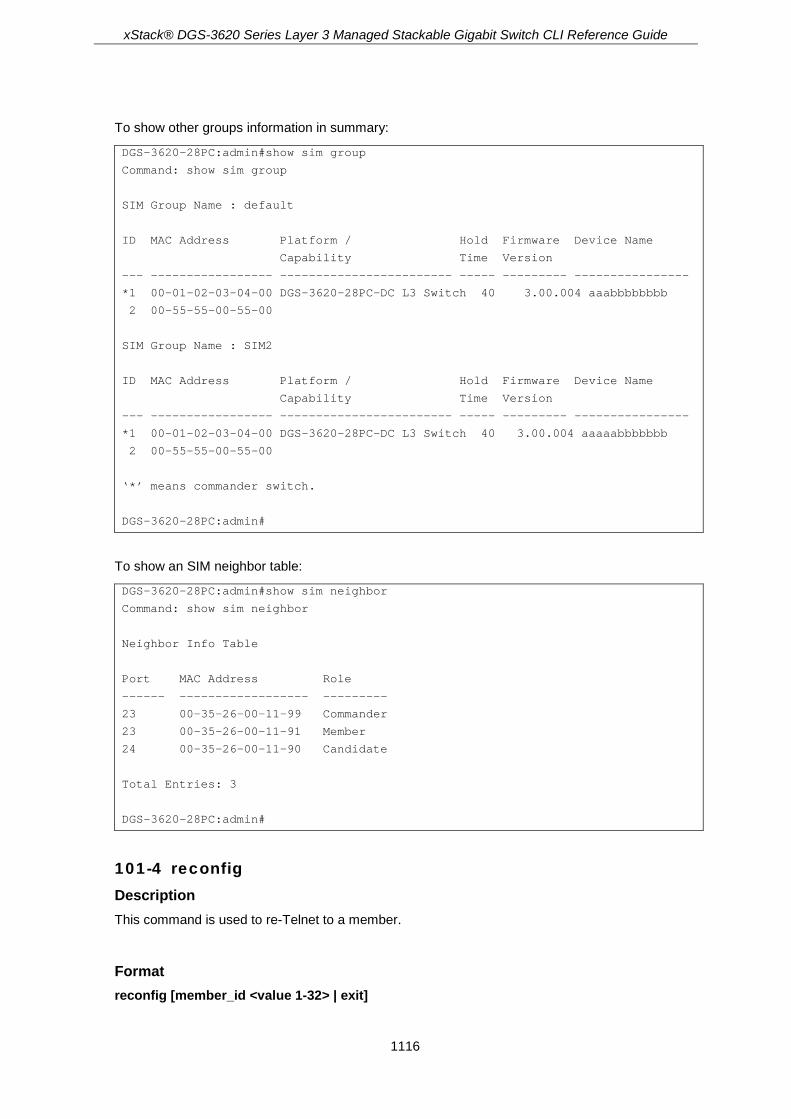
xStack® DGS-3620 Series Layer 3 Managed Stackable Gigabit Switch CLI Reference Guide
1116
To show other groups information in summary:
DGS-3620-28PC:admin#show sim group
Command: show sim group
SIM Group Name : default
ID MAC Address Platform / Hold Firmware Device Name
Capability Time Version
--- ----------------- ------------------------ ----- --------- ----------------
*1 00-01-02-03-04-00 DGS-3620-28PC-DC L3 Switch 40 3.00.004 aaabbbbbbbb
2 00-55-55-00-55-00
SIM Group Name : SIM2
ID MAC Address Platform / Hold Firmware Device Name
Capability Time Version
--- ----------------- ------------------------ ----- --------- ----------------
*1 00-01-02-03-04-00 DGS-3620-28PC-DC L3 Switch 40 3.00.004 aaaaabbbbbbb
2 00-55-55-00-55-00
‘*’ means commander switch.
DGS-3620-28PC:admin#
To show an SIM neighbor table:
DGS-3620-28PC:admin#show sim neighbor
Command: show sim neighbor
Neighbor Info Table
Port MAC Address Role
------ ------------------ ---------
23 00-35-26-00-11-99 Commander
23 00-35-26-00-11-91 Member
24 00-35-26-00-11-90 Candidate
Total Entries: 3
DGS-3620-28PC:admin#
101-4 reconfig Description This command is used to re-Telnet to a member.
Format reconfig [member_id <value 1-32> | exit]

xStack® DGS-3620 Series Layer 3 Managed Stackable Gigabit Switch CLI Reference Guide
1117
Parameters member_id - Specifies the serial number of a member.
<value 1-32> - Enter the serial number of a member. The value is between 1 and 32. exit - Specifies to terminate command switch access.
Restrictions Only Administrators, Operators and Power-Users can issue this command.
Example To re-Telnet to a member:
DGS-3620-28PC:admin#reconfig member_id 1
Command: reconfig member_id 1
DGS-3620-28PC:admin#
DGS-3620-28PC Gigabit Ethernet Switch
Command Line Interface
Firmware: Build 3.00.004
Copyright(C) 2013 D-Link Corporation. All rights reserved.
DGS-3620-28PC:admin#
101-5 config sim_group Description This command is used to configure group information on the switch.
Format config sim_group [add <candidate_id 1-100> {<password>} | delete <member_id 1-32>]
Parameters add - Specifies to add a specific candidate to the group.
<candidate_id 1-100> - Enter to add a specific candidate to the group. <password> - (Optional) Specifies the password of a candidate, if necessary.
delete - Specifies to remove a specific member from the group. <member_id 1-32> - Enter to remove a specific member from the group. The ID is from 1 to
32.
Restrictions Only Administrators, Operators and Power-Users can issue this command.
Example To add a member:

xStack® DGS-3620 Series Layer 3 Managed Stackable Gigabit Switch CLI Reference Guide
1118
DGS-3620-28PC:admin#config sim_group add 2
Command: config sim_group add 2
Please wait for ACK !!!
SIM Config Success !!!
Success.
DGS-3620-28PC:admin#
To delete a member:
DGS-3620-28PC:admin#config sim_group delete 1
Command: config sim_group delete 1
Please wait for ACK !!!
SIM Config Success !!!
Success.
DGS-3620-28PC:admin#
101-6 config sim Description This command is used to configure the role state and parameters of discovery protocol on the switch.
Format config sim [[commander {group_name <groupname 64>} | candidate] | dp_interval <sec 30-90> | hold_time <sec 100-255>]
Parameters commander - Transfer the role to commander.
group_name - (Optional) If commander, users can specify the name of the group. <groupname 64> - If commander, users can specify the name of the group. The maximum
length is 64 characters. candidate - Transfer role to candidate. dp_interval - Specifies the time in seconds between discoveries.
<sec 30-90> - Enter the time in seconds between discoveries. hold_time - Specifies the time in seconds the device holds the discovery result.
<sec 100-255> - Enter the time in seconds the device holds the discovery result.
Restrictions Only Administrators, Operators and Power-Users can issue this command.

xStack® DGS-3620 Series Layer 3 Managed Stackable Gigabit Switch CLI Reference Guide
1119
Example To transfer to commander:
DGS-3620-28PC:admin#config sim commander
Command: config sim commander
Success.
DGS-3620-28PC:admin#
To transfer to candidate:
DGS-3620-28PC:admin#config sim candidate
Command: config sim candidate
Success.
DGS-3620-28PC:admin#
To update the name of a group:
DGS-3620-28PC:admin#config sim commander group_name mygroup
Command: config sim commander group_name mygroup
Success.
DGS-3620-28PC:admin#
To change the time interval of discovery protocol:
DGS-3620-28PC:admin#config sim dp_interval 30
Command: config sim dp_interval 30
Success.
DGS-3620-28PC:admin#
To change the hold time of discovery protocol:
DGS-3620-28PC:admin#config sim hold_time 200
Command: config sim hold_time 200
Success.
DGS-3620-28PC:admin#
101-7 download sim_ms Description This command is used to download firmware or configuration from a TFTP server to indicated devices.

xStack® DGS-3620 Series Layer 3 Managed Stackable Gigabit Switch CLI Reference Guide
1120
Format download sim_ms [firmware_from_tftp | configuration_from_tftp] <ipaddr> <path_filename> {[members <mslist 1-32> | all ]}
Parameters firmware_from_tftp - Specifies to download firmware from a TFTP server. configuration_from_tftp - Specifies to download configuration from a TFTP server. <ipaddr> - Enter the IP address of the TFTP server. <path_filename> - Enter the file path of firmware or configuration in the TFTP server. members – (Optional) Specifies a range of members which download this firmware or
configuration. <mslist 1-32> - Enter a range of members which download this firmware or configuration. all - Specifies all members which download this firmware or configuration.
Restrictions Only Administrators, Operators and Power-Users can issue this command.
Example To download firmware:
DGS-3620-28PC:admin#download sim_ms firmware_from_tftp 10.55.47.1 D:\dwl600x.tfp members 1-3
Commands: download sim_ms firmware_from_tftp 10.55.47.1 D:\dwl600x.tfp members 1-3
This device is updating firmware. Please wait several minutes...
Download Status :
ID MAC Address Result
--- ----------------- ----------------
1 00-01-02-03-04-00 Success
2 00-07-06-05-04-03 Transfer Fail
3 00-07-06-05-04-04 Transfer Fail
DGS-3620-28PC:admin#
To download configuration:
DGS-3620-28PC:admin#download sim_ms configuration_from_tftp 10.55.47.1 D:\test.txt members 1-3
Commands: download sim_ms configuration_from_tftp 10.55.47.1 D:\test.txt members 1-3
This device is updating configuration. Please wait several minutes...
Download Status :
ID MAC Address Result
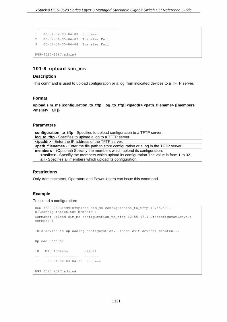
xStack® DGS-3620 Series Layer 3 Managed Stackable Gigabit Switch CLI Reference Guide
1121
--- ----------------- ----------------
1 00-01-02-03-04-00 Success
2 00-07-06-05-04-03 Transfer Fail
3 00-07-06-05-04-04 Transfer Fail
DGS-3620-28PC:admin#
101-8 upload sim_ms Description This command is used to upload configuration or a log from indicated devices to a TFTP server.
Format upload sim_ms [configuration_to_tftp | log_to_tftp] <ipaddr> <path_filename> {[members <mslist> | all ]}
Parameters configuration_to_tftp - Specifies to upload configuration to a TFTP server. log_to_tftp - Specifies to upload a log to a TFTP server. <ipaddr> - Enter the IP address of the TFTP server. <path_filename> - Enter the file path to store configuration or a log in the TFTP server. members – (Optional) Specifiy the members which upload its configuration.
<mslist> - Specifiy the members which upload its configuration.The value is from 1 to 32. all - Specifies all members which upload its configuration.
Restrictions Only Administrators, Operators and Power-Users can issue this command.
Example To upload a configuration:
DGS-3620-28PC:admin#upload sim_ms configuration_to_tftp 10.55.47.1 D:\configuration.txt members 1
Command: upload sim_ms configuration_to_tftp 10.55.47.1 D:\configuration.txt members 1
This device is uploading configuration. Please wait several minutes...
Upload Status:
ID MAC Address Result
-- ---------------- -------
1 00-01-02-03-04-00 Success
DGS-3620-28PC:admin#
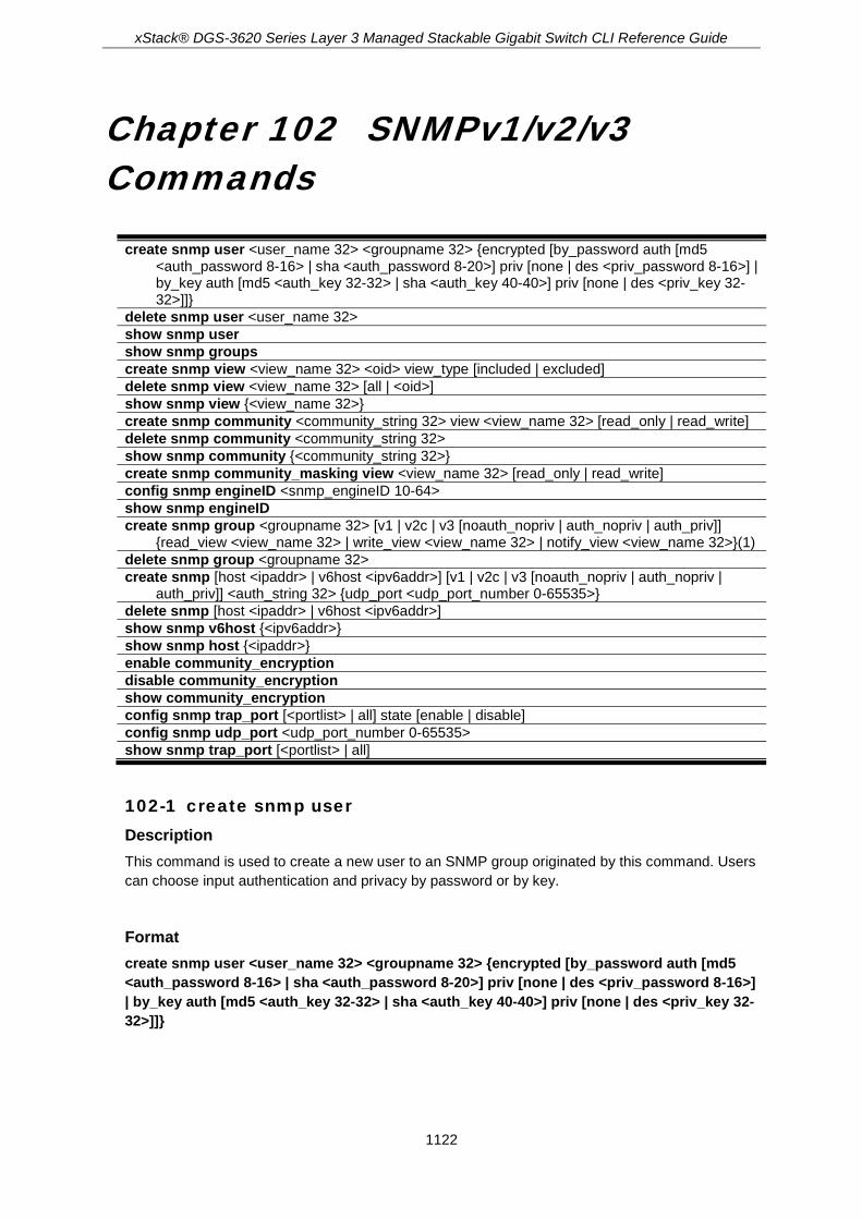
xStack® DGS-3620 Series Layer 3 Managed Stackable Gigabit Switch CLI Reference Guide
1122
Chapter 102 SNMPv1/v2/v3 Commands
create snmp user <user_name 32> <groupname 32> {encrypted [by_password auth [md5 <auth_password 8-16> | sha <auth_password 8-20>] priv [none | des <priv_password 8-16>] | by_key auth [md5 <auth_key 32-32> | sha <auth_key 40-40>] priv [none | des <priv_key 32-32>]]}
delete snmp user <user_name 32> show snmp user show snmp groups create snmp view <view_name 32> <oid> view_type [included | excluded] delete snmp view <view_name 32> [all | <oid>] show snmp view {<view_name 32>} create snmp community <community_string 32> view <view_name 32> [read_only | read_write] delete snmp community <community_string 32> show snmp community {<community_string 32>} create snmp community_masking view <view_name 32> [read_only | read_write] config snmp engineID <snmp_engineID 10-64> show snmp engineID create snmp group <groupname 32> [v1 | v2c | v3 [noauth_nopriv | auth_nopriv | auth_priv]]
{read_view <view_name 32> | write_view <view_name 32> | notify_view <view_name 32>}(1) delete snmp group <groupname 32> create snmp [host <ipaddr> | v6host <ipv6addr>] [v1 | v2c | v3 [noauth_nopriv | auth_nopriv |
auth_priv]] <auth_string 32> {udp_port <udp_port_number 0-65535>} delete snmp [host <ipaddr> | v6host <ipv6addr>] show snmp v6host {<ipv6addr>} show snmp host {<ipaddr>} enable community_encryption disable community_encryption show community_encryption config snmp trap_port [<portlist> | all] state [enable | disable] config snmp udp_port <udp_port_number 0-65535> show snmp trap_port [<portlist> | all]
102-1 create snmp user Description This command is used to create a new user to an SNMP group originated by this command. Users can choose input authentication and privacy by password or by key.
Format create snmp user <user_name 32> <groupname 32> {encrypted [by_password auth [md5 <auth_password 8-16> | sha <auth_password 8-20>] priv [none | des <priv_password 8-16>] | by_key auth [md5 <auth_key 32-32> | sha <auth_key 40-40>] priv [none | des <priv_key 32-32>]]}

xStack® DGS-3620 Series Layer 3 Managed Stackable Gigabit Switch CLI Reference Guide
1123
Parameters <user_name 32> - Enter the name of the user on the host that connects to the agent. The range
is 1 to 32 characters. <groupname 32> - Enter the name of the group to which the user is associated. The range is 1
to 32 characters. encrypted - (Optional) Specifies whether the password appears in encrypted format. by_password auth - Indicate the input password for authentication sha - Specifies the HMAC-SHA-96 authentication level between 8 and 20 characters.
<auth_password 8-20> - Enter the HMAC-SHA-96 authentication level between 8 and 20 characters.
md5 – Specifies the HMAC-MD5-96 authentication level between 8 and 16 characters. <auth_password 8-16> - Enter the HMAC-MD5-96 authentication level between 8 and 16
characters. priv - Indicate the input password for privacy. The options are none and DES.
none - Specifies there will be no privacy string. des - Specifies a privacy string used by DES between 8 and 16 characters.
<priv_password 8-16> - Enter a privacy string used by DES between 8 and 16 characters.
by_key auth - Indicate the input key for authentication. The options are MD5 and SHA1. md5 - Specifies an authentication key used by MD5. This is a hex string type of 32 characters.
<auth_key 32-32> - Enter an authentication key used by MD5. This is a hex string type of 32 characters.
sha - Specifies an authentication key used by SHA1. This is a hex string type of 40 characters. <auth_key 40-40> - Enter an authentication key used by SHA1. This is a hex string type of 40
characters. priv - Indicate the input key for privacy. The options are none and DES.
none - Specifies there will be no privacy key. des - Specifies a privacy key used by DES. This is a hex string type of 32 characters
<priv_key 32-32> - Enter a privacy key used by DES. This is a hex string type of 32 characters.
Restrictions Only Administrator-level users can issue this command.
Example To create a new user to an SNMP group originated by this command:
DGS-3620-28PC:admin#create snmp user dlink D-Link_group encrypted by_password auth md5 12345678 priv des 12345678
Command: create snmp user dlink D-Link_group encrypted by_password auth md5 12345678 priv des 12345678
Success.
DGS-3620-28PC:admin#
102-2 delete snmp user Description This command is used to remove a user from an SNMP group and deletes the associated group in the SNMP group.

xStack® DGS-3620 Series Layer 3 Managed Stackable Gigabit Switch CLI Reference Guide
1124
Format delete snmp user <user_name 32>
Parameters <user_name 32> - Enter the name of the user on the host to be deleted. The range is 1 to 32
characters.
Restrictions Only Administrator-level users can issue this command.
Example To delete an SNMP user:
DGS-3620-28PC:admin#delete snmp user dlink
Command: delete snmp user dlink
Success.
DGS-3620-28PC:admin#
102-3 show snmp user Description This command is used to display information on each SNMP username in the group username table.
Format show snmp user
Parameters None.
Restrictions None.
Example To display SNMP user information:
DGS-3620-28PC:admin#show snmp user
Command: show snmp user

xStack® DGS-3620 Series Layer 3 Managed Stackable Gigabit Switch CLI Reference Guide
1125
Username Group Name VerAuthPriv
--------------------------- --------------------------- ------------
initial initial V3 NoneNone
Total Entries : 1
DGS-3620-28PC:admin#
102-4 show snmp groups Description This command is used to display the names of groups on the switch, and the security model, level, and the status of the different views.
Format show snmp groups
Parameters None.
Restrictions None.
Example To display the names of the SNMP groups on the switch:
DGS-3620-28PC:admin#show snmp groups
Command: show snmp groups
Vacm Access Table Settings
Group Name : public
ReadView Name : CommunityView
WriteView Name :
Notify View Name : CommunityView
Security Model : SNMPv1
Security Level : NoAuthNoPriv
Group Name : public
ReadView Name : CommunityView
WriteView Name :
Notify View Name : CommunityView
Security Model : SNMPv2
Security Level : NoAuthNoPriv
Group Name : private
ReadView Name : CommunityView

xStack® DGS-3620 Series Layer 3 Managed Stackable Gigabit Switch CLI Reference Guide
1126
WriteView Name : CommunityView
Notify View Name : CommunityView
Security Model : SNMPv2
Security Level : NoAuthNoPriv
Total Entries: 3
DGS-3620-28PC:admin#
102-5 create snmp view Description This command is used to assign views to community strings to limit which MIB objects an SNMP manager can access.
Format create snmp view <view_name 32> <oid> view_type [included | excluded]
Parameters <view_name 32> - Enter the view name to be created. <oid> - Enter the object-identified tree (the MIB tree). view_type - Specifies the access type of of the MIB tree in this view. included - Specifies to include this view. excluded - Specifies to exclude this view.
Restrictions Only Administrator-level users can issue this command.
Example To assign views to community strings to limit which MIB objects an SNMP manager can access:
DGS-3620-28PC:admin#create snmp view dlinkview 1.3.6 view_type included
Command: create snmp view dlinkview 1.3.6 view_type included
Success.
DGS-3620-28PC:admin#
102-6 delete snmp view Description This command is used to remove a view record.
Format delete snmp view <view_name 32> [all | <oid>]

xStack® DGS-3620 Series Layer 3 Managed Stackable Gigabit Switch CLI Reference Guide
1127
Parameters <view_name 32> - Enter the view name of the user who will be deleted. all - Specifies to view all records. <oid> - Enter the object-identified tree (the MIB tree).
Restrictions Only Administrator-level users can issue this command.
Example To remove a view record:
DGS-3620-28PC:admin#delete snmp view dlinkview all
Command: delete snmp view dlinkview all
Success.
DGS-3620-28PC:admin#
102-7 show snmp view Description This command is used to display SNMP view records.
Format show snmp view {<view_name 32>}
Parameters <view_name 32> - (Optional) Specifies the view name of the user to be displayed.
Restrictions None.
Example To display SNMP view records:
DGS-3620-28PC:admin#show snmp view
Command: show snmp view
Vacm View Table Settings
View Name Subtree View Type
-------------------- ------------------------- ----------
restricted 1.3.6.1.2.1.1 Included
restricted 1.3.6.1.2.1.11 Included
restricted 1.3.6.1.6.3.10.2.1 Included
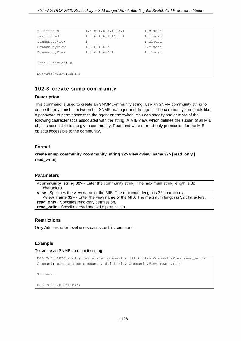
xStack® DGS-3620 Series Layer 3 Managed Stackable Gigabit Switch CLI Reference Guide
1128
restricted 1.3.6.1.6.3.11.2.1 Included
restricted 1.3.6.1.6.3.15.1.1 Included
CommunityView 1 Included
CommunityView 1.3.6.1.6.3 Excluded
CommunityView 1.3.6.1.6.3.1 Included
Total Entries: 8
DGS-3620-28PC:admin#
102-8 create snmp community Description This command is used to create an SNMP community string. Use an SNMP community string to define the relationship between the SNMP manager and the agent. The community string acts like a password to permit access to the agent on the switch. You can specify one or more of the following characteristics associated with the string: A MIB view, which defines the subset of all MIB objects accessible to the given community; Read and write or read-only permission for the MIB objects accessible to the community.
Format create snmp community <community_string 32> view <view_name 32> [read_only | read_write]
Parameters <community_string 32> - Enter the community string. The maximum string length is 32
characters. view - Specifies the view name of the MIB. The maximum length is 32 characters.
<view_name 32> - Enter the view name of the MIB. The maximum length is 32 characters. read_only - Specifies read-only permission. read_write - Specifies read and write permission.
Restrictions Only Administrator-level users can issue this command.
Example To create an SNMP community string:
DGS-3620-28PC:admin#create snmp community dlink view CommunityView read_write
Command: create snmp community dlink view CommunityView read_write
Success.
DGS-3620-28PC:admin#

xStack® DGS-3620 Series Layer 3 Managed Stackable Gigabit Switch CLI Reference Guide
1129
102-9 delete snmp community Description This command is used to remove a specific community string.
Format delete snmp community <community_string 32>
Parameters <community_string 32> - Enter the community string that will be deleted.
Restrictions Only Administrator-level users can issue this command.
Example To delete an SNMP community:
DGS-3620-28PC:admin#delete snmp community dlink
Command: delete snmp community dlink
Success.
DGS-3620-28PC:admin#
102-10 show snmp community Description This command is used to display community string configurations.
Format show snmp community {<community_string 32>}
Parameters <community_string 32> - (Optional) Specifies the community string to be displayed.
Note: If a community string is not specified, all community string information will be
displayed.
Restrictions None.

xStack® DGS-3620 Series Layer 3 Managed Stackable Gigabit Switch CLI Reference Guide
1130
Example To display the current community string configurations:
DGS-3620-28PC:admin#show snmp community
Command: show snmp community
SNMP Community Table
Community Name View Name Access Right
---------------------------- ------------------------ ------------
private CommunityView read_write
public CommunityView read_only
Total Entries : 2
DGS-3620-28PC:admin#
102-11 create snmp community_masking view Description This command is used to choose a security method for creating an SNMP community string, but the community string encrypted or not depends on the SNMP community encryption state.
If users use this command to create an SNMP community string, the community string that the user inputs will be displayed as “*”, and the user will have to double input (confirm) the SNMP community string when creating an SNMP community.
Format create snmp community_masking view <view_name 32> [read_only | read_write]
Parameters <view_name 32> - Enter the MIB view name used here. This name can be up to 32 characters
long. read_only - Specifies that the user, using the community string, will have read only access to the
switch’s SNMP agent. read_write - Specifies that the user, using the community string, will have read/write access to
the switch’s SNMP agent.
Restrictions Only Administrator level users can issue this command.
Example To create an SNMP community string called “community123” with the “read_only” security method:
DGS-3620-28PC:admin# create snmp community_masking view CommunityView read_only
Command: create snmp community_masking view CommunityView read_only
Enter a case-sensitive community:************
Enter the community again for confirmation:************

xStack® DGS-3620 Series Layer 3 Managed Stackable Gigabit Switch CLI Reference Guide
1131
Success.
DGS-3620-28PC:admin#
102-12 config snmp engineID Description This command is used to configure an identifier for the SNMP engine on the switch. Associated with each SNMP entity is a unique engine ID.
Format config snmp engineID <snmp_engineID 10-64>
Parameters <snmp_engineID 10-64> - Enter the identify for the SNMP engine on the switch.
Restrictions Only Administrator-level users can issue this command.
Example To configure an identifier for the SNMP engine on the switch:
DGS-3620-28PC:admin#config snmp engineID 1023457890
Command: config snmp engineID 1023457890
Success.
DGS-3620-28PC:admin#
102-13 show snmp engineID Description This command is used to display the identification of the SNMP engine on the switch.
Format show snmp engineID
Parameters None.
Restrictions None.

xStack® DGS-3620 Series Layer 3 Managed Stackable Gigabit Switch CLI Reference Guide
1132
Example To display the identification of an SNMP engine:
DGS-3620-28PC:admin#show snmp engineID
Command: show snmp engineID
SNMP Engine ID : 1023457890
DGS-3620-28PC:admin#
102-14 create snmp group Description This command is used to create a new SNMP group.
Format create snmp group <groupname 32> [v1 | v2c | v3 [noauth_nopriv | auth_nopriv | auth_priv]] {read_view <view_name 32> | write_view <view_name 32> | notify_view <view_name 32>}(1)
Parameters <groupname 32> - Enter the name of the group. v1 - Specifies the least secure of the possible security models. v2c - Specifies the second least secure of the possible security models. v3 - Specifies the most secure of the possible security models. Specifies authentication of a
packet. noauth_nopriv - Specifies to neither support packet authentication nor encrypting. auth_nopriv - Specifies to support packet authentication. auth_priv - Specifies to support packet authentication and encrypting. read_view - Specifies the view name between 1 and 32 characters.
<view_name 32> - Enter the view name between 1 and 32 characters. write_view - Specifies the view name between 1 and 32 characters.
<view_name 32> - Enter the view name between 1 and 32 characters. notify_view - Specifies the view name between 1 and 32 characters.
<view_name 32> - Enter the view name between 1 and 32 characters.
Restrictions Only Administrator-level users can issue this command.
Example To create a new SNMP group:
DGS-3620-28PC:admin#create snmp group D-Link_group v3 auth_priv read_view CommunityViewwrite_view CommunityView notify_view CommunityView
Command: create snmp group D-Link_group v3 auth_priv read_view CommunityView write_view CommunityView notify_view CommunityView
Success.

xStack® DGS-3620 Series Layer 3 Managed Stackable Gigabit Switch CLI Reference Guide
1133
DGS-3620-28PC:admin#
102-15 delete snmp group Description This command is used to remove an SNMP group.
Format delete snmp group <groupname 32>
Parameters <groupname 32> - Enter the name of the group that will be deleted.
Restrictions Only Administrator-level users can issue this command.
Example To remove an SNMP group:
DGS-3620-28PC:admin#delete snmp group D_Link_group
Command: delete snmp group D_Link_group
Success.
DGS-3620-28PC:admin#
102-16 create snmp Description This command is used to create a recipient of an SNMP operation.
Format create snmp [host <ipaddr> | v6host <ipv6addr>] [v1 | v2c | v3 [noauth_nopriv | auth_nopriv | auth_priv]] <auth_string 32> {udp_port <udp_port_number 0-65535>}
Parameters host - Specifies the IP address of the recipient for which the traps are targeted.
<ipaddr> - Enter the IP address of the recipient for which the traps are targeted. v6host - Specifies the v6host IP address to which the trap packet will be sent.
<ipv6addr> - Enter the v6host IP address to which the trap packet will be sent. v1 - Specifies the least secure of the possible security models. v2c - Specifies the second least secure of the possible security models. v3 - Specifies the most secure of the possible security models. noauth_nopriv - Specifies to neither support packet authentication nor encrypting. auth_nopriv - Specifies to support packet authentication.

xStack® DGS-3620 Series Layer 3 Managed Stackable Gigabit Switch CLI Reference Guide
1134
auth_priv - Specifies to support packet authentication and encrypting. <auth_string 32> - Enter the authentication string. If v1 or v2 is specified, the auth_string
presents the community string, and it must be one of the entries in the community table. If v3 is specified, the auth_string presents the user name, and it must be one of the entries in the user table.
udp_port - (Optional) Specifies the UDP port number. The default trap UDP port number is 162 <udp_port_number 0-65535> - Enter the UDP port number. This value must be between 0
and 65535.
Restrictions Only Administrator level users can issue this command.
Example To create a recipient of an SNMP operation:
DGS-3620-28PC:admin#create snmp host 10.48.74.100 v3 noauth_nopriv initial
Command: create snmp host 10.48.74.100 v3 noauth_nopriv initial
Success.
DGS-3620-28PC:admin#
102-17 delete snmp Description This command is used to delete a recipient of an SNMP trap operation.
Format delete snmp [host <ipaddr> | v6host <ipv6addr>]
Parameters host - Specifies the IP address of the SNMP host recipient to be deleted.
<ipaddr> - Enter the IP address of the SNMP host recipient to be deleted. v6host - Specifies the IPv6 address of the SNMP host recipient to be deleted.
<ipv6addr> - Enter the IPv6 address of the SNMP host recipient to be deleted.
Restrictions Only Administrator-level users can issue this command.
Example To delete a recipient of an SNMP trap operation:
DGS-3620-28PC:admin#delete snmp host 10.48.74.100
Command: delete snmp host 10.48.74.100
Success.

xStack® DGS-3620 Series Layer 3 Managed Stackable Gigabit Switch CLI Reference Guide
1135
DGS-3620-28PC:admin#
102-18 show snmp host Description This command is used to display the recipient for which the traps are targeted.
Format show snmp host {<ipaddr>}
Parameters <ipaddr> - (Optional) Specifies the IP address of the recipient for which the traps are targeted.
Note: If no parameter is specified, all SNMP hosts will be displayed.
Restrictions None.
Example To display the receipient for which the traps are targeted:
DGS-3620-28PC:admin#show snmp host
Command: show snmp host
SNMP Host Table
Host IP Address SNMP Version Community Name / SNMPv3 User Name UDP Port
--------------- --------------- --------------------------------- --------
10.90.90.6 V2c community3 162
Total Entries: 1
DGS-3620-28PC:admin#
102-19 show snmp v6host Description This command is used to display the recipient for which the traps are targeted.
Format show snmp v6host {<ipv6addr>}
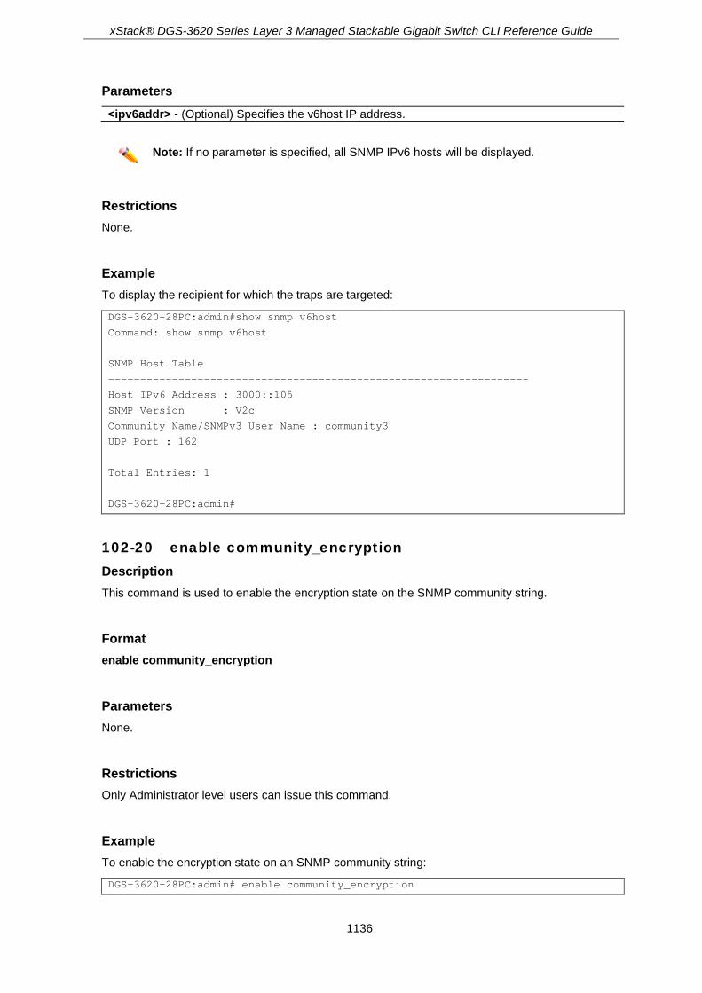
xStack® DGS-3620 Series Layer 3 Managed Stackable Gigabit Switch CLI Reference Guide
1136
Parameters <ipv6addr> - (Optional) Specifies the v6host IP address.
Note: If no parameter is specified, all SNMP IPv6 hosts will be displayed.
Restrictions None.
Example To display the recipient for which the traps are targeted:
DGS-3620-28PC:admin#show snmp v6host
Command: show snmp v6host
SNMP Host Table
------------------------------------------------------------------
Host IPv6 Address : 3000::105
SNMP Version : V2c
Community Name/SNMPv3 User Name : community3
UDP Port : 162
Total Entries: 1
DGS-3620-28PC:admin#
102-20 enable community_encryption Description This command is used to enable the encryption state on the SNMP community string.
Format enable community_encryption
Parameters None.
Restrictions Only Administrator level users can issue this command.
Example To enable the encryption state on an SNMP community string:
DGS-3620-28PC:admin# enable community_encryption
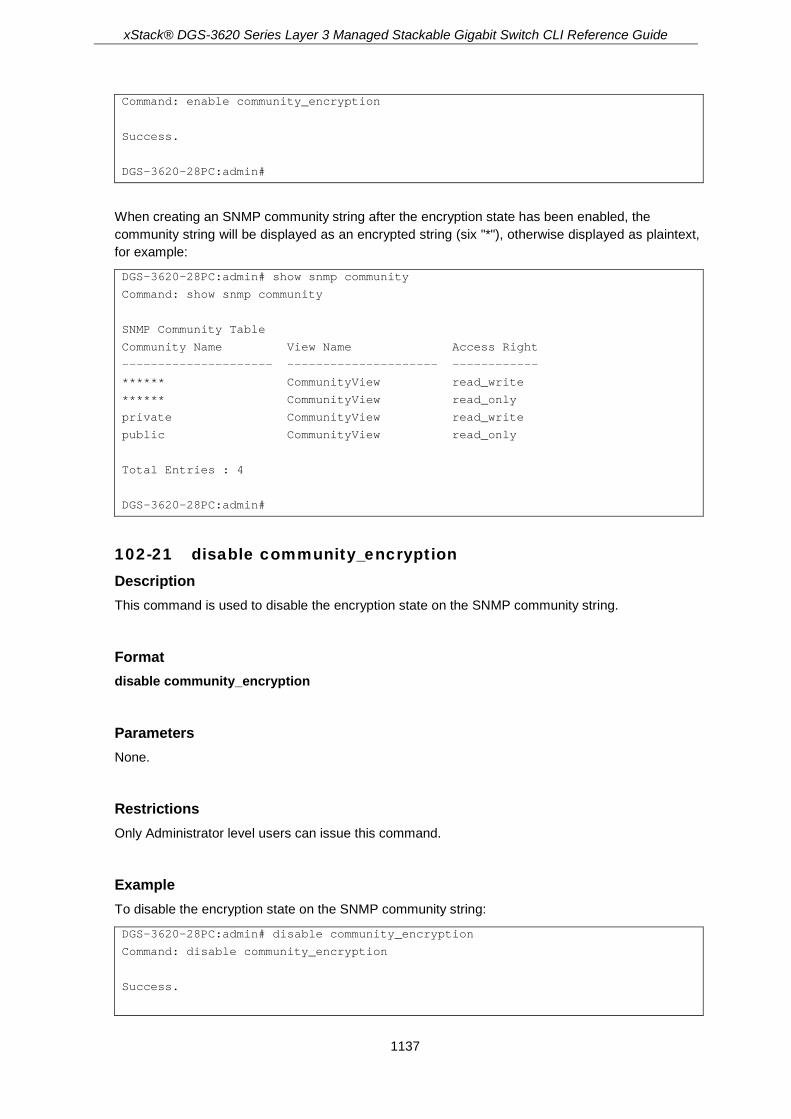
xStack® DGS-3620 Series Layer 3 Managed Stackable Gigabit Switch CLI Reference Guide
1137
Command: enable community_encryption
Success.
DGS-3620-28PC:admin#
When creating an SNMP community string after the encryption state has been enabled, the community string will be displayed as an encrypted string (six "*"), otherwise displayed as plaintext, for example:
DGS-3620-28PC:admin# show snmp community
Command: show snmp community
SNMP Community Table
Community Name View Name Access Right
--------------------- --------------------- ------------
****** CommunityView read_write
****** CommunityView read_only
private CommunityView read_write
public CommunityView read_only
Total Entries : 4
DGS-3620-28PC:admin#
102-21 disable community_encryption Description This command is used to disable the encryption state on the SNMP community string.
Format disable community_encryption
Parameters None.
Restrictions Only Administrator level users can issue this command.
Example To disable the encryption state on the SNMP community string:
DGS-3620-28PC:admin# disable community_encryption
Command: disable community_encryption
Success.

xStack® DGS-3620 Series Layer 3 Managed Stackable Gigabit Switch CLI Reference Guide
1138
DGS-3620-28PC:admin#
102-22 show community_encryption Description This command is used to display the encryption state on the SNMP community string.
Format show community_encryption
Parameters None.
Restrictions None.
Example To show the encryption state on the SNMP community string:
DGS-3620-28PC:admin# show community_encryption
Command: show community_encryption
SNMP Community Encryption State : Enabled
DGS-3620-28PC:admin#
102-23 config snmp trap_port Description This command is used to configure the per port’s SNMP trap state. The default port trap state is enabled for each port.
Format config snmp trap_port [<portlist> | all] state [enable | disable]
Parameters <portlist> - Enter the list of ports that will be used for this configuration. all - Specifies that all ports will be used for this configuration. state - Specifies the per port SNMP trap state.
enable - Specifies that the per port SNMP trap state will be enabled. This is the default option. disable - Specifies that the per port SNMP trap state will be disabled.

xStack® DGS-3620 Series Layer 3 Managed Stackable Gigabit Switch CLI Reference Guide
1139
Restrictions Only Administrator level users can issue this command.
Example To enable the per port SNMP trap state:
DGS-3620-28PC:admin#config snmp trap_port all state enable
Command: config snmp trap_port all state enable
Success.
DGS-3620-28PC:admin#
102-24 config snmp udp_port Description This command is used to change the default SNMP UDP port number.
Format config snmp udp_port <udp_port_number 0-65535>
Parameters <udp_port_number 0-65535> - Enter the UDP port number. This value must be between 0 and
65535. The default value is 161.
Restrictions Only Administrator level users can issue this command.
Example To configure the UDP port number of SNMP:
DGS-3620-28PC:admin#config snmp udp_port 50000
Command: config snmp udp_port 50000
Success.
DGS-3620-28PC:admin#
102-25 show snmp trap_port Description This command is used to display the SNMP trap port state.

xStack® DGS-3620 Series Layer 3 Managed Stackable Gigabit Switch CLI Reference Guide
1140
Format show snmp trap_port [<portlist> | all]
Parameters <portlist> - Enter the list of ports for this display. all - Specifies that all the ports will be displayed.
Restrictions None.
Example To display the port state of SNMP trap for port 1 to 10:
DGS-3620-28PC:admin#show snmp trap_port 1:1-1:10
Command: show snmp trap_port 1:1-1:10
Port Trap State
----- -------------
1:1 Enabled
1:2 Enabled
1:3 Enabled
1:4 Enabled
1:5 Enabled
1:6 Enabled
1:7 Enabled
1:8 Enabled
1:9 Enabled
1:10 Enabled
DGS-3620-28PC:admin#

xStack® DGS-3620 Series Layer 3 Managed Stackable Gigabit Switch CLI Reference Guide
1141
Chapter 103 Spanning Tree Protocol (STP) commands
show stp show stp instance {<value 0-64>} show stp ports {<portlist>} show stp mst_config_id create stp instance_id <value 1-64> delete stp instance_id <value 1-64> config stp instance_id <value 1-64> [add_vlan | remove_vlan] <vidlist> config stp mst_config_id {revision_level <int 0-65535> | name <string>} (1) enable stp disable stp config stp version [mstp | rstp | stp] config stp priority <value 0-61440> instance_id <value 0-64> config stp {maxage <value 6-40> | maxhops <value 6-40> | hellotime <value 1-2> | forwarddelay
<value 4-30> | txholdcount <value 1-10> | fbpdu [enable | disable] | nni_bpdu_addr [dot1d | dot1ad]}(1)
config stp ports <portlist> {externalCost [auto | <value 1-200000000>] | hellotime <value 1-2> | migrate [yes | no] | edge [true | false | auto] | p2p [true | false | auto] | state [enable | disable] | restricted_role [true | false] | restricted_tcn [true | false] | fbpdu [enable | disable]} (1)
config stp mst_ports <portlist> instance_id <value 0-64> {internalCost [auto | <value 1-200000000>] | priority <value 0-240>}(1)
config stp trap {topo_change [disable | enable] | new_root [enable | disable]}
103-1 show stp Description This command is used to display the bridge parameters global settings.
Format show stp
Parameters None.
Restrictions None.
Example To display STP:

xStack® DGS-3620 Series Layer 3 Managed Stackable Gigabit Switch CLI Reference Guide
1142
DGS-3620-28PC:admin#show stp
Command: show stp
STP Bridge Global Settings
---------------------------
STP Status : Disabled
STP Version : RSTP
Max Age : 20
Hello Time : 2
Forward Delay : 15
Max Hops : 20
TX Hold Count : 6
Forwarding BPDU : Disabled
New Root Trap : Enabled
Topology Change Trap : Enabled
NNI BPDU Address : dot1d
DGS-3620-28PC:admin#
103-2 show stp instance Description This command is used to display each instance parameters settings. Value means the instance ID, if there is no input of this value, all instances will be shown.
Format show stp instance {<value 0-64>}
Parameters <value 0-64> - (Optional) Specifies the MSTP instance ID. Instance 0 represents the default
instance: CIST. This value must be between 0 and 64.
Restrictions None.
Example To display STP instances:

xStack® DGS-3620 Series Layer 3 Managed Stackable Gigabit Switch CLI Reference Guide
1143
DGS-3620-28PC:admin#show stp instance
Command: show stp instance
STP Instance Settings
---------------------------
Instance Type : CIST
Instance Status : Enabled
Instance Priority : 32768(Bridge Priority : 32768, SYS ID Ext : 0 )
STP Instance Operational Status
--------------------------------
Designated Root Bridge : 32768/00-22-22-22-22-00
External Root Cost : 0
Regional Root Bridge : 32768/00-22-22-22-22-00
Internal Root Cost : 0
Designated Bridge : 32768/00-22-22-22-22-00
Root Port : None
Max Age : 20
Forward Delay : 15
Last Topology Change : 2430
Topology Changes Count : 0
DGS-3620-28PC:admin#
103-3 show stp ports Description This command is used to display the switch’s current per-port STP configuration:
STP port configuration, STP port role (Disabled, Alternate, Backup, Root, Designated, NonStp), and STP port status (Disabled, Discarding, Learning, Forwarding).
Format show stp ports {<portlist>}
Parameters <portlist> - (Optional) Specifies a range of ports to be displayed.
Restrictions None.
Example To show STP ports:
DGS-3620-28PC:admin#show stp ports
Command: show stp ports
MSTP Port Information
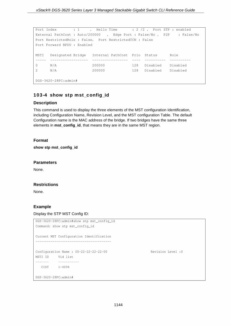
xStack® DGS-3620 Series Layer 3 Managed Stackable Gigabit Switch CLI Reference Guide
1144
Port Index : 1 , Hello Time : 2 /2 , Port STP : enabled
External PathCost : Auto/200000 , Edge Port : False/No , P2P : False/No
Port RestrictedRole : False, Port RestrictedTCN : False
Port Forward BPDU : Enabled
MSTI Designated Bridge Internal PathCost Prio Status Role
----- ------------------ ----------------- ---- ---------- ----------
0 N/A 200000 128 Disabled Disabled
2 N/A 200000 128 Disabled Disabled
DGS-3620-28PC:admin#
103-4 show stp mst_config_id Description This command is used to display the three elements of the MST configuration Identification, including Configuration Name, Revision Level, and the MST configuration Table. The default Configuration name is the MAC address of the bridge. If two bridges have the same three elements in mst_config_id, that means they are in the same MST region.
Format show stp mst_config_id
Parameters None.
Restrictions None.
Example Display the STP MST Config ID:
DGS-3620-28PC:admin#show stp mst_config_id
Command: show stp mst_config_id
Current MST Configuration Identification
----------------------------------------
Configuration Name : 00-22-22-22-22-00 Revision Level :0
MSTI ID Vid list
------- -----------
CIST 1-4094
DGS-3620-28PC:admin#

xStack® DGS-3620 Series Layer 3 Managed Stackable Gigabit Switch CLI Reference Guide
1145
103-5 create stp instance_id Description This command is used to create a new MST instance independent from the default Instance: CIST (Instance 0). After creating the MST instance, a user needs to configure the VLANs (using commands in 103-7), or the newly created MST instance will still be in a disabled state.
Format create stp instance_id <value 1-64>
Parameters <value 1-64> - Enter the MSTP instance ID. Instance 0 represents a default instance CIST. This
value must be between 1 and 64.
Restrictions Only Administrators, Operators and Power-Users can issue this command.
Example To create an MSTP instance:
DGS-3620-28PC:admin#create stp instance_id 2
Command: create stp instance_id 2
Warning:There is no VLAN mapping to this instance_id!
Success.
DGS-3620-28PC:admin#
103-6 delete stp instance_id Description This command is used to delete the specified MST Instance. CIST (Instance 0) cannot be deleted and you can only delete one instance at a time.
Format delete stp instance_id <value 1-64>
Parameters <value 1-64> - Enter the MSTP instance ID. Instance 0 represents the default instance CIST.
This value must be between 1 and 64.
Restrictions Only Administrators, Operators and Power-Users can issue this command.

xStack® DGS-3620 Series Layer 3 Managed Stackable Gigabit Switch CLI Reference Guide
1146
Example To delete an MSTP instance:
DGS-3620-28PC:admin#delete stp instance_id 2
Command: delete stp instance_id 2
Success.
DGS-3620-28PC:admin#
103-7 config stp instance_id Description There are two different action types to deal with an MST instance. They are listed as follows:
1) add_vlan: To map specified VLAN lists to an existing MST instance.
2) remove_vlan: To delete specified VLAN lists from an existing MST instance.
Format config stp instance_id <value 1-64> [add_vlan | remove_vlan] <vidlist>
Parameters <value 1-64> - Enter the MSTP instance ID. Instance 0 represents a default instance CIST. The
DUT supports 65 instances (0-64) at most. add_vlan - Defined action type to configure an MST instance. remove_vlan - Defined action type to configure an MST instance. <vidlist> - Enter the newly added CLI Value Type. It is similar to <portlist> type, but the value
range is 1 to 4094.
Restrictions Only Administrators, Operators and Power-Users can issue this command.
Example To map a VLAN ID to an MSTP instance:
DGS-3620-28PC:admin#config stp instance_id 2 add_vlan 1
Command: config stp instance_id 2 add_vlan 1
Success.
DGS-3620-28PC:admin#
To remove a VLAN ID from an MSTP instance:
DGS-3620-28PC:admin#config stp instance_id 2 remove_vlan 2
Command: config stp instance_id 2 remove_vlan 2

xStack® DGS-3620 Series Layer 3 Managed Stackable Gigabit Switch CLI Reference Guide
1147
Success.
DGS-3620-28PC:admin#
103-8 config stp mst_config_id Description This command is used to configure a configuration name or revision level in the MST configuration identification. The default configuration name is the MAC address of the bridge.
Format config stp mst_config_id {revision_level <int 0-65535> | name <string>} (1)
Parameters revision_level - Specifies the revision level.
<int 0-65535> - Enter the revision level. name - Specifies the name given for a specified MST region.
<string> - Enter the name given for a specified MST region.
Restrictions Only Administrators, Operators and Power-Users can issue this command.
Example To change the name and revision level of the MST configuration identification:
DGS-3620-28PC:admin#config stp mst_config_id revision_level 1 name R&D_BlockG
Commands: config stp mst_config_id revision_level 1 name R&D_BlockG
Success.
DGS-3620-28PC:admin#
103-9 enable stp Description Although it is possible to modify to allow a user to enable STP per instance, CIST should be enabled first before enabling other instances. When a user enables the CIST, all MSTIs will be enabled automatically if FORCE_VERSION is set to MSTP and there is at least one VLAN mapped to this instance.
Format enable stp

xStack® DGS-3620 Series Layer 3 Managed Stackable Gigabit Switch CLI Reference Guide
1148
Parameters None.
Restrictions Only Administrators, Operators and Power-Users can issue this command.
Example To enable STP:
DGS-3620-28PC:admin#enable stp
Command: enable stp
Success.
DGS-3620-28PC:admin#
103-10 disable stp Description This command is used to disable STP functionality in every existing instance.
Format disable stp
Parameters None.
Restrictions Only Administrators, Operators and Power-Users can issue this command.
Example To disable STP:
DGS-3620-28PC:admin#disable stp
Command: disable stp
Success.
DGS-3620-28PC:admin#

xStack® DGS-3620 Series Layer 3 Managed Stackable Gigabit Switch CLI Reference Guide
1149
103-11 config stp version Description This command is used to change STP version. If the version is configured as STP or RSTP, all currently running MSTIs should be disabled. If the version is configured as MSTP, the current chip design is enabled for all available MSTIs (assuming that CIST is enabled).
Format config stp version [mstp | rstp | stp]
Parameters mstp - Specifies to use Multiple Spanning Tree Protocol. rstp - Specifies to use Rapid Spanning Tree Protocol. This is the default. stp - Specifies to use Spanning Tree Protocol.
Restrictions Only Administrators, Operators and Power-Users can issue this command.
Example To configure the STP version:
DGS-3620-28PC:admin#config stp version mstp
Command: config stp version mstp
Success.
DGS-3620-28PC:admin#
To configure the STP version with the same value of the old configuration:
DGS-3620-28PC:admin#config stp version mstp
Command: config stp version mstp
Configure value is the same with current value.
Success.
DGS-3620-28PC:admin#
103-12 config stp priority Description One of the parameters used to select the Root Bridge.
Format config stp priority <value 0-61440> instance_id <value 0-64>
xStack® DGS-3620 Series Layer 3 Managed Stackable Gigabit Switch CLI Reference Guide
1150
Parameters <value 0-61440> - Enter the bridge priority value, which must be divisible by 4096. The default
value is 32768. instance_id - Specifies the identifier value, which is used to distinguish different STP instances.
<value 0-64> - Enter the identifier value, which is used to distinguish different STP instances.
Restrictions Only Administrators, Operators and Power-Users can issue this command.
Example To configure the STP instance ID:
DGS-3620-28PC:admin#config stp priority 61440 instance_id 0
Command: config stp priority 61440 instance_id 0
Success.
DGS-3620-28PC:admin#
103-13 config stp Description This command is used to configure the bridge parameter global settings.
Format config stp {maxage <value 6-40> | maxhops <value 6-40> | hellotime <value 1-2> | forwarddelay <value 4-30> | txholdcount <value 1-10> | fbpdu [enable | disable] | nni_bpdu_addr [dot1d | dot1ad]} (1)
Parameters maxage - Specifies to determine if a BPDU is valid.
<value 6-40> - Enter to determine if a BPDU is valid. The default value is 20. maxhops - Specifies to restrict the forwarded times of one BPDU.
<value 6-40> - Enter to restrict the forwarded times of one BPDU. The default value is 20. hellotime - Specifies the time interval for sending Configuration BPDUs by the Root Bridge. This
parameter is for STP and RSTP version. MSTP version uses per-port hellotime parameter. <value 1-2> - Enter the time interval for sending Configuration BPDUs by the Root Bridge.
This parameter is for STP and RSTP version. MSTP version uses per-port hellotime parameter. The default value is 2 seconds.
forwarddelay - Specifies the maximum delay time for one BPDU to be transmitted by a bridge and received from another bridge. <value 4-30>- Specifies the maximum delay time for one BPDU to be transmitted by a bridge
and received from another bridge. The default value is 15. txholdcount - Specifies to restrict the numbers of BPDU transmitted in a time interval (per Hello
Time). <value 1-10> - Enter to restrict the numbers of BPDU transmitted in a time interval (per Hello
Time). fbpdu - To decide if the Bridge will flood STP BPDU when STP functionality is disabled.
enable - Specifies to enable FBPDU. disable - Specifies to disable FBPDU.

xStack® DGS-3620 Series Layer 3 Managed Stackable Gigabit Switch CLI Reference Guide
1151
nni_bpdu_addr - Specifies to determine the BPDU protocol address for STP in service provide site. It can use 802.1d STP address, 802.1ad service provider STP address. dot1d - Specifies to use an 802.1d STP address. dot1ad - Specifies to use an 802.1ad service provider STP address.
Restrictions Only Administrators, Operators and Power-Users can issue this command.
Example To configure STP:
DGS-3620-28PC:admin# config stp maxage 25
Command: config stp maxage 25
Success.
DGS-3620-28PC:admin#
103-14 config stp ports Description This command is used to configure all the parameters of ports, except for Internal Path Cost and Port Priority.
Format config stp ports <portlist> {externalCost [auto | <value 1-200000000> ] | hellotime <value 1-2> | migrate [yes | no] | edge [true | false | auto] | p2p [true | false | auto] | state [enable | disable] | restricted_role [true | false] | restricted_tcn [true | false] | fbpdu [enable | disable ]} (1)
Parameters <portlist> - Enter a range of ports. externalCost - Specifies the path cost between the MST regions from the transmitting Bridge to
the CIST Root Bridge. It is only used at CIST level. auto - Specifies to automatically choose the path cost. <value 1-200000000> - Enter a value between 1 and 200000000.
hellotime - This is a per-Bridge parameter in RSTP, but it becomes a per-Port parameter in MSTP. <value 1-2> - This is a per-Bridge parameter in RSTP, but it becomes a per-Port parameter in
MSTP. The default value is 2. migrate - Operation of management in order to specify the port to send MSTP BPDU for a delay
time. yes - Specifies for port to send MSTP BPDU for a delay time. no - Specifies for port not to send MSTP BPDU for a delay time.
edge - Decide if this port is connected to a LAN or a Bridged LAN. In auto mode, the bridge will delay for a period to become edge port if no bridge BPDU is received. true - Specifies a true edge connection. false - Specifies a false edge connection. auto - The bridge will delay for a period to become edge port if no bridge BPDU is received.
p2p - Decide if this port is in Full-Duplex or Half-Duplex mode.

xStack® DGS-3620 Series Layer 3 Managed Stackable Gigabit Switch CLI Reference Guide
1152
true - Specifies full-duplex mode. false - Specifies half-duplex mode. auto - The switch will automatically determine the P2P mode.
state - Decide if this port supports the STP functionality. enable - Enable to support STP functionality. disable - Disable STP functionality support.
restricted_role - Decide if this port is to be selected as Root Port or not. The default value is false. true - Decide that this port is not to be selected as Root Port. false - Decide that this port is to be selected as Root Port.
restricted_tcn - Decide if this port is to propagate a topology change or not. The default value is false. true - Specifies not to propagate a topology change. false - Specifies to propagate a topology change.
fbpdu - Decide if this port will flood STP BPDU when STP functionality is disabled. enable - Enable port to flood STP BPDU when STP functionality is disabled. disable - Disable port from flooding STP BPDU when STP functionality is disabled.
Restrictions Only Administrators, Operators and Power-Users can issue this command.
Example To configure STP ports:
DGS-3620-28PC:admin# config stp ports 1 externalCost auto
Command: config stp ports 1 externalCost auto
Success.
DGS-3620-28PC:admin#
103-15 config stp mst_ports Description Internal Path Cost and Port Priority of a Port in MSTI can be separately configured to different values from the configuration of CIST (instance ID = 0).
Format config stp mst_ports <portlist> instance_id <value 0-64> {internalCost [auto | <value 1-200000000>] | priority <value 0-240>}(1)
Parameters <portlist> - Enter a range of ports. instance_id - Specifies an instance ID.
<value 0-64> - Instance = 0 represents CIST, Instance from 1 to 64 represents MSTI 1 to MSTI 64.
internalCost - The Port Path Cost used in MSTP. auto - Specifies to automatically determine the internal cost. <value 1-200000000> - Enter a value between 1 and 200000000.
priority - Specifies the Port Priority.

xStack® DGS-3620 Series Layer 3 Managed Stackable Gigabit Switch CLI Reference Guide
1153
<value 0-240> - Enter a value between 0 and 240 that must be divisible by 16. The default value is 128.
Restrictions Only Administrators, Operators and Power-Users can issue this command.
Example To configure STP MST ports:
DGS-3620-28PC:admin# config stp mst_ports 1 instance_id 0 internalCost auto
Command: config stp mst_ports 1 instance_id 0 internalCost auto
Success.
DGS-3620-28PC:admin#
103-16 config stp trap Description This command is used to configure sending the STP traps.
Format config stp trap {topo_change [disable | enable] | new_root [enable | disable]} (1)
Parameters topo_change - Specifies the state of sending topology change traps. The default state is enable.
enable - Enable sending topology change traps. disable - Disable sending topology change traps.
new_root - Specifies the state of sending new root traps. The default state is enable. disable - Disable sending new root traps. enable - Enable sending new root traps.
Restrictions Only Administrators, Operators and Power-Users can issue this command.
Example To configure the sending state for STP traps:
DGS-3620-28PC:admin#config stp trap new_root enable
Command: config stp trap new_root enable
Success.
DGS-3620-28PC:admin#

xStack® DGS-3620 Series Layer 3 Managed Stackable Gigabit Switch CLI Reference Guide
1154
Chapter 104 SSH Commands
config ssh algorithm [3DES | AES128 | AES192 | AES256 | arcfour | blowfish | cast128 | twofish128 | twofish192 | twofish256 | MD5 | SHA1 | RSA | DSA] [enable | disable]
show ssh algorithm config ssh authmode [password | publickey | hostbased] [enable | disable] show ssh authmode config ssh user <username 15> authmode [hostbased [hostname <domain_name 32> |
hostname_IP <domain_name 32> [<ipaddr> | <ipv6addr>]] | password | publickey] show ssh user authmode config ssh server {maxsession <int 1-8> | contimeout <sec 30-600> | authfail <int 2-20> | rekey
[10min | 30min | 60min | never] | port <tcp_port_number 1-65535>}(1) enable ssh disable ssh show ssh server config ssh publickey bypass_login_screen state [enable | disable] download ssh client_pub_key [<ipaddr> | <ipv6addr> | <domain_name 255>] src_file
<path_filename 64> upload ssh client_pub_key [<ipaddr> | <ipv6addr> | <domain_name 255>] dest_file
<path_filename 64> config ssh client_pubkey_owner key_id <int 1-8> [add | remove] user <username 15> show ssh client_pub_key
104-1 config ssh algorithm Description This command is used to configure the SSH service algorithm.
Format config ssh algorithm [3DES | AES128 | AES192 | AES256 | arcfour | blowfish | cast128 | twofish128 | twofish192 | twofish256 | MD5 | SHA1 | RSA | DSA] [enable | disable]
Parameters 3DES - Specifies an SSH server encryption algorithm. blowfish - Specifies an SSH server encryption algorithm. AES(128,192,256) - Specifies an SSH server encryption algorithm. arcfour - Specifies an SSH server encryption algorithm. cast128 - Specifies an SSH server encryption algorithm. twofish (128,192,256) - Specifies an SSH server encryption algorithm. MD5 - Specifies an SSH server data integrality algorithm. SHA1 - Specifies an SSH server data integrality algorithm. DSA - Specifies an SSH server public key algorithm. RSA - Specifies an SSH server public key algorithm. enable - Specifies to enable the algorithm. disable - Specifies to disable the algorithm.
Restrictions Only Administrators, Operators and Power-Users can issue this command.

xStack® DGS-3620 Series Layer 3 Managed Stackable Gigabit Switch CLI Reference Guide
1155
Example To enable an SSH server public key algorithm:
DGS-3620-28PC:admin#config ssh algorithm DSA enable
Command: config ssh algorithm DSA enable
Success.
DGS-3620-28PC:admin#
104-2 show ssh algorithm Description This command is used to display the SSH authentication algorithm.
Format show ssh algorithm
Parameters None.
Restrictions None.
Example To show the SSH server algorithms:
DGS-3620-28PC:admin#show ssh algorithm
Command: show ssh algorithm
Encryption Algorithm
--------------------------
3DES : Enabled
AES128 : Enabled
AES192 : Enabled
AES256 : Enabled
arcfour : Enabled
blowfish : Enabled
cast128 : Enabled
twofish128 : Enabled
twofish192 : Enabled
twofish256 : Enabled
Data Integrity Algorithm
--------------------------
MD5 : Enabled

xStack® DGS-3620 Series Layer 3 Managed Stackable Gigabit Switch CLI Reference Guide
1156
SHA1 : Enabled
Public Key Algorithm
--------------------------
RSA : Enabled
DSA : Enabled
DGS-3620-28PC:admin#
104-3 config ssh authmode Description This command is used to update the user authentication for SSH configuration.
Format config ssh authmode [password | publickey | hostbased] [enable | disable]
Parameters password - Specifies the user authentication method. publickey - Specifies the user authentication method. hostbased - Specifies the user authentication method. enable - Specifies to enable the user authentication method. disable - Specifies to disable the user authentication method.
Restrictions Only Administrators, Operators and Power-Users can issue this command.
Example To configure the SSH user authentication method:
DGS-3620-28PC:admin#config ssh authmode publickey enable
Command: config ssh authmode publickey enable
Success.
DGS-3620-28PC:admin#
104-4 show ssh authmode Description This command is used to display the user authentication methods.
Format show ssh authmode
xStack® DGS-3620 Series Layer 3 Managed Stackable Gigabit Switch CLI Reference Guide
1157
Parameters None.
Restrictions None.
Example To display the SSH user authentication method:
DGS-3620-28PC:admin#show ssh authmode
Command: show ssh authmode
The SSH Authentication Method:
Password : Enabled
Public Key : Enabled
Host-based : Enabled
DGS-3620-28PC:admin#
104-5 config ssh user Description This command is used to update SSH user information.
Format config ssh user <username 15> authmode [hostbased [hostname <domain_name 32> | hostname_IP <domain_name 32> [<ipaddr> | <ipv6addr>]] | password | publickey]
Parameters <username 15> - Enter the user name. authmode - Specifies the authentication mode. hostbased - Specifies the user authentication method.
hostname - Specifies the host domain name. <domain_name 32> - Enter the host domain name. The hostname value can be up to 32
characters long. hostname_IP - Specifies the host domain name and IP address.
<domain_name 32> - Enter the host domain name. The hostname value can be up to 32 characters long.
<ipaddr> - Enter the host IPv4 address. <ipv6addr> - Specifies the host IPv6 address.
password - Specifies the user authentication method. publickey - Specifies the user authentication method.
Restrictions Only Administrator-level users can issue this command.
Note: The user account must be created first.

xStack® DGS-3620 Series Layer 3 Managed Stackable Gigabit Switch CLI Reference Guide
1158
Example To update user “danilo” in authentication mode:
DGS-3620-28PC:admin#config ssh user danilo authmode publickey
Command: config ssh user danilo authmode publickey
Success.
DGS-3620-28PC:admin#
104-6 show ssh user authmode Description This command is used to display SSH user information.
Format show ssh user authmode
Parameters None.
Restrictions Only Administrator-level users can issue this command.
Example To show user information about SSH configuration:
DGS-3620-28PC:admin# show ssh user authmode
Command: show ssh user authmode
Current Accounts
User Name Authentication Host Name Host IP
-------------- --------------- --------------- -------------
test Public Key
alpha Host-based alpha-local 172.18.61.180
beta Host-based beta-local 3000::105
Total Entries : 3
DGS-3620-28PC:admin#
104-7 config ssh server Description This command is used to configure SSH server general information.

xStack® DGS-3620 Series Layer 3 Managed Stackable Gigabit Switch CLI Reference Guide
1159
Format config ssh server {maxsession <int 1-8> | contimeout <sec 30-600> | authfail <int 2-20> | rekey [10min | 30min | 60min | never] | port <tcp_port_number 1-65535>}(1)
Parameters maxsession - Specifies the SSH server maximum session at the same time.
<int 1-8> - Enter the SSH server maximum session at the same time. The maximum session value must be between 1 and 8. The default value is 8.
contimeout - Specifies the SSH server connection timeout. <sec 30-600> - Enter the SSH server connection timeout. The connection timeout value must
be between 30 and 600 seconds. The default value is 120 seconds. authfail - Specifies the user maximum fail attempts.
<int 2-20> - Enter the user maximum fail attempts. The maximum authentication fail attempts must be between 2 and 20. The default value is 2.
rekey - (Optional) Specifies the time to re-generate the session key. 10min - Specifies 10 minutes to re-generate the session key. 30min - Specifies 30 minutes to re-generate the session key. 60min - Specifies 60 minutes to re-generate the session key. never - Do not re-generate the session key.
port - Specifies a TCP port number between 1 and 65535. <tcp_port_number 1-65535> - Enter a TCP port number between 1 and 65535.
Restrictions Only Administrators, Operators and Power-Users can issue this command.
Example To configure an SSH server maximum session of 3:
DGS-3620-28PC:admin#config ssh server maxsession 3
Command: config ssh server maxsession 3
Success.
DGS-3620-28PC:admin#
104-8 enable ssh Description This command is used to enable SSH server services.
Format enable ssh
Parameters None.

xStack® DGS-3620 Series Layer 3 Managed Stackable Gigabit Switch CLI Reference Guide
1160
Restrictions Only Administrators, Operators and Power-Users can issue this command.
Example To enable SSH:
DGS-3620-28PC:admin#enable ssh
Command: enable ssh
Success.
DGS-3620-28PC:admin#
104-9 disable ssh Description This command is used to disable SSH server services.
Format disable ssh
Parameters None.
Restrictions Only Administrators, Operators and Power-Users can issue this command.
Example To disable SSH:
DGS-3620-28PC:admin#disable ssh
Command: disable ssh
Success.
DGS-3620-28PC:admin#
104-10 show ssh server Description This command is used to display SSH server general information.
Format show ssh server
xStack® DGS-3620 Series Layer 3 Managed Stackable Gigabit Switch CLI Reference Guide
1161
Parameters None.
Restrictions None.
Example To show SSH server:
DGS-3620-28PC:admin#show ssh server
Command: show ssh server
The SSH Server Configuration
Maximum Session : 8
Connection Timeout : 120
Authentication Fail Attempts : 2
Rekey Timeout : Never
TCP Port Number : 22
Bypass Login Screen State : Disabled
DGS-3620-28PC:admin#
104-11 config ssh publickey bypass_login_screen state Description This command is used to enable or disable bypassing login screen which is used to avoid a secondary username/password authentication for users using SSH public key authentication.
Format config ssh publickey bypass_login_screen state [enable | disable]
Parameters enable - Specifies to bypass the username/password login screen to avoid a secondary
authentication after using SSH public key authentication. If this method is specified, the login user using SSH public key authentication can execute command directly with the initial privilege level of the login user.
disable - Specifies to need a secondary username/password authentication after using SSH public key authentication. If this method is specified, the login user using SSH public key authentication must pass username/password authentication before execution shell is obtained. The initial privilege level depends on the secondary username/password authentication.
Restrictions Only Administrators, Operators and Power-Users can issue this command.

xStack® DGS-3620 Series Layer 3 Managed Stackable Gigabit Switch CLI Reference Guide
1162
Example To disable the secondary username/password authentication for users using SSH public key authentication:
DGS-3620-28PC:admin#config ssh publickey bypass_login_screen state disable
Command: config ssh publickey bypass_login_screen state disable
Success.
DGS-3620-28PC:admin#
104-12 download ssh client_pub_key Description This command is used to download the SSH public key file on client computer to the switch through TFTP protocol.
Format download ssh client_pub_key [<ipaddr> | <ipv6addr> | <domain_name 255>] src_file <path_filename 64>
Parameters <ipaddr> - Enter the IPv4 address of the TFTP server. <ipv6addr> - Enter the IPv6 address of the TFTP server. <domain_name 255> - Enter the domain name of the TFTP server. This name can be up to 255
characters long. src_file - Specifies the path name and file name of the TFTP server. It can be a relative path
name or an absolute path name. If path name is not specified, it refers to the TFTP server path. <path_filename 64> - Enter the source file path. This can be up to 64 characters long.
Restrictions Only Administrator level can issue this command.
Example To download a SSH public key file named id_rsa_keys from TFTP server 169.168.10.100 to the switch:
DGS-3620-28PC:admin#download ssh client_pub_key 169.168.10.100 src_file id_rsa_keys
Command: download ssh client_pub_key 169.168.10.100 src_file id_rsa_keys
Connecting to server................... Done.
Download SSH public key.................Done.
DGS-3620-28PC:admin#

xStack® DGS-3620 Series Layer 3 Managed Stackable Gigabit Switch CLI Reference Guide
1163
104-13 upload ssh client_pub_key Description This command is used to upload the SSH public key file from the switch to a computer through TFTP protocol.
Format upload ssh client_pub_key [<ipaddr> | <ipv6addr> | <domain_name 255>] dest_file <path_filename 64>
Parameters <ipaddr> - Enter the IPv4 address of the TFTP server. <ipv6addr> - Enter the IPv6 address of the TFTP server. <domain_name 255> - Enter the domain name of the TFTP server. This name can be up to 255
characters long. src_file - Specifies the path name and file name of the TFTP server. It can be a relative path
name or an absolute path name. If path name is not specified, it refers to the TFTP server path. <path_filename 64> - Enter the source file path. This can be up to 64 characters long.
Restrictions Only Administrator level can issue this command.
Example To upload a SSH public key file named id_rsa_keys from TFTP server 169.168.10.100 to the switch:
DGS-3620-28PC:admin#upload ssh client_pub_key 169.168.10.100 dest_file id_rsa_keys
Command: upload ssh client_pub_key 169.168.10.100 dest_file id_rsa_keys
Connecting to server................... Done.
Upload SSH public key.................. Done.
DGS-3620-28PC:admin#
104-14 config ssh client_pubkey_owner key_id Description This command is used to manage the public keys ownership. Once the authorized public keys file (each line of the file contains one key) is downloaded to the switch, each key will be automatically assigned an index which starts from one. The administrator can associate the public key with a user account based on the index.
Note: Each time the authorized public keys file is downloaded to the switch, the previous
configuration about the relationship between user account and public key will be reset. The administrator must re-configure if a public key is intended for a special

xStack® DGS-3620 Series Layer 3 Managed Stackable Gigabit Switch CLI Reference Guide
1164
user account.
Format config ssh client_pubkey_owner key_id <int 1-8> [add | remove] user <username 15>
Parameters key_id - Specifies the key ID that will be associated with the user account.
<int 1-8> - Enter the key ID used here. This value must be between 1 and 8. add - Specifies to add an association between the key and the user account. When a public key
is associated with a user account, the public key can only be used by that user account. A public key may be associated with more than one user account, and a user account may associate with more than one public keys. A public key which has not been associated with any user account can be used by all users.
remove - Specifies to remove the association between the key and the user account. user - Specifies the user account that will be used for this configuration.
<username 15> - Enter the user account's user name here. This name can be up to 15 characters long.
Restrictions Only Administrator level can issue this command.
Example This example shows how to associate a public key with the index of 1 to the user account named “User1”:
DGS-3620-28PC:admin# config ssh client_pubkey_owner key_id 1 add user User1
Command: config ssh client_pubkey_owner key_id 1 add user User1
Success.
DGS-3620-28PC:admin#
104-15 show ssh client_pub_key Description This command is used to display the client SSH public key.
Format show ssh client_pub_key
Parameters None.
Restrictions None.

xStack® DGS-3620 Series Layer 3 Managed Stackable Gigabit Switch CLI Reference Guide
1165
Example This example shows how to display SSH public keys.
DGS-3620-28PC:admin# show ssh client_pub_key
Command: show ssh client_pub_key
Key ID : 1
User Name :
Key :
ssh-rsa AAAAB3NzaC1yc2EAAAABIwAAAIEA2ubZ/h5yrP8vEmYeDcpZP/TA8SR7q0tZcywKcTujES0Ue/muoyytJhTZuI2B2Z4A4ufJ1yCR9NTWrL4mhJNJOspGLssBeHbf6HtGwyInYm5MJBqeoht0RrS8NIa2VWsvQcxQQSoNeS7J5ROvfSpgTdYBsTosJUHzBvNsGy4w1S0= rsa-key-20110603
Key ID : 2
User Name : User1
Key :
ssh-rsa AAAAB3NzaC1yc2EAAAABJQAAAIBJv3BYQ7DeO0mDatPa//wG3j/5yhBZw9mY+xw1ovskDE6/os7swVjw3wK+Tt40GJVdVVF7w195prYA+tYcBFy5iJpnwykwwxD09BMVwHhvZs9/U4LaAek2USarYfQU7ZoNofOC3F86EPtsUJ2s98rMAa6DYqRS+JyH/IpA8T1x5w== rsa-key-20110603
DGS-3620-28PC:admin#

xStack® DGS-3620 Series Layer 3 Managed Stackable Gigabit Switch CLI Reference Guide
1166
Chapter 105 SSL Commands
download ssl certificate <ipaddr> certfilename <path_filename 64> {keyfilename <path_filename 64>}
enable ssl [all | {ssl3.0 | tls1.0 | tls1.1 | tls1.2} {ciphersuite {RSA_with_RC4_128_MD5 | RSA_with_3DES_EDE_CBC_SHA | DHE_DSS_with_3DES_EDE_CBC_SHA | RSA_EXPORT_with_RC4_40_MD5 | RSA_with_RC4_128_SHA | RSA_with_AES_128_CBC_SHA | RSA_with_AES_128_CBC_SHA256 | RSA_with_AES_256_CBC_SHA | RSA_with_AES_256_CBC_SHA256 | DHE_DSS_with_AES_256_CBC_SHA | DHE_RSA_with_AES_256_CBC_SHA}}
disable ssl version [all | {ssl3.0 | tls1.0 | tls1.1 | tls1.2} {ciphersuite {RSA_with_RC4_128_MD5 | RSA_with_3DES_EDE_CBC_SHA | DHE_DSS_with_3DES_EDE_CBC_SHA | RSA_EXPORT_with_RC4_40_MD5 | RSA_with_RC4_128_SHA | RSA_with_AES_128_CBC_SHA | RSA_with_AES_128_CBC_SHA256 | RSA_with_AES_256_CBC_SHA | RSA_with_AES_256_CBC_SHA256 | DHE_DSS_with_AES_256_CBC_SHA | DHE_RSA_with_AES_256_CBC_SHA}}
show ssl {certificate {[chain | <path_filename 64>]}} show ssl cachetimeout config ssl cachetimeout <value 60-86400> config ssl certificate chain [default | <cert_list>] delete ssl certificate <path_filename 64>
105-1 download ssl certificate Description This command is used to download specified certificates to a device according to the desired key exchange algorithm. For RSA key exchange, a user must download an RSA type certificate and for DHS_DSS must use the DSA certificate for key exchange.
Format download ssl certificate <ipaddr> certfilename <path_filename 64> {keyfilename <path_filename 64>}
Parameters <ipaddr> - Enter the TFTP server IP address. certfilename - Specifies the desired certificate file name and the certificate file path in respect to
the TFTP server root path. Input characters with a maximum of 64 octets. <path_filename 64> - Enter the desired certificate file name and the certificate file path in
respect to the TFTP server root path. Input characters with a maximum of 64 octets. The certificate file name can be up to 64 characters long.
keyfilename - (Optional) Specifies the private key file name which accompanies the certificate and the private key file path in respect to the TFTP server root path. Input characters with a maximum of 64 octets. <path_filename 64> - Enter the private key file name which accompanies the certificate and
the private key file path in respect to the TFTP server root path. Input characters with a maximum of 64 octets. The private key file name can be up to 64 characters long.
Restrictions Only Administrators, Operators and Power-Users can issue this command.

xStack® DGS-3620 Series Layer 3 Managed Stackable Gigabit Switch CLI Reference Guide
1167
Example To download a certificate from a TFTP server:
DGS-3620-28PC:admin# download ssl certificate 10.55.47.1 certfilename cert.der keyfilename pkey.der
Command: download ssl certificate 10.55.47.1 certfilename cert.der keyfilename pkey.der
Success.
DGS-3620-28PC:admin#
105-2 enable ssl Description This command is used to enable the SSL status and its individual cipher suites. Using the enable ssl command will enable the SSL feature, which means SSLv3 and TLSv1. Each cipher suite must be enabled by this command.
Format enable ssl version [all | {ssl3.0 | tls1.0 | tls1.1 | tls1.2} {ciphersuite {RSA_with_RC4_128_MD5 | RSA_with_3DES_EDE_CBC_SHA | DHE_DSS_with_3DES_EDE_CBC_SHA | RSA_EXPORT_with_RC4_40_MD5 | RSA_with_RC4_128_SHA | RSA_with_AES_128_CBC_SHA | RSA_with_AES_128_CBC_SHA256 | RSA_with_AES_256_CBC_SHA | RSA_with_AES_256_CBC_SHA256 | DHE_DSS_with_AES_256_CBC_SHA | DHE_RSA_with_AES_256_CBC_SHA}}
Parameters Version - Specifies SSL/TLS version.
all - indicate the appliance accepts ssv3,tlsv1,tlsv1.1,tslv1.2. ssl3.0 - indicate the appliance accepts SSL version 3. Note: ssl3.0 is default disabled on v1.2 tls1.0 - indicate the appliance accepts TLS version 1. tls1.1 - indicate the appliance accepts TLS version 1.1. tls1.2 - indicate the appliance accepts TLS version 1.2.
ciphersuite - (Optional) This is used for configuring a cipher suite combination. RSA_with_RC4_128_MD5 - Indicate an RSA key exchange with RC4 128 bits encryption and
MD5 hash. RSA_with_3DES_EDE_CBC_SHA - Indicate an RSA key exchange with 3DES_EDE_CBC
encryption and SHA hash. DHE_DSS_with_3DES_EDE_CBC_SHA - Indicate a DH key exchange with
3DES_EDE_CBC encryption and SHA hash. RSA_EXPORT_with_RC4_40_MD5 - Indicate an RSA_EXPORT key exchange with RC4 40
bits encryption and MD5 hash. RSA_with_RC4_128_SHA - Specifies to enable RSA with the key exchange RC4, 128-bit,
MD5 encryption. RSA_with_RC4_128_SHA - indicate RSA key exchange with RC4 128 bits encryption and
SHA hash RSA_WITH_AES_128_CBC_SHA - indicate RSA key exchange with AES 128 bits encryption
and SHA hash RSA_with_AES_128_CBC_SHA256 - indicate RSA key exchange with AES 128 bits

xStack® DGS-3620 Series Layer 3 Managed Stackable Gigabit Switch CLI Reference Guide
1168
encryption and SHA256 hash RSA_WITH_AES_256_CBC_SHA - indicate RSA key exchange with AES 256 bits encryption
and SHA hash RSA_WITH_AES_256_CBC_SHA256 - indicate RSA key exchange with AES 256 bits
encryption and SHA256 hash DHE_DSS_with_AES_256_CBC_SHA - indicate DHE key exchange with AES 256 bits
encryption and SHA256 hash DHE_RSA_with_AES_256_CBC_SHA - indicate DHE key exchange with AES 256 bits
encryption and SHA256 hash
Restrictions Only Administrators, Operators and Power-Users can issue this command.
Example To enable SSL:
DGS-3620-28PC:admin# enable ssl
Command: enable ssl
Note: Web will be disabled if SSL is enabled.
Success.
DGS-3620-28PC:admin#
To enable the SSL ciphersuite for RSA_with_RC4_128_MD5:
DGS-3620-28PC:admin# enable ssl ciphersuite RSA_with_RC4_128_MD5
Command: enable ssl ciphersuite RSA_with_RC4_128_MD5
Success.
DGS-3620-28PC:admin#
To enable TLS v1.1 and ciphersuite RSA_WITH_AES_128_CBC_SHA
DGS-3620-28PC:admin#enable ssl version tls1.1 ciphersuite RSA_with_AES_128_CBC_SHA
Command: enable ssl version tls1.1 ciphersuite RSA_with_AES_128_CBC_SHA
Success.
DGS-3620-28PC:admin#
105-3 disable ssl Description This command is used to disable the SSL feature and supported ciphersuites.

xStack® DGS-3620 Series Layer 3 Managed Stackable Gigabit Switch CLI Reference Guide
1169
Format disable ssl version [all | {ssl3.0 | tls1.0 | tls1.1 | tls1.2} {ciphersuite {RSA_with_RC4_128_MD5 | RSA_with_3DES_EDE_CBC_SHA | DHE_DSS_with_3DES_EDE_CBC_SHA | RSA_EXPORT_with_RC4_40_MD5 | RSA_with_RC4_128_SHA | RSA_with_AES_128_CBC_SHA | RSA_with_AES_128_CBC_SHA256 | RSA_with_AES_256_CBC_SHA | RSA_with_AES_256_CBC_SHA256 | DHE_DSS_with_AES_256_CBC_SHA | DHE_RSA_with_AES_256_CBC_SHA}}
Parameters Version - Specifies SSL/TLS version.
all - indicate the appliance accepts ssv3,tlsv1,tlsv1.1,tslv1.2. ssl3.0 - indicate the appliance accepts SSL version 3. Note: ssl3.0 is default disabled on v1.2 tls1.0 - indicate the appliance accepts TLS version 1. tls1.1 - indicate the appliance accepts TLS version 1.1. tls1.2 - indicate the appliance accepts TLS version 1.2.
ciphersuite - (Optional) This is used for configuring a cipher suite combination. RSA_with_RC4_128_MD5 - Indicate an RSA key exchange with RC4 128 bits encryption and
MD5 hash. RSA_with_3DES_EDE_CBC_SHA - Indicate an RSA key exchange with 3DES_EDE_CBC
encryption and SHA hash. DHE_DSS_with_3DES_EDE_CBC_SHA - Indicate a DH key exchange with
3DES_EDE_CBC encryption and SHA hash. RSA_EXPORT_with_RC4_40_MD5 - Indicate an RSA_EXPORT key exchange with RC4 40
bits encryption and MD5 hash. RSA_with_RC4_128_SHA - Specifies to enable RSA with the key exchange RC4, 128-bit,
MD5 encryption. RSA_with_RC4_128_SHA - indicate RSA key exchange with RC4 128 bits encryption and
SHA hash RSA_WITH_AES_128_CBC_SHA - indicate RSA key exchange with AES 128 bits encryption
and SHA hash RSA_with_AES_128_CBC_SHA256 - indicate RSA key exchange with AES 128 bits
encryption and SHA256 hash RSA_WITH_AES_256_CBC_SHA - indicate RSA key exchange with AES 256 bits encryption
and SHA hash RSA_WITH_AES_256_CBC_SHA256 - indicate RSA key exchange with AES 256 bits
encryption and SHA256 hash DHE_DSS_with_AES_256_CBC_SHA - indicate DHE key exchange with AES 256 bits
encryption and SHA256 hash DHE_RSA_with_AES_256_CBC_SHA - indicate DHE key exchange with AES 256 bits
encryption and SHA256 hash
Restrictions Only Administrators, Operators and Power-Users can issue this command.
Example To disable the SSL feature:
DGS-3620-28PC:admin# disable ssl
Command: disable ssl
Success.

xStack® DGS-3620 Series Layer 3 Managed Stackable Gigabit Switch CLI Reference Guide
1170
DGS-3620-28PC:admin#
To disable the SSL ciphersuite for RSA_with_RC4_128_MD5:
DGS-3620-28PC:admin# disable ssl ciphersuite RSA_with_RC4_128_MD5
Command: disable ssl ciphersuite RSA_with_RC4_128_MD5
Success.
DGS-3620-28PC:admin#
105-4 show ssl Description This command is used to display the current SSL status and supported ciphersuites.
Format show ssl {certificate {[chain | <path_filename 64>]}}
Parameters certificate - (Optional) Specifies the certificate type. chain - (Optional) Specifies to view the chain of certifications on the Switch. <path_filename 64> - (Optional) Enter the certification path and file name on the Switch.
Restrictions None.
Example To display SSL:
DGS-3620-28PC:admin# show ssl
Command: show ssl
SSL Status Disabled
SSL 3.0 Disabled
TLS 1.0 Enabled
TLS 1.1 Enabled
TLS 1.2 Enabled
Cipher Suites:
RSA_WITH_RC4_128_MD5 0x0004 Enabled
RSA_WITH_3DES_EDE_CBC_SHA 0x000A Enabled
DHE_DSS_WITH_3DES_EDE_CBC_SHA 0x0013 Enabled
RSA_EXPORT_WITH_RC4_40_MD5 0x0003 Enabled
RSA_WITH_AES_128_CBC_SHA 0x002F Enabled
RSA_WITH_AES_256_CBC_SHA 0x0035 Enabled

xStack® DGS-3620 Series Layer 3 Managed Stackable Gigabit Switch CLI Reference Guide
1171
RSA_WITH_AES_128_CBC_SHA256 0x003C Enabled
RSA_WITH_AES_256_CBC_SHA256 0x003D Enabled
DHE_DSS_WITH_AES_256_CBC_SHA 0x0038 Enabled
DHE_RSA_WITH_AES_256_CBC_SHA 0x0039 Enabled
DGS-3620-28PC:admin#
To display the SSL certificate:
DGS-3620-28PC:admin#show ssl certificate
Command: show ssl certificate
Loaded with RSA Certificate!
DGS-3620-28PC:admin#
105-5 show ssl cachetimeout Description This command is used to display the cache timeout value which is designed for a dlktimer library to remove the session ID after it has expired. In order to support the resume session feature, the SSL library keeps the session ID on the web server and invokes the dlktimer library to remove this session ID by the cache timeout value.
Format show ssl cachetimeout
Parameters None.
Restrictions None.
Example To show the SSL cache timeout:
DGS-3620-28PC:admin# show ssl cachetimeout
Commands: show ssl cachetimeout
Cache timeout is 600 second(s)
DGS-3620-28PC:admin#

xStack® DGS-3620 Series Layer 3 Managed Stackable Gigabit Switch CLI Reference Guide
1172
105-6 config ssl cachetimeout Description This command is used to configure the cache timeout value which is designed for the dlktimer library to remove the session ID after expiration. In order to support the resume session feature, the SSL library keeps the session ID on the web server, and invokes the dlktimer library to remove this session ID by the cache timeout value. The unit of argument’s value is second and its boundary is between 60 (1 minute) and 86400 (24 hours). The default value is 600 seconds.
Format config ssl cachetimeout <value 60-86400>
Parameters cachetimeout - Specifies the SSL cache timeout value attributes. The SSL cache timeout value
must be between 60 and 86400 seconds. The default value is 600 seconds <value 60-86400> - Enter the SSL cache timeout value attributes. The SSL cache timeout
value must be between 60 and 86400 seconds. The default value is 600 seconds.
Restrictions Only Administrators, Operators and Power-Users can issue this command.
Example To configure an SSL cache timeout value of 60:
DGS-3620-28PC:admin# config ssl cachetimeout 60
Commands: config ssl cachetimeout 60
Success.
DGS-3620-28PC:admin#
105-7 config ssl certificate chain Description This command is used to specify chain of certifications on the Switch.
Format config ssl certificate chain [default | <cert_list>]
Parameters default - Specifies to use the all certificates to constitute the SSL certificate chain. <cert_list> - Specifies chain of certifications on the Switch.
Restrictions Only Administrator-level users can issue this command.

xStack® DGS-3620 Series Layer 3 Managed Stackable Gigabit Switch CLI Reference Guide
1173
Example To configure SSL chain of certifications
DGS-3620-28PC:admin#config ssl certificate chain web_ca2.cer,server.crt
Command: config ssl certificate chain web_ca2.cer,server.crt
Success.
DGS-3620-28PC:admin#
105-8 delete ssl certificate Description This command is used to delete a certification on the Switch.
Format delete ssl certificate <path_filename 64>
Parameters <path_filename 64> - Enter the certification file name on the Switch.
Restrictions Only Administrator-level users can issue this command.
Example To delete a certificate:
DGS-3620-28PC:admin#delete ssl certificate web_ca2.cer
Command: delete ssl certificate web_ca2.cer
Success.
DGS-3620-28PC:admin#

xStack® DGS-3620 Series Layer 3 Managed Stackable Gigabit Switch CLI Reference Guide
1174
Chapter 106 Stacking Commands
config stacking_mode [disable | enable] config stacking force_master_role state [enable | disable] show stacking_mode show stack_information show stack_device config box_id current_box_id <value 1-12> new_box_id [auto | <value 1-12>] config box_priority current_box_id <value 1-12> priority <value 1-63> config stacking log state [enable | disable] config stacking trap state [enable | disable] config stack_bandwidth [40G | 80G]
106-1 config stacking_mode Description This command configures the state of stacking function. By default stacking mode is disabled. Administrators need to specifically configure the stacking mode to make the switch stackable. Stacking mode can be changed under standalone mode only!
Format config stacking_mode [disable | enable]
Parameters enable - Specifies that the Switch's stacking capability will be enabled. disable - Specifies that the Switch's stacking capability will be disabled.
Restrictions Only Administrator-level users can issue this command.
Example To enable stacking mode:
DGS-3620-28PC:admin# config stacking_mode enable
Command: config stacking_mode enable
Change Box stacking_mode may cause devices work restart, still continue?(y/n) y
Please wait, the switch is rebooting...
106-2 config stacking force_master_role state Description This command is used to configure stacking force master role state. If state is enabled, when device is in election state, it still uses old priority setting and MAC to compare device priority. After

xStack® DGS-3620 Series Layer 3 Managed Stackable Gigabit Switch CLI Reference Guide
1175
stacking is stable, master’s priority will become zero. If stacking topology change again, Master will use priority zero and MAC address to determine who new primary master is.
Format config stacking force_master_role state [enable | disable]
Parameters enable - Specifies that the Switch's Stacking Force Master Role state will be enabled. disable - Specifies that the Switch's Stacking Force Master Role state will be disabled.
Restrictions Only Administrators, Operators and Power-Users can issue this command.
Example To enable stacking force master role state:
DGS-3620-28PC:admin# config stacking force_master_role state enable
Command: config stacking force_master_role state enable
Success.
DGS-3620-28PC:admin#
106-3 show stacking_mode Description This command displays the current stacking mode.
Format show stacking_mode
Parameters None.
Restrictions Only Administrators, Operators and Power-Users can issue this command.
Example To display stacking mode:

xStack® DGS-3620 Series Layer 3 Managed Stackable Gigabit Switch CLI Reference Guide
1176
DGS-3620-28PC:admin# show stacking_mode
Command: show stacking_mode
Stacking mode : Enabled
DGS-3620-28PC:admin#
106-4 show stack_information Description This command displays stacking information.
Format show stack_information
Parameters None.
Restrictions Only Administrators, Operators and Power-Users can issue this command.
Example To display the stack information:
DGS-3620-28PC:admin# show stack_information
Command: show stack_information
Stack topology status:
New device is detected, hot insert may happen after 7 seconds.
Topology :Duplex_Chain
My Box ID :3
Master ID :3
Box Count :1
Force Master Role: Enable
Box User Prio- Prom Runtime H/W
ID Set Type Exist rity MAC Version Version Version
--- ---- ------------- ----- ---- ------------------ ---------- --------- --------
1 - DGS-3620-28PC No
2 - NOT_EXIST No
3 User DGS-3620-28PC Exist 1 00-00-11-33-66-33 1.00.016 Build 3.00.004
4 - NOT_EXIST No
5 - NOT_EXIST No
6 - NOT_EXIST No

xStack® DGS-3620 Series Layer 3 Managed Stackable Gigabit Switch CLI Reference Guide
1177
7 - NOT_EXIST No
8 - NOT_EXIST No
DGS-3620-28PC:admin#
106-5 show stack_device Description This command displays stack device information.
Format show stack_device
Parameters None.
Restrictions None.
Example To display the stack information:
DGS-3620-28PC:admin# show stack_device
Command: show stack_device
Box ID Box Type H/W Version Serial Number
------- --------------- ------------ ----------------
1 DGS-3620-28PC A1 D1234567890
2 DGS-3620-28PC A1 D1234567891
DGS-3620-28PC:admin#
106-6 config box_id current_box_id Description This command configures the box ID. By default, the box ID is automatically assigned by the system based topology election results. Administrators can assign box IDs statically. The new box ID will take effect after unit reboot. Each unit in the Switch stack must have a unique box IDs. If the IDs duplicate, the stack system cannot stack normally.
Format config box_id current_box_id <value 1-12> new_box_id [auto | <value 1-12>]

xStack® DGS-3620 Series Layer 3 Managed Stackable Gigabit Switch CLI Reference Guide
1178
Parameters <value 1-12> - Enter the current box ID value used here. This value must be between 1 and 12. new_box_id - Specifies the new ID assigned to the box.
auto - Specifies that the box ID to be assigned automatically by the stack system. The new box ID will take effect after the next boot.
<value 1-12> - Enter the new box ID used here. This value must be between 1 and 12.
Restrictions Only Administrators, Operators and Power-Users can issue this command.
Example To configure box ID of box 1 to be auto:
DGS-3620-28PC:admin# config box_id current_box_id 1 new_box_id auto
Command: config box_id current_box_id 1 new_box_id auto
Success.
DGS-3620-28PC:admin#
106-7 config box_priority current_box_id Description This command configures the priority of switch, which will determines which box becomes master. Lower number means higher priority. New priority will take effect after user reboot
Format config box_priority current_box_id <value 1-12> priority <value 1-63>
Parameters <value 1-12> - Enter the current box ID value used here. This value must be between 1 and 12. priority - Specifies the priority assigned to the box, with lower number meaning higher priority.
<value 1-63> - Enter the priority value used here. This value must be between 1 and 63.
Restrictions Only Administrators, Operators and Power-Users can issue this command.
Example To configure box priority:
DGS-3620-28PC:admin# config box_priority current_box_id 1 priority 1
Command: config box_priority current_box_id 1 priority 1
Success.
DGS-3620-28PC:admin#

xStack® DGS-3620 Series Layer 3 Managed Stackable Gigabit Switch CLI Reference Guide
1179
106-8 config stacking log state Description This command is used to configure the log state for stacking.
Format config stacking log state [enable | disable]
Parameters enable - Specifies that the Switch’s stacking log will be enabled. disable - Specifies that the Switch’s stacking log will be disabled.
Restrictions Only Administrators, Operators and Power-Users can issue this command.
Example To enable the stacking log state:
DGS-3620-28PC:admin#config stacking log state enable
Command: config stacking log state enable
Success.
DGS-3620-28PC:admin#
106-9 config stacking trap state Description This command is used to configure the trap state for stacking.
Format config stacking trap state [enable | disable]
Parameters enable - Specifies that the Switch’s stacking trap will be enabled. disable - Specifies that the Switch’s stacking trap will be disabled.
Restrictions Only Administrators, Operators and Power-Users can issue this command.

xStack® DGS-3620 Series Layer 3 Managed Stackable Gigabit Switch CLI Reference Guide
1180
Example To enable the stacking trap state:
DGS-3620-28PC:admin# config stacking trap state enable
Command: config stacking trap state enable
Success.
DGS-3620-28PC:admin#
106-10 config stack_bandwidth Description This command is used to specify the stack bandwidth mode to 40G or 80G mode. This command only applies to the local box. The new bandwidth will take effect after the next reboot.
When stacking is enabled on the DGS-3620-28, if the stack bandwidth was configured to 40G, ports 27 and 28 act as SIO1 and SIO2. LEDs 27 and 28 indicate the link status for SIO1 and SIO2. If the stack bandwidth was configured to 80G, ports 25 and 27 are aggregated together and act as SIO1. LEDs 25 and 27 indicate the link status for SIO1 members. Ports 26 and 28 are aggregated together and act as SIO2. LEDs 26 and 28 indicate the link status for SIO2 members.
When stacking is enabled on the DGS-3620-52, if the stack bandwidth was configured to 40G, ports 51 and 52 act as SIO1 and SIO2. LEDs 51 and 52 indicate the link status for SIO1 and SIO2. If the stack bandwidth was configured to 80G, ports 49 and 51 are aggregated together and act as SIO1. LEDs 49 and 51 indicate the link status for SIO1 members. Ports 50 and 52 are aggregated together and act as SIO2. LEDs 50 and 52 indicate the link status for SIO2 members.
To change the stacking bandwidth from 40G to 80G or vice versa, the following procedure must be followed:
1. Disconnect the cable. 2. Enter the command config stacking_bandwidth 80G. Replace 80G with 40G when
changing from 80G to 40G. 3. Enter the command save all. 4. Enter the command reboot. 5. Reconnect the cable.
Note: SIO1 is a logical stacking port pair. SIO2 is also a logical stacking port pair. A
logical stacking port pair must always be connected to the same Switch in the stack. Splitting logical stacking port pairs between different Switches in the stack might not guarantee a stable stacking connection. For example, using DGS-3620-28 switches with 80G stacking, connecting port 25 from Switch A to port 25 on Switch B and then connecting port 27 from Switch A to port 27 on Switch C would cause a problem.
Format config stack_bandwidth [40G | 80G]
Parameters
40G – Specifies that the duplex ring’s stacking bandwidth of up to 40G will be used. This is the

xStack® DGS-3620 Series Layer 3 Managed Stackable Gigabit Switch CLI Reference Guide
1181
default option. 80G – Specifies that the duplex ring’s stacking bandwidth of up to 80G will be used.
Restrictions Only Administrators, Operators and Power-Users can issue this command.
Example This example shows how to configure the stacking bandwidth to 80G.
DGS-3620-28PC:admin# config stack_bandwidth 80G
Command: config stack_bandwidth 80G
Success.
DGS-3620-28PC:admin#

xStack® DGS-3620 Series Layer 3 Managed Stackable Gigabit Switch CLI Reference Guide
1182
Chapter 107 Static MAC-based VLAN Commands
create mac_based_vlan mac_address <macaddr> [vlan <vlan_name 32> | vlanid <vlanid 1-
4094>] {priority <value 0-7>} delete mac_based_vlan {mac_address <macaddr> [vlan <vlan_name 32>| vlanid <vlanid 1-
4094>]} show mac_based_vlan {mac_address <macaddr> | [vlan <vlan_name 32> | vlanid <vlanid 1-
4094>]}
107-1 create mac_based_vlan mac_address Description This command is used to create static MAC-based VLAN entries.
Format create mac_based_vlan mac_address <macaddr> [vlan <vlan_name 32> | vlanid <vlanid 1-4094>] {priority <value 0-7>}
Parameters <macaddr> - Enter the MAC address. vlan - Specifies the VLAN to be associated with the MAC address. The name must be an existing
static VLAN name. <vlan_name 32> - Enter the VLAN name. The maximum length is 32 characters.
vlanid - Specifies the VLAN ID to be associated with the MAC address. The ID must be an existing static VLAN ID. <vlanid 1-4094> - Enter the VLAN ID between 1 and 4094.
priority – (Optional) Specifies the priority that is assigned to untagged packets. If not specified, the priority is the default value 0. <value 0-7> - Enter the priority value used here. This value must be between 0 and 7.
Restrictions Only Administrators, Operators and Power-Users can issue this command.
Example To create a static MAC-based VLAN entry:
DGS-3620-28PC:admin#create mac_based_vlan mac_address 00-00-00-00-00-01 vlan default
Command: create mac_based_vlan mac_address 00-00-00-00-00-01 vlan default
Success.
DGS-3620-28PC:admin#