Embed Size (px)
Citation preview
1
1………………………………Welcome to your new stairlift Page 3 1.1………………………Warranty Page 3 1.2………………………Maintenance Page 3 1.3………………………Identification Page 3 1.4………………………Suppliers Page 4 2………………………………Products covered Page 5 3………………………………Key Features Page 6 4………………………………Stairlift Operation Page 7 4.1………………………Rocker Switch Page 7 4.2………………………Toggle Switch Page 7 4.2.1…………………….Keyswitch Page 8 4.2.2…………………….Arm Interlock Page 8 4.3………………………Safety Delay Page 8 4.4………………………Manual Seat Swivel Lever Page 8 4.5………………………Powered Swivel Seat (opt) Page 9 5………………………………Electrical Operation Page 9 5.1………………………Wall Mounted Charger Unit Page 9 5.2………………………AC Mains Power Failure Page 10 5.3………………………Extended Periods of Absence Page 11 6………………………………Remote Control Operation Page 12 6.1………………………Operation Page 12 6.2………………………Battery Replacement Page 13 7………………………………Using Your Stairlift Page 14 7.1………………………Obstructions Page 14 7.2………………………Mounting the Stairlift Page 15 7.4………………………Seatbelt Page 15
CONTENTS

2
8………………………………Hinged Track Operation Page 16 8.1………………………Manual Operation Page 16 8.2………………………Automatic Operation Page 16 9………………………………Platform Operation Page 18 9.1………………………Manual Operation Page 18 9.2………………………Automatic Operation Page 18 10……………………………..Seat/Footrest Linkage Page 19 11……………………………..Safety Page 20 11.1……………………..Children Page 20 11.2……………………..Carrying Capacity Page 20 11.3……………………..Supervision Page 20 12……………………………..Cleaning Page 21 13……………………………..Limited Warranty Page 21 14……………………………..Fault Finding Page 22 15……………………………..Contact Information Page 25 16……………………………..Battery Care Page 26 16.1……………………..Battery Charging Page 27 17……………………………..Stairlift Diagnostic Display Page 28 18……………………………..Hand winding Page 30 19……………………………..Stairlift Reset Procedure Page 31 20……………………………..Service History Page 32 21……………………………..Schematic Drawings Page 33
3
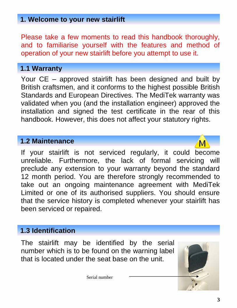
Please take a few moments to read this handbook thoroughly, and to familiarise yourself with the features and method of operation of your new stairlift before you attempt to use it.
Your CE – approved stairlift has been designed and built by British craftsmen, and it conforms to the highest possible British Standards and European Directives. The MediTek warranty was validated when you (and the installation engineer) approved the installation and signed the test certificate in the rear of this handbook. However, this does not affect your statutory rights.
If your stairlift is not serviced regularly, it could become unreliable. Furthermore, the lack of formal servicing will preclude any extension to your warranty beyond the standard 12 month period. You are therefore strongly recommended to take out an ongoing maintenance agreement with MediTek Limited or one of its authorised suppliers. You should ensure that the service history is completed whenever your stairlift has been serviced or repaired.
The stairlift may be identified by the serial number which is to be found on the warning label that is located under the seat base on the unit.
1. Welcome to your new stairlift
1.1 Warranty
1.2 Maintenance
1.3 Identification
Serial number

4
A list of suppliers of MediTek equipment who are also authorised to carry out formal servicing is available upon request from MediTek Limited. For convenience please enter the details of your supplier here: - Name …………………………………………… Address …………………………………………… …………………………………………… …………………………………………… Tel: ……………………………………………
Thank you for choosing
1.4 Suppliers

5
Standard MediTek Stairlift
2. Products covered in this handbook
Auto & Manual hinged rails

6
The key operating features of the MediTek range of stairlifts are shown in the photograph below. You should study this picture carefully and familiarise yourself with all the features before attempting to use the stairlift.
3. Key Features
Toggle Switch
Key Switch
Seat Swivel
Lever
Rail
Pressure
sensitive
cover
Folding
Footrest
Pressure
sensitive
edges
Folding
Armrests
Folding/
Swivelling
Seat
Pressure
sensitive
edge

7
There are two main controls which enable you to operate safely any of the MediTek range of stairlifts. These are the rocker switch and key switch which is used to control power to the stairlift, and the toggle switch which is used to control its movements on the stairs. Power to your stairlift is controlled by means of the rocker switch which is mounted on the front of the stairlift. This switch must be set to the on position (green) before attempting to operate the stairlift. You can prevent inadvertent use of the stairlift by switching the key switch to the off position.
The toggle switch provides one method of controlling the movement of your stairlift; the second is based upon a remote operated Infra-Red hand controller. The mechanical toggle switch is located at the end of one of the arm rests to control the movement of the
stairlift when you are safely seated; it is spring loaded to the centre position. Moving the toggle gently in the direction you wish to travel will cause the stairlift to go in that direction after a delay of half a second.
4. Stairlift Operation
4.1 Rocker Switch / Key Switch
4.2 Toggle Switch

8
The keyswitch allows you to disable operation of the stairlift. When the keyswitch is turned off, the lift will not respond to movement calls from the toggle or remote handset. The arm interlock device is present on the DOWN side of your stairlift. This device will prevent the lift from moving via calls from the toggle switch when the arm is raised. Please note that the lift will operate as normal when using the remote handset in this state. The 2 second safety delay between operating the toggle switch and the stairlift activating prevents sudden or inadvertent stairlift operation. A seat swivel lever is located to the side of seat base to suit customer preference. When pulled up, the lever unlocks the seat, allowing free rotation. This can be used at the top of the stairs to allow easier access to and from the landing. Always ensure that the seat is facing forward and the handle is fully locked down and engaged in its locked position before attempting to operate the stairlift. This action will ensure the seat interlock safety switch is activated, allowing the stairlift to move.
4.3 Safety Delay
4.4 Manual Seat Swivel Lever
Swivel Lever
4.2.1 Keyswitch
4.2.2 Arm Interlock

9
The powered swivel seat will only operate when the stairlift reaches the top of the stairs. When the stairlift completes its travel, release the toggle switch (or remote control) wait for 1 second and then operate the lift in the up direction again – the powered seat mechanism will then operate, turning the seat through 80 degrees. To return the seat to the forward position, operate the lift in the down direction, the seat will the move back to the forward position – again, release the toggle (or remote control) and then operate the lift in the down direction – The lift will now descend the stairs. The MediTek stairlift is powered by two 12 volt, 7 Amp/hour sealed batteries which require no periodic maintenance. They are continuously charged whenever the wall-mounted charger unit is connected to a domestic AC mains power supply outlet which is switched on. The wall mounted transformer has no controls but does have a green indicator light on its front panel to signify that power is being received from the mains supply. (If this light should be off then check the mains supply to the stairlift)
4.5 Powered Swivel Seat (optional)
5. Electrical Operation
5.1 Wall Mounted Charger/Transformer Unit

10
If the mains supply is inadvertently switched OFF then the stairlift will beep for 20-30 seconds to signify that no power is being received from the transformer. Each time you operate the stairlift in this state the 20-30 second warning beep will re-occur until power is resumed. It will also show a letter ‘C’ on the stairlift display as shown below. Please note that this situation could arise when the stairlift is off the charging strips when at the bottom of the rail with a hinge option. The stairlift may be operated safely when the batteries are being charged NOTE: Should you suffer a temporary loss of AC power (e.g. a power cut), your stairlift will continue to operate allowing you to complete many journeys up and down the staircase. If the AC mains supply to the charger unit is inadvertently switched off, a buzzer inside the stairlift will sound with an intermittent tone for 20-30 seconds (as described in section 5.1) If the charger is not reconnected to the supply, the battery level will eventually be reduced to a point where a long tone will sound each time the stairlift is operated.
5.2 AC Mains Power Failure
If you see this ‘C’ on the display then
the lift is not receiving AC power
from the domestic supply – check the
mains supply to make sure it is
switched ON

11
The stairlift will continue to operate for some time without the charger unit running. However if it is not switched back on, a point will be reached when the battery level is no longer sufficient to safely operate the stairlift. When this occurs the lift will complete its current operation at half speed and then shut down until the batteries are automatically recharged. The display will show the letter ‘r’ (for recharge) as shown: - When in the shutdown state, the stairlift buzzer will sound whenever an attempt is made to operate the stairlift. Further discharge could damage the batteries and prevent their recovery. In this event, correct replacement batteries will need to be fitted through MediTek Limited or one of its authorised service centres Should you suffer a complete loss of AC mains supply (e.g. a power cut), your stairlift will continue to operate, and will allow you to complete many journeys up and down your staircase. When leaving the house for lengthy periods of time (i.e. holidays etc), power to the stairlift must be left switched ON, but the rocker switch may be turned to the off position.
5.3 Extended Periods of Absence
If you see this letter ‘r’ on the
display it means that the stairlift
needs to be re-charged. Leave the
lift parked until this letter ‘r’ goes
off.
12
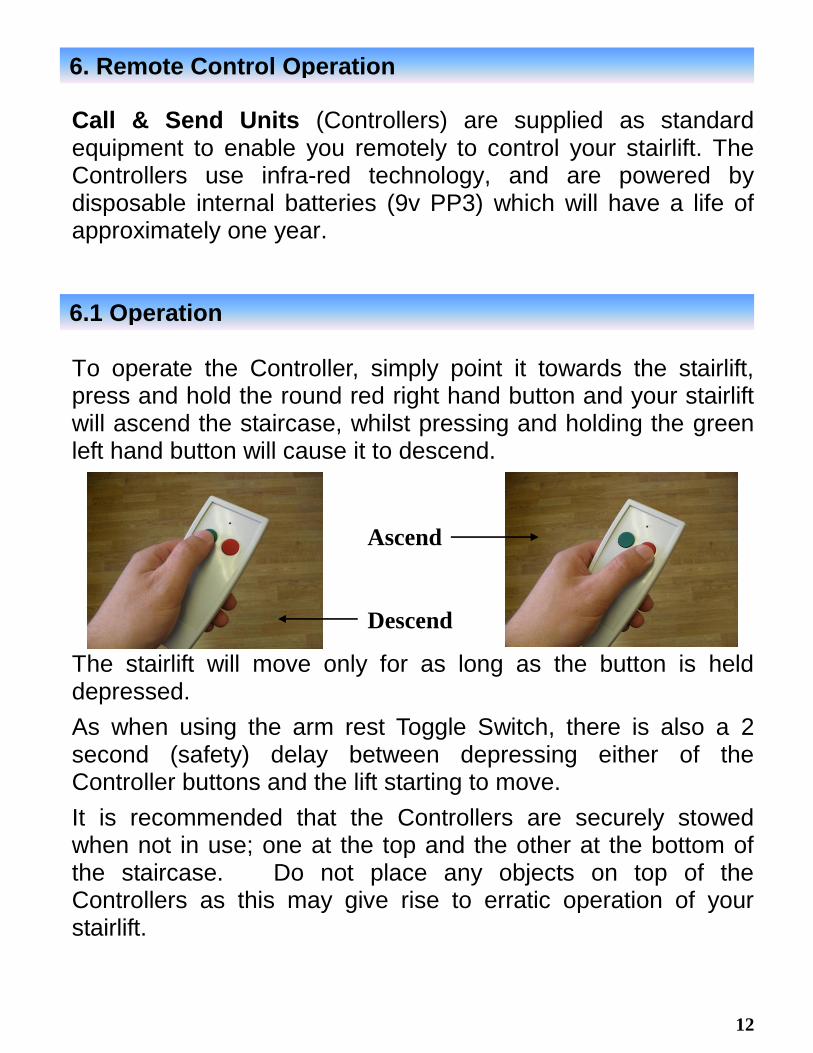
Call & Send Units (Controllers) are supplied as standard equipment to enable you remotely to control your stairlift. The Controllers use infra-red technology, and are powered by disposable internal batteries (9v PP3) which will have a life of approximately one year. To operate the Controller, simply point it towards the stairlift, press and hold the round red right hand button and your stairlift will ascend the staircase, whilst pressing and holding the green left hand button will cause it to descend.
The stairlift will move only for as long as the button is held depressed.
As when using the arm rest Toggle Switch, there is also a 2 second (safety) delay between depressing either of the Controller buttons and the lift starting to move.
It is recommended that the Controllers are securely stowed when not in use; one at the top and the other at the bottom of the staircase. Do not place any objects on top of the Controllers as this may give rise to erratic operation of your stairlift.
6. Remote Control Operation
6.1 Operation
Ascend
Descend

13
Batteries should be replaced regularly at intervals of approximately one year. It may be found useful if you make a written note on the Controller(s) of the date on which the batteries are changed.
Access is gained to the handset battery compartment by removing the plastic cover at the lower, rear of the Unit. The batteries are removed by pulling free from the connectors and withdrawing from the remote unit. To fit the new batteries, follow the reverse procedure.
NOTE: Make sure you check the polarity of the battery, this is identified inside the remote housing with a + or -, these symbols can also be found on the battery. You will need to match + to + and – to –
6.2 Remote Control Battery Replacement
Remote Control Battery Replacement

14
The seat, footrest and arm rests of your stairlift may be folded up when not in use to allow maximum access to the staircase. Before using your stairlift, these items must be folded down to their normal operating positions. For improved safety, the stairlift is fitted with a unique pressure-sensitive carriage cover and footrest. Always check that the staircase is clear of obstructions before attempting to use the stairlift. If the stairlift comes into contact with any obstructions, the pressure-sensitive edges will cause the stairlift to stop immediately. The stairlift can be reversed away from the obstruction by releasing the Toggle Switch (or the Controller button) and operating the stairlift in the opposite direction. The obstruction may then be safely removed.
7. Using Your MediTek Stairlift
7.1 Obstructions

15
If a manual swivelling seat has been supplied, the Seat Swivel Lever should be raised to unlock the seat assembly, enabling you to rotate the seat as required to make it easier to mount (and dismount) the stairlift.
Warning: - Always ensure that the lever is locked into position before attempting to mount (dismount) the stairlift.
When comfortably seated at the top of the stairs, raise the Seat Swivel Lever again and rotate the seat to its original (locked) position with the seat at right angles to the stairlift track. Release the lever and make sure that it is firmly locked down into position.
Remember, you will not be able to operate the stairlift until the seat is locked into the correct position
It is recommended that the Seat Belt be used at all times, and that Users should be supervised where the degree of infirmity makes this desirable. The Seat Belt may be adjusted as required to fit the User. To fasten the belt, sit well back in the seat, pull the belt across your lap and snap the clip into place.
7.2 Mounting the Stairlift
7.3 Seatbelt

16
Where there is a possibility of the stairlift rail causing an obstruction at the foot of the stairs, the final section of the track may be hinged so that it can be lifted vertically, as shown. This section of the track may be moved manually or automatically by low voltage power.
In the case of the manually hinged section of the track, simply grasp the end of the track and pull it forwards and down, allowing it to fall gently under the control of the inbuilt damper assembly. Check that the top of the hinged section is flush with the top of the track before attempting to operate the stairlift. To fold up the track, gently lift up the hinged section until it is locked in position vertical to the track assembly.
The folding hinge track will operate automatically as the stairlift ascends or descends the stairs. For your safety, it is prevented from beginning its descent by an electrical interlock that ensures that the track is fully down and locked before allowing the stairlift to move down. When ascending, the track will fold up automatically behind the stairlift as it moves up the stairs. Should an obstacle impede
8. Using the Hinged Track (optional)
8.1 Manual Operation
8.2 Automatic Operation

17
the operation of the folding mechanism, an electronic clutch will prevent excessive force from being exerted for a period of 20 seconds, after which time the drive to the folding mechanism will be disengaged. If the stairlift is ascending at the time that the obstruction occurs, it will continue its travel to the top. However, if the stairlift is at the head of the stairs in preparation for a descent, it will not move until the obstruction is removed and the hinge is fully lowered. In the event that damage results from the obstruction and the folding hinge track will not operate, a manual override facility is available. Override Facility
If for some reason the automatic folding hinge track should fail to open (or close), then an override facility is available so that the hinge may be moved manually. Located on the top face of the rail above the hinge top edge in a small oval slot is a spring
loaded pin, this is the mechanical override. Depress this pin (screw driver) and whilst maintaining pressure raise or lower the hinge manually. Each time the hinge is opened or closed this pin will need to be operated. This is a temporary solution and your local distributor MUST be called to rectify the fault.

18
When not in use, the platform should normally be left folded against the wall leaving the stairway clear, especially if other occupants regularly use the staircase. The platform must be placed fully down before attempting to use the stairlift. As with the Hinged Track, the Platform may be controlled either manually or automatically.
The platform is counter-balanced and can be lowered or raised easily by hand. No additional restraints are required in either the raised or lowered positions as these will have been set by the installation engineer.
The powered platform is controlled automatically, with this feature the platform raises and lowers automatically in conjunction with stairlift travel.
9.1 Manual Operation
9.2 Automatic Operation
9. Using the Platform (optional)

19
The seat/footrest linkage is a simple device to operate. When lifting the seat, the footrest will also lift, and when lowering the seat the footrest will also lower.
1. Lift the seat base to raise the footrest 2. Lower the seat base to lower the footrest
Note: - Do NOT lift the seat base whilst there is weight applied to the footrest, this may damage your stairlift.
10. Linked Seat to Footrest Operation (optional)
Seat Base

20
Your MediTek
stairlift has many built-in safety features which
are designed to prevent accidents due to mechanical failure or misuse. However, it is essential that YOU, the User, should be familiar with all of the features of the stairlift and its operation to prevent problems arising through error.
Children should NEVER be allowed to play with the stairlift; joyriding is dangerous and can lead to serious injury. If this situation is likely to arise, you should switch-off the stairlift. Where fitted, the bottom hinged section of the track assembly could prove to be potentially hazardous to children if they are allowed to play on, or close to it.
The
stairlift is designed to carry one person only within the
maximum load specified for the type of stairlift supplied, rated for stairs with a gradient of 50º.
Users should be supervised wherever possible, and when the degree of infirmity makes this necessary.
11. Safety
11.1 Children
11.2 Carrying Capacity
11.3 Supervision

21
The stairlift has been designed so that day-to-day cleaning or routine maintenance is unnecessary. However, the seat fabric and the rail surface may be cleaned with a damp cloth containing mild detergent every two weeks or so. Another good idea is to clean the surface of the aluminium rail once a month with a wax based furniture polish, this will eliminate the build up of black marks on the track and will also make the travel up and down smoother and will stop any squeaks that the rollers may develop.
MediTek Limited warrants parts and labour against defects and workmanship for purchases made directly by an End User, and parts only to its authorised Distributors who will undertake replacement at their own cost for a period of 12 months from date of acceptance following installation. The warranty does not cover normal wear and tear, or parts or product failure caused by accident or customer abuse. For distribution sales, please contact your authorised MediTek Distributor (information on which can be found inside the back cover of this handbook)
12. Cleaning Your Stairlift
13. Limited Warranty

22
If your stairlift fails to operate correctly, you are asked to carry-out the following checks BEFORE calling your Supplier. This may save you time, money and general inconvenience.
1. Check that the wall-mounted Charger Unit is connected to the AC mains and switched ON (see page 8).
2. Ensure that the Rocker Switch on the chassis is turned to
‘ON’, with the GREEN flash showing.
3. Check that the swivel seat (if fitted) is facing directly across the stairway at right angles to the track assembly, and that the Seat Swivel Lever is in the locked position (Down).
4. Check that there are no obstructions in the way of the
Pressure-sensitive Edges on the carriage or footrest assemblies.
a. Lift the footrest to make sure that there is nothing underneath and that there are no signs of obvious damage.
b. Press and release the carriage Pressure-sensitive
Cover in both directions. A ‘click’ may be heard as the switch operates.
c. Push in and release all of the footrest Pressure-
sensitive Edges
14. Fault Finding

23
d. Gently squeeze and release the footrest ‘under tray’
checking that the bottom pressure sensitive pad operates.
5. If the stairlift buzzer sounds each time the Toggle Switch
or Call & Send Unit is operated (intermittent tone), the batteries have been discharged to an unacceptable level. In this event, check that the AC mains supply to the Charger Unit is switched ON and that its green supply indicator is ON. If the AC mains supply is switched OFF, then switch ON immediately and leave the batteries to recharge for at least 1 hour before attempting to use the stairlift.
6. If the buzzer in the stairlift sounds (continuous) whenever
the toggle Switch or Call Unit is operated, the batteries are almost totally discharged. This will prevent operation of your stairlift until the batteries are recharged. Switch the AC mains supply to the Charger Unit ON immediately and leave the batteries to recharge for at least 1 hour before attempting to use the stairlift. If the display still shows an ‘r’ after 12 hours contact your supplier because the batteries may have been damaged.
7. If the stairlift fails to respond to one or other of the Call &
Send Units, check the handset battery and replace if necessary.
8. If the rail has a platform and/or hinged track section,
ensure that both are fully DOWN. If the stairlift still fails to operate correctly, contact your Supplier

24
15. Contact information
MediTek Ltd (UK)
Fishburn Industrial Estate
Fishburn
County Durham
TS21 4AJ
MANUFACTURING / HEAD OFFICE
Tel: 01740 623823
Fax: 01740 623923
Email:
INSTALLER INFORMATION:

25
The stairlift uses two batteries which are connected together to give the required operating voltage and current. They are completely sealed and must not be removed or tampered with in any way. Satisfactory operation of your MediTek stairlift is heavily dependent upon the rechargeable batteries that are used for its power. The batteries have been designed to be continuously ‘trickle-charged’ at a predetermined rate set by the charger circuit. In order that charging takes place, it is essential that the associated wall-mounted Charger Unit is permanently connected to the AC mains and is left switched ON. Whenever the Charger circuit senses that the batteries need additional ‘topping up’, e.g. following a period of extended use of the stairlift, the charging rate will increase automatically to return the batteries to their original fully-charged state. When the Key Switch on the arm-rest of the stairlift is selected to ‘ON’, a very small electrical current is drawn from the batteries, even when the stairlift is not being used. Therefore, you must always ensure that the AC mains to the Charger Unit remains switched ON to prevent the batteries from ever becoming discharged.
16. Battery Care
16.1 Battery Charging

26
Battery care (continued) If the AC mains supply to the Charger Unit is disconnected, the Charger Unit’s Green status indicator will go out and the stairlifts internal buzzer will sound beep for 30 seconds. Should the battery capacity fall below its normal operating level, a warning buzzer in the stairlift will sound every time an attempt is made to operate the stairlift. If the AC mains supply remains switched OFF, causing the battery to fall further to an unacceptable level, the stairlift will stop running when it reaches the end of its travel. The buzzer will sound if any further attempt is made to use the stairlift. In this event, the AC mains supply must be switched ON as soon as possible, and the stairlift not used until the batteries are recharged. The stairlift will remain inoperative until the fault has been cleared and the batteries have been brought up to an acceptable level of charge. For more information see pages 9, 10 & 11 IF THE STAIRLIFT STARTS TO OPERATE AT SLOW SPEED WITH THE MAINS SUPPLY ON, CONTACT YOUR SUPPLIER

27
A seven-segment display is incorporated into the stairlift to assist in fault diagnosis. It is located on the top side (up) of the stairlift main cover.
DISPLAY DIAGNOSIS REASON
Final limit switch open circuit
Seat not in travel position or Lift has activated final limit
switch or over speed cam has activated or green on/off switch on chassis is in the off position
Lower limit open circuit Check lower roller switch
Bottom / Lower footrest open circuit
Check lower footrest tray switch
Upper limit open circuit Check upper roller switch
Top / Upper footrest open circuit
Check footrest upper switch
Bottom / Lower carriage safety switch open circuit
Check lower pressure sensitive cover switch
Top / Upper carriage safety switch open circuit
Check upper pressure sensitive cover switch
17. Controller Diagnostic (7 segment) Display

28
Ancillaries
Power platform time out Has been running for 20
seconds and has not completed operation
Power platform open circuit Cable to platform is open circuit
or fault platform actuator
Automatic folding hinge track time out
Has been running for 20 seconds and has not completed
operation
Automatic folding hinge track open circuit
Cable to automatic hinge is open circuit or faulty actuator
Power swivel seat time out Has been running for 20
seconds and has not completed operation
Power swivel seat open circuit Cable to power swivel is open
circuit or faulty actuator
Brake failure Brake solenoid open circuit
Over temperature Lift is over temperature. Leave
for ten minutes
29
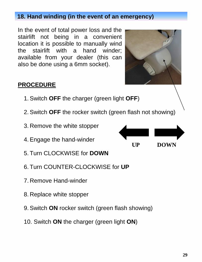
In the event of total power loss and the stairlift not being in a convenient location it is possible to manually wind the stairlift with a hand winder; available from your dealer (this can also be done using a 6mm socket). PROCEDURE
1. Switch OFF the charger (green light OFF)
2. Switch OFF the rocker switch (green flash not showing)
3. Remove the white stopper
4. Engage the hand-winder
5. Turn CLOCKWISE for DOWN
6. Turn COUNTER-CLOCKWISE for UP
7. Remove Hand-winder
8. Replace white stopper
9. Switch ON rocker switch (green flash showing)
10. Switch ON the charger (green light ON)
18. Hand winding (in the event of an emergency)
UP DOWN

30
A reset switch is available if the need arises for your stairlift to be reset. There is a set procedure to resetting your lift, this is detailed below.
1. Turn OFF the reset switch (green flash not showing)
2. Activate your stairlift toggle control (or remote handset) in either direction
3. Turn the reset switch back ON (green flash showing)
Your stairlift should now function correctly.
19. Stairlift Reset
Reset switch

31
Service Number Date Completed By
20. Service History
32
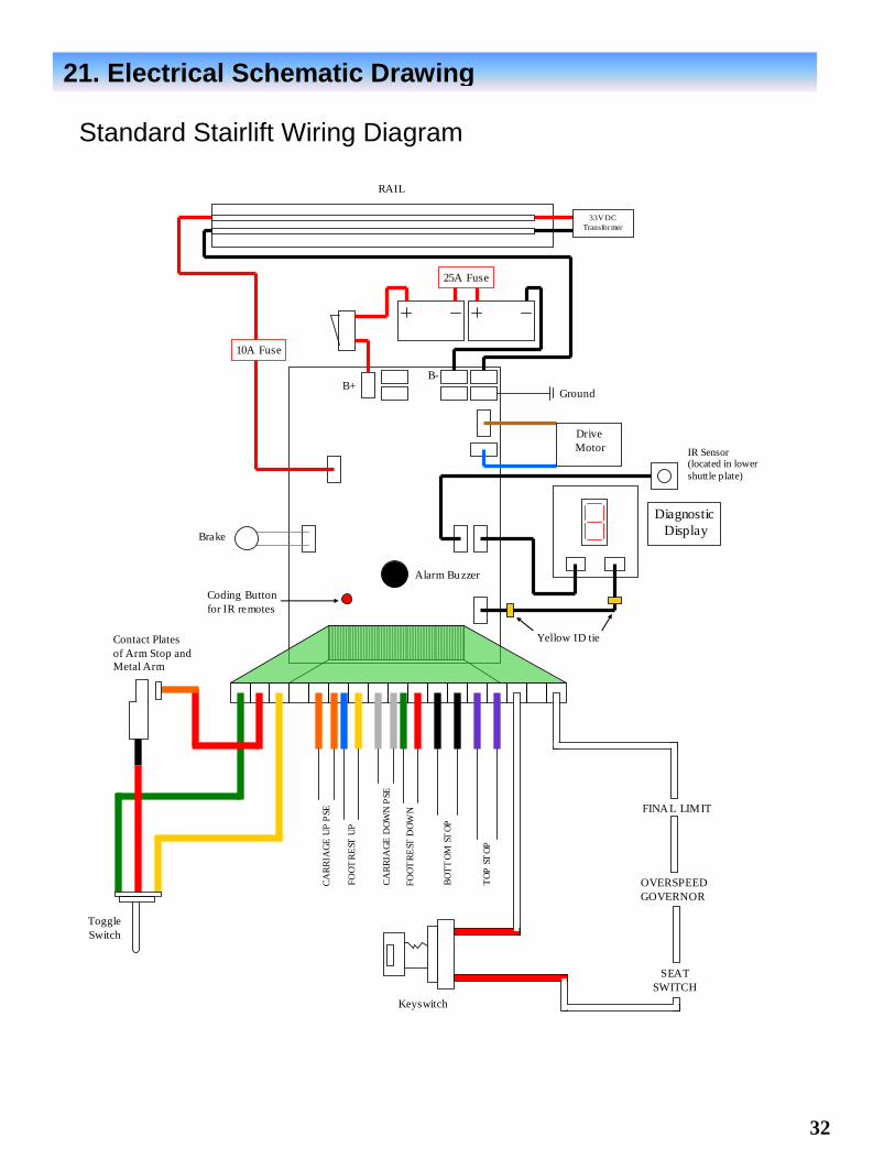
Standard Stairlift Wiring Diagram
21. Electrical Schematic Drawing
Alarm Buzzer
Drive
Motor
Diagnostic
Display
Yellow ID tie
IR Sensor (located in lower
shuttle plate)
Ground
25A Fuse
Brake
10A Fuse
Coding Button
for IR remotes
33V DC
Transformer
B+ B-
RAIL
Contact Plates
of Arm Stop and
Metal Arm
Toggle
Switch
CA
RR
IAG
E U
P P
SE
FO
OT
RE
ST U
P
CA
RR
IAG
E D
OW
N P
SE
FO
OT
RE
ST D
OW
N
BO
TT
OM
ST
OP
TO
P S
TO
P
FINA L LIMIT
OVERSPEED
GOVERNOR
SEAT
SWITCH
Keyswitch

33
Footrest Wiring Diagram LH

34
Footrest Wiring Diagram RH