Embed Size (px)
Citation preview
i
TABLE OF CONTENTS
General Release ................. 1-4
Historical Background of ASTP .......... 5-6 ASTP Yission Objectives ............. 7-9
Countdown and Liftoff ...... ., ....... 10
Saturn IB/Apollo. ................ 11-12
Launch Phase. .................. 12
Launch Windows. ................. 13-14 Mission Profile ................. 15-19
ASTP Mission Events ............... 20-23
Crew Transfers. ................. 24-25 ASTP Experiments. ................ 26-49
oh&
MA:088 MA-148 MA-151 MA-059 MA-007 ~~-136 MA-089 MA-128 ~~-106 MA-107 MA-147 AR-002 MA-031 MA-032 MA-011
MA-014 MA-010
MA-041 MA-044 ~~-060
E-2; rail31 MA-150 mb-028
Soft X-Ray. .... ..............
29-30 Extreme Ultraviolet Survey. 30 Helium Glow ...... .- ...... 30 Artificial Solar Eclipse. ...... 30-32 Crystal Activation.
................ 32
Ultraviolet Absorption. 32-3 4. Stratospheric Aerosol Measurement 35 Earth Observations and Photography. 35-36 Doppler Tracking. Geodynamics
.............................................
36-37
.... ..........
...... ......
38-39 Light Flash 39-41 Biostack. 39-4-l Zone Forming Fungi. 39-41 Microbial Exchange. 41 Cellular Immune Response. . ..... 41 Polymorphonuclear Leukocyte Response. 41 Electrophoresis Technology
Experiment System ...............
41-43 Electrophoresis -- German 43-44 Multipurpose Electric Furnace
Experiment System
.. ... ... ... ... ......................
45-46 Surface-Tension-Induced Convection. 46 Monotectic and Syntectic Alloys 46-47 Interface Marking in Crystals 47 Processing of Magnets Crystal Growth from the Vapor Phase
iz-48
Halide Eutectics. . 48-49 U.S.S.R. Multiple Material Melting. 49 Crystal Growth. ........... 49
Crew Training . . . . . . . . . . . . s . . . . . 50-51
i
_, --
Crew Equipment .................. 52-53 Survival Kit. ................ 52 Medical Kits. ................ 52 Space Suits ................. 52-53 Personal Hygiene. .............. 53
Apollo Menu. ................... 54-58 Menu of Thomas P. Stafford. ......... 55 Menu of Vance D. Brand. ........... 56 Menu of Donald K. Slayton .......... 57
Apollo Crew Biographies. ............. 59-66 Biography of Thomas P. Stafford ....... 59-61 Biography of Vance DeVoe Brand. ....... 62-63 Biography of Donald K. Slayton. ....... 64-66
Apollo Spacecraft. ................ 67-79 Command/Service Module. ........... 67-75 Docking Module. ............... 76-79
Saturn IB Launch Vehicle ............. 80-86 Saturn IB Launches. ............. 80-82 Vehicle Description ............. 82-84 Vehicle Concept ............... 84 Development Highlights. ........... 84-85 History of the ASTP Launch Vehicle. ..... 85-86
Tracking and Communications. ........... 87-96 Network Operations. ............. 92-94 Communications. ............... 94 Satellite Support .............. 94-95 Ship Support. ................ 95 Range Instrumented Aircraft ......... 95-96 Onboard Television Distribution ....... 96
Photography and Television ............ 97
Hardware Preparation ............... 98-99
Launch Preparation -- Sequences and Constraints. . loo-103
Launch Complex 39. ................ 104-108 The Vehicle Assembly Building ........ 104 The Launch Control Center .......... 105 The Mobile Launcher ............. 105 The Transporters. .............. 105 The Crawlerway. ............... 105 The Mobile Service Structure. ........ 106 Water Deluge System ............. 106 Flame Deflector ............... 106 Pad Areas .................. 106 ASTP-Related Modifications. ......... 106-108
ii
Program Management . ...... NASA Headquarters.
ILL;-111
Johnson Space Center ..
.......................................................................
110 Kennedy Space Center 110 Marshall Space Flight Center 110 Goddard Space Flight Center. 111 Department of Defense. 111
ASTP Major Contractors .............. 112
Conversion Table ................. 113
iii
.
TABLES AND ILLUSTRATIONS
ASTP Mission Profile ................ 7 ASTP Mission Sequence. ............... 8
Launch Window. ................... 14
Rendezvous Sequence. ................ 16 Entry Ground Trace for an SPS Deorbit Maneuver ... 19
ASTP Mission Events. ................ 20-23
First Transfer Operations. ............. 25
Experiments and ATS-6 Location Schematic ...... 27
ASTP Experiments CM Configuration. ......... 28
MA-148 Artificial Solar Eclipse. .......... 31
MA-059 WA Experiment (Earth Atmosphere) ...... 33
MA-059 WA Experiment (Spacecraft Atmosphere). ... 3 4.
MA-089 Doppler Tracking. .............. 37
MA-128 Geodynamics ................. 38 1~1-106 Light Flash ................. 40
MA-011 Electrophoresis Technology. ......... 42
MA-014 Electrophoresis ............... 44
Thomas P. Stafford Menu. .............. 55 Vance D. Brand Menu. ................ 56 Donald K. Slayton Menu ............... 57 Apollo Command and Service Modules ......... 68 Apollo-Soyuz Rendezvous and Docking Test Project . . 69 Apollo Spacecraft Configuration (side and front) . . 70 Apollo Spacecraft Configuration (top and front). .. 71
Major ASTP Modifications to CSM 111. ........ 72
Command Module Compartment Orientation ....... 73
CM General Arrangement ............... 74 ASTP Docking Module. ................ 77 Typical Docking System Major Components. ...... 78
Launch Configuration ................ 81
Launch Configuration for the Apollo CSM and DM ... 83
STDN Support for Apollo-Soyuz. ........... 88
iv
Apollo Soyuz Communication Overview ......... 90
ASTP ATS-Communications Coverage. .......... 91
Ground Support Instrumentation Summary. ....... 93
Lightning Mast Installation ............. 107
‘T
FOREWORD
This document contains information about the Apollo
Soyuz Test Project and consists of two parts prepared by the
U.S. and the U.S.S.R. respectively.
Each part contains information on the goals and on
the program of the mission, features and characteristics of
the spaceships, a flight plan and joint and unilateral experi-
ments. Brief biographies of the astronauts and cosmonauts
involved in the flight, a description of technical support
activities, also a description of the flight management per-
sonnel of each side are included.
The Soviet and American parts have been prepared indi-
vidually. For this reason certain sections pertaining to
joint activities may repeat the same information.
This document is intended for distribution to repre-
sentatives of the press and other mass media.
vii
WEANew NatIonal Aeronautics and Space Admintstratlon
WashIngton. D.C 20546 AC 202 755-8370
Terry White For Release: (Ph one: 713/483-5111) June 10, 1975
Bill O'Donnell (Ph one: 202/755-2354)
RELEASE NO: 75-118
COSMONAUTS, ASTRONAUTS TO MEET IN SPACE
Two manned spacecraft will be launched into Earth orbit
July 15 -- one from Merritt Island, Florida, and the other
from Central Asia -- to bring into reality the May 1972 agree-
ment between the United States and the Soviet Union to work
toward a common docking system for future generations of
spacecraft.
The nine-day Apollo Soyuz Test Project mission will mark the
first time that manned spacecraft of two nations have met in
space for joint engineering and scientific investigations.
- more -
‘T
2
First to go into space will be the Soviet Union's Soyuz
spacecraft with Commander Aleksey Leonov and Flight Engineer
Valeriy Kubasov aboard, lifting off at 8:20 am Eastern Day-
light Time July 15 from the Soviet Cosmodrome at Baykonur.
Seven and a half hours later, at 3:50 pm Eastern Daylight
Time, Apollo will lift off from Kennedy Space Center Launch
Complex 39B with Commander Thomas P. Stafford, Command Module
Pilot Vance Brand and Docking Module Pilot Donald K. Slayton
aboard.
Control Centers in Houston and Moscow will exercise
joint ground control over the mission through exchange of
communications and tracking data as a further means of ful-
filling the agreement on space cooperation.
Communications between the Apollo spacecraft and Mission
Control-Houston and between the docked Apollo Soyuz spacecraft
and both control centers will be enhanced by use of a communi-
cations satellite for real-time relay of voice, data and tele-
vision signals. Applications Technology Satellite 6 ('ATS-6),
in synchronous orbit 35,900 km (22,260 mi.) above Kenya, will
provide communications coverage for 55 percent of each Apollo
and docked Apollo Soyuz orbit through Apollo% steerable high-
gain antenna. This will be the first time a satellite is used
to relay communications between an orbiting manned spacecraft
and ground stations. Both live and recorded color television
will be relayed from Apollo to keep flight control teams and
the general public informed on mission activities.
- more -
3
The primary ASTP engineering objective is to develop a
universal docking system suitable for future joint activities
by manned spacecraft of different countries. Operational
aspects of docked spacecraft attitude control, inter-space-
craft communications and ground-control coordination also
will be studied during the flight.
Scientific investigations to be performed during the
flight fall into three general categories: space sciences,
life sciences and applications.
Flight crews of both nations have received extensive
training in the language of the other crew. During joint
mission periods, the American crew will communicate with
their Soviet counterparts in Russian, and the cosmonauts
will reply in English. Crew members will communicate with
their respective control centers in their native tongues.
Apollo Commander Thomas P. Stafford has spent 290 hours,
15 minutes in space aboard Gemini 6 and 9, and Apollo 10 and
has achieved five rendezvous. It is the first space flight
'for Slayton and Brand.
Soyuz Commander Leonov flew in Voskhod 2 March 18, 1965
and was the first person to perform a space walk. Kubasov
flew on Soyuz 6 October 11-16, 1969.
- more -
4
Apollo will rendezvous with Soyuz July 17 and docking
will take place about 12:15 pm Eastern Daylight Time above
Germany. During two days of docked operations, the crews
will visit each others' spacecraft in four different trans-
fers through the docking module. They also will perform
joint scientific experiments and share meals.
The two spacecraft will separate for the final time at
aboutll:Ol am Eastern Daylight Time July 19. Soyuz will deorbit
at 6:06 am Eastern Daylight Time and land in the Soviet recovery
area at 6:51 am Eastern Daylight Time July 21 -- some 42 hours
after Apollo's "I& svedanya" (Good bye).
Following a deorbit maneuver over the Indian Ocean,
the Apollo command module will splash down at 5:18 pm Eastern
Daylight Time July 24 in the Pacific Ocean 555 kilometers
(345 miles) west of Hawaii. Recovery Ship is the U.S.S. New
Orleans, a helicopter carrier.
(END OF GENERAL RELEASE; BACKGROUND INFORMATION FOLLOWS)
- more -
5
HISTORICAL BACKGROUND OF ASTP
Talks between Soviet Academician Anatoliy A. Blagonravov, and the late Dr. Hugh L. Dryden, Deputy Administrator of NASA, resulted in a three-part, bi-lateral space agreement drawn up in June 1962 which provided for:
--
--
--
Coordinated U.S. and Soviet launchings of experimental meteorological satellites, with data to be exchanged over a Washington-Moscow "cold-line";
Launchings by both countries of satellites equipped with absolute magnetometers, with subsequent exchange of data to arrive at a map of the Earth's magnetic field in space;
Joint communications experiments using Echo 2, the U.S. passive satellite.
The Dryden-Blagonravov talks led to a second agreement in November 1965, for the preparation and publication of a 'oint t
U.S.-Soviet review of space biology and medicine. This study has been completed and is in the printing
stages.)
In 1969, NASA Administrator Dr. Thomas 0. Paine wrote to Soviet Academy President M. V. Keldysh and Academician Blagonravov, inviting new initiatives in space cooperation, in general scientific fields, and in rendezvous and docking of manned spacecraft.
In October 1970 talks related to the possibility of the U.S. and U.S.S.R. each designing a manned spacecraft with a compatible docking mechanism were held in Moscow. These discussions were resumed in January 1971. Later , joint work- ing groups were established and technical understandings required for design of these systems were developed. In April 1972, the necessary management and operational under- standings were established to warrant a government-level agreement to a joint test docking mission.
Broader discussions on cooperation in space science and applications took place in January 1971 in Moscow. As a result of these talks, an agreement was reached which provided for:
-- Exchange of lunar samples obtained in Apollo and Luna programs;
-- Exchange of weather satellite data between the United States National Oceanic and Atmospheric Administration (NOAA) and the Soviet Hydrometeorological Service;
- more -
-a
--
--
--
b
Coordination of networks of meteorological rocket sounding along selected meridianal lines;
Development of a coordinated program to utilize space and Earth resources survey techniques to inves- tigate the natural environment in areas of common interest;
Joint consideration of the most important scientific objectives for exchange of results from investigation of near-Earth space, the Moon, and the planets; and
Exchange of detailed medical information of man's reaction to the space environment.
ASTP was formally provided for in the U.S.-U.S.S.R. Agreement Concerning Cooperation in the Exploration and Use of Outer Space signed by President Richard Nixon and Soviet Chairman Aleksey Kosygin in Moscow May 24, 1972. This agreement also pledged both countries to fulfill the NASA- Soviet Academy of Sciences agreement of January 1971.
- more -
3KCllEPkiMEHTAJIbHbIFi I-IPOEKT "AllOJISOH-COD3"
~PO'Z+iJIh IIOJIETA
APOLLO SOYUZ TEST PROJECT MISSION PROFILE
E!kJBOll HA OPMTY "COI03A"
BbIBOll HA OPISiTY
"Al-IOJLJIOHA"
OKOH~ATEJTbHOE
CTbIKOBO~HbIE PACXOHUIEHME
MCI-NTAHWI CTbIKOBKA INSERTION
APOLLO DEoR6IT cxon c 0PEM-m
KOPAWI " AIIOJIJIOH"
"AI'IOJIJIOHA"
COCTORHMM cxon c 0Pmrb1
KOPA6JIR "COK)3"
CTAPT KOPAEJM 'AIIOJIJIOH"
SOYUZ LAUNCH CTAPT KOPAUIR "COi03"
THXHII OKEAH
9
ASTP MISSION OBJECTIVES
A principal objective of the Apollo Soyuz Test Project is to test compatible rendezvous and docking systems being developed for future United States and Soviet manned space- craft and stations under the agreement on space cooperation signed in May 1972 by President Richard Nixon and Chairman Aleksey Kosygin.
The development of compatible rendezvous and docking systems will enhance the safety of manned flights in space and provide opportunity for conducting joint experiments in the future. The project's designs provide the basis for a standardized international system for rendezvous and docking by manned spacecraft.
In addition to the testing of the compatible docking system in orbit, the Apollo and Soyuz crews will practice docking and undocking and will conduct scientific experiments and engineering investigations. Flight control teams in the Mission Control Center at Houston and their counterparts in the USSR Center for Control of Flight at Kalinin, near Moscow, will gain experience in conducting joint flight operations.
Apollo and joint Apollo Soyuz experiments for the mission are MA-148 Artificial Solar Eclipse, MA-147, Zone Forming Fungi, AR-002 Microbial Exchange, MA-150 Multiple Material Melting, and MA-059 Ultraviolet Absorption.
One experiment, MA-014 Electrophoresis is a German experiment.
- more -
10
COUNTDOWN AND LIFTOFF
A government-industry team of about 500 people will conduct the countdown and launch of the Saturn IB/Apollo for ASTP at the Kennedy Space Center.
A team of approximately k4.0 people will conduct the launch of the Saturn IB/Apollo from the Launch Control Center's Firing Room 3. An additional 60 persons will control Apollo spacecraft aspects of the launch from the Manned Spacecraft Operations Building in the Kennedy Space Center Industrial Area.
Final precount activities for ASTP will begin three days before launch. Precount activities for ASTP include mechanical buildup of spacecraft components and servicing the spacecraft.
The final countdown for ASTP will begin at T minus 9 hours. Key activities in the countdown are listed below. The countdown is. synchronized with the Soviet preparations for the Soyuz launch from the Cosmodrome at Baykonur. An explanation of launch ffwindowst* and the sequences and con- straints involved in the dual countdown is to be found elsewhere in the press kit.
- more -
11
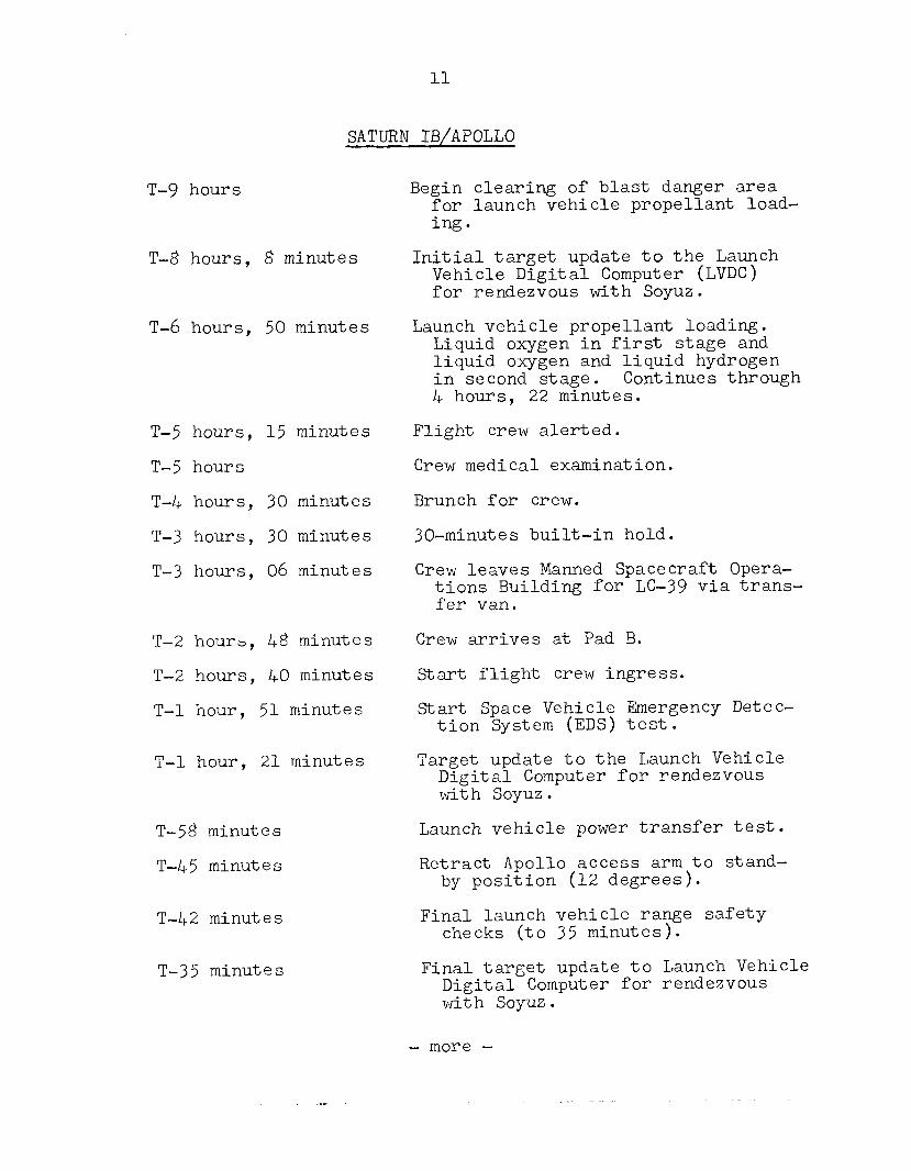
SATURN IB/APOLLO
T-9 hours
T-8 hours, 8 minutes
T-6 hours, 50 minutes
T-5 hours, 15 minutes
T-5 hours
T-4 hours, 30 minutes
T-3 hours, 30 minutes
T-3 hours, 06 minutes
T-2 hours, 48 minutes
T-2 hours, 40 minutes
T-l hour, 51 minutes
T-l hour, 21 minutes
T-58 minutes
T-45 minutes
T-42 minutes
T-35 minutes
Begin clearing of blast danger area for launch vehicle propellant load- ing.
Initial target update to the Launch Vehicle Digital Computer (LVDC) for rendezvous with Soyuz.
Launch vehicle propellant loading. Liquid oxygen in first stage and liquid oxygen and liquid hydrogen in second stage. Continues through 4 hours, 22 minutes.
Flight crew alerted.
Crew medical examination.
Brunch for crew.
30-minutes built-in hold.
Crew leaves Manned Spacecraft Opera- tions Building for LC-39 via trans- fer van.
Crew arrives at Pad B.
Start flight crew ingress.
Start Space Vehicle Emergency Detec- tion System (EDs) test.
Target update to the Launch Vehicle Digital Computer for rendezvous with Soyuz.
Launch vehicle power transfer test.
Retract Apollo access arm to stand- by position (12 degrees).
Final launch vehicle range safety checks (to 35 minutes).
Final target update to Launch Vehicle Digital Computer for rendezvous with Soyuz.
- more -
12
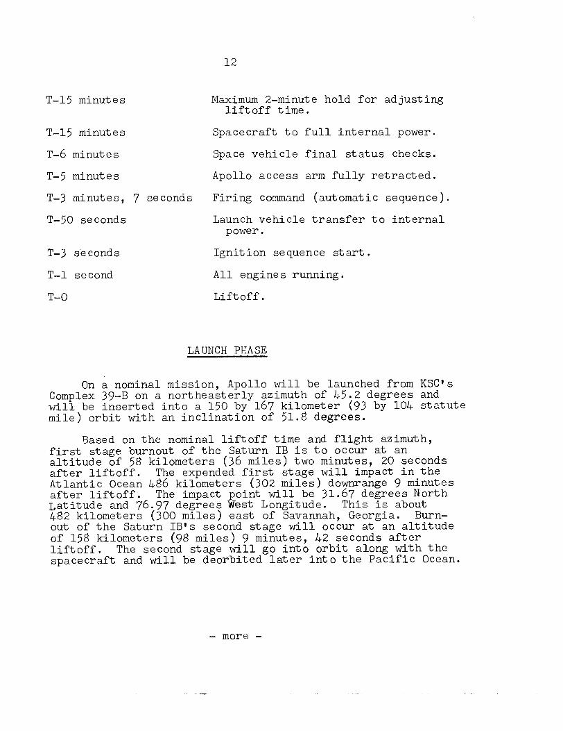
T-15 minutes
T-15 minutes
T-6 minutes
T-5 minutes
T-3 minutes, 7 seconds
T-50 seconds
T-3 seconds
T-l second
T-O
Maximum 2-minute hold for adjusting liftoff time.
Spacecraft to full internal power.
Space vehicle final status checks.
Apollo access arm fully retracted.
Firing command (automatic sequence).
Launch vehicle transfer to internal power.
Ignition sequence start.
All engines running.
Liftoff.
LAUNCH PHASE
On a nominal mission, Apollo will be launched from KSC's Complex 39-B on a northeasterly azimuth of 45.2 degrees and will be inserted into a 150 by 167 kilometer (93 by 104 statute mile) orbit with an inclination of 51.8 degrees.
Based on the nominal liftoff time and flight azimuth, first stage burnout of the Saturn IB is to occur at an altitude of 58 kilometers (36 miles) two minutes, 20 seconds after liftoff. The expended first stage will impact in the Atlantic Ocean 486 kilometers (302 miles) downrange 9 minutes after liftoff. The impact point will be 31.67 degrees North Latitude and 76.97 degrees West Longitude. This is about 482 kilometers (300 miles) east of Savannah, Georgia. Burn- out of the Saturn IB's second stage will occur at an altitude of 158 kilometers (98 miles) 9 minutes, 42 seconds after liftoff. The second stage will go into orbit along with the spacecraft and will be deorbited later into the Pacific Ocean.
- more -
13
LAUNCH WINDOWS
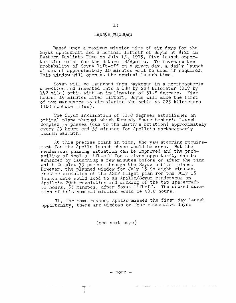
Based upon a maximum mission time of six days for the Soyuz spacecraft and a nominal liftoff of Soyuz at 8:20 am Eastern Daylight Time on July 15, 1975, five launch oppor- tunities exist for the Saturn IB/Apollo. To increase the probability of Soyuz lift-off on a given day, a daily launch window of approximately 10 minutes will be used if required. This window will open at the nominal launch time.
Soyuz will be launched from Baykonur in a northeasterly direction and inserted into a 188 by 228 kilometer (117 by 142 mile) orbit with an inclination of 51.8 degrees. Five hours, 19 minutes after liftoff, Soyuz will make the first of two maneuvers to circularize the orbit at 225 kilometers (140 statute miles).
The Soyuz inclination of 51.8 degrees establishes an orbital plane through which Kennedy Space Center's Launch Complex 39 passes (due to the Earth's rotation) approximately every 23 hours and 35 minutes for Apollo's northeasterly launch azimuth.
At this precise point in time, the yaw steering require- ment for the Apollo launch phase would be zero. But the rendezvous phasing situation can be improved and the prob- ability of Apollo lift-off for a given opportunity can be enhanced by launching a few minutes before or after the time which Complex 39 passes through the Soyuz orbital plane. However, the planned window for July 15 is eight minutes. Precise execution of the ASTP flight plan for the July 15 launch date would lead to an Apollo/Soyuz rendezvous on Apollo*s 29th revolution and docking of the two spacecraft 51 hours, 55 minutes, after Soyuz liftoff. The docked dura- tion of this nominal mission would be 43.8 hours.
If, for some reason, Apollo misses the first day launch opportunity, there are windows on four successive days:
(see next page)
- more -
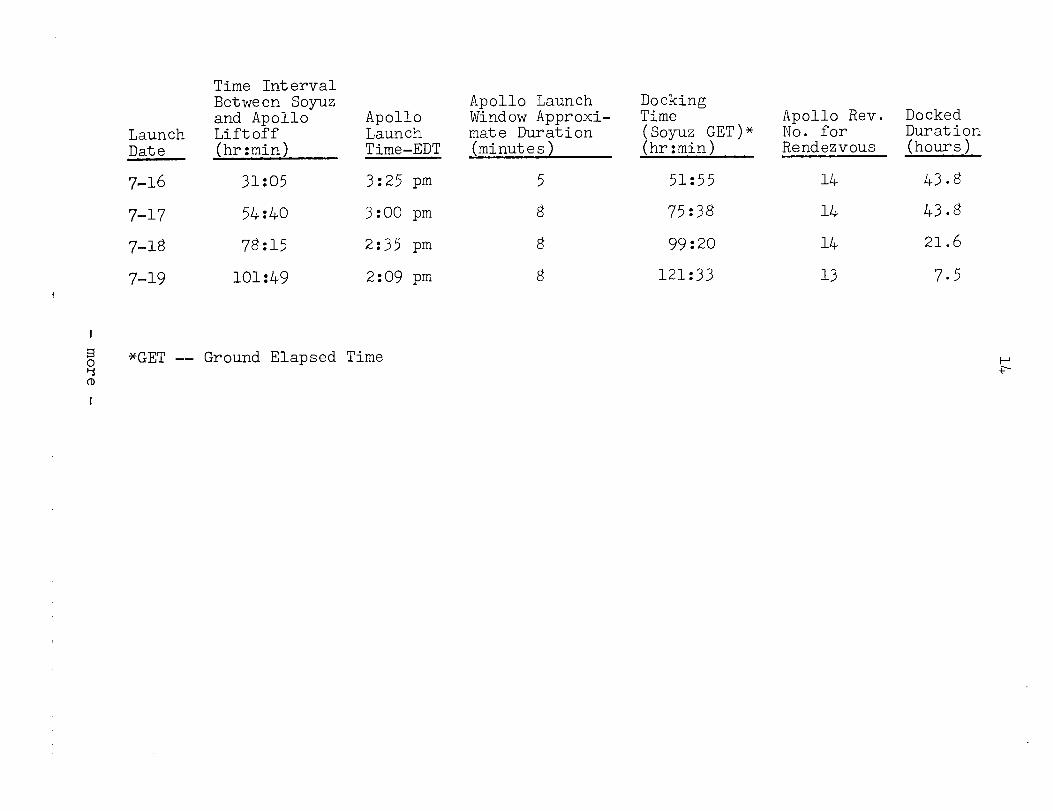
Launch Date
7-16
7-17
7-18
7-19
Time Interval Between Soyuz and Apollo Apollo Liftoff Launch (hr:min) Time-EDT
31:05 3:25 pm
54:40 3:OO pm
78:15 2:3T pm
101:49 2:09 pm
*GET -- Ground Elapsed Time CD I
Apollo Launch Docking Window Approxi- Time mate Duration (Soyuz GET)* (minutes) (hr:min)
8
51:55
75:38
99:20
121:33
Apollo Rev. Docked No. for Duration Rendezvous (hours)
14 43.8
14 43.8
14 21.6
13 7.5
15
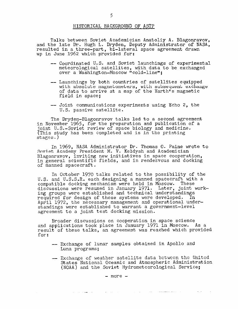
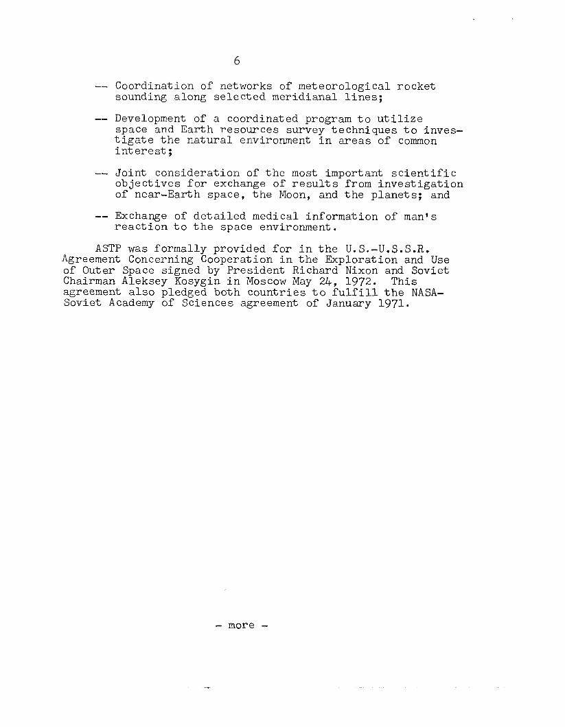
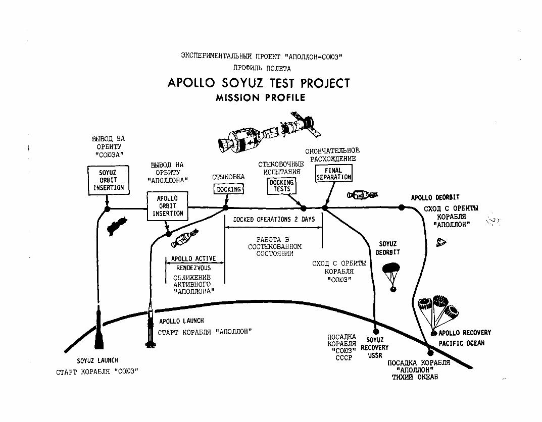
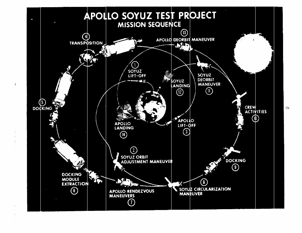
MISSION PROFILE
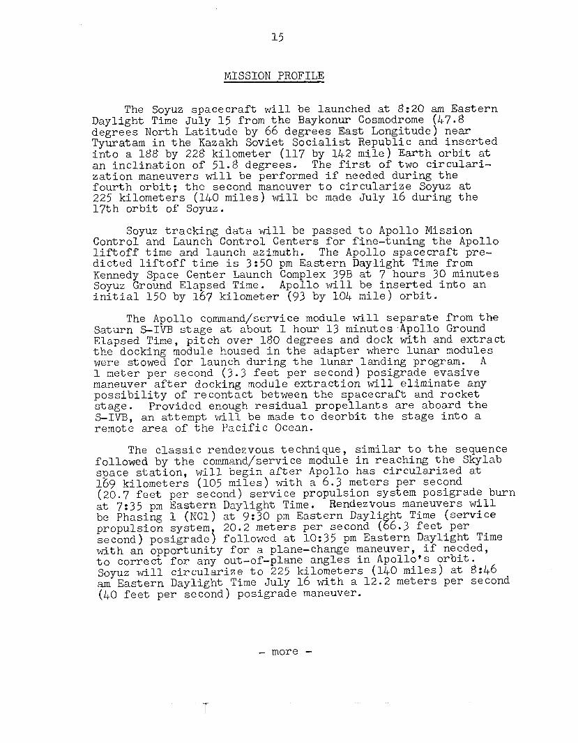
The Soyuz spacecraft will be launched at 8:20 am Eastern Daylight Time July 15 from the Baykonur Cosmodrome (47.8 degrees North Latitude by 66 degrees East Longitude) near Tyuratam in the Kazakh Soviet Socialist Republic and inserted into a 188 by 228 kilometer (117 by 142 mile) Earth orbit at an inclination of 51.8 degrees. The first of two circulari- zation maneuvers will be performed if needed during the fourth orbit; the second maneuver to circularize Soyuz at 225 kilometers (140 miles) will be made July 16 during the 17th orbit of Soyuz.
Soyuz tracking data will be passed to Apollo Mission Control and Launch Control Centers for fine-tuning the Apollo liftoff time and launch azimuth. The Apollo spacecraft pre- dicted liftoff time is 3:50 pm Eastern Daylight Time from Kennedy Space Center Launch Complex 39B at 7 hours 30 minutes Soyuz Ground Elapsed Time. Apollo will be inserted into an initial 150 by 167 kilometer (93 by 104 mile) orbit.
The Apollo command/service module will separate from the Saturn S-IVB stage at about 1 hour 13 minutes ,Apollo Ground Elapsed Time, pitch over 180 degrees and dock with and extract the docking module housed in the adapter where lunar modules were stowed for launch during the lunar landing program. A 1 meter per second (3.3 feet per second) posigrade evasive maneuver after docking module extraction will eliminate any possibility of recontact between the spacecraft and rocket stage. Provided enough residual propellants are aboard the S-IVB, an attempt will be made to deorbit the stage into a remote area of the Pacific Ocean.
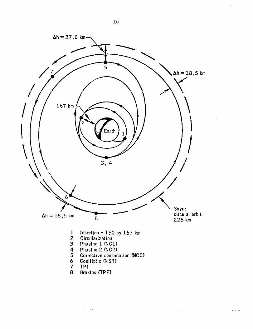
The classic rendezvous technique, similar to the sequence followed by the command/service module in reaching the Skylab space station, will begin after Apollo has circularized at 169 kilometers (105 miles) with a 6.3 meters per second (20.7 feet per second) service propulsion system posigrade burn at 7:35 pm Eastern Daylight Time. Rendezvous maneuvers will be Phasing 1 (NCl) at 9:30 pm Eastern Dayli ht Time (service propulsion system 20.2 meters per second ( El 6.3 feet per second) posigrade \ followed at lo:35 pm Eastern Daylight Time with an opportunity for a plane-change maneuver, if needed, to correct for any out-of-plane angles in Apollo's orbit. SOYUZ will circularize to 225 kilometers (140 miles) at 8:46 am Eastern Daylight Time July 16 with a 12.2 meters per second (40 feet per second) posigrade maneuver.
- more -
16
Ahz37.0 km -\
circular orhi 225 km
1 Insertion - 150 by 167 km 2 Circularization 3 Phasing 1 (NC11 4 Phasing 2 (NC21 5 Corrective combination @KC) 6 Coelliptic (NSR) 7 TPI 8 Braklng (TPF)
km _
it
17
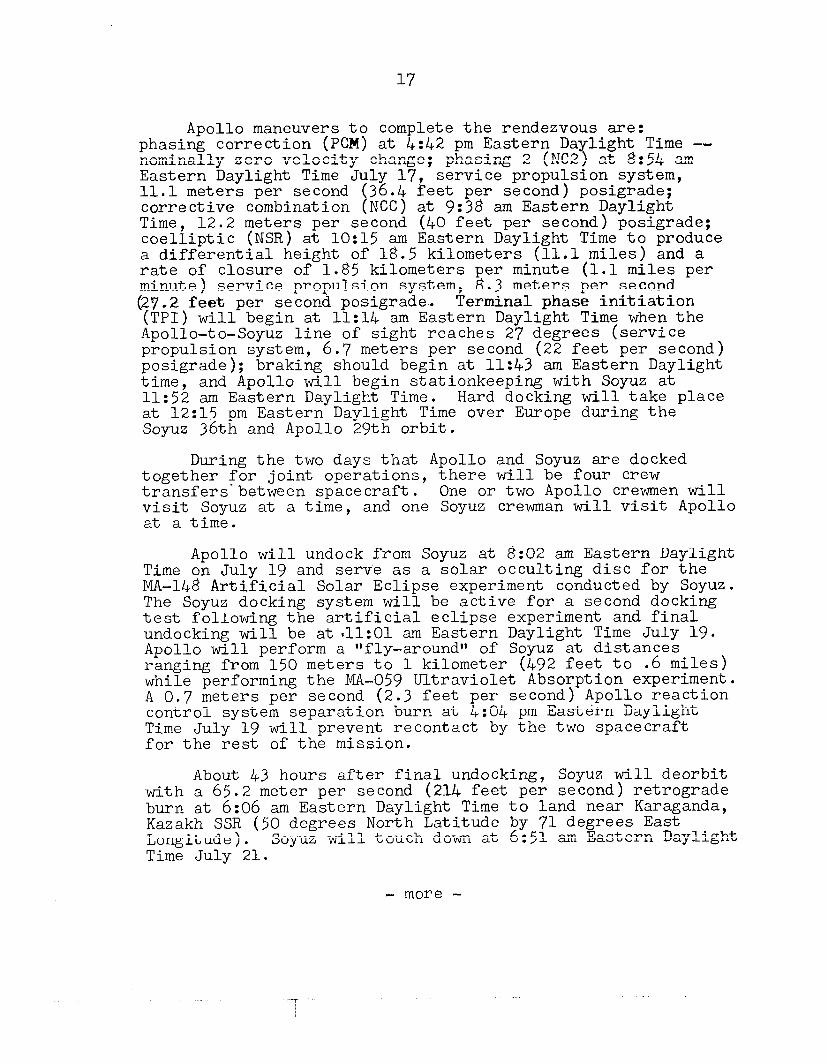
Apollo maneuvers to complete the rendezvous are: phasing correction (PCM) at 4:&2 pm Eastern Daylight Time -- nominally zero velocity change; phasing 2 (NC2) at 8:54 am Eastern Daylight Time July 17, 11.1 meters per second corrective combination t
service propulsion system, 36.4 feet per second) posigrade; NCC) at 9:38 am Eastern Daylight
Time, 12.2 meters per second (40 feet per second) posigrade; coelliptic (NSR) at lo:15 am Eastern Daylight Time to produce a differential height of 18.5 kilometers (11.1 miles) and a rate of closure of 1.85 kilometers per minute (1.1 miles per minute) service propulsion system, 8.3 meters per second (27.2 feet per second posigrade-. Terminal phase initiation (TPI) will begin at 11:14 am Eastern Daylight Time when the Apollo-to-Soyuz line of sight reaches 27 degrees (service propulsion system, 6.7 meters per second (22 feet per second) posigrade); braking should begin at 11:43 am Eastern Daylight time, and Apollo will begin stationkeeping with Soyuz at 11:52 am Eastern Daylight Time. Hard docking will take place at l2:l5 pm Eastern Daylight Time over Europe during the Soyuz 36th and Apollo 29th orbit.
During the two days that Apollo and Soyuz are docked together for joint operations, there will be four crew transfers'between spacecraft. One or two Apollo crewmen will visit Soyuz at a time, and one Soyuz crewman till visit Apollo at a time.
Apollo will undock from Soyuz at 8:02 am Eastern Daylight Time on July 19 and serve as a solar occulting disc for the MA-148 Artificial Solar Eclipse experiment conducted by Soyuz. The Soyuz docking system will be active for a second docking test following the artificial eclipse experiment and final undocking will be at*ll:Ol am Eastern Daylight Time July 19. Apollo will perform a "fly-around" of Soyuz at distances ranging from 150 meters to 1 kilometer (492 feet to .6 miles) while performing the MA-059 Ultraviolet Absorption experiment. A 0.7 meters per second (2.3 feet per second) Apollo reaction control system separation burn at 4:04 pm Eastern Daylight Time July 19 will prevent recontact by the two spacecraft for the rest of the mission.
About 43 hours after final undocking, Soyuz will deorbit with a 65.2 meter per second (214 feet per second) retrograde burn at 6:06 am Eastern Daylight Time to land near Karaganda, Kazakh SSR (50 degrees North Latitude by 71 degrees East Longitude). Soyuz will touch down at 6:51 am Eastern Daylight Time July 21.
- more -
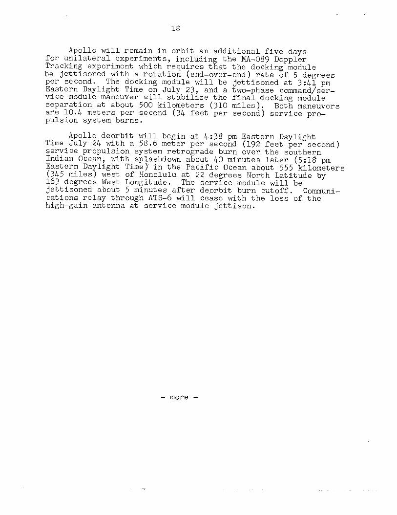
Apollo will remain in orbit an additional five days for unilateral experiments, including the MA-089 Doppler Tracking experiment which requires that the docking module be jettisoned with a rotation (end-over-end) rate of 5 degrees per second. The docking module will be jettisoned at 3:&l pm Eastern Daylight Time on July 23, and a two-phase command/ser- vice module maneuver will stabilize the final docking module separation at about 500 kilometers (310 miles). Both maneuvers are 10.4 meters per second (34 feet per second) service pro- pulsion system burns.
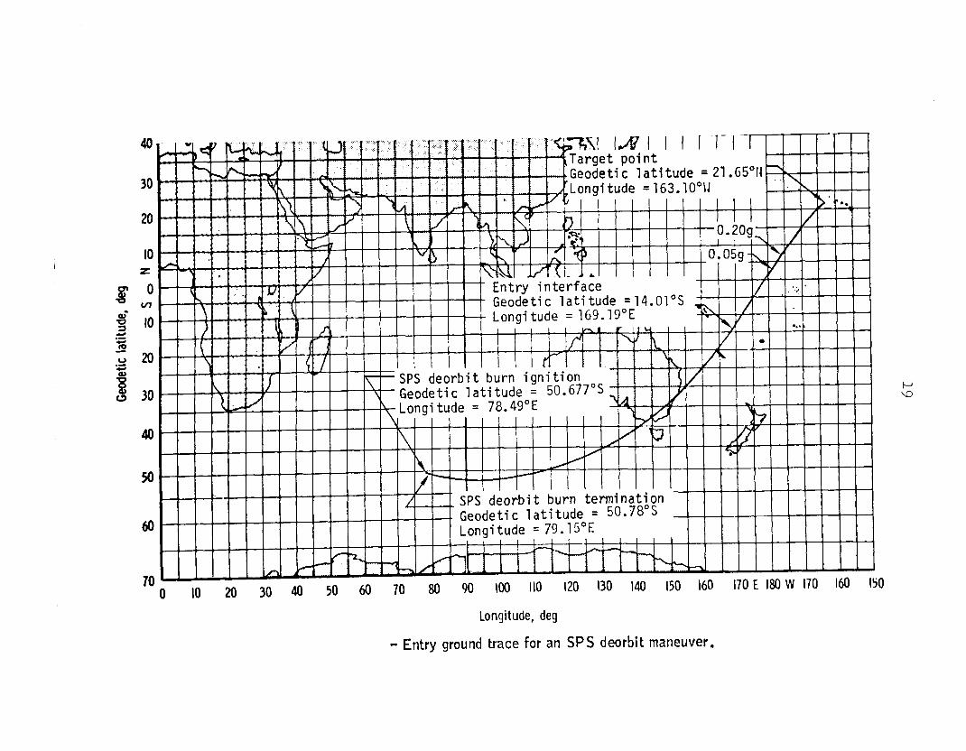
Apollo deorbit will begin at 4:38 pm Eastern Daylight Time July 24 with a 58.6 meter per second (192 feet per second) service propulsion system retrograde burn over the southern Indian Ocean, with splashdown about 40 minutes later (5:18 pm Eastern Daylight Time) in the Pacific Ocean about 555 kilometers (345 miles) west of Honolulu at 22 degrees North Latitude by 163 degrees West Longitude. The service module will be jettisoned about .5 minutes after deorbit burn cutoff. Communi- cations relay through ATS-6 will cease with the loss of the high-gain antenna at service module jettison.
- more -
20
g- to .= 5 2 20
f 30
40
50
0 IO 20 30 40 50 60 70 80 90 loo 110 120 130 I40 150 I60 170 E I80 W 170 160 IS0
Longitude, deg
- Entry ground trace for an SPS deorbit maneuver.
“. f * f
. . Geodeti'c latitude = Z'..,.. ., Longitude =163.10°H
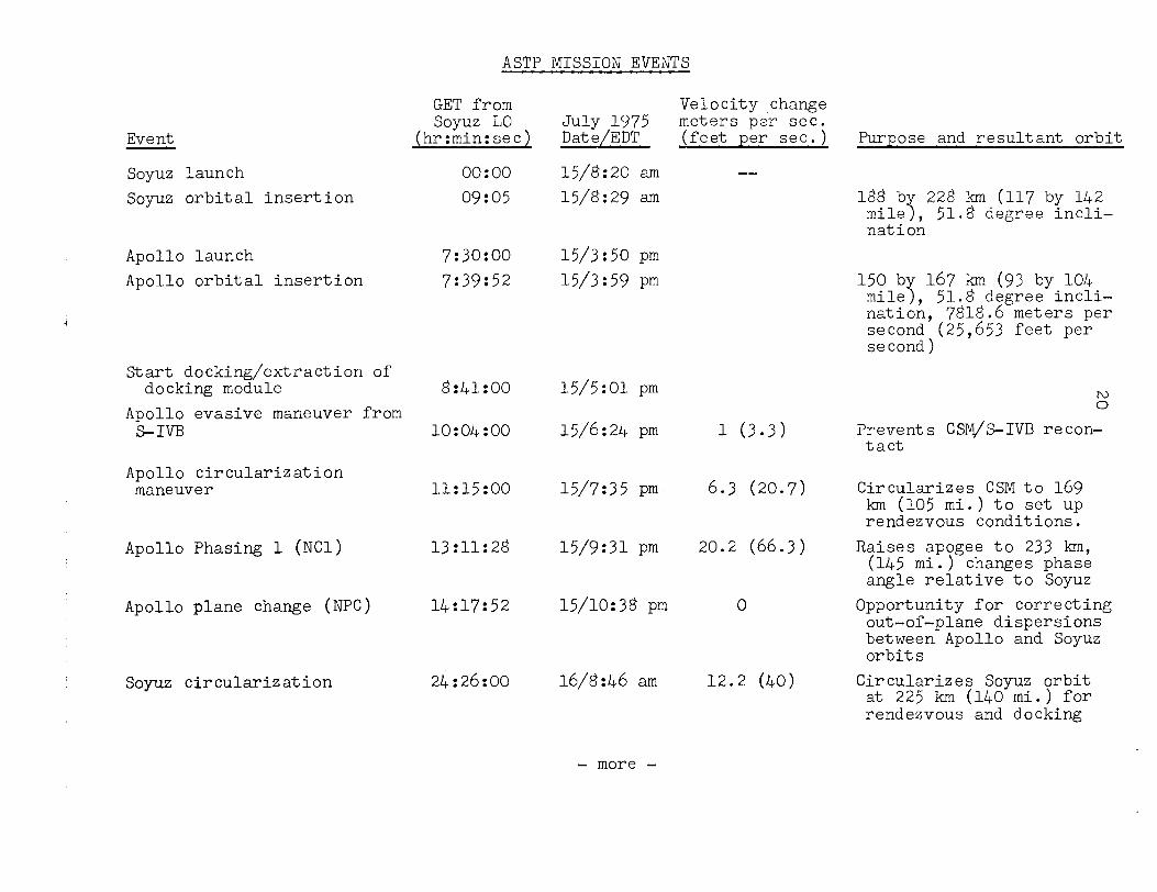
ASTP MISSION EVENTS
Event
GET from soyuz LO
(hr:min:secl
Soyuz launch Soyuz orbital insertion
Apollo launch Apollo orbital insertion
Start docking/extraction of docking module
Apollo evasive maneuver from S-IVB
Apollo circularization maneuver
Apollo Phasing 1 (NCl)
Apollo plane change (NPC)
Soyuz circularization
0o:oo 15/8:20 am 09:05 15/8:29 am
7:30:00 15/3:50 pm 7:39:52 15/3:59 pm
8:41:00 15/5:01 pm
10:04:00 15/6:24 pm
11:15:00 15/7:35 pm
13:11:28 15/9:31 pm
14:17:52 15/10:38 pm
2&26:00 16/tW+6 am
Velocity change
- more -
--
1 (3.3)
6.3 (20.7)
20.2 (66.3)
0
12.2 (40)
Purpose and resultant orbit
188 b 228 km (117 by 142 mile 5 natio;
51.8 degree incli-
150 by 167 km (93 by 104 mile), 51.8 degree incli- nation, 7818.6 meters per second (25,653 feet per second)
Prevents CSM/S-IVB recon- tact
Circularizes CSM to 169 km (105 mi.) to set up rendezvous conditions.
Raises apogee to 233 km, 04:em;e$a;;;;g;; N;E;
Opportunity for correcting out-of-plane dispersions between Apollo and Soyuz orbits
Circularizes Soyuz orbit at 225 km (140 mi.) for rendezvous and docking
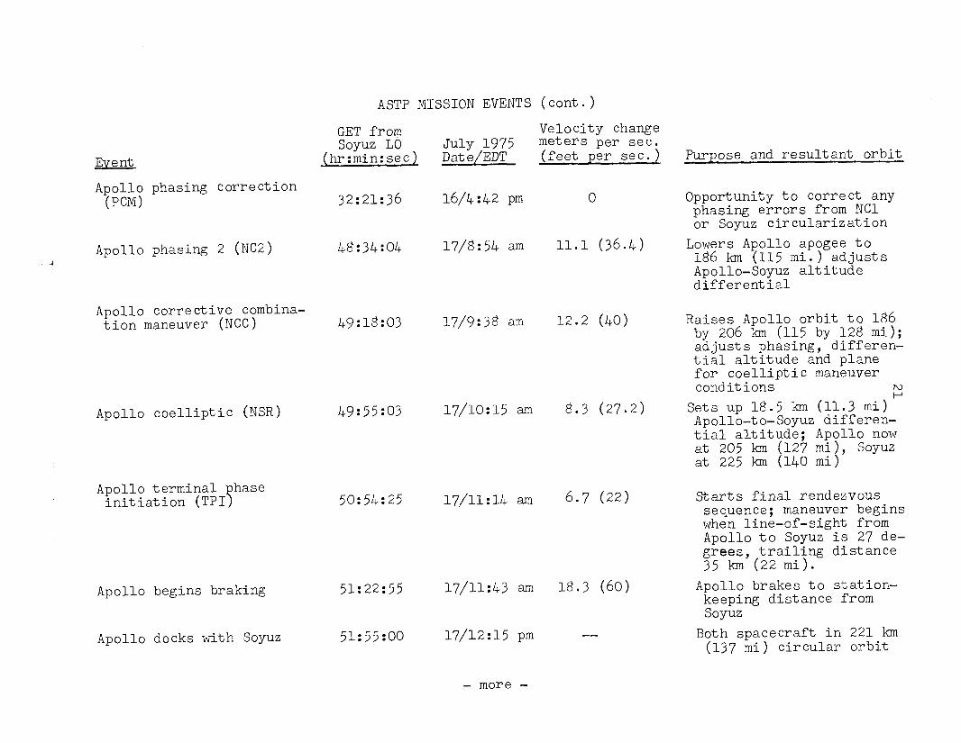
ASTP MISSION EVENTS (cont.)
Event
Apollo phasing correction (PCM)
Apollo phasing 2 (NC2)
Apollo corrective combina- tion maneuver (NCC)
Apollo coelliptic (NSR)
Apollo terminal hase initiation (TPI 7
Apollo begins braking
Apollo docks with Soyuz
GET from soyuz LO
(hr:min:secl
32:21:36
48:34:04
49:18:03
49:55:03
.50:54:25
51:22:55
51:55:00
Velocity change July 1975 meters per sec.
(feet per sec.) Date/EDT
16/4:42 pm
u/8:54 am
17/9:38 am
17/10:15 am
17/11:14 am
17/11:43 am
17/12:15 pm
- more -
0
11.1 (36.4)
12.2 (40)
g.3 (27.2)
6.7 (22)
18.3 (60)
--
Purpose and resultant orbit
Opportunity to correct any phasing errors from NC1 or Soyuz circularization
Lowers Apollo apogee to 186 km (115 mi.) adjusts Apollo-Soyuz altitude differential
Raises Apollo orbit to 186 by 206 km (115 by 128 mi); adjusts phasing, differen- tial altitude and plane for coelliptic maneuver conditions ?
Sets up 18.5 km (11.3 mi) Apollo-to-Soyuz differen- tial altitude; Apollo now at 205 km (127 mi), Soyuz at 225 km (140 mi)
Starts final rendezvous sequence; maneuver begins when line-of-sight from Apollo to Soyuz is 27 de- grees, trailing distance 35 km (22 mi).
Apollo brakes to station- keeping distance from soyuz
Both spacecraft in 221 km (137 mi) circular orbit
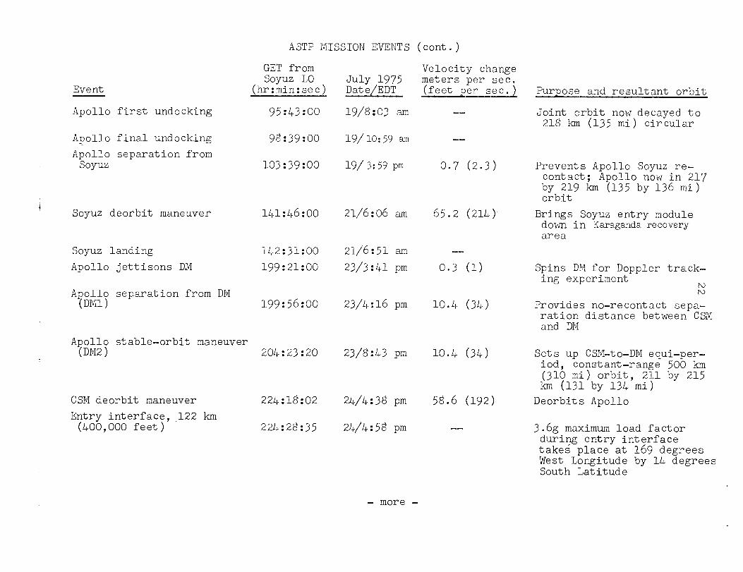
ASTP MISSION EVENTS (cont.)
Event
Apollo first undocking
GET from soyuz LO
(hr:min:sec)
95:43:00
Apollo final undocking Apollo separation from
soyuz
98:39:00
103:39:00
Soyuz deorbit maneuver 141:46:00 21/6:06 am 65.2 (214)
Soyuz landing 142:31:00 21/6:51 am --
Apollo jettisons DM 199:21:00 23/3:41 pm 0.3 (1)
Apollo separation from DM @Ml > 199:56:00
Apollo stable-orbit maneuver (DM2) 204:23:20
CSM deorbit maneuver Entry interface,,122 km
(400,000 feet)
224:18:02
224:28:35
Velocity change
19/8:03 am
19/10:5$ am
19/3:59 pm
23/4:16 pm
23/8:43 pm 10.4 (34)
24/4:38 pm
24/4:58 pm
--
--
0.7 (2.3)
10.4 (34)
58.6 (192)
--
Purpose and resultant orbit
Joint orbit now decayed to 21ti km (135 mi) circular
Prevents Apollo Soyuz re- contact; Apollo now in 217 by 219 km (135 by 136 mi) orbit
Brings Soyuz entry module down in Karaganda recovery area
Spins DZ for Doppler track- ing experiment P.l R)
Provides no-recontact sepa- ration distance between CSM and DM
Sets up CSTvl-to-DM equi-per- iod, constant-range 500 km (310 mi) orbit, 211 by 215 km (131 by 134 mi)
Deorbits Apollo
3.6g maximum load factor during entry interface takes place at 169 degrees West Longitude by 14 degrees South Latitude
- more -
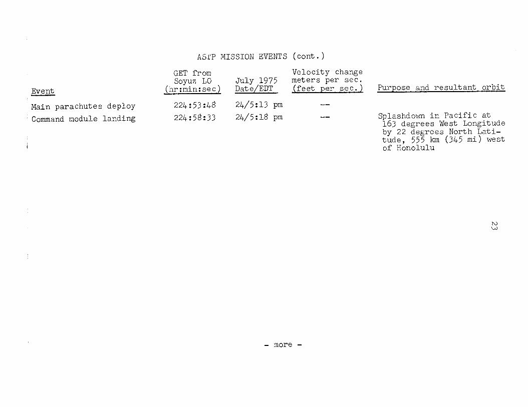
AS,I'P MISSION EVENTS (cont.)
Event
GET from Velocity change soyuz LO July 1975 meters per sec.
(hr:min:sec) Date/EDT jfeet per sec.) Purpose and resultant orbit
Main parachutes deploy 224~53~48 24/5:13 pm --
Command module landing
i
224:58:33 24/5:18 pm -- Splashdown in Pacific at 163 degrees West Longitude by 22 degrees North Lati- tude, 555 km (345 mi) west of Honolulu
- more -
24
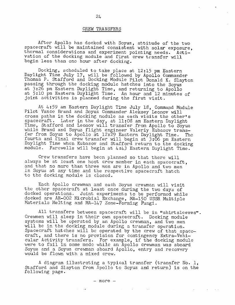
CREW TRANSFERS
After Apollo has docked with Soyuz, attitude of the two spacecraft will be maintained consistent with solar exposure, thermal considerations and experiment pointing needs. Acti- vation of the docking module and first crew transfer will begin less than one hour after docking.
Docking, scheduled to take place at l2:Yj pm Eastern Daylight Time July 17, will be followed by Apollo Commander Thomas P. Stafford and Docking Module Pilot Donald K. Slay-ton passing through the docking module hatches into the Soyuz at 3: 26 pm Eastern Daylight Time, and returning to Apollo at 5:lO pm Eastern Daylight Time. An hour and 12 minutes of joint activities is planned during the first visit.
Pilot At f+:59 am Eastern Daylight Time July 18, Command Module
Vance Brand and Soyuz Commander Aleksey Leonov will cross paths in the docking module as each visits the other's spacecraft. Later in the day, Time,
at 11:08 am Eastern Daylight Stafford and Leonov will transfer from Apollo to Soyuz
while Brand and Soyuz flight engineer Valeriy Kubasov trans- fer from Soyuz to Apollo at l2:29 Eastern Daylight Time. The fourth and final crew transfer will begin at 3:06 pm Eastern Daylight Time when Kubasov and Stafford return to the docking module. Farewells will begin at 4:.43 Eastern Daylight Time.
Crew transfers have been planned so that there will always be at least one host crew member in each spacecraft, and that no more than three men are in Apollo and two men in Soyuz at any time and the respective spacecraft hatch to the docking module is closed.
Each Apollo crewman and each Soyuz crewman will visit the other spacecraft at least once during the two days of docked operations. Joint experiments to be performed while docked are AR-002 Microbial Exchange, MA-150 USSR Multiple Materials Melting and MA-147 Zone-Forming Fungi.
All transfers between spacecraft will be in "shirtsleeves". Crewmen will sleep in their own spacecraft. Docking module systems will be operated by an Apollo crewman, and two men will be in the docking module during a transfer operation. Spacecraft hatches will be operated by the crew of that space- craft, and there is no provision for contingency Extra-Vehi- cular Activity transfers. For example, if the docking module were to fail in some mode while an Apollo crewman was aboard Soyuz and a Soyuz crewman aboard Apollo, entry and recovery would be flown with a mixed crew.
A diagram illustrating a typical transfer (transfer No. 1, Stafford and Slayton from Apollo to Soyuz and return) is on the following page.
- more -
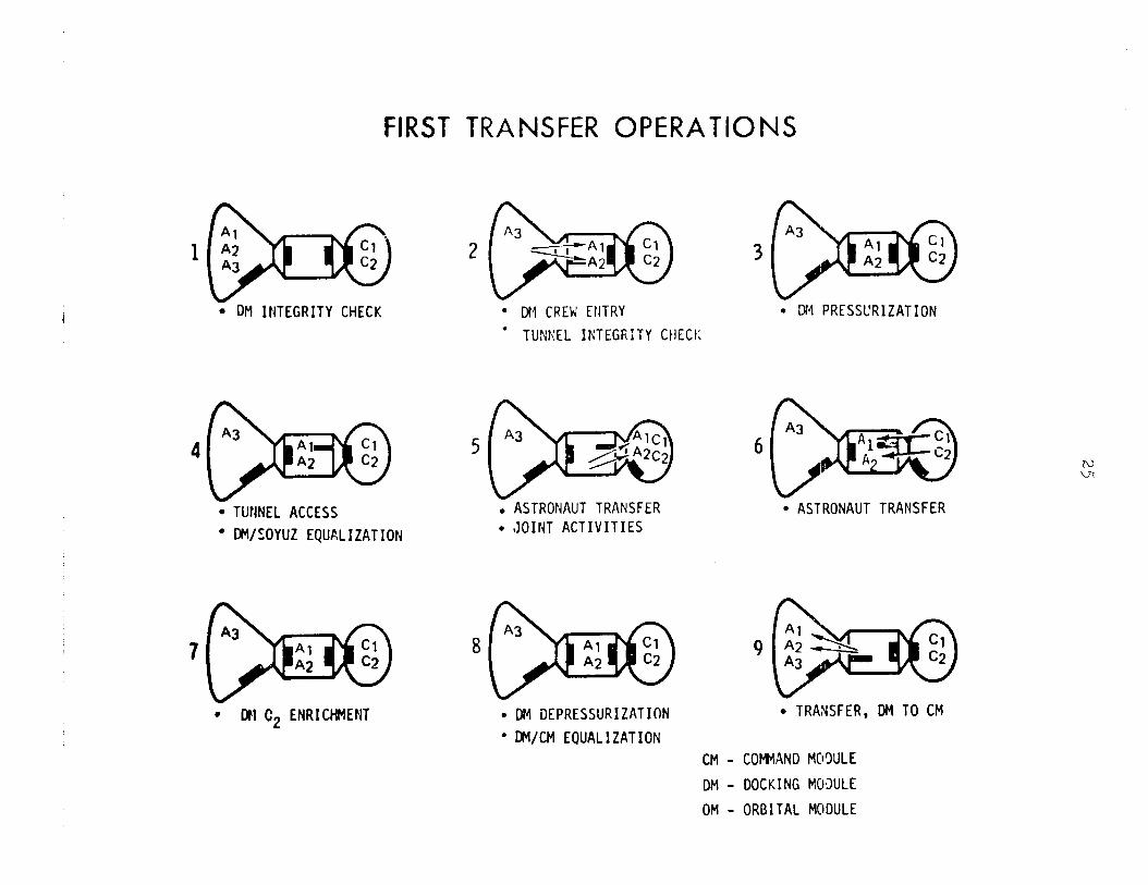
FIRST TRANSFER OPERATIONS
l DH INTEGRITY CHECK
4
l TUNNEL ACCESS
l DM/SOYUZ EQUALIZATION
7
l DM C2 ENRICHMENT
. MI CREW ENTRY i DM PRESSCRIZATION
l TUNKEL INTEGRITY CHECK
5
. ASTRONAUT TRANSFER
. JOINT ACTIVITIES
8
. DM DEPRESSURIZATION
l DM/CM EQUALIZATION
6
l ASTRONAUT TRANSFER
. TRANSFER, DM TO CM
CM - COWAND M03ULE
DM - DOCKING MOXJLE
OM - ORBITAL MODULE
26
ASTP EXPERIMENTS
The 27 experiments to be conducted during the ASTP mission fall into three basic categories: space sciences, life sciences and applications.
Five of the space sciences experiments examine phenomena within the solar system and toward the outer fringes of our galaxy, while five other experiments look inward toward the Earth and its envelope of atmosphere.
The space sciences-astronomy experiments are:
-- MA-048 Soft X-Ray to observe X-ray sources within and outside of our galaxy;
-- MA-083 Extreme Ultraviolet Survey of our galaxy;
-- MA-088 Helium Glow Detector to observe the inter- stellar medium near our solar system;
-- MA-148 Artificial Solar Eclipse to observe the solar corona;
-- MA-151 Crystal Activation to investigate the effects of particle radiation in Earth orbit on instrument noise levels of gamma-ray detectors.
Space sciences-Earth environment experiments are:
-- MA-059 Ultraviolet Absorption to measure atomic con- stituents of the Earth's upper atmosphere;
-- MA-007 Stratospheric Aerosol Measurements to measure the stratosphere's aerosol content;
-- MA-136 Earth Observations and Photography to study - - surface features on Earth;
-- MA-OZ?9 Doppler Tracking to measure mass below the Earth's surface;
distribution
-- MA-128 Geodynamics also to measure mass below the Earth's surface.
distribution
Life sciences experiments on ASTP have two objectives: to investigate the effects of heavy, charged particles upon live cells; and to study the effects of spaceflight upon the human immune system.
- more -
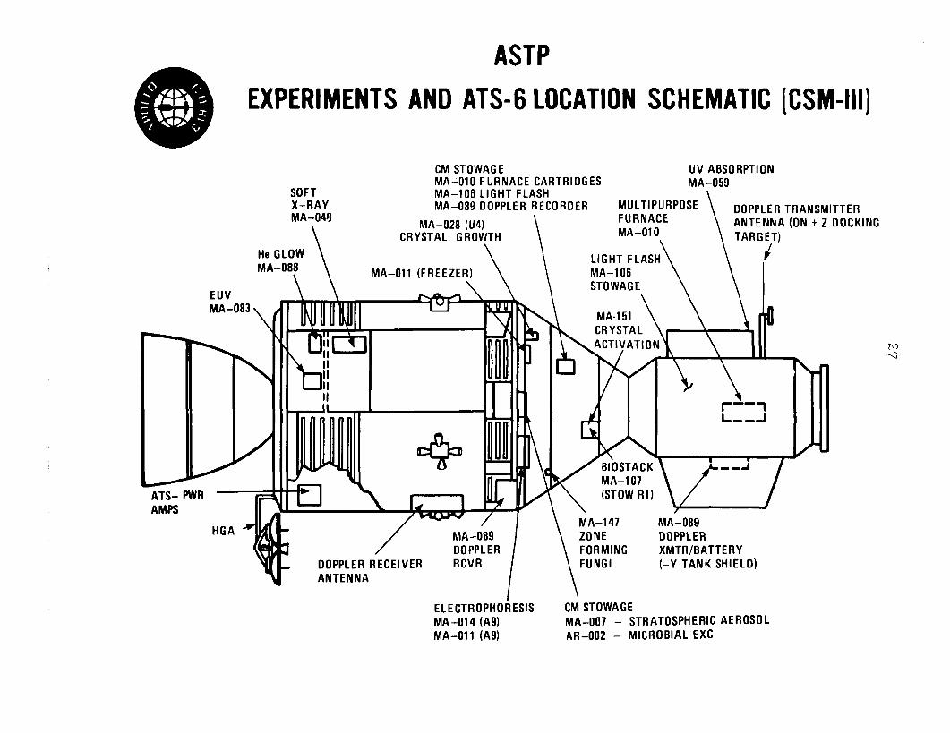
ASTP
EXPERIMENTS AND ATS-6 LOCATION SCHEMATIC [CSM-Ill)
SOFT X-RAY MA-048
\
CMSTOWAGE UV ABSORPTION MA-OlOFURNACE CARTRIDGES MA-059 MA-106 LIGHT FLASH MA-089OOPPLER RECORDER MULTIPURPOSE
\
DOPPLERTRANSMITTER MA-028 (U4)
CRYSTAL GROWTH \
FURNACE MA-010
ANTENNA(ONtZDOCKlNG . TARGET)
He GLOW MA-08:
\ .\ \
LIGHT FLASH MA-011 (FREEZER) MA-106 \ \
EUV MA-083\ ,
ATS- PWR Ii
HGA
c
/ MA-089 DOPPLER
. DOPPLER RECEIVER RCVR ANTENNA
i ELECTROPHOiESIS CMSTOWAGE MA-014 (A91 MA-007 - STRATOSPHERIC AEROSOL MA-011 (A91 AR-002 - MICROBIAL EXC
\
MA-147 MA-089 ZONE DOPPLER FORMING XMTR/BATTERY FUNGI (-Y TANK SHIELD)
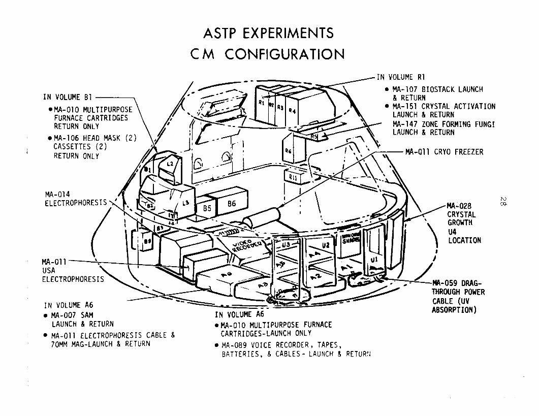
ASTP EXPERIMENTS
CM CONFIGURATION
IN VOLUME Bl
.MA-010 MULTIPURPOSE FURNACE CARTRIDGES RETURN ONLY
.MA-106 HEAD MASK CASSETTES (2) RETURN ONLY
MA-014 ELECTROPHORESIS< \- K<
<IN.V;LUME Rl
MA-107 BIOSTACK LAUNCH & RETURN MA-151 CRYSTAL ACTIVATION LAUNCH L RETURN MA-147 ZONE FORMING FUNGI LAUNCH L RETURN
1\ \ \ \ \, . - . . MA-011 CRY0 FREEZER
-\ MA-011 . USA ELECTROPHORESIS
IN VOLUME A6 l MA-007 SAM IN VOLUME A6
LAUNCH & RETURN .MA-010 MULTIPURPOSE FURNACE l MA-011 ELECTROPHORESIS CABLE 8 CARTRIDGES-LAUNCH ONLY
70MM MAG-LAUNCH & RETURN l MA-089 VOICE RECORDER, TAPES, BATTERIES, & CABLES- LAUNCH 8 RETlJRIi
\ LOCATION
:
/ -MA-o59 DRAG-
THROUGH POWER CABLE (UV ABSORPTION)
29
Live-cell experiments are:
-- upon the
MA-106 Light Flash to measure the effects of particles human retina;
-- MA-147 Zone Forming Fungi to measure particle effect upon growing bacteria cells;
-- MA-107 Biostack to measure particle effect upon seeds and eggs.
Human immune system experiments are:
-- AR-002 Microbial Exchange;
-- MA-031 Cellular Immune Response;
-- MA-032 Polymorphonuclear Leukocyte Response.
ASTP applications experiments investigate the isolation of medically-useful substances by electrophoresis, and proces- sing of materials in weightlessness. Applications experiments are:
-- MA-011 Electrophoresis Technology;
-- MA-014 Electrophoresis;
-- MA-010 Multipurpose Furnace which includes seven high-temperature processing experiments;
-- MA-028 Crystal Growth in which material is processed at ambient temperatures.
Following are descriptions of each experiment. News- persons desiring greater detail should contact the Query Desk at the JSC news center to obtain reference documents or to arrange interviews with principal investigators.
MA-048 Soft X-Ray -- Soft X-ray sources in the 0.1 to 10 ke'O (keV = 1000 electron volts) ener y region emanating from all regions of the Milky Way galaxy wil f be mapped by a counter carried aboard Apollo. This data will complement measurements of higher low-energy X-rays made by the Uhuru?satellite. The stream of soft X-rays appears to be maximum toward the poles of the Milky Way galaxy and is believed to be remnants of super- nova indicating the presence of hot gas plasmas produced by shock waves from the original exploding stars. An instrument aboard Skylab 3 measured X-ray sources in the 1 to 10 keV range using proportional counting equipment.
* Explorer 42, 1970.
small astronomy satellite launched December 12,
- more -
30
MA-048 of the U.S.
principal investigator is Dr. Herbert Friedman Naval Research Laboratory in Washington, D.C.
1MA-083 Extreme Ultraviolet Survey -- A search for extreme ultraviolet radiation sources in the 50 to 1000 Angstrom range, such as certain bright stars, planetary nebulae, red giants sub-giants, dwarfs systems.
, pulsating white dwarfs and contact bina;y (An Angstrom is one-hundred-millionth of a centimeter.
It is used to express the length of light waves.) The survey instrument, mounted in the service module, consists of four concentric "grazing incidence" mirrors which feed radiation through filters to an electronic detector. Instrument aiming toward specific targets on the celestial sphere will be done _ by controlling spacecraft attitude, since the telescope is rigidly mounted to the service module structure.
MA-083 principal investigator is Professor C. S. Bowyer of the University of California at Berkeley Space Science Laboratory.
speed MA-088 Helium Glow -- The abundance temperature and c and directinmotion of the int&stellar medium
near the solar system will be measured by the MA-088 helium glow detector in the service module. The detector will be measuring helium line radiations (304 Angstroms and 584 Ang- stroms) over as much of the sky as possible, with emphasis on those regions where helium spectral lines are predicted to be strongest. Additionally, the experiment will gather data on the shape of the spectral lines and motion of their sources by measuring the Doppler shift caused by the spacecraftts orbital velocity.
MA-088 principal investigator is Professor C. S. Bowyer of the University of California at Berkeley.
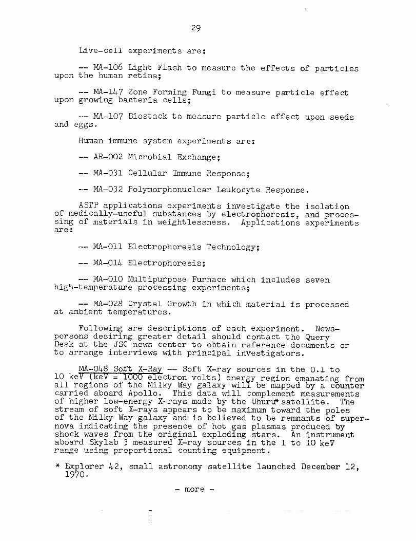
MA-148 Artificial Solar Ecli se -- A joint experiment in which the Apollo command/service mo ule ---% will serve as an occult- ing disc over the Sun while the Soyuz crew makes observations and photographs the solar corona. Prior to first undocking, the Apollo will maneuver the two spacecraft to an attitude to which the service propulsion system engine bell is pointed at the Sun and Soyuz away from the Sun. craft sunrise,
Shortly after space- Apollo will undock and back away toward the Sun.
A Soyuz camera will photograph the solar corona as the apparent size of Apollo grows smaller, and will also record the environ- ment around Apollo as thrusters fire and various spacecraft orifices vent. Ground-based astronomical observations of the solar disc will be conducted simultaneously and will be cor- related with Soyuz photography after the mission. The experi- ment will be the only space flight opportunity to observe the solar corona in 1975. Skylab9s last look at the corona from outside the Earth's atmosphere was a year and a half earlier.
- more -
U
LL
s E!
a
‘T
32
MA-148 principal investigator is Dr. G. M. Nikolsky of the USSR Institute of Terrestrial Magnetism and Ionosphere and Radio Vapor Propagation Laboratory of Solar Activity. * The American point of contact for this joint effort is Dr. R. T. Giuli of the Johnson Space Center Planetary and Earth Sciences Division.
MA-151 Crystal Activation -- A passive experiment aimed toward development of instrumentation and detectors for gamma- ray astronomy-experiments to be flown in future unmanned-or- biting spacecraft. Two candidate detector materials, large crystals of pure germanium and sodium iodide, will be stowed in a container aboard the command module. Susceptibility of these crystals to radioactive activation by particle radia- tion (proton and neutron) bombardment in the space environment produces a noise background that can obscure desired gamma- ray signals. The experiment will attempt to measure the noise background sensitivity of the crystals as a calibration guide to designers of future instruments. Immediately after Apollo splashdown, the crystals will be analyzed for radioactive species. Sodium iodide crystals were flown aboard Apollo 17 in a similar investigation.
MA-151 principal investigator is Dr. Jacob the NASA Goddard Space Flight Center Laboratory Physics and Astrophysics.
Trombka of for Solar
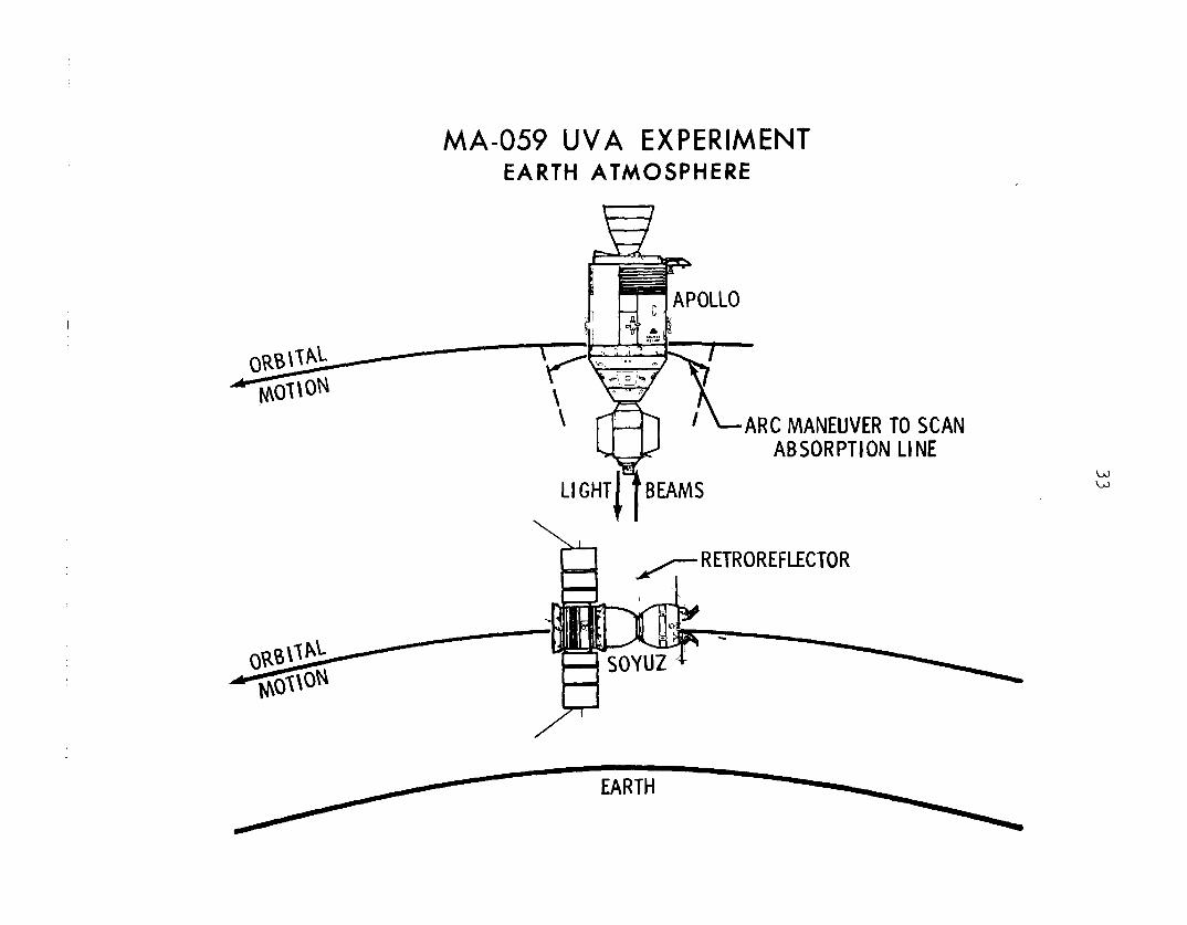
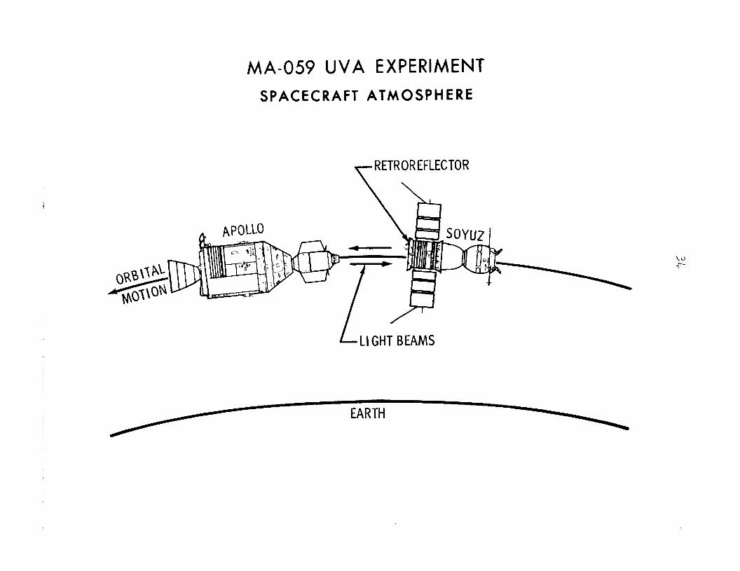
MA-059 Ultraviolet Absorption -- The quantities of atomic oxygen and atomic nitrogen in the Earth's upper atmosphere are not accurately known. In an effort to gather more accurate data on the presence of the gases at the ASTP orbital altitude, the ultraviolet absorption experiment will measure atomic oxy- gen and nitrogen using light beams directed from Apollo to a Soyuz retroreflector and back to an optical absorption spectrom- eter on Apollo. The light beams will have wavelengths cor- respondin nitrogen 7
to neutral atomic oxygen (1304 Angstroms) and atomic 1200 Angstroms). Measurements will be made at space-
craft separation distances ranging from 150 meters to 1 kilo- meter (492 feet to .6 miles).
MA-059 co-principal investigators are Dr. Thomas M. Donahue of the University of Michigan, Department of Atmospheric and Oceanic Science, and Dr. Robert D. Hudson of the JSC Environ- mental Effects Project Office.
- more -
_.__ , .
MA-059 UVA EXPERIMENT EARTH ATMOSPHERE
ARCMANEUVER TO SCAN ABSORPTION LINE
RETROREFLECTOR
w W
MA-059 UVA EXPERIMENT
SPACECRAFT ATMOSPHERE
/LIGHTBEAMS
35
MA-007 Stratospheric Aerosol Measurement -- Another experiment directed toward developing instruments and tech- niques for use in future spacecraft. Small, solid particles called aerosols remain suspended in the atmosphere for days or longer in the troposphere (lower atmosphere) and well into the stratosphere (upper atmosphere). The aerosol-measurement experi- ment will investigate the photometer technique as a potential method for long-term satellite monitoring of atmospheric aero- sols, while taking measurements of the concentration and ver- tical distribution of aerosols during the ASTP mission time frame. Direct sunlight extinction resulting from aerosols will be measured at spacecraft sunrise and sunset with a photometer operating in the one micron wavelength region. Differences in the atmospheric refraction of the solar disc will be photographed with a handheld Hasselblad camera with infrared film and fil- ters. Balloon flights carrying similar photometers will cover the lower 30 kilometers (18.6 miles) of the atmosphere during the same period.
Aerosols are injected into the atmosphere by such diverse means as meteoroids from above and volcanic eruptions and in- dustrial smoke from below, and by many other mechanisms -- many still unknown. Recently, interest has arisen in develop- ing techniques for monitoring the aerosol content of the atmo- sphere continuously. If these aerosols are present in suffi- cient quantity, they can affect the balance of radiation trans- fer through the atmosphere, and small changes in atmospheric temperatures have significant implications for long-term weather patterns and overall Earth environmental conditions.
MA-007 principal investigator is Dr. Theodore J. Pepin of the University of Wyoming Department of Physics and Astron- omy.
MA-136 Earth Observations and Photography -- Many of Earth's surface features that were observed and photographed during the 171 days the Skylab space station was manned will again come under the eye-and-camera scrutiny of a space crew in the MA-136 experiment, and many new features will be added. Surface features with scientific or with Earth resources appli- cations in the fields of geology, oceanography, hydrology, meteorology and desert motion will be recorded on film, but from a lower altitude.
Geological features to be observed include major active strike-slip fault zones and possible extensions of these zones as revealed by vegetation and drainage patterns.
- more -
36
Oceanographic studies in the MA-136 experiment include ocean upwellings and their subsequent hydrological and bio- logical effects, and ocean current trends and their effects upon trade, shipping and the fisheries. Also to be observed and photographed by the crew are river deltas, near-shore environments, the extent of water pollution, and the fish- poisoning "red tide".
Ranging inland, the ASTP crew will observe and photo- graph hydrological features such as closed-basin water circu- lation and shore lines such as in the Great Salt Lake. Photos of Himalayan snow cover will provide a basis for estimating water volume and its drainage, irrigation and flood-control aspects.
Frontal waves, storm centers, hurricanes and tropical storms, cloud features and localized atmospheric circulation will be observed by the crew as real-time targets of oppor- tunity in the meteorological portion of experiment MA-136.
Deserts in both hemispheres will be under photographic and visual scrutiny in an attempt to assess the effects of desert motion into vegetated regions. Special emphasis will be on sand dune sizes, shapes and patterns, and vegetated/arid transition zones in African deserts as an aid toward under- standing African drought problems.
MA-136 principal investigator is Dr. Farouk El Baz of the Smithsonian Institution Center for Earth and Planetary Studies.
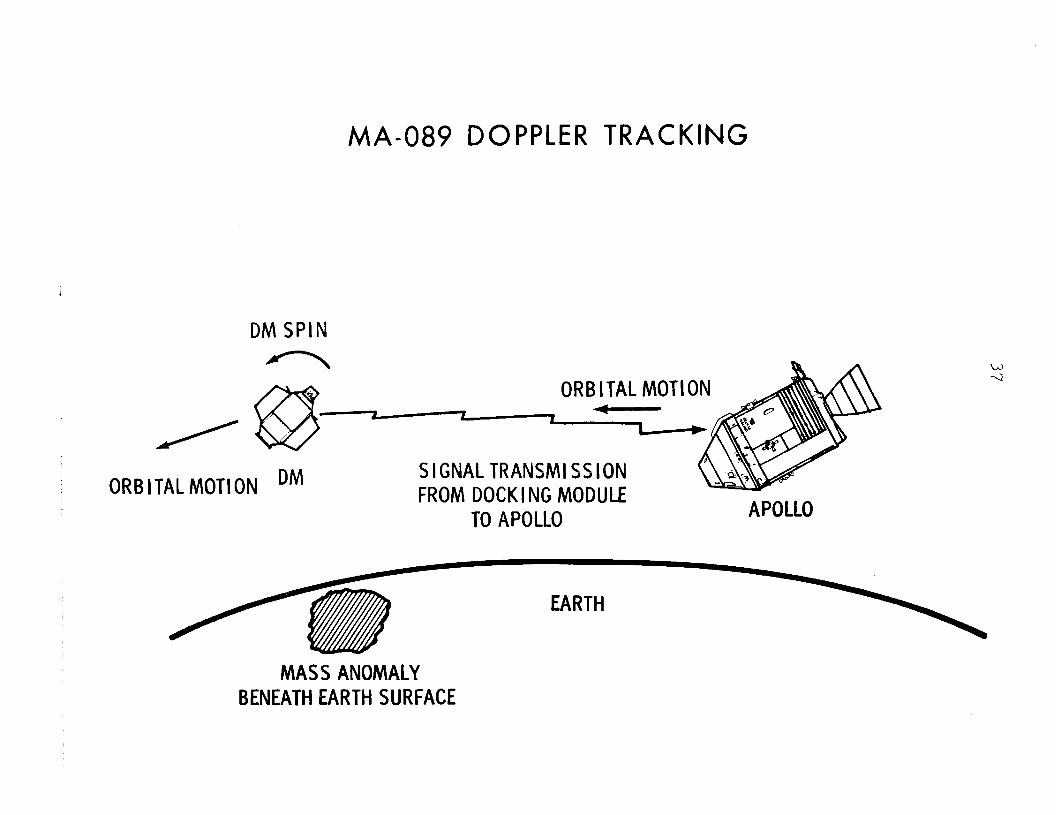
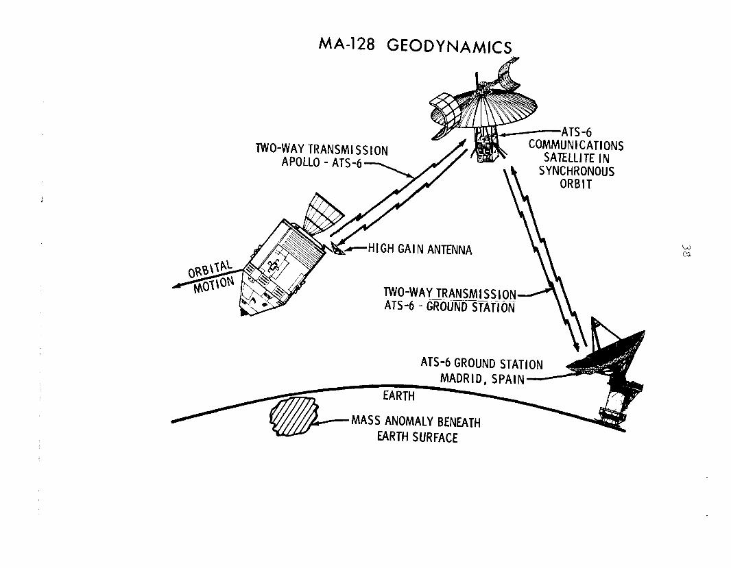
MA-089 Doppler Tracking and MA-128 Geodynamics -- Both MA-089 Doppler Tracking and MA-128 Geodynamics -- Both of these experiments investigate the feasibility of measuri of these experiments investigate the feasibility of measuri mass anomalies in the Earth's crust by means of measuring mass anomalies in the Earth's crust by means of measuring variations in the relative motions of two spacecraft with variations in the relative motions of two spacecraft with Doppler radio tracking. Doppler radio tracking. The emergence in recent years of The emergence in recent years of the plate tectonic hypothesis of the Earth's upper mantle the plate tectonic hypothesis of the Earth's upper mantle structure has brought increased interest in mass anomalies structure has brought increased interest in mass anomalies reconstructing such aspects of Earth's history as continent drift.
ng
in al
Surface gravimetry is limited to the measurement of the smaller mass anomalies. Perturbations of orbits of single satellites yield measurements of only the larger mass anomalies. Satellite-to-satellite relative motion measurements are hoped to provide measurements of gravitational anomalies in the mid-range -- from 100 to 1000 kilometers (60 to 620 miles) in width.
- more -
.- ,
MA-089 DOPPLER TRACKING
DM SPIN . % a ORBITAL MOTION
$
ORBITAL MOTION DM SIGNALTRANSMISSION FROM DOCKING MODULE
TO APOLLO APOLLO
MASS ANOMALY BENEATHEARTH SURFACE
MA-128 GEODYNAMICS
TWO-WAYTRANSMISSION
HIGH GAIN ANTENNA
TWO-WAYTRANSMlSSlOfl ATS-6 - @&iU%i%ifiON
ATS-6GROUND STATION
MASS ANOMALY BENEATH
39
MA-089 will employ Doppler tracking between the command/ service module and the docking module when they are separated by a distance of 300 kilometers (186 miles) and is expected to resolve mass anomalies of about 200-350 kilometers (1241 217 miles) in size. MA-128 will pursue the so-called ttlow- high" technique by CSM Doppler tracking of the ATS-6 communi- cations satellite which will be stationary 35,900 kilometers (22,260 miles) over Kenya. MA-128 is expected to resolve mass anomaly sizes similar to MA-089.
MA-089 principal investigator is Dr. George C. Weiffenbach of the Smithsonian Astrophysical Observatory, and MA-128 prin- cipal investigator is Dr. Friedrich 0. Vonbun of the NASA Goddard Space Flight Center.
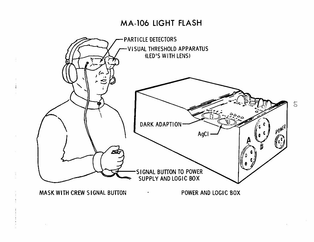
MA-106 Light Flash, MA-107 Biostack and MA-147 Zone Forming Fungi -- G effects of cosmic radiation upon human tissues during future long-duration spaceflights are a concern of life sciences investigators. MA-106, MA-107, and ~~A-147 experiments are three approaches toward determining the ill effects, if any, of high-charge, high-energy cosmic particles upon living organisms. Recent studies have shown that such' particles can kill living cells if they pass close enough to the cells* nuclei, and it is estimated that during a two- year mission to Mars between two and ten percent of all body cells would be struck by high-energy particles. Such an inci- dence of cell impact would be especially significant in the non-regenerative cells of the central nervous system. Earlier experiments on Apollo missions have shown that cosmic particles can cause mutations in some organisms.
~~-106 investigates high-energy particle interaction with human eye retina cells through a comparison between crew dark-adapted observations of light flashes and detector measure- ments of the actual particle environment. Similar light flash experiments were flown on Apollos 15, 16 and 17 and Skylab 4.
The MA-107 Biostack experiment subjects dormant cells such as plant seeds and brine shrimp eggs to particle effects, again with comparison detectors and with post-mission micro- scopic examination. Biostack materials also will be cultured or nurtured into growing systems post mission for observation of possible mutations.
Similar studies of radiation effects upon a bacteria cell are the objective of the MA-147 Zone Forming Fungi experi- ment. Post-mission culture growths will observe not only par- ticle effects but also any changes in the bacteria's circadian rhythm caused by the space environment.
- more -
MA-106 LIGHT FLASH
PARTICLE DETECTORS
VISUAL THRESHOLD APPARATUS (LED’S WITH LENS)
DARK ADAPTI ON
S I GNAL BUTTON TO PO SUPPLY AND LOGIC B
MASK WITH CREW SIGNAL BUTTON - POWER AND LOGIC BOX
41
~~-106 principal investigator is Dr. Thomas F. Budinger of the University of California Lawrence Radiation Laboratory; MA-107 principal investigator is Dr. Horst Bucker of the Uni- versity of Frankfurt-am-Main Space Biophysical Working Group; MA-147 principal investigator is Dr. I. G. Akoyev of the USSR Academy of Sciences Institute of Biological Physics.
AR-002 Microbial Exchange, MA-031 Cellular Immune Response and MA-032 Polymorphonuclear Leukocyte Response -- These three experiments investigate the effects of spaceflight upon the human immune system. Previous manned spaceflights have shown that microbes migrate from crewman to crewman and from crewman to spacecraft surfaces. Moreover, while the number of microbe strains tends to diminish in flight, the number of microbes of a surviving type-e significantly. Crew immunological resistance may change during a mission.
Experiment AR-002 will analyze the quantity and types of microbes at various locations in both the Apollo and Soyuz spacecraft and by comparisons of skin swabs taken before, during and after the mission from both crews. MA-031 and MA- 032 are passive experiments involving crew blood samples taken pre- and post-flight.
The three experiments complement each other as varying approaches toward learning how spaceflight alters the ability of microbes to infect humans and the ability of humans to resist infection. The ASTP mission is viewed as a unique opportunity to pursue immune system investigations, since the two crews represent widely divergent geographical locations and thus provide ideal initial general conditions.
AR-002 principal investigator is Dr. Gerald R. Taylor of the JSC Life Sciences Directorate. MA-031 principal investi- gator is Dr. B. Sue Criswell of the Baylor College of Medicine Department of Microbiology and Immunology; and MA-032 princi- pal investigator is Dr. Russell R. Martin, also of the,Baylor Department of Microbiology and Immunology.
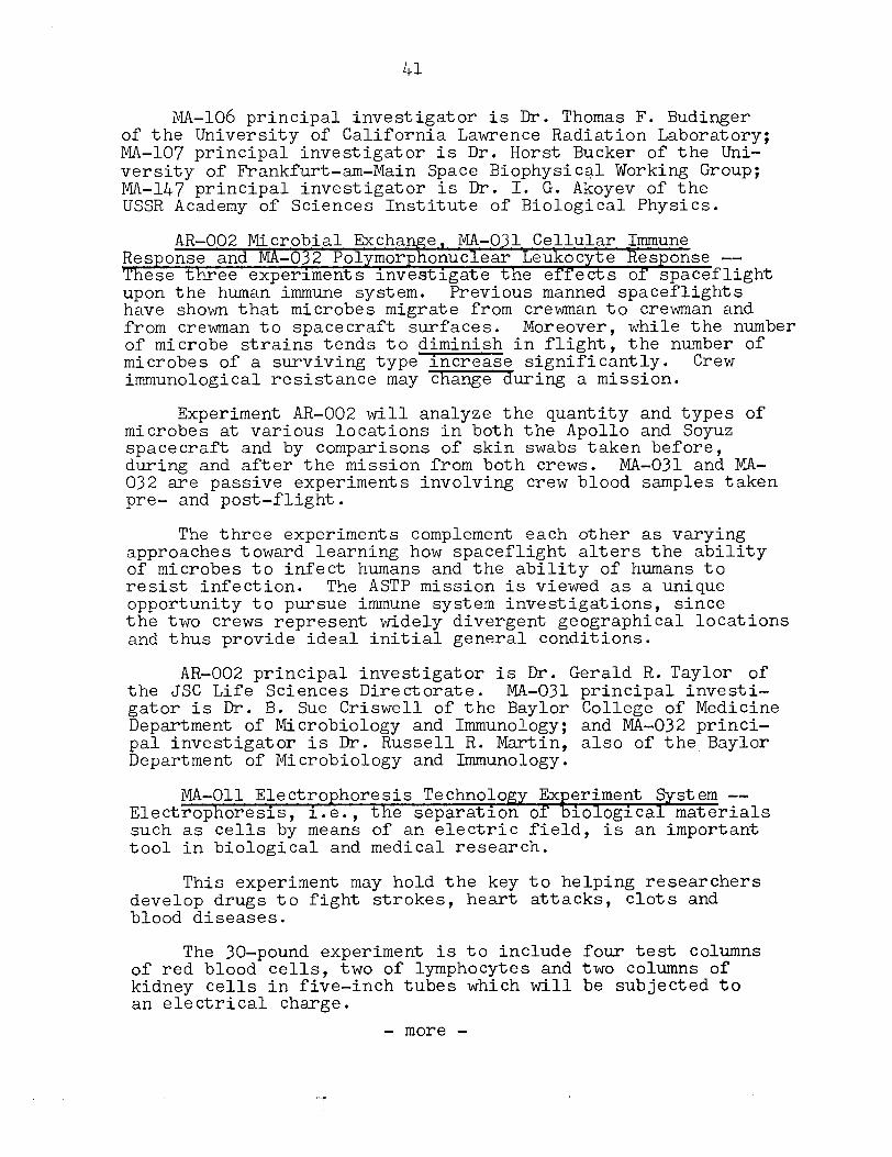
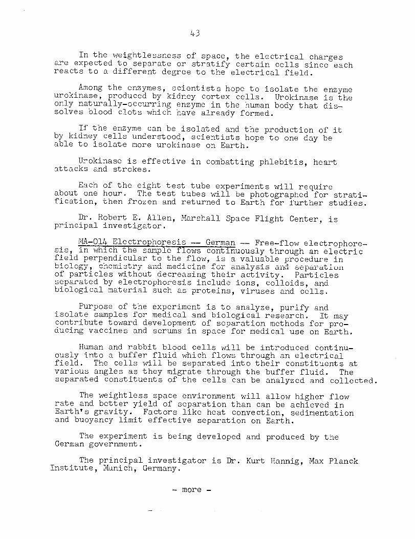
MA-011 Electrophoresis Technology Experiment System -- Electrophoresis, i.e., the separation of biological materials such as cells by means of an electric field, is an important tool in biological and medical research.
This experiment may hold the key to helping researchers develop drugs to fight strokes, heart attacks, clots and blood diseases.
The 30-pound experiment is to include four test columns of red blood cells, two of lymphocytes and two columns of kidney cells in five-inch tubes which will be subjected to an electrical charge.
- more -
42
Y e
43
In the weightlessness of space, the electrical charges are expected to separate or stratify certain cells since each reacts to a different degree to the electrical field.
Among the enzymes, urokinase,
scientists hope to isolate the enzyme produced by kidney cortex cells. Urokinase is the
only naturally-occurring enzyme in the human body that dis- solves blood clots which have already formed.
If the enzyme can be isolated and the production of it by kidney cells understood, scientists hope to one day be able to isolate more urokinase on Earth.
Urokinase is effective in combatting phlebitis, heart attacks and strokes.
about Each of the eight test tube experiments will require
one hour. The test tubes will be photographed for strati- fication, then frozen and returned to Earth for further studies.
Dr. Robert E. Allen, Marshall Space Flight Center, is principal investigator.
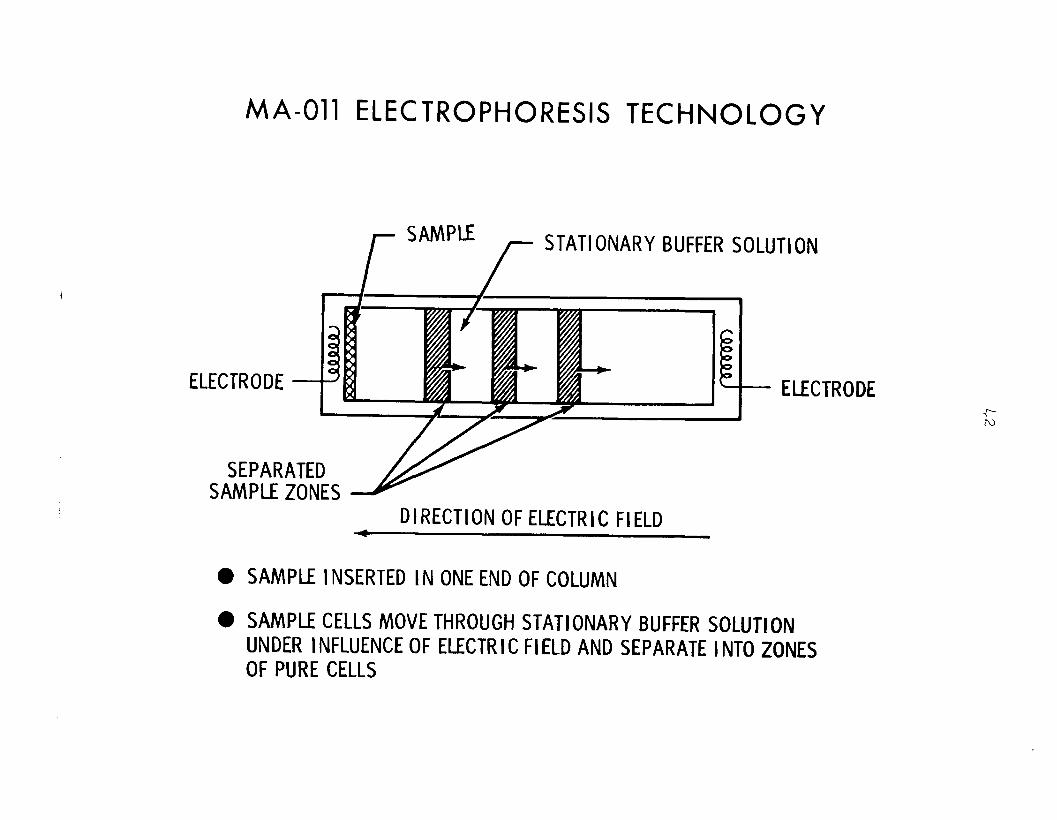
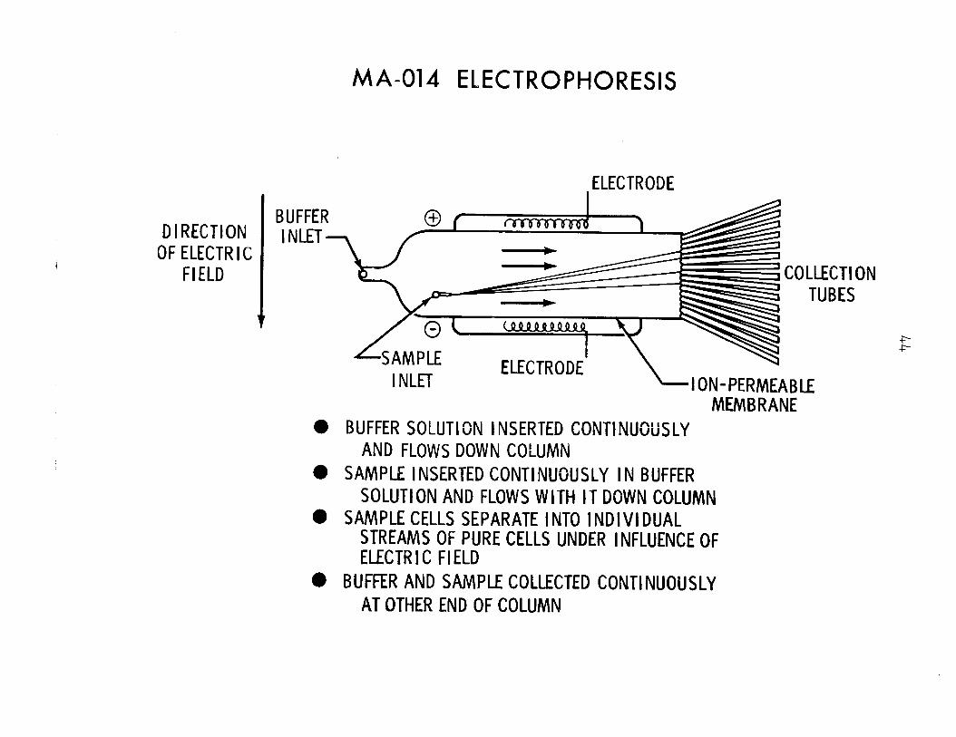
sis, MA-014 Electrophoresis -- German -- Free-flow electrophore-
field in which the sample flows continuously through an electric
perpendicular to the flow, biology,
is a valuable procedure in chemistry and medicine for analysis and separation
of particles without decreasing their activity. Particles separated by electrophoresis include ions, colloids, and biological material such as proteins, viruses and cells.
Purpose of the experiment is to analyze, purify and isolate samples for medical and biological research. It may contribute toward development of separation methods for pro- ducing vaccines and serums in space for medical use on Earth.
Human and rabbit blood cells will be introduced continu- ously into a buffer fluid which flows through an electrical field. The cells will be separated into their constituents at various angles as they migrate through the buffer fluid. The separated constituents of the cells can be analyzed and collected.
The weightless space environment will allow higher flow rate and better yield of separation than can be achieved in Earth's gravity. Factors like heat convection, sedimentation and buoyancy limit effective separation on Earth.
The experiment is being developed and produced by the German government.
The principal investigator is Dr. Kurt Hannig, Max Planck Institute, Munich, Germany.
- more -
MA-014 ELECTROPHORESIS
DIRECTION OF ELECTR I C
FIELD
BUFFER INLET-
l
l
0
l
ELECTRODE
MEMBRANE BUFFER SOLUTION INSERTED CONTINUOUSLY
AND FLOWS DOWN COLUMN SAMPLE INSERTED CONTINUOUSLY IN BUFFER
SOLUTION AND FLOWS WITH IT DOWN COLUMN SAMPLE CELLS SEPARATE I NT0 INDIVIDUAL
STREAMS OF PURE CELLS UNDER INFLUENCE OF ELECTR I C FIELD
BUFFER AND SAMPLE COLLECTED CONTINUOUSLY AT OTHER END OF COLUMN
LLECTI ON TUBES
45
MA-010 Multipurpose Electric Furnace Experiment System -- The Multipurpose Uectric Furnace Experiment System for the ASTP will consist of an upgraded modification based on the pioneering research of the electric furnace successfully demonstrated on Skylab.
The furnace system provides a means to perform experiments to demonstrate the feasibility of using the weightless space environment to investigate crystallization, convection, and immiscibility processes for use in future material-processing applications in space, on Earth.
as well as applications to technology
The furnace system will be used to perform experiments involving phase changes at elevated temperatures in systems comprising selected combinations of solid, liquid and vapor phases. Since the experiments will be performed in weightless- ness, the liquid and vapor phases will be essentially quiescent and phases of different density will have little or no tendency to separate.
The system consists of four main parts: the furnace, designed to mount on the docking module wall using a specially designed heat sink and vacuum line; a programmable electronic temperature controller to maintain temperature levels in the furnace and provide a controlled variable cool-down function to permit more constant crystal growth rates; experiment cart- ridges which will contain the sample materials; and the helium package to provide rapid cool-down capability.
Dimensions and weights of the furnace system are as follows:
Furnace -- 10.1 centimeters (4 inches) in diameter; 29.2 centimeters (11.5 inches) long; 5.2 kilograms (11.5 pounds).
Control package -- 26 centimeters (lo.25 inches 21.6 centimeters (8.5 inches 15.2 centimeters (6 inches); 5.6 kilograms (12.4 pounds).
Helium package -- 24.4 centimeters (9.6 inches) by 20.3 centimeters (8 inches) by 10 centimeters (4 inches); 27.2 kilograms (60 pounds).
Cartridge -- 1.23 centimeters (.8 inches) in diameter; 20 centimeters (7.9 inches) long; .18 kilogram (.4 pounds).
- more -
46
Prime contractor for the furnace system is Westinghouse Corporation, Pittsburgh, Pennsylvania.
Arthur Boese, Marshall Space Flight Center, is principal investigator.
A brief description of the seven experiments which will use the Multipurpose Electric Furnace follows:
MA-041 Surface-Tension-Induced Convection -- One of the most imp%%% effects of the weightless environment on metal- forming processes is the absence of gravity-induced convec- tion currents in the molten state. However, given the absence of gravity-induced convection currents, the possibility of convection effects caused by surface tension may become an important factor.
Surface-tension gradients can be caused by thermal or concentration differences. This experiment will evaluate sur- face-tension effects due to concentration gradients in order to determine whether special precautions need to be taken to avoid these convective effects in space processes that depend on the suppression of convection currents.
Paired specimens of alloys containing small amounts of gold will be melted in iron and graphite capsules and allowed to mix.
After the metals have solidified and returned to Earth, they will be cut into thin slices and the sections analyzed for distribution of gold to determine the presence or absence of convective effects caused by variations in surface tension during the heating.
Dr. Richard E. Reed, Oak Ridge National Laboratories, Oak Ridge, Tennessee, is principal investigator.
MA-044 Monotectic and Ssectic Alloys -- Specimens of two differentmoys will be melted and samples withdrawn .A after varying periods to assess how the lack of stratification in weightless mixtures of liquids of differing densities may influence the approach to equilibrium in the formation of intermetallic compounds.
Aluminum antimony compounds have promise as a high-effi- ciency solar cell material, but technological difficulties associated with compound formation and single crystal growth have hampered development efforts. One of the underlying causes of these difficulties may be the large difference in specific gravities of the two elements. Weightlessness should have pronounced effects on the solidification of this and other binary alloy systems having widely different specific gravities.
- more -
Understanding of phase separation due to the difference in specific gravities may lead to modified physical principles and new materials.
In this experiment, compound will be prepared
two samples of the aluminum-antimony and vacuum encapsulated in quartz.
After melting in the multipurpose furnace and solidifying samples will be returned to Earth and analyzed to determi;e
the
physical and electrical properties. Similar evaluation tech- niques will be applied to control samples processed on Earth, and the results compared.
As a companion experiment, also will be tested in space and
a sample of lead-zinc alloy compared to ground-processed
samples to determine the effects of zero-gravity on the degree of immiscibility of this monotectic system.
Dr. Choh-Yi Ang, Hawthorne, California, consultant to Marshall Space Flight Center, and Dr. Lewis Lacy of Marshall Space Flight Center are co-investigators.
~~-060 Interface Marking in Crystals -- A cylindrical crystal of doped germanium will be partly melted and then resolidified. During solidification, artificial growth bands will be introduced into the crystal by electrical pulses that produce cooling at the solid-liquid interface at four- second intervals. The bands will provide a time reference for determination of microscopic growth rates.
This information, and measurements of the distribution of material within the crystal, analysis of the growth process.
will make possible detailed
It is well known that defects limiting chemical and crystalling perfection are one of the major causes that make electronic devices (especially semi-conductor devices) perform below their theoretical levels.
Gravity-induced thermo-hydrodynamic perturbations in the melt have been identified as the primary cause for these defects. Thus semi-conductor crystal growth is one of the most promising projects for commercial space exploitation.
Dr. Harry C. Gatos, Cambridge,
Massachusetts Institute of Technology, is principal investigator.
MA-070 Processing of Magnets -- Magnetic materials will be melted and resolidified at controlled rates to see whether cast materials with improved properties can be made under weightless conditions.
- more -
Due to recent improvements in their properties, high- coercive-strength permanent magnets are being investigated for advanced technology applications such as levitators for high-speed ground transportation systems, magnetic bearings for flywheels used in energy storage, and gyros in deep space probes.
At present, coercive-strength
the major limitation to the use of high- cobalt/rare-earth permanent magnets is the
method of fabrication, i.e., sintering of powers. This is a process involving a large number of individual steps and the incomplete densification leads to degradation of the properties by oxidation.
The processing of these magnetic materials in the weight- less environment should, in one operation, eliminate gravity- induced segregation and increase the density and magnetic properties of the product. will be grown.
Almost perfect magnetic crystals
Dr. David J. Larson, Grumman Corporation, Bethpage, N.Y., is principal investigator.
MA-085 Crystal Growth from the Vapor Phase -- Three experi- ments will be done on the growth of semiconductor crystals in the electric furnace, using different materials to see how the growth process in weightlessness differs from crystal growth on Earth.
Alloy compositions of germanium selenide and germanium telluride will be used, with argon added in one experiment.
The experiments are of technological importance for fabrication and processing of single crystals for solid-state applications.
Dr. Heribert Wiedemeier, Rensselaer Polytechnic Institute, Troy, New York, is principal investigator.
MA-131 Halide Eutectics -- Samples of a sodium chloride lithium fluoride composition with a low melting point will be melted in the electric furnace and then solidified.
This material solidifies in the form of fibers of lithium- fluoride embedded in sodium chloride that can act as an image- transmitting medium for infrared light.
The experiment will attempt to produce samples with a fiber distribution showing a high degree of orientation, regu- larity, and fiber continuity.
- more -
49
Electrical, thermomagnetic, optical, and superconducting characteristics of this material are expected to make possible exciting device applications in the electronic and optical fields.
Dr. Alfred S. Yue, University of California, Los Angeles, is principal investigator.
MA-150 U.S.S.R. Multiple Material MeltinK -- Convective stirring-during solidification and segregation in the melt due to gravity contribute to inhomogeneities, voids and structural imperfections in materials when processed on Earth.
In weightlessness, these phenomena will be absew and investigations will show the degree of material improvement that can be attained.
This experiment will process three different material systems in each cartridge. In the hot isothermal region, a sample of aluminum with tungsten spheres will be melted and resolidified. A germanium rod with 0.5 percent silicon will be partially melted and resolidified in the gradient region. An additional isothermal region will be created in the gradient zone to process an ampoule of powdered aluminum.
The understanding of the effects of gravity and convection in the solidification of materials can be applied to improving the materials processing techniques on Earth and most impor- tantly could lead to manufacturing superior materials in space for use on Earth.
Professor Lev Ivanovich Ivanov, USSR Academy of Sciences, Moscow, is the principal investigator.
MA-028 Crystal Growth -- This experiment takes the water diffusion approach to semiconductor crystal growth in zero-g. The experiment consists of six transparent reactors of /three compartments each. The two outer compartments contain different salt solutions which form an insoluble compound when mixed -- a compound that will grow into a crystal. each set contain pure water,
Center compartments in and by opening the adjoining
compartments containing the salt solutions, the solutions will diffuse toward each other in the center compartment to mix and form crystals. Crew observations and photographs at intervals after experiment activation, and return of the containers to JSC post-mission, will provide the investigator with his test results.
Principal investigator is Dr. M. D. Lind of the Rockwell International Corporation Science Center.
- more -
50
CREW TRAINING -
Each ASTP crew member spent approximately 2,000 hours in formal crew training for the July 15 mission. This includes the time the U.S. astronauts spent in the Soviet Union fa- miliarizing themselves with U.S.S.R. and the Russian language instruction.
equipment and procedures In addition to the
programmed training, each astronaut spent additional hours participating in other training activities such as physical fitness, study, informal briefings and reviews, and the neces- sary mission-support activities. Included were prelaunch tests at NASA Kennedy Space Center and docking module check- outs at the Rockwell International plant in Downey, California.
By using major pieces of hardware already available from previous Apollo missions, the crewmen reduced the hours nor- mally required for command module simulator training. Main emphasis was on the new system for docking with the Soyuz spacecraft and on the learning of a new language. Based on six exchanges, the crew trained about 700 hours for joint crew activities. Language courses that started 30 months prior to launch comprised approximately 700 hours of their training.
Highlights of specialized ASTP crew training topics are:
oper -- Detailed series of briefings on space
tation and modifications; craft systems,
-- Three visits by U.S. three weeks each visit,
astronauts to the USSR, spending to be the reciprocal of the training
time the cosmonauts spent at Johnson Space Center;
-- Saturn launch vehicle briefings on countdown, range safety, flight dynamics, failure modes and abort conditions;
-- Briefings and continuous training on mission photo- graphic objectives (Earth observations) and use of camera equipment;
-- Extensive pilot participation in reviews of all flight procedures for normal as well as emergency situations;
-- Stowage reviews and practice in training sessions in the spacecraft, mockups, and command module simulators allowed the crewmen to evaluate spacecraft stowage of crew-associated equipment;
-- Studies, briefings, and continuous training on in- dependent mission experiments and joint U.S./U.S.S.R. experi- ments;
- more -
51
-- More than 300 hours of training per man in command module simulators at Johnson Space Center loop simulations with flight controllers
including closed-
Moscow control centers; in both Houston and
-- Water egress training conducted in the indoor tank Johnson Space Center included uprighting from the Stable II
at
position (apex down) and egress onto rafts;
-- Launch pad egress training from mockups and from the actual spacecraft on the launch pad for possible emergencies such as fire, contaminants and power failures;
-- The training covered use of Apollo spacecraft fire suppression equipment in the cockpit;
-- Celestial reviews using the celestial sphere in the command module simulator with special emphasis on the 37 navigational stars used by the Apollo guidance computer.
- more -
52
CREW EQUIPMENT
Survival Kit
The survival kit is stowed in two rucksacks in the right- hand forward equipment bay of the command module above the docking module pilot couch.
Contents of Rucksack 1 are: lights,
two combination survival one desalter kit,
radio beacon, three pairs of sunglasses, one
one spare radio beacon battery and spacecraft connector cable, one knife in sheath, three water containers, two containers of sun lotion, two utility knives, three survi- val blankets and one utility netting.
Rucksack 2 contains: one three-man liferaft with carbon dioxide inflater, one sea anchor, two sea dye markers, three sunbonnets, one mooring lanyard, three manlines and two attach brackets.
The survival kit is designed to provide a @-hour post- landing (water or land) survival capability for three crewmen between 4-O degrees north and south latitudes.
Medical Kits
The Apollo command module medical supplies are contained in two kits. Included in the larger medical accessories kit are eye drops, lip balm, spare biomedical harnesses, oral thermometer and capsules/units of the following types: 33 decongestant, cardiac,
106 antibiotic, 30 analgesic, six stimulant, 70 74 gastrointestinal, 34 motion sickness, 10 sleeping,
one antiviral, six blood pressure maintenance and 20 cough syrup. A smaller command module auxiliary drug kit contains 120 injectable and 4-O capsule cardiac medication dosages and four injectable analgesic dosages.
Space Suits
The Apollo crew will wear pressure suits from liftoff until after the Apollo circularization maneuver, and will not don them again until docking module jettison. The Soyuz crew will wear suits from liftoff through docking, and will don them again for undocking and reentry. Both crews will be "shirtsleevefV for crew transfers and joint activities.
- more -
53
Pressure suits carried aboard Apollo are basically the Apollo/Skylab command module pilot version of the A7LB pressure garment assembly. Since there are no space walks in the ASTP mission plan, the Apollo suits have been modified to save weight and cost. For example, the cover layer of Teflon Beta alumnized Kapton/nylon has been re Teflon Beta polybenzimidazole (PBI P
laced with more durable fabric. Extravehicular
gloves, the pressure relief valve, the liquid cooling garment connector and the gas connectors for contingency life support systems have been deleted.
Pressure helmets and boots are of the Skylab type, and no over-helmet extravehicular visors are carried.
The A7LB pressure suit is manufactured by ILC Industries, Inc., Dover, Delaware.
Personal Hygiene
Apollo crew personal hygiene equipment includes body cleanliness items, the waste management system and the medical kit.
Packaged with the food are a toothbrush and a two-ounce tube of toothpaste for each crewman, and packets of g-by-10 centimeter (3.5-by-4 inch) wet-wipe cleansing towels and 30-by-30 centimeter (12-by-12 inch) dry towels. Shaving equipment, soap, combs and nail clippers are also included.
Solid body wastes are collected in plastic defecation bags which contain a germicide to prevent bacteria and gas formation. The bags are off-loaded into the docking module before it is jettisoned.
Urine collection devices are provided for use while wearing either the pressure suit or the inflight coveralls. The urine is dumped overboard through the spacecraft urine dump valve in the command module, Containers are provided for temporary urine stowage to preclude overboard dumping during certain mission activities such as experiment operation.
- more -
54
APOLLO MENU
"Everything from soup to nuts" is an apt phrase to describe the lo-day food supply stowed in the command module food lockers. Each crewman selected his daily menu from the wide range of food items qualified for space flight in canned, thermostabilized pouch, thermostabilized can, rehydratable and natural forms.
Breakfast, l-,d5Gand 9;
lunch and dinner menus repeat for mission days days 2, 6 and 10; days 3, 7 and 11; and days 4
. Food items range from shrimp cocktail and steak to peanut butter and jam, sandwiches.
and the makings for corned beef-on-rye
Rehydratable food items are mixed with hot or cold water from the command module water gun and kneaded in their plastic wraps until ready to eat, and the canned and pouch foods are eaten directly from the containers.
Daily menus for the astronauts and visiting cosmonauts are listed on the following pages.
- more -
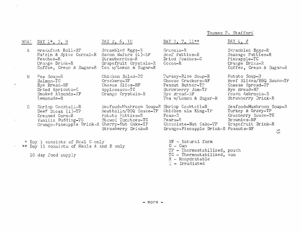
M3AL
A
B
‘
C
DAY l*, 5, 9 DAY 2, 6, 10
Breakfast Roll-NF Raisin & Spice Cereal-R Peaches-R Orange Drink-R Coffee, Cream & Sugar-R
Pea Soup-R Salmon-TC Rye Bread-NF Dried Apricots-C Smoked Almonds-NF Lemonade-R
Scrambled Eggs-R Bacon Wafers (4)-NF Strawberries-R Grapefruit Crystals-R Tea w/Lemon SC Sugar-R
Chicken Salad-TC Crackers-NF Cheese Slice-NF Applesauce-TC Orange Crystals-R
Shrimp Cocktail-R Beef Steak (I)-TP Creamed Corn-R
Seafood-Mushroom Soup-R Shrimp Cocktail-R Meatballs/BBQ Sauce-TP Chicken ala King-TP Potato Patties-R Peas-R Stewed Tomatoes-TC Pears-R
Thomas P. Stafford
DAY 3, 7, 11** DAY 4, 6
Granola-R Scrambled Eggs-R Beef Patties-R Sausage Patties-R Dried Peaches-C Pineapple-TC Cocoa-R Orange Drink-R
Coffee, Cream & Sugar-R
Turkey-Rice Soup-R Potato Soup-R Cheese Crackers-NF Beef Slices/BBQ Sauce-TP Peanut Butter-TP Cheese Spread-TP Strawberry Jam-TP Rye Bread-NF Rye Bread-NF Peach Ambrosia-R Tea w/Lemon SC Sugar-R Strawberry Drink-R
Vanilla Pudding-TC Orange-Pineapple Drink-R Cherry-Nut Cake-TP
Strawberry Drink-R
Seafood-Mushroom Soup-R Turkey & Gravy-TP Cranberry Sauce-TC Brownies-NF
Chocolate-Nut Cake-TP Grapefruit Drink-R Orange-Pineapple Drink-R Peanuts-NF v-l wl
* Day 1 consists of Meal C only ** Day 11 consists of Meals A and B only
10 day food supply
NF - Natural form c- Can TP - Thermostabilized, pouch TC - Thermostabilized, can R - Rehydratable I- Irradiated
- more -
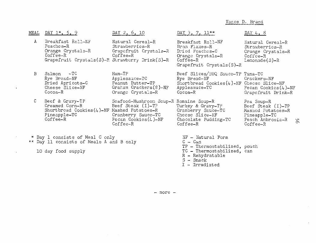
Vance D. Brand --
MEAL
A
DAY I*, 5, 9 DAY 2, 6, 10
Breakfast Roll-NF Natural Cereal-R Peaches-R Strawberries-R Orange Crystals-R Grapefruit Crystals-R Coffee-R Coffee-R Grapefruit Crystals(S)-R Strawberry Drink(S)-R
Salmon -TC Rye Bread-NF Dried Apricots-C Cheese Slice-NF Cocoa-R
Ham-TP Beef Slices/BBQ Sauce-TP Tuna-TC Applesauce-TC Rye Bread-NF Crackers-NF Peanut Butter-TP Graham Crackers(g)-NF
Shortbread Cookies(4)-NF Cheese Slice-NF Applesauce-TC Pecan Cookies(&)-NF
Orange Crystals-R Cocoa-R Grapefruit Drink-R
DAY 3, 7, ll** DAY 4, 8
Breakfast Roll-NF Natural Cereal-R Bran Flakes-R Strawberries-R Dried Peaches-C Orange Crystals-R Orange Crystals-R Coffee-R Coffee-R Lemonade(S)-R Grapefruit Crystals(S)-R
Beef & Gravy-TP Seafood-Mushroom Soup-R Romaine Soup-R Pea Soup-R Creamed Corn-R Beef Steak (I)-TP Shortbread Cookies(&)-NF Mashed Potatoes-R
Turkey & Gravy-TP Beef Steak (I)-TP Cranberry Sauce-TC Mashed Potatoes-R
Pineapple-TC Cranberry Sauce-TC Cheese Slice-NF Pineapple-TC Coffee-R Pecan Cookies(4)-NF Chocolate Pudding-TC
Coffee-R Coffee-R Peach Ambrosia-R g Coffee-R
* Day 1 consists of Meal C only ** Day 11 consists of Meals A and B only
10 day food supply
NF - Natural Form c- Can TP - Thermostabilized, pouch TC - Thermostabilized, can R - Rehydratable s- Snack I- Irradiated
- more -
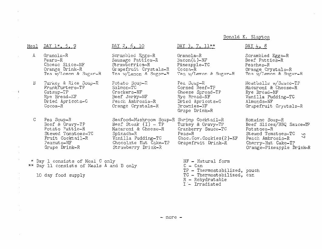
Donald K. Slay-to2
Meal
A
DAY 13, 5, 9
Granola-R Scrambled Eggs-R Pears-R Sausage Patties-R Cheese Slice-NF Strawberries-R Orange Drink-R Tea w/Lemon & Sugar-R
Grapefruit Crystals-R Tea w/Lemon &. Sugar-R
Turkey & Rice Soup-R Frankfurters-TP Catsup-TP Rye Bread-RF Dried Apricots-C Cocoa-R
Potato Soup-R Salmon-TC Crackers-NF Beef Jerky-NF Peach Ambrosia-R Grange Crystals-R
Pea Soup-R Beef & Gravy-TP Potato Pattie-R Stewed Tomatoes-TC Fruit Cocktail-R Peanuts-NF Grape Drink-R
DAY 2, 6, 10 DAY 3, 7, ll**
Granola-R Baton(4)-NF Pineapple-TC Cocoa-R Tea w/Lemon 6% Sugar-R
Pea Scup-R Corned Beef-TP Cheese Spread-TP Rye Bread-NF Dried Apricots-C Brownies-NF Grape Drink-R
Seafood-Mushroom Soup-R Shrimp Cocktail-R Beef Steak (I) - TP Turkey & Gravy-TP Macaroni 8c Cheese-R Cranberry Sauce-TC Spinach-R Peas-R Vanilla Pudding-TC Choc.Cov.Cookies(2)-NF Chocolate Wt Cake-TP Grapefruit Drink-R Strawberry Drink-R
DAY 4, 8
Scrambled Eggs-R Beef Patties-R Peaches-R Orange Crystals-R Tea w/Lemon & Sugar-R
Meatballs w/Sauce-TP i%caroni & Cheese-R Rye Bread-RF Vanilla Pudding-TC Almonds-NF Grapefruit Crystals-R
Romaine Soup-R Beef Slices/BBQ Sauce-TP Potatoes-R Stewed Tomatoes-TC 2 Peach Ambrosia-R Cherry-Nut Cake-TP Orange-Pineapple Drink-R
* Day 1 consists of Meal C only ** Day 11 consists of Meals A and B only
-0 day food supply
NF - n'atural form c- Can TP - Thermostabilized, pouch TC - Thermostabilized, can R - Rehydratable I'- Irradiated
- more -
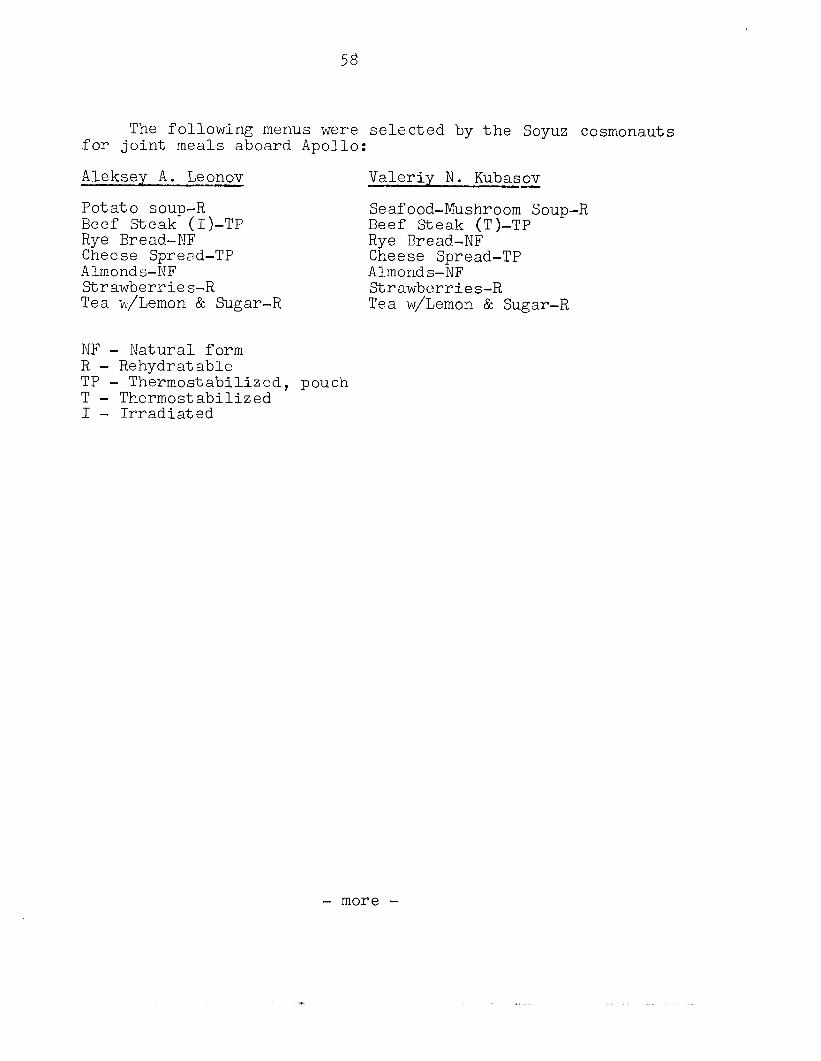
58
The following menus were selected by the Soyuz cosmonauts for joint meals aboard Apollo:
Aleksey A. Leonov Valeriy N. KubasE
Potato soup-R Beef Steak (I)-TP
Seafood-Mushroom Soup-R Beef Steak (T)-TP
Rye Bread-NF Rye Bread-NF Cheese Spread-TP Cheese Spread-TP Almonds-NF Almonds-NF Strawberries-R Strawberries-R Tea w/Lemon & Sugar-R Tea w/Lemon & Sugar-R
NF - JSatural form R - Rehydratable TP - Thermostabilized, pouch T - Thermostabilized I- Irradiated
- more -
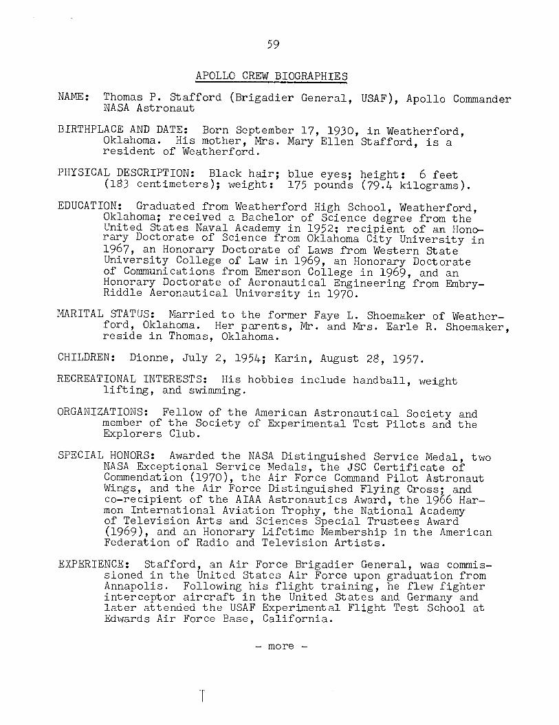
59
APOLLO CREW BIOGRAPHIES
NAME: Thomas P. Stafford (Brigadier General, USAF), Apollo Commander NASA Astronaut
BIRTHPLACE AND DATE: Oklahoma.
Born September 17, 1930, in Weatherford,
resident His mother, Mrs. Mary Ellen Stafford, is a
of Weatherford.
PHYSICAL DESCRIPTION: Black hair; blue eyes; height: 6 feet (183 centimeters); weight: 175 pounds (79.4 kilograms).
EDUCATION: Graduated from Weatherford High School, Weatherford, Oklahoma; received a Bachelor of Science degree from the United States Naval Academy in 1952; recipient of an Hono- rary Doctorate of Science from Oklahoma City University in 1967, an Honorary Doctorate of Laws from Western State University College of Law in 1969, an Honorary Doctorate of Communications from Emerson College in 1969, and an Honorary Doctorate of Aeronautical Engineering from Embry- Riddle Aeronautical University in 1970.
MARITAL STATUS: Married to the former Faye L. Shoemaker of Weather- ford, Oklahoma. Her parents, reside in Thomas, Oklahoma.
Mr. and Mrs. Earle R. Shoemaker,
CHILDREN: Dionne, July 2, 1954; Karin, August 28, 1957.
RECREATIONAL INTERESTS: lifting,
His hobbies include handball, weight and swimming.
ORGANIZATIONS: member
Fellow of the American Astronautical Society and of the Society of Experimental Test Pilots and the
Explorers Club.
SPECIAL HONORS: Awarded the NASA Distinguished Service Medal, two NASA Exceptional Service Medals, the JSC Certificate of Commendation (1970)) the Air Force Command Pilot Astronaut Wings, and the Air Force Distinguished Flying Cross; and co-recipient of the AIAA Astronautics Award, the 1966 Har- mon International Aviation Trophy, the National Academy of Television Arts and Sciences Special Trustees Award (l969), and an Honorary Lifetime Membership in the American Federation of Radio and Television Artists.
EXPERIENCE: Stafford, an Air Force Brigadier General, was commis- sioned in the United States Air Force upon graduation from Annapolis. Following his flight training, he flew fighter interceptor aircraft in the United States and Germany and later attended the USAF Experimental Flight Test School at Edwards Air Force Base, California.
- more -
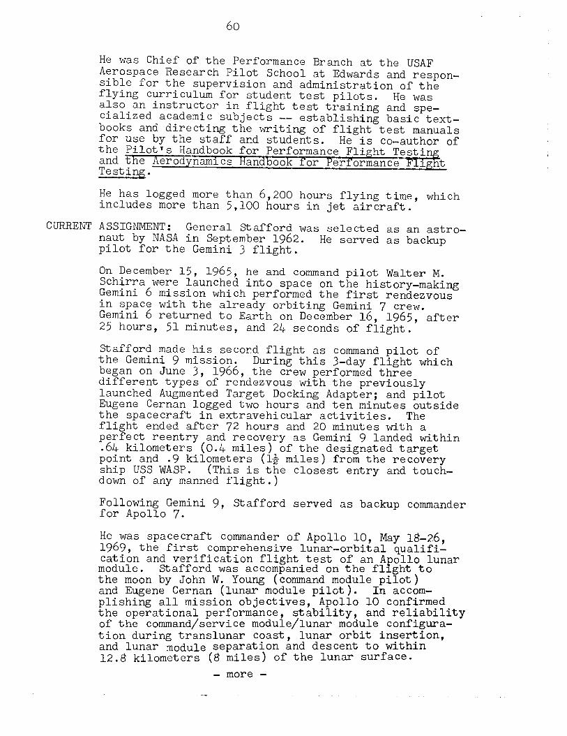
CURRENT
60
He was Chief of the Performance Aerospace Research Pilot School .-- -
Branch at the USAF at Edwards and respon-
sible for the supervision and administration of the flying curriculum for student test pilots. He was also an instructor in flight test training and spe- cialized academic subjects -- establishing basic text- books and directing the writing of flight test manuals for use by the staff and students. He is co-author of the Pilot's Handbook for Performance Flight Testi and the Aerodynamics Handbook for Performance Testing.
--FEgt
He has logged more than 6,200 hours flying time, which includes more than 5,100 hours in jet aircraft.
ASSIGNMENT: General Stafford was selected as an astro- naut by NASA in September 1962. pilot for the Gemini 3 flight.
He served as backup
On December 15, 1965, he and command pilot Walter M. Schirra were launched into space on the history-making Gemini 6 mission which performed the first rendezvous in space with the already orbiting Gemini 7 crew. Gemini 6 returned to Earth on December 16, 1965, after 25 hours, 51 minutes, and 24 seconds of flight.
Stafford made his second flight as command pilot of the Gemini 9 mission. began on June 3,
During this 3-day flight which 1966, the crew performed three
different types of rendezvous with the previously launched Augmented Target Docking Adapter; and pilot Eugene Cernan logged two hours and ten minutes outside the spacecraft in extravehicular activities. The flight ended after 72 hours and 20 minutes with a perfect reentry and recovery as Gemini 9 landed within .64 kilometers (0.4 miles) of the designated target point and .9 kilometers (l$ miles) from the recovery ship USS WASP. (This is the closest entry and touch- down of any manned flight.)
Following Gemini 9, for Apollo 7.
Stafford served as backup commander
He was spacecraft commander of Apollo 10, May 18-26, 1969, the first comprehensive lunar-orbital qualifi- cation and verification flight test of an Apollo lunar module. Stafford was accompanied on the flight to the moon by John W. Young (command module pilot) and Eugene Cernan (lunar module pilot). In accom- plishing all mission objectives, Apollo 10 confirmed the operational performance, stability, and reliability of the command/service module/lunar module configura- tion during translunar coast, lunar orbit insertion, and lunar module separation and descent to within 12.8 kilometers (8 miles) of the lunar surface.
- more -
61
The latter maneuver employed all but the final minutes of the technique prescribed for use in an actual lunar landing and permitted critical evaluations of the lunar module propulsion systems and rendezvous and landing radar devices during completion of the first rendezvous and re-docking maneuvers in lunar orbit. In addition to demonstrating that man could navigate safely and accurately in the Moon's gravitational fields, Apollo 10 photographed and mapped tentative landing sites for future missions.
In his three space flights, Stafford has completed five rendezvous and logged 290 hours and 1.5 minutes in space.
As Chief of the Astronaut Office from August 1969 through May 1971, he was responsible for the coordi- nation, scheduling, and control of all activities involving NASA astronauts. General Stafford was named Deputy Director of Flight Crew Operations in June 1971. He held this management position, assisting with over- seeing the activities of the Astronaut Office, the Aircraft Operations Office, the Flight Crew Integra- tion Division, sion,
the Crew Training and Simulation Divi-
1974. and the Crew Procedures Division until February
L
General Stafford currently is involved in preparations for his role as commander of the United States flight crew for the Apollo Soyuz Test Project (ASTP) mission. He will be making his fourth journey into space in the joint United States-Soviet Union Earth-orbital mission scheduled for launch July 15, 1975. The joint mission is designed to test equipment and techniques that will provide for an international crew rescue capabil- ity in space, as well as permit future cooperative scientific missions.
- more -
62
NAME: Vance DeVoe Brand (Mr.), Apollo command module pilot NASA Astronaut
BIRTHPLACE AND DATE: His parents,
Born in Longmont, Colorado, May 9, 1931.
Longmont. Dr. and Mrs. Rudolph W. Brand, reside in
PHYSICAL DESCRIPTION: Blond hair; grey eyes; height: 11 inches (180 centimeters); weight:
5 feet
(79.4 kilograms). 175 pounds
EI UCATION: Graduated from Longmont High School, Longmont, Colorado, received a Bachelor of Science degree in Business from the University of Colorado in 1953, Bachelor of Science degree in Aeronautical Engineering from the University of Colorado in 1960, and a Mas- ter's degree in Business Administration from the Uni- versity of California at Los Angeles in 1964.
MARITAL STATUS: Married to the former Joan Virginia Weninger of Chicago, Illinois. Weninger,
Her parents, reside in Chicago.
Mr. and Mrs. Ralph D.
CHILDREN: Susan N., April 30, 1954; Stephanie, August 6, 1955; Patrick R., March 22, 1958; Kevin S., December 1, 1963.
RECREATIONAL INTERESTS: skin diving,
Enjoys running to stay in condition, skiing, and canoeing.
ORGANIZATIONS: Member of the Society of Experimental Test Pilots, the American Institute of Aeronautics and Astronautics, Sigma Nu, and Beta Gamma Sigma.
SPECIAL HONORS: JSC Certificate of Commendation (1970) and NASA Exceptional Service Medal (19'74).
EXPERIENCE: and naw*
Brand served as a commissioned officer aviator with the U.S. Marine Corps from 1953
to 1957. His Marine Corps assignments included a 15-month tour in Japan as a jet fighter pilot. Fol- lowing release from active duty, he continued in Marine Corps Reserve and Air National Guard fighter squadrons until 1964; and he still retains a commission in the Air Force Reserve.
Civilian. From 1960 to 1966, Brand was employed as a civilian by the Lockheed Aircraft Corporation. He worked first as a flight test engineer on the P3A "Orion" aircraft and later transferred to the experi- mental test pilot ranks. In 1963, he graduated from the U.S. Naval Test Pilot School and was assigned to Palmdale, California, as an experimental pilot on Canadian and German F-104 development programs.
- more -
63
Immediately prior to his selection to the astronaut program, Brand was assigned to the West German F-104G Flight Test Center at Istres, France, as an experimental test pilot and leader of a Lockheed flight test advisory group.
He has logged more than 4,600 hours of flying time, which include more than 3,800 hours in jets and 390 hours in helicopters.
CURRENT ASSIGNMENT: Mr. Brand is one of the 19 astronauts selected by NASA in April 1966. He served as a crew member for the th.ermal vacuum testing of the proto- type command module and was an astronaut support crew- man for the Apollo 8 and 13 missions. He was the backup command module pilot for Apollo 15.
Brand served as backup commander for the Skylab 3 and Skylab 4 missions.
Immediately following fulfillment of his Skylab assign- ments, he commenced training as a prime crewman for the Apollo Soyuz Test Project (ASTP) mission scheduled for July 15, 1975. This will be Brand's first space flight. His crew position will be command module pilot. The joint docking mission will be a cooperative test of space flight equipment and techniques between the United States and the Soviet Union. The flight should pave the way for future cooperative scientific missions.
- more -
NAME: Donald K. Slay-ton (Mr.), Apollo docking module pilot NASA Astronaut
BIRTHPLACE AND DATE: Born March 1, 1924, in Sparta, Wisconsin.
PHYSICAL DESCRIPTION: Brown hair; blue eyes; height: 5 feet 1% inches (1'79 centimeters); weight: (74.8 kilograms).
165 pounds
EDUCATION: Graduated from Sparta High School; received a Bachelor of Science degree in Aeronautical Engineering from the University of Minnesota, Minneapolis, Minne- sota, in 1949; an Honorary Doctorate in Science from Carthage College, Carthage, Illinois, in 1961; and an Honorary Doctorate in Engineering from Mtichigan Tech- nological University, Houghton, Michigan, in 1965.
MARITAL STATUS: Married to the former Marjory Lunney of Los Angeles, California. George Lunney,
Her parents, Mr. and Mrs. reside in Los Angeles.
CHILDREN: Kent, April, 1957.
RECREATIONAL INTERESTS: and shooting.
His hobbies are hunting, fishing,
ORGANIZATIONS: Associate fellow of the Society of Experimental Test Pilots; fellow of the American Astronautical Society; member of the American Institute of Aeronautics and Astronautics, the Experimental Aircraft Association, the Space Pioneers, and the Confederate Air Force; life member of the Order of Daedalians and the National Rifle Association of America; and honorary member of the American Fighter Aces Association.
SPECIAL HONORS: Awarded two NASA Distinguished Service Medals and the NASA Exceptional Service Medal; the Collier Trophy; the SETP Iven C. Kinchloe Award; the General Billy Mitchell Award; and the SETP J. H. Doolittle Award for 1972.
EXPERIENCE: Slay-ton entered the Air Force as an aviation cadet and received his wings in April 1943 after com- pleting flight training at Vernon and Waco, Texas.
As a B-25 pilot with the 340th Bombardment Group, he flew 56 combat missions in Europe. He returned to the United States in mid-1944 as a B-25 instructor pilot at Columbia, South Carolina, and later served with a unit responsible for checking pilot proficiency in the ~-26. In April 1945, he was sent to Okinawa with the 319th Bombardment Group and flew seven combat mis- sions over Japan. He served as a B-25 instructor for one year following the end of the war and subsequently left the Air Force to enter the University of Minnesota.
- more - .-.
65
He became an aeronautical engineer after graduation and worked for two years with the Boeing Aircraft Corporation at Seattle, Washington, before being recalled to active duty in 1951 with the Minnesota Air National Guard.
Upon reporting for duty, he was assigned as maintenance flight test officer of an F-51 squadron located in Minneapolis, followed by 18 months as a technical in- spector at Headquarters Twelfth Air Force, and a similar tour as fighter pilot and maintenance officer with the 36th Fighter Day Wing at Bitburg, Germany.
Returning to the United States in June 1955, he attended the USAF Test Pilot School at Edwards Air Force Base, California. He was a test pilot there from January 1956 until April 1959 and participated in the testing of fighter aircraft built for the United States Air Force and some foreign countries.
He has logged more than 5,200 hours flying time, including 3,255 hours in jet aircraft.
CURRENT ASSIGNMENT: Mr. Slayton was named as one of the Mer- cur ule 3
astronauts in April 1959. He was originally sched- to pilot the Mercury-Atlas 7 mission but was re-
lieved of this assignment due to a heart condition which was discovered in August 1959. The MA-7 mission was subsequently flown by M. Scott Carpenter in May 1962.
Slayton became Coordinator of Astronaut Activities in September 1962 and was responsible for the operation of the astronaut office. In November 1963, he resigned his commission as an Air Force Major to assume the role of Director of Flight Crew Operations. In this capa- city, he was responsible for directing the activities of the Astronaut Office, the Aircraft Operations Office, the Flight Crew Integration Division, the Crew Training and Simulation Division, and the Crew Procedures Divi- sion.
In March 1972, following a comprehensive review of his medical status by NASA's Director for Life Sciences and the Federal Aviation Agency, Mr. Slayton was re- stored to full flight status and certified eligible for future manned space flights.
Slay-ton was named subsequently to the United States ',;;ght crew for the Apollo Soyuz Test Project (ASTP)
in February 1974, relinquished his position as Dirictor of Flight Crew Operations to concentrate efforts on preparations for that flight. He will be making his first journey into space and will serve as docking module pilot in the joint United States-Soviet union
- more -
66
Earth-orbital mission scheduled for July 15, 1975. The joint mission is designed to test equipment and techniques that will provide for an international crew rescue capability in space, as well as permit future cooperative scientific missions.
- more -
67
APOLLO SPACECRAFT
Command/Service Module
The Apollo command/service module to be flown for the ASTP mission is similar in most regards to the ones flown in ferrying Skylab crews to and from the space station, except that some modifications were made to the spacecraft to fit the mission needs.
For example, the steerable high-gain antenna that was used for deep-space communications during the Apollo lunar missions but was not needed for Earth-orbit Skylab on again on ASTP-command/service module 111. The antenna will lock on to the ATS-6 satellite in synchronous orbit, thus providing communications with Mission Control for 55 percent of each orbit. Additional controls for the docking system and special command/service module-to-docking module umbilicals had to be added, together with experiment packages and their controls.
Launch Escape System (LES) -- The launch escape system would propel the command module to a safe altitude in the case of a launch abort. The launch escape system has three solid- propellant rocket motors: a 658,000-newton (U-+7,000-pound) thrust motor, a 10,750-newton (2,400-pound) thrust pitch control motor, and a 141,000-newton (31,500-pound) thrust tower jettison motor. Two canard vanes deploy to turn the command module aerodynamically to a heatshield-forward attitude. The launch escape system is 10 meters (33 feet) tall and 1.2 meters (four feet) in diameter at the base, and weighs 4,165 kilo- grams (9,182 pounds).
Command Module (CM) -- The command module is a pressure vessel encased In a heatshield, cone-shaped, weighing 5,944 kilograms (13,105 pounds) at launch.
The command module consists of a forward compartment con- taining two entry-attitude reaction control thrusters and com- ponents of the Earth landing system; the crew compartment or inner pressure vessel containing crew accommodations, controls and displays, and many of the spacecraft systems; and the aft compartment housing 10 entry-attitude reaction control thrus- ters, propellant tankage, helium tanks, water tanks and the command/service module umbilical cable. The crew compartment has 6 cubic meters (210 cubic feet) of habitable volume.
Heatshields around the three compartments are made of brazed stainless steel honeycomb with an outer layer of pheno- lit epoxy resin as an ablative material.
- more -
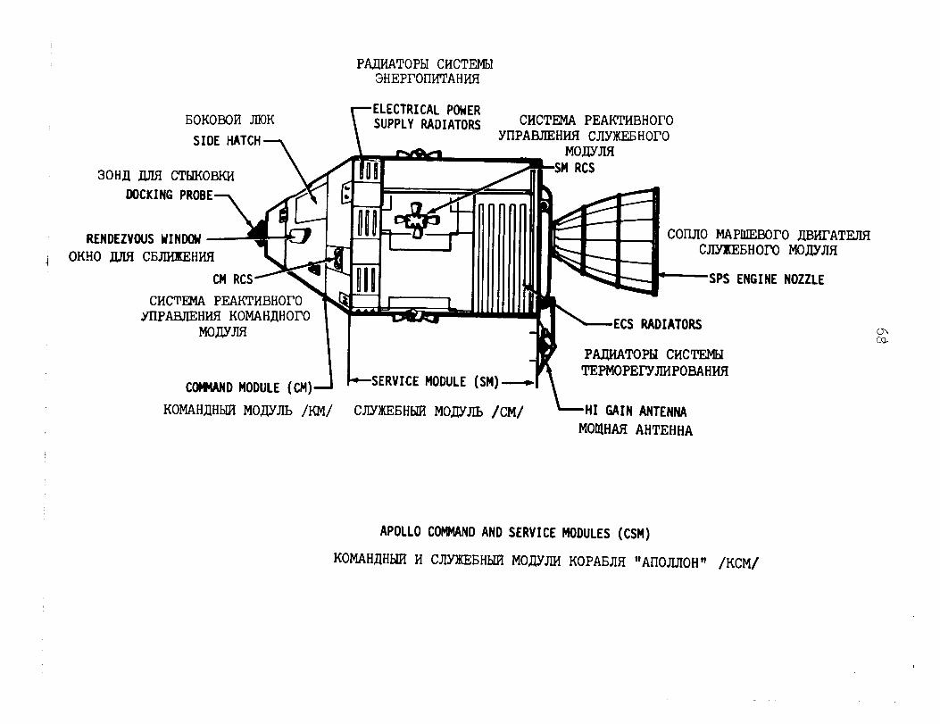
PAUiATOPbI CMCTEMbI 3HEPI'OWi'I'AH~
I;OKOBoFT JIIOK SIDE HATCH
\ 30HJJ DUl CT'bJKOBKJi
DOCKING PROBE -\
RENDEZVDUS YINDW OKHO LursI CNIHEOIHW
CMCTEMA PEAKTMBHOFO c YTIPABJIEHMR KOMAHnHOrO
MOAYJIfI
1 COMAND MODULE (CM)
KOMAHfiHbIFl MODJIb /KM/
ELECTRICAL POWER SUPPLY RADIATORS CHCTEMA PEAKTMBHOI'O
YIIPABJIEHWI CJIYXEEHOFO
-SERVICE MODULE (SM)o -SERVICE MODULE (SM)- \
COl-LJIO MAPIIJEEWO mHFATEJIfi CJIYlKEEiHOI'0 MOHVJIR
SPS ENGINE NOZZLE
-ECS RADIATORS
PIupwAToPbl CHCTEMEI TEPMOPEl-YJMPOBAHWI
CJIYXEBHhll? MODJIb /CM/ \HI GAIN ANTENNA MOUHAfi AHTEHHA
APOLLO COMMAND AND SERVICE MODULES (CSM)
KOMAHAHUI M CJYH(EEH~GI MOAYJM KOPAEJIR "AI-I~JIJI~H~~ /KCM/
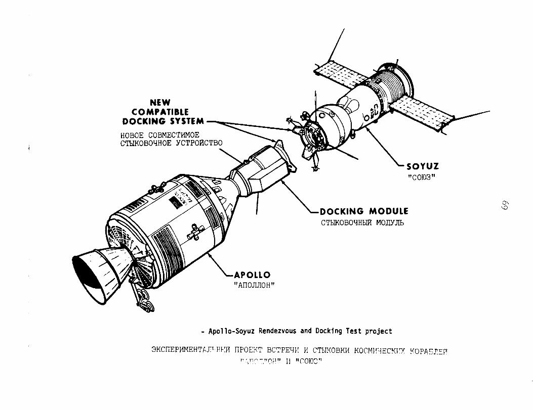
NEW COMPATIBLE
DOCKING SYSTEM
HOBOE COBMECTMMOE ___--- CThIKOBOYHOE YCTPOBCTBO 3Q
L SOYUZ "COlo3"
LDOCKING MODULE CTbIKOBOYHbIFf MOjJYJlb
"Al-IOJIJIOH"
- Apollo-Soyuz Rendezvous and Docking Test project
~KC~-IEPMMEHTL.JFH~!R l-IPOEKT BCTPEYH M CTMKOBKM KOCMI"-jECKIX I'OPAzqy II ' r;n ",nqF!" Ij "f-J)I(JJ" -1
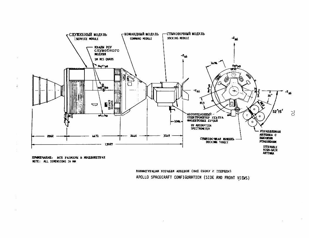
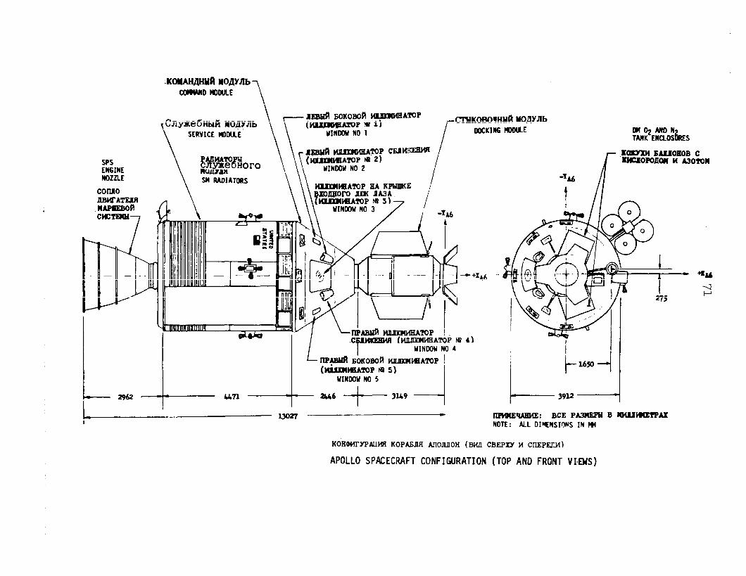
SPS ENSIWE NOZZLE Y( RADIATORS
un
\ \\ HUUtCIIATOPEAKPUIKE i
=ul-
i
.c -1 f
HeMlMBATOPNp YINWW NO 4
~~EOKOBO~blUIRI~AlVP ! (b6xm~zoPw51
YINDON NO 5
- zrJ6 -+- 3U9
KOHMWPWWI KOPANIfl AnORllOH (BW CBEPW H CIIEPECM)
APOLLO SPACECRAFT CONFIGURATION (TOP AND FRONT VIEUS)
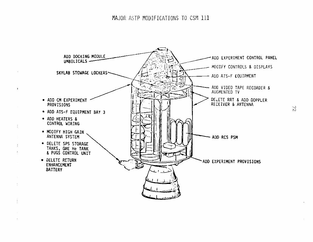
MAJOR ASTP MODIFICATIONS TO CSM 1111
ADD DOCKING MODULE UMBILICALS
ADD EXPERIMENT CONTROC PANEL
MODIFY CONTROLS & DISPLAYS
SKYLAB STOWAGE LOCKERS ADD ATS-F EQUIPMENT
ADC VIDEO TAPE RECORDER & AUGMENTED TV
l ADO CM EXPERIMENT PROVISIONS
l ADO ATS-F EQUIPMENT BAY 3
l ADO HEATERS L CONTROL WIRING
DELETE RRT & ADO DOPPLER RE:CEIVER & ANTENNA
l MODIFY HIGH GAIN ANTENNA SYSTEM
l DELETE SPS STORAGE TANKS, ONE He TANK & PUGS CONTROL UNIT
l DELETE RETURN ENHANCEMENT BATTERY
ADD RCS PSM
ADO EXPERIMENT PROVISIONS
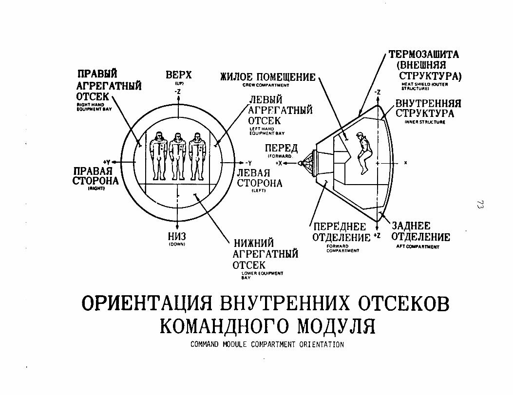
/TEPM03AUlMTA
/
(BHEUIHNI CTPYKTYPA) IlPABlitti BEPX
ArPErATHJdi lU?l IKMJIOE IIOMEIJEHME
C~EWCOMPARTMENT
JIEBbm
\ /
MEAT SHIELD louTEll
-2 STRUCTUREI
/A/ BHYTPEF- CTPVKT!
OTCEK P- .YPA
.-.-.-.
LEFT HAND LOUIPMENT BAY
(FORWARD
X
OTAEJIEHME ‘z OTAEJIEH (DOWN) FnRwARn ACT cnuD..NCY
ArPErATHMti -...... -.-
COMPARTMENT
OTCEK LOWER EOUIMENT BAY
OPMEHTA~IWBHYTPEHHMXOTCEKOB KOMAHAHOI'OMOJJYJIfI
COMMAND MODULE COMPARTMENT ORIENTATION
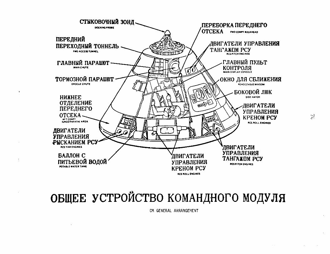
CI'bIKOBOtlHHft DtXKIMQ PROW
IlEPEflHClfi IIEPEXOAHkdiTOHHEnb
CID ACCES TWNEL b, / ,ABMI-ATEnM Yl-IPABJIEHMZi
I'nABHblti I-IAPAWIOT MAIN CHUTt
UIABHMihYnbT
TOPM03HOtiIlAPAUlIOT DRoGUE CHUTE
HMW(HEE
OKHO~nUWHNKEHMCl RENOEZVOUSWINOOW
SIDE HATCW
YllPABnEHMfl KPEHOMPCY
IUNDERNEATHl KS ROLL ENGINES
YIlPABnEHMR PblCKAHMEMPCY
KS YAW ENGINES
BAnnOHC / "$BMl-ATEnM YIlPABiEHMEI IIMTbEBOflBOAOfi YllPABnEHMfl TAHI-AlDMPCY
RCfPllCM ENGINES POTABLE WATER TANK KPEHOMPCY
nCS ROLL ENGINES
CM GENERAL ARRANGEMENT
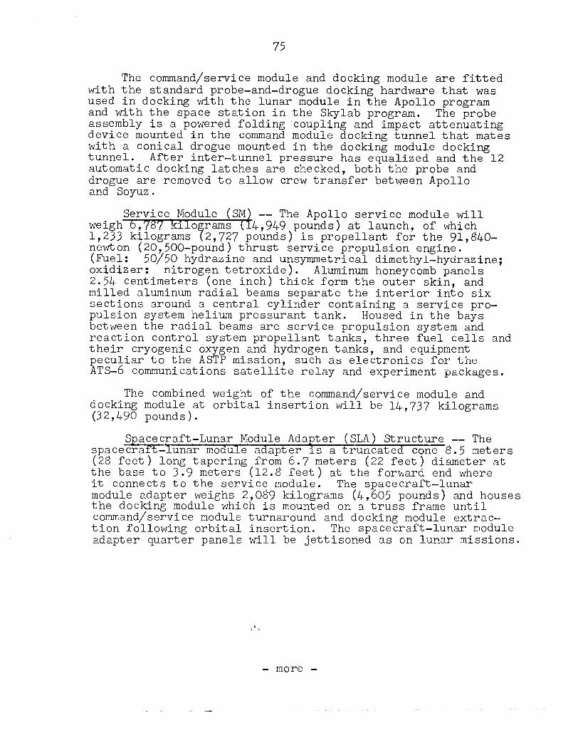
75
The command/service module and docking module are fitted with the standard probe-and-drogue docking hardware that was used in docking with the lunar module in the Apollo program and with the space station in the Skylab program. The probe assembly is a powered folding coupling and impact attenuating device mounted in the command module docking tunnel that mates with a conical drogue mounted in the docking module docking tunnel. After inter-tunnel pressure has equalized and the 12 automatic docking latches are checked, both the probe and drogue are removed to allow crew transfer between Apollo and Soyuz;.
Service Module (SM) -- The Apollo service module will weigh 6 '/8'/ kilo rams 1,233 kilograms 7
(1 4,949 pounds) at launch, of which 2,727 pounds) is propellant for the 91,840-
newton (20,500-pound) thrust service propulsion engine. (Fuel: W/50 hyd r a zine oxidizer:
and unsymmetrical dimethyl-hydrazine; nitrogen tetroxide). Aluminum honeycomb panels
2.54 centimeters (one inch) thick form the outer skin, and milled aluminum radial beams separate the interior into six sections around a central cylinder containing a service pro- pulsion system helium pressurant tank. Housed in the bays between the radial beams are service propulsion system and reaction control system propellant tanks, three fuel cells and their cryogenic oxygen and hydrogen tanks, and equipment peculiar to the ASTP mission, such as electronics for the ATS-6 communications satellite relay and experiment packages.
The combined weight- of the command/service module and docking module at orbital insertion will be 14,737 kilograms (32,490 pounds).
Spacecraft-Lunar Module Adapter (SLA) Structure -- The spacecraft-lunar module adapter is a truncated cone 8.5 meters (28 feet) long tapering from 6.7 meters (22 feet) diameter at the base to 3.9 meters (12.8 feet) at the forward end where it connects to the service module. The spacecraft-lunar module adapter weighs 2,089 kilograms (4,605 pounds) and houses the docking module which is mounted on a truss frame until command/service module turnaround and docking module extrac- tion following orbital insertion. The spacecraft-lunar module adapter quarter panels will be jettisoned as on lunar missions.
- more -
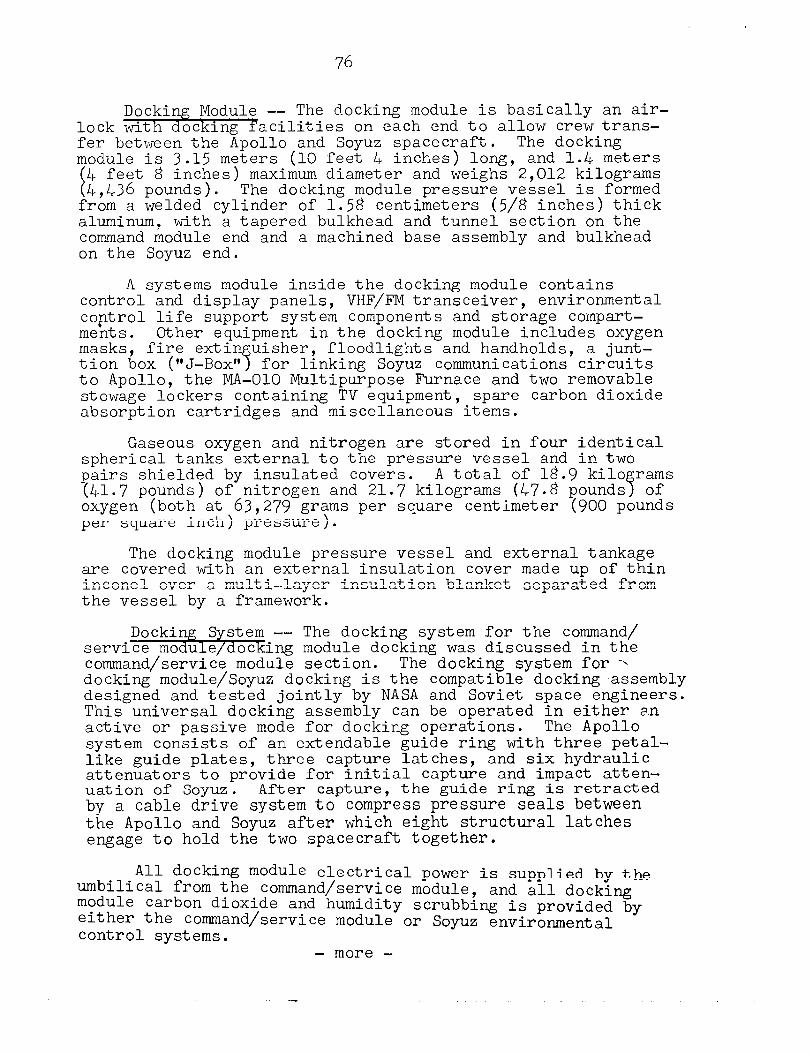
‘76
Docking Module -- The docking module is basically an air- lock with docking facilities on each end to allow crewtrans- fer between the Apollo and Soyuz spacecraft. The docking module is 3.15 meters (10 feet 4 inches) long, and 1.4 meters
t 4 feet 8 inches) maximum diameter and weighs 2,012 kilograms 4,436 pounds). The docking module pressure vessel is formed
from a welded cylinder of 1.58 centimeters (5/8 inches) thick aluminum, with a tapered bulkhead and tunnel section on the command module end and a machined base assembly and bulkhead on the Soyuz end.
A systems module inside the docking module contains control and display panels, VHF/FM transceiver, environmental co,ntrol life support system components and storage compart- ments. Other equipment in the docking module includes oxygen masks, fire extin uisher, floodlights and handholds, a junt- tion box ("J-BOX" 'j for linking Soyuz communications circuits to Apollo, the MA-010 Multipurpose Furnace and two removable stowage lockers containing TV equipment, spare carbon dioxide absorption cartridges and miscellaneous items.
Gaseous oxygen and nitrogen are stored in four identical spherical tanks external to the pressure vessel and in two pairs shielded by insulated covers. A total of 18.9 kilo rams (41.7 pounds) of nitrogen and 21.7 kilograms (47.8 pounds 7 of oxygen (both at 63,279 grams per square centimeter (900 pounds per square inch) pressure).
The docking module pressure vessel and external tankage are covered with an external insulation cover made up of thin inconel over a multi-layer insulation blanket separated from the vessel by a framework.
The docking system for the command/ module docking was discussed in the
command/service module section. The docking system for -, docking module/Soyuz docking is the compatible docking ,assembly designed and tested jointly by NASA and Soviet space engineers. This universal docking assembly can be operated in either zn active or passive mode for docking operations. The Apollo system consists of an extendable guide ring with three petal- like guide plates, three capture latches, and six hydraulic attenuators to provide for initial capture and impact atten- uation of Soyuz. After capture, the guide ring is retracted by a cable drive system to compress pressure seals between the Apollo and Soyuz after which eight structural latches engage to hold the two spacecraft together.
All docking module electrical power is supplied by the umbilical from the command/service module, and all docking module carbon dioxide and humidity scrubbing is provided by either the command/service module or soyuz environmental control systems.
- more -
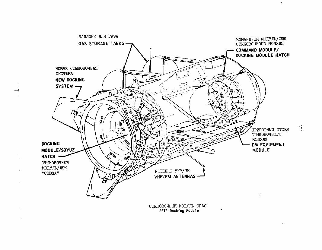
6AJLJlOHbI LLJlFi lTA3A KOMAHJHbIl? MOLIYm/JMIK GAS STORAGE TANKS
/\ CTbiiOBOqHOrO MOllYJIFI
!I 7 COMMAND MODULE/
HATCH HOBAR C'XWKOBOYHAR ^..I_..
CTbIKOBO'IH~ MOJiYJIb/JIIOK "COI03A"
v AHTEHHbI YKB/W t
/[ 47JF VHF/FM ANTENNAS d
CTbIKOBOrIHblFl MOAYJLb 3l'lAC PSTP Docking Module
.
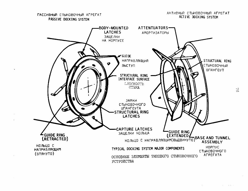
llACCMBHbll7 CTMHCBOVHtd ArPErAT PASSIVE DOCKING SYSTEM
AHTMBHbli? CTblHOBO~Hbl~ ArPErAT ACTIVE DOCKING SYSTEM
BODY-MOUNTED ATTENTUATORS LATCHES AMOPTM3ATOPH 3All/EllHM
HA HOPl-lYCE
HOJlbl(0 C HAllPABJl~K4klM (BTFIHYTO)
HAf-lPAB~fl~Mti
BbJCTYf-l
STRUCTURAL RING NTERFACE SURFACE
IiJIOCKOCTE CT'IJKA
'URAL RING @O'-lHblFi if-OYT
3AMHM v CTblHOf3O~HOrO
WilAHrOYTA I~STRUCTURAL RING
AEi
LGUIDE RING
tEXTENDED L mO~MM(Bt$WiHYTO)
BASE AND TUNNEL ASSEMBLY
TYPICAL DOCKING SYSTEM MAJOR COMPONENTS HoPnYc CTM-4OBO~HOrO
OCHOBHbIE 3JlEMEHTbI TMl-IOBOrO CTbIKOBOqHOI'O ArPErATA
YCTPOFICTBA
79
Apollots orbital atmosphere is 100 percent oxygen at 258 millimeters of mercury (5 pounds per square inch), while the Soyuz atmosphere is normally an oxygen/nitrogen mix at 760 millimeters of mercury (14.7 pounds per square inch). Transferring from Soyuz to Apollo in these conditions normally would require the cosmonauts to pre-breathe pure oxygen to purge suspended nitrogen from their blood streams, but by lowering the Soyuz pressure to 518 millimeters of mercury (10 pounds per square inch), crew inter-spacecraft transfers can be made without time-consuming pre-breathing. Hatches at both ends of the docking module and pressure equalization valves permit crew transfers without disturbing the atmospheres in either spacecraft.
The Apollo spacecraft and docking module were manufactured by Rockwell International Space Division, Downey, California.
- more -
SATURN IB LAUNCH VEHICLE
ASTP will utilize Apollo-Skylab Saturn IB launch vehicle hardware. The Saturn IB, consisting of a first stage (S-IB) a second stage (S-IVB), and an instrument unit (IU) will la&ch the Apollo spacecraft from the Kennedy Space Center.
The NASA Marshall Space Flight Center (MSFC), Huntsville Alabama, is responsible for Saturn IB Launch Vehicle hardware and software design as well as sustaining engineering to cover any problems or changes that occur before or during the ASTP mission and until de-orbit of the S-IVB/IU.
Saturn IB Launches
A total of eight Saturn IB's have been launched, all successfully.
The Saturn IB launch vehicle played a vital role in both the Apollo and Skylab programs prior to its use in the ASTP.
Five vehicles were launched during the period 1966-6$ in connection with Apollo, Skylab.
and three were launched in 1973 for
The first Saturn IB vehicle (designated SA-201) was launched on February 26, 1966, continuing a record of 10 per- fect flights set by the basic Saturn I vehicle. The unmanned sub-orbital mission was the first test in space of the Apollo spacecraft which would later send American astronauts to explore the Moon.
On July 5, 1966, the next Saturn IB vehicle (SA-203) launched an unmanned orbital mission to test the S-IVB stage and to verify that the orbital operation features of the liquid hydrogen propulsion system were satisfactory for S-IVB restart in orbit.
The third vehicle (SA-202) was launched on August 25, on an unmanned sub-orbital mission to verify performance of
1966,
the Saturn IB, the Apollo spacecraft's command and service module systems, and the ablative heat shield.
The fourth Saturn IB (SA-204) launch, on January 22, 1968, was for an unmanned orbital mission which provided the first test in space of the Apollo spacecraft's lunar module.
On October 11, 1968, the fifth Saturn IB (SA-205) launched the first manned Apollo, carrying astronauts Walter M. Schirra, Jr., Donn F. Eisele, and R. Walter Cunni development operations mission primarily T
ham into orbit on a o test the Apollo
command and service modules in space. - more -
. .
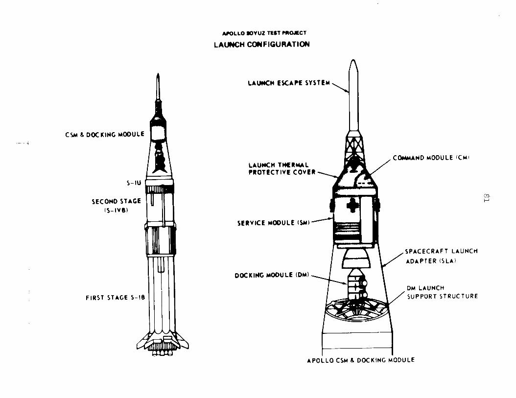
AlroLL0 loYUZ TEST MOJECT
LAUNCH COUFl6URATIW
DOCKING MOOULL r CSMb --i
LAUHCII TMRMAL PROTECTIVE COVER \
COMMAND MODULE ~CMI
S-IU
SLCOHD STAGE (S-IVB)
M SERVICE #OOlJLE (SW1
DOCKING MODULE (DM)
DM LAUNCH SUPPORT STRUCTURE FIRST STAGE 5
APOLLO CW 6 DOCKING MODULE
82
The sixth Saturn IB (SA-206) was launched May 25, 1973. It carried the first crew of Skylab astronauts (Charles Conrad, Jr., Joseph P. Kerwin, and Paul J. Weitz) into orbit to dock with the Skylab, which had been launched 11 days earlier by a Saturn V vehicle.
The seventh Saturn IB (SA-2O7), launched July 28, 1973, transported the second crew of Skylab astronauts, Alan L. Bean, Owen K. Garriott, and Jack R. Lousma.
The eighth Saturn IB (SA-208) took the third Skylab crew (Gerald P. Carr, Edward G. Gibson, and William R. Pogue) up to the orbiting space station on November 16, 1973.
SA-210 is the Saturn IB launch vehicle scheduled for use in the Apollo Soyuz Test Project on July 15, r975, with SA-209 as a back-up vehicle.
The ASTP launch is the final scheduled launch of a Saturn IB vehicle. Saturn IB is used,
After the ASTP mission, if only one there will remain two complete Saturn IB
vehicles in reserve, SA-209 and SA-211.
The first stage for SA-211 is in storage at MSFC's Michoud Assembly Facility, New Orleans. The second stage is stored at KSC, and the instrument unit is stored at MSFC, Huntsville.
Vehicle Description
Saturn IB, includin approximately 67 meters 7
the spacecraft and tower, stands 224 feet) tall, and is about 6.5
meters (21.7 feet) in diameter. 71,000 kilograms (79 tons),
Total weight empty is about and liftoff weight fully fueled
will be approximately 600,000 kilograms (650 tons).
First-stage flight is powered by eight H-l engines gen- erating 912,250 newtons (205,000 pounds) of thrust each, for a total of 7.3 million newtons (1.64 million pounds). In approximately 2.3 minutes of operation, it will burn 159,600 liters (42,000 (67,000 gallons '3
allons) of RP-1 fuel and 254,600 liters of liquid oxy en,
% to reach an altitude of
approximately 5'7 kilometers (3 miles) at burnout.
The S-IVB stage, with a single one-million-newton (225,OOO- pound) thrust J-2 engine, burns 250,gOO liters (66,000 gallons) of liquid hydrogen and 76,000 liters (20,000 gallons of liquid oxygen in about 7.3 minutes of operation, to achieve orbital speed and altitude.
- more -
--
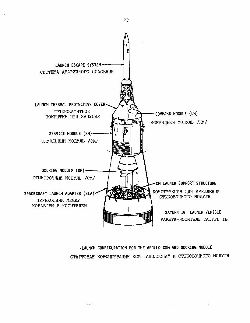
LAUNCH ESCAPE SYSTEM
CMCTEMA ABAPMFTHOI'O CIIACEHWi I I
LAUNCH THERMAL PROTECTIVE COVER
TElIJl03AJDiTHOE IlOKPbITkiE lIPM 3AllYCKE
LU~NLJ IIUUULC \bmJ
KOMAHJHbZm MOJIYJIb /KM/
SERVICE MODULE (SM)
CJTYIKEEjHbIFd MOjJYJIb /CM/
DOCKING MODULE (DM)
CTbIKOBOYHbIFI MOJYJIb /CM/ DM LAUNCH SUPPORT STRUCTURE
SPACECRAFT LAUNCH ADAPTER (SLA)
IIEPEXOAHMK MEIKJIY KOPANIEM M HOCMTEJIEN
KOHCTPYKLWI JUIR KF'El-LJIEHHfI CTbIKOBO'lHOrO MOAYJIR
SATURN IB LAUNCH VEHICLE
PAKETA-HOCMTEJIb CATYPH 1B
-LAUNCH CONFIGURATION FOR THE APOLLO CSM AND DOCKING MODULE
-CTAPTOBAff KOHWI'YPAUJSI KCM "Al-IOJIJIOHA" M CTbIKOBO~HOI'O MOHYJUI
The instrument unit is the Saturn IB "brain" responsible for originating electronic commands for stage steering, engine ignition and cutoff, staging operations, and all primary tim- ing signals.
It is carried atop the S-IVB stage to complete the vehicle's launch configuration.
Vehicle Concept
The Saturn IB launch vehicle was conceived in 1962 at the Marshall Space Flight Center as the quickest, most reliable, and most economical means of providing a booster with greater payload capability than the Saturn I. The new launch vehicle would be used for Earth orbital missions with the Apollo space- craft before the Saturn V launch vehicle would be available.
Development of the Saturn IB was based on a blending of existing designs for the Saturn I and the Saturn V. It uses a redesigned Saturn I booster (designated the S-IB stage), together with the S-IVB upper stage and the instrument unit from the Saturn V.
The concept permitted rapid development of a new vehicle. Maximum use of designs and facilities available from the ear- lier approved Saturn programs saved both time and costs.
Saturn IB thus became a second generation of the Saturn family -- the first U.S. rocket boosters developed from the start as large payload, manned space launch vehicles.
Development Highlights
Because of NASA's original determination to make maxi- mum use of technology and equipment already existing or under design, Saturn IB was brought to full development in less than four years after the initial go-ahead decision.
In that time, Marshall Space Flight Center and Chrysler Corporation Space Division completed necessary modifications and uprating on the S-IB stage; McDonnell-Douglas Astronautics Company developed the S-IVB stage for the Saturn IB and accel- erated production and .testing to meet the launch schedule; Marshall Space Flight Center and IBM Federal Systems Division did the same in adapting the Saturn V Instrument Unit for Saturn IB; and Rocketdyne Division of Rockwell International uprated the H-l engines for the S-IB first stage, and stepped up development and production of the J-2 engine for the S-IVB second stage.
- more -
The first Saturn IB flight vehicle was completed just 39 months after the initial NASA decision to proceed with its development.
History of the ASTP Launch Vehicle (SA-210)
The ASTP launch vehicle's first stage (designated S-IB-10) was manufactured at Marshall Space Flight Center's Michoud Assembly Facility, with the Chrysler Corporation as contractor. The stage was completed in January 1967.
Static firing tests were held at Marshall Space Flight Center in May 1967. The stage was returned to Michoud Assembly Facility for storage. The stage was removed from storage in October 1972, for modification, refurbishment and checkout. It was shipped to KSC in April 1974. There it was stored in the Vehicle Assembly Building (VAB) until November 1974. Then the stage was removed from storage and erected vertically, and post-storage checkout began. In early January 1975, the stage was moved into the Vehicle Assembly Building's high-bay area for further checkout, and was placed on its mobile launcher.
Here the second stage was mated to the booster, and the instrument unit was added to the stack to complete the launch vehicle.
Manufacturing of the second stage (S-IVB-210) had been finished in the spring of 1967 by the contractor, McDonnell- Douglas, at its facility at Huntington Beach, California.
The stage was removed from storage there and shipped in November 1972 to Kennedy Space Center where it was stored in the Vehicle Assembly Building unti .!L September 1974. After removal, post-storage checkout was performed prior to stacking atop the first stage.
The instrument unit for the SA-210 launch vehicle was assembled by IBM at its Huntsville, Alabama, facility. It was stored there until its shipment by barge to Kennedy Space Center in May 1974. It remained in storage in the Vehicle Assembly Building until December 1974 when it was removed and post-storage checkout got underway.
After the Apollo spacecraft and the special ASTP docking module were installed atop the Saturn IB, the space vehicle was rolled out on its transporter to the launch pad in late March 1975. Additional pre-flight checkouts were performed leading up to the scheduled launch.
- more -
The ASTP launch will be the JZnd, and final, scheduled launch of a vehicle of the Saturn class.
The first launch, a Saturn I, lifted off 14 years ear- lier, in 1961. Following 10 straight Saturn I successes, the first of eight Saturn IBs was launched, in 1966. The first Saturn V, the largest of the Saturn family, was launched in 1967, followed by 12 more, all successful.
- more -
TRACKING AND COMMUNICATIONS
The ASTP mission presents an unprecedented challenge to the personnel of the Spaceflight Tracking and Data Network to provide the vital link between the Earth and the two orbit- ing spacecraft.
To meet this challenge many changes have been made to the data acquisition, communications and command equipment at the far flung global network of stations. Much of this was accomplished during the interim between Skylab and the Apollo Soyuz programs.
Flight control personnel will maintain contact with the Apollo and Soyuz spacecraft through the Spaceflight Tracking and Data Network (STDN). This network is a complex of fixed ground stations , portable ground stations, specially equipped aircraft and an instrumented ship used for transmitting sig- nals to and receiving and processing data from the spacecraft during the mission from launch to Earth return. STDN stations include tracking telemetry, television and command systems; the communications systems and switching systems.
Under the overall supervision of NASA Headquarters Office of Tracking and Data Acquisition (OTDA), the Goddard Space Flight Center (GSFC), Greenbelt, Maryland, is responsible for the operation and maintenance of the world-wide network. Approximately 2,300 men and women at the global tracking sites and 500 personnel at Goddard will be actively engaged in the mission operations.
Fourteen STDN stations will be supporting the ASTP mis- sion. They are:
Merritt Island, Florida (MIL) Tananarive, Mala asy (TAN) Rosman, North Carolina (ROS) Santiago, Chile 7 AGO) Hawaii (HAW) Spain (M4D) Orroral, Australia (ORR)
Madrid, Ascension Island (ACN)
USNS Vanguard (VAN) Guam (GWM) (Tracking Ship) Goldstone, California (GOS)
Bermuda (BDA) Newfoundland (NFL)
Quito, Ecuador (QUI)
The Soviet network of stations which will support the joint venture consists of 7 ground stations and two ships. They are:
- more -
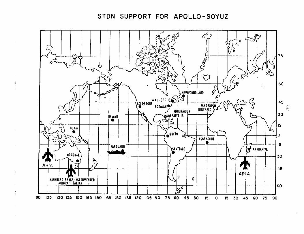
I I
, I /
I
Evpatoria (EVT) Kolpashevo (KLP) Ulan-Ude (ULD) Tbilisi (TBL) Ussuryisk (USK) Gagarin (Tracking Ship) (KYG) Dzhusaly (DJs) Korolev (Tracking Ship) (ASK) Petropavlovsk-Kamchatski (PPK)
Since the close of the Skylab Program, the network has undergone some major changes. Stations have had equipment and personnel added to provide the magnitude of support required for the mission. In addition, several stations have become totally staffed and operated by native personnel. The major changes which have occurred are:
Canary Islands, Corpus Christi, Texas and Carnarvon, Australia have been closed.
Honeysuckle Creek, Australia, station has been integrated into the Deep Space Network.
Newfoundland, a mobile site, has been reactivated to support the ASTP mission only.
Stations located at Rosman, North Carolina; Quito, Ecuador; Santiago, Chile; Orroral, Australia; and Tananarive. Malagasy, also will support ASTP.
The Apollo will be in an Earth orbit with at least one station pass every 90 minutes; therefore requiring a 24-hour tracking effort.
As a result of the low altitude of the spacecraft, use of the 26-meter (85-foot) antennas is severely restricted. The network stations supporting the flight will utilize the g-meter (30-foot) Unified S-Band antenna for tracking operations.
To assure the support required by ASTP all stations have dual channel receivers, additional decommutation equipment and special gear to handle the complex voice communications.
In addition, a new technical dimension will be added to the ASTP mission when, for the first time, an Applications Technology Satellite 6 will be used to relay communications from the orbiting spacecraft to a ground station. Through use of this satellite the ground coverage of the mission will be increased from approximately 17 percent to 55 percent. Telemetry, voice and television will be relayed through the ATS-6 terminal and the portable station in Spain. Air-to- ground voice communications from the Soyuz spacecraft will be relayed from 10 very high frequency sites located throughout the network.
- more -
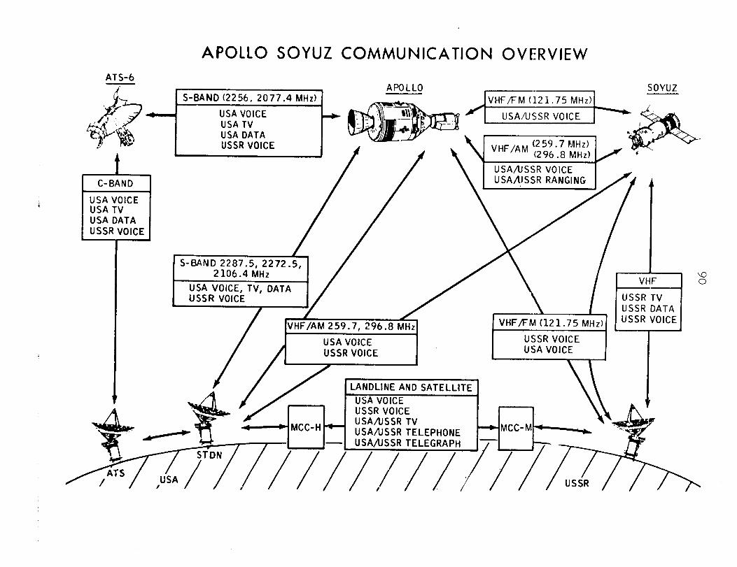
ATS-6
APOLLO SOYUZ COMMUNICATI
i
APOLLO
ON OVERVIEW
1 S-BAND 2287.5, 2272.5.
/ VHF/AM 259.7, 296.8 MHz VHF/FM (121.75 MHz)
USSR VOICE USSR VOICE USA VOICE
LANDLINE AND SATELLITE
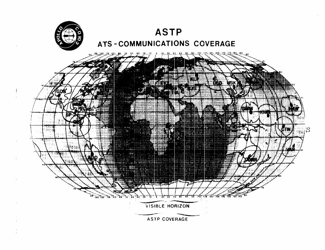
91
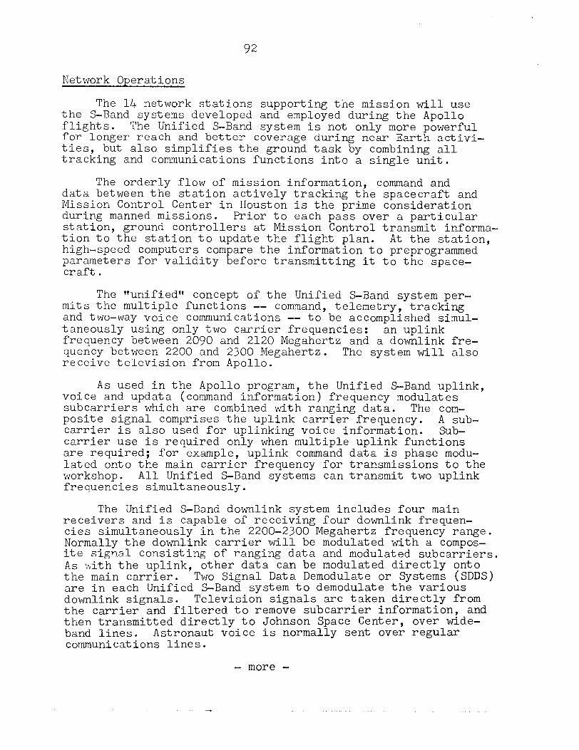
92
Network Operations
The 14 network stations supporting the mission will use the S-Band systems developed and employed during the Apollo flights. The Unified S-Band system is not only more powerful for longer reach and better coverage during near Earth activi- ties, but also simplifies the ground task by combining all tracking and communications functions into a single unit.
The orderly flow of mission information, command and data between the station actively tracking the spacecraft and Mission Control Center in Houston is the prime consideration during manned missions. Prior to each pass over a particular station, ground controllers at Mission Control transmit informa- tion to the station to update the flight plan. At the station, high-speed computers compare the information to preprogrammed parameters for validity before transmitting it to the space- craft.
The Qnified" concept of the Unified S-Band system per- mits the multiple functions -- command, telemetry, tracking and two-way voice communications -- to be accomplished simul- taneously using only two carrier frequencies: an uplink frequency between 2090 and 2120 Megahertz and a downlink fre- quency between 2200 and 2300 Megahertz. The system will also receive television from Apollo.
As used in the Apollo program, the Unified S-Band uplink, voice and updata (command information) frequency modulates subcarriers which are combined with ranging data. The com- posite signal comprises the uplink carrier frequency. A sub- carrier is also used for uplinking voice information. Sub- carrier use is required only when multiple uplink functions are required; for example, uplink command data is phase modu- lated onto the main carrier frequency for transmissions to the workshop. All Unified S-Band systems can transmit two uplink frequencies simultaneously.
The Unified S-Band downlink system includes four main receivers and is capable of receiving four downlink frequen- cies simultaneously in the 2200-2300 Megahertz frequency range. Normally the downlink carrier will be modulated with a compos- ite signal consisting of ranging data and modulated subcarriers. As rcith the uplink, other data can be modulated directly onto the main carrier. TWO Signal Data Demodulate or Systems (SDDS) are in each Unified S-Band system to demodulate the various downlink signals. Television signals are taken directly from the carrier and filtered to remove subcarrier information, and then transmitted directly to Johnson Space Center, over wide- band lines. Astronaut voice is normally sent over regular communications lines.
- more -
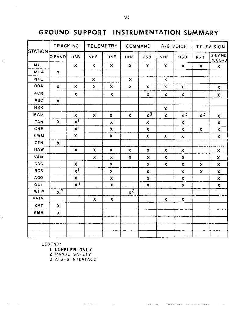
93
GROUND §UPPORT INSTRUMENTATION SUMMARY
TRACKING TELEMETRY COMMAND A/G VOICE TELEVISION
STAT10 N C-BAND US9 VHF USB UHF USB VHF use R/i S-BAND
RECORD MIL X X X X X X X X X
MLA X
NFL , X X X
BOA X X X X *X X X X X
ACN X X X X X X
ASC X
HSK X
MAO X X X X x3 x x3 x3 x
TAN X X’ X X X X
CRR X’ X X I X X X
GWM X X x ’ x X x I - . ..-- CTN X
HAW X X X X X X X X
VAN X X X X X x - X
GOS X X X X X X X
ROS XI X X X X X
AGO X X X X X
OUI X’ X X X X
-wLP X2
L
1 L X2
ARIA X X X X 4 KPT X
XMR X
LEGEND:
I DOPPLER ONLY 2 RANGE SAFETY 3 ATS-6 INTERFACE
94
The entire network is linked by the facilities of the NASA Communications Network (NASCOM), a global communications network established by NASA to provide operational ground com- munications for support of all spaceflight operations.
Communications
The NASA Communications Network, one of the most exten- sive and sophisticated communications networks in existence, links all the STDN stations and NASA installations together. More than two million circuit miles covered by the network includes data and voice channels, medium and high speed mes- sage circuits. The majority of these circuits connecting and servicing these centers are leased from common carriers such as American Telephone and Telegraph, Western Union, International Telephone and Telegraph, and various local telephone companies throughout the world. The circuits are specially engineered and maintained for NASA.
Control Center for the NASCOM Network is the NASA Goddard Space Flight Center. Special computers are used in the system to act as traffic policemen. The computers are programmed to recognize specific types of information and automatically direct or switch it to the proper destination. Switching centers located in London, Madrid, and Australia are used to augment the network, receive data from the tracking stations and route it to Goddard.
Satellite Support
Communications from the Apollo Soyuz spacecraft, includ- ing television, will be relayed through NASA's Applications Technology Satellite 6 (ATS-6). An advanced communications research satellite, the ATS-6, was launched into geosynchronous orbit from Cape Canaveral, Florida, May 30, 1974.
Use of the ATS-6 for the ASTP tracking and data relay will provide about three times the communications coverage of the ground stations. Thus it will permit larger amounts of biomedical and spacecraft data to be relayed to the Earth in one transmission and increase the television coverage from the flight.
Operations of the ATS-6 are coordinated and controlled from the ATS Control Center at Goddard. ATS ground~stations are located at Rosman, North Carolina; Mojave; California, and a mobile station at Buitrago, Spain.
- more -
95
To support the ASTP mission, the ATS-6 will be positioned on the equator some 35,900 kilometers (~2,260 statute miles) above the eastern edge of Lake Victoria in Kenya, East Africa. From this position, the spacecraft will be controlled through the Madrid mobile station and will command a view of more than 5% of the Apollo-Soyuz's 225-kilometer (140-statute mile) orbit.
During operations, the ATS-6 will point its antenna towards the edge of the Earth as seen from its orbit, and generate a signal for the Apollo spacecraft to lock onto when it moves into view. Apollo, using a wide-band antenna, will home-in on the signal and, after establishing contact, will transmit telemetry, voice and live television to the satellite. ATS-6 will relay the communications to the Buitrago, Spain ground station, which will then relay the data via the commercial satellite Intelsat to the Johnson Space Center, Houston, Texas.
Ship Support
Three seagoing tracking stations will be employed to support the ASTP mission. The USNS Vanguard will be stationed in a Test Support Position located at 25 degrees South and 155.0 degrees West and will be in position 48 hours prior to liftoff until released from the mission support role. Two Soviet ships will be employed. Ship No. liLthe Korolev will take up a position near Canada and Ship No. 2, the Gagarin, will be deployed in a position near Chile.
Range Instrumented Aircraft
Three instrumented aircraft will be used to support the mission, operating from Australia and South African airfields. The Advanced Range Instrumented Aircraft (ARIA) are used primarily to fill the voids between land and ship stations during the launch and early orbital phases of the flight.
The aircraft will depart Patrick Air Force Base, Florida, at T-5 days and deploy as follows:
Aria No. 1 and No. 3 will fly out of Perth,Australia- Aria No. 2 will fly out of Johannesburg, South Africa.
During the flight Aria No. 1 will provide first revolu- tion coverage south of Australia of the S-IVB maneuver for undocking, revolution 2 docking module extraction and will record CSM and Saturn second stage data and remote voice com- munications through the Pacific commercial communications satellite in realtime. The aircraft will then return to Perth for redeployment to Hawaii to cover reentry.
- more -
96
Aria No. 2 will provide coverage in the Indian Ocean area on the fourth revolution of the Saturn second stage deorbit maneuver. The aircraft will also receive and record data for relay through the Atlantic communications satellite in realtime.
Aria No. 3 provides fourth revolution coverage southwest of Australia over the Indian Ocean of the last portion of the Saturn second stage deorbit maneuver. The aircraft will then return to Guam.
Onboard Television Distribution
Television coverage during the mission will be both realtime and recorded. All stations in the STDN network are capable of receiving and recording video; however, only Buitrago, Spain, Merritt Island, Florida, Rosman, North Caro- lina, Goldstone, California, and Orroral, Australia have been designated as 'tprimeft for live television and will transmit video to the Johnson Space Center, Houston, Texas,in realtime.
"Livel' television will be transmitted via Apollo through the ATS-6 satellite to Buitrago, Spain, which will relay the video through the Atlantic communications satellite and landlines to the Johnson Space Center where it will be color converted and released to the news media. TV support period from Buitrago is approximately 55 minutes during each orbit scheduled for TV.
Video emanating from the Soyuz will be received by Soviet stations and sent to Houston through a variety of routings.
Color television from the ASTP spacecraft will be fed to the ground stations by four cameras. An onboard videotape recorder permits delayed relay of up to 30 minutes of TV.
- more -
97
PHOTOGRAPHY AND TELEVISION
Photographic equipment carried aboard Apollo includes still and motion picture cameras and four color television cameras for relaying onboard activity to Earth either tllive" or recorded on an onboard videotape recorder (VTR) for delayed playback to the ground. The equipment will record mission experiment activities, such as MA-136 Earth Observations and Photography, as well as document the historic first meeting in space of spacecraft and crews of two nations.
Among the mission activities scheduled for still and motion picture photography are command/service module/docking module docking and extraction, with Soyuz,
Apollo's approach and docking crew transfers between spacecraft, joint activities
such as meals and joint experiments aboard Apollo and Soyuz, post-undocking period and docking module jettison.
Apollo cameras are two 16 millimeter Maurer data acquisi- tion cameras (DAC) with lenses of 5, 10, 25 and 75 millimeter focal lengths; a 35 millimeter Nikon F camera with a 35 milli- meter focal-length moderate wide-angle lens and a 300 milli- meter lens; a 70 millimeter Hasselblad reflex camera (HRC) with 50 and 250 millimeter-Zeiss lenses; and a 70 millimeter Hasselblad data camera (HDC) with reseau plate with 60, 80 and 100 millimeter Zeiss lenses. The film supply includes high-speed color interior, medium-speed color exterior, color terrain, medium-speed black and white, infrared and false- color infrared.
Television equipment aboard Apollo consists of four Westinghouse color cameras with miniature monitors, an RCA Skylab-type videotape recorder with a 30-minute recording capacity and various camera locations -- in the command module, in the docking module and in Soyuz (after circuit is connected post-docking). The television signal is relayed to the ground either through five stations in the Space Tracking and Data Network or through the ATS-6 synchro- nous satellite. Mission Control has camera selection command capability and can "dump" the videotape recorder.
Activities to be televised either live or recorded on the videotape recorder for delayed playback to the ground are similar to those planned for still and motion picture photog- raphy. A detailed schedule of TV "passes" will be published prior to launch and available in the KSC and JSC News Centers, in addition to being listed in a table in the final edition of the ASTP Flight Plan.
- more -
HARDWARE PREPARATION
Active preparations for launching the Saturn IB/Apollo for ASTP began at Kennedy Space Center in September 1974 with the arrival of the Apollo spacecraft. The command/ser- vice module arrived at the Cape Canaveral Air Force Station Skid Strip aboard a C-5A aircraft September 8. It was imme- diately moved to the Manned Spacecraft Operations Building in the Kennedy Space Center Industrial Area for inspection. The mated command/service modules were later moved into an altitude chamber for systems tests and integrity checks.
The docking module was received at Kennedy Space Center October 30 and installed in a Manned Spacecraft Operations Building altitude chamber on the following day. The docking system was received at Kennedy Space Center January 3, 1975, and mated with the docking module January 17. Manned alti- tude runs of the Apollo spacecraft were conducted by the prime and backup crews on January lb and 16, respectively. Docking tests of the Apollo spacecraft and the docking module were conducted during the week of January 26.
t'Stackingtt of the Saturn IB launch vehicle on its pedes- tal aboard Mobile Launcher 1 in the Vehicle Assembly Building's High Bay 1 began in mid-January. The first stage was erected January 13 and the second stage was mated with it on the fol- lowing day. The instrument unit which provides guidance during powered flight was stacked atop the second stage January 16. A spacecraft mockup or ttboilerplatett was mated with the Saturn IB January 17 for fit tests with Mobile Launcher spacecraft interface points. The docking module was mated with the launch adapter February 18. Mating of the Apollo spacecraft with the launch adapter in preparation for the move to the Vehicle Assembly Building was accomplished in late February and early March.
The boilerplate spacecraft was removed from the Saturn IB March 18 and replaced with the flight spacecraft on the fol- lowing day. The assembled space vehicle was moved to Pad B at Launch Complex 39 late in March.
An extensive series of launch vehicle and spacecraft tests were conducted during April and May. A two-day Readiness Test of the space vehicle began in late May.
Flight
After hypergolic fuels are loaded aboard the space vehicle and the launch vehicle first stage fuel (RP-1 or kerosene) is brought aboard, the final major test of the Saturn IB/Apollo will begin. This is the countdown demonstration test (CDDT), a dress rehearsal for the final countdown to launch. This is divided into t*wettt and ttdrycc portions. During the first -- or llwettt portion -- the entire countdown including propellant loading will be carried down to T-3.1 seconds.
- more -
99
The astronaut crew will not participate in the wet count- down demonstration test. At the completion of the wet count- down demonstration test, the cryogenic propellants (liquid oxygen and liquid hydrogen) will be off-loaded and the final portion of the countdown will be re-run. This time the fuel- ing will be simulated and the prime astronaut crew will par- ticipate as they will on launch day. Successful conclusion of the countdown demonstration test scheduled for June 26- July 3 will clear the way for countdown and launch.
- more -
100
LAUNCH PREPARATION -- SEQUENCES AND CONSTRAINTS
The ASTP mission requires a dual Apollo and Soyuz craft launch. The United States has committed a single
space-
Saturn IB/Apollo to the mission and the Soviet Union has com- mitted two Soyuz space vehicles. be launched first,
The Soyuz spacecraft will at about 8:20 am Eastern Daylight Time
on July 15 from the Soviets' Baykonur cosmodrome. The flight plan calls for the Saturn IB/Apollo to be launched from the Kennedy Space Center at approximately 3:50 pm Eastern Daylight Time the same day.
In addition, a second Soyuz vehicle has been committed by the Soviets to allow for two contingencies:
-- The second Soyuz launch is planned primarily in the event the first Soyuz has been launched and Apollo cannot take advantage of its five launch opportunities. In this case, the second Soyuz will be launched whenever the Apollo is ready, the rendezvous will be attempted as in the nominal plan.
-- It is also possible that the second Soyuz would be used in the case of a premature first Soyuz landing after Apollo launch but before docking. In this case, the Apollo would remain in orbit and perform the proper maneuvers to improve the phasing situation for the second Soyuz launch opportunities. These events and their controlling constraints have been coordinated by the two nations to mesh the i.ntricate details of simultaneously preparing three space vehicles for launch within a limited time span.
- more -
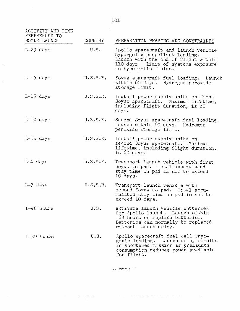
101
ACTIVITY AND TIME REFERENCED TO SOYUZ LAUNCH COUNTRY PREPARATION PHASING AND CONSTRAINTS
~-29 days U.S. Apollo spacecraft and launch vehicle hypergolic propellant loading. Launch with the end of flight within 110 days. Limit of systems exposure to hypergolic fluids.
L-15 days
L-15 days
L-12 days
L-12 days
L-4 days
L-3 days
L-48 hours
L-39 hours
U.S.S.R. Soyuz spacecraft fuel loading. Launch within 60 days. Hydrogen peroxide storage limit.
U.S.S.R. Install power supply units on first Soyuz spacecraft. Maximum lifetime, including flight duration, is 60 days.
U.S.S.R. Second Soyuz spacecraft fuel loading. Launch within 60 days. Hydrogen peroxide storage limit.
U.S.S.R. Install power supply units on second Soyuz spacecraft. Maximum lifetime, including flight duration, is 60 days.
U.S.S.R. Transport launch vehicle with first Soyuz to pad. Total accumulated stay time on pad is not to exceed 10 days.
U.S.S.R. Transport launch vehicle with second Soyuz to pad. Total accu- mulated stay time on pad is not to exceed 10 days.
U.S. Activate launch vehicle batteries for Apollo launch. Launch within 168 hours or replace batteries. Batteries can normally be replaced without launch delay.
U.S. Apollo spacecraft fuel cell cryo- genic loading. Launch delay results in shortened mission as prelaunch consumption reduces power available for flight.
- more -
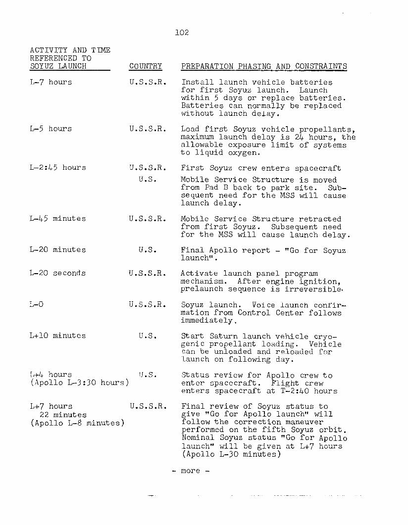
102
L-20 minutes
L-20 seconds
L-O
L+lO minutes
L-5 hours
L-2:45 hours
L-45 minutes
ACTIVITY AND TIME REFERENCED TO SOYUZ LAUNCH COUNTRY
L-7 hours U.S.S.R.
U.S.S.R.
U.S.S.R. U.S.
U.S.S.R.
U.S.
U.S.S.R.
U.S.S.R.
U.S.
L+4 hours U.S. {Apollo L-3:30 hours)
L+7 hours U.S.S.R. 22 minutes
(Apollo L-8 minutes)
PREPARATION PHASING AND CONSTRAINTS
Install launch vehicle batteries for first Soyuz launch. Launch within 5 days or replace batteries. Batteries can normally be replaced without launch delay.
Load first Soyuz vehicle propellants, maximum launch delay is 24 hours, the allowable exposure limit of systems to liquid oxygen.
First Soyuz crew enters spacecraft Mobile Service Structure is moved from Pad B back to park site. Sub- sequent need for the MSS will cause launch delay.
Mobile Service Structure retracted from first Soyuz. Subsequent need for the MSS will cause launch delay.
Final Apollo report - "Go for Soyuz launch".
Activate launch panel program mechanism. After engine ignition, prelaunch sequence is irreversible-
Soyuz launch. Voice launch confir- mation from Control Center follows immediately.
Start Saturn launch vehicle cryo- genic propellant loading. Vehicle can be unloaded and reloaded for -Launch on following day.
Status review for Apollo crew to enter spacecraft. Flight crew enters spacecraft at T-2:40 hours
Final review of Soyuz status to give "Go for Apollo launch" will follow the correction maneuver performed on the fifth Soyuz orbit. Nominal Soyuz status "Go for Apollo launch" will be given at L+7 hours (Apollo L-30 minutes)
- more -
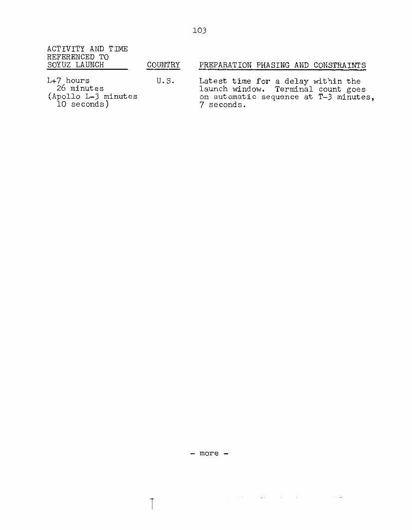
103
ACTIVITY AND TIME REFERENCED TO SOYUZ LAUNCH COUNTRY PREPARATION PHASING AND CONSTRAINTS
L+7 hours U.S. 26 minutes
Latest time for a delay within the launch window.
(Apollo L-3 minutes Terminal count goes
10 seconds) on automatic sequence at T-3 minutes, 7 seconds.
- more -
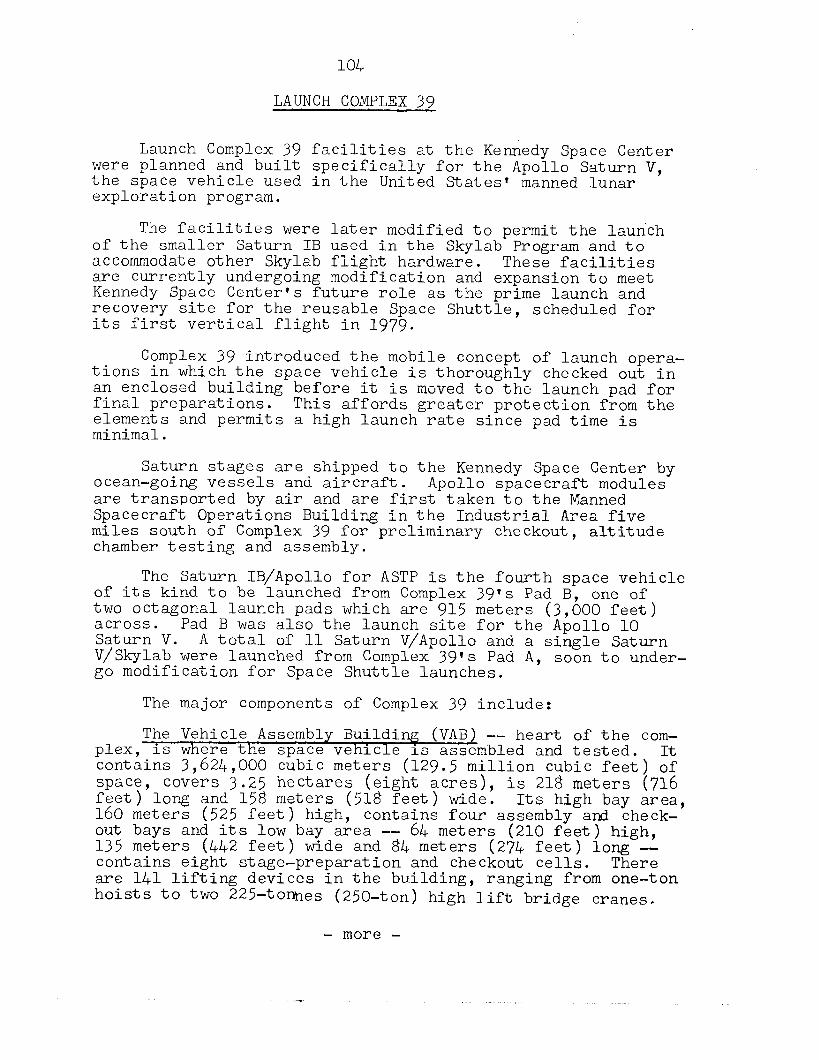
104
LAUNCH COMPLEX 39
Launch Complex 39 facilities at the Kennedy Space Center were planned and built specifically for the Apollo Saturn V, the space vehicle used in the United States' manned lunar exploration program.
The facilities were later modified to permit the launch of the smaller Saturn IB used in the Skylab Program and to accommodate other Skylab flight hardware. These facilities are currently undergoing modification and expansion to meet Kennedy Space Center's future role as the prime launch and recovery site for the reusable Space Shuttle, scheduled for its first vertical flight in 1979.
Complex 39 introduced the mobile concept of launch opera- tions in which the space vehicle is thoroughly checked out in an enclosed building before it is moved to the launch pad for final preparations. This affords greater protection from the elements and permits a high launch rate since pad time is minimal.
Saturn stages are shipped to the Kennedy Space Center by ocean-going vessels and aircraft. Apollo spacecraft modules are transported by air and are first taken to the Manned Spacecraft Operations Building in the Industrial Area five miles south of Complex 39 for preliminary checkout, altitude chamber testing and assembly.
The Saturn IB/Apollo for ASTP is the fourth space vehicle of its kind to be launched from Complex 39's Pad B, one of two octagonal launch pads which are 915 meters (3,000 feet) across. Saturn V.
Pad B was also the launch site for the Apollo 10 A total of 11 Saturn V/Apollo and a single Saturn
V/Skylab were launched from Complex 39's Pad A, soon to under- go modification for Space Shuttle launches.
The major components of Complex 39 include:
The Vehicle Assembly Building (VAB) -- heart of the com- plex, is where the space vehicle is assembled and tested. It contains 3,624,000 cubic meters (129.5 million cubic feet) of
covers 3.25 hectares (eight acres) F%T'long and 158 meters (518 feet) wide:
is 218 meters (716
160 meters (525 feet) high, Its high bay area,
contains four assembly and check- out bays and its low bay area -- 64 meters (210 feet) high, 135 meters (442 feet) wide and 84 meters (274 feet) long -- contains eight stage-preparation and checkout cells. There are 141 lifting devices in the building, ranging from one-ton hoists to two 22%tomes (250-ton) high lift bridge cranes.
- more -
105
The Launch Control Center -- a four-story structure adja- cent and to the south of the Vehicle Assembly Building is a radical departure from the dome-shaped "hardened" biock- house at older NASA launch sites. The Launch Control Center is the electronic ftbraint' of Complex 39 and was used for checkout and test operations while the ASTP Saturn IB was being assembled inside the Vehicle Assembly Building high bay. The firing room assigned to ASTP is associated with a ground computer facility to provide data links with the vehicle on its mobile launcher at the pad or inside the Vehicle Assembly Building. Two of the four firing rooms remain active; a third is being reconfigured to the needs of the Space Shuttle era.
The Mobile Launcher -- 136 meters (445 feet) tall and weighing 5 443 200 kilograms (12 million pounds) is a trans- portable liunc; base and unbilical tower for the space vehicle.
A 39-meter (127-foot) tall pedestal was constructed atop the launch platform of one of the three mobile launchers originally designed to accommodate the llO.6-meter (363-foot) tall Saturn V/Apollo. This adapted the launch tower to handle the 68-meter (223-foot) tall Saturn IB/Apollo used for the manned launches of the Skylab Program and ASTP.
The Transporters -- tons (6 million pounds),
(there are two) weigh 2,721 metric move mobile launchers into the
Vehicle Assembly Building and then -- with assembled flight hardware aboard -- move the mobile launchers to the launch pad. They are also used to transfer the Mobile Service Structure to and from the launch pads. The transporters are 40 meters (131 feet) long and 34.7 meters (114 feet) wide. They move on four double-tracked crawlers, each 3 meters (10 feet) high and 12.5 meters (41 feet) long. Each shoe on the crawler track weighs 0.9 metric ton (2,000 pounds). Maximum speed unloaded is 3.2 kilometers (2 miles) per hour. Loaded speed is 1.6 kilometers (1 mile) per hour. The overall height of the transporter is 6 meters (20 feet) from ground level to the top deck on which the mobile launcher is mounted for transportation. The deck is flat and about the size of a baseball diamond -- 27 meters (90 feet) square.
The Crawlerway -- is the roadway for the transporter, linking the Vehicle Assembly Building with the two launch pads. It has the approximate width of an eight-lane highway and the roadbed is designed to accommodate a combined weight of more than 8.1 million kilograms (18 million pounds). The roadway is built in three layers with an average depth of 2.13 meters (7 feet).
- more -
106
The Mobile Service Structure -- is a 125-meter (&lo-foot) tall, 4.7-million-kilogram (IO.>-million-pound) tower used to service Saturn/Apollo space vehicles at the pad. Noved into place around the space vehicle and its mobile launcher by a transporter, it contains five work platforms and provides 360-degree platform access to the vehicle being prepared for launch. It is removed to a parking area about 11 hours prior to launch.
A Water Deluge System -- will provide about 3.8 million liters (one million gallons) of industrial water for cooling and fire prevention during launch. The water is used to cool the mobile launcher, the flame trench and the flame deflector about which the mobile launcher is positioned.
The Flame Deflector -- is an ?'A"-shaped, 590,000-kilogram (1.3 million-pound) structure moved into the flame trench beneath the launcher prior to launch. It is covered with a refractory material designed to withstand the launch environ- ment. The flame trench itself is 17.7 meters (58 feet) wide and approximately 1.8 meters (six feet) above mean sea level at the base.
The Pad Areas -- A and B -- are octagonal in shape and have center hardstands constructed of heavilv reinforced con- crete. The tops of the pads stand about 14.6 meters (4.8 feet) above sea level. Saturn propellants - liquid oxygen, liquid hydrogen and RP-1, the latter a high grade kerosene - are stored in large tanks spaced near the pad perimeter and car- ried by pipelines from the tanks to the pads, up the mobile launcher and into the launch vehicle propellant tanks. Also located in the pad area are pneumatic, high pressure gas, electrical and industrial water support facilities. The dis- tance between the two pads is about 2,650 meters (8,700 feet).
ASTP-Related Modifications -- to Complex 39 were minimal. The most visible modification is the 24.&-meter (8X)-foot) tall insulated fiberglass mast atop the mobile launcher from which the Saturn IB/Apollo will be launched. A one-half inch diameter cable passes over the mast to grounding points 304.8 meters (1,000 feet) on each side of the mobile launcher. Lightning protection for the Apollo and Skylab s ace vehicles was pro- vided in part by a 16.Gmeter (54-foot P high mast and rod which took lightning strokes to ground through the mobile launcher structure. The new lightning protection system of which the mast is a part isolates the mobile launcher and space vehicle as a current path by providing a point of stroke impact. A path to ground is also provided which is insulated and separated from the mobile launcher.
- more -
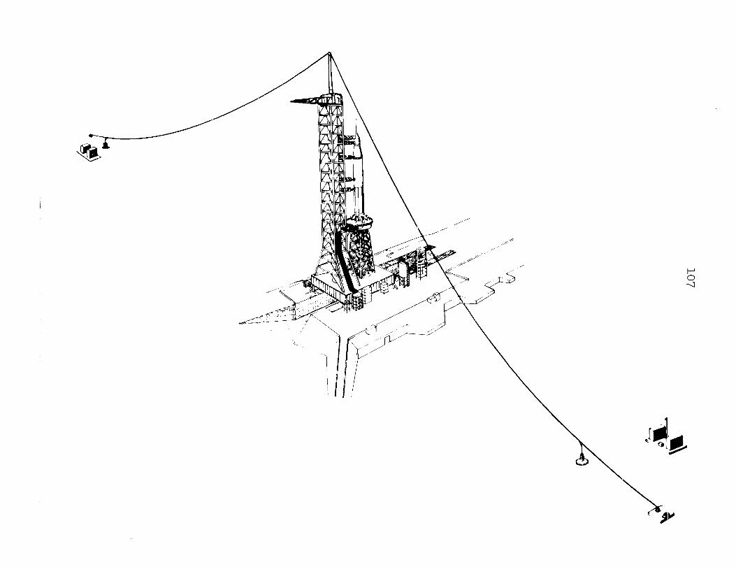
107
108
Florida is on the fringe of the subtropics and it is not uncommon for electrical storms to occur in the summer months during afternoon and early evening hours. The target ASTP launch date, July 15, comes at a season of the year and a time of day, 3:.50 pm Eastern Daylight Time, when there is historical precedent for storm activity. The Saturn IB/ Apollo launch window is less than 10 minutes long and the new lightning protection system was installed to help insure that storm activity will not interfere with the timely launch of the Apollo spacecraft.
- more -
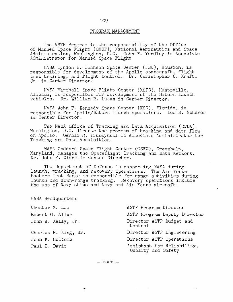
109
PROGRAM MANAGEMENT
The ASTP Program is the responsibility of the Office of Manned Space Flight (OMSF), National Aeronautics and Space Administration, Washington, D.C. John F. Yardley is Associate Administrator for Manned Space Flight
NASA Lyndon B. Johnson Space Center (JSC), Houston, is responsible for development of the Apollo spacecraft, flight crew training, and flight control. Dr. Christopher C. Kraft, Jr. is Center Director.
NASA Marshall Space Flight Center (MSFC), Huntsville, Alabama, is responsible for development of the Saturn launch vehicles. Dr. William R. Lucas is Center Director.
NASA John F. Kennedy Space Center (KSC), Florida, is responsible for Apollo/Saturn launch operations. Lee R. Scherer is Center Director.
The NASA Office of Tracking and Data Acquisition (OTDA), Washington, D.C. directs the program of tracking and data flow on Apollo. Gerald M. Truszynski is Associate Administrator for Tracking and Data Acquisition.
NASA Goddard Space Flight Center (GSFC), Greenbelt, Maryland, manages the Spaceflight Tracking and Data Network. Dr. John F. Clark is Center Director.
The Department of Defense is supporting NASA during launch, tracking, and recovery operations. -The Air Force Eastern Test Range is responsible for range activities during launch and down-range tracking. Recovery operations include the use of Navy ships and Navy and Air Force aircraft.
NASA Headquarters
Chester M. Lee
Robert 0. Aller John J. Kelly, Jr.
Charles H. King, Jr. John K. Holcomb Paul D. Davis
ASTP Program Director ASTP Program Deputy Director Director ASTP Budget and
Control Director ASTP Engineering Director ASTP Operations Assistant for Reliability,
Quality and Safety
- more -
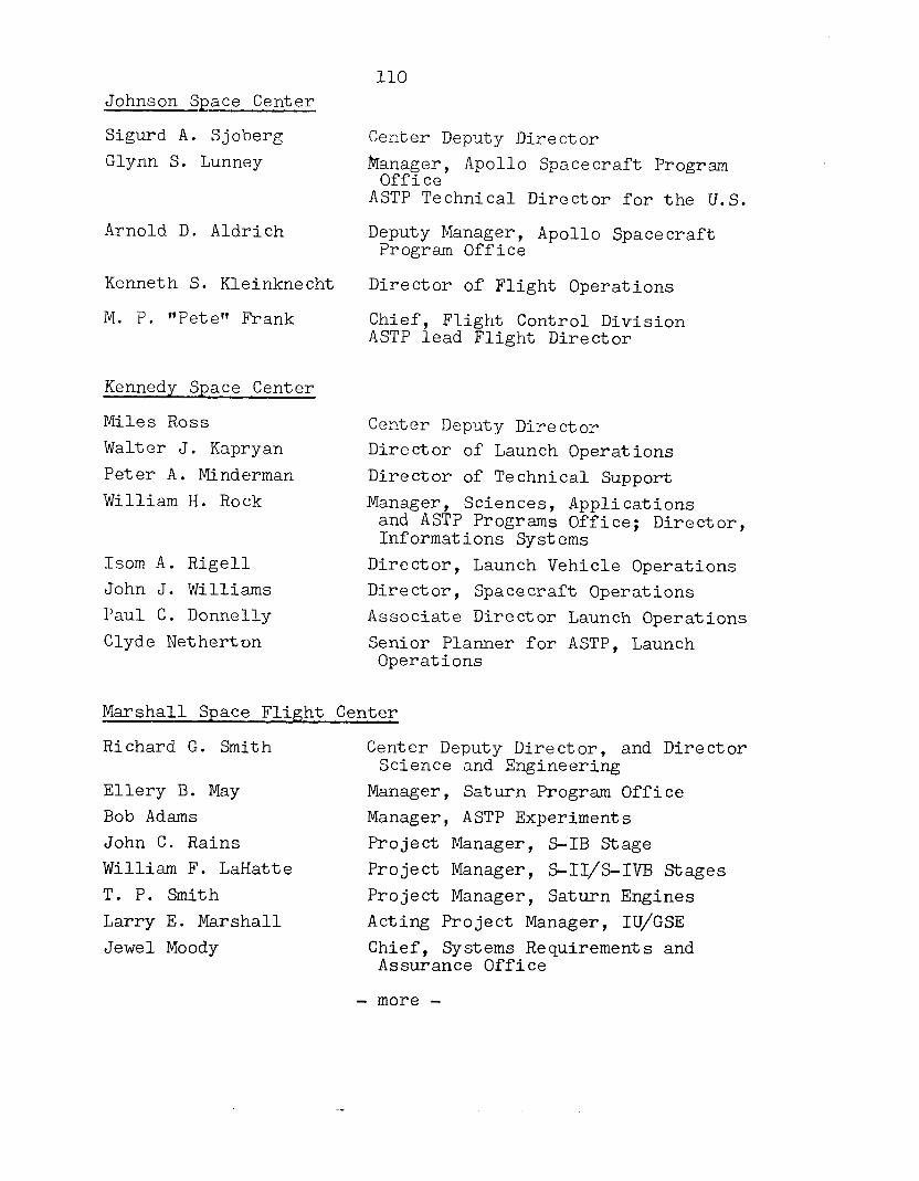
110 Johnson SpEe Center
Sigurd A. Sjoberg Glynn S. Lunney
Arnold D. Aldrich
Kenneth S. Kleinknecht
M. P. "Pete" Frank
Kennedy Space Center
Miles Ross Walter J. Kapryan
Peter A. Minderman William H. Rock
Isom A. Rigell John J. Williams Paul C. Donnelly Clyde Netherton
Center Deputy Director
Manager, Office
Apollo Spacecraft Program
ASTP Technical Director for the U.S.
Deputy Manager, Program Office
Apollo Spacecraft
Director of Flight Operations
Chief, Flight Control Division ASTP lead Flight Director
Center Deputy Director Director of Launch Operations Director of Technical Support Manager, Sciences, Applications
and ASTP Programs Office; Director, Informations Systems
Director, Launch Vehicle Operations Director, Spacecraft Operations Associate Director Launch Operations Senior Planner for ASTP, Launch Operations
Marshall Space Flight Center
Richard G. Smith
Ellery B. May Bob Adams John C. Rains William F. LaHatte T. P. Smith Larry E. Marshall Jewel Moody
Center Deputy Director, and Director Science and Engineering
Manager, Saturn Program Office Manager, ASTP Experiments Project Manager, S-IB Stage Project Manager, S-II/S-l33 Stages Project Manager, Saturn Engines Acting Project Manager, IU/GSE Chief, Systems Requirements and Assurance Office
- more -
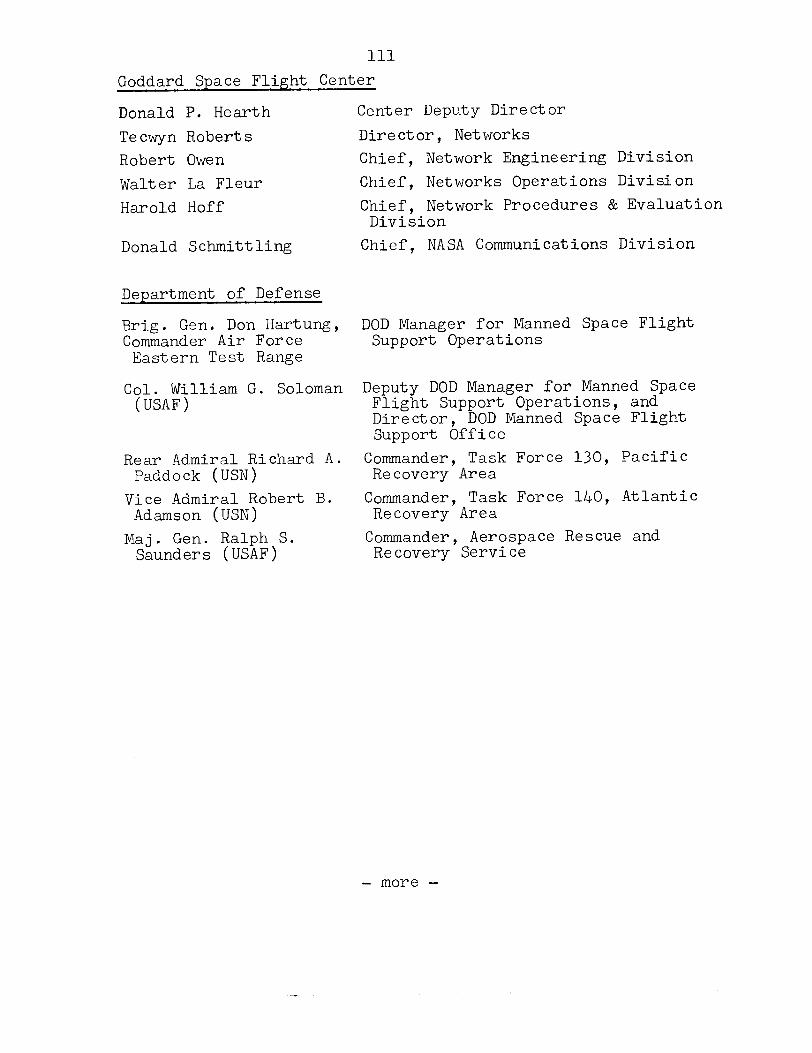
111
Goddard Space Flight Center
Donald P. Hearth
Tecwyn Roberts Robert Owen Walter La Fleur Harold Hoff
Donald Schmittling
Center Deputy Director
Director, Networks Chief, Network Engineering Division Chief, Networks Operations Division Chief, Network Procedures & Evaluation
Division Chief, NASA Communications Division
Department of Defense
Brig. Gen. Don Hartung, DOD Manager for Manned Space Flight Commander Air Force Support Operations
Eastern Test Range
Col. William G. Soloman Deputy DOD Manager for Manned Space (USAF) Flight Support Operations, and
Director, DOD Manned Space Flight Support Office
Rear Admiral Richard A. Commander, Task Force 130, Pacific Paddock (USN) Recovery Area
Vice Admiral Robert B. Commander, Task Force 140, Atlantic Adamson (USN) Recovery Area
Maj. Gen. Ralph S. Commander, Aerospace Rescue and Saunders (USAF) Recovery Service
- more -
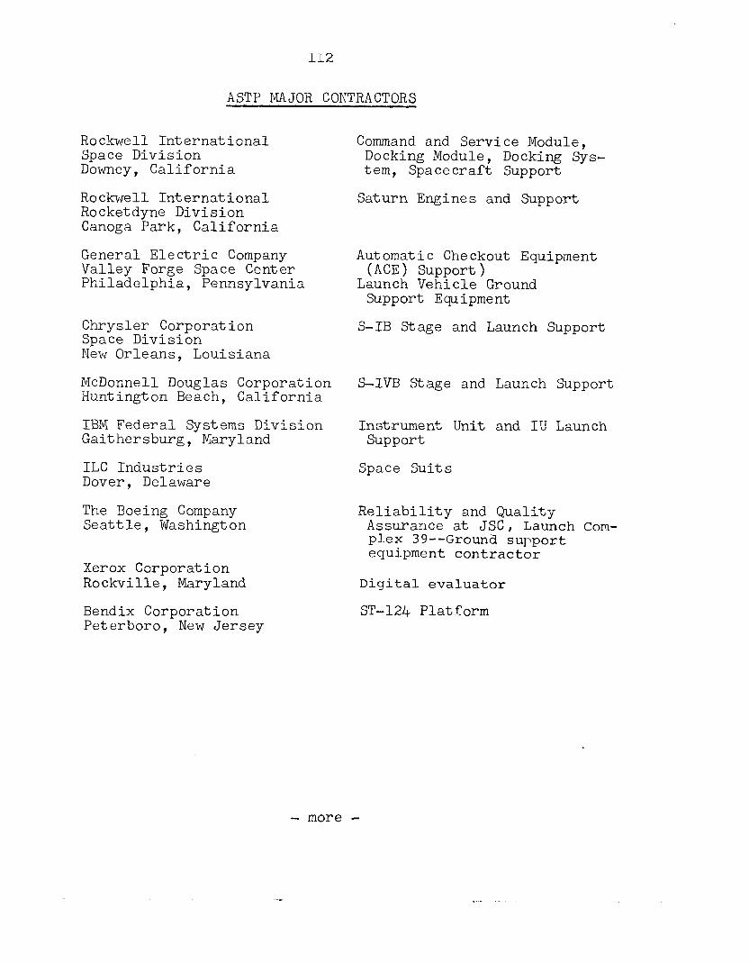
112
ASTP MAJOR CONTRACTORS
Rockwell International Space Division Downey, California
Rockwell International Rocketdyne Division Canoga Park, California
General Electric Company Valley Forge Space Center Philadelphia, Pennsylvania
Chrysler Corporation Space Division New Orleans, Louisiana
McDonnell Douglas Corporation Huntington Beach, California
IBM Federal Systems Division Gaithersburg, Maryland
ILC Industries Dover, Delaware
The Boeing Company Seattle, Washington
Xerox Corporation Rockville, Maryland
Bendix Corporation Peterboro, New Jersey
Command and Service Module, Docking Module, Docking Sys- tem, Spacecraft Support
Saturn Engines and Support
Automatic Checkout Equipment (ACE) support)
Launch Vehicle Ground Support Equipment
S-IB Stage and Launch Support
S-IVB Stage and Launch Support
Instrument Unit and IU Launch Support
Space Suits
Reliability and Quality Assurance at JSC, Launch Com- plex 39-- Ground-support equipment contractor
Digital evaluator
ST-124 Platform
- more -
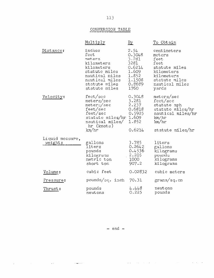
113
CONVERSION TABLE
Distance:
Velocity:
Multiply EL To Obtain
inches feet meters kilometers kilometers statute miles nautical miles nautical miles statute miles statute miles
2.54
7. %* 3281 0.6211, 1.609 1.852 1.1508
%E*9
centimeters meters feet feet statute miles kilometers kilometers statute miles nautical miles yards
; l 2
2:237 0.6818 0.5925
statute miles/hr 1.609 nautical miles/ 1.852
hr (knots) km/hr 0.6214
feet/set meters/set meters/set feet/set feet/set ,
meters/set feet/set statute mph statute miles/hr nautical miles/hr km/hr k.n/hr
statute miles/hr
Liquid measure, weight: gallons 3.785
liters 0.2642 pounds 0.45j6 kilograms 2.205 metric ton 1000 short ton 907.2
Volume: cubic feet 0.02832
Pressure: pounds/sq. inch 70.31
Thrust: pounds newtons
liters gallons kilograms pounds kilograms kilograms
cubic meters
grams/sq.cm
newtons pounds
- end -