Embed Size (px)
Citation preview

SPECTRUM ALASKA, LLC LNG PROJECT November, 2012 DESIGN BASIS FOR FEED GAS PIPELINE AND LNG FACILITIES Spectrum LNG, LLC
Page 1 of 35 Final Rev. 2-1-13
Table of Contents
LIST OF ACRONYMS AND ABBREVIATIONS ............................................................................................... 4
A. Project Overview ............................................................................................................................. 6
A.1 Introduction ............................................................................................................................. 6
A.1.1 Purpose ........................................................................................................................... 6
A.1.2 Project Summary ............................................................................................................. 6
A.1.3 Project Facilities ............................................................................................................... 6
A.2 GENERAL DESIGN AND CRITERIA ............................................................................................ 10
A.2.1 Feed Gas Properties and Characteristics ......................................................................... 10
A.2.2 Extent of Subject Facilities.............................................................................................. 11
A.2.3 Design Life ..................................................................................................................... 12
A.2.4 Regulations, Standards and Codes .................................................................................. 12
A.3 PHYSICAL FEATURES/CIVIL ...................................................................................................... 13
A.3.1 Topography.................................................................................................................... 13
A.3.2 Climate/Meteorology ..................................................................................................... 13
A.3.3 Geotechnical .................................................................................................................. 13
A.3.4 Hydrology ...................................................................................................................... 14
A.3.5 Seismicity ....................................................................................................................... 14
B. Feed Gas Pipeline (FGPL)................................................................................................................ 15
B.1 Pipeline Route ........................................................................................................................ 15
B.2 Road Crossings ....................................................................................................................... 15
B.3 High Consequence Area Evaluation and Selection .................................................................. 18
B.4 Structural ............................................................................................................................... 19
B.4.1 Vertical Support Members ............................................................................................. 19
B.4.2 Design Loads .................................................................................................................. 20
B.4.3 Foundation Design ......................................................................................................... 20
B.5 Mechanical ............................................................................................................................ 22
B.5.1 Steady State Hydraulics .................................................................................................. 22
B.5.2 Pipe Wall Thickness Considerations ................................................................................ 22
B.5.3 Pipeline Design Loading Categories ................................................................................ 22
SPECTRUM ALASKA, LLC LNG PROJECT November, 2012 DESIGN BASIS FOR FEED GAS PIPELINE AND LNG FACILITIES Spectrum LNG, LLC
Page 2 of 35 Final Rev. 2-1-13
B.6 Wind Induced Vibration ......................................................................................................... 24
B.7 Pipe Stress Criteria ................................................................................................................. 24
B.7.1 Allowable Stresses ......................................................................................................... 24
B.7.2 Load Combinations ........................................................................................................ 25
B.8 Configuration ......................................................................................................................... 25
B.9 Material Selection .................................................................................................................. 25
B.10 Guides, Slides, and Anchors .................................................................................................... 26
B.11 Wind Induced Vibration Prevention and Mitigation ................................................................ 26
B.12 Welding ................................................................................................................................. 26
B.12.1 Welding Criteria ............................................................................................................. 26
B.13 Hydrostatic Testing ................................................................................................................ 26
B.14 Cleaning and Drying ............................................................................................................... 26
B.15 Integrated Control and Safety System (ICSS) ........................................................................... 27
B.15.1 General Description of ICSS ............................................................................................ 27
B.16 Operations ............................................................................................................................. 27
B.16.1 Flow Control .................................................................................................................. 27
B.16.2 Pipeline Isolation ........................................................................................................... 28
B.16.3 Pressure Monitoring and Relief ...................................................................................... 28
B.16.4 Start-Up ......................................................................................................................... 28
B.16.5 Flow Constraints ............................................................................................................ 28
B.16.6 Normal Operations ........................................................................................................ 28
B.16.7 Planned and Unplanned Shutdown of Gas Line .............................................................. 28
B.16.8 Maintenance .................................................................................................................. 28
B.16.9 Surveillance ................................................................................................................... 28
B.17 Corrosion Control and Monitoring .......................................................................................... 28
B.17.1 Corrosion Control Measures........................................................................................... 28
C. SALNG PROCESSING FACILITY ......................................................................................................... 30
C.1 General Description ............................................................................................................... 30
C.2 Design Criteria........................................................................................................................ 30
C.2.1 Structural Design Criteria ............................................................................................... 30
C.2.2 Material Selection .......................................................................................................... 31
C.2.3 Equipment Design .......................................................................................................... 31
SPECTRUM ALASKA, LLC LNG PROJECT November, 2012 DESIGN BASIS FOR FEED GAS PIPELINE AND LNG FACILITIES Spectrum LNG, LLC
Page 3 of 35 Final Rev. 2-1-13
C.2.4 Building Design .............................................................................................................. 32
C.2.5 LNG Storage Design ........................................................................................................ 33
C.2.6 Primary LNG containment .............................................................................................. 33
C.2.7 Secondary LNG containment .......................................................................................... 33
D. Dismantle, Remove, and Restore ................................................................................................... 34
E. Risk Assessment............................................................................................................................. 35

SPECTRUM ALASKA, LLC LNG PROJECT November, 2012 DESIGN BASIS FOR FEED GAS PIPELINE AND LNG FACILITIES Spectrum LNG, LLC
Page 4 of 35 Final Rev. 2-1-13
LIST OF ACRONYMS AND ABBREVIATIONS AISC American Institute of Steel Construction
API American Petroleum Institute
APSC Alyeska Pipeline Service Company
ASCE American Society of Civil Engineers
ASME American Society of Mechanical Engineers
CFR Code of Federal Regulations
CVN Charpy V-Notch
DR&R Dismantle, Remove, and Restore
ESD Emergency Shut Down
F Fahrenheit
FBE Fusion-Bonded Epoxy
FDS Fire Detection System
FGPL Feed Gas Pipe Line
g Gravitational Acceleration
GPBU Greater Prudhoe Bay Unit
HAZOP Hazard and Operability Analysis
IBC International Building Code
ICSS Integrated Control and Safety System
MOP Maximum Operating Pressure
MSL Mean Sea Level
MTR Material Test Report
PBU Prudhoe Bay Unit
PBUFFG Prudhoe Bay Unit Field Fuel Gas
PCS Process Control System
PGA Peak Ground Acceleration
PLC Programmable Logic Controller
SALNG Spectrum Alaska LNG
SDV Shut Down Valve
SIS Safety Instrumented System
SMYS Specified Minimum Yield Stress
SPECTRUM ALASKA, LLC LNG PROJECT November, 2012 DESIGN BASIS FOR FEED GAS PIPELINE AND LNG FACILITIES Spectrum LNG, LLC
Page 5 of 35 Final Rev. 2-1-13
TAPS Trans Alaska Pipeline System
VSM Vertical Support Member(s)
WIV Wind Induced Vibration
ZPA Zero Period Acceleration
SPECTRUM ALASKA, LLC LNG PROJECT November, 2012 DESIGN BASIS FOR FEED GAS PIPELINE AND LNG FACILITIES Spectrum LNG, LLC
Page 6 of 35 Final Rev. 2-1-13
A. Project Overview
A.1 Introduction
A.1.1 Purpose
The purpose of this document is to provide the design basis for the Spectrum Alaska LNG (SALNG) Plant
and Feed Gas Pipeline facilities to be built in the project ROW lease.
A.1.2 Project Summary
Spectrum Alaska, LLC proposes to install a natural gas liquefaction facility in the Prudhoe Bay Field. The
plant will take delivery of gas through a short (approximately 1100 feet) 8” Feed Gas Pipeline (FGPL) that
will connect to the PBU field fuel gas header system. The plant will process the field fuel gas into LNG
and then load the LNG into trucks for delivery to markets anywhere that can be reached by truck.
The facility will provide processing for the production of liquefied natural gas (LNG), LNG storage,
dispensing for local truck fueling, and for transport by truck. It will be staffed with full-time operations
and support personnel for routine operations and maintenance activities. Transportation of personnel
and light equipment to and from the site will be via the existing local road system. Employee housing
will be provided as part of this project.
A.1.3 Project Facilities
The facilities to which this design basis pertains (i.e., the subject facilities) consist of the following:
- Feed gas pipeline (FGPL). - Processing Equipment - LNG Storage/Containment - Truck Loading - Office/Camp - Maintenance shop facility. - Control Room
The short Feed Gas Pipeline will tie into the Field Fuel Gas Unit (FFGU) distribution system that
originates at the CCP and CGF facilities belonging to the Prudhoe Bay Unit. The 24" diameter FFGU
header circles the field providing fuel gas to the PBU facilities. The Spectrum FGPL will connect to this
system in close proximity to the existing connection point that supplies Flow Station #3. This tie in will
require the approval of the PBU Operator and be conducted under their direct supervision.
Spectrum has recently inspected the site and is developing a detailed design for the tie-in piping and its
exit path from the multiple pipelines in the immediate vicinity and the crossing of the construction road.
These details will be included in a proprietary design package that will be submitted to the PBU
Operator for approval.
Once the pipe has exited the congested area of the tie in it will run straight to the LNG production
facility. The FGPL will be anchored in the center and each end of the FGPL will be designed to allow for
thermal expansion and contraction through the use conventional expansion loop design. Each end of the
FGPL will have flanges that can accommodate pigging equipment in the future should it ever be needed.
SPECTRUM ALASKA, LLC LNG PROJECT November, 2012 DESIGN BASIS FOR FEED GAS PIPELINE AND LNG FACILITIES Spectrum LNG, LLC
Page 7 of 35 Final Rev. 2-1-13
The FGPL will terminate at the LNG facility where it enters the metering skid. This skid will provide for
liquid knock out and at least three meter runs. This skid is completely enclosed and has already been
delivered to Prudhoe Bay, waiting to be installed. One meter run will be used for low flow conditions
when the plant is not producing LNG but still needs fuel for power generation and building heat, but the
volumes required are lower than the accuracy range of the meter needed for periods when the LNG is
being produced. So the first meter is for utilities when not producing LNG, the second meter is used
when the plant is operating and producing LNG, and the third meter will be for future use or if other
parties wish to take delivery through the pipeline.
The FGPL will be insulated and installed above ground on vertical support members (VSM) for its entire
length. The minimum design clearance between the surface of the tundra and lowest point of any
element being supported by VSM (e.g., pipe insulation, pipeline attachments such as tuned vibration
absorbers, electrical/communication cables, etc.) for the FGPL is 7 ft. This criterion does not apply to the
actual VSM where the bottom of the lowest structural elements will be less than seven feet from the
surface of the tundra.
This Design Basis sets out the criteria and standards to which the Spectrum FGPL and LNG Processing
Facility shall be built. The purpose of this document is to establish an engineering baseline for
preliminary design of the project. The Design Basis will be used to verify that requirements are met and
that the project will be engineered to standards that meet modern codes and are appropriate for its
scope and location.

SPECTRUM ALASKA, LLC LNG PROJECT November, 2012 DESIGN BASIS FOR FEED GAS PIPELINE AND LNG FACILITIES Spectrum LNG, LLC
Page 8 of 35 Final Rev. 2-1-13
Figure A.1 Map
Note: Approximate separation distances to other major facilities; Flow Station #3 inlet manifold building, 2,200 feet; Drill Site 14, 3,100 feet; Pump Station #1, 6,300 feet.
Connection details are being finalized and are
proprietary work performed by Spectrum and
its contractors that will be approved by the
PBU operator for the supply end of the FGPL.
Details will be submitted to SPCO as part of a
separate document.

SPECTRUM ALASKA, LLC LNG PROJECT November, 2012 DESIGN BASIS FOR FEED GAS PIPELINE AND LNG FACILITIES Spectrum LNG, LLC
Page 9 of 35 Final Rev. 2-1-13
Figure A.2 Facility Plan

SPECTRUM ALASKA, LLC LNG PROJECT November, 2012 DESIGN BASIS FOR FEED GAS PIPELINE AND LNG FACILITIES Spectrum LNG, LLC
Page 10 of 35 Final Rev. 2-1-13
A.2 GENERAL DESIGN AND CRITERIA
A.2.1 Feed Gas Properties and Characteristics
The composition of the feed gas is summarized in Table A.2.1. This current composition is typical for this
particular stream of gas. The field began producing in 1977 and there have been minor composition
changes over the past 35 years. No major changes are expected unless the PBU operators implement a
new type of enhanced oil recovery such as CO2 injection. In the event this happens, there will be a long
notice period and the PBU will likely modify the FFGU in manner that prevents impact the PBU facilities.
Whatever modifications the PBU implements will likely address impacts to the LNG facility as well.
Table A.2.1 Liquid Hydrocarbon Composition
Analysis Name Analysis Unit Combination Result
METHANE-MOL% MOL% 80.361
ETHANE-MOL% MOL% 5.172
PROPANE-MOL% MOL% 1.615
I-BUTANE-MOL% MOL% 0.083
N-BUTANE-MOL% MOL% 0.131
I-PENTANE-MOL% MOL% 0.015
N-PENTANE-MOL% MOL% 0.016
C6P-MOL% MOL% 0.056
CO2-MOL% MOL% 11.929
NITROGEN-MOL% MOL% 0.622
MOL WEIGHT 20.791
BTU GRSDRY IDEAL [email protected] 955.3
BTU GRSDRY REAL [email protected] 954.9
BTU GRSSAT IDEA [email protected] 940.9
BTU GRSSAT REAL [email protected] 938.2
BTU NET [email protected] 862.0
SPG IDEAL 0.7179
SPG REAL 0.7195
O2 CONTAM MOL% <0.001

SPECTRUM ALASKA, LLC LNG PROJECT November, 2012 DESIGN BASIS FOR FEED GAS PIPELINE AND LNG FACILITIES Spectrum LNG, LLC
Page 11 of 35 Final Rev. 2-1-13
COMPRESSIBILITY FAC. 0.997373
LINE PRES PSIG 600
LINE TEMP DEG.F 14
H2S PPM 38 +/-10%
A.2.2 Extent of Subject Facilities
Figure A.3 Spectrum Alaska LNG Block Flow Diagram
A.2.2.1 METERING FACILITY
The metering facility will provide flow measurement for the purposes of accounting for the sale of gas. It will also provide initial pressure control, emergency shutdown of gas flow, initial temperature control, and free liquids removal.
A.2.2.2 SALNG GAS PREPROCESSING AND CONDITIONING
After the gas has been measured and any free liquids removed, CO2 and H2S gases are removed by a chemical process that uses liquid amines. The amines are constantly regenerated and the CO2 and H2S are rejected in this process. The amines are water soluble and therefore the gas leaving this process is water saturated. The gas next passes through a glycol contactor that removes gross water vapor. This vapor is condensed and returned to the amine system for re‐use. The gas leaving this system still contains a minor amount of water and is next passed through a molecular sieve that removes the remaining water vapor that would freeze in the cryogenic processing section.
A.2.2.3 SALNG CRYOGENIC PROCESSING
Once the gas has been stripped of water, CO2 and H2S, it enters the cryo section of the plant where it is cooled to a point that the heavier hydrocarbon molecules such as a portion of the ethane, propane, butane, etc. condense. These are separated from the remaining stream and either sold as products or consumed as fuel gas. What remains is almost all methane and it proceeds to the next step in the process where it is cooled to its point of condensation. The pressure is also reduced in this process to below 15 psig.
SPECTRUM ALASKA, LLC LNG PROJECT November, 2012 DESIGN BASIS FOR FEED GAS PIPELINE AND LNG FACILITIES Spectrum LNG, LLC
Page 12 of 35 Final Rev. 2-1-13
A . 2 . 2 . 4 SALNG BULK STORAGE
The LNG product will be transferred from the cryo process section to the storage tanks and stored at a
pressure of close to 15 psig.
A . 2 . 2 . 5 TANKER TRUCK LOADING
The LNG product will be pumped from the storage tanks into trucks for delivery to end users outside of
the LNG plant area. These trucks are over the highway haulers similar to other 18 wheelers except they
are designed to haul LNG and the drivers have the appropriate training. This is a very common
occurrence in southern Alaska and places like Boston, MA where over 1,000,000 gallons per day is
trucked out of the Distrigas terminal during the winter.
A.2.3 Design Life
The minimum design life of the SALNG will be 30 years and will be incorporated into applicable design
criteria for the facilities. Time-sensitive parameters (e.g., VSM creep rate) are selected based on a 30-
year design life. It should be noted that a 30-year design life does not indicate that the pipeline and
associated structures will be used up, failure-prone and requiring replacement at the end of the lease.
Engineering design life is established from a combination of technical, regulatory, economic and
commercial considerations. There are various definitions of design life. However, for purposes of this
lease it can be defined as the period over which the systems, components and structure are required to
perform their primary function with acceptable safety, regulatory and environmental performance, and
with an acceptable probability that they will not experience large failures, require extensive
replacements or need significant repairs.
A.2.4 Regulations, Standards and Codes
The subject facilities will be designed in accordance with, but not limited to, the following regulations, standards and codes. The most current adopted version of these will be applied for construction. Where conflicts occur, the most restrictive/conservative design & construction standards will be used:
ANSI/ASME B31.3, Standard for Process Piping
ANSI/ASME B31.8, Standard for Gas Piping Systems
Code of Federal Regulations Title 49, “Transportation,” Parts 191, 192, 193, 195
Alaska Administrative Code (AAC) 18 AAC 75, Oil and Hazardous Substances Pollution Control.
American Institute of Steel Construction (AISC-303-05), “Code of Standard Practice for Steel Building and Bridges.”
American Institute of Steel Construction (ANSI/AISC 360-05), “Specification for Structural Steel Buildings.
AISC, Manual of Steel Construction, 13th Edition.
American Welding Society (AWS) D1.1/D1.1M:2006, Structural Welding Code – Steel.
API 5L, Specification for Line Pipe, 2004
API 6D, Pipeline Valves, Edition 22, 2002
API 1104, Welding Pipelines and Related Facilities, 2005
ASCE 7-05 Minimum Design Loads for Buildings and Other Structures 2005

SPECTRUM ALASKA, LLC LNG PROJECT November, 2012 DESIGN BASIS FOR FEED GAS PIPELINE AND LNG FACILITIES Spectrum LNG, LLC
Page 13 of 35 Final Rev. 2-1-13
ASME B16.5-2003, Pipe Flanges and Flanged Fittings: NPS ½ through 24
International Building Code, 2009
2008 National Electrical Code (NEC)
NFPA 59A, Standard for the Production, Storage, and Handling of Liquefied Natural Gas (LNG), 2009
Seismic Design Guidelines and Data Submittal Requirements for LNG Facilities, 2007 (Draft) Federal Energy Regulatory Commission.
Common Industry Standards that have been found successful.
A.3 PHYSICAL FEATURES/CIVIL
A.3.1 Topography
The project area is located on the Arctic Coastal Plain situated between the Beaufort Sea and the Brooks Mountain Range. The SALNG facility and FGPL will be located on the coastal zone of a broad, relatively level, treeless area. The coastal zone is located within 2 to 3 miles of the coastline and at elevations of up to 30 to 45 feet above mean sea level (MSL). Surface drainage in the inland zone is generally not confined to defined channels and is characterized as sheet flow.
Wind-oriented thaw lakes dominate the landscape in the coastal zone. The thaw lake basins originate in areas of restricted drainage, where shallow ponding results in a warmer surface temperature that causes the underlying ground ice to thaw resulting in subsidence. Most of the ponds and lakes are relatively shallow. The thaw lakes go through a cycle of development, expansion, drainage, and re-vegetation.
Topography at the facility and along the FGPL route is relatively flat with the land form between drainages dominated by patterned ground. Sharp topographic breaks and features are uncommon although low ridges exist at lake and stream edges and adjacent to ice wedges. Small (e.g., typically less than one foot) seasonal variation in local tundra elevation due to freezing and thawing of the active layer is common. The site is within a large oilfield adjacent to a developed road.
A.3.2 Climate/Meteorology
Based on Prudhoe Bay historical climate data between 1971 and 2000, the mean annual ambient temperature is approximately 10.7°F. Ambient temperature ranges from a highest daily average of 53.9°F to a lowest daily average of -35.8°F. The record maximum temperature is 83°F (June 21, 1991) and the record minimum temperature is -62°F (January 1989). The area annually experiences approximately 9,291 degree days °F freezing and approximately 960 degree days °F thawing.
Winds are generally from the northeast (N70°E at Prudhoe Bay to N79°E at Barter Island), but wind shifts to the west or northwest are common throughout the summer. Strong westerly and southwesterly winds periodically occur during storms. Wind speed varies from a low of 11.4 mph to a high of 12.9 mph. Maximum instantaneous recorded wind speeds vary from 38 mph in early summer to 81 mph in winter.
Prudhoe Bay mean annual precipitation is approximately 4 inches per year with total annual snow accumulation estimated to be about 4 inches.
A.3.3 Geotechnical
The entire area on which the SALNG facility & FGPL will be developed is underlain by permafrost.
Permafrost extends almost to the ground surface. By the end of summer thaw, the permafrost depth
(i.e., the active layer thickness) under the undisturbed tundra surface is less than 3 feet.
SPECTRUM ALASKA, LLC LNG PROJECT November, 2012 DESIGN BASIS FOR FEED GAS PIPELINE AND LNG FACILITIES Spectrum LNG, LLC
Page 14 of 35 Final Rev. 2-1-13
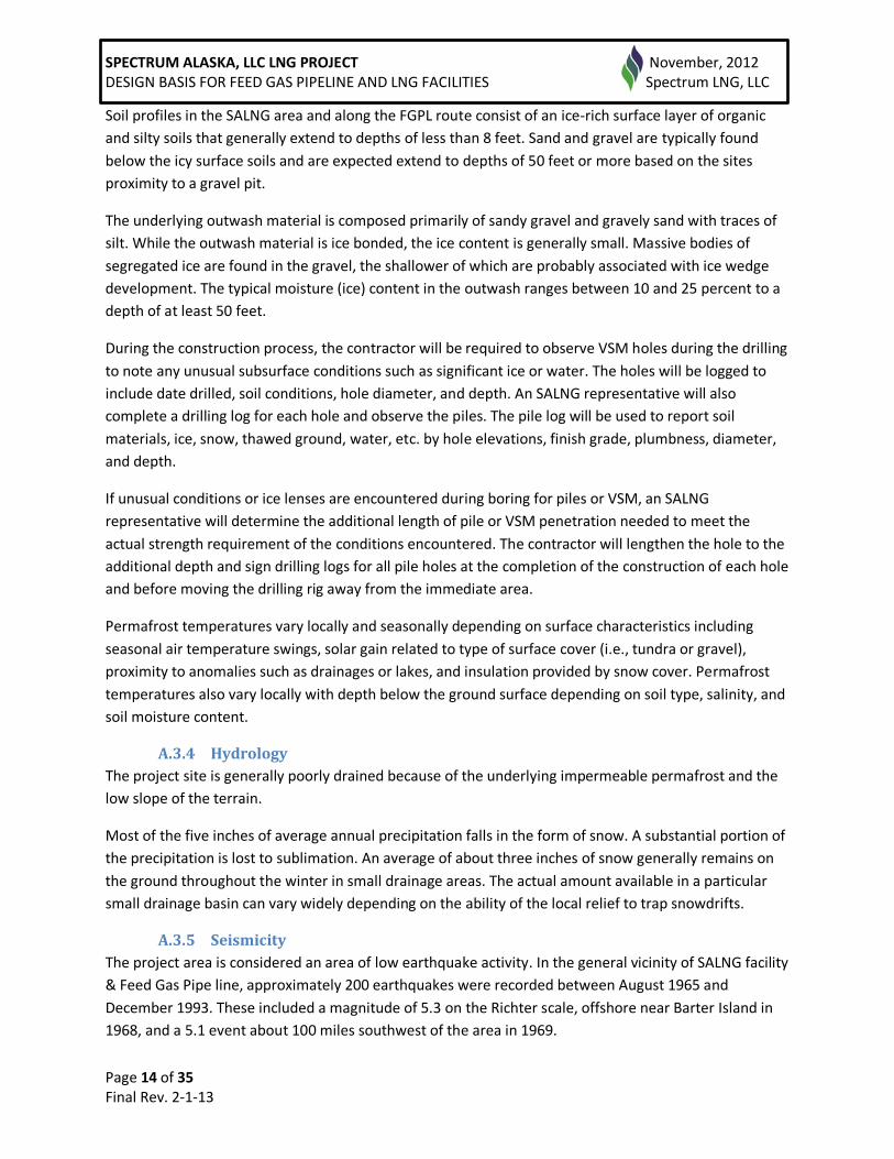
Soil profiles in the SALNG area and along the FGPL route consist of an ice-rich surface layer of organic
and silty soils that generally extend to depths of less than 8 feet. Sand and gravel are typically found
below the icy surface soils and are expected extend to depths of 50 feet or more based on the sites
proximity to a gravel pit.
The underlying outwash material is composed primarily of sandy gravel and gravely sand with traces of
silt. While the outwash material is ice bonded, the ice content is generally small. Massive bodies of
segregated ice are found in the gravel, the shallower of which are probably associated with ice wedge
development. The typical moisture (ice) content in the outwash ranges between 10 and 25 percent to a
depth of at least 50 feet.
During the construction process, the contractor will be required to observe VSM holes during the drilling
to note any unusual subsurface conditions such as significant ice or water. The holes will be logged to
include date drilled, soil conditions, hole diameter, and depth. An SALNG representative will also
complete a drilling log for each hole and observe the piles. The pile log will be used to report soil
materials, ice, snow, thawed ground, water, etc. by hole elevations, finish grade, plumbness, diameter,
and depth.
If unusual conditions or ice lenses are encountered during boring for piles or VSM, an SALNG
representative will determine the additional length of pile or VSM penetration needed to meet the
actual strength requirement of the conditions encountered. The contractor will lengthen the hole to the
additional depth and sign drilling logs for all pile holes at the completion of the construction of each hole
and before moving the drilling rig away from the immediate area.
Permafrost temperatures vary locally and seasonally depending on surface characteristics including
seasonal air temperature swings, solar gain related to type of surface cover (i.e., tundra or gravel),
proximity to anomalies such as drainages or lakes, and insulation provided by snow cover. Permafrost
temperatures also vary locally with depth below the ground surface depending on soil type, salinity, and
soil moisture content.
A.3.4 Hydrology
The project site is generally poorly drained because of the underlying impermeable permafrost and the
low slope of the terrain.
Most of the five inches of average annual precipitation falls in the form of snow. A substantial portion of
the precipitation is lost to sublimation. An average of about three inches of snow generally remains on
the ground throughout the winter in small drainage areas. The actual amount available in a particular
small drainage basin can vary widely depending on the ability of the local relief to trap snowdrifts.
A.3.5 Seismicity
The project area is considered an area of low earthquake activity. In the general vicinity of SALNG facility
& Feed Gas Pipe line, approximately 200 earthquakes were recorded between August 1965 and
December 1993. These included a magnitude of 5.3 on the Richter scale, offshore near Barter Island in
1968, and a 5.1 event about 100 miles southwest of the area in 1969.
SPECTRUM ALASKA, LLC LNG PROJECT November, 2012 DESIGN BASIS FOR FEED GAS PIPELINE AND LNG FACILITIES Spectrum LNG, LLC
Page 15 of 35 Final Rev. 2-1-13
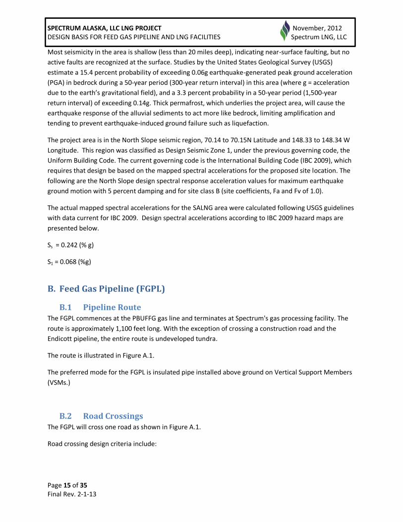
Most seismicity in the area is shallow (less than 20 miles deep), indicating near-surface faulting, but no
active faults are recognized at the surface. Studies by the United States Geological Survey (USGS)
estimate a 15.4 percent probability of exceeding 0.06g earthquake-generated peak ground acceleration
(PGA) in bedrock during a 50-year period (300-year return interval) in this area (where g = acceleration
due to the earth’s gravitational field), and a 3.3 percent probability in a 50-year period (1,500-year
return interval) of exceeding 0.14g. Thick permafrost, which underlies the project area, will cause the
earthquake response of the alluvial sediments to act more like bedrock, limiting amplification and
tending to prevent earthquake-induced ground failure such as liquefaction.
The project area is in the North Slope seismic region, 70.14 to 70.15N Latitude and 148.33 to 148.34 W
Longitude. This region was classified as Design Seismic Zone 1, under the previous governing code, the
Uniform Building Code. The current governing code is the International Building Code (IBC 2009), which
requires that design be based on the mapped spectral accelerations for the proposed site location. The
following are the North Slope design spectral response acceleration values for maximum earthquake
ground motion with 5 percent damping and for site class B (site coefficients, Fa and Fv of 1.0).
The actual mapped spectral accelerations for the SALNG area were calculated following USGS guidelines
with data current for IBC 2009. Design spectral accelerations according to IBC 2009 hazard maps are
presented below.
Ss = 0.242 (% g)
S1 = 0.068 (%g)
B. Feed Gas Pipeline (FGPL)
B.1 Pipeline Route The FGPL commences at the PBUFFG gas line and terminates at Spectrum's gas processing facility. The
route is approximately 1,100 feet long. With the exception of crossing a construction road and the
Endicott pipeline, the entire route is undeveloped tundra.
The route is illustrated in Figure A.1.
The preferred mode for the FGPL is insulated pipe installed above ground on Vertical Support Members
(VSMs.)
B.2 Road Crossings The FGPL will cross one road as shown in Figure A.1.
Road crossing design criteria include:

SPECTRUM ALASKA, LLC LNG PROJECT November, 2012 DESIGN BASIS FOR FEED GAS PIPELINE AND LNG FACILITIES Spectrum LNG, LLC
Page 16 of 35 Final Rev. 2-1-13
• Preservation of pipeline integrity particularly through minimization of accumulation of water around
the pipeline;
• Minimization of settlements that induce additional loading on the pipeline;
• Non-interference with adjacent pipelines;
• Protecting the underlying tundra from damage and thaw settlement;
• Promoting long term integrity of the road surface.
Casings will be designed in accordance with API 1102. Oversized casings with casing-carrier pipe
isolators, carrier pipe coating beneath insulation and additional insulation beneath casings will be
incorporated into road crossing design. A typical road crossing is illustrated in Figure B.1.

SPECTRUM ALASKA, LLC LNG PROJECT November, 2012 DESIGN BASIS FOR FEED GAS PIPELINE AND LNG FACILITIES Spectrum LNG, LLC
Page 17 of 35 Final Rev. 2-1-13
Figure B.1 Typical Road Crossing Elevation and Section

SPECTRUM ALASKA, LLC LNG PROJECT November, 2012 DESIGN BASIS FOR FEED GAS PIPELINE AND LNG FACILITIES Spectrum LNG, LLC
Page 18 of 35 Final Rev. 2-1-13
B.3 High Consequence Area Evaluation and Selection High consequence areas (HCA) that could be affected by the pipeline will be identified and evaluated
according to the requirements of Federal Regulation 49 CFR 195.452 “Pipeline Integrity Management in
High Consequence Areas.” Data available from the Office of Pipeline Safety and generated during the
detailed design phase of the pipeline will be used to determine the presence of any HCA along the
proposed pipeline alignment. HCA will be identified and used to develop an integrity management plan.
An HCA evaluation and risk assessment procedure will be prepared to assist identification of any
potentially affected areas. If the pipeline is determined to affect an HCA, then that fact will be identified
and a baseline integrity assessment completed before gas enters the pipeline. A written integrity
management program addressing the risks on the pipeline segments identified as possibly affecting an
HCA will be completed within one year after pipeline operation begins only if the pipeline is determined
to probably affect any HCA. Re-inspection intervals for integrity assessments will be based on federal
regulatory requirements.

SPECTRUM ALASKA, LLC LNG PROJECT November, 2012 DESIGN BASIS FOR FEED GAS PIPELINE AND LNG FACILITIES Spectrum LNG, LLC
Page 19 of 35 Final Rev. 2-1-13
B.4 Structural
B.4.1 Vertical Support Members
The FGPL will be installed on typical North Slope support structures. The supports will consist of a
horizontal steel beam connected to a steel pipe pile or vertical support member (VSM). VSM
components will be fabricated using accepted designs and materials. A general fracture control
philosophy has been developed which establishes acceptance criteria based on current procurement
practice for Charpy toughness-tested steels in low-temperature service.
Examples of steel shapes and temperatures that may apply are listed in Table B.4.1.
Table B.4.1 Steel Shapes and Grades Typically Meeting Charpy V-Notch (CVN) Testing
Shape 15/12 foot-pounds @ CVN Test Temperature
–20°F –50°F
Wide Flange Beams (Hot Rolled)
A572 A992(S5)
A572 normalized (2) A992(S5)
Plate Girders (Fabricated)
A572
A572 (3)
Plate (Smooth) A572 A572 / A588
Channel 8” & Larger (Hot Rolled)
A572 / A588
––
Channel (Formed) –– A572 (4)
Box Beams –– A572 (5)
Pipe
A333 Grade 6
A333 Grade 6 API-5L-X65
Box Columns –– A537 Class 1
Notes: (1) Certified Material Test Reports (MTRs) are required to confirm CVN test results on each individual heat.
(2) Normalized steels require special processing and are not usually stocked. Check with suppliers for
pricing and availability (3) Plate girders (similar to wide flange beams) can be custom fabricated to nearly any size and or shape
from plate steels meeting CVN low-temperature requirements. Consult fabrication shops for limitations. (4) Channel beams can be custom formed (by bending) to nearly any size and shape from plate steels
meeting CVN low-temperature requirements. Consult fabrication shops for limitations.
(5) Box Beams (similar to square or rectangular tube) can be custom fabricated to nearly any size and
shape from plate steels meeting CVN low-temperature requirements. Consult fabrication shops for limitations.
The VSM will be embedded and slurried at a specified depth in the ground. Design of the supports will
be in accordance with appropriate codes and standards, and information received from the geotechnical
and hydrology reports.

SPECTRUM ALASKA, LLC LNG PROJECT November, 2012 DESIGN BASIS FOR FEED GAS PIPELINE AND LNG FACILITIES Spectrum LNG, LLC
Page 20 of 35 Final Rev. 2-1-13
B.4.2 Design Loads
Pipeline supports will be designed to accommodate the following loads:
Dead Load (D): to include equipment and piping
Operating Loads (F): to include fluid in pipes, and other long-term loads which result from the operation of the facility (including pipeline anchor, guides, and slide loads)
Live Loads (L)
Thermal Load (T): as determined from the pipeline stress analysis
Wind Load (W): per IBC, and as follows: Basic Wind Speed = V = 110 mph Exposure Factor = D Importance Factor = II Total lateral wind force per foot on the supported pipeline will be considered
Seismic Load (E): as determined from the pipeline stress analysis and IBC requirements
Frost Jacking Force or Frost Heave (J): per Table B.4.2
Snow Load (S): as determined from the pipeline stress analysis
B.4.3 Foundation Design
The soil and geothermal conditions in the SALNG facility & FGPL area consist of an upper layer of icy silt and organics overlying outwash material consisting largely of sand and gravel. The outwash is generally encountered at a depth of 6 to 8 feet along the pipeline route. Thaw depths (i.e., active layer thickness) measured in August 1998 in the SALNG facility & FGPL area were found to be in the range of 2 feet to 5 feet with an average of about 2-3 feet.
In general, the pile foundation design will be based on: • The tangential adfreeze bond strength at the pile to slurry interface to resist the vertical loads • The resistive strength between the slurry and native soil to resist frost jacking (heave) forces. The required depth of pile embedment will be dependent on these forces.
Typical adfreeze and frost jacking (heave) stresses for North Slope VSMs are shown in Table B.4.2.
The adfreeze values set out in Table B.4.2 are based on controlling creep related vertical deflection (i.e., settlement) under long term loads.
The minimum embedment for VSM design is typically controlled by the need to resist frost heave forces. Based on a design active layer of 3 feet and a frost heave stress of 40 psi, the frost heave force is calculated to be 17.3 kips per foot of the pile’s perimeter. In areas of upland tundra without massive ice, an embedment of 12.9 feet below the tundra surface provides sufficient adfreeze bond between the sand-slurry and the steel pipe to resist this force. Massive ice is treated as a no-load zone for resistance to frost jacking and/or structural loads. The baseline design provides for up to three feet of massive ice at each VSM location before site-specific adjustments are needed. Therefore, VSM will be designed using 15 feet below tundra surface as the minimum embedment. If ice thickness in excess of 3 feet is encountered when drilling holes for VSM installation, the VSM is extended an additional 1 foot for each additional 1 foot of ice. The design basis for the Feed Gas pipeline VSM follows this approach.

SPECTRUM ALASKA, LLC LNG PROJECT November, 2012 DESIGN BASIS FOR FEED GAS PIPELINE AND LNG FACILITIES Spectrum LNG, LLC
Page 21 of 35 Final Rev. 2-1-13
Table B.4.2 Typical Adfreeze Stresses for VSM
Depth Below Top
of Tundra(feet)
Compressive or
Tensile Loading(psi)
From
To
Summer
Winter
0
3
0
–40
(upward)
3 6 5.8 5.8
6 9 11.6 11.6
9 12 16.5 16.5
12
Bottom of VSM 20.3 20.3
Notes: 1. The “Depth Below” shown in the above table applies to the undisturbed
tundra case or the gravel pad case, for other conditions substitute -3 with the appropriate case dependent depth of active layer as presented in Table B.4.2.
2. The capacity of a VSM to resist frost heave shall be the lesser of the following: • The summation of the allowable adfreeze bond stresses betweenVSM and slurry.
• The summation of the allowable stresses between the slurry and the native soil or ice.
3. Adfreeze stresses are at pile/slurry interface. 4. For wind and seismic loadings plus short term vertical loads, stress may be increased
by 33%. 5. Piles/VSM installed by the drilled and slurried method shall be calculated for all
sizes. In no case shall the embedment be less than 15 ft below top of tundra.
6. Adfreeze stresses based on Department of the Army TM5-852-4 “Arctic and Subarctic Construction Foundations for Structures” October 1983 Includes a factor of safety of 2 on sustained loading conditions.
7. Design temperature profile consistent with general 2010 measured ground temperatures.
In addition to adjusting VSM embedment where massive ice is encountered, other conditions such as
proximity to water bodies (ponds or drainages) or deeper snow drifting could result in a warmer ground
condition and result in deeper embedment being necessary as determined on a site specific basis. There
are no water bodies along the route of the FGPL.
The design basis for the FGPL is that the minimum distance between the surface of the tundra and
lowest point of any element being supported by VSM (e.g., pipe insulation, including pipeline
attachments such as tuned vibration absorbers, electrical/communication cables, etc.) is seven (7) feet.

SPECTRUM ALASKA, LLC LNG PROJECT November, 2012 DESIGN BASIS FOR FEED GAS PIPELINE AND LNG FACILITIES Spectrum LNG, LLC
Page 22 of 35 Final Rev. 2-1-13
B.5 Mechanical
B.5.1 Steady State Hydraulics
Anticipated LNG production from the SALNG Project is up to 400,000 gallons per day (gpd).
The design and engineering of pipeline shall be sized in accordance with accepted standards and provide
a hydraulic analysis as part of the documentation. It is expected that the diameter of the pipe will be
controlled by its structural bridging capacity between the VSMs rather than hydraulic capability.
A full hydraulic analysis will be performed on the pipeline. Engineering design parameters that will be
determined during final design of the pipeline are summarized in Table B.5.1.
Table B.5.1 Minimum Pipe Design Parameters for Hydraulic Analysis
Outside Diameter
Min Wall Thickness
Specified Minimum
Yield Strength (SMYS)
Normal Fluid/Gas Operating
Temperature
Maximum Fluid/Gas Operating
Temperature
Max Inlet Pressure
Max Outlet
Pressure
(in) (in) (psi) (⁰F) (⁰F) (psig) (psig)
B.5.2 Pipe Wall Thickness Considerations
B.5.2.1 Design Factor
The design factor used for wall thickness calculations will be 0.72 for the pipeline located outside of the
facilities. Where piping is inside of the facilities the design factor will be 0.6.
B.5.2.2 Corrosion Allowance
The pipeline design will include a 1/16 in corrosion allowance.
B.5.3 Pipeline Design Loading Categories
Two general categories of design loading conditions are the design operating condition and the design
contingency condition.
The design operating condition is defined to include all normal operating conditions and environmental
loadings. The ASME B31.8 Pipe Code establishes these loadings. The stresses produced in the pipeline
by these loadings are to be within the design criteria limits established by conventional engineering
practices and B31.8. The loadings for the design operating condition on the above ground pipeline are:
• Internal design pressure
• Dead and live loads
• Temperature differential
• Wind load
• Snow and ice load
• Operating Design Earthquake

SPECTRUM ALASKA, LLC LNG PROJECT November, 2012 DESIGN BASIS FOR FEED GAS PIPELINE AND LNG FACILITIES Spectrum LNG, LLC
Page 23 of 35 Final Rev. 2-1-13
The design contingency condition is defined to include the sustained loadings for normal operating conditions combined with occasional loadings from extreme environmental events. Design contingency conditions will occur rarely, if at all, during the lifetime of the system. The stresses produced in the pipeline by these loadings will remain within design criteria limits. When environmental loadings reach the design contingency condition levels; the pipeline systems will be inspected and may be shut down for maintenance purposes. The loading for the design contingency condition on the above ground pipeline are:
Internal design pressure
Dead and live loads
Temperature differential
Contingency Design Earthquake
Loss of a support
The contingency design earthquake and loss of support are not considered to occur concurrently.
B.5.3.1 Internal Design Pressure
The internal design pressure for the FGPL is 1440 psig.
B.5.3.2 Hydrostatic Testing
The FGPL will be tested to at least 1.25 times the design pressure. The SALNG Plant will be tested to at
least 1.5 times the design pressure. The maximum hoop stress during hydrostatic testing will be less
than 95% of the Specified Minimum Yield Stress (SMYS). The test pressure is combined only with dead
and live loads, thermal expansion at test fluid temperature, and 1/3 wind design speed.
B.5.3.3 Dead and Live Loads
The dead loads include pipe weight, insulation weight, and insulation jacket weight. Additional dead
loads include the weight of tuned vibration absorbers (TVA) where required along the pipeline.
B.5.3.4 Snow and Ice Loads
Typically ice and snow loads on North Slope pipelines can be neglected unless the topography is such
that consideration is warranted (i.e., pipelines in gulleys, areas of extreme drifting, or that may be
affected by snow removal operations. Where snow loads are to be considered, adjusted snow and ice
loads for an elevated pipeline will be based on a snow density of 20 lbs/ft³.
B.5.3.5 Wind Load
Design operating wind speed is 110 mph. The design and wind pressure will be calculated using ASCE 7-
05 as required by the IBC. The design wind exposure is “D”, the importance category is II, and the
velocity pressure exposure coefficient “Kz” is equal to 0.85 for heights up to 15 feet (The maximum
pipeline height is 7 to 8 feet), this results in a wind pressure of approximately 19 lb/ft² on the pipeline.
B.5.3.6 Temperature Differential
The temperature differential is based upon a minimum ambient temperature (-50°F) and the maximum
pipe wall temperature of 200°F.
SPECTRUM ALASKA, LLC LNG PROJECT November, 2012 DESIGN BASIS FOR FEED GAS PIPELINE AND LNG FACILITIES Spectrum LNG, LLC
Page 24 of 35 Final Rev. 2-1-13
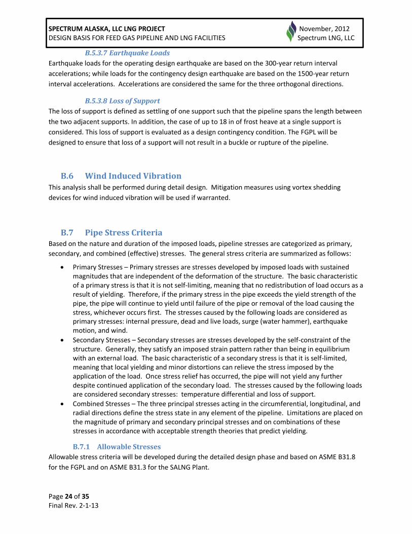
B.5.3.7 Earthquake Loads
Earthquake loads for the operating design earthquake are based on the 300-year return interval
accelerations; while loads for the contingency design earthquake are based on the 1500-year return
interval accelerations. Accelerations are considered the same for the three orthogonal directions.
B.5.3.8 Loss of Support
The loss of support is defined as settling of one support such that the pipeline spans the length between
the two adjacent supports. In addition, the case of up to 18 in of frost heave at a single support is
considered. This loss of support is evaluated as a design contingency condition. The FGPL will be
designed to ensure that loss of a support will not result in a buckle or rupture of the pipeline.
B.6 Wind Induced Vibration This analysis shall be performed during detail design. Mitigation measures using vortex shedding
devices for wind induced vibration will be used if warranted.
B.7 Pipe Stress Criteria Based on the nature and duration of the imposed loads, pipeline stresses are categorized as primary,
secondary, and combined (effective) stresses. The general stress criteria are summarized as follows:
Primary Stresses – Primary stresses are stresses developed by imposed loads with sustained magnitudes that are independent of the deformation of the structure. The basic characteristic of a primary stress is that it is not self-limiting, meaning that no redistribution of load occurs as a result of yielding. Therefore, if the primary stress in the pipe exceeds the yield strength of the pipe, the pipe will continue to yield until failure of the pipe or removal of the load causing the stress, whichever occurs first. The stresses caused by the following loads are considered as primary stresses: internal pressure, dead and live loads, surge (water hammer), earthquake motion, and wind.
Secondary Stresses – Secondary stresses are stresses developed by the self-constraint of the structure. Generally, they satisfy an imposed strain pattern rather than being in equilibrium with an external load. The basic characteristic of a secondary stress is that it is self-limited, meaning that local yielding and minor distortions can relieve the stress imposed by the application of the load. Once stress relief has occurred, the pipe will not yield any further despite continued application of the secondary load. The stresses caused by the following loads are considered secondary stresses: temperature differential and loss of support.
Combined Stresses – The three principal stresses acting in the circumferential, longitudinal, and radial directions define the stress state in any element of the pipeline. Limitations are placed on the magnitude of primary and secondary principal stresses and on combinations of these stresses in accordance with acceptable strength theories that predict yielding.
B.7.1 Allowable Stresses
Allowable stress criteria will be developed during the detailed design phase and based on ASME B31.8
for the FGPL and on ASME B31.3 for the SALNG Plant.
SPECTRUM ALASKA, LLC LNG PROJECT November, 2012 DESIGN BASIS FOR FEED GAS PIPELINE AND LNG FACILITIES Spectrum LNG, LLC
Page 25 of 35 Final Rev. 2-1-13
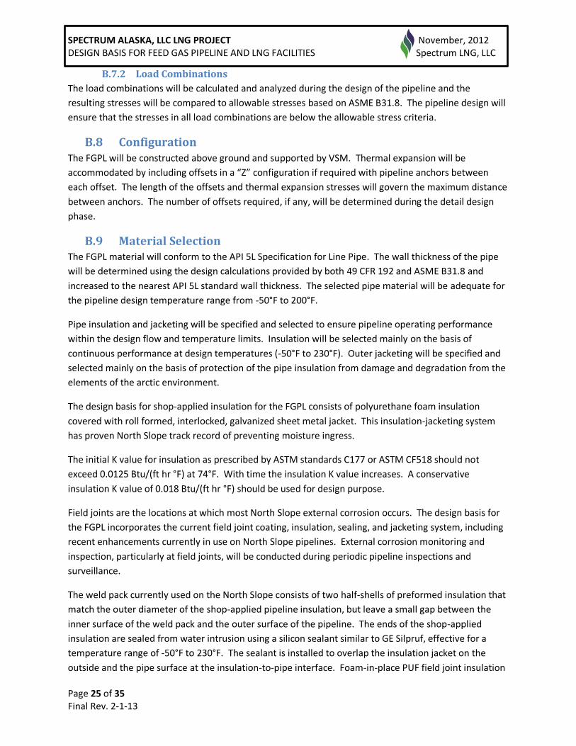
B.7.2 Load Combinations
The load combinations will be calculated and analyzed during the design of the pipeline and the
resulting stresses will be compared to allowable stresses based on ASME B31.8. The pipeline design will
ensure that the stresses in all load combinations are below the allowable stress criteria.
B.8 Configuration The FGPL will be constructed above ground and supported by VSM. Thermal expansion will be
accommodated by including offsets in a “Z” configuration if required with pipeline anchors between
each offset. The length of the offsets and thermal expansion stresses will govern the maximum distance
between anchors. The number of offsets required, if any, will be determined during the detail design
phase.
B.9 Material Selection The FGPL material will conform to the API 5L Specification for Line Pipe. The wall thickness of the pipe
will be determined using the design calculations provided by both 49 CFR 192 and ASME B31.8 and
increased to the nearest API 5L standard wall thickness. The selected pipe material will be adequate for
the pipeline design temperature range from -50°F to 200°F.
Pipe insulation and jacketing will be specified and selected to ensure pipeline operating performance
within the design flow and temperature limits. Insulation will be selected mainly on the basis of
continuous performance at design temperatures (-50°F to 230°F). Outer jacketing will be specified and
selected mainly on the basis of protection of the pipe insulation from damage and degradation from the
elements of the arctic environment.
The design basis for shop-applied insulation for the FGPL consists of polyurethane foam insulation
covered with roll formed, interlocked, galvanized sheet metal jacket. This insulation-jacketing system
has proven North Slope track record of preventing moisture ingress.
The initial K value for insulation as prescribed by ASTM standards C177 or ASTM CF518 should not
exceed 0.0125 Btu/(ft hr °F) at 74°F. With time the insulation K value increases. A conservative
insulation K value of 0.018 Btu/(ft hr °F) should be used for design purpose.
Field joints are the locations at which most North Slope external corrosion occurs. The design basis for
the FGPL incorporates the current field joint coating, insulation, sealing, and jacketing system, including
recent enhancements currently in use on North Slope pipelines. External corrosion monitoring and
inspection, particularly at field joints, will be conducted during periodic pipeline inspections and
surveillance.
The weld pack currently used on the North Slope consists of two half-shells of preformed insulation that
match the outer diameter of the shop-applied pipeline insulation, but leave a small gap between the
inner surface of the weld pack and the outer surface of the pipeline. The ends of the shop-applied
insulation are sealed from water intrusion using a silicon sealant similar to GE Silpruf, effective for a
temperature range of -50°F to 230°F. The sealant is installed to overlap the insulation jacket on the
outside and the pipe surface at the insulation-to-pipe interface. Foam-in-place PUF field joint insulation

SPECTRUM ALASKA, LLC LNG PROJECT November, 2012 DESIGN BASIS FOR FEED GAS PIPELINE AND LNG FACILITIES Spectrum LNG, LLC
Page 26 of 35 Final Rev. 2-1-13
will also be considered. This method may be preferred over the pre-formed half-shells because of the
chemical bond between field joint insulation and factory-installed insulation is stronger than silicon
sealant.
Weld pack insulation and jacketing will be selected during the final design. Recent and ongoing weld
pack enhancements will be considered and incorporated as appropriate during detailed design.
B.10 Guides, Slides, and Anchors Slide and anchor saddles will be strapped firmly to the pipe over the insulation jacket. Slides have
stainless steel sliding surfaces attached to the bottom of the saddle. This rests on a
polytetrafluoroethylene (PTFE) sliding surface, such as Teflon®, that will be installed on the top surface
of the support. Anchor saddles will be welded directly to the top of the supports which will prevent any
differential movement between the pipe and the support.
Guided saddles are the common bolted-in-place style used for recent North Slope pipeline projects (e.g.,
Badami and Alpine) and most of the other infield pipelines recently installed on the North Slope. A
sliding surface such as ultra-high molecular weight polyethylene (UHMWPE) placed on the inside of the
saddle protects the pipeline insulation jacket from wear. Tivar® is an example of several equal options
that will be considered for use in the guided saddles.
B.11 Wind Induced Vibration Prevention and Mitigation This analysis shall be performed during detail design. Mitigation measures using vortex shedding
devices for wind induced vibration will be used if warranted.
B.12 Welding
B.12.1 Welding Criteria
Welding and inspection requirements will comply with 49 CFR 192, API 1104, and B31.8.
Welding specifications and welder and welding operator qualifications will meet these requirements. All
welding consumable materials will meet API 1104 and be compatible with the line pipe materials.
Project specific welding procedures and inspection specifications will be based on API 1104.
B.13 Hydrostatic Testing Hydrostatic testing of the pipeline will meet the requirements of 49 CFR 192 and ASME B31.8.
Hydrostatic testing of the SALNG LNG Plant will meet the requirements of 49 CFR 193 and ASME B31.3.
B.14 Cleaning and Drying The entire pipeline system will be thoroughly cleaned prior to hydrostatic testing. Following testing, the
line will be completely evacuated and dried prior to commissioning. Drying will be adequate to ensure
the dew point within the pipeline system will be at or below -20°F. Following cleaning and drying, the
SPECTRUM ALASKA, LLC LNG PROJECT November, 2012 DESIGN BASIS FOR FEED GAS PIPELINE AND LNG FACILITIES Spectrum LNG, LLC
Page 27 of 35 Final Rev. 2-1-13
pipeline will have blind flanges with taps installed and the line will be inerted with nitrogen with a
nominal positive pressure.
B.15 Integrated Control and Safety System (ICSS)
B.15.1 General Description of ICSS
The SALNG facilities will be operated and controlled by an Integrated Control and Safety System (ICSS).
Design codes and practices applicable to the ICSS include but are not limited to NFPA 59A, IBC, HAZOP,
and the National Electric Code. Documentation demonstrating such compliance will be provided, as
required, during the final design phase.
B.15.1.1 Process Control System (PCS)
The system will serve as the primary means to control and monitor all operations of the facilities from a
full-manned, centralized control room (CCR) at the LNG Plant. It will be used to control not only the LNG
Plant equipment. The PCS will be a distributed control system relying on a redundant Ethernet
communication backbone to connect all of its components. The operator, engineering, and application
computers will all be industry standard personal computers and servers.
B.15.1.2 Safety Instrumented System (SIS)
The Safety Instrumented System (SIS at Spectrum Alaska will be a high integrity system to provide safety
shutdown and annunciation of all critical processes. This system, completely independent of the PCS,
will serve to protect equipment and personnel from process upset and emergency conditions and the
unexpected release of hazardous hydrocarbon vapors. This safety system, while functioning separately,
will have data links to the PCS for purposes of monitoring from the CCR Operator Stations.
B.15.1.3 Fire Detection System (FDS)
An independent, State of Alaska compliant fire detection and alarm system will provide early and
reliable detection of fire hazards, prompt notification of a fire condition, and activation of the fire
suppression system. It will have hard-wired interface to the SIS for shutdown coordination and gas
accumulation alarming. Dual serial links to the PCS will serve to provide integrated monitoring of the
fire system with all operations.
B.15.1.4 Gas Detection System
Gas detection monitors, located through the Spectrum Alaska facilities, will be connected to the fire and
gas detection system for alarm annunciation and shutdown activities. Full detection, suppression and
ventilation of 6 air changes per hour for normal and 12 air changes per hour for emergency will be
provided. The ventilated air will be heated.
B.16 Operations
B.16.1 Flow Control
Gas flow is controlled by the SALNG plant and driven by the delivery pressure in the PBUFFG pipeline.

SPECTRUM ALASKA, LLC LNG PROJECT November, 2012 DESIGN BASIS FOR FEED GAS PIPELINE AND LNG FACILITIES Spectrum LNG, LLC
Page 28 of 35 Final Rev. 2-1-13
B.16.2 Pipeline Isolation
Pipeline isolation valve(s) shall be installed to facilitate the Emergency Shutdown (ESD) of the pipeline
and LNG Facility. Fail closed design will be used for the primary ESD valve located upstream of the inlet
metering facility and downstream of the FGPL.
B.16.3 Pressure Monitoring and Relief
The pipeline shall have a pressure-relief capability to prevent over pressure conditions.
B.16.4 Start-Up
Initial start-up will be made using natural gas. The start-up procedures will be developed during the
detailed design of the system.
B.16.5 Flow Constraints
Flow constraints that must be mitigated by design or by becoming operating restrictions will be
determined based on connection agreements currently being negotiated.
B.16.6 Normal Operations
The steady state conditions for normal flow rates, temperatures, and pressures will be monitored and
controlled from the SALNG control room.
B.16.7 Planned and Unplanned Shutdown of Gas Line
The pipeline should be designed so that it can be shutdown at any time for planned or unplanned events
without additional work. The line would only need to be blown down to make repairs.
B.16.8 Maintenance
Pipeline valves will be inspected, serviced where necessary and operated per applicable regulations each
calendar year to verify proper operation. All pipeline valves will be designed and located to facilitate the
inspections.
B.16.9 Surveillance
Periodic surveillance of the pipeline right-of-way will be conducted in accordance with 49 CFR 192.
B.17 Corrosion Control and Monitoring
B.17.1 Corrosion Control Measures
B.17.1.1 Internal Corrosion
The fuel gas is non-corrosive and only annual ultrasonic testing of the pipe wall thickness will be
employed.
B.17.1.2 External Corrosion
External corrosion will be controlled in accordance with federal regulations. The design basis for
factory-installed insulation for the FGPL consists of polyurethane foam insulation covered with roll
SPECTRUM ALASKA, LLC LNG PROJECT November, 2012 DESIGN BASIS FOR FEED GAS PIPELINE AND LNG FACILITIES Spectrum LNG, LLC
Page 29 of 35 Final Rev. 2-1-13
formed, interlocked, galvanized sheet metal jacket. This insulation-jacketing system has a proven North
Slope track record of preventing moisture ingress.
Dual layer fusion-bonded epoxy anti-corrosion coating will be applied beneath the pipeline insulation.
Total dry film thickness will range between 20 and 32 mils with a minimum average thickness for the FBE
anti-corrosion (e.g., 3M, Scotchkote®: 226N/6233) coating of 24 mils. The anti-corrosion coating will be
sufficient of the operating conditions of the pipeline in Table B.5.1. FBE field joint coating will be
compatible with the factory-applied FBE anti-corrosion coating.
Field joints will be coated with field applied FBE to the maximum extent possible. Two-part paint on
epoxy coating is allowed where use of FBE is not practicable, e.g., tie-in welds, etc. An insulation, sealing,
and jacketing system will be installed based on best available North Slope practices.
SPECTRUM ALASKA, LLC LNG PROJECT November, 2012 DESIGN BASIS FOR FEED GAS PIPELINE AND LNG FACILITIES Spectrum LNG, LLC
Page 30 of 35 Final Rev. 2-1-13
C. SALNG PROCESSING FACILITY
C.1 General Description The SALNG facility will process the field fuel gas into a pure hydrocarbon stream by removing other
contaminants. Principally hydrogen sulfide, carbon dioxide and water will be removed by using amine
and glycol processes. Heavy hydrocarbon removal will be accomplished using refrigeration. Final
condensing of the methane and ethane will occur using a mixed refrigerant. The power required to
drive the process will be generated on site.
The SALNG LNG facility will be designed and built for the purpose of purifying and condensing gas at
cryogenic temperatures and various pressures. The plant process piping, vessels, exchangers, and other
components are built to NFPA59A, ASME B 31.3, API 1104, 49 CFR 193, and other design and
construction codes. The vessels, pipes, and equipment used for processing LNG within the SALNG
processing facility are primarily controlled by the ANSI/ASME B31.3 Process Piping Standard. The design
of the FGPL is primarily controlled by the ANSI/ASME B 31.8 Gas Piping System Standard as detailed in
Section B. The final design will be approved by Spectrum LNG, a licensed professional engineer for the
State of Alaska, and the State Fire Marshall. Once processed, the LNG is stored at pressures that are
lower than typical propane tanks used for residential barbeque gas grills. Special metals are used where
appropriate for the extremely low temperatures. There are thousands of cryogenic gas plants in
operation today, with several in Alaska. The most common is an air separation plant that deals with
even lower temperatures than an LNG plant. These plants produce liquid oxygen for use at hospitals,
among many other useful products. There is at least one plant that uses liquid nitrogen, removed from
the air we breathe and condensed into liquid form, to condense methane to make LNG, all at very low
pressures and temperatures. This is not a very efficient process unless there is a surplus of liquid
nitrogen.
C.2 Design Criteria
C.2.1 Structural Design Criteria
Design loads for all structures will be determined according to the criteria described below, unless the applicable building code requires more severe design conditions. SALNG facility shall be designed for Occupancy Category II in accordance with IBC 2009 and corresponding Importance Factors for wind and earthquake.
C.2.1.1 Dead Loads (D)
Dead loads shall be considered permanent loads. They consist of the weights of the structure and all equipment of a permanent or semi-permanent nature including tanks, bins, wall panels, partitions, roofing, piping, drains, electrical trays, bus ducts, and the contents of tanks and bins measured at full operating capacity. The contents of tanks and bins shall not be considered for resisting over turning due to wind forces, but shall be considered effective for resisting overturning for Earthquake forces.
C.2.1.2 Live Loads (L) or Roof Live Load (Lr)
Live loads are those defined by use or occupancy of building or structure. They consist of uniformly distributed, concentrated or equipment live loads. Uniform live loads are assumed unit loads which are sufficient to provide for movable and transitory loads, such as the weight of people, portable equipment

SPECTRUM ALASKA, LLC LNG PROJECT November, 2012 DESIGN BASIS FOR FEED GAS PIPELINE AND LNG FACILITIES Spectrum LNG, LLC
Page 31 of 35 Final Rev. 2-1-13
and tools, planking and small equipment, or parts which may be moved over or placed on floors during maintenance operations. These uniform live loads shall not be applied to floor areas which will be permanently occupied by equipment or other dead load. Equipment live loads are calculated loads based upon the actual weight and size of the equipment and parts to be placed on floors during dismantling and maintenance, or to be temporarily placed on or moved over floors during installation.
C.2.1.3 Snow Loads(S) and Ice Loads(I)
Snow and Ice Loads shall be determined per IBC 2009 and ASCE 7-05.
C.2.1.4 Wind Loads (W)
Wind loads on structures, systems, and components will be determined from ASCE 7-05 and IBC 2009. Design wind speed (V) is 110 mph. The design and wind pressure will be calculated using ASCE 7-05 as required by the IBC. The design wind exposure is “D”
C.2.1.5 Earthquake Loads (E)
The mapped maximum credible accelerations and design response spectrum shall be determined from IBC 2009.
C.2.1.6 Load Combinations
At a minimum, buildings and other structures shall be designed to resist the load combinations specified in IBC 2009 Section 1605 for strength or allowable stress design.
C.2.2 Material Selection
Materials used in the processing facility will typically be rated to -50F similar to the FGPL. Additionally,
materials used in cryogenic processing will be rated to cryogenic temperatures and suitable for LNG
service.
C.2.3 Equipment Design
C.2.3.1 Loads
Foundation loads will be furnished by the equipment Supplier and will be superimposed with loads for the foundation itself. Typical loads include the following:
• Dead loads
• Live loads
• Wind loads
• Earthquake Loads
• Temperature and pressure loads (as applicable)
Where applicable, loads caused by vibrating or rotating machinery will be considered in the design of the equipment and foundation.
C.2.3.2 Anchorage
All miscellaneous equipment will utilize steel anchor bolts, fasteners, welds, and other equipment anchorage devices as required by analysis or as recommended by the equipment manufacturer to resist equipment induced forces.
SPECTRUM ALASKA, LLC LNG PROJECT November, 2012 DESIGN BASIS FOR FEED GAS PIPELINE AND LNG FACILITIES Spectrum LNG, LLC
Page 32 of 35 Final Rev. 2-1-13
C.2.3.3 Structural System
Each individual piece of equipment will have its own unique structural system, and it is the responsibility of each manufacturer to assure its adequacy.
C.2.3.4 Structural Design
All miscellaneous equipment will be designed to resist project specific and IBC 2009 specified loads where possible and loads from applicable codes and standards. Earthquake loading and design of miscellaneous equipment will be in accordance with project specific criteria and ASCE 7-05 Chapter 15. The Earthquake loading will be calculated using equivalent lateral forces applied to the center of gravity of the equipment or component in accordance. Load combinations will be as indicated in Subsection C.2.1.6, Load Combinations. These load combinations are in addition to those normally used in design and those specified in applicable codes and standards.
C.2.4 Building Design
Buildings will be designed or selected to be in compliance with applicable code requirements.
C.2.4.1 Loads
Foundation loads will be determined from the analysis and design of the superstructure and from the
support of the equipment contained within the structure. The following loads will be considered:
• Dead loads
• Live loads
• Snow Loads
• Equipment and Piping Loads
• Wind Loads
• Earthquake Loads
• Other applicable loads, such as soil pressure, temperature, and rain.
C.2.4.2 Anchoring
The buildings and non-building structures will be securely anchored to the pile foundations using steel
anchor bolts or welds designed to resist any induced forces.
C.2.4.3 Structural Design
Design loads will be determined in accordance with IBC 2009 Chapter 16. Earthquake loading for the
buildings will be calculated using equivalent lateral forces applied to the structure in accordance with
the procedures of ASCE 7-05, Chapter 12 for Buildings.
C.2.4.4 Foundation Design
The foundation design will be based on the soil and geothermal conditions for the SALNG facility per the
recommendations of the final geotechnical report and all applicable code provisions. In general, the pile
foundation design will be based on the parameters presented in section B.4.3. In addition, the
foundation design shall consider the following:
• Allowable settlements
• Equipment, structure, and environmental loads
• Access and maintenance

SPECTRUM ALASKA, LLC LNG PROJECT November, 2012 DESIGN BASIS FOR FEED GAS PIPELINE AND LNG FACILITIES Spectrum LNG, LLC
Page 33 of 35 Final Rev. 2-1-13
• Equipment performance criteria
C.2.5 LNG Storage Design
C.2.5.1 Thermal Radiation
This will be determined using the LNGfire modeling program during initial design alongside applicable
code.
C.2.5.2 Vapor Dispersion
This will be determined using the DEGADIS modeling program during initial design alongside applicable
code.
C.2.6 Primary LNG containment
Primary LNG containment will be within vacuum jacketed pressure vessels designed for cryogenic
service using applicable building and pressure vessel codes. Up to 5 such vessels may be installed, each
with a capacity of up 80,000 gallons for a combined capacity of up to 400,000 gallons.
C.2.7 Secondary LNG containment
Secondary LNG containment in the event of a catastrophic failure will be by earthen dams surrounding
the vessels. These earth structures shall be built to contain the necessary volume of liquid as
determined by the governing code as well as computer simulation of fire and vapor hazard studies using
DEGADIS and LNGFIRE modeling programs.
SPECTRUM ALASKA, LLC LNG PROJECT November, 2012 DESIGN BASIS FOR FEED GAS PIPELINE AND LNG FACILITIES Spectrum LNG, LLC
Page 34 of 35 Final Rev. 2-1-13
D. Dismantle, Remove, and Restore Dismantle, remove, and restore (DR&R) activities will be consistent with lease terms, permit conditions,
and other applicable regulatory requirements. Detailed abandonment procedures will be developed at
the time of project termination. Specific plans will depend on the facilities in place and the specific
requirements applicable to those facilities at the time of abandonment.

SPECTRUM ALASKA, LLC LNG PROJECT November, 2012 DESIGN BASIS FOR FEED GAS PIPELINE AND LNG FACILITIES Spectrum LNG, LLC
Page 35 of 35 Final Rev. 2-1-13
E. Risk Assessment Risk Assessment for the Spectrum FGPL and LNG Facilities shall be performed during the detail design
phase and shall include Vapor dispersion exclusion zones and Thermal Radiation Exclusion Zones as
described in C.2.4.