Embed Size (px)
Citation preview

TABLE OF CONTENTS
Table of Contents ............................................................................................................................ 1
List of Figures ................................................................................................................................. 2
33-2A Slope Wall, Riprap and Sodding Limits for Grade Separation Structures ................. 3
33-2B Typical Floor Drain Sections ...................................................................................... 3
33-3A Gutter Cross Section (Equation 33-3.3) ...................................................................... 3
33-4A Gutter Cross Section (Equation 33-4.1) ...................................................................... 3
33-5A Efficiency Curves for Circular Drains ........................................................................ 3
33-5B Ratio of Frontal Flow to Total Gutter Flow (Rectangular Inlets) ............................... 3
33-5C Grate Inlet Frontal Flow Interception Efficiency........................................................ 3
33-5D IDF Data from HYDRO (40 deg Latitude and 86 deg Longitude) ............................. 3
33-5E Parameters for Equation 33-5.6 .................................................................................. 3
33-5F Parameters for Equation 33-5.7 .................................................................................. 3
Chapter Thirty-three........................................................................................................................ 4
33-1.0 INTRODUCTION .............................................................................................................. 4
33-1.01 Scope ............................................................................................................................ 4
33-1.02 Objectives ..................................................................................................................... 4
33-1.02(01) Minimization of Maintenance ............................................................................ 4
33-1.02(02) Minimization of Spread ..................................................................................... 5
33-1.02(03) Avoidance of Hydroplaning ............................................................................... 5
33-1.02(04) Reduction of Icing Potential on Deck ................................................................ 5
33-1.02(05) Integration into Structural Dimensions .............................................................. 5
33-1.02(06) Aesthetics ........................................................................................................... 5
33-1.02(07) Protection of Water Quality [Rev. Jan. 2011] .................................................... 6
33-1.03 Concept Definitions ...................................................................................................... 6
33-2.0 SYSTEM COMPONENTS [Rev. Jan. 2011] ..................................................................... 7
33-2.01 System Requirements ................................................................................................... 7
33-2.01(01) Structural Considerations ................................................................................... 7
33-2.01(02) Deck and Gutters................................................................................................ 8
33-2.01(03) Drainage Appurtenances .................................................................................... 8
33-2.01(04) Riprap Turnout ................................................................................................... 8
33-2.01(05) Bridge-End Collector on Curbed Roadway ....................................................... 8
33-2.01(06) Stormwater-Pollution-Prevention Controls [Added Jan. 2011] ......................... 9
33-2.02 Bridge-Deck Inlet ......................................................................................................... 9
33-2.02(01) Types .................................................................................................................. 9
33-2.02(02) Interception Capacity and Efficiency ............................................................... 10
33-2.03 Inlet Location .............................................................................................................. 11
33-2.03(01) Factors .............................................................................................................. 11
33-2.03(02) Spacing ............................................................................................................. 12
2012

33-2.03(03) Sag Vertical Curve ........................................................................................... 12
33-2.03(04) Minimum Number and Location ..................................................................... 12
33-2.03(05) Coordination with Deck Reinforcement .......................................................... 13
33-2.03(06) Maintenance ..................................................................................................... 13
33-2.04 Underdeck Collectors and Discharge System ............................................................ 13
33-2.04(01) Design .............................................................................................................. 13
33-2.04(02) Free-Fall ........................................................................................................... 14
33-2.04(03) Cleanout ........................................................................................................... 14
33-3.0 CALCULATION OF RUNOFF ....................................................................................... 15
33-3.01 Rational Method ......................................................................................................... 15
33-3.02 Rainfall Intensity ........................................................................................................ 15
33-3.03 Time of Concentration ................................................................................................ 16
33-3.03(01) Overland Flow Time of Concentration ............................................................ 16
33-3.03(02) Gutter Flow Time of Concentration ................................................................. 16
33-3.03(03) Total Time of Concentration ............................................................................ 17
33-4.0 FLOW IN A GUTTER ..................................................................................................... 17
33-5.0 INLET SPACING............................................................................................................. 18
33-5.01 Constant-Grade Bridge ............................................................................................... 18
33-5.01(01) Procedure ......................................................................................................... 18
33-5.01(02) Example 33-5.1 ................................................................................................ 21
33-5.01(03) Example 33-5.2 ................................................................................................ 22
33-5.02 Flat Bridge .................................................................................................................. 25
33-5.02(01) Procedure ......................................................................................................... 25
33-5.02(02) Example 33-5.3 ................................................................................................ 26
33-5.03 Vertically-Curved Bridge ........................................................................................... 27
33-5.03(01) Procedure ......................................................................................................... 27
33-5.03(02) Example 33-5.4 ................................................................................................ 29
LIST OF FIGURES Figure Title
2012

33-2A Slope Wall, Riprap and Sodding Limits for Grade Separation Structures 33-2B Typical Floor Drain Sections 33-3A Gutter Cross Section (Equation 33-3.3) 33-4A Gutter Cross Section (Equation 33-4.1) 33-5A Efficiency Curves for Circular Drains 33-5B Ratio of Frontal Flow to Total Gutter Flow (Rectangular Inlets) 33-5C Grate Inlet Frontal Flow Interception Efficiency 33-5D IDF Data from HYDRO (40 deg Latitude and 86 deg Longitude) 33-5E Parameters for Equation 33-5.6 33-5F Parameters for Equation 33-5.7
2012

CHAPTER THIRTY-THREE
BRIDGE DECK DRAINAGE 33-1.0 INTRODUCTION The objective of this Chapter is to present a sound, economic, and low-maintenance design for bridge-deck and bridge-end drainage facilities. The detrimental effects of runoff emphasize the importance of removing water from the bridge deck as quickly as practical. This highlights the need for an efficient drainage system that always works properly. Proper design provides benefits for traffic safety, maintenance, structural integrity, and aesthetics. 33-1.01 Scope This Chapter provides guidelines and procedures for designing a bridge-deck drainage system, including illustrative and practical examples. It incorporates hydraulic capacity, traffic safety, structural integrity, and practical maintenance. System hardware components, such as inlets, pipes, and downspouts, are described. It provides guidance for selecting a design gutter spread and flood frequency, and a design methodology for inlet spacing including example problems. 33-1.02 Objectives The objectives in developing a design that will control the spread of water into traffic lanes, will function properly with a minimum of maintenance, and will not interfere with the architectural beauty or structural integrity of the bridge are discussed below. 33-1.02(01) Minimization of Maintenance A bridge may not require a drainage system. This is ideal because of the high maintenance required to keep deck drains and other types of inlets free from debris discarded from vehicles and sand deposited during winter-maintenance activities. A clogged deck drain can cause more encroachment of runoff onto the shoulder or travel lane than no drainage structure. Bridge deck drains may be necessary in addition to riprap turnouts to capture runoff from the bridge and convey it to an appropriate outlet.
2012

33-1.02(02) Minimization of Spread As water accumulates and spreads across the width of the gutter and into the travel lane, it can reduce service levels and cause safety problems. Where inlets are required, they must be adequately sized and spaced to remove runoff from the bridge deck before it encroaches onto the traveled way to the limit of the design spread. This Chapter provides a procedure to determine the maximum length of deck allowable without exceeding the design spread. See Chapter Thirty-six for more information. 33-1.02(03) Avoidance of Hydroplaning Precipitation produces sheet flow on pavement and gutter flow. If sheet flow or spread has sufficient depth, vehicle tires can separate from the pavement surface and produce hydroplaning. To reduce this risk, the drainage system must be designed to prevent the accumulation of significant depths of water. 33-1.02(04) Reduction of Icing Potential on Deck A bridge deck is usually the first segment of a highway to become icy in cold weather. Adequate deck drainage through use of minimum grades and cross slopes is essential to prevent the accumulation and spreading of icy spots. Icing on a bridge deck caused by frost is difficult to prevent except through surface texture and maintenance practices. Proper signing to warn the motoring public of the potential of ice on a bridge may be appropriate. 33-1.02(05) Integration into Structural Dimensions The deck-drainage system must satisfy the structural requirements of the bridge. Drainage details affect structural design. For example, inlets for a reinforced-concrete bridge deck must fit within the reinforcing-bars layout. If deck drainage is not needed, structural design is free of inlet details. The drainage system should prevent water, road salt, or other corrosives from contacting the structural components. 33-1.02(06) Aesthetics A pipe system conveying water from deck inlets to natural ground can be affixed to the exterior surfaces of a bridge. However, encasing the piping in structural members may not be advisable because of potential freezing damage. Pipes affixed to exterior surfaces of a structure, running at
2012

odd angles, can present an unpleasant silhouette and detract from the bridge’s architectural
aesthetics. To avoid this, pipes can be located in slots up the back of the columns or can be
hidden behind decorative pilasters.
33-1.02(07) Protection of Water Quality [Rev. Jan. 2011]
The number of drains that discharge directly into a waterway should be reduced. Where possible
and practicable, stormwater treatment measures should be included to treat the stormwater runoff
prior to entering the waterway. Additional treatment or additional measures may be required as a
result of a commitment during early coordination or as a regulatory-agency-permit condition.
33-1.03 Concept Definitions
The following are definitions of concepts used in bridge-deck-drainage analysis and design.
1. Cleanout plug. A removable plug in the piping system that provides access to a run of
piping for cleaning. It is located near a bend or Y-shaped intersection.
2. Cross Slope. The slope of the pavement cross section from the curb to the crown.
3. Drop Inlet. A drain that is used away from a bridge or at a bridge end. It is larger than an
inlet chamber and is set in earth in the subgrade or shoulder of an approach embankment.
It has a horizontal or near-horizontal opening.
4. Drain. A receptacle that receives and conveys water.
5. Drainage System. The entire arrangement of grates, drains, inlet chambers, pipes,
gutters, ditches, outfalls, and energy dissipators necessary to collect water and convey it
to a disposal point.
6. Grate. The ribbed or perforated cover of an inlet chamber that admits water and supports
traffic loads. Grates are removable to allow access for maintenance.
7. Inlet Chamber. The small cast-iron, welded steel, or formed concrete compartment that is
beneath a grate. Although set into the bridge deck, it is sometimes only an open hole in
the deck.
8. Outlet Pipe. The pipe that leads the water away from an inlet chamber or drop inlet.
2012

9. Runoff, Drainage. A liquid that can run off the roadway surface. Although the liquid is
most-often water, it includes other liquids and dissolved solids that can make their way
into the drainage system.
10. Scupper. A small opening in a curb or barrier through which water can flow from the
bridge deck. The term is nautical and by analogy relates bridge-deck drains to openings
in the sides of a ship at deck level to allow water to exit.
11. Spread. The top of water measured laterally from the bridge curb.
12. Storm Drain. A beneath-the-bridge and underground piping system that may connect to a
municipal storm-drain system or may be a separate collection system for highway and
bridge drainage.
33-2.0 SYSTEM COMPONENTS [REV. JAN. 2011]
A bridge-deck drainage system includes the bridge deck itself, bridge gutters, inlets, pipes,
downspouts, and stormwater-pollution-prevention controls. The system is designed by the
bridge designer and coordinated with the Hydraulics Team. Coordination of efforts is essential
in designing the components of the system to satisfy the objectives described in Section 33-1.0.
33-2.01 System Requirements
The primary requirement of the drainage system is to remove rainfall-generated runoff from the
bridge deck before it collects and spreads in the gutter to encroach onto the traveled way and
exceed the limit of a design spread. To satisfy this objective, the drainage system must satisfy
the design criteria described below.
33-2.01(01) Structural Considerations
The primary structural considerations in bridge-deck drainage-system design are as follows.
1. Inlet sizing and placement must be compatible with the structural reinforcement and
components of a bridge.
2. The drainage system should be designed to deter flow from contacting vulnerable
structural members and to minimize the potential of eroding embankments.
2012

The structural and hydraulics engineer should work together to design a system that has the
necessary hydraulic capacity and is compatible with structural elements. To avoid corrosion and
erosion, the design must include proper placement of outfalls, including prevention of flow from
splashing or being blown back onto support members. Water should be prevented from running
down the joint between the pavement and the bridge and thereby undermining an abutment or
wingwall.
33-2.01(02) Deck and Gutters
The bridge deck and gutters are surfaces that initially receive precipitation. If grades, super-
elevations, and cross slopes are properly designed, water and debris are efficiently conveyed to
the inlets or riprap turnouts. A bridge deck with a level profile grade or in a sag vertical curve
has poor hydraulics and may cause ponded water and hydroplaning problems. Superelevation
transitions through a level grade may cause water and ice problems as well. The cross slope is
2% on a tangent section. A level grade or a sag vertical curve is not allowed for a bridge on a
new alignment. The desirable longitudinal grade for bridge-deck drainage is 0.5% or steeper. A
flatter grade is permissible where it is not physically possible or economically desirable to satisfy
the above criteria.
33-2.01(03) Drainage Appurtenances
These include inlets, grates, pipes, and downspouts. From the deck and gutters, water and debris
flow to the inlets, through pipes and downspouts, and finally to the outfall. A number of grate
and inlet box designs are available to discourage clogging. Collector pipes and downspouts with
smooth Y-connections and bends help prevent clogging in mid-system. T-connections are
discouraged because of their propensity to plug. Collector pipes need a slope of 2% to sustain a
self-cleaning velocity. Cleanout plugs located near curves and Y-connections should be included
to provide access to the pipe to facilitate cleaning. A storm-drainage system beneath the bridge
may be necessary to transport runoff to side-ditch, storm-drain or stormwater detention facilities.
33-2.01(04) Riprap Turnout
See Figure 33-2A, Slopewall, Riprap, and Sodding Limits for Grade Separation Structure, for
treatment for a grade separation. See Figures 17-4 I and 17-4J for treatment for a stream
crossing.
33-2.01(05) Bridge-End Collector on Curbed Roadway
2012

A drainage inlet placed at the end of the bridge is essential for proper drainage. A grate inlet,
curb-opening inlet, or combination inlet may be used at a bridge end. The hydraulic
characteristics of the inlet should be considered in selecting the type. An inlet placed on the
upslope end of the bridge should be designed to collect all of the runoff upslope of the bridge.
This will prevent the bridge-deck drains and inlets from being overtaxed from runoff entering
onto the bridge from the approaches. A collector at the downslope end of the bridge should be
designed to collect all of the flow not intercepted by the bridge inlet. A conservative design
approach is to assume that 50% of the inlets on the bridge are plugged and to size the end
collectors accordingly. If there are no bridge inlets, downslope inlets should be designed to
intercept all of the bridge drainage. From the inlet structure, there must be a pipe, paved
channel, or trough to transport the water down the face of the embankment.
33-2.01(06) Stormwater-Pollution-Prevention Controls [Added Jan. 2011]
Stormwater-pollution-prevention controls (SWPPP) should be designed to provide an average
annual post-development TSS removal rate of 80%. All stormwater controls should satisfy the
other design criteria described herein. Controls should not increase the spread of water into
traffic lanes, should function properly with minimum maintenance, and should not interfere with
the structural integrity of the bridge. Downspouts should not be allowed to discharge untreated
flow, unless such discharge is collected and treated on the receiving body beneath the bridge.
Direct discharge of untreated stormwater runoff is not allowed. Flow consolidation should be
considered to reduce the number of multiple BMP installations and maintenance requirements.
33-2.02 Bridge-Deck Inlet
33-2.02(01) Types
A bridge-deck inlet must remove water from a deck within the limits of the allowable spread.
Considering hydraulics, inlets should be large and widely separated. Considering the structure,
inlets should be avoided or be as small and as few as practical. This Section describes the inlet
designs used by INDOT and discusses the factors that affect inlet interception capacity. This
Section discusses design features to help prevent clogging, and it provides guidance for
determining inlet locations. The following inlets are currently in use.
1. Grate A. This grate fits onto roadway drain type SQ. It is a parallel bar grate and the
most hydraulically efficient grate in use. The grate is 19 in. square. Because the width of
the openings is 1 in., the grate is not considered bicycle-safe if placed with the bars
parallel to the direction of traffic. However, it is feasible to use this grate where bicycle
traffic is allowed on the bridge if the bars are placed perpendicular to the direction of
travel. The perpendicular arrangement may substantially reduce the hydraulic capacity of
2012

the grate, as shown on Figure 33-5C, Grate Inlet Frontal Flow Interception Efficiency. The outlet fitting is circular pipe, 6 in. diameter.
2. Grate D. This grate fits onto roadway drain type OS. This is a type C grate with parallel
bars but has two transverse bars which prevent bicycle wheels from dropping into the inlet; therefore, it is considered bicycle-safe. The transverse bars reduce the hydraulic capacity of the grate. The grate dimensions are 19 in. wide by 20 in. long. The outlet fitting is circular pipe, 6 in. diameter.
3. Slab-Bridge Floor Drain. This deck drain is to be used with a reinforced-concrete slab
bridge. The drain is a PVC pipe, 6 in. diameter, set into the deck. This drain has limited hydraulic capacity; therefore, the spacing will be much closer than that for grate type A or D. The standard spacing is approximately 72 in. A ½-in. depression, which extends 1 ft transversely from the face of the curb, slightly increases the capacity.
4. Curved-Vane Grate. This grate is to be used on a curbed roadway where the inlets are
located off the bridge deck. 5. Concrete-Barrier-Railing Scupper. This device should be used only on a local public
agency bridge with concrete-barrier railings. 33-2.02(02) Interception Capacity and Efficiency Inlet interception capacity is the flow intercepted by a bridge deck inlet under a given set of conditions. The efficiency of an inlet is the percent of total flow that the inlet will intercept. The efficiency of an inlet varies with cross slope, longitudinal slope, total gutter flow and, to a lesser extent, pavement roughness. Efficiency, E, is defined as follows:
E i= (Equation 33-2.1)
Where: Q = Total gutter flow, ft3/s
Qi = Intercepted flow, ft3/s The intercepted flow consists of frontal flow entering the inlet parallel to the gutter and flow entering from the side of the inlet. For a small, rectangular inlet, side flow is assumed to be small. The ratio of side flow intercepted to total side flow, Rs, is defined as follows::
2012

+
=
3.2
8.115.01
1
gx
s
LSV
R (Equation 33-2.2)
Where: Lg = Length of the inlet parallel to the flow, ft
V = Average velocity in the gutter, ft/s SX = Pavement cross slope, ft/ft
Because the side flow is small compared to the total flow, the inclusion of side flow is at the discretion of the designer. Equation 33-2.3 describes the ratio of frontal flow to total gutter flow as follows:
67.2
11
−−=
TWEO (Equation 33-2.3)
Where: W = Width of the inlet, ft
T = Width of the design spread, ft Figure 33-5B provides a solution to Equation 33-2.3. The fraction of frontal flow that actually enters the inlet can be expressed as follows: ( )Of VVR −−= 09.01 (Equation 33-2.4) Where: Rf = Frontal flow capture fraction
V = Gutter velocity, ft/s VO = Grate splashover velocity, ft/s
See Figure 33-5C, Grate Inlet Frontal Flow Interception Efficiency, for a nomograph solution. 33-2.03 Inlet Location 33-2.03(01) Factors The deck-spread criteria and geometric controls will determine the optimal hydraulic location of inlets. See Section 33-4.0. However, structural constraints, maintenance considerations, and other factors will influence the actual locations of inlets. For a pavement on grade, design spread will determine the distance between grates. Gutter flow should be intercepted on a horizontal curve or within a superelevation transition to minimize water flow across the bridge deck.
2012

33-2.03(02) Spacing Determining the maximum spacing between inlets is straightforward if the drainage area consists of pavement only, or has reasonably uniform runoff characteristics and is regularly shaped. This assumes that the time of concentration, tC, is the same for all evenly-spaced inlets. See Section 33-5.0 for inlet-spacing calculations. 33-2.03(03) Sag Vertical Curve Where ponding can occur in a sag vertical curve, flanking inlets should be placed on each side of the inlet at the low point of the sag. The flanking inlets should be placed so that they will limit spread on a low-gradient approach to the level point and act in relief of the inlet at the low point if it becomes clogged, or if the design storm is exceeded. See Section 36-10.0. 33-2.03(04) Minimum Number and Location The following applies to inlet location. 1. Structure with Curbs.
a. For a structure of less than 170 ft length and on grade, or a structure of less than 250 ft length and on a crest vertical curve, inlets are not required. However, hydraulic calculations for deck drains are required.
b. For a structure on grade, provide roadway drains at the low end of the structure
and riprap turnouts at the ends of the railing transitions.
c. For a structure on a crest vertical curve, provide a circular roadway drain on each corner of the bridge and riprap turnouts at the end of the railing transitions.
d. For a structure on a sag vertical curve, a minimum of two roadway inlets are
required. 2. Structure Without Curbs. Inlets or riprap turnouts are not required. 3. Grade-Separation Structure. If deck drainage is required at the ends of the bridge, deck
drains should discharge into inlets located in the berm or on the slopewall under the bridge as shown on the INDOT Standard Drawings.
2012

33-2.03(05) Coordination with Deck Reinforcement Inlet locations must be considered in the design and layout of the reinforcement spacing within the deck and must not promote corrosion of the structural members. Additional reinforcement should be provided around the deck drain to maintain the continuity of the deck reinforcement. 33-2.03(06) Maintenance An inlet should be placed where it can be serviced easily and safely. A difficult-to-reach inlet will be neglected and inevitably become plugged. An inlet placed in a traffic lane may plug due to vehicles forcing debris into it. 33-2.04 Underdeck Collectors and Discharge System 33-2.04(01) Design The following applies to the design of the underdeck drainage system. 1. General. A bridge-drainage pipe beneath the deck is sized larger than needed for
hydraulic purposes to facilitate maintenance. The minimum pipe diameter is 6 in. The inlet conditions will control the flow capacity. Entrances, bends, and junctions in the underdeck pipe system provide opportunities for debris to snag and collect. Provide smooth transitions and smooth interior surfaces. Avoid sharp bends, corner joints, or bevel joints.
2. Velocity. The recommended minimum velocity for storm drainage is 2.67 ft/s. Because
vertical fall for a pipe beneath a bridge is available, an 8% slope is the minimum required to transport sand and silt through the pipe at over 2.67 ft/s.
3. Standard Details. The details for cast-iron roadway drains used by the Department are
shown on the INDOT Standard Drawings. 4. Alternative Design. Figure 33-2B, Ratio of Frontal Flow to Total Gutter Flow,
Rectangular Inlet, illustrates two alternatives to drains. Figure 33-2B(a) shows a traditional arrangement including a short overhang and a steel beam, which permits the drain pipe to be located internally with reference to the external beam. Figure 33-2B(b) shows another arrangement including a large overhang and a bulb-tee beam, which locates the drain pipe to the outside. This is aesthetically less pleasing, therefore emphasizing the desirability of keeping the number of drains to a minimum.
2012

5. Drain Location, Exterior Beam. A drainage casting should be positioned such that the outlet pipe is located inside the exterior beam, if practical. See Figure 33-2B(a). If not, the casting type and position should be selected to locate the drainage pipe as close as practical to the exterior beam. The plans should show the drain location, positioning, and attachment details.
6. Longitudinal Pipe, Closed Drainage. This pipe must not extend below the superstructure.
The minimum slope is 1% for a longitudinal pipe between drains or from a drain to the point of discharge.
7. Overpass. An open deck drain should not be located over a roadway, sidewalk, or
railroad. If a drain must be located in one of these areas, a closed drainage system should be provided.
33-2.04(02) Free-Fall The following applies to free-fall, where used beneath a bridge. 1. The downspout should be extended 6 in. below the beam soffit. The downspout should
be placed approximately 10 ft from the face of a substructure unit, unless a closed drainage system is used. A downspout should not interfere with the required horizontal or vertical clearances. A pipe system designed to bring water down to ground level may become clogged with debris and ice and should only be used as the last option.
2. A downspout should not discharge water where such water can be windblown and flow
down a column or pier. 3. Water should not be discharged openly over a traveled way (vehicular, railroad, or
pedestrian), unpaved embankment, or unprotected ground where it can cause erosion or undermine a structural element. An energy dissipater or riprap should be provided to prevent erosion.
4. A free fall exceeding 25 ft will sufficiently disperse the falling water so that erosion
damage will not occur beneath the bridge. Where the water freefalls onto riprap or flowing water a lesser freefall will be permissible.
33-2.04(03) Cleanout A cleanouts for maintenance access should be provided at key points within the system to facilitate the removal of obstructions. A downspout should be located so that a maintenance
2012

crew can access it from underneath the bridge and preferably from the ground. The most convenient arrangement should be made, as a cleanout that is inaccessible or difficult to reach will not be cleaned. 33-3.0 CALCULATION OF RUNOFF 33-3.01 Rational Method The conventional method for estimating runoff for bridge-deck drainage is the Rational Method. This hydrologic method is discussed in detail in Chapter Twenty-nine. The Rational Method is discussed below as it pertains to bridge -deck drainage. The Rational formula is as follows:
Where: Q = Peak runoff rate, ft3
C = A dimensionless runoff coefficient that represents characteristics of the drainage area. C = 0.9 for a bridge deck.
i = Rainfall intensity, in./h
A = Drainage area, ac
33-3.02 Rainfall Intensity For a bridge deck, the determination of the design rainfall intensity for use in the Rational Method can be based on the following: 1. the time of concentration, which is a function of the design spread; 2. the specific intensity at which a motorist’s vision will be impaired; or 3. the condition for which hydroplaning will occur. The source of rainfall intensity data is from Intensity-Duration-Frequency (IDF) curves which can be plotted for the location in question. Other sources of rainfall intensity data are available and will be discussed below. The design rainfall intensity can be obtained from IDF Curves for the exact location (latitude and longitude) of the project. This is readily available from the HYDRO module of the computer program HYDRAIN. Regional IDF curves are included in Chapter Twenty-nine. The rainfall
CiA = Q (Equation 33-3.1)
2012

intensity obtained from the IDF curve is a conservative design value if compared with values obtained from hydroplaning or motorist-vision criteria. Because these latter criteria involve variable factors, such as tire tread wear and driver behavior, one approach is to use the IDF curve as the governing criteria for selecting rainfall intensity and then compare that intensity to the other two criteria. The most conservative rainfall intensity value should be used. For non-freeway bridge-deck drainage, the design flood for determining the spacing and location of inlets is based on a 10-year return period. For a freeway, the return period is 50-years. Rainfall intensity of 5 in./h to 6 ½ in./h for time of concentration of 5 to 10 min during a 10-year frequency storm is not unusual. 33-3.03 Time of Concentration HEC 12 Drainage of Highway Pavements assumes that inlets are independent drainage elements that collect runoff from their small contributing drainage areas. This assumption yields a conservative and constant time of concentration for equally-spaced deck inlets or scuppers, and equals the time of concentration to the first inlet. The time of concentration for bridge-deck inlets consists of overland-flow time and gutter-flow time. The overland flow is sheet flow from the deck high point to the gutter. Gutter-flow time is the time of flow in the gutter. 33-3.03(01) Overland Flow Time of Concentration The following equations should be used for determining time of concentration for overland flow, tO.
( )
( )( )
( ) 3.04.0
6.0
3.04.0
6.0 93.0
SCinW
SCinlk
t pOWO == (Equation 33-3.2)
Where: tO = Time of overland flow, min
lO = Wp = Overland, flow length, ft n = Manning’s roughness coefficient C = Runoff coefficient i = Rainfall intensity, in./h S = Average slope of the overland area kW = 0.93, a constant
33-3.03(02) Gutter Flow Time of Concentration
2012

The following equation should be used for determining time of concentration for gutter flow, tg.
=
p
Xgg CiW
TSkt2
(Equation 33-3.3)
Where: tg = Time of gutter flow, min
SX = Cross slope of gutter T = Spread, ft C = Runoff coefficient i = Rainfall intensity, in./h WP= Width of pavement contributing runoff, ft kg = 484, a constant
Figure 33-3A illustrates the cross-section elements which apply to Equation 33-3.3. 33-3.03(03) Total Time of Concentration The total time of concentration, tC, is the sum of tO and tg. 33-4.0 FLOW IN A GUTTER A bridge-deck gutter is defined as the section of pavement adjacent to the curb or parapet that conveys water during a storm-runoff event. It may include a portion or all of a travel lane. A gutter cross section has a triangular shape with the curb forming the near-vertical leg of the triangle. A bridge-deck gutter has a straight cross slope. Chapter Thirty-six discusses gutter flow in detail relative to pavement drainage. Gutter flow is discussed below as it pertains to bridge-deck drainage. For a bridge deck, a modification of the Manning equation is necessary for use in computing flow in a triangular channel because the hydraulic radius in the equation does not adequately describe the gutter cross section, especially where the top width of the water surface may be more than 40 times the depth at the curb. The resulting equation is as follows:
67.25.067.1 TSSn
kQ x
g
= (Equation 33-4.1)
Where: Q = Flow rate, ft3/s
kg = 0.56, a constant T = Width of flow (spread), ft
2012

SX = Cross slope S = Longitudinal slope n = Manning’s roughness coefficient
Figure 33-4A illustrates the cross section which applies to Equation 33-4.1. See Figure 36-7A for the criteria for design frequency and allowable water spread, T. Gutter velocity is determined by dividing the gutter-flow equation by the cross-sectional area of the gutter. The resulting relation is as follows:
67.067.05.02 TSSnkgV x
= (Equation 33-4.2)
Where: V = Gutter velocity, ft/s
33-5.0 INLET SPACING Chapter Thirty-six discusses inlet spacing in detail for pavement. This Section provides methods specifically for determining inlet spacing for a constant-grade, flat, or vertically-curved bridge. Example problems are also included. 33-5.01 Constant-Grade Bridge 33-5.01(01) Procedure An IDF curve for the appropriate location will be necessary. HYDRO can be used to generate an IDF curve for a known latitude and longitude, or the designer may use the closest regional IDF curve shown in Chapter Twenty-nine. The designer must select a return period (10 years) and design spread (see Section 33-4.0 and Chapter Thirty-six). If the bridge slope is nearly flat (less than 0.3%), the procedure for a flat bridge should also be followed as a check. The hydraulic procedure is to start at the high end of the bridge and work downslope from inlet to inlet. Use the following procedure. 1. Step 1. An iterative process is necessary to determine rainfall intensity, i, because this
value is necessary to solve both Equations 33-3.2 and 33-3.3. Assume a value of i and solve for overland time of concentration using Equation 33-3.2, and gutter-flow time of concentration using Equation 33-3.3. Add the times together for the total time. If it is less than 5 min, use 5 min. Compare with the assumed value and repeat the process if not sufficiently close. Select a design rainfall intensity from the IDF data.
2012

2. Step 2. Find the flow on the deck, Q, at design spread, T, using Equation 33-4.1. 3. Step 3. Starting at the high end of the bridge, the inlet spacing, LC, can be computed
using Equation 33-5.1 as follows:
( )p
C CiWEQxL
410356.4= (Equation 33-5.1)
Where: LC = Distance to the first inlet or between inlets, ft
i = Design rainfall intensity, in/h (Step 1) Q = Gutter flow, ft3/s (Step 2) C = Rational runoff coefficient Wp = Width of pavement contributing to gutter flow, ft E = Constant equal to 1 for first inlet, equal to capture efficiency for
subsequent inlets
LO = LC for the first inlet; LC = LC for the others.
2. For vertical curve, E = K; K = 1, LO = LC for the first inlet; LO = L C, for others.
4. Step 4. Compare LC with the length of the bridge. If LC is greater than the length of the
bridge, inlets are not needed and only bridge end treatment is needed. If LC is less than the bridge length, go to Step 5.
5. Step 5. If inlets are required, the designer should calculate the constant inlet spacing, LC,
for the subsequent inlets. To do this, it will be necessary to determine the capture efficiency, E, for the type of inlet that is proposed for use. For type SQ inlets where the grate is transverse to the direction of travel for a bicyclist, a reduction in capture efficiency will be required as indicated in Figure 33-5C.
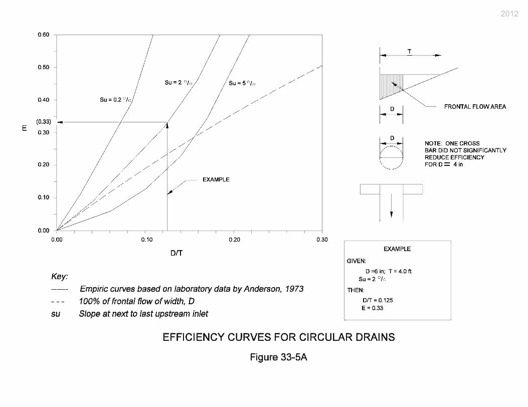
For a circular drain, such as a slab-bridge floor drain, Figure 33-5A, Efficiency Curves for Circular Drain, summarizes results from a laboratory study. To use the figure, calculate the ratio of inlet diameter, D, to gutter spread, and enter the graph at the appropriate value along the x-axis. Upon interception with the applicable curve (or appropriate interpolated curve), read efficiency, E, from the y-axis.
For a rectangular inlet, the steps necessary are shown below to calculate flow interception efficiency, E, which is the ratio of intercepted to total deck flow.
2012

a. Find the ratio of frontal flow, EO, bound by the width of grate, W, to total deck flow, using Figure 33-5B, Ratio of Frontal Flow to Total Gutter Flow (Rectangular Inlet), or the following:
67.2
11
−−=
TWEO (Equation 33-5.2)
b. Find the flow intercepted by the inlet as a percent of the frontal flow. The gutter
velocity is needed and is provided by Equation 33-4.2.
c. Identify the grate type, and, using Figure 33-5C, Grate Inlet Frontal Flow Interception Efficiency, determine the portion of frontal flow, Rf, the total flow within a grate width from the curb, which is intercepted by a grate. This will be less than 100% if the gutter velocity exceeds the splashover velocity.
d. The interception efficiency, E, is then computed as follows:
E = RfEO (Equation 33-5.3)
If side flow is to be considered, see Chapter Thirty-six.
e. The flow intercepted by an inlet is as follows:
Qi = EQw (Equation 33-5.4) Where Qw = QEo
f. The flow bypassing an inlet is as follows: ( ) ( )[ ]oob EEEQQ −+−= 11 (Equation 33-5.5) 6. Step 6. After E is determined, solve for LC, spacing of all inlets using Equation 33-5.1.
Because bridge-deck grade and time of concentration are assumed to be constant, the spacing between inlets will be constant.
7. Step 7. Continue to space inlets until the end of the bridge is reached. Once LO and LC
have been determined analytically, these values may need to be adapted to accommodate structural and aesthetic constraints.
* * * * * * * *
2012
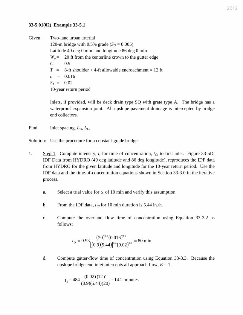
33-5.01(02) Example 33-5.1 Given: Two-lane urban arterial
120-m bridge with 0.5% grade (SO = 0.005) Latitude 40 deg 0 min, and longitude 86 deg 0 min Wp = 20 ft from the centerline crown to the gutter edge C = 0.9 T = 8-ft shoulder + 4-ft allowable encroachment = 12 ft n = 0.016 SX = 0.02 10-year return period
Inlets, if provided, will be deck drain type SQ with grate type A. The bridge has a waterproof expansion joint. All upslope pavement drainage is intercepted by bridge end collectors.
Find: Inlet spacing, LO, LC. Solution: Use the procedure for a constant-grade bridge. 1. Step 1. Compute intensity, i, for time of concentration, tC, to first inlet. Figure 33-5D,
IDF Data from HYDRO (40 deg latitude and 86 deg longitude), reproduces the IDF data from HYDRO for the given latitude and longitude for the 10-year return period. Use the IDF data and the time-of-concentration equations shown in Section 33-3.0 in the iterative process.
a. Select a trial value for tC of 10 min and verify this assumption. b. From the IDF data, i10 for 10 min duration is 5.44 in./h.
c. Compute the overland flow time of concentration using Equation 33-3.2 as follows:
( ) ( )( )( )[ ] ( )
min8002.044.59.0
016.02093.0 3.04.0
6.06.0
==Ot
d. Compute gutter-flow time of concentration using Equation 33-3.3. Because the
upslope bridge end inlet intercepts all approach flow, E = 1.
minutes 14.2 = )20)(44.5(0.9)(
)12( (0.02) 844 = t2
g
2012

e. Compute total tC and compare with selected value as follows:
f. Because the trial value of 10 min and the computed value of 15 min are not equal,
select another trial tC value of 19 min and repeat steps c through e. The interpolated value of i from Figure 33-5D, IDF Data from HYDRO (40 deg latitude and 86 deg longitude), for a duration of 19 min is 4.2 in./h.
g. The computed time of concentration for the second trial duration is 19.02 min,
which is very close to 19 min. Therefore, use i = 4.2 in./h as the design rainfall intensity.
2. Step 2. Compute full-gutter flow based on the design spread of 12 ft. Use Equation 33-
4.1 as follows:
3. Step 3. Starting at the upslope end of the bridge, compute the distance to the first inlet,
LO, using Equation 33-5.1 with E = 1.
4. Step 4. Compare LO = 1579 ft with the bridge length of 400 ft. Because LO is greater
than the total bridge length of 400 ft, drainage inlets are not required on the bridge. 5. Step 5. Not applicable. 6. Step 6. Not applicable. 7. Step 7. Not applicable.
* * * * * * * * 33-5.01(03) Example 33-5.2 Given: 6-lane rural freeway
2200-ft bridge on 1% grade (SO = 0.01) Latitude 40 deg 0 min, and longitude 86 deg 0 min WP = 34 ft from the centerline crown to the gutter edge
minutes 15.0 = 14.2 + 0.80 = tc
/s 74.2 = )12( )(0.005 )(0.02 0.016
560. = Q 32.670.51.67f ft
ft1579 = )20)(2.4(0.9)()74.2( )46250( = LO
2012

n = 0.016 C = 0.9 SX = 0.02 T = 10 ft to edge of traveled way 10-year return period
Bicycle traffic is not allowed on the bridge. Therefore, inlets will be deck drain type SQ with grate type A.
The bridge has a waterproof expansion joint. All upslope pavement drainage is intercepted by a bridge-end collector.
Find: Inlet spacing, LO, LC. Solution: Use the procedure for a constant-grade bridge. 1. Step 1. Compute intensity, i, for time of concentration, tc, to the first inlet. Use the IDF
data in Figure 33-5E, Parameters for Equation 33-5.6, and the time-of-concentration equations in Section 33-3.0 in an iterative procedure.
a. Select trial value for tC of 6 minutes and verify the assumption.
b. The i for duration of 6 min is 6.48 in./h from the IDF data.
c. Compute overland flow time of concentration using Equation 33-3.2 as follows:
d. Compute gutter-flow time of concentration using Equation 33-3.3. Because the
upslope bridge-end inlet intercepts all approach flow, E = 1.
e. Compute total tC and compare it with the selected trial value as follows:
f. Because the trial value and the computed value are approximately equal, use i =
6.48 in./h as the design rainfall intensity.
minutes 1.03 = )(0.02 ])48.6[(0.9)(
)(0.016)34( 93.0 = t 0.30.4
0.60.6
O
minutes 4.88 = )34)(48.6(0.9)(
)10(0.02)( 484 = t2
g
minutes 5.91 = 4.88 + 1.03 = tc
2012

0.37 = (0.37)(1) = E
2. Step 2. Compute full-gutter flow for the design spread of 10 ft. Use Equation 33-4.1 as
follows:
3. Step 3. Starting at the upslope end of the bridge, compute the distance to the first inlet,
LO, using Equation 33-5.1 as follows:
4. Step 4. Because LO of 522 ft is less than the total bridge length of 2250 ft, inlets are
needed. 5. Step 5. Determine the inlet efficiency, E, for the rectangular inlets:
a. Using Equation 33-5.2, compute the frontal flow ratio, EO, as follows:
b. Using Equation 33-4.2, compute gutter velocity as follows:
c. Using Figure 33-5C, find the frontal-flow intercept efficiency, Rf, for a parallel
bar grate, L = 1.6 ft. The splash over velocity is approximately 4.3 ft/sec, which is greater than the gutter velocity which implies Rf = 1.0.
d. Therefore, the interception efficiency from Equation 33-5.3 is as follows:
6. Step 6. Compute constant spacing for the remainder of the inlets using Equation 33-5.1
as follows:
7. Step 7. Adapt spacing to structural constraints. For example, if bent spacing is 183 ft to
200 ft, place the first inlet at the second bent approximately 366 ft to 400 ft from the high
/s38.2 = )10( )(0.01 )(0.02 0.016
560. = Q 32.670.51.67f ft
ft522 = )34)(48.6(0.9)(
(1) )38.2( )56043( = LO
0.37 = 10
6.1 - 1 - 1 = E 2.67O
/s38.2= )10( )(0.02 )(0.01 0.016
)56(2)(0. = V 0.670.670.5 ft
ft193 = (0.37) )34)(48.6(0.9)()38.2( )56043( = LC
2012

end of the bridge. Place an inlet at each bent thereafter for a total of 10 or 11 inlets, depending on the bent spacing.
* * * * * * * *
33-5.02 Flat Bridge 33-5.02(01) Procedure A bridge in a vertical curve, either sag or crest, is nearly flat at its low- or high-point station. A bridge with a grade of less than about 0.3% is nearly flat. For a nearly-flat station on a vertically-curved bridge, or a bridge with a constant grade, the designer should check spacing assuming that the bridge is flat. If the flat-bridge spacing is less than the spacing determined using a nearly flat grade, the flat-grade spacing is warranted. Use the following procedure. 1. Step 1. The time of concentration, tC, to each inlet is assumed to be 5 min. Frequency,
design spread, T, pavement width, WP, bridge length, LB, Manning’s n, Rational runoff coefficient, C, and gutter slope, SX, are assumed to be known. Using a time of concentration of 5 min and the selected frequency, rainfall intensity is determined from HYDRO or from the regional IDF curves shown in Chapter Twenty-nine.
2. Step 2. Constant inlet spacing, LC, can then be computed using Equation 33-5.6, as
follows:
( )11.244.1
67.0
1312 TSnCiW
L xp
C
= (Equation 33-5.6)
Where variables are as previously defined. Figure 33-5E illustrates the parameters for Equation 33-5.6.
3. Step 3. Compare the computed spacing with the known bridge length. If LC is greater
than the length of the bridge, there is no need for inlets and the designer need only be concerned with the design of bridge end treatments (Step 6). If LC is less than the bridge length, the total needed inlet perimeter, P, can be computed using Equation 33-5.7, which is based on critical depth along the perimeter of the inlet (weir flow), as follows:
n S 5.102T )CiW(
= P0.670.06
0.610.33
x
p (Equation 33-5.7)
2012
Where variables as previously defined. Figure 33-5F illustrates the parameters for Equation 33-5.7.
4. Step 4. Select inlet based on perimeter requirements. 5. Step 5. Adapt spacing to accommodate structural and aesthetic constraints.
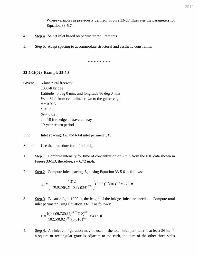
* * * * * * * * 33-5.02(02) Example 33-5.3 Given: 6-lane rural freeway
1000-ft bridge Latitude 40 deg 0 min, and longitude 86 deg 0 min Wp = 34 ft from centerline crown to the gutter edge n = 0.016 C = 0.9 SX = 0.02 T = 10 ft to edge of traveled way 10-year return period
Find: Inlet spacing, LC, and total inlet perimeter, P. Solution: Use the procedure for a flat bridge. 1. Step 1. Compute intensity for time of concentration of 5 min from the IDF data shown in
Figure 33-5D, therefore, i = 6.72 in./h. 2. Step 2. Compute inlet spacing, LC, using Equation 33-5.6 as follows:
3. Step 3. Because LC < 1000 ft, the length of the bridge, inlets are needed. Compute total
inlet perimeter using Equation 33-5.7 as follows:
4. Step 4. An inlet configuration may be used if the total inlet perimeter is at least 56 in. If
a square or rectangular grate is adjacent to the curb, the sum of the other three sides
ftc 227 = )10()(0.02 )]34)(72.6.9)([(0.016)(0
1312 = L 2.111.440.67
ft65.4 = )(0.016 )(0.025.102)10( ])34)(72.6[(0.9)( = P 0.670.06
0.610.33
2012

should equal 56 in. Thus, 56 / 3 = 18¾ in. Either deck drain type OS or SQ is adequate. A circular floor drain, such as the slab-bridge floor drain, can be used. Three 6-in. diameter drains are necessary at 267-ft intervals.
5. Step 5. Adapt spacing and type of inlet to structural constraints.
* * * * * * * * 33-5.03 Vertically-Curved Bridge 33-5.03(01) Procedure The methodology for spacing inlets on a vertically-curved bridge is similar to that for a constant-grade bridge, except that a trial-and-error approach is incorporated into the inlet-spacing computations to reflect the estimated grade at the next inlet. The designer first selects a design frequency and design spread. Bridge dimensions, bridge-end grades, roughness and runoff coefficients, and inlet specifications are assumed to be given. Using basic geometry, the designer computes the distance from the high point to each end of the bridge, LE1, LE2. Use the following procedure. 1. Step 1. Compute the lengths of the short and long ends of the bridge, LE1, LE2, by solving
Equation 33-5.8 as follows:
Where: LB = length of bridge, ft
g1, g2 = slopes of the tangents of the vertical curve, decimals
Solving for X with S = 0 provides the distance from the left edge to the high point, LE1. 2. Step 2. Determine the rainfall intensity based on the computed time of concentration to
the first inlet as follows.
a. Select trial time of concentration and determine rainfall intensity from the IDF data.
b. Compute overland travel time, tO, using Equation 33-3.2.
c. Compute gutter travel time, tg, using Equation 33-3.3.
g + X L
g - g = S 1B
12
(Equation 33-5.8)
2012

d. Compute time of concentration by summing the gutter- and overland-travel times.
e. Compare computed time with trial time in Step 2.a. and repeat if necessary. 3. Step 3. Select a trial distance from the high point to the first inlet on the long end of the
bridge, LO, and compute the local slope using Equation 33-5.8. 4. Step 4. Compute gutter flow, Qf, corresponding to the design spread using Equation 33-
4.1. 5. Step 5. Compute the distance to the first inlet, LO, letting K = 1 for the first inlet, and
using Equation 33-5.1. Substitute K for E and LO for LC in the equation. 6. Step 6. Determine spacing to the next inlet on the long end of the bridge as follows.
a. Select a trial L1.
b. Compute the local slope, S, using Equation 33-5.3.
c. Calculate the gutter flow, Q, using Equation 33-4.1.
d. Compute inlet efficiency, E, using Figure 33-5A for circular scuppers, Figure 33-5B, Equation 33-4.2, Figure 33-5C, and Equation 33-5.3 for rectangular inlets.
e. Compute the interception, K. K is less than 1 for the inlets following the first one.
Use Equation 33-5.9 as follows:
Where: E = EO. Rf = interception efficiency
Su = Longitudinal grade for upstream inlet.
f. Compute inlet spacing, L1, using Equation 33-5.1 by substituting K for E and L1 for LC, and compare to the trial L1 in Step 6.a. If the computed L1 value does not equal the trial L1 value, repeat Step 6.
7. Step 7. Repeat Step 6 for the next inlet. Inlet spacing is determined one at a time until
the sum of the inlet spacings exceeds the length of the long side of the bridge. Spacing on the short side of the bridge, starting from the high point and working down, will be the same as that determined for the long side until, of course, the length of the short side is
SS ) E-(1 -1 =K
0.5 u (Equation 33-5.9)
2012

exceeded. The spacing of the vertically-curved-deck inlets is symmetrical with respect to the high point of the bridge.
8. Step 8. Adapt spacing of inlets to accommodate structural constraints.
* * * * * * * * 33-5.03(02) Example 33-5.4 Given: 6-lane rural freeway
Bridge on vertical curve Latitude 40 deg 0 min, and longitude 86 deg 0 min Wp = 34 ft from centerline crown to gutter edge n = 0.016 SX = 0.02 T = 10 ft to edge of traveled way C = 0.9 LB = 2000 ft 10-year return period g1 = +0.01 g2 = -0.02
Inlets will be deck drain type SQ. Bicycle traffic is not allowed.
Find: Inlet spacing LO, L1, L2, L3, etc. Solution: Use the procedure for a vertically-curved bridge. 1. Step 1. Compute LE1 and LE2, assuming a parabolic vertical curve. Locate the high point,
XHP, using Equation 33-5.30 with S = 0, as follows:
Thus: LE1 = 667 ft and LE2 = 2000 – 667 = 1333 ft
2. Step 2. Compute intensity for time of concentration to the first inlet. Use the IDF data
shown in Figure 33-5D as follows:
a. Select trial time of concentration of 6 min. Then i10 = 6.48 in./h for a 10-year return period.
ft 667 = 0.01)-(-0.02
00)20( (-0.01) = XHP
2012

b. Compute tO from Equation 33-3.2 as follows:
c. Compute tg from Equation 33-3.3 as follows:
d. Compute tC as follows:
e. The calculated tC is sufficiently close to the assumed tC. Therefore, use 6.48 in./h
as the design rainfall intensity. 3. Step 3. Select a trial value for the distance from the bridge’s high point to the first inlet,
working down the long side of the bridge, and compute the local slope.
a. Select LO = 333 ft (1st trial)
X = 667 + 333 = 1000 ft (distance from the left end)
b. Use Equation 33-5.8 to determine S as follows:
Use S = 0.005
4. Step 4. Compute full gutter flow, Qf, at design spread of 10 ft for Equation 33-4.1 as
follows:
5. Step 5. Compute distance to first inlet, LO. K = 1 for the first inlet. Use Equation 33-5.1
as follows:
minutes 1.03 = )(0.02 ])48.6[(0.9)(
](0.016) )34[( 93.0 = t 0.30.4
0.6
O
minutes 4.88 = )34)(48.6(0.9)(
)10( (0.02) 844 = t2
g
minutes 5.91 = 4.88 + 1.03 = tc
0.005- = 0.01 + 00)10( 00200.01) - (-0.02 = S
/s 68.1 = )10( )(0.005 )(0.02 0.016
560. = Q 32.670.51.67f ft
ft370 = )34)(48.6( (0.9)
)68.1( )56043( = LO
2012

0.0065- = 0.01 + )1100( 02000.01)-(-0.02 = S (Use |S| = 0.0065)
Use LO = 333 ft. Inlets are needed because LO is less than the length of the long side of the bridge.
6. Step 6. Determine spacing to next inlet as follows.
a. Select L1 = 100 ft (1st trial).
X = 667 + 333 + 100 = 1100 ft (distance from left end)
b. Use Equation 33-5.30 to determine S as follows:
Su = prior S = 0.0050, the slope at immediately-upstream inlet.
c. Compute full gutter flow, Qf, using Equation 33-4.1 as follows:
d. Compute inlet efficiency, E, for rectangular inlets using Equation 33-5.2 or Figure
33-5B.
EO = 1 - [1 – 1.6/10]2.67 = 0.37
Rf = 1.0 from Figure 33-5C, Grate Inlet Frontal Flow Interception Efficiency
E = EORf = 0.37 (1.0) = 0.37
From Figure 33-5C, splash over does not occur for parallel grates until a gutter velocity of 4.3 ft/s is reached corresponding to a slope of 1.9%. Thus, Rf will equal 1.0 and E will equal 0.37 for the remainder of this example. For less-efficient grates on a steep slope, E can change from inlet to inlet.
e. Compute interception coefficient, K, using Equation 33-5.9. K does not equal 1
for the second inlet.
/s92.1 = )10( )(0.0065 )(0.02 0.016
560. = Q 32.670.51.67f ft
/s92.1 = )10( )(0.0065 )(0.02 0.016
12.1 = V 0.670.50.67 ft
2012

( ) 45.00065.0005.037.011
5.0
=
−−=K
f. Compute inlet spacing, L1, using Equation 33-5.1 as follows:
( )( )( )( )( ) ( ) 19045.0
3448.69.092.156043
1 ==L ft (not equal to 100 ft as assumed)
7. Repeat Step 6. Because the computed value for L1 does not equal the trial value, select a
new trial value for L1 and repeat Step 6 as follows:
a. Select L1 = 250 ft (2nd trial).
X = 667 + 333 + 250 = 1250 ft (Equation 33-5.10)
b. Use Equation 33-5.8 to redetermine S as follows:
Su is still equal to 0.005.
c. Recompute Q as follows:
d. Recompute inlet efficiency, E, as follows:
E = 0.37 (no change as noted) (Equation 33-5.12)
e. Recompute interception coefficient, K1, as follows:
( ) 524.000875.0005.0
37.0115.0
=
−−=K (Equation 33-5.13)
f. Recompute inlet spacing, L1, as follows:
( )( )( )( )( ) ( ) 256524.0
3448.69.023.243560
1 ==L ft (Equation 33-5.14)
0.00875) = |S| (use 0.00875- = 0.01 + )0512( 00200.01) - (-0.02 = S
/s23.2 = )10( )(0.00875 )(0.02 0.016
560. = Q 32.670.51.67 ft
(Equation 33-5.11)
2012

This is sufficiently close to 250 ft. 8. Step 7. Determine spacing to next and subsequent inlets. Select the values as follows:
L2 = 250 ft X = 1500 ft
S = 0.0125 Q = 2.58 ft3/s E = 0.37 K1 = 0.473 L2 = 280 ft, therefore OK
2012

Inlet Spacing From High Point
Slope, S Gutter Flow,
Q (ft3/s) Li Long Side Short Side LO 333 ft 333 ft 0.0050 1.68 L1 250 ft 250 ft 0.00875 2.23 L2 250 ft N/A 0.0125 2.58 L3 250 ft N/A 0.0163 2.93
9. Step 8. Adapt spacing to accommodate structural constraints.
* * * * * * * *
2012

2012

2012

2012

2012
2012

2012

2012

Duration (min)
i10
(in./h)
5 10 15 30 60 120
6.4 5.44 4.56 3.28 2.12 1.36
IDF DATA FROM HYDRO (40 deg Latitude and 86 deg Longitude)
Figure 33-5D
2012

2012

2012