Embed Size (px)
Citation preview

Table of contents 1. Key Information and results ............................................................................................. 1 1.a. Description of equipment to be tested ............................................................................. 1
1.b. Tested configurations ...................................................................................................... 1
1.c. Level of qualification ........................................................................................................ 1
1.d. Test facility and personnel .............................................................................................. 2
1.e. Description of shake-table testing equipment .................................................................. 2
1.f. Replica of identification plate............................................................................................ 3
1.g. Seismic outline drawing .................................................................................................. 4
1.h. Comparison of the TRS and the RRS ............................................................................. 5
2. Main results and test configuration .................................................................................. 7 2.a. Instrumentation ........................................................................................................................... 7
2.b. Test method ................................................................................................................................ 8
2.c. Test sequence ............................................................................................................................. 8
2.d. Installation details ........................................................................................................................ 8
3. Detailed test results and supporting data (shake-table test) ............................................ 9 3.a. Frequencies and damping ............................................................................................... 9
3.b. Input time histories .......................................................................................................... 9
3.c. Tabulated list of maximum ACC, DIS and SG values .................................................... 11
4. Conclusion ..................................................................................................................... 12
Appendix A ................................................................................................................................... 13
Appendix B ................................................................................................................................... 14
Appendix D ................................................................................................................................... 15
Appendix E ................................................................................................................................... 16
Appendix F.................................................................................................................................... 17
Appendix H ................................................................................................................................... 17
1
1. Key information and results
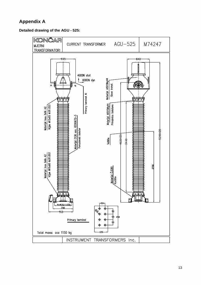
1.a. Description of equipment to be tested The object being tested is a current transformer of the type AGU-525 (manufacturer: Končar – Instrument transformers, Inc., Zagreb). AGU-525 is an inversed, outdoor type transformer with oil-impregnated paper insulation.
The transformer core is of the wound type, made of cold rolled grain oriented transformer steel sheets (M0H-0.3), soft magnetic material with very high permeability (Mumetal) and special nano-crystalline material, all depending on the required accuracy.
The primary winding passes through the core center, ensuring minimum leakage reactance. In other words, the transformer is of the low leakage flux type (according to IEC 60044-6).
The low voltage secondary winding is made of high-quality electrical copper wire insulated with thermal class F insulating varnish. It is uniformly wound around the core and enclosed in a frame made of high quality insulating material.
The insulation between the primary winding and the grounded parts of the transformer is made of high quality insulating paper, grade P5318 / DIN 6740, dried and impregnated with transformer oil under high vacuum. The capacitor effect of the conductive screens inserted into the main insulation defines the optimum distribution of service voltage and makes this transformer resistant to atmospheric impulse voltages.
The insulator is made of high quality electro-grade porcelain, type C130. It is cylindrically shaped and brown glazed. The creepage distance is set according to the ambient air pollution.
The transformer head is cast of aluminium alloy. It houses the primary winding as well as the cores and the secondary windings. It is fitted with metallic bellows for the purpose of compensating oil dilatation.
The transformer is hermetically closed, ensuring no contact between the oil and ambient air. The high quality metallic bellows made of stainless steel compensate the thermal oil dilatation. Since there is no contact of oil with the atmosphere, the insulating properties are maximally preserved.
The primary terminals are made of aluminium and are, along with the primary connection links, mounted onto the transformer head.
The transformer housing is made of welded steel plates. High quality corrosion protection is obtained by hot dip galvanization in accordance with ISO 1461-73. The hot dip galvanized surface is additionally protected with paint (colour RAL-7001). The housing is equipped with the secondary terminal box, earthing screws and the transformer name plate. Four holes are provided for fastening the transformer onto the supporting structure.
The secondary and the earthing terminals for the secondary windings are installed in the terminal box. The transformer is filled with high quality inhibited transformer oil. The oil is degassed and dried in high vacuum ensuring residual humidity content of no more than 10 μg in one gram. In this way the maximum insulation dielectric properties are obtained.
Detailed drawing is given in appendix A.
1.b. Tested configurations The test configuration of the current transformer is without support structure.
1.c. Level of qualification According to customer specifications and in compliance with definition 8.4.1.2 of the IEEE Std. 693 - 2005, MODERATE level is chosen with RRS at 0.30g.

2
1.d. Test facility and personnel Institute of Earthquake Engineering and Engineering Seismology - IZIIS
Salvador Aljende 73, MK-1000 Skopje, Republic of Macedonia
tel: +389 2 3107701
fax: +389 2 3112163
web: http://www.iziis.edu.mk
Assoc Prof. Dr. Zoran Rakicevic, Grad. CEng – Principal Investigator, Head of Dynlab
Vitko Mateski, Grad EEng – report preparing, signal processing and analysis
Nikola Naumovski, Grad MEng. – shaking table operator and instrumentation
Blagoja Keramiciev, technician – instrumentation
Dusko Trifunovski, technician – specimen installation
Ljupco Ivanov, technician – specimen installation
test dates: July 11, 2008
1.e. Description of shake-table testing equipment The seismic shaking table used has the following characteristics:
• Size in plane 5.0 x 5.0 m. • Prestressed reinforced concrete with total weight of 32.0 t. • Payload up to 40.0 t. • Biaxial fully programmable. • Kinematic quantities:
horizontal dir.: displacement ±12.5 cm, velocity 75 cm/s, acc 3.0g for zero pay load vertical dir.: displacement ±6.0 cm, velocity 30 cm/s, acc 1.0g for zero pay load
• Frequency range: 0.1 Hz up to 80 Hz.
For maximum pay load of 40.0 t, the max accelerations in horizontal direction will be 0.75g, while in vertical direction 0.5g. Data acquisition system has 72 channels, and mechanical properties in terms of displacements, accelerations and strain could be recorded.
Detailed description is given in Appendix B.
3
1.f. Replica of identification plate
Seis
mic
Qua
lific
atio
n pl
ate:
AG
U-5
25, K
ON
ČA
R –
Inst
rum
ent t
rans
form
ers
Inc.
Zag
reb
IEEE
693
-200
5 –
07/2
009
– M
oder
ate
– [IZ
IIS 2
009
- 42]
Tim
e H
isto
ry S
hake
Tab
le T
est

4
1.g. Seismic outline drawing
DA
TA:
TOTA
L W
EIG
HT:
120
0 kg
C
G O
F EQ
UIP
MEN
T O
NLY
: X
– 0
Y –
0 Z
– 27
00 m
m
NA
TUR
AL
FREQ
UEN
CIE
S W
/DA
MPI
NG
: 3.6
2 H
z @
1.7
5 %
4.17
Hz
@ 1
.34
%
MA
XIM
UM
DEF
LEC
TIO
N: 2
1.58
mm
Q
UA
LIFI
ED B
Y: T
IME
HIS
TOR
Y TE
ST
MA
NU
FAC
TUR
ED: K
ON
ČA
R –
INST
RU
MEN
TIO
N T
RA
NSF
OR
MER
S In
c.
DA
TE T
ESTE
D: 2
5.06
.200
9
SEIS
MIC
OU
TLIN
E D
RA
WIN
G
TYPE
OF
EQU
IPM
ENT:
AG
U –
525
Cur
rent
Tra
nsfo
rmer
EQ
UIP
MEN
T VO
LTA
GE:
525
kV
APP
RO
VED
BY:
IZIIS
R
EPO
RT
OR
CO
NTR
AC
T N
UM
BER
: 08-
920/
1, 1
Jun
e 20
009,
Sko
pje
QU
ALI
FIED
BY
IEEE
693
Std
. – 2
005,
Lev
el M
OD
ERA
TE, A
nnex
B, A
nnex
F
5
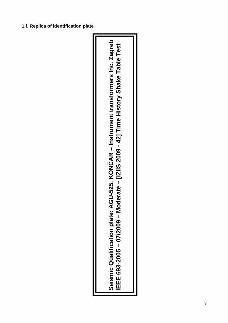
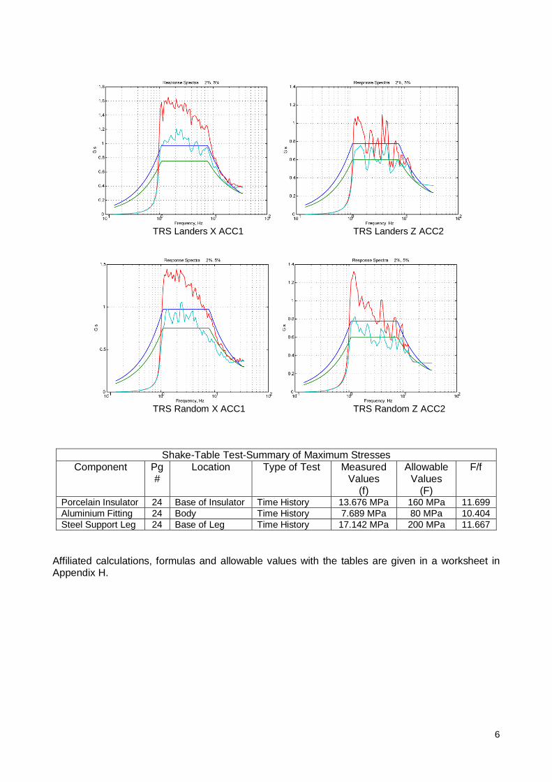
1.h. Comparison of the TRS and the RRS Following are the plots of comparison of the TRS with the RRS of the qualifying input time histories:
RRS Landers X input ground motion RRS Landers Z input ground motion
RRS Random X input ground motion RRS Random Z input ground motion
6
TRS Landers X ACC1 TRS Landers Z ACC2
TRS Random X ACC1 TRS Random Z ACC2
Shake-Table Test-Summary of Maximum Stresses Component Pg
# Location Type of Test Measured
Values (f)
Allowable Values
(F)
F/f
Porcelain Insulator 24 Base of Insulator Time History 13.676 MPa 160 MPa 11.699 Aluminium Fitting 24 Body Time History 7.689 MPa 80 MPa 10.404 Steel Support Leg 24 Base of Leg Time History 17.142 MPa 200 MPa 11.667
Affiliated calculations, formulas and allowable values with the tables are given in a worksheet in Appendix H.
7
2. Main results and test configuration
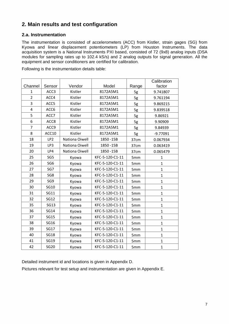
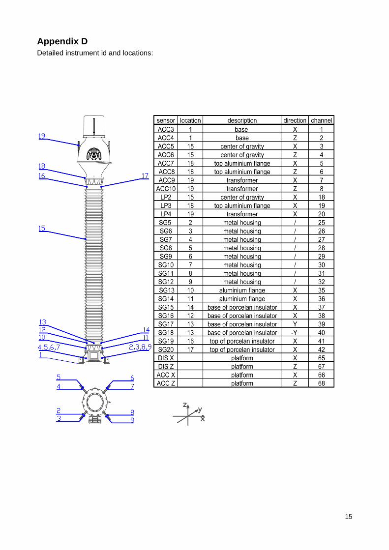
2.a. Instrumentation The instrumentation is consisted of accelerometers (ACC) from Kistler, strain gages (SG) from Kyowa and linear displacement potentiometers (LP) from Houston Instruments. The data acquisition system is a National Instruments PXI based, consisted of 72 (9x8) analog inputs (DSA modules for sampling rates up to 102.4 kS/s) and 2 analog outputs for signal generation. All the equipment and sensor conditioners are certified for calibration.
Following is the instrumentation details table:
Channel Sensor Vendor Model Range Calibration
factor 1 ACC3 Kistler 8172A5M1 5g 9.741807 2 ACC4 Kistler 8172A5M1 5g 9.761194 3 ACC5 Kistler 8172A5M1 5g 9.869215 4 ACC6 Kistler 8172A5M1 5g 9.839518 5 ACC7 Kistler 8172A5M1 5g 9.86921 6 ACC8 Kistler 8172A5M1 5g 9.90909 7 ACC9 Kistler 8172A5M1 5g 9.84939 8 ACC10 Kistler 8172A5M1 5g -9.77091
18 LP2 Nationa Oiwell 1850 -15B 37cm 0.067934 19 LP3 Nationa Oiwell 1850 -15B 37cm 0.063419 20 LP4 Nationa Oiwell 1850 -15B 37cm 0.065479 25 SG5 Kyowa KFC-5-120-C1-11 5mm 1 26 SG6 Kyowa KFC-5-120-C1-11 5mm 1 27 SG7 Kyowa KFC-5-120-C1-11 5mm 1 28 SG8 Kyowa KFC-5-120-C1-11 5mm 1 29 SG9 Kyowa KFC-5-120-C1-11 5mm 1 30 SG10 Kyowa KFC-5-120-C1-11 5mm 1 31 SG11 Kyowa KFC-5-120-C1-11 5mm 1 32 SG12 Kyowa KFC-5-120-C1-11 5mm 1 35 SG13 Kyowa KFC-5-120-C1-11 5mm 1 36 SG14 Kyowa KFC-5-120-C1-11 5mm 1 37 SG15 Kyowa KFC-5-120-C1-11 5mm 1 38 SG16 Kyowa KFC-5-120-C1-11 5mm 1 39 SG17 Kyowa KFC-5-120-C1-11 5mm 1 40 SG18 Kyowa KFC-5-120-C1-11 5mm 1 41 SG19 Kyowa KFC-5-120-C1-11 5mm 1 42 SG20 Kyowa KFC-5-120-C1-11 5mm 1
Detailed instrument id and locations is given in Appendix D.
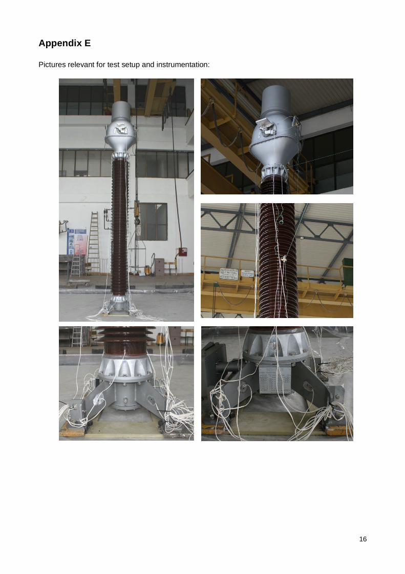
Pictures relevant for test setup and instrumentation are given in Appendix E.
8
2.b. Test method Test method used for the seismic qualification is Time History Test. Biaxial (2D) testing is used, justified by testing object being symmetrical in all horizontal directions as required in A.1.1.2 of the IEEE Std. 693. Two stage testing is performed - resonant frequency search test and earthquake ground motion test.
Sine-sweep and broadband white noise tests are used to establish the dynamic characteristics (natural frequencies and damping ratios) of the current transformer. Both the sine-sweep and the white noise excitations are generated in accordance with specifications A.1.2.1 of the IEEE Std.693.
Two sets of time histories were used. One is based on records of real earthquake motion, Landers 1992. The second set of time histories, Random, is artificially generated. Both sets of input motions are provided by IEEE.
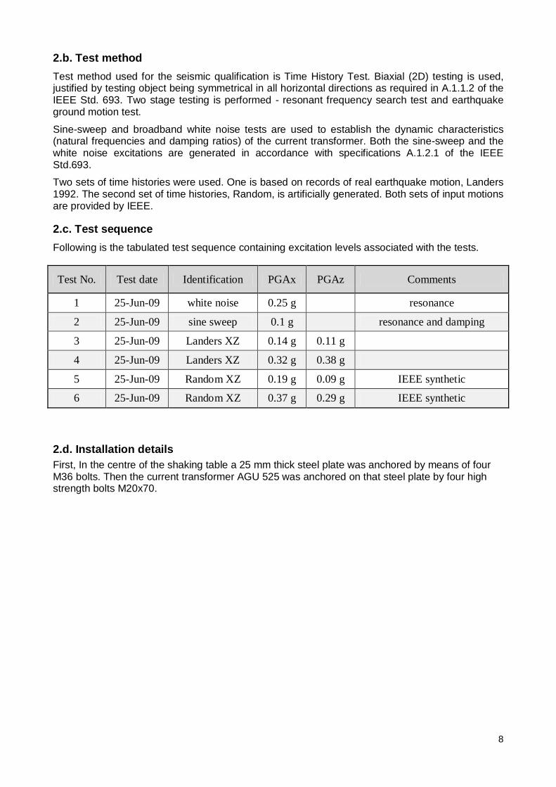
2.c. Test sequence Following is the tabulated test sequence containing excitation levels associated with the tests.
Test No. Test date Identification PGAx PGAz Comments
1 25-Jun-09 white noise 0.25 g resonance
2 25-Jun-09 sine sweep 0.1 g resonance and damping
3 25-Jun-09 Landers XZ 0.14 g 0.11 g
4 25-Jun-09 Landers XZ 0.32 g 0.38 g
5 25-Jun-09 Random XZ 0.19 g 0.09 g IEEE synthetic
6 25-Jun-09 Random XZ 0.37 g 0.29 g IEEE synthetic
2.d. Installation details First, In the centre of the shaking table a 25 mm thick steel plate was anchored by means of four M36 bolts. Then the current transformer AGU 525 was anchored on that steel plate by four high strength bolts M20x70.
9
3. Detailed test results and supporting data (shake-table test)
3.a. Frequencies and damping Natural frequencies and dumping are determined by using sine sweep pre-tests.
fR = 3.62 Hz d = 1.75 %
fR = 4.17 Hz d = 1.34 %
Plots of search data are available on pages 20-23 in the LTR.
Details on calculations for damping estimates are given in Appendix F.
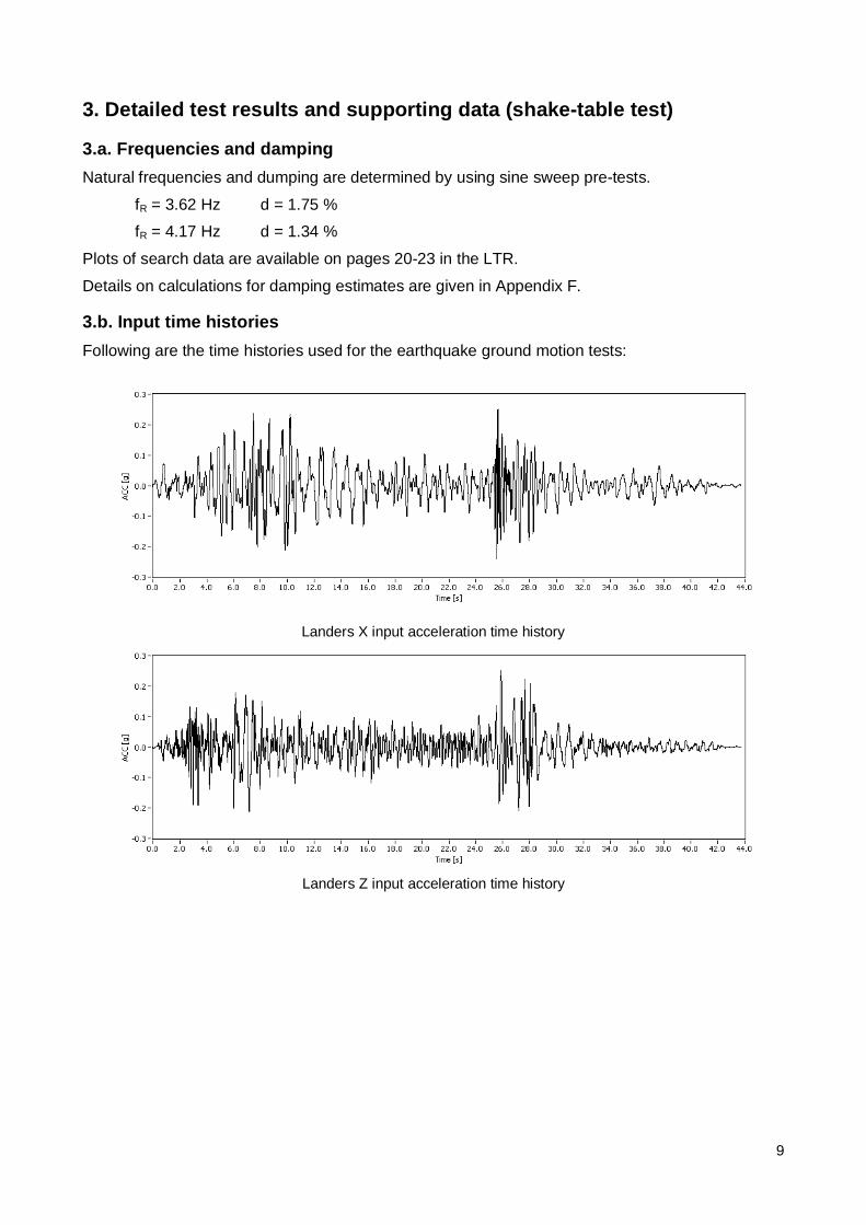
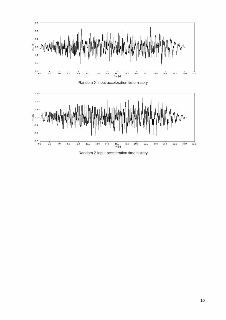
3.b. Input time histories Following are the time histories used for the earthquake ground motion tests:
Landers X input acceleration time history
Landers Z input acceleration time history
10
Random X input acceleration time history
Random Z input acceleration time history

11
3.c. Tabulated list of maximum ACC, DIS, SG values Following is the table of maximum accelerations, displacements and stresses at measuring points.
Maximum values taken from tests:
Sensor unit Landers Random DIS X [mm] 32.02 21.82 DIS Y [mm] 21.25 22.49 LP 2 [mm] 37.73 28.27 LP 3 [mm] 40.20 31.90 LP 4 [mm] 41.28 35.22 rLP 2 [mm] 13.34 15.21 rLP 3 [mm] 18.02 19.97 rLP 4 [mm] 19.87 21.58 ACC X [g] 0.40 0.38
ACC Z [g] 0.40 0.31
ACC 3 [g] 0.33 0.33
ACC 4 [g] 0.39 0.29
ACC 5 [g] 0.63 0.60
ACC 6 [g] 0.42 0.29
ACC 7 [g] 0.83 0.89
ACC 8 [g] 0.42 0.31
ACC 9 [g] 1.02 1.11
ACC 10 [g] 0.40 0.38
SG 5 µξ 50.33 52.72 SG 6 µξ 51.67 51.12 SG 7 µξ 44.54 38.10 SG 8 µξ 2.61 2.77 SG 9 µξ 72.05 77.60
SG 10 µξ 45.92 35.71 SG 11 µξ 81.63 89.71 SG 12 µξ 44.89 35.50 SG 13 µξ 79.78 98.70 SG 14 µξ 14.91 14.22 SG 15 µξ 127.13 136.76 SG 16 µξ 118.51 125.26 SG 17 µξ 97.47 113.87 SG 18 µξ 89.04 100.31 SG 19 µξ 15.58 17.44 SG 20 µξ 22.84 19.67

12
4. Conclusion
Having in mind all experimental results and above stated it can be certified that the current transformer AGU-525 kV, manufactured by KONČAR Instrument transformers Inc, from Zagreb, Croatia, without support meets and exceeds all of the requirements of the IEEE Std. 693-2005 regarding the Moderate Level of Seismic Qualification with ZPA=0.3g of the RRS, and it is expected to have acceptable performance at the Performance Level with ZPA=0.6g of the RRS.
13
Appendix A
Detailed drawing of the AGU - 525:
14
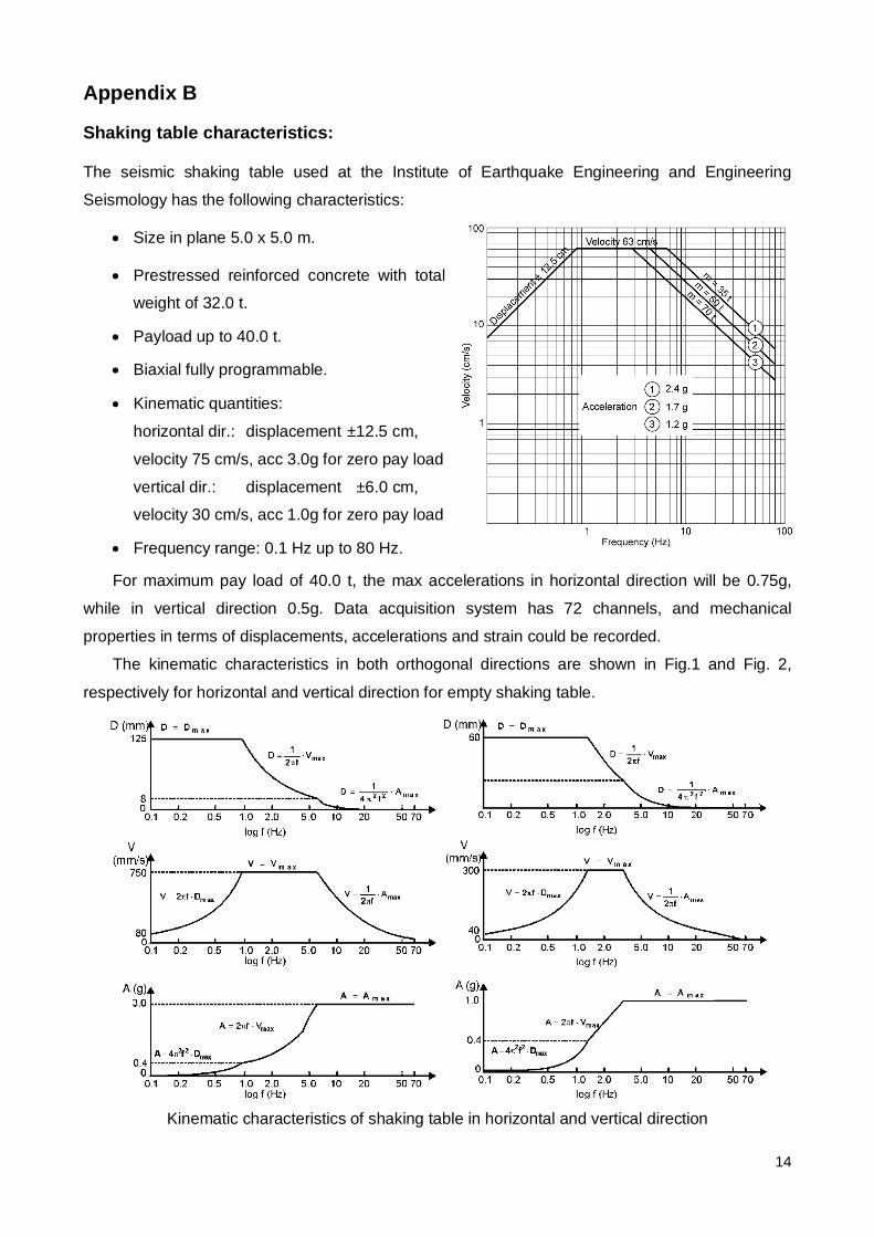
Appendix B
Shaking table characteristics:
The seismic shaking table used at the Institute of Earthquake Engineering and Engineering
Seismology has the following characteristics:
• Size in plane 5.0 x 5.0 m.
• Prestressed reinforced concrete with total
weight of 32.0 t.
• Payload up to 40.0 t.
• Biaxial fully programmable.
• Kinematic quantities:
horizontal dir.: displacement ±12.5 cm,
velocity 75 cm/s, acc 3.0g for zero pay load
vertical dir.: displacement ±6.0 cm,
velocity 30 cm/s, acc 1.0g for zero pay load
• Frequency range: 0.1 Hz up to 80 Hz.
For maximum pay load of 40.0 t, the max accelerations in horizontal direction will be 0.75g,
while in vertical direction 0.5g. Data acquisition system has 72 channels, and mechanical
properties in terms of displacements, accelerations and strain could be recorded.
The kinematic characteristics in both orthogonal directions are shown in Fig.1 and Fig. 2,
respectively for horizontal and vertical direction for empty shaking table.
Kinematic characteristics of shaking table in horizontal and vertical direction
15
Appendix D Detailed instrument id and locations:
16
Appendix E Pictures relevant for test setup and instrumentation:
17
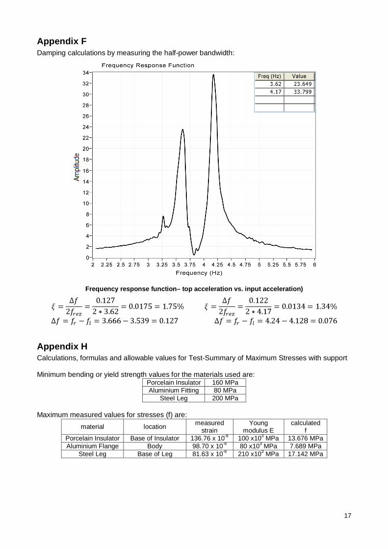
Appendix F Damping calculations by measuring the half-power bandwidth:
Frequency response function– top acceleration vs. input acceleration)
Appendix H Calculations, formulas and allowable values for Test-Summary of Maximum Stresses with support Minimum bending or yield strength values for the materials used are:
Porcelain Insulator 160 MPa Aluminium Fitting 80 MPa
Steel Leg 200 MPa Maximum measured values for stresses (f) are:
material location measured strain
Young modulus E
calculated f
Porcelain Insulator Base of Insulator 136.76 x 10⁻⁶ 100 x103 MPa 13.676 MPa Aluminium Flange Body 98.70 x 10⁻⁶ 80 x103 MPa 7.689 MPa
Steel Leg Base of Leg 81.63 x 10⁻⁶ 210 x103 MPa 17.142 MPa


![Workshop III Potenzialstudie KWK Hemmnisse KWK-Realisierung Vorläufiger Zwischenbericht [Es gilt das gesprochene Wort !] 4. 7. 2005 IV – Wien Institut](https://img.pdfslide.net/doc/110x75/55204d8049795902118d2b6c/workshop-iii-potenzialstudie-kwk-hemmnisse-kwk-realisierung-vorlaeufiger-zwischenbericht-es-gilt-das-gesprochene-wort-4-7-2005-iv-wien-institut.jpg)