Embed Size (px)
Citation preview
TABLE OF CONTENTS
Number Revision Title
0013 6 Guidelines for Loadouts
0021 8 Guidelines for the approval of towing vessels
0027 9 Marine lifting operations
0030 4 Guidelines for marine transportations
0032 0 Guidelines for moorings
TECHNICAL POLICY BOARD
www.gl-nobledenton.com
GUIDELINES FOR LOADOUTS
0013/ND
Once downloaded this document becomes UNCONTROLLED. Please check the website below for the current version.
6 Dec 10 6 GPB Technical Policy Board
31 Mar 10 5 GPB Technical Policy Board
19 Jan 09 4 GPB Technical Policy Board
01 Dec 04 3 JR Technical Policy Board
01 Apr 02 2 JR Technical Policy Board
07 Jul 93 1 JR Technical Policy Board
16 Oct 86 0 JR Technical Policy Board
Date Revision Prepared by Authorised by
GUIDELINES FOR LOADOUTS
PREFACE This document has been drawn with care to address what are likely to be the main concerns based on the experience of the GL Noble Denton organisation. This should not, however, be taken to mean that this document deals comprehensively with all of the concerns which will need to be addressed or even, where a particular matter is addressed, that this document sets out the definitive view of the organisation for all situations. In using this document, it should be treated as giving guidelines for sound and prudent practice on which our advice should be based, but guidelines should be reviewed in each particular case by the responsible person in each project to ensure that the particular circumstances of that project are addressed in a way which is adequate and appropriate to ensure that the overall advice given is sound and comprehensive. Whilst great care and reasonable precaution has been taken in the preparation of this document to ensure that the content is correct and error free, no responsibility or liability can be accepted by GL Noble Denton for any damage or loss incurred resulting from the use of the information contained herein.
© 2010 Noble Denton Group Limited, who will allow: the document to be freely reproduced, the smallest extract to be a complete page including headers and footers but smaller extracts may be
reproduced in technical reports and papers, provided their origin is clearly referenced.
0013/ND REV 6 Page 2
GUIDELINES FOR LOADOUTS
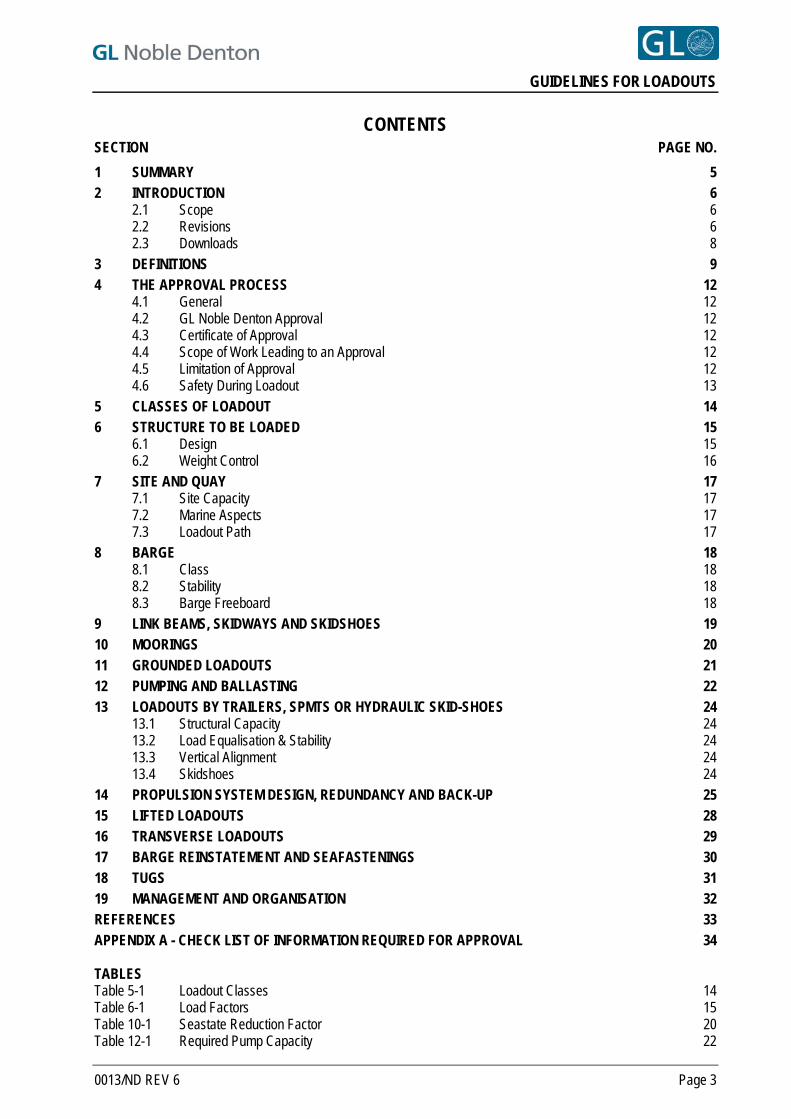
CONTENTS SECTION PAGE NO.
1 SUMMARY 5 2 INTRODUCTION 6
2.1 Scope 6 2.2 Revisions 6 2.3 Downloads 8
3 DEFINITIONS 9 4 THE APPROVAL PROCESS 12
4.1 General 12 4.2 GL Noble Denton Approval 12 4.3 Certificate of Approval 12 4.4 Scope of Work Leading to an Approval 12 4.5 Limitation of Approval 12 4.6 Safety During Loadout 13
5 CLASSES OF LOADOUT 14 6 STRUCTURE TO BE LOADED 15
6.1 Design 15 6.2 Weight Control 16
7 SITE AND QUAY 17 7.1 Site Capacity 17 7.2 Marine Aspects 17 7.3 Loadout Path 17
8 BARGE 18 8.1 Class 18 8.2 Stability 18 8.3 Barge Freeboard 18
9 LINK BEAMS, SKIDWAYS AND SKIDSHOES 19 10 MOORINGS 20 11 GROUNDED LOADOUTS 21 12 PUMPING AND BALLASTING 22 13 LOADOUTS BY TRAILERS, SPMTS OR HYDRAULIC SKID-SHOES 24
13.1 Structural Capacity 24 13.2 Load Equalisation & Stability 24 13.3 Vertical Alignment 24 13.4 Skidshoes 24
14 PROPULSION SYSTEM DESIGN, REDUNDANCY AND BACK-UP 25 15 LIFTED LOADOUTS 28 16 TRANSVERSE LOADOUTS 29 17 BARGE REINSTATEMENT AND SEAFASTENINGS 30 18 TUGS 31 19 MANAGEMENT AND ORGANISATION 32 REFERENCES 33 APPENDIX A - CHECK LIST OF INFORMATION REQUIRED FOR APPROVAL 34 TABLES Table 5-1 Loadout Classes 14 Table 6-1 Load Factors 15 Table 10-1 Seastate Reduction Factor 20 Table 12-1 Required Pump Capacity 22
0013/ND REV 6 Page 3

GUIDELINES FOR LOADOUTS
0013/ND REV 6 Page 4
Table 12-2 Example of required pumping capacity calculation 23 Table 14-1 Propulsion System Design 26 Table 14-2 Typical Friction Coefficients 27
GUIDELINES FOR LOADOUTS
1 SUMMARY 1.1 These Guidelines have been developed for the loadout of items including offshore jackets, SPAR
sections, modules, bridges and components from the shore onto floating or grounded barges and ships.
1.2 The principles of these Guidelines can also be applied to the load-in of structures onto the shore from a floating vessel/barge.
1.3 This document supersedes the previous revision, document no 0013/ND Rev 5 dated 31 March 2010. The only significant changes are in the Mooring Sections 10.2 to 10.8 and the inclusion of Section 8.3. 6
1.4 These Guidelines are intended to lead to an approval by GL Noble Denton, which may be sought where an operation is the subject of an insurance warranty, or where an independent third party review is required.
1.5 A description of the Approval Process is included, for those projects which are the subject of an insurance warranty.
1.6 This document includes the requirements for consideration, intended to represent sound practice, for the structure to be loaded, loadout site, link beams and skidways, trailers, pumping and ballasting, jacking systems and winches, grounded loadouts, transverse loadouts, moorings, seafastenings, tugs and weather forecasts.
1.7 Methods for lifted loadouts are derived from GL Noble Denton’s 0027/ND “Guidelines for Marine Lifting Operations”, Ref. [1].
1.8 Check lists are appended, to act as a guide to information required.
0013/ND REV 6 Page 5
GUIDELINES FOR LOADOUTS
2 INTRODUCTION
2.1 SCOPE 2.1.1 This document refers to the transfer of a cargo onto a barge or vessel by horizontal movement or by
lifting, including structures such as jackets, SPAR sections, modules, topside components and bridges. It contains general recommendations and checklists of information required to allow approval of such operations by GL Noble Denton.
2.1.2 The guidelines and calculation methods set out in this document represent the views of GL Noble Denton and are considered sound and in accordance with offshore industry practice. Operators should also consider national and local regulations, which may be more stringent.
2.1.3 Due to the wide range of loadout and loadin methods, this document cannot cover all aspects of every loadout or loadin scheme. Alternative proposals and methods will be considered on their own merits, and can be approved if they are shown to be in accordance with safe practice.
2.1.4 This document applies particularly to skidded and trailer transported floating loadouts, in tidal waters. The varying requirements for grounded loadouts, or loadouts accomplished by lifting are also included. Reference to a 'barge' includes a 'ship' or a 'vessel' as applicable.
2.1.5 For lifted loadouts, the factors to be applied to rigging arrangements, lift points and structure may be derived from the latest revision of GL Noble Denton 0027/ND “Guidelines for Marine Lifting Operations”, Ref. [1]. It should be noted that Ref. [1], although aimed primarily at offshore lifting operations, also includes methods and factors for lifts by floating cranes inshore, and for loadouts by shore-mounted cranes.
2.1.6 These guidelines are intended to lead to an approval by GL Noble Denton. Such approval does not imply that approval by designers, regulatory bodies and/or any other party would be given.
2.2 REVISIONS 2.2.1 Revision 2 dated 1 April 2002 superseded and replaced the previous Revision 1 dated 7 July 1993.
Changes introduced in Revision 2 included:
The inclusion of a Definitions Section
Expansion of the Section on Limitation of Approval
The introduction of the concept of classes of loadout, depending primarily on the tidal conditions
Reference to the Draft ISO Standard on Weight Control
Relaxation of under-keel clearance requirements.
Expansion of the Section on Moorings
Relationship of pumping requirements to the loadout class
Relationship of propulsion, braking and pull-back system requirements to the loadout class
Limited allowance of friction for temporary seafastenings
Reformatting and Section renumbering as necessary.
0013/ND REV 6 Page 6
GUIDELINES FOR LOADOUTS
2.2.2 Revision 3 superseded and replaced Revision 2. Changes included:
Classes of loadout reduced from 6 classes to 5 (Sections 5, 12 and 14.7)
Reference to the ISO weight control standard, to reflect the change from a Draft to a published Standard (Section 6.2)
Introduction of stability considerations for floating barges (Section 8.2)
Reference to GL Noble Denton’s transportation guideline, for post-loadout stability (Section 8.2.2)
Consideration of stability of hydraulic trailer systems (Section 13.2.2)
Introduction of a new section on transverse loadouts (Section 16)
Modifications to the loading definition and stress levels for barge movements following loadout (Sections 17.2 and 17.4)
Minor changes to the checklist of information required for approval (Appendix A)
Deletion of the previous flow chart for lifted loadouts (previous Appendix B), which can be obtained from GL Noble Denton’s 0027/ND Lifting guideline, Ref. [1]
2.2.3 Revision 4 superseded and replaced Revision 3. Changes included:
Addition of Sections 1.2, 4.5.5, 4.6, 6.2.6 to 6.2.8, 10.9, 11.10 to 11.12, 13.1.4, 13.3, 14.11, 15.5, 16.6 and 16.7.
Additions and revision to some Definitions.
Minor text revisions (Sections 4.3.4, 6.1.2, 6.2.4, 7.1.1, 7.2.1, 8.2, 10.1, 10.6, 10.7, 13.2.3, 14.7 and 17.3).
Change in the one third overload allowance in Sections 6.1.7 to 6.1.10.
Addition of requirements for site moves and trailer path grading (Section 7.3).
Skidway line and level documentation (Section 9.7) and Sections 9.8 and 9.9 added.
Additional safety factor included for single line failure mooring cases (Sections 10.4 and 10.5).
Additional requirements for lifted loadouts (Sections 15.2, 15.3, and 15.4).
Addition of tug inspection (Section 18.3).
Removal of Section 12.9 and the addition of an example for pumping system requirements in Section 12.9.
0013/ND REV 6 Page 7
GUIDELINES FOR LOADOUTS
2.2.4 Revision 5 superseded and replaced Revision 4. Significant changes included:
Text in Sections 2.1.1 and 2.1.2 amended
Definitions (Barge, Insurance Warranty, IACS, Loadout, NDT, Survey, Surveyor, Vessel, Weather Restricted Operation, and Weather Un-restricted Operations) in Section 3 revised.
Text in Section 4.3.2 revised to state loadout.
Link beam adequacy in Section 4.5.3.included.
Skidway tolerances included in Section 6.1.5.
1% load cell accuracy deleted from Section 6.2.5.
Class reinstatement added in Section 8.1.4 and Section 17.7 included.
Grounding pad area and depth added to Section 11.1.
Text added to Section 13.2.2 for stability of 3-point support.
Text in Section 14.3 and Table 14-1 for Class 2 skidded loadout pull-back and braking, requirements changed from “Required” to “Recommended”. Slope changed to gradient.
Weight and CoG tolerances included in Section 16.7.
Requirements for weight reports and weighing enhanced in Section A.1.2 below.
Link beam construction reports added in Section A.2.8.
Reference to IACS for rigging added in Section A.8.4 and Section A.9.4.
2.2.5 This Revision 6 supersedes and replaces Revision 5. The only significant changes (indicated by a line in the right hand margin is in the Mooring Sections 10.2 to 10.8 which includes the new 0032/ND “Guidelines for Moorings”, Ref. [3] and the inclusion of a new Section 8.3 on barge freeboard.
6
2.3 DOWNLOADS 2.3.1 All GL Noble Denton Guidelines can be downloaded from www.gl-nobledenton.com.
0013/ND REV 6 Page 8
GUIDELINES FOR LOADOUTS
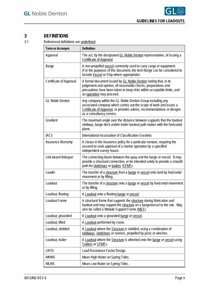
3 DEFINITIONS 3.1 Referenced definitions are underlined.
Term or Acronym Definition
Approval The act, by the designated GL Noble Denton representative, of issuing a Certificate of Approval.
Barge A non-propelled vessel commonly used to carry cargo or equipment. (For the purposes of this document, the term Barge can be considered to include Vessel or Ship where appropriate).
Certificate of Approval A formal document issued by GL Noble Denton stating that, in its judgement and opinion, all reasonable checks, preparations and precautions have been taken to keep risks within acceptable limits, and an operation may proceed.
GL Noble Denton Any company within the GL Noble Denton Group including any associated company which carries out the scope of work and issues a Certificate of Approval, or provides advice, recommendations or designs as a consultancy service.
Gradient The maximum angle over the distance between supports that the loadout skidway, barge deck and/or trailer loadout path makes with the horizontal plane.
IACS International Association of Classification Societies
Insurance Warranty A clause in the insurance policy for a particular venture, requiring the assured to seek approval of a marine operation by a specified independent survey house.
Link beam/ linkspan The connecting beam between the quay and the barge or vessel. It may provide a structural connection, or be intended solely to provide a smooth path for skidshoes or trailers /SPMTs.
Loadin The transfer of a structure from a barge or vessel onto land by horizontal movement or by lifting.
Loadout The transfer of a structure onto a barge or vessel by horizontal movement or by lifting.
Loadout, floating A Loadout onto a floating barge or vessel.
Loadout Frame A structural frame that supports the structure during fabrication and loadout and may support the structure on a barge/vessel to the site. May also be called a Module Support Frame (MSF).
Loadout, grounded A Loadout onto a grounded barge or vessel.
Loadout, lifted A Loadout performed by crane.
Loadout, skidded A Loadout where the Structure is skidded, using a combination of skidways, skidshoes or runners, propelled by jacks or winches.
Loadout, trailer A Loadout where the Structure is wheeled onto the barge or vessel using Trailers or SPMTs.
LRFD Load Resistance Factor Design.
MHWS Mean High Water on Spring Tides.
MLWS Mean Low Water on Spring Tides.
0013/ND REV 6 Page 9
GUIDELINES FOR LOADOUTS
0013/ND REV 6 Page 10
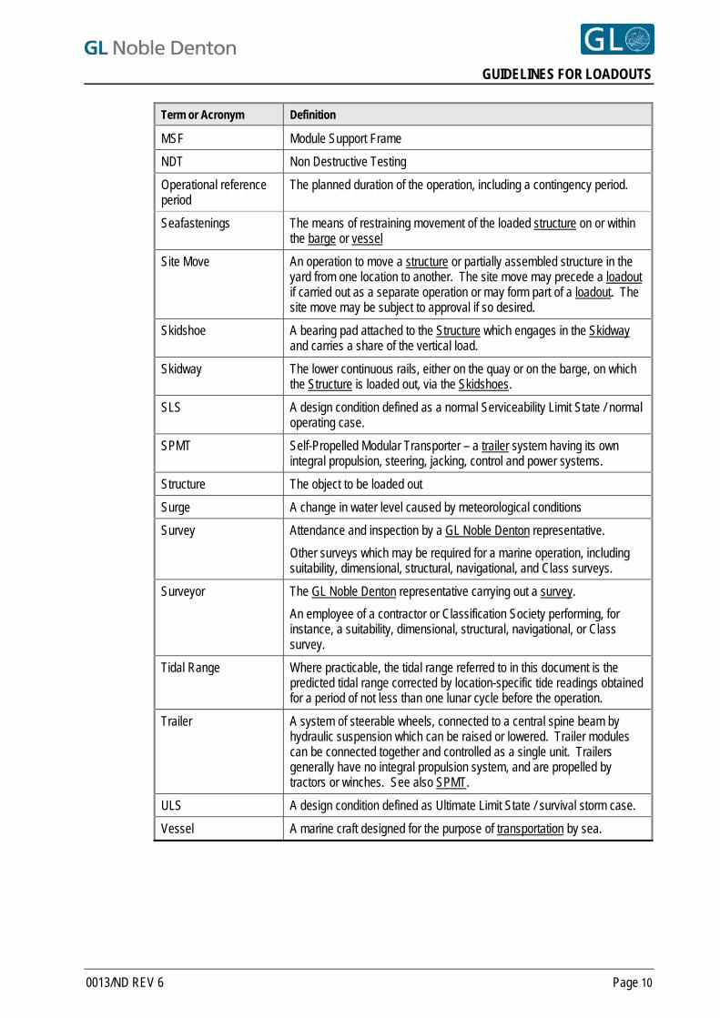
Term or Acronym Definition
MSF Module Support Frame
NDT Non Destructive Testing
Operational reference period
The planned duration of the operation, including a contingency period.
Seafastenings The means of restraining movement of the loaded structure on or within the barge or vessel
Site Move An operation to move a structure or partially assembled structure in the yard from one location to another. The site move may precede a loadout if carried out as a separate operation or may form part of a loadout. The site move may be subject to approval if so desired.
Skidshoe A bearing pad attached to the Structure which engages in the Skidway and carries a share of the vertical load.
Skidway The lower continuous rails, either on the quay or on the barge, on which the Structure is loaded out, via the Skidshoes.
SLS A design condition defined as a normal Serviceability Limit State / normal operating case.
SPMT Self-Propelled Modular Transporter – a trailer system having its own integral propulsion, steering, jacking, control and power systems.
Structure The object to be loaded out
Surge A change in water level caused by meteorological conditions
Survey Attendance and inspection by a GL Noble Denton representative.
Other surveys which may be required for a marine operation, including suitability, dimensional, structural, navigational, and Class surveys.
Surveyor The GL Noble Denton representative carrying out a survey.
An employee of a contractor or Classification Society performing, for instance, a suitability, dimensional, structural, navigational, or Class survey.
Tidal Range Where practicable, the tidal range referred to in this document is the predicted tidal range corrected by location-specific tide readings obtained for a period of not less than one lunar cycle before the operation.
Trailer A system of steerable wheels, connected to a central spine beam by hydraulic suspension which can be raised or lowered. Trailer modules can be connected together and controlled as a single unit. Trailers generally have no integral propulsion system, and are propelled by tractors or winches. See also SPMT.
ULS A design condition defined as Ultimate Limit State / survival storm case.
Vessel A marine craft designed for the purpose of transportation by sea.
GUIDELINES FOR LOADOUTS
0013/ND REV 6 Page 11
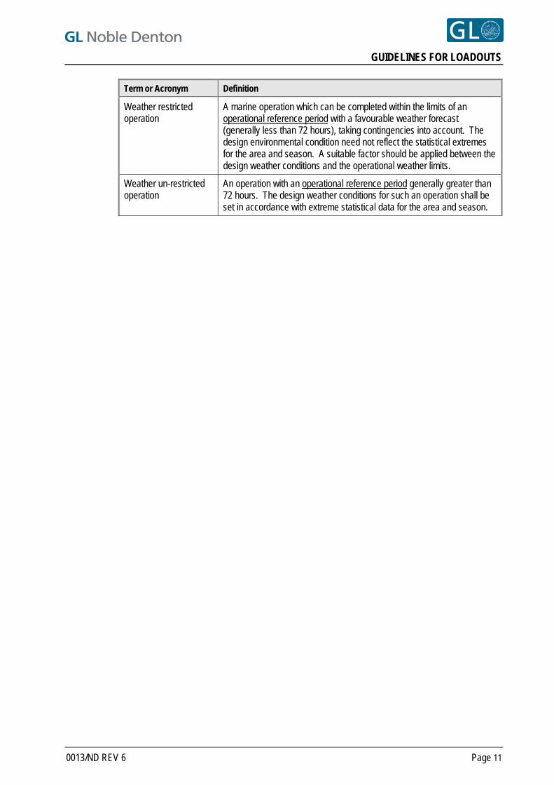
Term or Acronym Definition
Weather restricted operation
A marine operation which can be completed within the limits of an operational reference period with a favourable weather forecast (generally less than 72 hours), taking contingencies into account. The design environmental condition need not reflect the statistical extremes for the area and season. A suitable factor should be applied between the design weather conditions and the operational weather limits.
Weather un-restricted operation
An operation with an operational reference period generally greater than 72 hours. The design weather conditions for such an operation shall be set in accordance with extreme statistical data for the area and season.
GUIDELINES FOR LOADOUTS
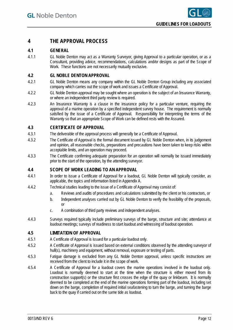
4 THE APPROVAL PROCESS
4.1 GENERAL 4.1.1 GL Noble Denton may act as a Warranty Surveyor, giving Approval to a particular operation, or as a
Consultant, providing advice, recommendations, calculations and/or designs as part of the Scope of Work. These functions are not necessarily mutually exclusive.
4.2 GL NOBLE DENTON APPROVAL 4.2.1 GL Noble Denton means any company within the GL Noble Denton Group including any associated
company which carries out the scope of work and issues a Certificate of Approval. 4.2.2 GL Noble Denton approval may be sought where an operation is the subject of an Insurance Warranty,
or where an independent third party review is required. 4.2.3 An Insurance Warranty is a clause in the insurance policy for a particular venture, requiring the
approval of a marine operation by a specified independent survey house. The requirement is normally satisfied by the issue of a Certificate of Approval. Responsibility for interpreting the terms of the Warranty so that an appropriate Scope of Work can be defined rests with the Assured.
4.3 CERTIFICATE OF APPROVAL 4.3.1 The deliverable of the approval process will generally be a Certificate of Approval. 4.3.2 The Certificate of Approval is the formal document issued by GL Noble Denton when, in its judgement
and opinion, all reasonable checks, preparations and precautions have been taken to keep risks within acceptable limits, and an operation may proceed.
4.3.3 The Certificate confirming adequate preparation for an operation will normally be issued immediately prior to the start of the operation, by the attending surveyor.
4.4 SCOPE OF WORK LEADING TO AN APPROVAL 4.4.1 In order to issue a Certificate of Approval for a loadout, GL Noble Denton will typically consider, as
applicable, the topics and information listed in Appendix A. 4.4.2 Technical studies leading to the issue of a Certificate of Approval may consist of:
a. Reviews and audits of procedures and calculations submitted by the client or his contractors, or b. Independent analyses carried out by GL Noble Denton to verify the feasibility of the proposals,
or c. A combination of third party reviews and independent analyses.
4.4.3 Surveys required typically include preliminary surveys of the barge, structure and site; attendance at loadout meetings; surveys of readiness to start loadout and witnessing of loadout operation.
4.5 LIMITATION OF APPROVAL 4.5.1 A Certificate of Approval is issued for a particular loadout only. 4.5.2 A Certificate of Approval is issued based on external conditions observed by the attending surveyor of
hull(s), machinery and equipment, without removal, exposure or testing of parts. 4.5.3 Fatigue damage is excluded from any GL Noble Denton approval, unless specific instructions are
received from the client to include it in the scope of work. 4.5.4 A Certificate of Approval for a loadout covers the marine operations involved in the loadout only.
Loadout is normally deemed to start at the time when the structure is either moved from its construction support(s) or the structure first crosses the edge of the quay or linkbeam. It is normally deemed to be completed at the end of the marine operations forming part of the loadout, including set down on the barge, completion of required initial seafastening to turn the barge, and turning the barge back to the quay if carried out on the same tide as loadout.
0013/ND REV 6 Page 12
GUIDELINES FOR LOADOUTS
4.5.5 A Certificate of Approval for a loadin covers the marine operations involved in the loadin only. Loadin is normally deemed to start at the time when the structure is moved from its barge grillage support(s), and all barge ballasting and mooring activities are complete. It is normally deemed to be completed at the end of the operations forming part of the loadin procedure, including set down on the shore supports.
4.5.6 Unless specifically included, a Certificate of Approval for loadout does not include any moorings of the barge or vessel following completion of loadout or loadin. If approval of moorings is required, other than for the loadout or loadin operation itself, then specific approval should be requested.
4.5.7 Any alterations to the surveyed items or agreed procedures after issue of the Certificate of Approval may render the Certificate invalid unless the changes are approved by GL Noble Denton in writing.
4.6 SAFETY DURING LOADOUT 4.6.1 During the loadout there will be a number of construction activities ongoing and hazards present for
operations that will be carried out in a relatively short period of time. The Surveyor, and all others involved in loadout operations, should be aware of these hazards and participate in the fabrication yard safety culture that prevails. Some hazards are, but not limited to those listed below:
Wires under tension
Trip hazards, grease on decks and hydraulic oil leaks
Openings in the barge deck
High pressure hoses/equipment
Temporary access bridges /scaffolding /wire hand railing
Hot works
Overside working
Other shipping operations in the vicinity.
0013/ND REV 6 Page 13
GUIDELINES FOR LOADOUTS
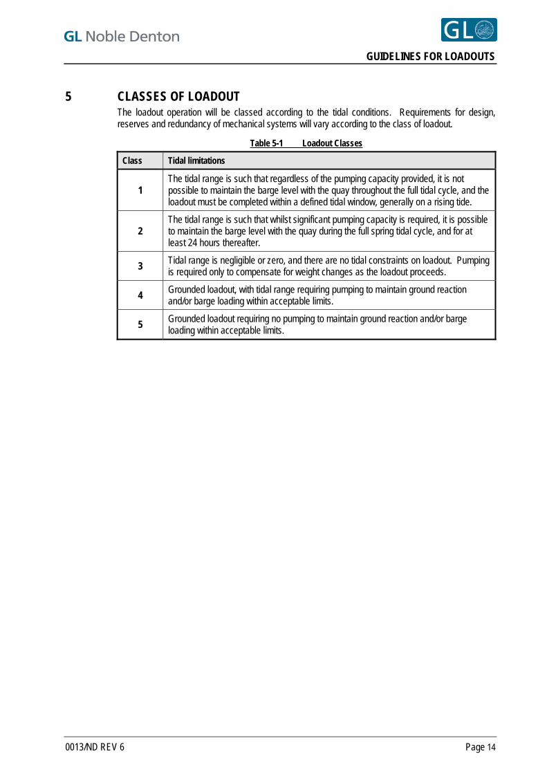
5 CLASSES OF LOADOUT The loadout operation will be classed according to the tidal conditions. Requirements for design, reserves and redundancy of mechanical systems will vary according to the class of loadout.
Table 5-1 Loadout Classes
Class Tidal limitations
1 The tidal range is such that regardless of the pumping capacity provided, it is not possible to maintain the barge level with the quay throughout the full tidal cycle, and the loadout must be completed within a defined tidal window, generally on a rising tide.
2 The tidal range is such that whilst significant pumping capacity is required, it is possible to maintain the barge level with the quay during the full spring tidal cycle, and for at least 24 hours thereafter.
3 Tidal range is negligible or zero, and there are no tidal constraints on loadout. Pumping is required only to compensate for weight changes as the loadout proceeds.
4 Grounded loadout, with tidal range requiring pumping to maintain ground reaction and/or barge loading within acceptable limits.
5 Grounded loadout requiring no pumping to maintain ground reaction and/or barge loading within acceptable limits.
0013/ND REV 6 Page 14
GUIDELINES FOR LOADOUTS
6 STRUCTURE TO BE LOADED
6.1 DESIGN 6.1.1 The item to be loaded, hereafter called the 'structure', shall be designed taking into account static and
dynamic loads, support conditions, environmental loads and loads due to misalignment of the barge and shore skidways or uneven ballasting.
6.1.2 For skidded loadouts, analyses which account for the structure and skidway should be presented which consider the elasticity, alignment and as-built dimensions of the shore and barge skidways for each stage of loadout. In the absence of detailed information, a 75/25 percent distribution of load across either diagonal may be considered as appropriate.
6.1.3 For trailer or SPMT loadouts, the reactions imposed by the trailer configuration shall be considered. 6.1.4 For lifted loadouts, the structure, including the padeyes, shall be analysed for the loads and reactions
imposed during the lift, as set out in 0027/ND, Ref. [1] 6.1.5 The structure and supports shall be demonstrated as being capable of withstanding the subsidence of
any single support with respect to the others by at least 25mm. 6.1.6 Consideration shall also be given to lifting off construction supports or onto seafastening supports
where these operations form an integral part of the loadout operation. 6.1.7 The primary structure shall be of high quality structural steelwork with full material certification and
NDT inspection certificates showing appropriate levels of inspection. It shall be assessed using the methodology of a recognised and applicable offshore code including the associated load and resistance factors for LRFD codes or safety factors for ASD/WSD codes.
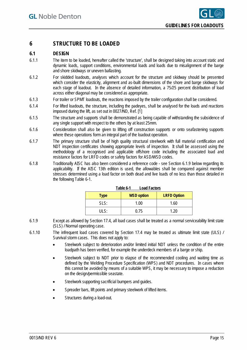
6.1.8 Traditionally AISC has also been considered a reference code - see Section 6.1.9 below regarding its applicability. If the AISC 13th edition is used, the allowables shall be compared against member stresses determined using a load factor on both dead and live loads of no less than those detailed in the following Table 6-1.
Table 6-1 Load Factors
Type WSD option LRFD Option
SLS: 1.00 1.60
ULS: 0.75 1.20
6.1.9 Except as allowed by Section 17.4, all load cases shall be treated as a normal serviceability limit state (SLS) / Normal operating case.
6.1.10 The infrequent load cases covered by Section 17.4 may be treated as ultimate limit state (ULS) / Survival storm cases. This does not apply to:
Steelwork subject to deterioration and/or limited initial NDT unless the condition of the entire loadpath has been verified, for example the underdeck members of a barge or ship.
Steelwork subject to NDT prior to elapse of the recommended cooling and waiting time as defined by the Welding Procedure Specification (WPS) and NDT procedures. In cases where this cannot be avoided by means of a suitable WPS, it may be necessary to impose a reduction on the design/permissible seastate.
Steelwork supporting sacrificial bumpers and guides.
Spreader bars, lift points and primary steelwork of lifted items.
Structures during a load-out.
0013/ND REV 6 Page 15
GUIDELINES FOR LOADOUTS
6.2 WEIGHT CONTROL 6.2.1 Weight control shall be performed by means of a well defined, documented system, in accordance with
current good practice, such as International Standard ISO 19901-5 – Petroleum and natural gas industries – specific requirements for offshore structures – Part 5: Weight control during engineering and construction, Ref. [4]
6.2.2 Ref. [4] states (inter alia) that:
“Class A (weight control) will apply if the project is weight- or CoG- sensitive for lifting and marine operations or during operation (with the addition of temporaries), or has many contractors with which to interface. Projects may also require this high definition if risk gives cause for concern”.
“Class B (weight control) shall apply to projects where the focus on weight and CoG is less critical for lifting and marine operations than for projects where Class A is applicable”.
“Class C (weight control) shall apply to projects where the requirements for weight and CoG data are not critical”.
6.2.3 Unless it can be shown that a particular structure and specific loadout operation is not weight or CoG sensitive, then Class A weight control definition will be needed, as shown in Ref. [4], Section 4.2. If the 50/50 weight estimate as defined in Ref. [4] is derived, then a reserve of not less than 5% shall be applied. The extremes of the CoG envelope shall be used.
6.2.4 A reserve of not less than 3% shall be applied to the final weighed weight. 6.2.5 If weighing takes place shortly before loadout, the effect on the loadout procedures of any weight
changes shall be assessed, and the procedures modified if necessary. 6.2.6 Prior to any structure being weighed, a predicted weight and CoG report shall be issued, so that the
weighed weight and CoG can immediately be compared with the predicted results. 6.2.7 Any items added after weighing shall be carefully monitored for weight and position to facilitate
accurate calculation of a final loadout weight and centre of gravity. 6.2.8 A responsible engineer shall provide a statement verifying the adequacy of existing calculations and
analyses following reconciliation with the weight and CoG values used in those analyses and the final derived weight values following weighing.
0013/ND REV 6 Page 16
GUIDELINES FOR LOADOUTS
7 SITE AND QUAY
7.1 SITE CAPACITY 7.1.1 A statement shall be submitted showing the adequacy for the loadout of the quay, quay approaches,
wall and foundations. This can be in the form of historical data. 7.1.2 A statement shall be submitted showing the capacity of all mooring bollards, winches and other
attachments to be used for the loadout. 7.1.3 Compatibility between quay strength and elasticity, and the support conditions used for analysis of the
structure, shall be demonstrated where appropriate.
7.2 MARINE ASPECTS 7.2.1 Bathymetric information for the area covered or crossed by the barge during loadout, post-loadout
operations and sailaway shall be supplied. Underkeel clearance shall not normally be less than 1.0 m during the period for which the barge is in position for loadout. This may be relaxed to 0.5 m, subject to confidence in the lowest predicted water levels, and provided a check of the loadout area has been made by bar sweep, divers’ inspection or side-scan survey sufficiently recently to represent actual conditions at the time of loadout. Where there is a risk of debris reducing underkeel clearance, a sweep shall be made immediately prior to the barge berthing to ensure that no debris exists that could damage the barge keel plating. The results of the sweep shall be confirmed by further soundings check around the barge perimeter after barge berthing.
7.2.2 For tidal loadouts, an easily readable tide gauge shall be provided adjacent to the loadout quay in such a location that it will not be obscured during any stage of the loadout operation. Where the tide level is critical, the correct datum should be established.
7.2.3 Port authority approval for the operation should be obtained, and control of marine traffic instituted, as required.
7.3 LOADOUT PATH 7.3.1 The loadout path shall be freshly graded prior to loadout, pot holes filled and compacted, debris
removed and obstructions to the loadout path identified and removed. 7.3.2 Where a structure cannot be loaded out directly onto a barge or vessel without turning, turning radii
shall be maximised where possible. For small turning radii, lateral supports /restraints shall be installed between the trailer and the structure /loadout frame /cribbage. It is possible that a site move may be part of the loadout operation.
0013/ND REV 6 Page 17
GUIDELINES FOR LOADOUTS
8 BARGE
8.1 CLASS 8.1.1 The barge shall be classed by a recognised IACS Member. Alternatively, structural drawings and
results of structural analyses shall be supplied to GL Noble Denton for review. Additional surveys may be required by GL Noble Denton.
8.1.2 The loads induced during loadout, including longitudinal bending, loads on internal structure and local loads, shall be checked to be within the approved design capabilities.
8.1.3 Mooring attachments and all attachments for jacking or winching shall be demonstrated to be adequate for the loads anticipated during or after loadout. See also Section 10.
8.1.4 Some loadout operations may temporarily invalidate the class or loadline certificate, and it will be necessary for any items temporarily removed for loadout be reinstated after loadout. This may apply if, for instance, holes have been cut in the deck for ballasting, if towing connections have been removed or, in some instances, after grounding on a pad. In such cases the vessel must be brought back into class prior to sailaway.
8.2 STABILITY 8.2.1 Barge stability shall be shown to be adequate throughout the loadout operation. Particular attention
should be paid to:
A loadout onto a barge with a small metacentric height, where an offset centre of gravity may induce a heel or trim as the structure transfer is completed – i.e. when any transverse moment ceases to be restrained by the shore skidways or trailers.
A loadout where there is a significant friction force between the barge and the quay wall, contributed to by the reaction from the pull on system and the moorings. The friction may cause “hang-up” by resisting the heel or trim, until the pull-on reaction is released, or the friction force is overcome, whereupon a sudden change of heel or trim may result. (See also Section 14.5).
Cases where a change of wind velocity may cause a significant change of heel or trim during the operation.
8.2.2 After the structure is fully on the barge, then stability should comply with the requirements of 0030/ND “Guidelines for Marine Transportations”, Ref. [2] and those of the flag state.
8.3 BARGE FREEBOARD 8.3.1 The minimum barge freeboard during loadout shall be 0.5 m plus 50% of the maximum wave height
expected during the loadout operation. The bunding of openings in the barge deck shall also be considered for low freeboards.
6
0013/ND REV 6 Page 18
GUIDELINES FOR LOADOUTS
9 LINK BEAMS, SKIDWAYS AND SKIDSHOES 9.1 Documentation including a statement showing the strength of the skidways, link beams and skid shoes
shall be submitted, demonstrating compatibility with the statements made and assumptions used for the structural analysis.
9.2 Link beams shall be checked for loads induced by barge moorings, barge movements and pull on/pull back forces.
9.3 Tolerances on link beam movement shall be shown to be suitable for anticipated movements of the barge during the operation.
9.4 Where a barge, because of tidal limitations, has to be turned within the loadout tidal window the design of the link beams shall be such that when the loaded unit is in its final position they are not trapped, i.e. they are free for removal.
9.5 Suitable lateral guides shall be provided along the full length of skidways. 9.6 Sufficient articulation or flexibility of skid shoes shall be provided to compensate for level and slope
changes when crossing from shore to barge. 9.7 The line and level of the skidways and skidshoes shall be documented by dimensional control surveys
and reports. The line and level shall be within the tolerances defined for the loadout operation and skidway/skidshoe design.
9.8 For floating loadouts care shall be taken to ensure that minimum friction exists between the barge and quay face. Where the quay has a rendered face, steel plates shall be installed in way of the barge fendering system.
9.9 The interface between the barge and barge fendering shall be liberally lubricated with a grease or other substitute which complies with local environmental rules.
0013/ND REV 6 Page 19
GUIDELINES FOR LOADOUTS
10 MOORINGS 10.1 A loadout may normally be considered a weather restricted operation. Limiting weather conditions for
the loadout operation shall be defined, taking into account:
the forecast reliability for the area
the duration of the operation including a suitable contingency period
the exposure of the site
the time required for any operations before or after the loadout operation including barge movements and moorings, ballasting, system testing, final positioning and initial seafastening
currents during and following the operation, including blockage effects if applicable
the wind area of the cargo and the barge/vessel.
10.2 Unless agreed otherwise with GL Noble Denton, for loadout operations with an operational duration of no more than 24 hours the maximum forecast seastate shall not exceed the design seastate multiplied by the applicable factor from Table 10-1 below. For operations with other durations alternative factors apply and should be agreed with GL Noble Denton. The forecast wind and current shall be similarly considered when their effects on the operation or structure are significant.
Table 10-1 Seastate Reduction Factor
Weather Forecast Provision Reduction Factor
No project-specific forecast (in emergencies only) 0.50
One project-specific forecast source 0.65
One project-specific forecast source plus local wave monitoring (wave rider buoy)
0.70
One project-specific forecast source plus local wave monitoring and local meteorologist
0.75
6 10.3 Moorings for the loadout operation shall be designed for the limiting weather as defined in Sections 10.1 and 10.2 above.
10.4 The analysis of environmental forces for the barge/vessel mooring arrangement, and the resulting design of the mooring system shall be carried out in accordance with 0032/ND “Guidelines for Moorings”, Ref [3].
10.5 New synthetic lines/ropes, if used, should be pre-stretched. 10.6 If the mooring load is to be held on the winch brake, then the winch brake capacity, with the outer wrap
on the drum, should exceed the maximum mooring design load (intact or damaged) times by a minimum factor of 1.2. Where winches are used, tension monitoring devices/meters shall be used.
10.7 In cases where existing yard loadout mooring equipment is being used, wires and winches may sometimes be offered which have a breaking load greater than the barge equipment to which they are connected. Great care is needed in such situations, and the wire loadings should be controlled and monitored.
10.8 Mooring prior to and after loadout shall normally be considered an unrestricted operation. If approval is required for such moorings, they shall normally be designed to the 10 year return period storm for the area and season and in accordance with 0032/ND, Ref [3].
10.9 Safety factors in mooring design may be reduced on a case by case basis on the submission of risk mitigation measures, provision of standby tugs, restricted operations or rigorous mooring design calculations.
0013/ND REV 6 Page 20
GUIDELINES FOR LOADOUTS
11 GROUNDED LOADOUTS 11.1 The plan area of the grounding pad with respect to the barge keel shall be of sufficient extent to ensure
stability of the edges of the grounding pad. Geotechnical site investigation data shall be submitted together with geotechnical calculations demonstrating the capacity of the grounding pad.
11.2 A survey of levels over an area including the grounding pad shall be submitted, showing suitable support conditions for the barge.
11.3 A bar sweep or side-scan survey, supported by divers’ inspection if appropriate, shall be made just before positioning the barge, to ensure that no debris exists which could damage the barge bottom plating.
11.4 If even support over the barge bottom plating cannot be achieved, then calculations shall be submitted showing that no overstress will occur.
11.5 The barge shall be ballasted to provide sufficient ground reaction to withstand the 10 year return period storm loadings, in both pre and post-loadout conditions, at mean high water spring tide and 10 year storm surge condition.
11.6 The barge should be positioned and ballasted onto the pad several tides before the loadout operation, to allow for consolidation and settlement. Barge levels should be monitored during this time.
11.7 Final skidway levels shall be compatible with assumptions used for structural analysis as in Sections 6.1.1 and 6.1.2.
11.8 The ballast shall be adjusted during loadout, if required, to avoid barge settlement or overstress. 11.9 A plan shall be prepared for the initial seafastening and float-off operation following completion of
loadout. 11.10 Even when the barge is on the grounding pad, mooring lines between the barge and quayside shall be
maintained. 11.11 Between loadout and sailaway, the barge keel shall be inspected, either by diver survey or internal
tank inspection, in order to maintain the barge in class. Class surveyor attendance will be required. 11.12 The grounding pad elevation shall be defined based on the actual depth of the barge and not the
moulded barge depth.
0013/ND REV 6 Page 21
GUIDELINES FOR LOADOUTS
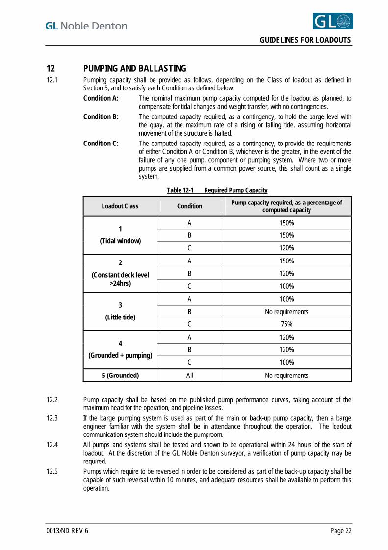
12 PUMPING AND BALLASTING 12.1 Pumping capacity shall be provided as follows, depending on the Class of loadout as defined in
Section 5, and to satisfy each Condition as defined below: Condition A: The nominal maximum pump capacity computed for the loadout as planned, to
compensate for tidal changes and weight transfer, with no contingencies. Condition B: The computed capacity required, as a contingency, to hold the barge level with
the quay, at the maximum rate of a rising or falling tide, assuming horizontal movement of the structure is halted.
Condition C: The computed capacity required, as a contingency, to provide the requirements of either Condition A or Condition B, whichever is the greater, in the event of the failure of any one pump, component or pumping system. Where two or more pumps are supplied from a common power source, this shall count as a single system.
Table 12-1 Required Pump Capacity
Loadout Class Condition Pump capacity required, as a percentage of computed capacity
A 150%
B 150% 1
(Tidal window) C 120%
A 150%
B 120%
2
(Constant deck level >24hrs) C 100%
A 100%
B No requirements 3
(Little tide) C 75%
A 120%
B 120% 4
(Grounded + pumping) C 100%
5 (Grounded) All No requirements
12.2 Pump capacity shall be based on the published pump performance curves, taking account of the
maximum head for the operation, and pipeline losses. 12.3 If the barge pumping system is used as part of the main or back-up pump capacity, then a barge
engineer familiar with the system shall be in attendance throughout the operation. The loadout communication system should include the pumproom.
12.4 All pumps and systems shall be tested and shown to be operational within 24 hours of the start of loadout. At the discretion of the GL Noble Denton surveyor, a verification of pump capacity may be required.
12.5 Pumps which require to be reversed in order to be considered as part of the back-up capacity shall be capable of such reversal within 10 minutes, and adequate resources shall be available to perform this operation.
0013/ND REV 6 Page 22
GUIDELINES FOR LOADOUTS
12.6 Pumps which require to be moved around the barge in order to be considered as part of the back-up capacity, shall be easily transportable, and may only be so considered if free access is provided at all stages of loadout between the stations at which they may be required. Adequate resources shall be available to perform this operation.
12.7 Ballast and barge levels shall be monitored during loadout, and shown to be within the limits of movements of any link beams and the structural limitations of the barge and structure.
12.8 Where a barge, vessel or ship has a compressed air ballast/de-ballast system the time lag needed to pressurise or de-pressurise a tank should be taken into account, as should any limitations on differential pressure across a bulkhead.
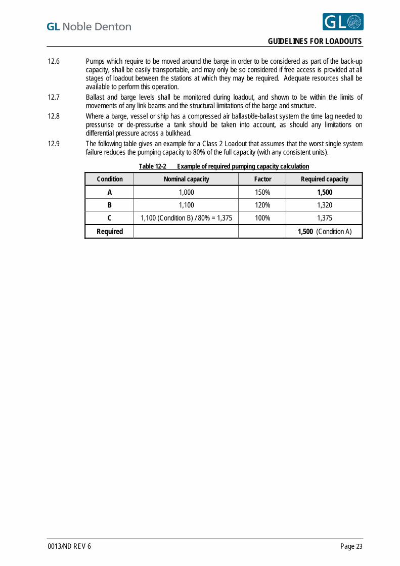
12.9 The following table gives an example for a Class 2 Loadout that assumes that the worst single system failure reduces the pumping capacity to 80% of the full capacity (with any consistent units).
Table 12-2 Example of required pumping capacity calculation
Condition Nominal capacity Factor Required capacity
A 1,000 150% 1,500
B 1,100 120% 1,320
C 1,100 (Condition B) / 80% = 1,375 100% 1,375
Required 1,500 (Condition A)
0013/ND REV 6 Page 23
GUIDELINES FOR LOADOUTS
13 LOADOUTS BY TRAILERS, SPMTS OR HYDRAULIC SKID-SHOES
13.1 STRUCTURAL CAPACITY 13.1.1 Maximum axle loading shall be shown to be within the trailer manufacturer's recommended limits. 13.1.2 "Footprint" pressure on the quayside, linkbeam and barge deck shall be shown to be within the
allowable values. 13.1.3 Shear force and bending moment curves shall be prepared for the trailer spine structure, and
maximum values shall be shown to be within the manufacturer's allowable figures. 13.1.4 Linkspan bridge capacity shall be demonstrated by calculation and these calculations shall form part of
the loadout procedure.
13.2 LOAD EQUALISATION & STABILITY 13.2.1 In general, hydraulic systems should be linked or balanced as a three point hydraulically linked system
to provide a statically determinate support system thus minimising torsion on the structure. In any event the arrangement shall be compatible with the support assumptions considered for structural analysis of the structure being loaded out. A contingency plan shall be presented to cover potential hydraulic leakage or power pack failure.
13.2.2 Stability of the hydraulic system to resist overturning shall be shown to be adequate, particularly when a 3-point hydraulic linkage system is proposed. The centre of action of the structure CoG shall remain within the middle quarter of the trailer support base, taking into account any uncertainty in:
the horizontal and vertical centre of gravity,
the design wind,
any inclination of the structure/trailer assembly on shore,
the predicted inclination of the barge under the design wind,
possible change of heel or trim due to release of hang-up between the barge and the quay, and
any free surface liquids within the structure. Note: Whilst a 3-point linkage system results in a determinate support system, a 3-point support
system is generally less stable than a 4-point support system. Stability for both 3 point and 4 point support systems shall be documented.
13.2.3 Loadouts with high slender structures on narrow support bases, or offset from the barge centreline, shall be subject to special attention in terms of the effects of uncertainties in ballasting and de-ballasting.
13.3 VERTICAL ALIGNMENT 13.3.1 Vertical alignment of barge, linkbeam and quay, including the effects of any change of slope and any
movement of the barge due to wave or swell action, should generally be within approximately one third of the maximum travel of the axles relative to the trailer spine.
13.4 SKIDSHOES 13.4.1 As appropriate, the requirements for trailers and SPMTs shall also apply to hydraulically operated
skidshoes. The stability of hydraulic skidshoes transverse to their line of action shall be demonstrated to be adequate. Attention should be paid to the effects listed in Section 13.2.2.
0013/ND REV 6 Page 24
GUIDELINES FOR LOADOUTS
14 PROPULSION SYSTEM DESIGN, REDUNDANCY AND BACK-UP 14.1 The propulsion system, including back-up and contingency systems shall be designed according to the
Class of loadout as defined in Table 5-1, and as shown in Table 14-1 . Requirements for skidded loadouts include propulsion by wire and winch, hydraulic jacks or stand jacks. Requirements for non-propelled trailer loadouts include propulsion by wire and winch or tractors.
14.2 “System redundancy” means that adequate back-up systems shall be provided such that the loadout can still proceed in the event of failure of any one mechanical component, hydraulic system, control system, prime mover or power source.
14.3 Where Table 14-1 states that a requirement is “recommended” and it is not planned to provide that requirement, a risk assessment shall be carried out, and the risks shown to be acceptable to the approving office. “Recommended” shall be taken to read “required” if a foreseeable failure could extend the operation outside the planned window.
14.4 Where a requirement is assumed to be “built-in”, including reversibility of motion, it shall be demonstrated that this is indeed the case.
14.5 Where the propulsion method induces a reaction between the barge and the quay, then the possible effects of this reaction shall be considered, including “hang-up” and sudden release. (See also Sections 8.2.1 and 13.2.2). Mooring line tensions may also contribute to the reaction.
14.6 Where a pull back system is required, and is achieved by de-rigging and re-rigging the pull on system, then the time taken to achieve this shall be defined, taking into account the Class of loadout.
0013/ND REV 6 Page 25
GUIDELINES FOR LOADOUTS
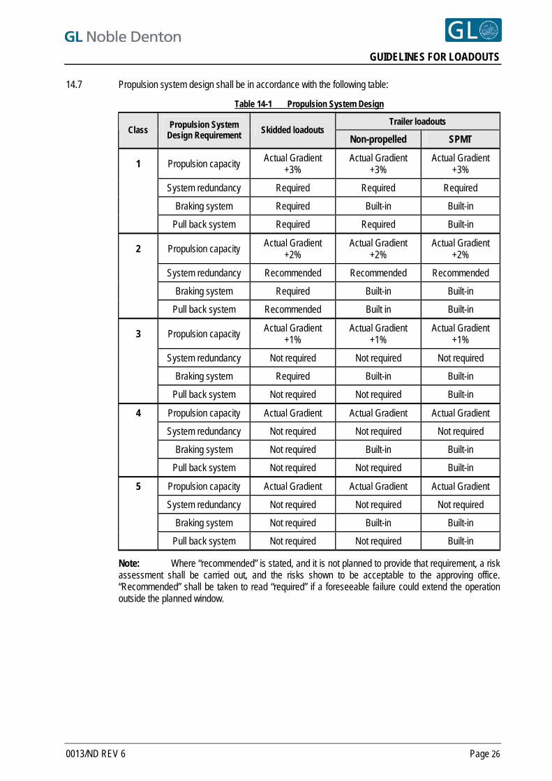
14.7 Propulsion system design shall be in accordance with the following table:
Table 14-1 Propulsion System Design
Trailer loadouts Class
Propulsion System Design Requirement Skidded loadouts
Non-propelled SPMT
1 Propulsion capacity Actual Gradient
+3% Actual Gradient
+3% Actual Gradient
+3%
System redundancy Required Required Required
Braking system Required Built-in Built-in
Pull back system Required Required Built-in
2 Propulsion capacity Actual Gradient
+2% Actual Gradient
+2% Actual Gradient
+2%
System redundancy Recommended Recommended Recommended
Braking system Required Built-in Built-in
Pull back system Recommended Built in Built-in
3 Propulsion capacity Actual Gradient
+1% Actual Gradient
+1% Actual Gradient
+1%
System redundancy Not required Not required Not required
Braking system Required Built-in Built-in
Pull back system Not required Not required Built-in
Propulsion capacity Actual Gradient Actual Gradient Actual Gradient
System redundancy Not required Not required Not required
Braking system Not required Built-in Built-in
4
Pull back system Not required Not required Built-in
Propulsion capacity Actual Gradient Actual Gradient Actual Gradient
System redundancy Not required Not required Not required
Braking system Not required Built-in Built-in
5
Pull back system Not required Not required Built-in
Note: Where “recommended” is stated, and it is not planned to provide that requirement, a risk assessment shall be carried out, and the risks shown to be acceptable to the approving office. “Recommended” shall be taken to read “required” if a foreseeable failure could extend the operation outside the planned window.
0013/ND REV 6 Page 26
GUIDELINES FOR LOADOUTS
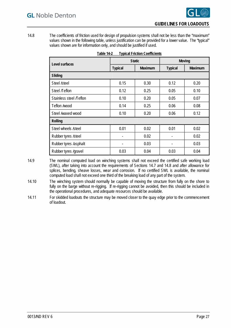
14.8 The coefficients of friction used for design of propulsion systems shall not be less than the “maximum” values shown in the following table, unless justification can be provided for a lower value. The “typical” values shown are for information only, and should be justified if used.
Table 14-2 Typical Friction Coefficients
Static Moving Level surfaces
Typical Maximum Typical Maximum
Sliding
Steel /steel 0.15 0.30 0.12 0.20
Steel /Teflon 0.12 0.25 0.05 0.10
Stainless steel /Teflon 0.10 0.20 0.05 0.07
Teflon /wood 0.14 0.25 0.06 0.08
Steel /waxed wood 0.10 0.20 0.06 0.12
Rolling
Steel wheels /steel 0.01 0.02 0.01 0.02
Rubber tyres /steel - 0.02 - 0.02
Rubber tyres /asphalt - 0.03 - 0.03
Rubber tyres /gravel 0.03 0.04 0.03 0.04
14.9 The nominal computed load on winching systems shall not exceed the certified safe working load (SWL), after taking into account the requirements of Sections 14.7 and 14.8 and after allowance for splices, bending, sheave losses, wear and corrosion. If no certified SWL is available, the nominal computed load shall not exceed one third of the breaking load of any part of the system.
14.10 The winching system should normally be capable of moving the structure from fully on the shore to fully on the barge without re-rigging. If re-rigging cannot be avoided, then this should be included in the operational procedures, and adequate resources should be available.
14.11 For skidded loadouts the structure may be moved closer to the quay edge prior to the commencement of loadout.
0013/ND REV 6 Page 27
GUIDELINES FOR LOADOUTS
15 LIFTED LOADOUTS 15.1 Where the structure is lifted onto the barge by shore-based or floating crane, the requirements of
0027/ND “Guidelines for Marine Lifting Operations”, Ref. [1] shall apply, as appropriate. 15.2 Loads imposed by shore-based mobile cranes on the quay shall be shown to be within allowable
values, either by calculation or historical data. 15.3 Floating cranes shall be moored as required by Section 10. Thruster assistance may be used if
available to augment the mooring arrangement following successful DP tests carried out immediately prior to loadout.
15.4 Where the offshore lifting padeyes are used for loadout, then a programme for inspection of the lift points after loadout shall be presented. As a minimum, inspection of the padeyes and their connection into the structure shall be carried out by a qualified NDT inspector in accordance with the original fabrication drawings. Access for this (including the possible de-rigging of the lift point) shall be provided as required. At the discretion of the attending surveyor, additional NDT inspections may be required.
15.5 If the offshore lift rigging is used for loadout then the rigging shall be inspected by a competent person prior to departure of the structure.
0013/ND REV 6 Page 28
GUIDELINES FOR LOADOUTS
16 TRANSVERSE LOADOUTS 16.1 Loadouts where the Structure is moved transversely onto the barge require special consideration and
care, for various, but not limited to, the following reasons:
In nearly all cases the ballast plan must take account of additional parameters. Structure weight transfer, transverse heel, longitudinal trim and tidal level must all be considered.
Friction between the side of the barge and the quay may be more critical than for an end-on loadout, as there may be a smaller righting moment available in heel than in trim to overcome this force. Snagging or hang-up can lead to the ballast operator getting out of synchronisation with the structure travel. Release of the snagging load has led to instability and failures.
Stability may be more critical than for an end-on loadout and changes of heel may be significant. The moment to change the barge heel 1 degree should be computed and understood for all stages of loadout.
16.2 A risk assessment should be made of the effects of potential errors in ballasting, and of friction between the barge and the quay.
16.3 Calculations should be carried out for the full range of probable GM values, module weight and centre of gravity predicted during loadout.
16.4 Ideally, discrete ballast programmes should be prepared for tidal level, weight on barge, trim and heel corrections.
16.5 Where a winch or strand jack system is used to pull the structure onto the barge, the effects of the pulling force on the friction on the fenders should be considered.
16.6 For sliding surfaces between the barge and the quay, particular attention should be paid to lubrication and use of low friction or rolling fenders.
16.7 Ballasting calculations for transverse loadouts shall be based on the weighed weight and CoG and include load combinations addressing weight and CoG contingencies.
0013/ND REV 6 Page 29
GUIDELINES FOR LOADOUTS
17 BARGE REINSTATEMENT AND SEAFASTENINGS 17.1 Seafastening work shall be started as soon as possible after positioning the structure on the barge. 17.2 No movement of the barge shall take place until sufficient seafastening is completed to withstand the
greatest of: a. an inclination equivalent to a horizontal force of 0.1 x structure weight, or b. the inclination caused by damage to any one compartment of the barge, or c. the direct wind loading, and inclination due to the design wind. Inclination loadings shall be applied at the structure centre of gravity; direct wind load shall be applied at the structure centre of area.
17.3 In specific circumstances where very limited barge movements may be required, e.g. turning from end-on to alongside the quay before it is practical to install seafastenings fully in accordance with Section 17.2, then friction may be allowed to contribute to the seafastenings, provided that it forms part of a design loadcase. Design and condition of the actual supporting structure, and potential sliding surfaces, at the time of movement, must be taken into account. The possibility of contaminants such as grease, water or sand, which may reduce the friction between the sliding surfaces, should be assessed.
17.4 The greatest of the loadings shown in Section 17.2 may be considered to be an extreme loading, and the seafastening strength assessed as an ultimate limit state ULS / Survival storm case, as described in Sections 6.1.7 to 6.1.10.
17.5 Approval of barge movements in any case shall be subject to the specific approval of the attending surveyor, after consideration of the procedures for moving the barge, the state of completion of the seafastenings and the weather and tidal conditions for the movement.
17.6 All manhole covers shall be replaced as soon as practical after loadout. 17.7 Any holes cut for ballasting purposes shall be closed as soon as practical and the barge certification
and class reinstated before sailaway. 17.8 Final seafastening connections should be made with the barge ballast condition as close as practical to
the transport condition.
0013/ND REV 6 Page 30
GUIDELINES FOR LOADOUTS
18 TUGS 18.1 Approved tugs shall be available or in attendance as required, for barge movements, removal of the
barge from the loadout berth in the event of deteriorating weather, or tug back-up to the moorings. 18.2 Towing operations following loadout should generally be in accordance with GL Noble Denton
document 0030/ND – “Guidelines for Marine Transportations” Ref. [2]. 18.3 If tugs are used as part of the loadout, inspections shall be carried out as part of the approval, i.e. for
communications and adequacy. Tug inspections shall be carried out at least 12 hours prior to the start of operations.
0013/ND REV 6 Page 31

GUIDELINES FOR LOADOUTS
0013/ND REV 6 Page 32
19 MANAGEMENT AND ORGANISATION 19.1 Sufficient management and resources shall be provided to carry out the operation efficiently and
safely. 19.2 Quality, safety and environmental hazards shall be managed by a formal Quality Management System. 19.3 The management structure, including reporting and communication systems, and links to safety and
emergency services should be demonstrated. 19.4 Shift changes shall be avoided at critical stages of loadout. 19.5 A readiness meeting should be held shortly before the start of loadout, attended by all involved parties. 19.6 A weather forecast from an approved source, predicting that conditions will be within the prescribed
limits, shall be received not less that 48 hours prior to the start of the operation, and at 12 hourly intervals thereafter, or more frequently if appropriate, until the barge is moored in accordance with Section 10.8 and the seafastening is completed in accordance with Section 17.2.
19.7 Fit-for-purpose safety procedures shall be in effect.
GUIDELINES FOR LOADOUTS
REFERENCES
[1] GL Noble Denton 0027/ND – Guidelines for Marine Lifting Operations. [2] GL Noble Denton 0030/ND – Guidelines for Marine Transportations. [3] GL Noble Denton 0032/ND - Guidelines for Moorings 6 [4] ISO International Standard ISO 19901-5 – Petroleum and natural gas industries – specific requirements for
offshore structures – Part 5: Weight control during engineering and construction.
All GL Noble Denton Guidelines can be downloaded from www.gl-nobledenton.com
0013/ND REV 6 Page 33
GUIDELINES FOR LOADOUTS
APPENDIX A - CHECK LIST OF INFORMATION REQUIRED FOR APPROVAL
A.1 STRUCTURE A.1.1 Structural analysis report, including:
Structural drawings including any additional loadout steelwork
Description of analyses programs used
Structural model
Description of support conditions
Loadcases including derivation of weights and contingencies
Unity checks greater than 0.8 for members and joints
Justification of over-stressed members
Detailed checks on structure support points, padeyes, winch connection points
Proposals for reinforcements if required.
A.1.2 Weight report for structure (including results of weighing operation and load cell calibration certificates).
A.2 SITE A.2.1 Site plan, showing loadout quay, position of structure, route to quay edge if applicable, position of all
mooring bollards and winches and any reinforced areas with allowable bearing capacities. A.2.2 Section through quay wall. A.2.3 Drawing showing heights above datum of quay approaches, structure support points, barge,
linkbeams, pad (if applicable) and water levels. The differential between civil and bathymetric datums shall be clearly shown.
A.2.4 Statement of maximum allowable loadings on quay, quay approaches, wall, grounding pads and foundations.
A.2.5 Specification and capacity of all mooring bollards and other attachment points proposed. A.2.6 Bathymetric survey report of area adjacent to the quay and passage to deep water, related to same
datum as item A.2.3. A.2.7 Bathymetric survey of pad, for grounded loadouts, related to the same datum as item A.2.3. A.2.8 Structural drawings of skidways and link beams, with statement of structural capacity, construction
(material and NDT reports) and supporting calculations. A.2.9 Method of fendering between barge and quay, showing any sliding or rolling surfaces and their
lubrication.
A.3 BARGE A.3.1 General arrangement and compartmentation drawings. A.3.2 Hydrostatic tables and tank tables. A.3.3 Details of class. A.3.4 Static stability at all stages of loadout. A.3.5 Allowable deck loadings and skidway loadings if applicable. A.3.6 Specification and capacity of all mooring bollards. A.3.7 Details of any additional steelwork such as grillages or winch attachments.
0013/ND REV 6 Page 34
GUIDELINES FOR LOADOUTS
A.3.8 Details of barge pumping system.
A.4 TRAILERS A.4.1 Trailer specification and configuration. A.4.2 Details of any additional supporting steelwork, including linkspan bridges and attachments. A.4.3 Allowable and actual axle loadings. A.4.4 Allowable and actual spine bending moments and shear forces. A.4.5 Schematic of hydraulic interconnections. A.4.6 Statement of hydraulic stability of trailer or SPMT system, with supporting calculations. A.4.7 For SPMTs, details of propulsion axles and justification of propulsion capacity. A.4.8 Specifications of tractors if used.
A.5 PUMPS A.5.1 Specification and layout of all pumps, including back-up pumps. A.5.2 Pipe schematic, and details of manifolds and valves where applicable. A.5.3 Pump performance curves.
A.6 JACKING AND/OR WINCHING A.6.1 Jack/winch specification. A.6.2 Layout of pull-on system. A.6.3 Layout of pull-back and braking systems. A.6.4 Details of power sources and back-up equipment. A.6.5 Calculations showing friction coefficient, allowances for bending and sheaves, loads on attachment
points and safety factors. A.6.6 Reactions induced between barge and quay.
A.7 BALLAST CALCULATIONS A.7.1 Planned date, time and duration of loadout, with alternative dates, tidal limitations and windows. A.7.2 Ballast calculations for each stage showing:
Time
Tidal level
Structure position
Weight on quay, linkbeam and barge
Ballast distribution
Barge draft, trim and heel
Pumps in use, and pump rates required
Moment to change heel and trim.
A.7.3 Stages to be considered should include as a minimum:
Start condition with structure entirely on shore
A suitable number of intermediate steps, e.g. 25%, 50% and 75% of travel, steps of 5 axles, or half jacket node spacing, whichever is appropriate
100% of weight on barge
Any subsequent movements on barge up to the final position. A.7.4 Any stages requiring movement or reconnection of pumps shall be defined.
0013/ND REV 6 Page 35
GUIDELINES FOR LOADOUTS
A.8 LIFTED LOADOUTS A.8.1 Crane specification, including load-radius curve. A.8.2 Copy of crane certification. A.8.3 Slinging arrangement. A.8.4 Copy of certificates of slings, shackles and other equipment. These certificates shall be issued or
endorsed by bodies approved by an IACS member or other recognised certification body accepted by GL Noble Denton.
A.8.5 For mobile cranes, position of crane at pick-up and set-down, travel route if applicable, actual and allowable ground bearing pressures at all locations.
A.8.6 Non-destructive testing report of lifting attachments and connection into structure. A.8.7 Mooring arrangements and thruster specification for floating cranes. A.8.8 If the lift points and offshore lift rigging will be re-used offshore, proposals for inspection after loadout. A.8.9 Rigging calculations.
A.9 MOORINGS A.9.1 Limiting design and operational weather conditions for loadout. A.9.2 Mooring arrangements for loadout operation and post-loadout condition. A.9.3 Mooring design calculations showing environmental loads, line tensions and attachment point loads for
limiting weather condition for loadout, and for post-loadout moorings if applicable. A.9.4 Specification and certificates of all wires, ropes, shackles, fittings and chains. This certificate shall be
issued or endorsed by a body approved by an IACS member or other recognised certification body accepted by GL Noble Denton.
A.9.5 Specification for winches, details and design of winch foundation/securing arrangements. A.9.6 Details of fendering including lubrication arrangements as appropriate.
A.10 TUGS A.10.1 Details of any supporting tugs including bollard pull and towing equipment.
A.11 MANAGEMENT A.11.1 Organogram showing management structure and responsibilities. A.11.2 Location of key personnel. A.11.3 Details of manning levels, showing adequate coverage for all operations and emergency procedures. A.11.4 Times of shift changes, if applicable. A.11.5 Weather forecast arrangements. A.11.6 Communications. A.11.7 Adequate lighting for all critical areas. A.11.8 Operation bar-chart showing time and duration of all critical activities including:
Mobilisation of equipment
Testing of pumps and winches
Testing of pull-on and pull-back systems
Barge movements
Initial ballasting
Structure movements
Loadout operation
Trailer removal
0013/ND REV 6 Page 36
GUIDELINES FOR LOADOUTS
Seafastening
Re-mooring
Decision points.
A.11.9 Methods of monitoring barge level and trim, and ballast quantities, including consideration of hang-up between barge and quay.
A.11.10 If a computerised ballast control system is to be used, a description of the system, with back-up arrangements, should be supplied.
A.11.11 Time and place for progress and decision meetings. A.11.12 Safety procedures. A.11.13 HAZOPs, HAZIDs and Risk Assessments,
A.12 CONTINGENCIES A.12.1 Contingency plans shall be presented for all eventualities, including as appropriate:
Pump failure
Mains power supply failure
Jack-winch failure
Trailer/skidshoe power pack failure
Trailer/skidshoe hydraulics failure
Trailer tyre failure
Tractor failure
Failure of any computerised control or monitoring system
Mooring system failure
Structural failure
Deteriorating weather.
0013/ND REV 6 Page 37
TECHNICAL POLICY BOARD
GUIDELINES FOR THE APPROVAL OF
TOWING VESSELS
0021/ND
Once downloaded this document becomes UNCONTROLLED.
Please check the website below for the current version.
31 Mar 10 8 RLJ Technical Policy Board
17 Nov 08 7 RLJ Technical Policy Board
4 Oct 06 6 PJD Technical Policy Board
1 Apr 02 5 JMRL Technical Policy Board
1 Dec 01 4 JMRL Technical Policy Board
1 Apr 01 3 JMRL /JR For use in TVAS
2 Apr 96 2 JMRL For use in TVAS
28 Dec 89 1 PAC Technical Policy Board
DATE REVISION PREPARED BY AUTHORISED BY
www.gl-nobledenton.com
GUIDELINES FOR THE APPROVAL OF TOWING VESSELS
PREFACE
This document has been drawn with care to address what are likely to be the main concerns based on the experience of the GL Noble Denton organisation. This should not, however, be taken to mean that this document deals comprehensively with all of the concerns which will need to be addressed or even, where a particular matter is addressed, that this document sets out the definitive view of the organisation for all situations. In using this document, it should be treated as giving guidelines for sound and prudent practice on which our advice should be based, but guidelines should be reviewed in each particular case by the responsible person in each project to ensure that the particular circumstances of that project are addressed in a way which is adequate and appropriate to ensure that the overall advice given is sound and comprehensive. Whilst great care and reasonable precaution has been taken in the preparation of this document to ensure that the content is correct and error free, no responsibility or liability can be accepted by GL Noble Denton for any damage or loss incurred resulting from the use of the information contained herein.
© 2010 Noble Denton Group Limited, who will allow: the document to be freely reproduced, the smallest extract to be a complete page including headers and footers but smaller extracts may be
reproduced in technical reports and papers, provided their origin is clearly referenced.
0021/ND REV 8 Page 2
GUIDELINES FOR THE APPROVAL OF TOWING VESSELS
CONTENTS SECTION PAGE NO.
1 SUMMARY 5 2 INTRODUCTION 6
2.1 BACKGROUND 6 2.2 TOWING VESSEL APPROVABILITY SCHEME (TVAS) 6 2.3 SUMMARY OF REQUIREMENTS 6 2.4 OTHER GL NOBLE DENTON GUIDELINES 7 2.5 BOLLARD PULL AND EQUIPMENT TESTS 7
3 DEFINITIONS 8 4 TOWING VESSEL CATEGORIES 10
4.1 OCEAN-GOING SALVAGE TUG (ST) 10 4.2 UNRESTRICTED TOWAGES (U) 10 4.3 COASTAL TOWAGES (C) 11 4.4 RESTRICTED TOWAGES (R1) 11 4.5 BENIGN AREA TOWAGES (R2) 11 4.6 RESTRICTED BENIGN AREA TOWAGES (R3) 12 4.7 LIMITED DURATION AND SHORT DISTANCE TOWAGES 12
5 DOCUMENTATION 13 5.1 GENERAL SPECIFICATION 13 5.2 GENERAL ARRANGEMENT PLANS 13 5.3 TOWING/ANCHOR-HANDLING WINCHES 13 5.4 TOWING EQUIPMENT 13 5.5 CERTIFICATES 14 5.6 SALVAGE EQUIPMENT 14
6 TOWING EQUIPMENT 15 6.1 OCEAN-GOING SALVAGE TUGS (ST) 15 6.2 UNRESTRICTED (U) OR COASTAL (C) CATEGORIES 16 6.3 RESTRICTED CATEGORIES (RI) 16 6.4 BENIGN AREA CATEGORIES (R2) 17 6.5 RESTRICTED BENIGN AREA CATEGORIES (R3) 17 6.6 ALL ENTERED VESSELS 17
7 TOWING WINCH 19 8 TOWING WIRE PROTECTION AND CONTROL 20
8.1 PROTECTORS 20 8.2 TOW BARS, CARGO PROTECTION RAIL, BULWARKS, STERN RAIL, TAILGATE AND STERN
ROLLER 20 8.3 ADJUSTABLE GOGWIRE SYSTEM 20 8.4 FIXED GOGWIRE SYSTEM 20 8.5 TOWING POD 20
9 STABILITY 21 10 MANNING AND ACCOMMODATION 22 11 SEAKEEPING 23 12 ADDITIONAL EQUIPMENT FOR SALVAGE TUGS (ST) 24
REFERENCES 25
APPENDIX A - SUMMARY OF REQUIREMENTS 26
APPENDIX B - BOLLARD PULL TESTS 27
APPENDIX C - TOWING EQUIPMENT TESTS 29
0021/ND REV 8 Page 3

GUIDELINES FOR THE APPROVAL OF TOWING VESSELS
TABLES Table 6-1 15 Towline Minimum Breaking Loads for Salvage TugsTable 6-2 16 Towline Minimum Breaking Loads for Unrestricted TowagesTable 6-3 16 Towline Minimum Breaking Loads for Restricted TowagesTable 6-4 18 Default Shackle SWL
0021/ND REV 8 Page 4
GUIDELINES FOR THE APPROVAL OF TOWING VESSELS
1 SUMMARY 1.1 These Guidelines are intended to lead to an approval by GL: Noble Denton for entry into the Towing
Vessel Approvability Scheme. They also provide guidance for the approval of towing vessels for specific tows, and bollard pull tests. They do not cover the towage of specific vessels or barges, guidance for which may be found in 0030/ND. 8
1.2 This revision 8 supersedes revision 7 dated 17th Nov 2008. Changes are described in Section 2.1.5.
1.3 This report refers to, and should be read in conjunction with other GL Noble Denton Guideline documents, in particular Reference [1] - GL Noble Denton report 0030/ND - “Guidelines for Marine Transportations”.
1.4 A definitions section is included.
1.5 A description of the approval process is included.
1.6 There are Sections on:
Towing Vessel Categories (Section 4)
Documentation (Section 5)
Towing Equipment (Section 6)
Towing Winch (Section 7)
Towing Wire Protection and Control (Section 8)
Stability (Section 9)
Manning and Accommodation (Section 10)
Seakeeping (Section 11)
Additional Equipment for Salvage Tugs (ST - Section 12)
0021/ND REV 8 Page 5
GUIDELINES FOR THE APPROVAL OF TOWING VESSELS
2 INTRODUCTION
2.1 BACKGROUND
2.1.1 These guidelines are the basis for the approval of towing vessels for specific towages.
2.1.2 The guidelines are also the standard for owners, charterers, managers or builders of towing vessels when they seek entry of a vessel into the GL Noble Denton Towing Vessel Approvability Scheme (TVAS).
2.1.3 Revision 6 superseded Revision 5 dated 1st April 2002. Major changes were:
Updating to reflect changes to 0030/ND
Modified definition of Approved Bollard Pull
Recommendations for carrying a towing wire history for categories U and R1.
2.1.4 Revision 7 superseded Revision 6 dated 4 October 2006. Major changes were:
Introduction of a new category, Coastal Towages (C), in Section 4.3 for smaller tugs for vessels with an overall length of less than 40 metres unless they have very good seakeeping qualities including good propeller immersion in bad weather and a displacement greater than 1,000 tonnes.
(For vessels with only one towing winch drum). Introduction in Section 7.10 of a maximum time requirement for safely transferring a spare towline to the towing winch after a towline break in bad weather.
Introduction in Section 9 of stability requirements that allow for the effect of the towline force.
Removal of the draught /length ratios in Section 11.4.
Introduction in Section 11.5 of a requirement for the height of raised forecastles to be at least 2 metres above the freeboard deck for all categories except for in benign weather areas.
2.1.5 This revision 8 supersedes Revision 7 dated 17 November 2008. Changes include:
the change from Noble Denton to GL Noble Denton 8
certificate requirements in Section 5.5
reduction in the maximum ULC of bridles for Category ST in Section 6.1.6.
bollard pull test requirements in Section B.4.4.
2.2 TOWING VESSEL APPROVABILITY SCHEME (TVAS)
2.2.1 The GL Noble Denton entity in London operates the GL Noble Denton Towing Vessel Approvability Scheme on behalf of the GL Noble Denton Group.
2.2.2 These guidelines provide a standard against which a towing vessel will be assessed for the issue of a Towing Vessel Approvability Certificate and entry into the TVAS database.
2.2.3 Such approval does not imply that approval by designers, regulatory bodies, harbour authorities and/or any other parties would be given. Nor does it imply approval of a vessel for any specific towage or operation for which further consideration of the suitability of the vessel for the towage or operation would be required.
2.3 SUMMARY OF REQUIREMENTS
A summary of the requirements for each towing vessel category is appended to this document as Appendix A.
0021/ND REV 8 Page 6
GUIDELINES FOR THE APPROVAL OF TOWING VESSELS
2.4 OTHER GL NOBLE DENTON GUIDELINES
This document shall be read in conjunction with other GL Noble Denton current guideline documents. In the event of conflict between two or more GL Noble Denton Guideline Documents, the last dated shall apply unless specifically agreed otherwise.
2.5 BOLLARD PULL AND EQUIPMENT TESTS
Guidance notes for carrying out bollard pull and towing equipment tests are appended to this document as Appendices B and C.
0021/ND REV 8 Page 7
GUIDELINES FOR THE APPROVAL OF TOWING VESSELS
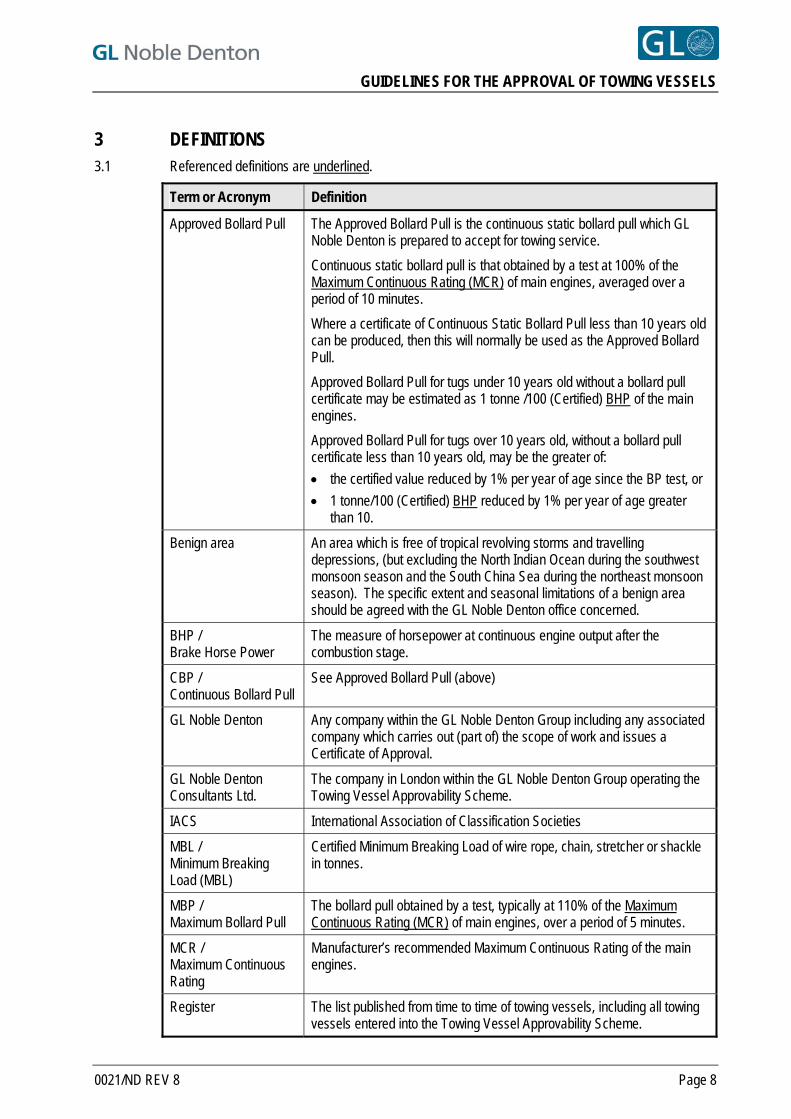
3 DEFINITIONS 3.1 Referenced definitions are underlined.
Term or Acronym Definition
Approved Bollard Pull The Approved Bollard Pull is the continuous static bollard pull which GL Noble Denton is prepared to accept for towing service.
Continuous static bollard pull is that obtained by a test at 100% of the Maximum Continuous Rating (MCR) of main engines, averaged over a period of 10 minutes.
Where a certificate of Continuous Static Bollard Pull less than 10 years old can be produced, then this will normally be used as the Approved Bollard Pull.
Approved Bollard Pull for tugs under 10 years old without a bollard pull certificate may be estimated as 1 tonne /100 (Certified) BHP of the main engines.
Approved Bollard Pull for tugs over 10 years old, without a bollard pull certificate less than 10 years old, may be the greater of:
the certified value reduced by 1% per year of age since the BP test, or
1 tonne/100 (Certified) BHP reduced by 1% per year of age greater than 10.
Benign area An area which is free of tropical revolving storms and travelling depressions, (but excluding the North Indian Ocean during the southwest monsoon season and the South China Sea during the northeast monsoon season). The specific extent and seasonal limitations of a benign area should be agreed with the GL Noble Denton office concerned.
BHP / Brake Horse Power
The measure of horsepower at continuous engine output after the combustion stage.
CBP / Continuous Bollard Pull
See Approved Bollard Pull (above)
GL Noble Denton Any company within the GL Noble Denton Group including any associated company which carries out (part of) the scope of work and issues a Certificate of Approval.
GL Noble Denton Consultants Ltd.
The company in London within the GL Noble Denton Group operating the Towing Vessel Approvability Scheme.
IACS International Association of Classification Societies
MBL / Minimum Breaking Load (MBL)
Certified Minimum Breaking Load of wire rope, chain, stretcher or shackle in tonnes.
MBP / Maximum Bollard Pull
The bollard pull obtained by a test, typically at 110% of the Maximum Continuous Rating (MCR) of main engines, over a period of 5 minutes.
MCR / Maximum Continuous Rating
Manufacturer’s recommended Maximum Continuous Rating of the main engines.
Register The list published from time to time of towing vessels, including all towing vessels entered into the Towing Vessel Approvability Scheme.
0021/ND REV 8 Page 8
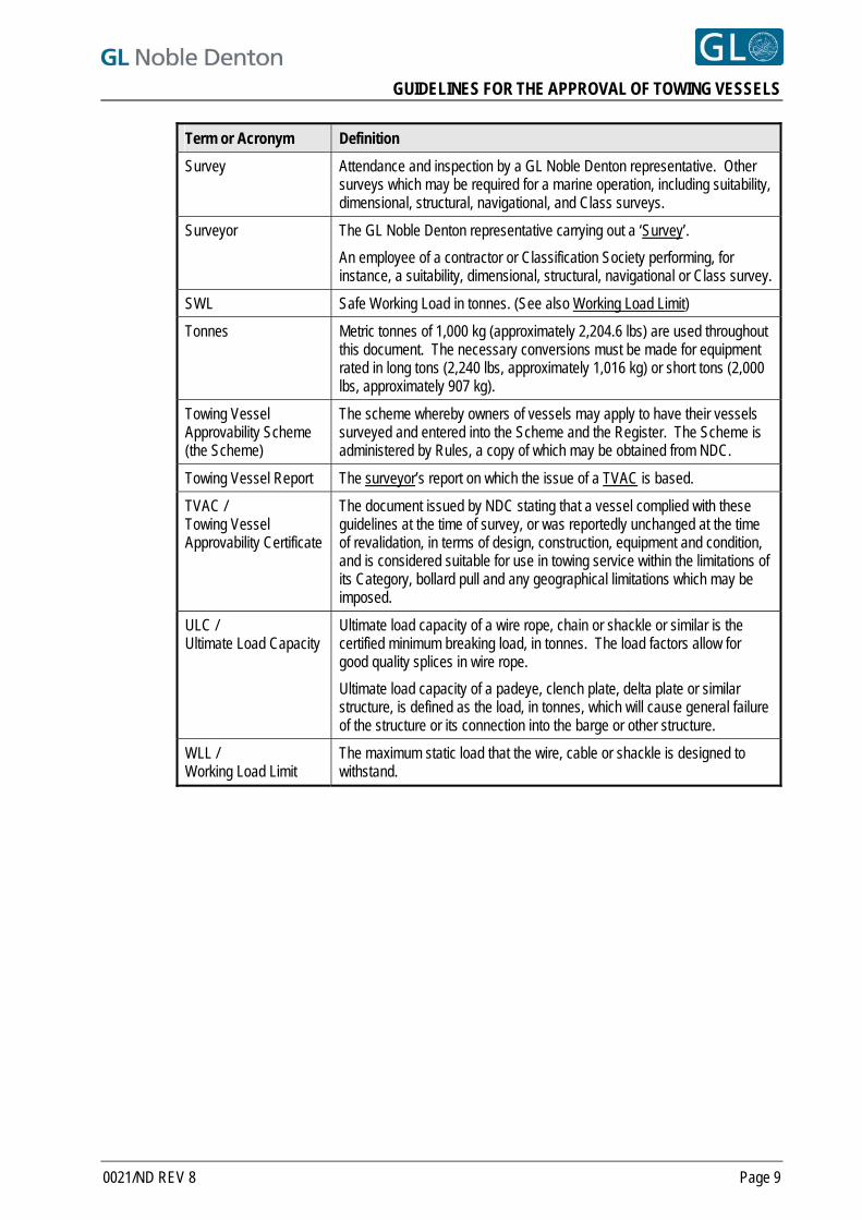
GUIDELINES FOR THE APPROVAL OF TOWING VESSELS
0021/ND REV 8 Page 9
Term or Acronym Definition
Survey Attendance and inspection by a GL Noble Denton representative. Other surveys which may be required for a marine operation, including suitability, dimensional, structural, navigational, and Class surveys.
Surveyor The GL Noble Denton representative carrying out a ‘Survey’.
An employee of a contractor or Classification Society performing, for instance, a suitability, dimensional, structural, navigational or Class survey.
SWL Safe Working Load in tonnes. (See also Working Load Limit)
Tonnes Metric tonnes of 1,000 kg (approximately 2,204.6 lbs) are used throughout this document. The necessary conversions must be made for equipment rated in long tons (2,240 lbs, approximately 1,016 kg) or short tons (2,000 lbs, approximately 907 kg).
Towing Vessel Approvability Scheme (the Scheme)
The scheme whereby owners of vessels may apply to have their vessels surveyed and entered into the Scheme and the Register. The Scheme is administered by Rules, a copy of which may be obtained from NDC.
Towing Vessel Report The surveyor’s report on which the issue of a TVAC is based.
TVAC / Towing Vessel Approvability Certificate
The document issued by NDC stating that a vessel complied with these guidelines at the time of survey, or was reportedly unchanged at the time of revalidation, in terms of design, construction, equipment and condition, and is considered suitable for use in towing service within the limitations of its Category, bollard pull and any geographical limitations which may be imposed.
ULC / Ultimate Load Capacity
Ultimate load capacity of a wire rope, chain or shackle or similar is the certified minimum breaking load, in tonnes. The load factors allow for good quality splices in wire rope.
Ultimate load capacity of a padeye, clench plate, delta plate or similar structure, is defined as the load, in tonnes, which will cause general failure of the structure or its connection into the barge or other structure.
WLL / Working Load Limit
The maximum static load that the wire, cable or shackle is designed to withstand.
GUIDELINES FOR THE APPROVAL OF TOWING VESSELS
4 TOWING VESSEL CATEGORIES Vessels that are entered into the Scheme or proposed for towing duties will be designated one of six (6) categories. The requirements for each category are stated below, and summarised in Appendix A.
4.1 OCEAN-GOING SALVAGE TUG (ST)
4.1.1 Vessels within this category are approvable for all towages within the limits of their bollard pull in all geographical areas subject to the vessel’s Ice Classification.
4.1.2 Vessels shall be equipped with two (2) main towing wires and a spare towing wire, all of which shall comply with the strength and length requirements of Section 6.1.
4.1.3 Vessels shall be adequately manned for towing operations in all geographical areas. Each vessel shall have a minimum complement of officers and crew as required in the safe manning certificates and also have the capability of accommodating increased manning levels where it is deemed necessary for a specific towage. Refer to Section 10 and Appendix A.
4.1.4 Vessels shall be of such a design that they are capable of undertaking towages in all geographical areas subject to their Ice Classification (see Section 11). They must have very good seakeeping qualities including good propeller immersion in bad weather. These qualities are unlikely to be satisfied with a Length Over All (LOA) less than 40 metres and a displacement of less than 1,000 tonnes.
4.1.5 Vessels shall have a minimum bunker capacity of at least 35 days consumption at 80% MCR.
4.1.6 Vessels shall be equipped with a workboat with sufficient power and capacity to carry four (4) persons plus material/equipment to the casualty/tow.
4.1.7 Vessels shall be equipped with the additional equipment listed in Section 12.
4.2 UNRESTRICTED TOWAGES (U)
4.2.1 Vessels within this category are approvable for all towages within the limits of their bollard pull in all geographical areas subject to the vessels’ Ice Classification.
4.2.2 Vessels shall be equipped with a main towing wire and a spare towing wire, both of which shall comply with the strength and length requirements of Section 6.2.
4.2.3 Vessels shall be adequately manned for towing operations in all geographical areas. Each vessel shall have a minimum complement of officers and crew as required in the safe manning certificates and also have the capability of accommodating increased manning levels where it is deemed necessary for a specific towage. Refer to Section 10 and Appendix A.
4.2.4 Vessels shall be of such a design that they are capable of undertaking towages in all geographical areas subject to their Ice Classification and Section 11. They must have very good seakeeping qualities including good propeller immersion in bad weather. These qualities are unlikely to be satisfied with a Length Over All (LOA) less than 40 metres and a displacement of less than 1,000 tonnes.
4.2.5 Vessels shall be equipped with a workboat with sufficient power and capacity to carry four (4) persons plus material/equipment to the tow. The man overboard boat may be considered as a workboat provided there is sufficient space to carry out a workboat function and the appropriate flag state is in agreement that it will not only be used for man overboard duties.
0021/ND REV 8 Page 10
GUIDELINES FOR THE APPROVAL OF TOWING VESSELS
4.3 COASTAL TOWAGES (C)
4.3.1 Vessels within this category are approvable for all coastal towages within the limits of their bollard pull in all geographical areas subject to the vessels’ Ice Classification. Coastal towages are defined as routes for which a tow can safely reach a place of safety within the period of a reliable weather forecast, or are in benign weather areas.
4.3.2 Vessels shall be equipped with a main towing wire and a spare towing wire, both of which shall comply with the strength and length requirements of Section 6.2.
4.3.3 Vessels shall be adequately manned for towing operations in all relevant geographical areas. Each vessel shall have a minimum complement of officers and crew as required in the safe manning certificates and also have the capability of accommodating increased manning levels where it is deemed necessary for a specific towage. Refer to Section 10 and Appendix A.
4.3.4 Vessels shall be of such a design that they are capable of undertaking towages in all relevant geographical areas subject to their Ice Classification and Section 11.
4.3.5 Vessels shall be equipped with a workboat with sufficient power and capacity to carry four (4) persons plus material/equipment to the tow. The man overboard boat may be considered as a workboat provided there is sufficient space to carry out a workboat function and the appropriate flag state is in agreement that it will not only be used for man overboard duties.
4.4 RESTRICTED TOWAGES (R1)
4.4.1 Vessels within this category are approvable for assisting with towages within the limits of their bollard pull in all geographical areas subject to the vessels’ Ice Classification.
4.4.2 Vessels shall be equipped with a minimum of one main towing wire which shall comply with the strength and length requirements of Section 6.3.
4.4.3 Vessels in this category shall comply with the requirements for manning and seakeeping as outlined in Sections 4.2.3, 4.2.4, 10 and 11.
4.4.4 If proposed as the lead or only tug for a particular towage, as may be allowed in Section 4.7, vessels shall be equipped with a workboat with sufficient power and capacity to carry four (4) persons plus material/equipment to the tow. The man overboard boat may be considered as a workboat provided there is sufficient space to carry out a workboat function and the appropriate flag state is in agreement that it will not only be used for man overboard duties.
4.5 BENIGN AREA TOWAGES (R2)
4.5.1 Vessels within this category are approvable for towages within the limits of their bollard pull and the defined geographical limits of Benign Areas.
4.5.2 Vessels shall be equipped with a main towing wire and a spare towing wire, both of which shall comply with the strength and length requirements of Section 6.4.
4.5.3 Vessels shall be adequately manned for towage operations within the geographical limits of Benign Areas. These vessels shall have the capability of accommodating increased manning levels where it is deemed necessary for a specific towage. Refer to Section 10.
4.5.4 Vessels shall be of such a design that they are capable of undertaking towages within the geographical limits of Benign Areas. Refer to Section 11.
4.5.5 If proposed as the lead or only tug for a particular towage, vessels shall be equipped with a workboat with sufficient power and capacity to carry three (3) persons plus material/equipment to the tow. The man overboard boat may be considered as a workboat provided there is sufficient space to carry out a workboat function and the appropriate flag state is in agreement that it will not only be used for man overboard duties.
0021/ND REV 8 Page 11
GUIDELINES FOR THE APPROVAL OF TOWING VESSELS
4.6 RESTRICTED BENIGN AREA TOWAGES (R3)
4.6.1 Vessels in this category are approvable for assisting with towages within the limits of their bollard pull and the defined geographical limits of Benign Areas.
4.6.2 Vessels shall be equipped with a minimum of one main towing wire which shall comply with the strength and length requirements of Section 6.5.
4.6.3 Vessels shall comply with the requirements for manning and seakeeping as outlined in Sections 4.5.3, 4.5.4, 10 and 11.
4.7 LIMITED DURATION AND SHORT DISTANCE TOWAGES
4.7.1 GL Noble Denton will not in normal circumstances approve single tug towages where the tug is equipped with only one tow wire. However, vessels in category R1 may in certain circumstances be approved for single tug towages where the towage is in sheltered waters or within the limits of a reliable weather forecast. Approval of a vessel for this type of towage will be subject to a specific assessment.
0021/ND REV 8 Page 12
GUIDELINES FOR THE APPROVAL OF TOWING VESSELS
5 DOCUMENTATION Prior to a survey of the vessel being carried out for entry into the Scheme, and in order to assess the likelihood of successful entry, copies of the following documents should be submitted to NDC for review.
5.1 GENERAL SPECIFICATION
This should include, but is not limited to, general details of:
Overall dimensions and tonnages
Classification
Propulsion equipment
Speed, consumption and bunker capacity
Towing and anchor-handling equipment
Anchoring system
Accommodation capacity and layout
5.2 GENERAL ARRANGEMENT PLANS
These should show the overall arrangement of the vessel, and should be sufficiently detailed to show the deck area including the towing, anchor handling and mooring equipment.
5.3 TOWING/ANCHOR-HANDLING WINCHES
Specifications of the towing/anchor-handling winch and its foundation.
5.4 TOWING EQUIPMENT
Specifications of all towing equipment carried including bridles, chains, towing wires, pennant wires, stretchers, towing shackles and connecting links.
0021/ND REV 8 Page 13
GUIDELINES FOR THE APPROVAL OF TOWING VESSELS
5.5 CERTIFICATES
Copies of the following valid documents (unless not legally required, typically for some vessels less than 500 gt) shall be submitted to NDC, or made available to the surveyor at time of survey:
Certificate of registry
International load line certificate
Certificates of class for hull and machinery
Cargo ship safety equipment certificate
Cargo ship safety radio certificate
Safety Construction Certificate
Certificate of safe manning
International Oil Pollution Prevention Certificate
Safety Management Certificate
International Ship Security Certificate
Ballast Water Exchange Certificate (if required)
Certificates for all required bridles, chains, tow wires, pennants, stretchers, and shackles and connecting links. These certificates shall be issued or endorsed by bodies approved by an IACS member or other recognised certification body accepted by GL Noble Denton.
8
Bollard Pull Certificate (by a recognised authority or body)
Approved Stability Booklet.
5.6 SALVAGE EQUIPMENT
For the entry of Ocean-Going Salvage Tugs (ST) details of the salvage equipment should be submitted. A list of the minimum requirements appears in Section 12.
0021/ND REV 8 Page 14
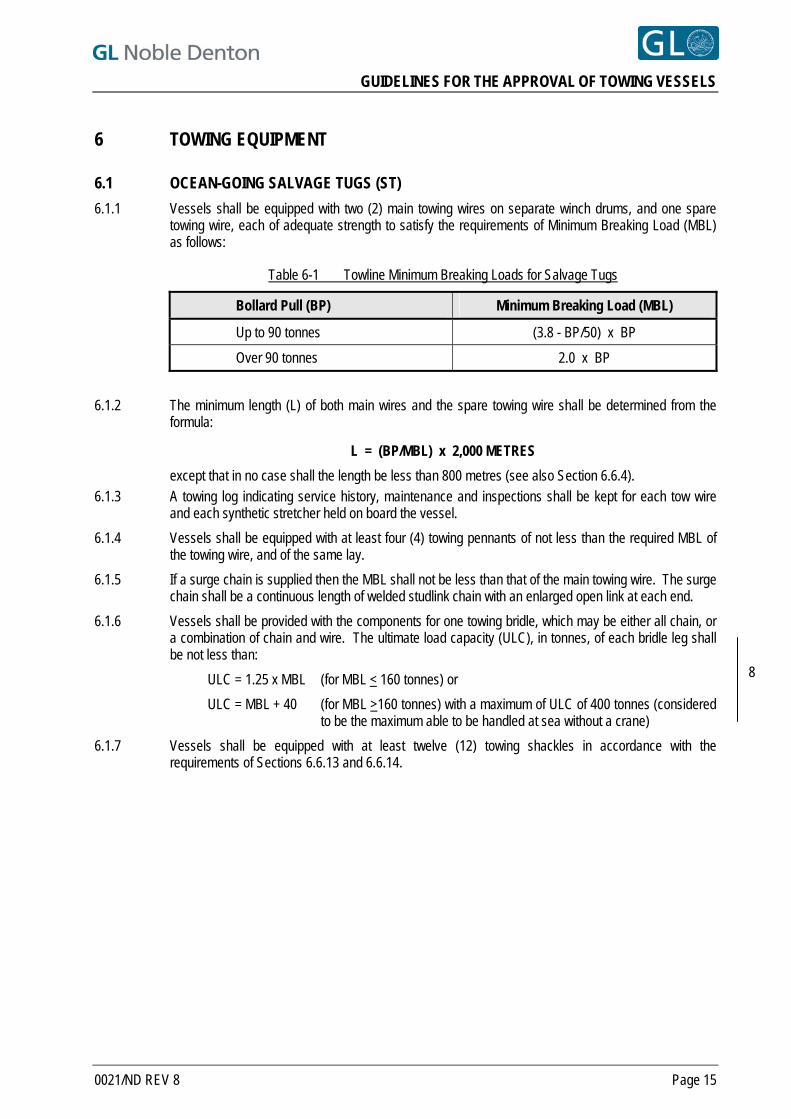
GUIDELINES FOR THE APPROVAL OF TOWING VESSELS
6 TOWING EQUIPMENT
6.1 OCEAN-GOING SALVAGE TUGS (ST)
6.1.1 Vessels shall be equipped with two (2) main towing wires on separate winch drums, and one spare towing wire, each of adequate strength to satisfy the requirements of Minimum Breaking Load (MBL) as follows:
Table 6-1 Towline Minimum Breaking Loads for Salvage Tugs
Bollard Pull (BP) Minimum Breaking Load (MBL)
Up to 90 tonnes (3.8 - BP/50) x BP
Over 90 tonnes 2.0 x BP
6.1.2 The minimum length (L) of both main wires and the spare towing wire shall be determined from the
formula:
L = (BP/MBL) x 2,000 METRES
except that in no case shall the length be less than 800 metres (see also Section 6.6.4). 6.1.3 A towing log indicating service history, maintenance and inspections shall be kept for each tow wire
and each synthetic stretcher held on board the vessel.
6.1.4 Vessels shall be equipped with at least four (4) towing pennants of not less than the required MBL of the towing wire, and of the same lay.
6.1.5 If a surge chain is supplied then the MBL shall not be less than that of the main towing wire. The surge chain shall be a continuous length of welded studlink chain with an enlarged open link at each end.
6.1.6 Vessels shall be provided with the components for one towing bridle, which may be either all chain, or a combination of chain and wire. The ultimate load capacity (ULC), in tonnes, of each bridle leg shall be not less than:
ULC = 1.25 x MBL (for MBL < 160 tonnes) or
ULC = MBL + 40 (for MBL >160 tonnes) with a maximum of ULC of 400 tonnes (considered to be the maximum able to be handled at sea without a crane)
8
6.1.7 Vessels shall be equipped with at least twelve (12) towing shackles in accordance with the requirements of Sections 6.6.13 and 6.6.14.
0021/ND REV 8 Page 15
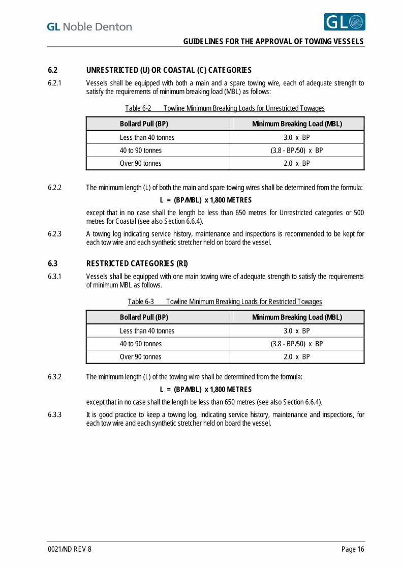
GUIDELINES FOR THE APPROVAL OF TOWING VESSELS
6.2 UNRESTRICTED (U) OR COASTAL (C) CATEGORIES
6.2.1 Vessels shall be equipped with both a main and a spare towing wire, each of adequate strength to satisfy the requirements of minimum breaking load (MBL) as follows:
Table 6-2 Towline Minimum Breaking Loads for Unrestricted Towages
Bollard Pull (BP) Minimum Breaking Load (MBL)
Less than 40 tonnes 3.0 x BP
40 to 90 tonnes (3.8 - BP/50) x BP
Over 90 tonnes 2.0 x BP
6.2.2 The minimum length (L) of both the main and spare towing wires shall be determined from the formula:
L = (BP/MBL) x 1,800 METRES
except that in no case shall the length be less than 650 metres for Unrestricted categories or 500 metres for Coastal (see also Section 6.6.4).
6.2.3 A towing log indicating service history, maintenance and inspections is recommended to be kept for each tow wire and each synthetic stretcher held on board the vessel.
6.3 RESTRICTED CATEGORIES (RI)
6.3.1 Vessels shall be equipped with one main towing wire of adequate strength to satisfy the requirements of minimum MBL as follows.
Table 6-3 Towline Minimum Breaking Loads for Restricted Towages
Bollard Pull (BP) Minimum Breaking Load (MBL)
Less than 40 tonnes 3.0 x BP
40 to 90 tonnes (3.8 - BP/50) x BP
Over 90 tonnes 2.0 x BP
6.3.2 The minimum length (L) of the towing wire shall be determined from the formula:
L = (BP/MBL) x 1,800 METRES
except that in no case shall the length be less than 650 metres (see also Section 6.6.4).
6.3.3 It is good practice to keep a towing log, indicating service history, maintenance and inspections, for each tow wire and each synthetic stretcher held on board the vessel.
0021/ND REV 8 Page 16
GUIDELINES FOR THE APPROVAL OF TOWING VESSELS
6.4 BENIGN AREA CATEGORIES (R2)
6.4.1 Vessels shall be equipped with both a main and spare towing wire each of adequate strength to satisfy the requirements of Minimum BL as follows:
MBL = 2.0 x BP
6.4.2 The minimum length (L) of both the main and spare towing wires shall be determined from the formula:
L = (BP/MBL) x 1,200 METRES
except that in no case shall the length be less than 500 metres (see also Section 6.6.4).
6.5 RESTRICTED BENIGN AREA CATEGORIES (R3)
6.5.1 Vessels shall be equipped with a towing wire of adequate strength to satisfy the requirements of MBL as follows:
MBL = 2.0 x BP 6.5.2 The minimum length (L) of the towing wire shall be determined from the formula:
L = (BP/MBL) x 1,200 METRES
except that in no case shall the length be less than 500 metres (see also Section 6.6.4).
6.6 ALL ENTERED VESSELS
6.6.1 All towing wires shall have hard eyes formed by a heavy-duty gusseted thimble, “pee-wee” or a closed spelter socket fitted at the outer end.
6.6.2 The main towing wire(s) should be spooled onto the towing winch drum(s) using adequate tension. The end of the wire must be adequately secured to the winch drum.
6.6.3 Where a spare towing wire is carried, it shall be stowed on a winch drum, or reverse stowed on a reel. Where the spare wire is stowed on a reel, it shall be accessible even in heavy weather, and be in such a position as to ensure that transfer to the main towing drum can be achieved safely and efficiently.
6.6.4 Where a reduced towline length demands a higher Minimum Breaking Load (MBL) in order to satisfy the towline length formula, then this increased MBL shall be the required MBL when determining the strength of the other components in the towing arrangement.
6.6.5 Vessels shall be equipped with at least 2 (4 for category ST) towing pennants of not less than the required breaking load of the main towing wire.
6.6.6 Pennants shall be of the same lay as the towing wire.
6.6.7 Pennants shall have hard eyes formed by a heavy-duty gusseted thimble, “pee-wee” or a spelter socket at each end.
6.6.8 If a soft-eyed pennant is carried, then such pennant shall be additional to the other requirements of this Section.
6.6.9 The towing pennants shall have a length appropriate to their intended service. Typically these will be in the range of 10 to 50 metres long but at least 2 should be suitable for making up a towing bridle.
6.6.10 If synthetic stretchers are used, at least 2 shall be carried. For Benign Areas, one (1) synthetic stretcher may be acceptable.
0021/ND REV 8 Page 17
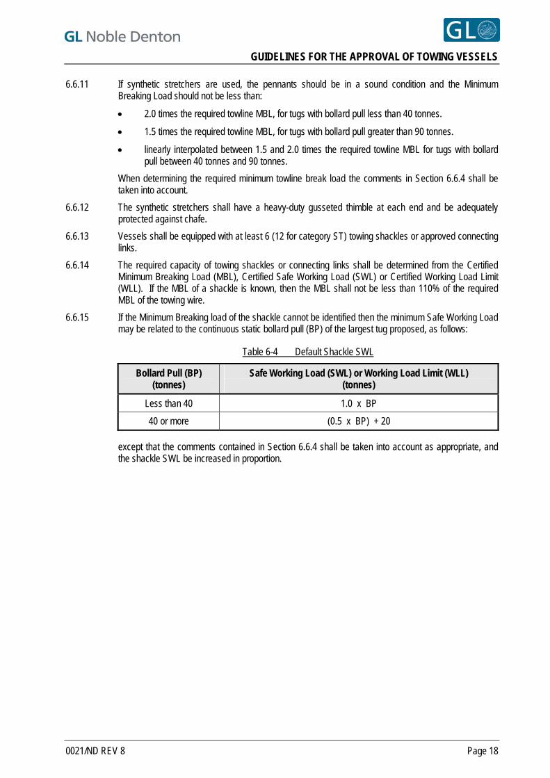
GUIDELINES FOR THE APPROVAL OF TOWING VESSELS
6.6.11 If synthetic stretchers are used, the pennants should be in a sound condition and the Minimum Breaking Load should not be less than:
2.0 times the required towline MBL, for tugs with bollard pull less than 40 tonnes.
1.5 times the required towline MBL, for tugs with bollard pull greater than 90 tonnes.
linearly interpolated between 1.5 and 2.0 times the required towline MBL for tugs with bollard pull between 40 tonnes and 90 tonnes.
When determining the required minimum towline break load the comments in Section 6.6.4 shall be taken into account.
6.6.12 The synthetic stretchers shall have a heavy-duty gusseted thimble at each end and be adequately protected against chafe.
6.6.13 Vessels shall be equipped with at least 6 (12 for category ST) towing shackles or approved connecting links.
6.6.14 The required capacity of towing shackles or connecting links shall be determined from the Certified Minimum Breaking Load (MBL), Certified Safe Working Load (SWL) or Certified Working Load Limit (WLL). If the MBL of a shackle is known, then the MBL shall not be less than 110% of the required MBL of the towing wire.
6.6.15 If the Minimum Breaking load of the shackle cannot be identified then the minimum Safe Working Load may be related to the continuous static bollard pull (BP) of the largest tug proposed, as follows:
Table 6-4 Default Shackle SWL
Bollard Pull (BP) (tonnes)
Safe Working Load (SWL) or Working Load Limit (WLL) (tonnes)
Less than 40 1.0 x BP
40 or more (0.5 x BP) + 20
except that the comments contained in Section 6.6.4 shall be taken into account as appropriate, and the shackle SWL be increased in proportion.
0021/ND REV 8 Page 18
GUIDELINES FOR THE APPROVAL OF TOWING VESSELS
7 TOWING WINCH 7.1 Vessels in all categories shall be provided with at least one towing winch, (two towing winch drums for
category ST).
7.2 The towing winch and its connection to the vessel shall be strong enough to withstand a force equal to the breaking load of the tow wire acting at its maximum height above deck, without over-stressing either the winch or the deck connections
7.3 If the power for the towing winch is supplied via a main engine shaft generator during normal operating conditions, then another generator shall be available to provide power for the towing winch in case of main engine or generator failure.
7.4 If a multi-drum winch is used, then each winch drum shall be capable of independent operation.
7.5 The towing winch drum(s) shall have sufficient capacity to stow the required minimum length of the tow wire(s).
7.6 A spooling device shall be provided such that the tow wire(s) is effectively spooled on to the winch drum(s).
7.7 The towing winch brake shall be capable of preventing the towing wire from paying out when the vessel is towing at its maximum continuous static bollard pull and shall not release automatically in case of a power failure.
7.8 The winch shall be fitted with a mechanism for emergency release of the tow wire.
7.9 There shall be an adequate means of communication between the winch control station(s) and the engine control station(s) and the bridge.
7.10 If there is only one towing winch then the crew must be able to demonstrate that a spare tow wire can be safely run onto the towing winch within 6 hours of a towline break in bad weather.
0021/ND REV 8 Page 19
GUIDELINES FOR THE APPROVAL OF TOWING VESSELS
8 TOWING WIRE PROTECTION AND CONTROL
8.1 PROTECTORS
8.1.1 Sufficient towing wire protectors shall be provided to prevent the towing wire from being damaged by abrasion and chafe against tow bars, cargo protection rails, bulwarks, stern rail, tail gate or stern roller.
8.1.2 If a “fixed” gogwire system or towing pod is used, then whenever possible, towing wire protectors should also be provided for the towing wire at the gogwire shackle or towing pod.
8.2 TOW BARS, CARGO PROTECTION RAIL, BULWARKS, STERN RAIL, TAILGATE AND STERN ROLLER
8.2.1 The top of the tow bars, cargo protection rail, bulwarks, stern rail, tail gate and stern roller shall be free of sharp edges, corners or obstructions which could damage the towing wire or prevent it from free lateral movement.
8.2.2 Where, during normal towing conditions, the towing wire bears on tow bars, cargo protection rail, bulwarks, stern rail or tailgate, the radius of bend shall be at least ten (10) times the diameter of the towing wire.
8.3 ADJUSTABLE GOGWIRE SYSTEM
8.3.1 Preference shall be given to the use of an adjustable gogwire system.
8.3.2 The winch or capstan used to adjust the gogwire system shall be controlled from a safe location.
8.4 FIXED GOGWIRE SYSTEM
8.4.1 If a single wire or single chain gogwire system is used, then the connection point on the aft deck shall be on the centreline of the vessel.
8.4.2 The length of the single wire or single chain of the gogwire system shall not exceed half the distance between the cargo protection rails or bulwarks, whichever is less.
8.4.3 Either a “wide body” sling shackle, having an enlarged bearing surface at the bow, or a purpose-designed sheave, shall be used to connect the gogwire system to the towing wire.
8.5 TOWING POD
8.5.1 The centre line of the towing pod shall be in line with the centre line of the towing wire winch drum.
8.5.2 The towing pod shall be well faired and have a bend radius of at least ten (10) times the diameter of the towing wire.
0021/ND REV 8 Page 20
GUIDELINES FOR THE APPROVAL OF TOWING VESSELS
9 STABILITY 9.1 The stability of the vessel shall never be less than that required by the ”Guidelines for the Design and
Construction of Offshore Supply Vessels” (Resolution A.469 [XII] adopted by the International Maritime Organisation 1981) and the Merchant Shipping (Load Line) Rules 1966, S.I. 1053.
9.2 In addition, if the vessel has an IACS class notation of "Tug" or “Towing Vessel” then the stability booklet should contain an example loading condition that fulfils the Classification Society's Notation. The vessel’s Master should show to the attending surveyor how the example loading condition relates to that for the voyage(s), including whether any roll reduction tanks may be in use.
9.3 If the example loading condition varies, the Master should prove adequate stability, including the arrival fuel loads. The relevant print out(s) from the onboard calculations (e.g.“Loadmaster”) should be given to the surveyor.
9.4 If the vessel cannot show that it satisfies an IACS class “Tug" or “Towing Vessel” notation as described above, then the heeling lever (defined below) must not exceed 0.5 times the maximum GZ for the most critical loading condition.
9.5 Heeling Lever = [0.6 x Max. Bollard Pull x Vertical Distance between Hawser and Centre of the Propeller(s)] /Displacement
9.6 The height of the hawser should be measured at:
the fixed gog, or the side rails if higher, if a fixed gog is always used, or
the top of the winch drum (with no towline deployed), or the side rails if higher, if a fixed gog is not always used.
9.7 If the maximum GZ occurs at an angle greater than 30 degrees of heel then the GZ value for 30 degrees of heel should be used instead of the angle of maximum GZ.
0021/ND REV 8 Page 21
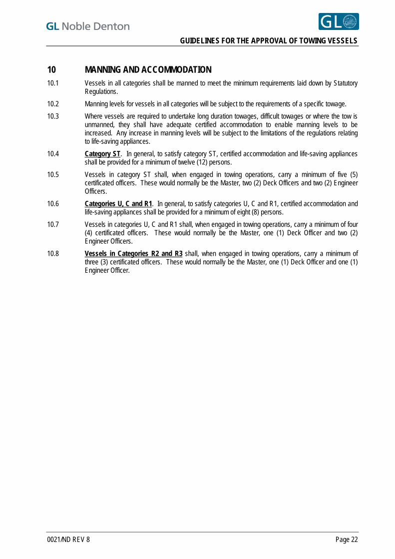
GUIDELINES FOR THE APPROVAL OF TOWING VESSELS
10 MANNING AND ACCOMMODATION 10.1 Vessels in all categories shall be manned to meet the minimum requirements laid down by Statutory
Regulations.
10.2 Manning levels for vessels in all categories will be subject to the requirements of a specific towage.
10.3 Where vessels are required to undertake long duration towages, difficult towages or where the tow is unmanned, they shall have adequate certified accommodation to enable manning levels to be increased. Any increase in manning levels will be subject to the limitations of the regulations relating to life-saving appliances.
10.4 Category ST. In general, to satisfy category ST, certified accommodation and life-saving appliances shall be provided for a minimum of twelve (12) persons.
10.5 Vessels in category ST shall, when engaged in towing operations, carry a minimum of five (5) certificated officers. These would normally be the Master, two (2) Deck Officers and two (2) Engineer Officers.
10.6 Categories U, C and R1. In general, to satisfy categories U, C and R1, certified accommodation and life-saving appliances shall be provided for a minimum of eight (8) persons.
10.7 Vessels in categories U, C and R1 shall, when engaged in towing operations, carry a minimum of four (4) certificated officers. These would normally be the Master, one (1) Deck Officer and two (2) Engineer Officers.
10.8 Vessels in Categories R2 and R3 shall, when engaged in towing operations, carry a minimum of three (3) certificated officers. These would normally be the Master, one (1) Deck Officer and one (1) Engineer Officer.
0021/ND REV 8 Page 22
GUIDELINES FOR THE APPROVAL OF TOWING VESSELS
11 SEAKEEPING 11.1 Vessels in all categories shall be of such a design to allow them to operate safely and effectively in
their designated areas.
11.2 Vessels in all categories must be purpose-built for towing operations or be of a multi-purpose design having towing capability.
11.3 Vessels must be assigned an appropriate Classification by a recognised Classification Society.
11.4 The length and normal operating draught of the vessel shall be adequate to maintain propeller effectiveness and reduce slamming in heavy weather conditions.
11.5 Vessels in category ST, U, C and R1 shall have a raised forecastle with a height of at least 2 metres above the freeboard deck. The forecastle shall be of such a design to ensure minimum water retention.
0021/ND REV 8 Page 23
GUIDELINES FOR THE APPROVAL OF TOWING VESSELS
12 ADDITIONAL EQUIPMENT FOR SALVAGE TUGS (ST) All vessels in category ST shall carry the following equipment:
12.1 Lifting Equipment
A deck crane or derrick with a minimum capacity of two (2) tonnes for transferring equipment.
12.2 Pumps
Portable salvage pumps with an ample supply of suitable hoses.
12.3 Generators
Portable generator or facilities and cabling to allow power to be distributed to the casualty /tow from the tug.
12.4 Air Compressor
Portable air compressor suitable for salvage purposes with ample supply of hoses or facility to allow compressed air to be distributed to the casualty /tow.
12.5 Welding/Cutting
Portable welding and cutting equipment with ample supply of extension cables, hoses and consumables.
12.6 Damage Control
Assorted steel plate, timber, canvas, cement, sand, tools, etc. for damage control purposes.
12.7 Spare Parts
A comprehensive inventory of spare parts should be carried, for the vessel to allow repairs to be carried out during long voyages.
0021/ND REV 8 Page 24

GUIDELINES FOR THE APPROVAL OF TOWING VESSELS
0021/ND REV 8 Page 25
REFERENCES [1] GL Noble Denton report 0030/ND - Guidelines for Marine Transportations
[2] International Maritime Organization (IMO), Guidelines for Safe Ocean Towing, Ref T1/3.02
All GL Noble Denton Guidelines can be downloaded from www.gl-nobledenton.com
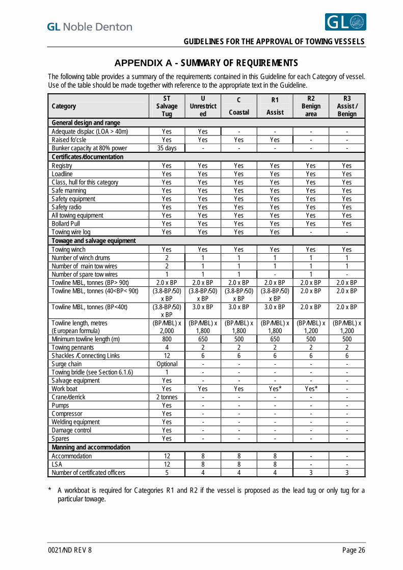
GUIDELINES FOR THE APPROVAL OF TOWING VESSELS
APPENDIX A - SUMMARY OF REQUIREMENTS The following table provides a summary of the requirements contained in this Guideline for each Category of vessel. Use of the table should be made together with reference to the appropriate text in the Guideline.
Category ST
Salvage Tug
U Unrestrict
ed
C
Coastal
R1
Assist
R2 Benign
area
R3 Assist / Benign
General design and range Adequate displac (LOA > 40m) Yes Yes - - - - Raised fo’csle Yes Yes Yes Yes - - Bunker capacity at 80% power 35 days - - - - - Certificates/documentation Registry Yes Yes Yes Yes Yes Yes Loadline Yes Yes Yes Yes Yes Yes Class, hull for this category Yes Yes Yes Yes Yes Yes Safe manning Yes Yes Yes Yes Yes Yes Safety equipment Yes Yes Yes Yes Yes Yes Safety radio Yes Yes Yes Yes Yes Yes All towing equipment Yes Yes Yes Yes Yes Yes Bollard Pull Yes Yes Yes Yes Yes Yes Towing wire log Yes Yes Yes Yes - - Towage and salvage equipment Towing winch Yes Yes Yes Yes Yes Yes Number of winch drums 2 1 1 1 1 1 Number of main tow wires 2 1 1 1 1 1 Number of spare tow wires 1 1 1 - 1 - Towline MBL, tonnes (BP> 90t) 2.0 x BP 2.0 x BP 2.0 x BP 2.0 x BP 2.0 x BP 2.0 x BP Towline MBL, tonnes (40<BP< 90t) (3.8-BP/50)
x BP (3.8-BP/50)
x BP (3.8-BP/50)
x BP (3.8-BP/50)
x BP 2.0 x BP 2.0 x BP
Towline MBL, tonnes (BP<40t) (3.8-BP/50) x BP
3.0 x BP 3.0 x BP 3.0 x BP 2.0 x BP 2.0 x BP
Towline length, metres (European formula)
(BP/MBL) x 2,000
(BP/MBL) x 1,800
(BP/MBL) x 1,800
(BP/MBL) x 1,800
(BP/MBL) x 1,200
(BP/MBL) x 1,200
Minimum towline length (m) 800 650 500 650 500 500 Towing pennants 4 2 2 2 2 2 Shackles /Connecting Links 12 6 6 6 6 6 Surge chain Optional - - - - - Towing bridle (see Section 6.1.6) 1 - - - - - Salvage equipment Yes - - - - - Work boat Yes Yes Yes Yes* Yes* - Crane/derrick 2 tonnes - - - - - Pumps Yes - - - - - Compressor Yes - - - - - Welding equipment Yes - - - - - Damage control Yes - - - - - Spares Yes - - - - - Manning and accommodation Accommodation 12 8 8 8 - - LSA 12 8 8 8 - - Number of certificated officers 5 4 4 4 3 3
* A workboat is required for Categories R1 and R2 if the vessel is proposed as the lead tug or only tug for a
particular towage.
0021/ND REV 8 Page 26
GUIDELINES FOR THE APPROVAL OF TOWING VESSELS
APPENDIX B - BOLLARD PULL TESTS
B.1 GENERAL
B.1.1 The following guidance notes apply to the bollard pull test of any towing vessel which GL Noble Denton is requested to approve or attend.
B.1.2 The safe working load of the test equipment, fittings and any connection points ashore shall be at least 10% in excess of the designed maximum continuous static bollard pull of the vessel.
B.2 LOCATION
B.2.1 The water depth at the test location shall be at least 20 metres within a radius of 100 metres of the vessel.
B.2.2 If a water depth of 20 metres cannot be obtained at the test location, then a minimum water depth which is equal to twice the maximum draught of the vessel may be accepted. The owner of the vessel must be advised that the reduced water depth may adversely affect the test results.
B.2.3 The test location shall be clear of navigational hazards and underwater obstructions within a radius of 300 metres of the vessel.
B.2.4 The current shall be less than 0.5 metres/second from any direction.
B.2.5 The wind speed shall be less than 5 metres/second from any direction.
B.2.6 The condition of the sea at the test location shall be calm, without swell or waves.
B.3 VESSEL
B.3.1 The draught and trim of the vessel shall be as near as possible to the draught and trim under normal operating conditions.
B.3.2 The propellers and fuel used during the tests shall be the same as the propellers and fuel used under normal operating conditions.
B.3.3 All auxiliary equipment such as pumps, generators and other equipment which are driven from the main engine(s) or propeller shaft(s) during normal operation of the vessel shall be connected during the test.
B.4 TEST
B.4.1 The distance between the stern of the vessel and the shore shall be at least 300 metres.
B.4.2 If it is not possible to maintain a distance of 300 metres between the stern of the vessel and the shore, then a minimum distance which is equal to twice the waterline length of the vessel may be accepted. The owner of the vessel must be advised that the reduced distance between the vessel’s stern and the shore may adversely affect the test results.
B.4.3 Adequate communications shall be established between the vessel and instrument recording station.
0021/ND REV 8 Page 27
GUIDELINES FOR THE APPROVAL OF TOWING VESSELS
B.4.4 The Continuous Bollard Pull (CBP) test shall be carried out at the manufacturer’s recommended maximum continuous rating of the main engines (100% MCR), for a period of 10 minutes (see IMO requirements in Ref [2]) with the vessel on a steady heading.
8
B.4.5 Whenever possible a maximum (MBP) test shall be carried out at the manufacturer’s maximum rating of the main engines (typically 110% MCR), for a period of 5 minutes.
B.4.6 When requested, continuous bollard pull may also be verified at different RPM and/or propeller pitch settings or with fewer propellers or engines in use.
B.4.7 The load cell used for measuring the bollard pull shall have an accuracy of 2% for the average temperature observed during the test and shall have been calibrated not more than six (6) months prior to the test date. The calibration certificate shall be available.
B.4.8 An autographic recording instrument giving a continuous read-out of the bollard pull shall be connected to the load cell.
B.4.9 If no continuous record of the test is printed, then the bollard pull shall be the mean of consecutive readings recorded at 20 second intervals over the test period.
B.5 BOLLARD PULL TESTS ACCEPTANCE
B.5.1 Bollard pull test certificates issued by Classification Societies are acceptable, or by another recognised body provided that acceptable procedures for the tests are produced.
0021/ND REV 8 Page 28
GUIDELINES FOR THE APPROVAL OF TOWING VESSELS
APPENDIX C - TOWING EQUIPMENT TESTS
C.1 GENERAL
C.1.1 The following guidance notes apply to the towing equipment tests of any vessel which GL Noble Denton is requested to approve or attend.
C.1.2 Before carrying out any tests, it shall be ascertained that the equipment to be tested has been installed according to the manufacturer’s recommendations and can be operated safely.
C.1.3 The wire used during the winch tests shall be equal to the towing wire in breaking load, diameter and construction and shall be spooled onto the towing winch drum with a tension of 25% of the vessel’s CBP or 40 tonnes, whichever is less.
C.1.4 During stalling, brake and quick release tests, the wire shall be kept as near as possible to the centre line of the vessel.
C.1.5 The safe working load of the test equipment, fittings and any connection points ashore shall be at least ten (10) percent in excess of the designed maximum static bollard pull of the vessel.
C.2 WINCH TESTS
C.2.1 Stalling Test
First Test: To be carried out with a full drum.
Second Test: To be carried out with an effective drum diameter which is estimated to stall the winch at CBP.
The winch shall be heaving in wire while the engine revolution or propeller pitch is gradually increased.
When the winch stalls, the following shall be recorded: a. Bollard Pull
b. Effective Drum Diameter
C.2.2 Brake Test
The test shall be carried out with a full drum of wire.
A wire of approximately 300 metres shall be connected to the winch wire if required.
The brake shall be applied at maximum holding capacity.
The engine revolutions or propeller pitch shall be gradually increased until CBP is achieved.
The following shall be recorded: a. Bollard Pull
b. Brake Pressure
0021/ND REV 8 Page 29
GUIDELINES FOR THE APPROVAL OF TOWING VESSELS
0021/ND REV 8 Page 30
C.2.3 Quick Release Test
The quick release tests shall be carried out when the vessel is towing at approximately 30% of its CBP.
First Test: When heaving in the test wire.
Second Test: When the brake is engaged.
C.2.4 Spooling Gear Test (if fitted)
The spooling gear shall be engaged when tested.
The engine power or propeller pitch shall be gradually increased to CBP.
The test wire shall be at an angle of approximately 60° to the centreline, on each side of the vessel.
The duration of the test shall be not less than one (1) minute.
C.3 FIXED GOGWIRE SYSTEM, TOWING POD, LINE STOPS AND GUIDE PINS TESTS
C.3.1 The spooling gear, if fitted, shall be disengaged during the “fixed” gogwire system, towing pod, line stops and guide pin tests.
C.3.2 The engine power or propeller pitch shall be gradually increased to the CBP.
C.3.3 The test wire shall be at an angle of approximately 60° to the centreline, on each side of the vessel.
C.3.4 The duration of each test shall not be less than one (1) minute.
TECHNICAL POLICY BOARD
GUIDELINES FOR MARINE LIFTING OPERATIONS
0027/ND
Once downloaded this document becomes UNCONTROLLED.
Please check the website below for the current version.
31 Mar 10 9 GPB Technical Policy Board
23 Jun 09 8 GPB Technical Policy Board
15 Apr 09 7 GPB Technical Policy Board
19 Jan 09 6 GPB Technical Policy Board
17 Feb 06 5 RLJ Technical Policy Board
30 Nov 05 4 JR Technical Policy Board
15 Oct 02 3 JR Technical Policy Board
01 May 02 2 JR Technical Policy Board
11 Aug 93 1 JR Technical Policy Board
31 Oct 90 0 JR Technical Policy Board
DATE REVISION PREPARED AUTHORISED BY
www.gl-nobledenton.com
GUIDELINES FOR MARINE LIFTING OPERATIONS
PREFACE
This document has been drawn with care to address what are likely to be the main concerns based on the experience of the GL Noble Denton organisation. This should not, however, be taken to mean that this document deals comprehensively with all of the concerns which will need to be addressed or even, where a particular matter is addressed, that this document sets out the definitive view of the organisation for all situations. In using this document, it should be treated as giving guidelines for sound and prudent practice on which our advice should be based, but guidelines should be reviewed in each particular case by the responsible person in each project to ensure that the particular circumstances of that project are addressed in a way which is adequate and appropriate to ensure that the overall advice given is sound and comprehensive. Whilst great care and reasonable precaution has been taken in the preparation of this document to ensure that the content is correct and error free, no responsibility or liability can be accepted by GL Noble Denton for any damage or loss incurred resulting from the use of the information contained herein.
© 2010 Noble Denton Group Limited, who will allow: the document to be freely reproduced, the smallest extract to be a complete page including headers and footers but smaller extracts may be
reproduced in technical reports and papers, provided their origin is clearly referenced.
0027/ND REV 9 Page 2
GUIDELINES FOR MARINE LIFTING OPERATIONS
CONTENTS SECTION PAGE NO.
1 SUMMARY 5 2 INTRODUCTION 6 3 DEFINITIONS 9 4 THE APPROVAL PROCESS 13
4.1 GL NOBLE DENTON APPROVAL 13 4.2 CERTIFICATE OF APPROVAL 13 4.3 SCOPE OF WORK LEADING TO AN APPROVAL 14 4.4 APPROVAL OF MOORINGS 14 4.5 LIMITATION OF APPROVAL 15
5 LOAD AND SAFETY FACTORS 16 5.1 INTRODUCTION 16 5.2 WEIGHT CONTINGENCY FACTORS 18 5.3 HOOK LOADS 18 5.4 RIGGING GEOMETRY 18 5.5 LIFT POINT AND SLING LOADS 19 5.6 DYNAMIC AMPLIFICATION FACTORS 19 5.7 SKEW LOAD FACTOR (SKL) 20 5.8 2-HOOK LIFT FACTORS 21 5.9 LATERAL LIFT POINT LOAD 21 5.10 2-PART SLING FACTOR 21 5.11 TERMINATION EFFICIENCY FACTOR 22 5.12 BENDING EFFICIENCY FACTOR 22 5.13 SLING OR GROMMET SAFETY FACTORS 22 5.14 SHACKLE SAFETY FACTORS 23 5.15 GROMMETS 23 5.16 CONSEQUENCE FACTORS 23
6 THE CRANE AND CRANE VESSEL 24 6.1 HOOK LOAD 24 6.2 DOCUMENTATION 24
7 STRUCTURAL CALCULATIONS 25 7.1 LOAD CASES AND STRUCTURAL MODELLING 25 7.2 STRUCTURE 25 7.3 LIFT POINTS 25 7.4 SPREADER BARS OR FRAMES 25 7.5 ALLOWABLE STRESSES 25
8 LIFT POINT DESIGN 27 8.1 INTRODUCTION 27 8.2 SLING OVALISATION 27 8.3 PLATE ROLLING AND LOADING DIRECTION 27 8.4 PIN HOLES 27 8.5 CAST PADEARS AND WELDED TRUNNIONS 27 8.6 NON-DESTRUCTIVE TESTING 27 8.7 CHEEK PLATES 28
9 CLEARANCES 29 9.1 INTRODUCTION 29 9.2 CLEARANCES AROUND LIFTED OBJECT 29 9.3 CLEARANCES AROUND CRANE VESSEL 29 9.4 CLEARANCES AROUND MOORING LINES AND ANCHORS 30
0027/ND REV 9 Page 3
GUIDELINES FOR MARINE LIFTING OPERATIONS
10 BUMPERS AND GUIDES 32 10.1 INTRODUCTION 32 10.2 MODULE MOVEMENT 32 10.3 POSITION OF BUMPERS AND GUIDES 32 10.4 BUMPER AND GUIDE FORCES 33 10.5 DESIGN CONSIDERATIONS 33
11 PRACTICAL CONSIDERATIONS 35 12 INFORMATION REQUIRED FOR APPROVAL 37
12.1 GENERAL INFORMATION REQUIRED 37 12.2 THE STRUCTURE TO BE LIFTED 37 12.3 INDEPENDENT ANALYSIS 37 12.4 CODES AND SPECIFICATIONS 38 12.5 EVIDENCE OF SATISFACTORY CONSTRUCTION 38 12.6 RIGGING ARRANGEMENTS 38 12.7 THE CRANE VESSEL 39 12.8 PROCEDURES AND MANAGEMENT 40 12.9 SURVEYS 41
REFERENCES 42
FIGURES Figure 5.1 Lift Calculation Flowchart 17 TABLES Table 5-1 In Air Dynamic Amplification Factors (DAF) 19 Table 5-2 Seastate Reduction Factor 20 Table 5-3 Bending Efficiency Factors 22 Table 5-4 Consequence Factors 23 Table 12-1 Typically Required Surveys 41
0027/ND REV 9 Page 4
GUIDELINES FOR MARINE LIFTING OPERATIONS
1 SUMMARY
1.1 These guidelines have been developed for the design and approval of marine lifting operations.
1.2 This document supersedes the previous revision, document No. 0027/NDI Rev 8 dated 23 Jun 09. The changes are described in Section 2.12. 9
1.3 These guidelines cover lifting operations by floating crane vessels, including crane barges, crane ships, semi-submersible crane vessels and jack-up crane vessels. They may also be applied to lifting operations by land-based cranes for the purpose of loadout. They are intended to lead to an approval by GL Noble Denton, which may be required where an operation is the subject of an insurance warranty, or where an independent third party review is required.
1.4 A description of the approval process is given for those projects which are the subject of an insurance warranty.
1.5 The report includes guidelines for the load and safety factors to be applied at the design stage.
1.6 Comments on the practical aspects of the management of the operation are also offered.
0027/ND REV 9 Page 5
GUIDELINES FOR MARINE LIFTING OPERATIONS
2 INTRODUCTION
2.1 This document provides guidelines on which the design and approval of marine lifting operations may be based.
2.2 It covers lifting operations by floating crane vessels, including crane barges, crane ships, semi-submersible crane vessels and jack-up crane vessels. It refers to lifting operations inshore and offshore. Reference is also made to lifting operations by land-based cranes for the purpose of loadout onto a barge or other transportation vessel.
2.3 The guidelines and calculation methods set out in this report represent the views of GL Noble Denton and are considered to be sound and in accordance with offshore industry practice. Operators should also consider national and local regulations, which may be more stringent.
2.4 The Report includes guidelines for the safety factors to be applied, comments on safe rigging practice and the information and documentation to be produced by others in order to obtain GL Noble Denton approval.
2.5 Revision 2 superseded and replaced the previous version, Revision 1, dated 11th August 1993. Principal changes in Revision 2 included:
Reference to the ISO Draft Standard on weight control
Reserves specified on weights as calculated or measured according to the ISO/DIS
Limitations of GL Noble Denton Approval clarified
Changes to the required clearances on pipelines and other subsea assets
Addition to a section on heave-compensated lifts
Addition of a section on lifts using Dynamic Positioning.
2.6 Revision 3 superseded and replaced Revision 2, and includes additional clarification on safety factors for shackles, and testing and certification requirements.
2.7 Revision 4 superseded and replaced Revision 3, and includes:
Changes to referenced documents (Sections 2.8 and References)
Some changes to definitions (Section 3)
Changes to Dynamic Amplification Factors, to eliminate discontinuities (Section 5.6)
Elimination of an anomaly in the definition of Hook Load (Section 5.3)
Inclusion of consideration of fibre slings (Sections 5.10, 5.15 and 12)
Elimination of an anomaly in the treatment of spreader bars and frames (Sections 5.16 and 7.4)
Modification of the flow chart (old Section 5.16)
Changes to the derivation of bumper and guide design forces (Section 10.3).
2.8 Revision 5 superseded and replaced Revision 4, and corrected typographical errors in Table 5-1.
0027/ND REV 9 Page 6
GUIDELINES FOR MARINE LIFTING OPERATIONS
2.9 Revision 6 superseded and replaces Revision 5, and made the following principal revisions, highlighted by a line in the right hand margin:
The Guideline refers as appropriate to other standards, including
- ISO International Standard ISO2408 - Steel wire ropes for General Purposes - Characteristics [Ref. 4]
- ISO International Standard ISO 7531 - Wire Rope slings for General Purposes - Characteristics and Specifications [Ref.5].
Definitions in Section 3 were generally revised and expanded.
Section 4.1.2 added for the Certificate of Approval
Section 5 was re-ordered, Figure 5.1 revised, DAF's expanded to include submerged lifts, guidelines for 1 crane-2 hook lifts added, yaw factor for inshore lifts deleted, use of alternative codes added, minimum sling angles included
Old Section 11 (Underwater Lifting) moved into Section 5.6.6
Section 5.6.8 added for inshore lifts made by jack-up crane vessels.
Section 5.6.9 expanded to include weather forecast levels.
Section 5.7.6 added: SKL for multi hook lifts.
Table 5-4: consequence factors revised.
Section 5.12.6 added: sling eye design.
Sections 6.1.5 and 8.7 added.
Old Section 12 (Heave compensated lifts) moved to Section 6.1.5
Section 8.5 expanded to include trunnions and sling retainers.
Clearances in Section 9.3 generally updated and expanded.
Dimensional control requirements added to 10.3 and design requirements in Section 10.5.4.
Sections 9.2.6 - 9.2.8 added: bumper and guide clearances and dropped objects.
Limitation on number of chained shackles and shackle orientation added in Section 11.11.
Section 12 updated, showing requirements for sling certificates, doubled sling restrictions and requirements for wire/sling type.
Old Section 13 (Lifts using DP) moved to Sections 12.7.1 and 12.8.9.
Sections 12.8.7 and 12.8.8 amended for in field environmental condition monitoring.
Section 12.8.10 added for risk assessments and HAZOPs
General text changes and revisions made.
2.10 Revision 7 superseded and replaced Revision 6. The changes are the removal of “by Floating Crane Vessels” in the document title and a correction in Section 5.14.1.
2.11 Revision 8 superseded and replaced Revision 7. The change is a correction in Section 5.12.5.
0027/ND REV 9 Page 7
GUIDELINES FOR MARINE LIFTING OPERATIONS
2.12 This Revision 9 supersedes and replaces Revision 8. The changes are:
Definitions (Barge, IACS, Insurance Warranty, NDT, Survey, Vessel, Surveyor, Weather Restricted Operation, and Weather Un-restricted Operations) in Section 3 revised.
Text modified in Section 4.1.4.
Weather forecast needs modified in Section 4.4.1.
Weight and CoG factor for piles added in Section 5.2.6.
CoG factor included for lifts not using a CoG envelope in Section 5.5.3.
DAF for lifts 100t to 1000t revised in Table 5-1.
Text added in Section 5.7.7 for 4 unequal slings in a single hook lift.
Factor for fibre rope sling splices included in Section 5.11.1. 9
Radius changed to diameter in Section 5.12.5.
Shackle MBL used instead of sling MBL in Section 5.14.2
Text amended in Sections 6.1.4, 8.4.1 and 11.7.h.
Clause added for tuggers attached to lift points in Section 7.3.3.
Clearances clarified in Sections 8.7.2 , 9.2.1.
Bumper force increased in Section 10.4.1.d.
Secondary bumper and guide forces added in Section 10.4.4.
Set down loads added in Section 10.4.3.
IACS member certification added in Sections 12.1.1 and 12.6.1.
Sling certificate validity added in Section 12.6.3.
Spreader bar/frame certification added in Sections 12.6.6 and 12.6.7.
Reference 6 added.
Mooring analysis requirements added to Sections 12.1.1 and 12.7.3 to 12.7.7.
Reference [7] added.
2.13 All GL Noble Denton Guidelines can be downloaded from www.gl-nobledenton.com.
0027/ND REV 9 Page 8
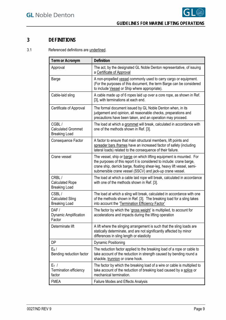
GUIDELINES FOR MARINE LIFTING OPERATIONS
3 DEFINITIONS
3.1 Referenced definitions are underlined.
Term or Acronym Definition
Approval The act, by the designated GL Noble Denton representative, of issuing a Certificate of Approval
Barge A non-propelled vessel commonly used to carry cargo or equipment. (For the purposes of this document, the term Barge can be considered to include Vessel or Ship where appropriate).
Cable-laid sling
A cable made up of 6 ropes laid up over a core rope, as shown in Ref. [3], with terminations at each end.
Certificate of Approval The formal document issued by GL Noble Denton when, in its judgement and opinion, all reasonable checks, preparations and precautions have been taken, and an operation may proceed.
CGBL / Calculated Grommet Breaking Load
The load at which a grommet will break, calculated in accordance with one of the methods shown in Ref. [3].
Consequence Factor A factor to ensure that main structural members, lift points and spreader bars /frames have an increased factor of safety (including lateral loads) related to the consequence of their failure.
Crane vessel The vessel, ship or barge on which lifting equipment is mounted. For the purposes of this report it is considered to include: crane barge, crane ship, derrick barge, floating shear-leg, heavy lift vessel, semi-submersible crane vessel (SSCV) and jack-up crane vessel.
CRBL / Calculated Rope Breaking Load
The load at which a cable laid rope will break, calculated in accordance with one of the methods shown in Ref. [3].
CSBL / Calculated Sling Breaking Load
The load at which a sling will break, calculated in accordance with one of the methods shown in Ref. [3]. The breaking load for a sling takes into account the ‘Termination Efficiency Factor’
DAF / Dynamic Amplification Factor
The factor by which the ‘gross weight’ is multiplied, to account for accelerations and impacts during the lifting operation
Determinate lift
A lift where the slinging arrangement is such that the sling loads are statically determinate, and are not significantly affected by minor differences in sling length or elasticity
DP Dynamic Positioning
EB / Bending reduction factor
The reduction factor applied to the breaking load of a rope or cable to take account of the reduction in strength caused by bending round a shackle, trunnion or crane hook.
ET / Termination efficiency factor
The factor by which the breaking load of a wire or cable is multiplied to take account of the reduction of breaking load caused by a splice or mechanical termination.
FMEA Failure Modes and Effects Analysis
0027/ND REV 9 Page 9
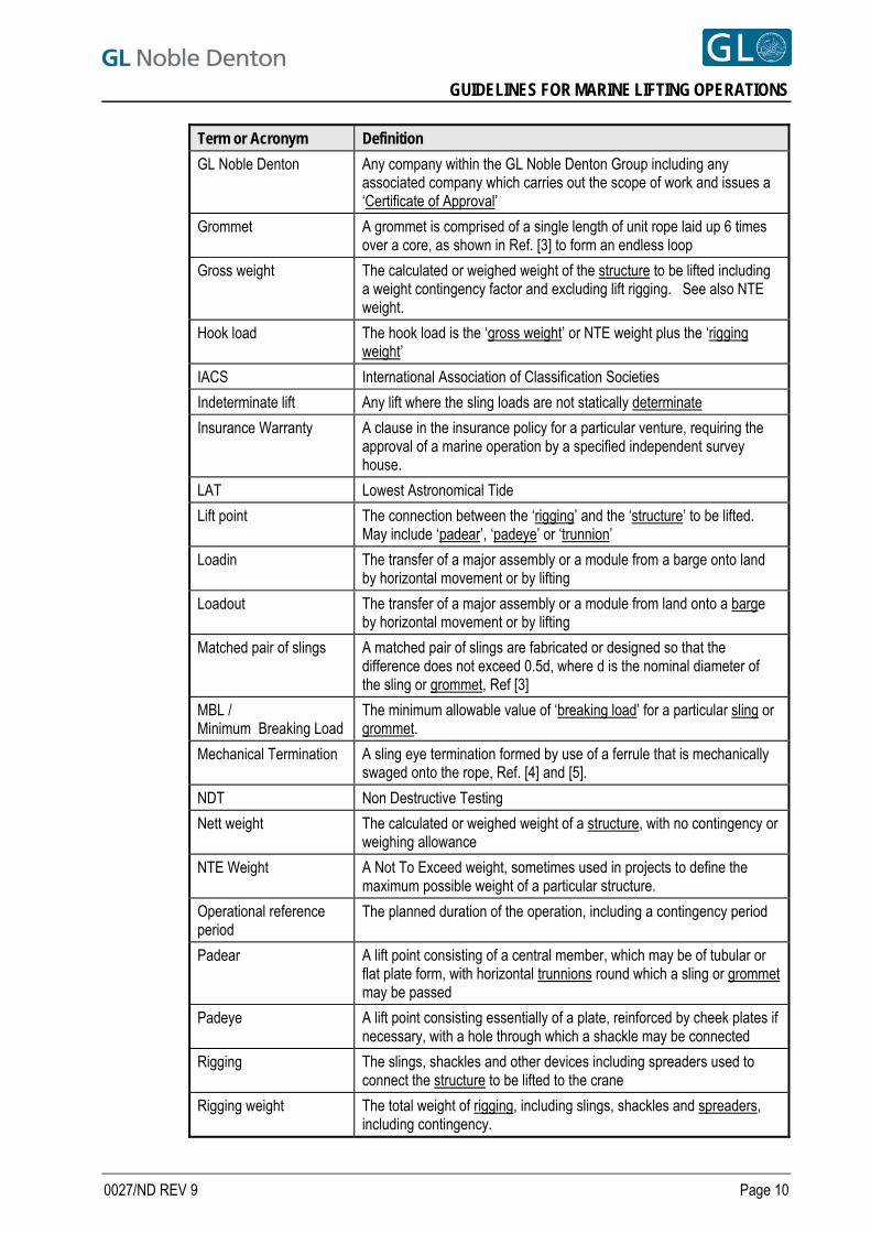
GUIDELINES FOR MARINE LIFTING OPERATIONS
0027/ND REV 9 Page 10
Term or Acronym Definition
GL Noble Denton Any company within the GL Noble Denton Group including any associated company which carries out the scope of work and issues a ‘Certificate of Approval’
Grommet A grommet is comprised of a single length of unit rope laid up 6 times over a core, as shown in Ref. [3] to form an endless loop
Gross weight The calculated or weighed weight of the structure to be lifted including a weight contingency factor and excluding lift rigging. See also NTE weight.
Hook load The hook load is the ‘gross weight’ or NTE weight plus the ‘rigging weight’
IACS International Association of Classification Societies
Indeterminate lift Any lift where the sling loads are not statically determinate
Insurance Warranty A clause in the insurance policy for a particular venture, requiring the approval of a marine operation by a specified independent survey house.
LAT Lowest Astronomical Tide
Lift point The connection between the ‘rigging’ and the ‘structure’ to be lifted. May include ‘padear’, ‘padeye’ or ‘trunnion’
Loadin The transfer of a major assembly or a module from a barge onto land by horizontal movement or by lifting
Loadout The transfer of a major assembly or a module from land onto a barge by horizontal movement or by lifting
Matched pair of slings A matched pair of slings are fabricated or designed so that the difference does not exceed 0.5d, where d is the nominal diameter of the sling or grommet, Ref [3]
MBL / Minimum Breaking Load
The minimum allowable value of ‘breaking load’ for a particular sling or grommet.
Mechanical Termination A sling eye termination formed by use of a ferrule that is mechanically swaged onto the rope, Ref. [4] and [5].
NDT Non Destructive Testing
Nett weight The calculated or weighed weight of a structure, with no contingency or weighing allowance
NTE Weight A Not To Exceed weight, sometimes used in projects to define the maximum possible weight of a particular structure.
Operational reference period
The planned duration of the operation, including a contingency period
Padear A lift point consisting of a central member, which may be of tubular or flat plate form, with horizontal trunnions round which a sling or grommet may be passed
Padeye A lift point consisting essentially of a plate, reinforced by cheek plates if necessary, with a hole through which a shackle may be connected
Rigging The slings, shackles and other devices including spreaders used to connect the structure to be lifted to the crane
Rigging weight The total weight of rigging, including slings, shackles and spreaders, including contingency.
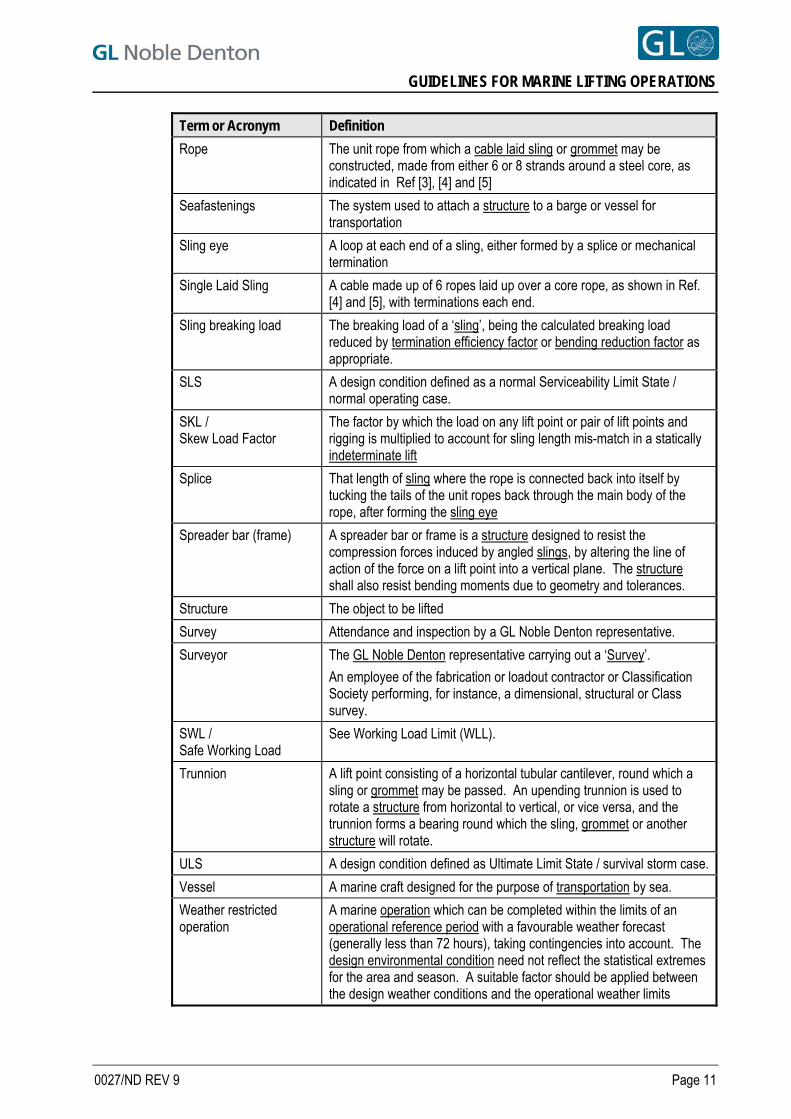
GUIDELINES FOR MARINE LIFTING OPERATIONS
0027/ND REV 9 Page 11
Term or Acronym Definition
Rope The unit rope from which a cable laid sling or grommet may be constructed, made from either 6 or 8 strands around a steel core, as indicated in Ref [3], [4] and [5]
Seafastenings The system used to attach a structure to a barge or vessel for transportation
Sling eye A loop at each end of a sling, either formed by a splice or mechanical termination
Single Laid Sling A cable made up of 6 ropes laid up over a core rope, as shown in Ref. [4] and [5], with terminations each end.
Sling breaking load The breaking load of a ‘sling’, being the calculated breaking load reduced by termination efficiency factor or bending reduction factor as appropriate.
SLS A design condition defined as a normal Serviceability Limit State / normal operating case.
SKL / Skew Load Factor
The factor by which the load on any lift point or pair of lift points and rigging is multiplied to account for sling length mis-match in a statically indeterminate lift
Splice That length of sling where the rope is connected back into itself by tucking the tails of the unit ropes back through the main body of the rope, after forming the sling eye
Spreader bar (frame) A spreader bar or frame is a structure designed to resist the compression forces induced by angled slings, by altering the line of action of the force on a lift point into a vertical plane. The structure shall also resist bending moments due to geometry and tolerances.
Structure The object to be lifted
Survey Attendance and inspection by a GL Noble Denton representative.
Surveyor The GL Noble Denton representative carrying out a ‘Survey’.
An employee of the fabrication or loadout contractor or Classification Society performing, for instance, a dimensional, structural or Class survey.
SWL / Safe Working Load
See Working Load Limit (WLL).
Trunnion A lift point consisting of a horizontal tubular cantilever, round which a sling or grommet may be passed. An upending trunnion is used to rotate a structure from horizontal to vertical, or vice versa, and the trunnion forms a bearing round which the sling, grommet or another structure will rotate.
ULS A design condition defined as Ultimate Limit State / survival storm case.
Vessel A marine craft designed for the purpose of transportation by sea.
Weather restricted operation
A marine operation which can be completed within the limits of an operational reference period with a favourable weather forecast (generally less than 72 hours), taking contingencies into account. The design environmental condition need not reflect the statistical extremes for the area and season. A suitable factor should be applied between the design weather conditions and the operational weather limits
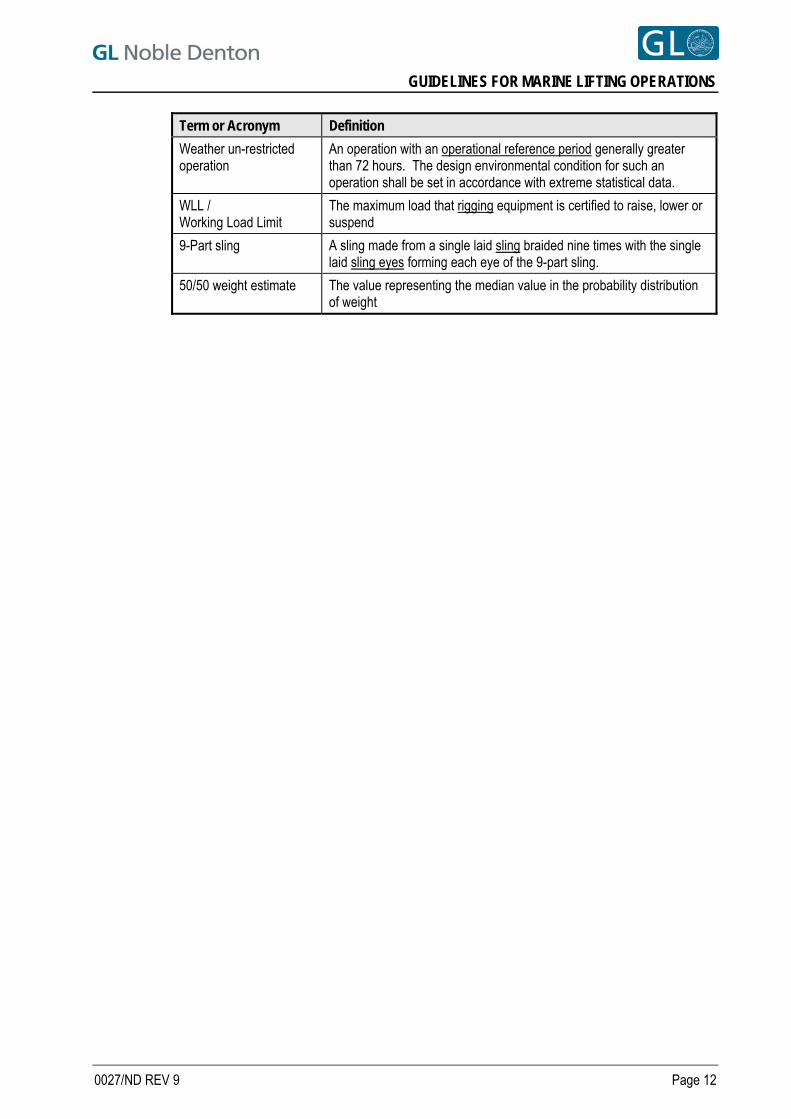
GUIDELINES FOR MARINE LIFTING OPERATIONS
0027/ND REV 9 Page 12
Term or Acronym Definition
Weather un-restricted operation
An operation with an operational reference period generally greater than 72 hours. The design environmental condition for such an operation shall be set in accordance with extreme statistical data.
WLL / Working Load Limit
The maximum load that rigging equipment is certified to raise, lower or suspend
9-Part sling A sling made from a single laid sling braided nine times with the single laid sling eyes forming each eye of the 9-part sling.
50/50 weight estimate The value representing the median value in the probability distribution of weight
GUIDELINES FOR MARINE LIFTING OPERATIONS
4 THE APPROVAL PROCESS
4.1 GL NOBLE DENTON APPROVAL
4.1.1 GL Noble Denton approval may be sought where the lift forms part of a marine operation covered by an insurance warranty, or where an independent third party review is required.
4.1.2 The Certificate of Approval is the formal document issued by GL Noble Denton when, in its judgement and opinion, all reasonable checks, preparations and precautions have been taken, and an operation may proceed.
4.1.3 An Insurance Warranty is a clause in the insurance policy for a particular venture, requiring the approval of a marine operation by a specified independent surveyor. The requirement is normally satisfied by the issue of a Certificate of Approval. Responsibility for interpreting the terms of the Warranty so that an appropriate scope of work can be defined rests with the client.
4.1.4 Approval may be given for such operations as:
Installation of liftable jackets
Hook-assisted installation of launched or lifted jackets
Installation of templates and other sub-sea equipment
Handling of piles
Installation of decks, topsides modules, bridges and flare towers/booms
Loadouts and Loadins. 9
Transfer of items between a transport barge and the deck of a crane vessel.
4.1.5 Lifts may be by a variety of crane configurations, including single cranes, two cranes on a single vessel, two or more cranes on separate vessels, single crane multi-hook sheerleg vessels, cranes mounted on jack-up vessels, or by one or more land based cranes.
4.1.6 GL Noble Denton approval may be given for the operation, including reviews of marine and engineering calculations and procedures, and consideration of:
The actual and forecast weather conditions
The suitability and readiness of all equipment
The behaviour of the lifting vessel
Any site changes in procedures
The general conduct of the preparations for the operation.
4.2 CERTIFICATE OF APPROVAL
4.2.1 The deliverable of the approval process will generally be a Certificate of Approval. This will be issued on site, immediately prior to the lift taking place.
4.2.2 For an offshore lift, the Certificate will normally be issued after lift rigging and tuggers have been connected / inspected and prior to cutting the seafastenings on the transport barge or vessel. Consideration shall be given where a partial seafastening removal is proposed to be carried out in parallel with rigging up operations. The lifting operation will be deemed to have commenced when seafastening cutting starts. The lift will be deemed to be completed when the load is landed in its final position, and the crane(s) has been disconnected.
4.2.3 The Certificate confirming adequate preparation for an operation will normally be issued immediately prior to the start of the operation, by the attending surveyor.
0027/ND REV 9 Page 13
GUIDELINES FOR MARINE LIFTING OPERATIONS
4.3 SCOPE OF WORK LEADING TO AN APPROVAL
4.3.1 In order to issue a Certificate of Approval, GL Noble Denton will require to consider the following topics:
The strength of the structure to be lifted, including the strength of the lift points.
The capacity of the crane, taking into account the radius at which the lift will take place, whether the crane will be fixed or revolving and whether any down-rating is required for operations in a specified design and operational seastate.
The capacity of the crane in the event that multiple hooks are used to suspend /upend a load.
The rigging arrangement, including slings, shackles and any spreader frames or beams, and the certification of the rigging components.
The mooring arrangements for the crane vessel, as outlined in Section 4.4.
The limiting weather conditions proposed, and the anticipated behaviour of the crane vessel in those conditions.
The arrangements for handling and mooring the transport barge or vessel alongside the crane vessel.
The arrangements for cutting seafastenings prior to lifting.
The management structure for the operations and Management of Change procedures.
Risk assessments, HAZOP /HAZID studies carried out by Contractor involving all parties.
Simultaneous Marine Operations (SIMOPS).
4.3.2 The information required in order to issue a Certificate of Approval is discussed in more detail in Section 12.
4.4 APPROVAL OF MOORINGS
4.4.1 A lift may normally be considered a weather restricted operation. Limiting weather conditions for the lift operation shall be defined, taking into account:
9 the weather forecast reliability and frequency for the area
the duration of the operation, including a suitability contingency period
the exposure of the site
the time required for any operations before or after the lift operation, including crane vessel and transport barge movements.
currents on the lifting vessel/transport barge during the lift.
currents on the lifted structure during lowering through the water column.
0027/ND REV 9 Page 14
GUIDELINES FOR MARINE LIFTING OPERATIONS
4.4.2 An approval of a lift will normally include the approval of the crane vessel and transport barge moorings in the limiting weather conditions specified for the lifting operation. When operating alongside an offshore installation, procedures should be submitted which show that the crane vessel and transport barge can and will be removed to a safe distance when the weather conditions exceed a specified level. An approval of a lift does not include approval of the vessel moorings in extreme weather conditions).
4.4.3 Similarly, an approval of a lifted loadout will include the approval of the crane vessel and transport barge moorings at the loadout quay in the limiting weather conditions specified for loadout. It does not necessarily include approval of either moorings in extreme weather conditions. Note that for approval of loadouts, reference should also be made to GL Noble Denton Report 0013/ND - Guidelines for Loadouts Ref. [1].
4.4.4 Additionally, and if specifically requested, GL Noble Denton will study and issue an approval of the moorings of the crane vessel or the transport barge, for a more extended period.
4.5 LIMITATION OF APPROVAL
4.5.1 A Certificate of Approval is issued for a particular lift only. 4.5.2 A Certificate of Approval is issued based on external conditions observed by the attending surveyor of
hull(s) machinery and equipment, without removal, exposure or testing of parts. 4.5.3 A Certificate of Approval for a lift covers the marine operations involved in the lift only. A lift is normally
deemed to start offshore when cutting of seafastenings starts, and after the crane is connected and slings tensioned. It is normally deemed to be completed when the lifted object is set down in its intended position. For completion of lifted loadouts see Ref. [1].
4.5.4 Unless specifically included, a Certificate of Approval for a lift excludes moorings of the crane vessel and transport barge outside the period of the immediate lift, as defined in Section 4.4.2.
4.5.5 Any alterations to the surveyed items or agreed procedures after issue of the Certificate of Approval may render the Certificate invalid unless the changes are approved in writing by GL Noble Denton.
0027/ND REV 9 Page 15
GUIDELINES FOR MARINE LIFTING OPERATIONS
5 LOAD AND SAFETY FACTORS
5.1 INTRODUCTION
5.1.1 For any lift, the calculations carried out shall include allowances, safety factors, loads and load effects as described in these guidelines.
5.1.2 The various factors and their application are illustrated in Figure 5.1. This flowchart is for guidance only, and is not intended to cover every case. In case of any conflict between the flowchart and the text, the text shall govern. Figures in parentheses relate to sections in these guidelines.
5.1.3 Use of other recognised offshore codes of practice relating to lift engineering can also be considered, but care should be taken since not all other codes are exhaustive in determining the actual behaviour of lifting systems.
0027/ND REV 9 Page 16
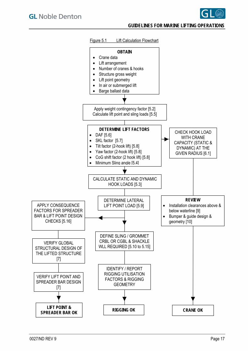
GUIDELINES FOR MARINE LIFTING OPERATIONS
Figure 5.1 Lift Calculation Flowchart
OBTAIN Crane data Lift arrangement Number of cranes & hooks Structure gross weight Lift point geometry In air or submerged lift Barge ballast data
RIGGING OK
CALCULATE STATIC AND DYNAMIC HOOK LOADS [5.3]
DEFINE SLING / GROMMET CRBL OR CGBL & SHACKLE WLL REQUIRED [5.10 to 5.15]
DETERMINE LATERAL LIFT POINT LOAD [5.9]
REVIEW Installation clearances above &
below waterline [9] Bumper & guide design &
geometry [10]
VERIFY LIFT POINT AND SPREADER BAR DESIGN
[7]
IDENTIFY / REPORT RIGGING UTILISATION FACTORS & RIGGING
GEOMETRY
VERIFY GLOBAL STRUCTURAL DESIGN OF THE LIFTED STRUCTURE
[7]
CHECK HOOK LOAD WITH CRANE
CAPACITY (STATIC & DYNAMIC) AT THE
GIVEN RADIUS [6.1]
APPLY CONSEQUENCE FACTORS FOR SPREADER BAR & LIFT POINT DESIGN
CHECKS [5.16]
DETERMINE LIFT FACTORS DAF [5.6] SKL factor [5.7] Tilt factor (2-hook lift) [5.8] Yaw factor (2-hook lift) [5.8] CoG shift factor (2 hook lift) [5.8] Minimum Sling angle [5.4]
Apply weight contingency factor [5.2] Calculate lift point and sling loads [5.5]
LIFT POINT & SPREADER BAR OK CRANE OK
0027/ND REV 9 Page 17
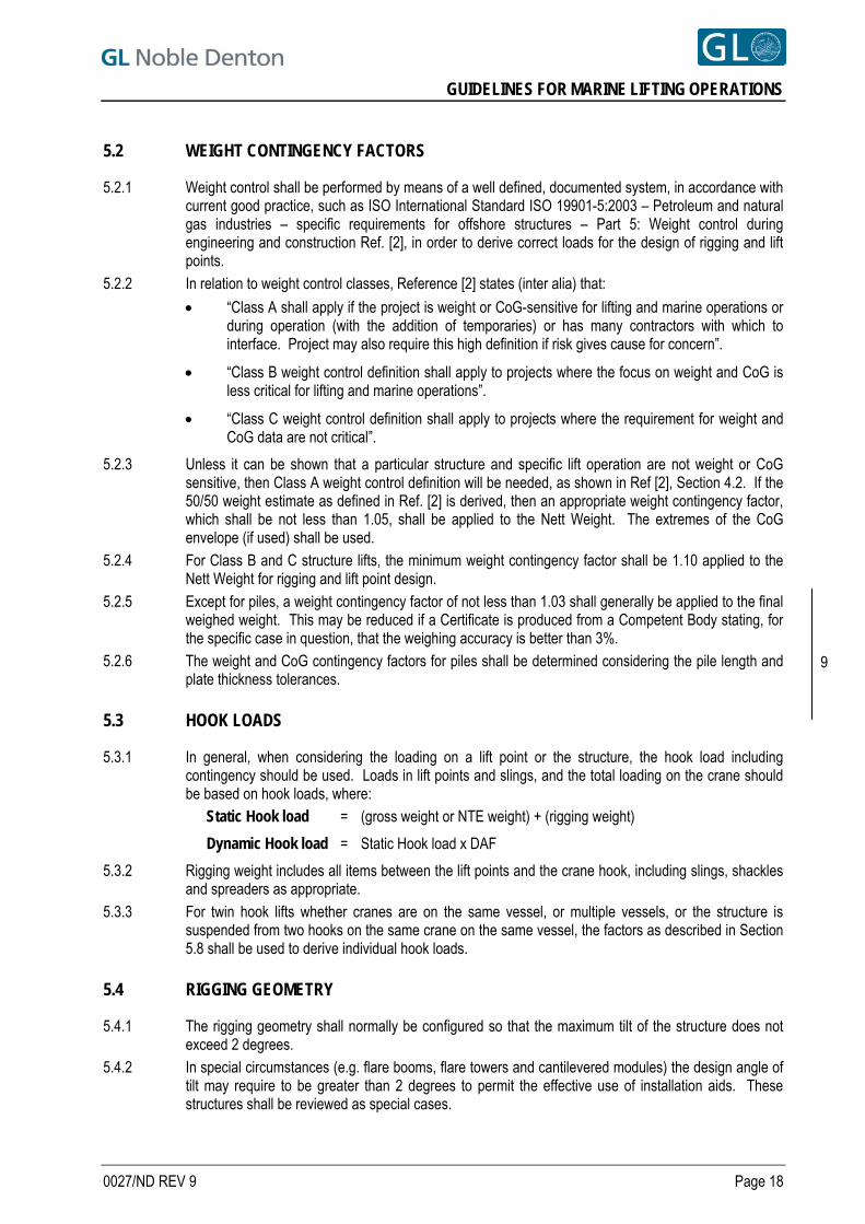
GUIDELINES FOR MARINE LIFTING OPERATIONS
5.2 WEIGHT CONTINGENCY FACTORS
5.2.1 Weight control shall be performed by means of a well defined, documented system, in accordance with current good practice, such as ISO International Standard ISO 19901-5:2003 – Petroleum and natural gas industries – specific requirements for offshore structures – Part 5: Weight control during engineering and construction Ref. [2], in order to derive correct loads for the design of rigging and lift points.
5.2.2 In relation to weight control classes, Reference [2] states (inter alia) that:
“Class A shall apply if the project is weight or CoG-sensitive for lifting and marine operations or during operation (with the addition of temporaries) or has many contractors with which to interface. Project may also require this high definition if risk gives cause for concern”.
“Class B weight control definition shall apply to projects where the focus on weight and CoG is less critical for lifting and marine operations”.
“Class C weight control definition shall apply to projects where the requirement for weight and CoG data are not critical”.
5.2.3 Unless it can be shown that a particular structure and specific lift operation are not weight or CoG sensitive, then Class A weight control definition will be needed, as shown in Ref [2], Section 4.2. If the 50/50 weight estimate as defined in Ref. [2] is derived, then an appropriate weight contingency factor, which shall be not less than 1.05, shall be applied to the Nett Weight. The extremes of the CoG envelope (if used) shall be used.
5.2.4 For Class B and C structure lifts, the minimum weight contingency factor shall be 1.10 applied to the Nett Weight for rigging and lift point design.
5.2.5 Except for piles, a weight contingency factor of not less than 1.03 shall generally be applied to the final weighed weight. This may be reduced if a Certificate is produced from a Competent Body stating, for the specific case in question, that the weighing accuracy is better than 3%.
5.2.6 The weight and CoG contingency factors for piles shall be determined considering the pile length and plate thickness tolerances.
9
5.3 HOOK LOADS
5.3.1 In general, when considering the loading on a lift point or the structure, the hook load including contingency should be used. Loads in lift points and slings, and the total loading on the crane should be based on hook loads, where:
Static Hook load = (gross weight or NTE weight) + (rigging weight)
Dynamic Hook load = Static Hook load x DAF
5.3.2 Rigging weight includes all items between the lift points and the crane hook, including slings, shackles and spreaders as appropriate.
5.3.3 For twin hook lifts whether cranes are on the same vessel, or multiple vessels, or the structure is suspended from two hooks on the same crane on the same vessel, the factors as described in Section 5.8 shall be used to derive individual hook loads.
5.4 RIGGING GEOMETRY
5.4.1 The rigging geometry shall normally be configured so that the maximum tilt of the structure does not exceed 2 degrees.
5.4.2 In special circumstances (e.g. flare booms, flare towers and cantilevered modules) the design angle of tilt may require to be greater than 2 degrees to permit the effective use of installation aids. These structures shall be reviewed as special cases.
0027/ND REV 9 Page 18
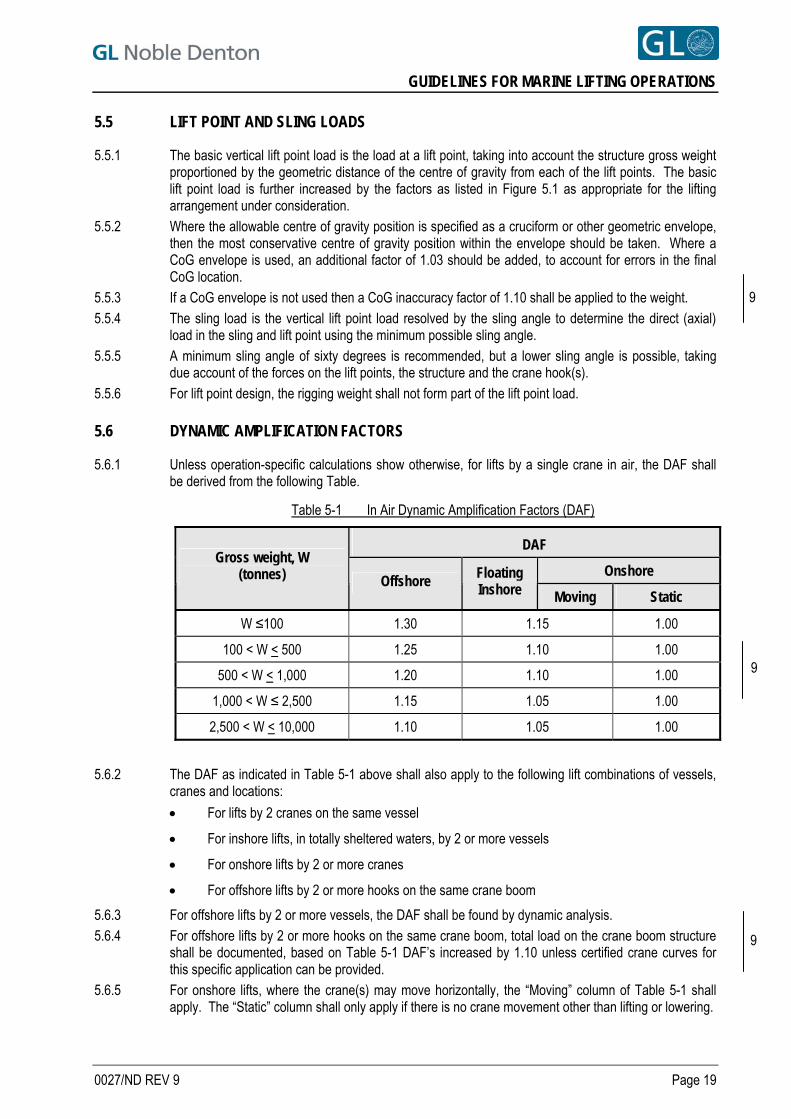
GUIDELINES FOR MARINE LIFTING OPERATIONS
5.5 LIFT POINT AND SLING LOADS
5.5.1 The basic vertical lift point load is the load at a lift point, taking into account the structure gross weight proportioned by the geometric distance of the centre of gravity from each of the lift points. The basic lift point load is further increased by the factors as listed in Figure 5.1 as appropriate for the lifting arrangement under consideration.
5.5.2 Where the allowable centre of gravity position is specified as a cruciform or other geometric envelope, then the most conservative centre of gravity position within the envelope should be taken. Where a CoG envelope is used, an additional factor of 1.03 should be added, to account for errors in the final CoG location.
9 5.5.3 If a CoG envelope is not used then a CoG inaccuracy factor of 1.10 shall be applied to the weight. 5.5.4 The sling load is the vertical lift point load resolved by the sling angle to determine the direct (axial)
load in the sling and lift point using the minimum possible sling angle. 5.5.5 A minimum sling angle of sixty degrees is recommended, but a lower sling angle is possible, taking
due account of the forces on the lift points, the structure and the crane hook(s). 5.5.6 For lift point design, the rigging weight shall not form part of the lift point load.
5.6 DYNAMIC AMPLIFICATION FACTORS
5.6.1 Unless operation-specific calculations show otherwise, for lifts by a single crane in air, the DAF shall be derived from the following Table.
Table 5-1 In Air Dynamic Amplification Factors (DAF)
DAF
Onshore Gross weight, W
(tonnes) Offshore Floating Inshore Moving Static
W ≤100 1.30 1.15 1.00
100 < W < 500 1.25 1.10 1.00
500 < W < 1,000 1.20 1.10 1.00
1,000 < W ≤ 2,500 1.15 1.05 1.00
2,500 < W < 10,000 1.10 1.05 1.00
9
5.6.2 The DAF as indicated in Table 5-1 above shall also apply to the following lift combinations of vessels, cranes and locations:
For lifts by 2 cranes on the same vessel
For inshore lifts, in totally sheltered waters, by 2 or more vessels
For onshore lifts by 2 or more cranes
For offshore lifts by 2 or more hooks on the same crane boom
5.6.3 For offshore lifts by 2 or more vessels, the DAF shall be found by dynamic analysis.
9 5.6.4 For offshore lifts by 2 or more hooks on the same crane boom, total load on the crane boom structure shall be documented, based on Table 5-1 DAF’s increased by 1.10 unless certified crane curves for this specific application can be provided.
5.6.5 For onshore lifts, where the crane(s) may move horizontally, the “Moving” column of Table 5-1 shall apply. The “Static” column shall only apply if there is no crane movement other than lifting or lowering.
0027/ND REV 9 Page 19
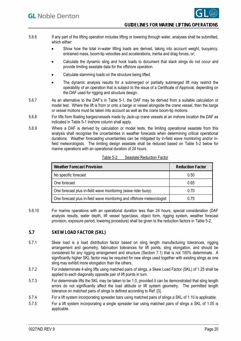
GUIDELINES FOR MARINE LIFTING OPERATIONS
5.6.6 If any part of the lifting operation includes lifting or lowering through water, analyses shall be submitted, which either:
Show how the total in-water lifting loads are derived, taking into account weight, buoyancy, entrained mass, boom-tip velocities and accelerations, inertia and drag forces, or;
Calculate the dynamic sling and hook loads to document that slack slings do not occur and provide limiting seastate data for the offshore operation.
Calculate slamming loads on the structure being lifted.
The dynamic analysis results for a submerged or partially submerged lift may restrict the operability of an operation that is subject to the issue of a Certificate of Approval, depending on the DAF used for rigging and structure design.
5.6.7 As an alternative to the DAF’s in Table 5-1, the DAF may be derived from a suitable calculation or model test. Where the lift is from or onto a barge or vessel alongside the crane vessel, then the barge or vessel motions must be taken into account as well as the crane boom-tip motions.
5.6.8 For lifts from floating barges/vessels made by Jack-up crane vessels at an inshore location the DAF as indicated in Table 5-1 Inshore column shall apply.
5.6.9 Where a DAF is derived by calculation or model tests, the limiting operational seastate from this analysis shall recognise the uncertainties in weather forecasts when determining critical operational durations. Weather forecasting uncertainties can be mitigated by in-field wave monitoring and/or in-field meteorologists. The limiting design seastate shall be reduced based on Table 5-2 below for marine operations with an operational duration of 24 hours.
Table 5-2 Seastate Reduction Factor
Weather Forecast Provision Reduction Factor
No specific forecast 0.50
One forecast 0.65
One forecast plus in-field wave monitoring (wave rider buoy) 0.70
One forecast plus in-field wave monitoring and offshore meteorologist 0.75
5.6.10 For marine operations with an operational duration less than 24 hours, special consideration (DAF
analysis results, water depth, lift vessel type/class, object form, rigging system, weather forecast provision, exposure period, lowering procedure) shall be given to the reduction factors in Table 5-2.
5.7 SKEW LOAD FACTOR (SKL)
5.7.1 Skew load is a load distribution factor based on sling length manufacturing tolerances, rigging arrangement and geometry, fabrication tolerances for lift points, sling elongation, and should be considered for any rigging arrangement and structure (Section 7.1) that is not 100% determinate. A significantly higher SKL factor may be required for new slings used together with existing slings as one sling may exhibit more elongation than the others.
5.7.2 For indeterminate 4-sling lifts using matched pairs of slings, a Skew Load Factor (SKL) of 1.25 shall be applied to each diagonally opposite pair of lift points in turn.
5.7.3 For determinate lifts the SKL may be taken to be 1.0, provided it can be demonstrated that sling length errors do not significantly affect the load attitude or lift system geometry. The permitted length tolerance on matched pairs of slings is defined according to Ref. [3].
5.7.4 For a lift system incorporating spreader bars using matched pairs of slings a SKL of 1.10 is applicable. 5.7.5 For a lift system incorporating a single spreader bar using matched pairs of slings a SKL of 1.05 is
applicable.
0027/ND REV 9 Page 20
GUIDELINES FOR MARINE LIFTING OPERATIONS
5.7.6 For multi hook lifts where the hook elevation can be shown to be individually controlled, a lower skew load factor than stated above may be applicable, subject to evaluation of sling length tolerances, rigging arrangement and crane operating procedures.
5.7.7 For a single hook lift where four slings of un-equal length are used (i.e. not Matched Pairs), the skew load factor shall be calculated by the designer (considering sling length tolerances and measured lengths) and applied to the structure and lift system design accordingly. Where the calculated SKL is less 1.25 (as required in Section 5.7.2), an SKL of 1.25 shall be applied.
9
5.8 2-HOOK LIFT FACTORS
5.8.1 For a 2-hook lift (hooks on the same vessel) the individual gross weight at each hook shall be multiplied by the following factors, to account for increased loads due to the tolerances of the elevation in the crane hooks:
Centre of gravity shift factor = 1.03
Tilt factor = 1.03
Reduced factors to those defined above may be used, subject to supporting analyses, limiting seastate criteria and installation procedure steps/controls.
5.8.2 For a 2-hook lift, with 2 slings to each hook, the load to each lift point shall be multiplied by a yaw factor, to account for tolerances in lift radii of the 2 hooks:
Yaw factor = 1.05
Yaw factors for 2-hook lifts with other rigging arrangements will require special consideration.
5.8.3 For 2 hook lifts where the crane hooks are located on separate vessels the factors in Sections 5.8.1 and 5.8.2 shall be applied for inshore lifts, and be subject to calculation for offshore lifts.
5.8.4 For 2 hook lifts where the hooks are on the same crane, the factors in Sections 5.8.1 and 5.8.2 shall be applied.
5.9 LATERAL LIFT POINT LOAD
5.9.1 Provided the lift-point is correctly orientated with the sling direction, then a horizontal force equal to 5% of the resolved lift point load shall be applied, acting through the centreline and along the axis of the padeye pin-hole or trunnion /padear geometric centre.
5.9.2 If the lift point is not correctly orientated with the sling direction, then the computed forces acting transverse to the major lift point axis of the pin-hole or trunnion /padear geometric centre shall be added to the lateral lift point load as defined in Section 5.9.1 above.
5.10 2-PART SLING FACTOR
5.10.1 Where a 2-part sling or grommet passes over, round or through a shackle, trunnion, padear or crane hook, other than at a termination, the total sling force shall be distributed into each part in the ratio 45:55 to account for frictional losses over the bend.
5.10.2 Where a 2-part sling or grommet passes over a rotating greased sheave on a trunnion the total sling force shall be distributed into each part in the ratio 49:51 to account for the frictional losses over the rotating sheave on the trunnion.
0027/ND REV 9 Page 21
GUIDELINES FOR MARINE LIFTING OPERATIONS
5.11 TERMINATION EFFICIENCY FACTOR
5.11.1 The breaking load of a sling ending in a termination shall be the calculated rope breaking load multiplied by a factor as follows:
For hand splices, including fibre slings: 0.75
For resin sockets: 1.00
Swage fittings, e.g. “Superloop or Flemish Eye”: 1.00
Steel ferrules (mechanical termination): 0.80
Fibre rope sling splices: 0.90 9 Other methods of termination (i.e. 9-part slings) will require special consideration.
5.12 BENDING EFFICIENCY FACTOR
5.12.1 Where any wire rope sling or grommet is bent round a shackle, trunnion, padear or crane hook, the breaking load shall be assumed to be the calculated breaking load multiplied by a bending efficiency factor in accordance with Ref. [3]:
Bending efficiency factor = 1 - 0.5/( D/d),
where: d = the sling or cable laid rope diameter
D = the minimum diameter over which the sling body, sling eye, or grommet is bent.
5.12.2 For wire rope slings and grommets, this results in the bending efficiency factors detailed in the following Table 5-3.
Table 5-3 Bending Efficiency Factors
D/d <1.0 1.0 1.5 2.0 3.0 4.0 5.0 6.0 7.0
Factor Not Advised
0.50 0.59 0.65 0.71 0.75 0.78 0.80 0.81
5.12.3 For fibre rope slings, the bending efficiency may normally be taken as 1.00, provided the bending
diameter is not less than the minimum specified by the manufacturer. 5.12.4 It should be noted that termination and bending factors should not be applied simultaneously. The one
which results in the lower value of breaking load will govern, and should be used. 5.12.5 Under no circumstances should the sling or grommet body contact any surface where the diameter is
less than 1.0d to maintain the sling in good condition under load. Bending in way of splices shall be avoided.
9
5.12.6 In certain circumstances, it will be necessary to check sling eye bending losses around a shackle or trunnion, where the D/d ratio is less that 4.0.
5.13 SLING OR GROMMET SAFETY FACTORS
5.13.1 The minimum safety factor on sling or grommet breaking load shall be calculated after:
resolution of the load based on centre of gravity position and sling angle, and
consideration of the factors shown in Sections 5.2 to 5.12 as appropriate.
5.13.2 For steel slings and grommets the minimum safety factor shall be not less than 2.25.
0027/ND REV 9 Page 22
GUIDELINES FOR MARINE LIFTING OPERATIONS
5.13.3 For fibre slings and grommets the minimum safety factor shall be not less than 4.75. 5.13.4 Further safety factors shall be applied to the sling design based on termination and sling bending
efficiency and sling usage.
5.14 SHACKLE SAFETY FACTORS
5.14.1 The shackle WLL should not be less than the static sling load. 5.14.2 In addition to Section 5.14.1 above, the dynamic sling load (static sling load x DAF) shall not exceed
the shackle MBL divided by a safety factor equal to 3.0. 9
5.14.3 Where the shackle is at the lower end of the rigging, the weight of the rigging components above the shackle, (including effects of the DAF and taking account of sling angle) may be deducted from the shackle load.
5.15 GROMMETS
5.15.1 Grommets require special consideration, to ensure that the rope breaking load and bending efficiency have been correctly taken into account. It is assumed that grommets are constructed and used in accordance with Ref. [3].
5.15.2 The load in a grommet shall be distributed into each part in the ratio 45:55, as indicated by Section 5.10.
5.15.3 The core of a grommet should be discounted when computing breaking load. The breaking load of a grommet is determined in accordance with Ref. [3].
5.15.4 The bending efficiency factors at each end of a grommet may differ, and the more severe value should be taken. Bending efficiency is derived as in Section 5.12 where rope diameter is the single part grommet diameter.
5.15.5 Bending in way of grommet butt and tuck positions shall be avoided. The location of the butt connection shall be marked.
5.16 CONSEQUENCE FACTORS
5.16.1 The following consequence factors shall be further applied to the structure including lift points and the lateral load effects on lift points, and their attachments into the structure:
Table 5-4 Consequence Factors
Lift points including spreader bars and frames 1.30
Attachments of lift points to structure 1.30
Members directly supporting or framing into the lift points 1.15
Other structural members 1.00
5.16.2 The consequence factors shown in Table 5-4 shall be applied based on the calculated lift point loads
after consideration of all the factors shown in Sections 5.2 through 5.10. If a partial load factor design is used then the consequence factors in Table 5-4 shall also be applied to the partial load factors for structural design. Consequence factors in Table 5-4 shall also be applied to lift point lateral loads.
0027/ND REV 9 Page 23
GUIDELINES FOR MARINE LIFTING OPERATIONS
6 THE CRANE AND CRANE VESSEL
6.1 HOOK LOAD
6.1.1 The hook load shall be shown not to exceed the allowable crane capacity as taken from the load-radius curves. Crane curves are generally expressed as safe working loads or static capacities. Information should be obtained to document this.
6.1.2 The allowable load-radius curves as presented may sometimes include a dynamic effect allowance. If a suitable statement is received to this effect, the hook load may, for comparison with the load-radius curves, be derived from the dynamic hook load as defined in Section 5.3.
6.1.3 Some crane curves specify different allowable load curves for different seastates. These may similarly be taken to include dynamic effects. A seastate representing the probable limits for the operation should be chosen, and the gross weight used.
6.1.4 If the DAF included in the crane curves differs from the operation-specific value derived from Section 5.6, then the allowable load should be adjusted accordingly but shall not exceed the certified crane (SWL or WLL) load-radius curve.
9
6.1.5 Where heave compensated lifts are planned, then the following information on the crane or cranes shall be obtained:
Crane technical description and operating procedures,
Load radius curves in heave compensated mode plus limiting seastates and boom slew angles,
Crane de-rating curves,
FMEA for the crane system,
DAF analysis in heave compensated mode
Verify engine room/deck mechanics maintenance logs
6.2 DOCUMENTATION
6.2.1 Where Approval is required, the documentation as stated in Section 12 shall be submitted.
0027/ND REV 9 Page 24
GUIDELINES FOR MARINE LIFTING OPERATIONS
7 STRUCTURAL CALCULATIONS
7.1 LOAD CASES AND STRUCTURAL MODELLING
7.1.1 Structural calculations, based on the load factors discussed above, shall include adequate loadcases to justify the structure. For example, for an indeterminate, 4-point lift the following loadcases should normally be considered: a. Base case, using gross or NTE weight, resolved to the lift points, but with no skew load factor.
b. Gross or NTE weight, with skew load factor applied to one diagonal.
c. Gross or NTE weight, with skew load factor applied to the other diagonal.
7.1.2 In all cases the correct or minimum sling angle and point of action, and any offset or torsional loading imposed by the slings shall be considered.
7.2 STRUCTURE
7.2.1 The overall structure shall be analysed for the loadings shown in Section 7.1. 7.2.2 The primary supporting members shall be analysed using the most severe loading resulting from
Section 7.1, with a consequence factor applied (see Section 5.16).
7.3 LIFT POINTS
7.3.1 An analysis of the lift points and attachments to the structure shall be performed, using the most severe load resulting from Section 7.1 and all the factors as appropriate from Section 5.
7.3.2 Where the lift point forms an integral part of the structural node, then the lift point calculations shall also include the effects of loads imposed by the members framing into the lift point.
7.3.3 Where tugger lines are attached to lift points their effect shall be considered in the lift point design. 9
7.4 SPREADER BARS OR FRAMES
7.4.1 Spreader bars or frames, if used, should be similarly treated, with loadcases as above. A consequence factor shall be applied to spreader bars and frames, in accordance with Section 5.16.
7.5 ALLOWABLE STRESSES
7.5.1 The structural strength of high quality structural steelwork with full material certification and NDT inspection certificates showing appropriate levels of inspection shall be assessed using the methodology of a recognised and applicable offshore code including the associated load and resistance factors for LRFD codes or safety factors for ASD/WSD codes. Traditionally AISC and API RP2A have also been considered a reference code - see Note 1 in Section 7.5.3 regarding its applicability.
7.5.2 Except for sacrificial bumpers and guides, the loading shall be treated as a normal serviceability limit state (SLS) / Normal operating case.
0027/ND REV 9 Page 25
GUIDELINES FOR MARINE LIFTING OPERATIONS
7.5.3 Infrequent load cases on sacrificial bumpers and guides should be treated as an ultimate limit state (ULS)/Survival storm case. This does not apply to:
Steelwork subject to deterioration and/or limited initial NDT unless the condition of the entire loadpath has been verified, for example the underdeck members of a barge or ship
Steelwork subject to NDT prior to elapse of the recommended cooling and waiting time as defined by the Welding Procedure Specification (WPS) and NDT procedures. In cases where this cannot be avoided by means of a suitable WPS, it may be necessary to impose a reduction on the design/permissible seastate
Steelwork supporting sacrificial bumpers and guides
Spreader bars, lift points and primary steelwork of lifted items
Structures during a load-out.
Note: If the AISC 13th Edition is used, the allowables shall be compared against member stresses determined using a load factor on both dead and live loads of no less than:
WSD Option LRFD Option
SLS: 1.00 1.60
ULS: 0.75 1.20
0027/ND REV 9 Page 26
GUIDELINES FOR MARINE LIFTING OPERATIONS
8 LIFT POINT DESIGN
8.1 INTRODUCTION
8.1.1 In addition to the structural requirements shown in Sections 5 and 7, the following should be taken into account in the lift point design:
8.2 SLING OVALISATION
8.2.1 Adequate clearance is required between cheek plates, shackle pins or inside trunnion keeper plates, to allow for ovalisation under load. In general, the width available for the sling shall be not less than (1.25D + 25mm), where D is nominal sling diameter. However, the practical aspects of the rigging and de-rigging operations may demand a greater clearance than this.
8.2.2 For cast padears the geometry of the padear shall be configured to fully support and maintain the sling geometry and shape under load.
8.3 PLATE ROLLING AND LOADING DIRECTION
8.3.1 In general, for fabricated lift points, the direction of loading should be in line with the plate rolling direction. Lift point drawings should show the rolling direction.
8.3.2 Through thickness loading of lift points and their attachments to the structure should be avoided if possible. If such loading cannot be avoided, the material used shall be documented to be free of laminations, with a recognised through-thickness designation.
8.4 PIN HOLES
8.4.1 Pin-holes should be bored /reamed, and should be designed to suit the shackle proposed. The pin hole diameter shall be 2mm or 3% larger than the diameter of the shackle pin, whichever is the greater, up to a maximum of 6mm.
9
8.5 CAST PADEARS AND WELDED TRUNNIONS
8.5.1 Cast padears and trunnions shall be designed taking into account the following aspects:
The geometrical considerations as indicated in Section 8.2.
The stress analysis and finite element design process (modelling and load application).
Load paths, trunnion geometry and space and support for slings. And grommets
The manufacturing process and quality control.
Sling keeper plates shall be incorporated into the padear/trunnions design to prevent the loss of sling or grommets during load application and lifting. These devices shall be proportioned to allow easy rigging and de-rigging whilst being capable of supporting the weight of the sling section during transportation.
8.6 NON-DESTRUCTIVE TESTING
8.6.1 The extent of NDT shall be submitted for review. 8.6.2 Where repeated use is to be made of a lift point, a procedure should be presented for re-inspection
after each lift.
0027/ND REV 9 Page 27
GUIDELINES FOR MARINE LIFTING OPERATIONS
8.7 CHEEK PLATES
8.7.1 Individual cheek plate thicknesses shall not exceed 50% of the main plate thickness to maintain the primacy of the main plate in load transfer to the structure, and to provide robustness to lateral loads.
8.7.2 Non-load bearing spacer plates may be used to centralise shackle pins, by effectively increasing the padeye thickness. The diameter of the internal hole in such spacer plates shall be greater than the pin hole diameter. Spacer plates, if used, shall provide a 20-30mm clearance to the inside width of the shackle (i.e. 10 to 15mm each side).
8.7.3 Cheek plate welds shall be proportioned and designed with due regard to possible uneven bearing across the padeye/cheek plate thickness due to combined nominal (5%) and actual lateral loads.
0027/ND REV 9 Page 28
GUIDELINES FOR MARINE LIFTING OPERATIONS
9 CLEARANCES
9.1 INTRODUCTION
9.1.1 The required clearances will depend on the nature of the lift, the proposed limiting weather conditions, the arrangement of bumpers and guides and the size and motion characteristics of the crane vessel and the transport barge.
9.1.2 Subject to the above, for offshore lifts, the following clearances should normally be maintained at each stage of the operation. Smaller clearances may be acceptable for inshore or onshore lifts. Clearances are based on a level lift (no tilt) of each structure. Additional clearances may be required for structures with a prescribed tilt.
9.2 CLEARANCES AROUND LIFTED OBJECT
9 9.2.1 3 metres between any part of the lifted object (including spreaders and lift points) and crane boom, when the load is suspended.
9.2.2 3 metres vertical clearance between the underside of the lifted object and any other previously installed structure, except in the immediate vicinity of the proposed landing area or installation aid where 1.5m clearance shall be adequate.
9.2.3 5 metres between the lifted object and other structures on the same transport barge unless bumpers and guides are used for lift-off.
9.2.4 3 metres horizontal clearance between the lifted object and any other previously installed structure, unless purpose-built guides or bumpers are fitted.
9.2.5 3 metres remaining travel between travelling block and fixed block at maximum load elevation with the lift vessel at LAT.
9.2.6 Where a structure is securely engaged within a bumper/guide or pin/bucket system, clearance between the extremities of the structure and the host structure must be demonstrated to be positive, considering the worst possible combinations of tilt. This may require dimensional control surveys to be carried out on the host structure and the structure to be installed.
9.2.7 Lift arrangement drawings shall clearly show all clearances as defined above. 9.2.8 Clearances above for lifts by floating crane vessels onto floating structures (e.g. spars, FPSO’s) will
need special consideration. It is expected that these clearances will need to be larger than those stated above, and is dependent on the transient motion of the floating structure and the lifting vessel.
9.2.9 Consideration should be given when lifting and overboarding structures over or in the vicinity of a subsea asset to provide sufficient horizontal clearance for dropped objects.
9.3 CLEARANCES AROUND CRANE VESSEL
9.3.1 Where the crane vessel is moored adjacent to an existing fixed platform the following clearances apply, for an intact mooring system:
3m between any part of the crane vessel/crane and the fixed platform on lifted structure;
5m between any part of the crane vessel hull extremity and the fixed platform or submerged lift;
10 m between any anchor line and the fixed platform.
9.3.2 Where the crane vessel is dynamically positioned in accordance with class 3 DP regulations, a 5m nominal clearance between any part of the crane vessel and the fixed platform shall be maintained.
9.3.3 3m between crane vessel keel (including thrusters) and seabed, after taking account of tidal conditions, vessel motions, increased draft and changed heel or trim during the lift.
0027/ND REV 9 Page 29
GUIDELINES FOR MARINE LIFTING OPERATIONS
9.3.4 Clearances around the crane vessel either moored or dynamically positioned and any floating platform, drilling rig or submersible, shall be determined as special cases based on the station keeping analysis of the floating structure and the lifting vessel. Positioning equipment and procedures shall be defined to maintain minimum clearances for specific operations and minimum durations.
9.4 CLEARANCES AROUND MOORING LINES AND ANCHORS
9.4.1 The clearances stated below are given as guidelines to good practice. The specific requirements and clearances should be defined for each project and operation, taking into account particular circumstances such as:
water depth
proximity of subsea assets
survey accuracy
the station keeping ability of the anchor handling vessel
seabed conditions
estimated anchor drag during embedment
single mooring line failure in the vessel stand-off position
the probable weather conditions during anchor installation.
9.4.2 Operators may have their own requirements which may differ from those stated below, and should govern if more conservative.
9.4.3 Clearances should take into account the possible working and stand-off positions of the crane vessel. 9.4.4 Moorings should never be laid in such a way that they could be in contact with any subsea asset. This
may be relaxed when the subsea asset is a trenched pipeline, provided it can be demonstrated that the mooring will not cause frictional damage or abrasion to coating systems.
9.4.5 Moorings shall never be run over the top of a subsea completion or wellhead. 9.4.6 Whenever an anchor is run out over a pipeline, flowline or umbilical, the anchor shall be securely
stowed on the deck of the anchor handling vessel. In circumstances where either gravity anchors or closed stern tugs are used, and anchors cannot be stowed on deck, the anchors shall be double secured through the additional use of a safety strap or similar.
9.4.7 The vertical clearance between any anchor line and any subsea asset should be not less than 20 metres in water depths exceeding 40 metres, and 50% of water depth in depths of less than 40 metres. Anchor catenaries shall be presented indicating minimum and maximum tensions in order to demonstrate that these clearances can be met. 9
9.4.8 Horizontal clearance between any mooring line and any structure other than a subsea asset should not be less than 10 metres.
9.4.9 When an anchor is placed on the same side of a subsea asset as the crane vessel, it should not be placed closer than 100 metres to the subsea asset.
9.4.10 When the subsea asset lies between the anchor and the crane vessel, the final anchor position should be no less than 200 metres from the subsea asset.
9.4.11 During lifting operations, crossed mooring situations should be avoided wherever practical. Where crossed moorings cannot be avoided, the separation between active catenaries should be no less than 30 metres in water depths exceeding 100 metres, and 30% of water depth in water depths less than 100 metres.
9.4.12 If any of the clearances specified in Sections 9.4.7 to 9.4.11 are impractical because of the mooring configuration or seabed layout, a risk assessment shall be carried out and special precautions taken as necessary.
9.4.13 Temporary lay-down of an anchor wire (but not chain) over a pipeline, umbilical, spool or cable may be acceptable subject to all of the following being submitted to this office:
0027/ND REV 9 Page 30
GUIDELINES FOR MARINE LIFTING OPERATIONS
a. Evidence that there is no other practicable anchor pattern that would avoid the lay-down.
b. The status of a pipeline or spool (e.g. trenched, live, rock-dumped, on surface) and its contents (e.g. oil, gas, water) and internal pressure.
c. Procedures clearly stating the maximum duration that the anchor wire is in contact with the pipeline, umbilical, spool or cable and the reason for the contact.
d. Written evidence that the pipeline owner accepts the laying down of the anchor wire over the pipeline, umbilical, spool or cable.
e. Evidence that the anchor wire will be completely slack i.e. no variation in tension.
f. Evidence that the seastate during the lay-down will be restricted to an acceptable value.
g. Documentation demonstrating that the anchor wire or its weight will not overstress or damage the coating on the pipeline, umbilical, spool or cable.
0027/ND REV 9 Page 31
GUIDELINES FOR MARINE LIFTING OPERATIONS
10 BUMPERS AND GUIDES
10.1 INTRODUCTION
10.1.1 For module installation the arrangement and design philosophy for bumpers and guides shall be submitted, where applicable. In general, bumpers and guides should be designed in accordance with this Section taking into account of their use, configuration and geometry.
9
10.2 MODULE MOVEMENT
10.2.1 The maximum module movement during installation should be defined. In general the module motions should be limited to:
Vertical movement: + 0.75 m
Horizontal movement: + 1.50 m
Longitudinal tilt: 2 degrees
Transverse tilt: 2 degrees
Plan rotation: 3 degrees.
10.2.2 The plan rotation limit is only applicable prior to engagement on the bumper/guide or pin/bucket system, and when the module is close to its final position or adjacent to another structure on a cargo barge.
10.3 POSITION OF BUMPERS AND GUIDES
10.3.1 The position of bumpers and guides shall be determined taking into account acceptable support points on the module.
10.3.2 Dimensional control reports shall be reviewed of the as-built bumper and guide system to ensure fit up offshore.
10.3.3 Nominal clearances between bumpers/guides and pins/buckets shall be +/-25mm to account for fabrication and installation tolerances. These may be reduced based on trial fits and/or a more stringent dimensional control regime.
0027/ND REV 9 Page 32
GUIDELINES FOR MARINE LIFTING OPERATIONS
10.4 BUMPER AND GUIDE FORCES
10.4.1 For offshore lifts, bumpers and guides should be designed to the following forces (where W = static hook load):
a. Vertical sliding bumpers
Horizontal force in plane of bumper: 0.10 x W
Horizontal (friction) force, out of plane of bumper: 0.05 x W
Vertical (friction) force: 0.01 x W
Forces in all 3 directions will be combined to establish the worst design case.
b. Pin/bucket guides
Horizontal force on cone/end of pin: 0.05 x W
Vertical force on cone/end of pin: 0.10 x W
Horizontal force in any direction will be combined with the vertical force to establish the worst design case.
c. Horizontal “cow-horn” type bumpers with vertical guide
Horizontal force in any direction: 0.10 x W
Vertical (friction) force: 0.01 x W
Horizontal force in any direction will be combined with the vertical force to establish the worst design case.
d. Vertical “cow-horn” type guide with horizontal bumper
Horizontal force in any direction: 0.10 x W
Vertical force on inclined guide-face: 0.10 x W
10.4.2 Horizontal force in any direction will be combined with the vertical force to establish the worst design case.
10.4.3 For inshore lifts under controlled conditions, bumpers and guides may be designed to 50% of the forces shown in Section 10.4.1.
10.4.4 Bumpers and guides that are deemed to arrest secondary motions may be designed to 50% of the forces shown in Section 10.4. 9
10.5 DESIGN CONSIDERATIONS
10.5.1 The connection into the module, and the members framing the bumper or guide location, should be at least as strong as the bumper or guide.
10.5.2 The stiffness of bumper and guide members should be as low as possible, in order that they may deflect appreciably without yielding.
10.5.3 Design of bumpers and guides should cater for easy sliding motion of the guide in contact with bumper. Sloping members should be at an acute angle to the vertical. Ledges and sharp corners should be avoided on areas of possible contact, and weld beads should be ground flush.
0027/ND REV 9 Page 33
GUIDELINES FOR MARINE LIFTING OPERATIONS
10.5.4 With reference to Section 7.5.1, the strength of bumpers and guides that are deemed to be “sacrificial” should be assessed to the ultimate limit state (ULS). The bumper and guide connection to the supporting structure shall be assessed to the normal serviceability limit state (SLS).
0027/ND REV 9 Page 34
GUIDELINES FOR MARINE LIFTING OPERATIONS
11 PRACTICAL CONSIDERATIONS
11.1 Adequate and safe access and working platforms should be provided for connection of slings, particularly where connection or disconnection is required offshore or underwater.
11.2 Seafastening on the transport barge should be designed:
To minimise offshore cutting
To provide restraint after cutting
To allow lift off without fouling.
11.3 All cut lines should be clearly marked. Where a 2-stage lift is planned - e.g. barge to lift vessel, then lift vessel to final position, involving 2 sets of cut lines, these should preferably be in different colours.
11.4 Adequate equipment must be available on the transport barge, including as appropriate:
Burning sets
Tuggers and lifting gear
Means of securing loose seafastening material
Lighting for night operations
Safety equipment for personnel.
Safe access to and from the transport barge.
11.5 All loose equipment, machinery, pipework and scaffolding shall be secured against movement during the lift, and the weights and positions allowed for in the gross weight.
11.6 Prior to the start of the lift, a forecast of suitable weather shall be received, of a duration adequate to complete the operation, with contingencies, and taking into account any subsequent critical marine operations.
11.7 The sling laydown arrangement shall show that:
a. The slinging arrangement is in accordance with acceptable good practice.
b. Large diameter slings and grommets shall be painted with a white line along the length to monitor twisting during handling and laydown.
c. The slings are matched as accurately as possible, unless the rigging arrangement is deliberately non-symmetrical to take account of centre of gravity offset, in which case matched pairs of slings should normally be used. Where minor mismatch in sling length exists, the slings should be arranged to minimise skew loads.
d. The slings are adequately secured against barge motions, prior to the start of the lift.
e. The slings will not foul obstructions such as walkways and handrails when lifted, and any unavoidable obstructions are properly protected.
f. The slings will not kink when lifted.
g. After the lift the slings (and spreaders if used) can be safely laid down again, without damage.
h. In the event that a single sling attached to a single lift point is planned, it should be doubled to prevent the sling unwinding under load.
11.8 Slings with hand spliced terminations must be prevented from rotation.
0027/ND REV 9 Page 35
GUIDELINES FOR MARINE LIFTING OPERATIONS
11.9 No bending is allowed at or close to a termination.
11.10 It is permissible to shackle slings together end-to-end to increase the length. However, slings of opposite lay should never be connected together.
11.11 It is permissible to increase the length of a sling by inserting an extra shackle or specifically designed link plates. Any shackle to shackle connections should be bow-to-bow, not pin-to-pin or pin-to-bow so that shackles remain centred under load and also the load take-up.
11.12 Crane vessel motions should be monitored in the period prior to the lift, to confirm that the dynamic behaviour is acceptable, taking into account the weight and size of the lifted object, the clearances for lifting off the transport barge, the hoisting speed, the clearances for installation and the installation tolerances.
11.13 Transport barge motions should be similarly monitored prior to the start of the lift. The change in attitude of the transport barge when the weight is removed should be taken into account.
0027/ND REV 9 Page 36
GUIDELINES FOR MARINE LIFTING OPERATIONS
12 INFORMATION REQUIRED FOR APPROVAL
12.1 GENERAL INFORMATION REQUIRED
12.1.1 Where approval is required, a package shall be submitted to GL Noble Denton for review, consisting of: a. Justification of weight and centre of gravity, by Weight Control Report or weighing report.
b. Structural analysis report for structure to be lifted, including lift points and spreaders, as set out in Section 7.
c. Rigging arrangement package, showing sling geometry, computed sling loads, required breaking loads, tabulation of slings and shackles proposed, certificates for slings and shackles. This certificate shall be issued or endorsed by a body approved by an IACS member or other recognised certification body accepted by GL Noble Denton. Crane details, including load-radius curve with lift superimposed, and details of vertical and horizontal clearances.
9 d. Mooring arrangements, mooring analyses, anchor catenaries and anchor running procedures.
e. The management structure and marine procedures.
f. Site survey reports.
12.2 THE STRUCTURE TO BE LIFTED
12.2.1 Calculations shall be presented for the structure to be lifted, demonstrating its capacity to withstand, without overstress, the loads imposed by the lift operation, with the load and safety factors stated in Section 5, and the loadcases discussed in Section 7.
12.2.2 The calculation package shall present, as a minimum: a. Plans, elevations and sections showing main structural members
b. The structural model. This should account for the proposed lifting geometry, including any offset of the lift points
c. The weight and centre of gravity
d. The steel grades and properties
e. The loadcases imposed
f. The Codes used
g. A tabulation of member and joint Unity Checks greater than 0.8
h. Justification or proposal for redesign, for any members with a Unity Check in excess of 1.0.
i. Copies of existing sling certificates planned to be used (consolidation and dimensional conformity certificates). This certificate shall be issued or endorsed by a body approved by an IACS member or other recognised certification body accepted by GL Noble Denton.
12.2.3 An analysis or equivalent justification shall be presented for all lift points, including padeyes, padears and trunnions, to demonstrate that each lift point, and its attachment into the structure, is adequate for the loads and factors set out in Sections 5 and 7.
12.2.4 A similar analysis shall be presented for spreader bars, beams and frames.
12.3 INDEPENDENT ANALYSIS
12.3.1 Alternatively, GL Noble Denton will, if instructed, perform an independent analysis of the structure to be lifted, including the lift points, on receipt of the necessary information.
0027/ND REV 9 Page 37
GUIDELINES FOR MARINE LIFTING OPERATIONS
12.4 CODES AND SPECIFICATIONS
12.4.1 For analysis of the structure to be lifted and the lift points, an accepted offshore structural design code shall be used as described in Section 7.5.
12.4.2 Adequate specifications for material properties, construction, welding, casting, inspection and testing shall be used.
12.5 EVIDENCE OF SATISFACTORY CONSTRUCTION
Confirmation shall be presented, from a Certifying Authority, Classification Society or similar, that the structure including the lift points and their attachments has been constructed in accordance with the drawings and specifications.
12.6 RIGGING ARRANGEMENTS
12.6.1 A proposal shall be presented showing: a. The proposed rigging geometry showing dimensions of the structure, centre of gravity position,
lift points, crane hook, sling lengths and angles, including shackle dimensions and "lost" length around hook and trunnions.
b. A computation of the sling and shackle loads and required breaking loads, taking into account the factors set out in Section 5.
c. A list of actual slings and shackles proposed, tabulating:
Sling/shackle identification number
Sling length and diameter
Rigging utilisation factor summaries
CSBL, CRBL for slings or CGBL for grommets,
SWL or WLL for shackles
Construction
Direction of lay
Wire grade and wire type (bright or galvanised).
Copies of inspection/test Certificates for all rigging components. These certificates shall be Position on structure
9
9
issued or endorsed by a body approved by an IACS member for the certification of that type of equipment.
12.6.2 Slings and grommets should be manufactured and inspected in accordance with the International Marine Contractors Association Guidance on Cable laid slings and grommets Ref. [3], or similar acceptable standard. A thorough examination shall be carried out as required by that document for all rigging components whether new or existing.
12.6.3 Shackles manufactured by an industry-recognised manufacturer, shall be covered by a test certificate not exceeding 6 months old, and if not new, a report of an inspection by a competent person since the last lift. The lift shall be executed within the date validity of the sling certificate.
12.6.4 Where 9-part slings are proposed for use in a lifting system, certification of these slings shall be given special consideration.
12.6.5 Where an existing sling has been used doubled and this sling shows a permanent kink, it shall not be used in a single configuration.
0027/ND REV 9 Page 38
GUIDELINES FOR MARINE LIFTING OPERATIONS
12.6.6 Where spreader bars or spreader frames are used in a lifting system, there shall either be a load test certificate provided indicating the SWL or WLL, tested in accordance with ref [6], or an as-built dossier provided with data as listed in Section 12.6.7.
12.6.7 Where spreader bars or spreader frames are not load tested an as-built fabrication dossier shall be provided listing the following minimum information: a. Material certificates (3rd party endorsed),
b. Welding consumables certificates,
c. Weld procedures,
9 d. NDT procedures,
e. Welders and NDT operatives qualifications,
f. Inspection and Test Plan (ITP) listing Hold Monitor and Witness points,
g. 3rd party fabrication release note,
h. Technical queries/concession requests,
i. As-built drawings,
j. Design report.
12.7 THE CRANE VESSEL
12.7.1 Information shall be submitted on the crane vessel and the crane. This shall include, as appropriate:
Vessel general arrangement drawings and specification
Details of registry and class
Mooring system and anchors
Vessel station keeping procedures
DP operating and positioning procedures (as applicable) and station keeping analyses/rosettes
Vessel DP system FMEA
Operating and survival drafts
Crane specification and operating curves (including where necessary the dynamic crane capacity / curve).
Details of any ballasting operations required during the lift.
12.7.2 The mooring arrangement for the operation and stand-off position shall be submitted. This should include the lengths and specifications of all mooring wires and anchors, and a mooring plan showing adequate horizontal clearances on all platforms, pipelines and any other seabed obstructions. An elevation of the catenary for each mooring line, for upper and lower tension limits, shall demonstrate adequate vertical clearance over pipelines and horizontal clearance to fixed installations and the structure being lifted.
12.7.3 Mooring analyses shall be submitted based on the 10 year seasonal return data for the vessel in the stand-off position, for moorings that are deployed for a period less than 30 days. The analysis shall demonstrate that the mooring system is able to safely resist the environmental conditions, including single line failure cases.
9 12.7.4 The mooring analysis shall also provide the limiting seastate for the crane vessel to remain in the working position. The transient motions due to single line failure shall be considered.
12.7.5 Factors of safety shall meet the requirements of Ref. [7]. 12.7.6 Anchors shall be selected with sufficient holding capacity for the soils expected based on the
geotechnical and geophysical data for the location.
0027/ND REV 9 Page 39
GUIDELINES FOR MARINE LIFTING OPERATIONS
12.7.7 A site survey of the area encompassing the anchor pattern shall be provided to verify the location of all subsea infrastructure with respect to the proposed vessel anchor patterns. The survey should generally be carried out no less than 4 weeks prior to the start of installation.
9
12.8 PROCEDURES AND MANAGEMENT
12.8.1 Sufficient management and resources shall be provided to carry out the operation efficiently and safely.
12.8.2 Quality, safety and environmental hazards shall be managed by a formal Quality Management system. 12.8.3 The management structure for the operation, including reporting and communication systems, and
links to safety and emergency services shall be demonstrated. 12.8.4 The anticipated timing and duration of each operation shall be submitted. 12.8.5 The arrangements for control, manoeuvring and mooring of barges and/or other craft alongside the
crane vessel shall be submitted. 12.8.6 A weather forecast from an approved source, predicting that conditions will be within the prescribed
limits, shall be received prior to the start of the operation, and at 12 hourly intervals thereafter, until the operation is deemed complete, in accordance with Section 4.5.3.
12.8.7 In field monitoring of waves (height, direction and period) should be considered to enhance the 12 hourly forecast for each specific lift operation where a Certificate of Approval is required.
12.8.8 In field monitoring of currents (speed and direction) for subsea lifts in areas where it is known that high currents exist in the water column should be considered to enhance the 12 hourly forecast where a Certificate of Approval is required.
12.8.9 For marine operations that are planned to carried out in close proximity to fixed or moored installations, appropriate risk assessments and vessel audits shall be carried out prior to issue of a certificate of approval. This may include attendance at vessel annual DP trials and witnessing of in-field DP checks that are scheduled for a specific marine operation.
12.8.10 Risk assessments, HAZOP/HAZID studies shall be carried out by the Contractor in the presence of the Client, MWS and actual Contractor’s operational personnel. These studies shall be completed at an early stage so that the findings can be incorporated into the operational procedures.
0027/ND REV 9 Page 40
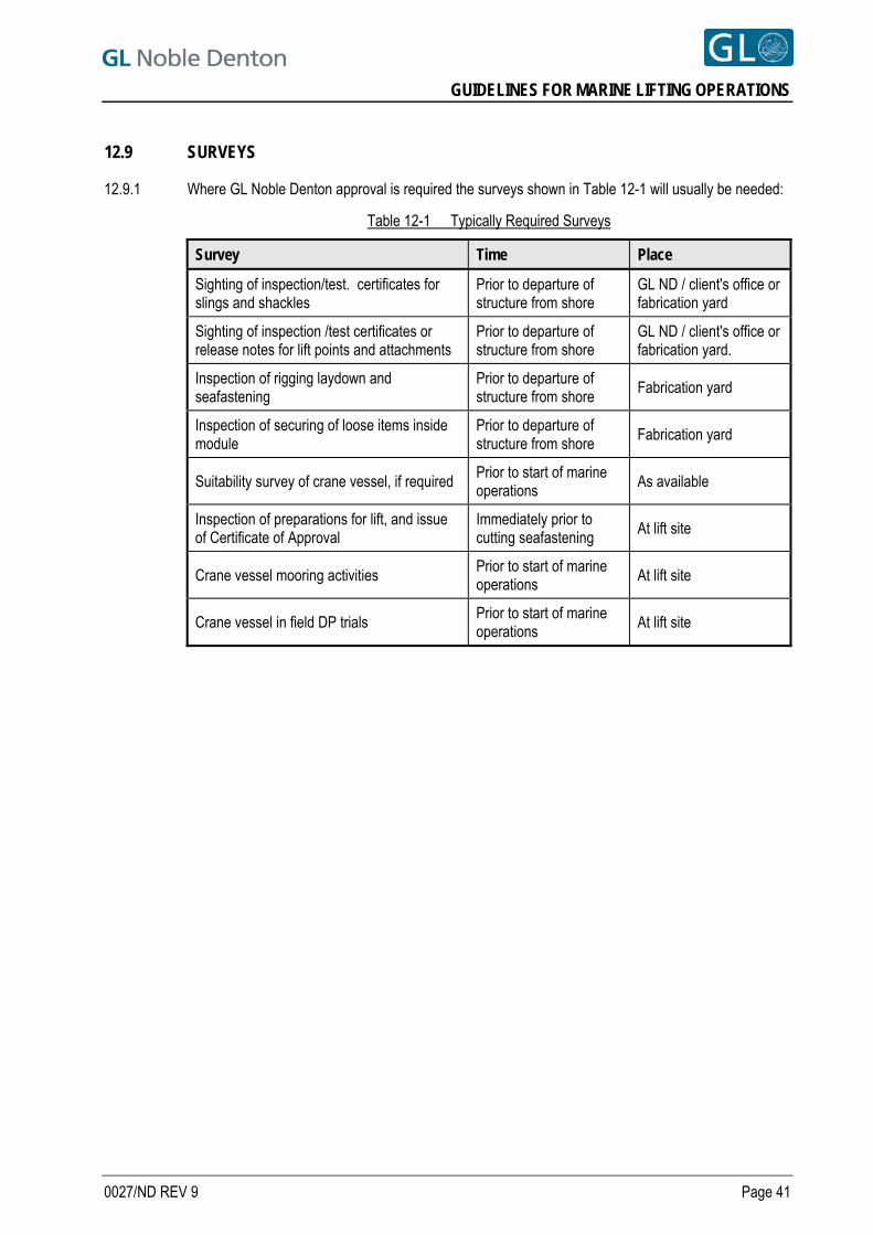
GUIDELINES FOR MARINE LIFTING OPERATIONS
12.9 SURVEYS
12.9.1 Where GL Noble Denton approval is required the surveys shown in Table 12-1 will usually be needed:
Table 12-1 Typically Required Surveys
Survey Time Place
Sighting of inspection/test. certificates for slings and shackles
Prior to departure of structure from shore
GL ND / client's office or fabrication yard
Sighting of inspection /test certificates or release notes for lift points and attachments
Prior to departure of structure from shore
GL ND / client's office or fabrication yard.
Inspection of rigging laydown and seafastening
Prior to departure of structure from shore
Fabrication yard
Inspection of securing of loose items inside module
Prior to departure of structure from shore
Fabrication yard
Suitability survey of crane vessel, if required Prior to start of marine operations
As available
Inspection of preparations for lift, and issue of Certificate of Approval
Immediately prior to cutting seafastening
At lift site
Crane vessel mooring activities Prior to start of marine operations
At lift site
Crane vessel in field DP trials Prior to start of marine operations
At lift site
0027/ND REV 9 Page 41
GUIDELINES FOR MARINE LIFTING OPERATIONS
REFERENCES [1] GL Noble Denton Report 0013/ND - Guidelines for Loadouts.
[2] ISO International Standard ISO 19901-5:2003 – Petroleum and natural gas industries – specific requirements for offshore structures – Part 5: Weight control during engineering and construction.
[3] The International Marine Contractors Association - Guidance on the Use of Cable Laid Slings and Grommets - IMCA M 179 August 2005.
[4] ISO International Standard ISO2408 - Steel wire ropes for General Purposes - Characteristics
[5] ISO International Standard ISO 7531 - Wire Rope slings for General Purposes - Characteristics and Specifications.
[6] Lloyds Register - Code for Lifting Appliances in a Marine Environment
[7] GL Noble Denton Report 0032/ND - Guidelines for Moorings 9
All GL Noble Denton Guidelines can be downloaded from www.gl-nobledenton.com.
0027/ND REV 9 Page 42
TECHNICAL POLICY BOARD
GUIDELINES FOR MARINE TRANSPORTATIONS
0030/ND
Once downloaded this document becomes UNCONTROLLED.
Please check the website below for the current version.
31 Mar 10 4 RLJ Technical Policy Board
15 Apr 09 3 RLJ Technical Policy Board
1 Apr 05 2 JR Technical Policy Board
22 Sep04 1 RJP Technical Policy Board
18 May 04 0 JR Technical Policy Board
DATE REVISION PREPARED BY AUTHORISED BY
www.gl-nobledenton.com

GUIDELINES FOR MARINE TRANSPORTATIONS
PREFACE
This document has been drawn with care to address what are likely to be the main concerns based on the experience of the GL Noble Denton organisation. This should not, however, be taken to mean that this document deals comprehensively with all of the concerns which will need to be addressed or even, where a particular matter is addressed, that this document sets out the definitive view of the organisation for all situations. In using this document, it should be treated as giving guidelines for sound and prudent practice on which our advice should be based, but guidelines should be reviewed in each particular case by the responsible person in each project to ensure that the particular circumstances of that project are addressed in a way which is adequate and appropriate to ensure that the overall advice given is sound and comprehensive. Whilst great care and reasonable precaution has been taken in the preparation of this document to ensure that the content is correct and error free, no responsibility or liability can be accepted by GL Noble Denton for any damage or loss incurred resulting from the use of the information contained herein.
© 2010 Noble Denton Group Limited, who will allow: the document to be freely reproduced, the smallest extract to be a complete page including headers and footers but smaller extracts may be
reproduced in technical reports and papers, provided their origin is clearly referenced.
0030/ND REV 4 Page 2
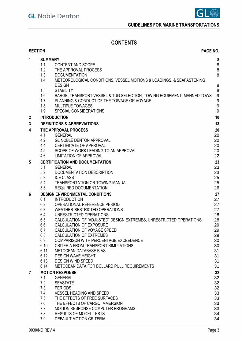
GUIDELINES FOR MARINE TRANSPORTATIONS
CONTENTS SECTION PAGE NO.
1 SUMMARY 8 1.1 CONTENT AND SCOPE 8 1.2 THE APPROVAL PROCESS 8 1.3 DOCUMENTATION 8 1.4 METEOROLOGICAL CONDITIONS, VESSEL MOTIONS & LOADINGS, & SEAFASTENING
DESIGN 8 1.5 STABILITY 8 1.6 BARGE, TRANSPORT VESSEL & TUG SELECTION, TOWING EQUIPMENT, MANNED TOWS 9 1.7 PLANNING & CONDUCT OF THE TOWAGE OR VOYAGE 9 1.8 MULTIPLE TOWAGES 9 1.9 SPECIAL CONSIDERATIONS 9
2 INTRODUCTION 10 3 DEFINITIONS & ABBREVIATIONS 13 4 THE APPROVAL PROCESS 20
4.1 GENERAL 20 4.2 GL NOBLE DENTON APPROVAL 20 4.4 CERTIFICATE OF APPROVAL 20 4.5 SCOPE OF WORK LEADING TO AN APPROVAL 20 4.6 LIMITATION OF APPROVAL 22
5 CERTIFICATION AND DOCUMENTATION 23 5.1 GENERAL 23 5.2 DOCUMENTATION DESCRIPTION 23 5.3 ICE CLASS 25 5.4 TRANSPORTATION OR TOWING MANUAL 25 5.5 REQUIRED DOCUMENTATION 26
6 DESIGN ENVIRONMENTAL CONDITIONS 27 6.1 INTRODUCTION 27 6.2 OPERATIONAL REFERENCE PERIOD 27 6.3 WEATHER-RESTRICTED OPERATIONS 27 6.4 UNRESTRICTED OPERATIONS 28 6.5 CALCULATION OF “ADJUSTED” DESIGN EXTREMES, UNRESTRICTED OPERATIONS 28 6.6 CALCULATION OF EXPOSURE 29 6.7 CALCULATION OF VOYAGE SPEED 29 6.8 CALCULATION OF EXTREMES 29 6.9 COMPARISON WITH PERCENTAGE EXCEEDENCE 30 6.10 CRITERIA FROM TRANSPORT SIMULATIONS 30 6.11 METOCEAN DATABASE BIAS 31 6.12 DESIGN WAVE HEIGHT 31 6.13 DESIGN WIND SPEED 31 6.14 METOCEAN DATA FOR BOLLARD PULL REQUIREMENTS 31
7 MOTION RESPONSE 32 7.1 GENERAL 32 7.2 SEASTATE 32 7.3 PERIODS 32 7.4 VESSEL HEADING AND SPEED 33 7.5 THE EFFECTS OF FREE SURFACES 33 7.6 THE EFFECTS OF CARGO IMMERSION 33 7.7 MOTION RESPONSE COMPUTER PROGRAMS 33 7.8 RESULTS OF MODEL TESTS 34 7.9 DEFAULT MOTION CRITERIA 34
0030/ND REV 4 Page 3
GUIDELINES FOR MARINE TRANSPORTATIONS
7.10 DIRECTIONALITY AND HEADING CONTROL 36 8 LOADINGS 38
8.1 INTRODUCTION 38 8.2 LOADCASES 38 8.3 DEFAULT MOTION CRITERIA 39 8.4 LONGITUDINAL BENDING 39 8.5 CARGO BUOYANCY AND WAVE SLAM 39
9 DESIGN AND STRENGTH 40 9.1 COMPUTATION OF LOADS 40 9.2 FRICTION 41 9.3 SEAFASTENING DESIGN 43 9.4 CRIBBING 44 9.5 STRESS LEVELS IN CARGO, GRILLAGE & SEAFASTENINGS 44 9.6 SECURING OF PIPE AND OTHER TUBULAR GOODS 45 9.7 INSPECTION OF WELDING AND SEAFASTENINGS 47 9.8 FATIGUE 47 9.9 USE OF SECOND HAND STEEL SEAFASTENINGS 47
10 STABILITY 48 10.1 INTACT STABILITY 48 10.2 DAMAGE STABILITY 49 10.3 WIND OVERTURNING 50 10.4 DRAUGHT AND TRIM 51 10.5 COMPARTMENTATION AND WATERTIGHT INTEGRITY 51
11 TRANSPORT VESSEL SELECTION 53 11.1 GENERAL 53 11.2 SUITABILITY AND ON-HIRE SURVEYS 53
12 TOWING VESSEL SELECTION AND APPROVAL 54 12.1 GENERAL 54 12.2 BOLLARD PULL REQUIREMENTS 55 12.3 MAIN & SPARE TOWING WIRES & TOWING CONNECTIONS 57 12.4 TAILGATES / STERN RAILS 57 12.5 TOWLINE CONTROL 57 12.6 WORKBOAT 58 12.7 COMMUNICATION EQUIPMENT 58 12.8 NAVIGATIONAL EQUIPMENT 58 12.9 SEARCHLIGHT 58 12.10 PUMP 58 12.11 ADDITIONAL EQUIPMENT 58 12.12 BUNKERS & OTHER CONSUMABLES 58 12.13 TUG MANNING 59
13 TOWING & MISCELLANEOUS EQUIPMENT ON TOW 60 13.1 TOWING EQUIPMENT & ARRANGEMENTS - GENERAL 60 13.2 STRENGTH OF TOWLINE & TOWLINE CONNECTIONS 61 13.3 RELATIONSHIP BETWEEN TOWLINE LENGTH AND STRENGTH 63 13.4 TOWLINE CONNECTION POINTS 63 13.5 BRIDLE LEGS 63 13.6 BRIDLE APEX 63 13.7 SHACKLES 63 13.8 INTERMEDIATE PENNANT OR SURGE CHAINS 64 13.9 SYNTHETIC SPRINGS 64 13.10 BRIDLE RECOVERY SYSTEM 64 13.11 EMERGENCY TOWING GEAR 65 13.12 CERTIFICATION 66 13.13 NAVIGATION LIGHTS & SHAPES 66 13.14 ACCESS TO TOWS 66
0030/ND REV 4 Page 4
GUIDELINES FOR MARINE TRANSPORTATIONS
13.15 ANCHORING & MOORING EQUIPMENT 66 13.16 DAMAGE CONTROL & EMERGENCY EQUIPMENT 67
14 VOYAGE PLANNING 68 14.1 GENERAL 68 14.2 PLANNING 68 14.3 ROUTEING 68 14.4 WEATHER ROUTEING & FORECASTING 68 14.5 DEPARTURE 69 14.6 PORTS OF SHELTER, SHELTER AREAS, HOLDING AREAS 69 14.7 BUNKERING 69 14.8 ASSISTING TUGS 70 14.9 PILOTAGE 70 14.10 LOG 70 14.11 INSPECTIONS DURING THE TOWAGE OR VOYAGE 70 14.12 REDUCING EXCESSIVE MOVEMENT & THE SHIPPING OF WATER 70 14.13 NOTIFICATION 70 14.14 DIVERSIONS 70 14.15 RESPONSIBILITY 70 14.16 TUG CHANGE 71 14.17 HAZARDOUS MATERIALS 71 14.18 BALLAST WATER 71 14.19 RESTRICTED DEPTHS, HEIGHTS & MANOEUVRABILITY 71 14.20 UNDER-KEEL CLEARANCES 72 14.21 AIR DRAUGHT 72 14.22 CHANNEL WIDTH & RESTRICTED MANOEUVRABILITY 73
15 PUMPING AND SOUNDING 74 15.1 GENERAL 74 15.2 PURPOSE OF PUMPS 74 15.3 PUMPING SYSTEM 75 15.4 PUMP TYPE 75 15.5 PUMP CAPACITY 75 15.6 WATERTIGHT MANHOLES 76 15.7 SOUNDING PLUGS AND TAPES 76 15.8 VENTS 76
16 ANCHORS AND MOORING ARRANGEMENTS 77 16.1 EMERGENCY ANCHORS 77 16.2 SIZE AND TYPE OF ANCHOR 77 16.3 ANCHOR CABLE LENGTH 77 16.4 ANCHOR CABLE STRENGTH 77 16.5 ATTACHMENT OF CABLE 77 16.6 ANCHOR MOUNTING AND RELEASE 78 16.7 MOORING ARRANGEMENTS 78
17 MANNED TOWS AND TRANSPORTATIONS 79 17.1 GENERAL 79 17.2 INTERNATIONAL REGULATIONS 79 17.3 RIDING CREW CARRIED ON THE CARGO 79 17.4 SAFETY AND EMERGENCY EQUIPMENT 80 17.5 MANNED ROUTINE 80
18 MULTIPLE TOWAGES 81 18.1 DEFINITIONS 81 18.2 GENERAL 81 18.3 DOUBLE TOWS 82 18.4 TANDEM TOWS 82 18.5 PARALLEL TOWS 82 18.6 TWO TUGS (IN SERIES) TOWING ONE TOW 82
0030/ND REV 4 Page 5
GUIDELINES FOR MARINE TRANSPORTATIONS
18.7 MULTIPLE TUGS TO ONE TOW 82 19 SPECIAL CONSIDERATIONS FOR THE TRANSPORT OF JACK-UPS 83
19.1 GENERAL 83 19.2 MOTION RESPONSES 83 19.3 LOADINGS 83 19.4 HULL STRENGTH 83 19.5 STRESS LEVELS 84 19.6 STABILITY AND WATERTIGHT INTEGRITY 84 19.7 TUGS, TOWLINES AND TOWING CONNECTIONS 85 19.8 SECURING OF LEGS 85 19.9 DRILLING DERRICK, SUBSTRUCTURE AND CANTILEVER 85 19.10 HELIDECK 86 19.11 SECURING OF EQUIPMENT AND SOLID VARIABLE LOAD 86 19.12 SPUD CANS 86 19.13 PUMPING ARRANGEMENTS 87 19.14 MANNING 87 19.15 PROTECTION OF MACHINERY 87 19.16 ANCHORS 87 19.17 SAFETY EQUIPMENT 87 19.18 CONTINGENCY STAND-BY LOCATIONS 87
20 SPECIAL CONSIDERATIONS FOR THE TOWAGE OF SHIPS 88 20.1 GENERAL CONSIDERATIONS 88 20.2 TUG SELECTION 89 20.3 TOWLINES AND TOWING CONNECTIONS 89 20.4 STABILITY, DRAUGHT AND TRIM 90 20.5 COMPARTMENTATION AND WATERTIGHT INTEGRITY 90 20.6 ANCHORS 90 20.7 SECURING OF EQUIPMENT AND MOVEABLE ITEMS 90 20.8 EMERGENCY PUMPING 91 20.9 CARRIAGE OF CARGO 91
21 SPECIAL CONSIDERATIONS FOR THE TOWAGE OF FPSOS 92 21.1 GENERAL AND BACKGROUND 92 21.2 THE ROUTE AND WEATHER CONDITIONS 92 21.3 STRUCTURAL ISSUES 92 21.4 TUG SELECTION 93 21.5 BALLAST, TRIM AND DIRECTIONAL STABILITY 93 21.6 TOWING EQUIPMENT 94 21.7 SELF-PROPELLED OR THRUSTER-ASSISTED VESSELS 94 21.8 MANNING AND CERTIFICATION 94 21.9 EMERGENCY ANCHOR 94 21.10 MOORINGS & UNDER KEEL CLEARANCE 95
22 SPECIAL CONSIDERATIONS FOR THE TOWAGE OF VESSELS AND STRUCTURES IN ICE COVERED WATERS 96 22.1 GENERAL 96 22.2 VESSEL ICE CLASSIFICATION 97 22.3 TOWAGE WITHOUT INDEPENDENT ICEBREAKER ESCORT 98 22.4 TOWAGE OPERATIONS WITH INDEPENDENT ICEBREAKER ESCORT 99 22.5 MANNING 100 22.6 MULTIPLE TOWS AND MULTI-TUG TOWS 100 22.7 TOWING EQUIPMENT 101 22.8 TUG SUITABILITY 104 22.9 CARGO LOADINGS 104 22.10 SEA-FASTENING DESIGN AND STRENGTH 104 22.11 STABILITY 104 22.12 BALLASTING 105
0030/ND REV 4 Page 6
GUIDELINES FOR MARINE TRANSPORTATIONS
0030/ND REV 4 Page 7
22.13 VOYAGE PLANNING 105 22.14 WEATHER /ICE RESTRICTED OPERATIONS 106 22.15 DAMAGE CONTROL AND EMERGENCY EQUIPMENT 107
23 SPECIAL CONSIDERATIONS FOR CASPIAN SEA TOWAGES 108 23.1 BACKGROUND 108 23.2 REQUIREMENTS WITHIN NORTHERN CASPIAN SEA 109 23.3 REQUIREMENTS FOR REMAINING CASPIAN SEA AREAS 110 23.4 REQUIREMENTS FOR TOWAGES BETWEEEN CASPIAN SEA AREAS 110
REFERENCES 111
APPENDIX A - EXAMPLE OF MAIN TOW BRIDLE WITH RECOVERY SYSTEM 112 APPENDIX B - EXAMPLE OF EMERGENCY TOWING GEAR 113 APPENDIX C - EXAMPLE OF SMIT-TYPE CLENCH PLATE 114 APPENDIX D - EMERGENCY ANCHOR MOUNTING ON A BILLBOARD 115 APPENDIX E - ALTERNATIVES TO THE PROVISION & USE OF AN EMERGENCY ANCHOR 116 APPENDIX F - FILLET WELD STRESS CHECKING 118 APPENDIX G - TRANSPORTATION OR TOWING MANUAL CONTENTS 122 TABLES Table 5-1 Principal Documentation 23 Table 5-2 Required Documentation 26 Table 7-1 Value of JONSWAP γ, ratio of Tp:Tz and Tp:T1 for each integer value of K 33 Table 7-2 Default Motion Criteria 35 Table 7-3 Reduced Seastate v Heading 37 Table 9-1 Maximum allowable coefficients of friction & minimum seafastening forces 41 Table 9-2 Typical Friction Coefficients 45 Table 10-1 Intact Stability Range 48 Table 10-2 Minimum draught & trim 51 Table 12-1 Towing Vessel Categories 54 Table 12-2 Meteorological Criteria for Calculating TPR (Towline Pull Required) 55 Table 12-3 Values of Tug Efficiency, Te 56 Table 12-4 Selecting Bollard Pull from TPR for Hsig = 5 m 57 Table 13-1 Minimum Towline Breaking Loads (MBL) 61 Table 13-2 Fairlead Resolved ULC 62 Table 13-3 Default Shackle SWL 64 Table 22-1 Polar Class Descriptions 97 Table 22-2 Previous Icebreaker Classifications 97 Table 22-3 Previous Vessel Ice Classifications 98 Table 22-4 Minimum Towline MBL in Ice 101
FIGURES Figure 10-1 Wind Overturning Criteria (Intact Case) 50 Figure 10-2 Wind Overturning Criteria (Damaged Case) 50 Figure 12-1 Tug efficiencies in different sea states 56 Figure 12-2 Effective Bollard Pull in Different Sea States 57 Figure 13-1 Definition of angle with and without a bridle 62 Figure 23-1 Northern Caspian Sea areas 108
Figure F.1 Effective Throat Dimension ‘a’ for concave and Convex Fillet Welds 118 Figure F.2 Normal and Shear Stresses acting on the plane of Weld Throat 119 Figure F.3 Bracket connected by double Fillet Weld 120 Figure F.4 121 Stresses and Forces acting on Fillet Weld
GUIDELINES FOR MARINE TRANSPORTATIONS
1 SUMMARY
1.1 CONTENT AND SCOPE
1.1.1 These guidelines will be used by GL Noble Denton for approval of specialised marine transportations, including: a. Cargoes on ships or towed barges
b. Towage of self-floating marine and oilfield equipment, civil engineering structures and ships
but are not normally intended to apply to “standard” cargoes such as bulk liquids, bulk solids, refrigerated cargoes, vehicles or containers.
1.1.2 This Revision 4 includes changes described in Section 2.7. 4
1.1.3 It should be noted that this document cannot cover every case of all transportation types. The reader should satisfy himself that the guidelines used are fit for purpose for the actual transportation under consideration.
1.1.4 In general, in addition to compliance with these Guidelines, towing operations should comply with the mandatory parts of relevant IMO documents. The approval of any transportation by GL Noble Denton does not imply that approval by any other involved parties would be given. These Guidelines are intended to ensure the safety of the transported equipment. They do not specifically apply to the safety of personnel or protection of the environment, for which more stringent guidelines may be appropriate.
1.1.5 These Guidelines are not intended to exclude alternative methods, new technology and new equipment, provided an equivalent level of safety can be demonstrated.
1.2 THE APPROVAL PROCESS
1.2.1 A description of the Approval Process is included, for projects where GL Noble Denton is acting as a Warranty Surveyor. The extent and limitations of the approval given are discussed.
1.3 DOCUMENTATION
1.3.1 The documents and certificates which are expected to be possessed or obtained for differing operations/equipment are described and tabulated.
1.4 METEOROLOGICAL CONDITIONS, VESSEL MOTIONS & LOADINGS, & SEAFASTENING DESIGN
1.4.1 Guidelines are presented for determining the design meteorological conditions, for differing operational durations and exposures.
1.4.2 Alternative means of computing vessel motions are given, as are default motion criteria. 1.4.3 Methods of deriving the loadings resulting from vessel motions are stated. 1.4.4 Considerations are given for the design of grillage and seafastenings, and assessing the strength of
the cargo.
1.5 STABILITY
1.5.1 Guidelines for intact and damage stability are presented, with reference to International Codes where appropriate.
0030/ND REV 4 Page 8
GUIDELINES FOR MARINE TRANSPORTATIONS
1.6 BARGE, TRANSPORT VESSEL & TUG SELECTION, TOWING EQUIPMENT, MANNED TOWS
1.6.1 Considerations in the selection of a suitable transport barge or vessel are listed. 1.6.2 Tug specification, bollard pull requirements and equipment are stated. 1.6.3 Towing and miscellaneous equipment to be provided on the tow is also stated, including pumping
systems, anchoring and mooring systems. 1.6.4 Reasons for manning a tow in certain circumstances are discussed, and the equipment and
precautions to be taken in the event of manning.
1.7 PLANNING & CONDUCT OF THE TOWAGE OR VOYAGE
1.7.1 The planning and conduct of the towage or voyage are discussed in Section 14.
1.8 MULTIPLE TOWAGES
1.8.1 The different types of multiple towages are defined in Section 18, and the practical problems and acceptability of each are discussed.
1.9 SPECIAL CONSIDERATIONS
Special considerations are given for:
a. Transport or towage of jack-ups in Section 19.
b. Towage of ships, including demolition towages in Section 20.
c. Towage of FPSOs and similar vessels in Section 21.
d. Towages of vessels and structures in ice covered waters in Section 22.
4 e. Towages in the Caspian Sea in Section 23.
0030/ND REV 4 Page 9
GUIDELINES FOR MARINE TRANSPORTATIONS
2 INTRODUCTION 2.1 This document describes the guidelines for approval of specialised marine transportations, including:
a. Transportation of cargoes on towed barges
b. Transportation of specialised cargoes on ships
c. Transportation of specialised cargoes on submersible, heavy lift vessels
d. Towage of ships including demolition towages
e. Towages of self-floating marine and oilfield equipment such as mobile offshore drilling units (MODUs), self floating jackets, floating docks, dredgers, crane vessels and Floating Production Storage and Offload vessels (FPSOs)
f. One-off towages of self-floating civil engineering structures such as caissons, power plants, bridge components and submerged tube tunnel sections.
2.2 Where GL Noble Denton is acting as a consultant rather than a Warranty Surveyor, these Guidelines may be applied, as a guide to good practice.
2.3 These Guidelines are not intended to be applicable to “standard” cargoes such as bulk liquids, bulk solids, refrigerated cargoes, vehicles or containers.
2.4 The document refers to other GL Noble Denton guidelines as appropriate.
2.5 Revision 2 included an additional Section 22, relating to towages in ice covered waters. It also superseded and replaced earlier Noble Denton guidelines:
a. Guidelines for the transportation of specialised cargoes on ships and heavy transport vessels - 0007/NDI
b. Self-elevating platforms - guidelines for operations and towages (towage section only) - 0009/ND [Ref. 1]
c. Guidelines for Marine Transportations - 0014/NDI
d. Guidelines for the Towage of Ships - 0026/NDI.
2.6 Revision 3 superseded Revision 2, and included:
a. Modification of spectra definition in Section 7.3.5.
b. Clarification of forward speed for motion analysis in Section 7.4.2.
c. Minor changes to loadings in Sections 8.2, 8.3, and pump capacity in Section 15.5.1.
d. Changes to friction in seafastenings in Section 9.2.
e. Additional comments on the use of chain in seafastenings in Section 9.3.8.
f. Changes of the use of 1/3 overload in Section 9.5.4 to 9.5.7
g. Addition of Section 9.9 for use of second hand steel seafastenings.
h. Default wind speed added for intact stability in Section 10.3.2.
i. Removing the definition on “Field Move” for jack-ups and replacing it with 24-hour moves, with revised bollard requirements in Section 12.2 and tug efficiencies in Table 12-3.
j. Amplification of tug efficiencies in Sections 12.2.9 to 12.2.11.
k. Clarification of the ULC for fairleads in Section 13.2.4.
l. Implications of large bridle apex angles in Section 13.5.2.
m. Introduction of surge chains in Section 13.8.5.
0030/ND REV 4 Page 10
GUIDELINES FOR MARINE TRANSPORTATIONS
n. Increase in safety factor for bridle recovery .system in Section 13.10.5
o. Addition of paragraphs on Hazardous materials in Section 14.17 and Ballast Water in Section 14.18.
p. Addition of Sections 14.19 to 14.22 on vertical and horizontal clearances on passage.
q. Changes to the philosophy of emergency anchors in Sections 16.1 and 16.2.
r. Amplification of Flag State approval of riding crews on transported cargo. In Sections 17.1.3 and 17.1.4.
s. Additional restriction for carrying drill pipe etc in the derrick for field moves (Section 19.9.3)
t. Reference is made to the IMO Stability code for icing in Section 22.11.1.
u. Introduction of the IACS Polar class for vessels operating in ice in Section 22.2.2
v. Additional Reference documents in the Reference Section.
w. Addition of fillet weld stress checking in Appendix F.
2.7 This Revision 4 supersedes Revision 3, and includes:
a. The addition of Transportation / Towage Manuals in Section 5.4 and Appendix G.
b. Updates to required documentation in Table 5-2.
c. Clarification of design extremes in Sections 6.5.4 and 6.8.7.
d. Clarification of Sections 7.2.2, 7.8.1 and 9.5.7. 4 e. An additional option for design seastates in Sections 7.3.1 to 7.3.3.
f. Additional default motion requirements in Section 7.9.1.
g. Clarification of coupon testing results in Section 9.9.3.
h. Minor changes for stability ranges in Table 10-1.
i. Addition of towage requirements for concrete gravity units in Sections 12.1 and 14.20.
j. Additional requirements for certificates in Sections 13.2.2 and 13.12.1.
k. The addition of Section 23 for Towages in the Caspian Sea.
2.8 It should be noted that this document cannot cover every case of all transportation types. The reader should satisfy himself that the guidelines used are fit for purpose for the actual transportation under consideration.
2.9 Further information referring to other phases of marine operations may be found in:
a. Self-elevating platforms – Guidelines for Elevated Operations 0009/ND [Ref. 1]
b. Guidelines for Loadouts - 0013/ND [Ref. 2]
c. Concrete Offshore Gravity Structures – Guidelines for Approval of Construction, Towage and Installation - 0015/ND [Ref. 3]
d. Seabed and Sub-Seabed Data Required for Approvals of Mobile Offshore Units (MOU) - 0016/ND [Ref. 4]
e. Guidelines for the Approvability of Towing Vessels - 0021/ND [Ref. 5]
f. Guidelines for Lifting Operations by Floating Crane Vessels - 0027/ND [Ref. 6]
g. Guidelines for the Transportation and Installation of Steel Jackets 0028/ND - [Ref. 7].
2.10 All current GL Noble Denton Guidelines can be downloaded from www.gl-nobledenton.com.
0030/ND REV 4 Page 11
GUIDELINES FOR MARINE TRANSPORTATIONS
2.11 The approval of any transportation by GL Noble Denton does not imply that approval by designers, regulatory bodies, harbour authorities and/or any other involved parties would be given, nor does it imply approval of the seaworthiness of the vessel.
2.12 These Guidelines are intended to ensure the safety of the transported equipment. They do not specifically apply to the safety of personnel or protection of the environment, which are covered by other International and National Regulations. In some cases more stringent guidelines may be appropriate in order to protect personnel and the environment.
2.13 These Guidelines refer both to towages of barges and other self-floating equipment, and to voyages of self-propelled vessels. Where applicable, and unless particular distinction is required, the term “vessel” may include “barge”, and “voyage” may include “towage”, and vice versa.
2.14 The “Special Considerations” Sections 19 through 23 may amend, add to or contradict the general sections. Care should be taken to ensure that the special requirements are considered as appropriate.
2.15 These Guidelines are not intended to exclude alternative methods, new technology and new equipment, provided an equivalent level of safety can be demonstrated.
0030/ND REV 4 Page 12
GUIDELINES FOR MARINE TRANSPORTATIONS
3 DEFINITIONS & ABBREVIATIONS 3.1 Referenced definitions are underlined.
Term or acronym Definition
24-hour Move A jack-up move taking less than 24 hours between entering the water and reaching a safe airgap with at least two very high confidence good weather forecasts for the 48 hours after entering the water, having due regard to area and season.
ABS American Bureau of Shipping
AISC American Institute of Steel Construction
API American Petroleum Institute
Approval The act, by the designated GL Noble Denton representative, of issuing a ‘Certificate of Approval’.
ASPPR Arctic Shipping Pollution Prevention Regulations
Assured The Assured is the person who has been insured by some insurance company, or underwriter, against losses or perils mentioned in the policy of insurance.
Barge A non-propelled vessel commonly used to carry cargo or equipment.
Benign area An area that is free from tropical revolving storms and travelling depressions, (but excluding the North Indian Ocean during the Southwest monsoon season, and the South China Sea during the Northeast monsoon season). The specific extent and seasonal limitations of a benign area should be agreed with the GL Noble Denton office concerned.
BL / Breaking Load
Breaking load (BL) = Certified minimum breaking load of wire rope, chain or shackles, measured in tonnes.
BP / Bollard Pull
Bollard pull (BP) = Certified continuous static bollard pull of a tug measured in tonnes.
BV Bureau Veritas
Cargo Where the item to be transported is carried on a barge or a vessel, it is referred to throughout this report as the cargo. If the item is towed on its own buoyancy, it is referred to as the tow.
Cargo ship safety certificates
(Safety Construction) (Safety Equipment) (Safety Radio)
Certificates issued by a certifying authority to attest that the vessel complies with the cargo ship construction and survey regulations, has radiotelephone equipment compliant with requirements and carries safety equipment that complies with the rules applicable to that vessel type.
Certificate validities vary and are subject to regular survey to ensure compliance.
CASPRR Canadian Arctic Shipping Pollution Prevention Regulations
Certificate of Approval A formal document issued by GL Noble Denton stating that, in its judgement and opinion, all reasonable checks, preparations and precautions have been taken to keep risks within acceptable limits, and an operation may proceed.
Class A system of ensuring ships are built and maintained in accordance with the Rules of a particular Classification Society. Although not an absolute legal requirement the advantages (especially as regards insurance) mean that almost all vessels are maintained in Class.
0030/ND REV 4 Page 13

GUIDELINES FOR MARINE TRANSPORTATIONS
0030/ND REV 4 Page 14
Term or acronym Definition
COSHH Control of Substances Hazardous to Health
Cribbing An arrangement of timber baulks, secured to the deck of a barge or vessel, formally designed to support the cargo, generally picking up the strong points in vessel and/or cargo.
Demolition towage Towage of a “dead” vessel for scrapping.
Deratisation Introduced to prevent the spread of rodent borne disease, Certification attesting the vessel is free of rodents (Derat Exemption Certificate) or has been satisfactorily fumigated to derat the vessel (Derat Certificate). Certificates are valid for 6 months unless further evidence of infestation found.
Design environmental condition
The design wave height, design wind speed, and other relevant environmental conditions specified for the design of a particular transportation or operation.
Design wave height Typically the 10-year monthly extreme significant wave height, for the area and season of the particular transportation or operation.
Design wind speed Typically the 10-year monthly extreme 1-minute wind velocity at a reference height of 10 m above sea level, for the area and season of the particular transportation or operation.
DNV Det Norske Veritas
Double tow The operation of towing two tows with two tow wires by a single tug. See Section 18.3.
Dry Towage (or Dry Tow)
Transportation of a cargo on a barge towed by a tug. Commonly mis-used term for what is actually a voyage with a powered vessel, more properly referred to as ‘Dry Transportation’
Dry Transportation Transportation of a cargo on a barge or a powered vessel.
Dunnage See cribbing.
EPIRB Emergency Position Indicating Radio Beacon
Flagged vessel A vessel entered in a national register of shipping with all the appropriate certificates.
Floating offload The reverse of floating onload
Floating onload The operation of transferring a cargo, which itself is floating, onto a vessel or barge, which is submerged for the purpose.
FPSO Floating Production, Storage and Offload vessel
GL Germanischer Lloyd
GL Noble Denton Any company within the GL Noble Denton Group including any associated company which carries out the scope of work and issues a Certificate of Approval, or provides advice, recommendations or designs as a consultancy service.
GMDSS Global Maritime Distress and Safety System
GPS Global Positioning System
Grillage A steel structure, secured to the deck of a barge or vessel, formally designed to support the cargo and distribute the loads between the cargo and barge or vessel.
GZ Righting arm
IACS International Association of Classification Societies
4
4
GUIDELINES FOR MARINE TRANSPORTATIONS
0030/ND REV 4 Page 15
Term or acronym Definition
IMDG Code International Maritime Dangerous Goods Code
IMO International Maritime Organisation
Independent leg jack-up
A jack-up where the legs may be raised or lowered independently of each other.
Insurance Warranty A clause in the insurance policy for a particular venture, requiring the approval of a marine operation by a specified independent survey house.
IOPP Certificate International Oil Pollution Prevention Certificate (see also MARPOL)
ISM Code International Safety Management Code - the International Management Code for the Safe Operation of Ships and for Pollution Prevention - SOLAS Chapter IX [Ref. 8]
Jack-up A self-elevating MODU, MOU or similar, equipped with legs and jacking systems capable of lifting the hull clear of the water.
Line pipe Coated or uncoated steel pipe sections, intended to be assembled into a Pipeline
LOA Length Over All
Load line The maximum depth to which a ship may be loaded in the prevailing circumstances in respect to zones, areas and seasonal periods. A Loadline Certificate is subject to regular surveys, and remains valid for 5 years unless significant structural changes are made.
Loadout The transfer of a cargo onto a barge or vessel by horizontal movement, lifting, floatover etc.
Location move A move of a MODU or similar, which, although not falling within the definition of a field 24-hour move, may be expected to be completed with the unit essentially in 24-hour field move configuration, without overstressing or otherwise endangering the unit, having due regard to the length of the move, and to the area (including availability of shelter points) and season.
LRFD Load and Resistance Factor Design
LRS Lloyds Register of Shipping
Marine operation See Operation
MARPOL International Convention for the Prevention of Pollution from Ships 1973/78, as amended.
Mat-supported jack-up A jack-up which is supported in the operating mode on a mat structure, into which the legs are connected and which therefore may not be raised or lowered independently of each other.
MBL Minimum Breaking Load (see Sections 13.2.1 and 22.7.3.2)
MODU See MOU
MOU Mobile Offshore Unit. For the purposes of this document, the term may include mobile offshore drilling units (MODUs), and non-drilling mobile units such as accommodation, construction, lifting or production units
GUIDELINES FOR MARINE TRANSPORTATIONS
0030/ND REV 4 Page 16
Term or acronym Definition
MPME / Most Probable Maximum Extreme
The value of the maximum of a variable with the highest probability of occurring over a period of 3 hours.
NOTE The most probable maximum is the value for which the probability density function of the maxima of the variable has its peak. It is also called the mode or modus of the statistical distribution. It typically occurs with the same frequency as the maximum wave associated with the design seastate.
Multiple tow The operation of towing more than one tow by a single tug. See Section 18.1.
NDT Non Destructive Testing
Ocean towage Any towage which does not fall within the definition of a restricted operation, or any towage of a MODU or similar which does not fall within the definition of a 24-hour move or location move.
Ocean transportation Any transportation which does not fall within the definition of a restricted operation
Off-hire survey A survey carried out at the time a vessel, barge, tug or other equipment is taken off-hire, to establish the condition, damages, equipment status and quantities of consumables, intended to be compared with the on-hire survey as a basis for establishing costs and liabilities.
Offload The reverse of loadout
On-hire survey A survey carried out at the time a vessel, barge, tug or other equipment is taken on-hire, to establish the condition, any pre-existing damages, equipment status and quantities of consumables. It is intended to be compared with the off-hire survey as a basis for establishing costs and liabilities. It is not intended to confirm the suitability of the equipment to perform a particular operation.
Operation, marine operation
Any activity, including loadout, transportation, offload or installation, which is subject to the potential hazards of weather, tides, marine equipment and the marine environment,
Operational reference period
The planned duration of an operation including a contingency period.
Parallel tow The operation of towing two tows with one tow wire by a single tug, the second tow being connected to a point on the tow wire ahead of the first tow with the catenary of its tow wire passing beneath the first tow. See Section 18.1.4.
PIC Person In Charge
Pipe carrier A vessel specifically designed or fitted out to carry Line pipe
Port (or point) of shelter
See Shelter point
Port of refuge A location where a towage or a vessel seeks refuge, as decided by the Master, due to events occurring which prevent the towage or vessel proceeding towards the planned destination. A safe haven where a towage or voyage may seek shelter for survey and/or repairs, when damage is known or suspected.
Procedure A documented method statement for carrying out an operation
4
4

GUIDELINES FOR MARINE TRANSPORTATIONS
0030/ND REV 4 Page 17
Term or acronym Definition
Registry Registry indicates who may be entitled to the privileges of the national flag, gives evidence of title of ownership of the ship as property and is required by the need of countries to be able to enforce their laws and exercise jurisdiction over their ships. The Certificate of Registry remains valid indefinitely unless name, flag or ownership changes.
Restricted operation See Weather-restricted operation.
Risk assessment A method of hazard identification where all factors relating to a particular operation are considered.
SART Search and Rescue Radar Transponder
Seafastening The means of preventing movement of the cargo or other items carried on or within the barge, vessel, or tow.
Semi-submersible A MODU or similar designed to operate afloat, generally floating on columns which reduce the water-plane area, and often moored to the seabed when operating.
Shelter point (or shelter port, or point of shelter)
An area or safe haven where a towage or vessel may seek shelter, in the event of actual or forecast weather outside the design limits for the transportation concerned. A planned holding point for a staged transportation
Single tow The operation of towing a single tow with a single tug.
SLS A design condition defined as a normal Serviceability Limit State / normal operating case.
SMC / Safety Management Certificate
A document issued to a ship which signifies that the Company and its shipboard management operate in accordance with the approved SMS.
SMS / Safety Management System
A structured and documented system enabling Company personnel to implement the Company safety environmental protection policy.
SOPEP Shipboard Oil Pollution Emergency Plan
Staged transportation A transportation which can proceed in stages between shelter points, not leaving or passing each shelter point unless there is a suitable weather forecast for the next stage. Each stage may, subject to certain safeguards, be considered a weather-restricted operation.
Submersible transport vessel
A vessel which is designed to ballast down to submerge its main deck, to allow self-floating cargoes to be on-loaded and off-loaded.
Suitability survey A survey intended to assess the suitability of a tug, barge, vessel or other equipment to perform its intended purpose. Different and distinct from an on-hire survey.
Survey Attendance and inspection by a GL Noble Denton representative.
Surveyor The GL Noble Denton representative carrying out a Survey.
An employee of the fabrication or loadout contractor or Classification Society performing, for instance, a dimensional, structural or Class survey.
Tandem tow The operation of towing two or more tows in series with one tow wire from a single tug, the second and subsequent tows being connected to the stern of the tow ahead.
GUIDELINES FOR MARINE TRANSPORTATIONS
0030/ND REV 4 Page 18
Term or acronym Definition
Te / Tug efficiency (Te)
Defined as:
Effective bollard pull produced in the weather considered Certified continuous static bollard pull
Tonnage A measurement of a vessel in terms of the displacement of the volume of water in which it floats, or alternatively, a measurement of the volume of the cargo carrying spaces on the vessel. Tonnage measurements are principally used for freight and other revenue based calculations. Tonnage Certificates remain valid indefinitely unless significant structural changes are made.
Tow The item being towed. This may be a barge or vessel (laden or un-laden) or an item floating on its own buoyancy. Approval by GL Noble Denton of the tow will normally include, as applicable: consideration of condition and classification of the barge or vessel; strength, securing and weather protection of the cargo, draught, stability, documentation, emergency equipment, lights, shapes and signals, fuel and other consumable supplies, manning.
Towage The operation of transporting a non-propelled barge or vessel (whether laden or not with cargo) or other floating object by towing it with a tug.
Towing (or towage) arrangements
The procedures for effecting the towage. Approval by GL Noble Denton of the towing (or towage) arrangements will normally include consideration of towlines and towline connections, weather forecasting, pilotage, routeing arrangements, points of shelter, bunkering arrangements, assisting tugs, communication procedures.
Towing vessel See Tug
Towline connection strength
Towline connection strength (TC) = ultimate load capacity of towline connections, including connections to barge, bridle and bridle apex, in tonnes.
TPR / Towline pull required
The towline pull computed to hold the tow, or make a certain speed against a defined weather condition, in tonnes.
Transportation The operation of transporting a tow or a cargo by a towage or a voyage.
Tug The vessel performing a towage. Approval by GL Noble Denton of the tug will normally include consideration of the general design; classification; condition; towing equipment; bunkers and other consumable supplies; emergency and salvage equipment; communication equipment; manning.
TVAC / Towing Vessel Approvability Certificate
A document issued by GL Noble Denton stating that a towing vessel complied with the requirements of Ref [5] at the time of survey, or was reportedly unchanged at the time of revalidation, in terms of design, construction, equipment and condition, and is considered suitable for use in towing service within the limitations of its Category, bollard pull and any geographical limitations which may be imposed.
TVAS / Towing Vessel Approvability Scheme
The scheme whereby owners of towing vessels may apply to have their vessels surveyed, leading to the issue of a TVAC.
GUIDELINES FOR MARINE TRANSPORTATIONS
0030/ND REV 4 Page 19
Term or acronym Definition
ULC / Ultimate Load Capacity
Ultimate load capacity of a wire rope, chain or shackle or similar is the certified minimum breaking load, in tonnes. The load factors allow for good quality splices in wire rope.
Ultimate load capacity of a padeye, clench plate, delta plate or similar structure, is defined as the load, in tonnes, which will cause general failure of the structure or its connection into the barge or other structure.
ULS A design condition defined as Ultimate Limit State / survival storm case.
Vessel A self-propelled marine craft designed for the purpose of transportation by sea.
Voyage For the purposes of this report, the operation of transporting a cargo on a powered vessel from one location to another.
Watertight A watertight opening is an opening fitted with a closure designated by Class as watertight, and maintained as such, or is fully blanked off so that no leakage can occur when fully submerged.
Weather un-restricted operation
An operation with an operational reference period generally greater than 72 hours. The design environmental condition for such an operation shall be set in accordance with extreme statistical data.
Weather-restricted operation
A marine operation which can be completed within the limits of an operational reference period with a favourable weather forecast (generally less than 72 hours), taking contingencies into account. The design environmental condition need not reflect the statistical extremes for the area and season. A suitable factor should be applied between the design weather conditions and the operational weather limits.
Weathertight A weathertight opening is an opening closed so that it is able to resist any significant leakage from one direction only, when temporarily immersed in green water or fully submerged.
WMO World Meteorological Organisation
WPS Welding Procedure Specification
WSD Working Stress Design
GUIDELINES FOR MARINE TRANSPORTATIONS
4 THE APPROVAL PROCESS
4.1 GENERAL
4.1.1 GL Noble Denton may act as a Warranty Surveyor, giving Approval to a particular operation, or as a Consultant, providing advice, recommendations, calculations and/or designs as part of the Scope of Work. These functions are not necessarily mutually exclusive.
4.2 GL NOBLE DENTON APPROVAL
4.2.1 GL Noble Denton approval means approval by any company within the GL Noble Denton Group including any associated company which carries out the scope of work and issues a Certificate of Approval.
4.2.2 GL Noble Denton approval may be sought where the towage, voyage or operation is the subject of an Insurance Warranty, or where an independent third party review is required.
4.3 An Insurance Warranty is a clause in the insurance policy for a particular venture, requiring the approval of a marine operation by a specified independent survey house. The requirement is normally satisfied by the issue of a Certificate of Approval. Responsibility for interpreting the terms of the Warranty so that an appropriate Scope of Work can be defined rests with the Assured.
4.3.1 GL Noble Denton approval may be required for the loadout and offload operations, either in addition to the transportation, or where such operations are deemed to be part of the transportation.
4.4 CERTIFICATE OF APPROVAL
4.4.1 The deliverable of the approval process will generally be a Certificate of Approval. 4.4.2 The Certificate of Approval is the formal document issued by GL Noble Denton when, in its judgement
and opinion, all reasonable checks, preparations and precautions have been taken to keep risks within acceptable limits, and an operation may proceed.
4.4.3 A Certificate confirming adequate preparation for a transportation will normally be issued by the attending surveyor immediately prior to departure, when all preparations including seafastening and ballasting are complete, the barge or vessel, cargo, tug and towing connections (as applicable) have been inspected, and the actual and forecast weather are suitable for departure.
4.5 SCOPE OF WORK LEADING TO AN APPROVAL
4.5.1 In order to issue a Certificate of Approval, GL Noble Denton will typically require to consider, as applicable, the following topics: a. History, condition and documentation of the tow or cargo
b. Voyage or towage route, season and design environmental conditions, with shelter points if applicable
c. Capability of the vessel or barge to carry the cargo
d. Vessel, barge or tow motions
e. Strength of the tow, cargo, seafastening and cribbing to withstand static and motion induced transportation loads
f. Stability of the vessel, barge or tow
g. Towing resistance and required bollard pull
h. Towing vessel specification and documentation
i. Towing connections and arrangements
j. Weather protection of the tow or cargo
0030/ND REV 4 Page 20
GUIDELINES FOR MARINE TRANSPORTATIONS
k. Seafastening of items and substructures within the tow or cargo
l. Arrangements for receiving weather forecasts along the route
m. Transportation or towing manual (see Section 5.4 and Appendix G). 4
4.5.2 If approval is also required for the onload and/or offload operations of a self-floating cargo onto/from a submersible vessel or barge, then the following will typically require consideration: a. Location details, water depth, tidal conditions and meteorological exposure.
b. Vessel or barge moorings.
c. Stability and ballasting conditions during the load transfer operation and the critical parts of the deballasting/ballasting operation.
d. Cribbing position and securing during submergence.
e. Towing and handling arrangements for the cargo.
f. Cargo positioning arrangements.
g. Reactions between vessel or barge and cargo.
h. Limiting weather conditions for the operation.
4.5.3 If approval is required for loadout from the shore onto a vessel or barge, offload from a vessel or barge to the shore, or lifting from a vessel or barge to a platform, reference should be made to documents 0013/ND [Ref. 2] and 0027/ND [Ref. 6] as appropriate.
4.5.4 Technical studies leading up to the issue of a Certificate of Approval for transportation may consist of: a. Reviews of specifications, procedures and calculations submitted by the client or his
contractors, or
b. Independent analyses carried out by GL Noble Denton to verify the feasibility of the proposals, or
c. A combination of third party reviews and independent analyses.
4.5.5 Surveys required in order to issue a Certificate of Approval will typically include: a. Survey of the transport vessel or barge
b. Survey of the tow or cargo
c. Survey of completed seafastenings and other voyage preparations including vessel or barge readiness, ballast condition, cargo securing, weather-tightness and internal seafastening
d. Survey of tug and towing connections, if applicable
e. Inspection of documentation for vessel, barge and tug as appropriate
f. Review of actual and forecast weather for departure
4.5.6 The above surveys may be carried out immediately before departure, but the client may consider it in his interests to have initial surveys carried out in advance, to reduce the risk of rejection of any major item.
4.5.7 Tugs in possession of a GL Noble Denton Towing Vessel Approvability Certificate (TVAC) may be pre-approved in principle in advance. It may be advisable to request a survey of an unknown tug prior to mobilisation.
4.5.8 Whilst not forming part of the surveys required for approval, the client may also consider it in his interests to have on- and off-hire surveys performed of equipment taken on charter, in order to establish inventories of equipment and consumables, and liability for degradation or damage.
0030/ND REV 4 Page 21
GUIDELINES FOR MARINE TRANSPORTATIONS
4.6 LIMITATION OF APPROVAL
4.6.1 A Certificate of Approval is issued for a specific towage, voyage or operation only. 4.6.2 A Certificate of Approval is issued based on external conditions observed by the attending surveyor of
hull, machinery and equipment, without removal, exposure or testing of parts. 4.6.3 A Certificate of Approval shall not be deemed or considered to be a general Certificate of
Seaworthiness. 4.6.4 A Certificate of Approval for a towage or voyage does not include any moorings prior to the start of the
towage or voyage, or at any intermediate shelter, bunkering or arrival port, unless specifically approved by GL Noble Denton.
4.6.5 No responsibility is accepted by GL Noble Denton for the way in which the towage or voyage is conducted, this being solely the responsibility of the master of the tug or vessel.
4.6.6 The towage is deemed to be completed and the related Certificate of Approval invalidated when the approved tug(s) is/are disconnected.
4.6.7 Fatigue damage is excluded from any GL Noble Denton approval, unless specific instructions are received from the client to include it in the scope of work.
4.6.8 Any alterations in the surveyed items or agreed procedures or arrangements, after issue of a Certificate of Approval, may render the Certificate void unless the alterations are specifically approved by GL Noble Denton.
4.6.9 The Certificate covers the surveyed items within the agreed scope of work only. It does not, for instance, cover any other cargo on board a vessel or barge, or any damage to the surveyed cargo as a consequence of inadequacy of any other cargo or its seafastenings, unless specifically included in the scope of work.
0030/ND REV 4 Page 22
GUIDELINES FOR MARINE TRANSPORTATIONS
5 CERTIFICATION AND DOCUMENTATION
5.1 GENERAL
5.1.1 In general, some or all of the documentation listed in the Table 5-1 and Table 5-2 below will be required. Some documentation is mandatory to comply with international legislation and standards. The documentation and certification requirements for any particular structure, vessel or operation should be determined in advance. Where new documentation is needed, the issuing authority and the Rules to be applied should be identified.
5.2 DOCUMENTATION DESCRIPTION
5.2.1 Principal documentation and certification is described in the following Table 5-1:
Table 5-1 Principal Documentation
Document / Certificate Description Ship Safety Construction Covers the hull, machinery and equipment of a ship, (over 500
gt) and shows that the ship complies with the construction and safety regulations applicable to the ship and the voyages she is to be engaged in. Issued by the Flag State, or appointed Classification Society.
Ship Safety Equipment This is a record of the safety equipment carried on the vessel (over 500 gt), in compliance with SOLAS, including life saving appliances, fire fighting equipment, lights and shapes, pilot ladders, magnetic compass etc. Issued by the Flag State, or appointed Classification Society.
Class (Hull and machinery) Vessels and their machinery, built and maintained in accordance with the Rules of a Classification Society will be assigned a class in the Society’s Register Book, and issued with the relevant Certificates, which will indicate the character assigned to the vessel and machinery. Issued by the Classification Society.
Customs clearance Issued by Customs confirming that so far as they are concerned the vessel is free to sail. Issued after light dues have been paid, and on production of various other mandatory documentation.
De-rat, or De-rat Exemption A De-rat Certificate is issued after a vessel has been fumigated, or dealt with be other means to rid her of rats. A De-rat exemption is issued where inspection has shown no evidence of rats on board. Issued by a Port medical officer.
Garbage Management Plan A Class-approved document for management of waste. International Oil Pollution Prevention
Certifies that the vessel complies with international oil pollution regulations (MARPOL Annex 1). Unless stated otherwise, all vessels over 400 grt must comply with the requirements of the code. Issued by the Flag State, or appointed Classification Society.
Lifesaving Appliances Normally covered under Cargo Ship Safety Equipment Certificate. Where temporary equipment, e.g. liferafts or fire fighting equipment, is placed on a structure not in possession of a Cargo Ship Safety Equipment Certificate, it is expected that each would be individually certified, with an in-date inspection.
0030/ND REV 4 Page 23
GUIDELINES FOR MARINE TRANSPORTATIONS
0030/ND REV 4 Page 24
Document / Certificate Description Load Line Issued after a vessel has been marked with her assigned load
line marks. The Certificate gives details of the dimensions related to the freeboard, and the various special marks, e.g. TF (Tropical Fresh), WNA (Winter North Atlantic) etc. The vessel must be periodically inspected, to confirm that no changes have occurred to the hull or superstructure which would render invalid the data on which the assignment of freeboard was made. Issued by the Flag State, or appointed Classification Society.
Load Line Exemption Where a vessel or structure is exempt from some or all of the provisions of the above, it may be issued with a Load Line Exemption Certificate, which will include any qualifying provisions. Issued by the Flag State, appointed Classification Society, or Port Authority.
Navigation Lights and Shapes Normally covered under Cargo Ship Safety Equipment Certificate. Where temporary lights are placed on a structure not in possession of a Cargo Ship Safety Equipment Certificate, it is expected that they would be individually certified, or in possession of a manufacturer’s guarantee of compliance.
Panama Canal documentation For transit through the Panama Canal, drawings are required showing the extent of visibility from the bridge, and the extension of bilge keels, if fitted.
Registry The Certificate of Registry is required by all commercial vessels. It contains the details from the Flag State Register in which the vessel has been registered, including principal dimensions, tonnage, and ownership. Issued by the Flag State Register.
Safe Manning document A document issued by Flag State, showing the minimum safe manning for a vessel
Safety Management Certificate (SMC) - Document of Compliance
A document issued to a ship which signifies that the Company and its shipboard management operate in accordance with the approved Safety Management System. Issued by the Flag State, or appointed Classification Society.
Safety Radio
Issued by the Flag State after survey of the vessel’s radio installation, declaring that it is satisfactory for the intended service.
SOPEP Shipboard Oil Pollution Emergency Plan - Class approved Tonnage Shows the Tonnage as obtained by measurement, and is a
measure of volume rather that weight. 1 ton equals 2.83 cu.m (100 cu.ft). Measured by a surveyor appointed by the Flag State.
Transportation or towing manual A manual providing the Master with the key information that he needs, including the cargo and route.
Trim and Stability booklet A booklet setting out the vessel’s stability particulars, and allowing the actual draught, trim and stability characteristics and limitations to be determined for any cargo arrangement. Usually prepared by designers, and must be approved by the Flag State.
4
GUIDELINES FOR MARINE TRANSPORTATIONS
5.3 ICE CLASS
5.3.1 See the comments relating to Ice Class vessels in Section 22.2.
5.4 TRANSPORTATION OR TOWING MANUAL
5.4.1 A transportation or towing manual is required for all transportations or towages for the following reasons: a. It shall provide the Master with the key information that he needs, including the cargo and route.
b. It shall describe the structural and any other limitations of the cargo.
c. It shall summarise contingency plans in the event of an emergency including contact details 4 d. It shall give approving bodies the key information that they require for approval.
e. It shall define the responsibilities of different parties if parts of the transport / tow and installation are performed by different contractors. The scope split between the contractors shall be clearly defined, to ensure that all parties are aware of their responsibilities, handover points and reporting lines.
5.4.2 More details are given in Appendix G.
0030/ND REV 4 Page 25
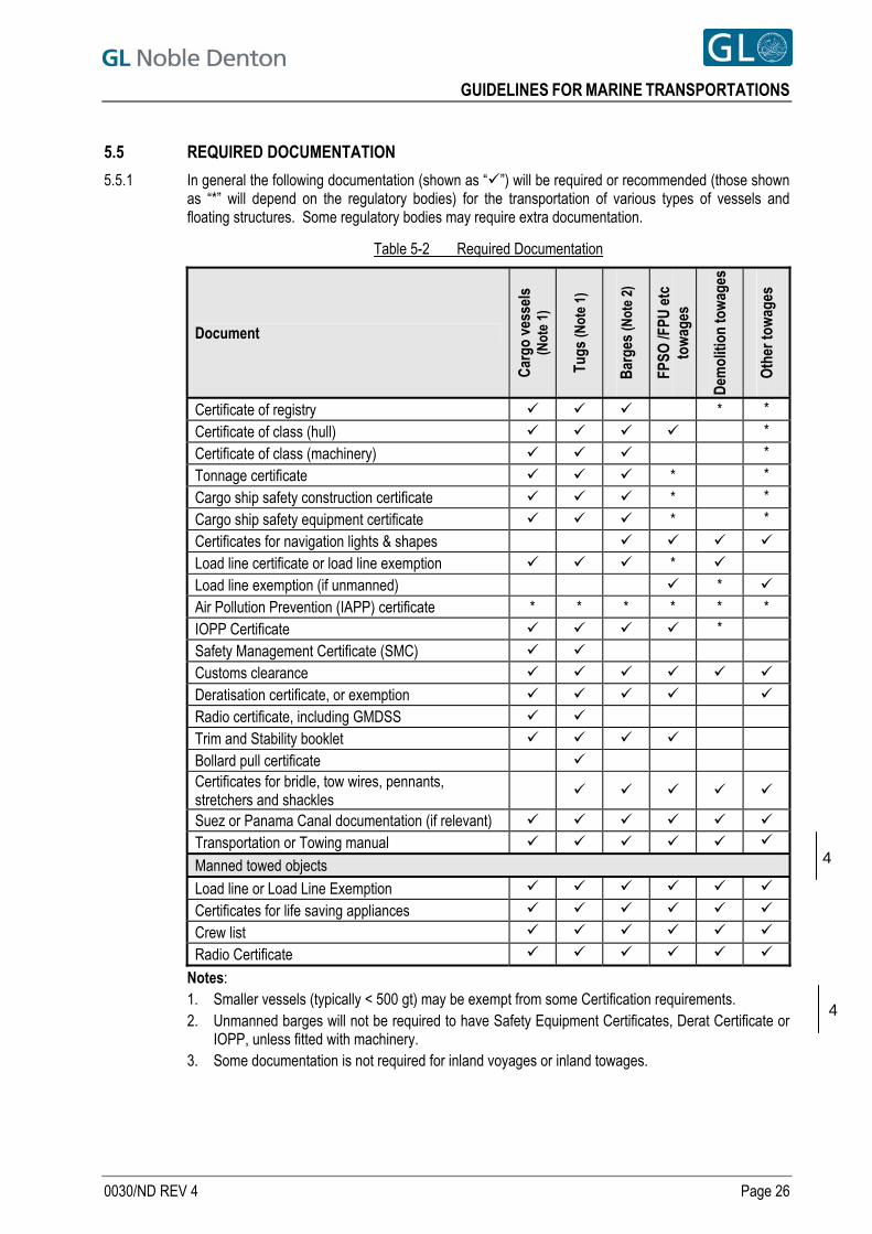
GUIDELINES FOR MARINE TRANSPORTATIONS
5.5 REQUIRED DOCUMENTATION
5.5.1 In general the following documentation (shown as “”) will be required or recommended (those shown as “*” will depend on the regulatory bodies) for the transportation of various types of vessels and floating structures. Some regulatory bodies may require extra documentation.
Table 5-2 Required Documentation
Document
Car
go v
esse
ls
(Not
e 1)
Tugs
(Not
e 1)
Bar
ges
(Not
e 2)
FPSO
/FPU
etc
to
wag
es
Dem
oliti
on to
wag
es
Oth
er to
wag
es
Certificate of registry * *
Certificate of class (hull) * Certificate of class (machinery) * Tonnage certificate * *
Cargo ship safety construction certificate * * Cargo ship safety equipment certificate * * Certificates for navigation lights & shapes Load line certificate or load line exemption * Load line exemption (if unmanned) * Air Pollution Prevention (IAPP) certificate * * * * * * IOPP Certificate * Safety Management Certificate (SMC) Customs clearance Deratisation certificate, or exemption Radio certificate, including GMDSS Trim and Stability booklet Bollard pull certificate Certificates for bridle, tow wires, pennants, stretchers and shackles
Suez or Panama Canal documentation (if relevant) Transportation or Towing manual
Manned towed objects Load line or Load Line Exemption
Certificates for life saving appliances
Crew list
Radio Certificate
4
Notes: 1. Smaller vessels (typically < 500 gt) may be exempt from some Certification requirements.
42. Unmanned barges will not be required to have Safety Equipment Certificates, Derat Certificate or
IOPP, unless fitted with machinery. 3. Some documentation is not required for inland voyages or inland towages.
0030/ND REV 4 Page 26
GUIDELINES FOR MARINE TRANSPORTATIONS
6 DESIGN ENVIRONMENTAL CONDITIONS
6.1 INTRODUCTION
6.1.1 Each transportation shall be designed to withstand the loads caused by the most adverse environmental conditions expected for the area and season through which it will pass, taking account of any agreed mitigating measures.
6.1.2 For each phase of a transportation or marine operation, the design criteria should be defined, consisting of the design wave, design wind and, if relevant, design current. It should be noted that the maximum wave and maximum wind may not occur in the same geographical area, in which case it may be necessary to check the extremes in each area, to establish governing loadcases.
6.1.3 Except as allowed by Sections 6.3 and 6.5 below, the transportation should generally be designed to the 10-year monthly extremes for the area and season, on the basis of a 30 day exposure.
6.2 OPERATIONAL REFERENCE PERIOD
6.2.1 Planning and design of marine transportations shall be based on an operational reference period equal to the planned duration of the operation plus a contingency period.
6.2.2 The planned duration for a transportation shall include, typically: a. The time anticipated, after the departure decision, preparing for departure or waiting for the
correct tidal conditions
b. The time anticipated for the voyage or towage itself
c. Time anticipated on arrival, waiting for the correct tidal conditions to enter harbour
d. If the operation following the transportation is a weather-dependent marine operation such as installation, the time required after arrival at the installation site to reach a safe condition.
6.2.3 The contingency period shall include, as appropriate, an allowance for: a. slower than predicted voyage or towing speed, because of adverse weather conditions or
vessel performance below specification
b. the time required to reach and enter the planned shelter point, in worsening weather conditions if the operation following the transportation is a weather-dependent marine operation such as installation, and the contingency action is to return to shelter.
6.3 WEATHER-RESTRICTED OPERATIONS
6.3.1 A transportation with a reference period generally less than 72 hours may be classed as a weather-restricted operation. The design environmental conditions for such an operation may be set independent of extreme statistical data, provided that: a. The statistics indicate an adequate frequency and duration of the required weather windows
b. Dependable weather forecasts are available
c. The start of the operation is governed by an acceptable weather forecast, covering the reference period
d. A risk assessment has been carried out and the risks shown to be acceptable.
e. Adequate marine procedures are in place.
0030/ND REV 4 Page 27
GUIDELINES FOR MARINE TRANSPORTATIONS
6.3.2 A transportation with a reference period greater than 72 hours may exceptionally be classed as a weather-restricted operation, provided that: a. An adequate shelter point which can be entered in worsening weather is always available within
48 hours or the transport has sufficient speed to avoid the area of forecast severe weather
b. An acceptable weather routeing service is contracted and is available for advice at any time
c. Weather forecasts are received at appropriate intervals
d. The weather forecast service is contracted to issue a warning should the weather forecast deteriorate
e. Management resources of interested parties are always available with the right authority level to monitor any decision to proceed to shelter
f. A risk assessment has been carried out and the risks shown to be acceptable.
g. Adequate marine procedures and equipment are in place.
6.3.3 For weather-restricted operations, the maximum forecast operational criteria should be lower than the design criteria by a margin depending on the area and season, the delicacy of the operation, and the typical reliability of the forecast. The factor is dependent on the duration of the operation and the level of the design criteria set. Typically a factor of 0.7 times the design maxima may be used to determine the maximum forecast operational criteria.
6.4 UNRESTRICTED OPERATIONS
6.4.1 Except as allowed in Section 6.3.2, transportations with an operational reference period greater than 72 hours shall be defined as un-restricted operations.
6.5 CALCULATION OF “ADJUSTED” DESIGN EXTREMES, UNRESTRICTED OPERATIONS
6.5.1 The risk of encounter of extreme conditions by a particular transport is dependent on the length of time that it spends in those route sectors where extreme conditions are possible. If the length of time is reduced, then the probability of encountering extreme conditions is similarly reduced.
6.5.2 It is generally accepted that for a prolonged ocean transport the wind and wave design criteria should be those with a probability of exceedance per voyage of 0.1 or less. For an ocean transport of 30 days (or more), through meteorologically and oceanographically consistent areas, this corresponds to the 10 year monthly extreme.
6.5.3 Many transports last less than 30 days, or are potentially exposed to the most severe conditions for less than 30 days. Consequently, for shorter exposures, the 10 year monthly extreme may be adjusted for reduced exposure. This value is equivalent to the 10 voyage extreme and is also referred to as the 10% risk level extreme. This must not be confused with the 10% exceedance value for the transport, as discussed in Section 6.9.
6.5.4 When the 10% risk level extremes are less than the 1-year return monthly extremes, the 1-year monthly extremes are the minimum that shall be used for design. 4
6.5.5 If the 10 year extremes are due to a tropical cyclone it may not be appropriate to design to adjusted extremes. This is likely to be the case for barge or MODU towages that are not able to respond effectively to weather routeing.
0030/ND REV 4 Page 28
GUIDELINES FOR MARINE TRANSPORTATIONS
6.6 CALCULATION OF EXPOSURE
6.6.1 For the purpose of the calculation of “adjusted” extremes the exposure time to potentially extreme or near extreme conditions is calculated taking consideration of the points discussed below. a. The initial 48 hours of the transportation, is assumed to be covered by a reliable departure
weather forecast and is excluded
b. The speed of the transport is reduced by taking the monthly mean wave heights along the route into consideration as described in Section 6.7.2.
c. The speed of the transport is adjusted to take into consideration the mean currents as described in Section 6.7.3.
d. A contingency time of 25 percent of the time is added. This allowance is to account for severe adverse weather, for tug breakdowns or other operational difficulties
e. A minimum exposure time of 3 days is considered.
6.7 CALCULATION OF VOYAGE SPEED
6.7.1 Voyage duration shall be calculated using the speed in the monthly mean sea state for each route sector and shall allow for adverse currents as described below.
6.7.2 The effect of the mean sea state on the transport speed in each route sector is calculated assuming that the wave height in which the transport will come to a dead stop is b (metres). This is typically 5m for barge towages, and 8m for ships. The calm weather speed is multiplied by a factor, F, defined by:
2
1
b
HF m
where Hm is the monthly mean wave height in that route sector.
6.7.3 The effect of the mean current on the transport speed in each route sector is calculated by adding the current vector (resolved with respect to the transport heading). For the calculation of exposure to the extreme conditions only negative currents which act to delay the transport shall be taken into account.
6.8 CALCULATION OF EXTREMES
6.8.1 The probability of non-exceedance of a value of wind speed or significant wave height in a particular route sector is expressed as a cumulative frequency distribution (e.g. a Weibull distribution).
6.8.2 The probability that during some 3 hour period for waves (or 1 hour for wind) the transport will experience a significant wave height (or wind speed) less than some value x is given by FX(x).
6.8.3 If it takes M hours to pass through the route sector and making the assumption that consecutive wave height and wind speed events are independent then the probability of not exceeding the value x is given by [FX(x)]N where N=M/T where T=1 hour is applied for winds and T=3 hours for waves, which are a more persistent form of energy.
6.8.4 If it is reasonable to expect that extremes of wind speed or wave height could occur in more than one route sector then the probability of not exceeding the value x is given by the product
i
NX
i
ixF )(
6.8.5 The probability of encountering an extreme value of wind speed or significant wave height, during a particular transport, that is reached or exceeded once on average for every 10 transports is 0.1. The value of x is varied until
i
NX
i
ixF )(1 is equal to 0.1
to give the 10 transport extreme for the voyage or towage.
0030/ND REV 4 Page 29
GUIDELINES FOR MARINE TRANSPORTATIONS
6.8.6 This value is also referred to as the “adjusted” extreme for the transport, or as having a risk level of 10%. The method may be adjusted to give other risk levels (e.g. 1% or 5%).
6.8.7 The extremes used for design shall not be less than the 1-year return monthly extremes. 4
6.9 COMPARISON WITH PERCENTAGE EXCEEDENCE
6.9.1 Given a series of values of wind speed or significant wave height, as may be observed during a complete transport, some value y will be exceeded at some times but not others and the percentage exceedance of value y is equal to:
nsobservatioofnumbertotal
exceededytimesofnumber )(100
6.9.2 If each observed value of wind speed or significant wave height is assumed to last for some duration (typically 1 hour for winds and 3 hours for waves) then for example, during a transport lasting 10 days there will be 240 wind events and 80 wave events. On the transport, if a wind speed greater than 30 knots is observed during 24 separate, hourly occasions then the percentage exceedance of 30 knots is 10%.
6.9.3 The 10% risk level (as defined in Section 6.5.3) for a transport along a specific route, departing on a specific date is expected to occur only once, on average, in every 10 transports. However a value with a 10% exceedance level for the same route and departure date is likely to occur on average for 10% of the time on every transport.
6.9.4 Thus a 10% exceedance value is far more likely to occur than a 10% risk level value, or an adjusted, 10 year extreme value.
6.10 CRITERIA FROM TRANSPORT SIMULATIONS
6.10.1 If continuous time series of winds and waves are available along the entire transport route (e.g. from hindcast data or satellite observations), an alternative way to develop criteria with a specified risk of exceedance in a single transport is to perform tow simulations. A large number of simulations can be performed, with uniformly spaced (in time) departure times during the specified month of departure over the number of years in the database. For each simulated transport, the maximum wind speed and the maximum wave height experienced somewhere along the tow route are retained. Then the probability distribution of these transport-maxima can be used to determine the design value with a specified risk of exceedance. For example, the value exceeded once in every 20 transports, on average, can be determined by reading off the value of wave height from the distribution of transport-maximum wave heights at the 95th percentile level.
6.10.2 If fatigue during tow is an issue, the complete distributions of winds and waves experienced during the simulated transports (not just the transport-maximum values) can be retained. These can be used to give scatter diagrams of wave height against period and/or direction, and wind speed against direction.
6.10.3 The transport simulation method can be made to be very realistic and account for. variation of speed due to inclement weather or ocean currents, weather avoidance en route through forecasting/routeing services, or the use of safe havens, etc. If the transport simulator cannot accommodate all these features, a reasonably conservative estimate of criteria can be derived by using a conservative (slow) estimate of the average speed. Care should be taken when choosing the average speed estimate - a slow speed may not be conservative if it results in the vessel apparently arriving in a route sector late enough to miss severe weather, which might have been encountered if arrival had been earlier.
0030/ND REV 4 Page 30
GUIDELINES FOR MARINE TRANSPORTATIONS
6.11 METOCEAN DATABASE BIAS
6.11.1 Regardless of whether the method described in Section 6.8 or the method described in Section 6.10 is used, it is important to know the accuracy of the metocean database being used. Specifically, if there is a known bias in the wind or wave statistics for any segment of a tow, it is essential to adjust the criteria accordingly.
6.12 DESIGN WAVE HEIGHT
6.12.1 The design wave height shall be the significant wave height (Hsig), where Hsig = 4m0 where m0 is the sea surface variance. In sea states with only a narrow band of wave frequencies, Hsig is approximately equal to H1/3 (the mean height of the largest third of the zero up-crossing waves). Advice should be provided as to the appropriate spectra.
6.13 DESIGN WIND SPEED
6.13.1 The design wind speed shall be the 1 minute mean velocity at a reference height of 10m above sea level. The 1 hour wind may also be needed in the calculation process.
6.14 METOCEAN DATA FOR BOLLARD PULL REQUIREMENTS
6.14.1 The design extremes are not normally used for calculation of bollard pull requirements, which are covered in Section 12.2.
0030/ND REV 4 Page 31
GUIDELINES FOR MARINE TRANSPORTATIONS
7 MOTION RESPONSE
7.1 GENERAL
7.1.1 Design motions may be derived by means of motion response analyses, from model tank testing, or by using the default equivalent motion values shown in Section 7.9.
7.2 SEASTATE
7.2.1 For the motion analyses, seastates shall include all relevant spectra up to and including the design wave height for the most severe areas of the proposed voyage route. A wave height smaller than the design wave height, at the natural period of roll and/or pitch of the tow, should also be checked if necessary. "Long-crested" seas will be considered unless there is a justifiable basis for using "short-crested" seas. Consideration should be given to the choice of spectrum which should be applicable to the geographic area and Hsig of the design sea states.
7.2.2 The most probable maximum extreme (MPME) responses are to be based on a 3 hour exposure period and shall be used for design.
7.3 PERIODS
7.3.1 The range of periods associated with the extreme seastate may be calculated in two different ways, with due consideration given to the influence of swell.
7.3.2 In the simplest method the peak period (Tp) for all seastates considered, should be varied as:
(13.Hsig) < Tp < (30.Hsig) where Hsig is in metres, Tp in seconds. The effects of swell should also be considered if not already covered in this peak period range.
However, this method incorrectly assumes that all periods are equally probable. As a result this method should generally produce higher design accelerations than would be the case when using the more robust Hsig-Tp method described in the following section.
4
7.3.3 In the alternative method, a contour is constructed within the Hsig-Tp plane that identifies equally probable combinations of Hsig & Tp for the design return period subject to theoretical constraints on wave breaking. This contour should also cover swell. The combinations should be tested in motion response calculations to identify the worst case response.
7.3.4 The relationship between the peak period Tp and the zero-up crossing period Tz is dependent on the spectrum. For a mean JONSWAP spectrum (γ=3.3) Tp/Tz = 1.286; for a Pierson-Moskowitz spectrum (γ=1) Tp/Tz = 1.41.
0030/ND REV 4 Page 32
GUIDELINES FOR MARINE TRANSPORTATIONS
0030/ND REV 4 Page 33
7.3.5 The following Table 7-1 indicates how the characteristics of the JONSWAP wave energy spectrum vary over the range of recommended seastates. The constant, K, varies from 13 to 30 as shown in the equation in Section 7.3.1 above. T1 is the mean period (also known as Tm).
Table 7-1 Value of JONSWAP γ, ratio of Tp:Tz and Tp:T1 for each integer value of K
Constant K γ Tp/Tz Tp/T1 Constant K γ Tp/Tz Tp/T1 13 5.0 1.24 1.17 22 1.4 1.37 1.27 14 4.3 1.26 1.18 23 1.3 1.39 1.28 15 3.7 1.27 1.19 24 1.1 1.40 1.29 16 3.2 1.29 1.20 25 1.0 1.40 1.29 17 2.7 1.31 1.21 26 1.0 1.40 1.29 18 2.4 1.32 1.23 27 1.0 1.40 1.29 19 2.1 1.34 1.24 28 1.0 1.40 1.29 20 1.8 1.35 1.25 29 1.0 1.40 1.29 21 1.6 1.36 1.26 30 1.0 1.40 1.29
7.4 VESSEL HEADING AND SPEED
7.4.1 The analyses should be carried out for zero vessel speed for head, bow quartering, beam, stern quartering and stern seas.
7.4.2 In addition the analysis should be carried out for non-beam sea cases for the maximum service speed of the vessel or the maximum speed that can be maintained in the given seastate. The range of probable peak wave periods, Tp, should be adjusted for the speed of the vessel as follows:
where VSHIP is the ship speed in m/s and θ is the ship’s heading in degrees (0 = head seas, 180 = following seas).
7.5 THE EFFECTS OF FREE SURFACES
7.5.1 The application of free surface corrections to reduce metacentric height (GM) and hence to increase natural roll period will not generally be accepted. The effect of any reduction in GM must, however, be considered in intact and damage stability calculations.
7.6 THE EFFECTS OF CARGO IMMERSION
7.6.1 The effect of cargo immersion in increasing GM and hence reducing natural roll period as well as increasing damping should be considered in motion response analyses.
7.7 MOTION RESPONSE COMPUTER PROGRAMS
7.7.1 Computer programs shall be validated against a suitable range of model test results in irregular seas. The validation is to be made available to GL Noble Denton and is to contain appropriate analytical work which must be compared with applicable model tests.
7.7.2 When applying the results of a first-order motion response analysis program, heave shall be assumed to be parallel to the global vertical axis. Therefore the component of heave parallel to the deck at the computed roll or pitch angle (theta) is additive to the forces caused by the static gravity component and by the roll or pitch acceleration.
sig
SHIP
sig
P
sig
SHIP
sig
H
V
HT
H
V
H
3056.1
cos1
30
1356.1
cos1
13
GUIDELINES FOR MARINE TRANSPORTATIONS
7.8 RESULTS OF MODEL TESTS
7.8.1 Model tests may be used to derive design motions, provided the tests pass the usual review of overall integrity. Generally, for transportation analyses, the model test results should present the standard deviation of the relevant responses. The standard deviation of the responses should then be multiplied by (2.logn(N)), where N is the number of zero-upcrossings, to obtain the most probable maximum extreme (MPME) in 3 hours, which is required for design. The individual measured maxima from model tests should generally not be used in design as these vary between different realisations of the same sea conditions, and are therefore unreliable for use as design values. These recommendations apply to Gaussian responses, which is an appropriate assumption for most wave frequency motion responses. If in the unlikely event that the response is significantly non-Gaussian, then alternative methods should be used.
4
7.8.2 Maximum values of global loads, motions or accelerations from model test results can be used provided ten similar realisations, or greater, are carried out to ensure that variations between individual tests are accounted for. The mean and standard deviations of the maxima should be calculated. The design value should be the mean plus two standard deviations.
7.8.3 Scale effects should also be accounted for by increasing the design loads by a further 10% or a mutually agreed value.
7.9 DEFAULT MOTION CRITERIA
7.9.1 If neither a motions study nor model tests are performed, then for standard configurations and subject to satisfactory marine procedures, the following motion criteria may be acceptable.
0030/ND REV 4 Page 34
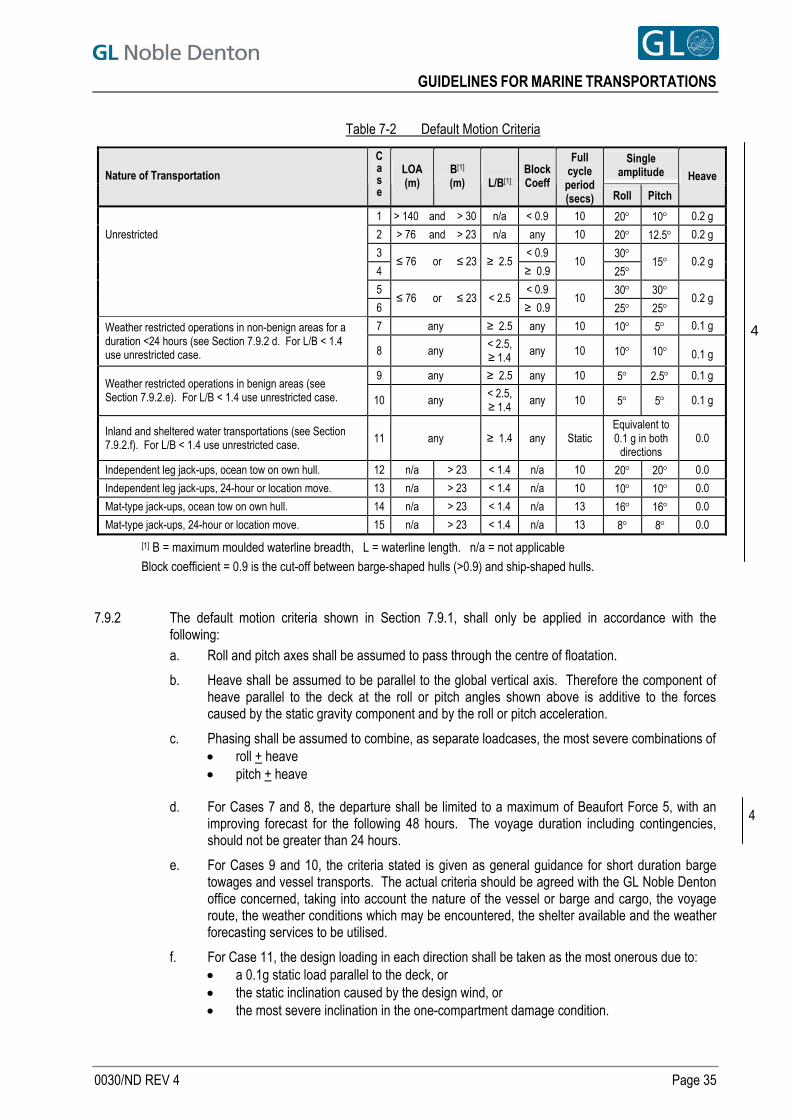
GUIDELINES FOR MARINE TRANSPORTATIONS
Table 7-2 Default Motion Criteria
Single amplitude Nature of Transportation
Ca s e
LOA (m)
B[1] (m)
L/B[1]
Block Coeff
Full cycle period (secs) Roll Pitch
Heave
1 > 140 and > 30 n/a < 0.9 10 20 10 0.2 g
Unrestricted 2 > 76 and > 23 n/a any 10 20 12.5 0.2 g
3 < 0.9 30
4 ≤ 76 or ≤ 23 ≥ 2.5 10
≥ 0.9 25 15 0.2 g
5 < 0.9 30 30
6 ≤ 76 or ≤ 23 < 2.5 10
≥ 0.9 25 25 0.2 g
7 any ≥ 2.5 any 10 10 5 0.1 g Weather restricted operations in non-benign areas for a duration <24 hours (see Section 7.9.2 d. For L/B < 1.4 use unrestricted case. 8 any < 2.5,
≥ 1.4 any 10 10 10
0.1 g
9 any ≥ 2.5 any 10 5 2.5 0.1 g Weather restricted operations in benign areas (see Section 7.9.2.e). For L/B < 1.4 use unrestricted case. 10 any < 2.5,
≥ 1.4 any 10 5 5 0.1 g
Inland and sheltered water transportations (see Section 7.9.2.f). For L/B < 1.4 use unrestricted case. 11 any ≥ 1.4 any Static
Equivalent to 0.1 g in both
directions 0.0
Independent leg jack-ups, ocean tow on own hull. 12 n/a > 23 < 1.4 n/a 10 20 20 0.0
Independent leg jack-ups, 24-hour or location move. 13 n/a > 23 < 1.4 n/a 10 10 10 0.0
Mat-type jack-ups, ocean tow on own hull. 14 n/a > 23 < 1.4 n/a 13 16 16 0.0
Mat-type jack-ups, 24-hour or location move. 15 n/a > 23 < 1.4 n/a 13 8 8 0.0
4
[1] B = maximum moulded waterline breadth, L = waterline length. n/a = not applicable
Block coefficient = 0.9 is the cut-off between barge-shaped hulls (>0.9) and ship-shaped hulls.
7.9.2 The default motion criteria shown in Section 7.9.1, shall only be applied in accordance with the following: a. Roll and pitch axes shall be assumed to pass through the centre of floatation.
b. Heave shall be assumed to be parallel to the global vertical axis. Therefore the component of heave parallel to the deck at the roll or pitch angles shown above is additive to the forces caused by the static gravity component and by the roll or pitch acceleration.
c. Phasing shall be assumed to combine, as separate loadcases, the most severe combinations of roll + heave pitch + heave
d. For Cases 7 and 8, the departure shall be limited to a maximum of Beaufort Force 5, with an improving forecast for the following 48 hours. The voyage duration including contingencies, should not be greater than 24 hours.
4
e. For Cases 9 and 10, the criteria stated is given as general guidance for short duration barge towages and vessel transports. The actual criteria should be agreed with the GL Noble Denton office concerned, taking into account the nature of the vessel or barge and cargo, the voyage route, the weather conditions which may be encountered, the shelter available and the weather forecasting services to be utilised.
f. For Case 11, the design loading in each direction shall be taken as the most onerous due to: a 0.1g static load parallel to the deck, or the static inclination caused by the design wind, or the most severe inclination in the one-compartment damage condition.
0030/ND REV 4 Page 35
GUIDELINES FOR MARINE TRANSPORTATIONS
7.9.3 Alternative default motion criteria may be acceptable, as set out, for instance, in DNV Rules for the Classification of Ships, January 2003, Part 3, Chapter 1, Section 4 [Ref. 9], or IMO Code of Safe Practice for Cargo Stowage and Securing, 2003 Edition, Section 7 [Ref. 10]. Care should be taken to ensure that the criteria adopted are applicable to the actual case in question.
7.10 DIRECTIONALITY AND HEADING CONTROL
7.10.1 The incident weather shall be considered to be effectively omni-directional, as stated in Section 7.4. No relaxation in the design seastates from the bow-quartering, beam and stern-quartering directions shall be considered for: a. Any transport where the default motion criteria are used, in accordance with Section 7.9, or
similar
b. Single tug towages, or voyages by vessels with non-redundant propulsion systems (see Section 7.10.3 below).
c. Any transport where the design conditions on any route sector are effectively beam on or quartering, of constant direction, and of long duration, including, for example, crossing of the Indian Ocean or Arabian Sea in the south-west monsoon
d. Any towage in a Tropical Revolving Storm area and season
e. Any un-manned towage.
f. Any transport where the vessel does not have sufficient, redundant systems to maintain any desired heading in all conditions up to and including the design storm, taking account of the windage of the cargo.
7.10.2 Relaxation in the non-head sea cases may be considered for: a. Manned, multiple tug towages, where after breakdown of any one tug or breakage of any one
towline or towing connection, the remaining tug(s) still comply with the criteria of Section 12.2.
b. Voyages by self-propelled vessels with redundant propulsion systems. A vessel with a redundant propulsion system is defined as having, as a minimum:
2 or more independent main engines
2 or more independent fuel supplies
2 or more independent power transmission systems
2 or more independent switchboards
2 or more independent steering systems, or an alternative means of operation of a single steering system (but excluding emergency steering systems that cannot be operated from the bridge)
the ability to maintain any desired heading in all conditions up to and including the design storm, taking account of the windage of the cargo.
7.10.3 Any vessel not complying with all the above shall be considered non-redundant. 7.10.4 An advance survey may be required, to establish whether or not a vessel can be considered to have a
redundant propulsion system.
0030/ND REV 4 Page 36
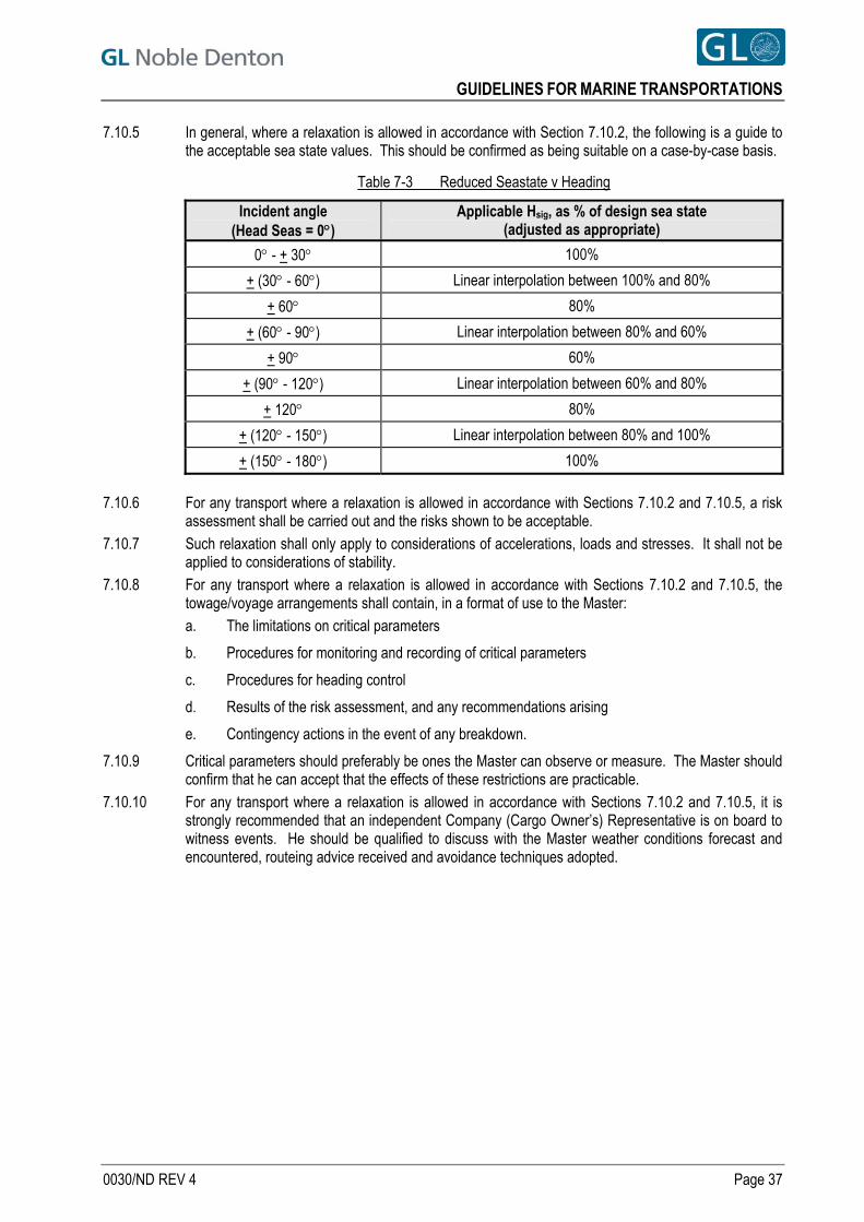
GUIDELINES FOR MARINE TRANSPORTATIONS
7.10.5 In general, where a relaxation is allowed in accordance with Section 7.10.2, the following is a guide to the acceptable sea state values. This should be confirmed as being suitable on a case-by-case basis.
Table 7-3 Reduced Seastate v Heading
Incident angle (Head Seas = 0)
Applicable Hsig, as % of design sea state (adjusted as appropriate)
0 - + 30 100%
+ (30 - 60) Linear interpolation between 100% and 80%
+ 60 80%
+ (60 - 90) Linear interpolation between 80% and 60%
+ 90 60%
+ (90 - 120) Linear interpolation between 60% and 80%
+ 120 80%
+ (120 - 150) Linear interpolation between 80% and 100%
+ (150 - 180) 100%
7.10.6 For any transport where a relaxation is allowed in accordance with Sections 7.10.2 and 7.10.5, a risk
assessment shall be carried out and the risks shown to be acceptable. 7.10.7 Such relaxation shall only apply to considerations of accelerations, loads and stresses. It shall not be
applied to considerations of stability. 7.10.8 For any transport where a relaxation is allowed in accordance with Sections 7.10.2 and 7.10.5, the
towage/voyage arrangements shall contain, in a format of use to the Master: a. The limitations on critical parameters
b. Procedures for monitoring and recording of critical parameters
c. Procedures for heading control
d. Results of the risk assessment, and any recommendations arising
e. Contingency actions in the event of any breakdown.
7.10.9 Critical parameters should preferably be ones the Master can observe or measure. The Master should confirm that he can accept that the effects of these restrictions are practicable.
7.10.10 For any transport where a relaxation is allowed in accordance with Sections 7.10.2 and 7.10.5, it is strongly recommended that an independent Company (Cargo Owner’s) Representative is on board to witness events. He should be qualified to discuss with the Master weather conditions forecast and encountered, routeing advice received and avoidance techniques adopted.
0030/ND REV 4 Page 37
GUIDELINES FOR MARINE TRANSPORTATIONS
8 LOADINGS
8.1 INTRODUCTION
8.1.1 The structure of the cargo or tow, including the legs, hull and jackhouses of self-elevating units, shall be shown to possess adequate strength to resist the loads imposed due to the specified or calculated motions and wind, combined with the additional loading caused by any overhang of the cargo over the side of the vessel or barge.
8.1.2 The cargo shall be shown to possess adequate strength to withstand the local cribbing and seafastening reactions.
8.2 LOADCASES
8.2.1 Loadcases for each heading shall be derived by the addition of fluctuating loads resulting from wind and wave action to static loads resulting from gravity and still water initial conditions.
8.2.2 The fluctuating components shall be the worst possible combination of the loads resulting from calculations or model tests carried out in accordance with Sections 7.1 through 7.8, with due account to be taken of the effects of phase. All influential loadings shall be considered: however the following static and environmental loadings are the most likely to be of importance: S1: Loadings caused by gravity including the effects of the most onerous ballast condition on the
voyage.
F1: Loadings caused by the wind heel and trim angle.
F2: Loadings caused by surge and sway acceleration
F3: Loadings caused by pitch and roll acceleration
F4: Loadings caused by the gravity component of pitch and roll motion
F5: Loadings caused by direct wind
F6: Loadings caused by heave acceleration, including heave.sin(theta) terms
F7: Loadings caused by wave induced bending
F8: Loadings caused by slam and the effects of immersion.
8.2.3 One of the following three methods shall be used to determine the design loadings: 8.2.3.1 Except as noted in Section 7.9.2, the effects of phase differences between the various motions can be
considered, if resulting from model test measurements, or if the method of calculation has been suitably validated.
8.2.3.2 In cases where it is not convenient or possible to determine the relative phasing of extreme wind loadings and heave accelerations with roll/sway or pitch/surge maxima, a reduction of 10 percent may be applied to fluctuating loadcases F1 through F8 which combine maximum wind and wave effects. However, if wind induced or wave induced loads individually exceed the reduced load, then the greatest single effect shall be considered.
8.2.3.3 Alternatively, the total loads may be calculated by combination of loads as follows:
S1 + F1(1hr) + F5(1hr) + {[F2+F3+F4+F6]2 + [F1(1min)+F5(1min)–F1(1hr)–F5(1hr)]2}
Where:
F(1hr) = Loads based on 1 hour mean wind speed
F(1min) = Loads based on 1 minute mean wind speed.
0030/ND REV 4 Page 38
GUIDELINES FOR MARINE TRANSPORTATIONS
8.3 DEFAULT MOTION CRITERIA
8.3.1 For loads computed in accordance with Section 7.9, the loads applied to the cargo shall be:
S1 + F1 + F3 + F4 + F6
where: S1, F1, F3, F4 and F6 are as defined in Section 8.2.2. The effects of buoyancy and wave slam loading shall also be considered if appropriate.
As stated in Section 7.9.2 c) roll and pitch cases are to be considered separately. Combined roll and pitch are not required.
8.4 LONGITUDINAL BENDING
8.4.1 The potential effects of longitudinal wave bending effects need to be considered if: a. The towed hull is not a classed, seagoing vessel or barge, or
b. The cargo is longer than about 1/3rd of the transport barge or vessel length, or
c. The cargo is supported longitudinally on more than 2 groups of supports, or
d. The relative stiffness of the hull and cargo could cause unacceptable stresses to be induced in either, or
e. The seafastening design allows little or no flexibility between cargo and barge.
8.4.2 Some cargoes, such as large steel jackets, may be inherently much stiffer than the barge, and will reduce barge deflections, at the expense of increased cargo stresses.
8.4.3 See also Sections 9.2.2 for friction, 9.3 for seafastening design and 19.4 for jack-ups.
8.5 CARGO BUOYANCY AND WAVE SLAM
8.5.1 Cargo overhangs which are occasionally immersed, and which may receive loadings due to wave slam and/or immersion, will require special consideration.
8.5.2 Buoyant cargoes, particularly where the buoyancy contributes to stability requirements, shall be adequately secured against lift-off unless it can be shown that lift-off will not occur.
0030/ND REV 4 Page 39

GUIDELINES FOR MARINE TRANSPORTATIONS
9 DESIGN AND STRENGTH
9.1 COMPUTATION OF LOADS
9.1.1 The loads acting on grillages, cribbing, dunnage, seafastening and components of the cargo shall be derived from the loads acting on the cargo, according to Sections 6, 7 and 8, as applicable.
9.1.2 The loads shall include components due to the distribution of mass and rotational inertia of the cargo. This is of particular importance in the calculation of shear forces and bending moments in the legs of self-elevating units and similar tall structures.
9.1.3 If the computed loads are less than the “Minimum allowable seafastening force” shown in Table 9-1, then the values in the Table shall apply.
9.1.4 Care should be taken in cases where the cargo may be designed for service loads in the floating condition, but is being dry-transported. Its centre of gravity may be higher above the roll centre in the dry-transportation condition than in any of its floating service conditions. Even though the transportation motions may appear to be less than the service motions, the loads on cargo components and ship-loose items may be greater.
0030/ND REV 4 Page 40
GUIDELINES FOR MARINE TRANSPORTATIONS
9.2 FRICTION
9.2.1 For certain cargo weights, cargo overhangs and arrangements of cribbing and seafastenings, the effects of friction may be used, as shown in the following Table 9-1 and subject to Section 9.2.2, to resist part of the computed loadings on the cribbing and seafastenings. This shows the maximum coefficient of friction which may be considered, and the minimum required seafastening force, expressed as a percentage of cargo weight, below which the actual seafastening design capability shall not be allowed to fall.
Table 9-1 Maximum allowable coefficients of friction & minimum seafastening forces
Cargo weight, W, tonnes
<100 100 <W< 1,000
1,000 <W< 5,000
5,000 <W<
10,000
10,000<W<
20,000
20,000<W<
40,000 > 40,000 Overhang
Maximum allowable coefficient of friction
None 0 0.10 0.20 0.20 0.20 0.20 0.20
< 15 m 0 0 0.10 0.20 0.20 0.20 0.20
15 – 25 m 0 0 0 0.10 0.20 0.20 0.20
25 – 35 m 0 0 0 0 0.10 0.20 0.20
35 - 45 m 0 0 0 0 0 0.10 0.10
> 45 m 0 0 0 0 0 0 0
Minimum required seafastening force, %W
Transverse 10% 10% 10% 10% 10% See Note 1 5%
Longitudinal 5% 5% 5% 5% See Note 2
See Note 3 1.5%
Notes: 1. For 20,000 ≤ W < 40,000 tonnes, the minimum required seafastening force, transversely, shall be
not less than 15 - W/4,000 (%W) 2. For 10,000 ≤ W < 20,000 tonnes, the minimum required seafastening force, longitudinally, shall be
not less than 7.5 - W/4,000 (%W) 3. For 20,000 ≤ W < 40,000 tonnes, the minimum required seafastening force, longitudinally, shall be
not less than 3.5 - W/20,000 (%W) 4. For transport of pipes and similar tubular goods, the above table does not apply. See Section 9.6. 5. The friction coefficient may be interpolated as a function of overhang using the maximum cargo
overhang.
0030/ND REV 4 Page 41
GUIDELINES FOR MARINE TRANSPORTATIONS
9.2.2 Friction is allowed as a contribution to seafastening restraint subject to the following: a. Loadings are computed in accordance with Sections 7.2 though 7.8 and 8.2 above. Friction
may not be used if the loadings are computed in accordance with the default criteria in Sections 7.9 and 8.3, except as allowed by Section 9.6.
b. Friction forces shall be computed using the normal reaction between the vessel and cargo compatible with the direction of the heave.sin(theta) term used in computing the forces parallel to the deck in Section 8.2.2. Thus, when heave.sin(theta) increases the force parallel to the deck, it also increases the normal reaction and vice-versa.
c. The cargo is supported by wood dunnage or cribbing – friction is not allowed for steel to steel interfaces.
d. The overhang is the distance from the side of the vessel to the extreme outer edge of the cargo.
e. For wood cribbing less than 600 mm high, with a width not less than 300 mm, the friction force due to the friction coefficient permitted in Table 9-1 may be assumed to act in any direction relative to the cribbing provided that:
(i) the cribbing is reasonably well balanced in terms of the proportion in the fore-aft and transverse directions, AND
(ii) each of these groups is reasonably well balanced about the cargo CoG in plan.
f. Provided that the conditions in (e) above are met, for cribbing heights between 600 and 900 mm, with a width not less than 300 mm, then the percentage computed friction force at right angles to the longitudinal axis of a cribbing beam shall not exceed (900 - H)/3 %, where H = the height of cribbing above deck, in mm. In the direction of the longitudinal axis of a cribbing beam, the full friction force can be used. 4
g. For wood cribbing over 900 mm high, or with a width less than 300 mm, no friction force is assumed to act in a direction at right angles to the longitudinal axis of a cribbing beam.
h. If greater cribbing friction is required than available according to (f) and (g) above, stanchions may be fitted to provide transverse cribbing restraint. Where such stanchions are fitted, they should be designed to carry loads due to a friction coefficient of 0.5 (to ensure they are able to carry loads due to upper-bound friction assumptions).
i. The underlying assumption in the approach given above is that the seafastenings have sufficient flexibility to deflect in the order of at least 2mm without failing. This will be reasonable in most cases, but when this is not the case the more detailed approach given in (j) below shall be used.
j. As an alternative to (e) through (h) above, a more detailed approach may be used. In such cases, the friction permitted in Table 9-1 can be doubled, but the relative flexibility of the cribbing and seafastenings shall be taken into account. The arrangements shall be such as to ensure that the required lateral load can be carried by the combination of friction & seafastening reactions BEFORE the seafastenings are overstressed. Where stanchions are used, they shall comply with (h) above.
k. The “Minimum allowable seafastening force” is the minimum allowable value of seafastening restraint, expressed as a percentage of cargo weight, in the event that the total required seafastening force, as computed, is less than this value.
l. For very short duration moves in sheltered water, such as turning a barge back alongside the quay after a loadout, then friction may be allowed to contribute. The entire load path, including the potential sliding surfaces, shall be demonstrated to be capable of withstanding the loading generated.
0030/ND REV 4 Page 42
GUIDELINES FOR MARINE TRANSPORTATIONS
9.3 SEAFASTENING DESIGN
9.3.1 In this context, seafastenings include any grillage, dunnage, cribbing or other supporting structure, roll, pitch and uplift stops, and the connections to the barge or vessel.
9.3.2 Seafastenings shall be designed to withstand the global loadings as computed in Sections 7 and 8. 9.3.3 Seafastenings shall be designed to accept deflections of the barge or vessel in a seaway, principally
due to longitudinal bending. In general, longitudinal bending should be considered for the cases described in Sections 8.4.1 and 8.4.2.
9.3.4 Where longitudinal bending is a consideration, suitable seafastening designs include: a. Chocks which allow some movement between the barge and cargo
b. Pitch stops at one point only along the cargo, with other points free to slide or deflect longitudinally
c. Vertical supports at only 2 positions longitudinally
d. An integrated structure of barge-seafastenings-cargo, capable of resisting the loads induced by bending and shear.
9.3.5 Additionally, for towed objects such as FPSOs, which may have permanently installed modules with piping or other connections between them, there should be adequate flexibility in the connections to avoid overstress. It should be noted that the transport wave bending condition may be more severe than the operating condition. In long modules carried as cargo, internal pipework should be similarly considered.
9.3.6 In the absence of more detailed information, it should be assumed that the barge will incur bending and shear deflection as if unrestrained by the cargo. Quasi-static barge hogging and sagging should be considered in a wave of length L equal to the barge length, and height = 0.61L, metres.
9.3.7 Grillage and seafastening design is frequently influenced by the loadout method. Cargoes lifted onto the transport barge or vessel, or floated over a submersible barge or vessel, are frequently supported by timber cribbing or dunnage to distribute the loads and allow for minor undulations in the deck plating. Cargoes loaded by skidding normally remain on, and are seafastened to, the skidways. Cargoes loaded out by trailers normally need a grillage structure higher than the minimum trailer height. The grillage or cribbing height must allow for any projections below the cargo support line.
9.3.8 Welded steel seafastenings are preferred, but for smaller cargoes, typically of less than 100 tonnes, chain or wire lashings with suitable tensioning devices may be acceptable. Chain binders or turnbuckles shall be tensioned before departure to spread the load between the seafastenings and secured so that they cannot become slack. Lashings should be inspected regularly and after bad weather to ensure that tension is maintained. Wire lashings are not recommended for unmanned transportations unless such inspections can be made. Guidance on good practice for lashings and similar devices may be found in the IMO Code of Safe Practice for Cargo Securing and Stowing, 2003 Edition [Ref. 10].
9.3.9 The design load in any chain used for seafastening should not exceed the certified (lifting) WLL or SWL of the chain. When the WLL /SWL is not known, it shall be taken as no more than the certified BL / 2.25.
9.3.10 Connections to the deck of a barge or vessel should be carefully considered, particularly tension connections. Calculations should be presented to justify all connections. It should not be assumed, without inspection, that underdeck connections between deck plating and stiffeners or bulkheads are adequate. Seafastenings landing on doubler plates are not generally acceptable as tension connections.
9.3.11 Care should be taken to avoid welding onto fuel oil tanks or oil cargo tanks, unless the tanks are empty, and gas free certification has been obtained.
9.3.12 Final welded connections, particularly those which may be influenced by longitudinal deflections of the barge or vessel, should be carried out with the barge or vessel ballasted to the transportation condition, or as close as draught limitations permit.
0030/ND REV 4 Page 43
GUIDELINES FOR MARINE TRANSPORTATIONS
9.3.13 Welding of seafastenings should not be carried out in wet conditions. Weather protection should be used to minimise the effects of wet conditions.
9.3.14 For cargoes that will be removed offshore, the seafastenings should be capable of being released in stages, such that the cargo is secure for a 10 degree static angle until the release of the final stage. The release of seafastenings, and the removal of any one item, should not disturb the seafastenings of any other item.
9.3.15 Where a lift is made onto a barge offshore, the seafastenings should be designed accordingly, normally by means of guides or a cradle, which will hold the cargo whilst it is being seafastened.
9.3.16 Items of the cargo which are vulnerable to wave action, wetting or weather damage shall be suitably protected. This may require provision of breakwaters or waterproofing of sensitive areas.
9.3.17 Internal seafastenings may be needed to prevent items moving inside structures or modules. See also the caution in Section 9.1.4 for dry transportations.
9.3.18 Guide posts should not be used for seafastenings unless specifically designed for that purpose.
9.4 CRIBBING
9.4.1 Where the cargo is supported on wooden cribbing or dunnage, rather than steel-to-steel supports, then sufficient material should be provided to ensure an adequate distribution of load to the underside of the cargo and to the deck of the transport vessel, under the static loadings and the design environmental loadings as shown in Sections 7 and 8.
9.4.2 Cribbing designed to pick up structural members in the underside of the cargo, the transport vessel deck, or both, and fixed to the deck of the vessel, should not normally be less than 200 mm high. See also the comments on cribbing width in Sections 9.2.2.f and 9.2.2.g.
9.4.3 A minimum clearance of 0.075 m should be provided between the lowest protrusion of the cargo and the deck of the barge or vessel.
9.4.4 The nominal bearing pressure on the cribbing should not normally exceed 4 N/mm2 for softwood. Should it be demonstrated that the cargo, vessel and cribbing, without crushing, can withstand a higher pressure, then this may be acceptable. The cribbing pressure should be calculated taking into account the deadweight of the cargo plus the loads caused by the design environmental loadings.
9.4.5 Ideally the type of timber selected should withstand the computed cribbing pressures without crushing. Localised crushing to accommodate cargo and cribbing imperfections is permissible. A satisfactory arrangement may consist of hardwood for the main cribbing structure, topped by a soft packing layer, say 50 mm thick.
9.4.6 In the case of a random or herring-bone dunnage layout supporting a flat-bottomed cargo, without taking into account the strong points, then the maximum cribbing pressures should not exceed 1 N/mm2, subject to consideration of the overall allowable loads on the deck of the vessel and the underside of the cargo.
9.4.7 For cargoes floated on and/or off a grounded or partially grounded transport barge or vessel, the cribbing should be designed to withstand loads caused by point loads and trim or heel angles during on-load and off-load. A minimum of 5º should be considered.
9.5 STRESS LEVELS IN CARGO, GRILLAGE & SEAFASTENINGS
9.5.1 The cargo, grillage and seafastenings shall be shown to possess adequate strength to resist the loads imposed during the voyage. Any additional loadings caused by any overhang of the cargo over the side of the transport vessel, buoyancy forces and wave slam loadings shall be included.
9.5.2 The cargo shall be shown to have adequate strength to withstand the local cribbing and seafastening loads.
9.5.3 Stress levels shall be within those permitted by the latest edition of a recognised and applicable offshore structures code.
0030/ND REV 4 Page 44
GUIDELINES FOR MARINE TRANSPORTATIONS
9.5.4 The structural strength of high quality structural steelwork with full material certification and NDT inspection certificates showing appropriate levels of inspection (see Section 9.7) shall be assessed using the methodology of a recognised and applicable offshore code including the associated load and resistance factors for LRFD codes or safety factors for ASD/WSD codes. Traditionally AISC has also been considered a reference code. If the AISC 13th Edition is used, the allowables shall be compared against member stresses determined using a load factor on both dead and live loads of no less than:
WSD option LRFD Option
SLS: 1.0 1.60 ULS: 0.75 1.20
9.5.5 Stress in fillet fillet welds for brackets loaded by a force acting in a direction parallel to the weld bead shall be assessed using the method presented in Appendix F. The allowables shall be compared against member stresses determined using a load factor on both dead and live loads of no less than
SLS: 1.40 ULS: 1.05
9.5.6 Any load case may be treated as a normal serviceability limit state (SLS) / Normal operating case. 9.5.7 Most probable maximum extreme (MPME) load cases, (which typically occur at the same frequency as
the maximum wave associated with the design seastate) may be treated as an ultimate limit state (ULS) / Survival storm case provided that they are dominated by environmental forces. This does not apply to:
4
Steelwork subject to deterioration and/or limited initial NDT unless the condition of the entire loadpath has been verified, for example the underdeck members of a barge or vessel.
Steelwork subject to NDT prior to elapse of the recommended cooling and waiting time as defined by the Welding Procedure Specification (WPS) and NDT procedures. In cases where this cannot be avoided by means of a suitable WPS, it may be necessary to increase the strength or impose a reduction on the design/permissible seastate.
9.6 SECURING OF PIPE AND OTHER TUBULAR GOODS
9.6.1 This section refers to the transport of tubulars, including line pipe, casing, drill pipe, collars, piles, conductors marine risers and similar, hereafter called “pipes”, on vessels and barges. Transport of drill pipe, collars etc on jack-ups is covered in Section 19.11. The degree and design of securing required will depend on the type of vessel, the nature of the cargo, the duration of the towage or voyage, and the weather conditions expected.
9.6.2 For these types of cargoes, friction may be assumed to resist longitudinal seafastening loads, and Sections 9.2.1 and 9.2.2.a do not apply. The following friction coefficients may be used, as examples:
Table 9-2 Typical Friction Coefficients
Materials in contact Friction coefficient
Concrete coated pipe - concrete coated pipe 0.5
Concrete coated pipe - timber 0.4
Timber - timber 0.4
Uncoated steel - timber 0.3
Uncoated steel - uncoated steel 0.15
Epoxy coated pipe - timber 0.1
Epoxy coated pipe - epoxy coated pipe 0.05
0030/ND REV 4 Page 45
GUIDELINES FOR MARINE TRANSPORTATIONS
9.6.3 Caution should be exercised where sand may be present between the friction surfaces as this may considerably reduce the friction coefficient.
9.6.4 Generally speaking, pipes should be stowed in the fore and aft direction. 9.6.5 Where pipes are stacked in several layers, the maximum permissible stacking height shall be
established, in order to avoid overstress of the lower layers. Reference may be made to API RP 5LW “Recommended practice for transportation of line pipe on barges and marine vessels” [Ref. 14].
9.6.6 Smaller diameter pipes such as drill pipe may be stacked without individual chocking arrangements and restrained transversely by means of vertical stanchions. Timber dunnage or wedges shall be used to chock off any clearance between the pipes and the stanchions. The stanchions, taken collectively, shall be capable of resisting the total transverse force computed. a. For weather-restricted operations, and 24-hour or location moves of jack-ups, the stack may be
secured by means of transverse chain or wire lashings over the top, adequately tensioned. Provided it can be demonstrated that sufficient friction exists to prevent longitudinal movement, no end stops need be provided.
b. For unrestricted operations, including ocean transportations of jack-ups, steel strongbacks should be fitted over the top layer, and each stow (group of pipes) set up hard by driving wooden wedges between the strongbacks and the top layer of pipe. End stops or bulkheads shall be provided.
9.6.7 Line pipe on pipe carrier vessels may be stacked between the existing stanchions/crash barriers, on the wooden sheathed deck. Timber dunnage or wedges should be used to chock off any clearance between the pipes and the stanchions. a. For weather restricted operations, provided it can be demonstrated that adequate friction exists
to prevent longitudinal movement, no end stops need be provided. This is likely to apply to concrete coated pipe, but uncoated or epoxy coated pipe should be treated with caution.
b. For unrestricted operations, steel strongbacks should be fitted over the top layer, and each stow set up hard by driving wooden wedges between the strongbacks and the top layer of pipe. End stops or bulkheads shall be provided.
9.6.8 Larger diameter pipes such as piles are often individually chocked, and end stops provided, often at one end only. Unless it can be demonstrated that the piles cannot roll out of the chocks further restraints may be necessary, such as individual wire or chain lashings, stanchions or strongbacks.
9.6.9 In all cases of transportation of coated line pipe, the transportation and securing arrangements must be designed so that the coating will be protected from damage. The manufacturer’s and/or shipper’s recommendations should be sought.
9.6.10 Where end stops are provided for pipes with prepared ends, the end preparation should be protected, either with protectors on the pipe, or by wood sheathing on the end stops.
9.6.11 When open ended pipes are carried as deck cargo and the pipes could become partially filled with water, care should be taken to ensure that: a. the vessel’s stability meets the requirements of Section 10, with particular reference to the
effects of entrapped water, and
b. the deck and pipe layers are not overstressed.
Otherwise, it may be necessary to seal the ends of at least the lowest level of the stack. 9.6.12 Note: the trim and stability booklet of some vessels may include suitable example loading conditions
and should be considered.
0030/ND REV 4 Page 46
GUIDELINES FOR MARINE TRANSPORTATIONS
9.7 INSPECTION OF WELDING AND SEAFASTENINGS
9.7.1 For newly-constructed cargoes, an adequate system of construction supervision, weld inspection and testing shall be demonstrated. For other cargoes, the extent of inspection and testing shall be agreed.
9.7.2 Principal seafastening welds shall be visually checked and the weld sizes confirmed against the agreed design.
9.7.3 Non-destructive testing (NDT), by a suitable and agreed method, shall be carried out on the structural members of the seafastenings. NDT acceptance criteria should be to EEMUA 158 “Construction specification for fixed offshore structures in the North Sea” [Ref. 15], AWS D1.1 “Structural welding code – steel” [Ref .16] or equivalent. The following is a guide to the minimum recommended extent of NDT: a. 100% visual
b. Penetration welds - 40% UT and 20% MPI
c. Fillet welds - 20% MPI
d. All welds to barge/vessel deck - 100% MPI with additional 40% UT for penetration welds
e. In any case, the extent of NDT should be not less than the Project specification requirements
f. For critical areas or where poor welding quality is suspected, then 100% inspection may be required.
9.7.4 Care should be taken where the seafastening load path depends on the tension connection of the deck plating of a barge or vessel to underdeck stiffeners or bulkheads. In cases of any doubt about the condition, an initial visual inspection should be undertaken, to establish that fully welded connections exist, and that the general condition is fit for purpose. Further inspection may be required, depending on the stress levels imposed and the condition found.
9.7.5 Any faulty welds discovered shall be repaired and re-tested.
9.8 FATIGUE
9.8.1 Notwithstanding the exclusion in Section 4.6.7, clients may wish the effects of fatigue on the towed object, cargo and/or seafastenings to be considered, in which case they should instruct GL Noble Denton accordingly.
9.9 USE OF SECOND HAND STEEL SEAFASTENINGS
9.9.1 When second hand steel seafastenings are used, any wastage caused during previous removal(s) or use should not affect its fitness for purpose, and there should be sufficient documentation to ensure the traceability of the steel and in particular documentation relating to the grade of steel.
9.9.2 There should be NDT inspection reports for areas of previous fabrication, old welds, burnt off attachments etc, to demonstrate no cracking or lamellar tearing in critical areas.
9.9.3 Should sufficient documentation of the type of steel (e.g. EN10025) be unavailable, coupon testing is acceptable to determine the steel type. The guaranteed minimum properties of this type of steel are to be used, not the tested values which may not be representative of the rest of the steel.
4
0030/ND REV 4 Page 47
GUIDELINES FOR MARINE TRANSPORTATIONS
10 STABILITY
10.1 INTACT STABILITY
10.1.1 The intact range of stability, defined as the range between 0º degrees heel or trim and the angle at which the righting arm (GZ) becomes negative, shall not be less than the values shown in the following Table 10-1. Objects which do not fall into the categories shown in the Table, which are non-symmetrical, or which have an initial heel or trim which is not close to 0º, may require special consideration. Where there is a significant difference between the departure, arrival or any intermediate condition, then the most severe should be considered, including the effects of any ballast water changes during the voyage.
Table 10-1 Intact Stability Range
Vessel or towed object, type and size Intact range
Large and medium vessels, LOA > 76 m and B[1] > 23 m 36
Large cargo barges, LOA > 76 m and B[1] > 23 m 36
Small cargo barges, LOA <76 m or B[1] < 23 m 40
Small vessels, LOA <76 m or B[1] < 23 m 44
Jack-ups with B[1], [2] > 23 m for ocean towages 36
Jack-ups with B[1], [2] > 23 m for 24-hour or location moves 28
Inland and sheltered water (in ice areas) 36
Inland and sheltered water (out of ice areas) 24
Notes: 1. B = maximum moulded waterline beam 2. Jack-ups with B < 23 m and without radiused bilges shall be considered as small barges. Those
with radiused bilges shall be considered as small vessels.
10.1.2 Alternatively, if maximum amplitudes of motion for a specific towage or voyage can be derived from model tests or motion response calculations, the intact range of stability shall be not less than:
(20 + 0.8θ) where θ = the maximum amplitude of roll or pitch caused by the design seastate as defined in Section 6.1.3, plus the static wind heel or trim caused by the design wind, in degrees.
10.1.3 Metacentric height (GM) shall be positive throughout the range shown in Section 10.1.1 or 10.1.2. The initial metacentric height, GM0, should include an adequate margin for computational and other inaccuracies. A GM0 of around 1.0 m will normally be required, and in any case shall not be less than 0.15 m.
10.1.4 Cargo overhangs shall generally not immerse as a result of heel from a 15 m/s wind in still water conditions.
10.1.5 Subject to Sections 8.5 and 10.1.4, buoyant cargo overhangs may be assumed to contribute to the range of stability requirement of Section 10.1.1.
10.1.6 The effects of free surface shall be considered in the stability calculations. The effects of free surface liquids in the cargo must also be taken into account, as must residual free surface due to incomplete venting, such as may occur if ballasting when trimmed.
10.1.7 Vessels shall comply with the mandatory parts of the International Maritime Organisation (IMO) Resolution A.749 (18) as amended by Resolution MSC.75 (69) - “Code on Intact Stability” [Ref. 17], and the IMO International Convention on Load Lines, Consolidated Edition 2002 [Ref 18].
0030/ND REV 4 Page 48
GUIDELINES FOR MARINE TRANSPORTATIONS
10.1.8 In areas and seasons prone to icing of superstructures, the effects of icing on stability should be considered as described in Section 22.11.
10.2 DAMAGE STABILITY
10.2.1 Except as described in Sections 10.2.4 and 10.2.5 below, towed objects, including cargo barges, MODUs and structures towed on their own buoyancy, shall have positive stability with any one compartment flooded or broached. Minimum penetration shall be considered to be 1.5 metres. Two adjacent compartments on the periphery of the unit shall be considered as one compartment if separated by a horizontal watertight flat within 5 m of the towage waterline.
10.2.2 The emptying of a full compartment to the damaged waterline shall be considered if it gives a more severe result than the flooding of an empty compartment.
10.2.3 If buoyancy of the cargo has been included to meet intact stability requirements, then loss of cargo buoyancy or flooding of cargo compartments, shall be considered as a damage case, as appropriate.
10.2.4 One-compartment damage stability is not always achievable without impractical design changes, for the following and similar structures: a. Concrete gravity structures, particularly when towing on the columns
b. Submerged tube tunnel sections
c. Bridge pier caissons
d. Outfall or water intake caissons.
10.2.5 For those structures listed in Section 10.2.4, or similar, damage stability requirements may be relaxed, provided the towage is a one-off towage of short duration, carried out under controlled conditions, and suitable precautions are taken, which may include: a. Areas vulnerable to collision should be reinforced or fendered to withstand collision from the
largest towing or attending vessel, at a speed of 2 metres/second, and:
b. Projecting hatches, pipework and valves are protected against collision or damage from towing and handling lines.
c. Emergency towlines are provided, with trailing pick-up lines, to minimise the need for vessels to approach the structure closely during the tow.
d. Emergency pumping equipment is provided.
e. Potential leaks via ballast or other systems are minimised.
f. Ballast intakes and discharges, and any other penetrations through the skin of the vessel or object, shall be protected by a double barrier system, or blanked off.
g. Vulnerable areas are conspicuously marked.
h. Masters of all towing or attending vessels are aware of the vulnerable areas.
i. A guard vessel is available to warn off other approaching vessels.
j. A risk assessment is carried out and the risks shown to be acceptable.
10.2.6 The extent and adequacy of the precautions necessary for a particular towage will be assessed on a case-by-case basis.
10.2.7 The relaxations allowed by Sections 10.2.4 and 10.2.5 do not apply in ice-affected areas, where the vessel or structure should comply with Section 22.11.
10.2.8 The damage stability recommendations of this Section do not apply to transport of cargoes on flagged trading vessels, sailing at the assigned ‘B’ freeboard or greater. The ‘B’ freeboard is the minimum freeboard assigned to a Type B vessel, which is generally defined as any vessel not carrying a bulk liquid cargo. Reduced freeboards may be assigned to a Type B vessel over 100 m in length, depending on the arrangements for protection of crew, freeing arrangements, strength, sealing and
0030/ND REV 4 Page 49
GUIDELINES FOR MARINE TRANSPORTATIONS
security of hatch covers, and damage stability characteristics. See the IMO International Convention on Load Lines, Consolidated Edition 2002, [Ref. 15] for further details.
10.3 WIND OVERTURNING
10.3.1 For the intact condition, the area under the righting moment curve shall be not less than 40% in excess of the area under the wind overturning arm curve. The areas shall be bounded by 0º heel or trim, and the second intercept of the righting and wind overturning arm curves, or the downflooding angle, whichever is less.
10.3.2 The wind velocity used for intact wind overturning calculations shall be the 1-minute design wind speed, as described in Section 6.13. In the absence of other data, 50 metres /second shall be used.
0.0
0.8
0 40HEEL ANGLE (DEGREES)
RIG
HT
ING
AR
M (
GZ
)
Figure 10-1 Wind Overturning Criteria (Intact Case)
(A + B) > 1.4 (B + C)
Downflooding angle
Intact GZ
Wind Overturning Arm
A
Intercept angle
C B
10.3.3 For the damage condition, the area under the righting moment curve shall be not less than 40% in excess of the area under the wind overturning arm curve. The areas shall be bounded by the angle of loll, and the second intercept of the righting and wind overturning arm curves, or the downflooding angle, whichever is less.
0
0.6
0 40HEEL ANGLE (DEGREES)
RIG
HT
ING
AR
M (
GZ
)
Figure 10-2 Wind Overturning Criteria (Damaged Case)
(A + B) > 1.4 (B + C)
Damaged GZ
Angle of Loll
Downflooding angle
Wind Overturning Arm
A
Intercept angle
BC
0030/ND REV 4 Page 50
GUIDELINES FOR MARINE TRANSPORTATIONS
10.3.4 The wind velocity used for overturning moment calculations in the damage condition shall be 25 metres /second, or the wind used for the intact calculation if less.
10.4 DRAUGHT AND TRIM
10.4.1 For vessels and barges with a load-line certificate, the draught shall never exceed the appropriate load-line draught, except for temporary on-load and off-load operations under controlled conditions.
10.4.2 The draught should be small enough to give adequate freeboard and stability, and large enough to reduce motions and slamming. Typically, for barge towages, it will be between 35% and 60% of hull depth, which is usually significantly less than the load-line draught.
10.4.3 For barges and large towed objects, such as FPSOs, the draught and trim should be selected to minimise slamming under the forefoot, to give good directional control, and to allow for the forward trim caused by towline pull.
10.4.4 For guidance, and for discussion with the Master of the tug, the tow should be ballasted to the following minimum draughts and trims:
Table 10-2 Minimum draught & trim
Length of Towed Vessel Minimum Draught Forward Minimum Trim by Stern
30 metres 1.0 metre 0.3 metre
60 metres 1.7 metres 0.6 metre
90 metres 2.4 metres 0.8 metre
120 metres 3.1 metres 1.0 metre
150 metres 3.7 metres 1.2 metres
200 metres 4.0 metres 1.5 metres
10.4.5 Where barges with faired sterns are fitted with directional stabilising skegs, it may be preferable to
have no trim. This should normally be documented in the Trim and Stability booklet. However allowance should be made for trim caused by the towline force and there should be adequate freeboard at the bow (and possibly a breakwater) to minimise damage from “green water” coming over the bow.
10.4.6 It may be preferable to tow structures such as floating docks, at minimum draught with zero trim, in order to minimise longitudinal bending moments.
10.4.7 Draught marks forward and aft shall be easily readable and, if necessary, re-painted in the area above the waterline.
10.4.8 Where the tow is unmanned, and in order that the tug may monitor any increased draught during the towage, it may be advantageous to paint a broad distinctive line of contrasting colour around the bow approximately 0.5 metre above the waterline.
10.5 COMPARTMENTATION AND WATERTIGHT INTEGRITY
10.5.1 Where the watertight integrity of any tow is in question, particularly for demolition tows, part built ships and MODUs, it shall be checked by visual inspection, chalk test, ultrasonic test, hose test or air test as considered appropriate by the attending surveyor.
10.5.2 Any opening giving an angle of downflooding less than 20 degrees, or (θ + 5) degrees if less than 20 degrees, where θ is the angle as defined in Section 10.1.2, shall be closed and watertight, or protected by automatic closures in operable condition.
10.5.3 Hatches, ventilators, gooseneck air pipes and sounding pipes shall be carefully checked for proper closure and their watertight integrity confirmed. Where such equipment could be damaged by sea action or movement of loose equipment, then additional precautions should be considered.
0030/ND REV 4 Page 51
GUIDELINES FOR MARINE TRANSPORTATIONS
10.5.4 Outboard accommodation doors shall be carefully checked for proper closure and their weathertight integrity confirmed. All dogs shall be in good operating condition and seals shall be functioning correctly.
10.5.5 Watertight doors in holds, tween decks and engine room bulkheads, including shaft alleyway and boiler room spaces, shall be checked for condition and securely closed.
10.5.6 Any watertight doors required to be opened for access during the transportation, shall be marked, on both sides, “To be kept closed except for access” or words to that effect. In some cases a length of bar or pipe may be required to assist opening and closing.
10.5.7 Portholes shall be checked watertight. Porthole deadlights shall be closed where fitted. Any opening without deadlights that may suffer damage in a seaway shall be plated over.
10.5.8 Windows which could be exposed to wave action shall be plated over, or similarly protected. 10.5.9 All tank top and deck manhole covers and their gaskets shall be in place, checked in good condition,
and securely bolted down. 10.5.10 All overboard valves shall be closed and locked with wire or chain. Where secondary or back-up
valves are fitted for double protection, they shall also be closed. 10.5.11 Closure devices fitted to sanitary discharge pipes, particularly near the waterline, shall be closed. Any
discharge pipe close to the waterline not fitted with a closure device, may need such a facility incorporated, or be plated over.
10.5.12 All holds, void spaces and engine room bilges shall be checked before departure and should be pumped dry.
10.5.13 All other spaces shall be sounded prior to departure. It is recommended that all spaces should be either pressed up or empty. Slack tanks should be kept to a minimum.
0030/ND REV 4 Page 52
GUIDELINES FOR MARINE TRANSPORTATIONS
11 TRANSPORT VESSEL SELECTION
11.1 GENERAL
11.1.1 The following points should be considered in the selection of a suitable transport barge or vessel: a. Is there adequate deck space for all the cargo items planned, including room for seafastenings,
access between cargo items, access to towing and emergency equipment, access to tank manholes, installation of cargo protection breakwaters if needed, and for lifting offshore if required?
b. Has the barge or vessel adequate intact and damage stability with the cargo and ballast as planned, including any requirement for ballast water exchange?
c. Does the barge or vessel as loaded have sufficient freeboard to give reasonable protection to the cargo?
d. If a floating loadout is planned, is there sufficient water depth to access and leave the loadout berth? Can the loadout be carried out in accordance with GL Noble Denton document 0013/ND - Guidelines for Loadouts [Ref. 2]
e. If a submerged loadout is planned, can the barge or vessel be submerged, within its Class limitation, so as to give adequate clearance over the deck, and adequate stability at all stages, within the water depth limitations of the loadout location?
f. Is the deck strength adequate, including stiffener, frame and bulkhead spacing and capacity, for loadout and transportation loads?
g. For a vessel, does securing of seafastenings require welding in way of fuel tanks?
h. For a barge, is it properly equipped with main and emergency towing connections, recovery gear, pumping equipment, mooring equipment, anchors, lighting and access ladders?
i. Will the motion responses as calculated cause overstress of the cargo?
j. Is all required equipment and machinery in sound condition and operating correctly?
k. Does the barge or vessel possess the relevant, in date, documentation as set out in Section 5?
11.2 SUITABILITY AND ON-HIRE SURVEYS
11.2.1 In his interest, the charterer is advised to have a suitability survey and an on-hire survey of the barge or vessel carried out prior to acceptance of the charter.
0030/ND REV 4 Page 53
GUIDELINES FOR MARINE TRANSPORTATIONS
12 TOWING VESSEL SELECTION AND APPROVAL
12.1 GENERAL
12.1.1 The tug(s) selected should comply with the minimum bollard pull requirements shown in Section 12.2 below, and should also comply with the appropriate Category in Section 3 of GL Noble Denton document 0021/ND - Guidelines for the Approvability of Towing Vessels [Ref. 5]. The categories are summarised in the following table. The appropriate category should be agreed with the GL Noble Denton office concerned.
Table 12-1 Towing Vessel Categories
Category Used for
ST – Salvage Tug
U - Unrestricted Single tug towages in benign or non-benign weather areas
C - Coastal Towages in benign weather areas or weather routed
R1 - Restricted Assisting in multi-tug towages
R2 - Restricted Benign weather area towages
R3 - Restricted Assisting in multi-tug towages in benign weather areas
12.1.2 The tug(s) used for any towage to be approved by GL Noble Denton should be inspected by a
surveyor nominated by GL Noble Denton before the start of the towage. The survey will cover the suitability of the vessel for the proposed operation, its seakeeping capability, general condition, documentation, towing equipment, manning and fuel requirements.
12.1.3 For tugs entered in the GL Noble Denton Towing Vessel Approvability Scheme (TVAS), it will generally be possible to issue a statement of acceptability in principle, prior to departure. The extent and frequency of surveys as required by the TVAS is defined in Ref. [5]. A survey on departure will still be required, to ensure that the vessel still complies with the rules of the scheme.
12.1.4 Vessels not entered into the scheme will require to be surveyed before any formal opinion on acceptability or approvability can be issued. For vessels not known to GL Noble Denton, a survey well in advance of departure is recommended.
12.1.5 An additional tug may be recommended for high value tows or towages through areas with limited searoom, to carry out the following duties: a. Act as a Guardship, to protect the tow, and advise approaching vessels they may be running into
danger
b. In the event of mechanical failure or towline breakage, assist in removing the failed tug from the towing spread
c. Take over the duties of the failed tug
e. Provide any other required assistance in an emergency.
4
0030/ND REV 4 Page 54
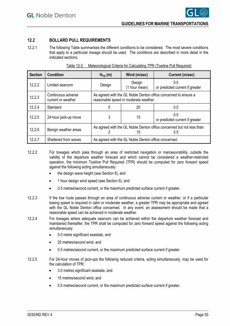
GUIDELINES FOR MARINE TRANSPORTATIONS
12.2 BOLLARD PULL REQUIREMENTS
12.2.1 The following Table summarises the different conditions to be considered. The most severe conditions that apply to a particular towage should be used. The conditions are described in more detail in the indicated sections.
Table 12-2 Meteorological Criteria for Calculating TPR (Towline Pull Required)
Section Condition Hsig (m) Wind (m/sec) Current (m/sec)
12.2.2 Limited searoom Design Design
(1 hour mean) 0.5 or predicted current if greater
12.2.3 Continuous adverse current or weather
As agreed with the GL Noble Denton office concerned to ensure a reasonable speed in moderate weather.
12.2.4 Standard 5 20 0.5
12.2.5 24-hour jack-up move 3 15 0.5 or predicted current if greater
12.2.6 Benign weather areas As agreed with the GL Noble Denton office concerned but not less than: 2 15 0.5
12.2.7 Sheltered from waves As agreed with the GL Noble Denton office concerned.
12.2.2 For towages which pass through an area of restricted navigation or manoeuvrability, outside the
validity of the departure weather forecast and which cannot be considered a weather-restricted operation, the minimum Towline Pull Required (TPR) should be computed for zero forward speed against the following acting simultaneously:
the design wave height (see Section 6), and
1 hour design wind speed (see Section 6), and
0.5 metres/second current, or the maximum predicted surface current if greater.
12.2.3 If the tow route passes through an area of continuous adverse current or weather, or if a particular towing speed is required in calm or moderate weather, a greater TPR may be appropriate and agreed with the GL Noble Denton office concerned. In any event, an assessment should be made that a reasonable speed can be achieved in moderate weather.
12.2.4 For towages where adequate searoom can be achieved within the departure weather forecast and maintained thereafter, the TPR shall be computed for zero forward speed against the following acting simultaneously:
5.0 metre significant seastate, and
20 metres/second wind, and
0.5 metres/second current, or the maximum predicted surface current if greater.
12.2.5 For 24-hour moves of jack-ups the following reduced criteria, acting simultaneously, may be used for the calculation of TPR:
3.0 metres significant seastate, and
15 metres/second wind, and
0.5 metres/second current, or the maximum predicted surface current if greater.
0030/ND REV 4 Page 55
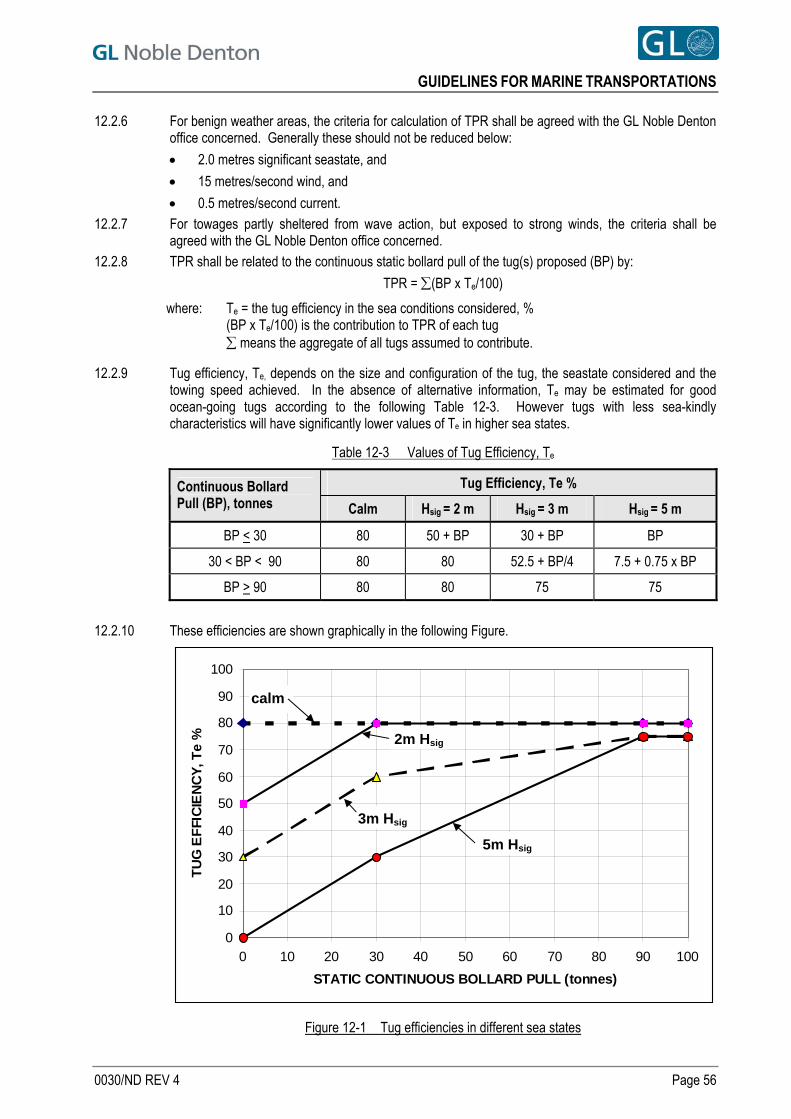
GUIDELINES FOR MARINE TRANSPORTATIONS
12.2.6 For benign weather areas, the criteria for calculation of TPR shall be agreed with the GL Noble Denton office concerned. Generally these should not be reduced below:
2.0 metres significant seastate, and
15 metres/second wind, and
0.5 metres/second current. 12.2.7 For towages partly sheltered from wave action, but exposed to strong winds, the criteria shall be
agreed with the GL Noble Denton office concerned. 12.2.8 TPR shall be related to the continuous static bollard pull of the tug(s) proposed (BP) by:
TPR = (BP x Te/100)
where: Te = the tug efficiency in the sea conditions considered, % (BP x Te/100) is the contribution to TPR of each tug
means the aggregate of all tugs assumed to contribute.
12.2.9 Tug efficiency, Te, depends on the size and configuration of the tug, the seastate considered and the towing speed achieved. In the absence of alternative information, Te may be estimated for good ocean-going tugs according to the following Table 12-3. However tugs with less sea-kindly characteristics will have significantly lower values of Te in higher sea states.
Table 12-3 Values of Tug Efficiency, Te
Tug Efficiency, Te % Continuous Bollard Pull (BP), tonnes Calm Hsig = 2 m Hsig = 3 m Hsig = 5 m
BP < 30 80 50 + BP 30 + BP BP
30 < BP < 90 80 80 52.5 + BP/4 7.5 + 0.75 x BP
BP > 90 80 80 75 75
12.2.10 These efficiencies are shown graphically in the following Figure.
0
10
20
30
40
50
60
70
80
90
100
0 10 20 30 40 50 60 70 80 90 100
STATIC CONTINUOUS BOLLARD PULL (tonnes)
TU
G E
FFI
CIE
NC
Y, T
e %
Figure 12-1 Tug efficiencies in different sea states
calm
2m Hsig
3m Hsig
5m Hsig
0030/ND REV 4 Page 56
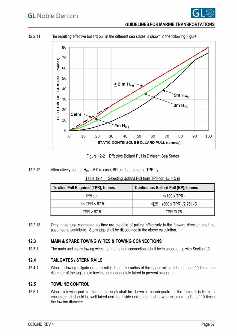
GUIDELINES FOR MARINE TRANSPORTATIONS
12.2.11 The resulting effective bollard pull in the different sea states is shown in the following Figure:
0
10
20
30
40
50
60
70
80
0 10 20 30 40 50 60 70 80 90 100
STATIC CONTINUOUS BOLLARD PULL (tonnes)
EF
FE
CT
IVE
BO
LL
AR
D P
UL
L (t
on
nes
)
Figure 12-2 Effective Bollard Pull in Different Sea States
5m Hsig
< 2 m Hsig
2m Hsig
Calm
3m Hsig
12.2.12 Alternatively, for the Hsig = 5.0 m case, BP can be related to TPR by:
Table 12-4 Selecting Bollard Pull from TPR for Hsig = 5 m
Towline Pull Required (TPR), tonnes Continuous Bollard Pull (BP), tonnes
TPR < 9 (100 x TPR)
9 < TPR < 67.5 [25 + (300 x TPR) /2.25] - 5
TPR > 67.5 TPR /0.75
12.2.13 Only those tugs connected so they are capable of pulling effectively in the forward direction shall be
assumed to contribute. Stern tugs shall be discounted in the above calculation.
12.3 MAIN & SPARE TOWING WIRES & TOWING CONNECTIONS
12.3.1 The main and spare towing wires, pennants and connections shall be in accordance with Section 13.
12.4 TAILGATES / STERN RAILS
12.4.1 Where a towing tailgate or stern rail is fitted, the radius of the upper rail shall be at least 10 times the diameter of the tug’s main towline, and adequately faired to prevent snagging.
12.5 TOWLINE CONTROL
12.5.1 Where a towing pod is fitted, its strength shall be shown to be adequate for the forces it is likely to encounter. It should be well faired and the inside and ends must have a minimum radius of 10 times the towline diameter.
0030/ND REV 4 Page 57
GUIDELINES FOR MARINE TRANSPORTATIONS
12.5.2 Where no pod is fitted, the after deck should be fitted with a gog rope, mechanically operated and capable of being adjusted from a remote station. If a gog rope arrangement is fitted then a spare shall be carried. Where neither a towing pod nor gog rope is fitted, then an alternative means of centring the tow line should be provided.
12.5.3 On square-sterned towing vessels, it is preferred that mechanically or hydraulically operated stops be fitted near the aft end of the bulwarks, to prevent the towline slipping around the tug's quarter in heavy weather.
12.6 WORKBOAT
12.6.1 A powered workboat must be provided for emergency communication with the tow, and must have adequate means for launching safely in a seastate associated with Beaufort Force 4 to 5. An inflatable or RIB may be acceptable provided it has flooring suitable for carriage of emergency equipment to the tow.
12.7 COMMUNICATION EQUIPMENT
12.7.1 In addition to normal Authorities’ requirements, the tug shall carry portable marine VHF and/or UHF radios, for communication with the tow when tug personnel are placed on board for inspections or during an emergency. Spare batteries and a means of recharging them shall be provided.
12.8 NAVIGATIONAL EQUIPMENT
12.8.1 Towing vessels shall be provided with all necessary navigational instruments, charts and publications that may be required on the particular towage, including information for possible diversion ports and their approaches.
12.9 SEARCHLIGHT
12.9.1 The tug shall be fitted with a searchlight to aid night operations and for use in illuminating the tow during periods of emergency or malfunction of the prescribed navigation lights. The searchlight(s) should provide illumination both forward and aft, thereby allowing the tug to approach the tow either bow or stern on.
12.10 PUMP
12.10.1 On any tow outside coastal limits, the tug shall carry at least one portable pump, equipped with means of suction and delivery and having a self contained power unit with sufficient fuel for 12 hours usage at the pump’s maximum rating. The pump shall be suitable for the requirements outlined in Section 15.2.1.e through 15.2.1.h, but may not be considered to be a substitute for the pump(s) required by Section 15. The methods and feasibility of deployment should be considered.
12.11 ADDITIONAL EQUIPMENT
12.11.1 Anti-chafe gear should be fitted as necessary. Particular attention should be paid to contact between the towline and towing pods, tow bars and stern rail.
12.11.2 All tugs should be equipped with burning and welding gear for use in emergency.
12.12 BUNKERS & OTHER CONSUMABLES
12.12.1 The tug should carry fuel and other consumables including potable water, lubricating oil and stores, for the anticipated duration of the towage, taking into account the area and season, plus a reserve of at least 5 days supply. If refuelling en route is proposed, then suitable arrangements must be made before the towage starts, and included in the towing procedures.
0030/ND REV 4 Page 58
GUIDELINES FOR MARINE TRANSPORTATIONS
12.13 TUG MANNING
12.13.1 Notwithstanding minimum manning levels for tugs as described in Ref. [5], or those required by State or Port Authorities, consideration shall be given to the fact that in an emergency situation, two or more of the tug crew may need to board and remain on the tow for an extended period. This should be taken into account when approving the manning level of a towing vessel.
0030/ND REV 4 Page 59
GUIDELINES FOR MARINE TRANSPORTATIONS
13 TOWING & MISCELLANEOUS EQUIPMENT ON TOW
13.1 TOWING EQUIPMENT & ARRANGEMENTS - GENERAL
13.1.1 Towage should normally be from the forward end of the barge or tow via a suitable bridle as shown in Appendix A. The components of the system are: a. Towline connections, including towline connection points, fairleads, bridle legs and bridle apex
b. Intermediate pennant
c. Bridle recovery system
d. Emergency towing gear.
13.1.2 There may be a case for towing some structures by the stern. These could include: a. Part-built or damaged ships, or any structure when the bow sections could be vulnerable to
wave damage.
b. Part-built ships, converted ships or FPSOs without a rudder or skeg, or with a turret or spider fitted forward, where better directional stability may be obtained if towed by the stern.
c. Any structure with overhanging or vulnerable equipment near the bow, which could be vulnerable to wave damage, or could interfere with the main and emergency towing connections.
13.1.3 A decision whether to tow by the stern should be based on the results of a risk assessment which shall be presented to GL Noble Denton for review.
13.1.4 If two tugs are to be used for towing, then in general the larger tug should be connected to the bridle, and the smaller tug to a chain or chain/wire pennant set to one side of the main bridle. Alternatively two bridles may be made up, one for each tug. For two balanced tugs, the bridle may be split and the tugs should tow off separate bridle legs, via intermediate pennants. This is not generally preferred for tows with rectangular bows. Whichever system is used, a recovery system should be provided for the connection point for each tug.
13.1.5 For tows where a bridle is not appropriate, such as multiple tug towages, then normally each tug should tow off a chain pennant and an intermediate wire pennant.
13.1.6 It is normal that the towline and the intermediate pennant are supplied by the tug. However, the strength requirements are presented here, to bring together the requirements for towlines and towing connections.
0030/ND REV 4 Page 60
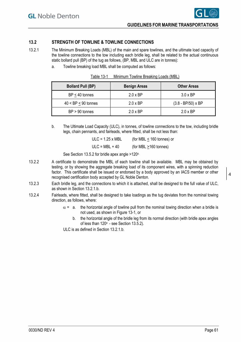
GUIDELINES FOR MARINE TRANSPORTATIONS
13.2 STRENGTH OF TOWLINE & TOWLINE CONNECTIONS
13.2.1 The Minimum Breaking Loads (MBL) of the main and spare towlines, and the ultimate load capacity of the towline connections to the tow including each bridle leg, shall be related to the actual continuous static bollard pull (BP) of the tug as follows, (BP, MBL and ULC are in tonnes): a. Towline breaking load MBL shall be computed as follows:
Table 13-1 Minimum Towline Breaking Loads (MBL)
Bollard Pull (BP) Benign Areas Other Areas
BP < 40 tonnes 2.0 x BP 3.0 x BP
40 < BP < 90 tonnes 2.0 x BP (3.8 - BP/50) x BP
BP > 90 tonnes 2.0 x BP 2.0 x BP
b. The Ultimate Load Capacity (ULC), in tonnes, of towline connections to the tow, including bridle legs, chain pennants, and fairleads, where fitted, shall be not less than:
ULC = 1.25 x MBL (for MBL < 160 tonnes) or
ULC = MBL + 40 (for MBL >160 tonnes)
See Section 13.5.2 for bridle apex angle >120o.
13.2.2 A certificate to demonstrate the MBL of each towline shall be available. MBL may be obtained by testing, or by showing the aggregate breaking load of its component wires, with a spinning reduction factor. This certificate shall be issued or endorsed by a body approved by an IACS member or other recognised certification body accepted by GL Noble Denton.
4
13.2.3 Each bridle leg, and the connections to which it is attached, shall be designed to the full value of ULC, as shown in Section 13.2.1.b.
13.2.4 Fairleads, where fitted, shall be designed to take loadings as the tug deviates from the nominal towing direction, as follows, where:
= a. the horizontal angle of towline pull from the nominal towing direction when a bridle is not used, as shown in Figure 13-1, or
b. the horizontal angle of the bridle leg from its normal direction (with bridle apex angles of less than 120o - see Section 13.5.2).
ULC is as defined in Section 13.2.1.b.
0030/ND REV 4 Page 61
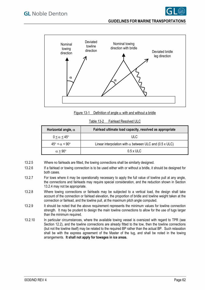
GUIDELINES FOR MARINE TRANSPORTATIONS
Figure 13-1 Definition of angle with and without a bridle
Table 13-2 Fairlead Resolved ULC
Deviated bridle leg direction
Nominal towing direction with bridle
Deviated towline
direction
Nominal towing
direction
Horizontal angle, Fairlead ultimate load capacity, resolved as appropriate
0 < < 45 ULC
45 < < 90 Linear interpolation with between ULC and (0.5 x ULC)
> 90 0.5 x ULC
13.2.5 Where no fairleads are fitted, the towing connections shall be similarly designed. 13.2.6 If a fairlead or towing connection is to be used either with or without a bridle, it should be designed for
both cases. 13.2.7 For tows where it may be operationally necessary to apply the full value of towline pull at any angle,
the connections and fairleads may require special consideration, and the reduction shown in Section 13.2.4 may not be appropriate.
13.2.8 Where towing connections or fairleads may be subjected to a vertical load, the design shall take account of the connection or fairlead elevation, the proportion of bridle and towline weight taken at the connection or fairlead, and the towline pull, at the maximum pitch angle computed.
13.2.9 It should be noted that the above requirement represents the minimum values for towline connection strength. It may be prudent to design the main towline connections to allow for the use of tugs larger than the minimum required.
13.2.10 In particular circumstances, where the available towing vessel is oversized with regard to TPR (see Section 12.2), and the towline connections are already fitted to the tow, then the towline connections (but not the towline itself) may be related to the required BP rather than the actual BP. Such relaxation shall be with the express agreement of the Master of the tug, and shall be noted in the towing arrangements. It shall not apply for towages in ice areas.
0030/ND REV 4 Page 62
GUIDELINES FOR MARINE TRANSPORTATIONS
13.3 RELATIONSHIP BETWEEN TOWLINE LENGTH AND STRENGTH
13.3.1 Except in benign areas and sheltered water towages, the minimum length available of each of the main and spare towlines (L) shall be determined from the “European” formula:
L > (BP/MBL) x 1800 metres
except that in no case shall the available length be less than 650 metres, apart from coastal towages within a good weather forecast when this may be reduced to 500m.
13.3.2 For benign areas, the minimum length available shall be not less than:
L > (BP/MBL) x 1200 metres
except that in no case shall the available length be less than 500 metres. 13.3.3 The available length shall take into account the minimum remaining turns on the winch drum, and the
distance from the drum to the stern rail or roller. One full strength wire rope pennant which is permanently included in the towing configuration may be considered when determining the available length.
13.3.4 MBL as shown in Section 13.2.1 shall be increased if required for L to comply with Section 13.3.1 or 13.3.2 as appropriate. ULC shall be correspondingly increased.
13.4 TOWLINE CONNECTION POINTS
13.4.1 Towline connections to the tow shall be of an approved type. Preferably they should be capable of quick release under adverse conditions, to allow a fouled bridle or towline to be cleared, but must also be secured against premature release. A typical bracket design is shown in Appendix C.
13.4.2 Towline connections and fairleads shall be designed to the requirements of Section 13.2. 13.4.3 Sufficient internal/underdeck strength must be provided for all towline connections and fairleads. 13.4.4 Where fitted, fairleads should be of an approved type, located close to the deck edge. They should be
fitted with capping bars and sited in line with the towline connections, to prevent side load on the towing connections.
13.4.5 Where the bridle might bear on the deck edge, the deck edge should be suitably faired and reinforced to prevent chafe of the bridle.
13.4.6 Where towing connections are of a quick-release type, then the fairlead design shall allow all the released parts to pass easily through the fairlead.
13.5 BRIDLE LEGS
13.5.1 Each bridle leg should be of stud link chain or composite chain and wire rope. If composite, the chain should of sufficient length to extend beyond the deck edge and prevent chafing of the wire rope.
13.5.2 The angle at the apex of the bridle should normally be between 45 and 60 degrees. If it exceeds 120o then the strength of the bridle legs, fittings and towing connections will need to be increased to allow for the increased resolved load in the bridle from the towline force.
13.5.3 The end link of all chains shall be a special enlarged link, not a normal link with the stud removed. 13.5.4 All wire ropes shall have hard eyes or sockets.
13.6 BRIDLE APEX
13.6.1 The bridle apex connection should be a towing ring or triangular plate, often called a Delta, Flounder or Monkey Plate, or an enlarged bow shackle.
13.7 SHACKLES
13.7.1 The breaking load of shackles forming part of the towline shall be at least 110% of the actual breaking load of the towline to be used.
0030/ND REV 4 Page 63
GUIDELINES FOR MARINE TRANSPORTATIONS
13.7.2 The breaking load of shackles forming part of the bridle shall be not less than 110% of the required breaking load of the connected parts.
13.7.3 If the breaking load of a shackle cannot be identified then the minimum Safe Working Load (SWL) may be related to the continuous static bollard pull (BP) of the largest tug proposed, as follows:
Table 13-3 Default Shackle SWL
Continuous bollard pull, BP, tonnes Minimum Safe Working Load,
SWL, tonnes
BP < 40 1.0 x BP
BP > 40 (0.5 x BP) + 20
13.8 INTERMEDIATE PENNANT OR SURGE CHAINS
13.8.1 An intermediate wire rope pennant should be fitted between the main towline and the bridle or chain pennant. Its main use is for ease of connection and reconnection. All wire rope pennants shall have hard eyes or sockets, and be of the same lay (i.e. left or right hand) as the main towline.
13.8.2 A synthetic spring, if used, should not normally replace the intermediate wire rope pennant. 13.8.3 The length of the wire pennant for barge tows is normally 10-15 metres since this can be handled on
the stern of most tugs without the connecting shackle reaching the winch. Longer pennants may be needed in particular cases.
13.8.4 The breaking strength of the wire rope pennant shall not be less than that of the main towline with the possible exceptions in Section 13.8.6.
13.8.5 A surge chain may be used, especially in shallow water when a long towline catenary cannot be used, to provide shock absorption. If a surge chain is supplied then the MBL shall not be less than that of the main towing wire. The surge chain shall be a continuous length of welded studlink chain with an enlarged open link at each end (see Section 13.5.3). A method of recovery of the chain shall be provided in case a tow wire breaks.
13.8.6 GL Noble Denton may approve a “fuse” or “weak link” pennant provided that: a. The strength reduction is not more than 10% of the actual strength of the main towline, and
b. The resulting strength of the pennant is at least equal to that required for the towline.
13.9 SYNTHETIC SPRINGS
13.9.1 Where a synthetic spring is used, its breaking load shall be at least 1.5 times that required for the main towline. As synthetic springs have a limited life due to embrittlement and ageing, they must be in good condition, and have been stored to protect them from wear, solvents and sunlight. See Section 22.7.7 for towages when icing can occur.
13.9.2 If used, a synthetic spring should normally be connected between the main towing wire and the intermediate pennant, rather than connected directly into the bridle apex.
13.9.3 All synthetic springs shall have hard eyes. A synthetic spring made up as a continuous loop with a hard eye each end is generally preferable to a single line with an eye splice each end.
13.10 BRIDLE RECOVERY SYSTEM
13.10.1 A system shall be fitted to recover the bridle or chain pennant, to allow reconnection in the event of towline breakage. The preferred type of bridle recovery system is shown in Appendix A. It consists of a winch and a recovery line connected to the bridle apex, via a suitable lead, preferably an A-frame.
13.10.2 The recovery winch shall be capable of handling at least 100% of the weight of the bridle, plus attachments including the apex and the intermediate pennant. It shall be suitably secured to the structure of the tow. Except for very small barges, the winch should have its own power source. It
0030/ND REV 4 Page 64
GUIDELINES FOR MARINE TRANSPORTATIONS
should be noted that an adequate winch will be useful for initial connection of the towline. Adequate fuel should be carried.
13.10.3 If the winch is manually operated, it should be fitted with ratchet gear and brake, and should be geared so that the tow bridle apex can be recovered by 2 persons.
13.10.4 Should no power source be available, and manual operation is deemed impractical, then arrangements shall be made, utilising additional pennant wires as necessary, which will allow the tug to reconnect.
13.10.5 The breaking load of the recovery wire, shackles, leads etc shall be at least 6 times the weight of the bridle, apex and intermediate pennant. The winch barrel should be adequate for the length and size of the wire required.
13.11 EMERGENCY TOWING GEAR
13.11.1 Emergency towing gear shall be provided in case of towline failure, bridle failure or inability to recover the bridle. Preferably it should be fitted at the bow of the tow. It may consist of a separate bridle and pennant or a system as shown in Appendix B. Precautions should be taken to minimise chafe of all wire ropes.
13.11.2 The emergency system will typically consist of the following: a. Towing connection on or near the centreline of the tow, over a bulkhead or other suitable strong
point
b. Closed fairlead
c. Emergency pennant, minimum length 80 metres, with hard eyes or sockets, preferably in one length. This length may be reduced for small barges and in benign areas
d. Extension wire, if required, long enough to prevent the float line chafing on the stern of the tow
e. Float line, to extend 75-90 metres abaft the stern of the tow
f. Conspicuous pick-up buoy, with reflective tape, on the end of the float line.
13.11.3 The strength of items a, b and c above should be as for the main towline connections, as shown in Section 13.2.1. The breaking load of the handling system, items d and e above should be not less than 25 tonnes, and must be sufficient to break the securing devices.
13.11.4 If the emergency towline is attached forward, it must be led over the main tow bridle. It should be secured to the outer edge of the tow, outside all obstructions, with soft lashings, or metal clips opening outwards, approximately every 3 metres.
13.11.5 If the emergency towing gear is attached aft, the wire rope should be coiled or flaked near the stern, so that it can be pulled clear. The outboard eye should be led over the deck edge to prevent chafe of the float line.
13.11.6 For towage of very long vessels, alternative emergency arrangements may be approvable but any arrangement shall be agreed with the Master of the tug to ensure that reconnection is possible in an emergency.
13.11.7 Whatever the arrangement agreed, care shall be taken that no chafe can occur to the floating line when deployed.
13.11.8 It is good practice to have swivels at the connection of the float line to the pennant line or extension wire, and at the connection of the float line to the buoy.
13.11.9 The following reconnection equipment should also be considered, and placed on board if the duration and area of the towage demand it: a. Heaving lines
b. Line throwing equipment
c. Spare shackles.
0030/ND REV 4 Page 65
GUIDELINES FOR MARINE TRANSPORTATIONS
13.12 CERTIFICATION
13.12.1 Valid certificates shall be available for all chains, wires and shackles utilised in the towing arrangement. Where certification is not available or attainable for minor items the surveyor may recommend that oversized equipment shall be fitted. Certificates shall be issued or endorsed by bodies approved by an IACS member or other recognised certification bodies accepted by GL Noble Denton.
4
13.12.2 The GL Noble Denton surveyor may reject any items that appear to be unfit for purpose, or are lacking valid certification.
13.13 NAVIGATION LIGHTS & SHAPES
13.13.1 The tow shall carry the lights and shapes required by the International Regulations for Preventing Collisions at Sea, 1972 amended 1996 (COLREGS [Ref. 19]) and any local regulations.
13.13.2 Navigation lights shall be independently powered (e.g. from an independent electric power sources or from gas containers). Fuel or power sources shall be adequate for the maximum duration of the towage, plus a reserve. Spare mantles or bulbs should be carried, even if the tow is unmanned.
13.13.3 It is desirable that a duplicate system of lights be provided. 13.13.4 Towed objects which may offer a small response to radar, such as barges or concrete caissons with
low freeboard, should be fitted with a radar reflector. The reflector should be mounted as high as practical. Octahedral reflectors should be mounted in the “catch-rain” orientation.
13.14 ACCESS TO TOWS
13.14.1 Whether a tow is manned or not, suitable access must be provided. This may include at least one permanent steel ladder on each side, from main deck to below the waterline.
13.14.2 Where practical, ladders should be recessed, back painted for ease of identification, be clear of overhanging cargo, and faired off to permit access by the tug’s workboat.
13.14.3 Alternatives may be accepted if it can be demonstrated that they will provide a safe and reliable means of access during the towage. For example, a pilot ladder on each side or over the stern, secured to prevent it being washed up on deck, may be accepted for short tows or where it can be deployed from a manned tow.
13.14.4 Objects with high freeboard (e.g. over about 10 m) may need special consideration. Ladders should be enclosed, except within 5 m of the towage waterline, with resting platforms every 10 metres. Where practical, stairways are preferable to ladders.
13.14.5 Where practical, a clear space should be provided and appropriately marked, with access ladders if necessary so that, in an emergency, men may landed or recovered by helicopter. If it is required to land a crew on board prior to entering port, for instance to start pumps and reduce draught, then a properly marked and certified helideck or landing area would be an advantage.
13.14.6 A boarding party should be appropriately equipped with survival suits, lifejackets and communication equipment.
13.14.7 Even if the tow is not manned, consideration should be given to placing life saving appliances on board, appropriate to the hazards a boarding party may face once aboard.
13.14.8 Not withstanding the potential for piracy in some areas, means of boarding shall still be available.
13.15 ANCHORING & MOORING EQUIPMENT
13.15.1 See Section 16.
0030/ND REV 4 Page 66
GUIDELINES FOR MARINE TRANSPORTATIONS
13.16 DAMAGE CONTROL & EMERGENCY EQUIPMENT
13.16.1 When the length and area of the towage demand it, the following equipment should be carried on the tow in suitable packages or in a waterproof container secured to the deck: a. Burning gear
b. Welding equipment
c. Steel plate - various thicknesses
d. Steel angle section - various sizes and lengths
e. Plywood sheets - 25 mm thick
f. Lengths of 3” x 3” (75mm x 75mm) timber
g. Caulking material
h. Sand and cement (suitably packaged)
i. Nails - various sizes
j. Wooden plugs – various sizes
k. Wooden wedges – various sizes
l. A selection of tools, including a hydraulic jack, hammers, saws, crowbars, Tirfors.
m. Portable coamings 60 cm minimum height, with a flange and boltholes to suit the manhole design. The top should be constructed to avoid damage to hoses and cables
n. A sounding tube extension, of 60 cm minimum height, threaded so that it can be screwed into all sounding plug holes
o. Sounding tapes
p. Fire fighting equipment as appropriate
q. Personal protection equipment - gloves, goggles, hard hats, survival suits etc
r. Emergency lighting.
0030/ND REV 4 Page 67
GUIDELINES FOR MARINE TRANSPORTATIONS
14 VOYAGE PLANNING
14.1 GENERAL
14.1.1 The following recommendations apply with respect to the way in which the towage or voyage is conducted. The Certificate of Approval is based on agreed towage or voyage arrangements, which shall not be deviated from without good cause, and where practical with the prior agreement of GL Noble Denton.
14.2 PLANNING
14.2.1 Planning of the voyage or towage shall be carried out in accordance with the requirements of the IMO International Safety Management Code [Ref. 8].
14.3 ROUTEING
14.3.1 Routeing procedures shall be agreed with the Master prior to commencement of the towage or voyage, taking into account the transport vessel or tug’s capacity and fuel consumption, the weather and current conditions and normal good navigation and seamanship.
14.3.2 Piracy in some areas, for instance South East Asia, is prevalent, and slow moving vessels or tows are particularly at risk. Maintaining sufficient distance from land throughout the tow will reduce this risk and also ensure there is sufficient sea room in case of emergency. Guidance on prevention of piracy may be found in IMO MSC/Circ.623 - Piracy and armed robbery against ships [Ref. 20].
14.4 WEATHER ROUTEING & FORECASTING
14.4.1 Weather forecasts for the departure area should be commenced at least 48 hours before the anticipated departure date. Whenever possible a second weather forecast should be obtained from a different independent source prior to departure.
14.4.2 For any towage, the weather conditions for departure from the departure port or any intermediate port or shelter area shall take into account the capabilities of the towing vessel, the marine characteristics of the tow, the forecast wind direction, any hazards close to the departure port or shelter area and the distance to the next port or shelter area. A suitable weather forecast may be one that predicts a minimum 48 hour period with winds not in excess of Beaufort Force 5 and a favourable outlook for a further 24 hours.
14.4.3 If appropriate, a weather routeing service, provided by a reputable company, should be arranged prior to the start of the towage or voyage. The utilisation of a weather routeing service may be a requirement of the approval. See also Section 6.3.2. In any event, every effort shall be made by the Master to obtain regular and suitable weather forecasts from a reputable source during the towage.
0030/ND REV 4 Page 68
GUIDELINES FOR MARINE TRANSPORTATIONS
14.5 DEPARTURE
14.5.1 Prior to departure, a departure condition report for the tow or vessel shall be provided by the owners or their agents, for the Master and the GL Noble Denton surveyor. This report should contain as a minimum: a. The documentation referred to in Section 5 as appropriate
b. Lightship weight
c. Tabulation and distribution of ballast, consumables, and cargo, including any hazardous materials
d. Calculated displacement and draughts
e. Actual draughts and displacement
f. For ships, a statement that the longitudinal bending and shear force are within the allowable seagoing limits
g. Calculated VCG
h. Calculated GM and confirmation that it is within allowable limits
i. GZ Curve and confirmation that it is within allowable limits.
14.5.2 Departure condition shall be verified to be satisfactory regarding the stability of the tow with proper allowance made for any slack tanks.
14.5.3 If no stability documentation is available then it may be necessary to perform an inclining experiment to check that the GM is satisfactory. Calculations may be needed to establish righting and overturning lever curves.
14.5.4 It shall be verified that the tow floats in a proper upright attitude and at a draught and trim appropriate to the calculated weight and centre of gravity.
14.5.5 The Certificate of Approval shall be issued on agreed readiness for departure and on receipt of a suitable weather forecast.
14.6 PORTS OF SHELTER, SHELTER AREAS, HOLDING AREAS
14.6.1 Ports of shelter, or shelter areas on or adjacent to the route, with available safe berths, mooring or holding areas, shall be agreed before departure and all necessary permissions obtained.
14.6.2 Where such shelter points are required as part of a weather-restricted operation, as described in Section 6.3, they shall be capable of entry in worsening weather.
14.7 BUNKERING
14.7.1 Bunkering ports, if required, shall be agreed before departure. If it is not practical to take the tow into port, then alternative arrangements must be agreed which may include: a. Where the towage is by more than one tug, each tug in turn may be released to proceed to a
nearby port for bunkers, subject to a favourable weather forecast. The remaining tug(s) should meet the requirements of Section 12.2, or some other agreed criterion.
b. Relief of the towing tug by another suitable tug, which itself is considered suitable to undertake the towage, so that the towing tug may proceed to a nearby port for bunkers.
c. Bunkering at sea from a visiting vessel, subject to suitable procedures and calm weather conditions.
14.7.2 Such procedures shall form part of the approved towage or voyage arrangements.
0030/ND REV 4 Page 69
GUIDELINES FOR MARINE TRANSPORTATIONS
14.8 ASSISTING TUGS
14.8.1 Assisting tugs shall be engaged at commencement of the towage, at any intermediate bunkering port and at the arrival destination, as appropriate.
14.9 PILOTAGE
14.9.1 The Master shall engage local pilotage assistance during the towage or voyage, as appropriate.
14.10 LOG
14.10.1 A detailed log of events shall be maintained during the towage or voyage.
14.11 INSPECTIONS DURING THE TOWAGE OR VOYAGE
14.11.1 Unless the tow is manned, it should be boarded on a regular basis by the crew of the tug, particularly after a period of bad weather, in order to verify that all the towing arrangements, condition of the cargo, seafastenings and watertight integrity of the tow are satisfactory. Suitable access shall be provided - see Section 13.14.
14.11.2 For manned tows, and self propelled vessels, the above inspections should be carried out on a daily basis as relevant - see also Section 17.5.
14.11.3 Any adjustable seafastenings or lashings should be re-tensioned as necessary.
14.12 REDUCING EXCESSIVE MOVEMENT & THE SHIPPING OF WATER
14.12.1 The Master should take any necessary measures to reduce excessive movement or the shipping of water which may damage the cargo, cribbing or seafastenings. This may entail changes of course, or speed, or both.
14.13 NOTIFICATION
14.13.1 After departure of an approved towage or voyage, regular notification shall be sent to GL Noble Denton regarding progress, the reporting of any unusual or abnormal events, or necessary deviation from the agreed towing arrangements.
14.14 DIVERSIONS
14.14.1 Should any emergency situation arise during the towage or voyage which necessitates diversion to a port of refuge, then GL Noble Denton shall be advised. GL Noble Denton will review and advise on the validity of the existing Certificate of Approval for continuing the towage or voyage depending on the circumstances of the case. A further attendance at the port of refuge may be required in order to re-validate the Certificate of Approval.
14.15 RESPONSIBILITY
14.15.1 The Towmaster is responsible for the overall conduct of a tow, and towing arrangements during the towage.
14.15.2 If any special situations arise during the towage or voyage and it is not possible to comply with any specific recommendations, agreed procedures or International Regulations, then such measures as appropriate for the safety of life and property shall be taken. GL Noble Denton shall be informed as soon as practical of any such circumstances.
14.15.3 Nothing in this document shall set aside or limit the authority of the Master who remains solely responsible for his vessel during the voyage in accordance with maritime laws.
0030/ND REV 4 Page 70
GUIDELINES FOR MARINE TRANSPORTATIONS
14.16 TUG CHANGE
14.16.1 The tug(s) approved for any towage, as noted on the Certificate of Approval, shall be the only tug(s) approved for that specific towage and should remain with the tow throughout the towage. Should it be required to change the tug(s) for any reason, except in emergency or where special arrangements have been agreed for bunkering, the replacement tug must be approved by GL Noble Denton and a new Certificate of Approval issued.
14.17 HAZARDOUS MATERIALS
14.17.1 Hazardous substances may be considered as materials which, when released in sufficient quantities or improperly handled, have the potential to cause damage to the asset, personnel or the environment through chemical means or combustion. Unless it is necessary the carriage of such materials should be avoided, unless it can be shown that the substances are effectively controlled. Stowage of such materials should take into account that the transportation may be unmanned and therefore remedial action in the case of inadvertent release will be limited.
14.17.2 The properties of such material should be contained in the COSHH (Control of Substances Hazardous to Health) data sheets and the recommended method of stowage and handling is found in the IMDG (International Maritime Dangerous Goods) Code.
14.17.3 Where identifiable hazardous material is found on board prior to a tow / transportation taking place, it should be controlled either through isolation or removal ashore.
14.18 BALLAST WATER
14.18.1 The IMO Ballast Water Convention of 2004 (Resolution A.868(20)) requires the monitoring and recording of ballasting and de-ballasting operations. Vessels flagged in signatory states are required to have on board and to implement a Ballast Water Management Plan. This plan is specific to each vessel and the record of ballast operations may be examined by the Port State Authorities.
14.18.2 Vessels may need to change ballast water before or at their arrival port for operational reasons (loading /discharging). There may be local laws that will have an impact on these activities. In the U.S.A. there are numerous state laws that cover these operations. Compliance with these rules may need to become part of the voyage planning.
14.18.3 The necessary ballast plan and records should be available for any attending surveyor.
14.19 RESTRICTED DEPTHS, HEIGHTS & MANOEUVRABILITY
14.19.1 The following recommended clearances are general, and each towage should be assessed on its own, taking into account a. environmental conditions,
b. length of areas of restricted manoeuvrability,
c. any course changes within the areas of restricted manoeuvrability,
d. cross section of areas of restricted manoeuvrability in relation to underwater area/shape of the base structure, and
e. capability of the tugs.
14.19.2 The recommended values give guidance. If it can be proved that smaller values give the same or even better level of confidence these values should be taken.
14.19.3 For areas where the under-keel or side clearance is critical, a survey report that is not older than 3 months shall be available. If not, the tow route should be surveyed with a width of 5 times the beam, with a minimum of 500 metres. Side-scan sonar and bathymetric data should be provided. The equipment used should be of a recognized industry standard. The spacing between depth contour lines should be appropriate for the purpose. Current surveys should be made in restricted parts of the tow route.
0030/ND REV 4 Page 71
GUIDELINES FOR MARINE TRANSPORTATIONS
14.19.4 The survey requirements can be relaxed if it can be shown that the on-board bathymetry measurement systems and position management systems have sufficiently high precision.
14.19.5 Ideally passages through areas of restricted manoeuvrability and passing under bridges and power cables should not take place in darkness.
14.20 UNDER-KEEL CLEARANCES
14.20.1 The under-keel clearance allowing for protrusions below the hull shall account for the effects of a. Roll, pitch and initial heel and trim,
b. heave,
c. tow-line pull,
d. inclination due to wind,
e. tolerance on bathymetry,
f. changes in draught of the transport or towed object,
g. differences in water density,
h. low water tidal height variations,
i. squat effects,
j. deflections of the structure
4 k. errors in measurement, and
l. negative surge.
and shall include a margin of not less than the greater of one metre or ten percent of the maximum draught. The 10% may be reduced in very benign conditions after agreement with the GL Noble Denton office concerned.
14.20.2 Under-keel clearances for departure from dry-docks or building basins are covered in 0015/ND [Ref 3]. 14.20.3 If sections of the passage are tidally dependent, safe holding areas should be identified in the vicinity
with adequate sea room and water depth to keep the structure afloat at low tide, while maintaining the minimum under-keel clearance. Any delay time waiting for the tide must be included in the overall planning.
14.20.4 Immediately before critical sections of the passage the tidal level shall be confirmed by measurement. 14.20.5 Use of an air cushion to reduce draft to assist in crossing localised areas of restricted water depth may
be considered subject to: a. Any conceivable loss of air not increasing the draft by more than the reserve on underkeel
clearance, and
b. The recommendations contained in 0015/ND [Ref 3] on air cushions.
14.21 AIR DRAUGHT
14.21.1 When passing under bridges and power cables, the overhead clearance shall be calculated allowing a margin of not less than one metre plus dimensional tolerances on the items listed in Section 14.20.1 excluding squat. Where clearance is limited then a dimensional survey of the barge/vessel and structure shall take place just prior to sailaway in order to ensure that the required clearance exists.
14.21.2 Power cables need a 'spark gap', as well as a physical clearance; the transmission company will have their own criteria on the minimum allowable clearance. It should be noted that the catenary of the power cable will change depending on the load being carried in the cable; the lowest position should be used.
14.21.3 The actual clearance shall be confirmed with all appropriate authorities including those responsible for the obstruction.
0030/ND REV 4 Page 72
GUIDELINES FOR MARINE TRANSPORTATIONS
14.21.4 Immediately before the passage the tidal level shall be confirmed by measurement.
14.22 CHANNEL WIDTH & RESTRICTED MANOEUVRABILITY
14.22.1 The minimum channel width along any inshore legs of the tow route with the underkeel clearance and air draught required in Sections 14.20 and 14.21 should be three times the maximum width of the towed object after allowances for yaw. Additional channel width may be required in exposed areas, if there are significant cross currents or if needed for the tugs to manoeuvre safely.
14.22.2 Side clearances for departure from dry-docks or building basins are covered in 0015/ND [Ref 3].
0030/ND REV 4 Page 73
GUIDELINES FOR MARINE TRANSPORTATIONS
15 PUMPING AND SOUNDING
15.1 GENERAL
15.1.1 Emergency-pumping arrangements should be available for any tow. 15.1.2 Pumps in accordance with this section are primarily required for barges. The need for, and
specification of, pumps for other tows, including self-floating objects, MODUs, FPSOs and ships, will be assessed on a case-by-case basis, depending on the nature of the towage and the extent and availability of any installed system.
15.1.3 Some relaxation may be possible, agreed on a case-by-case basis, for a towage considered as a weather-restricted operation.
15.1.4 Whatever pumping system is agreed, and whether or not a tow is manned, the pumping system shall be available at short notice. Any time required for connection or warm-up should be included in the pumping times and capacities shown in Section 15.5.
15.1.5 Where a tow is not manned, then the tug master and chief engineer shall be aware of the available pumping system. Members of the tug crew shall be familiar with the systems, and be able to board the tow and run the pumps at short notice. Procedures for pumping shall be known and available, including any restrictions arising from considerations of stability or hull stresses, and any vents, which must be opened before pumping starts.
15.2 PURPOSE OF PUMPS
15.2.1 Pumps may be required for the following: a. Ballasting before, during and after loadouts
b. Ballasting to the agreed departure condition
c. Restoration of draught and trim after discharge (especially at sea)
d. Deballasting to reduce draught to enter port
e. Damage control, including counterflooding
f. Deballasting after accidental grounding
g. Trimming to allow inspection and repair below normal waterline
h. Access to a flooded compartment (e.g. pump room, anchor winch room).
15.2.2 The use of a barge compressed air system may not be practicable for all these cases, especially if manhole covers have been removed, or the barge is holed above the waterline. A compressed air system should have a compressor on board and available, connected into the permanent lines.
15.2.3 It should be possible to sound and pump into or from critical compartments (defined in Section 15.3.2) in severe weather. The following shall be provided: a. Pumping system
b. Watertight manholes
c. Portable coamings
d. Sounding plugs, extensions and tapes or rods. An additional remote sounding system may be needed for compressed air ballasting systems
e. Vents to all compartments.
0030/ND REV 4 Page 74
GUIDELINES FOR MARINE TRANSPORTATIONS
15.3 PUMPING SYSTEM
15.3.1 It is recommended that barges have one of the following systems, able to pump into and from all critical spaces, in order of preference: a. Two independent pumprooms or one protected pumproom, as described below
b. An unprotected pumproom with an independent emergency system that can pump out the pumproom
c. A system of portable pumps.
15.3.2 A critical space is defined as any tank or compartment which:
1. when flooded or emptied, at any stage of the voyage, may lead to: a. non compliance of intact or damage stability criteria, or
b. non compliance of structural load limits, or
c. heeling or trimming that may prevent the tow from continuing its passage safely and free from obstructions in shallow water, or
d. maximum allowable transit draught being exceeded.
2. may be required for ballasting / de-ballasting so that the barge or vessel can safely continue her passage after any single compartment is damaged.
4
15.3.3 Independent pumprooms should have separate power supply, pumps, control and access. Each pumproom should be able to work into all spaces.
15.3.4 To be considered protected, a pumproom, and any compartment required for access, should be separated from the bottom plating by a watertight double bottom not less than 0.60 m deep and from the outer shell by other compartments or cofferdams not less than 1.5 metres wide.
15.4 PUMP TYPE
15.4.1 If portable pumps are used then either they should be portable enough to be moved around the barge (and cargo) by two men, or enough pumping equipment should be carried so that any critical compartment can be reached.
15.4.2 Each portable pump should be able to pump out from the deepest space (with portable coaming installed). This requires submersible pumps for barges over about 6 metres depth, due to suction head. Portable submersible pumps must be able to fit through tank manholes.
15.5 PUMP CAPACITY
15.5.1 The total capacity of the fixed or portable pumps should be such that any one wing space (or other critical tank or pumproom) can be emptied or filled in 4 hours for an unmanned tow, or 12 hours for a manned tow. At least two pumps shall be provided, except where there is a protected pump room.
15.5.2 Whatever type of pumps are fitted or supplied, sufficient fuel shall be carried for at least 72 hours continuous operation.
0030/ND REV 4 Page 75
GUIDELINES FOR MARINE TRANSPORTATIONS
15.6 WATERTIGHT MANHOLES
15.6.1 If manholes to critical compartments are covered by cargo then either alternative manholes should be fitted, or cutting gear should be installed and positions marked for making access. Welding gear and materials shall be carried to restore watertight integrity.
15.6.2 Where the barge is classed, the owner should inform the classification society in good time of any holes to be cut or any structural alterations to be made.
15.6.3 Access shall always be available to pumprooms and other work areas. 15.6.4 Ladders to the tank bottom are required from each manhole position. 15.6.5 Suitable tools shall be provided for removal and refastening of manhole covers and sounding plugs.
All manhole covers should be properly secured with bolts and gaskets, renewed as necessary. 15.6.6 Portable coamings to suit the manhole design should be carried, if required by Section 13.16.1.m.
15.7 SOUNDING PLUGS AND TAPES
15.7.1 For vessels or barges with compressed air ballast systems, gauges should be provided in lieu of sounding pipes.
15.7.2 A sounding plug shall be installed in each compartment (in manhole covers if necessary) to avoid removing manhole covers. Sounding tapes and chalk shall be carried on board the tow.
15.7.3 For spaces that will be sounded regularly, a tube and striker plate are recommended.
15.8 VENTS
15.8.1 All compartments connected to a pumping system should have vents fitted, preferably of an approved, automatic, self-closing type. If not automatic, then the vents should be sealed for towage with wooden bungs or steel blanks, but with a 6 mm diameter breather hole fitted. This will give audible warning or reduce pressure differentials in event of mishap, and compensate for temperature changes. The breather hole can be drilled into the gooseneck of the vent or through the wooden bung used to close the vent.
0030/ND REV 4 Page 76
GUIDELINES FOR MARINE TRANSPORTATIONS
16 ANCHORS AND MOORING ARRANGEMENTS
16.1 EMERGENCY ANCHORS
16.1.1 Emergency anchors have traditionally been required to reduce the risk of a tow running aground if a towing vessel is disabled or a towline broken. However in many cases the disadvantages (described in Section E.4 of Appendix E) associated with using such anchors may outweigh the advantages.
16.1.2 If a tow passes through an area of restricted sea room, a comparative risk assessment should be performed to determine the preferred arrangements. Appendix E sets out topics to be taken into account in this risk assessment. One possible outcome may be the provision of suitably sized extra tugs in some sectors of the tow.
16.1.3 The same requirements apply for towed ships, including demolition towages. See Section 20.6. Where such towages may need to wait for a few days on arrival at the end of a voyage before documentation is completed then, if this is in a high-current area, anchoring or mooring arrangements may be required.
16.1.4 For self-elevating platforms, see also Section 19.16.
16.2 SIZE AND TYPE OF ANCHOR
16.2.1 For classed vessels and barges, the anchor(s) fitted in accordance with Class requirements will generally be acceptable unless there is deck cargo.
16.2.2 In other cases the minimum weight of the emergency anchor should be 1/10 of the towline pull required (TPR) for the tow, as defined in Section 12.2. A high holding power anchor with anti-roll stabilisation is preferred.
16.3 ANCHOR CABLE LENGTH
16.3.1 The normal minimum effective length of anchor cable required is 180 metres, preferably mounted on a winch. If the cable runs through a spurling pipe, or other access, to storage below decks, then the pipe or access should be capable of being made watertight.
16.4 ANCHOR CABLE STRENGTH
16.4.1 For cable on a winch, or capstan, which can be paid out under control, the minimum breaking load of the cable should be 15 times the weight of the anchor, or 1.5 times the holding power of the anchor if greater.
16.4.2 For cable flaked out on deck, the minimum breaking load of the cable should be 20 times the weight of the anchor, or twice the holding power if greater, to allow for the extra shock load.
16.4.3 The last few flakes of cable on deck should have lashings that will break and slow down the cable before it is fully paid out.
16.5 ATTACHMENT OF CABLE
16.5.1 The inboard end of the cable should be led through a capped fairlead near the barge centre line and be securely fixed to the barge. Precautions should be taken to minimise chafe of the cable.
16.5.2 The breaking load of the connections of the cable to padeye or winch, and padeye or winch to the barge structure should be greater than that of the cable.
16.5.3 For towed ships, and tows with similar arrangements, the anchor cable(s) shall be properly secured, with the windlass brake(s) applied. Any additional chain stopper arrangements that are fitted shall be utilised, or alternatively, removable preventer wires should be deployed.
16.5.4 Spurling pipes into chain lockers should be made watertight with cement plugs, or another satisfactory method.
0030/ND REV 4 Page 77
GUIDELINES FOR MARINE TRANSPORTATIONS
16.6 ANCHOR MOUNTING AND RELEASE
16.6.1 If there is no suitable permanent anchor housing the anchor should be mounted on a billboard, as shown in Appendix D, at about 60 degrees to the horizontal.
16.6.2 The anchor should be held on the billboard in stops to prevent lateral and upwards movement. It should be secured by wire rope and/or chain strops that can be easily released manually without endangering the operator.
16.6.3 The billboard should normally be mounted on the stern. It should be positioned such that on release the anchor will drop clear of the barge and the cable will pay out without fouling.
16.6.4 For any system, it shall be possible to release the anchor safely, without the use of power to release pawls or dog securing devices. If the anchor is held only on a brake, an additional manual quick release fastening should be fitted.
16.6.5 The anchor arrangement should be capable of release by one person. Adequate access shall be made available.
16.7 MOORING ARRANGEMENTS
16.7.1 All vessels and floating objects should be provided with at least four mooring positions (bollards / staghorns etc.) on each side of the barge unless it is impracticable to moor them, e.g. because of draught limitations.
16.7.2 If fairleads to the bollards are not installed then the bollards should preferably be provided with capping bars, horns, or head plate to retain the mooring lines at high angles of pull. Suitable chafe protection should be fitted as required e.g. to the deck edge for low angles of pull.
16.7.3 At least four mooring ropes in good condition of adequate strength and length, typically about 50-75 mm diameter polyprop or nylon, and each 60-90 metres long, should be provided.
16.7.4 Mooring ropes should be stowed in a protected but accessible position. 16.7.5 Objects with very large freeboard such as FPSOs may advantageously be fitted with mooring and
towing connection points along the side, at a convenient height above the towage waterline. These may provide a more convenient connection for mooring lines and harbour tugs than bollards at deck level. Care should be taken that the connection points cannot damage, or be damaged by, attending vessels.
0030/ND REV 4 Page 78
GUIDELINES FOR MARINE TRANSPORTATIONS
17 MANNED TOWS AND TRANSPORTATIONS
17.1 GENERAL
17.1.1 Manning of tows should generally be limited to those where early intervention by a riding crew can be shown to reduce the risks to the tow, for example tows of MODUs, passenger ships and Ro-Ro vessels.
17.1.2 Where a riding crew is carried on a tow for commissioning and/or maintenance, sufficient marine personnel shall be included to operate the equipment listed in Section 17.4 and to carry out the duties in Section 17.5. A riding crew may be carried on an FPSO for similar reasons.
17.1.3 There is sometimes a requirement for a riding crew on a dry transportation to maintain or commission systems or to carry out general maintenance. Riding crew carried on any dry transportation must be within the carrying vessel’s Flag State limits for life saving appliances; any exceedance of the Flag State limit must be approved by the Flag State in advance.
17.1.4 GL Noble Denton will only be able to approve the transport with respect to the riding crew when the documented flag state approval for the proposed number of riding crew has been seen. The transportation contractor is therefore advised to obtain this Flag State approval in good time. The underwriters should also be informed if a large riding crew is proposed.
17.1.5 The health and safety of the riding crew shall be assured at all times. 17.1.6 A risk assessment shall be carried out to demonstrate the acceptability of the proposed arrangements.
17.2 INTERNATIONAL REGULATIONS
17.2.1 Accommodation, consumables, lifesaving appliances, pumping arrangements and communication facilities with the tug shall comply with International Regulations.
17.3 RIDING CREW CARRIED ON THE CARGO
17.3.1 Where a riding crew is carried on the cargo, for instance a maintenance crew on a dry-transported jack-up rig, the total number of persons on board may exceed the capacity of the vessel or barge. Subject to Flag State approval (see Section 17.1.3) this may be permissible. Additional precautions which may be necessary include: a. Access to/from the cargo /rig forward and aft, and to the liferaft launching area
b. The cargo /rig’s liferafts and lifeboats should be relocated and the falls lengthened, if necessary, so that on launching they will land in the water.
c. A firewater supply should be made available to the cargo /rig.
d. The cargo /rig’s and vessel’s alarm systems should be linked, so that an alarm on the cargo /rig is repeated on the vessel, and vice versa.
0030/ND REV 4 Page 79
GUIDELINES FOR MARINE TRANSPORTATIONS
17.4 SAFETY AND EMERGENCY EQUIPMENT
17.4.1 Notwithstanding the requirements of SOLAS and any or all international regulations for Life Saving Appliances and Fire Fighting Equipment, the minimum complement of safety and emergency equipment carried aboard the tow shall be as follows: a. Certified liferafts located on each side of the tow, clear of any possible wave action, provided
with means of launching and fitted with hydrostatic releases. The liferaft or liferafts on each side of the tow shall be capable of taking the full crew complement. Adequate means of access to the water shall be provided
b. 4 lifebuoys, two located on each side of the tow and including two fitted with self igniting lights and two with a buoyant line
c. Approved life jackets to be provided for each crew member plus 25% reserve
d. If appropriate, a survival suit to be provided for each crew member
e. First aid kit
f. Fire fighting equipment, which may consist of an independently powered fire pump with adequate hoses, and portable fire extinguishers as appropriate.
g. 6 parachute distress rockets and 6 hand held flares
h. A daylight signalling lamp and battery
i. 2 portable VHF radios, fitted with all marine VHF channels, with appropriate battery charging equipment
j. Hand held GPS (Global Positioning System) receiver
k. GMDSS radio (Global Maritime Distress and Safety System)
l. Charts covering the route
m. An EPIRB (Emergency Position Indicating Radio Beacon) emergency transmitter
n. 2 SARTs (Search and Rescue Radar Transponder)
o. Heaving line(s) and/or line throwing apparatus if appropriate.
17.4.2 All members of the riding crew shall be adequately trained in the use of the safety equipment. At least 1 crew member shall possess the appropriate radio operator’s licences.
17.5 MANNED ROUTINE
17.5.1 The riding crew shall take the following actions during the towage: a. Maintain a daily log and include all significant events
b. Inspect towing arrangements and navigation lights
c. Inspect all seafastenings and any other accessible, critical structures
d. Tension any adjustable seafastenings or lashings as necessary
e. Check soundings of all bilges and spaces
f. Monitor any unexpected or unexplained ingress of water
g. Pump out any ingress of water
h. Maintain regular contact by radio with the tug, reporting any abnormalities.
0030/ND REV 4 Page 80
GUIDELINES FOR MARINE TRANSPORTATIONS
18 MULTIPLE TOWAGES
18.1 DEFINITIONS
18.1.1 This section expands on the definitions in Section 3 for multiple towages: 18.1.2 Double tow – 2 tows each connected to the same tug with separate towlines. One towline is of
sufficient length that the catenary to the second vessel is below that of the first. 18.1.3 Tandem tow – 2 (or more) tows in series behind 1 tug, i.e. the second and following tows connected to
the stern of the previous one. 18.1.4 Parallel tow – the method of towing 2 (or more) tows, using one tow wire, where the second (or
subsequent) tow(s) is connected to a point on the tow wire ahead of the preceding tow, and with each subsequent towing pennant passing beneath the preceding tow.
18.1.5 Two tugs (in series) towing one tow – where there is only 1 towline connected to the tow and the leading tug is connected to the bow of the second tug.
18.1.6 More than 1 tug (in parallel) towing one tow – each tug connected by its own towline, pennant or bridle to the tow.
18.2 GENERAL
18.2.1 Compared with single towages, multiple towages have additional associated problems including those of:
a. Manoeuvring in close quarter situations
b. Reconnecting the towlines after a breakage
c. Maintaining sufficient water depth for the longer and deeper catenaries required.
18.2.2 With the exception of the cases described in Section 18.1.6, multiple towages may only be approvable in certain configurations, areas and seasons, and subject to a risk assessment.
18.2.3 When approval is sought, then full details of the operation, including detailed drawings, procedures and equipment specifications shall be submitted to GL Noble Denton for review and comment. An initial assessment of the method will then be made, and if the basic philosophy is sound, recommendations may be made for the approval process to continue.
18.2.4 Approval may be rejected if any doubt exists as to the viability of the operation proposed. 18.2.5 For those multiple towages that are approvable, each tow shall be prepared as described in these
Guidelines. 18.2.6 Additional factors may be applied to the towing arrangements, so that the probability of breakage is
further reduced. 18.2.7 The bollard pull requirement of the tug shall be according to the number and configuration of the tows
connected. The Towline Pull Required (TPR) should be the sum of those required for each tow. The towing arrangements on each tow shall have sufficient capacity for the Bollard Pull (BP) of the tug(s).
18.2.8 The tug shall be equipped as in Ref. [5], although additional or stronger equipment and longer towlines may be necessary. Where longer towlines are required, these may be formed by the utilisation of pennant wires of no less Ultimate Load Capacity than the main tow wires.
18.2.9 Where the towing configuration requires the use of 2 towlines from 1 tug, a third tow wire shall be carried on board the tug, stowed in a protected position, whence it can be safely transferred at sea to either towing winch.
18.2.10 It may be necessary to include (surge) chain or a stretcher to improve the spring, or to provide the required catenary in any towing arrangement.
18.2.11 If a synthetic stretcher is included in any towing arrangement, it shall comply with Section 13.9. A spare stretcher shall be carried aboard the tug for each stretcher utilised in the towing arrangement.
0030/ND REV 4 Page 81
GUIDELINES FOR MARINE TRANSPORTATIONS
18.2.12 Multiple tows being towed behind a single tug may yaw in different directions. Special arrangements shall be made on the deck of the tug to separate the towlines.
18.2.13 It is particularly difficult to reconnect to a tow that has broken loose when another tow or tows are connected to the same tug. Special procedures must be agreed for reconnection.
18.2.14 Due to the difficulties that will be encountered if a towline breakage should occur, GL Noble Denton may recommend a higher total number of crew on the tug.
18.3 DOUBLE TOWS
18.3.1 These are usually only considered as acceptable: a. In benign areas
b. For short duration towages covered by good weather forecasts
c. Where there is sufficient water depth along the tow route to allow for the catenary required for the second tow.
18.3.2 The tug should be connected to each tow with a separate towline on a separate winch drum. It shall also carry a spare towline, stowed on a winch, or capable of being spooled onto a winch at sea.
18.4 TANDEM TOWS
18.4.1 These are normally only acceptable in very benign areas or in ice conditions where the towed barges will follow each other.
18.4.2 In ice conditions the towlines between tug and lead tow and between tows will normally be short enough for the line to be clear of the water. Care must be taken to avoid tows over-running each other, or the tug.
18.5 PARALLEL TOWS
18.5.1 This method is generally only approvable in extremely benign areas, and may be subject to additional safety factors with respect to the capacity of the towing arrangements.
18.6 TWO TUGS (IN SERIES) TOWING ONE TOW
18.6.1 This is usually only feasible when a small tug is connected to the bow of a larger, less manoeuvrable tug to improve steering.
18.6.2 This configuration is generally only acceptable if:
a. All the towing gear (towline/pennants/bridles/connections etc.) between the second tug and the tow is strong enough for the total combined bollard pull
b. The second tug is significantly heavier than the leading tug (to avoid girding the second tug).
18.7 MULTIPLE TUGS TO ONE TOW
18.7.1 This is generally considered acceptable, provided that each tug has a separate towline to the vessel (via bridles or pennants as required). Care must be taken that the tugs do not foul each other or their towing equipment.
18.7.2 Consideration should be given to matching the size and power of the tugs. 18.7.3 The use of eccentric bridles may be advantageous but care must be taken to avoid chafe. 18.7.4 Normally there will not be more than 3 tugs, except for the towage of very large objects, such as
FPSOs and concrete gravity structures.
0030/ND REV 4 Page 82
GUIDELINES FOR MARINE TRANSPORTATIONS
19 SPECIAL CONSIDERATIONS FOR THE TRANSPORT OF JACK-UPS
19.1 GENERAL
19.1.1 This Section is intended to cover the special requirements of jack-up platforms, not covered by other sections. The terms 24-hour move, location move, ocean towage and ocean transportation have the meanings shown in Section 3.
19.1.2 Reference [24] – “UKOOA Guidelines for Safe Movement of Self-Elevating Offshore Installations” and Reference [25] “The Safe Approach, Set-Up And Departure of Jack-Up Rigs to Fixed Installations” describe good practice for jack-up moves within the North Sea and many of these practices can be usefully followed in other areas.
19.2 MOTION RESPONSES
19.2.1 The motion responses for towage of a jack-up on its own hull, or for transport on a barge or vessel, may be derived from Section 7, either by calculation, from the standard motion criteria in Section 7.9, or by model tests.
19.3 LOADINGS
19.3.1 Loads in legs, guides, jack-houses and jack-house connections into the hull, as appropriate, shall be derived in accordance with one of the methods set out in Section 8.
19.3.2 For jack-ups transported on a barge or vessel, the loads in cribbing and seafastenings shall be similarly derived in accordance with Section 8.
19.4 HULL STRENGTH
19.4.1 For units transported on their own buoyancy, either the hull shall be built to the requirements of a recognised Classification Society, and be in Class or verified to comply with Class building and inspection requirements. Otherwise the requirements of Section 19.4.2 through 19.4.5 shall apply.
19.4.2 If not in Class, the hull shall be demonstrated to be capable of withstanding the following loadings: a. Static loading, afloat in still water, with all equipment, variable load and legs in towage position,
plus either:
b. Longitudinal or transverse bending, as derived from Section 19.4.3, or
c. Loads imposed on the hull and guide support structures by the legs, when subjected to the agreed motion criteria.
19.4.3 Longitudinal and transverse bending may be derived by quasi-static methods, assuming a wave length, Lw, equal to the unit’s length or beam, and height:
Hw = 0.61Lw, where Lw is in metres.
19.4.4 External plating shall be demonstrated to have adequate strength to withstand the hydrostatic loads due to the immersion of the section of shell plating considered, to a depth equivalent to that which would be caused by inclining the hull, in towage condition, to the static angle equal to the amplitude of motion as considered in Section 7.9.1.
19.4.5 Hull and superstructure construction, details, materials and workmanship shall be shown to be in accordance with sound marine practice, and shall be in sound condition.
0030/ND REV 4 Page 83
GUIDELINES FOR MARINE TRANSPORTATIONS
19.5 STRESS LEVELS
19.5.1 Stress levels in legs, guides, jack-houses, hull and all temporary securing arrangements shall comply with Section 9.5. The hull in way of seafastenings to a barge or transportation vessel shall also be checked to comply with Section 9.5. See also the caution for dry transportations in Section 9.1.4.
19.5.2 A critical motion curve may be drawn up, or provided in the Operations Manual, reflecting the motion limits for the legs or any other component. This may be used as a guide during the towage or voyage, indicating whether course or speed should be changed, or the legs lowered, as appropriate.
19.5.3 Prior to an ocean transportation of a jack-up, an inspection programme, including non-destructive testing, for critical structural areas shall be implemented. Typically, this should include, as appropriate, the areas of legs from just below the lower guides to 2 bays above the upper guides, with the legs in any proposed transport condition. It should also include the guide connections, the jack-house connections to the deck and connections of the spudcans to the leg chords.
19.5.4 The exclusion stated in Section 4.6.7 regarding fatigue damage should be noted. Local areas of jack-up platforms may be particularly prone to fatigue damage. The effects of fatigue damage will be excluded from any Certificate of Approval issued by GL Noble Denton unless specific instructions are received from the client.
19.6 STABILITY AND WATERTIGHT INTEGRITY
19.6.1 For units transported on their own buoyancy, the following shall apply: a. The intact stability requirements set out in Sections 10.1 and 10.3.
b. The damage stability requirements of Sections 10.2 and 10.3.
19.6.2 For ocean towages, the compartmentation and watertight integrity requirements of Section 10.5 shall be particularly addressed. Engine room intake vents and exhausts, shall comply with Section 10.5.2. Other special considerations for jack-ups include: a. All compartments and their vents, intakes, exhausts and any other appurtenances or openings
shall be effectively watertight up to the waterline associated with the minimum required downflooding angle (see Section 10.5.2), or 3 m above main deck level, whichever is the higher.
b. All compartments and their vents, intakes, exhausts and any other appurtenances or openings shall be structurally capable of withstanding hydrostatic pressure due to inclination to the minimum required downflooding angle, and direct loadings from green water.
c. All air intakes and exhausts for equipment that must be kept running and/or which must be available for emergency use must extend above the waterline associated with the minimum required downflooding angle, or 3 m above main deck level, whichever is the higher.
d. Any jetting lines and pumping nipples in lines shall be checked closed and watertight before departure.
e. All pre-load dump valves shall be closed and secured.
f. Mud return lines from shale shaker pumps etc, leading below main deck, shall be blanked off.
g. Dump valves in mud pits shall be checked closed secured.
h. Overboard discharges shall be blanked off, or fitted with non-return valves.
19.6.3 For all towages, liquid variable loads shall be minimised and shall be in pressed up tanks where possible.
19.6.4 Free surface in the mud pits is not generally acceptable, except for very short 24-hour moves in controlled conditions.
19.6.5 Free surface effects of all remaining liquid variables, except those in pressed up tanks, shall be taken into account in the stability calculations.
0030/ND REV 4 Page 84
GUIDELINES FOR MARINE TRANSPORTATIONS
19.6.6 Stability calculations shall accurately reflect the position and buoyancy of the spud cans. Spud can water shall be taken into account in weight and centre of gravity calculations, where appropriate.
19.7 TUGS, TOWLINES AND TOWING CONNECTIONS
19.7.1 Tugs shall be selected in general accordance with Section 12, using the categories required in Section 4 of 0021/ND - Ref [5] as applicable to: a. ocean towages
b. 24-hour or location moves.
19.7.2 The particular requirements for manoeuvring on and off location may be taken into account when selecting the towing fleet, unless additional tugs are used for manoeuvring. Similarly additional tugs may be required when in congested waters or when approaching a lee shore when there may not be sufficient time to reconnect a tug after a broken towline or breakdown in the forecast weather conditions.
19.7.3 Towlines and towing connections shall, as a minimum, be in accordance with Section 13. The cautions in Section 13.2.8 (for vertical loads) and 13.2.9 (for larger tugs) should be noted.
19.8 SECURING OF LEGS
19.8.1 For ocean transportations, legs shall be properly secured against excessive horizontal movement by means of shimming in the upper and lower guides, or by means of an approved locking device. Shim material specification should take into account the pressures expected, particularly for units with guides having a small contact area.
19.8.2 For 24-hour and location moves, leg position and securing arrangements shall be agreed, and shall comply with designers’ recommendations.
19.8.3 For electric jacking systems, all motors should be checked for torque and equalised in accordance with manufacturers’ instructions.
19.8.4 Hydraulic and pneumatic jacking systems shall be secured in accordance with manufacturers’ recommendations.
19.8.5 For jacking systems fitted with elastomeric pads, clearances should be shimmed or preload applied in accordance with the manufacturer’s specifications.
19.8.6 For tilt-leg jacking systems, tie bars shall be fitted to by-pass the tilt mechanism. 19.8.7 Where lowering of legs or jacking on a standby location is envisaged during the towage, then any leg
securing arrangements shall be quickly removable. 19.8.8 Where a critical motion curve, or equivalent limitation, is provided for the legs, it may be necessary to
lower the legs in order to comply. Instructions and limitations for this operation shall be clearly defined in the Operations Manual, taking into account any lesser motion limitation during the lowering operation. The lowering operation shall be carried out well before the onset of forecast bad weather.
19.9 DRILLING DERRICK, SUBSTRUCTURE AND CANTILEVER
19.9.1 The drilling derrick, substructure and cantilever shall be shown to be capable of withstanding the motions as derived from Sections 7 and 19.2. For 24-hour and location moves the crown block may be left in place. For ocean transportations the derrick shall be considered in the condition proposed for transportation, with the crown block lowered if required. Other machinery and equipment are to be similarly considered.
19.9.2 For ocean transportations and location moves, no setback shall be carried.
0030/ND REV 4 Page 85
GUIDELINES FOR MARINE TRANSPORTATIONS
19.9.3 For 24-hour moves, towage with setback in the derrick may be considered, provided it can be demonstrated that all of the following apply: a. The derrick, with the setback proposed and after suitable allowance for wear, corrosion or
fatigue, can withstand the motion criteria derived from Section 19.2.
b. All pipe, collars and other equipment racked in the derrick are secured to meet the same criteria.
c. The seabed conditions at the arrival location are confirmed as presenting virtually zero risk of a punch-through.
d. The stability of the unit can meet the requirements of Section 19.6.
e. The carriage of setback in the derrick is clearly documented. The limitations thereof, the securing method, and any special precautions shall be clearly stated.
19.9.4 For ocean transportations the travelling block and/or topdrive should be lowered and secured. The drill line should be tightened, and secured against movement.
19.9.5 The cantilever and substructure shall be skidded to their approved positions for tow, and secured in accordance with manufacturers’ recommendations.
19.10 HELIDECK
19.10.1 For ocean towages, it shall be shown that at an inclination in still water of 20 degrees about any horizontal axis, no part of the helideck plating or framing is immersed.
19.10.2 Alternatively, model tests may be used to demonstrate that the helideck remains at least 1.5 m clear of wave action, in any seastate up to the design seastate as defined in Section 6.
19.10.3 If neither Section 19.10.1 nor 19.10.2 can be satisfied, then all or part of the helideck shall be removed for the towage.
19.11 SECURING OF EQUIPMENT AND SOLID VARIABLE LOAD
19.11.1 Weight of equipment variable load carried on board shall not exceed the maximum variable load allowed for jacking.
19.11.2 All items of equipment above and below decks shall be secured to resist the motions indicated in Sections 7 and 19.2.
19.11.3 For 24-hour and location moves, drill pipe, collars and other tubulars shall be properly stowed on the pipe deck and in the bays provided with stanchions erected. Chain lashings over each stack shall be used. See also Section 9.6.
19.11.4 For ocean transportations, drill pipe, collars and other tubulars shall be stowed in the piperacks, to a height above the rack beams of no more than 1.8 metres. Drill pipes should normally be stowed on top of collars. Timber battens should be placed between each layer of pipe. See also Section 9.6.
19.11.5 For ocean transportations, the well logging unit shall be secured in position and stops fitted to prevent rotation.
19.11.6 All crane and lifting derrick booms shall be laid in secure boom rests. For ocean transportations, the booms should be shimmed or wedged against transverse and vertical movements, but left free to move axially. Fitted brake systems for prevention of crane rotation shall be implemented. Electric power shall be isolated at the main switchboard. Cranes shall not be used at sea except in an emergency.
19.11.7 Deepwell and leg well pumps shall be fully raised and secured.
19.12 SPUD CANS
19.12.1 For 24-hour and location moves, the spud cans should normally be full. See also Section 19.6.6 for stability calculations.
0030/ND REV 4 Page 86
GUIDELINES FOR MARINE TRANSPORTATIONS
19.12.2 For ocean towages, the spud cans may be full or empty. See also Section 19.6.6. If empty, and if the towage procedures call for lowering of legs (see Section 19.8.7), then the lowering procedures must include procedures for filling the spud cans.
19.12.3 For dry transports, the spud cans should be empty and vented. Safety notices should be posted at each spudcan, and at the control panel.
19.13 PUMPING ARRANGEMENTS
19.13.1 For units transported on their own buoyancy, the general pumping requirements of Section 15 shall apply. The requirements of Sections 19.13.2 and 19.13.3 shall also apply.
19.13.2 All spaces should be capable of being pumped by the unit’s own pumping systems. Sufficient generator capacity should be available to operate bilge and ballast systems simultaneously.
19.13.3 Additionally for ocean towages, 2 no x 3 inch portable, self-contained, self-priming salvage pumps shall be on board, with not less than 30 metres each of suction and delivery hose.
19.14 MANNING
19.14.1 Units transported on their own buoyancy should usually be manned, and the general manning requirements of Section 17 shall apply.
19.14.2 Units transported on a barge or vessel need not be manned. However, it may be advantageous for person(s) familiar with the unit’s structure, machinery and systems to be on board the tug or the transport vessel, and to inspect the unit periodically.
19.15 PROTECTION OF MACHINERY
19.15.1 Where practical, and where the unit is manned, main and auxiliary machinery should be run periodically during the transportation.
19.15.2 For ocean transportation, electrical equipment which cannot be run, including motors, switchgear and junction boxes, should have dehumidifying chemicals placed inside, and then be wrapped against wetting damage. Heaters, where fitted, should be run periodically.
19.16 ANCHORS
19.16.1 The general emergency anchor /risk assessment requirements of Section 16 shall apply. 19.16.2 For ocean towages where anchors are fitted, the forward anchors should normally be removed, and
secured on deck. The aft anchors should be left in place and stopped on the racks to prevent lateral movement. A retaining wire tightened by a turnbuckle and incorporating a quick-release system should be passed through the anchor shackle and secured on deck. The turnbuckle and quick-release system shall be on deck and accessible.
19.17 SAFETY EQUIPMENT
19.17.1 For towages on a unit’s own buoyancy, safety equipment in accordance with SOLAS and any or all regulations for Life Saving Appliances and Fire Fighting Equipment shall be carried. Consideration should be given to any additional safety and emergency equipment listed in Section 17.4.1.
19.17.2 For ocean towages, it may be necessary to relocate liferafts stowed forward or overboard to a secure area protected from wave action. Securing arrangements for liferafts stowed aft should be checked.
19.18 CONTINGENCY STAND-BY LOCATIONS
19.18.1 Where the towing arrangements envisage jacking up at any intermediate location, suitable procedures shall be written to cover location feasibility, preloading requirements, airgap requirements, local clearances and Customs formalities etc.
0030/ND REV 4 Page 87
GUIDELINES FOR MARINE TRANSPORTATIONS
20 SPECIAL CONSIDERATIONS FOR THE TOWAGE OF SHIPS
20.1 GENERAL CONSIDERATIONS
20.1.1 This Section sets out the technical and marine aspects, which would be considered by GL Noble Denton for approval of the towage of ships, including demolition towages and as appropriate, towages of FPSOs.
20.1.2 It is recognised that all ships are different and these guidelines are therefore general in nature. Each specific approval depends on a survey to identify any particular problems which may exist for the vessel(s) in question.
20.1.3 It is preferred that any towed vessel should be in Class with a recognised Classification Society, and possess a current Load Line or Load Line Exemption Certificate. It is recognised that for demolition towages, the Class and other documentation may have expired, and renewal may be impractical. Minimum certification and documentation requirements are shown in Section 5.
20.1.4 The existence of current classification and certification will be taken into account when determining the extent of survey required.
20.1.5 After carrying out an inspection, and in order to verify that the structural strength and watertight integrity of the tow is approvable for the intended voyage, the attending surveyor may require one or more of the following: a. An extended, in depth, survey of the vessel structure involving one or more specialist
surveyor(s). Facilities for close-up survey of inaccessible parts of the hull structure may be required.
b. Thickness determination (gauging) of specified areas of the vessel structure. This survey may be in limited areas or extend over large parts of the hull structure. Such surveys shall be carried out by a reputable independent company. An existing survey report may be acceptable provided that it is not more than 1 year old, and there is no evidence of damage or significant deterioration since that date.
c. A GL Noble Denton review of classification society approved scantling drawings.
d. Calculations to show that the structural strength of particular local areas of the vessel is adequate. The extent of the calculation required to be determined by the results of the surveys.
20.1.6 Should any doubt exist as to the ability of the vessel to complete the proposed towage, after all the necessary surveys and calculations have been undertaken, a dry dock survey of the vessel may be necessary.
20.1.7 After complying with the requirements of Sections 20.1.2 through 20.1.6 above, GL Noble Denton may deem that the vessel is unfit for tow and decline to issue a Certificate of Approval. Alternatively the vessel may only be considered fit for tow after specified repairs or temporary strengthening have been carried out.
20.1.8 The towage of any vessel which is damaged below the waterline, is suspected of being damaged below the waterline or has suffered other damage or deterioration which could affect the structural strength will not normally be approved except where it is clearly shown by survey and calculation that the strength of the vessel and its watertight integrity is satisfactory for the intended towage.
20.1.9 Passenger ships and warships, because of the complex nature of their systems, pose particular problems with respect to their compartmentation, and require special consideration. Ro-Ro ships may also pose particular problems, on account of the potentially large free surface in the event of flooding. Passenger ships and Ro-Ro ships will generally only be approved for towage if the tow is manned, to permit early intervention in the event of any problems.
0030/ND REV 4 Page 88
GUIDELINES FOR MARINE TRANSPORTATIONS
20.1.10 Any heavy fuel oil within the tanks of the vessel must be identified, and shall be minimised where possible. In the event of heavy fuel oil being carried, possible limitations on entry to ports of refuge and ports of shelter shall be noted and taken into account in the towage procedures. To minimise the risk of pollution, the requirements of the IMO “Guidelines for Safe Ocean Towing” [Ref. 21], paragraph 13.19, shall be taken into account so far as is practical.
20.1.11 These guidelines assume that the tow will be towed from its forward end or bow. If a stern-first towage is required (see Section 13.1.2) then approval may be given and the basic guidance contained in this report is valid. In this case, and depending on the circumstances, special care shall be taken regarding towing connections, draught, trim and the control and protection of the tow during the towage.
20.2 TUG SELECTION
20.2.1 Tug selection, including specification and bollard pull, shall be in accordance with Section 12.
20.3 TOWLINES AND TOWING CONNECTIONS
20.3.1 Each ship or vessel towage is unique and it is therefore not possible to specify the connection equipment to be used and how it is to be attached for every case. The guidelines hereunder are therefore general in nature. In any event, any equipment used for the towage must be fit for purpose and must be agreed between the Owner of the tow, the tug master and the GL Noble Denton surveyor.
20.3.2 Towlines, towline connections, recovery systems and emergency towing gear shall be in general accordance with Sections 13.1 through 13.12.
20.3.3 Unless the tow has been fitted with proper towing brackets, or the anchor chain and windlass are used, it may be necessary to utilise attachments such as mooring bitts to connect to the tow. In such cases it shall be shown that the mooring equipment has sufficient ultimate strength, above and below deck, to comply with Section 13.2.1. If necessary, reinforcements shall be fitted to achieve the required capacity, otherwise alternative arrangements must be made.
20.3.4 The configuration of the attachments to the tow may be one of the following depending on the circumstances and equipment available: a. Chain bridle with bridle leg from each side of the bow
b. Single chain from centre line location or forward fairlead
c. Anchor chain(s) from vessel’s hawse pipe(s)
d. Single continuous chain with the ends extending out from each bow
e. Single continuous chain, or chain and wire combination, around a part of, or the whole superstructure of the vessel.
20.3.5 Chain may be substituted by wire rope of the required ultimate load capacity, but only where chafe cannot occur.
20.3.6 Chafe of chain or wire may occur when unsuitable fairleads have to be used, or the tow yaws significantly. In these cases, consideration should be given to providing oversize chain or wire.
20.3.7 A bridle is most suitable for tows which have a wide bow. In any event the angle at the apex of the bridle should not exceed 60º. A triangle plate, delta plate or towing ring shall be fitted at the apex of the bridle.
20.3.8 For tows which have a sharp bow configuration a single chain pennant passing through a bow centre line or forward fairlead may be preferred.
0030/ND REV 4 Page 89
GUIDELINES FOR MARINE TRANSPORTATIONS
20.3.9 If deemed appropriate an anchor chain from the tow may be used after removal of the associated anchor. The condition and capacity of the chain shall be assessed with reference to Section 13.2. If such a method is utilised then appropriate safety measures shall be applied as follows: a. Windlass in gear
b. Windlass brake applied
c. Chain claw or stopper deployed
d. Back-up wire to connect chain to base of windlass or other suitable securing point.
20.3.10 A single chain passing through one side fairlead, around a strongpoint such as the windlass base and out of a fairlead on the other side may be approvable. An alternative arrangement may consist of a single chain passing up one hawse pipe and out of the other. In either case the outboard ends should be made up into a bridle. Each leg should have preventers on the inboard side to stop the chain sliding and it should not interfere with the vessel’s emergency anchoring arrangements.
20.3.11 On a vessel which is not provided with suitable attachments, or where the anchoring arrangements do not permit the single chain method described above, a chain, or a combination of chain and wire may be positioned around a part of, or the whole superstructure of the vessel and made up into a bridle at the bow.
20.3.12 Where mooring bitts are utilised to secure chain to the tow, and in order to ensure that the towing arrangement is securely anchored on the vessel and does not slip on the bitts, the chain should be backed-up to further bitts abaft the main connection points using suitable wire pennants locked into position with clips. If such an arrangement is used then the first bitts used must have the required ultimate capacity, unless positive load-sharing can be achieved. Bitts and fairleads shall be capped with welded bars or plates of sufficient strength to prevent equipment jumping off or out of the arrangement.
20.4 STABILITY, DRAUGHT AND TRIM
20.4.1 Stability, draught and trim shall be in accordance with Sections 10.1 through 10.4.
20.5 COMPARTMENTATION AND WATERTIGHT INTEGRITY
20.5.1 Compartmentation and watertight integrity shall be in accordance with Section 10.5.
20.6 ANCHORS
20.6.1 An emergency anchor shall be provided if required as a result of the risk assessment described in Section 16.1 and appropriate access afforded for deployment by one person.
20.6.2 Port and starboard anchor cables shall be properly secured with the windlass brake applied. Any additional chain stopper arrangements that are fitted shall be utilised or, alternatively, removable preventer wires shall be deployed.
20.6.3 Spurling pipes into chain lockers shall be made watertight with cement plugs or other satisfactory method.
20.7 SECURING OF EQUIPMENT AND MOVEABLE ITEMS
20.7.1 In general, all equipment shall be secured to meet the appropriate motion requirements of Section 7, and seafastenings of loose items designed in accordance with Sections 8 and 9.
20.7.2 See Section 19.11.6 for securing and use of cranes and lifting derricks. 20.7.3 The rudder shall be positioned in the amidships position, or as agreed with the Tug Master, and
immobilised. 20.7.4 The propeller shaft shall be immobilised, or disconnected, to prevent damage to machinery during the
towage.
0030/ND REV 4 Page 90
GUIDELINES FOR MARINE TRANSPORTATIONS
20.7.5 Every effort shall be made to limit the carriage of any loose deck equipment to an absolute minimum. Where equipment must be carried on an exposed deck then it shall be protected and secured against movement using welded brackets, chain or wire. Equipment in other areas shall also be secured.
20.7.6 For large equipment, engineering calculations shall be carried out in order to verify that the securing of items is satisfactory.
20.7.7 Additional protection or securing may be required for equipment exposed to wave slam.
20.8 EMERGENCY PUMPING
20.8.1 Emergency pumping arrangements shall be available on the tow, in general accordance with Section 15.
20.9 CARRIAGE OF CARGO
20.9.1 The carriage of manifested cargo on the tow shall not normally be approved unless the tow is manned and is fully classed by a Classification Society, including the possession of a current International Load Line Certificate.
20.9.2 International Load Line Regulations shall be strictly followed. Approval shall not be given to any towage where the prescribed Load Line draught is exceeded.
20.9.3 A cargo plan shall be provided for agreement by the attending surveyor. 20.9.4 The cargo shall be loaded in a seaman-like manner making proper allowances for load distribution
both during loading and for the duration and route of the towage. Longitudinal strength requirements shall be complied with.
20.9.5 Bulk cargoes shall be properly trimmed to prevent shifting in a seaway. Shifting boards or other preventative methods shall be utilised where appropriate.
20.9.6 All other cargoes shall be secured in accordance with Sections 7, 8 and 9. 20.9.7 Particular attention shall be paid to the securing of scrap steel, which if carried shall be properly
seafastened. If carried in a hold, it shall not be treated as a bulk cargo.
0030/ND REV 4 Page 91
GUIDELINES FOR MARINE TRANSPORTATIONS
21 SPECIAL CONSIDERATIONS FOR THE TOWAGE OF FPSOS
21.1 GENERAL AND BACKGROUND
21.1.1 Many of the foregoing guidelines apply equally to the towage of FPSOs, and similar large vessels. The aim of this Section is to address the specific marine-related issues associated with the towage of these units. Although it is recognized that there are many more marine activities in an FPSO development, towage to field is a critical and often long operation, which must be addressed by the project team early in the schedule.
21.1.2 Some FPSO developments are ‘fast-track’, resulting in construction and commissioning activities being completed during the tow.
21.1.3 New-build or converted FPSOs usually undertake a limited number of towages only, following construction or conversion. There may be a further towage at the end of their working life.
21.1.4 Frequently the design weather conditions for towage are more severe than the service conditions. There is a natural reluctance to build in additional strength or equipment which will have no practical value during the service life.
21.1.5 Project-specific fit-for-purpose guidelines must be agreed in each case.
21.2 THE ROUTE AND WEATHER CONDITIONS
21.2.1 Metocean design criteria should be carefully established early in the project, in accordance with Section 6. In many cases, the field’s operational criteria may be less onerous than the tow-to-field criteria, so temporary-phase operational limits may define structural load cases and equipment motion criteria.
21.2.2 Mitigation of the design extremes may be achieved by the use of a staged towage, in accordance with Section 6.3.
21.2.3 In such cases the towage route must be planned to incorporate a series of safe-havens, meaning sheltered locations where the tow can safely ride out severe weather. It may also be necessary to identify suitable bunker ports. These requirements may conflict with the requirement for adequate searoom, and such conflicts should be resolved.
21.2.4 Passage through restricted or busy waters should be considered, and the need for appropriate additional tugs determined.
21.3 STRUCTURAL ISSUES
21.3.1 FPSOs are intended to remain at sea without dry-docking for their entire working life, usually in the order of 20 years. In this respect the integrity of the hull must be maintained and precautions taken to ensure no damage occurs during the tow. A commercial vessel is usually assumed, for design purposes, to spend about 20% of its life in port, and is periodically dry-docked. These differences place much greater emphasis on the reliability, integrity and quality of the hull including its coating. These qualities must not be compromised during the tow other than by reasonable wear and tear.
21.3.2 For long towages, fatigue damage may need to be considered. 21.3.3 The capability of the FPSO to withstand design towage conditions shall be demonstrated. Checks
should include hull girder strength, local plating strength, operating limit states for process equipment including rotating machinery.
21.3.4 Equipment foundations shall be designed for the temporary phase operations. Fatigue damage to the connections between the topsides and hull should be considered.
21.3.5 Any temporary equipment aboard shall be secured to withstand the design conditions. If construction, completion, or commissioning work is performed during tow, then all the scaffolding, temporary power packs, work containers etc shall be installed to withstand the design criteria. Any scaffolding or other temporary works which cannot comply with the design criteria shall be dismantled or removed.
0030/ND REV 4 Page 92
GUIDELINES FOR MARINE TRANSPORTATIONS
21.3.6 Green water damage or slamming damage on temporary equipment should be considered in the location of equipment.
21.4 TUG SELECTION
21.4.1 Tugs shall be selected, as a minimum, in accordance with Section 12, but with regard to the comments on redundancy below.
21.4.2 Redundancy in the towing fleet is recommended. 21.4.3 The use of additional tug(s) may be required in restricted waters. 21.4.4 Redundancy of towing vessels gives greater freedom for bunkering, where one tug may divert to
bunker whilst the other(s) continue(s) with the towage. 21.4.5 A concern in multiple-tug towages relates to emergency procedures in the event of loss of a tug's
power. If, for example, the lead tug in a three-tug spread blacks out, then it could be over-ridden by the FPSO, with catastrophic consequences. Suitable emergency procedures and tow equipment will be required to mitigate such a possibility.
21.4.6 Additional or larger tugs may be required if it is not possible or practical to provide an emergency anchor. See also Section 21.9.
21.5 BALLAST, TRIM AND DIRECTIONAL STABILITY
21.5.1 Directional stability under tow may be compromised resulting in the FPSO veering off the course line. This is due to various factors related to the design and construction of the FPSO, including but not limited to: a. The presence of a mooring or riser turret, below the keel of the vessel, generally at the forward
end or midlength.
b. The removal of the vessel’s rudder, where the FPSO is a conversion
c. The hull design of purpose-built FPSOs
d. High windage structure at the fore end.
21.5.2 The lack of directional stability can be hazardous due to: a. Lack of sea room in congested and/or confined waters, e.g. Dover Strait
b. Accelerated deterioration of the towing gear caused by excessive movement, especially wear of chains.
21.5.3 To limit the loss of directional stability the hull must be carefully ballasted, trimmed by the stern and in the case of a ship-shape hull with the forefoot well immersed. This will also reduce slamming in heavy weather. The ballast distribution must be checked to ensure that the shear and longitudinal bending moment are within acceptable limits.
21.5.4 Consideration may also be given to attaching a towing vessel at the stern of the FPSO (see also Section 21.5.5 below).
21.5.5 Careful design of the towing gear may mitigate the problem. Consideration may be given to towing by the stern. If this is proposed then any motions analysis or model testing shall recognise this configuration. The strength of the hull in way of the stern shall be checked to ensure that: a. The stern can withstand the anticipated slamming loads
b. Suitably sized towing connections and fairleads are or can be attached.
0030/ND REV 4 Page 93
GUIDELINES FOR MARINE TRANSPORTATIONS
21.6 TOWING EQUIPMENT
21.6.1 Requirements for assisting tugs to provide additional manoeuvring control, and to assist with berthing or connection to the permanent mooring system shall be assessed for: a. Departure
b. Any intermediate ports
c. Any shelter areas
d. Bunkering
e. Arrival.
21.6.2 The towing equipment shall be configured to accommodate additional and assisting tugs and to allow connection and disconnection when required. These activities may dictate the equipment on board the unit. For example, tugger winches, davits or cranes could be needed.
21.6.3 As noted in Section 21.5, FPSOs may exhibit a lack of directional stability during towage. There are two key tow-gear-related issues to address this problem and minimise the risk of gear failure: a. The towing brackets on the vessel need to be wide-spaced, preferably more than one-half of
the beam
b. The chafe chains should be generously oversized (typically +50%) to allow for accelerated wear during the voyage.
21.6.4 At least one emergency towline is mandatory, and means to recover each bridle after any breakage shall be provided. The possible manning of the vessel will influence the type and location of any recovery gear.
21.7 SELF-PROPELLED OR THRUSTER-ASSISTED VESSELS
21.7.1 In some cases, the FPSO may have its own propulsion, which may be either the original ship’s system or thruster units to be used in service. If these are to be used for the voyage to site, the vessel must comply fully with all regulatory requirements.
21.7.2 The specification of the thruster units, power supplies and manning should be reviewed, to ensure that they are compatible with the voyage requirements.
21.7.3 A risk assessment shall be undertaken to determine the need for assisting tugs.
21.8 MANNING AND CERTIFICATION
21.8.1 Most FPSOs are not classed as ships during their service life. The documentation set out in Section 5 shall be provided.
21.8.2 If the towage is to be manned, then the requirements of Section 17 shall be considered. 21.8.3 Regardless of the presence of construction or commissioning personnel, a dedicated marine riding
crew is recommended, as shown in Section 17.1.4. 21.8.4 In all cases, whether manned or unmanned, the unit must be fitted with appropriate means of boarding,
in accordance with Section 13.14.
21.9 EMERGENCY ANCHOR
21.9.1 The general emergency anchor requirements of Section 16 shall apply. 21.9.2 FPSO mooring systems (whether turret-type or spread), being only for in-place conditions, are not
configured to act as emergency moorings during transit. On a conversion the permanent anchors will often be removed. For many designs the deck space where an emergency anchor might be sited is taken up with the permanent mooring equipment.
0030/ND REV 4 Page 94
GUIDELINES FOR MARINE TRANSPORTATIONS
21.10 MOORINGS & UNDER KEEL CLEARANCE
21.10.1 The need for moorings before, during or immediately after the towage shall be considered. Design and layout of such quayside moorings should be incorporated into the overall arrangement of the vessel as described in Section 16.7.
21.10.2 Wherever an FPSO hull is moored in shallow water, a minimum of 1m underkeel clearance must be maintained at all levels of tide for the duration of the vessel’s stay in a particular location. The clearance should be calculated after consideration of: a. Lowest predicted astronomical tide,
b. Maximum negative surge
c. Other environmental factors,
d. Weight growth due to construction activities and loading of modules,
e. Ballast, trim and heel changes,
f. Bottom protrusions,
g. Hull girder bending,
h. Water density,
i. Squat (when moored in a river or tidal stream),
j. Seabed conditions.
0030/ND REV 4 Page 95
GUIDELINES FOR MARINE TRANSPORTATIONS
22 SPECIAL CONSIDERATIONS FOR THE TOWAGE OF VESSELS AND STRUCTURES IN ICE COVERED WATERS
22.1 GENERAL
22.1.1 This Section sets out the special technical and marine aspects and issues not covered elsewhere in these Guidelines, that will be considered by GL Noble Denton for the approval of the towage of ships, barges, MODU’s and any other floating structure towed in ice-covered waters.
22.1.2 It is recognized that towing in ice-covered water is a unique marine operation and that all vessels and towages in ice are different - making these guidelines general in nature. Each approval will depend on the result of an in-depth review of the tow-plan as well as an equipment inspection/attendance by a surveyor to identify any particular problems that may exist for the specific vessel(s) and towage in question.
22.1.3 Structural safety and towing performance will require careful consideration of the size and shape of the vessel being towed, especially with respect to the beam of the towed vessel in comparison to the beam of the towing vessel and the shape of the bow of the towed unit. The beam difference will affect the level of ice protection provided by the tug to the tow, as well as the ice interaction and towing resistance caused when the beam of the tow is greater than that of the tug and/or of any independent icebreaker support. In addition, special towing techniques used in ice and manoeuvrability restrictions caused by the ice require that experienced personnel plan and execute the tow.
22.1.4 Except as allowed by Section 22.1.5, any vessel that is operated and/or towed in ice shall be in Class with a recognized Classification Society and have a current Load Line Certificate.
22.1.5 Special cases may be considered for the towage of vessels with a Load Line Exemption Certificate or for objects with no classification such as caissons and vessels with expired classification such as a demolition towage. In such special cases an inspection will be carried out and, in order to verify if the structural strength and watertight integrity of the tow is approvable for the intended voyage, the attending surveyor may require one or more of the following: a. An extended, in depth, survey of the vessel structure involving one or more specialist
surveyor(s). Facilities for a close-up survey of inaccessible parts of the hull structure may be required.
b. Thickness determination (gauging) of specified areas of the vessel structure. This survey may be in limited areas or extend over large parts of the hull structure. Such surveys shall be carried out by a reputable independent company. An existing survey report may be acceptable provided that it is not more than 1 year old, and there is no evidence of damage or significant deterioration since that date.
c. A GL Noble Denton review of classification society approved scantling drawings.
d. Calculations to show that the structural strength of particular local areas of the vessel is adequate. The extent of the calculation required to be determined by the results of the surveys and drawings review.
22.1.6 Should any doubt exist as to the ability of the vessel (object) to complete the proposed towage, after all the necessary surveys and calculations have been undertaken, a dry dock survey of the vessel may be necessary.
22.1.7 After complying with the requirements of Sections 22.1.2 to 22.1.4 listed above, GL Noble Denton may deem that the vessel/object is unfit for tow and decline to issue a Certificate of Approval. For example, the towage of any vessel or object which is damaged below the waterline, is suspected of being damaged below the waterline or has suffered other damage or deterioration which could affect the structural strength and/or watertight integrity will not be approved for towage in ice. Alternatively, the vessel/object may only be considered fit for tow after specified repairs and suitable ice strengthening has been carried out.
0030/ND REV 4 Page 96
GUIDELINES FOR MARINE TRANSPORTATIONS
22.2 VESSEL ICE CLASSIFICATION
22.2.1 The tug(s) and towed vessel shall have an appropriate ice classification or equivalent for transit through the anticipated ice conditions identified in the Tow Plan and verified by GL Noble Denton.
22.2.2 The International Association of Classification Societies (IACS) introduced “Requirements concerning Polar Class” in 2007 [Ref 23] which came into effect on ships contracted for construction on and after 1 March 2008. These are described in the following Table:
Table 22-1 Polar Class Descriptions
Polar Class Ice Description (based on WMO Sea Ice Nomenclature)
PC 1 Year-round operation in all Polar waters
PC 2 Year-round operation in moderate multi-year ice conditions
PC 3 Year-round operation in second-year ice which may include multiyear ice inclusions
PC 4 Year-round operation in thick first-year ice which may include old ice inclusions
PC 5 Year-round operation in medium first-year ice which may include old ice inclusions
PC 6 Summer/autumn operation in medium first-year ice which may include old ice inclusions
PC 7 Summer/autumn operation in thin first-year ice which may include old ice inclusions
22.2.3 The following tables summarize the previous nominal ice classification equivalencies for some
classification societies and regulators. 22.2.4 It is important to note that the structural requirements of various classification societies are different
and that many requirements have changed substantially over the years so that the ‘equivalencies’ shown in the tables should only be used for general guidance. This may result in a vessel’s ice capability being interpreted by GL Noble Denton to be different to that indicated by the table.
22.2.5 Vessels classed as Ice breakers:
Table 22-2 Previous Icebreaker Classifications
Operating Criteria Polar
Classes Russian LRS
Canadian Arctic Class
CASPRR DNV Typical WMO ice
type & thickness capability
Ice thickness
PC 5 Ice 05
Winter ice with pressure ridges
0.5 m
PC 4
(LL4) LU6 C1 CAC4
Ice 10 1.0 m Ice 15
Thick first year ice with old ice inclusions 1.5 m
PC 3 (LL3) LU7
AC1.5 CAC3 Polar 10
PC 2 (LL2) LU8
AC2 CAC2 Polar 20 2.0 m
PC 1 (LL1) LU9
AC3 CAC1 Polar 30
Multi-year ice floes and glacial ice
inclusions 3.0 m
0030/ND REV 4 Page 97
GUIDELINES FOR MARINE TRANSPORTATIONS
22.2.6 Vessels classed For Ice Navigation:
Table 22-3 Previous Vessel Ice Classifications
Canada (ASPPR)
GL Russian ABS BV DNV LRS Typical WMO ice type
and thickness capability
E E (L4) LU
D0 1D Ice C 1D Grey
(0.0 m - 0.15 m)
D E1 (L3) LU2
1C 1C 1C 1C
(Ice 3) Grey white
(0.15 m - 0.3 m)
C E2 (L2) LU3
1B 1B 1B 1B
(Ice 2) Thin first year (1st stage -
0.3 m - 0.5 m)
B E3 (L1) LU4
1A 1A 1A 1A
(Ice 1) Thin first year (2nd stage -
0.5 m - 0.7 m)
A E4 (UL/ULA)
LU5 1AA
1A Super
1A* 1A
Super Medium first year (0.7 m - 1.2 m)
For Russian Classes L-ICE U-REINFORCED A-ARCTIC
22.3 TOWAGE WITHOUT INDEPENDENT ICEBREAKER ESCORT
22.3.1 Where no independent icebreaker escort is identified in the tow-plan for the intended voyage, the tug and tow must be of appropriate ice classification and power to maintain continuous headway in the anticipated ice conditions. When a tow is anticipated to take more than three (3) days (the maximum for a reasonably accurate weather/ice forecast) or longer in ice conditions that includes a concentration of five (5) tenths or more of limiting ice types, the tow-plan must indicate the location of the nearest icebreaker support and the anticipated time before independent icebreaker assistance (Coast Guard or Commercial) can be provided.
22.3.2 With the exception of a vessel pushed ahead (push-towed), the ice classification requirement for the towed object may be considered for reduction if it is determined that the tug has a higher than necessary level of ice classification and can protect the tow from potentially damaging ice interaction.
22.3.3 CONVENTIONAL TOW OPERATIONS: a. the tug must have sufficient power and hull strength (ice classification) to be capable of safely
maintaining continuous towing headway through the worst anticipated ice conditions including, if necessary, the breaking of large diameter floes and deformed ice with no requirement for ramming and:
b. the tow-plan must show that the towage should not be subjected to ice pressure.
22.3.4 CLOSE-COUPLE TOWING OPERATIONS 22.3.4.1 Close-couple towing is an operation that allows a specially designed icebreaker to combine towing and
icebreaking assistance. The stern of the icebreaker has a heavily fendered ‘notch’ into which the bow of a ship is pulled by the icebreaker’s towline. The towline remains attached and the icebreaker steams ahead, usually with additional power provided by the towed vessel in the notch. In this way an icebreaker can tow a low-powered and low ice classed ship quickly (up to 3 times faster than conventional towing in ice) and safely (better protection of the towed vessel and less risk of collision due to over-running) through high concentrations of difficult ice. For close-couple towages:
a. The beam of the icebreaker must be more than that of the towed ship in order to avoid shoulder damage to the towed vessel and excessive towline stress and:
b. The icebreaker is fitted with a constant tension winch or equipment that will reduce the effects of shock-loading:
c. The bow of the towed ship must be compatible with the notch design of the icebreaker. Preferably the entrance of the towed ship is not so sharp as to apply excessive force on the
0030/ND REV 4 Page 98
GUIDELINES FOR MARINE TRANSPORTATIONS
stem when going straight ahead. Freedom of movement of the towed ships bow can cause manoeuvring difficulties as well as applying heavy side forces on the towed ships bow when turning. The bow should not be so bluff that all the force is concentrated in localized areas. In addition the towed ship cannot have a bulbous bow because the underwater protrusion could damage the icebreakers propellers and:
d. The displacement and freeboard of the towed vessel should not be so disproportionate with that of the icebreaker that the manoeuvring characteristics of the icebreaker are seriously compromised:
e. The anticipated ice conditions should not require ramming or passage through areas where high levels of ice pressure may be experienced without independent icebreaker assistance.
22.3.5 PUSH-TOW OPERATIONS 22.3.5.1 Push-Tow operations can be carried out using rigid connection (composite unit) or flexible connections
(a push-knee erected at the stern of the pushed vessel). In some cases where the design and ice strength of the tug and tow is appropriate a tug may opt to push rather than tow in ice, especially when experiencing ice pressure, so that headway can be maintained and to remove the stress from the towline.
22.3.5.2 In some cases a push-tow is a more efficient and a more desirable method of ice transit to conventional towing, however, in all circumstances where the push-towing technique may be used, it is important that the pushed vessel has appropriate ice strengthening, particularly in the bow and shoulder areas.
22.3.5.3 The ice classification of a tug that is engaged in a ‘push-tow’ operation with no independent icebreaker support can be reduced if:
a. the vessel being pushed has appropriate ice classification and strength for unescorted transit in the anticipated ice conditions and:
b. the beam of the pushed vessel is greater than that of the tug. The beam of the pushed vessel should be at least one third greater than that of the tug to allow suitable manoeuvring for a flexible connection and:
c. the connection between tug and tow is of suitable strength for emergency stops and:
d. the tow-plan shows that the ‘push-tow’ will not enter, or be exposed to, an area where ice pressure may be encountered of sufficient severity to stop the continuous forward progress of the push-tow without independent icebreaker assistance.
22.4 TOWAGE OPERATIONS WITH INDEPENDENT ICEBREAKER ESCORT
22.4.1 The ice classification requirements indicated in Section 22.2.2 for the tug(s) and towed vessel(s) may be considered for reduction if it is determined that appropriate icebreaker escort assistance is provided for the duration of the tow in ice and that: a. The icebreaker(s) has sufficient capability to allow the towage to maintain continuous headway
through all of the anticipated ice conditions and,
b. The icebreaker(s) has a beam equal to, or greater than, the tug and tow combination or:
c. The icebreaker(s) is fitted with suitable and operational equipment such as azimuthing main propulsion units or compressed air systems that are capable of opening the track wider than the beam of the escorted towage in the anticipated ice conditions or:
d. More than one icebreaker will be used to provide a broken track equal to, or wider than, the beam of the tug and tow combination.
0030/ND REV 4 Page 99
GUIDELINES FOR MARINE TRANSPORTATIONS
22.5 MANNING
22.5.1 In addition to Section 12.13 concerning manning, special consideration should be given to the number, qualification and experience of personnel required on the navigating bridge to ensure safe navigation including steering and engine control, lookout, operation of searchlights and, emergency operation of the towing winch abort system.
22.5.2 The master in charge of a tow (tow-master) should typically have at least 3 years experience of towing in ice conditions similar to those anticipated for the proposed towage. Other navigating officers on tugs involved in a towage in ice should also have previous experience of towages in ice.
22.6 MULTIPLE TOWS AND MULTI-TUG TOWS
22.6.1 Multiple Towages in ice are subject to the appropriate provisions set out in this section regarding ice classification, equipment and suitable propulsion power as well as the general provisions (particularly those presented in Section 18). However, only in exceptional circumstances of very light ice and/or very low ice concentration (trace) will a Double Tow (Section 18.1.1) or a Parallel Tow (Section 18.1.4) be considered for approval. An in-depth risk assessment would be required and the risks shown to be acceptable.
22.6.2 In addition to the provisions presented in Section 18 concerning towing operations that use more than one tug or multiple tows: a. To avoid collision or over-running each tug shall have a quick release and re-set system as
described in Sections 22.7.2.1 and 22.7.2.2.
b. The most experienced tug Master shall be designated as the tow-master and give directions to the other vessels. All other tug Masters and senior navigating officers involved in the multi-tug towage should have an appropriate level of experience of towing in ice and be familiar with the associated difficulties and hazards.
c. A multi-tug tow-plan that is presented to GL Noble Denton for approval that does not include independent icebreaker escort assistance shall demonstrate clearly why it is not considered necessary. As an acceptable example, the tow could be configured such that one or more tugs with the capability to perform ice management (escort duties) can be released, and the remaining tug(s) have sufficient BP to continue making towing progress. In some circumstances a tow-plan can include the contingency of releasing one or more tugs that are towing in the conventional manner to push-tow provided that:
the towed vessel is appropriately ice strengthened:
the towed vessel is appropriately designed and strengthened in the pushing location(s):
the tugs are designed and adequately fendered for pushing:
such action would only be considered in a high ice concentration where there is no influence by sea or swell.
d. When two tugs are towing in series as described in Section 18.6 in an ice infested area, special attention shall be given to the strength of the towing connections on the foredeck of the second tug in case it is necessary for the lead tug to break through ice floes of varying thickness that may cause shock-loading.
e. A tandem tow of barges as described in Section 18.4.2 is sometimes referred to as ice-coupled. Where the presence of ice increases the potential for rapid changes to the towing speed, this type of close connection necessitates good fenders to be in place between each unit in the tow.
0030/ND REV 4 Page 100
GUIDELINES FOR MARINE TRANSPORTATIONS
22.7 TOWING EQUIPMENT
22.7.1 GENERAL 22.7.1.1 The towing techniques that are used in ice typically require a short distance between the tug and tow
to increase manoeuvrability and so that the propeller wash from the towing vessel can assist in clearing ice accumulation around the bow of the towed vessel. Because of the short towing distance and reduction of towline catenary it is necessary for the towing arrangement to be suitable for the additional stress that can be experienced. The stress on the towing arrangement can vary considerably with:
a. the thickness and concentration of ice as well as ice pressure,
b. the difference in beam between the tug and tow resulting in ice interaction on the shoulders of the towed vessel and ice accumulation in front of the tow as well as the use and effectiveness of independent icebreaker escort and
c. large heading deviations due to manoeuvring through and around ice and
d. unintentional tug interaction with heavy ice floes which can result in shock-loading to towing components due to whiplash and the tow taking charge.
It is for these reasons that additional provisions concerning towing equipment strength, type and configuration are necessary.
22.7.2 ADDITIONAL EQUIPMENT REQUIREMENTS FOR TOWING IN ICE 22.7.2.1 In addition to Section 12.5 (Tow-line Control), a tug involved in towing in ice infested waters must be
fitted with an operational towline quick release/reset system (tow-wire abort system):
a. when towing in ice that could rapidly reduce towing speed or
b. when a tug is involved in a multiple tow or
c. when a tug is involved with a multi-tug tow.
22.7.2.2 The towline quick release system should be capable of immediate winch brake release for pay out of tow-wire as well as winch brake re-set from the navigation bridge and the winch control station (if different).
22.7.2.3 With reference to Section 12.9, a tug involved in a towage in ice should be fitted with at least two searchlights that can be directed from the navigation bridge.
22.7.2.4 As recommended in Sections 12.11.2 and 13.16, every tug that is towing in ice shall be equipped with burning and welding gear for ice damage control and repair.
22.7.3 STRENGTH OF TOWLINE
With reference to Section 13.2.1 (a): 22.7.3.1 For a tug that is planning a conventional single towline towage in ice the Minimum Towline Breaking
Load (MBL) should be computed as follows:
Table 22-4 Minimum Towline MBL in Ice
Bollard Pull (BP) MBL (tonnes)
BP ≤ 40 tonnes 3.7 x BP + 12
40 < BP ≤ 90 tonnes (4.2 – BP/50) x BP + 24
BP > 90 tonnes 2 x BP + 60
0030/ND REV 4 Page 101
GUIDELINES FOR MARINE TRANSPORTATIONS
22.7.3.2 An exception can be made for short tows in very thin ‘new’ ice or in very low concentrations (<3/10ths) of medium or thick ‘rotten’ ice. In these circumstances the Minimum Towline Breaking Load (MBL) should be computed as shown for a ‘non-benign’ tow in Section 13.2.
22.7.3.3 The strength of all other towing connections and associated equipment should be appropriately calculated as required by the provisions of Section 13.2.
22.7.3.4 Further, ALL tugs involved in a towage in ice must carry a spare tow-wire of the same length and strength as the main tow-wire that is immediately available on a reel to replace the main tow-wire. In addition, there must be enough competent personnel, equipment and spares on board to crop and re-socket the main tow-wire at least once.
22.7.4 SPECIAL CASES OF REDUCED TOW-WIRE STRENGTH 22.7.4.1 The minimum size of tow-wire that is typically used by icebreaking tugs of 160te BP for close-couple
towing is for example, 64mm EIPS rove through a multiple sheave floating ‘Nicoliev Block’ system. In this system a single bridle wire, usually of the same size and strength as tug's main tow-wire, is made fast to each bow of the vessel being towed.. The tow-wire goes from the towing winch to the floating block on the bridle and back via a fairlead to a towing damper on the tug. For larger powered tugs, the tow-wire may be doubled up again by passing the wire through a standing block on the tug’s deck and around a second sheave on the floating block before it is made fast to the towing damper. This makes the bridle wire the ‘weak link’ in the system and because of this an icebreaking tug shall carry sufficient spare bridle wires, typically at least 6.
22.7.4.2 To meet the minimum towline strength criteria a tug that has an appropriate bollard pull may, in exceptional circumstances, be considered for approval of a conventional towage in calm waters containing ice using two towlines provided that:
a. Each of the two independent towlines is a minimum of 90% of the required strength and
b. Each tow-wire is on a separate towing winch that can be adjusted, quick released and reset independently from the other and
c. Each tow-wire meets the requirements of a single tow-wire in terms of minimum length, construction etc. and
d. Each tow-line has a monitoring system to enable load sharing.
22.7.5 TOWING WINCHES 22.7.5.1 Towing winches are required due to the typical manoeuvring restrictions and hazards that are inherent
to towing in ice. Towing hooks do not allow for the rapid adjustment of towline length.
22.7.5.2 Each towing winch should have sufficient pull to allow the towline to be shortened under tension. When possible, the navigating bridge and winch operator should be provided with continuous readouts of towline length deployed and towline tension.
22.7.5.3 Winch controls and winch operating machinery should be suitably protected from environmental conditions, particularly low temperatures that can result in winch malfunction.
22.7.5.4 Towing winches shall have a quick release and re-set system as described in Sections 22.7.2.1 and 22.7.2.2.
22.7.6 CHAIN BRIDLES 22.7.6.1 A chain bridle is typically used for a towage in ice with a chain pigtail connected to a ‘fuse wire’ or
directly to the towline. In some circumstances where high shock loads are anticipated, an extra long chain pigtail may be considered appropriate. Wire pennants and bridles are sometimes used for small barge and vessel tows, especially when the close-couple or ice-couple towing technique is anticipated.
0030/ND REV 4 Page 102
GUIDELINES FOR MARINE TRANSPORTATIONS
22.7.7 SYNTHETIC ROPE 22.7.7.1 Synthetic rope is prone to rapid cutting both internally by ice crystals and externally by ice edges and
therefore is not approved for use in a towing system for an in-ice towage. Sections 13.8.2 and all parts of Section 13.9 do not apply in ice transits or in very low temperatures where icing can occur.
22.7.8 BRIDLE RECOVERY SYSTEM 22.7.8.1 In addition to the requirements of Section 13.10:
a. To reduce direct ice interaction and disconnection of the bridle recovery wire, the wire should be lightly secured to one leg of the bridle and the end shackled onto the apex or a chain link close to the apex of the tri-plate.
b. The fuel mentioned in Section 13.10.2 for a motorized recovery winch shall be appropriate for the anticipated temperatures.
22.7.9 EMERGENCY TOWING GEAR 22.7.9.1 With reference to Section 13.11, special arrangements may be required for the emergency towing
gear, especially on an unmanned tow proceeding in ice. For all towages in ice the emergency towing gear should be fitted and arranged to tow from the bow unless it can be shown that the object being towed is designed for multi-directional towing.
22.7.9.2 A floating line and pick-up buoy are susceptible to being cut and lost or snagged by ice and pulled clear of the soft lashings or metal clips. It is recommended that a different arrangement is employed in high concentrations of ice. For example, an intermediate wire may be attached to the end of the emergency tow-wire and lightly secured to a pole extended astern at least 5 metres. The eye of the intermediate wire is suspended above the surface of the ice approximately 1 metre above the aft working deck of the tug where it can be captured for connection to a tugger-winch wire. The float line and pick-up buoy are shackled to the emergency tow-wire in the same way as described in Section 13.11.2, but remain coiled on the deck of the tow for deployment once the towage arrives in open water.
22.7.10 ACCESS TO TOWS 22.7.10.1 With reference to Section 13.14, whether a tow is manned or not, suitable access must be provided.
For towages in ice, a permanent steel ladder should be provided at the stern from the main deck to just above the waterline. As discussed in Section 13.14.2, ladders, particularly side ladders should be recessed to avoid ice damage. A tug workboat should carry suitable equipment to de-ice recessed access arrangements and ladders to tows. Pilot ladders used as a short term alternative should be closely inspected for ice damage before being used. Typically, a pilot ladder secured at the stern of the tow is subject to the least amount of ice interaction.
22.7.11 TOWING EQUIPMENT CERTIFICATION AND SPECIAL PRECAUTIONS 22.7.11.1 As described in Section 13.12, all equipment used in the main and emergency towing arrangements
for a towage in ice shall have valid certificates. Special precautions are necessary for equipment that has been, or will be, used in extremely low temperatures. Regardless of anticipated temperatures during the proposed towage, a GL Noble Denton surveyor may request to have sockets, chains, flounder plates and shackles used in the towing process non-destructively tested (NDT). Based on the results of a visual inspection of the tow-wire, the surveyor may also require that the tow-wire is cropped and re-socketed prior to the towage.
22.7.12 RECOMMENDED SAFETY EQUIPMENT FOR THE WORKBOAT 22.7.12.1 In addition to Section 12.6, sufficient Arctic survival suits shall be carried on board the tug for all
personnel that may be operating the workboat and personnel transferred to the tow by the work boat. These additional survival suits should be fitted with hard soled boots, belts and detachable gloves.
0030/ND REV 4 Page 103
GUIDELINES FOR MARINE TRANSPORTATIONS
22.8 TUG SUITABILITY
22.8.1 The tug shall have a bollard pull appropriate for the anticipated ice and weather conditions. The calculated BP should never be less than that necessary for an open ocean towage, as shown in Section 12.2.
22.8.2 OVERSIZED TUG 22.8.2.1 For all towages in ice, Section 13.2.10 concerning towing connections does not apply. In the case of
an oversized tug (in terms of TPR) all connections should be at least equal to the MBL of the tow-wire in use. The tow-master must be fully aware of any strength reduction to the connections, carry adequate replacement spares and the towing procedures should identify the maximum power setting that may be applied.
22.9 CARGO LOADINGS
22.9.1 Special attention should be given to cargo overhangs on a case-by-case basis. 22.9.2 In general, cargo overhang for a towage in ice will not be approved unless it can be shown that the
cargo is adequately protected such that no ice interaction can occur. 22.9.3 To determine the potential for ice interaction, calculations must show that the cargo has at least three
meters clearing height above the maximum height of ice deformity that can be experienced during the tow. In all ice concentrations this minimum clearing height will be maintained in all conditions of roll, pitch and heave (see Sections 7 and 8). Due to the potential for ice impact and resulting damage cargo overhang cannot be allowed to immerse under any circumstance, so that Sections 7.6, 8.5, 10.1.4 and 10.1.5 are not applicable.
22.10 SEA-FASTENING DESIGN AND STRENGTH
22.10.1 The motions of a vessel transiting through low concentrations of ice should be assumed to be as severe as those experienced in clear open water storm conditions. Swell waves can persist for many miles even into an ice edge of very high ice concentration. In high ice concentrations where no waves are evident, impact or over-running of thick ice floes can cause sudden deceleration, heading deflections, listing and rolling of the tow. For these reasons the strength of cargo and sea-fastenings for transportation in ice conditions should be of appropriate design and not less than that required for unrestricted transportations in non-benign areas - see Sections 7 and 8. The cargo mass shall include the effect of ice accretion calculated in accordance with the IMO Intact Stability Code [Ref. 17], Chapter 5.
22.10.2 INSPECTION OF WELDING AND SEAFASTENINGS 22.10.2.1 With reference to Section 9.7, consideration of special welding procedures and techniques may be
necessary for sea-fastenings installed in very cold temperatures.
22.10.3 PIPES AND TUBULARS 22.10.3.1 With reference to Section 9.6.4 - stress on pipes in a stack, and Section 9.6.10 - open ended pipes,
special consideration should be given to pipes filling with ice due to freezing spray and/or wave action in low temperatures and the potential to overstress lower levels of pipe, seafastenings and deck structures. The effect on the vessel stability should also be considered.
22.11 STABILITY
22.11.1 Stability calculations for vessels, including tugs and tows, operating in very cold temperatures and in ice conditions shall be submitted to GL Noble Denton for review against the IMO Intact Stability Code [Ref. 17], Chapter 5.
22.11.2 The intact range of stability of a towed vessel (see Section 10.1.1) shall never be less than 36 degrees, including inland and sheltered towages.
0030/ND REV 4 Page 104
GUIDELINES FOR MARINE TRANSPORTATIONS
22.11.3 For transit in ice-infested waters, the statement in Section 10.1.4 of these guidelines shall be modified to read ‘Cargo overhangs shall be such that no immersion is possible in the anticipated environmental conditions’.
22.11.4 Section 10.1.5 referring to buoyant cargo overhangs does not apply to transits in ice. 22.11.5 In addition to the requirements of Section 10.2.1, towed objects shall have positive stability with any
two compartments flooded or broached. 22.11.6 The damaged stability relaxations for towed objects referenced in Sections 10.2.4 and 10.2.5 do not
apply in any area where ice interaction can occur. See also Section 10.2.7. 22.11.7 The integrity of all underwater compartments of a tug and compartments subject to down-flooding must
be safeguarded from flooding by watertight doors and hatches that access such compartments. This is a critical requirement for an approval to conduct a towage in ice. All compartment accesses must be checked for watertight integrity and kept closed at all times throughout the towage.
22.11.8 The draughts mentioned in Section 10.4.4 are the minimum for open water operations. In an ice environment, additional consideration must be given to the location of any specially strengthened ‘ice belt’ and to the exposure of areas vulnerable to ice damage such as propulsion and steering equipment that may require specific and/or deeper overall ice transit draughts.
22.11.9 A vessel being towed or pushed (regardless of being self propelled) shall not be excessively trimmed. On manned tows the trim should be appropriate to provide watch personnel with as much forward visibility as possible for observation of approaching ice conditions and the movements of other vessels involved in the towage to reduce the potential for ice impact and/or collision damage.
22.12 BALLASTING
22.12.1 Ballasting of the forepeak (to above the waterline) of a tug and towed vessel is done to assist with ice impact load dispersal. This also provides protection against developing excessive trim by the head in the event that a forward compartment is breached by ice and flooded. In addition, the emptying of a ballasted forward compartment can assist with exposing damage for emergency repair or to raise the damaged area clear to avoid continued ice interaction and escalation of damage.
22.12.2 Special precautions should be taken to avoid structural damage caused by pressurizing compartments when ballasting and deballasting due to water freezing in tanks or inside tank vent pipes. This is in addition to the freezing of tank vents from coating with freezing spray in very low temperatures.
22.13 VOYAGE PLANNING
22.13.1 In addition to the requirements listed in Section 14, a written voyage plan or tow-plan should be submitted for review and comment by GL Noble Denton in advance of a proposed towage in an ice-infested region.
22.13.2 The plan should include: a. A general description of the proposed voyage (manned/unmanned towage etc)
b. Tug and tow particulars including ice classifications and certification
c. Research documentation indicating the anticipated ice/weather conditions
d. Routeing including shelter and holding locations
e. Navigation and communications equipment appropriate for the region
f. Summary of tow-master and senior officer experience
g. Arrangements for receiving weather and ice information and/or routeing
h. Voyage speed and fuel calculations including any bunkering requirements and procedures to comply with National regulations
i. Contingency fuel, hydraulic & lubricating oils of suitable viscosity for the low ambient temperatures
0030/ND REV 4 Page 105
GUIDELINES FOR MARINE TRANSPORTATIONS
j. Main and emergency towing arrangements and certification
k. Stability calculations and location of all cargoes, consumables, ballast and pollutants for the tug and tow
l. Sea-fastening (cargo securing) arrangements
m. Arrangements for assist tugs for docking etc and for ice management as required
n. Damage and pollution control equipment as applicable
o. Contingency procedures for ice damage, tug breakdown, fire, broken tow, man overboard and the nearest icebreaker assistance.
22.13.3 In addition to the list in Section 14.5.1, prior to departure the tow-master of an unmanned towage should be supplied with the appropriate drawings that indicate the basic structure, watertight compartments, ballast system, cargo securing arrangements on the tow, and manuals that provide the tug crew with operating procedures for emergency equipment such as ballast pumps (see Section 15), the emergency generator, the emergency anchor system and the tow bridle retrieval system.
22.13.4 RE-FUELLING THE TUG 22.13.4.1 The tow-plan should indicate the calculated fuel usage during the tow for the required power in the
anticipated ice conditions.
22.13.4.2 For the portion of the voyage that will be carried out in ice conditions, in addition to the times listed in Section 6.2.2 - the operational reference period, and Section 6.7 – calculation of voyage speed, the planned duration will include:
a. typical towing speeds of not more than 2 knots in ice covered areas as a conservative estimate where the actual towing distance is unlikely to be direct. A towing speed of 5 knots may be used where it can be shown that the tow will only encounter very thin new ice or alternatively very low concentrations (<3/10ths) of thick rotting ice and:
b. waiting for appropriate ice conditions for departure, transit and arrival and:
c. up to 25% additional fuel (and other consumables) may be required (see Sections 6.2 and 12.12).
22.13.4.3 The tow-plan must indicate compliance with the International, National and Local regulations and guidelines concerning the carriage of oil cargoes, the allowable quantity and distribution of fuel oil or any other pollutant or dangerous cargo. In addition, where a tow-plan indicates the requirement to re-fuel the tug from the tow or from another vessel this will normally require special approval from a National authority and also require that the tug carries appropriate pollution containment and clean-up equipment. The re-fuelling approval from the appropriate jurisdiction, as well as the re-fuelling procedure and equipment, shall be provided in the tow-plan for review.
22.14 WEATHER /ICE RESTRICTED OPERATIONS
22.14.1 In addition to the requirements of Section 6.3, for a towage in an ice infested area, dependable ice forecasts must be available and the tug must have appropriate equipment on board to receive ice information including ice maps, bulletins, advisories and forecasts.
0030/ND REV 4 Page 106
GUIDELINES FOR MARINE TRANSPORTATIONS
22.15 DAMAGE CONTROL AND EMERGENCY EQUIPMENT
22.15.1 Special consideration should be given to the remoteness of the area and the anticipated ice conditions where a towage will take place to determine the availability of emergency response, assistance and equipment. In addition to the damage control equipment listed in Section 13.16, additional equipment is recommended for a towage in ice: a. Portable generator
b. Portable compressor
c. Portable salvage pump(s)
d. Bracing shores
e. Portable de-icing equipment
f. Space heaters
g. Extension ladders
h. Chain falls
i. Collision mat materials.
0030/ND REV 4 Page 107
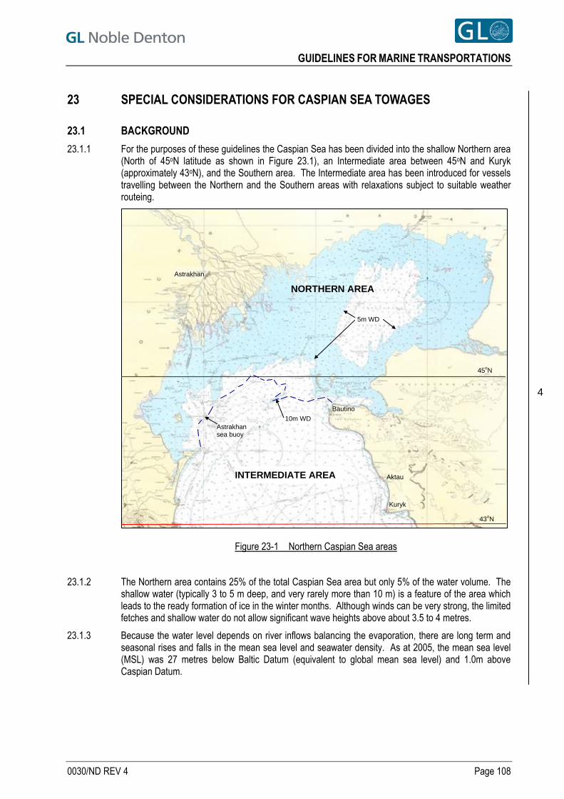
GUIDELINES FOR MARINE TRANSPORTATIONS
23 SPECIAL CONSIDERATIONS FOR CASPIAN SEA TOWAGES
23.1 BACKGROUND
23.1.1 For the purposes of these guidelines the Caspian Sea has been divided into the shallow Northern area (North of 45oN latitude as shown in Figure 23.1), an Intermediate area between 45oN and Kuryk (approximately 43oN), and the Southern area. The Intermediate area has been introduced for vessels travelling between the Northern and the Southern areas with relaxations subject to suitable weather routeing.
Figure 23-1 Northern Caspian Sea areas
INTERMEDIATE AREA Aktau
Astrakhan
43oN
Kuryk
45oN
Astrakhan sea buoy
10m WD
Bautino
5m WD
NORTHERN AREA
4
23.1.2 The Northern area contains 25% of the total Caspian Sea area but only 5% of the water volume. The shallow water (typically 3 to 5 m deep, and very rarely more than 10 m) is a feature of the area which leads to the ready formation of ice in the winter months. Although winds can be very strong, the limited fetches and shallow water do not allow significant wave heights above about 3.5 to 4 metres.
23.1.3 Because the water level depends on river inflows balancing the evaporation, there are long term and seasonal rises and falls in the mean sea level and seawater density. As at 2005, the mean sea level (MSL) was 27 metres below Baltic Datum (equivalent to global mean sea level) and 1.0m above Caspian Datum.
0030/ND REV 4 Page 108

GUIDELINES FOR MARINE TRANSPORTATIONS
23.1.4 The whole Caspian Sea suffers from a large number of unmarked fishing nets which provide a serious hazard to tugs which can be immobilised by these nets fouling their propellers. Therefore single propeller tugs are not recommended, unless there are suitable additional (redundant) tugs in attendance to replace them.
23.1.5 Many of the tugs found in this region are pusher tugs which should not be used for pushing in open waters.
23.2 REQUIREMENTS WITHIN NORTHERN CASPIAN SEA
23.2.1 GENERAL The following departures from the requirements shown in Sections 5 to 22 of these guidelines may be accepted for tows that take place totally within the Northern area (North of 45oN latitude).
23.2.2 BOLLARD PULL REQUIREMENTS Because of the limited wave heights (due to the shallow water) the meteorological criteria for calculating the Towline Pull Required (TPR) referred to in Section 12.2.7, when there is no ice, may be taken as:
Hsig = 2.5 m
Wind = 20 m/sec
Current = 0.5 m/sec
provided that the tow will have adequate sea room after the initial departure. If there will not be adequate searoom, then Section 12.2.2 will apply.
4
23.2.3 TOWLINE LENGTHS Because of the very shallow water depths and limited wave heights the minimum towline lengths required in Section 13.3.1 may be reduced within this area as follows. The minimum length available for each of the main and spare towlines (L) shall be determined from the “European” formula:
L > (BP/MBL) x 1,200 metres except that in no case shall the available length be less than 200 metres.
23.2.4 TOWLINE STRENGTH Because of the short towlines there will be little catenary to absorb shock loads in bad weather. Unless other methods of reducing the shock loads are used, the towline MBL shall be increased in line with Section 13.3.2. As an example, a deployed towline length of 200m will require a towline MBL of 6 (=1,200/200) times the continuous static bollard pull. The towing connection capacities in Section 13.2.1 b shall be related to the increased required towline MBL.
23.2.5 TOWING CONNECTIONS Suitably positioned, purpose-built quick-release towing connections are preferred. Where bollards have to be used as the towline connection:
The capacity of the bollards and their foundations must comply with the requirements of Section 13.4.
Suitable fairleads and anti-chafe arrangements must be used.
A keeper plate, capping bar or other means of keeping the towing bridle connected to the bollards must be provided and this must be suitable for any vertical loads likely to be encountered.
The design must also allow for quick release of the keeper plate, capping bar or another proven method to rapidly clear a fouled bridle.
23.2.6
23.2.7 WORKBOAT A twin screw tug fitted with a bow thruster and two anchors in accordance with Class requirements may be exempt from the requirement for a workboat in Section 12.6 provided the voyage can be completed within a favourable weather forecast. The tug must also be able to come alongside the barge at sea so that crew can board with any necessary equipment for pumping, repairs, dropping the barge’s anchor or reconnecting a towline.
0030/ND REV 4 Page 109
GUIDELINES FOR MARINE TRANSPORTATIONS
23.2.8 BUNKERS The requirement for 5 days reserve in Section 12.12 may be reduced to 3 days (pumpable reserve) provided that:
the towage can be completed within a good weather forecast period, and
there are suitable bunkering ports within 3 days sailing at all times, and
there are suitable tugs available to take over the tow if required during a diversion for refuelling.
23.2.9 TOWAGES IN ICE Section 22 applies.
23.3 REQUIREMENTS FOR REMAINING CASPIAN SEA AREAS
23.3.1 All tows in this area should follow the requirements in Sections 5 to 22 of these guidelines for unrestricted ocean tows outside benign weather areas, as applicable.
23.3.2 In addition, tugs with a single propeller are not recommended, unless there are suitable additional (redundant) tugs in attendance to replace them.
4 23.4 REQUIREMENTS FOR TOWAGES BETWEEEN CASPIAN SEA AREAS
23.4.1 Many shallow draft tugs that are designed for working in the shallow Northern area will be unable to carry towing gear suitable for towing in the Southern area. When it is not practicable for towages to change tugs when travelling between these areas whilst within the intermediate area defined in Section 23.1.1, and subject to suitable weather routeing, the following relaxations may be accepted:
Deployable towline length to be at least 400 m, and
Towline and towing connection strength requirements of Sections 22.3.4 and 23.2.5 will apply, and
Minimum bollard pull requirements as in Section 23.2.2.
23.4.2 Weather routeing will include:
Voyage planning to avoid travelling too close to a lee shore and to identify sufficient suitable safe places of shelter for different weather directions, and
Receipt of regular marine weather forecasts and a commitment to go to a suitable safe place of shelter on receipt of a bad weather forecast.
0030/ND REV 4 Page 110
GUIDELINES FOR MARINE TRANSPORTATIONS
0030/ND REV 4 Page 111
REFERENCES [1] GL Noble Denton document 0009/ND - Self-Elevating Platforms - Guidelines for Elevated Operations
[2] GL Noble Denton document 0013/ND - Guidelines for Loadouts
[3] GL Noble Denton document 0015/ND - Concrete Offshore Gravity Structures - Guidelines for Approval of Construction and Installation
[4] GL Noble Denton document 0016/ND - Seabed and Sub-Seabed data required for Approvals of Mobile Offshore Units (MOU)
[5] GL Noble Denton document 0021/ND - Guidelines for the Approval of Towing Vessels
[6] GL Noble Denton document 0027/ND - Guidelines for Marine Lifting Operations
[7] GL Noble Denton document 0028/ND - Guidelines for the Transportation and Installation of Steel Jackets
[8] IMO International Safety Management Code - ISM Code - and Revised Guidelines on Implementation of the ISM Code by Administrations - 2002 Edition
[9] DNV Rules for the Classification of Ships, January 2003, Part 3, Chapter 1, Section 4
[10] IMO Code of Safe Practice for Cargo Securing and Stowing - 2003 Edition
[11] API Recommended Practice 2A-WSD (RP 2A-WSD), Twenty First Edition, December 2000, Errata and Supplement 1, December 2002.
[12] API Recommended Practice 2A-LRFD (RP 2A-LRFD), First Edition, July 1, 1993
[13] AISC Allowable Stress Design and Plastic Design, July 1, 1989, with Supplement 1
[14] API RP 5LW - Recommended Practice for Transportation of Line Pipe on Barges and Marine Vessels
[15] EEMUA 158 - Construction Specification for Fixed Offshore Structures in the North Sea,
[16] AWS D1.1 - Structural Welding Code - steel
[17] IMO Resolution A.749 (18) as amended by Resolution MSC.75(69) - Code on Intact Stability
[18] International Convention on Load Lines, Consolidated Edition 2002
[19] International Regulations for Preventing Collisions at Sea, 1972 (amended 1996) (COLREGS)
[20] IMO MSC/Circ.623 - Piracy and armed robbery against ships - guidance to ship-owners and ship operators, shipmasters and crews on preventing and suppressing acts of piracy and armed robbery against ships
[21] IMO Document Ref. T1/3.02, MSC/Circ.884 - Guidelines for Safe Ocean Towing
[22] IMO BWM/CONF/36 - International Convention for the Control & Management of Ships' Ballast Water & Sediments, 2004
[23] IACS Requirements concerning Polar Class Oct 2007
[24] UKOOA Guidelines for Safe Movement of Self-Elevating Offshore Installations (Jack-ups) April 1995
[25] UK HSE circular “The Safe Approach, Set-Up And Departure of Jack-Up Rigs to Fixed Installations” Sept 03 from www.hse.gov.uk/foi/internalops/hid/spc/spctosd21.pdf
[26] Eurocode 3: Design of steel structures - Part 1-8: Design of Joints (BS EN 11993-1-8:2005)
All GL Noble Denton Guidelines can be downloaded from www.gl-nobledenton.com
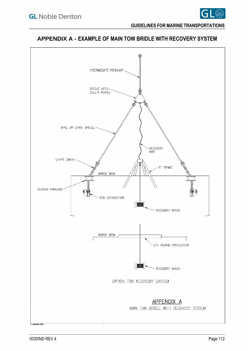
GUIDELINES FOR MARINE TRANSPORTATIONS
APPENDIX A - EXAMPLE OF MAIN TOW BRIDLE WITH RECOVERY SYSTEM
0030/ND REV 4 Page 112
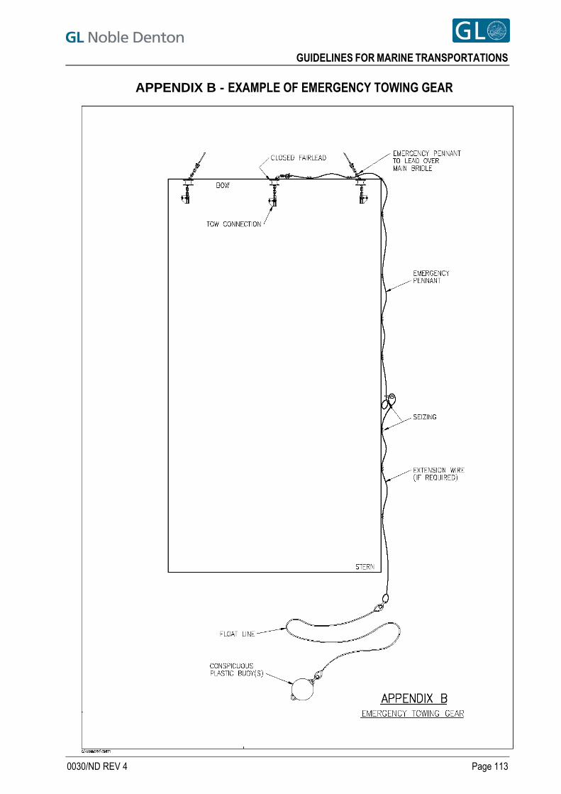
GUIDELINES FOR MARINE TRANSPORTATIONS
APPENDIX B - EXAMPLE OF EMERGENCY TOWING GEAR
0030/ND REV 4 Page 113
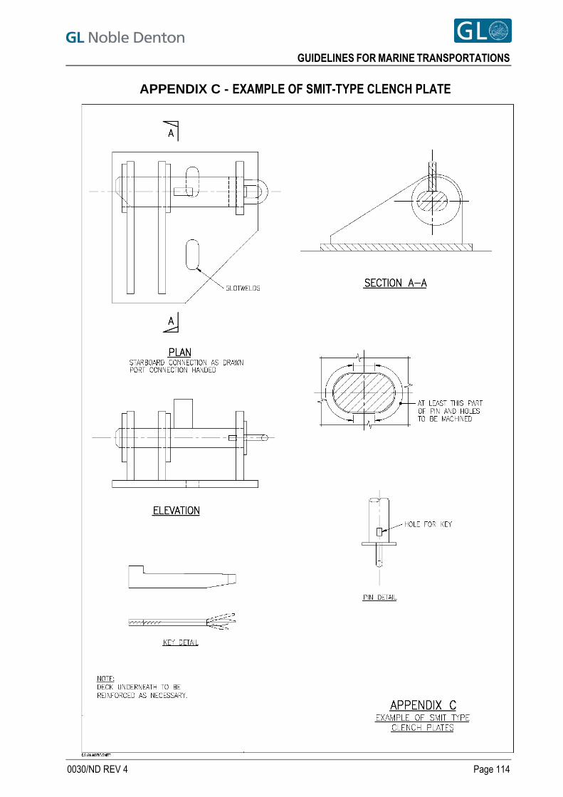
GUIDELINES FOR MARINE TRANSPORTATIONS
APPENDIX C - EXAMPLE OF SMIT-TYPE CLENCH PLATE
0030/ND REV 4 Page 114
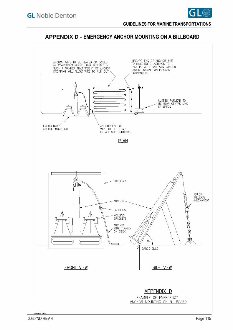
GUIDELINES FOR MARINE TRANSPORTATIONS
APPENDIX D - EMERGENCY ANCHOR MOUNTING ON A BILLBOARD
0030/ND REV 4 Page 115
GUIDELINES FOR MARINE TRANSPORTATIONS
APPENDIX E - ALTERNATIVES TO THE PROVISION & USE OF AN EMERGENCY ANCHOR
E.1 An anchor may be required in an emergency situation, for instance in the event of a broken towline, or
tug failure due to breakdown or fire. The requirement for an emergency anchor in areas of restricted searoom may be determined as a result of a risk assessment as set out in Section 16.1.2 and which should satisfy all parties that the precautions proposed are adequate.
E.2 For very large tows, such as GBS’s, TLP’s and FPSO’s, an emergency anchor may be impractical, and alternative means of achieving an equivalent level of safety should be sought.
E.3 FPSO mooring systems (whether turret-type or spread), being only for in-place conditions, are not normally configured to act as emergency moorings during transit. On a conversion the permanent gear is usually removed. For many designs the deck space where an emergency anchor might be sited is taken up with the permanent mooring equipment.
E.4 For any tow, there are arguments for and against the provision of anchors:
For: a. Conventional marine and insurance industry practice is that an anchor is provided, and any
alternative arrangement must be justified.
b. Once access is gained to the tow, or if the tow is manned, an anchor may provide a “last resort” method of controlling the tow.
Against: a. A chain locker must be provided together with an anchor windlass, chain stoppers etc. and
these will be for one use only. A billboard arrangement, as shown in Section 16.6 and Appendix D would almost certainly be ineffective for large tows.
b. Whereas ships and ship-FPSO conversions may retain a hawse pipe, chain locker, anchor windlass, chain stoppers etc, most new build FPSO’s are not fitted with these facilities.
c. For most of an ocean towage, and close to steep-to coastlines, the depth of water will be too great for an anchor to be effective.
d. If the tow is not manned, then boarding it in bad weather could pose an unacceptable hazard to the boarding crew, and deploying the anchor may prove to be impossible. In this respect a spare tug rather than an anchor would be more useful.
e. In some restricted areas, especially with pipelines, cables or subsea equipment, anchoring is prohibited, even in emergency situations.
f. Unless the anchor can be paid out under control, the shock loads when the anchor beds in and the cable comes taut may be excessive, and could result in damage, loss of the anchor or unacceptable risk to the riding crew.
g. Under adverse conditions the anchor may drag, and the tow could still be lost.
h. If 2 or more tugs are towing, then it is unlikely that any attempt to deploy an anchor would be made until all tugs or towlines had failed. If, for instance, 2 tugs were towing, dropping an anchor after a single towline failure would seriously hamper the efforts of the remaining tug to control the situation. An anchor will probably only be dropped, therefore, if all towlines break.
i. After deployment of an anchor the towage must resume at some point. The anchor must either be retrieved or cut and abandoned for later retrieval. It is probable that the tow would then be lacking an anchor, at least for a time. It is suggested that any anchor used is fitted with a retrieval pennant and buoy.
0030/ND REV 4 Page 116
GUIDELINES FOR MARINE TRANSPORTATIONS
E.5 If sufficient towing capacity and redundancy is provided, in the towing spread, tugs will provide a more flexible and manoeuvrable means of controlling the tow. Reaction time will be faster and control should be possible in all water depths.
E.6 Proposed criteria, if anchor(s) are not used, include:
a. Provision of at least N main towing tugs, any (N-1) of which comply with the requirements of Section 12.2, or:
b. Provision of at least 2 main towing tugs, which together comply with the requirements of Section 12.2, and:
c. If 1 or 2 main towing tugs are provided, an additional tug will be required to escort the tow, if the tow comes within an agreed distance of any coastline or offshore hazard. (48 nautical miles is suggested as a minimum, assuming the tow may drift uncontrollably at 2 knots for 24 hours).
d. The escort tug should be approximately equal in specification to the larger main towing tug.
e. The escort tug is not always required to hook up for escort duties, but contingency plans and equipment must allow for it to be connected rapidly, either in place of one of the other two tugs, or in addition, such that the configuration is still reasonably balanced.
f. In restricted waters, if one of the main towing tugs has a breakdown, it may be preferable to connect the escort tug to the bow of the broken-down tug, rather than to the tow
g. The towage route must be drawn up showing the proximity to coastlines or other hazards, and the route sectors where an escort tug is required. Planning should ensure that the escort tug has time to arrive and connect up before the searoom is below the agreed limits.
0030/ND REV 4 Page 117
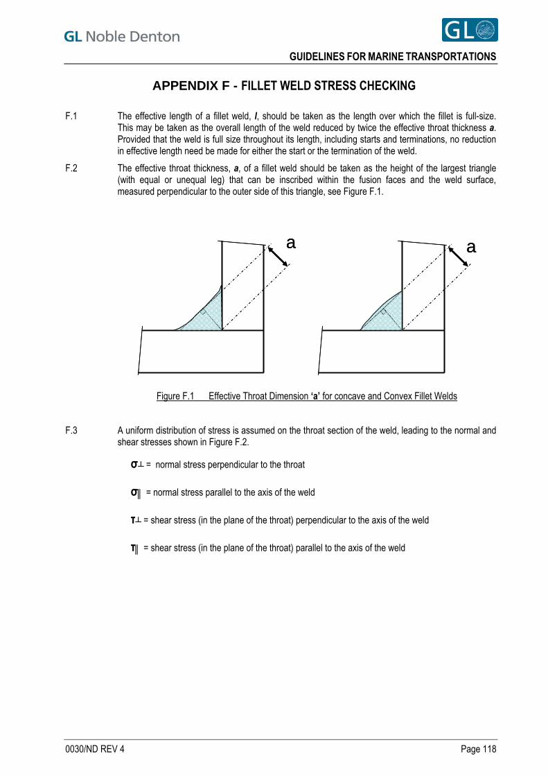
GUIDELINES FOR MARINE TRANSPORTATIONS
APPENDIX F - FILLET WELD STRESS CHECKING
F.1 The effective length of a fillet weld, l, should be taken as the length over which the fillet is full-size. This may be taken as the overall length of the weld reduced by twice the effective throat thickness a. Provided that the weld is full size throughout its length, including starts and terminations, no reduction in effective length need be made for either the start or the termination of the weld.
F.2 The effective throat thickness, a, of a fillet weld should be taken as the height of the largest triangle (with equal or unequal leg) that can be inscribed within the fusion faces and the weld surface, measured perpendicular to the outer side of this triangle, see Figure F.1.
a aa a
Figure F.1 Effective Throat Dimension ‘a’ for concave and Convex Fillet Welds
F.3 A uniform distribution of stress is assumed on the throat section of the weld, leading to the normal and shear stresses shown in Figure F.2.
σ┴ = normal stress perpendicular to the throat
σ║ = normal stress parallel to the axis of the weld
τ┴ = shear stress (in the plane of the throat) perpendicular to the axis of the weld
τ║ = shear stress (in the plane of the throat) parallel to the axis of the weld
0030/ND REV 4 Page 118
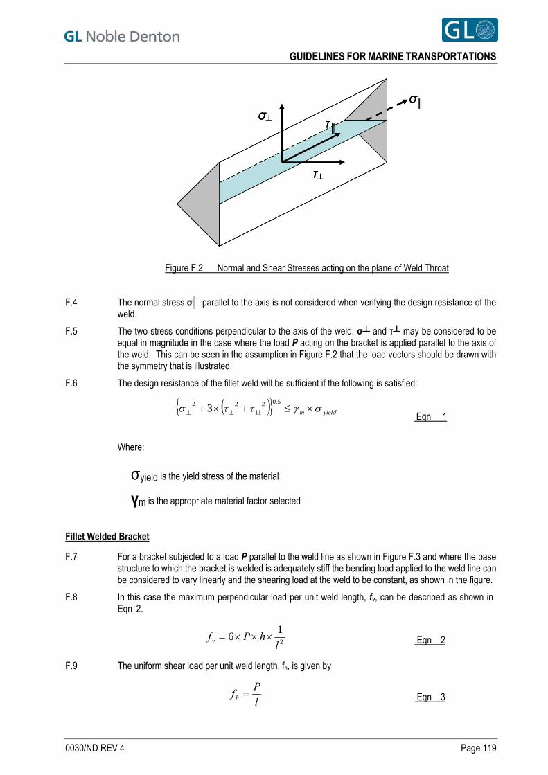
GUIDELINES FOR MARINE TRANSPORTATIONS
σ┴
τ┴
τ║
σ║σ┴
τ┴
τ║
σ║
Figure F.2 Normal and Shear Stresses acting on the plane of Weld Throat
F.4 The normal stress σ║ parallel to the axis is not considered when verifying the design resistance of the weld.
F.5 The two stress conditions perpendicular to the axis of the weld, σ┴ and τ┴ may be considered to be equal in magnitude in the case where the load P acting on the bracket is applied parallel to the axis of the weld. This can be seen in the assumption in Figure F.2 that the load vectors should be drawn with the symmetry that is illustrated.
F.6 The design resistance of the fillet weld will be sufficient if the following is satisfied:
yieldm
5.0211
22 3
Eqn 1
Where:
σyield is the yield stress of the material
γm is the appropriate material factor selected
Fillet Welded Bracket
F.7 For a bracket subjected to a load P parallel to the weld line as shown in Figure F.3 and where the base structure to which the bracket is welded is adequately stiff the bending load applied to the weld line can be considered to vary linearly and the shearing load at the weld to be constant, as shown in the figure.
F.8 In this case the maximum perpendicular load per unit weld length, fv, can be described as shown in Eqn 2.
2
16
lhPfv Eqn 2
F.9 The uniform shear load per unit weld length, fh, is given by
l
Pfh Eqn 3
0030/ND REV 4 Page 119
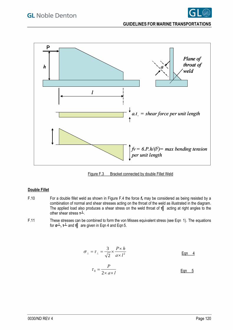
GUIDELINES FOR MARINE TRANSPORTATIONS
h
P
l
a
Plane of throat of weld
a.t- = shear force per unit length
fv = 6.P.h/(l2)= max bending tension per unit length
h
P
l
a
Plane of throat of weld
h
P
l
a
Plane of throat of weld
h
P
l
a
Plane of throat of weld
a.t- = shear force per unit length
fv = 6.P.h/(l2)= max bending tension per unit length
Figure F.3 Bracket connected by double Fillet Weld
Double Fillet
F.10 For a double fillet weld as shown in Figure F.4 the force fv may be considered as being resisted by a combination of normal and shear stresses acting on the throat of the weld as illustrated in the diagram. The applied load also produces a shear stress on the weld throat of τ║ acting at right angles to the other shear stress τ┴.
F.11 These stresses can be combined to form the von Misses equivalent stress (see Eqn 1). The equations for σ┴, τ┴ and τ║ are given in Eqn 4 and Eqn 5.
22
3
la
hP
Eqn 4
la
P
2ll Eqn 5
0030/ND REV 4 Page 120
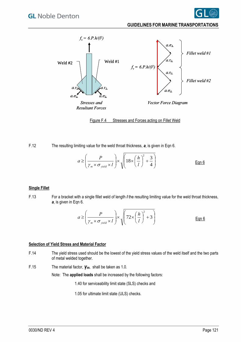
GUIDELINES FOR MARINE TRANSPORTATIONS
Stresses and Resultant Forces
fv = 6.P.h/(l2)
a.σ┴a.τ┴
a.σ┴
a.τ┴
Fillet weld #1
Fillet weld #2
fv = 6.P.h/(l2)
a.σ┴ a.σ┴
a.τ┴
a.τ┴Weld #2 Weld #1
Vector Force DiagramStresses and Resultant Forces
fv = 6.P.h/(l2)
a.σ┴a.τ┴
a.σ┴
a.τ┴
Fillet weld #1
Fillet weld #2
fv = 6.P.h/(l2)
a.σ┴ a.σ┴
a.τ┴
a.τ┴Weld #2 Weld #1
Vector Force Diagram
Figure F.4 Stresses and Forces acting on Fillet Weld
F.12 The resulting limiting value for the weld throat thickness, a, is given in Eqn 6.
4
318.
2
l
h
l
Pa
yieldm Eqn 6
Single Fillet
F.13 For a bracket with a single fillet weld of length l the resulting limiting value for the weld throat thickness, a, is given in Eqn 6.
372.
2
l
h
l
Pa
yieldm Eqn 6
Selection of Yield Stress and Material Factor
F.14 The yield stress used should be the lowest of the yield stress values of the weld itself and the two parts of metal welded together.
F.15 The material factor, γm, shall be taken as 1.0.
Note: The applied loads shall be increased by the following factors:
1.40 for serviceability limit state (SLS) checks and
1.05 for ultimate limit state (ULS) checks.
0030/ND REV 4 Page 121
GUIDELINES FOR MARINE TRANSPORTATIONS
APPENDIX G - TRANSPORTATION OR TOWING MANUAL CONTENTS
G.1 The purpose of the transportation or towing manual described in Section 5.4 is to give to:
the vessel or tug Master and
Persons In Charge (PIC), or Responsible Persons ashore for emergency response planning in the event of an incident or accident,
information about:
1. The cargo,
2. Routeing, including possible deviations to shelter points if required,
3. What to do in an emergency,
4. Contact details (client, owner, local authorities, Marine Warranty Surveyor etc.),
5. Organogram showing the scope split between different contractors (if applicable). These must be clearly defined, to ensure that all parties are aware of their responsibilities, handover points and reporting lines.
G.2 The contents of the manual shall be in a form and language that can be clearly understood by the Master and senior officers undertaking the operations.. Revisions should be clearly marked and attached drawings, with their revision numbers noted in the main text. 4
G.3 Where a manual has been produced to satisfy local authority requirements then this should take precedence, providing it satisfies the main requirements detailed below.
G.4 The list below is what the Marine Warranty Surveyor would expect to see in the transportation or towage manual. The list also includes the essential details needed by the vessel’s Master. Detailed calculations and other documents may be in separate manuals referenced in the transportation or towage manual.
1. Introduction. What is the cargo, where is it being transported or towed, who for and why. 2. Description of the vessel and cargo. 3. Proposed route (with plot or chart) including waypoints and any refuelling arrangements,
anticipated departure date and speed. 4. Metocean conditions for the route for anticipated departure date. 5. Any limiting criteria and motions (roll, pitch and period etc) for the transport or tow, weather
forecasting arrangements and weather routeing details if applicable. 6. Contact details and responsibilities. 7. Reporting details: who to, how often and content. 8. Summary of ballast conditions and stability (usually including anticipated departure and arrival
loading conditions) with corresponding stability calculations and GZ curves. Calculations should also be provided for any ballasting required for loading or discharging where applicable.
9. Motions and strength - detailed supporting calculations for the motions and accelerations, longitudinal strength and strength of the seafastening and cribbing/grillage.
10. Arrival details, contacts, field plan etc. 11. Contingency arrangements. 12. Drawings to include, where applicable, cargo, GA and other key drawings of vessel and cargo,
stowage plan, towing arrangement, cribbing /grillage arrangement, load-out /discharge plan, seafastening arrangement, guidepost details etc.
13. Reference documents. 14. Tug bollard pull calculation (if applicable). 15. Tug or transport vessel specification.
0030/ND REV 4 Page 122
TECHNICAL POLICY BOARD
www.gl-nobledenton.com
0032/ND
Once downloaded this document becomes UNCONTROLLED. Please check the website below for the current version.
GUIDELINES FOR MOORINGS
6 Dec 10 0 RK Technical Policy Board
Date Revision Prepared by Authorised by
GUIDELINES FOR MOORINGS
CONTENTS SECTION PAGE NO.
1 SUMMARY 5 1.1 Scope 5 1.2 Contents 5
2 INTRODUCTION 6 3 DEFINITIONS 7 4 THE APPROVAL PROCESS 10
4.1 General 10 4.2 Scope of work leading to an approval 10
5 CODES AND STANDARDS 11 5.1 General 11 5.2 Offshore moorings 11 5.3 Inshore moorings and quayside moorings 11
6 INFORMATION REQUIRED 13 6.1 General 13 6.2 Operation 13 6.3 Design criteria 13 6.4 Location 13 6.5 Design environmental conditions 13 6.6 Vessel 14 6.7 Mooring system 14
7 DESIGN ENVIRONMENTAL CONDITIONS 15 7.1 General 15 7.2 Unrestricted operations 15 7.3 Weather-restricted operations 15 7.4 Use of seasonal / directional Metocean data 16 7.5 Wind 17 7.6 Current 17 7.7 Waves 17 7.8 Tide 17
8 ENVIRONMENTAL LOADS AND MOTIONS 18 8.1 General 18 8.2 Wind loads 18 8.3 Current loads 18 8.4 Wave loads 18 8.5 Wave frequency motions 19 8.6 Low frequency motions 19
9 MOORING ANALYSIS 20 9.1 General 20 9.2 Analysis cases 20 9.3 mooring Line length/tension adjustment 21 9.4 Analysis techniques 21
10 DESIGN AND STRENGTH 23 10.1 General 23 10.2 Redundancy 23 10.3 mooring pattern 23 10.4 Mooring line and connection strength 23 10.5 Anchor capacity 24
0032/ND Rev 0 Page 2
GUIDELINES FOR MOORINGS
0032/ND Rev 0 Page 3
11 CLEARANCES 26 11.1 General 26 11.2 Horizontal anchor clearances 27 11.3 Horizontal Wire or Chain clearances 27 11.4 Line vertical clearances 27 11.5 Line-line clearances 28 11.6 Installing Anchors 28
12 MOORING EQUIPMENT 29 12.1 Mooring integrity 29 12.2 Certification 29 12.3 Anchors 29 12.4 Chain 29 12.5 Wire rope 29 12.6 Fibre rope 29 12.7 Connectors 29 12.8 Buoys (surface and subsurface) 30 12.9 Vessel connection points 30 12.10 Fendering 30
13 PROCEDURAL CONSIDERATIONS 32 13.1 General 32 13.2 Anchor proof loading 32 13.3 Manning 32 13.4 Inspection, monitoring and maintenance 32
14 DOCUMENTATION 33 14.1 Leading to approval 33 14.2 Office review 33 14.3 On site 33
15 SPECIAL CONSIDERATIONS FOR INSHORE AND QUAYSIDE MOORINGS 34 15.1 Background 34 15.2 Locations within harbour limits 34 15.3 Contingency arrangements 34 15.4 Mooring considerations 34 15.5 Shore mooring points / bollards / winches 35 15.6 Procedures 35 15.7 Cold stacking 35 15.8 Ice loading 35
16 SPECIAL CONSIDERATIONS FOR PERMANENT MOORINGS 36 16.1 General 36
REFERENCES 37 TABLES Table 7-1 Environmental Return Periods 15 Table 7-2 Seastate Reduction Factors for 24 hour Operational Duration 16 Table 9-1 Recommended Analysis Methods and Conditions 20 Table 9-2 Types of Analyses 22 Table 10-1 Line Tension Limits and Design Safety Factors 24 Table 10-2 Drag Anchor Holding Capacity Design Safety Factors 24 Table 10-3 Design Safety Factors for Holding Capacity of Anchor Piles and Suction Piles 24 Table 10-4 Design Safety Factors for Holding Capacity of Gravity and Plate Anchors 25 Table 11-1 Summary of Minimum Mooring Clearances 26 FIGURES Figure 11.1 Minimum Horizontal Anchor Clearances from Pipelines or Cables 27
GUIDELINES FOR MOORINGS
PREFACE This document has been drawn with care to address what are likely to be the main concerns based on the experience of the GL Noble Denton organisation. This should not, however, be taken to mean that this document deals comprehensively with all of the concerns which will need to be addressed or even, where a particular matter is addressed, that this document sets out the definitive view of the organisation for all situations. In using this document, it should be treated as giving guidelines for sound and prudent practice on which our advice should be based, but guidelines should be reviewed in each particular case by the responsible person in each project to ensure that the particular circumstances of that project are addressed in a way which is adequate and appropriate to ensure that the overall advice given is sound and comprehensive. Whilst great care and reasonable precaution has been taken in the preparation of this document to ensure that the content is correct and error free, no responsibility or liability can be accepted by GL Noble Denton for any damage or loss incurred resulting from the use of the information contained herein.
© 2010 Noble Denton Group Limited, who will allow:
the document to be freely reproduced, the smallest extract to be a complete page including headers and footers, but smaller extracts may be
reproduced in technical reports and papers, provided their origin is clearly referenced.
0032/ND Rev 0 Page 4
GUIDELINES FOR MOORINGS
1 SUMMARY
1.1 SCOPE 1.1.1 This document describes the guidelines which will be used by GL Noble Denton for the approval of
moorings, including: a. Offshore catenary or taut leg moorings of mobile offshore units (MOU) b. Offshore catenary or taut leg mooring of floating offshore installations (FOI) c. Inshore mooring of MOUs and FOIs, e.g. for stacking d. Temporary mooring of offshore installations in an afloat condition during construction,
installation or decommissioning e. Quayside mooring of MOUs and FOIs, e.g. during maintenance or conversion f. Mooring of vessels during loadouts and installation operations.
1.2 CONTENTS 1.2.1 The following aspects of moorings are described:
a. The approval process b. Codes and standards c. Information required d. Design environmental conditions e. Environmental loads f. Motion response g. Mooring analysis h. Design and strength i. Clearances j. Mooring equipment k. Procedural considerations l. Documentation m. Special considerations for inshore and quayside moorings n. Special considerations for permanent moorings.
0032/ND Rev 0 Page 5
GUIDELINES FOR MOORINGS
2 INTRODUCTION 2.1 This document describes the guidelines which will be used by GL Noble Denton for the approval of
moorings, including: a. Offshore catenary or taut leg moorings of mobile offshore units (MOU) b. Offshore catenary or taut leg mooring of floating offshore installations (FOI) c. Inshore mooring of MOUs and FOIs, e.g. for stacking d. Temporary mooring of offshore installations in an afloat condition during construction,
installation or decommissioning e. Quayside mooring of MOUs and FOIs, e.g. during maintenance or conversion f. Mooring of vessels during loadouts and installation operations.
2.2 Where GL Noble Denton is acting as a consultant rather than a Warranty Surveyor, these Guidelines may also be applied as a guide to good practice.
2.3 This document is not intended to apply to “standard”, temporary moorings such as ships in port or anchored or moored by the bow where the vessels are fully manned, have a full marine watch, live engines and tugs available.
2.4 This document does not cover all types of mooring and every mooring application. Readers should therefore satisfy themselves that the Guidelines used are fit for purpose for the actual mooring under consideration.
2.5 This document refers to recognised standards and design codes and to other GL Noble Denton Guidelines as appropriate. All current GL Noble Denton Guideline documents can be downloaded from www.gl-nobledenton.com.
2.6 This document gives guidance on engineering analysis and practical marine considerations, both of which will form the basis for any approval.
2.7 These Guidelines are intended to lead to an approval by GL Noble Denton. Approval by GL Noble Denton does not necessarily imply that submitted proposals will comply with the requirements of any other party or organisation (e.g. as defined by codes, national legislation, guidelines, etc).
2.8 This document is submitted for general guidance and it should be noted that each mooring will differ in design due to the nature of the moored structure and the particulars of the location. This document therefore contains general guidance and detailed recommendations that will apply to individual cases.
2.9 These Guidelines are not intended to exclude alternative methods, new technology and new equipment, provided that an equivalent level of safety can be demonstrated.
0032/ND Rev 0 Page 6
GUIDELINES FOR MOORINGS
3 DEFINITIONS Referenced definitions are underlined.
Term or Acronym Definition
Approval The act, by the designated GL Noble Denton representative, of issuing a ‘Certificate of Approval’.
ATA Automatic Thruster Assist
Barge A non-propelled vessel commonly used to carry cargo or equipment. (For the purposes of this document, the term Barge can be considered to include Vessel or Ship where appropriate).
Benign Area An area that is free from tropical revolving storms and travelling depressions, (excluding the North Indian Ocean during the Southwest monsoon season and the South China Sea during the Northeast monsoon season). The specific extent and seasonal limitations of a benign area should be agreed with the GL Noble Denton office concerned.
Certificate of Approval A formal document issued by GL Noble Denton stating that, in its judgement and opinion, all reasonable checks, preparations and precautions have been taken to keep risks within acceptable limits, and an operation may proceed.
Client The company to which GL Noble Denton is contracted to perform marine warranty or consultancy activities.
Cold Stacking Cold stacking is where the unit is expected to be moored up for a significant period of time and will have minimum or, in some cases, no services or personnel available.
DNV Det Norske Veritas
DP Dynamic Positioning
FLS Fatigue Limit State
FOI Floating Offshore Installation
FOS Factor of Safety
GL Noble Denton Any company within the GL Noble Denton Group including any associated company which carries out the scope of work and issues a Certificate of Approval, or provides advice, recommendations or designs as a consultancy service.
HAZID Hazard Identification
Hot Stacking Hot stacking may be defined as mooring the vessel in a manned functional condition, with the option to run machinery to provide sufficient power to operate all mooring winches, thrusters, etc as may be required.
IACS International Association of Classification Societies.
Inshore Mooring A mooring operation in relatively sheltered coastal waters, but not at a quayside.
Insurance Warranty A clause in the insurance policy for a particular venture, requiring the approval of a marine operation by a specified independent survey house.
Loadout The transfer of a major assembly or a module onto a barge, e.g. by horizontal movement or by lifting.
0032/ND Rev 0 Page 7
GUIDELINES FOR MOORINGS
0032/ND Rev 0 Page 8
Term or Acronym Definition
MBL Certified Minimum Breaking Load (of a wire, chain or other mooring system component).
Mobile Mooring Mooring system, generally retrievable, intended for deployment at a specific location for a short-term duration, such as those for mobile offshore units.
MODU Mobile Offshore Drilling Unit
Mooring System Consists of all the components in the mooring system including shackles windlasses and other jewellery and, in addition, rig/vessel and shore attachments such as bollards.
MOU Mobile Offshore Unit
n/a Not Applicable
NMD Norwegian Maritime Directorate.
Operational Reference Period
The planned duration of the operation, including a contingency period.
OCIMF Oil Companies International Marine Forum.
Permanent Mooring Mooring system normally used to moor floating structures deployed for long-term operations, such as those for a floating production system.
PSA Petroleum Safety Authority Norway
QTF / Quadratic Transfer Function
Refers to the matrix that defines second order mean wave loads on a vessel in bi-chromatic waves. When combined with a wave spectrum the mean wave drift loads and low frequency loads can be calculated.
Quayside Mooring A mooring that locates a vessel alongside a quay (usually at a sheltered location).
RAO / Response Amplitude Operator
Defines the vessel’s (first order) response in regular waves and allows calculation of vessel wave frequency (first order) motion in a given seastate using spectral analysis techniques.
Redundancy Check Check of the failure loadcase associated with the applicable extreme (survival) environment, e.g. the one leg damaged case.
Semi-Submersible Unit A floating structure normally consisting of a deck structure with a number of widely spaced, large cross-section, supporting columns connected to submerged pontoons.
Self-Elevating Unit More commonly know as a ‘Jack-up’. It is a Marine Unit equipped with legs and jacking systems capable of lifting the hull clear of the water. A ‘Jack-up’ unit may be used as a production platform, drilling platform, construction support platform or accommodation platform.
SLS / Serviceability Limit State
A design condition defined as a normal Serviceability Limit State / normal operating case.
Survey Attendance and inspection by a GL Noble Denton representative. Other surveys which may be required for a marine operation, including suitability, dimensional, structural, navigational, and Class surveys.
Surveyor The GL Noble Denton representative carrying out a survey. An employee of a contractor or Classification Society performing, for instance, a suitability, dimensional, structural, navigational or Class survey.
TA Thruster Assist
UKCS United Kingdom Continental Shelf
GUIDELINES FOR MOORINGS
0032/ND Rev 0 Page 9
Term or Acronym Definition
ULS / Ultimate Limit State
The intact loadcase associated with the applicable extreme (survival) environment.
VLA Vertical Load Anchors.
Vessel Within the scope of this document refers to any structure which is being moored.
GUIDELINES FOR MOORINGS
4 THE APPROVAL PROCESS
4.1 GENERAL 4.1.1 GL Noble Denton may act as a warranty surveyor, issuing an approval for a particular mooring or
mooring operation, or as a consultant providing advice, recommendations, calculations and/or designs as part of the scope of work. These functions are not necessarily mutually exclusive.
4.1.2 Agreement is required on the start point (or point of no return) for the mooring or mooring operation and the end point (or termination) which may apply to each issued certificate of approval.
4.2 SCOPE OF WORK LEADING TO AN APPROVAL 4.2.1 Technical studies leading to the issue of a certificate of approval may consist of:
a. Reviews and audits of procedures, calculations and/or physical model tests submitted by the client or his contractors, or
b. Independent analyses carried out by GL Noble Denton to verify the feasibility of the proposals, or
c. A combination of third party reviews and independent analyses.
4.2.2 Surveys and attendances carried out as part of GL Noble Denton's scope of work typically include: a. Site survey or examination of the mooring system, confirming that it complies with mooring
design as submitted to GL Noble Denton b. Review of the certification of all component parts of the system c. Confirmation of the general condition of the vessel in terms of machinery and manning d. Inspection and verification of procedures for maintenance and operation of mooring equipment
and actions in an emergency including availability of tugs, etc. e. Discussions with the local port authority or pilots as appropriate f. Examination and/or function testing of any key items of equipment, vessels, etc. to be employed
during the installation of the mooring system or in the as installed operational condition g. Attendance at HAZIDs, risk assessment meetings as required h. Attendance and witnessing mooring installation activities, including deployment, test tensioning,
etc.
0032/ND Rev 0 Page 10
GUIDELINES FOR MOORINGS
5 CODES AND STANDARDS
5.1 GENERAL 5.1.1 A number of recognised standards and design codes covering moorings are already in existence. It is
not intended that this document should redefine recommendations in areas already well covered by established codes. The default standard for mooring system design and approval is ISO 19901-7.
5.1.2 Although many aspects of mooring design and practice are covered by existing codes, it is often necessary to draw upon more than one source. This document aims to collate relevant guidance from several sources where necessary. Care shall be taken to use coherent input data, analysis methods and safety factors; in general this means that these should be taken together from a single source. Combining the least conservative options from different sources is not acceptable.
5.1.3 References to guidance on best practice relating to specific issues are provided in this document wherever possible.
5.1.4 In some subject areas, particularly in relation to inshore or quayside moorings of offshore units, there is little relevant guidance available. It is intended that this document be a primary source of reference for these areas.
5.2 OFFSHORE MOORINGS 5.2.1 The International Standard ISO 19901-7, Ref. [2], represents the most modern and widely accepted
set of criteria and guidelines for offshore moorings. GL Noble Denton considers ISO 19901-7 to be the preferred code for the design of all mooring systems.
5.2.2 API Recommended Practice 2SK (RP 2SK), Ref. [3] is to be incorporated within, and superseded by, ISO 19901-7 but at present it includes extensive guidance that is not included within the International Standard. This document makes reference to API RP 2SK guidance on some subjects not covered in detail by ISO 19901-7:2005.
5.2.3 DNV OS E301, Position Mooring (POSMOOR E301), Ref. [6], is considered by GL Noble Denton to be an acceptable alternative to ISO 19901-7 when used in conjunction with DNV RP C205.
5.2.4 DNV Rules for the Classification of Mobile Offshore Units, Part 6, Chapter 2: Position Mooring (POSMOOR ‘96), Ref. [6] has been superseded by DNV Offshore Standard E301. However POSMOOR ‘96 still remains the de facto standard code in some regions. GL Noble Denton will accept its use in some circumstances, such as if specifically requested by a field operator for MOUs with existing POSMOOR notation under the Rules for the Classification of Mobile Offshore Units Ref. [6].
5.3 INSHORE MOORINGS AND QUAYSIDE MOORINGS 5.3.1 Although the environmental loads experienced by a vessel moored in a sheltered inshore location or
alongside a quayside are likely to be significantly lower than those it may experience offshore, the risk profile of these types of mooring is high due to a combination of the following factors: a. Offshore mooring systems are generally designed for large deployed lengths of mooring wire or
chain whereas inshore moorings will generally have short taut lines which can lead to very high tensions and can result in uplift on anchors
b. High consequence of failure given the proximity to shore, other assets and limited response time
c. Potential lack of suitable or degraded connection points on the vessel and onshore, e.g. quayside
d. Uncertainty in the calculation of environmental forces due to wind shear effects and shallow water blockage effects
e. Potential limitations on the ability to adjust moorings and balance the line tensions in adverse weather conditions
f. Potential difficulty in knowing the actual tensions in the lines, in other words a lack of instrumentation
g. Potential for failures due to chafe points and abrasion (especially for quayside moorings).
0032/ND Rev 0 Page 11
GUIDELINES FOR MOORINGS
5.3.2 The basic approach to the review and approval of inshore and quayside moorings will be similar to that for offshore moorings, and the basic design philosophy should be the same although suitably modified to take account of the key features of these applications. Acceptance criteria (safety factors, etc.) should be based upon either the codes discussed in Section 5.2 (subject to the limitations stated therein) or those given in Sections 5.3.4 and 10 of this Guideline.
5.3.3 BS6349-6 “Design of Inshore Moorings and Floating Structures”, Ref. [7], whilst somewhat outdated in a number of aspects (material selection and analytical techniques being two primary areas) provides suitable guidance for the assessment of pontoons, floating docks and Admiralty-type buoy moorings. If used, the general philosophy must be consistent with that laid out in this guideline.
5.3.4 OCIMF, Ref. [11], is considered appropriate for evaluating quayside mooring requirements of marine vessels such as tankers. It also provides good guidance on the use of quayside moorings and on design factors of safety for common vessel connections such as bitts, Smit brackets and Panama chocks.
0032/ND Rev 0 Page 12
GUIDELINES FOR MOORINGS
6 INFORMATION REQUIRED
6.1 GENERAL 6.1.1 This section outlines the information required for the approval of a mooring or for carrying out mooring-
related consultancy work. 6.1.2 Where relevant the approved operations manual should be submitted, for example, where it contains
details of approved wind and current load coefficients, motions response amplitude operators, wave drift coefficients, etc. The manual is also likely to be relevant where it defines any limitations, guidelines or performance criteria relating to the active control of winches, windlasses and thrusters.
6.2 OPERATION 6.2.1 Details of the operation to be undertaken should be established, including:
a. Nature of operation b. Timing, e.g. dates c. Duration d. Any operational mooring system performance criteria e. Whether the mooring system will be active or passive; an active system allows line
tension/length adjustment f. Manned or unmanned and, if manned, whether on a 24 hour basis.
6.3 DESIGN CRITERIA 6.3.1 All relevant design criteria should be established, including the code or standard to which the design
has been carried out.
6.4 LOCATION 6.4.1 All relevant details of the mooring location should be established including
a. Geographical location, e.g. grid coordinates and possible local currents e.g. river outflows b. Water depth including bathymetry covering the full area of the mooring spread c. Seabed conditions, e.g. soil type d. Geotechnical information, e.g. soil properties derived from core samples, if required e. Details of any existing installations or infrastructure on the surface and subsea, documented by
reliable surveys f. For inshore or quayside moorings some details of the local topography may be required to help
determine the wind sheltering effects and the wind shear profiles that should be applied g. Quay wall section drawings detailing water levels and elevation of fendering arrangements h. Capacity of quayside bollards (see Section 15.5).
6.4.2 Further details of seabed and geotechnical data requirements are given in GL Noble Denton Guideline 0016/ND, Ref [9] “Seabed and Sub-seabed Data Required for Approvals of Mobile Offshore Units (MOU)”.
6.5 DESIGN ENVIRONMENTAL CONDITIONS 6.5.1 The environment considered in any analysis is dependent on the design criteria used but, in general,
environmental information should include the following: a. Design seastate is usually characterised by significant wave height and mean zero-crossing
period, together with a parametric wave spectrum, e.g. JONSWAP spectrum b. Design wind speed and, if applicable, gust spectrum c. Design current and, if applicable, current profile d. Long period swell and direction,
0032/ND Rev 0 Page 13
GUIDELINES FOR MOORINGS
e. Minimum temperature if below 0oC.
6.6 VESSEL 6.6.1 The type and characteristics of the vessel to be moored should be established. The required
information can be broadly categorised as shown below. 6.6.2 Vessel condition:
a. Intended draught(s) b. Details of loading condition, if required.
6.6.3 Environmental loading and response characteristics (for all relevant draughts): a. Response Amplitude Operators (RAOs) b. Quadratic Transfer Functions (QTFs) c. Wind load coefficients d. Current load coefficients e. Displacement and frequency dependent added mass and damping.
6.6.4 Vessel mooring points: a. Fairleads - type, positions and documented structural capacity including supporting structure b. Winches or windlasses - number, type, brake capacity, stopper capacity, stall capacity, pawl
details, etc. c. Position and capacity of onboard bollards, mooring bitts or Smit brackets d. Dimensions, condition and load capacity of anchor racks (cow catchers).
6.6.5 Propulsion and dynamic positioning systems: a. Thrusters - number, type, thrust and positions and operational; status b. Control system - manual joystick or fully dynamically positioned (TA / ATA) c. Critical failure modes - thrust available following a worst case single point failure.
6.7 MOORING SYSTEM 6.7.1 Details of mooring system components including:
a. Anchors - number, type and weight b. Mooring line make-up, length, type and age of each component c. Mooring line diameter, area, minimum breaking load, axial stiffness and weight per length d. Latest mooring line inspection report e. Details of any buoys or clump weights f. Details of any connecting hardware g. Condition and operational status of equipment.
6.7.2 If GL Noble Denton is undertaking a mooring analysis, details of any Operator or Drilling Contractor preferred or standard anchor patterns should be supplied.
0032/ND Rev 0 Page 14
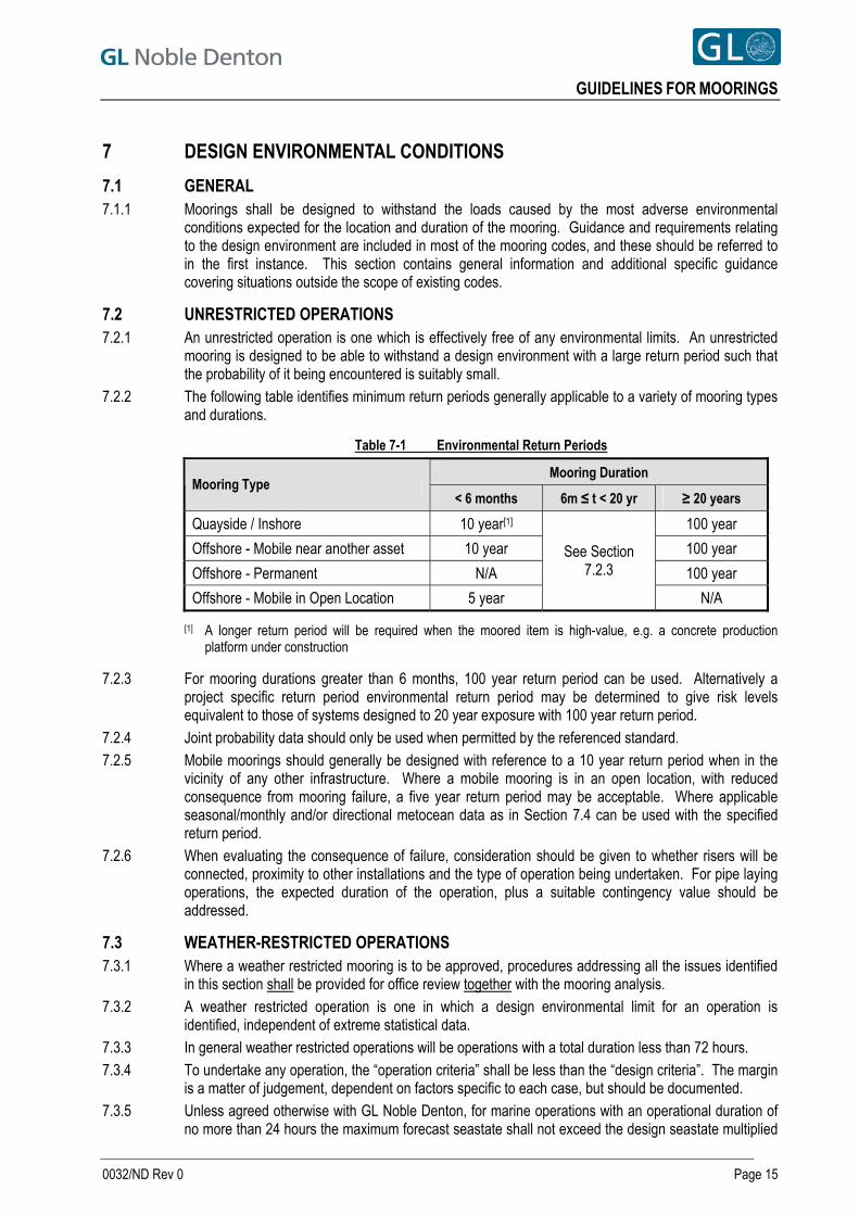
GUIDELINES FOR MOORINGS
7 DESIGN ENVIRONMENTAL CONDITIONS
7.1 GENERAL 7.1.1 Moorings shall be designed to withstand the loads caused by the most adverse environmental
conditions expected for the location and duration of the mooring. Guidance and requirements relating to the design environment are included in most of the mooring codes, and these should be referred to in the first instance. This section contains general information and additional specific guidance covering situations outside the scope of existing codes.
7.2 UNRESTRICTED OPERATIONS 7.2.1 An unrestricted operation is one which is effectively free of any environmental limits. An unrestricted
mooring is designed to be able to withstand a design environment with a large return period such that the probability of it being encountered is suitably small.
7.2.2 The following table identifies minimum return periods generally applicable to a variety of mooring types and durations.
Table 7-1 Environmental Return Periods
Mooring Duration Mooring Type
< 6 months 6m ≤ t < 20 yr ≥ 20 years
Quayside / Inshore 10 year[1] 100 year
Offshore - Mobile near another asset 10 year 100 year
Offshore - Permanent N/A 100 year
Offshore - Mobile in Open Location 5 year
See Section 7.2.3
N/A
[1] A longer return period will be required when the moored item is high-value, e.g. a concrete production platform under construction
7.2.3 For mooring durations greater than 6 months, 100 year return period can be used. Alternatively a project specific return period environmental return period may be determined to give risk levels equivalent to those of systems designed to 20 year exposure with 100 year return period.
7.2.4 Joint probability data should only be used when permitted by the referenced standard. 7.2.5 Mobile moorings should generally be designed with reference to a 10 year return period when in the
vicinity of any other infrastructure. Where a mobile mooring is in an open location, with reduced consequence from mooring failure, a five year return period may be acceptable. Where applicable seasonal/monthly and/or directional metocean data as in Section 7.4 can be used with the specified return period.
7.2.6 When evaluating the consequence of failure, consideration should be given to whether risers will be connected, proximity to other installations and the type of operation being undertaken. For pipe laying operations, the expected duration of the operation, plus a suitable contingency value should be addressed.
7.3 WEATHER-RESTRICTED OPERATIONS 7.3.1 Where a weather restricted mooring is to be approved, procedures addressing all the issues identified
in this section shall be provided for office review together with the mooring analysis. 7.3.2 A weather restricted operation is one in which a design environmental limit for an operation is
identified, independent of extreme statistical data. 7.3.3 In general weather restricted operations will be operations with a total duration less than 72 hours. 7.3.4 To undertake any operation, the “operation criteria” shall be less than the “design criteria”. The margin
is a matter of judgement, dependent on factors specific to each case, but should be documented. 7.3.5 Unless agreed otherwise with GL Noble Denton, for marine operations with an operational duration of
no more than 24 hours the maximum forecast seastate shall not exceed the design seastate multiplied
0032/ND Rev 0 Page 15
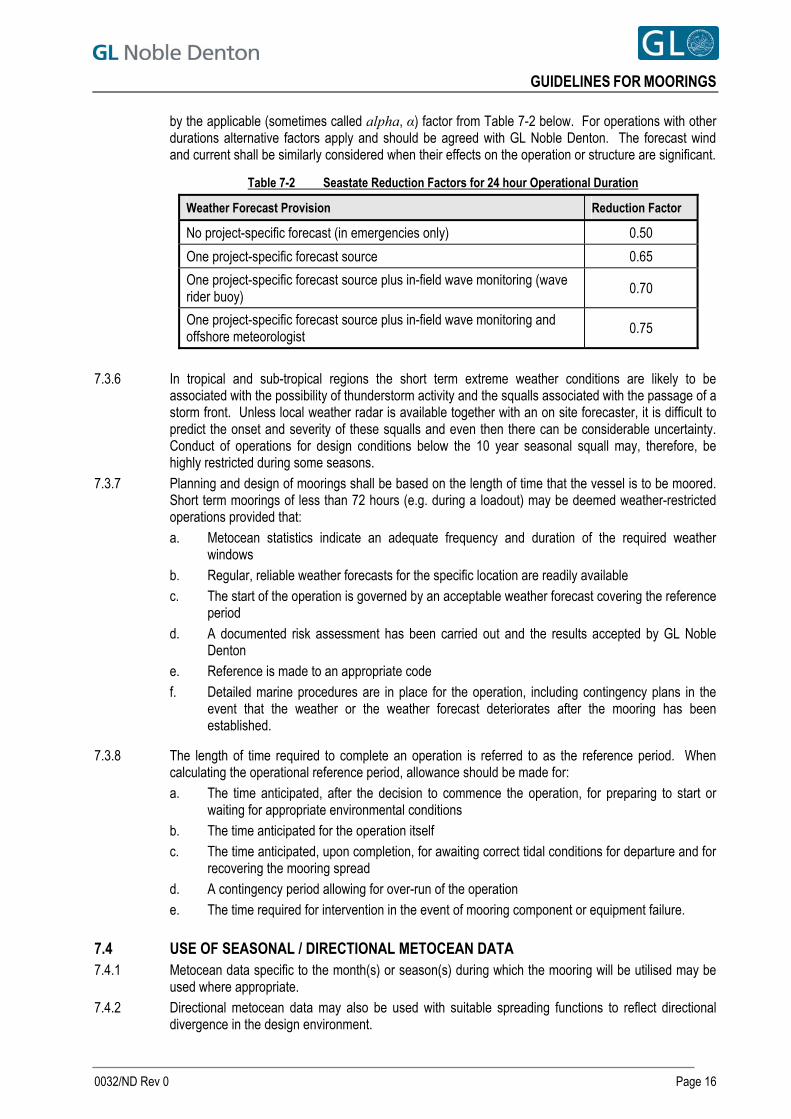
GUIDELINES FOR MOORINGS
by the applicable (sometimes called alpha, α) factor from Table 7-2 below. For operations with other durations alternative factors apply and should be agreed with GL Noble Denton. The forecast wind and current shall be similarly considered when their effects on the operation or structure are significant.
Table 7-2 Seastate Reduction Factors for 24 hour Operational Duration
Weather Forecast Provision Reduction Factor
No project-specific forecast (in emergencies only) 0.50
One project-specific forecast source 0.65
One project-specific forecast source plus in-field wave monitoring (wave rider buoy)
0.70
One project-specific forecast source plus in-field wave monitoring and offshore meteorologist
0.75
7.3.6 In tropical and sub-tropical regions the short term extreme weather conditions are likely to be
associated with the possibility of thunderstorm activity and the squalls associated with the passage of a storm front. Unless local weather radar is available together with an on site forecaster, it is difficult to predict the onset and severity of these squalls and even then there can be considerable uncertainty. Conduct of operations for design conditions below the 10 year seasonal squall may, therefore, be highly restricted during some seasons.
7.3.7 Planning and design of moorings shall be based on the length of time that the vessel is to be moored. Short term moorings of less than 72 hours (e.g. during a loadout) may be deemed weather-restricted operations provided that: a. Metocean statistics indicate an adequate frequency and duration of the required weather
windows b. Regular, reliable weather forecasts for the specific location are readily available c. The start of the operation is governed by an acceptable weather forecast covering the reference
period d. A documented risk assessment has been carried out and the results accepted by GL Noble
Denton e. Reference is made to an appropriate code f. Detailed marine procedures are in place for the operation, including contingency plans in the
event that the weather or the weather forecast deteriorates after the mooring has been established.
7.3.8 The length of time required to complete an operation is referred to as the reference period. When calculating the operational reference period, allowance should be made for: a. The time anticipated, after the decision to commence the operation, for preparing to start or
waiting for appropriate environmental conditions b. The time anticipated for the operation itself c. The time anticipated, upon completion, for awaiting correct tidal conditions for departure and for
recovering the mooring spread d. A contingency period allowing for over-run of the operation e. The time required for intervention in the event of mooring component or equipment failure.
7.4 USE OF SEASONAL / DIRECTIONAL METOCEAN DATA 7.4.1 Metocean data specific to the month(s) or season(s) during which the mooring will be utilised may be
used where appropriate. 7.4.2 Directional metocean data may also be used with suitable spreading functions to reflect directional
divergence in the design environment.
0032/ND Rev 0 Page 16
GUIDELINES FOR MOORINGS
7.5 WIND 7.5.1 Wind speeds should be referenced at 10m above the still water level. 7.5.2 For permanent moorings the more onerous of the following should be considered:
a. Steady one minute mean velocity; or b. One hour mean plus a suitable gust spectrum.
7.5.3 Generally the ISO 19901 gust spectrum Ref. [2] would be applicable to 7.5.2b unless an alternative can be clearly justified.
7.5.4 For mobile moorings either a steady state wind speed or a suitable gust spectrum may be used depending upon the stiffness of the mooring system. The 10 minute averaged wind speed can be used to analyse catenary moorings if the effect of wind dynamics on the line tension is shown to be insignificant.
7.5.5 For inshore or quayside moorings care must be taken to ensure that all natural periods of response of the system have been considered. Some of the mooring system response periods may be shorter than one minute but on the other hand the use of shorter gust periods may not represent a sustained design wind that will act at the same time across the whole of the structure. The representative design wind sampling period, therefore, has to be carefully established on a case by case basis for inshore and quayside moorings.
7.6 CURRENT 7.6.1 The design current shall taking account of mean spring tide, the return period storm surge, fluvial
(river) and wind-driven components.
7.7 WAVES 7.7.1 For mobile moorings it is generally acceptable to consider a single extreme significant wave height and
associated zero crossing period corresponding to the relevant return period for a location. 7.7.2 For permanent moorings a number of Hs-Tz combinations along the 100 year return period contour
line have to be considered for the analysis. If a contour plot is not available, a sensitivity study by varying peak period for the 100 year return period sea state is required. This is to ensure that extreme line tensions due to low frequency motion at lower periods are captured in the analysis, especially for ship shaped floaters.
7.8 TIDE 7.8.1 For moorings at locations where the tidal range is greater than 10% of the water depth, the highest and
lowest still water levels at the location for the duration of the mooring should be established and considered in the analysis of the mooring.
7.8.2 For quayside moorings the effect of tide should always be considered including possible means to adjust line lengths for locations subject to substantial tidal variations and also to monitor line tensions with the possible provision of an alarm system (24 hour monitoring required) when tensions approach pre-specified levels.
0032/ND Rev 0 Page 17
GUIDELINES FOR MOORINGS
8 ENVIRONMENTAL LOADS AND MOTIONS
8.1 GENERAL 8.1.1 This section addresses the calculation of forces imposed by the environment upon a moored vessel, its
mooring spread and appendages, such as risers and umbilicals. 8.1.2 Unless it is clearly demonstrated that any of the following forces or motions are insignificant, they
should always be considered in any mooring analysis. 8.1.3 Drag coefficients or model tests should be representative of the vessel at the draught(s) under
consideration. Line tensions should be evaluated for all possible vessel draughts.
8.2 WIND LOADS 8.2.1 Wind loads should be considered to have a variable component modelled by an appropriate gust
spectrum. 8.2.2 Wind loads may be determined through model tests, by numerical modelling (computational fluid
dynamics analysis), or by calculation using accepted drag coefficients. 8.2.3 Offshore wind shear profiles may also not be appropriate for inshore or quayside moorings. The use of
an offshore design wind with an offshore shear profile will always be conservative for an inshore location unless it is exposed to funnelling or squalling effects. Conversely the use of an inshore sheltered wind extreme with an offshore wind shear profile may be non-conservative because of substantially different wind shear profiles that are typical of inshore locations.
8.2.4 Wind loads are likely to be the dominant source of loading for inshore and quayside moorings. Therefore the design wind conditions need to be very carefully established.
8.3 CURRENT LOADS 8.3.1 Current loads may be determined through model tests, by numerical modelling or by calculation using
accepted drag coefficients. 8.3.2 If current profile information is available it should be utilised when calculating current loads and/or
damping associated with mooring lines. Only the surface current speed need be considered when calculating current loads on conventional draught vessels (ship-shaped, barges, semi-submersibles).
8.3.3 Current loads upon mooring lines, risers, umbilicals and power cables shall be assessed and their effects must be taken into account in a mooring analysis unless they have been shown to have negligible effect.
8.3.4 Any increase in the effective drag diameter of mooring line and risers due to marine growth shall be taken into account when analysing a permanent mooring. Guidance on estimating the effect of marine growth can be found in Section 6.7.4 of DNV RP C205.
8.3.5 When mooring takes place in shallow water depths (<75m) account should be taken of increase in current loads due to current blockage effects. Note that additional blockage effects will also arise when mooring alongside a quay.
8.4 WAVE LOADS 8.4.1 In addition to causing motions (see Section 8.5) waves also impose mean and slowly varying loads
upon a vessel. The mean wave drift force contributes to the mean environmental load. The slowly varying loads contribute to low frequency motions of a moored vessel at its natural periods, sometimes called slow drift behaviour.
8.4.2 Wave drift forces are generally calculated from the wave spectrum and QTFs. 8.4.3 The direct effect of waves upon mooring lines can generally be neglected. 8.4.4 Shallow water corrections will be required for vessels in water depths less than 100m. 8.4.5 The possible impact of long period swell should be checked.
0032/ND Rev 0 Page 18
GUIDELINES FOR MOORINGS
8.5 WAVE FREQUENCY MOTIONS 8.5.1 Forces imposed by waves upon a vessel lead to a wave frequency motion response of the vessel. The
magnitude and phase of this response is generally calculated from the wave spectrum and the vessel’s RAOs. RAOs may be derived from the results of model tests, or by numerical analysis (e.g. diffraction analysis taking a suitable level of damping into account). The RAOs should be determined at the relevant vessel draughts.
8.5.2 Where moorings take place in areas where the seas can be considered short crested, a reduction in the first order motion may be justifiable, e.g. in line with Section A.8.7 of ISO 19901-1, Ref. [1]. In cases where short-crestedness increases the responses this should be taken into account.
8.5.3 When mooring takes place in shallow water depths (<100m), account should be taken of increase in wave frequency motions due to elliptical particle orbits and attenuation of motions due to reduced wave energy for standard wave height.
8.5.4 For quayside moorings in relatively exposed locations the impact of long period swell should be taken into account, preferably by a time domain analysis (see Section 15.4.1).
8.6 LOW FREQUENCY MOTIONS 8.6.1 Catenary moored vessels (i.e. not moored against a fixed structure) are often subject to low frequency
surge, sway, and yaw motions. These are due to the excitation of the combined vessel / mooring system, at periods close the natural frequency of the overall system, by low frequency variable loads including a. Varying wind load (due to gust spectrum); b. Frequency difference components of the wave drift force.
8.6.2 Low frequency motions often have a marked influence on mooring line tensions, particularly in deeper water. Unless it is clearly demonstrated that second order motions are not significant they should always be considered in any mooring analysis.
0032/ND Rev 0 Page 19
GUIDELINES FOR MOORINGS
9 MOORING ANALYSIS
9.1 GENERAL 9.1.1 This section addresses the calculation of mooring line tensions based on environmental loads
evaluated using the methods described in the preceding section.
9.2 ANALYSIS CASES 9.2.1 To ensure that redundancy requirements discussed in Section 10.2 are met, mooring analyses should
include, as a minimum, an examination of the following cases for each environment direction (at least every 45 degrees, and including the directions of environmental maxima): a. The mooring system as designed (intact case) b. For each line, as the environment is applied round the clock, but with one of the loaded lines
removed from the analysis (single line failure case / redundancy check) c. If thruster assistance is being considered, the system as designed, with available thrust reduced
to that available following the worst case single point failure in the propulsion or DP system.
9.2.2 In cases where the moored vessel is in close proximity to a structure (other than a quayside) or specific operational constraints upon the vessel offset exist (e.g. a connected drilling riser), the vessel’s trajectory immediately following each single point failure should be calculated (transient analysis). Relevant closest points of approach and maximum offsets of points of interest should be extracted from the output of the transient analysis.
9.2.3 Full guidance on expected analysis cases is given in Section 6.2 of ISO 19901-7, Ref. [2] and Table 1 therefrom is reproduced below:
Table 9-1 Recommended Analysis Methods and Conditions
Type of Mooring Limit State Conditions to be Analysed Analysis Method
Intact / Redundancy Check Dynamic ULS
Transient[1] Quasi-Static or Dynamic
FLS Intact Dynamic
Permanent Mooring
SLS No guidance given No guidance given
Intact / Redundancy Check Quasi-static or Dynamic ULS
Transient[1],[2] Quasi-static or Dynamic
FLS Not required Not applicable Mobile Mooring
SLS No guidance given No guidance given
NOTES [1] Applicable only if another installation is in proximity to the mooring. [2] Applicable for MODUs drilling in deepwater where excessive transient motions can cause
stroke-out of the riser slip joint.
0032/ND Rev 0 Page 20
GUIDELINES FOR MOORINGS
9.3 MOORING LINE LENGTH/TENSION ADJUSTMENT 9.3.1 ISO 19901-7, Ref [2] permits only the consideration of adjustments “for operational reasons and/or in
advance of foreseeable environmental events” not “the modelling of active adjustments of line tension during the analysis of design situations”. This is interpreted as follows: a. Line manipulations to maintain vessel position, etc, in operating (SLS) cases ARE permitted
provided that tension levels remain below winch stall capacities b. A reduction in line pretensions in advance of worsening weather or on moving to survival draft
IS permitted provided a single adjusted spread is used for all environmental loadcases c. Line adjustments following line failure ARE NOT permitted d. Line adjustments to optimise tensions in particular loadcases, e.g. windward / leeward line
manipulations ARE NOT permitted.
9.3.2 Where it is permissible under the selected code and is permitted by the vessel mooring equipment classification and where a policy of leeward line slackening has been demonstrated to be actively employed on a vessel, it is considered acceptable to take account of this in a survival analysis, provided: a. Line manipulations are only performed in the intact case b. Due consideration is made regarding to winch/windlass stall limits c. The adjustments performed are intuitive and with regard to the intact mooring system only (i.e.
not with regard to optimising tension distributions after line failure) d. The operations are carried out in advance of any worsening weather conditions that have been
forecast. Note location specific forecasts are required. e. Adequate trained and experienced personnel are available on board (24 hour call off basis) to
carry out mooring line adjustment operations.
9.4 ANALYSIS TECHNIQUES 9.4.1 Two principal classes of analytical technique for the calculation of mooring line tensions are in common
use. The advantages, limitations and validity of each technique are briefly described below. Further guidance on analytical methods is available in Section 5 of API RP 2SK 3rd Edition (2005), Ref. [3].
9.4.2 In quasi-static analysis, the mean environmental force is applied and the mean vessel offset calculated. The low frequency and wave frequency responses in the horizontal plane are combined to find the maximum instantaneous offset. The wave frequency response shall be determined taking the effects of the mooring system into account when these are significant. Mooring line tensions are then calculated statically for this maximum offset position. Quasi-static analysis is known to increasingly underestimate line tensions as water depth increases. Design codes generally allow for this by requiring higher safety factors to be applied to the results of quasi-static analyses. However, in deeper water this is no longer a conservative approach.
9.4.3 In contrast, dynamic analysis takes account of both moored vessel responses and line dynamics resulting from the fairlead motions and the hydrodynamic forces on the mooring lines. It is generally more accurate than quasi-static analysis, particularly so in deep water.
9.4.4 Frequency domain analysis is significantly faster with respect to computation time than time domain analyses, but generally cannot handle nonlinear systems as accurately.
9.4.5 For most moorings a frequency domain analysis is adequate - for long term or non standard moorings the adequacy of results should be confirmed with a check of key cases by a time domain simulation.
0032/ND Rev 0 Page 21
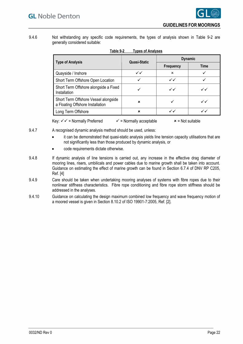
GUIDELINES FOR MOORINGS
9.4.6 Not withstanding any specific code requirements, the types of analysis shown in Table 9-2 are generally considered suitable:
Table 9-2 Types of Analyses
Dynamic Type of Analysis Quasi-Static
Frequency Time
Quayside / Inshore
Short Term Offshore Open Location
Short Term Offshore alongside a Fixed Installation
Short Term Offshore Vessel alongside a Floating Offshore Installation
Long Term Offshore
Key: = Normally Preferred = Normally acceptable = Not suitable
9.4.7 A recognised dynamic analysis method should be used, unless:
it can be demonstrated that quasi-static analysis yields line tension capacity utilisations that are not significantly less than those produced by dynamic analysis, or
code requirements dictate otherwise.
9.4.8 If dynamic analysis of line tensions is carried out, any increase in the effective drag diameter of mooring lines, risers, umbilicals and power cables due to marine growth shall be taken into account. Guidance on estimating the effect of marine growth can be found in Section 6.7.4 of DNV RP C205, Ref. [4]
9.4.9 Care should be taken when undertaking mooring analyses of systems with fibre ropes due to their nonlinear stiffness characteristics. Fibre rope conditioning and fibre rope storm stiffness should be addressed in the analyses.
9.4.10 Guidance on calculating the design maximum combined low frequency and wave frequency motion of a moored vessel is given in Section 8.10.2 of ISO 19901-7:2005, Ref. [2].
0032/ND Rev 0 Page 22
GUIDELINES FOR MOORINGS
10 DESIGN AND STRENGTH
10.1 GENERAL 10.1.1 This section discusses how the design forces on mooring components may be calculated. It provides
guidance on determining the acceptability of these calculated forces, together with guidance on general design considerations.
10.2 REDUNDANCY 10.2.1 The mooring system must have sufficient built in redundancy, such that the failure of any single
component will not result in a loss of ability to maintain station or an infringement of safe clearances from other structures.
10.2.2 Failure cases should consider the worst potential failure case which may include shore or vessel connection points.
10.2.3 Mooring systems without single point failure capacity may be found acceptable and approved, provided that both the following are submitted: a. Emergency response procedures showing that suitable arrangements are in place, e.g. 24-hour
manning / monitoring, vessel assistance on standby and other practical arrangements to ensure that any loss of position can be identified and controlled;
b. A risk assessment that has been or can be accepted by GL Noble Denton; this shall include the effect of losing buoys if these are used.
Note: The approach of simply doubling the safety factor requirements to compensate for lack of redundancy is not acceptable for systems, including chain and associated connectors, because mooring failures are not always directly related to a design overload. A case by case review taking into account the age and condition of all the mooring line components should be carried out.
10.3 MOORING PATTERN 10.3.1 The mooring pattern chosen should be balanced, with line pretensions as evenly distributed as is
practicable. Patterns should be as close to symmetrical as practicable taking into account the actual surveyed sea-bed infrastructure.
10.3.2 The methods for achieving design pretensions and sensitivity to variations therein will be of particular importance in quayside moorings where the typically short line lengths and highly asymmetric mooring arrangements can lead to very uneven load sharing between the lines.
10.3.3 Mooring line bearing angles should be selected to avoid placing out-of-plane loads on all components including padeyes and pivoting fairleads, which have limited rotation angles.
10.3.4 In deeper water analytical checks must be carried out to confirm that mooring lines do not make contact with the vessel itself or with the anchor racks/bolsters, as the resulting abrasive wear can damage both the mooring line(s) and the vessel.
10.4 MOORING LINE AND CONNECTION STRENGTH 10.4.1 For quayside moorings the implications of tidal variation and how this could potentially result in chafing
and abrasion of moorings should be taken into account with respect to line protection and the arrangements for mooring line adjustment, monitoring and maintenance.
10.4.2 The maximum analysed line tensions, when multiplied by a recognised appropriate safety factor shall not exceed the MBLs of the mooring lines and the ultimate strength of the connections and attachments, taking their present condition into account.
10.4.3 Mooring line tension safety factors for various analysis methods and cases are given in Section 10.2 of ISO 19901-7:2005, Ref. [2].
0032/ND Rev 0 Page 23
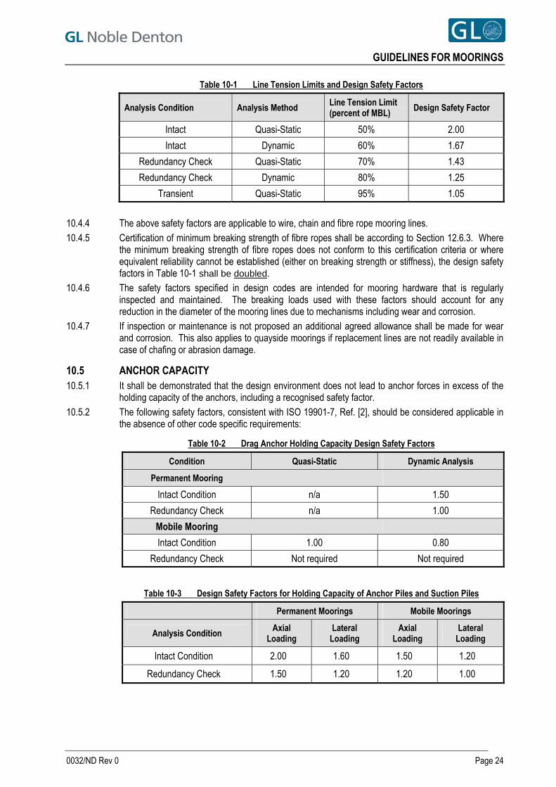
GUIDELINES FOR MOORINGS
Table 10-1 Line Tension Limits and Design Safety Factors
Analysis Condition Analysis Method Line Tension Limit (percent of MBL)
Design Safety Factor
Intact Quasi-Static 50% 2.00
Intact Dynamic 60% 1.67
Redundancy Check Quasi-Static 70% 1.43
Redundancy Check Dynamic 80% 1.25
Transient Quasi-Static 95% 1.05
10.4.4 The above safety factors are applicable to wire, chain and fibre rope mooring lines. 10.4.5 Certification of minimum breaking strength of fibre ropes shall be according to Section 12.6.3. Where
the minimum breaking strength of fibre ropes does not conform to this certification criteria or where equivalent reliability cannot be established (either on breaking strength or stiffness), the design safety factors in Table 10-1 shall be doubled.
10.4.6 The safety factors specified in design codes are intended for mooring hardware that is regularly inspected and maintained. The breaking loads used with these factors should account for any reduction in the diameter of the mooring lines due to mechanisms including wear and corrosion.
10.4.7 If inspection or maintenance is not proposed an additional agreed allowance shall be made for wear and corrosion. This also applies to quayside moorings if replacement lines are not readily available in case of chafing or abrasion damage.
10.5 ANCHOR CAPACITY 10.5.1 It shall be demonstrated that the design environment does not lead to anchor forces in excess of the
holding capacity of the anchors, including a recognised safety factor. 10.5.2 The following safety factors, consistent with ISO 19901-7, Ref. [2], should be considered applicable in
the absence of other code specific requirements:
Table 10-2 Drag Anchor Holding Capacity Design Safety Factors
Condition Quasi-Static Dynamic Analysis
Permanent Mooring
Intact Condition n/a 1.50
Redundancy Check n/a 1.00
Mobile Mooring
Intact Condition 1.00 0.80
Redundancy Check Not required Not required
Table 10-3 Design Safety Factors for Holding Capacity of Anchor Piles and Suction Piles
Permanent Moorings Mobile Moorings
Analysis Condition Axial
Loading Lateral
Loading Axial
Loading Lateral
Loading
Intact Condition 2.00 1.60 1.50 1.20
Redundancy Check 1.50 1.20 1.20 1.00
0032/ND Rev 0 Page 24
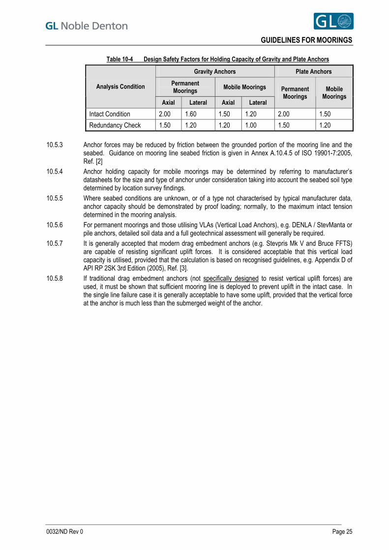
GUIDELINES FOR MOORINGS
Table 10-4 Design Safety Factors for Holding Capacity of Gravity and Plate Anchors
Gravity Anchors Plate Anchors
Permanent Moorings Mobile Moorings Analysis Condition
Axial Lateral Axial Lateral
Permanent Moorings
Mobile Moorings
Intact Condition 2.00 1.60 1.50 1.20 2.00 1.50
Redundancy Check 1.50 1.20 1.20 1.00 1.50 1.20
10.5.3 Anchor forces may be reduced by friction between the grounded portion of the mooring line and the
seabed. Guidance on mooring line seabed friction is given in Annex A.10.4.5 of ISO 19901-7:2005, Ref. [2]
10.5.4 Anchor holding capacity for mobile moorings may be determined by referring to manufacturer’s datasheets for the size and type of anchor under consideration taking into account the seabed soil type determined by location survey findings.
10.5.5 Where seabed conditions are unknown, or of a type not characterised by typical manufacturer data, anchor capacity should be demonstrated by proof loading; normally, to the maximum intact tension determined in the mooring analysis.
10.5.6 For permanent moorings and those utilising VLAs (Vertical Load Anchors), e.g. DENLA / StevManta or pile anchors, detailed soil data and a full geotechnical assessment will generally be required.
10.5.7 It is generally accepted that modern drag embedment anchors (e.g. Stevpris Mk V and Bruce FFTS) are capable of resisting significant uplift forces. It is considered acceptable that this vertical load capacity is utilised, provided that the calculation is based on recognised guidelines, e.g. Appendix D of API RP 2SK 3rd Edition (2005), Ref. [3].
10.5.8 If traditional drag embedment anchors (not specifically designed to resist vertical uplift forces) are used, it must be shown that sufficient mooring line is deployed to prevent uplift in the intact case. In the single line failure case it is generally acceptable to have some uplift, provided that the vertical force at the anchor is much less than the submerged weight of the anchor.
0032/ND Rev 0 Page 25
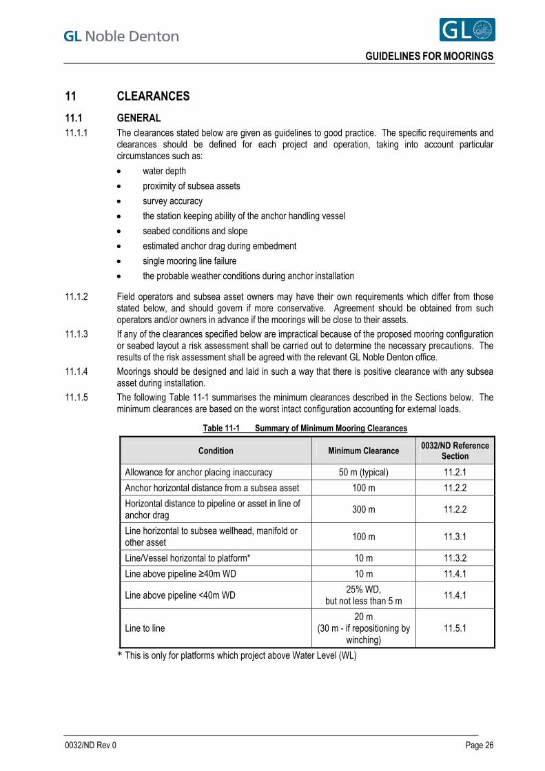
GUIDELINES FOR MOORINGS
11 CLEARANCES
11.1 GENERAL 11.1.1 The clearances stated below are given as guidelines to good practice. The specific requirements and
clearances should be defined for each project and operation, taking into account particular circumstances such as:
water depth
proximity of subsea assets
survey accuracy
the station keeping ability of the anchor handling vessel
seabed conditions and slope
estimated anchor drag during embedment
single mooring line failure
the probable weather conditions during anchor installation
11.1.2 Field operators and subsea asset owners may have their own requirements which differ from those stated below, and should govern if more conservative. Agreement should be obtained from such operators and/or owners in advance if the moorings will be close to their assets.
11.1.3 If any of the clearances specified below are impractical because of the proposed mooring configuration or seabed layout a risk assessment shall be carried out to determine the necessary precautions. The results of the risk assessment shall be agreed with the relevant GL Noble Denton office.
11.1.4 Moorings should be designed and laid in such a way that there is positive clearance with any subsea asset during installation.
11.1.5 The following Table 11-1 summarises the minimum clearances described in the Sections below. The minimum clearances are based on the worst intact configuration accounting for external loads.
Table 11-1 Summary of Minimum Mooring Clearances
Condition Minimum Clearance 0032/ND Reference Section
Allowance for anchor placing inaccuracy 50 m (typical) 11.2.1
Anchor horizontal distance from a subsea asset 100 m 11.2.2
Horizontal distance to pipeline or asset in line of anchor drag
300 m 11.2.2
Line horizontal to subsea wellhead, manifold or other asset 100 m 11.3.1
Line/Vessel horizontal to platform* 10 m 11.3.2
Line above pipeline ≥40m WD 10 m 11.4.1
Line above pipeline <40m WD 25% WD,
but not less than 5 m 11.4.1
Line to line 20 m
(30 m - if repositioning by winching)
11.5.1
* This is only for platforms which project above Water Level (WL)
0032/ND Rev 0 Page 26
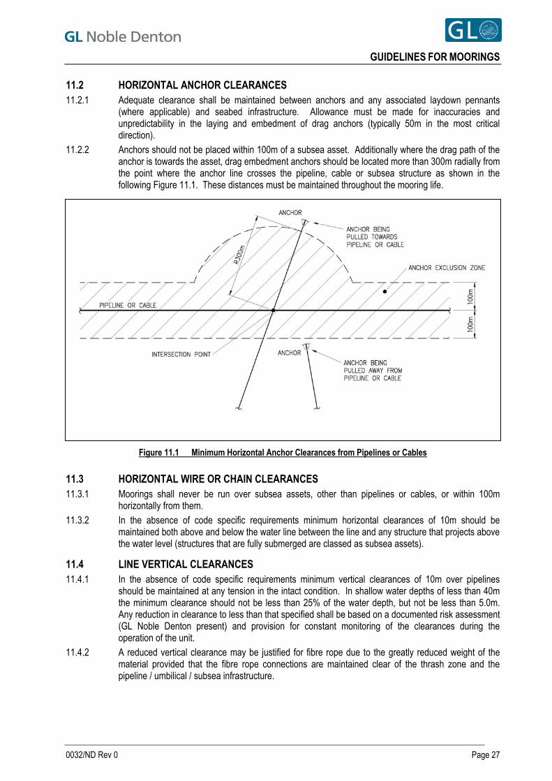
GUIDELINES FOR MOORINGS
11.2 HORIZONTAL ANCHOR CLEARANCES 11.2.1 Adequate clearance shall be maintained between anchors and any associated laydown pennants
(where applicable) and seabed infrastructure. Allowance must be made for inaccuracies and unpredictability in the laying and embedment of drag anchors (typically 50m in the most critical direction).
11.2.2 Anchors should not be placed within 100m of a subsea asset. Additionally where the drag path of the anchor is towards the asset, drag embedment anchors should be located more than 300m radially from the point where the anchor line crosses the pipeline, cable or subsea structure as shown in the following Figure 11.1. These distances must be maintained throughout the mooring life.
Figure 11.1 Minimum Horizontal Anchor Clearances from Pipelines or Cables
11.3 HORIZONTAL WIRE OR CHAIN CLEARANCES 11.3.1 Moorings shall never be run over subsea assets, other than pipelines or cables, or within 100m
horizontally from them. 11.3.2 In the absence of code specific requirements minimum horizontal clearances of 10m should be
maintained both above and below the water line between the line and any structure that projects above the water level (structures that are fully submerged are classed as subsea assets).
11.4 LINE VERTICAL CLEARANCES 11.4.1 In the absence of code specific requirements minimum vertical clearances of 10m over pipelines
should be maintained at any tension in the intact condition. In shallow water depths of less than 40m the minimum clearance should not be less than 25% of the water depth, but not be less than 5.0m. Any reduction in clearance to less than that specified shall be based on a documented risk assessment (GL Noble Denton present) and provision for constant monitoring of the clearances during the operation of the unit.
11.4.2 A reduced vertical clearance may be justified for fibre rope due to the greatly reduced weight of the material provided that the fibre rope connections are maintained clear of the thrash zone and the pipeline / umbilical / subsea infrastructure.
0032/ND Rev 0 Page 27
GUIDELINES FOR MOORINGS
11.4.3 Temporary lay-down of an anchor wire or fibre rope (but not chain) over a pipeline, umbilical, spool or cable may be acceptable subject to all of the following being submitted to review:
Evidence that there is no other practicable anchor pattern that would avoid the lay-down.
The status of a pipeline or spool (e.g. trenched, live, rock-dumped, on surface) and its contents (e.g. oil, gas, water) and internal pressure.
Procedures clearly stating the maximum duration that the anchor wire/fibre rope is in contact with the pipeline, umbilical, spool or cable and the reason for the contact.
Written evidence that the pipeline owner accepts laying down of the anchor wire over their pipeline, umbilical spool or cable and has contingency measures in place in case of damage and a possible hydrocarbon leak.
Evidence that the anchor wire will be completely slack i.e. no variation in tension.
Evidence that the seastate during the lay-down will be restricted to an acceptable value.
Documentation demonstrating that the anchor wire or its weight will not overstress or damage the coating on the pipeline, umbilical, spool or cable.
11.5 LINE-LINE CLEARANCES 11.5.1 Crossed mooring lines are generally not acceptable except:
a. Where crossing points are visible and contact avoided / wear mitigated with suitable protection; b. Where a minimum line-line clearance requirement of 20 m (or 30 m if repositioning by
winching), can be demonstrated for the combinations of tensions and vessel motions that are most critical from the clearance perspective. This would normally apply to independently moored vessels.
11.6 INSTALLING ANCHORS 11.6.1 Whenever an anchor is run out over a pipeline, flowline or umbilical, the anchor shall be securely
stowed on the deck of the anchor handling vessel. In circumstances where either gravity anchors or closed stern tugs (tugs without stern rollers) are used, and anchors cannot be stowed on deck, the anchors shall be double secured through the additional use of a safety strap or similar.
11.6.2 At no time shall an anchor wire come in contact with a pipeline, cable or subsea structure while running out or retrieving an anchor.
0032/ND Rev 0 Page 28
GUIDELINES FOR MOORINGS
12 MOORING EQUIPMENT
12.1 MOORING INTEGRITY 12.1.1 Whilst the selection of a mooring system to meet code requirements is imperative to ensure the overall
safety of a moored structure, it should be borne in mind that inappropriate selection of materials (connections and jewellery, etc) and inadequate inspection and maintenance programmes are likely to be the primary factors in most failures.
12.1.2 Care shall be taken such that all mooring hardware is used in strict accordance with the manufacturer’s recommendations and best industry practice.
12.1.3 Experience is required to assess the suitability of a proposed mooring system for a long term application. Reference should be made to the principal findings from Noble Denton’s Phase 1 and Phase 2 Mooring Integrity Joint Industry Projects (JIPs). See Refs [12] and [13].
12.2 CERTIFICATION 12.2.1 All components of a mooring system should be certified and their certificates available for inspection by
an attending surveyor.
12.3 ANCHORS 12.3.1 Anchors should be of a type approved by a recognised classification society and suitable for the
seabed composition at the location. In particular, at locations where the seabed is hard, anchors capable of taking the full load through the fluke tips alone should be used.
12.3.2 Where applicable, anchors should be correctly configured for the seabed composition at the location, e.g. fluke angle should be set as per manufacturer’s recommendations.
12.4 CHAIN 12.4.1 Mooring chain shall be manufactured in accordance with an appropriate standard for offshore mooring
chain (such as an IACS classification society) and certified by an IACS member or other recognised certification body accepted by GL Noble Denton.
12.5 WIRE ROPE 12.5.1 Wire rope mooring components for offshore mooring shall comply with the requirements of Section
11.1.2 of ISO 19901-7, Ref. [2] (Stationkeeping Systems) and be certified by an IACS member or other recognised certification body accepted by GL Noble Denton.
12.6 FIBRE ROPE 12.6.1 In general, contact between fibre rope and the seabed should be avoided in normal operating
conditions. 12.6.2 Given the nonlinear stiffness characteristics of fibre ropes, it is essential that appropriate data is
obtained on the stiffness characteristics under load. 12.6.3 Minimum breaking strength of fibre ropes shall be certified in accordance with a standard industry
practice (such as API RP 2SM) by bodies approved by an IACS member or other recognised certification body accepted by GL Noble Denton.
12.7 CONNECTORS 12.7.1 Mooring chains should be composed of continuous lengths of chain where practicable. 12.7.2 Where it is necessary to use in-line connectors, the mooring pattern should be designed, so as to
ensure that no connecting hardware is subjected to thrashing against the seabed. If this is not possible this should be risk assessed on a case by case basis and suitable contingency measures put in place in case of failure at this location.
12.7.3 Only classification society approved Long Term Mooring (LTM) connectors should be used where a double locking mechanism has been employed to restrain the main load bearing pins of the connector.
0032/ND Rev 0 Page 29
GUIDELINES FOR MOORINGS
12.8 BUOYS (SURFACE AND SUBSURFACE) 12.8.1 Spring buoys should be designed in accordance with the requirements of a recognised design code.
Guidance on spring buoy design is given in Section 11.1.5 of ISO 19901-7, Ref. [2], (Stationkeeping Systems).
12.8.2 It should be ensured that any subsurface buoy is supplied with a suitable submersion rating for the intended application.
12.8.3 For long term applications, the dynamic response of the buoy and the resulting fatigue implications for all connections should be addressed. Experience has shown that such analyses are complex and time consuming and do not necessarily predict possible failure modes which may be experienced in the field.
12.8.4 Where buoys are used to provide clearances, means to detect their loss should be provided e.g. tension monitoring (this should reveal a loss), transponders, etc. The operating procedures should document the loss monitoring procedure and the remedial actions required. Suitable spares should also be readily available and stored in a convenient location.
12.9 VESSEL CONNECTION POINTS 12.9.1 Where vessel connections are to fairleads / winches / windlasses that make up part of a classed
mooring system for a vessel, e.g. under POSMOOR notation, it is acceptable to assume that these have adequate strength (as the capacities of these are specified under the class rules in relation to the MBL of the vessel’s mooring lines).
12.9.2 Vessel connections points (including windlasses, winches, fairleads, Smit brackets, bollards, bitts etc) should generally be designed for a load equal to 1.1 times the MBL of the connected mooring line. The foundation structure must also be demonstrated to be suitable for the same design loads.
12.9.3 Where design calculations and/or certificates are unavailable, it may be acceptable to demonstrate adequate connection capacity through proof loading. OCIMF, Ref. [11], gives some guidance on suitable levels of proof loading for common vessel connections (e.g. double bitts, panama chocks etc). Proof loading is potentially hazardous and a detailed, risk assessed procedure, will be required before commencing such proof loading operations.
12.9.4 Notwithstanding any class requirements, winches/windlasses should have a stall capacity sufficiently in excess (typically 20%) of the maximum line tensions in the limiting operating environment to allow the vessel to safely move to the standby/survival condition (as applicable).
12.10 FENDERING 12.10.1 When a vessel is to be moored against another structure such as a quayside, adequate fendering shall
be provided to prevent damage to the vessel and structure. 12.10.2 In cases where fendering must restrain the vessel (e.g. when the vessel is blown on to the quay),
fenders shall be considered to be structural elements of the mooring system and shall be subject to the same redundancy requirements as mooring lines.
12.10.3 It must be demonstrated that the maximum analysed load upon any fender when multiplied by the appropriate safety factor (see Table 10-1) does not exceed the static reaction force rating of the fender.
12.10.4 The pressure exerted by a fender on the hull of the vessel and the quay shall be calculated, and it shall be demonstrated that this pressure is not in excess of that which the vessel’s structure and the quay are designed to resist.
12.10.5 The rated energy absorption capacity of the fendering shall be at least twice the energy associated with the vessel’s peak velocity due to the environment or wake induced motion from passing traffic.
12.10.6 Structural elements of fendering (e.g. pressure membranes) shall be protected (e.g. with sacrificial elements such as tyres) such that they are not damaged through contact with the vessel or quayside.
12.10.7 Moveable fenders shall be restrained to prevent excessive movement. Restraints shall be designed to resist a load equal to the maximum analysed load on the fender multiplied by the maximum coefficient of friction between the fender and vessel.
0032/ND Rev 0 Page 30

GUIDELINES FOR MOORINGS
12.10.8 Particular care should be taken where it is intended to employ a spacer barge as a fender. These arrangements have historically proven to have high failure potential and should, therefore, always be the subject of careful design and independent scrutiny.
12.10.9 Fenders should be arranged to avoid the possibility of a vessel “hang up” against the quayside. The fender arrangement should be subject to a local site inspection. This is particularly relevant for loadout operations where “hung up” barges may suddenly come free as the load of a module is being transferred from the quayside to a barge.
0032/ND Rev 0 Page 31
GUIDELINES FOR MOORINGS
13 PROCEDURAL CONSIDERATIONS
13.1 GENERAL 13.1.1 The planning and preparation for mooring a vessel should be carried out sufficiently in advance of the
operation such that the analyses described in this document can be carried out. 13.1.2 Non-standard mooring operations such as quayside moorings of MODUs shall be risk assessed to
confirm that all factors relating to the security of the vessel have been taken into account and that the level of risk is controlled. The risk assessment shall be submitted for approval by GL Noble Denton. The risk assessment should also take into account political or crime related security risks associated with the location.
13.1.3 Prior to designing a mooring spread a mooring analysis needs to be carried out and the factors detailed in Sections 7, 8 and 9 are to be taken into account.
13.2 ANCHOR PROOF LOADING 13.2.1 After installation, anchors should be proof load tested to ensure adequate embedment. Proof loads
should be maintained for at least 15 minutes. 13.2.2 For mobile moorings in open locations, proof loads will generally be to the maximum expected
operating tension at a location. 13.2.3 For mobile moorings in proximity to other installations, proof load is expected to be the maximum intact
tension identified in a mooring analysis. 13.2.4 Mooring test loading for permanent moorings shall be in accordance with Section 10.4.6.2 of ISO
19901-7, Ref [2].
13.3 MANNING 13.3.1 The level of manning shall be sufficient in terms of numbers, skill competency and experience to
operate all the relevant machinery and to manage the mooring system and emergency systems, on a twenty-four hour basis, without the need for any personnel to work excessively long hours. The numbers shall be sufficient to take appropriate action in the case of any emergency to ensure the safety and security of the crew, the vessel and the location infrastructure (including port facilities, moored vessels and environmental considerations).
13.3.2 Where appropriate shore-side assistance should be available on a 24-hour basis with direct lines of communication to the moored vessel.
13.4 INSPECTION, MONITORING AND MAINTENANCE 13.4.1 Where practicable, an inspection, monitoring and maintenance programme should be in place to
ensure that all mooring components are in a serviceable condition and that their certified MBLs remain valid. Discard criteria shall be documented and applied in line with recognised industry standards
0032/ND Rev 0 Page 32
GUIDELINES FOR MOORINGS
14 DOCUMENTATION
14.1 LEADING TO APPROVAL 14.1.1 For GL Noble Denton to issue approval, the following documentation must be provided.
14.2 OFFICE REVIEW 14.2.1 Mooring analysis report detailing:
a. Location and Vessel Data (see Sections 6 and 7); b. Environmental Loads and Motions (see Section 8); c. Mooring Analysis Results (see Sections 9, 10, 11 and 12).
14.2.2 Mooring plan detailing vessel location and mooring arrangement. 14.2.3 Supporting procedures and risk assessments (particularly where the mooring is weather restricted or is
not fully redundant).
14.3 ON SITE 14.3.1 Certification for all mooring components including vessel and shore connection points. These
certificates shall be issued or endorsed by bodies approved by an IACS member or other recognised certification bodies accepted by GL Noble Denton. If the certification is old, on site inspection by a competent person should have been carried out to check the present condition of connection points, etc.
14.3.2 Details of manning and emergency response plan.
0032/ND Rev 0 Page 33
GUIDELINES FOR MOORINGS
15 SPECIAL CONSIDERATIONS FOR INSHORE AND QUAYSIDE MOORINGS
15.1 BACKGROUND 15.1.1 The engineering, design, verification and execution of inshore and especially quayside moorings is
very frequently underestimated leading to a gap between the strict requirements for approval and what the client / contractor may wish to provide. The default standards used often fall below the requirements of a 10 year return period design to recognised codes.
15.2 LOCATIONS WITHIN HARBOUR LIMITS 15.2.1 The intended location of the unit within the port area should be established with the Port Authority. In
some cases the Port Authority will have determined this well in advance and it will not be subject to change. In some Ports, where commercial shipping forms the core of their business, the berth selected by the Port may be subject to change. In all cases discussions should be held with the Port Authority to determine the berth likely to be selected and its characteristics and those of any likely alternatives.
15.2.2 If the Port Authority is reluctant to commit to a particular berth the importance of the details of the berth in the project planning and design should be emphasised in discussions with the Port Authority. In order to avoid delays it may be necessary to undertake analyses for not only the most probable berth but also a number of contingencies.
15.2.3 The potential for surge due to passing traffic, particularly if moored in a river or canal, should be assessed. The unit may experience surge up and down the berth and may be drawn off it.
15.2.4 The Port Authority should be requested to issue a Notice to Mariners requesting passing marine traffic to reduce their speed to limit any effect of surge on the moorings.
15.3 CONTINGENCY ARRANGEMENTS 15.3.1 Details of tug capacity and shore-based manpower, their availability, call out times, phone numbers
and port emergency procedures should all be provided for review and taken into account in the risk assessment (see Sections 13.1.2 and 13.3).
15.4 MOORING CONSIDERATIONS 15.4.1 Even very small magnitude motions induced by waves or long period swell, can result in very large
tensions on the short, stiff mooring lines commonly utilised in quayside moorings. This effect should be evaluated closely (see Section 8.5.4).
15.4.2 Motions will also increase the likelihood of abrasion damage particularly in fibre ropes. Chafe chain, stretchers and adequate protection should be employed to minimise chafe points. Chafe points should be regularly inspected and if significant damage is found the damaged components should be replaced as a matter of priority. Thus, adequate contingency spares are required at the site of the mooring.
15.4.3 Wind loads shall take account of all construction phases and can be increased due to scaffolding, wind and weather protection, etc.
15.4.4 It is often impossible to properly tension and adjust moorings at quayside. It is therefore necessary to take account of large variations in working tension in the mooring analysis. A suitable method for achieving and verifying the design pretension should be considered during mooring design. In practice a smaller number of high capacity, lines with similar lengths and pretensions is better than multiple small ones in an asymmetric arrangement.
15.4.5 In some cases a mooring is simply not feasible without some means of adjustment and this can be somewhat difficult and expensive to provide if it is not available on the vessel. It, however, represents a wise investment given the likely value of the moored object.
15.4.6 Quayside moorings will often necessitate the use of multiple connections, strops etc to make up the mooring lines. These need to be reviewed carefully to ensure that there are no unforeseen failure modes. All connections shall be properly matched and all soft rope to hard tackle connections shall have properly fitted hard eyes.
0032/ND Rev 0 Page 34
GUIDELINES FOR MOORINGS
15.4.7 Adequate fendering is hard to achieve on larger vessels, semi-submersibles, etc. because the loads involved can be large. Spacer barges, in particular, have a poor record in operation and proposals to use spacer barges should always be carefully engineered. If possible, some means of holding the vessel off the quay as well as the fenders should be provided. Laying offshore anchors on a semi-submersible moored at the quayside can provide an additional contingency.
15.4.8 Inshore and especially quayside moorings will typically require a careful local study of environmental design extremes. Usually it is not feasible to design the mooring to resist the omni-directional extremes so some form of directional metocean study is required. It is rare to have available a full set of data on current and tides, and it may be necessary to take some local measurements to determine the actual current at the quayside.
15.4.9 Quayside moorings typically have short natural periods. Therefore the wind and wave excitation frequencies need to be carefully established.
15.5 SHORE MOORING POINTS / BOLLARDS / WINCHES 15.5.1 The capacity of shore mooring points and winches, including their foundations, should be
demonstrated by certification or by design. Where these are unavailable, proof loading may be undertaken to demonstrate capacity. Proof loads should be a minimum of 1.25 times the maximum intact tension for that line calculated in the mooring analysis. Proof loading operations can be potentially very hazardous and should be carefully planned taking into account the possibility of catastrophic failure of connection points. A suitable, risk assessed, proof testing procedure should be available.
15.6 PROCEDURES 15.6.1 Procedures should detail and quantify, where applicable,
mooring tension monitoring, inspection, line adjustment and
emergency response arrangements, including spare equipment and availability of tugs and shore-based manpower as described in Section 15.3.
mooring line tending arrangements to account for predicted variations in tidal height
safe access to vessels accounting for potentially significant tidal variations.
15.7 COLD STACKING 15.7.1 Approval for cold stacking can only be given when it can be demonstrated that all of the factors
mentioned in this document have been taken into account and it can be demonstrated by a risk assessment accepted by GL Noble Denton that cold stacking presents no substantially increased risk to the unit. It is clear, however, that moorings on cold stacked units still require regular inspection and it should be documented that steps have been put in place for this to be carried out.
15.8 ICE LOADING 15.8.1 For locations where loading from drifting ice is expected on a moored structure the impact on mooring
line tensions shall be assessed. 15.8.2 Mooring lines employed in locations where sea ice is expected shall be qualified by the manufacturers
for the range of temperatures expected in the region. The mooring lines shall be resistant to abrasion.
0032/ND Rev 0 Page 35
GUIDELINES FOR MOORINGS
16 SPECIAL CONSIDERATIONS FOR PERMANENT MOORINGS
16.1 GENERAL 16.1.1 Requirements for permanent moorings are fairly comprehensively covered in the industry standard
codes referred to previously. 16.1.2 Additional considerations over mobile moorings are likely to include the following with further
information available in the Mooring Integrity JIP OTC papers, Ref. [12] and [13]:
Fatigue (axial, bending and torsion)
Marine growth and how to r remove it for inspection to take place
Wear and corrosion including , microbial induced corrosion (MIC)
Mooring line failure detection and instrumentation
Spring buoy failure detection.
0032/ND Rev 0 Page 36
GUIDELINES FOR MOORINGS
0032/ND Rev 0 Page 37
REFERENCES
[1] ISO IS 19901-1: Petroleum and Natural Gas Industries — Specific Requirements for Offshore Structures — Part 1: Met ocean Design and Operating Conditions.
[2] ISO IS 19901-7: Petroleum and Natural Gas Industries — Specific Requirements for Offshore Structures — Part 7: Stationkeeping Systems for Floating Offshore Structures and Mobile Offshore Units.
[3] API RP 2SK 3rd Edition (2005): Design and Analysis of Station keeping Systems for Floating Structures. [4] DNV RP C205 (2007): Environmental Conditions and Environmental Loads. Det Norske Veritas, [5] DNV OS E301 (2008): Position Mooring. Det Norske Veritas [6] DNV Rules for Classification of Mobile Offshore Units, Part 6, Chapter 2 (1996): Position Mooring
(POSMOOR). [7] BS 6349-6 (1989): Maritime Structures — Design of Inshore Moorings and Floating Structures. [8] GL Noble Denton 0013/ND “Guidelines for Loadouts” [9] GL Noble Denton 0016/ND “Seabed and Sub-seabed Data Required for Approvals of Mobile Offshore Units
(MOU)” [10] IMCA M 179 (2005): Guidance on the Use of Cable Laid Slings and Grommets. [11] OCIMF Mooring Equipment Guidelines, Second Edition 1997 [12] “Floating Production Mooring Integrity JIP – Key Findings” Martin G. Brown, Tony D. Hall, Douglas G. Marr,
Max English and Richard O. Snell, OTC 17499, 2005 [13] “Phase 2 Mooring Integrity JIP – Summary of Findings” Martin G. Brown, Andrew P. Comley, Morten
Eriksen, Ian Williams, Philip Smedley, Subir Bhattacharjee, OTC 20613, 2010
All GL Noble Denton Guidelines can be downloaded from www.gl-nobledenton.com