Embed Size (px)
Citation preview


Table of Contents
1. Purpose of this Manual 3
2. Magic-Pak: Designed and Built for Designers and Builders 42.1 Totally Packaged HVAC System Provides Individual
Comfort Control2.2 Hermetically Sealed Refrigeration System2.3 Interchangeable with Earlier Models2.4 Gas and Electric Alternatives
3. Unit Location 83.1 General Considerations3.2 Sound Considerations3.3 Accessibility3.4 Vent Location for Gas Models
4. Wall Sleeves 124.1 Installation4.2 Recessed Sleeves4.3 Weatherproofing Wall Sleeves
5. Types Of Wall Construction 185.1 Support5.2 Wood Frame Walls5.3 Cement Block Walls5.4 Poured Concrete Walls5.5 Metal Studs
6. Noise Transmission 226.1 Vibration Transmission6.2 Radiated Sound and Resonant Surfaces or Objects6.3 Clearances6.4 Air Noise
6.4.1 Supply-Air Duct System6.4.2 Return-Air Duct System
7. Infiltration 297.1 Water Infiltration7.2 Air Infiltration7.3 Introduction of Ventilation Air7.4 Sealing Return-Air Ducts
8. Louver Grilles 328.1 Louver Grilles Furnished on Magic-Pak8.2 Discharging Flue Gas Products from Gas-Fired
MGE Models8.2.1 Vent Pipe Installation
1

Table of Contents (cont.)
9. Condensate Drain 36
10. Electrical Service Wiring 37
11. Air Filter 38
12. Special Considerations for Gas Units 3912.1 Gas Distribution in Multi-Family Buildings
13. Retrofit Applications 40
2

1. Purpose of this ManualThis manual provides assistance to architects and design engineerswho are considering the use of Magic-Pak heating and cooling equip-ment in multi-dwelling buildings or shopping centers.
It conveys some of the experience gained over many decades, andincludes some of the most successful and economical installationpractices for Magic-Pak units.
Building structure heat loss and heat gain, duct sizing, gas supplymains and riser sizing, and electrical-supply wiring should be deter-mined for the building by a qualified Professional Engineer familiarwith the applicable local building code requirements for the type ofoccupancy.
3

For over 30 years, theMagic-Pak concept ofproviding quality heatingand cooling in high-risecondominiums and apart-ment buildings has provenincreasingly popular amongbuilding designers andmechanical contractors.
Over these years withliterally hundreds of thou-sands of units installedthroughout the UnitedStates and Canada,Armstrong has compiledcomprehensive practicalexperience for varyingtypes of building construc-tion and operating condi-tions.
2. Magic-Pak: Designed and Builtfor Designers and Builders
2.1 Totally Packaged HVAC System Provides Individual ComfortControl
The Magic-Pak concept provides all the practical benefits of a splitsystem, plus a heating system, without the expense and complicationsof split-system units. Magic-Pak provides a ducted, single-package,combination heating-and-cooling unit for each individual suite that isreliable, easy to install and inexpensive to maintain. Just as important, itallows individual metering and comfort control for each unit.
Occupants can have heating or air conditioning any time of the yearaccording to the outdoor temperature. A cold day in June, heating; ahot day in January, cooling. No central system has this flexibility.
2.2 Hermetically Sealed Refrigeration SystemThe hermetically sealed refrigeration system is another feature of theMagic-Pakís refrigeration system. The system is completely factory-built, checked for leaks with sensitive electronic equipment, andthoroughly performance tested before placement in any unit. Thiscomprehensive testing eliminates the need for highly trained person-nel at the time of installation or start up.
2.3 Interchangeable with Earlier ModelsAnother advantage of the single package combination is the one thateliminates concerns of obsolescence. Replacement units are avail-able for units installed in the very first Magic-Pak buildings over 30years ago. The equipment built today includes modern technology inheat transfer surface and compressor design for higher efficiencies,but the equipment will still fit the older Magic-Pak installations. Formore information, see Retrofit Applications on page 40.
Dedication to this interchangeability with earlier models is basic to theMagic-Pak concept of today and insures that these units will neverbecome �orphans� in the future.
2.4 Gas and Electric AlternativesMagic-Pak offers a variety of heat sources to best suit the geograph-ic area or local utility energy costs. All are ducted, through-the-wallunits which have no need for chimneys.
4

MGEGas Heating, Electric CoolingMaximizes energy-cost efficiency inapplications where gas is available. Usesonly outside air for combustion. Built-inpower vent eliminates need for chimney.
Dimensions (in.)
2. Magic-Pak: Designed and Built ... (cont.)
5
ledoM A B C
21-01EGM8/7-85 5/1-02 8/5-81
81-01EGM
42-01EGM
8/7-95 2/1-22 8/5-0203-01EGM
81-21EGM
42-21EGM
03-21EGM 46 2/1-62 4/3-42

2. Magic-Pak: Designed and Built ... (cont.)
16 8
SupplyOpening
A
LowVoltage
PowerEntry
3
C
2
BBlowerControlAccess
Compressor/FanAccess
Return AirOpening
Indoor CoilCondensateDrain " NPT
Outdoor CoilCondensateDrain NPT"
D
1-1/8
1-1/8
6-1/81-1/2
5/8
28-1/16
10-3/16½
6-1/1613/16
3/4
MHPElectric Heat PumpThe energy-efficient option for heating and cooling where gas is not available or preferred.
ledoM A B C D
21-01PHM8/7-34 8/7-61 61/5-52 2/1-12
81-01PHM
42-01PHM
61/31-74 61/51-81 8/1-72 8/3-4203-01PHM
81-21PHM
42-21PHM
03-21PHM 61/31-55 61/31-22 8/1-13 8/3-42
Dimensions (in.)
6

MCEElectric Heating, Electric CoolingProvides the best alternative to a heat pump in all-electric applications.2
2. Magic-Pak: Designed and Built ... (cont.)
16 8
SupplyOpening
A
LowVoltage
PowerEntry
3
C
2
BBlowerControlAccess
Compressor/FanAccess
Return AirOpening
Indoor CoilCondensateDrain " NPT
Outdoor CoilCondensateDrain NPT"
D
1-1/8
1-1/8
6-1/81-1/2
5/8
28-1/16
10-3/16½
6-1/1613/16
3/4
ledoM A B C D
21-01ECM8/7-34 8/7-61 61/5-52 2/1-12
81-01ECM
42-01ECM
61/31-74 61/51-81 8/1-72 8/3-4203-01ECM
81-21ECM
42-21ECM
03-21ECM 61/31-55 61/31-22 8/1-13 8/3-42
Dimensions (in.)
7

Magic-Pak units shouldbe installed in an outsidebuilding wall that is clearof obstructions whichmight impede the freeintake and discharge ofcondenser air.
3. Unit Location
3.1 General ConsiderationsA building wall should be no closer to an opposite building wall than twofeet for every floor or Magic-Pak unit in a vertical array facing the wall.
For example, a one-story building with a Magic-Pak unit should be aminimum of 2 ft. from the wall facing the unit, and if the facing wallalso has a Magic-Pak unit, the two walls should be at least 4 ft. apart.
A six-story building with six Magic-Pak units in a vertical array shouldbe at least 12 ft. from the opposite building wall, and if that buildingwall also contains Magic-Pak units, the buildings should be at least24 ft. apart.
Buildings taller than six stories need not exceed the separationneeded for six-story buildings.
If three or more adjacent walls form an air shaft with Magic-Pak unitsfacing each other in each wall, the separation between opposite wallsshould be increased by 20%.
These �rule-of-thumb� dimensions are intended to minimize possibili-ties for recirculation of condenser air, or interaction between units.However, these numbers are not exact for every application, andother considerations might suggest that the designer consult thefactory about desired alternatives.
3.2 Sound ConsiderationsIt should be mentioned that any time a hard surface or wall faces aunit, the sound emanating from that unit can be reflected by theopposite wall. If the two walls are not parallel, the sound may besomewhat dispersed, but in general it is preferable to locate Magic-Pak units in a wall with as much clear distance to the nearest wall orreflecting surface as is practical.
Figure 1 Condominium with Magic-Paks on outside walls
8

3. Unit Location (cont.)
Units located in walls forming an air shaft or confined courtyard arenot as desirable (from a sound standpoint) as units located in theouter perimeter walls of a building.
Similarly, if the unit is to be installed in a wall at right angles to a wallcontaining a window, at least 6 ft. of separation between the closestpoint of glass to the unit should be maintained in order to minimizesound transmission through the window.
3.3 AccessibilityAn important consideration when selecting a suitable location isaccessibility for equipment removal.
A 30 in. wide minimum clear opening is needed in front of the unit inorder to remove it.
A 30 in. wide door or access covering to the enclosure is preferred asa minimum to allow for some tolerance in locating the access doorframe exactly centered on the unit.
If the unit is located in the end of a clothes closet, and it is acceptedthat the clothes must be removed first to remove the unit, be sure thatthe closet door is large enough to get the unit out of the closet.
Also, if the Magic-Pak is installed through the side of a closet, be surethe closet is wide enough to permit sliding the unit all the way outbefore running into the opposite closet wall.
The minimum distance to allow for equipment removal from the frontof the unit cabinet to the opposite wall is 36 in.
Units in a relatively inaccessible location for easy removal should beavoided if at all possible; if for no other reason than to keep the airfilter accessible for easy and timely cleaning by the occupants or bymaintenance personnel.
3.4 Vent Location for Gas ModelsConsideration for location must be given to the power vent of gas-fired Magic-Pak models such that they will not be installed at variancewith the latest edition of the National Fuel Gas Code (NFPA 54/ANSIZ223.1).
9

3. Unit Location (cont.)
Clearance to combustible materials is 0" at the side, top, and front of plenum. If accessibility clear-ances are greater than clearances to combustibles, accessibility clearances take precedence.
The front of the unit must be accessible for service. If the unit is enclosed, providing a door oraccess panel opposite the front of the unit is the preferred method of providing access. The door oraccess panel must be at least 30" wide (centered on the unit) and as tall as the unit.
Top View Side View
* Minimum clearance tocombustibles for the front ofthe unit is 1". Added clear-ance must be provided for thegas supply line and drain trapinstallation.
Figure 2 Minimum Clearances � MGE Units
10

Figure 3 Minimum Clearances � MHP/MCE Units
3. Unit Location (cont.)
Clearance to combustible materials is 0" at the side, top, and front of plenum. If accessibilityclearances are greater than clearances to combustibles, accessibility clearances take precedence.
The front of the unit must be accessible for service. If the unit is enclosed, providing a door oraccess panel opposite the front of the unit is the preferred method of providing access. The door oraccess panel must be at least 30" wide (centered on the unit) and as tall as the unit. If a return ductis not installed, in order to provide adequate return air the minimum clearance required betweenthe front of the unit and the door or access panel is 4" for 43" tall cabinets and 5" for 48" and 56"tall cabinets.
Side View
* With no return duct installed, minimum clearances to the front of the unit are 4" for43" tall cabinets and 5" for 48" and 56" cabinets. If a return duct is installed, enoughclearance must be provided for the drain trap installation.
Top View
11

4. Wall Sleeves
�Wall sleeve� is the termused to describe an ac-cessory for the Magic-Pakunits. The wall sleeve isdesigned to facilitate theinstallation of Magic-Pakunits by providing anaccurate opening duringbuilding construction.Units can then remain off-site until building con-struction approachescompletion.
The wall sleeve is comprised of four assemblies (top, bottom, and rightand left sides) which easily slip together on the job to form a rectangularbox correctly sized to receive a Magic-Pak unit (see Figure 4).
When in place and securely fastened, the wall sleeve opening provideseasy access to the finished wall perimeter for caulk sealing.
Magic-Pak units must be installed with wall sleeves. Various wall sleevekits are available to fit a multitude of wall applications. See Chapter 5 �Types of Wall Construction for proper wall sleeve selection.
retteL ytitnauQ noitpircseD
A 1 ylbmessAlenaPpoT
B 1 esaB
C 1 ylbmessAlenaPediStfeL
D 1 ylbmessAlenaPediSthgiR
E 1 resiRdoowylP"4/3
F 1 ylbmessAlenaPrediviD
G 1 etalpmeT
-- 2 srehsaWdnaswercSgaL
-- 8 swercSlateMteehS
-- 1 snoitcurtsnInoitallatsnI
Figure 4 Wall Sleeve Assembly
12

4. Wall Sleeves (cont.)
Figure 5 Installing Wall Sleeve from Outside of Building
4.1 InstallationThe sleeve may not extend beyond the finished wall. This is due tothe fit-up of the outdoor grille which is designed to be flush with thefinished wall.
Reaching the perimeter through the opening from inside for sealingcan become difficult and dangerous. Adequate safety precautionsshould be taken to protect personnel.
In many high-rise construction applications, contractors insert the wallsleeves from the outside while the wall is being constructed (seeFigure 5). Three flashing angles are included with the wall sleeve kitsto provide the installer a means to mount the wall sleeve to theexterior surface of the rough wall. The flashing angles mount to thetop and side panels of the wall sleeve (see Figure 6 on page 14).Each of these panels has two sets of holes in them for mounting theangles: one set of holes which will extend the wall sleeve 1/2 in.beyond the outside rough wall and another set of holes which willextend it 4-1/2 in. beyond the rough wall. If the application requiresthat the wall sleeve fit flush with the �rough wall�, reverse the anglesand use the holes closest to the front of the wall sleeve.
It is recommended that the flashing angles be caulk sealed to thesleeve during installation. This will provide proper weather seal.
The wall sleeve can now be installed from the outside into a wallunder construction.
13

4. Wall Sleeves (cont.)
Figure 6 Flashing Angles
The wall sleeve may also be installed from the inside of the buildingwithout using the flashing angles. This type of installation is neces-sary with wall construction that may incorporate various finished walldesigns. The wall sleeve can be fastened directly through the sidesallowing enough clearance for the exterior grille to fit flush to thefinished wall (approximately 1 in. for poly grilles and 1-1/4 in. foraluminum grilles).
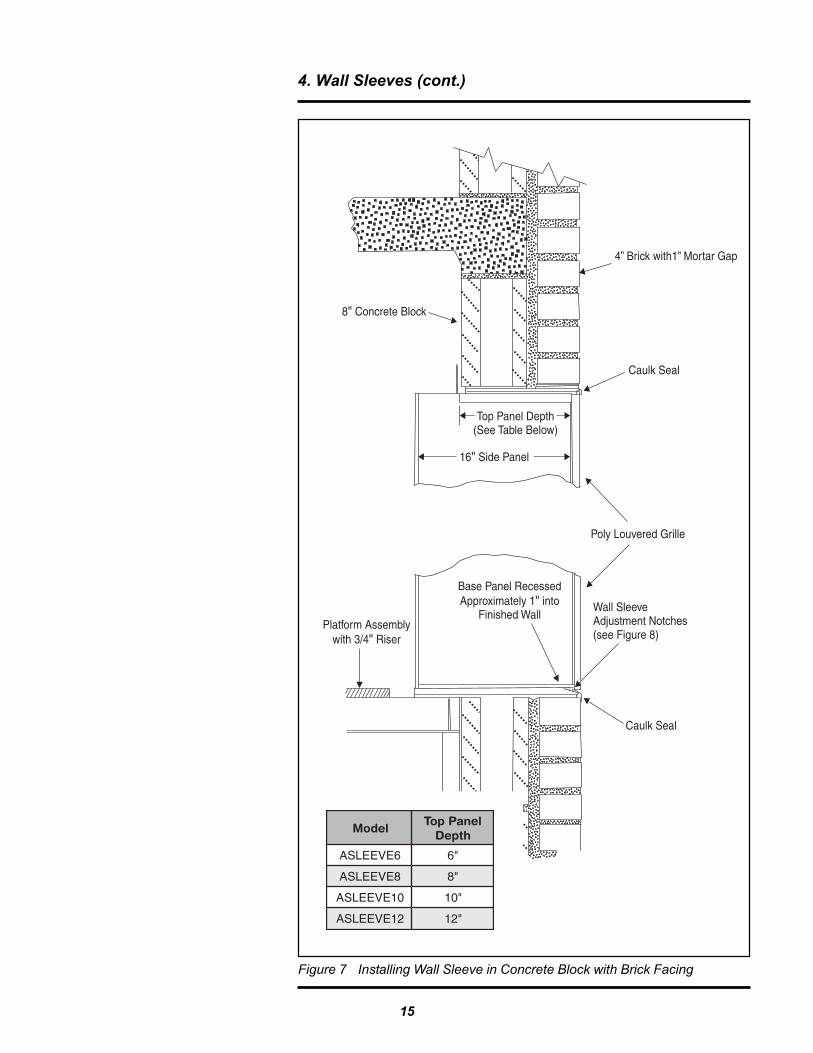
For example, if the supporting wall (rough wall) is concrete block witha brick facing, there is usually a space between the block and thebrick. This space dimension must be added to the width of the brickand block when choosing the correct wall sleeve (see Chapter 5 �Types of Wall Construction). When the wall sleeve is inserted intothe opening and fastened to the block wall, it will recess into thefinished wall by 1 in or 1-1/4 in. depending on the type of grille beingused (see Figure 7).
The same applies if the supporting wall (rough wall) is wood framed.The sleeve must be inserted, whether from inside or outside, allowingfor the thickness of the finish siding, trim, and caulk sealing.
Position wall sleeve in base as shown in Figure 8 on page 16.IMPORTANT: The notched edge of both front corners of the basemust be positioned correctly. If an aluminum louver will be used inthe installation, the notches must line up 1-1/4" back from the face ofthe outside wall. If a polypropylene louver will be used, the notchedmust line up 1" from the face of the outside wall.
After inserting the sleeve into the wall, it is very important to ensurethat the sleeve is level and plumb. Use of shims between the walland the wall sleeve may be necessary.
14
4. Wall Sleeves (cont.)
Figure 7 Installing Wall Sleeve in Concrete Block with Brick Facing
ledoMlenaPpoT
htpeD
6EVEELSA "6
8EVEELSA "8
01EVEELSA "01
21EVEELSA "21
15

Figure 8 Positioning Wall Sleeve Base
Line up this notch inthe base the properdistance from the faceof the outside wall.
Platform
Wall Sleeve Base
Outside Wall
Caulk and flash betweenwall sleeve base and sillplate of wall opening.
4. Wall Sleeves (cont.)
4.2 Recessed SleevesIn some applications, where building walls are either very thick (over12 in.) or architectural design dictates, units can be recessed. Thefinished wall should not protrude beyond the exterior grille by morethan 1 in. However, if the wall opening can be larger in verticaldimension than the wall sleeve, so that the bottom can rest on a sillthat is at least 2 in. higher than the bottom of the wall opening, somefurther recessing is permitted.
The top of the wall opening should be above the top of the wall sleeveby a dimension equal to or greater than the amount of the recess toavoid restriction of the condenser discharge air.
4.3 Weatherproofing Wall SleevesWall sleeves are packaged in a carton and are shipped flat to savespace and shipping costs. They snap and screw together easily at thejob site and are held square by the center divider panel. Instructionsfor caulk sealing the slip joints and spot-welded joints have beenadded to minimize problems with water infiltration during episodes ofhigh wind-driven rain.
This sealing must be done while the sleeve is assembled, but before theMagic-Pak unit is installed in the sleeve. Caulk sealing of the bottom isbest accomplished while the wall sleeve sides are being attached to thebase before it is placed in the wall opening (see Figure 9). The top panelmust be sealed to the side panels while they are being attached. It isalso recommended that the base be caulk sealed to the bottom of theopening during wall sleeve installation. Remaining final sealing can bedone just after the sleeve is secured into the wall opening, if desired, toavoid breaking the seal during handling.
Further sealing against air infiltration is done while the Magic-Pak unitis installed in the wall sleeve and utility connections are completed.Rubber gasket seals are included with each wall sleeve kit to provideall necessary unit-to-wall sleeve sealing.
16

Figure 9 Caulk Sealing Wall Sleeve Bottom
4. Wall Sleeves (cont.)
17

5. Types of Wall Construction5.1 SupportThe wall sleeve is not designed to support the unit. It is designed toserve as an air and weather seal channel through the wall. A sepa-rate platform assembly is required to be constructed before wallsleeve or unit installation (see Figure 10).
The platform must be constructed to be level with the sill plate of the wallopening. The minimum height of the platform is 4 in. from the floor.
The platform assembly should be constructed of a minimum of 2 x 4lumber and 3/4 in. plywood. The width of the platform must be atleast 30 in. The depth of the platform must be consistent with thedepth of the Magic-Pak unit and the distance between the unit andthe wall. Example: Wall Sleeve Kit 8-1 is 8 in deep. If that wall sleevekit is used on a 6 in. deep wall, there would be a 2 in. difference.That 2 in. difference must be added to the unit depth to determinethe proper platform depth.
A 3/4 in. platform riser is included with each wall sleeve kit. The risermust be installed as it is used to level the platform with the plastic wallsleeve base. It will also serve as the bottom seal of the unit. Positionriser so that the front edge of the riser is aligned with where the frontedge of the unit will be when it is installed. The back edge of the riserdoes not need to be flush against the plastic base of wall sleeve.
Three base pads gaskets are supplied with the wall sleeve kits. Theyare adhesive-backed foam rubber pads designed to serve as theunit-to-wall sleeve seal and vibration isolators. The base pads mustbe installed prior to unit installation.
18
NOTE: The platform base must be sized to support the full length and width of the bottom of theunit and constructed so that it is level with the sill plate of the wall opening.
Figure 10 Typical Wall Sleeve Installation

5. Types of Wall Construction (cont.)
Figure 11 Wall Opening in Frame Wall
See specification sheets for wall sleeve dimensions.
Add 1/8" to �H� and �W� dimensions for clearance and later caulk seal weathertight.
5.2 Wood Frame WallsThe framed opening should consist of double 2 x 4�s or 2 x 6�s on bothsides and across the bottom of the opening (see Figure 11).
Wall opening dimensions will vary based on the size of the equipmentbeing used. Proportionally, the wall sleeve kit also will vary based on thesize of the equipment and the depth of the wall.
Wall sleeve kits are designed to fit a multitude of wall constructiontypes. To aide installation it is acceptable to use wall sleeves that aredeeper than necessary. However, the greater the depth of the wallsleeve, the further the unit will sit away from the wall. This will alsonecessitate a deeper platform.
Consideration for vibration control should be made when constructingwall openings and platform assemblies. Walls of particularly lightweight construction with little or no insulation and thin drywall andexterior sheathing can be excited by vibrating machinery. They willtransmit the vibrations more easily to other areas. As a precaution,vibration isolating materials may be installed between the floor andthe platform assembly. The wall sleeve assembly should be securelyfastened to the wall opening to avoid vibration as well.
19

5. Types of Wall Construction (cont.)
5.3 Cement Block WallsCement block or cinder block walls have proved to be the most forgivingfor vibration and noise transmission in single or multistory buildings.
Wall sleeve openings must include a suitable lintel across thetop as prescribed by local building codes.The wall sleeves may be installed from inside or outside of thebuilding and this choice will determine the location of the side angles.
Many contractors prefer to shoot fasteners through the sides of thesleeves into the block, using the side angles as position locators.
It is important that the angles be held tightly to the block along both sideswhile shooting the fasteners in order for the wall sleeve to finish vertical.
Wall sleeves are made to fit 6, 8, 10, or 12 in. deep walls. The depth ofthe wall, whether constructed of masonry materials or wood frame,should take into account any brick facia, stucco, or siding minus 1-1/4 in.for aluminum grilles and 1 in. for poly grilles.
Walls of depths greater than 12 in. will require recessing the wallsleeve into the wall opening. This may be accomplished by installingthe wall sleeve from the inside without using the flashing (support)angles. The inside stop of the wall sleeveës top panel should beplaced against the inside surface of the wall. Proper weathersealing ofthe wall sleeve exterior must be done once the wall sleeve is fastenedto the wall.
When recessing the wall sleeve in this manner, the vertical dimensionof the wall opening must be increased to an amount equal to theamount that the wall sleeve is recessed. Example: The wall isconstructed of 10 in. masonry material with a 1 in. air space and 4 in.brick facade. The total wall thickness is equal to 15 in. The 12 in. wallsleeve will be recessed 3 in. In this case, the vertical dimension of thewall opening should be made larger by 3 in. to permit the use of arecessed sill on which the wall sleeve can rest and still provide ameans to seal the outside edges of the wall sleeve. It is important thatthe entire wall sleeve base and Magic-Pak unit is supported as statedin Section 5.1 on page 18.
When the outside facing is brick, another approach has been to keepthe block wall opening the same for the wall sleeve, but the directionof the brick placed along the bottom is changed. The long dimensionis placed at an angle starting underneath the wall sleeve by 1/2 in ormore, sloping downward to permit drainage, while still providing asuitable groove between the sleeve and brick in which to applycaulking material.
20

5. Types of Wall Construction (cont.)
5.4 Poured Concrete WallsThe use of �pre-cast� or poured concrete walls has increasedconsiderably in high-rise or multistory building construction. Thesebuildings require no special consideration to install Magic-Pak units.When used in conjunction with prestressed concrete floors, noisephenomena can occur several floors away or on an opposite side ofthe building. Curing these phenomena usually means isolating theunit from the wall, as well as the floor. The use of vibration isolationblocks is recommended between the platform and the floor.
5.5 Metal StudsSome types of construction involve the use of steel 2 in. x 4 in.channel studs in exterior walls, covered with rigid sheathing and thick,rigid insulation panels with extensive use of adhesives. Magic-Pakwall sleeves are attached to the steel studding just as for wood,except that self-drilling screws are used with power drivers.
21

6. Noise Transmission
Noise perception bybuilding occupants can beelusive, and early plan-ning can address manyadverse contributingfactors.
For duct layout and air distribution, it is better to locate a unit centrallyin the floor plan. If it can also be a utility room, kitchen, or balconylocation, as opposed to a bedroom or living room location, then bothductwork and sound-transmission concerns can be better served.
In general, the perception of noise can be traced to:
• Vibration transmission• Sound radiating from the source (compressor and motors)
through the panels and enclosure walls• Air noise• Resonant surfaces and objects
6.1 Vibration TransmissionIn spite of the efforts of rubber mounting, balancing, flexible loops oftubing, and mufflers, there is always some vibration created bymoving machinery, and a Magic-Pak unit is no exception. If theremaining vibration can be absorbed by the wall surrounding the unitwithout transmitting the energy further or exciting an adjacent struc-tural member, there is no problem.
Concrete block walls have proved to absorb vibration better thanpoured concrete walls.
Wooden stud wall construction can be more easily excited to re-radiate vibration unless adequately dampened by other materials.
Wooden stud walls which are heavily packed with fiberglass battinsulation or rock wool are less likely to re-radiate vibration than aresparsely insulated (or uninsulated walls).
Flexible duct collars must be used between the Magic-Pak plenumduct flanges and any sheet metal ducts. Also, the ducts must not besupported by, or otherwise touch, the unit.
6.2 Radiated Sound and Resonant Surfaces or ObjectsIn general, the sources of sound are the compressor and the rotatingmotors incorporating air moving blades. A 60 Hz AC power hum cansometimes be heard from these sources or the control transformer,but generally this is imperceptible in a normal operating unit and doesnot contribute to any sound problem. The sound frequencies gener-ated by the motor/compressor acting upon the refrigerant gas are asubstantial contributor to the total sound radiated by the unit.
Sound frequencies generated by the action of the blades of thecirculating air blower and the condenser fan blade upon air areadditional sources of radiated sound.
Frequently these sources of sound can transfer certain frequencies toother objects or surfaces which might in turn be resonant with someof the frequencies from these sources of sound. If this is the case,
22

6. Noise Transmission (cont.)
these objects or surfaces can be excited to vibrate and further imposethe sound on another area.
These sound sources then radiate to enclosing panels, which aremade of materials that either reflect, absorb, or transmit (usually acombination of all three) certain frequencies.
Some types of materials are more �transparent� to some frequenciesthan others. Factors that affect this property include thickness, den-sity, and distance from the source. A closet enclosure for the Magic-Pak unit can reduce the sound level in the adjoining space if con-structed with this purpose in mind.
6.3 ClearancesThe Magic-Pak cabinet is approved for �zero� clearances, as far assafety codes are concerned. However, if sound transmission througha wall is of major concern, a minimum dimension of 4 in. to the insidewall surface is preferred. This applies also to the front access door ofthe closet. Additional sound attenuation can be achieved by using twolayers of gypsum dry wall (5/8 in. or 1/2 in. minimum) on the inside(Magic-Pak unit side) of the walls and the front access door of thecloset (see Figure 12 on page 24).
The side walls can further be improved for sound transmission if the2 in. x 4 in. studs are fastened to 2 in. x 6 in. top and bottom platesand staggered to opposite edges of the plates on 16 in. centers. Thisforms a nominal 6 in. partition wall instead of the usual 4 in. wall, andpermits the inside wall board and outside wall board to be fastened tostuds without being tied together to the same stud. The space be-tween the two wall surfaces may then be filled with 2-1/2 in. mini-mum, 1-1/2 pound density fiberglass.
This same type of staggered stud wall construction may effectively beused as return air space, where local building codes permit.
Cement block construction for the side walls of the closet enclosurehas been employed successfully using a minimum thickness of 4 in.block to attenuate radiated sound. The effectiveness is further im-proved by adding two layers of gypsum wall board fastened to theinside wall surface by means of furring strips and structural adhesive(and/or nails).
Fiberglass or rigid polystyrene insulation may be applied between thefurring strips if thermal insulation and a vapor barrier is appropriate inthe building design. However, the fiberglass or polystyrene alone willnot prove effective at these frequencies without two thicknesses ofgypsum wall board, unless the fiberglass thickness is increased tomore than 3 in.
23

6. Noise Transmission (cont.)
Figure 12 Cross section of walls with 2 x 4 studs staggered on wide top andbottom plate for lateral air passage.
Top View
Side View
6.4 Air Noise6.4.1 Supply-Air Duct System
Duct air velocity, air turning corners, changes in duct size, etc., canall create sound of a much different character than the vibration andradiated sounds of moving machinery. Since Magic-Pak units areusually connected to ducts for air distribution, any air noise will usu-ally be heard at the supply registers or return-air grille in the room.
24

6. Noise Transmission (cont.)
Supply ducts and the plenum on the Magic-Pak unit should be insu-lated to prevent condensation formation on the outside of the ductduring summer operation. If the insulation is applied to the inside ofthe ductwork when it is made, the dual purpose of insulation andsound reduction will have been achieved.
The use of 1 in. thick fiberglass duct board will accomplish the samewhere local codes will permit.
A supply register cut into the side of the supply plenum or at the endof a very short duct is not recommended. At least 4 ft. of insideinsulated duct and/or at least one turn of direction is needed toattenuate the noise in the duct or plenum.
The face velocity of air out of the supply register will ultimately deter-mine the perception of sound from air noise.
The selection tables furnished by the register manufacturer usuallyinclude values for noise along with face velocity, throw, and air frictionat the required air flow for each supply register.
6.4.2 Return-Air Duct System
Duct air velocity, air turning corners, changes in duct size, etc., canall create sound of a much different character than the vibration andradiated sounds of moving machinery. Since Magic-Pak units areusually connected to ducts for air distribution, any air noise will usu-ally be heard at the supply registers or return-air grille in the room.
More frequently, air noise involves the return-air system (or lack of it)when a return grille is simply cut into the side or the door of the closetenclosing the Magic-Pak unit. This is not recommended, since anyequipment operating noise or air velocity noise in the closet canescape through the return grille unimpeded.
This practice also frequently utilizes the closet space as a returnplenum for air returning to the Magic-Pak unit and presents additionaldisadvantages discussed later.
If only one return-air grille is used, it should not be in ìline of sightî tothe closet enclosure or the return duct opening in the bottom of theMagic-Pak unit.
Offsetting the grille location up or sideways in a 6 in. closet side wallis one method used successfully (see Figure 13 on page 26).
Additional air noise attenuation can be accomplished by adding 1/2in. thick duct liner to the air passages thus created, and to the insidesurface of the opposite wall facing the return grille.
If the closet enclosing the Magic-Pak is used as a return-air plenumand the return-air grille is located in one of the enclosing walls directlyadjacent to the unit, the grille should be located high on the wall,rather than at floor level. Then duct liner can be placed on the insidecloset walls and door to effectively reduce the air noise from the
25

6. Noise Transmission (cont.)
Figure 13 Return Air Duct System
bottom of the unit. This high wall location has the advantage ofminimizing �roll out� of infiltration air during high-wind conditions.
If other considerations dictate that a low wall return grille should beused, the air passage should be �trapped� inside the closet with avertical duct 4 ft. to 5 ft. high, open at the top, 4 in. deep and as wideas the grille, with duct liner (1/2 in. thick) applied to the inside ductsurface. Rigid duct board may also be used where local codes permit.This will reduce the airborne sound at the return grille and is alsoeffective against cold air �roll out� due to infiltration in high windconditions.
Another treatment for air-noise reduction on the return-air side is todrop a short duct down through the return-air opening of the Magic-Pak to within 6 in. to 8 in. of the floor. The filter access door must firstbe removed in order to reach the opening. This short duct must also belined inside with 1/2 in. duct liner.
A second piece of sheet metal (about 30 in. x 30 in.) with duct liner onone side should be placed on the floor directly under the return-airduct with the insulated side up. A piece of thick pile carpet directlybeneath this short duct will serve the same purpose.
If the return grille is low in the sidewall or closet door, the effect ofinfiltration in high-wind conditions may still be noticeable due to �roll out�if the circulating blower is off and the room thermostat is satisfied.
Since most of the infiltration comes through the wall sleeve and notthrough the Magic-Pak unit, it is recommended that the closet enclosurenot be used as a return-air plenum. Instead, connect the return grille (or
26

6. Noise Transmission (cont.)
Figure 14 Concentric Supply and Return Duct System for MGE Magic-Pak Unit
duct) directly to the return duct flanges on the Magic-Pak unit usingsheet metal ducts lined with fiberglass insulation or duct liner and aflexible collar connector between the unit and the metal ductwork.
The practices just described are intended to deal primarily with airnoise and airborne sound, as well as vibration and radiated sound.
Infiltration will be discussed in the following section.
27

7. Infiltration
Water infiltration and airinfiltration are mosteffectively addressed indifferent ways.
7.1 Water InfiltrationInstead of relying heavily on seals and gaskets to keep the water out-side, the design contains, and channels off, the water to the outside.
During periods of rain, an air conditioner must adequately channel largeamounts of water through the appropriate drainage paths. The length oftime and the amount of water received during that time determineswhether or not the base pans will fill faster than they can drain. The unitbase takes the first water entering through the condenser coil face andthe upper discharge condenser air opening. The Magic-Pak unit uses amolded composite base with a built-in drain pan. The base of the wallsleeve is also molded composite and sloped outward to allow sufficientdrainage of rainwater to the outside.
If the Magic-Pak wall sleeve is recessed into the wall opening, it willalso likely receive the water running down the building wall above itplus the water draining out of any units in the same wall directlyabove. The cabinet base takes the overflow from the wall sleeve baseand can take about another 1 in. of water depth along the sides of thecondenser compartment. The design is such that all of the rainwaterdrains to the outside by gravity. Wind pressure is generally the sameover the entire outside face and should not affect the ability of thewater to run out the drain opening.
If the quantity of water is excessive for a short period of time, thedrain pans can be filled with water faster than it can run out the drainopenings, it can find its way inside the building. During high windconditions, the outside pressure is greater than the indoor pressureand more water can be forced through the wall sleeve. Even then, theinside cabinet condenser compartment bottom frame is designed tofurther retain this leakage if it should occur. The condenser base panhas a 3/4 in. N.P.T. drain opening which must be connected to thebuilding drain system. Should infiltration make its way into the con-denser compartment, a properly installed drain line will not allowinfiltration into the building.
There have been few instances of water infiltration over the past 30years, and the problems which have arisen have been traced to leakyflashing or sealing to the wall sleeve, or to cases where sealant wasomitted or improperly installed.
7.2 Air InfiltrationThe wall sleeve design allows little air infiltration into the building.Proper sealing of the exterior portion of the wall sleeve and properinstallation of the unit to the sleeve will enhance the resistance to airinfiltration. The unit is installed on three foam rubber base gaskets,two foam rubber side gaskets, and one foam rubber top gasket. Theunit is held in place by two mounting straps which maintain constantpressure between the unit and the gaskets.
28

7. Infiltration (cont.)
The load added to the Magic-Pak units for both sensible and latentheat of the outside air entering the conditioned space must be in-cluded in the heat loss/gain calculations in accordance with standardpractice.
The amount of outside air that enters the space by infiltration throughthe Magic-Pak unit itself, and the wall sleeve, must also be includedin this calculation. For applications in high wind areas, such as high-rise buildings, the amount of infiltration can be assumed to be mini-mal. An average of 15-30 CFM of infiltration can be used for calcula-tion purposes. Wind conditions below 30 miles per hour can beconsidered as no (too low to measure) CFM air infiltration through theMagic-Pak unit and wall sleeve.
If the closet enclosure is on a balcony, it would not need to be sealedor gasketed around the access door as would an enclosure with anaccess door opening into the conditioned space.
7.3 Introduction of Ventilation AirSome local building codes require that a specific amount of ventilationair be brought into the conditioned space, depending upon the occu-pancy and use of the building. In order to comply, some builders willinstall a short duct with a fixed damper to the outside wall from thereturn duct or plenum space.
A grille is placed over the opening in the outside wall. The grilleshould be backed up with a piece of screening to prevent insectsfrom entering.
This method is particularly useful in keeping the space under a slightpositive pressure; however, controlling the amount of air entering theduct under high wind conditions in high-rise buildings is very unpre-dictable. Therefore this practise should be limited to one, two, orthree story buildings, or where adjacent walls form an air shaft offer-ing some protection from high winds.
In any case, the amount of outside air brought directly into the inlet ofthe evaporator coil of the Magic-Pak unit must not exceed 25% ofthe total rated cooling CFM for the unit.
It is preferable to seal the exterior portions of the wall sleeve withsilicone caulk and ensure the sleeve and platform are level andplumb. This allows for proper sealing of the Magic-Pak unit to the wallsleeve.
It is preferable to seal out any infiltration air that can enter the unitthrough the wall sleeve or building design and add a ventilation duct witha controlling damper to an air shaft constructed to meet local codes.
29

7. Infiltration (cont.)
7.4 Sealing Return-Air DuctsWhenever return ducts are connected directly to the inlet of a Magic-Pak using flexible duct collars, care should be taken to seal all cracks,holes, and joints against air leaks, if the enclosing closet can bepressurized by high wind.
If the return-air grille is low in the sidewall or access door and con-nected by a duct coming down to the return location in the unit, theeffect of leaky return ductwork and high wind pressure during an offcycle can be reduced, but not necessarily eliminated.
30

Water infiltration and airinfiltration are mosteffectively addressed indifferent ways.
8.1 Louver Grille Furnished on Magic-PakMagic-Pak units eliminate the unsightly appearance of externalcondensers and cooling towers, and integrate unobtrusively into thebuilding design. The polypropylene (available in white, beige, sand-stone, taupestone, or custom color) or aluminum grille finish comple-ments any exterior wall.
The appearance from outside is similar for all Magic-Pak models ofany heating or cooling capacity. However, there are different cabinetsizes. See pages 5, 6, and 7 for illustrations showing the differentheights, widths, and depths of the Magic-Pak units.
The louvers in the upper grille section are turned slightly upward todirect discharge air away from the intake of the condenser coil belowit, to minimize recirculation of air, and to present a better appearanceby avoiding line-of-sight observation of the space and action takingplace behind the louvered grille (see Figure 15).
The lower grille section covering the condenser coil is on the intakeside of the condenser coil, which can be more easily cleaned from the
8. Louver Grilles
Figure 15 Magic-Pak Louver Grille
31

8. Louver Grilles (cont.)
outside where dirt, leaves, and other airborne debris can collect, asopposed to a �blow through� design which deposits this debris on theinaccessible side of the coil. In buildings over three stories tall, thelikelihood of collecting such debris on the outside is very much re-duced, and the action of rain and other elements ordinarily will cleanaway any accumulation.
If it becomes necessary to remove the louver grille for painting,cleaning, or repair, it can be removed from inside the building. Toremove the grille, first remove the Magic-Pak unit, and reaching in,hold onto the grille. It may be necessary to attach a rope through thegrille louvers to hold it in place while removing the six perimeterscrews. This will help avoid dropping the grille while repositioning it tofit through the wall sleeve. The division panel must be removed priorto loosening the louver screws from the inside. Reverse the proce-dure to replace the grill and Magic-Pak unit.
Table 1 shows the different Magic-Pak louver grilles available.
8.2 Discharging Flue Gas Products from Gas-Fired MGE ModelsThe combustion products must be allowed to discharge freely and atsufficient velocity to project away from the outside surface minimizingcondensation and corrosion. Inhibiting the free discharge of thecombustion flue gases creates an undesirable back pressure withinthe heat exchanger this can contribute to poor combustion and a dirtyflame. Also, the combustion products must not be allowed to recircu-late back into the fresh air intake for the unit combustion air.
If it is necessary to locate an MGE (gas-fired) model in an insidecorner of a wall, where the adjacent wall is at a right angle and is onthe same side as the flue gas discharge tube, the adjacent wall mustnot have any obstruction or protrusion extending away from it thatwould interfere with the free discharge of the flue gases or wouldcontribute toward recirculation of the flue gases.
Any protrusion on an adjacent wall must not extend into the path ofthe flue gases by an amount in excess of 1/2 the distance from thelouvered grille to the protrusion.
Condensation of flue products, which emanate from the combustionblower discharge tube of MGE models, represent a possible cause ofcorrosion and ice build-up. A vent pipe extension is supplied with theunit (see Section 8.2.1 Vent Pipe Installation on page 34).
Due the high temperatures of the combustion products released fromthe gas vent, MGE gas package units require the use of either analuminum louver kit or special MGE polypropylene louver kit (seeTable 1).
32

8. Louver Grilles (cont.)
.oNtiK noitpircseD htiWdesU
THWPRVLA )etihW(tiKrevuoLenelyporpyloPstinUllA-REES01PHM/ECM
stinUnoT2dna5.1-REES21PHM/ECM
THWPRVLA )etihW(tiKrevuoLenelyporpyloP stinUnoT5.2-REES21PHM/ECM
NASPRVLA )enotsdnaS(tiKrevuoLenelyporpyloPstinUllA-REES01PHM/ECM
stinUnoT2dna5.1-REES21PHM/ECM
NASPRVLA )enotsdnaS(tiKrevuoLenelyporpyloP stinUnoT5.2-REES21PHM/ECM
EGBPRVLA )egieB(tiKrevuoLenelyporpyloPstinUllA-REES01PHM/ECM
stinUnoT2dna5.1-REES21PHM/ECM
EGBPRVLA )egieB(tiKrevuoLenelyporpyloP stinUnoT5.2-REES21PHM/ECM
TSPTPRVLA )enotsepuaT(tiKrevuoLenelyporpyloPstinUllA-REES01PHM/ECM
stinUnoT2dna5.1-REES21PHM/ECM
TSPTPRVLA )enotsepuaT(tiKrevuoLenelyporpyloP stinUnoT5.2-REES21PHM/ECM
MTSCPRVLA )*roloCmotsuC(tiKrevuoLenelyporpyloPstinUllA-REES01PHM/ECM
stinUnoT2dna5.1-REES21PHM/ECM
MTSCPRVLA )*roloCmotsuC(tiKrevuoLenelyporpyloP stinUnoT5.2-REES21PHM/ECM
EGMTHWPRVLA )etihW(tiKrevuoLenelyporpyloPstinUllA-REES01EGM
stinUnoT2dna5.1-REES21EGM
EGMTHWPRVLA )etihW(tiKrevuoLenelyporpyloP stinUnoT5.2-REES21EGM
EGMNASPRVLA )enotsdnaS(tiKrevuoLenelyporpyloPstinUllA-REES01EGM
stinUnoT2dna5.1-REES21EGM
EGMNASPRVLA )enotsdnaS(tiKrevuoLenelyporpyloP stinUnoT5.2-REES21EGM
EGMEGBPRVLA )egieB(tiKrevuoLenelyporpyloPstinUllA-REES01EGM
stinUnoT2dna5.1-REES21EGM
EGMEGBPRVLA )egieB(tiKrevuoLenelyporpyloP stinUnoT5.2-REES21EGM
EGMTSPTPRVLA )enotsepuaT(tiKrevuoLenelyporpyloPstinUllA-REES01EGM
stinUnoT2dna5.1-REES21EGM
EGMTSPTPRVLA )enotsepuaT(tiKrevuoLenelyporpyloP stinUnoT5.2-REES21EGM
EGMMTSCPRVLA )*roloCmotsuC(tiKrevuoLenelyporpyloPstinUllA-REES01EGM
stinUnoT2dna5.1-REES21EGM
EGMMTSCPRVLA )*roloCmotsuC(tiKrevuoLenelyporpyloP stinUnoT5.2-REES21EGM
1-LARVLA tiKrevuoLmunimulAdedurtxEstinUllA-REES01PHM/EGM/ECM
stinUnoT2dna5.1-REES21PHM/EGM/ECM
2-LARVLA tiKrevuoLmunimulAdedurtxE stinUnoT5.2-REES21PHM/EGM/ECM
3-LARVLA )thgieH"54(tiKrevuoLmunimulAdedurtxEstinUllA-REES01PHM/EGM/ECM
stinUnoT2dna5.1-REES21PHM/EGM/ECM
4-LARVLA )thgieH"54(tiKrevuoLmunimulAdedurtxE stinUnoT5.2-REES21PHM/EGM/ECM
5-LARVLA )thgieH"05(tiKrevuoLmunimulAdedurtxEstinUllA-REES01PHM/EGM/ECM
stinUnoT2dna5.1-REES21PHM/EGM/ECM
6-LARVLA )thgieH"05(tiKrevuoLmunimulAdedurtxE stinUnoT5.2-REES21PHM/EGM/ECM
Table 1 Magic-Pak Louver Grilles Available* Customer specified color
33

8. Louver Grilles (cont.)
8.2.1 Vent Pipe Installation
Determining the length of the vent pipe extension is dependent uponwhich wall sleeve accessory is installed at the job site for each par-ticular installation.
34
For proper operation, the vent length must becorrect for the installation. The unit may notoperate correctly with inadequate vent length.
CAUTION
1. Access vent pipe at the side of the unit that will face the outdoors.
2. The vent pipe and vent pipe extension is located to the right of theoutdoor fan (see Figure 16).
Outdoor Fan
Vent Pipe/Vent Pipe Extension
5/16" Screw
MountingBracket
Figure 16 Locating Magic-Pak MGE Vent Pipe and Extension
3. Remove the 5/16" screw used to mount the vent pipe assembly tothe mounting bracket. Keep this screw.
4. Five holes have been drilled into the vent extension (see Figure 17).Four of those holes are provided so that the vent can be extendedthe necessary length required for the installation. The wall sleeve thatis installed determines which of these clearance holes should beused. Using Table 2 and Figure 17, determine which clearance holeshould be used to position the vent extension properly. Slide the ventextension outward and line up the correct clearance hole on the ventextension with the hole in the vent pipe and the hole in the mountingbracket.
5. Re-install the 5/16" screw that was removed in Step 3. Thread thescrew first through the clearance hole in the mounting bracket, theproper clearance hole in the vent extension, and into the engage-ment hole in the vent pipe. The length of the vent pipe extensionthat extends out of the cabinet should be as shown in Table 2.

In order to keep operating costs to a minimum, the restriction of con-denser air flow must be minimized and the recirculation of condenser airat the outdoor face of the Magic-Pak must be prevented. These areprime considerations over which the building designer has control.
Table 2 Determining Hole Setting on MGE Vent Pipe Extension
desUeveelSllaW #eloHhtgneLetamixorppA
tenibaCmorfsdnetxEtneV
4,3,2,1-6EVEELSA 4 sehcni5.5
4,3,2,1-8EVEELSA 3 sehcni5.7
4,3,2,1-01EVEELSA 2 sehcni5.9
4,3,2,1-21EVEELSA 1 sehcni5.11
Figure 17 Positioning Magic-Pak MGE Vent Pipe (Flue) Extension
* The numbers are for identification purposes only. They are not marked on theactual vent extension.
35
8. Louver Grilles (cont.)

9. Condensate Drain
The Magic-Pak conceptprovides for the disposalof condensate water to adrain or wastewaterline inside the building.
Provisions must be made to properly drain the indoor and outdoordrain pans of the Magic-Pak unit. (MGE Magic-Pak units have onlyone drain fitting as the indoor drain pan drains internally into theoutdoor drain.) Piping the condensate to an inside drain is required.
The outdoor drain connection is located in the left end of the base ofthe Magic-Pak unit. The field-supplied outdoor drain connection is a3/4 in. NPT to 3/4 in. PVC fitting (schedule 40). On MCE and MHPMagic-Pak units, the factory-supplied indoor drain connection is a 1/2in. NPT to 3/4 in. PVC fitting (schedule 40). Both drains (if applicable)must be trapped as shown in Figures 18 and 19. The drain line(s)should pitch gradually downward at least 1 in. per 10 ft. of horizontalrun to open drain.
Although the drain trap forms a trap when filled with condensatewater during cooling operation, it is likely to be dry during prolongedperiods of heating operation. The pan is always under negative airpressure when the condenser fan is in operation.
The building drain or waste line should be connected as local codesmay prescribe for any other kind of air conditioning system, be itresidential or commercial.
Use thread sealant on the threaded fittings. Install threaded fittings byhand only. Do not overtorque the fittings.
Figure 18 MGE Condensate Drain Connection
Figure 19 MCE/MHP Condensate Drain Connections
36

10. Electrical Service Wiring
Each Magic-Pak model isshipped with installationinstructions which describethe options for electricalsupply wiring connectionsto the specific unit model.All instructions defer to thecode requirements of theagencies of local jurisdic-tion.
In most cases, the MGE gas-fired Magic-Pak units will be connectedto nominal 230 volt, 60 Hz, single-phase power. The same units canbe connected to 208 volt power if assurances can be given by thepower supplier that a minimum of 197 volts will always be available.Cooling capacities will be reduced by about 1% for 208 volt operation.Gas heating ratings are not affected.
The MCE electric units and the MHP heat pump units are affected onthe cooling cycle in a manner similar to the MGE models, as describedabove. However, since the MCE and MHP models both contain electricresistance strip heaters in the heating cycle, the supply line voltage hasa bearing on the heating output of the strip heaters.
The specification sheet for each model contains a table which lists theBTUH output for each heater size at the voltages of 240, 230, 208,and 197 volts. The �rated� voltage of the heaters is 240 volts. Thenominal KW is for a 240-volt rating.
The remainder of the Magic-Pak unit is ìratedî at 230 volts, but hasan operating voltage range from 253 to 197 volts, in accordance withthe A.R.I. Standard 240.
The actual BTUH output of the electric strip heaters varies with thesquare of the voltage ratio; so if the expected operating voltage at ajob location is known or can be determined, the actual heater outputcan be determined, or a heater optional size can be selected to meeta heating requirement at any chosen voltage.
Example:
• At 240 volts, 9.2 KW delivers 31,400 BTUH
• At 208 volts, the same heater delivers
The heat output for any other application voltage may be determinedin the same way.
The specification sheets for each model also include the ampacityvalues required to determine wire sizes, in addition to the minimumfuse size requirements for both single-entry and multiple-entry con-nections to the units.
2 x 9.2 = 6.9 KW or 23,550 BTUH208240( )
37

11. Air FilterAll indoor return air must be filtered. A washable filter is furnishedwith the Magic-Pak unit, located in the return air opening. If a returnduct is installed, provisions must be to accommodate filter servicing.
The filter should be cleaned at least three times during the heatingand cooling seasons, or more frequently if unusual conditions areencountered. To clean the washable filter, shake filter to removeexcess dirt and/or use a vacuum cleaner. Wash filter in soap ordetergent water and replace after filter is dry. It is not necessary to oilthe filter after washing.
If an installation is made in which it is more desirable to mount thefilter exterior to the unit, in the return duct work or elsewhere, thewashable filter can be used or replaced with a disposable filter. If adisposable filter is used, use the information provided in Table 3 whensizing the disposable filter.
NOTE: When replacing filters, either the same filter must beused or an equivalent filter that achieves the same pressuredrop and has the same filter area measurement (square inches).
Table 3 Minimum Required Surface Area for Disposable Filters
* 10 and 12 SEER models
rebmuNledoM aerAretliF
21*EGM/PHM/ECM sehcnierauqs291
81*EGM/PHM/ECM sehcnierauqs882
42*EGM/PHM/ECM sehcnierauqs483
03*EGM/PHM/ECM sehcnierauqs084
38

Gas-fired Magic-Paks take combustion air directly from the outside.
A centrifugal combustion air blower provides the displacement andpressure required to overcome the internal resistance of the heatexchanger passages, while drawing in the correct amount of air forefficient combustion.
The materials used in the construction of the heat exchanger, com-bustion blower, flue gas discharge tube, and outside louver grille areconsistent with the requirements for corrosion resistance for theapplication, and consider the presence of moisture and the formationof acids through condensation internally and externally on the lou-vered grille.
The flue gas velocity and temperature are usually high enough toproject the gases beyond the louvered grille before they condense,but in the event that erratic wind conditions could blow them back, thecorrosion protection is provided.
12.1 Gas Distribution in Multi-Family BuildingsUse of �2 psi� gas distribution systems requires an additional regulator.It must be sized for the total BTUH load of only the appliances servedin the apartment, such as a gas range, gas clothes dryer, gas waterheater, etc., as well as the Magic-Pak gas unit.
If one of the appliances is located too far away from the others to permituse of small diameter tubing, it may be necessary to install a tee aheadof the regulator and run the 2 psi gas to it, locating a second pressureregulator at the distant appliance.
12. Special Considerations forGas Units
One of the advantages ofMagic-Pak units is thatcombustion air is nottaken from the occupiedspace.
39

MCE, MHP, and MGE Magic-Pak units can be retrofitted to replaceany thru-the-wall product that utilizes a 45-1/8 in. tall by 29-1/8 in.wide wall opening.
Magic-Pak units can be used to replace the following thru-the-wall units:
• HWC Series Gas Heating with Electric Cooling Units(Johnson Furnace, Magic Chef, Armstrong)
• EWC Series Electric Cooling Package Units(Johnson Furnace, Magic Chef, Armstrong)
• PWC Series Self-Contained Heat Pump Units(Johnson Furnace, Magic Chef, Armstrong)
• 50QT Series (Carrier Corp.)
• 50QP Series (Carrier Corp.)
13. Retrofit Applications
40

© 2003, Armstrong Air Conditioning, Inc. MPA-100 10/03
421 Monroe StreetBellevue, Ohio 44811
(419) 483-4840www.magicpak.com