Embed Size (px)
Citation preview

.

5-5-Mincon_MP55_Service_Manual_Rev_A1 Page 1
Table of Contents
INTRODUCTION ........................................................................................................................................... 2
1. SAFETY ............................................................................................................................................... 2
2. HAMMER CARE................................................................................................................................... 2
2.1 STORAGE ................................................................................................................................................................ 2
3. DTH HAMMER SET UP........................................................................................................................ 3
3.1 THE AFFECT OF TEMPERATURE AND ALTITUDE ON COMPRESSED AIR ....................................................................... 3
3.2 UP-HOLE AIR BAILING VELOCITY REQUIREMENTS ..................................................................................................... 3
3.3 CHOKE SELECTION .................................................................................................................................................. 3
3.4 DRILL BIT CARE AND INSTALLATION ........................................................................................................................ 4
3.4.1 Drill Bit Handling ............................................................................................................................................. 4
3.4.2 Drill Bits: Prior to Use ..................................................................................................................................... 4
3.4.3 Drill Bit Installation .......................................................................................................................................... 4
3.5 TORQUING UP A DTH HAMMER ............................................................................................................................... 5
3.6 LUBRICATION .......................................................................................................................................................... 6
3.7 OPERATION ............................................................................................................................................................. 6
3.7.1 Commissioning a New DTH Hammer............................................................................................................. 7
3.7.2 Collaring the Hole ........................................................................................................................................... 7
3.7.3 Feed Force/Pressure ...................................................................................................................................... 7
3.7.4 Rotation .......................................................................................................................................................... 8
3.7.5 Hole Cleaning, Flushing and Dust Suppression ............................................................................................. 8
3.8 HAMMER SERVICE ................................................................................................................................................... 9
3.9 GENERAL ................................................................................................................................................................ 9
3.10 BREAKING OUT CHUCK AND BACKHEAD .................................................................................................................. 9
3.10.1 Breaking Out Chuck to Change Drill Bit ......................................................................................................... 9
3.10.2 Disassembly for Full Servicing of Hammer .................................................................................................... 9
3.10.3 Inspection ....................................................................................................................................................... 9
3.10.4 Checking Wear Limits ................................................................................................................................... 10
3.10.5 Reassembly .................................................................................................................................................. 10
4. TROUBLE SHOOTING....................................................................................................................... 11
5. APPENDIX ......................................................................................................................................... 12
5.1 DTH HAMMER EXPLODED VIEW AND PARTS LIST AND TECHNICAL DATA ................................................................. 12
5.2 HAMMER SERVICE LOG ......................................................................................................................................... 13
6. WARRANTY ....................................................................................................................................... 14

5-5-Mincon_MP55_Service_Manual_Rev_A1 Page 2
Introduction Thank you for choosing the Mincon MP55 Down-the-Hole hammer. Please read this manual carefully before using your hammer in the interests of safety, warranty and best operational care. The Mincon MP55 is ruggedly built with a hardened wear sleeve to withstand the stresses of drilling in the most extreme conditions. However, on the inside it is a precision tool with care taken in manufacture to ensure that the components meet finely matching tolerances to provide fast drilling, reliability and efficient use of air without waste. With correct care your Mincon MP55 hammer should provide you with top performance reliability and long service life.
Warranty is provided by Mincon as per the warranty section 6.
Please keep this instruction manual as a permanent part of your DTH Hammer.
The specifications and instructions contained in this manual are based on the up-to-date information as at publication date.
1. Safety Be sure to work safely at all times. Wear protective clothing and safety equipment and observe all safety regulations as prescribed by your employer, Government, or the site on which you work. Do not wear loose clothing that may get caught in rotating parts and cause serious personal injury.
Remember that a “Down-the-Hole” percussive hammer emits noise and you should therefore take every precaution to safeguard your hearing against damage by using proper hearing protection. Use eye protection at all times. Rock chips and dust which may be discharged from the face of the bit or bore hole at high velocities and can cause severe injury.
Hammers can be heavy – Always use proper and approved lifting equipment and take every precaution to safeguard yourself against injury. Keep hands clear at all times – Beware of getting fingers trapped between the chuck and bit and do not use hands or feet to clear the top of the borehole at any time.
Other safety advice is given throughout this document which you are advised to read.
2. Hammer Care.
2.1 Storage
It is important to take the following steps in order to ensure smooth operation when hammer is to be re used. When the hole is completed and the hammer is to be inactive for some time the following steps should be taken.
Short Term Storage (e.g. 1 -2 weeks)
Using high pressure air, blow the hammer clear of all water.
Turn automatic oiler up full and cycle hammer until oil is running out the shank of the drill bit.
If there is not an automatic oiler, pour 1 litre (2 pints) of rock drill oil in to the backhead.
Turn the air on and cycle for 10 seconds. This will lubricate the internal parts.
Seal the hammer at the backhead and chuck end to exclude any dust or foreign particles.
Store the hammer horizontally in a clean dry environment.
Long Term storage (e.g. 1 month or longer)
Using high pressure air, blow the hammer clear of all water.
Break out the back head and chuck on the rig as it is easier to do it here than back in the workshop.
Disassemble the hammer.
Inspect and clean all hammer components.
Lubricate all the internal components with rock drill oil.
Reassemble the hammer, and seal the backhead and chuck end.
Store horizontally in a clean and dry environment.
Periodically rotate the hammer as the oil will settle.
Before restarting any hammer after prolonged periods of inactivity, disassemble and inspect all internal parts. Clean and remove any oxidation with an emery cloth. Re-lubricate all internal components with rock drill oil and reassemble the hammer. Full assembly and disassembly instructions can be found further on in this manual.

5-5-Mincon_MP55_Service_Manual_Rev_A1 Page 3
3. DTH Hammer Set Up It is important to remember that although the injection of water into the hammer will increase the pressure in the hammer, the water is a restriction in the hammer that will cause a drop in the drilling performance.
3.1 The Affect of Temperature and Altitude on Compressed Air
Both temperature and altitude have an effect on air and consequently on compressed air. Higher temperatures and higher altitudes result in air becoming thinner, less dense, and the effect of this is a reduction in a compressor’s delivery pressure.
The table below shows just how much operating pressure can be affected by these two factors. For example, if we take a compressor which will deliver 1000 cfm (28.3 M3/Min) at sea level and a temperature of 68° F, this same compressor will only deliver 745 cfm (21.1 M3/Min) at 9,000ft (2744m), given a temperature of 40° F (4.4° C). Method: 1000 cfm/1.341.
°F °C Sea Level 1000ft 3000ft 5000ft 7000ft 9000ft 11000ft 13000ft 15000ft
Sea Level 305m 915m 1524m 2134m 2744m 3354m 3963m 4573m
-40 -40 0.805 0.835 0.898 0.968 1.043 1.127 1.217 1.317 1.426
-30 -34.4 0.824 0.855 0.920 0.991 1.068 1.154 1.246 1.349 1.460
-20 -28.9 0.844 0.875 0.941 1.014 1.092 1.180 1.275 1.380 1.494
-10 -23.3 0.863 0.895 0.962 1.037 1.117 1.207 1.304 1.411 1.528
0 -17.8 0.882 0.915 0.984 1.060 1.142 1.234 1.333 1.443 1.562
10 -12.2 0.901 0.935 1.005 1.083 1.167 1.261 1.362 1.474 1.596
20 -6.7 0.920 0.954 1.026 1.106 1.192 1.288 1.391 1.506 1.630
30 -1.1 0.939 0.974 1.048 1.129 1.217 1.315 1.420 1.537 1.664
40 4.4 0.959 0.994 1.069 1.152 1.241 1.341 1.449 1.568 1.698
50 10 0.978 1.014 1.091 1.175 1.266 1.368 1.478 1.600 1.732
60 15.6 0.997 1.034 1.112 1.198 1.291 1.395 1.507 1.631 1.766
70 21.1 1.016 1.054 1.133 1.221 1.316 1.422 1.536 1.662 1.800
80 26.7 1.035 1.074 1.155 1.244 1.341 1.449 1.565 1.694 1.834
90 32.2 1.055 1.094 1.176 1.267 1.365 1.475 1.594 1.725 1.868
100 37.8 1.074 1.114 1.198 1.290 1.390 1.502 1.623 1.756 1.902
110 43.3 1.093 1.133 1.219 1.313 1.415 1.529 1.652 1.783 1.936
120 48.9 1.112 1.153 1.240 1.336 1.440 1.556 1.681 1.819 1.970
3.2 Up-hole Air Bailing Velocity Requirements
The up-hole air bailing velocity is the velocity of the air as it exhausts from the hole and returns to the surface carrying cuttings. Sufficient volume of compressed air is required to maintain pressure at the hammer and to maintain sufficient bailing energy to clean the hole.
Bailing velocity requirements vary with bailing rates, material hardness, density and depth of hole. The higher the drilling rate and density of the material the higher the bailing velocity must be.
Bailing velocity for hammers with operating pressures in the range of 200 to 350 psi should be 3000 feet (900m) per minute minimum. Recommended minimum bailing velocity is 5000-7000 feet (1500-2100m) per minute. Velocities in excess of 7000 feet (2100m) per minute are not uncommon but in abrasive material this can cause rapid erosion of the bit body and hammer.
Bailing velocities are calculated by using hole diameter, drill pipe diameter and the actual volume of air delivered down the hole. Make sure to allow for the affect of altitude and temperature when calculating the actual volume.
VF = Velocity in feet per minute.
Y(CFM) = CFM of air passed by hammer
DL2 = diameter of hole squared in inches
di2 = diameter of drill tube squared in inches
VM = Velocity in meters per minute
X(M3) = M3/min of air passed by hammer
DM2 = diameter of hole squared in mm
dm2 = diameter of drill tube squared in mm
3.3 Choke Selection
Chokes increase the airflow through the hammer and vary the operating air pressure or air volume delivered from large compressors by reducing compressor modulation to increase hammer efficiency and bailing velocity in the hole. They do this by diverting a portion of the air flow directly through the hammer and bypassing the hammer cycle. Where a hammer is to be used on
Imperial
VF = Y(CFM) x 183.40
DL2 – di2
Metric
VM = X(M3) x 1273406.57
DM2 – dm2

5-5-Mincon_MP55_Service_Manual_Rev_A1 Page 4
a drill machine that has an excess of cfm available, a choke size should be selected to run the hammer at an optimum pressure. To determine the amount of air that will be bypassed, the following formula can be used.
F = 9.71 x D2 x P
Where: F = Flow in scfm
D = The equivalent hole diameter
P = Pressure in psig
It is assumed that the flow coefficient is 0.7, temperature is 120°F and gas is air.
For example: If a 1/8” choke is installed in a hammer then the additional air required to operate the hammer at 350 psi would be:
F = 9.71 x 0.1252 x 350
F = 53.1 scfm
The use of chokes will assist to clean the face of the hole at the bit, minimizing ‘regrinds’ of cuttings in medium density broken ground allowing the drill bit carbides to directly contact and break fresh rock and improve the drilling rate. Operators should select a choke with the smallest orifice hole necessary as a hammer develops the highest energy with a blank choke. Larger orifice chokes should only be used in very soft ground formations or where large volumes of water are encountered as they increase back pressure in the hammer and reduce hammer performance. All Mincon hammers are supplied with a solid choke installed, and a selection of chokes that can be installed as needed.
3.4 Drill Bit Care and Installation
Your Mincon DTH drill bit is at the working end of drilling and just like the hammer, it will perform extremely well if cared for. Good drill bit care and maintenance helps ensure the longest life and best performance from that bit. The following gives recommendations on how to best care for your Mincon Drill Bits and install them correctly to maximize productivity and longevity.
3.4.1 Drill Bit Handling
A drill bit is capable of taking considerable punishment in drilling operations; however, care must be taken while handling them to ensure that the bit you are drilling with is in sound condition. Drill bit foot valves or blow tubes are manufactured from hard plastics are can be easily broken if dropped or something heavy is dropped on them.
The tungsten carbide buttons on a bit are extremely hard to fracture the rock they are drilling in. Dropping the bits onto hard surfaces (such as metal) can cause the buttons to crack and break. All care must be made to ensure drill bit heads do not come in heavy contact as the buttons striking each other can also cause damage.
3.4.2 Drill Bits: Prior to Use
Prior to using a new or used drill bit it should be inspected for the following and lubricated with rock drill oil:
• Check the condition of all the carbides and ensure that no damage has occurred and that the carbides are sharp.
• Inspect the face and head of the bit for any cracking or damage that could be detrimental to the drill bit.
• Make sure the gauge row carbides have sufficient clearance from the head of the bit.
• Inspect the foot valve (blow tube) for damage or cracking.
• Check that the foot valve is not loose, and check the length of the foot valve from the strike face of the bit to the top of the
foot valve. This dimension is critical in the correct operation of the DTH hammer and drill bit. The length of the foot valve
above the drill bit strike face for the shanks used in Mincon hammers can be found below.
• Inspect the splines of the drill bit and chuck. Remove any burrs that have formed. Excessive wear to the splines of the bit
and/or chuck will cause the hammer to run loose and can cause broken foot valve, shanking of the bit, or damage to the
strike face of the piston and/or drill bit.
Shank Length Above Drill Bit Strike Face Shank Length Above Drill Bit Strike Face
Inches Millimeters Inches Millimeters DHD3.5 2.300 58.4 QL60 2.100 53.3 MD3.5 2.300 58.4 DHD360 1.860 47.2 MD4 2.200 55.9 SD6 / 5315 2.130 54.1 SD4 / 3415 2.035 51.7 DHD380 1.950 49.5 DHD340A 2.200 55.9 SD8 / 6315 2.250 57.1 SD5 / 4315 2.140 54.4 QL80 2.000 50.8 QL50 2.030 51.6 SD12 1.700 43.2 DHD350R 2.600 66.0 QL120 2.770 70.4
3.4.3 Drill Bit Installation
When installing a new drill bit into a new hammer lubricate the splines on the bit with rock drill oil. Place the chuck over the bit and install the bit retaining ring. Most models of Mincon DTH hammers have reversible bit retaining rings, however some do not, and it is important to make sure that they are inserted in the correct orientation. Failure to do this can result in poor performance and damage to the internals of the hammer.

5-5-Mincon_MP55_Service_Manual_Rev_A1 Page 5
When using the drill machines rotary head to screw the chuck into the hammer, take care not to cross thread the chuck. With the head of the bit in the bit basket, torque up the bit in the hammer. See later for torque recommendations.
When installing a new bit on a used hammer it is important to inspect the chuck for wear to the body and splines. In soft and broken drilling conditions there is often excessive bit travel that results in uneven wear to the splines. Where this wear is excessive the chuck should be replaced as failure to do this will result in premature wear to the splines of the new drill bit, and possible damage to other components in the hammer due to lateral movement of the drill bit in the hammer. The body of the chuck should also be inspected for any gouging or grooving that is caused by erosive wear. Where this has occurred index the chuck so that the grooves or gouges do not line up with the drill bits exhaust grooves.
In the case when a used or newly sharpened drill bit is installed on a used hammer (used bits should never be used on a new hammer), the same indexing principles occur. If the bit is to be removed, sharpened and replaced back on the hammer, mark the location of the current bit alignment on the chuck and drill bit prior to removal. After sharpening of the drill bit has been completed, index the chuck by one spline so that the drill bits exhaust grooves are moved to a new location on the chuck as shown below.
In drilling conditions that are very abrasive such as granite, sandstone or quartzite the chuck should be indexed more than one spline. The Mincon DTH hammer chucks are multiple lead threads so it may also be necessary to turn the chucks starting position so that any grooves that have progressed into the wear sleeve are also separated into new locations as demonstrated below.
3.5 Torquing Up a DTH Hammer
Mincon DTH hammers use a patented three piece seating ring system and a compression ring to ensure that the hammers top end components are held firmly in place. This is extremely important as any movement of these components will result in premature wear and loss of performance. When a Mincon hammer’s backhead is closed up by hand there is a gap between the wear sleeve and backhead shoulder known as stand-off. All Mincon hammers have 0.030” (0.76mm) stand-off except the Mincon XP120 12” hammer which has 0.080” (2.0mm) stand-off.
The stand-off must be completely closed as part of the locking system for the hammer. It is not recommended to use the hammer action of drilling to close up the gap as movement in the top end will occur that will be detrimental to the hammer and ultimately lead to premature wear and loss of performance.
Recommendations for closing the hammer are to have it torque to between 750 - 1000 ft.lb per inch of hammer diameter. Where the rotary head cannot apply the requisite torque, a Make-up and Break-out machine like the Mincon Sidewinder or Mincon DTH Break-out Bench should be used.

5-5-Mincon_MP55_Service_Manual_Rev_A1 Page 6
Fit the hammer to the drilling rig ensuring no debris or dirt enters the hammer from the site, dirty tubes or from unclean air lines. Make sure that the coupling threads from the drill are of the same specification to that of the hammer and they are in good condition. Run the hammer at half the air flow for a few minutes to allow the oil to flow through and for internal components to settle in.
3.6 Lubrication
There are two main types of lubricators in use on drill rigs, a plunger oiler and a venturi oiler. Plunger oilers operate on a timed plunger system that feeds a fixed amount of oil into the air stream at timed intervals. The main benefit with this type of system is that the oil tank does not need to be pressurized. The oil viscosity and temperature are also not a factor with these oilers. They are quite complex and not as reliable as venturi oilers. Moreover, the oil is not atomized to deliver it more evenly.
Venturi lubricators, or pig oilers as they are also known, work like a carburettor. A constricted area in the venturi creates a pressure drop which draws oil into the line. The oil is atomized and mixed very efficiently with the air allowing for excellent adherence to the hammer components. The volume of oil used is generally controlled with a needle valve. The rate of lubrication is dependent on oil viscosity which varies with temperature.
It is vital for DTH hammers to receive a constant supply of proper rock drill oil to protect the internal components and to provide a good air seal between the piston and the inner cylinder, and the piston and the wear sleeve for efficient drilling. Mincon recommends the use of Mincon Envirosafe® rock drill oil (RDO) to maintain optimal performance and extend the life of the internal components of your hammer.
The correct consumption of oil is dependent upon the air volume and conditions. Please refer to the lubrication graph below for recommendations. There should be visual evidence of oil around the drill bit shank and within the tube joints when changing tubes. When using the recommended Mincon Envirosafe® RDO the consumption can be reduced to 70 percent of the amount outlined in the consumption graph.
If using petroleum based rock drill oils, the recommended grade of oil is dependent on the ambient temperature in which drilling is taking place as well as the operating pressure. As a rule of thumb, ISO320 grade rock drill oil should be used whenever possible as the hammer is a high frequency tool, however, where the pump cannot pump the oil in colder conditions, a lower grade of oil can be used as per the graph below. The viscosity of Mincon Envirosafe® RDO is such that it can be used at any time without it becoming too tacky to pump.
When using water injection to flush and clean the hole, the quantity of rock drill oil being used must be increased. When drilling with 1 gallon (3.8 liters) a minute then the quantity of oil used should be increased by half. When drilling with 2 gallons (7.6 liters) a minute then the quantity of oil used should be doubled.
Rockdrill Oil Grade Rockdrill Oil Consumption
Remember: Insufficient lubrication or incorrect lubrication grades may result in damage being caused to the hammer and it’s components. Hydraulic oils, engine oils, gear oils and diesel are not recommended for lubricating DTH hammers.
3.7 Operation
Be sure to familiarise yourself with the controls of the machine and work in accordance with the manufacturers recommendations. The percussive mechanism begins to operate as the air supply is turned on and when the drill bit is pushed firmly into the hammer. Excessive thrust pressures are not needed to make it work. The thrust controls on the drill should be adjusted to the correct pressure and should be readjusted to take account of the weight of any extra tubes added so that the thrust pressure remains constant and not excessive. Insufficient thrust pressure will make the hammer drill erratically and less efficiently and cause premature wear to the bit and chuck splines with likely damage to the hammer components and threads.
When the hammer is lifted from the rock face, the drill bit extends from the chuck and the percussive action ceases. Extra air will pass through the hammer, which can be used to flush the hole clean. Whenever possible, the pressurized air in the hammer should

5-5-Mincon_MP55_Service_Manual_Rev_A1 Page 7
be drilled out to avoid situations where back hammering can occur. This is not always possible in conditions where the rock is quite fractured and broken.
When changing drill rods, ensure that the drill string has been depressurized before breaking the tool joint. Rapid depressurization of the drill string can cause a sudden pressure drop in the hammer forcing debris from the bottom of the hole into the hammer. Before adding drill tubes make sure that the threads are clean and well greased and that there are no contaminants likely to enter the hammer to cause damage and early wear.
3.7.1 Commissioning a New DTH Hammer
Coat the drill bit shank and the hammer threads with rock drill oil for protection and easier break-out. Prior to use, lubricate the hammer with ½ pint (¼ liter) of rock drill oil. The oil should be poured through the backhead and by using a long screwdriver inserted into the backhead; the check valve can be depressed to allow the oil to run down into the piston chamber. Alternatively, install the hammer onto the drill machine’s rotary head, place a piece of cardboard on the table, locate the hammer’s drill bit just over the cardboard and turn the air on low. When the cardboard becomes wet with rock drill oil all internal components should be sufficiently coated with oil.
Fit the hammer to the drilling rig ensuring no debris or dirt enters the hammer from the site, dirty tubes or from unclean air lines. Make sure that the coupling threads from the drill are of the same specification to that of the hammer and they are in good condition. Run the hammer at half the air flow for a few minutes to allow the oil to flow through and for internal components to settle in.
3.7.2 Collaring the Hole
Collaring the hole is a very important aspect of the drilling process. In blast hole drilling the quality of the top of the hole will often determine the how well a charge can be set, the straightness of water well, geothermal well and foundation holes is determined by the straightness and quality of hole collaring.
The following procedure should be used when collaring the hole in rock:
1. While rotating the hammer clockwise at very slow speed feed the hammer to a few inches from the surface.
2. Turn on the air at a reduced pressure and slowly feed the hammer into the ground and continue at low pressure and
impact.
3. As the hammer drills into the ground increase the air pressure, feed pressure and rotation as the hole becomes stable. It
is advisable to lift the hammer off bottom occasionally to clean the hole as necessary. The conditions will dictate this and
will be required more often in more broken conditions.
4. Once the hole has been stabilized continue drilling as normal.
The following procedure should be used when collaring the hole in overburden:
1. While rotating the hammer clockwise at very slow speed feed the hammer to a few inches from the surface.
2. Turn on the air at a reduced pressure and slowly feed the hammer into the ground and continue at low pressure and
impact.
3. As the hammer drills further into the ground increase rotation and feed pressure. Lift the hammer off bottom occasionally
to clean the hole as necessary as drilling through the overburden continues. Use of water and/or foam may be necessary
to maintain the integrity of the bore-hole walls.
4. Continue until the hammer enters consolidated rock and case the hole. Be sure to follow all regulations regarding depth of
casing into rock.
5. In situations where casing in extremely difficult conditions where the stability of the bore-hole walls cannot be maintained,
such as gravel, heaving or flowing sands etc. the use of specialized foams, eccentric or concentric casing systems should
be employed.
3.7.3 Feed Force/Pressure
For shallow holes the hydraulic down pressure applied to the Rotary Head through the pull down cylinders provides the necessary additional force. This additional pull down force is usually shown as a PSI value on the Rig gauges. To convert this figure to a weight value you will need to multiply the PSI reading by the area of the pull down cylinders. This can then be added to the weight of the Rods, Rotary Head, and Hammer minus Piston, to give the total “Weight on Bit”.
As the hole deepens with the addition of extra rods, a point is reached where the pull down force needs to be reversed to create a “hold back force” thus preventing too much weight being applied to the Bit. Since there are so many different types and sizes of rigs, it is not possible to give specific guidelines on the amount of additional down pressure as shown by the gauge. This becomes part of the necessary tuning by the drill operator. Regarding the actual figures for required weight the easiest way to calculate this is to use the two simplified formulae below:

5-5-Mincon_MP55_Service_Manual_Rev_A1 Page 8
1. When working with air pressure below 250PSI, (17.2bar) multiply the Bit Head Diameter by 500 for inches and by 9 for
millimeters. Example :- A Button Bit with a 6” (152mm) diameter Head would require 3000Lbs “weight on bit” or 1365Kg.
2. When working with air pressure at 250PSI (17.2bar) and above, multiply the Bit Head Diameter by 800 for inches and 14
for millimeters. Example:- A Button Bit with a 6” (152mm) diameter Head would require 4800Lbs “weight on bit” or 2182Kg.
Since these formulae have been simplified to allow for quick calculation you may find that, dependent upon ground
conditions, slight alterations may need to be made to these values. Again this is a necessary part of the tuning process
performed by the drill operator.
It is also important to bear in mind that underfeeding, or insufficient weight on the bit will result in the bit “bouncing” up and down in the chuck. This will lead to a build-up of very high temperatures between the splines of the chuck and the bit which will eventually lead to “spot welding” and burning marks which will soon lead to bit shank failures.
Underfeeding also results in other types of failures, particularly button pop out and striking face failures. This is a result of the energy developed by the piston impacts not being transferred efficiently into the rock. As a result, a percentage of this energy is contained in the drill bit where it will eventually lead to failure through the weakest part of the bit. The percussive mechanism begins to operate as the air supply is turned on and when the drill bit is pushed firmly into the hammer. Excessive thrust pressures are not needed to make it work. The thrust controls on the drill should be adjusted to the correct pressure and should be readjusted to take account of the weight of any extra tubes added so that the thrust pressure remains constant and not excessive. Insufficient thrust pressure will make the hammer drill erratically and less efficiently and cause premature wear to the bit and chuck splines with likely damage to the hammer components and threads.
The best way to ensure the correct feed pressure is to start drilling the hole and continue to increase the hold-down pressure until the drill string begins to bind in the hole and then reduce the hold-down pressure to achieve smooth drilling. If there is a concern for voids, the drilling should be closely monitored so that the hold-down pressure can be turned off and the hole cleaned before resuming drilling. Another method to identify the point at which optimal hold-down pressure is applied is to increase the hold-down pressure until the rotation pressure gauge starts to pulse and the reduce the pull down pressure until the rotation pressure gauge stops pulsing. A combination of hold-down and holdback can be used to stop the drill string from advancing too rapidly when a significant change in the rock conditions is encountered. Ultimately whichever method is used, the optimum situation is to have enough weight on the bit to drill as fast as possible without having excessive rotational torque.
When the hammer is lifted from the rock face, the drill bit extends from the chuck and the percussive action ceases. Extra air will pass through the hammer, which can be used to flush the hole clean.
3.7.4 Rotation
The action of a percussive 'Down the hole button bit' is to make indentations in the rock which, with the rotation of the bit, make chippings and these need to be carried away to the surface by the hammer exhaust air as quickly as possible. Button bits have no cutting or tearing action as such and the effect of over rotation and overfeeding can have a serious effect on the life of the bit, especially in abrasive rock. This can wear away the outer carbide insert buttons or in more solid or dense material can cause the inserts to overheat causing micro-cracks which can lead to fracturing. If the drill string is rotated too slowly this will cause the button bit to re-drill previously cut chippings in the hole causing a drop in penetration rate and unnecessary wear on the buttons. As a guideline, the harder the rock and larger the bit diameter, the slower the rotation speed required. However it may be necessary to increase the RPM if in broken ground so as to prevent the bit jamming in the hole. Remember that this could also be caused by a badly worn bit and increasing RPM in these circumstances would only accelerate the problem. The controls of the drill should be adjusted in order to provide the largest drill chip size with the smoothest rotation and feed characteristics. Recommended rotation speeds would normally vary between 25 – 35 R.P.M. for most applications.
As the feed pressure is increased or decreased as rock conditions change, the rotation speed needs to be monitored and adjusted to maintain correct indexing of the bit face to new rock and maintain the largest chip size. To determine the correct rotation in relation to the feed pressure, adjust rotation so that it is ½” to 5/8” (12-16mm) of penetration per rotation. The use of a piece of chalk or soapstone applied to the drill pipe during operation will create a spiral that indicates the amount of penetration per rotation. The rotation should be adjusted to keep this between the recommended to 5/8” of penetration per rotation.
The effect of incorrect rotation speeds can be seen by observing the wear patterns on the drill bits carbides. Where the rotation is too slow, wear will be observed on the leading edge of the carbides (side facing direction of rotation), and rotation that is too fast shows wear on the trailing edge of the carbide.
It is essential to keep the hammer rotating clockwise at all times during drilling and tool recovery to avoid uncoupling of the drill bit, hammer and drill pipe or damage to the drill bit from point loading on anything that may fall back into the bore-hole.
3.7.5 Hole Cleaning, Flushing and Dust Suppression
Effective hole cleaning is essential to maintain a maximum penetration rate and extend the life of the drill bit, hammer and drill pipe. Ensure that sufficient air volume is available to maintain an effective up-hole bailing velocity as described previously.
Use of a small quantity of water, usually less than 1 gallon per minute (3.8 lpm) can be used for dust suppression. Larger volumes of water injection are usually required in water well and deep holes for oil and gas drilling to keep the holes clean. In situations where water is encountered in the hole dry cuttings from the bottom of the hole meet the water as they are bailed from the hole and create mud rings that stick to the hole causing a restriction. Water injection is required to moisten the cuttings to prevent this from occurring.
It is important to remember that water injected into the hammer is a restriction in the operating cycle of the hammer and as such should be kept to a minimum as allowed by the conditions during drilling operations.
5-5-Mincon_MP55_Service_Manual_Rev_A1 Page 9
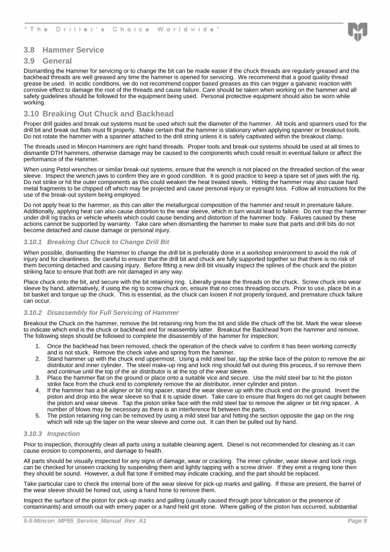
3.8 Hammer Service
3.9 General
Dismantling the Hammer for servicing or to change the bit can be made easier if the chuck threads are regularly greased and the backhead threads are well greased any time the hammer is opened for servicing. We recommend that a good quality thread grease be used. In acidic conditions, we do not recommend copper based greases as this can trigger a galvanic reaction with corrosive effect to damage the root of the threads and cause failure. Care should be taken when working on the hammer and all safety guidelines should be followed for the equipment being used. Personal protective equipment should also be worn while working.
3.10 Breaking Out Chuck and Backhead
Proper drill guides and break out systems must be used which suit the diameter of the hammer. All tools and spanners used for the drill bit and break out flats must fit properly. Make certain that the hammer is stationary when applying spanner or breakout tools. Do not rotate the hammer with a spanner attached to the drill string unless it is safely captivated within the breakout clamp.
The threads used in Mincon Hammers are right hand threads. Proper tools and break-out systems should be used at all times to dismantle DTH hammers, otherwise damage may be caused to the components which could result in eventual failure or affect the performance of the Hammer.
When using Petol wrenches or similar break-out systems, ensure that the wrench is not placed on the threaded section of the wear sleeve. Inspect the wrench jaws to confirm they are in good condition. It is good practice to keep a spare set of jaws with the rig. Do not strike or hit the outer components as this could weaken the heat treated steels. Hitting the hammer may also cause hard metal fragments to be chipped off which may be projected and cause personal injury or eyesight loss. Follow all instructions for the use of the break-out system being employed.
Do not apply heat to the hammer, as this can alter the metallurgical composition of the hammer and result in premature failure. Additionally, applying heat can also cause distortion to the wear sleeve, which in turn would lead to failure. Do not trap the hammer under drill rig tracks or vehicle wheels which could cause bending and distortion of the hammer body. Failures caused by these actions cannot be supported by warranty. Take care when dismantling the hammer to make sure that parts and drill bits do not become detached and cause damage or personal injury.
3.10.1 Breaking Out Chuck to Change Drill Bit
When possible, dismantling the Hammer to change the drill bit is preferably done in a workshop environment to avoid the risk of injury and for cleanliness. Be careful to ensure that the drill bit and chuck are fully supported together so that there is no risk of them becoming detached and causing injury. Before fitting a new drill bit visually inspect the splines of the chuck and the piston striking face to ensure that both are not damaged in any way.
Place chuck onto the bit, and secure with the bit retaining ring. Liberally grease the threads on the chuck. Screw chuck into wear sleeve by hand, alternatively, if using the rig to screw chuck on, ensure that no cross threading occurs. Prior to use, place bit in a bit basket and torque up the chuck. This is essential, as the chuck can loosen if not properly torqued, and premature chuck failure can occur.
3.10.2 Disassembly for Full Servicing of Hammer
Breakout the Chuck on the hammer, remove the bit retaining ring from the bit and slide the chuck off the bit. Mark the wear sleeve to indicate which end is the chuck or backhead end for reassembly latter. Breakout the Backhead from the hammer and remove. The following steps should be followed to complete the disassembly of the hammer for inspection:
1. Once the backhead has been removed, check the operation of the check valve to confirm it has been working correctly and is not stuck. Remove the check valve and spring from the hammer.
2. Stand hammer up with the chuck end uppermost. Using a mild steel bar, tap the strike face of the piston to remove the air distributor and inner cylinder. The steel make-up ring and lock ring should fall out during this process, if so remove them and continue until the top of the air distributor is at the top of the wear sleeve.
3. Place the hammer flat on the ground or place onto a suitable vice and secure. Use the mild steel bar to hit the piston strike face from the chuck end to completely remove the air distributor, inner cylinder and piston.
4. If the hammer has a bit aligner or bit ring spacer, stand the wear sleeve up with the chuck end on the ground. Invert the piston and drop into the wear sleeve so that it is upside down. Take care to ensure that fingers do not get caught between the piston and wear sleeve. Tap the piston strike face with the mild steel bar to remove the aligner or bit ring spacer. A number of blows may be necessary as there is an interference fit between the parts.
5. The piston retaining ring can be removed by using a mild steel bar and hitting the section opposite the gap on the ring which will ride up the taper on the wear sleeve and come out. It can then be pulled out by hand.
3.10.3 Inspection
Prior to inspection, thoroughly clean all parts using a suitable cleaning agent. Diesel is not recommended for cleaning as it can cause erosion to components, and damage to health.
All parts should be visually inspected for any signs of damage, wear or cracking. The inner cylinder, wear sleeve and lock rings can be checked for unseen cracking by suspending them and lightly tapping with a screw driver. If they emit a ringing tone then they should be sound. However, a dull flat tone if emitted may indicate cracking, and the part should be replaced.
Take particular care to check the internal bore of the wear sleeve for pick-up marks and galling. If these are present, the barrel of the wear sleeve should be honed out, using a hand hone to remove them.
Inspect the surface of the piston for pick-up marks and galling (usually caused through poor lubrication or the presence of contaminants) and smooth out with emery paper or a hand held grit stone. Where galling of the piston has occurred, substantial

5-5-Mincon_MP55_Service_Manual_Rev_A1 Page 10
heat has been generated and quite often, micro cracking has occurred on the piston. In these cases, the piston should be replaced if there is evidence of such cracking. Check the strike face of the piston for cracking or damage. If the piston has strike face damage, the face can be turned on a lathe to remove this up to 1/16” (1.5mm).
Inspect the threads of the chuck and backhead paying close attention to the locking side of the threads. The locking side of the chuck and backhead threads is the side facing away from the top of the wear sleeve. Look for signs of galling which would indicate that the chuck or backhead is coming loose during drilling and there is friction in the threads. Any galling can lead to the failure of the chuck, backhead and/or wear sleeve.
3.10.4 Checking Wear Limits
The performance of the hammer is dependent on the amount of wear the critical components have. These should be measured and recorded in the Service log in the appendix. The service log gives the location of where measurements should be taken. Depending on how many parts need to be replaced, it may be economical to replace the hammer all together.
IF the hammer’s wear sleeve is reversible and the reverse wear limit has been reached on the outer diameter at the chuck end of the wear sleeve, the hammer can be reassembled with the backhead end becoming the chuck end. Additionally if the internal running surface in the wear sleeve for the piston is excessive, the wear sleeve can be reversed.
3.10.5 Reassembly
The hammer can be reassembled in the following manner, referring to the exploded view of the hammer in the appendix. Ensure all components are liberally coated with good quality rock drill oil and threads with thread grease. Replace all O Rings.
1. Identify which end will be the chuck end, fit the piston retaining ring with open end facing into the hammer perpendicular to the recess it sits in. Use a small hammer to drive the ring down over the threads. When the ring is close, use the handle of the hammer to hit the ring sideways and seat into the recess.
2. IF the hammer has an aligner or bit ring spacer, push it in as far as it will go by hand making sure that it is oriented in the correct way.
3. Using a steel dolly that fits into the wear sleeve and over the aligner, hit the aligner into place with a sledgehammer. 4. Place the bit retaining Ring into the hammer. 5. Liberally grease the threads on the chuck and screw in fully. If the chuck does not close up fully, the aligner or bit ring
spacer is not in all the way. 6. Place the three piece seating ring on the inner cylinder and secure in place with the seating ring O Ring. 7. Stand the piston upright with the strike face down. Place the inner cylinder over the piston and gently let it slide down as
far as it can go. Insert The Air distributor into the inner cylinder at the seating ring end and using a soft headed mallet, tap it into place so that it seats up against the top of the inner cylinder. The piston will act as a guide to ensure that the air distributor remains correctly aligned.
8. Turn wear sleeve over with the chuck on the floor, and drop the piston in with the strike face in first. Again ensure that fingers do not get caught between the wear sleeve and the piston.
9. Place the inner cylinder assembly into the wear sleeve, and tap down with a soft headed mallet. When beginning to hit the assembly, ensure that it goes in square. Using a steel dolly, on top of the air distributor and inside the wear sleeve, drive the assembly into place with a sledgehammer.
10. Drop the lock ring into place and then the steel make up ring on top of this. 11. Insert the spring and check valve in place and finally screw the backhead in place. With the backhead in place, there
should be a small gap between the backhead and the wear sleeve. This gap should be between 0.015” and 0.030”, and can be measured using a feeler gauge. If the gap is less than the minimum, then the lock ring will need to be replaced.
12. Protect the hammer as earlier described by internal lubrication.

5-5-Mincon_MP55_Service_Manual_Rev_A1 Page 11
4. Trouble Shooting
Problem Possible cause Remedy
Low penetration and high pressure.
Chuck shoulder length worn too much.
Measure chuck shoulder length against discard length and discard if necessary as air is restricted on the upstroke of the piston.
Contamination in hammer. Open hammer and clean the obstruction.
Too much water injection. Reduce level of water in flow.
Rough or erratic operation.
Too much feed pressure. Set the feed pressure until the rotation starts to bind. Then back off the feed pressure until the rotation runs smoothly.
Shoulder length of the chuck has worn too much.
Measure the chuck shoulder against the discard length and discard if necessary as air is restricted to the upstroke of the drill.
Rotation speed too slow. Drill bit peripheral rotation speed of 12 – 15” per second (300-380mm). Place chalk mark on drill rod and check the advance revolution. If greater than ½” (12mm) per revolution increase rotation until the advance per revolution is a maximum of between 3/8” – ½” (10-12mm).
Worn bit bearing (some models only).
Replace bit bearing if outside discard limit.
Too much water injection. Reduce level of water injection.
Low penetration / Low pressure.
Worn drill clearances. Inspect piston, inner cylinder, wear sleeve, air distributor probe and bearing against discard measurements as outlined in Hammer Service Log 5.2 and discard as necessary.
Lack of oil. Ensure there is an oil film coming from bit spline and bit parts. (Place cardboard under bit to check).
Drill running off bottom.
Worn piston. Measure the large end of the piston for wear. If air leaks past this area it can cause the piston to cycle when off bottom.
Too much water injection. Reduce water injection flow.
Chuck I/D is worn. Replace chuck.
Aligner I/D is worn. Replace aligner.
PART FAILURE
Problem Possible cause Remedy
Cracked wear sleeve
Abuse of wear sleeve Avoid welding, heating or torque wrenching in the wrong place.
Worn wear sleeve Casing has worn beyond the discard point. Measure casing O/D approx. 3” from chuck end and backhead end and replace if necessary
Corrosion Ensure a pH neutral water, well filtered and free from contaminants is used in the drill. Corrosion usually accelerates from the threaded area or any undercut area. Coat with corrosion protector if there is any danger of corrosion
Cracked backhead body
Bogged Drill requiring lots of fighting to recover the drill
If such danger is imminent use a dig out sub
Piston cracked through large diameter
Lack of lubrication causes micro-cracks leading to breakage
Check lubricator and ensure oil film on the bit splines and slow holes
Drill badly bogged which can cause wear sleeve to distort (causing functional heat and cracks)
Flood tool with water when bogged
Feeding hard through voids on broken ground can cause wear sleeve to distort causing heat and cracks
Use light feed and ensure the hole is kept clean and consolidated. Use foam or mud if necessary
Using wrench over wrong area causes wear sleeve to distort
Use wrench only in the area above the wear sleeve threads.
Piston strike end breaking.
Not enough down-force Increase feed until rotation binds and pressure pulses and then back off until the rotation and pressure becomes smooth
Contamination from excess water injection causes pitting in the piston face and external failure.
Avoid excessive water. Use only pH neutral water. Use only filtered water, free from contamination.

5-5-Mincon_MP55_Service_Manual_Rev_A1 Page 12
5. Appendix
5.1 DTH Hammer exploded view and Parts List and Technical Data
Item # Part Number Description
MBX501AS03 Mincon MP55 (3 1/2" A.P.I. Reg. Pin)
1 MBX501BH02 Backhead (3 1/2" A.P.I. Reg. Pin)
2 MB506CH01 Choke Blank
3 MB502CV01 Check Valve
4 MB503SP01 Spring
5 MB504SM01 Steel Make-Up Ring
6 MB505LR01 Lock Ring
7 MB507DR01 Air Distributor
8 MB521OR01 O Ring
9 MB523OR01 O Ring
10 MB509SR01 Seating Ring
11 MB508IC02 Inner Cylinder
12 MB510PN04 Piston
13 MBX511WS03 Wear Sleeve
14 MB511PR01 Piston Retaining Ring
15 MB517BB01 Aligner
16 MD621OR01 O Ring
17 MB513BR03 Bit Retaining Ring
18 MB522OR01 O Ring
19 MBX514CK04 Chuck (QL50)
20 MB526SK01 Service Kit
MB526SK01 Service Kit
2 MB506CH01 Choke Blank
MB506CH02 Choke 1/8” (3.2mm)
MB506CH03 Choke 3/16” (4.8mm)
4 MB503SP01 Spring
MB525OK01 O Ring Kit
MB525OK01 O Ring Kit
8 MB521OR01 O Ring
9 MB523OR01 O Ring
16 MD621OR01 O Ring
18 MB522OR01 O Ring
Specifications Metric Imperial
Hammer Outside Diameter 124mm 4.88"
Hammer Length (Less Bit, Backhead Shoulder to Chuck) 993mm 39.1"
Backhead Spanner Flat Size 89mm 3.5”
Drill Bit Shank Type QL50
Minimum Bit Size 140mm 5.5"
Hammer Weight (Less Bit) 67.3Kgs 148Lbs
Drill Bit Weight (146mm/5 3/4”) 17.7Kgs 39Lbs
Piston Weight 15.0Kgs 33.6Lbs
Backhead Stand Off 0.75mm 0.030”
Make up Torque 5085-6780 NM 3750-5000 FT Lbs
Wear Sleeve Reverse Limit 116.1mm 4.570”
Wear Sleeve Discard Limit 111.8mm 4.400”
Recommended Minimum Air Package 283 l/s @ 17.2 Bar 600 cfm @ 250 psi
5-5-Mincon_MP55_Service_Manual_Rev_A1 Page 13
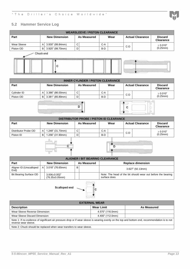
5.2 Hammer Service Log
WEARSLEEVE / PISTON CLEARANCE
Part New Dimension As Measured Wear Actual Clearance Discard Clearance
Wear Sleeve A 3.930” (99.84mm) C C-A C-D
0.010” (0.25mm) Piston OD B 3.925” (99.70mm) D B-D
INNER CYLINDER / PISTON CLEARANCE
Part New Dimension As Measured Wear Actual Clearance Discard Clearance
Cylinder ID A 3.386” (86.00mm) C C-A C-D
0.010” (0.25mm) Piston OD B 3.381” (85.89mm) D B-D
DISTRIBUTOR PROBE / PISTON ID CLEARANCE
Part New Dimension As Measured Wear Actual Clearance Discard Clearance
Distributor Probe OD A 1.248” (31.70mm) C C-A C-D
0.010” (0.25mm) Piston ID B 1.256” (31.90mm) D B-D
ALIGNER / BIT BEARING CLEARANCE
Part New Dimension As Measured Replace dimension
Aligner ID (Unscalloped End)
A 3.018” (76.65mm) B 3.627” (92.13mm)
Bit Bearing Surface OD 3.0060.002” (76.35±0.05mm)
Note: The head of the bit should wear out before the bearing surface does
EXTERNAL WEAR
Description Wear Limit As Measured
Wear Sleeve Reverse Dimension: 4.570” (116.0mm)
Wear Sleeve Discard Dimension: 4.400” (112.0mm)
Note 1: If no evidence of significant air pressure drop or if wear sleeve is wearing evenly on the top and bottom end, recommendation is to not reverse wear sleeve.
Note 2: Chuck should be replaced when wear transfers to wear sleeve.

5-5-Mincon_MP55_Service_Manual_Rev_A1 Page 14
6. Warranty
Mincon DTH HAMMERS
Warranty, January 2016
Mincon warrants that the Mincon DTH Hammers and spare parts therefore, manufactured by Mincon and delivered to the initial user to be free of defects in materials or workmanship for a period of 3 months after initial operation or 6 months from the date of shipment to the initial user, whichever occurs first. Mincon may elect to repair the defective part or issue full or partial credit towards the purchase of a new part. The extent of credit issued will be determined on a pro-rata basis bearing in mind the service life of the defective part against the normal service life of that part. The part will be replaced or repaired without charge to the initial user at the place of business of an authorized Mincon distributor during normal working hours. The user must present proof of purchase at the time of exercising the warranty.
The warranty applies only to failures resulting from defects in the material or workmanship and does not apply to failures occurring as a result of abuse, misuse, corrosion, erosion, negligent repairs and normal wear and tear. Failure to follow recommended operating and maintenance procedures which result in component failure will not be considered for warranty.
This warranty is in lieu of all other warranties, other than title, expressed or implied.
Limitation of Liability
Mincon will not accept any remedies to the user other than those set out under the provisions of warranty above. The total liability of Mincon or its distributors with respect to the sale of DTH Hammers or spare parts therefor, whether based on contract, negligence, warranty, indemnity or otherwise shall not exceed the purchase price of the product upon which such liability is based. Mincon and its distributors shall in no event be liable to any party relating to this sale for any consequential, indirect, special or punitive damages arising out of this sale or any breach thereof, or any defects in or failure of or malfunction of the Mincon DTH Hammer or spare parts.
Warranty will be voided where:
There is evidence of damage resulting from insufficient or incorrect lubrication.
There is evidence of misuse through the application of heat, welding or of being struck.
There is evidence of distortion or bending however caused.
There is damage caused as a result of using incorrect servicing tools or procedures.
If it is evident that the hammer or its components have achieved a reasonable proportion of their anticipated life.