Embed Size (px)
Citation preview

INDIANA DEPARTMENT OF TRANSPORTATION—2013 DESIGN MANUAL
CHAPTER 77
Traffic Signals
Design Memorandum
Revision Date
Sections Affected
13-06 Mar. 2013 77-5.05 13-07 Mar. 2013 77-4.05 14-01 Feb. 2014 Ch. 75, 76, 77, 78 superseded by Ch. 502
NOTE: This chapter is currently being re-written and its content will be included in Chapter 502 in the future.

Page 2 2013 Indiana Design Manual, Ch. 77
TABLE OF CONTENTS
LIST OF FIGURES......................................................................................................................... 5
77-1.0 GENERAL .......................................................................................................................... 7
77-1.01 MUTCD Context .......................................................................................................... 7
77-1.02 References ..................................................................................................................... 7
77-1.03 Official Action .............................................................................................................. 8
77-1.04 Project and Plan Development ...................................................................................... 8
77-1.05 Definitions .................................................................................................................... 8
77-2.0 PRELIMINARY DESIGN ACTIVITIES ........................................................................ 11
77-2.01 Signal-Study Request .................................................................................................. 11
77-2.02 Signal Warrants .......................................................................................................... 12
77-2.03 Warrant Analysis ........................................................................................................ 12
77-2.04 Responsibilities ........................................................................................................... 13
77-3.0 FLASHER OR FLASHING BEACON ............................................................................ 14
77-3.01 Guidelines for Hazard-Identification Beacon ............................................................. 14
77-3.02 Speed-Limit-Sign Beacon ........................................................................................... 14
77-3.03 Intersection-Control Beacon ....................................................................................... 14
77-3.04 “Stop” Sign Beacon .................................................................................................... 15
77-3.05 General Beacon Design .............................................................................................. 16
77-4.0 TRAFFIC-SIGNAL EQUIPMENT .................................................................................. 17
77-4.01 Traffic-Signal Controller ............................................................................................ 17
77-4.01(01) Pretimed Operation Mode ................................................................................ 17
77-4.01(02) Semi-Actuated Operation Mode....................................................................... 18
77-4.01(03) Fully-Actuated Operation Mode ...................................................................... 18
77-4.01(04) Pedestrian Feature ............................................................................................ 19
77-4.01(05) Enhanced Modes of Operation ......................................................................... 20
77-4.01(06) Controller-Design Concepts ............................................................................. 20
77-4.01(07) Associated Controller Equipment .................................................................... 21
77-4.01(08) Malfunction Management Unit (MMU) .......................................................... 21
77-4.01(09) Controller Cabinet ............................................................................................ 21
77-4.01(10) Preemption ....................................................................................................... 22
77-4.02 Detector ....................................................................................................................... 24
77-4.02(01) Operation .......................................................................................................... 24
77-4.02(02) Inductive Loop Detector................................................................................... 26
77-4.02(03) Other Detector Types [Rev. May 2011] ........................................................... 27
77-4.02(04) Decision-Making Criteria for Use of Detection System Other than Inductive
Loops [Added Jan. 2011] ............................................................................................. 28

2013 Indiana Design Manual, Ch. 77 Page 3
77-4.02(05) Pedestrian Detector .......................................................................................... 29
77-4.02(06) Bicycle Detector ............................................................................................... 29
77-4.03 Signal Mounting [Rev. Oct. 2011] ............................................................................. 29
77-4.04 Signal Cantilever Structure Design Criteria [Inserted Oct. 2011] .............................. 30
77-4.04(01) Selection Guidance ........................................................................................... 30
77-4.04(02) Design Criteria ................................................................................................. 31
77-4.05 Signal Display [Rev. Mar. 2013] ................................................................................ 31
77-5.0 TRAFFIC-SIGNAL DESIGN .......................................................................................... 33
77-5.01 Design Criteria ............................................................................................................ 33
77-5.01(01) Signal Displays ................................................................................................. 34
77-5.01(02) Visibility Requirements ................................................................................... 35
77-5.02 Placement of Signal Equipment .................................................................................. 36
77-5.03 Pedestrian Signal ........................................................................................................ 38
77-5.04 Pavement Marking and Signing .................................................................................. 38
77-5.05 Electrical System [Rev. Mar. 2013] ........................................................................... 39
77-5.06 Phasing ........................................................................................................................ 41
77-5.06(01) Phasing Types .................................................................................................. 42
77-5.06(02) Phase Numbering and Conventions ................................................................. 44
77-5.06(03) Phase Assignments ........................................................................................... 45
77-5.06(04) Examples .......................................................................................................... 46
77-5.06(05) Left-Turn Phase ................................................................................................ 46
77-5.06(06) Assignment of Right of Way ............................................................................ 47
77-5.07 Pretimed Traffic-Signal Timing ................................................................................. 47
77-5.07(01) Guidelines for Signal Timing ........................................................................... 47
77-5.07(02) Cycle Determination ........................................................................................ 49
77-5.08 Actuated-Controller Setting ......................................................................................... 51
77-5.08(01) Basic-Actuated Controller ................................................................................ 52
77-5.08(02) Advanced-Design Actuated Controller ............................................................ 54
77-5.08(03) Actuated Controller with Large Detection Area .............................................. 56
77-5.09 Vehicle-Counting Loop .............................................................................................. 57
77-5.09(01) Considerations for Counting-Loop Use ........................................................... 57
77-5.09(02) Preferred Counting-Loop Configurations ........................................................ 58
77-5.09(03) Traffic-Signal Loop Tagging Table [Added June 2012] .................................. 59
77-5.10 Computer Software ..................................................................................................... 61
77-5.11 Maintenance Considerations ....................................................................................... 62
77-6.0 SIGNAL-SYSTEM DESIGN ........................................................................................... 63
77-6.01 System-Timing Parameters ......................................................................................... 63
77-6.02 System Types .............................................................................................................. 64
77-6.02(01) Interconnected Time-of-Day System ............................................................... 64
77-6.02(02) Time-Based Coordinated Time-of-Day System ............................................... 64
Page 4 2013 Indiana Design Manual, Ch. 77
77-6.02(03) Traffic-Responsive Arterial System ................................................................. 65
77-6.02(04) Distributed-Master, or Closed-Loop, System .................................................. 65
77-6.02(05) Central Computer, or Interval-Command System............................................ 66
77-6.02(06) Central Database-Driven Control System ........................................................ 66
77-6.03 Communications Techniques [Rev. June 2012] ......................................................... 66
FIGURES ...................................................................................................................................... 68

2013 Indiana Design Manual, Ch. 77 Page 5
LIST OF FIGURES
Figure Title
77-4A Sequence of Phases, 8-Phase Dual-Ring Controller Unit
77-4B Typical Wireless-Vehicle-Detection System
77-4C Typical Hybrid Wireless-Vehicle-Detection System
77-4D Post-Mounted Signal, Advantages and Disadvantages
77-4E Cable-Span-Mounted Signal, Advantages and Disadvantages
77-4F Cantilever-, or Mast-Arm-, Mounted Signal, Advantages and Disadvantages
77-4G Combination Signal-Luminaire Pole
77-4H Cable-Span-Mounted Signal Configuration
77-4 I Signal-Cantilever-Structure Foundation-Type Determination
77-4J Area and Weight of Device to be Mounted on Signal Cantilever
77-5A Signal Placement, Offsetting Intersection
77-5B Signal Placement, Urban Area, No Left-Turn Lane
77-5C Signal Placement, Urban Area, Left-Turn Lane
77-5D Signal Placement, Left-Turn Lane, Unprotected Left-Turn Movement
77-5E Signal Placement, Left-Turn Lane, Protected Left-Turn Phase
77-5F Signal Placement, Protected Left-Turn Phase or Permissible Left-Turn Movement
77-5G Signal Placement, Multiple-Lanes Approach with Left-Turn Lane
77-5H Signal Placement, Multiple-Lanes Approach with Left- and Right-Turn Lanes
77-5 I Signal Placement, Multiple-Lanes Approach, Z-Span with Supplemental Far-Side
Heads
77-5J Signal Placement, Rural One-Lane Approach with Truck Obstruction
77-5K Signal Placement, Rural One-Lane Approach with Obstructed Sight Distance, Near-
Side Signal Indication, Advance Warning Signs and Flashers
77-5L Minimum Visibility Distance
77-5M Vision Cone
77-5N Two-Phase Operation
77-5 O Three-Phase Operation, Separate Split Phases for Major Street
77-5P Three-Phase Operation, Separate Split Phases for Minor Street
77-5Q Three-Phase Operation, Separate Left-Turn Phase for Major Street
77-5R Three-Phase Operation, Exclusive Pedestrian Phase
77-5S T Intersection, Single-Lane Approaches
77-5T T Intersection, Multiple-Lanes Approaches
77-5U 8-Phase Operation, Dual-Ring
77-5V Typical Phase-Numbering Schemes
77-5W Typical Phase Diagrams
77-5X Comparison of Left-Turn-Phase Alternatives
77-5Y Indecision Zone

Page 6 2013 Indiana Design Manual, Ch. 77
77-5 Z Detection Setback Distance (ft)
77-5AA Counting-Loop Selection, General
77-5BB Counting-Loop Selection, Frontage Road or Parking Lot
77-5CC Counting-Loop Selection, Advance Counting Loops
77-5DD Loop Tagging Table
77-6A Radio Site Survey Report

2013 Indiana Design Manual, Ch. 77 Page 7
CHAPTER 77
TRAFFIC SIGNALS
77-1.0 GENERAL
The design of traffic signals is one of the most dynamic fields of traffic engineering. Although
this Chapter will address most traffic-signal-design issues, it is impractical to provide a complete
traffic-signal-design guide. For detailed design information, the references listed in Section 77-
1.02 should be reviewed. The intent of this Chapter is to provide the user with an overview of the
traffic-signal-design issues and to provide INDOT’s applicable positions, policies, and
procedures.
77-1.01 MUTCD Context
Throughout the Manual on Uniform Traffic Control Devices (MUTCD), the words shall, should,
and may are used to describe the appropriate application for traffic-control devices. Section 75-
1.0 provides the Department’s position on these qualifying words.
77-1.02 References
For additional information on traffic-signal design, see the publications as follows:
Equipment and Material Standards of the Institute of Transportation Engineers, ITE;
Highway Capacity Manual, Transportation Research Board (TRB);
ITE Journal (published monthly), ITE;
Manual of Traffic Signal Design, ITE;
Manual on Uniform Traffic Control Devices, FHWA;
Manual on Uniform Traffic Control Devices, Indiana;
manufacturers’ literature;
National, State and local electrical codes;
Standard Drawings, INDOT;
Standard Specifications, INDOT;
Traffic Control Devices Handbook, FHWA;
Traffic Control Systems, National Electrical Manufacturers Association (NEMA);
Traffic Detector Handbook, FHWA;
Traffic Engineering Handbook, ITE; and

Page 8 2013 Indiana Design Manual, Ch. 77
Traffic Signal Installation and Maintenance Manual, ITE.
77-1.03 Official Action
Where a new traffic signal is installed or an existing traffic signal is removed, an Official Action
is required. For a State-controlled highway, the designer must obtain an approval for the
proposed change from the Highway Management Deputy Commissioner. The request for an
Official Action should be sent to the appropriate district traffic engineer before implementation of
the proposed change. If the district traffic engineer concurs with the request to install or
remove a traffic signal, an Official Action will be drafted and sent to the district Deputy
Commissioner for approval of the new traffic signal or existing traffic signal removal. For a
locally-controlled facility, approval must be obtained from the appropriate jurisdiction before
starting design. An Official Action may also be required where other regulatory-controlled items are
revised in association with a traffic signal, e.g., “No Turn On Red” sign.
77-1.04 Project and Plan Development
Chapter 2 provides the Department’s procedures for preparing a typical traffic-signal project.
Chapter 2 also indicates the responsible unit for each activity. Part II provides the Department’s
criteria for developing a set of plans, which are also applicable to a traffic-signal project. Part II
also includes information on scale sizes, drafting requirements, plan-sheet requirements,
quantities, specifications, etc.
77-1.05 Definitions
The following are definitions for the more commonly used terms in traffic-signal design.
1. Controller Assembly. A complete electrical device mounted in a cabinet for controlling
the operation of a highway traffic signal.
2. Cycle. For a pretimed controller, it is the period of time used to display a complete
sequence of signal indications. For an actuated controller, a complete cycle is
dependent on the presence of calls on all phases.
3. Cycle Length. The time required for one complete sequence of signal indications.
4. Delay. A measure of the time that has elapsed between the stimulus and the response.
2013 Indiana Design Manual, Ch. 77 Page 9
a. Traffic Delay. The time lost while traffic is impeded by some element over which
the motorist has no control.
b. Fixed Delay. The delay caused by traffic controls.
c. Operational Delay. The delay caused by interference between components of
traffic.
5. Demand. The need for service, i.e., the number of vehicles desiring to use a given
segment of roadway during a specified unit of time.
6. Detection. The process used to identify the presence or passage of a vehicle at a specific
point, or to identify the presence of one or more vehicles in a specific area.
7. Detector. A device for indicating the presence or passage of vehicles or pedestrians, e.g.,
loop detector, microloop detector, push button.
8. Indecision Zone. A range of distances from the intersection where a driver can react
unpredictably to a yellow signal indication, i.e., deciding to stop or to continue through
the intersection.
9. Interconnected. The situation in which traffic signals, signs, or computers are designed
to work in coordination with each other.
10. Interval. The part of a signal cycle during which signal indications do not change.
11. Interval Sequence. The order of appearance of signal indications during
successive intervals of a signal cycle.
12. Interval Timing. The passage of time that occurs during an interval.
13. LED. A light-emitting diode used to illuminate signal indications. It is the only
illumination device that complies with the U.S. Energy Policy Act of 2005.
14. Loop Amplifier. A device capable of sensing a change in the inductance of a loop
detector.

Page 10 2013 Indiana Design Manual, Ch. 77
15. Loop Detector. A device embedded in the roadway that senses the presence of a vehicle
by changes in magnetic lines of flux that are generated around the loop, thereby increasing
the inductance so that a change is detected as monitored by the loop amplifier.
16. Offset. The time difference or interval in seconds between the start of the green
indication at one intersection as related to the start of the green interval at another
intersection or from a system time base. It may also be expressed in percent of cycle
length.
17. Pattern. A unique set of timing parameters (cycle length, split, and offset) associated with
each signalized intersection within a predefined group of intersections.
18. Phase. A part of the traffic-signal-cycle length allocated to a combination of traffic or
pedestrian movements receiving the right of way simultaneously during one or more
intervals.
19. Phase Overlap. A phase that operates concurrently with one or more other phases.
20. Phase Sequence. The order in which a controller cycles through all phases.
21. Point Detection. The detection of a vehicle as it passes a point on a roadway.
22. Preemption. Interruption or alteration of the normal signal sequence at an intersection in
deference to a situation such as the passage of a train, bridge opening, or the granting of
the right of way to an emergency vehicle.
23. Presence Detection. The ability of a vehicular detector to sense that a vehicle, whether
moving or stopped, has appeared in its detection area.
24. Recall. An operational mode for an actuated intersection controller whereby a phase,
either vehicular or pedestrian, is displayed during each cycle whether the demand exists or
not.
25. Signal Coordination. The establishment of timed relationships between adjacent
traffic-control signals.
26. Signal Head. An arrangement of one or more signal lenses in one direction.
27. Signal Indication. The illumination of a signal lens or equivalent device.

2013 Indiana Design Manual, Ch. 77 Page 11
28. Split. A percentage of the cycle length allocated to each of the various phases in a signal
sequence.
29. Yield Point. The point at which the controller permits the existing phase to be terminated
to service a conflicting phase.
77-2.0 PRELIMINARY DESIGN ACTIVITIES
The district Office of Traffic is responsible for making the determination regarding the need for
a new or existing traffic signal. This determination is based on factors including traffic volumes,
accident history, schools, pedestrians, local needs, driver needs, construction costs, and maintenance
costs. The following provides information on the guidelines, policies, procedures, and factors
used by INDOT to make these determinations.
77-2.01 Signal-Study Request
A request for a new signal can be generated by FHWA, the district Office of Traffic, other
INDOT divisions, local officials, or developers or local citizens. Each request for a new traffic-
signal installation should be first forwarded to the appropriate district traffic engineer. If the
district traffic engineer determines that the request merits further investigation, he or she will then
begin coordinating the collection of the necessary traffic data.
For an in-house request, the district traffic engineer, possibly in conjunction with others, will
conduct the appropriate traffic studies to obtain accurate and up-to-date traffic data and
projections. For another type of request, the latest traffic data and projections should be
forwarded with the request. The data collector should refer to the MUTCD, which provides the
warrants for traffic signals, to determine the appropriate information required. For additional
information on the collection of traffic data, the ITE publication, Manual of Traffic Engineering
Studies, should be reviewed, or the Environmental Services Division should be contacted.
If it is determined that a traffic signal is warranted, the district traffic engineer, the District
Office of Design, the Division of Highway Design and Technical Support, or a consultant, will
prepare the design for the proposed traffic signal. The district traffic engineer will be responsible
for determining the traffic-signal timings. The local agency or consultant may sometimes be
responsible for determining the traffic-signal timings.
Page 12 2013 Indiana Design Manual, Ch. 77
77-2.02 Signal Warrants
Each new traffic signal should satisfy one or more of the primary warrants listed below. The
MUTCD traffic signal warrants are as follows:
Warrant 1, Eight-Hour Vehicular Volume
Warrant 2, Four-Hour Vehicular Volume
Warrant 3, Peak-Hour Volume
Warrant 4, Pedestrian Volume
Warrant 5, School Crossing
Warrant 6, Coordinated Signal System
Warrant 7, Crash Experience
Warrant 8, Roadway Network
The MUTCD provides the criteria and procedures that should be used to determine if the warrant
is satisfied.
77-2.03 Warrant Analysis
Though traffic volume may be sufficiently high to satisfy one or more of the warrants, the
installation of a traffic signal may not always be the most prudent choice. In addition to the
MUTCD warrants, the following information should be considered.
1. Minimums. The MUTCD warrants are considerations for determining the need for a
traffic signal. The intent of the MUTCD thresholds is to establish a minimum boundary
below which a traffic signal should not be installed. The satisfaction of one or more
traffic-signal warrants should not in itself require the installation of a traffic control signal.
2. Benefits. The benefits of the traffic signal should outweigh its disadvantages. A
traffic signal will cause delays for at least one leg of the intersection while serving the
needs of another. A traffic signal should be installed only if the safety or the operations of the
intersection or system are improved.
3. Crash History. A traffic signal is often installed to reduce certain types of crashes, e.g.,
right-angle collision, pedestrian crossing. However, the installation of a traffic signal can
increase the number of rear-end collisions and can fail to reduce turning conflicts between
vehicles and pedestrians. Consideration should be given as to whether a change in crash
types and their severity will be an actual improvement for the intersection. Crash data for
the location should be available for at least the past three years. Consideration should be
2013 Indiana Design Manual, Ch. 77 Page 13
given to alternative solutions to the problem of crashes, e.g., no longer permitting
parking, using larger signs.
4. Geometrics. The geometric design of the intersection can affect the efficiency of the
traffic signal. A traffic-signal placed at a poorly-aligned intersection may increase driver
confusion and thereby reduce the overall efficiency of the intersection. If practical, the
intersection should be properly aligned and have sufficient space to adequately provide
turning lanes, through lanes, etc. Chapter 46 provides information on the geometric design
of an at-grade intersection.
5. System Analysis. The control of traffic should be conceived and implemented on a
systematic system/route/intersection basis. This may sometimes result in compromises at
an individual intersection in order to optimize the overall system. The presence of a
traffic signal also may encourage drivers to use local unsignalized facilities so as to
bypass the signal. Intersection controls should favor the major streets to move traffic
through an area.
6. Location. The intersection should be considered relative to the context of the land use,
density of development (e.g., urban, suburban, rural), and the potential for future
development. The location of the intersection should be considered within the context of
the transportation system such as isolated locations, interrelated operations, and functional
classification. An isolated location is an intersection where the distance to the nearest
signalized intersection or potential future signalized intersection is greater than 0.5 mi.
7. Existing Signal. For a project that includes at least one existing signal, it will rarely be
required to conduct a detailed study to determine if the existing signal should be
removed, retained, or upgraded. This determination will be made during the preliminary
field review. If it is determined during the field review that a detailed analysis may be
required, the designer should consult with the district Office of Traffic to determine if
there may be a need to remove the traffic signal.
77-2.04 Responsibilities
It is the Department’s policy to fund the design and installation of a traffic signal only where the
intersection is on a State-maintained highway, or where a freeway exit or entrance ramp
intersects with a local facility. For a State highway intersecting a private drive or road, or a public
road where a high traffic volume is generated from a private source, the private entity will
typically be responsible for funding the design, installation, and energy costs of the new signal.

Page 14 2013 Indiana Design Manual, Ch. 77
Each traffic signal on a State highway is maintained by INDOT or through a contract agreement with
others. A local municipality, through a formal contract, will rarely assume responsibility for the
maintenance of a traffic signal on a State highway.
77-3.0 FLASHER OR FLASHING BEACON
77-3.01 Guidelines for Hazard-Identification Beacon
A hazard-identification beacon should only be used to supplement an appropriate warning or
regulatory sign or marker. Typical applications include the following:
1. identifying an obstruction in or immediately adjacent to the roadway;
2. as a supplement to an advance warning sign, e.g., school crossing; See MUTCD Part 7;
3. at a mid-block pedestrian crossing;
4. at an intersection where a warning device is required; or
5. as a supplement to a regulatory signs, excluding a “Stop,” “Yield,” or “Do Not Enter”
sign.
The need for a hazard-identification beacon will be determined as required for each site. The
following provide additional guidance for the use of a hazard-identification beacon.
77-3.02 Speed-Limit-Sign Beacon
Where applicable, a flashing beacon with an appropriate accompanying sign may be used to indicate
the time periods or conditions in which the speed limit shown is in effect.
A speed-limit-sign beacon consists of one or two circular yellow lenses, each having a minimum
visible diameter of 8 in. Where two lenses are used, they should be aligned vertically at the top
and bottom of the sign. If the sign is longer horizontally than vertically, the lenses may be aligned
horizontally. The beacons should flash alternately. If the speed limit is for a school zone, the
beacon indications may be positioned within the face of the sign.
77-3.03 Intersection-Control Beacon
This is intended for use at an intersection where traffic or physical conditions do not justify a
traffic signal, but where conditions indicate a hazard potential. The installation of this device
with yellow flashing for the preferential street and red flashing for the stop-condition street may be
warranted where two or more of the following conditions exist.
2013 Indiana Design Manual, Ch. 77 Page 15
1. Crash History. At an intersection with five or more reported crashes during a 12-
month period that have a predominance of crash types that may be corrected by
cautioning and stopping traffic.
2. Sight Distance. In conjunction with “Stop” signs where sight distance is limited or where
other physical or traffic conditions make it especially desirable to emphasize the need for
stopping on one street and for proceeding with caution on the other.
3. Traffic Volume. Where the minimum vehicular volume entering an urban intersection
from all directions averages 400 vehicles per hour for two 1-h periods of one day, and
where vehicular traffic entering the intersection from the minor-street approaches averages
at least 50 vehicles per hour for the same hour. For a rural area or a community with a
population of 500 or less, the traffic volume is 70 percent of the urban volume, i.e., 280
vehicles per hour and 35 vehicles per hour, respectively.
4. Speed. At an intersection where excessive speed prevails. This warrant should not be
considered where the 85th percentile speed is equal to or less than 40 mph.
5. School. At an intersection having at least 50 school children crossing the major
approaches as pedestrians, or where 10 school buses, each transporting one or more
children crossing, turning onto or turning from the major approaches per hour for any two
1-h periods of one day during regular school arrival and dismissal periods.
Where based on engineering judgment, a supplemental beacon may be used at a multi-way, stop-
controlled intersection. The intersection-control beacon should be red for all approaches. An
intersection-control beacon consists of one or more sections of a standard traffic-signal head, having
flashing, circular yellow or circular red indications in each face. Each intersection should have at
least two indications for each approach. Indications normally flash alternately, but may flash
simultaneously. Supplemental indications may be required on one or more approaches to provide
adequate visibility to approaching motorists.
77-3.04 “Stop” Sign Beacon
This beacon is used to draw attention to a “Stop” sign. The beacon uses one or two sections of a
standard traffic-signal head with a flashing, circular red indication in each section. The lenses
may be either 8 in. or 12 in. diameter. Where they are aligned horizontally they should flash
simultaneously. Where they are aligned vertically they should flash alternately. The bottom of the
housing for the beacon should be located 1 to 2 ft above the top of the “Stop” sign.

Page 16 2013 Indiana Design Manual, Ch. 77
77-3.05 General Beacon Design
A flashing-beacon unit and its mountings should satisfy the general design specifications for traffic-
control signals. These include the following.
1. Lens. Each signal-unit lens should have a visible diameter of at least 8 in. Red or
yellow lenses should satisfy the ITE Standard for Adjustable Face Vehicle Traffic
Control Signal Heads.
2. Sight Distance. While illuminated, the beacon should be visible to all drivers it faces
for a distance of 1200 ft under normal atmospheric conditions, unless otherwise physically
obstructed.
3. Flashing. The flashing contacts should be equipped with filters for suppression of radio
interference. Beacons should flash at a rate of at least 50 but not more than 60 flashes per
minute. The illumination period of each flash should be between one-half and two-
thirds of the total cycle. Where hazard identification beacons have more than one
section, they may flash alternately.
4. Hours of Operation. A hazard-identification beacon should be operated only during those
hours during which the hazard or regulation exists, e.g., school arrival and dismissal
periods; see MUTCD Part 7.
5. Lamp Dimming. If a 150-W lamp is used in a 12-in. dia. flashing yellow beacon and the
flashing causes excessive glare during night operation, an automatic dimming device may
be necessary to reduce the brilliance during night operations.
6. Traffic Signal. A flashing yellow beacon used with an advance traffic signal warning
sign may be interconnected with a traffic-signal controller.
7. Alignment. If used to supplement a warning or regulatory sign, individual flashing
beacon units should be horizontally or vertically aligned. The edge of the housing should not
be located closer than 1 ft outside of the nearest edge of the sign.
8. Location. The obstruction or other condition warranting the beacon will largely
govern the location of the beacon with respect to the roadway. If used alone and located
at the roadside, the bottom of the beacon unit should be at least 8 ft, but not more than

2013 Indiana Design Manual, Ch. 77 Page 17
16 ft above the pavement. If suspended over the roadway, the beacon clearance above the
pavement should be at least 17 ft, but not more than 19 ft.
77-4.0 TRAFFIC-SIGNAL EQUIPMENT
All traffic-signal equipment should satisfy the criteria set forth in the MUTCD, NEMA Traffic
Control Systems, INDOT Standard Drawings and INDOT Standard Specifications. The
following provides additional information regarding traffic-signal equipment. For an INDOT
location, the equipment choice should be made at the preliminary field inspection with the
approval of the designer and the district traffic engineer.
77-4.01 Traffic-Signal Controller
A traffic-signal controller is a microprocessor-based, menu-driven, fully-actuated device,
including internal coordinator and preemption, mounted in a cabinet for controlling the sequence
and phase duration of the traffic signal. Right of way is assigned by turning the green indication
on or off. A controller’s operation mode can be pretimed, semi-actuated, or fully-actuated. In the
pretimed mode, the controller operates according to pre-determined schedules. In the semi-
actuated and fully-actuated modes, the controller operates with variable vehicular and
pedestrian timing and phasing intervals which are dependent upon traffic demands. If there is
no demand for a phase, an actuated controller may omit that phase in the cycle. For example, if
there is not a demand for left turns, the left-turn phase will not be activated. The following
provides information on the modes of operation used by the Department. Section 77-5.0
describes the phasing and timing aspects of controllers. INDOT typically uses fully-actuated
operation for its new traffic signals.
77-4.01(01) Pretimed Operation Mode
In the pretimed mode, the controller can be programmed to provide several different timing
plans based on the time of day or day of week.
The pretimed mode is best suited where traffic volume and pattern are consistent from day-to-
day, e.g., downtown area, where variations in volume are predictable and where control timing
can be preset to accommodate variations throughout the day.
The primary advantage of the pretimed mode is the cost savings realized by not installing traffic-
detection equipment around the intersection. The primary disadvantages of the pretimed mode
Page 18 2013 Indiana Design Manual, Ch. 77
are the lack of flexibility in timings, the inefficiency of traffic movements where vehicle arrivals
are largely random, and the inability to automatically count traffic volume.
The pretimed mode should not be used where the posted speed limit on at least one approach is 40
mph or higher.
77-4.01(02) Semi-Actuated Operation Mode
The semi-actuated mode requires detection on one or more, but not all, approaches. Vehicular
detectors or pedestrian detectors are installed only for the minor approaches, the left turns on the
major approaches, and where traffic is light and sporadic. The through movements on the major
approaches are kept in the green phase until a vehicle on a minor approach, or a major
approach left turn, is detected. If there is a demand on a detected approach or movement, and
the minimum green time for the major approach has elapsed, the right of way will then be assigned
to the detected approach or movement. Controller timings are set to provide enough time to
clear two vehicles. Additional time is added for each new detection up to the predetermined
limit for the maximum green time. Once the detected approach demand has been satisfied, or
once the maximum green time has been reached, the right of way returns to the major approaches
and the cycle begins again.
The primary advantage of the semi-actuated mode is the reduced cost of installation because
detection is not needed on some approaches and more-efficient operations.
The semi-actuated mode should not be used where the posted speed limit of at least one approach
is 40 mph or higher due to the lack of indecision-zone protection. See Section 77-5.08 for further
discussion of the indecision-zone requirements.
77-4.01(03) Fully-Actuated Operation Mode
The fully-actuated mode requires detection devices for all approaches or movements at the
intersection. The green interval for each street or phase is determined on the basis of volume
demand. Continuous traffic on one street is not interrupted by an actuation demand from the
side street until a gap in the traffic appears or once the preset maximum green time has elapsed.
Once the minor approaches’ or movements’ demand has been satisfied, the right of way is
typically returned to the major approaches.

2013 Indiana Design Manual, Ch. 77 Page 19
The fully-actuated mode is the appropriate design choice for the conditions as follows:
1. the posted speed limit on at least one approach is 40 mph or higher;
2. an isolated location where the traffic volume on each approach is sporadic;
3. where a traffic signal is warranted for only short periods of the day; or
4. where turning movements are heavy only during specific time periods and are light the
remainder of the time.
The advantages of the fully-actuated mode are as follows:
1. it can efficiently control a high traffic volume;
2. it is very efficient at an isolated intersection;
3. it can handle varying traffic demands such as a complex intersection where one or more
movements are sporadic or subject to wide variations in traffic volume; and
4. it can count traffic volume for all detected movements.
The primary disadvantages of the fully-actuated mode are the additional costs associated with
installing and maintaining detection equipment on all of the approaches.
77-4.01(04) Pedestrian Feature
The pedestrian feature commonly works in conjunction with the signal controller. This feature
allows for the timing of the Walk and Don’t Walk cycles and can be actuated by pedestrian push
buttons. The use of an accessible pedestrian signal should be considered where visually-impaired
pedestrians use the crosswalks at a signalized intersection.
The advantages and disadvantages of the pedestrian feature are as follows:
1. Advantages.
a. It provides additional time for crossing pedestrians.
b. Where there is minimal pedestrian demand, disruption to the vehicular phases can
be minimized.
2. Disadvantages.
a. Where pedestrian push buttons are required, they must be located in a convenient,
accessible location.

Page 20 2013 Indiana Design Manual, Ch. 77
b. Pedestrian cycles concurrent with green time may marginally delay right-turning
vehicles.
c. They can significantly increase the required minimum green time on the minor
street if the major street is substantially wider than the minor street.
77-4.01(05) Enhanced Modes of Operation
Coordination is an enhanced mode which is used to provide progression through a system of two
or more signals. Coordination can be achieved with either a timed-based coordination (TBC)
system or a closed-loop system. A TBC system operates on an internal time clock which is used
to automatically select timing plans based upon the time of day and day of week. In a closed-loop
system, the signals are interconnected using cables or other communication mechanism.
Preemption is the modification of a signal’s normal operation to accommodate a special
occurrence, such as the approach of an emergency vehicle, the passage of a train through a nearby
grade crossing, priority passage of a transit vehicle, or the opening of a moveable bridge.
77-4.01(06) Controller-Design Concepts
As established by the National Electrical Manufacturers Association (NEMA), a controller has
standard functions and input/output formats, and uses microprocessing to provide the functions.
NEMA controllers are interchangeable between manufacturers, except where used in a
coordinated system. If changes or upgrades to the controller are desired, the controller unit
hardware is typically replaced.
INDOT uses the NEMA criteria for all of its traffic signal controllers. At a minimum, each
INDOT-maintained traffic controller must satisfy the INDOT Standard Specifications and
NEMA TS-2 criteria. Each controller is subject to approval per the requirements of the
Department’s Traffic Signal Control Bench Test Procedures. A list of all approved controller
equipment is provided in the Department’s approved-materials list, which can be obtained from
the INDOT website.
A NEMA controller is configured to operate as a dual-ring controller unless special
circumstances warrant the use of additional rings. Section 77-5.06 provides information on the
selection of phases for an intersection. Figure 77-4A illustrates the appropriate phasing
sequence for an 8-phase dual-ring controller. A multi-ring controller unit includes two or more
rings that are arranged to time in a preferred sequence and to allow concurrent timing of all rings,
subject to the restraint of a barrier. For the controller to advance beyond each barrier, a set of
2013 Indiana Design Manual, Ch. 77 Page 21
phases must cross the barrier line at the same time, i.e., no conflicting phases are displayed at
the same time).
77-4.01(07) Associated Controller Equipment
Each controller unit will require a TS-2 power supply, Buss Interface Unit (BIU), load switches,
and Malfunction Management Unit (MMU). Detection and communications devices may be
added to enhance operation of the controller, depending on the intersection. All associated
controller equipment must appear on the Department’s approved materials list.
77-4.01(08) Malfunction Management Unit (MMU)
With solid-state equipment, there is a potential for the display of erroneous indications, e.g., green
indications for conflicting movements. The MMU monitors the signal indications and, should
such an error occur, the MMU switches the control of the signal indications to the flashing mode.
77-4.01(09) Controller Cabinet
A controller cabinet is an enclosure designed to house the controller unit and its associated
equipment, providing for its security and environmental protection. Each controller cabinet must
satisfy the INDOT Standard Specifications. Section 77-5.02 provides roadside-safety
considerations for the placement of the cabinet. Foundation requirements for each cabinet type
are shown on the INDOT Standard Drawings. The following discusses the cabinet types used by
the Department.
1. Type G Cabinet. This is a pedestal-mounted or pole-mounted cabinet. The
Department no longer uses this cabinet due to its limited size. However, this cabinet type
may be used, if practical, for matching or upgrading existing local signals.
2. Type M Cabinet. This is a ground-mounted cabinet. This cabinet should be used where
space limitations or sight restrictions are a factor at the intersection.
3. Type P-1 Cabinet. This is a ground-mounted cabinet. This cabinet is the preferred
cabinet.
4. Type R-1 Cabinet. This is a taller version of the P-1 cabinet. It is used only where
equipment needs warrant the additional space.

Page 22 2013 Indiana Design Manual, Ch. 77
77-4.01(10) Preemption
Preemption-sequences details should be shown in the plans or described in the special provisions.
For information on preemption equipment, the manufacturer should be contacted. The following
describes situations where preemption is used.
1. Railroad Crossing. The purpose of the preemption is to clear vehicles from a railroad
crossing before the arrival of a train. Where a signalized intersection is within 200 ft of a
railroad grade crossing with active warning devices, preemption is required. If this
distance 200 to 600 ft, a queue analysis should be performed to determine if a highway-
traffic queue has the potential for extending across a nearby rail crossing. If the analysis
indicates that this potential exists, consideration should be given to interconnecting the
traffic signal with active warning devices at the railroad crossing. The MUTCD and the
FHWA Railroad-Highway Grade Crossing Handbook describe preemption strategies and
define the requirements for grade-crossing preemption.
Railroad-crossing preemption requires interconnection between the traffic-signal controller
and the grade-crossing signal equipment. The preemption routine at the traffic-signal
controller is initiated by the approach of a train, as detected by the railroad’s
controller, and starts with a transition from the current phase into the Clear Track Green
interval (CTG). The CTG interval is used to clear motorists who may be stopped between
the railroad-crossing stop line and the intersection. Subsequent signal displays include
only those that are not in conflict with the occupied grade crossing. Once the railroad
preemption call is cleared, after the train has passed, the traffic signal is returned to
normal operations. For a State route, this type of preemption requires an agreement
between the State and the railroad company.
Railroad-crossing preemption should be designed using either simultaneous or advance
preemption sufficient to provide for Right-of-Way Transfer Time (RTT), to transition into
the CTG interval. The CTG interval should be sufficient to clear the last vehicle in the queue
past the Minimum Track Clear Distance (MTCD), avoid vehicle-gate interaction, and
provide separation time as required.
The designer should consider best- and worst-case scenarios with regard to the signal phase
state and all known preemption traps, such as the advance, second-train, failed-circuit, and
vehicular-yellow preemption traps. The designer should consider pre-signals and queue-
cutter signals as options where an engineering study determines that the queue extends into
the track area.

2013 Indiana Design Manual, Ch. 77 Page 23
Other options to consider are blank-out signs for protected/permitted left turns, optically
programmable heads for pre-signals, and pavement markings and signage to prevent vehicles
from stopping on the tracks if inadequate storage distance exists for the design vehicle.
2. Fire Station or Fire Route. The most common form of this preemption is the
activation of the preemption sequence at a fixed point, e.g., a push button located
within the fire station. For a State route, this type of preemption requires an agreement
between the State and the appropriate local governmental agency.
The simplest form of fire station preemption is the installation of a traffic signal at the
fire-station driveway intersection with a major through street. The signal indication for
the through street is green until called by an actuation in the fire station. The signal
then provides a timed green indication to the driveway to allow emergency vehicles to
enter the major street.
Where the fire station is near a signalized intersection, a preemption sequence can be
designed to display a movement permitting the passage of emergency equipment through
the intersection.
Where emergency vehicles frequently follow the same route through more than one
nearby signal, it may be desirable to provide a fire route-preemption operation.
Actuation of the fire-station push button will be transmitted to all the signals along the
route and, after a variable timed delay, each signal will provide a preempt movement
display. This will provide a one-way green wave away from the fire station, allowing
the optimal movement of emergency equipment.
3. Moving Emergency Vehicle. The preemption equipment causes the signals to
advance to a preempt movement display. For a State route, this type of preemption
requires an agreement between the State and the appropriate local governmental agency.
The system used on a State route for identifying the presence of the approaching
emergency vehicle uses a light emitter on the emergency vehicle and a photocell receiver
for each approach to the intersection. The emitter outputs an intense strobe-light flash
sequence, coded to distinguish the flash from lightning or other light sources. The
electronics package in the receiver identifies the coded flash and generates an output that
causes the controller unit to advance through to the desired preempt sequence.
This system requires a specialized transmitting device on each vehicle for which
preemption is desired. It requires that the driver activates the transmitter during the run
Page 24 2013 Indiana Design Manual, Ch. 77
and turns off the transmitter after arriving at the scene. This system also provides
directionality of approach and a confirmation light at the signal that notifies the
approaching emergency vehicle that the preemption call has been received by the
equipment in the traffic-controller cabinet.
4. Transit Vehicle. Most transit-preemption systems are designed to extend an existing
green indication for an approaching bus and do not cause the immediate termination of
conflicting phases, as can occur for emergency-vehicle preemption. For a State route, this
type of preemption requires an agreement between the State and the appropriate local
governmental agency.
Two transit-vehicle preemption systems are similar to the moving-emergency-vehicle
preemption system. One is a light emitter/receiver system, using the coded, flash-
strobe light emitter. An infrared filter is placed over the emitter, so that the flash is
invisible to the human eye, and a flash code is used to distinguish the transit
preemption call from that for an emergency vehicle. The intersection receiver can be
configured to provide both emergency-vehicle and transit preemption with the same
equipment. The second system uses the same type of radio transmitter/receiver
equipment as used for emergency-vehicle preemption.
Two other types of transit-vehicle detectors have been used and are available. One,
identified as a passive detector, can identify the electrical signature of a bus traveling
over an inductive loop detector. The other, identified as an active detector, requires a
vehicle-mounted transponder that replies to a roadside polling detector.
5. Preemption Equipment. With a microprocessor-based controller, virtually all
preemption routines are performed by the controller software. The only necessary
external equipment is the preemption call-detection device.
77-4.02 Detector
77-4.02(01) Operation
The purpose of a detector is to determine the presence or the passage of a vehicle, bicyclist, or
pedestrian. This presence or passage detection is sent back to the controller which adjusts the
signal accordingly. INDOT uses only an inductive loop detector in its signal design. The
inductive loop detector is preferred because it can be used for passage or presence detection,
vehicular counts, speed determinations, and it is accurate and easy to maintain. Although the
inductive loop detector is usually the system of choice, this does not prevent the designer from

2013 Indiana Design Manual, Ch. 77 Page 25
recommending the use of newly-developed devices in the future. If, in the designer’s opinion,
a different detector should be considered, its use must be first coordinated with the district traffic
engineer to determine special maintenance requirements or equipment needs.
The controller’s detection device can operate in the modes described below.
1. Passage (Pulse) Detection. A passage detector detects the passage of a vehicle moving
through the detection zone and ignores the presence of a vehicle stopped within the
detection zone. The detector produces a short output pulse once the vehicle enters the
detection zone. The short loop design is a single 6 ft by 6 ft loop at a location upstream of
the stop line.
2. Presence Detection. A presence detector is capable of detecting the presence of a
standing or moving vehicle in any portion of the detection zone. A signal output is
generated for as long as the detected vehicle is within the detection zone. This is
subject to the eventual tuning out of the call by some types of detectors. The long loop,
or long detection area, is considered to be a presence detector.
3. Locking Mode. The controller memory holds the call once a vehicle arrives during
the red or yellow signal indication, or after the vehicle leaves the detection zone
until the call has been satisfied by a green display.
4. Non-locking Mode. For this operation, the call is held only while the detector is
occupied. The call is voided once the vehicle leaves the detection area. The
non-locking mode is used with a presence detector.
5. Delayed Detection. This requires the vehicle to be located in the detection area
for a certain set time before a detection is recorded. If a vehicle leaves the area
before the time limit is reached, no detection is noted. This application is
appropriate where a right turn on red is allowed.
6. Extended-Call or Stretch Detection. The detection is held by the detector after a
vehicle has left the detection area. This operation is performed to hold the call until
the passing vehicle has time to reach a predetermined point beyond the detection
zone. With a solid-state controller , the extended-call detection is handled by the
controller software.
Where the controller is part of a coordinated signal system design, extended or delayed detection
should be used to ensure that the local controller will not adversely affect the timing of the
system.

Page 26 2013 Indiana Design Manual, Ch. 77
77-4.02(02) Inductive Loop Detector
An inductive loop detector consists of four or more turns of wire embedded in the pavement
surface. As a vehicle passes over the loop, it changes the inductance of the wire. This change is
recorded by an amplifier and is transmitted to the controller as a vehicular detection. NEMA criteria
define the requirements for the detector unit and the INDOT approved materials list identifies
the detector units approved for use.
The advantages of an inductive loop detector are as follows:
1. It can detect vehicles in both presence and passage modes.
2. It can be used for vehicular counts and speed determination.
3. It can be easily designed to satisfy various site conditions.
A disadvantage of the loop detector is that it is vulnerable to pavement-surface problems such
as potholes which can cause breaks in the loops. To alleviate this problem, a sequence of loops
should be used.
Along rectangular loop is 6 ft by 20 ft to 65 ft. A short octagonal or circular loop is 6 ft by 6 ft.
INDOT normally uses the short loop. The long loop, as a single entity, is being supplanted by a
sequence of short loops which emulate the long loop. The INDOT Standard Drawings illustrate
loop layouts and installation details. The typical layouts shown on the INDOT Standard
Drawings are for illustrative purposes only. Each intersection should be designed individually to
satisfy local site conditions.
A sequence of loops is used at the intersection itself for presence detection of vehicles stopped at
the traffic signal. A set of loops before the intersection is used to determine the passage of
vehicles. The distance from the stop line to these loops is based on the posted speed limit.
Section 77-5.08 provides additional information on detector location. Section 77-5.09 provides
information on loops set up to count traffic.
A preformed loop is a detector loop constructed of the designated number of turns of wire
contained inside a protective conduit. It is paved over with concrete or asphalt pavement. A
preformed loop may be installed in a 1-, 2-, 3-, or 4-loop configuration. Wires from a preformed
loop are spliced to the 2-conductor lead-in cable in a handhole or detector housing. INDOT’s
approved materials list identifies the preformed loops approved for use.
2013 Indiana Design Manual, Ch. 77 Page 27
77-4.02(03) Other Detector Types [Rev. May 2011]
INDOT uses the inductive loop detector. However, other detector types are available, as described
below.
1. Magnetic Detector. This consists of a small coil of wires located inside a protective
housing embedded into the roadway surface. As vehicles pass over the device, the
detector registers the change in the magnetic field surrounding the device. This signal
is recorded by an amplifier and relayed back to the controller as a vehicular detection.
A problem with this detector is that it can only detect the passage of a vehicle traveling at
a speed of 3 mph or higher. It cannot be used to determine a stopped vehicle's presence.
The advantages are that it are simple to install and is resistant to pavement-surfacing
problems.
2. Magnetometer Detector. This consists of a magnetic metal core with wrapped
windings, similar to a transformer. This core is sealed in a cylinder of about 1 in.
diameter and 4 in. length. The detector is placed in a drilled vertical hole of about 1 ft
depth into the pavement surface. This detector senses the variation between the magnetic
fields caused by the passage or presence of a vehicle. The signal is recorded by an
amplifier and is relayed to the controller as a passage or presence vehicle. This
detector is sufficiently sensitive to use to detect bicyclists or as a counting device. A
problem with the magnetometer detector is that it does not provide a sharp cutoff at the
perimeter of the detection vehicle, i.e., it may detect a vehicle in an adjacent lane.
3. Microloop Detector. This is similar to a magnetometer detector, but it can work with a
standard inductive-loop-detector amplifier. The microloop is installed by drilling a 3-in.
diameter hole of 1.5 ft depth into the pavement structure, by securing it to the underside
of a bridge deck, or inserting a 3-in. diameter conduit under the pavement to
accommodate a series of microloops (non-invasive microloop system). A
disadvantage of the microloop detector is that it requires some motion to activate the
triggering circuitry of the detector and does not detect a stopped vehicle. This type of
detector requires two detectors placed side-by-side per lane due to its limited field of
detection.
4. Video-Image Detection. This consists of one to six video cameras, an automatic
control unit, and a supervisor computer. The computer detects a vehicle by comparing the
images from the cameras to the images stored in its memory. The detector can work in
either the presence or passage mode. This detector also allows the images to be used for
counting and vehicular classification. A housing is required to protect the camera from
environmental elements. Early models experienced problems with the video detection

Page 28 2013 Indiana Design Manual, Ch. 77
during adverse weather conditions such as fog, rain, or snow. INDOT currently allows
video detection only for a temporary signal.
5. Wireless Vehicle-Detection System.
A wireless vehicle detector is similar to a magnetometer detector except that it uses a low-
power radio to transmit the signal to a wireless repeater or receiver processor. The signal
is recorded by an amplifier and is relayed to the controller as a passage or presence
vehicle. The detector is placed in a drilled vertical hold of 0.2 ft depth in the pavement
surface. The wireless repeaters and receiver processors should be mounted to the signal
structures. The Ethernet cable for the receiver processors may be run across span wire on
a span-and-strain-pole installation. See the INDOT Standard Drawings. Wireless vehicle
detectors are sufficiently sensitive to detect bicyclists or for use as a counting device. A
disadvantage of a wireless vehicle detector is that it should be replaced at least every 10
years, and the wireless repeater’s batteries should be replaced every 2 years. See Figure
77-4B for wireless-system typical installation details, or Figure 77-4C for hybrid wireless-
system typical installation details.
77-4.02(04) Decision-Making Criteria for Use of Detection System Other than Inductive
Loops [Added Jan. 2011]
Such a system will require plans details. In specifying such a system, the designer should submit
documentation that two of the following conditions have been satisfied.
1. An inductive loop design will not function due to a physical limitation such as right-of-
way limitations, geometrics, pavement conditions, obstructed conduit paths, etc.
2. A full inductive loop design has been considered and there is a post-design lifecycle cost
advantage to using a detection system other than loops. Design-time cost or labor savings
will not be considered in lifecycle-cost calculations.
3. A hybrid design using loops at the stop line and wireless magnetometers for advance
vehicle detection has been considered and evaluated where wireless magnetometers have
been evaluated for advance vehicle detection only, and the hybrid design is the most cost
effective, based on post-design lifecycle cost.
Written concurrence will also be required from the Office of Traffic Control Systems and the
district traffic engineer, before wireless vehicle detection may be used at a specific location. For
a local-agency project, such concurrence will be required from the local agency.

2013 Indiana Design Manual, Ch. 77 Page 29
77-4.02(05) Pedestrian Detector
The most common pedestrian detector is the pedestrian push or call button. A pedestrian call
button should be placed so that it is convenient to use, is reachable by the handicapped, and is
not placed in the direct path for the blind. Inconvenient placement of a pedestrian detector is why
pedestrians may choose to cross the intersection illegally or unsafely.
77-4.02(06) Bicycle Detector
The methods of bicycle detection are as follows.
1. Pedestrian Push-Button Detector. The bicyclist must stop and push the detector button
for the controller to record the detection. This may require the bicyclist to leave the
roadway and proceed to the sidewalk to reach the detector.
2. Inductive Loop Detector. This can detect the bicycle without the bicyclist’s interaction.
For the greatest sensitivity of the detector, the bicycle should be guided directly over the
wire. A problem with this detector is that it requires a significant amount of metal to be
activated. A bicycle includes a substantial amount of non-magnetic, man-made
materials to increase its strength and reduce its weight. This has substantially reduced
the metal content that can be detected.
77-4.03 Signal Mounting [Rev. Oct. 2011]
The Department’s preferred practice is to install a traffic signal using span, catenary, and tether
cables, or cantilever structures with poles on all four corners. A pedestrian signal is mounted on a
pedestal or pole. A pedestal- or pole-mounted supplemental signal may be used if there is a left-
turn signal head in a median or on the near side of the intersection if the intersection is
significantly wide. Figures 77-4D, 77-4E, and 77-4F list the advantages and disadvantages of the
post-mounted signal, cable-span signal mounting, and the cantilever signal mounting,
respectively.
For spans, steel strain poles are used. Steel strain poles provide greater strength, are easier to
maintain, and require less space. Wood poles require the use of down-guy cables and are limited
to a temporary installation.
Overhead highway lighting may be provided, where warranted (see Section 78-2.0), at a rural
signalized intersection. Traffic-signal span-support poles or cantilever poles may be used for

Page 30 2013 Indiana Design Manual, Ch. 77
overhead highway lighting. Figure 77-4G provides an illustration of a combination signal-
luminaire pole. INDOT does not use combination poles. Figure 77-4H provides the heads’
orientation for a cable-span-mounted signal.
77-4.04 Signal Cantilever Structure Design Criteria [Inserted Oct. 2011]
A signal-cantilever structure and its foundations should be as shown on the Standard Drawings.
See Section 77-4.04(01) for guidance in selecting a standardized structure. See Section 77-
4.04(02) for design criteria for a non-standardized structure. A cantilever structure must be
designed to satisfy the AASHTO Standard Specifications for Structural Supports for Highway
Signs, Luminaires and Traffic Signals, 2009 Fifth Edition.
77-4.04(01) Selection Guidance
The Standard Drawings provide details for standardized signal-cantilever structures, pole section
2, combination arm, and drilled-shaft and spread foundations.
If soil-borings information is available for a roadwork project that the signalized intersection is
part of, it should be used to determine if the soil is cohesive or sand, the soil-bearing capacity, and
the friction coefficient. Otherwise, the designer should contact the Office of Geotechnical
Services. If soil-properties information is unavailable, one boring should be made at the
intersection to be signalized. Once the soil properties are known, and the values are equal to or
higher than those shown in Figure 77-4 I, the foundation type can be determined as shown in
Figure 77-4 I.
If the soil properties are such that the values are lower than those shown in Figure 77-4 I, the
foundation should be designed, and its details should be shown on the plans.
A signal-cantilever structure should be designed to provide a minimum clearance of 17.5 ft under
each signal head or sign. Clearance should be the vertical distance from the lowest point of the
signal head or sign to a horizontal plane to the pavement surface below the signal head or sign.
A three-section signal head may be placed where a five-section signal head is shown on the
Standard Drawings.
The structure should be provided with vibration-mitigation devices if either of the conditions
applies as follows:
1. structure has an arm length in excess of 50 ft; or

2013 Indiana Design Manual, Ch. 77 Page 31
2. structure is located where the speed limit exceeds 35 mph and the ADT exceeds 10,000, or
the ADTT exceeds 1000. ADT and ADTT are for one direction regardless of the number
of lanes.
The foundation location and type, pole height, arm length, and sign designations and messages
should be shown on the plans. The true arm length should be shown from the center of the pole
to the end of the arm. Such length, for pay-item-determination purposes, should be rounded to
the higher 5-ft increment. The plans should show ADT and ADTT for each direction.
77-4.04(02) Design Criteria
If a structure shown on the Standard Drawings cannot be used, its foundation, pole, arm, and
connections should be designed utilizing the design conditions as follows:
1. wind speed of 90-mph;
2. service life of 50-years;
3. Fatigue Category II;
4. galloping considered;
5. wind gusts considered with truck speed of 60 mph;
6. backplates included for signal heads; and
7. Cd for structure members = 1.1 for fatigue and in accordance with AASHTO Standard
Specifications for Structural Supports for Highway Signs, Luminaires, and Traffic Signals,
Table 3-6 for working loads.
The device weights and areas are listed in Figure 77-4J.
If necessary, the combination arm can be added by including pole section 2 of diameter of either
17 in. or 24 in. Where used, the combination-arm length should be equal to or less that the
length of the signal-cantilever arm.
The pole’s maximum allowable horizontal deflection should be limited to 2.5% of the structure
height in accordance with AASHTO Standard Specifications for Structural Supports for Highway
Signs, Luminaries, and Traffic Signals, Section 10.4.2, group 1 load combination.
77-4.05 Signal Display [Rev. Mar. 2013]
The traffic-signal display consists of parts including the signal head, signal face, optical unit,
visors, etc. The criteria set forth in the MUTCD Part IV, the INDOT Standard Specifications, and
ITE’s Equipment and Material Standards of the Institute of Transportation Engineers should be

Page 32 2013 Indiana Design Manual, Ch. 77
followed in determining appropriate signal-display arrangements and equipment. The following
provides additional guidance for the selection of the signal display equipment.
1. Signal-Head Housing. This is made of polycarbonate (plastic). For new traffic signal
installations on the State highway system, the signal-head housing should have a black
color. For traffic signal modernization projects on the state highway system, the existing
yellow signal heads may be reused if approved by the District Traffic Engineer.
2 Signal Faces. Section 77-5.01 provides INDOT’s preferred signal-face arrangements for
use on a State highway. The signal lenses should be placed in a vertical line rather than
horizontally except where overhead obstructions may limit visibility. Where protected left
turns are followed by permissive left turns, the five-section signal head is the
recommended arrangement choice. The MUTCD Part IV provides additional information
on the arrangement of signal heads.
3. Lens Size. INDOT’s preferred practice is to use only 12-in. diameter lenses. INDOT
Standard Specifications require the use of plastic lenses in its signal displays.
4. Signal Illumination. Only Light-Emitting Diodes (LED) should be used.
5. Visors. A visor should be used with each lens. A visor is used to direct the signal
indication to the appropriate approaching traffic and to reduce sun phantom. A tunnel
visor provides a complete circle around the lens. A cutaway visor is a partial visor, with
the bottom cut away. A partial visor reduces water and snow accumulation and does not
let birds build nests within the visor. The decision on which visor type should be used is
determined on a site-by-site basis. For a Department installation, partial visors are
normally used. Visors are made of the same material as the housing.
6. Louvers. Louvers are sometimes used to direct the signal indication to a specific lane.
Louvers are used where several signal heads may cause confusion for the approaching
driver. One example of this problem is where an intersection has its approaches at angles
less than 90 deg and the signal indications can be seen from both approaches. The decision
on whether to use louvers depends on site conditions and will be determined for each site.
7. Optically-Programmable Signal. Like louvers, an optically-programmable signal is
designed to direct the signal indication to specific approach lanes and for specific
distances. An advantage is that they can be narrowly aligned so that motorists from other
approaches cannot see the indications. Applications include closely-spaced intersections
or an intersection where the approaches have acute angles. An optically-programmable
signal requires rigid mountings to keep the indicator properly directed. The cost is higher

2013 Indiana Design Manual, Ch. 77 Page 33
than for louvers but the improved visibility often makes it a better choice. The decision on
whether to use an optically-programmable signal depends on site conditions and will be
determined for each site.
8. Backplate. A signal indication loses some of its contrast value if viewed against a bright
sky or other intensive background lighting such as advertising lighting. A backplate placed
around a signal assembly enhance the signal’s visibility and have been shown to provide a
benefit in reducing crashes. However, a backplate adds weight to the signal head and can
increase the effect of wind loading on the signal. A backplate should be used on overhead
3-section signal heads for through lanes and on other signal heads as determined by the
District Traffic Engineer. Use on other signal heads should be identified on the plans.
INDOT Standard Specifications require backplates to include a 2-in. yellow retroreflective
strip around the perimeter of the backplate to enhance the conspicuity of the signal head at
night. For non-INDOT projects where the reflectorized surface is not desired, the plans or
special provisions should so indicate.
Traffic signal head retrofits may be specified instead of new signal heads when the
existing LED’s have some service life remaining but backplates are needed. Currently
LED indicators have a service life of about 6 years. The INDOT Standard Specifications
require a retrofit to include a new housing along with the backplate. Retrofits should be
indicated on the plans.
77-5.0 TRAFFIC-SIGNAL DESIGN
77-5.01 Design Criteria
INDOT has adopted the MUTCD criteria for the placement and design of a traffic or pedestrian
signal. This includes, but is not limited to, signal indications, color requirements, number of
lenses per signal head, number and location of signal heads, height of signal heads, location of
signal supports, etc. In addition to the MUTCD, the INDOT Standard Drawings, and the
references in Section 77-1.01, the following provides further information on traffic-signal design.
Once a signal is determined to be warranted, or completely modernized, the following should be
considered.
1. All electric service should be metered.
2. All parking regulations should be reviewed for a distance of at least 150 ft from the stop
line or back to a detector.

Page 34 2013 Indiana Design Manual, Ch. 77
3. All signal-head indications should be placed within 40 to 180 ft from the stop line.
4. The necessary signal heads should be verified for the traffic movements as shown in the
phase diagram.
5. All signal equipment should satisfy the lateral clearances as specified in Chapter 49 for a
4R project, or Chapter 55 for a 3R project.
6. The height of a steel-strain-pole support is 30 ft or 36 ft.
7. Preformed loop detection should be used where new pavement is constructed or where
pavement is to be replaced.
8. All existing signal components should be field verified.
9. Position and direction of aiming for all signal heads should be in accordance with Section
77-5.01(01).
10. A detector should be provided that counts vehicles in each travel lane approaching the
signalized intersection. The count loops should be identified in the loop tagging table.
11. The detection-setback-distance value shown in Figure 77-5 Z should be used.
77-5.01(01) Signal Displays
The MUTCD requires at least two signal indications for each through approach to an
intersection or other signalized location. A single indication is permitted for control of an
exclusive turn lane, provided that this single indication is in addition to the minimum two for
through movements. For multiple left turn lanes, one indication per lane shall be provided.
Supplemental signal indications may be used if the two signal indications are marginally visible
or detectable. One signal head per approach lane has been shown to provide a benefit in
reducing crashes. Situations where supplemental indications can improve visibility include the
following:
1. approach in excess of two through lanes;
2. location where there may be driver uncertainty;
3. where there is a high percentage of trucks which can obscure the signal indications; or

2013 Indiana Design Manual, Ch. 77 Page 35
4. where the approach alignment affects the continuous visibility of normally-positioned
signal indications.
The following figures illustrate the placement for signal heads.
Figure 77-5A, offsetting intersection
Figure 77-5B, urban street with parking on the near side, no left-turn lane
Figure 77-5C, urban street with parking on the far side and a near-side left-turn lane
Figure 77-5D, left-turn lanes with permissible left turns, but no separate left-turn phase
Figure 77-5E, left-turn lanes with protected left-turn phase
Figure 77-5F, left-turn lane with both protected-phase and permissible left turns, and
5-section head. This figure also illustrates the preferred 5-section head display
Figure 77-5G, multiple-lanes approach with left-turn lanes and protected left-turn phase
Figure 77-5H, multiple-lanes approach with both left- and right-turn lanes and protected
phases
Figure 77-5 I, multiple-lanes approach z-span with supplemental far-side heads
Figure 77-5J, rural one-lane approach with truck obstruction
Figure 77-5K, rural one-lane approach with obstructed sight distance, near-side signal
indication, advance warning sign, and flasher.
77-5.01(02) Visibility Requirements
The minimum visibility for a traffic signal is defined as the distance from the stop line at which a
signal should be continuously visible for various approach speeds. Figure 77-5L provides the
MUTCD minimum visibility distance. If the visibility distance cannot be satisfied, an advance
warning sign should be used to alert an approaching motorist of the upcoming signal.
A driver’s vision is vertically limited by the top of the vehicle’s windshield. This restriction
requires the signal to be located far enough beyond the stop line to be seen by the driver. The
MUTCD requires a minimum distance of 40 ft from the stop line. The lateral location of the
indication should be in the driver’s cone of vision. Research indicates that this cone of vision
should be desirably within 5 deg on either side of the center line of the eye position (i.e., a cone of
10 deg). The MUTCD requires that at least one, and preferably two, signal faces be located within
20 deg on each side of the center of the approach extended (i.e., a cone of 40 deg). There may be
confusion on where to measure the center of the approach lanes for a multilane approach.
Figure 77-5M, Vision Cone, illustrates INDOT’s interpretation of this requirement. The right- and
left-turn lanes and parking lanes are included.

Page 36 2013 Indiana Design Manual, Ch. 77
The following discusses other requirements in determining the location of a signal indication.
1. Where a signal indication is meant to control a specific lane or lanes of approach, its
position should make it readily visible to the drivers making the specific movement.
2. Near-side signal heads should be located as near as practical to the stop line.
3. Signal heads for one approach should be mounted not less than 10 ft apart between the
centers of the heads, measured perpendicular to the direction of travel.
4. At least one, and preferably both, signal heads that control through traffic should be
located not less than 40 ft nor more than 180 ft beyond the stop line.
Where the nearest signal head is more than 150 ft, but 180 ft or less, beyond the stop line,
engineering judgment of the conditions, including the worst-case visibility conditions, should
be used to determine if a supplemental near-side signal head should be provided. Where the
nearest signal head is more than 180 ft beyond the stop line, a supplemental near-side signal head
should be used.
77-5.02 Placement of Signal Equipment
There are limited options available in determining acceptable locations for the placement of
signal pedestals, signal poles, pedestrian detectors, and controller cabinets. Considering roadside
safety, these elements should be placed as far back from the roadway as practical. However, due
to visibility requirements, limited mast-arm lengths, limited right of way, restrictive geometrics,
or pedestrian requirements, traffic-signal equipment often must be placed relatively close to the
travelway. The following should be considered in determining the placement of traffic-signal
equipment.
1. Clear Zone. If practical, the placement of traffic-signal equipment for a new-
construction or reconstruction project should satisfy the clear-zone criteria described in
Section 49-2.0. For a 3R project, the equipment should be located outside of the
obstruction-free zone as described in Section 55-5.02. A new-signal installation on an
existing route or a signal-modernization project is considered to be a 3R project.
2. Controller Cabinet. In determining the location of the controller cabinet, the following
should be considered.
2013 Indiana Design Manual, Ch. 77 Page 37
a. It should be placed in a position so that it is unlikely to be struck by an errant
vehicle. It should be located outside the obstruction-free zone.
b. It should be located where it can be easily accessed by maintenance personnel.
c. It should be located so that a technician working in the cabinet can see the
signal indications in at least one direction.
d. It should be located where the potential for water damage is minimized.
e. It should not obstruct intersection visibility.
f. The power-service connect should be reasonably close to the controller cabinet.
3. Traffic-Signal Supports. These should be placed to provide the obstruction-free
zone through the area where the traffic-signal supports are located. However, the
following exceptions will apply.
a. Channelizing Island. Installation of a signal support in a channelizing island
should be avoided, if practical. However, if a signal support must be located in a
channelizing island, a minimum clearance of 30 ft should be provided from all
travel lanes including turn lanes in a rural area, or in an urban area where the
posted speed limit is 50 mph or higher. In an urban area where the island is
bordered by a barrier curb and the posted speed limit is 45 mph or lower, a
minimum clearance of 10 ft should be provided from all travel lanes including
turn lanes.
b. Non-Curbed Facility with Posted Speed Limit of 50 mph or Higher, and
ADT > 1500. Where conflicts exist such that the placement of the signal
supports outside of the obstruction-free zone is impractical (e.g., conflicts with
buried or utility cables), the signal supports should be located at least 10 ft beyond
the outside edge of the paved shoulder.
c. Non-Curbed Facility with Posted Speed Limit of 45 mph or Lower, or ADT ≤
1500. Where conflicts exist such that the placement of the signal supports outside
of the obstruction-free zone is impractical (e.g., conflicts with buried or utility
cables), the signal supports should be located at least 6 ft beyond the outside
edge of the paved shoulder.
Page 38 2013 Indiana Design Manual, Ch. 77
d. Curbed Facility. See Section 55-5.02. For a facility with curbs of less than 6 in.
height, see items 3.a. and 3.b. above.
4. Location of Signal Heads Relative to Stop Line. Figure 77-5M shows this
information, and the appropriate lens diameters.
5. Pedestrians. If the signal pole must be located in the sidewalk, it should be placed to
minimize pedestrian conflicts. The signal pole should not be placed such that will
restrict a handicapped individual’s access to a curb ramp. Pedestrian push buttons must be
conveniently located. Section 51-1.0 provides criteria for handicapped accessibility.
77-5.03 Pedestrian Signal
Pedestrian-signal indications should be provided for each new or modernized traffic-signal
installation in accordance with the MUTCD.
An INDOT pedestrian-signal installation should satisfy the INDOT Standard Specifications.
For a local-agency facility, a pedestrian-signal installation should satisfy ITE criteria and local
practice. A location where visually-impaired pedestrians are anticipated may warrant the
supplemental use of an accessible pedestrian signal. The use of an accessible signal will be
determined on a site-by-site basis.
77-5.04 Pavement Marking and Signing
Cantilevers and span cables often include regulatory and informational signs, e.g., left turn
only, name of cross street. The effect of the weight of the sign and additional wind loading on
the cantilever or the span cables should be considered. The number of signs on a traffic-signal
structure should be limited. Chapter 75 provides additional guidance on the placement and design
of signs.
For a cable-span signal installation, a lane-use-control sign should be placed over the lane on the
near-side span. A street-name sign should be placed on right side of the far-side span.
An internally-illuminated street-name sign provides increased visibility at night. INDOT does not
install such a sign, but a local agency may request its installation on an INDOT-controlled traffic
signal. Its installation requires a contract between INDOT and the appropriate local governmental
agency.

2013 Indiana Design Manual, Ch. 77 Page 39
Chapter 76 provides the criteria for the application of pavement markings at an
intersection. Pavement markings are used to supplement the traffic-signal indication and lane-
use signs.
77-5.05 Electrical System [Rev. Mar. 2013]
The electrical system consists of electrical cables or wires, connectors, conduit, handholes, etc.
Electrical connections between the power supply, controller cabinet, detectors, and signal poles
are carried in conduit. The following should be considered in developing the traffic-signal wiring
plan.
1. Service Connections. Service connections from the local utility lines should go directly to
the service disconnect and then to the controller cabinet. The lines should be as short as
practical. The service disconnect should be located as close to the controller cabinet as
practical. These installations will be placed underground in separate conduits from other
signal wires. Easy access to a shut-off device in the controller is required to turn the power
supply off while performing system maintenance.
The designer should contact the local utility company and obtain an estimate for the
service connection cost. A unique special provision should be created for the service
connection cost. The provision should indicate the estimated cost of the service
connection and that the cost is included in the cost of Signal Service.
2. Electric Cables. All electric cables and connections must satisfy national, State, and local
electrical codes, in addition to the NEMA criteria, except for the green wire, which is used
for the green indication or interconnect function and not for the system ground. The
number of conductor cables should be kept to a minimum, usually only 3 or 4
combinations, to reduce inventory requirements. A 7- or greater-conductor cable is used
between the controller cabinet and the disconnect hangers or cantilever base. A 5-
conductor cable is used between the disconnect hanger or cantilever base and 3-section
signal indication. A 7-conductor cable is used between the disconnect hanger or cantilever
base and 5-section signal indication. A 5-conductor cable is used between the controller
cabinet and the pedestrian-signal indication. A 5-conductor cable is used between the
controller cabinet and each pair of pedestrian push buttons located in the same corner of
the intersection. Connections to flashers use only a 3-conductor cable. The INDOT
Standard Drawings illustrate the correct procedures for wiring and splicing cables.
3. Cable Runs. All cable runs should be continuous between the following:
a. controller cabinet to base of cantilever structure or pedestal;

Page 40 2013 Indiana Design Manual, Ch. 77
b. controller cabinet to disconnect hangers;
c. controller cabinet to service disconnect;
d. disconnect hanger to signal indications;
e. base of cantilever structure to signal indications; and
f. controller cabinet to detector housing.
4. Handhole. A handhole should be located outside the travel and shoulder pavement and
adjacent to the controller cabinet, each signal pole, and each detector location. Type I
handholes are made of reinforced concrete pipe and Type II handholes are made of
polymer concrete. The material type that should be used will depend on the location. A
Type I (concrete) handhole should be used for a location that will be closer to motor
vehicles, such as in the shoulder or immediately adjacent to the unprotected edge of
pavement. A Type II (polymer concrete) handhole should be used for a location that will
not be exposed to motor vehicles, such as on sidewalk, behind guardrail or non-mountable
curb, or as directed by the District Traffic or District Maintenance Offices. A handhole
that will be placed directly in a travel or auxiliary lane should be designated as a Type III
and will require a special design and plan detail that includes a means by which the cover
and ring are secured to the handhole.
The INDOT Standard Drawings provide additional handhole and wiring details. The
maximum spacing between handholes in the same conduit run is 200 ft.
5. Underground Conduit. Underground conduit is used to connect the controller cabinet,
traffic signals, and loop detectors together. Conduits run underneath the pavement and
between the handholes, using a 2-in. diameter conduit. For a run with additional cables,
the conduit size may need to be increased. The NEC should be checked to determine the
appropriate conduit size for the number of electric cables that can be contained within the
conduit. The INDOT Standard Drawings provide additional placement details of
underground conduit.
The designer should indicate which material type should be used. The conduit type should
be determined based on the guidelines as follows:
a. PVC Schedule 40, HDPE Schedule 40, or rigid fiberglass should be used conduit to
be placed in a trench.
b. HDPE Schedule 80 should be used for conduit to be jacked or bored, e.g.,
underneath pavement.

2013 Indiana Design Manual, Ch. 77 Page 41
c. Galvanized steel may be used as requested or confirmed by the district traffic
engineer for a signal-modernization project to match the existing conduit or for
new signal construction.
d. PVC Schedule 80 or rigid fiberglass should be used for conduit on bridges or other
structures
As the practice of using HDPE, PVC or rigid fiberglass conduit becomes more prevalent,
the need for the designer to indicate the conduit type may not be necessary, as contractors
will gain experience in using the material type that is appropriate for the application.
6. Grounding. Each metal pole, cantilever structure, controller cabinet, etc., should be
grounded. The INDOT Standard Drawings illustrate the correct methods for grounding
these devices.
7. Detector Housing. A detector housing should be a cast-aluminum box encased in concrete.
A detector housing is used to splice the wires from the loops to the lead-in cable to the
detector amplifier. The INDOT Standard Drawings provide additional information on
detector housings, including wiring details.
8. Disconnect Hangers. Disconnect hangers are used for a cable-span-mounted signal to
provide a junction box between the signal heads and the controller.
9. Loop Tagging. Each loop-detector cable should be tagged in the controller cabinet to
indicate which loop detector wire belongs to which loop detector. Each should be labeled
according to street, direction, lane, and distance from the stop line, and if the loop is a
count loop.
10. Interconnect Cable. A 7-conductor signal wire is used for hard-wiring interconnected
signals. For a closed-loop system, the hard-wired connection should use a
telecommunication cable consisting of either a fiberoptic cable or a 6-pair twisted cable.
77-5.06 Phasing
The designer, in consultation with the district Office of Traffic, is responsible for determining the
initial phasing plan. The selected phase diagram should be shown on the plans and should
include the roadway preferentiality.

Page 42 2013 Indiana Design Manual, Ch. 77
77-5.06(01) Phasing Types
A signal phase is defined as the part of the traffic-signal cycle allocated to a combination of traffic
movements receiving the right of way simultaneously during one or more intervals. Each cycle can
have 2 or more phases. For practicality, there should not be more than 8 phases per cycle and
there should desirably be fewer. An 8-phase dual-ring controller should be used with a new or
modernized traffic signal. As the number of non-overlapping phases increases, the total vehicular
delay at the intersection will increase due to the lost time of starting and clearing each phase. The
minimum number of phases practical that will accommodate the existing and anticipated traffic
demands should be used. A capacity analysis should be conducted to determine if the
proposed phasing is appropriate. Phases 2 and 6 are considered to be the preferential phases.
The following provides the applications for phased operations.
1. Two-Phase Operation. A 2-phase operation is appropriate with a 4-way intersection that
has moderate turning movements and low-pedestrian volume. Figure 77-5N illustrates a
typical 2-phase operation. A 2-phase operation is also appropriate for the intersection of
two one-way streets. Disadvantages of a 2-phase operation are that left turns are in
conflict with traffic from opposite directions, and that right- and left-turning traffic is in
conflict with pedestrian flows.
2. Three-Phase Operation. The following describes where a 3-phase operation may be
used.
a. Major or Minor Street with Separate Phases. A 3-phase operation with separate
phases on a major or minor street (split phase) may be used where there is heavy
left-turning demand on the major or minor street from one or both directions and
there is inadequate pavement width to provide a left-turn lane. See Figure 77-5
O, Three-Phase Operation, Separate Split Phases for Major Street, or Figure 77-
5P, Three-Phase Operation, Separate Split Phases for Minor Street. This phase
selection is not an efficient operation for a multilane street because it reduces
capacity and increases delay.
b. Major Street with Left-Turn Lanes. A 3-phase operation should be considered
where separate left-turn lanes are provided on the major street (see Figure 77-
5Q). A left-turn lane will reduce the number of left-turn accidents. Left-
turning traffic from both directions should be nearly equal.
c. Exclusive Pedestrian Phase. This option is used where there are a significant
number of pedestrians (e.g., college, downtown business district) and where the
signal normally operates in a 2-phase operation (i.e., minimum number of left-
2013 Indiana Design Manual, Ch. 77 Page 43
turns). Figure 77-5R illustrates a 3-phase operation with an exclusive pedestrian
phase. During the exclusive pedestrian phase, pedestrians can use all crosswalks
or walk diagonally across the intersection.
d. T Intersection. A 3-phase operation will be required if there is a large turning
volume on the through street. The 3-phase operation allows a number of options
depending on the traffic volume and geometrics of the intersection, e.g., left- and
right-turn lanes. Figure 77-5S illustrates the options for single-lane approaches.
Figure 77-5T illustrates the options for multiple-lane approaches.
3. Four-Phase Operation. A 4-phase operation may be used where left-turn lanes are
provided on all four approaches and the left-turn volume for each set of opposing turns
is approximately equal. However, an 8-phase controller is more efficient for this type of
operation. This phase operation may be used at the intersection of multilane major routes.
It is most appropriate for actuated control with detection on all approaches.
4. Eight-Phase Operation. An 8-phase operation provides the maximum efficiency and
minimum conflicts for a high-volume intersection with many turning movements. A left-
turn lane should be provided on each approach. It is most appropriate for actuated
control with detection on all approaches. The 8-phase operation allows for the skipping
of phases or selection of alternate phases depending upon traffic demand. Figure 77-5U
illustrates an 8-phase operation, dual ring. An 8-phase operation uses the NEMA dual-
ring controller.
5. Other Phases. For other phase operations, e.g., a 6-phase operation, one of the phase
operations described above can be used by eliminating the nonapplicable phase from the
sequence.
Figures 77-5N through 77-5U also illustrate the movements that should be assigned to the
numbered phases. On a 4- or 8- phase operation, the through phases are assigned to the even-
numbered phase-diagram locations, and the left turns are assigned to the odd-numbered phase-
diagram locations. See Section 77-5.06(02) for more information on phase assignment.
The controller accommodates control of each individual phase. Each phase is programmed as a
single-entry operation in which a single phase can be selected and timed alone if there is no
demand for service in a non-conflicting phase. There are phases that can be timed concurrently
with a dual-ring controller. For example, a through movement can be timed concurrently with its
accompanying left turn or its opposing through movement, but not with another phase or vice
versa. For example, Phase 2 can be timed concurrently with Phase 5 or Phase 6. This
concurrent timing is not an overlap because each phase times individually. An overlap is

Page 44 2013 Indiana Design Manual, Ch. 77
dependent on the phase or phases with which it is overlapped for time and is terminated as the
phase or phases terminate.
There are computer programs available that can assist the designer to determine the appropriate
phasing requirements (see Section 77-5.10). The Application Development Division can be
contacted for more information on the latest software packages or versions used by INDOT.
77-5.06(02) Phase Numbering and Conventions
Phase numbers are the labels assigned to the individual movements around an intersection. For
an 8-phase dual-ring controller, it is common to assign the main street’s through movements as
phases 2 and 6. Also, it is common to use odd numbers for left-turn signals and even numbers for
through signals. The sum of phase numbers of the through movement and the adjacent left turn is
equal to seven or eleven. Figure 77-5V shows typical phase-numbering schemes. Figure 77-5W
shows typical phase diagrams.
For signals in a coordinated system, phases 2 and 6 are the coordinated phases.
Intersection approach directional labels and corresponding NEMA phase assignments should be
shown on the plans according to standard route-numbering convention and priority routes as
defined below.
1. Highest-Priority Intersecting Route. This should be determined based on route
classification (US Route; State Route; local route, respectively). For equally-classified
routes, the higher-priority route has the higher vehicular volume.
2. Labeling Approaches NB, SB, EB, or WB. For route-numerical designation, an odd-
numbered route should be labeled NB and SB. An even-numbered route should be labeled
EB and WB, for the highest-priority route (phases 2 and 6) on the intersection-design plan.
All remaining minor-approach directional labels should be assigned as relative directions
to the highest-priority NB or EB route. If two equally-classified routes, both even- or odd-
numbered, intersect, phase 2 should be assigned to the higher-volume NB or EB through
movement. The remaining directional labels should be relatively assigned to the
remaining movements.

2013 Indiana Design Manual, Ch. 77 Page 45
77-5.06(03) Phase Assignments
1. 4- or 8- Phase Intersection. Phase 2 should be assigned to the highest-priority arterial NB
or EB route at the intersection. The remaining even-numbered through phases should be
assigned to vehicle movements clockwise around the 4-approaches intersection. Phase 4
should be immediately to the left of phase 2, followed to the left by phase 6 (opposing
phase 2), and followed by phase 8 immediately left of phase 6 or right of phase 2. Odd-
numbered phases should be assigned to each corresponding left-turn phase by standard
NEMA convention, also increasing numerically in the clockwise direction.
Deviation from the priority convention described above is permitted to maintain the
integrity of an existing or planned coordinated system by assigning phase 2 and 6 as the
coordinated phases.
2. T Intersection. A three-legged or T intersection should follow the 4- or 8- phase
intersection convention, skipping those phases that are otherwise assigned to the missing
vehicle movements.
3. Split-Phase Intersection. Phase assignments should follow the 4- or 8- phase intersection
to the extent possible. NB and EB movements should be assigned a lower phase number
than the phase number assigned to SB and WB movements, respectively.
4. Grade-Separated Intersection or Interchange. Grade-separated intersection or interchange
ramps that terminate and intersect at numbered US and State arterial routes should use the
through surface arterial route numerical designation to determine the NB/EB phase 2
assignment regardless of route priority. NB/WB ramp movements will be assigned to
phase 8. SB/EB ramps will be assigned to phase 4.
A ramp terminating at a local street may use either the numbered Interstate or State route
as directional reference, or the nearest actual NB/EB cardinal direction of the local arterial
movement in determining arterial orientation for assigning phase 2 as NB or EB.
Regardless, phase 2 should be labeled NB or EB, and the remaining conventions described
above should be applied.
5. TTI 4-Phase and Single-Controller Diamond Interchange. A single-controller diamond
interchange should incorporate a flexible ring structure that allows TTI 4-phase, extended
3-phase, standard 3-phase, or two separate intersection modes by time-of-day selection in
the controller. Phases will not strictly follow the convention described above.

Page 46 2013 Indiana Design Manual, Ch. 77
77-5.06(04) Examples
1. SR 32 at SR 38 east or west side of Noblesville. SR 32 is the through movement. Phase 2
is EB SR 32.
2. SR 32 at SR 37 in Noblesville. SR 37 is the higher-volume route. Phase 2 is NB SR 37.
3. I-465 at US 31 in Hamilton County. US 31 is the odd-numbered NB route. Phase 2 is NB
US 31.
4. I-465 at Allisonville Road in Indianapolis. Phase 2 is NB Allisonville Road.
5. US 30 at SR 15 in Warsaw. This is grade separated. SR 15 is the arterial route. Phase 2
is NB SR 15.
77-5.06(05) Left-Turn Phase
The most commonly added phase is for protected left-turns, for which left-turning vehicles are
given a green arrow without conflicting movements. A left-turn phase can be either a leading left,
where the protected left turn precedes the opposing through movements, or a lagging left, where
the left-turn phase follows the opposing through movements. Opposing left turns may both be
leading, lagging, or a combination of leading and lagging. The decision on whether to use either
a leading-left or a lagging-left turn will be determined for each situation. The preferred
practice is to use leading left turns. A combination of leading and lagging or lagging left
turns can provide more-efficient operation in a coordinated signal system. Figure 77-5X
provides a comparison for each left-turn phase alternative.
Not all signalized intersections will require a separate left-turn phase. The decision on whether to
provide exclusive left-turn phases is dependent upon traffic volume, delays, and crash
history. This will be determined on a site-by-site basis. For an intersection with exclusive left-turn
lanes, the following can be used to determine the need for a left-turn phase.
1. Capacity. A left-turn phase should be considered where the demand for left turns
exceeds the left-turn capacity of the approach lane. The left-turn capacity of an approach
lane is 1,200 vehicles times the percent of green time minus the opposing volume, but not
less than two vehicles per cycle.
2013 Indiana Design Manual, Ch. 77 Page 47
2. Delay. A left-turn phase should be considered where the delay time for left-turning
vehicles is excessive for 4 h during an average day. Delay is considered excessive if left-
turning vehicles are delayed for more than two complete signal cycles.
3. Miscellaneous. Intersection geometrics, total volume demand, crash history, posted
speeds, etc., should also be considered.
4. Non-INDOT Facility. The ITE Manual of Traffic Signal Design provides alternative
guidelines for consideration of left-turn phasing.
On an approach without an exclusive left-turn lane, the decision on whether to include a
left-turn phase is determined on a site-by-site basis. The inclusion of a left-turn phase at
an intersection without an exclusive left-turn lane will require split phasing. Where
practical, opposing left-turn arrows should also be provided.
77-5.06(06) Assignment of Right of Way
The assignment of right of way, also referred to as preferentiality, at a traffic signal determines
which signal indications will flash amber if the traffic signal goes to a flash condition.
None of the signal indications should flash amber. Therefore, none of the approaches should have
preferentiality over the others. This condition is also referred to as all-red flash.
A local agency is permitted to assign preferentiality to one of the roads at an intersection. This
will permit the preferential road’s indication to flash amber while the crossroad’s indication will
flash red.
77-5.07 Pretimed Traffic-Signal Timing
77-5.07(01) Guidelines for Signal Timing
For a State highway, the district Office of Traffic will be responsible for timing the signal after
it has been installed. For a local facility, the consultant will be responsible for determining
the signal timing. However, designer must still understand the aspects of traffic-signal timing so
that the appropriate equipment will be selected and an efficient design can be provided.
The following should be considered in determining pretimed-signal timing.
Page 48 2013 Indiana Design Manual, Ch. 77
1. Phases. The number of phases should be kept to a minimum. Each additional phase
reduces the effective green time available for the movement of traffic flows, such as
increased lost time due to starting delays and clearance intervals. Adding concurrent
phases may not reduce capacity.
2. Cycle Length. A short cycle length yields the best performance by providing the lowest
average delay provided the capacity of the cycle to pass vehicles is not exceeded. The
following should be considered relative to cycle lengths.
a. Delay. For a 2-phase operation, a shorter cycle length of 50 to 60 s produces
the shortest delays.
b. Capacity. A cycle length of longer than 60 s will accommodate more vehicles
per hour if there is a constant demand during the entire green period on each
approach. Such a cycle length has higher capacity because, over a given time
period, there are fewer starting delays and clearance intervals.
c. Maximum. A maximum cycle length of 120 s should be used, irrespective of
the number of phases. For a cycle of longer than 120 s, there is an insignificant
increase in capacity and a rapid increase in the total delay.
3. Green Interval. The division of the cycle into green intervals will be approximately
correct if made proportional to the critical lane volume for each signal phase. The
critical lane volume can be determined by using the Highway Capacity Manual’s Planning
Methodology, or the of the Highway Capacity Software’s Signalized Intersections
Module. The green interval should be checked against the following.
a. Pedestrians. If pedestrians are to be accommodated, each green interval should be
checked to ensure that it is not less than the pedestrian clearance time required for
pedestrians to cross the respective intersection approaches plus the initial walk
interval time.
b. Minimum Lengths. Major movements relative to driver expectations should not
have green intervals which are less than 15 s. An exception to this may be
appropriate for special turn phases.
4. Capacity. For an intersection approach with many left turns, the capacity should be
checked to determine the need for a separate left-turn lane; see Section 77-5.06(03).

2013 Indiana Design Manual, Ch. 77 Page 49
5. Phase-Change Interval. Each phase-change interval (yellow plus all-red) should be designed to satisfy Section 77-5.07(02) item 2 to ensure that approaching vehicles can either come to a stop or clear the intersection during the change interval.
6. Coordination. Traffic signals within 0.5 mi of each other should be coordinated together
in a system. Section 77-6.0 further discusses signal-system coordination. 7. Field Adjustments. Each signal-timing program should be checked and adjusted in the
field to satisfy the existing traffic conditions. 77-5.07(02) Cycle Determination In determining the appropriate cycle length and interval lengths, the following should be considered. 1. Cycle Length. Cycle length should be within the range as follows:
a. 2-Phase Operation, 50 to 80 s. b. 3-Phase Operation, 60 to 100 s. c. 4-Phase Operation, 80 to 120 s.
2. Phase-Change Interval. The yellow change interval advises the driver that the phase
has expired and that he or she should stop prior to the stop line, or allows entry to the intersection if too close to stop. The phase-change interval length should be determined using Equation 77-5.1. The yellow change interval should be followed by a red-clearance interval, or all-red phase, of sufficient duration to permit traffic to clear the intersection before conflicting traffic movements are released. For a more-efficient operation, start-up time for the conflicting movements may be considered in setting the length of the all-red interval.
V
LW
a
VtRAY
4.642.. (Equation 77-5.1)

Page 50 2013 Indiana Design Manual, Ch. 77
Where: Y + A.R. = Sum of the yellow and all-red intervals, s t = perception/reaction time of driver, s, assumed to be 1 s V = approach speed, ft/s W = width of intersection, ft L = length of vehicle, ft, assumed to be 20 ft a = deceleration rate, ft/s2, assumed to be 10 ft/s2
The yellow change interval is in the range of 3 to 6 s. The all-red interval is in the range of 1 to 4.4 s.
3. Green Interval. To determine the cycle division, the green interval should be
estimated using the proportion of the critical lane volume for each phase. The following equations illustrate how to calculate this proportion for a 2-phase system. The green interval for a signal with additional phases can be determined in a similar manner.
ba YYCG (Equation 77-5.2)
ba
aa VV
GVG
(Equation 77-5.3)
ba
bb VV
GVG
(Equation 77-5.4)
Where: G = total green time available for all phases, s C = cycle length, s Ya and Yb = yellow and all-red phase-change interval, s, on streets A and B Ga and Gb = green interval, s, calculated for streets A and B Va and Vb = critical-lane volumes on streets A and B
The effect that the pedestrian clearance interval will have on the green interval should be considered where there is an exclusive pedestrian phase, or if the pedestrian phase runs concurrently with traffic at a wide intersection with a short green interval. If pedestrians walk with the green indication or a walk indication, the minimum green interval should be determined using Equation 77-5.5. The walking distance is from the edge of the near
=

2013 Indiana Design Manual, Ch. 77 Page 51
roadway to the center of the farthest travel lane.
YS
DPG (Equation 77-5.5)
Where: G = minimum green time, s P = pedestrian start-off period, 4 to 7 s S = walking speed, 4 ft/s D = walking distance, ft Y = yellow interval, s
Where there are fewer than 10 pedestrians per cycle, the lower limit of 4 s is adequate as a pedestrian start-off period. A walking speed of 4 ft/s can be assumed for an adult pedestrian. Where a significant volume of elderly, handicapped, or child pedestrians is present, a reduced walking speed should be considered.
4. Recheck. After the cycle length and interval lengths have been selected, the design
should be rechecked to ensure that sufficient capacity is available. Several cycle lengths should be checked to ensure that the most-efficient cycle length and interval lengths are used. If the initial design is inadequate, the designer should perform the following:
a. select a different cycle length; b. select a different phasing scheme; or c. make geometric or operational changes to the intersection approaches, such as
adding left-turn lanes.
There are software programs available to assist in determining the most efficient design. Section 77-5.10 discusses these.
77-5.08 Actuated-Controller Setting As with a pretimed controller, the district Office of Traffic will be responsible for timing each actuated controller on a State highway after it is installed. However, the designer should understand how the signal timing will affect the efficiency of the actuated signalized intersection. The designer should also understand how the signal timing will affect the placement of the traffic detectors.

Page 52 2013 Indiana Design Manual, Ch. 77
The design of actuated control is a trade-off process where the location of vehicular detection is
optimized to provide safe operation while providing controller settings that will minimize
intersection delay. The compromises that should be made among these conflicting criteria
become increasingly difficult to resolve as approach speeds increase. For example, for an
approach speed of 40 mph or higher, the detector should be located in advance of the indecision
zone. The indecision zone is the decision area, on such an approach, where the driver must decide
whether to go through the intersection or stop once the yellow interval begins. Depending on the
distance from the intersection and vehicular speed, the driver may be uncertain whether to stop or
continue through the intersection, thus, creating the indecision problem. Figure 77-5Y further
defines the indecision zone. The following discusses the design considerations for an actuated
controller.
77-5.08(01) Basic-Actuated Controller
Basic-actuated control with passage detection is limited in application to an isolated intersection
with fluctuating or unpredictable traffic demands and approach speeds of 35 mph or lower. Basic-
actuated control includes fully-actuated and semi-actuated control equipment. INDOT does not
use this type of signal control; see Section 77-5.08(02).
Because of the small area covered by the small loop detector and its location relative to the stop
line, this type of detection is used only with a controller that has a locking memory feature for
detector calls. The controller remembers the actuation of a detector on the yellow or red interval,
or the arrival of a vehicle that did not receive enough green time to reach the intersection.
In developing the timing criteria and the detector placement for basic-actuated controllers, the
following should be considered.
1. Minimum Assured Green (MAG). Although there is no timing adjustment labeled
MAG on the controller, the MAG should still be calculated. The minimum green time is
composed of the initial green interval plus one vehicle extension. A long minimum green
time should be avoided. The minimum assured green time should be between 10 and 20
s for a major movement. The actual value selected should be based on the time it takes to
clear all possible stored vehicles between the stop line and the detector. If the MAG is
too short, the stored vehicles may be unable to reach the stop line before the signal
changes. This time can be calculated using Equation 77-5.6.
MAG = 3.7 + 2.1n (Equation 77-5.6)

2013 Indiana Design Manual, Ch. 77 Page 53
Where
MAG is in s
n = number of vehicles per lane which can be stored between the stop line and
the detector
The minimum green time selected should be able to service at least two vehicles per lane.
Using Equation 77-5.6, this translates into a time of approximately 8 s. Assuming two
vehicles occupy approximately 45 ft, the detector should not be placed closer than 45 ft
from the stop line. Closer placement will not reduce the MAG.
Where pedestrians must be accommodated, a pedestrian detector, e.g., push button,
should be provided. Where a pedestrian call has been detected, the MAG must be
sufficient enough for the pedestrian to cross the intersection. The minimum time for a
pedestrian, as discussed in Section 77-5.07, is also applicable to an actuated system.
2. Vehicular Extension. The vehicular-extension setting fixes both the allowable gap
and the passage of time at one value. The extension should be long enough so that a
vehicle can travel from the detector to the intersection while the signal is held in
green. However, the allowable gap should be kept reasonably short to ensure quick
transfer of green to the side street. Headway between vehicles in platoons average
between 2 and 3 s. Therefore, the minimum vehicular extension time should be at
least 3 s. For the maximum gap, studies have shown that a driver waiting on red finds
that a gap of 5 s or longer is too long and inefficient. Therefore, the vehicular
extension should be set between 3 and 5 s. For a quicker phase change, a shorter gap
of 3 to 3.5 s should be used.
3. Initial Green. The initial green setting is the MAG minus one vehicular
extension. The initial green should be limited to a maximum of 10 s.
4. Detector Placement. The detector setback distance should be set equal to the time
required for a vehicle to stop before entering the intersection. The vehicular passage time
is used to determine this placement, e.g., 5 s. The posted speed limit of the approach
roadway should be used to determine the appropriate setback.
5. Maximum Green Interval. This is the maximum time that the green should be held for
the green phase, given a detection from the side street. For a light to moderate
traffic volume, the signal should gap out before reaching the maximum green time.
However, for a period with higher traffic volume, the signal may rarely gap out.
Therefore, a maximum green interval is set to accommodate the waiting vehicles. The

Page 54 2013 Indiana Design Manual, Ch. 77
maximum green interval can be determined assuming a pretimed intersection (see Section
77-5.07). It may be somewhat longer to allow for peaking.
6. Clearance Interval. The clearance interval should be determined as for a pretimed signal
(see Section 77-5.07).
7. Left-Turn Lane. A left-turn lane should be treated like a side street with semi-actuated
control. Short allowable gaps and minimum greens should be used. A vehicle may
enter the left-turn lane beyond the detector. If this is a problem, a presence detector
should be considered at the stop line; see Section 77-5.08(03).
8. Semi-Actuated Controller. For a minor street with semi-actuated control, the signal is
held on green for the major street. To ensure that the mainline is not interrupted too
frequently, a long minimum green interval should be used on the major street. The minor
street will experience delay.
9. Intermediate Traffic. Where a vehicle can enter the roadway between the detector and
intersection, e.g., driveway, side parking, or where a vehicle may be traveling so slow
that it does not clear the intersection in the calculated clearance time, the signal controller
will not register its presence. A presence detector at the stop line may be required to
address this situation; see Section 77-5.08(03).
77-5.08(02) Advanced-Design Actuated Controller
An advanced-design controller is used at an isolated intersection with fluctuating or unpredictable
traffic demands, and approach speeds of 40 mph or higher. INDOT uses this type of controller,
irrespective of the approach speed. An advanced-design actuated controller is one that has a
variable initial interval. It can count waiting vehicles beyond the first one and can extend the
initial interval to meet the needs of the number of vehicles actually stored between the stop line
and the detector. As with basic-actuated control, the small-area detection requires that the
controller have a locking memory.
The timing for an advanced-design actuated controller requires judgment. Therefore, field
adjustments are often required after the initial setup. The following discusses considerations
regarding the signal timing and detector placement.
1. Detector Placement. For an approach speed of 40 mph or higher, the detector should be
located in advance of the indecision zone (see Figure 77-5Y). This will place the detector
about 5 s of passage time from the intersection. The speed selected should be the posted
2013 Indiana Design Manual, Ch. 77 Page 55
speed limit of the approach roadway. Figure 77-5 Z provides the appropriate detector
setback distance for each combination of passage time and approach speed. Figure 77-5 Z
also provides the passage time that is appropriate for other types of detection.
2. Minimum Initial Time. Because the advanced-design actuated controller can count the
number of vehicular arrivals, the minimum initial time should be long enough only to
satisfy driver expectancy. The minimum initial interval is set at 8 to 15 s for a through
movement, or 5 to 7 s for a left-turn movement.
3. Variable Initial Time. The variable initial time is the upper limit to which the minimum
initial time can be extended. It should be long enough to clear all vehicles that have
accumulated between the detector and the stop line during the red interval. The
variable initial time is determined in the same manner as the minimum assured green
for the basic-actuated control; see Section 77-5.08(01).
4. Number of Actuations. The number of actuations is the number of vehicles that can be
accommodated during the red interval that will extend the initial green to the variable initial
limit. This is a function of the number of approach lanes, average vehicle length, and lane
distribution. It should be set based on the worst-possible condition, in which vehicles
are stored back to the detector.
5. Passage Time. The passage time is the time required for a vehicle to pass from the
detector to the stop line. This is based on the posted speed limit of the approach
roadway.
6. Maximum Green Interval. The maximum green interval should be set the same as for the
basic controller; see Section 77-5.08(01).
7. Allowable Gap. A density-type controller permits a gradual reduction of the
allowable gap to a preset minimum gap based on cross-street traffic parameters such
as time waiting, vehicles waiting, or density. Time waiting has been determined to be
the most reliable and usable. As time passes after a conflicting call, the allowable gap time is
gradually reduced. The appropriate minimum gap setting will depend on the number of
approach lanes, the traffic volume, and the time of day. Adjustments will need to
be made in the field.
8. Clearance Interval. The clearance interval should be determined in the same manner as for
a pretimed signal (see Section 77-5.07).
Page 56 2013 Indiana Design Manual, Ch. 77
77-5.08(03) Actuated Controller with Large Detection Area A large-area detector is used with an actuated controller in the non-locking memory mode and with the initial interval and vehicular extension set at or near zero. This is referred to as the loop occupancy control (LOC). A large-area detector is used in the presence mode, which holds the vehicle call for as long as the vehicle remains over the loop. One advantage of a large-area detector is that it reduces the number of false calls due to right-turning-on-red vehicles. The large-area detector consists of four octagonal 6 ft by 6 ft or circular 6-ft diameter small loops, 9 ft apart connected in series; see the INDOT Standard Drawings. With a large-area detector, the length of the green time is determined by the time the area is occupied. However, a minimum initial time should be provided for driver expectancy. The following discusses the applications for LOC. 1. Left-Turn Lane. An LOC arrangement is appropriate for a left-turn lane where a left
turn can be serviced on a permissive green or yellow clearance, or where a vehicle can enter the left-turn lane beyond the initial detector. The following should be considered in using the LOC for a left-turn.
a. To ensure that the driver is fully committed to making the left turn, the initial loop
detector may need to be installed beyond the stop line to hold the call.
b. Where motorcycles are a significant part of the vehicular fleet, the vehicular extension may need to be set to 1 s so that a motorcycle will be able to hold the call as it passes from loop to loop. An alternative is to use an extended-call detector.
2. Through Lanes, Approach Speed of 35 mph or Lower. The indecision zone
protection is not considered a significant problem. The detection-area length and controller settings are determined based on the desired allowable gap. For example, assuming a 30-mph approach speed and 3 s desired allowable gap, the LOC area is calculated as follows:
1323600
13
528030
s
hs
mi
ft
h
mi ft in 3 s
The vehicular length of 20 ft should be subtracted from the LOC, so that the required detector area is 112 ft. A loop layout is only 45 ft in length; therefore, for a 30-mph approach speed, the vehicular extension setting should be set at 1.5 s to provide the 3 s gap.

2013 Indiana Design Manual, Ch. 77 Page 57
If the initial interval is set at zero and the vehicular extension is between 0 and 1 s
then, under low-traffic-volume conditions, a green interval as short as 2 or 4 s may occur.
Pedestrians or bicyclists presence should be determined. If so, the minimum green times for
their crossings should be provided. Driver expectancy should also be considered. A
driver for a major through movement expects a minimum green interval of 8 to 15 s.
3. Through Lanes, Approach Speed of 40 mph or Higher. It is not practical to extend
the LOC beyond the indecision zone of 5 s of passage time back from the stop line. To
address the indecision-zone problem, an extended-call detector is placed beyond the
indecision zone. This detector is used in a non-locking mode. The time extension is
based on the time for the vehicle to reach the LOC area. An intermediate detector may be
used to better discriminate the gaps.
The concerns with using the LOC concept for this approach speed include the
following.
a. The allowable gap is higher than the desired 1.5 to 3 s. The controller’s ability to
detect gaps in traffic is substantially impaired. As a result, moderate traffic will
routinely extend the green to the maximum setting, which is undesirable.
b. An LOC design should be used only if the AADT is 8,000 to 10,000. This
approach speed with a greater AADT is better served with a density controller.
The intersection of a higher-speed artery with a lower-speed crossroad is better
served with a density controller on the artery and LOC for the crossroad.
77-5.09 Vehicle-Counting Loop
A new or modernized traffic signal should include vehicle-counting loops. This is an inductive
loop detector that, in addition to detecting the presence or passage of a vehicle, provides a count
pulse once a vehicle passes over the loop. The traffic-signal controller stores the counts in a
format that can be uploaded either remotely or onsite to a personal computer.
77-5.09(01) Considerations for Counting-Loop Use
The configuration of counting loops and determination of which loops are used to count vehicles
at a signalized intersection are dependent on the geometry of the intersection. The considerations
include the following.
Page 58 2013 Indiana Design Manual, Ch. 77
1. Encroachment. A vehicle from one movement drives over a loop providing vehicle count
for another movement, causing that movement to over-count. A lane with an
encroachment issue should use only loop numbers 4 or 1 to count, depending on the area
of encroachment.
2. Late Entrance or Early Departure. A vehicle enters or exits the side of a count loop series
and does not cross every count loop in the series, causing that movement to under-count.
3. Lane Change Within the Loop System. A vehicle changing lanes within 50 ft of the stop
line is unpredictable and cannot be eliminated. This is a minor issue. For a lane where
this is a major issue, use loop numbers 1 or 4 to count, avoiding issues 1 and 2 above.
4. Tractor-Trailer. A tractor-trailer may be counted once or multiple times due to the
difference in height of the bed and the axles. This is inconsistent between trucks and there
are too many variables to eliminate this issue. For a lane where this is a major issue, using
all four loops to count may minimize over-counting.
5. Shared Lane for Through and Right Movements. Figure 77-5AA shows two methods of
counting through and right-turn movements if they share a lane. The minimum distance
between the loops in the through lane and the loop in the radius for a right-turning vehicle
should be 6 ft. Method A should be chosen if the radius is large enough that a right-
turning vehicle will not cross the front loop in the lane. If a right-turning vehicle will pass
partially or completely over the front loop in the lane, method B should be used.
Figures 77-5AA, 77-5BB, and 77-5CC illustrate the effects of the considerations described
above, and show suggested counting-loop configurations.
77-5.09(02) Preferred Counting-Loop Configurations
One loop will provide the most accurate count but at a higher cost in hardware and detector lead-
ins than for a four-loop series. Some detectors are not as accurate with one loop.
Two loops may increase accuracy for a detector that is not as accurate in counting with one loop.
Counting with two loops is equal in cost to counting with one loop of a four loop series.
Counting with two loops may decrease accuracy due to encroachment, late entrance, early
departure, or lane changes within the count zone. Therefore, counting with two loops is subject to
approval of the district Office of Traffic.

2013 Indiana Design Manual, Ch. 77 Page 59
Four loops provide an accurate count installation with the lowest cost. However, this may
decrease count accuracy if there are encroachments, late entrances, early departures, or lane
changes within the count zone.
The preferred counting configurations, listed from most to least desired, are as follows:
1. Four loops: Loops 1, 2, 3, and 4
2. One loop: Loop 4
3. One loop: Loop 1
4. Two loops: Loops 3 and 4; requires district Office of Traffic approval
5. Two loops: Loops 1 and 2; requires district Office of Traffic approval
Only one movement can be counted per lane. As many movements as feasible should be counted
at the intersection.
77-5.09(03) Traffic-Signal Loop Tagging Table [Added June 2012]
Figure 77-5DD, the Loop Tagging Table, which appears on the editable-documents webpage, at
http://www.in.gov/dot/div/contracts/design/dmforms/index.html, shall be completed for the
signalized intersection plan, including properly-identified loop numbers, vehicle directional
movements with associated lane designations, phase assignments, individual loop numbers, and
count output numbers. The completed Loop Tagging Table should be included in the Contract
Information Book. Instructions for completing the Loop Tagging Table are shown below.
1. Loop Number. The loop number shall be left blank as it will be assigned by the signal-
controller vendor. Once assigned by the vendor, the loop number will be the detector-rack
channel number for each additional rack added. The channel numbers shall be increased
by sixteen, i.e., the third detector rack’s first loop number is 33. The loop numbers shall
be assigned in groups as counting and non-counting channels. Each group shall follow the
direction and lane-designation convention. To minimize the number of detection channels
required, counting-loop channels shall be grouped first followed by non-counting
channels. The order of the loops shall minimize the number of loop amplifiers and
detector racks required for the operation. If micro-loops are used with Canoga amplifiers,
loops shall be numbered in three groups with the Canoga amplifier channels following the
non-counting channels.
2. Direction of Vehicle Movement. The Loop Tagging Table shall begin with highest-
priority route, either the northbound or eastbound movement including phase 2. The
corresponding first cardinal-direction letter for each movement, N for north, S for south, E
for east, W for west, shall be entered in the Table. The remaining movements shall be

Page 60 2013 Indiana Design Manual, Ch. 77
labeled and listed according to plan view, clockwise from the movement including phase
2, followed by the movement including phases 4, 6, and 8, omitting missing movements
and corresponding phases. Phase designations may vary for specialized signal operations.
3. Lane Designation. Loops shall be listed in the Table starting with the farthest-left lane for
each approach and continuing to be listed sequentially to the right, designated as follows.
a. Left-Turn Lanes. Exclusive left-turn lanes shall be designated with an L for left in
the Table. Multiple left-turn lanes on a single approach shall be designated with an
additional alpha character identifier so that LA represents the leftmost left-turn
lane, followed by LB and LC respectively, and continuing for each subsequent
left-turn lane for that approach.
b. Though Lanes. Through lanes or a shared through/right or shared through/left lane
shall be designated with an A for the leftmost lane followed alphabetically by B,
C, etc., for each subsequent through lane. Loops from different lanes shall not be
connected together. Loops placed in the right-turn radius shall be designated as
being in the through lane. A radius loop that is a counting loop shall have an
exclusive lead-in.
c. Right-Turn Lanes. Exclusive right-turn lanes shall be designated as R for right.
Multiple right-turn lanes on a single approach shall be designated with an
additional alpha character identifier so that RA represents the leftmost right-turn
lane, followed by RB and RC respectively, and continuing for each subsequent
right-turn lane for that approach.
4. Phase Number. The phase number shall be the controller phase number, 1 through 16,
assigned to each protected movement corresponding to each lane.
5. Loops. On each approach with stop-line detection, loop number 1 will normally be at the
stop line for the lane. Loop number 2 shall be the next loop away from the stop line in the
same lane. The loop numbering shall continue in order, for the through portion of the
lane, from the stop line back. The next loop number shall be assigned to the adjacent
right-turn radius loop at the stop line followed by the next radius loop away from the stop
line until all radius loops are numbered. The advance loops that may be in the same lane
as the stop line loops shall be numbered in order following the right-turn radius loops. All
loops connected to one lead-in shall be listed in order separated with a comma. For micro-
loops, these numbers shall have an M directly in front of them with no space between the
M and the numbers, i.e., Ml,2,3 or M4.

2013 Indiana Design Manual, Ch. 77 Page 61
6. Count Output. This number shall be left blank as it will be assigned by the signal-
controller vendor. Each lane will have a count output. Once assigned by the vendor, the
count-output number will be labeled identically to the controller-detector channel that is
assigned to log the count pulse. Count output for a counting amplifier is typically 2
channels higher than the corresponding Presence output, unless an auxiliary BIU is
installed. Where logging the call output of a standard, or non-counting, amplifier, the
space in the Table’s C # column shall be left blank. No number shall be used more than
once for combined loop and count-output numbers.
7. Asterisk. An asterisk will be placed after each counting-loop tag to denote it as a counting
loop. The vendor will then know how to build the cabinet for counting.
77-5.10 Computer Software
There are many software programs available to help assist in preparing a traffic-signal design or
timing plan. New programs, as well as updates to existing programs, are continuously being
developed. Before using these programs, the Traffic Control Systems Division should be
contacted to determine which software packages or versions INDOT is currently using. The
following programs are used for signal-timing optimization.
1. SYNCHRO and SIMTRAFFIC. SYNCHRO is a traffic-signal simulation program that
develops a timing plan for either an isolated signal or an arterial signal system. It will
optimize timing for either a fixed or an actuated traffic signal. SIMTRAFFIC is a
companion microscopic simulation and animation program that uses SYNCHRO files.
Both programs will estimate measures of effectiveness for a timing plan.
2. PASSER II. This is Progression Analysis and Signal System Evaluation Routine II, a
bandwidth-optimization program. It develops a timing plan that maximizes the through
progression band along an arterial for up to 20 intersections. It works best in
unsaturated traffic conditions and where turning movements onto the arterial are
relatively light. PASSER II can also be used to develop arterial phase sequencing for
input into a stop-and-delay optimization model such as TRANSYT-7F.
3. TRANSYT-7F. This is Traffic Signal Network Study Tool 7F, which develops a signal-
timing plan for an arterial or grid network. The objective of this program is to minimize
stops and delays for the system as a whole, rather than maximizing arterial bandwidth.
4. AAP. This is Arterial Analysis Package, which allows the user to easily access
PASSER II and TRANSYT-7F to perform a complete analysis and design of arterial
signal timing. The package includes a user-friendly forms display program so that data
Page 62 2013 Indiana Design Manual, Ch. 77
can be entered interactively on a microcomputer. Through AAP, the user can generate
an input file for two of the component programs to quickly evaluate an arterial signal-
timing design or strategy. The package also links to the Wizard of the Helpful
Intersection Control Hints (WHICH) to facilitate detailed design and analysis of the
individual intersections. This program interfaces with TRANSYT-7F, PASSER II, and
WHICH.
5. HCS. This is Highway-Capacity Software, which replicates the procedures described in the
Highway Capacity Manual. It is a tool that increases productivity and accuracy, but it
should only be used in conjunction with the Highway Capacity Manual and not as a
replacement for it.
6. Passer IIITM
-98. This is a diamond-interchange optimization software. The program can
evaluate an existing or proposed signalization strategy, determine a signalization strategy
which minimizes the average delay per vehicle, and calculate a signal-timing plan for
interconnecting a series of interchanges on one-way frontage roads.
Most of these software programs can be purchased from McTrans Center, 512 Weil Hall, Gainesville,
Florida 32611-2083, or from PC-TRANS, Kansas University Transportation Center, 2011 Learned
Hall, Lawrence, Kansas 66045.
77-5.11 Maintenance Considerations
After a signal is installed, the district Office of Traffic will be responsible for the maintenance of
the traffic signal. Therefore, it should be consulted early in the design process for the selected signal
equipment and its location (e.g., controller, cabinet, signal heads, etc.). The selected
equipment must satisfy the operator’s capability to adjust the signal and maintain it.
For a signal on a local facility, it will be the responsibility of the local municipality or county to
operate and maintain the signal. The designer should review the local jurisdiction's existing
traffic-signal hardware and maintenance capabilities. If practical, the designer should attempt to
match the local jurisdiction’s existing hardware. This will reduce the municipality’s need for
additional resources and personnel training. However, this should not limit the designer’s
options, as there are consultants who can help a local government operate and maintain a traffic
signal.
2013 Indiana Design Manual, Ch. 77 Page 63
77-6.0 SIGNAL-SYSTEM DESIGN
As traffic volume continues to increase, installation of a coordinated signal system is an
important tool to improve traffic flow. By coordinating two or more traffic signals together, the
overall capacity of the highway can be significantly increased. Traffic signals which are 0.5 mi or
closer should be considered for coordination. Although not a perfect solution, the use of a
coordinated traffic-signal system can satisfy the traffic needs of a highway for many years. It is
also a relatively inexpensive method of improving capacity, thereby reducing delay, with minimal
disruption to the highway as compared to the construction of additional lanes.
77-6.01 System-Timing Parameters
The basic system-timing parameters used in a coordinated system include the following.
1. Cycle. The period of time in which a pretimed controller, or an actuated controller, with
demand on all phases, displays a complete sequence of signal indications. The cycle
length is common to all intersections operating together and is called the background
cycle.
2. Split. The proportioning of the cycle length among the phases of the local
controller.
3. Offset. The time relationship determined by the difference between a specific point in
the local signal sequence, the beginning of the major-street green interval, and a system-wide
reference point.
4. Time of Day or Day of Week. This system selects a system-timing plan based on a
predefined schedule. The timing-plan selection may be based not only on the time of
day but also on the day of week and week of year. Some systems permit the selection of
the plan based upon a specific day of the year.
5. Traffic-Responsive. A traffic-responsive system implements timing patterns
based on varying traffic conditions in the street. Most traffic-responsive systems select
from a number of predefined patterns. This system uses a computerized library of
predefined timing patterns that are based on data collected by the system to develop the
timing plan for the system.

Page 64 2013 Indiana Design Manual, Ch. 77
77-6.02 System Types
The methodologies available to coordinate traffic signals take advantage of computer technology.
As new signal controllers, computers, and software are developed, the design of a coordinated
traffic-signal system will continue to improve. These systems should match existing systems or
be coordinated with nearby systems. A traffic-signal system is designed by a consultant who
specializes in this work. To maintain consistency, each traffic-signal-system design must be
coordinated through the Highway Design and Technical Support Division. These systems are
described below.
77-6.02(01) Interconnected Time-of-Day System
This system is applicable to either a pretimed or actuated controller, in either a grid system or along an
arterial system. The configuration for this type of system includes a field-located, time-clock-based
master controller generating pattern selection and synchronization commands for transmission along
an interconnecting cable or via radio modem. Local intersection coordination equipment interprets
these commands and implements the desired timing.
An interconnected time-of-day system can use the physical interconnection solely for the purpose
of synchronizing the time clocks in the local controller. The local controller selects the desired
timing from pre-programmed plans stored in the local controller.
77-6.02(02) Time-Based Coordinated Time-of-Day System
Operationally equivalent to the interconnected time-of-day system, this type of system uses
accurate timekeeping techniques to maintain a common time of day at each intersection without
physical interconnection. Time-base coordination is tied to the 60-Hz AC power supply, with a
battery backup in case of a power failure.
Time-based coordination allows for the inexpensive implementation of a system, because the need
for an interconnect cable is eliminated. However, a time-based system requires periodic
checking by maintenance personnel, because the 60-Hz power-company reference is
sometimes inconsistent. Power outages sometimes affect only portions of a system, resulting in
drift between intersections that continue to operate on power-company lines and those that
maintain time on a battery backup.
Time-based coordination often is used as a backup for a computerized signal system.
2013 Indiana Design Manual, Ch. 77 Page 65
77-6.02(03) Traffic-Responsive Arterial System
This system is used with a semi-actuated controller along an arterial. The field-located system
master selects predetermined cycle lengths, splits, and offsets based upon current traffic-flow
measurements. These selections are transmitted along an interconnect cable or radio modem to
coordination equipment at the local intersections.
Cycle lengths are selected based on traffic-volume and possibly occupancy-level thresholds on
the arterial. The higher the volume, the longer the cycle length. Splits are selected based on
the side-street traffic-volume demands. Offsets are selected by determining the predominant
direction of flow along the arterial.
System-sampling detectors, located along the arterial, input data back to the master controller
along an interconnect cable or radio modem. Most systems have the capability to implement
plans on a time-of-day basis as well as through traffic-responsive techniques.
77-6.02(04) Distributed-Master, or Closed-Loop, System
This system advances the traffic-responsive arterial system one step further by adding a
communications link between the field-located master controller and an office-based
microcomputer. Most systems are designed to interface with a standard personal computer
over dial-up telephone lines. This connection is established only if the field master is generating
a report or if the operator is interrogating or monitoring the system. With proper equipment, many
systems can share a single office-based microcomputer.
The system permits the maintenance of the complete controller database from the office. The
controller’s configuration data, phase and timing parameters, and coordination patterns can be
downloaded directly from the office.
The distributed-master system provides substantial remote monitoring and timing-plan updating
capabilities for only a minor increase in cost. This consists of only the expense of the personal
computer and the monthly costs of a standard business telephone or cellphone line. Graphics
displays are provided to assist in monitoring the system.

Page 66 2013 Indiana Design Manual, Ch. 77
77-6.02(05) Central Computer, or Interval-Command System
This system can control large numbers of intersections from a central digital computer. This
system requires constant communications between the central computer and each local
intersection. The central computer determines the desired timing-pattern parameters, based
either on time-of-day or traffic-responsive criteria, and issues commands specific to each
intersection once per second. These commands manipulate the controller into coordinated
operation.
The system also monitors each intersection once per second. Detector data, current-phase green,
and other information is transmitted back to the computer for necessary processing. Many
systems include a large wall-size map display, with indicators showing controller and detector
status and other informational displays. Many systems include a color-graphics monitoring
system.
A system of this type requires a large minicomputer, complete with a conditioned,
environmentally-controlled computer room.
77-6.02(06) Central Database-Driven Control System
This system draws from the quality points of the distributed-master system and the central-
computer system. Although communications are maintained continuously with each
intersection, timing-pattern parameters are downloaded to each controller, eliminating most of
the second-by-second approach. This allows a greater number of intersections to be controlled
by a less-powerful computer.
The reduction in communications data required also allows an increase in monitoring data to be
returned to the computer. Thus, the complex graphics displays normally found in distributed-
master systems can also be implemented in a large-scale system.
77-6.03 Communications Techniques [Rev. June 2012]
Radio interconnection is the Department’s preferred communication method if the radio site
survey is satisfactory. The use of other interconnection methods will be determined on a system-
by-system basis.
The district or the designer will conduct a site survey and submit the completed radio site survey
report to the district traffic engineer. The radio site survey should be conducted with foliage on
deciduous trees in the vicinity to ensure a minimum level of communications during the summer

2013 Indiana Design Manual, Ch. 77 Page 67
months. An approved digital Ethernet radio should be used for the survey. Figure 77-6A, Radio
Site Survey Report form appears on the editable-documents webpage,
http://www.in.gov/dot/div/contracts/design/dmforms/index.html. A copy of the radio site survey
report should be included in the Contract Information book.
The district or the designer will determine, based on the results of the radio site survey, what type
of radio antenna should be used and the number of repeaters, if necessary, for the signal system.
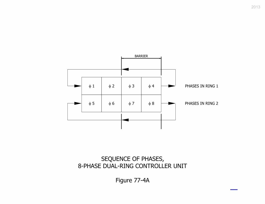
2013

2013

2013

Advantages
• Low installation costs. • Easy maintenance, no roadway interference. • Generally considered most aesthetically acceptable. • Generally correct locations for pedestrian signals and push buttons. • Provides adequate visibility where a wide median with left-turn lanes and phasing exist. • Unlimited roadway vertical clearance.
Disadvantages
• Requires underground wiring which can offset initial cost advantages. • Generally does not provide adequate visibility of signal indications for motorist due to
lateral placement of signal indications. • May not provide mounting locations such that a display with a clear meaning is provided. • Height limitations may provide problems where approach is on a vertical curve. • Subject to vehicular impact if installed close to the roadway, particularly in a median.
POST-MOUNTED SIGNAL, ADVANTAGES AND DISADVANTAGES
Figure 77-4D
2013

Advantages
• Easy to install, less underground work required. • Allows excellent lateral placement of signal heads for maximum visibility. • Allows for easy future adjustments of signal heads. • Allows correct signal-placement location with respect to stop line. • Can provide convenient post locations for supplemental signal heads and pedestrian signals and push buttons. • Permits bridles to reduce distance from stop line at wide intersection (see Figure 77-4F)
Disadvantages
• Seen by some users as aesthetically unpleasing. • Requires periodic maintenance for span tightening. • Prevents passage of an overheight vehicle.
CABLE-SPAN-MOUNTED SIGNAL, ADVANTAGES AND DISADVANTAGES
Figure 77-4E
2013

Advantages
• Allows correct lateral placement of signal heads and placement relative to stop line for maximum visibility of signal indications. • Can provide post locations for supplementary signals or pedestrian signals and push buttons. • Accepted as an aesthetically-pleasing method for installing overhead signals in a developed area. • Rigid mountings provide the most positive control of signal movement in wind. • Allows for clearance to overhead obstructions.
Disadvantages
• Costs are generally the highest. • It may be difficult to properly place signal heads over a wide approach. • Limited flexibility for addition of new signal heads or signs on existing cantilevers.
CANTILEVER-, OR MAST-ARM-, MOUNTED SIGNAL, ADVANTAGES AND DISADVANTAGES
Figure 77-4F
2013

2013

2013
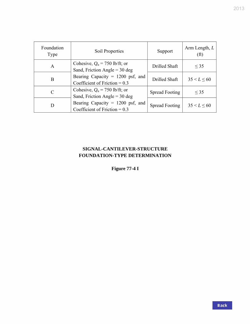
Foundation Type
Soil Properties Support Arm Length, L
(ft)
A Cohesive, Qu = 750 lb/ft; or Sand, Friction Angle = 30 deg Bearing Capacity = 1200 psf, and Coefficient of Friction = 0.3
Drilled Shaft ≤ 35
B Drilled Shaft 35 < L ≤ 60
C Cohesive, Qu = 750 lb/ft; or Sand, Friction Angle = 30 deg Bearing Capacity = 1200 psf, and Coefficient of Friction = 0.3
Spread Footing ≤ 35
D Spread Footing 35 < L ≤ 60
SIGNAL-CANTILEVER-STRUCTURE FOUNDATION-TYPE DETERMINATION
Figure 77-4 I
2013
Device Area, ft2 Weight, lb Signal Head with Backplate, 3 Sec., Lens Dia. 12 in. 8.7 35 Signal Head with Backplate, 5 Sec., Lens Dia. 12 in. 13.1 55 Regulatory Sign, 36 in. x 30 in. 7.5 19 Street-Name Sign, 18 in. x 96 in. 12 30 Street-Name Sign, 18 in. x 132 in. 16.5 41 Mounted Camera 1 20 Top-Pole Luminaire 2.4 53
AREA AND WEIGHT OF DEVICE TO BE MOUNTED ON SIGNAL CANTILEVER
Figure 77-4J
2013
2013

2013
2013

2013
2013

2013

2013

2013

2013

2013
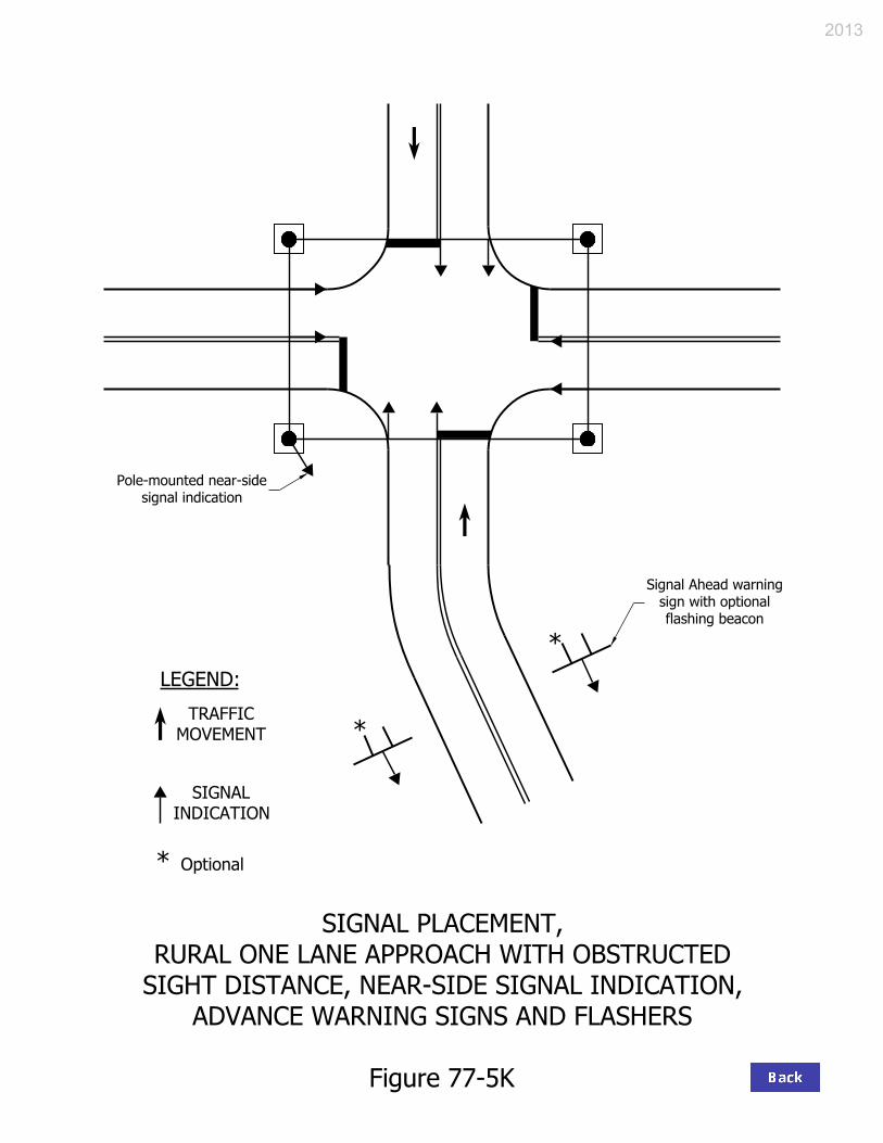
2013

85th Percentile
Speed, mph Minimum Visibility
Distance, ft 20 175 25 215 30 270 35 325 40 390 45 460 50 540 55 625 60 715
MINIMUM-VISIBILITY DISTANCE
Figure 77-5L
2013

2013

2013

2013

2013

2013

2013

2013

2013

2013

2013

2013

LEADING-LEFT-TURN PHASE
ADVANTAGES DISADVANTAGES
• Increases intersection capacity of a 1- or 2-lane approach without a left-turn lane if compared with 2-phase traffic-signal operation.
• Minimizes conflicts between left-turn and
opposing straight-through vehicles by clearing the left-turn vehicles through the intersection first.
• A driver tends to react quicker than with lagging-
left operation.
• A left-turning vehicle completing its movement may delay the beginning of the opposing through movement once the green is exhibited to the stopped opposing movement.
• Opposing movement may make a false start in
response to the movement of a vehicle given the leading green.
• Where there is no left-turn lane, an obstruction to
the left-turn movement is created if a through vehicle is present.
LAGGING-LEFT-TURN PHASE
ADVANTAGES DISADVANTAGES
• Both directions of straight-through traffic start at the same time.
• Approximates the normal driving behavior of a
vehicle operator. • Provides for vehicle/pedestrian separation as
pedestrians usually cross at the beginning of straight-through traffic.
• Where pedestrian signals are used, pedestrians
have cleared the intersection by the beginning of the lag-green interval.
• Cuts off only the platoon stragglers from adjacent
interconnected intersections.
• A left-turning vehicle can be trapped during the left-turn yellow change interval as opposing through traffic is not stopping as expected.
• Creates conflicts for opposing left turns at start of
lag interval because an opposing left-turning driver expects both movements to stop at the same time.
• Where there is no left-turn lane, an obstruction to
the through movement during the initial green interval is created.
Notes: 1. The disadvantages inherent in the lagging-left operation are such that its use is restricted to
an interconnected or pre-timed operation, or to an actuated-control operation, such as a T intersection.
2. The lagging-left turn phase is acceptable where both opposing through movements are
stopped at the same time.
COMPARISON OF LEFT-TURN-PHASE ALTERNATIVES
Figure 77-5X
2013
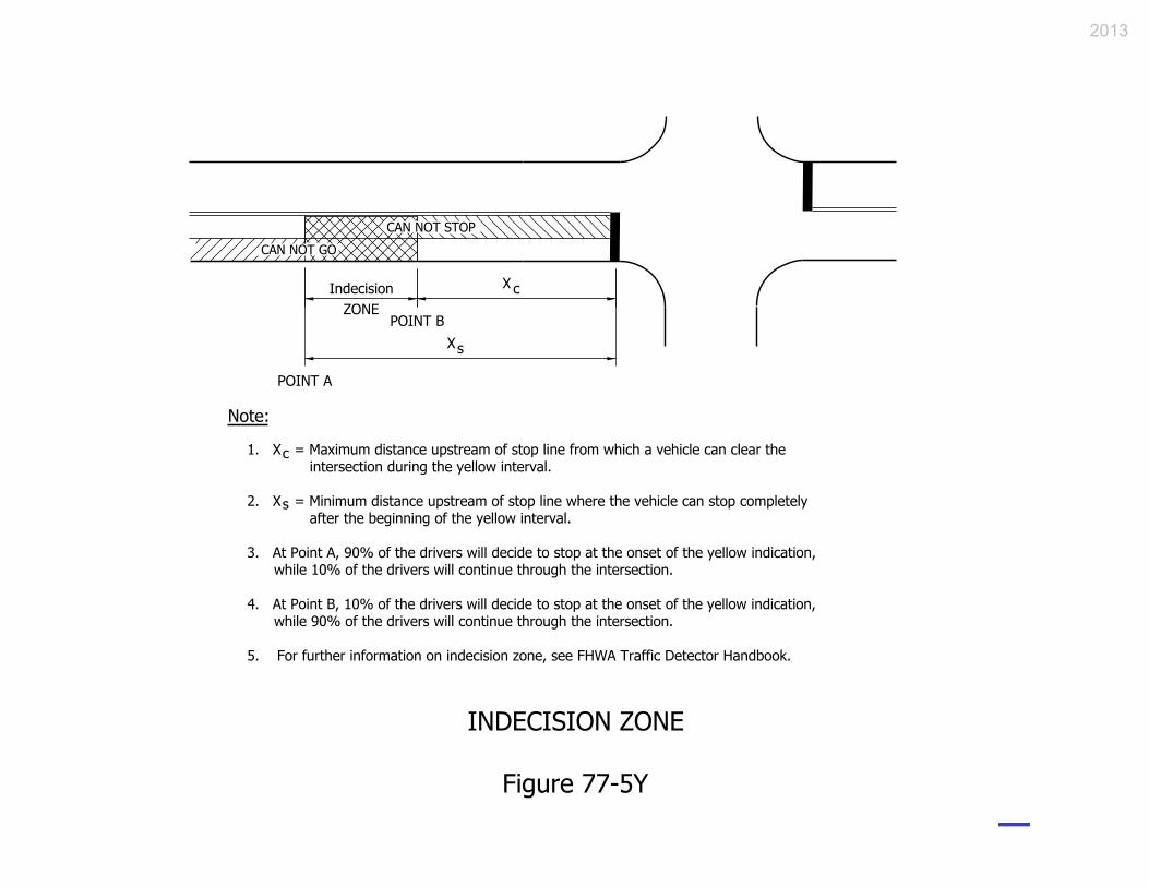
2013

Approach Posted Speed
(mph)
Passage Time from Detector to Stop Line (s)
1 2 3 4 5 1 6 7
20 29 53 87 116 145 174 193 25 36 78 108 144 180 216 252 30 44 88 132 2 176 220 264 308 35 51 102 153 204 255 306 357 40 59 113 177 236 295 354 413 45 66 132 198 264 330 396 462 50 73 146 219 292 365 438 511 55 81 162 243 324 405 486 567 60 88 176 264 352 475 528 616 65 95 190 285 380 550 570 665
Legend: 000 Basic Ctrlr. 000 Variable Initial Only 000 Density 000 Indecision Zone
1 INDOT uses 5 s passage time. 2 This value is also in the indecision zone.
DETECTION SETBACK DISTANCE (ft)
Figure 77-5 Z
2013

2013
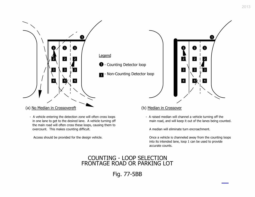
2013
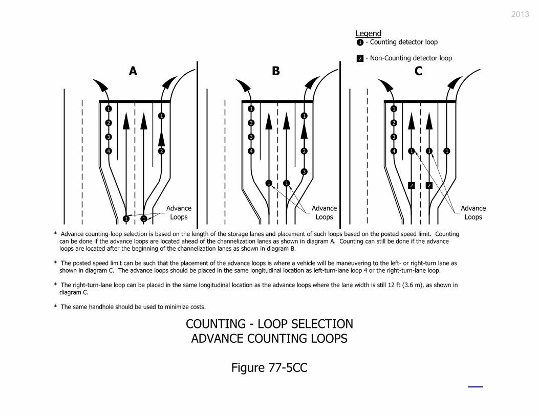
2013

This figure is a multiple-sheet spreadsheet which can be accessed and downloaded from the
editable documents webpage at http://www.in.gov/dot/div/contracts/design/dmforms/index.html.
LOOP TAGGING TABLE
Figure 77-5DD
2013

Send Copies To: District Traffic Engineer
Project Manger
RADIO SITE SURVEY REPORT
General Location Information
Location:
Commission Number: Contract Number: Project Des Number:
Date of Survey: Weather Conditions: Equipment Used:
Location of Master Controller:
Radio Survey Information Radio Configuration:
Master: Repeater: Remote:
Was a Spectrum Analyzer used? Yes No
Personnel in Attendance:
Instruction: Primary Hop Patterns #1 and #2 are required if this is a repeater location.
1. Primary Hop Pattern #1:
2. Primary Hop Pattern #2:
Recommended antenna location: Recommended location and orientation of antenna: Vertical Horizontal Distance from pole on mast arm:
Pointing:
Mounting: Standard Bracket
Truss Arm Length:
Communications Test No. of Polls: % Successful:
Base Unit Signal Strength: Mobile Unit Signal Strength: Comments:
Radio Site Surveyor Signature:
Figure 77-6A – Radio Site Survey Report Form
2013