Embed Size (px)
Citation preview
TABLE OF CONTENTS OF SPECIAL PROVISIONS Note: This Table of Contents has been prepared for the convenience of those using this contract with the sole express purpose of locating quickly the information contained herein; and no claims shall arise due to omissions, additions, deletions, etc., as this Table of Contents shall not be considered part of the contract.
Project No. 0152-0160
1
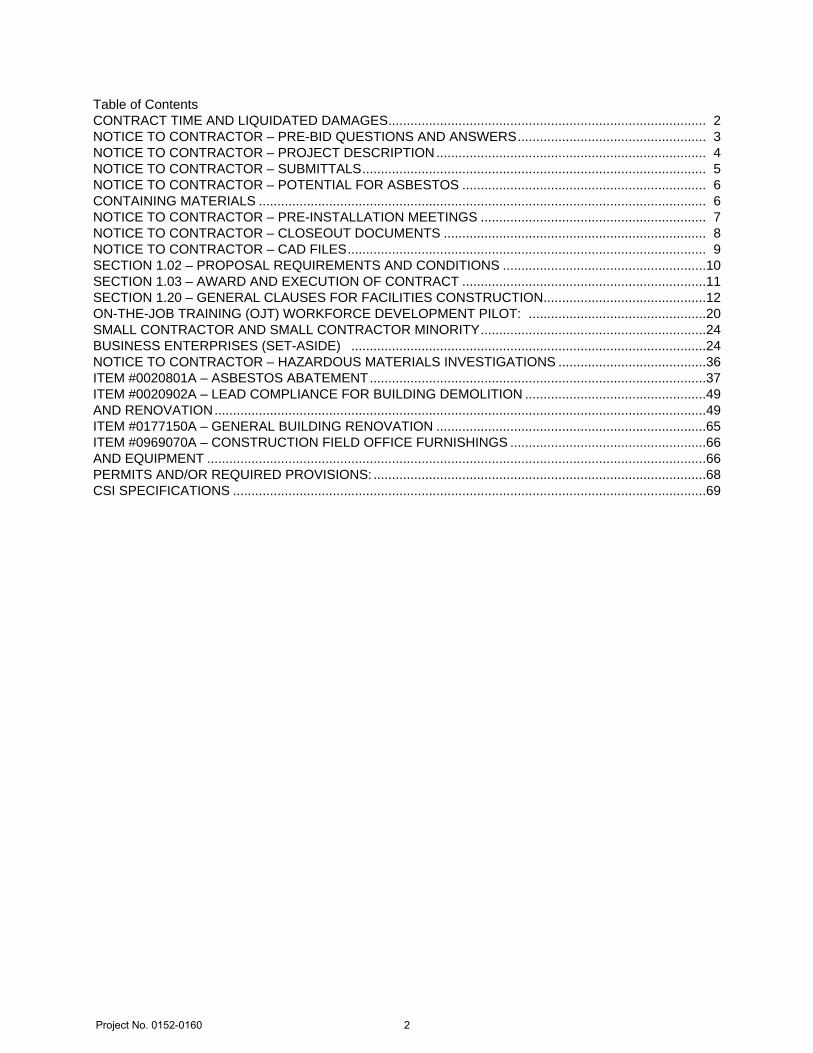
Table of ContentsCONTRACT TIME AND LIQUIDATED DAMAGES......................................................................................NOTICE TO CONTRACTOR – PRE-BID QUESTIONS AND ANSWERS...................................................NOTICE TO CONTRACTOR – PROJECT DESCRIPTION.........................................................................NOTICE TO CONTRACTOR – SUBMITTALS.............................................................................................NOTICE TO CONTRACTOR – POTENTIAL FOR ASBESTOS ..................................................................CONTAINING MATERIALS .........................................................................................................................NOTICE TO CONTRACTOR – PRE-INSTALLATION MEETINGS .............................................................NOTICE TO CONTRACTOR – CLOSEOUT DOCUMENTS .......................................................................NOTICE TO CONTRACTOR – CAD FILES.................................................................................................SECTION 1.02 – PROPOSAL REQUIREMENTS AND CONDITIONS .......................................................SECTION 1.03 – AWARD AND EXECUTION OF CONTRACT ..................................................................SECTION 1.20 – GENERAL CLAUSES FOR FACILITIES CONSTRUCTION............................................ON-THE-JOB TRAINING (OJT) WORKFORCE DEVELOPMENT PILOT: ................................................SMALL CONTRACTOR AND SMALL CONTRACTOR MINORITY.............................................................BUSINESS ENTERPRISES (SET-ASIDE) ................................................................................................NOTICE TO CONTRACTOR – HAZARDOUS MATERIALS INVESTIGATIONS ........................................ITEM #0020801A – ASBESTOS ABATEMENT...........................................................................................ITEM #0020902A – LEAD COMPLIANCE FOR BUILDING DEMOLITION .................................................AND RENOVATION.....................................................................................................................................ITEM #0177150A – GENERAL BUILDING RENOVATION .........................................................................ITEM #0969070A – CONSTRUCTION FIELD OFFICE FURNISHINGS .....................................................AND EQUIPMENT .......................................................................................................................................PERMITS AND/OR REQUIRED PROVISIONS: ..........................................................................................CSI SPECIFICATIONS ................................................................................................................................
234566789
101112202424363749496566666869
Project No. 0152-0160
2
Rev. Date 06-09-17
GENERAL
February 14, 2018
FEDERAL AID PROJECT NO. N/A
STATE PROJECT NO. 0152-0160
The Roof Replacement of the Maintenance Garage
Town of Waterford
Federal Aid Project No. N/A
The State of Connecticut, Department of Transportation, Standard Specifications for
Roads, Bridges, Facilities and Incidental Construction, Form 817, 2016, as revised by the
Supplemental Specifications dated July 2017 (otherwise referred to collectively as "ConnDOT
Form 817") is hereby made part of this contract, as modified by the Special Provisions contained
herein. Form 817 is available at the following DOT website link
http://www.ct.gov/dot/cwp/view.asp?a=3609&q=430362. The current edition of the State of
Connecticut Department of Transportation's "Construction Contract Bidding and Award Manual"
("Manual"), is hereby made part of this contract. If the provisions of this Manual conflict with
provisions of other Department documents (not including statutes or regulations), the provisions
of the Manual will govern. The Manual is available at the following DOT website link
http://www.ct.gov/dot/cwp/view.asp?a=2288&q=259258. The Special Provisions relate in
particular to The Roof Replacement of the Maintenance Garage in the Town of Waterford.
CONTRACT TIME AND LIQUIDATED DAMAGES
One Hundred Forty Seven (147) calendar days will be allowed for completion of the work
on this Contract and the liquidated damages charge to apply will be One Thousand Six Hundred
Dollars ($1,600.00) per calendar day.
Project No. 0152-0160
3
September 2016
GENERAL
NOTICE TO CONTRACTOR – PRE-BID QUESTIONS AND ANSWERS
Questions pertaining to DOT advertised construction projects must be presented through the
CTDOT Pre-Bid Q and A Website. The Department cannot guarantee that all questions will be
answered prior to the bid date. PLEASE NOTE - at 9:00 am Monday (i.e. typical Wednesday
Bid Opening) the project(s) being bid will be closed for questions, at which time questions
can no longer be submitted through the Q and A Website.
Answers may be provided by the Department up to 12:00 noon, the day before the bid. At
this time, the Q and A for those projects will be considered final, unless otherwise stated
and/or the bid is postponed to a future date and time to allow for further questions and
answers to be posted.
If a question needs to be asked the day before the bid date, please contact the Contracts Unit staff
and email your question to [email protected] immediately.
Contractors must identify their company name, contact person, contact email address and phone
number when asking a question. The email address and phone number will not be made public.
The questions and answers (if any) located on the Q and A Website are hereby made part of the
bid/contract solicitation documents (located on the State Contracting Portal), and resulting
contract for the subject project(s). It is the bidder’s responsibility to monitor, review, and become
familiar with the questions and answers, as with all bid requirements and contract documents,
prior to bidding. By signing the bid proposal and resulting contract, the bidder acknowledges
receipt of, and agrees to the incorporation of the final list of Q and A, into the contract document.
Contractors will not be permitted to file a future claim based on lack of receipt, or knowledge of
the questions and answers associated with a project. All bidding requirements and project
information, including but not limited to contract plans, specifications, addenda, Q and A, Notice
to Contractors, etc., are made public on the State Contracting Portal and/or the CTDOT website.
Project No. 0152-0160
4
Rev. Date 9/22/16
GENERAL
NOTICE TO CONTRACTOR – PROJECT DESCRIPTION
The Project consists of the roof replacement of the maintenance garage located in the town of
Waterford, Connecticut as shown and described in the Contract.
The work includes the removal of the existing built-up roof and the installation of a Polyvinyl
Chloride (PVC) membrane roof system.
Other related work includes the removal and replacement of the perimeter metal wall panels and
roof drains. The chimney and roof vents will be removed and additional roof exhaust fans will be
installed.
Environmental work associated with this project includes asbestos abatement and lead
compliance for building demolition and renovation as indicated in the NOTICE TO
CONTRACTOR – HAZARDOUS MATERIALS INVESTIGATION.
Project No. 0152-0160
5
Rev. Date 07/31/17
GENERAL
NOTICE TO CONTRACTOR – SUBMITTALS
Unless otherwise noted, the Designer will be the “submittal reviewer.”
Any Product Samples that are to be sent to the Designer requiring review for conformance with
the Contract shall be transmitted by letter and hand delivered or sent by mail directly to Mr.
Christopher Bonsignore, P.E., Transportation Principal Engineer, Facilities Design, Bureau of
Engineering and Construction, Connecticut Department of Transportation, 2800 Berlin Turnpike,
P.O. Box 317546, Newington, CT 06131-7546, Room 3405.
The Engineer will be the “submittal reviewer” for the following materials:
Demolition Plan
Disposal Plan
Certified Test Reports, Material Certificates, etc. from Form 817 Standard Items (non “A” Items
from Bid List)
“Non-A” items, including those items in CSI-formatted Specifications
All test reports identified in CSI-formatted Specification except for Testing, Adjusting, and
Balancing Reports
Environmental Compliance will be the “submittal reviewer” for review of work identified in the
following special provisions:
1. Item No. 0020801A – Asbestos Abatement.
2. Item No. 0020902A – Lead Compliance for Building Demolition and Renovation.
The Contractor shall send submittals e-mail alerts to the following key personnel:
Designer (Project Engineer): Shinel M. Mercado
Designer (Project Manager): Michael J. Strong
Construction Project Chief Inspector: Will be identified at Pre-Construction meeting.
Construction Supervising Engineer: Will be identified at Pre-Construction meeting.
Owner: David Hartley
Add the following for submittals where Environmental Compliance is listed in NOTICE TO
CONTRACTOR – SUBMITTALS as the “submittal reviewer:”
Environmental Designer (Project Engineer): Felix Mathieu Jr.
Environmental Designer (Project Manager): Judith Nemecek
Other key construction personnel will be identified at the Pre-Construction Meeting.
Project No. 0152-0160
6
Rev. Date 07/18/16
GENERAL
NOTICE TO CONTRACTOR – POTENTIAL FOR ASBESTOS
CONTAINING MATERIALS
The Contractor shall submit manufacturer certification letters for all materials specified in the
following Contract provisions (including CSI-formatted specifications contained within a
particular special provision):
1. Adhesives, Sealers: Division 03 Section 033000, “Cast-In-Place Concrete.”
2. Adhesives, Insulation, Sealants: Division 07 Section 074213, “Metal Wall Panels.”
3. Adhesives, Insulation, Cover Board: Division 07 Section 075419, “Polyvinyl Chloride
(PVC) Roofing.”
4. Adhesives, Sealants: Division 07 Section 076200, “Sheet Metal Flashing and Trim.”
5. Sealants: Division 07 Section 077100, “Roof Specialties.”
6. Division 07 Section 079200, “Joint Sealants.”
The above list may not be all-inclusive and does not relieve the Contractor from its responsibility
to provide manufacturer certification letters that are required under other Contract provisions.
Furthermore, the Department may at any time require the Contractor to submit manufacturer
certification letters proving that other materials do not contain asbestos.
Project No. 0152-0160
7
Rev. Date 9/29/16
GENERAL
NOTICE TO CONTRACTOR – PRE-INSTALLATION MEETINGS
The Engineer will conduct a pre-installation meeting at the Project Site before each of the
following construction activities:
1. Predemolition: Form 817 Article 1.20-1.08.03 – Prosecution of Work, subsection 5 –
Selective Demolition.
2. Roofing: CSI Division 7 Section 075419, “Polyvinyl-Chloride (PVC) Roofing.”
The above list may not be all-inclusive and does not relieve the Contractor from its responsibility
to provide pre-installation meetings that are required under other Contract provisions.
Project No. 0152-0160
8
Rev. Date 07/14/17
GENERAL
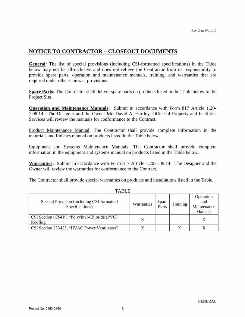
NOTICE TO CONTRACTOR – CLOSEOUT DOCUMENTS
General: The list of special provisions (including CSI-formatted specifications) in the Table
below may not be all-inclusive and does not relieve the Contractor from its responsibility to
provide spare parts, operation and maintenance manuals, training, and warranties that are
required under other Contract provisions.
Spare Parts: The Contractor shall deliver spare parts on products listed in the Table below to the
Project Site.
Operation and Maintenance Manuals: Submit in accordance with Form 817 Article 1.20-
1.08.14. The Designer and the Owner Mr. David A. Hartley, Office of Property and Facilities
Services will review the manuals for conformance to the Contract.
Product Maintenance Manual: The Contractor shall provide complete information in the
materials and finishes manual on products listed in the Table below.
Equipment and Systems Maintenance Manuals: The Contractor shall provide complete
information in the equipment and systems manual on products listed in the Table below.
Warranties: Submit in accordance with Form 817 Article 1.20-1.08.14. The Designer and the
Owner will review the warranties for conformance to the Contract.
The Contractor shall provide special warranties on products and installations listed in the Table.
TABLE
Special Provision (including CSI-formatted
Specifications) Warranties
Spare
Parts Training
Operation
and
Maintenance
Manuals
CSI Section 075419, “Polyvinyl-Chloride (PVC)
Roofing” X X
CSI Section 233423, “HVAC Power Ventilators” X X X
Project No. 0152-0160
9
Rev. Date 9/22/16
GENERAL
NOTICE TO CONTRACTOR – CAD FILES
The Contractor is hereby advised that CAD files will not be provided to construction contract
bidders, the Contractor, or any subcontractor. Contract documents, including plans, are provided
in Portable Document Format (PDF).
The Department AEC Applications unit has prepared technical reference materials on
extending the utility of PDF contract plan sheets. See the Repurposing PDF Contract Plan
Sheets web page (http://www.ct.gov/dot/cwp/view.asp?a=2288&Q=567262&PM=1).
The Contractor shall bid the Project accordingly.
Project No. 0152-0160
10
Rev. Date 03/25/08
GENERAL
SECTION 1.02 – PROPOSAL REQUIREMENTS AND CONDITIONS
Article 1.02.04 – Examination of Plans, Specifications, Special Provisions and Site of Work:
Replace the third sentence of the last paragraph with:
The Department cannot ensure a response to inquiries received later than ten (10) days
prior to the original scheduled opening of the related bid.
Project No. 0152-0160
11
Rev. Date 04-01-13
GENERAL
SECTION 1.03 – AWARD AND EXECUTION OF CONTRACT
Article 1.03.02 - Award and Execution of Contract:
After the second sentence of the only paragraph add the following:
The successful bidder is hereby notified of the Department’s intent to award this contract within 44
days of the bid opening.
Article 1.03.08 - Notice to Proceed and Commencement of Work:
Change the first paragraph to read as follows:
The Contractor shall commence and proceed with the Contract work on the date specified in a
written Notice to Proceed issued by the Engineer to the Contractor. The date specified will be no
later than 45 calendar days after the date of the execution of the Contract by the Department,
however, the contractor is hereby put on notice that it is the Department’s intent to issue the Notice
to Proceed no later than 17 calendar days after the date of the execution of the Contract by the
Department.
Project No. 0152-0160
12
Rev. Date 08/22/17
GENERAL
SECTION 1.20 – GENERAL CLAUSES FOR FACILITIES CONSTRUCTION
1.20-1.05.02— Facilities Construction – Contractor Submittals: Replace #1, #2, and #3. 1. General: If the plans prepared by the Department do not show complete details, they will show the necessary dimensions and preliminary details, which when used along with the other Contract documents, will enable the Contractor to prepare submittals necessary to complete the Contract work. The Contractor is required to prepare submittals as Portable Document Format (PDF) files using Bluebeam Revu. The Contractor is also required to acquire and maintain access to the Department’s Bentley ProjectWise data management system portal. The minimum recommended internet speed is 25MB/sec. For reference, the Department’s internet speed is 1 GB/sec. The Contractor shall submit a “CT DOT ProjectWise – New User Form” to request user names and passwords. The Department will permit Web-based access and no more than 2 users for the Contractor. The entry/log-in procedure is described in Section 3.2 of the CT DOT Digital Project Development Manual.
2. Submittal Preparation and Processing: The Contractor shall:
(a) Coordinate preparation and processing of submittals with performance of construction
activities;
(b) Transmit each submittal sufficiently in advance of performance of related construction
activities to avoid delay;
(c) Coordinate each submittal with fabrication, purchasing, testing, delivery, and other
submittals and related activities that require sequential activity;
(d) Provide complete submittal packages as multi-page PDF’s (Working Drawings, Shop
Drawings, Product Data, Product Samples, and Quality Assurance Submittals, as applicable) for
related elements of Project work for a concurrent review of all information. Incomplete
submittal packages will be returned to the Contractor without being reviewed. Electronic PDF
packages shall be limited to 75 MB unzipped; larger PDF packages will need to be broken up.
The Contractor shall allow at least 21 calendar days for initial submittal review by the submittal
reviewer, and allow additional time for such review if processing must be delayed to permit
coordination with subsequent submittals. If a subsequent submittal is necessary, the Contractor
shall allow at least 21 additional calendar days for processing each subsequent submittal. The
submittal reviewer reserves the right to withhold action on a submittal if coordination with other
submittals is necessary, until all related submittals are received. The submittal reviewer will
promptly inform the Contractor when a submittal being processed must be delayed for such
coordination.
Project No. 0152-0160
13
Rev. Date 08/22/17
GENERAL
The Contractor shall allow at least 28 calendar days for outside agency review of any submittal
requiring their approval, including but not limited to the following: any utility, FTA, any
railroad, DEEP, U.S. Coast Guard, Army Corps of Engineers, FM Global, and any
Commissioning Authority.
The Engineer will not authorize an extension of Contract time because of the Contractor’s failure
to transmit submittals to the submittal reviewer or outside agencies sufficiently in advance of the
work to permit processing.
The Contractor shall be limited to one acceptable submittal per product. Once a product has
been accepted either as originally specified, or as an “Or Equal” to the product specified, the
Contractor may elect to submit a subsequent product for consideration, but the Contractor shall
be required to reimburse the Department for all costs associated with reviewing the subsequent
request.
The Contractor shall attach a Submittal Transmittal Form to the beginning of each PDF submittal
package. A blank Submittal Transmittal Form is located in ProjectWise “01.0 – Projects-Active”
under the subfolder “120_Contractor_Submittals (PDF)” under the project number main folder.
This form will be used for the Contractor to digitally certify that “Having reviewed this
submittal, I certify that it is complete, accurate, coordinated in all aspects of the item being
submitted and conforms to the requirements of the Contract in all respects, including all Federal
requirements such as “Buy America”, except as otherwise noted.” The digital certification
process is detailed in Section 2 of the CT DOT Digital Project Development Manual.
3. Transmittal of Submittals: The digitally certified PDF submittal package shall be uploaded
into ProjectWise “01.0 – Projects-Active” under the subfolder “120_Contractor_Submittals
(PDF)” under the project number main folder. The upload process is detailed in Section 3.2.1-3
of the CT DOT Digital Project Development Manual. The submittal reviewer will not act on
submittals received in any other manner.
The Contractor shall attribute the submittal packages in ProjectWise using the following the
following attributes and naming conventions:
a) Discipline: CTR
b) Main Category: CONTRACTOR
c) Sub Category: SUBMITTAL
d) Label: “XXX-Spec Reference-##”
1. “XXX” is the chronological submittal number created by the Contractor starting
at 001.
2. “Spec Reference” is the 7-digit Contract Item No. (no “A” shall be included) for
individual Contract items or is the 6-digit CSI Section number preceded by a “C”
(making it a total of 7 digits) for the MLSI.
3. “##” is the submission attempt (01, 02, 03, etc.) of the submittal.
e) Description: Brief description of submittal content labeled “Submittal – submittal
Project No. 0152-0160
14
Rev. Date 08/22/17
GENERAL
content.”
The first submission for a particular item is the “01” submittal. Subsequent resubmittals (02, 03,
etc.) are transmitted as described above only for those submittals or portions thereof returned to
the Contractor with a “Revise and Resubmit” or “Rejected” disposition. The chronological
submittal number shall not be revised on a resubmittal.
After uploading an initial or subsequent submittal, the Contractor shall provide e-mail
notification to submittal reviewers and other key personnel at their business e-mail address that
the submittals have been uploaded and are available for review. The Contractor shall provide a
web link to the PDF submittal within their e-mail notification. The Contractor shall include the
following information in the notification e-mail subject line in this order: Project Number -
“XXX-Spec Reference-##” – “Description.” The submittal review time begins when the
submittal reviewer is notified by e-mail.
In the 4th paragraph of subsection e, insert “color” between the phrase “2 copies” in each
location.
1.20-1.05.07—Facilities Construction – Coordination with Work by Other Parties:
Add the following after the last paragraph:
“The Contractor shall cooperate with the Engineer during construction operations to minimize
conflicts and facilitate Engineer and Department personnel usage. The Contractor, the Engineer,
and the Department personnel will coordinate construction operations and Department operations
on a daily basis, if necessary.”
1.20-1.05.08— Facilities Construction – Schedules and Reports:
Delete the first sentence and replace with the following:
“Transmittals of Schedules: The schedule package shall be uploaded into ProjectWise “01.0 –
Projects-Active” under the subfolder “115_Contractor_Schedules” under the project number
main folder. The specific work flow to do so will be distributed at the Preconstruction Meeting.
The Contractor shall attribute the submittal packages in ProjectWise using the following the
following attributes and naming conventions:
a) Discipline: CTR
b) Main Category: CONTRACTOR
c) Sub Category: SCHEDULE
d) Label: “Project Number - Schedule #XX - Date”
e) Description: “Schedule #XX – Date”
After uploading a schedule (baseline bar chart, monthly update, biweekly, or recovery), the
Contractor shall provide e-mail notification to submittal reviewers and other key personnel at
Project No. 0152-0160
15
Rev. Date 08/22/17
GENERAL
their business e-mail address that the submittals have been uploaded and are available for review.
The Contractor shall provide a web link to the schedule within their e-mail notification. The
Contractor shall include the following information in the notification e-mail subject line in this
order: “Project Number - Schedule #XX - Date”
When a project coordinator is not required by the Contract the following shall apply:”
1.20-1.05.23 – Facilities Construction – Requests for Information (RFI’s) and Requests for
Change (RFC’s):
Delete the first paragraph and replace with the following:
“The Contractor shall upload all RFIs and RFCs into ProjectWise “01.0 – Projects-Active” under
the subfolder “121_Contractor RFIs and RFCs” under the project number main folder. The
specific work flow to do so will be distributed at the Preconstruction Meeting. The Contractor
shall attribute the RFIs and RFCs in ProjectWise using the following the following attributes and
naming conventions:
Discipline: CTR
Main Category: CONTRACTOR
Sub Category: RFI or RFC
Label: “Project Number – RFI #XX - Date” or “Project Number – RFC #XX - Date”
Description: “RFI #XX - Date” or “RFC #XX - Date”
After uploading the RFIs and RFCs, the Contractor shall provide e-mail notification to the
Engineer at their business e-mail address that the submittals have been uploaded and are
available for review. The Contractor shall provide a web link to the RFI or RFC within their e-
mail notification. The Contractor shall include the following information in the notification e-
mail subject line in this order: “Project Number - RFI #XX - Date” or “Project Number - RFC
#XX – Date.”
The Engineer will forward the RFI or RFC to the Designer for review. Upon receipt of an RFI
or RFC, the Designer will attempt to determine if additional information is required from the
Contractor to respond to the RFI or RFC and request said information from the Engineer.”
1.20-1.06.08 – Facilities Construction – Warranties
Delete paragraph 8 starting “Prior to the date for the Substantial Completion Inspection to the
end of the Article.
“Prior to the date of the Substantial Completion Inspection, the Contractor shall compile each
required warranty, properly executed by the Contractor or any other required party. The
warranties shall be uploaded into ProjectWise “01.0 – Projects-Active” under the subfolder
“122_Contractor Closeout Documents” under the project number main folder. The specific work
flow to do so will be distributed at the Preconstruction Meeting. The Contractor shall attribute
the warranties in ProjectWise using the following the following attributes and naming
Project No. 0152-0160
16
Rev. Date 08/22/17
GENERAL
conventions:
Discipline: CTR
Main Category: CONTRACTOR
Sub Category: WARRANTIES
Label: “Project Number – Warranties”
Description: “Warranties”
After uploading the warranties, the Contractor shall provide e-mail notification to submittal
reviewers and other key personnel at their business e-mail address that the warranties have been
uploaded and are available for review. The Contractor shall provide a web link to the zipped
folder within their e-mail notification. The Contractor shall include the following information in
the notification e-mail subject line in this order: “Project Number - Warranties.”
The Contractor shall submit warranties in PDF format, assembling the complete warranty
submittal package into a single electronic PDF file with bookmarks enabling navigation to each
item and providing a bookmarked table of contents at beginning of document. The Contractor
shall place the warranty documents in an orderly sequence based on the organization of the
Contract provisions (including specific CSI-formatted specifications contained within a
particular Special Provision). Electronic PDF packages shall be limited to 75 MB unzipped;
larger PDF packages will need to be broken up.
The Contractor shall include a description of the product or installation, including the name of
the product, and the name, address and telephone number of the Contractor or pertinent
subcontractor.
The Contractor shall furnish to the Department a written warranty for all Project work
accompanied by a cover letter with the following contents:
[Addressed to:]
Commissioner of Transportation
Department of Transportation
P.O. Box 317546
Newington, Connecticut 06131-7546
Project Title and Number
[We] hereby warrant all materials and workmanship for all work
performed under this Contract for a period of one (1) year from [date of
issuance of C.O.C.] against failures of workmanship and materials in
accordance with the Contract. Furthermore, as a condition of this
warranty, [we] agree to have in place all insurance coverage identified in
the Contract for the performance of any warranty work.
[Signature:] [Name of authorized signatory]
[Title]
Upon determination by the Engineer that Project work covered by a warranty has failed, the
Project No. 0152-0160
17
Rev. Date 08/22/17
GENERAL
Contractor shall replace or rebuild the work to an acceptable condition complying with Contract
requirements. The Contractor is responsible for the cost of replacing or rebuilding defective
construction or components and those which may have needed to be damaged or removed in
order to cure the defective work including costs of material, equipment, labor, and material
disposal, regardless of whether or not the State has benefited from use of the work through a
portion of its anticipated useful service life. The Contractor shall respond to the Project Site
when Project work covered by a warranty has failed within 3 calendar days, unless in the
Engineer’s opinion said failure is deemed to be an emergency, in which case the Contractor shall
respond to the Project Site as directed by the Engineer.
When Project work covered by a warranty has failed and been corrected by replacement or
rebuilding, the Contractor shall reinstate the warranty by written endorsement. The reinstated
warranty shall be equal to the time that remains on the original warranty period at the time of the
failure.”
1.20-1.08.04—Facilities Construction – Limitation of Operations:
Add following the last paragraph.
“The Contractor shall repair at its own expense any and all damage caused by construction
operations to existing buildings unless said damage is scheduled as part of the Project work. The
Contractor shall take all precautions necessary to protect the building and its occupants during
the construction period.”
The Contractor is hereby advised of the need to perform the following Project work related to the
building when the building is unoccupied (between the hours of 4 p.m. and 6.a.m. or on
weekends, except during winter storms) to minimize the impacts to the Department Personnel,
unless otherwise approved by the Engineer:
1. Asbestos abatement.
2. Demolition, salvage of materials, and lead remediation.
3. Any work that negatively impacts the ability of Department Personnel from performing
their assigned duties. This includes but is not limited to utility or building services
work/interruptions.”
The Contractor shall bid the Project accordingly.
1.20-1.08.14 – Facilities Construction – Acceptance of Project
Delete 4. Operation and Maintenance Manuals down to “Product Maintenance Manual” and
replace with the following:
“4. Operation and Maintenance Manuals: Prior to the date of the Semi-Final Inspection, the
Contractor shall compile operation and maintenance manuals in the form of instructional
manuals for use by the Owner. The operation and maintenance manuals shall be uploaded into
ProjectWise “01.0 – Projects-Active” under the subfolder “122_Contractor Closeout
Project No. 0152-0160
18
Rev. Date 08/22/17
GENERAL
Documents” under the project number main folder. The specific work flow to do so will be
distributed at the Preconstruction Meeting. The Contractor shall attribute the operational and
maintenance manual packages in ProjectWise using the following the following attributes and
naming conventions:
Discipline: CTR
Main Category: CONTRACTOR
Sub Category: OPERATION AND MAINTENANCE MANUALS
Label: “Project Number – Operation and Maintenance Manuals - Description”
Description: “Operation and Maintenance Manuals - Description”
After uploading the manuals, the Contractor shall provide e-mail notification to submittal
reviewers and other key personnel at their business e-mail address that the submittals have been
uploaded and are available for review. The Contractor shall provide a web link to the zipped
folder manuals within their e-mail notification. The Contractor shall include the following
information in the notification e-mail subject line in this order: “Project Number - Operation and
Maintenance Manuals – Description.”
The Contractor shall submit manuals in the form of a multiple file composite electronic PDF
file for each manual type required using electronic files prepared by manufacturer where
available. Where scanning of paper documents is required, configure scanned file for minimum
readable file size. Electronic PDF packages shall be limited to 75 MB unzipped; larger PDF
packages will need to be broken up.
For each manual, the Contractor shall:
(a) Bookmark individual documents based on file names. Name document files to
correspond to system, subsystem, and equipment names used in manual directory and
table of contents. Group documents for each system and subsystem into individual
composite bookmarked files, then create composite manual, so that resulting bookmarks
reflect the system, subsystem, and equipment names in a readily navigated file tree.
Configure electronic manual to display bookmark panel on opening file.
(b) Provide a title page as the first page of each manual with the following information:
subject matter covered by the manual; Contract number and title; date of submittal; name,
address, and telephone number of the Contractor; and cross-reference to related systems
in other sections.
(c) Provide a table of contents, arranged systematically according to the organization of the
Contract provisions (including specific CSI-formatted specifications within a particular
Special Provision).
(d) Provide a general information section immediately following the table of contents, listing
each product included in the manual, identified by product name. The Contractor shall
list the name, address, and telephone number of the subcontractor, the maintenance
contractor, and the local source for replacement parts and equipment for each product.
(e) Include manufacturer's standard data and mark each sheet to identify each part or product
included in the Project, identify each product using appropriate references from the
Contract, and delete references to information that is not applicable. The use of project
record documents as part of operation and maintenance manuals is not permitted.
Project No. 0152-0160
19
Rev. Date 08/22/17
GENERAL
(f) Prepare supplementary text to provide operation and maintenance information when the
manufacturer's standard data is not available or the data is insufficient and the
information is necessary for proper operation and maintenance of equipment or systems,
organize text in a consistent format under separate headings for each procedure, and
provide a logical sequence of instruction for each operation or maintenance procedure.
(g) Provide drawings where necessary in order to supplement manufacturer's data to illustrate
the relationship of component parts of equipment or systems or to provide control or flow
diagrams. The Contractor shall coordinate these drawings with information contained in
project record drawings to ensure correct illustration of the completed installation. The
use of Project record documents as part of operation and maintenance manuals is not
permitted.
(h) Provide estimated life cycle costs to maintain each product included in the manual to
reach maximum useful life (i.e. annual, mid-life overhaul, end of life overhaul, or
programmed interval replacement).”
Add New Section:
“1.20-1.10.09 – Facilities Construction – Compliance with Existing Site Permits
The Contractor shall conduct its operations in conformance with the permit requirements
established by Federal, State and municipal laws and regulations.
In addition to permits obtained by the Department specifically for the Project, facilities have
existing site specific permits and regulatory requirements related to site operational activities.
The specific permits and regulatory requirements will be identified in the Contract. The
Contractor shall become familiar with these requirements and shall conduct their operations in
conformance with these requirements.
The Contractor shall be responsible for, and hold the State harmless from, any penalties or fines
assessed by any authority due to the Contractor’s failure to comply with any term of an
applicable environmental permit.”
Project No. 0152-0160
20
Rev. Date 08/02/11
GENERAL
ON-THE-JOB TRAINING (OJT) WORKFORCE DEVELOPMENT PILOT:
Description
To provide construction industry related job opportunities to minorities, women and
economically disadvantaged individuals; and to increase the likelihood of a diverse and inclusive
workforce on Connecticut Department of Transportation (ConnDOT) projects.
All contractors (existing and newcomers) will be automatically placed in the Workforce
Development Pilot. Standard OJT requirements typically associated with individual projects will
no longer be applied at the project level for new projects. Instead, these requirements will be
applicable on an annual basis for each contractor performing work on ConnDOT projects.
The OJT Workforce Development Pilot will allow a contractor to train employees on Federal,
State and privately funded projects located in Connecticut. However, contractors should give
priority to training employees on ConnDOT Federal-Aid funded projects.
Funding
The Department will establish an OJT fund annually from which contractors may bill the
Department directly for eligible trainee hours. The funds for payment of trainee hours on
federal-aid projects will be allocated from the ½ of 1% provided for OJT funding, and will be
based on hours trained, not to exceed a maximum of $25,000.00 per year; per contractor.
Minorities and Women
Developing, training and upgrading of minorities, women and economically disadvantaged
individuals toward journeyperson level status is the primary objective of this special training
provision. Accordingly, the Contractor shall make every effort to enroll minority, women and
economically disadvantaged individuals as trainees to the extent that such persons are available
within a reasonable area of recruitment. This training commitment is not intended, and shall not
be used, to discriminate against any applicant for training whether a member of a minority group
or not.
Assigning Training Goals
The Department, through the OJT Program Coordinator, will assign training goals for a calendar
year based on the contractor’s past two year’s activities and the contractor’s anticipated
upcoming year’s activity with the Department. At the beginning of each year, all contractors
eligible will be contacted by the Department to determine the number of trainees that will be
assigned for the upcoming calendar year. At that time, the Contractor shall enter into an
agreement with the Department to provide a self-imposed on-the-job training program for the
calendar year. This agreement will include a specific number of annual training goals agreed to
by both parties. The number of training assignments may range from one (1) to six (6) per
Project No. 0152-0160
21
Rev. Date 08/02/11
GENERAL
contractor per calendar year. Each January, a summary of the trainees required and the OJT
Workforce Development Pilot package will be sent to participating contractors. The number of
trainees assigned to each contractor in the summary will increase proportionately not to exceed
6, as shown in the following table. This package will also be provided to contractors as they
become newly eligible for the OJT Workforce Development Pilot throughout the remainder of
the year. Projects awarded after September 30 will be included in the following year’s Program.
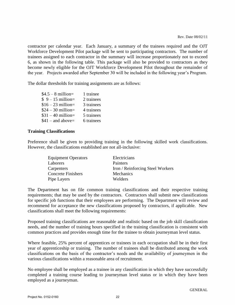
The dollar thresholds for training assignments are as follows:
$4.5 – 8 million= 1 trainee
$ 9 – 15 million= 2 trainees
$16 – 23 million= 3 trainees
$24 – 30 million= 4 trainees
$31 – 40 million= 5 trainees
$41 – and above= 6 trainees
Training Classifications
Preference shall be given to providing training in the following skilled work classifications.
However, the classifications established are not all-inclusive:
Equipment Operators Electricians
Laborers Painters
Carpenters Iron / Reinforcing Steel Workers
Concrete Finishers Mechanics
Pipe Layers Welders
The Department has on file common training classifications and their respective training
requirements; that may be used by the contractors. Contractors shall submit new classifications
for specific job functions that their employees are performing. The Department will review and
recommend for acceptance the new classifications proposed by contractors, if applicable. New
classifications shall meet the following requirements:
Proposed training classifications are reasonable and realistic based on the job skill classification
needs, and the number of training hours specified in the training classification is consistent with
common practices and provides enough time for the trainee to obtain journeyman level status.
Where feasible, 25% percent of apprentices or trainees in each occupation shall be in their first
year of apprenticeship or training. The number of trainees shall be distributed among the work
classifications on the basis of the contractor’s needs and the availability of journeymen in the
various classifications within a reasonable area of recruitment.
No employee shall be employed as a trainee in any classification in which they have successfully
completed a training course leading to journeyman level status or in which they have been
employed as a journeyman.
Project No. 0152-0160
22
Rev. Date 08/02/11
GENERAL
Records and Reports
The Contractor shall maintain enrollment in the program and submit all required reports
documenting company compliance under these contract requirements. These documents and any
other information shall be submitted to the OJT Program Coordinator as requested.
Upon the trainee’s completion and graduation from the program, the Contractor shall provide
each trainee with a certification Certificate showing the type and length of training satisfactorily
completed.
Trainee Interviews
In order to determine the continued effectiveness of the OJT Program in Connecticut, the
department will periodically conduct personal interviews with current trainees and may survey
recent graduates of the program. This enables the OJT Program Coordinator to modify and
improve the program as necessary. Trainee interviews are generally conducted at the job site to
ensure that the trainees’ work and training is consistent with the approved training program.
Trainee Wages
Contractors shall compensate trainees on a graduating pay scale based upon a percentage of the
prevailing minimum journeyman wages (Davis-Bacon Act). Minimum pay shall be as follows:
60 percent of the journeyman wage for the first half of the training period
75 percent of the journeyman wage for the third quarter of the training period
90 percent of the journeyman wage for the last quarter of the training period
In no case, will the trainee be paid less than the prevailing rate for general laborer as shown in
the contract wage decision (must be approved by the Department of Labor).
Achieving or Failing to Meet Training Goals
The Contractor will be credited for each trainee currently enrolled or who becomes enrolled in
the approved training program and providing they receive the required training under the specific
training program. Trainees will be allowed to be transferred between projects if required by the
Contractor’s schedule and workload. The OJT Program Coordinator must be notified of
transfers within five (5) days of the transfer or reassignments by e-mail
Where a contractor does not or cannot achieve its annual training goal with female or minority
trainees, they must produce adequate Good Faith Efforts documentation. Good Faith Efforts are
those designed to achieve equal opportunity through positive, aggressive, and continuous result-
oriented measures. 23 CFR § 230.409(g) (4). Contractors should request minorities and females
from unions when minorities and females are under-represented in the contractor’s workforce.
Project No. 0152-0160
23
Rev. Date 08/02/11
GENERAL
Whenever a contractor requests ConnDOT approval of someone other than a minority or female,
the contractor must submit documented evidence of its Good Faith Efforts to fill that position
with a minority or female. When a non-minority male is accepted, a contractor must continue to
attempt to meet its remaining annual training goals with females and minorities.
Where a contractor has neither attained its goal nor submitted adequate Good Faith Efforts
documentation, ConnDOT will issue a letter of non-compliance. Within thirty (30) days of
receiving the letter of non-compliance, the contractor must submit a written Corrective Action
Plan (CAP) outlining the steps that it will take to remedy the non-compliance. The CAP must be
approved by ConnDOT. Failure to comply with the CAP may result in your firm being found
non-responsive for future projects.
Measurement and Payment
Optional reimbursement will be made to the contractor for providing the required training under
this special provision on ConnDOT Federal-Aid funded projects only.
Contractor will be reimbursed at $0.80 for each hour of training given to an employee in
accordance with an approved training or apprenticeship program. This reimbursement will be made
even though the Contractor receives additional training program funds from other sources, provided
such other source does not specifically prohibit the contractor from receiving other reimbursement.
Reimbursement for training is made annually or upon the trainees completion and not on a monthly
basis. No payment shall be made to the Contractor if either the failure to provide the required
training, or the failure to hire the trainee as a journeyperson, is caused by the Contractor.
Program reimbursements will be made directly to the prime contractor on an annual basis. To
request reimbursement, prime contractors must complete the Voucher for OJT Workforce
Development Pilot Hourly Reimbursement for each trainee in the OJT Program. This form is
included in the OJT Workforce Development Pilot package and is available on the Department’s
web site at:
www.ct.gov/dot
The completed form must be submitted to the Office of Contract Compliance for approval. The
form is due on the 15th
day of January for each trainee currently enrolled and for hours worked
on ConnDOT Federal-Aid funded projects only.
Project No. 0152-0160
24
GENERAL
SMALL CONTRACTOR AND SMALL CONTRACTOR MINORITY
BUSINESS ENTERPRISES (SET-ASIDE)
March, 2001
NOTE: Certain of the requirements and procedures stated in this "Special Provision" are
applicable prior to the execution of the Contract.
I. GENERAL
A. The Contractor shall cooperate with the Connecticut Department of
Transportation (CONNDOT) in implementing the required contract obligations
concerning "Small Contractor" and "Small Contractor Minority Business
Enterprise" use on this Contract in accordance with Section 4a-60g of the
Connecticut General Statutes as revised. References, throughout this "Special
Provision", to "Small Contractors" are also implied references to "Small
Contractor Minority Business Enterprises" as both relate to Section IIA of these
provisions. The Contractor shall also cooperate with CONNDOT in reviewing
the Contractor's activities relating to this provision. This "Special Provision" is in
addition to all other equal opportunity employment requirements of this Contract.
B. For the purpose of this "Special Provision", the "Small Contractor(s)" and
"Minority Business Enterprise(s)" named to satisfy the set-aside requirement
must be certified by the Department of Administrative Services, Business
Connections/ Set-Aside Unit [(860) 713-5236 www.das.state.ct.us/busopp.htm] as
a "Small Contractor" and "Minority Business Enterprises" as defined by Section
4a-60g Subsections (1) and (3) of the Connecticut General Statutes as revised and
is subject to approval by CONNDOT to do the work for which it is nominated
pursuant to the criteria stipulated in Section IIC-3.
C. Contractors who allow work which they have designated for "Small Contractor"
participation in the pre-award submission required under Section IIC to be
performed by other than the approved "Small Contractor" organization and prior
to concurrence by CONNDOT, will not be paid for the value of the work
performed by organizations other than the "Small Contractor" designated.
D. If the Contractor is unable to achieve the specified contract goals for "Small
Contractor" participation, the Contractor shall submit written documentation to
CONNDOT's Manager of Construction Operations indicating his/her good faith
efforts to satisfy goal requirements. Documentation is to include but not be
limited to the following:
Project No. 0152-0160
25
GENERAL
1. A detailed statement of the efforts made to select additional subcontract
opportunities for work to be performed by each "Small Contractor" in
order to increase the likelihood of achieving the stated goal.
2. A detailed statement, including documentation of the efforts made to
contact and solicit contracts with each "Small Contractor", including the
names, addresses, dates and telephone numbers of each "Small
Contractor" contacted, and a description of the information provided to
each "Small Contractor" regarding the scope of services and anticipated
time schedule of items proposed to be subcontracted and the nature of
response from firms contacted.
3. For each "Small Contractor" that placed a subcontract quotation which the
Contractor considered not to be acceptable, provide a detailed statement of
the reasons for this conclusion.
4. Documents to support contacts made with CONNDOT requesting
assistance in satisfying the contract specified or adjusted "Small
Contractor" dollar requirements.
5. Document other special efforts undertaken by the Contractor to meet the
defined goal.
E. Failure of the Contractor to have at least the specified dollar amount of this
contract performed by "Small Contractor" as required in Section IIA of this
"Special Provision" will result in the reduction in contract payment to the
Contractor by an amount equivalent to that determined by subtracting from the
specific dollar amount required in Section IIA, the dollar payments for the work
actually performed by each "Small Contractor". The deficiency in "Small
Contractor" achievement, will therefore, be deducted from the final contract
payment. However, in instances where the Contractor can adequately document
or substantiate its good faith efforts made to meet the specified or adjusted dollar
amount to the satisfaction of CONNDOT, no reduction in payments will be
imposed.
F. All records must be retained for a period of three (3) years following completion
of the contract and shall be available at reasonable times and places for inspection
by authorized representatives of CONNDOT.
G. Nothing contained herein, is intended to relieve any contractor or subcontractor or
material supplier or manufacturer from compliance with all applicable Federal
and State legislation or provisions concerning equal employment opportunity,
affirmative action, nondiscrimination and related subjects during the term of this
Contract.
Project No. 0152-0160
26
GENERAL
II. SPECIFIC REQUIREMENTS
In order to increase the participation of "Small Contractors", CONNDOT requires the
following:
A. Not less than 5 (%) percent of the final value of this Contract shall be
subcontracted to and performed by, and/or supplied by, manufactured by and paid to
"Small Contractors" and/or "Small Contractors Minority Business Enterprises".
If the above percentage is zero (0%) AND an asterisk (*) has been entered in the
adjacent brackets [ ], this Contract is 100% solely set-aside for participation by "Small
Contractors" and/or "Small Contractors Minority Business Enterprises".
B. The Contractor shall assure that each "Small Contractor" will have an equitable
opportunity to compete under this "Special Provision", particularly by arranging
solicitations, time for the preparation of Quotes, Scope of Work, and Delivery
Schedules so as to facilitate the participation of each "Small Contractor".
C. The Contractor shall provide to CONNDOT's Manager of Contracts within Seven
(7) days after the bid opening the following items:
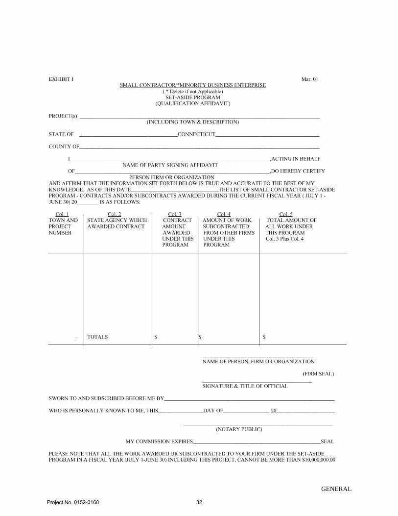
1. An affidavit (Exhibit I) completed by each named "Small Contractor"
subcontractor listing a description of the work and indicating the dollar
amount of all contract(s) and/or subcontract(s) that have been awarded to
him/her for the current State Fiscal Year (July 1 - June 30) does not
exceed the Fiscal Year limit of $10,000,000.00.
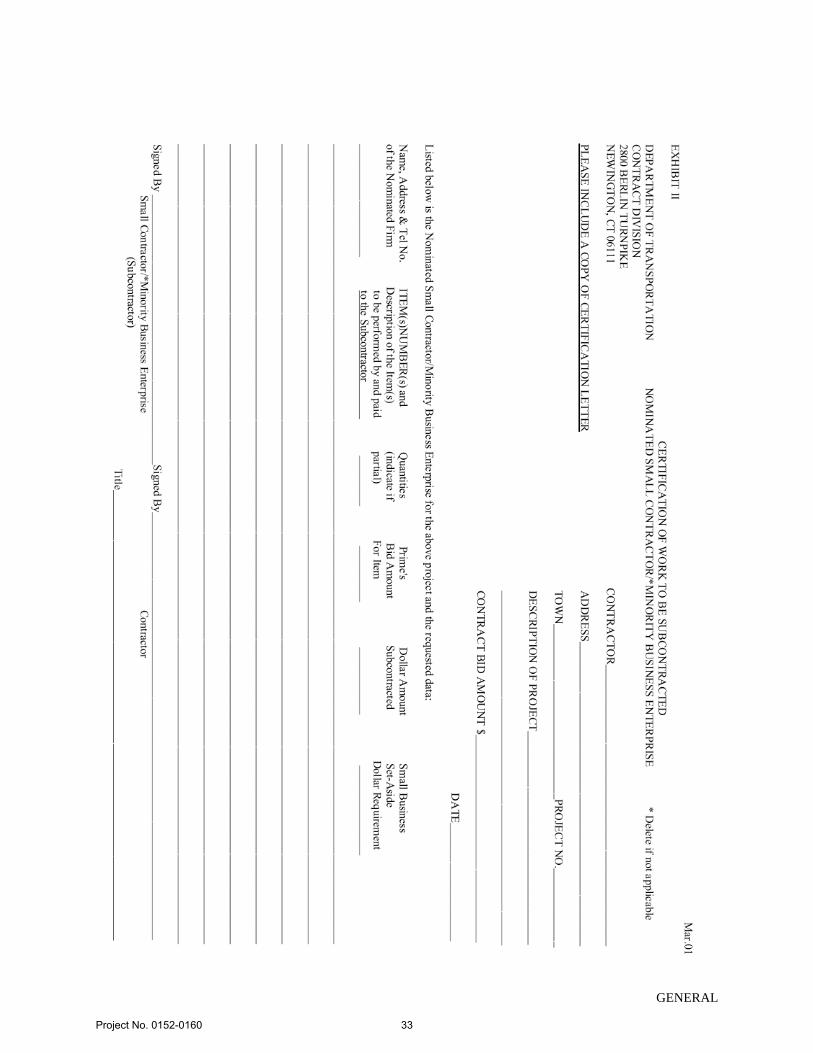
2. A certification of work to be subcontracted (Exhibit II) signed by both the
Contractor and the "Small Contractor" listing the work items and the
dollar value of the items that the nominated "Small Contractor" is to
perform on the project to achieve the minimum percentage indicated in
Section IIA above.
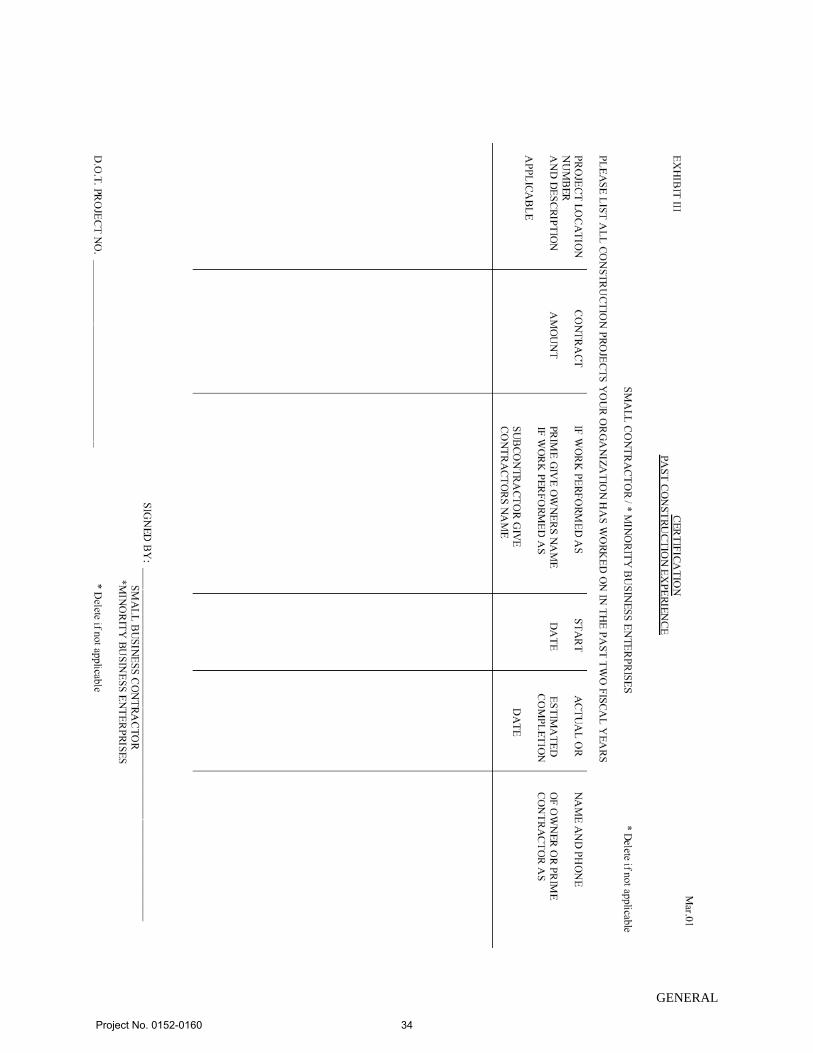
3. A certification of past experience (Exhibit III) indicating the scope of
work the nominated "Small Contractor" has performed on all projects,
public and private, for the past two (2) years.
4. In instances where a change from the originally approved named "Small
Contractor" (see Section IB) is proposed, the Contractor is required to
submit, in a reasonable and expeditious manner, a revised submission,
comprised of the documentation required in Section IIC, Paragraphs 1, 2
and 3 and Section E together with documentation to substantiate and
Project No. 0152-0160
27
GENERAL
justify the change, (i.e., documentation to provide a basis for the change)
to CONNDOT's Manager of Construction Operations for its review and
approval prior to the implementation of the change. The Contractor must
demonstrate that the originally named "Small Contractor" is unable to per-
form in conformity to specifications, or unwilling to perform, or is in
default of its contract, or is overextended on other jobs. The Contractor's
ability to negotiate a more advantageous contract with another "Small
Contractor" is not a valid basis for change. Documentation shall include a
letter of release from the originally named "Small Contractor" indicating
the reason(s) for the release.
D. After the Contractor signs the Contract, the Contractor will be required to meet
with CONNDOT's Manager of Construction Operations or his/her designee to
review the following:
1. What is expected with respect to the "Small Contractor" set aside
requirements.
2. Failure to comply with and meet the requirement can and will result in
monetary deductions from payment.
3. Each quarter after the start of the "Small Contractor" the Contractor shall
submit a report to CONNDOT's Manager of Construction Operations
indicating the work done by, and the dollars paid to each "Small
Contractor" to date.
4. What is required when a request to sublet to a "Small Contractor" is
submitted.
E. The Contractor shall submit to CONNDOT's Manager of Construction Operations
all requests for subcontractor approvals on standard forms provided by the
Department.
If the request for approval is for a "Small Contractor" subcontractor for the
purpose of meeting the contract required "Small Contractor" percentage stipulated
in Section IIA, a copy of the legal contract between the Contractor and the "Small
Contractor" subcontractor must also be submitted at the same time. Any
subsequent amendments or modifications of the contract between the Contractor
and the "Small Contractor" subcontractor must also be submitted to CONNDOT's
Manager of Construction Operations with an explanation of the change(s). The
contract must show items of work to be performed, unit prices and, if a partial
item, the work involved by both parties.
In addition, the following documents are to be attached:
Project No. 0152-0160
28
GENERAL
(1) A statement explaining any method or arrangement for renting
equipment. If rental is from a Contractor, a copy of Rental
Agreement must be submitted.
(2) A statement addressing any special arrangements for manpower.
(3) A statement addressing who will purchase material.
F. Contractors subcontracting with a "Small Contractor" to perform work or services
as required by this "Special Provision" shall not terminate such firms without
advising CONNDOT, in writing, and providing adequate documentation to
substantiate the reasons for termination if the designated "Small Contractor" firm
has not started or completed the work or the services for which it has been con-
tracted to perform.
G. Material Suppliers or Manufacturers
If the Contractor elects to utilize a "Small Contractor" supplier or manufacturer to
satisfy a portion or all of the specified dollar requirements, the Contractor must
provide the Department with:
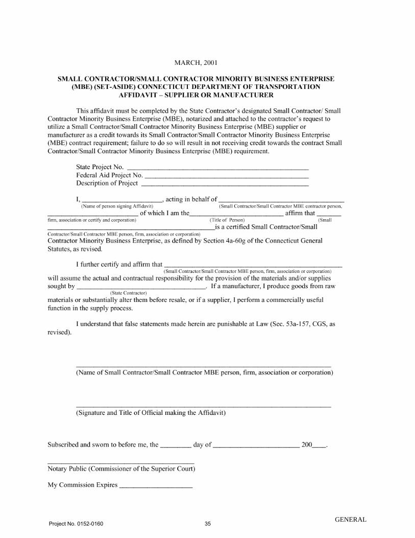
1. An executed Affidavit Small Contractor (Set-Aside) Connecticut
Department of Transportation Affidavit Supplier or Manufacturer (sample
attached), and
2. Substantiation of payments made to the supplier or manufacturer for
materials used on the project.
Brokers and packagers shall not be regarded as material Suppliers or
manufacturer.
H. Non-Manufacturing or Non-Supplier "Small Contractor" Credit
Contractors may count towards its "Small Contractor" goals the following
expenditures with "Small Contractor" firms that are not manufacturers or
suppliers:
1. Reasonable fees or commissions charged for providing a bona fide service
such as professional, technical, consultant or managerial services and
assistance in the procurement of essential personnel, facilities, equipment,
material or supplies necessary for the performance of the contract
provided that the fee or commission is determined by the Department of
Transportation to be reasonable and consistent with fees customarily
allowed for similar services.
Project No. 0152-0160
29
GENERAL
2. The fees charged for delivery of materials and supplies required on a job
site (but not the cost of the materials and supplies themselves) when the
hauler, trucker, or delivery service is not also the manufacturer of or a
regular dealer in the materials and supplies, provided that the fee is
determined by the Department of Transportation to be reasonable and not
excessive as compared with fees customarily allowed for similar services.
3. The fees or commissions charged for providing any bonds or insurance
specifically required for the performance of the Contract, provided that the
fee or commission is determined by the Department of Transportation to
be reasonable and not excessive as compared with fees customarily
allowed for similar services.
III. BROKERING
For the purpose of this "Special Provision", a "Broker" is one who acts as an agent for
others in negotiating contracts, purchases, sales, etc., in return for a fee or commission.
Brokering of work by a "Small Contractor" is not allowed and is a contract violation.
IV. PRE-AWARD WAIVERS:
If the Contractor's submission of the "Small Contractor" listing, as required by Section
IIC indicates that it is unable, by subcontracting to obtain commitments which at least
equal the amount required by Section IIA, it may request, in writing, a waiver of up to
50% of the amount required by Section IIA. To obtain such a waiver, the Contractor
must submit a completed "Application for Waiver of Small Contractor Minority Business
Enterprise Goals" to CONNDOT's Manager of Contracts which must also contain the
following documentation:
1. Information described in Section ID.
2. For each "Small Contractor" contacted but unavailable, a statement from each
"Small Contractor" confirming its unavailability.
Upon receipt of the submission requesting a waiver, the CONNDOT's Manager of
Contracts shall submit the documentation to the Director of the Office of Contract
Compliance who shall review it for completeness. After completion of the Director of
Contract Compliance's review, she/he should write a narrative of his/her findings of the
application for a waiver, which is to include his/her recommendation. The Director of
Contract Compliance shall submit the written narrative to the Chairperson of the DBE
Screening Committee at least five (5) working days before the scheduled meeting. The
Contractor shall be invited to attend the meeting and present his/her position. The DBE
Screening Committee shall render a decision on the waiver request within five (5)
Project No. 0152-0160
30
GENERAL
working days after the meeting. The DBE Screening Committee's decision shall be final.
Waiver applications are available from the CONNDOT Manager of Contracts.
Project No. 0152-0160
31
GENERAL
Project No. 0152-0160
32
GENERAL
Project No. 0152-0160
33
GENERAL
Project No. 0152-0160
34
GENERAL Project No. 0152-0160
35
GENERAL
Project No. 0152-0160
36
Rev. Date 10/16/17
GENERAL
NOTICE TO CONTRACTOR – HAZARDOUS MATERIALS INVESTIGATIONS
A limited hazardous materials site investigation has been conducted at the Waterford
Maintenance Facility, Waterford, Connecticut. The scope of inspection was limited to the
roofing and associated components projected for impact.
The results of the investigation identified asbestos-containing-material (ACM) to be present in
both the roofing materials and transite wall panels scheduled for impact.
Lead based paint (LBP) was also identified on metal roof trusses and I-Beams that will
impacted/painted during the project.
The Contractor is hereby notified that these hazardous materials requiring special management or
disposal procedures will be encountered during various construction activities conducted within
the project limits. The Contractor will be required to implement appropriate health and safety
measures for all construction activities impacting these materials. These measures shall include,
but are not limited to, air monitoring, engineering controls, personal protective equipment and
decontamination, equipment decontamination and personnel training. WORKER HEALTH
AND SAFETY PROTOCOLS WHICH ADDRESS POTENTIAL AND/OR ACTUAL RISK OF
EXPOSURE TO SITE SPECIFIC HAZARDS ARE SOLELY THE RESPONSIBILITY OF
THE CONTRACTOR.
The Department, as Generator, will provide an authorized representative to sign all manifests and
waste profile documentation required by disposal facilities for disposal of hazardous materials.
The Sections which shall be reviewed by the Contractor include, but are not limited to, the
following:
Item No. 0020801A - Asbestos Abatement
Item No. 0020902A – Lead Compliance for Building Demolition and Renovation
The Contractor is alerted to the fact that a Department environmental consultant may be on site
for abatement and related activities, to collect environmental samples (if necessary), and to
observe site conditions for the State.
Information pertaining to the results of the limited hazardous materials investigation discussed
can be found in the document listed below. This document shall be available for review
electronically.
Pre-Renovation Investigative Survey for Hazardous Building Materials, Waterford Maintenance Facility, Waterford, Connecticut, TRC Environmental Corporation, October, 2017.
Project No. 0152-0160
37
Rev. Date 10/16/17
ITEM #0020801A
ITEM #0020801A – ASBESTOS ABATEMENT
Description:
Work under this item shall include the abatement of asbestos containing materials (ACM) and
associated work by persons who are knowledgeable, qualified, trained and licensed in the
removal, treatment, handling, and disposal of ACM and the subsequent cleaning of the affected
environment. ACM shall include material composed of any type of asbestos in amounts greater
than one percent (1%) by weight. The Contractor performing this work shall possess a valid
Asbestos Abatement Contractor license issued by the Connecticut Department of Public Health
(CTDPH).
These Specifications govern all work activities that disturb asbestos containing materials. All
activities shall be performed in accordance with, but not limited to, the current revision of the
OSHA General Industry Standard for Asbestos (29 CFR 1926.1001), the OSHA Asbestos in
Construction Regulations (29 CFR 1926.1101), the USEPA Asbestos National Emission
Standards for Hazardous Air Pollutants (NESHAP) Regulations (40 CFR Part 61 Subpart M), the
CTDPH Standards for Asbestos Abatement, Licensure and Training (19a-332a-1 through 16, 20-
440-1 through 9 & 20-441), and the CTDEEP Special Waste Disposal Regulations (22a-209-
8(i)).
The asbestos abatement work shall include the removal and disposal of all ACM as identified on
the Contract Plans and Specifications prior to the planned renovation/demolition project.
Deviations from these Specifications require the written approval of the Engineer.
The Contractor may elect to utilize an Alternative Work Practice (AWP), if approved by the
CTDPH and the Engineer prior to the initiation of the abatement activities. An AWP is a
variance from certain CTDPH asbestos regulatory requirements, which must provide the
equivalent or a greater measure of asbestos emission control than the standard work practices
prescribed by the CTDPH.
Materials:
All materials shall be delivered to the job site in the original packages, containers, or bundles
bearing the name of the manufacturer, the brand name and product technical description.
No damaged or deteriorating materials shall be used. If material becomes contaminated with
asbestos, the material shall be decontaminated or disposed of as asbestos-containing waste
material. The cost to decontaminate and dispose of this material shall be at the expense of the
Contractor.
Fire retardant polyethylene sheet shall be in roll size to minimize the frequency of joints, with
factory label indicating four (4) or six (6) mil thickness.
Project No. 0152-0160
38
Rev. Date 10/16/17
ITEM #0020801A
Six (6) mil polyethylene disposable bags shall have pre-printed OSHA/EPA/DOT labels and
shall be transparent.
Tape (or equivalent) capable of sealing joints in adjacent polyethylene sheets and for the
attachment of polyethylene sheets to finished or unfinished surfaces must be capable of adhering
under both dry and wet conditions.
Surfactant is a chemical wetting agent added to water to improve penetration and shall consist of
fifty (50) percent polyoxyethylene ether and fifty (50) percent polyoxyethylene ester, or
equivalent. The surfactant shall be mixed with water to provide a concentration one (1) ounce
surfactant to five (5) gallons of water, or as directed by the manufacturer.
Spray equipment must be capable of mixing necessary chemical agents with water, generating
sufficient pressure and volume; and equipped with adequate hose length to access all necessary
work areas.
Sanders, grinders, wire brushes and needle-gun type removal equipment shall be equipped with a
High Efficiency Particulate Air (HEPA) filtered vacuum dust collection system.
Containers for storage, transportation and disposal of asbestos containing waste material shall be
impermeable and both air and watertight.
Labels and warning signs shall conform to OSHA 29 CFR 1926.1101, USEPA 40 CFR Part
61.152, and USDOT 49 CFR Part 172 as appropriate.
Encapsulant, a material used to chemically entrap asbestos fibers to prevent these fibers from
becoming airborne, shall be of the type which has been approved by the Engineer. Use shall be
in accordance with manufacturer's printed technical data. The encapsulant shall be clear and
must be compatible with new materials being installed, if any.
Mastic removal chemicals shall be low odor and non-citrus based, with a flash point in excess of
140° F.
Any planking, bracing, shoring, barricades and/or temporary sheet piling, necessary to
appropriately perform work activities shall conform to all applicable federal, state and local
regulations.
Air filtration devices and vacuum units shall be equipped with HEPA filters.
Construction Methods:
(1) Pre-Abatement Submittals and Notices
Project No. 0152-0160
39
Rev. Date 10/16/17
ITEM #0020801A
(a) The Contractor shall submit, in accordance with CTDPH Standard 19a-332a-3, proper
notification using the prescribed form, to the Commissioner, State of Connecticut,
Department of Public Health not fewer than ten (10) days prior to the commencement of
work as follows:
1. The asbestos to be removed is exterior NESHAP Category I/II Non-Friable
ACM, and it is not expected that the abatement procedures will render the
Category I/II asbestos friable; thereby not categorizing it as NESHAP
Regulated ACM (RACM); therefore not defining the removal as a CTDPH
“abatement”; and as such the CT licensed Asbestos Abatement Contractor
will not be required to file an Asbestos Abatement notification.
(b) Fifteen (15) working days prior to the commencement of asbestos abatement work, the
Contractor shall submit to the Engineer for review and acceptance and/or
acknowledgment of the following:
1. Permits and licenses for the removal, transport, and disposal of asbestos-
containing or contaminated materials, including a CTDPH valid asbestos removal
contractor’s license.
2. Documentation dated within the previous twelve (12) months, certifying that all
employees have received USEPA Model Accreditation Plan approved asbestos
worker/supervisor training in the proper handling of materials that contain
asbestos; understand the health implications and risks involved, including the
illnesses possible from exposure to airborne asbestos fibers; understands the use
and limits of respiratory equipment to be used; and understands the results of
monitoring of airborne quantities of asbestos as related to health and respiratory
equipment as indicated in 29 CFR 1926.1101 on an initial and annual basis, and
copies of all employees CTDPH asbestos worker and/or supervisor licenses.
3. Documentation from the Contractor, typed on company letterhead and signed by
the Contractor, certifying that all employees listed therein have received the
following:
a. medical monitoring within the previous twelve (12) months, as
required in 29 CFR 1926.1101;
b. respirator fit testing within the previous twelve (12) months as
detailed in 29 CFR 1910.134 (for all employees who must also don a
tight-fitting face piece respirator).
4. Copies of the EPA/State-approved certificates for the proposed asbestos landfill.
(c) No abatement shall commence until a copy of all required submittals have been received
and found acceptable to the Engineer. Those employees added to the Contractor's
Project No. 0152-0160
40
Rev. Date 10/16/17
ITEM #0020801A
original list will be allowed to perform work only upon submittal to, and receipt of, all
required paperwork by the Engineer.
(2) Asbestos Abatement Provisions:
(a) General Requirements
The Abatement Contractor/Subcontractor shall possess a valid State of Connecticut Asbestos
Contractor License. Should any portion of the work be subcontracted, the subcontractor must
also possess a valid State of Connecticut Asbestos Contractor License. The Asbestos Abatement
Site Supervisor employed by the Contractor shall be in control on the job site at all times during
asbestos abatement work. All employees of the Contractor who shall perform work (i.e. Asbestos
Abatement Site Supervisor, Asbestos Abatement Worker) shall be properly certified/licensed by
the State of Connecticut to perform such duties.
All labor, materials, tools, equipment, services, testing, insurance (with specific coverage for
work on asbestos), and incidentals which are necessary or required to perform the work in
accordance with applicable governmental regulations, industry standards and codes, and these
Specifications shall be provided by the Contractor. The Contractor shall be prepared to work all
shifts and weekends throughout the course of this project.
Prior to beginning work, the Engineer and Contractor shall perform a visual survey of each work
area and review conditions at the site for safety reasons. In addition, the Contractor shall instruct
all workers in all aspects of personnel protection, work procedures, emergency evacuation
procedures and use of equipment including procedures unique to this project.
The Contractor shall:
Shut down and lock out electrical power, including all receptacles and light fixtures,
when feasible. The use or isolation of electrical power will be coordinated with all other
ongoing uses of electrical power at the site.
When necessary, provide temporary power and adequate lighting and ensure safe
installation of electrical equipment, including ground fault protection and power cables,
in compliance with applicable electrical codes and OSHA requirements. The Contractor
is responsible for proper connection and installation of electrical wiring.
Water service may not be available at the site. Contractor shall supply sufficient water for each
shift to operate the decontamination shower units as well as to maintain the work areas
adequately wet.
Ladders and/or scaffolds shall be in compliance with OSHA requirements, and of adequate
length, strength and sufficient quantity to support the scope of work. Use of ladders/scaffolds
shall be in conformance with OSHA 29 CFR 1926 Subpart L and X requirements.
Project No. 0152-0160
41
Rev. Date 10/16/17
ITEM #0020801A
Work performed at heights exceeding six feet (6’) shall be performed in accordance with the
OSHA Fall Protection Standard 29 CFR 1926 Subpart M including the use of fall arrest systems
as applicable.
Data provided regarding asbestos sampling conducted throughout the structure(s) is for
informational purposes only. Under no circumstances shall this information be the sole means
used by the Contractor for determining the presence and location of all asbestos containing
materials. The Contractor shall verify all field conditions affecting performance of the work as
described in these Specifications in accordance with OSHA, USEPA, USDOT, DEP standards.
Compliance with the applicable requirements is solely the responsibility of the Contractor.
The Engineer will provide a Project Monitor to oversee the activities of the Contractor. No
asbestos work shall be performed until the Project Monitor is on-site. Pre-abatement, during
abatement and post-abatement air sampling will be conducted as deemed necessary by the
Project Monitor. Waste stream testing will be performed, as necessary, by the Project Monitor
prior to waste disposal.
(b) Set-Up
The Contractor shall establish contiguous to the Regulated Area, a Worker Decontamination
Enclosure System consisting of Equipment Room, Shower Room and Clean Room in series, as
detailed below. Access to the Regulated Area shall only be through this enclosure.
Access between rooms in the Worker Decontamination Enclosure System shall be through
airlocks. Other effective designs are permissible. The Clean Room, Shower Room and
Equipment Room located within the Worker Decontamination Enclosure, shall be contiguously
connected with taped airtight edges, thus ensuring the sole source of airflow originates from
outside the regulated areas, once the negative pressure differential within the Regulated Area is
established.
The Clean Room shall be adequately sized to accommodate workers and shall be equipped with
a suitable number of hooks, lockers, shelves, etc., for workers to store personal articles and
clothing. Changing areas of the Clean Room shall be suitably screened from areas occupied by
the public.
The Shower Room shall be of sufficient capacity to accommodate the number of workers. One
shower stall shall be provided for each eight (8) workers. Showers shall be equipped with hot
and cold or warm running water through the use of electric hot water heaters supplied by the
Contractor. No worker or other person shall leave a Regulated Area without showering. Shower
water shall be collected and filtered using best available technology and dumped down an
approved sanitary drain. Shower stalls and plumbing shall include sufficient hose length and
drain system or an acceptable alternate.
The Contractor shall ensure that no personnel or equipment be permitted to leave the Regulated
Area until proper decontamination procedures (including HEPA vacuuming, wet wiping and
Project No. 0152-0160
42
Rev. Date 10/16/17
ITEM #0020801A
showering) to remove all asbestos debris have occurred. No asbestos-contaminated materials or
persons shall enter the Clean Room.
Post warning signs meeting the specifications of OSHA 29 CFR 1910.1001 and 29 CFR
1926.1101 at each Regulated Area. In addition, signs shall be posted at all approaches to
Regulated Areas so that an employee or building occupant may read the sign and take the
necessary protective steps before entering the area. Additional signs may require posting
following construction of workplace enclosure barriers.
(c) Alternate set up requirements for exterior non-friable asbestos abatement procedures
In lieu of the establishment of a negative pressure enclosure (NPE) system as described by
CTDPH Sections 19a-332a-5(c), 5(d), 5(e), and 5(h), non-friable ACM will be removed from
exterior work areas within an outdoor Regulated Area(s). The regulated work area will be
established by the use of appropriately labeled barrier tape and postings in compliance with
CTDPH 19a-332a-5(a) as well as OSHA 29 CFR 1926.1101. A remote personnel
decontamination unit as specified in Section 19a-332a-6 will be required. This method shall
only be utilized provided exposure assessment air sampling data collected during the removal of
the exterior non-friable materials indicates that the exposure levels during removal of such
materials do not exceed 0.1 asbestos f/cc. Should exposure assessment air sampling data exceed
this level, and engineering efforts to reduce the airborne fiber levels not be successful in reducing
the levels to less than 0.1 f/cc, removal shall occur within these areas under full containment
conditions.
(d) Personnel Protection
The Contractor shall utilize all appropriate engineering controls and safety and protective
equipment while performing the work in accordance with OSHA, USEPA, USDOT, CTDEEP
and CTDPH regulations.
The Contractor shall provide and require all workers to wear protective clothing in the Regulated
Areas where asbestos fiber concentrations may reasonably be expected to exceed the OSHA
established Permissible Exposure Limits (PEL) or where asbestos contamination exists.
Protective clothing shall include impervious coveralls with elastic wrists and ankles, head
covering, gloves and foot coverings.
Respiratory protection shall be provided and shall meet the requirements of OSHA as required in
29 CFR 1910.134, and 29 CFR 1926.1101 as well as the requirements of the CTDPH
regulations. A formal respiratory protection program must be implemented in accordance with
29 CFR 1926.1101 and 29 CFR 1910.134. The Contractor shall provide respirators from among
those approved as being acceptable for protection by the National Institute for Occupational
Safety and Health (NIOSH) under the provisions of 30 CFR Part ll.
Project No. 0152-0160
43
Rev. Date 10/16/17
ITEM #0020801A
All other necessary personnel protective equipment (i.e. hardhat, work boots, safety glasses,
hearing protection, etc.) required to perform the asbestos abatement work activities shall conform
to all applicable federal, state and local regulations.
All other qualified and authorized persons entering into a Regulated Area (i.e. Project Monitor,
Regulatory Agency Representative) shall adhere to the requirements of personnel protection as
stated in this section.
(e) Asbestos Abatement Procedures
The Asbestos Abatement Site Supervisor, as the OSHA Competent Person shall be at the site at
all times.
The Contractor shall not begin abatement work until authorized by the Project Monitor,
following a pre-abatement visual inspection.
All workers and authorized persons shall enter and leave the Regulated Area through the Worker
Decontamination Enclosure System, leaving contaminated protective clothing in the Equipment
Room for reuse or disposal of as asbestos contaminated waste. No one shall eat, drink, smoke,
chew gum or tobacco, or apply cosmetics while in a Regulated Area.
The following details the extent of each phase of operation designated for this project. Phase
areas may be combined or divided at the direction of the Engineer. Proceed through the
sequencing of the work phases under the direction of the Engineer.
Phase 1 - Exterior Roofing & Siding
Phase 1 includes the removal of:
built-up roofing material – all layers -all roofs
grey flashing cement –around base of chimney & mechanical units – Office Roof
felt paper flashing –around base of chimney & mechanical units – Office Roof
transite panels – building exterior upper walls
A regulated area(s) shall be established at the perimeter of the work area(s), and access
shall be controlled by the Contractor. A remote personnel decontamination unit shall be
utilized. Removal shall be undertaken in accordance with OSHA Class II and USEPA
Asbestos NESHAP requirements.
During removal, the Contractor shall spray asbestos materials with amended water using airless
spray equipment capable of providing a "mist" application to reduce the release of airborne
fibers. Spray equipment shall be capable of mixing wetting agent with water and capable of
generating sufficient pressure and volume. Hose length shall be sufficient to reach all of the
Regulated Area. Do not “flood” the area with hose type water supply equipment with the
potential to create water releases from the regulated area.
Project No. 0152-0160
44

Rev. Date 10/16/17
ITEM #0020801A
The Contractor shall continue to spray the asbestos materials with amended water, as necessary,
throughout removal activities to ensure the asbestos materials remain adequately wet. The
asbestos materials shall not be allowed to dry out.
In order to minimize airborne asbestos concentrations inside the Regulated Area, the Contractor
shall remove the adequately wetted asbestos in manageable sections. In addition, asbestos
materials removed from any elevated level shall be carefully lowered to the floor.
The Contractor shall promptly place the adequately wet asbestos material in disposal containers
(six (6) mil polyethylene bags/fiber drum/poly-lined dumpsters, etc.) as it is removed. Large
components removed intact may be wrapped in two (2) layers of six (6) mil polyethylene
sheeting secured with tape. As the disposal containers are filled, the Contractor shall promptly
seal the containers, apply caution labels and clean the containers before transportation to the
equipment decontamination area. Bags shall be securely sealed to prevent accidental opening
and leakage by taping in gooseneck fashion. Small components and asbestos-containing waste
with sharp-edged components (e.g. nails, screws, metal lath, tin sheeting) which could tear
polyethylene bags and sheeting shall be placed in clean drums and sealed with locking ring tops.
All waste containers shall be leak-tight, (typically consisting of two layers of 6 mil poly (or
bags)), and shall be properly labeled and placarded with OSHA Danger labels, DOT shipping
labels, markings and placards and USEPA NESHAP generators labels. Containers shall be
decontaminated by wet cleaning and HEPA vacuuming within the equipment decontamination
area prior to exiting the regulated area. Wet clean each container thoroughly before moving to
Holding Area.
If at any time during asbestos removal, the Project Monitor should suspect contamination of
areas outside the Regulated Area, the Contractor shall immediately stop all abatement work and
take steps to decontaminate these areas and eliminate causes of such contamination. Unprotected
individuals shall be prohibited from entering contaminated areas until air sampling and/or visual
inspections determine decontamination.
After completion of abatement work, all surfaces from which asbestos has been removed shall be
wet brushed, using a nylon brush, wet wiped and sponged or cleaned by an equivalent method to
remove all visible material (wire brushes are not permitted). During this work the surfaces being
cleaned shall be kept wet. Cleaning shall also include the use of HEPA filtered vacuum
equipment.
The Contractor shall also remove and containerize all visible accumulations of asbestos-
containing and/or asbestos-contaminated debris which may have splattered or collected on the
polyethylene engineering controls/barriers.
Once the Regulated Area surfaces have dried, the Project Monitor shall perform a thorough post
abatement visual inspection utilizing protocols from the ASTM Standard E1368-90 Standard
Practice for Visual Inspection of Asbestos Abatement Projects. All surfaces within the
Regulated Area, including but not limited to ledges, beams, and hidden locations shall be
Project No. 0152-0160
45
Rev. Date 10/16/17
ITEM #0020801A
inspected for visible residue. Evidence of asbestos contamination identified during this
inspection will necessitate further cleaning as heretofore specified. The area shall be re-cleaned
at the Contractor's expense, until the standard of cleaning is achieved.
Once the area has received a satisfactory post-abatement visual inspection, any equipment, tools
or materials not required for completion of the work, shall be removed by the Contractor from
the Regulated Area.
(f) Air Monitoring Requirements
1. The Contractor shall:
a. Provide air monitoring equipment including sample filter cassettes of the
type and quantity required to properly monitor operations and personnel
exposure surveillance throughout the duration of the project.
b. Conduct personnel exposure assessment air sampling, as necessary, to
assure that workers are using appropriate respiratory protection in
accordance with OSHA Standard 1926.1101. Documentation of air
sampling results must be recorded at the work site within twenty-four (24)
hours and shall be available for review until the job is complete.
2. The Project Monitor, acting as the representative of the Engineer during
abatement activities, will:
a. Collect air samples in accordance with the current revision of the NIOSH
7400 Method of Air Sampling for Airborne Asbestos Fibers while
overseeing the activities of the Abatement Contractor. Frequency and
duration of the air sampling during abatement will be representative of the
actual conditions at the abatement site. The size and configuration of the
asbestos project will be a factor in the number of samples required to
monitor the abatement activities and shall be determined by the Project
Monitor. The following schedule of samples may be collected by the
Project Monitor:
1. Pre-Abatement (Optional)
a. Background areas
b. Area(s) adjacent to Work Area(s)
c. Work Area(s)
2. During Abatement (Optional)
a. At the exhaust of air filtering device
b. Within Regulated Area(s)
c. Area(s) adjacent to Regulated Areas(s)
(exterior to critical barriers)
Project No. 0152-0160
46
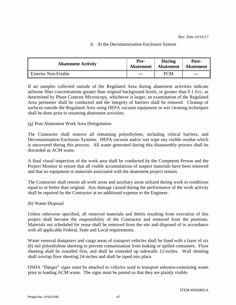
Rev. Date 10/16/17
ITEM #0020801A
d. At the Decontamination Enclosure System
Abatement Activity Pre-
Abatement
During
Abatement
Post-
Abatement
Exterior Non-Friable --- PCM ---
If air samples collected outside of the Regulated Area during abatement activities indicate
airborne fiber concentrations greater than original background levels, or greater than 0.1 f/cc, as
determined by Phase Contrast Microscopy, whichever is larger, an examination of the Regulated
Area perimeter shall be conducted and the integrity of barriers shall be restored. Cleanup of
surfaces outside the Regulated Area using HEPA vacuum equipment or wet cleaning techniques
shall be done prior to resuming abatement activities.
(g) Post Abatement Work Area Deregulation
The Contractor shall remove all remaining polyethylene, including critical barriers, and
Decontamination Enclosure Systems. HEPA vacuum and/or wet wipe any visible residue which
is uncovered during this process. All waste generated during this disassembly process shall be
discarded as ACM waste.
A final visual inspection of the work area shall be conducted by the Competent Person and the
Project Monitor to ensure that all visible accumulations of suspect materials have been removed
and that no equipment or materials associated with the abatement project remain.
The Contractor shall restore all work areas and auxiliary areas utilized during work to conditions
equal to or better than original. Any damage caused during the performance of the work activity
shall be repaired by the Contractor at no additional expense to the Engineer.
(h) Waste Disposal
Unless otherwise specified, all removed materials and debris resulting from execution of this
project shall become the responsibility of the Contractor and removed from the premises.
Materials not scheduled for reuse shall be removed from the site and disposed of in accordance
with all applicable Federal, State and Local requirements.
Waste removal dumpsters and cargo areas of transport vehicles shall be lined with a layer of six
(6) mil polyethylene sheeting to prevent contamination from leaking or spilled containers. Floor
sheeting shall be installed first, and shall be extended up sidewalls 12-inches. Wall sheeting
shall overlap floor sheeting 24-inches and shall be taped into place.
OSHA “Danger” signs must be attached to vehicles used to transport asbestos-containing waste
prior to loading ACM waste. The signs must be posted so that they are plainly visible.
Project No. 0152-0160
47
Rev. Date 10/16/17
ITEM #0020801A
Waste haulers and disposal facilities utilized shall match those indicated on the submitted
CTDPH notification.
Ensure all waste containers (bags, drums, etc.) are properly packed, sealed and labeled with
USEPA NESHAP generator labels, OSHA danger labels and DOT shipping labels. For each
shipment of ACM waste, the Contractor shall complete an EPA-approved asbestos waste
shipment record.
Authorized representatives signing waste shipment records on behalf of the generator must have
USDOT Shipper Certification training in accordance with HMR 49 CFR Parts 171-180.
Transport vehicles hauling ACM waste shall have appropriate USDOT placards visible on all
four (4) sides of the vehicle.
The Contractor shall dispose of asbestos-containing and/or asbestos contaminated material at an
EPA authorized site and must be in compliance with the requirements of the Special Waste
Provisions of the Office of Solid Waste Management, Department of Environmental Protection,
State of Connecticut, or other designated agency having jurisdiction over solid waste disposal.
Any asbestos-containing and/or asbestos-contaminated waste materials which also contain other
hazardous contaminants shall be disposed of in accordance with the EPA’s Resource
Conservation and Recovery Act (RCRA), CTDEEP and ConnDOT requirements. Materials may
be required to be stored on-site and tested by the Project Monitor to determine proper waste
disposal requirements.
(i) Project Closeout Data:
1. Provide the Engineer, within 30 days of completion of asbestos abatement, a
compliance package; which shall include, but not be limited to, the following:
a. Asbestos Abatement Site Supervisor job log;
b. OSHA personnel air sampling data;
c. Completed waste shipment records.
The Contractor shall submit the original completed waste shipment records to the Engineer.
Method of Measurement:
No measurement will be made for the work in this Section. The completed work shall be paid as
a lump sum.
Basis of Payment:
Project No. 0152-0160
48

Rev. Date 10/16/17
ITEM #0020801A
The lump sum bid price for this item shall include the specialty services of the Asbestos
Removal Contractor including: labor, materials, equipment, insurance, permits, notifications,
submittals, personal air sampling, personal protection equipment, temporary enclosures, utility
costs, incidentals, fees and labor incidental to the removal, transport and disposal of ACM,
including close out documentation.
Final payment for asbestos abatement will not be made until all the project closeout data
submittals have been completed (including waste shipment record(s) signed by an authorized
disposal facility representative) and provided to the Engineer. Once the completed package has
been received in its entirety, the Engineer will make the final payment to the Contractor.
Pay Item Pay Unit
Asbestos Abatement Lump Sum
Project No. 0152-0160
49
Rev. Date 10/27/17
ITEM #0020902A
ITEM #0020902A – LEAD COMPLIANCE FOR BUILDING DEMOLITION
AND RENOVATION
Description:
Work under this item shall include activities impacting various materials containing or covered
by lead paint and associated work by persons who are knowledgeable, qualified, and trained in
the removal, treatment and handling of lead contaminated materials, including the transportation
and disposal of hazardous and non-hazardous lead construction and demolition solid waste
containing or contaminated with lead, the recycling of metallic components covered with lead
paint, and the subsequent cleaning of the affected environment. Lead paint includes paint found
to contain any detectable amount of lead by Atomic Absorption Spectrophotometry (AAS) or X-
Ray Fluorescence (XRF).
All activities shall be performed in accordance with, but not limited to, the current revision of the
OSHA Lead in Construction Regulations (29 CFR 1926.62), the USEPA RCRA Hazardous
Waste Regulations (40 CFR Parts 260 through 274), and the CTDEEP Hazardous Waste
Regulations (22a-209-1 and 22a-449(c).
The lead paint activity shall include the demolition/renovation, removal and/or disposal of
building components coated with lead painted surfaces as identified on the Contract Plans and
Specifications.
Deviations from these Specifications require the written approval of the Engineer.
Materials:
All materials shall be delivered to the job site in the original packages, containers, or bundles
bearing the name of the manufacturer, the brand name and product technical description.
No damaged or deteriorating materials shall be used. If material becomes contaminated with
lead, the material shall be decontaminated or disposed of as lead-containing waste material. The
cost to decontaminate and dispose of this material shall be at the expense of the Contractor.
Fire retardant polyethylene sheet shall be in roll size to minimize the frequency of joints, with
factory label indicating four (4) or six (6) mil thickness.
Six (6) mil polyethylene disposable bags shall have pre-printed OSHA/EPA/DOT labels and
shall be transparent.
Tape (or equivalent) capable of sealing joints in adjacent polyethylene sheets and for the
attachment of polyethylene sheets to finished or unfinished surfaces must be capable of adhering
under both dry and wet conditions.
Project No. 0152-0160
50
Rev. Date 10/27/17
ITEM #0020902A
The cleaning agent detergent shall be lead specific, such as TriSodium Phosphate (TSP).
Any chemical stripper and chemical neutralizer to be utilized shall be compatible with the
substrate as well as with each other.
Labels and warning signs shall conform to OSHA 29 CFR 1926.62, USEPA 40 CFR 260
through 274 and USDOT 49 CFR 172 as appropriate.
Any planking, bracing, shoring, barricades and/or temporary sheet piling, necessary to
appropriately perform work activities shall conform to all applicable federal, state and local
regulations.
Air filtration devices and vacuum units shall be equipped with HEPA filters.
Construction Methods:
(1) Pre-Abatement Submittals and Notices
A. Prior to the start of any work that will generate hazardous lead waste above conditionally
exempt small quantities, the Contractor shall obtain from the Engineer a temporary EPA
Hazardous Waste Generators ID number, unless otherwise directed by the Engineer.
B. Fifteen (15) working days prior to beginning work that impacts lead paint, the Contractor
shall submit the following to the Engineer:
1. Copies of all employee certificates, dated within the previous twelve (12) months,
relating to OSHA lead awareness and hazard communication training and training
in the use of lead-safe work practices.
2. Work plan for work impacting lead paint including engineering controls, methods
of containment of debris and work practices to be employed, as needed, to
minimize employee/occupant exposure and prevent the spread of lead
contamination outside the Regulated Area.
3. Documentation from the Contractor, typed on company letterhead and signed by
the Contractor, certifying that all employees listed therein have received the
following:
a. medical monitoring within the previous twelve (12) months, as
required in 29 CFR 1926.62;
b. biological monitoring within the previous six (6) months, as required
in 29 CFR 1926.62;
c. respirator fit testing within the previous twelve (12) months, as
required in 29 CFR 1910.134 (for those who don a tight-fitting face
piece respirator).
Project No. 0152-0160
51
Rev. Date 10/27/17
ITEM #0020902A
4. Copies of state-approved certificates for the proposed non-hazardous construction
and demolition (C&D) lead debris disposal facility and any concrete/wood or
scrap metal recycling facilities.
5. Names of the proposed scrap metal recycling facilities. The Contractor shall
submit to the Engineer all documentation necessary to demonstrate the selected
facility is able to accept lead-painted scrap metal.
6. Names of the proposed hazardous waste disposal facility (selected from the
Department approved list provided herein), and copies of each facilities
acceptance criteria and sampling frequency requirements.
7. Copies of the proposed hazardous waste transporters current USDOT Certificate
of Registration for Hazardous Materials Transport, and the proposed transporters
current Hazardous Waste Transporter Permits for the State of Connecticut and the
waste destination State.
8. Negative exposure assessments conducted within the previous 12 months
documenting that employee exposure to lead for each task is below the OSHA
Action Level of 30 μg/m3. If a negative exposure assessment has not been
conducted, the Contractor shall submit its air monitoring program for the work
tasks as part of the Work Plan. Until a negative exposure assessment is developed
for each task impacting lead paint, the Contractor shall ensure that all workers and
authorized persons entering the Regulated Area wear protective clothing and
respirators in accordance with OSHA 29 CFR 1926.62.
No activity shall commence until a copy of all required submittals have been received and found
acceptable to the Engineer. Those employees added to the Contractor's original list will be
allowed to perform work only upon submittal of all required paperwork to, and review by, the
Engineer.
Contractor shall provide the Engineer with a minimum of 48 hours notice in advance of
scheduling, changing or canceling work activities.
(2) Lead Abatement Provisions
(a) General Requirements:
All employees of the Contractor who perform work impacting lead paint shall be properly
trained to perform such duties.
All labor, materials, tools, equipment, services, testing, insurance (with specific coverage for
work on lead), and incidentals which are necessary or required to perform the work in
accordance with applicable governmental regulations, industry standards and codes, and these
Project No. 0152-0160
52
Rev. Date 10/27/17
ITEM #0020902A
Specifications shall be provided by the Contractor. The Contractor shall be prepared to work all
shifts and weekends throughout the course of this project.
Prior to beginning work, the Engineer and Contractor shall perform a visual survey of each work
area and review conditions at the site for safety reasons. In addition, the Contractor shall instruct
all workers in all aspects of personnel protection, work procedures, emergency evacuation
procedures and use of equipment including procedures unique to this project.
The Contractor shall:
Shutdown and isolate heating, cooling, and ventilating air systems to prevent
contamination and particulate dispersal to the other areas of the building.
Shut down and lock out electrical power, including all receptacles and light fixtures,
when feasible. The use or isolation of electrical power will be coordinated with all other
ongoing uses of electrical power at the site.
Coordinate all power and fire alarm isolation with the appropriate representatives.
When necessary, provide temporary power and adequate lighting and ensure safe
installation of electrical equipment, including ground fault protection and power cables,
in compliance with applicable electrical codes and OSHA requirements. The Contractor
is responsible for proper connection and installation of electrical wiring.
Ladders and/or scaffolds to be utilized throughout this project shall be in compliance with OSHA
requirements, and of adequate length, strength and sufficient quantity to support the scope of
work. Use of ladders/scaffolds shall be in conformance with OSHA 29 CFR 1926 Subpart L and
X requirements.
Work performed at heights exceeding six feet (6’) shall be performed in accordance with the
OSHA Fall Protection Standard 29 CFR 1926 Subpart M including the use of fall arrest systems
as applicable.
Electrical service may not be available at the site. Costs for supplying electrical service shall be
the responsibility of the Contractor.
Water service may not be available at the site. The Contractor shall supply sufficient water for
each shift to operate the wash facility/decontamination shower units in addition to the water
needed at the work area.
Data for random lead testing conducted on surfaces throughout the buildings as well as
hazardous waste characterization results are available from the Engineer for informational
purposes only. Under no circumstances shall this information be the sole means used by the
Contractor for determining the extent of lead painted materials. The Contractor shall be
responsible for verification of all field conditions affecting performance of the work as described
Project No. 0152-0160
53
Rev. Date 10/27/17
ITEM #0020902A
in these Specifications in accordance with OSHA, USEPA, USDOT and CTDEEP standards.
Compliance with the applicable requirements is solely the responsibility of the Contractor.
Activity impacting lead painted surfaces shall be performed in a manner which minimizes the
spread of lead dust contamination and generation of airborne lead.
The Engineer will provide a Project Monitor to oversee the activities of the Contractor. No
activity impacting lead paint shall be performed until the Project Monitor is on-site.
Environmental sampling, including ambient air sampling, TCLP waste stream sampling and/or
dust wipe sampling, shall be conducted throughout the project as deemed necessary.
(b) Set-Up
The Contractor shall prepare a Regulated Area as follows:
In all areas where airborne exposures may exceed the OSHA PEL, post warning signs meeting
the requirements of OSHA 29 CFR 1926.62 at each regulated area.
In addition, signs shall be posted at all approaches to regulated areas so that an employee may
read the sign and take the necessary protective steps before entering the area. These signs shall
read:
DANGER
LEAD WORK AREA
MAY DAMAGE FERTILITY OR THE UNBORN CHILD
CAUSES DAMAGE TO THE CENTRAL NERVOUS SYSTEM
DO NOT EAT, DRINK OR SMOKE IN THIS AREA
Establish a Regulated Area, through the use of appropriate barrier tape, etc. and control
unauthorized access into the area throughout the lead paint related activity.
Implement appropriate engineering controls such as critical barriers, poly drop cloths, negative
pressure, local exhaust ventilation, wet dust suppression methods, etc. to prevent the spread of
lead contamination from the Regulated Area.
For exterior work areas, the Contractor shall use a High Efficiency Particulate Air (HEPA)
filtered vacuum dust collection system to remove any visible existing paint chips from the
ground to a distance of 20' out from the base of the exterior surface scheduled for lead paint
activity prior to commencement of work and extend a 6 mil polyethylene sheet drop cloth on the
ground adjacent to the exterior surface scheduled for lead paint activity to contain
debris/contamination.
The Contractor shall provide handwash facilities in compliance with 29 CFR 1926.51(f) and 29
CFR 1926.62 regardless of airborne lead exposure. This wash facility will consist, at least, of
potable water, towels, soap, and a HEPA vacuum.
Project No. 0152-0160
54
Rev. Date 10/27/17
ITEM #0020902A
If air monitoring data by the Contractor or Project Monitor shows that employee exposure to
airborne lead exceeds the OSHA PEL (50 μg/m3), shower rooms must be utilized. The Shower
Room shall be of sufficient capacity to accommodate the number of workers. One shower stall
shall be provided for each eight (8) workers. Showers shall be equipped with hot and cold or
warm running water through the use of electric hot water heaters supplied by the Contractor.
Shower water shall be collected and filtered using best available technology and dumped down
an approved sanitary drain. Shower stalls and plumbing shall include sufficient hose length and
drain system or an acceptable alternate.
(c) Personal Protection:
The Contractor shall initially determine if any employee performing construction tasks impacting
lead paint may be exposed to lead at or above the OSHA Action Level of 30 micrograms per
cubic meter (30 μg/m3). Assessments shall be based on initial air monitoring results as well as
other relevant information. The Contractor may rely on historical air monitoring data obtained
within the past 12 months under workplace conditions closely resembling the process, type of
material, control methods, work practices and environmental conditions used and prevailing in
the Contractors current operations to satisfy the exposure assessment requirements. Monitoring
shall continue as specified in the OSHA standard until a negative exposure assessment is
developed.
Until a negative exposure assessment is developed for the required tasks impacting lead paint,
the Contractor shall ensure that all workers and authorized person entering the Regulated Area
wear protective clothing and respirators in accordance with OSHA 29 CFR 1926.62. Protective
clothing shall include impervious coveralls with elastic wrists and ankles, head covering, gloves
and foot coverings. Sufficient quantities shall be provided to last throughout the duration of the
project.
Protective clothing provided by the Contractor and used during chemical removal operations
shall be impervious to caustic materials. Gloves provided by the Contractor and used during
chemical removal shall be of neoprene composition with glove extenders.
Respiratory protective equipment shall be provided and selection shall conform to 30 CFR Part
11, 29 CFR Part 1910.134, and 29 CFR Part 1926.62. A formal respiratory protection program
must be implemented in accordance with 29 CFR Part 1926.62 and Part 1910.134.
(d) Lead Abatement Procedures
Ensure that the Competent Person is on the job at all times.
Do not begin abatement work until authorized by the Engineer, following a pre-abatement visual
inspection by the Project Monitor.
The Contractor shall ensure proper entry and exit procedures for workers and authorized persons
Project No. 0152-0160
55
Rev. Date 10/27/17
ITEM #0020902A
who enter and leave the Regulated Area. All workers and authorized persons shall leave the
Regulated Area and proceed directly to the wash or shower facilities where they will HEPA
vacuum gross debris from work suit, remove and dispose of work suit, wash and dry face and
hands, and vacuum clothes. Do not remove lead chips or dust by blowing or shaking of clothing.
Wash water shall be collected, filtered, and disposed of in accordance with federal, state and
local water discharge standards.
No one shall eat, drink, smoke, chew gum or tobacco, or apply cosmetics while in the Regulated
Area.
The following details the extent of each phase of operation designated for this project. Phase
areas may be combined or divided at the direction of the Engineer. Proceed through the
sequencing of the work phases under the direction of the Engineer.
Metal Roof Related Components To Be Impacted
Lead paint has been identified on/associated with metal roof trusses/decking, metal
roof drains/water pipes and metal I-beams. All renovation work impacting those
materials shall be conducted within an established lead control (regulated) area with
a remote handwash facility/decontamination system in accordance with OSHA Lead
in Construction Standards. Engineering controls and work practices shall be
utilized to prevent the spread of lead dust and debris beyond the work area and
limit the generation of airborne lead.
Contractor shall ensure all renovation work which may impact/disturb the metal
roof deck/truss system (such as vibration from above, installation of fasteners,
surface prep for painting, etc) which may disturb or dislodge the lead paint in any
way shall be conducted in a manner which contains the spread of lead dust and
debris from release beyond the regulated work area and limits the generation of
airborne lead. Any/all lead paint dust/debris generated shall be properly cleaned
for removal/disposal.
All steel and metal generated from the renovation of the structure shall be
segregated and recycled as scrap metal at an approved facility. The recycling of
scrap metal (regardless of lead paint concentration) is exempt from USEPA RCRA
and CTDEEP Hazardous Waste Regulation.
Where it is necessary to remove paint from the metal substrate, any paint waste to
be generated is presently presumed to be hazardous waste. Should the paint be
removed from the components, the Engineer will conduct TCLP testing or mass
balance calculations on a representative sample of the lead paint waste materials to
confirm if it is classified as hazardous waste or non-hazardous, non-RCRA waste.
Should the waste be determined to be hazardous, it shall be handled and disposed of
in accordance with USEPA/CTDEEP Hazardous Waste Regulations as described
under this Item 0020902A. If the waste is determined to be non-hazardous, it shall
Project No. 0152-0160
56
Rev. Date 10/27/17
ITEM #0020902A
be disposed of as non-hazardous, non-RCRA Connecticut Regulated Waste in
accordance with CTDEEP Solid Waste Regulations as described under this Item
0020902A.
The Contractor shall conduct exposure assessments for the tasks required which impact
lead paint in accordance with OSHA 29 CFR 1926.62(d) and shall implement appropriate
personal protective equipment until negative exposure assessments are developed.
Utilize appropriate engineering controls (e.g. wet methods) as directed by 29 CFR 1926.62 to
control lead emissions and contamination.
Properly contain wastes containing lead paint for appropriate transport/disposal.
Stop all work in the regulated area and take steps to decontaminate non-work areas and eliminate
causes of such contamination should lead contamination be discovered in areas outside of the
regulated area.
Special Requirements:
1. Demolition:
a. Demolish in a manner which minimizes the spread of lead contamination
and generation of lead dust.
b. Implement dust suppression controls, such as misters, local exhausts
ventilation, etc. to minimize the generation of airborne lead dust.
c. Segregate work areas from non-work areas through the use or barrier tape,
poly criticals, etc.
d. Clean up immediately after renovation/demolition has been completed
2. Chemical Removal:
a. Apply chemical stripper in quantities and for durations specified by manufacturer.
b. Where necessary, scrape lead paint from surface down to required level of
removal (i.e. stabilized surface, bare substrate with no trace of residual pigment,
etc.). Use sanding, hand scraping, and dental picks to supplement chemical
methods as necessary.
c. Apply neutralizer compatible with substrate and chemical agent to substrate
following removal in accordance with manufacturer's instructions.
d. Protect adjacent surfaces from damage from chemical removal.
Project No. 0152-0160
57
Rev. Date 10/27/17
ITEM #0020902A
e. Maintain a portable eyewash station in the work area.
f. Wear respirators that will protect workers from chemical vapors.
g. Do not apply caustic agents to aluminum surfaces.
3. Mechanical Paint Removal:
a. Provide sanders, grinders, rotary wire brushes, or needle gun removers equipped
with a HEPA filtered vacuum dust collection system. Cowling on the dust
collection system for orbital-type tools must be capable of maintaining a
continuous tight seal with the surface being abated. Cowling on the dust
collection system for reciprocating-type tools shall promote an effective vacuum
flow of loosened dust and debris. Inflexible cowlings may be used on flat
surfaces only. Flexible contoured cowlings are required for curved or irregular
surfaces.
b. Provide HEPA vacuums that are high performance designed to provide maximum
static lift and maximum vacuum system flow at the actual operating vacuum
condition with the shroud in use. The HEPA vacuum shall be equipped with a
pivoting vacuum head.
c. Remove lead paint from surface down to required level of removal (i.e. stabilized
surface, bare substrate with no trace of residual pigment, etc.). Use chemical
methods, hand scraping, and dental picks to supplement abrasive removal
methods as necessary.
d. Protect adjacent surfaces from damage from abrasive removal techniques.
e. “Sandblasting” type removal techniques shall not be allowed.
4. Component Removal/Replacement:
a. Wet down components which are to be removed to reduce the amount of dust
generated during the removal process.
b. Remove components utilizing hand tools, and follow appropriate safety
procedures during removal. Remove the components by approved methods which
will provide the least disturbance to the substrate material. Do not damage
adjacent surfaces.
c. Clean up immediately after component removals have been completed. Remove
any dust located behind the component removed.
Project No. 0152-0160
58
Rev. Date 10/27/17
ITEM #0020902A
(e) Prohibited Removal Methods:
The use of heat guns in excess of 700 degrees Fahrenheit to remove lead paint is prohibited.
The use of sand, steel grit, water, air, CO2, baking soda, or any other blasting media to remove
lead or lead paint without the use of a HEPA ventilated contained negative pressure enclosure is
prohibited.
Power tool assisted grinding, sanding, cutting, or wire brushing of lead paint without the use of
cowled HEPA vacuum dust collection systems is prohibited.
Lead paint burning, busting of rivets painted with lead paint, welding of materials painted with
lead paint, and torch cutting of materials painted with lead paint is prohibited. Where cutting,
welding, busting, or torch cutting of materials is required, pre-remove the lead paint in the area
affected.
Use of chemical strippers containing Methylene Chloride is prohibited.
Compressed air shall not be utilized to remove lead paint.
(f) Air Monitoring Requirements
1. The Contractor shall:
a. Provide air monitoring equipment including sample filter cassettes of the
type and quantity required to properly monitor operations and personnel
exposure surveillance throughout the duration of the project.
b. Conduct initial exposure monitoring to determine if any employee
performing construction tasks impacting lead paint may be exposed to lead
at or above the OSHA Action Level of 30 micrograms per cubic meter.
Monitoring shall continue as specified in the OSHA standard until a
negative exposure assessment is developed.
c. Conduct personnel exposure assessment air sampling, as necessary, to
assure that workers are using appropriate respiratory protection in
accordance with OSHA Standard 1926.62. Documentation of air
sampling results must be recorded at the work site within twenty-four (24)
hours and shall be available for review until the job is complete.
2. The Project Monitor will:
a. Collect air samples in accordance with the current revision of the NIOSH
7082 or 7702 Method of Air Sampling for Airborne Lead while
overseeing the activities of the Contractor. Frequency and duration of the
Project No. 0152-0160
59
Rev. Date 10/27/17
ITEM #0020902A
air sampling during abatement will be representative of the actual
conditions at the site. The size and configuration of the project will be a
factor in the number of samples required to monitor the activities and shall
be determined by the Project Monitor.
As determined by AAS, XRF, or equivalent analysis, if air samples collected outside of the
Regulated Area during abatement activities indicate airborne lead concentrations greater than
original background levels or greater than 30 ug/m3, whichever is larger, an examination of the
Regulated Area perimeter shall be conducted and the integrity of barriers shall be restored.
Cleanup of surfaces outside the Regulated Area using HEPA vacuum equipment or wet cleaning
techniques shall be done prior to resuming abatement activities.
Abatement outside the initial designated work area(s) will not be paid for by the Engineer. The
Contractor will be responsible for all costs incurred from these abatement activities.
(g) Clean-up and Visual Inspection:
Remove and containerize all lead waste material and visible accumulations of debris, paint chips
and associated items.
During clean up the Contractor shall utilize rags and sponges wetted with lead-specific detergent
and water as well as HEPA filtered vacuum equipment.
The Engineer will conduct a visual inspection of the work areas in order to document that all
surfaces have been maintained as free as practicable of accumulations of lead in accordance with
OSHA 29 CFR 1926.62(h). If visible accumulations of waste, debris, lead paint chips or dust are
found in the work area, the Contractor shall repeat the cleaning, at the Contractor's expense, until
the area is in compliance. The visual inspection will detect incomplete work, damage caused by
the abatement activity, and inadequate clean up of the work site.
(h) Post-Abatement Work Area Deregulation:
Following the visual inspection, (and clearance testing if appropriate,) any engineering controls
implemented may be removed and the Work Area deregulated.
A final visual inspection of the work area shall be conducted by the Competent Person and the
Project Monitor to ensure that all visible accumulations of suspect materials have been removed
and that no equipment or materials associated with the abatement project remain.
The Contractor shall restore all work areas and auxiliary areas utilized during work to conditions
equal to or better than original. Any damage caused during the performance of the work activity
shall be repaired by the Contractor at no additional expense to the Engineer.
(I) Waste Disposal/Recycling:
Project No. 0152-0160
60
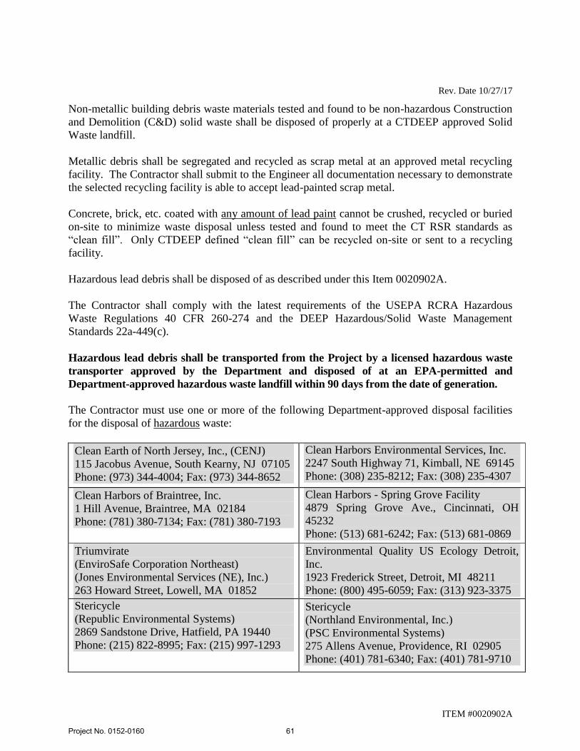
Rev. Date 10/27/17
ITEM #0020902A
Non-metallic building debris waste materials tested and found to be non-hazardous Construction
and Demolition (C&D) solid waste shall be disposed of properly at a CTDEEP approved Solid
Waste landfill.
Metallic debris shall be segregated and recycled as scrap metal at an approved metal recycling
facility. The Contractor shall submit to the Engineer all documentation necessary to demonstrate
the selected recycling facility is able to accept lead-painted scrap metal.
Concrete, brick, etc. coated with any amount of lead paint cannot be crushed, recycled or buried
on-site to minimize waste disposal unless tested and found to meet the CT RSR standards as
“clean fill”. Only CTDEEP defined “clean fill” can be recycled on-site or sent to a recycling
facility.
Hazardous lead debris shall be disposed of as described under this Item 0020902A.
The Contractor shall comply with the latest requirements of the USEPA RCRA Hazardous
Waste Regulations 40 CFR 260-274 and the DEEP Hazardous/Solid Waste Management
Standards 22a-449(c).
Hazardous lead debris shall be transported from the Project by a licensed hazardous waste
transporter approved by the Department and disposed of at an EPA-permitted and
Department-approved hazardous waste landfill within 90 days from the date of generation.
The Contractor must use one or more of the following Department-approved disposal facilities
for the disposal of hazardous waste:
Clean Earth of North Jersey, Inc., (CENJ)
115 Jacobus Avenue, South Kearny, NJ 07105
Phone: (973) 344-4004; Fax: (973) 344-8652
Clean Harbors Environmental Services, Inc.
2247 South Highway 71, Kimball, NE 69145
Phone: (308) 235-8212; Fax: (308) 235-4307 Clean Harbors of Braintree, Inc.
1 Hill Avenue, Braintree, MA 02184
Phone: (781) 380-7134; Fax: (781) 380-7193
Clean Harbors - Spring Grove Facility
4879 Spring Grove Ave., Cincinnati, OH
45232
Phone: (513) 681-6242; Fax: (513) 681-0869 Triumvirate
(EnviroSafe Corporation Northeast)
(Jones Environmental Services (NE), Inc.)
263 Howard Street, Lowell, MA 01852
Phone: (978) 453-7772; Fax: (978) 453-7775
Environmental Quality US Ecology Detroit,
Inc.
1923 Frederick Street, Detroit, MI 48211
Phone: (800) 495-6059; Fax: (313) 923-3375
Stericycle
(Republic Environmental Systems)
2869 Sandstone Drive, Hatfield, PA 19440
Phone: (215) 822-8995; Fax: (215) 997-1293
Stericycle
(Northland Environmental, Inc.)
(PSC Environmental Systems)
275 Allens Avenue, Providence, RI 02905
Phone: (401) 781-6340; Fax: (401) 781-9710
Project No. 0152-0160
61
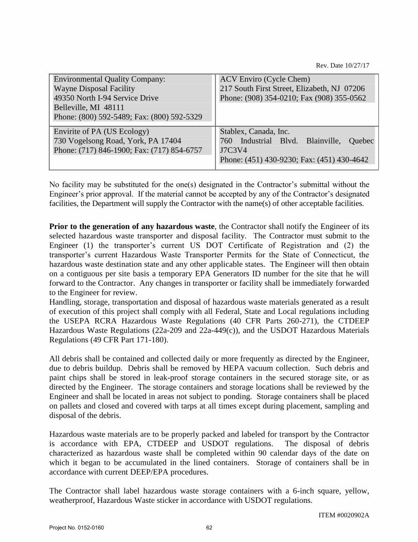
Rev. Date 10/27/17
ITEM #0020902A
Environmental Quality Company:
Wayne Disposal Facility
49350 North I-94 Service Drive
Belleville, MI 48111
Phone: (800) 592-5489; Fax: (800) 592-5329
ACV Enviro (Cycle Chem)
217 South First Street, Elizabeth, NJ 07206
Phone: (908) 354-0210; Fax (908) 355-0562
Envirite of PA (US Ecology)
730 Vogelsong Road, York, PA 17404
Phone: (717) 846-1900; Fax: (717) 854-6757
Stablex, Canada, Inc.
760 Industrial Blvd. Blainville, Quebec
J7C3V4
Phone: (451) 430-9230; Fax: (451) 430-4642
No facility may be substituted for the one(s) designated in the Contractor’s submittal without the
Engineer’s prior approval. If the material cannot be accepted by any of the Contractor’s designated
facilities, the Department will supply the Contractor with the name(s) of other acceptable facilities.
Prior to the generation of any hazardous waste, the Contractor shall notify the Engineer of its
selected hazardous waste transporter and disposal facility. The Contractor must submit to the
Engineer (1) the transporter’s current US DOT Certificate of Registration and (2) the
transporter’s current Hazardous Waste Transporter Permits for the State of Connecticut, the
hazardous waste destination state and any other applicable states. The Engineer will then obtain
on a contiguous per site basis a temporary EPA Generators ID number for the site that he will
forward to the Contractor. Any changes in transporter or facility shall be immediately forwarded
to the Engineer for review.
Handling, storage, transportation and disposal of hazardous waste materials generated as a result
of execution of this project shall comply with all Federal, State and Local regulations including
the USEPA RCRA Hazardous Waste Regulations (40 CFR Parts 260-271), the CTDEEP
Hazardous Waste Regulations (22a-209 and 22a-449(c)), and the USDOT Hazardous Materials
Regulations (49 CFR Part 171-180).
All debris shall be contained and collected daily or more frequently as directed by the Engineer,
due to debris buildup. Debris shall be removed by HEPA vacuum collection. Such debris and
paint chips shall be stored in leak-proof storage containers in the secured storage site, or as
directed by the Engineer. The storage containers and storage locations shall be reviewed by the
Engineer and shall be located in areas not subject to ponding. Storage containers shall be placed
on pallets and closed and covered with tarps at all times except during placement, sampling and
disposal of the debris.
Hazardous waste materials are to be properly packed and labeled for transport by the Contractor
is accordance with EPA, CTDEEP and USDOT regulations. The disposal of debris
characterized as hazardous waste shall be completed within 90 calendar days of the date on
which it began to be accumulated in the lined containers. Storage of containers shall be in
accordance with current DEEP/EPA procedures.
The Contractor shall label hazardous waste storage containers with a 6-inch square, yellow,
weatherproof, Hazardous Waste sticker in accordance with USDOT regulations.
Project No. 0152-0160
62
Rev. Date 10/27/17
ITEM #0020902A
Materials other than direct paint related debris which are incidental to the paint removal work
activities (tarps, poly, plywood, PPE, gloves, decontamination materials, etc.) which may be
contaminated with lead, shall be stored separately from the direct paint debris, and shall be
sampled by the Engineer for waste disposal characterization testing. Such materials
characterized as hazardous shall be handled/disposed of as described herein.
Direct paint related debris materials not previously sampled and characterized for disposal,
which may be originally presumed to be hazardous waste, shall also be stored separately and
sampled by the Engineer for ultimate waste disposal characterization testing and
handled/disposed of based on that testing.
Project construction waste materials unrelated to the paint removal operations shall NOT be
combined/stored with paint debris waste and/or incidental paint removal materials as they are not
lead contaminated and shall NOT be disposed of as hazardous waste. The Engineer’s on-site
Inspectors shall conduct inspections to verify materials remain segregated.
The Contractor shall obtain and complete all paperwork necessary to arrange for material
disposal, including disposal facility waste profile sheets. It is solely the Contractor’s
responsibility to co-ordinate the disposal of hazardous materials with its selected
treatment/recycling/disposal facility(s). Upon receipt of the final approval from the facility, the
Contractor shall arrange for the loading, transport and treatment/recycling/disposal of the
materials in accordance with all Federal and State regulations. No claim will be considered
based on the failure of the Contractor’s disposal facility(s) to meet the Contractor’s
production rate or for the Contractor’s failure to select sufficient facilities to meet its
production rate.
The Contractor shall process the hazardous waste such that the material conforms with the
requirements of the selected treatment/disposal facility, including but not limited to specified
size and dimension. Refusal on the part of the treatment/disposal facility to accept said material
solely on the basis of non-conformance of the material to the facility’s physical requirements is
the responsibility of the Contractor and no claim for extra work shall be accepted for
reprocessing of said materials to meet these requirements.
All DOT shipping documents, including the Uniform Hazardous Waste Manifests utilized to
accompany the transportation of the hazardous waste material shall be prepared by the
Contractor and reviewed/signed by an authorized agent representing ConnDOT, as Generator,
for each load of hazardous material that is packed to leave the site. The Contractor shall not sign
manifests on behalf of the State as Generator. The Contractor shall forward the appropriate
original copies of all manifests to the Engineer the same day the material leaves the Project site.
Materials not related to lead paint removal and/or characterized as non-hazardous waste shall
NOT be shipped for hazardous waste disposal in accordance with USEPA RCRA hazardous
waste minimization requirements.
Project No. 0152-0160
63
Rev. Date 10/27/17
ITEM #0020902A
A load-specific certificate of disposal, signed by the authorized agent representing the waste
disposal facility, shall be obtained by the Contractor and promptly delivered to the Engineer for
each load.
In addition to all pertinent Federal, State and local laws or regulatory agency polices, the
Contractor shall adhere to the following precautions during the transport of hazardous materials
off-site:
All vehicles departing the site are to be properly logged to show the vehicle
identification, driver’s name, time of departure, destination, and approximate volume,
and contents of materials carried. Vehicles shall display the proper USDOT placards
for the type and quantity of waste;
No materials shall leave the site unless a disposal facility willing to accept all of the
material being transported has agreed to accept the type and quantity of waste;
Documentation must be maintained indicating that all applicable laws have been
satisfied and that the materials have been successfully transported and received at the
disposal facility; and,
The Contractor shall segregate the waste streams (i.e. concrete, wood, etc.) as
directed by the receiving disposal facility.
Any spillage of debris during disposal operations during loading, transport and unloading shall
be cleaned up in accordance with EPA 40 CFR 265 Subparts C & D, at the Contractor’s expense.
The Contractor is liable for any fines, costs or remediation costs incurred as a result of their
failure to be in compliance with this Item and all Federal, State and Local laws.
(j) Project Closeout Data:
1. Provide the Engineer, within thirty (30) days of completion of the project site
work, a compliance package; which shall include, but not be limited to, the
following:
a. Competent persons (supervisor) job log;
b. OSHA-compliant personnel air sampling data;
c. Completed waste shipment papers for non-hazardous lead construction
and demolition (C&D) solid waste and/or concrete/wood/scrap metal
recycling.
d. Completed copies of Hazardous Waste Manifests (signed by authorized
disposal facility representative)
Method of Measurement:
Project No. 0152-0160
64
Rev. Date 10/27/17
ITEM #0020902A
No measurement will be made for the work in this Section. The completed work shall be paid as
a lump sum.
Basis of Payment:
The lump sum price bid for this item shall include: services, materials, equipment, insurance, all
permits, notifications, submittals, personal air sampling, personal protection equipment,
temporary enclosures, incidentals, fees and labor incidental to activities impacting lead removal,
treatment and handling of lead contaminated materials, and the transport and disposal of any
non-hazardous lead construction and demolition (C&D) solid waste.
Final payment for lead abatement will not be made until all project closeout data submittals have
been completed and provided to the Engineer. Once the completed package has been received in
its entirety and accepted by the Engineer, final payment will be made to the Contractor.
Pay Item Pay Unit
Lead Compliance Lump Sum
END OF SECTION
Project No. 0152-0160
65
Rev. Date 9/22/16
ITEM #0177150A
ITEM #0177150A – GENERAL BUILDING RENOVATION
Description: Under this item, the Contractor shall complete all work depicted on the Contract
Plans and described in the CSI-formatted Specifications that make up this Major Lump Sum Item
(MLSI). Refer to Form 817 Article 1.20-1.02.04 for additional information in this regard.
Any work incidental to another bid item which is not specifically described or included in
the bid item, but which is required for performance and completion of the work required under
the Contract, shall be considered to be included under this item.
Materials: All materials shall be as required by the Contract Plans and as described in the CSI-
formatted Specifications that make up this MLSI.
Construction Methods: All methods of construction shall conform to the requirements as
stipulated in the CSI-formatted Specifications that make up this MLSI.
Method of Measurement: This item will be paid for at the contract lump sum price for “General
Building Renovation” complete.
Basis of Payment: This item will be paid for at the contract lump sum price for “General
Building Renovation, Item No. 0177150A”, which price shall include all administrative and
procedural requirements, material, equipment, labor, and work incidental thereto.
PAY ITEM PAY UNIT
General Building Renovation LS
Project No. 0152-0160
66
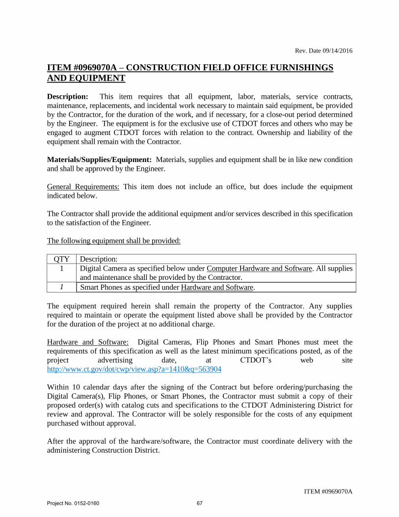
Rev. Date 09/14/2016
ITEM #0969070A
ITEM #0969070A – CONSTRUCTION FIELD OFFICE FURNISHINGS
AND EQUIPMENT
Description: This item requires that all equipment, labor, materials, service contracts,
maintenance, replacements, and incidental work necessary to maintain said equipment, be provided
by the Contractor, for the duration of the work, and if necessary, for a close-out period determined
by the Engineer. The equipment is for the exclusive use of CTDOT forces and others who may be
engaged to augment CTDOT forces with relation to the contract. Ownership and liability of the
equipment shall remain with the Contractor.
Materials/Supplies/Equipment: Materials, supplies and equipment shall be in like new condition
and shall be approved by the Engineer.
General Requirements: This item does not include an office, but does include the equipment
indicated below.
The Contractor shall provide the additional equipment and/or services described in this specification
to the satisfaction of the Engineer.
The following equipment shall be provided:
QTY Description:
1 Digital Camera as specified below under Computer Hardware and Software. All supplies
and maintenance shall be provided by the Contractor.
1
Smart Phones as specified under Hardware and Software.
The equipment required herein shall remain the property of the Contractor. Any supplies
required to maintain or operate the equipment listed above shall be provided by the Contractor
for the duration of the project at no additional charge.
Hardware and Software: Digital Cameras, Flip Phones and Smart Phones must meet the
requirements of this specification as well as the latest minimum specifications posted, as of the
project advertising date, at CTDOT’s web site
http://www.ct.gov/dot/cwp/view.asp?a=1410&q=563904
Within 10 calendar days after the signing of the Contract but before ordering/purchasing the
Digital Camera(s), Flip Phones, or Smart Phones, the Contractor must submit a copy of their
proposed order(s) with catalog cuts and specifications to the CTDOT Administering District for
review and approval. The Contractor will be solely responsible for the costs of any equipment
purchased without approval.
After the approval of the hardware/software, the Contractor must coordinate delivery with the
administering Construction District.
Project No. 0152-0160
67
Rev. Date 09/14/2016
ITEM #0969070A
The Contractor shall provide all supplies, maintenance, and repairs (including labor and parts) for
the hardware/software, for the duration of the Contract. All repairs must be performed with-in 48
hours. If the repairs require more than a 48 hours then an equal or better replacement must be
provided.
Repair(s) or replacement(s) of equipment for any reason shall be provided at no additional cost to
the State.
Concrete Testing Equipment: If the Contract includes items that require compressive strength
cylinders for concrete, in accordance with the Schedule of Minimum Testing Requirements for
Sampling Materials for Test, the Contractor shall provide the following.
A) Concrete Cylinder Curing Box – meeting the requirements of Section 6.12 of the Standard
Specifications.
B) Air Meter – The air meter provided shall be in good working order and will meet the
requirements of AASHTO T 152.
C) Slump Cone Mold – Slump cone, base plate, and tamping rod shall be provided in like-new
condition and meet the requirements of AASHTO T119, Standard Test Method for Slump
of Hydraulic-Cement Concrete.
All testing equipment will remain the property of the Contractor at the completion of the project.
Method of Measurement: The furnishing and maintenance of the construction field office
furnishings and equipment will be measured for payment by the number of calendar months that the
equipment is in place and in operation, measured to the nearest month.
There will not be a price adjustment due to a change in the minimum computer system
requirements.
Basis of Payment: The furnishing and maintenance of the construction field office furnishings and
equipment will be paid at the listed unit price per month for the respective item “Construction Field
Office Furnishings and Equipment”, which price shall include all material, equipment, labor, service
contracts, licenses, repair or replacement of hardware and software, related supplies and work
incidental thereto, as well as any other costs to provide requirements of this specification.
Pay Item Pay Unit
Construction Field Office Furnishings and Equipment Month
Project No. 0152-0160
68
GENERAL
PERMITS AND/OR REQUIRED PROVISIONS:
The following Permits and/or Supplemental to Form 817 and Required Provisions follow this page and
are hereby made part of this Contract.
PERMITS AND/OR PERMIT APPLICATIONS
No Permits are required for this contract
Construction Contracts - Required Contract Provisions (State Funded Only Contracts)
Project No. 0152-0160
69
Rev. Date 10/13/10
GENERAL
CSI SPECIFICATIONS
Project No. 0152-0160
70
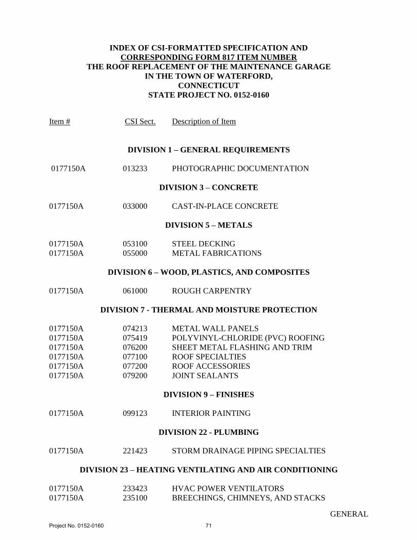
GENERAL
INDEX OF CSI-FORMATTED SPECIFICATION AND
CORRESPONDING FORM 817 ITEM NUMBER
THE ROOF REPLACEMENT OF THE MAINTENANCE GARAGE
IN THE TOWN OF WATERFORD,
CONNECTICUT
STATE PROJECT NO. 0152-0160
Item # CSI Sect. Description of Item
DIVISION 1 – GENERAL REQUIREMENTS
0177150A 013233 PHOTOGRAPHIC DOCUMENTATION
DIVISION 3 – CONCRETE
0177150A 033000 CAST-IN-PLACE CONCRETE
DIVISION 5 – METALS
0177150A 053100 STEEL DECKING
0177150A 055000 METAL FABRICATIONS
DIVISION 6 – WOOD, PLASTICS, AND COMPOSITES
0177150A 061000 ROUGH CARPENTRY
DIVISION 7 - THERMAL AND MOISTURE PROTECTION
0177150A 074213 METAL WALL PANELS
0177150A 075419 POLYVINYL-CHLORIDE (PVC) ROOFING
0177150A 076200 SHEET METAL FLASHING AND TRIM
0177150A 077100 ROOF SPECIALTIES
0177150A 077200 ROOF ACCESSORIES
0177150A 079200 JOINT SEALANTS
DIVISION 9 – FINISHES
0177150A 099123 INTERIOR PAINTING
DIVISION 22 - PLUMBING
0177150A 221423 STORM DRAINAGE PIPING SPECIALTIES
DIVISION 23 – HEATING VENTILATING AND AIR CONDITIONING
0177150A 233423 HVAC POWER VENTILATORS
0177150A 235100 BREECHINGS, CHIMNEYS, AND STACKS
Project No. 0152-0160
71
Rev. Date 09/22/16
PHOTOGRAPHIC DOCUMENTATION 013233 - 1
SECTION 013233 - PHOTOGRAPHIC DOCUMENTATION
PART 1 - GENERAL
1.1 SUMMARY:
A. Section includes administrative and procedural requirements for the following:
1. Preconstruction photographs.
2. Periodic construction photographs.
3. Final completion construction photographs.
1.2 INFORMATIONAL SUBMITTALS:
A. At the Preconstruction Meeting, submit to the Engineer for approval the name of the
photographer who will be responsible for taking the photographs during construction.
1.3 PHOTOGRAPHIC DOCUMENTATION SUBMITTALS:
A. Transmittal of Submittals: The zipped folder submittal package shall be uploaded into
ProjectWise “01.0 – Projects-Active” under the subfolder “151_Project Photos” under
the project number main folder. The specific work flow to do so will be distributed at
the Preconstruction Meeting.
1. The Contractor shall attribute the submittal packages in ProjectWise using the
following the following attributes and naming conventions:
a. Discipline: CTR
b. Main Category: CONTRACTOR
c. Sub Category: PROGRESS PHOTOS
d. Label: “Project Number - Progress Photos #XX - Date”
e. Description: “Progress Photos #XX – Date”
2. After uploading photographic documentation, the Contractor shall provide e-mail
notification to submittal reviewers and other key personnel at their business e-
mail address that the submittals have been uploaded and are available for review.
The Contractor shall provide a web link to the zipped folder submittal within their
e-mail notification. The Contractor shall include the following information in the
notification e-mail subject line in this order: “Project Number - Progress Photos
#XX - Date”.
B. Digital Photographs: Submit image files within 7 days of taking photographs.
Project No. 0152-0160
72

Rev. Date 09/22/16
PHOTOGRAPHIC DOCUMENTATION 013233 - 2
1. Include copy of key plan with each photograph submittal of Project site and
building with notation of vantage points marked for location and direction of each
photograph. Include same information as corresponding photographic
documentation.
1.4 QUALITY ASSURANCE:
A. Photographer Qualifications: An individual who has been regularly engaged as a
professional photographer of construction projects for not less than 3 years.
1.5 FORMATS AND MEDIA:
A. Digital Photographs: Provide color images in JPG format, produced by a digital camera
with minimum sensor size of 12 megapixels, and at an image resolution of not less than
3200 by 2400 pixels, and with vibration-reduction technology. Use flash in low light
levels or backlit conditions.
B. Digital Images: Submit digital media as originally recorded in the digital camera,
without alteration, manipulation, editing, or modifications using image-editing software.
C. Metadata: Record accurate date and time and GPS location data from camera.
1.6 CONSTRUCTION PHOTOGRAPHS:
A. Photographer: Engage a qualified photographer to take construction photographs.
B. General: Take photographs with maximum depth of field and in focus.
1. Maintain key plan with each set of construction photographs that identifies each
photographic location.
C. Preconstruction Photographs: Before commencement of Project Work, take
photographs of Project site and surrounding properties, including existing items to
remain during construction, from different vantage points, as directed by the Engineer.
1. Flag construction limits before taking construction photographs.
2. Take 20 photographs to show existing conditions adjacent to property before
starting the Work.
3. Take 20 photographs of existing buildings either on or adjoining property to
accurately record physical conditions at start of construction.
D. Periodic Construction Photographs: Take 20 photographs monthly coinciding as closely
as possible with the completion of a major construction phase. Select vantage points to
show status of construction and progress since last photographs were taken. Prior to
taking any photographs review the proposed vantage points with the Engineer.
Project No. 0152-0160
73
Rev. Date 09/22/16
PHOTOGRAPHIC DOCUMENTATION 013233 - 3
1. Photographs are for a record of the progress of work. Therefore, they shall be
taken at a maximum interval of one month, whether or not they show any
completion of work performed during the preceding month.
E. Final Completion Construction Photographs: Take 40 photographs after the date of
Substantial Completion for submission as Project Record Documents. The Engineer
will inform photographer of desired vantage points.
F. Additional Photographs: The Engineer may request photographs in addition to periodic
photographs specified. Additional photographs will be paid for by Change Order and
are not included in the Contract Sum.
1. Three days' notice will be given, where feasible.
2. In emergency situations, take additional photographs within 24 hours of request.
3. Circumstances that could require additional photographs include, but are not
limited to, the following:
a. Special events planned at Project site.
b. Immediate follow-up when on-site events result in construction damage or
losses.
c. Photographs to be taken at fabrication locations away from Project site.
These photographs are not subject to unit prices or unit-cost allowances.
d. Substantial Completion of a major phase or component of the Work.
e. Extra record photographs at time of final acceptance.
f. Owner's request for special publicity photographs.
PART 2 - PRODUCTS (Not Used)
PART 3 - EXECUTION (Not Used)
END OF SECTION 013233
Project No. 0152-0160
74
CAST-IN-PLACE CONCRETE
033000 - 1
SECTION 033000 - CAST-IN-PLACE CONCRETE
PART 1 - GENERAL
1.1 SUMMARY:
A. This Section specifies Cast-in-Place Concrete, including formwork, reinforcement,
concrete materials, mixture design, placement procedures and finishes for the following:
Pad Footings, Strip Footings, Foundation Walls, Structural Walls, Retaining Walls,
Columns, Pilasters, Beams, Structural Slabs, Slab-on-Grade, Grade Beams, Equipment
Pads, Concrete Roof In-Fill, Bollards and other appurtenant concrete structures as
indicated on the Contract Plans.
1.2 SUBMITTALS:
A. Submit the following in accordance with Form 817 Article 1.20-1.05.02 and NOTICE
TO CONTRACTOR – SUBMITTALS.
B. Product Data: For proprietary materials and items, including reinforcement and forming
accessories, admixtures, joint systems, curing compounds, water repellents, sealants,
colored hardener and others if requested by the Designer.
C. Shop Drawings: For reinforcement detailing fabricating, bending, and placing concrete
reinforcement. Comply with ACI 315 Detailing Manual – SP-66(94) showing bar
schedules, stirrup spacing, bent bar diagrams, splices and laps and arrangement of concrete
reinforcement. Include special reinforcing required for openings through concrete
structures. For slabs with mechanically-connected steel reinforcement, indicate anchors
and inserts locations, proposed locations of all control, expansion and construction
joints not otherwise shown on the plans.
D. Quality Assurance Submittals:
1. Laboratory test reports for concrete materials and mix design test.
2. Material certificates in lieu of material laboratory test reports when permitted by
Engineer. Material certificates shall be signed by manufacturer and Contractor,
certifying that each material item complies with or exceeds specified requirements.
Provide certification from admixture manufacturers that chloride content complies
with specification requirements.
3. Evidence that concrete materials have been tested and the test results are on file with
the State of Connecticut Department of Transportation Laboratory.
4. Certified Materials Test Reports for each lot of reinforcement showing that it
complies with ASTM A 615.
Project No. 0152-0160
75
CAST-IN-PLACE CONCRETE
033000 - 2
1.3 QUALITY ASSURANCE:
A. Codes and Standards: Comply with provisions of the following codes, specifications
and standards, except where more stringent requirements are shown or specified:
1. State of Connecticut Department of Transportation "Form 817," "Standard
Specification for Roads, Bridges, Facilities and Incidental Construction”
2. ACI 301, "Specifications for Structural Concrete for Buildings."
3. ACI 318, "Building Code Requirements for Reinforced Concrete."
4. CRSI, "Manual of Standard Practice."
5. ACI 315, “Details and Detailing of Concrete Reinforcement"
6. ACI 347, “Recommended Practice for Concrete Formwork"
7. ACI 304R, "Recommended Practice for Measuring, Mixing, Transportation and
Placing Concrete"
8. ACI 302.1R, "Guide for Concrete Floor and Slab Construction"
9. ACI 305R, "Hot Weather Concreting"
10. ACI 306R, "Cold Weather Concreting"
11. ACI 306.1, “Standard Specifications for Cold Weather Concreting"
12. ACI 308, "Standard Practice for Curing Concrete"
13. 309R "Standard Practice for Consolidating of Concrete"
14. ACI 211.1, “Standard Practice for Selecting Proportions for Normal, Heavy Weight
and Mass Concrete”
15. ACI 303.1 “Standard Specifications for Cast-In-Place Architectural Concrete”
16. ASTM C309 “Standard Specifications for Liquid Membrane-Forming Compounds
for Curing Concrete”
17. ASTM C494 “Standard Specifications for Chemical Admixtures for Concrete”
B. Testing Agency Qualifications: An independent agency, acceptable to the Engineer to
perform material evaluation tests and to design concrete mixes, qualified according to
ASTM C 1077 and ASTM E 329 for testing indicated, as documented according to
ASTM E 548.
C. Concrete and concrete materials may require testing and retesting at any time during the
progress of work. Tests, including the retesting of rejected materials for installed work,
shall be done at the Contractor’s expense.
D. Concrete Testing Service: Engage a qualified independent testing agency, acceptable to
the Engineer, to perform material evaluation tests and to design concrete mixtures. The
Engineer or his designated representative will perform material evaluation tests on the
concrete mixes designed by the Contractor.
E. Conduct a Pre-Installation Meeting at the Project Site in compliance with the
requirements of Form 817 Article 1.20-1.05.24, subsection 2.
1. At least 35 calendar days prior to submitting design mixes, conduct a meeting to
review detailed requirements for preparing concrete design mixes and to
determine procedures for satisfactory concrete operations. Review requirements
for submittals, status of coordinating work, and availability of materials.
Project No. 0152-0160
76
CAST-IN-PLACE CONCRETE
033000 - 3
Establish materials inspection, testing, and certifications. Require representatives
of each entity directly concerned with cast-in-place concrete to attend the
meeting.
F. Source Limitations: Obtain each type or class of cementitious material of the same
brand from the same manufacturer’s plant, obtain aggregate from one source, and obtain
admixtures and color hardener through one source from a single manufacturer in
accordance with Form 817 Article 1.20-1.06.01.
1.4 DELIVERY, STORAGE, AND HANDLING:
A. Refer to Form 817 Article 1.06.03 and Form 817 Article 1.20-1.06.03 for additional
information.
B. Steel Reinforcement: Deliver, store, and handle steel reinforcement to prevent bending
and damage. Avoid damaging coatings on steel reinforcement. Repair damaged epoxy
coatings on steel reinforcement according to ASTM D 3963.
C. Water-stops: Store water-stops under cover to protect from moisture, sunlight, dirt, oil,
and other contaminants.
PART 2 - PRODUCTS
2.1 FORM-FACING MATERIALS:
A. Forms for Exposed Finish Concrete: Plywood, metal, metal-framed plywood faced, or
other acceptable panel type material that will provide continuous, true, and smooth,
exposed concrete surfaces. Furnish in largest practicable sizes to minimize number of
joints and to conform to joint system shown on the plans.
1. Use overlaid plywood complying with DOC PS-1 "A-C or B-B High Density
Overlaid Concrete Form," Class I or better.
2. Use plywood complying with DOC PS-1 "B-B (Concrete Form) Plywood," Class
I, Exterior Grade or better, mill-oiled and edge-sealed, with each piece bearing
legible inspection trademark.
B. Forms for Unexposed Finished Concrete: Plywood, lumber, metal, or another approved
material. Provide lumber dressed on at least two edges and one side for tight fit.
C. Chamfer Strips: Wood, metal, PVC, or rubber strips, 3/4 by 3/4 inch, minimum.
D. Form-Release Agent: Commercially formulated form-release agent that will not bond
with, stain, or adversely affect concrete surfaces and will not impair subsequent
treatments of concrete surfaces. Comply with local regulations controlling use of
volatile organic compounds (VOC’s).
Project No. 0152-0160
77
CAST-IN-PLACE CONCRETE
033000 - 4
E. Form Ties: Factory-fabricated, adjustable length, removable or snap-off metal or glass-
fiber-reinforced plastic form ties designed to resist lateral pressure of fresh concrete on
forms and to prevent spalling of concrete on removal.
1. Provide units that will leave no corrodible metal closer than 1-1/2 inches to the
plane of the exposed concrete surface.
2. Provide ties that, when removed, will leave holes not larger than 1 inch in
diameter in the concrete surface.
3. Furnish ties with integral water-barrier plates to walls indicated to receive
dampproofing or waterproofing.
2.2 STEEL REINFORCEMENT:
A. Reinforcing Bars: ASTM A 615, Grade 60, deformed.
B. Epoxy-Coated Reinforcing Bars: ASTM A 775, with less than 2 percent damaged
coating in each 12-inch bar length.
C. Plain-Steel Wire: ASTM A 1064/A 1064M
D. Plain-Steel Welded-Wire Reinforcement: ASTM A 1064/A 1064M, plain, fabricated
from as-drawn steel wire into flat sheets.
E. Epoxy-Coated Welded Wire Reinforcement: ASTM A 884, Class A coated, Type 1,
deformed steel.
2.3 REINFORCEMENT ACCESSORIES:
A. Joint Dowel Bars: ASTM A 615, Grade 60, plain-steel bars. Cut bars true to length
with ends square and free of burrs.
B. Epoxy-Coated Joint Dowel Bars: ASTM A 615, Grade 60, plain-steel bars,
ASTM A 775 epoxy coated. Cut bars to true length with ends square and free of burrs.
C. Epoxy Repair Coating: Liquid, two-part, epoxy repair coating; compatible with epoxy
coating on reinforcement and complying with ASTM A 775.
D. Bar Supports: Bolsters, chairs, spacers, and other devices for spacing, supporting, and
fastening reinforcing bars and welded wire reinforcement in place. Manufacture bar
supports from steel wire, plastic, or pre-cast concrete according to CRSI's "Manual of
Standard Practice," of greater compressive strength than concrete and as follows:
1. For concrete surfaces exposed to view where legs of wire bar supports contact
forms, use CRSI Class 1 plastic-protected steel wire or CRSI Class 2 stainless-
steel bar supports.
Project No. 0152-0160
78
CAST-IN-PLACE CONCRETE
033000 - 5
2. For epoxy-coated reinforcement, use epoxy-coated or other dielectric-polymer-
coated wire bar supports.
3. For zinc-coated reinforcement, use galvanized wire or dielectric-polymer-coated
wire bar supports.
E. Mechanical connections that develop the ACI 318 full tension splice strength of 125% of
the specified yield strength of the reinforcing steel.
2.4 CONCRETE MATERIALS:
A. Cementitious Material: Use the following cementitious materials, of the same type,
brand, and source, throughout Project:
1. Portland Cement: ASTM C 150, Type 1 or II, gray. Do not use air-entraining
cement.
2. Fly Ash: ASTM C618, Type C or F. 3. Slag Cement: ASTM C 989/C 989M, Grade 100 or 120.
4. Silica Fume: ASTM C 1240, amorphous silica.
B. Normal-Weight Aggregates: ASTM C 33, Class 3S. Provide aggregates from a single
source for exposed concrete.
1. For exposed exterior surfaces, do not use fine or coarse aggregates that contain
substances that cause spalling.
2. Provide evidence that all aggregates are non-reactive with alkaline when tested in
accordance with ASTM C 289 and C 227.
3. Local aggregates not complying with ASTM C 33 but has shown to produce
concrete of adequate strength and durability by special tests or actual service may be
used when acceptable to the Engineer.
C. Water: ASTM C 94, clean in appearance and free from oil, soil, salt, acids, alkalis,
sugar and organic matter. The Engineer may request that the water from any surface and
ground source be tested in accordance with ASTM C 94 if the appearance or scent of
the water is suspect.
2.5 ADMIXTURES:
A. Air-Entraining Admixture: ASTM C 260.
B. Chemical Admixtures: Provide admixtures certified by manufacturer to be compatible
with other admixtures and that will not contribute water-soluble chloride ions exceeding
those permitted in hardened concrete. Do not use calcium chloride or admixtures
containing calcium chloride.
1. Water-Reducing Admixture: ASTM C 494, Type A.
2. Water-Reducing and Retarding Admixture: ASTM C 494, Type D.
Project No. 0152-0160
79
CAST-IN-PLACE CONCRETE
033000 - 6
3. High-Range, Water-Reducing Admixture: ASTM C 494, Type F.
C. Corrosion-Inhibiting Admixture: Commercially formulated, non-set-accelerating,
anodic inhibitor or mixed cathodic and anodic inhibitor; capable of forming a protective
barrier and minimizing chloride reactions with steel reinforcement in concrete and
complying with ASTM C 494/C 494M, Type C.
2.6 WATERSTOPS:
A. Flexible PVC Water-stops: CE CRD-C 572, for embedding in concrete to prevent
passage of fluids through joints. Factory-fabricate corners, intersections, and
directional changes. Size to suit joints.
1. Profile: Flat, dumbbell with center bulb or approved equal.
2.7 VAPOR RETARDERS:
A. Plastic Vapor Retarder: ASTM E 1745, Class C or reinforced polyethylene sheet,
ASTM D 4397, not less than 10 mils thick. Include manufacturer's recommended
adhesive or pressure-sensitive tape. Shall be applied in the entire underside of Slab-on-
Grade in buildings, as called out on the Plans.
2.8 CURING MATERIALS:
A. Evaporation Retarder: Waterborne, monomolecular film forming, manufactured for
application to fresh concrete.
B. Absorptive Cover: AASHTO M 182, Class 2, burlap cloth made from jute or kenaf,
weighing approximately 9 oz./sq. yd. when dry. No curing membranes can be used on
slabs-on grade and slab above the basement.
C. Moisture-Retaining Cover: ASTM C 171, polyethylene film or white burlap-
polyethylene sheet.
D. Water: Clean and potable.
E. Clear, Waterborne, Membrane-Forming Curing Compound: ASTM C 309, Type 1,
Class B, dissipating.
F. Clear, Waterborne, Membrane-Forming Curing Compound: ASTM C 309, Type 1,
Class B, non-dissipating, certified by curing compound manufacturer to not interfere
with bonding of floor covering.
Project No. 0152-0160
80
CAST-IN-PLACE CONCRETE
033000 - 7
2.9 RELATED MATERIALS:
A. Expansion and Isolation-Joint-Filler Strips: ASTM D 1751, asphalt-saturated cellulosic
fiber or ASTM D 1752, cork or self-expanding cork.
B. Semi-rigid Joint Filler: Two-component, semi-rigid, 100 percent solids, epoxy resin
with a Type A Shore Durometer hardness of 80 per ASTM D 2240.
C. Bonding Agent: ASTM C 1059, Type II, non-redispersible, acrylic emulsion or styrene
butadiene.
D. Epoxy Bonding Adhesive: ASTM C 881, two-component epoxy resin, capable of
humid curing and bonding to damp surfaces, of class suitable for application
temperature and of grade to suit requirements, and as follows:
1. Types I and II, non-load bearing, for bonding hardened or freshly mixed concrete
to hardened concrete.
E. Sealer for floors and vertical surfaces of masonry walls: Refer to CSI SECTION 071900 –
“Water Repellents”.
F. Chemical Anchoring Compound: Chemical Anchoring Compound of polyester,
vinylester or epoxy used for the post-installation of rebar dowels, threaded rods, anchor
bolts and inserts into new or existing concrete. The Chemical Anchoring
Compound shall have the capability to sustain without failure, a shear and tensile load
equal to six times the load imposed when installed in solid or grouted unit masonry, and
equal to four times the load imposed when installed in concrete, as determined by
testing per ASTM E488 conducted by a qualified independent testing agency. The
installation of the complete anchoring system shall be as specified by the manufacturer
of the Chemical Anchoring Compound. Available products include but are not limited
to the following:
1. Hilti HIT HY 70 (with screen tube)
2. Hilti Hit HY 200 MAX Adhesive Anchoring System
3. Simpson Strong Tie SET High Strength Epoxy
G. Compacted Granular Fill: Refer to Form 817, Section 2.14 “Compacted Granular Fill,
for the required material and construction method.
2.10 REPAIR MATERIALS:
A. Repair Underlayment: Cement-based, polymer-modified, self-leveling product that can
be applied in thicknesses from 1/8 inch and that can be feathered at edges to match
adjacent floor elevations.
1. Cement Binder: ASTM C 150, Portland cement or hydraulic or blended hydraulic
cement as defined in ASTM C 219.
Project No. 0152-0160
81
CAST-IN-PLACE CONCRETE
033000 - 8
2. Primer: Product of underlayment manufacturer recommended for substrate
conditions and application.
3. Aggregate: Well-graded, washed gravel, 1/8 to 1/4 inch or coarse sand as
recommended by underlayment manufacturer.
4. Compressive Strength: Not less than 4000 psi at 28 days when tested according
to ASTM C 109/C 109M.
B. Repair Over-layment: Cement-based, polymer-modified, self-leveling product that can
be applied in thicknesses from 1/4 inch and that can be feathered at edges to match
adjacent floor elevations.
1. Cement Binder: ASTM C 150, Portland cement or hydraulic or blended hydraulic
cement as defined in ASTM C 219.
2. Primer: Product of topping manufacturer recommended for substrate, conditions,
and application.
3. Aggregate: Well-graded, washed gravel, 1/8 to 1/4 inch or coarse sand as
recommended by topping manufacturer.
4. Compressive Strength: Not less than 4000 psi at 28 days when tested according
to ASTM C 109/C 109M.
C. Penetrating Sealer: Slabs-on-Grade that are exposed to weather and the elements, such
as but not limited to the slab for a Fuel Island, or as indicated on the Plans, shall receive
a coating of penetrating sealer applied in accordance with the manufacturer’s written
instructions. Provide a certification by the manufacturer that the product complies with
local regulations controlling the use of Volatile Organic Compounds (VOC). Available
products include, but are not limited to the following:
1. Hydrozo Silane 40M and Hydrozo Enviroseal 40 by Hydrozo.
2. Chem-Trete BSM 40 by Huls-America.
3. Masterseal SL40 by Master Builders
4. Penetrating Sealer 40 by Sonneborn Building Products.
2.11 CONCRETE MIXTURES, GENERAL:
A. Prepare design mixtures for each type and strength of concrete, proportioned on the
basis of laboratory trial mixture or field test data, or both, according to ACI 301.
1. Use a qualified independent testing agency for preparing and reporting proposed
mixture designs based on laboratory trial mixtures.
B. Cementitious Materials: Limit percentage, by weight, of cementitious materials other
than Portland cement in concrete as follows:
1. Fly Ash: 15 percent.
2. Slag Cement: 50 percent
3. Silica Fume: 10 percent
Project No. 0152-0160
82
CAST-IN-PLACE CONCRETE
033000 - 9
C. Limit water-soluble, chloride-ion content in hardened concrete to 250 ppm.
D. Admixtures: Use admixtures according to manufacturer's written instructions and only
when approved by the Engineer.
1. Use water-reducing high-range water-reducing or plasticizing admixture in all
concrete, as required, for placement and workability.
2. Use water-reducing and retarding admixture in all concrete when required by high
temperatures, low humidity, or other adverse placement conditions.
3. Use water-reducing admixture in pumped concrete, except footings, concrete for
heavy-use industrial slabs and parking structure slabs, concrete required to be
watertight, and concrete with a water-cementitious materials ratio below 0.50.
4. Use non-chlorine accelerating admixture in concrete slabs placed at ambient
temperatures below 50 deg F.
5. Use corrosion-inhibiting admixture in the concrete for Salt Shed walls and piers
and in the concrete slab for weather-exposed Equipment Pads. The corrosion-
inhibiting admixture shall contain calcium nitrite at 4 gal. per cubic yard of a 30
percent solid solution.
6. No admixtures containing calcium chloride shall be permitted in Slabs-on-Grade
and other concrete floors.
2.13 CONCRETE MIXTURE FOR STRUCTURES:
A. Normal-Weight, Class ‘F’ Concrete shall be used for Pad Footings, Strip Footings,
Foundation Walls, Structural Walls, Retaining Walls, Columns, Pilasters, Beams,
Structural Slabs, Slab-on-Grade, Grade Beams, Equipment Pads, Concrete Roof In-fill,
Bollards and other appurtenant concrete structures on the Contract Plans.
Proportion the Normal-Weight, Class ‘F’ Concrete Design Mix as follows:
1. Minimum Compressive Strength: 4400 psi at 28 days.
2. Maximum Water-Cementitious Materials Ratio: 0.44.
3. Slump Limit: not less than 1 inch and not more than 4 inches before adding high-
range water-reducing admixture or plasticizing admixture.
4. Air Content: 6 percent, plus or minus 1.5 percent at point of delivery
5. Maximum Aggregate Size: No. 6
6. Minimum Cement Required: 658 Lbs./Cu. Yd.
2.14 FABRICATING REINFORCEMENT:
A. Fabricate steel reinforcement according to CRSI's "Manual of Standard Practice."
Project No. 0152-0160
83
CAST-IN-PLACE CONCRETE
033000 - 10
2.15 CONCRETE MIXING:
A. Ready-Mixed Concrete: Measure, batch, mix, and deliver concrete according to
ASTM C 94, and furnish batch ticket information.
1. When air temperature is between 85 and 90 deg F, reduce mixing and delivery
time from 1-1/2 hours to 75 minutes; when air temperature is above 90 deg F,
reduce mixing and delivery time to 60 minutes.
B. Project-Site Mixing: Measure, batch, and mix concrete materials and concrete
according to ASTM C 94. Mix concrete materials in appropriate drum-type batch
machine mixer.
1. For mixer capacity of 1 cu. yd or smaller, continue mixing at least 1-1/2 minutes,
but not more than 5 minutes after ingredients are in mixer, before any part of
batch is released.
2. For mixer capacity larger than 1 cu. yd, increase mixing time by 15 seconds for
each additional 1 cu. yd.
3. Provide batch ticket for each batch discharged and used in the Work, indicating
Project identification name and number, date, mixture type, mixture time,
quantity, and amount of water added. Record approximate location of final
deposit in structure.
PART 3 - EXECUTION
3.1 FORMWORK:
A. Design, erect, shore, brace, and maintain formwork, according to ACI 301, to support
vertical, lateral, static, and dynamic loads, and construction loads that might be applied,
until structure can support such loads.
B. Construct formwork so concrete members and structures are of size, shape, alignment,
elevation, and position indicated, within tolerance limits of ACI 117.
C. Limit concrete surface irregularities, designated by ACI 347R as abrupt or gradual, as
follows:
1. Class A, 1/8 inch for concrete surfaces exposed to view.
2. Class B, 1/4 inch for other concrete surfaces.
D. Construct forms tight enough to prevent loss of concrete mortar.
E. Fabricate forms for easy removal without hammering or prying against concrete
surfaces. Provide crush or wrecking plates where stripping may damage cast concrete
surfaces. Provide top forms for inclined surfaces steeper than 1.5 horizontal to 1
vertical.
Project No. 0152-0160
84
CAST-IN-PLACE CONCRETE
033000 - 11
1. Install keyways, reglets, recesses, and the like, for easy removal.
2. Do not use rust-stained steel form-facing material.
F. Set edge forms, bulkheads, and intermediate screed strips for slabs to achieve required
elevations and slopes in finished concrete surfaces. Provide and secure units to support
screed strips; use strike-off templates or compacting-type screeds.
G. Provide temporary openings for cleanouts and inspection ports where interior area of
formwork is inaccessible. Close openings with panels tightly fitted to forms and
securely braced to prevent loss of concrete mortar. Locate temporary openings in
forms at inconspicuous locations.
H. Chamfer exterior corners and edges of concrete that are permanently exposed to view.
I. Form openings, chases, offsets, sinkages, keyways, blocking, screeds, and bulkheads
required in the Work. Determine sizes and locations from trades providing such items.
J. Clean forms and adjacent surfaces to receive concrete. Remove chips, wood, sawdust,
dirt, and other debris just before placing concrete.
K. Retighten forms and bracing before placing concrete, as required, to prevent mortar
leaks and maintain proper alignment.
L. Coat contact surfaces of forms with form-release agent, according to manufacturer's
written instructions, before placing reinforcement.
3.2 EMBEDDED ITEMS:
A. Place and secure anchorage devices and other embedded items required for adjoining
work that is attached to or supported by Cast-in-Place Concrete. Use setting drawings,
templates, diagrams, instructions, and directions furnished with items to be embedded.
1. Install anchor rods, accurately located, to elevations required and complying with
tolerances in Section 7.5 of AISC's "Code of Standard Practice for Steel Buildings
and Bridges."
3.3 REMOVING AND REUSING FORMS:
A. General: Formwork for sides of beams, walls, columns, and similar parts of the Work
that does not support weight of concrete may be removed after cumulatively curing at
not less than 50 deg F for 24 hours after placing concrete, if concrete is hard enough to
not be damaged by form-removal operations and curing and protection operations are
maintained.
Project No. 0152-0160
85
CAST-IN-PLACE CONCRETE
033000 - 12
1. Leave formwork for beam soffits, joists, slabs, and other structural elements that
supports weight of concrete in place until concrete has achieved at least 70
percent of its 28-day design compressive strength.
2. Remove forms only if shores have been arranged to permit removal of forms
without loosening or disturbing shores.
B. Clean and repair surfaces of forms to be reused in the Work. Split, frayed, delaminated,
or otherwise damaged form-facing material will not be acceptable for exposed surfaces.
Apply new form-release agent.
C. When forms are reused, clean surfaces, remove fins and laitance, and tighten to close
joints. Align and secure joints to avoid offsets. Do not use patched forms for exposed
concrete surfaces unless approved by Engineer.
3.4 VAPOR RETARDERS:
A. Plastic Vapor Retarders: Place, protect, and repair vapor retarders according to
ASTM E 1643 and manufacturer's written instructions.
1. Lap joints 6 inches and seal with manufacturers recommended tape.
3.5 STEEL REINFORCEMENT:
A. General: Comply with CRSI's "Manual of Standard Practice" for placing
reinforcement.
1. Do not cut or puncture vapor retarder. Repair damage and reseal vapor retarder
before placing concrete.
B. Clean reinforcement of loose rust and mill scale, earth, ice, and other foreign materials
that would reduce bond to concrete.
C. Accurately position, support, and secure reinforcement against displacement. Locate
and support reinforcement with bar supports to maintain minimum concrete cover. Do
not tack weld crossing reinforcing bars.
1. Weld reinforcing bars according to AWS D1.4, where indicated.
D. Set wire ties with ends directed into concrete, not toward exposed concrete surfaces.
E. Install welded wire reinforcement in longest practicable lengths on bar supports spaced
to minimize sagging. Lap edges and ends of adjoining sheets at least one mesh spacing.
Offset laps of adjoining sheet widths to prevent continuous laps in either direction.
Lace overlaps with wire.
Project No. 0152-0160
86
CAST-IN-PLACE CONCRETE
033000 - 13
F. Epoxy-Coated Reinforcement: Repair cut and damaged epoxy coatings with epoxy
repair coating according to ASTM D 3963/D 3963M. Use epoxy-coated steel wire ties
to fasten epoxy-coated steel reinforcement.
1. Use epoxy-coated reinforcing bars for all concrete exposed to salt such as, but not
limited to Slabs-on-Grade, walls of Salt Sheds and slab for Fuel Islands.
3.6 JOINTS:
A. General: Construct joints true to line with faces perpendicular to surface plane of
concrete.
B. Construction Joints: Install so strength and appearance of concrete are not impaired, at
locations indicated or as approved by the Engineer.
1. Place joints perpendicular to main reinforcement. Continue reinforcement across
construction joints, unless otherwise indicated. Do not continue reinforcement
through sides of strip placements of floors and slabs.
2. Form keyed joints as indicated. Embed keys at least 1-1/2 inches into concrete.
3. Locate joints for beams, slabs, joists, and girders in the middle third of spans.
Offset joints in girders a minimum distance of twice the beam width from a beam-
girder intersection.
4. Locate horizontal joints in walls and columns at underside of floors, slabs, beams,
and girders and at the top of footings or floor slabs.
5. Space vertical joints in walls as indicated. Locate joints beside piers integral with
walls, near corners, and in concealed locations where possible.
6. Use a bonding agent at locations where fresh concrete is placed against hardened
or partially hardened concrete surfaces.
7. Use epoxy-bonding adhesive at locations where fresh concrete is placed against
hardened or partially hardened concrete surfaces.
C. Contraction Joints in Slabs-on-Grade: Form weakened-plane contraction joints,
sectioning concrete into areas as indicated. Construct contraction joints for a depth
equal to at least one-fourth of concrete thickness as follows:
1. Grooved Joints: Form contraction joints after initial floating by grooving and
finishing each edge of joint to a radius of 1/8 inch. Repeat grooving of contraction
joints after applying surface finishes. Eliminate groover tool marks on concrete
surfaces.
2. Sawed Joints: Form contraction joints with power saws equipped with
shatterproof abrasive or diamond-rimmed blades. Cut 1/8-inch-wide joints into
concrete when cutting action will not tear, abrade, or otherwise damage surface
and before concrete develops random contraction cracks.
D. Isolation Joints in Slabs-on-Grade: After removing formwork, install joint-filler strips
at slab junctions with vertical surfaces, such as column pedestals, foundation walls,
grade beams, and other locations, as indicated.
Project No. 0152-0160
87
CAST-IN-PLACE CONCRETE
033000 - 14
1. Extend joint-filler strips full width and depth of joint, terminating flush with
finished concrete surface, unless otherwise indicated.
2. Terminate full-width joint-filler strips not less than 1/2 inch or more than 1 inch
below finished concrete surface where joint sealants, specified in CSI Division 07
Section 079200, "Joint Sealants," are indicated.
3. Install joint-filler strips in lengths as long as practicable. Where more than one
length is required, lace or clip sections together.
E. Doweled Joints: Install dowel bars and support assemblies at joints where indicated.
Lubricate or asphalt coat one-half of dowel length to prevent concrete bonding to one
side of joint.
3.7 WATERSTOPS:
A. Flexible Water-stops: Install in construction joints and at other joints indicated to form
a continuous diaphragm. Install in longest lengths practicable. Support and protect
exposed water-stops during progress of the Work. Field-fabricate joints in water-stops
according to manufacturer's written instructions.
3.8 CONCRETE PLACEMENT:
A. Before placing concrete, verify that installation of formwork, reinforcement, and
embedded items is complete and that required inspections have been performed.
B. Do not add water to concrete during delivery, at Project Site, or during placement unless
approved by the Engineer.
C. Before test sampling and placing concrete, water may be added at Project Site, subject
to limitations of ACI 301.
1. Do not add water to concrete after adding high-range water-reducing admixtures
to mixture.
D. Deposit concrete continuously in one layer or in horizontal layers of such thickness that no
new concrete will be placed on concrete that has hardened enough to cause seams or
planes of weakness. If a section cannot be placed continuously, provide construction joints
as indicated. Deposit concrete to avoid segregation.
1. Deposit concrete in horizontal layers of depth to not exceed formwork design
pressures and in a manner to avoid inclined construction joints.
2. Consolidate placed concrete with mechanical vibrating equipment according to
ACI 301.
3. Do not use vibrators to transport concrete inside forms. Insert and withdraw
vibrators vertically at uniformly spaced locations to rapidly penetrate placed layer
and at least 6 inches into preceding layer. Do not insert vibrators into lower
layers of concrete that have begun to lose plasticity. At each insertion, limit
Project No. 0152-0160
88
CAST-IN-PLACE CONCRETE
033000 - 15
duration of vibration to time necessary to consolidate concrete and complete
embedment of reinforcement and other embedded items without causing mixture
constituents to segregate.
E. Deposit and consolidate concrete for floors and slabs in a continuous operation, within
limits of construction joints, until placement of a panel or section is complete.
1. Consolidate concrete during placement operations so concrete is thoroughly
worked around reinforcement and other embedded items and into corners.
2. Maintain reinforcement in position on chairs during concrete placement.
3. Screed slab surfaces with a straightedge and strike off to correct elevations.
4. Slope surfaces uniformly to drains where required.
5. Begin initial floating using bull floats or darbies to form a uniform and open-
textured surface plane, before excess bleed-water appears on the surface. Do not
further disturb slab surfaces before starting finishing operations.
F. Cold-Weather Placement: Comply with ACI 306.1 and as follows. Protect concrete
work from physical damage or reduced strength that could be caused by frost, freezing
actions, or low temperatures.
1. When average high and low temperature is expected to fall below 40 deg F for
three successive days, maintain delivered concrete mixture temperature within the
temperature range required by ACI 301.
2. Do not use frozen materials or materials containing ice or snow. Do not place
concrete on frozen sub-grade or on sub-grade containing frozen materials.
3. Do not use calcium chloride, salt, or other materials containing antifreeze agents
or chemical accelerators unless otherwise specified and approved in mixture
designs.
G. Hot-Weather Placement: Comply with ACI 301 and as follows:
1. Maintain concrete temperature below 90 deg F at time of placement. Chilled
mixing water or chopped ice may be used to control temperature, provided water
equivalent of ice is calculated to total amount of mixing water. Using liquid
nitrogen to cool concrete is Contractor's option.
2. Fog-spray forms, steel reinforcement, and sub-grade just before placing concrete.
Keep sub-grade uniformly moist without standing water, soft spots, or dry areas.
3.9 FINISHING FORMED SURFACES:
A. Rough-Formed Finish: As-cast concrete texture imparted by form-facing material with
tie holes and other defects. Repair tie holes and defects. Remove fins and other
projections that exceed specified limits on formed-surface irregularities.
1. Apply to concrete surfaces not exposed to public view or not to be covered with a
coating or covering material applied directly to concrete.
Project No. 0152-0160
89
CAST-IN-PLACE CONCRETE
033000 - 16
B. Smooth-Formed Finish: As-cast concrete texture imparted by form-facing material,
arranged in an orderly and symmetrical manner with a minimum of seams. Repair and
patch tie holes and defects. Remove fins and other projections that exceed specified
limits on formed-surface irregularities.
1. Apply to concrete surfaces exposed to public view, or to be covered with a
coating or covering material applied directly to concrete, such as waterproofing,
dampproofing, veneer plaster, or painting.
C. Rubbed Finish: Apply the following to smooth-formed finish and exposed-to-view
concrete.
1. Grout-Cleaned Finish: Wet concrete surfaces and apply grout of a consistency of
thick paint to coat surfaces and fill small holes. Mix one part Portland cement to
one and one-half parts fine sand with a 1:1 mixture of bonding admixture and
water. Add white Portland cement in amounts determined by trial patches so
color of dry grout will match adjacent surfaces. Scrub grout into voids and
remove excess grout. When grout whitens, rub surface with clean burlap and
keep surface damp by fog spray for at least 36 hours.
D. Related Unformed Surfaces: At tops of walls, horizontal offsets, and similar unformed
surfaces adjacent to formed surfaces, strike off smooth and finish with a texture matching
adjacent formed surfaces. Continue final surface treatment of formed surfaces uniformly
across adjacent unformed surfaces, unless otherwise indicated.
3.10 FINISHING FLOORS AND SLABS:
A. General: Comply with ACI 302.1R recommendations for screeding, re-straightening,
and finishing operations for concrete surfaces. Do not wet concrete surfaces.
1. Slab for Fuel Islands. Edge, float and groove the slab when all traces of water are
gone and the concrete starts to harden. Start by running the edger around the
perimeter to round and compact the corners. After finishing edging, start slab
float and trowel the surface to smooth and compact. Floating removes the marks
left by edging. After finishing slab floating, start the grooving process at the slab
surrounding the pump island. Use a straightedge and proper groove tool.
B. Scratch Finish: While concrete is still plastic, texture the concrete surface that has been
screeded, bull-floated or darbied. Use a stiff brush, broom, or rake to produce surface
profile amplitude of 1/4 inch in one direction.
1. Apply scratch finish on surfaces that are indicated on the architectural plans to
receive concrete floor toppings or mortar setting bed for bonded cementitious
floor finishes including ceramic floor tiles, and on surfaces designed to receive
penetrating liquid floor treatment and sealant.
Project No. 0152-0160
90
CAST-IN-PLACE CONCRETE
033000 - 17
C. Float Finish: Consolidate surface with power-driven floats or by hand floating if area is
small or inaccessible to power driven floats. Re-straighten, cut down high spots, and
fill low spots. Repeat float passes and re-straighten until surface is left with a uniform,
smooth, granular texture.
1. Apply float finish on surfaces indicated to receive trowel finish and on surfaces to
be covered with fluid-applied sheet-waterproofing or built-up membrane water-
proofing.
D. Trowel Finish: After applying float-finish, apply first troweling and consolidate
concrete by hand or power-driven trowel. Continue troweling passes and re-straighten
until surface is free of trowel marks and uniform in texture and appearance. Grind-
smooth any surface defects that would project through applied coatings or floor
coverings.
1. Apply a trowel finish to surfaces indicated to be exposed to view or to be covered
with resilient flooring, carpet, paint, or another thin-film-finish coating system.
2. Finish surfaces to the following tolerances, according to ASTM E 1155 for a
randomly trafficked floor surface:
a. Specified overall values of flatness, F(F) 35; and of levelness, F(L) 25; with
minimum local values of flatness, F(F) 24; and of levelness, F(L) 17; for
slabs-on-grade.
3. Finish and measure surface so that a gap at any point between concrete surface
and an unleveled, freestanding, 10-foot- long straightedge resting on two high
spots and placed anywhere on the surface does not exceed 1/8 inch.
E. Broom Finish: Apply a broom finish to exterior concrete platforms, steps, and ramps,
and elsewhere as indicated.
1. Immediately after float finishing, slightly roughen trafficked surface by brooming
with fiber-bristle broom perpendicular to main traffic route. The slab shall be
uniform in appearance. The broom finish shall not dislodge aggregate nor leave
large particles of cement paste which not conform to the broom finish. Coordinate
required final finish with Engineer before application.
3.11 MISCELLANEOUS CONCRETE ITEMS:
A. Filling In: Fill in holes and openings left in concrete structures, unless otherwise
indicated, after work of other trades is in place. Mix, place, and cure concrete, as
specified, to blend with in-place construction. Provide other miscellaneous concrete
filling indicated or required to complete the Work.
B. Curbs: Provide monolithic finish to interior curbs by stripping forms while concrete is
still green and by steel-troweling surfaces to a hard, dense finish. All corners,
intersections, and terminations shall be slightly rounded.
Project No. 0152-0160
91
CAST-IN-PLACE CONCRETE
033000 - 18
C. Equipment Bases and Foundations: Provide machine and equipment bases and
foundations as shown on the plans. Set anchor bolts for machines and equipment at
correct elevations, complying with diagrams or templates from manufacturer furnishing
machines and equipment.
3.11 CONCRETE PROTECTING AND CURING:
A. General: Protect freshly placed concrete from premature drying and excessive cold or
hot temperatures. Comply with ACI 306.1 for cold-weather protection and ACI 301 for
hot-weather protection during curing. Do not use curing membranes on slabs-on-grade
and concrete floors generally in areas of etched floors.
B. Evaporation Retarder: Apply evaporation retarder to unformed concrete surfaces if hot,
dry, or windy conditions cause moisture loss approaching 0.2 lb/sq. ft. x h before and
during finishing operations. Apply according to manufacturer's written instructions
after placing, screeding, and bull floating or darbying concrete, but before float
finishing.
C. Formed Surfaces: Cure formed concrete surfaces, including underside of beams,
supported slabs, and other similar surfaces. If forms remain during curing period, moist
cure after loosening forms. If removing forms before end of curing period, continue
curing for the remainder of the curing period.
D. Unformed Surfaces: Begin curing immediately after finishing concrete. Cure unformed
surfaces, including floors and slabs, concrete floor toppings, and other surfaces.
E. Cure concrete according to ACI 308.1, by one or a combination of the following
methods:
1. Moisture Curing: Keep surfaces continuously moist for not less than seven days
with the following materials:
a. Water.
b. Continuous water-fog spray.
c. Absorptive cover, water saturated, and kept continuously wet. Cover
concrete surfaces and edges with 12-inch lap over adjacent absorptive
covers.
2. Moisture-Retaining-Cover Curing: Cover concrete surfaces with moisture-
retaining cover for curing concrete, placed in widest practicable width, with sides
and ends lapped at least 12 inches and sealed by waterproof tape or adhesive.
Cure for not less than seven days. Immediately repair any holes or tears during
curing period using cover material and waterproof tape.
a. Moisture cure or use moisture-retaining covers to cure concrete surfaces to
receive floor coverings.
Project No. 0152-0160
92
CAST-IN-PLACE CONCRETE
033000 - 19
b. Moisture cure or use moisture-retaining covers to cure concrete surfaces to
receive penetrating liquid floor treatments.
c. Cure concrete surfaces to receive floor coverings with either a moisture-
retaining cover or a curing compound that the manufacturer certifies will
not interfere with bonding of floor covering used on Project.
3. Curing Compound: Apply uniformly in continuous operation by power spray or
roller according to manufacturer's written instructions. Recoat areas subjected to
heavy rainfall within three hours after initial application. Maintain continuity of
coating and repair damage during curing period.
a. After curing period has elapsed, remove curing compound without
damaging concrete surfaces by method recommended by curing compound
manufacturer unless manufacturer certifies curing compound will not
interfere with bonding of floor covering used on Project.
4. Curing and Sealing Compound: Apply uniformly to floors and slabs indicated in
a continuous operation by power spray or roller according to manufacturer's
written instructions. Recoat areas subjected to heavy rainfall within three hours
after initial application. Repeat process 24 hours later and apply a second coat.
Maintain continuity of coating and repair damage during curing period.
3.14 CONCRETE SURFACE REPAIRS:
A. Defective Concrete: Repair and patch defective areas when approved by the Engineer.
Remove and replace concrete that cannot be repaired and patched to Engineer's
approval.
B. Patching Mortar: Mix dry-pack patching mortar, consisting of one part Portland cement
to two and one-half parts fine aggregate passing a No. 16 sieve, using only enough
water for handling and placing.
C. Repairing Formed Surfaces: Surface defects include color and texture irregularities,
cracks, spalls, air bubbles, honeycombs, rock pockets, fins and other projections on the
surface, and stains and other discolorations that cannot be removed by cleaning.
1. Immediately after form removal, cut out honeycombs, rock pockets, and voids
more than 1/4 inch in any dimension in solid concrete, but not less than 1 inch in
depth. Make edges of cuts perpendicular to concrete surface. Clean, dampen with
water, and brush-coat holes and voids with bonding agent. Fill and compact with
patching mortar before bonding agent has dried. Fill form-tie voids with patching
mortar or cone plugs secured in place with bonding agent.
2. Repair defects on surfaces exposed to view by blending white Portland cement
and standard Portland cement so that, when dry, patching mortar will match
surrounding color. Patch a test area at inconspicuous locations to verify mixture
and color match before proceeding with patching. Compact mortar in place and
strike off slightly higher than surrounding surface.
Project No. 0152-0160
93
CAST-IN-PLACE CONCRETE
033000 - 20
3. Repair defects on concealed formed surfaces that affect concrete's durability and
structural performance as determined by Engineer.
D. Repairing Unformed Surfaces: Test unformed surfaces, such as floors and slabs, for
finish and verify surface tolerances specified for each surface. Correct low and high
areas. Test surfaces sloped to drain for trueness of slope and smoothness; use a sloped
template.
1. Repair finished surfaces containing defects. Surface defects include spalls, pop-
outs, honeycombs, rock pockets, crazing and cracks in excess of 0.01 inch wide or
that penetrate to reinforcement or completely through unreinforced sections
regardless of width, and other objectionable conditions.
2. After concrete has cured at least 14 days, correct high areas by grinding.
3. Correct localized low areas during or immediately after completing surface
finishing operations by cutting out low areas and replacing with patching mortar.
Finish repaired areas to blend into adjacent concrete.
4. Correct other low areas scheduled to receive floor coverings with a repair
underlayment. Prepare, mix, and apply repair underlayment and primer according
to manufacturer's written instructions to produce a smooth, uniform, plane, and
level surface. Feather edges to match adjacent floor elevations.
5. Correct other low areas scheduled to remain exposed with a repair topping. Cut
out low areas to ensure a minimum repair topping depth of 1/4 inch to match
adjacent floor elevations. Prepare, mix, and apply repair topping and primer
according to manufacturer's written instructions to produce a smooth, uniform,
plane, and level surface.
6. Repair defective areas, except random cracks and single holes 1 inch or less in
diameter, by cutting out and replacing with fresh concrete. Remove defective
areas with clean, square cuts and expose steel reinforcement with at least a 3/4
inch clearance all around. Dampen concrete surfaces in contact with patching
concrete and apply bonding agent. Mix patching concrete of same materials and
mixture as original concrete except without coarse aggregate. Place, compact,
and finish to-blend with adjacent finished concrete. Cure in same manner as
adjacent concrete.
7. Repair random cracks and single holes 1 inch or less in diameter with patching
mortar. Groove top of cracks and cut out holes to sound concrete and clean off
dust, dirt, and loose particles. Dampen cleaned concrete surfaces and apply
bonding agent. Place patching mortar before bonding agent has dried. Compact
patching mortar and finish to match adjacent concrete. Keep patched area
continuously moist for at least 72 hours.
E. Perform structural repairs of concrete, subject to Engineer's approval, using epoxy
adhesive and patching mortar.
F. Repair materials and installation not specified above may be used, subject to Engineer's
approval.
Project No. 0152-0160
94
CAST-IN-PLACE CONCRETE
033000 - 21
3.15 FIELD QUALITY CONTROL:
A. Testing and Inspecting: The State will engage a qualified testing and inspecting agency
to perform field tests and inspections and prepare test reports.
B. Inspections:
1. Steel reinforcement placement.
2. Headed bolts and studs.
3. Verification of use of required design mixture.
4. Concrete placement, including conveying and depositing.
5. Curing procedures and maintenance of curing temperature.
6. Verification of concrete strength before removal of shores and forms.
C. Concrete Tests: Testing of composite samples of fresh concrete obtained according to
ASTM C 172 shall be performed according to the following requirements:
1. Testing Frequency: Obtain one composite sample for each day's pour of each
concrete mixture exceeding 5 cu. yd., but less than 25 cu. yd. , plus one set for
each additional 50 cu. yd. or fraction thereof.
a. When frequency of testing will provide fewer than five compressive-
strength tests for each concrete mixture, testing shall be conducted from at
least five randomly selected batches or from each batch if fewer than five
are used.
2. Slump: ASTM C 143; one test at point of placement for each composite sample,
but not less than one test for each day's pour of each concrete mixture. Perform
additional tests when concrete consistency appears to change.
3. Air Content: ASTM C 231, pressure method, for normal-weight concrete: one test
for each composite sample, but not less than one test for each day’s pour of each
composite mixture.
4. Concrete Temperature: ASTM C 1064; one test hourly when air temperature is
40 deg F and below and when 80 deg F and above, and one test for each
composite sample.
5. Compression Test Specimens: ASTM C 31.
a. Cast and laboratory cure two sets of two standard cylinder specimens for
each composite sample.
6. Compressive-Strength Tests: ASTM C 39; test one set of two laboratory-cured
specimens at 7 days and one set of two specimens at 28 days.
a. Test one set of two field-cured specimens at 7 days and one set of two
specimens at 28 days.
Project No. 0152-0160
95
CAST-IN-PLACE CONCRETE
033000 - 22
b. A compressive-strength test shall be the average compressive strength from
a set of two specimens obtained from same composite sample and tested at
age indicated.
7. When strength of field-cured cylinders is less than 85 percent of companion
laboratory-cured cylinders, Contractor shall evaluate operations and provide
corrective procedures for protecting and curing in-place concrete.
8. Strength of each concrete mixture will be satisfactory if every average of any
three consecutive compressive-strength tests equals or exceeds specified
compressive strength and no compressive-strength test value falls below specified
compressive strength by more than 500 psi .
9. Test results shall be reported in writing to the Engineer, concrete manufacturer,
and Contractor within 48 hours of testing. Reports of compressive strength tests
shall contain Project identification name and number, date of concrete placement,
name of concrete testing and inspecting agency, location of concrete batch in
Work, design compressive strength at 28 days, concrete mixture proportions and
materials, compressive breaking strength, and type of break for both 7- and 28-
day tests.
10. Nondestructive Testing: Impact hammer, sonoscope, or other nondestructive
device may be permitted by Engineer but will not be used as sole basis for
approval or rejection of concrete.
11. Additional Tests: Testing and inspecting agency shall make additional tests of
concrete when test results indicate that slump, air entrainment, compressive
strengths, or other requirements have not been met, as directed by Engineer.
Testing and inspecting agency may conduct tests to determine adequacy of
concrete by cored cylinders complying with ASTM C 42 or by other methods as
directed by Engineer.
12. Installed work may require testing and retesting at any time during the progress of
work. Installed work determined to be not in compliance with the specifications
shall be rejected and be replaced by the Contractor at Contractor’s expense.
Additional testing and inspecting, at Contractor's expense, will be performed to
determine the compliance of replacement or additional work with the specified
requirements.
13. Correct deficiencies in the Work that test reports and inspections indicate do not
comply with the Contract.
D. At Contractor’s expense and solely dependent on the Contractor’s schedule of concrete
pour, measure floor and slab flatness, levelness and slopes for drainage requirements
according to ASTM E 1155 within 48 hours of finishing.
END OF SECTION 033000
Project No. 0152-0160
96
STEEL DECKING
053100 - 1
SECTION 053100 - STEEL DECKING
PART 1 - GENERAL
1.1 SUMMARY:
A. This Section includes the following:
1. Metal Roof Deck.
B. Related CSI Sections include the following:
1. Division 05 Section 055000, "Metal Fabrications" for framing deck openings with
miscellaneous steel shapes.
1.2 SUBMITTALS:
A. Submit the following in accordance with Form 817 Article 1.20-1.05.02 and NOTICE
TO CONTRACTOR - SUBMITTALS.
B. Product Data: For each type of deck, accessory and product indicated.
C. Shop Drawings: Show layout and types of deck panels, anchorage details, reinforcing
channels, pans, cut deck openings, special jointing, accessories and attachments to other
construction.
D. Quality Assurance Submittals:
1. Product Certificates: For each type of steel deck, signed by product manufacturer.
2. Welding certificates.
3. Field quality-control test and inspection reports.
4. Product Test Reports: Based on evaluation of comprehensive tests performed by
a qualified testing agency, indicating that each of the following complies with
requirements: Power-actuated mechanical fasteners.
5. Research/Evaluation Reports: Evidence of steel deck’s compliance with building
code in effect for the Project.
1.3 QUALITY ASSURANCE:
A. Testing Agency Qualifications: An independent agency, acceptable to authorities
having jurisdiction, qualified according to ASTM E 329 to conduct the testing
indicated, as documented according to ASTM E 548.
Project No. 0152-0160
97
STEEL DECKING
053100 - 2
B. Installer Qualifications: An experienced installer who has completed steel deck similar
in material, design, and extent to that indicated for this Project and whose work has
resulted in construction with a record of successful service and performance.
C. Welding: Qualify procedures and personnel according to AWS D1.1, “Structural
Welding Code-Steel and AWS D1.3, "Structural Welding Code - Sheet Steel."
D. AISI Specifications: Calculate structural characteristics of steel deck according to
AISI's "Specification for the Design of Cold-Formed Steel Structural Members."
E. FMG Listing: Provide steel roof deck evaluated by FMG and listed in FMG’s
"Approval Guide, Building Materials" for Class 1 fire rating and Class 1-105 windstorm
ratings.
1.4 DELIVERY, STORAGE, AND HANDLING:
A. Protect steel deck from corrosion, deformation, and other damage during delivery,
storage and handling.
B. Stack steel deck on platforms or pallets and slope to provide drainage. Protect with a
waterproof covering and ventilate to avoid condensation.
1.5 COORDINATION:
A. Coordinate installation of sound-absorbing insulation strips in topside ribs of acoustical
deck with roofing installation specified in CSI Division 07 to ensure protection of
insulation strips against damage from effects of weather and other causes.
PART 2 - PRODUCTS
2.1 MANUFACTURERS:
A. Available Manufacturers: Subject to compliance with requirements, manufacturers
offering products that may be incorporated into the Work include, but are not limited to,
the following:
1. Steel Deck:
a. BHP Steel Building Products USA Inc.
b. Canam Steel Corp.; The Canam Manac Group.
c. Consolidated Systems, Inc.
d. DACS, Inc.
e. D-Mac Industries Inc.
f. Epic Metals Corporation.
g. Marlyn Steel Decks, Inc.
Project No. 0152-0160
98
STEEL DECKING
053100 - 3
h. Nucor Corp.; Vulcraft Division.
i. Roof Deck, Inc.
j. United Steel Deck, Inc.
2.2 ROOF DECK:
A. Steel Roof Deck: Fabricate panels, without top-flange stiffening grooves, to comply
with "SDI Specifications and Commentary for Steel Roof Deck," in SDI Publication
No. 30, and with the following:
1. Galvanized Steel Sheet: ASTM A 653, Structural Steel (SS), Grade 33, G90 zinc
coating.
2. Deck Profile: As indicated on plans.
3. Profile Depth: As indicated on plans.
4. Span Condition: As indicated on plans. The location of support for the steel roof
deck should not be greater than that indicated on plans. The indicated spans are
measured center-to-center. The deflection limitation for the steel roof deck should
not exceed L/240.
5. Side Laps: Overlapped or interlocking seam at Contractor's option.
B. The steel roof deck should be FM Global-Approved.
2.3 ACCESSORIES:
A. General: Provide manufacturer's standard accessory materials for deck that comply
with requirements indicated.
B. Mechanical Fasteners: Corrosion-resistant, low-velocity, power-actuated or
pneumatically driven carbon-steel fasteners; or self-drilling, self-threading screws.
C. Side-Lap Fasteners: Corrosion-resistant, hexagonal washer head; self-drilling, carbon-
steel screws, No. 10 minimum diameter.
D. Flexible Closure Strips: Vulcanized, closed-cell, synthetic rubber.
E. Miscellaneous Sheet Metal Deck Accessories: Steel sheet, minimum yield strength of
33,000 psi, not less than 0.0359-inch designs uncoated thickness, of same material and
finish as deck; of profile indicated or required for application.
F. Weld Washers: Uncoated steel sheet, shaped to fit deck rib, 0.0598 inch thick, with
factory-punched hole of 3/8-inch minimum diameter.
G. Flat Sump Plate: Single-piece steel sheet, 0.0747 inch thick, of same material and
finish as deck. For drains, cut holes in the field.
H. Galvanizing Repair Paint: ASTM A 780.
Project No. 0152-0160
99
STEEL DECKING
053100 - 4
PART 3 - EXECUTION
3.1 EXAMINATION:
A. Examine supporting frame and field conditions for compliance with requirements for
installation tolerances and other conditions affecting performance.
3.2 INSTALLATION, GENERAL:
A. The steel deck should be installed per its FM Approval listing and the FM Global
Property Loss Prevention Data Sheet 1-29, Roof Deck Securement and Above-Deck
Roof Components.
B. Install deck panels and accessories according to applicable specifications and
commentary in SDI Publication No. 30, manufacturer's written instructions and
requirements in this Section.
C. Install temporary shoring before placing deck panels, if required to meet deflection
limitations.
D. Locate deck bundles to prevent overloading of supporting members.
E. Place deck panels on supporting frame and adjust to final position with ends accurately
aligned and bearing on supporting frame before being permanently fastened. Do not
stretch or contract side-lap interlocks.
F. Place deck panels flat and square and fasten to supporting frame without warp or
deflection.
G. Cut and neatly fit deck panels and accessories around openings and other work
projecting through or adjacent to deck.
H. Provide additional reinforcement and closure pieces at openings as required for
strength, continuity of deck and support of other work. The metal decking shall be
trimmed out by the decking Contractor to eliminate rough edges.
I. Comply with AWS requirements and procedures for manual shielded metal arc welding,
appearance and quality of welds and methods used for correcting welding work.
J. Mechanical fasteners may be used in lieu of welding to fasten deck. Locate mechanical
fasteners and install according to deck manufacturer's written instructions.
Project No. 0152-0160
100
STEEL DECKING
053100 - 5
3.3 ROOF-DECK INSTALLATION:
A. Fasten roof-deck panels to steel supporting members by arc spot (puddle) welds of the
surface diameter indicated or arc seam welds with an equal perimeter that is not less
than 1-1/2 inches long, and as follows:
1. Weld Diameter: 5/8 inch, nominal.
2. Weld Spacing: a 36/7 fastening pattern. The weld should be spaced at a maximum
spacing of 6 inches on center (every rib) in the field, and at all supports, corners
and perimeter.
3. Weld Washers: Install weld washers at each weld location.
B. Side-Lap and Perimeter Edge Fastening: Fasten side laps and perimeter edges of panels
between supports, at intervals not exceeding the lesser of 1/2 of the span or 18 inches,
and as follows:
1. Mechanically fasten with self-drilling, No. 10 diameter or larger, carbon-steel
screws.
2. Mechanically clinch or button punch.
3. Fasten with a minimum of 1-1/2-inch- long welds.
C. End Bearing: Install deck ends over supporting frame with a minimum end bearing of
1-1/2 inches , with end joints as follows:
1. End Joints: Lapped 2 inches minimum.
D. Uplift Loading: Install and anchor roof deck units to resist gross uplift loading of 15 psf
at eave overhang and 10 psf for other roof areas.
E. Roof Sump Pans and Sump Plates: Install over openings provided in roof deck and
weld flanges to top of deck. Space more than 12 inches apart with at least one weld at
each corner.
F. Miscellaneous Roof-Deck Accessories: Install ridge and valley plates, finish strips, end
closures and reinforcing channels according to deck manufacturer's written instructions.
Weld to substrate to provide a complete deck installation.
G. Flexible Closure Strips: Install flexible closure strips over partitions, walls and where
indicated. Install with adhesive according to manufacturer's written instructions to
ensure complete closure.
3.4 FIELD QUALITY CONTROL:
A. Testing Agency: The Engineer will engage a qualified independent testing and
inspecting agency to perform field tests and inspections and prepare test reports.
B. Field welds will be subject to inspection.
Project No. 0152-0160
101
STEEL DECKING
053100 - 6
C. Testing agency will report inspection results promptly and in writing to Contractor and
Engineer.
D. Remove and replace work that does not comply with specified requirements.
E. Additional inspecting, at Contractor's expense, will be performed to determine
compliance of corrected work with specified requirements.
3.5 REPAIRS AND PROTECTION:
A. Galvanizing Repairs: Prepare and repair damaged galvanized coatings on both surfaces
of deck with galvanized repair paint according to ASTM A 780 and manufacturer's
written instructions.
B. Repair Painting: Wire brushing, cleaning, and repair painting of rust spots, welds and
abraded areas of both deck surfaces are included in CSI Division 09.
C. Provide final protection and maintain conditions to ensure that steel deck is without
damage or deterioration at time of the issuance of the Certificate of Compliance.
END OF SECTION 053100
Project No. 0152-0160
102
METAL FABRICATIONS
055000 - 1
SECTION 055000 - METAL FABRICATIONS
PART 1 - GENERAL
1.1 SUMMARY:
A. This Section includes the following:
1. Steel framing and supports for mechanical and electrical equipment.
2. Steel framing and supports for applications where framing and supports are not
specified in other Sections.
3. Loose bearing and leveling plates.
4. Steel weld plates and angles for casting into concrete not specified in other
Sections.
5. Structural-steel door frames.
6. Miscellaneous steel trim including steel angle corner guards.
7. Metal ladders.
B. Products furnished, but not installed, under this Section include the following:
1. Loose steel lintels.
2. Anchor bolts, steel pipe sleeves and wedge-type inserts indicated to be cast into
concrete or built into unit masonry.
C. Related CSI Sections include the following:
1. Division 05 Section 051200, "Structural Steel Framing."
2. Division 06 Section 061000, "Rough Carpentry” for metal framing anchors.
1.2 PERFORMANCE REQUIREMENTS:
A. Structural Performance of Ladders: Provide ladders capable of withstanding the effects
of loads and stresses within limits and under conditions specified in ANSI A14.3.
B. Thermal Movements: Provide exterior metal fabrications that allow for thermal
movements resulting from the following maximum change (range) in ambient and
surface temperatures by preventing buckling, opening of joints, overstressing of
components, failure of connections and other detrimental effects. Base engineering
calculation on surface temperatures of materials due to both solar heat gain and
nighttime-sky heat loss.
1.3 SUBMITTALS:
A. Submit the following in accordance with Form 817 Article 1.20-1.05.02 and NOTICE
TO CONTRACTOR-SUBMITTALS.
Project No. 0152-0160
103
METAL FABRICATIONS
055000 - 2
B. Product Data: For the following:
1. Paint products.
2. Grout.
3. Ladders.
4. Drilled-In Anchors.
5. Materials used in miscellaneous metal fabrications.
C. Shop Drawings: Show fabrication and installation details for metal fabrications.
1. Include plans, elevations, sections and details of metal fabrications and their
connections. Show anchorage and accessory items.
2. Provide templates for anchors and bolts specified for installation under other
Sections.
3. For installed products indicated to comply with design loads, include structural
analysis data signed and sealed by the qualified professional engineer responsible
for their preparation.
D. Quality Assurance Submittals
1. Welding Certificates.
2. Qualification Data: For Professional Engineer.
1.4 QUALITY ASSURANCE:
A. Welding: Qualify procedures and personnel according to the following:
1. AWS D1.1, "Structural Welding Code--Steel."
2. AWS D1.2, "Structural Welding Code--Aluminum."
3. AWS D1.3, "Structural Welding Code--Sheet Steel."
4. AWS D1.6, "Structural Welding Code--Stainless Steel."
5. Certify that each welder has satisfactory passed AWS qualification test for
welding process involved and, if pertinent, has undergone recertification.
1.5 PROJECT CONDITIONS:
A. Field Measurements: Verify actual locations of walls and other construction contiguous
with metal fabrications by field measurements before fabrication and indicate
measurements on Shop Drawings.
1. Established Dimensions: Where field measurements cannot be made without
delaying the Work, establish dimensions and proceed with fabricating metal
fabrications without field measurements. Coordinate wall and other contiguous
construction to ensure that actual dimensions correspond to established
dimensions.
2. Provide allowance for trimming and fitting at site.
Project No. 0152-0160
104
METAL FABRICATIONS
055000 - 3
1.6 COORDINATION:
A. Coordinate installation of anchorages for metal fabrications. Furnish setting drawings,
templates, and directions for installing anchorages, including sleeves, concrete inserts,
anchor bolts and items with integral anchors that are to be embedded in concrete or
masonry. Deliver such items to Project Site in time for installation.
B. Coordinate installation of steel weld plates and angles for casting into concrete that are
specified in this Section but required for work of another Section. Deliver such items to
Project Site in time for installation.
PART 2 - PRODUCTS
2.1 MANUFACTURERS:
A. In other portions of Part 2 where titles below introduce lists, the following requirements
apply to product selection:
1. Available Products: Subject to compliance with requirements, products that may
be incorporated into the Work include, but are not limited to, products specified.
2.2 METALS, GENERAL:
A. Metal Surfaces, General: Provide materials with smooth, flat surfaces, unless otherwise
indicated. For metal fabrications exposed to view in the completed Work, provide
materials without seam marks, roller marks, rolled trade names or blemishes.
2.3 FERROUS METALS:
A. Steel Plates, Shapes and Bars: ASTM A 36.
B. Steel Pipe: ASTM A 53, standard weight (Schedule 40), unless another weight is
indicated or required by structural loads.
2.4 FASTENERS:
A. General: Unless otherwise indicated, provide Type 304 and Type 316 for corrosive
environment, stainless-steel fasteners for exterior use and zinc-plated fasteners with
coating complying with ASTM B 633, Class Fe/Zn 5, at exterior walls. Provide
stainless-steel fasteners for fastening aluminum. Select fasteners for type, grade and
class required.
B. Steel Bolts and Nuts: Regular hexagon-head bolts, ASTM A 307, Grade A; with hex
nuts, ASTM A 563; and where indicated, flat washers.
Project No. 0152-0160
105
METAL FABRICATIONS
055000 - 4
C. Anchor Bolts: ASTM F 1554, Grade 36
1. Provide hot-dip or mechanically deposited, zinc-coated anchor bolts where item
being fastened is indicated to be galvanized.
D. Eyebolts: ASTM A 489
E. Machine Screws: ASME B18.6.3
F. Lag Bolts: ASME B18.2.1
G. Wood Screws: Flat head, ASME B18.6.1
H. Plain Washers: Round, ASME B18.22.1
I. Lock Washers: Helical, spring type, ASME B18.21.1
J. Cast-in-Place Anchors in Concrete: Anchors capable of sustaining, without failure, a
load equal to four times the load imposed, as determined by testing according to
ASTM E 488, conducted by a qualified independent testing agency.
1. Threaded or wedge type; galvanized ferrous castings, either ASTM A 47
malleable iron or ASTM A 27 cast steel. Provide bolts, washers and shims as
needed, hot-dip galvanized per ASTM A 153.
K. Expansion Anchors: Anchor bolt and sleeve assembly with capability to sustain,
without failure, a load equal to six times the load imposed when installed in unit
masonry and four times the load imposed when installed in concrete, as determined by
testing according to ASTM E 488, conducted by a qualified independent testing agency.
1. Material for Anchors in Interior Locations: Carbon-steel components zinc-plated
to comply with ASTM B 633, Class Fe/Zn 5.
2. Material for Anchors in Exterior Locations: Alloy Group 1 (A1) or 2 (A4)
stainless-steel bolts complying with ASTM F 593 and nuts complying with
ASTM F 594.
2.5 MISCELLANEOUS MATERIALS:
A. Welding Rods and Bare Electrodes: Select according to AWS specifications for metal
alloy welded.
B. Shop Primers: Comply with Standard Specification Section M.07, except that the
NEPCOAT Qualified Products List shall not apply, and is replaced with the following:
1. Use primer with a VOC content that complies with local regulations.
2. Available Products:
a. Benjamin Moore & Co.; Epoxy Zinc-Rich Primer CM18/19.
Project No. 0152-0160
106
METAL FABRICATIONS
055000 - 5
b. Carboline Company; Carbozinc 621.
c. ICI Devoe Coatings; Catha-Coat 313.
d. International Coatings Limited; Interzinc 315 Epoxy Zinc-Rich Primer.
e. PPG Architectural Finishes, Inc.; Aquapon Zinc-Rich Primer 97-670.
f. Sherwin-Williams Company (The); Corothane I GalvaPac Zinc Primer.
g. Tnemec Company, Inc.; Tneme-Zinc 90-97.
C. Galvanizing Repair Paint: High-zinc-dust-content paint for re-galvanizing welds in
steel, complying with SSPC-Paint 20.
D. Bituminous Paint: Cold-applied asphalt emulsion complying with ASTM D 1187.
E. Non-shrink, Non-metallic Grout: Factory-packaged, non-staining, non-corrosive, non-
gaseous grout complying with ASTM C 1107. Provide grout specifically recommended
by manufacturer for interior and exterior applications.
F. Concrete Materials and Properties: Comply with requirements in CSI Division 03
Section 033000, "Cast-in-Place Concrete" for normal-weight, air-entrained, ready-mix
concrete with a minimum 28-day compressive strength of 4000 psi, unless otherwise
indicated.
2.6 FABRICATION, GENERAL:
A. Shop Assembly: Preassemble items in the shop to greatest extent possible.
Disassemble units only as necessary for shipping and handling limitations. Use
connections that maintain structural strength and integrity of joined pieces. Clearly
mark units for reassembly and coordinated installation.
B. Cut, drill and punch metals cleanly and accurately. Remove burrs and ease edges to a
radius of approximately 1/32 inch, unless otherwise indicated. Remove sharp or rough
areas on exposed surfaces.
C. Form bent-metal corners to smallest radius possible without causing grain separation or
otherwise impairing work.
D. Form exposed work true to line and level with accurate angles and surfaces and straight
edges.
E. Weld corners and seams continuously to comply with the following:
1. Use materials and methods that minimize distortion and develop strength and
corrosion-resistance of base metals.
2. Obtain fusion without undercut or overlap.
3. Remove welding flux immediately.
4. At exposed connections, finish exposed welds and surfaces smooth and blended
so no roughness shows after finishing and the contour of welded surface matches
that of adjacent surface.
Project No. 0152-0160
107
METAL FABRICATIONS
055000 - 6
F. Form exposed connections with hairline joints, flush and smooth, using concealed
fasteners where possible. Where exposed fasteners are required, use Phillips flat-head
(countersunk) screws or bolts, unless otherwise indicated. Locate joints where least
conspicuous.
G. Fabricate seams and other connections that will be exposed to weather in a manner to
exclude water. Provide weep holes where water may accumulate.
H. Cut, reinforce, drill and tap metal fabrications as indicated to receive finish hardware,
screws and similar items.
I. Provide for anchorage of type indicated; coordinate with supporting structure. Space
anchoring devices to secure metal fabrications rigidly in place and to support indicated
loads.
J. Allow for thermal movement resulting from the following maximum change (range) in
ambient and surface temperatures by preventing buckling, opening up of joints,
overstressing of components, failure of connections and other detrimental effects. Base
engineering calculations on surface temperatures of materials due to both solar heat gain
and nighttime-sky heat loss.
1. Temperature Change (Range): 120 deg F, ambient; 180 F, material surfaces.
2.7 MISCELLANEOUS FRAMING AND SUPPORTS:
A. General: Provide steel framing and supports not specified in other Sections as needed
to complete the Work.
B. Fabricate units from steel shapes, plates and bars of welded construction, unless
otherwise indicated. Fabricate to sizes, shapes and profiles indicated and as necessary
to receive adjacent construction retained by framing and supports. Cut, drill and tap
units to receive hardware, hangers and similar items.
1. Fabricate units from slotted channel framing where indicated.
2. Furnish inserts if units are installed after concrete is placed.
C. Fabricate steel girders for wood frame construction from continuous steel shapes of
sizes indicated.
1. Provide bearing plates welded to beams where indicated.
2. Drill girders and plates for field-bolted connections where indicated.
3. Where wood nailers are attached to girders with bolts or lag screws, drill holes at
24 inches o.c.
D. Fabricate steel pipe columns for supporting wood frame construction from steel pipe
with steel base plates and top plates as indicated. Drill base plates and top plates for
Project No. 0152-0160
108
METAL FABRICATIONS
055000 - 7
anchor and connection bolts and weld to pipe with fillet welds all around. Make welds
the same size as pipe wall thickness, unless otherwise indicated.
1. Unless otherwise indicated, fabricate from Schedule 40 steel pipe.
2. Unless otherwise indicated, provide 1/2-inch base plates with four 5/8-inch
anchor bolts and 1/4-inch top plates.
E. Galvanize miscellaneous framing and supports where indicated.
2.8 LOOSE STEEL LINTELS:
A. Fabricate loose steel lintels from steel angles and shapes of size indicated for openings
and recesses in masonry walls and partitions at locations indicated. Weld adjoining
members together to form a single unit where indicated.
B. Size loose lintels to provide bearing length at each side of openings equal to 1/12 of
clear span but not less than 8 inches, unless otherwise indicated.
C. Galvanize loose steel lintels located in exterior walls.
2.9 LOOSE BEARING AND LEVELING PLATES:
A. Provide loose bearing and leveling plates for steel items bearing on masonry or concrete
construction. Drill plates to receive anchor bolts and for grouting.
B. Galvanize plates after fabrication.
2.10 STEEL WELD PLATES AND ANGLES:
A. Provide steel weld plates and angles not specified in other Sections, for items supported
from concrete construction as needed to complete the Work. Provide each unit with not
less than two integrally welded steel strap anchors for embedding in concrete.
2.11 MISCELLANEOUS STEEL TRIM:
A. Unless otherwise indicated, fabricate units from steel shapes, plates and bars of profiles
shown with continuously welded joints and smooth exposed edges. Miter corners and
use concealed field splices where possible.
B. Provide cutouts, fittings and anchorages as needed to coordinate assembly and
installation with other work.
1. Provide with integrally welded steel strap anchors for embedding in concrete or
masonry construction.
Project No. 0152-0160
109
METAL FABRICATIONS
055000 - 8
C. Galvanize exterior miscellaneous steel trim and interior miscellaneous steel trim, where
indicated.
2.12 METAL LADDERS:
A. General:
1. Comply with ANSI A14.3, unless otherwise indicated.
2. Space side-rails 24 inches apart, unless otherwise indicated.
3. Support each ladder at top and bottom and not more than 48 inches o.c. with
welded or bolted brackets, made from same metal as ladder to comply with ANSI
A 14.3 and manufacturer’s recommendations.
B. Metal Ladders:
1. Side-rails: Continuous channels or tubes, not less than 2-1/2 inches deep, 3/4
inch wide, and 1/8 inch thick.
2. Rungs: Tubes, not less than 3/4 inch deep and not less than 1/8 inch thick, with
ribbed tread surfaces.
3. Fit rungs in centerline of side-rails; fasten by welding or with stainless-steel
fasteners or brackets.
C. Anchors:
1. Anchor metal ladder supports through existing masonry with the following:
a. For Non-Grouted Masonry: Provide Hilti Hit HY 70 with screen tube, or
approved equal.
b. For Grouted Masonry: Provide Hilti Hit HY 200, or approved equal.
2.13 METAL LADDER SAFETY CAGES:
A. General:
1. Fabricate ladder safety cages to comply with ANSI A14.3. Assemble by welding
or with stainless-steel fasteners.
2. Provide primary hoops at tops and bottoms of cages and spaced not more than 20
feet o.c. Provide secondary intermediate hoops spaced not more than 48 inches
o.c. between primary hoops.
3. Fasten assembled safety cage to ladder rails and adjacent construction by welding
or with stainless-steel fasteners, unless otherwise indicated.
B. Ladder Safety Cages:
1. Primary Hoops: 1/4-by-4-inch flat bar hoops.
2. Secondary Intermediate Hoops: 1/4-by-2-inch flat bar hoops.
Project No. 0152-0160
110
METAL FABRICATIONS
055000 - 9
3. Vertical Bars: 1/4-by-2-inch flat bars secured to each hoop.
C. Security Gate:
1. Manufacturer’s standard hinged gate at the bottom opening of the safety cage, to
accept a padlock.
a. Padlock: Furnish and install a padlock, as manufactured by Wilson
Bohannan model 8625 or equal, to accept 7 pin small format
interchangeable core.
1) Keying: Temporary 7 pin cores shall be furnished and installed by the
contractor for these padlocks. Cores to be 626 finish in the Best /
Falcon “A” keyway. Cores to be keyed 1335331 for an operating key
and operated by a control key of 4118114.
2.14 FINISHES, GENERAL:
A. Finish metal fabrications after assembly.
2.15 STEEL AND IRON FINISHES:
A. Galvanizing: Hot-dip galvanize items as indicated to comply with applicable standard
listed below:
1. ASTM A 123, for galvanizing steel and iron products.
2. ASTM A 153, for galvanizing steel and iron hardware.
B. Preparation for Shop Priming: Comply with Form 817, Article 6.03.03-24 modified as
follows:
1. Add: “Remove by grinding, all fins, tears, slivers and burred or sharp edges that
are present on any steel member or that appear during the blasting operation and
re-blast the area to give a 2 mil surface profile.”
PART 3 - EXECUTION
3.1 INSTALLATION, GENERAL:
A. Cutting, Fitting and Placement: Perform cutting, drilling and fitting required for
installing metal fabrications. Set metal fabrications accurately in location, alignment
and elevation; with edges and surfaces level, plumb, true and free of rack; and measured
from established lines and levels.
Project No. 0152-0160
111
METAL FABRICATIONS
055000 - 10
B. Fit exposed connections accurately together to form hairline joints. Weld connections
that are not to be left as exposed joints but cannot be shop welded because of shipping
size limitations. Do not weld, cut or abrade surfaces of exterior units that have been
hot-dip galvanized after fabrication and are for bolted or screwed field connections.
C. Field Welding: Comply with the following requirements:
1. Use materials and methods that minimize distortion and develop strength and
corrosion resistance of base metals.
2. Obtain fusion without undercut or overlap.
3. Remove welding flux immediately.
4. At exposed connections, finish exposed welds and surfaces smooth and blended
so no roughness shows after finishing and contour of welded surface matches that
of adjacent surface.
D. Fastening to In-Place Construction: Provide anchorage devices and fasteners where
metal fabrications are required to be fastened to in-place construction. Provide threaded
fasteners for use with concrete and masonry inserts, toggle bolts, through bolts, lag
bolts, wood screws and other connectors.
E. Provide temporary bracing or anchors in formwork for items that are to be built into
concrete, masonry or similar construction.
F. Corrosion Protection: Coat concealed surfaces of aluminum that will come into contact
with grout, concrete, masonry, wood or dissimilar metals with a heavy coat of
bituminous paint.
3.2 INSTALLING MISCELLANEOUS FRAMING AND SUPPORTS:
A. General: Install framing and supports to comply with requirements of items being
supported, including manufacturers' written instructions and requirements indicated on
Shop Drawings.
B. Anchor supports for operable partitions securely to and rigidly brace from building
structure.
C. Support steel girders on solid grouted masonry, concrete or steel pipe columns. Secure
girders with anchor bolts embedded in grouted masonry or concrete or with bolts
through top plates of pipe columns.
1. Where grout space under bearing plates is indicated for girders supported on
concrete or masonry, install as specified in Part 3.3 "Installing Bearing and
Leveling Plates".
D. Install pipe columns on concrete footings with grouted base plates. Position and grout
column base plates as specified in Part 3.3 "Installing Bearing and Leveling Plates".
Project No. 0152-0160
112
METAL FABRICATIONS
055000 - 11
1. Grout base plates of columns supporting steel girders after girders are installed
and leveled.
3.3 INSTALLING BEARING AND LEVELING PLATES:
A. Clean concrete and masonry bearing surfaces of bond-reducing materials and roughen
to improve bond to surfaces. Clean bottom surface of plates.
B. Set bearing and leveling plates on wedges, shims or leveling nuts. After bearing
members have been positioned and plumbed, tighten anchor bolts. Do not remove
wedges or shims but, if protruding, cut off flush with edge of bearing plate before
packing with grout.
1. Use non-shrink, non-metallic grout in exposed locations, unless otherwise
indicated.
2. Pack grout solidly between bearing surfaces and plates to ensure that no voids
remain.
3.4 ADJUSTING AND CLEANING:
A. Touchup Painting: Comply with Section M.07 of Form 817 except as otherwise
indicated.
A. Galvanized Surfaces: Clean field welds, bolted connections and abraded areas and
repair galvanizing to comply with ASTM A 780.
END OF SECTION 055000
Project No. 0152-0160
113
ROUGH CARPENTRY
061000 - 1
SECTION 061000 - ROUGH CARPENTRY
PART 1 - GENERAL
1.1 SUMMARY:
A. This Section includes the following:
1. Framing with dimension lumber.
2. Wood blocking, cants, and nailers.
1.2 DEFINITIONS:
A. Exposed Framing: Framing not concealed by other construction.
B. Dimension Lumber: Lumber of 2 inches nominal or greater, but less than 5 inches
nominal in least dimension.
C. Lumber grading agencies, and the abbreviations used to reference them, include the
following:
1. SPIB: Southern Pine Inspection Bureau.
1.3 SUBMITTALS:
A. Submit the following in accordance with Form 817, Article 1.20-1.05.02 and NOTICE
TO CONTRACTOR – SUBMITTALS.
B. Product Data: For each type of process and factory-fabricated product. Indicate
component materials and dimensions and include construction and application details.
1. Include data for wood-preservative treatment from chemical treatment
manufacturer and certification by treating plant that treated materials comply with
requirements. Indicate type of preservative used and net amount of preservative
retained.
2. Include data for fire-retardant treatment from chemical treatment manufacturer
and certification by treating plant that treated the materials comply with
requirements. Include physical properties of treated materials based on testing by
a qualified independent testing agency.
3. Fire-retardant treatments specified to be High-Temperature (HT) type, include
physical properties of treated lumber both before and after exposure to elevated
temperatures, based on testing by a qualified independent testing agency
according to ASTM D 5664.
Project No. 0152-0160
114
ROUGH CARPENTRY
061000 - 2
4. For products receiving a waterborne treatment, include statement that moisture
content of treated materials was reduced to levels specified before shipment to
Project site.
5. Include copies of warranties from chemical treatment manufacturers for each type
of treatment.
C. Material Certificates: For dimension lumber specified to comply with minimum
allowable unit stresses. Indicate species and grade selected for each use and design
values approved by the ALSC Board of Review.
D. Research/Evaluation Reports: For the following, showing compliance with building
code in effect for Project:
1. Wood-preservative-treated wood.
2. Engineered wood products.
3. Fire-retardant-treated wood
4. Power-driven fasteners.
5. Powder-actuated fasteners.
6. Metal framing anchors.
1.4 QUALITY ASSURANCE:
A. Source Limitations for Engineered Wood Products: Obtain each type of engineered
wood product through one source from a single manufacturer in accordance with Form
817 Article 1.20-1.06.01.
B. Forest Certification: For the following wood products, provide materials produced from
wood obtained from forests certified by an FSC-accredited certification body to comply
with FSC 1.2, "Principles and Criteria":
1. Dimension lumber framing.
2. Laminated veneer lumber.
3. Rim boards.
4. Miscellaneous lumber.
1.5 DELIVERY, STORAGE, AND HANDLING:
A. Stack lumber flat with spacers between each bundle to provide air circulation. Provide
for air circulation around stacks and under coverings.
Project No. 0152-0160
115
ROUGH CARPENTRY
061000 - 3
PART 2 - PRODUCTS
2.1 WOOD PRODUCTS, GENERAL:
A. Lumber: DOC PS 20 and applicable rules of grading agencies indicated. If no grading
agency is indicated, provide lumber that complies with the applicable rules of any rules-
writing agency certified by the ALSC Board of Review. Provide lumber graded by an
agency certified by the ALSC Board of Review to inspect and grade lumber under the
rules indicated.
1. Factory-mark each piece of lumber with grade-stamp of grading agency.
2. Where nominal sizes are indicated, provide actual sizes required by DOC PS 20
for moisture content specified. Where actual sizes are indicated, they are
minimum dressed sizes for dry lumber.
3. Provide dressed lumber, S4S, unless otherwise indicated.
2.2 WOOD-PRESERVATIVE-TREATED LUMBER:
A. Preservative Treatment by Pressure Process: AWPA U1; Use Category UC2 for
interior construction not in contact with the ground; Use Category UC3b for exterior
construction not in contact with ground, and Use Category UC4a for items in contact
with ground.
1. Preservative Chemicals: Acceptable to authorities having jurisdiction and
containing no arsenic or chromium. Do not use inorganic boron (SBX) for sill
plates.
2. For exposed items indicated to receive a stained or natural finish, use chemical
formulations that do not require incising, contain colorants, bleed through, or
otherwise adversely affect finishes.
B. Kiln-dry lumber after treatment to a maximum moisture content of 19 percent. Do not
use material that is warped or does not comply with requirements for untreated material.
C. Mark lumber with treatment quality mark of an inspection agency approved by the
ALSC Board of Review.
1. For exposed lumber indicated to receive a stained or natural finish, mark end or
back of each piece.
D. Application: Treat all rough carpentry items, unless otherwise indicated.
2.3 FIRE-RETARDANT-TREATED MATERIALS:
A. General: Comply with performance requirements in AWPA U1.
1. Use Exterior type for exterior locations and where indicated.
Project No. 0152-0160
116
ROUGH CARPENTRY
061000 - 4
2. Use Interior Type A, High Temperature (HT) for enclosed roof framing, framing
in attic spaces, and where indicated.
3. Use Interior Type A, unless otherwise indicated.
B. Identify fire-retardant-treated wood with appropriate classification marking of testing
and inspecting agency acceptable to authorities having jurisdiction.
1. For exposed lumber indicated to receive a stained or natural finish, mark end or
back of each piece or omit marling and provide certificates of treatment
compliance issued by inspection agency.
C. For exposed items indicated to receive a stained or natural finish, use chemical
formulations that do not bleed through, contain colorants, or otherwise adversely affect
finishes.
D. Application: Treat all rough carpentry items, unless otherwise indicated, and the
following:
1. Concealed blocking
2. Framing for non-load-bearing exterior walls
3. Roof construction
2.4 DIMENSION LUMBER FRAMING:
A. Maximum Moisture Content: 15 percent for 2-inch nominal thickness or less, and 19
percent for more than 2-inch nominal thickness.
B. Wall Framing, Roof Framing and Truss Members: Southern Pine of No.1, No. 2 or
better grade, with minimum Allowable Stress Capacities and Modulus of Elasticity as
indicated on the plans.
2.5 MISCELLANEOUS LUMBER:
A. General: Provide miscellaneous lumber indicated and lumber for support or attachment
of other construction, including the following:
1. Blocking
2. Nailers
3. Cants
4. Furring
5. Grounds
B. For blocking not used for attachment of other construction. Southern Pine of No.1, No.
2 or better grade, with minimum Allowable Stress Capacities and Modulus of Elasticity
as indicated on the plans.
Project No. 0152-0160
117
ROUGH CARPENTRY
061000 - 5
C. For items of dimension lumber, provide Southern Pine, No.1 grade, with 15 percent
maximum moisture content.
D. For blocking and nailer used for attachment of other construction. Select and cut
lumber to eliminate knots and other defects that will interfere with attachment of other
work.
2.6 FASTENERS:
A. General: Provide fasteners of size and type indicated that comply with requirements
specified in this Article for material and manufacture.
1. Where rough carpentry is exposed to weather, in ground contact, pressure-
preservative treated, or in area of high relative humidity, provide fasteners with
hot-dip zinc coating complying with ASTM A 153.
B. Nails, Brads, and Staples: ASTM F 1667.
C. Power-Driven Fasteners: NES NER-272.
D. Wood Screws: ASME B18.6.1.
E. Lag Bolts: ASME B18.2.1.
F. Bolts: Steel bolts complying with ASTM A 307, Grade A; with ASTM A 563 hex nuts
and, where indicated, flat washers.
G. Expansion Anchors: Anchor bolt and sleeve assembly of material indicated below with
capability to sustain, without failure, a load equal to 6 times the load imposed when
installed in unit masonry assemblies and equal to 4 times the load imposed when
installed in concrete as determined by testing per ASTM E 488 conducted by a qualified
independent testing and inspecting agency.
1. Material: Carbon-steel components, zinc plated to comply with ASTM B 633,
Class Fe/Zn 5.
2.7 METAL FRAMING ANCHORS:
A. Available Manufacturers: Subject to compliance with requirements, manufacturers
offering products that may be incorporated into the Work include, but are not limited to,
the following:
1. Alpine Engineered Products, Inc.
2. Simpson Strong-Tie Co., Inc.
3. USP Structural Connectors.
Project No. 0152-0160
118
ROUGH CARPENTRY
061000 - 6
B. Allowable Design Loads: Provide products with allowable design loads that meet or
exceed those indicated, as published by the manufacturer. Manufacturer's published
values shall be determined from empirical data or by rational engineering analysis and
demonstrated by comprehensive testing performed by a qualified independent testing
agency.
C. Galvanized Steel Sheet: Hot-dip, zinc-coated steel sheet complying with ASTM A 653,
G60 coating designation.
1. Use for interior locations where stainless steel is not indicated.
D. Stainless-Steel Sheet: ASTM A 666, Type 316.
1. Use for exterior locations and where indicated.
2.8 MISCELLANEOUS MATERIALS:
A. Sill-Sealer Gaskets: Glass-fiber-resilient insulation, fabricated in strip form, for use as a
sill sealer; 1-inch nominal thickness, compressible to 1/32 inch; selected from
manufacturer's standard widths to suit width of sill members indicated.
B. Water-Repellent Preservative: NWWDA-tested and -accepted formulation containing
3-iodo-2-propynyl butyl carbamate, combined with an insecticide containing
chloropyrifos as its active ingredient.
PART 3 - EXECUTION
3.1 INSTALLATION, GENERAL:
A. Set rough carpentry to required levels and lines, with members plumb, true to line, cut,
and fitted. Fit rough carpentry to other construction; scribe and cope as needed for
accurate fit. Locate furring, nailers, blocking, grounds, and similar supports to comply
with requirements for attaching other construction.
B. Framing Standard: Comply with AF&PA's WCD 1 "Details for Conventional Wood
Frame Construction," unless otherwise indicated.
C. Metal Framing Anchors: Install metal framing to comply with manufacturer's written
instructions.
D. Do not splice structural members between supports, unless otherwise indicated.
E. Provide blocking and framing as indicated and as required to support facing materials,
fixtures, specialty items, and trim.
F. Provide fire blocking in furred spaces, stud spaces, and other concealed cavities.
Project No. 0152-0160
119
ROUGH CARPENTRY
061000 - 7
G. Sort and select lumber so that natural characteristics will not interfere with installation
or with fastening other materials to lumber. Do not use materials with defects that
interfere with function of member or pieces that are too small to use with minimum
number of joints or optimum joint arrangement.
H. Comply with AWPA M4 for applying field treatment to cut surfaces of preservative-
treated lumber.
1. Use inorganic boron for items that are continuously protected from liquid water.
I. Securely attach rough carpentry work to substrate by anchoring and fastening as
indicated, complying with the following:
1. NES NER-272 for power-driven fasteners.
2. Table 2304.9.1, "Fastening Schedule," in ICC's International Building Code.
J. Use common wire nails, unless otherwise indicated. Select fasteners of size that will not
fully penetrate members where opposite side will be exposed to view or will receive
finish materials. Make tight connections between members. Install fasteners without
splitting wood. Do not countersink nail heads, unless otherwise indicated.
K. For exposed work, arrange fasteners in straight rows parallel with edges of members,
with fasteners evenly spaced, and with adjacent rows staggered.
3.2 WOOD BLOCKING, AND NAILER INSTALLATION:
A. Install where indicated and where required for screeding or attaching other work. Form
to shapes indicated and cut as required for true line and level of attached work.
Coordinate locations with other work involved.
B. Attach items to substrates to support applied loading. Recess bolts and nuts flush with
surfaces, unless otherwise indicated.
C. Provide permanent grounds of dressed, pressure-preservative-treated, key-beveled
lumber not less than 1-1/2 inches wide and of thickness required to bring face of ground
to exact thickness of finish material. Remove temporary grounds when no longer
required.
3.3 WOOD FURRING INSTALLATION:
A. Install level and plumb with closure strips at edges and openings. Shim with wood as
required for tolerance of finish work.
Project No. 0152-0160
120
ROUGH CARPENTRY
061000 - 8
3.4 PROTECTION:
A. Protect wood that has been treated with inorganic boron (SBX) from weather. If, despite
protection, inorganic boron-treated wood becomes wet, apply EPA-registered borate
treatment. Apply borate solution by spraying to comply with EPA-registered label.
B. Protect rough carpentry from weather. If, despite protection, rough carpentry becomes
wet, apply EPA-registered borate treatment. Apply borate solution by spraying to
comply with EPA-registered label.
END OF SECTION 061000
Project No. 0152-0160
121
METAL WALL PANELS
074213 - 1
SECTION 074213 - METAL WALL PANELS
PART 1 - GENERAL
1.1 SUMMARY:
A. Section Includes:
1. Concealed-fastener, lap-seam metal wall panels.
B. Related CSI Sections:
1. Division 07 Section 076200, "Sheet Metal Flashing and Trim" for flashing and
other sheet metal work that is not part of metal wall panel assemblies.
1.2 PREINSTALLATION MEETINGS:
A. Conduct a Pre-Installation Meeting at the Project Site in compliance with the
requirements of Form 817 Article 1.20-1.05.24 subsection 2.
1. Meet with Owner, Designer, Owner's insurer if applicable, metal wall panel
Installer, metal wall panel manufacturer's representative, structural-support
Installer, and installers whose work interfaces with or affects metal wall panels,
including installers of doors, windows, and louvers.
2. Review and finalize construction schedule, and verify availability of materials,
Installer's personnel, equipment, and facilities needed to make progress and avoid
delays.
3. Review methods and procedures related to metal wall panel installation, including
manufacturer's written instructions.
4. Examine support conditions for compliance with requirements, including
alignment between and attachment to structural members.
5. Review flashings, special siding details, wall penetrations, openings and condition
of other construction that affects metal wall panels.
6. Review governing regulations and requirements for insurance, certificates, test
and inspections if applicable.
7. Review temporary protection requirements for metal wall panel assembly during
and after installation.
8. Review repair procedures for metal wall panels damaged after installation.
1.3 SUBMITTALS:
A. Submit the following in accordance with Form 817 Article 1.20-1.05.02 and NOTICE
TO CONTRACTOR – SUBMITTALS.
Project No. 0152-0160
122
METAL WALL PANELS
074213 - 2
B. Product Data: For each type of product indicated. Include construction details, material
descriptions, dimensions of individual components and profiles, and finishes for each
type of wall panel and accessory.
C. Working Drawings: Show fabrication and installation layouts of metal wall panels;
details of edge conditions, joints, panel profiles, corners, anchorages, attachment
system, trim, flashings, closures, and accessories; and special details. Distinguish
between factory-, shop- and field-assembled work.
1. Accessories: Include details of the following items, at a scale of not less than 1-
1/2 inches per 12 inches (1:10):
a. Flashing and trim.
b. Anchorage systems.
D. Samples for Verification:
1. (2) 6 X 12 inch sections of insulated wall panel, of exterior and interior finish
specified and with the interlocking profile at one long edge each.
2. Physical color palette of manufacturer’s full range of colors.
E. Quality Assurance Submittals:
1. Manufacturer Certification Letter in accordance with NOTICE TO
CONTRACTOR – POTENTIAL FOR ASBESTOS CONTAINING
MATERIALS.
F. Qualification Data: For Installer.
G. Material Certificates:
1. For thermal insulation, signed by manufacturers.
2. Air Infiltration: Air leakage through assembly of not more than 0.06 cfm/sq. ft. of
wall area when tested according to ASTM E 283
H. Maintenance Data: For metal wall panels to include in maintenance manuals to include
in the operation and maintenance manuals specified in Form 817 Article 1.20-1.08.14
subsection 2 and described in NOTICE TO CONTRACTOR – CLOSEOUT
DOCUMENTS.
I. Warranty: Special warranty specified in this Section.
1.4 QUALITY ASSURANCE:
A. Installer Qualifications: An employer of workers trained and approved by
manufacturer.
Project No. 0152-0160
123
METAL WALL PANELS
074213 - 3
B. Testing Agency Qualifications: Qualified according to ASTM E 329 for testing
indicated.
C. Source Limitations: Obtain each type of metal wall panel from single source from
single manufacturer.
1.5 DELIVERY, STORAGE, AND HANDLING:
A. Deliver components, sheets, metal wall panels, and other manufactured items so as not
to be damaged or deformed. Package metal wall panels for protection during
transportation and handling.
B. Unload, store, and erect metal wall panels in a manner to prevent bending, warping,
twisting, and surface damage.
C. Stack metal wall panels horizontally on platforms or pallets, covered with suitable
weathertight and ventilated covering. Store metal wall panels to ensure dryness, with
positive slope for drainage of water. Do not store metal wall panels in contact with
other materials that might cause staining, denting, or other surface damage.
1.6 PROJECT CONDITIONS:
A. Weather Limitations: Proceed with installation only when existing and forecasted
weather conditions permit assembly of metal wall panels to be performed according to
manufacturers' written instructions and warranty requirements.
1.7 WARRANTY:
A. Refer to Form 817 Article 1.20-1.06.08 and NOTICE TO CONTRACTOR –
CLOSEOUT DOCUMENTS for additional information.
B. Special Warranty: Manufacturer's standard form in which manufacturer agrees to repair
or replace components of metal wall panel assemblies that fail in materials or
workmanship within specified warranty period.
1. Failures include, but are not limited to, the following:
a. Structural failures including rupturing, cracking, or puncturing.
b. Deterioration of metals and other materials beyond normal weathering.
2. Warranty Period: Manufacturer's standard, but not less than 5-years from the
issuance of the Certificate of Compliance.
C. Special Warranty on Panel Finishes: Manufacturer's standard form in which
manufacturer agrees to repair finish or replace metal wall panels that show evidence of
deterioration of factory-applied finishes within specified warranty period.
Project No. 0152-0160
124
METAL WALL PANELS
074213 - 4
1. Fluoropolymer Finish Warranty Period: 25 years from the issuance of the
Certificate of Compliance.
PART 2 - PRODUCTS
2.1 PERFORMANCE REQUIREMENTS:
A. General Performance: Metal wall panel assemblies shall comply with performance
requirements without failure due to defective manufacture, fabrication, installation, or
other defects in construction.
B. Delegated Design: Design metal wall panel assembly, including comprehensive
engineering analysis signed and sealed by a qualified professional engineer, using
performance requirements and design criteria indicated.
C. Water Penetration under Static Pressure: No water penetration when tested according to
ASTM E 331 at the following test-pressure difference:
1. Test-Pressure Difference: 6.24 lbf/sq. ft.
D. Water Penetration under Dynamic Pressure: No evidence of water leakage when tested
according to AAMA 501.1 under dynamic pressure equal to 20 percent of inward-
acting, wind-load design pressure of not less than 6.24 lbf/sq. ft. and not more than 12
lbf/sq. ft.
1. Water Leakage: Uncontrolled water infiltrating the system or appearing on
system's normally exposed interior surfaces from sources other than condensation.
Water controlled by flashing and gutters that is drained back to the exterior and
cannot damage adjacent materials or finishes is not water leakage.
E. Structural Performance: Provide metal wall panel assemblies capable of withstanding
the effects the following loads and stresses within limits and under conditions indicated,
based on testing according to ASTM E 1592:
1. Wind Pressures: As indicated on Architectural Drawings.
2. Deflection Limits: Metal wall panel assemblies shall withstand wind loads with
horizontal deflections no greater than 1/180 of the span.
F. FM Global Listing: Metal Wall Panels shall comply with the following design
requirements:
1. Ground Roughness Catergory: C.
2. Basic Wind Speed: 120 mph.
3. Building Importance Factor: 1.15.
4. Safety Factor: 2.0.
Project No. 0152-0160
125
METAL WALL PANELS
074213 - 5
5. FM Global Data Sheet 1-28 Wind Design.
G. Thermal Movements: Allow for thermal movements from ambient and surface
temperature changes by preventing buckling, opening of joints, overstressing of
components, failure of joint sealants, failure of connections, and other detrimental
effects. Base calculations on surface temperatures of materials due to both solar heat
gain and nighttime-sky heat loss.
1. Temperature Change (Range): 120 deg F, ambient; 180 deg F, material surfaces.
2.2 PANEL MATERIALS:
A. Metallic-Coated Steel Sheet: Restricted flatness steel sheet metallic coated by the hot-
dip process and prepainted by the coil-coating process to comply with
ASTM A 755/A 755M.
1. Zinc-Coated (Galvanized) Steel Sheet: ASTM A 653/A 653M, G90 (Z275)
coating designation; structural quality.
2. Aluminum-Zinc Alloy-Coated Steel Sheet: ASTM A 792/A 792M, Class AZ50
coating designation, Grade 40 (Class AZM150 coating designation, Grade 275);
structural quality.
3. Surface: Embossed finish.
4. Exposed Coil-Coated Finish
5. Concealed Finish: Apply pretreatment and manufacturer's standard white or
light-colored acrylic or polyester backer finish consisting of prime coat and wash
coat with a minimum total dry film thickness of 0.5 mil.
B. Panel Sealants:
1. Sealant Tape: Pressure-sensitive, 100 percent solids, gray polyisobutylene
compound sealant tape with release-paper backing. Provide permanently elastic,
nonsag, nontoxic, nonstaining tape 1/2 inch wide and 1/8 inch thick.
2. Joint Sealant: ASTM C 920; elastomeric polyurethane, polysulfide, or silicone
sealant; of type, grade, class, and use classifications required to seal joints in
metal wall panels and remain weathertight; and as recommended in writing by
metal wall panel manufacturer.
3. Butyl-Rubber-Based, Solvent-Release Sealant: ASTM C 1311.
2.3 MISCELLANEOUS METAL FRAMING:
A. Miscellaneous Metal Framing, General: ASTM C 645, cold-formed metallic-coated
steel sheet, ASTM A 653/A 653M, G60 (Z180) hot-dip galvanized or coating with
equivalent corrosion resistance unless otherwise indicated.
B. Subgirts: Manufacturer's standard C- or Z-shaped sections, 0.064-inch nominal
thickness.
Project No. 0152-0160
126
METAL WALL PANELS
074213 - 6
C. Zee Clips: 0.079-inch nominal thickness.
D. Base or Sill Angles: 0.079-inch nominal thickness.
E. Cold-Rolled Furring Channels: Minimum 1/2-inch wide flange.
1. Depth: 3/4 inch.
2. Furring Brackets: Adjustable, corrugated-edge type of steel sheet with 0.040-inch
nominal thickness.
3. Tie Wire: ASTM A 641/A 641M, Class 1 zinc coating, soft temper, 0.062-inch
diameter wire, or double strand of 0.048-inch diameter wire.
F. Z-Shaped Furring: With slotted or nonslotted web, face flange of 1-1/4 inches, wall
attachment flange of 7/8 inch, and depth required to fit insulation thickness indicated.
G. Fasteners for Miscellaneous Metal Framing: Of type, material, size, corrosion
resistance, holding power, and other properties required to fasten miscellaneous metal
framing members to substrates.
2.4 CONCEALED-FASTENER, LAP-SEAM METAL WALL PANELS:
A. General: Provide factory-formed metal wall panels designed to be field assembled by
lapping and interconnecting side edges of adjacent panels and mechanically attaching
through panel to supports using concealed fasteners and factory-applied sealant in side
laps. Include accessories required for weathertight installation.
B. Concealed-Fastener, Foamed-Insulation-Core Metal Wall Panels: Formed with vertical
panel edges and intermediate stiffening ribs symmetrically spaced, flat pan between
panel edges; with flush joint between panels.
1. Panel Material and Finish:
a. Exterior Face: Corrugated 24 ga. (0.0239 inches) min. Zinc-coated
(galvanized) steel sheet.
b. Exterior Profile: Textured profile.
c. Exterior Finish: 2-coat fluoropolymer Kynar 500 finish.
d. Exterior Color: Tan.
e. Interior Face: 26 ga. (0.0179 inches) Zinc-coated (galvanized) steel sheet.
f. Interior Profile: Minor ribs.
g. Interior Color: Imperial White.
2. Panel Thickness: 2 inches.
3. Panel Coverage: 36 inches.
4. Minimum Thermal-Resistance Value (R-Value): R-12.
5 Polyurethane foam core insulation.
Project No. 0152-0160
127
METAL WALL PANELS
074213 - 7
2.5 MISCELLANEOUS MATERIALS:
A. Wall Panel Accessories: Provide components required for a complete metal wall panel
assembly including trim, copings, fasciae, mullions, sills, corner units, clips, flashings,
sealants, gaskets, fillers, closure strips, and similar items. Match material and finish of
metal wall panels, unless otherwise indicated.
1. Closures: Provide closures at eaves and rakes, fabricated of same metal as metal
wall panels.
2. Closure Strips: Closed-cell, expanded, cellular, rubber or crosslinked, polyolefin-
foam or closed-cell laminated polyethylene; minimum 1-inch thick, flexible
closure strips; cut or premolded to match metal wall panel profile. Provide
closure strips where indicated or necessary to ensure weathertight construction.
B. Flashing and Trim: Formed from 0.018-inch minimum thickness, zinc-coated
(galvanized) steel sheet or aluminum-zinc alloy-coated steel sheet prepainted with coil
coating. Provide flashing and trim as required to seal against weather and to provide
finished appearance. Locations include, but are not limited to, bases, drips, sills, jambs,
corners, endwalls, framed openings, rakes, fascia, parapet caps, soffits, reveals, and
fillers. Finish flashing and trim with same finish system as adjacent metal wall panels.
C. Panel Fasteners: Self-tapping screws, bolts, nuts, self-locking rivets and bolts, end-
welded studs, and other suitable fasteners designed to withstand design loads. Provide
exposed fasteners with heads matching color of metal wall panels by means of plastic
caps or factory-applied coating. Provide EPDM, PVC, or neoprene sealing washers.
2.6 FABRICATION:
A. General: Fabricate and finish metal wall panels and accessories at the factory to
greatest extent possible, by manufacturer's standard procedures and processes, as
necessary to fulfill indicated performance requirements. Comply with indicated profiles
and with dimensional and structural requirements.
B. Fabricate metal wall panels in a manner that eliminates condensation on interior side of
panel and with joints between panels designed to form weathertight seals.
C. Provide panel profile, including major ribs and intermediate stiffening ribs, if any, for
full length of panel.
D. Fabricate metal wall panel joints with factory-installed captive gaskets or separator
strips that provide a tight seal and prevent metal-to-metal contact, and that will
minimize noise from movements within panel assembly.
E. Sheet Metal Accessories: Fabricate flashing and trim to comply with recommendations
in SMACNA's "Architectural Sheet Metal Manual" that apply to the design,
dimensions, metal, and other characteristics of item indicated.
Project No. 0152-0160
128
METAL WALL PANELS
074213 - 8
1. Form exposed sheet metal accessories that are without excessive oil canning,
buckling, and tool marks and that are true to line and levels indicated, with
exposed edges folded back to form hems.
2. Seams for Aluminum: Fabricate nonmoving seams with flat-lock seams. Form
seams and seal with epoxy seam sealer. Rivet joints for additional strength.
3. Seams for Other Than Aluminum: Fabricate nonmoving seams in accessories
with flat-lock seams. Tin edges to be seamed, form seams, and solder.
4. Sealed Joints: Form nonexpansion but movable joints in metal to accommodate
elastomeric sealant to comply with SMACNA standards.
5. Conceal fasteners and expansion provisions where possible. Exposed fasteners
are not allowed on faces of accessories exposed to view.
6. Fabricate cleats and attachment devices from same material as accessory being
anchored or from compatible, noncorrosive metal recommended by metal wall
panel manufacturer.
a. Size: As recommended by SMACNA's "Architectural Sheet Metal Manual"
or metal wall panel manufacturer for application but not less than thickness
of metal being secured.
PART 3 - EXECUTION
3.1 EXAMINATION:
A. Examine substrates, areas, and conditions, with Installer present, for compliance with
requirements for installation tolerances, metal wall panel supports, and other conditions
affecting performance of work.
B. Examine roughing-in for components and systems penetrating metal wall panels to
verify actual locations of penetrations relative to seam locations of metal wall panels
before metal wall panel installation.
C. Proceed with installation only after unsatisfactory conditions have been corrected.
3.2 PREPARATION:
A. Miscellaneous Framing: Install subgirts, base angles, sills, furring, and other
miscellaneous wall panel support members and anchorages according to ASTM C 754
and metal wall panel manufacturer's written recommendations.
3.3 METAL WALL PANEL INSTALLATION:
A. General: Install metal wall panels according to manufacturer's written instructions in
orientation, sizes, and locations indicated on the plans. Install panels perpendicular to
girts and subgirts unless otherwise indicated. Anchor metal wall panels and other
Project No. 0152-0160
129
METAL WALL PANELS
074213 - 9
components of the Work securely in place, with provisions for thermal and structural
movement.
1. Field cutting of metal wall panels by torch in not permitted.
2. Commence metal wall panel installation and install minimum of 300 sq. ft. in
presence of factory-authorized representative.
3. Shim or otherwise plumb substrates receiving metal wall panels.
4. Flash and seal metal wall panels at perimeter of all openings. Fasten with self-
tapping screws. Do not begin installation until weather barrier and flashings that
will be concealed by metal wall panels are installed.
5. Install screw fasteners in predrilled holes.
6. Apply butyl caulk under flashing to prevent air infiltration.
7. Locate and space fastenings in uniform vertical and horizontal alignment.
8. Install flashing and trim as metal wall panel work proceeds.
9. Locate panel splices over, but not attached to, structural supports. Stagger panel
splices and end laps to avoid a four-panel lap splice condition.
10. Apply elastomeric sealant continuously between metal base channel (sill angle)
and concrete and elsewhere as indicated or, if not indicated, as necessary for
waterproofing.
11. Align bottom of metal wall panels and fasten with blind rivets, bolts, or self-
tapping screws. Fasten flashings and trim around openings and similar elements
with self-tapping screws.
12. Provide weathertight escutcheons for pipe and conduit penetrating exterior walls.
B. Fasteners:
1. Steel Wall Panels: Use stainless-steel fasteners for surfaces exposed to the
exterior; use galvanized steel fasteners for surfaces exposed to the interior.
C. Metal Protection: Where dissimilar metals will contact each other or corrosive
substrates, protect against galvanic action as recommended by metal wall panel
manufacturer.
D. Joint Sealers: Install gaskets, joint fillers, and sealants where indicated and where
required for weathertight performance of metal wall panel assemblies. Provide types of
gaskets, fillers, and sealants indicated or, if not indicated, types recommended by metal
wall panel manufacturer.
1. Seal metal wall panel end laps with double beads of tape or sealant, full width of
panel. Seal side joints where recommended by metal wall panel manufacturer.
2. Prepare joints and apply sealants to comply with requirements in CSI Division 07
Section 079200, "Joint Sealants."
E. Lap-Seam Metal Wall Panels: Fasten metal wall panels to supports with fasteners at
each lapped joint at location and spacing recommended by manufacturer.
Project No. 0152-0160
130
METAL WALL PANELS
074213 - 10
1. Lap ribbed or fluted sheets one full rib corrugation. Apply panels and associated
items for neat and weathertight enclosure. Avoid "panel creep" or application not
true to line.
2. Provide metal-backed washers under heads of exposed fasteners bearing on
weather side of metal wall panels.
3. Locate and space exposed fasteners in uniform vertical and horizontal alignment.
Use proper tools to obtain controlled uniform compression for positive seal
without rupture of washer.
4. Install screw fasteners with power tools having controlled torque adjusted to
compress washer tightly without damage to washer, screw threads, or panels.
Install screws in predrilled holes.
5. Provide sealant tape at lapped joints of metal wall panels and between panels and
protruding equipment, vents, and accessories.
6. Apply a continuous ribbon of sealant tape to weather-side surface of fastenings on
end laps; on side laps of nesting-type panels; on side laps of corrugated nesting-
type, ribbed, or fluted panels; and elsewhere as needed to make panels
weathertight.
7. At panel splices, nest panels with minimum 6-inch end lap, sealed with butyl-
rubber sealant and fastened together by interlocking clamping plates.
F. Zee Clips: Provide Zee clips of size indicated or, if not indicated, as required to act as
standoff from subgirts for thickness of insulation indicated. Attach to subgirts with
fasteners.
G. Metal Liner Panels: Install panels on girts as indicated on Drawings.
3.4 ACCESSORY INSTALLATION:
A. General: Install accessories with positive anchorage to building and weathertight
mounting, and provide for thermal expansion. Coordinate installation with flashings
and other components.
1. Install components required for a complete metal wall panel assembly including
trim, copings, corners, seam covers, flashings, sealants, gaskets, fillers, closure
strips, and similar items.
2. Comply with performance requirements, manufacturer's written installation
instructions, and SMACNA's "Architectural Sheet Metal Manual." Provide
concealed fasteners where possible, and set units true to line and level as
indicated. Install work with laps, joints, and seams that will be permanently
watertight and weather resistant.
Project No. 0152-0160
131
METAL WALL PANELS
074213 - 11
3.5 FIELD QUALITY CONTROL:
A. Manufacturer’s Field Service: Engage a factory-authorized service representative to test
and inspect completed metal panel installation, including accessories. Report results in
writing.
B. Metal wall panels will be considered defective if they do not pass test and inspections.
3.6 CLEANING AND PROTECTION:
A. Remove temporary protective coverings and strippable films, if any, as metal wall
panels are installed, unless otherwise indicated in manufacturer's written installation
instructions. On completion of metal wall panel installation, clean finished surfaces as
recommended by metal wall panel manufacturer. Maintain in a clean condition during
construction.
B. After metal wall panel installation, clear weep holes and drainage channels of
obstructions, dirt, and sealant.
END OF SECTION 074213
Project No. 0152-0160
132
POLYVINYL-CHLORIDE (PVC) ROOFING
075419 - 1
SECTION 075419 - POLYVINYL-CHLORIDE (PVC) ROOFING
PART 1 - GENERAL
1.1 SUMMARY:
A. Section Includes:
1. Mechanically fastened polyvinyl-chloride (PVC) roofing system.
2. Roof insulation.
3. Cover Board.
B. Related CSI Sections include the following:
1. Division 05 Section 052100, “Steel Decking” for roof deck infill.
2. Division 06 Section 061000, “Rough Carpentry” for wood nailers, curbs, and
blocking; and for wood-based, structural-use roof deck panels.
3. Division 07 Section 076200, “Sheet Metal Flashing and Trim” for metal roof
flashings and counterflashings.
4. Division 07 Section 077100, “Roof Specialties”.
5. Division 07 Section 077200, “Roof Accessories”.
6. Division 07 Section 079200, “Joint Sealants” for joint sealants, joint fillers, and
joint preparation.
7. Division 22 Section 221423, “Storm Drainage Piping Specialties” for roof drains.
1.2 DEFINITIONS:
A. Roofing Terminology: Definitions in ASTM D 1079 and glossary in NRCA's "The
NRCA Roofing and Waterproofing Manual" apply to work of this Section.
1.3 PREINSTALLATION MEETINGS:
A. Conduct a Pre-Installation Meeting at the Project Site in compliance with the
requirements of Form 817 Article 1.20-1.05.24 subsection 2.
1. Meet with Owner, Designer, Owner's insurer if applicable, testing and inspecting
agency representative, roofing Installer, roofing system manufacturer's
representative, deck Installer, and installers whose work interfaces with or affects
roofing, including installers of roof accessories and roof-mounted equipment.
2. Review methods and procedures related to roofing installation, including
manufacturer's written instructions.
Project No. 0152-0160
133
POLYVINYL-CHLORIDE (PVC) ROOFING
075419 - 2
3. Review and finalize construction schedule, and verify availability of materials,
Installer's personnel, equipment, and facilities needed to make progress and avoid
delays.
4. Review deck substrate requirements for conditions and finishes, including flatness
and fastening.
5. Review structural loading limitations of roof deck during and after roofing.
6. Review base flashings, special roofing details, roof drainage, roof penetrations,
equipment curbs, and condition of other construction that affects roofing system.
7. Review governing regulations and requirements for insurance and certificates if
applicable.
8. Review temporary protection requirements for roofing system during and after
installation.
9. Review roof observation and repair procedures after roofing installation.
1.4 SUBMITTALS:
A. Submit the following in accordance with Form 817 Article 1.20-1.05.02 and NOTICE
TO CONTRACTOR – SUBMITTALS.
B. Product Data: For each type of product.
1. Include FM Global RoofNav Assembly Number.
2. Include “FM Global Application for Acceptance of Roofing System (Form
X2688), Checklist for Roofing System.” A copy of this document immediately
follows this Section.
C. LEED Submittals:
1. Product Data for Credit SS 7.2: For roof materials, documentation indicating that
roof materials comply with Solar Reflectance Index requirement.
D. Shop Drawings: For roofing system. Include plans, elevations, sections, details, and
attachments to other work, including:
1. Base flashings and membrane terminations.
2. Tapered insulation, including slopes.
3. Roof plan showing orientation of steel roof deck and orientation of roofing,
fastening spacings, and patterns for mechanically fastened roofing.
4. Insulation fastening patterns for corner, perimeter, and field-of-roof locations.
5. FM Global submittal forms for the roofing system.
E. Samples for Verification: For the following products:
1. 6 X 6 inch square of sheet roofing, of color specified including T-shaped side and
end lap seam.
F. Qualification Data: For Installer and manufacturer.
Project No. 0152-0160
134
POLYVINYL-CHLORIDE (PVC) ROOFING
075419 - 3
G. Manufacturer Certificates: Signed by roofing manufacturer certifying that roofing
system complies with requirements specified in Part 2.3 "Performance Requirements".
1. Submit evidence of compliance with performance requirements.
2. F.M. Roof Nav#
H. Product Test Reports: For components of roofing system, for tests performed by
manufacturer and witnessed by a qualified testing agency.
I. Sample Written Warranties: For manufacturer's and installers warranties as required.
J. Quality Assurance Submittals:
1. Manufacturer Qualifications: Manufacturer Certification Letter in accordance
with NOTICE TO CONTRACTOR – POTENTIAL FOR ASBESTOS
CONTAINING MATERIALS.
2. Qualification Data: For Installer and manufacturer.
3. Product Test Reports: Based on evaluation of comprehensive tests performed by
manufacturer and witnessed by a qualified testing agency, for components of
roofing system.
4. Research/Evaluation Reports: For components of membrane roofing system.
K. Maintenance Data: For roofing system to include in maintenance manuals to include in
the operation and maintenance manuals specified in Form 817 Article 1.20-1.08.14
subsection 2 and described in NOTICE TO CONTRACTOR – CLOSEOUT
DOCUMENTS.
1.5 QUALITY ASSURANCE:
A. Manufacturer Qualifications: A qualified manufacturer that is FM Global approved for
roofing system identical to that used for this Project.
B. Installer Qualifications: A qualified firm that is approved, authorized, or licensed by
roofing system manufacturer to install manufacturer's product and that is eligible to
receive manufacturer's special warranty.
1.6 DELIVERY, STORAGE, AND HANDLING:
A. Deliver roofing materials to Project site in original containers with seals unbroken and
labeled with manufacturer's name, product brand name and type, date of manufacture,
approval or listing agency markings, and directions for storing and mixing with other
components.
B. Store liquid materials in their original undamaged containers in a clean, dry, protected
location and within the temperature range required by roofing system manufacturer.
Protect stored liquid material from direct sunlight.
Project No. 0152-0160
135
POLYVINYL-CHLORIDE (PVC) ROOFING
075419 - 4
1. Discard and legally dispose of liquid material that cannot be applied within its
stated shelf life.
C. Protect roof insulation materials from physical damage and from deterioration by
sunlight, moisture, soiling, and other sources. Store in a dry location. Comply with
insulation manufacturer's written instructions for handling, storing, and protecting
during installation.
D. Handle and store roofing materials, and place equipment in a manner to avoid
permanent deflection of deck.
1.7 FIELD CONDITIONS:
A. Weather Limitations: Proceed with installation only when existing and forecasted
weather conditions permit roofing system to be installed according to manufacturer's
written instructions and warranty requirements.
1.8 WARRANTY:
A. Refer to Form 817 Article 1.20-1.06.08 and NOTICE TO CONTRACTOR –
CLOSEOUT DOCUMENTS for additional information.
B. Roofing Manufacturer's Warranty: Submit a written warranty, without monetary
limitation (no-dollar-limit), signed by roofing system manufacturer agreeing to
promptly repair leaks resulting from defects in factory materials or site workmanship.
Warranty shall cover the entire roofing system and shall be an all- inclusive “edge-to-
edge” warranty, including but not limited to performance of design wind speed included
in Part 2.2. All roofing work performed under this Section including membrane roofing,
sheet flashing, PVC-coated metal flashing, roof insulation, metal flashing, fasteners,
and all accessories required by the roofing system manufacturer for the installation,
shall be warranted by the roofing manufacturer for the following warranty period: 20
years from the issuance of the Certificate of Compliance.
C. Special Project Warranty: All work included under this Section including membrane
roofing, base flashing, roof insulation, fasteners, cover boards, substrate boards, and
walkway products, shall be warranted by the Contractor for the following warranty
period: Two (2) years from the issuance of the Certificate of Compliance.
Project No. 0152-0160
136
POLYVINYL-CHLORIDE (PVC) ROOFING
075419 - 5
PART 2 - PRODUCTS
2.1 MANUFACTURERS:
A. Source Limitations: Obtain components including roof insulation fasteners for roofing
system from same manufacturer as membrane roofing or manufacturer approved by
membrane roofing manufacturer.
B. Membrane Roofing Manufactures: Subject to compliance with requirements,
membrane roofing manufacturers offering products that may be incorporated into the
Work are limited to the following:
a. Johns Manville.
b. GAF.
c. Sarnafil Inc.
2.2 PERFORMANCE REQUIREMENTS:
A. General Performance: Installed roofing and base flashings shall withstand specified
uplift pressures, thermally induced movement, and exposure to weather without failure
due to defective manufacture, fabrication, installation, or other defects in construction.
Roofing and base flashings shall remain watertight.
1. Accelerated Weathering: Roofing system shall withstand 2000 hours of exposure
when tested according to ASTM G 152, ASTM G 154, or ASTM G 155.
2. Impact Resistance: Roofing system shall resist impact damage when tested
according to ASTM D 3746 or ASTM D 4272.
B. Material Compatibility: Roofing materials shall be compatible with one another and
adjacent materials under conditions of service and application required, as demonstrated
by roofing manufacturer based on testing and field experience.
C. Roofing System Design: Tested by a qualified testing agency to resist the following
uplift pressures:
1. Uplift Pressures: Refer to Architectural Roof Plan.
D. FM Global Listing: Roofing, base flashings, and component materials shall comply
with requirements in FM Global 4450 or FM Global 4470 as part of a built-up roofing
system, and shall be listed in FM Global's "RoofNav" for Class 1 or noncombustible
construction, as applicable. Identify materials with FM Global markings.
1. Fire/Windstorm Classification: Class 1A-105.
2. Hail-Resistance Rating: MH.
3. Approval Category for Wind Zone: HM-SM (hurricane-prone region with small
debris impact).
Project No. 0152-0160
137
POLYVINYL-CHLORIDE (PVC) ROOFING
075419 - 6
4. Ground Roughness Category: C.
5. Basic Wind Speed: 120 mph.
6. Building Importance Factor: 1.15.
7. FM Global Data Sheet 1-28 Wind Design and 1-29 Roof Deck Securement and
Above-Deck Components.
8. FM Global Data sheet 1-49 Perimeter Flashing.
E. Fire-Resistance Ratings: Comply with fire-resistance-rated assembly designs indicated.
Identify products with appropriate markings of applicable testing agency.
F. U-Factor: Provide maximum U-factor of 0.039 for roof assembly as required by IECC.
2.3 PVC ROOFING:
A. PVC Sheet: ASTM D 4434/D 4434M, Type III, fabric reinforced.
1. Thickness: 80 mils.
2. Exposed Face Color: White.
2.4 AUXILIARY ROOFING MATERIALS:
A. General: Auxiliary materials recommended by roofing system manufacturer for
intended use and compatible with roofing.
1. Liquid-type auxiliary materials shall comply with VOC limits of authorities
having jurisdiction.
B. Sheet Flashing: Manufacturer's standard sheet flashing of same material, type,
reinforcement, thickness, and color as PVC sheet.
C. Slip Sheet: Manufacturer's standard, of thickness required for application.
D. Metal Termination Bars: Manufacturer's standard, predrilled stainless-steel or aluminum
bars, approximately 1 by 1/8 inch thick; with anchors. Provide water blocking between
membrane and bar.
E. Metal Battens: Manufacturer's standard, aluminum-zinc-alloy-coated or zinc-coated
steel sheet, approximately 1 inch wide by 0.05 inch thick, prepunched.
F. Fasteners: Factory-coated steel fasteners and metal or plastic plates complying with
corrosion-resistance provisions in FM Global 4470, designed for fastening roofing to
substrate, and acceptable to roofing system manufacturer.
G. Miscellaneous Accessories: Provide pourable sealers, preformed cone and vent sheet
flashings, preformed inside and outside corner sheet flashings, T-joint covers, lap
sealants, termination reglets, and other accessories.
Project No. 0152-0160
138
POLYVINYL-CHLORIDE (PVC) ROOFING
075419 - 7
H. PVC Pipe Boots: Provide manufacturer’s standard cone-shaped boot for vent pipe.
Clamp boot to vent and provide water block.
2.5 ROOF INSULATION:
A. General: Preformed roof insulation boards manufactured by PVC roofing manufacturer,
selected from manufacturer's standard sizes suitable for application, of thicknesses
indicated and that produce FM Global-approved roof insulation.
B. Polyisocyanurate Board Insulation: ASTM C 1289, Type II, Class 1, Grade 2, felt or
glass-fiber mat facer on both major surfaces.
C. Tapered Insulation: Provide factory-tapered insulation boards fabricated to slope of 1/4
inch per 12 inches (1:48) unless otherwise indicated.
D. Provide preformed saddles, crickets, tapered edge strips, and other insulation shapes
where indicated for sloping to drain. Fabricate to slopes indicated.
2.6 INSULATION ACCESSORIES:
A. General: Roof insulation accessories recommended by insulation manufacturer for
intended use and compatibility with roofing.
B. Fasteners: Factory-coated steel fasteners and metal or plastic plates complying with
corrosion-resistance provisions in FM Global 4470, designed for fastening roof
insulation and cover boards to metal deck, and acceptable to roofing system
manufacturer.
2.7 COVER BOARD:
A. Provide manufacturers standard recommended cover board to be installed over the roof
insulation. Product must be warrantable with the whole roof membrane system.
2.8 EXTRUDED FASCIA:
A. Extruded two (2) part retainer bar and fascia assembly, fastened to roofing system. The
8-1/2” fascia is formed with 24ga. Kynar 500 coated steel with concealed anchoring
system as provided by manufacturer. Color to as selected from manufacturer’s color
palette by Designer.
2.9 WALKWAYS:
A. Flexible Walkways: Factory-formed, nonporous, heavy-duty, slip-resisting, surface-
textured walkway rolls, and acceptable to roofing system manufacturer.
Project No. 0152-0160
139
POLYVINYL-CHLORIDE (PVC) ROOFING
075419 - 8
2.10 ROOF WARRANTY SIGN:
A. Materials: Provide cast (not extruded or continuous cast) methyl methacrylate monomer
plastic sheet, in sizes and thickness indicated, with a minimum flexural strength of 16,000
psi when tested according to ASTM D 790, with a minimum allowable continuous service
temperature of 176 deg F and of the following general types:
1. Opaque Sheet: Provide plaque sign that is manufactured from 1/8” thick laminated
engraving stock.
2. Engraved Copy: Engraved copy characters through the first background layer to
expose the contrasting color of the inner core of the engraving stock.
a. Panel Size: 18”x20”, long side horizontal.
b. Engraving Stock Thickness: 1/8-inch minimum.
c. Engraved Letter proportion: Letters and Numbers on signs shall have a width-
to-height ratio between 3:5 and 1:1 and a stroke-width-to-height ratio between
1:5 and 1:10.
d. Engraved Letter Size: Characters shall be 5/8 inch high.
e. Background or first layer of engraving stock: Black
f. Inner core of engraving stock: White
g. Engraved letter style: Helvetica Medium with all upper case letters.
h. Mounting Methods: Mechanical mounting as indicated in PART 3.11 of this
Section.
PART 3 - EXECUTION
3.1 EXAMINATION:
A. Examine substrates, areas, and conditions, with Installer present, for compliance with
requirements and other conditions affecting performance of the Work:
1. Verify that roof openings and penetrations are in place, curbs are set and braced,
and roof-drain bodies are securely clamped in place.
2. Verify that wood blocking, curbs, and nailers are securely anchored to roof deck
at penetrations and terminations and that nailers match thicknesses of insulation.
B. Proceed with installation only after unsatisfactory conditions have been corrected.
3.2 PREPARATION:
A. Rip and remove the existing roof ballast, walkway pads, wood blocking gas supports
and built-up roof system down to the existing deck. Remove any loose adhesive residue.
Any remaining tacky residue on the deck shall remain.
Project No. 0152-0160
140
POLYVINYL-CHLORIDE (PVC) ROOFING
075419 - 9
B. Clean substrate of dust, debris, moisture, and other substances detrimental to roofing
installation according to roofing system manufacturer's written instructions. Remove
sharp projections.
The Contractor shall notify the Engineer for any damage caused in the gypsum
reinforced deck for structural evaluation prior to the start of any work for the
construction of the new roofing system.
If the damage requires structural reconstruction, or complete replacement of deck units,
the Contractor shall submit a designed procedure and drawings stamped and signed by a
Professional Engineer who is licensed to practice in Connecticut for the Engineer’s
review and approval without any cost to the State. The replacement units shall totally
mimic the existing construction in material, form and application.
C. Prevent materials from entering and clogging roof drains and conductors and from
spilling or migrating onto surfaces of other construction. Remove roof-drain plugs when
no work is taking place or when rain is forecast.
3.3 ROOFING INSTALLATION, GENERAL:
A. Install roofing system according to roofing system manufacturer's written instructions.
B. Complete terminations and base flashings and provide temporary seals to prevent water
from entering completed sections of roofing system at end of workday or when rain is
forecast. Remove and discard temporary seals before beginning work on adjoining
roofing.
3.4 INSULATION INSTALLATION:
A. Install tapered insulation under area of roofing to conform to slopes indicated.
B. Install insulation under area of roofing to achieve required thickness. Minimum
thickness of insulation at roof edge shall be 6 inches. Where overall insulation thickness
is 2.7 inches or greater, install two or more layers with joints of each succeeding layer
staggered from joints of previous layer a minimum of 6 inches in each direction.
1. Where installing composite and noncomposite insulation in two or more layers,
install noncomposite board insulation for bottom layer and intermediate layers, if
applicable, and install composite board insulation for top layer.
C. Trim surface of insulation where necessary at roof drains so completed surface is flush
and does not restrict flow of water.
D. Install insulation with long joints of insulation in a continuous straight line with end
joints staggered between rows, abutting edges and ends between boards. Fill gaps
exceeding 1/4 inch with insulation.
Project No. 0152-0160
141
POLYVINYL-CHLORIDE (PVC) ROOFING
075419 - 10
1. Cut and fit insulation within 1/4 inch of nailers, projections, and penetrations.
E. Mechanically Fastened Insulation: Install each layer of insulation and secure to deck
using mechanical fasteners specifically designed and sized for fastening specified
board-type roof insulation to deck type.
1. Fasten insulation according to requirements in FM Global's "RoofNav" for
specified Windstorm Resistance Classification.
2. Fasten insulation to resist uplift pressure at corners, perimeter, and field of roof.
F. Install cover boards over insulation with long joints in continuous straight lines with
end joints staggered between rows. Offset joints of insulation below a minimum of 6
inches in each direction. Loosely butt cover boards together and fasten to roof deck.
1. Fasten cover boards according to requirements in FM Global's "RoofNav" for
specified Windstorm Resistance Classification.
2. Fasten cover boards to resist uplift pressure at corners, perimeter, and field of
roof.
3.5 MECHANICALLY FASTENED ROOFING INSTALLATION:
A. Mechanically fasten roofing over area to receive roofing according to roofing system
manufacturer's written instructions. Unroll roofing and allow to relax before retaining.
1. Install sheet according to ASTM D 5082.
2. For in-splice attachment, install roofing with long dimension perpendicular to
steel roof deck flutes.
B. Start installation of roofing in presence of roofing system manufacturer's technical
personnel.
C. Accurately align roofing, and maintain uniform side and end laps of minimum
dimensions required by manufacturer. Stagger end laps.
D. In-Seam Attachment: Secure one edge of PVC sheet using fastening plates or metal
battens centered within seam, and mechanically fasten PVC sheet to roof deck.
E. Seams: Clean seam areas, overlap roofing, and hot-air weld side and end laps of roofing
and sheet flashings according to manufacturer's written instructions to ensure a
watertight seam installation.
1. Test lap edges with probe to verify seam weld continuity. Apply lap sealant to
seal cut edges of sheet.
2. Verify field strength of seams a minimum of twice daily, and repair seam sample
areas.
3. Repair tears, voids, and lapped seams in roofing that do not comply with
requirements.
Project No. 0152-0160
142
POLYVINYL-CHLORIDE (PVC) ROOFING
075419 - 11
F. Spread sealant bed over deck-drain flange at roof drains, and securely seal roofing in
place with clamping ring.
3.6 EXTRUDED FASCIA:
A. Install extruded fascia in locations indicated. Install per roofing system manufacturer’s
written instructions and details.
3.7 WALKWAY INSTALLATION:
A. Flexible Walkways: Install walkway products in locations indicated. Heat weld to
substrate according to roofing system manufacturer's written instructions.
3.8 FIELD QUALITY CONTROL:
A. Final Roof Inspection: Arrange for roofing system manufacturer's technical personnel to
inspect roofing installation on completion.
1. Notify Engineer seven (7) calendar days in advance of date and time of
inspection.
B. Flood Testing: Flood test each roofing area for leaks, according to recommendations in
ASTM D 5957, after completing roofing and flashing but before overlying construction
is placed. Install temporary containment assemblies, plug or dam drains, and flood with
potable water.
1. Flood each area for 24 hours.
2. After flood testing, repair leaks, repeat flood tests, and make further repairs until
roofing and flashing installations are watertight.
C. Repair or remove and replace components of roofing system where inspections indicate
that they do not comply with specified requirements.
D. Additional testing and inspecting, at Contractor's expense, will be performed to
determine if replaced or additional work complies with specified requirements.
3.9 PROTECTING AND CLEANING:
A. Protect roofing system from damage and wear during remainder of construction period.
When remaining construction does not affect or endanger roofing, inspect roofing for
deterioration and damage, describing its nature and extent in a written report, with
copies to the Engineer.
B. Correct deficiencies in or remove roofing system that does not comply with
requirements, repair substrates, and repair or reinstall roofing system to a condition free
Project No. 0152-0160
143
POLYVINYL-CHLORIDE (PVC) ROOFING
075419 - 12
of damage and deterioration at time of the issuance of the Certificate of Compliance and
according to requirements.
C. Clean overspray and spillage using cleaning agents and procedures recommended by
manufacturer of affected construction.
D. Clean roof of debris, dirt and stains after installation is complete. Clean roof using
cleaning agents and procedures recommended by manufacturer of affected construction.
E. Contractor shall inspect above ceiling tiles for any debris that was dislodged during the
removal and installation of the roof. Temporarily remove ceiling tiles to remove debris,
and reinstall after cleaning has been performed. Clean work surface area and floor
directly under ceiling tiles after they have been reinstalled.
3.10 INSTALLATION OF ROOF WARRANTY SIGN:
A. The Roof Warranty Sign shall be permanently anchored to the facility in an extruded
aluminum with clear anodized finish frame, with stainless steel fasteners, adjacent to the
roof hatch ladder, unless otherwise directed by the Engineer. Panel sign shall include
the following information:
NEW ROOF INSTALLATION WARRANTY
CTDOT (Project #): WATERFORD GARAGE
WARRANTY START DATE: (X/X/XX)
(Date of the issuance of the Certificate of Compliance)
ROOF TYPE: (Type of roof installed),
(i.e. Johns-Manville International, Inc. PVC Membrane)
WARRANTY: (Manufacturer’s name and type of warranty), 20 yr NDL
WARRANTY NUMBER: (Actual Warranty number)
INSTALLER: (Contractor's name, town located, and telephone number.)
AFTER 2 YEARS CONTACT MANUFACTURER: (Manufacturer’s name and
telephone number of warranty service)
END OF SECTION 075419
Project No. 0152-0160
144
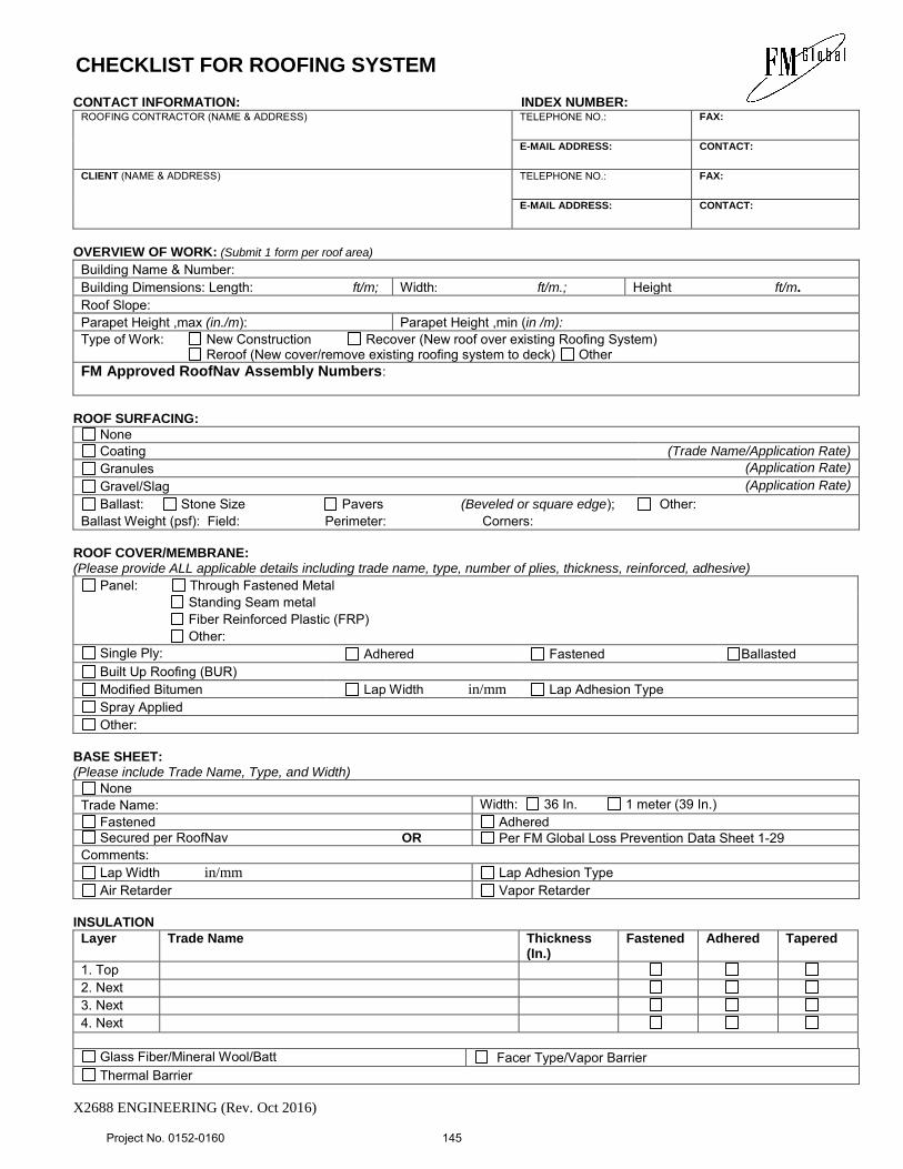
CHECKLIST FOR ROOFING SYSTEM
X2688 ENGINEERING (Rev. Oct 2016)
CONTACT INFORMATION: INDEX NUMBER:
ROOFING CONTRACTOR (NAME & ADDRESS)
TELEPHONE NO.:
FAX:
E-MAIL ADDRESS:
CONTACT:
CLIENT (NAME & ADDRESS)
TELEPHONE NO.:
FAX:
E-MAIL ADDRESS:
CONTACT:
OVERVIEW OF WORK: (Submit 1 form per roof area)
Building Name & Number:
Building Dimensions: Length: ft/m; Width: ft/m.; Height ft/m.
Roof Slope:
Parapet Height ,max (in./m): Parapet Height ,min (in /m): Type of Work: New Construction Recover (New roof over existing Roofing System) Reroof (New cover/remove existing roofing system to deck) Other FM Approved RoofNav Assembly Numbers:
ROOF SURFACING:
None
Coating (Trade Name/Application Rate) Granules (Application Rate)
Gravel/Slag (Application Rate)
Ballast: Stone Size Pavers (Beveled or square edge); Other:
Ballast Weight (psf): Field: Perimeter: Corners:
ROOF COVER/MEMBRANE: (Please provide ALL applicable details including trade name, type, number of plies, thickness, reinforced, adhesive)
Panel: Through Fastened Metal Standing Seam metal Fiber Reinforced Plastic (FRP) Other:
Single Ply: Adhered Fastened Ballasted Built Up Roofing (BUR) Modified Bitumen Lap Width in/mm Lap Adhesion Type Spray Applied Other:
BASE SHEET: (Please include Trade Name, Type, and Width)
None Trade Name: Width: 36 In. 1 meter (39 In.)
Fastened Adhered Secured per RoofNav OR Per FM Global Loss Prevention Data Sheet 1-29
Comments: Lap Width in/mm Lap Adhesion Type Air Retarder Vapor Retarder
INSULATION
Layer Trade Name Thickness (In.)
Fastened Adhered Tapered
1. Top 2. Next 3. Next 4. Next
Glass Fiber/Mineral Wool/Batt Facer Type/Vapor Barrier Thermal Barrier
Project No. 0152-0160
145
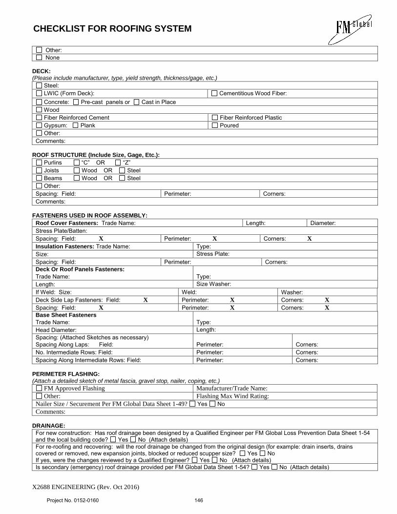
CHECKLIST FOR ROOFING SYSTEM
X2688 ENGINEERING (Rev. Oct 2016)
Other: None
DECK: (Please include manufacturer, type, yield strength, thickness/gage, etc.)
Steel: LWIC (Form Deck): Cementitious Wood Fiber: Concrete: Pre-cast panels or Cast in Place Wood Fiber Reinforced Cement Fiber Reinforced Plastic Gypsum: Plank Poured Other:
Comments: ROOF STRUCTURE (Include Size, Gage, Etc.):
Purlins “C” OR “Z” Joists Wood OR Steel Beams Wood OR Steel Other:
Spacing: Field: Perimeter: Corners: Comments:
FASTENERS USED IN ROOF ASSEMBLY:
Roof Cover Fasteners: Trade Name: Length: Diameter: Stress Plate/Batten: Spacing: Field: X Perimeter: X Corners: X Insulation Fasteners: Trade Name: Type: Size: Stress Plate: Spacing: Field: Perimeter: Corners: Deck Or Roof Panels Fasteners:
Trade Name: Type:
Length: Size Washer: If Weld: Size: Weld: Washer: Deck Side Lap Fasteners: Field: X Perimeter: X Corners: X Spacing: Field: X Perimeter: X Corners: X Base Sheet Fasteners
Trade Name: Type:
Head Diameter: Length: Spacing: (Attached Sketches as necessary) Spacing Along Laps: Field:
Perimeter:
Corners:
No. Intermediate Rows: Field: Perimeter: Corners: Spacing Along Intermediate Rows: Field: Perimeter: Corners:
PERIMETER FLASHING:
(Attach a detailed sketch of metal fascia, gravel stop, nailer, coping, etc.)
FM Approved Flashing Manufacturer/Trade Name: Other: Flashing Max Wind Rating:
Nailer Size / Securement Per FM Global Data Sheet 1-49? Yes No Comments:
DRAINAGE:
For new construction: Has roof drainage been designed by a Qualified Engineer per FM Global Loss Prevention Data Sheet 1-54 and the local building code? Yes No (Attach details) For re-roofing and recovering: will the roof drainage be changed from the original design (for example: drain inserts, drains covered or removed, new expansion joints, blocked or reduced scupper size? Yes No If yes, were the changes reviewed by a Qualified Engineer? Yes No (Attach details) Is secondary (emergency) roof drainage provided per FM Global Data Sheet 1-54? Yes No (Attach details)
Project No. 0152-0160
146
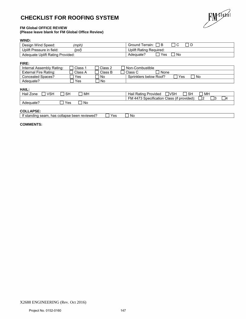
CHECKLIST FOR ROOFING SYSTEM
X2688 ENGINEERING (Rev. Oct 2016)
FM Global OFFICE REVIEW (Please leave blank for FM Global Office Review) WIND:
Design Wind Speed: (mph) Ground Terrain: B C D Uplift Pressure in field: (psf) Uplift Rating Required: Adequate Uplift Rating Provided: Adequate? Yes No
FIRE:
Internal Assembly Rating: Class 1 Class 2 Non-Combustible External Fire Rating: Class A Class B Class C None Concealed Spaces? Yes No Sprinklers below Roof? Yes No Adequate? Yes No
HAIL:
Hail Zone VSH SH MH Hail Rating Provided VSH SH MH FM 4473 Specification Class (if provided): 2 3 4 Adequate? Yes No
COLLAPSE:
If standing seam, has collapse been reviewed? Yes No
COMMENTS:
Project No. 0152-0160
147
SHEET METAL FLASHING AND TRIM
076200 - 1
SECTION 076200 - SHEET METAL FLASHING AND TRIM
PART 1 - GENERAL
1.1 SUMMARY:
A. Section Includes:
1. Manufactured surface-mounted flashing.
2. Formed wall sheet metal fabrications.
3. Formed equipment support flashing.
B. Related CSI Sections:
1. Division 06 Section 061000, "Rough Carpentry" for wood nailers, curbs, and
blocking.
2. Division 07 Section 075419, "Polyvinyl-Chloride (PVC) Roofing" for installation
of sheet metal flashing and trim integral with roofing.
3. Division 07 Section 077100, "Roof Specialties" for manufactured roof specialties
not part of sheet metal flashing and trim.
4. Division 07 Section 077200, "Roof Accessories" for set-on-type curbs, equipment
supports, roof hatches, vents, and other manufactured roof accessory units.
5. Division 07 Section 079200, "Joint Sealants" for field-applied sheet metal
flashing and trim sealants.
1.2 COORDINATION:
A. Coordinate sheet metal flashing and trim layout and seams with sizes and locations of
penetrations to be flashed, and joints and seams in adjacent materials.
B. Coordinate sheet metal flashing and trim installation with adjoining roofing and wall
materials, joints, and seams to provide leakproof, secure, and noncorrosive installation.
1.3 SUBMITTALS:
A. Submit the following in accordance with Form 817 Article 1.20-1.05.02 and NOTICE
TO CONTRACTOR – SUBMITTALS.
B. Product Data: For each type of product.
1. Include construction details, material descriptions, dimensions of individual
components and profiles, and finishes for each manufactured product and
accessory.
Project No. 0152-0160
148
SHEET METAL FLASHING AND TRIM
076200 - 2
C. Shop Drawings: For sheet metal flashing and trim.
1. Include plans, elevations, sections, and attachment details.
2. Include identification of material, thickness, weight, and finish for each item and
location in Project.
3. Include details for forming, including profiles, shapes, seams, and dimensions.
4. Include details for joining, supporting, and securing, including layout and spacing
of fasteners, cleats, clips, and other attachments. Include pattern of seams.
5. Include details of edge conditions, including eaves, ridges, valleys, rakes, crickets,
and counterflashings as applicable.
D. Samples for Initial Selection:
1. For each type of sheet metal flashing and accessory indicated with factory-applied
finishes.
2. Physical color palette of manufacturer’s full range of colors for each type of
flashing and accessories indicated.
E. Quality Assurance Submittals:
1. Manufacturer Certification Letter in accordance with NOTICE TO
CONTRACTOR – POTENTIAL FOR ASBESTOS CONTAINING
MATERIALS.
1.4 QUALITY ASSURANCE:
A. Fabricator Qualifications: Employs skilled workers who custom fabricate sheet metal
flashing and trim similar to that required for this Project and whose products have a
record of successful in-service performance.
1. For copings and roof edge flashings that are FM approved, shop shall be listed as
able to fabricate required details as tested and approved.
1.5 DELIVERY, STORAGE, AND HANDLING:
A. Do not store sheet metal flashing and trim materials in contact with other materials that
might cause staining, denting, or other surface damage. Store sheet metal flashing and
trim materials away from uncured concrete and masonry.
B. Protect strippable protective covering on sheet metal flashing and trim from exposure to
sunlight and high humidity, except to the extent necessary for the period of sheet metal
flashing and trim installation.
Project No. 0152-0160
149
SHEET METAL FLASHING AND TRIM
076200 - 3
PART 2 - PRODUCTS
2.1 PERFORMANCE REQUIREMENTS:
A. General: Sheet metal flashing and trim assemblies shall withstand wind loads,
structural movement, thermally induced movement, and exposure to weather without
failure due to defective manufacture, fabrication, installation, or other defects in
construction. Completed sheet metal flashing and trim shall not rattle, leak, or loosen,
and shall remain watertight.
B. Sheet Metal Standard for Flashing and Trim: Comply with NRCA's "The NRCA
Roofing Manual" and SMACNA's "Architectural Sheet Metal Manual" requirements for
dimensions and profiles shown unless more stringent requirements are indicated.
C. Thermal Movements: Allow for thermal movements from ambient and surface
temperature changes to prevent buckling, opening of joints, overstressing of
components, failure of joint sealants, failure of connections, and other detrimental
effects. Base calculations on surface temperatures of materials due to both solar heat
gain and nighttime-sky heat loss.
1. Temperature Change: 120 deg F, ambient; 180 deg F, material surfaces.
D. Water Infiltration: Provide sheet metal flashing and trim that do not allow water
infiltration to building interior.
2.2 SHEET METALS:
A. General: Protect mechanical and other finishes on exposed surfaces from damage by
applying a strippable, temporary protective film before shipping.
B. Aluminum Sheet: ASTM B 209 (ASTM B 209M), alloy as standard with manufacturer
for finish required, with temper as required to suit forming operations and performance
required.
1. As-Milled Finish: Standard two-side bright finish.
2. Surface: Smooth, flat.
3. Color: As selected by Designer from Manufacturer’s full range of colors.
C. Stainless-Steel Sheet: ASTM A 240/A 240M or ASTM A 666, Type 304, dead soft,
fully annealed.
1. Finish: No.4 (polished directional satin).
2. Surface: Smooth, flat.
3. Color: As selected by Designer from Manufacturer’s full range of colors.
Project No. 0152-0160
150
SHEET METAL FLASHING AND TRIM
076200 - 4
2.3 MISCELLANEOUS MATERIALS:
A. General: Provide materials and types of fasteners, solder, protective coatings, sealants,
and other miscellaneous items as required for complete sheet metal flashing and trim
installation and recommended by manufacturer of primary sheet metal or manufactured
item unless otherwise indicated.
B. Fasteners: Wood screws, annular threaded nails, self-tapping screws, self-locking rivets
and bolts, and other suitable fasteners designed to withstand design loads and
recommended by manufacturer of primary sheet metal or manufactured item.
1. General: Blind fasteners or self-drilling screws, gasketed, with hex-washer head.
a. Blind Fasteners: High-strength aluminum or stainless-steel rivets suitable
for metal being fastened.
C. Sealant Tape: Pressure-sensitive, 100 percent solids, gray polyisobutylene compound
sealant tape with release-paper backing. Provide permanently elastic, nonsag, nontoxic,
nonstaining tape 1/2 inch wide and 1/8 inch thick.
D. Elastomeric Sealant: ASTM C 920, elastomeric silicone polymer sealant; of type,
grade, class, and use classifications required to seal joints in sheet metal flashing and
trim and remain watertight.
2.4 FABRICATION, GENERAL:
A. General: Custom fabricate sheet metal flashing and trim to comply with
recommendations in SMACNA's "Architectural Sheet Metal Manual" that apply to
design, dimensions, geometry, metal thickness, and other characteristics of item
indicated. Fabricate items at the shop to greatest extent possible.
1. Fabricate sheet metal flashing and trim in thickness or weight needed to comply
with performance requirements, but not less than that specified for each
application and metal.
2. Obtain field measurements for accurate fit before shop fabrication.
3. Form sheet metal flashing and trim to fit substrate without excessive oil canning,
buckling, and tool marks and true to line, levels and slopes and with exposed
edges folded back to form hems.
4. Conceal fasteners and expansion provisions where possible. Do not use exposed
fasteners on faces exposed to view.
B. Fabrication Tolerances: Fabricate sheet metal flashing and trim that is capable of
installation to a tolerance of 1/4 inch in 20 feet on slope and location lines as indicated
and within 1/8-inch offset of adjoining faces and of alignment of matching profiles.
C. Expansion Provisions: Form metal for thermal expansion of exposed flashing and trim.
Project No. 0152-0160
151
SHEET METAL FLASHING AND TRIM
076200 - 5
1. Form expansion joints of intermeshing hooked flanges, not less than 1 inch deep,
filled with butyl sealant concealed within joints.
D. Fabricate cleats and attachment devices of sizes as recommended by cited sheet metal
standard and by FM Global Property Loss Prevention Data Sheet 1-49 for application,
but not less than thickness of metal being secured.
E. Seams: Fabricate nonmoving seams with flat-lock seams. Tin edges to be seamed,
form seams and seal with elastomeric sealant unless otherwise recommended by sealant
manufacturer for intended use. Rivet joints where necessary for strength.
F. Seams for Aluminum: Fabricate nonmoving seams with flat-lock seams. Form seams
and seal with epoxy seam sealer. Rivet joints where necessary for strength.
G. Do not use graphite pencils to mark metal surfaces.
2.5 WALL SHEET METAL FABRICATIONS:
A. Through-Wall Flashing: Fabricate continuous flashings in minimum 96-inch long, but
not exceeding 12-foot long, sections, under copings, at shelf angles, and where
indicated. Fabricate discontinuous lintel, sill, and similar flashings to extend 6 inches
beyond each side of wall openings and form with 2-inch high, end dams. Fabricate
from the following materials:
1. Aluminum: 0.040 inch thick.
B. Wall Expansion-Joint Cover: Fabricate from the following materials:
1. Aluminum: 0.040 inch thick.
2.6 MISCELLANEOUS SHEET METAL FABRICATIONS:
A. Equipment Support Flashing: Fabricate from the following materials:
1. Aluminum: 0.040 inch thick.
PART 3 - EXECUTION
3.1 EXAMINATION:
A. Examine substrates, areas, and conditions, with Installer present, for compliance with
requirements for installation tolerances, substrate, and other conditions affecting
performance of the Work.
1. Verify compliance with requirements for installation tolerances of substrates.
Project No. 0152-0160
152
SHEET METAL FLASHING AND TRIM
076200 - 6
2. Verify that substrate is sound, dry, smooth, clean, sloped for drainage, and
securely anchored.
B. Proceed with installation only after unsatisfactory conditions have been corrected.
3.2 INSTALLATION, GENERAL:
A. General: Anchor sheet metal flashing and trim and other components of the Work
securely in place, with provisions for thermal and structural movement. Use fasteners,
solder, welding rods, protective coatings, separators, sealants, and other miscellaneous
items as required to complete sheet metal flashing and trim system.
1. Install sheet metal flashing and trim true to line and levels and slopes. Provide
uniform, neat seams with minimum exposure of solder, welds, and sealant.
2. Install sheet metal flashing and trim to fit substrates and to result in watertight
performance. Verify shapes and dimensions of surfaces to be covered before
fabricating sheet metal.
3. Space cleats not more than 12 inches apart. Anchor each cleat with two fasteners.
Bend tabs over fasteners.
4. Install exposed sheet metal flashing and trim with limited oil canning, and free of
buckling and tool marks.
5. Torch cutting of sheet metal flashing and trim is not permitted.
6. Do not use graphite pencils to mark metal surfaces.
B. Metal Protection: Where dissimilar metals contact each other, or where metal contacts
pressure-treated wood or other corrosive substrates, protect against galvanic action or
corrosion by painting contact surfaces with bituminous coating or by other permanent
separation as recommended by sheet metal manufacturer or cited sheet metal standard.
1. Coat concealed side of uncoated-aluminum and stainless-steel sheet metal
flashing and trim with bituminous coating where flashing and trim contact wood,
ferrous metal, or cementitious construction.
C. Expansion Provisions: Provide for thermal expansion of exposed flashing and trim.
Space movement joints at maximum of 10 feet with no joints within 24 inches of corner
or intersection.
1. Form expansion joints of intermeshing hooked flanges, not less than 1 inch deep,
filled with sealant concealed within joints.
2. Use lapped expansion joints only where indicated on Drawings.
D. Fasteners: Use fastener sizes that penetrate wood blocking or sheathing not less than 1-
1/4 inches for nails and not less than 3/4 inch for wood screws substrate not less than
recommended by fastener manufacturer to achieve maximum pull-out resistance.
E. Seal joints as shown and as required for watertight construction.
Project No. 0152-0160
153
SHEET METAL FLASHING AND TRIM
076200 - 7
1. Where sealant-filled joints are used, embed hooked flanges of joint members not
less than 1 inch into sealant. Form joints to completely conceal sealant. When
ambient temperature at time of installation is moderate, between 40 and 70 deg F,
set joint members for 50 percent movement each way. Adjust setting
proportionately for installation at higher ambient temperatures. Do not install
sealant-type joints at temperatures below 40 deg F.
2. Prepare joints and apply sealants to comply with requirements in CSI Division 07
Section 079200, "Joint Sealants."
F. Soldered Joints: Clean surfaces to be soldered, removing oils and foreign matter. Pre-
tin edges of sheets to be soldered to a width of 1-1/2 inches, except reduce pre-tinning
where pre-tinned surface would show in completed Work.
1. Do not solder metallic-coated steel and aluminum sheet.
2. Pre-tinning is not required for zinc-tin alloy-coated stainless steel and zinc-tin
alloy-coated copper.
3. Do not use torches for soldering. Heat surfaces to receive solder and flow solder
into joint. Fill joint completely. Completely remove flux and spatter from
exposed surfaces.
4. Copper Soldering: Tin edges of uncoated copper sheets using solder for copper.
5. Copper-Clad Stainless-Steel Soldering: Tin edges of uncoated sheets, using solder
for copper-clad stainless steel.
G. Rivets: Rivet joints in uncoated aluminum where necessary for strength.
3.3 ROOF FLASHING INSTALLATION:
A. Counterflashing: Coordinate installation of counterflashing with installation of base
flashing. Insert counterflashing in reglets or receivers and fit tightly to base flashing.
Extend counterflashing 4 inches over base flashing. Lap counterflashing joints a
minimum of 4 inches. Secure in a waterproof manner by means of snap-in installation
and sealant or lead wedges and sealant.
3.4 WALL FLASHING INSTALLATION:
A. General: Install sheet metal wall flashing to intercept and exclude penetrating moisture
according to cited sheet metal standard unless otherwise indicated. Coordinate
installation of wall flashing with installation of wall-opening components such as
windows, doors, and louvers.
3.5 MISCELLANEOUS FLASHING INSTALLATION:
A. Equipment Support Flashing: Coordinate installation of equipment support flashing
with installation of roofing and equipment. Weld or seal flashing with elastomeric
sealant to equipment support member.
Project No. 0152-0160
154
SHEET METAL FLASHING AND TRIM
076200 - 8
3.6 CLEANING AND PROTECTION:
A. Clean exposed metal surfaces of substances that interfere with uniform oxidation and
weathering.
B. Clean and neutralize flux materials. Clean off excess solder.
C. Clean off excess sealants.
D. Remove temporary protective coverings and strippable films as sheet metal flashing and
trim are installed unless otherwise indicated in manufacturer's written installation
instructions. On completion of installation, remove unused materials and clean finished
surfaces. Maintain in a clean condition during construction.
E. Replace sheet metal flashing and trim that have been damaged or that have deteriorated
beyond successful repair by finish touchup or similar minor repair procedures.
END OF SECTION 076200
Project No. 0152-0160
155
ROOF SPECIALTIES
077100 - 1
SECTION 077100 - ROOF SPECIALTIES
PART 1 - GENERAL
1.1 SUMMARY:
A. Section Includes:
1. Copings.
2. Roof-edge flashings.
B. Related CSI Sections:
1. Division 06 Section 061000, "Rough Carpentry" for wood nailers, curbs, and
blocking.
2. Division 07 Section 076200, "Sheet Metal Flashing and Trim" for custom- and
site-fabricated sheet metal flashing and trim.
3. Division 07 Section 077200, "Roof Accessories" for set-on-type curbs, equipment
supports, roof hatches, vents, and other manufactured roof accessory units.
4. Division 07 Section 079200, "Joint Sealants" for field-applied sealants between
roof specialties and adjacent materials.
1.2 PERFORMANCE REQUIREMENTS:
A. General Performance: Roof specialties shall withstand exposure to weather and resist
thermally induced movement without failure, rattling, leaking, or fastener
disengagement due to defective manufacture, fabrication, installation, or other defects
in construction.
B. FM Approvals' Listing: Manufacture and install roof-edge flashings that are listed in
FM Approvals' "RoofNav" and approved for windstorm classification, Class 1-105.
Identify materials with FM Approvals' markings.
C. SPRI Wind Design Standard: Manufacture and install roof-edge flashings tested
according to SPRI ES-1 and capable of resisting the following design pressures:
1. Design Pressure: 26 psf-outward force; 42 psf-uplift force.
D. Water Infiltration: Provide manufactured roof specialties that do not allow water
infiltration into building interior.
E. Thermal Movements: Allow for thermal movements from ambient and surface
temperature changes to prevent buckling, opening of joints, hole elongation,
overstressing of components, failure of joint sealants, failure of connections, and other
detrimental effects. Provide clips that resist rotation and avoid shear stress as a result of
Project No. 0152-0160
156
ROOF SPECIALTIES
077100 - 2
thermal movements. Base calculations on surface temperatures of materials due to both
solar heat gain and nighttime-sky heat loss.
1. Temperature Change (Range): 120 deg F, ambient; 180 deg F, material surfaces.
1.3 SUBMITTALS:
A. Submit the following in accordance with Form 817 Article 1.20-1.05.02 and NOTICE
TO CONTRACTOR – SUBMITTALS.
B. Product Data: For each type of product indicated. Include construction details, material
descriptions, dimensions of individual components and profiles, and finishes.
C. Shop Drawings: For roof specialties. Include plans, elevations, expansion-joint
locations, keyed details, and attachments to other work. Distinguish between plant- and
field-assembled work. Include the following:
1. Details for expansion and contraction; locations of expansion joints, including
direction of expansion and contraction.
2. Pattern of seams and layout of fasteners, cleats, clips, and other attachments.
D. Samples for Initial Selection:
1. For each type of roof specialties indicated with factory-applied finishes.
2. Physical color palette of manufacturer’s full range of colors for each type of roof
specialties indicated.
E. Quality Assurance Submittals:
1. Manufacturer Certification Letter in accordance with NOTICE TO
CONTRACTOR – POTENTIAL FOR ASBESTOS CONTAINING
MATERIALS.
1.4 QUALITY ASSURANCE:
A. Conduct a Pre-Installation Meeting at the Project Site in compliance with the
requirements of Form 817 Article 1.20-1.05.24 subsection 2. Review the following:
1. Meet with Owner, Engineer, Designer, Owner's insurer if applicable, Installer,
and installers whose work interfaces with or affects roof specialties including
installers of roofing materials and accessories.
2. Examine substrate conditions for compliance with requirements, including
flatness and attachment to structural members.
3. Review special roof details, roof drainage, and condition of other construction
that will affect roof specialties.
Project No. 0152-0160
157
ROOF SPECIALTIES
077100 - 3
1.5 DELIVERY, STORAGE, AND HANDLING:
A. Do not store roof specialties in contact with other materials that might cause staining,
denting, or other surface damage. Store roof specialties away from uncured concrete
and masonry.
B. Protect strippable protective covering on roof specialties from exposure to sunlight and
high humidity, except to extent necessary for the period of roof specialties installation.
PART 2 - PRODUCTS
2.1 EXPOSED METALS:
A. Aluminum Sheet: ASTM B 209 (ASTM B 209M), alloy as standard with manufacturer
for finish required, with temper to suit forming operations and performance required.
1. Surface: Smooth, flat finish.
2. Three-Coat Fluoropolymer: AAMA 620. System consisting of primer,
fluoropolymer color coat, and clear fluoropolymer topcoat, with both color coat
and clear topcoat containing not less than 70 percent PVDF resin by weight.
3. Clear Anodic Finish, Coil Coated: AAMA 611, AA-M12C22A41, Class I, 0.018
mm or thicker.
4. Color: As selected by Designer from Manufacturer’s full range of colors.
B. Aluminum Extrusions: ASTM B 221 (ASTM B 221M), alloy and temper
recommended by manufacturer for type of use and finish indicated, finished as follows:
1. Exposed High-Performance Organic Finish: Prepare, pretreat, and apply coating
to exposed metal surfaces to comply with coating and resin manufacturers' written
instructions.
a. Three-Coat Fluoropolymer: AAMA 2605. System consisting of primer,
fluoropolymer color coat, and clear fluoropolymer topcoat, with both color
coat and clear topcoat containing not less than 70 percent PVDF resin by
weight.
2. Color: As selected by Designer from Manufacturer’s full range of colors.
2.2 CONCEALED METALS:
A. Aluminum Sheet: ASTM B 209 (ASTM B 209M), alloy and temper recommended by
manufacturer for type of use and structural performance indicated, mill finished.
Project No. 0152-0160
158
ROOF SPECIALTIES
077100 - 4
B. Aluminum Extrusions: ASTM B 221 (ASTM B 221M), alloy and temper
recommended by manufacturer for type of use and structural performance indicated,
mill finished.
C. Stainless-Steel Sheet: ASTM A 240/A 240M or ASTM A 666, Type 304.
D. Zinc-Coated (Galvanized) Steel Sheet: ASTM A 653/A 653M, G90 (Z275) coating
designation.
2.3 MISCELLANEOUS MATERIALS:
A. General: Provide materials and types of fasteners, protective coatings, sealants, and
other miscellaneous items required by manufacturer for a complete installation.
B. Fasteners: Manufacturer's recommended fasteners, suitable for application and
designed to meet performance requirements. Furnish the following unless otherwise
indicated:
1. Exposed Penetrating Fasteners: Gasketed screws with hex washer heads
matching color of sheet metal.
C. Elastomeric Sealant: ASTM C 920, elastomeric silicone polymer sealant of type, grade,
class, and use classifications required by roofing-specialty manufacturer for each
application.
D. Butyl Sealant: ASTM C 1311, single-component, solvent-release butyl rubber sealant;
polyisobutylene plasticized; heavy bodied for hooked-type expansion joints with limited
movement.
2.4 GENERAL FINISH REQUIREMENTS:
A. Comply with NAAMM's "Metal Finishes Manual for Architectural and Metal Products"
for recommendations for applying and designating finishes.
B. Protect mechanical and painted finishes on exposed surfaces from damage by applying
a strippable, temporary protective covering before shipping.
C. Appearance of Finished Work: Noticeable variations in same piece are not acceptable.
Variations in appearance of adjoining components are acceptable if they are within the
range of approved Samples and are assembled or installed to minimize contrast.
Project No. 0152-0160
159
ROOF SPECIALTIES
077100 - 5
PART 3 - EXECUTION
3.1 EXAMINATION:
A. Examine substrates, areas, and conditions, with Installer present, to verify actual
locations, dimensions, and other conditions affecting performance of the Work.
B. Examine walls, roof edges, and parapets for suitable conditions for roof specialties.
C. Verify that substrate is sound, dry, smooth, clean, sloped for drainage, and securely
anchored.
D. Proceed with installation only after unsatisfactory conditions have been corrected.
3.2 INSTALLATION, GENERAL:
A. General: Install roof specialties according to manufacturer's written instructions.
Anchor roof specialties securely in place, with provisions for thermal and structural
movement. Use fasteners, solder, protective coatings, separators, sealants, and other
miscellaneous items as required to complete roof-specialty systems.
1. Install roof specialties level, plumb, true to line and elevation; with limited oil-
canning and without warping, jogs in alignment, buckling, or tool marks.
2. Provide uniform, neat seams with minimum exposure of solder and sealant.
3. Install roof specialties to fit substrates and to result in watertight performance.
Verify shapes and dimensions of surfaces to be covered before manufacture.
4. Torch cutting of roof specialties is not permitted.
5. Do not use graphite pencils to mark metal surfaces.
B. Metal Protection: Protect metals against galvanic action by separating dissimilar metals
from contact with each other or with corrosive substrates by painting contact surfaces
with bituminous coating or by other permanent separation as recommended by
manufacturer.
1. Coat concealed side of uncoated aluminum roof specialties with bituminous
coating where in contact with wood, ferrous metal, or cementitious construction.
2. Bed flanges in thick coat of asphalt roofing cement where required by
manufacturers of roof specialties for waterproof performance.
C. Expansion Provisions: Allow for thermal expansion of exposed roof specialties.
1. Space movement joints at a maximum of 12 feet with no joints within 18 inches
of corners or intersections unless otherwise shown on plans.
2. When ambient temperature at time of installation is between 40 and 70 deg F, set
joint members for 50 percent movement each way. Adjust setting proportionately
for installation at higher ambient temperatures.
Project No. 0152-0160
160
ROOF SPECIALTIES
077100 - 6
D. Fastener Sizes: Use fasteners of sizes that will penetrate wood blocking or sheathing
not less than 1-1/4 inches for nails and not less than 3/4 inch for wood screws.
E. Seal joints with elastomeric sealant as required by roofing-specialty manufacturer.
F. Seal joints as required for watertight construction. Place sealant to be completely
concealed in joint. Do not install sealants at temperatures below 40 deg F.
G. Soldered Joints: Clean surfaces to be soldered, removing oils and foreign matter. Pre-
tin edges of sheets to be soldered to a width of 1-1/2 inches except reduce pre-tinning
where pre-tinned surface would show in completed Work. Tin edges of uncoated
copper sheets using solder for copper. Do not use torches for soldering. Heat surfaces
to receive solder and flow solder into joint. Fill joint completely. Completely remove
flux and spatter from exposed surfaces.
3.3 COPING INSTALLATION:
A. Install cleats, anchor plates, and other anchoring and attachment accessories and devices
with concealed fasteners.
B. Anchor copings to meet performance requirements.
1. Interlock face and back leg drip edges of snap-on coping cap into cleated anchor
plates anchored to substrate at manufacturer's required spacing that meets
performance requirements.
3.4 ROOF-EDGE FLASHING INSTALLATION:
A. Install cleats, cants, and other anchoring and attachment accessories and devices with
concealed fasteners.
B. Anchor roof edgings with manufacturer's required devices, fasteners, and fastener
spacing to meet performance requirements.
C. Counterflashings: Insert counterflashings into reglets or other indicated receivers;
ensure that counterflashings overlap 4 inches over top edge of base flashings. Lap
counterflashing joints a minimum of 4 inches and bed with elastomeric sealant. Fit
counterflashings tightly to base flashings.
3.5 CLEANING AND PROTECTION:
A. Clean exposed metal surfaces of substances that interfere with uniform oxidation and
weathering.
B. Clean and neutralize flux materials. Clean off excess solder and sealants.
Project No. 0152-0160
161
ROOF SPECIALTIES
077100 - 7
C. Remove temporary protective coverings and strippable films as roof specialties are
installed. On completion of installation, clean finished surfaces including removing
unused fasteners, metal filings, pop rivet stems, and pieces of flashing. Maintain roof
specialties in a clean condition during construction.
D. Replace roof specialties that have been damaged or that cannot be successfully repaired
by finish touchup or similar minor repair procedures.
END OF SECTION 077100
Project No. 0152-0160
162
ROOF ACCESSORIES
077200 - 1
SECTION 077200 - ROOF ACCESSORIES
PART 1 - GENERAL
1.1 SUMMARY:
A. This Section includes the following:
1. Preformed flashings.
2. Fall Protection Guardrail.
B. Related CSI Sections include the following:
1. Division 06 Section 061000, "Rough Carpentry" for roof sheathing, wood cants,
and wood nailers.
2. Division 07 Section 076200, "Sheet Metal Flashing and Trim" for shop- and field-
fabricated metal flashing and counterflashing, roof expansion-joint covers, and
miscellaneous sheet metal trim and accessories.
3. Division 07 Section 077100, "Roof Specialties" for fascia and copings.
4. Division 23 Section 233423, "HVAC Power Ventilators" for power roof-mounted
ventilators.
1.2 SUBMITTALS:
A. Submit the following in accordance with Form 817 Article 1.20-1.05.02 and NOTICE
TO CONTRACTOR – SUBMITTALS.
B. Product Data: For each type of roof accessory indicated. Include construction details,
material descriptions, dimensions of individual components and profiles, and finishes.
C. Shop Drawings: Show fabrication and installation details for roof accessories. Show
layouts of roof accessories including plans and elevations. Indicate dimensions,
weights, loadings, required clearances, method of field assembly, and components.
Include plans, elevations, sections, details, and attachments to other work.
D. Samples for Initial Selection:
1. Physical color palette of manufacturer’s full range of colors, for each type of
preformed flashing indicated.
E. Quality Assurance Submittals:
1. Manufacturer Certification Letter in accordance with NOTICE TO
CONTRACTOR – POTENTIAL FOR ASBESTOS CONTAINING
MATERIALS.
Project No. 0152-0160
163
ROOF ACCESSORIES
077200 - 2
1.3 QUALITY ASSURANCE:
A. Sheet Metal Standard: Comply with SMACNA's "Architectural Sheet Metal Manual"
details for fabrication of units, including flanges and cap flashing to coordinate with
type of roofing indicated.
1.4 DELIVERY, STORAGE, AND HANDLING:
A. Pack, handle, and ship roof accessories properly labeled in heavy-duty packaging to
prevent damage.
1.5 PROJECT CONDITIONS:
A. Field Measurements: Verify required openings for each type of roof accessory by field
measurements before fabrication and indicate measurements on Shop Drawings.
1.6 COORDINATION:
A. Coordinate layout and installation of roof accessories with roofing membrane and base
flashing and interfacing and adjoining construction to provide a leakproof, weathertight,
secure, and noncorrosive installation.
1. With Designer’s approval, adjust location of roof accessories that would interrupt
roof drainage routes.
PART 2 - PRODUCTS
2.1 MANUFACTURERS:
A. Available Manufacturers: Subject to compliance with requirements, manufacturers
offering products that may be incorporated into the Work include, but are not limited to,
manufacturers listed in other portions of Part 2.
2.2 METAL MATERIALS:
A. Galvanized Steel Sheet: ASTM A 653/A 653M, G90 (Z275) coated.
B. Prepainted, Metallic-Coated Steel Sheet: Steel sheet metallic coated by hot-dip process
and prepainted by coil-coating process to comply with ASTM A 755/A 755M.
1. Galvanized Steel Sheet: ASTM A 653/A 653M, G90 (Z275) coated.
Project No. 0152-0160
164
ROOF ACCESSORIES
077200 - 3
2. Exposed Finishes: High-Performance Organic Finish (2-Coat Fluoropolymer):
Prepare, pretreat, and apply coating to exposed metal surfaces to comply with
coating and resin manufacturer's written instructions.
a. Fluoropolymer 2-Coat System: Manufacturer's standard 2-coat,
thermocured system consisting of specially formulated inhibitive primer
and fluoropolymer color topcoat containing not less than 70 percent
polyvinylidene fluoride resin by weight; complying with physical properties
and coating performance requirements in AAMA 2605, except as modified
below:
1) Humidity Resistance: 2000 hours.
2) Salt-Spray Resistance: 2000 hours.
C. Aluminum Sheet: ASTM B 209 (ASTM B 209M), alloy and temper recommended by
manufacturer for type of use and finish.
1. High-Performance Organic Finish (2-Coat Fluoropolymer): AA-C12C40R1x
(Chemical Finish: Cleaned with inhibited chemicals; Chemical Finish:
Conversion coating; Organic Coating: Manufacturer's standard 2-coat,
thermocured system consisting of specially formulated inhibitive primer and
fluoropolymer color topcoat containing not less than 70 percent polyvinylidene
fluoride resin by weight). Prepare, pretreat, and apply coating to exposed metal
surfaces to comply with AAMA 2605 and with coating and resin manufacturer's
written instructions.
a. Color and Gloss: As selected by Designer from manufacturer's full range of
colors and gloss.
D. Aluminum Extrusions and Tubes: ASTM B 221 (ASTM B 221M), alloy and temper
recommended by manufacturer for type of use, mill finished.
E. Stainless-Steel Shapes or Sheet: ASTM A 240/A 240M or ASTM A 666, Type 304 or
Type 316, No. 2D finish.
F. Steel Shapes: ASTM A 36/A 36M, hot-dip galvanized to comply with
ASTM A 123/A 123M, unless otherwise indicated.
G. Steel Tube: ASTM A 500, round tube, baked-enamel finished.
H. Galvanized Steel Tube: ASTM A 500, round tube, hot-dip galvanized to comply with
ASTM A 123/A 123M.
I. Galvanized Steel Pipe: ASTM A 53/A 53M.
Project No. 0152-0160
165
ROOF ACCESSORIES
077200 - 4
2.3 MISCELLANEOUS MATERIALS:
A. Acrylic Glazing: ASTM D 4802, thermoformable, monolithic sheet, category as
standard with manufacturer, Type UVA (formulated with UV absorber), Finish 1
(smooth or polished).
B. Polyisocyanurate Board Insulation: ASTM C 1289, 1 inch thick.
C. Wood Nailers: Softwood lumber, pressure treated with waterborne preservatives for
aboveground use, complying with AWPA U1; not less than 1-1/2 inches thick.
D. Fasteners: Same metal as metals being fastened, or nonmagnetic stainless steel or other
noncorrosive metal as recommended by roof accessory manufacturer. Match finish of
exposed fasteners with finish of material being fastened. Provide nonremovable
fastener heads to exterior exposed fasteners.
E. Gaskets: Manufacturer's standard tubular or fingered design of neoprene, EPDM, or
PVC; or flat design of foam rubber, sponge neoprene, or cork.
F. Elastomeric Sealant: ASTM C 920, silicone sealant; of type, grade, class, and use
classifications required to seal joints in sheet metal flashing and trim and remain
watertight.
2.4 FALL PROTECTION:
A. Fall Protection: A guardrail system consisting of a top and mid rail in accordance with
OSHA Standards 29 CFR 1910.20 and CFR 1926.502:
1. Structural Load: 200lb, minimum, in any direction to all components in
accordance with OSHA Standards 29 CFR 1910.20 and CFR 1926.502.
2. Height: 42 inches (1067 mm). minimum.
3. Railing: 1.66”O.D. galvanized pipe.
4. Mounting Bases: Class 30 gray iron material cast with four receiver post. Base
weight 108 lb. Rubber pads on the bottom.
5. Finishes: Factory standard hot-dip galvanized.
PART 3 - EXECUTION
3.1 EXAMINATION:
A. Examine substrates, areas, and conditions, with Installer present, to verify actual
locations, dimensions, and other conditions affecting performance of work.
1. Verify that substrate is sound, dry, smooth, clean, sloped for drainage, and
securely anchored and is ready to receive roof accessories.
2. Verify dimensions of roof openings for roof accessories.
Project No. 0152-0160
166
ROOF ACCESSORIES
077200 - 5
3. Proceed with installation only after unsatisfactory conditions have been corrected.
3.2 INSTALLATION:
A. General: Install roof accessories according to manufacturer's written instructions.
Anchor roof accessories securely in place and capable of resisting forces specified. Use
fasteners, separators, sealants, and other miscellaneous items as required for completing
roof accessory installation. Install roof accessories to resist exposure to weather
without failing, rattling, leaking, and fastener disengagement.
B. Install roof accessories to fit substrates and to result in watertight performance.
C. Metal Protection: Where dissimilar metals will contact each other or corrosive
substrates, protect against galvanic action by painting contact surfaces with bituminous
coating or by other permanent separation as recommended by manufacturer.
D. Install roof accessories level, plumb, true to line and elevation, and without warping,
jogs in alignment, excessive oil canning, buckling, or tool marks.
E. Fall Protection Installation:
1. Install components per manufacturer’s installation.
F. Seal joints with elastomeric sealant as required by manufacturer of roof accessories.
G. Fastening to In-Place Construction: Provide anchorage devices and fasteners where
metal fabrications are required to be fastened to in-place construction. Provide threaded
fasteners for use with concrete and masonry inserts, toggle bolts, through bolts, lag
bolts, wood screws and other connectors.
3.3 TOUCH UP:
A. Galvanized Surfaces: Clean field welds, bolted connections, and abraded areas and
repair galvanizing to comply with ASTM A 780.
3.4 CLEANING:
A. Clean exposed surfaces according to manufacturer's written instructions.
END OF SECTION 077200
Project No. 0152-0160
167
JOINT SEALANTS
079200 - 1
SECTION 079200 - JOINT SEALANTS
PART 1 - GENERAL
1.1 SUMMARY
A. Section Includes:
1. Silicone joint sealants.
2. Preformed joint sealants.
B. Related CSI Sections:
1. Division 07 Section 075419, “Polyvinyl-Chloride (PVC) Roofing.”
2. Division 07 Section 076200, “Sheet Metal Flashing and Trim.”
3. Division 07 Section 077100, “Roof Accessories.”
4. Division 07 Section 077200, “Roof Specialties.”
1.2 PERFORMANCE REQUIREMENTS:
A. Provide elastomeric joint sealants that establish and maintain watertight and airtight
continuous joint seals without staining or deteriorating joint substrates.
B. Provide joint sealants for interior applications that establish and maintain airtight and
water-resistant continuous joint seals without staining or deteriorating joint substrates.
1.3 SUBMITTALS:
A. Submit the following in accordance with Form 817 Article 1.20-1.05.02 and NOTICE
TO CONTRACTOR – SUBMITTALS.
B. Product Data: For each joint-sealant product indicated.
C. Quality Assurance Submittals:
1. Manufacturer Certification Letter in accordance with NOTICE TO
CONTRACTOR – POTENTIAL FOR ASBESTOS CONTAINING
MATERIALS.
D. LEED Submittal:
1. Product Data for Credit EQ 4.1: For sealants and sealant primers used inside the
weatherproofing system, including printed statement of VOC content.
Project No. 0152-0160
168
JOINT SEALANTS
079200 - 2
E. Samples for Initial Selection: Manufacturer's color charts consisting of strips of cured
sealants showing the full range of colors available for each product exposed to view.
F. Joint-Sealant Schedule: Include the following information:
1. Joint-sealant application, joint location, and designation.
2. Joint-sealant manufacturer and product name.
3. Joint-sealant formulation.
4. Joint-sealant color.
G. Qualification Data: For qualified Installer and testing agency.
H. Product Certificates: For each kind of joint sealant and accessory, from manufacturer.
I. Sealant, Waterproofing, and Restoration Institute (SWRI) Validation Certificate: For
each sealant specified to be validated by SWRI's Sealant Validation Program.
J. Product Test Reports: Based on evaluation of comprehensive tests performed by a
qualified testing agency, indicating that sealants comply with requirements.
1.4 QUALITY ASSURANCE
A. Installer Qualifications: Manufacturer's authorized representative who is trained and
approved for installation of units required for this Project.
B. Source Limitations: Obtain each kind of joint sealant from single source from single
manufacturer.
C. Product Testing: Test joint sealants using a qualified testing agency.
1. Testing Agency Qualifications: An independent testing agency qualified
according to ASTM C 1021 to conduct the testing indicated.
2. Test according to SWRI's Sealant Validation Program for compliance with
requirements specified by reference to ASTM C 920 for adhesion and cohesion
under cyclic movement, adhesion-in-peel, and indentation hardness.
1.5 PROJECT CONDITIONS
A. Do not proceed with installation of joint sealants under the following conditions:
1. When ambient and substrate temperature conditions are outside limits permitted
by joint-sealant manufacturer or are below 40 deg F.
2. When joint substrates are wet.
3. Where joint widths are less than those allowed by joint-sealant manufacturer for
applications indicated.
4. Where contaminants capable of interfering with adhesion have not yet been
removed from joint substrates.
Project No. 0152-0160
169
JOINT SEALANTS
079200 - 3
PART 2 - PRODUCTS
2.1 MATERIALS, GENERAL
A. Compatibility: Provide joint sealants, backings, and other related materials that are
compatible with one another and with joint substrates under conditions of service and
application, as demonstrated by joint-sealant manufacturer, based on testing and field
experience.
B. VOC Content of Interior Sealants: Provide sealants and sealant primers for use inside
the weatherproofing system that comply with the following limits for VOC content
when calculated according to 40 CFR 59, Part 59, Subpart D (EPA Method 24):
1. Architectural Sealants: 250 g/L.
2. Sealant Primers for Nonporous Substrates: 250 g/L.
3. Sealant Primers for Porous Substrates: 775 g/L.
C. Colors of Exposed Joint Sealants: As selected by Designer from manufacturer's full
range.
2.2 SILICONE JOINT SEALANTS
A. Single-Component, Nonsag, Neutral-Curing Silicone Joint Sealant: ASTM C 920,
Type S, Grade NS, Class 100/50, for Use NT.
1. Available Products: Subject to compliance with requirements, available products
that may be incorporated into the Work include, but are not limited to, the
following:
a. Dow Corning Corporation; 790.
b. GE Advanced Materials - Silicones; SilPruf LM SCS2700.
c. May National Associates, Inc.; Bondaflex Sil 290.
d. Pecora Corporation; 311 NS.
e. Tremco Incorporated; Spectrem 1.
B. Multicomponent, Nonsag, Neutral-Curing Silicone Joint Sealant: ASTM C 920,
Type M, Grade NS, Class 50, for Use NT.
1. Available Products: Subject to compliance with requirements, available products
that may be incorporated into the Work include, but are not limited to, the
following:
a. Tremco Incorporated; Spectrem 4TS.
C. Multicomponent, Pourable, Traffic-Grade, Neutral-Curing Silicone Joint Sealant:
ASTM C 920, Type M, Grade P, Class 100/50, for Use T.
Project No. 0152-0160
170
JOINT SEALANTS
079200 - 4
1. Avaiable Products: Subject to compliance with requirements, available products
that may be incorporated into the Work include, but are not limited to, the
following:
a. Dow Corning Corporation; FC Parking Structure Sealant.
b. May National Associates, Inc.; Bondaflex Sil 728 RCS.
D. Mildew-Resistant, Single-Component, Nonsag, Neutral-Curing Silicone Joint Sealant:
ASTM C 920, Type S, Grade NS, Class 25, for Use NT.
1. Available Products: Subject to compliance with requirements, available products
that may be incorporated into the Work include, but are not limited to, the
following:
a. Pecora Corporation; 898.
2.3 PREFORMED JOINT SEALANTS
A. Preformed Silicone Joint Sealants: Manufacturer's standard sealant consisting of
precured low-modulus silicone extrusion, in sizes to fit joint widths indicated, combined
with a neutral-curing silicone sealant for bonding extrusions to substrates.
1. Available Products: Subject to compliance with requirements, available products
that may be incorporated into the Work include, but are not limited to, the
following:
a. Dow Corning Corporation; 123 Silicone Seal.
b. GE Advanced Materials - Silicones; UltraSpan US1100.
c. May National Associates, Inc.; Bondaflex Silbridge 300.
d. Pecora Corporation; Sil-Span.
e. Sealex, Inc.; ImmerSeal.
B. Preformed Foam Joint Sealant: Manufacturer's standard preformed, precompressed,
open-cell foam sealant manufactured from urethane foam with minimum density of 10
lb/cu. ft. and impregnated with a nondrying, water-repellent agent. Factory produce in
precompressed sizes in roll or stick form to fit joint widths indicated; coated on one side
with a pressure-sensitive adhesive and covered with protective wrapping.
1. Products: Subject to compliance with requirements, available products that may
be incorporated into the Work include, but are not limited to, the following:
a. Dayton Superior Specialty Chemicals; Polytite Standard.
b. EMSEAL Joint Systems, Ltd.; Emseal 25V.
c. Sandell Manufacturing Co., Inc.; Polyseal.
d. Schul International, Inc.; Sealtite.
e. Willseal USA, LLC; Willseal 150.
Project No. 0152-0160
171
JOINT SEALANTS
079200 - 5
2.4 JOINT SEALANT BACKING
A. General: Provide sealant backings of material that are nonstaining; are compatible with
joint substrates, sealants, primers, and other joint fillers; and are approved for
applications indicated by sealant manufacturer based on field experience and laboratory
testing.
B. Cylindrical Sealant Backings: ASTM C 1330, Type C (closed-cell material with a
surface skin), Type O (open-cell material), Type B (bicellular material with a surface
skin), or any of the preceding types, as approved in writing by joint-sealant
manufacturer for joint application indicated, and of size and density to control sealant
depth and otherwise contribute to producing optimum sealant performance.
C. Bond-Breaker Tape: Polyethylene tape or other plastic tape recommended by sealant
manufacturer for preventing sealant from adhering to rigid, inflexible joint-filler
materials or joint surfaces at back of joint. Provide self-adhesive tape where applicable.
2.5 MISCELLANEOUS MATERIALS
A. Primer: Material recommended by joint-sealant manufacturer where required for
adhesion of sealant to joint substrates indicated, as determined from preconstruction
joint-sealant-substrate tests and field tests.
B. Cleaners for Nonporous Surfaces: Chemical cleaners acceptable to manufacturers of
sealants and sealant backing materials, free of oily residues or other substances capable
of staining or harming joint substrates and adjacent nonporous surfaces in any way, and
formulated to promote optimum adhesion of sealants to joint substrates.
C. Masking Tape: Nonstaining, nonabsorbent material compatible with joint sealants and
surfaces adjacent to joints.
PART 3 - EXECUTION
3.1 EXAMINATION
A. Examine joints indicated to receive joint sealants, with Installer present, for compliance
with requirements for joint configuration, installation tolerances, and other conditions
affecting joint-sealant performance.
B. Proceed with installation only after unsatisfactory conditions have been corrected.
Project No. 0152-0160
172
JOINT SEALANTS
079200 - 6
3.2 PREPARATION
A. Surface Cleaning of Joints: Clean out joints immediately before installing joint sealants
to comply with joint-sealant manufacturer's written instructions and the following
requirements:
1. Remove all foreign material from joint substrates that could interfere with
adhesion of joint sealant, including dust, paints (except for permanent, protective
coatings tested and approved for sealant adhesion and compatibility by sealant
manufacturer), old joint sealants, oil, grease, waterproofing, water repellents,
water, surface dirt, and frost.
2. Clean porous joint substrate surfaces by brushing, grinding, mechanical abrading,
or a combination of these methods to produce a clean, sound substrate capable of
developing optimum bond with joint sealants. Remove loose particles remaining
after cleaning operations above by vacuuming or blowing out joints with oil-free
compressed air. Porous joint substrates include the following:
a. Concrete.
b. Masonry.
3. Remove laitance and form-release agents from concrete.
4. Clean nonporous joint substrate surfaces with chemical cleaners or other means
that do not stain, harm substrates, or leave residues capable of interfering with
adhesion of joint sealants. Nonporous joint substrates include the following:
a. Metal.
b. Glass.
c. Porcelain enamel.
B. Joint Priming: Prime joint substrates where recommended by joint-sealant
manufacturer or as indicated by preconstruction joint-sealant-substrate tests or prior
experience. Apply primer to comply with joint-sealant manufacturer's written
instructions. Confine primers to areas of joint-sealant bond; do not allow spillage or
migration onto adjoining surfaces.
C. Masking Tape: Use masking tape where required to prevent contact of sealant or
primer with adjoining surfaces that otherwise would be permanently stained or damaged
by such contact or by cleaning methods required to remove sealant smears. Remove
tape immediately after tooling without disturbing joint seal.
3.3 INSTALLATION OF JOINT SEALANTS
A. General: Comply with joint-sealant manufacturer's written installation instructions for
products and applications indicated, unless more stringent requirements apply.
B. Sealant Installation Standard: Comply with recommendations in ASTM C 1193 for use
of joint sealants as applicable to materials, applications, and conditions indicated.
Project No. 0152-0160
173
JOINT SEALANTS
079200 - 7
C. Install sealant backings of kind indicated to support sealants during application and at
position required to produce cross-sectional shapes and depths of installed sealants
relative to joint widths that allow optimum sealant movement capability.
1. Do not leave gaps between ends of sealant backings.
2. Do not stretch, twist, puncture, or tear sealant backings.
3. Remove absorbent sealant backings that have become wet before sealant
application and replace them with dry materials.
D. Install bond-breaker tape behind sealants where sealant backings are not used between
sealants and backs of joints.
E. Install sealants using proven techniques that comply with the following and at the same
time backings are installed:
1. Place sealants so they directly contact and fully wet joint substrates.
2. Completely fill recesses in each joint configuration.
3. Produce uniform, cross-sectional shapes and depths relative to joint widths that
allow optimum sealant movement capability.
F. Tooling of Nonsag Sealants: Immediately after sealant application and before skinning
or curing begins, tool sealants according to requirements specified in subparagraphs
below to form smooth, uniform beads of configuration indicated; to eliminate air
pockets; and to ensure contact and adhesion of sealant with sides of joint.
1. Remove excess sealant from surfaces adjacent to joints.
2. Use tooling agents that are approved in writing by sealant manufacturer and that
do not discolor sealants or adjacent surfaces.
3. Provide concave joint profile per Figure 8A in ASTM C 1193, unless otherwise
indicated.
4. Provide flush joint profile where indicated per Figure 8B in ASTM C 1193.
5. Provide recessed joint configuration of recess depth and at locations indicated per
Figure 8C in ASTM C 1193.
a. Use masking tape to protect surfaces adjacent to recessed tooled joints.
G. Installation of Preformed Silicone-Sealant System: Comply with the following
requirements:
1. Apply masking tape to each side of joint, outside of area to be covered by sealant
system.
2. Apply silicone sealant to each side of joint to produce a bead of size complying
with preformed silicone-sealant system manufacturer's written instructions and
covering a bonding area of not less than 3/8 inch. Hold edge of sealant bead 1/4
inch inside masking tape.
3. Within 10 minutes of sealant application, press silicone extrusion into sealant to
wet extrusion and substrate. Use a roller to apply consistent pressure and ensure
uniform contact between sealant and both extrusion and substrate.
Project No. 0152-0160
174
JOINT SEALANTS
079200 - 8
4. Complete installation of sealant system in horizontal joints before installing in
vertical joints. Lap vertical joints over horizontal joints. At ends of joints, cut
silicone extrusion with a razor knife.
H. Installation of Preformed Foam Sealants: Install each length of sealant immediately
after removing protective wrapping. Do not pull or stretch material. Produce seal
continuity at ends, turns, and intersections of joints. For applications at low ambient
temperatures, apply heat to sealant in compliance with sealant manufacturer's written
instructions.
I. Acoustical Sealant Installation: At sound-rated assemblies and elsewhere as indicated,
seal construction at perimeters, behind control joints, and at openings and penetrations
with a continuous bead of acoustical sealant. Install acoustical sealant at both faces of
partitions at perimeters and through penetrations. Comply with ASTM C 919 and with
manufacturer's written recommendations.
3.4 CLEANING
A. Clean off excess sealant or sealant smears adjacent to joints as the Work progresses by
methods and with cleaning materials approved in writing by manufacturers of joint
sealants and of products in which joints occur.
3.5 PROTECTION
A. Protect joint sealants during and after curing period from contact with contaminating
substances and from damage resulting from construction operations or other causes so
sealants are without deterioration or damage at time of the issuance of the Certificate of
Compliance. If, despite such protection, damage or deterioration occurs, cut out and
remove damaged or deteriorated joint sealants immediately so installations with
repaired areas are indistinguishable from original work.
END OF SECTION 079200
Project No. 0152-0160
175
INTERIOR PAINTING 099123 - 1
SECTION 099123 - INTERIOR PAINTING
PART 1 - GENERAL
1.1 SUMMARY:
A. This Section includes surface preparation and the application of paint systems on the
following interior substrates:
1. Existing Steel Deck.
2. Existing Steel Joists.
3. Existing Steel Angle Framing.
4. Existing Roof Drain Sump Pan.
1.2 SUBMITTALS:
A. Submit the following in accordance with Form 817 Article 1.20-1.05.02 and NOTICE
TO CONTRACTOR – SUBMITTALS.
B. Product Data: For each type of product indicated.
C. Samples for Verification: For each type of paint system and in each color and gloss of
topcoat indicated.
1. Submit Samples on rigid backing, 8 inches square.
2. Step coats on Samples to show each coat required for system.
3. Label each coat of each Sample.
4. Label each Sample for location and application area.
D. Product List: For each product indicated, include the following:
1. Cross-reference to paint system and locations of application areas. Use same
designations indicated on Drawings and in schedules.
2. Printout of current "MPI Approved Products List" for each product category
specified in Part 2, with the proposed product highlighted.
E. LEED Submittal:
1. Product Data for Credit EQ 4.2: For paints, including printed statement of VOC
content and chemical components.
1.3 QUALITY ASSURANCE:
A. MPI Standards:
Project No. 0152-0160
176
INTERIOR PAINTING 099123 - 2
1. Products: Complying with MPI standards indicated and listed in "MPI Approved
Products List."
2. Preparation and Workmanship: Comply with requirements in "MPI Architectural
Painting Specification Manual" for products and paint systems indicated.
1.4 DELIVERY, STORAGE, AND HANDLING:
A. Deliver all painting materials in sealed, original labeled containers bearing
manufacturer’s name, brand name, type of paint or coating and color designation,
standard compliance, materials content as well as mixing and/or reducing and
application requirements.
B. Store materials not in use in tightly covered containers in well-ventilated areas with
ambient temperatures continuously maintained at not less than 45 deg F.
1. Maintain containers in clean condition, free of foreign materials and residue.
2. Remove rags and waste from storage areas daily.
C. Where toxic and/or volatile / explosive / flammable materials are being used, provide
adequate fireproof storage lockers and take all necessary precautions and post adequate
warnings (e.g. no smoking) as required.
D. Take all necessary precautionary and safety measures to prevent fire hazards and
spontaneous combustion and to protect the environment from hazard spills. Materials
that constitute a fire hazard (paints, solvents, drop clothes, etc.) shall be stored in
suitable closed and rated containers and removed from the site on a daily basis.
1.5 PROJECT CONDITIONS:
A. Apply paints only when temperature of surfaces to be painted and ambient air
temperatures are between 50 and 95 deg F.
B. Do not apply paints when relative humidity exceeds 85 percent; at temperatures less
than 5 deg F above the dew point; or to damp or wet surfaces.
C. Perform no interior painting or decorating work unless adequate continuous ventilation
and sufficient heating facilities are in place to maintain ambient air and substrate
temperatures above minimum requirements for 24 hours before, during and after paint
application. Provide supplemental ventilating and heating equipment if ventilation and
heating from existing system is inadequate to meet minimum requirements.
D. Conduct all moisture tests using a properly calibrated electronic Moisture Meter, except
test concrete floors for moisture using a simple cover patch test.
E. Test masonry surfaces for alkalinity as required.
Project No. 0152-0160
177
INTERIOR PAINTING 099123 - 3
1. Masonry surfaces must be installed at least 28 days prior to painting and
decorating work and must be visually dry on both sides.
PART 2 - PRODUCTS
2.1 MANUFACTURERS:
A. Available Manufacturers: Subject to compliance with requirements, manufacturers
offering products that may be incorporated into the Work include, but are not limited to,
the following:
1. Benjamin Moore & Co.
2. ICI Paints.
3. Pittsburgh Paints.
4. Sherwin-Williams Company (The).
2.2 PAINT, GENERAL:
A. Material Compatibility:
1. Provide materials for use within each paint system that are compatible with one
another and substrates indicated, under conditions of service and application as
demonstrated by manufacturer, based on testing and field experience.
2. For each coat in a paint system, provide products recommended in writing by
manufacturers of topcoat for use in paint system and on substrate indicated.
B. Chemical Components of Field-Applied Interior Paints and Coatings: Provide topcoat
paints and anti-corrosive and anti-rust paints applied to ferrous metals that comply with
the following chemical restrictions; these requirements do not apply to paints and
coatings that are applied in a fabrication or finishing shop:
1. Flat Paints, Coatings, and Primers: VOC content of not more than 50 g/L.
2. Nonflat Paints, Coatings, and Primers: VOC content of not more than 150 g/L.
3. Aromatic Compounds: Paints and coatings shall not contain more than 1.0
percent by weight of total aromatic compounds (hydrocarbon compounds
containing one or more benzene rings).
4. Restricted Components: Paints and coatings shall not contain any of the
following:
a. Acrolein.
b. Acrylonitrile.
c. Antimony.
d. Benzene.
e. Butyl benzyl phthalate.
f. Cadmium.
Project No. 0152-0160
178
INTERIOR PAINTING 099123 - 4
g. Di (2-ethylhexyl) phthalate.
h. Di-n-butyl phthalate.
i. Di-n-octyl phthalate.
j. 1,2-dichlorobenzene.
k. Diethyl phthalate.
l. Dimethyl phthalate.
m. Ethylbenzene.
n. Formaldehyde.
o. Hexavalent chromium.
p. Isophorone.
q. Lead.
r. Mercury.
s. Methyl ethyl ketone.
t. Methyl isobutyl ketone.
u. Methylene chloride.
v. Naphthalene.
w. Toluene (methylbenzene).
x. 1,1,1-trichloroethane.
y. Vinyl chloride.
C. Colors: As selected by Designer from manufacturer's full range.
2.3 METAL PRIMERS:
A. Acrylic Anticorrosive Metal Primer: MPI #19.
1. VOC Content: E Range of E1.
2.4 ACRYLIC PAINTS:
A. Interior Acrylic (Gloss): MPI #114 (Gloss Level 6).
1. VOC Content: E Range of E1.
2. Environmental Performance Rating: EPR 1.
PART 3 - EXECUTION
3.1 EXAMINATION:
A. Examine substrates and conditions, with Applicator present, for compliance with
requirements for maximum moisture content and other conditions affecting
performance of work.
Project No. 0152-0160
179
INTERIOR PAINTING 099123 - 5
B. Maximum Moisture Content of Substrates: When measured with an electronic moisture
meter as follows:
1. 12 % for masonry.
2. 15% for wood.
3. 12 % for gypsum board.
C. Verify suitability of substrates, including surface conditions and compatibility with
existing finishes and primers.
D. Begin coating application only after unsatisfactory conditions have been corrected and
surfaces are dry.
1. Beginning coating application constitutes Contractor's acceptance of substrates
and conditions.
3.2 PREPARATION:
A. Comply with manufacturer's written instructions and recommendations in "MPI
Architectural Painting Specification Manual" applicable to substrates indicated.
B. Remove plates, machined surfaces, and similar items already in place that are not to be
painted. If removal is impractical or impossible because of size or weight of item,
provide surface-applied protection before surface preparation and painting.
1. After completing painting operations, use workers skilled in the trades involved to
reinstall items that were removed. Remove surface-applied protection if any.
2. Do not paint over labels of independent testing agencies or equipment name,
identification, performance rating, or nomenclature plates.
C. Clean substrates of substances that could impair bond of paints, including dirt, oil,
grease, and incompatible paints and encapsulants.
1. Remove incompatible primers and reprime substrate with compatible primers as
required to produce paint systems indicated.
D. Existing Steel Substrates: Remove loose paint, rust and loose mill scale through a hand
wire brush. Grinding or sanding shall not be used.
3.3 APPLICATION:
A. Apply paints according to manufacturer's written instructions.
1. Use applicators and techniques suited for paint and substrate indicated.
2. Paint surfaces behind movable equipment and furniture same as similar exposed
surfaces. Before final installation, paint surfaces behind permanently fixed
equipment or furniture with prime coat only.
Project No. 0152-0160
180
INTERIOR PAINTING 099123 - 6
3. Paint front and backsides of access panels, removable or hinged covers, and
similar hinged items to match exposed surfaces.
B. Tint each undercoat a lighter shade to facilitate identification of each coat if multiple
coats of same material are to be applied. Tint undercoats to match color of topcoat, but
provide sufficient difference in shade of undercoats to distinguish each separate coat.
C. If undercoats or other conditions show through topcoat, apply additional coats until
cured film has a uniform paint finish, color, and appearance.
D. Apply paints to produce surface films without cloudiness, spotting, holidays, laps, brush
marks, roller tracking, runs, sags, ropiness, or other surface imperfections. Cut in sharp
lines and color breaks.
3.4 FIELD QUALITY CONTROL:
A. Contractor shall touch up and restore painted surfaces damaged during construction.
3.5 CLEANING AND PROTECTION:
A. At end of each workday, remove rubbish, empty cans, rags, and other discarded
materials from Project Site.
B. After completing paint application, clean spattered surfaces. Remove spattered paints
by washing, scraping, or other methods. Do not scratch or damage adjacent finished
surfaces.
C. Protect work of other trades against damage from paint application. Correct damage to
work of other trades by cleaning, repairing, replacing, and refinishing, as approved by
Engineer, and leave in an undamaged condition.
D. At completion of construction activities of other trades, touch up and restore damaged
or defaced painted surfaces.
3.6 INTERIOR PAINTING SCHEDULE:
A. Existing Steel Substrates:
1. Prime Coat: Acrylic, anti-corrosive primer. (MPI#19)
2. Intermediate Coat: Interior acrylic to match topcoat.
3. Topcoat: Interior acrylic, gloss. (MPI#114)
END OF SECTION 099123
Project No. 0152-0160
181
STORM DRAINAGE PIPING SPECIALTIES
221423 - 1
SECTION 221423 - STORM DRAINAGE PIPING SPECIALTIES
PART 1 - GENERAL
1.1 SUMMARY:
A. Section Includes:
1. Roof drains.
1.2 ACTION SUBMITTALS:
A. Submit the following in accordance with Form 816 Article 1.20-1.05.02 and NOTICE
TO CONTRACTOR – SUBMITTALS.
B. Product Data: For each type of product indicated.
1.3 QUALITY ASSURANCE:
A. Drainage piping specialties shall bear label, stamp, or other markings of specified
testing agency.
PART 2 - PRODUCTS
2.1 METAL ROOF DRAINS:
A. Cast-Iron, Large-Sump, General-Purpose Roof Drains:
1. Basis-of-Design Product: Subject to compliance with requirements, provide
Series 21500-AE as manufactured by Josam Company; Josam Div., or an
approved equal.
2. Standard: ASME A112.6.4, for general-purpose roof drains.
3. Body Material: Cast iron.
4. Dimension of Body: Nominal 14-inch diameter.
5. Combination Flashing Ring and Gravel Stop: Required.
6. Outlet: Bottom, 6-inch minimum diameter.
7. Extension Collars: Required.
8. Underdeck Clamp: Required.
9. Sump Receiver Plate: Required.
10. Dome Material: Rough bronze.
11. Vandal-Proof Dome: Required.
Project No. 0152-0160
182
STORM DRAINAGE PIPING SPECIALTIES
221423 - 2
PART 3 - EXECUTION
3.1 INSTALLATION:
A. Install roof drains at low points of roof areas according to roof membrane
manufacturer's written installation instructions. Roofing materials are specified in CSI
Division 07 Sections.
1. Install flashing collar or flange of roof drain to prevent leakage between drain and
adjoining roofing. Maintain integrity of waterproof membranes where penetrated.
2. Position roof drains for easy access and maintenance.
3.2 CONNECTIONS:
A. Comply with requirements for piping specified in CSI Division 22 Section 221413
"Facility Storm Drainage Piping." Plans indicate general arrangement of piping, fittings,
and specialties.
3.3 PROTECTION:
A. Protect drains during remainder of construction period to avoid clogging with dirt or
debris and to prevent damage from traffic or construction work.
B. Place plugs in ends of uncompleted piping at end of each day or when work stops.
END OF SECTION 221423
Project No. 0152-0160
183
HVAC POWER VENTILATORS
233423 - 1
SECTION 233423 - HVAC POWER VENTILATORS
PART 1 - GENERAL
1.1 SUMMARY:
A. Section Includes:
1. Centrifugal roof ventilators.
1.2 PERFORMANCE REQUIREMENTS:
A. Operating Limits: Classify according to AMCA 99.
1.3 ACTION SUBMITTALS:
A. Submit the following in accordance with Form 816 Article 1.20-1.05.02 and NOTICE
TO CONTRACTOR – SUBMITTALS.
B. Product Data: For each type of product indicated. Include rated capacities, operating
characteristics, and furnished specialties and accessories. Also include the following:
1. Certified fan performance curves with system operating conditions indicated.
2. Certified fan sound-power ratings.
3. Motor ratings and electrical characteristics, plus motor and electrical accessories.
4. Material thickness and finishes, including color charts.
5. Dampers, including housings, linkages, and operators.
6. Roof curbs.
7. Fan speed controllers.
8. Spare Parts: Include name, address, and telephone number of in-state supplier of
spare parts. No out-of-state suppliers shall be permitted.
C. Shop Drawings: Include plans, elevations, sections, details, and attachments to other
work.
1. Detail equipment assemblies and indicate dimensions, weights, loads, required
clearances, method of field assembly, components, and location and size of each
field connection.
2. Wiring Diagrams: For power, signal, and control wiring.
D. Delegated-Design Submittal: For unit hangers and supports indicated to comply with
performance requirements and design criteria, including analysis data signed and sealed
by the qualified professional engineer responsible for their preparation.
Project No. 0152-0160
184
HVAC POWER VENTILATORS
233423 - 2
1. Vibration Isolation Base Details: Detail fabrication including anchorages and
attachments to structure and to supported equipment. Include adjustable motor
bases, rails, and frames for equipment mounting.
2. Design Calculations: Calculate requirements for selecting vibration isolators and
seismic restraints and for designing vibration isolation bases.
1.4 INFORMATIONAL SUBMITTALS:
A. Quality Assurance Submittals:
1. Field quality-control reports.
1.5 CLOSEOUT SUBMITTALS:
A. Maintenance Data: For power ventilators to include in operation, and maintenance
manuals specified in Form 816 Article 1.20-1.08.14 subsection 2 and described in
NOTICE TO CONTRACTOR – CLOSEOUT DOCUMENTS.
1.6 SPARE PARTS:
A. Furnish to the Engineer spare parts described below that match products installed and
that are packaged with protective covering for storage and identified with labels
describing contents.
1. Belts: One set for each belt-driven unit.
1.7 QUALITY ASSURANCE:
A. Electrical Components, Devices, and Accessories: Listed and labeled as defined in
NFPA 70, by a qualified testing agency, and marked for intended location and
application.
B. AMCA Compliance: Fans shall have AMCA-Certified performance ratings and shall
bear the AMCA-Certified Ratings Seal.
C. NEMA Compliance: Motors and electrical accessories shall comply with NEMA
standards.
D. UL Standards: Power ventilators shall comply with UL 705.
1.8 DELIVERY, STORAGE, AND HANDLING:
A. Deliver fans as a factory-assembled unit, to the extent allowable by shipping limitations,
with protective crating and covering.
Project No. 0152-0160
185
HVAC POWER VENTILATORS
233423 - 3
B. Disassemble and reassemble units, as required for moving to final location, according to
manufacturer’s written instructions.
C. Lift and support units with manufacturer’s designated lifting or supporting points.
1.9 COORDINATION:
A. Coordinate size and location of structural-steel support members.
B. Coordinate sizes and locations of roof curbs, equipment supports, and roof penetrations
with actual equipment provided.
PART 2 - PRODUCTS
2.1 CENTRIFUGAL ROOF VENTILATORS:
A. Manufacturers: Subject to compliance with requirements, available manufacturers
offering products that may be incorporated into the Work include, but are not limited to,
the following:
1. Acme Engineering & Manufacturing Corporation.
2. Greenheck Fan Corporation.
3. Loren Cook Company.
B. Description: Belt-driven centrifugal fans consisting of housing, wheel, fan shaft,
bearings, motor and disconnect switch, drive assembly, curb base, and accessories.
1. Upblast Units: Provide spun-aluminum discharge baffle to direct discharge air
upward, with rain and snow drains.
C. Housing (Exhaust): Removable, spun-aluminum, dome top and outlet baffle; square,
one-piece, aluminum base with venturi inlet cone.
D. Housing (Supply): Removable, extruded-aluminum, rectangular top; square, one-piece,
aluminum base with venturi inlet cone.
E. Fan Wheels: Aluminum hub and wheel with backward-inclined blades.
F. Belt Drives:
1. Resiliently mounted to housing.
2. Fan Shaft: Turned, ground, and polished steel; keyed to wheel hub.
3. Shaft Bearings: Permanently lubricated, permanently sealed, self-aligning ball
bearings.
4. Pulleys: Cast-iron, adjustable-pitch motor pulley.
5. Fan and motor isolated from exhaust airstream.
Project No. 0152-0160
186
HVAC POWER VENTILATORS
233423 - 4
G. Accessories:
1. Disconnect Switch: Nonfusible type, with thermal-overload protection mounted
inside fan housing, factory wired through an internal aluminum conduit.
2. Bird Screens: Removable, 1/2-inch mesh, aluminum or brass wire.
3. Dampers: Counterbalanced, parallel-blade, backdraft dampers mounted in curb
base; factory set to close when fan stops.
H. Roof Curbs: Galvanized steel; mitered and welded corners; 1-1/2-inch-thick, rigid,
fiberglass, thermal and acoustical insulation adhered to inside walls; and 1-1/2-inch
wood nailer. Size as required to suit roof opening and fan base.
1. Configuration: Built-in cant and mounting flange.
2. Overall Height: 12 inches.
2.2 SOURCE QUALITY CONTROL:
A. Comply with sound-power level ratings according to AMCA 301, "Methods for
Calculating Fan Sound Ratings from Laboratory Test Data." Factory test fans according
to AMCA 300, "Reverberant Room Method for Sound Testing of Fans." Label fans
with the AMCA-Certified Ratings Seal.
B. Comply with fan performance ratings, including flow rate, pressure, power, air density,
speed of rotation, and efficiency by factory tests according to AMCA 210, "Laboratory
Methods of Testing Fans for Aerodynamic Performance Rating." Label fans with the
AMCA-Certified Ratings Seal.
PART 3 - EXECUTION
3.1 INSTALLATION:
A. Set roof curbs so top surface of equipment support is level in accordance with
manufacturer’s written installation instructions.
B. Install power ventilators level and plumb.
C. Secure roof-mounted fans to roof curbs with cadmium-plated hardware.
D. Support suspended units from structure using threaded steel rods and elastomeric
hangers, spring hangers, or spring hangers with vertical-limit stops. Vibration-control
devices are specified in CSI Division 23 Section 230548, "Vibration and Seismic
Controls for HVAC."
E. Install units with clearances for service and maintenance.
Project No. 0152-0160
187
HVAC POWER VENTILATORS
233423 - 5
F. Label units according to requirements specified in CSI Division 23 Section 230553
"Identification for HVAC Piping and Equipment."
3.2 CONNECTIONS:
A. Duct installation and connection requirements are specified in other CSI Division 23
Sections. Plans indicate general arrangement of ducts and duct accessories. Make final
duct connections with flexible connectors. Flexible connectors are specified in CSI
Division 23 Section 233300, "Air Duct Accessories."
B. Install ducts adjacent to power ventilators to allow service and maintenance.
C. Ground equipment according to CSI Division 26 Section 260526, "Grounding and
Bonding for Electrical Systems."
D. Connect wiring according to CSI Division 26 Section 260519, "Low-Voltage Electrical
Power Conductors and Cables."
E. BAS/ATC control wiring and interlock wiring are specified in CSI Division 23 Section
230900, “Instrumentation and Control for HVAC.”
3.3 FIELD QUALITY CONTROL:
A. Engage a factory authorized service representative to perform the following field tests
and inspections and prepare test reports:
1. Verify that shipping, blocking, and bracing are removed.
2. Verify that unit is secure on mountings and supporting devices and that
connections to ducts and electrical components are complete. Verify that proper
thermal-overload protection is installed in motors, starters, and disconnect
switches.
3. Verify that cleaning and adjusting are complete.
4. Disconnect fan drive from motor, verify proper motor rotation direction, and
verify fan wheel free rotation and smooth bearing operation. Reconnect fan drive
system, align and adjust belts, and install belt guards.
5. Adjust belt tension.
6. Adjust damper linkages for proper damper operation.
7. Verify lubrication for bearings and other moving parts.
8. Verify that manual and automatic volume control and fire and smoke dampers in
connected ductwork systems are in fully open position.
9. Disable automatic temperature-control operators, energize motor and adjust fan to
indicated rpm, and measure and record motor voltage and amperage.
10. Shut unit down and reconnect automatic temperature-control operators.
11. Remove and replace malfunctioning units and retest as specified above.
Project No. 0152-0160
188
HVAC POWER VENTILATORS
233423 - 6
B. Test and adjust controls and safeties. Replace damaged and malfunctioning controls
and equipment.
3.4 ADJUSTING:
A. Adjust damper linkages for proper damper operation.
B. Adjust belt tension.
C. Comply with requirements in CSI Division 23 Section 230593, "Testing, Adjusting, and
Balancing for HVAC" for testing, adjusting, and balancing procedures.
D. Replace fan and motor pulleys as required to achieve design airflow.
E. Lubricate bearings.
3.5 TRAINING:
A. Refer to From 816 Article 1.20-1.08.14 subsection 3 for additional information.
B. Engage a factory-authorized service representative to train the Owner’s maintenance
personnel on procedures and schedules for starting and stopping, troubleshooting,
servicing, and maintaining equipment and schedules.
END OF SECTION 233423
Project No. 0152-0160
189
BREECHINGS, CHIMNEYS, AND STACKS
235100 - 1
SECTION 235100 - BREECHINGS, CHIMNEYS, AND STACKS
PART 1 - GENERAL
1.1 SUMMARY:
A. This Section includes the following:
1. Listed double-wall vents and chimneys.
1.2 ACTION SUBMITTALS:
A. Submit the following in accordance with Form 816 Article 1.20-1.05.02 and NOTICE
TO CONTRACTOR – SUBMITTALS.
B. Product Data: For each type of product indicated.
C. Working Drawings: For vents, breechings, chimneys, and stacks. Include plans,
elevations, sections, details, and attachments to other work.
1. Detail equipment assemblies and indicate dimensions, weights, loads, required
clearances, methods of field assembly, components, hangers and seismic
restraints, and location and size of each field connection.
2. For installed products indicated to comply with design loads, include calculations
required for selecting seismic restraints and structural analysis data signed and
sealed by the qualified professional engineer responsible for their preparation.
1.3 INFORMATIONAL SUBMITTALS:
A. Manufacturer Seismic Qualification Certification: Submit certification that factory-
fabricated breeching, chimneys, and stacks; accessories; and components will withstand
seismic forces defined in CSI Division 23 Section 230548 "Vibration and Seismic
Controls for HVAC." Include the following:
1. Basis for Certification: Indicate whether withstand certification is based on actual
test of assembled components or on calculation.
a. The term "withstand" means "the unit will remain in place without
separation of any parts from the device when subjected to the seismic forces
specified and the unit will be fully operational after the seismic event."
2. Dimensioned Outline Drawings of Breeching, Chimneys, and Stacks: Identify
center of gravity and locate and describe mounting and anchorage provisions.
Project No. 0152-0160
190
BREECHINGS, CHIMNEYS, AND STACKS
235100 - 2
3. Detailed description of anchorage devices on which the certification is based and
their installation requirements.
B. Quality Assurance Submittals:
1. Manufacturer Certification Letter in accordance with NOTICE TO
CONTRACTOR – POTENTIAL FOR ASBESTOS CONTAINING
MATERIALS.
2. Certified Sizing Calculations.
3. Welding certificates.
1.4 QUALITY ASSURANCE:
A. Source Limitations: Obtain listed system components through one source from a single
manufacturer.
B. Welding: Qualify procedures and personnel according to AWS D1.1/D1.1M,
"Structural Welding Code--Steel," for hangers and supports and AWS D9.1/D9.1M,
"Sheet Metal Welding Code," for shop and field welding of joints and seams in vents,
breechings, and stacks.
C. Certified Sizing Calculations: Manufacturer shall certify venting system sizing
calculations.
PART 2 - PRODUCTS
2.1 LISTED BUILDING-HEATING-APPLIANCE CHIMNEYS:
A. Available Manufacturers: Subject to compliance with requirements, manufacturers
offering products that may be incorporated into the Work include, but are not limited to,
the following:
1. Metal-Fab, Inc.
2. Selkirk Inc.; Selkirk Metalbestos and Air Mate.
3. Van-Packer Company, Inc.
B. Description: Double-wall metal vents tested according to UL 103 and UL 959 and rated
for 1400 deg F continuously, or 1800 deg F for 10 minutes; with positive or negative
flue pressure complying with NFPA 211.
C. Construction: Inner shell and outer jacket separated by at least a 1-inch annular space
filled with high-temperature, ceramic-fiber insulation.
D. Inner Shell: ASTM A 666, Type 304 stainless steel.
E. Outer Jacket: Aluminized steel.
Project No. 0152-0160
191
BREECHINGS, CHIMNEYS, AND STACKS
235100 - 3
F. Accessories: Tees, elbows, increasers, draft-hood connectors, terminations, adjustable
roof flashings, storm collars, support assemblies, firestop spacers, and fasteners;
fabricated from similar materials and designs as vent-pipe straight sections; all listed for
same assembly.
1. Termination: Stack cap designed to exclude minimum 90 percent of rainfall.
2.2 GUYING AND BRACING MATERIALS:
A. Cable: Four galvanized, stranded wires of the following thickness:
1. Minimum Size: 5/16 inch in diameter.
B. Pipe: Galvanized steel, NPS 1-1/4, quantity as required.
C. Angle Iron: Galvanized steel, 2 by 2 by 0.25 inch, quantity as required.
PART 3 - EXECUTION
3.1 EXAMINATION:
A. Examine areas and conditions for compliance with requirements for installation
tolerances and other conditions affecting performance of work.
1. Proceed with installation only after unsatisfactory conditions have been corrected.
3.2 APPLICATION:
A. Listed Special Gas Vent: Gas-fired, tankless, domestic-water heaters.
B. Listed Building-Heating-Appliance Chimneys: Dual-fuel boilers.
3.3 INSTALLATION OF LISTED VENTS AND CHIMNEYS:
A. Locate to comply with minimum clearances from combustibles and minimum
termination heights according to product listing or NFPA 211, whichever is most
stringent.
B. Seal between sections of positive-pressure vents according to manufacturer's written
installation instructions, using sealants recommended by manufacturer.
C. Support vents at intervals recommended by manufacturer to support weight of vents and
all accessories, without exceeding appliance loading.
Project No. 0152-0160
192
BREECHINGS, CHIMNEYS, AND STACKS
235100 - 4
D. Lap joints in direction of flow.
E. Install, support, and restrain according to seismic requirements.
3.4 CLEANING:
A. After completing system installation, including outlet fittings and devices, inspect
exposed finish. Remove burrs, dirt, and construction debris and repair damaged
finishes.
B. Clean breechings internally, during and after installation, to remove dust and debris.
Clean external surfaces to remove welding slag and mill film. Grind welds smooth and
apply touchup finish to match factory or shop finish.
C. Provide temporary closures at ends of breechings, chimneys, and stacks that are not
completed or connected to equipment.
END OF SECTION 235100
Project No. 0152-0160
193
August 2015
Page 1 of 27
Construction Contracts - Required Contract Provisions (State Funded Only Contracts)
Index
1. Title VI of the Civil Rights Act of 1964 / Nondiscrimination Requirements
2. Contractor Work Force Utilization / Specific Equal Employment Opportunity
3. Contract Wage Rates
4. Americans with Disabilities Act of 1990, as Amended
5. Connecticut Statutory Labor Requirements
a. Construction, Alteration or Repair of Public Works Projects; Wage Rates
b. Debarment List - Limitation on Awarding Contracts
c. Construction Safety and Health Course
d. Awarding of Contracts to Occupational Safety and Health Law Violators Prohibited
e. Residents Preference in Work on Other Public Facilities (Not Applicable to Federal
Aid Contracts)
6. Tax Liability - Contractor’s Exempt Purchase Certificate (CERT – 141)
7. Executive Orders (State of CT)
8. Non Discrimination Requirement (pursuant to section 4a-60 and 4a-60a of the Connecticut
General Statutes, as revised)
9. Whistleblower Provision
10. Connecticut Freedom of Information Act
a. Disclosure of Records
b. Confidential Information
11. Service of Process
12. Substitution of Securities for Retainages on State Contracts and Subcontracts
13. Health Insurance Portability and Accountability Act of 1996 (HIPAA)
14. Forum and Choice of Law
15. Summary of State Ethics Laws
16. Audit and Inspection of Plants, Places of Business and Records
17. Campaign Contribution Restriction
August 2015
Page 2 of 27
18. Tangible Personal Property
19. Bid Rigging and/or Fraud – Notice to Contractor
20. Consulting Agreement Affidavit
Index of Exhibits
EXHIBIT A – Title VI Contractor Assurances (page 13)
EXHIBIT B – Contractor Work Force Utilization / Equal Employment Opportunity (page 14)
EXHIBIT C – Health Insurance Portability and Accountability Act of 1996 (HIPAA) (page 17)
EXHIBIT D - Campaign Contribution Restriction (page 25)
EXHIBIT E - State Wage Rates (Attached at the end)
August 2015
Page 3 of 27
1. Title VI of the Civil Rights Act of 1964 / Nondiscrimination Requirements
The Contractor shall comply with Title VI of the Civil Rights Act of 1964 as amended (42 U.S.C. 2000
et seq.), all requirements imposed by the regulations of the United States Department of Transportation
(49 CFR Part 21) issued in implementation thereof, and the Title VI Contractor Assurances attached
hereto at Exhibit A, all of which are hereby made a part of this Contract.
2. Contractor Work Force Utilization / Equal Employment Opportunity
(a) The Contractor shall comply with the Contractor Work Force Utilization / Equal
Employment Opportunity requirements attached at Exhibit B and hereby made part of this
Contract, whenever a contractor or subcontractor at any tier performs construction work in
excess of $10,000. These goals shall be included in each contract and subcontract. Goal
achievement is calculated for each trade using the hours worked under each trade.
(b) Companies with contracts, agreements or purchase orders valued at $10,000 or more will
develop and implement an Affirmative Action Plan utilizing the ConnDOT Affirmative
Action Plan Guideline. This Plan shall be designed to further the provision of equal
employment opportunity to all persons without regard to their race, color, religion, sex or
national origin, and to promote the full realization of equal employment opportunity
through a positive continuation program. Plans shall be updated as required by ConnDOT.
3. Contract Wage Rates
The Contractor shall comply with:
The State wage rate requirements indicated in Exhibit E hereof are hereby made part of this Contract.
Prevailing Wages for Work on State Highways; Annual Adjustments. With respect to contracts for
work on state highways and bridges on state highways, the Contractor shall comply with the provisions
of Section 31-54 and 31-55a of the Connecticut General Statutes, as revised.
As required by section 1.05.12 (Payrolls) of the State of Connecticut, Department of Transportation’s
Standard Specification for Roads, Bridges and Incidental Construction (FORM 816), as may be
revised, every Contractor or subcontractor performing project work on a federal aid project is required
to post the relevant prevailing wage rates as determined by the United States Secretary of Labor. The
wage rate determinations shall be posted in prominent and easily accessible places at the work site.
4. Americans with Disabilities Act of 1990, as Amended
This provision applies to those Contractors who are or will be responsible for compliance with the
terms of the Americans with Disabilities Act of 1990, as amended (42 U.S.C. 12101 et seq.), (Act),
during the term of the Contract. The Contractor represents that it is familiar with the terms of this Act
and that it is in compliance with the Act. Failure of the Contractor to satisfy this standard as the same
applies to performance under this Contract, either now or during the term of the Contract as it may be
amended, will render the Contract voidable at the option of the State upon notice to the contractor. The
Contractor warrants that it will hold the State harmless and indemnify the State from any liability
which may be imposed upon the State as a result of any failure of the Contractor to be in compliance
with this Act, as the same applies to performance under this Contract.
August 2015
Page 4 of 27
5. Connecticut Statutory Labor Requirements
(a) Construction, Alteration or Repair of Public Works Projects; Wage Rates. The
Contractor shall comply with Section 31-53 of the Connecticut General Statutes, as revised. The
wages paid on an hourly basis to any person performing the work of any mechanic, laborer or
worker on the work herein contracted to be done and the amount of payment or contribution paid
or payable on behalf of each such person to any employee welfare fund, as defined in subsection (i)
of section 31-53 of the Connecticut General Statutes, shall be at a rate equal to the rate customary
or prevailing for the same work in the same trade or occupation in the town in which such public
works project is being constructed. Any contractor who is not obligated by agreement to make
payment or contribution on behalf of such persons to any such employee welfare fund shall pay to
each mechanic, laborer or worker as part of such person’s wages the amount of payment or
contribution for such person’s classification on each pay day.
(b) Debarment List. Limitation on Awarding Contracts. The Contractor shall comply with
Section 3l-53a of the Connecticut General Statutes, as revised.
(c) Construction Safety and Health Course. The Contractor shall comply with section 31-53b
of the Connecticut General Statutes, as revised. The contractor shall furnish proof to the Labor
Commissioner with the weekly certified payroll form for the first week each employee begins work
on such project that any person performing the work of a mechanic, laborer or worker pursuant to
the classifications of labor under section 31-53 of the Connecticut General Statutes, as revised, on
such public works project, pursuant to such contract, has completed a course of at least ten hours in
duration in construction safety and health approved by the federal Occupational Safety and Health
Administration or, has completed a new miner training program approved by the Federal Mine
Safety and Health Administration in accordance with 30 CFR 48 or, in the case of
telecommunications employees, has completed at least ten hours of training in accordance with 29
CFR 1910.268.
Any employee required to complete a construction safety and health course as required that has not
completed the course, shall have a maximum of fourteen (14) days to complete the course. If the
employee has not been brought into compliance, they shall be removed from the project until such
time as they have completed the required training.
Any costs associated with this notice shall be included in the general cost of the contract. In
addition, there shall be no time granted to the contractor for compliance with this notice. The
contractor’s compliance with this notice and any associated regulations shall not be grounds for
claims as outlined in Section 1.11 – “Claims”.
(d) Awarding of Contracts to Occupational Safety and Health Law Violators Prohibited. The
Contract is subject to Section 31-57b of the Connecticut General Statutes, as revised.
(e) Residents Preference in Work on Other Public Facilities. NOT APPLICABLE TO
FEDERAL AID CONTRACTS. Pursuant to Section 31-52a of the Connecticut General Statutes,
as revised, in the employment of mechanics, laborers or workmen to perform the work specified
herein, preference shall be given to residents of the state who are, and continuously for at least six
months prior to the date hereof have been, residents of this state, and if no such person is available,
then to residents of other states
August 2015
Page 5 of 27
6. Tax Liability - Contractor’s Exempt Purchase Certificate (CERT – 141)
The Contractor shall comply with Chapter 219 of the Connecticut General Statutes pertaining to
tangible personal property or services rendered that is/are subject to sales tax. The Contractor is
responsible for determining its tax liability. If the Contractor purchases materials or supplies pursuant
to the Connecticut Department of Revenue Services’ "Contractor’s Exempt Purchase Certificate
(CERT-141)," as may be revised, the Contractor acknowledges and agrees that title to such materials
and supplies installed or placed in the project will vest in the State simultaneously with passage of title
from the retailers or vendors thereof, and the Contractor will have no property rights in the materials
and supplies purchased.
Forms and instructions are available anytime by:
Internet: Visit the DRS website at www.ct.gov/DRS to download and print Connecticut tax forms; or
Telephone: Call 1-800-382-9463 (Connecticut calls outside the Greater Hartford calling area only) and
select Option 2 or call 860-297-4753 (from anywhere).
7. Executive Orders This contract is subject to the provisions of Executive Order No. Three of Governor Thomas J. Meskill, promulgated June 16, 1971, concerning labor employment practices, Executive Order No. Seventeen of Governor Thomas J. Meskill, promulgated February 15, 1973, concerning the listing of employment openings and Executive Order No. Sixteen of Governor John G. Rowland promulgated August 4, 1999, concerning violence in the workplace, all of which are incorporated into and are made a part of the contract as if they had been fully set forth in it. The contract may also be subject to Executive Order No. 14 of Governor M. Jodi Rell, promulgated April 17, 2006, concerning procurement of cleaning products and services and to Executive Order No. 49 of Governor Dannel P. Malloy, promulgated May 22, 2015, mandating disclosure of certain gifts to public employees and contributions to certain candidates for office. If Executive Order No. 14 and/or Executive Order No. 49 are applicable, they are deemed to be incorporated into and are made a part of the contract as if they had been fully set forth in it. At the Contractor’s request, the Department shall provide a copy of these orders to the Contractor.
8. Non Discrimination Requirement (pursuant to section 4a-60 and 4a-60a of the Connecticut
General Statutes, as revised): References to “minority business enterprises” in this Section are
not applicable to Federal-aid projects/contracts. Federal-aid projects/contracts are instead
subject to the Federal Disadvantaged Business Enterprise Program.
(a) For purposes of this Section, the following terms are defined as follows:
i. "Commission" means the Commission on Human Rights and Opportunities;
ii. "Contract" and “contract” include any extension or modification of the Contract or
contract;
iii. "Contractor" and “contractor” include any successors or assigns of the Contractor or
contractor;
iv. “gender identity or expression" means a person's gender-related identity, appearance or
behavior, whether or not that gender-related identity, appearance or behavior is different
from that traditionally associated with the person's physiology or assigned sex at birth,
which gender-related identity can be shown by providing evidence including, but not
limited to, medical history, care or treatment of the gender-related identity, consistent and
uniform assertion of the gender-related identity or any other evidence that the gender-
related identity is sincerely held, part of a person's core identity or not being asserted for
an improper purpose.
August 2015
Page 6 of 27
v. “good faith" means that degree of diligence which a reasonable person would exercise in
the performance of legal duties and obligations;
vi. "good faith efforts" shall include, but not be limited to, those reasonable initial efforts
necessary to comply with statutory or regulatory requirements and additional or
substituted efforts when it is determined that such initial efforts will not be sufficient to
comply with such requirements;
vii. "marital status" means being single, married as recognized by the State of Connecticut,
widowed, separated or divorced;
viii. "mental disability" means one or more mental disorders, as defined in the most recent
edition of the American Psychiatric Association's "Diagnostic and Statistical Manual of
Mental Disorders", or a record of or regarding a person as having one or more such
disorders;
ix. "minority business enterprise" means any small contractor or supplier of materials fifty-
one percent or more of the capital stock, if any, or assets of which is owned by a person or
persons: (1) who are active in the daily affairs of the enterprise, (2) who have the power
to direct the management and policies of the enterprise, and (3) who are members of a
minority, as such term is defined in subsection (a) of Connecticut General Statutes § 32-
9n; and
x. “public works contract" means any agreement between any individual, firm or
corporation and the State or any political subdivision of the State other than a
municipality for construction, rehabilitation, conversion, extension, demolition or repair
of a public building, highway or other changes or improvements in real property, or
which is financed in whole or in part by the State, including, but not limited to, matching
expenditures, grants, loans, insurance or guarantees.
For purposes of this Section, the terms "Contract" and “contract” do not include a contract where
each contractor is (1) a political subdivision of the State, including, but not limited to, a
municipality, (2) a quasi-public agency, as defined in Conn. Gen. Stat. Section 1-120, (3) any
other state, including but not limited to any federally recognized Indian tribal governments, as
defined in Conn. Gen. Stat. Section 1-267, (4) the federal government, (5) a foreign government,
or (6) an agency of a subdivision, agency, state or government described in the immediately
preceding enumerated items (1), (2), (3), (4) or (5).
(b) (1) The Contractor agrees and warrants that in the performance of the Contract such Contractor
will not discriminate or permit discrimination against any person or group of persons on the
grounds of race, color, religious creed, age, marital status, national origin, ancestry, sex, gender
identity or expression, intellectual disability, mental disability or physical disability, including,
but not limited to, blindness, unless it is shown by such Contractor that such disability prevents
performance of the work involved, in any manner prohibited by the laws of the United States or
of the State of Connecticut; and the Contractor further agrees to take affirmative action to insure
that applicants with job-related qualifications are employed and that employees are treated when
employed without regard to their race, color, religious creed, age, marital status, national origin,
ancestry, sex, gender identity or expression, intellectual disability, mental disability or physical
disability, including, but not limited to, blindness, unless it is shown by the Contractor that such
disability prevents performance of the work involved; (2) the Contractor agrees, in all
solicitations or advertisements for employees placed by or on behalf of the Contractor, to state
that it is an "affirmative action-equal opportunity employer" in accordance with regulations
adopted by the Commission; (3) the Contractor agrees to provide each labor union or
representative of workers with which the Contractor has a collective bargaining Agreement or
other contract or understanding and each vendor with which the Contractor has a contract or
August 2015
Page 7 of 27
understanding, a notice to be provided by the Commission, advising the labor union or workers’
representative of the Contractor's commitments under this section and to post copies of the notice
in conspicuous places available to employees and applicants for employment; (4) the Contractor
agrees to comply with each provision of this Section and Connecticut General Statutes §§ 46a-
68e and 46a-68f and with each regulation or relevant order issued by said Commission pursuant
to Connecticut General Statutes §§ 46a-56, 46a-68e and 46a-68f; and (5) the Contractor agrees to
provide the Commission on Human Rights and Opportunities with such information requested by
the Commission, and permit access to pertinent books, records and accounts, concerning the
employment practices and procedures of the Contractor as relate to the provisions of this Section
and Connecticut General Statutes § 46a-56. If the contract is a public works contract, the
Contractor agrees and warrants that he will make good faith efforts to employ minority business
enterprises as subcontractors and suppliers of materials on such public works projects.
(c) Determination of the Contractor's good faith efforts shall include, but shall not be limited to, the
following factors: The Contractor's employment and subcontracting policies, patterns and
practices; affirmative advertising, recruitment and training; technical assistance activities and
such other reasonable activities or efforts as the Commission may prescribe that are designed to
ensure the participation of minority business enterprises in public works projects.
(d) The Contractor shall develop and maintain adequate documentation, in a manner prescribed by
the Commission, of its good faith efforts.
(e) The Contractor shall include the provisions of subsection (b) of this Section in every subcontract
or purchase order entered into in order to fulfill any obligation of a contract with the State and
such provisions shall be binding on a subcontractor, vendor or manufacturer unless exempted by
regulations or orders of the Commission. The Contractor shall take such action with respect to
any such subcontract or purchase order as the Commission may direct as a means of enforcing
such provisions including sanctions for noncompliance in accordance with Connecticut General
Statutes §46a-56; provided if such Contractor becomes involved in, or is threatened with,
litigation with a subcontractor or vendor as a result of such direction by the Commission, the
Contractor may request the State of Connecticut to enter into any such litigation or negotiation
prior thereto to protect the interests of the State and the State may so enter.
(f) The Contractor agrees to comply with the regulations referred to in this Section as they exist on
the date of this Contract and as they may be adopted or amended from time to time during the
term of this Contract and any amendments thereto.
(g) (1) The Contractor agrees and warrants that in the performance of the Contract such Contractor
will not discriminate or permit discrimination against any person or group of persons on the
grounds of sexual orientation, in any manner prohibited by the laws of the United States or the
State of Connecticut, and that employees are treated when employed without regard to their
sexual orientation; (2) the Contractor agrees to provide each labor union or representative of
workers with which such Contractor has a collective bargaining Agreement or other contract or
understanding and each vendor with which such Contractor has a contract or understanding, a
notice to be provided by the Commission on Human Rights and Opportunities advising the labor
union or workers' representative of the Contractor's commitments under this section, and to post
copies of the notice in conspicuous places available to employees and applicants for employment;
(3) the Contractor agrees to comply with each provision of this section and with each regulation
or relevant order issued by said Commission pursuant to Connecticut General Statutes § 46a-56;
August 2015
Page 8 of 27
and (4) the Contractor agrees to provide the Commission on Human Rights and Opportunities
with such information requested by the Commission, and permit access to pertinent books,
records and accounts, concerning the employment practices and procedures of the Contractor
which relate to the provisions of this Section and Connecticut General Statutes § 46a-56.
(h) The Contractor shall include the provisions of the foregoing paragraph in every subcontract or
purchase order entered into in order to fulfill any obligation of a contract with the State and such
provisions shall be binding on a subcontractor, vendor or manufacturer unless exempted by
regulations or orders of the Commission. The Contractor shall take such action with respect to
any such subcontract or purchase order as the Commission may direct as a means of enforcing
such provisions including sanctions for noncompliance in accordance with Connecticut General
Statutes § 46a-56; provided, if such Contractor becomes involved in, or is threatened with,
litigation with a subcontractor or vendor as a result of such direction by the Commission, the
Contractor may request the State of Connecticut to enter into any such litigation or negotiation
prior thereto to protect the interests of the State and the State may so enter.”
The Nondiscrimination Certifications can be found at the Office of Policy and Management website.
http://www.ct.gov/opm/cwp/view.asp?a=2982&Q=390928
9. Whistleblower Provision
The following clause is applicable if the Contract has a value of Five Million Dollars ($5,000,000) or
more.
Whistleblowing. This Contract may be subject to the provisions of Section 4-61dd of the Connecticut General Statutes. In accordance with this statute, if an officer, employee or appointing authority of the Contractor takes or threatens to take any personnel action against any employee of the Contractor in retaliation for such employee's disclosure of information to any employee of the contracting state or quasi-public agency or the Auditors of Public Accounts or the Attorney General under the provisions of subsection (a) of such statute, the Contractor shall be liable for a civil penalty of not more than five thousand dollars for each offense, up to a maximum of twenty per cent of the value of this Contract. Each violation shall be a separate and distinct offense and in the case of a continuing violation, each calendar day's continuance of the violation shall be deemed to be a separate and distinct offense. The State may request that the Attorney General bring a civil action in the Superior Court for the Judicial District of Hartford to seek imposition and recovery of such civil penalty. In accordance with subsection (f) of such statute, each large state contractor, as defined in the statute, shall post a notice of the provisions of the statute relating to large state contractors in a conspicuous place which is readily available for viewing by the employees of the Contractor. 10. Connecticut Freedom of Information Act
(a) Disclosure of Records. This Contract may be subject to the provisions of section 1-218 of
the Connecticut General Statutes. In accordance with this statute, each contract in excess of two million five hundred thousand dollars between a public agency and a person for the performance of a governmental function shall (a) provide that the public agency is entitled to receive a copy of records and files related to the performance of the governmental function, and (b) indicate that such records and files are subject to FOIA and may be disclosed by the public agency pursuant to FOIA. No request to inspect or copy such records or files shall be valid unless the request is made to the public agency in accordance with FOIA. Any complaint by a person who is denied the right to inspect or copy such records or files shall be brought to the Freedom of Information Commission in accordance with the provisions of sections 1-205 and 1-206 of the Connecticut General Statutes.
August 2015
Page 9 of 27
(b) Confidential Information. The State will afford due regard to the Contractor’s request
for the protection of proprietary or confidential information which the State receives from
the Contractor. However, all materials associated with the Contract are subject to the terms
of the FOIA and all corresponding rules, regulations and interpretations. In making such a
request, the Contractor may not merely state generally that the materials are proprietary or
confidential in nature and not, therefore, subject to release to third parties. Those particular
sentences, paragraphs, pages or sections that the Contractor believes are exempt from
disclosure under the FOIA must be specifically identified as such. Convincing explanation
and rationale sufficient to justify each exemption consistent with the FOIA must
accompany the request. The rationale and explanation must be stated in terms of the
prospective harm to the competitive position of the Contractor that would result if the
identified material were to be released and the reasons why the materials are legally exempt
from release pursuant to the FOIA. To the extent that any other provision or part of the
Contract conflicts or is in any way inconsistent with this section, this section controls and
shall apply and the conflicting provision or part shall not be given effect. If the Contractor
indicates that certain documentation is submitted in confidence, by specifically and clearly
marking the documentation as “CONFIDENTIAL,” DOT will first review the Contractor’s
claim for consistency with the FOIA (that is, review that the documentation is actually a
trade secret or commercial or financial information and not required by statute), and if
determined to be consistent, will endeavor to keep such information confidential to the
extent permitted by law. See, e.g., Conn. Gen. Stat. §1-210(b)(5)(A-B). The State,
however, has no obligation to initiate, prosecute or defend any legal proceeding or to seek a
protective order or other similar relief to prevent disclosure of any information that is
sought pursuant to a FOIA request. Should the State withhold such documentation from a
Freedom of Information requester and a complaint be brought to the Freedom of
Information Commission, the Contractor shall have the burden of cooperating with DOT in
defense of that action and in terms of establishing the availability of any FOIA exemption
in any proceeding where it is an issue. In no event shall the State have any liability for the
disclosure of any documents or information in its possession which the State believes are
required to be disclosed pursuant to the FOIA or other law.
11. Service of Process
The Contractor, if not a resident of the State of Connecticut, or, in the case of a partnership, the
partners, if not residents, hereby appoints the Secretary of State of the State of Connecticut, and his
successors in office, as agent for service of process for any action arising out of or as a result of this
Contract; such appointment to be in effect throughout the life of this Contract and six (6) years
thereafter.
12. Substitution of Securities for Retainages on State Contracts and Subcontracts
This Contract is subject to the provisions of Section 3-ll2a of the General Statutes of the State of
Connecticut, as revised.
13. Health Insurance Portability and Accountability Act of 1996 (HIPAA)
The Contractor shall comply, if applicable, with the Health Insurance Portability and Accountability
Act of 1996 and, pursuant thereto, the provisions attached at Exhibit C, and hereby made part of this
Contract.
August 2015
Page 10 of 27
14. Forum and Choice of Law
Forum and Choice of Law. The parties deem the Contract to have been made in the City of Hartford, State of Connecticut. Both parties agree that it is fair and reasonable for the validity and construction of the Contract to be, and it shall be, governed by the laws and court decisions of the State of Connecticut, without giving effect to its principles of conflicts of laws. To the extent that any immunities provided by Federal law or the laws of the State of Connecticut do not bar an action against the State, and to the extent that these courts are courts of competent jurisdiction, for the purpose of venue, the complaint shall be made returnable to the Judicial District of Hartford only or shall be brought in the United States District Court for the District of Connecticut only, and shall not be transferred to any other court, provided, however, that nothing here constitutes a waiver or compromise of the sovereign immunity of the State of Connecticut. The Contractor waives any objection which it may now have or will have to the laying of venue of any Claims in any forum and further irrevocably submits to such jurisdiction in any suit, action or proceeding.
15. Summary of State Ethics Laws Pursuant to the requirements of section 1-101qq of the Connecticut General Statutes, the summary of State ethics laws developed by the State Ethics Commission pursuant to section 1-81b of the Connecticut General Statutes is incorporated by reference into and made a part of the Contract as if the summary had been fully set forth in the Contract.
16. Audit and Inspection of Plants, Places of Business and Records
(a) The State and its agents, including, but not limited to, the Connecticut Auditors of Public
Accounts, Attorney General and State’s Attorney and their respective agents, may, at
reasonable hours, inspect and examine all of the parts of the Contractor’s and Contractor
Parties’ plants and places of business which, in any way, are related to, or involved in, the
performance of this Contract. For the purposes of this Section, “Contractor Parties” means the
Contractor’s members, directors, officers, shareholders, partners, managers, principal officers,
representatives, agents, servants, consultants, employees or any one of them or any other
person or entity with whom the Contractor is in privity of oral or written contract and the
Contractor intends for such other person or entity to Perform under the Contract in any
capacity. (b) The Contractor shall maintain, and shall require each of the Contractor Parties to maintain,
accurate and complete Records. The Contractor shall make all of its and the Contractor Parties’ Records available at all reasonable hours for audit and inspection by the State and its agents.
(c) The State shall make all requests for any audit or inspection in writing and shall provide the Contractor with at least twenty-four (24) hours’ notice prior to the requested audit and inspection date. If the State suspects fraud or other abuse, or in the event of an emergency, the State is not obligated to provide any prior notice.
(d) The Contractor shall keep and preserve or cause to be kept and preserved all of its and Contractor Parties’ Records until three (3) years after the latter of (i) final payment under this Agreement, or (ii) the expiration or earlier termination of this Agreement, as the same may be modified for any reason. The State may request an audit or inspection at any time during this period. If any Claim or audit is started before the expiration of this period, the Contractor shall retain or cause to be retained all Records until all Claims or audit findings have been resolved.
(e) The Contractor shall cooperate fully with the State and its agents in connection with an audit or inspection. Following any audit or inspection, the State may conduct and the Contractor shall cooperate with an exit conference.
(f) The Contractor shall incorporate this entire Section verbatim into any contract or other agreement that it enters into with any Contractor Party.
August 2015
Page 11 of 27
17.Campaign Contribution Restriction
For all State contracts, defined in Conn. Gen. Stat. §9-612(f)(1) as having a value in a calendar year of $50,000 or more, or a combination or series of such agreements or contracts having a value of $100,000 or more, the authorized signatory to this contract expressly acknowledges receipt of the State Elections Enforcement Commission’s notice advising state contractors of state campaign contribution and solicitation prohibitions, and will inform its principals of the contents of the notice, as set forth in "Notice to Executive Branch State Contractors and Prospective State Contractors of Campaign Contribution and Solicitation Limitations,” a copy of which is attached hereto and hereby made a part of
this contract, attached as Exhibit D. 18. Tangible Personal Property (a) The Contractor on its behalf and on behalf of its Affiliates, as defined below, shall comply with the
provisions of Conn. Gen. Stat. §12-411b, as follows:
(1) For the term of the Contract, the Contractor and its Affiliates shall collect and remit to the State of Connecticut, Department of Revenue Services, any Connecticut use tax due under the provisions of Chapter 219 of the Connecticut General Statutes for items of tangible personal property sold by the Contractor or by any of its Affiliates in the same manner as if the Contractor and such Affiliates were engaged in the business of selling tangible personal property for use in Connecticut and had sufficient nexus under the provisions of Chapter 219 to be required to collect Connecticut use tax;
(2) A customer’s payment of a use tax to the Contractor or its Affiliates relieves the customer of liability for the use tax;
(3) The Contractor and its Affiliates shall remit all use taxes they collect from customers on or before the due date specified in the Contract, which may not be later than the last day of the month next succeeding the end of a calendar quarter or other tax collection period during which the tax was collected;
(4) The Contractor and its Affiliates are not liable for use tax billed by them but not paid to them by a customer; and
(5) Any Contractor or Affiliate who fails to remit use taxes collected on behalf of its customers by the due date specified in the Contract shall be subject to the interest and penalties provided for persons required to collect sales tax under chapter 219 of the general statutes.
(b) For purposes of this section of the Contract, the word “Affiliate” means any person, as defined in
section 12-1 of the general statutes, that controls, is controlled by, or is under common control with another person. A person controls another person if the person owns, directly or indirectly, more than ten per cent of the voting securities of the other person. The word “voting security” means a security that confers upon the holder the right to vote for the election of members of the board of directors or similar governing body of the business, or that is convertible into, or entitles the holder to receive, upon its exercise, a security that confers such a right to vote. “Voting security” includes a general partnership interest.
(c) The Contractor represents and warrants that each of its Affiliates has vested in the Contractor plenary authority to so bind the Affiliates in any agreement with the State of Connecticut. The Contractor on its own behalf and on behalf of its Affiliates shall also provide, no later than 30 days after receiving a request by the State’s contracting authority, such information as the State may require to ensure, in the State’s sole determination, compliance with the provisions of Chapter 219 of the Connecticut General Statutes, including, but not limited to, §12-411b.
19. Bid Rigging and/or Fraud – Notice to Contractor The Connecticut Department of Transportation is cooperating with the U.S. Department of Transportation and the Justice Department in their investigation into highway construction contract bid rigging and/or fraud.
August 2015
Page 12 of 27
A toll-free “HOT LINE” telephone number 800-424-9071 has been established to receive information from contractors, subcontractors, manufacturers, suppliers or anyone with knowledge of bid rigging and/or fraud, either past or current. The “HOT LINE” telephone number will be available during normal working hours ( 8:00 am – 5:00 pm EST). Information will be treated confidentially and anonymity respected. 20. Consulting Agreement Affidavit The Contractor shall comply with Connecticut General Statutes Section 4a-81(a) and 4a-81(b), as revised. Pursuant to Public Act 11-229, after the initial submission of the form, if there is a change in the information contained in the form, a contractor shall submit the updated form, as applicable, either (i) not later than thirty (30) days after the effective date of such change or (ii) prior to execution of any new contract, whichever is earlier. The Affidavit/Form may be submitted in written format or electronic format through the Department of Administrative Services (DAS) website.
August 2015
Page 13 of 27
EXHIBIT A
TITLE VI CONTRACTOR ASSURANCES
During the performance of this Contract, the contractor, for itself, its assignees and successors in interest
(hereinafter referred to as the "Contractor") agrees as follows:
1. Compliance with Regulations: The Contractor shall comply with the regulations relative to nondiscrimination
in federally assisted programs of the United States Department of Transportation (hereinafter, "USDOT”), Title
49, Code of Federal Regulations, Part 21, as they may be amended from time to time (hereinafter referred to as
the "Regulations"), which are herein incorporated by reference and made a part of this contract.
2. Nondiscrimination: The Contractor, with regard to the work performed by it during the Contract, shall not
discriminate on the grounds of race, color, national origin, sex, age, or disability in the selection and retention of
subcontractors, including procurements of materials and leases of equipment. The Contractor shall not participate
either directly or indirectly in the discrimination prohibited by Subsection 5 of the Regulations, including
employment practices when the Contract covers a program set forth in Appendix B of the Regulations.
3. Solicitations for Subcontracts, Including Procurements of Materials and Equipment:
In all solicitations either by competitive bidding or negotiation made by the Contractor for work to be performed
under a subcontract, including procurements of materials or leases of equipment, each potential subcontractor or
supplier shall be notified by the Contractor of the Contractor’s obligations under this contract and the Regulations
relative to nondiscrimination on the grounds of race, color, national origin, sex, age, or disability.
4. Information and Reports: The Contractor shall provide all information and reports required by the
Regulations or directives issued pursuant thereto and shall permit access to its books, records, accounts, other
sources of information, and its facilities as may be determined by the Connecticut Department of Transportation
(ConnDOT) or the Funding Agency (FHWA, FTA and FAA) to be pertinent to ascertain compliance with such
Regulations, orders, and instructions. Where any information required of a Contractor is in the exclusive
possession of another who fails or refuses to furnish this information, the Contractor shall so certify to ConnDOT
or the Funding Agency, as appropriate, and shall set forth what efforts it has made to obtain the information.
5. Sanctions for Noncompliance: In the event of the Contractor’s noncompliance with the nondiscrimination
provisions of this Contract, the ConnDOT shall impose such sanctions as it or the Funding Agency may
determine to be appropriate, including, but not limited to:
A. Withholding contract payments until the Contractor is in-compliance; and/or
B. Cancellation, termination, or suspension of the Contract, in whole or in part.
6. Incorporation of Provisions: The Contractor shall include the provisions of paragraphs 1 through 5 in every
subcontract, including procurements of materials and leases of equipment, unless exempt by the Regulations or
directives issued pursuant thereto. The Contractor shall take such action with respect to any subcontract or
procurement as the ConnDOT or the Funding Agency may -direct as a means of enforcing such provisions
including sanctions for noncompliance. Provided, however, that in the event a Contractor becomes involved in, or
is threatened with, litigation with a subcontractor or supplier as a result of such direction, the Contractor may
request the ConnDOT to enter into such litigation to protect the interests of the Funding Agency, and, in addition,
the Contractor may request the United States to enter into such litigation to protect the interests of the United
States
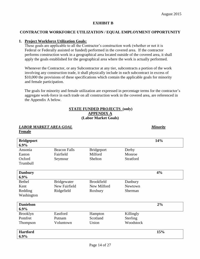
August 2015
Page 14 of 27
EXHIBIT B
CONTRACTOR WORKFORCE UTILIZATION / EQUAL EMPLOYMENT OPPORTUNITY
1. Project Workforce Utilization Goals:
These goals are applicable to all the Contractor’s construction work (whether or not it is
Federal or Federally assisted or funded) performed in the covered area. If the contractor
performs construction work in a geographical area located outside of the covered area, it shall
apply the goals established for the geographical area where the work is actually performed.
Whenever the Contractor, or any Subcontractor at any tier, subcontracts a portion of the work
involving any construction trade, it shall physically include in each subcontract in excess of
$10,000 the provisions of these specifications which contain the applicable goals for minority
and female participation.
The goals for minority and female utilization are expressed in percentage terms for the contractor’s
aggregate work-force in each trade on all construction work in the covered area, are referenced in
the Appendix A below.
STATE FUNDED PROJECTS (only)
APPENDIX A
(Labor Market Goals)
LABOR MARKET AREA GOAL Minority
Female
Bridgeport 14%
6.9%
Ansonia Beacon Falls Bridgeport Derby
Easton Fairfield Milford Monroe
Oxford Seymour Shelton Stratford
Trumbull
Danbury 4%
6.9%
Bethel Bridgewater Brookfield Danbury
Kent New Fairfield New Milford Newtown
Redding Ridgefield Roxbury Sherman
Washington
Danielson 2%
6.9%
Brooklyn Eastford Hampton Killingly
Pomfret Putnam Scotland Sterling
Thompson Voluntown Union Woodstock
Hartford 15%
6.9%
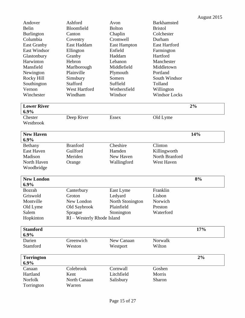
August 2015
Page 15 of 27
Andover Ashford Avon Barkhamsted
Belin Bloomfield Bolton Bristol
Burlington Canton Chaplin Colchester
Columbia Coventry Cromwell Durham
East Granby East Haddam East Hampton East Hartford
East Windsor Ellington Enfield Farmington
Glastonbury Granby Haddam Hartford
Harwinton Hebron Lebanon Manchester
Mansfield Marlborough Middlefield Middletown
Newington Plainville Plymouth Portland
Rocky Hill Simsbury Somers South Windsor
Southington Stafford Suffield Tolland
Vernon West Hartford Wethersfield Willington
Winchester Windham Windsor Windsor Locks
Lower River 2%
6.9%
Chester Deep River Essex Old Lyme
Westbrook
New Haven 14%
6.9%
Bethany Branford Cheshire Clinton
East Haven Guilford Hamden Killingworth
Madison Meriden New Haven North Branford
North Haven Orange Wallingford West Haven
Woodbridge
New London 8%
6.9%
Bozrah Canterbury East Lyme Franklin
Griswold Groton Ledyard Lisbon
Montville New London North Stonington Norwich
Old Lyme Old Saybrook Plainfield Preston
Salem Sprague Stonington Waterford
Hopkinton RI – Westerly Rhode Island
Stamford 17%
6.9%
Darien Greenwich New Canaan Norwalk
Stamford Weston Westport Wilton
Torrington 2%
6.9%
Canaan Colebrook Cornwall Goshen
Hartland Kent Litchfield Morris
Norfolk North Canaan Salisbury Sharon
Torrington Warren
August 2015
Page 16 of 27
Waterbury 10%
6.9%
Bethlehem Middlebury Naugatuck Prospect
Southbury Thomaston Waterbury Watertown
Wolcott Woodbury
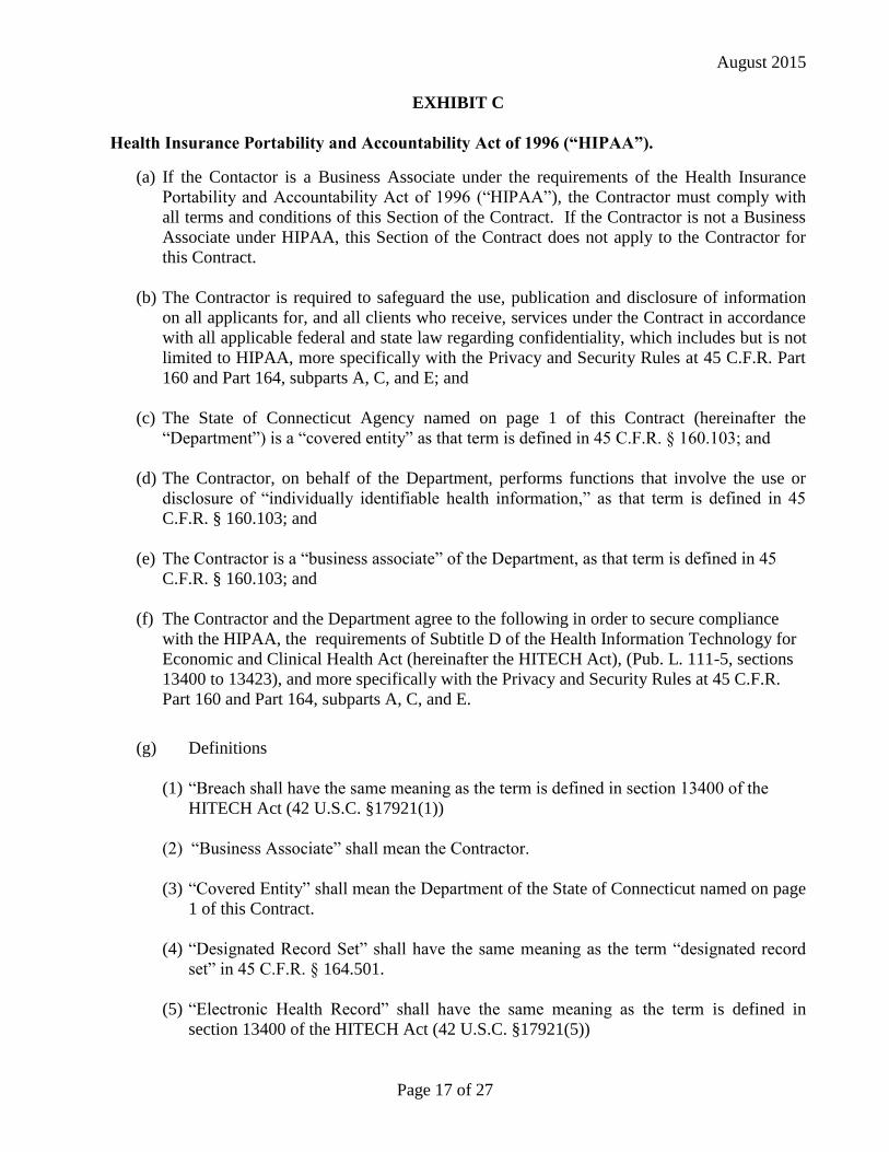
August 2015
Page 17 of 27
EXHIBIT C
Health Insurance Portability and Accountability Act of 1996 (“HIPAA”).
(a) If the Contactor is a Business Associate under the requirements of the Health Insurance
Portability and Accountability Act of 1996 (“HIPAA”), the Contractor must comply with
all terms and conditions of this Section of the Contract. If the Contractor is not a Business
Associate under HIPAA, this Section of the Contract does not apply to the Contractor for
this Contract.
(b) The Contractor is required to safeguard the use, publication and disclosure of information
on all applicants for, and all clients who receive, services under the Contract in accordance
with all applicable federal and state law regarding confidentiality, which includes but is not
limited to HIPAA, more specifically with the Privacy and Security Rules at 45 C.F.R. Part
160 and Part 164, subparts A, C, and E; and
(c) The State of Connecticut Agency named on page 1 of this Contract (hereinafter the
“Department”) is a “covered entity” as that term is defined in 45 C.F.R. § 160.103; and
(d) The Contractor, on behalf of the Department, performs functions that involve the use or
disclosure of “individually identifiable health information,” as that term is defined in 45
C.F.R. § 160.103; and
(e) The Contractor is a “business associate” of the Department, as that term is defined in 45
C.F.R. § 160.103; and
(f) The Contractor and the Department agree to the following in order to secure compliance
with the HIPAA, the requirements of Subtitle D of the Health Information Technology for
Economic and Clinical Health Act (hereinafter the HITECH Act), (Pub. L. 111-5, sections
13400 to 13423), and more specifically with the Privacy and Security Rules at 45 C.F.R.
Part 160 and Part 164, subparts A, C, and E.
(g) Definitions
(1) “Breach shall have the same meaning as the term is defined in section 13400 of the
HITECH Act (42 U.S.C. §17921(1))
(2) “Business Associate” shall mean the Contractor.
(3) “Covered Entity” shall mean the Department of the State of Connecticut named on page
1 of this Contract.
(4) “Designated Record Set” shall have the same meaning as the term “designated record
set” in 45 C.F.R. § 164.501.
(5) “Electronic Health Record” shall have the same meaning as the term is defined in
section 13400 of the HITECH Act (42 U.S.C. §17921(5))
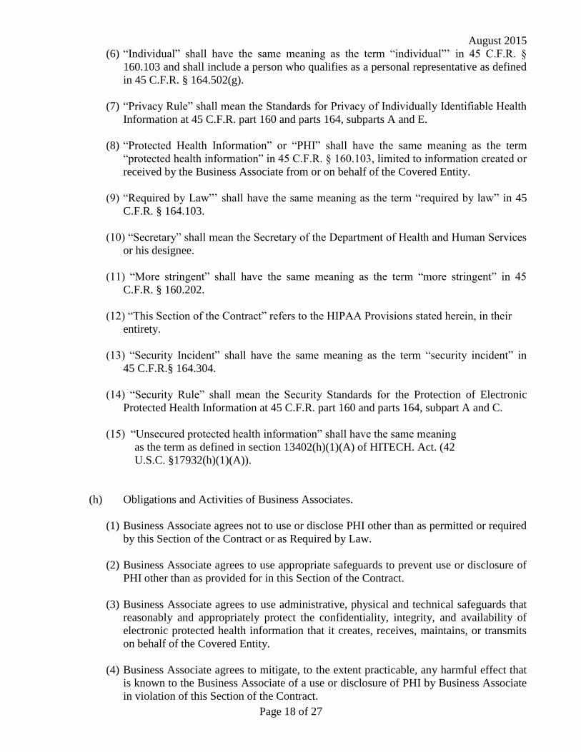
August 2015
Page 18 of 27
(6) “Individual” shall have the same meaning as the term “individual”’ in 45 C.F.R. §
160.103 and shall include a person who qualifies as a personal representative as defined
in 45 C.F.R. § 164.502(g).
(7) “Privacy Rule” shall mean the Standards for Privacy of Individually Identifiable Health
Information at 45 C.F.R. part 160 and parts 164, subparts A and E.
(8) “Protected Health Information” or “PHI” shall have the same meaning as the term
“protected health information” in 45 C.F.R. § 160.103, limited to information created or
received by the Business Associate from or on behalf of the Covered Entity.
(9) “Required by Law”’ shall have the same meaning as the term “required by law” in 45
C.F.R. § 164.103.
(10) “Secretary” shall mean the Secretary of the Department of Health and Human Services
or his designee.
(11) “More stringent” shall have the same meaning as the term “more stringent” in 45
C.F.R. § 160.202.
(12) “This Section of the Contract” refers to the HIPAA Provisions stated herein, in their
entirety.
(13) “Security Incident” shall have the same meaning as the term “security incident” in
45 C.F.R.§ 164.304.
(14) “Security Rule” shall mean the Security Standards for the Protection of Electronic
Protected Health Information at 45 C.F.R. part 160 and parts 164, subpart A and C.
(15) “Unsecured protected health information” shall have the same meaning
as the term as defined in section 13402(h)(1)(A) of HITECH. Act. (42
U.S.C. §17932(h)(1)(A)).
(h) Obligations and Activities of Business Associates.
(1) Business Associate agrees not to use or disclose PHI other than as permitted or required
by this Section of the Contract or as Required by Law.
(2) Business Associate agrees to use appropriate safeguards to prevent use or disclosure of
PHI other than as provided for in this Section of the Contract.
(3) Business Associate agrees to use administrative, physical and technical safeguards that
reasonably and appropriately protect the confidentiality, integrity, and availability of
electronic protected health information that it creates, receives, maintains, or transmits
on behalf of the Covered Entity.
(4) Business Associate agrees to mitigate, to the extent practicable, any harmful effect that
is known to the Business Associate of a use or disclosure of PHI by Business Associate
in violation of this Section of the Contract.
August 2015
Page 19 of 27
(5) Business Associate agrees to report to Covered Entity any use or disclosure of PHI not
provided for by this Section of the Contract or any security incident of which it
becomes aware.
(6) Business Associate agrees to insure that any agent, including a subcontractor, to whom
it provides PHI received from, or created or received by Business Associate, on behalf
of the Covered Entity, agrees to the same restrictions and conditions that apply through
this Section of the Contract to Business Associate with respect to such information.
(7) Business Associate agrees to provide access, at the request of the Covered Entity, and in
the time and manner agreed to by the parties, to PHI in a Designated Record Set, to
Covered Entity or, as directed by Covered Entity, to an Individual in order to meet the
requirements under 45 C.F.R. § 164.524.
(8) Business Associate agrees to make any amendments to PHI in a Designated Record Set
that the Covered Entity directs or agrees to pursuant to 45 C.F.R. § 164.526 at the
request of the Covered Entity, and in the time and manner agreed to by the parties.
(9) Business Associate agrees to make internal practices, books, and records, including
policies and procedures and PHI, relating to the use and disclosure of PHI received
from, or created or received by, Business Associate on behalf of Covered Entity,
available to Covered Entity or to the Secretary in a time and manner agreed to by the
parties or designated by the Secretary, for purposes of the Secretary determining
Covered Entity’s compliance with the Privacy Rule.
(10)Business Associate agrees to document such disclosures of PHI and information related
to such disclosures as would be required for Covered Entity to respond to a request by
an Individual for an accounting of disclosures of PHI in accordance with 45 C.F.R.
§ 164.528 and section 13405 of the HITECH Act (42 U.S.C. § 17935) and any
regulations promulgated thereunder.
(11)Business Associate agrees to provide to Covered Entity, in a time and manner agreed to
by the parties, information collected in accordance with clause h. (10) of this Section of
the Contract, to permit Covered Entity to respond to a request by an Individual for an
accounting of disclosures of PHI in accordance with 45 C.F.R. § 164.528 and section
13405 of the HITECH Act (42 U.S.C. § 17935) and any regulations promulgated
thereunder. Business Associate agrees at the Covered Entity’s direction to provide an
accounting of disclosures of PHI directly to an individual in accordance with 45 C.F.R.
§ 164.528 and section 13405 of the HITECH Act (42 U.S.C. § 17935) and any
regulations promulgated thereunder.
(12)Business Associate agrees to comply with any state or federal law that is more stringent
than the Privacy Rule.
(13) Business Associate agrees to comply with the requirements of the HITECH Act
relating to privacy and security that are applicable to the Covered Entity and with the
requirements of 45 C.F.R. sections 164.504(e), 164.308, 164.310, 164.312, and
164.316.
August 2015
Page 20 of 27
(14) In the event that an individual requests that the Business Associate (a) restrict
disclosures of PHI; (b) provide an accounting of disclosures of the individual’s PHI; or
(c) provide a copy of the individual’s PHI in an electronic health record, the Business
Associate agrees to notify the covered entity, in writing, within two business days of the
request.
(15) Business Associate agrees that it shall not, directly or indirectly, receive any
remuneration in exchange for PHI of an individual without (1) the written approval of
the covered entity, unless receipt of remuneration in exchange for PHI is expressly
authorized by this Contract and (2) the valid authorization of the individual, except for
the purposes provided under section 13405(d)(2) of the HITECH Act,(42 U.S.C. §
17935(d)(2)) and in any accompanying regulations
(16) Obligations in the Event of a Breach
A. The Business Associate agrees that, following the discovery of a breach of
unsecured protected health information, it shall notify the Covered Entity of such
breach in accordance with the requirements of section 13402 of HITECH (42 U.S.C.
17932(b) and the provisions of this Section of the Contract.
B. Such notification shall be provided by the Business Associate to the Covered Entity
without unreasonable delay, and in no case later than 30 days after the breach is
discovered by the Business Associate, except as otherwise instructed in writing by a
law enforcement official pursuant to section 13402 (g) of HITECH (42 U.S.C.
17932(g)) . A breach is considered discovered as of the first day on which it is, or
reasonably should have been, known to the Business Associate. The notification
shall include the identification and last known address, phone number and email
address of each individual (or the next of kin of the individual if the individual is
deceased) whose unsecured protected health information has been, or is reasonably
believed by the Business Associate to have been, accessed, acquired, or disclosed
during such breach.
C. The Business Associate agrees to include in the notification to the Covered Entity at
least the following information:
1. A brief description of what happened, including the date of the breach and the
date of the discovery of the breach, if known.
2. A description of the types of unsecured protected health information that were
involved in the breach (such as full name, Social Security number, date of birth,
home address, account number, or disability code).
3. The steps the Business Associate recommends that individuals take to protect
themselves from potential harm resulting from the breach.
4. A detailed description of what the Business Associate is doing to investigate the
breach, to mitigate losses, and to protect against any further breaches.
5. Whether a law enforcement official has advised either verbally or in writing the
Business Associate that he or she has determined that notification or notice to
August 2015
Page 21 of 27
individuals or the posting required under section 13402 of the HITECH Act
would impede a criminal investigation or cause damage to national security and;
if so, include contact information for said official.
D. Business Associate agrees to provide appropriate staffing and have established
procedures to ensure that individuals informed by the Covered Entity of a breach by
the Business Associate have the opportunity to ask questions and contact the
Business Associate for additional information regarding the breach. Such
procedures shall include a toll-free telephone number, an e-mail address, a posting
on its Web site and a postal address. Business Associate agrees to include in the
notification of a breach by the Business Associate to the Covered Entity, a written
description of the procedures that have been established to meet these requirements.
Costs of such contact procedures will be borne by the Contractor.
E. Business Associate agrees that, in the event of a breach, it has the burden to
demonstrate that it has complied with all notifications requirements set forth above,
including evidence demonstrating the necessity of a delay in notification to the
Covered Entity.
(i) Permitted Uses and Disclosure by Business Associate.
(1) General Use and Disclosure Provisions Except as otherwise limited in this Section of
the Contract, Business Associate may use or disclose PHI to perform functions,
activities, or services for, or on behalf of, Covered Entity as specified in this Contract,
provided that such use or disclosure would not violate the Privacy Rule if done by
Covered Entity or the minimum necessary policies and procedures of the Covered
Entity.
(2) Specific Use and Disclosure Provisions
(A) Except as otherwise limited in this Section of the Contract, Business Associate may
use PHI for the proper management and administration of Business Associate or to
carry out the legal responsibilities of Business Associate.
(B) Except as otherwise limited in this Section of the Contract, Business Associate may
disclose PHI for the proper management and administration of Business Associate,
provided that disclosures are Required by Law, or Business Associate obtains
reasonable assurances from the person to whom the information is disclosed that it
will remain confidential and used or further disclosed only as Required by Law or
for the purpose for which it was disclosed to the person, and the person notifies
Business Associate of any instances of which it is aware in which the confidentiality
of the information has been breached.
(C) Except as otherwise limited in this Section of the Contract, Business Associate may
use PHI to provide Data Aggregation services to Covered Entity as permitted by 45
C.F.R. § 164.504(e)(2)(i)(B).
(j) Obligations of Covered Entity.
August 2015
Page 22 of 27
(1) Covered Entity shall notify Business Associate of any limitations in its notice of privacy
practices of Covered Entity, in accordance with 45 C.F.R. § 164.520, or to the extent
that such limitation may affect Business Associate’s use or disclosure of PHI.
(2) Covered Entity shall notify Business Associate of any changes in, or revocation of,
permission by Individual to use or disclose PHI, to the extent that such changes may
affect Business Associate’s use or disclosure of PHI.
(3) Covered Entity shall notify Business Associate of any restriction to the use or disclosure
of PHI that Covered Entity has agreed to in accordance with 45 C.F.R. § 164.522, to the
extent that such restriction may affect Business Associate’s use or disclosure of PHI.
(k) Permissible Requests by Covered Entity. Covered Entity shall not request Business
Associate to use or disclose PHI in any manner that would not be permissible under the
Privacy Rule if done by the Covered Entity, except that Business Associate may use and
disclose PHI for data aggregation, and management and administrative activities of
Business Associate, as permitted under this Section of the Contract.
(l) Term and Termination.
(1) Term. The Term of this Section of the Contract shall be effective as of the date the
Contract is effective and shall terminate when the information collected in accordance
with clause h. (10) of this Section of the Contract is provided to the Covered Entity and
all of the PHI provided by Covered Entity to Business Associate, or created or received
by Business Associate on behalf of Covered Entity, is destroyed or returned to
Covered Entity, or, if it is infeasible to return or destroy PHI, protections are extended
to such information, in accordance with the termination provisions in this Section.
(2) Termination for Cause Upon Covered Entity’s knowledge of a material breach by
Business Associate, Covered Entity shall either:
(A) Provide an opportunity for Business Associate to cure the breach or end the
violation and terminate the Contract if Business Associate does not cure the breach
or end the violation within the time specified by the Covered Entity; or
(B) Immediately terminate the Contract if Business Associate has breached a material
term of this Section of the Contract and cure is not possible; or
(C) If neither termination nor cure is feasible, Covered Entity shall report the violation
to the Secretary.
(3) Effect of Termination
(A) Except as provided in (l)(2) of this Section of the Contract, upon termination of this
Contract, for any reason, Business Associate shall return or destroy all PHI received
from Covered Entity, or created or received by Business Associate on behalf of
Covered Entity. Business Associate shall also provide the information collected in
accordance with clause h. (10) of this Section of the Contract to the Covered Entity
August 2015
Page 23 of 27
within ten business days of the notice of termination. This provision shall apply to
PHI that is in the possession of subcontractors or agents of Business Associate.
Business Associate shall retain no copies of the PHI.
(B) In the event that Business Associate determines that returning or destroying the PHI
is infeasible, Business Associate shall provide to Covered Entity notification of the
conditions that make return or destruction infeasible. Upon documentation by
Business Associate that return or destruction of PHI is infeasible, Business
Associate shall extend the protections of this Section of the Contract to such PHI
and limit further uses and disclosures of PHI to those purposes that make return or
destruction infeasible, for as long as Business Associate maintains such PHI.
Infeasibility of the return or destruction of PHI includes, but is not limited to,
requirements under state or federal law that the Business Associate maintains or
preserves the PHI or copies thereof.
(m) Miscellaneous Provisions.
(1) Regulatory References. A reference in this Section of the Contract to a section in the
Privacy Rule means the section as in effect or as amended.
(2) Amendment. The Parties agree to take such action as in necessary to amend this Section
of the Contract from time to time as is necessary for Covered Entity to comply with
requirements of the Privacy Rule and the Health Insurance Portability and
Accountability Act of 1996, Pub. L. No. 104-191.
(3) Survival. The respective rights and obligations of Business Associate shall survive the
termination of this Contract.
(4) Effect on Contract. Except as specifically required to implement the purposes of this
Section of the Contract, all other terms of the Contract shall remain in force and effect.
(5) Construction. This Section of the Contract shall be construed as broadly as necessary to
implement and comply with the Privacy Standard. Any ambiguity in this Section of the
Contract shall be resolved in favor of a meaning that complies, and is consistent with,
the Privacy Standard.
(6) Disclaimer. Covered Entity makes no warranty or representation that compliance with
this Section of the Contract will be adequate or satisfactory for Business Associate’s
own purposes. Covered Entity shall not be liable to Business Associate for any claim,
civil or criminal penalty, loss or damage related to or arising from the unauthorized use
or disclosure of PHI by Business Associate or any of its officers, directors, employees,
contractors or agents, or any third party to whom Business Associate has disclosed PHI
contrary to the provisions of this Contract or applicable law. Business Associate is
solely responsible for all decisions made, and actions taken, by Business Associate
regarding the safeguarding, use and disclosure of PHI within its possession, custody or
control.
(7) Indemnification. The Business Associate shall indemnify and hold the Covered Entity harmless
from and against any and all claims, liabilities, judgments, fines, assessments, penalties, awards and
any statutory damages that may be imposed or assessed pursuant to HIPAA, as amended or the
August 2015
Page 24 of 27
HITECH Act, including, without limitation, attorney’s fees, expert witness fees, costs of investigation,
litigation or dispute resolution, and costs awarded thereunder, relating to or arising out of any violation
by the Business Associate and its agents, including subcontractors, of any obligation of Business
Associate and its agents, including subcontractors, under this section of the contract, under HIPAA, the
HITECH Act, the Privacy Rule and the Security Rule.
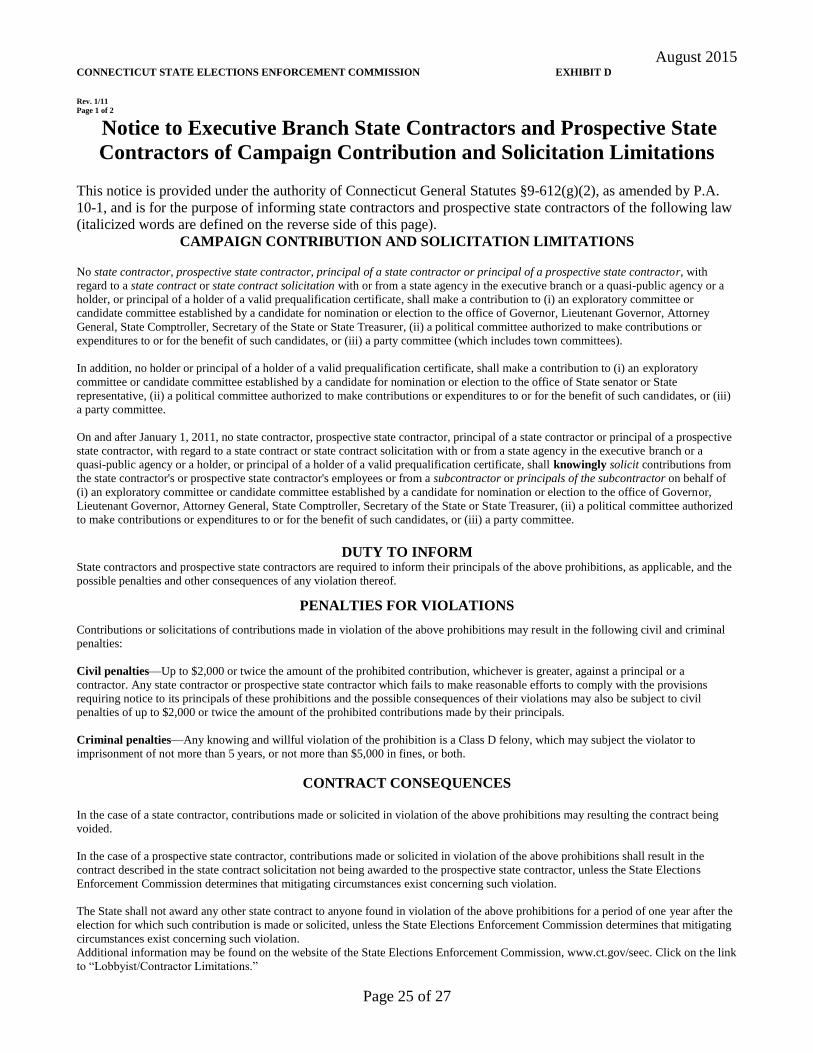
August 2015
Page 25 of 27
CONNECTICUT STATE ELECTIONS ENFORCEMENT COMMISSION EXHIBIT D
Rev. 1/11
Page 1 of 2
Notice to Executive Branch State Contractors and Prospective State
Contractors of Campaign Contribution and Solicitation Limitations
This notice is provided under the authority of Connecticut General Statutes §9-612(g)(2), as amended by P.A.
10-1, and is for the purpose of informing state contractors and prospective state contractors of the following law
(italicized words are defined on the reverse side of this page).
CAMPAIGN CONTRIBUTION AND SOLICITATION LIMITATIONS
No state contractor, prospective state contractor, principal of a state contractor or principal of a prospective state contractor, with
regard to a state contract or state contract solicitation with or from a state agency in the executive branch or a quasi-public agency or a
holder, or principal of a holder of a valid prequalification certificate, shall make a contribution to (i) an exploratory committee or
candidate committee established by a candidate for nomination or election to the office of Governor, Lieutenant Governor, Attorney
General, State Comptroller, Secretary of the State or State Treasurer, (ii) a political committee authorized to make contributions or
expenditures to or for the benefit of such candidates, or (iii) a party committee (which includes town committees).
In addition, no holder or principal of a holder of a valid prequalification certificate, shall make a contribution to (i) an exploratory
committee or candidate committee established by a candidate for nomination or election to the office of State senator or State
representative, (ii) a political committee authorized to make contributions or expenditures to or for the benefit of such candidates, or (iii)
a party committee.
On and after January 1, 2011, no state contractor, prospective state contractor, principal of a state contractor or principal of a prospective
state contractor, with regard to a state contract or state contract solicitation with or from a state agency in the executive branch or a
quasi-public agency or a holder, or principal of a holder of a valid prequalification certificate, shall knowingly solicit contributions from
the state contractor's or prospective state contractor's employees or from a subcontractor or principals of the subcontractor on behalf of
(i) an exploratory committee or candidate committee established by a candidate for nomination or election to the office of Governor,
Lieutenant Governor, Attorney General, State Comptroller, Secretary of the State or State Treasurer, (ii) a political committee authorized
to make contributions or expenditures to or for the benefit of such candidates, or (iii) a party committee.
DUTY TO INFORM State contractors and prospective state contractors are required to inform their principals of the above prohibitions, as applicable, and the
possible penalties and other consequences of any violation thereof.
PENALTIES FOR VIOLATIONS
Contributions or solicitations of contributions made in violation of the above prohibitions may result in the following civil and criminal
penalties:
Civil penalties—Up to $2,000 or twice the amount of the prohibited contribution, whichever is greater, against a principal or a
contractor. Any state contractor or prospective state contractor which fails to make reasonable efforts to comply with the provisions
requiring notice to its principals of these prohibitions and the possible consequences of their violations may also be subject to civil
penalties of up to $2,000 or twice the amount of the prohibited contributions made by their principals.
Criminal penalties—Any knowing and willful violation of the prohibition is a Class D felony, which may subject the violator to
imprisonment of not more than 5 years, or not more than $5,000 in fines, or both.
CONTRACT CONSEQUENCES
In the case of a state contractor, contributions made or solicited in violation of the above prohibitions may resulting the contract being
voided.
In the case of a prospective state contractor, contributions made or solicited in violation of the above prohibitions shall result in the
contract described in the state contract solicitation not being awarded to the prospective state contractor, unless the State Elections
Enforcement Commission determines that mitigating circumstances exist concerning such violation.
The State shall not award any other state contract to anyone found in violation of the above prohibitions for a period of one year after the
election for which such contribution is made or solicited, unless the State Elections Enforcement Commission determines that mitigating
circumstances exist concerning such violation.
Additional information may be found on the website of the State Elections Enforcement Commission, www.ct.gov/seec. Click on the link
to “Lobbyist/Contractor Limitations.”
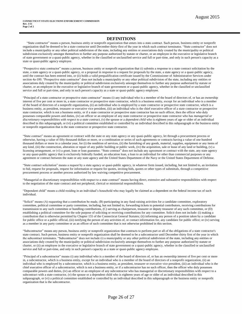
August 2015
Page 26 of 27
CONNECTICUT STATE ELECTIONS ENFORCEMENT COMMISSION
Rev. 1/11
Page 2 of 2
DEFINITIONS “State contractor” means a person, business entity or nonprofit organization that enters into a state contract. Such person, business entity or nonprofit
organization shall be deemed to be a state contractor until December thirty-first of the year in which such contract terminates. “State contractor” does not
include a municipality or any other political subdivision of the state, including any entities or associations duly created by the municipality or political subdivision exclusively amongst themselves to further any purpose authorized by statute or charter, or an employee in the executive or legislative branch
of state government or a quasi-public agency, whether in the classified or unclassified service and full or part-time, and only in such person's capacity as a
state or quasi-public agency employee.
“Prospective state contractor” means a person, business entity or nonprofit organization that (i) submits a response to a state contract solicitation by the
state, a state agency or a quasi-public agency, or a proposal in response to a request for proposals by the state, a state agency or a quasi-public agency, until the contract has been entered into, or (ii) holds a valid prequalification certificate issued by the Commissioner of Administrative Services under
section 4a-100. “Prospective state contractor” does not include a municipality or any other political subdivision of the state, including any entities or
associations duly created by the municipality or political subdivision exclusively amongst themselves to further any purpose authorized by statute or charter, or an employee in the executive or legislative branch of state government or a quasi-public agency, whether in the classified or unclassified
service and full or part-time, and only in such person's capacity as a state or quasi-public agency employee.
“Principal of a state contractor or prospective state contractor” means (i) any individual who is a member of the board of directors of, or has an ownership
interest of five per cent or more in, a state contractor or prospective state contractor, which is a business entity, except for an individual who is a member
of the board of directors of a nonprofit organization, (ii) an individual who is employed by a state contractor or prospective state contractor, which is a business entity, as president, treasurer or executive vice president, (iii) an individual who is the chief executive officer of a state contractor or prospective
state contractor, which is not a business entity, or if a state contractor or prospective state contractor has no such officer, then the officer who duly
possesses comparable powers and duties, (iv) an officer or an employee of any state contractor or prospective state contractor who has managerial or discretionary responsibilities with respect to a state contract, (v) the spouse or a dependent child who is eighteen years of age or older of an individual
described in this subparagraph, or (vi) a political committee established or controlled by an individual described in this subparagraph or the business entity
or nonprofit organization that is the state contractor or prospective state contractor.
“State contract” means an agreement or contract with the state or any state agency or any quasi-public agency, let through a procurement process or
otherwise, having a value of fifty thousand dollars or more, or a combination or series of such agreements or contracts having a value of one hundred
thousand dollars or more in a calendar year, for (i) the rendition of services, (ii) the furnishing of any goods, material, supplies, equipment or any items of any kind, (iii) the construction, alteration or repair of any public building or public work, (iv) the acquisition, sale or lease of any land or building, (v) a
licensing arrangement, or (vi) a grant, loan or loan guarantee. “State contract” does not include any agreement or contract with the state, any state agency
or any quasi-public agency that is exclusively federally funded, an education loan, a loan to an individual for other than commercial purposes or any agreement or contract between the state or any state agency and the United States Department of the Navy or the United States Department of Defense.
“State contract solicitation” means a request by a state agency or quasi-public agency, in whatever form issued, including, but not limited to, an invitation
to bid, request for proposals, request for information or request for quotes, inviting bids, quotes or other types of submittals, through a competitive
procurement process or another process authorized by law waiving competitive procurement.
“Managerial or discretionary responsibilities with respect to a state contract” means having direct, extensive and substantive responsibilities with respect
to the negotiation of the state contract and not peripheral, clerical or ministerial responsibilities.
“Dependent child” means a child residing in an individual’s household who may legally be claimed as a dependent on the federal income tax of such
individual.
“Solicit” means (A) requesting that a contribution be made, (B) participating in any fund-raising activities for a candidate committee, exploratory
committee, political committee or party committee, including, but not limited to, forwarding tickets to potential contributors, receiving contributions for transmission to any such committee or bundling contributions, (C) serving as chairperson, treasurer or deputy treasurer of any such committee, or (D)
establishing a political committee for the sole purpose of soliciting or receiving contributions for any committee. Solicit does not include: (i) making a
contribution that is otherwise permitted by Chapter 155 of the Connecticut General Statutes; (ii) informing any person of a position taken by a candidate for public office or a public official, (iii) notifying the person of any activities of, or contact information for, any candidate for public office; or (iv) serving
as a member in any party committee or as an officer of such committee that is not otherwise prohibited in this section.
“Subcontractor” means any person, business entity or nonprofit organization that contracts to perform part or all of the obligations of a state contractor's
state contract. Such person, business entity or nonprofit organization shall be deemed to be a subcontractor until December thirty first of the year in which
the subcontract terminates. “Subcontractor” does not include (i) a municipality or any other political subdivision of the state, including any entities or
associations duly created by the municipality or political subdivision exclusively amongst themselves to further any purpose authorized by statute or
charter, or (ii) an employee in the executive or legislative branch of state government or a quasi-public agency, whether in the classified or unclassified
service and full or part-time, and only in such person's capacity as a state or quasi-public agency employee.
“Principal of a subcontractor” means (i) any individual who is a member of the board of directors of, or has an ownership interest of five per cent or more
in, a subcontractor, which is a business entity, except for an individual who is a member of the board of directors of a nonprofit organization, (ii) an individual who is employed by a subcontractor, which is a business entity, as president, treasurer or executive vice president, (iii) an individual who is the
chief executive officer of a subcontractor, which is not a business entity, or if a subcontractor has no such officer, then the officer who duly possesses
comparable powers and duties, (iv) an officer or an employee of any subcontractor who has managerial or discretionary responsibilities with respect to a subcontract with a state contractor, (v) the spouse or a dependent child who is eighteen years of age or older of an individual described in this
subparagraph, or (vi) a political committee established or controlled by an individual described in this subparagraph or the business entity or nonprofit
organization that is the subcontractor.

August 2015
Page 27 of 27
EXHIBIT E
(state wages will be inserted here)
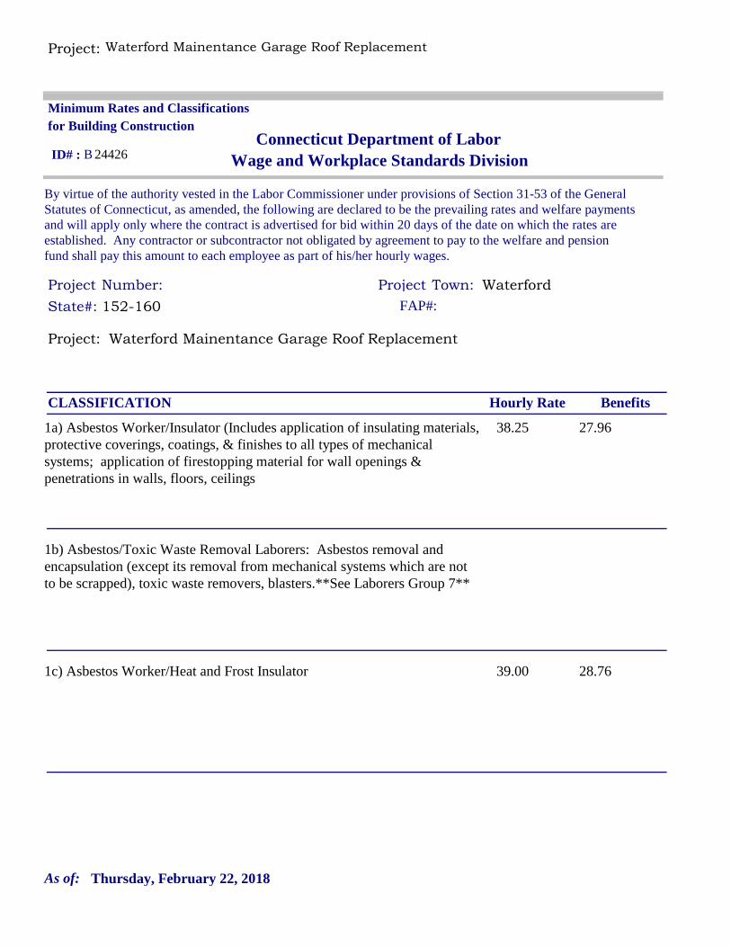
Project: Waterford Mainentance Garage Roof Replacement
Project: Waterford Mainentance Garage Roof Replacement
Project Project Waterford
By virtue of the authority vested in the Labor Commissioner under provisions of Section 31-53 of the General Statutes of Connecticut, as amended, the following are declared to be the prevailing rates and welfare payments and will apply only where the contract is advertised for bid within 20 days of the date on which the rates are established. Any contractor or subcontractor not obligated by agreement to pay to the welfare and pension fund shall pay this amount to each employee as part of his/her hourly wages.
Minimum Rates and Classifications for Building Construction
Connecticut Department of LaborWage and Workplace Standards Division
Number: Town:
B 24426
State#: 152-160 FAP#:
ID# :
Hourly Rate BenefitsCLASSIFICATION
38.25 27.961a) Asbestos Worker/Insulator (Includes application of insulating materials, protective coverings, coatings, & finishes to all types of mechanical systems; application of firestopping material for wall openings & penetrations in walls, floors, ceilings
1b) Asbestos/Toxic Waste Removal Laborers: Asbestos removal and encapsulation (except its removal from mechanical systems which are not to be scrapped), toxic waste removers, blasters.**See Laborers Group 7**
39.00 28.761c) Asbestos Worker/Heat and Frost Insulator
Thursday, February 22, 2018As of:

Project: Waterford Mainentance Garage Roof Replacement
38.34 26.012) Boilermaker
33.48 32.06 + a3a) Bricklayer, Cement Mason, Concrete Finisher (including caulking), Stone Masons
34.90 25.873b) Tile Setter
31.69 22.353c) Terrazzo Mechanics and Marble Setters
26.70 21.753d) Tile, Marble & Terrazzo Finishers
33.48 32.063e) Plasterer
Thursday, February 22, 2018As of:
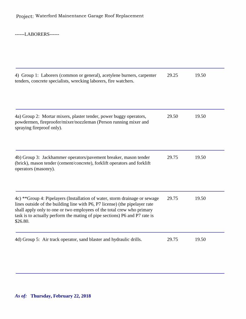
Project: Waterford Mainentance Garage Roof Replacement
------LABORERS------
29.25 19.504) Group 1: Laborers (common or general), acetylene burners, carpenter tenders, concrete specialists, wrecking laborers, fire watchers.
29.50 19.504a) Group 2: Mortar mixers, plaster tender, power buggy operators, powdermen, fireproofer/mixer/nozzleman (Person running mixer and spraying fireproof only).
29.75 19.504b) Group 3: Jackhammer operators/pavement breaker, mason tender (brick), mason tender (cement/concrete), forklift operators and forklift operators (masonry).
29.75 19.504c) **Group 4: Pipelayers (Installation of water, storm drainage or sewage lines outside of the building line with P6, P7 license) (the pipelayer rate shall apply only to one or two employees of the total crew who primary task is to actually perform the mating of pipe sections) P6 and P7 rate is $26.80.
29.75 19.504d) Group 5: Air track operator, sand blaster and hydraulic drills.
Thursday, February 22, 2018As of:
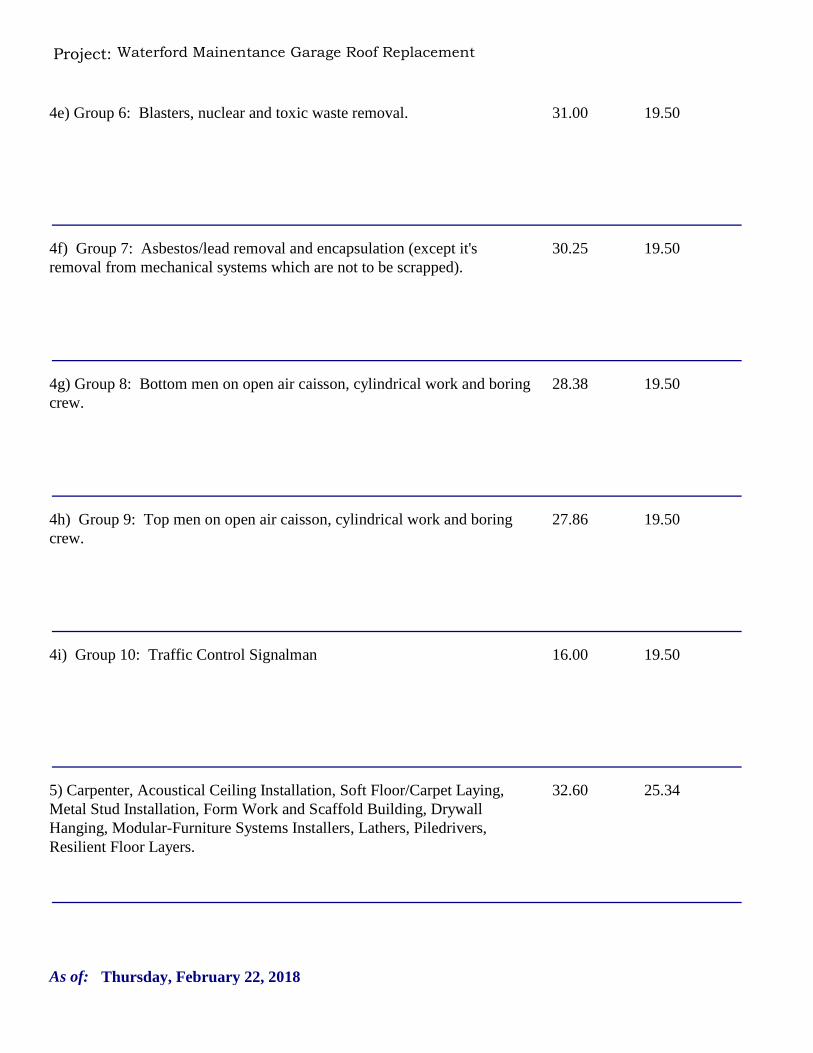
Project: Waterford Mainentance Garage Roof Replacement
31.00 19.504e) Group 6: Blasters, nuclear and toxic waste removal.
30.25 19.504f) Group 7: Asbestos/lead removal and encapsulation (except it's removal from mechanical systems which are not to be scrapped).
28.38 19.504g) Group 8: Bottom men on open air caisson, cylindrical work and boring crew.
27.86 19.504h) Group 9: Top men on open air caisson, cylindrical work and boring crew.
16.00 19.504i) Group 10: Traffic Control Signalman
32.60 25.345) Carpenter, Acoustical Ceiling Installation, Soft Floor/Carpet Laying, Metal Stud Installation, Form Work and Scaffold Building, Drywall Hanging, Modular-Furniture Systems Installers, Lathers, Piledrivers, Resilient Floor Layers.
Thursday, February 22, 2018As of:
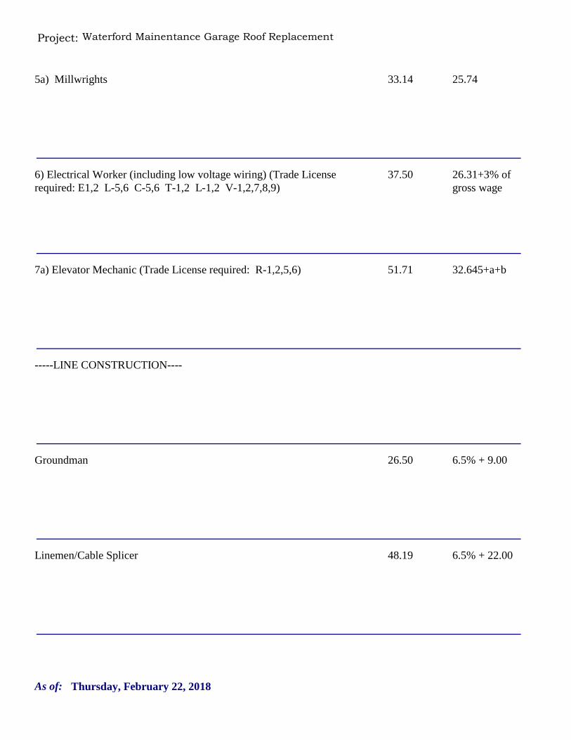
Project: Waterford Mainentance Garage Roof Replacement
33.14 25.745a) Millwrights
37.50 26.31+3% of gross wage
6) Electrical Worker (including low voltage wiring) (Trade License required: E1,2 L-5,6 C-5,6 T-1,2 L-1,2 V-1,2,7,8,9)
51.71 32.645+a+b7a) Elevator Mechanic (Trade License required: R-1,2,5,6)
-----LINE CONSTRUCTION----
26.50 6.5% + 9.00Groundman
48.19 6.5% + 22.00Linemen/Cable Splicer
Thursday, February 22, 2018As of:
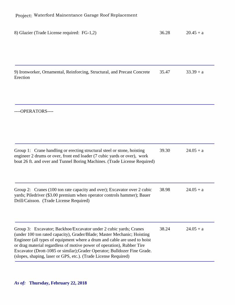
Project: Waterford Mainentance Garage Roof Replacement
36.28 20.45 + a8) Glazier (Trade License required: FG-1,2)
35.47 33.39 + a9) Ironworker, Ornamental, Reinforcing, Structural, and Precast Concrete Erection
----OPERATORS----
39.30 24.05 + aGroup 1: Crane handling or erecting structural steel or stone, hoisting engineer 2 drums or over, front end loader (7 cubic yards or over), work boat 26 ft. and over and Tunnel Boring Machines. (Trade License Required)
38.98 24.05 + aGroup 2: Cranes (100 ton rate capacity and over); Excavator over 2 cubic yards; Piledriver ($3.00 premium when operator controls hammer); Bauer Drill/Caisson. (Trade License Required)
38.24 24.05 + aGroup 3: Excavator; Backhoe/Excavator under 2 cubic yards; Cranes (under 100 ton rated capacity), Grader/Blade; Master Mechanic; Hoisting Engineer (all types of equipment where a drum and cable are used to hoist or drag material regardless of motive power of operation), Rubber Tire Excavator (Drott-1085 or similar);Grader Operator; Bulldozer Fine Grade. (slopes, shaping, laser or GPS, etc.). (Trade License Required)
Thursday, February 22, 2018As of:
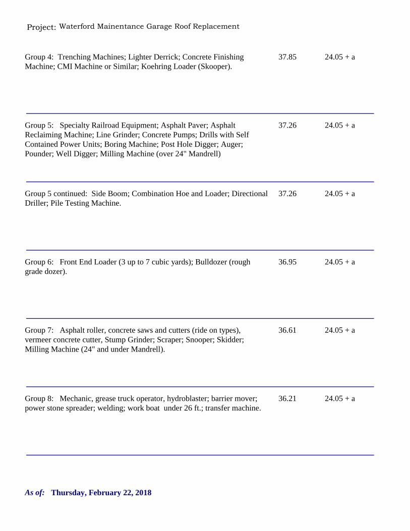
Project: Waterford Mainentance Garage Roof Replacement
37.85 24.05 + aGroup 4: Trenching Machines; Lighter Derrick; Concrete Finishing Machine; CMI Machine or Similar; Koehring Loader (Skooper).
37.26 24.05 + aGroup 5: Specialty Railroad Equipment; Asphalt Paver; Asphalt Reclaiming Machine; Line Grinder; Concrete Pumps; Drills with Self Contained Power Units; Boring Machine; Post Hole Digger; Auger; Pounder; Well Digger; Milling Machine (over 24" Mandrell)
37.26 24.05 + aGroup 5 continued: Side Boom; Combination Hoe and Loader; Directional Driller; Pile Testing Machine.
36.95 24.05 + aGroup 6: Front End Loader (3 up to 7 cubic yards); Bulldozer (rough grade dozer).
36.61 24.05 + aGroup 7: Asphalt roller, concrete saws and cutters (ride on types), vermeer concrete cutter, Stump Grinder; Scraper; Snooper; Skidder; Milling Machine (24" and under Mandrell).
36.21 24.05 + aGroup 8: Mechanic, grease truck operator, hydroblaster; barrier mover; power stone spreader; welding; work boat under 26 ft.; transfer machine.
Thursday, February 22, 2018As of:
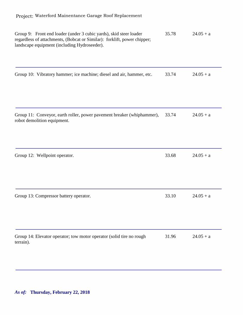
Project: Waterford Mainentance Garage Roof Replacement
35.78 24.05 + aGroup 9: Front end loader (under 3 cubic yards), skid steer loader regardless of attachments, (Bobcat or Similar): forklift, power chipper; landscape equipment (including Hydroseeder).
33.74 24.05 + aGroup 10: Vibratory hammer; ice machine; diesel and air, hammer, etc.
33.74 24.05 + aGroup 11: Conveyor, earth roller, power pavement breaker (whiphammer), robot demolition equipment.
33.68 24.05 + aGroup 12: Wellpoint operator.
33.10 24.05 + aGroup 13: Compressor battery operator.
31.96 24.05 + aGroup 14: Elevator operator; tow motor operator (solid tire no rough terrain).
Thursday, February 22, 2018As of:
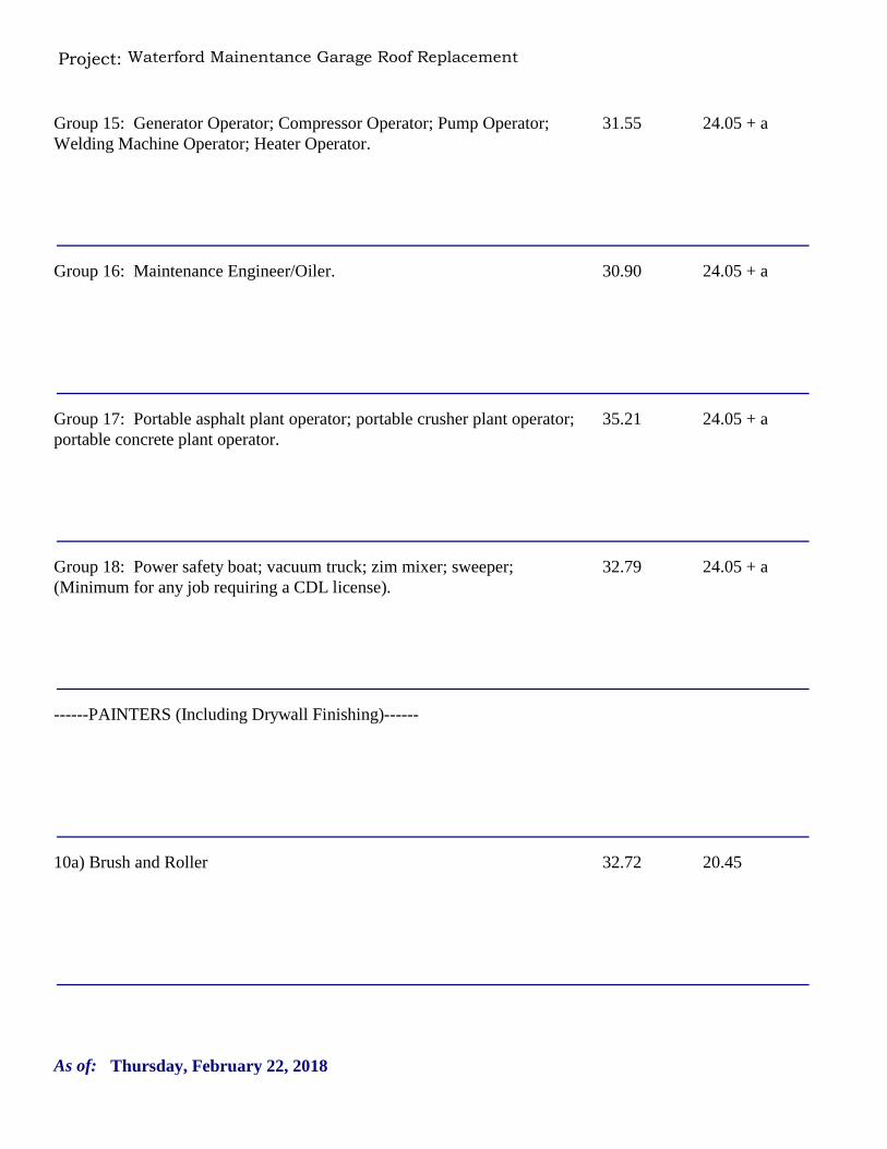
Project: Waterford Mainentance Garage Roof Replacement
31.55 24.05 + aGroup 15: Generator Operator; Compressor Operator; Pump Operator; Welding Machine Operator; Heater Operator.
30.90 24.05 + aGroup 16: Maintenance Engineer/Oiler.
35.21 24.05 + aGroup 17: Portable asphalt plant operator; portable crusher plant operator; portable concrete plant operator.
32.79 24.05 + aGroup 18: Power safety boat; vacuum truck; zim mixer; sweeper; (Minimum for any job requiring a CDL license).
------PAINTERS (Including Drywall Finishing)------
32.72 20.4510a) Brush and Roller
Thursday, February 22, 2018As of:
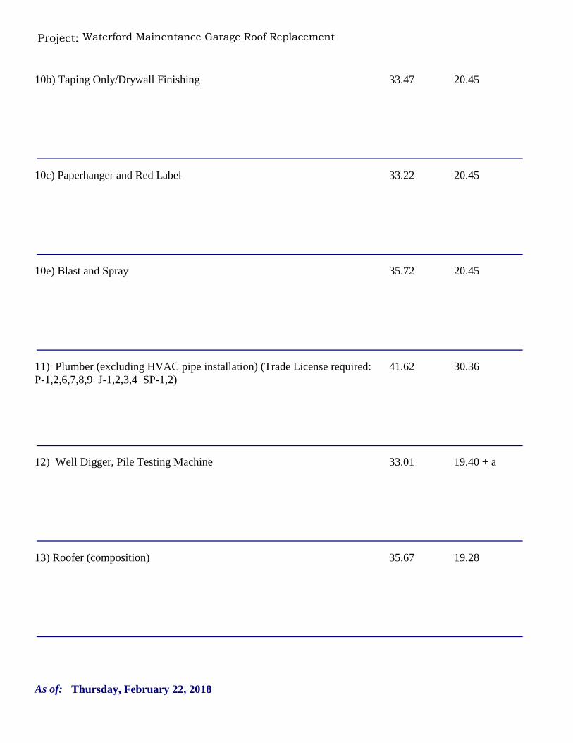
Project: Waterford Mainentance Garage Roof Replacement
33.47 20.4510b) Taping Only/Drywall Finishing
33.22 20.4510c) Paperhanger and Red Label
35.72 20.4510e) Blast and Spray
41.62 30.3611) Plumber (excluding HVAC pipe installation) (Trade License required: P-1,2,6,7,8,9 J-1,2,3,4 SP-1,2)
33.01 19.40 + a12) Well Digger, Pile Testing Machine
35.67 19.2813) Roofer (composition)
Thursday, February 22, 2018As of:
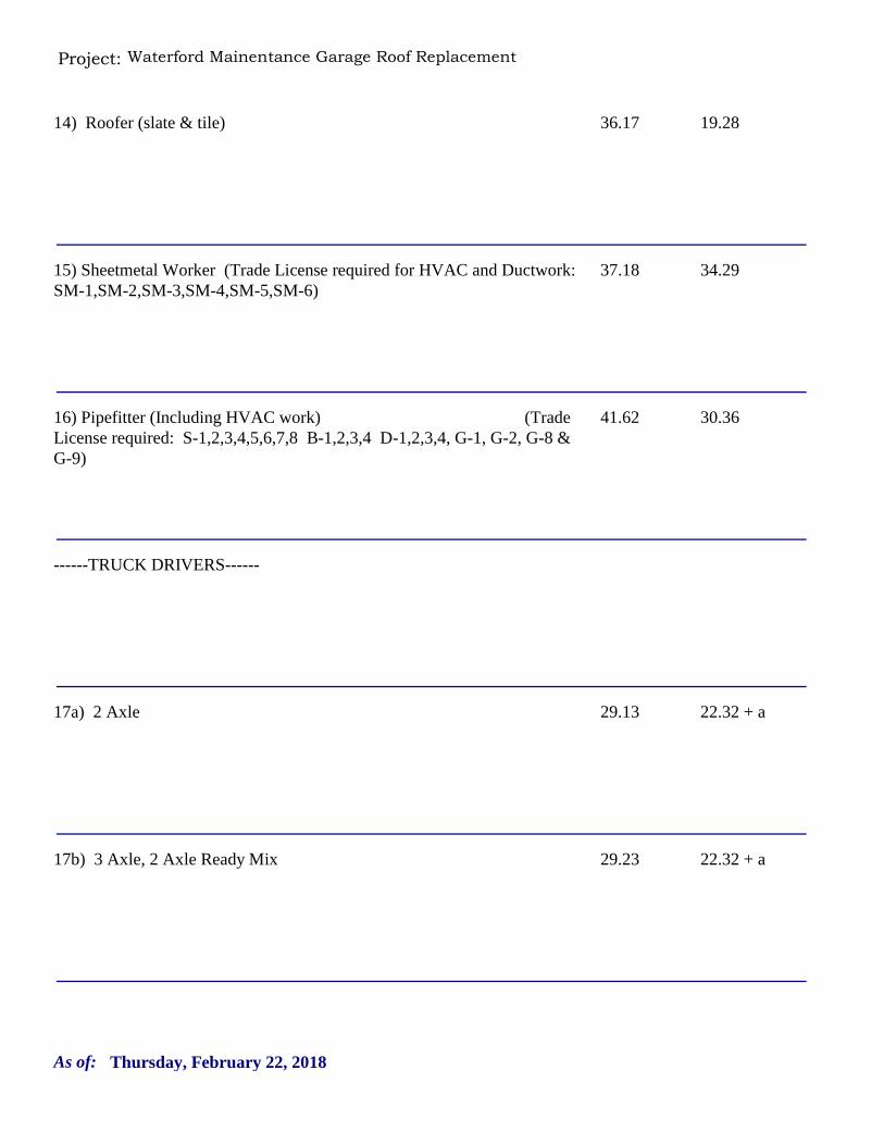
Project: Waterford Mainentance Garage Roof Replacement
36.17 19.2814) Roofer (slate & tile)
37.18 34.2915) Sheetmetal Worker (Trade License required for HVAC and Ductwork: SM-1,SM-2,SM-3,SM-4,SM-5,SM-6)
41.62 30.3616) Pipefitter (Including HVAC work) (Trade License required: S-1,2,3,4,5,6,7,8 B-1,2,3,4 D-1,2,3,4, G-1, G-2, G-8 & G-9)
------TRUCK DRIVERS------
29.13 22.32 + a17a) 2 Axle
29.23 22.32 + a17b) 3 Axle, 2 Axle Ready Mix
Thursday, February 22, 2018As of:
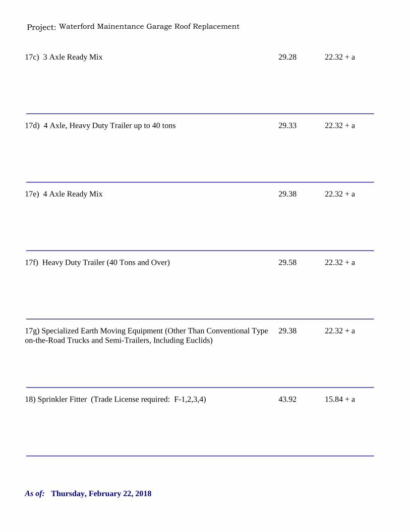
Project: Waterford Mainentance Garage Roof Replacement
29.28 22.32 + a17c) 3 Axle Ready Mix
29.33 22.32 + a17d) 4 Axle, Heavy Duty Trailer up to 40 tons
29.38 22.32 + a17e) 4 Axle Ready Mix
29.58 22.32 + a17f) Heavy Duty Trailer (40 Tons and Over)
29.38 22.32 + a17g) Specialized Earth Moving Equipment (Other Than Conventional Type on-the-Road Trucks and Semi-Trailers, Including Euclids)
43.92 15.84 + a18) Sprinkler Fitter (Trade License required: F-1,2,3,4)
Thursday, February 22, 2018As of:
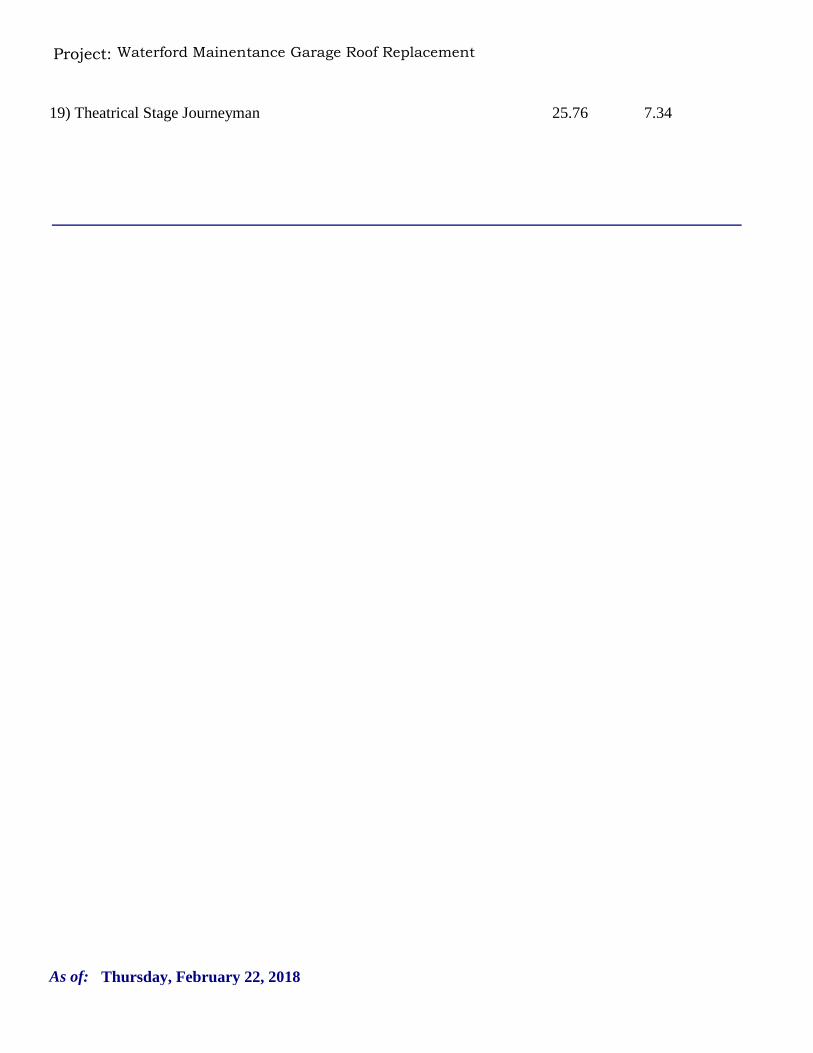
Project: Waterford Mainentance Garage Roof Replacement
25.76 7.3419) Theatrical Stage Journeyman
Thursday, February 22, 2018As of:
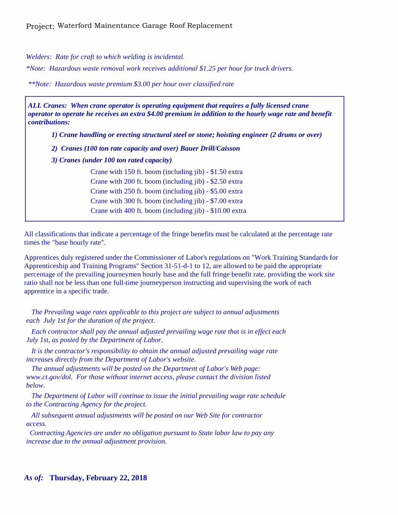
Project: Waterford Mainentance Garage Roof Replacement
Welders: Rate for craft to which welding is incidental.
*Note: Hazardous waste removal work receives additional $1.25 per hour for truck drivers.
**Note: Hazardous waste premium $3.00 per hour over classified rate
Crane with 150 ft. boom (including jib) - $1.50 extraCrane with 200 ft. boom (including jib) - $2.50 extraCrane with 250 ft. boom (including jib) - $5.00 extraCrane with 300 ft. boom (including jib) - $7.00 extra
All classifications that indicate a percentage of the fringe benefits must be calculated at the percentage rate times the "base hourly rate".
Apprentices duly registered under the Commissioner of Labor's regulations on "Work Training Standards for Apprenticeship and Training Programs" Section 31-51-d-1 to 12, are allowed to be paid the appropriate percentage of the prevailing journeymen hourly base and the full fringe benefit rate, providing the work site ratio shall not be less than one full-time journeyperson instructing and supervising the work of each apprentice in a specific trade.
Crane with 400 ft. boom (including jib) - $10.00 extra
Each contractor shall pay the annual adjusted prevailing wage rate that is in effect each July 1st, as posted by the Department of Labor.
It is the contractor's responsibility to obtain the annual adjusted prevailing wage rate increases directly from the Department of Labor's website. The annual adjustments will be posted on the Department of Labor's Web page:
www.ct.gov/dol. For those without internet access, please contact the division listed below.
The Department of Labor will continue to issue the initial prevailing wage rate schedule to the Contracting Agency for the project.
All subsequent annual adjustments will be posted on our Web Site for contractor access.
The Prevailing wage rates applicable to this project are subject to annual adjustments each July 1st for the duration of the project.
Contracting Agencies are under no obligation pursuant to State labor law to pay any increase due to the annual adjustment provision.
ALL Cranes: When crane operator is operating equipment that requires a fully licensed crane operator to operate he receives an extra $4.00 premium in addition to the hourly wage rate and benefit contributions:
1) Crane handling or erecting structural steel or stone; hoisting engineer (2 drums or over)
2) Cranes (100 ton rate capacity and over) Bauer Drill/Caisson
3) Cranes (under 100 ton rated capacity)
Thursday, February 22, 2018As of:
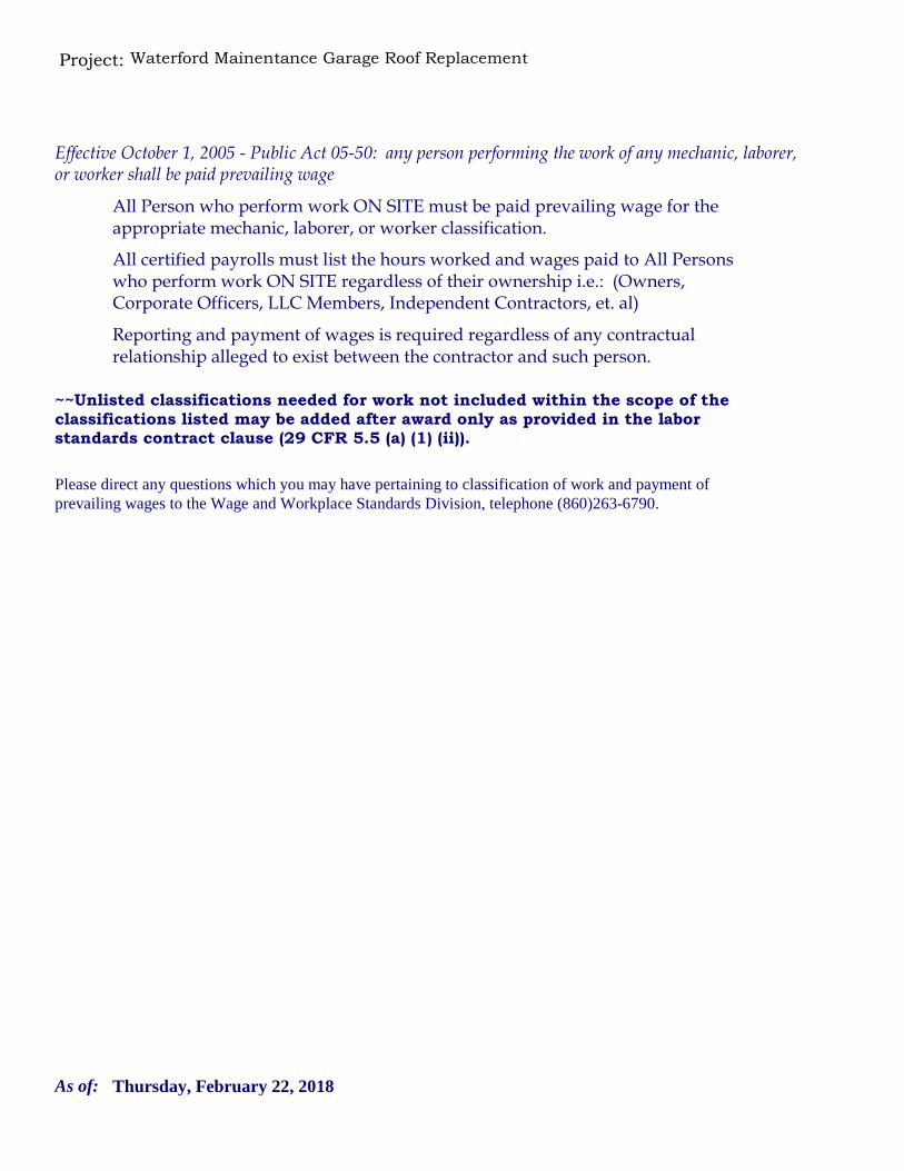
Project: Waterford Mainentance Garage Roof Replacement
Please direct any questions which you may have pertaining to classification of work and payment of prevailing wages to the Wage and Workplace Standards Division, telephone (860)263-6790.
Effective October 1, 2005 - Public Act 05-50: any person performing the work of any mechanic, laborer, or worker shall be paid prevailing wage
All Person who perform work ON SITE must be paid prevailing wage for the appropriate mechanic, laborer, or worker classification.
All certified payrolls must list the hours worked and wages paid to All Persons who perform work ON SITE regardless of their ownership i.e.: (Owners, Corporate Officers, LLC Members, Independent Contractors, et. al)
Reporting and payment of wages is required regardless of any contractual relationship alleged to exist between the contractor and such person.
~~Unlisted classifications needed for work not included within the scope of the classifications listed may be added after award only as provided in the labor standards contract clause (29 CFR 5.5 (a) (1) (ii)).
Thursday, February 22, 2018As of:
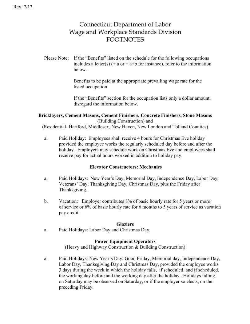
Connecticut Department of Labor Wage and Workplace Standards Division
FOOTNOTES
Please Note: If the “Benefits” listed on the schedule for the following occupations includes a letter(s) (+ a or + a+b for instance), refer to the information below.
Benefits to be paid at the appropriate prevailing wage rate for the listed occupation. If the “Benefits” section for the occupation lists only a dollar amount, disregard the information below.
Bricklayers, Cement Masons, Cement Finishers, Concrete Finishers, Stone Masons (Building Construction) and
(Residential- Hartford, Middlesex, New Haven, New London and Tolland Counties)
a. Paid Holiday: Employees shall receive 4 hours for Christmas Eve holiday provided the employee works the regularly scheduled day before and after the holiday. Employers may schedule work on Christmas Eve and employees shall receive pay for actual hours worked in addition to holiday pay.
Elevator Constructors: Mechanics
a. Paid Holidays: New Year’s Day, Memorial Day, Independence Day, Labor Day,
Veterans’ Day, Thanksgiving Day, Christmas Day, plus the Friday after Thanksgiving.
b. Vacation: Employer contributes 8% of basic hourly rate for 5 years or more
of service or 6% of basic hourly rate for 6 months to 5 years of service as vacation pay credit.
Glaziers
a. Paid Holidays: Labor Day and Christmas Day.
Power Equipment Operators (Heavy and Highway Construction & Building Construction)
a. Paid Holidays: New Year’s Day, Good Friday, Memorial day, Independence Day,
Labor Day, Thanksgiving Day and Christmas Day, provided the employee works 3 days during the week in which the holiday falls, if scheduled, and if scheduled, the working day before and the working day after the holiday. Holidays falling on Saturday may be observed on Saturday, or if the employer so elects, on the preceding Friday.
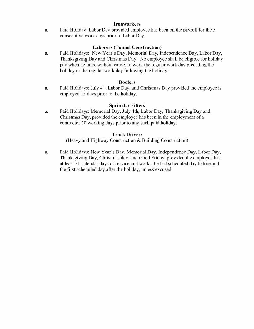
Ironworkers a. Paid Holiday: Labor Day provided employee has been on the payroll for the 5
consecutive work days prior to Labor Day.
Laborers (Tunnel Construction) a. Paid Holidays: New Year’s Day, Memorial Day, Independence Day, Labor Day,
Thanksgiving Day and Christmas Day. No employee shall be eligible for holiday pay when he fails, without cause, to work the regular work day preceding the holiday or the regular work day following the holiday.
Roofers
a. Paid Holidays: July 4th, Labor Day, and Christmas Day provided the employee is employed 15 days prior to the holiday.
Sprinkler Fitters
a. Paid Holidays: Memorial Day, July 4th, Labor Day, Thanksgiving Day and Christmas Day, provided the employee has been in the employment of a contractor 20 working days prior to any such paid holiday.
Truck Drivers
(Heavy and Highway Construction & Building Construction)
a. Paid Holidays: New Year’s Day, Memorial Day, Independence Day, Labor Day, Thanksgiving Day, Christmas day, and Good Friday, provided the employee has at least 31 calendar days of service and works the last scheduled day before and the first scheduled day after the holiday, unless excused.
Information Bulletin Occupational Classifications
The Connecticut Department of Labor has the responsibility to properly determine "job
classification" on prevailing wage projects covered under C.G.S. Section 31-53.
Note: This information is intended to provide a sample of some occupational classifications for guidance purposes only. It is not an all-inclusive list of each occupation's duties. This list is being provided only to highlight some areas where a contractor may be unclear regarding the proper classification. Below are additional clarifications of specific job duties performed for certain
classifications:
ASBESTOS WORKERS
Applies all insulating materials, protective coverings, coatings and finishes to all
types of mechanical systems.
ASBESTOS INSULATOR
Handle, install apply, fabricate, distribute, prepare, alter, repair, dismantle, heat and
frost insulation, including penetration and fire stopping work on all penetration fire
stop systems.
BOILERMAKERS
Erects hydro plants, incomplete vessels, steel stacks, storage tanks for water, fuel,
etc. Builds incomplete boilers, repairs heat exchanges and steam generators.
BRICKLAYERS, CEMENT MASONS, CEMENT FINISHERS, MARBLE MASONS, PLASTERERS, STONE MASONS, PLASTERERS. STONE MASONS, TERRAZZO WORKERS, TILE SETTERS
Lays building materials such as brick, structural tile and concrete cinder, glass, gypsum, terra cotta block. Cuts, tools and sets marble, sets stone, finishes concrete, applies decorative steel, aluminum and plastic tile, applies cements, sand, pigment and marble chips to floors, stairways, etc.
CARPENTERS, MILLWRIGHTS. PILEDRIVERMEN. LATHERS. RESILEINT FLOOR LAYERS, DOCK BUILDERS, DIKERS, DIVER TENDERS Constructs, erects, installs and repairs structures and fixtures of wood, plywood and wallboard. Installs, assembles, dismantles, moves industrial machinery. Drives piling into ground to provide foundations for structures such as buildings and bridges, retaining walls for earth embankments, such as cofferdams. Fastens wooden, metal or rockboard lath to walls, ceilings and partitions of buildings, acoustical tile layer, concrete form builder. Applies firestopping materials on fire resistive joint systems only. Installation of curtain/window walls only where attached to wood or metal studs. Installation of insulated material of all types whether blown, nailed or attached in other ways to walls, ceilings and floors of buildings. Assembly and installation of modular furniture/furniture systems. Free-standing furniture is not covered. This includes free standing: student chairs, study top desks, book box desks, computer furniture, dictionary stand, atlas stand, wood shelving, two-position information access station, file cabinets, storage cabinets, tables, etc.
CLEANING LABORER
The clean up of any construction debris and the general cleaning, including sweeping, wash down, mopping, wiping of the construction facility, washing, polishing, dusting, etc., prior to the issuance of a certificate of occupancy falls under the Labor classification.
DELIVERY PERSONNEL
If delivery of supplies/building materials is to one common point and stockpiled there, prevailing wages are not required. If the delivery personnel are involved in the distribution of the material to multiple locations within the construction site then they would have to be paid prevailing wages for the type of work performed: laborer, equipment operator, electrician, ironworker, plumber, etc. An example of this would be where delivery of drywall is made to a building and the delivery personnel distribute the drywall from one "stockpile" location to further sub‐locations on each floor. Distribution of material around a construction site is the job of a laborer/tradesman and not a delivery personnel.
ELECTRICIANS
Install, erect, maintenance, alteration or repair of any wire, cable, conduit, etc.,
which generates, transforms, transmits or uses electrical energy for light, heat,
power or other purposes, including the Installation or maintenance of
telecommunication, LAN wiring or computer equipment, and low voltage wiring.
*License required per Connecticut General Statutes: E-1,2 L-5,6 C-5,6 T-1,2 L-
1,2 V-1,2,7,8,9.
ELEVATOR CONSTRUCTORS
Install, erect, maintenance and repair of all types of elevators, escalators, dumb
waiters and moving walks. *License required by Connecticut General Statutes:
R-1,2,5,6.
FORK LIFT OPERATOR
Laborers Group 4) Mason Tenders - operates forklift solely to assist a mason to a maximum height of nine (9) feet only. Power Equipment Operator Group 9 ‐ operates forklift to assist any trade, and to
assist a mason to a height over nine (9) feet.
GLAZIERS
Glazing wood and metal sash, doors, partitions, and 2 story aluminum storefronts.
Installs glass windows, skylights, store fronts and display cases or surfaces such as
building fronts, interior walls, ceilings and table tops and metal store fronts.
Installation of aluminum window walls and curtain walls is the "joint" work of
glaziers and ironworkers which requires either a blended rate or equal composite
workforce.
IRONWORKERS
Erection, installation and placement of structural steel, precast concrete,
miscellaneous iron, ornamental iron, metal curtain wall, rigging and reinforcing
steel. Handling, sorting, and installation of reinforcing steel (rebar). Metal bridge rail
(traffic), metal bridge handrail, and decorative security fence installation.
Installation of aluminum window walls and curtain walls is the "joint" work of
glaziers and ironworkers which requires either a blended rate or equal composite
workforce. Insulated metal and insulated composite panels are still installed by the
Ironworker.
INSULATOR
Installing fire stopping systems/materials for "Penetration Firestop Systems": transit to cables, electrical conduits, insulated pipes, sprinkler pipe penetrations, ductwork behind radiation, electrical cable trays, fire rated pipe penetrations, natural polypropylene, HVAC ducts, plumbing bare metal, telephone and communication wires, and boiler room ceilings. Past practice using the applicable licensed trades, Plumber, Sheet Metal, Sprinkler Fitter, and Electrician, is not inconsistent with the Insulator classification and would be permitted.
LABORERS
Acetylene burners, asphalt rakers, chain saw operators, concrete and power buggy operator, concrete saw operator, fence and guard rail erector (except metal bridge rail (traffic), metal bridge handrail, and decorative security fence installation.), hand operated concrete vibrator operator, mason tenders, pipelayers (installation of storm drainage or sewage lines on the street only), pneumatic drill operator, pneumatic gas and electric drill operator, powermen and wagon drill operator, air track operator, block paver, curb setters, blasters, concrete spreaders.
PAINTERS
Maintenance, preparation, cleaning, blasting (water and sand, etc.), painting or application of any protective coatings of every description on all bridges and appurtenances of highways, roadways, and railroads. Painting, decorating, hardwood finishing, paper hanging, sign writing, scenic art work and drywall hhg for any and all types of building and residential work.
LEAD PAINT REMOVAL
Painter’s Rate
1. Removal of lead paint from bridges. 2. Removal of lead paint as preparation of any surface to be repainted. 3. Where removal is on a Demolition project prior to reconstruction.
Laborer’s Rate
1. Removal of lead paint from any surface NOT to be repainted. 2. Where removal is on a TOTAL Demolition project only.
PLUMBERS AND PIPEFITTERS
Installation, repair, replacement, alteration or maintenance of all plumbing, heating, cooling and piping. *License required per Connecticut General Statutes: P-1,2,6,7,8,9 J-1,2,3,4 SP-1,2 S-1,2,3,4,5,6,7,8 B-1,2,3,4 D-1,2,3,4.
POWER EQUIPMENT OPERATORS
Operates several types of power construction equipment such as compressors,
pumps, hoists, derricks, cranes, shovels, tractors, scrapers or motor graders, etc.
Repairs and maintains equipment. *License required, crane operators only, per
Connecticut General Statutes.
ROOFERS
Covers roofs with composition shingles or sheets, wood shingles, slate or asphalt
and gravel to waterproof roofs, including preparation of surface. (tear-off and/or
removal of any type of roofing and/or clean-up of any and all areas where a roof is
to be relaid)
SHEETMETAL WORKERS
Fabricate, assembles, installs and repairs sheetmetal products and equipment in
such areas as ventilation, air-conditioning, warm air heating, restaurant equipment,
architectural sheet metal work, sheetmetal roofing, and aluminum gutters.
Fabrication, handling, assembling, erecting, altering, repairing, etc. of coated metal
material panels and composite metal material panels when used on building
exteriors and interiors as soffits, facia, louvers, partitions, wall panel siding,
canopies, cornice, column covers, awnings, beam covers, cladding, sun shades,
lighting troughs, spires, ornamental roofing, metal ceilings, mansards, copings,
ornamental and ventilation hoods, vertical and horizontal siding panels, trim, etc.
The sheet metal classification also applies to the vast variety of coated metal
material panels and composite metal material panels that have evolved over the
years as an alternative to conventional ferrous and non-ferrous metals like steel,
iron, tin, copper, brass, bronze, aluminum, etc. Insulated metal and insulated
composite panels are still installed by the Iron Worker. Fabrication, handling,
assembling, erecting, altering, repairing, etc. of architectural metal roof, standing
seam roof, composite metal roof, metal and composite bathroom/toilet partitions,
aluminum gutters, metal and composite lockers and shelving, kitchen equipment,
and walk‐in coolers.
SPRINKLER FITTERS
Installation, alteration, maintenance and repair of fire protection sprinkler systems.
*License required per Connecticut General Statutes: F-1,2,3,4.
TILE MARBLE AND TERRAZZO FINISHERS
Assists and tends the tile setter, marble mason and terrazzo worker in the performance of their duties.
TRUCK DRIVERS
Definitions:
1) “Site of the work” (29 Code of Federal Regulations (CFR) 5.2(l)(b) is the physical place or
places where the building or work called for in the contract will remain and any other site
where a significant portion of the building or work is constructed, provided that such site is
established specifically for the performance of the contact or project;
(a) Except as provided in paragraph (l) (3) of this section, job headquarters, tool yards,
batch plants, borrow pits, etc. are part of the “site of the work”; provided they are dedicated
exclusively, or nearly so, to the performance of the contract or project, and provided they
are adjacent to “the site of work” as defined in paragraph (e)(1) of this section;
(b) Not included in the “site of the work” are permanent home offices, branch plant
establishments, fabrication plants, tool yards etc, of a contractor or subcontractor whose
location and continuance in operation are determined wholly without regard to a
particular State or political subdivision contract or uncertain and indefinite periods of time
involved of a few seconds or minutes duration and where the failure to count such time is
due to consideration justified by industrial realities (29 CFR 785.47)
2) “Engaged to wait” is waiting time that belongs to and is controlled by the employer
which is an integral part of the job and is therefore compensable as hours worked. (29 CFR
785.15)
3) “Waiting to be engaged” is waiting time that an employee can use effectively for their
own purpose and is not compensable as hours worked. (29 CFR 785.16)
4) “De Minimus” is a rule that recognizes that unsubstantial or insignificant periods of time
which cannot as a practical administrative matter be precisely recorded for payroll
purposes, may be disregarded. This rule applies only where there are uncertain and
indefinite periods of time involved of a short duration and where the failure to count such
time is due to consideration justified by worksite realities. For example, with respect to
truck drivers on prevailing wage sites, this is typically less than 15 minutes at a time.
Coverage of Truck Drivers on State or Political subdivision Prevailing Wage Projects
Truck drivers are covered for payroll purposes under the following conditions:
Truck Drivers for time spent working on the site of the work.
Truck Drivers for time spent loading and/or unloading materials and supplies on the site of the work, if such time is not de minimus
Truck drivers transporting materials or supplies between a facility that is deemed part of the site of the work and the actual construction site.
Truck drivers transporting portions of the building or work between a site established specifically for the performance of the contract or project where a significant portion of such building or work is constructed and the physical places where the building or work outlined in the contract will remain.
For example: Truck drivers delivering asphalt are covered under prevailing wage while”
engaged to wait” on the site and when directly involved in the paving operation, provided the
total time is not “de minimus”
Truck Drivers are not covered in the following instances:
Material delivery truck drivers while off “the site of the work”
Truck Drivers traveling between a prevailing wage job and a commercial supply facility while they are off the “site of the work”
Truck drivers whose time spent on the “site of the work” is de minimus, such as under 15 minutes at a time, merely to drop off materials or supplies, including asphalt.
These guidelines are similar to U.S. Labor Department policies. The application of these
guidelines may be subject to review based on factual considerations on a case by case basis.
For example:
Material men and deliverymen are not covered under prevailing wage as long as they are not directly involved in the construction process. If, they unload the material, they would then be covered by prevailing wage for the classification they are performing work in: laborer, equipment operator, etc.
Hauling material off site is not covered provided they are not dumping it at a location outlined above.
Driving a truck on site and moving equipment or materials on site would be considered covered work, as this is part of the construction process.
Any questions regarding the proper classification should be directed to: Public Contract Compliance Unit
Wage and Workplace Standards Division Connecticut Department of Labor
200 Folly Brook Blvd, Wethersfield, CT 06109 (860) 263-6543
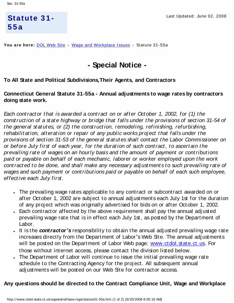
Sec. 31-55a
Statute 31-55a
Last Updated: June 02, 2008
You are here: DOL Web Site Wage and Workplace Issues Statute 31-55a
- Special Notice -
To All State and Political Subdivisions,Their Agents, and Contractors
Connecticut General Statute 31-55a - Annual adjustments to wage rates by contractors doing state work.
Each contractor that is awarded a contract on or after October 1, 2002, for (1) the construction of a state highway or bridge that falls under the provisions of section 31-54 of the general statutes, or (2) the construction, remodeling, refinishing, refurbishing, rehabilitation, alteration or repair of any public works project that falls under the provisions of section 31-53 of the general statutes shall contact the Labor Commissioner on or before July first of each year, for the duration of such contract, to ascertain the prevailing rate of wages on an hourly basis and the amount of payment or contributions paid or payable on behalf of each mechanic, laborer or worker employed upon the work contracted to be done, and shall make any necessary adjustments to such prevailing rate of wages and such payment or contributions paid or payable on behalf of each such employee, effective each July first.
● The prevailing wage rates applicable to any contract or subcontract awarded on or after October 1, 2002 are subject to annual adjustments each July 1st for the duration of any project which was originally advertised for bids on or after October 1, 2002.
● Each contractor affected by the above requirement shall pay the annual adjusted prevailing wage rate that is in effect each July 1st, as posted by the Department of Labor.
● It is the contractor’s responsibility to obtain the annual adjusted prevailing wage rate increases directly from the Department of Labor’s Web Site. The annual adjustments will be posted on the Department of Labor Web page: www.ctdol.state.ct.us. For those without internet access, please contact the division listed below.
● The Department of Labor will continue to issue the initial prevailing wage rate schedule to the Contracting Agency for the project. All subsequent annual adjustments will be posted on our Web Site for contractor access.
Any questions should be directed to the Contract Compliance Unit, Wage and Workplace
http://www.ctdol.state.ct.us/wgwkstnd/laws-regs/statute31-55a.htm (1 of 2) [6/20/2008 8:00:16 AM]
Sec. 31-55a
Standards Division, Connecticut Department of Labor, 200 Folly Brook Blvd., Wethersfield, CT 06109 at (860)263-6790.
Workplace Laws
Published by the Connecticut Department of Labor, Project Management Office
http://www.ctdol.state.ct.us/wgwkstnd/laws-regs/statute31-55a.htm (2 of 2) [6/20/2008 8:00:16 AM]
November 29, 2006
NoticeTo All Mason Contractors and Interested Parties
Regarding Construction Pursuant to Section 31-53 of theConnecticut General Statutes (Prevailing Wage)
The Connecticut Labor Department Wage and Workplace Standards Division is empowered toenforce the prevailing wage rates on projects covered by the above referenced statute.
Over the past few years the Division has withheld enforcement of the rate in effect for workerswho operate a forklift on a prevailing wage rate project due to a potential jurisdictional dispute.
The rate listed in the schedules and in our Occupational Bulletin (see enclosed) has been asfollows:
Forklift Operator:
- Laborers (Group 4) Mason Tenders - operates forklift solely to assist a mason to a maximumheight of nine feet only.
- Power Equipment Operator (Group 9) - operates forklift to assist any trade and to assist amason to a height over nine feet.
The U.S. Labor Department conducted a survey of rates in Connecticut but it has not beenpublished and the rate in effect remains as outlined in the above Occupational Bulletin.
Since this is a classification matter and not one of jurisdiction, effective January 1,2007 the Connecticut Labor Department will enforce the rate on each schedule inaccordance with our statutory authority.
Your cooperation in filing appropriate and accurate certified payrolls is appreciated.
Informational Bulletin
THE 10-HOUR OSHA CONSTRUCTION SAFETY AND HEALTH COURSE
(applicable to public building contracts entered into on or after July 1, 2007, where the total cost of all work to be performed is at least $100,000)
(1) This requirement was created by Public Act No. 06-175, which is codified in
Section 31-53b of the Connecticut General Statutes (pertaining to the prevailing wage statutes);
(2) The course is required for public building construction contracts (projects funded
in whole or in part by the state or any political subdivision of the state) entered into on or after July 1, 2007;
(3) It is required of private employees (not state or municipal employees) and
apprentices who perform manual labor for a general contractor or subcontractor on a public building project where the total cost of all work to be performed is at least $100,000;
(4) The ten-hour construction course pertains to the ten-hour Outreach Course
conducted in accordance with federal OSHA Training Institute standards, and, for telecommunications workers, a ten-hour training course conducted in accordance with federal OSHA standard, 29 CFR 1910.268;
(5) The internet website for the federal OSHA Training Institute is
http://www.osha.gov/fso/ote/training/edcenters/fact_sheet.html;
(6) The statutory language leaves it to the contractor and its employees to determine who pays for the cost of the ten-hour Outreach Course;
(7) Within 30 days of receiving a contract award, a general contractor must furnish
proof to the Labor Commissioner that all employees and apprentices performing manual labor on the project will have completed such a course;
(8) Proof of completion may be demonstrated through either: (a) the presentation of a
bona fide student course completion card issued by the federal OSHA Training Institute; or (2) the presentation of documentation provided to an employee by a trainer certified by the Institute pending the actual issuance of the completion card;
(9) Any card with an issuance date more than 5 years prior to the commencement
date of the construction project shall not constitute proof of compliance;
(10) Each employer shall affix a copy of the construction safety course completion card to the certified payroll submitted to the contracting agency in accordance with Conn. Gen. Stat. § 31-53(f) on which such employee’s name first appears;
(11) Any employee found to be in non-compliance shall be subject to removal from
the worksite if such employee does not provide satisfactory proof of course completion to the Labor Commissioner by the fifteenth day after the date the employee is determined to be in noncompliance;
(12) Any such employee who is determined to be in noncompliance may continue to
work on a public building construction project for a maximum of fourteen consecutive calendar days while bringing his or her status into compliance;
(13) The Labor Commissioner may make complaint to the prosecuting authorities
regarding any employer or agent of the employer, or officer or agent of the corporation who files a false certified payroll with respect to the status of an employee who is performing manual labor on a public building construction project;
(14) The statute provides the minimum standards required for the completion of a
safety course by manual laborers on public construction contracts; any contractor can exceed these minimum requirements; and
(15) Regulations clarifying the statute are currently in the regulatory process, and shall
be posted on the CTDOL website as soon as they are adopted in final form. (16) Any questions regarding this statute may be directed to the Wage and Workplace
Standards Division of the Connecticut Labor Department via the internet website of http://www.ctdol.state.ct.us/wgwkstnd/wgemenu.htm; or by telephone at (860)263-6790.
THE ABOVE INFORMATION IS PROVIDED EXCLUSIVELY AS AN EDUCATIONAL RESOURCE, AND IS NOT INTENDED AS A SUBSTITUTE FOR LEGAL INTERPRETATIONS WHICH MAY ULTMATELY ARISE CONCERNIG THE CONSTRUCTION OF THE STATUTE OR THE REGULATIONS.

Sec. 31-53b. Construction safety and health course. Proof of completion required for employees on public building projects. Enforcement. Regulations. (a) Each contract entered into on or after July 1, 2007, for the construction, remodeling, refinishing, refurbishing, rehabilitation, alteration or repair of any public building project by the state or any of its agents, or by an political subdivision of the state or any of its agents, where the total cost of all work to be performed by all contractors and subcontractors in connection with the contract is at least one hundred thousand dollars, shall contain a provision requiring that, not later than thirty days after the date such contract is awarded, each contractor furnish proof to the Labor Commissioner that all employees performing manual labor on or in such public building, pursuant to such contract, have completed a course of at least ten hours in duration in construction safety and health approved by the federal Occupational Safety and Health Administration or, in the case of telecommunications employees, have completed at least ten hours of training in accordance with 29 CFR 1910.268. (b) Any employee required to complete a construction safety and health course required under subsection (a) of this section who has not completed the course shall be subject to removal from the worksite if the employee does not provide documentation of having completed such course by the fifteenth day after the date the employee is found to be in noncompliance. The Labor Commissioner or said commissioner’s designee shall enforce this section. (c) Not later than January 1, 2007, the Labor Commissioner shall adopt regulations, in accordance with the provisions of chapter 54, to implement the provisions of subsections (a) and (b) of this section. Such regulations shall require that the ten-hour construction safety and health courses required under subsection (a) of this section be conducted in accordance with federal Occupational Safety and Health Administration Training Institute standards, or in accordance with 29 CFR 1910.268, as appropriate. The Labor Commissioner shall accept as sufficient proof of compliance with the provisions of subsection (a) or (b) of this section a student course completion card issued by the federal Occupational Safety and Health Administration Training Institute, or such other proof of compliance said commissioner deems appropriate, dated no earlier than five years before the commencement date of such public works project. (d) For the purposes of this section, “public building” means a structure, paid for in whole or in part with state funds, within a roof and within exterior walls or fire walls, designed for the housing, shelter, enclosure and support or employment of people, animals or property of any kind, including, but not limited to, sewage treatment plants and water treatment plants, “Public building” does not include site work, roads or bridges, rail lines, parking lots or underground water, sewer or drainage systems including pump houses or other utility systems.
CONNECTICUT DEPARTMENT OF LABOR WAGE AND WORKPLACE STANDARDS DIVISION
CONTRACTORS WAGE CERTIFICATION FORM
I, of Officer, Owner, Authorized Rep. Company Name
do hereby certify that the Company Name Street City and all of its subcontractors will pay all workers on the
Project Name and Number
Street and City
the wages as listed in the schedule of prevailing rates required for such project (a copy of which isattached hereto).
Signed
Subscribed and sworn to before me this day of , 2004.
Notary Public
L Return to: Connecticut Department of Labor
Wage & Workplace Standards Division 200 Folly Brook Blvd.
Wethersfield, CT 06109


![HIGH ALBEDO MATERIALS [5.2] Submittal Form](https://img.pdfslide.net/doc/110x75/628b2ef4c51362607935c9f7/high-albedo-materials-52-submittal-form.jpg)