Embed Size (px)
Citation preview
Table of Contents
Section 1: Principle of Operation ..................................................................... 2
Model FC 125 ............................................................................................. 3
Model FC 150 ............................................................................................. 4
Model FC 200 ............................................................................................. 5
Model FC 300 ............................................................................................. 6
Model FC 400 ............................................................................................. 7
Model FC 600 ............................................................................................. 8
Section 3: Options ........................................................................................ 9
Port Orientation.......................................................................................... 9
Drain Port.................................................................................................. 9
Section 4: Performance: GAS-to-GAS ..............................................................10
Section 5: Performance: Water-to-GAS ............................................................11
Section 6: Setup: Water-to-GAS .....................................................................11
Nafion® is a registered trademark of DuPont. FC™ is a trademark of Perma Pure LLC.
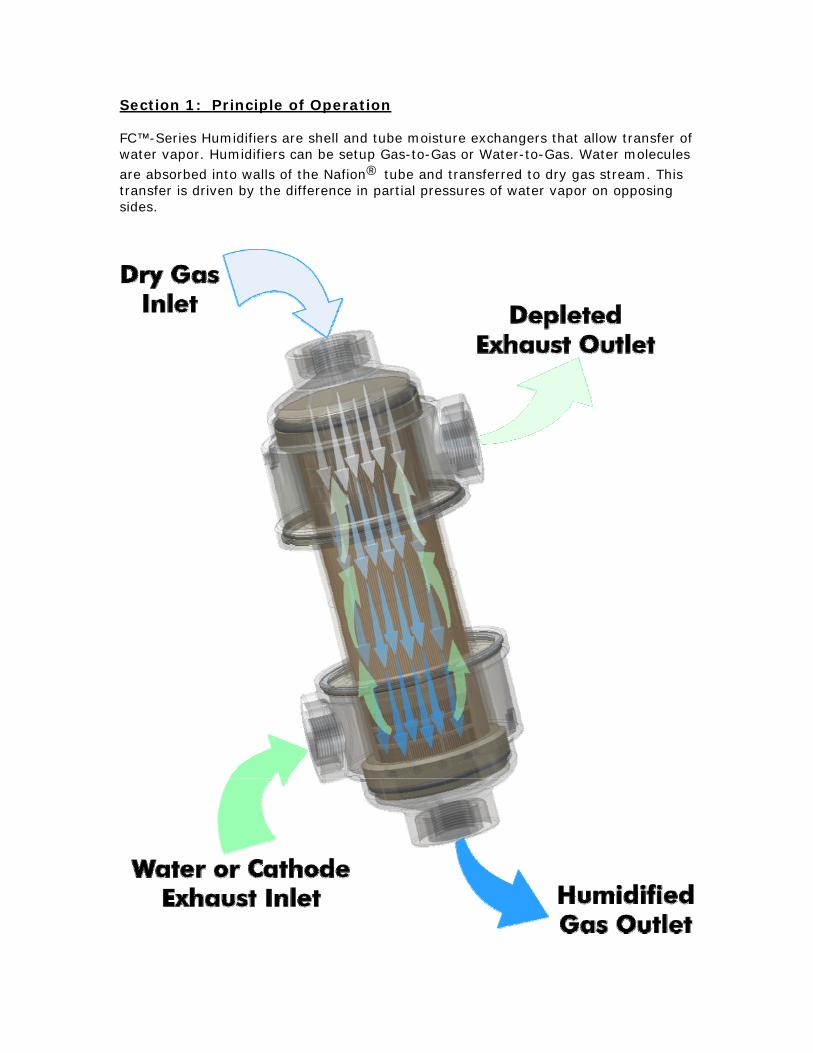
Section 1: Principle of Operation FC™-Series Humidifiers are shell and tube moisture exchangers that allow transfer of water vapor. Humidifiers can be setup Gas-to-Gas or Water-to-Gas. Water molecules
are absorbed into walls of the Nafion® tube and transferred to dry gas stream. This transfer is driven by the difference in partial pressures of water vapor on opposing sides.
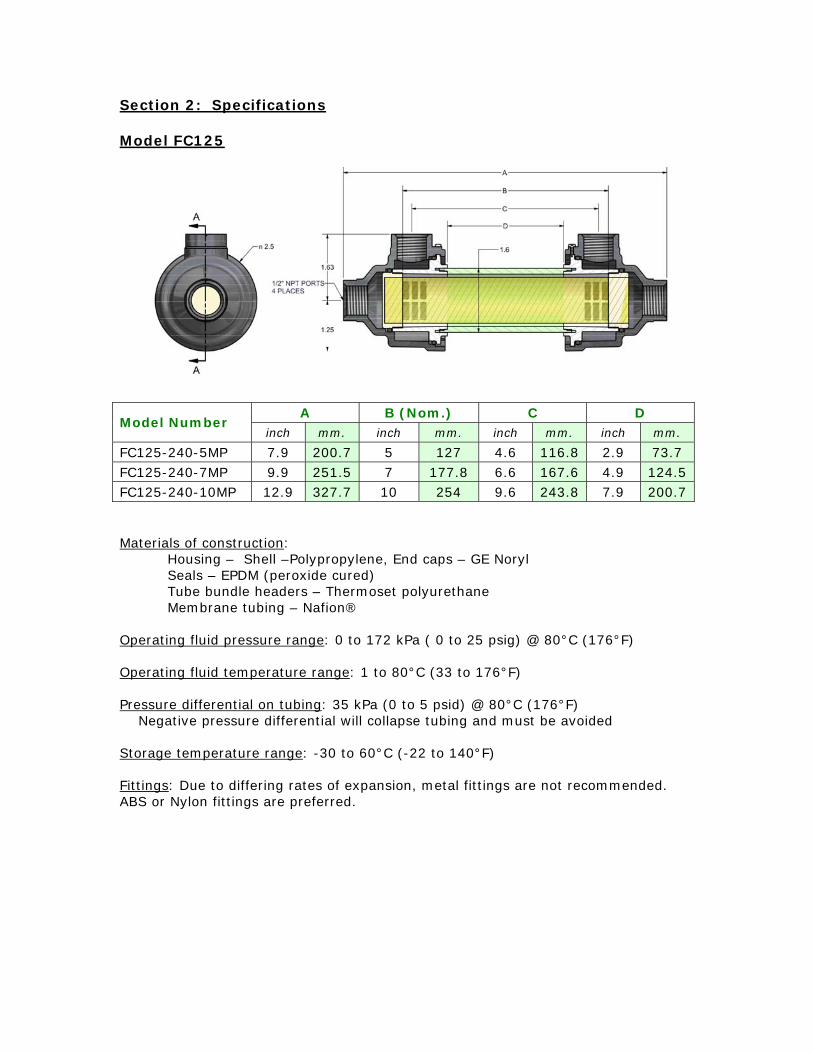
Section 2: Specifications
Model FC125
A B (Nom.) C DModel Number
inch mm. inch mm. inch mm. inch mm.
FC125-240-5MP 7.9 200.7 5 127 4.6 116.8 2.9 73.7 FC125-240-7MP 9.9 251.5 7 177.8 6.6 167.6 4.9 124.5 FC125-240-10MP 12.9 327.7 10 254 9.6 243.8 7.9 200.7
Materials of construction: Housing – Shell –Polypropylene, End caps – GE Noryl Seals – EPDM (peroxide cured) Tube bundle headers – Thermoset polyurethane Membrane tubing – Nafion®
Operating fluid pressure range: 0 to 172 kPa ( 0 to 25 psig) @ 80°C (176°F)
Operating fluid temperature range: 1 to 80°C (33 to 176°F)
Pressure differential on tubing: 35 kPa (0 to 5 psid) @ 80°C (176°F) Negative pressure differential will collapse tubing and must be avoided
Storage temperature range: -30 to 60°C (-22 to 140°F)
Fittings: Due to differing rates of expansion, metal fittings are not recommended. ABS or Nylon fittings are preferred.
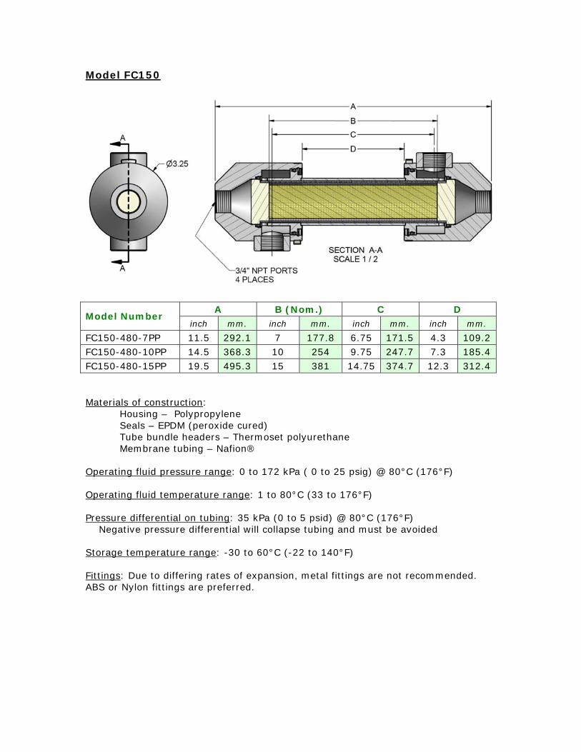
Model FC150
A B (Nom.) C DModel Number
inch mm. inch mm. inch mm. inch mm.
FC150-480-7PP 11.5 292.1 7 177.8 6.75 171.5 4.3 109.2 FC150-480-10PP 14.5 368.3 10 254 9.75 247.7 7.3 185.4 FC150-480-15PP 19.5 495.3 15 381 14.75 374.7 12.3 312.4
Materials of construction: Housing – Polypropylene Seals – EPDM (peroxide cured) Tube bundle headers – Thermoset polyurethane Membrane tubing – Nafion®
Operating fluid pressure range: 0 to 172 kPa ( 0 to 25 psig) @ 80°C (176°F)
Operating fluid temperature range: 1 to 80°C (33 to 176°F)
Pressure differential on tubing: 35 kPa (0 to 5 psid) @ 80°C (176°F) Negative pressure differential will collapse tubing and must be avoided
Storage temperature range: -30 to 60°C (-22 to 140°F)
Fittings: Due to differing rates of expansion, metal fittings are not recommended. ABS or Nylon fittings are preferred.
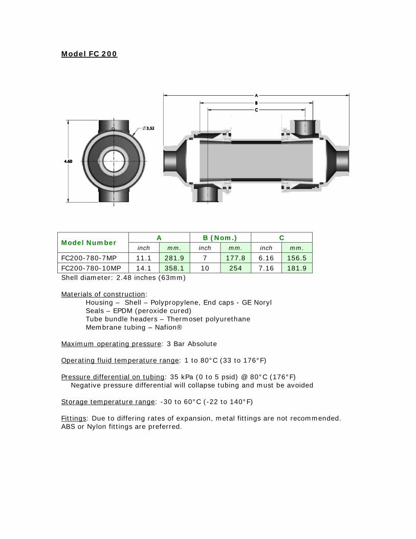
Model FC 200
A B (Nom.) CModel Number
inch mm. inch mm. inch mm.
FC200-780-7MP 11.1 281.9 7 177.8 6.16 156.5 FC200-780-10MP 14.1 358.1 10 254 7.16 181.9 Shell diameter: 2.48 inches (63mm)
Materials of construction: Housing – Shell – Polypropylene, End caps - GE Noryl Seals – EPDM (peroxide cured) Tube bundle headers – Thermoset polyurethane Membrane tubing – Nafion®
Maximum operating pressure: 3 Bar Absolute
Operating fluid temperature range: 1 to 80°C (33 to 176°F)
Pressure differential on tubing: 35 kPa (0 to 5 psid) @ 80°C (176°F) Negative pressure differential will collapse tubing and must be avoided
Storage temperature range: -30 to 60°C (-22 to 140°F)
Fittings: Due to differing rates of expansion, metal fittings are not recommended. ABS or Nylon fittings are preferred.
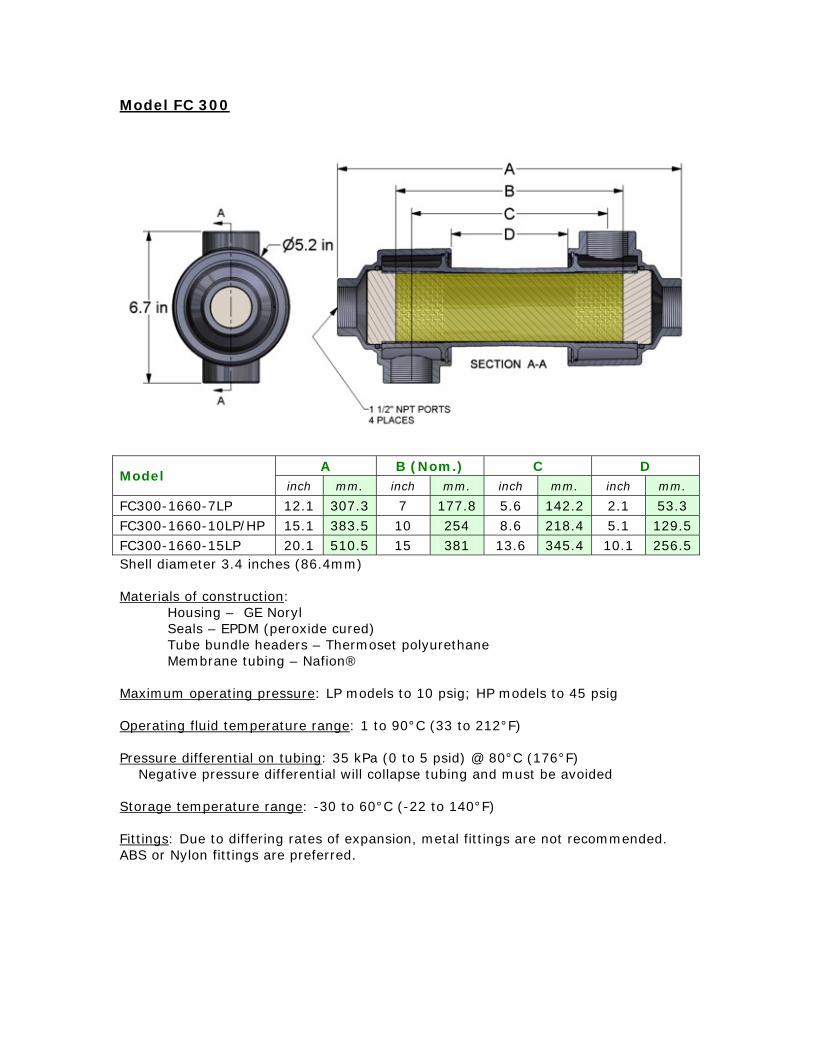
Model FC 300
A B (Nom.) C DModel
inch mm. inch mm. inch mm. inch mm.
FC300-1660-7LP 12.1 307.3 7 177.8 5.6 142.2 2.1 53.3 FC300-1660-10LP/HP 15.1 383.5 10 254 8.6 218.4 5.1 129.5 FC300-1660-15LP 20.1 510.5 15 381 13.6 345.4 10.1 256.5 Shell diameter 3.4 inches (86.4mm)
Materials of construction: Housing – GE NorylSeals – EPDM (peroxide cured) Tube bundle headers – Thermoset polyurethane Membrane tubing – Nafion®
Maximum operating pressure: LP models to 10 psig; HP models to 45 psig
Operating fluid temperature range: 1 to 90°C (33 to 212°F)
Pressure differential on tubing: 35 kPa (0 to 5 psid) @ 80°C (176°F) Negative pressure differential will collapse tubing and must be avoided
Storage temperature range: -30 to 60°C (-22 to 140°F)
Fittings: Due to differing rates of expansion, metal fittings are not recommended. ABS or Nylon fittings are preferred.
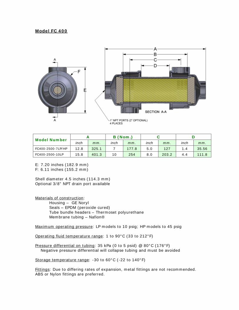
Model FC 400
E: 7.20 inches (182.9 mm) F: 6.11 inches (155.2 mm)
Shell diameter 4.5 inches (114.3 mm) Optional 3/8” NPT drain port available
Materials of construction: Housing – GE Noryl Seals – EPDM (peroxide cured) Tube bundle headers – Thermoset polyurethane Membrane tubing – Nafion®
Maximum operating pressure: LP models to 10 psig; HP models to 45 psig
Operating fluid temperature range: 1 to 90°C (33 to 212°F)
Pressure differential on tubing: 35 kPa (0 to 5 psid) @ 80°C (176°F) Negative pressure differential will collapse tubing and must be avoided
Storage temperature range: -30 to 60°C (-22 to 140°F)
Fittings: Due to differing rates of expansion, metal fittings are not recommended. ABS or Nylon fittings are preferred.
A B (Nom.) C DModel Number
inch mm. inch mm. inch mm. inch mm.
FC400-2500-7LP/HP 12.8 325.1 7 177.8 5.0 127 1.4 35.56
FC400-2500-10LP 15.8 401.3 10 254 8.0 203.2 4.4 111.8
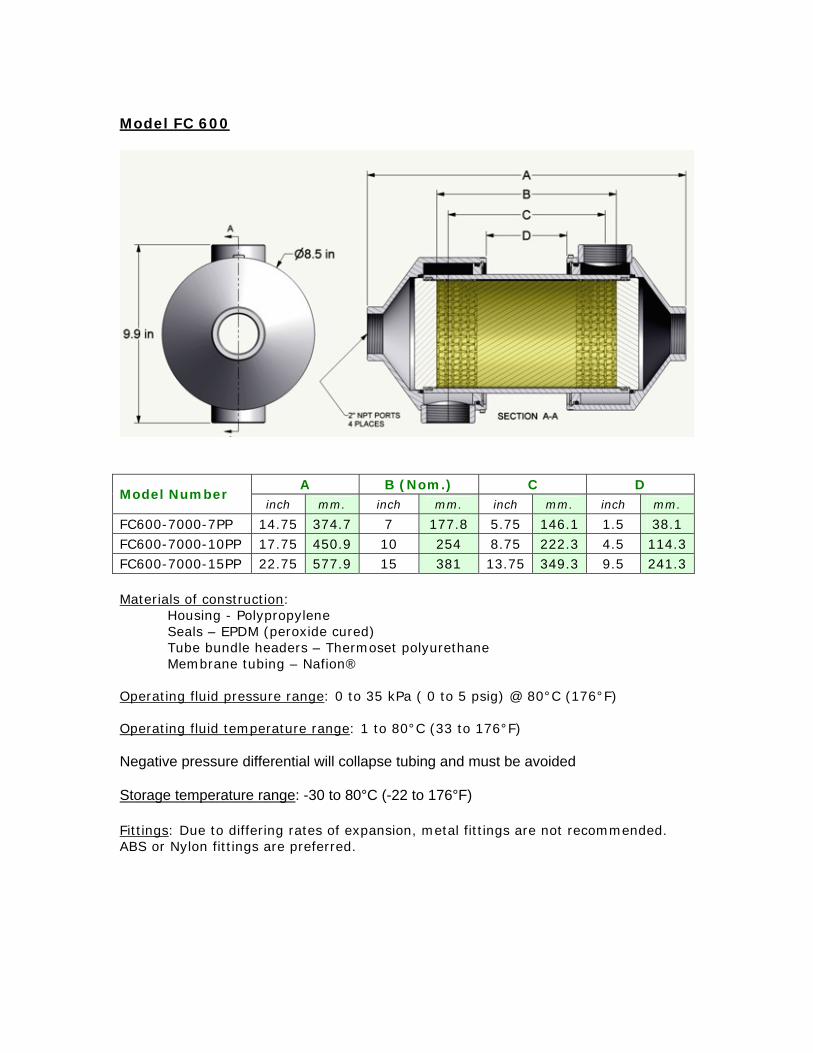
Model FC 600
A B (Nom.) C DModel Number
inch mm. inch mm. inch mm. inch mm.
FC600-7000-7PP 14.75 374.7 7 177.8 5.75 146.1 1.5 38.1 FC600-7000-10PP 17.75 450.9 10 254 8.75 222.3 4.5 114.3 FC600-7000-15PP 22.75 577.9 15 381 13.75 349.3 9.5 241.3
Materials of construction: Housing - PolypropyleneSeals – EPDM (peroxide cured) Tube bundle headers – Thermoset polyurethane Membrane tubing – Nafion®
Operating fluid pressure range: 0 to 35 kPa ( 0 to 5 psig) @ 80°C (176°F)
Operating fluid temperature range: 1 to 80°C (33 to 176°F)
Negative pressure differential will collapse tubing and must be avoided
Storage temperature range: -30 to 80°C (-22 to 176°F)
Fittings: Due to differing rates of expansion, metal fittings are not recommended. ABS or Nylon fittings are preferred.

Section 3: Options
Port Orientation
When ordering, please specify the orientation of the end caps.
Drain Port
Drain port in end cap
Due to differing rates of expansion, metal fittings are not recommended. ABS or Nylon fittings are preferred.
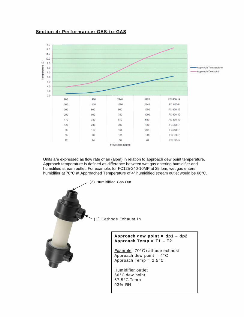
Section 4: Performance: GAS-to-GAS
Units are expressed as flow rate of air (alpm) in relation to approach dew point temperature. Approach temperature is defined as difference between wet gas entering humidifier and humidified stream outlet. For example, for FC125-240-10MP at 25 lpm, wet gas enters humidifier at 70°C at Approached Temperature of 4° humidified stream outlet would be 66°C.
(2) Humidified Gas Out
(1) Cathode Exhaust In
Approach dew point = dp1 – dp2 Approach Temp = T1 – T2 Example: 70°C cathode exhaust Approach dew point = 4°C Approach Temp = 2.5°C Humidifier outlet 66°C dew point 67.5°C Temp 93% RH
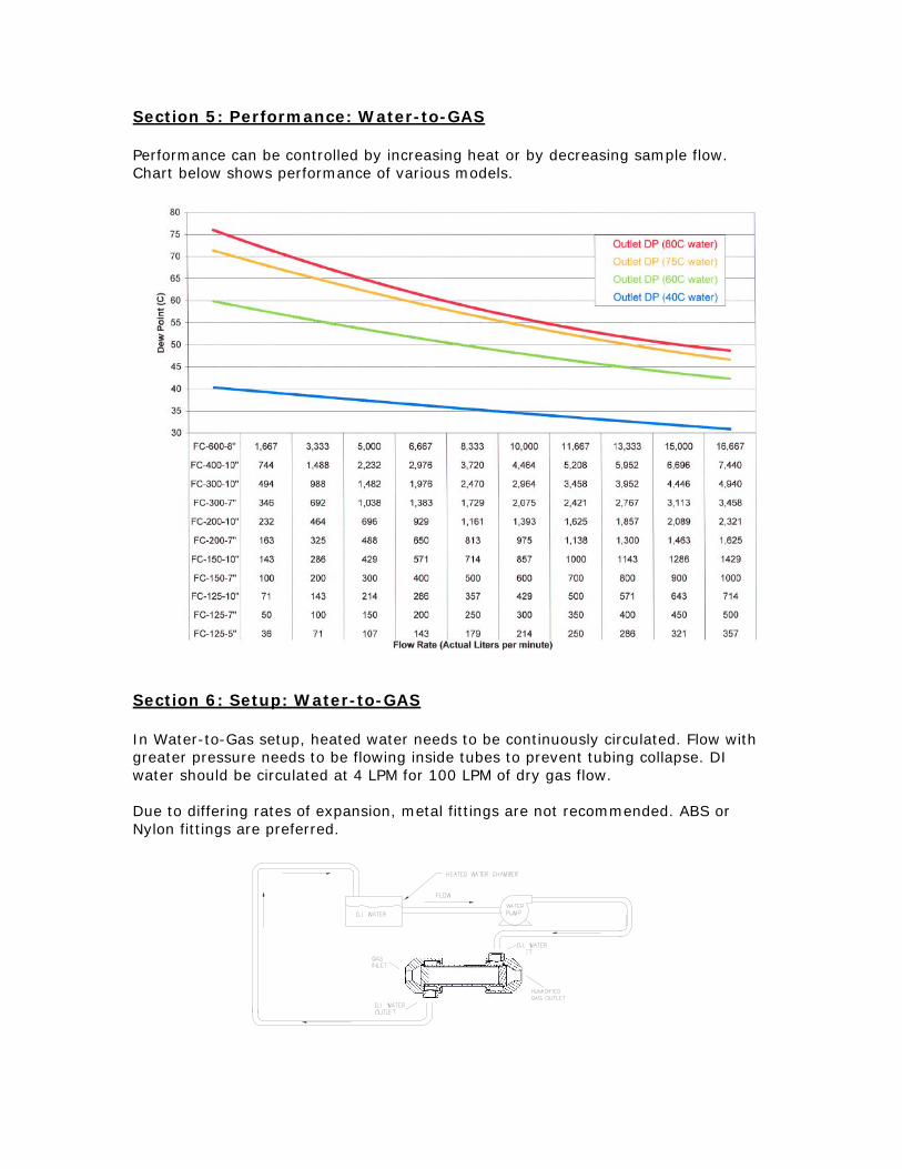
Section 5: Performance: Water-to-GAS
Performance can be controlled by increasing heat or by decreasing sample flow. Chart below shows performance of various models.
Section 6: Setup: Water-to-GAS
In Water-to-Gas setup, heated water needs to be continuously circulated. Flow with greater pressure needs to be flowing inside tubes to prevent tubing collapse. DI water should be circulated at 4 LPM for 100 LPM of dry gas flow.
Due to differing rates of expansion, metal fittings are not recommended. ABS or Nylon fittings are preferred.