Embed Size (px)
Citation preview
TABLE OF CONTENTSIntroduction . . . . . . . . . . . . . . . . . . . . . . . . . . . . . . . . . . . . . . . . . . . . . .1RME SENTAR II Specifications . . . . . . . . . . . . . . . . . . . . . . . . . . . . . . .2
Electrical Specifications . . . . . . . . . . . . . . . . . . . . . . . . . . . . . . . . . .5Mechanical Specifications . . . . . . . . . . . . . . . . . . . . . . . . . . . . . . . .6Documentation . . . . . . . . . . . . . . . . . . . . . . . . . . . . . . . . . . . . . . . .6
MOUNTING AND INSTALLATION . . . . . . . . . . . . . . . . . . . . . . . . .7Mounting the Controller . . . . . . . . . . . . . . . . . . . . . . . . . . . . . . . . .7Controller Connections – AC Power . . . . . . . . . . . . . . . . . . . . . . . .7Grounding of Controller . . . . . . . . . . . . . . . . . . . . . . . . . . . . . . . . .8
Controller Connections – Valves and Field Wiring . . . . . . . . . . . . . . . . . .9Master Valve and Pump Wiring Options . . . . . . . . . . . . . . . . . . . . .9Electrical Connection for Master Valve . . . . . . . . . . . . . . . . . . . . . .10
Normally Closed Master Valve Operation . . . . . . . . . . . . . . . . .10Simultaneous Normally Closed Master Valve and Pump . . . . .10Independent Normally Closed Master Valve and Pump . . . . . .12Normally Open Master Valve . . . . . . . . . . . . . . . . . . . . . . . . . .12Normally Open Master Valve and Pump . . . . . . . . . . . . . . . . .13
Flow Sensor Installation . . . . . . . . . . . . . . . . . . . . . . . . . . . . . . . . .13Sensor Wiring . . . . . . . . . . . . . . . . . . . . . . . . . . . . . . . . . . . . . . . .14Tapping Wires to Locate Valves in the Field . . . . . . . . . . . . . . . . . .15AC Power Failures . . . . . . . . . . . . . . . . . . . . . . . . . . . . . . . . . . . . .15Remote Control Capability . . . . . . . . . . . . . . . . . . . . . . . . . . . . . .15
KEY OPERATIONS . . . . . . . . . . . . . . . . . . . . . . . . . . . . . . . . . . . . .17Function Keys . . . . . . . . . . . . . . . . . . . . . . . . . . . . . . . . . . . . . . . .18Execute Keys . . . . . . . . . . . . . . . . . . . . . . . . . . . . . . . . . . . . . . . . .19Data Keys . . . . . . . . . . . . . . . . . . . . . . . . . . . . . . . . . . . . . . . . . . .20
WORDS AND TERMS USED IN THE DISPLAY . . . . . . . . . . . .21Other Terms . . . . . . . . . . . . . . . . . . . . . . . . . . . . . . . . . . . . . . . . .23Automatic Mode . . . . . . . . . . . . . . . . . . . . . . . . . . . . . . . . . . . . . .26Rain Mode . . . . . . . . . . . . . . . . . . . . . . . . . . . . . . . . . . . . . . . . . .26Programmable Rain . . . . . . . . . . . . . . . . . . . . . . . . . . . . . . . . . . . .27
QUICK AND BASIC PROGRAMMING . . . . . . . . . . . . . . . . . . . .29Set Time . . . . . . . . . . . . . . . . . . . . . . . . . . . . . . . . . . . . . . . . . . . .29Program . . . . . . . . . . . . . . . . . . . . . . . . . . . . . . . . . . . . . . . . . . . .29Program Selection . . . . . . . . . . . . . . . . . . . . . . . . . . . . . . . . . . . . .29Program Clear . . . . . . . . . . . . . . . . . . . . . . . . . . . . . . . . . . . . . . . .30Watering Day Selections . . . . . . . . . . . . . . . . . . . . . . . . . . . . . . . .30Water Days . . . . . . . . . . . . . . . . . . . . . . . . . . . . . . . . . . . . . . . . . .30Skip Days . . . . . . . . . . . . . . . . . . . . . . . . . . . . . . . . . . . . . . . . . . .31Stations and Watering Times . . . . . . . . . . . . . . . . . . . . . . . . . . . . .31Stations (for a conventional program) . . . . . . . . . . . . . . . . . . . . . . .32
Quick Stations (for a conventional program) . . . . . . . . . . . . . . . . . .33Cycle and Soak . . . . . . . . . . . . . . . . . . . . . . . . . . . . . . . . . . . . . . .33Stations (for a Cycle and Soak program) . . . . . . . . . . . . . . . . . . . . .34Quick Stations (for a Cycle and Soak program) . . . . . . . . . . . . . . . .35Percentage . . . . . . . . . . . . . . . . . . . . . . . . . . . . . . . . . . . . . . . . . .36Start Timeand Automatic Program Overlap Protection . . . . . . . . . .37Start Times . . . . . . . . . . . . . . . . . . . . . . . . . . . . . . . . . . . . . . . . . .38Review Programs and Totalizer . . . . . . . . . . . . . . . . . . . . . . . . . . . .39
MANUALLY ACTIVATED FUNCTIONS WITH EXAMPLES . . . .41Manual Program . . . . . . . . . . . . . . . . . . . . . . . . . . . . . . . . . . . . . .41Manual Station . . . . . . . . . . . . . . . . . . . . . . . . . . . . . . . . . . . . . . .41Manual Master Valve . . . . . . . . . . . . . . . . . . . . . . . . . . . . . . . . . . .42Manual System Check/Syringe Cycle . . . . . . . . . . . . . . . . . . . . . . .42Monitoring Station Flow . . . . . . . . . . . . . . . . . . . . . . . . . . . . . . . .43Fault Detection Overview . . . . . . . . . . . . . . . . . . . . . . . . . . . . . . . .43Wiring Fault . . . . . . . . . . . . . . . . . . . . . . . . . . . . . . . . . . . . . . . . .44Flow Main Fault . . . . . . . . . . . . . . . . . . . . . . . . . . . . . . . . . . . . . .44Flow Unscheduled Fault . . . . . . . . . . . . . . . . . . . . . . . . . . . . . . . . .45Flow Station Fault . . . . . . . . . . . . . . . . . . . . . . . . . . . . . . . . . . . . .46
ADVANCED SETUP PROGRAMMING . . . . . . . . . . . . . . . . . . . .47Master Valve . . . . . . . . . . . . . . . . . . . . . . . . . . . . . . . . . . . . . . . . .48Type of Master Valve . . . . . . . . . . . . . . . . . . . . . . . . . . . . . . . . . . .48Pump . . . . . . . . . . . . . . . . . . . . . . . . . . . . . . . . . . . . . . . . . . . . . .49Stack or No Stack . . . . . . . . . . . . . . . . . . . . . . . . . . . . . . . . . . . . .49Delay . . . . . . . . . . . . . . . . . . . . . . . . . . . . . . . . . . . . . . . . . . . . . .50Security Code . . . . . . . . . . . . . . . . . . . . . . . . . . . . . . . . . . . . . . . .50Sensor . . . . . . . . . . . . . . . . . . . . . . . . . . . . . . . . . . . . . . . . . . . . . .51Alarm . . . . . . . . . . . . . . . . . . . . . . . . . . . . . . . . . . . . . . . . . . . . . .53Cycle and Soak . . . . . . . . . . . . . . . . . . . . . . . . . . . . . . . . . . . . . . .53Flow Sensor Features Enabled/Disabled . . . . . . . . . . . . . . . . . . . . . .53Pipe . . . . . . . . . . . . . . . . . . . . . . . . . . . . . . . . . . . . . . . . . . . . . . . .54Main Line Flow Limit . . . . . . . . . . . . . . . . . . . . . . . . . . . . . . . . . .54Unscheduled Flow Limit . . . . . . . . . . . . . . . . . . . . . . . . . . . . . . . .55Flow Check Delay . . . . . . . . . . . . . . . . . . . . . . . . . . . . . . . . . . . . .55Totalizer . . . . . . . . . . . . . . . . . . . . . . . . . . . . . . . . . . . . . . . . . . . .56Flow Percentage . . . . . . . . . . . . . . . . . . . . . . . . . . . . . . . . . . . . . .57Limits . . . . . . . . . . . . . . . . . . . . . . . . . . . . . . . . . . . . . . . . . . . . . .58Station Limits Using Learn Mode . . . . . . . . . . . . . . . . . . . . . . . . .58Setting Station Limits . . . . . . . . . . . . . . . . . . . . . . . . . . . . . . . . . . .59
TROUBLESHOOTING . . . . . . . . . . . . . . . . . . . . . . . . . . . . . . . . . . .63
APPENDIX A . . . . . . . . . . . . . . . . . . . . . . . . . . . . . . . . . . . . . . . . . .64
INDEX . . . . . . . . . . . . . . . . . . . . . . . . . . . . . . . . . . . . . . . . . . . . . . . .65

Congratulations . . . you have chosen one of the most advanced irrigationcontrollers available. Rain Master has taken great pride and patience indeveloping and building the most trouble-free controllers in the irrigationindustry. Your RME SENTAR II has many high-end features. Features suchas accurate, economical flow sensing, and Cycle and Soak programming areyours at the press of a button. In addition, your new RME SENTAR IIcontroller maintains full support of independent pump and Normally Closedor Normally Open Master Valves. All this was designed to protect one of ourmost precious resources…water… as well as your bottom line!
To take full advantage of the many features available in your RME SENTARII controller, please take a few minutes and read through your User Manual.For those who do not have the time, a Quick Reference sheet is provided.This sheet will allow you to perform many of the basic functions required inprogramming and operating your controller.
1
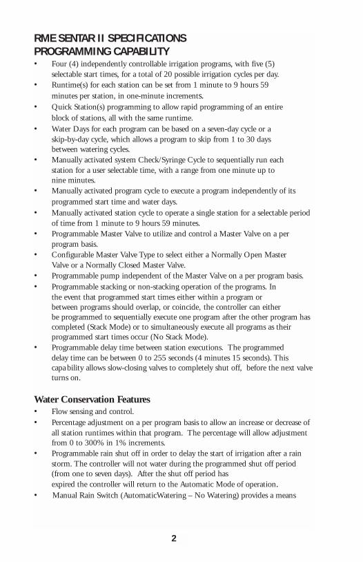
RME SENTAR II SPECIFICATIONSPROGRAMMING CAPABILITY• Four (4) independently controllable irrigation programs, with five (5)
selectable start times, for a total of 20 possible irrigation cycles per day.• Runtime(s) for each station can be set from 1 minute to 9 hours 59
minutes per station, in one-minute increments. • Quick Station(s) programming to allow rapid programming of an entire
block of stations, all with the same runtime. • Water Days for each program can be based on a seven-day cycle or a
skip-by-day cycle, which allows a program to skip from 1 to 30 days between watering cycles.
• Manually activated system Check/Syringe Cycle to sequentially run each station for a user selectable time, with a range from one minute up to nine minutes.
• Manually activated program cycle to execute a program independently of its programmed start time and water days.
• Manually activated station cycle to operate a single station for a selectable periodof time from 1 minute to 9 hours 59 minutes.
• Programmable Master Valve to utilize and control a Master Valve on a perprogram basis.
• Configurable Master Valve Type to select either a Normally Open Master Valve or a Normally Closed Master Valve.
• Programmable pump independent of the Master Valve on a per program basis.• Programmable stacking or non-stacking operation of the programs. In
the event that programmed start times either within a program or between programs should overlap, or coincide, the controller can either be programmed to sequentially execute one program after the other program has completed (Stack Mode) or to simultaneously execute all programs as theirprogrammed start times occur (No Stack Mode).
• Programmable delay time between station executions. The programmed delay time can be between 0 to 255 seconds (4 minutes 15 seconds). Thiscapa bility allows slow-closing valves to completely shut off, before the next valveturns on.
Water Conservation Features• Flow sensing and control. • Percentage adjustment on a per program basis to allow an increase or decrease of
all station runtimes within that program. The percentage will allow adjustment from 0 to 300% in 1% increments.
• Programmable rain shut off in order to delay the start of irrigation after a rain storm. The controller will not water during the programmed shut off period (from one to seven days). After the shut off period has expired the controller will return to the Automatic Mode of operation.
• Manual Rain Switch (AutomaticWatering – No Watering) provides a means
2
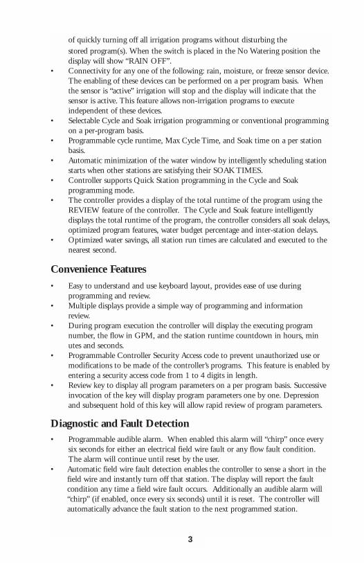
of quickly turning off all irrigation programs without disturbing the stored program(s). When the switch is placed in the No Watering position the display will show “RAIN OFF”.
• Connectivity for any one of the following: rain, moisture, or freeze sensor device.The enabling of these devices can be performed on a per program basis. When the sensor is “active” irrigation will stop and the display will indicate that the sensor is active. This feature allows non-irrigation programs to executeindependent of these devices.
• Selectable Cycle and Soak irrigation programming or conventional programmingon a per-program basis.
• Programmable cycle runtime, Max Cycle Time, and Soak time on a per station basis.
• Automatic minimization of the water window by intelligently scheduling station starts when other stations are satisfying their SOAK TIMES.
• Controller supports Quick Station programming in the Cycle and Soak programming mode.
• The controller provides a display of the total runtime of the program using the REVIEW feature of the controller. The Cycle and Soak feature intelligentlydisplays the total runtime of the program, the controller considers all soak delays,optimized program features, water budget percentage and inter-station delays.
• Optimized water savings, all station run times are calculated and executed to the nearest second.
Convenience Features
• Easy to understand and use keyboard layout, provides ease of use during programming and review.
• Multiple displays provide a simple way of programming and information review.
• During program execution the controller will display the executing program number, the flow in GPM, and the station runtime countdown in hours, minutes and seconds.
• Programmable Controller Security Access code to prevent unauthorized use or modifications to be made of the controller’s programs. This feature is enabled byentering a security access code from 1 to 4 digits in length.
• Review key to display all program parameters on a per program basis. Successive invocation of the key will display program parameters one by one. Depression and subsequent hold of this key will allow rapid review of program parameters.
Diagnostic and Fault Detection• Programmable audible alarm. When enabled this alarm will “chirp” once every
six seconds for either an electrical field wire fault or any flow fault condition. The alarm will continue until reset by the user.
• Automatic field wire fault detection enables the controller to sense a short in the field wire and instantly turn off that station. The display will report the faultcondition any time a field wire fault occurs. Additionally an audible alarm will “chirp” (if enabled, once every six seconds) until it is reset. The controller will automatically advance the fault station to the next programmed station.
3
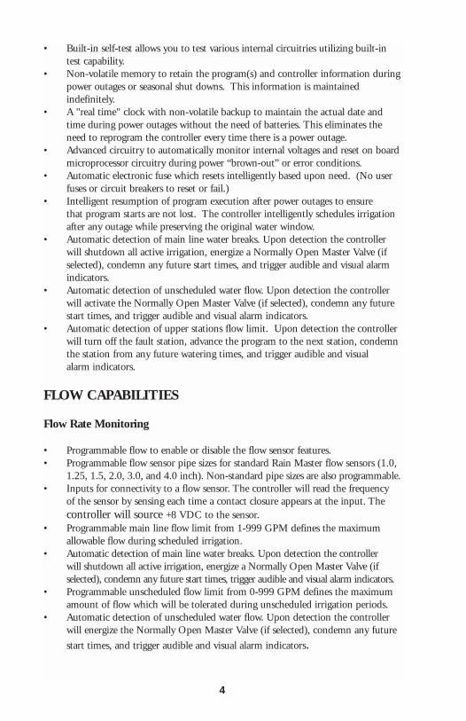
• Built-in self-test allows you to test various internal circuitries utilizing built-in test capability.
• Non-volatile memory to retain the program(s) and controller information duringpower outages or seasonal shut downs. This information is maintainedindefinitely.
• A "real time" clock with non-volatile backup to maintain the actual date and time during power outages without the need of batteries. This eliminates the need to reprogram the controller every time there is a power outage.
• Advanced circuitry to automatically monitor internal voltages and reset on boardmicroprocessor circuitry during power “brown-out” or error conditions.
• Automatic electronic fuse which resets intelligently based upon need. (No user fuses or circuit breakers to reset or fail.)
• Intelligent resumption of program execution after power outages to ensure that program starts are not lost. The controller intelligently schedules irrigation after any outage while preserving the original water window.
• Automatic detection of main line water breaks. Upon detection the controller will shutdown all active irrigation, energize a Normally Open Master Valve (if selected), condemn any future start times, and trigger audible and visual alarm indicators.
• Automatic detection of unscheduled water flow. Upon detection the controller will activate the Normally Open Master Valve (if selected), condemn any future start times, and trigger audible and visual alarm indicators.
• Automatic detection of upper stations flow limit. Upon detection the controller will turn off the fault station, advance the program to the next station, condemn the station from any future watering times, and trigger audible and visual alarm indicators.
FLOW CAPABILITIES
Flow Rate Monitoring
• Programmable flow to enable or disable the flow sensor features.• Programmable flow sensor pipe sizes for standard Rain Master flow sensors (1.0,
1.25, 1.5, 2.0, 3.0, and 4.0 inch). Non-standard pipe sizes are also programmable.• Inputs for connectivity to a flow sensor. The controller will read the frequency
of the sensor by sensing each time a contact closure appears at the input. The controller will source +8 VDC to the sensor.
• Programmable main line flow limit from 1-999 GPM defines the maximum allowable flow during scheduled irrigation.
• Automatic detection of main line water breaks. Upon detection the controllerwill shutdown all active irrigation, energize a Normally Open Master Valve (if selected), condemn any future start times, trigger audible and visual alarm indicators.
• Programmable unscheduled flow limit from 0-999 GPM defines the maximum amount of flow which will be tolerated during unscheduled irrigation periods.
• Automatic detection of unscheduled water flow. Upon detection the controller will energize the Normally Open Master Valve (if selected), condemn any future
start times, and trigger audible and visual alarm indicators.
4
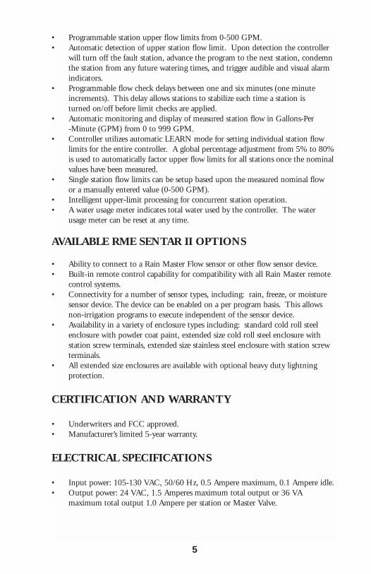
• Programmable station upper flow limits from 0-500 GPM.• Automatic detection of upper station flow limit. Upon detection the controller
will turn off the fault station, advance the program to the next station, condemn the station from any future watering times, and trigger audible and visual alarm indicators.
• Programmable flow check delays between one and six minutes (one minute increments). This delay allows stations to stabilize each time a station is turned on/off before limit checks are applied.
• Automatic monitoring and display of measured station flow in Gallons-Per-Minute (GPM) from 0 to 999 GPM.
• Controller utilizes automatic LEARN mode for setting individual station flow limits for the entire controller. A global percentage adjustment from 5% to 80% is used to automatically factor upper flow limits for all stations once the nominal values have been measured.
• Single station flow limits can be setup based upon the measured nominal flowor a manually entered value (0-500 GPM).
• Intelligent upper-limit processing for concurrent station operation.• A water usage meter indicates total water used by the controller. The water
usage meter can be reset at any time.
AVAILABLE RME SENTAR II OPTIONS
• Ability to connect to a Rain Master Flow sensor or other flow sensor device.• Built-in remote control capability for compatibility with all Rain Master remote
control systems.• Connectivity for a number of sensor types, including: rain, freeze, or moisture
sensor device. The device can be enabled on a per program basis. This allows non-irrigation programs to execute independent of the sensor device.
• Availability in a variety of enclosure types including: standard cold roll steel enclosure with powder coat paint, extended size cold roll steel enclosure with station screw terminals, extended size stainless steel enclosure with station screw terminals.
• All extended size enclosures are available with optional heavy duty lightningprotection.
CERTIFICATION AND WARRANTY
• Underwriters and FCC approved. • Manufacturer’s limited 5-year warranty.
ELECTRICAL SPECIFICATIONS
• Input power: 105-130 VAC, 50/60 Hz, 0.5 Ampere maximum, 0.1 Ampere idle.• Output power: 24 VAC, 1.5 Amperes maximum total output or 36 VA
maximum total output 1.0 Ampere per station or Master Valve.
5
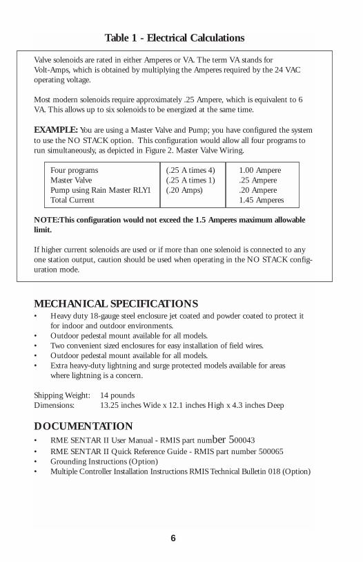
Table 1 - Electrical Calculations
Valve solenoids are rated in either Amperes or VA. The term VA stands for Volt-Amps, which is obtained by multiplying the Amperes required by the 24 VACoperating voltage.
Most modern solenoids require approximately .25 Ampere, which is equivalent to 6VA. This allows up to six solenoids to be energized at the same time.
EXAMPLE: You are using a Master Valve and Pump; you have configured the systemto use the NO STACK option. This configuration would allow all four programs torun simultaneously, as depicted in Figure 2. Master Valve Wiring.
Four programs (.25 A times 4) 1.00 AmpereMaster Valve (.25 A times 1) .25 AmperePump using Rain Master RLY1 (.20 Amps) .20 AmpereTotal Current 1.45 Amperes
NOTE:This configuration would not exceed the 1.5 Amperes maximum allowablelimit.
If higher current solenoids are used or if more than one solenoid is connected to anyone station output, caution should be used when operating in the NO STACK config-uration mode.
MECHANICAL SPECIFICATIONS• Heavy duty 18-gauge steel enclosure jet coated and powder coated to protect it
for indoor and outdoor environments. • Outdoor pedestal mount available for all models.• Two convenient sized enclosures for easy installation of field wires.• Outdoor pedestal mount available for all models.• Extra heavy-duty lightning and surge protected models available for areas
where lightning is a concern.
Shipping Weight: 14 poundsDimensions: 13.25 inches Wide x 12.1 inches High x 4.3 inches Deep
DOCUMENTATION• RME SENTAR II User Manual - RMIS part number 500043 • RME SENTAR II Quick Reference Guide - RMIS part number 500065 • Grounding Instructions (Option)• Multiple Controller Installation Instructions RMIS Technical Bulletin 018 (Option)
6
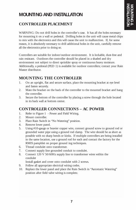
MOUNTING AND INSTALLATION
CONTROLLER PLACEMENT
WARNING: Do not drill holes in the controller's case. It has all the holes necessaryfor mounting it on a wall or pedestal. Drilling holes in the unit will cause metal chipsto mix with the electronics and this will cause the unit to malfunction. If, for somereason, it is absolutely necessary to drill additional holes in the unit, carefully removeall the electronics prior to doing so.
Controllers are suitable for indoor/outdoor environment. It is lockable, dust-free andrain resistant. Outdoors the controller should be placed in a shaded and dryenvironment not subject to direct sprinkler spray or continuous heavy moisture.Additionally, a pedestal (PED 1) is available for outdoor controllers; contact your RainMaster distributor.
MOUNTING THE CONTROLLER 1. On an upright, flat and secure surface, place the mounting bracket at eye level
and fasten securely.2. Mate the bracket on the back of the controller to the mounted bracket and hang
the controller.3. Secure the bottom of the controller by placing a screw through the hole located
in its back wall at bottom center.
CONTROLLER CONNECTIONS – AC POWER1. Refer to Figure 1 - Power and Field Wiring.2. Mount controller.3. Place Rain Switch in “No Watering” position.4. Remove lower panel.5. Using #10-gauge or heavier copper wire, connect ground screw to ground rod or
grounded water pipe using a ground rod clamp. The wire should be as short as possible with no sharp bends or kinks. If multiple controllers are being installed in the same location, use a ground rod for each and contact the factory for the RMIS pamphlet on proper ground ing techniques.
6. Thread condulet onto transformer.7. Connect supply line grounded conduit to condulet.8. Connect 120 V 50/60Hz supply line to transformer wires within the
conduletInstall gasket and cover onto condulet with 2 screws.
9. Follow all appropriate electrical wiring codes. 10. Replace the lower panel and place the Rain Switch in “Automatic Watering”
position after field valve wiring is complete.
MO
UNTING &
INSTALLATION
7

ELECTRICAL GROUNDING FOR THE CONTROLLERProper electrical grounding is required to ensure safety to you, as well as to protect thecontroller electronics in the event of electrical line surges or lightning. In areas wherelightning is a common occurrence, it is strongly recommended to use the RMESENTAR II model SE-T.
Grounding Instructions1. Mount the controller as close as possible to the grounding rod, so that the #10
grounding wire from the controller to the ground rod is as short as possible. Ensure the grounding wire is free of nicks and bends.
2. Use a grounding rod clamp to secure grounding wire to grounding rod. Be sure all surfaces are clean of oxides and dirt, and that all connections are solid and secure.
3. In areas of very dry soil or sand, it may be necessary to "Dope" the grounding rod. Contact your Rain Master distributor or Rain Master for grounding pamphlet, “RMIS Grounding”.
4. Should the 8' grounding rod not penetrate completely into the soil it is acceptable to put it into the ground on a slight angle. It is important that the rod be a full 8' into the ground, with only enough of the rod showing to clamp the wire on. Should other grounding installation requirements be necessary, contact your distributor or Rain Master.
Note: It is important to check the resistance periodically to ensure it is notgreater than 10 ohms. Contact your Rain Master Distributor for details.
FIGURE 1. POWER AND FIELD WIRING
8
CONTROLLER CONNECTIONS – VALVES AND FIELD WIRINGThe controller utilizes quick disconnects and color coded wires. The wires are 24"long and each end must be stripped and attached to the corresponding field wire.RME SENTAR II ST and ST-T model controllers come equipped with terminals towhich the field wires are directly connected. Unused wires should be taped off toprevent shorting.
The station numbers are labeled just above the quick disconnects behind the lowerpanel of the controller. Simply match the station's wire to the appropriate field wire.Note that the controller's COMMON wire is WHITE and the MASTERVALVE/PUMP is BLACK.
Should it be necessary to detach the Quick Disconnect blocks from the printed circuitboard, hold the plastic assembly and pull down gently but firmly.
Note: When reattaching the Quick Disconnect, be careful to make sure that the lip at the top of the plastic connector is facing you as you push the connector onto the pins. Additionally, be sure to match the Quick Disconnect blocks with the corresponding color as labeled on the bottom of the printed circuit board.
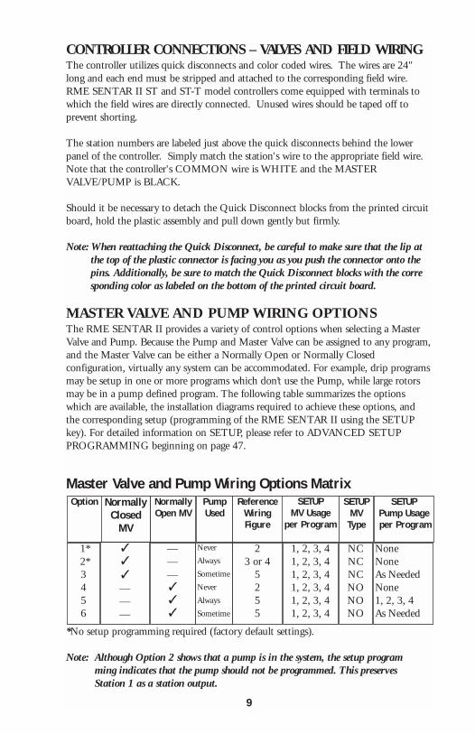
MASTER VALVE AND PUMP WIRING OPTIONSThe RME SENTAR II provides a variety of control options when selecting a MasterValve and Pump. Because the Pump and Master Valve can be assigned to any program,and the Master Valve can be either a Normally Open or Normally Closedconfiguration, virtually any system can be accommodated. For example, drip programsmay be setup in one or more programs which don’t use the Pump, while large rotorsmay be in a pump defined program. The following table summarizes the optionswhich are available, the installation diagrams required to achieve these options, andthe corresponding setup (programming of the RME SENTAR II using the SETUPkey). For detailed information on SETUP, please refer to ADVANCED SETUPPROGRAMMING beginning on page 47.
Master Valve and Pump Wiring Options Matrix
*No setup programming required (factory default settings).
Note: Although Option 2 shows that a pump is in the system, the setup programming indicates that the pump should not be programmed. This preserves Station 1 as a station output.
Option NormallyClosed
MV
NormallyOpen MV
PumpUsed
ReferenceWiringFigure
SETUPMV Usage
per Program
SETUPMV
Type
SETUPPump Usageper Program
1*2*3456
✓✓
✓
———
———✓✓✓
Never
Always
Sometime
Never
Always
Sometime
23 or 4
5255
1, 2, 3, 41, 2, 3, 41, 2, 3, 41, 2, 3, 41, 2, 3, 41, 2, 3, 4
NCNCNCNONONO
NoneNoneAs NeededNone1, 2, 3, 4As Needed
9
ELECTRICAL CONNECTIONS FOR A MASTER VALVEThe RME SENTAR II allows you to setup the Master Valve (MV) output as either aNormally Open or Normally Closed configuration. When used in the NormallyClosed mode, the Master Valve line is a source of 24 VAC power. It is activewhenever any station in the controller is on. For Normally Open Master Valves, thecontroller supplies 24 VAC only when either a Main Line Fault or Unscheduled FlowFault occurs.
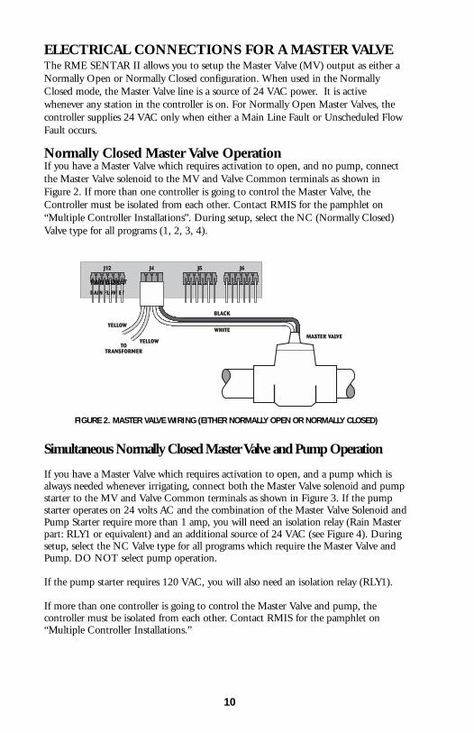
Normally Closed Master Valve OperationIf you have a Master Valve which requires activation to open, and no pump, connectthe Master Valve solenoid to the MV and Valve Common terminals as shown inFigure 2. If more than one controller is going to control the Master Valve, theController must be isolated from each other. Contact RMIS for the pamphlet on“Multiple Controller Installations”. During setup, select the NC (Normally Closed)Valve type for all programs (1, 2, 3, 4).
FIGURE 2. MASTER VALVE WIRING (EITHER NORMALLY OPEN OR NORMALLY CLOSED)
Simultaneous Normally Closed Master Valve and Pump Operation
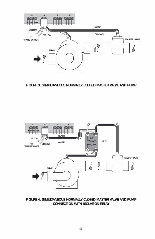
If you have a Master Valve which requires activation to open, and a pump which isalways needed whenever irrigating, connect both the Master Valve solenoid and pumpstarter to the MV and Valve Common terminals as shown in Figure 3. If the pumpstarter operates on 24 volts AC and the combination of the Master Valve Solenoid andPump Starter require more than 1 amp, you will need an isolation relay (Rain Masterpart: RLY1 or equivalent) and an additional source of 24 VAC (see Figure 4). Duringsetup, select the NC Valve type for all programs which require the Master Valve andPump. DO NOT select pump operation.
If the pump starter requires 120 VAC, you will also need an isolation relay (RLY1).
If more than one controller is going to control the Master Valve and pump, thecontroller must be isolated from each other. Contact RMIS for the pamphlet on“Multiple Controller Installations.”
RAIN FLOW ET
10
TOTRANSFORMER
YELLOW
YELLOW COMMON
BLACK
MASTER VALVE
PUMP
J12
RAIN FLOW ET
J4 J5 J6
FIGURE 3. SIMULTANEOUS NORMALLY CLOSED MASTER VALVE AND PUMP
TOTRANSFORMER
YELLOW
YELLOWWHITE
BLACK
MASTER VALVE
PUMP
24 VACCOIL
1
2
3
4
RLY1
J12
RAIN FLOW ET
J4 J5 J6
FIGURE 4. SIMULTANEOUS NORMALLY CLOSED MASTER VALVE AND PUMPCONNECTION WITH ISOLATION RELAY
11
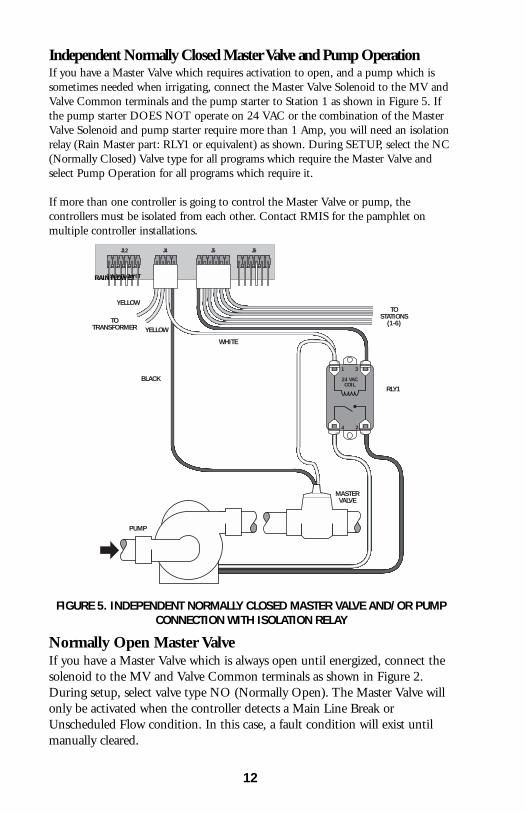
Normally Open Master ValveIf you have a Master Valve which is always open until energized, connect thesolenoid to the MV and Valve Common terminals as shown in Figure 2.During setup, select valve type NO (Normally Open). The Master Valve willonly be activated when the controller detects a Main Line Break orUnscheduled Flow condition. In this case, a fault condition will exist untilmanually cleared.
Independent Normally Closed Master Valve and Pump OperationIf you have a Master Valve which requires activation to open, and a pump which issometimes needed when irrigating, connect the Master Valve Solenoid to the MV andValve Common terminals and the pump starter to Station 1 as shown in Figure 5. Ifthe pump starter DOES NOT operate on 24 VAC or the combination of the MasterValve Solenoid and pump starter require more than 1 Amp, you will need an isolationrelay (Rain Master part: RLY1 or equivalent) as shown. During SETUP, select the NC(Normally Closed) Valve type for all programs which require the Master Valve andselect Pump Operation for all programs which require it.
If more than one controller is going to control the Master Valve or pump, thecontrollers must be isolated from each other. Contact RMIS for the pamphlet onmultiple controller installations.
FIGURE 5. INDEPENDENT NORMALLY CLOSED MASTER VALVE AND/OR PUMPCONNECTION WITH ISOLATION RELAY
TOTRANSFORMER
YELLOW
YELLOW
WHITE
BLACK
MASTERVALVE
PUMP
24 VACCOIL
1
2
3
4
TOSTATIONS
(1-6)
RLY1
J12
RAIN FLOW ET
J4 J5 J6
RAIN FLOW ET
12
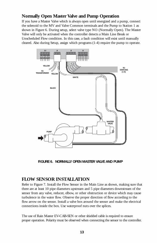
Normally Open Master Valve and Pump OperationIf you have a Master Valve which is always open until energized and a pump, connectthe solenoid to the MV and Valve Common terminals and the Pump to Station 1 asshown in Figure 6. During setup, select valve type NO (Normally Open). The MasterValve will only be activated when the controller detects a Main Line Break orUnscheduled Flow condition. In this case, a fault condition will exist until manuallycleared. Also during Setup, assign which programs (1-4) require the pump to operate.
FLOW SENSOR INSTALLATIONRefer to Figure 7. Install the Flow Sensor in the Main Line as shown, making sure thatthere are at least 10 pipe diameters upstream and 5 pipe diameters downstream of thesensor from any valve, reducer, elbow, or other obstruction or device which may causeturbulence in the water flow. Observe the proper direction of flow according to theflow arrow on the sensor. Install a valve box around the sensor and make the electricalconnections inside the box. Use waterproof nuts over the splices.
The use of Rain Master EV-CAB-SEN or other shielded cable is required to ensureproper operation. Polarity must be observed when connecting the sensor to the controller.
FIGURE 6. NORMALLY OPEN MASTER VALVE AND PUMP
TOTRANSFORMER
YELLOW
YELLOW
WHITE
BLACK
MASTERVALVE
PUMP
TOSTATIONS
(1-6)
J12
RAIN FLOW ET
J4 J5 J6
13
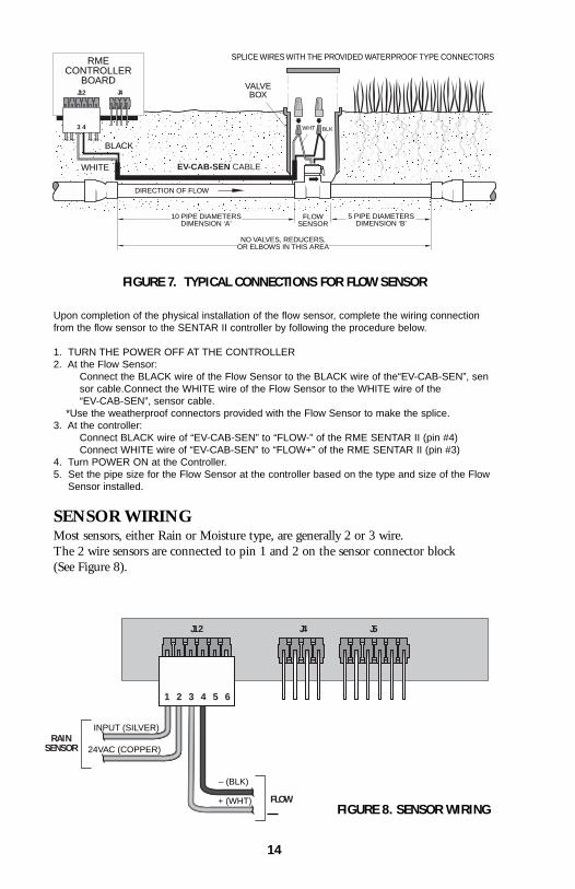
Upon completion of the physical installation of the flow sensor, complete the wiring connectionfrom the flow sensor to the SENTAR II controller by following the procedure below.
1. TURN THE POWER OFF AT THE CONTROLLER2. At the Flow Sensor:
Connect the BLACK wire of the Flow Sensor to the BLACK wire of the“EV-CAB-SEN”, sensor cable.Connect the WHITE wire of the Flow Sensor to the WHITE wire of the “EV-CAB-SEN”, sensor cable.
*Use the weatherproof connectors provided with the Flow Sensor to make the splice.3. At the controller:
Connect BLACK wire of “EV-CAB-SEN” to “FLOW-” of the RME SENTAR II (pin #4) Connect WHITE wire of “EV-CAB-SEN” to “FLOW+” of the RME SENTAR II (pin #3)
4. Turn POWER ON at the Controller.5. Set the pipe size for the Flow Sensor at the controller based on the type and size of the Flow
Sensor installed.
SENSOR WIRINGMost sensors, either Rain or Moisture type, are generally 2 or 3 wire.The 2 wire sensors are connected to pin 1 and 2 on the sensor connector block (See Figure 8).
FIGURE 7. TYPICAL CONNECTIONS FOR FLOW SENSOR
SPLICE WIRES WITH THE PROVIDED WATERPROOF TYPE CONNECTORS
VALVEBOX
10 PIPE DIAMETERSDIMENSION ‘A’
5 PIPE DIAMETERSDIMENSION ‘B’
NO VALVES, REDUCERS,OR ELBOWS IN THIS AREA
DIRECTION OF FLOW
FLOWSENSOR
EV-CAB-SEN CABLE
WHT BLK
WHITE
BLACK
RMECONTROLLER
BOARDJ12
3 4
J4
RAINSENSOR
FLOW
J12 J4 J5
1 2 3 4 5 6
INPUT (SILVER)
24VAC (COPPER)
+ (WHT)
– (BLK)
FIGURE 8. SENSOR WIRING
14
TAPPING WIRES TO LOCATE VALVES IN THE FIELDDON'T – turn a station on and tap a wire to the controller's station terminal/wire tosee what valve in the field is connected to it. This is damaging to both mechanicaland solid state controllers and will cause the controller to go into a field wire faultdetection mode. The simple method shown below is safe and will work for both typesof controllers.
1. Use Manual Station to turn on Station 1, perhaps for 1 hour.2. Flip the Rain Switch to the “No Watering” position.3. Touch the wire from the unknown field valve to the controller's Station 1
terminal/wire.4. Flip the Rain Switch to the “Automatic Watering” position and the valve on that
wire will be activated.5. When you know what valve it is, flip the Rain Switch off before removing the
field wire from the controller's station terminal/wire.6. Choose the next field wire and start the process over at Step 2.7. When all done, turn off Station 1.
AC POWER FAILURESIn the event of an AC power failure, all irrigation stations are turned off and thedisplay goes blank. The RME SENTAR II controller is equipped with non-volatileRAM (NVRAM) in order to protect user entered programs as well as important setupinformation during power loss.
This data will be retained for an indefinite period of time regardless of the length ofthe power outage. Additionally, your RME SENTAR II is also able to maintain thetime and date for a period of up to 30 days (continuous) without the use of any type
of battery. If the power is off for longer than 30 days, the user will be notified by aflashing time display, when power is reestablished. The correct time can then bere-entered using the SETUP function.
Regardless of the number of power failures, the date and time will be maintained forup to 30 days.
In the event that a program is executing or a scheduled start time is missed when apower failure happens, the controller will intelligently resume execution where itwould have been if the outage had not occurred. The RME SENTAR II will completeits program execution preserving the original water window.
REMOTE CONTROL CAPABILITYAll Rain Master controllers feature patented built-in remote control capability whichallows you to operate the controller for a distance of 1 mile in congested areas via ahand held transmitter. Consult the Remote Manual for operating instructions.Neverconnect anything but a Rain Master remote control receiver to the controller's frontpanel remote control connector or damage will result. Connecting to any other remotecontrol device to any portion of the Rain Master controller will void all warranties andmay cause damage.
15

THIS PAGE INTENTIONALLY LEFT BLANK.
16
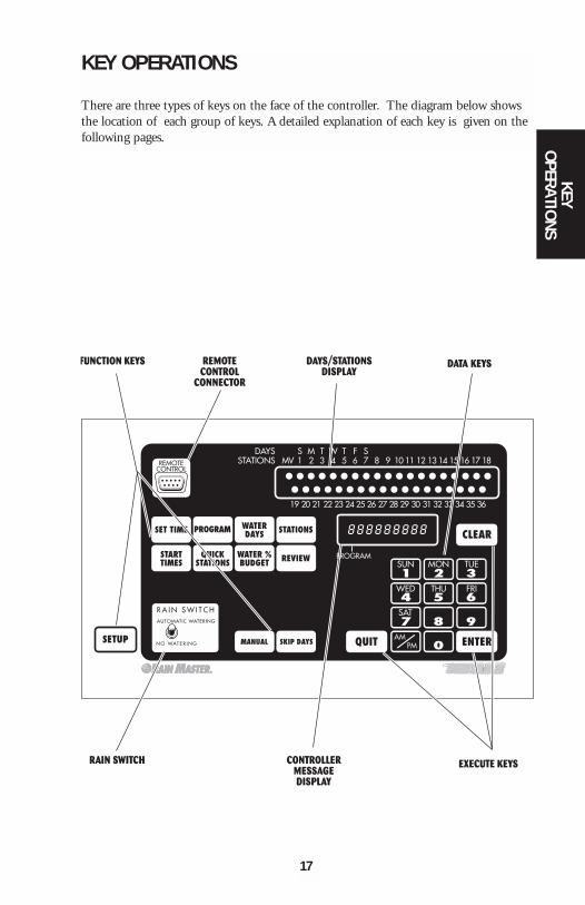
KEY OPERATIONS
There are three types of keys on the face of the controller. The diagram below showsthe location of each group of keys. A detailed explanation of each key is given on thefollowing pages.
KEYO
PERATIONS
17
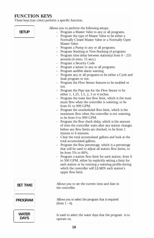
FUNCTION KEYSThese keys (tan color) perform a specific function.
Allows you to perform the following setups:- Program a Master Valve to any or all programs.- Program the type of Master Valve to be either a
Normally Closed Master Valve or a Normally Open Master Valve.
- Program a Pump to any or all programs.- Program Stacking or Non-Stacking of programs- Program time delay between station(s) from 0 - 255
seconds (4 mins. 15 secs.)- Program a Security Code- Program a sensor to any or all programs- Program audible alarm warning- Program any or all programs to be either a Cycle and
Soak program or not.- Program the Flow Sensor features to be enabled or
not.- Program the Pipe size for the Flow Sensor to be
either 1, 1.25, 1.5, 2, 3 or 4 inches.- Program the main line flow limit, which is the maxi
mum flow when the controller is watering, to be from 01 to 999 GPM.
- Program the unscheduled flow limit, which is the maximum flow when the controller is not watering, to be from 0 to 999 GPM.
- Program the flow check delay, which is the amount of time the controller waits after any station changes before any flow limits are checked, to be from 1 minute to 6 minutes.
- Clear the total accumulated gallons and look at the total accumulated gallons.
- Program the flow percentage, which is a percentage that will be used to adjust all station flow limits, to be from 5% to 80%.
- Program a station flow limit for each station, from 0to 500 GPM, either by explicitly setting a limit for each station or by running a watering profile during which the controller will LEARN each station's upper flow limit.
Allows you to set the current time and date inthe controller.
Allows you to select the program that is required(from 1 - 4).
Is used to select the water days that the program is to operate on.
SETUP
SET TIME
PROGRAM
WATERDAYS
18
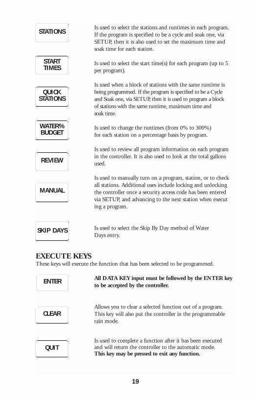
Is used to select the stations and runtimes in each program. If the program is specified to be a cycle and soak one, via SETUP, then it is also used to set the maximum time and soak time for each station.
Is used to select the start time(s) for each program (up to 5 per program).
Is used when a block of stations with the same runtime is being programmed. If the program is specified to be a Cycle and Soak one, via SETUP, then it is used to program a block of stations with the same runtime, maximum time andsoak time.
Is used to change the runtimes (from 0% to 300%) for each station on a percentage basis by program.
Is used to review all program information on each program in the controller. It is also used to look at the total gallons used.
Is used to manually turn on a program, station, or to check all stations. Additional uses include locking and unlocking the controller once a security access code has been entered via SETUP, and advancing to the next station when executing a program.
Is used to select the Skip By Day method of WaterDays entry.
EXECUTE KEYSThese keys will execute the function that has been selected to be programmed.
All DATA KEY input must be followed by the ENTER keyto be accepted by the controller.
Allows you to clear a selected function out of a program. This key will also put the controller in the programmable rain mode.
Is used to complete a function after it has been executed and will return the controller to the automatic mode.This key may be pressed to exit any function.
STATIONS
STARTTIMES
QUICKSTATIONS
WATER%BUDGET
REVIEW
MANUAL
SKIP DAYS
ENTER
CLEAR
QUIT
19
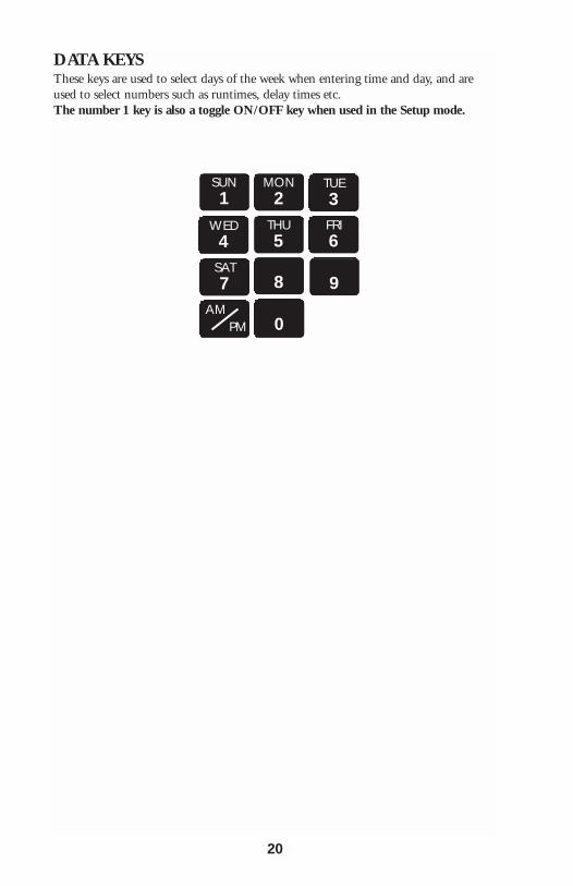
DATA KEYSThese keys are used to select days of the week when entering time and day, and areused to select numbers such as runtimes, delay times etc. The number 1 key is also a toggle ON/OFF key when used in the Setup mode.
20
SUN1
MON2
TUE3
WED4
THU5
FRI6
SAT7 8 9
0AM
PM

WORDS AND TERMS USED IN THE DISPLAY
= Hello will be displayed when the controller is powered up for the very first time.When Hello is displayed there are NO user programs in the controller. If left in the HELLO mode the controller will begin to water every station for 10 minutes, starting 6hours after the HELLO has been displayed. The 10 minute per station watering shall repeat every 24 hours.
Hitting any key exits HELLO mode, and removes the default watering program.
UNDER SETUP
= Master Valve.
= Master Valve type is Normally Closed (NC).
= Master Valve type is Normally Open (NO).
= Pump.
= Ensures that programs run one after another,even if their start times overlap.
= Run programs at their scheduled start times.In the event that start times overlap, multipleprograms will run concurrently.
= Time delay between stations (0-255 seconds).
= Access or Security Code.
= Sensor input.
HELLOI
PROGRAM
M VI
PROGRAM
TYPE - NCI
PROGRAM
TYPE - NOI
PROGRAM
PUMPI
PROGRAM
STACKI
PROGRAM
NO STACKI
PROGRAM
DELAY 000I
PROGRAM
CODE 00 00I
PROGRAM
S N S R I
PROGRAM
21
WO
RDS &
TERM
S

22
= An audible beep will be given off (o r not) if a fault is detected.
= Cycle and Soak.
= Flow sensor features are enabled (or disabled).
= Flow sensor is standard 1" pipe.
= Flow sensor is standard 1.25" pipe.
= Flow sensor is standard 1.5" pipe.
= Flow sensor is standard 2" pipe.
= Flow sensor is standard 3" pipe.
= Flow sensor is standard 4" pipe.
= Reserved for Rain Master use only.
= Main line flow limit (in GPM).
= Unscheduled flow limit (in GPM).
= Flow check delay (in minutes).
= The total gallons used since the last time it was cleared. (Display flashes “TOTAL”, “GALLONS”, then number.)
= Percentage adjust to all station upperflow limits.
ALARM ON / OFF I
PROGRAM
SOAKI
PROGRAM
FLOW ON / OFFI
PROGRAM
PIPE 1 . 0 0 I
PROGRAM
PIPE 1 . 5 0 I
PROGRAM
PIPE 2 . 0 0 I
PROGRAM
PIPE 1 . 2 5 I
PROGRAM
PIPE 3 . 0 0 I
PROGRAM
PIPE 4 . 0 0 I
PROGRAM
PIPE OTHER I
PROGRAM
MAIN SOO I
PROGRAM
UNSCH 200 I
PROGRAM
F DELAY 2 I
PROGRAM
TOTAL . . .GALLONS . . .
1234I
PROGRAM
PERCENT 20 I
PROGRAM
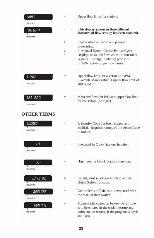
= Upper flow limits for stations.
=
1. Flashes when an automatic program is executing.
2. In Manual System Check/Syringe Cycle.3. Displays measured flow while the controller
is going through watering profile to LEARN station upper flow limits.
= Upper flow limit for a station in GPM. (Example shows station 1 upper flow limit of200 GPM.)
= Measured flow (on left) and upper flow limit for the station (on right).
OTHER TERMS
= A Security Code has been entered and enabled. Requires reentry of the Access Codeto unlock.
= Low, used in Quick Stations function.
= High, used in Quick Stations function.
= Length, used in station function and in Quick Station function.
= Controller is in Rain shut-down, used with the manual Rain Switch.
= Momentarily comes up before the runtime is to be entered in the station feature and quick station feature, if the program is Cycleand Soak.
LIMITSI
PROGRAM
1 0 0 G P M I
PROGRAM
1 - 2 0 0I
PROGRAM
1 2 3 2 0 0 I
PROGRAM
LOCKEDI
PROGRAM
LO -I
PROGRAM
HI - I
PROGRAM
L M - 0 : 0 0 I
PROGRAM
RAIN OFFI
PROGRAM
RUN TIMEI
PROGRAM
23
This display appears in three differentinstances (if flow sensing has been enabled).
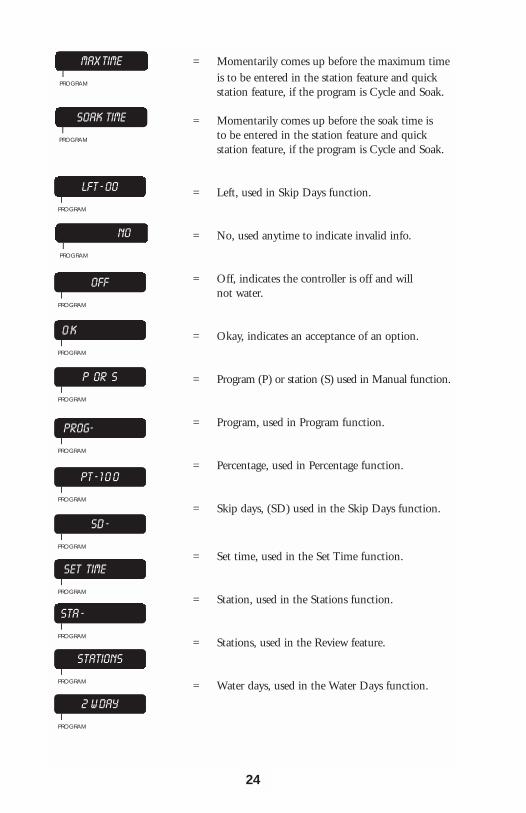
= Momentarily comes up before the maximum time is to be entered in the station feature and quick station feature, if the program is Cycle and Soak.
= Momentarily comes up before the soak time is to be entered in the station feature and quick station feature, if the program is Cycle and Soak.
= Left, used in Skip Days function.
= No, used anytime to indicate invalid info.
= Off, indicates the controller is off and will not water.
= Okay, indicates an acceptance of an option.
= Program (P) or station (S) used in Manual function.
= Program, used in Program function.
= Percentage, used in Percentage function.
= Skip days, (SD) used in the Skip Days function.
= Set time, used in the Set Time function.
= Station, used in the Stations function.
= Stations, used in the Review feature.
= Water days, used in the Water Days function.
MAX TIMEI
PROGRAM
SOAK TIMEI
PROGRAM
LFT - 00I
PROGRAM
NO I
PROGRAM
OFFI
PROGRAM
O K I
PROGRAM
P OR S I
PROGRAM
PROG-I
PROGRAM
PT - 1 0 0I
PROGRAM
SD - I
PROGRAM
SET TIMEI
PROGRAM
STA - I
PROGRAM
STATIONSI
PROGRAM
2 W DAYI
PROGRAM
24
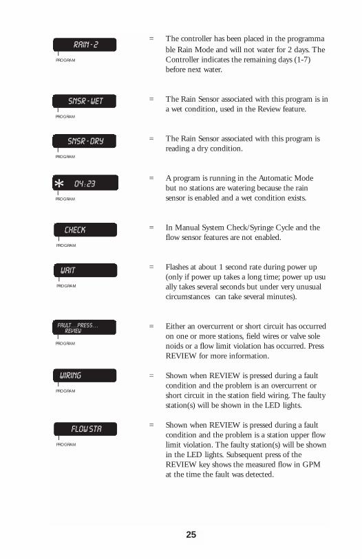
= The controller has been placed in the programmable Rain Mode and will not water for 2 days. The Controller indicates the remaining days (1-7) before next water.
= The Rain Sensor associated with this program is ina wet condition, used in the Review feature.
= The Rain Sensor associated with this program is reading a dry condition.
= A program is running in the Automatic Mode but no stations are watering because the rain sensor is enabled and a wet condition exists.
= In Manual System Check/Syringe Cycle and the flow sensor features are not enabled.
= Flashes at about 1 second rate during power up (only if power up takes a long time; power up usually takes several seconds but under very unusual circumstances can take several minutes).
= Either an overcurrent or short circuit has occurred on one or more stations, field wires or valve solenoids or a flow limit violation has occurred. Press REVIEW for more information.
= Shown when REVIEW is pressed during a fault condition and the problem is an overcurrent or short circuit in the station field wiring. The faulty station(s) will be shown in the LED lights.
= Shown when REVIEW is pressed during a fault condition and the problem is a station upper flow limit violation. The faulty station(s) will be shownin the LED lights. Subsequent press of the REVIEW key shows the measured flow in GPM at the time the fault was detected.
RAIN - 2I
PROGRAM
SNSR - WETI
PROGRAM
SNSR - DRYI
PROGRAM
04 : 23 I
PROGRAM
CHECKI
PROGRAM
WAITI
PROGRAM
FAULT . . . PRESS . . . REVIEW
IPROGRAM
WIRINGI
PROGRAM
FLOW STAI
PROGRAM
*
25

= Shown when REVIEW is pressed during a fault condition and the problem is an unscheduled flowlimit violation. Subsequent press of the REVIEW key shows the measured flow in GPM at the time the fault was detected.
= Shown when REVIEW is pressed during a fault condition and the problem is a main line flow limit violation. Subsequent press of the REVIEW key shows the measured flow in GPM at the time the fault was detected.
AUTOMATIC MODE
The controller is in the Automatic Mode whenever the time is displayed, and the dayof the week indicator light is lit.
Pressing will always return the controller to the Automatic Mode.
When a program is watering in the Automatic Mode, the station and program numberwill be displayed as a convenience. If the controller has been setup to enable flow sensing,the measured flow (GPM) will alternately appear in the display at a 1 second rate.
A in place of the program number, indicates a program is running but all stationsare off because the rain sensor is enabled and a wet condition exists.To advance to the next station in a program when a program is already watering,
Press:
To stop and cancel a program that is watering,
Press:
The controller returns to the Automatic Mode.
RAIN MODE
The controller has a Rain Switch. The switch MUST BE in the "AutomaticWatering" position anytime watering is desired. In the "Automatic Watering"position, watering WILL occur if the controller is programmed to do so.
The switch should be placed in the "No Watering" position when no watering isdesired, such as when it is raining, etc. In the "No Watering" position, no wateringwill occur and “RAIN OFF” will appear in the display to indicate that all programsare inhibited from watering. The user's program will not be disturbed
*
QUIT
MANUAL
QUITCLEAR
26
FLOW UNI
PROGRAM
FLOW MAINI
PROGRAM

PROGRAMMABLE RAINThis method is used in place of the Rain Switch when you know how many days youwant the controller to stay off. It allows you to select the number of days, from 1-7,that the controller will stay in the programmable Rain Mode after which it will returnto the Automatic Mode by itself.
EXAMPLE: You wish the controller to stay off for 6 days,
Press: The controller will diplay
Each night at midnight the controller will deduct one day until it finally returns to theAutomatic Mode.
Note: No watering will occur when it goes back to the Automatic Mode if you have also placed the Rain Switch in the “No Watering” position.
CLEARFRI6 ENTER
RAIN - 6 I
PROGRAM
27

THIS PAGE INTENTIONALLY LEFT BLANK.
28

QUICK AND BASIC PROGRAMMING
Before the controller will operate, some basic information must be programmed.1. Set the Time of day and Date for the controller. 2. Establish a valid watering program:
a. Choose the program number you wish to work with (1-4).b. Set the Water Days.c. Set the Stations and the Watering Time for each station.d. Set the Start Time(s) the program will begin to water on the chosen days.
SET TIMEThis is used to set the current time of day and the current date.
EXAMPLE 1: The time is 2:00 PM, Saturday, June 16, 2001.
Press:
The controller returns to the Automatic Mode.
EXAMPLE 2: The time is 10:35 AM, Tuesday, December 12, 2002
Press:
The controller returns to the Automatic Mode.
PROGRAMThis is used to select the program(s) you wish to work with. Once selected, you need not change the program # until you wish to program or review information in adifferent program. There are 4 programs available for your use. They are referred toas 1, 2, 3, and 4. If desired, it is also possible to select and clear ALL information in aprogram using this function.
PROGRAM SELECTIONSelect the program you wish to work with, either 1, 2, 3, or 4. While programmingother functions, the selected program number is displayed as a convenience.
EXAMPLE: You wish to work with Program 2,
Press:
The controller returns to the Automatic Mode.
SET TIMEAM
PMMON2 ENTER0 0
0FRI6
SUN1
FRI6 0
SUN1 ENTER
SET TIME 0SUN1 ENTER
MON2 0
SUN1
MON2
SUN1
MON2 ENTER
TUE3
THU5
PROGRAM MON2 ENTER
29
QUICK &
BASICPRO
GRAM
MING

PROGRAM CLEARIf desired, it is possible to both select and clear all information in a program.
EXAMPLE: You wish to select and clear all information in Program 1,
Press:
The controller returns to the Automatic Mode.
WATERING DAY SELECTIONSWatering days for Programs 1, 2, 3 and 4, may be set on a 7 day week or a Skip Daysmode. Although you cannot do both within the same program, each program may beset to either mode.
EXAMPLE: Program 1 may be on a 7 day weekly basis but Program 2 might be on a skip days basis.
WATER DAYSTo select watering days based on a 7 day week. Watering will occur on the daysselected each and every week. Selected days are shown in the top display. TheProgram # is shown in the display as a convenience.
EXAMPLE: You wish to water on Sunday, Wednesday and Friday,
Press:
The controller returns to the Automatic Mode.
EXAMPLE: To remove a watering day, such as Sunday,
Press:
Press:
The controller returns to the Automatic Mode.
EXAMPLE: To review Water Days information,
Press: (An LED light will light up for every
day that watering is to occur.)
Press:
The controller returns to the Automatic Mode.
PROGRAMSUN1 CLEAR
WATERDAYS
SUN1 ENTER
WED4 ENTER
FRI6 ENTER QUIT
WATERDAYS
SUN1 CLEAR
QUIT
WATERDAYS
QUIT
30
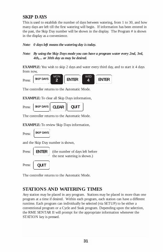
SKIP DAYSThis is used to establish the number of days between watering, from 1 to 30, and howmany days are left till the first watering will begin. If information has been entered inthe past, the Skip Day number will be shown in the display. The Program # is shownin the display as a convenience.
Note: 0 days left means the watering day is today.
Note: By using the Skip Days mode you can have a program water every 2nd, 3rd, 4th,... or 30th day as may be desired.
EXAMPLE: You wish to skip 2 days and water every third day, and to start it 4 daysfrom now,
Press:
The controller returns to the Automatic Mode.
EXAMPLE: To clear all Skip Days information,
Press:
The controller returns to the Automatic Mode.
EXAMPLE: To review Skip Days information,
Press:
and the Skip Day number is shown,
Press: (the number of days left before the next watering is shown.)
Press:
The controller returns to the Automatic Mode.
STATIONS AND WATERING TIMESAny station may be placed in any program. Stations may be placed in more than oneprogram at a time if desired. Within each program, each station can have a differentruntime. Each program can individually be selected (via SETUP) to be either aconventional program or a Cycle and Soak program. Depending upon the selection,the RME SENTAR II will prompt for the appropriate information whenever theSTATION key is pressed.
SKIP DAYSMON2 ENTER
WED4 ENTER
SKIP DAYS CLEAR QUIT
SKIP DAYS
ENTER
QUIT
31
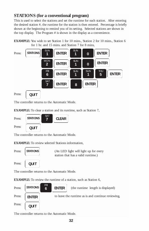
STATIONS (for a conventional program)This is used to select the stations and set the runtime for each station. After enteringthe desired station #, the runtime for the station is then entered. Percentage is brieflyshown at the beginning to remind you of its setting. Selected stations are shown inthe top display. The Program # is shown in the display as a convenience.
EXAMPLE: You wish to set Station 1 for 10 mins., Station 2 for 10 mins., Station 6 for 1 hr. and 15 mins. and Station 7 for 8 mins,
Press:
Press:
The controller returns to the Automatic Mode.
EXAMPLE: To clear a station and its runtime, such as Station 7,
Press:
Press:
The controller returns to the Automatic Mode.
EXAMPLE: To review selected Stations information,
Press: (An LED light will light up for every station that has a valid runtime.)
Press:
The controller returns to the Automatic Mode.
EXAMPLE: To review the runtime of a station, such as Station 6,
Press: (the runtime length is displayed)
Press: to leave the runtime as is and continue reviewing,
Press:
The controller returns to the Automatic Mode.
STATIONSSUN1 ENTER 0
SUN1 ENTER
ENTER
ENTER
ENTER
ENTER
ENTER
ENTER
MON2
FRI6
SAT7
SUN1
SUN1
0
SUN1
8
THU5
QUIT
STATIONS CLEARSAT7
QUIT
STATIONS
QUIT
ENTERFRI6STATIONS
ENTER
QUIT
32
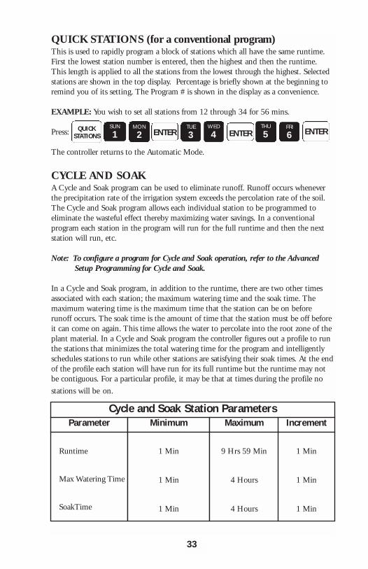
QUICK STATIONS (for a conventional program)This is used to rapidly program a block of stations which all have the same runtime.First the lowest station number is entered, then the highest and then the runtime.This length is applied to all the stations from the lowest through the highest. Selectedstations are shown in the top display. Percentage is briefly shown at the beginning toremind you of its setting. The Program # is shown in the display as a convenience.
EXAMPLE: You wish to set all stations from 12 through 34 for 56 mins.
Press:
The controller returns to the Automatic Mode.
CYCLE AND SOAKA Cycle and Soak program can be used to eliminate runoff. Runoff occurs wheneverthe precipitation rate of the irrigation system exceeds the percolation rate of the soil.The Cycle and Soak program allows each individual station to be programmed toeliminate the wasteful effect thereby maximizing water savings. In a conventionalprogram each station in the program will run for the full runtime and then the nextstation will run, etc.
Note: To configure a program for Cycle and Soak operation, refer to the AdvancedSetup Programming for Cycle and Soak.
In a Cycle and Soak program, in addition to the runtime, there are two other timesassociated with each station; the maximum watering time and the soak time. Themaximum watering time is the maximum time that the station can be on beforerunoff occurs. The soak time is the amount of time that the station must be off beforeit can come on again. This time allows the water to percolate into the root zone of theplant material. In a Cycle and Soak program the controller figures out a profile to runthe stations that minimizes the total watering time for the program and intelligentlyschedules stations to run while other stations are satisfying their soak times. At the endof the profile each station will have run for its full runtime but the runtime may notbe contiguous. For a particular profile, it may be that at times during the profile no
stations will be on.
QUICKSTATIONS
SUN
1MON
2 ENTERTUE
3WED
4 ENTER ENTERTHU
5FRI
6
Cycle and Soak Station ParametersParameter Minimum Maximum Increment
Runtime
Max Watering Time
SoakTime
1 Min
1 Min
1 Min
9 Hrs 59 Min
4 Hours
4 Hours
1 Min
1 Min
1 Min
33
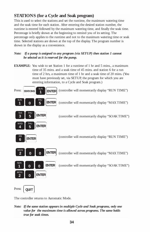
STATIONS (for a Cycle and Soak program)This is used to select the stations and set the runtime, the maximum watering timeand the soak time for each station. After entering the desired station number, theruntime is entered followed by the maximum watering time, and finally the soak time.Percentage is briefly shown at the beginning to remind you of its setting. Thepercentage only applies to the runtime and not to the maximum watering time or soaktime. Selected stations are shown at the top of the display. The program number isshown in the display as a convenience.
Note: If a pump is assigned to any program (via SETUP) then station 1 cannot be selected as it is reserved for the pump.
EXAMPLE: You wish to set Station 1 for a runtime of 1 hr and 5 mins., a maximum time of 35 mins. and a soak time of 45 mins. and station 6 for a runtime of 2 hrs, a maximum time of 1 hr and a soak time of 20 mins. (Youmust have previously set, via SETUP, the program for which you are entering information, to a Cycle and Soak program.)
Press: (controller will momentarily display “RUN TIME”)
(controller will momentarily display “MAX TIME”)
(controller will momentarily display “SOAK TIME”)
(controller will momentarily display “RUN TIME”)
(controller will momentarily display “MAX TIME”)
(controller will momentarily display “SOAK TIME”)
Press:
The controller returns to Automatic Mode.
Note: If the same station appears in multiple Cycle and Soak programs, only one value for the maximum time is allowed across programs. The same holds true for soak times.
34
STATIONSSUN
1 ENTER
SUN
1 0THU
5 ENTER
ENTERTHU
5TUE
3
ENTERTHU
5WED
4
ENTERFRI
6
MON
2 0 ENTER0
SUN
1 0 ENTER0MON
2 0 ENTER
QUIT

EXAMPLE: To clear a station and its runtime, such as Station 7,
Press:
Press:
The controller returns to the Automatic Mode.
EXAMPLE: To review selected Stations information,
Press: (An LED light will light up for every station that has a valid runtime.)
Press: The controller returns to the Automatic Mode.
EXAMPLE: To review the runtime, maximum time and soak time of a station suchas Station 6,
Press: (the runtime is displayed)
Press:to leave the runtime as is and continue reviewing,
Press: to leave the maximum time as is and continue reviewing,
Press: to leave the soak time as is and continue reviewing,
Press:
The controller returns to the Automatic Mode.
QUICK STATIONS (for a Cycle and Soak program)This is used to rapidly program a block of stations which all have the same runtime,maximum watering time and soak time. First the lowest station number is entered andthen the highest and then the runtime and then the maximum watering time and thenthe soak time. Percentage is briefly shown at the beginning to remind you of itssetting. The percentage only applies to the runtime and not to the maximum wateringtime or soak time. Selected stations are shown at the top of the display. The programnumber is shown in the display as a convenience.
Note: If a pump is assigned to any program (via SETUP) then Station 1 cannot be selected as part of the block of stations as it is reserved for the pump.
STATIONSSAT
7 CLEAR
QUIT
STATIONS
QUIT
STATIONSFRI
1 ENTER
ENTER
ENTER
ENTER
QUIT
35
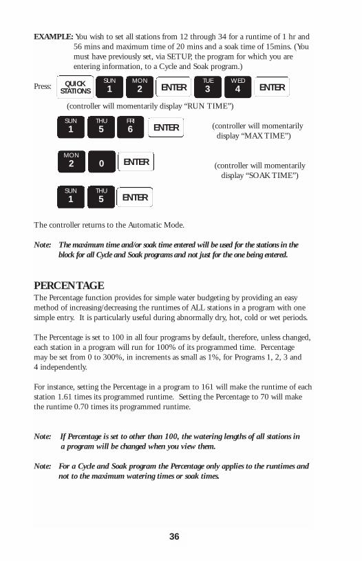
EXAMPLE: You wish to set all stations from 12 through 34 for a runtime of 1 hr and 56 mins and maximum time of 20 mins and a soak time of 15mins. (You must have previously set, via SETUP, the program for which you are entering information, to a Cycle and Soak program.)
Press:
(controller will momentarily display “RUN TIME”)
(controller will momentarily display “MAX TIME”)
(controller will momentarily display “SOAK TIME”)
The controller returns to the Automatic Mode.
Note: The maximum time and/or soak time entered will be used for the stations in the block for all Cycle and Soak programs and not just for the one being entered.
PERCENTAGEThe Percentage function provides for simple water budgeting by providing an easymethod of increasing/decreasing the runtimes of ALL stations in a program with onesimple entry. It is particularly useful during abnormally dry, hot, cold or wet periods.
The Percentage is set to 100 in all four programs by default, therefore, unless changed,each station in a program will run for 100% of its programmed time. Percentage may be set from 0 to 300%, in increments as small as 1%, for Programs 1, 2, 3 and4 independently.
For instance, setting the Percentage in a program to 161 will make the runtime of eachstation 1.61 times its programmed runtime. Setting the Percentage to 70 will makethe runtime 0.70 times its programmed runtime.
Note: If Percentage is set to other than 100, the watering lengths of all stations in a program will be changed when you view them.
Note: For a Cycle and Soak program the Percentage only applies to the runtimes and not to the maximum watering times or soak times.
QUICKSTATIONS
SUN1
MON2 ENTER
TUE3
WED4 ENTER
SUN1 ENTER
THU5
FRI6
MON2 ENTER0
SUN1 ENTER
THU5
36
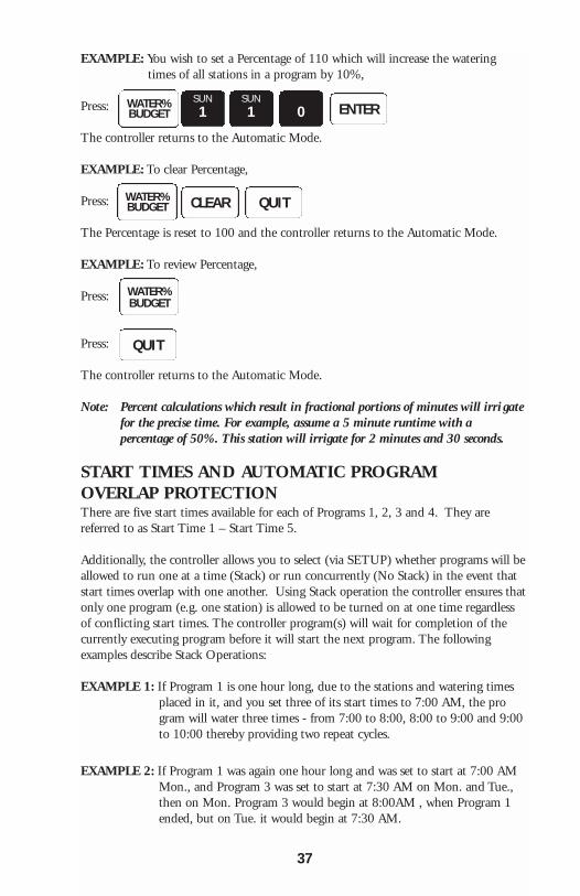
EXAMPLE: You wish to set a Percentage of 110 which will increase the watering times of all stations in a program by 10%,
Press:
The controller returns to the Automatic Mode.
EXAMPLE: To clear Percentage,
Press:
The Percentage is reset to 100 and the controller returns to the Automatic Mode.
EXAMPLE: To review Percentage,
Press:
Press:
The controller returns to the Automatic Mode.
Note: Percent calculations which result in fractional portions of minutes will irri gatefor the precise time. For example, assume a 5 minute runtime with a percentage of 50%. This station will irrigate for 2 minutes and 30 seconds.
START TIMES AND AUTOMATIC PROGRAM OVERLAP PROTECTIONThere are five start times available for each of Programs 1, 2, 3 and 4. They arereferred to as Start Time 1 – Start Time 5.
Additionally, the controller allows you to select (via SETUP) whether programs will beallowed to run one at a time (Stack) or run concurrently (No Stack) in the event thatstart times overlap with one another. Using Stack operation the controller ensures thatonly one program (e.g. one station) is allowed to be turned on at one time regardlessof conflicting start times. The controller program(s) will wait for completion of thecurrently executing program before it will start the next program. The followingexamples describe Stack Operations:
EXAMPLE 1: If Program 1 is one hour long, due to the stations and watering times placed in it, and you set three of its start times to 7:00 AM, the program will water three times - from 7:00 to 8:00, 8:00 to 9:00 and 9:00 to 10:00 thereby providing two repeat cycles.
EXAMPLE 2: If Program 1 was again one hour long and was set to start at 7:00 AM Mon., and Program 3 was set to start at 7:30 AM on Mon. and Tue., then on Mon. Program 3 would begin at 8:00AM , when Program 1 ended, but on Tue. it would begin at 7:30 AM.
WATER%BUDGET
SUN1 ENTER0
SUN1
WATER%BUDGET CLEAR QUIT
WATER%BUDGET
QUIT
37
The Stack operation ensures that you will always get the number of watering cyclesyou desire and at the same time your system will never be under-pressurized becausetwo programs are running simultaneously.
Note: The controller is shipped with Stack active, however, it may be programmedso that multiple programs can be run simultaneously. See Advanced
Setup Programming.
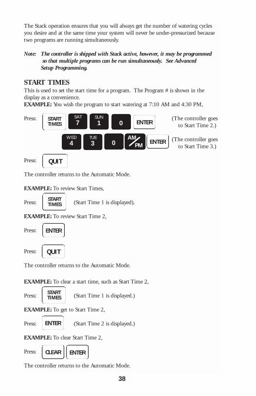
START TIMESThis is used to set the start time for a program. The Program # is shown in thedisplay as a convenience.EXAMPLE: You wish the program to start watering at 7:10 AM and 4:30 PM,
Press: (The controller goesto Start Time 2.)
(The controller goes to Start Time 3.)
Press:
The controller returns to the Automatic Mode.
EXAMPLE: To review Start Times,
Press: (Start Time 1 is displayed).
EXAMPLE: To review Start Time 2,
Press:
Press:
The controller returns to the Automatic Mode.
EXAMPLE: To clear a start time, such as Start Time 2,
Press: (Start Time 1 is displayed.)
EXAMPLE: To get to Start Time 2,
Press: (Start Time 2 is displayed.)
EXAMPLE: To clear Start Time 2,
Press:
The controller returns to the Automatic Mode.
STARTTIMES
SAT7
SUN1 0 ENTER
AMPM
WED4 ENTER
TUE3 0
QUIT
STARTTIMES
ENTER
ENTER
QUIT
STARTTIMES
ENTERCLEAR
38
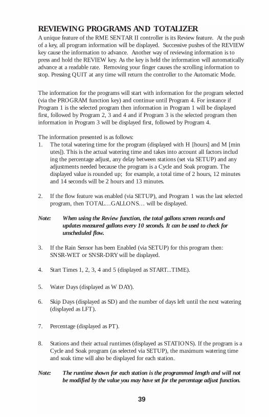
REVIEWING PROGRAMS AND TOTALIZERA unique feature of the RME SENTAR II controller is its Review feature. At the pushof a key, all program information will be displayed. Successive pushes of the REVIEWkey cause the information to advance. Another way of reviewing information is topress and hold the REVIEW key. As the key is held the information will automaticallyadvance at a readable rate. Removing your finger causes the scrolling information tostop. Pressing QUIT at any time will return the controller to the Automatic Mode.
The information for the programs will start with information for the program selected(via the PROGRAM function key) and continue until Program 4. For instance ifProgram 1 is the selected program then information in Program 1 will be displayedfirst, followed by Program 2, 3 and 4 and if Program 3 is the selected program theninformation in Program 3 will be displayed first, followed by Program 4.
The information presented is as follows:1. The total watering time for the program (displayed with H [hours] and M [min
utes]). This is the actual watering time and takes into account all factors including the percentage adjust, any delay between stations (set via SETUP) and any adjustments needed because the program is a Cycle and Soak program. Thedisplayed value is rounded up; for example, a total time of 2 hours, 12 minutes and 14 seconds will be 2 hours and 13 minutes.
2. If the flow feature was enabled (via SETUP), and Program 1 was the last selected program, then TOTAL…GALLONS… will be displayed.
Note: When using the Review function, the total gallons screen records and updates measured gallons every 10 seconds. It can be used to check for unscheduled flow.
3. If the Rain Sensor has been Enabled (via SETUP) for this program then:SNSR-WET or SNSR-DRY will be displayed.
4. Start Times 1, 2, 3, 4 and 5 (displayed as START...TIME).
5. Water Days (displayed as W DAY).
6. Skip Days (displayed as SD) and the number of days left until the next watering (displayed as LFT).
7. Percentage (displayed as PT).
8. Stations and their actual runtimes (displayed as STATIONS). If the program is a Cycle and Soak program (as selected via SETUP), the maximum watering time and soak time will also be displayed for each station.
Note: The runtime shown for each station is the programmed length and will not be modified by the value you may have set for the percentage adjust function.
39

EXAMPLE: You wish to review program 3 only,
Press:
Press: Continue to press:
Press:
The controller returns to the Automatic mode.
PROGRAM
REVIEW
TUE3 ENTER
QUIT
40

MANUALLY ACTIVATED FUNCTIONS WITH EXAMPLESThe Manual Mode offers four different features as described below:
MANUAL PROGRAMThis is used to run a program - assuming stations are in the program.
EXAMPLE: You wish to run Program 1,
Press:
The controller returns to the Automatic Mode.
EXAMPLE: To advance to the next station when the program is already watering,
Press:
EXAMPLE: To stop the watering program that is currently running,
Press:
The controller returns to the Automatic Mode.
MANUAL STATIONThis is used to run a selected station for a specified time.
EXAMPLE: You wish to run station 6 for 25 min,
Press:
(The display shows station and watering time. As time elapses, watering time willcount down. When time ends, the station shuts off and the controller returns to theAutomatic Mode.)
EXAMPLE: To stop the watering station,
Press:
The controller returns to the Automatic Mode.
Note: If a pump is assigned to any program (via SETUP) then Station 1 is reserved for the pump, but it can still be turned on manually by specifying Station 1.
Note: If the Master Valve type is Normally Closed (as specified via SETUP) then the Master Valve will come on with the station. If the station being turned on is in
MANUAL PROGRAM SUN1 ENTER
MANUAL
QUITCLEAR
MANUAL STATIONSMON2 ENTER
THU5 ENTER
MON2
QUIT
(The display shows a 1 to indicateProgram 1 is running. The activestations are displayed as well as theelapsed station runtime.)
MANUAL
FUNCTIONS
41
any program that has a pump assigned to it (via SETUP) then the pump (Station 1 output) will come on with the station.
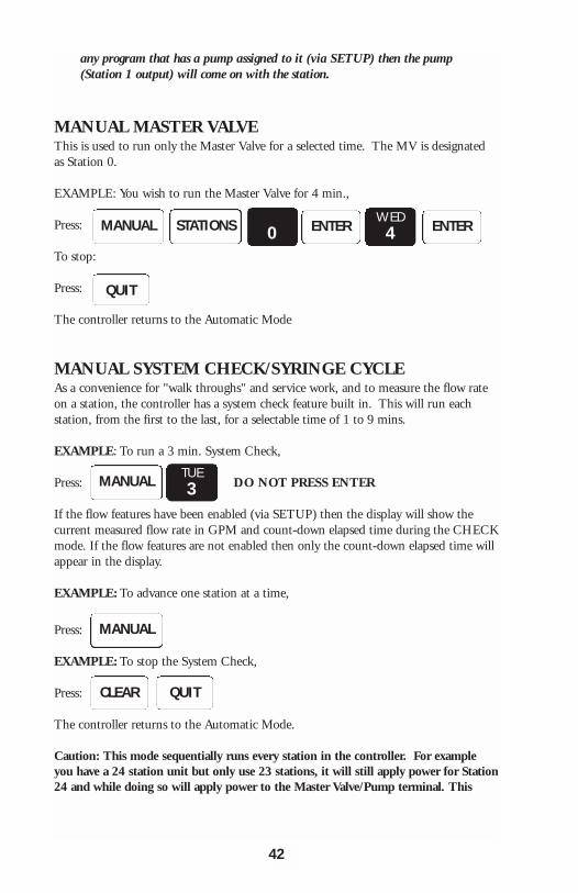
MANUAL MASTER VALVEThis is used to run only the Master Valve for a selected time. The MV is designatedas Station 0.
EXAMPLE: You wish to run the Master Valve for 4 min.,
Press:
To stop:
Press:
The controller returns to the Automatic Mode
MANUAL SYSTEM CHECK/SYRINGE CYCLEAs a convenience for "walk throughs" and service work, and to measure the flow rateon a station, the controller has a system check feature built in. This will run eachstation, from the first to the last, for a selectable time of 1 to 9 mins.
EXAMPLE: To run a 3 min. System Check,
Press: DO NOT PRESS ENTER
If the flow features have been enabled (via SETUP) then the display will show thecurrent measured flow rate in GPM and count-down elapsed time during the CHECKmode. If the flow features are not enabled then only the count-down elapsed time willappear in the display.
EXAMPLE: To advance one station at a time,
Press:
EXAMPLE: To stop the System Check,
Press:
The controller returns to the Automatic Mode.
Caution: This mode sequentially runs every station in the controller. For exampleyou have a 24 station unit but only use 23 stations, it will still apply power for Station24 and while doing so will apply power to the Master Valve/Pump terminal. This
MANUAL STATIONS 0WED4ENTER ENTER
QUIT
MANUAL TUE3
MANUAL
QUITCLEAR
42
could be a problem for a system when you are using the Master Valve output todrive a pump because during the period that Station 24 is activated, the pumpwill be pumping against a closed system. If the system uses a master valve, it willbe activated during the period that Station 24 is active and this could causeheating of the Master Valve's solenoid (if the valve depends on water flow to coolit). Therefore, if all stations are not used, cancel the System Check/Syringe cycleafter the last used station has watered.
MONITORING STATION FLOWThere are three ways to observe the measured flow in gallons per minute (GPM):
1. The measured flow is automatically displayed when the controller is in the automatic mode and one or more programs are operating.
2. When a manual system check is performed, the flow is shown for each station. (Refer to MANUAL SYSTEM CHECK for details.)
3. When in the SETUP function, measured flow can be observed on a per station basis when utilizing the LIMITS subfunction. (Refer to the LIMITS SETUP feature in the ADVANCED SETUP PROGRAMMING section for more details.)
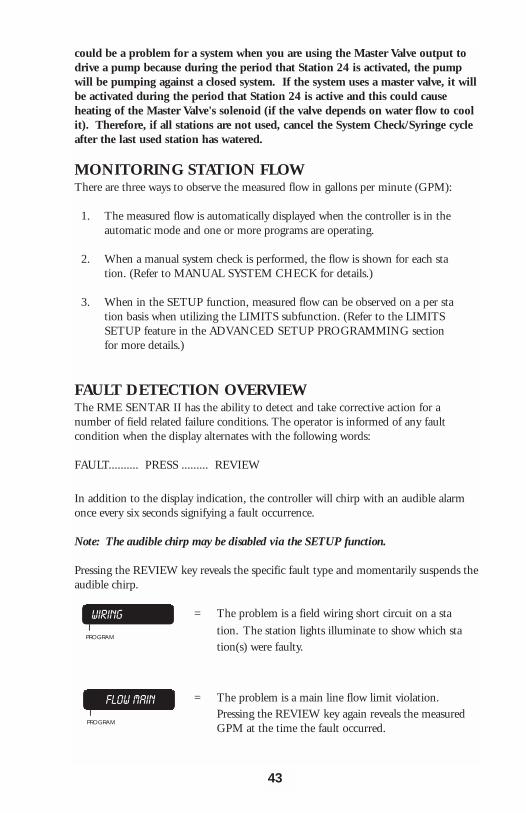
FAULT DETECTION OVERVIEWThe RME SENTAR II has the ability to detect and take corrective action for anumber of field related failure conditions. The operator is informed of any faultcondition when the display alternates with the following words:
FAULT.......... PRESS ......... REVIEW
In addition to the display indication, the controller will chirp with an audible alarmonce every six seconds signifying a fault occurrence.
Note: The audible chirp may be disabled via the SETUP function.
Pressing the REVIEW key reveals the specific fault type and momentarily suspends theaudible chirp.
= The problem is a field wiring short circuit on a sta
tion. The station lights illuminate to show which station(s) were faulty.
= The problem is a main line flow limit violation. Pressing the REVIEW key again reveals the measured GPM at the time the fault occurred.
FLOW MAINI
PROGRAM
WIRINGI
PROGRAM
43
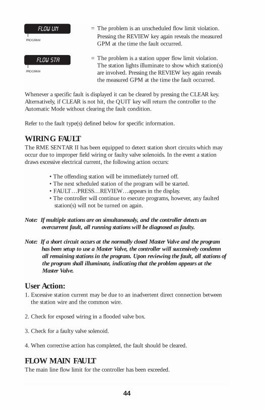
= The problem is an unscheduled flow limit violation. Pressing the REVIEW key again reveals the measured GPM at the time the fault occurred.
= The problem is a station upper flow limit violation. The station lights illuminate to show which station(s) are involved. Pressing the REVIEW key again reveals the measured GPM at the time the fault occurred.
Whenever a specific fault is displayed it can be cleared by pressing the CLEAR key.Alternatively, if CLEAR is not hit, the QUIT key will return the controller to theAutomatic Mode without clearing the fault condition.
Refer to the fault type(s) defined below for specific information.
WIRING FAULTThe RME SENTAR II has been equipped to detect station short circuits which mayoccur due to improper field wiring or faulty valve solenoids. In the event a stationdraws excessive electrical current, the following action occurs:
• The offending station will be immediately turned off.• The next scheduled station of the program will be started.• FAULT…PRESS…REVIEW…appears in the display.• The controller will continue to execute programs, however, any faulted
station(s) will not be turned on again.
Note: If multiple stations are on simultaneously, and the controller detects anovercurrent fault, all running stations will be diagnosed as faulty.
Note: If a short circuit occurs at the normally closed Master Valve and the programhas been setup to use a Master Valve, the controller will successively condemn all remaining stations in the program. Upon reviewing the fault, all stations of the program shall illuminate, indicating that the problem appears at the Master Valve.
User Action:1. Excessive station current may be due to an inadvertent direct connection between
the station wire and the common wire.
2. Check for exposed wiring in a flooded valve box.
3. Check for a faulty valve solenoid.
4. When corrective action has completed, the fault should be cleared.
FLOW MAIN FAULTThe main line flow limit for the controller has been exceeded.
FLOW UNI
PROGRAM
FLOW STAI
PROGRAM
44
• All present irrigation programs are terminated.• FAULT…PRESS…REVIEW…appears in the display.• If the Master Valve for the controller has been setup as a Normally Open
(NO) Master Valve, then this terminal will be energized with 24 VAC (Master Valve is closed).
• All scheduled start times for future programs will be ignored (no programs will start).
• The controller remains in this state until the fault is cleared by you.
User Action:1. Inspect the main line as well as major branches for failure.
2. Examine the main line limits to ensure they have been correctly established. If the controller has been setup for No Stack operation, multiple stations may be on at the same time. The main line limit should be larger than the sum of the flow totals of all simultaneously "ON" stations.
3. When corrective action has completed, the fault should be cleared.
FLOW UNSCHEDULED FAULTThe unscheduled flow limit has been exceeded. The controller tests for unscheduledflow whenever the controller is not performing any irrigation. With no irrigation, anda Normally Closed Master Valve, the typical installation should have no flow and thelimit should be set to zero. For systems which have a Normally Open Master Valveand the possibility of supplemental watering due to quick coupler manual devices, youhave the option of setting a non-zero value which shall be allowed when the controllerdoes not have any active stations. If this value is exceeded the unscheduled flowfault occurs.
• All present irrigation (running programs) are terminated.• FAULT…PRESS…REVIEW…appears in the display.• If the Master Valve for the controller has been setup as a Normally Open
(NO) Master Valve, then this terminal shall be energized with 24 VAC (Master Valve is closed).
• All scheduled start times for future programs will be ignored (no programs will start).
• The controller remains in this state until the fault is cleared by you.
User Action:1. The user should check for leaks, broken pipe(s), or physical damage.
2. Check the system for any stuck valves from a previous scheduled irrigation cycle.
3. Check that the unscheduled limit has been properly established. If quick cou
pling devices were on at the time the alarm occurred, ensure that there is enough margins for the unscheduled flow limit.
4. When corrective action has completed, the fault should be cleared.
45
FLOW STATION FAULTThis fault occurs whenever the measured flow is more than the expected flow (upperstation limit failure). Each time a station overflow condition is detected the followingaction occurs:
• The offending station will be immediately turned off.• The next scheduled station of the program will be started.• FAULT…PRESS…REVIEW…appears in the display.• The controller will continue to execute programs, however, any faulted
station(s) will not be turned on again.
Note: If multiple stations are on simultaneously, and the controller detects an overflow fault, all running stations will be diagnosed as faulty.
User Action:1. Check for:
a. Stuck valve (from a previous station)b. Broken pipes/headsc. Incorrectly established individual station limitsd. Large variations in system water pressure
2. If station limits are suspected, proceed to the SETUP-LIMITS function toreestablish a stations nominal limit reading.
3. Compare the nominal reading and ensure that adequate margin exists (typical: 20%over nominal).
4. When corrective action has completed, the fault should be cleared by you.
46

ADVANCED SETUP PROGRAMMING
In addition to the many operating features available in your RME SENTAR IIcontroller, there are a number of programmable features as well.
Pressing the SETUP key, you can program, review and modify the followingfunctions. Successive presses of the SETUP key will allow you to advance to the nextSetup feature. Some of the Setup functions will be skipped depending on what youhave configured for previous Setup functions. The conditions for which a Setupfunction will be skipped are noted in the applicable paragraphs for those conditions.
IMPORTANT: When entering setup information the display will change but the controller will not actually accept the information until ENTER or CLEAR (for those setup functions that accept CLEAR) is pressed.
Setup Options and Controller Defaults
FunctionMaster Valve Used
Type of Master Valve
Pump
Cycle and Soak
Flow Sensor Features
Pipe Size (inches)
Main Line Flow Limit
Unscheduled Flow Limit
Flow Check Delay
Total Gallons
Flow Percentage
Station Upper Flow Limits
OptionUses, Does Not Use
NC, NO
Uses, Does Not Use
Uses, Does Not Use
On, Off
1, 1.25, 1.5, 2, 3, 4
1-999 GPM
0-999 GPM
1-6 minutes
N/A
5-80%
0-500 GPM
Default1,2,3,4 (all programs enabled)
NC
(all programs disabled)
(all programs disabled)
Off
1.5 inches
500 GPM
200 GPM
2 minutes
N/A
20%
200 GPM for all stations
47
ADVANCEDSETUP

MASTER VALVE (MV)Using this feature allows you to program a Master Valve to be activated when program1,2,3 or 4 is activated. If you have your Pump connected to the Master Valve outputof the controller then use this feature to activate the pump when program 1,2,3 or 4is activated.
EXAMPLE: You want a pump to go on when Programs 1 and 3 are running.
Press: you will see
Press: This removes Programs 2 and 4 from activating the Master Valve.
you will see
Press:
Subsequent pressing of 2 and 4 will add the Master Valve to Programs 2 and 4.
Note: The Master Valve will not be activated with the program if it is a Normally Open Master Valve type as selected in the next Setup option.
TYPE OF MASTER VALVEThis feature allows you to select either a Normally Closed or Normally Open MasterValve. A Normally Closed Master Valve is the most common type used in irrigation. Ifa Normally Open Master Valve is selected then it will not come on with any programbut will come on when the controller detects a main line or unscheduled overflowcondition.
Note: This Setup function will be skipped if you have not selected a Master Valve for at least one program (in the MASTER VALVE Setup function). In this case thecontroller will act as if you had selected a Normally Closed Master Valve: therefore if you are using a Normally Open Master Valve select the Master Valve for at least one program. Refer to wiring diagrams and explanations in the MOUNTING & INSTALLATION section before configuring this option
.EXAMPLE: To select a Normally Open Master Valve,
Successively Press: until you see
Press: until you see
Press:
The controller returns to the Automatic Mode.
SETUP
MON2
WED4
ENTER
M V 1 2 3 4 I
PROGRAM
M V 1 3 I
PROGRAM
TYPE - NCI
PROGRAM
TYPE - N OI
PROGRAM
SETUP
SUN1
ENTER QUIT
48

PUMPUsing this feature will allow you to program a Pump to be activated when program1,2,3, or 4 is activated. The controller uses Station 1 as the Pump output. This featureshould only be used for the Pump, if it is connected to the Station 1 output of thecontroller. If the Pump is connected to the Master Valve output, then use the MV feature.
Note: Refer to wiring diagrams and explanations in the MASTER VALVE and PUMP WIRING OPTIONS before configuring this option.
A typical example for usage of this feature occurs when using a Normally Open MasterValve and Pump.
Note: If you select a Pump for any program, the controller will not allow you to include a Station 1 runtime in any program. If you have already programmed Station 1 into a program the controller will automatically remove it.
EXAMPLE: You want the Pump to go on when Programs 2 and 4 are running,
Successively Press: until you see
Press: This allows Programs 2 and 4 to activate the Pump.
you will see
Press:Subsequent pressing 2 and 4 will remove the Pump from Programs 2and 4.
STACK or NO STACKThis feature allows you to run your programs one after another (Stack) or at the sametime (No Stack). Where volume of water and pressure will allow, you have the optionof running several stations from different programs at the same time.
Note: The maximum current draw cannot exceed 1 amp per station, and 1.5 amps for the controller.
EXAMPLE: You have a 30 station controller, and watering must be completed by 7:00 AM and cannot begin until 2:00 AM (5 hours total).You can put: Station 1 through 7 in Program #1
Station 8 through 14 in Program #2 Station 15 through 21 in Program #3
Station 22 through 30 in Program #4
SETUP
MON2
WED4
ENTER
PUMPI
PROGRAM
PUMP 2 4 I
PROGRAM
49
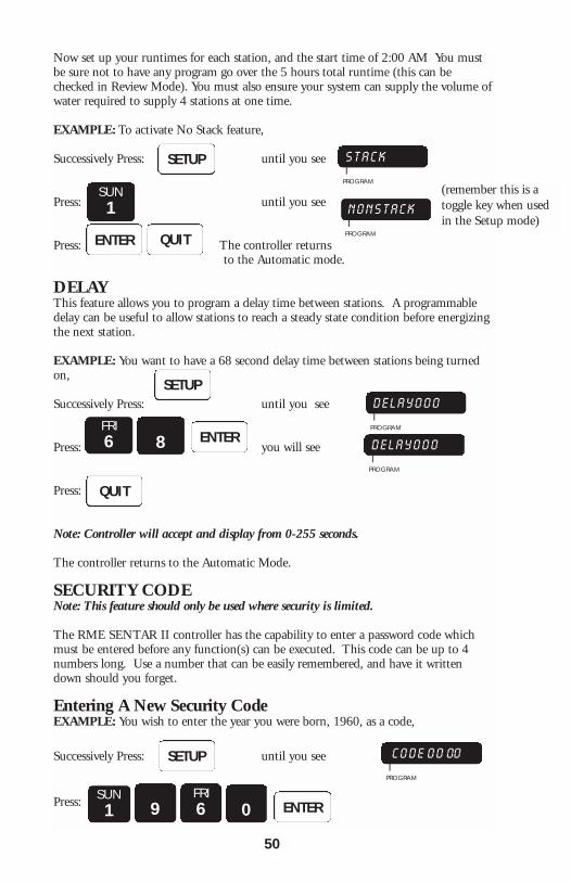
Now set up your runtimes for each station, and the start time of 2:00 AM You mustbe sure not to have any program go over the 5 hours total runtime (this can bechecked in Review Mode). You must also ensure your system can supply the volume ofwater required to supply 4 stations at one time.
EXAMPLE: To activate No Stack feature,
Successively Press: until you see
Press: until you see
Press: The controller returns to the Automatic mode.
DELAYThis feature allows you to program a delay time between stations. A programmabledelay can be useful to allow stations to reach a steady state condition before energizingthe next station.
EXAMPLE: You want to have a 68 second delay time between stations being turnedon,
Successively Press: until you see
Press: you will see
Press:
Note: Controller will accept and display from 0-255 seconds.
The controller returns to the Automatic Mode.
SECURITY CODENote: This feature should only be used where security is limited.
The RME SENTAR II controller has the capability to enter a password code whichmust be entered before any function(s) can be executed. This code can be up to 4numbers long. Use a number that can be easily remembered, and have it writtendown should you forget.
Entering A New Security CodeEXAMPLE: You wish to enter the year you were born, 1960, as a code,
Successively Press: until you see
Press:
50
SETUP S T A C KI
PROGRAM
N O N S T A C KI
PROGRAMQUITENTER
SETUP
SETUP
D E L A Y 0 0 0 I
PROGRAM
C O D E 0 0 00 I
PROGRAM
SUN1 9
SUN1
FRI6 0 ENTER
QUIT
FRI6 8 D E L A Y 0 0 0
IPROGRAM
(remember this is atoggle key when usedin the Setup mode)
ENTER
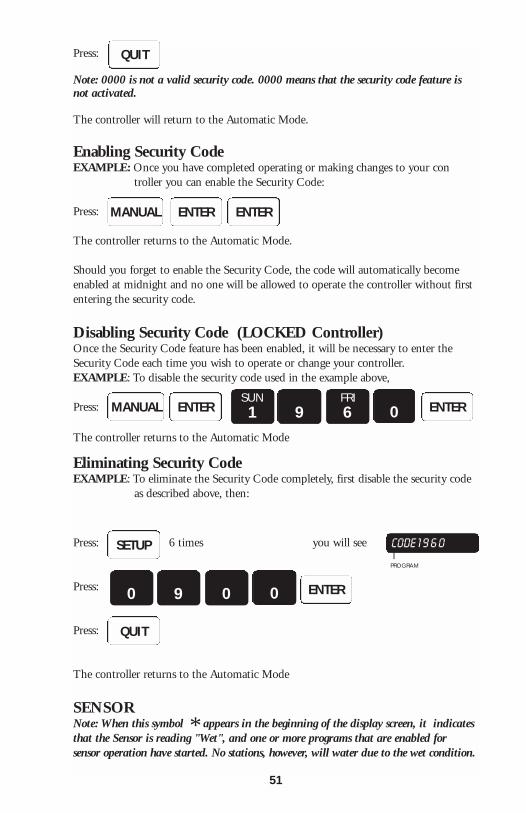
Press:
Note: 0000 is not a valid security code. 0000 means that the security code feature isnot activated.
The controller will return to the Automatic Mode.
Enabling Security CodeEXAMPLE: Once you have completed operating or making changes to your con
troller you can enable the Security Code:
Press:
The controller returns to the Automatic Mode.
Should you forget to enable the Security Code, the code will automatically becomeenabled at midnight and no one will be allowed to operate the controller without firstentering the security code.
Disabling Security Code (LOCKED Controller)Once the Security Code feature has been enabled, it will be necessary to enter theSecurity Code each time you wish to operate or change your controller.EXAMPLE: To disable the security code used in the example above,
Press:
The controller returns to the Automatic Mode
Eliminating Security CodeEXAMPLE: To eliminate the Security Code completely, first disable the security code
as described above, then:
Press: 6 times you will see
Press:
Press:
The controller returns to the Automatic Mode
SENSORNote: When this symbol appears in the beginning of the display screen, it indicatesthat the Sensor is reading "Wet", and one or more programs that are enabled forsensor operation have started. No stations, however, will water due to the wet condition.
QUIT
MANUAL ENTER ENTER
MANUAL ENTER ENTERSUN1 9
FRI6 0
ENTER0 9 0 0
SETUP
QUIT
CODE 1 9 6 0 I
PROGRAM
51
*

The RME SENTAR II Controller has the ability to affect irrigation based on anexternal rain sensor or remote switch. This feature can be programmed on anindividual program basis so that one or more programs will cease watering as long asthe rain sensor is active.
The external sensor or switch must be of the type which is Closed when there is norain detected, and opens when rain is detected or it is desired to suspend irrigation.Most commercial rain sensors are of this type. See the wiring instructions in theMOUNTING and INSTALLATION section.
EXAMPLE: You have program 4 set up to operate your outdoor lighting, however youalso have a rain sensor connected to your RME SENTAR II.
Successively Press: until you see
Press: you will see
Press: The controller will return to automatic mode.
Once programmed in the above manner, the designated program(s) will not turn onany stations unless the rain sensor terminals labeled pins 1 & 2 are shorted together,either by an external switch or the appropriate rain sensor.
If any program is set up to be sensitive to the rain sensor then the status of the rainsensor can be determined by pressing the REVIEW key repeatedly or holding it downuntil the display shows the word SNSR- followed by WET or DRY. If Dry, thecontrolled program(s) will operate normally. If Wet, no irrigation will take place onthose program(s). Additionally, when a program is scheduled to operate, an asteriskwill appear in the leftmost location of the display. If the external sensor has detectedrain, or the external switch is Open.
Note: The external sensor is independent of the Rain Switch on the front of the con-troller. Leave the switch in the Automatic Watering position.
EXAMPLE: To reinstate program 4 into the Sensor Mode,
Successively Press: until you see
Press: you will see
Press:
The controller returns to the Automatic Mode.
SETUP
QUIT
SUN1
MON2
TUE3 ENTER
SNCRI
PROGRAM
SNCR 123I
PROGRAM
SETUP
WED4 ENTER
QUIT
SNCR 123I
PROGRAM
SNCR 1234I
PROGRAM
52
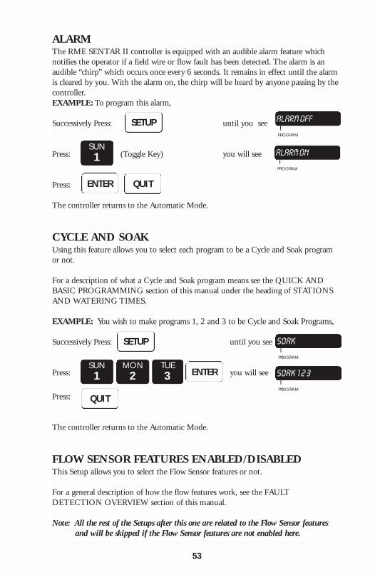
ALARMThe RME SENTAR II controller is equipped with an audible alarm feature whichnotifies the operator if a field wire or flow fault has been detected. The alarm is anaudible “chirp” which occurs once every 6 seconds. It remains in effect until the alarmis cleared by you. With the alarm on, the chirp will be heard by anyone passing by thecontroller.EXAMPLE: To program this alarm,
Successively Press: until you see
Press: (Toggle Key) you will see
Press:
The controller returns to the Automatic Mode.
CYCLE AND SOAKUsing this feature allows you to select each program to be a Cycle and Soak programor not.
For a description of what a Cycle and Soak program means see the QUICK ANDBASIC PROGRAMMING section of this manual under the heading of STATIONSAND WATERING TIMES.
EXAMPLE: You wish to make programs 1, 2 and 3 to be Cycle and Soak Programs,
Successively Press: until you see
Press: you will see
Press:
The controller returns to the Automatic Mode.
FLOW SENSOR FEATURES ENABLED/DISABLEDThis Setup allows you to select the Flow Sensor features or not.
For a general description of how the flow features work, see the FAULTDETECTION OVERVIEW section of this manual.
Note: All the rest of the Setups after this one are related to the Flow Sensor features and will be skipped if the Flow Sensor features are not enabled here.
SETUP
QUITENTER
SETUP
QUIT
ENTERSUN1
MON2
TUE3
ALARM OFFI
PROGRAM
ALARM ONI
PROGRAM
SOAKI
PROGRAM
SOAK 1 2 3I
PROGRAM
53
SUN1
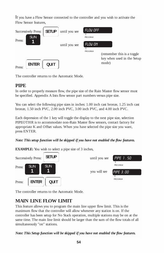
If you have a Flow Sensor connected to the controller and you wish to activate theFlow Sensor features,
Successively Press: until you see
Press:until you see
Press:
The controller returns to the Automatic Mode.
PIPEIn order to properly measure flow, the pipe size of the Rain Master flow sensor mustbe specified. Appendix A lists flow sensor part numbers versus pipe size.
You can select the following pipe sizes in inches: 1.00 inch cast bronze, 1.25 inch castbronze, 1.50 inch PVC, 2.00 inch PVC, 3.00 inch PVC, and 4.00 inch PVC.
Each depression of the 1 key will toggle the display to the next pipe size, selectionPIPEOTHR is to accommodate non-Rain Master flow sensors, contact factory forappropriate K and Offset values. When you have selected the pipe size you want, press ENTER.
Note: This setup function will be skipped if you have not enabled the flow features.
EXAMPLE: You wish to select a pipe size of 3 inches,
Successively Press: until you see
Press:you will see
Press:
The controller returns to the Automatic Mode.
MAIN LINE FLOW LIMITThis feature allows you to program the main line upper flow limit. This is themaximum flow that the controller will allow whenever any station is on. If thecontroller has been setup for No Stack operation, multiple stations may be on at thesame time. The main line limit should be larger than the sum of the flow totals of allsimultaneously "on" stations.
Note: This Setup function will be skipped if you have not enabled the flow features.
SETUPSUN1
ENTER QUIT
FLOW OFFI
PROGRAM
(remember this is a togglekey when used in the Setupmode)
FLOW ONI
PROGRAM
SETUP
SUN1
SUN1
PIPE 1 . 50I
PROGRAM
PIPE 3 . 00I
PROGRAM
ENTER QUIT
54
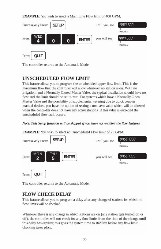
EXAMPLE: You wish to select a Main Line Flow limit of 400 GPM,
Successively Press: until you see
Press: you will see
Press:
The controller returns to the Automatic Mode.
UNSCHEDULED FLOW LIMITThis feature allows you to program the unscheduled upper flow limit. This is themaximum flow that the controller will allow whenever no station is on. With noirrigation, and a Normally Closed Master Valve, the typical installation should have noflow and the limit should be set to zero. For systems which have a Normally OpenMaster Valve and the possibility of supplemental watering due to quick couplermanual devices, you have the option of setting a non-zero value which will be allowedwhen the controller does not have any active stations. If this value is exceeded theunscheduled flow fault occurs.
Note: This Setup function will be skipped if you have not enabled the flow features.
EXAMPLE: You wish to select an Unscheduled Flow limit of 25 GPM,
Successively Press: until you see
Press: you will see
Press:
The controller returns to the Automatic Mode.
FLOW CHECK DELAYThis feature allows you to program a delay after any change of stations for which noflow limits will be checked.
Whenever there is any change in which stations are on (any station gets turned on oroff ), the controller will not check for any flow limits from the time of the change untilthis delay has expired; this gives the system time to stabilize before any flow limitchecking takes place.
SETUP
WED4 0 0 ENTER
QUIT
MAIN 500I
PROGRAM
MAIN 500I
PROGRAM
SETUP
MON2
THU5 ENTER
QUIT
UNSCH200I
PROGRAM
UNSCH025I
PROGRAM
55
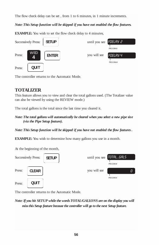
The flow check delay can be set , from 1 to 6 minutes, in 1 minute increments.
Note: This Setup function will be skipped if you have not enabled the flow features.
EXAMPLE: You wish to set the flow check delay to 4 minutes,
Successively Press: until you see
Press: you will see
Press:
The controller returns to the Automatic Mode.
TOTALIZERThis feature allows you to view and clear the total gallons used. (The Totalizer valuecan also be viewed by using the REVIEW mode.)
The total gallons is the total since the last time you cleared it.
Note: The total gallons will automatically be cleared when you select a new pipe size (via the Pipe Setup feature).
Note: This Setup function will be skipped if you have not enabled the flow features .
EXAMPLE: You wish to determine how many gallons you use in a month.
At the beginning of the month,
Successively Press: until you see
Press: you will see
Press:
The controller returns to the Automatic Mode.
Note: If you hit SETUP while the words TOTAL/GALLONS are on the display you will
miss this Setup feature because the controller will go to the next Setup feature.
SETUP FDELAY 2I
PROGRAM
FDELAY 4I
PROGRAM
WED4 ENTER
QUIT
SETUP
CLEAR
QUIT
TOTAL...GALSI
PROGRAM
0I
PROGRAM
56
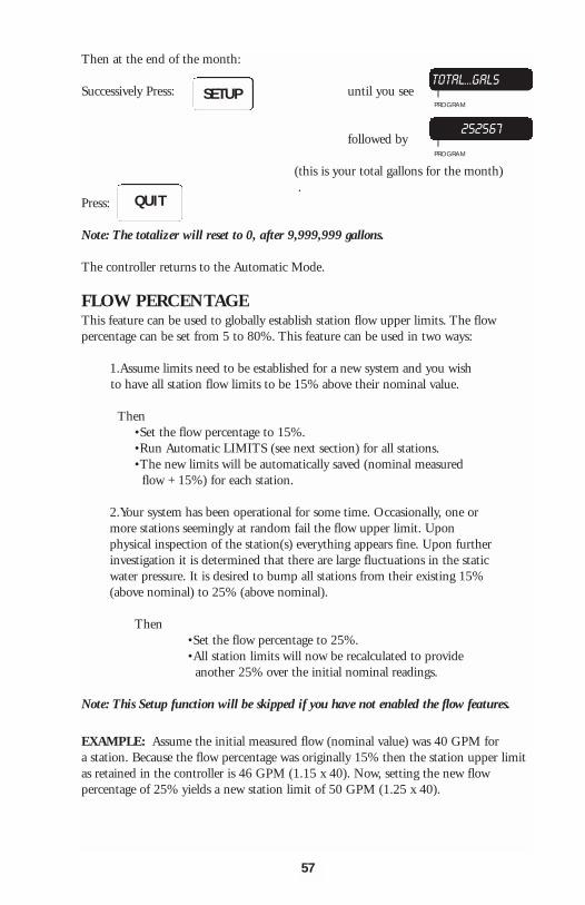
Then at the end of the month:
Successively Press: until you see
followed by
(this is your total gallons for the month).
Press:
Note: The totalizer will reset to 0, after 9,999,999 gallons.
The controller returns to the Automatic Mode.
FLOW PERCENTAGEThis feature can be used to globally establish station flow upper limits. The flowpercentage can be set from 5 to 80%. This feature can be used in two ways:
1.Assume limits need to be established for a new system and you wishto have all station flow limits to be 15% above their nominal value.
Then •Set the flow percentage to 15%.•Run Automatic LIMITS (see next section) for all stations.•The new limits will be automatically saved (nominal measured
flow + 15%) for each station.
2.Your system has been operational for some time. Occasionally, one or more stations seemingly at random fail the flow upper limit. Upon physical inspection of the station(s) everything appears fine. Upon further investigation it is determined that there are large fluctuations in the static water pressure. It is desired to bump all stations from their existing 15% (above nominal) to 25% (above nominal).
Then•Set the flow percentage to 25%.•All station limits will now be recalculated to provide
another 25% over the initial nominal readings.
Note: This Setup function will be skipped if you have not enabled the flow features.
EXAMPLE: Assume the initial measured flow (nominal value) was 40 GPM fora station. Because the flow percentage was originally 15% then the station upper limitas retained in the controller is 46 GPM (1.15 x 40). Now, setting the new flowpercentage of 25% yields a new station limit of 50 GPM (1.25 x 40).
SETUP
QUIT
TOTAL...GALSI
PROGRAM
252567I
PROGRAM
57
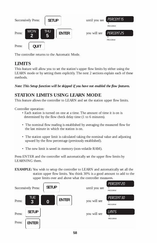
Successively Press: until you see
Press: you will see
Press:
The controller returns to the Automatic Mode.
LIMITSThis feature will allow you to set the station's upper flow limits by either using theLEARN mode or by setting them explicitly. The next 2 sections explain each of thesemethods.
Note: This Setup function will be skipped if you have not enabled the flow features.
STATION LIMITS USING LEARN MODEThis feature allows the controller to LEARN and set the station upper flow limits.
Controller operation:• Each station is turned on one at a time. The amount of time it is on is
determined by the flow check delay time (1 to 6 minutes).
• The nominal flow reading is established by averaging the measured flow for the last minute in which the station is on.
• The station upper limit is calculated taking the nominal value and adjusting upward by the flow percentage (previously established).
• The new limit is saved in memory (non-volatile RAM).
Press ENTER and the controller will automatically set the upper flow limits byLEARNING them.
EXAMPLE: You wish to setup the controller to LEARN and automatically set all the station upper flow limits. You think 30% is a good amount to add to the upper limits over and above what the controller measures.
Successively Press: until you see
Press: you will see
Press: you will see
Press:
SETUP PERCENT 15I
PROGRAM
PERCENT 25I
PROGRAM
MON2
THU5 ENTER
QUIT
SETUP
TUE3 0 ENTER
SETUP
ENTER
PERCENT 20I
PROGRAM
PERCENT 30I
PROGRAM
LIMITSI
PROGRAM
58
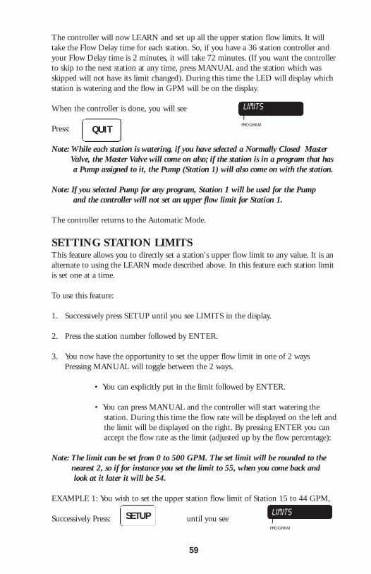
The controller will now LEARN and set up all the upper station flow limits. It willtake the Flow Delay time for each station. So, if you have a 36 station controller andyour Flow Delay time is 2 minutes, it will take 72 minutes. (If you want the controllerto skip to the next station at any time, press MANUAL and the station which wasskipped will not have its limit changed). During this time the LED will display whichstation is watering and the flow in GPM will be on the display.
When the controller is done, you will see
Press:
Note: While each station is watering, if you have selected a Normally Closed Master Valve, the Master Valve will come on also; if the station is in a program that has a Pump assigned to it, the Pump (Station 1) will also come on with the station.
Note: If you selected Pump for any program, Station 1 will be used for the Pump and the controller will not set an upper flow limit for Station 1.
The controller returns to the Automatic Mode.
SETTING STATION LIMITSThis feature allows you to directly set a station's upper flow limit to any value. It is analternate to using the LEARN mode described above. In this feature each station limitis set one at a time.
To use this feature:
1. Successively press SETUP until you see LIMITS in the display.
2. Press the station number followed by ENTER.
3. You now have the opportunity to set the upper flow limit in one of 2 ways Pressing MANUAL will toggle between the 2 ways.
• You can explicitly put in the limit followed by ENTER.
• You can press MANUAL and the controller will start watering thestation. During this time the flow rate will be displayed on the left andthe limit will be displayed on the right. By pressing ENTER you can accept the flow rate as the limit (adjusted up by the flow percentage):
Note: The limit can be set from 0 to 500 GPM. The set limit will be rounded to the nearest 2, so if for instance you set the limit to 55, when you come back and look at it later it will be 54.
EXAMPLE 1: You wish to set the upper station flow limit of Station 15 to 44 GPM,
Successively Press: until you see
LIMITS
IPROGRAM
QUIT
LIMITSI
PROGRAM
SETUP
59
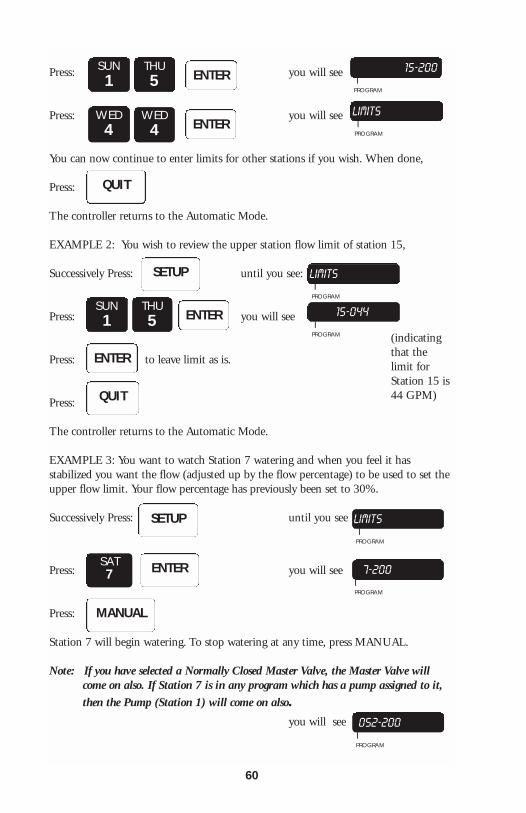
Press: you will see
Press: you will see
You can now continue to enter limits for other stations if you wish. When done,
Press:
The controller returns to the Automatic Mode.
EXAMPLE 2: You wish to review the upper station flow limit of station 15,
Successively Press: until you see:
Press: you will see
Press: to leave limit as is.
Press:
The controller returns to the Automatic Mode.
EXAMPLE 3: You want to watch Station 7 watering and when you feel it hasstabilized you want the flow (adjusted up by the flow percentage) to be used to set theupper flow limit. Your flow percentage has previously been set to 30%.
Successively Press: until you see
Press: you will see
Press:
Station 7 will begin watering. To stop watering at any time, press MANUAL.
Note: If you have selected a Normally Closed Master Valve, the Master Valve will come on also. If Station 7 is in any program which has a pump assigned to it,
then the Pump (Station 1) will come on also. you will see
SUN1
THU5
15-200I
PROGRAM
LIMITSI
PROGRAM
ENTER
WED4
WED4 ENTER
QUIT
SETUP LIMITSI
PROGRAM
15-044I
PROGRAM
SUN1
THU5 ENTER
ENTER
QUIT
SETUP LIMITSI
PROGRAM
7-200IPROGRAM
ENTERSAT7
MANUAL
052-200IPROGRAM
(indicatingthat thelimit forStation 15 is44 GPM)
60
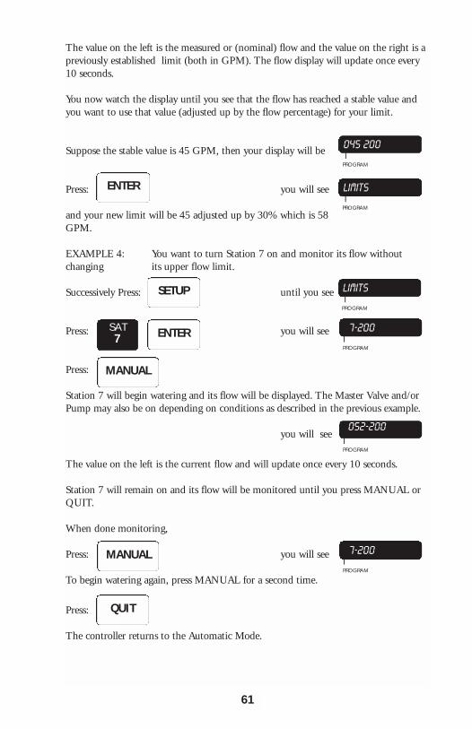
The value on the left is the measured or (nominal) flow and the value on the right is apreviously established limit (both in GPM). The flow display will update once every10 seconds.
You now watch the display until you see that the flow has reached a stable value andyou want to use that value (adjusted up by the flow percentage) for your limit.
Suppose the stable value is 45 GPM, then your display will be
Press: you will see
and your new limit will be 45 adjusted up by 30% which is 58GPM.
EXAMPLE 4: You want to turn Station 7 on and monitor its flow withoutchanging its upper flow limit.
Successively Press: until you see
Press: you will see
Press:
Station 7 will begin watering and its flow will be displayed. The Master Valve and/orPump may also be on depending on conditions as described in the previous example.
you will see
The value on the left is the current flow and will update once every 10 seconds.
Station 7 will remain on and its flow will be monitored until you press MANUAL orQUIT.
When done monitoring,
Press: you will see
To begin watering again, press MANUAL for a second time.
Press:
The controller returns to the Automatic Mode.
045 200I
PROGRAM
LIMITSI
PROGRAM
LIMITSI
PROGRAM
7-200IPROGRAM
ENTER
SETUP
ENTERSAT7
MANUAL
052-200
IPROGRAM
7-200IPROGRAM
QUIT
MANUAL
61

62
THIS PAGE INTENTIONALLY LEFT BLANK.
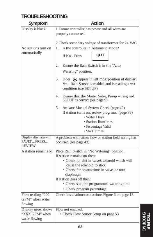
1. Is the controller in Automatic Mode?
If No - Press
2. Ensure the Rain Switch is in the “Auto
Watering” position.
3. Does appear in left most position of display? Yes - Rain Sensor is enabled and is reading a wet condition (see SETUP)
4. Ensure that the Master Valve, Pump wiring and SETUP is correct (see page 9).
5. Activate Manual System Check (page 42)If station turns on, review programs: (page 39)
• Water Days• Station Runtimes• Percentage Valid• Start Times
TROUBLESHOOTINGSymptom Action
Display is blank
No stations turn on automatically
Display alternateswithFAULT…PRESS…REVIEWA station remains on
Flow reading “000GPM” when waterflowingDisplay never shows“XXX GPM” whenwater flowing
1.Ensure controller has power and all wires areproperly connected.
2.Check secondary voltage of transformer for 24 VAC
*
QUIT
A problem with either flow or station field wiring hasoccurred (see page 43).
Place Rain Switch in “No Watering” position.If station remains on then:
• Check for dirt in valve’s solenoid which will cause the solenoid to stick
• Check for obstructions in valve, or torn diaphragm
If station goes off then:• Check station’s programmed watering time• Check program percentage
Check installation/connections Figure 6 on page 13.
Flow not enabled. • Check Flow Sensor Setup on page 53
63
TROUBLE
SHO
OTING
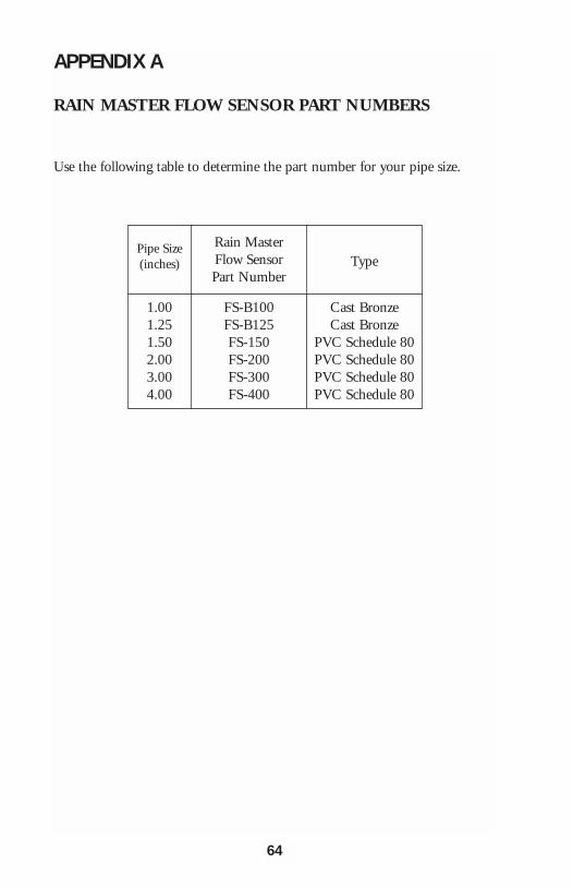
APPENDIX A
RAIN MASTER FLOW SENSOR PART NUMBERS
Use the following table to determine the part number for your pipe size.
64
Pipe Size(inches)
Rain MasterFlow SensorPart Number
1.001.251.502.003.004.00
FS-B100FS-B125FS-150FS-200FS-300FS-400
Type
Cast BronzeCast Bronze
PVC Schedule 80PVC Schedule 80PVC Schedule 80PVC Schedule 80
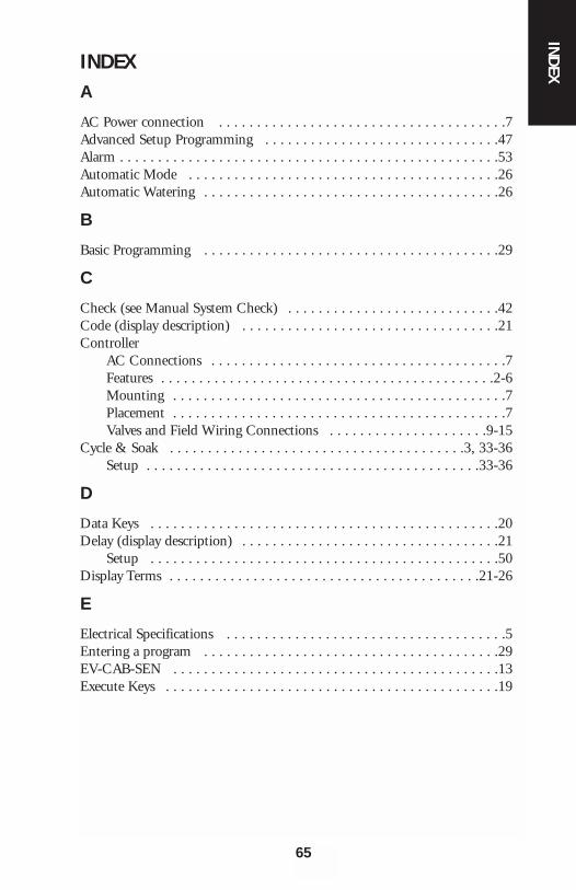
INDEXA
AC Power connection . . . . . . . . . . . . . . . . . . . . . . . . . . . . . . . . . . . . . .7Advanced Setup Programming . . . . . . . . . . . . . . . . . . . . . . . . . . . . . . .47Alarm . . . . . . . . . . . . . . . . . . . . . . . . . . . . . . . . . . . . . . . . . . . . . . . . . .53Automatic Mode . . . . . . . . . . . . . . . . . . . . . . . . . . . . . . . . . . . . . . . . .26Automatic Watering . . . . . . . . . . . . . . . . . . . . . . . . . . . . . . . . . . . . . . .26
B
Basic Programming . . . . . . . . . . . . . . . . . . . . . . . . . . . . . . . . . . . . . . .29
C
Check (see Manual System Check) . . . . . . . . . . . . . . . . . . . . . . . . . . . .42Code (display description) . . . . . . . . . . . . . . . . . . . . . . . . . . . . . . . . . .21Controller
AC Connections . . . . . . . . . . . . . . . . . . . . . . . . . . . . . . . . . . . . . . .7 Features . . . . . . . . . . . . . . . . . . . . . . . . . . . . . . . . . . . . . . . . . . . .2-6Mounting . . . . . . . . . . . . . . . . . . . . . . . . . . . . . . . . . . . . . . . . . . . .7Placement . . . . . . . . . . . . . . . . . . . . . . . . . . . . . . . . . . . . . . . . . . . .7Valves and Field Wiring Connections . . . . . . . . . . . . . . . . . . . . .9-15
Cycle & Soak . . . . . . . . . . . . . . . . . . . . . . . . . . . . . . . . . . . . . . .3, 33-36Setup . . . . . . . . . . . . . . . . . . . . . . . . . . . . . . . . . . . . . . . . . . . .33-36
D
Data Keys . . . . . . . . . . . . . . . . . . . . . . . . . . . . . . . . . . . . . . . . . . . . . .20Delay (display description) . . . . . . . . . . . . . . . . . . . . . . . . . . . . . . . . . .21
Setup . . . . . . . . . . . . . . . . . . . . . . . . . . . . . . . . . . . . . . . . . . . . . .50 Display Terms . . . . . . . . . . . . . . . . . . . . . . . . . . . . . . . . . . . . . . . . .21-26
E
Electrical Specifications . . . . . . . . . . . . . . . . . . . . . . . . . . . . . . . . . . . . .5 Entering a program . . . . . . . . . . . . . . . . . . . . . . . . . . . . . . . . . . . . . . .29 EV-CAB-SEN . . . . . . . . . . . . . . . . . . . . . . . . . . . . . . . . . . . . . . . . . . .13 Execute Keys . . . . . . . . . . . . . . . . . . . . . . . . . . . . . . . . . . . . . . . . . . . .19
65
INDEX
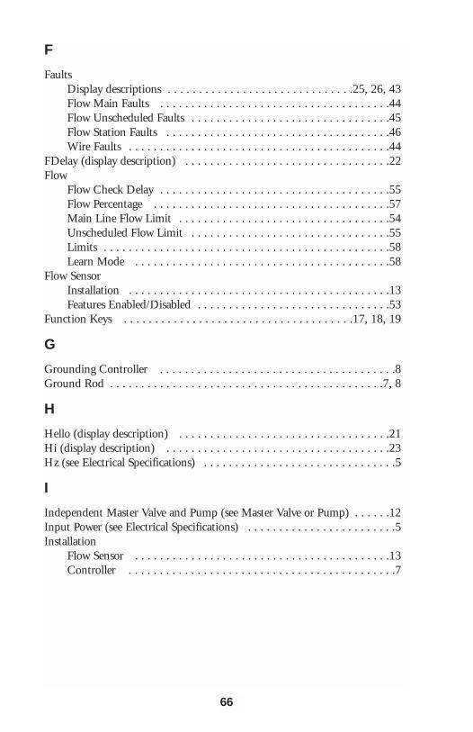
F
FaultsDisplay descriptions . . . . . . . . . . . . . . . . . . . . . . . . . . . . . .25, 26, 43Flow Main Faults . . . . . . . . . . . . . . . . . . . . . . . . . . . . . . . . . . . . .44Flow Unscheduled Faults . . . . . . . . . . . . . . . . . . . . . . . . . . . . . . . .45Flow Station Faults . . . . . . . . . . . . . . . . . . . . . . . . . . . . . . . . . . . .46Wire Faults . . . . . . . . . . . . . . . . . . . . . . . . . . . . . . . . . . . . . . . . . .44
FDelay (display description) . . . . . . . . . . . . . . . . . . . . . . . . . . . . . . . . .22Flow
Flow Check Delay . . . . . . . . . . . . . . . . . . . . . . . . . . . . . . . . . . . . .55Flow Percentage . . . . . . . . . . . . . . . . . . . . . . . . . . . . . . . . . . . . . .57Main Line Flow Limit . . . . . . . . . . . . . . . . . . . . . . . . . . . . . . . . . .54Unscheduled Flow Limit . . . . . . . . . . . . . . . . . . . . . . . . . . . . . . . .55Limits . . . . . . . . . . . . . . . . . . . . . . . . . . . . . . . . . . . . . . . . . . . . . .58Learn Mode . . . . . . . . . . . . . . . . . . . . . . . . . . . . . . . . . . . . . . . . .58
Flow SensorInstallation . . . . . . . . . . . . . . . . . . . . . . . . . . . . . . . . . . . . . . . . . .13Features Enabled/Disabled . . . . . . . . . . . . . . . . . . . . . . . . . . . . . . .53
Function Keys . . . . . . . . . . . . . . . . . . . . . . . . . . . . . . . . . . . . .17, 18, 19
G
Grounding Controller . . . . . . . . . . . . . . . . . . . . . . . . . . . . . . . . . . . . . .8Ground Rod . . . . . . . . . . . . . . . . . . . . . . . . . . . . . . . . . . . . . . . . . . . .7, 8
H
Hello (display description) . . . . . . . . . . . . . . . . . . . . . . . . . . . . . . . . . .21Hi (display description) . . . . . . . . . . . . . . . . . . . . . . . . . . . . . . . . . . . .23Hz (see Electrical Specifications) . . . . . . . . . . . . . . . . . . . . . . . . . . . . . . .5
I
Independent Master Valve and Pump (see Master Valve or Pump) . . . . . .12Input Power (see Electrical Specifications) . . . . . . . . . . . . . . . . . . . . . . . .5Installation
Flow Sensor . . . . . . . . . . . . . . . . . . . . . . . . . . . . . . . . . . . . . . . . .13Controller . . . . . . . . . . . . . . . . . . . . . . . . . . . . . . . . . . . . . . . . . . .7
66
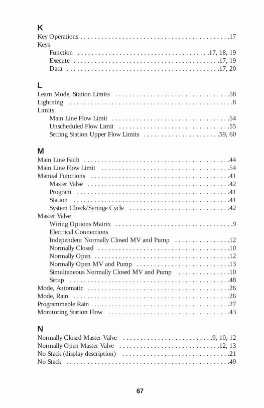
KKey Operations . . . . . . . . . . . . . . . . . . . . . . . . . . . . . . . . . . . . . . . . . . .17Keys
Function . . . . . . . . . . . . . . . . . . . . . . . . . . . . . . . . . . . . . .17, 18, 19Execute . . . . . . . . . . . . . . . . . . . . . . . . . . . . . . . . . . . . . . . . . .17, 19Data . . . . . . . . . . . . . . . . . . . . . . . . . . . . . . . . . . . . . . . . . . . .17, 20
LLearn Mode, Station Limits . . . . . . . . . . . . . . . . . . . . . . . . . . . . . . . . .58Lightning . . . . . . . . . . . . . . . . . . . . . . . . . . . . . . . . . . . . . . . . . . . . . . .8Limits
Main Line Flow Limit . . . . . . . . . . . . . . . . . . . . . . . . . . . . . . . . . .54Unscheduled Flow Limit . . . . . . . . . . . . . . . . . . . . . . . . . . . . . . . .55Setting Station Upper Flow Limits . . . . . . . . . . . . . . . . . . . . . .59, 60
MMain Line Fault . . . . . . . . . . . . . . . . . . . . . . . . . . . . . . . . . . . . . . . . . .44Main Line Flow Limit . . . . . . . . . . . . . . . . . . . . . . . . . . . . . . . . . . . . .54Manual Functions . . . . . . . . . . . . . . . . . . . . . . . . . . . . . . . . . . . . . . . .41
Master Valve . . . . . . . . . . . . . . . . . . . . . . . . . . . . . . . . . . . . . . . . .42Program . . . . . . . . . . . . . . . . . . . . . . . . . . . . . . . . . . . . . . . . . . . .41Station . . . . . . . . . . . . . . . . . . . . . . . . . . . . . . . . . . . . . . . . . . . . .41System Check/Syringe Cycle . . . . . . . . . . . . . . . . . . . . . . . . . . . . .42
Master ValveWiring Options Matrix . . . . . . . . . . . . . . . . . . . . . . . . . . . . . . . . . .9Electrical ConnectionsIndependent Normally Closed MV and Pump . . . . . . . . . . . . . . . .12Normally Closed . . . . . . . . . . . . . . . . . . . . . . . . . . . . . . . . . . . . . .10Normally Open . . . . . . . . . . . . . . . . . . . . . . . . . . . . . . . . . . . . . . .12Normally Open MV and Pump . . . . . . . . . . . . . . . . . . . . . . . . . . .13Simultaneous Normally Closed MV and Pump . . . . . . . . . . . . . . .10Setup . . . . . . . . . . . . . . . . . . . . . . . . . . . . . . . . . . . . . . . . . . . . . .48
Mode, Automatic . . . . . . . . . . . . . . . . . . . . . . . . . . . . . . . . . . . . . . . . .26Mode, Rain . . . . . . . . . . . . . . . . . . . . . . . . . . . . . . . . . . . . . . . . . . . . .26Programmable Rain . . . . . . . . . . . . . . . . . . . . . . . . . . . . . . . . . . . . . . .27Monitoring Station Flow . . . . . . . . . . . . . . . . . . . . . . . . . . . . . . . . . . .43
NNormally Closed Master Valve . . . . . . . . . . . . . . . . . . . . . . . . . .9, 10, 12Normally Open Master Valve . . . . . . . . . . . . . . . . . . . . . . . . . . . . .12, 13No Stack (display description) . . . . . . . . . . . . . . . . . . . . . . . . . . . . . . .21No Stack . . . . . . . . . . . . . . . . . . . . . . . . . . . . . . . . . . . . . . . . . . . . . . .49
67
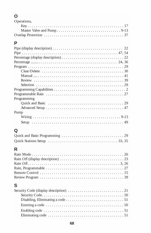
OOperations,
Key. . . . . . . . . . . . . . . . . . . . . . . . . . . . . . . . . . . . . . . . . . . . . . . . . 17Master Valve and Pump . . . . . . . . . . . . . . . . . . . . . . . . . . . . . . . . 9-13
Overlap Protection . . . . . . . . . . . . . . . . . . . . . . . . . . . . . . . . . . . . . . . . 37
PPipe (display description) . . . . . . . . . . . . . . . . . . . . . . . . . . . . . . . . . . . 22Pipe . . . . . . . . . . . . . . . . . . . . . . . . . . . . . . . . . . . . . . . . . . . . . . . . 47, 54Percentage (display description) . . . . . . . . . . . . . . . . . . . . . . . . . . . . . . . 22Percentage ........ . . . . . . . . . . . . . . . . . . . . . . . . . . . . . . . . . . . . . . . 24, 36Program . . . . . . . . . . . . . . . . . . . . . . . . . . . . . . . . . . . . . . . . . . . . . . . . 29
Clear/Delete . . . . . . . . . . . . . . . . . . . . . . . . . . . . . . . . . . . . . . . . . 30Manual .... . . . . . . . . . . . . . . . . . . . . . . . . . . . . . . . . . . . . . . . . . . . 41Review . . . . . . . . . . . . . . . . . . . . . . . . . . . . . . . . . . . . . . . . . . . . . 39Selection . . . . . . . . . . . . . . . . . . . . . . . . . . . . . . . . . . . . . . . . . . . . 29
Programming Capabilities . . . . . . . . . . . . . . . . . . . . . . . . . . . . . . . . . . . . 2Programmable Rain . . . . . . . . . . . . . . . . . . . . . . . . . . . . . . . . . . . . . . . 27Programming
Quick and Basic . . . . . . . . . . . . . . . . . . . . . . . . . . . . . . . . . . . . . . 29Advanced Setup . . . . . . . . . . . . . . . . . . . . . . . . . . . . . . . . . . . . . . . 47
PumpWiring . . . . . . . . . . . . . . . . . . . . . . . . . . . . . . . . . . . . . . . . . . . . 9-13Setup . . . . . . . . . . . . . . . . . . . . . . . . . . . . . . . . . . . . . . . . . . . . . . 49
QQuick and Basic Programming . . . . . . . . . . . . . . . . . . . . . . . . . . . . . . . 29Quick Stations Setup . . . . . . . . . . . . . . . . . . . . . . . . . . . . . . . . . . . 33, 35
RRain Mode . . . . . . . . . . . . . . . . . . . . . . . . . . . . . . . . . . . . . . . . . . . . . . 26Rain Off (display description) . . . . . . . . . . . . . . . . . . . . . . . . . . . . . . . . 23Rain Off . . . . . . . . . . . . . . . . . . . . . . . . . . . . . . . . . . . . . . . . . . . . . . 3, 26Rain, Programmable . . . . . . . . . . . . . . . . . . . . . . . . . . . . . . . . . . . . . . . 27Remote Control . . . . . . . . . . . . . . . . . . . . . . . . . . . . . . . . . . . . . . . . . . 15Review Program . . . . . . . . . . . . . . . . . . . . . . . . . . . . . . . . . . . . . . . . . . 39
SSecurity Code (display description) . . . . . . . . . . . . . . . . . . . . . . . . . . . . 21
Security Code. . . . . . . . . . . . . . . . . . . . . . . . . . . . . . . . . . . . . . . . . 50Disabling, Eliminating a code . . . . . . . . . . . . . . . . . . . . . . . . . . . . . 51Entering a code . . . . . . . . . . . . . . . . . . . . . . . . . . . . . . . . . . . . . . . 50
Enabling code . . . . . . . . . . . . . . . . . . . . . . . . . . . . . . . . . . . . . . . . 51Eliminating code . . . . . . . . . . . . . . . . . . . . . . . . . . . . . . . . . . . . . . 51
68
Sensor (display description) . . . . . . . . . . . . . . . . . . . . . . . . . . . . . . . . . .25Sensor . . . . . . . . . . . . . . . . . . . . . . . . . . . . . . . . . . . . . . . . . . . . . . . . .51
Setup . . . . . . . . . . . . . . . . . . . . . . . . . . . . . . . . . . . . . . . . . . . . . .52Wiring . . . . . . . . . . . . . . . . . . . . . . . . . . . . . . . . . . . . . . . . . . . . .14
Set Time . . . . . . . . . . . . . . . . . . . . . . . . . . . . . . . . . . . . . . . . . . . . . . .29Setup (display description) . . . . . . . . . . . . . . . . . . . . . . . . . . . . . . . . . . .18
Audible Alarm . . . . . . . . . . . . . . . . . . . . . . . . . . . . . . . . . . . . . . .53Cycle and Soak . . . . . . . . . . . . . . . . . . . . . . . . . . . . . . . . . . . . . . .53Flow Delay . . . . . . . . . . . . . . . . . . . . . . . . . . . . . . . . . . . . . . . . . .55Flow Sensor . . . . . . . . . . . . . . . . . . . . . . . . . . . . . . . . . . . . . . . . .53Main Flow Limits . . . . . . . . . . . . . . . . . . . . . . . . . . . . . . . . . . . . .54Master Valve/Type . . . . . . . . . . . . . . . . . . . . . . . . . . . . . . . . . . . . .48Percentage . . . . . . . . . . . . . . . . . . . . . . . . . . . . . . . . . . . . . . . . . . .36Pipe Size . . . . . . . . . . . . . . . . . . . . . . . . . . . . . . . . . . . . . . . . . . . .54Pump . . . . . . . . . . . . . . . . . . . . . . . . . . . . . . . . . . . . . . . . . . . . . .49Unscheduled Flow Limits . . . . . . . . . . . . . . . . . . . . . . . . . . . . . . .55
Skip Days (display description) . . . . . . . . . . . . . . . . . . . . . . . . . . . . . . .24Skip Days . . . . . . . . . . . . . . . . . . . . . . . . . . . . . . . . . . . . . . . . . . .19, 31Stack/No Stack (display description) . . . . . . . . . . . . . . . . . . . . . . . . . . .21Stack/No Stack . . . . . . . . . . . . . . . . . . . . . . . . . . . . . . . . . . . . . . . . . .49Start Times . . . . . . . . . . . . . . . . . . . . . . . . . . . . . . . . . . . . . . . . . .37, 38Stations . . . . . . . . . . . . . . . . . . . . . . . . . . . . . . . . . . . . . . . . . .31, 32, 34
Manual . . . . . . . . . . . . . . . . . . . . . . . . . . . . . . . . . . . . . . . . . . . . .41Quick Stations . . . . . . . . . . . . . . . . . . . . . . . . . . . . . . . . . . . .33, 35
TTroubleshooting . . . . . . . . . . . . . . . . . . . . . . . . . . . . . . . . . . . . . . . . . .63Totalizer . . . . . . . . . . . . . . . . . . . . . . . . . . . . . . . . . . . . . . . . . . . .39, 56Type of Master Valve . . . . . . . . . . . . . . . . . . . . . . . . . . . . . . . . . . . . . .48
UUnscheduled Flow Fault . . . . . . . . . . . . . . . . . . . . . . . . . . . . . . . . . . . .45Unscheduled Flow Limits . . . . . . . . . . . . . . . . . . . . . . . . . . . . . . . . . . .55
WWater Days (display description) . . . . . . . . . . . . . . . . . . . . . . . . . . . . . .24Water Days . . . . . . . . . . . . . . . . . . . . . . . . . . . . . . . . . . . . . . . . . . . . .30Watering Times . . . . . . . . . . . . . . . . . . . . . . . . . . . . . . . . . . . . . . . . . .31Wiring
Fault Detection . . . . . . . . . . . . . . . . . . . . . . . . . . . . . . . . . . . . . . .44Master Valve and Pump . . . . . . . . . . . . . . . . . . . . . . . . . . . . . . . . . .9Sensor . . . . . . . . . . . . . . . . . . . . . . . . . . . . . . . . . . . . . . . . . . . . .14Valve and Field . . . . . . . . . . . . . . . . . . . . . . . . . . . . . . . . . . . . . . . .9
69

RAIN MASTER LIMITED WARRANTYRain Master Irrigation Systems Inc. warrants to the first customer purchaser that this Rain Master brand product (the"product"), when shipped in its original container, will be free from defective workmanship, and materials and agreesthat it will, at its option, either repair the defect or replace the defective product or part thereof at no charge to thepurchaser for parts or labor for the time period set forth below.
This warrant does not apply to any appearance items of the product nor to any product the exterior of which has beendamaged, or defaced, which has been subjected to misuse, abnormal service or handling, or which has been altered ormodified in design or construction. (See additional exclusion below).
In order to enforce the rights under this limited warranty, the purchaser should ship or carry the product to a RainMaster authorized service depot, or send product prepaid to Rain Master at the address below (ensuring product ispackaged correctly for shipment).
For nearest location, call Rain Master Service Center 1-805-527-4498.
This limited warrant described above is in addition to whatever implied warranties may be granted to purchasers by law.
(All implied warranties including the warranty of merchantability, and fit for use are limited to the period(s) from dateof purchase set forth below).
Neither the sales personnel of the seller nor any other person is authorized to make any warranties other than thosedescribed above, or to extend the duration of any warranties beyond the time period described herein.
The warranties described above shall be the sole and exclusive warranties granted by Rain Master Irrigation Systems Inc.and shall be the sole and exclusive remedy available to the purchaser. Correction of defects, in the manner and periodof time described herein, shall constitute complete fulfillment of all liabilities and responsibilities of Rain Master to thepurchaser with respect to the product, and shall constitute full satisfaction of all claims, whether based on contract,negligence, strict liability or otherwise.
In no event shall Rain Master be liable or in any way responsible, for any damages or defects in the product which werecaused by repairs or attempted repairs performed by anyone other than a Rain Master service dealer or center. Nor shallRain Master be liable or in any way responsible for an incidental or consequential economic or property damage. Somestates do not allow the exclusion of incidental or consequential damages, so the above exclusion may not apply to you.
This limited warranty does not apply to improper installation or grounding, acts of God, such as lightning and/orpower surges, floods, earthquakes, hurricane, tornados, vandalism etc.
SENTAR II carries a 5 year limited warrant from date of purchase
All other Rain Master brand products carry a 2 year limited warranty unless otherwise specified.
SERVICE
Should it be necessary to require servicing of your controller, contact your local Rain Master distributor or contact RainMaster at 1-805-527-4498 for a listing of distributors in your area.When sending a controller or a component of the controller back to be serviced, ensure it is properly protected with asoft packaging material, and that the box will withstand normal shipping abuses. Enclose a complete description of thetype of problem that is occurring, and be sure to put your name, address and phone number where you can be reached.
WARNING: This equipment has been tested and found to comply with the limits for Class A digital device pursuant toPart 15 of the FCC Rules. These limits are designed to provide reasonable protection against harmful interference whenthe equipment is operated in a commercial environment. This equipment generates, uses, and can radiate radiofrequency energy and , if not installed and used in accordance with the instructions manual, may cause interference toradio communications. Operation of this equipment in a residential area is likely to cause interference in which case theuser will be required to correct the interference at his own expense.
The user is cautioned that changes and modifications made to the equipment without approval of the manufacturercould void the user’s authority to operate this equipment
3910-B Royal Ave.Simi Valley, CA 93063www.rainmaster.com
Tel (805) 527-4498Fax (805) 527-2813


![Controllable Sliding Bearings and Controllable Lubrication ... · Review Controllable Sliding Bearings and Controllable ... or evolutionary [5], but it does not change the fact that](https://img.pdfslide.net/doc/110x75/5fc50df11ca4e1756528a85b/controllable-sliding-bearings-and-controllable-lubrication-review-controllable.jpg)