Embed Size (px)
Citation preview

This publication sets forth detailed recommended procedures for using Stryker Orthopaedics devices and instruments. It offers guidance that you should heed,but, as with any such technical guide, each surgeon must consider the particular needs of each patient and make appropriate adjustments when and as required.
Table of Contents
Indications and Contraindications.................................... IFC
Surgical Protocol
Step 1 - Pre-Operative Planning and X-ray Evaluation.... 1
Step 2 - Surgical Exposure ................................................... 2
Step 3 - Femoral Neck Resection......................................... 2
Step 4 - Femoral Preparation .............................................. 3
Step 5 - Femoral Rasping ..................................................... 4
Step 6 - Trial Reduction........................................................ 5
Step 7 -Further Femoral Preparation................................. 6
Step 8 -Femoral Cementing................................................. 7
Step 9 - Stem Insertion......................................................... 8
Step 10 - Stem Insertion (continued) ................................. 9
Step 11 -Reduction ............................................................. 10
Step 12 - Post-Operative Management............................. 10
Step 13 - Follow Up............................................................. 10
Catalog Information
Implant & Instrument Listing .......................................... 11
Instrument Listing ............................................................. 13
Indications
The indications for use in total hip arthroplasty include:
• Non-inflammatory degenerative joint disease, includingosteoarthritis and avascular necrosis.
• Rheumatoid arthritis.
• Correction of functional deformity.
• Revision procedures where other treatments or devices havefailed.
• Treatment of non-unions, femoral neck fractures andtrochanteric fractures of the proximal femur with headinvolvement that are not manageable using othertechniques.
Contraindications
• Active infection or suspected latent infection in or about thehip joint.
• Bone stock that is inadequate for support or fixation of theprosthesis.
• Skeletal immature.
• Any mental or neuromuscular disorder that would create anunacceptable risk of prosthesis instability, prosthesis fixationfailure, or complications in postoperative care.
Warnings and Precautions
See implant package insert for warnings, precautions, adverseeffects and other essential product information.
Before using instrumentation, verify:
• Instruments have been properly disassembled prior tocleaning and sterilization
• Instruments have been properly assembled post sterilization
• Instruments have maintained design integrity
• Proper size configuration is available
For instructions for Cleaning, Sterilization, Inspection andMaintenance of Orthopaedic Medical Devices, refer to LSTPI-B.
Exeter V40 Femoral Stem

1
Pre-operative planning is an essential part of theprocedure and templating should be performed prior toevery case. When it is done using x-rays that have beensuitably scaled for magnification, templating allows thesurgeon to predict the size and offset of the implant thatwill restore the correct anatomy of the individual patient.Planning the positions of the cup and stem will also helpthe surgeon place each component at the correct centreof rotation and thereby restore the correct leg length.
Pre-operative planning can be done using acetatetemplates for printed radiographs or pre-operativeplanning software for digital studies (Figure 1). It shouldstart with an assessment of the magnification of theradiograph and adjustment for that if necessary. Thesurgeon should then take account of the pre-operative
leg length and any adjustment that may be required. Thecorrect centre of rotation for the acetabular and femoralcomponents should be established and this will includemeasurement of the patient’s existing femoral offset,which will need to be replicated.
The appropriate stem size for the patient can be judgedfrom the templates, using the lines marked alongside thestem profile. The set of lines closest to the stem profileindicates the minimum necessary cement mantle andwhen placed on the patients X-rays they should lie withinthe femoral canal. It is important to remember that usingan excessively large femoral stem may compromise thecement mantle, but an excessively small stem may be atrisk of fracture.
STEP 1PRE-OPERATIVE PLANNING AND X-RAY EVALUATION
Figure 1

2 EXETER V40 FEMORAL STEM SURGICAL TECHNIQUE
STEP 2The Exeter stem can be implanted through the commonlyused surgical approaches to the hip including the directlateral approach and the posterior approach, which isfeatured in this technique manual. Whichever approach isused, a full exposure of both the acetabulum and theproximal femur, with appropriate soft tissue releases, isessential for effective preparation of the bony cavities,cementing and implant insertion (Figure 2).
SURGICAL EXPOSURE
STEP 3FEMORAL NECK RESECTION
The level and orientation of neck resection are not criticalfor the Exeter Hip stem because it has no collar or otherfeatures that would affect the position of the osteotomy.However, there should be adequate proximal support forthe stem, guidance for which is given by the threemarkings on the femoral prosthesis. It is advised that theneck osteotomy is not made so low as to leave all threemarkings proud of the cement mantle.
In most individuals an appropriate level of neck resectionlies along a line drawn from a point medially mid-waybetween the upper margin of the lesser trochanter and theinferior aspect of the head (Figure 3 point A), to a pointlaterally at the base of the neck (Figure 3 point B).
Figure 2
Figure 3
B
A

3
The leg is placed in a position that enables the surgeon toachieve straight-line access down the length of the femoralshaft and sufficient soft tissue clearance for stem ante -version. Use of a gluteus medius retractor may help toexpose the lateral aspect of the cut femoral neck, which isimportant for straight-line access to the femoral canal.The use of one or more femoral elevators will help todeliver the femur out of the wound, providing clearance ofthe soft tissues, which allows the surgeon to control thedegree of anteversion of the femoral component (Figure 4).
The medullary canal is opened using a hollow box chiselor a straight gouge, undercutting the lateral cortex of theneck, and developing a slot into the trochanteric region(Figure 5). If necessary, a rongeur is used afterundercutting of the neck, to resect the lateral-mostcortical bone of the neck.
The tapered pin reamer is introduced into the femoralcanal, in line with the long axis of the femur, which helpsto ensure that the femoral stem can be inserted down themidline of the femur (Figure 6). To achieve this, thesurgeon may rotate the handle of the tapered pin reamerwhilst applying a moderate valgus force to the handle,which removes any remnants of the lateral neck cortexthat would otherwise tend to force the stem into a varusposition.
The surgeon then uses the Exeter rasps to prepare thecancellous bone for cementing.The aim is to preserve 2-3 mm of strong cancellous bone circumferentiallyaround the stem cavity, into which the cement will bepressurized. Each rasp is slightly larger than thecorresponding stem and creates a cavity that will hold thestem with a complete cement mantle around it.
STEP 4FEMORAL PREPARATION
Figure 4
Figure 5 Figure 6
Hollow Chisel 4842-3012
Exeter Tapered Pin ReamerLarge and Small Small = 0932-0-000Large = 0932-2-000

4 EXETER V40 FEMORAL STEM SURGICAL TECHNIQUE
STEP 5The surgeon should start with a rasp that is one or twosizes smaller than the anticipated stem size predicted bypre-operative planning.The rasp is inserted along the longaxis of the femur (Figure 7A) to the level at whichtemplating has shown the leg length will be restored.
The rasp bears three holes in the neck region thatcorrespond to the three marks on the neck of theprosthesis. The surgeon should ensure that these threeholes are not all left proud of the femur because thiswould risk leaving a stem with inadequate proximalsupport (Figure 7B).
Having started with a small rasp, the surgeon sequentiallyintroduces larger rasps until a firm fit is achieved with arasp at the correct insertion depth. It is a serious mistaketo over-rasp the canal and remove too much cancellousbone.
If excess force is required to introduce a rasp to the correctlevel then the surgeon should either drop down a rasp sizeor, if this is not possible, the canal may be enlarged withthe taper pin reamer, taking care not to compromise thelayer of trabecular bone.
FEMORAL RASPING
Figure 7A
Exeter V40Rasp 0579-X-XXX
Exeter V40Rasp Handle 0930-9-005
Figure 7B
5
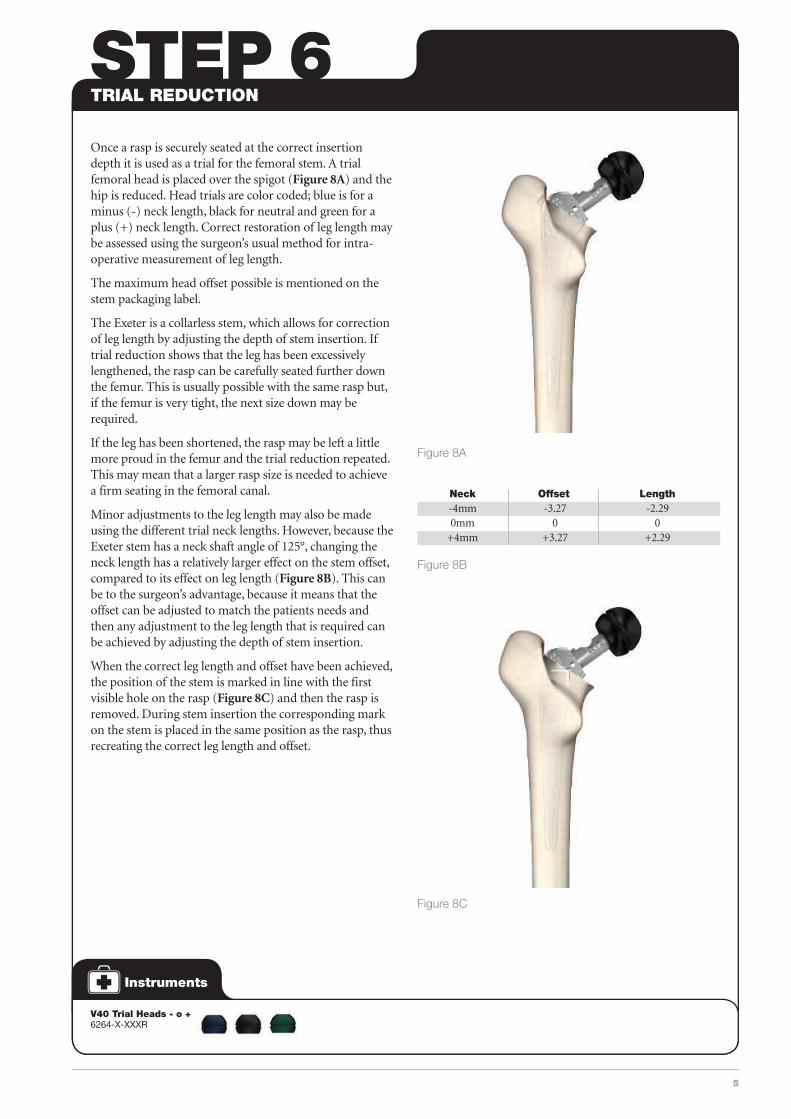
Once a rasp is securely seated at the correct insertiondepth it is used as a trial for the femoral stem. A trialfemoral head is placed over the spigot (Figure 8A) and thehip is reduced. Head trials are color coded; blue is for aminus (-) neck length, black for neutral and green for aplus (+) neck length. Correct restoration of leg length maybe assessed using the surgeon’s usual method for intra-operative measurement of leg length.
The maximum head offset possible is mentioned on thestem packaging label.
The Exeter is a collarless stem, which allows for correctionof leg length by adjusting the depth of stem insertion. Iftrial reduction shows that the leg has been excessivelylengthened, the rasp can be carefully seated further downthe femur. This is usually possible with the same rasp but,if the femur is very tight, the next size down may berequired.
If the leg has been shortened, the rasp may be left a littlemore proud in the femur and the trial reduction repeated.This may mean that a larger rasp size is needed to achievea firm seating in the femoral canal.
Minor adjustments to the leg length may also be madeusing the different trial neck lengths. However, because theExeter stem has a neck shaft angle of 125°, changing theneck length has a relatively larger effect on the stem offset,compared to its effect on leg length (Figure 8B). This canbe to the surgeon’s advantage, because it means that theoffset can be adjusted to match the patients needs andthen any adjustment to the leg length that is required canbe achieved by adjusting the depth of stem insertion.
When the correct leg length and offset have been achieved,the position of the stem is marked in line with the firstvisible hole on the rasp (Figure 8C) and then the rasp isremoved. During stem insertion the corresponding markon the stem is placed in the same position as the rasp, thusrecreating the correct leg length and offset.
STEP 6TRIAL REDUCTION
Figure 8B
Figure 8A
V40 Trial Heads - o + 6264-X-XXXR
Neck Offset Length -4mm -3.27 -2.29 0mm 0 0 +4mm +3.27 +2.29
Figure 8C

6 EXETER V40 FEMORAL STEM SURGICAL TECHNIQUE
STEP 7The femoral canal should be occluded distally with anExeter cement restrictor and the restrictor size is measuredusing the Exeter plug trials (Figure 9A).
Starting with the smallest size, the surgeon introducessequentially larger sounds until reaching the first one thatjams in the femoral canal when its landmark (corre -sponding to the stem length chosen) is at or just below thetip of the greater trochanter. This sound indicates the sizeof distal cement restrictor that should be used.
The appropriate intramedullary plug is mounted onto theintroducer (Figure 9B), which bears the same threemarkings proximally as the rasp and femoral stem.
The plug introducer comes with two alternative distalattachments, onto which the plug is mounted. The flutedattachment should be used for size 10-20mm plugs,whereas the straight-sided attachment is used for 6 and8mm plugs.
Once seated on the introducer, the cement restrictor isdriven down the femoral canal until the correct circle onthe introducer lies adjacent to the marks made on thefemoral surface during trial reduction (Figure 9C) If theintroducer is inserted to the same point as the rasp, therestrictor will lie 10mm below the final position of the stem.
The theatre nursing staff can now start to prepare thecement, while the surgeon washes the femoral canalthoroughly using pressurized lavage. The aim is to removethe blood from the strong cancellous bone in preparationfor cementing. A catheter is placed in the distal end of thecanal and connected to suction. Hydrogen Peroxide (1.5%concentration) soaked ribbon gauze is moderatelysqueezed before being packed into the femur to maintainhaemostasis in the canal and to provide a clean dry surfaceinto which the cement can key.
FURTHER FEMORAL PREPARATION
Exeter IM Plug 0939-0-1XX
Exeter PlugIntroducer 0939-0-002M
Figure 9A
Exeter PlugTrial 0939-1-1XXM
Figure 9C
Figure 9B

7
The correct cementing technique involves retrogradeinjection of cement using a cement gun, followed byvigorous pressurization using a proximal seal fitted to thenozzle of the cement gun. Bone cement such as Simplexshould be mixed in a bowl for approximately 1 minuteand then poured into the cement gun barrel, after which itis left to stand for approximately 30 seconds. Either two orthree mixes of cement will be required, depending on thesize of the femoral canal, which can be judged from thesizes of rasp and intramedullary plug that were used.
The correct time to begin cement injection variesaccording to operating theatre conditions but, typically,using bone cement such as Simplex with a theatretemperature of 21°C, cement delivery should start at 2½ to3 minutes after the commencement of mixing. The nozzleof the cement gun is inserted all the way down the femoralcanal until the tip is at the level of the plug, or as far as itcan be inserted if the femur is very tight (Figure 10A).
Cement is introduced in a retrograde (i.e. from distal toproximal) fashion and as the canal fills distally the cementgun nozzle is gradually withdrawn until the canal iscompletely filled with cement (Figure 10B). When thecanal is full, the gun is withdrawn and the femoral sealand metal backing plate are placed over the nozzle of thegun. The cement in the nozzle is pushed back until it islevel with the seal and then the nozzle is cut short at thepoint at which it emerges through the seal (Figure 10C).
Cement injection and pressurization is continued untilthe viscosity of the cement starts rising. Typically, usingbone cement such as Simplex with a theatre temperatureof 21°C, this is seldom less than 5 minutes from the startof mixing, judged by a small sample held in the hand. Thefemoral stem is then inserted. The aim should be to delaystem insertion for as long as possible, remembering thatduring stem insertion interface pressures in the canal aredirectly related to the viscosity of the cement.
STEP 8FEMORAL CEMENTING
Exeter Half MoonSeal Backing Plate0937-8-101
Half MoonSeal 0937-8-205
Figure 10A Figure 10B
Figure 10C

8 EXETER V40 FEMORAL STEM SURGICAL TECHNIQUE
STEP 9The hollow centralizer must be used with the Exeter stembecause it provides a space below the stem tip, whichprevents ‘end-bearing’ of the stem and ensures that theproximal, expanded taper of the stem will engage properlyin the cement mantle. Each Exeter V40 stem is suppliedwith a winged and a straight-sided centralizer (Figure 11A).
If an intramedullary plug of 10mm or less has been used,the straight-sided centralizer should be fitted to the stem,but when a plug size of 12mm or more has been inserted,the winged centralizer is applied. The stem centralizer isnot retentive and when placed on the tip of the stem itmay need to be held in place as the stem is transferred tothe femur ready for insertion. The centralizer should notbe forced excessively onto the stem tip.
The stem introducer can be used with one hand and has asmooth trigger action that releases the introducer pinfrom the dimple in the lateral shoulder of the stemimplant after the stem has been seated.
The stem is introduced through the proximal femoralopening closer to the posterior femoral cortex than theanterior, and aiming at the middle of the popliteal fossa ifthe posterior approach is used, or the patella if the directlateral approach is used.
Placing a thumb over the antero-medial aspect of thefemoral canal (Figure 11B) helps to force the stem intothe correct posterior entry point (Figure 11C) and alsooccludes the top of the canal, thereby boosting the cementpressure during stem insertion. There will often be furtherextrusion of fat from the walls of the femur as a result ofthis pressure rise.
Figure 11B
Exeter V40 Stem Introducer 0930-5-000
Exeter WingedCentralizer 0920-2-920
STEM INSERTION
Figure 11A
Figure 11C
Offset Length Sizes (No.)
30 95 33 115 35.5 125 37.5 125 1 37.5 150 0,1,2,3,4 44 125 1 44 150 0,1,2,3,4,5,6 50 125 1 50 150 1,2,3,4,5 56 150 1,2
Exeter V40 Femoral StemSizing Chart
The dimple on the shoulder of the stem should not beused for impaction
NOTE

9
The insertion should be brisk until the stem reaches aposition approximately 1cm above its final position (Figure 11D).
Insertion thereafter should be slower, gradually bringingthe stem to its final pre-determined position as judged bythe marks placed on the femur that were made after trialreduction with the rasp (Figure 11E).
The stem should not be left with all three circularmarkings proud of the cement mantle because this wouldrisk leaving it with inadequate proximal support. Whenthe final position has been reached and the introducer hasbeen removed, the stem seal and backing plate are placedaround the stem and firm pressure maintained on the topof the cement until it has polymerized (Figure 11F).
The surgeon should ensure that the stem does not backout during cement polymerization and when it has fullyset any excess cement should be removed from the cutsurface of the femur.
STEP 10STEM INSERTION CONTINUED
Exeter FemoralStem Seal Pusher 0937-3-301
Exeter Horse CollarFemoral Seal Small = 0937-3-215Large = 0937-3-225
Figure 11D
Figure 11E
Figure 11F
Exeter V40 Stem Trials (0581-X-XXX) are approved insome markets to assess cement mantle around thestem, avoiding excessive bone removal around thestem that allows anatomic restoration in cases wherethe broach is oversized compared to the femoral canal.
After bone preparation with the rasp, the trial stem canbe used to ensure that the correct depth of insertionand stem version can be achieved.
Once the desired position of the stem has beenachieved, using the Trial Locating Pin, a trial reductioncan now be performed to confirm stability and leglength.
When the correct leg length and offset have beenachieved, the position of the stem is marked in linewith the hole in which the trial locating pin is located.
During stem insertion the corresponding mark on thestem is placed in the same position as the stem trial,thus recreating the correct leg length and offset.
NOTE

10 EXETER V40 FEMORAL STEM SURGICAL TECHNIQUE
STEP 11The spigot protector is removed and a further trialreduction is carried out using the appropriate trial head(Figure 12A) to confirm that the leg length and offset havebeen restored and the hip is stable through a full range ofmovement.
Exeter V40 stems can be used with Stryker V40 Headsincluding Orthinox, CoCr, LFIT CoCr, Alumina, BIOLOXdelta, Universal Taper BIOLOX delta and Unitrax. Theappropriate size of femoral head is removed from itspackaging and placed over the clean, dry stem spigot. It issecured in place by firm blows with the palm of the handon an impactor or the head may be pushed onto thespigot by hand and rotated 10°. The surgeon should avoidthe use of excess impaction force and hard instruments asthey may damage the fine polished surface (Figure 12B).The hip is then reduced and a thorough lavage carriedout. The soft tissues and skin are closed according to thesurgeons’s usual practice.
REDUCTION
STEP 12The general post-operative management of the patientshould follow the normal protocols of the operatingsurgeon and the hospital in which the procedure is carriedout. A check X-ray is taken to confirm satisfactoryappearances of the arthroplasty. When inserted using the
technique outlined above, the Exeter stem is ready for fullweight-bearing immediately after the operation. Mostpatients prefer to use crutches for a short period after thesurgery but these can be discarded as soon as the patientfeels confident to do without them.
POST-OPERATIVE MANAGEMENT
STEP 13The follow-up arrangements should follow the normalprotocols of the operating surgeon and the institution inwhich the surgery was performed. The Exeter Hip Unit
surgeons repeat X-rays at 5 yearly intervals after theoperation, unless a clinical presentation suggests that anearlier review is required.
FOLLOW-UP
Figure 12A Figure 12B
Exeter V40Stem 0580-X-XXX
V40 StainlessSteel Head 6364-2-XXX
V40 TrialHead6264-X-XXXR

11
Exeter V40 Femoral StemsMade from Orthinox Stainless Steel
Product Length Trial Code (mm) Description Stem
0580-1-300 95 30 mm L.95 0581-1-300 0580-1-330 115 33 mm L.115 0581-1-330 0580-1-351 125 35.5 mm L.125 0581-1-351 0580-1-352 150 37.5 mm N°0 L.150 0581-1-352 0580-3-371 125 37.5 mm N°1 L.125 0581-3-371 0580-1-371 150 37.5 mm N°1 L.150 0581-1-371 0580-1-372 150 37.5 mm N°2 L.150 0581-1-372 0580-1-373 150 37.5 mm N°3 L.150 0581-1-373 0580-1-374 150 37.5 mm N°4 L.150 0581-1-374 0580-1-440 150 44 mm N°0 L.150 0581-1-440 0580-3-441 125 44 mm N°1 L.125 0581-3-441 0580-1-441 150 44 mm N°1 L.150 0581-1-441 0580-1-442 150 44 mm N°2 L.150 0581-1-442 0580-1-443 150 44 mm N°3 L.150 0581-1-443 0580-1-444 150 44 mm N°4 L.150 0581-1-444 0580-1-445 150 44 mm N°5 L.150 0581-1-445 0580-1-446 150 44 mm N°6 L.150 0581-1-446 0580-3-501 125 50 mm N°1 L.125 0581-3-501 0580-1-501 150 50 mm N°1 L.150 0581-1-501 0580-1-502 150 50 mm N°2 L.150 0581-1-502 0580-1-503 150 50 mm N°3 L.150 0581-1-503 0580-1-504 150 50 mm N°4 L.150 0581-1-504 0580-1-505 150 50 mm N°5 L.150 0581-1-505 0580-1-561 150 56 mm N°1 L.150 0581-1-561 0580-1-562 150 56 mm N°2 L.150 0581-1-562
Exeter V40 Long Stems
Product Length Trial Code (mm) Description Stem
0580-3-321 205 37.5 mm N°1 L205 fully tapered 0581-3-321 0580-3-422 205 44 mm N°2 L205 fully tapered 0581-3-422 0580-1-200 200 44 mm N°3 L200 0581-1-200 0580-1-220 220 44 mm N°3 L220 0581-1-220 0580-1-240 240 44 mm N°3 L240 0581-1-240 0580-1-260 260 44 mm N°3 L260 0581-1-260
V40 Orthinox Compatible Heads – SS
Product Trial Code Description Head
6364-2-022 Stainless steel 22.2mm (-2) 6365-9-022 6364-2-122 Stainless steel 22.2mm (0) 6264-8-122R 6364-2-222 Stainless steel 22.2mm (+3) 6264-8-222R 6364-2-322 Stainless steel 22.2mm (+8) Skirted 6264-8-322R 6364-2-026 Stainless steel 26mm (-3) 6264-8-026R 6364-2-126 Stainless steel 26mm (0) 6264-8-126R 6364-2-226 Stainless steel 26mm (+4) 6264-7-226R 6364-2-326 Stainless steel 26mm (+8) skirted 6264-8-326R 6364-2-028 Stainless steel 28mm (-4) 6264-8-028R 6364-2-128 Stainless steel 28mm (0) 6264-8-128R 6364-2-228 Stainless steel 28mm (+4) 6264-8-228R 6364-2-328 Stainless steel 28mm (+8) skirted 6264-8-328R 6364-2-032 Stainless steel 32mm (-4) 6264-8-032R 6364-2-132 Stainless steel 32mm (0) 6264-8-132R 6364-2-232 Stainless steel 32mm (+4) 6264-8-232R 6364-2-332 Stainless steel 32mm (+8) 6264-8-332R 6364-2-036 Stainless steel 36mm (-5) 6264-8-036R 6364-2-136 Stainless steel 36mm (0) 6264-8-136R 6364-2-236 Stainless steel 36mm (+5) 6264-8-236R
V40 Taper LFIT CoCr Heads
Product Trial Code Description Head
6260-9-122 LFIT CoCr 22.2mm (0) 6264-8-122R 6260-9-222 LFIT CoCr 22.2mm (+3) 6264-8-222R 6260-9-322 LFIT CoCr 22.2mm (+8) skirted 6264-8-322R 6260-9-026 LFIT CoCr 26mm (-3) 6264-8-026R 6260-9-126 LFIT CoCr 26mm (0) 6264-8-126R 6260-9-226 LFIT CoCr 26mm (+4) 6264-8-226R 6260-9-326 LFIT CoCr 26mm (+8) skirted 6264-8-326R 6260-9-028 LFIT CoCr 28mm (-4) 6264-8-028R 6260-9-128 LFIT CoCr 28mm (0) 6264-8-128R 6260-9-228 LFIT CoCr 28mm (+4) 6264-8-228R 6260-9-328 LFIT CoCr 28mm (+8) skirted 6264-8-328R 6260-9-032 LFIT CoCr 32mm (-4) 6264-8-032R 6260-9-132 LFIT CoCr 32mm (0) 6264-8-132R 6260-9-232 LFIT CoCr 32mm (+4) 6264-8-232R 6260-9-332 LFIT CoCr 32mm (+8) skirted 6264-8-332R
V40 Taper LFIT CoCr Anatomic Heads
Product Trial Code Description Head
6260-9-036 LFIT CoCr anatomic 36mm (-5) 6264-8-036R 6260-9-136 LFIT CoCr anatomic 36mm (0) 6264-8-136R 6260-9-236 LFIT CoCr anatomic 36mm (+5) 6264-8-236R 6260-9-040 LFIT CoCr anatomic 40mm (-4) 6264-8-040R 6260-9-140 LFIT CoCr anatomic 40mm (0) 6264-8-140R 6260-9-240 LFIT CoCr anatomic 40mm (+4) 6264-8-240R 6260-9-044 LFIT CoCr anatomic 44mm (-4) 6264-8-044R 6260-9-144 LFIT CoCr anatomic 44mm (0) 6264-8-144R 6260-9-244 LFIT CoCr anatomic 44mm (+4) 6264-8-244R
IMPLANT &INSTRUMENT LISTING
Exeter IM Plug (PMMA)
Product Trial Code Description Plug
0939-0-106 Exeter IM plug 6mm 0939-1-106M 0939-0-108 Exeter IM plug 8mm 0939-1-108M 0939-0-110 Exeter IM plug 10mm 0939-1-110M 0939-0-112 Exeter IM plug 12mm 0939-1-112M 0939-0-114 Exeter IM plug 14mm 0939-1-114M 0939-0-116 Exeter IM plug 16mm 0939-1-116M 0939-0-118 Exeter IM plug 18mm 0939-1-118M 0939-0-120 Exeter IM plug 20mm 0939-1-120M
Winged Centralizer
0920-2-920
V40 Spigot Protector
0930-3-005

12 EXETER V40 FEMORAL STEM SURGICAL TECHNIQUE
V40 Taper Alumina Ceramic Head
Product Trial Code Description Head
6565-0-028 Alumina Ceramic 28mm (-2.7) 6264-8-928R 6565-0-128 Alumina Ceramic 28mm (0) 6264-8-128R 6565-0-228 Alumina Ceramic 28mm (+4) 6264-8-228R 6565-0-032 Alumina Ceramic 32mm (-4) 6264-8-032R 6565-0-132 Alumina Ceramic 32mm (0) 6264-8-132R 6565-0-232 Alumina Ceramic 32mm (+4) 6264-8-232R 6565-0-036 Alumina Ceramic 36mm (-5) 6264-8-036R 6565-0-136 Alumina Ceramic 36mm (0) 6264-8-136R 6565-0-236 Alumina Ceramic 36mm (+5) 6264-8-236R
Product Trial Code Description Head
4656-0-041 V40 Unipolar head 41mm 4656-0-141 4656-0-043 V40 Unipolar head 43mm 4656-0-143 4656-0-044 V40 Unipolar head 44.5mm 4656-0-144 4656-0-046 V40 Unipolar head 46mm 4656-0-146 4656-0-047 V40 Unipolar head 47.5mm 4656-0-147 4656-0-049 V40 Unipolar head 49mm 4656-0-149 4656-0-051 V40 Unipolar head 51mm 4656-0-151 4656-0-052 V40 Unipolar head 52.5mm 4656-0-152 4656-0-054 V40 Unipolar head 54mm 4656-0-154 4656-0-056 V40 Unipolar head 56mm 4656-0-156
Product Trial Code Description Head
6570-0-028 Delta Ceramic 28mm (-4) 6264-8-028R 6570-0-328 Delta Ceramic 28mm (-2.7) 6264-8-928R 6570-0-128 Delta Ceramic 28mm (0) 6264-8-128R 6570-0-228 Delta Ceramic 28mm (+4) 6264-8-228R 6570-0-032 Delta Ceramic 32mm (-4) 6264-8-032R 6570-0-132 Delta Ceramic 32mm (0) 6264-8-132R 6570-0-232 Delta Ceramic 32mm (+4) 6264-8-232R 6570-0-036 Delta Ceramic 36mm (-5) 6264-8-036R 6570-0-436 Delta Ceramic 36mm (-2.5) 6264-8-436R 6570-0-136 Delta Ceramic 36mm (0) 6264-8-136R 6570-0-536 Delta Ceramic 36mm (+2.5) 6264-8-536R 6570-0-236 Delta Ceramic 36mm (+5) 6264-8-236R 6570-0-736 Delta Ceramic 36mm (+7.5) 6264-8-736R
V40 Taper BIOLOX deltaCeramic Heads
NOTE: When selecting a BIOLOX delta Universal Taper CeramicFemoral Head for implantation, use of a V40 Universal Adaptor Sleeve isnecessary (6519-T-XXX).
After completing the trialing process, intra-operatively assemble theAdaptor Sleeve to the femoral stem manually. The Universal AdaptorSleeve must be fully seated on the stem taper before the head is assembled.
NOTE: In no instance should any attempt be made to pre-assemble theAdaptor Sleeve inside the BIOLOX delta Universal Ceramic head.
Intra-operatively assemble the BIOLOX delta Universal Taper Ceramichead onto the sleeved femoral stem and set with two moderate blowsusing a head impactor instrument. Care must be taken to avoid excessiveimpact forces when assembling the Ceramic Head to the sleeved femoralcomponent.
BIOLOX delta Universal Taper Ceramic Heads
Product Code Description
6519-1-028 Universal T Ceramic 28mm (+0) 6519-1-032 Universal T Ceramic 32mm (+0) 6519-1-036 Universal T Ceramic 36mm (+0) 6519-1-040 Universal T Ceramic 40mm (+0) 6519-1-044 Universal T Ceramic 44mm (+0)
V40 Universal Adapter Sleeves – Titanium
Product Code Description
6519-T-025 Universal adapter (-2.5mm) 6519-T-100 Universal adapter (+0mm) 6519-T-204 Universal adapter (+4mm)
Unitrax Unipolar Sleeves
Product Code Description
6942-6-060 V40 taper sleeve -4mm 6942-6-065 V40 taper sleeve 0 6942-6-070 V40 taper sleeve +4mm 6942-6-075 V40 taper sleeve +8mm
V40 Taper Universal Trial Heads
Product Code Description
6264-8-728R Universal trial 28mm (-2.5) 6264-8-632R Universal trial 32mm (-2.5) 6264-3-236R Universal trial 36mm (+4.0) 6264-8-940R Universal trial 40mm (-2.5) 6264-8-944R Universal trial 44mm (-2.5)
Unitrax Unipolar Head
Product Code Description
6942-5-038 Unitrax Unipolar head 38mm 6942-5-040 Unitrax Unipolar head 40mm 6942-5-041 Unitrax Unipolar head 41mm 6942-5-042 Unitrax Unipolar head 42mm 6942-5-043 Unitrax Unipolar head 43mm 6942-5-044 Unitrax Unipolar head 44mm 6942-5-045 Unitrax Unipolar head 45mm 6942-5-046 Unitrax Unipolar head 46mm 6942-5-047 Unitrax Unipolar head 47mm 6942-5-048 Unitrax Unipolar head 48mm 6942-5-049 Unitrax Unipolar head 49mm 6942-5-050 Unitrax Unipolar head 50mm 6942-5-051 Unitrax Unipolar head 51mm 6942-5-052 Unitrax Unipolar head 52mm 6942-5-053 Unitrax Unipolar head 53mm 6942-5-054 Unitrax Unipolar head 54mm 6942-5-055 Unitrax Unipolar head 55mm 6942-5-056 Unitrax Unipolar head 56mm 6942-5-058 Unitrax Unipolar head 58mm 6942-5-061 Unitrax Unipolar head 61mm
IMPLANT &INSTRUMENT LISTING
V40 Unipolar Head

13
Exeter V40 Rasp
Product Code Description
0579-9-300 30 mm L.95 0579-9-330 33 mm L.115 0579-9-351 35.5 mm L.125 0579-9-352 37.5 mm N°0 L.150 0579-3-371 37.5 mm N°1 L.125 0579-9-371 37.5 mm N°1 L.150 0579-9-372 37.5 mm N°2 L.150 0579-9-373 37.5 mm N°3 L.150 0579-9-374 37.5 mm N°4 L.150 0579-9-440 44 mm N°0 L.150 0579-3-441 44 mm N°1 L.125 0579-9-441 44 mm N°1 L.150 0579-9-442 44 mm N°2 L.150 0579-9-443 44 mm N°3 L.150 0579-9-444 44 mm N°4 L.150 0579-9-445 44 mm N°5 L.150 0579-9-446 44 mm N°6 L.150 0579-3-501 50 mm N°1 L.125 0579-9-501 50 mm N°1 L.150 0579-9-502 50 mm N°2 L.150 0579-9-503 50 mm N°3 L.150 0579-9-504 50 mm N°4 L.150 0579-9-505 50 mm N°5 L.150 0579-9-561 56 mm N°1 L.150 0579-9-562 56 mm N°2 L.150
Exeter V40 Rasp Tray
0590-1-401
Exeter V40 Rasp Handle
0930-9-005
Exeter Femoral Seals
Product Code Description
0937-3-301 Femoral stem seal pusher (horse collar) 0937-3-215 Horse collar femoral seals Sm (5 pack) 0937-3-225 Horse collar femoral seals Lg (5 pack) 0937-8-205 Half moon seals (5 pack) 0937-8-101 Half moon seal backing plate
Retractors
Product Code Description
0929-1-001 Straight femoral elevator 0929-1-002 Left femoral elevator 0929-1-003 Right femoral elevator 0929-1-020 Exeter inferior acetabular retractor 0929-1-030 Exeter short blunt retractor 1440-1130 Narrow Hohmann retractor
INSTRUMENT LISTING
General instruments
Product Code Description
4842-3-012 Hollow chisel 0932-0-000 Exeter tapered reamer small 0932-2-000 Exeter tapered reamer large 0939-0-002M Exeter plug introducer 4842-2-000 Head impactor 0930-5-000 Exeter V40 stem introducer 0590-1-200 Exeter femoral tray 0570-9-000 Trial Locating Pin
Exeter Plug Trial
Product Code Description
0939-1-106M Exeter Plug Trial 6mm 0939-1-108M Exeter Plug Trial 8mm 0939-1-110M Exeter Plug Trial 10mm 0939-1-112M Exeter Plug Trial 12mm 0939-1-114M Exeter Plug Trial 14mm 0939-1-116M Exeter Plug Trial 16mm 0939-1-118M Exeter Plug Trial 18mm 0939-1-120M Exeter Plug Trial 20mm
Exeter V40 Plug Trial instrument Tray
0590-1-500
Product Code Description
0580-3-500 30mm L.95 / 33mm L.115 / 35.5mm L.125 stems 0% oversize (scale 1) 0580-3-520 30mm L.95 / 33mm L.115 / 35.5mm L.125 stems 20% oversize (scale 1.2) 0580-2-500 37.5mm/44mm/50mm L.125mm stems 0% oversize (scale 1) 0580-2-510 37.5mm/44mm/50mm L.125mm stems 10% oversize (scale 1.1) 0580-2-520 37.5mm/44mm/50mm L.125mm stems 20% oversize (scale 1.2) 0580-3-700 37.5mm L.150 stems 0% oversize (scale 1) 0580-3-720 37.5mm L.150 stems 20% oversize (scale 1.2) 0580-4-400 44mm L.150 stems 0% oversize (scale 1) 0580-4-420 44mm L.150 stems 20% oversize (scale 1.2) 0580-5-000 50mm L.150 stems 0% oversize (scale 1) 0580-5-020 50mm L.150 stems 20% oversize (scale 1.2) 0580-3-200 37.5mm N°1 / 44mm No 2 L205 0% oversize (scale 1) 0580-3-220 37.5mm N°1 / 44mm No 2 L205 20% oversize (scale 1.2) 0580-4-200 44mm N°3 L200/220/240/260 0% oversize (scale 1) 0580-4-220 44mm N°3 L200/220/240/260 20% oversize (scale 1.2)
Acetate Surgical Templates(5 pack)

325 Corporate DriveMahwah, NJ 07430t: 201 831 5000
www.stryker.com
A surgeon must always rely on his or her own professional clinical judgment when deciding whether to use aparticular product when treating a particular patient. Stryker does not dispense medical advice and recommendsthat surgeons be trained in the use of any particular product before using it in surgery.
The information presented is intended to demonstrate the breadth of Stryker product offerings. A surgeon mustalways refer to the package insert, product label and/or instructions for use before using any Stryker product. Theproducts depicted are CE marked according to the Medical Device Directive 93/42/EEC. Products may not beavailable in all markets because product availability is subject to the regulatory and/or medical practices inindividual markets. Please contact your Stryker representative if you have questions about the availability ofStryker products in your area.
Stryker Corporation or its divisions or other corporate affiliated entities own, use or have applied for thefollowing trademarks or service marks: Exeter, LFIT, Orthinox, Simplex, Stryker, Unitrax, V40. All othertrademarks are trademarks of their respective owners or holders.
BIOLOX delta is a registered trademark of CeramTec AG.
EXETER-SP-2
KAM 231 8/14
Copyright © 2014 Stryker