Embed Size (px)
Citation preview
w w w . t n b . c a C1
Heat-Shrinkable TubingTM
Table of Contents
Overview ......................................................................................... C2–C3
Heavy-Wall Heat-Shrinkable Tubing .................................................. C4–C9
Medium-Wall Heat-Shrinkable Tubing .................................................... C10
Thin-Wall Heat-Shrinkable Tubing ..................................................C11–C16
Splice Insulators and Insulating Covers ..........................................C17–C22
Installation Tools ....................................................................................C23
Installation Guidelines and Cross Reference ...........................................C24
Breakaway Connector Kits ............................................................ C25–C26
w w w . t n b . c aC2
Heat-Shrinkable TubingTM
Overview
Protect against moisture, corrosion and abrasion! T&B has you covered when it comes to insulation!
• Easy to use• Heat shrinkable• Products with heavy, medium, and thin walls• Covers available for H-type taps and splices
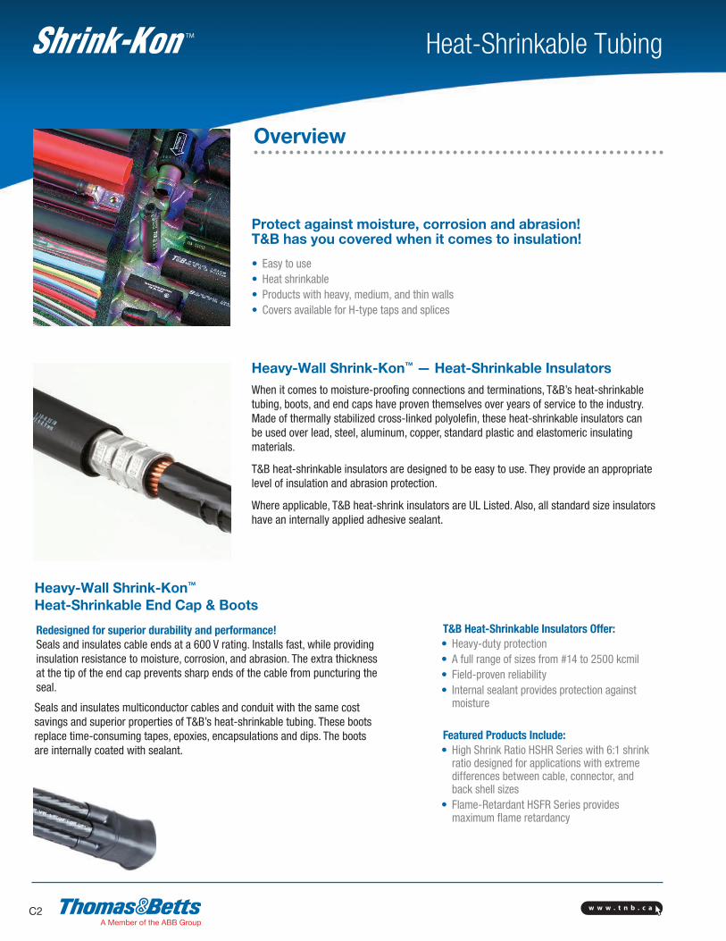
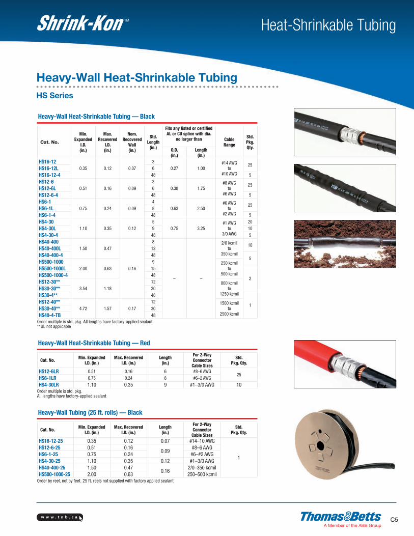
Heavy-Wall Shrink-Kon™ — Heat-Shrinkable InsulatorsWhen it comes to moisture-proofing connections and terminations, T&B’s heat-shrinkable tubing, boots, and end caps have proven themselves over years of service to the industry. Made of thermally stabilized cross-linked polyolefin, these heat-shrinkable insulators can be used over lead, steel, aluminum, copper, standard plastic and elastomeric insulating materials.
T&B heat-shrinkable insulators are designed to be easy to use. They provide an appropriate level of insulation and abrasion protection.
Where applicable, T&B heat-shrink insulators are UL Listed. Also, all standard size insulators have an internally applied adhesive sealant.
Heavy-Wall Shrink-Kon™
Heat-Shrinkable End Cap & Boots
Redesigned for superior durability and performance! Seals and insulates cable ends at a 600 V rating. Installs fast, while providing insulation resistance to moisture, corrosion, and abrasion. The extra thickness at the tip of the end cap prevents sharp ends of the cable from puncturing the seal.
Seals and insulates multiconductor cables and conduit with the same cost savings and superior properties of T&B’s heat-shrinkable tubing. These boots replace time-consuming tapes, epoxies, encapsulations and dips. The boots are internally coated with sealant.
T&B Heat-Shrinkable Insulators Offer:• Heavy-duty protection• A full range of sizes from #14 to 2500 kcmil• Field-proven reliability• Internal sealant provides protection against
moisture
Featured Products Include:• High Shrink Ratio HSHR Series with 6:1 shrink
ratio designed for applications with extreme differences between cable, connector, and back shell sizes
• Flame-Retardant HSFR Series provides maximum flame retardancy
w w w . t n b . c a C3
Heat-Shrinkable TubingTM
Overview
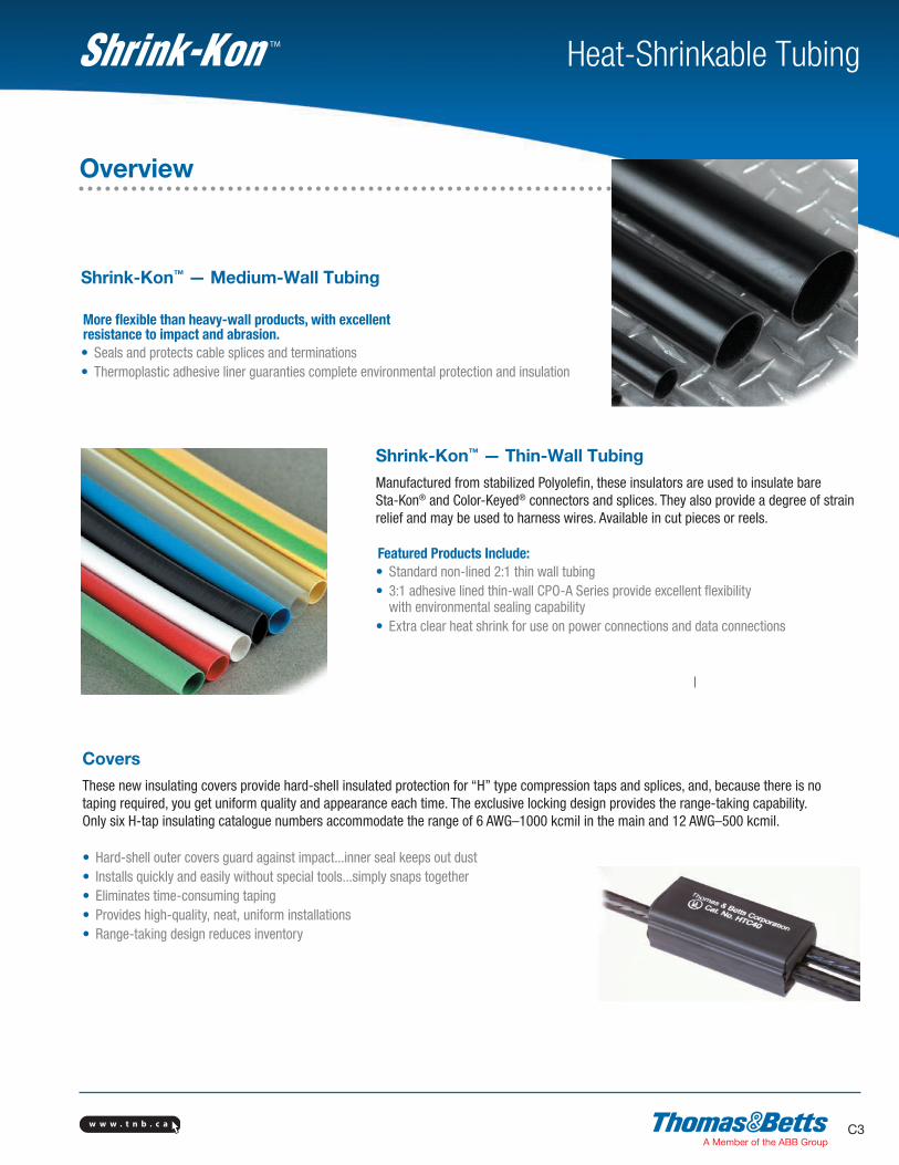
Shrink-Kon™ — Medium-Wall Tubing
More flexible than heavy-wall products, with excellent resistance to impact and abrasion.• Seals and protects cable splices and terminations• Thermoplastic adhesive liner guaranties complete environmental protection and insulation
Shrink-Kon™ — Thin-Wall TubingManufactured from stabilized Polyolefin, these insulators are used to insulate bare Sta-Kon® and Color-Keyed® connectors and splices. They also provide a degree of strain relief and may be used to harness wires. Available in cut pieces or reels.
Featured Products Include:• Standard non-lined 2:1 thin wall tubing• 3:1 adhesive lined thin-wall CPO-A Series provide excellent flexibility with environmental sealing capability• Extra clear heat shrink for use on power connections and data connections
CoversThese new insulating covers provide hard-shell insulated protection for “H” type compression taps and splices, and, because there is no taping required, you get uniform quality and appearance each time. The exclusive locking design provides the range-taking capability. Only six H-tap insulating catalogue numbers accommodate the range of 6 AWG–1000 kcmil in the main and 12 AWG–500 kcmil.
• Hard-shell outer covers guard against impact...inner seal keeps out dust• Installs quickly and easily without special tools...simply snaps together• Eliminates time-consuming taping• Provides high-quality, neat, uniform installations• Range-taking design reduces inventory
w w w . t n b . c aC4
Heat-Shrinkable TubingTM
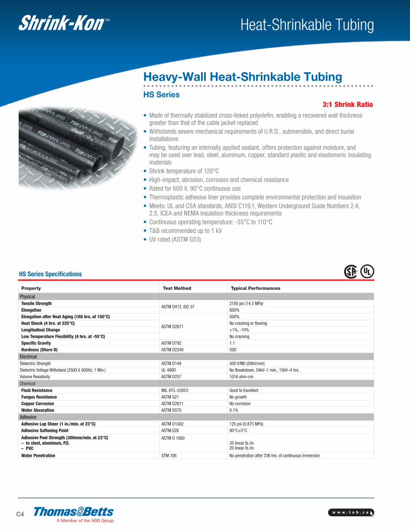
3:1 Shrink Ratio• Made of thermally stabilized cross-linked polyolefin, enabling a recovered wall thickness greater than that of the cable jacket replaced• Withstands severe mechanical requirements of U.R.D., submersible, and direct burial
installations• Tubing, featuring an internally applied sealant, offers protection against moisture, and
may be used over lead, steel, aluminum, copper, standard plastic and elastomeric insulating materials
• Shrink temperature of 120°C• High-impact, abrasion, corrosion and chemical resistance• Rated for 600 V, 90°C continuous use• Thermoplastic adhesive liner provides complete environmental protection and insulation• Meets: UL and CSA standards, ANSI C119.1, Western Underground Guide Numbers 2.4, 2.5, ICEA and NEMA insulation thickness requirements• Continuous operating temperature: -55°C to 110°C• T&B recommended up to 1 kV• UV rated (ASTM G53)
HS Series Specifications
Property Test Method Typical Performances
PhysicalTensile Strength
ASTM D412, ISO 372100 psi (14.5 MPa)
Elongation 600%Elongation after Heat Aging (168 hrs. at 150°C)
ASTM D2671
500%Heat Shock (4 hrs. at 225°C) No cracking or flowingLongitudinal Change +1%, -10%Low Temperature Flexibility (4 hrs. at -55°C) No crackingSpecific Gravity ASTM D792 1.1Hardness (Shore D) ASTM D2240 50D
ElectricalDIelectric Strength ASTM D149 500 V/Mil (20kV/mm)Dielectric Voltage Withstand (2500 V, 600Hz, 1 Min.) UL 486D No Breakdown, 24kV–1 min., 15kV–4 hrs.Volume Resistivity ASTM D257 1016 ohm-cm
Chemical
Fluid Resistance MIL-DTL-23053 Good to Excellent Fungus Resistance ASTM G21 No growthCopper Corrosion ASTM D2671 No corrosionWater Absorption ASTM D570 0.1%
AdhesiveAdhesive Lap Sheer (1 in./min. at 23°C) ASTM D1002 125 psi (0.875 MPa)Adhesive Softening Point ASTM E28 90°C±5°C
Adhesive Peel Strength (300mm/min. at 23°C)– to steel, aluminum, P.E.– PVC
ASTM D 100035 linear lb./in.20 linear lb./in.
Water Penetration STM 706 No penetration after 236 hrs. of continuous immersion
Heavy-Wall Heat-Shrinkable TubingHS Series
w w w . t n b . c a C5
Heat-Shrinkable TubingTM
Heavy-Wall Heat-Shrinkable Tubing — Black
Cat. No.
Min.Expanded
I.D.(in.)
Max.Recovered
I.D.(in.)
Nom.Recovered
Wall(in.)
Std.Length
(in.)
Fits any listed or certifiedAL or CU splice with dia.
no larger than CableRange
Std.Pkg.Qty.O.D.
(in.)Length
(in.)HS16-12
0.35 0.12 0.073
0.27 1.00#14 AWG
to#10 AWG
25HS16-12L 6
HS16-12-4 48 5
HS12-60.51 0.16 0.09
30.38 1.75
#8 AWGto
#6 AWG
25HS12-6L 6
HS12-6-4 48 5
HS6-10.75 0.24 0.09
40.63 2.50
#6 AWGto
#2 AWG
25HS6-1L 8
HS6-1-4 48 5
HS4-301.10 0.35 0.12
50.75 3.25
#1 AWGto
3/0 AWG
20
HS4-30L 9 10
HS4-30-4 48 5
HS40-4001.50 0.47
0.16
8
– –
2/0 kcmilto
350 kcmil
10HS40-400L 12
HS40-400-4 485
HS500-10002.00 0.63
9 250 kcmilto
500 kcmilHS500-1000L 15
2HS500-1000-4 48
HS12-30**3.54 1.18
12 800 kcmilto
1250 kcmilHS30-30** 30
HS30-4** 48
1HS12-40**
4.72 1.57 0.1712 1500 kcmil
to2500 kcmil
HS30-40** 30
HS40-4-TB 48Order multiple is std. pkg. All lengths have factory-applied sealant**UL not applicable
Heavy-Wall Heat-Shrinkable Tubing — Red
Cat. No. Min. ExpandedI.D. (in.)
Max. RecoveredI.D. (in.)
Length(in.)
For 2-WayConnector
Cable Sizes
Std.Pkg. Qty.
HS12-6LR 0.51 0.16 6 #8–6 AWG25
HS6-1LR 0.75 0.24 8 #6–2 AWG
HS4-30LR 1.10 0.35 9 #1–3/0 AWG 10Order multiple is std. pkg.All lengths have factory-applied sealant
Heavy-Wall Tubing (25 ft. rolls) — Black
Cat. No. Min. ExpandedI.D. (in.)
Max. RecoveredI.D. (in.)
Length(in.)
For 2-WayConnector
Cable Sizes
Std.Pkg. Qty.
HS16-12-25 0.35 0.12 0.07 #14–10 AWG
1
HS12-6-25 0.51 0.160.09
#8–6 AWGHS6-1-25 0.75 0.24 #6–#2 AWGHS4-30-25 1.10 0.35 0.12 #1–3/0 AWGHS40-400-25 1.50 0.47
0.162/0–350 kcmil
HS500-1000-25 2.00 0.63 250–500 kcmilOrder by reel, not by feet. 25 ft. reels not supplied with factory applied sealant
Heavy-Wall Heat-Shrinkable TubingHS Series
w w w . t n b . c aC6
Heat-Shrinkable TubingTM
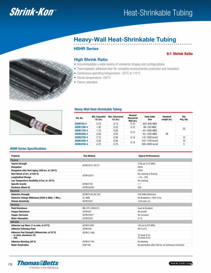
High Shrink Ratio• Accommodates a wide variety of connector shapes and configurations• Thermoplastic adhesive liner for complete environmental protection and insulation• Continuous operating temperature: -55°C to 110°C• Shrink temperature: 120°C• Flame-retardant
Heavy-Wall Heat-Shrinkable Tubing
Cat. No. Min. ExpandedI.D. (in.)
Max. RecoveredI.D. (in.)
NominalRecoveredWall (in.)
Code CableSize
StandardLength (in.)
Std.Pkg. Qty.
HSHR750-4 0.75 0.13 0.10 #22–#46 AWG
48
25HSHR1300-4 1.30 0.22 0.12 #8–700 AWGHSHR1750-4 1.75 0.29
0.13#4–1000 AWG
HSHR2000-4 2.00 0.33 #2–1250 AWGHSHR2750-4 2.75 0.46 0.14 1/0–1500 kcmil 15HSHR3500-4 3.50 0.58
0.153/0–1750 kcmil 10
HSHR4700-4 4.70 0.78 300–2000 kcmil 5
6:1 Shrink Ratio
HSHR Series Specifications
Property Test Method Typical Performances
PhysicalTensile Strength
ASTM D412, ISO 372100 psi (14.5 MPa)
Elongation 600%Elongation after Heat Aging (168 hrs. at 150°C)
ASTM D2671
500%Heat Shock (4 hrs. at 225°C) No cracking or flowingLongitudinal Change +1%, -10%Low Temperature Flexibility (4 hrs. at -55°C) No crackingSpecific Gravity ASTM D792 1.1Hardness (Shore D) ASTM D2240 50D
ElectricalDIelectric Strength ASTM D149, IEC 243 500 V/Mil (20kV/mm)Dielectric Voltage Withstand (2500 V, 60Hz, 1 Min.) UL 486D No Breakdown, 15kV–4 hrs.Volume Resistivity ASTM D257 1016 ohm-cm
ChemicalFluid Resistance MIL-DTL-23053/15 Good to Excellent Fungus Resistance ASTM G21 No growthCopper Corrosion ASTM D2671 No corrosionWater Absorption ASTM D570 0.1%
AdhesiveAdhesive Lap Sheer (1 in./min. at 23°C) ASTM D1002 125 psi (0.875 MPa)Adhesive Softening Point ASTM E28 90°C±5°C
Adhesive Peel Strength (300mm/min. at 23°C)– to steel, aluminum, P.E.– PVC
ASTM D 100035 linear lb./in.20 linear lb./in.
Adhesive Blocking (30°C) ASTM D1146 No blockingWater Penetration STM 706 No penetration after 236 hrs. of continuous immersion
Heavy-Wall Heat-Shrinkable TubingHSHR Series
w w w . t n b . c a C7
Heat-Shrinkable TubingTM
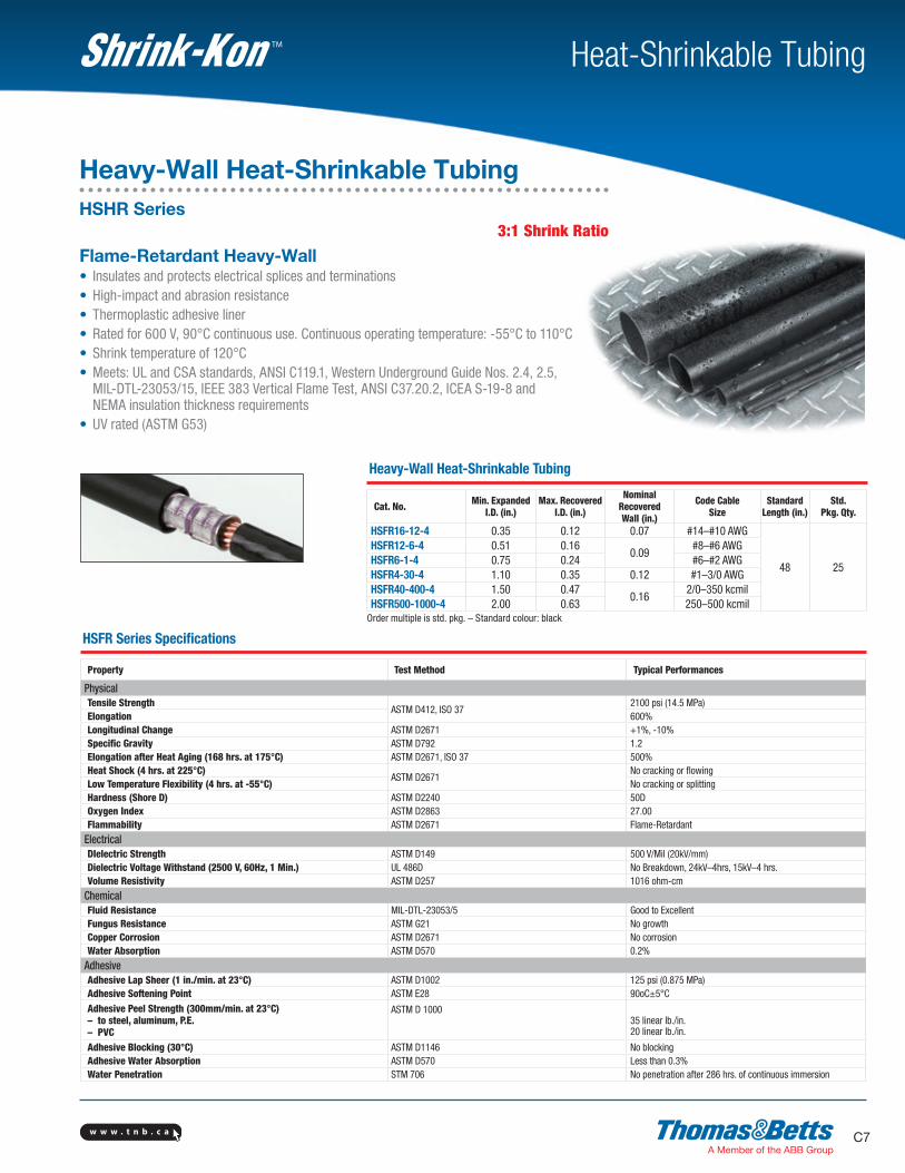
Flame-Retardant Heavy-Wall• Insulates and protects electrical splices and terminations• High-impact and abrasion resistance• Thermoplastic adhesive liner• Rated for 600 V, 90°C continuous use. Continuous operating temperature: -55°C to 110°C• Shrink temperature of 120°C• Meets: UL and CSA standards, ANSI C119.1, Western Underground Guide Nos. 2.4, 2.5, MIL-DTL-23053/15, IEEE 383 Vertical Flame Test, ANSI C37.20.2, ICEA S-19-8 and NEMA insulation thickness requirements• UV rated (ASTM G53)
3:1 Shrink Ratio
Heavy-Wall Heat-Shrinkable Tubing
Cat. No. Min. ExpandedI.D. (in.)
Max. RecoveredI.D. (in.)
NominalRecoveredWall (in.)
Code CableSize
StandardLength (in.)
Std.Pkg. Qty.
HSFR16-12-4 0.35 0.12 0.07 #14–#10 AWG
48 25
HSFR12-6-4 0.51 0.160.09
#8–#6 AWGHSFR6-1-4 0.75 0.24 #6–#2 AWGHSFR4-30-4 1.10 0.35 0.12 #1–3/0 AWGHSFR40-400-4 1.50 0.47
0.162/0–350 kcmil
HSFR500-1000-4 2.00 0.63 250–500 kcmilOrder multiple is std. pkg. – Standard colour: black
HSFR Series Specifications
Property Test Method Typical Performances
PhysicalTensile Strength
ASTM D412, ISO 372100 psi (14.5 MPa)
Elongation 600%Longitudinal Change ASTM D2671 +1%, -10%Specific Gravity ASTM D792 1.2Elongation after Heat Aging (168 hrs. at 175°C) ASTM D2671, ISO 37 500%Heat Shock (4 hrs. at 225°C)
ASTM D2671No cracking or flowing
Low Temperature Flexibility (4 hrs. at -55°C) No cracking or splitting Hardness (Shore D) ASTM D2240 50DOxygen Index ASTM D2863 27.00Flammability ASTM D2671 Flame-Retardant
ElectricalDIelectric Strength ASTM D149 500 V/Mil (20kV/mm)Dielectric Voltage Withstand (2500 V, 60Hz, 1 Min.) UL 486D No Breakdown, 24kV–4hrs, 15kV–4 hrs.Volume Resistivity ASTM D257 1016 ohm-cm
ChemicalFluid Resistance MIL-DTL-23053/5 Good to Excellent Fungus Resistance ASTM G21 No growthCopper Corrosion ASTM D2671 No corrosionWater Absorption ASTM D570 0.2%
AdhesiveAdhesive Lap Sheer (1 in./min. at 23°C) ASTM D1002 125 psi (0.875 MPa)Adhesive Softening Point ASTM E28 90oC±5°C
Adhesive Peel Strength (300mm/min. at 23°C)– to steel, aluminum, P.E.– PVC
ASTM D 100035 linear lb./in.20 linear lb./in.
Adhesive Blocking (30°C) ASTM D1146 No blockingAdhesive Water Absorption ASTM D570 Less than 0.3%Water Penetration STM 706 No penetration after 286 hrs. of continuous immersion
Heavy-Wall Heat-Shrinkable TubingHSHR Series
w w w . t n b . c aC8
Heat-Shrinkable TubingTM
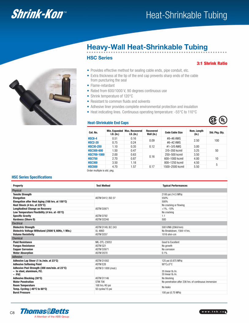
• Provides effective method for sealing cable ends, pipe conduit, etc.• Extra thickness at the tip of the end cap prevents sharp ends of the cable
from puncturing the seal• Flame-retardant• Rated from 600/1000 V, 90 degrees continuous use• Shrink temperature of 120°C• Resistant to common fluids and solvents• Adhesive liner provides complete environmental protection and insulation• Heat indicating lines. Continuous operating temperature: -55°C to 110°C
Heat-Shrinkable End Caps
Cat. No. Min. ExpandedI.D. (in.)
Max. RecoveredI.D. (in.)
RecoveredWall (in.) Code Cable Size Nom. Length
(in.) Std. Pkg. Qty.
HSC8-4 0.51 0.160.09
#8–#6 AWG2.50 100
HSC2-20 0.75 0.24 #6–#2 AWGHSC30-250 1.10 0.35 0.12 #1–3/0 AWG 3.00
50HSC300-600 1.50 0.47
0.16
2/0–350 kcmil 3.25HSC700-1000 2.00 0.63 250–500 kcmil 3.50HSC750 2.70 0.87 600–1000 kcmil 4.00 10HSC300 3.50 1.18 800–1250 kcmil 4.50
5HSC500 4.70 1.57 0.17 1500–2500 kcmil 5.50
Order multiple is std. pkg.
3:1 Shrink Ratio
HSC Series Specifications
Property Test Method Typical Performances
PhysicalTensile Strength
ASTM D412, ISO 372100 psi (14.5 MPa)
Elongation 550%Elongation after Heat Aging (168 hrs. at 150°C) 500%Heat Shock (4 hrs. at 225°C)
ASTM D2671No cracking or flowing
Longitudinal Change on Recovery +1%, -10%Low Temperature Flexibility (4 hrs. at -55°C) No crackingSpecific Gravity ASTM D792 1.1Hardness (Shore D) ASTM D2240 50D
ElectricalDIelectric Strength ASTM D149, IEC 243 500 V/Mil (20kV/mm)Dielectric Voltage Withstand (2500 V, 60Hz, 1 Min.) UL 486D No Breakdown, 15kV–4 hrs.Volume Resistivity ASTM D257 1016 ohm-cm
ChemicalFluid Resistance MIL-DTL-23053 Good to Excellent Fungus Resistance ASTM G21 No growthCopper Corrosion ASTM D2671 No corrosionWater Absorption ASTM D570 0.1%
AdhesiveAdhesive Lap Sheer (1 in./min. at 23°C) ASTM D1002 125 psi (0.875 MPa)Adhesive Softening Point ASTM E28 90°C±5°CAdhesive Peel Strength (300 mm/min. at 23°C)– to steel, aluminum, P.E.– PVC
ASTM D 1000 (mod.)35 linear lb./in.20 linear lb./in.
Adhesive Blocking (30°C) ASTM D1146 No blockingWater Penetration STM 706 No penetration after 236 hrs. of continuous immersionRoom Temperature 168 hrs./40 psi
No leaksTemp. Cycling (-40°C to 60°C) 50 cycles/15 psiBurst Pressure 100 psi (0.70 MPa)
Heavy-Wall Heat-Shrinkable TubingHSC Series
w w w . t n b . c a C9
Heat-Shrinkable TubingTM
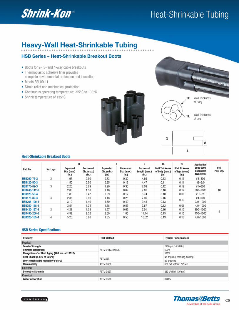
• Boots for 2-, 3- and 4-way cable breakouts• Thermoplastic adhesive liner provides complete environmental protection and insulation• Meets ESI 09-11• Strain relief and mechanical protection• Continuous operating temperature: -55°C to 100°C• Shrink temperature of 135°C Wall Thickness
of Body
Wall Thickness of Leg
TB
TL
D
L
d
Heat-Shrinkable Breakout Boots
Cat. No. No. Legs
D d L TB TL ApplicationLegs 600VConductorAWG/kcmil
Std.Pkg. Qty.
ExpandedDia. (min.)
(in.)
RecoveredDia. (max.)
(in.)
ExpandedDia. (min.)
(in.)
RecoveredDia. (max.)
(in.)
RecoveredLength (nom.)
(in.)
Wall Thicknessof body (nom.)
(in.)
Wall Ticknessof legs (nom.)
(in.)
HSB200-75-2 2 1.97 0.90 0.83 0.30 4.69 0.13 0.13 #3–300
10
HSB120-50-33
1.50 0.50 0.65 0.16 4.47 0.11 0.11 #8–3/0HSB170-82-3 2.20 0.89 1.20 0.35 7.09 0.12 0.12 #1–600HSB240-112-3 2.83 1.38 1.46 0.69 7.01 0.16 0.12 300–1000HSB125-50-4
41.83 0.47 0.59 0.12 3.74 0.10 0.08 #12–2/0
HSB175-82-4 2.36 0.90 1.18 0.25 7.95 0.160.13
#4–600HSB265-120-4 3.10 1.40 1.50 0.49 9.45 0.13 3/0–1000HSB350-138-3
33.54 1.34 1.38 0.55 7.87 0.12 0.08 4/0–1000
5HSB430-157-3 4.33 1.38 1.57 0.69 7.01 0.16 0.12 300–1000HSB490-200-3 4.92 2.32 2.00 1.00 11.14 0.15 0.15 450–1000HSB520-135-4 4 5.25 3.00 1.35 0.55 10.02 0.13 0.16 4/0–1000
HSB Series Specifications
Property Test Method Typical Performances
PhysicalTensile Strength
ASTM D412, ISO 5402100 psi (14.5 MPa)
Ultimate Elongation 600%Elongation after Heat Aging (168 hrs. at 175°C) 520%Heat Shock (4 hrs. at 225°C)
ASTM2671No dripping, cracking, flowing
Low Temperature Flexibility (-55°C) No crackingFlammability ASTM D630 Self ext. within 1.97 sec.
ElectricalDIelectric Strength ASTM D2671 280 V/Mil (11kV/mm)
ChemicalWater Absorption ASTM D570 0.03%
Heavy-Wall Heat-Shrinkable TubingHSB Series – Heat-Shrinkable Breakout Boots
w w w . t n b . c aC10
Heat-Shrinkable TubingTM
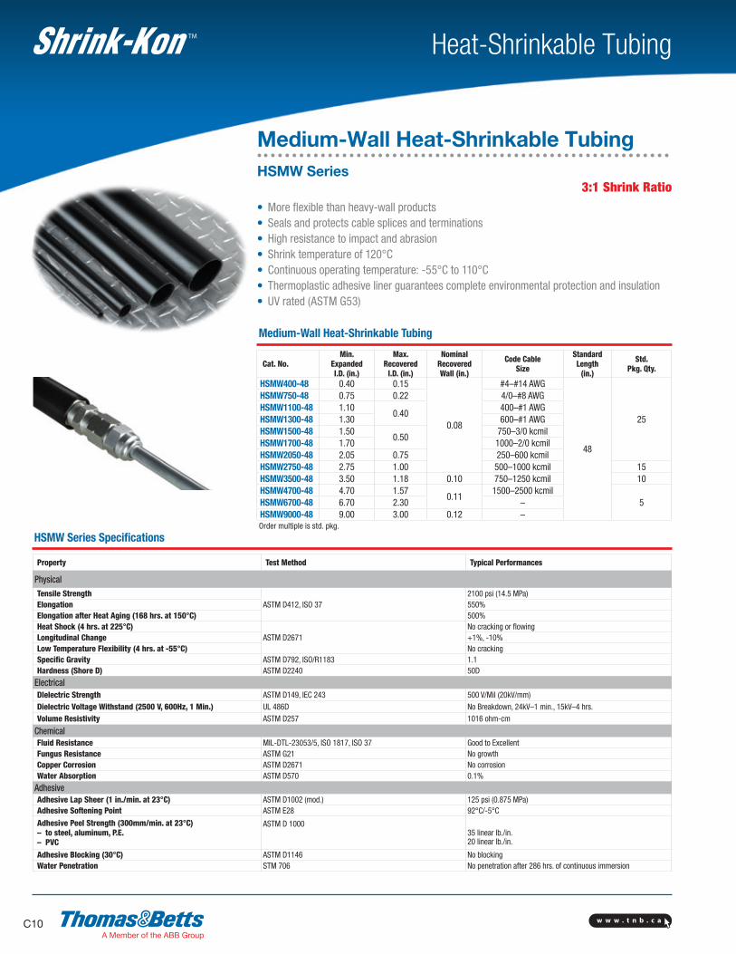
• More flexible than heavy-wall products• Seals and protects cable splices and terminations• High resistance to impact and abrasion• Shrink temperature of 120°C• Continuous operating temperature: -55°C to 110°C• Thermoplastic adhesive liner guarantees complete environmental protection and insulation• UV rated (ASTM G53)
Medium-Wall Heat-Shrinkable Tubing
Cat. No.Min.
ExpandedI.D. (in.)
Max.Recovered
I.D. (in.)
NominalRecoveredWall (in.)
Code CableSize
StandardLength
(in.)
Std.Pkg. Qty.
HSMW400-48 0.40 0.15
0.08
#4–#14 AWG
48
25
HSMW750-48 0.75 0.22 4/0–#8 AWGHSMW1100-48 1.10
0.40400–#1 AWG
HSMW1300-48 1.30 600–#1 AWGHSMW1500-48 1.50
0.50750–3/0 kcmil
HSMW1700-48 1.70 1000–2/0 kcmilHSMW2050-48 2.05 0.75 250–600 kcmilHSMW2750-48 2.75 1.00 500–1000 kcmil 15HSMW3500-48 3.50 1.18 0.10 750–1250 kcmil 10HSMW4700-48 4.70 1.57
0.111500–2500 kcmil
5HSMW6700-48 6.70 2.30 –HSMW9000-48 9.00 3.00 0.12 –
Order multiple is std. pkg.
HSMW Series Specifications
Property Test Method Typical Performances
PhysicalTensile Strength
ASTM D412, ISO 372100 psi (14.5 MPa)
Elongation 550%Elongation after Heat Aging (168 hrs. at 150°C) 500%Heat Shock (4 hrs. at 225°C)
ASTM D2671No cracking or flowing
Longitudinal Change +1%, -10%Low Temperature Flexibility (4 hrs. at -55°C) No crackingSpecific Gravity ASTM D792, ISO/R1183 1.1Hardness (Shore D) ASTM D2240 50D
ElectricalDIelectric Strength ASTM D149, IEC 243 500 V/Mil (20kV/mm)Dielectric Voltage Withstand (2500 V, 600Hz, 1 Min.) UL 486D No Breakdown, 24kV–1 min., 15kV–4 hrs.Volume Resistivity ASTM D257 1016 ohm-cm
ChemicalFluid Resistance MIL-DTL-23053/5, ISO 1817, ISO 37 Good to Excellent Fungus Resistance ASTM G21 No growthCopper Corrosion ASTM D2671 No corrosionWater Absorption ASTM D570 0.1%
AdhesiveAdhesive Lap Sheer (1 in./min. at 23°C) ASTM D1002 (mod.) 125 psi (0.875 MPa)Adhesive Softening Point ASTM E28 92°C/-5°C
Adhesive Peel Strength (300mm/min. at 23°C)– to steel, aluminum, P.E.– PVC
ASTM D 100035 linear lb./in.20 linear lb./in.
Adhesive Blocking (30°C) ASTM D1146 No blockingWater Penetration STM 706 No penetration after 286 hrs. of continuous immersion
Medium-Wall Heat-Shrinkable TubingHSMW Series
3:1 Shrink Ratio
w w w . t n b . c a C11
Heat-Shrinkable TubingTM
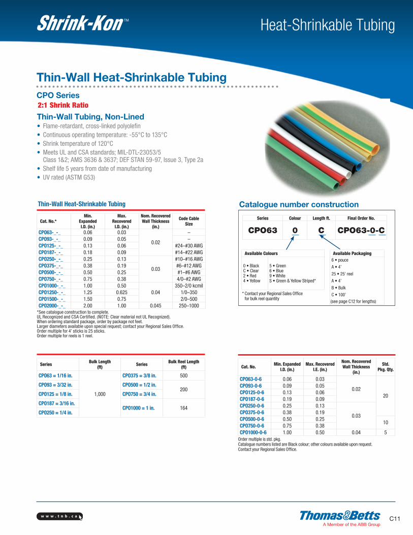
Series Colour Length ft. Final Order No.
CPO63 0 C CPO63-0-C
Catalogue number construction
Thin-Wall Tubing, Non-Lined• Flame-retardant, cross-linked polyolefin• Continuous operating temperature: -55°C to 135°C• Shrink temperature of 120°C• Meets UL and CSA standards; MIL-DTL-23053/5 Class 1&2; AMS 3636 & 3637; DEF STAN 59-97, Issue 3, Type 2a• Shelf life 5 years from date of manufacturing• UV rated (ASTM G53)
Thin-Wall Heat-Shrinkable Tubing
Cat. No.*Min.
ExpandedI.D. (in.)
Max.Recovered
I.D. (in.)
Nom. RecoveredWall Thickness
(in.)
Code CableSize
CPO63-_-_ 0.06 0.03
0.02
–CPO93-_-_ 0.09 0.05 –CPO125-_-_ 0.13 0.06 #24–#30 AWGCPO187-_-_ 0.18 0.09 #14–#22 AWGCPO250-_-_ 0.25 0.13
0.03
#10–#16 AWGCPO375-_-_ 0.38 0.19 #6–#12 AWGCPO500-_-_ 0.50 0.25 #1–#6 AWGCPO750-_-_ 0.75 0.38 4/0–#2 AWGCPO1000-_-_ 1.00 0.50
0.04350–2/0 kcmil
CPO1250-_-_ 1.25 0.625 1/0–350CPO1500-_-_ 1.50 0.75 2/0–500CPO2000-_-_ 2.00 1.00 0.045 250–1000
*See catalogue construction to complete.UL Recognized and CSA Certified. (NOTE: Clear material not UL Recognized). When ordering standard package, order by package not feet.Larger diameters available upon special request; contact your Regional Sales Office.Order multiple for 4’ sticks is 25 sticks.Order multiple for reels is 1 reel.
Series Bulk Length(ft) Series Bulk Reel Length
(ft)
CPO63 = 1/16 in.
1,000
CPO375 = 3/8 in. 500
CPO93 = 3/32 in. CPO500 = 1/2 in.200
CPO125 = 1/8 in. CPO750 = 3/4 in.
CPO187 = 3/16 in.CPO1000 = 1 in. 164
CPO250 = 1/4 in.
Cat. No. Min. ExpandedI.D. (in.)
Max. RecoveredI.E. (in.)
Nom. RecoveredWall Thickness
(in.)
Std.Pkg. Qty.
CPO63-0-6 0.06 0.03
0.0220
CPO93-0-6 0.09 0.05CPO125-0-6 0.13 0.06CPO187-0-6 0.19 0.09CPO250-0-6 0.25 0.13
0.03CPO375-0-6 0.38 0.19CPO500-0-6 0.50 0.25
10CPO750-0-6 0.75 0.38CPO1000-0-6 1.00 0.50 0.04 5
Order multiple is std. pkg.Catalogue numbers listed are Black colour; other colours available upon request.Contact your Regional Sales Office.
Thin-Wall Heat-Shrinkable TubingCPO Series
* Contact your Regional Sales Office for bulk reel quantity
2:1 Shrink Ratio
Available Colours
0 • BlackC • Clear2 • Red4 • Yellow
5 • Green6 • Blue9 • WhiteS • Green & Yellow Striped*
Available Packaging6 • pouce
A • 4’
25 • 25’ reel
A • 4’
B • Bulk
C • 100’(see page C12 for lengths)
w w w . t n b . c aC12
Heat-Shrinkable TubingTM
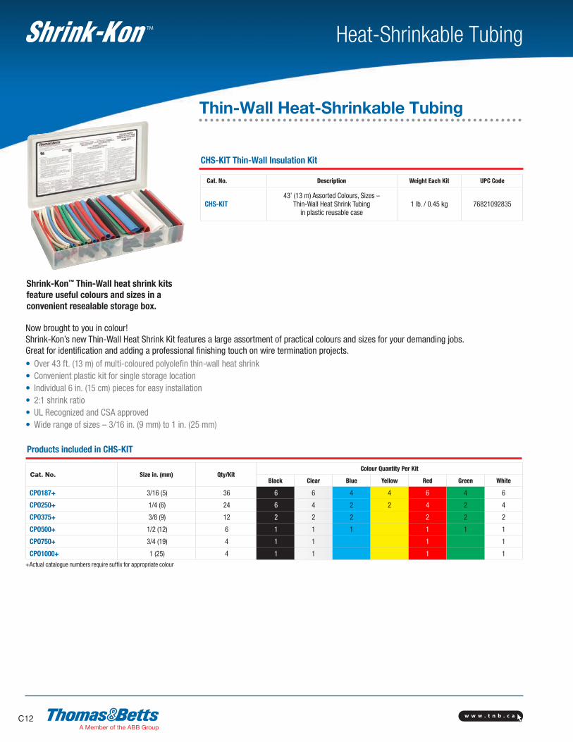
Now brought to you in colour! Shrink-Kon’s new Thin-Wall Heat Shrink Kit features a large assortment of practical colours and sizes for your demanding jobs. Great for identification and adding a professional finishing touch on wire termination projects.• Over 43 ft. (13 m) of multi-coloured polyolefin thin-wall heat shrink• Convenient plastic kit for single storage location• Individual 6 in. (15 cm) pieces for easy installation• 2:1 shrink ratio• UL Recognized and CSA approved• Wide range of sizes – 3/16 in. (9 mm) to 1 in. (25 mm)
Products included in CHS-KIT
Cat. No. Size in. (mm) Qty/KitColour Quantity Per Kit
Black Clear Blue Yellow Red Green White
CPO187+ 3/16 (5) 36 6 6 4 4 6 4 6
CPO250+ 1/4 (6) 24 6 4 2 2 4 2 4
CPO375+ 3/8 (9) 12 2 2 2 2 2 2
CPO500+ 1/2 (12) 6 1 1 1 1 1 1
CPO750+ 3/4 (19) 4 1 1 1 1
CPO1000+ 1 (25) 4 1 1 1 1+Actual catalogue numbers require suffix for appropriate colour
CHS-KIT Thin-Wall Insulation Kit
Cat. No. Description Weight Each Kit UPC Code
CHS-KIT43’ (13 m) Assorted Colours, Sizes –
Thin-Wall Heat Shrink Tubing in plastic reusable case
1 lb. / 0.45 kg 76821092835
Shrink-Kon™ Thin-Wall heat shrink kits feature useful colours and sizes in a convenient resealable storage box.
Thin-Wall Heat-Shrinkable Tubing

w w w . t n b . c a C13
Heat-Shrinkable TubingTM
HS-KIT Thin-Wall Insulation Kit
Cat. No. Description Weight Each Kit UPC Code
HS-KIT37’ (11 m) Assorted Sizes – Black Colour Thin-Wall
Heat Shrink Tubing in plastic reusable case
1 lb. /0.45 kg 76821093898
The Original Black Version HS-KIT• Over 37 ft. (11 m) of black polyolefin thin-wall heat shrink• Convenient plastic kit for single storage location• Individual 6 in. (15 cm) pieces for easy installation• 2:1 shrink ratio• UL Recognized and CSA approved
Products included in HS-KIT
Cat. No. Size in. (mm) Qty./Kit
CPO187-0-6 3/16 (5) 32
CPO250-0-6 1/4 (6) 20
CPO375-0-6 3/8 (9) 8
CPO500-0-6 1/2 (12) 6
CPO750-0-6 3/4 (19) 4
CPO1000-0-6 4 (25) 4
Thin-Wall Heat-Shrinkable Tubing
w w w . t n b . c aC14
Heat-Shrinkable TubingTM
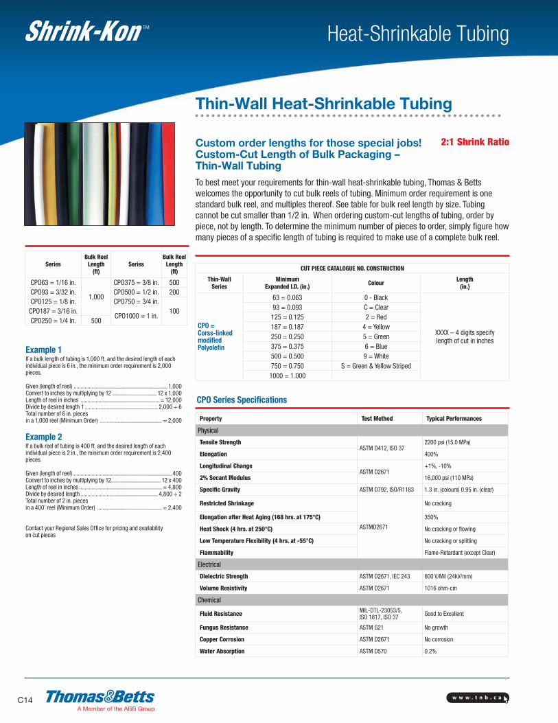
Example 1If a bulk length of tubing is 1,000 ft. and the desired length of each individual piece is 6 in., the minimum order requirement is 2,000 pieces.
Given (length of reel) .................................................................... 1,000 Convert to inches by multiplying by 12 ................................ 12 x 1,000 Length of reel in inches ......................................................... = 12,000 Divide by desired length 1 ..................................................... 2,000 ÷ 6 Total number of 6 in. pieces in a 1,000 reel (Minimum Order) ............................................. = 2,000
Example 2If a bulk reel of tubing is 400 ft. and the desired length of each individual piece is 2 in., the minimum order requirement is 2,400 pieces.
Given (length of reel) ........................................................................ 400Convert to inches by multiplying by 12.................................... 12 x 400Length of reel in inches ............................................................ = 4,800Divide by desired length ........................................................ 4,800 ÷ 2Total number of 2 in. pieces in a 400’ reel (Minimum Order) ............................................... = 2,400
Contact your Regional Sales Office for pricing and availability on cut pieces
Custom order lengths for those special jobs! Custom-Cut Length of Bulk Packaging – Thin-Wall TubingTo best meet your requirements for thin-wall heat-shrinkable tubing, Thomas & Betts welcomes the opportunity to cut bulk reels of tubing. Minimum order requirement is one standard bulk reel, and multiples thereof. See table for bulk reel length by size. Tubing cannot be cut smaller than 1/2 in. When ordering custom-cut lengths of tubing, order by piece, not by length. To determine the minimum number of pieces to order, simply figure how many pieces of a specific length of tubing is required to make use of a complete bulk reel.
CUT PIECE CATALOGUE NO. CONSTRUCTION
Thin-WallSeries
Minimum Expanded I.D. (in.) Colour Length
(in.)
CPO = Corss-linkedmodifiedPolyolefin
63 = 0.063 0 - Black
XXXX – 4 digits specifylength of cut in inches
93 = 0.093 C = Clear125 = 0.125 2 = Red187 = 0.187 4 = Yellow250 = 0.250 5 = Green375 = 0.375 6 = Blue500 = 0.500 9 = White750 = 0.750 S = Green & Yellow Striped1000 = 1.000
CPO Series Specifications
Property Test Method Typical Performances
Physical
Tensile StrengthASTM D412, ISO 37
2200 psi (15.0 MPa)
Elongation 400%
Longitudinal ChangeASTM D2671
+1%, -10%
2% Secant Modulus 16,000 psi (110 MPa)
Specific Gravity ASTM D792, ISO/R1183 1.3 in. (colours) 0.95 in. (clear)
Restricted Shrinkage
ASTMD2671
No cracking
Elongation after Heat Aging (168 hrs. at 175°C) 350%
Heat Shock (4 hrs. at 250°C) No cracking or flowing
Low Temperature Flexibility (4 hrs. at -55°C) No cracking or splitting
Flammability Flame-Retardant (except Clear)
Electrical
DIelectric Strength ASTM D2671, IEC 243 600 V/Mil (24kV/mm)
Volume Resistivity ASTM D2671 1016 ohm-cm
Chemical
Fluid Resistance MIL-DTL-23053/5,ISO 1817, ISO 37 Good to Excellent
Fungus Resistance ASTM G21 No growth
Copper Corrosion ASTM D2671 No corrosion
Water Absorption ASTM D570 0.2%
SeriesBulk Reel
Length(ft)
SeriesBulk Reel
Length(ft)
CPO63 = 1/16 in.
1,000
CPO375 = 3/8 in. 500CPO93 = 3/32 in. CPO500 = 1/2 in. 200CPO125 = 1/8 in. CPO750 = 3/4 in.
100CPO187 = 3/16 in.CPO1000 = 1 in.
CPO250 = 1/4 in. 500
Thin-Wall Heat-Shrinkable Tubing
2:1 Shrink Ratio
w w w . t n b . c a C15
Heat-Shrinkable TubingTM
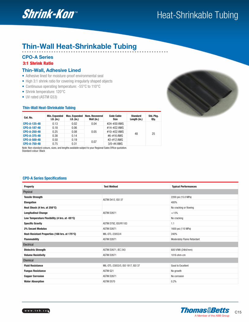
Thin-Wall, Adhesive Lined• Adhesive lined for moisture-proof environmental seal• High 3:1 shrink ratio for covering irregularly shaped objects• Continuous operating temperature: -55°C to 110°C• Shrink temperature: 120°C• UV rated (ASTM G53)
Thin-Wall Heat-Shrinkable Tubing
Cat. No. Min. ExpandedI.D. (in.)
Max. ExpandedI.D. (in.)
Nom. RecoveredWall (in.)
Code CableSize
StandardLength (in.)
Std. Pkg.Qty.
CPO-A-125-48 0.13 0.02 0.04 #24–#30 AWG
48 25
CPO-A-187-48 0.18 0.060.05
#14–#22 AWGCPO-A-250-48 0.25 0.08 #10–#22 AWGCPO-A-375-48 0.38 0.14 #6–#16 AWGCPO-A-500-48 0.50 0.19
0.07#2–#12 AWG
CPO-A-750-48 0.75 0.31 3/0–#4 AWGNote: Non-standard colours, sizes, and lengths available subject to your Regional Sales Office quotation.Standard colour: Black
CPO-A Series Specifications
Property Test Method Typical Performances
Physical
Tensile StrengthASTM D412, ISO 37
2200 psi (15.0 MPa)
Elongation 400%
Heat Shock (4 hrs. at 250°C)
ASTM D2671
No cracking or flowing
Longitudinal Change +/-5%
Low Temperature Flexibility (4 hrs. at -55°C) No cracking
Specific Gravity ASTM D792, ISO/R1183 1.1
2% Secant Modulus ASTM D2671 1600 psi (110 MPa)
Heat-Resistant Properties (168 hrs. at 175°C) MIL-DTL-23053/4 240%
Flammability ASTM D2671 Moderately Flame Retardant
Electrical
DIelectric Strength ASTM D2671, IEC 243 600 V/Mil (24kV/mm)
Volume Resistivity ASTM D2671 1016 ohm-cm
Chemical
Fluid Resistance MIL-DTL-23053/5, ISO 1817, ISO 37 Good to Excellent
Fungus Resistance ASTM G21 No growth
Copper Corrosion ASTM D2671 No corrosion
Water Absorption ASTM D570 0.2%
Thin-Wall Heat-Shrinkable TubingCPO-A Series3:1 Shrink Ratio
w w w . t n b . c aC16
Heat-Shrinkable TubingTM
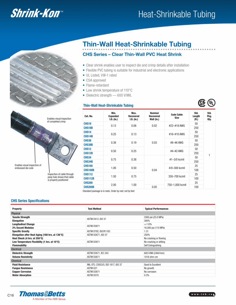
Inspection of cable throughpeep hole shows that cableis properly positioned
Enables visual inspection ofembossed die code
Enables visual inspectionof completed crimp
CHS Series Specifications
Property Test Method Typical Performances
PhysicalTensile Strength
ASTM D412, ISO 373300 psi (23.0 MPa)
Elongation 300%Longitudinal Change
ASTM D2671+/-10%
2% Secant Modulus 16,000 psi (110 MPa)Specific Gravity ASTM D792, ISO/R1183 1.31Elongation after Heat Aging (168 hrs. at 136°C) ASTM D2671, ISO 37 250%Heat Shock (4 hrs. at 250°C)
ASTM D2671No cracking or flowing
Low Temperature Flexibility (1 hrs. at 10°C) No cracking or slittingFlammability Self Extinguishing
ElectricalDIelectric Strength ASTM D2671, IEC 243 600 V/Mil (24kV/mm)Volume Resistivity ASTM D2671 1016 ohm-cm
ChemicalFluid Resistance MIL-DTL-23053/5, ISO 1817, ISO 37 Good to Excellent Fungus Resistance ASTM G21 No growthCopper Corrosion ASTM D2671 No corrosionWater Absorption ASTM D570 0.3%
Thin-Wall Heat-Shrinkable TubingCHS Series – Clear Thin-Wall PVC Heat Shrink
• Clear shrink enables user to inspect die and crimp details after installation• Flexible PVC tubing is suitable for industrial and electronic applications• UL Listed, VW-1 rated• CSA approved• Flame-retardant• Low shrink temperature of 110°C• Dielectric strength — 600 V/MIL
Thin-Wall Heat-Shrinkable Tubing
Cat. No.Min.
ExpandedI.D. (in.)
Max.Recovered
I.D. (in.)
NominalRecoveredWall (in.)
Code CableSize
Std.Length
(ft.)
Std.Pkg.Qty.
CHS180.13 0.06 0.02 #22–#18 AWG
50
1
CHS18B 250CHS14
0.25 0.13
0.03
#16–#10 AWG50
CHS14B 250CHS38
0.38 0.19 #8–#6 AWG50
CHS38B 250CHS12
0.50 0.25 #4–#2 AWG50
CHS12B 250CHS34
0.75 0.38
0.04
#1–3/0 kcmil50
CHS34B 250CHS100
1.00 0.50 4/0–300 kcmil25
CHS100B 100CHS112
1.50 0.75 350–700 kcmil25
CHS112B 100CHS200
2.00 1.00 750–1,000 kcmil25
CHS200B 0.05 100Standard package is in reels. Order by reel; not by feet

w w w . t n b . c a C17
Heat-Shrinkable TubingTM
• Interlocking insulating covers for H-type compression taps• Easy installation: place the H-Tap in the cover and snap the cover closed• Consult your Regional Sales Office for flame-retardant version• Can also be used on C-Taps
Cat. No.Nominal Dimensions in. Std.
Pkg. Qty.A (Length) B (Thick.) C (Width)
HTC2S 21.13 1.44 15
HTC2 3.5HTC40 4.25 1.56 2 2HTC500 6 1.75 2.75 8HTC1000 7
2.38 3.882
HTC1000L 10 3
Specifications• HTC2 and HTC2S use insulation wrap instead of end cushions for inner seal
• Connector Cat. Nos. 54755 through 54790 and 63148 through 63180 require hydraulic crimping tools. Refer to instruction sheets
• Outer Hard Shell Covers: High-impact black thermoplastic (Noryl) Flammability Class, UL 94V-1
• Inner seal: Black neoprene sponge soft closed cell, oxygen index 28% UL 94 HBF
• Temperature Rating: 90°C Maximum
• Voltage Rating: 600 V Maximum
For H-Tap Applications
CoverCat. No.
AL/CUH-Tap No. CU H-Tap
HTC2 63105 –
HTC2S – CHT814-10
HTC40
63110631186312563140
CHT214-9CHT250214-8CHT2514-7CHT2502-6
HTC500 6314863160
CHT50010-5/CHT50040-4CHT75010-3/CHT750350-2
HTC1000L 63170 –
HTC1000 63180/63169 CHT750350-1F
For C-Tap Applications
CoverCat. No. C-Tap No. Colour Code
HTC40
5472054725547305475554760
BrownGreenPinkBlue
Brown
HTC40L2
54735547405474554750
BlackOrangePurpleYellow
HTC500
5476554770547755478054785
PinkBlackYellowWhite
–HTC1000 54790 –
Splice Insulators and Insulating CoversH-Tap Insulating Covers (Hard Covers)
w w w . t n b . c aC18
Heat-Shrinkable TubingTM
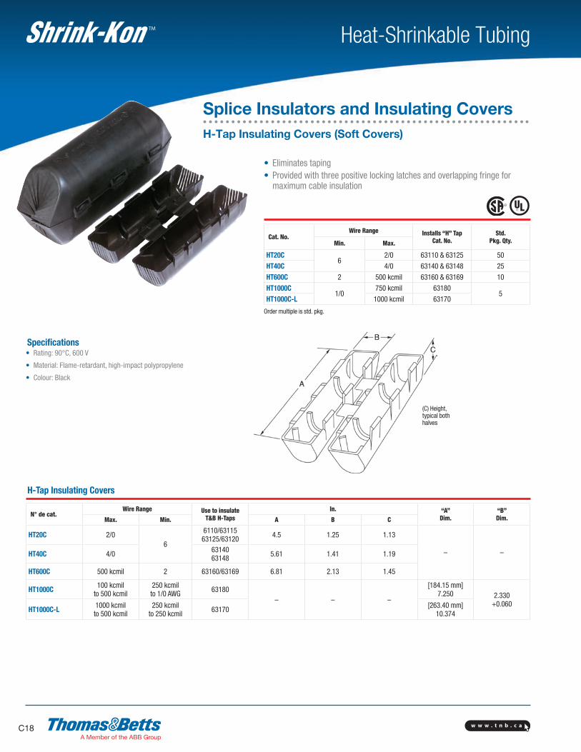
• Eliminates taping• Provided with three positive locking latches and overlapping fringe for
maximum cable insulation
Cat. No.Wire Range Installs “H” Tap
Cat. No.Std.
Pkg. Qty.Min. Max.
HT20C6
2/0 63110 & 63125 50
HT40C 4/0 63140 & 63148 25
HT600C 2 500 kcmil 63160 & 63169 10
HT1000C1/0
750 kcmil 631805
HT1000C-L 1000 kcmil 63170
Order multiple is std. pkg.
(C) Height,typical bothhalves
Specifications• Rating: 90°C, 600 V
• Material: Flame-retardant, high-impact polypropylene
• Colour: Black
H-Tap Insulating Covers
N° de cat.Wire Range Use to insulate
T&B H-TapsIn. “A”
Dim.“B”Dim.Max. Min. A B C
HT20C 2/06
6110/6311563125/63120 4.5 1.25 1.13
– –HT40C 4/0 6314063148 5.61 1.41 1.19
HT600C 500 kcmil 2 63160/63169 6.81 2.13 1.45
HT1000C 100 kcmilto 500 kcmil
250 kcmilto 1/0 AWG 63180
– – –
[184.15 mm]7.250 2.330
+0.060HT1000C-L 1000 kcmil
to 500 kcmil250 kcmil
to 250 kcmil 63170 [263.40 mm]10.374
Splice Insulators and Insulating CoversH-Tap Insulating Covers (Soft Covers)
w w w . t n b . c a C19
Heat-Shrinkable TubingTM
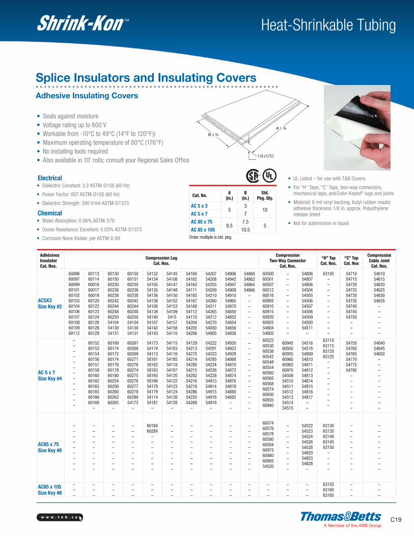
• UL Listed – for use with T&B Covers
• For “H” Taps, “C” Taps, two-way connectors, mechanical taps, and Color-Keyed® lugs and joints
• Material: 6 mil vinyl backing, butyl rubber mastic adhesive thickness 1/8 in. approx. Polyethylene release sheet
• Not for submersion in liquid
Cat. No. A (in.)
B (in.)
Std.Pkg. Qty.
AC 5 x 3 5
310
AC 5 x 7 7
AC 85 x 758.5
7.55
AC 85 x 105 10.5Order multiple is std. pkg.
AdhésivesInsulatorCat. Nos.
Compression LugCat. Nos.
CompressionTwo-Way Connector
Cat. Nos.
“H” TapCat. Nos.
“C” TapCat. Nos
CompressionCable JointCat. Nos.
AC5X3Size Key #2
600966009760099601016010260103601046010660107601086010960112
601136011460016600176001860120601226012360124601266012860129
601306015060230602366023860242602446024860250541045413054131
601506015160230602366023860242602446024860250541045413054131
541325413454105541355413654138541065413954140541075414254143
54145541085414754148541505415254153541095415541575415854110
541605416254163541115416554167541685411254170542045420554206
542075420854255542095421054260542115426554212542705493054905
549065494254947549095491054965549705485054852548545485654858
54860548625486454866
––––––––
605006050160507605126051660905609106091560920609255480454805
––––––––––––
5480654807548065450454505545065450754506545095450054511
–
63105–––––––––––
547105471554720547255473054735547405474554750
–––
546105461554620546255463054635
––––––
AC 5 x 7Size Key #4
–––––––––––––
601526015360154601566015760159601606016260163601656016660168
–
601696017460172601746017660178601806025460256602606026260265
–
602676026860269602716027660274602756027660277602786028054172
–
541735417454113581615816258163581655816654178541795411454181
–
541155418354116541855411854187541205412254123541245412654128
–
541295421354275542145428054215542825421654218542865422054289
–
542225429154223542955422454226542285491354914549155491654918
–
5492054923549285486854870548725487454876548785488054882
––
–––––––––––––
60522605306053860542605486055460560605656056860574609306093560940
60945609506095560960609656097054509545105451154512545135451454515
5451654518548095481054811548125481354814548155481654817
––
63110631156312063125
–––––––––
547555476054765547705477554780
–––––––
546405464554650
––––––––––
AC85 x 75Size Key #6
–––––––––
–––––––––
–––––––––
–––––––––
6018460284
–––––––
–––––––––
–––––––––
–––––––––
–––––––––
–––––––––
605746057660578605806058460975609806098554520
–––––––––
5452254523545245452654528548205482354828
–
6313063135631406314563150
––––
–––––––––
–––––––––
AC85 x 105Size Key #8
–––
–––
–––
–––
–––
–––
–––
–––
–––
–––
–––
–––
–––
631556316063165
–––
–––
Splice Insulators and Insulating CoversAdhesive Insulating Covers
• Seals against moisture• Voltage rating up to 600 V• Workable from -10°C to 49°C (14°F to 120°F))• Maximum operating temperature of 80°C (176°F)• No installing tools required• Also available in 10’ rolls; consult your Regional Sales Office
Electrical• Dielectric Constant: 3.2 ASTM-D150 (60 Hz)
• Power Factor: 007 ASTM-D150 (60 Hz)
• Dielectric Strength: 340 V/mil ASTM-D1373
Chemical• Water Absorption: 0.06% ASTM-570
• Ozone Resistance: Excellent: 0.03% ASTM-D1373
• Corrosion None Visible: per ASTM-D 69
w w w . t n b . c aC20
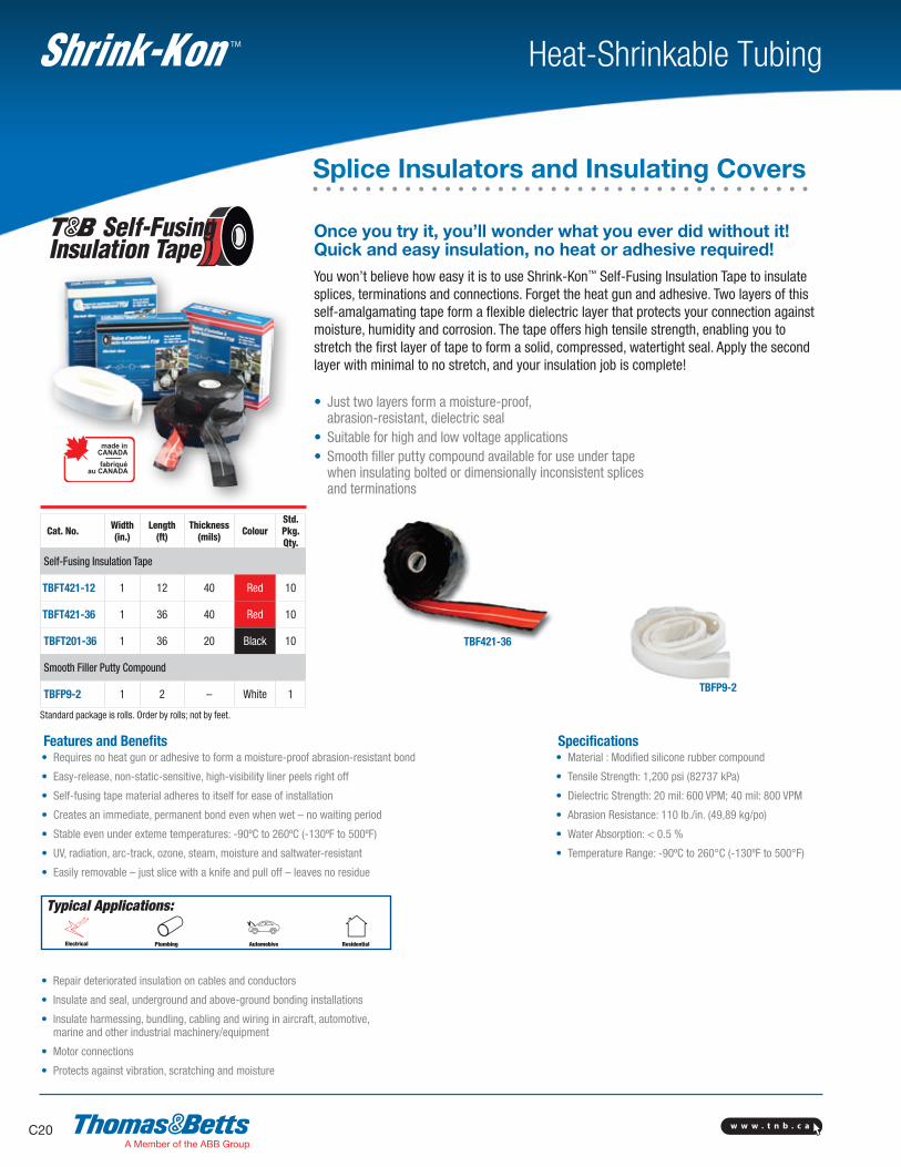
TBF421-36
TBFP9-2
Heat-Shrinkable TubingTM
Once you try it, you’ll wonder what you ever did without it! Quick and easy insulation, no heat or adhesive required!You won’t believe how easy it is to use Shrink-Kon™ Self-Fusing Insulation Tape to insulate splices, terminations and connections. Forget the heat gun and adhesive. Two layers of this self-amalgamating tape form a flexible dielectric layer that protects your connection against moisture, humidity and corrosion. The tape offers high tensile strength, enabling you to stretch the first layer of tape to form a solid, compressed, watertight seal. Apply the second layer with minimal to no stretch, and your insulation job is complete! • Just two layers form a moisture-proof, abrasion-resistant, dielectric seal• Suitable for high and low voltage applications• Smooth filler putty compound available for use under tape when insulating bolted or dimensionally inconsistent splices and terminations
Typical Applications:
Features and Benefits• Requires no heat gun or adhesive to form a moisture-proof abrasion-resistant bond
• Easy-release, non-static-sensitive, high-visibility liner peels right off
• Self-fusing tape material adheres to itself for ease of installation
• Creates an immediate, permanent bond even when wet – no waiting period
• Stable even under exteme temperatures: -90ºC to 260ºC (-130ºF to 500ºF)
• UV, radiation, arc-track, ozone, steam, moisture and saltwater-resistant
• Easily removable – just slice with a knife and pull off – leaves no residue
• Repair deteriorated insulation on cables and conductors
• Insulate and seal, underground and above-ground bonding installations
• Insulate harmessing, bundling, cabling and wiring in aircraft, automotive, marine and other industrial machinery/equipment
• Motor connections
• Protects against vibration, scratching and moisture
Specifications• Material : Modified silicone rubber compound
• Tensile Strength: 1,200 psi (82737 kPa)
• Dielectric Strength: 20 mil: 600 VPM; 40 mil: 800 VPM
• Abrasion Resistance: 110 lb./in. (49,89 kg/po)
• Water Absorption: < 0.5 %
• Temperature Range: -90ºC to 260°C (-130ºF to 500°F)
Cat. No. Width(in.)
Length(ft)
Thickness(mils) Colour
Std.Pkg. Qty.
Self-Fusing Insulation Tape
TBFT421-12 1 12 40 Red 10
TBFT421-36 1 36 40 Red 10
TBFT201-36 1 36 20 Black 10
Smooth Filler Putty Compound
TBFP9-2 1 2 – White 1
Standard package is rolls. Order by rolls; not by feet.
Splice Insulators and Insulating Covers
w w w . t n b . c a C21
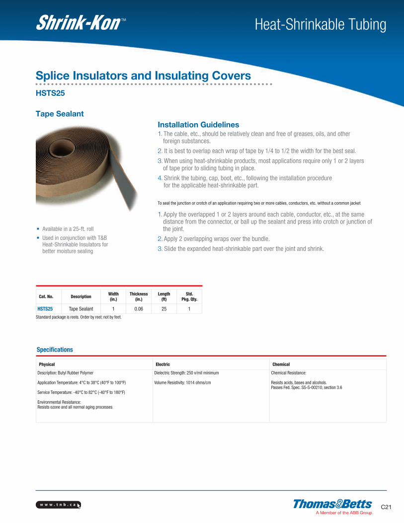
Heat-Shrinkable TubingTM
Tape SealantInstallation Guidelines1. The cable, etc., should be relatively clean and free of greases, oils, and other
foreign substances.
2. It is best to overlap each wrap of tape by 1/4 to 1/2 the width for the best seal.
3. When using heat-shrinkable products, most applications require only 1 or 2 layers of tape prior to sliding tubing in place.
4. Shrink the tubing, cap, boot, etc., following the installation procedure for the applicable heat-shrinkable part.
To seal the junction or crotch of an application requiring two or more cables, conductors, etc. without a common jacket
1. Apply the overlapped 1 or 2 layers around each cable, conductor, etc., at the same distance from the connector, or ball up the sealant and press into crotch or junction of the joint.
2. Apply 2 overlapping wraps over the bundle.
3. Slide the expanded heat-shrinkable part over the joint and shrink.
• Available in a 25-ft. roll
• Used in conjunction with T&B Heat-Shrinkable Insulators for better moisture sealing
Cat. No. Description Width(in.)
Thickness(in.)
Length(ft)
Std.Pkg. Qty.
HSTS25 Tape Sealant 1 0.06 25 1
Standard package is reels. Order by reel; not by feet.
Specifications
Physical Electric Chemical
Description: Butyl Rubber Polymer
Application Temperature: 4°C to 38°C (40°F to 100°F)
Service Temperature: -40°C to 82°C (-40°F to 180°F)
Environmental Resistance:Resists ozone and all normal aging processes
Dielectric Strength: 250 v/mil minimum
Volume Resistivity: 1014 ohms/cm
Chemical Resistance:
Resists acids, bases and alcohols.Passes Fed. Spec. SS-S-00210, section 3.6
Splice Insulators and Insulating CoversHSTS25
w w w . t n b . c aC22
Heat-Shrinkable TubingTM
• UL Listed and CSA Certified (UL 94V-1 Flammability Class)
• Rated for 600 V and 90°C application
• Material Body: Modified Neoprene Elastomer Straps: Nylon
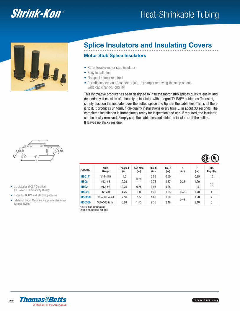
• Re-enterable motor stub insulator • Easy installation • No special tools required • Permits inspection of connector joint by simply removing the snap on cap,
wide cable range, long life
This innovative product has been designed to insulate motor stub splices quickly, easily, and dependably. It consists of a boot-type insulator with integral TY-RAP® cable ties. To install, simply position the insulator over the bolted splice and tighten the cable ties. That’s all there is to it. It produces uniform, high-quality installations every time… in about 30 seconds. The completed installation is immediately ready for inspection and use. If required, the insulator can be easily removed. Simply snip the cable ties and slide the insulator off the splice. It leaves no sticky residue.
Cat. No. WireRange
Length A(in.)
Bolt Max.(in.)
Dia. B(in.)
Dia. C(in.)
D(in.)
E(in.)
Std.Pkg. Qty.
MSC14* #14–#10 1.50.38
0.56 0.50
0.38
0.35 15
MSC8 #12–#8 2.39 0.76 0.67 1.2010
MSC2 #12–#2 3.25 0.75 0.95 0.88 1.5
MSC20 #2–2/0 4.25 1.0 1.39 1.05 0.43 1.70 4
MSC250 3/0–300 kcmil 7.56 1.5 1.88 1.800.45
1.90 2
MSC500 350–500 kcmil 8.88 1.75 2.56 2.48 2.10 5*One Ty-Rap cable tie onlyOrder in multiples of std. pkg.
Splice Insulators and Insulating CoversMotor Stub Splice Insulators
w w w . t n b . c a C23
Heat-Shrinkable TubingTM
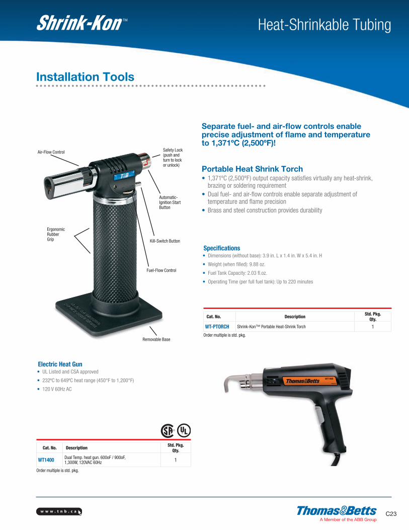
Portable Heat Shrink Torch• 1,371ºC (2,500ºF) output capacity satisfies virtually any heat-shrink,
brazing or soldering requirement• Dual fuel- and air-flow controls enable separate adjustment of
temperature and flame precision• Brass and steel construction provides durability
Specifications• Dimensions (without base): 3.9 in. L x 1.4 in. W x 5.4 in. H
• Weight (when filled): 9.88 oz.
• Fuel Tank Capacity: 2.03 fl.oz.
• Operating Time (per full fuel tank): Up to 220 minutes
Electric Heat Gun• UL Listed and CSA approved
• 232ºC to 649ºC heat range (450°F to 1,200°F)
• 120 V 60Hz AC
Safety Lock (push and turn to lock or unlock)
Air-Flow Control
Automatic- Ignition Start Button
Kill-Switch Button
Fuel-Flow Control
ErgonomicRubberGrip
Removable Base
Cat. No. Description Std. Pkg.Qty.
WT1400 Dual Temp. heat gun. 600oF / 900oF,1,300W, 120VAC 60Hz 1
Order multiple is std. pkg.
Cat. No. Description Std. Pkg.Qty.
WT-PTORCH Shrink-Kon™ Portable Heat-Shrink Torch 1
Order multiple is std. pkg.
Separate fuel- and air-flow controls enable precise adjustment of flame and temperature to 1,371ºC (2,500ºF)!
Installation Tools
w w w . t n b . c aC24
Heat-Shrinkable TubingTM
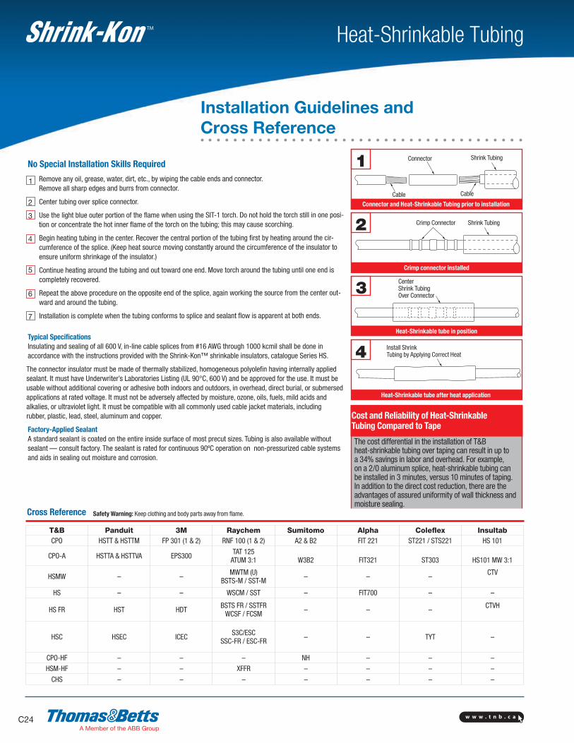
Remove any oil, grease, water, dirt, etc., by wiping the cable ends and connector. Remove all sharp edges and burrs from connector.
Center tubing over splice connector.
Use the light blue outer portion of the flame when using the SIT-1 torch. Do not hold the torch still in one posi-tion or concentrate the hot inner flame of the torch on the tubing; this may cause scorching.
Begin heating tubing in the center. Recover the central portion of the tubing first by heating around the cir-cumference of the splice. (Keep heat source moving constantly around the circumference of the insulator to ensure uniform shrinkage of the insulator.)
Continue heating around the tubing and out toward one end. Move torch around the tubing until one end is completely recovered.
Repeat the above procedure on the opposite end of the splice, again working the source from the center out-ward and around the tubing.
Installation is complete when the tubing conforms to splice and sealant flow is apparent at both ends.
No Special Installation Skills Required
1
2
3
4
5
6
7
Typical Specifications Insulating and sealing of all 600 V, in-line cable splices from #16 AWG through 1000 kcmil shall be done in accordance with the instructions provided with the Shrink-Kon™ shrinkable insulators, catalogue Series HS.
The connector insulator must be made of thermally stabilized, homogeneous polyolefin having internally applied sealant. It must have Underwriter’s Laboratories Listing (UL 90°C, 600 V) and be approved for the use. It must be usable without additional covering or adhesive both indoors and outdoors, in overhead, direct burial, or submersed applications at rated voltage. It must not be adversely affected by moisture, ozone, oils, fuels, mild acids and alkalies, or ultraviolet light. It must be compatible with all commonly used cable jacket materials, including rubber, plastic, lead, steel, aluminum and copper.
Factory-Applied Sealant A standard sealant is coated on the entire inside surface of most precut sizes. Tubing is also available without sealant — consult factory. The sealant is rated for continuous 90ºC operation on non-pressurized cable systems and aids in sealing out moisture and corrosion.
The cost differential in the installation of T&B heat-shrinkable tubing over taping can result in up to a 34% savings in labor and overhead. For example, on a 2/0 aluminum splice, heat-shrinkable tubing can be installed in 3 minutes, versus 10 minutes of taping. In addition to the direct cost reduction, there are the advantages of assured uniformity of wall thickness and moisture sealing.
Cost and Reliability of Heat-Shrinkable Tubing Compared to Tape
2 Crimp Connector Shrink Tubing
3Center Shrink Tubing Over Connector
4 Install Shrink Tubing by Applying Correct Heat
1 Connector
Cable Cable
Shrink Tubing
Heat-Shrinkable tube after heat application
Heat-Shrinkable tube in position
Crimp connector installed
Connector and Heat-Shrinkable Tubing prior to installation
Cross Reference
T&B Panduit 3M Raychem Sumitomo Alpha Coleflex InsultabCPO HSTT & HSTTM FP 301 (1 & 2) RNF 100 (1 & 2) A2 & B2 FIT 221 ST221 / STS221 HS 101
CPO-A HSTTA & HSTTVA EPS300 TAT 125ATUM 3:1 W3B2 FIT321 ST303 HS101 MW 3:1
HSMW – – MWTM (U)BSTS-M / SST-M – – – CTV
HS – – WSCM / SST – FIT700 – –
HS FR HST HDT BSTS FR / SSTFRWCSF / FCSM – – – CTVH
HSC HSEC ICEC S3C/ESCSSC-FR / ESC-FR – – TYT –
CPO-HF – – – NH – – –HSM-HF – – XFFR – – – –
CHS – – – – – – –
Safety Warning: Keep clothing and body parts away from flame.
Installation Guidelines and Cross Reference
w w w . t n b . c a C25
Heat-Shrinkable TubingTM
Features / Benefits:• Completely waterproof• Individual fusing allows separation of kit without de-energizing complete circuit• Break-away style fuse holder eliminates risk of electrical shock. Exposed current carrying components are all contained in harmless load side of the kit.• Readily identifiable problem area simplifies maintenance• Easy to install, no need for tapes or compounds• Insulated to 600 V
Applications:• Roadway lighting fixtures• Flood and area lighting fixtures• Power distribution systems
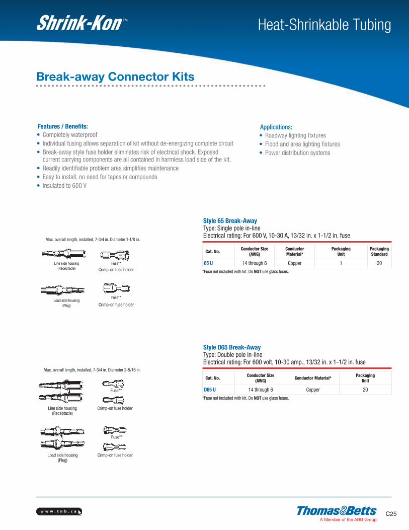
Max. overall length, installed, 7-3/4 in. Diameter 1-1/8 in.
Crimp-on fuse holder
Max. overall length, installed, 7-3/4 in. Diameter 2-5/16 in.
Fuse**
Fuse**
Fuse**
Fuse**
Line side housing (Receptacle)
Load side housing (Plug)
Crimp-on fuse holder
Style 65 Break-Away Type: Single pole in-line Electrical rating: For 600 V, 10-30 A, 13/32 in. x 1-1/2 in. fuse
Cat. No. Conductor Size(AWG)
Conductor Material*
Packaging Unit
Packaging Standard
65 U 14 through 6 Copper 1 20
*Fuse not included with kit. Do NOT use glass fuses.
Style D65 Break-Away Type: Double pole in-line Electrical rating: For 600 volt, 10-30 amp., 13/32 in. x 1-1/2 in. fuse
Cat. No. Conductor Size(AWG) Conductor Material* Packaging
Unit
D65 U 14 through 6 Copper 20
*Fuse not included with kit. Do NOT use glass fuses.
Break-away Connector Kits
Line side housing(Receptacle)
Load side housing(Plug) Crimp-on fuse holder
Crimp-on fuse holder
w w w . t n b . c aC26
Heat-Shrinkable TubingTM
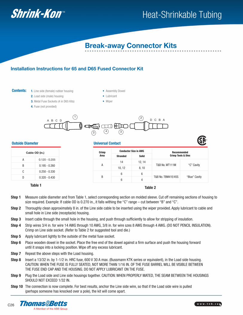
Contents: 1. Line side (female) rubber housing
2. Load side (male) housing
3. Metal Fuse Sockets (4 in D65 Kits)
4. Fuse (not provided)
A B C D D C B A1
3 4 3
2
Step 1 Measure cable diameter and from Table 1, select corresponding section on molded sleeve. Cut off remaining sections of housing to size required. Example: If cable OD is 0.270 in., it falls withing the “C” range – cut between “B” and “C”.
Step 2 Thoroughly clean approximately 8 in. of the Line side cable to be inserted using the wiper provided. Apply lubricant to cable and small hole in Line side (receptacle) housing.
Step 3 Insert cable through the small hole in the housing, and push through sufficiently to allow for stripping of insulation.
Step 4 Strip wires 3/4 in. for wire 14 AWG through 10 AWG, 3/8 in. for wire szes 8 AWG through 4 AWG. (DO NOT PENCIL INSULATION). Crimp on Line side socket. (Refer to Table 2 for suggested tool and die.)
Step 5 Apply lubricant lightly to the outside of the metal fuse socket.
Step 6 Place wooden dowel in the socket. Place the free end of the dowel against a firm surface and push the housing forward until it snaps into a locking position. Wipe off any excess lubricant.
Step 7 Repeat the above steps with the Load housing.
Step 8 Insert a 13/32 in. by 1-1/2 in. HRC fuse, 600 V 30 A max. (Bussmann KTK series or equivalent), in the Load side housing. CAUTION: WHEN THE FUSE IS FULLY SEATED, NOT MORE THAN 1/16 IN. OF THE FUSE BARREL WILL BE VISIBLE BETWEEN THE FUSE END CAP AND THE HOUSING. DO NOT APPLY LUBRICANT ON THE FUSE.
Step 9 Plug the Load side and Line side housings together. CAUTION: WHEN PROPERLY MATED, THE SEAM BETWEEN THE HOUSINGS SHOULD NOT EXCEED 1/32 IN.
Step 10 The connection is now complete. For best results, anchor the Line side wire, so that if the Load side wire is pulled (perhaps someone has knocked over a pole), the kit will come apart.
Installation Instructions for 65 and D65 Fused Connector Kit
• Assembly Dowel
• Lubricant
• Wiper
Break-away Connector Kits
Outside Diameter
Cable OD (in.)
A 0.120 - 0.205
B 0.195 - 0.260
C 0.250 - 0.330
D 0.320 - 0.430
Table 1
Universal Contact
Crimp Area
Conductor Size in AWG RecommendedCrimp Tools & DiesStranded Solid
A14 12, 14
T&B No. WT111M “C” Cavity10, 12 8, 10
B6 6
T&B No. TBM41E/45S “Blue” Cavity6 4
Table 2