Embed Size (px)
Citation preview

25 Inst Issue 3 12.01.2009
1
Operating & Maintenance Instructions 25 Injection Moulding Machine Table of Contents 1. Health and Safety Information ............................................................................................................................... 2
2. Upon Receipt ......................................................................................................................................................... 2
3a. Temperature Controller Settings (Brainchild Controller) ..................................................................................... 4
3b. Temperature Controller Settings (Panasonic Controller) .................................................................................... 4
4. Mould Clamp .......................................................................................................................................................... 5
5. To prepare for use ................................................................................................................................................. 9
6. Shutdown and Changing Colours ........................................................................................................................ 13
7. Design requirements and tips for the design of an injection Moulding die .......................................................... 13
8. Mould Specifications ............................................................................................................................................ 14
9. Standard Material Choices .................................................................................................................................. 15
10. Electrical Supply and Connection ...................................................................................................................... 16
11. Connection Diagram .......................................................................................................................................... 17
25 Inst Issue 3 12.01.2009
2
1. Health and Safety Information Hot Surfaces Surfaces of the 25 Injection Moulding Machine may become hot in use. Please take care when using the machine, in particular around the nozzle at the end of the heater barrel. The 25 Injection Moulding Machine is intended for the injection moulding of thermoplastic materials which can be moulded at temperatures under 200°C. Do not use materials with a moulding temperature over 200°C. Do not attempt to mould materials with a flash point under 200°C. Always check the MSDS of any material prior to using it in the 25 Injection Moulding Machine. If you are in any doubt as to the source and characteristics of a material that you wish to use in the 25 Injection Moulder, seek advice before loading it into the machine.
2. Upon Receipt Unpack carefully and fit the rack guard immediately, if not already fitted, using the 2 x M4 screws provided.
! WARNING ! There is a trapping hazard between the teeth of the
rack and the top rack bush until the rack guard is fitted!
The capstan handle assembly is fitted to the machine as follows:
1. Remove the M6 socket head screw from the pinion shaft on the upper right hand side of the machine
2. Remove the securing tape from the key in the pinion shaft 3. Fit the capstan handle assembly, ensuring that the key is still in position.
25 Inst Issue 3 12.01.2009
3
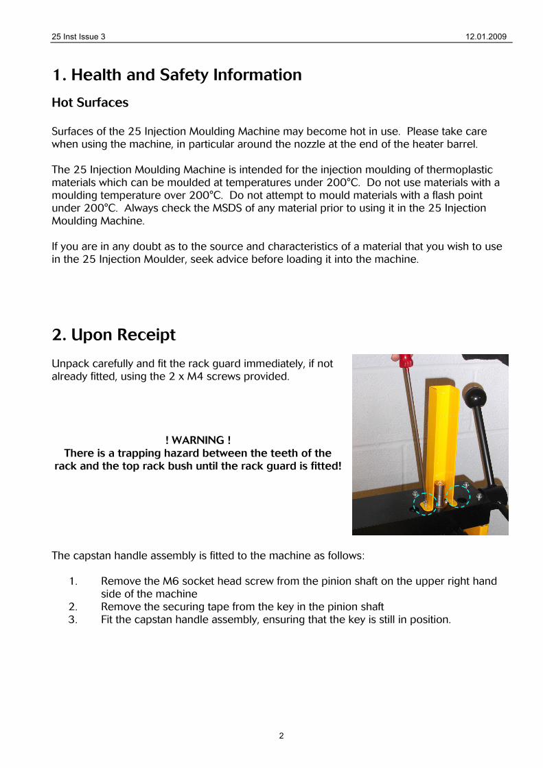
4. Secure the capstan assembly using the M6 socket head screw.
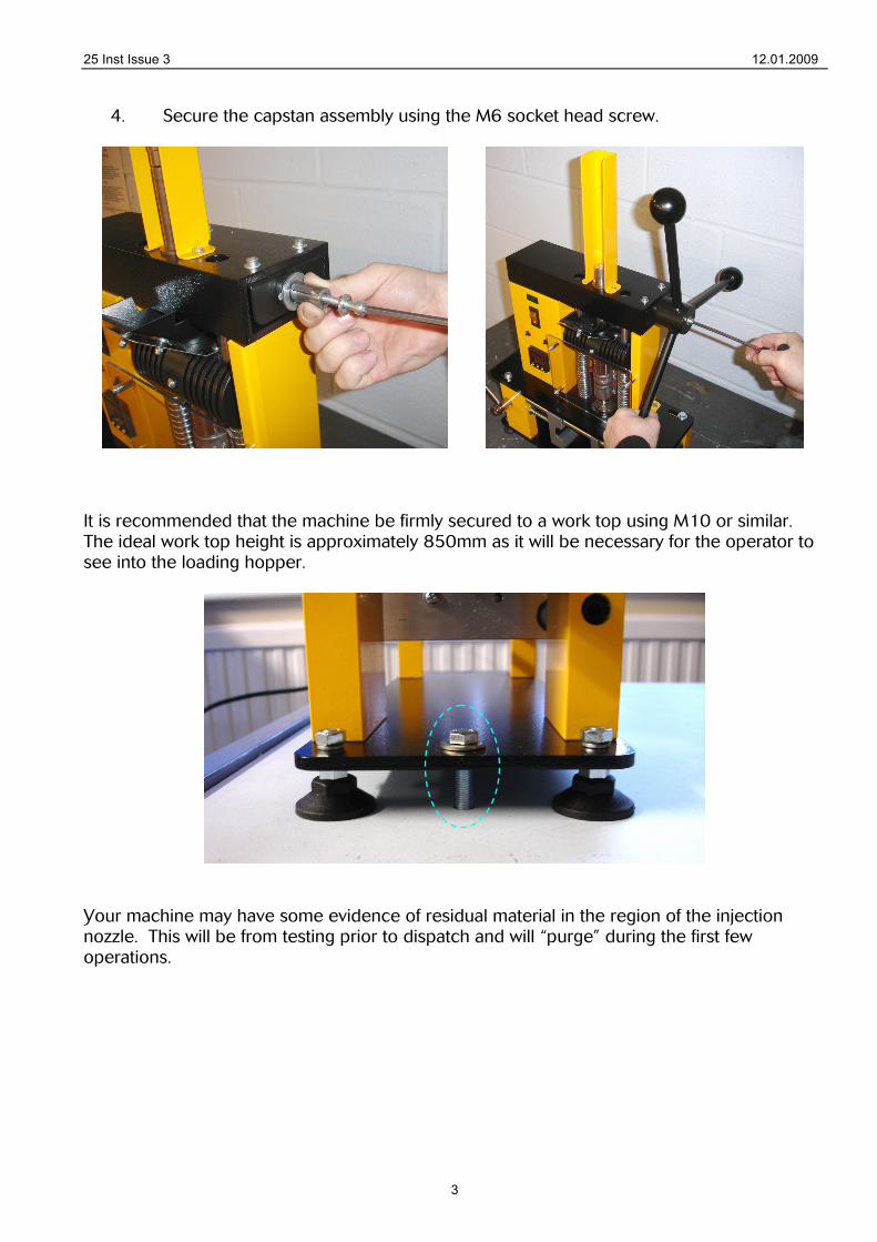
It is recommended that the machine be firmly secured to a work top using M10 or similar. The ideal work top height is approximately 850mm as it will be necessary for the operator to see into the loading hopper.
Your machine may have some evidence of residual material in the region of the injection nozzle. This will be from testing prior to dispatch and will “purge” during the first few operations.
25 Inst Issue 3 12.01.2009
4
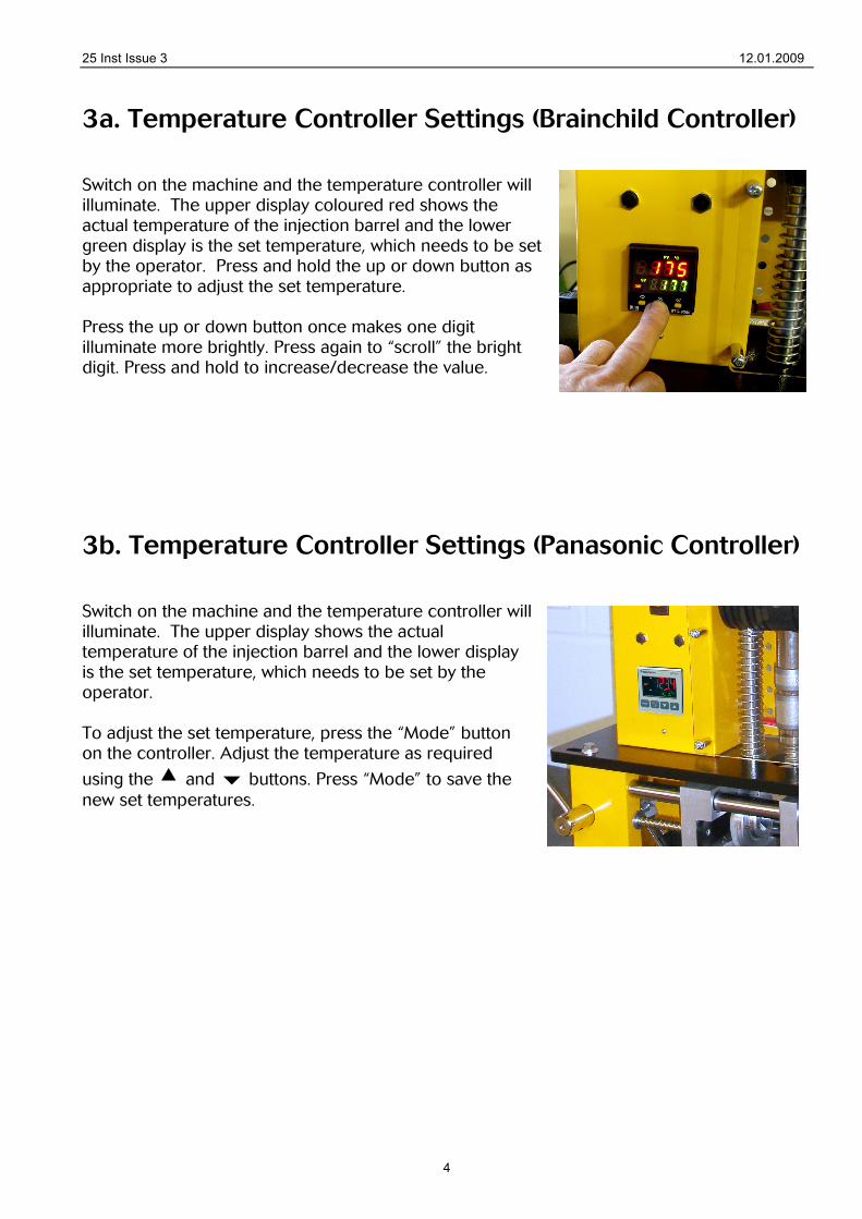
3a. Temperature Controller Settings (Brainchild Controller) Switch on the machine and the temperature controller will illuminate. The upper display coloured red shows the actual temperature of the injection barrel and the lower green display is the set temperature, which needs to be set by the operator. Press and hold the up or down button as appropriate to adjust the set temperature. Press the up or down button once makes one digit illuminate more brightly. Press again to “scroll” the bright digit. Press and hold to increase/decrease the value.
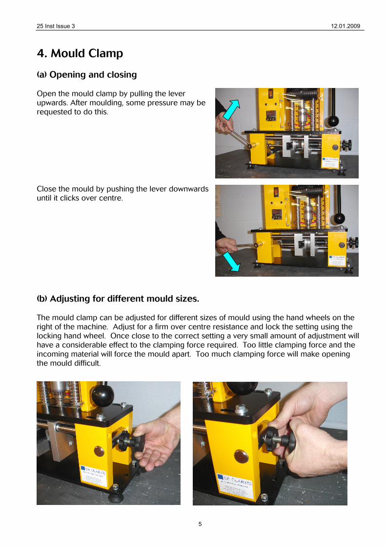
3b. Temperature Controller Settings (Panasonic Controller) Switch on the machine and the temperature controller will illuminate. The upper display shows the actual temperature of the injection barrel and the lower display is the set temperature, which needs to be set by the operator. To adjust the set temperature, press the “Mode” button on the controller. Adjust the temperature as required
using the and buttons. Press “Mode” to save the new set temperatures.
25 Inst Issue 3 12.01.2009
5
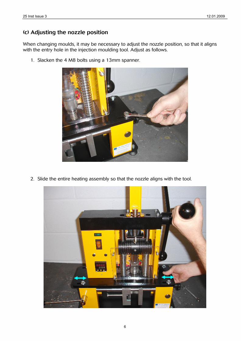
4. Mould Clamp (a) Opening and closing Open the mould clamp by pulling the lever upwards. After moulding, some pressure may be requested to do this.
Close the mould by pushing the lever downwards until it clicks over centre.
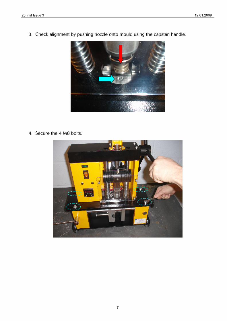
(b) Adjusting for different mould sizes. The mould clamp can be adjusted for different sizes of mould using the hand wheels on the right of the machine. Adjust for a firm over centre resistance and lock the setting using the locking hand wheel. Once close to the correct setting a very small amount of adjustment will have a considerable effect to the clamping force required. Too little clamping force and the incoming material will force the mould apart. Too much clamping force will make opening the mould difficult.
25 Inst Issue 3 12.01.2009
6
(c) Adjusting the nozzle position When changing moulds, it may be necessary to adjust the nozzle position, so that it aligns with the entry hole in the injection moulding tool. Adjust as follows.
1. Slacken the 4 M8 bolts using a 13mm spanner.
2. Slide the entire heating assembly so that the nozzle aligns with the tool.
25 Inst Issue 3 12.01.2009
7
3. Check alignment by pushing nozzle onto mould using the capstan handle.
4. Secure the 4 M8 bolts.
25 Inst Issue 3 12.01.2009
8
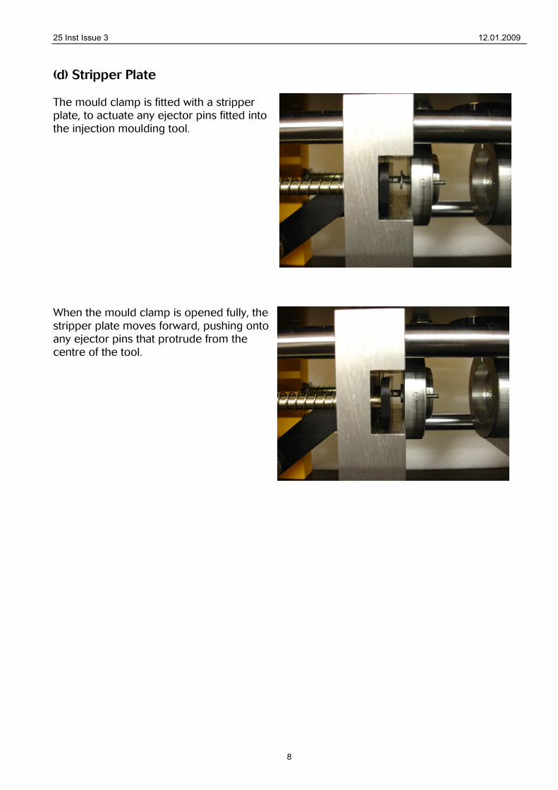
(d) Stripper Plate The mould clamp is fitted with a stripper plate, to actuate any ejector pins fitted into the injection moulding tool. When the mould clamp is opened fully, the stripper plate moves forward, pushing onto any ejector pins that protrude from the centre of the tool.
25 Inst Issue 3 12.01.2009
9
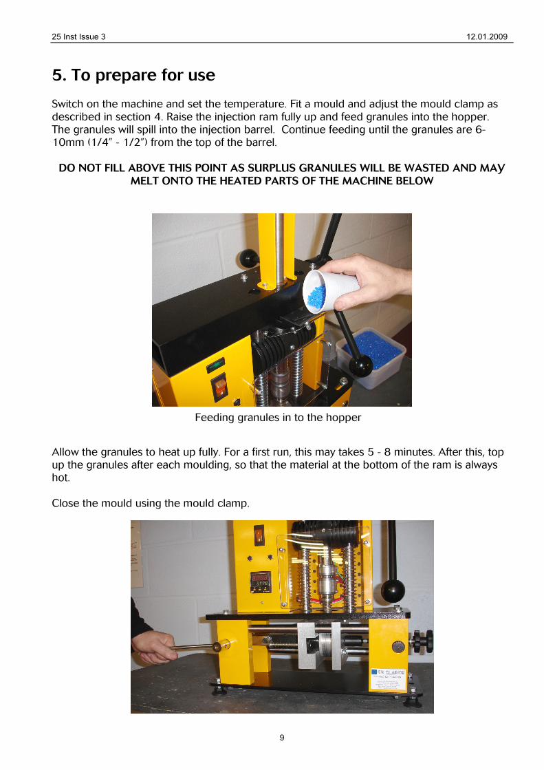
5. To prepare for use Switch on the machine and set the temperature. Fit a mould and adjust the mould clamp as described in section 4. Raise the injection ram fully up and feed granules into the hopper. The granules will spill into the injection barrel. Continue feeding until the granules are 6-10mm (1/4” - 1/2”) from the top of the barrel.
DO NOT FILL ABOVE THIS POINT AS SURPLUS GRANULES WILL BE WASTED AND MAY MELT ONTO THE HEATED PARTS OF THE MACHINE BELOW
Allow the granules to heat up fully. For a first run, this may takes 5 - 8 minutes. After this, top up the granules after each moulding, so that the material at the bottom of the ram is always hot. Close the mould using the mould clamp.
Feeding granules in to the hopper
25 Inst Issue 3 12.01.2009
10
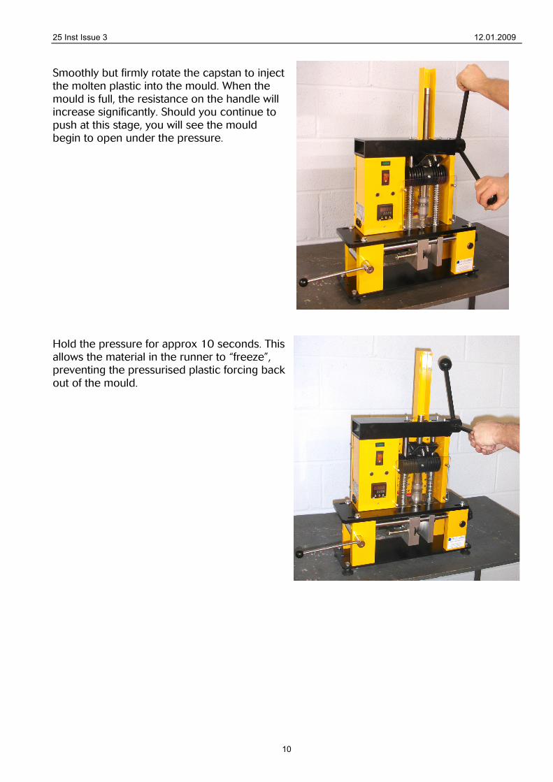
Smoothly but firmly rotate the capstan to inject the molten plastic into the mould. When the mould is full, the resistance on the handle will increase significantly. Should you continue to push at this stage, you will see the mould begin to open under the pressure. Hold the pressure for approx 10 seconds. This allows the material in the runner to “freeze”, preventing the pressurised plastic forcing back out of the mould.
25 Inst Issue 3 12.01.2009
11
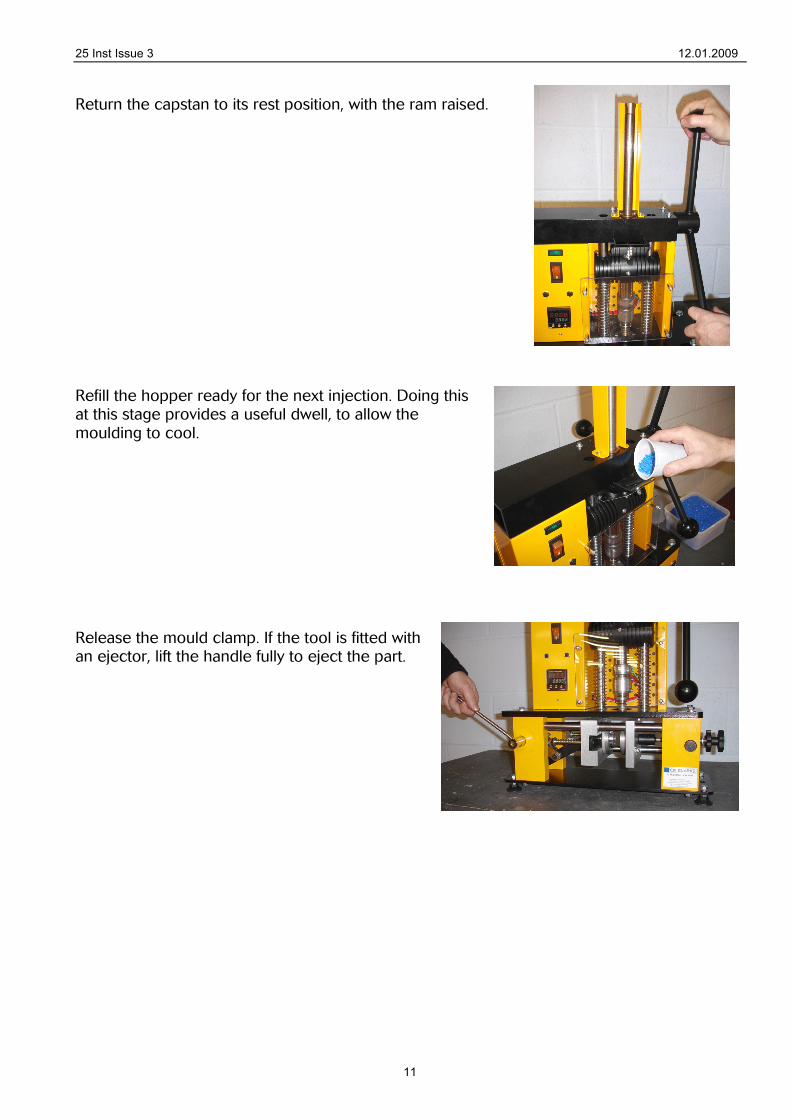
Return the capstan to its rest position, with the ram raised. Refill the hopper ready for the next injection. Doing this at this stage provides a useful dwell, to allow the moulding to cool. Release the mould clamp. If the tool is fitted with an ejector, lift the handle fully to eject the part.
25 Inst Issue 3 12.01.2009
12
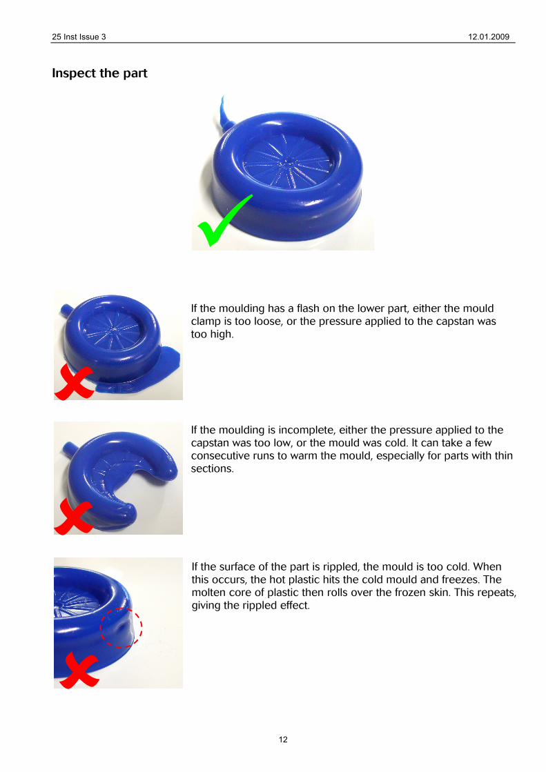
Inspect the part
If the moulding has a flash on the lower part, either the mould clamp is too loose, or the pressure applied to the capstan was too high. If the moulding is incomplete, either the pressure applied to the capstan was too low, or the mould was cold. It can take a few consecutive runs to warm the mould, especially for parts with thin sections. If the surface of the part is rippled, the mould is too cold. When this occurs, the hot plastic hits the cold mould and freezes. The molten core of plastic then rolls over the frozen skin. This repeats, giving the rippled effect.

25 Inst Issue 3 12.01.2009
13
6. Shutdown and Changing Colours When the session is finished do not add further granules, simply switch off and allow the machine to cool. The residual material in the barrel and valve at the injection point will be reheated when next used. If it is required to change colours the new material can purge the old material out without a mould in place. This may seem wasteful but it is standard practice and the easiest way of changing colours. There is normally no need to dismantle the machine for cleaning.
7. Design requirements and tips for the design of an injection Moulding die
1. Make the outer shape of the mould to the dimensions in Part 8. It can be round or square.
2. A draft angle of no less than 1° should be applied to any vertical faces of the mould. 3. The plastic will contract quite significantly as it cools. Therefore, if you put most of the
female detail on the right (non-ejector) side of the mould, and most of the male detail on the left (ejector) side of the mould, the part will tend to shrink away from the right side, and grip the ejector side. This makes ejection of the part much easier.
4. The feed hole should be around 5mm in diameter, with a countersink to accept the nozzle.
5. Mould sections should be approx 2-8mm in thickness. Large variations in thickness may cause different shrinkages and distort the completed part.
25 Inst Issue 3 12.01.2009
14
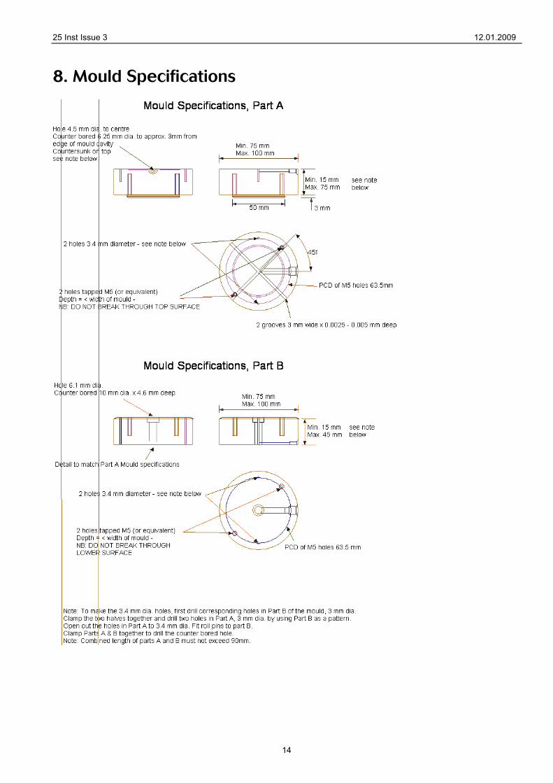
8. Mould Specifications
25 Inst Issue 3 12.01.2009
15
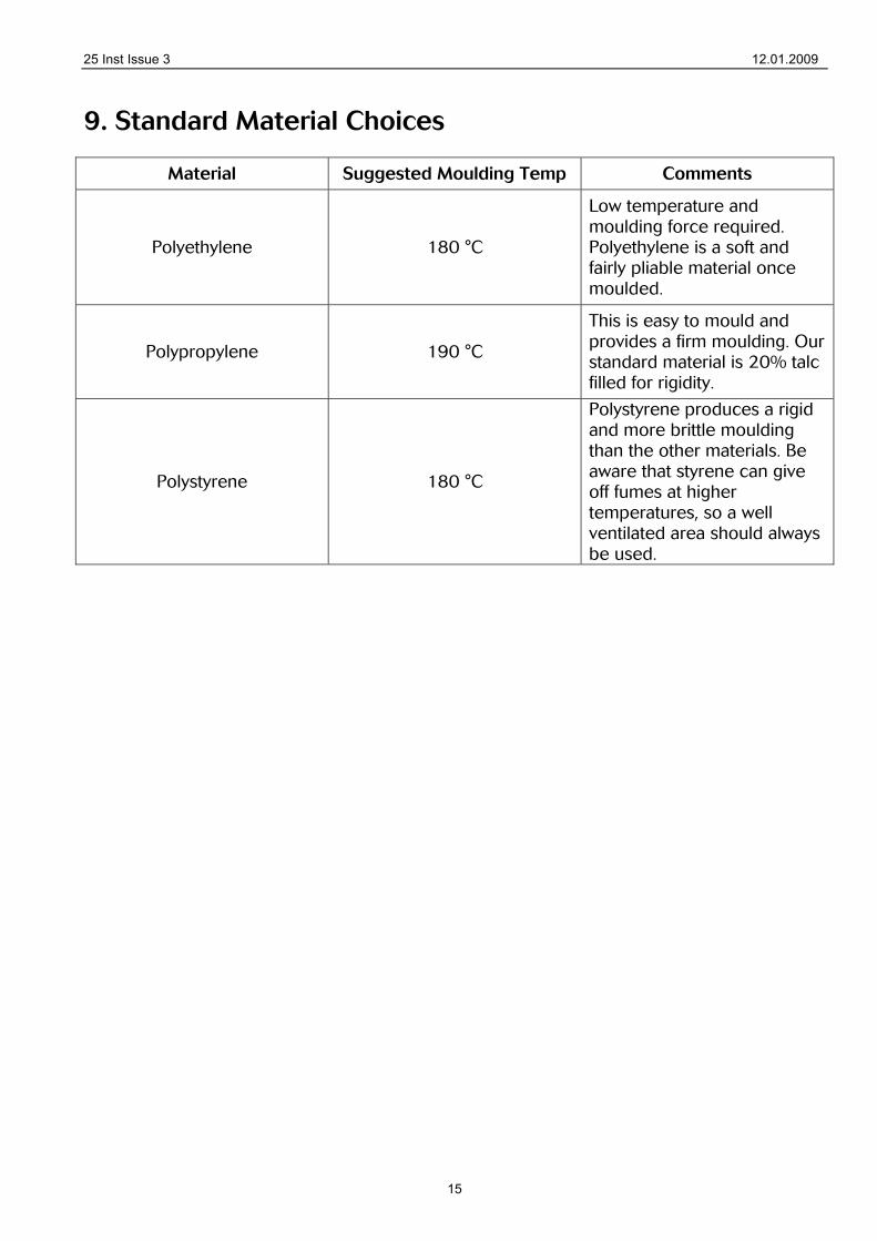
9. Standard Material Choices
Material Suggested Moulding Temp Comments
Polyethylene 180 °C
Low temperature and moulding force required. Polyethylene is a soft and fairly pliable material once moulded.
Polypropylene 190 °C
This is easy to mould and provides a firm moulding. Our standard material is 20% talc filled for rigidity.
Polystyrene 180 °C
Polystyrene produces a rigid and more brittle moulding than the other materials. Be aware that styrene can give off fumes at higher temperatures, so a well ventilated area should always be used.
25 Inst Issue 3 12.01.2009
16
10. Electrical Supply and Connection
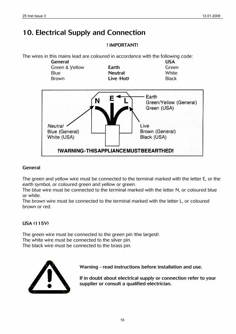
! IMPORTANT! The wires in this mains lead are coloured in accordance with the following code: General USA Green & Yellow Earth Green Blue Neutral White Brown Live (Hot) Black
General The green and yellow wire must be connected to the terminal marked with the letter E, or the earth symbol, or coloured green and yellow or green. The blue wire must be connected to the terminal marked with the letter N, or coloured blue or white. The brown wire must be connected to the terminal marked with the letter L, or coloured brown or red. USA (115V) The green wire must be connected to the green pin (the largest). The white wire must be connected to the silver pin. The black wire must be connected to the brass pin.
Warning - read instructions before installation and use. If in doubt about electrical supply or connection refer to your supplier or consult a qualified electrician.
25 Inst Issue 3 12.01.2009
17
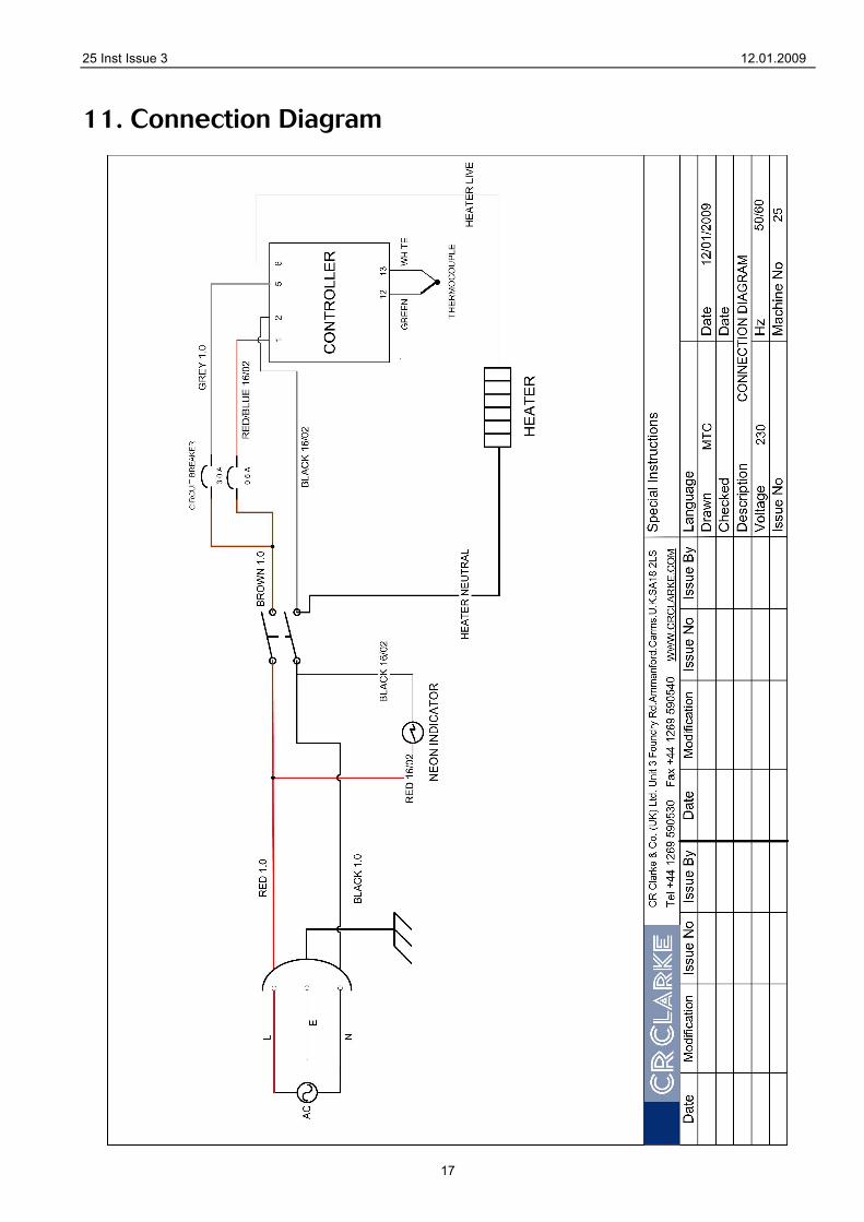
11. Connection Diagram