Embed Size (px)
Citation preview


ii
TABLE OF CONTENTS
WARNINGS GENERAL INFORMATION INSTALLATION INSTRUCTIONS OPERATING INSTRUCTIONS ACCESSORY CONNECTIONS MOTOR CONTROL SCHEMATIC REVERSE OPERATION & MASTER / SLAVE CONNECTIONS MAINTENANCE PARTS LIST TROUBLE SHOOTING
1
2
3
4
6
7
9
12
13
14
24

1
WARNINGS:
Gate operator system designers, installers and users must take into account the possible hazards associated with each individual application. Improperly designed, installed or maintained systems can create risks for the user as well as bystanders. Gate systems installation and design must reduce public exposure to potential hazards.
The operator is intended for installation for applications used for motor vehicles only. Pedestrians must be supplied with a separate access opening. The pedestrian access opening shall be designed to promote pedestrian usage. Locate the gate so that persons will not come in contact with the vehicular gate during the entire path of travel of the vehicular gate.
Keep all pedestrians out of the traffic lane and away from the moving gate. Signage indicating "NO PEDESTRIANS" is recommended. NO ONE SHOULD CROSS THE PATH OF THE MOVING GATE ARM.
Install safety devices such as loops and loop detectors, safety edges, and/or photo beams in all installations to prevent the gate from closing on a vehicle.
Do not install the gate operator in a location where the arm can come within 24” of a stationary object. The gate must be installed in a location so that enough clearance is supplied between the gate and adjacent structures when opening and closing to reduce the risk of entrapment.
Use only good quality pine for the gate arm. The use of materials other than wood may result in damage to the gate operator.
Do not install any opening or closing device out of view of the gate when the devices are operated. Controls shall be far enough from the gate arm or positioned to prevent the user from coming in contact with the arm while operating the controls.
Stay clear of the pulleys, belts, and gate arm at all times.
Always turn off power before attempting any service.
FIGURE 1

2
GENERAL INFORMATION
Your parking gate has been designed to provide many years of reliable service. It incorporates design features for all types of automatic parking control operations. WARRANTY: All equipment manufactured by Engineered Parking Systems is warranted against defects in material and workmanship for one full year from date of shipment. All equipment is tested and inspected before shipment. The warranty covers repairs or replacement of any part that fails under normal usage. Transportation and labor charges are to be paid by the customer. GATE HOUSING: The parking gate is constructed of eleven (11) gauge steel. It is of welded construction with a top hinged access cover and a weatherproof door. The door is fitted with a mounted key lock. Two keys are provided. The housing is finished with powder coat paint. OPERATING MECHANISM: The gate arm is operated by a ½ HP instant reversing motor through a heavy duty speed reducer with a 60:1 ratio. The gate arm flange is connected directly to the main shaft. Adjustable cams are provided to limit gate arm travel. All internal parts are zinc plated to prevent rusting. ELECTRICAL CONTROLS: The parking gate uses a self-contained, solid-state, plug-in controller. The field wiring connections are to be terminated to the terminal panel. The terminal panel contains a circuit breaker on/off switch and a manual raise/lower switch. GATE ARM: The gate arm comes in a standard 10 foot length, however 12, 14, and 16 foot lengths are also available. They are finished in white and black diagonal stripes and are made of pine. A minimum of two warning signs/placards must be installed in the area of the gate. A warning sign/placard is to be installed on each side of the gate and be visible by persons located on the side of the gate on which the warning sign/placard is installed. Figure 1 illustrates a warning sign/placard. CLASSES OF VEHICULAR GATES: RESIDENTIAL VEHICULAR GATE OPERATOR – CLASS I- A vehicular gate operator (or system) intended for use in a home of one to four single family dwelling, or a garage or parking area associated therewith. COMMERCIAL/GENERAL ACCESS VEHICULAR GATE OPERATOR – CLASS II – A vehicular gate operator (or system) intended for use in a commercial location or building such as a multi-family housing unit (five or more single family units), hotel, garages, retail store, or other building servicing the general public. INDUSTRIAL/LIMITED ACCESS VEHICULAR GATE OOPERATOR – CLASS III – A vehicular gate operator (or system) intended for use in an industrial location or building such as a factory or loading dock area or other locations not intended to service the general public. RESTRICTED ACCESS VEHICULAR GATE OPERATOR – CLASS IV – A vehicular gate operator (or system) intended for use in a guarded industrial location or building such as an airport security area or other restricted access locations not servicing the general public, in which unauthorized access is prevented via supervision by security personnel. The Model 301 barrier gate operator in intended for use in Class II, III, and IV installations.

3
IMPORTANT INSTALLATION WARNING
WARNING – TO REDUCE THE RISK OF SEVERE INJURY OR DEATH
1. READ AND FOLLOW ALL INSTALLATION INSTRUCTIONS.
2. Install only the proper length and material of gate arm. An improper gate arm could cause severe injury. Have a qualified service person make repair to gate.
3. Do not connect operator to source of power until instructed to do so.
INSTALLATION INSTRUCTIONS
1. Concrete foundations, not more than 6” above the driveway, with anchor bolts and conduit should be finished per the applicable installation drawings.
2. Gate should be left on the wooden shipping platform, with cardboard left around it for protection until it is ready to be mounted on foundation.
3. When ready to install, remove cardboard carton and machine bolts from the bottom of the
wooden platform.
4. Position gate with door facing away from driveway. Once the gate is in position, anchor it down with ½” flat washers, ½” lock washers, and ½” hex nuts. Lubricate the bolts before installation.
5. Open the top cover and install speed reducer breather plug.
6. Connect interconnecting wires to the other parts in the system by referring to the field
wiring diagram (page 5). Be sure all power is OFF when hooking up L1 and Neut. All electrical wiring must be connected exactly as indicated in the wiring diagrams.
7. Turn the circuit breaker in gate housing OFF. The gate is now ready to operate. Turn
power on at L1 and Neut.
8. Turn the circuit breaker on and check initial gate activation by operating the RAISE/LOWER switch.
9. Make adjustments to the up and down limit switch cams as required. NOTE: DOWN limit
switch has the black wire and the UP limit switch has the red wire. ENSURE CIRCUIT BREAKER IN GATE IS OFF WHILE MAKING LIMIT SWITCH ADJUSTMENTS. To adjust the cams, loosen the allen set screws and rotate the cams to the desired setting. After the adjustments have been made, turn the circuit breaker on and test the gate arm travel by operating the RAISE/LOWER switch. Repeat adjustments if needed.
10. Gate arm may now be affixed to the gate arm flange by sliding the gate arm between the
flange and the break away flange cover and tightening down the four outside bolts.
4
IMPORTANT SAFETY INSTRUCTIONS
WARNING – TO REDUCE THE RISK OF INJURY OR DEATH:
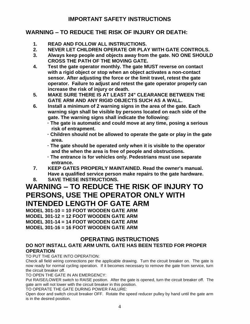
1. READ AND FOLLOW ALL INSTRUCTIONS. 2. NEVER LET CHILDREN OPERATE OR PLAY WITH GATE CONTROLS. 3. Always keep people and objects away from the gate. NO ONE SHOULD
CROSS THE PATH OF THE MOVING GATE. 4. Test the gate operator monthly. The gate MUST reverse on contact
with a rigid object or stop when an object activates a non-contact sensor. After adjusting the force or the limit travel, retest the gate operator. Failure to adjust and retest the gate operator properly can increase the risk of injury or death.
5. MAKE SURE THERE IS AT LEAST 24" CLEARANCE BETWEEN THE GATE ARM AND ANY RIGID OBJECTS SUCH AS A WALL.
6. Install a minimum of 2 warning signs in the area of the gate. Each warning sign shall be visible by persons located on each side of the gate. The warning signs shall indicate the following:
· The gate is automatic and could move at any time, posing a serious risk of entrapment. · Children should not be allowed to operate the gate or play in the gate area. · The gate should be operated only when it is visible to the operator and the when the area is free of people and obstructions. · The entrance is for vehicles only. Pedestrians must use separate entrance.
7. KEEP GATES PROPERLY MAINTAINED. Read the owner's manual. Have a qualified service person make repairs to the gate hardware.
8. SAVE THESE INSTRUCTIONS.
WARNING – TO REDUCE THE RISK OF INJURY TO PERSONS, USE THE OPERATOR ONLY WITH INTENDED LENGTH OF GATE ARM MODEL 301-10 = 10 FOOT WOODEN GATE ARM MODEL 301-12 = 12 FOOT WOODEN GATE ARM MODEL 301-14 = 14 FOOT WOODEN GATE ARM MODEL 301-16 = 16 FOOT WOODEN GATE ARM
OPERATING INSTRUCTIONS DO NOT INSTALL GATE ARM UNTIL GATE HAS BEEN TESTED FOR PROPER OPERATION TO PUT THE GATE INTO OPERATION: Check all field wiring connections per the applicable drawing. Turn the circuit breaker on. The gate is now ready for normal cycling operation. If it becomes necessary to remove the gate from service, turn the circuit breaker off. TO OPEN THE GATE IN AN EMERGENCY: Put RAISE/LOWER switch to RAISE position. After the gate is opened, turn the circuit breaker off. The gate arm will not lower with the circuit breaker in this position. TO OPERATE THE GATE DURING POWER FAILURE: Open door and switch circuit breaker OFF. Rotate the speed reducer pulley by hand until the gate arm is in the desired position.

5

6
ACCESSORY CONNECTIONS All accessories are connected to the terminal panel. Disconnect power before connecting accessories. VEHICLE DETECTOR CONNECTIONS: Vehicle detectors are to be placed on the same shelf as the controller inside the gate housing. **Safety/Close Vehicle Detector-Connect power according to the manufacturer’s instructions. Connect presence relay common to terminal 7. Connect presence relay normally open to terminal 8. Connect loop wire from detector and actual loop wires to terminals 21 and 22. Dipswitch #3 on control board is on for safety/close operation. **Safety Only Vehicle Detector-Connect the same as safety/close detector except dipswitch #3 is off for safety only operation. Safety only operation is used when internal closing timer or a push button is used for closing the gate. **Free Open Vehicle Detector-Connect power according the manufacturer’s instructions. Connect presence relay common to terminal 7. Connect presence relay normally open to terminal 10. Connect loop wires from detector and actual loop wires to terminals 23 and 24. OPENING DEVICE CONNECTIONS: All opening devices such as card readers, cash registers, radio receivers, push buttons, telephone entry systems, etc. should be installed according to the manufacturer’s instructions. Open input type should be momentary dry contact. Connect common to terminal 7 and normally open to terminal 10. A continuous contact across terminal 7 and 10 will cause the gate to remain open. PUSH BUTTON STATION CONNECTIONS: **Open Push Button-Normally pen contacts connect to terminals 7 and 10. **Close Push Button-Normally open contacts connect to terminal 7 and 11. **Stop Push Button-Remove jumper across terminals 2 and 3. Normally closed contacts connect to terminals 2 and 3.

7
MOTOR CONTROL BOARD DESCRIPTION OF FUNCTION SWITCHES
SETTING SWITCH#
OPEN (OFF) 1 P1: Requires that open signal be set, then reset prior to opening gate.
CLOSED(ON) 1 P1: When other conditions allow, initiates immediate opening after setting of open input.
OPEN (OFF) 2 P2: Requires that close signal be set, then reset prior to closing gate.
CLOSED (ON) 2 P2: When other conditions allow, initiates immediate closure after setting of close input.
CLOSED (ON) 3 LATCH: Causes immediate closing of gate following setting and resetting of safety while gate is on open limit, if open signal in not present.
CLOSED (ON) 4 INTERRUPT: Stops all gate movement when safety is set, hold until safety is reset.
OPEN (OFF) 4 INTERRUPT: Stops gate from closing when safety is set. Prevents closing until safety is reset.
CLOSED (ON) 5 SEQUENCE: When gate is on open limit, will initiate closure after receiving open signal.
CLOSED (ON) 6 REVERSE: Causes gate to open following a stop or safety input, unless gate is on close limit.
CLOSED (ON) 7 WAIT: Causes a 2 second delay in any change in gate motion direction.
OPEN (OFF) 8 CLOSE TIMER: Starts when gate reaches open limit, if open signal is not present and safeties are reset. Open input and safeties when on will hold timer off until cleared.
OPEN (OFF) 9 BRAKE: Provides power to opposite motor winding momentarily upon reaching either limit switch.
NOTE: On all configurations, switch 9 must be off for the brake to be active, and switch 8 must be off for closing timer to be active.

8
ENTRY CONTROL 1000 CONTROL BOARD
DESCRIPTION OF L.E.D.’s
LED 1: LED 2: LED 3: LED 4: LED 5: LED 6: LED 7: LED 8: LED 9: LED 10:
INPUT LIGHTS (USED WITH DOUBLE DIRECTION LOGIC ONLY) ILLUMINATES WHEN CLOSING LOOP IS ACTIVATED WHEN GATE IS WIRED FOR DOUBLE DIRECTION LOGIC. (CLOSE) ILLUMINATES AS LONG AS CLOSE INPUT IS PRESENT. (OPEN) ILLUMINATES AS LONG AS OPEN INPUT IS PRESENT. (SAFETY) ILLUMINATES AS LONG AS SAFETY SIGNAL IS PRESENT OR AS LONG AS CLOSING LOOP IS ACTIVATED. LIMIT SWITCH LIGHTS (CLOSE) ILLUMINATES WHEN GATE IS OPEN. (SHOWING WHAT NEXT FUNCTION IS GOING TO BE) OR WHEN GATE IS IN MOTION. EXTINGUISHES WHEN GAE IS CLOSED (May be dim). (OPEN) ILLUMINATES WHEN GATE IS CLOSED. (SHOWING WHAT NEXT FUNCTION IS GOING TO BE) OR WHEN GATE IS IN MOTION. EXTINGUISHES WHEN GATE IS OPEN (May be dim). (STOP) ALWAYS ILLUMINATE UNLESS STOP INPUT IS PRESENT. (OPEN CONTACTS ACROSS STOP INPUT) MOTOR LIGHTS (CLOSE) ILLUMINATES WHILE MOTOR IS RUNNING IN CLOSE CYCLE. (OPEN) ILLUMINATES WHILE MOTOR IS RUNNING IN OPEN CYCLE. POWER LIGHT (DC) ALWAYS ILLUMINATED UNLESS POWER IS REMOVED. (EX: BLOWN FUSE, ETC).

9

10
STANDARD SYSTEM #4 SINGLE DIRECTION CARD OR EQUIVALENT ENTRANCE OR EXIT SYSTEM FUNCTION: The patron inserts the entry card into the card reader, which causes the gate arm to rise. When the vehicle leaves loop #1, the gate will return to the down position. Suggested control board switch setting: 1, 2, 3, 6, 8 = ON INCOMING POWER: 115 VAC 60 Hz 20 Amps NOTE: THE LOOP IS CENTERED IN THE LANE MAKE SURE THERE IS AT LEAST 2 FT. OF CLEARANCE BETWEEN THE GATE ARM AND ANY RIGID OBJECTS

11
STANDARD SYSTEM #8 DOUBLE DIRECTION CARD OR KEY ENTRANCE/FREE EXIT SYSTEM FUNCTION: The patron inserts the entry card into the card reader. This will cause the gate arm to rise, permitting the vehicle to drive through. When the vehicle leaves loop #2, the gate arm will return to the down position. When the vehicle approaches from the free side, loop #2 will be activated, which will raise the gate arm, permitting the vehicle to drive through. As the vehicle leaves loop #1, the gate will automatically return to the down position Suggested control board switch setting: 1, 3, 6, 8 = ON Auxiliary Board in controller is required for this configuration in units manufactured prior to May 2008. INCOMING POWER: 115 VAC 60 Hz 20 Amps NOTE: THE LOOP IS CENTERED IN THE LANE MAKE SURE THERE IS AT LEAST 2 FT. OF CLEARANCE BETWEEN THE GATE ARM AND ANY RIGID OBJECTS

12
REVERSE OPERATION In standard installations, the parking gate access door faces away from the lane. If you encounter an obstacle that prevents access to the door, or if the gate needs to be reversed for a master / slave application, follow these instructions for gate cabinet reversal. NOTE: REMOVE GATE ARM AND DISCONNECT MAIN POWER BEFORE ATTEMPTING ANY ADJUSTMENTS OR MODIFICATIONS.
Remove the motor by removing (4) 5/16” hex nuts. Remove terminal cover on the back of the motor and swap terminal 1 with terminal 2
(white and green/red wires). Re-install the motor. Manually turn the pulley until the gate arm flange turns 180˚. Rotate limit switch cams and adjust accordingly. Make all final adjustments and tests before installing the gate arm.
MASTER / SLAVE INSTALLATION For locations with very wide lanes, two gates can be installed in a master/slave configuration. Gates are installed on opposite sides of the driveway to operate simultaneously. Use the wiring diagram below to connect the gates together for simultaneous operation. If timer to close is required, order model M.S. master/slave pack. (M.S. Pack not required on units manufactured after May 2008.)

13
LUBRICATION AND GENERAL MAINTENANCE
THE FOLLOWING ROUTINE MAINTENANCE SHOULD BE CARRIED OUT TO ENSURE YEARS OF TROUBLE FREE OPERATION. EVERY 30 DAYS:
1. WASH AND WAX THE EXTERIOR SURFACE OF THE CABINET TO HELP MAINTAIN THE POWDERCOAT SURFACE.
2. CHECK REBOUND SENSITIVITY AND ADJUST AS NECESSARY. EVERY 60 DAYS:
1. CHECK AND TIGHTEN ALL NUTS, BOLTS, AND SCREWS THROUGHOUT THE GATE OPERATOR.
2. CHECK THE UP AND DOWN LIMIT SWITCHES FOR ADJUSTMENT AND TIGHTNESS. DO NOT MAKE ANY ADJUSTMENTS UNLESS THE GATE CIRCUIT BREAKER IS IN THE OFF POSITION.
3. CHECK THE BELT TENSION AND PULLEYS FOR ALIGNMENT AND WEAR.
EVERY 12 MONTHS:
DRAIN AND REFILL THE SPEED REDUCER WITH SYNTHETIC GEAR OIL. (MOBIL SHC634 OR EQUIVALENT). DO NOT OVERFILL.
14

15
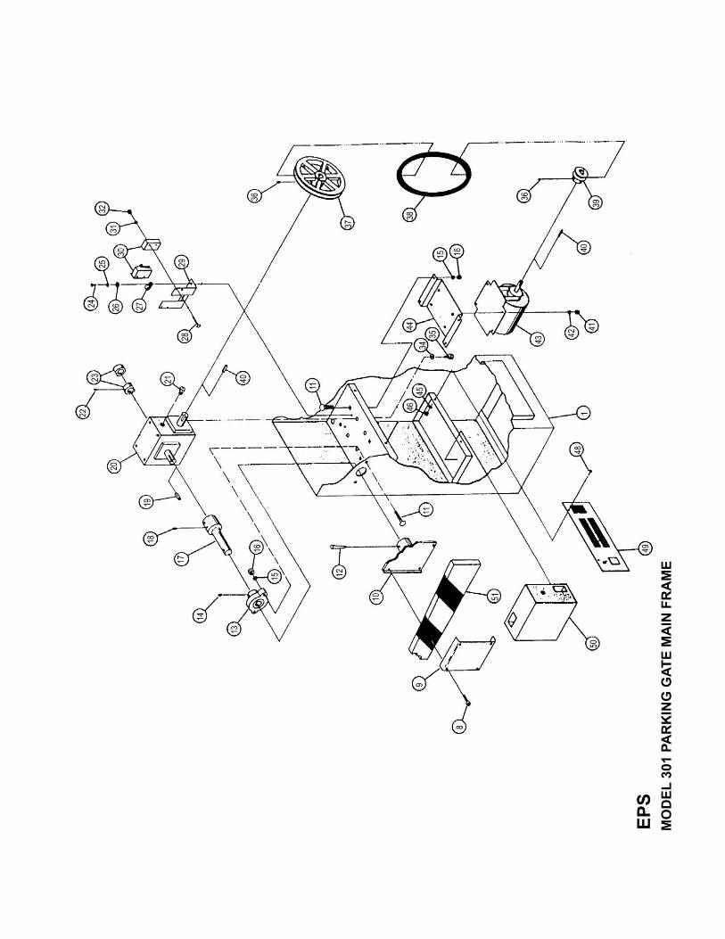
PARTS LIST 301-10 PARKING GATE
MAIN FRAME
I.D. #
8 9
10 11 12 13 14 15 16 17 18 19 20 21 22 23 24 25 26 28 29 30 31 32 34 35 36 37 38 39 40 41 42 43 44 45 46 48 49 50 51
QUANT.
4 1 1 6 1 1 2 6 6 1 4 1 1 1 2 2 2 2 2 4 1 2 4 4 4 4 2 1 1 1 2 4 4 1 1 2 2 2 1 1 1 3
PART NUMBER
016-2000A 9000-16-2 9000-16-1 016-312-1000 050-8-2500 907-8 013-300-250 016-2 016-375-16NA 9602-1-1 015-300-500 097-250-1250 457-1 015-300-250 9601-1 010-500RS 010-2 010-6 006-1250RS 9000-10-1 492-1 006-2 006-632NA 015-2 015-750H 015-300-375 908-3 542-4L320 908-2 097-187-1000 015-312-18NA 015-2 541-6 9000-12-2 008-2 008-832NA 008-500RS 9000-S10 1051-45
DESCRIPTION
3/8-16 X 2” SOCKET HD. BOLT GATE ARM FLANGE COVER GATE ARM FLANGE 3/8-16 X 1” CARRIAGE BOLT #8 X 2 ½ TAPER PIN 1 ¼” FLANGE BEARING ¼-28 X ¼ ALLEN HD. SET SCREW 3/8 SPLIT LOCK WASHER 3/8-16 HEX NUT 1 ¼” OUTPUT SHAFT 5/16-18 ALLEN HD. SET SCREW ¼ X ¼ X 1 ¼ KEYSTOCK 60:1 SPEED REDUCER AIR BREATHER 5/16-18 X ¼ ALLEN HD. SET SCREW LIMIT SWITCH CAM 10-32 X ½ RD. HD. MS. #10 SPLIT LOCK WASHER #10 FLAT WASHER 6-32 X 1 ¼ RD. HD. M.S. LIMIT SWITCH MTG. BRACKET MICRO-SWITCH, ROLLER STYLE #6 INTERNAL TOOTH LOCK WASHER 6-32 HEX NUT 5/16 SPLIT LOCK WASHER 5/16-18 X ¾ HEX HD. BOLT 5/16-18 X 3/8 ALLEN HD. SET SCREW 8” SPEED REDUCER PULLEY 4L320 V-BELT 2” MOTOR PULLEY 3/16 X 3/16 X 1 KEYSTOCK 5/16-18 HEX NUT 5/16 SPLIT LOCK WASHER 1/2 HP INSTANT REVERSING MOTOR MOTOR MOUNTING RACKET #8 INTERNAL TOOTH LOCK WASHER 8-32 HEX NUT 8-32 X ½ RD. HD. M.S. TERMINAL PANEL, COMPLETE CONTROLLER, COMPLETE 10 FOOT WOODEN GATE ARM 6 ¾” X 3 ½” WARNING LABEL
16
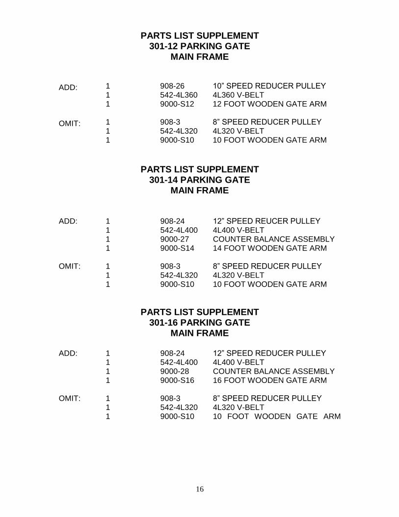
PARTS LIST SUPPLEMENT 301-12 PARKING GATE
MAIN FRAME
ADD: OMIT:
1 1 1 1 1 1
908-26 542-4L360 9000-S12 908-3 542-4L320 9000-S10
10” SPEED REDUCER PULLEY 4L360 V-BELT 12 FOOT WOODEN GATE ARM 8” SPEED REDUCER PULLEY 4L320 V-BELT 10 FOOT WOODEN GATE ARM
PARTS LIST SUPPLEMENT
301-14 PARKING GATE MAIN FRAME
ADD: OMIT:
1 1 1 1 1 1 1
908-24 542-4L400 9000-27 9000-S14 908-3 542-4L320 9000-S10
12” SPEED REUCER PULLEY 4L400 V-BELT COUNTER BALANCE ASSEMBLY 14 FOOT WOODEN GATE ARM 8” SPEED REDUCER PULLEY 4L320 V-BELT 10 FOOT WOODEN GATE ARM
PARTS LIST SUPPLEMENT 301-16 PARKING GATE
MAIN FRAME
ADD: OMIT:
1 1 1 1 1 1 1
908-24 542-4L400 9000-28 9000-S16 908-3 542-4L320 9000-S10
12” SPEED REDUCER PULLEY 4L400 V-BELT COUNTER BALANCE ASSEMBLY 16 FOOT WOODEN GATE ARM 8” SPEED REDUCER PULLEY 4L320 V-BELT 10 FOOT WOODEN GATE ARM

17
PARTS LIST
301 PARKING GATE HOUSING
I.D. # 1 2 3 4 5 6 7
QUANT. 1 1 1 1 1 1 1
PART NUMBER 9000-1-1 015-312-18WN 1051-24 1051-24A 806-1A 806-1 806-1B
DESCRIPTION MAIN HOUSING, PARKING GATE 5/16-8 WING NUT EPS NAME PLATE EPS ELECTRICAL NAME PLATE CAM LOCK NUT CAM LOCK KEY

18

19
PARTS LIST FOLDING GATE ARM ASSEMBLY
I.D. # 1 1 2 3 4 5 6 7 8 9
10 11 12 13 14 15 16 17 18 19 20 21 22 23 24 25
NOT SHOWN
QUANT. 1 1 2 2 3 3 1 1 2 1 1 1 1 1 2 1 1 1 1 4 1 1 3 1 2 2 1 1
* * * * * *
PART NUMBER 9000-S10-2 9000-S12-2 9600-F-02 073-04 012-2 012-250-20NA 021-11-RNA 018-500-13RNA 018-6 9000-16-1 050-8-2500 018-20 074-8 018-500-13NA 016-312-1000 9600-F015 018-3000H 074-9 9000-16-2 016-2000SA 018-2000H 021-2000H 012-750H 074-4 016-2 016-375-16NA 908-26 542-4L360
DESCRIPTION 10’ TWO PIECE ARM ASSEMBLY 12’ TWO PIECE ARM ASSEMBLY SANDWICH PLATES ROD END BEARING ¼” SPLIT LOCK WASHER ¼-20 HEX NUT 5/8-11 NYLOCK HEX NUT ½-13 NYLOCK HEX NUT ½” USS FLAT WASHER GATE ARM FLANGE #8 X 2 ½ TAPERED PIN ½-20 THREADED ROD SPACER, ½ ID X 7/8 OD X 1 ¼ ½-13 HEX NUT 3/8-16 X 1” CARRIAGE SCREW. FOLDING GATE ARM BRACKET ½-13 X 3 HEX HD. SPACER, ½ ID X 7/8 OD X ½ GATE ARM FLANGE COVER 3/8-16 X 2 SOCKET HD. ½-13 X 2 HEX HD. 5/8-11 X 2 HEX HD. ¼-20 X 1 ¼ HEX HD. 5/8 ID X ¾ OD X ¾ BRONZE BUSHING 3/8” SPLIT LOCKWASHER 3/8-16 HEX NUT 10” PULLEY 4L360 V-BELT * = Not included in folding gate arm kit

20

21
PARTS LIST
MODEL 301 PARKING GATE TERMINAL PANEL
I.D. # 1 2 3 4 5 6 7 8 9
10 11 12 13 17 18 19 20 22 24 25 26 27 28
QUANT. 1 1 1 6 7 3 1 1 1 1 1 1 9 2 1 2 1 2 1
17” 1 1 1
23 2 2 3
10 12” 12” 12” 16” 16” 48”
PART NUMBER
425-10 480-13 006-750RS 006-632NA 006-6 006-1250RS 304-1 9000-4-1 915-3 526-3 526-1 006-2 526-12 916-6B 537-9 1051-35 006-250RS 500-S318-CCE 945-8619 915-6 1051-23 530-8 530-9 531-6 537-1 910-4 936-16-1 936-16-3 936-16-5 938-14-9 938-14-10 945-864
DESCRIPTION
10-AMP CIRCUIT BREAKER SPDT TOGGLE SWITCH TOGGLE SWITCH NUT 6-32 X ¾ RD. HD. M.S. 6-32 HEX NUT #6 FLAT WASHER 6-32 X 1 ¼ RD. HD. M.S. 1 OHM. 55 WATT RESISTOR CONTROL PANEL MARKER STRIP, L1, NEUT, GND 3 TERMINAL BLOCK TERMINAL JUMPER #6 INTERNAL TOOTH LOCK WASHER 12 ERMINAL BLOCK MARKER STRIP, 13 THRU 24 RUBBER GROMMET DECAL; CIRCUIT BREAKER 6-32 X ¼ RD. HD. M.S. 18 PIN FEMALE PLUG 19 CONDUCTOR CABLE MARKER STRIP, 1 THRU 12 TOGGLE SWITCH MTG. RING DECAL; GATE RAISE/LOWER RED SPADE TERMINALS BLUE SPADE TERMINALS INSULATE SLIP ON TERMINALS RED RING TERMINAL 4” CABLE TIE 16 GA. STRANDED WIRE, WHITE 16 GA. STRANDED WIRE, GREEN 16 GA. STRANDED WIRE, RED 14 GA. STRANDED WIRE, WHITE 14 GA. STRANDED WIRE, BLACK 20 GA. 4 CONDUCTOR CABLE

22

23
PARTS LIST MODEL 301 PARKING GATE
CONTROLLER I.D.#
1 2 3 4 5 6 7 8 9
10 11 12 13 14 15 16
NOT
SHOWN
QUANT. 6 1 1 1 1 2 2 1
10 10 1 1 1 1 1 2 1
12” 12” 12” 1
OPT
PART NUMBER
006-500RS 505-P318DB 537-9 1051-37 091-1 006-1000RS 006-1250RS 9700-1000 006-2 006-632NA 500-S406AB 085-5 507-1000 9700-1002 080-750 530-8 938-14-7 938-14-9 938-14-10 091-5-1 9700-1001
DESCRIPTION 6-32 X ½ RD. HD. M.S. 18 PIN MALE PLUG, FLUSH MOUNT RUBBER GROMMET DECAL, REBOUND SENSITIVITY 8 X 8 X 4 CONTROL BOX 6-32 X 1” RD. HD. M.S. 6-32 X 1 ¼” RD. HD. M.S. CONTROL BOARD #6 INTERNAL TOOTH LOCK WASHER 6-32 HEX NUT 6 PIN FEMALE PLUG, FLUSH MOUNT NYLON CABLE CLAMP 18 TERMINAL EDGE CONNECTOR REBOUND MODULE CABLE ASSEMBLY REBOUND MODULE #6 X ¾ NYLON SPACER RED SPADE LUG 14 GA. WIRE, RED 14 GA. WIRE, WHITE 14 GA. WIRE, BLACK 8” X 8” CONTROL BOX LINER TICKET ISSUE/DOUBLE DIRECTION BOARD

24
TROUBLE SHOOTING INSTRUCTIONS The following procedures should be followed if the gate fails to operate correctly: 1. Check to see that the main circuit breaker switch is “ON”. 2. Check the electrical gate function by activating the RAISE/LOWER switch to the RAISE
position. The gate arm should go up. If it fails to do so, do the following:
a. Check the 115V AC on L1 and Neut. b. Check the fuses in the controller. c. Check the motor overload switch located on the backside of the motor.
3. If the gate operates correctly with RAISE/LOWER switch, but will not operate as a system, check the following:
a. Controlled entrance/exits: Check the terminals for operating the gate. If the
terminal strip is wired correctly, the gate should open when the common and the open terminals are shorted together. If the gate opens, the malfunction is in the activating equipment, such as the card reader, coin station, ticket dispenser, push button, etc. If the gate does not open, the malfunction is in the gate controller.
b. Free entrance/exits: Check the loop detector for proper tuning and loop wiring for continuity. Make sure all terminal connections are properly connected. If the gate still does not open, jumper between the common and open terminals on the terminal strip. Failure at this point indicates that the malfunction is in the gate controller or in the terminal connection(s).
4. If the gate still will not operate, disconnect the main power. Check all terminals and wire
connections to make sure they are properly connected. Check all wire connections to the limit switches.
5. If the gate arm goes up and down without stopping, do the following:
a. Check the limit switches and cams for proper adjustment. b. If the limit switches and cams are properly adjusted, and the gate still runs
without stopping, you may have a faulty limit switch(es). c. If the gate is configured for single button open and close, check to make sure
there is not a constant open input.
6. If the gate arm starts to lower but reverses and stays up, make sure the rebound sensitivity adjustment is set properly.
IF YOUR GATE IS STILL NOT OPERATING PROPERLY AFTER YOU HAVE FOLLOWED THESE INSTRUCTIONS, CALL OUR LOCAL SALES REPRESENTATIVE, CALL US AT (661) 294-0778 OR SEND AN EMAIL TO [email protected] FOR FURTHER ASSISTANCE.