Embed Size (px)
Citation preview

1
TACH-IT MODEL #3567 SEMI-AUTOMATIC TWIST TIE
MACHINEREPAIR MANUAL
01/05

2
TABLE OF CONTENTS: SECTION 1—REMOVING AND REPLACING TOP COVER:
SECTION 2—REPLACING THE CUTTER BLADES:
SECTION 3—REMOVING AND REPLACING THE SEGMENT GEAR:
SECTION 4—REMOVING AND REPLCING OF UPPER PLATE:
SECTION 5—REPLACING THE TWISTER ASSEMBLY AND TWISTER GEAR:
SECTION 6—REMOVING AND REPLACING THE TWISTING HEAD MAIN ASSEMBLY FROM THE BASE OF THE MACHINE:
SECTION 7—REMOVING AND REPLACING OF BOTTOM PLATE:
SECTION 8—LUBRICATING THE NEEDLE ARM AND NEEDLE CAM:
SECTION 9—REPLACING OF THE MOTOR, CAPACITOR, SAFETY INTERLOCK, ON/OFF SWITCH AND FUSE HOLDER:
SECTION 10—MAINTENANCE:
SECTION 11—TROUBLESHOOTING:
PAGE 3
PAGE 4
PAGES 5-6
PAGES 7-9
PAGE 10
PAGES 11-12
PAGES 13-14
PAGE 15
PAGES 16-19
PAGES 20-21
PAGE 22
TOOLS NEEDED FOR REPAIR OF MODEL #3567: Flat Head Screwdriver
Phillips Head Screwdriver
2mm Allen Wrench
Long Nose Pliers
Slip Joint Pliers or Small Gear Puller
Medium Weight Machine Grease

3
SECTION 1—REMOVING AND REPLACING THE TOP COVER: To remove the Top Cover:Power Cord must be unplugged from electrical outlet prior to removing the Top Cover.1) Loosen the screw marked below in Figure 1. 2) This machine is equipped with a Safety Interlock. To disengage the Safety Interlock lift the Top Cover
straight up.
To replace the Top Cover:1) Locate the Safety Interlock Opening located at the back of the plate. See Figure 2. 2) Locate the Safety Interlock Bar mounted to the underside of the Top Cover. See Figure 3. 3) Matching the Safety Interlock Bar with the Safety Interlock Opening, push the Top Cover down onto the
machine. 4) Tighten the screw pictured in Figure 1
Loosen this screw to remove the cover. Tighten this screw to replace cover.
Figure 1
Figure 2 Safety Interlock Opening
Figure 3
Safety Interlock Bar

4
SECTION 2—REPLACING THE CUTTER BLADES: 1) Remove the Top Cover as per the instructions in Section 1. 2) Locate the Cutter Blade Linkage. See Figure 4 3) Locate and remove the Cutter Blade Linkage Spring from its post. See Figure 4. 4) Locate the Movable Blade Holding Spring holding the Movable Blade in position. Release pressure on the
Spring by removing it from the Spring Hanger on the linkage. See Figure 4. 5) Locate the 2 screws marked Screw 1 and Screw 2 in Figure 4, and remove them and their related washers
and spacers. Suggestion: Screw 1 is longer than Screw 2, when removing these screws, place them in dif-ferent locations for easy replacement, or they can just be loosened and kept within the linkage as it is lifted off the machine.
6) Lift the Cutter Blade Linkage from the Machine. Suggestion: Placing the Cutter Blade Linkage down in the same position as it was removed will make for easier re-installation..
7) Locate the Moveable Blade and the Fixed Blade from the now exposed area of the machine. See Figure 5.Suggestion: The Fixed Blade fits into a cutout in the upper plate and also sits slightly higher than the plate. Please note this position prior to removal so that it can be verified that the Fixed Blade is in the proper position prior to re-assembly.
8) Remove the worn Movable Blade and Fixed Blade. 9) Install the new Fixed Blade first making sure that it is in the proper position fitting into the cutout in the
upper plate, and then install the Movable Blade. 10) Replace the Cutter Blade Linkage. When replacing, it must be verified that the projection pointing down-
ward from the front end of the Linkage goes into the circle located at the back end of the Movable Blade. See Figure 6
11) Replace Screw 1 and Screw 2 making sure that they are in their proper positions and that all related washer and collars are properly installed.
12) Release the Movable Blade Holding Spring so that it is putting pressure onto the Movable Blade. 13) Replace the Cutter Blade Linkage Spring to its Spring Hanger. 14) Replace the Top Cover per the instructions in Section 1.
Figure 4 Figure 5
Screw 1 Cutter Blade Linkage Cutter Blade Linkage Spring
Screw 2 Movable Blade Holding Spring
Movable Blade Fixed Blade
Figure 6 Release the pressure on the Movable Blade Holding Spring by unclipping the Spring from the Spring Hanger.

5
SECTION 3—REMOVING AND REPLACING THE SEGMENT GEAR: To remove the Segment Gear and Feeding Roller:1) Unplug the power cord from the electrical outlet. 2) Remove the Top Cover as per instructions in Section 1. 3) Locate the Upper Holding Plate and the 3 Screws Securing it. Remove the 3 Screws and lift the Upper
Holding Plate off. Remove the 3 Upper Holding Plate Spacer Collars. See Figure 7 4) Locate the Main Shaft. See Figure 8. 5) Using a Flat Head Screwdriver, Rotate the Main Shaft Counter-Clockwise until the flat portion of the
Feeding Roller is meeting the flat portion of the Segment Gear. 6) Remove the Arm Spring taking pressure off of the Feeding Roller. 7) Locate the Switch Lock Lever Spring. This is located behind the Micro-switch. Locate the long leg of this
spring which should be resting against the Switch Lock Lever. Grasp the Spring and pull it down against the body of the machine taking all pressure off of the Switch Lock Lever. Rotate the Switch Lock Lever away from the Segment Gear.
8) Locate and remove the Switch Lever Spring. Rotate the Switching Arm away from the Segment Gear. 9) Without rotating the Main Shaft, lift together the Feeding Roller and the Segment Gear from the machine,
noticing their position in relation to each other.
To replace the Segment Gear and Feeding Roller:1) Make sure that prior to re-assembling, the set screw located on the Twister Gear is facing down to the table
and that the legs of openings of the Twister Assembly are in a vertical position..2) Holding the Feeding Roller and the Segment Gear align them so that the flat of the Feeding Roller is
against the Flat of the Segment Gear in a similar position to how they were removed. Make sure that the both parts are fully lowered into the plate and that the keyway in the Segment Gear matched to the key in the Main Shaft.
3) Rotate the Switching Arm towards the Segment Gear so that it contacts the Segment Gear and re-install the Switch Lever Spring.
4) Rotate the Switch Lock Lever towards the Segment Gear so that it is in contact with the Segment Gear. Locating the long leg of the Switch Lever Lock Spring which was rotated out of the way in Step 7 above, place it back against the Switch Lock Lever making sure that it is putting pressure against this part.
5) Replace the Arm Spring, making sure that the urethane idler wheel is pressing against the Feeding Roller. 6) Replace the Upper Holding Plate fitting it into its proper position securing the Main Shaft and the Feeding
Roller. Make sure that the Upper Holding Plate Spacer Collars are put into their proper positions and secure the 3 screws.
7) Locate the Main Shaft. 8) Using a Flat Head Screwdriver, turn the Main Shaft until the cutout across the top of the Main Shaft is
perpendicular to the machine. Locate the Switching Arm, and make sure that when it is pushed, the end depresses the lever of the micro-switch.
9) Replace the Top Cover per the instructions in Section 1. 10) Plug the power cord into the proper electrical outlet and try the machine.
See Figure 7 and Figure 8 on the next page.

6
SECTION 3—REMOVING AND REPLACING THE SEGMENT GEAR CONTINUED:
Figure 7
Remove Screw. Upper Holding Plate Spacer Collar located directly beneath.
Remove Screw. Upper Holding Plate Spacer Collar located directly beneath.
Remove Screw. Upper Holding Plate Spacer Collar located directly beneath.
Upper Holding Plate
Figure 8
Arm Spring
Main Shaft
Micro-Switch
This shows the Flats of the Segment Gear and the Feeding Roller
Feeding Roller
Segment Gear
Switch Lock Lever Spring
Switch Lock Lever, Located under switching Arm
Switching Arm
Switch Lever Spring Urethane Roller

7
SECTION 4—REMOVING AND REPLACING OF UPPER PLATE: Removal of this part is necessary to; change the Twister Assembly, clean debris from under the Upper Plate, change the Needle Left and Needle Right, change the Needle Guard Arm Spring, change theNeedle Guard Arm, and to do any other service required on parts located between the Upper Plate and Middle Plate.
To remove the Upper Plate:1) Remove the Top Cover as per the instructions in Section 1. 2) Locate the Micro-Switch. See Figure 9. 3) Pull the 2 wires off the Micro-Switch. These wires are connected to the Micro-Switch with push on
connectors. 4) Unscrew the 2 screws holding the Micro-Switch and place the whole assembly to the side. 5) Locate the screw holding the Green and Yellow Ground Wire. See Figure 9. Remove the screw and place
the screw to the side. 6) Locate the screw holding the Switch Lock Lever Spring assembly. See Figure 9. 7) Unscrew the screw and remove the assembly. Suggestion: To remove this assembly without the spring
recoiling and scattering the parts, loosen the screw about half way, locate the short leg of the spring which will be pressed up against a post behind the Micro-Switch. Using a long nose pliers, grab the short leg of the spring and remove it from the post. This will release the pressure from the spring. Then continue un-screwing the screw and removing the assembly. Place the assembly intact to the side.
8) Remove the Arm Spring. See Figure 9. 9) Locate the Tie Feeding Roller Arm. See Figure 9. 10) Locate the Screw and remove the Tie Feeding Roller Arm. 11) Below the Tie Feeding Roller Arm locate the Tie Feeding Roller with Bushing. 12) Place the Tie Feeding Roller with Bushing to the side. Suggestion: The bushing inside the Tie Feeding
Roller with Bushing has a shoulder, this shoulder must always be on top. When placing it down to the side, place it in the same orientation as it is used in the machine so that when it is re-installed, the bushing will be in the right direction.
13) Follow the instructions in Section 3 to remove the Segment Gear and Feeding Roller. Steps 6 and 7 will not be required as these parts have already been removed.
14) Locate the Movable Blade Holding Spring holding the Movable Blade in position. Release pressure on the Spring by removing it from the Spring Hanger on the linkage. See Figure 4. The Cutter Blade Linkage does not have to be removed to remove the Upper Plate.
15) Remove the 6 screws shown in Figure 10. Suggestion: Loosen the screws, but do not physically remove them from the machine. Once they are loose, the Upper Plate can be removed, and the screws will be in the right place during re-assembly.
16) Lift up the Upper Plate. Note: The Movable Blade is may still be connected to the Cutter Blade Linkage. When lifting the Upper Place do so carefully as not to disturb this positioning. If the position is disturbed, it can be reset with the Upper Plate off.
See Figure 9 and Figure 10 on the next page.

8
SECTION 4—REMOVING AND REPLACING OF UPPER PLATE CONTINUED:
Figure 9
Arm Spring Micro-Switch
Switch Lock Lever Spring Assembly
Ground Wire and Screw
Tie Feeding Roller Arm
Tie Feeding Roller and Bushing
Figure 10 Remove screw
Remove screw
Remove screw
Remove screw
Remove screw
Remove screw
Hole for Wires

9
SECTION 4—REMOVING AND REPLACING OF UPPER PLATE CONTINUED:
To replace the Upper Plate:1) Hold the Upper Plate over the Middle Plate and insert the 3 wires into the hole from which they were
removed. See Figure 10 on previous page. 2) Begin lowering the Upper Plate onto the Middle Plate. Looking at the bottom side of the Upper Plate,
locate the projection coming down from the Cutter Blade Linkage. This projection must match up with the circle at the end of the Movable Blade. If necessary move the Movable Blade to match with the projection. See Figure 6 in Section 2.
3) Once this is lined up, lower the Upper Plate until it is sitting properly on top of the Middle Plate. This may take a little twisting to have everything line up properly.
4) Tighten the 6 screws that were loosened when removing the Upper Plate. See Figure 10 on the previous page.
5) Follow Step 12 in Section 2 of this manual to release the Movable Blade Holding Spring and put pressure onto the Movable Blade.
6) Re-install the Micro-Switch and connect the wires. The wire marked R1 goes to the “Normally Open” terminal (this is the terminal next to the empty terminal), and the wire marked R3 goes to the “Common” terminal (this is the terminal offset from the other ones)
7) Re-install the ground wire. 8) Re-install the Switch Lock Lever Spring Assembly, making sure that the long leg is resting against the
Switch Lock Lever. To add pressure, take the short leg of the Switch Lock Lever Spring and using a long nose pliers push it towards the back of the machine so that it rests against the post from which it was removed. Suggestion: Only screw the Spring Lock Lever Assembly about half way into the machine. Then reset the short leg of the Spring Lock Lever Spring and once it is set complete the tightening of the screw.
9) Replace the Segment Gear and Feeding Roller per the instructions in Section 3. Skip steps 4 and 5 as they are addressed in this section of the manual.
10) Re-install the Tie Feeding Roller with Bushing making sure it is in the proper orientation. There is a split in the Bushing which should be facing up.
11) Re-install the Tie Feeding Roller Arm. Make sure that the projection located at the front of this arm isinserted into the center hole of the Tie Feeding Roller with Bushing.
12) Re-install the Top Cover per the instructions in Section 1.

10
SECTION 5—REPLACING THE TWISTER ASSEMBLY AND TWISTER GEAR:
1) Follow the instructions in Section 4 to remove the Upper Plate. 2) Remove the Twister Assembly from the Middle Plate. See Figure 12. 3) Slide the Bushing off the end of the Twister Gear. See Figure 11. 4) Using a 2mm Allen Wrench loosen the set screw on the Twister Gear. See Figure 11 5) Slide the Twister Assembly from the Twister Gear. See Figure 11. 6) Insert one of the Bushings and then the new Twister Assembly into either the new or used Twister Gear.
Make sure that the flat area located on the shaft of the Twister Assembly lines up with the set screw in the Twister Gear.
7) Slide the 2nd Bushing onto the shaft of the Twister Assembly until the end of the Bushing is flush with the end of the Twister Assembly shaft.
8) Tighten the set screw using a 2mm Allen Wrench. 9) Insert the Twister Assembly back into the Middle Plate pushing down until it is secure. 10) Follow the instructions in Section 4 to replace the Upper Plate.
Figure 11
Bushings
Set Screws
Twister Gear Twister Assembly
Figure 12
Twister Assembly Main Shaft Needle Guard Arm Spring Needle Guard Arm
Needle Left
Needle Right
Movable Blade Fixed Blade

11
SECTION 6—REMOVING AND REPLACING THE TWISTING HEAD ASSEMBLY FROM THE BASE OF THE MACHINE:
It is necessary to remove the Twisting Head Assembly from the base of the machine if any service is required between the Middle Plate and the Bottom Plate. It may also be required for lubrication or if any work is required on the motor.
To remove the Twisting Head Assembly from the base of the machine:1) Remove the Top Cover as per the instructions in Section 1. 2) Locate and remove the Tie Feeding Roller Arm. See Figure 9. 3) Below the Tie Feeding Roller Arm locate the Tie Feeding Roller with Bushing. 4) Place the Tie Feeding Roller with Bushing to the side. Suggestion: The bushing inside the Tie Feeding
Roller with Bushing has a shoulder, this shoulder must always be on top. When placing it down to the side, place it in the same orientation as it is used in the machine so that when it is re-installed, the bushing will be in the right direction.
5) Locate the Green and Yellow Ground Wire. Remove the screw holding the wire in place. See Figure 9. 6) Remove the 2 wires from the Micro-Switch. It is not necessary to remove the Micro-Switch itself. See
Figure 9. 7) Locate the 3 screws that hold the Twisting Head Assembly to the Base of the machine. See Figure 13 8) Loosen the 3 screws. Suggestion: Do not remove these 3 screws, just loosen them completely. This way
they will be in the proper position during re-assembly. 9) Lift the Twisting Head Assembly from the Base and set to the side.
To replace the Twisting Head Assembly from the base of the machine:1) Holding the Twisting Head Assembly over the base, feed the wires through the hole in the Twisting Head
Assembly. See Figure 10. 2) Lower the Twisting Head Assembly onto the base of the machine. 3) Tighten the 3 screws that were loosened above securing the Twisting Head Assembly to the base. See
Figure 13 4) Re-connect the Micro-Switch Wires. The wire marked R1 goes to the “Normally Open” terminal (this is
the terminal next to the empty terminal), and the wire marked R3 goes to the “Common” terminal (this is the terminal offset from the other ones)
5) Re-install the ground wire. 6) Re-install the Tie Feeding Roller with Bushing making sure it is in the proper orientation. There is a split
in the Bushing which should be facing up. 7) Re-install the Tie Feeding Roller Arm. Make sure that the projection located at the front of this arm is in-
serted into the center hole of the Tie Feeding Roller with Bushing. 8) Re-install the Top Cover per the instructions in Section 1.
See Figure 13 on the next page.

12
Figure 13
Remove screw Remove screw
Remove screw
TIE FEEDING ROLLER ARM AND TIE FEEDING ROLLER WITH BUSHING HAVE BEEN RE-MOVED IN ABOVE FIGURE.
SECTION 6—REMOVING AND REPLACING THE TWISTING HEAD ASSEMBLY FROM THE BASE OF THE MACHINE CONTINUED:

13
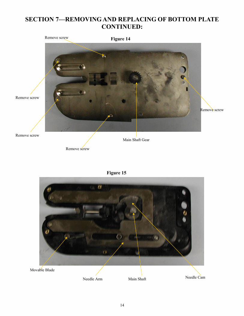
SECTION 7—REMOVING AND REPLACING OF BOTTOM PLATE:
To remove the Bottom Plate:1) Follow the instructions in Section 6 To Remove the Twisting Head Assembly from the Base of the
machine. 2) Turn the Twisting Head Assembly over so that the Bottom Plate is facing up. 3) Locate the Main Shaft Gear 4) Using a 2mm Allen Wrench, loosen the Set Screw located on the side of the Gear. There is a hole in the
shaft that the Set Screw lines up with, so the screw may need to be backed out of the Gear almost all the way prior to lifting the Gear.
5) Remove the Main Shaft Gear from the Shaft. This may require the use of a pair of pliers to grab the gear.Be careful not to scar the teeth of the gear.
6) Locate the 5 screws securing the Bottom Plate to the Middle Plate. Remove the 5 screws. 7) Running a Flat Head Screwdriver around the sides of the Twisting Head Assembly between the Middle
Plate and the Bottom Plate, separate the Plates. Gently lift the Bottom Plate until it can be removed. Note:Due to lubrication, the Needle Cam may stick to the underside of the Bottom Plate when it is removed. Turn the Bottom Plate over and look at the underside, if the Needle Cam is stuck to the Bottom Plate remove it and put it back onto the Main Shaft in the same direction as it came off. It is very important that it is in the same direction. Make sure that the Needle Cam is seated properly and secured by the keys. See Figure 15.
To replace the Bottom Plate:1) Verify that the Needle Cam and all other parts are properly installed. 2) Slowly lower the Bottom Plate onto the Shaft. Due to holes that must line up with in the Bottom Plate and
the Middle Plate, some twisting of the Bottom Plate may be required. Once the holes are located push on the Bottom Plate securely until it meets the Middle Plate.
3) Replace the 5 screws that were removed in Step 6 above. Make sure that the 2 countersunk screws go into the holes at the front of the Twisting Head Assembly.
4) Slide the Main Shaft Gear onto the Main Shaft, making sure that the Set screw lines up with the Hole in the Main Shaft.
5) Tighten the Set Screw securely. 6) Re-install the Twisting Head Main Assembly per the instructions in Section 6.
The following parts can be accessed by removing the Bottom Plate; the Needle Cam and the Needle Arm, Needle Left, Needle Right, and the Movable Blade. It may also be necessary to remove the Bottom Plate to lubricate using a medium weight machine grease the Needle Arm and the Needle Cam.
See Figure 14 and 15 on the next page.
14
SECTION 7—REMOVING AND REPLACING OF BOTTOM PLATE CONTINUED:
Figure 14
Remove screw
Remove screw
Remove screw
Remove screw
Main Shaft Gear
Figure 15
Needle Arm Main Shaft Needle Cam
Movable Blade
Remove screw

15
SECTION 8—LUBRICATING THE NEEDLE ARM AND NEEDLE CAM: Lubricating of the Needle Arm and the Needle Cam may be necessary after extended use. Friction between the Needle Arm and the Middle Plate may build up and the symptom of this is that the machine occasionally will not complete a cycle. Follow instructions below to solve this problem if it becomes apparent. Please note that lubrication of the whole machine is not recommended. Lubricants, espe-cially in dusty environments may become sticky and cause parts to not run smoothly against each other.Only lubricate using the manufacturer’s specified lubricants and in the shown locations.
1) Remove the Bottom Plate of the Twisting Head Assembly as per the instructions in Section 7 2) Using a medium weight machine grease generously spread the grease along the Needle Arm. See Figure
16. Note: When the Middle Plate and Bottom Plate are assembled the seal between them does not allow for much penetration of dust, so liberal greasing of these parts only will not be damaging to the machine.
3) Replace the Bottom Plate of the Twisting Head Assembly as per the instructions in Section 7.
Figure 16
Lubricate here
Lubricate here
Lubricate here
Needle Arm

16
SECTION 9—REPLACING OF THE MOTOR, CAPACITOR, SAFETY INTERLOCK, ON/OFF SWITCH AND FUSE HOLDER
To replace the Motor, Capacitor, Safety Interlock, On/Off Switch and Fuse Holder, the Motor Box must be opened. Follow the instructions below on how to Open the Motor Box. There is a sub-section for the replacement of each of the parts previously mentioned. When done, follow the instructions below on how to Close the Motor Box.
To Open the Motor Box:1) Remove the Twisting Head Assembly as per the instructions in Section 6. 2) Turn the machine over so the bottom of the machine is facing upwards. 3) Locate the Brake Arm Spring. 4) Release the tension on the Brake Arm Spring by removing the leg from the Spring Hanger on the
Perforated Plate. See Figure 17. 5) Unscrew the 4 legs which will release the Perforated Plate. See Figure 18. 6) Raise the Perforated Plate. Be careful as the Capacitor is mounted onto the Perforated Plate. The Motor
Box is open with access to all above mentioned parts. See Figure 19.
To Change the Motor:1) Follow the directions above to open the Motor Box. 2) Locate the 4 screws holding the Motor into the Motor Box. These are located on the top of the Motor Box,
so the Motor Box must be flipped. See Figure 20. 3) Remove the 4 screws marked Motor Screws and carefully lower the Motor. 4) With the new Motor near, remove the wires to the Motor one by one, installing them into the new Motor. 5) Remove the Main Shaft Gear by loosening and removing the Set Screw, and install the Main Shaft Gear
onto the new Motor. Make sure that the Set Screw lines up with the hole in the Motor Shaft. 6) Raise the Motor back into the Motor Box and Re-install the 4 Motor Screws. 7) Follow the directions below to close the Motor Box.
To Change the Capacitor:1) Follow the directions above to open the Motor Box. 2) Locate the Capacitor on the underside of the Perforated Plate. See Figure 19. 3) Remove the screw holding the Capacitor in place. 4) Remove the insulation from the Capacitor, and with the new Capacitor near, switch the wires one by one to
the new Capacitor. 5) Re-install the Capacitor to the underside of the Perforated Plate. 6) Follow the directions below to close the Motor Box..
To Change the Safety Interlock:1) Follow the directions above to open the Motor Box. 2) Locate the 2 screws holding the Safety Interlock into the Motor Box. These are located on the top of the
Motor Box so the Motor Box must be flipped. See Figure 20. 3) Remove the 2 screws marked Safety Interlock Screws and carefully lower the Safety Interlock. 4) With the new Safety Interlock near, remove the wires from the old Safety Interlock one by one, and install
them onto the new Safety Interlock. 5) Raise the new Safety Interlock into the Motor Box and re-install the 2 Safety Interlock screws. 6) Follow the directions below to close the Motor Box.
Section 9 Continued on the Next Page

17
SECTION 9—REPLACING OF THE MOTOR, CAPACITOR, SAFETY INTERLOCK, ON/OFF SWITCH AND FUSE HOLDER CONTINUED:
To Change the On/Off Switch:1) Follow the directions above to open the Motor Box. 2) Pressing the tabs on the On/Off Switch pull forward and remove it from the case. 3) With the new On/Off Switch near, transfer the wires from the old switch to the new switch making sure
they are installed in the same place. 4) Slide the new On/Off switch back into the Motor Box 5) Follow the instructions below to close the Motor Box.
To change the Fuse Holder:1) Follow the instructions above to open the Motor Box. 2) Locate the Fuse Holder and remove the wires. Note that the wire marked R1 goes onto the middle tab of
the Fuse Holder while wire marked R0 goes to the tab at the end of the Fuse Holder. 3) Unscrew the old Fuse Holder and replace it with the new Fuse Holder. 4) Replace the wires making sure the wire R1 goes to the middle tab and wire R0 goes to the end tab. 5) Follow the instructions below to close the Motor Box.
To Close the Motor Box:1) Turn the Motor Box over so that the opening is up. 2) Lower the Perforated Plate onto the Motor Box. Be careful that all the wires are within the Motor Box and
that they will not be pinched when securing the Perforated Plate. 3) Replace and screw in the 4 legs that were previously removed. See Figure 18. 4) Locating the Brake Arm Spring, secure it back onto the Spring Hanger on the Perforated Plate restoring
tension to the Brake Arm Spring. See Figure 17. 5) Turn the machine over to its proper orientation. 6) Replace the Twisting Head Assembly as per the instructions in Section 6.
Figure 17
Brake Arm Spring
Spring Hanger
See Figures 18, 19 and 20 on the next page.

18
Figure 18
SECTION 9—REPLACING OF THE MOTOR, CAPACITOR, SAFETY INTERLOCK, ON/OFF SWITCH AND FUSE HOLDER CONTINUED:
Remove screw Remove screw
Remove screw
Remove screw
Figure 19
On/Off Switch
Motor
Perforated Plate Capacitor
Fuse Holder
Safety Interlock Not visible, Located within well.
See Figure 20 on the next page.

19
SECTION 9—REPLACING OF THE MOTOR, CAPACITOR, SAFETY INTERLOCK, ON/OFF SWITCH AND FUSE HOLDER CONTINUED:
Figure 20
Motor Screw Motor Screw
Motor Screw
Motor Screw Safety Interlock Screw Safety Interlock Screw

20
SECTION 10—MAINTENANCE: The Tach-It Model #3567 has been designed to require as little normally scheduled maintenance aspossible. Excess lubrication in this machine becomes a detriment, not a benefit for the machine. In Especially dusty environments, the lubricants attract the dust and become pasty losing any benefit they may have had. When lubricating this machine, please only lubricate where specified and in limited quantities. The gears of this machine are hardened and do not need lubrication to function properly.
Keep the unit clean and free of debris:The most important maintenance that can be performed on the Model #3567 is to keep it free of dirt anddebris. The best way to do this is with using compressed air. Small pieces of twist tie ribbon, bags, dust, and products may enter the machine and effect the movement of the parts. This debris should be removed periodically. Also, debris may settle between the Upper Plate and Middle Plate. To remove this, follow the directions in Section 4 and when the Upper Plate is removed, clean or blow out the debris and re-assemble.
There is no exact time frame for how often this must be done. Much will depend on the environment, the product and the twist tie ribbon used.
Lubricate the Switching Arm:There is a protrusion on the Switching Arm that rides along a groove of the Segment Gear. This protrusion should be lubricated when it becomes dry using a medium weight machine grease. Do not over-lubricate this part, as excess grease may fly during the cycle of the machine. See Figure 21.
Lubricate the Switching Arm Assembly:The Switching Arm Assembly runs from the front Tying Aperture of the machine back to the Micro-switch. It is the assembly that moves when a bag is inserted into the tying aperture and triggers the Micro-Switch to be-gin the next cycle. See Figure 21. If this becomes dirty or dry, the assembly should be removed, which is easily done, clean under the assembly, lubricate, and re-assemble. To do this follow the instructions below: 1) Remove the Top Cover per the instructions in Section 1. Notice the path of travel of the Switch Lever
Assembly. 2) Locate and remove the Switch Lever Spring. 3) Locate the 2 C-Clips shown on Figure 21 and remove them with a long nosed pliers. 4) Lift the Switching Arm Assembly up out of the machine. There are rollers and washers located on the
posts where the C-Clips have been removed. These should also be removed from the machine at this time. 5) Clean all the components of the Switching Arm Assembly including the washers and rollers. 6) Using a spray lubricant such as silicone or a very lightweight machine oil, lightly coat the path of travel of
the Switching Arm Assembly. Do not over-lubricate, not much lubrication is necessary. 7) Re-install the washers and rollers onto the posts that they were removed from. 8) Place the Switching Arm Assembly back onto the posts and re-align its travel so it is the same as whenit
was removed. 9) Re-install the C-Clips using a long nosed pliers. 10) Replace the Top Cover per the instructions in Section 1.
Lubricate the Needle Arm:Lubrication of the Needle Arm may become necessary if the machine occasionally does not complete its cycle. Due to friction between the Needle Arm and the underside of the Middle Plate, lubrication may be necessary. This is the only area of the machine where a lubricant can be liberally applied as the area is sealed. Complete instructions for doing this can be found in Section 8 of this manual. See Figure 21 on the next page.

21
Micro-Switch
Segment Gear
Lubricate this protrusion with medium weight machine grease.
Switching Arm
Switch Lever Spring
Figure 21 C-Clip
C-Clip located under Switch Lever Spring
Rollers and washers Located below the C-Clips.
Tying Aperture
SECTION 10—MAINTENANCE CONTINUED:

22
SECTION 11—TROUBLESHOOTING:
PROBLEM CAUSE REMEDYMachine does not operate even though the On/Off Switch id in the On position (Switch is not lit)
Power Cord is not plugged in Check Fuse
Plug the Machine into the proper Power Outlet
Change Fuse if blown 2 amp
Machine does not operate even though On/Off Switch in the On position (Switch is Lit)
Make sure the Top Cover is on and secure and that the Safety Interlock Bar is Meeting the Safety Interlock See Section
1.
Re-fasten the Top Cover ifnecessary. See Section 1
Replace the Safety Interlock if faulty. See Section 9.
Machine is operating normally except it does not tie the item or the twist tie ribbon is wrapping around the Twister Assembly
Make sure the ribbon is fed correctly and in the right
positionCutter Blades are worn.
If necessary re-thread the twist tie ribbon into the machine.
Replace the Cutter Blades per the instructions in Section 2.
During the loading process, the twist tie ribbon does not appear in the Tying Aperture of themachine.
The twist tie ribbon may not be following the correct path
through the machine.
Holding the Tie Feeding Roller Arm in, slowly remove the ribbon. Do not pull, if it breaks the piece left in the machine will need to be removed. Pull gently until all the
ribbon is out and then re-feed.
The Machine does not cycle properly or stops mid-cycle
Check if the Twist Tie Ribbon is not feeding properly within
the machine. The Top Cover Fixing Screw is loose or the Top Cover is
not seated properly. The Safety Interlock is mal-
functioning.The Needle Cam is dry and there is friction between the Middle Plate and the Needle
Arm.
Open the Top Cover per the in-structions in Section 1, remove any excess ribbon or debris and replace
the Top Cover. Check the Top Cover Screw and make sure it is tight and that the Top Cover is seated properly per
the instructions in Section 1. Check the Safety Interlock and re-place if necessary per the instruc-
tions in Section 9. Lubricate the Needle Arm per the
instructions in Section 8.
After making a successful closure, the machine will not cycle.
The Cutout in the Main Shaft should be perpendicular to the
Twisting Head Assembly if not, the Needle Arm may need
lubrication.Check that the Switching Arm
Assembly is moving and returning into its proper posi-
tion smoothly.
Using a screwdriver turn the Main Shaft Clockwise till the cutout is
perpendicular and then lubricate the Needle Arm
Clean and lubricate the Switching Arm Assembly per the instructions
in Section 10.