Embed Size (px)
Citation preview

TachometersTach•Pak® 1 Digital Process Speed SwitchTach•Pak® 3 Digital Process TachometerTachtrol 2 Digital Speed/Rate MonitorTachtrol® 3 Dual Input Digital TachometerEnclosure Options
SensorsPrinciples of Operation of VR SensorsMagnetic Sensor SelectionCalculation of Output VoltagePassive Speed Sensors, VR TypesHall Effect Sensors
AccessoriesConnectors and Cable AssemblieSplit and Solid GearsTachometer TransduceNEMA “C Face” Ring AssembliesSensor Mounting Brackets
Table of Contents
TACHOMETERSSPEED SENSORSAND ACCESSORIES
AI-Tek / AIRPAX INSTRUMENTS

(Speed Switch Only)CSA Listed
Ordering P/N Input Power Enclosure
T77130-11 120 Vac/24 Vdc Standard NEMA 1-12 240 Vac/24 Vdc Standard NEMA 1-41 120 Vac/24 Vdc NEMA 4X *-42 240 Vac/24 Vdc NEMA 4X *-71 120 Vac/24 Vdc Explosion Proof **-72 240 Vac/24 Vdc Explosion Proof **
TACH•PAK ® 1Digital Process Tachometer
It is the customer's responsibility todetermine whether the product isproper for customer's use andapplication.
Part Number Series T77130
Features and Advantages
Quicker Response Time - 50 millisec-ond updates above 100 Hz.
Higher Level of Accuracy - ±.05% forrelay setpoints in operation overtemperature ranges.
Field Programmable - Adaptable tovarious applications and require-ments by utilizing a unique internalswitch design. No additionalcalibration equipment is required.
Digital Configuration - Utilizes adap-tive period averaging and floatingpoint calculation.
2 Relays - Sealed 6 amp SPDT autoreset or latching.
AC or DC Power - Adaptable to eitherAC or DC power source.
Applications
• Fast response overspeedshutdown
• Petrochemical productionapplications
• Pump or generator alarm• Low speed switching• Start-up, over/under speed
switching• Textile production applications• Machine control• Paper and pulp production• Turbine speed control• Food processing• Conveyor alarms• Printing industry• Metal production• Mining applications• Test labs• Generator sets• Broken or slipping belt drives
Faster - More Accurate - FieldProgrammable
The Tach•Pak 1 computingspeed switch is a single channelinstrument. It measures inputfrequency and converts the resultingquantities to relay closure.
The microcomputer-basedTach•Pak 1 speed switch usesadaptive period averaging whichpermits a combination of fastresponse and high accuracy notavailable in other industrial speedinstruments. The instrumentfunctions can easily be programmedin the field or altered at any timeusing a unique internal switchdesign.
Typically, a Tach•Pak 1 speedswitch is used with magneticsensors as a signal source. How-ever, it may receive a sine wave orTTL signal from any frequencysource. The resulting speed is usedfor alarm switching. It is superior inapplications requiring fast updatetimes and high accuracy for equip-ment protection.
* See page 15 for dimensions** See page 16 for dimensions
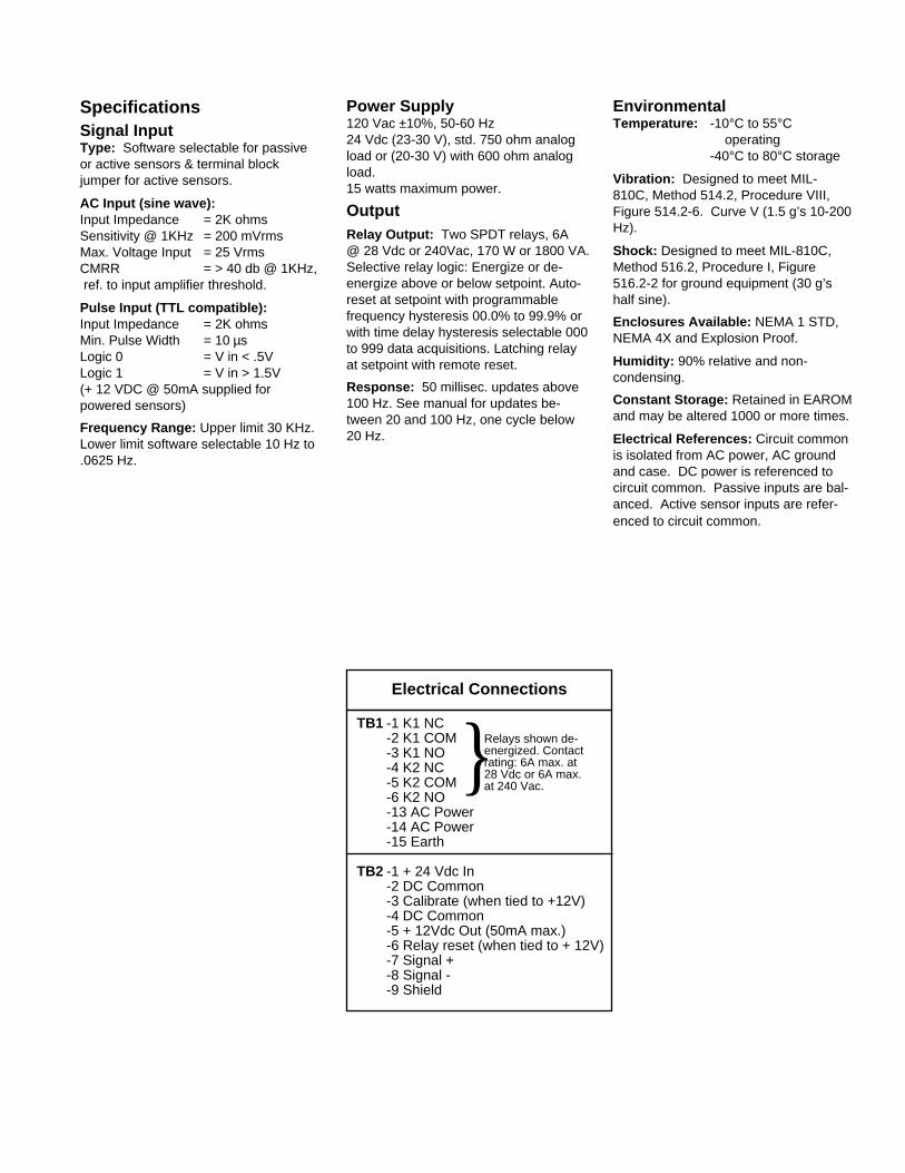
}TB1 -1 K1 NC
-2 K1 COM-3 K1 NO-4 K2 NC-5 K2 COM-6 K2 NO-13 AC Power-14 AC Power-15 Earth
TB2 -1 + 24 Vdc In-2 DC Common-3 Calibrate (when tied to +12V)-4 DC Common-5 + 12Vdc Out (50mA max.)-6 Relay reset (when tied to + 12V)-7 Signal +-8 Signal --9 Shield
Power Supply120 Vac ±10%, 50-60 Hz24 Vdc (23-30 V), std. 750 ohm analogload or (20-30 V) with 600 ohm analogload.15 watts maximum power.
OutputRelay Output: Two SPDT relays, 6A@ 28 Vdc or 240Vac, 170 W or 1800 VA.Selective relay logic: Energize or de-energize above or below setpoint. Auto-reset at setpoint with programmablefrequency hysteresis 00.0% to 99.9% orwith time delay hysteresis selectable 000to 999 data acquisitions. Latching relayat setpoint with remote reset.
Response: 50 millisec. updates above100 Hz. See manual for updates be-tween 20 and 100 Hz, one cycle below20 Hz.
Electrical Connections
SpecificationsSignal InputType: Software selectable for passiveor active sensors & terminal blockjumper for active sensors.
AC Input (sine wave):Input Impedance = 2K ohmsSensitivity @ 1KHz = 200 mVrmsMax. Voltage Input = 25 VrmsCMRR = > 40 db @ 1KHz, ref. to input amplifier threshold.
Pulse Input (TTL compatible):Input Impedance = 2K ohmsMin. Pulse Width = 10 µsLogic 0 = V in < .5VLogic 1 = V in > 1.5V(+ 12 VDC @ 50mA supplied forpowered sensors)
Frequency Range: Upper limit 30 KHz.Lower limit software selectable 10 Hz to.0625 Hz.
Relays shown de-energized. Contactrating: 6A max. at28 Vdc or 6A max.at 240 Vac.
EnvironmentalTemperature: -10°C to 55°C
operating-40°C to 80°C storage
Vibration: Designed to meet MIL-810C, Method 514.2, Procedure VIII,Figure 514.2-6. Curve V (1.5 g’s 10-200Hz).
Shock: Designed to meet MIL-810C,Method 516.2, Procedure I, Figure516.2-2 for ground equipment (30 g’shalf sine).
Enclosures Available: NEMA 1 STD,NEMA 4X and Explosion Proof.
Humidity: 90% relative and non-condensing.
Constant Storage: Retained in EAROMand may be altered 1000 or more times.
Electrical References: Circuit commonis isolated from AC power, AC groundand case. DC power is referenced tocircuit common. Passive inputs are bal-anced. Active sensor inputs are refer-enced to circuit common.
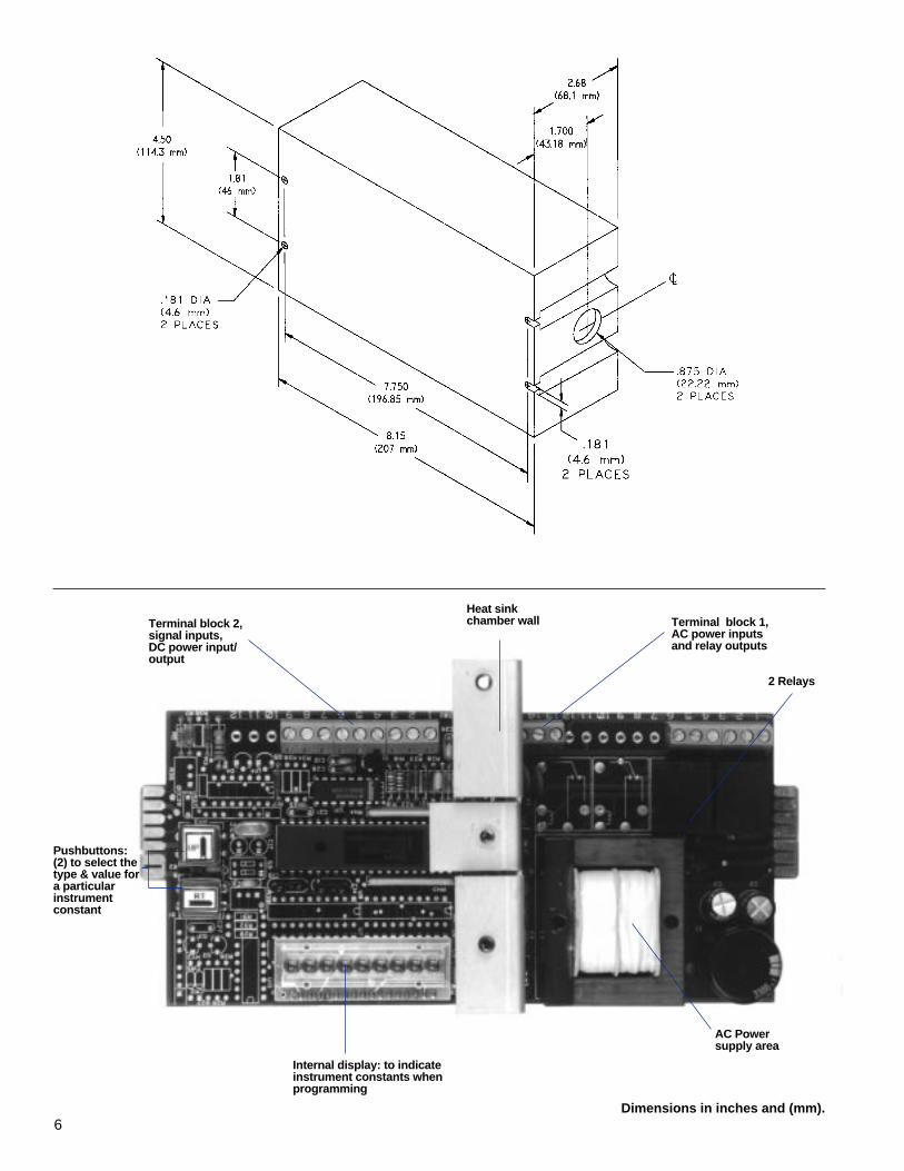
6Dimensions in inches and (mm).
Terminal block 1,AC power inputsand relay outputs
Heat sinkchamber wallTerminal block 2,
signal inputs,DC power input/output
2 Relays
Pushbuttons:(2) to select thetype & value fora particularinstrumentconstant
Internal display: to indicateinstrument constants whenprogramming
AC Powersupply area

TACH•PAK ® 3Digital Process Tachometer
CSA ListedPart Number Series T 77430
Faster - More Accurate - FieldProgrammable
The Tach•Pak 3 computingtachometer is a single channelinstrument. It measures input fre-quency and converts the resultingquantities to a meter output, ananalog output and four relays.
The microcomputer-basedTach•Pak 3 tachometer uses adap-tive period averaging which permits acombination of fast response andhigh accuracy not available in otherindustrial speed instruments. Theinstrument functions can easily beprogrammed in the field or altered atany time using a unique internalswitch design.
Features & AdvantagesQuicker Response Time - 50 milli-
second updates above 100 Hz.Higher Level of Accuracy - ±.5% for
analog outputs and ±.05% for relaysetpoints in operation overtemperature ranges.
Field Programmable - Adaptable tovarious applications and require-ments by utilizing a unique internalswitch design. No additonalcalibration equipment required.
Digital Configuration - Utilizes adap-tive period averaging and floatingpoint calculation.
2 Analog Current Outputs - 0-1milliamps. 0-20 or 4-20 milliamps.
4 Relays - Sealed 6 amp SPDT autoreset or latching.
AC or DC Power - Adaptable to eitherAC or DC power source.
Typically, a Tach•Pak 3 tachome-ter is used with magnetic sensors asa signal source. However, it mayreceive a sine wave or TTL signalfrom any frequency source. Theresulting speed is used for meteroutput, analog output or alarms. It issuperior in applications requiring fastupdate times and high accuracy.
Applications• Fast response overspeed
shutdown• PLC control input• Petrochemical production
applications• Pump or generator alarm• Low speed tachometer• Expanding analog scale speed
transmitter• Start-up, over/under speed
switching• Textile production applications• RPM measurement• Paper and pulp production• Turbine speed control input• Metal production• Mining applications• Frequency measurement• Test labs• Generator sets• Food processing• Conveyor protection• Printing industry
It is the customer's responsibility todetermine whether the product isproper for customer's use andapplication.
Ordering P/N Input Power Enclosure
T77430 -11 120 Vac/24 Vdc Standard NEMA 1-12 240 Vac/24 Vdc Standard NEMA 1-41 120 Vac/24 Vdc NEMA 4X *-42 240 Vac/24 Vdc NEMA 4X *-71 120 Vac/24 Vdc Explosion Proof **-72 240 Vac/24 Vdc Explosion Proof **
* See page 15 for dimensions** See page 16 for dimensions
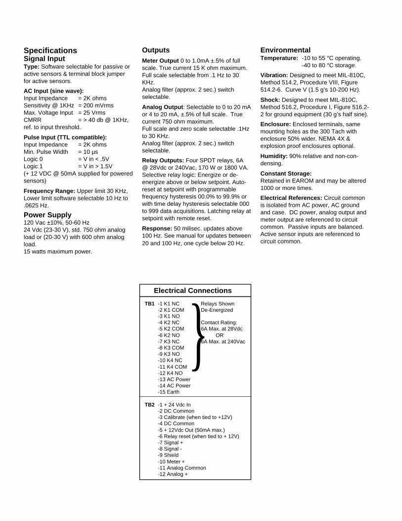
}TB1 -1 K1 NC Relays Shown
-2 K1 COM De-Energized-3 K1 NO-4 K2 NC Contact Rating:-5 K2 COM 6A Max. at 28Vdc-6 K2 NO OR-7 K3 NC 6A Max. at 240Vac-8 K3 COM-9 K3 NO-10 K4 NC-11 K4 COM-12 K4 NO-13 AC Power-14 AC Power-15 Earth
TB2 -1 + 24 Vdc In-2 DC Common-3 Calibrate (when tied to +12V)-4 DC Common-5 + 12Vdc Out (50mA max.)-6 Relay reset (when tied to + 12V)-7 Signal +-8 Signal --9 Shield-10 Meter +-11 Analog Common-12 Analog +
SpecificationsSignal InputType: Software selectable for passive oractive sensors & terminal block jumperfor active sensors.
AC Input (sine wave):Input Impedance = 2K ohmsSensitivity @ 1KHz = 200 mVrmsMax. Voltage Input = 25 VrmsCMRR = > 40 db @ 1KHz,ref. to input threshold.
Pulse Input (TTL compatible):Input Impedance = 2K ohmsMin. Pulse Width = 10 µsLogic 0 = V in < .5VLogic 1 = V in > 1.5V(+ 12 VDC @ 50mA supplied for poweredsensors)
Frequency Range: Upper limit 30 KHz,Lower limit software selectable 10 Hz to.0625 Hz.
Power Supply120 Vac ±10%, 50-60 Hz24 Vdc (23-30 V), std. 750 ohm analogload or (20-30 V) with 600 ohm analogload.15 watts maximum power.
OutputsMeter Output 0 to 1.0mA ±.5% of fullscale. True current 15 K ohm maximum.Full scale selectable from .1 Hz to 30KHz.Analog filter (approx. 2 sec.) switchselectable.
Analog Output : Selectable to 0 to 20 mAor 4 to 20 mA, ±.5% of full scale. Truecurrent 750 ohm maximum.Full scale and zero scale selectable .1Hzto 30 KHz.Analog filter (approx. 2 sec.) switchselectable.
Relay Outputs: Four SPDT relays, 6A@ 28Vdc or 240Vac, 170 W or 1800 VA.Selective relay logic: Energize or de-energize above or below setpoint. Auto-reset at setpoint with programmablefrequency hysteresis 00.0% to 99.9% orwith time delay hysteresis selectable 000to 999 data acquisitions. Latching relay atsetpoint with remote reset.
Response: 50 milisec. updates above100 Hz. See manual for updates between20 and 100 Hz, one cycle below 20 Hz.
EnvironmentalTemperature: -10 to 55 °C operating.
-40 to 80 °C storage.
Vibration: Designed to meet MIL-810C,Method 514.2, Procedure VIII, Figure514.2-6. Curve V (1.5 g’s 10-200 Hz).
Shock: Designed to meet MIL-810C,Method 516.2, Procedure I, Figure 516.2-2 for ground equipment (30 g’s half sine).
Enclosure: Enclosed terminals, samemounting holes as the 300 Tach withenclosure 50% wider. NEMA 4X &explosion proof enclosures optional.
Humidity: 90% relative and non-con-densing.
Constant Storage:Retained in EAROM and may be altered1000 or more times.
Electrical References: Circuit commonis isolated from AC power, AC groundand case. DC power, analog output andmeter output are referenced to circuitcommon. Passive inputs are balanced.Active sensor inputs are referenced tocircuit common.
Electrical Connections

Dimensions in inches and (mm).
Heat sinkchamber wall
Terminal block 2, signalinputs/outputs, DC powerinput/output
Terminal block 1, AC powerinput and relay outputs
4 Relays
AC Powersupply area
Analog outputfull scale adjustingpotentiometer
Internal display: toindicate instrumentconstants whenprogramming
Analogoutputfilterdipswitch
Meteroutputfilterdipswitch
Pushbuttons:(2) to select thetype & value fora particularinstrumentconstant
Meter ouputFull scaleadjustingpotentiometer
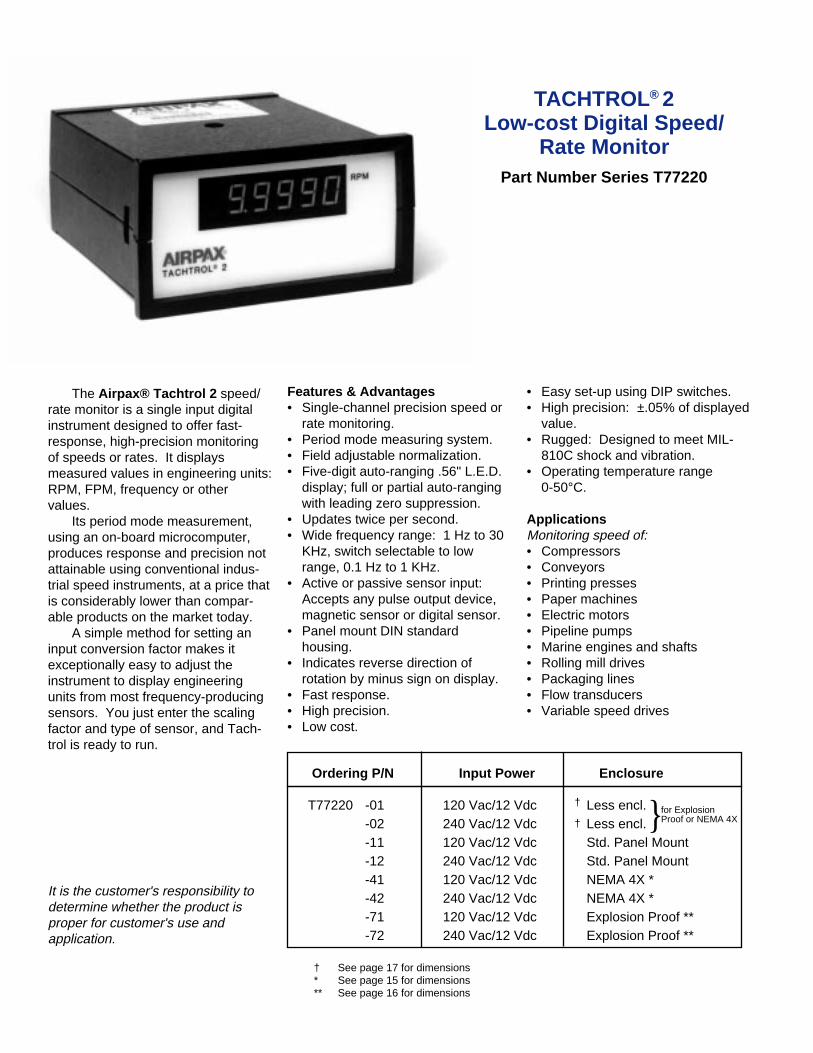
TACHTROL® 2Low-cost Digital Speed/
Rate MonitorPart Number Series T77220
• Easy set-up using DIP switches.• High precision: ±.05% of displayed
value.• Rugged: Designed to meet MIL-
810C shock and vibration.• Operating temperature range
0-50°C.
ApplicationsMonitoring speed of:• Compressors• Conveyors• Printing presses• Paper machines• Electric motors• Pipeline pumps• Marine engines and shafts• Rolling mill drives• Packaging lines• Flow transducers• Variable speed drives
Features & Advantages• Single-channel precision speed or
rate monitoring.• Period mode measuring system.• Field adjustable normalization.• Five-digit auto-ranging .56" L.E.D.
display; full or partial auto-rangingwith leading zero suppression.
• Updates twice per second.• Wide frequency range: 1 Hz to 30
KHz, switch selectable to lowrange, 0.1 Hz to 1 KHz.
• Active or passive sensor input:Accepts any pulse output device,magnetic sensor or digital sensor.
• Panel mount DIN standardhousing.
• Indicates reverse direction ofrotation by minus sign on display.
• Fast response.• High precision.• Low cost.
The Airpax® Tachtrol 2 speed/rate monitor is a single input digitalinstrument designed to offer fast-response, high-precision monitoringof speeds or rates. It displaysmeasured values in engineering units:RPM, FPM, frequency or othervalues.
Its period mode measurement,using an on-board microcomputer,produces response and precision notattainable using conventional indus-trial speed instruments, at a price thatis considerably lower than compar-able products on the market today.
A simple method for setting aninput conversion factor makes itexceptionally easy to adjust theinstrument to display engineeringunits from most frequency-producingsensors. You just enter the scalingfactor and type of sensor, and Tach-trol is ready to run.
It is the customer's responsibility todetermine whether the product isproper for customer's use andapplication.
} for ExplosionProof or NEMA 4X
Ordering P/N Input Power Enclosure
T77220 -01 120 Vac/12 Vdc Less encl.-02 240 Vac/12 Vdc Less encl.-11 120 Vac/12 Vdc Std. Panel Mount-12 240 Vac/12 Vdc Std. Panel Mount-41 120 Vac/12 Vdc NEMA 4X *-42 240 Vac/12 Vdc NEMA 4X *-71 120 Vac/12 Vdc Explosion Proof **-72 240 Vac/12 Vdc Explosion Proof **
† See page 17 for dimensions* See page 15 for dimensions** See page 16 for dimensions
†
†
Display OutputAccuracy: ±.03% typ., ±.05% maximum(% of reading).
Resolution: Five (5) digit resolution fordisplay values from 1.0000 to 99999.Four (4) digit resolution for displayvalues<1.0000. When fixed decimal isused, fixed position will determineresolution.
Type: .56" red, seven (7) segment LEDdisplay with red filtered lens.
Response Time:For f
in >2Hz Display Response = .5 sec.+1/f in sec.For .1 Hz-2 Hz Display Response = 1/f in
sec.
Adjustment Range: Input frequenciesmay be scaled for display by aninternally adjustble constant (C). Thedisplay indication is C x input frequency.C may be set from 1.000 x 10⁻⁷ to 9.999x 10+7.
Power Supply120 Vac ±10%, 50-60 Hz.12 Vdc, +3V, - 2V.15 watts maximum.
EnvironmentalEnclosures:Panel mount 1/2 DIN case standard.Optional enclosures designed to meetNEMA 4, and NEMA 4X. Hazardouslocation enclosure meets NFPA/NEC,Class I, Groups B, C, D; Class II, GroupsE, F & G, UL standard 886 and CSAstandard C22.2 No. 30 1970.
Vibration:Designed to meet MIL-810C, method514.2, procedure VII, fig. 514.2-6, curveV (1.5 g’s 10-200 Hz).
Shock:Designed to meet MIL-810C, method516.2, procedure 1, fig. 516.2-2 forground equipment (30 g’s half-sine).
Temperature:0 to 50°C operating-40 to 80°C storage
Humidity:90% relative humidity and non-condens-ing.
Electrical References:Circuit common is isolated from ACpower, AC ground and case. DC poweris referenced to circuit common. Passive(AC) signal inputs are balanced. Activesensors require terminal two (2) connec-tion to terminal five (5). This referencesthe active sensor to circuit common.
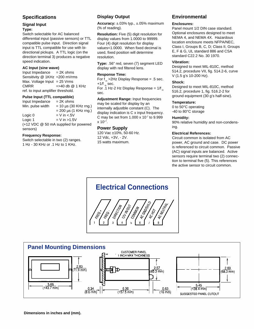
SpecificationsSignal InputType:Switch selectable for AC balanceddifferential input (passive sensors) or TTLcompatible pulse input. Direction signalinput is TTL compatible for use with bi-directional pickups. A TTL logic (on thedirection terminal 3) produces a negativespeed indication.
AC Input (sine wave)Input Impedance = 2K ohmsSensitivity @ 1KHz =200 mVrmsMax. Voltage Input = 25 VrmsCMRR =>40 db @ 1 KHzref. to input amplifier threshold.
Pulse Input (TTL compatible)Input Impedance = 2K ohmsMin. pulse width = 10 µs (30 KHz rng.)
= 200 µs (1 KHz rng.)Logic 0 = V in <.5VLogic 1 = V in >1.5V(+12 VDC @ 50 mA supplied for poweredsensors)
Frequency Response:Switch selectable in two (2) ranges.1 Hz - 30 KHz or .1 Hz to 1 KHz.
Dimensions in inches and (mm).
Electrical Connections
Panel Mounting Dimensions
.Ordering P/N Input Power Enclosure
T77310 -01 120 Vac/24 Vdc Less Encl.-02 240 Vac/24 Vdc Less Encl.-11 120 Vac/24 Vdc Std. Panel Mount-12 240 Vac/24 Vdc Std. Panel Mount-21 120 Vac/24 Vdc Splashproof Panel Mount-22 240 Vac/24 Vdc Splashproof Panel Mount-41 120 Vac/24 Vdc NEMA 4X *-42 240 Vac/24 Vdc NEMA 4X *-71 120 Vac/24 Vdc Explosion Proof **-72 240 Vac/24 Vdc Explosion Proof **
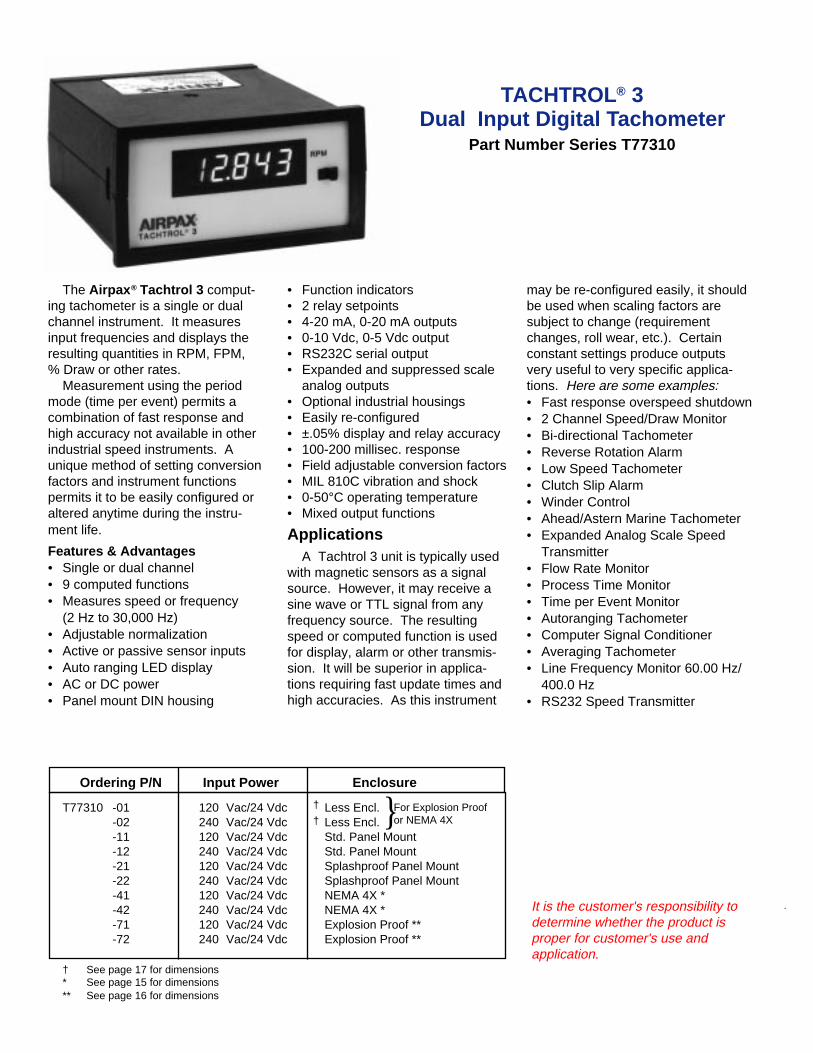
TACHTROL® 3Dual Input Digital Tachometer
Part Number Series T77310
The Airpax ® Tachtrol 3 comput-ing tachometer is a single or dualchannel instrument. It measuresinput frequencies and displays theresulting quantities in RPM, FPM,% Draw or other rates.
Measurement using the periodmode (time per event) permits acombination of fast response andhigh accuracy not available in otherindustrial speed instruments. Aunique method of setting conversionfactors and instrument functionspermits it to be easily configured oraltered anytime during the instru-ment life.
Features & Advantages• Single or dual channel• 9 computed functions• Measures speed or frequency
(2 Hz to 30,000 Hz)• Adjustable normalization• Active or passive sensor inputs• Auto ranging LED display• AC or DC power• Panel mount DIN housing
• Function indicators• 2 relay setpoints• 4-20 mA, 0-20 mA outputs• 0-10 Vdc, 0-5 Vdc output• RS232C serial output• Expanded and suppressed scale
analog outputs• Optional industrial housings• Easily re-configured• ±.05% display and relay accuracy• 100-200 millisec. response• Field adjustable conversion factors• MIL 810C vibration and shock• 0-50°C operating temperature• Mixed output functions
may be re-configured easily, it shouldbe used when scaling factors aresubject to change (requirementchanges, roll wear, etc.). Certainconstant settings produce outputsvery useful to very specific applica-tions. Here are some examples:• Fast response overspeed shutdown• 2 Channel Speed/Draw Monitor• Bi-directional Tachometer• Reverse Rotation Alarm• Low Speed Tachometer• Clutch Slip Alarm• Winder Control• Ahead/Astern Marine Tachometer• Expanded Analog Scale Speed
Transmitter• Flow Rate Monitor• Process Time Monitor• Time per Event Monitor• Autoranging Tachometer• Computer Signal Conditioner• Averaging Tachometer• Line Frequency Monitor 60.00 Hz/
400.0 Hz• RS232 Speed Transmitter
It is the customer's responsibility todetermine whether the product isproper for customer's use andapplication.
ApplicationsA Tachtrol 3 unit is typically used
with magnetic sensors as a signalsource. However, it may receive asine wave or TTL signal from anyfrequency source. The resultingspeed or computed function is usedfor display, alarm or other transmis-sion. It will be superior in applica-tions requiring fast update times andhigh accuracies. As this instrument
}For Explosion Proofor NEMA 4X
† See page 17 for dimensions* See page 15 for dimensions** See page 16 for dimensions
†
†

.
one function for each output. Here arethe possibilities:
Outputs Selective FunctionFunction
Display - - - - - - Speed AAnalog - - - - - - Speed BRelay 1 - - - - - - A - BRelay 2 - - - - - - ±A (dir.)
A/BB/A(A + B)/2(A - B)/A x 100(B - A)/A x 100
If one of the outputs is not used, a tenthfunction, coded O, may be specified,turning the specific output off.
Analog OutputThe zero and full scale for the analog
output can be programmed to normal orexpanded scale, such as:
4-20 mA = 0 to 900 FPM or4-20 mA= 450 - 900 FPM
Serial Digital OutputThe serial digital (RS232C) output may
transmit the value on the display, theanalog output value, the two setpointdeviations or all four of these values.They may be continuously transmitted ortransmitted on setpoint alarm.
An example of the outputs specified is:Display: A/B
OperationThe Tachtrol 3 unit may be
configured for measurement of asingle speed signal, two unrelatedspeeds or a speed with directionindication (from an Airpax bi-directional sensor). In addition, amathematical function may becomputed from two related inputsignals. These computed functionsare:• Speed A • (A + B)/2 (Average)• Speed B • A-B (Difference)• A/B (Ratio) • B/A (Inverse Ratio)• ±A (Speed with direction)
• (A-B)/A x 100 (% Slip)• (B-A)/A x 100 (% Elongation)
The Tachtrol 3 unit permitsindependent assignment of any ofthese functions to any output(display, analog output and 1 or 2setpoints). Additionally, the serialdigital ouput may report on any or alloutputs continuously or on setpointalarm. All forms of relay logic arefield selectable.
The Tachtrol 3 unit is suppliedwith an electrically alterable readonly memory (EAROM) which
contains all of the constants neces-sary to define the conversion factorsand instrument functions. Theseconstants can be individuallydisplayed and altered by a methodsimilar to the setting of a digitalclock.
By utilizing a microcomputer asthe heart of the instrument, re-sponse time is improved tenfoldover the traditional EPUT (eventsper unit time) tachometry. Further,this fast response time is attainedwith no sacrifice in digital accuracy.
FIG. 1 shows the CTW (constantthumbwheel switch), the DTW (digitthumbwheel switch) and the Pb (pushbutton)by which each digit may be entered oraltered and a dip switch for selection of inputsignal type for channel A or B. A battery isnot necessary to retain the programmedconstants. During normal operation, theDTW may be used to display Speed A,Speed B or the computed function.
Product ApplicationGuidelines
The part number specifies thehardware. Individual requirements forsetpoints, scaling and functions may beset into the instrument during installa-tion. The following is a guide fromwhich data to be entered may besupplied.
Input FrequencyTypically, an input frequency is
sensed from rotating gear teeth.Frequency may be obtained from RPMby the formula:f (in Hz) = RPM x PPR
60where PPR = pulses per revolution = no.of gear teeth.The normalization or scaling factor (SF)to be specified may now be obtained foreach input by:SF = DISPLAY VALUE (RPM,FPM, etc.)
INPUT FREQUENCY (Hz)
The desired form, as an example, is:Input A: 2000 Hz = 800 FPMInput B: 1600 Hz = 800 FPM
OutputsThe TACHTROL 3 can transmit any ofthe 6 computed functions, speed A, orspeed B, or speed A with direction toany of the 4 outputs. You may specify
Analog output:Speed ARS232C: Transmit all values.Setpoint 1: A/B
RelaysEach relay may operate on Input A,
Input B or the computed function. Theymay energize, de-energize, latch orauto-reset at the setpoint. Hysteresis(difference between setpoint value andsetpoint reset) is normally 5% but maybe specified for any value from 1% to99% of setpoint.
A typical example for a Tachtrol 3application is:
Input A: 2000 Hz = 800 FPMInput B: 1600 Hz = 800 FPMDisplay: A/BAnalog output: Speed A=0-900 FPM
=4-20mASetpoint 1: Energize at 1.00 ratio &above with 1% hysteresisSetpoint 2: Not usedSerial output: Transmit all valuescontinuously.
This specific example is intended asa guide. The versatility of the Tachtrol 3unit permits several approaches toconfiguration. Unavailable informationmay be omitted as it could be suppliedduring installation. More detailedinformation is available in the Tachtrol 3Instruction Manual.
FIG. 1

SpecificationsInput SignalsFrequency: 2 Hz to 30K Hz
Passive Sensor (sine wave):200 mV to 25 Vrms standard 2K ohmimpedance, common mode rejection:40 db, balanced input sensitivitymeasured at 1K Hz.
Active Sensor (TTL): duty cycle 20 to80%, DC sensor power is 12 Vdc @ 100mA [will power two (2) zero velocitysensors or one (1) bi-directional sensor].
Bi-Directional Sensor: One (1)frequency input (TTL input A) and thedirection input (TTL Input B)from a bi-directional sensor. [High (+5v) indicatespositive direction, and only single speedfunctions (Speed A) are useful whenconnected in this operation mode.]
Power Supply120 Vac ±10%, 50-60 Hz24 Vdc (23-30 V) std. 750 ohm analogload or (20-30 V) with 600 ohm analogload. 15 watts maximum power.
Temperature: 0 to 50°C operating-40° to 80°C storage
Humidity:90% relative and non-condensing
Vibration:Designed to meet MIL 810C, method514.2. Procedure VIII. Fig. 514.2-6.Curve V (1.5 g's. 10-200 Hz).
Shock:Designed to meet MIL 810C. method516.2. Procedure I Fig. 516.2-2 forground equipment (30 g's. half sine).
Displays:4 1/2 digit with minus sign & decimals(positive direction indicated by no minussign).Bright .56" Red LEDFixed or floating decimal (3 places)
Number range ±0.000 to ±19999Three (3) LED function indicator lamps.
OutputsAnalog: 0-20 mA or 4-20 mA, fieldselectable, output consists of onethousand 20 µA steps. 750 ohm loadmaximum. Span pot-adjustable ±10%.Zero and full scale set into memory inengineering units.0-10 Vdc or 0-5 Vdc output obtained byselecting the 0-20mA mode and using aresistor across the input of the receivinginstrument whose parallel combinationwith the input resistance of the receiveris 500 ohms or 250 ohms respectively.
Serial Digital: RS232C compatibletransmit only ASCII. 300 baud. asyn-chronous with odd parity. 2 stop bits andcarriage return. Transmission formatselectable to transmit continuously or onany setpoint alarm. Transmissionpreceded by linefeed (Lf) and followedby carriage return (Cr). Each valueconsists of a space (Ø), a two (2) digitidentifier, a colon and a right justified (7)character field of data (4 1/2 digitnumber, sign and decimal) Plus (+) sign,and leading zeros indicated by spaces(bbb). The following are examples of thefour (4) type transmissions:LfbDO:(display value) CrLfbAO:(analog output value) CrLfbS1: (SP 1 value) bS2 (SP 2 value) Cr (SP value = difference between setpoint and actual)
LfbDO: -19.999bAC: b199.99bSP1: bbb-999bSP2:bbb0.00Cr
Relay Setpoints: 2 relays standard,SPDT, 6A@ 28 Vdc or 240 Vac, 170Wor 1800 VA. Selective relay logic:Energize or de-energize above or belowsetpoint, auto-reset with hysteresisselectable 0-99% in 1% steps, latching(reset by pushbutton located behindfront panel door).
Dimensions in inches and (mm).
Accuracy: (including temp. variations)Digital ±.03% typical (±.05% max.) &
± 1 least significant digitAnalog ±.3% of range
Response Times:
Display updated approx. every 1/2 sec.based on latest available inputmeasurement(s).
Serial Output: Transmits each outputvalue in approx. 1/2 second based oninput measurements obtained at the timeeach value is transmitted.
Analog & Relay Outputs updated at avariable rate depending on the fre-quency. The typical & maximumresponse times are:Above 100 Hz = 100 ms typical
200 ms max. 2 to 100 Hz = 2 cycles + 30 ms typ.
6 cycles + 30 ms max.Below 2 Hz =Measurement considered 0For values computed from both signalinputs, a new computed value is updatedeach time either signal completes ameasurement.
Range of Normalization (linear orinverse only)Input frequencies A & B may be normal-ized by a number from .5000 x 10-7 to2.000 x 107
Normalization is entered in the form:+-1XXXX+-1XXXX
Additional display normalization range±.001 to 19999.
Constant Storage:Retained in EAROM and may be altered1000 or more times.
Electrical References:Circuit Common is isolated from ACpower, AC ground and case.DC power, analog output and serialoutput are referenced to circuit common.Passive inputs are balanced. Activesensor inputs are referenced to circuitcommon.
Electrical Connections
Panel Mounting Dimensions
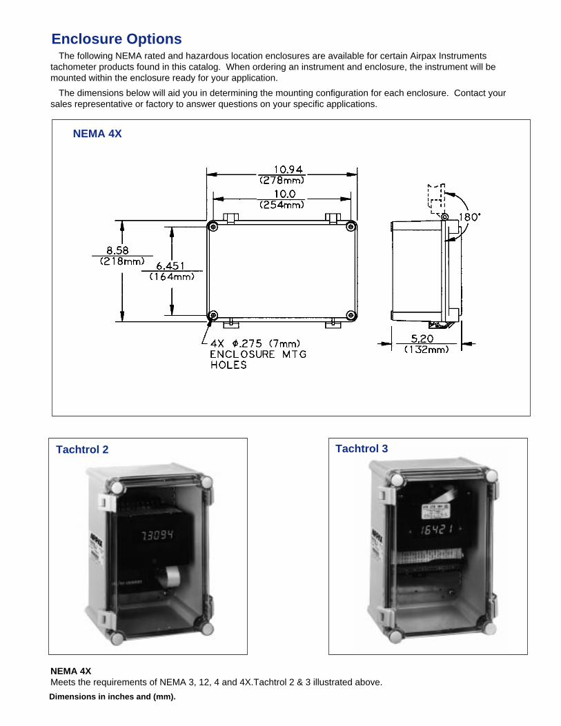
NEMA 4XMeets the requirements of NEMA 3, 12, 4 and 4X.Tachtrol 2 & 3 illustrated above.
Enclosure OptionsThe following NEMA rated and hazardous location enclosures are available for certain Airpax Instruments
tachometer products found in this catalog. When ordering an instrument and enclosure, the instrument will bemounted within the enclosure ready for your application.
The dimensions below will aid you in determining the mounting configuration for each enclosure. Contact yoursales representative or factory to answer questions on your specific applications.
NEMA 4X
Tachtrol 2 Tachtrol 3
Dimensions in inches and (mm).
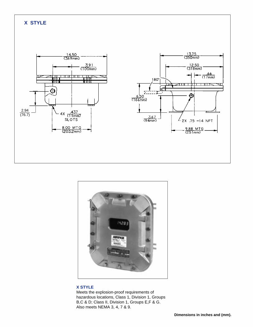
X STYLE
Dimensions in inches and (mm).
2.94(76.7)
X STYLEMeets the explosion-proof requirements ofhazardous locations, Class 1, Division 1, GroupsB,C & D; Class II, Division 1, Groups E,F & G.Also meets NEMA 3, 4, 7 & 9.
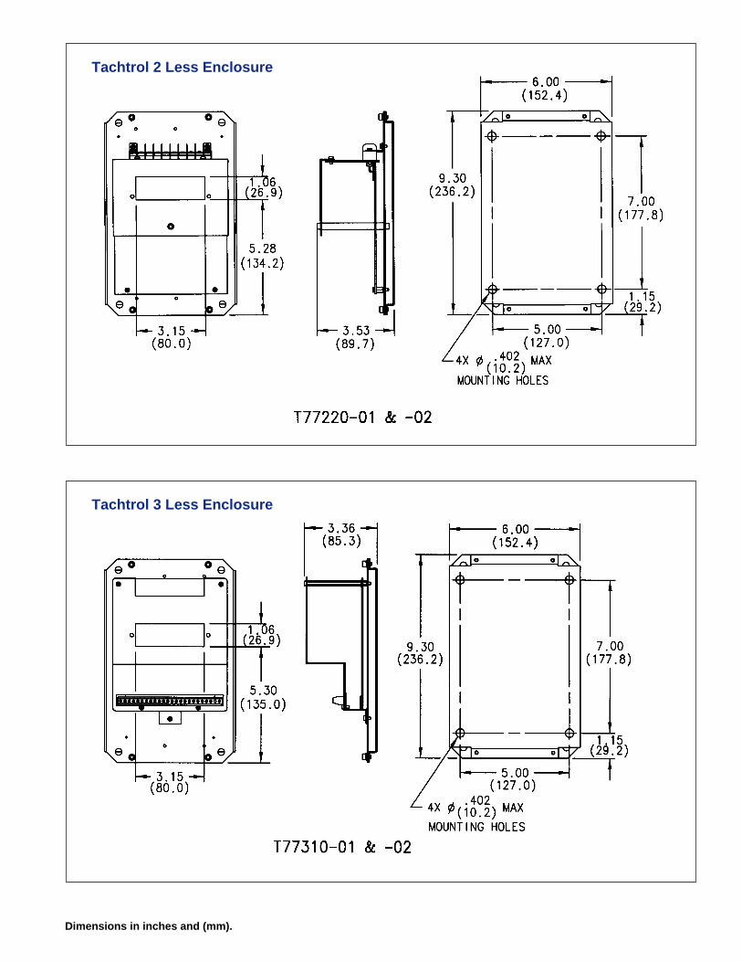
Tachtrol 2 Less Enclosure
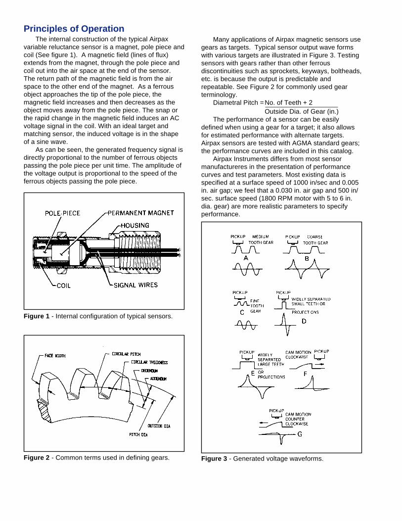
Tachtrol 3 Less Enclosure
Dimensions in inches and (mm).

Speed Sensors
Designed to meet severe industrial, automotive and aerospace environ-ments, Airpax speed sensors, will provide reliable, around-the-clock operationfor many years under adverse conditions. Our design engineers have paidparticular attention to trouble areas such as vibration, shock, extreme tem-peratures, wet, oily and corrosive atmospheres. Many of our speed sensorsare specifically designed for high temperature, high or low speeds, varioustargets or for precise accuracy and timing applications. Airpax uses primarilythe three technologies of variable reluctance, magneto-resistive and Halleffect to convert motion into an electronic signal. By selecting the best tech-nology for a specific application we can assure years of reliable performance.
This catalog offers a variety of options readily available through ourdistributors. If you cannot find a catalog item to meet your specific require-ments, please contact your area distributor with your specifics; there isprobably an existing design which comes close to your requirements. As aworld leader in producing quality speed sensors, Airpax Instruments willprovide a superb price/performance ratio.
Passive Magnetic SensorsControl and protection circuits have relied on variable reluctance technol-
ogy for years. With few components and no moving parts, the passive mag-netic speed sensors can provide a signal from the inside of an aircraft engineat temperatures approaching 425°C or from the hub of an automobile wheelat high shock and vibration. The advantages of these sensors are:
• High reliability• Simple installation• Long life due to no moving parts or contacts• Self powered operation• Wide variety of shapes and sizes• Easy alignment• Can be designed for almost any environment
Due to their flexibility, you will find Airpax variable reluctance sensors ineverything from low-cost consumer products to highly-accurate automotiveengine ignition systems to flight-worthy aircraft engine controls.
It is the customer's responsibility to determine whether theproduct is proper for customer's use and application.
Many applications of Airpax magnetic sensors usegears as targets. Typical sensor output wave formswith various targets are illustrated in Figure 3. Testingsensors with gears rather than other ferrousdiscontinuities such as sprockets, keyways, boltheads,etc. is because the output is predictable andrepeatable. See Figure 2 for commonly used gearterminology.
Diametral Pitch =No. of Teeth + 2Outside Dia. of Gear (in.)
The performance of a sensor can be easilydefined when using a gear for a target; it also allowsfor estimated performance with alternate targets.Airpax sensors are tested with AGMA standard gears;the performance curves are included in this catalog.
Airpax Instruments differs from most sensormanufactureres in the presentation of performancecurves and test parameters. Most existing data isspecified at a surface speed of 1000 in/sec and 0.005in. air gap; we feel that a 0.030 in. air gap and 500 in/sec. surface speed (1800 RPM motor with 5 to 6 in.dia. gear) are more realistic parameters to specifyperformance.
Figure 1 - Internal configuration of typical sensors.
Figure 3 - Generated voltage waveforms.Figure 2 - Common terms used in defining gears.
Principles of OperationThe internal construction of the typical Airpax
variable reluctance sensor is a magnet, pole piece andcoil (See figure 1). A magnetic field (lines of flux)extends from the magnet, through the pole piece andcoil out into the air space at the end of the sensor.The return path of the magnetic field is from the airspace to the other end of the magnet. As a ferrousobject approaches the tip of the pole piece, themagnetic field increases and then decreases as theobject moves away from the pole piece. The snap orthe rapid change in the magnetic field induces an ACvoltage signal in the coil. With an ideal target andmatching sensor, the induced voltage is in the shapeof a sine wave.
As can be seen, the generated frequency signal isdirectly proportional to the number of ferrous objectspassing the pole piece per unit time. The amplitude ofthe voltage output is proportional to the speed of theferrous objects passing the pole piece.
Magnetic Sensor SelectionThe following information is supplied for assis-
tance in selecting the proper sensors for your particu-lar applications. One of the fundamental questions tobe answered is, “Will there be enough sensor outputvoltage at the lowest operating speed?”
The sensor output voltage depends on:• Surface Speed - speed target passes pole piece• Gap - distance between target and pole piece• Target Size - geometric relationship of pole piece
and target• Load Impedance - connected to sensorThe surface speed of a gear depends upon its
diameter and RPM. Surface speed is expressed interms of inches per second (IPS).
Surface Speed (IPS) = RPM x Outside Dia. (in.) x π60
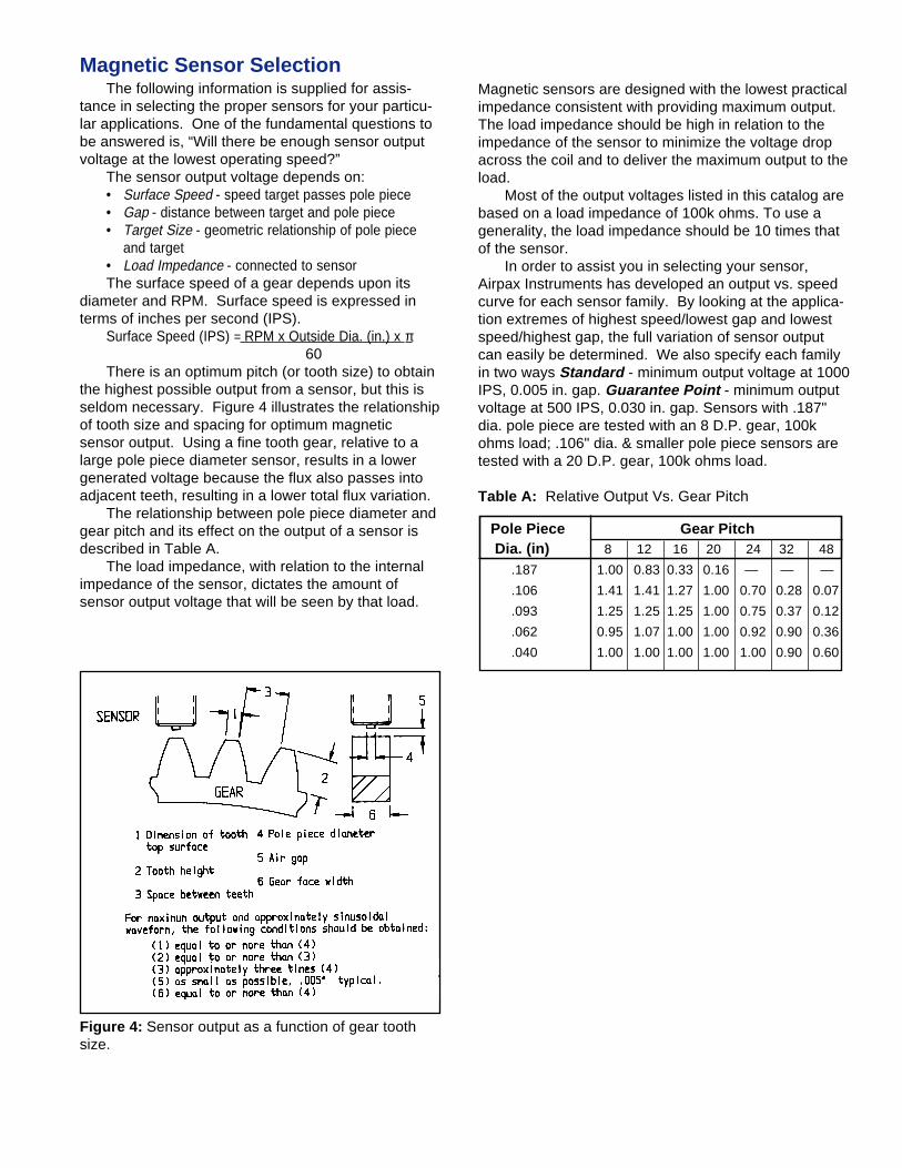
There is an optimum pitch (or tooth size) to obtainthe highest possible output from a sensor, but this isseldom necessary. Figure 4 illustrates the relationshipof tooth size and spacing for optimum magneticsensor output. Using a fine tooth gear, relative to alarge pole piece diameter sensor, results in a lowergenerated voltage because the flux also passes intoadjacent teeth, resulting in a lower total flux variation.
The relationship between pole piece diameter andgear pitch and its effect on the output of a sensor isdescribed in Table A.
The load impedance, with relation to the internalimpedance of the sensor, dictates the amount ofsensor output voltage that will be seen by that load.
Figure 4: Sensor output as a function of gear toothsize.
Magnetic sensors are designed with the lowest practicalimpedance consistent with providing maximum output.The load impedance should be high in relation to theimpedance of the sensor to minimize the voltage dropacross the coil and to deliver the maximum output to theload.
Most of the output voltages listed in this catalog arebased on a load impedance of 100k ohms. To use agenerality, the load impedance should be 10 times thatof the sensor.
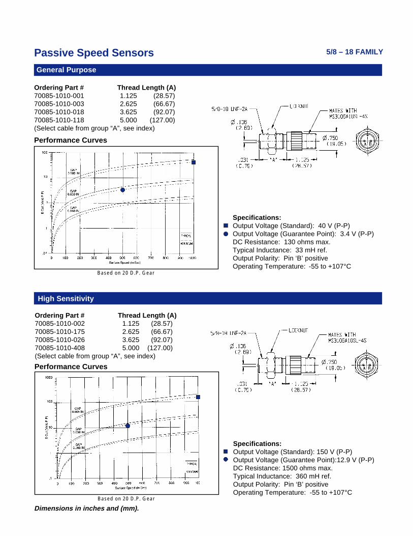
In order to assist you in selecting your sensor,Airpax Instruments has developed an output vs. speedcurve for each sensor family. By looking at the applica-tion extremes of highest speed/lowest gap and lowestspeed/highest gap, the full variation of sensor outputcan easily be determined. We also specify each familyin two ways Standard - minimum output voltage at 1000IPS, 0.005 in. gap. Guarantee Point - minimum outputvoltage at 500 IPS, 0.030 in. gap. Sensors with .187"dia. pole piece are tested with an 8 D.P. gear, 100kohms load; .106" dia. & smaller pole piece sensors aretested with a 20 D.P. gear, 100k ohms load.
Table A: Relative Output Vs. Gear Pitch
Pole Piece Gear Pitch Dia. (in) 8 12 16 20 24 32 48
.187 1.00 0.83 0.33 0.16 — — —
.106 1.41 1.41 1.27 1.00 0.70 0.28 0.07
.093 1.25 1.25 1.25 1.00 0.75 0.37 0.12
.062 0.95 1.07 1.00 1.00 0.92 0.90 0.36
.040 1.00 1.00 1.00 1.00 1.00 0.90 0.60

Step 3: Correction for pitch:For a 0.106 in. pole piece dia. and a 12 D.P. gearthe correction factor from Table A is 1.41. (See pg.25.)E
C = .55 x 1.41 = .78 V (P-P)
Step 4: Converting to rms voltage: Simply divide by 3, a method which is close enough.
(If the peak-to-peak output voltage is a sine function,the divisor is 2 times the square root of 2 or 2.83).E
C = .78 ÷ 3 = .26 V rms
Step 5: Correction for load: The .26V or 260 mV rms sensor output voltage will
be divided across the impedance of the load andsensor. The load impedance is 2000 ohms resistive.The impedance of the sensor has a resistive andinductive element. At low frequencies the inductiveelement is very small and can therefore be disre-garded, leaving the max. DC resistance of 130 ohmsfor consideration.
The load correction factor (fL) can be expressed as:
(fL) = Z (load) = 2000 = .94
Z (load) + Z (sensor) 2130 E
C = .94 x 260 = 244 mV rms
The final adjusted value is 244 mV rms.
As stated earlier, the sensitivity or threshold of theTachtrol•3 is 200 mV rms at the stated conditions,the selection of P/N 70085-1010-001 is acceptable.
If the final value of EC had been slightly less than
200 mV, a reduction of the air gap (from .030" to.025") would boost the output above 200 mV.
If it should be determined that the required sensorcannot be selected from the catalog models, thebest procedure is to compile a list of all your require-ments and contact your area distributor to assist youin the selection of the correct sensor.
Calculation of Output VoltageSelection of the proper Airpax magnetic sensor
may require the calculation of sensor output voltage toassure proper operation in your specific application.To assist in this area, let us consider the followingtypical application: Requirement is speed display withoverspeed and underspeed control as well as 4-20 mAsignal to a PLC. Speed range is 0-3600 RPM with lowspeed set point at 300 RPM, available shaft diameterfor mounting a gear is 2.000 in. and a .030 in. air gapis ideal.
You have selected a Tachtrol 3, P/N T77310-11,with a 60T cast iron, split gear, P/N G79870-202-0301,and you are considering to use sensor P/N 70085-1010-001. The question is if the sensor has enoughoutput voltage at 300 RPM.
We can list the following parameters:a. Tachtrol 3: Load impedance - 2000 ohms
Sensitivity - 200 mV rmsb. Split gear: Outside dia. - 5.166 in.
D.P. - 12No. of Teeth - 60
c. Sensor: Standard output voltage - 40V (P-P) min.Guarantee Point - 3.4V P-P min.D.C. Resistance - 130 ohms max.Typical inductance - 33 mH ref.
Step 1: Calculate surface speed of gear:SS = RPM x Outside Dia. x π = 300 x 5.166 x 3.14
60 60SS = 81 IPS
Step 2.: Determine Peak-to-Peak output voltage:Referring to the performance curves of sensor P/N70085-1010-001 the min. output voltage is approx.0.3 V (P-P) at 81 IPS and 0.030 in. gap. It is a factthat output voltage vs. surface speed is a near linearfunction; therefore, another method of determiningoutput voltage is to set up a ratio using the guaran-tee point:3.4V (P-P) = E E = .55V (P-P) 500 IPS 81
Passive Speed Sensors
Dimensions in inches and (mm).
Ordering Part # Thread Length (A)70085-1010-001 1.125 (28.57)70085-1010-003 2.625 (66.67)70085-1010-018 3.625 (92.07)70085-1010-118 5.000 (127.00)(Select cable from group “A”, see index)
Specifications:Output Voltage (Standard): 40 V (P-P)Output Voltage (Guarantee Point): 3.4 V (P-P)DC Resistance: 130 ohms max.Typical Inductance: 33 mH ref.Output Polarity: Pin ‘B’ positiveOperating Temperature: -55 to +107°C
5/8 – 18 FAMILY
Ordering Part # Thread Length (A)70085-1010-002 1.125 (28.57)70085-1010-175 2.625 (66.67)70085-1010-026 3.625 (92.07)70085-1010-408 5.000 (127.00)(Select cable from group “A”, see index)
Performance Curves
Specifications:Output Voltage (Standard): 150 V (P-P)Output Voltage (Guarantee Point):12.9 V (P-P)DC Resistance: 1500 ohms max.Typical Inductance: 360 mH ref.Output Polarity: Pin ‘B’ positiveOperating Temperature: -55 to +107°C
Performance Curves
General Purpose
High Sensitivity
Based on 20 D.P. Gear
Based on 20 D.P. Gear

Passive Speed Sensors
Dimensions in inches and (mm).
5/8 – 18 FAMILY
Ordering Part # Thread Length (A)70085-1010-004 1.125 (28.57)70085-1010-469 2.750 (69.85)
Performance Curves
Specifications:Output Voltage (Standard): 43 V (P-P)Output Voltage (Guarantee Point): 4.3 V (P-P)DC Resistance: 130 ohms max.Typical Inductance: 32-46 mH ref.Output Polarity: Red lead positiveOperating Temperature: -73 to +107°CLead length: 10 ft (3.05 m)
Ordering Part # Thread Length (A)70085-1010-028 1.437 (36.50)(Select cable from group “A”, see index)
Power Output
Performance Curves
Specifications:Output Voltage (Standard): 75 V (P-P)Output Voltage (Guarantee Point): 21.5 V (P-P)DC Resistance: 210 ohms max.Typical Inductance: 50 to 95 mH ref.Output Polarity: Pin "B" positiveOperating Temperature: -73 to +107° C
Conduit Fitting – General Purpose
Based on 8 D.P. Gear
Based on 20 D.P. Gear
Passive Speed Sensors
Dimensions in inches and (mm).
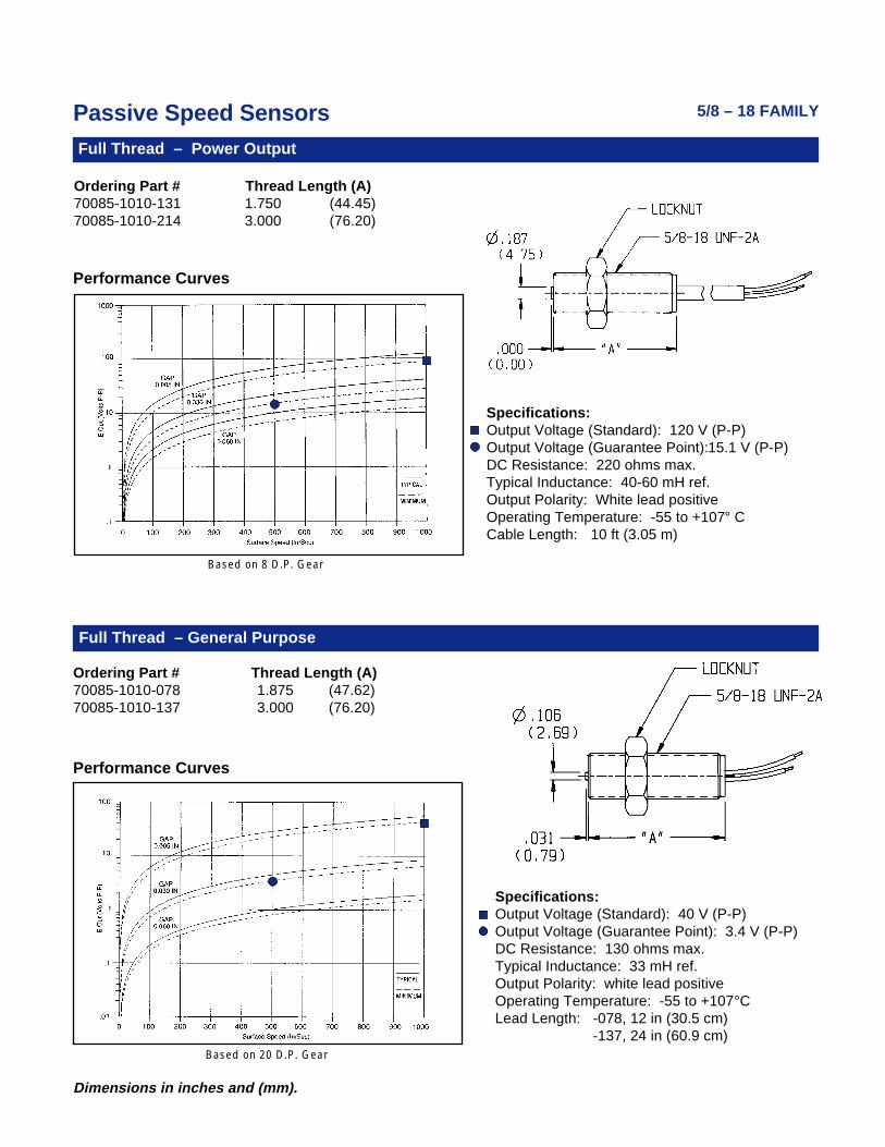
Ordering Part # Thread Length (A)70085-1010-078 1.875 (47.62)70085-1010-137 3.000 (76.20)
Performance Curves
Specifications:Output Voltage (Standard): 40 V (P-P)Output Voltage (Guarantee Point): 3.4 V (P-P)DC Resistance: 130 ohms max.Typical Inductance: 33 mH ref.Output Polarity: white lead positiveOperating Temperature: -55 to +107°CLead Length: -078, 12 in (30.5 cm)
-137, 24 in (60.9 cm)
5/8 – 18 FAMILY
Ordering Part # Thread Length (A)70085-1010-131 1.750 (44.45)70085-1010-214 3.000 (76.20)
Specifications:Output Voltage (Standard): 120 V (P-P)Output Voltage (Guarantee Point):15.1 V (P-P)DC Resistance: 220 ohms max.Typical Inductance: 40-60 mH ref.Output Polarity: White lead positiveOperating Temperature: -55 to +107° CCable Length: 10 ft (3.05 m)
Full Thread – Power Output
Performance Curves
Full Thread – General Purpose
Based on 8 D.P. Gear
Based on 20 D.P. Gear
Passive Speed Sensors
Dimensions in inches and (mm).
Full Thread – High Sensitivity
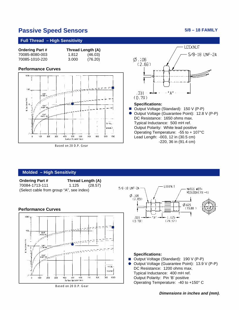
Ordering Part # Thread Length (A)70085-8080-003 1.812 (46.03)70085-1010-220 3.000 (76.20)
Performance Curves
Molded – High Sensitivity
Ordering Part # Thread Length (A)70084-1713-111 1.125 (28.57)(Select cable from group “A”, see index)
Performance Curves
Specifications:Output Voltage (Standard): 190 V (P-P)Output Voltage (Guarantee Point): 13.9 V (P-P)DC Resistance: 1200 ohms max.Typical Inductance: 400 mH ref.Output Polarity: Pin ‘B’ positiveOperating Temperature: -40 to +150° C
Specifications:Output Voltage (Standard): 150 V (P-P)Output Voltage (Guarantee Point): 12.8 V (P-P)DC Resistance: 1650 ohms max.Typical Inductance: 500 mH ref.Output Polarity: White lead positiveOperating Temperature: -55 to + 107°CLead Length: -003, 12 in (30.5 cm)
-220, 36 in (91.4 cm)
.62515.88
5/8 – 18 FAMILY
Based on 20 D.P. Gear
Based on 20 D.P. Gear
Passive Speed Sensors
Dimensions in inches and (mm).
Molded
5/8 – 18 FAMILY
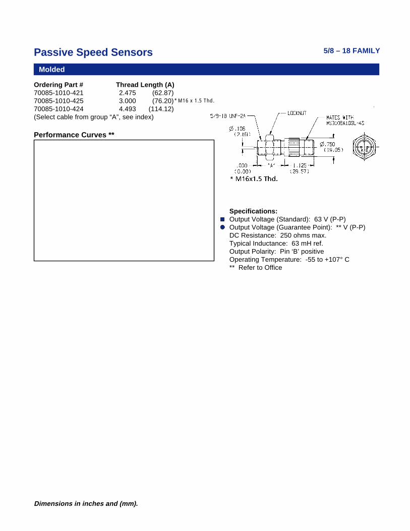
Ordering Part # Thread Length (A)70085-1010-421 2.475 (62.87)70085-1010-425 3.000 (76.20)70085-1010-424 4.493 (114.12)(Select cable from group “A”, see index)
Performance Curves **
Specifications:Output Voltage (Standard): 63 V (P-P)Output Voltage (Guarantee Point): ** V (P-P)DC Resistance: 250 ohms max.Typical Inductance: 63 mH ref.Output Polarity: Pin ‘B’ positiveOperating Temperature: -55 to +107° C** Refer to Office
* M16 x 1.5 Thd.
Passive Speed Sensors
28 Dimensions in inches and (mm).
General Purpose
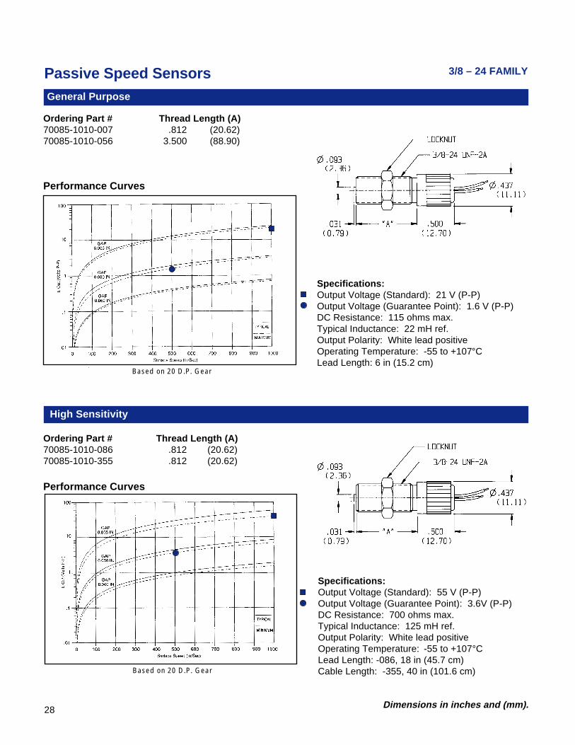
Ordering Part # Thread Length (A)70085-1010-007 .812 (20.62)70085-1010-056 3.500 (88.90)
Ordering Part # Thread Length (A)70085-1010-086 .812 (20.62)70085-1010-355 .812 (20.62)
Performance Curves
High Sensitivity
3/8 – 24 FAMILY
Specifications:Output Voltage (Standard): 21 V (P-P)Output Voltage (Guarantee Point): 1.6 V (P-P)DC Resistance: 115 ohms max.Typical Inductance: 22 mH ref.Output Polarity: White lead positiveOperating Temperature: -55 to +107°CLead Length: 6 in (15.2 cm)
Specifications:Output Voltage (Standard): 55 V (P-P)Output Voltage (Guarantee Point): 3.6V (P-P)DC Resistance: 700 ohms max.Typical Inductance: 125 mH ref.Output Polarity: White lead positiveOperating Temperature: -55 to +107°CLead Length: -086, 18 in (45.7 cm)Cable Length: -355, 40 in (101.6 cm)
Performance Curves
Based on 20 D.P. Gear
Based on 20 D.P. Gear
Passive Speed Sensors
29Dimensions in inches and (mm).
3/8 – 24 FAMILY
General Purpose – High Temperature
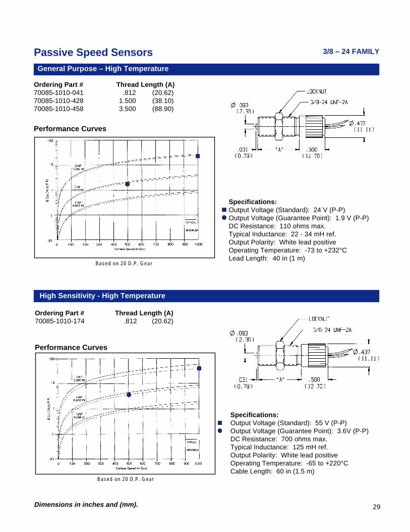
Ordering Part # Thread Length (A)70085-1010-041 .812 (20.62)70085-1010-428 1.500 (38.10)70085-1010-458 3.500 (88.90)
Performance Curves
Specifications:Output Voltage (Standard): 24 V (P-P)Output Voltage (Guarantee Point): 1.9 V (P-P)DC Resistance: 110 ohms max.Typical Inductance: 22 - 34 mH ref.Output Polarity: White lead positiveOperating Temperature: -73 to +232°CLead Length: 40 in (1 m)
Based on 20 D.P. Gear
Based on 20 D.P. Gear
Ordering Part # Thread Length (A)70085-1010-174 .812 (20.62)
Performance Curves
High Sensitivity - High Temperature
Specifications:Output Voltage (Standard): 55 V (P-P)Output Voltage (Guarantee Point): 3.6V (P-P)DC Resistance: 700 ohms max.Typical Inductance: 125 mH ref.Output Polarity: White lead positiveOperating Temperature: -65 to +220°CCable Length: 60 in (1.5 m)
Passive Speed Sensors
30 Dimensions in inches and (mm).
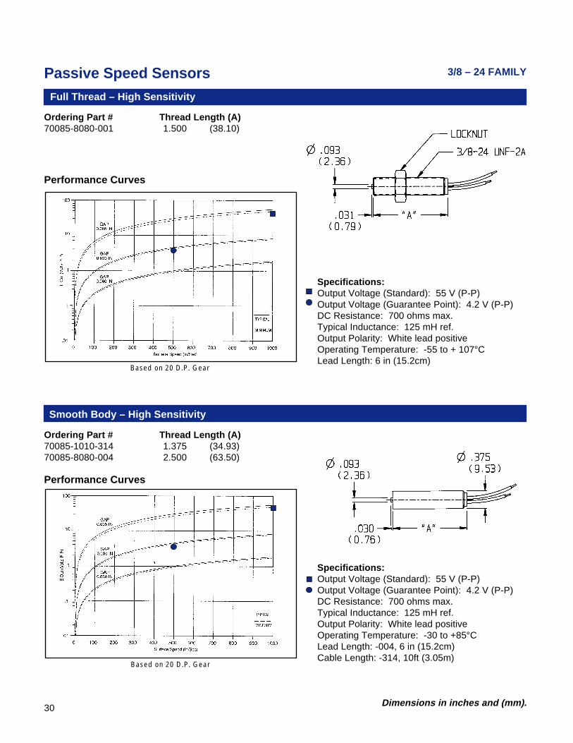
Ordering Part # Thread Length (A)70085-8080-001 1.500 (38.10)
Full Thread – High Sensitivity
Smooth Body – High Sensitivity
Ordering Part # Thread Length (A)70085-1010-314 1.375 (34.93)70085-8080-004 2.500 (63.50)
Performance Curves
Performance Curves
3/8 – 24 FAMILY
Specifications:Output Voltage (Standard): 55 V (P-P)Output Voltage (Guarantee Point): 4.2 V (P-P)DC Resistance: 700 ohms max.Typical Inductance: 125 mH ref.Output Polarity: White lead positiveOperating Temperature: -55 to + 107°CLead Length: 6 in (15.2cm)
Specifications:Output Voltage (Standard): 55 V (P-P)Output Voltage (Guarantee Point): 4.2 V (P-P)DC Resistance: 700 ohms max.Typical Inductance: 125 mH ref.Output Polarity: White lead positiveOperating Temperature: -30 to +85°CLead Length: -004, 6 in (15.2cm)Cable Length: -314, 10ft (3.05m)
Based on 20 D.P. Gear
Based on 20 D.P. Gear
Passive Speed Sensors
31Dimensions in inches and (mm).
1/4 – 40 FAMILY
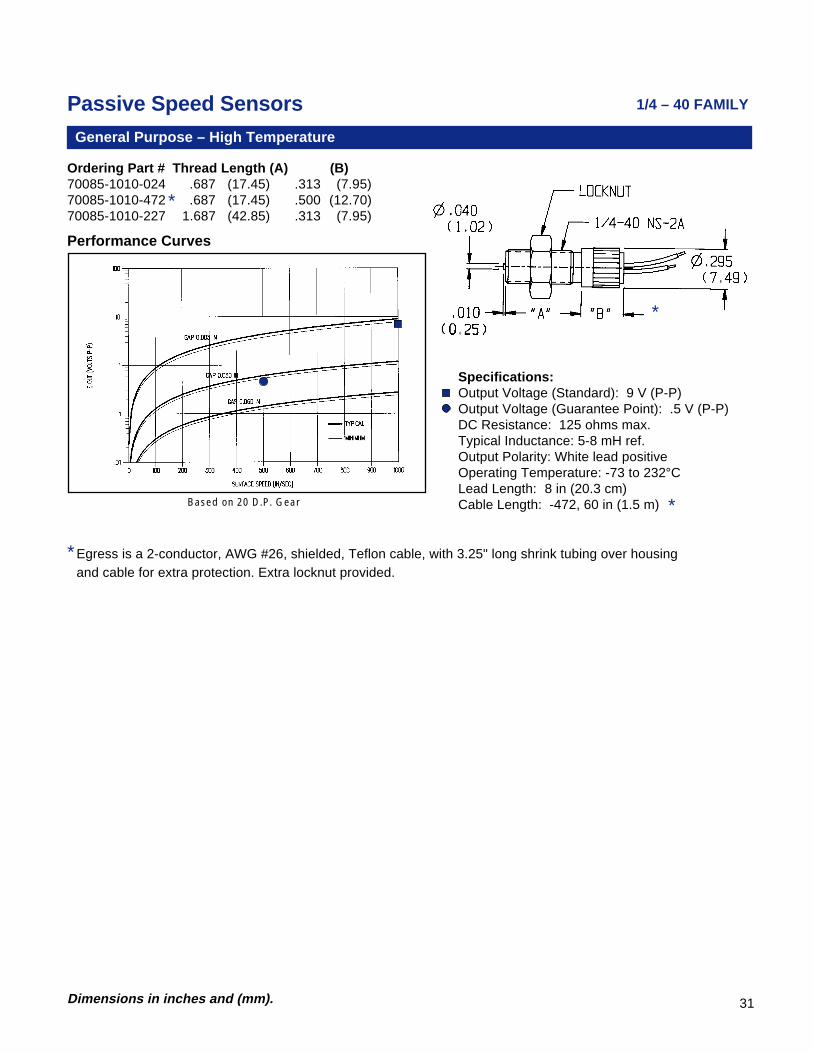
Performance Curves
General Purpose – High Temperature
Ordering Part # Thread Length (A) (B)70085-1010-024 .687 (17.45) .313 (7.95)70085-1010-472 .687 (17.45) .500 (12.70)70085-1010-227 1.687 (42.85) .313 (7.95)
Specifications:Output Voltage (Standard): 9 V (P-P)Output Voltage (Guarantee Point): .5 V (P-P)DC Resistance: 125 ohms max.Typical Inductance: 5-8 mH ref.Output Polarity: White lead positiveOperating Temperature: -73 to 232°CLead Length: 8 in (20.3 cm)Cable Length: -472, 60 in (1.5 m)Based on 20 D.P. Gear
*
*Egress is a 2-conductor, AWG #26, shielded, Teflon cable, with 3.25" long shrink tubing over housingand cable for extra protection. Extra locknut provided.
*
*
Passive Speed Sensors
32 Dimensions in inches and (mm).
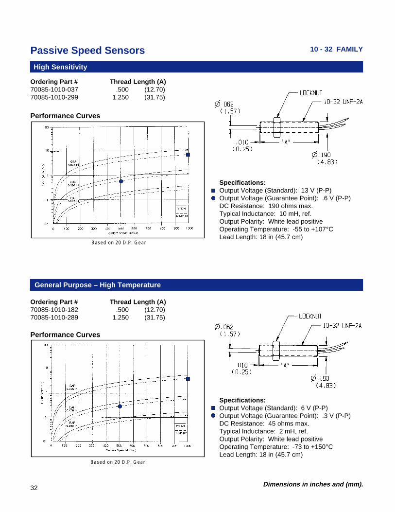
Ordering Part # Thread Length (A)70085-1010-037 .500 (12.70)70085-1010-299 1.250 (31.75)
Performance Curves
General Purpose – High Temperature
Specifications:Output Voltage (Standard): 13 V (P-P)Output Voltage (Guarantee Point): .6 V (P-P)DC Resistance: 190 ohms max.Typical Inductance: 10 mH, ref.Output Polarity: White lead positiveOperating Temperature: -55 to +107°CLead Length: 18 in (45.7 cm)
10 - 32 FAMILY
High Sensitivity
Ordering Part # Thread Length (A)70085-1010-182 .500 (12.70)70085-1010-289 1.250 (31.75)
Performance Curves
Specifications:Output Voltage (Standard): 6 V (P-P)Output Voltage (Guarantee Point): .3 V (P-P)DC Resistance: 45 ohms max.Typical Inductance: 2 mH, ref.Output Polarity: White lead positiveOperating Temperature: -73 to +150°CLead Length: 18 in (45.7 cm)
Based on 20 D.P. Gear
Based on 20 D.P. Gear

Passive Speed Sensors
33Dimensions in inches and (mm).Based on 8 D.P. Gear
UL/CSA Sensors
LISTED PRODUCT
Ordering Part # Thread Length (A)70085-1010-413 1.500 (38.10)70085-1010-005 1.875 (47.63)70085-1010-327 2.750 (69.85)70085-1010-328 4.000 (101.60)70085-1010-414 6.000 (152.40)
Specifications:Output Voltage (Standard): 54 V (P-P)Output Voltage (Guarantee Point):13.4 V (P-P)DC Resistance: 240 ohms max.Typical Inductance: 30 mH ref.Output Polarity: White lead positiveOperating Temperature: -65 to +100°CLead Length: 10 ft (3.05 m)
UL/CSA Sensors
Performance Curves
Rating: UL and CSA listed for hazardous locations.Class I, Div 1, Groups A, B, C & D; Class II, Div 1,Groups E, F ,G. Temp Code T3C.
Ordering Part # Thread Length (A)70085-1010-081 1.500 (38.10)70085-1010-411 1.875 (47.63)70085-1010-329 2.750 (69.85)70085-1010-330 4.000 (101.60)70085-1010-412 6.000 (152.40)
Performance Curves
Rating: UL and CSA listed for hazardous locations.Class I, Div 1, Groups A, B, C & D; Class II, Div 1,Groups E, F ,G. Temp Code T3C.
Specifications:Output Voltage (Standard): 54 V (P-P)Output Voltage (Guarantee Point):13.4 V (P-P)DC Resistance: 240 ohms max.Typical Inductance: 30 mH ref.Output Polarity: White lead positiveOperating Temperature: -65 to 100°CLead Length: 10 ft (3.05 m)
Based on 8 D.P. Gear
Passive Speed Sensors
34 Dimensions in inches and (mm).
LISTED PRODUCT
FM Sensors
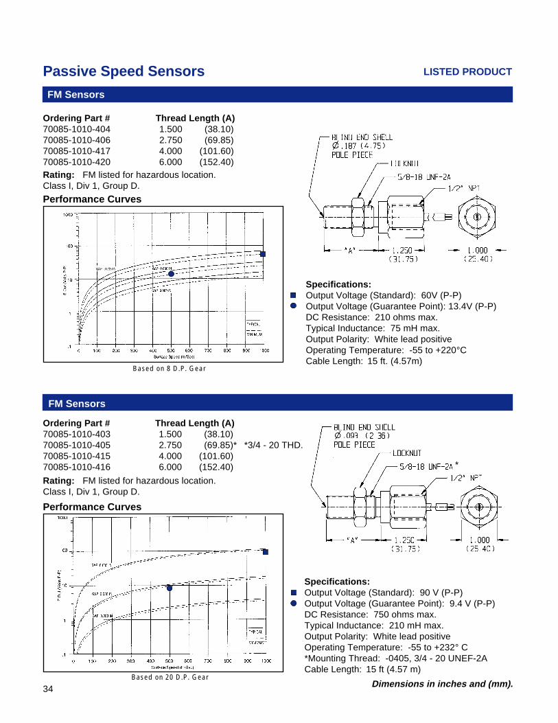
Ordering Part # Thread Length (A)70085-1010-403 1.500 (38.10)70085-1010-405 2.750 (69.85)*70085-1010-415 4.000 (101.60)70085-1010-416 6.000 (152.40)
Performance Curves
Rating: FM listed for hazardous location.Class I, Div 1, Group D.
Specifications:Output Voltage (Standard): 90 V (P-P)Output Voltage (Guarantee Point): 9.4 V (P-P)DC Resistance: 750 ohms max.Typical Inductance: 210 mH max.Output Polarity: White lead positiveOperating Temperature: -55 to +232° C*Mounting Thread: -0405, 3/4 - 20 UNEF-2ACable Length: 15 ft (4.57 m)
*3/4 - 20 THD.
*
FM Sensors
Ordering Part # Thread Length (A)70085-1010-404 1.500 (38.10)70085-1010-406 2.750 (69.85)70085-1010-417 4.000 (101.60)70085-1010-420 6.000 (152.40)Rating: FM listed for hazardous location.Class I, Div 1, Group D.
Specifications:Output Voltage (Standard): 60V (P-P)Output Voltage (Guarantee Point): 13.4V (P-P)DC Resistance: 210 ohms max.Typical Inductance: 75 mH max.Output Polarity: White lead positiveOperating Temperature: -55 to +220°CCable Length: 15 ft. (4.57m)
Performance Curves
Based on 20 D.P. Gear
Based on 8 D.P. Gear

37Dimensions in inches and (mm).
Hall Effect SensorsAirpax has taken its years of experience of designing and manufacturing
Hall Effect sensors for engine timing applications and has developed a new lineof durable products for industrial use.
With multiple standard variations we offer the widest range of standardcatalog sensors to meet your various design needs. The design is flexible toeasily meet all of your application requirements.
The Hall Effect sensor can sense each change in target movement, regard-less of speed, from near zero to 15 kHz frequency range, generating a steadypulse train of frequency proportional to target speed. Typically, each time a geartooth (or any ferrous discontinuity) passes in front of the sensor the outputchanges state. This type of sensor is known as a “P” type because it uses N-P-Ntransistor logic (as opposed to “N” type, which uses P-N-P transistor logic).
Key features to note are:• Reverse voltage protection, up to -30 Vdc, to prevent damage if miswired• Higher temperature range of -40°C to +125°C• Wide range of supply voltage in single design of 4.5 – 24 Vdc• Two output options of Supply Tracking or TTL Compatible• Rugged design meeting IEC 77 Standards (European Railroad Applications)
Suitable for 20 diametral pitch or coarser gear (target), the standard catalogsensors are easily applied to your varied sensing needs. If you have a unique,special requirement which cannot be met with any of the standard options, wewill gladly review your specs and work with you on a special sensor design.
It is the customer's responsibility to determine whether the product is properfor customer's use and application.
Dimensions in inches and (mm).
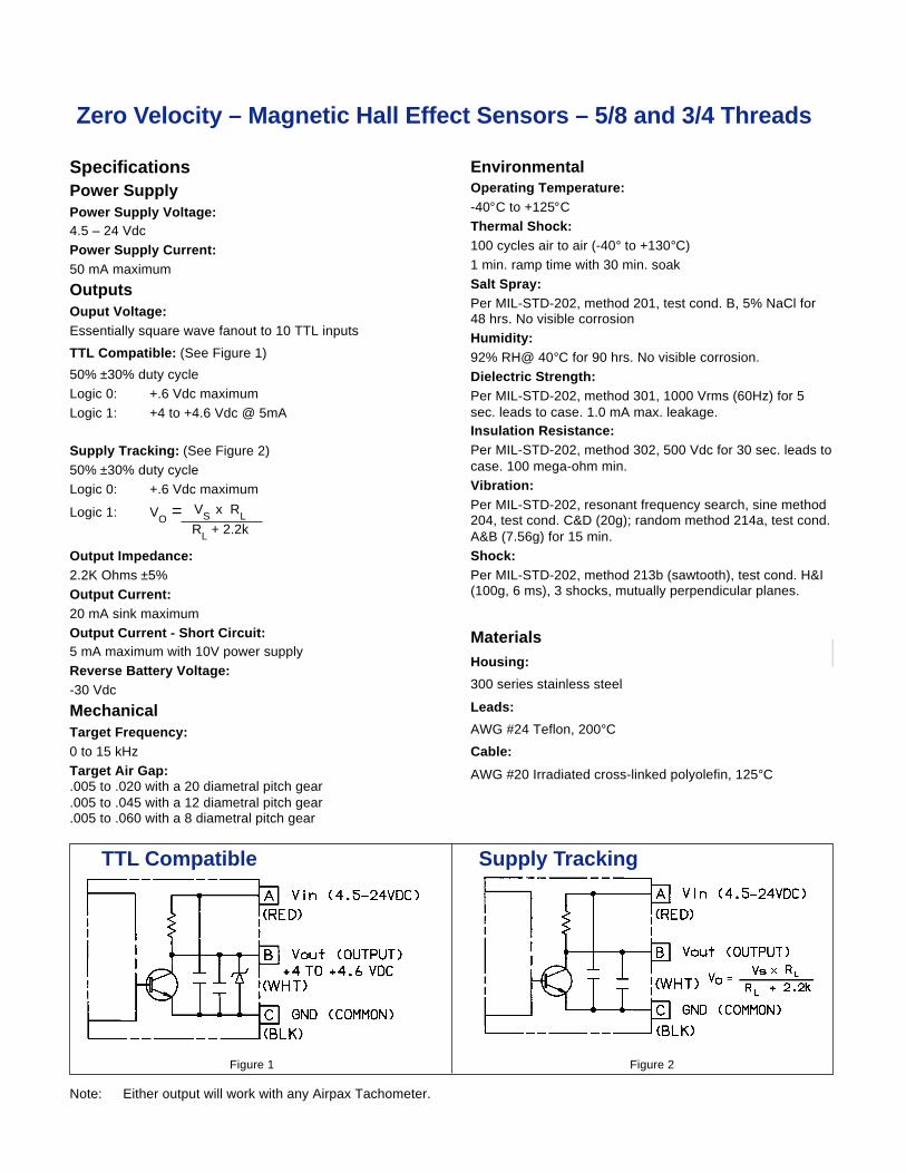
Zero Velocity – Magnetic Hall Effect Sensors – 5/8 and 3/4 Threads
VS x RLRL + 2.2k
EnvironmentalOperating Temperature:-40°C to +125°CThermal Shock:100 cycles air to air (-40° to +130°C)1 min. ramp time with 30 min. soakSalt Spray:Per MIL-STD-202, method 201, test cond. B, 5% NaCl for48 hrs. No visible corrosionHumidity:92% RH@ 40°C for 90 hrs. No visible corrosion.Dielectric Strength:Per MIL-STD-202, method 301, 1000 Vrms (60Hz) for 5sec. leads to case. 1.0 mA max. leakage.Insulation Resistance:Per MIL-STD-202, method 302, 500 Vdc for 30 sec. leads tocase. 100 mega-ohm min.Vibration:Per MIL-STD-202, resonant frequency search, sine method204, test cond. C&D (20g); random method 214a, test cond.A&B (7.56g) for 15 min.Shock:Per MIL-STD-202, method 213b (sawtooth), test cond. H&I(100g, 6 ms), 3 shocks, mutually perpendicular planes.
MaterialsHousing:
300 series stainless steel
Leads:
AWG #24 Teflon, 200°C
Cable:
AWG #20 Irradiated cross-linked polyolefin, 125°C
Figure 1 Figure 2
Supply TrackingTTL Compatible
SpecificationsPower SupplyPower Supply Voltage:4.5 – 24 VdcPower Supply Current:50 mA maximum
OutputsOuput Voltage:Essentially square wave fanout to 10 TTL inputs
TTL Compatible: (See Figure 1)
50% ±30% duty cycleLogic 0: +.6 Vdc maximumLogic 1: +4 to +4.6 Vdc @ 5mA
Supply Tracking: (See Figure 2)50% ±30% duty cycleLogic 0: +.6 Vdc maximum
Logic 1: VO =
Output Impedance:2.2K Ohms ±5%Output Current:20 mA sink maximumOutput Current - Short Circuit:5 mA maximum with 10V power supplyReverse Battery Voltage:-30 Vdc
MechanicalTarget Frequency:0 to 15 kHzTarget Air Gap:.005 to .020 with a 20 diametral pitch gear.005 to .045 with a 12 diametral pitch gear.005 to .060 with a 8 diametral pitch gear
Note: Either output will work with any Airpax Tachometer.
Dimensions in inches and (mm).
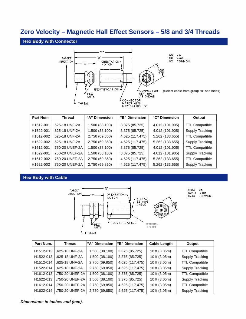
Zero Velocity – Magnetic Hall Effect Sensors – 5/8 and 3/4 ThreadsHex Body with Connector
Hex Body with Cable
Part Num. Thread “A” Dimension “B” Dimension “C” Dimension Output
H1512-001 .625-18 UNF-2A 1.500 (38.100) 3.375 (85.725) 4.012 (101.905) TTL Compatible
H1522-001 .625-18 UNF-2A 1.500 (38.100) 3.375 (85.725) 4.012 (101.905) Supply Tracking
H1512-002 .625-18 UNF-2A 2.750 (69.850) 4.625 (117.475) 5.262 (133.655) TTL Compatible
H1522-002 .625-18 UNF-2A 2.750 (69.850) 4.625 (117.475) 5.262 (133.655) Supply Tracking
H1612-001 .750-20 UNEF-2A 1.500 (38.100) 3.375 (85.725) 4.012 (101.905) TTL Compatible
H1622-001 .750-20 UNEF-2A 1.500 (38.100) 3.375 (85.725) 4.012 (101.905) Supply Tracking
H1612-002 .750-20 UNEF-2A 2.750 (69.850) 4.625 (117.475) 5.262 (133.655) TTL Compatible
H1622-002 .750-20 UNEF-2A 2.750 (69.850) 4.625 (117.475) 5.262 (133.655) Supply Tracking
Part Num. Thread “A” Dimension “B” Dimension Cable Length Output
H1512-013 .625-18 UNF-2A 1.500 (38.100) 3.375 (85.725) 10 ft (3.05m) TTL Compatible
H1522-013 .625-18 UNF-2A 1.500 (38.100) 3.375 (85.725) 10 ft (3.05m) Supply Tracking
H1512-014 .625-18 UNF-2A 2.750 (69.850) 4.625 (117.475) 10 ft (3.05m) TTL Compatible
H1522-014 .625-18 UNF-2A 2.750 (69.850) 4.625 (117.475) 10 ft (3.05m) Supply Tracking
H1612-013 .750-20 UNEF-2A 1.500 (38.100) 3.375 (85.725) 10 ft (3.05m) TTL Compatible
H1622-013 .750-20 UNEF-2A 1.500 (38.100) 3.375 (85.725) 10 ft (3.05m) Supply Tracking
H1612-014 .750-20 UNEF-2A 2.750 (69.850) 4.625 (117.475) 10 ft (3.05m) TTL Compatible
H1622-014 .750-20 UNEF-2A 2.750 (69.850) 4.625 (117.475) 10 ft (3.05m) Supply Tracking
(Select cable from group “B” see index)
INTERNAL1/2 NPT
Dimensions in inches and (mm).
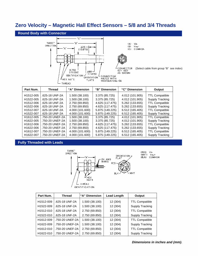
Zero Velocity – Magnetic Hall Effect Sensors – 5/8 and 3/4 ThreadsRound Body with Connector
Fully Threaded with Leads
Part Num. Thread “A” Dimension “B” Dimension “C” Dimension Output
H1512-005 .625-18 UNF-2A 1.500 (38.100) 3.375 (85.725) 4.012 (101.905) TTL CompatibleH1522-005 .625-18 UNF-2A 1.500 (38.100) 3.375 (85.725) 4.012 (101.905) Supply TrackingH1512-006 .625-18 UNF-2A 2.750 (69.850) 4.625 (117.475) 5.262 (133.655) TTL CompatibleH1522-006 .625-18 UNF-2A 2.750 (69.850) 4.625 (117.475) 5.262 (133.655) Supply TrackingH1512-007 .625-18 UNF-2A 4.000 (101.600) 5.875 (149.225) 6.512 (165.405) TTL CompatibleH1522-007 .625-18 UNF-2A 4.000 (101.600) 5.875 (149.225) 6.512 (165.405) Supply TrackingH1612-005 .750-20 UNEF-2A 1.500 (38.100) 3.375 (85.725) 4.012 (101.905) TTL CompatibleH1622-005 .750-20 UNEF-2A 1.500 (38.100) 3.375 (85.725) 4.012 (101.905) Supply TrackingH1612-006 .750-20 UNEF-2A 2.750 (69.850) 4.625 (117.475) 5.262 (133.655) TTL CompatibleH1622-006 .750-20 UNEF-2A 2.750 (69.850) 4.625 (117.475) 5.262 (133.655) Supply TrackingH1612-007 .750-20 UNEF-2A 4.000 (101.600) 5.875 (149.225) 6.512 (165.405) TTL CompatibleH1622-007 .750-20 UNEF-2A 4.000 (101.600) 5.875 (149.225) 6.512 (165.405) Supply Tracking
Part Num. Thread “A” Dimension Lead Length Output
H1512-009 .625-18 UNF-2A 1.500 (38.100) 12 (304) TTL Compatible
H1522-009 .625-18 UNF-2A 1.500 (38.100) 12 (304) Supply Tracking
H1512-010 .625-18 UNF-2A 2.750 (69.850) 12 (304) TTL Compatible
H1522-010 .625-18 UNF-2A 2.750 (69.850) 12 (304) Supply Tracking
H1612-009 .750-20 UNEF-2A 1.500 (38.100) 12 (304) TTL Compatible
H1622-009 .750-20 UNEF-2A 1.500 (38.100) 12 (304) Supply Tracking
H1612-010 .750-20 UNEF-2A 2.750 (69.850) 12 (304) TTL Compatible
H1622-010 .750-20 UNEF-2A 2.750 (69.850) 12 (304) Supply Tracking
(Select cable from group “B” see index)
Dimensions in inches and (mm).
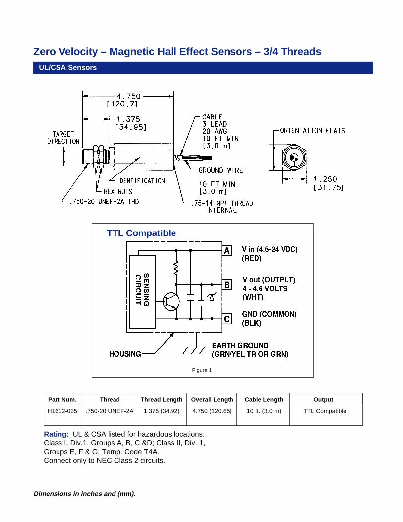
Zero Velocity – Magnetic Hall Effect Sensors – 3/4 ThreadsUL/CSA Sensors
Part Num. Thread Thread Length Overall Length Cable Length Output
H1612-025 .750-20 UNEF-2A 1.375 (34.92) 4.750 (120.65) 10 ft. (3.0 m) TTL Compatible
TTL Compatible
Figure 1
Rating: UL & CSA listed for hazardous locations.Class I, Div.1, Groups A, B, C &D; Class II, Div. 1,Groups E, F & G. Temp. Code T4A.Connect only to NEC Class 2 circuits.
Dimensions in inches and (mm).
Zero Velocity – Magnetic Hall Effect Sensors – 3/8 Diameter
MechanicalTarget Frequency:
0 to 15 kHz
Target Air Gap:.000 to .015 with a 20 diametral pitch gear.000 to .040 with a 12 diametral pitch gear.000 to .055 with a 8 diametral pitch gear
EnvironmentalOperating Temperature:
-25°C to +80°C
MaterialsHousing:
Aluminum / 300 series stainless steel
Leads:
AWG #24 Teflon, 200°C
Cable:
AWG #26 PVC, 105°C
Specifications
Power SupplyPower Supply Voltage:
4.5 – 24 Vdc
Power Supply Current:
50 mA maximum
OutputsOuput Voltage:
Essentially square wave fanout to 10 TTL inputs
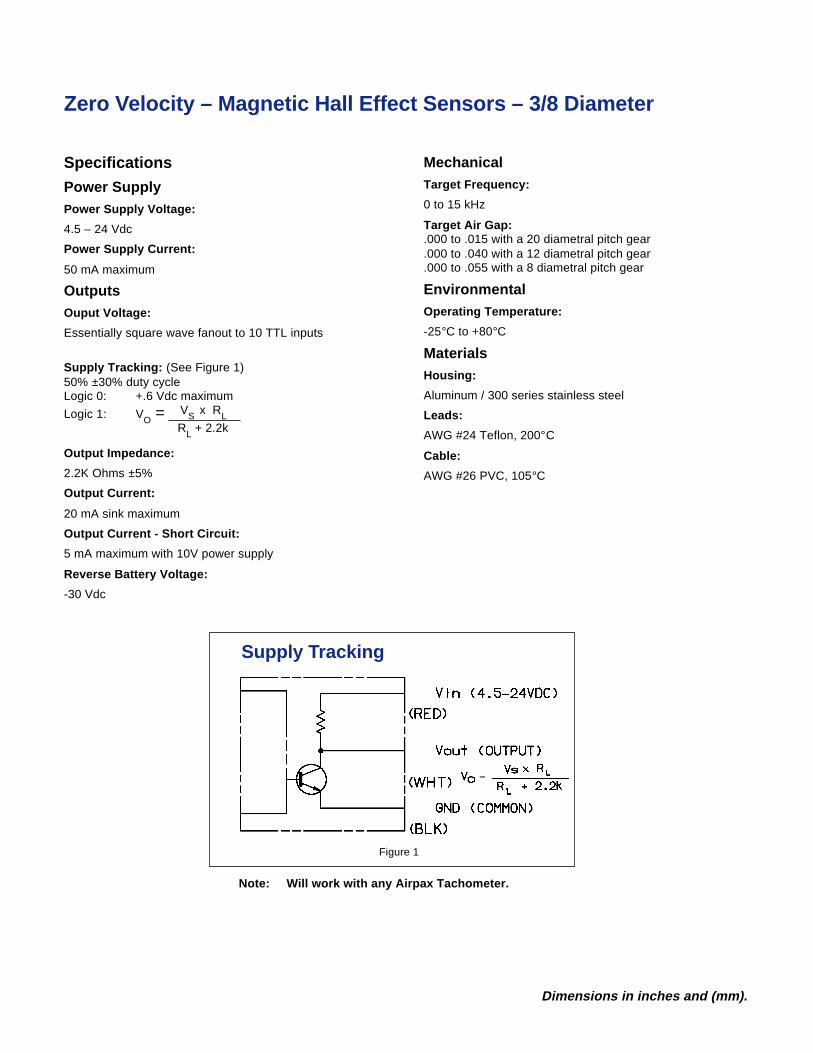
Supply Tracking: (See Figure 1)50% ±30% duty cycleLogic 0: +.6 Vdc maximum
Logic 1: VO =
Output Impedance:
2.2K Ohms ±5%
Output Current:
20 mA sink maximum
Output Current - Short Circuit:
5 mA maximum with 10V power supply
Reverse Battery Voltage:
-30 Vdc
VS x RLRL + 2.2k
Supply Tracking
Figure 1
Note: Will work with any Airpax Tachometer.
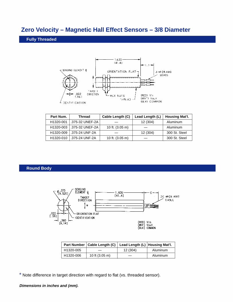
Dimensions in inches and (mm).
Part Num. Thread Cable Length (C) Lead Length (L) Housing Mat'l.
H1320-001 .375-32 UNEF-2A — 12 (304) Aluminum
H1320-003 .375-32 UNEF-2A 10 ft. (3.05 m) — Aluminum
H1320-009 .375-24 UNF-2A — 12 (304) 300 St. Steel
H1320-010 .375-24 UNF-2A 10 ft. (3.05 m) — 300 St. Steel
Fully Threaded
Round Body
Zero Velocity – Magnetic Hall Effect Sensors – 3/8 Diameter
Part Number Cable Length (C) Lead Length (L) Housing Mat'l.
H1320-005 — 12 (304) Aluminum
H1320-006 10 ft (3.05 m) — Aluminum
* Note difference in target direction with regard to flat (vs. threaded sensor).
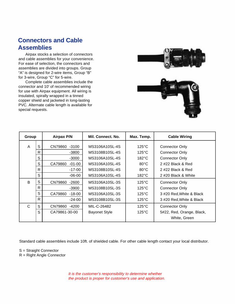
Connectors and CableAssemblies
Airpax stocks a selection of connectorsand cable assemblies for your convenience.For ease of selection, the connectors andassemblies are divided into groups. Group“A” is designed for 2-wire items, Group “B”for 3-wire, Group “C” for 5-wire.
Complete cable assemblies include theconnector and 10' of recommended wiringfor use with Airpax equipment. All wiring isinsulated, spirally wrapped in a tinnedcopper shield and jacketed in long-lastingPVC. Alternate cable length is available forspecial requests.
It is the customer's responsibility to determine whetherthe product is proper for customer's use and application.
S
R
S
S
R
S
S
R
S
R
S
S
Group Airpax P/N Mil. Connect. No. Max. Temp. Cable Wiring
A CN79860 -3100 MS3106A10SL-4S 125°C Connector Only
-3800 MS3108B10SL-4S 125°C Connector Only
-3000 MS3106A10SL-4S 182°C Connector Only
CA79860 -01-00 MS3106A10SL-4S 80°C 2 #22 Black & Red
-17-00 MS3108B10SL-4S 80°C 2 #22 Black & Red
-06-00 MS3106A10SL-4S 182°C 2 #20 Black & White
B CN79860 -2600 MS3106A10SL-3S 125°C Connector Only
-3900 MS3108B10SL-3S 125°C Connector Only
CA79860 -18-00 MS3106A10SL-3S 125°C 3 #20 Red,White & Black
-24-00 MS3108B10SL-3S 125°C 3 #20 Red,White & Black
C CN79860 -4200 MIL-C-26482 125°C Connector Only
CA79861-30-00 Bayonet Style 125°C 5#22, Red, Orange, Black,
White, Green
Standard cable assemblies include 10ft. of shielded cable. For other cable length contact your local distributor.
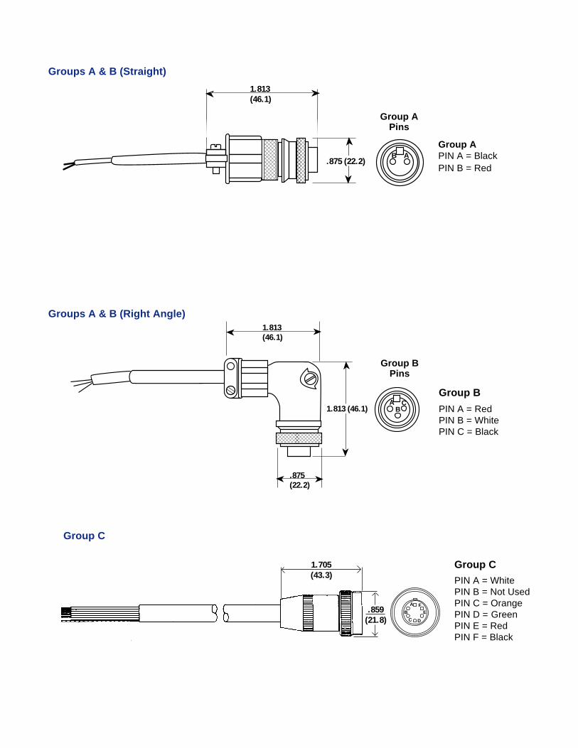
S = Straight ConnectorR = Right Angle Connector
1.705(43.3)
Group B
PIN A = RedPIN B = WhitePIN C = Black
Group APIN A = BlackPIN B = Red
������ AB
➤➤1.813(46.1)
➤
➤
.875 (22.2)
Group C
Group BPins
Group APins
��
AB
1.813(46.1)
➤➤
➤
➤
1.813 (46.1)C
.875(22.2)
➤➤
Groups A & B (Right Angle)
Groups A & B (Straight)
A
B
C D
EF
.859(21.8)
Group C
PIN A = WhitePIN B = Not UsedPIN C = OrangePIN D = GreenPIN E = RedPIN F = Black
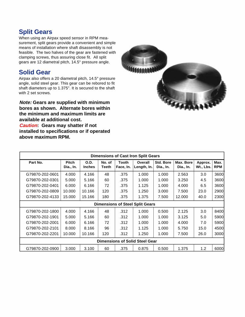
Split GearsWhen using an Airpax speed sensor in RPM mea-surement, split gears provide a convenient and simplemeans of installation where shaft disassembly is notfeasible. The two halves of the gear are fastened withclamping screws, thus assuring close fit. All splitgears are 12 diametral pitch, 14.5° pressure angle.
Solid GearAirpax also offers a 20 diametral pitch, 14.5° pressureangle, solid steel gear. This gear can be rebored to fitshaft diameters up to 1.375". It is secured to the shaftwith 2 set screws.
Note: Gears are supplied with minimumbores as shown. Alternate bores withinthe minimum and maximum limits areavailable at additional cost.Caution : Gears may shatter if notinstalled to specifications or if operatedabove maximum RPM.
Dimensions of Cast Iron Split Gears
Part No. Pitch O.D. No. of Tooth Overall Std. Bore Max. Bore Approx. Max.Dia., In. Inches Teeth Face, In. Length, In. Dia., In. Dia., In. Wt., Lbs. RPM
G79870-202-0601 4.000 4.166 48 .375 1.000 1.000 2.563 3.0 3600G79870-202-0301 5.000 5.166 60 .375 1.000 1.000 3.250 4.5 3600G79870-202-0401 6.000 6.166 72 .375 1.125 1.000 4.000 6.5 3600G79870-202-0809 10.000 10.166 120 .375 1.250 3.000 7.500 23.0 2900G79870-202-4133 15.000 15.166 180 .375 1.375 7.500 12.000 40.0 2300
Dimensions of Steel Split Gears
G79870-202-1800 4.000 4.166 48 .312 1.000 0.500 2.125 3.0 8400G79870-202-1901 5.000 5.166 60 .312 1.000 1.000 3.125 5.0 5900G79870-202-2001 6.000 6.166 72 .312 1.000 1.000 4.000 7.0 5900G79870-202-2101 8.000 8.166 96 .312 1.125 1.000 5.750 15.0 4500G79870-202-2201 10.000 10.166 120 .312 1.250 1.000 7.500 26.0 3000
Dimensions of Solid Steel Gear
G79870-202-0900 3.000 3.100 60 .375 0.875 0.500 1.375 1.2 6000
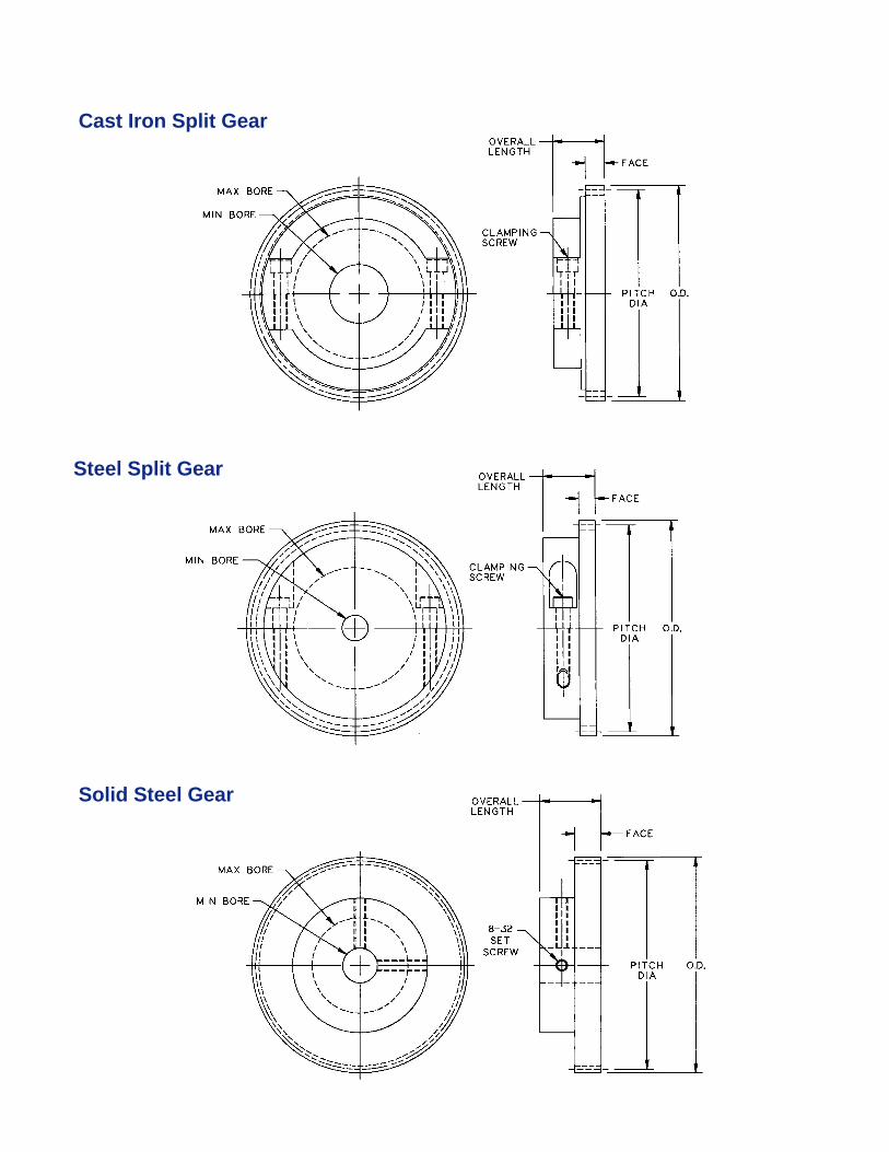
Steel Split Gear
Cast Iron Split Gear
Solid Steel Gear
Mechanical SpecificationsLubrication: Bearings are permanently lubricated; do
not use pressure washes or solvents.Finish: Reference rod and outer ring are gold
anodized aluminum; rotor and Taper-Lockbushing are plated steel.
Reference Rod : 1/4" diameter, 6" longBearing Limits: Sealed type - 2000 RPM max. speed
Shielded type - 4000 RPM max. speedWeight: 54 oz. (1.53 kg) max.Sensor Mounting: 5/8-18 UNF-2A threaded hole std.
Electrical SpecificationsOutput Frequency: 30 pulses/rev. (1 Hz = 2RPM),
Standard; 60 pulses/rev. (1 Hz - 1RPM),Optional.
Output Voltage: Depends on magnetic sensor used.One turn of sensor controls 0.056 inches of airgapbased on 5/8-18 UNF-2A thread. Normal gapsetting range from 0.005 to 0.020 inches.
Ambient Temperature: -30°C to +50°C
NOTE: Not for use in abrasive atmospheres.
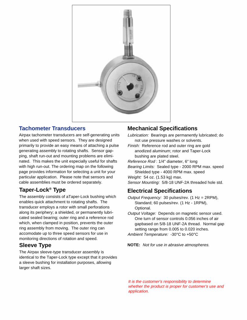
Tachometer TransducersAirpax tachometer transducers are self-generating unitswhen used with speed sensors. They are designedprimarily to provide an easy means of attaching a pulsegenerating assembly to rotating shafts. Sensor gap-ping, shaft run-out and mounting problems are elimi-nated. This makes the unit especially useful for shaftswith high run-out. The ordering map on the followingpage provides information for selecting a unit for yourparticular application. Please note that sensors andcable assemblies must be ordered separately.
Taper-Lock ® TypeThe assembly consists of aTaper-Lock bushing whichenables quick attachment to rotating shafts. Thetransducer employs a rotor with small perforationsalong its periphery; a shielded, or permanently lubri-cated sealed bearing; outer ring and a reference rodwhich, when clamped in position, prevents the outerring assembly from moving. The outer ring canaccomodate up to three speed sensors for use inmonitoring directions of rotation and speed.
Sleeve TypeThe Airpax sleeve-type transducer assembly isidentical to the Taper-Lock type except that it providesa sleeve bushing for installation purposes, allowinglarger shaft sizes.
It is the customer's responsibility to determinewhether the product is proper for customer's use andapplication.
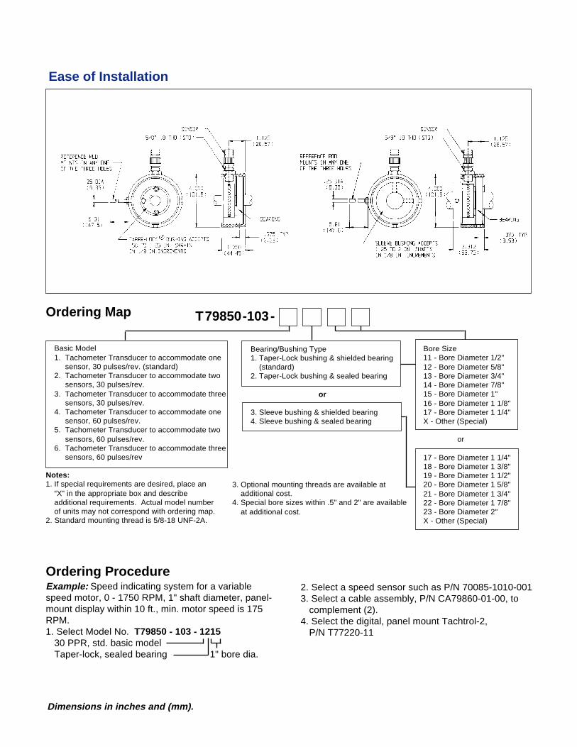
Ordering ProcedureExample: Speed indicating system for a variablespeed motor, 0 - 1750 RPM, 1" shaft diameter, panel-mount display within 10 ft., min. motor speed is 175RPM.1. Select Model No. T79850 - 103 - 1215
30 PPR, std. basic modelTaper-lock, sealed bearing 1" bore dia.
Ease of Installation
Ordering Map
Basic Model1. Tachometer Transducer to accommodate one
sensor, 30 pulses/rev. (standard)2. Tachometer Transducer to accommodate two
sensors, 30 pulses/rev.3. Tachometer Transducer to accommodate three
sensors, 30 pulses/rev.4. Tachometer Transducer to accommodate one
sensor, 60 pulses/rev.5. Tachometer Transducer to accommodate two
sensors, 60 pulses/rev.6. Tachometer Transducer to accommodate three
sensors, 60 pulses/rev
Bore Size11 - Bore Diameter 1/2"12 - Bore Diameter 5/8"13 - Bore Diameter 3/4"14 - Bore Diameter 7/8"15 - Bore Diameter 1"16 - Bore Diameter 1 1/8"17 - Bore Diameter 1 1/4"X - Other (Special)
or
17 - Bore Diameter 1 1/4"18 - Bore Diameter 1 3/8"19 - Bore Diameter 1 1/2"20 - Bore Diameter 1 5/8"21 - Bore Diameter 1 3/4"22 - Bore Diameter 1 7/8"23 - Bore Diameter 2"X - Other (Special)
Bearing/Bushing Type1. Taper-Lock bushing & shielded bearing
(standard)2. Taper-Lock bushing & sealed bearing
or
3. Sleeve bushing & shielded bearing4. Sleeve bushing & sealed bearing
Notes:1. If special requirements are desired, place an
“X” in the appropriate box and describeadditional requirements. Actual model numberof units may not correspond with ordering map.
2. Standard mounting thread is 5/8-18 UNF-2A.
3. Optional mounting threads are available atadditional cost.
4. Special bore sizes within .5" and 2" are availableat additional cost.
2. Select a speed sensor such as P/N 70085-1010-0013. Select a cable assembly, P/N CA79860-01-00, to
complement (2).4. Select the digital, panel mount Tachtrol-2,
P/N T77220-11
T79850-103-
Dimensions in inches and (mm).
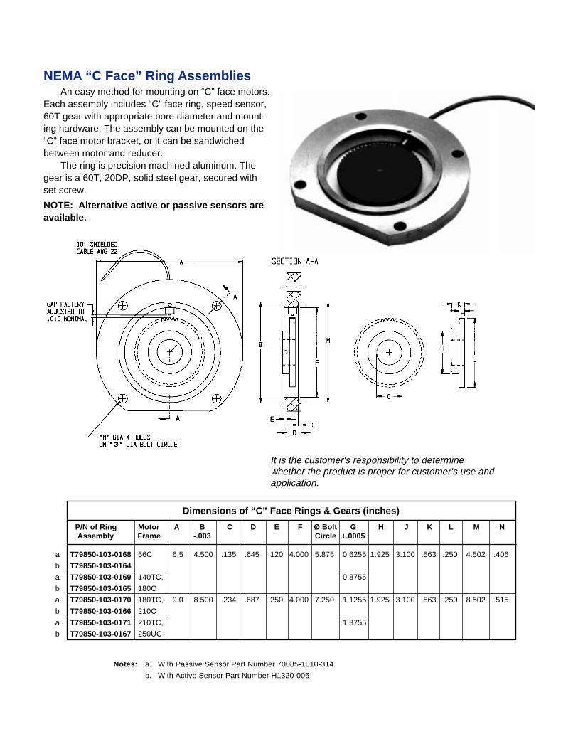
NEMA “C Face” Ring AssembliesAn easy method for mounting on “C” face motors.
Each assembly includes “C” face ring, speed sensor,60T gear with appropriate bore diameter and mount-ing hardware. The assembly can be mounted on the“C” face motor bracket, or it can be sandwichedbetween motor and reducer.
The ring is precision machined aluminum. Thegear is a 60T, 20DP, solid steel gear, secured withset screw.
NOTE: Alternative active or passive sensors areavailable.
It is the customer's responsibility to determinewhether the product is proper for customer's use andapplication.
Notes: a. With Passive Sensor Part Number 70085-1010-314
b. With Active Sensor Part Number H1320-006
P/N of Ring Motor A B C D E F Ø Bolt G H J K L M NAssembly Frame -.003 Circle +.0005
T79850-103-0168 56C 6.5 4.500 .135 .645 .120 4.000 5.875 0.6255 1.925 3.100 .563 .250 4.502 .406
T79850-103-0164
T79850-103-0169 140TC, 0.8755
T79850-103-0165 180C
T79850-103-0170 180TC, 9.0 8.500 .234 .687 .250 4.000 7.250 1.1255 1.925 3.100 .563 .250 8.502 .515
T79850-103-0166 210C
T79850-103-0171 210TC, 1.3755
T79850-103-0167 250UC
Dimensions of “C” Face Rings & Gears (inches)
a
b
a
b
a
b
a
b
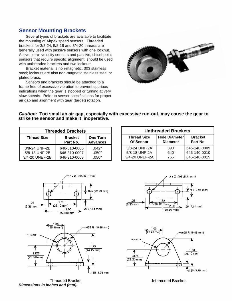
Sensor Mounting BracketsSeveral types of brackets are available to facilitate
the mounting of Airpax speed sensors. Threadedbrackets for 3/8-24, 5/8-18 and 3/4-20 threads aregenerally used with passive sensors with one locknut.Active, zero- velocity sensors and passive, chisel-pointsensors that require specific alignment should be usedwith unthreaded brackets and two locknuts.
Bracket material is non-magnetic, 303 stainlesssteel; locknuts are also non-magnetic stainless steel orplated brass.
Sensors and brackets should be attached to aframe free of excessive vibration to prevent spuriousindications when the gear is stopped or turning at veryslow speeds. Refer to sensor specifications for properair gap and alignment with gear (target) rotation.
Caution: Too small an air gap, especially with excessive run-out, may cause the gear tostrike the sensor and make it inoperative.
Threaded BracketsThread Size Bracket One Turn
Part No. Advances
3/8-24 UNF-2B 646-310-0006 .042"5/8-18 UNF-2B 646-310-0007 .050"
3/4-20 UNEF-2B 646-310-0008 .050"
Unthreaded BracketsThread Size Hole Diameter BracketOf Sensor Diameter Part No .
3/8-24 UNF-2A .390" 646-140-00095/8-18 UNF-2A .640" 646-140-0010
3/4-20 UNEF-2A .765" 646-140-0015
Dimensions in inches and (mm).