Embed Size (px)
Citation preview
Revision 3.6 Dated 25 Oct 2010
DEPARTMENT OF THE ARMY FACILITIES STANDARDIZATION
PROGRAM
TACTICAL EQUIPMENT MAINTENANCE FACILITIES
(TEMF)
STANDARD DESIGN
UFC 4-214-02 25 Oct 2010
Revision 3.6 Dated 25 Oct 2010
TACTICAL EQUIPMENT MAINTENANCE FACILITY STANDARD DEFINITIVE DESIGN
TABLE OF CONTENTS
PART I GENERAL DESIGN REQUIREMENTS
SECTIONS
1. GENERAL AND SPECIFIC CRITERIA a. Standardization b. Space Planning Criteria c. Applicability d. <REV> Sustainability </REV> Information e. <REV> Renovations </REV>
2. LEVELS OF MAINTENANCE
a. Field Maintenance (FM) b. Sustainment Maintenance (SM)
3. BUILDING FUNCTIONAL AREAS
a. Repair and Maintenance Areas b. Core Areas c. Warehouse Areas d. Non-Assignable Spaces and Gross Area
4. SITE FUNCTIONAL AREAS
a. Shop Hardstand b. Vehicle Parking c. Site Storage d. Not Authorized
5. REFERENCES (Part I) 6. DECISION AND REFERENCE DIAGRAM PART II STATEMENT OF WORK 1.0 PROJECT OBJECTIVES 2.0 SCOPE 3.0 FUNCTIONAL AND AREA REQUIREMENTS FOR TACTICAL EQUIPMENT MAINTENANCE
FACILITY 3.1 GENERAL
(1) Functional Areas (2) Gross Building Area
(3) Net Area (4) Deviations and Improvements (5) Handicapped Access (6) Site and Functional Areas
Revision 3.6 Dated 25 Oct 2010
3.1.1 REPAIR AREAS AND MAINTENANCE AREAS
(1) Repair Areas (2) Maintenance Areas (3) Circulation Bays
3.1.2 CORE AREAS
(1) Administration and Shop Control (2) Training Room (3) Consolidated Bench (4) Tool Room (5) Tool Box Storage (6) Combat Spares (7) Latrine, Shower, and Locker Rooms (8) Break, Training and Conference (BTC) (9) Vaults (10) Non-Sensitive Secure Storage (11) Telecommunication Equipment Room (12) Non-Assignable Spaces and Gross Area
3.1.3 SITE FUNCTIONAL AREAS
(1) Dock (2) Organizational Vehicle Parking (3) Site Storage
3.1.4. SITE DESIGN
(1) Hardstand (2) Antiterrorism and Force Protection (3) Storm Water Management (4) Storm Drainage System (5) Oil/Water Separator (6) Used and Waste Oil, Antifreeze, Solvents, Cleaning Compounds, and Hazardous
Materials (7) Primary and Secondary Drives
(8) Organizational Vehicle Hardstand (9) Circulation Lane (10) Tactical/Military Vehicle Parking (11) POL Vehicle Parking (12) Dead Line Vehicle Parking (13) TEMF Aprons (14) Site Storage Building Aprons (15) Bollards at TEMF Repair Bays (16) Mechanical and Electrical Equipment Yard
(17) Bollards at Out of Spec Waste Oil, Used Oil and Used Engine Coolant (antifreeze) Storage Tank(s)
(18) Bollards at Site Storage Buildings
3.1.5 ARCHITECTURE (1) Exterior Materials (2) Floors (3) Natural Lighting (4) Partitions
Revision 3.6 Dated 25 Oct 2010
(5) Repair Area Bay Doors (6) Personnel Doors (7) Overhead Cranes
3.1.6 FIRE PROTECTION
3.1.7 HEATING, VENTILATION, AND AIR CONDITIONING (HVAC) SYSTEMS
(1) Ventilation System (2) System Selection (3) Building Exhaust System Systems (4) Vehicle Exhaust Evacuation Systems (5) UMCS
3.1.8 PLUMBING
(1) Trench Drains (2) Emergency Showers and Eye Washes
(3) Compressed Air (4) Sump Pump
3.1.9 ELECTRICAL AND TELECOMMUNICATIONS SYSTEMS (1) Exterior Electrical Distribution System
(a) Parking Pad and Power Connections (2) Exterior Lighting (a) Exterior Lighting General (b) Perimeter Security Lighting (3) Exterior Communications Services (a) Parking Pad and Data Connections (4) Interior Electrical and Telecommunications (a) Electrical (b) Receptacles (c) Special Power Receptacles (d) Hazardous Locations (e) Lighting (f) Telecommunications System – Telecommunications Pathways (g) Cable Television (CATV) (h) Audio/Visual Systems (i) Security Infrastructure (j) Mass Notification System (MNS) (k) Grounding (l) SIPRNet (m) Hydraulic Lift (n) Fire Detection and Alarm
3.1.10 ENERGY CONSERVATION
3.1.11 EQUIPMENT AND FURNITURE
<REV> (a) Equipment and Furniture </REV> <REV> (b) Furniture Systems </REV>
3.2 FUNCTIONAL / OPERATIONAL REQUIREMENTS
Revision 3.6 Dated 25 Oct 2010
(a) Small (b) Medium (c ) Large (d) Extra-Large
(e) Architectural TEMF Features Matrix (f) Mechanical TEMF Features Matrix
(g) Electrical TEMF Features Matrix
3.3 REFERENCES (Part II)
Revision 3.6 Dated 25 Oct 2010
PART I
GENERAL DESIGN REQUIREMENTS
1 Revision 3.6 Dated 25 Oct 2010
TACTICAL EQUIPMENT MAINTENANCE FACILITY (TEMF) GENERAL DESIGN REQUIREMENTS
1. GENERAL AND SPECIFIC CRITERIA. The criteria in this document are applicable to the
design of facilities for deployable maintenance organizations and non-deployable garrison maintenance organizations.
a. Standardization. The Center of Standardization (COS) for Tactical Equipment
Maintenance Facilities (TEMF) is the U.S. Army Engineer District, Savannah (CESAS). In accordance with ER 1110-3-113 (Reference 1), the COS (CESAS) maintains lessons-learned and CADD files of completed designs and should be consulted when starting a project (reference 2).
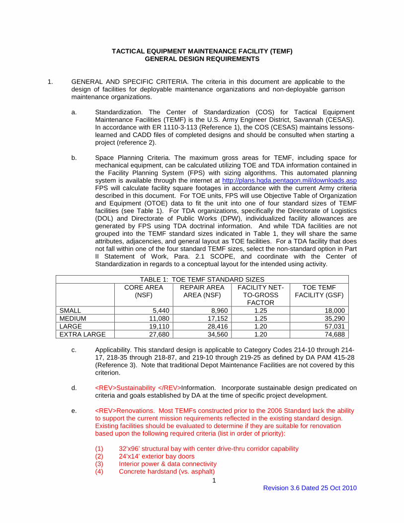
b. Space Planning Criteria. The maximum gross areas for TEMF, including space for
mechanical equipment, can be calculated utilizing TOE and TDA information contained in the Facility Planning System (FPS) with sizing algorithms. This automated planning system is available through the internet at http://plans.hqda.pentagon.mil/downloads.asp FPS will calculate facility square footages in accordance with the current Army criteria described in this document. For TOE units, FPS will use Objective Table of Organization and Equipment (OTOE) data to fit the unit into one of four standard sizes of TEMF facilities (see Table 1). For TDA organizations, specifically the Directorate of Logistics (DOL) and Directorate of Public Works (DPW), individualized facility allowances are generated by FPS using TDA doctrinal information. And while TDA facilities are not grouped into the TEMF standard sizes indicated in Table 1, they will share the same attributes, adjacencies, and general layout as TOE facilities. For a TDA facility that does not fall within one of the four standard TEMF sizes, select the non-standard option in Part II Statement of Work, Para. 2.1 SCOPE, and coordinate with the Center of Standardization in regards to a conceptual layout for the intended using activity.
TABLE 1: TOE TEMF STANDARD SIZES
CORE AREA (NSF)
REPAIR AREA AREA (NSF)
FACILITY NET-TO-GROSS
FACTOR
TOE TEMF FACILITY (GSF)
SMALL 5,440 8,960 1.25 18,000 MEDIUM 11,080 17,152 1.25 35,290 LARGE 19,110 28,416 1.20 57,031 EXTRA LARGE 27,680 34,560 1.20 74,688
c. Applicability. This standard design is applicable to Category Codes 214-10 through 214-
17, 218-35 through 218-87, and 219-10 through 219-25 as defined by DA PAM 415-28 (Reference 3). Note that traditional Depot Maintenance Facilities are not covered by this criterion.
d. <REV>Sustainability </REV>Information. Incorporate sustainable design predicated on
criteria and goals established by DA at the time of specific project development. e. <REV>Renovations. Most TEMFs constructed prior to the 2006 Standard lack the ability
to support the current mission requirements reflected in the existing standard design. Existing facilities should be evaluated to determine if they are suitable for renovation based upon the following required criteria (list in order of priority):
(1) 32’x96’ structural bay with center drive-thru corridor capability (2) 24’x14’ exterior bay doors (3) Interior power & data connectivity (4) Concrete hardstand (vs. asphalt)
Page 2 Revision 3.6 Dated 25 Oct 2010
(5) Exterior connectivity for SATS & ASLMS (or other parts storage containers) (6) Exterior building storage capability Existing facilities that cannot be feasibly upgraded to meet these requirements should not be renovated, but instead, be replaced with new construction. </REV>
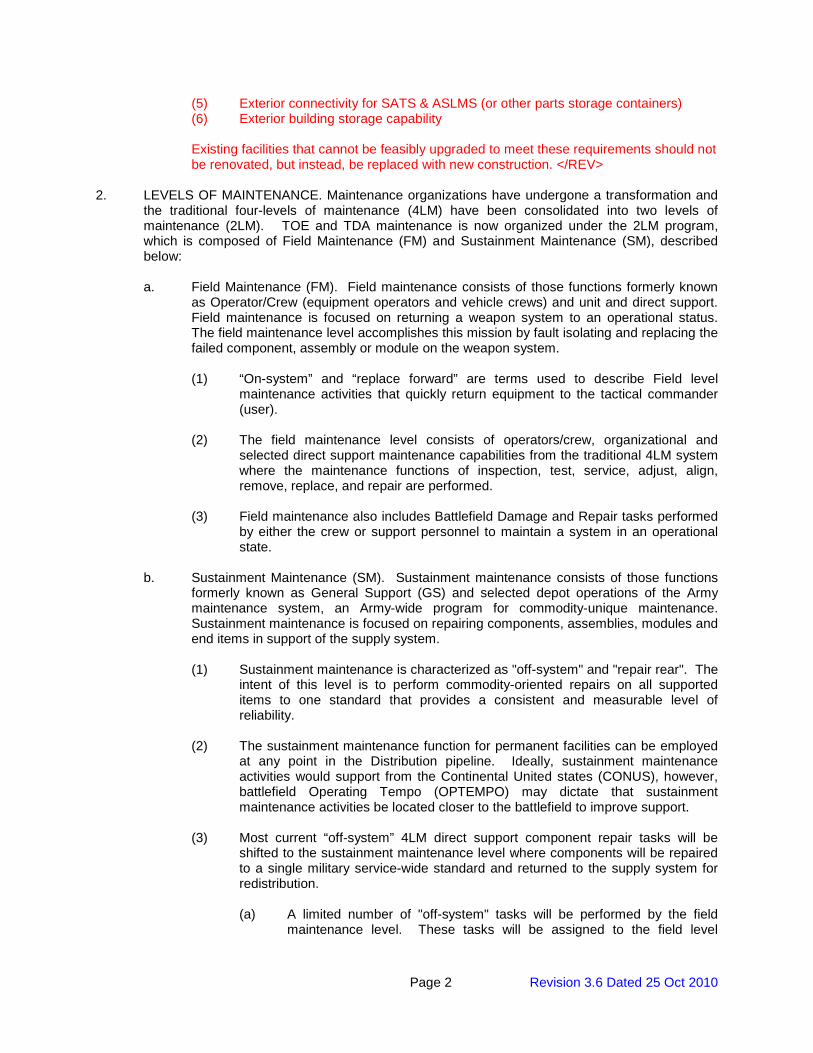
2. LEVELS OF MAINTENANCE. Maintenance organizations have undergone a transformation and
the traditional four-levels of maintenance (4LM) have been consolidated into two levels of maintenance (2LM). TOE and TDA maintenance is now organized under the 2LM program, which is composed of Field Maintenance (FM) and Sustainment Maintenance (SM), described below:
a. Field Maintenance (FM). Field maintenance consists of those functions formerly known
as Operator/Crew (equipment operators and vehicle crews) and unit and direct support. Field maintenance is focused on returning a weapon system to an operational status. The field maintenance level accomplishes this mission by fault isolating and replacing the failed component, assembly or module on the weapon system.
(1) “On-system” and “replace forward” are terms used to describe Field level
maintenance activities that quickly return equipment to the tactical commander (user).
(2) The field maintenance level consists of operators/crew, organizational and
selected direct support maintenance capabilities from the traditional 4LM system where the maintenance functions of inspection, test, service, adjust, align, remove, replace, and repair are performed.
(3) Field maintenance also includes Battlefield Damage and Repair tasks performed
by either the crew or support personnel to maintain a system in an operational state.
b. Sustainment Maintenance (SM). Sustainment maintenance consists of those functions
formerly known as General Support (GS) and selected depot operations of the Army maintenance system, an Army-wide program for commodity-unique maintenance. Sustainment maintenance is focused on repairing components, assemblies, modules and end items in support of the supply system.
(1) Sustainment maintenance is characterized as "off-system" and "repair rear". The
intent of this level is to perform commodity-oriented repairs on all supported items to one standard that provides a consistent and measurable level of reliability.
(2) The sustainment maintenance function for permanent facilities can be employed
at any point in the Distribution pipeline. Ideally, sustainment maintenance activities would support from the Continental United states (CONUS), however, battlefield Operating Tempo (OPTEMPO) may dictate that sustainment maintenance activities be located closer to the battlefield to improve support.
(3) Most current “off-system” 4LM direct support component repair tasks will be
shifted to the sustainment maintenance level where components will be repaired to a single military service-wide standard and returned to the supply system for redistribution.
(a) A limited number of "off-system" tasks will be performed by the field
maintenance level. These tasks will be assigned to the field level
Page 3 Revision 3.6 Dated 25 Oct 2010
because they are easy tasks to complete or they are critical to sustaining equipment readiness.
(b) Current General Support level tasks will transition to the “off-system”
category. Component repair tasks will be performed to a single national maintenance standard replacing the existing overhaul and rebuild categories.
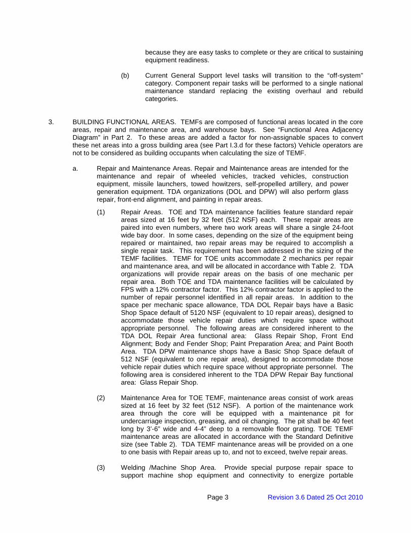
3. BUILDING FUNCTIONAL AREAS. TEMFs are composed of functional areas located in the core
areas, repair and maintenance area, and warehouse bays. See “Functional Area Adjacency Diagram” in Part 2. To these areas are added a factor for non-assignable spaces to convert these net areas into a gross building area (see Part I.3.d for these factors) Vehicle operators are not to be considered as building occupants when calculating the size of TEMF.
a. Repair and Maintenance Areas. Repair and Maintenance areas are intended for the
maintenance and repair of wheeled vehicles, tracked vehicles, construction equipment, missile launchers, towed howitzers, self-propelled artillery, and power generation equipment. TDA organizations (DOL and DPW) will also perform glass repair, front-end alignment, and painting in repair areas.
(1) Repair Areas. TOE and TDA maintenance facilities feature standard repair areas sized at 16 feet by 32 feet (512 NSF) each. These repair areas are paired into even numbers, where two work areas will share a single 24-foot wide bay door. In some cases, depending on the size of the equipment being repaired or maintained, two repair areas may be required to accomplish a single repair task. This requirement has been addressed in the sizing of the TEMF facilities. TEMF for TOE units accommodate 2 mechanics per repair and maintenance area, and will be allocated in accordance with Table 2. TDA organizations will provide repair areas on the basis of one mechanic per repair area. Both TOE and TDA maintenance facilities will be calculated by FPS with a 12% contractor factor. This 12% contractor factor is applied to the number of repair personnel identified in all repair areas. In addition to the space per mechanic space allowance, TDA DOL Repair bays have a Basic Shop Space default of 5120 NSF (equivalent to 10 repair areas), designed to accommodate those vehicle repair duties which require space without appropriate personnel. The following areas are considered inherent to the TDA DOL Repair Area functional area: Glass Repair Shop, Front End Alignment; Body and Fender Shop; Paint Preparation Area; and Paint Booth Area. TDA DPW maintenance shops have a Basic Shop Space default of 512 NSF (equivalent to one repair area), designed to accommodate those vehicle repair duties which require space without appropriate personnel. The following area is considered inherent to the TDA DPW Repair Bay functional area: Glass Repair Shop.
(2) Maintenance Area for TOE TEMF, maintenance areas consist of work areas
sized at 16 feet by 32 feet (512 NSF). A portion of the maintenance work area through the core will be equipped with a maintenance pit for undercarriage inspection, greasing, and oil changing. The pit shall be 40 feet long by 3’-6” wide and 4-4” deep to a removable floor grating. TOE TEMF maintenance areas are allocated in accordance with the Standard Definitive size (see Table 2). TDA TEMF maintenance areas will be provided on a one to one basis with Repair areas up to, and not to exceed, twelve repair areas.
(3) Welding /Machine Shop Area. Provide special purpose repair space to
support machine shop equipment and connectivity to energize portable
Page 4 Revision 3.6 Dated 25 Oct 2010
welding equipment within one pair of repair bays, typically in repair bay farthest from the Core Area. The space allowed is two standard repair areas (1024 NSF). For TOE and TDA TEMF, one welding /machine shop area is allowed per shop.
(4) Circulation Bays. A circulation bay measures 8 feet by 96 feet (768 NSF) and
has a personnel door at each outside wall. Its purpose is for emergency egress from the repair areas. For both TOE and TDA TEMF, one circulation bay is allowed to separate each wing of repair bays from the core.
Page 5 Revision 3.6 Dated 25 Oct 2010
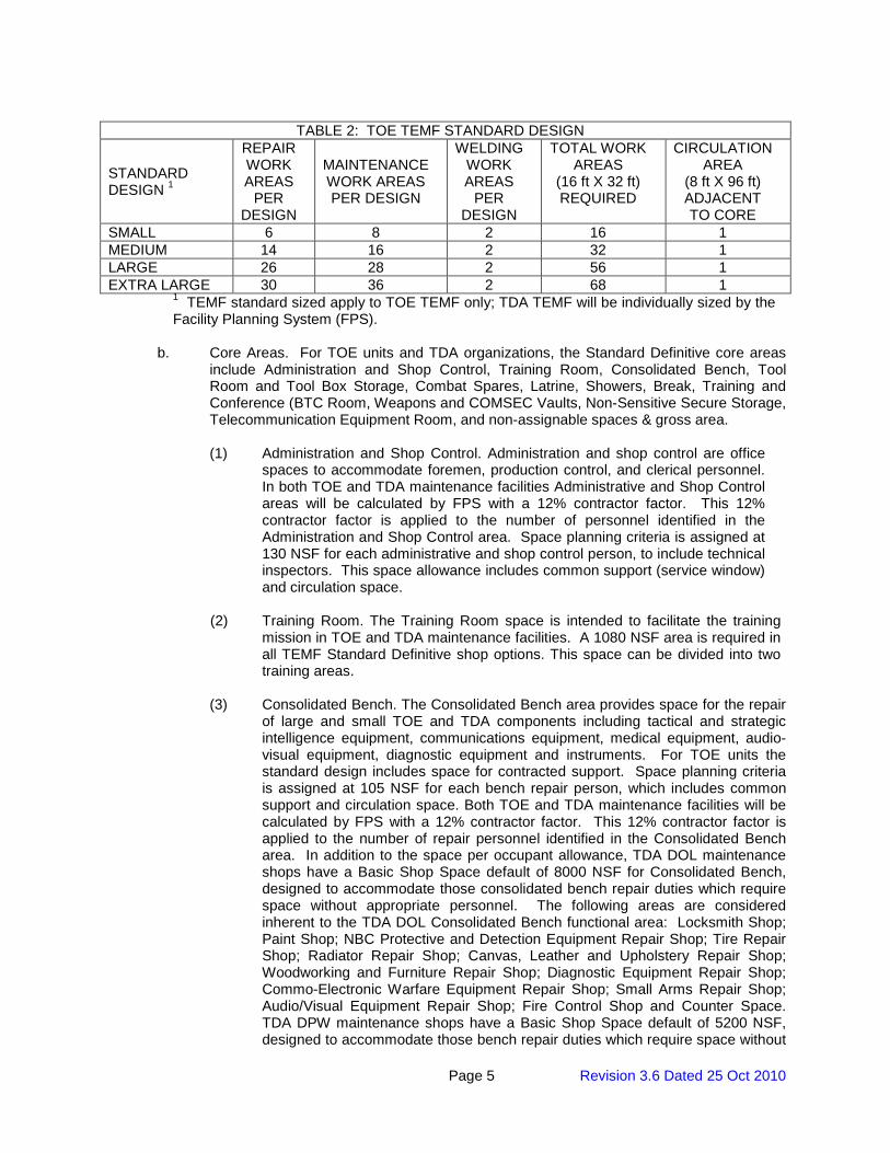
TABLE 2: TOE TEMF STANDARD DESIGN
STANDARD DESIGN 1
REPAIR WORK AREAS
PER DESIGN
MAINTENANCE WORK AREAS PER DESIGN
WELDING WORK AREAS
PER DESIGN
TOTAL WORK AREAS
(16 ft X 32 ft) REQUIRED
CIRCULATION AREA
(8 ft X 96 ft) ADJACENT TO CORE
SMALL 6 8 2 16 1 MEDIUM 14 16 2 32 1 LARGE 26 28 2 56 1 EXTRA LARGE 30 36 2 68 1
1 TEMF standard sized apply to TOE TEMF only; TDA TEMF will be individually sized by the Facility Planning System (FPS).
b. Core Areas. For TOE units and TDA organizations, the Standard Definitive core areas
include Administration and Shop Control, Training Room, Consolidated Bench, Tool Room and Tool Box Storage, Combat Spares, Latrine, Showers, Break, Training and Conference (BTC Room, Weapons and COMSEC Vaults, Non-Sensitive Secure Storage, Telecommunication Equipment Room, and non-assignable spaces & gross area.
(1) Administration and Shop Control. Administration and shop control are office
spaces to accommodate foremen, production control, and clerical personnel. In both TOE and TDA maintenance facilities Administrative and Shop Control areas will be calculated by FPS with a 12% contractor factor. This 12% contractor factor is applied to the number of personnel identified in the Administration and Shop Control area. Space planning criteria is assigned at 130 NSF for each administrative and shop control person, to include technical inspectors. This space allowance includes common support (service window) and circulation space.
(2) Training Room. The Training Room space is intended to facilitate the training
mission in TOE and TDA maintenance facilities. A 1080 NSF area is required in all TEMF Standard Definitive shop options. This space can be divided into two training areas.
(3) Consolidated Bench. The Consolidated Bench area provides space for the repair
of large and small TOE and TDA components including tactical and strategic intelligence equipment, communications equipment, medical equipment, audio-visual equipment, diagnostic equipment and instruments. For TOE units the standard design includes space for contracted support. Space planning criteria is assigned at 105 NSF for each bench repair person, which includes common support and circulation space. Both TOE and TDA maintenance facilities will be calculated by FPS with a 12% contractor factor. This 12% contractor factor is applied to the number of repair personnel identified in the Consolidated Bench area. In addition to the space per occupant allowance, TDA DOL maintenance shops have a Basic Shop Space default of 8000 NSF for Consolidated Bench, designed to accommodate those consolidated bench repair duties which require space without appropriate personnel. The following areas are considered inherent to the TDA DOL Consolidated Bench functional area: Locksmith Shop; Paint Shop; NBC Protective and Detection Equipment Repair Shop; Tire Repair Shop; Radiator Repair Shop; Canvas, Leather and Upholstery Repair Shop; Woodworking and Furniture Repair Shop; Diagnostic Equipment Repair Shop; Commo-Electronic Warfare Equipment Repair Shop; Small Arms Repair Shop; Audio/Visual Equipment Repair Shop; Fire Control Shop and Counter Space. TDA DPW maintenance shops have a Basic Shop Space default of 5200 NSF, designed to accommodate those bench repair duties which require space without
Page 6 Revision 3.6 Dated 25 Oct 2010
appropriate personnel. The following areas are considered inherent to the TDA Repair Area functional area: Locksmith Shop; Paint Shop; Tire Repair Shop; Canvas, Leather and Upholstery Repair Shop; Woodworking and Furniture Repair Shop; Diagnostic Equipment Repair Shop; Audio/Visual Repair Shop and Counter Space. The Consolidated Bench should have both direct interior and exterior access.
(4) Tool Room and Tool Box Storage. For TOE and TDA TEMF, the Tool Room is
for the issue and secure storage of common and supplemental tool kits shared by shop personnel, to include providing access to containerized Standard Automotive Tool Sets (SATS). Tool Room space is provided at the rate of 97 NSF for Unit Common tool sets, and 43 NSF for Supplemental tool sets. Locate the Tool Room adjacent to the docking space for SATS. Tool Box Storage provides space for issue and secure storage of individual tool kits used in the repair areas and shops at the rate of 3 NSF per mechanic. Tool box storage space for persons working outside of the facility (contact maintenance personnel) is provided at the rate of 21 NSF each due to special tools required for contact teams. Locate Tool Box Storage adjacent to the Repair areas.
(5) Combat Spares. For TOE TEMF the Combat Spares functional area
accommodates the former Repairable Exchange and Technical Supply (RX/TS) mission, as well as the Prescribed Load List (PLL), shop stocks and miscellaneous storage mission. This area is to accommodate the docking of Authorized Stockage List - Mobility System (ASL-MS) containers where necessary. Combat Spares space planning criteria is 50 NSF per four repair and maintenance areas. For TDA TEMF this mission is accommodated in the Warehouse Module of the TEMF.
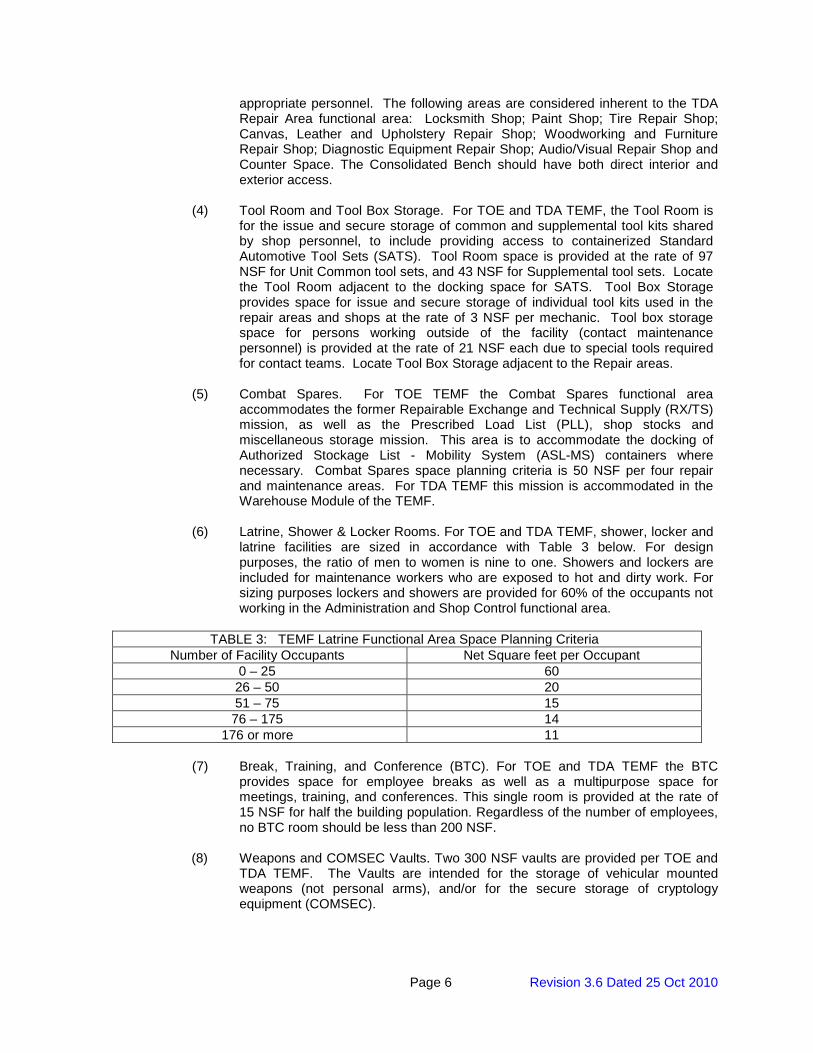
(6) Latrine, Shower & Locker Rooms. For TOE and TDA TEMF, shower, locker and
latrine facilities are sized in accordance with Table 3 below. For design purposes, the ratio of men to women is nine to one. Showers and lockers are included for maintenance workers who are exposed to hot and dirty work. For sizing purposes lockers and showers are provided for 60% of the occupants not working in the Administration and Shop Control functional area.
TABLE 3: TEMF Latrine Functional Area Space Planning Criteria
Number of Facility Occupants Net Square feet per Occupant 0 – 25 60 26 – 50 20 51 – 75 15 76 – 175 14
176 or more 11
(7) Break, Training, and Conference (BTC). For TOE and TDA TEMF the BTC provides space for employee breaks as well as a multipurpose space for meetings, training, and conferences. This single room is provided at the rate of 15 NSF for half the building population. Regardless of the number of employees, no BTC room should be less than 200 NSF.
(8) Weapons and COMSEC Vaults. Two 300 NSF vaults are provided per TOE and
TDA TEMF. The Vaults are intended for the storage of vehicular mounted weapons (not personal arms), and/or for the secure storage of cryptology equipment (COMSEC).
Page 7 Revision 3.6 Dated 25 Oct 2010
(9) Non-Sensitive Secure Storage. For TOE and TDA TEMF, the Non-Sensitive Secure Storage area is a fixed 300 NSF space providing flexible storage space for shop occupants. This space may be used to support contractor requirements.
(10) Telecommunication Equipment Room. The communications room is for the
dedicated operation of the communications infrastructure of the facility in TOE and TDA TEMF facilities. This space is provided in addition to the Non-Assignable Spaces and Gross Area, and is a fixed 300 NSF for Small and Medium TOE TEMF, and a fixed 600 NSF for Large and Extra Large TOE TEMF, and for TDA TEMF. The 600 SF may be divided into two 300 SF rooms.
c. Warehouse Bays. For TOE TEMF shops, the storage of Class IX material is not a
maintenance function for the TOE unit under 2LM; Warehouse space will not be authorized for TOE TEMF. Warehouse space is authorized for TDA maintenance activities, and will be allowed for TDA organizations having a technical supply mission. This module is the sum of three sub areas.
(1) Warehouse. Warehouse space is authorized at the rate of 765 NSF for each
material-handling specialist. If this calculated area falls below 10% of the total of administration and shop control, repair areas, and consolidated bench, then use 30% of the sum of these areas as the warehouse space.
(2) Supply Administration. Supply administration is authorized only if the warehouse
is authorized. Area is provided at the rate of 130 NSF for the sum of supply administration, warehouse stock control, and accounting personnel. This space planning allowance includes space for common support and circulation space. If this area is less than 33% of the warehouse, use the calculated figure. If the area exceeds 33% of the warehouse it is limited to 7% of the total of administration and shop control, repair areas, and consolidated bench.
(3) Direct Exchange and Technical Supply (DX/TS). This area provides space for the
turn-in and issue of repairable Direct Exchange (DX) items, as well as supporting storage requirements for Technical Supply (TS) items. For TDA units this area is fixed at 1185 NSF.
d. Non-Assignable Spaces and Gross Area. Non-assignable area includes stairwells,
elevator, common circulation corridors, janitorial spaces, exterior wall thickness, and area for HVAC, electrical and fluid distribution room. To determine gross allowable area of the facility total the net areas: Repair, Circulation, Welding and maintenance areas, Warehouse bays, Administration and Shop Control, Consolidated Bench, Tool and Tool Box Storage, Combat Spares, Latrine, Break, Training and Conference room, Vaults, Non-Sensitive Secure Storage and Communications Room. For Small and Medium sized TEMF’s use a 1.25 net-to-gross factor for conversion from net to gross area. For Large and Extra-Large sized TOE TEMF and all TDA TEMF use a 1.20 net-to-gross factor for conversion from net to gross area.
4. SITE FUNCTIONAL AREAS.
a. Shop Hardstand. A standard access clearance of 45 feet is required along both sides and both ends of the maintenance building described above. A minimum circulation lane 20 feet in width surrounds this area and is required for vehicular circulation routes. When a warehouse is provided, a 65 foot clearance is required on the side with the loading dock.
b. Vehicle Parking.
Page 8 Revision 3.6 Dated 25 Oct 2010
(1) Organizational. Parking allowance is determined by FPS based on the number and size of organizational vehicles. Parking stalls are back to back with access lane widths of 30 feet for vehicles of 18 feet or less in length. Where parked vehicles are longer than 18 feet, that access aisle should be widened to 45 feet. Circulation aisle widths are to remain 30 feet. Side clearances in spaces are to be 3 feet. End clearances in spaces are to be 2 feet. Unit integrity should be maintained at the company level whenever possible.
(2) POL. POL vehicles are to be parked at least 50 feet from other vehicles or
permanent structures. POL parking spaces are 19 feet wide by 40 feet to 55 feet, depending on the length of the vehicle. Maintain 10 feet spacing between vehicles. Provide one additional space as a fuel dispensing point for minor day to day fueling of organizational vehicles. Provide a 50 foot access apron on the access side of this parking area for maneuvering.
(3) Dead-Line. Provide 1dead-line vehicle parking spaces 12 feet by 30 feet for
each pair of repair areas provided. Size of spaces may be increased if the unit or organization supports larger vehicles.
(4) Parking Pad Data and Power Connections. This is required only for
specialized vehicles as noted in Para. 3.2 (g) Electrical Matrix.
(5) Privately Owned Vehicles (POV). Provide POV parking at the rate of 56% of the total assigned personnel (this is predicated on a parking rate of 50% for military personnel and 100% for civilian employees). Spaces are to be 9 feet by 16 feet, where vehicle overhang occurs, and 9 feet by 18 feet where no overhang occurs. Aisles are to be 24 feet wide. Locate as close to the Core area of the TEMF as possible, but in accordance with antiterrorism setbacks.
c. Site Storage.
(1) Optional POL Storage Building (Category Code 21470). For TOE TEMF, this space can be accommodated within the TEMF facility in conjunction with the Fluid Distribution Room; or on the same basis as for TDA TEMF. For TDA TEMF provide a building for the storage of oil, lubricants, and flammable solvents for daily use at the rate of 60 SF for each 25 vehicles maintained. Provide a minimum of 120 SF. Provide an access apron at the entry of this building 23 feet by 27 feet. Maintain minimum separation from other site structures in accordance with IBC and local codes to avoid the need for sprinkling this facility. Comply with model and local codes for separation distance.
(2) Hazardous Waste Storage Building (Category Code 21470). For TOE and TDA
TEMF, this building is to be provided for the short term storage of waste fuels, spent solvents, cleaning compounds, and similar hazardous waste at the rate of 60 SF for each 25 vehicles maintained. Provide a minimum of 120 SF. Maintain minimum separation from other site structures in accordance with IBC and local codes to avoid the need for sprinkling this facility.
(3) Organizational Storage Building. Organizational Storage (Category Code
<REV>21412, formerly</REV> 44224) is shown on the site plans of the standard design. This area is a separate line item, independent of building and pavement areas. It should be programmed as an integral part of the maintenance facility. For TOE TEMF, FPS calculates the required square footage for this facility based on individual unit personnel structure, vehicle count and Class VII material (minus rolling stock). From this the total cubic feet of unit material (Class II and Class VII) to be stored is calculated and
Page 9 Revision 3.6 Dated 25 Oct 2010
converted into GSF. For TDA TEMF, FPS identifies unique organizational structure and personnel to develop the allowance for this facility. Provide an access apron 27 feet wide along the access side of this building.
(4) Distribution Company Storage Facility. For TOE TEMF, this facility (Category
Code <REV>21412, formerly</REV> 44220) is allowed to Quartermaster Distribution Companies only, with an allowance of 8000 SF. The intended use for this facility is for storage of Basic Load and combat spares only. For TDA TEMF, this facility is not authorized.
(5) Secured Open Storage. For TOE TEMF, Secured Open Storage (Category
Code 45210) is provided in conjunction with the Distribution Company Storage Facility allowed to Quartermaster Distribution Companies only, with an allowance of 445 SY. For TDA TEMF, provide at the rate of 20% of the warehouse allowance (converted to SY).
(6) Unmanned Aerial Vehicle (UAV)<REV> </REV>Storage Facility. The UAV
<REV> </REV>Storage facility (Category Code <REV>21412, formerly</REV> 21115) is allowed for those TOE units with a UAV mission. Provision is made for Class I and Class II UAVs at the TEMF. Other classes of UAVs will be stored at an airfield. Provide a 40 foot by 45 foot (1800 SF) building to accommodate<REV> </REV>storage of assigned UAVs.
d. Not Authorized.
(1) Wash Rack. Vehicle wash facilities should not be provided within the
maintenance facility. Vehicle washing is to be accomplished at the centralized vehicle wash facility. These facilities will be designed in accordance with UFC 4-214-03 (Reference 4). Where central vehicle wash facilities are not available a waiver may be requested through the appropriate Regional Installation Management Agency (IMA). Approved wash facilities must be shown as a separate line item on the programming documents. Minor component and vehicle spot washing may be done in the assigned maintenance area.
(2) Fueling Island. Fueling should be performed at a centralized bulk fueling station.
Fueling islands and underground tanks will not be provided in maintenance facilities. Minor daily fueling for organizational needs may be performed using a designated POL vehicle.
5. REFERENCES (Part I)
1. ER 1110-3-113, Department of the Army Facilities Standardization Program, 27 September 1993
2. DA PAM 415-28, Facilities Guide To Army Real Property Category Codes, 11 April 2006 3. UFC 4-214-03, Design: Central Vehicle Wash Facilities, 16 January 2004
Page 10 Revision 3.6 Dated 25 Oct 2010
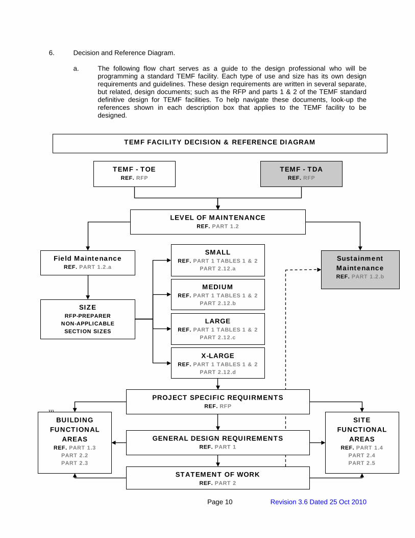
6. Decision and Reference Diagram.
a. The following flow chart serves as a guide to the design professional who will be programming a standard TEMF facility. Each type of use and size has its own design requirements and guidelines. These design requirements are written in several separate, but related, design documents; such as the RFP and parts 1 & 2 of the TEMF standard definitive design for TEMF facilities. To help navigate these documents, look-up the references shown in each description box that applies to the TEMF facility to be designed.
\\\
TEMF - TOE REF. RFP
TEMF - TDA REF. RFP
SIZE RFP-PREPARER
NON-APPLICABLE SECTION SIZES
SMALL REF. PART 1 TABLES 1 & 2
PART 2.12.a
MEDIUM REF. PART 1 TABLES 1 & 2
PART 2.12.b
LARGE REF. PART 1 TABLES 1 & 2
PART 2.12.c
X-LARGE REF. PART 1 TABLES 1 & 2
PART 2.12.d
TEMF FACILITY DECISION & REFERENCE DIAGRAM
Field Maintenance REF. PART 1.2.a
Sustainment Maintenance REF. PART 1.2.b
LEVEL OF MAINTENANCE REF. PART 1.2
GENERAL DESIGN REQUIREMENTS REF. PART 1
STATEMENT OF WORK REF. PART 2
PROJECT SPECIFIC REQUIRMENTS REF. RFP
BUILDING FUNCTIONAL
AREAS REF. PART 1.3
PART 2.2 PART 2.3
SITE FUNCTIONAL
AREAS REF. PART 1.4
PART 2.4 PART 2.5
Page 11 Revision 3.6 Dated 25 Oct 2010
PART II
STATEMENT OF WORK
Page 12 Revision 3.6 Dated 25 Oct 2010
1.0 PROJECT OBJECTIVES
The project objective is to design and construct facilities for the military that are consistent with the design and construction practices used for civilian sector projects that perform similar functions to the military projects. For example, a Company Operations Facility has the similar function as an office/warehouse in the civilian sector; therefore the design and construction practices should be consistent with the design and construction of an office/warehouse building.
Comparison of Military Facilities to Civilian Facilities
Military Facility Civilian Facility
Tactical Equipment Maintenance Facility (TEMF) Heavy Equipment/Vehicle Maintenance Garage
It is the Army’s objective that these buildings will have a 25-year useful life before needing any major renovation, repair, or replacement. Therefore, the design and construction should provide an appropriate level of quality to ensure the continued use of the facility over that time period with the application of reasonable preventive maintenance and repairs that would be industry-acceptable to a major civilian sector project OWNER. The site infrastructure will have at least a 50-year life expectancy with industry-accepted maintenance and repair cycles.
The government is required by Public Law 102-486, Executive Order 12902, and Federal Regulations 10 CFR 435 to design and construct facilities in an energy-conserving manner while considering life cycle cost over the life of the facilities.
The project site should be developed for efficiency and to convey a sense of unity or connectivity with the adjacent buildings and with the Installation as a whole.
Requirements stated in this RFP are minimums. Innovative, creative, and life cycle cost effective solutions, which meet or exceed these requirements are encouraged. Further, the OFFEROR is encouraged to seek solutions that will expedite construction (panelization, pre-engineered, etc.) and shorten the schedule. The intent of the Government is to emphasize the placement of funds into functional/operational requirements. Materials and methods should reflect this by choosing the lowest Type of Construction allowed by code for this occupancy/project allowing the funding to be reflected in the quality of interior/exterior finishes and systems selected.
2.0 SCOPE 2.1 TACTICAL EQUIPMENT MAINTENANCE FACILITY (TEMF)
Provide Tactical Equipment Maintenance Facilities. This project type is to provide facilities for the purpose of maintaining and repairing vehicles, complete with equipment and parts storage and administrative offices. It is intended to be similar to heavy equipment or motor pool facilities in the private sector community. Assume 12 percent of personnel are female unless otherwise indicated. The project will include TEMFs for [_____] battalion(s). Specific sizing parameters for each battalion TEMF included in the project are as follows: [Unit Identification
]
Page 13 Revision 3.6 Dated 25 Oct 2010
TEMF size: [Small] [Medium] [Large] [X-Large] [Non-Standard] A [10-ton] [35-ton] bridge crane is required in this TEMF. Number of organizational vehicles to be accommodated: [_____] Organizational vehicle hardstand: [____] square yards Organizational storage building: [_____] square feet POL storage building: [____] square feet Hazardous waste storage building: [_____] square feet Distribution company storage building, 8000 SF w/445 SY Secure Storage, [is] [is not] required. UAV<REV> </REV>storage building, 1800SF, [is] [is not] required. POL vehicle parking [is] [is not] required. The maximum gross area for the primary Tactical Equipment Maintenance Facilities (excluding site storage buildings) in the project is limited to [_____]SF.
2.2 SITE
Provide all site design and construction within the TEMF limits of construction necessary to support the new building facilities. Supporting facilities include, but are not limited to, utilities, electric service, exterior and security lighting, fire protection and alarm systems, security fencing and gates, water, gas, sewer, oil water separators, storm drainage and site improvements. Provide accessibility for individuals with disabilities. Include Antiterrorism/Force Protection measures in the facility design in accordance with applicable criteria.
Maintain the construction site and haul route. Repair/replace damage to existing sidewalks, pavements, curb and gutter, utilities, and/or landscaping within the construction limit, adjacent to the construction site, and along the Contractor’s haul route resulting from the Contractor’s construction activities at no additional cost to the Government. Prior to construction activities, Contractor and Contracting Officer Representative shall perform an existing condition survey. At completion of the Task Order, Contractor and Contracting Officer representative shall perform a final condition survey to determine repair/replacement requirements.
Approximate area available for [this facility] [these facilities] is shown on the drawings.
2.3 GOVERNMENT-FURNISHED GOVERNMENT-INSTALLED EQUIPMENT (GFGI)
Coordinate with Government on GFGI item requirements and provide suitable structural support, brackets for projectors/VCRs/TVs, all utility connections and space with required clearances for all GFGI items. All computers and related hardware, copiers, faxes, printers, video projectors, VCRs and TVs are GFGI. 2.4 FURNITURE REQUIREMENTS
Page 14 Revision 3.6 Dated 25 Oct 2010
Provide furniture design for all spaces, including existing furniture and equipment to be re-used. Coordinate with the user to define requirements for furniture systems, movable furniture, equipment, existing items to be re-used, storage systems, etc. Early coordination of furniture schedule is required so the facility is complete and usable at turnover. Furniture procurement is not included in this contract or task order.
3.0 FUNCTIONAL AND AREA REQUIREMENTS FOR TACTICAL EQUIPMENT MAINTENANCE FACILITY 3.1 GENERAL
(1) Functional Areas. The primary TEMF is composed of two main types of functional areas: Repair Bays (consisting of Repair areas and Maintenance areas), and the Core Area. Refer to the attached Floor Plans for recommended layout. (2) Gross Building Area. Gross areas of facilities shall be computed according to subparagraphs below. Maximum gross area limits indicated in Paragraph 2.0, SCOPE, may not be exceeded. A smaller overall gross area is permissible if all established net area program requirements are met. (a) Enclosed Spaces. The gross area includes the total area of all floors, including basements, mezzanines, penthouses, usable attic or sloping spaces used to accommodate mechanical equipment or for storage with an average height of 6’-11” measured from the underside of the structural system and with the perimeter walls measuring a minimum of 4’-11” in height, and other enclosed spaces as determined by the effective outside dimensions of the building. (b) One-Half Spaces. One half of the area will be included in the gross area for balconies and porches; exterior covered loading platforms or facilities, either depressed, ground level, or raised; covered but not enclosed passageways or walks; covered and uncovered but open stairs; and covered ramps. (c) Excluded Spaces. Crawl spaces; exterior uncovered loading platforms or facilities, either depressed, ground level, or raised; exterior insulation applied to existing buildings; open courtyards; open paved terraces; roof overhangs and soffits for weather protection; uncovered ramps; uncovered stoops; and utility tunnels and raceways will be excluded from the gross area. (3) Net Area. Net area requirements for functional spaces are included in the drawings. If net area requirements are not indicated, the space shall be sized to accommodate the required function, comply with code requirements, comply with overall gross area limitations and other requirements of the RFP (for example, area requirements for corridors, stairs, and mechanical rooms will typically be left to the discretion of the Offeror). (4) Deviations and Improvements. It is the intent of this document to allow deviations and improvements to the design shown. (5) Handicapped Access. All TEMF buildings are to be handicapped accessible. (6) Site Design and Functional Areas. Site features include vehicular hardstand, utilities and site improvements.
(7) Adapt-Build Model. An Adapt-Build Model for a TEMF, which contains a fully developed design, including a Building Information Model (BIM), 2-D CADD files, and specifications, can be downloaded from the following FTP site: ftp://ftp.usace.army.mil/pub/sas/TEMF/. This design is provided as a guide that exemplifies a technically suitable product and incorporates
Page 15 Revision 3.6 Dated 25 Oct 2010
mandatory functional/operational requirements for a similar (although perhaps not an exact) facility to be constructed under this solicitation. It will be left to the offerors' discretion if, and how, they will use the sample design provided to satisfy the requirements of this Request for Proposal. This model is not intended to modify or over-ride specific requirements of this RFP and, under all circumstances, it will be incumbent upon the successful offeror to adhere to the site specific scope and functional/operational requirements specified within the RFP. Neither this statement of work, nor the adapt-build model, are intended to diminish the offeror’s responsibilities under the clauses titled “Responsibility of the Contractor for Design,” “Warranty of Design,” and “Construction Role During Design.” The successful offeror shall be the designer-of-record and shall be responsible for the final design and construction product, including but not limited to, adherence to the installation architectural theme, building code compliance and suitability of the engineering systems provided. The government assumes no liability for the model design provided and, to the extent it is used by an offeror, the offeror will be responsible for all aspects of the design as designer-of-record.
3.1.1 Repair Areas and Vehicle Corridor/Maintenance Areas
Repair areas and maintenance areas are garage areas used for service and repair of the full range of Army tactical equipment. They are single story ground floor spaces. A typical structural bay to accommodate both repair and maintenance areas is sized to measure 32’ x 96’. Conceptually, this structural bay contains four 16’ x 32’ repair work areas, and a 32’ wide vehicle corridor dividing them crosswise. The vehicle corridor also serves as a maintenance area. It accommodates 16’ x 32’ maintenance work areas down the length of the entire building. Two contiguous work areas may be required to accommodate work on larger equipment, thus resulting in the need for work areas to be constructed in pairs. Repair and maintenance areas are to be free of intermediate support columns, i.e. columns are only permissible along exterior perimeter walls. This allows complete shop floor coverage by a single bridge crane for all contiguous maintenance and repair areas (each wing of the facility). TEMFs requiring four structural bays or less shall be constructed contiguously in a single wing of the facility.
(1) Repair Areas
(a) Function. Repair of vehicles as described above. Structural height shall be as required to allow minimum bridge crane hook cradle height of 20 feet (minimum of 25 feet for bays with 35-ton bridge cranes). Overhead coiling doors, 24’-0” wide x 14’-0” high, shall be provided at each end of each structural bay.
(b) Equipment. Repair Bays shall be served by a 10-ton or a 35-ton capacity traveling bridge crane with full structural bay coverage as indicated in the Architectural TEMF Features Matrix and as specified in Para. 2.1. Additional requirements are specified in the paragraph ARCHITECTURE.
(c) Provide one hose bibb and two compressed air outlets 3’-0” above the floor for each pair of repair areas.
(d) Welding/Machine Shop Area: Provide special purpose repair space to support machine shop equipment and power connectivity for portable welding equipment within one pair of repair areas, typically in repair bay farthest from the Core Area. This area will not be used exclusively for welding. It may be utilized as a repair area also and shall be equipped with all requirements for repair areas except items (e), and (j).
(e) Provide utilities for component washing and vehicle spot washing in the outermost work area of each wing of repair/maintenance areas. Provide a 5’-4” high concrete masonry wall separating the outermost bay from others to contain spray resulting from
Page 16 Revision 3.6 Dated 25 Oct 2010
engine and component wash functions. Terminate partition to provide 6’-0” clear space at each end of the partition.
(f) In each pair of repair areas, provide electric power for user provided (GFGI) portable hydraulic lift.
(g) Provide continuous 6-inch wide trench drains with continuous grating along full width of bays at exterior doors; locate drains approximately 3’-0” inside face of exterior walls. In addition to the outside trench drains, a center trench drain running the full width of the bays is permissible to facilitate internal drainage of the facility. When a dedicated, partitioned welding area is provided, provide a solid cover to trench drain where it runs through the welding area.
(h) Each work area shall have access to NIPRNet data connection points.
(i) Provide an outlet to a vehicle exhaust evacuation system for each repair area.
(j) Tire Changing Area: Provide capability for tire changing function where shown on the
TEMF Standard Drawings. Tire changing equipment shall be GFGI. (k) <REV> POL Dispensing Points: Provide POL dispensing points between each pair of
structural bays so that each repair area has ready access to POL fluids. Two points will be provided in the repair area of a small facility, four in a medium, etc. Hose and reel assembly shall be heavy duty, designed for the applicable fluid or oil. Provide shutoff valve at reel. Provide distribution for grease, engine oil, gear oil, transmission fluid, and antifreeze from each dispensing point. </REV>
(2) Vehicle Corridor/Maintenance Areas
(a) Function. Maintenance of vehicles as described above. Maintenance areas within core area shall be equipped for inspection, oil changing and lubrication. All requirements listed above, except items (d), (e), (f), <REV> (j), and (k)</REV> apply to the maintenance areas.
(b) Maintenance Area within the High Bay Portion of Facility. Access to compressed air, water, vehicle exhaust, power and data in the maintenance areas within high bay portion of facility shall be via connections along the nearest wall.
(c) Maintenance Area within the Core Area. Maintenance areas within the core area shall be equipped for inspection, oil changing and lubrication. The minimum clear ceiling height shall be 14’-0” Above Finished Floor. Provide an outlet to a vehicle exhaust evacuation system for each pair of maintenance areas. Bridge crane access is not required for maintenance areas along central vehicle corridor in the core area.
1. Maintenance Pit. Provide one 40-foot long x 3’-6” wide concrete maintenance pit in the central vehicle corridor portion maintenance area within the core with stair access. Due to inside clearance for some vehicles, the maximum 3’-6” width is critical for the pit and curbing. Pit shall have non-sparking, non-slip removable floor grating approximately 4’-4” below finish floor elevation, with concrete pit floor below sloping to sump. Provide sump pump, see Paragraph 3.1.8(4) Plumbing for additional information. Provide compressed air outlet at two places in the pit. When not in use, pit shall be provided with removable cover capable of supporting pedestrian traffic. Provide minimum 4-inch high
Page 17 Revision 3.6 Dated 25 Oct 2010
steel angle curb surrounding pit opening. Pit cover panels to be light enough to be handled by a maximum of two personnel.
2. POL Hose Reels. Provide two POL dispensing points mounted to the wall <REV>adjacent to maintenance area pit. </REV> Hose and reel assembly shall be heavy duty, designed for the applicable fluid or oil. Provide shutoff valve at reel. Provide distribution for grease, engine oil, gear oil, transmission fluid, and antifreeze <REV> at the two dispensing points on the wall. Provide a third dispensing point mounted in a recess in the maintenance pit. Provide only grease, gear oil and transmission fluid at the dispensing point inside the maintenance pit. </REV>
3. <REV> Fluid Recovery System: Provide a Pneumatic Fluid Recovery System that will allow the evacuation of used POL fluids and waste antifreeze to the appropriate 500 gallon wasted fluid tank. Provide two collection points for each type of waste fluid within the maintenance pit, and provide a third collection point at a central location within the facility (out of the flow of traffic) to accommodate used fluids collected in the repair area. </REV>
(3) Circulation Bays
(a) Provide an 8’ wide x 96’ long structural bay between each wing of repair bays and the core area to facilitate pedestrian egress from the building and shall conform to OSHA requirements.
(b) Equipment. Provide 4’-0” high x 8’-0” wide framed tack board (for ‘safety board’) mounted on wall along the circulation bay near the tool room. Provide one permanently installed emergency eyewash, hand held drench hose and shower station at each circulation bay that is adjacent to a core area and provide additional emergency eye wash, hand held drench hose and shower stations in other bays as required per OSHA standard 1910.151(c) and ANSI Z358.1. Provide one or more emergency eyewash, hand held drench hose and shower stations in Consolidated Bench Repair and in the Fluid Distribution Room when the equipment being serviced or solvents being used generate this requirement. Locate emergency wash stations in accordance with OSHA standard 1910.151(c) and ANSI Z358.1. Per OSHA 1910.151(c) emergency eyewash/shower units should be located such that a worker can reach one in 10 seconds. ANSI Z358.1 gives a guideline of 55 feet to meet this requirement.
3.1.2 Core Areas
Core areas are arranged in one and two story configurations (refer to the attached floor plans for standard layouts). Internal walls within the core should be non-load bearing to the extent possible to allow future rearrangement of spaces. (1) Administration and Shop Control. Office space to accommodate foremen, production control, and clerical personnel. Provide one space per core; may be located on first or second floor but shall be accessible to the physically disabled. Provide counter and pass-through window between this room and the customer Waiting Area; size pass-through window to accommodate transfer of 30-inch by 30-inch items, and layout the area outside window so that two people can stand at the window and be out of the corridor traffic pattern. Provide viewing windows from administration and shop control space into the repair areas. (2) Training Room. The training room space is intended to facilitate the training mission for maintenance personnel. This space is to be divided into two training areas with an operable folding partition (movable wall) having a sound isolation of STC 45, minimum. Provision shall be made to accommodate up to 30 students for computer based training, including power and data connections for each student. <REV> Provide projection equipment hookups and a
Page 18 Revision 3.6 Dated 25 Oct 2010
screen in the Training Room. In subdivided Training Rooms, two hookups and two pull-down screens are to be provided. </REV>
(3) Consolidated Bench. Shop space for unit-level maintenance of electronics, optics, and other gear. Locate on first floor.
(a) Equipment. Provide an overhead coiling door 10’-0” wide x 10’-0” high.
(b) Furnishings/Fixtures. See Table 7 for furnishings. Provide capabilities shown in the features matrix for each work space.
(c) Provide operable exterior windows. Provide at least one window with clear view and unobstructed line of sight out of the building to a minimum of 800 feet for testing weapon sights.
(4) Tool Room. Designated space for the issue and secure storage of unit common tool kits, as well as supplemental tool kits and individual tools shared by shop personnel. Direct covered access from the tool room to the SATS containers (described below) on the exterior of the building is required. Provide lockable pair of personnel doors and pass-through opening with impact resistant counter and metal overhead lockable coiling shutter between Tool Room and Corridor.
(a) Standard Automotive Tool Set (SATS). The SATS is a unit-owned (i.e. GF/GI) containerized tool system with the dimensions of 8’ x 20’ x 8’ high. An exterior hardstand storage area adjacent to the Tool Room shall be provided for three SATS containers. Connectivity to building and installation network is required. SATS are accessed from the end. Provide wall mounted awning with minimum 14-foot clear height above hardstand for weather protected entry into SATS containers. The technical manual for SATS is TM 9-4910-783-13&P.
(5) Tool Box Storage. Provide one Tool Box Storage Room for each wing of Repair Areas (if Repair Areas are located on both sides of a core, each side of core shall have a Tool Box Storage Room). Tool Box Storage is provided for personnel working inside the maintenance complex in the Repair Areas and the Consolidated Bench for the storage of individually assigned or personal (Contractor) tools requiring security. Provide lockable personnel door with closer between Tool Box Storage and Circulation Bay. (6) Combat Spares. Storage and issue of Prescribed Load List (PLL) and shop stock items kept in stock at all times because of demand or management decisions. Direct covered access from the Combat Spares room to the ASL-MS containers (described below) on the exterior of the building is required. Provide lockable pair of personnel doors so to accommodate 48” x 48” x 74” ASL-MS repair parts bins and shelving modules, and pass-through opening with impact resistant counter and overhead lockable coiling shutter between Combat Spares and Corridor.
(a) Authorized Stockage List - Mobility System (ASL-MS). Similar to the SATS, the ASL-MS is a unit-owned (i.e. GF/GI) 8’ x 20’ x 8’ high container for repair parts. An exterior hardstand storage area adjacent to the Combat Spares room shall be provided for three ASL-MS containers. ASL-MS are accessed from the side. Provide sufficient aisles between ASL-MS for access. Provide wall mounted awning with minimum 14-foot clear height above hardstand for weather protected entry into ASL-MS containers. Provide lockable pair of personnel doors at building exterior to accommodate large bulk portable tools and equipment, and ASLMS repair parts modules. The technical manual for ASL-MS is TM 9-5411-236-13&P.
Page 19 Revision 3.6 Dated 25 Oct 2010
(7) Latrine, Shower and Locker Rooms
(a) Latrines. Provide separate latrines for men and women on each floor. Provide water closets, urinals, lavatories and drinking fountains in accordance with established layouts and referenced codes.
(b) Shower and Locker Rooms. Provide a Men’s Shower and Locker Room and Women’s Shower and Locker Room. Locate on first floor of each core, sized to accommodate the number of lockers and showers indicated. Shower and locker area shall be adjacent to and connect to the latrine area. Provide individual shower compartments (3’-0” x 3’-0”) in the number indicated on the drawings. Provide a single tier steel locker for each non-administrational occupant of the building, minimum size 1’-0” wide x 1’-6” deep x 6’-0” high.
(8) Break, Training, and Conference (BTC). Locate this room on same floor as Admin and Shop Control.
(a) Furnishings. Provide kitchen, base and wall cabinets and 30-inch deep countertop minimum 10’-0” long.
(b) Equipment. Provide stainless steel two-compartment sink.
(c) Allow space and hookups for vending machines, refrigerator and microwave.
(d) Projection equipment hookups <REV>and a pull-down screen are</REV> to be provided in Medium, Large and X-Large BTC Room only. Due to small size of BTC Room in the Small TEMF, no projection equipment hookup <REV>or screen</REV> will be provided in this area.
(9) Vaults. All vault walls, floors and ceilings shall be constructed in compliance with appropriate requirements referenced below. Provision for a user provided (GFGI) intrusion detection system including motion detectors, door alarm, and camera, is required.
(a) Weapons Storage Vault. Provide secure storage of weapons being repaired, especially vehicle-mounted weapons such as machine guns and firing port weapons. Weapons vault walls, floors and ceilings shall be constructed in compliance with AR 190-11, Physical Security of Arms, Ammunition, and Explosives. An option exists for use of prefabricated, modular vaults conforming to Fed. Spec. AA-V-2737 requirements. Provide a GSA-approved Class 5 Armory vault door with lock in accordance with Fed. Spec. AA-D-600D and a ”Dutch door” style day gate. Provide an internal wire mesh partitioned space or provide space for GFGI lockable cabinets IAW installation requirements to accommodate armorer’s tool kits, spare arms parts, machine gun barrels and major subassemblies. Coordinate arms rack anchor rings, common storage racks, etc with user.
(b) COMSEC Vault. Provide secure storage of communications/cryptology equipment. Room must have a minimum 8-foot dimension. Refer to Physical Security Standards of Appendix D of AR 380-40, Policy for Safeguarding and Controlling Communications Security (COMSEC) Material (FOUO).
(10) Nonsensitive Secure Storage. Nonsensitive Secure Storage shall be constructed to meet Secure Storage standards for Risk Level II per AR 190-51, Security of Unclassified Army Property.
Page 20 Revision 3.6 Dated 25 Oct 2010
(11) Telecommunications Room. Telecommunications rooms shall be provided for voice and data. There shall be a minimum of one room on each floor, located as near the center of the building as practicable, and stacked between floors. The telecommunications rooms shall be designed in accordance with the Technical Criteria for Installation Information Infrastructure Architecture I3A Criteria and ANSI/EIA/TIA-569-B. A SIPRNET Room shall also be provided for future SIPRNet connectivity in accordance with the Technical Guide for the Integration of Secret Internet Protocol Router Network (SIPRNet). <REV> Due to NEC security requirements, Mass Notification, Fire Alarm and CATV panels cannot be located in the Telecommunications Room, these panels will be located in the Electrical room. Where required, the Fire Alarm Panel may be located in the Mechanical Room. </REV>
(12) Non-Assignable Spaces and Gross Area. The items below account for additional gross area within the core that is not specifically listed in the spaces above. These items may also vary in size contingent on site, climate, type and use.
(a) Stairwells. Design in accordance with model and local building codes.
(b) Elevator. Provide one passenger elevator in each two-story building. Elevator machine room is also part of the gross area of the core.
(c) Common Circulation Corridors. All circulation corridors shall be a minimum of 6 feet wide.
(d) Waiting Area. Locate adjacent to Admin and Shop Control pass-through window off of corridor. Size Waiting Area for the seating of a minimum of four persons.
(e) Janitorial Spaces. Provide one janitorial space as shown on drawings with mop sink and heavy duty shelving. Expansion of the Janitorial Space to include a recycling function is optional.
(f) Mechanical Rooms. Utility space must be provided for heating and cooling equipment. Where feasible, vertically stack like utility spaces if located on two floors. Locate first floor mechanical rooms adjacent to exterior walls for external maintenance access and ventilation. See paragraph 3.1.7 Heating, Ventilation, and Air Conditioning (HVAC) Systems, for additional requirement. Walls and floor/ceiling assemblies enclosing mechanical room shall have a sound transmission class (STC) rating of not less than 50 (45 if field tested) for air-borne noise when tested in accordance with ASTM E 90, and an impact insulation class (IIC) rating of 50 (45 if field tested) when tested in accordance with ASTM E 492.
(g) Electrical Rooms. Locate first floor electrical rooms adjacent to exterior walls for external maintenance access and ventilation.
(h) Fluid Distribution Room. Provide a room to house the POL central distribution equipment and unused POL storage containers (typically 55-gallon drums) for five types of lubricants/fluids. Fluids shall be dispensed by automotive lubricant type air driven pump assemblies. Motor shall be heavy-duty compressed air driven reciprocating action. For antifreeze unit all parts shall be corrosion resistant. Locate near maintenance pit to minimize length of fluid distribution lines. Compliance with UFC 3-600-01, NFPA 30, and 29 CFR 1910.106 is mandatory. Provide secondary containment in compliance with applicable federal and state environmental regulations. Square footage for this space is part of the gross area for the core.
Page 21 Revision 3.6 Dated 25 Oct 2010
3.1.3 Site Functional Areas
(1) Dock. Provide one docking location for maintenance and electronic testing of specialized, permanently vehicle mounted, communications equipment. Provide equipment power connections and grounding points for vehicle degauss and individual personnel static discharge protection of equipment.
(2) Organizational Vehicle Hardstand. This area consists of a rigid concrete paved area used for parking assigned vehicles (wheeled and heavy and tracked), commercial vehicles (Contractor support), trailers and generators. Organizational vehicle hardstand includes building aprons, parking spaces, and circulation lanes on site.
(a) Tactical/Military and Commercial Vehicle Parking. Maximize vehicle parking and traffic flow to best support the operation of the TEMF. (b) POL Vehicle Parking Area. [Not required.] [Parking for POL vehicles is considered separate from other organizational vehicle parking and shall be segregated from other vehicle parking areas.] (c) Dead Line Vehicle Parking. Parking for vehicles waiting for parts or for work to be performed. One dead line parking space for every pair of repair areas and shall be located in parking areas adjacent to repair bays that will service them. (d) Building Aprons. Provide concrete pavement for aprons associated with each of the facilities located in the maintenance complex.
(3) Site Storage
(a) Hazardous Waste Storage Building. Provide a building with solid walls and roof. It
is used to temporarily store used lubricants, flammable solvents, dry sweep, etc. A unit is authorized 60 square feet for each 25 vehicles, or part thereof, which it maintains. A minimum of 120 square feet of hazardous waste storage space will be provided. The specific requirement for this project is specified in Para. 2.1. Provide secondary containment in compliance with applicable federal and state environmental regulations. Compliance with UFC 3-600-01, NFPA 30, and 29 CFR 1910.106 is mandatory. Maintain minimum separation distance from other buildings in accordance with the IBC in order to eliminate the need for automatic sprinkler protection. Pre-fabricated, fire-rated, self-contained, moveable steel safety storage buildings are permitted as an option. Minimum size of 120 SF per container, though multiple containers may add up to the total quantity required per satellite accumulation area. <REV> Hazardous Waste Storage Buildings do not require sprinkler protection if the following conditions are met:
1. The buildings shall not exceed 1000 SF in area. For facilities over 1000 SF, in order to reduce costs, divide the total requirement for these facilities into multiple buildings so that each building is less than 1000 SF.
2. The buildings shall be separated from tactical equipment maintenance facilities or other important buildings by a minimum of 60 feet.
3. Construction and exterior separation of Hazardous Waste Storage Buildings shall be per UFC 3-600-01 and NFPA 30 as indicated with the following restrictions. Where multiple POL and Hazardous Waste Storage buildings are present, groups of POL and Hazardous Waste Storage Buildings shall not exceed two buildings and shall be separated by no less than 10 feet. Additional POL and Hazardous Waste Storage Buildings or groups of two buildings shall be separated by not less than 50 feet from adjacent POL and Hazardous Waste Storage Buildings. </REV>
Page 22 Revision 3.6 Dated 25 Oct 2010
(b) (b) POL Storage Building. Provide a building for the storage of oil, lubricants, and flammable solvents for daily use. A unit is authorized 60 square feet for each 25 vehicles, or part thereof, which it maintains. A minimum of 120 square feet of oil storage space will be provided. The specific requirement for this project is specified in Para. 2.1. Provide an access apron at the entry of this building. Provide secondary containment in compliance with applicable federal and state environmental regulations. Compliance with UFC 3-600-01, NFPA 30, and 29 CFR 1910.106 is mandatory. Maintain minimum separation distance from other buildings in accordance with the IBC and local codes in order to eliminate the need for automatic sprinkler protection. Pre-fabricated, fire-rated, self-contained, moveable steel safety storage buildings are permitted as an option. Minimum size of 120 SF per container, though multiple containers may add up to the total quantity required per satellite accumulation area. <REV> POL Storage Buildings do not require sprinkler protection if the following conditions are met:
1. The buildings shall not exceed 1000 SF in area. For facilities over 1000 SF, in order to reduce costs, divide the total requirement for these facilities into multiple buildings so that each building is less than 1000 SF.
2. The buildings shall be separated from tactical equipment maintenance facilities or other important buildings by a minimum of 60 feet.
3. Construction and exterior separation of Hazardous Waste Storage Buildings shall be per UFC 3-600-01 and NFPA 30 as indicated with the following restrictions. Where multiple POL and Hazardous Waste Storage buildings are present, groups of POL and Hazardous Waste Storage Buildings shall not exceed two buildings and shall be separated by no less than 10 feet. Additional POL and Hazardous Waste Storage Buildings or groups of two buildings shall be separated by not less than 50 feet from adjacent POL and Hazardous Waste Storage Buildings. </REV>
(c) Organizational Storage Building. This building is for storage of deployment equipment. The size of this facility is determined by the organizational structure and the number of organizational vehicles; specific to each project. Provide a 10’ x 10’ coiling door and a personnel door for each 700 SF of company supply area along one side of building. Provide internal wire or secure partitions between each 700 SF space. Floor area of building shall be as specified in the project scope of work. Building shall be approximately 25 feet deep. The floor system of this facility should be designed for fork-lift lifting.
(d) Distribution Company Storage Facility. [Not required] [Provide 8000 SF building for storage of Distribution Company materials and equipment.] (e) Secure Open Storage. [Not required] [Where a Distribution Company Storage Facility is provided, provide a 445 SY fenced area on concrete paving for exterior storage.] (f) UAV<REV> </REV>Storage Building. [Not required] [This building is for<REV> </REV>storage of Unmanned Aerial Vehicles (UAV). Provide a 40-foot by 45-foot (1800 SF) building to accommodate<REV> </REV>storage of assigned UAVs.] Provide a 24’ x 14’ coiling door as well as minimum two personnel doors for emergency egress and ingress. (g) Used Oil Storage Tank(s). Provide one 500-gallon above-ground used engine oil storage tank at the end of the Repair Areas. Tank shall be constructed of non-corrosive material. Provide secondary containment in compliance with applicable federal and state environmental regulations. Tank construction and location shall comply with IBC requirements. Recommended location is adjacent to the end repair area. Used oil, waste fuel, and used engine coolant storage tanks should be co-located, if possible.
Page 23 Revision 3.6 Dated 25 Oct 2010
(h) Used Engine Coolant (antifreeze) Storage Tank(s). Provide one 500-gallon above-ground used engine coolant storage tank at the end of the Repair Areas. Tank shall be constructed of non-corrosive material. Provide secondary containment in compliance with applicable federal and state environmental regulations. Tank construction and location shall comply with IBC requirements. Recommended location is adjacent to the end repair areas. Used oil, waste fuel, and used engine coolant storage tanks should be co-located, if possible.
(i) Out of Spec Waste Fuel Tank(s). Provide one 500-gallon above-ground Out-of-Spec
Waste Fuel Tank at the end of Repair Areas. Tank shall be constructed of non-corrosive material. Provide secondary containment in compliance with applicable federal and state environmental regulations. Tank construction and location shall comply with IBC requirements. Recommended location is adjacent to the end repair area. Used oil, waste fuel, and used engine coolant storage tanks should be co-located, if possible.
(4) Entrance Drives. Provide primary and secondary entrance drives to connect organizational vehicle hardstand to existing roads and/or tank trails. (5) Privately Owned Vehicle (POV) Parking. [POV parking to be provided by others.] [POV
parking shall be provided at a ratio of one space for 56% of the total assigned personnel.]
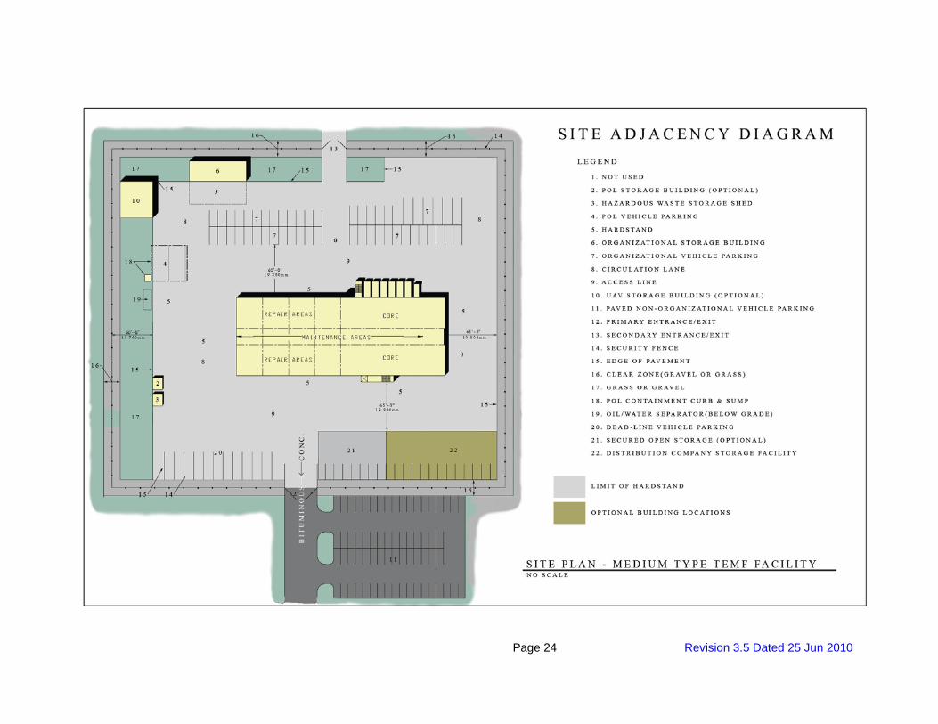
3.1.4 Site Design The following drawing should be used to associate relative adjacencies to site structures.
Page 24 Revision 3.5 Dated 25 Jun 2010
Page 25 Revision 3.5 Dated 25 Jun 2010
(1) Hardstand. All hardstand areas shall be rigid concrete pavement. Pavement design for organizational vehicle areas shall be designed to support the vehicles assigned to this facility and the heaviest vehicle at the installation. See appendix for Organizational Vehicle assigned to this facility. The parking layout and configuration shall be adjusted as necessary to for the site limits and space provided.
(2) Antiterrorism and Force Protection. Each project should be evaluated for security requirements in accordance with UFC 4-010-01. Minimum requirement is a security fence at the site perimeter consisting of 7-foot high chain link fabric plus a single outrigger with 3-strand barbed wire, designed in accordance with STD 872-90-03, FE-6, Chain-Link Security Fence Details. A zone cleared of trees and shrubs, 20 feet wide inside the fence and 10 feet wide outside the fence is required. The clear zone shall be gravel underlain by a synthetic fabric. The clear zone shall be treated with herbicides to discourage vegetative growth. Manually operated vehicular gates, approximately 30 feet wide overall, shall be provided at each vehicle entrance/exit.
(3) Storm Water Management. [Site storm water management may require controls on the peak flow that can be discharged. Installations are required to have a storm water pollution prevention plan. Implement the applicable portions of this plan using best management practices. Segregate drainage from areas likely to be contaminated (e.g., fueling area). Provide treatment for contaminated water prior to its discharge. Maintenance should not be performed outside the primary facility.] [Storm water management shall be constructed by others.]
(4) Storm Drainage System. Construction and material specified for storm drainage installation shall be per the State’s DOT requirements. All storm drainage lines constructed under organizational vehicle hardstand, entrance drives, and other surfaces subject to vehicular traffic shall be reinforced concrete pipe with watertight joints. See paragraph 6 for additional storm drainage system requirements. (5) Oil/Water Separator. One or more oil/water separators are required to remove, oil, lubricants, floatables, and grit from contaminated water sources (e.g., repair and maintenance areas, POL fluids distribution, etc.). Oil/water separators shall be designed in accordance with local codes and standard industry practice for the specific waste stream to be treated. Minimize maintenance requirements and locate oil/water separators to minimize pipe runs, provide vehicular access, and built out of circulation areas. (6) Used and Waste Oil, Antifreeze, Solvents, Cleaning Compounds, and Hazardous Materials. Hazardous materials generated in the course of maintenance operations shall be classified in accordance with 40 CFR 261. Criteria for short term storage (less than 90 days) of hazardous materials is provided in 40 CFR 262. Long-term storage is not authorized for TEMF facilities. The installation Defense Resources Management Office has responsibility for long term storage. Long term storage of hazardous materials is governed by 40 CFR 264. (7) Primary and Secondary drives. Provide a primary and secondary entrance drive into the organizational vehicle hardstand area. The primary and secondary entrance drives shall be 30 feet wide. (8) Organizational Vehicle hardstand. Organizational vehicle pavement grades shall provide positive surface drainage with a 1 percent minimum slope in the direction of drainage. Maximum pavement slope shall be 2 percent. (9) Circulation Lane. Organizational vehicle parking circulation lanes shall be 20 feet wide when lanes are located adjacent to TEMF aprons. Parking stalls within the hardstand are to be placed back-to-back with circulation lane widths of 30 feet for vehicles less than or equal to 18 feet long and 45 feet for vehicles more than 18 feet long.
Page 26 Revision 3.6 Dated 25 Oct 2010
(10) Tactical/Military Vehicle Parking. Tactical/Military Vehicle Parking spaces shall be spaced with side clearances of 3 feet and end clearances of 2 feet. (11) POL Vehicle Parking (if applicable). POL vehicle parking shall be physically separated from organizational hardstand. POL parking shall be spaced a minimum of 10 feet between vehicles. POL parking area circulation lanes shall be 50 feet wide. Drainage from the POL parking area shall be isolated and shall not be allowed to enter underground storm or sanitary sewer systems without being impounded first and manually released. POL drainage impoundment shall be located 100 feet from any structure. (12) Dead Line Vehicle Parking. Dead Line Vehicle Parking spaces shall be sized based on the largest vehicle for the assigned maintenance bay. Parking spaces shall be spaced with side clearances of 3 feet and end clearances of 2 feet. (13) TEMF Aprons. TEMF aprons shall measure 45 feet wide on all four sides of the facility. Circulation lanes are not part of the 45-foot wide apron. (14) Site Storage Building Aprons. Site storage building aprons shall measure 27 feet wide along the entire building length on the vehicular access side. Circulation lanes are not part of the 27-foot wide apron. (15) Bollards at TEMF repair bays. Provide 12-inch diameter steel bollards filled with concrete at all TEMF repair bay openings where frequent vehicle access/egress increases the risk of damage by vehicle impact. Bollard footings shall be designed to withstand organizational vehicular impact. (16) Mechanical and Electrical Equipment Yard. Provide 12-inch diameter by 5-foot high, concrete-filled, schedule 80 galvanized steel pipe bollards, 5 feet O.C. spacing, 5 feet from edge of the mechanical and Electrical Equipment Yard, painted safety yellow, around the perimeter of the equipment yards. Provide vehicular access and locate out of circulation areas. Bollard footings shall be designed to withstand organizational vehicular impact. (17) Bollards at Out of Spec Waste Fuel, Used Oil and Used Engine Coolant (antifreeze) Storage Tank(s). Provide 12-inch diameter by 5-foot high, concrete-filled, schedule 80 galvanized steel pipe bollards, 5 feet O.C. spacing as , 5 feet from edge of containment wall, painted safety yellow, around the perimeter of above-ground tank areas. Bollard footings shall be designed to withstand organizational vehicular impact. (18) Bollards at Site Storage Buildings. Provide 12-inch diameter by 5-foot high, concrete-filled, schedule 80 galvanized steel pipe bollards, 5 feet O.C. spacing, 5 feet from the edge of the building. Bollard spacing may be greater than 5’ O.C. if portion of building being protected is not in a high volume traffic area. Bollard footings shall be designed to withstand organizational vehicular impact.
3.1.5 Architecture
(1) Exterior Materials. Select exterior materials to be attractive, economical, and durable and low maintenance. Masonry walls are recommended at the ground floor level.
(2) Floors. Provide concrete floors in maintenance and repair areas sloped in accordance with NFPA 30A and IBC/IPC. Provide a continuous trench drain located on the interior side of the overhead doors at repair areas and at centerline of central vehicle corridor, extending the length of maintenance areas.
Page 27 Revision 3.6 Dated 25 Oct 2010
(3) Natural Lighting. Repair and maintenance bays, storage and admin areas shall be illuminated using hybrid lighting systems which includes electric lighting with electronic daylight controls in combination with skylights with reflective tube that channels the light into the work area and a lens that diffuses the light, clerestory windows, and translucent wall panels above overhead doors. Open maintenance and storage sheds shall use hybrid lighting systems with a dome-shape skylights. Provide operable windows for natural lighting and ventilation in administration and shop control, training room, break/training/conference room, and consolidated bench repair shop. Preference will be given for designs providing vision panels in overhead doors.
(4) Partitions. Fixed walls are required to separate repair areas and maintenance areas from the core areas, along corridors, and surrounding fixed areas such as latrines, vaults, storage areas and shops. Shops and storage areas may be subdivided with metal mesh partitions. Admin., training and break room walls should be non-load bearing to the greatest extent possible (for example, gypsum board on steel studs) except around latrines.
(5) Sound Insulation. Provide sound insulation in all administration areas, training rooms, and bench repair areas to meet a minimum rating of STC 42 at walls and floor/ceiling assemblies, and a rating of STC 33 for doors. In addition to the sound insulation required, training areas shall meet a Noise Criteria (NC) 30 rating in accordance with ASHRAE Fundamentals Handbook.
(6) Repair Area Bay Doors. Provide overhead doors 24 feet wide by 14’-0” feet high in the exterior wall at each end of each structural bay. Provide doors of coiling, sectional, or telescoping design. Provide electrically operated doors with provision for manual chain operation. Provide manual 10-foot by 10-foot overhead doors for Consolidated Bench Repair Shop.
(a) Locking. Provide overhead doors that are operable from the interior only. Provide doors with a positive locking mechanism that will allow the door to remain open at engine exhaust position approximately 1 foot above the floor. Coordinate door locking requirements with the using service. (b) Serviceability. Repair and maintenance bay doors shall be designed to meet heavy duty loads and high frequency of operation. Provide testing of deflection and operation of the doors prior to acceptance during construction. Doors shall be provided and installed by a commercial door company having not less than 5 years of experience in manufacturing, installing, and servicing the size and type of doors provided. (c) Insulated Doors. Preference will be given to proposals that include insulated doors for thermal resistance and noise control.
(7) Personnel Doors. Provide exterior personnel doors in the ends of central vehicle corridor portion of maintenance areas and in the circulation bays as shown on the drawings. Provide steel doors with vision panels, except at storage, janitorial, and latrine areas. Minimum size for personnel doors is 3 feet wide by 7 feet high.
(8) Overhead Cranes. Crane shall be designed and constructed to CMAA 70 (Class C) or CMAA 74 (moderate requirements) for operation with hoist in accordance with ASME HST-1 or HST-4.
(a) The 10-ton crane shall have the following rated load speeds (plus or minus 15 percent): 1. Hoist - 20 fpm 2. Trolley - 65 fpm
Page 28 Revision 3.6 Dated 25 Oct 2010
3. Bridge - 125 fpm (b) The 35-ton crane shall have the following rated load speeds (plus or minus 15 percent): 1. Hoist - 10 fpm 2. Trolley - 60 fpm 3. Bridge - 85 fpm (c) Hoist motor control system shall provide one speed in each direction. (d) Bridge and trolley main control systems shall provide one speed in each direction.
(e) Provide runway stops at limits of crane bridge travel.
3.1.6 Fire Protection 3.1.6.1 Standards and Codes
All fire protection and life safety features shall be in accordance with UFC 3-600-01 and the criteria referenced therein. Tactical Equipment Maintenance Facilities shall be classified as mission essential and shall be provided with complete sprinkler protection.
3.1.6.2 Fire Protection and Life Safety Analysis
A fire protection and life safety design analysis shall be provided for all buildings in the project. The analysis shall be submitted with the interim design submittal. The analysis shall include classification of occupancy (both per the IBC and NFPA 101); type of construction; height and area limitations (include calculations for allowable area increases); life safety provisions (exit travel distances, common path distances, dead end distances, exit unit width required and provided); building separation or exposure protection; specific compliance with NFPA codes and the IBC; requirements for fire-rated walls, doors, fire dampers, etc.; analysis of automatic suppression systems and protected areas; water supplies; smoke control systems; fire alarm system, including connection to the base-wide system; fire detection system; standpipe systems; fire extinguishers; interior finish ratings; and other pertinent fire protection data. The submittal shall include a life safety floor plan for all buildings in the project showing occupant loading, occupancy classifications and construction type, egress travel distances, exit capacities, areas with sprinkler protection, fire extinguisher locations, ratings of fire-resistive assemblies, and other data necessary to exhibit compliance with life safety code requirements.
3.1.6.3 Sprinkler System
Provide complete sprinkler protection for Vehicle Maintenance Shops, UAV<REV> </REV> Storage Buildings, Organizational Storage Buildings, and Distribution Company Storage Buildings. Wet pipe sprinkler systems shall be provided in areas that are heated and dry pipe sprinkler systems shall be provided in areas subject to freezing. All floors and all areas of the facilities shall be protected. The sprinkler system design shall be in accordance with UFC 3-600-01 and NFPA 13. The sprinkler hazard classifications shall be in accordance with UFC 3-600-01, NFPA 13, and other applicable criteria. Design densities, design areas and exterior hose streams shall be in accordance with UFC 3-600-01. [Fire suppression for UAV aircraft bays shall be wet pipe sprinkler systems. UAV bay design density shall be 0.40 gpm/sf, design area shall be the entire UAV bay, and exterior hose stream shall be 500 gpm. Sprinklers in UAV bays shall be 286 degree F quick response type.] The sprinkler systems shall be designed and all piping sized with computer generated hydraulic calculations. The exterior hose stream demand shall be included in the hydraulic calculations. A complete sprinkler system design, including sprinklers, branch lines, floor mains and risers, shall be shown on the drawings. The sprinkler system plans shall include node
Page 29 Revision 3.6 Dated 25 Oct 2010
and pipe identification used in the hydraulic calculations. All sprinkler system drains, including main drains, test drains, and auxiliary drains, shall be routed to a 2’ x 2’ splash block at exterior grade.
3.1.6.3.1 Sprinkler Service Main and Riser
The sprinkler service main shall be a dedicated line from the distribution main. Sprinkler service and domestic service shall not be combined. The sprinkler service main shall be provided with an exterior post indicator valve with tamper switch reporting to the fire alarm control panel (FACP). The ground floor entry penetration shall be sleeved per NFPA 13 requirements for seismic protection. The sprinkler entry riser shall include a double check backflow preventer, a fire department connection, and a wall hydrant for testing of backflow preventer. The sprinkler system shall include an indicating control valve for each sprinkler system riser, a flow switch reporting to the FACP, and an exterior alarm bell. All control valves shall be OS&Y gate type and shall be provided with tamper switches connected to the FACP. Facilities with multiple floors shall be provided with floor control valves for each floor. The floor control valve assembly shall be in accordance with UFC 3-600-01, Figure 4-1.
3.1.6.3.2 Exterior Hose Stream
Exterior hose stream demand shall be in accordance with UFC 3-600-01. Exterior hose stream demand shall be included in the sprinkler system hydraulic calculations.
3.1.6.3.3 Backflow Preventer
A double check backflow preventer shall be provided on the fire water main serving each building. This shall be located within the building. An exterior wall hydrant with dual hose connections with OS&Y valve shall be provided to allow testing of backflow preventer at design flow as required by NFPA 13.
3.1.6.3.4 Fire Department Connection
A fire department connection shall be provided for each building with sprinkler protection. These shall be located to be directly accessible to the fire department.
3.1.6.4 Elevators
The fire protection features of elevators, hoist ways, machine rooms and lobbies shall be in accordance with UFC 3-600-01, ASME A17.1, NFPA 13 and NFPA 72.
3.1.6.5 System Components and Hardware
Materials for the sprinkler system, fire pump system, and hose standpipe system shall be in accordance with NFPA 13 and NFPA 20.
3.1.6.6 Protection of Piping Against Earthquake Damage
Sprinkler and fire pump piping systems shall be protected against damage from earthquakes. Seismic protection shall include flexible and rigid couplings, sway bracing, seismic separation assemblies where piping crosses building seismic separation joints, and other features as required by NFPA 13 for protection of piping against damage from earthquakes.
3.1.6.7 Fire Water Supply
Fire flow test data is provided in Appendix D.
Page 30 Revision 3.6 Dated 25 Oct 2010
3.1.6.8 Fire Pump
The requirement for a fire pump installation shall be determined by the Contractor based on fire flow test data from the project site and fire protection system design requirements for the project. If required a complete fire pump installation shall be provided for the facility. It shall comply with the requirements of UFC 3-600-01, NFPA 13 and NFPA 20. The Contractor shall submit fire pump design analysis and drawings in the design requirements.
3.1.6.9 Fire Detection and Alarm
Refer to paragraph 3.1.9, Electrical and Communication Systems, for requirements.
3.1.6.10 Building Construction
Construction shall comply with requirements of UFC 3-600-01, the International Building Code and NFPA 101.
3.1.6.10.1 Fire Extinguisher Cabinets and Brackets
Fire Extinguisher cabinets and brackets shall be provided when fire extinguishers are required by UFC 3-600-01 and NFPA 101. Placement of cabinets and brackets shall be in accordance with NFPA 10. Semi-recessed cabinets shall be provided in finished areas and brackets shall be provided in non-finished areas (such as utility rooms, storage rooms, shops, and vehicle bays). Fire extinguishers shall not be provided in this contract.
3.1.6.10.2 Interior Wall and Ceiling Finishes
Interior wall and ceiling finishes and movable partitions shall conform to the requirements of UFC 3-600-01 and NFPA 101.
3.1.7 Heating, Ventilation, and Air Conditioning (HVAC) Systems
(1) Ventilation System. Ventilation Supply system for the repair and maintenance bays and the vehicle corridor shall be designed to provide 100% of outdoor air with no recirculation and sized for minimum of 1.5 cfm per square foot per ASHRAE 62.1. The ventilation air shall be tempered to 55 degrees (F). CO and NOx sensors shall be provided throughout the repair bays and vehicle corridor. If the sensors register concentrations above acceptable levels they shall initiate an alarm both locally and at the Building Automation System. The general exhaust system’s fan shall be equipped with a VFD to adjust the exhaust airflow rate based on the operation of the vehicle exhaust systems. The repair and maintenance areas and vehicle corridor shall be maintained at negative pressure with respect to the air conditioned core area. UAV<REV> </REV>Storage Building<REV>, </REV>Organizational Storage, Distribution Company Storage, POL Building, mechanical and electrical rooms, the ventilation rate shall be such that the space is maintained at a maximum of 10 degrees (F) above ambient conditions. Air supplied into the air conditioned core area shall be cascaded into adjacent areas for pressurization and to prevent polluted air from entering this area. (2) System Selection.
(a) Repair and maintenance bays,<REV> and</REV>the vehicle corridor<REV></REV> are to be heated to 55 degrees F. The repair and maintenance bays shall be heated by some form of radiant heating; overhead gas infrared, in-floor hydronic, or some combination thereof. Other site storage buildings (see paragraph 3.2.f) are to be heated to 40 degrees F for freeze protection.
Page 31 Revision 3.6 Dated 25 Oct 2010
(b) Occupied spaces within the core shall be heated and cooled in accordance with Paragraph 5 of Section 01 10 00. Consider all viable alternative systems meeting the functional requirements of each of the areas of the facility. For the core spaces, consider packaged equipment, split systems or systems utilizing chilled/heating water from either a central plant or decentralized sources.
(c) Return air plenum systems are not allowed for Tactical Equipment Maintenance Facilities.
(d) Consider use of evaporative air pre-cooling in hot climates.
(e) Telecommunications Rooms and SIPRNet rooms will each be served by an independent and dedicated air-handling system. Air handling unit system(s) shall not be floor-space mounted within the actual space served. Rooms shall be maintained at 72 degrees F and 50 percent relative humidity year-round. Assume 616 Watts for the equipment heat dissipation for SIPRNet rooms and 1941 Watts for Telecommunication rooms. Contractor shall verify this load during the design stage.
(3) Building Exhaust Systems. Provide general exhaust in repair and maintenance areas and exhaust systems at maintenance area pit, welding area and weapons vault. Welding function is portable but welding exhaust shall be a part of the building construction. Exhaust fan shall be non-sparking. Maintenance area pit exhaust system will be ducted exhaust system with explosion proof fans. Welding exhaust shall be manually engaged during the welding activity. All other exhaust systems will operate continuously while the building is occupied. Exhaust duct openings shall be located so that they effectively remove vapor accumulations at floor level from all parts of the floor area. Exhaust systems shall be in accordance with NFPA 30 and 30A. Energy recovery from exhaust air shall be used in climate zones 3 through 8. (4) Vehicle Exhaust Evacuation Systems. Vehicle exhaust evacuation system for wheeled and tracked vehicles shall be provided at each repair area and along the vehicle corridor allowing for capturing exhaust fumes from stationary vehicles and vehicles moving in and out of the building and along the vehicle corridor. Consider viable alternative systems meeting the functional requirements of each of the areas of the facility. Size and locate the exhaust lines as required to service vehicles and equipment within the repair areas. Lines shall not interfere with maintenance operations or obstruct equipment such as the traveling bridge crane. 50% duty cycle of the total available capacity of vehicle exhaust can be considered unless specified otherwise by the using service. The using service is responsible for providing the transition connectors (if required, depending on the type of exhaust system provided) between the vehicle exhaust and the vehicle exhaust system installed in the building. All system components must be compatible with the vehicle exhaust temperatures. Unless otherwise indicated by the user, design exhaust outlets for 1400 cfm and <REV>900</REV> degrees F. <REV> For vehicles with higher rate requirements, two exhaust lines may be combined. No exhaust system is currently available that will satisfy the requirements of the AGT 1500 Gas Turbine. </REV> Ventilation in the maintenance and repair bays shall be as a minimum per ASHRAE 62.1. Additional makeup air may be needed compensate for the exhaust requirements.
(5) HVAC Controls. HVAC Controls shall be in accordance with paragraph 5.8.3. See
Appendix for HVAC Controls for typical control system points schedules. These schedules identify as a minimum points to be monitored and controlled by the building automation system (BAS). See paragraph 6 for any additional installation specific points. Points schedule drawings convey a great deal of information critical to design, installation, and subsequent performance of the control system. It includes hardware input/output information, device ranges and settings, ANSI 709.1 communications protocol data, and information about data that is to be used at the operator workstation by Monitoring and Control software. These schedules are available as an excel spread sheet and as AutoCAD drawings on Engineering Knowledge Online (EKO) website
Page 32 Revision 3.6 Dated 25 Oct 2010
https://eko.usace.army.mil/fa/bas/. Point schedule of system types not addressed in the appendix shall be developed by the Contractor, and shall be sufficiently detailed to a level consistent to a similar listed system in the appendix. It is recommended that all of the guidance and instruction documents be reviewed prior to using any of the info, as the documents provide necessary and critical information to the use of website drawings and other information.
3.1.8 Plumbing
(1) Trench Drains. Design trench drain for easy cleaning. Provide basket strainers to facilitate trash removal where trench drains discharge to piping systems. Convey waste to exterior oil/water separator prior to discharge to the sanitary sewer system. When a dedicated, partitioned welding area is provided, provide a solid cover to the trench drain where it runs through the welding area. (2) Emergency Showers and Eye Washes. See Section 3.1.1 (3) (b) for eye wash, hand held drench hose and emergency shower requirements within the repair and maintenance areas and core area. (3) Compressed Air. Provide the compressed air outlets with quick disconnect couplings in all repair and maintenance areas, along the vehicle corridor, at two places in the pit, and in the Consolidated Bench Repair area. Provide one compressed air outlet per bench in Consolidated Bench Repair area. Each drop shall include an isolation valve, filter and pressure regulator, condensate trap with drain cock. Provide air compressor with receiver, refrigerated air dryer, filtration and pressure regulation. The air compressor shall be installed building equipment. Size air compressor for 10 CFM per outlet in repair and maintenance areas and 5 cfm per outlet in the Consolidated Bench Repair area, with a 60 percent diversity (assume 60% of all drops in the facility will be in use at the same time), plus any additional compressed-air equipment in the facility. Unless otherwise indicated by the user requirements in paragraph 6, provide compressed air at 125 psi. (4) Sump Pump. Provide sump pump in maintenance pit and elevator pit. Determine if maintenance pit sump pump shall be explosion proof type and provide explosion type, if required. Sump pump shall be submersible type and shall be capable of handling small amounts of oil and anti-freeze. Maintenance pit and elevator pit sumps shall discharge to an oil water separator.
3.1.9 Electrical and Telecommunications Systems
See Paragraph 6 for work to be performed by others (work indicated in paragraph 3 shall be a part of this contract unless otherwise indicated in paragraph 6), clarifications and additional requirements for the electric and telecommunications systems.
(1) Exterior Electrical Distribution System
(a) Parking Pad and Power Connections. Provide power connections to hardstand for existing equipment as required in Features Matrix.
(2) Exterior Lighting
(a) Exterior Lighting General. Exterior lighting systems inside the TEMF security fence shall be provided for sidewalks, roadways, service yards, facility aprons, open storage areas and parking areas. Exterior lighting shall consist of high intensity discharge (HID) light fixtures, mounted on poles located within the AT/FP fence line clear zone and elsewhere as required to attain illumination levels and uniformity. Poles located within the service yards, facility
Page 33 Revision 3.6 Dated 25 Oct 2010
aprons and hardstand parking areas shall be located and protected to minimize damage from vehicles. Building-mounted light fixtures may be used around the building perimeter to supplement pole mounted light fixtures. Building mounted light fixtures used solely for building perimeter and doorway lighting may be fluorescent. Illumination levels shall be 5 foot-candles for areas adjacent to the primary facility and no less than 0.5 foot-candles for parking areas. Exterior lighting shall be controlled by a photosensor or astronomical time clock that is capable of automatically turning off the exterior lighting when sufficient daylight is available or the lighting is not required. (b) Perimeter Security Lighting. Protective lighting systems shall be provided in response to project specific requirements to deter trespassers and make them visible to guards. Levels of exterior lighting for protected areas shall conform to the requirements in the IESNA Lighting Handbook. Lighting circuits shall be controlled by a photosensor with manual override.
(3) Exterior Communication Services
(a) Parking Pad and Data Connections. None required. (4) Interior Electrical and Telecommunications
(a) Electrical
i. Power Service. In the electrical equipment room provide a space for 3-phase, 200 ampere breaker with additional 3-phase, 200 ampere power capacity for this breaker in the main switch board. Installation shall conform to NFPA 70, National Electrical Code. ii. Nonlinear Loads. The effect of nonlinear loads such as computers and other electronic devices shall be considered and accommodated as necessary. These loads generate harmonics, which can overload conventionally sized conductors or equipment and thereby cause safety hazards and premature failures. Circuits serving such devices shall be equipped with a separate neutral conductor not shared with other circuits. Panelboards and any dry type transformers shall be rated accordingly. iii. Lightning Protection System and Transient Voltage Surge Protection. Design shall be in accordance with NFPA 780 and other referenced criteria. Provide transient voltage surge protection. All tactical equipment maintenance facilities are classified as mission essential and continuity of facility services is required for lightning protection risk assessments.
(b) Receptacles. Power receptacles shall be provided per NFPA 70 and in conjunction with the proposed equipment and furniture layouts. Provide power connectivity to each workstation. Provide a duplex receptacle adjacent to each duplex voice/data and CATV outlet. (c) Special Power Requirements. Electrical power outlets for special power shall be coordinated with workbench locations in shops and provided in the maintenance areas. Both low voltage and high frequency power may be required in some areas. See the TEMF Features Matrix. Coordinate with the User for the electrical characteristics of the equipment to be provided by the Government.
(d) Hazardous Locations. Hazardous locations shall be clearly defined on the drawings by the designer based on the intended use of the facility and applicable criteria. Receptacles, devices, equipment and wiring in hazardous locations shall be designed (UL listed for the application) and installed in accordance with the NFPA codes. When hazardous locations
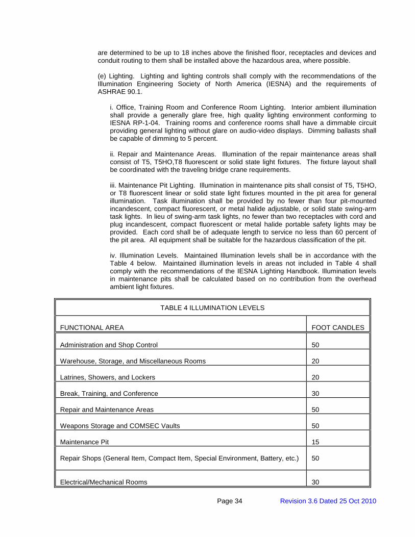
Page 34 Revision 3.6 Dated 25 Oct 2010
are determined to be up to 18 inches above the finished floor, receptacles and devices and conduit routing to them shall be installed above the hazardous area, where possible. (e) Lighting. Lighting and lighting controls shall comply with the recommendations of the Illumination Engineering Society of North America (IESNA) and the requirements of ASHRAE 90.1.
i. Office, Training Room and Conference Room Lighting. Interior ambient illumination shall provide a generally glare free, high quality lighting environment conforming to IESNA RP-1-04. Training rooms and conference rooms shall have a dimmable circuit providing general lighting without glare on audio-video displays. Dimming ballasts shall be capable of dimming to 5 percent. ii. Repair and Maintenance Areas. Illumination of the repair maintenance areas shall consist of T5, T5HO,T8 fluorescent or solid state light fixtures. The fixture layout shall be coordinated with the traveling bridge crane requirements. iii. Maintenance Pit Lighting. Illumination in maintenance pits shall consist of T5, T5HO, or T8 fluorescent linear or solid state light fixtures mounted in the pit area for general illumination. Task illumination shall be provided by no fewer than four pit-mounted incandescent, compact fluorescent, or metal halide adjustable, or solid state swing-arm task lights. In lieu of swing-arm task lights, no fewer than two receptacles with cord and plug incandescent, compact fluorescent or metal halide portable safety lights may be provided. Each cord shall be of adequate length to service no less than 60 percent of the pit area. All equipment shall be suitable for the hazardous classification of the pit. iv. Illumination Levels. Maintained Illumination levels shall be in accordance with the Table 4 below. Maintained illumination levels in areas not included in Table 4 shall comply with the recommendations of the IESNA Lighting Handbook. Illumination levels in maintenance pits shall be calculated based on no contribution from the overhead ambient light fixtures.
TABLE 4 ILLUMINATION LEVELS
FUNCTIONAL AREA
FOOT CANDLES
Administration and Shop Control
50
Warehouse, Storage, and Miscellaneous Rooms
20
Latrines, Showers, and Lockers
20
Break, Training, and Conference
30
Repair and Maintenance Areas
50
Weapons Storage and COMSEC Vaults
50
Maintenance Pit
15
Repair Shops (General Item, Compact Item, Special Environment, Battery, etc.)
50
Electrical/Mechanical Rooms
30
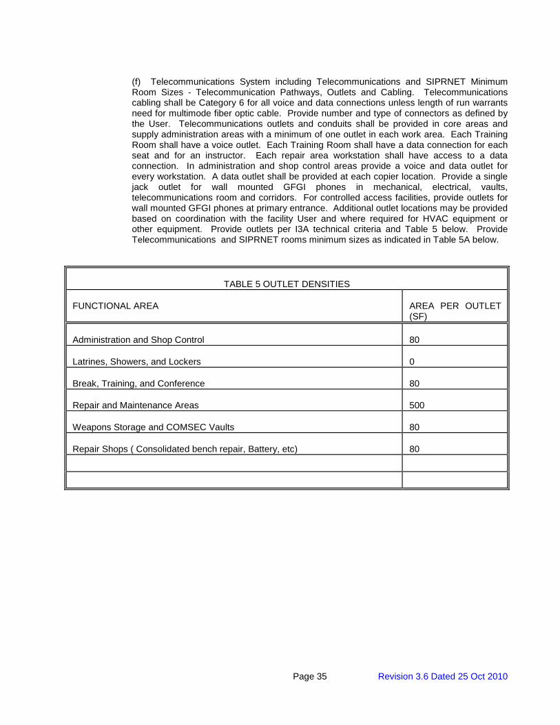
Page 35 Revision 3.6 Dated 25 Oct 2010
(f) Telecommunications System including Telecommunications and SIPRNET Minimum Room Sizes - Telecommunication Pathways, Outlets and Cabling. Telecommunications cabling shall be Category 6 for all voice and data connections unless length of run warrants need for multimode fiber optic cable. Provide number and type of connectors as defined by the User. Telecommunications outlets and conduits shall be provided in core areas and supply administration areas with a minimum of one outlet in each work area. Each Training Room shall have a voice outlet. Each Training Room shall have a data connection for each seat and for an instructor. Each repair area workstation shall have access to a data connection. In administration and shop control areas provide a voice and data outlet for every workstation. A data outlet shall be provided at each copier location. Provide a single jack outlet for wall mounted GFGI phones in mechanical, electrical, vaults, telecommunications room and corridors. For controlled access facilities, provide outlets for wall mounted GFGI phones at primary entrance. Additional outlet locations may be provided based on coordination with the facility User and where required for HVAC equipment or other equipment. Provide outlets per I3A technical criteria and Table 5 below. Provide Telecommunications and SIPRNET rooms minimum sizes as indicated in Table 5A below.
TABLE 5 OUTLET DENSITIES FUNCTIONAL AREA
AREA PER OUTLET (SF)
Administration and Shop Control
80
Latrines, Showers, and Lockers
0
Break, Training, and Conference
80
Repair and Maintenance Areas
500
Weapons Storage and COMSEC Vaults
80
Repair Shops ( Consolidated bench repair, Battery, etc)
80
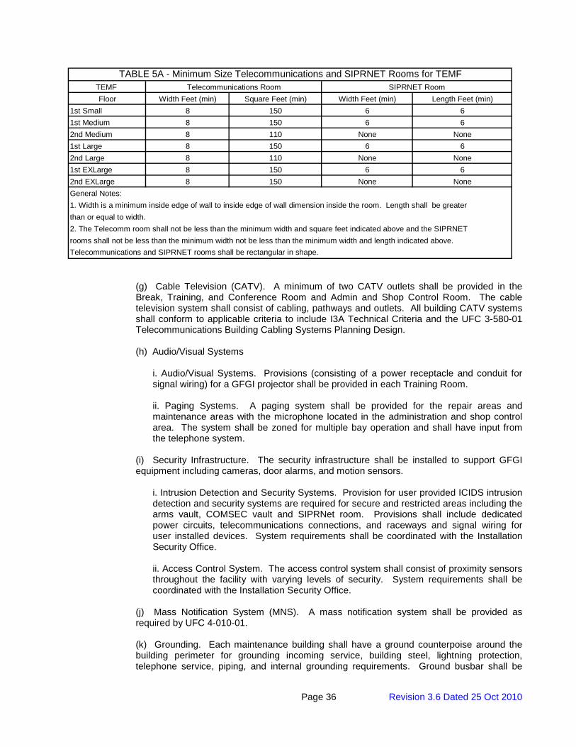
Page 36 Revision 3.6 Dated 25 Oct 2010
TEMF Floor Width Feet (min) Square Feet (min) Width Feet (min) Length Feet (min)
1st Small 8 150 6 61st Medium 8 150 6 62nd Medium 8 110 None None1st Large 8 150 6 62nd Large 8 110 None None1st EXLarge 8 150 6 62nd EXLarge 8 150 None NoneGeneral Notes:1. Width is a minimum inside edge of wall to inside edge of wall dimension inside the room. Length shall be greater than or equal to width.2. The Telecomm room shall not be less than the minimum width and square feet indicated above and the SIPRNET rooms shall not be less than the minimum width not be less than the minimum width and length indicated above.Telecommunications and SIPRNET rooms shall be rectangular in shape.
SIPRNET RoomTelecommunications RoomTABLE 5A - Minimum Size Telecommunications and SIPRNET Rooms for TEMF
(g) Cable Television (CATV). A minimum of two CATV outlets shall be provided in the Break, Training, and Conference Room and Admin and Shop Control Room. The cable television system shall consist of cabling, pathways and outlets. All building CATV systems shall conform to applicable criteria to include I3A Technical Criteria and the UFC 3-580-01 Telecommunications Building Cabling Systems Planning Design. (h) Audio/Visual Systems
i. Audio/Visual Systems. Provisions (consisting of a power receptacle and conduit for signal wiring) for a GFGI projector shall be provided in each Training Room. ii. Paging Systems. A paging system shall be provided for the repair areas and maintenance areas with the microphone located in the administration and shop control area. The system shall be zoned for multiple bay operation and shall have input from the telephone system.
(i) Security Infrastructure. The security infrastructure shall be installed to support GFGI equipment including cameras, door alarms, and motion sensors.
i. Intrusion Detection and Security Systems. Provision for user provided ICIDS intrusion detection and security systems are required for secure and restricted areas including the arms vault, COMSEC vault and SIPRNet room. Provisions shall include dedicated power circuits, telecommunications connections, and raceways and signal wiring for user installed devices. System requirements shall be coordinated with the Installation Security Office. ii. Access Control System. The access control system shall consist of proximity sensors throughout the facility with varying levels of security. System requirements shall be coordinated with the Installation Security Office.
(j) Mass Notification System (MNS). A mass notification system shall be provided as required by UFC 4-010-01. (k) Grounding. Each maintenance building shall have a ground counterpoise around the building perimeter for grounding incoming service, building steel, lightning protection, telephone service, piping, and internal grounding requirements. Ground busbar shall be
Page 37 Revision 3.6 Dated 25 Oct 2010
provided on walls of each repair area. A grounding point shall be provided in each repair area and each maintenance area. Each repair area and maintenance area is 16’ x 32’ in size. Grounding points shall be provided in vehicle and equipment parking areas on 40-foot centers (maximum) and coordinated with the parking layout. It will be acceptable to provide a minimum of one grounding point for every eight vehicles parked in a double row, and one grounding point for every four vehicles parked in a single row configuration. Equipment parking grounding shall be in accordance with the recommendations of MIL-HNBK-419A, which is referenced in I3A. This includes, but is not limited to, the earth electrode subsystem should exhibit a resistance to earth of 10 ohms or less and multiple ground rods should be interconnected using 1/0 AWG bare copper cable. Install an interior #2 AWG bare tinned copper ground loop around the perimeter of the Fluid Distribution Room for dissipation of potential static charge. Bond ground loop to building structure and grounding riser. Provide thirty (30) #6 AWG bare copper pigtails complete with alligator clips on both ends for grounding of metallic barrels/dispensing equipment. Length of pigtails should be based on potential layout of equipment/drums and the location of ground ring. Additional grounding may be provided based on project requirements. Systems shall conform to NFPA 70 National Electrical Code, NFPA 780 Standard for the Installation of Lightning Protection Systems, local codes and the Technical Criteria for Installation Information Infrastructure Architecture (I3A).
(l) SIPRNET. The SIPRNET room shall be designed and constructed in accordance with the “Building SIPRNET Communication Room – New Construction Guidance”, paragraph of the Technical Guide for Integration of SIPRNET (Secret Internet Protocol Router Network). The SIPRNET room design and construction shall be coordinated with local NEC and Physical Security Office. SIPRNET conduit and cable to SIPRNET Drops and the SIPRNET Drops will be provided in the future and is not to be provided as part of this scope of work. Connection to the main telecommunications room from the SIPRNet room shall be via a 2-inch trade size steel conduit. Provide six strands of single mode fiber optic cable from Telecommunications Room to the SIPRNET Room. Provide a communications signal ground bus bar connected to the main communications room signal bus bar via a properly sized ground wire (see MIL-HDBK-419-A, which is referenced in the Technical Guide for the Integration of SIPRNET). Provide one dedicated standard 20-amp duplex receptacle for future SIPRNET rack in addition to convenience receptacles in the SIPRNET room.
(m) Hydraulic Lift. In each pair of repair areas, provide electric power for User provided (GFGI) portable hydraulic lift. Coordinate electrical requirements with the User. (n) Fire Detection and Alarm
i. A fire alarm and detection system shall be provided for this facility. It shall comply with the requirements of UFC 3-600-01 and NFPA 72. The system shall be addressable and fully compatible with and integrated with the local installation wide central monitoring system. Coordinate fire alarm system requirements with the Fire Department’s Representative during design.
ii. All initiating devices shall be connected, Class A, Style 6, to signal line circuits (SLC). All alarm appliances shall be connected to notification appliance circuits (NAC), Class A. A looped conduit system shall be provided so that if the conduit and all conductors within are severed at any point, all NAC and SLC shall remain functional. iii. Breakglass manual fire alarm stations shall not be used. iv. Over-voltage and surge protection shall be provided at the input power of all panels.
Page 38 Revision 3.6 Dated 25 Oct 2010
3.1.10 Energy Conservation
3.1.10.1 Energy Performance. The building, including the building envelope, HVAC, ventilation and exhaust systems, service water heating, power, and lighting systems shall be designed to achieve a non-plug energy consumption that is at least 40% below the consumption of a baseline building meeting the minimum requirements of ANSI/ASHRAE/IESNA Standard 90.1 (see paragraph 5.9 Energy Conservation).(Note: Plug loads shall be included in building energy modeling but are subtracted in the final calculation of Energy Performance. See section “Design After Award” for additional guidance).
3.1.10.2 Required Energy Conservation Features. All items listed in the energy conservation features table shall be provided as a minimum. Additional energy conservation features may be required to meet the above energy performance. The contractor is responsible for determining and providing additional energy conservation features to meet the energy performance requirement.
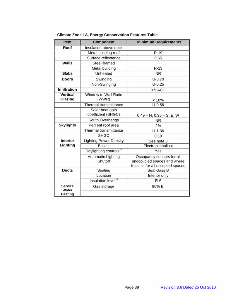
Page 39 Revision 3.6 Dated 25 Oct 2010
Climate Zone 1A, Energy Conservation Features Table
Item Component Minimum Requirements Roof Insulation above deck
Metal building roof R-19 Surface reflectance 0.65
Walls Steel-framed Metal building R-13
Slabs Unheated NR Doors Swinging U-0.70
Non-Swinging U-0.25 Infiltration 0.5 ACH
Vertical Glazing
Window to Wall Ratio (WWR) < 10%
Thermal transmittance U-0.56 Solar heat gain
coefficient (SHGC) 0.49 – N; 0.35 – S, E, W South Overhangs NR
Skylights Percent roof area 2% Thermal transmittance U-1.36
SHGC 0.19 Interior Lighting
Lighting Power Density See note 3 Ballast Electronic ballast
Daylighting controls 4 Yes Automatic Lighting
Shutoff Occupancy sensors for all
unoccupied spaces and where feasible for all occupied spaces
Ducts Sealing Seal class B Location Interior only
Insulation level 5 R-6 Service Water
Heating
Gas storage 90% Et
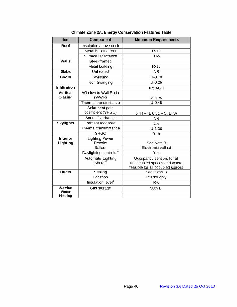
Page 40 Revision 3.6 Dated 25 Oct 2010
Climate Zone 2A, Energy Conservation Features Table
Item Component Minimum Requirements Roof Insulation above deck
Metal building roof R-19 Surface reflectance 0.65
Walls Steel-framed Metal building R-13
Slabs Unheated NR Doors Swinging U-0.70
Non-Swinging U-0.25 Infiltration 0.5 ACH
Vertical Glazing
Window to Wall Ratio (WWR) < 10%
Thermal transmittance U-0.45 Solar heat gain
coefficient (SHGC) 0.44 – N; 0.31 – S, E, W South Overhangs NR
Skylights Percent roof area 2% Thermal transmittance U-1.36
SHGC 0.19 Interior Lighting
Lighting Power Density See Note 3 Ballast Electronic ballast
Daylighting controls 4 Yes Automatic Lighting
Shutoff Occupancy sensors for all
unoccupied spaces and where feasible for all occupied spaces
Ducts Sealing Seal class B Location Interior only
Insulation level5 R-6 Service Water
Heating
Gas storage 90% Et
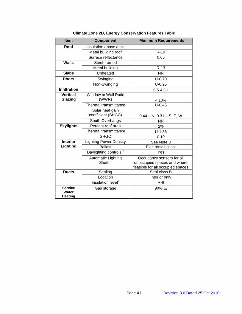
Page 41 Revision 3.6 Dated 25 Oct 2010
Climate Zone 2B, Energy Conservation Features Table
Item Component Minimum Requirements Roof Insulation above deck
Metal building roof R-19 Surface reflectance 0.65
Walls Steel-framed Metal building R-13
Slabs Unheated NR Doors Swinging U-0.70
Non-Swinging U-0.25 Infiltration 0.5 ACH
Vertical Glazing
Window to Wall Ratio (WWR) < 10%
Thermal transmittance U-0.45 Solar heat gain
coefficient (SHGC) 0.44 – N; 0.31 – S, E, W South Overhangs NR
Skylights Percent roof area 2% Thermal transmittance U-1.36
SHGC 0.19 Interior Lighting
Lighting Power Density See Note 3 Ballast Electronic ballast
Daylighting controls 4 Yes Automatic Lighting
Shutoff Occupancy sensors for all
unoccupied spaces and where feasible for all occupied spaces
Ducts Sealing Seal class B Location Interior only
Insulation level5 R-6 Service Water
Heating
Gas storage 90% Et

Page 42 Revision 3.6 Dated 25 Oct 2010
Climate Zone 3A, Energy Conservation Features Table
Item Component Minimum Requirements Roof Insulation above deck
Metal building roof R-13 + R-13 Surface reflectance 0.65
Walls Steel-framed Metal building R-13
Slabs Unheated NR Heated R-10
Doors Swinging U-0.70 Non-Swinging U-0.25
Infiltration 0.5 ACH Vertical Glazing
Window to Wall Ratio (WWR) < 10%
Thermal transmittance U-0.45 Solar heat gain
coefficient (SHGC) 0.44 – N; 0.31 – S, E, W
South Overhangs NR Skylights Percent roof area
2% Thermal transmittance U-0.69
SHGC 0.19 Interior Lighting
Lighting Power Density See Note 3 Ballast Electronic ballast
Daylighting controls 4 Yes Automatic Lighting
Shutoff Occupancy sensors for all
unoccupied spaces and where feasible for all occupied spaces
Ducts Sealing Seal class B Location Interior only
Insulation level 5 R-6 Service Water
Heating
Gas storage 90% Et

Page 43 Revision 3.6 Dated 25 Oct 2010
Climate Zone 3B, Energy Conservation Features Table
Item Component Minimum Requirements Roof Insulation above deck
Metal building roof R-13 + R-13 Surface reflectance 0.65
Walls Steel-framed Metal building R-13
Slabs Unheated NR Heated R-10
Doors Swinging U-0.70 Non-Swinging U-0.25
Infiltration 0.5 ACH Vertical Glazing
Window to Wall Ratio (WWR) < 10%
Thermal transmittance U-0.45 Solar heat gain
coefficient (SHGC) 0.44 – N; 0.31 – S, E, W
South Overhangs NR Skylights Percent roof area
2% Thermal transmittance U-0.69
SHGC 0.19 Interior Lighting
Lighting Power Density See Note 3 Ballast Electronic ballast
Daylighting controls 4 Yes Automatic Lighting
Shutoff Occupancy sensors for all
unoccupied spaces and where feasible for all occupied spaces
Ducts Sealing Seal class B Location Interior only
Insulation level 5 R-6 Service Water
Heating
Gas storage 90% Et
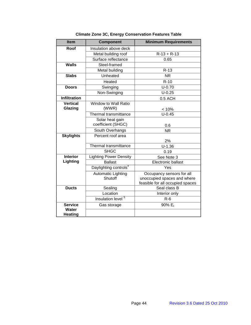
Page 44 Revision 3.6 Dated 25 Oct 2010
Climate Zone 3C, Energy Conservation Features Table
Item Component Minimum Requirements Roof Insulation above deck
Metal building roof R-13 + R-13 Surface reflectance 0.65
Walls Steel-framed Metal building R-13
Slabs Unheated NR Heated R-10
Doors Swinging U-0.70 Non-Swinging U-0.25
Infiltration 0.5 ACH Vertical Glazing
Window to Wall Ratio (WWR) < 10%
Thermal transmittance U-0.45 Solar heat gain
coefficient (SHGC) 0.6 South Overhangs NR
Skylights Percent roof area 2%
Thermal transmittance U-1.36 SHGC 0.19
Interior Lighting
Lighting Power Density See Note 3 Ballast Electronic ballast
Daylighting controls4 Yes Automatic Lighting
Shutoff Occupancy sensors for all
unoccupied spaces and where feasible for all occupied spaces
Ducts Sealing Seal class B Location Interior only
Insulation level 5 R-6 Service Water
Heating
Gas storage 90% Et

Page 45 Revision 3.6 Dated 25 Oct 2010
Climate Zone 4A, Energy Conservation Features Table
Item Component Minimum Requirements Roof Insulation above deck
Metal building roof R-13 + R-19 Surface reflectance 0.65
Walls Steel-framed Metal building R-13
Slabs Unheated NR Heated R-10
Doors Swinging U-0.70 Non-Swinging U-0.25
Infiltration 0.5 ACH Vertical Glazing
Window to Wall Ratio (WWR) < 10%
Thermal transmittance U-0.42 Solar heat gain
coefficient (SHGC) 0.46 South Overhangs NR
Skylights Percent roof area 2%
Thermal transmittance U-0.69 SHGC 0.34
Interior Lighting
Lighting Power Density See Note 3 Ballast Electronic ballast
Daylighting controls 4 Yes Automatic Lighting
Shutoff Occupancy sensors for all
unoccupied spaces and where feasible for all occupied spaces
Ducts Sealing Seal class B Location Interior only
Insulation level 5 R-6 Service Water
Heating
Gas storage 90% Et
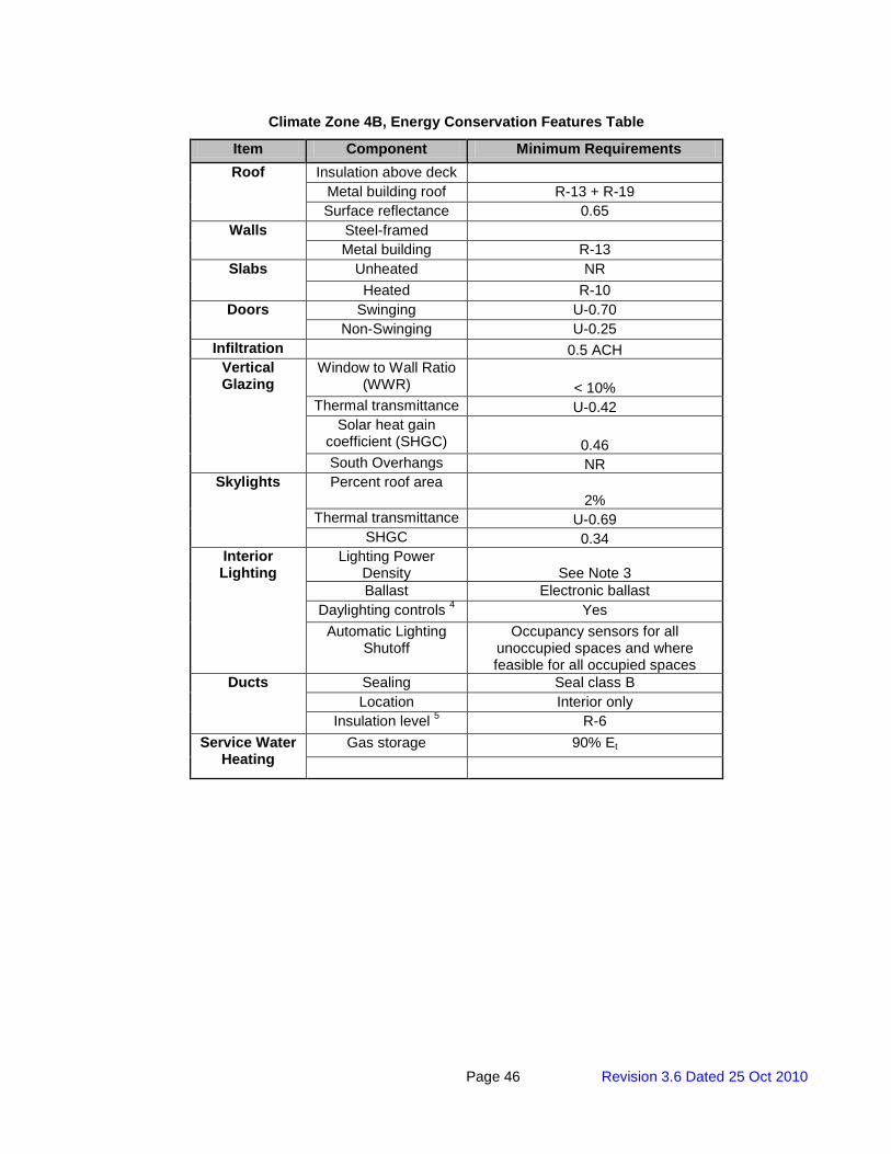
Page 46 Revision 3.6 Dated 25 Oct 2010
Climate Zone 4B, Energy Conservation Features Table
Item Component Minimum Requirements Roof Insulation above deck
Metal building roof R-13 + R-19 Surface reflectance 0.65
Walls Steel-framed Metal building R-13
Slabs Unheated NR Heated R-10
Doors Swinging U-0.70 Non-Swinging U-0.25
Infiltration 0.5 ACH Vertical Glazing
Window to Wall Ratio (WWR) < 10%
Thermal transmittance U-0.42 Solar heat gain
coefficient (SHGC) 0.46 South Overhangs NR
Skylights Percent roof area 2%
Thermal transmittance U-0.69 SHGC 0.34
Interior Lighting
Lighting Power Density See Note 3 Ballast Electronic ballast
Daylighting controls 4 Yes Automatic Lighting
Shutoff Occupancy sensors for all
unoccupied spaces and where feasible for all occupied spaces
Ducts Sealing Seal class B Location Interior only
Insulation level 5 R-6 Service Water
Heating Gas storage 90% Et

Page 47 Revision 3.6 Dated 25 Oct 2010
Climate Zone 4C, Energy Conservation Features Table
Item Component Minimum Requirements Roof Insulation above deck
Metal building roof R-13 + R-19 Surface reflectance 0.65
Walls Steel-framed Metal building R-13
Slabs Unheated NR Heated R-10
Doors Swinging U-0.70 Non-Swinging U-0.25
Infiltration 0.5 ACH Vertical Glazing
Window to Wall Ratio (WWR) < 10%
Thermal transmittance U-0.42 Solar heat gain
coefficient (SHGC) 0.46 South Overhangs NR
Skylights Percent roof area 2%
Thermal transmittance U-0.69 SHGC 0.34
Interior Lighting
Lighting Power Density See Note 3 Ballast Electronic ballast
Daylighting controls 4 Yes Automatic Lighting
Shutoff Occupancy sensors for all
unoccupied spaces and where feasible for all occupied spaces
Ducts Sealing Seal class B Location Interior only
Insulation level 5 R-6 Service Water
Heating Gas storage 90% Et
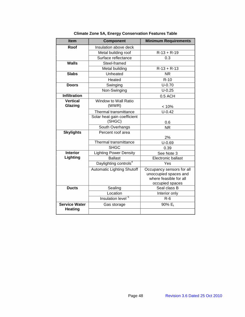
Page 48 Revision 3.6 Dated 25 Oct 2010
Climate Zone 5A, Energy Conservation Features Table
Item Component Minimum Requirements Roof Insulation above deck
Metal building roof R-13 + R-19 Surface reflectance 0.3
Walls Steel-framed Metal building R-13 + R-13
Slabs Unheated NR Heated R-10
Doors Swinging U-0.70 Non-Swinging U-0.25
Infiltration 0.5 ACH Vertical Glazing
Window to Wall Ratio (WWR) < 10%
Thermal transmittance U-0.42 Solar heat gain coefficient
(SHGC) 0.6 South Overhangs NR
Skylights Percent roof area 2%
Thermal transmittance U-0.69 SHGC 0.39
Interior Lighting
Lighting Power Density See Note 3 Ballast Electronic ballast
Daylighting controls4 Yes Automatic Lighting Shutoff Occupancy sensors for all
unoccupied spaces and where feasible for all
occupied spaces Ducts Sealing Seal class B
Location Interior only Insulation level 5 R-6
Service Water Heating
Gas storage 90% Et

Page 49 Revision 3.6 Dated 25 Oct 2010
Climate Zone 5B, Energy Conservation Features Table
Item Component Minimum Requirements Roof Insulation above deck
Metal building roof R-13 + R-19 Surface reflectance 0.3
Walls Steel-framed Metal building R-13 + R-13
Slabs Unheated NR Heated R-10
Doors Swinging U-0.70 Non-Swinging U-0.25
Infiltration 0.5 ACH Vertical Glazing
Window to Wall Ratio (WWR) < 10%
Thermal transmittance U-0.42 Solar heat gain coefficient
(SHGC) 0.6 South Overhangs NR
Skylights Percent roof area 2%
Thermal transmittance U-0.69 SHGC 0.39
Interior Lighting
Lighting Power Density See Note 3 Ballast Electronic ballast
Daylighting controls4 Yes Automatic Lighting Shutoff Occupancy sensors for all
unoccupied spaces and where feasible for all
occupied spaces Ducts Sealing Seal class B
Location Interior only Insulation level 5 R-6
Service Water Heating
Gas storage 90% Et
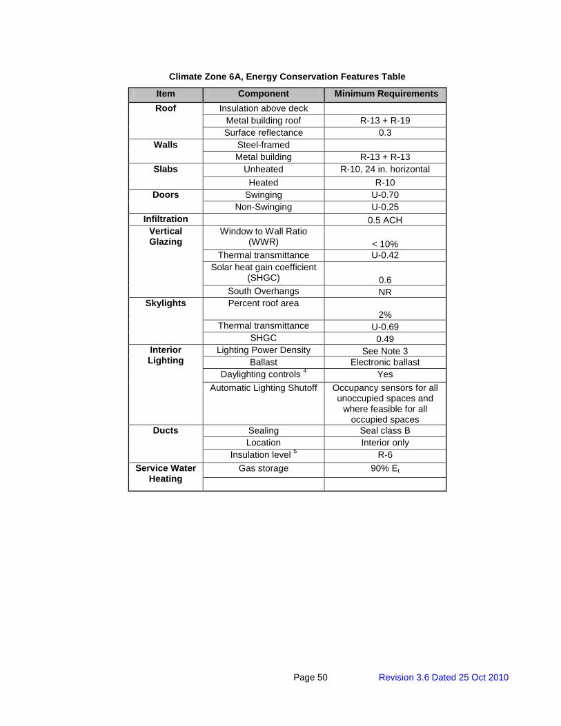
Page 50 Revision 3.6 Dated 25 Oct 2010
Climate Zone 6A, Energy Conservation Features Table
Item Component Minimum Requirements Roof Insulation above deck
Metal building roof R-13 + R-19 Surface reflectance 0.3
Walls Steel-framed Metal building R-13 + R-13
Slabs Unheated R-10, 24 in. horizontal Heated R-10
Doors Swinging U-0.70 Non-Swinging U-0.25
Infiltration 0.5 ACH Vertical Glazing
Window to Wall Ratio (WWR) < 10%
Thermal transmittance U-0.42 Solar heat gain coefficient
(SHGC) 0.6 South Overhangs NR
Skylights Percent roof area 2%
Thermal transmittance U-0.69 SHGC 0.49
Interior Lighting
Lighting Power Density See Note 3 Ballast Electronic ballast
Daylighting controls 4 Yes Automatic Lighting Shutoff Occupancy sensors for all
unoccupied spaces and where feasible for all
occupied spaces Ducts Sealing Seal class B
Location Interior only Insulation level 5 R-6
Service Water Heating
Gas storage 90% Et
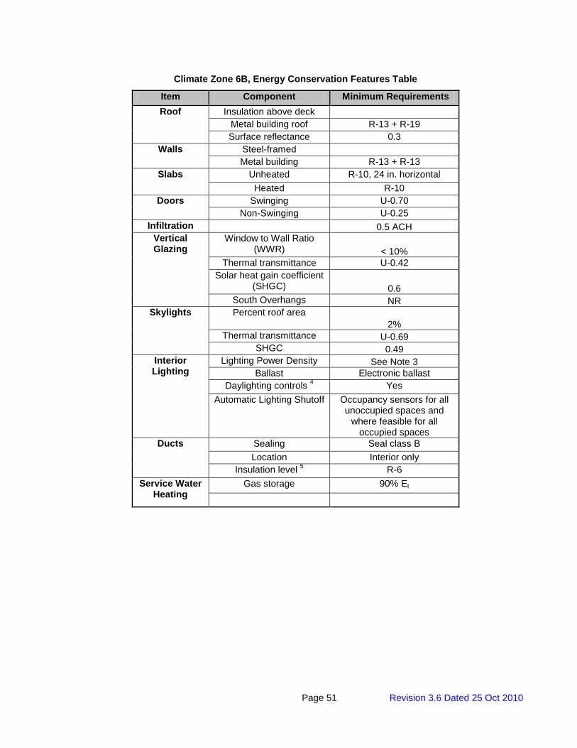
Page 51 Revision 3.6 Dated 25 Oct 2010
Climate Zone 6B, Energy Conservation Features Table
Item Component Minimum Requirements Roof Insulation above deck
Metal building roof R-13 + R-19 Surface reflectance 0.3
Walls Steel-framed Metal building R-13 + R-13
Slabs Unheated R-10, 24 in. horizontal Heated R-10
Doors Swinging U-0.70 Non-Swinging U-0.25
Infiltration 0.5 ACH Vertical Glazing
Window to Wall Ratio (WWR) < 10%
Thermal transmittance U-0.42 Solar heat gain coefficient
(SHGC) 0.6 South Overhangs NR
Skylights Percent roof area 2%
Thermal transmittance U-0.69 SHGC 0.49
Interior Lighting
Lighting Power Density See Note 3 Ballast Electronic ballast
Daylighting controls 4 Yes Automatic Lighting Shutoff Occupancy sensors for all
unoccupied spaces and where feasible for all
occupied spaces Ducts Sealing Seal class B
Location Interior only Insulation level 5 R-6
Service Water Heating
Gas storage 90% Et
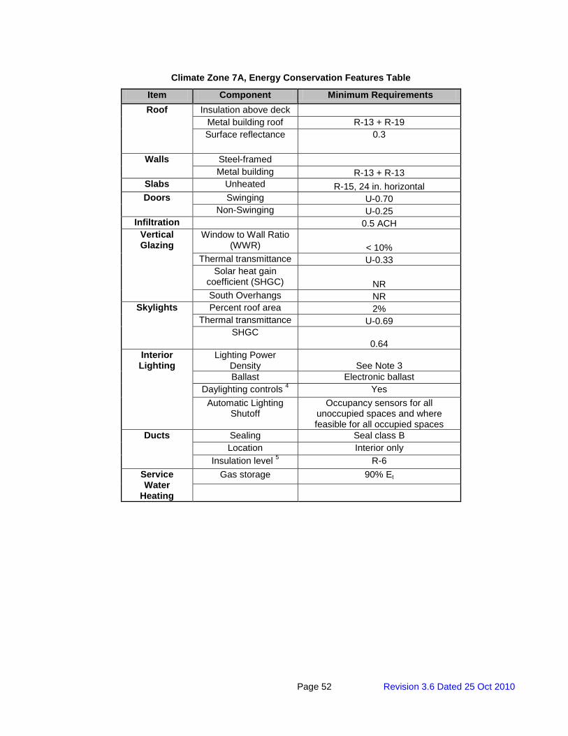
Page 52 Revision 3.6 Dated 25 Oct 2010
Climate Zone 7A, Energy Conservation Features Table
Item Component Minimum Requirements Roof Insulation above deck
Metal building roof R-13 + R-19 Surface reflectance 0.3
Walls Steel-framed Metal building R-13 + R-13
Slabs Unheated R-15, 24 in. horizontal Doors Swinging U-0.70
Non-Swinging U-0.25 Infiltration 0.5 ACH
Vertical Glazing
Window to Wall Ratio (WWR) < 10%
Thermal transmittance U-0.33 Solar heat gain
coefficient (SHGC) NR South Overhangs NR
Skylights Percent roof area 2% Thermal transmittance U-0.69
SHGC 0.64
Interior Lighting
Lighting Power Density See Note 3 Ballast Electronic ballast
Daylighting controls 4 Yes Automatic Lighting
Shutoff Occupancy sensors for all
unoccupied spaces and where feasible for all occupied spaces
Ducts Sealing Seal class B Location Interior only
Insulation level 5 R-6 Service Water
Heating
Gas storage 90% Et
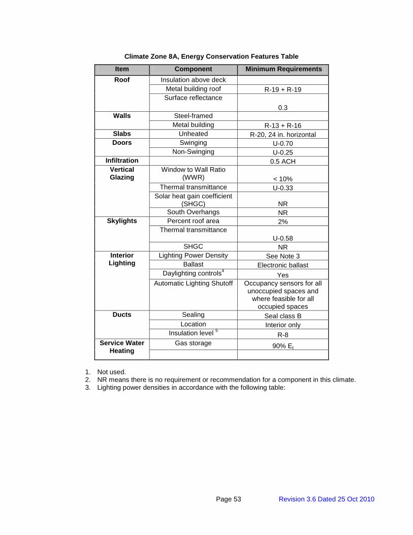
Page 53 Revision 3.6 Dated 25 Oct 2010
Climate Zone 8A, Energy Conservation Features Table
Item Component Minimum Requirements Roof Insulation above deck
Metal building roof R-19 + R-19 Surface reflectance
0.3 Walls Steel-framed
Metal building R-13 + R-16 Slabs Unheated R-20, 24 in. horizontal Doors Swinging U-0.70
Non-Swinging U-0.25 Infiltration 0.5 ACH
Vertical Glazing
Window to Wall Ratio (WWR) < 10%
Thermal transmittance U-0.33 Solar heat gain coefficient
(SHGC) NR South Overhangs NR
Skylights Percent roof area 2% Thermal transmittance
U-0.58 SHGC NR
Interior Lighting
Lighting Power Density See Note 3 Ballast Electronic ballast
Daylighting controls4 Yes Automatic Lighting Shutoff Occupancy sensors for all
unoccupied spaces and where feasible for all
occupied spaces Ducts Sealing Seal class B
Location Interior only Insulation level 5 R-8
Service Water Heating
Gas storage 90% Et
1. Not used. 2. NR means there is no requirement or recommendation for a component in this climate. 3. Lighting power densities in accordance with the following table:
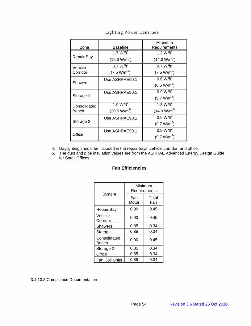
Page 54 Revision 3.6 Dated 25 Oct 2010
Lighting Power Dens ities
Zone Baseline Minimum
Requirements
Repair Bay 1.7 W/ft2 1.3 W/ft2
(18.3 W/m2) (14.0 W/m2)
Vehicle Corridor
0.7 W/ft2 0.7 W/ft2 (7.5 W/m2) (7.5 W/m2)
Showers Use ASHRAE90.1 0.6 W/ft2
(6.5 W/m2)
Storage 1 Use ASHRAE90.1 0.9 W/ft2
(9.7 W/m2)
Consolidated Bench
1.9 W/ft2 1.3 W/ft2 (20.5 W/m2) (14.0 W/m2)
Storage 2 Use ASHRAE90.1 0.9 W/ft2
(9.7 W/m2)
Office Use ASHRAE90.1 0.9 W/ft2
(9.7 W/m2)
4. Daylighting should be included in the repair bays, vehicle corridor, and office. 5. The duct and pipe insulation values are from the ASHRAE Advanced Energy Design Guide
for Small Offices.
Fan Efficiencies
System
Minimum Requirements
Fan Motor
Total Fan
Repair Bay 0.90 0.45 Vehicle Corridor
0.90 0.45
Showers 0.85 0.34 Storage 1 0.85 0.34 Consolidated Bench
0.90 0.45
Storage 2 0.85 0.34 Office 0.85 0.34 Fan Coil Units 0.85 0.34
3.1.10.3 Compliance Documentation
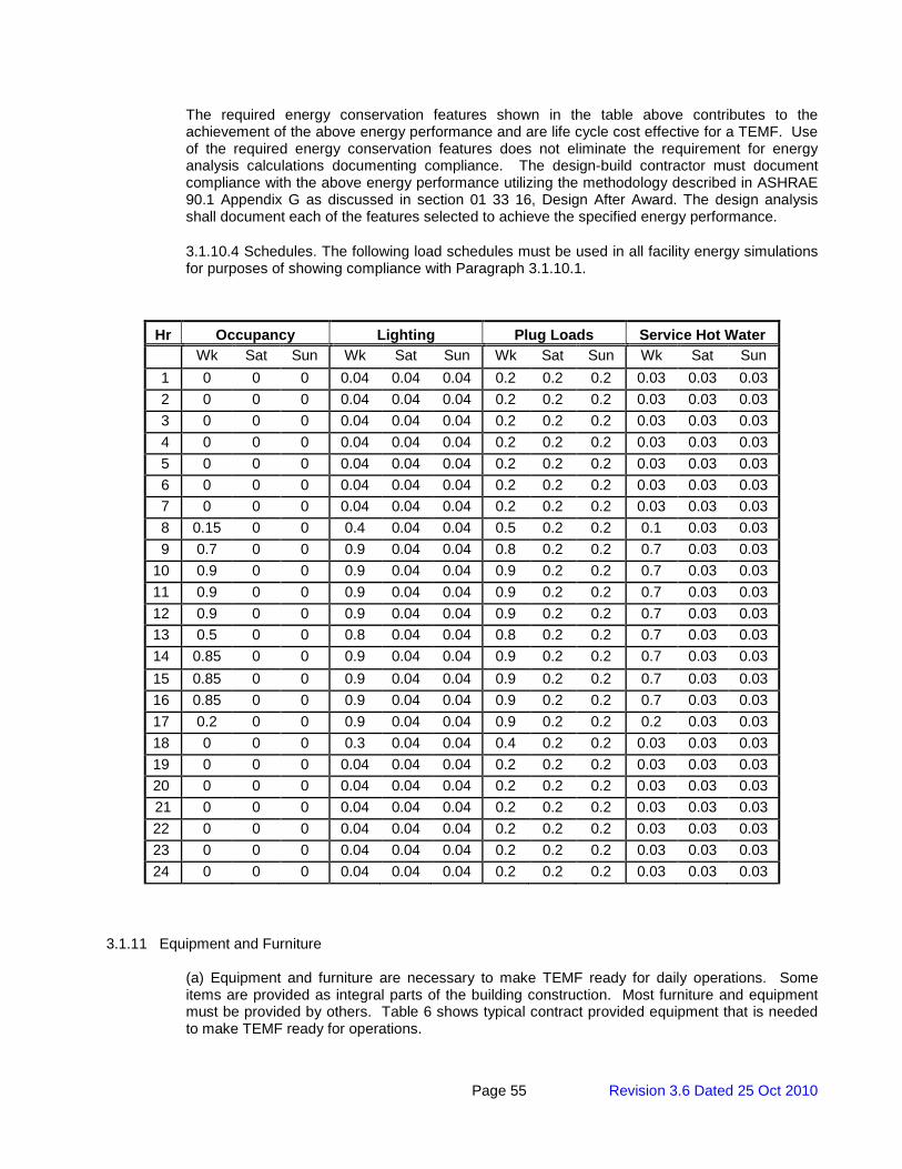
Page 55 Revision 3.6 Dated 25 Oct 2010
The required energy conservation features shown in the table above contributes to the achievement of the above energy performance and are life cycle cost effective for a TEMF. Use of the required energy conservation features does not eliminate the requirement for energy analysis calculations documenting compliance. The design-build contractor must document compliance with the above energy performance utilizing the methodology described in ASHRAE 90.1 Appendix G as discussed in section 01 33 16, Design After Award. The design analysis shall document each of the features selected to achieve the specified energy performance.
3.1.10.4 Schedules. The following load schedules must be used in all facility energy simulations for purposes of showing compliance with Paragraph 3.1.10.1.
Hr Occupancy Lighting Plug Loads Service Hot Water Wk Sat Sun Wk Sat Sun Wk Sat Sun Wk Sat Sun 1 0 0 0 0.04 0.04 0.04 0.2 0.2 0.2 0.03 0.03 0.03 2 0 0 0 0.04 0.04 0.04 0.2 0.2 0.2 0.03 0.03 0.03 3 0 0 0 0.04 0.04 0.04 0.2 0.2 0.2 0.03 0.03 0.03 4 0 0 0 0.04 0.04 0.04 0.2 0.2 0.2 0.03 0.03 0.03 5 0 0 0 0.04 0.04 0.04 0.2 0.2 0.2 0.03 0.03 0.03 6 0 0 0 0.04 0.04 0.04 0.2 0.2 0.2 0.03 0.03 0.03 7 0 0 0 0.04 0.04 0.04 0.2 0.2 0.2 0.03 0.03 0.03 8 0.15 0 0 0.4 0.04 0.04 0.5 0.2 0.2 0.1 0.03 0.03 9 0.7 0 0 0.9 0.04 0.04 0.8 0.2 0.2 0.7 0.03 0.03
10 0.9 0 0 0.9 0.04 0.04 0.9 0.2 0.2 0.7 0.03 0.03 11 0.9 0 0 0.9 0.04 0.04 0.9 0.2 0.2 0.7 0.03 0.03 12 0.9 0 0 0.9 0.04 0.04 0.9 0.2 0.2 0.7 0.03 0.03 13 0.5 0 0 0.8 0.04 0.04 0.8 0.2 0.2 0.7 0.03 0.03 14 0.85 0 0 0.9 0.04 0.04 0.9 0.2 0.2 0.7 0.03 0.03 15 0.85 0 0 0.9 0.04 0.04 0.9 0.2 0.2 0.7 0.03 0.03 16 0.85 0 0 0.9 0.04 0.04 0.9 0.2 0.2 0.7 0.03 0.03 17 0.2 0 0 0.9 0.04 0.04 0.9 0.2 0.2 0.2 0.03 0.03 18 0 0 0 0.3 0.04 0.04 0.4 0.2 0.2 0.03 0.03 0.03 19 0 0 0 0.04 0.04 0.04 0.2 0.2 0.2 0.03 0.03 0.03 20 0 0 0 0.04 0.04 0.04 0.2 0.2 0.2 0.03 0.03 0.03 21 0 0 0 0.04 0.04 0.04 0.2 0.2 0.2 0.03 0.03 0.03 22 0 0 0 0.04 0.04 0.04 0.2 0.2 0.2 0.03 0.03 0.03 23 0 0 0 0.04 0.04 0.04 0.2 0.2 0.2 0.03 0.03 0.03 24 0 0 0 0.04 0.04 0.04 0.2 0.2 0.2 0.03 0.03 0.03
3.1.11 Equipment and Furniture
(a) Equipment and furniture are necessary to make TEMF ready for daily operations. Some items are provided as integral parts of the building construction. Most furniture and equipment must be provided by others. Table 6 shows typical contract provided equipment that is needed to make TEMF ready for operations.
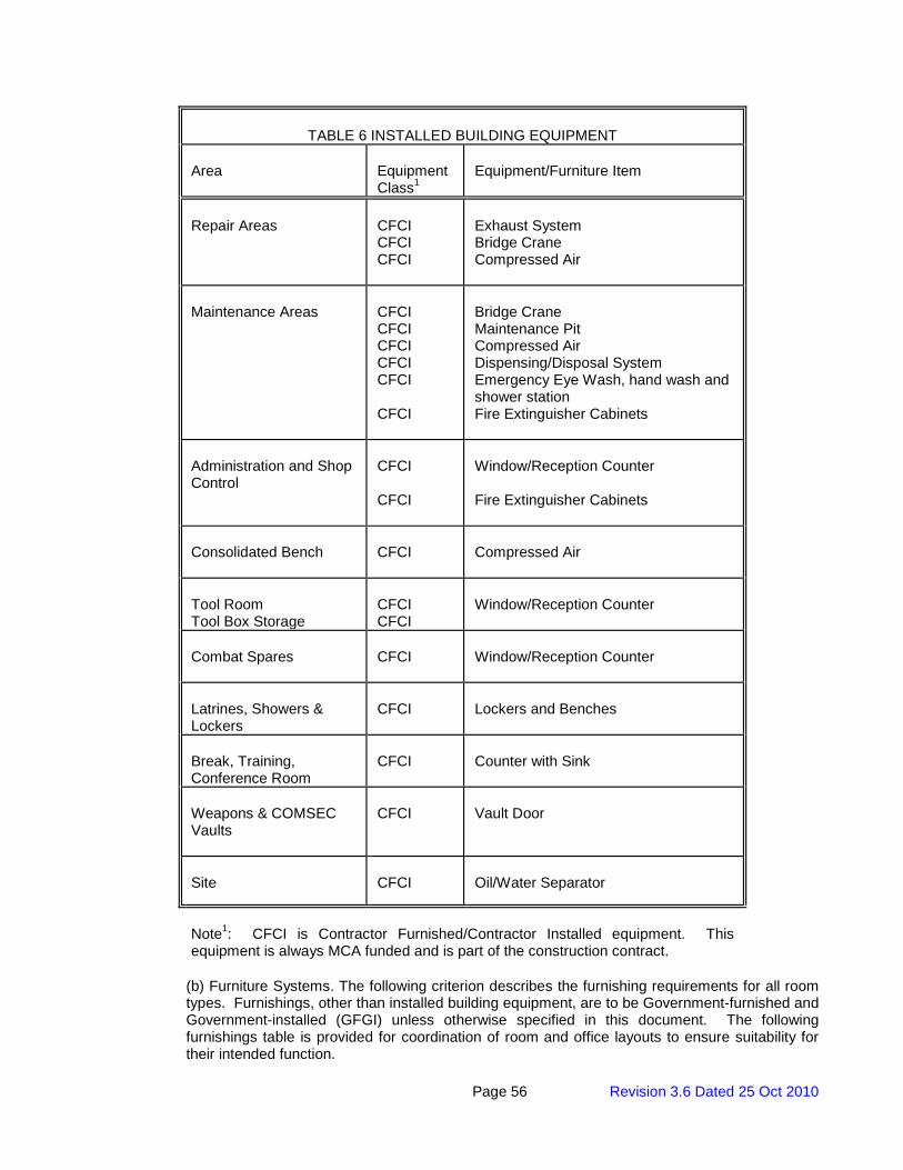
Page 56 Revision 3.6 Dated 25 Oct 2010
TABLE 6 INSTALLED BUILDING EQUIPMENT
Area
Equipment Class1
Equipment/Furniture Item
Repair Areas
CFCI CFCI CFCI
Exhaust System Bridge Crane Compressed Air
Maintenance Areas
CFCI CFCI CFCI CFCI CFCI CFCI
Bridge Crane Maintenance Pit Compressed Air Dispensing/Disposal System Emergency Eye Wash, hand wash and shower station Fire Extinguisher Cabinets
Administration and Shop Control
CFCI CFCI
Window/Reception Counter Fire Extinguisher Cabinets
Consolidated Bench
CFCI
Compressed Air
Tool Room Tool Box Storage
CFCI CFCI
Window/Reception Counter
Combat Spares
CFCI
Window/Reception Counter
Latrines, Showers & Lockers
CFCI
Lockers and Benches
Break, Training, Conference Room
CFCI
Counter with Sink
Weapons & COMSEC Vaults
CFCI
Vault Door
Site
CFCI
Oil/Water Separator
Note1: CFCI is Contractor Furnished/Contractor Installed equipment. This equipment is always MCA funded and is part of the construction contract.
(b) Furniture Systems. The following criterion describes the furnishing requirements for all room types. Furnishings, other than installed building equipment, are to be Government-furnished and Government-installed (GFGI) unless otherwise specified in this document. The following furnishings table is provided for coordination of room and office layouts to ensure suitability for their intended function.
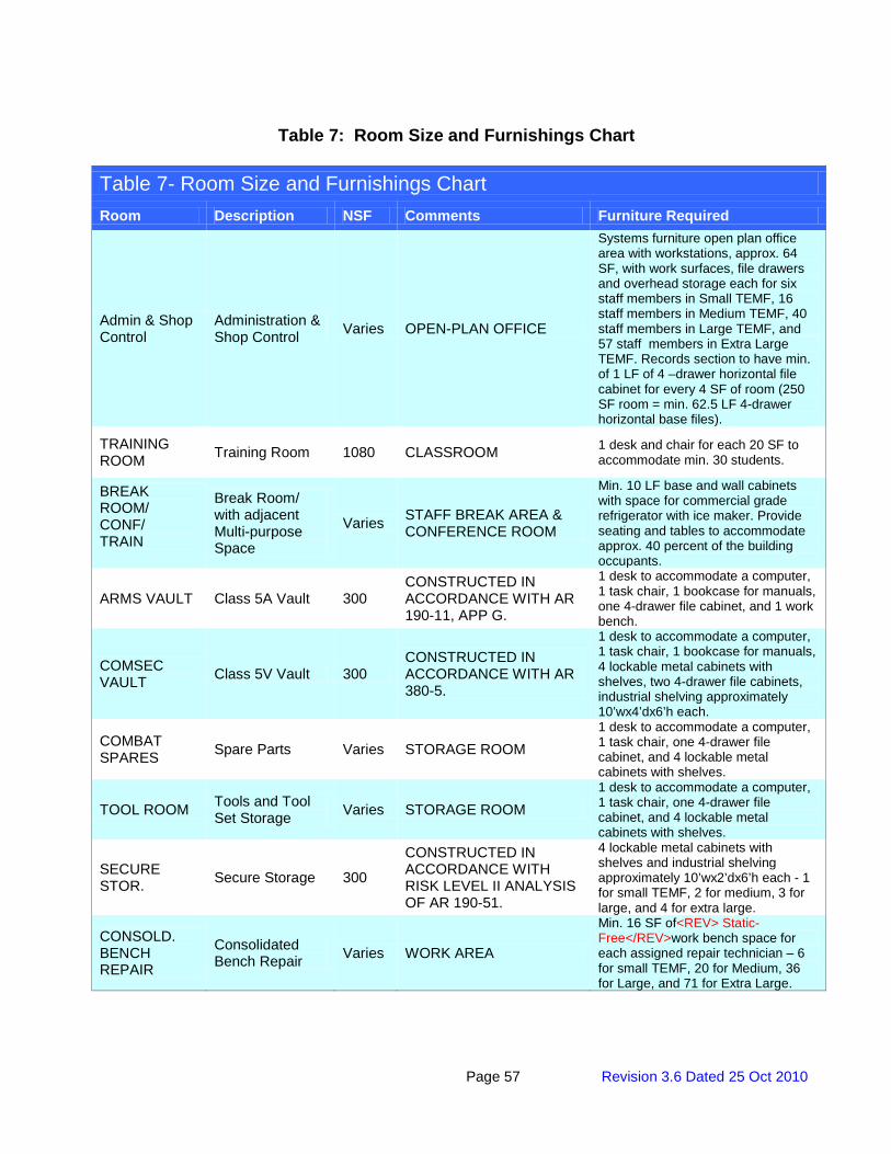
Page 57 Revision 3.6 Dated 25 Oct 2010
Table 7: Room Size and Furnishings Chart
Table 7- Room Size and Furnishings Chart Room Description NSF Comments Furniture Required
Admin & Shop Control
Administration & Shop Control Varies OPEN-PLAN OFFICE
Systems furniture open plan office area with workstations, approx. 64 SF, with work surfaces, file drawers and overhead storage each for six staff members in Small TEMF, 16 staff members in Medium TEMF, 40 staff members in Large TEMF, and 57 staff members in Extra Large TEMF. Records section to have min. of 1 LF of 4 –drawer horizontal file cabinet for every 4 SF of room (250 SF room = min. 62.5 LF 4-drawer horizontal base files).
TRAINING ROOM Training Room 1080 CLASSROOM 1 desk and chair for each 20 SF to
accommodate min. 30 students.
BREAK ROOM/ CONF/ TRAIN
Break Room/ with adjacent Multi-purpose Space
Varies STAFF BREAK AREA & CONFERENCE ROOM
Min. 10 LF base and wall cabinets with space for commercial grade refrigerator with ice maker. Provide seating and tables to accommodate approx. 40 percent of the building occupants.
ARMS VAULT Class 5A Vault 300 CONSTRUCTED IN ACCORDANCE WITH AR 190-11, APP G.
1 desk to accommodate a computer, 1 task chair, 1 bookcase for manuals, one 4-drawer file cabinet, and 1 work bench.
COMSEC VAULT Class 5V Vault 300
CONSTRUCTED IN ACCORDANCE WITH AR 380-5.
1 desk to accommodate a computer, 1 task chair, 1 bookcase for manuals, 4 lockable metal cabinets with shelves, two 4-drawer file cabinets, industrial shelving approximately 10’wx4’dx6’h each.
COMBAT SPARES Spare Parts Varies STORAGE ROOM
1 desk to accommodate a computer, 1 task chair, one 4-drawer file cabinet, and 4 lockable metal cabinets with shelves.
TOOL ROOM Tools and Tool Set Storage Varies STORAGE ROOM
1 desk to accommodate a computer, 1 task chair, one 4-drawer file cabinet, and 4 lockable metal cabinets with shelves.
SECURE STOR. Secure Storage 300
CONSTRUCTED IN ACCORDANCE WITH RISK LEVEL II ANALYSIS OF AR 190-51.
4 lockable metal cabinets with shelves and industrial shelving approximately 10’wx2’dx6’h each - 1 for small TEMF, 2 for medium, 3 for large, and 4 for extra large.
CONSOLD. BENCH REPAIR
Consolidated Bench Repair Varies WORK AREA
Min. 16 SF of<REV> Static-Free</REV>work bench space for each assigned repair technician – 6 for small TEMF, 20 for Medium, 36 for Large, and 71 for Extra Large.
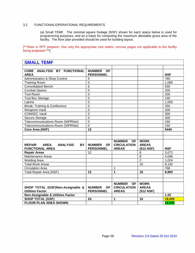
Page 58 Revision 3.6 Dated 25 Oct 2010
3.2 FUNCTIONAL/OPERATIONAL REQUIREMENTS
(a) Small TEMF. The nominal square footage (NSF) shown for each space below is used for programming purposes, and as a basis for computing the maximum allowable gross area of the facility. The floor plan provided should be used for building layout.
[***Note to RFP preparer: Use only the appropriate size matrix; remove pages not applicable to the facility being proposed.***] SMALL TEMF CORE ANALYSIS BY FUNCTIONAL AREA
NUMBER OF PERSONNEL
NSF
Administration & Shop Control 6 780 Training Room 0 1,080 Consolidated Bench 6 630 Combat Spares 0 200 Tool Room 0 200 Tool Box Storage 0 100 Latrine 0 1,000 Break, Training & Conference 0 250 Weapons Vault 0 300 COMSEC Vault 0 300 Secure Storage 0 300 Telecommunications Room (NIPRNet) 0 150 Telecommunications Room (SIPRNet) 0 150 Core Area (NSF) 12 5440
REPAIR AREA ANALYSIS BY FUNCTIONAL AREA
NUMBER OF PERSONNEL
NUMBER OF CIRCULATION AREAS
WORK AREAS (512 NSF) NSF
Repair Areas 12 6 3,072 Maintenance Areas 8 4,096 Welding Area 2 1,024 Total Work Areas 16 8,192 Circulation Area 1 768 Total Repair Area (NSF) 12 1 16 8,960
SHOP TOTAL (GSF)Non-Assignable & Utilities Factor
NUMBER OF PERSONNEL
NUMBER OF CIRCULATION AREAS
WORK AREAS (512 NSF)
Non-Assignable & Utilities Factor 1.25 SHOP TOTAL (GSF) 24 1 16 18,000 FLOOR PLAN AREA SHOWN 18,000
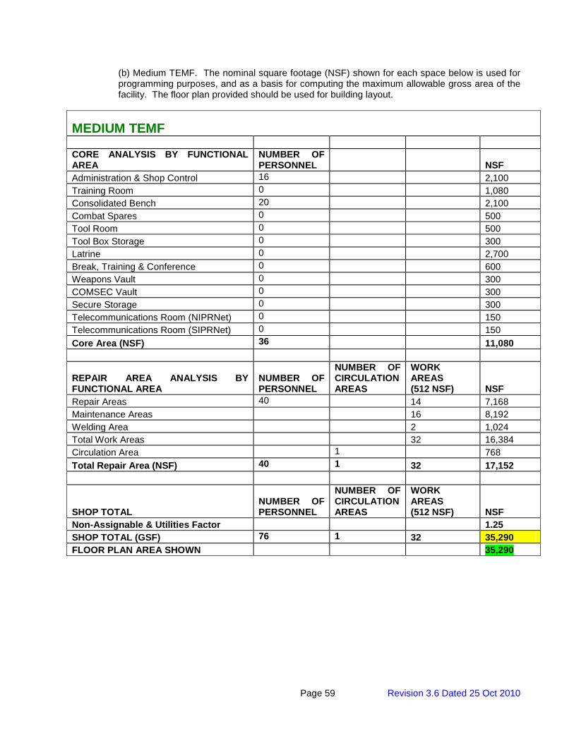
Page 59 Revision 3.6 Dated 25 Oct 2010
(b) Medium TEMF. The nominal square footage (NSF) shown for each space below is used for programming purposes, and as a basis for computing the maximum allowable gross area of the facility. The floor plan provided should be used for building layout.
MEDIUM TEMF CORE ANALYSIS BY FUNCTIONAL AREA
NUMBER OF PERSONNEL
NSF
Administration & Shop Control 16 2,100 Training Room 0 1,080 Consolidated Bench 20 2,100 Combat Spares 0 500 Tool Room 0 500 Tool Box Storage 0 300 Latrine 0 2,700 Break, Training & Conference 0 600 Weapons Vault 0 300 COMSEC Vault 0 300 Secure Storage 0 300 Telecommunications Room (NIPRNet) 0 150 Telecommunications Room (SIPRNet) 0 150 Core Area (NSF) 36 11,080
REPAIR AREA ANALYSIS BY FUNCTIONAL AREA
NUMBER OF PERSONNEL
NUMBER OF CIRCULATION AREAS
WORK AREAS (512 NSF) NSF
Repair Areas 40 14 7,168 Maintenance Areas 16 8,192 Welding Area 2 1,024 Total Work Areas 32 16,384 Circulation Area 1 768 Total Repair Area (NSF) 40 1 32 17,152
SHOP TOTAL NUMBER OF PERSONNEL
NUMBER OF CIRCULATION AREAS
WORK AREAS (512 NSF) NSF
Non-Assignable & Utilities Factor 1.25 SHOP TOTAL (GSF) 76 1 32 35,290 FLOOR PLAN AREA SHOWN 35,290
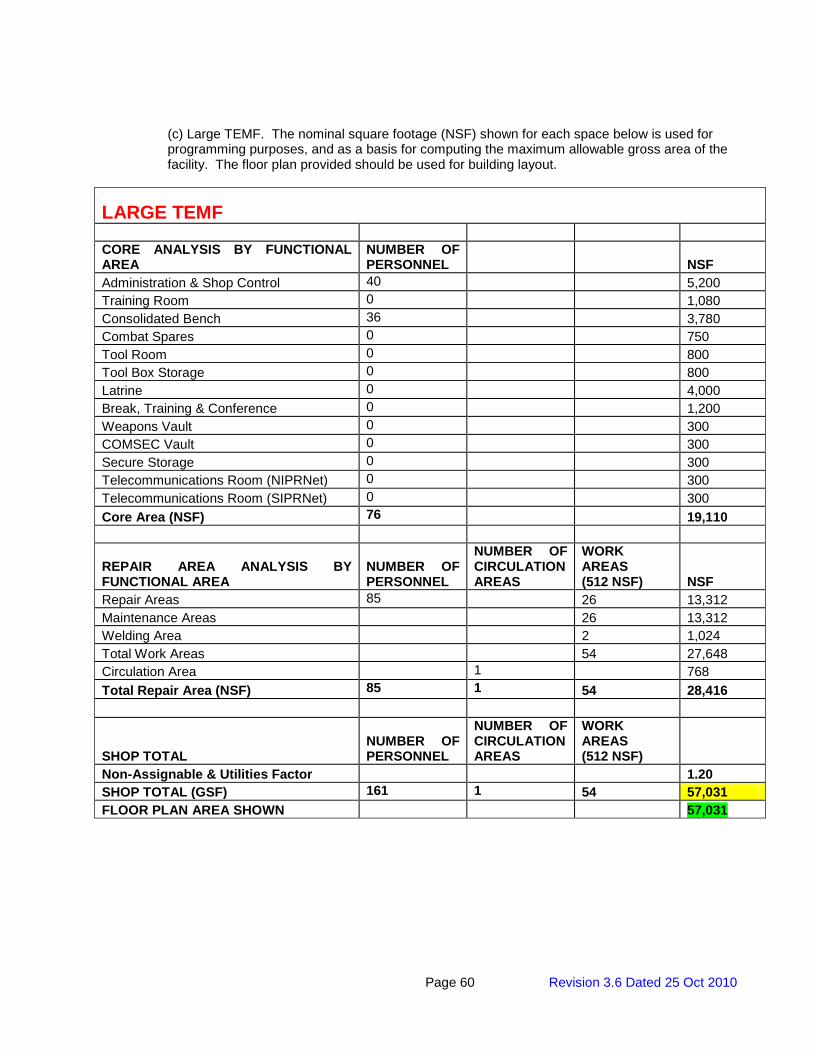
Page 60 Revision 3.6 Dated 25 Oct 2010
(c) Large TEMF. The nominal square footage (NSF) shown for each space below is used for programming purposes, and as a basis for computing the maximum allowable gross area of the facility. The floor plan provided should be used for building layout.
LARGE TEMF CORE ANALYSIS BY FUNCTIONAL AREA
NUMBER OF PERSONNEL
NSF
Administration & Shop Control 40 5,200 Training Room 0 1,080 Consolidated Bench 36 3,780 Combat Spares 0 750 Tool Room 0 800 Tool Box Storage 0 800 Latrine 0 4,000 Break, Training & Conference 0 1,200 Weapons Vault 0 300 COMSEC Vault 0 300 Secure Storage 0 300 Telecommunications Room (NIPRNet) 0 300 Telecommunications Room (SIPRNet) 0 300 Core Area (NSF) 76 19,110
REPAIR AREA ANALYSIS BY FUNCTIONAL AREA
NUMBER OF PERSONNEL
NUMBER OF CIRCULATION AREAS
WORK AREAS (512 NSF) NSF
Repair Areas 85 26 13,312 Maintenance Areas 26 13,312 Welding Area 2 1,024 Total Work Areas 54 27,648 Circulation Area 1 768 Total Repair Area (NSF) 85 1 54 28,416
SHOP TOTAL NUMBER OF PERSONNEL
NUMBER OF CIRCULATION AREAS
WORK AREAS (512 NSF)
Non-Assignable & Utilities Factor 1.20 SHOP TOTAL (GSF) 161 1 54 57,031 FLOOR PLAN AREA SHOWN 57,031
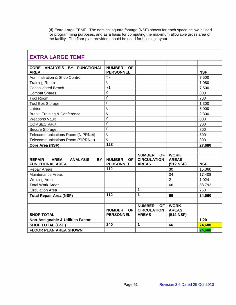
Page 61 Revision 3.6 Dated 25 Oct 2010
(d) Extra-Large TEMF. The nominal square footage (NSF) shown for each space below is used for programming purposes, and as a basis for computing the maximum allowable gross area of the facility. The floor plan provided should be used for building layout.
EXTRA LARGE TEMF CORE ANALYSIS BY FUNCTIONAL AREA
NUMBER OF PERSONNEL
NSF
Administration & Shop Control 57 7,500 Training Room 0 1,080 Consolidated Bench 71 7,500 Combat Spares 0 800 Tool Room 0 700 Tool Box Storage 0 1,300 Latrine 0 5,000 Break, Training & Conference 0 2,300 Weapons Vault 0 300 COMSEC Vault 0 300 Secure Storage 0 300 Telecommunications Room (NIPRNet) 0 300 Telecommunications Room (SIPRNet) 0 300 Core Area (NSF) 128 27,680
REPAIR AREA ANALYSIS BY FUNCTIONAL AREA
NUMBER OF PERSONNEL
NUMBER OF CIRCULATION AREAS
WORK AREAS (512 NSF) NSF
Repair Areas 112 30 15,360 Maintenance Areas 34 17,408 Welding Area 2 1,024 Total Work Areas 66 33,792 Circulation Area 1 768 Total Repair Area (NSF) 112 1 66 34,560
SHOP TOTAL NUMBER OF PERSONNEL
NUMBER OF CIRCULATION AREAS
WORK AREAS (512 NSF)
Non-Assignable & Utilities Factor 1.20 SHOP TOTAL (GSF) 240 1 66 74,688 FLOOR PLAN AREA SHOWN 74,688
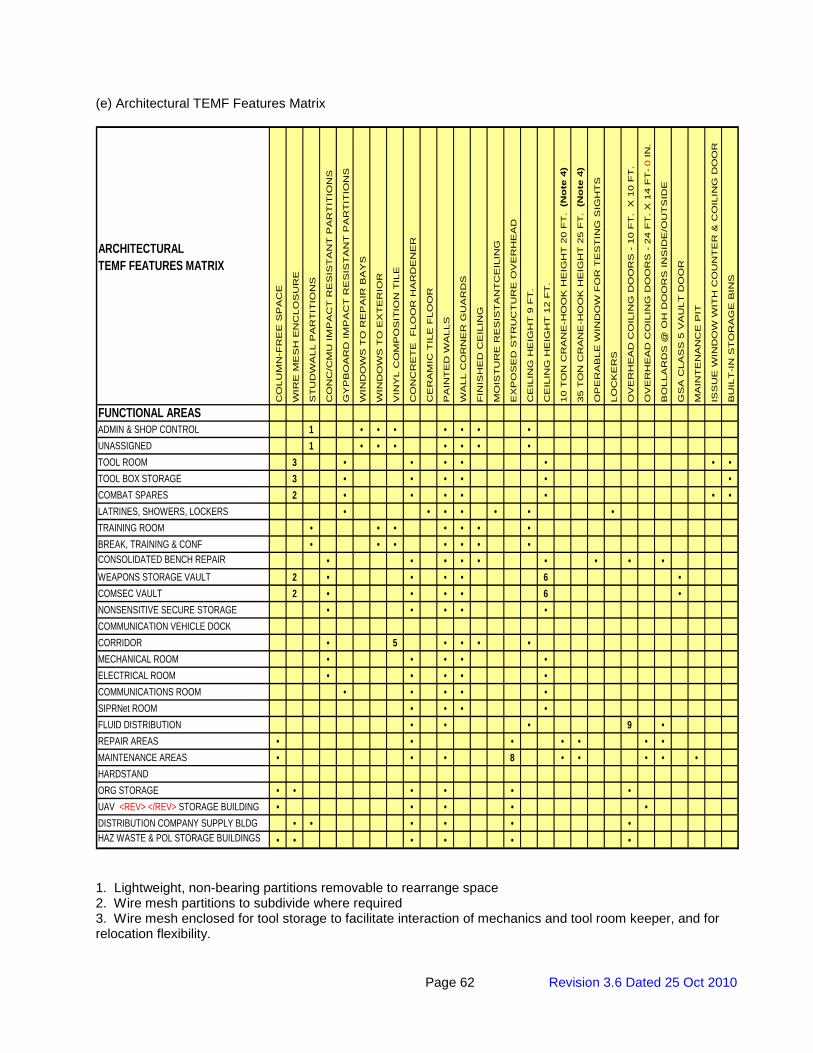
Page 62 Revision 3.6 Dated 25 Oct 2010
(e) Architectural TEMF Features Matrix
FUNCTIONAL AREASADMIN & SHOP CONTROL 1 • • • • • • •UNASSIGNED 1 • • • • • • •TOOL ROOM 3 • • • • • • •TOOL BOX STORAGE 3 • • • • • •COMBAT SPARES 2 • • • • • • •LATRINES, SHOWERS, LOCKERS • • • • • • •TRAINING ROOM • • • • • • •BREAK, TRAINING & CONF • • • • • • •CONSOLIDATED BENCH REPAIR • • • • • • • • •WEAPONS STORAGE VAULT 2 • • • • 6 •COMSEC VAULT 2 • • • • 6 •NONSENSITIVE SECURE STORAGE • • • • •COMMUNICATION VEHICLE DOCKCORRIDOR • 5 • • • •MECHANICAL ROOM • • • • •ELECTRICAL ROOM • • • • •COMMUNICATIONS ROOM • • • • •SIPRNet ROOM • • • •FLUID DISTRIBUTION • • • 9 •REPAIR AREAS • • • • • • •MAINTENANCE AREAS • • • 8 • • • • •HARDSTANDORG STORAGE • • • • • •UAV <REV> </REV> STORAGE BUILDING • • • • •DISTRIBUTION COMPANY SUPPLY BLDG • • • • • •HAZ WASTE & POL STORAGE BUILDINGS • • • • • •
ARCHITECTURALTEMF FEATURES MATRIX
GS
A C
LA
SS
5 V
AU
LT
DO
OR
MA
INT
EN
AN
CE
PIT
ISS
UE
WIN
DO
W W
ITH
CO
UN
TE
R &
CO
ILIN
G D
OO
R
CE
ILIN
G H
EIG
HT
12 F
T.
10 T
ON
CR
AN
E-H
OO
K H
EIG
HT
20 F
T.
(N
ote
4)
35 T
ON
CR
AN
E-H
OO
K H
EIG
HT
25 F
T.
(N
ote
4)
OP
ER
AB
LE
WIN
DO
W F
OR
TE
ST
ING
SIG
HT
S
FIN
ISH
ED
CE
ILIN
G
MO
IST
UR
E R
ES
IST
AN
TC
EIL
ING
BU
ILT
-IN
ST
OR
AG
E B
INS
LO
CK
ER
S
OV
ER
HE
AD
CO
ILIN
G D
OO
RS
- 1
0 F
T.
X 1
0 F
T.
OV
ER
HE
AD
CO
ILIN
G D
OO
RS
- 2
4 F
T.
X 1
4 F
T- 0 IN
.
BO
LLA
RD
S @
OH
DO
OR
S I
NS
IDE
/OU
TS
IDE
EX
PO
SE
D S
TR
UC
TU
RE
OV
ER
HE
AD
CE
ILIN
G H
EIG
HT
9 F
T.
PA
INT
ED
WA
LLS
WA
LL C
OR
NE
R G
UA
RD
S
GY
PB
OA
RD
IM
PA
CT
RE
SIS
TA
NT
PA
RT
ITIO
NS
WIN
DO
WS
TO
RE
PA
IR B
AY
S
WIN
DO
WS
TO
EX
TE
RIO
R
VIN
YL C
OM
PO
SIT
ION
TIL
E
CO
LU
MN
-FR
EE
SP
AC
E
WIR
E M
ES
H E
NC
LO
SU
RE
ST
UD
WA
LL P
AR
TIT
ION
S
CO
NC
/CM
U I
MP
AC
T R
ES
IST
AN
T P
AR
TIT
ION
S
CO
NC
RE
TE
F
LO
OR
HA
RD
EN
ER
CE
RA
MIC
TIL
E F
LO
OR
1. Lightweight, non-bearing partitions removable to rearrange space 2. Wire mesh partitions to subdivide where required 3. Wire mesh enclosed for tool storage to facilitate interaction of mechanics and tool room keeper, and for relocation flexibility.
Page 63 Revision 3.6 Dated 25 Oct 2010
4. Provide either a 10-ton or a 35-ton top running bridge crane for the repair areas and maintenance areas as noted in para. 2.1. 5. VCT in corridor on 2nd Floor (except Small TEMF). 6. Provide top of Concrete Cap at 12’-0”’. Provide an additional dropped ceiling to protect weapons and COMSEC equipment under repair. Top of caps shall be secure from unauthorized access. 7. All Finishes are considered minimum finishes only. 8. The Maintenance Corridor through the Core Area shall have a minimum 14’-0” clear Ceiling Height. 9. Roll-up doors or double doors may be provided for exterior access to the Fluid Distribution Room based on User preference.
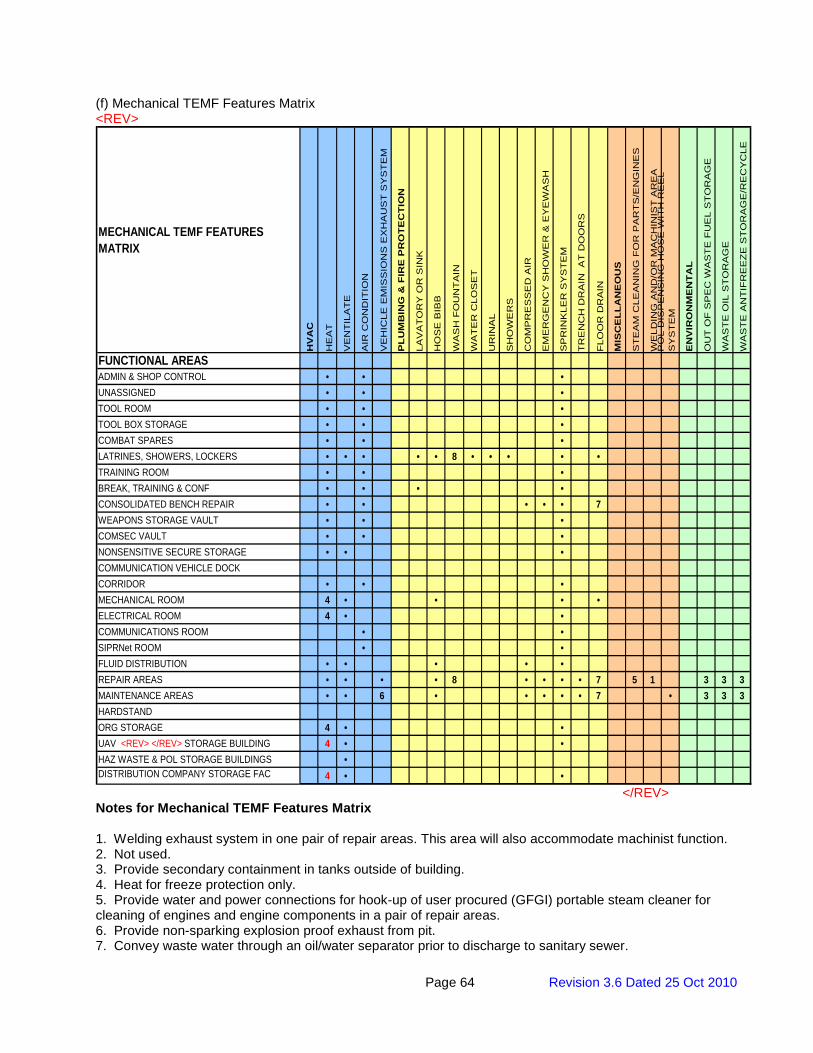
Page 64 Revision 3.6 Dated 25 Oct 2010
(f) Mechanical TEMF Features Matrix <REV>
MECHANICAL TEMF FEATURES MATRIX
HV
AC
HE
AT
VE
NT
ILA
TE
AIR
CO
ND
ITIO
N
VE
HIC
LE E
MIS
SIO
NS
EX
HA
US
T S
YS
TE
M
PL
UM
BIN
G &
FIR
E P
RO
TE
CT
ION
LAV
AT
OR
Y O
R S
INK
HO
SE
BIB
B
WA
SH
FO
UN
TA
IN
WA
TE
R C
LOS
ET
UR
INA
L
SH
OW
ER
S
CO
MP
RE
SS
ED
AIR
EM
ER
GE
NC
Y S
HO
WE
R &
EY
EW
AS
H
SP
RIN
KLE
R S
YS
TE
M
TR
EN
CH
DR
AIN
A
T D
OO
RS
FLO
OR
DR
AIN
MIS
CE
LL
AN
EO
US
ST
EA
M C
LEA
NIN
G F
OR
PA
RT
S/E
NG
INE
S
WE
LDIN
G A
ND
/OR
MA
CH
INIS
T A
RE
AP
OL
DIS
PE
NS
ING
HO
SE
WIT
H R
EE
L S
YS
TE
M
EN
VIR
ON
ME
NT
AL
OU
T O
F S
PE
C W
AS
TE
FU
EL
ST
OR
AG
E
WA
ST
E O
IL S
TO
RA
GE
WA
ST
E A
NT
IFR
EE
ZE
ST
OR
AG
E/R
EC
YC
LE
FUNCTIONAL AREASADMIN & SHOP CONTROL • • •UNASSIGNED • • •TOOL ROOM • • •TOOL BOX STORAGE • • •COMBAT SPARES • • •LATRINES, SHOWERS, LOCKERS • • • • • 8 • • • • •TRAINING ROOM • • •BREAK, TRAINING & CONF • • • •CONSOLIDATED BENCH REPAIR • • • • • 7WEAPONS STORAGE VAULT • • •COMSEC VAULT • • •NONSENSITIVE SECURE STORAGE • • •COMMUNICATION VEHICLE DOCKCORRIDOR • • •MECHANICAL ROOM 4 • • • •ELECTRICAL ROOM 4 • •COMMUNICATIONS ROOM • •SIPRNet ROOM • •FLUID DISTRIBUTION • • • • •REPAIR AREAS • • • • 8 • • • • 7 5 1 3 3 3MAINTENANCE AREAS • • 6 • • • • • 7 • 3 3 3HARDSTANDORG STORAGE 4 • •UAV <REV> </REV> STORAGE BUILDING 4 • •HAZ WASTE & POL STORAGE BUILDINGS •DISTRIBUTION COMPANY STORAGE FAC 4 • •
</REV> Notes for Mechanical TEMF Features Matrix 1. Welding exhaust system in one pair of repair areas. This area will also accommodate machinist function. 2. Not used. 3. Provide secondary containment in tanks outside of building. 4. Heat for freeze protection only. 5. Provide water and power connections for hook-up of user procured (GFGI) portable steam cleaner for cleaning of engines and engine components in a pair of repair areas. 6. Provide non-sparking explosion proof exhaust from pit. 7. Convey waste water through an oil/water separator prior to discharge to sanitary sewer.
Page 65 Revision 3.6 Dated 25 Oct 2010
8. Provide wash fountain in 8 FT circulation bay adjacent to the core area, or outside the latrines in the core area as shown on the drawings.
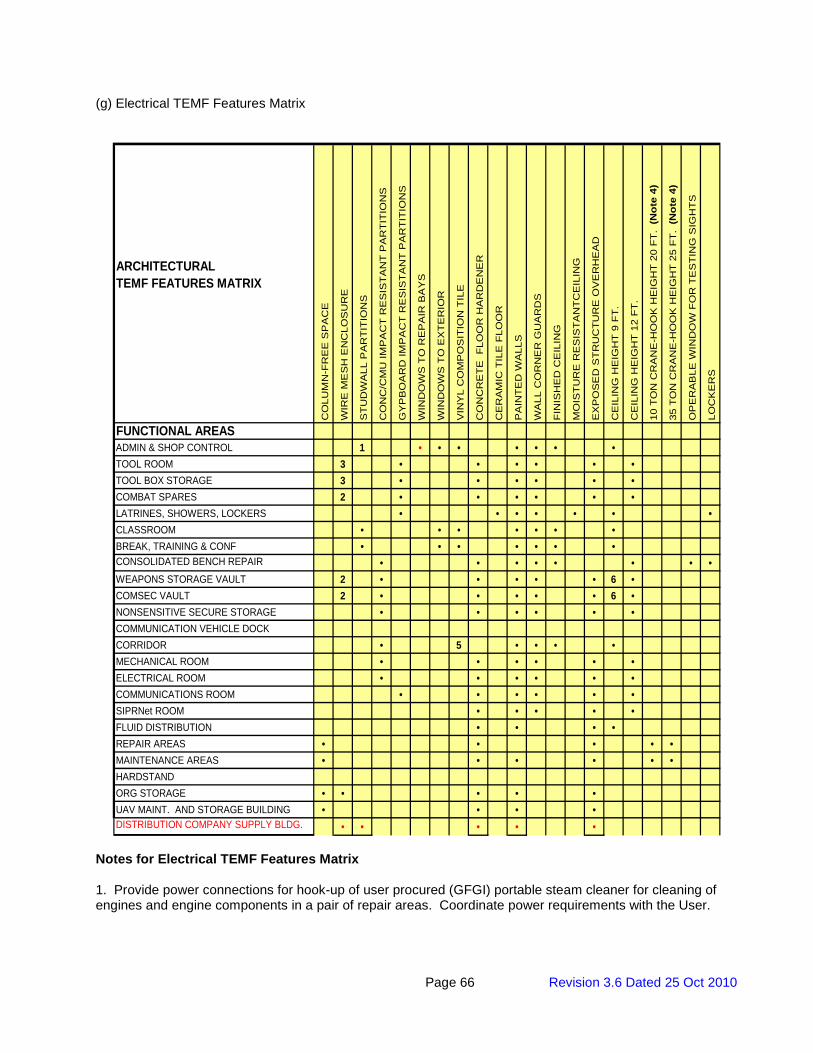
Page 66 Revision 3.6 Dated 25 Oct 2010
(g) Electrical TEMF Features Matrix
FUNCTIONAL AREASADMIN & SHOP CONTROL 1 • • • • • • •TOOL ROOM 3 • • • • • •TOOL BOX STORAGE 3 • • • • • •COMBAT SPARES 2 • • • • • •LATRINES, SHOWERS, LOCKERS • • • • • • •CLASSROOM • • • • • • •BREAK, TRAINING & CONF • • • • • • •CONSOLIDATED BENCH REPAIR • • • • • • • •WEAPONS STORAGE VAULT 2 • • • • • 6 •COMSEC VAULT 2 • • • • • 6 •NONSENSITIVE SECURE STORAGE • • • • • •COMMUNICATION VEHICLE DOCKCORRIDOR • 5 • • • •MECHANICAL ROOM • • • • • •ELECTRICAL ROOM • • • • • •COMMUNICATIONS ROOM • • • • • •SIPRNet ROOM • • • • •FLUID DISTRIBUTION • • • •REPAIR AREAS • • • • •MAINTENANCE AREAS • • • • • •HARDSTANDORG STORAGE • • • • •UAV MAINT. AND STORAGE BUILDING • • • •DISTRIBUTION COMPANY SUPPLY BLDG. • • • • •
CE
RA
MIC
TIL
E F
LOO
R
PA
INT
ED
WA
LLS
WA
LL C
OR
NE
R G
UA
RD
S
CO
LUM
N-F
RE
E S
PA
CE
WIR
E M
ES
H E
NC
LOS
UR
E
ST
UD
WA
LL P
AR
TIT
ION
S
CO
NC
/CM
U IM
PA
CT
RE
SIS
TA
NT
PA
RT
ITIO
NS
GY
PB
OA
RD
IMP
AC
T R
ES
IST
AN
T P
AR
TIT
ION
S
WIN
DO
WS
TO
RE
PA
IR B
AY
S
ARCHITECTURALTEMF FEATURES MATRIX
CE
ILIN
G H
EIG
HT
12
FT
.
WIN
DO
WS
TO
EX
TE
RIO
R
VIN
YL
CO
MP
OS
ITIO
N T
ILE
EX
PO
SE
D S
TR
UC
TU
RE
OV
ER
HE
AD
CE
ILIN
G H
EIG
HT
9 F
T.
CO
NC
RE
TE
FLO
OR
HA
RD
EN
ER
10 T
ON
CR
AN
E-H
OO
K H
EIG
HT
20
FT
. (N
ote
4)
35 T
ON
CR
AN
E-H
OO
K H
EIG
HT
25
FT
. (N
ote
4)
OP
ER
AB
LE W
IND
OW
FO
R T
ES
TIN
G S
IGH
TS
FIN
ISH
ED
CE
ILIN
G
MO
IST
UR
E R
ES
IST
AN
TC
EIL
ING
LOC
KE
RS
Notes for Electrical TEMF Features Matrix 1. Provide power connections for hook-up of user procured (GFGI) portable steam cleaner for cleaning of engines and engine components in a pair of repair areas. Coordinate power requirements with the User.
Page 67 Revision 3.6 Dated 25 Oct 2010
2. MILVANS (100A), TOE vans (50A), Hospital (100A, 208V, 3-PH, 5-Wire). Each of these vans will be located adjacent to the SATS, ASLMS or Communications Van on the TEMF apron. Provide power connections on the exterior of the building for these vans, when they are required by the User. 3. LCSS Vans (to be discontinued in future), Patriot Missile Units. 4. For Engineers shop. 5. Communications Vans (100A). 6. Hospital units require 120/208V, 3-PH, 5-Wire connection. 7. Provide power and conduit and wiring system(s) for user provided panable zoom camera system; monitored in Admin and Shop Control. 8. Lighting classification for pit lighting shall be determined during the design. 9. Provide 1-4" conduit with a 6 pair copper cable to the Distribution Company Storage and Organizational Storage Buildings from the main communications room in the TEMF. Conduit and cable routing may be to the nearest telecommunications maintenance hole before routing cable back to the TEMF main communications room. Provide Protected Entrance Terminal (PET) with one 110 type block mounted on a 4 ft by 8 ft backboard mounted vertically. Backboard treatment shall be in accordance with I3A. Provide one wall mounted telephone outlet inside the building. Ground PET in accordance with 250.50 and 800.100 of NFPA 70 National Electrical Code. 10. Provide 208V single phase power in all Repair Areas and for tire changing machine where shown on the TEMF Standard Drawings. 11. ASLMS Containers
a) The ASLMS Container is provided with the following: 1) Each ASLMS container comes with a set of two – 150 foot cables with each end plug identical. MS part number for the plug used on cable is MS3456W16-10P. 2) Electrical circuit is 20 ampere, 120 volt, single phase.
b) Provide the following power provisions for each ASLMS container: 1) Two dedicated 20 ampere, 120 volt, single phase circuits with a special receptacle for each circuit. MS part number for special receptacle to be provided is MS3451W16-10S.
12. SATS Containers a) The SATS Container is provided with the following:
1) Integrated 10 KW generator (208V, 3 phase 60 Hz) 2) A wall mounted 100 Amp, 208 volt, 3-phase, 60 Hz AC conforming to MIL-C-22992, Class L, Style P comprised of a MS90558 C 44 4 shell, with an MS14055 insert having insert arrangement 44-12, along with a MS90564 44 C weather-tight cover. 3) Signal entry panel (SEP) with the following connections: RS 232 Male/Female small and large, RJ 11 (phone), RJ 45 (LAN), 10 Base 2 (BNC), and 10 Base T (Ethernet).
b) Provide the following power and data provisions for each SATS container: 1) A branch circuit sized to the full load capacity of the 10kw generator to a weatherproof wall mounted 100 amp disconnect switch located within the cable’s reach. 2) A pre-manufacturer cable, stock number 5995-01-435-8697. This cable is 50 foot long with a plug for the SATS receptacle at one end and terminal connections on the other end. Connect the cable’s terminal ends to the disconnect switch. Provide a means to hang the cable. 3) A weatherproof RJ 45 (phone) and RJ 45 (LAN) outlet with the conduit and cables (Category 6) to the Communication Room and connect per I3A requirements. Provide 50 feet of exterior cable with appropriate connectors on each end for each outlet. Provide a means to hang the cables.
Page 68 Revision 3.6 Dated 25 Oct 2010
3.2 References
1. 40 CFR 261, Identification and Listing of Hazardous Waste 2. 40 CFR 262, Standards Applicable to Generators of Hazardous Waste 3. 40 CFR 264, Standards for Owners and Operators of Hazardous Waste Treatment, Storage,
and Disposal Facilities 4. American Society of Mechanical Engineers (AMSE); ASME HST-1, Performance Standard for
Electric Chain Hoists; ASME HST-4, Performance Standard for Overhead Electric Wire Rope Hoists
5. ANSI Z358.1, American National Standard for Emergency Eyewash and Shower Equipment 6. ANSI/TIA/EIA 606-A, Administration Standard for Commercial Telecommunication
Infrastructure. 7. AR 190-11, Physical Security of Arms, Ammunition, and Explosives (FOUO) 8. AR 190-51, Security of Unclassified Army Property (Sensitive and Nonsensitive) 9. AR 380-5, Department of the Army Information Security Program 10. Crane Manufacturers Association of America (CMAA); CMAA 70, Top Running and Bridge
and Gantry Type Multiple Girder Electric Overhead Traveling Cranes, No. 70; CMAA 74, Top Running and Under Running Single Girder Electric Overhead Cranes Utilizing Under Running Trolley Hoist, No. 74
11. Fed Spec AA-V-2737, Modular Vault Systems 12. <REV>UFC 4-020-01 DoD Security Engineering Facilities Planning Manual </REV> 13. <REV>UFC 3-550-1 Exterior Electrical Power Distribution </REV> 14. AR 380-40, Policy for Safeguarding and Controlling Communications Security (COMSEC)
Material (FOUO). 15. USACE STD 872-90-03, FE6 Chain-Link Security Fence Details
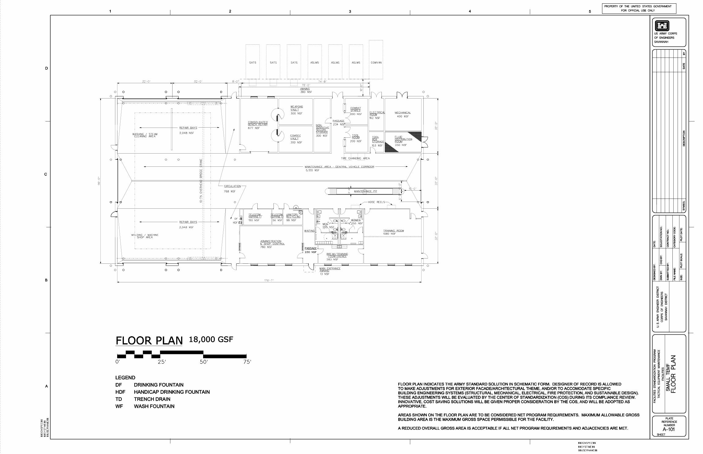
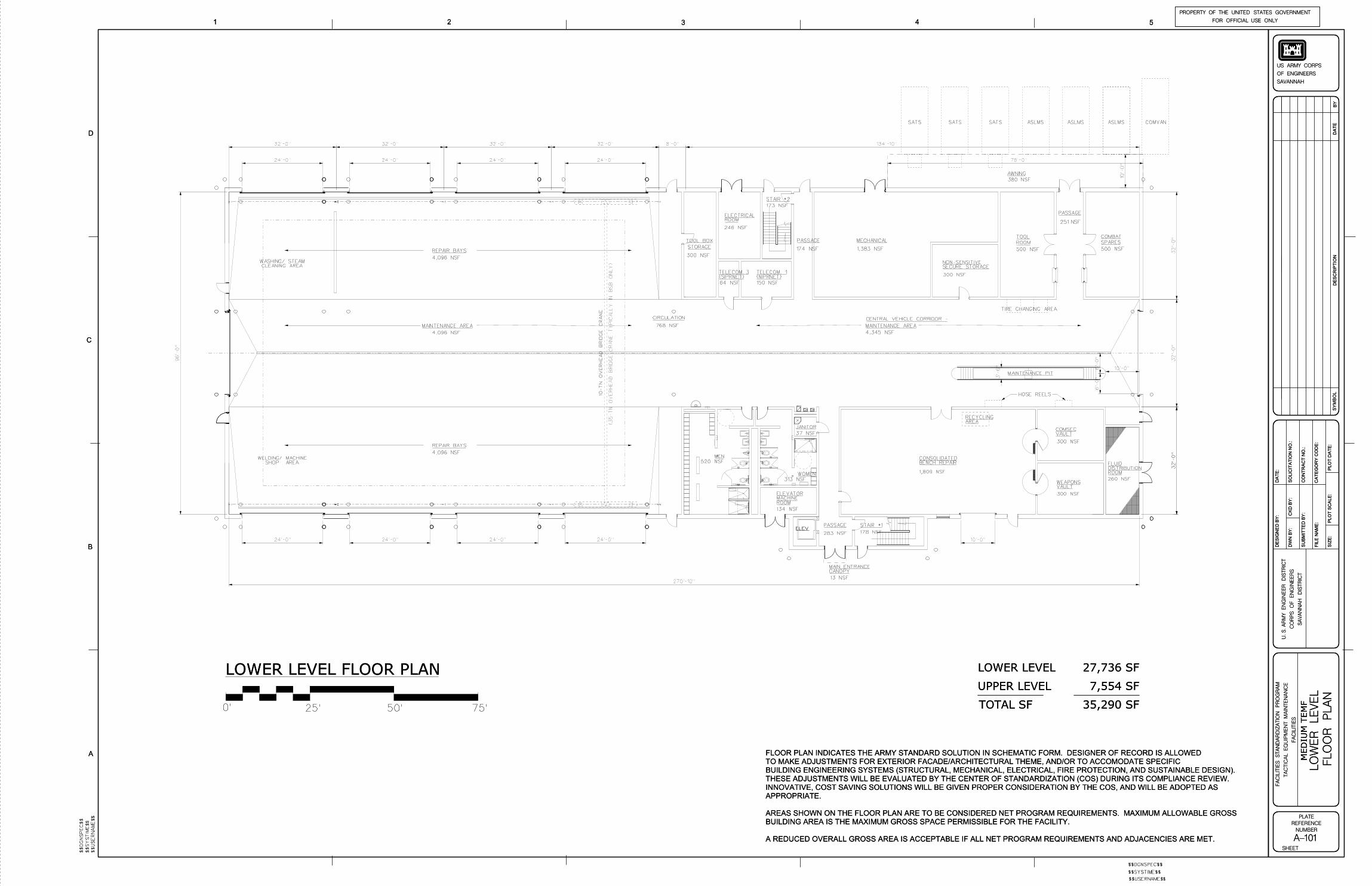
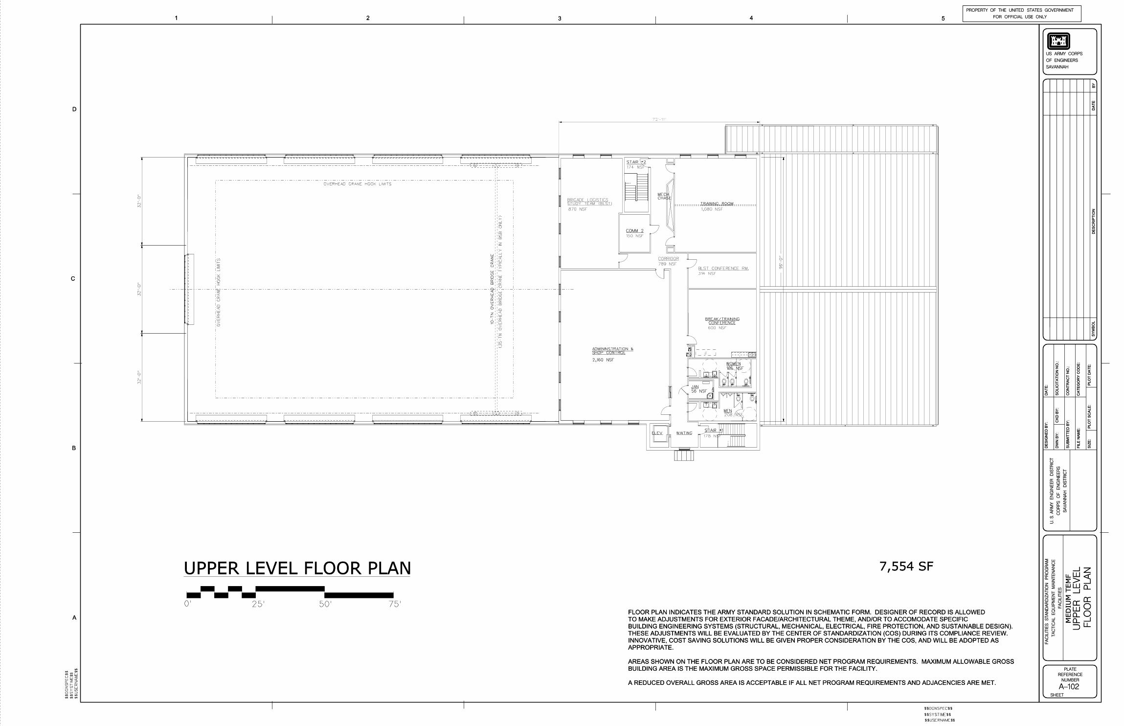
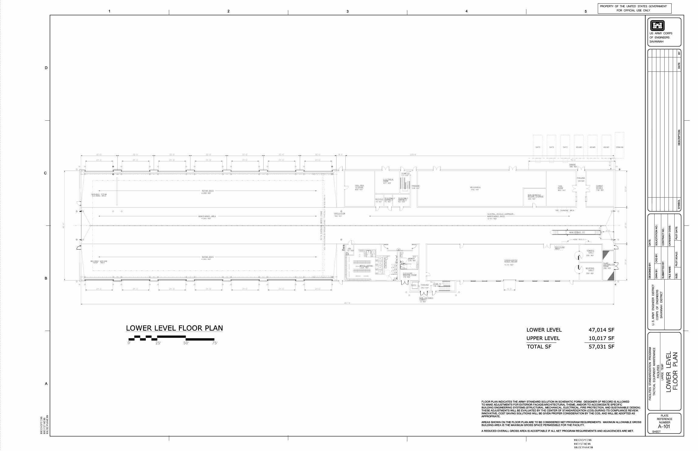
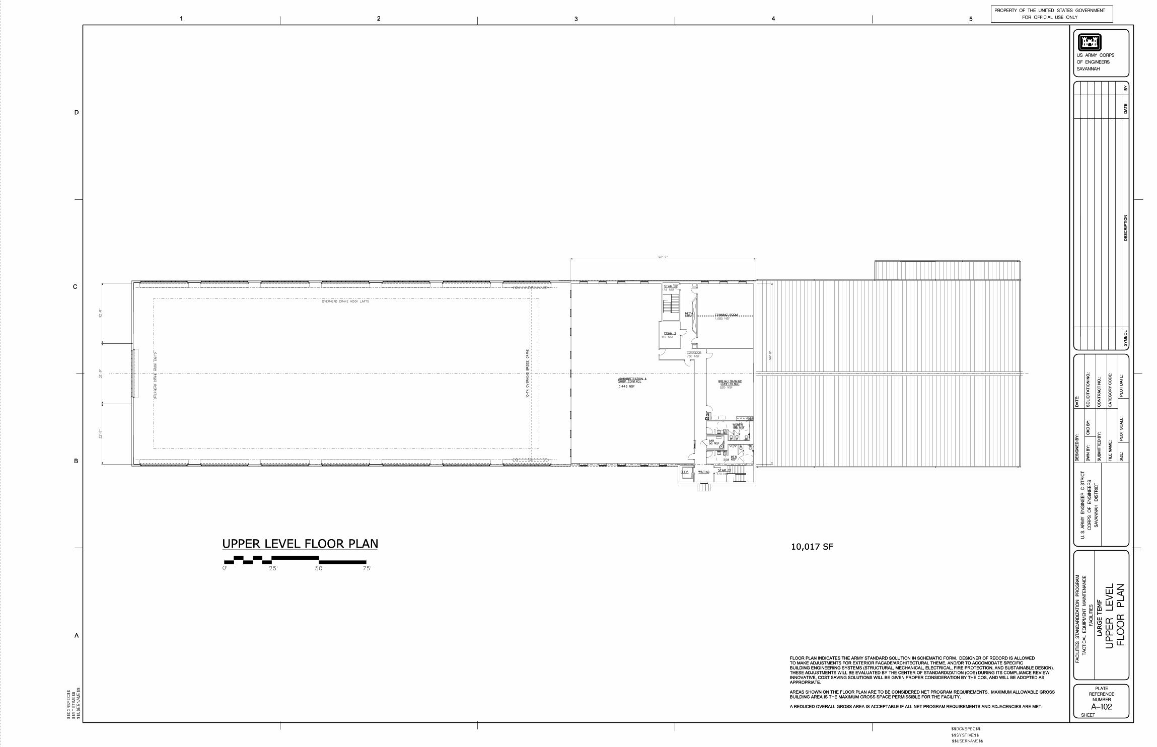
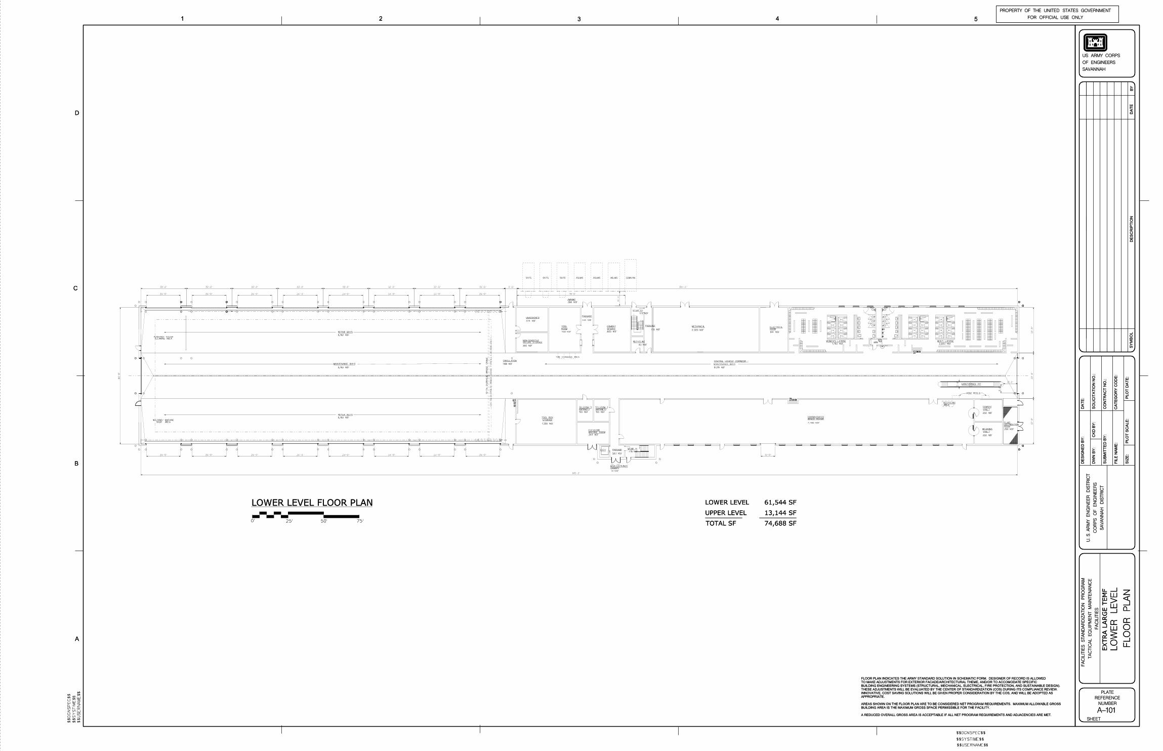
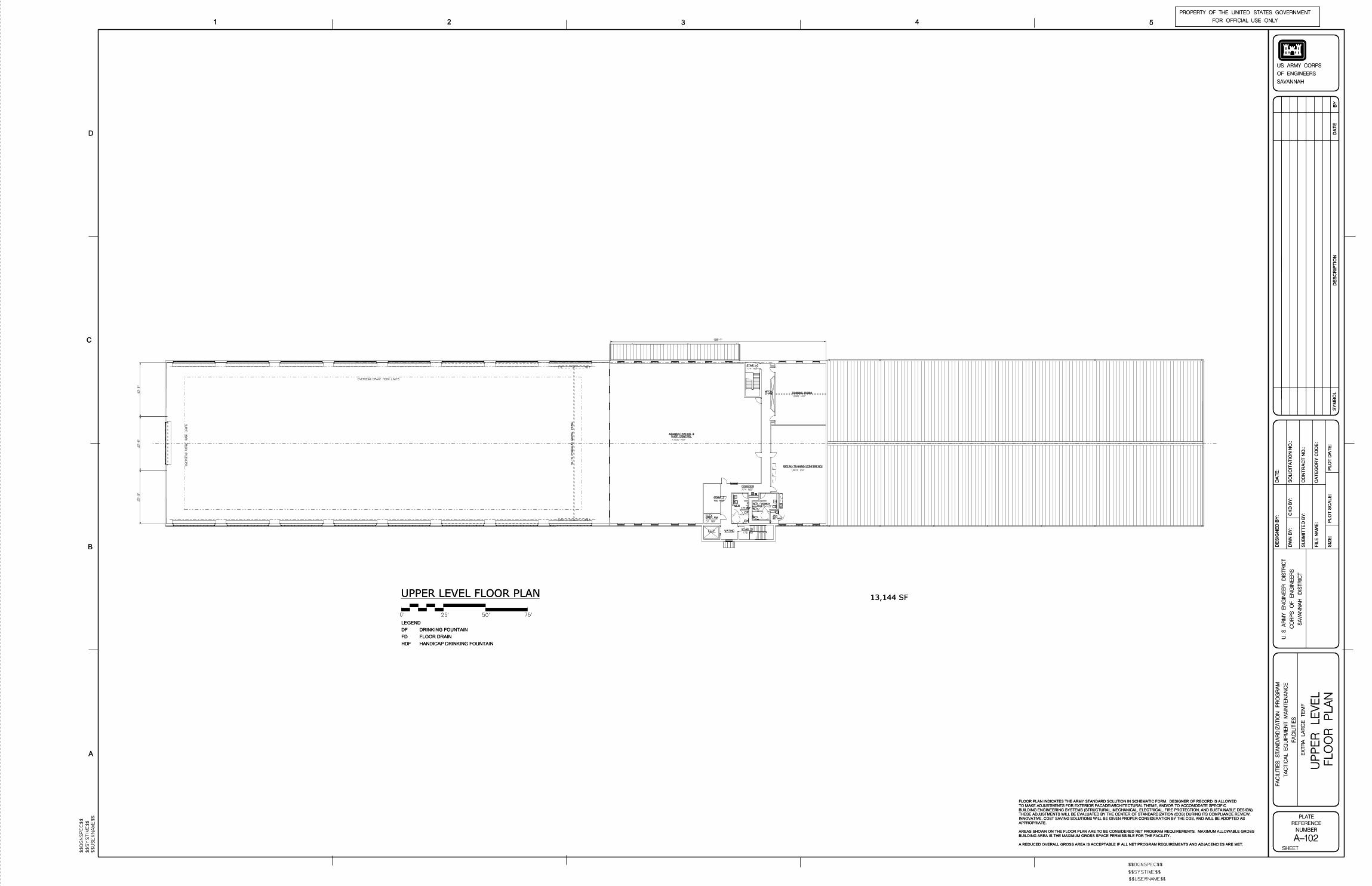
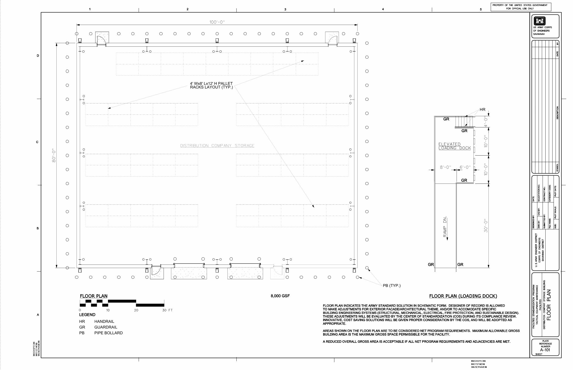
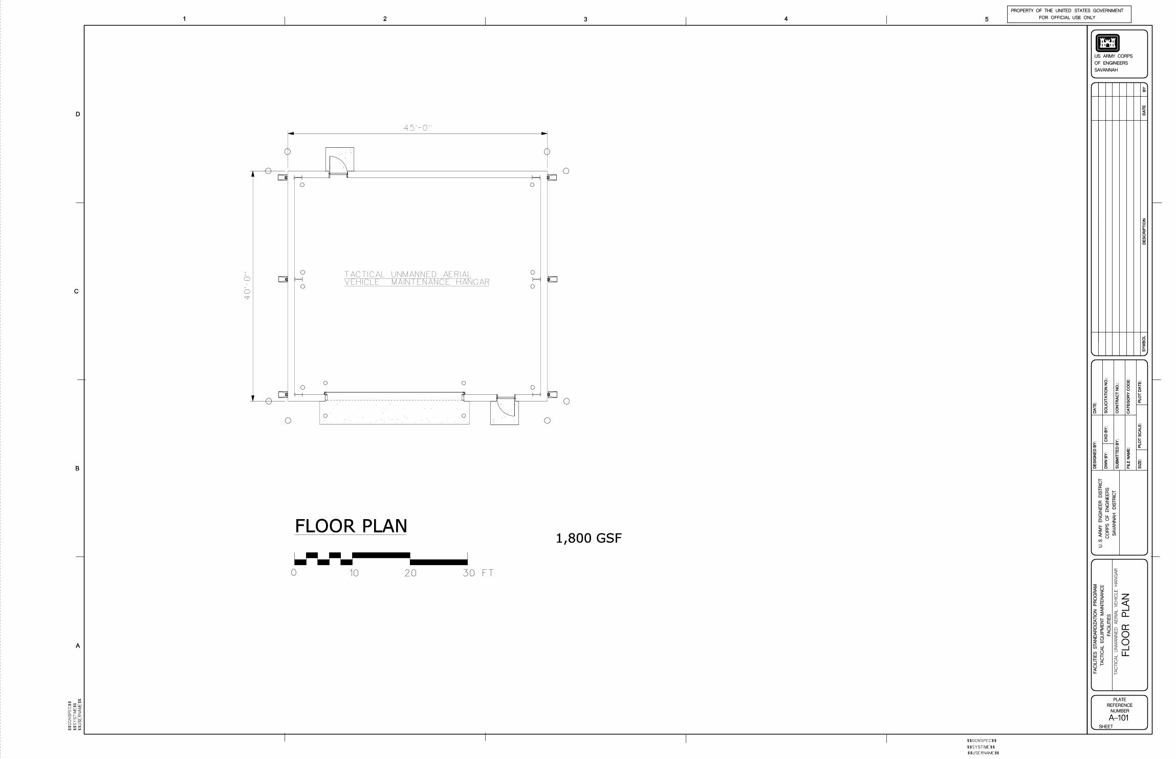


![Tactical Combat Casualty Care [TCCC] Some reminders and ...€¦ · Tactical Combat Casualty Care Tactical Evacuation Care The term “Tactical Evacuation” includes both Casualty](https://img.pdfslide.net/doc/110x75/604ef4767ef6a83727287be2/tactical-combat-casualty-care-tccc-some-reminders-and-tactical-combat-casualty.jpg)