Embed Size (px)
Citation preview

Christof Pflumm, Nils Haase, Antonia Morherr, Johannes Nickel, Amel Mekic, Philipp Harbach, Lara-Isabel Rodriguez
TADF FOR HIGH PERFORMANCE OLEDS
1

Outline
We are Merck – Company Overview
OLED at Merck
TADF in OLEDs
2

we are
3

1668founded
66countries
50,000 employees
€1.7 bninvested in R&D
in 2015
€12.8 bnsales in 2015
Merck FamilyEquity interest
70.3%
Family-ownedfor 12 generations
with long term orientation
ShareholdersShare capital
29.7%
Publicly traded since 1995
DAX member since 2007
Our ownership structure
4

5
Founded in Darm-stadt, Germany, in 1668 by Friedrich Jacob Merck, we are the world’s oldest pharmaceutical and chemical company. Today, the Merck family remains the majority owner of the company.
Over the course of nearly 350 years, we have become a truly global company. Our approximately 50,000 people work in 66 countries and are united by their passion for new ideas, the possibilities of tech-nology, and the potential to make a difference in the world.
We are known as Merck internatio-nally. In the United States and Canada we operate as EMD Serono in the Biopharma business, as MilliporeSigma in the Life Science business, and as EMD Performance Materials in the materials business.
We live in a world of possibilities.
A world where exploration and discovery are celebrated. Our meticulous and research-driven businesses deliver diverse, high-quality products that enrich lives and enable us to share business success with our customers.
we are

We advance technologies for life across 3 sectors:Healthcare, Life Science, and Performance Materials
Life SciencePerformance
MaterialsHealthcare
• Liquid crystals and OLEDs
• Effect pigments
• High-tech materials
• Innovative products, tools and laboratory supplies
• Industry leading e-commerceplatform and supply chaincapability
• Prescription medicines
• Oncology
• Multiple sclerosis
• Fertility
• Over-the-counter products
• Innovations in allergies and biosimilars
Healthcare
Life Science
Performance Materials
6

History and future
Nearly 350 years of experience for customers and clients
Friedrich Jacob Merck purchases the “Angel Pharmacy” (Engel-Apotheke) in Darmstadt
Acquisitionof Serono
Acquisitionof Millipore
Acquisition of AZElectronic Materials
1668 1900 2007 2010 2014 2015 2018
Acquisition of Sigma-Aldrich
Our 350th
anniversaryWe are represented onall continents
7

Performance Materials
Business Units and Product Lines
• Liquid crystals
• Photoresists
• Dielectric materials
• Dielectrics
• Colloidal silica
• Lithography
• Photoresists
• Yield enhancers
• Edge bead removers
• OLED
• Quantum materials
• LED materials
• Photovoltaic
• Flexible hybrid electronics
Integrated Circuit Materials
DisplayMaterials
AdvancedTechnologies
• Effect and functional pigments
• Functional materials for specialist applications
Pigments &Functional Materials
Performance Materials Sales by region 2015 in € million8
OLED AT MERCK
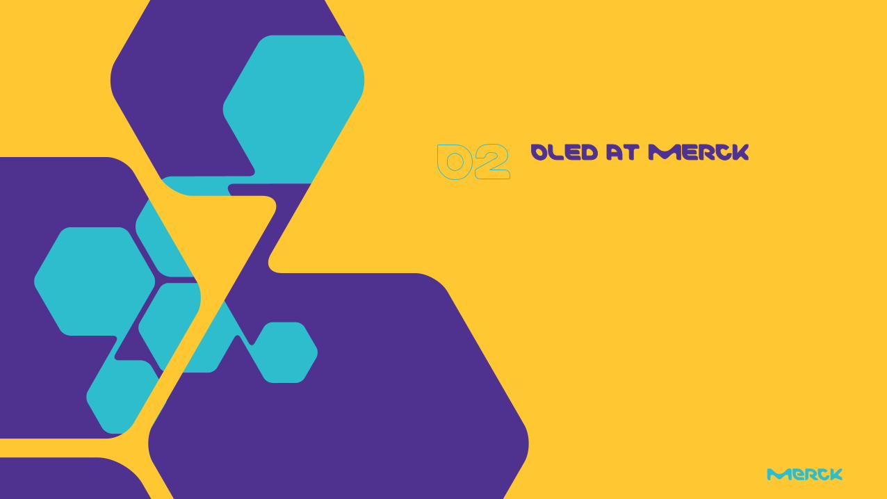
OLED: a strategic initiative at MerckWe have continuously invested in OLED material innovation since 2005
10
Pictures: Merck’s latest investments for innovation in OLED technology
Merck is committed to continuing its 45 years of successful innovation for displays with strong leaders
Since 2005 Merck is investing continuously in OLED materials innovation with increasing speed, power and dedication.
30 mio. EUR investment in new production site – opened Sept. 2016.
NEW milestone:
Our OLED production site was be inaugurated in September
2016 at our global headquarters in Darmstadt
10

Merck OLED: Worldwide Capabilities
Chemical Synthesis Physics and Application High Volume Ink Production
Germany Germany & UK Japan
Customer Specific Development and MarketingInk Formulation
Germany Germany, Korea, Taiwan, China, Japan, US
11

livilux® OLED Materials for vapor and printing
Excellent Quality and Large Scale
livilux® OLED materials for vaporization
Hole transport materials
Electron transport materials
Matrix materials
Emitter materials
Hole and electron blocking materials
Make it large. livilux® for printing
Hole transport inks
Hole injection inks
Emitter inks
livilux® – Excellent Quality. Reliable. Reproducible.
12

TADF IN OLEDS

Strong request for highly efficient display blue
Why?
Roughly 1/3 of the power needs to be blue, 1/3 green and 1/3 red in a display
State of the art
Blue ≈ 10% EQE
Green, Red > 20% EQE
Very roughly: > 50% of the power used by blue!
High potential for power saving in blue
Why not phosphorescent?
No stable material set found so far for display blue (CIE y < 0.1)
TADF!
Why TADF?
14

TADF Device: Emission Layer
+
-
Ea ~ LUMO
e transport level
h transport level
Ip ~ HOMO
Host TADF
S+T CT
Electrical power
abs fl
abs ph
fl (CT)
IC
+TADF
1ππ*
3ππ*
1CT 3CT
3nπ*
TA ISC
+TADF
S0
15

16
The Device Consists of More
Injection layers
For lowering voltage
Blocking Layers (EBL, HBL)
Reduction of leakage currents
…
All layers contribute to device performance
Anode CathodeEML
1
2
1
2
3
3
hn 4
HBLEBL
17
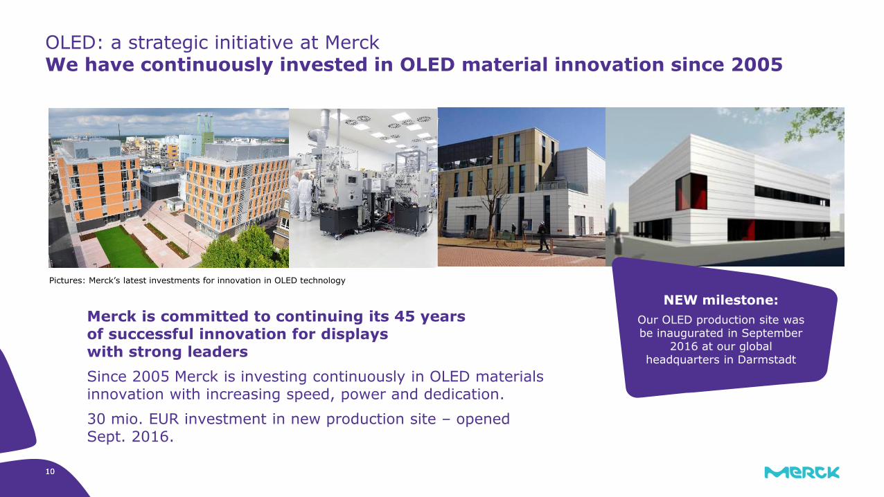
Basic device structure, exact stacks shown might differ (especially HTM thickness)
4CzIPN used as literature known, efficient TADF material
Green emission
Materials and Device
4CzIPN
100 nm Alu
40 nm ETM
10 nm HBM
15 nm Host+4CzIPN
40 nm HTM
20 nm P-doped HTM
50 nm ITO

18
In a Merck standard triplet green host (H1), 4CzIPN shows
Good peak EQE but rather strong roll-off
Lower lifetime than Ir(ppy)3
Need to address roll-off and lifetime
Worse roll-off due to higher excited state lifetime?
Basic Performance Overview
0
5
10
15
20
25
0 5000 10000
EQ
E [
%]
luminance [cd/m²]
Ir(ppy)3
4CzIPN
4000
4200
4400
4600
4800
5000
0 200 400 600
lum
ina
nce
[cd
/m²]
time [h]

19
Ip/Ea from calculations calibrated to CV measurements
TADF is electron trap => Recombination mainly at EML/HBL interface for low TADF concentration
Opposite situation than in phosphorescent emitter device
Has to be taken into account, some optimization for phosphorescent devices might not work
A Rough Look at Energy Levels
EMLHTM HBL
Ip
-5.2eV
-1.8
-1.6eVEa
-5.2
-
++
-
H1+Ir(ppy)3
EMLHTM HBL
Ip
-5.2eV
-3.4
-1.6eVEa
-6.0
-5.7
-2.6
-
+
+
++
+
--
--
H1+4CzIPN

20
The employed ETL has a low T1 and thus quenches the TADF emission
Without HBL, the efficiency is significantly reduced as emission mainly from EML/HBL interface
However, much longer lifetime (@ 10mA/cm²)
Would look different when compared at same initial luminance
An HBL is Crucial
With HBL
Without HBL

21
Important optimization parameter: TADF concentration in EML. Can we improve performance?
Increase of TADF concentration (Host H1):
Roll-off improves
Lifetime improves (starting current 10mA/cm²)
BUT: Unacceptable efficiency drop, strong spectral shift (30nm shift between 5% and 40% TADF)
Variation of TADF Concentration
22
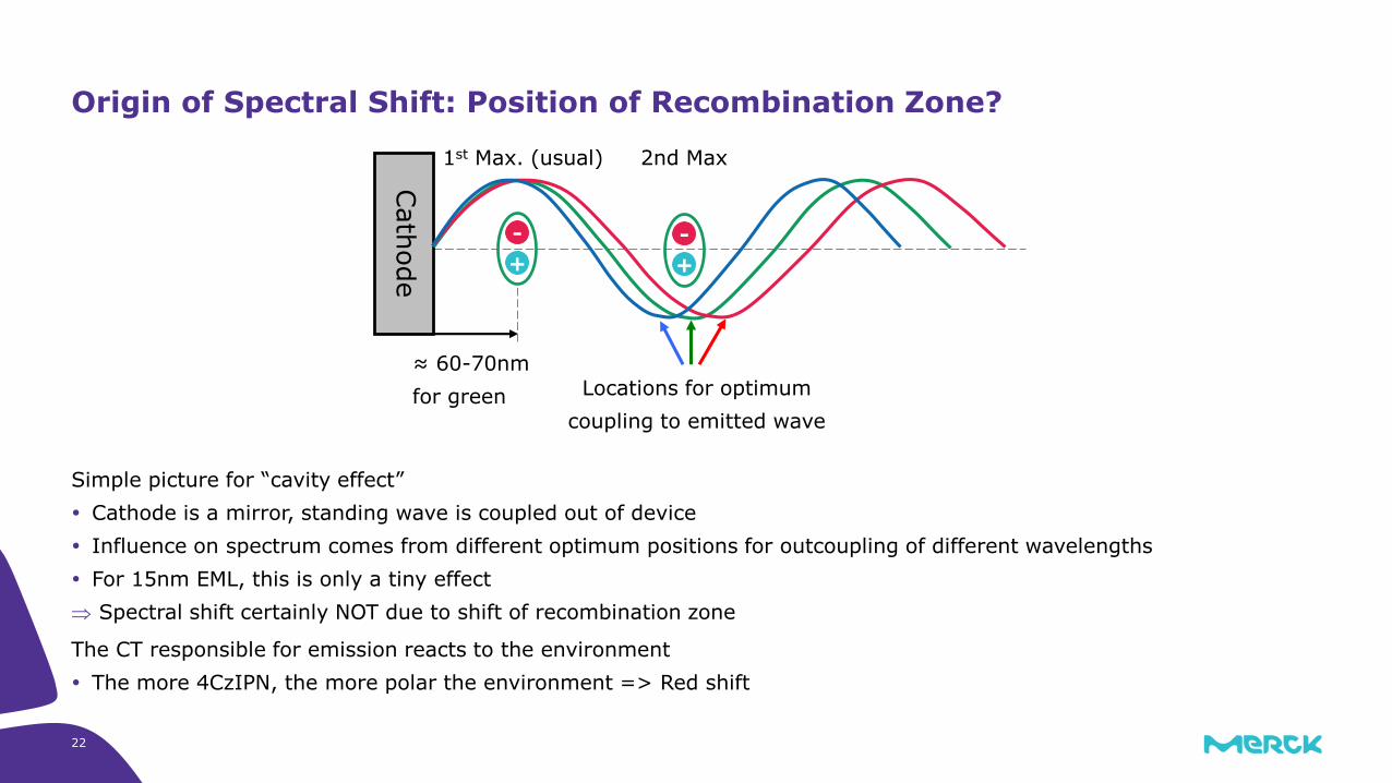
Simple picture for “cavity effect”
Cathode is a mirror, standing wave is coupled out of device
Influence on spectrum comes from different optimum positions for outcoupling of different wavelengths
For 15nm EML, this is only a tiny effect
Spectral shift certainly NOT due to shift of recombination zone
The CT responsible for emission reacts to the environment
The more 4CzIPN, the more polar the environment => Red shift
Origin of Spectral Shift: Position of Recombination Zone?
Cath
ode
2nd Max1st Max. (usual)
Locations for optimum
coupling to emitted wave
+
-
+
-
≈ 60-70nm
for green

23
Using another host results in the same trends:
Increase of concentration => Improved roll-off & lifetime, but spectral shift and unacceptable EQE
More examples exist
Is this a general trend?
Decrease could be due to aggregation, increased TTA or TPA,… -> “EML internal”
Another Host…

24
Host H3 results in rather low efficiency
Otherwise, similar trends as other hosts regarding the TADF concentration
Perhaps T1 of H3 too low? Inefficient due to some loss channels? -> “EML internal”
A Bad Host to Start With?

25
Basic energy level consideration:
Very high injection barrier for holes into EML
Adding a Step
100 nm Alu
40 nm ETM
10 nm H3
15 nm H3+4CzIPN
40 nm HTM2
20 nm P-doped HTM
50 nm ITO
HTM2 HBL
-5.3eV
-3.4
-1.8eV
-6.0
-6.3
-2.5
H3+4CzIPN
0.7
eV
1 e
V

100 nm Alu
40 nm ETM
10 nm H3
15 nm H3+4CzIPN
40 nm HTM2
20 nm P-doped HTM
50 nm ITO
26
Basic energy level consideration:
Very high injection barrier for holes into EML
Add an additional EBL with Ip inbetween HTM2 and EML
Adding a Step
EBL HBL
-5.3eV
-3.4
-1.8eV
-6.0
-6.3
-2.5
H3+4CzIPN
EBL 10 nm
HTM230 nm
-1.0
-5.7
HTM2

27
Adding the step considerably improves efficiency
Quite o.k. roll-off with high efficiency possible with 30% 4CzIPN
The “obvious” reason that the high excited state lifetime is responsible for bad roll-off is not so clear
Can only be judged in "correct" device!
Adding a Step Helps

28
With additional EBL
High efficiency
Lifetime AND efficiency increases with increasing TADF concentration!
Trends seen for other hosts H1 and H2 also not “EML internal” => Same basic behavior if step is added! (not shown)
But: Spectral shift of course still present…
Adding a Step Helps
HTM2 only
HTM2+EBL

29
Addition of a fluorescent dopant: “Hyperfluorescence”
Peak position in EL Spectrum not changing with TADF concentration
Device with “Step” required for good efficiency (shown: Devices with EBL, Host H3, 4CzIPN and fluorescent dopant)
Beneficial effect of increasing TADF concentration carries over to hyperfluorescent system
Lifetime and efficiency increase with increasing TADF concentration
TADF contribution to emission decreasing -> Probably due to better diffusion of triplets, easier to “find” fluorescent dopant for energy transfer
Getting Rid of the Spectral Shift: Hyperfluorescence

30
Why an additional EBL? How about changing the Ip of the EML?
Simpler device
Adding the Step Differently
EBL HBL
-5.3eV
-3.4
-1.8eV
-6.0
-6.3
-2.5
Host+4CzIPN
-1.0
-5.7
HTM2
HTM2 HBL
-5.3eV
-3.4
-1.8eV
-6.0
-2.5
Host+4CzIPN

31
Formation of additional state between HOMO of the host and LUMO of the TADF
Usually lower efficiency than TADF, red shifted
Due to donor-acceptor nature of the TADF, this is hard to avoid when shifting the Ip upwards
Inherent limitation for hole injection into EML
Exciplex Formation
HTM2 HBL
-5.3eV
-3.4
-1.8eV
-6.0
-2.5
Host+4CzIPN
+
-

32
TADF gives high efficiency, but improvement in roll-off and lifetime is required
Host materials can only be judged in an adjusted device
Too high injection barriers into the EML can lead to rather low efficiencies
The TADF concentration is an important optimization parameter
The right device (with “Step”) has to be used to exploit the optimization potential
A strong spectral shift is observed upon change of the concentration
This can be avoided with the hyperfluorescence approach
This work was partially funded by the European commission, GAP 732013, Project “HyperOLED”, www.hyperoled.eu
Summary, Conclusion and Acknowledgements

33


![Aryl-substituted acridanes as hosts for TADF-based OLEDs€¦ · Conventional hosts such as 1,3-bis(N-carbazolyl)benzene (mCP) and bis[2-(diphenylphosphino)phenyl] ether oxide (DPEPO),](https://img.pdfslide.net/doc/110x75/60061ab6bb03d00df535f785/aryl-substituted-acridanes-as-hosts-for-tadf-based-oleds-conventional-hosts-such.jpg)