Embed Size (px)
Citation preview

1
Taikai Cable
Manufacturing Expert of
Compound Insulated Shiedling Copper Tubular Busbar

2
Taikai Cable located in Tai’an city with the famous mountain Tai Mountain.
Taikai Appearance View

3
Contents
Summary ........................................................................................................................................................................... 4
Features ............................................................................................................................................................................ 5
Structure and description ................................................................................................................................................. 5
The condition the Compound Insulated Shiedling Copper Tubular Busbar been used .................................................... 6
Technical Parameters ........................................................................................................................................................ 8
Classic solution ................................................................................................................................................................ 15
Product comparison ........................................................................................................................................................ 20

4
Compound Insulated Shiedling Copper Tubular Busbar
Summary
When the generator and power substation come to a new generation, traditional open rectangle bus bar can not meet the
demand of irregular distribution load, large coefficient of skin effect, severe thermal dissipation problem, dynamic thermal
stability and current carrying capability, that it can not meet the capacity of increasing power transmission. We have
invented triple-extrusion composite shielded insulated bus bar, inspired by triple-extrusion XLPE insulated power cable.
The current carrying media of bus bar is hollow tubular conductor, with triple-extrusion technology outside of the tubular.
The three layers of polymer material extruded are called internal shield, insulation, outside shield, which make the tubular
conductor complete insulated. The composite shield insulated bus bar is one kind of new generation. There are several
advantages compare to the traditional bus bar, such as carrying larger current, low skin effect, little efficiency loss, lower
temperature rising, better thermal dissipation and insulation performance, and smaller space occupied etc.

5
Features
1. Big current loading, higher mechanical strength, large allowable contract stress.
2. Small coefficient of skin effect, Kf≦1, low AC resistance, and the power loss is about 1/4 of rectangle bus bar with the
same cross section area.
3. Good thermal dissipation, low temperature rise, long service time.
4. Insulation material, with excellent anti-aging performance, weather resistance, and stable electric and mechanical
performance, are imported EPDM, to ensure the life time longer than 30 years.
5. Safety have been improved, for perfect insulation performance, little distance between every phase and to the the
earth, economizing the land resources, reducing the opportunity of shortage caused by human beings and animal
contact.
6. Simple structure, easy to install, low cost of construction, and there is barely maintenance.
Structure and description
a. Composite shielded insulated bus bar contains tubular conductor, conductor shielded layer, insulation layer, insulation
shielded layer, metallic shielded layer and out sheath.
1
2
3
4
5
6
1. Tubular conductor
2. Conductor shielded layer
3. Insulation layer
4. Insulation shield layer
5. Metallic shield layer
6. Sheath

6
b. Description
TK
G G M
1
2
3
4
5
6
7
1. Rated current (A)
2. Rated voltage U(KV)
3. Out sheath
J: Metallic
Y: PE
4. Conductor
T: Copper
L: Aluminum
5. Insulation
H: Epoxy resin
E: EPR
G: Silicone rubber
6. Dry insulated tubular bus bar
7. Company name code
The condition the Compound Insulated Shiedling Copper Tubular
Busbar been used
1. Regular condition
A. Apply to condition such as indoors, outdoors, tunnel, Trench and interlayer etc.
B. Ambient air temperature ranging from -40 ℃ to +40℃.
C. Altitude height not more than 1000m
D. Relative humidity: daily average value not more than 98%, monthly average no more than 95%
E. Seismic fortification intensity (basic seismic acceleration 0.3g)
F. Wind pressure no more than 700Pa (about 34m/s)
G. Sunlight intensity 0.1w/cm2
H. Icing thickness no more than 20mm

7
2. Special service conditions
A. As for the composite insulated shielded bus bar, the ambient temperature, higher than 40℃, the test voltage of
insulated in dry ambient, and withstand voltage times KT(temperature correction coefficient)
KT=1+0.0033(T-40)
Note of formula: T—the temperature in the ambient air.
B. As for the altitude between 1000m and 4000m, the dielectric withstand voltage of composite shielded insulated bus
bar should be corrected according to GB3.11.1-2012 standard.
C. When necessary, composite shielded insulated bus bar besides terminal, can be used in corrosive gas, conductive and
explosive dusts. The designing and application are cooperated by supplier and demander, when special operating
condition.
8
Technical Parameters
1. Rated voltage
Rated voltage of composite shielded insulated bus bar show as follows, standard GB/T 156-2007
Form5-1 Composite shielded insulated bus bar
Form 5-1
Nominal voltage of system (U) Rated voltage U0 Maximum voltage of system Um
1 0.6 1.2
3 1.8 3.6
6 3.6 7.2
10 6 12
15 8.7 18
20 12 24
35 26 40.5
2. Rated current
The rated current of composite shielded insulated bus bar is 630, 800, 1000, 1250, 1600, 2000, 2500, 3150, 6300,
8000, 10000A according to GB/T 762-2002.
3. Rated frequency
Rated frequency of composite shielded insulated bus bar is 50Hz.
4. Insulation level
The insulation level of composite shielded insulated bus bar shows as following chart 5-2, as per GB311.1-2012.
Chart 5-2
Nominal
system
voltage U
Maximum
system
voltage Um
Insulation level
Power frequency withstand voltage within 1 minute Rated impulse lightning
withstand voltage(Peak) Wet (effective value) Dry (effective value)
1 1.2 6 6 ---
3 3.6 18 25 40
6 7.2 23 30 60
10 12 30 42 75
15 17.5 40 55 95
20 24 50 65 125
35 40.5 80 95 200
5. Dynamic thermal stability of composite shielded insulated bus bar
According to the requirement of GB/T11022-2009 and GB/T 762-2002, the current list for dynamic thermal stability of
composite shielded insulated bus bar, showed in Chart 5-3.
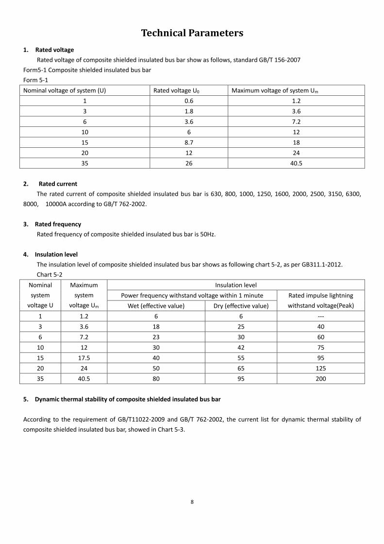
9
Chart 5-3 The current list for dynamic thermal stability of Compound Insulated Shielding Copper Tubular Busbar, Current
Rated current(effective
value: A)
Current of thermal stability(4S) (effective
value: kA)
Current of Dynamic stability (Peak
value: kA)
630~10000
16 40
25 63
31.5 80
40 100
50 125
63 160
80 200
80 200
6. Permissible temperature and rise of Compound Insulated Shielding Copper Tubular Busbar
According to the requirement of GB/T 11022-2009, the permissible temperature and rise of composite shielded insulated
bus bar meet the requirement in Chart 5-4
Chart 5-4 Permissible temperature and rise.
Insulation material Permissible Max. temperature of Conductor Permissible Max. temperature
rise of Conductor (K) Long running Short circuit
Epoxy resin
90 250 50 Silicone rubber
EPR

10
1kV Compound Insulated Shielding Copper Tubular Busbar
Rated
current
Frequency
withstand voltage
for 1min
Thermal stable
current(4S)
Dynamic
stable current
Bending
radius
Temperature
rise
Phase
space Busbar span
1600A 6kV 40kA 100kA
≤360
mm
≤50k ≥275mm 6m or 8m
2000A 6kV 40kA 100kA
2500A 6kV 50kA 125kA
3150A 6kV 50kA 125kA
4000A 6kV 63kA 160kA
≤600mm
5000A 6kV 63kA 160kA
6300A 6kV 80kA 160kA
8000A 6kV 80kA 200kA
10000A 6kV 80kA 200kA
1kV series products cover 0.4kV
1kV Compound Insulated Shielding Copper Tubular Busbar

11
6kV composite shielded insulated busbar
Rated
current
Frequency
withstand voltage
for 1min
Thermal stable
current(4S)
Dynamic
stable current
Bending
radius
Temperature
rise
Phase
space Bus bar span
1600A 30kV 40kA 100kA
≤360mm
≤50k ≥275mm 6m or 8m
2000A 30kV 40kA 100kA
2500A 30kV 50kA 125kA
3150A 30kV 50kA 125kA
4000A 30kV 63kA 160kA
≤600mm
5000A 30kV 63kA 160kA
6300A 30kV 80kA 160kA
8000A 30kV 80kA 200kA
10000A 30kV 80kA 200kA
6kV series products can cover 3kV

12
15kV composite shielded insulated busbar
Rated
current
Frequency
withstand voltage
for 1min
Thermal stable
current(4S)
Dynamic
stable current
Bending
radius
Temperature
rise
Phase
space Bus bar span
1600A 55kV 40kA 100kA
≤360mm
≤50k ≥275mm 6m 或 8m
2000A 55kV 40kA 100kA
2500A 55kV 50kA 125kA
3150A 55kV 50kA 125kA
4000A 55kV 63kA 160kA
≤600mm
5000A 55kV 63kA 160kA
6300A 55kV 80kA 160kA
8000A 55kV 80kA 200kA
10000A 55kV 80kA 200kA
15kV series products cover 10kV

13
20kV composite shielded insulated busbar
Rated
current
Frequency
withstand voltage
for 1min
Thermal stable
current(4S)
Dynamic
stable current
Bending
radius
Temperature
rise
Phase
space Bus bar span
1600A 65kV 40kA 100kA
≤360mm
≤50k ≥275mm 6m or 8m
2000A 65kV 40kA 100kA
2500A 65kV 50kA 125kA
3150A 65kV 50kA 125kA
4000A 65kV 63kA 160kA
≤600mm
5000A 65kV 63kA 160kA
6300A 65kV 80kA 160kA
8000A 65kV 80kA 200kA
10000A 65kV 80kA 200kA
14
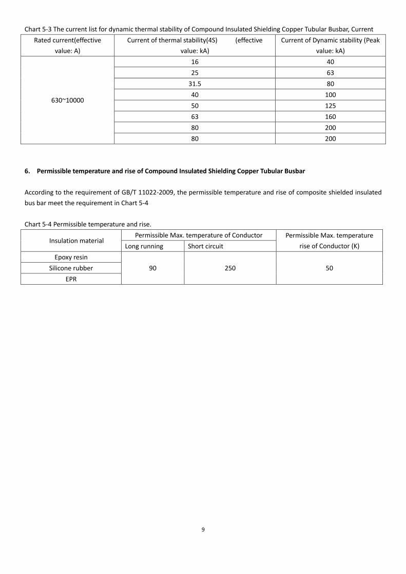
35kV composite shielded insulated busbar
Rated
current
Frequency
withstand voltage
for 1min
Thermal stable
current(4S)
Dynamic
stable current
Bending
radius
Temperature
rise
Phase
space Bus bar span
1600A 95kV 40kA 100kA
≤360mm
≤50k ≥275mm 6m or 8m
2000A 95kV 40kA 100kA
2500A 95kV 50kA 125kA
3150A 95kV 50kA 125kA
4000A 95kV 63kA 160kA
≤600mm
5000A 95kV 63kA 160kA
6300A 95kV 80kA 160kA
8000A 95kV 80kA 200kA
10000A 95kV 80kA 200kA
15
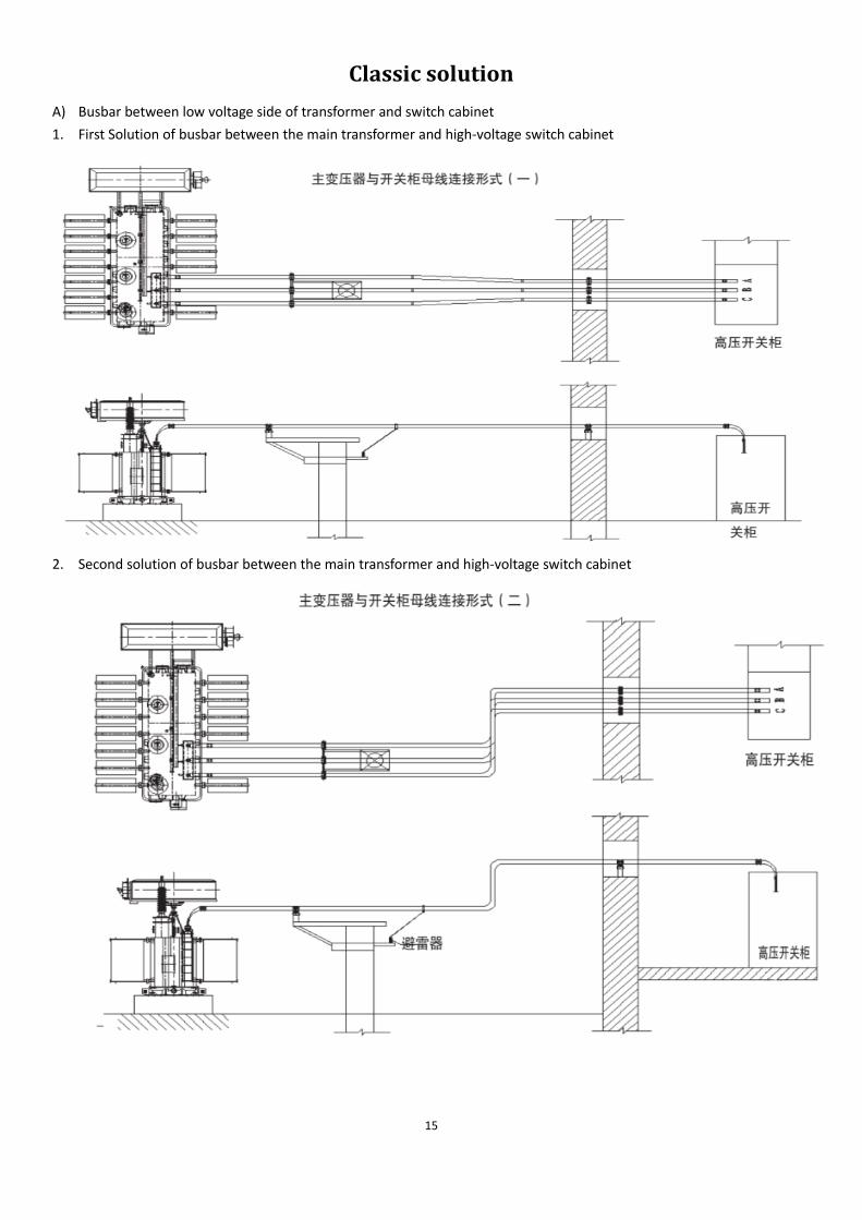
Classic solution
A) Busbar between low voltage side of transformer and switch cabinet
1. First Solution of busbar between the main transformer and high-voltage switch cabinet
2. Second solution of busbar between the main transformer and high-voltage switch cabinet

16
3. Third solution of busbar between the main transformer and high-voltage switch cabinet
4. Forth solution of busbar between the main transformer and high-voltage switch cabinet

17
5. Fifth solution of busbar between the main transformer and high-voltage switch gear cabinet
6. Sixth kind of solution of busbar between the main transformer and high-voltage switch cabinet

18
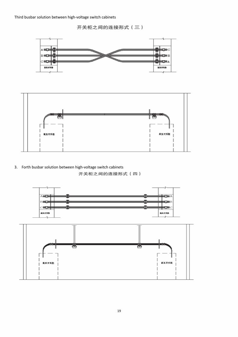
B) Busbar solution between high-voltage switch cabinets
1. First busbar solution between high-voltage switch cabinets
2. Second kind of busbar solution between high-voltage switch cabinets
19
Third busbar solution between high-voltage switch cabinets
3. Forth busbar solution between high-voltage switch cabinets
20
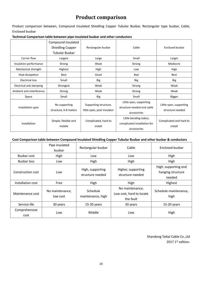
Product comparison
Product comparison between, Compound Insulated Shiedling Copper Tubular Busbar, Rectangular type busbar, Cable,
Enclosed busbar
Technical Comparison table between pipe insulated busbar and other conductors
Compound Insulated
Shiedling Copper
Tubular Busbar
Rectangular busbar Cable Enclosed busbar
Carrier flow Largest Large Small Larger
Insulation performance Strong Weak Strong Mediocre
Mechanical strength Highest High Low High
Heat dissipation Best Good Bad Best
Electrical loss Small Big Big Big
Electrical anti-damping Strongest Weak Strong Weak
Ambient anti-interference Strong Weak Strong Weak
Space Small Big Small Bigger
Installation span No supporting
structure, 6-8 meters
Supporting structure,
little span, post insulator
Little span, supporting
structure needed and cable
accessories
Little span, supporting
structure needed
Installation Simple, flexible and
mobile
Complicated, hard to
install
Little bending radius,
complicated installation for
accessories
Complicated and hard to
install
Cost Comparison table between Compound Insulated Shiedling Copper Tubular Busbar and other busbar & conductors
Pipe insulated
busbar Rectangular busbar Cable Enclosed busbar
Busbar cost High Low Low High
Busbar loss Low High High High
Construction cost Low High, supporting
structure needed
Higher, supporting
structure needed
High, supporting and
hanging structure
needed
Installation cost Free High High Highest
Maintenance cost No maintenance,
low cost
Schedule
maintenance, high
No maintenance,
Low cost, hard to locate
the fault
Schedule maintenance,
high
Service life 30 years 15-20 years 30 years 15-20 years
Comprehensive
cost Low Middle Low High
Shandong Taikai Cable Co.,Ltd
2017 1st edition.