Embed Size (px)
Citation preview
Tamjets F-16 Instruction Manual
Instruction Manual
Weight: 17-18 lbs Length: 72” Wingspan: 51” Radio: 8-10 Channels Power: 13-17 lbs thrust turbine
www.tamjets.com 408-224-7600 1of64
Tamjets F-16 Instruction Manual
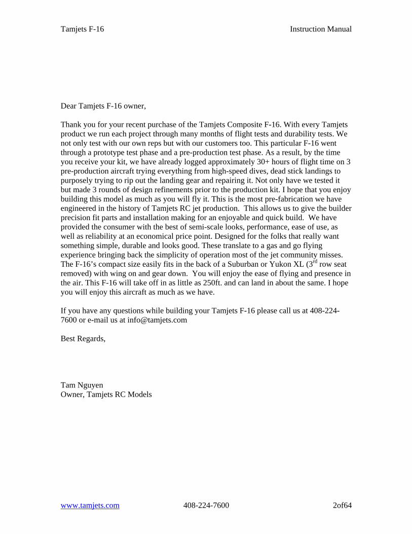
Dear Tamjets F-16 owner, Thank you for your recent purchase of the Tamjets Composite F-16. With every Tamjets product we run each project through many months of flight tests and durability tests. We not only test with our own reps but with our customers too. This particular F-16 went through a prototype test phase and a pre-production test phase. As a result, by the time you receive your kit, we have already logged approximately 30+ hours of flight time on 3 pre-production aircraft trying everything from high-speed dives, dead stick landings to purposely trying to rip out the landing gear and repairing it. Not only have we tested it but made 3 rounds of design refinements prior to the production kit. I hope that you enjoy building this model as much as you will fly it. This is the most pre-fabrication we have engineered in the history of Tamjets RC jet production. This allows us to give the builder precision fit parts and installation making for an enjoyable and quick build. We have provided the consumer with the best of semi-scale looks, performance, ease of use, as well as reliability at an economical price point. Designed for the folks that really want something simple, durable and looks good. These translate to a gas and go flying experience bringing back the simplicity of operation most of the jet community misses. The F-16’s compact size easily fits in the back of a Suburban or Yukon XL (3rd row seat removed) with wing on and gear down. You will enjoy the ease of flying and presence in the air. This F-16 will take off in as little as 250ft. and can land in about the same. I hope you will enjoy this aircraft as much as we have. If you have any questions while building your Tamjets F-16 please call us at 408-224-7600 or e-mail us at [email protected] Best Regards, Tam Nguyen Owner, Tamjets RC Models
www.tamjets.com 408-224-7600 2of64
Tamjets F-16 Instruction Manual
Standard Kit Contents
1- 1 Fuselage with tail cone 2- 1 Canopy and frame 3- 1 Rudder base (where the rudder servo installed) 4- 2 Wings, 2 Horizontal stabs, 1 Vertical stab with rudder 5- 3 gear doors, 2 ventral fins and 2 wing missile rails 6- Fiberglass cockpit deck 7- Hardware Accessory Package
a. 2 Carbon push rods, 4 4-40 end cabs, 2 Sullivan gold-clevises b. 2 Elevator control arms` and 4 plastic washer (for elevators stab) c. 8 Offset gear door hinges with micro screws d. 8 Servo bracket with servo screws e. 1 Pull-Pull cable and hardware f. 12 4-40 x5/8” screws and tee nuts (for retracts) g. 8 5-40 x 5/8” and 1 aluminum washer (for vertical fin) h. 1 M3 x 25mm screw for rudder pin i. Nose reinforcement support former and hardware j. Pipe support former and 2 1/8” plywood mounting blocks k. Nose accessories wood tray with support formers
Landing gear package 1. Complete retracts with struts and wheels/brakes 2. 3 different colors of heavy duty airline 3. 12 Metal Tees 4. 2 Air fill valves 5. 1 Retract valve with hardware 6. 1 Brake valve 7. 2 300 cc air bottles 8. 4 Brake clips
Turbine install kit
1. Tamjets pipe, 3 fuel cells, UAT, fuel line and hardware
Gear door package
1. 3 Air cylinders and gear door closing valve Cockpit kit 1. Thunder Bird or Military version available
www.tamjets.com 408-224-7600 3of64
Tamjets F-16 Instruction Manual
Task List (IN ORDER)
Before starting assembly, sand all formers with 80 grit sand paper Drill 1/16” hole to wings, stabs, and vertical fin Install nose reinforcement support former Install nose accessories wood tray Glue smoke pump mounting bracket (optional) Insert M3 x 25mm screw to rudder (for rudder pin shaft) Glue in rudder Install rudder servo Install gear doors Mount retracts, struts and wheels Install nose steering servo and hook up Pull-Pull steering cable Mount air tanks Run air lines for retracts, doors air cylinders, wheels/brakes and door closing
valve Install ventral fins Install elevator servos, push rods and horizontals stabs Run and secure servo wires from elevator and rudder forward to canopy area Install stainless steel heat shield and mount the pipe Reinstall air intake ducting Install fuel cells (Fill fuel first to check for pinhole leaks) Install smoke tanks (optional) Install engine and accessories Set up radio equipment Install cockpit kit (optional) Balance (C.G location 5” back from inner root leading edge) Preflight check
www.tamjets.com 408-224-7600 4of64
Tamjets F-16 Instruction Manual
WARNING This model is designed to safely operate with model turbine engines into the 13-17 lbs thrust range. Early pre-production aircraft are powered with a Jetcat P-60. We find that is plenty of power. We also flew with a P-70. We recommend the use safe of throttle management and keep the speed below 180mph. Every airplane has its safety limit. We tested the model harder than the most average pilot would normally fly. Pilot operation of any R/C model jet should be done by following safety rules and all manufacturer safety suggestions. Here is few not to do lists.
1) A larger, more powerful engine than suggested could cause excessive speed and possible control problems and/or structural fatigue and potential failure.
2) Pulling high G maneuvers at full throttle can cause structural fatigue and/or failure.
3) Caution-- when using the optional smoke system. Do not blind yourself and other
pilots at the flight line. This can cause loss of control of the model due to poor visibility.
The privilege of operating a turbine powered model aircraft carries with it an increased responsibility. Adherence to the manufacturer’s specifications and the AMA regulations are included in the responsibility. Please give serious thought before trying to modify or “improve” any facet of this power and airframe package. DISCLAIMER Tamjets R/C Inc. assumes no liability for the operation and uses these products. The owner and operator of these products should have the necessary experience and exercise sense. Said owner and operator must have a valid Academy of Model Aeronautics license and a turbine waiver for purpose of insurance.
www.tamjets.com 408-224-7600 5of64
Tamjets F-16 Instruction Manual
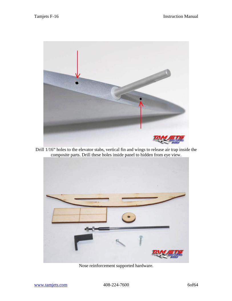
Drill 1/16” holes to the elevator stabs, vertical fin and wings to release air trap inside the
composite parts. Drill these holes inside panel to hidden from eye view.
Nose reinforcement supported hardware.
www.tamjets.com 408-224-7600 6of64
Tamjets F-16 Instruction Manual
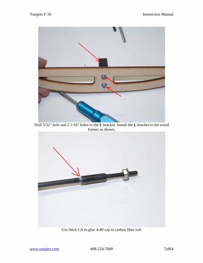
Drill 5/32” hole and 2 1/16” holes to the L bracket. Install the L bracket to the wood
former as shown.
Use thick CA to glue 4-40 cap to carbon fiber rod.
www.tamjets.com 408-224-7600 7of64
Tamjets F-16 Instruction Manual
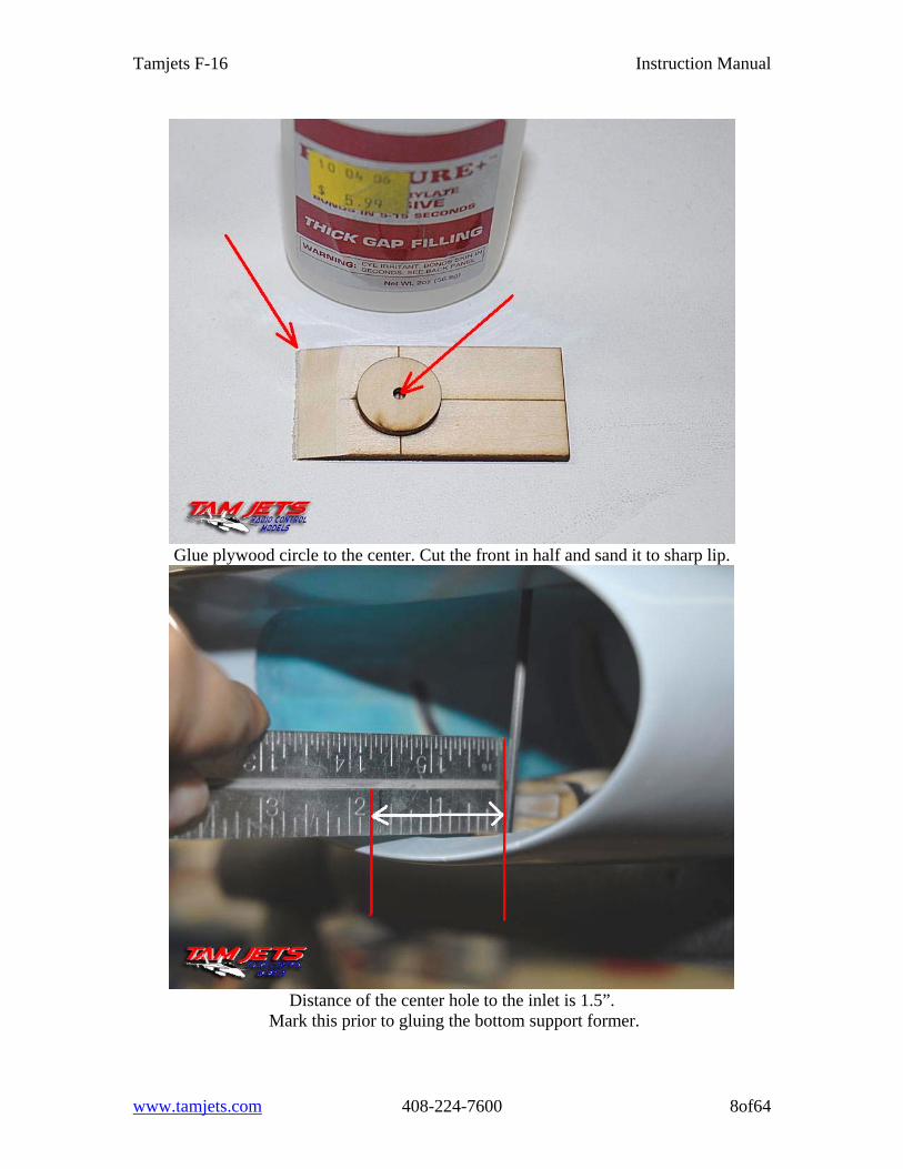
Glue plywood circle to the center. Cut the front in half and sand it to sharp lip.
Distance of the center hole to the inlet is 1.5”.
Mark this prior to gluing the bottom support former.
www.tamjets.com 408-224-7600 8of64
Tamjets F-16 Instruction Manual
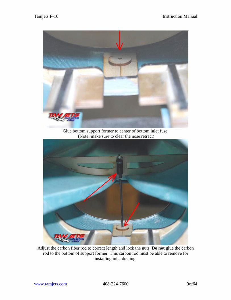
Glue bottom support former to center of bottom inlet fuse.
(Note: make sure to clear the nose retract)
Adjust the carbon fiber rod to correct length and lock the nuts. Do not glue the carbon
rod to the bottom of support former. This carbon rod must be able to remove for installing inlet ducting.
www.tamjets.com 408-224-7600 9of64
Tamjets F-16 Instruction Manual
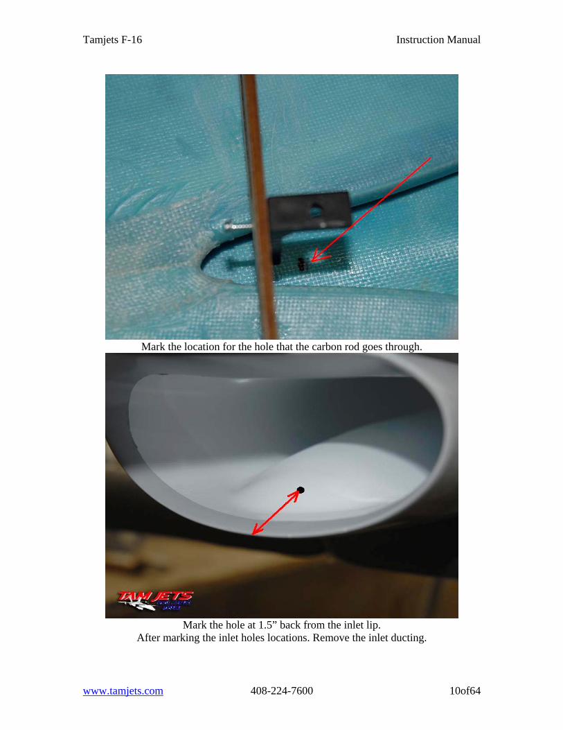
Mark the location for the hole that the carbon rod goes through.
Mark the hole at 1.5” back from the inlet lip.
After marking the inlet holes locations. Remove the inlet ducting.
www.tamjets.com 408-224-7600 10of64
Tamjets F-16 Instruction Manual
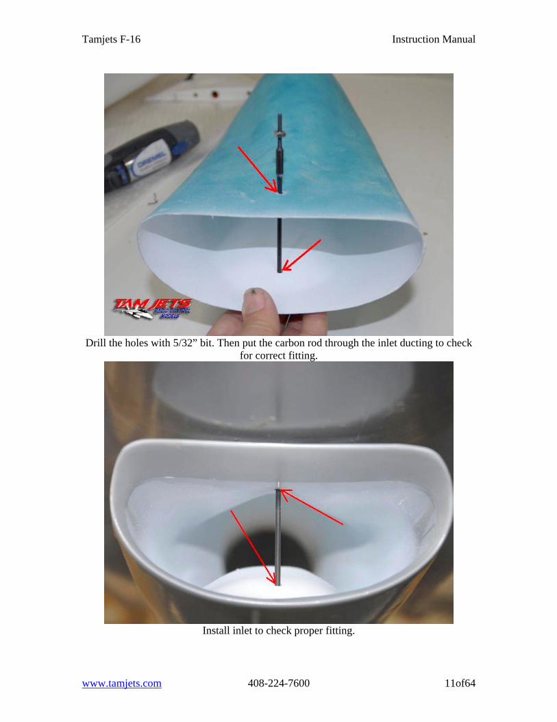
Drill the holes with 5/32” bit. Then put the carbon rod through the inlet ducting to check
for correct fitting.
Install inlet to check proper fitting.
www.tamjets.com 408-224-7600 11of64
Tamjets F-16 Instruction Manual
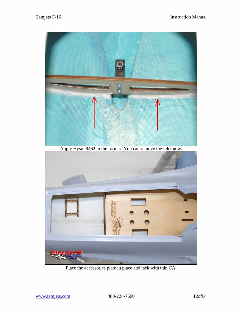
Apply Hysol 9462 to the former. You can remove the inlet now.
Place the accessories plate in place and tack with thin CA.
www.tamjets.com 408-224-7600 12of64
Tamjets F-16 Instruction Manual
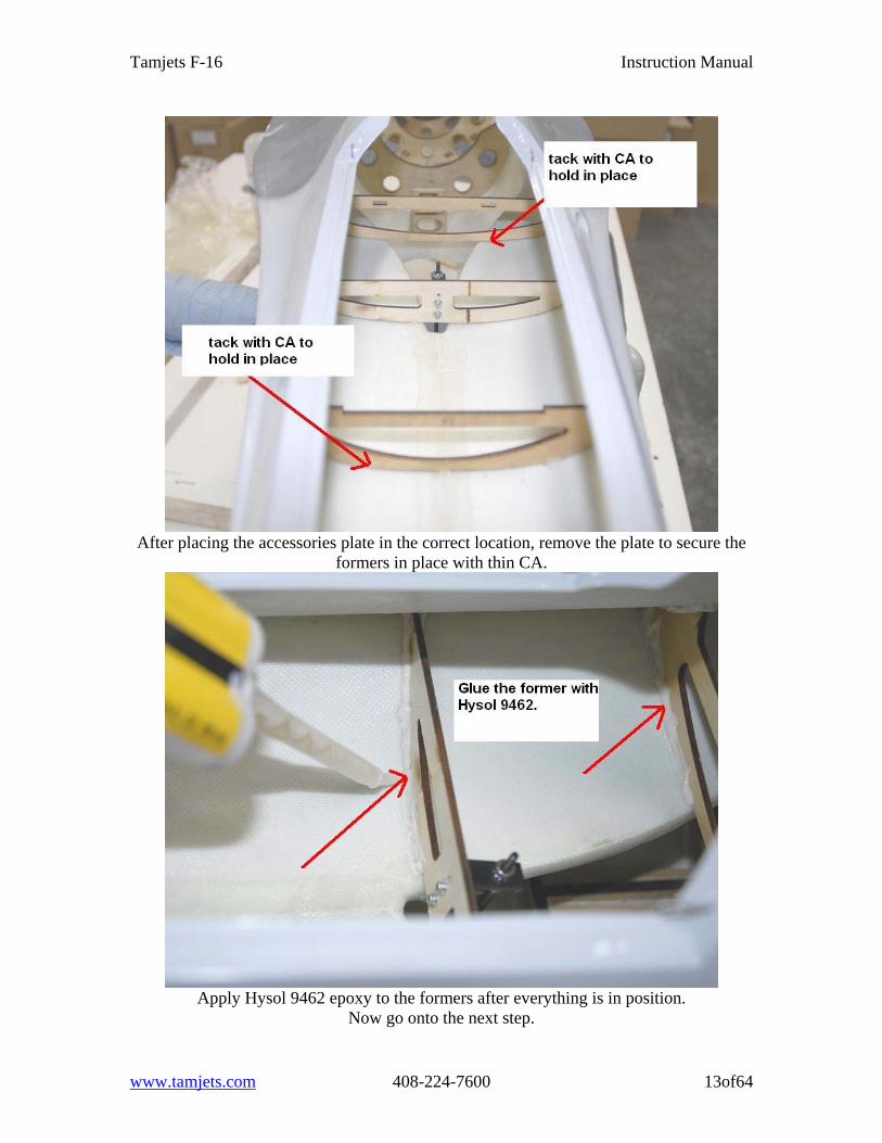
After placing the accessories plate in the correct location, remove the plate to secure the
formers in place with thin CA.
Apply Hysol 9462 epoxy to the formers after everything is in position.
Now go onto the next step.
www.tamjets.com 408-224-7600 13of64
Tamjets F-16 Instruction Manual
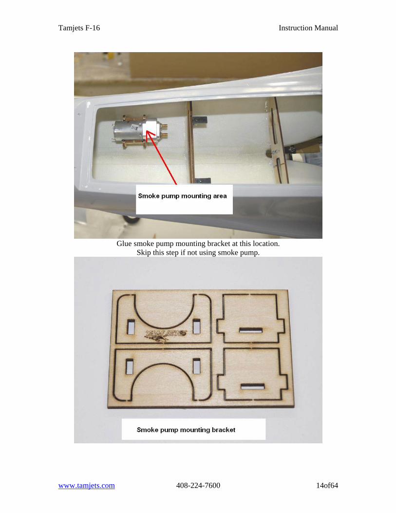
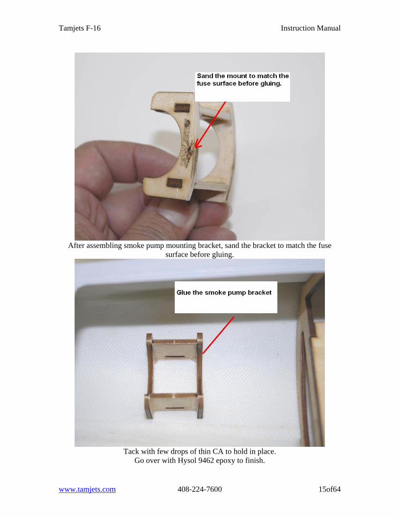
Glue smoke pump mounting bracket at this location.
Skip this step if not using smoke pump.
www.tamjets.com 408-224-7600 14of64
Tamjets F-16 Instruction Manual
After assembling smoke pump mounting bracket, sand the bracket to match the fuse
surface before gluing.
Tack with few drops of thin CA to hold in place.
Go over with Hysol 9462 epoxy to finish.
www.tamjets.com 408-224-7600 15of64
Tamjets F-16 Instruction Manual
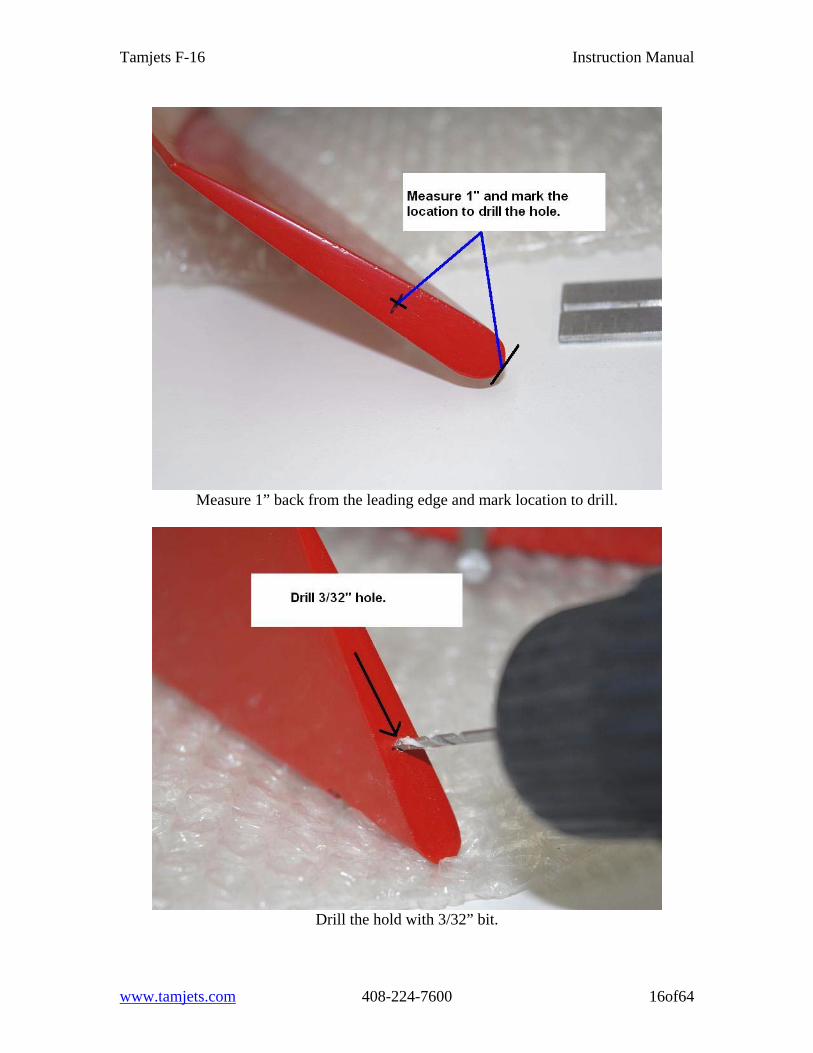
Measure 1” back from the leading edge and mark location to drill.
Drill the hold with 3/32” bit.
www.tamjets.com 408-224-7600 16of64
Tamjets F-16 Instruction Manual
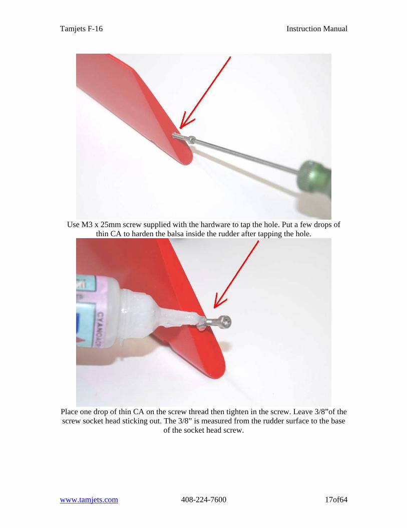
Use M3 x 25mm screw supplied with the hardware to tap the hole. Put a few drops of
thin CA to harden the balsa inside the rudder after tapping the hole.
Place one drop of thin CA on the screw thread then tighten in the screw. Leave 3/8”of the screw socket head sticking out. The 3/8” is measured from the rudder surface to the base
of the socket head screw.
www.tamjets.com 408-224-7600 17of64
Tamjets F-16 Instruction Manual
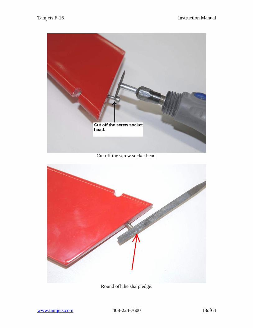
Cut off the screw socket head.
Round off the sharp edge.
www.tamjets.com 408-224-7600 18of64
Tamjets F-16 Instruction Manual
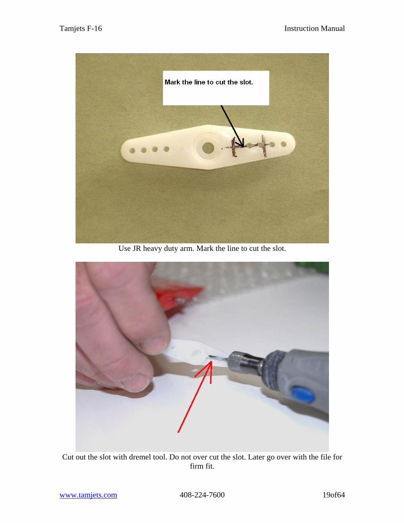
Use JR heavy duty arm. Mark the line to cut the slot.
Cut out the slot with dremel tool. Do not over cut the slot. Later go over with the file for
firm fit.
www.tamjets.com 408-224-7600 19of64
Tamjets F-16 Instruction Manual
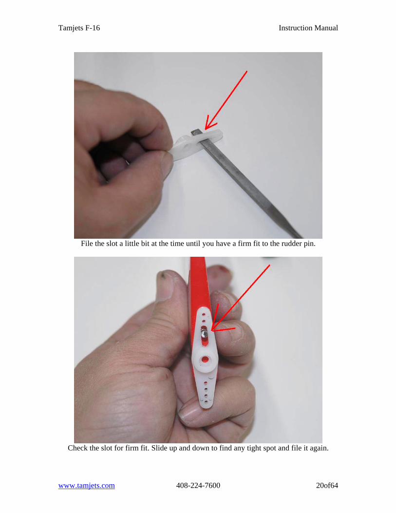
File the slot a little bit at the time until you have a firm fit to the rudder pin.
Check the slot for firm fit. Slide up and down to find any tight spot and file it again.
www.tamjets.com 408-224-7600 20of64
Tamjets F-16 Instruction Manual
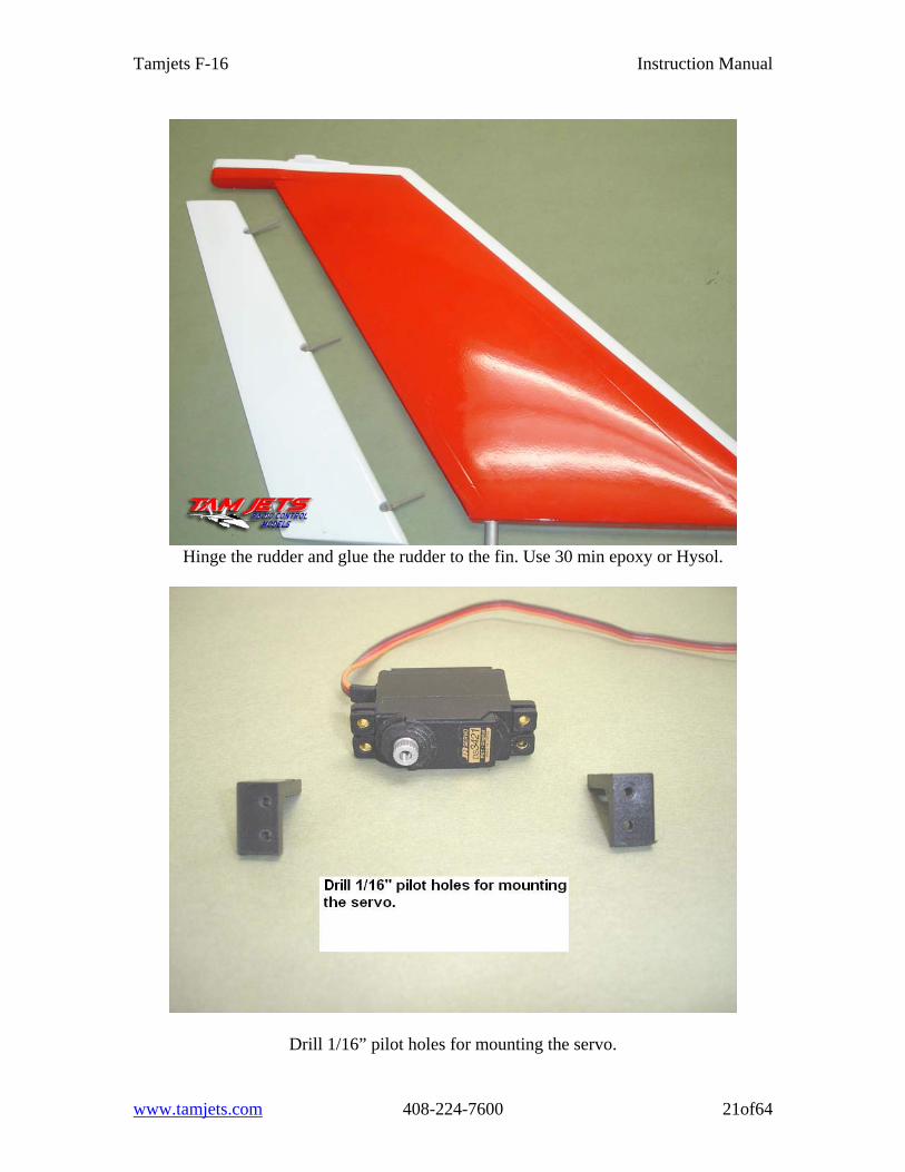
Hinge the rudder and glue the rudder to the fin. Use 30 min epoxy or Hysol.
Drill 1/16” pilot holes for mounting the servo.
www.tamjets.com 408-224-7600 21of64
Tamjets F-16 Instruction Manual
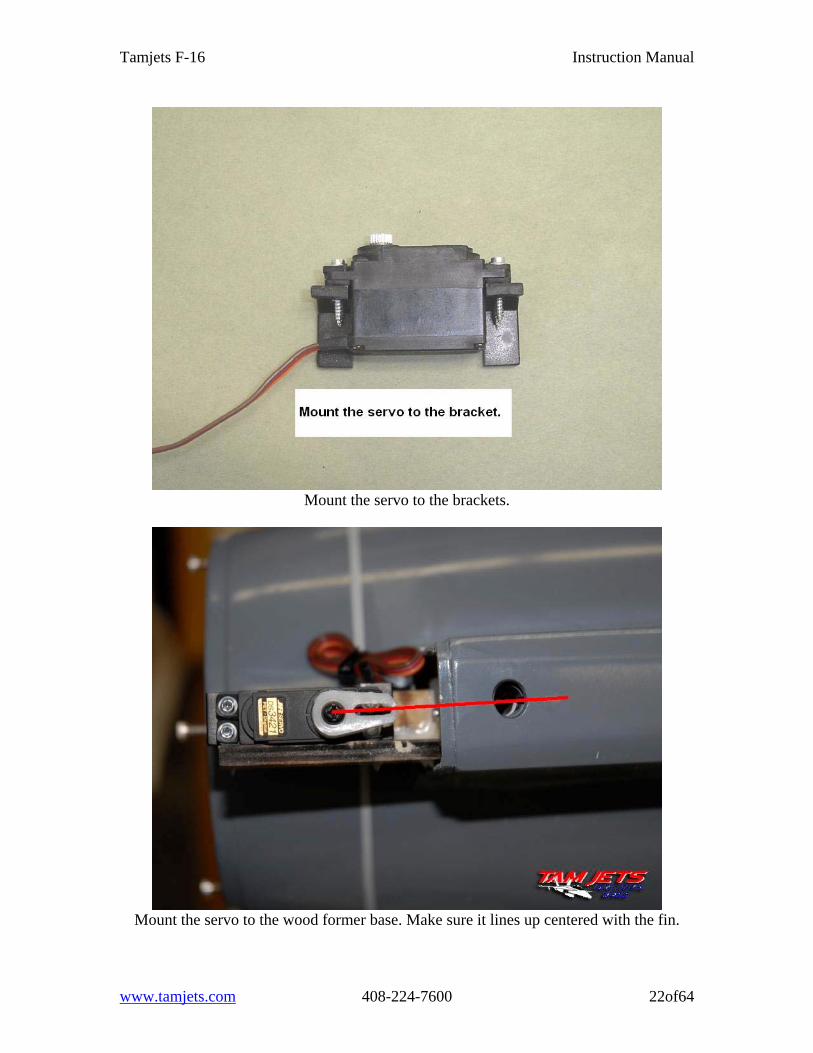
Mount the servo to the brackets.
Mount the servo to the wood former base. Make sure it lines up centered with the fin.
www.tamjets.com 408-224-7600 22of64
Tamjets F-16 Instruction Manual
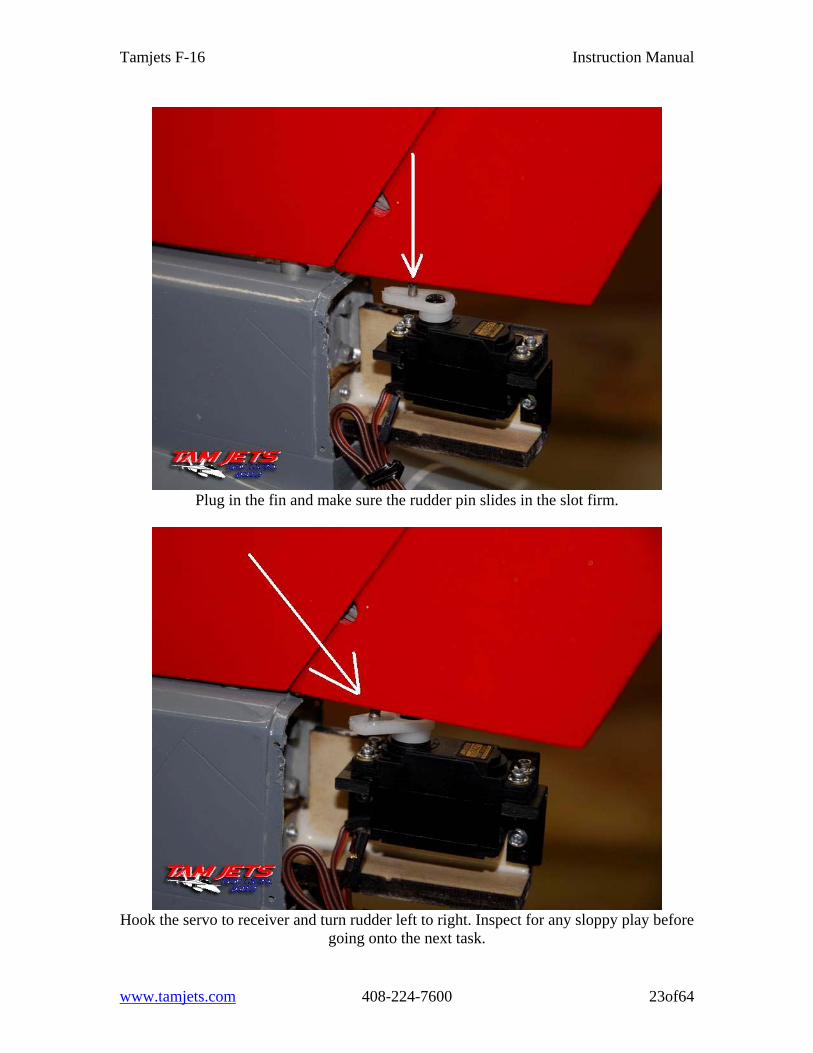
Plug in the fin and make sure the rudder pin slides in the slot firm.
Hook the servo to receiver and turn rudder left to right. Inspect for any sloppy play before
going onto the next task.
www.tamjets.com 408-224-7600 23of64
Tamjets F-16 Instruction Manual
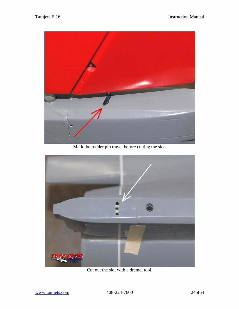
Mark the rudder pin travel before cutting the slot.
Cut out the slot with a dremel tool.
www.tamjets.com 408-224-7600 24of64
Tamjets F-16 Instruction Manual
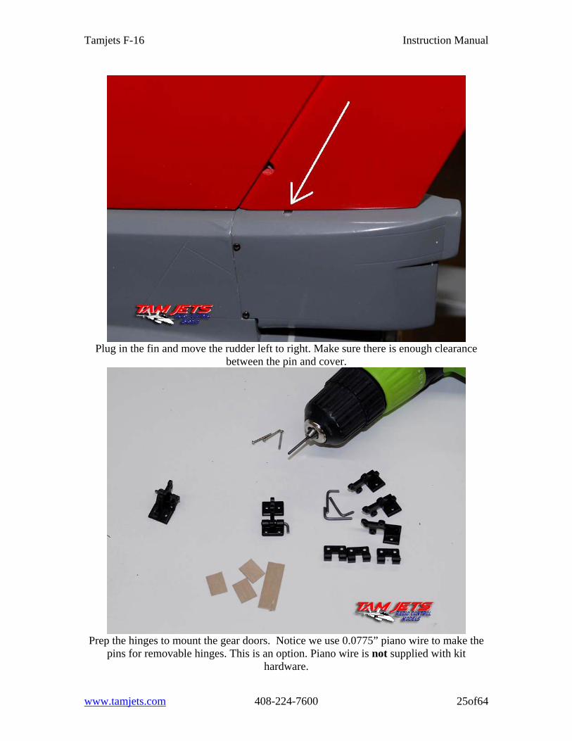
Plug in the fin and move the rudder left to right. Make sure there is enough clearance
between the pin and cover.
Prep the hinges to mount the gear doors. Notice we use 0.0775” piano wire to make the
pins for removable hinges. This is an option. Piano wire is not supplied with kit hardware.
www.tamjets.com 408-224-7600 25of64
Tamjets F-16 Instruction Manual
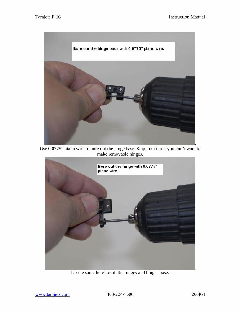
. Use 0.0775” piano wire to bore out the hinge base. Skip this step if you don’t want to
make removable hinges.
Do the same here for all the hinges and hinges base.
www.tamjets.com 408-224-7600 26of64
Tamjets F-16 Instruction Manual
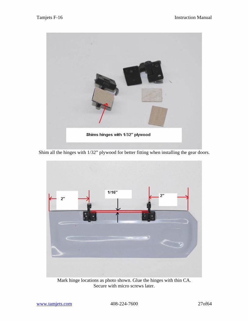
Shim all the hinges with 1/32” plywood for better fitting when installing the gear doors.
Mark hinge locations as photo shown. Glue the hinges with thin CA.
Secure with micro screws later.
www.tamjets.com 408-224-7600 27of64
Tamjets F-16 Instruction Manual
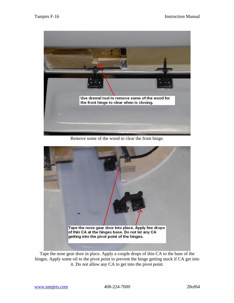
Remove some of the wood to clear the front hinge.
Tape the nose gear door in place. Apply a couple drops of thin CA to the base of the
hinges. Apply some oil to the pivot point to prevent the hinge getting stuck if CA get into it. Do not allow any CA to get into the pivot point.
www.tamjets.com 408-224-7600 28of64
Tamjets F-16 Instruction Manual
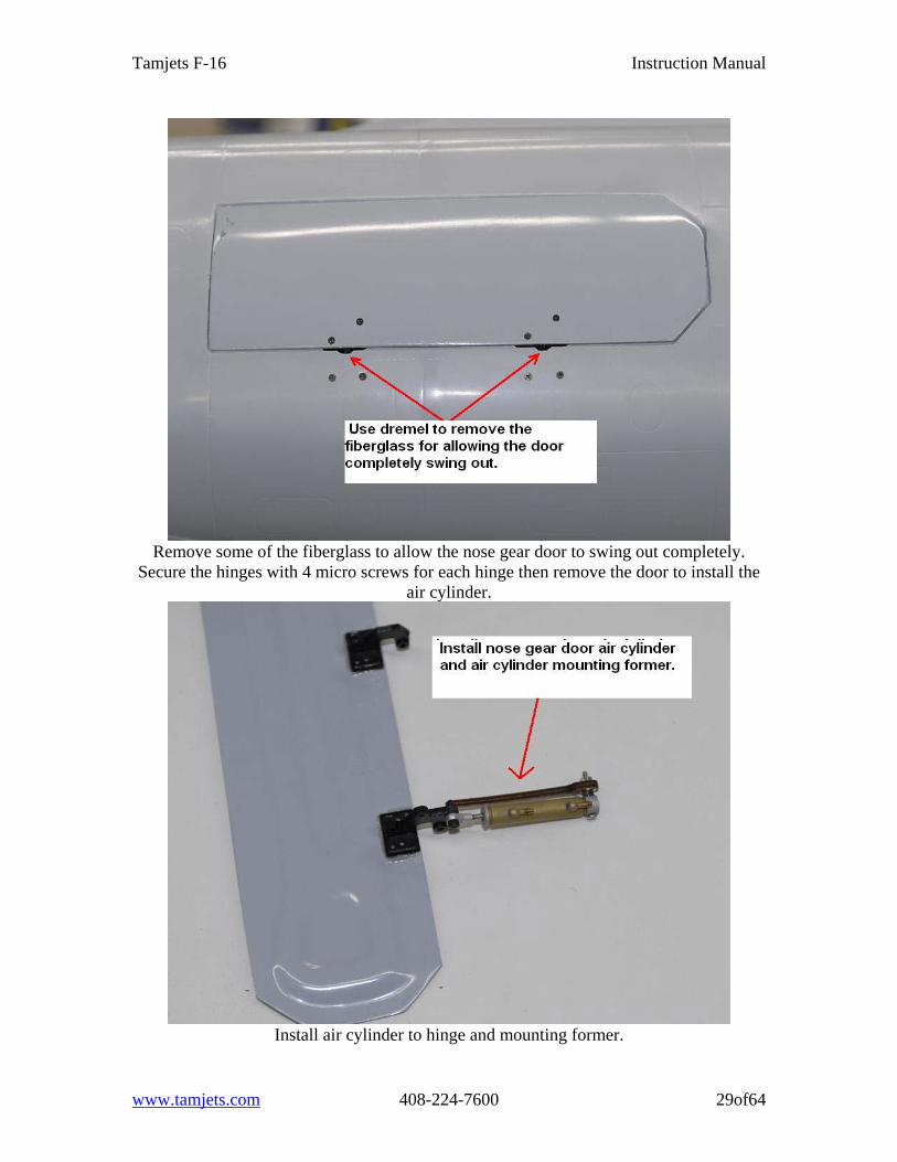
Remove some of the fiberglass to allow the nose gear door to swing out completely.
Secure the hinges with 4 micro screws for each hinge then remove the door to install the air cylinder.
Install air cylinder to hinge and mounting former.
www.tamjets.com 408-224-7600 29of64
Tamjets F-16 Instruction Manual
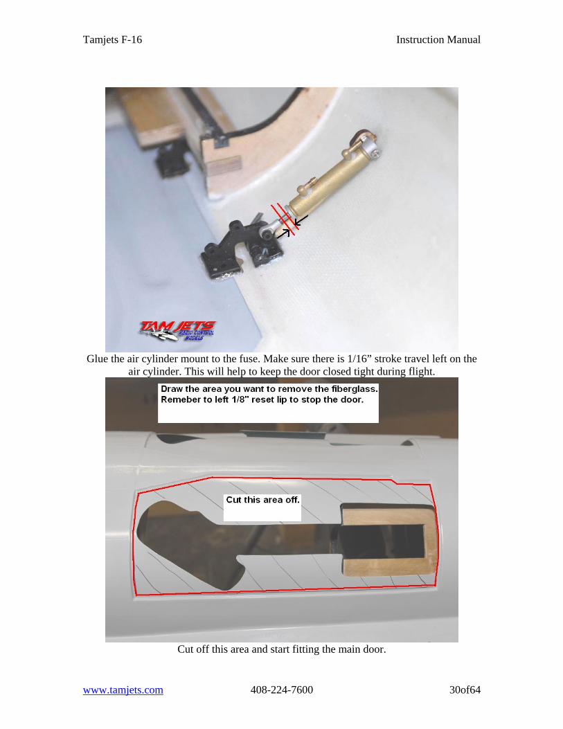
Glue the air cylinder mount to the fuse. Make sure there is 1/16” stroke travel left on the
air cylinder. This will help to keep the door closed tight during flight.
Cut off this area and start fitting the main door.
www.tamjets.com 408-224-7600 30of64
Tamjets F-16 Instruction Manual
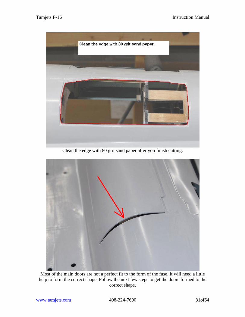
Clean the edge with 80 grit sand paper after you finish cutting.
Most of the main doors are not a perfect fit to the form of the fuse. It will need a little
help to form the correct shape. Follow the next few steps to get the doors formed to the correct shape.
www.tamjets.com 408-224-7600 31of64
Tamjets F-16 Instruction Manual
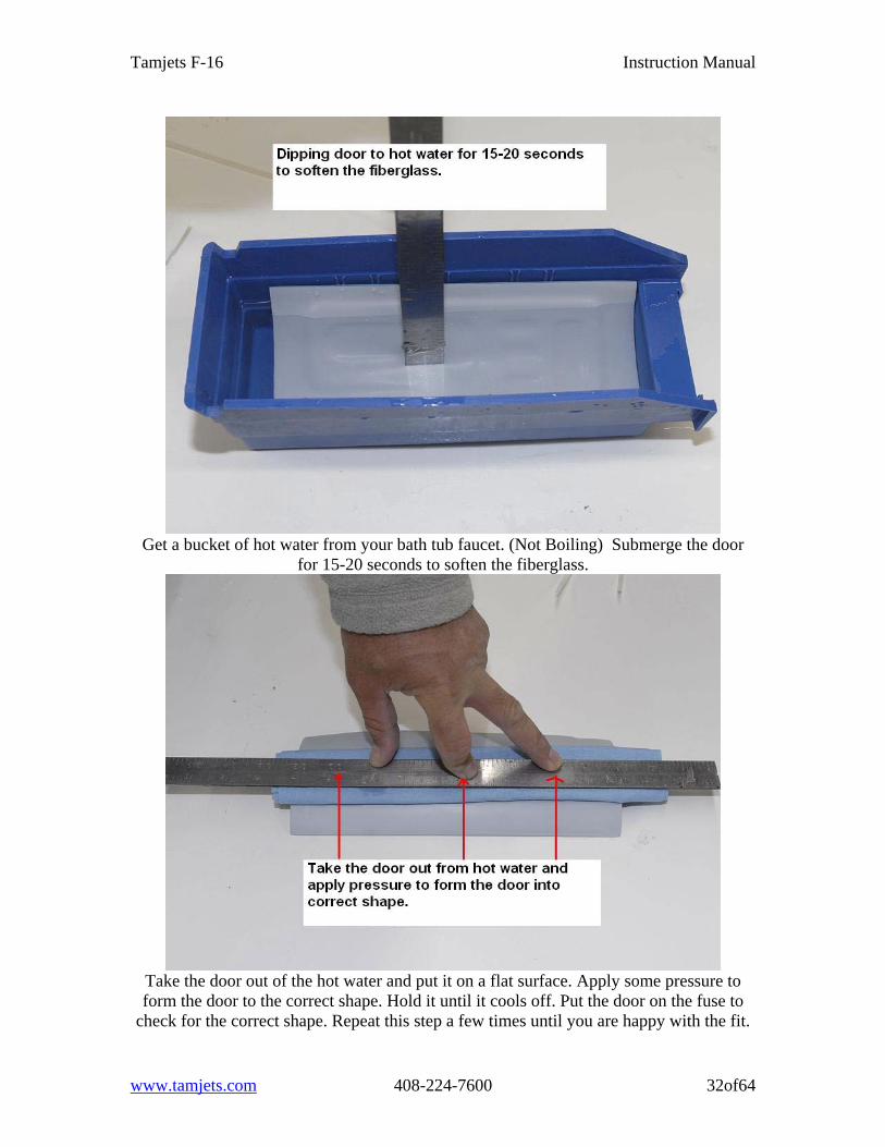
Get a bucket of hot water from your bath tub faucet. (Not Boiling) Submerge the door
for 15-20 seconds to soften the fiberglass.
Take the door out of the hot water and put it on a flat surface. Apply some pressure to form the door to the correct shape. Hold it until it cools off. Put the door on the fuse to
check for the correct shape. Repeat this step a few times until you are happy with the fit.
www.tamjets.com 408-224-7600 32of64
Tamjets F-16 Instruction Manual
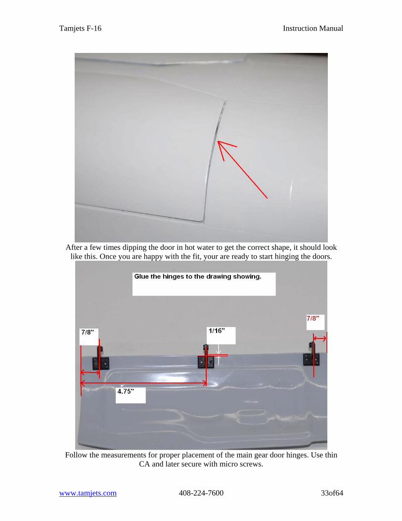
After a few times dipping the door in hot water to get the correct shape, it should look
like this. Once you are happy with the fit, your are ready to start hinging the doors.
Follow the measurements for proper placement of the main gear door hinges. Use thin
CA and later secure with micro screws.
www.tamjets.com 408-224-7600 33of64
Tamjets F-16 Instruction Manual
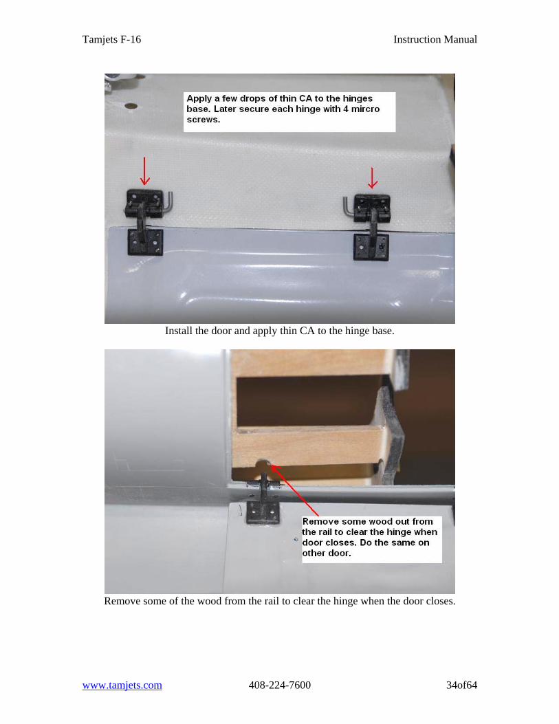
Install the door and apply thin CA to the hinge base.
Remove some of the wood from the rail to clear the hinge when the door closes.
www.tamjets.com 408-224-7600 34of64
Tamjets F-16 Instruction Manual
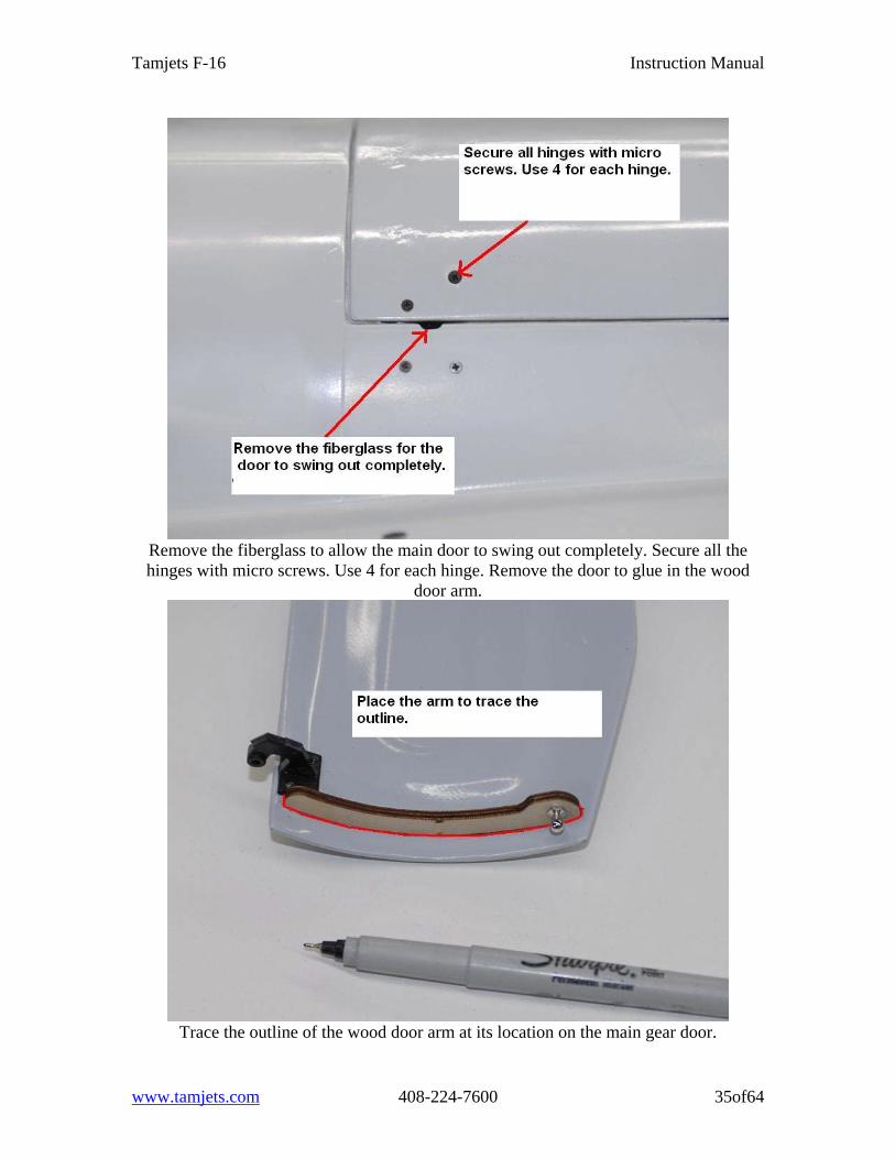
Remove the fiberglass to allow the main door to swing out completely. Secure all the hinges with micro screws. Use 4 for each hinge. Remove the door to glue in the wood
door arm.
Trace the outline of the wood door arm at its location on the main gear door.
www.tamjets.com 408-224-7600 35of64
Tamjets F-16 Instruction Manual
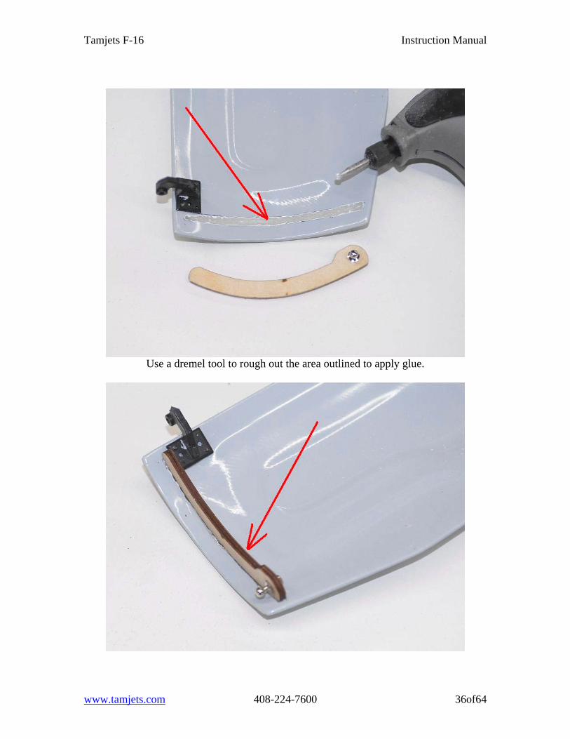
Use a dremel tool to rough out the area outlined to apply glue.
www.tamjets.com 408-224-7600 36of64
Tamjets F-16 Instruction Manual
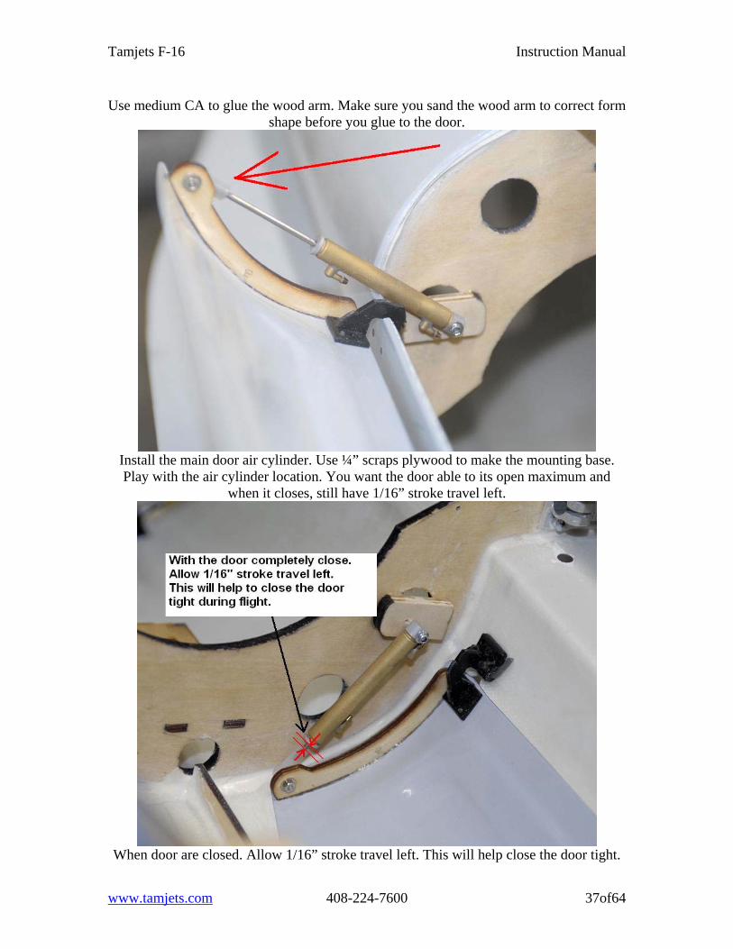
Use medium CA to glue the wood arm. Make sure you sand the wood arm to correct form shape before you glue to the door.
Install the main door air cylinder. Use ¼” scraps plywood to make the mounting base. Play with the air cylinder location. You want the door able to its open maximum and
when it closes, still have 1/16” stroke travel left.
When door are closed. Allow 1/16” stroke travel left. This will help close the door tight.
www.tamjets.com 408-224-7600 37of64
Tamjets F-16 Instruction Manual
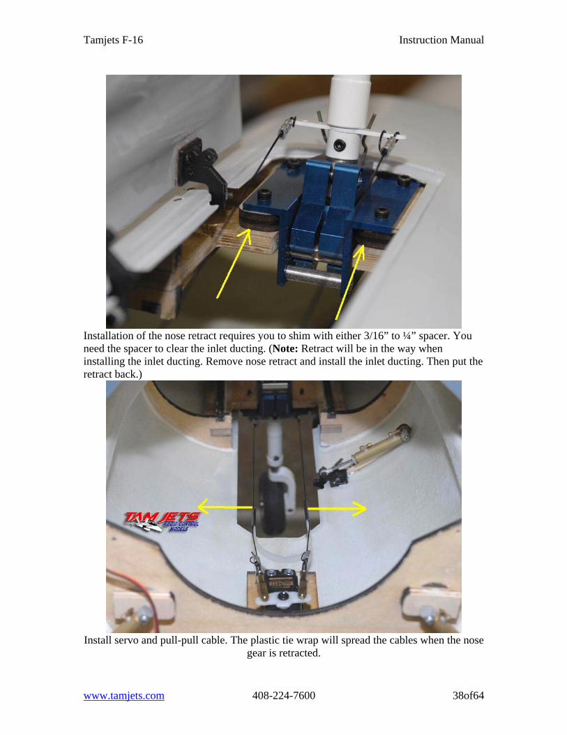
Installation of the nose retract requires you to shim with either 3/16” to ¼” spacer. You need the spacer to clear the inlet ducting. (Note: Retract will be in the way when installing the inlet ducting. Remove nose retract and install the inlet ducting. Then put the retract back.)
Install servo and pull-pull cable. The plastic tie wrap will spread the cables when the nose
gear is retracted.
www.tamjets.com 408-224-7600 38of64
Tamjets F-16 Instruction Manual
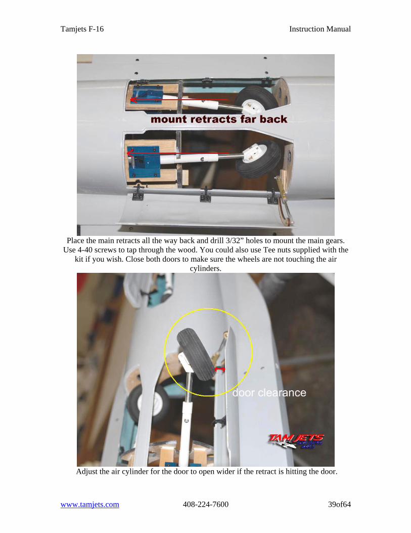
Place the main retracts all the way back and drill 3/32” holes to mount the main gears.
Use 4-40 screws to tap through the wood. You could also use Tee nuts supplied with the kit if you wish. Close both doors to make sure the wheels are not touching the air
cylinders.
Adjust the air cylinder for the door to open wider if the retract is hitting the door.
www.tamjets.com 408-224-7600 39of64
Tamjets F-16 Instruction Manual
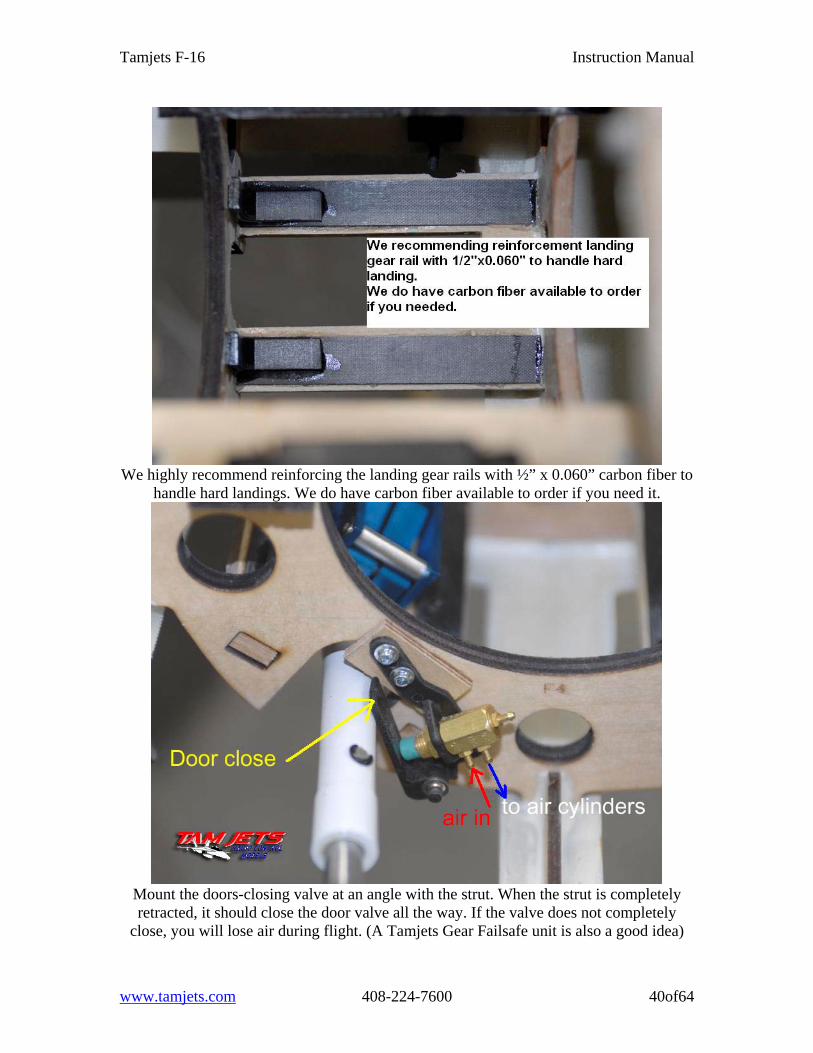
We highly recommend reinforcing the landing gear rails with ½” x 0.060” carbon fiber to
handle hard landings. We do have carbon fiber available to order if you need it.
Mount the doors-closing valve at an angle with the strut. When the strut is completely retracted, it should close the door valve all the way. If the valve does not completely
close, you will lose air during flight. (A Tamjets Gear Failsafe unit is also a good idea)
www.tamjets.com 408-224-7600 40of64
Tamjets F-16 Instruction Manual
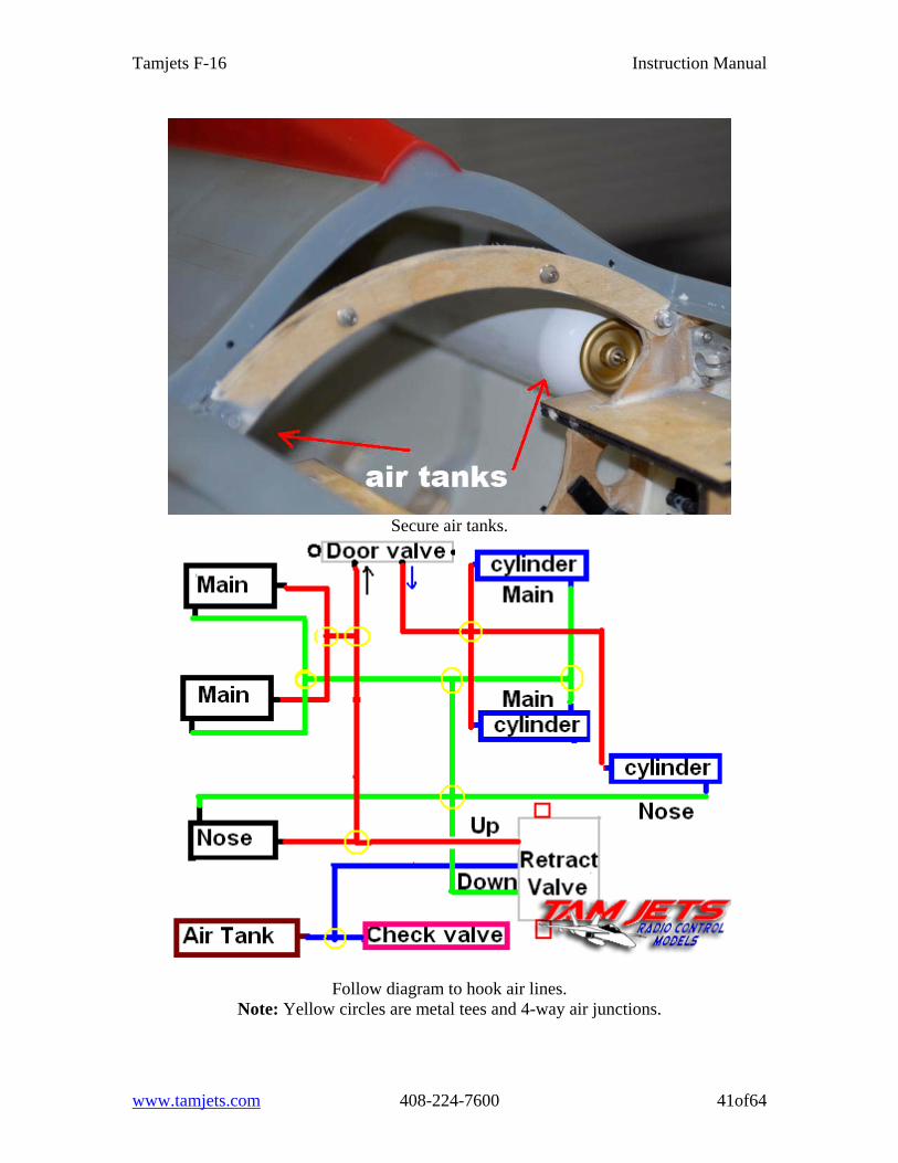
Secure air tanks.
Follow diagram to hook air lines. Note: Yellow circles are metal tees and 4-way air junctions.
www.tamjets.com 408-224-7600 41of64
Tamjets F-16 Instruction Manual
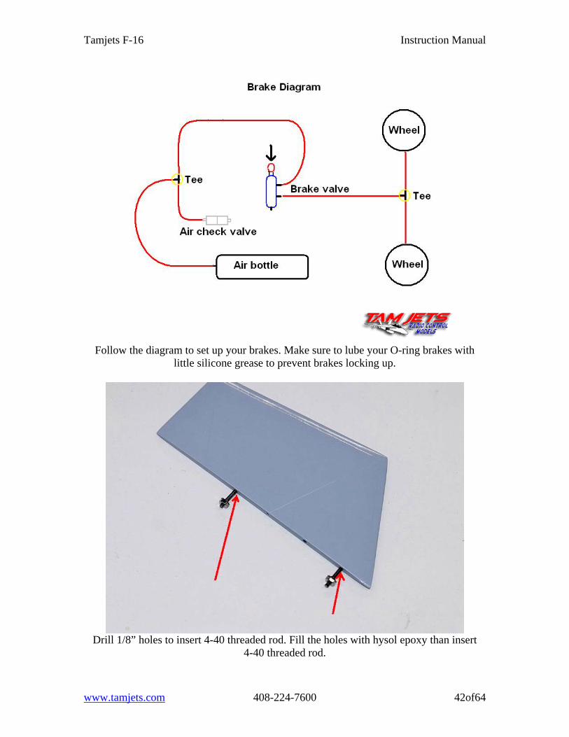
Follow the diagram to set up your brakes. Make sure to lube your O-ring brakes with
little silicone grease to prevent brakes locking up.
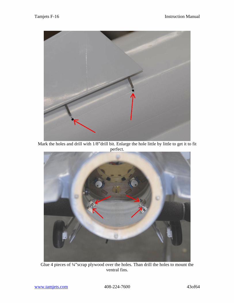
Drill 1/8” holes to insert 4-40 threaded rod. Fill the holes with hysol epoxy than insert
4-40 threaded rod.
www.tamjets.com 408-224-7600 42of64
Tamjets F-16 Instruction Manual
Mark the holes and drill with 1/8”drill bit. Enlarge the hole little by little to get it to fit
perfect.
Glue 4 pieces of ¼”scrap plywood over the holes. Than drill the holes to mount the
ventral fins.
www.tamjets.com 408-224-7600 43of64
Tamjets F-16 Instruction Manual
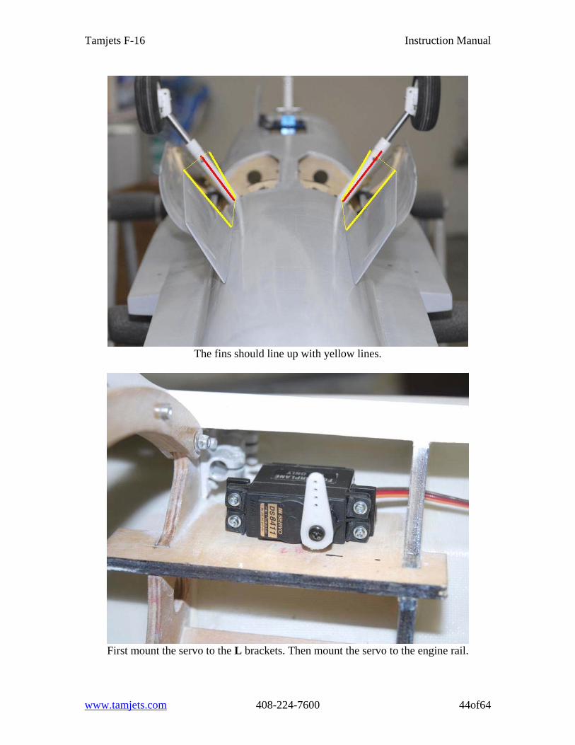
The fins should line up with yellow lines.
First mount the servo to the L brackets. Then mount the servo to the engine rail.
www.tamjets.com 408-224-7600 44of64
Tamjets F-16 Instruction Manual
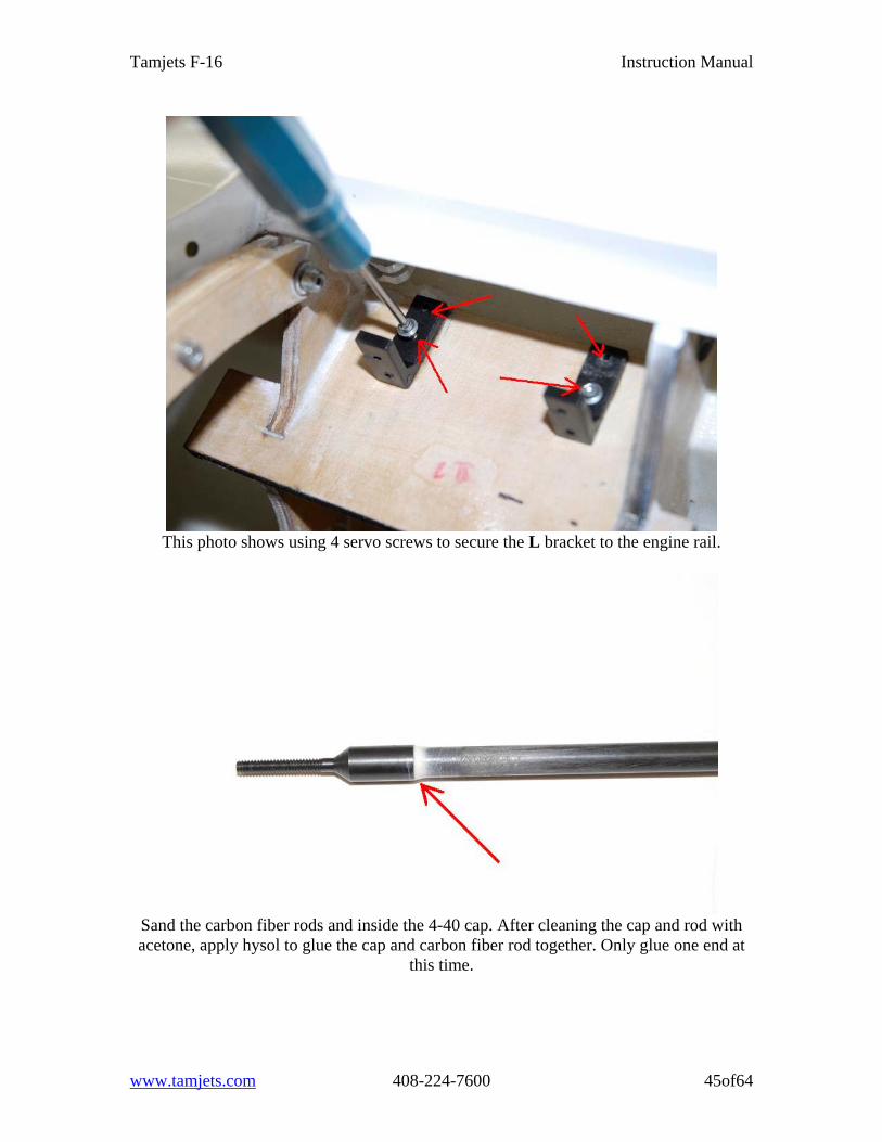
This photo shows using 4 servo screws to secure the L bracket to the engine rail.
Sand the carbon fiber rods and inside the 4-40 cap. After cleaning the cap and rod with acetone, apply hysol to glue the cap and carbon fiber rod together. Only glue one end at
this time.
www.tamjets.com 408-224-7600 45of64
Tamjets F-16 Instruction Manual
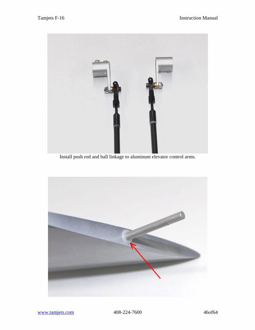
Install push rod and ball linkage to aluminum elevator control arms.
www.tamjets.com 408-224-7600 46of64
Tamjets F-16 Instruction Manual
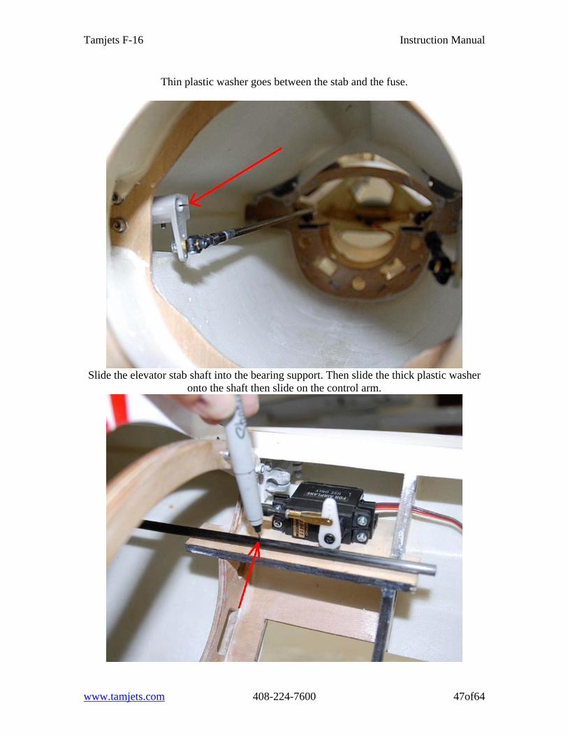
Thin plastic washer goes between the stab and the fuse.
Slide the elevator stab shaft into the bearing support. Then slide the thick plastic washer
onto the shaft then slide on the control arm.
www.tamjets.com 408-224-7600 47of64
Tamjets F-16 Instruction Manual
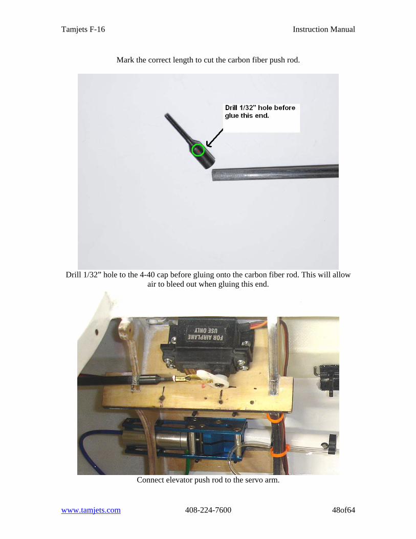
Mark the correct length to cut the carbon fiber push rod.
Drill 1/32” hole to the 4-40 cap before gluing onto the carbon fiber rod. This will allow
air to bleed out when gluing this end.
Connect elevator push rod to the servo arm.
www.tamjets.com 408-224-7600 48of64
Tamjets F-16 Instruction Manual
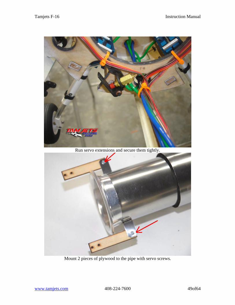
Run servo extensions and secure them tightly.
Mount 2 pieces of plywood to the pipe with servo screws.
www.tamjets.com 408-224-7600 49of64

Tamjets F-16 Instruction Manual
Glue the pipe support ring to the tail cone former.
Sand the ring until the pipe fits firmly in the ring. P-70 pipe needs more sanding to fit.
www.tamjets.com 408-224-7600 50of64
Tamjets F-16 Instruction Manual
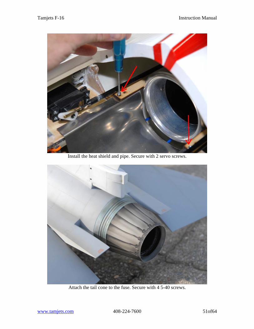
Install the heat shield and pipe. Secure with 2 servo screws.
Attach the tail cone to the fuse. Secure with 4 5-40 screws.
www.tamjets.com 408-224-7600 51of64
Tamjets F-16 Instruction Manual
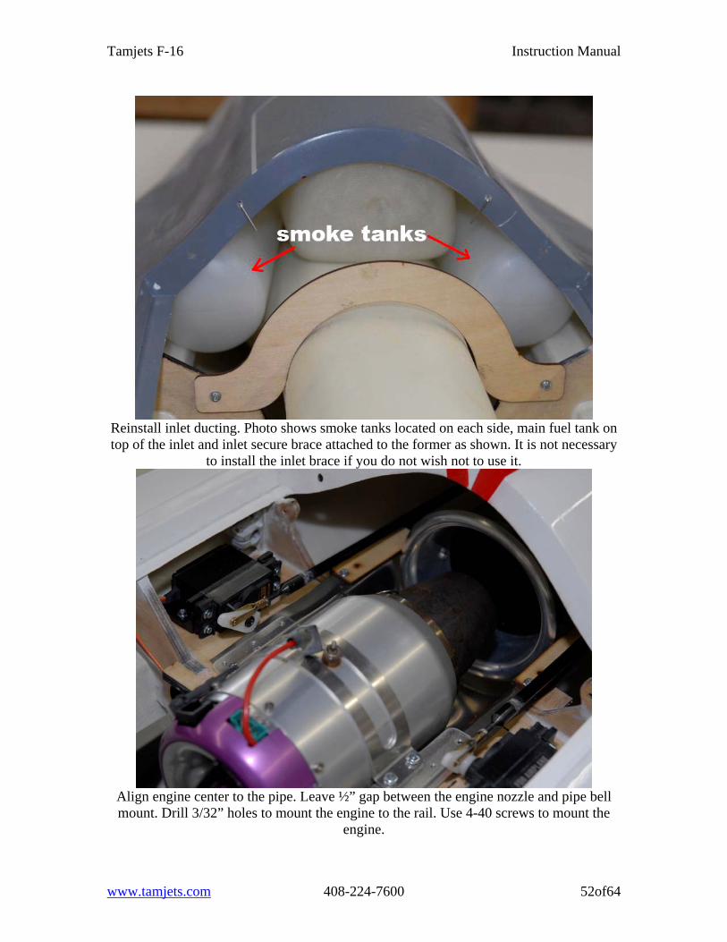
Reinstall inlet ducting. Photo shows smoke tanks located on each side, main fuel tank on top of the inlet and inlet secure brace attached to the former as shown. It is not necessary
to install the inlet brace if you do not wish not to use it.
Align engine center to the pipe. Leave ½” gap between the engine nozzle and pipe bell mount. Drill 3/32” holes to mount the engine to the rail. Use 4-40 screws to mount the
engine.
www.tamjets.com 408-224-7600 52of64
Tamjets F-16 Instruction Manual
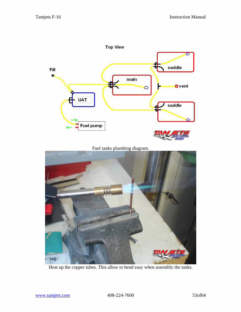
Fuel tanks plumbing diagram.
Heat up the copper tubes. This allow to bend easy when assembly the tanks.
www.tamjets.com 408-224-7600 53of64
Tamjets F-16 Instruction Manual
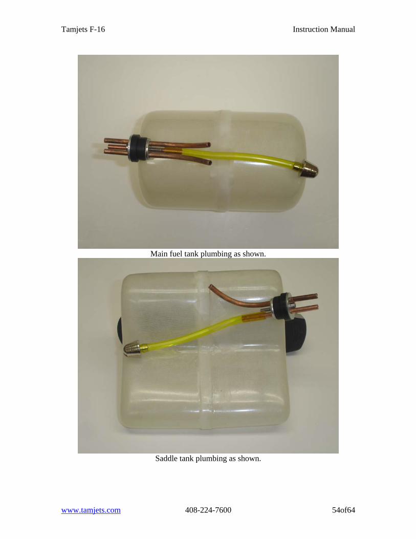
Main fuel tank plumbing as shown.
Saddle tank plumbing as shown.
www.tamjets.com 408-224-7600 54of64
Tamjets F-16 Instruction Manual
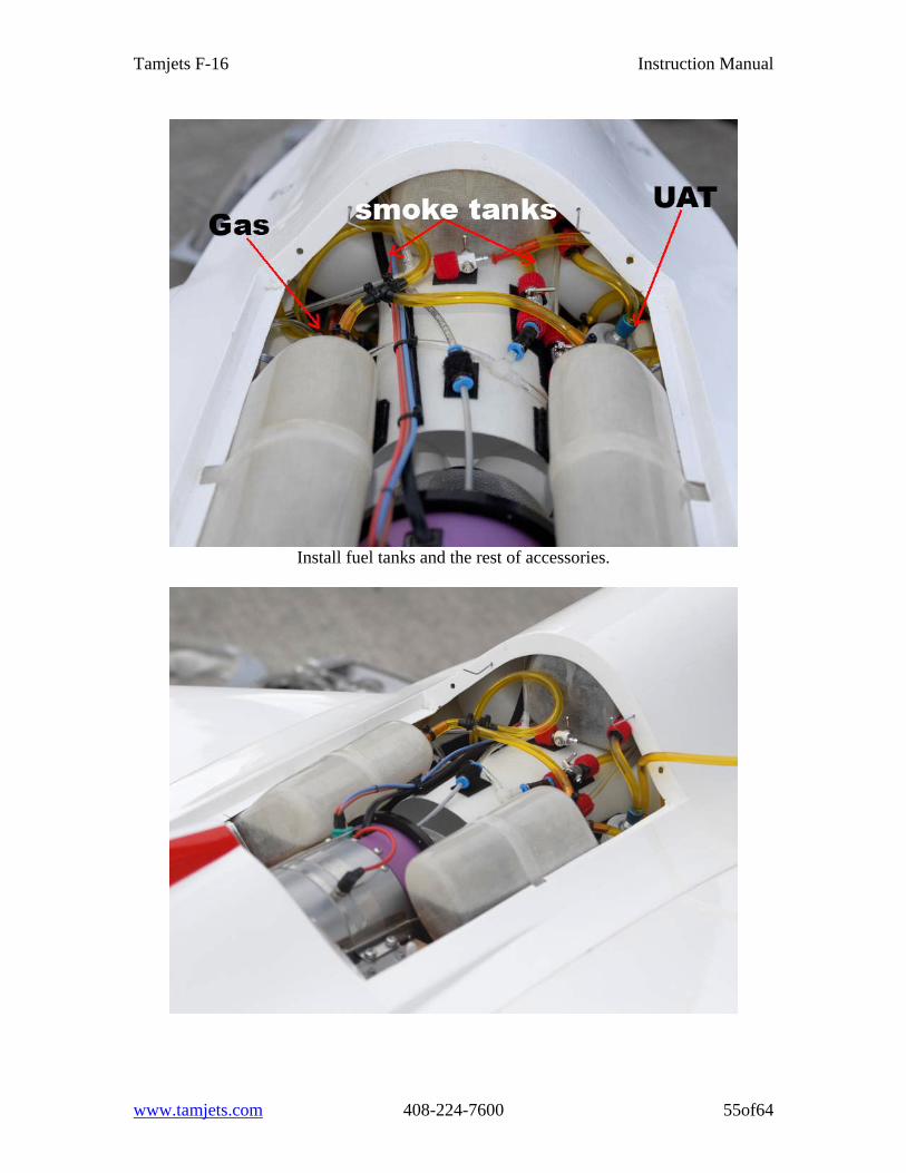
Install fuel tanks and the rest of accessories.
www.tamjets.com 408-224-7600 55of64
Tamjets F-16 Instruction Manual
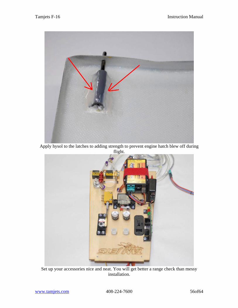
Apply hysol to the latches to adding strength to prevent engine hatch blew off during
flight.
Set up your accessories nice and neat. You will get better a range check than messy
installation.
www.tamjets.com 408-224-7600 56of64
Tamjets F-16 Instruction Manual
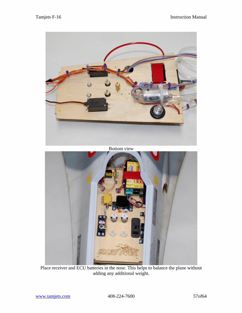
Bottom view
Place receiver and ECU batteries in the nose. This helps to balance the plane without
adding any additional weight.
www.tamjets.com 408-224-7600 57of64
Tamjets F-16 Instruction Manual
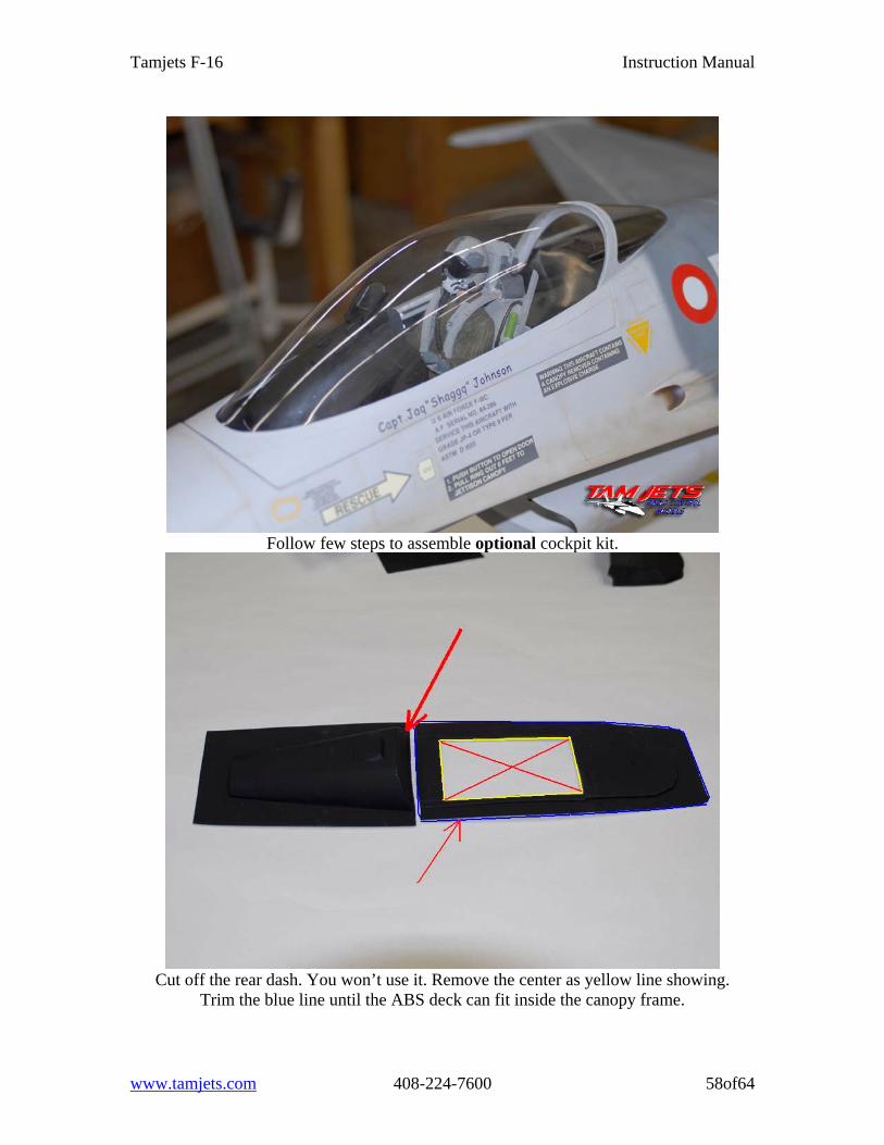
Follow few steps to assemble optional cockpit kit.
Cut off the rear dash. You won’t use it. Remove the center as yellow line showing.
Trim the blue line until the ABS deck can fit inside the canopy frame.
www.tamjets.com 408-224-7600 58of64
Tamjets F-16 Instruction Manual
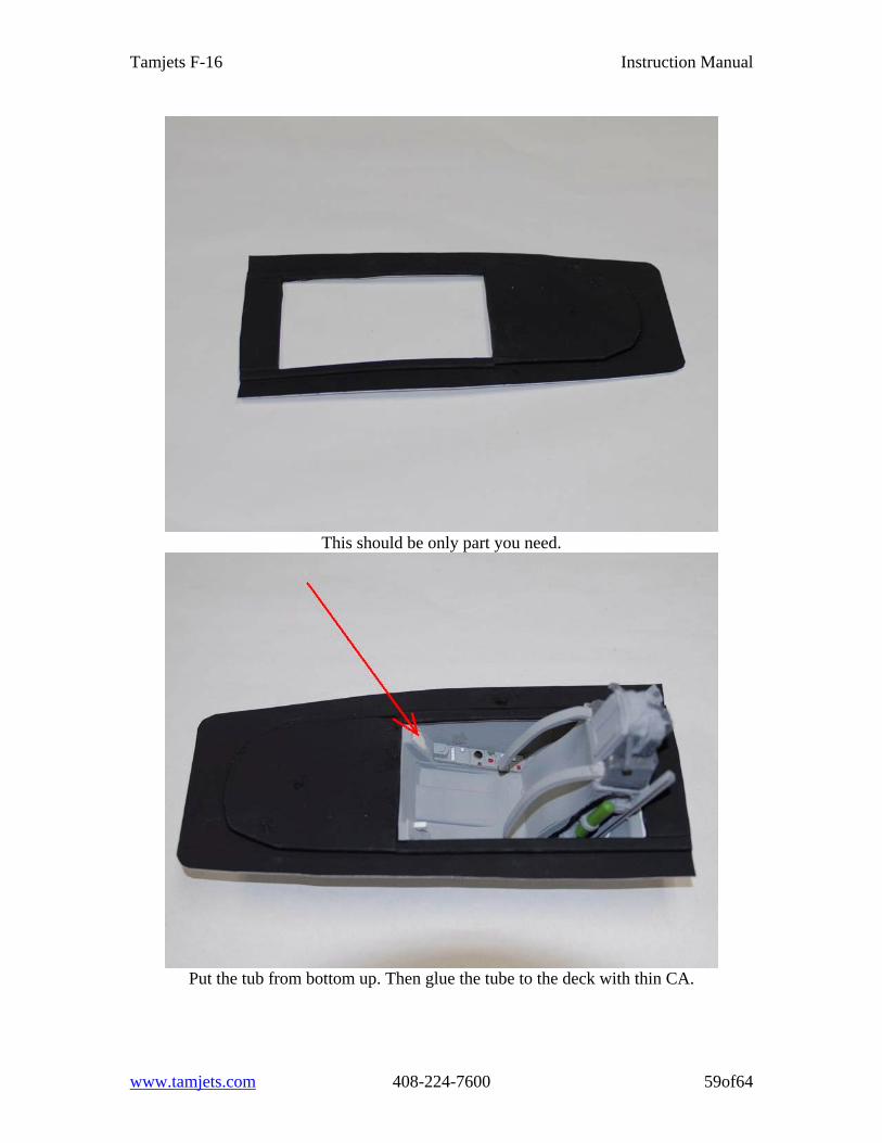
This should be only part you need.
Put the tub from bottom up. Then glue the tube to the deck with thin CA.
www.tamjets.com 408-224-7600 59of64

Tamjets F-16 Instruction Manual
Put the dash display on top the deck and glue with thin CA.
Glue in the instrument panel. If the panel the not fit. Look the next photo where to sand to
make it fit.
www.tamjets.com 408-224-7600 60of64
Tamjets F-16 Instruction Manual
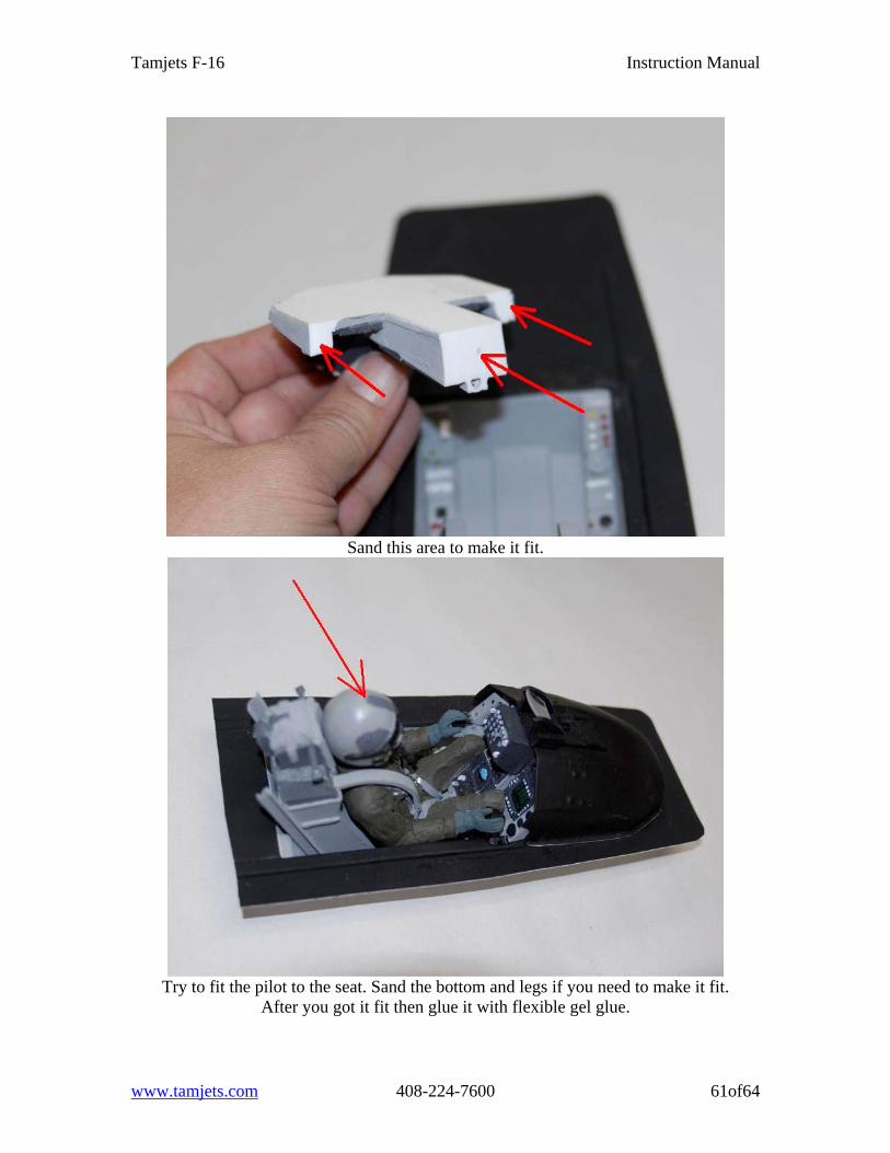
Sand this area to make it fit.
Try to fit the pilot to the seat. Sand the bottom and legs if you need to make it fit.
After you got it fit then glue it with flexible gel glue.
www.tamjets.com 408-224-7600 61of64
Tamjets F-16 Instruction Manual
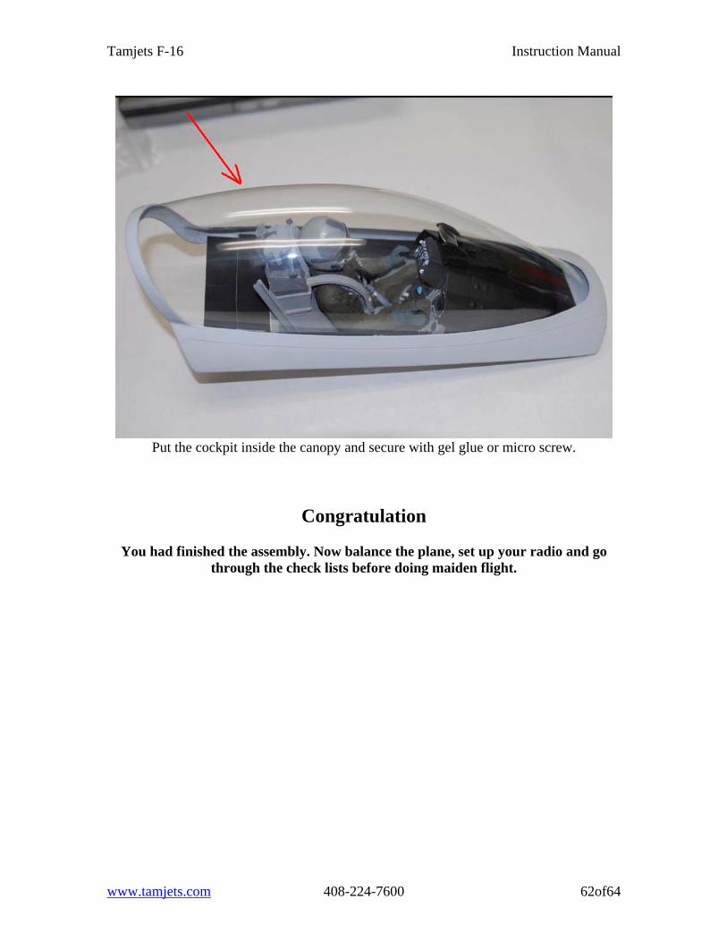
Put the cockpit inside the canopy and secure with gel glue or micro screw.
Congratulation
You had finished the assembly. Now balance the plane, set up your radio and go through the check lists before doing maiden flight.
www.tamjets.com 408-224-7600 62of64
Tamjets F-16 Instruction Manual
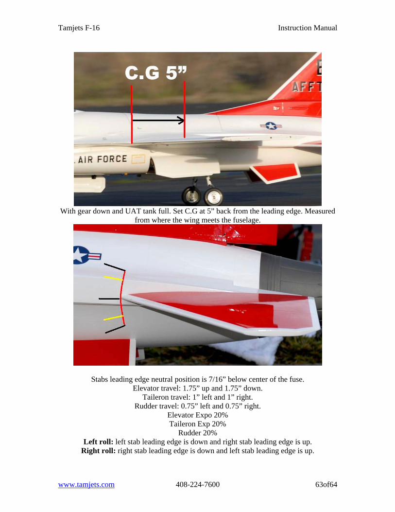
With gear down and UAT tank full. Set C.G at 5” back from the leading edge. Measured
from where the wing meets the fuselage.
Stabs leading edge neutral position is 7/16” below center of the fuse. Elevator travel: 1.75” up and 1.75” down.
Taileron travel: 1” left and 1” right. Rudder travel: 0.75” left and 0.75” right.
Elevator Expo 20% Taileron Exp 20%
Rudder 20% Left roll: left stab leading edge is down and right stab leading edge is up.
Right roll: right stab leading edge is down and left stab leading edge is up.
www.tamjets.com 408-224-7600 63of64
Tamjets F-16 Instruction Manual
Do’s and Don’t’s Do balance your aircraft Do check that your control surfaces are operating in the correct direction Do lube your brakes with BVM brake lube or equivalent Do make sure your pull-pull system is tight or the plain will be squirrelly on
takeoff. It should takeoff straight as an arrow Do range check. We have flown our models with and without a whip antenna and
have successfully range checked in all situations. Whip antennas are always recommended. Available at Tamjets.
Do test your retracts before every first flight of the day. Do check your brakes prior to each flight. With the amount of flying we do. We
have seen a brake line pop off from time to time. We have put a touch of CA on the brake line where it connects to the brake hub as an added precaution.
Do check all your E-clips on your struts prior to first flight of the day. Some times these can pop off in transportation or otherwise.
DON’T start your engine with the engine hatch on. If you have a hot start you will
warp your hatch or do worse damage.
DON’T fly your test flight without shaking all of the air/bubbles out of your UAT
Recommendations and Options OPTION- Whip antenna. Available at Tamjets OPTION- Install smoke system RECCOMENDATION- On short runways, make sure to set your wheel brakes to
the on position prior to landing. We do this at our field and stop in 250 ft or less. With the wheel brakes lubed it works phenomenally well without locking up or slamming the nose down.
RECCOMENDATION- On take off use a generous amount of elevator for a shorter and more scale takeoff. There is no need to rocket the plane down the runway like a 40lb jet. This jet should be 17.5-18.5 lbs dry.
ENJOY!
www.tamjets.com 408-224-7600 64of64