Embed Size (px)
Citation preview
© C
OP
YR
IGH
T 2
001,
MU
LTIQ
UIP
IN
C.
PARTS AND OPERATION MANUAL
Tamping RammerModel MT-60HS
PARTS AND OPERATION MANUAL
MULTIQUIP INC..... PARTS DEPARTMENT:18910 WILMINGTON AVE. 800-427-1244CARSON, CALIFORNIA 90746 FAX: 800-672-7877310-537-3700 SERVICE DEPARTMENT/TECHNICAL ASSISTANCE:800-421-1244 800-478-1244FAX: 310-537-3927 FAX: 310-631-5032E-mail:[email protected] • www:multiquip.comAtlanta • Boise • Dallas • Houston • NewarkMontreal, Canada • Manchester, UKRio De Janiero, Brazil • Guadalajara, Mexico
Revision #7 (03/02/01)
PAGE 2 — MT-60HS — PARTS & OPERATION MANUAL — REV. #7 (03/02/01)
MT-60HS — PARTS & OPERATION MANUAL — REV. #7 (03/02/01) — PAGE 3
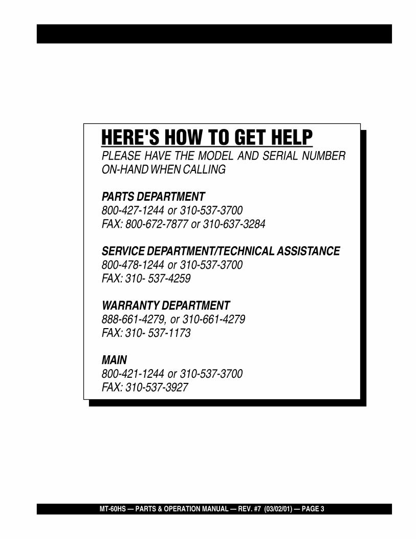
HERE'S HOW TO GET HELPPLEASE HAVE THE MODEL AND SERIAL NUMBERON-HAND WHEN CALLING
PARTS DEPARTMENT800-427-1244 or 310-537-3700FAX: 800-672-7877 or 310-637-3284
SERVICE DEPARTMENT/TECHNICAL ASSISTANCE800-478-1244 or 310-537-3700FAX: 310- 537-4259
WARRANTY DEPARTMENT888-661-4279, or 310-661-4279FAX: 310- 537-1173
MAIN800-421-1244 or 310-537-3700FAX: 310-537-3927
PAGE 4 — MT-60HS — PARTS & OPERATION MANUAL — REV. #7 (03/02/01)
TABLE OF CONTENTS
Here's How To Get Help ........................................ 3Table Of Contents ................................................. 4Parts Ordering Procedures ................................... 5Rules For safe Operation ..................................6-7Operation and Safety Decals ................................ 8General Information .............................................. 9
MT-60HSSpecification ........................................................ 10Controls and Components .................................. 11Operation .......................................................12-14Maintenance ..................................................15-16Troubleshooting Guide ...................................17-18Explanation Of Codes In Remarks Column ........ 20Suggested Spare Parts ....................................... 21Name Plate and Decals .................................22-23Crankcase and Engine Assembly ..................24-25Guide Cylinder and Foot Assembly ...............26-27Tank and Handle Assembly ...........................28-31
NOTE
Specification and part numberare subject to change withoutnotice.
ROBIN EC-08GH ENGINECrankcase and Cylinder Assembly ................32-33Crankshaft and Piston Assembly ...................34-35Governor Assembly .......................................36-37Muffler Assembly ...........................................38-39Carburetor and Oil Pump Assembly ..............40-41Recoil Starter and Blower Assembly ...........42-43Air Cleaner Assembly .................................. 44-45Carburetor Components Assembly ...............46-47Recoil Starter Components Assembly ...........48-49Magneto Assembly ........................................50-51
Terms and Condition of Sale — Parts ..................... 52
MT-60HS — PARTS & OPERATION MANUAL — REV. #7 (03/02/01) — PAGE 5
PARTS ORDERING PROCEDURES
Get special freight allowanceswhen you order 10 or moreline items via FAX!**n UPS Ground Service at no charge for freight
n PS Third Day Service at one-half of actual freight cost
No other allowances on freight shipped by any other carrier.
**Common nuts, bolts and washers (all items under $1.00 list price)do not count towards the 10+ line items.
*DISCOUNTS ARE SUBJECT TO CHANGE*
Fax order discount and UPS special programs revised June 1, 1995
For faxed orders only
UPSSpecial
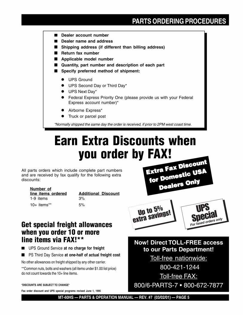
Earn Extra Discounts whenyou order by FAX!
All parts orders which include complete part numbersand are received by fax qualify for the following extradiscounts:
Number ofline items ordered Additional Discount1-9 items 3%
10+ items** 5%
Now! Direct TOLL-FREE accessto our Parts Department!
Toll-free nationwide: 800-421-1244Toll-free FAX:
800/6-PARTS-7 • 800-672-7877
n Dealer account numbern Dealer name and addressn Shipping address (if different than billing address)n Return fax numbern Applicable model numbern Quantity, part number and description of each partn Specify preferred method of shipment:
• UPS Ground
• UPS Second Day or Third Day*
• UPS Next Day*
• Federal Express Priority One (please provide us with your FederalExpress account number)*
• Airborne Express*
• Truck or parcel post
*Normally shipped the same day the order is received, if prior to 2PM west coast time.
Extra Fax Discount
Extra Fax Discount
Extra Fax Discount
Extra Fax Discount
Extra Fax Discount
for Domestic USAfor Domestic USAfor Domestic USAfor Domestic USA
for Domestic USA
Dealers OnlyDealers OnlyDealers OnlyDealers OnlyDealers Only
PAGE 6 — MT-60HS — PARTS & OPERATION MANUAL — REV. #7 (03/02/01)
RULES FOR SAFE OPERATION
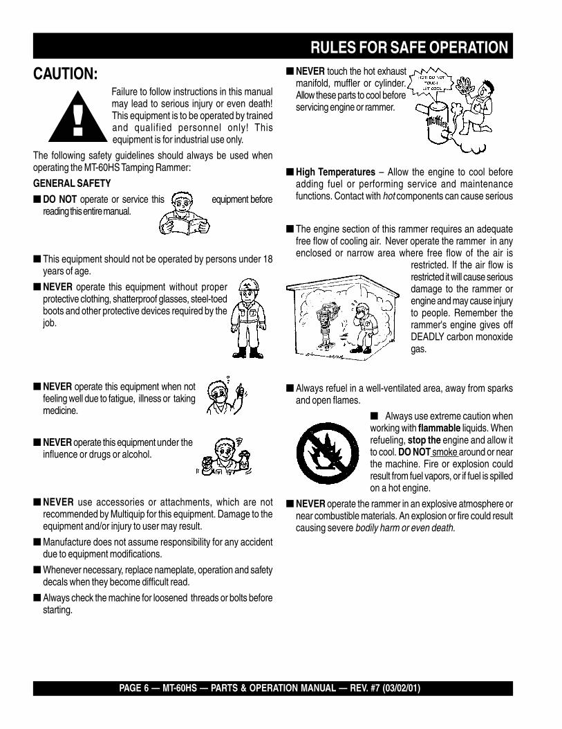
CAUTION:Failure to follow instructions in this manualmay lead to serious injury or even death!This equipment is to be operated by trainedand qualified personnel only! Thisequipment is for industrial use only.
The following safety guidelines should always be used whenoperating the MT-60HS Tamping Rammer:
GENERAL SAFETY
� DO NOT operate or service this equipment beforereading this entire manual.
� This equipment should not be operated by persons under 18years of age.
� NEVER operate this equipment without properprotective clothing, shatterproof glasses, steel-toedboots and other protective devices required by thejob.
� NEVER operate this equipment when notfeeling well due to fatigue, illness or takingmedicine.
� NEVER operate this equipment under theinfluence or drugs or alcohol.
� NEVER use accessories or attachments, which are notrecommended by Multiquip for this equipment. Damage to theequipment and/or injury to user may result.
� Manufacture does not assume responsibility for any accidentdue to equipment modifications.
� Whenever necessary, replace nameplate, operation and safetydecals when they become difficult read.
� Always check the machine for loosened threads or bolts beforestarting.
� Always refuel in a well-ventilated area, away from sparksand open flames.
� Always use extreme caution whenworking with flammable liquids. Whenrefueling, stop the engine and allow itto cool. DO NOT smoke around or nearthe machine. Fire or explosion couldresult from fuel vapors, or if fuel is spilledon a hot engine.
� NEVER operate the rammer in an explosive atmosphere ornear combustible materials. An explosion or fire could resultcausing severe bodily harm or even death.
� NEVER touch the hot exhaustmanifold, muffler or cylinder.Allow these parts to cool beforeservicing engine or rammer.
� The engine section of this rammer requires an adequatefree flow of cooling air. Never operate the rammer in anyenclosed or narrow area where free flow of the air is
restricted. If the air flow isrestricted it will cause seriousdamage to the rammer orengine and may cause injuryto people. Remember therammer's engine gives offDEADLY carbon monoxidegas.
� High Temperatures – Allow the engine to cool beforeadding fuel or performing service and maintenancefunctions. Contact with hot components can cause serious
MT-60HS — PARTS & OPERATION MANUAL — REV. #7 (03/02/01) — PAGE 7
RULES FOR SAFE OPERATION� NEVER Run engine without air filter. Severe engine may
occur.
� Always service air cleaner frequently to prevent carburetormalfunction.
� Always be sure the operator is familiar with proper safetyprecautions and operations techniques before using rammer.
� Always store equipment properly when it is not being used.Equipment should be stored in a clean, dry location out of thereach of children.
� NEVER use accessories or attachments, which are notrecommended by Multiquip for this equipment. Damage tothe equipment and/or injury to user may result.
� NEVER Run engine without air cleaner. Severe enginedamage may occur.
� Always read, understand, and follow procedures in Operator’sManual before attempting to operate equipment.
� Always be sure the operator is familiar with proper safetyprecautions and operations techniques before using pump.
� Always store equipment properly when it is not being used.Equipment should be stored in a clean, dry location out of thereach of children.
� Refer to the ROBIN Engine Owner's Manual for enginetechnical questions or information recommended by Multiquipfor this equipment. Damage to the equipment and/or injury touser may result.
Transporting� Always shutdown engine before transporting.
� Tighten fuel tank cap securly and close fuel cock to preventfuel from spilling.
� Drain fuel when transporting rammer over long distances orbad roads.
� When placing the rammer inside a truck-bed for transport,always tie-down the rammer.
Emergencies
� Always know the location of the nearest fire extinguisherand first aid kit. Know the location of the nearest telephone.Also know the phone numbers of the nearest ambulance,doctor and fire department. This information will beinvaluable in the case of an emergency.
Maintenance Safety� NEVER lubricate components or attempt service on a running
machine.
� Always allow the machine a proper amount of time to coolbefore servicing.
� Keep the machinery in proper running condition.
� Fix damage to the machine immediately and always replacebroken parts.
� Dispose of hazardous waste properly. Examples of potentiallyhazardous waste are used motor oil, fuel and fuel filters.
� DO NOT use plastic containers to dispose of hazardouswaste.
PAGE 8 — MT-60HS — PARTS & OPERATION MANUAL — REV. #7 (03/02/01)
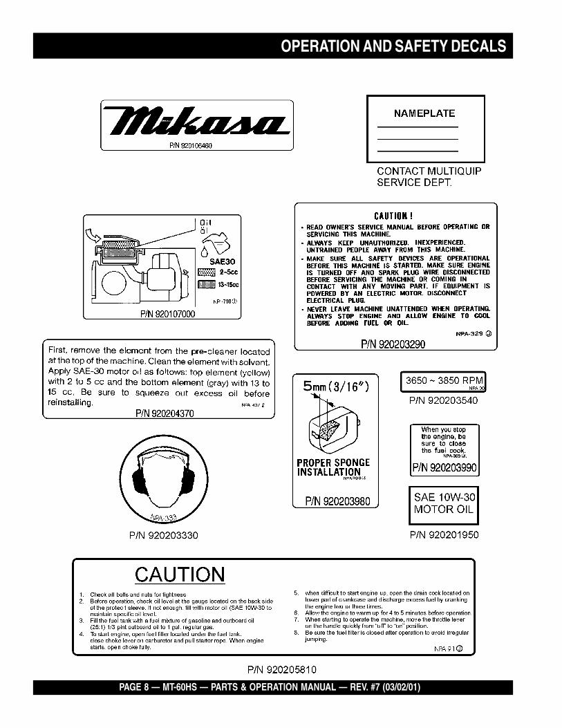
OPERATION AND SAFETY DECALS

MT-60HS — PARTS & OPERATION MANUAL — REV. #7 (03/02/01) — PAGE 9
PAGE 10 — MT-60HS — PARTS & OPERATION MANUAL — REV. #7 (03/02/01)
Definition of Tamping Rammer
The Mikasa MT-60HS Tamping Rammer is a powerfulcompacting tool capable of applying a tremendous force inconsecutive impacts to a soil surface. Its applications includesoil compacting for backfilling for gas pipelines, water pipelinesand cable installation work.
The impact force of the MT-60HS levels and uniformly compactsvoids between soil particles to increase dry density.
Circular motion is converted to create impact force. The MT-60HS tamping rammer develops a powerful compacting force atthe foot of the rammer. To maintain optimum performance, properoperation and service are essential.
Construction of Tamping Rammer
The Mikasa MT-60HS is equipped with an Robin air cooled, oil-injected two cycle gasoline engine. Transmission of the powertakes place by increasing the engine speed to engage thecentrifugal clutch.
Rammer Gearbox and Spring Cylinder
The Mikasa MT-60HS uses an oil bath lubrication system. Alwayscheck the oil level through the oil level sight glass at the rear ofthe tamper foot.
Controls
Before starting the MT-60HS Tamping Rammer identify andunderstand the function of the controls, see Figure 1 on page 11.
GENERAL INFORMATION
MT-60HS — PARTS & OPERATION MANUAL — REV. #7 (03/02/01) — PAGE 11
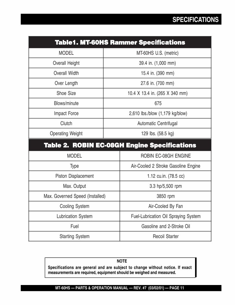
NOTESpecifications are general and are subject to change without notice. If exactmeasurements are required, equipment should be weighed and measured.
SPECIFICATIONS
snoitacificepSremmaRSH06-TM.1elbaT snoitacificepSremmaRSH06-TM.1elbaT snoitacificepSremmaRSH06-TM.1elbaT snoitacificepSremmaRSH06-TM.1elbaT snoitacificepSremmaRSH06-TM.1elbaT
LEDOM )cirtem(.S.USH06-TM
thgieHllarevO )mm000,1(.ni4.93
htdiWllarevO )mm093(.ni4.51
htgneLrevO )mm007(.ni6.72
eziSeohS )mm043X562(.ni4.31X4.01
etunim/swolB 576
ecroFtcapmI )wolb/gk971,1(wolb/.sbl016,2
hctulC lagufirtneCcitamotuA
thgieWgnitarepO )gk5.85(.sbl921
snoitacificepSenignEHG80-CENIBOR.2elbaT snoitacificepSenignEHG80-CENIBOR.2elbaT snoitacificepSenignEHG80-CENIBOR.2elbaT snoitacificepSenignEHG80-CENIBOR.2elbaT snoitacificepSenignEHG80-CENIBOR.2elbaT
LEDOM ENIGNEHG80-CENIBOR
epyT enignEenilosaGekortS2delooC-riA
tnemecalpsiDnotsiP )cc5.87(.ni.uc21.1
tuptuO.xaM mpr005,5/ph3.3
)dellatsnI(deepSdenrevoG.xaM mpr0583
metsySgnilooC naFyBdelooC-riA
metsySnoitacirbuL metsySgniyarpSliOnoitacirbuL-leuF
leuF liOekortS-2dnaenilosaG
metsySgnitratS retratSlioceR
PAGE 12 — MT-60HS — PARTS & OPERATION MANUAL — REV. #7 (03/02/01)
MT-60HS — CONTROLS AND COMPONENTS
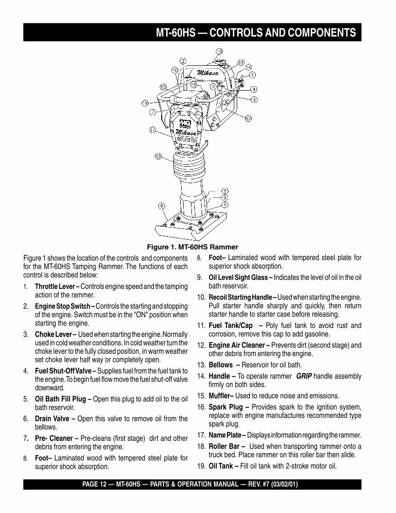
Figure 1 shows the location of the controls and componentsfor the MT-60HS Tamping Rammer. The functions of eachcontrol is described below:
1. Throttle Lever – Controls engine speed and the tampingaction of the rammer.
2. Engine Stop Switch – Controls the starting and stoppingof the engine. Switch must be in the "ON" position whenstarting the engine.
3. Choke Lever – Used when starting the engine. Normallyused in cold weather conditions. In cold weather turn thechoke lever to the fully closed position, in warm weatherset choke lever half way or completely open.
4. Fuel Shut-Off Valve – Supplies fuel from the fuel tank tothe engine. To begin fuel flow move the fuel shut-off valvedownward.
5. Oil Bath Fill Plug – Open this plug to add oil to the oilbath reservoir.
6. Drain Valve – Open this valve to remove oil from thebellows.
7. Pre- Cleaner – Pre-cleans (first stage) dirt and otherdebris from entering the engine.
8. Foot– Laminated wood with tempered steel plate forsuperior shock absorption.
8. Foot– Laminated wood with tempered steel plate forsuperior shock absorption.
9. Oil Level Sight Glass – Indicates the level of oil in the oilbath reservoir.
10. Recoil Starting Handle – Used when starting the engine.Pull starter handle sharply and quickly, then returnstarter handle to starter case before releasing.
11. Fuel Tank/Cap – Poly fuel tank to avoid rust andcorrosion, remove this cap to add gasoline.
12. Engine Air Cleaner – Prevents dirt (second stage) andother debris from entering the engine.
13. Bellows – Reservoir for oil bath.
14. Handle – To operate rammer GRIP handle assemblyfirmly on both sides.
15. Muffler– Used to reduce noise and emissions.16. Spark Plug – Provides spark to the ignition system,
replace with engine manufactures recommended typespark plug.
17. Name Plate – Displays information regarding the rammer.
18. Roller Bar – Used when transporting rammer onto atruck bed. Place rammer on this roller bar then slide.
19. Oil Tank – Fill oil tank with 2-stroke motor oil.
Figure 1. MT-60HS Rammer
MT-60HS — PARTS & OPERATION MANUAL — REV. #7 (03/02/01) — PAGE 13
Failure to understand the operation of the MT-60HS Tamping Rammer could result in severedamage to the rammer or personal injury.
Engine
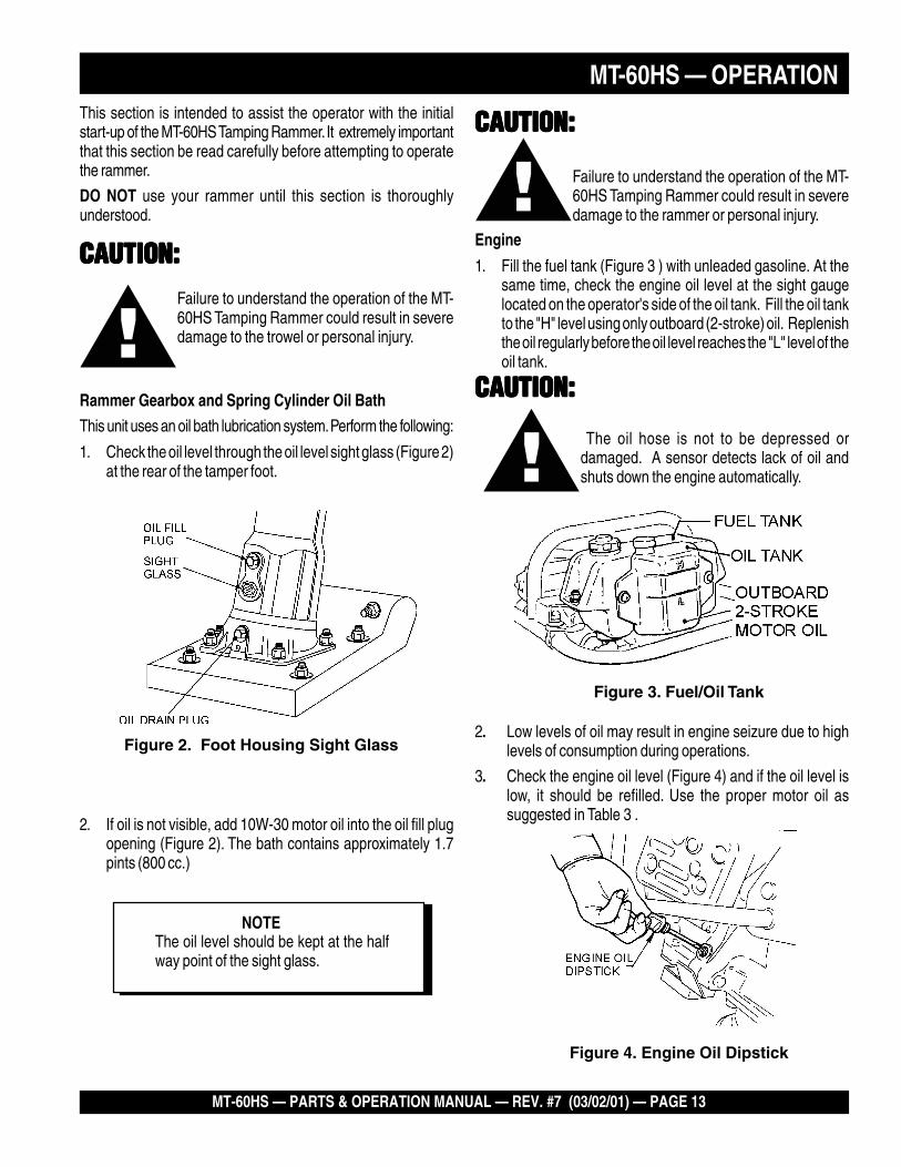
1. Fill the fuel tank (Figure 3 ) with unleaded gasoline. At thesame time, check the engine oil level at the sight gaugelocated on the operator's side of the oil tank. Fill the oil tankto the "H" level using only outboard (2-stroke) oil. Replenishthe oil regularly before the oil level reaches the "L" level of theoil tank.
MT-60HS — OPERATION
Figure 4. Engine Oil Dipstick
CAUTION:CAUTION:CAUTION:CAUTION:CAUTION:
The oil hose is not to be depressed ordamaged. A sensor detects lack of oil andshuts down the engine automatically.
CAUTION:CAUTION:CAUTION:CAUTION:CAUTION:
CAUTION:CAUTION:CAUTION:CAUTION:CAUTION:Failure to understand the operation of the MT-60HS Tamping Rammer could result in severedamage to the trowel or personal injury.
Rammer Gearbox and Spring Cylinder Oil Bath
This unit uses an oil bath lubrication system. Perform the following:
1. Check the oil level through the oil level sight glass (Figure 2)at the rear of the tamper foot.
This section is intended to assist the operator with the initialstart-up of the MT-60HS Tamping Rammer. It extremely importantthat this section be read carefully before attempting to operatethe rammer.
DO NOT use your rammer until this section is thoroughlyunderstood.
NOTEThe oil level should be kept at the halfway point of the sight glass.
Figure 2. Foot Housing Sight Glass
2. If oil is not visible, add 10W-30 motor oil into the oil fill plugopening (Figure 2). The bath contains approximately 1.7pints (800 cc.)
2. Low levels of oil may result in engine seizure due to highlevels of consumption during operations.
3. Check the engine oil level (Figure 4) and if the oil level islow, it should be refilled. Use the proper motor oil assuggested in Table 3 .
Figure 3. Fuel/Oil Tank
PAGE 14 — MT-60HS — PARTS & OPERATION MANUAL — REV. #7 (03/02/01)
MT-60HS — OPERATION
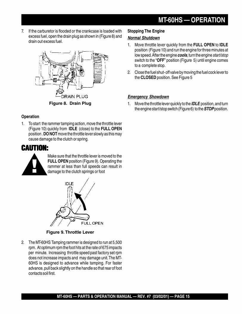
5. If engine fails to start, move the choke lever (Figure 5) to thehalf open position to avoid flooding.
6. Repeat steps 1 thru 5.
7. If the engine does not start after repeated attempts,check the spark plug for excess fuel. Clean and replacethe spark plug as needed.
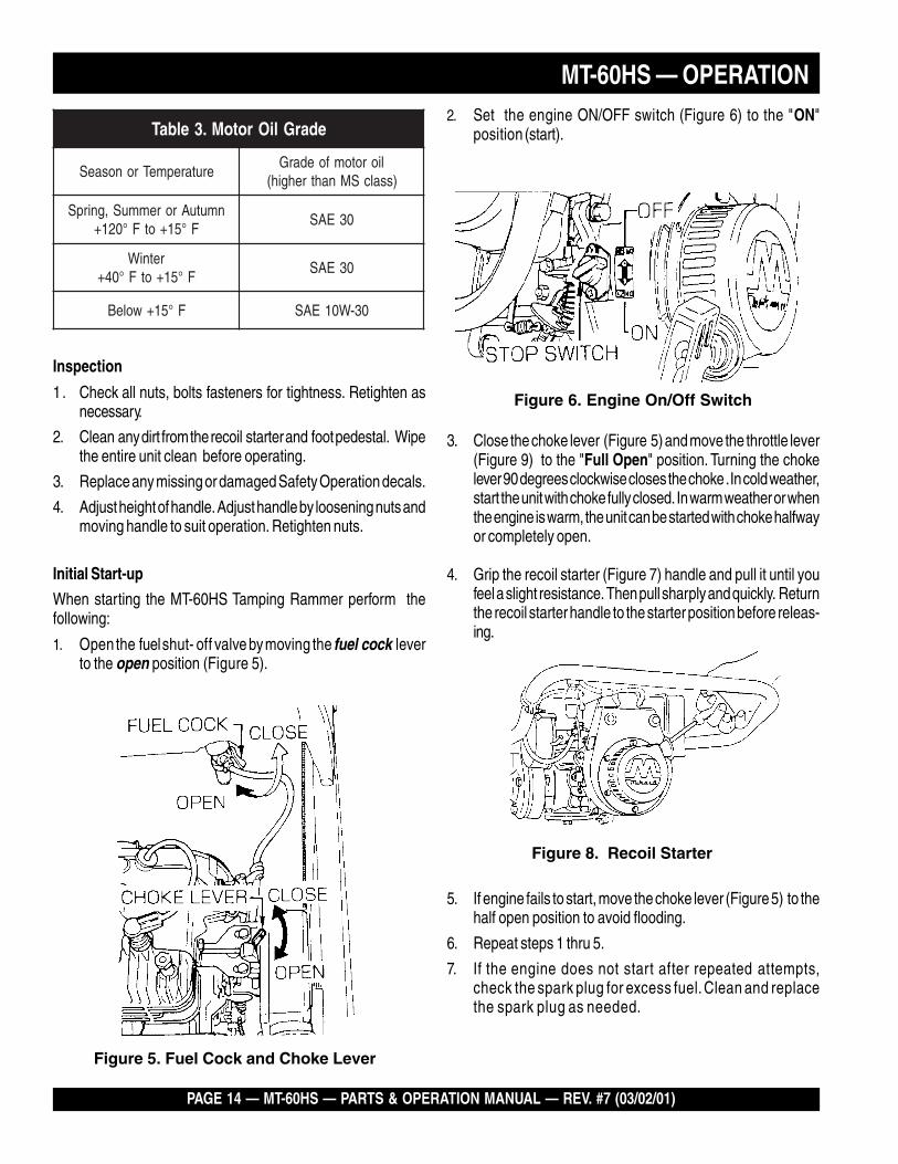
Figure 6. Engine On/Off Switch
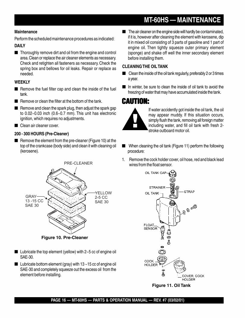
Figure 8. Recoil Starter
2. Set the engine ON/OFF switch (Figure 6) to the "ON"position (start).
Figure 5. Fuel Cock and Choke Lever
3. Close the choke lever (Figure 5) and move the throttle lever(Figure 9) to the "Full Open" position. Turning the chokelever 90 degrees clockwise closes the choke . In cold weather,start the unit with choke fully closed. In warm weather or whenthe engine is warm, the unit can be started with choke halfwayor completely open.
4. Grip the recoil starter (Figure 7) handle and pull it until youfeel a slight resistance. Then pull sharply and quickly. Returnthe recoil starter handle to the starter position before releas-ing.
Inspection
1. Check all nuts, bolts fasteners for tightness. Retighten asnecessary.
2. Clean any dirt from the recoil starter and foot pedestal. Wipethe entire unit clean before operating.
3. Replace any missing or damaged Safety Operation decals.
4. Adjust height of handle. Adjust handle by loosening nuts andmoving handle to suit operation. Retighten nuts.
Initial Start-up
When starting the MT-60HS Tamping Rammer perform thefollowing:
1. Open the fuel shut- off valve by moving the fuel cock leverto the open position (Figure 5).
edarGliOrotoM.3elbaT
erutarepmeTronosaeSliorotomfoedarG
)ssalcSMnahtrehgih(
nmutuAroremmuS,gnirpSF°51+otF°021+
03EAS
retniWF°51+otF°04+
03EAS
F°51+woleB 03-W01EAS
MT-60HS — PARTS & OPERATION MANUAL — REV. #7 (03/02/01) — PAGE 15
Stopping The Engine
Normal Shutdown
1. Move throttle lever quickly from the FULL OPEN to IDLEposition (Figure 10) and run the engine for three minutes atlow speed. After the engine cools, turn the engine start/stopswitch to the “OFF” position (Figure 5) until engine comesto a complete stop.
2. Close the fuel shut- off valve by moving the fuel cock lever tothe CLOSED position. See Figure 5
Emergency Showdown
1. Move the throttle lever quickly to the IDLE position, and turnthe engine start/stop switch (Figure 6) to the STOP position.
MT-60HS — OPERATION
CAUTION:CAUTION:CAUTION:CAUTION:CAUTION:Make sure that the throttle lever is moved to theFULL OPEN position (Figure 9). Operating therammer at less than full speeds can result indamage to the clutch springs or foot
Figure 9. Throttle Lever
2. The MT-60HS Tamping rammer is designed to run at 5,500rpm. At optimum rpm the foot hits at the rate of 675 impactsper minute. Increasing throttle speed past factory set rpmdoes not increase impacts and may damage unit. The MT-60HS is designed to advance while tamping. For fasteradvance, pull back slightly on the handle so that rear of footcontacts soil first.
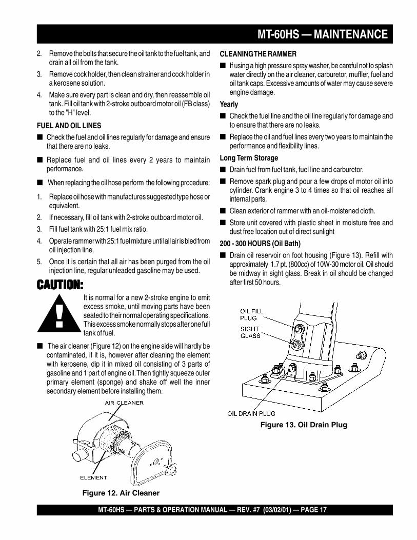
7. If the carburetor is flooded or the crankcase is loaded withexcess fuel, open the drain plug as shown in (Figure 8) anddrain out excess fuel.
Figure 8. Drain Plug
Operation
1. To start the rammer tamping action, move the throttle lever(Figure 10) quickly from IDLE (close) to the FULL OPENposition . DO NOT move the throttle lever slowly as this maycause damage to the clutch or spring.
PAGE 16 — MT-60HS — PARTS & OPERATION MANUAL — REV. #7 (03/02/01)
Maintenance
Perform the scheduled maintenance procedures as indicated:
DAILY
� Thoroughly remove dirt and oil from the engine and controlarea. Clean or replace the air cleaner elements as necessary.Check and retighten all fasteners as necessary. Check thespring box and bellows for oil leaks. Repair or replace asneeded.
WEEKLY
� Remove the fuel filter cap and clean the inside of the fueltank.
� Remove or clean the filter at the bottom of the tank.
� Remove and clean the spark plug, then adjust the spark gapto 0.02~0.03 inch (0.6~0.7 mm). This unit has electronicignition, which requires no adjustments.
� Clean air cleaner cover.
200 - 300 HOURS (Pre-Cleaner)� Remove the element from the pre-cleaner (Figure 10) at the
top of the crankcase (body side) and clean it with cleaning oil(kerosene).
MT-60HS — MAINTENANCE
� Lubricate the top element (yellow) with 2~5 cc of engine oilSAE-30.
� Lubricate bottom element (gray) with 13 ~15 cc of engine oilSAE-30 and completely squeeze out the excess oil from theelement before installing.
� The air cleaner on the engine side will hardly be contaminated,if it is, however after cleaning the element with kerosene, dipit in mixed oil consisting of 3 parts of gasoline and 1 part ofengine oil. Then tightly squeeze outer primary element(sponge) and shake off well the inner secondary elementbefore installing them.
CLEANING THE OIL TANK
� Clean the inside of the oil tank regularly, preferably 2 or 3 timesa year.
� In winter, be sure to clean the inside of oil tank to avoid thefreezing of water that may have accumulated inside the tank.
Figure 10. Pre-Cleaner
YELLOWGRAY
13 -15 CC
SAE 30
2-5 CC
SAE 30
PRE-CLEANER
Figure 11. Oil Tank
CAUTION:CAUTION:CAUTION:CAUTION:CAUTION:If water accidently got inside the oil tank, the oilmay appear muddy. If this situation occurs,simply flush the tank, removing all foreign matterincluding water, and fill oil tank with fresh 2-stroke outboard motor oil.
� When cleaning the oil tank (Figure 11) perform the followingprocedure:
1. Remove the cock holder cover, oil hose, red and black leadwires from the float sensor.
MT-60HS — PARTS & OPERATION MANUAL — REV. #7 (03/02/01) — PAGE 17
MT-60HS — MAINTENANCE2. Remove the bolts that secure the oil tank to the fuel tank, and
drain all oil from the tank.
3. Remove cock holder, then clean strainer and cock holder ina kerosene solution.
4. Make sure every part is clean and dry, then reassemble oiltank. Fill oil tank with 2-stroke outboard motor oil (FB class)to the "H" level.
FUEL AND OIL LINES� Check the fuel and oil lines regularly for damage and ensure
that there are no leaks.
� Replace fuel and oil lines every 2 years to maintainperformance.
� When replacing the oil hose perform the following procedure:
1. Replace oil hose with manufactures suggested type hose orequivalent.
2. If necessary, fill oil tank with 2-stroke outboard motor oil.
3. Fill fuel tank with 25:1 fuel mix ratio.
4. Operate rammer with 25:1 fuel mixture until all air is bled fromoil injection line.
5. Once it is certain that all air has been purged from the oilinjection line, regular unleaded gasoline may be used.
CAUTION:CAUTION:CAUTION:CAUTION:CAUTION:It is normal for a new 2-stroke engine to emitexcess smoke, until moving parts have beenseated to their normal operating specifications.This excess smoke normally stops after one fulltank of fuel.
CLEANING THE RAMMER� If using a high pressure spray washer, be careful not to splash
water directly on the air cleaner, carburetor, muffler, fuel andoil tank caps. Excessive amounts of water may cause severeengine damage.
Yearly
� Check the fuel line and the oil line regularly for damage andto ensure that there are no leaks.
� Replace the oil and fuel lines every two years to maintain theperformance and flexibility lines.
Long Term Storage� Drain fuel from fuel tank, fuel line and carburetor.
� Remove spark plug and pour a few drops of motor oil intocylinder. Crank engine 3 to 4 times so that oil reaches allinternal parts.
� Clean exterior of rammer with an oil-moistened cloth.
� Store unit covered with plastic sheet in moisture free anddust free location out of direct sunlight
� The air cleaner (Figure 12) on the engine side will hardly becontaminated, if it is, however after cleaning the elementwith kerosene, dip it in mixed oil consisting of 3 parts ofgasoline and 1 part of engine oil. Then tightly squeeze outerprimary element (sponge) and shake off well the innersecondary element before installing them.
200 - 300 HOURS (Oil Bath)
� Drain oil reservoir on foot housing (Figure 13). Refill withapproximately 1.7 pt. (800cc) of 10W-30 motor oil. Oil shouldbe midway in sight glass. Break in oil should be changedafter first 50 hours.
Figure 12. Air Cleaner
Figure 13. Oil Drain Plug
PAGE 18 — MT-60HS — PARTS & OPERATION MANUAL — REV. #7 (03/02/01)
MT-60HS — TROUBLESHOOTING GUIDE
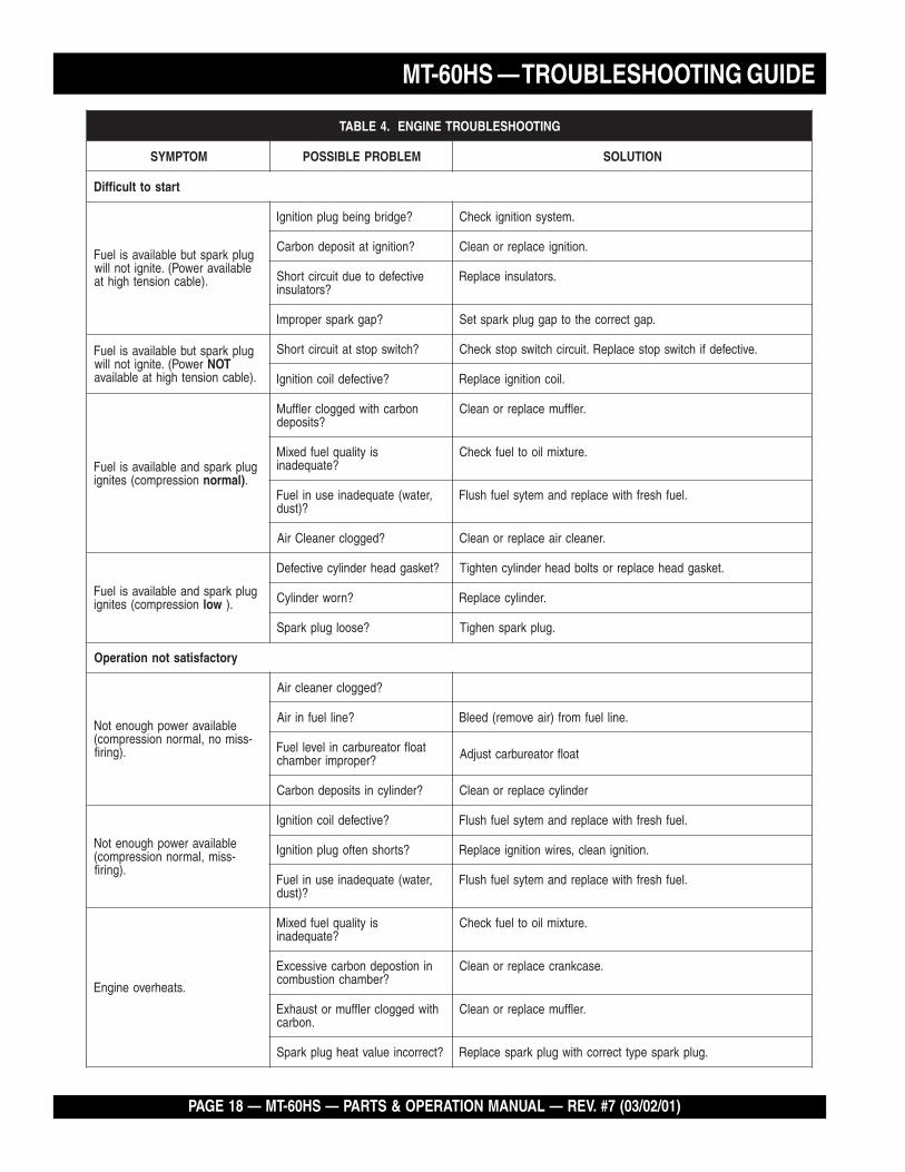
GNITOOHSELBUORTENIGNE.4ELBAT
MOTPMYS MELBORPELBISSOP NOITULOS
tratsottluciffiD
gulpkrapstubelbaliavasileuFelbaliavarewoP(.etingitonlliw
.)elbacnoisnethgihta
?egdirbgniebgulpnoitingI .metsysnoitingikcehC
?noitingitatisopednobraC .noitingiecalperronaelC
evitcefedoteudtiucrictrohS?srotalusni
.srotalusniecalpeR
?pagkrapsreporpmI .pagtcerrocehtotpaggulpkrapsteS
gulpkrapstubelbaliavasileuFrewoP(.etingitonlliw TON
.)elbacnoisnethgihtaelbaliava
?hctiwspotstatiucrictrohS .evitcefedfihctiwspotsecalpeR.tiucrichctiwspotskcehC
?evitcefedliocnoitingI .liocnoitingiecalpeR
gulpkrapsdnaelbaliavasileuFnoisserpmoc(setingi )lamron .
nobrachtiwdeggolcrelffuM?stisoped
.relffumecalperronaelC
siytilauqleufdexiM?etauqedani
.erutximliootleufkcehC
,retaw(etauqedaniesunileuF?)tsud
.leufhserfhtiwecalperdnametysleufhsulF
?deggolcrenaelCriA .renaelcriaecalperronaelC
gulpkrapsdnaelbaliavasileuFnoisserpmoc(setingi wol .)
?teksagdaehrednilycevitcefeD .teksagdaehecalperrostlobdaehrednilycnethgiT
?nrowrednilyC .rednilycecalpeR
?esoolgulpkrapS .gulpkrapsnehgiT
yrotcafsitastonnoitarepO
elbaliavarewophguonetoN-ssimon,lamronnoisserpmoc(
.)gnirif
?deggolcrenaelcriA
?enilleufniriA .enilleufmorf)riaevomer(deelB
taolfrotaerubracnilevelleuF?reporpmirebmahc taolfrotaerubractsujdA
?rednilycnistisopednobraC rednilycecalperronaelC
elbaliavarewophguonetoN-ssim,lamronnoisserpmoc(
.)gnirif
?evitcefedliocnoitingI .leufhserfhtiwecalperdnametysleufhsulF
?strohsnetfogulpnoitingI .noitinginaelc,seriwnoitingiecalpeR
,retaw(etauqedaniesunileuF?)tsud
.leufhserfhtiwecalperdnametysleufhsulF
.staehrevoenignE
siytilauqleufdexiM?etauqedani
.erutximliootleufkcehC
ninoitsopednobracevissecxE?rebmahcnoitsubmoc
.esacknarcecalperronaelC
htiwdeggolcrelffumrotsuahxE.nobrac
.relffumecalperronaelC
?tcerrocnieulavtaehgulpkrapS .gulpkrapsepyttcerrochtiwgulpkrapsecalpeR
MT-60HS — PARTS & OPERATION MANUAL — REV. #7 (03/02/01) — PAGE 19
MT-60HS — TROUBLESHOOTING GUIDE
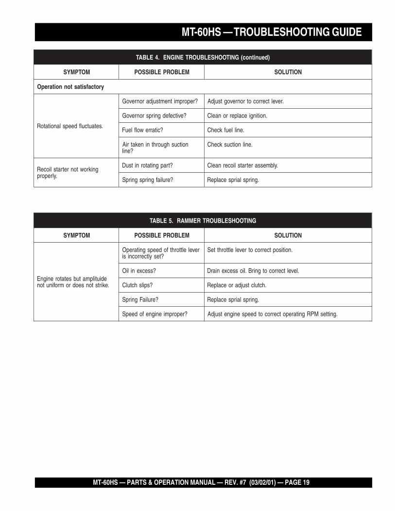
ENGINEENGINEENGINEENGINEENGINE )deunitnoc(GNITOOHSELBUORTENIGNE.4ELBAT
MOTPMYS MELBORPELBISSOP NOITULOS
yrotcafsitastonnoitarepO
.setautculfdeepslanoitatoR
?reporpmitnemtsujdaronrevoG .reveltcerrocotronrevogtsujdA
?evitcefedgnirpsronrevoG .noitingiecalperronaelC
?citarrewolfleuF .enilleufkcehC
noitcushguorhtninekatriA?enil
.enilnoitcuskcehC
gnikrowtonretratslioceR.ylreporp
?trapgnitatornitsuD .ylbmessaretratsliocernaelC
?eruliafgnirpsgnirpS .gnirpslairpsecalpeR
GNITOOHSELBUORTREMMAR.5ELBAT
MOTPMYS MELBORPELBISSOP NOITULOS
ediutilpmatubsetatorenignE.ekirtstonseodromrofinuton
revelelttorhtfodeepsgnitarepO?tesyltcerrocnisi
.noitisoptcerrocotrevelelttorhtteS
?ssecxeniliO .leveltcerrocotgnirB.liossecxeniarD
?spilshctulC .hctulctsujdaroecalpeR
?eruliaFgnirpS .gnirpslairpsecalpeR
?reporpmienignefodeepS .gnittesMPRgnitarepotcerrocotdeepsenignetsujdA
PAGE 20 — MT-60HS — PARTS & OPERATION MANUAL — REV. #7 (03/02/01)
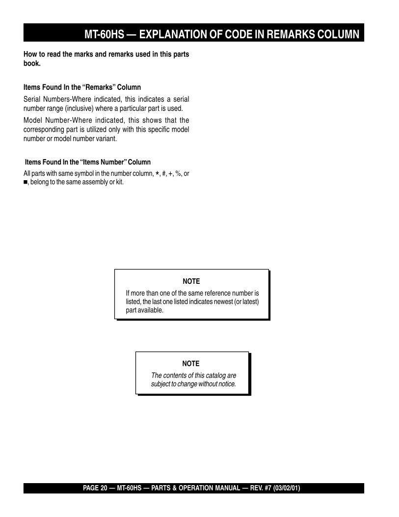
How to read the marks and remarks used in this partsbook.
Items Found In the “Remarks” Column
Serial Numbers-Where indicated, this indicates a serialnumber range (inclusive) where a particular part is used.
Model Number-Where indicated, this shows that thecorresponding part is utilized only with this specific modelnumber or model number variant.
Items Found In the “Items Number” Column
All parts with same symbol in the number column, *, #, +, %, or�, belong to the same assembly or kit.
NOTE
If more than one of the same reference number islisted, the last one listed indicates newest (or latest)part available.
NOTE
The contents of this catalog aresubject to change without notice.
MT-60HS — EXPLANATION OF CODE IN REMARKS COLUMN
MT-60HS — PARTS & OPERATION MANUAL — REV. #7 (03/02/01) — PAGE 21
MT-60HS — SUGGESTED SPARE PARTS
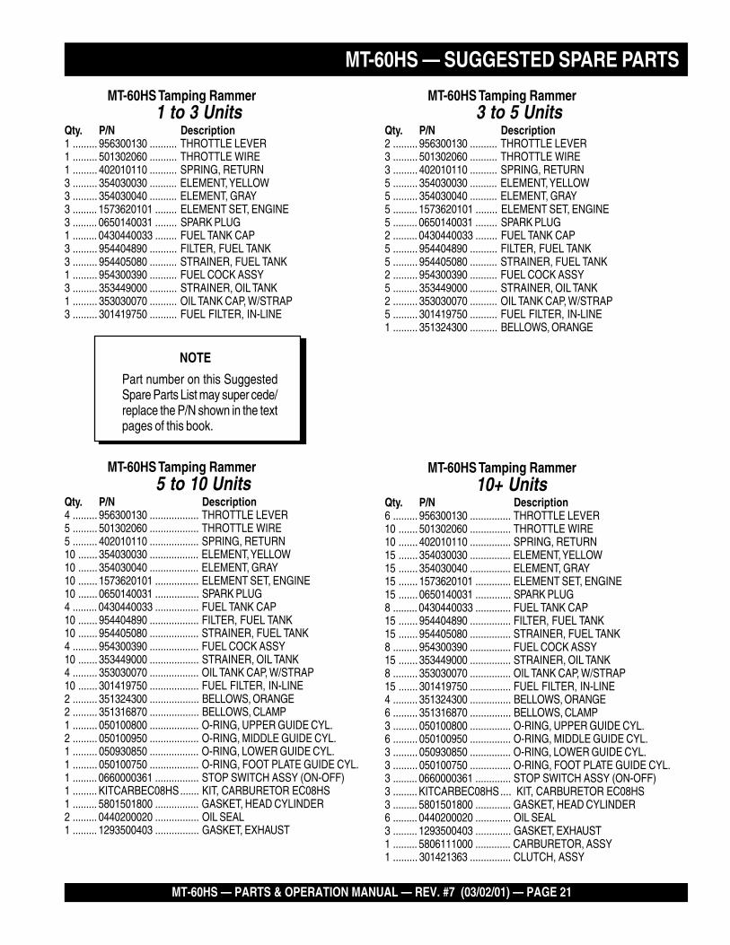
NOTE
Part number on this SuggestedSpare Parts List may super cede/replace the P/N shown in the textpages of this book.
MT-60HS — SUGGESTED SPARE PARTSMT-60HS Tamping Rammer1 to 3 Units
Qty. P/N Description1 ......... 956300130 .......... THROTTLE LEVER1 ......... 501302060 .......... THROTTLE WIRE1 ......... 402010110 .......... SPRING, RETURN3 ......... 354030030 .......... ELEMENT, YELLOW3 ......... 354030040 .......... ELEMENT, GRAY3 ......... 1573620101 ........ ELEMENT SET, ENGINE3 ......... 0650140031 ........ SPARK PLUG1 ......... 0430440033 ........ FUEL TANK CAP3 ......... 954404890 .......... FILTER, FUEL TANK3 ......... 954405080 .......... STRAINER, FUEL TANK1 ......... 954300390 .......... FUEL COCK ASSY3 ......... 353449000 .......... STRAINER, OIL TANK1 ......... 353030070 .......... OIL TANK CAP, W/STRAP3 ......... 301419750 .......... FUEL FILTER, IN-LINE
MT-60HS Tamping Rammer3 to 5 Units
Qty. P/N Description2 ......... 956300130 .......... THROTTLE LEVER3 ......... 501302060 .......... THROTTLE WIRE3 ......... 402010110 .......... SPRING, RETURN5 ......... 354030030 .......... ELEMENT, YELLOW5 ......... 354030040 .......... ELEMENT, GRAY5 ......... 1573620101 ........ ELEMENT SET, ENGINE5 ......... 0650140031 ........ SPARK PLUG2 ......... 0430440033 ........ FUEL TANK CAP5 ......... 954404890 .......... FILTER, FUEL TANK5 ......... 954405080 .......... STRAINER, FUEL TANK2 ......... 954300390 .......... FUEL COCK ASSY5 ......... 353449000 .......... STRAINER, OIL TANK2 ......... 353030070 .......... OIL TANK CAP, W/STRAP5 ......... 301419750 .......... FUEL FILTER, IN-LINE1 ......... 351324300 .......... BELLOWS, ORANGE
MT-60HS Tamping Rammer5 to 10 Units
Qty. P/N Description4 ......... 956300130 .................. THROTTLE LEVER5 ......... 501302060 .................. THROTTLE WIRE5 ......... 402010110 .................. SPRING, RETURN10 ....... 354030030 .................. ELEMENT, YELLOW10 ....... 354030040 .................. ELEMENT, GRAY10 ....... 1573620101 ................ ELEMENT SET, ENGINE10 ....... 0650140031 ................ SPARK PLUG4 ......... 0430440033 ................ FUEL TANK CAP10 ....... 954404890 .................. FILTER, FUEL TANK10 ....... 954405080 .................. STRAINER, FUEL TANK4 ......... 954300390 .................. FUEL COCK ASSY10 ....... 353449000 .................. STRAINER, OIL TANK4 ......... 353030070 .................. OIL TANK CAP, W/STRAP10 ....... 301419750 .................. FUEL FILTER, IN-LINE2 ......... 351324300 .................. BELLOWS, ORANGE2 ......... 351316870 .................. BELLOWS, CLAMP1 ......... 050100800 .................. O-RING, UPPER GUIDE CYL.2 ......... 050100950 .................. O-RING, MIDDLE GUIDE CYL.1 ......... 050930850 .................. O-RING, LOWER GUIDE CYL.1 ......... 050100750 .................. O-RING, FOOT PLATE GUIDE CYL.1 ......... 0660000361 ................ STOP SWITCH ASSY (ON-OFF)1 ......... KITCARBEC08HS....... KIT, CARBURETOR EC08HS1 ......... 5801501800 ................ GASKET, HEAD CYLINDER2 ......... 0440200020 ................ OIL SEAL1 ......... 1293500403 ................ GASKET, EXHAUST
MT-60HS Tamping Rammer10+ Units
Qty. P/N Description6 ......... 956300130 ............... THROTTLE LEVER10 ....... 501302060 ............... THROTTLE WIRE10 ....... 402010110 ............... SPRING, RETURN15 ....... 354030030 ............... ELEMENT, YELLOW15 ....... 354030040 ............... ELEMENT, GRAY15 ....... 1573620101 ............. ELEMENT SET, ENGINE15 ....... 0650140031 ............. SPARK PLUG8 ......... 0430440033 ............. FUEL TANK CAP15 ....... 954404890 ............... FILTER, FUEL TANK15 ....... 954405080 ............... STRAINER, FUEL TANK8 ......... 954300390 ............... FUEL COCK ASSY15 ....... 353449000 ............... STRAINER, OIL TANK8 ......... 353030070 ............... OIL TANK CAP, W/STRAP15 ....... 301419750 ............... FUEL FILTER, IN-LINE4 ......... 351324300 ............... BELLOWS, ORANGE6 ......... 351316870 ............... BELLOWS, CLAMP3 ......... 050100800 ............... O-RING, UPPER GUIDE CYL.6 ......... 050100950 ............... O-RING, MIDDLE GUIDE CYL.3 ......... 050930850 ............... O-RING, LOWER GUIDE CYL.3 ......... 050100750 ............... O-RING, FOOT PLATE GUIDE CYL.3 ......... 0660000361 ............. STOP SWITCH ASSY (ON-OFF)3 ......... KITCARBEC08HS.... KIT, CARBURETOR EC08HS3 ......... 5801501800 ............. GASKET, HEAD CYLINDER6 ......... 0440200020 ............. OIL SEAL3 ......... 1293500403 ............. GASKET, EXHAUST1 ......... 5806111000 ............. CARBURETOR, ASSY1 ......... 301421363 ............... CLUTCH, ASSY
PAGE 22 — MT-60HS — PARTS & OPERATION MANUAL — REV. #7 (03/02/01)
MT-60HS — NAMEPLATE AND DECALS
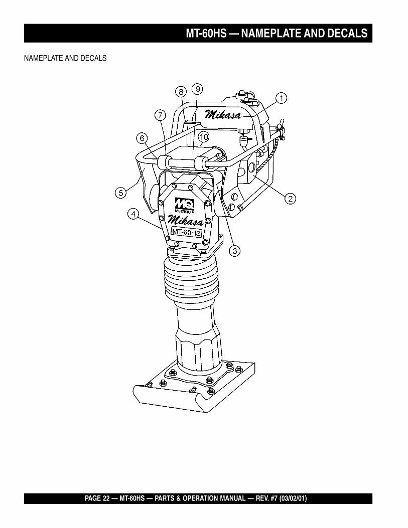
NAMEPLATE AND DECALS
MT-60HS — PARTS & OPERATION MANUAL — REV. #7 (03/02/01) — PAGE 23
MT-60HS — NAMEPLATE AND DECALS
MT-60HS — NAME PLATES AND DECALS
NAME PLATE AND DECALS
NO. PART NO. PART NAME QTY. REMARKS1* 920106460 DECAL: MIKASA MARK 12* 920203980 DECAL: ELEMENT SET 13* 920203290 DECAL: READ OWNER'S MAN. 14 PLATE: SERIAL NO. ....................... 1 .....ORDER FROM MQ SER. DEPT. W/MODEL & S/N5* 920107000 DECAL: PRE-CLEANER / MT-W 16* 920203540 DECAL ENGINE R.P.M 3850 17* 920203990 DECAL: FUEL COCK 18* 920203330 DECAL: EAR PROTECTION 19* 920204370 DECAL: PRE CLEANER 110* 920201950 DECAL MOTOR OIL 111 DCLMT60H2 DECAL KIT MT-60H/ 60H2 .............. 1 ..... INCLS. ALL ITEMS W/*FOR DECAL ILLUSTRATIONS SEE PAGE 8.
PAGE 24 — MT-60HS — PARTS & OPERATION MANUAL — REV. #7 (03/02/01)
MT-60HS — CRANKCASE AND ENGINE ASSY.
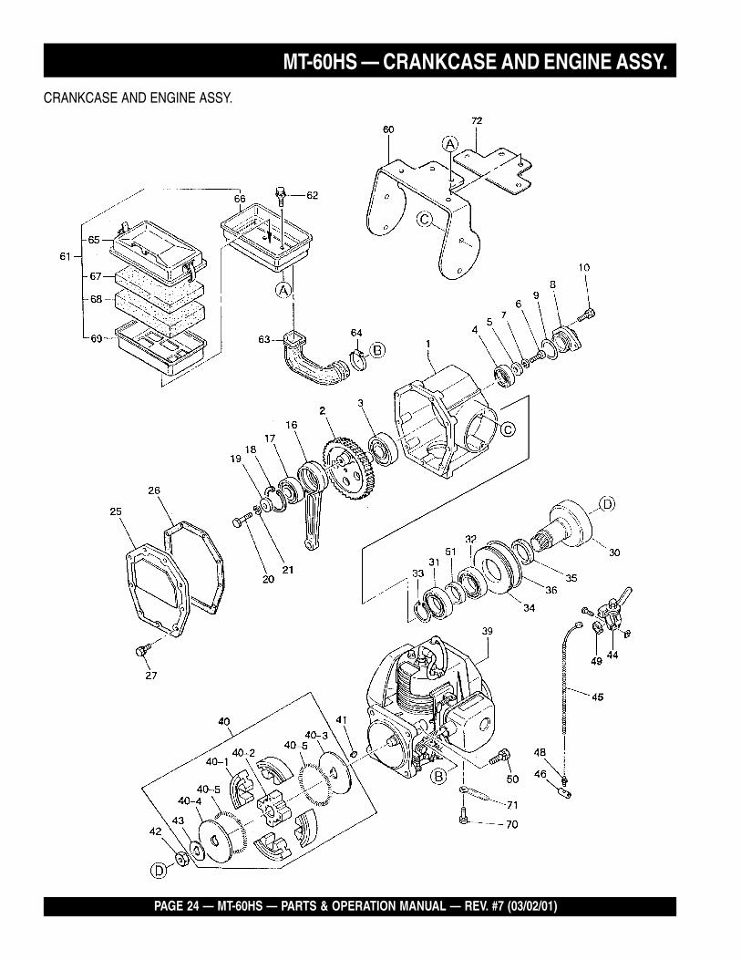
CRANKCASE AND ENGINE ASSY.
MT-60HS — PARTS & OPERATION MANUAL — REV. #7 (03/02/01) — PAGE 25
MT-60HS — CRANKCASE AND ENGINE ASSY.
CRANKCASE AND ENGINE ASSY.
NO. PART NO. PART NAME QTY. REMARKS1 351109060 CRANK CASE 12 351324110 CRANK GEAR 13 040006305 BEARING 6305 14 042506203 BEARING 6203 .................................... 1 ............REPLACES 0400062035 952401450 WASHER 8.5X22X3 16 011208025 BOLT 8X25 T ........................................ 1 ............REPLACES 0012208257 030208200 WASHER SW M8 18 351434563 BEARING COVER 19 050100350 O-RING G-35 110 011706020 BOLT 6X20 H,SW ................................ 2 ............REPLACES 00221062016 303010060 CONNECTING ROD 117 040006304 BEARING 6304 118 080100520 STOP RING R-52 119 952400130 WASHER 9304 120 011208025 BOLT 8X25 T ........................................ 1 ............REPLACES 00122082521 030208200 WASHER SW M8 125 353213630 FRONT COVER 126 351319880 PACKING, FRONT COVER 127 011706020 BOLT 6X20 H,SW ................................ 9 ............REPLACES 00221062030 303010084 PINION 131 040006007 BEARING 6007 132 041006007 BEARING 6007Z 133 080200350 STOP RING S-35 134 351421900 SPACER, CLUTCH DRUM 135 060404010 OIL SEAL TC-40528 136 050300900 O-RING S-90 139 911100832 ENGINE ASSY ECO8HS 140 301421363 CLUTCH ASSY C812E ........................ 1 ............ INCLS. ALL ITEMS W/*40-1* 943020020 CLUTCH SHOE C812 440-2* 943050050 CLUTCH BOSS C812 140-3* 943060010 CLUTCH GUIDE/1A 140-4* 943060020 CLUTCH GUIDE/B 140-5* 943030020 CLUTCH SPRING C812 241 0053204201 WOODRUFF KEY 142 0173120010 LOCK NUT 143 301010210 LOCK WASHER, CLUTCH 144 956300130 THROTTLE LEVER ASSY 145 501302060 THROTTLE WIRE 146 959401750 WIRE STOPPER ASSY 148 402010110 RETURN SPRING ............................... 1 ............REPLACES 30101095049 959403750 RUBBER, SLIP STOP 150 011708030 BOLT 8X30 H,SW ................................ 4 ............REPLACES 00221083051 351437750 SPACER 35.4-42.7-11 160 353335230 CLEANER STAY 161 354211841 AIR CLEANER ASSY ........................... 1 ............ INCLS. ALL ITEMS W/#62 002210815 BOLT 8X15 H,SW 463 354330590 INTAKE PIPE 164 507010110 CLAMP TC-200 165# 354030011 BODY /W-CLEANER 166# 354030020 BACK PLATE 167# 354030030 ELEMENT, YELLOW 168# 354030040 ELEMENT, GRAY 169# 354030050 ELEMENT FRAME 170 002200815 BOLT 8X15 SW 171 0566000170 CLAMP OIL ALERT 172 353449210 CLEANER HOLDER 1
PAGE 26 — MT-60HS — PARTS & OPERATION MANUAL — REV. #7 (03/02/01)
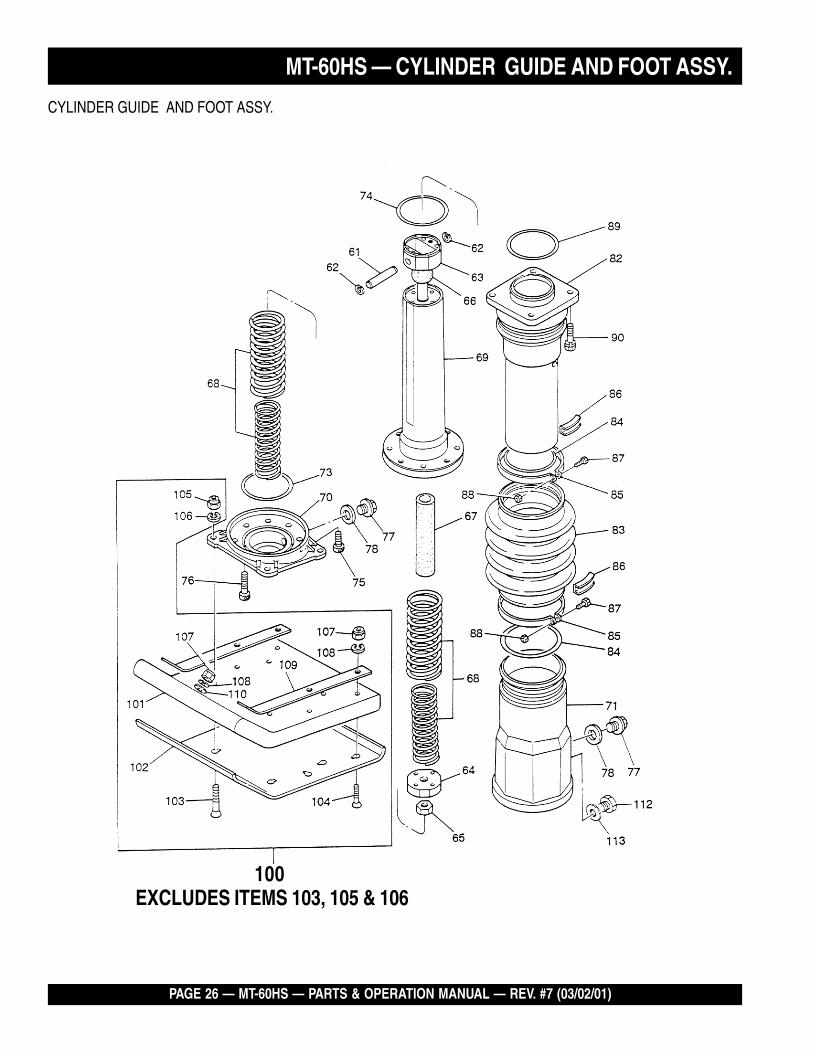
MT-60HS — CYLINDER GUIDE AND FOOT ASSY.
EXCLUDES ITEMS 103, 105 & 106100
CYLINDER GUIDE AND FOOT ASSY.
MT-60HS — PARTS & OPERATION MANUAL — REV. #7 (03/02/01) — PAGE 27
CYLINDER GUIDE AND FOOT ASSY.
NO. PART NO. PART NAME QTY. REMARKS61 351420390 PISTON PIN 162 080100120 STOP RING R-12 263 351324120 PISTON ROD 164 351420400 PISTON END 165 020316130 NUT M16, P1.5 ..................................... 1 ............REPLACES 02011613066 351434200 STOPPER, UPPER 167 351434211 STOPPER, LOWER............................. 1 ............REPLACES 35143421068 351324140 MAIN SPRING A,B 269 351324130 SPRING CYLINDER 170 351209600 FOOT PLATE 171 351109020 PROTECTION SLEEVE 173 050100750 O-RING G-75 174 050930850 O-RING JASO3085 175 014210020 SOCKET HEAD BOLT 10X20 T .......... 4 ............REPLACES 00152102076 014210035 SOCKET HEAD BOLT 10X35 T .......... 4 ............REPLACES 00152103577 953405270 PLUG 1/4X14 13L 278 953405260 PACKING 1/4 (CU) 282 351209590 GUIDE CYLINDER 183 351324300 BELLOWS,(ORANGE) 184 050100950 O-RING G-95 285 351316870 BELLOWS CLAMP 286 351433250 BAND GUIDE/BELLOWS 287 011008040 BOLT 8X40 T ........................................ 2 ............REPLACES 001220840
011208035 BOLT 8X35 T ........................................ 2 ............REPLACES 00122083588 020108060 NUT M8 ................................................ 2 ............REPLACES 02030806089 050100800 O-RING G-80 190 012710040 BOLT 10X40 H,SW .............................. 4 ............REPLACES 002211040100 351910130 FOOT ASSY 265W-215P .................... 1 ............ INCLUDES ITEMS W/* REPLACES 050100800101* 351109030 FOOT, 265W-215P 1102* 351109040 METAL SHEET 265W-215P-4.5 1103 015112075 SUNK HEAD BOLT 12X70 H ............... 4 ............REPLACES 001611253 & 015112060104* 015110055 SUNK HEAD BOLT 10X55 H ............... 7 ............REPLACES 001611051105 021112140 NYLON NUT M12 ................................ 4 ............REPLACES 022711214106 030212300 WASHER SW M12 4107* 021110120 NYLON NUT M10 ................................ 7 ............REPLACES 022711012108* 030210250 WASHER SW M10 7109* 352322581 FOOT FITTING 38B-3T 2110* 506404060 WASHER 11X34X3.2 ........................... 1 ............REPLACES 301010540112 959010150 LEVEL GUAGE, PLUG TYPE 1113 953404670 COPPER PACKING 17X25.5X1 1
MT-60HS — CYLINDER GUIDE AND FOOT ASSY.
PAGE 28 — MT-60HS — PARTS & OPERATION MANUAL — REV. #7 (03/02/01)
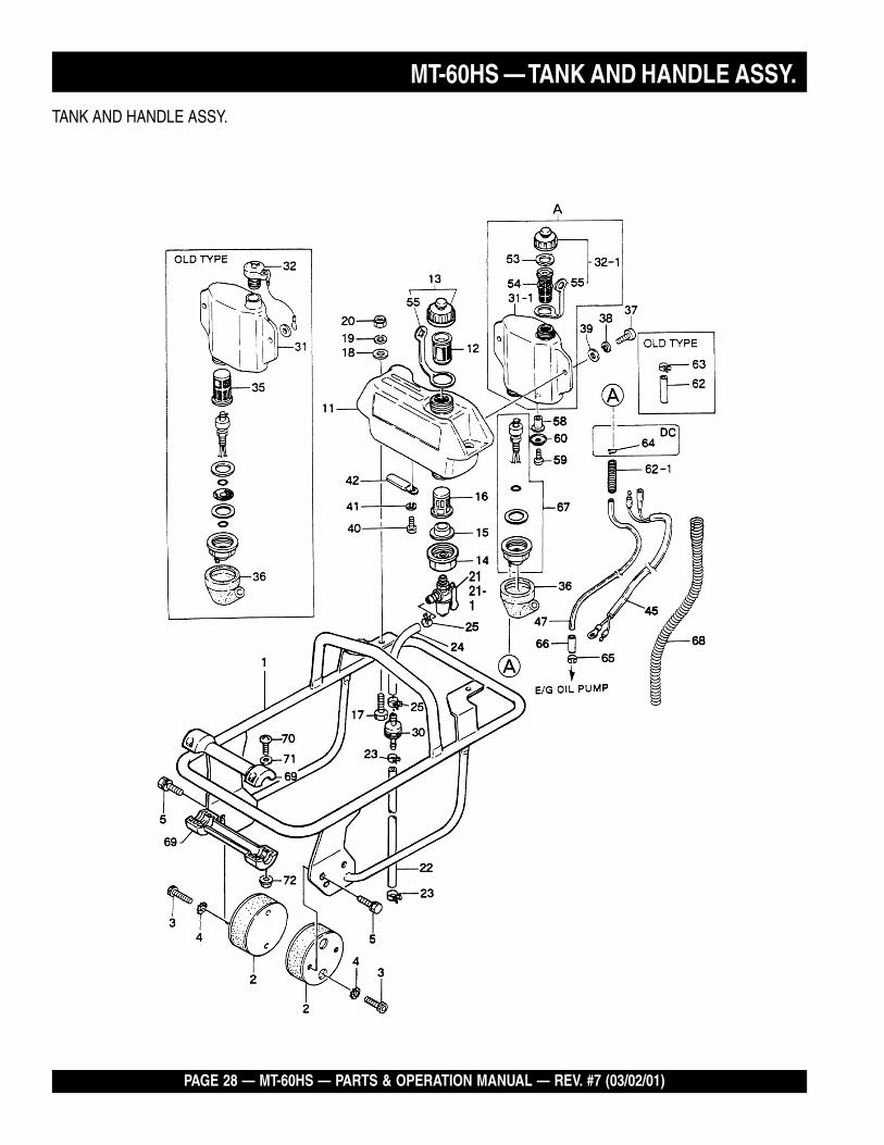
MT-60HS — TANK AND HANDLE ASSY.
2121-1
TANK AND HANDLE ASSY.
MT-60HS — PARTS & OPERATION MANUAL — REV. #7 (03/02/01) — PAGE 29
MT-60HS — TANK AND HANDLE ASSY.
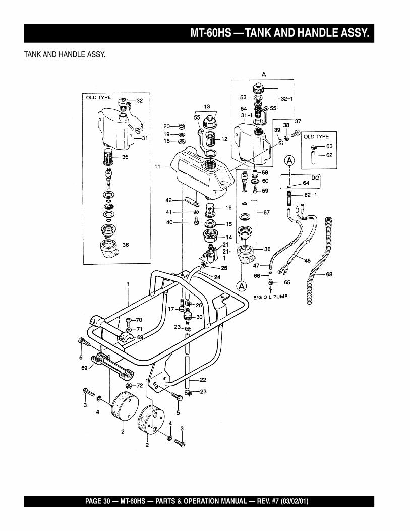
TANK AND HANDLE ASSY.
NO. PART NO. PART NAME QTY. REMARKSA 353213710CPL OIL TANK ASSY W/CAP ...................... 1 .......... REPLACES 3539100301 353113591 HANDLE 289B 11 353115080 HANDLE (FOR ROLLER) 12 351319900 SHOCK ABSORBER 100D-45B 23 001521020 SOCKET HEAD BOLT 10 x 20 44 033121009 TOOTHED LOCK WASHER B M10 45 002211020 BOLT 10 x 20 H, SW 411 355113610 FUEL TANK 112 954404890 FILTER, TANK 113 361910020 TANK CAP ASSY (ORANGE) 114 351437785 HOLDER, COCK 115 953405640 PACKING, COCK HOLDER 115 954406020 PACKING, FUEL TANK 116 954405080 STRAINER (100) 116 954406010 STRAINER (110) 117 001220830 BOLT 8 x 30 218 952401450 WASHER 8, 5 x 22 x 3 219 030208200 SW M8 220 022710809 NYLON NUT M8 221 954300390 FUEL COCK ASSY 1 .......... INCLUDES ITEMS W/#21-1# 0642001410 BOWL FUEL FILTER 121-2# 0642001420 STRAINER SCREEN 121-3# 0642001430 PACKING 122 351435160 FUEL HOSE B-150 123 954404590 HOSE BAND 9.5D 224 351436350 FUEL HOSE R-150 125 954403030 HOSE BAND (8) 230 301419750 FUEL FILTER CP, MQ75MIC 131 * OIL TANK 1 .......... *MUST ORDER NEW OIL TANK ASSY.31-1 353213710 OIL TANK 132 * OIL TANK CAP 132-1 353030070 OIL TANK CAP CP (YELLOW) 135 * STRAINER, OIL TANK 1 .......... NO LONGER USED36 355448071 COVER, COCK HOLDER 1 .......... REPLACES 35544807037 009110011 SOCKET HEAD SCREW 8 x 20 238 030208200 SW M8 239 952401450 WASHER 8.5 x 22 x 3 240 001200610 BOLT 6 x 10 141 030206150 SW M6 142 2267510103 CLAMP 145 353448490 WIRE CP/MT-50, 60 HS 147 5806113020 OIL HOSE 1
PAGE 30 — MT-60HS — PARTS & OPERATION MANUAL — REV. #7 (03/02/01)
MT-60HS — TANK AND HANDLE ASSY.
2121-1
TANK AND HANDLE ASSY.
MT-60HS — PARTS & OPERATION MANUAL — REV. #7 (03/02/01) — PAGE 31
TANK AND HANDLE ASSY.
NO. PART NO. PART NAME QTY. REMARKS53 353448990 PACKING, OIL TANK CAP 154 353449001 STRAINER, OIL TANK 1 ................ REPLACES 35344900055 353449010 STRAP, OIL TANK 258 353030080 WELL NUT 159 091005015 SCREW 5x 5 160 031105080 PW M5 160 952405970 WASHER 6. 4D-20D 162 353449240 OUTER HOSE 6 x 9 x 65 162-1 353450220 GUARD, OIL HOUSE 163 954403030 HOSE BAND 164 1616391008 CLIP EC12HS 165 1616391608 CLIP 166 5806113040 PROTECTOR 167 353910020 OIL SENSOR ASSY 168 355450600 OUTER LINER 525L 169 361910040 ROLLER ASSY., W/PINS ........................ 2 ................ REPLACES 95520005170 091005025 SCREW 5 x 25 471 031105080 WASHER PW M5 472 022610505 FLANGE NUT M5 H 4
MT-60HS — TANK AND HANDLE ASSY.
PAGE 32 — MT-60HS — PARTS & OPERATION MANUAL — REV. #7 (03/02/01)
115
CRANKCASE AND CYLINDER ASSY.
ROBIN EC-08GH ENGINE — CRANKCASE AND CYLINDER ASSY.
MT-60HS — PARTS & OPERATION MANUAL — REV. #7 (03/02/01) — PAGE 33
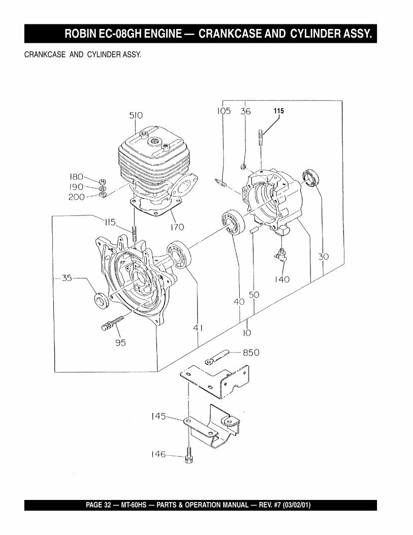
CRANKCASE AND CYLINDER ASSY.
NO. PART NO. PART NAME QTY. REMARKS10 5801056000 CRANK CASE CP ................................ 1 ............ INCLUDES ITEMS W/*30* 0440200020 OIL SEAL 135* 0440200020 OIL SEAL 136* 0440060010 OIL SEAL 140* 0600200010 BALL BEARING 6004C3 141* 0600200020 BALL BEARING 6204C3 150* 0052606140 DOWEL PIN 295 0011406450 BOLT ASSY 4105* 0105060050 STUD 1115* 0105064940 STUD 4140 0643109980 DRAIN COCK 1145 5809011000 PROTECTOR COMPL. 1146 0011308180 BOLT AND WASHER ASSY 3170 5801501800 GASKET,CYLINDER 1180 0021706000 NUT ...................................................... 4 ............REPLACES 0021806000190 0030206150 SPRING WASHER ............................... 4 ............REPLACES 003200600200 0031006000 WASHER 4510 5801501400 CYLINDER CP 1850 1507520103 CLAMP ................................................. 1 ............REPLACES 0566099950
ROBIN EC-08GH ENGINE — CRANKCASE AND CYLINDER ASSY.
PAGE 34 — MT-60HS — PARTS & OPERATION MANUAL — REV. #7 (03/02/01)
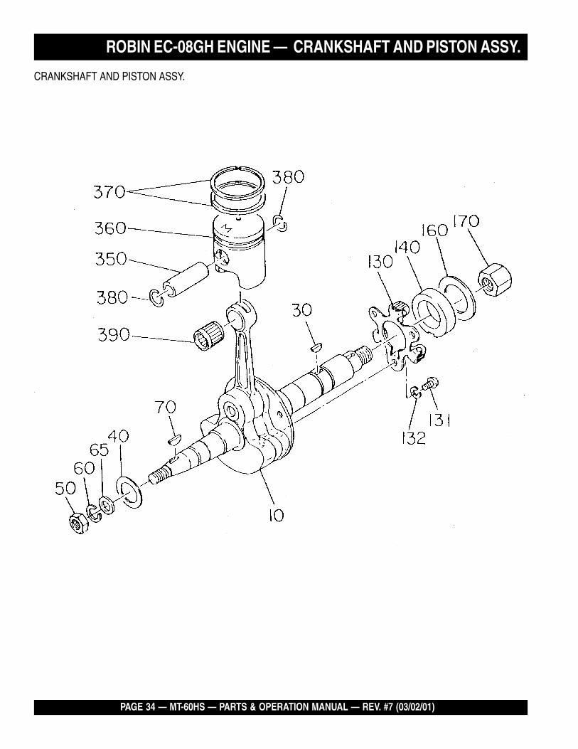
ROBIN EC-08GH ENGINE — CRANKSHAFT AND PISTON ASSY.
CRANKSHAFT AND PISTON ASSY.
MT-60HS — PARTS & OPERATION MANUAL — REV. #7 (03/02/01) — PAGE 35
CRANKSHAFT AND PISTON ASSY.
NO. PART NO. PART NAME QTY. REMARKS10 5802028000 CRANK SHAFT 130 0323049950 WOODRUFF KEY 140 1292500103 SPACER 250 0039310000 NUT ...................................................... 1 ............REPLACES 002181000060 0030210250 SPRING WASHER ............................... 1 ............REPLACES 003201000065 0030206150 WASHER .............................................. 1 ............REPLACES 003101000070 0323049950 WOODRUFF KEY 1130 5804010000 PLATE,GOVERNOR 1131 0043105080 SCREW (PAN HEAD) 3132 0032005000 SPRING WASHER 3140 5514500100 GOVERNOR SLEEVE 1160 0230230020 SPACER 1170 0173120010 LOCK NUT 1350 5802500400 PISTON PIN 1360 5802500600 PISTON 1370 5000008100 PISTON RING SET 1380 0565119990 CLIP 2390 0610120010 NEEDLE BEARING 1
ROBIN EC-08GH ENGINE — CRANKSHAFT AND PISTON ASSY.
PAGE 36 — MT-60HS — PARTS & OPERATION MANUAL — REV. #7 (03/02/01)
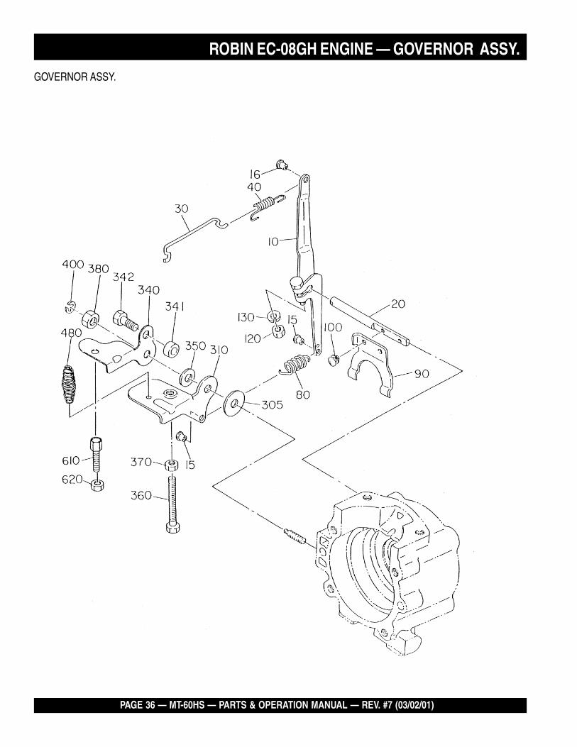
GOVERNOR ASSY.
ROBIN EC-08GH ENGINE — GOVERNOR ASSY.
MT-60HS — PARTS & OPERATION MANUAL — REV. #7 (03/02/01) — PAGE 37
GOVERNOR ASSY.
NO. PART NO. PART NAME QTY. REMARKS10 5804005000 GOVERNOR LEVER 115 5804500900 BUSH 216 2266255008 BUSH, NYLON ..................................... 1 ............REPLACES 580608306020 1294220103 GOVERNOR SHAFT 130 1054270111 GOVERNOR ROD 140 1064280113 ROD SPRING ...................................... 1 ............REPLACES 106428011180 1294250111 GOVERNOR SPRING 190 1294210113 GOVERNOR YOKE 1100 0140039980 SCREW ASSY 2120 0021706000 NUT 1130 0032061500 SPRING WASHER ............................... 1 ............REPLACES 0032006000305 0217060020 FRICTION WASHER 1310 5804500800 CONTROL LEVER 1340 5804500600 STOP PLATE 1341 0230060090 SPACER 1342 0105050616 BOLT .................................................... 1 ............REPLACES 6202500400350 0200070010 WASHER 1360 0016506400 BOLT 1370 0021706000 NUT 1380 0170069960 U NUT 1400 1294500103 CLIP 1480 402010110 COIL SPRING ...................................... 1 ............REPLACES 0830000010610 0149060040 ADJUSTING SCREW .......................... 1 ............REPLACES 0149069981620 0020106050 NUT ...................................................... 1 ............REPLACES 0022706000
ROBIN EC-08GH ENGINE — GOVERNOR ASSY.
PAGE 38 — MT-60HS — PARTS & OPERATION MANUAL — REV. #7 (03/02/01)
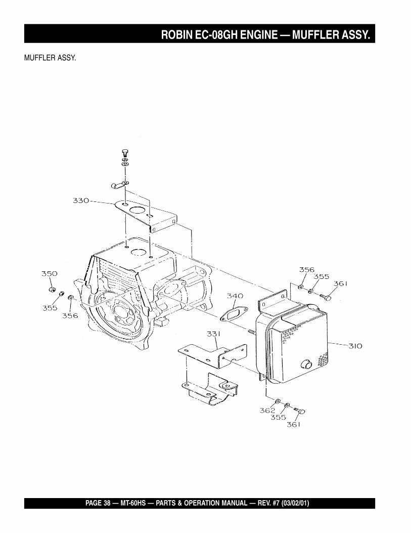
MUFFLER ASSY.
ROBIN EC-08GH ENGINE — MUFFLER ASSY.
MT-60HS — PARTS & OPERATION MANUAL — REV. #7 (03/02/01) — PAGE 39
MUFFLER ASSY.
NO. PART NO. PART NAME QTY. REMARKS310 5803032000 MUFFLER 1330 5803033000 MUFFLER BRACKET A 1331 5803034000 MUFFLER BRACKET B 1340 1293500403 GASKET (MUFFLER) 1350 0170069960 U NUT 2355 0030206150 SPRING WASHER ............................... 6 ............REPLACES 0032006000356 0031006000 WASHER 4361 00167061960 BOLT (MUFFLER) 4362 0031006000 WASHER 2
ROBIN EC-08GH ENGINE — MUFFLER ASSY.
PAGE 40 — MT-60HS — PARTS & OPERATION MANUAL — REV. #7 (03/02/01)
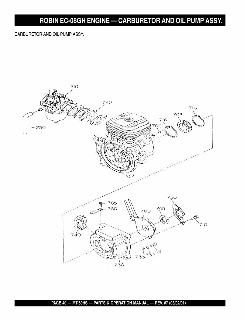
CARBURETOR AND OIL PUMP ASSY.
ROBIN EC-08GH ENGINE — CARBURETOR AND OIL PUMP ASSY.
MT-60HS — PARTS & OPERATION MANUAL — REV. #7 (03/02/01) — PAGE 41
CARBURETOR AND OIL PUMP ASSY.
NO. PART NO. PART NAME QTY. REMARKS210 5806111000 CARBURETOR ASSY ......................... 1 ............SEE CARBURETOR FIG. FOR COMPONENTS250 1616235308 HOSE 1700 5806113000 OIL PUMP ASSY 1705 5806502300 WORM GEAR 1706 0323039980 WOODRUFF KEY 1710 0011306250 BOLT AND WASHER ASSY 2716 0031520000 SNAP RING, OUTER 2720 1616350101 COLLAR CP (OIL INJ.) 1730 5806501900 OIL PUMP HOUSING 1731 0119089970 SOCKET HEAD BOLT 4732 0030208200 SPRING WASHER ............................... 4 ............REPLACES 0032008000733 0031008000 WASHER 4740 5806502000 GROMMET 1745 5806502100 SEAL 1750 5806502200 PLATE 1760 0566059980 CLAMP 1765 0119059610 SOCKET HEAD BOLT 1
ROBIN EC-08GH ENGINE — CARBURETOR AND OIL PUMP ASSY.
PAGE 42 — MT-60HS — PARTS & OPERATION MANUAL — REV. #7 (03/02/01)
RECOIL STARTER AND BLOWER ASSY.
ROBIN EC-08GH ENGINE — RECOIL STARTER AND BLOWER ASSY.
MT-60HS — PARTS & OPERATION MANUAL — REV. #7 (03/02/01) — PAGE 43
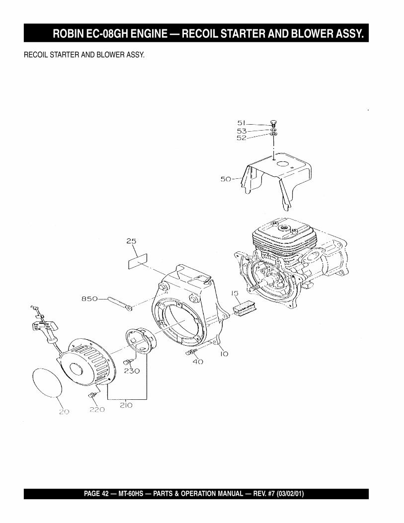
RECOIL STARTER AND BLOWER ASSY.
NO. PART NO. PART NAME QTY. REMARKS10 5805501200 FAN COVER 115 5515500200 GUIDE RUBBER 120 920100240 DECAL, (M-MARK) 125 5809500701 LABEL, MODEL 140 0011106200 BOLT ASSY 450 5805022000 CYLINDER COVER CP 151 0016706200 BOLT (CYLINDER) 252 0031206000 WASHER 253 0030206150 SPRING WASHER ............................... 2 ............REPLACES 0032006000210 5805001000 RECOIL STARTER ASSY .................... 1 ............SEE RECOIL STARTER FIG. FOR COMPONENTS’
REPLACES 5805011001220 0011006100 BOLT AND WASHER ASSY 3230 0011006140 BOLT ASSY 2850 0566000250 CLAMP 2
ROBIN EC-08GH ENGINE — RECOIL STARTER AND BLOWER ASSY.
PAGE 44 — MT-60HS — PARTS & OPERATION MANUAL — REV. #7 (03/02/01)
526
AIR CLEANER ASSY.
ROBIN EC-08GH ENGINE — AIR CLEANER ASSY.
MT-60HS — PARTS & OPERATION MANUAL — REV. #7 (03/02/01) — PAGE 45
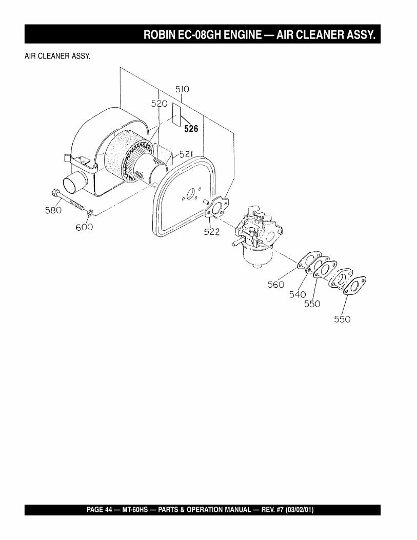
AIR CLEANER ASSY.
NO. PART NO. PART NAME QTY. REMARKS510 1063273110 AIR CLEANER ASSY ........................... 1 ............ INCLS. ALL ITEMS W/*520* 1573620101 ELEMENT SET .................................... 1 ............REPLACES 1573260007521* 1613261008 ELEMENT 1522* 2263272008 GASKET (AIR CLEANER) 1526 0736439980 LABEL 1540 1293290103 INSULATOR 1550 1063500103 GASKET (INSULATOR) 2560 2363590303 GASKET 2 (INSULATOR) 1580 0011306800 BOLT 2600 0030206150 SPRING WASHER ............................... 2 ............REPLACES 0032006000
ROBIN EC-08GH ENGINE — AIR CLEANER ASSY.
PAGE 46 — MT-60HS — PARTS & OPERATION MANUAL — REV. #7 (03/02/01)
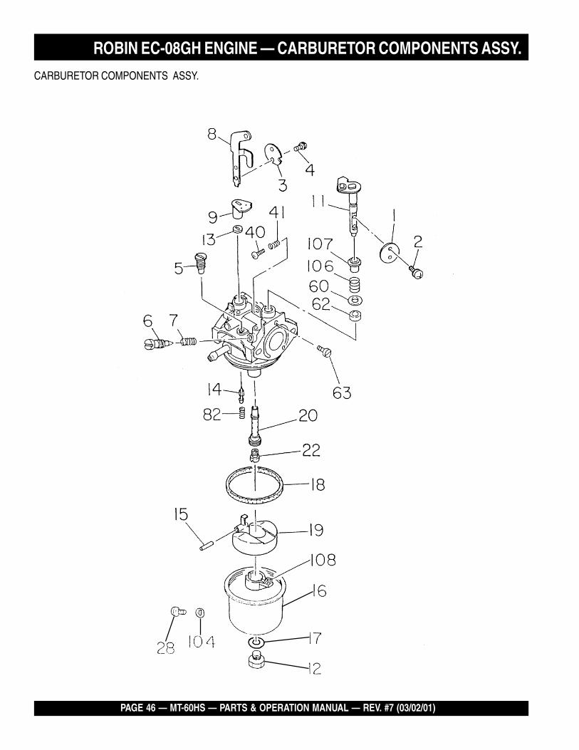
CARBURETOR COMPONENTS ASSY.
ROBIN EC-08GH ENGINE — CARBURETOR COMPONENTS ASSY.
MT-60HS — PARTS & OPERATION MANUAL — REV. #7 (03/02/01) — PAGE 47
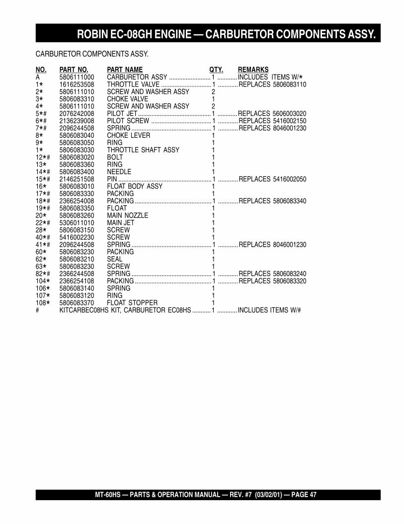
CARBURETOR COMPONENTS ASSY.
NO. PART NO. PART NAME QTY. REMARKSA 5806111000 CARBURETOR ASSY ......................... 1 ............ INCLUDES ITEMS W/*1* 1616253508 THROTTLE VALVE .............................. 1 ............REPLACES 58060831102* 5806111010 SCREW AND WASHER ASSY 23* 5806083310 CHOKE VALVE 14* 5806111010 SCREW AND WASHER ASSY 25*# 2076242008 PILOT JET ............................................ 1 ............REPLACES 56060030206*# 2136239008 PILOT SCREW .................................... 1 ............REPLACES 54160021507*# 2096244508 SPRING ................................................ 1 ............REPLACES 80460012308* 5806083040 CHOKE LEVER 19* 5806083050 RING 11* 5806083030 THROTTLE SHAFT ASSY 112*# 5806083020 BOLT 113* 5806083360 RING 114*# 5806083400 NEEDLE 115*# 2146251508 PIN ........................................................ 1 ............REPLACES 541600205016* 5806083010 FLOAT BODY ASSY 117*# 5806083330 PACKING 118*# 2366254008 PACKING .............................................. 1 ............REPLACES 580608334019*# 5806083350 FLOAT 120* 5806083260 MAIN NOZZLE 122*# 5306011010 MAIN JET 128* 5806083150 SCREW 140*# 5416002230 SCREW 141*# 2096244508 SPRING ................................................ 1 ............REPLACES 804600123060* 5806083230 PACKING 162* 5806083210 SEAL 163* 5806083230 SCREW 182*# 2366244508 SPRING ................................................ 1 ............REPLACES 5806083240104* 2366254108 PACKING .............................................. 1 ............REPLACES 5806083320106* 5806083140 SPRING 1107* 5806083120 RING 1108* 5806083370 FLOAT STOPPER 1# KITCARBEC08HS KIT, CARBURETOR EC08HS ........... 1 ............ INCLUDES ITEMS W/#
ROBIN EC-08GH ENGINE — CARBURETOR COMPONENTS ASSY.
PAGE 48 — MT-60HS — PARTS & OPERATION MANUAL — REV. #7 (03/02/01)
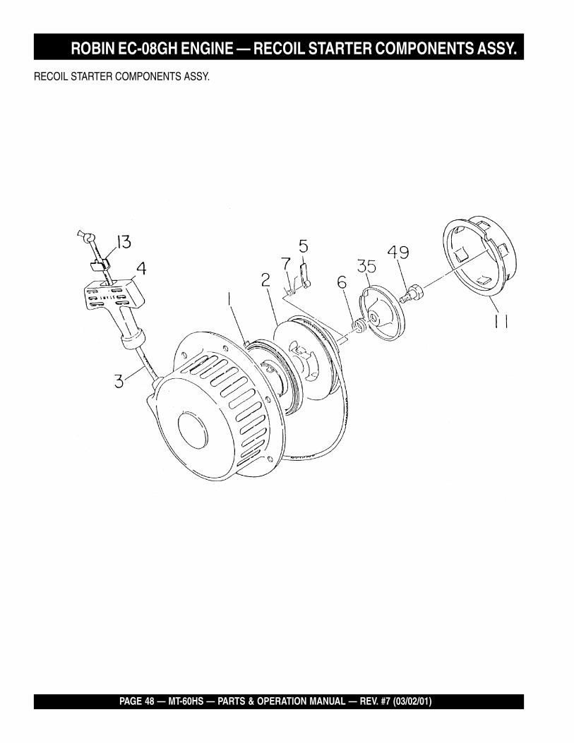
RECOIL STARTER COMPONENTS ASSY.
ROBIN EC-08GH ENGINE — RECOIL STARTER COMPONENTS ASSY.
MT-60HS — PARTS & OPERATION MANUAL — REV. #7 (03/02/01) — PAGE 49
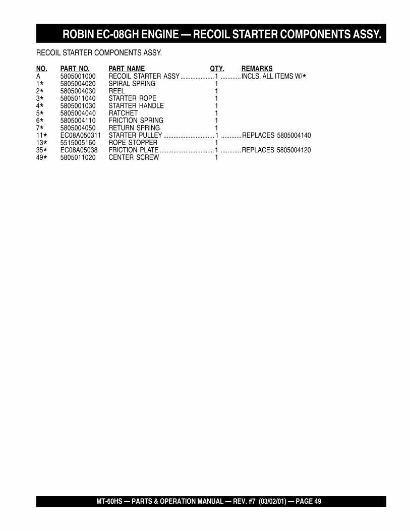
RECOIL STARTER COMPONENTS ASSY.
NO. PART NO. PART NAME QTY. REMARKSA 5805001000 RECOIL STARTER ASSY .................... 1 ............ INCLS. ALL ITEMS W/*1* 5805004020 SPIRAL SPRING 12* 5805004030 REEL 13* 5805011040 STARTER ROPE 14* 5805001030 STARTER HANDLE 15* 5805004040 RATCHET 16* 5805004110 FRICTION SPRING 17* 5805004050 RETURN SPRING 111* EC08A050311 STARTER PULLEY .............................. 1 ............REPLACES 580500414013* 5515005160 ROPE STOPPER 135* EC08A05038 FRICTION PLATE ................................ 1 ............REPLACES 580500412049* 5805011020 CENTER SCREW 1
ROBIN EC-08GH ENGINE — RECOIL STARTER COMPONENTS ASSY.
PAGE 50 — MT-60HS — PARTS & OPERATION MANUAL — REV. #7 (03/02/01)
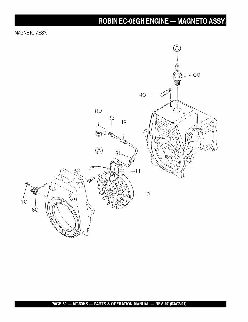
MAGNETO ASSY.
ROBIN EC-08GH ENGINE — MAGNETO ASSY.
MT-60HS — PARTS & OPERATION MANUAL — REV. #7 (03/02/01) — PAGE 51
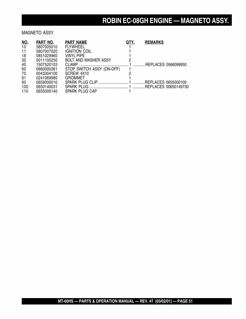
MAGNETO ASSY.
NO. PART NO. PART NAME QTY. REMARKS10 5807005010 FLYWHEEL 111 5807007020 IGNITION COIL 118 0851029960 VINYL PIPE 130 0011105250 BOLT AND WASHER ASSY 240 1507520103 CLAMP ................................................. 1 ............REPLACES 056609995060 0660000361 STOP SWITCH ASSY (ON-OFF) 170 0043304100 SCREW 4X10 281 0241069980 GROMMET 195 0659000010 SPARK PLUG CLIP .............................. 1 ............REPLACES 0655000100100 0650140031 SPARK PLUG ....................................... 1 ............REPLACES 00650149730110 0655000140 SPARK PLUG CAP 1
ROBIN EC-08GH ENGINE — MAGNETO ASSY.
PAGE 52 — MT-60HS — PARTS & OPERATION MANUAL — REV. #7 (03/02/01)
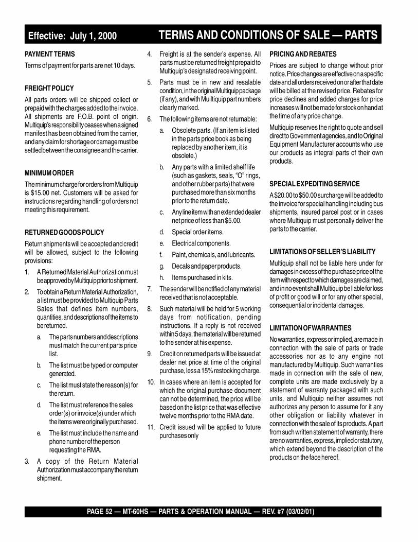
PAYMENT TERMS
Terms of payment for parts are net 10 days.
FREIGHT POLICY
All parts orders will be shipped collect orprepaid with the charges added to the invoice.All shipments are F.O.B. point of origin.Multiquip’s responsibility ceases when a signedmanifest has been obtained from the carrier,and any claim for shortage or damage must besettled between the consignee and the carrier.
MINIMUM ORDER
The minimum charge for orders from Multiquipis $15.00 net. Customers will be asked forinstructions regarding handling of orders notmeeting this requirement.
RETURNED GOODS POLICY
Return shipments will be accepted and creditwill be allowed, subject to the followingprovisions:
1. A Returned Material Authorization mustbe approved by Multiquip prior to shipment.
2. To obtain a Return Material Authorization,a list must be provided to Multiquip PartsSales that defines item numbers,quantities, and descriptions of the items tobe returned.
a. The parts numbers and descriptionsmust match the current parts pricelist.
b. The list must be typed or computergenerated.
c. The list must state the reason(s) forthe return.
d. The list must reference the salesorder(s) or invoice(s) under whichthe items were originally purchased.
e. The list must include the name andphone number of the personrequesting the RMA.
3. A copy of the Return MaterialAuthorization must accompany the returnshipment.
PRICING AND REBATES
Prices are subject to change without priornotice. Price changes are effective on a specificdate and all orders received on or after that datewill be billed at the revised price. Rebates forprice declines and added charges for priceincreases will not be made for stock on hand atthe time of any price change.
Multiquip reserves the right to quote and selldirect to Government agencies, and to OriginalEquipment Manufacturer accounts who useour products as integral parts of their ownproducts.
SPECIAL EXPEDITING SERVICE
A $20.00 to $50.00 surcharge will be added tothe invoice for special handling including busshipments, insured parcel post or in caseswhere Multiquip must personally deliver theparts to the carrier.
LIMITATIONS OF SELLER’S LIABILITY
Multiquip shall not be liable here under fordamages in excess of the purchase price of theitem with respect to which damages are claimed,and in no event shall Multiquip be liable for lossof profit or good will or for any other special,consequential or incidental damages.
LIMITATION OF WARRANTIES
No warranties, express or implied, are made inconnection with the sale of parts or tradeaccessories nor as to any engine notmanufactured by Multiquip. Such warrantiesmade in connection with the sale of new,complete units are made exclusively by astatement of warranty packaged with suchunits, and Multiquip neither assumes notauthorizes any person to assume for it anyother obligation or liability whatever inconnection with the sale of its products. A partfrom such written statement of warranty, thereare no warranties, express, implied or statutory,which extend beyond the description of theproducts on the face hereof.
4. Freight is at the sender’s expense. Allparts must be returned freight prepaid toMultiquip’s designated receiving point.
5. Parts must be in new and resalablecondition, in the original Multiquip package(if any), and with Muiltiquip part numbersclearly marked.
6. The following items are not returnable:
a. Obsolete parts. (If an item is listedin the parts price book as beingreplaced by another item, it isobsolete.)
b. Any parts with a limited shelf life(such as gaskets, seals, “O” rings,and other rubber parts) that werepurchased more than six monthsprior to the return date.
c. Any line item with an extended dealernet price of less than $5.00.
d. Special order items.
e. Electrical components.
f. Paint, chemicals, and lubricants.
g. Decals and paper products.
h. Items purchased in kits.
7. The sender will be notified of any materialreceived that is not acceptable.
8. Such material will be held for 5 workingdays from notification, pendinginstructions. If a reply is not receivedwithin 5 days, the material will be returnedto the sender at his expense.
9. Credit on returned parts will be issued atdealer net price at time of the originalpurchase, less a 15% restocking charge.
10. In cases where an item is accepted forwhich the original purchase documentcan not be determined, the price will bebased on the list price that was effectivetwelve months prior to the RMA date.
11. Credit issued will be applied to futurepurchases only
Effective: July 1, 2000 TERMS AND CONDITIONS OF SALE — PARTS
MT-60HS — PARTS & OPERATION MANUAL — REV. #7 (03/02/01) — PAGE 53
NOTE PAGE
PARTS AND OPERATION MANUAL
MULTIQUIP INC.POST OFFICE BOX 6254CARSON, CA 90749310-537-3700 • 800-421-1244FAX: 310-537-3927E-MAIL: [email protected]: multiquip.com
Atlanta • Boise • Dallas • Houston • NewarkQuebec, Canada • Manchester, UK • Rio De Janiero, BR • Guadalajara, MX
manufactured for Multiquip Inc.by
MIKASA SANGYO CO., LTD. Tokyo, Japan
HERE'S HOW TO GET HELPPLEASE HAVE THE MODEL AND SERIAL NUMBERON-HAND WHEN CALLING
PARTS DEPARTMENT800-427-1244 or 310-537-3700FAX: 800-672-7877 or 310-637-3284
SERVICE DEPARTMENT/TECHNICAL ASSISTANCE800-478-1244 or 310-537-3700FAX: 310- 537-4259
WARRANTY DEPARTMENT888-661-4279, or 310-661-4279FAX: 310- 537-1173
MAIN800-421-1244 or 310-537-3700FAX: 310-537-3927