Embed Size (px)
Citation preview
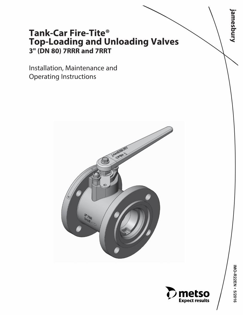
Tank-Car Fire-Tite®Top-Loading and Unloading Valves3" (DN 80) 7RRR and 7RRT
Installation, Maintenance andOperating Instructions
IMO
-R22E
N • 5/2016
2 IMO-R22EN
Table of Contents1 GENERAL . . . . . . . . . . . . . . . . . . . . . . . . . . . . . . . . . . . . 3
1.1 Scope of the Manual . . . . . . . . . . . . . . . . . . . . . . . . 31.2 Valve Markings . . . . . . . . . . . . . . . . . . . . . . . . . . . . . . 31.3 Safety Precautions . . . . . . . . . . . . . . . . . . . . . . . . . . 3
2 TRANSPORTATION AND STORAGE. . . . . . . . . . . . . 3
3 INSTALLATION . . . . . . . . . . . . . . . . . . . . . . . . . . . . . . . 43.1 General . . . . . . . . . . . . . . . . . . . . . . . . . . . . . . . . . . . . . 43.2 Handles . . . . . . . . . . . . . . . . . . . . . . . . . . . . . . . . . . . . . 43.3 Installing on tank car . . . . . . . . . . . . . . . . . . . . . . . . 43.4 Commissioning . . . . . . . . . . . . . . . . . . . . . . . . . . . . . 4
4 MAINTENANCE . . . . . . . . . . . . . . . . . . . . . . . . . . . . . . . 44.1 General . . . . . . . . . . . . . . . . . . . . . . . . . . . . . . . . . . . . . 44.2 Disassembly . . . . . . . . . . . . . . . . . . . . . . . . . . . . . . . . 54.3 Checking Parts . . . . . . . . . . . . . . . . . . . . . . . . . . . . . . 54.4 Assembly . . . . . . . . . . . . . . . . . . . . . . . . . . . . . . . . . . . 64.5 Testing the Valve. . . . . . . . . . . . . . . . . . . . . . . . . . . . 7
5 SERVICE KITS. . . . . . . . . . . . . . . . . . . . . . . . . . . . . . . . . 7
6 SERVICE/SPARE PARTS. . . . . . . . . . . . . . . . . . . . . . . . 7
7 EXPLODED VIEW & PARTS LIST . . . . . . . . . . . . . . . . 8
8 HOW TO ORDER. . . . . . . . . . . . . . . . . . . . . . . . . . . . . 11
READ THESE INSTRUCTIONS FIRST!
These instructions provide information about safe handling and operation of the valve.If you require additional assistance, please contact the manufacturer or manufacturer's representative.Addresses and phone numbers are printed on the back cover.See also www.metso.com/valves for the latest documentation.
SAVE THESE INSTRUCTIONS!
Subject to change without notice.All trademarks are property of their respective owners.
IMO-R22EN 3
1 GENERAL
1.1 Scope of the Manual
This instruction manual contains important informationregarding the installation, operation and troubleshootingof the Jamesbury® 3" (DN 80) 7RRR and 7RRT Tank Car Fire-Tite Top-Loading and Unloading Valves. Please readthese instructions carefully and save them for futurereference.
1.2 Valve Markings
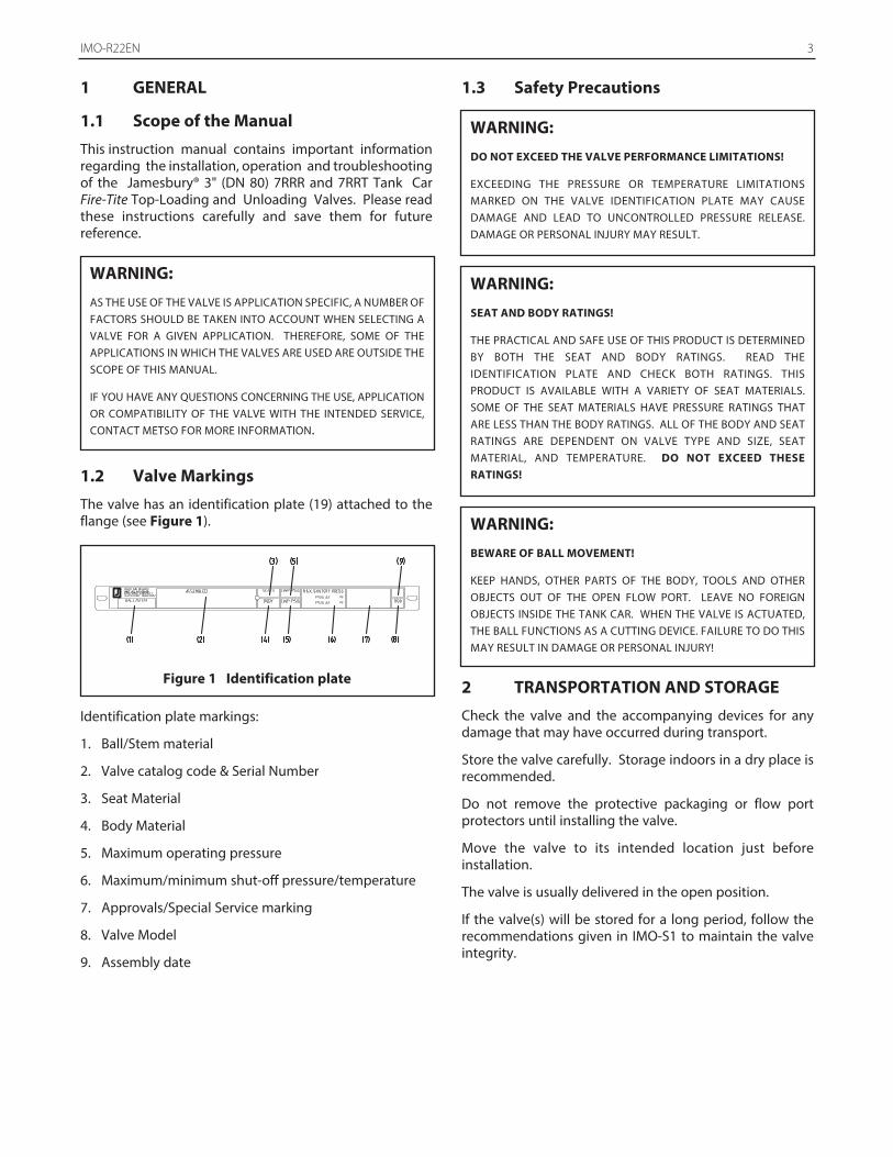
The valve has an identification plate (19) attached to theflange (see Figure 1).
Identification plate markings:
1. Ball/Stem material
2. Valve catalog code & Serial Number
3. Seat Material
4. Body Material
5. Maximum operating pressure
6. Maximum/minimum shut-off pressure/temperature
7. Approvals/Special Service marking
8. Valve Model
9. Assembly date
1.3 Safety Precautions
2 TRANSPORTATION AND STORAGE
Check the valve and the accompanying devices for anydamage that may have occurred during transport.
Store the valve carefully. Storage indoors in a dry place isrecommended.
Do not remove the protective packaging or flow port protectors until installing the valve.
Move the valve to its intended location just beforeinstallation.
The valve is usually delivered in the open position.
If the valve(s) will be stored for a long period, follow therecommendations given in IMO-S1 to maintain the valveintegrity.
WARNING:
AS THE USE OF THE VALVE IS APPLICATION SPECIFIC, A NUMBER OFFACTORS SHOULD BE TAKEN INTO ACCOUNT WHEN SELECTING AVALVE FOR A GIVEN APPLICATION. THEREFORE, SOME OF THEAPPLICATIONS IN WHICH THE VALVES ARE USED ARE OUTSIDE THESCOPE OF THIS MANUAL.
IF YOU HAVE ANY QUESTIONS CONCERNING THE USE, APPLICATIONOR COMPATIBILITY OF THE VALVE WITH THE INTENDED SERVICE,CONTACT METSO FOR MORE INFORMATION.
WARNING:
SEAT AND BODY RATINGS!
THE PRACTICAL AND SAFE USE OF THIS PRODUCT IS DETERMINEDBY BOTH THE SEAT AND BODY RATINGS. READ THEIDENTIFICATION PLATE AND CHECK BOTH RATINGS. THISPRODUCT IS AVAILABLE WITH A VARIETY OF SEAT MATERIALS.SOME OF THE SEAT MATERIALS HAVE PRESSURE RATINGS THATARE LESS THAN THE BODY RATINGS. ALL OF THE BODY AND SEATRATINGS ARE DEPENDENT ON VALVE TYPE AND SIZE, SEATMATERIAL, AND TEMPERATURE. DO NOT EXCEED THESERATINGS!
WARNING:
BEWARE OF BALL MOVEMENT!
KEEP HANDS, OTHER PARTS OF THE BODY, TOOLS AND OTHEROBJECTS OUT OF THE OPEN FLOW PORT. LEAVE NO FOREIGNOBJECTS INSIDE THE TANK CAR. WHEN THE VALVE IS ACTUATED,THE BALL FUNCTIONS AS A CUTTING DEVICE. FAILURE TO DO THISMAY RESULT IN DAMAGE OR PERSONAL INJURY!
WARNING:
DO NOT EXCEED THE VALVE PERFORMANCE LIMITATIONS!
EXCEEDING THE PRESSURE OR TEMPERATURE LIMITATIONSMARKED ON THE VALVE IDENTIFICATION PLATE MAY CAUSEDAMAGE AND LEAD TO UNCONTROLLED PRESSURE RELEASE.DAMAGE OR PERSONAL INJURY MAY RESULT.
Figure 1 Identification plate
4 IMO-R22EN
3 INSTALLATION
3.1 General
Remove the protective packaging and flow portprotectors and check that the valve is clean inside. Cleanvalve if necessary.
Flush the tank car carefully before installing the valve.Foreign objects, such as sand or pieces of weldingelectrodes, will damage the ball and seats.
Read and follow all WARNINGS!
The Jamesbury Series 7RRR and 7RRT are an end entrydesign with an internal insert. The insert contains a slotdrive which can be identified by looking into the end ofthe valve before installation.
3.2 Handles
If the Series 7RRR or 7RRT valve handle (31) has to beremoved for any reason, the handle must be remountedwith the handle as shown in Figure 9.
3.3 Installing on tank car
The valve may be installed in any position and offerstightness in both directions. It is recommended, however,that the valve be installed with the insert (2) towards thetank car.
Refer to the Section 4, MAINTENANCE for packingadjustment. If there is weepage past the packing uponinstallation, it means the valve may have been subject towide temperature variations in shipment. Leak-tightperformance will be restored by a simple packingadjustment described in the MAINTENANCE section.
3.4 Commissioning
Ensure that there is no dirt or foreign objects left inside thevalve or tank car. Flush the tank car carefully. Make surethat the valve is fully open when flushing.
Ensure that all nuts and fittings are properly fastened.
4 MAINTENANCE
4.1 General
Good operating procedure requires periodic observationto ensure that the valve is functioning well. The frequencyof observation will depend on the application. Routinemaintenance consists of tightening the bonnet stud nuts(item 18 in Figure 9) periodically to compensate for stemseal wear. More frequent observation is recommendedunder extreme operating conditions.
Overhaul maintenance consists of replacing seats andseals. A standard service kit consisting of these parts maybe obtained through your authorized Metso Distributor.
NOTE: Service kits include stem bearings (70), secondarystem seal (71), seats (7), body seal (65) and stem seals (69).Refer to the Service Kit chart (see Table 2).
WARNING:
THE VALVE SHOULD BE TIGHTENED ON FLANGES USINGAPPROPRIATE GASKETS AND FASTENERS COMPATIBLE WITH THEAPPLICATION, AND IN COMPLIANCE WITH APPLICABLE PIPINGCODES AND STANDARDS. CENTER THE FLANGE GASKETSCAREFULLY WHEN FITTING THE VALVE BETWEEN FLANGES. DONOT ATTEMPT TO CORRECT MISALIGNMENT BY MEANS OF FLANGEBOLTING!
WARNING:
GOOD PRACTICE DICTATES THAT ONCE INSTALLED, BUT PRIOR TOFIRST USE, THE VALVE IS LEAK TESTED IN PLACE TO ASSURE LEAK-TIGHTNESS HAS NOT BEEN COMPROMISED BY THE INSTALLATIONPROCESS. INSTALLATION ACTIONS THAT CAN CAUSE LEAKAGEINCLUDE, BUT ARE NOT LIMITED TO; WRENCHING, SOLDERING,WELDING AND/OR HOISTING. SEE SECTION 4.5
WARNING:
SERIES 7RRR AND 7RRT VALVES ARE DESIGNED FOR MANUAL USEONLY AND ARE NOT INTENDED FOR AUTOMATION! DO NOTFABRICATE OR ADD ON ANY TYPE OF AUTOMATING ACCESSORY.
WARNING:
FAILURE TO PROPERLY MOUNT THE HANDLE MAY RESULT INIMPROPER VALVE OPERATION, DAMAGE OR PERSONAL INJURY.
WARNING:
FOR YOUR SAFETY IT IS IMPORTANT THE FOLLOWINGPRECAUTIONS BE TAKEN PRIOR TO INSTALLATION, SERVICING ORREMOVAL OF THE VALVE FROM THE TANK CAR OR BEFORE ANYDISASSEMBLY:
1. WEAR ANY PROTECTIVE CLOTHING OR EQUIPMENTNORMALLY REQUIRED WHEN WORKING WITH THE FLUIDINVOLVED.
2. DEPRESSURIZE THE TANK CAR AND CYCLE THE VALVE AS FOLLOWS:
A. PLACE THE VALVE IN THE OPEN POSITION AND DRAIN THETANK CAR.
B. CYCLE THE VALVE TO RELIEVE RESIDUAL PRESSURE IN THEBODY CAVITY BEFORE REMOVAL FROM THE TANK CAR.
C. AFTER REMOVAL AND BEFORE ANY DISASSEMBLY, CYCLETHE VALVE AGAIN SEVERAL TIMES.
3. THESE VALVES ARE SUITABLE FOR A WIDE VARIETY OF FLUIDSAND GASES. BE CERTAIN THAT THE VALVE MATERIALSSELECTED ARE SUITABLE FOR THE APPLICATION.
IMO-R22EN 5
4.2 Disassembly
1. Comply fully with ALL WARNINGS prior to working onthe valve.
2. Open and close the valve and leave in the half openposition.
3. Remove the handle screw (35), and handle (31).
4. Remove retaining ring (34), spring (33), and indicatorstop (32).
5. Remove stud nuts (18), disc springs (17), stop bushings(39), and compression plate (10).
6. Close the valve.
7. Clamp the valve body (1) securely in a vise in thevertical position with the insert end up, taking care notto damage any valve sealing surfaces.
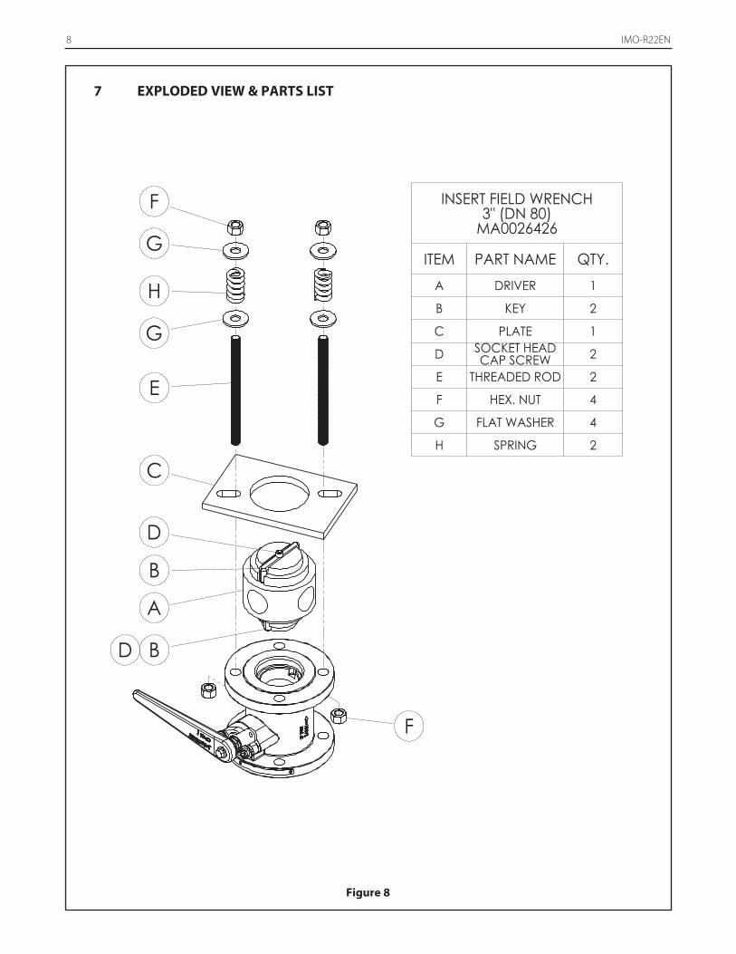
8. Unscrew and remove insert (2). The insert designrequires that the insert be unscrewed in acounterclockwise motion. An insert field wrench isavailable for purchase to remove the valve insert andshown in Figure 8, which may be ordered asMA0026426 from your local Metso Distributor.
NOTE: lf complete disassembly becomes necessary; it isrecommended to replace all seats and seals. Refer to theService Kit chart (see Table 2).
NOTE: Always use original OEM parts to make sure thatthe valve functions properly.
9. If using the insert field wrench, assemble the insertfield wrench as follows (refer to Figure 8):
a. Place driver (A) into the insert slots.
b. Put the plate (C) on top of the driver (A).
c. Place the studs (E) through the plate (C) and flangeholes. Thread the nuts (F) onto the stud below theflange.
d. On the top side of the plate (C) put a flat washer (G),die spring (H), flat washer (G) and nut (F). Tightento slightly compress the springs.
10. Place a pipe or rod through the driver (A) and loosenthe insert by turning counterclockwise.
11. Remove the tool and lift out the insert.
12. Remove and discard the old body seal (65). BE CAREFUL NOT TO DAMAGE THE SEALINGSURFACES.
13. With the ball in the closed position, remove ball (3) andseats (7). NOTE: A piece of wood or other soft materialmay be used to unseat the parts from the opposite sideby gently tapping the ball from the end opposite theinsert. BE CAREFUL NOT TO DAMAGE THE BALL ORSEATING SURFACES IN THE BODY.
14. Press the stem (5) into the body (1) and remove itthrough the insert side of the valve. It may benecessary to tap it with a piece of wood or some othersoft material. BE CAREFUL NOT TO DAMAGE THESTEM OR BODY SEALING SURFACES.
15. Carefully remove and discard the packing V-Ring set(69) and stem bearings (70) and secondary stem seal(71). BE CAREFUL NOT TO DAMAGE THE SEALINGSURFACES.
4.3 Checking Parts
NOTE: For detailed instructions on visual inspection ofcritical components, refer to IMO-R26.
1. Clean all disassembled parts.
2. Check the stem (5) and ball (3) for damage. Payparticular attention to the sealing areas.
3. Check all sealing and gasket surfaces of the body (1)and insert (2).
4. Replace any damaged parts.
NOTE: When ordering spare parts not included in thestandard service kits listed in Table 2, always include thefollowing information:
a. Valve catalog code from Identification plate,
b. The serial number (stamped on the valveIdentification plate),
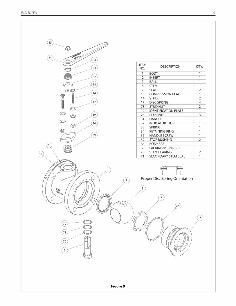
c. From Figure 9, the ballooned part number, partname and quantity required.
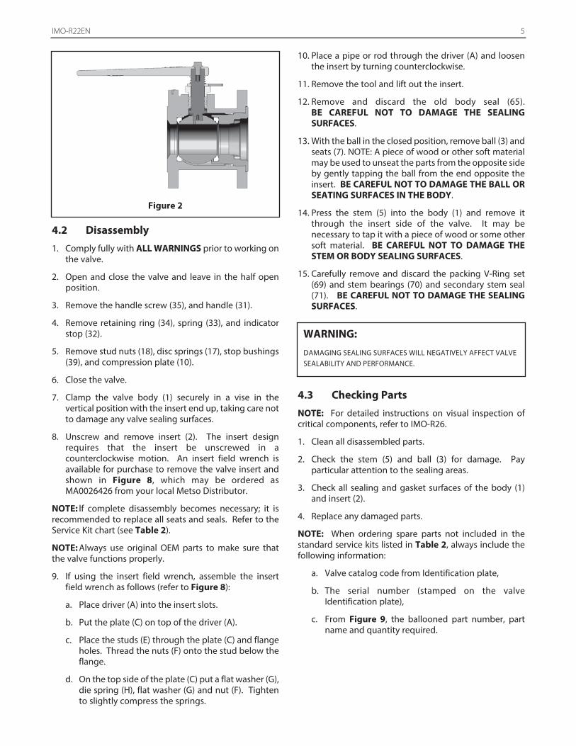
Figure 2
WARNING:
DAMAGING SEALING SURFACES WILL NEGATIVELY AFFECT VALVESEALABILITY AND PERFORMANCE.
6 IMO-R22EN
4.4 Assembly
Refer to standard service kit shown in Table 2 forreplacement seats and seals. Apply a good lubricantcompatible with the flow medium lightly to insert (2) andbonnet stud (14) threads to facilitate assembly.
1. Clean all valve parts, if not previously cleaned.
2. Inspect the parts to ensure sealing surfaces are in goodcondition and all parts are properly cleaned andprepared for assembly. Look for damage to theseating areas, body and insert. Check stem finish in thesealing area. If there are marks, use 600 or greater gritsand paper and polish circumferentially not up anddown. Replace any damaged parts.
3. Clamp the valve body (1) securely in a vise in thevertical position with the insert end up, taking care notto damage any valve sealing surfaces.
4. Place one valve seat (7) sidewise into the body cavity(1) to just below the stem hole and tilt it into place sothat the proper face will come in contact with the ball(3) (see Figure 3).
5. Place the stem bearings (70) and secondary stem seal(71) on the stem (5) shown in Figure 4.
6. Insert the stem (5) with the bearings into the valvebody and through the stem bore in the body, as shownin (Figure 2). Press it gently up into the stem bore untilresistance is felt from the lower stem bearing. Becareful not to scratch or damage the seals.
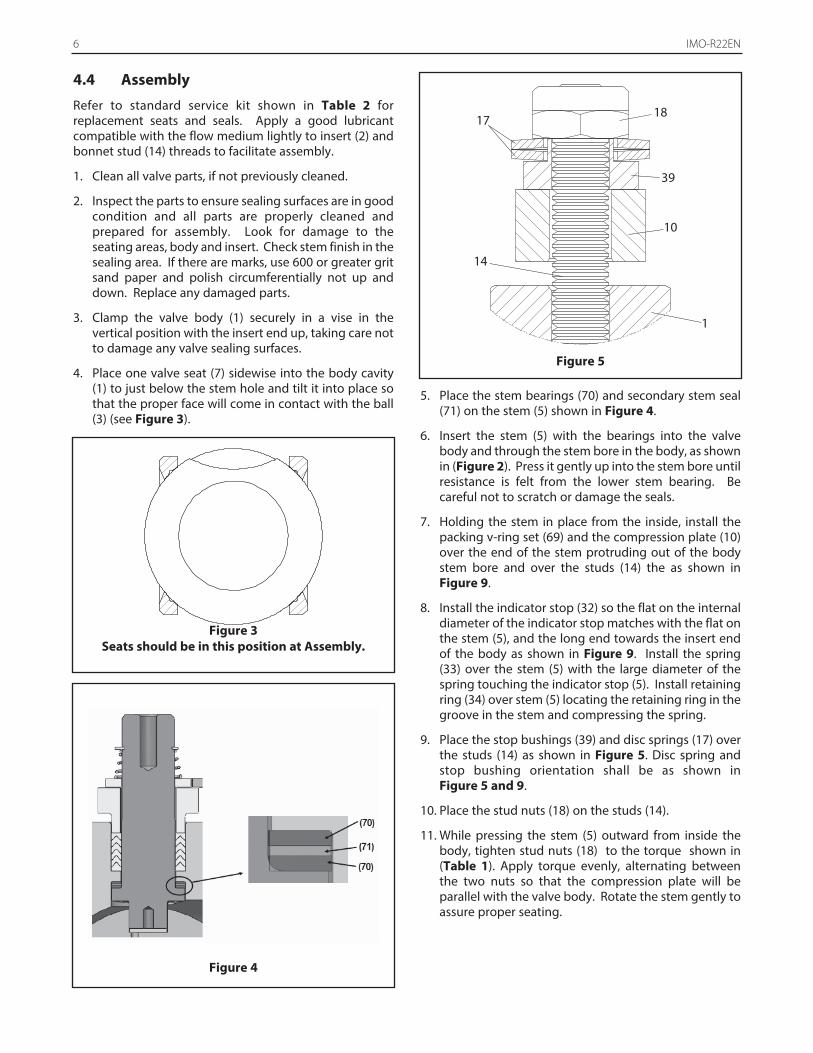
7. Holding the stem in place from the inside, install thepacking v-ring set (69) and the compression plate (10)over the end of the stem protruding out of the bodystem bore and over the studs (14) the as shown inFigure 9.
8. Install the indicator stop (32) so the flat on the internaldiameter of the indicator stop matches with the flat onthe stem (5), and the long end towards the insert endof the body as shown in Figure 9. Install the spring(33) over the stem (5) with the large diameter of thespring touching the indicator stop (5). Install retainingring (34) over stem (5) locating the retaining ring in thegroove in the stem and compressing the spring.
9. Place the stop bushings (39) and disc springs (17) overthe studs (14) as shown in Figure 5. Disc spring andstop bushing orientation shall be as shown in Figure 5 and 9.
10. Place the stud nuts (18) on the studs (14).
11. While pressing the stem (5) outward from inside thebody, tighten stud nuts (18) to the torque shown in(Table 1). Apply torque evenly, alternating betweenthe two nuts so that the compression plate will beparallel with the valve body. Rotate the stem gently toassure proper seating.
Figure 5
Figure 3Seats should be in this position at Assembly.
Figure 4
14
1
10
39
1817
IMO-R22EN 7
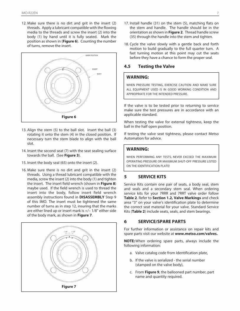
12. Make sure there is no dirt and grit in the insert (2)threads. Apply a lubricant compatible with the flowingmedia to the threads and screw the insert (2) into thebody (1) by hand until it is fully seated. Mark theposition as shown in (Figure 6). Counting the numberof turns, remove the insert.
13. Align the stem (5) to the ball slot. Insert the ball (3)rotating it onto the stem (4) in the closed position. Ifnecessary turn the stem blade to align with the ballslot.
14. Insert the second seat (7) with the seat sealing surfacetowards the ball. (See Figure 3).
15. Insert the body seal (65) onto the insert (2).
16. Make sure there is no dirt and grit in the insert (2)threads. Using a thread lubricant compatible with themedia, screw the insert (2) into the body (1) and tightenthe insert. The insert field wrench (shown in Figure 8)maybe used. If the field wrench is used to thread theinsert into the body, follow insert field wrenchassembly instructions found in DISASSEMBLY Step 9of this IMO. The insert must be tightened the samenumber of turns as in step 12, insuring that the marksare either lined up or insert mark is +/– 1/8" either sideof the body mark, as shown in Figure 7.
17. Install handle (31) on the stem (5), matching flats onthe stem and handle. The handle should be in theorientation as shown in Figure 2. Thread handle screw(35) through the handle into the stem and tighten.
18. Cycle the valve slowly with a gentle back and forthmotion to build gradually to the full quarter turn. Afast turning motion at this point may cut the seatsbefore they have a chance to form the proper seal.
4.5 Testing the Valve
If the valve is to be tested prior to returning to servicemake sure the test pressures are in accordance with anapplicable standard.
When testing the valve for external tightness, keep theball in the half open position.
If testing the valve seat tightness, please contact MetsoAutomation for advice.
5 SERVICE KITS
Service Kits contain one pair of seats, a body seal, stemand seals and a secondary stem seal. When orderingservice kits for your 7RRR and 7RRT valve order followTable 2. Refer to Section 1.2, Valve Markings and checkarea “3” on your valve’s identification plate to determinethe correct seat material for your valve. Standard ServiceKits (Table 2) include seats, seals, and stem bearings.
6 SERVICE/SPARE PARTS
For further information or assistance on repair kits andspare parts visit our website at www.metso.com/valves.
NOTE: When ordering spare parts, always include thefollowing information:
a. Valve catalog code from Identification plate,
b. If the valve is serialized - the serial number (stamped on the valve body),
c. From Figure 9, the ballooned part number, part name and quantity required.
WARNING:
WHEN PRESSURE TESTING, EXERCISE CAUTION AND MAKE SUREALL EQUIPMENT USED IS IN GOOD WORKING CONDITION ANDAPPROPRIATE FOR THE INTENDED PRESSURE.
WARNING:
WHEN PERFORMING ANY TESTS, NEVER EXCEED THE MAXIMUMOPERATING PRESSURE OR MAXIMUM SHUT-OFF PRESSURE LISTEDON THE IDENTIFICATION PLATE!
–1/8" +1/8"
Figure 7
INSERT
MARK POSITION
BODY
Figure 6
8 IMO-R22EN
D
A
F
G
G
F
H
E
C
B
BD
INSERT FIELD WRENCH3" (DN 80)
MA0026426
ITEM PART NAME QTY.A DRIVER 1
B KEY 2
C PLATE 1
D SOCKET HEAD CAP SCREW 2
E THREADED ROD 2
F HEX. NUT 4
G FLAT WASHER 4
H SPRING 2
Figure 8
7 EXPLODED VIEW & PARTS LIST
IMO-R22EN 9
34
33
18
14
39
10
65
2
3
7
5
71
70
1
69
17
32
31
35
7
70
19
23
Proper Disc Spring Orientation
ITEM NO. DESCRIPTION QTY.
1 BODY 12 INSERT 13 BALL 15 STEM 17 SEAT 2
10 COMPRESSION PLATE 114 STUD 217 DISC SPRING 473 STUD NUT 219 IDENTIFICATION PLATE 123 POP RIVET 331 HANDLE 132 INDICATOR STOP 133 SPRING 134 RETAINING RING 135 HANDLE SCREW 139 STOP BUSHING 265 BODY SEAL 169 PACKING/V RING SET 170 STEM BEARING 271 SECONDARY STEM SEAL 1
Figure 9
10 IMO-R22EN
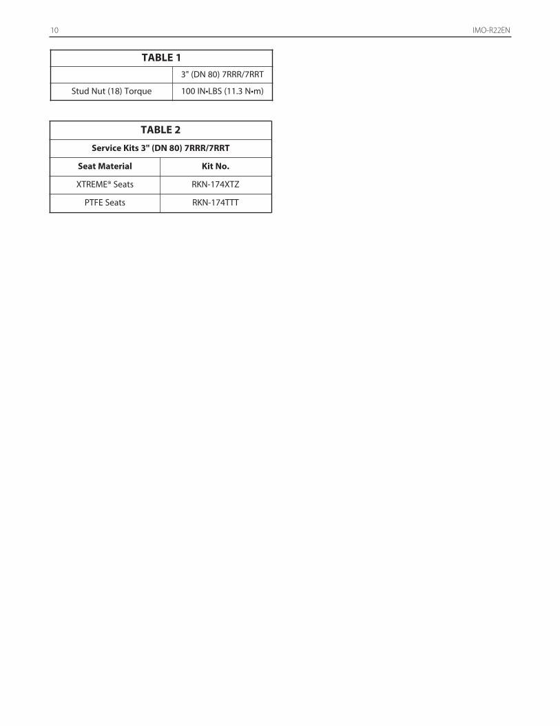
TABLE 13" (DN 80) 7RRR/7RRT
Stud Nut (18) Torque 100 IN•LBS (11.3 N•m)
TABLE 2
Service Kits 3" (DN 80) 7RRR/7RRT
Seat Material Kit No.
XTREME® Seats RKN-174XTZ
PTFE Seats RKN-174TTT
IMO-R22EN 11
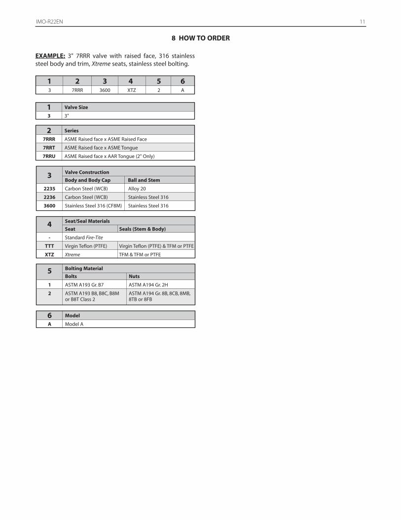
8 HOW TO ORDER
EXAMPLE: 3" 7RRR valve with raised face, 316 stainlesssteel body and trim, Xtreme seats, stainless steel bolting.
1 2 3 4 5 6 3 7RRR 3600 XTZ 2 A
1 Valve Size
3 3"
2 Series
7RRR ASME Raised face x ASME Raised Face
7RRT ASME Raised face x ASME Tongue
7RRU ASME Raised face x AAR Tongue (2" Only)
3 Valve Construction
Body and Body Cap Ball and Stem
2235 Carbon Steel (WCB) Alloy 20
2236 Carbon Steel (WCB) Stainless Steel 316
3600 Stainless Steel 316 (CF8M) Stainless Steel 316
4 Seat/Seal Materials
Seat Seals (Stem & Body)
- Standard Fire-Tite
TTT Virgin Teflon (PTFE) Virgin Teflon (PTFE) & TFM or PTFE
XTZ Xtreme TFM & TFM or PTFE
5 Bolting Material
Bolts Nuts
1 ASTM A193 Gr. B7 ASTM A194 Gr. 2H
2 ASTM A193 B8, B8C, B8M ASTM A194 Gr. 8B, 8CB, 8MB,
or B8T Class 2 8TB or 8FB
6 Model
A Model A
12 IMO-R22EN
Subject to change without prior notice.
Metso Flow Control Inc.Europe, Vanha Porvoontie 229, P.O. Box 304, FI-01301 Vantaa, Finland. Tel. +358 20 483 150. Fax +358 20 483 151
North America, 44 Bowditch Drive, P.O. Box 8044, Shrewsbury, MA, 01545, USA. Tel. +1 508 852 0200. Fax +1 508 852 8172South America, Av. Independência, 2500-Iporanga, 18087-101, Sorocaba-São Paulo, Brazil. Tel. +55 15 2102 9700. Fax +55 15 2102 9748/49
Asia Pacific, Haw Par Centre #06-01, 180 Clemenceau Avenue, Singapore 239922. Tel. +65 6511 1011. Fax +65 6250 0830China, 11/F, China Youth Plaza, No.19 North Rd of East 3rd Ring Rd, Chaoyang District, Beijing 100020, China. Tel. +86 10 6566 6600. Fax +86 10 6566 2583
Middle East, Roundabout 8, Unit AB-07, P.O. Box 17175, Jebel Ali Freezone, Dubai, United Arab Emirates. Tel. +971 4 883 6974. Fax +971 4 883 6836www.metso.com/valves