Embed Size (px)
Citation preview
Office: Level 3, 51 Alfred Street, Fortitude Valley, Queensland, Australia 4006 Mail: PO Box 133, Fortitude Valley, Queensland, Australia 4006 Telephone: +61 7 3510 7222 Website: www.bon-infra.com
Tanker Jetty, Esperance Remediation Report
Prepared for The Jetty Group Incorporated
DOCUMENT HISTORY
ISSUE REVISION DATE AUTHOR REVIEWER Draft A 22-09-2016 TJM DH
Tanker Jetty Remediation Report 2 Esperance, Western Australia
TABLE OF CONTENTS 1 INTRODUCTION ............................................................................................................................. 3
2 PROFESSIONAL BACKGROUND AND QUALIFICATIONS ........................................................ 3
3 DISCLOSURE OF INTEREST ........................................................................................................ 3
4 TERMINOLOGY .............................................................................................................................. 3
5 JETTY OWNERSHIP AND MAINTENANCE .................................................................................. 4
6 HISTORICAL AND INDIGENOUS SIGNIFICANCE ....................................................................... 4
7 PREVIOUS REPORTS .................................................................................................................... 5
8 JETTY INSPECTION ....................................................................................................................... 7
8.1 Addressing Structural Concerns ............................................................................................. 7
8.2 Addressing Community Concerns ........................................................................................... 7
8.3 Addressing Council Concerns ................................................................................................. 8
8.4 Addressing Heritage Concerns ............................................................................................... 8
9 TECHNICAL SOLUTIONS TO REMEDIATE THE JETTY ............................................................. 9
9.1 Key Design loads .................................................................................................................... 9
9.2 The need for design innovation ............................................................................................... 9
9.3 Option 1 – Baseline Case ....................................................................................................... 9
9.3.1 New Pile Configuration ........................................................................................................ 9
9.3.2 The argument for a sleeved pile arrangement .................................................................. 10
9.3.3 New Pile Bent Position ...................................................................................................... 11
9.3.4 Superstructure works ........................................................................................................ 11
9.3.5 Durability ........................................................................................................................... 11
9.4 Option 2 – Improved aesthetic and heritage case ................................................................ 12
9.5 Abutment works and Heritage Opportunity ........................................................................... 12
10 REHABILITATION COSTING AND CONSTRUCTION PROGRAM ............................................ 12
10.1 Whole of Life Costing ............................................................................................................ 14
10.2 Construction Program (Timing) ............................................................................................. 15
Appendix A: Design Drawings Appendix B: Denso Seashield Series 60 System Appendix C: Bonacci Infrastructure Capability Brochures Appendix D: Terry Memory CV
Tanker Jetty Remediation Report 3 Esperance, Western Australia
1 INTRODUCTION
Bonacci Infrastructure (Bonacci) was engaged by The Jetty Group Inc. following the decision of the Esperance Shire Council to invite Contractors to tender for the demolition of the Tanker Jetty, which located on the Esperance shoreline. The Jetty is 81 years old and is heritage listed, as it is one of only three (3) timber jetties left in Western Australia. The Jetty was closed to public assess, by the Council, last November following the release of a Condition Assessment report prepared by BMT JFA, on behalf of the Council.
2 PROFESSIONAL BACKGROUND AND QUALIFICATIONS
My name is Mr Terry James Memory. My CV is attached in Appendix D. I have 25 years’ experience as a structural engineer, predominantly in the design and construction industry, but I also have academic experience and have on numerous occasions been engaged as an expert consultant/witness. I am a member of the following organisations:
x Member of the Institution of Engineers Australia (MIEAust) x Chartered Profession Engineer (CPENG) x Register Member of the Board of Profession Engineers Queensland (RPEQ) x Register Member of the Board of Building Practitioners North Territory (Aust.) x Member of the New Zealand Institute of Professional Engineers (IPENZ)
I am a principal and company Director of Bonacci Infrastructure whose registered office is Level 3, 51 Alfred Street, Fortitude Valley, QLD 4006, Australia. My primary area of expertise lies in the design of civil infrastructure including marine works, mining and resources, bridges, tunnels and large scale water treatment facilities. A particular area of interest is the numerical modelling of soil and its interaction with structural elements and the subsequent design of those structural elements. Also attached, in Appendix C, are Bonacci Infrastructure company brochures dedicated to our speciality areas of Marine and Mining, and Construction Engineering.
3 DISCLOSURE OF INTEREST
Prior to preparing this report, I have had no involvement with the proposed demolition or preservation of the Tanker Jetty.
4 TERMINOLOGY
Throughout this report, engineering terminology is used to describe the Jetty and its condition or technical concepts. Below is a short list and explanation of these engineering terms.
x Piles: refers to the current HW timber piles that support the Jetty x Headstock: refers to the horizontal structural element that both supports the Jetty Deck and
is connected to the top of the piles. x Jetty Bent or Bent: refers to the “frame” that is comprised of two piles and a headstock and
on this Jetty are spaced at 4.6m along the length of the Jetty. x Corbel: refers to the 1.5m long HW timber element that is horizontal and located above the
piles and below the main deck. Its structural function is to reinforce the area above the pile by facilitating the spread of the pile load up through the corbel to the deck timbers.
x Deck Stringers or Stringers: refer to the main horizontal HW timbers that span from headstock to headstock. On this Jetty, each stringer is 9.2m long and each stringer spans two bays.
Tanker Jetty Remediation Report 4 Esperance, Western Australia
x HW Decking: refers to the HW deck planks that are laid across the stringers and are currently covered by a concrete deck.
x Substructure: refers to all the elements below the underside of the stringer x Superstructure: refers to all the elements above the underside of the stringers, inclusive of
the stringers.
5 JETTY OWNERSHIP AND MAINTENANCE
The BMT JFA report cited above in the introduction did not condemn the structural integrity of the entire Jetty, however, it did highlight and warn of serious structural concerns that required immediate rectification. Additionally, it highlighted the requirement for ongoing maintenance after the initial repair works. With regard to ownership, we understand that the State Government of Western Australian are the legal owner of the Jetty. However, the Esperance Shire Council has the legal responsibility to maintain the Jetty for public use and to this end has received funds from a variety of sources to do so. To our knowledge, the Council has not undertaken any programmed maintenance of the Jetty since it acquired responsibility to do so, around 2010/2011. This is despite the that fact that the Council has commissioned several reports, since 2010, which have all highlighted the need to regular maintenance, if not immediate localised repairs. We further understand that, given the lack of maintenance undertaken over the past six (6) years, the funds set aside for the Jetty should remain largely intact.
6 HISTORICAL AND INDIGENOUS SIGNIFICANCE
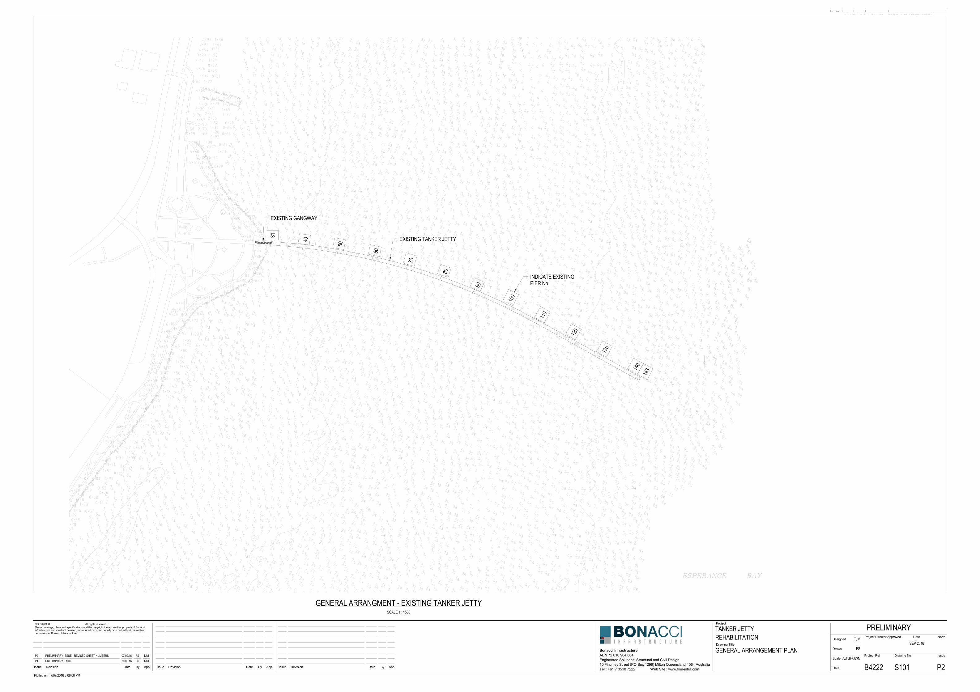
The Tanker Jetty was constructed in 1935 and is now 81 years old. The name is derived from the fact that a key functional aspect of the Jetty was the transmission of petroleum between vessels and the adjacent fuel tank farm located on the shoreline. Originally, the Jetty was a commercial facility servicing the Esperance harbour. The Jetty itself was originally in excess of 872m long, complete with a Jetty Head for berthing vessels and a locomotive rail line from shore to Jetty head. The Jetty head was lost to deterioration some years ago and more seaward bents have been lost in the same manner. Currently, the Jetty extends to bent 143, of the original 192 bents. The recent foreshore redevelopment has also necessitated the demolition of the shore end of the Jetty, such that bent 31 is now the first remaining bent of the Jetty. An aluminium gangway presently spans the foreshore to bent 31, to enable access onto the Jetty. Currently the Jetty is comprised of 112 x 4.57m spans, on 113 twin pile bents. The Jetty is currently 512m long, configured as a graceful arch into the harbour. During my trip to Esperance, I noticed and read the storyboards erected as part of the recent foreshore redevelopment. At the Jetty itself, the storyboards celebrate the Jetty via large-scale images of the Jetty’s construction in 1935. Whilst I did not walk the entire length of the foreshore redevelopment, the apparent absence of any reference to the local indigenous heritage, acknowledgment or recognition was surprising to me. The Jetty does have indigenous significance, however, it is not something to celebrate, rather to acknowledge and respect. In the past, the Jetty was the landmark delineating the boundary between colonial and indigenous communities. That is, historically, indigenous peoples were not permitted past the Jetty and thereby not permitted to enter the township of Esperance. Whilst this historical fact is clearly an anathema to any modern society, it is nevertheless a significant reminder of the prejudices and wrongs done in this country under the name of colonialism. I therefore submit that preservation of the Jetty and the documenting of this historical fact, via a storyboard at the Jetty, is a necessary and
Tanker Jetty Remediation Report 5 Esperance, Western Australia
respectful acknowledgment of the past. To this end, I would suggest and encourage The Jetty Group to seek guidance from the local indigenous community, indigenous leaders and anthropologists.
7 PREVIOUS REPORTS
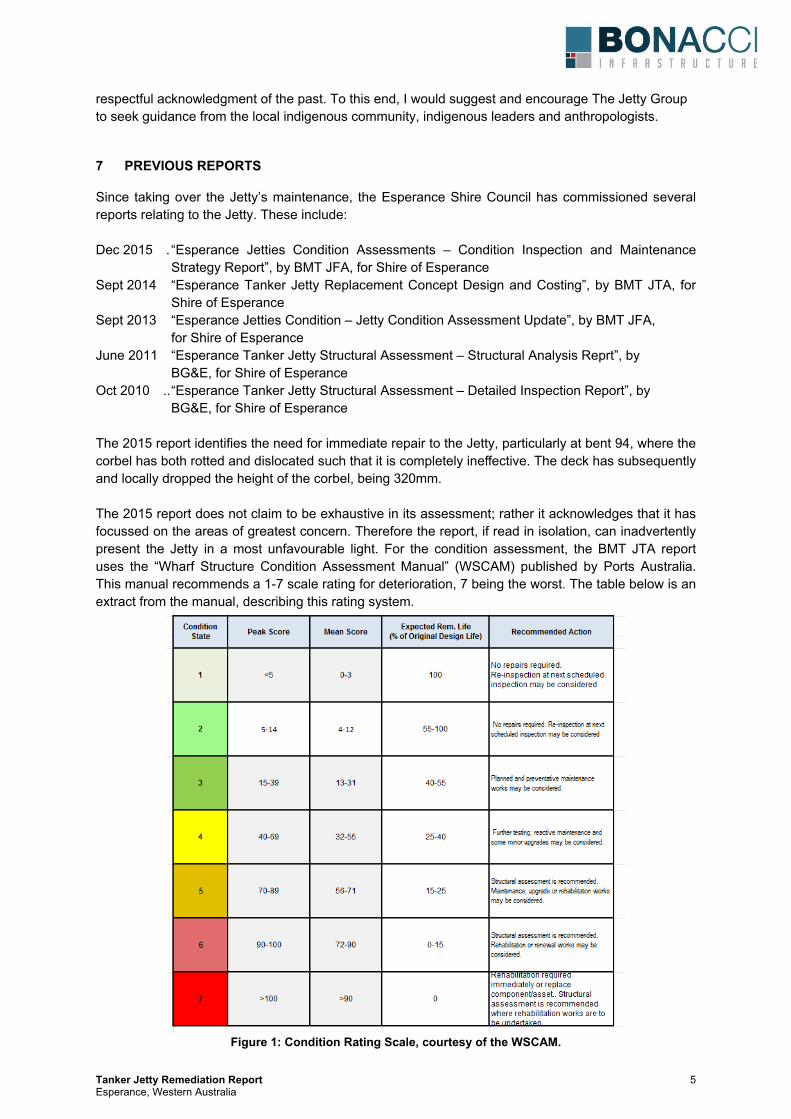
Since taking over the Jetty’s maintenance, the Esperance Shire Council has commissioned several reports relating to the Jetty. These include: Dec 2015 . “Esperance Jetties Condition Assessments – Condition Inspection and Maintenance Strategy Report”, by BMT JFA, for Shire of Esperance Sept 2014 “Esperance Tanker Jetty Replacement Concept Design and Costing”, by BMT JTA, for Shire of Esperance Sept 2013 “Esperance Jetties Condition – Jetty Condition Assessment Update”, by BMT JFA, for Shire of Esperance June 2011 “Esperance Tanker Jetty Structural Assessment – Structural Analysis Reprt”, by BG&E, for Shire of Esperance Oct 2010 .. “Esperance Tanker Jetty Structural Assessment – Detailed Inspection Report”, by BG&E, for Shire of Esperance The 2015 report identifies the need for immediate repair to the Jetty, particularly at bent 94, where the corbel has both rotted and dislocated such that it is completely ineffective. The deck has subsequently and locally dropped the height of the corbel, being 320mm. The 2015 report does not claim to be exhaustive in its assessment; rather it acknowledges that it has focussed on the areas of greatest concern. Therefore the report, if read in isolation, can inadvertently present the Jetty in a most unfavourable light. For the condition assessment, the BMT JTA report uses the “Wharf Structure Condition Assessment Manual” (WSCAM) published by Ports Australia. This manual recommends a 1-7 scale rating for deterioration, 7 being the worst. The table below is an extract from the manual, describing this rating system.
Figure 1: Condition Rating Scale, courtesy of the WSCAM.
Tanker Jetty Remediation Report 6 Esperance, Western Australia
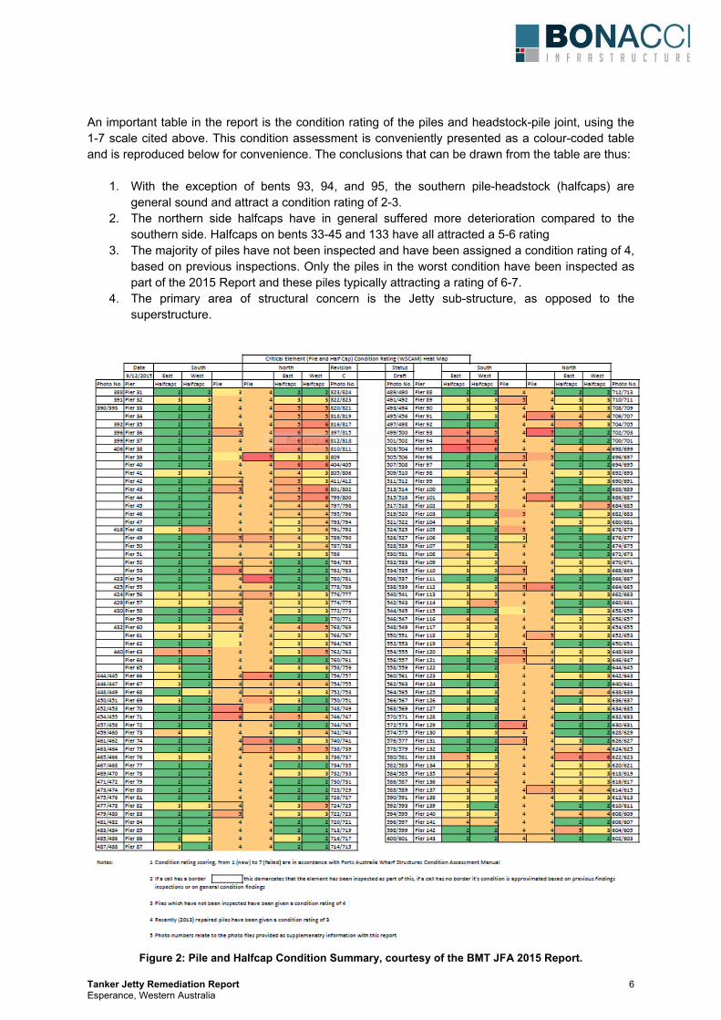
An important table in the report is the condition rating of the piles and headstock-pile joint, using the 1-7 scale cited above. This condition assessment is conveniently presented as a colour-coded table and is reproduced below for convenience. The conclusions that can be drawn from the table are thus:
1. With the exception of bents 93, 94, and 95, the southern pile-headstock (halfcaps) are general sound and attract a condition rating of 2-3.
2. The northern side halfcaps have in general suffered more deterioration compared to the southern side. Halfcaps on bents 33-45 and 133 have all attracted a 5-6 rating
3. The majority of piles have not been inspected and have been assigned a condition rating of 4, based on previous inspections. Only the piles in the worst condition have been inspected as part of the 2015 Report and these piles typically attracting a rating of 6-7.
4. The primary area of structural concern is the Jetty sub-structure, as opposed to the superstructure.
Figure 2: Pile and Halfcap Condition Summary, courtesy of the BMT JFA 2015 Report.
Tanker Jetty Remediation Report 7 Esperance, Western Australia
8 JETTY INSPECTION
The Jetty was inspected by myself over a two-day period between the 31/08 and 01/09. The Jetty was inspected from both deck level and under the deck, via boat. The inspection was very valuable as it facilitated independent validation of the previously commissioned condition assessments and resulted in the following independent conclusions being made:
a) That the Jetty sub-structure should only be rehabilitated with new materials, as opposed to trying to salvage the existing timber piles or headstocks for structural re-use.
b) Several external stringers have deteriorated to the extent that they needed replacement or strength augmentation.
c) The internal stringers appear to be in relatively good condition and this is most likely because they are shielded from direct sunlight and salt rich wind.
d) The Jetty deck level is quite irregular and this irregularity should be corrected if the Jetty is rehabilitated.
e) The current concrete deck has sustained cracking and from both a structural and aesthetic point of view should be replaced as part of any rehabilitation regime.
8.1 Addressing Structural Concerns
In regard ot the Jetty sub-structure I agree with the sentiment of the most recent Council commissioned report, that immediate rehabilitation is required. I also believe that it is not technically feasible to consider the reuse of any existing piles or headstock for structural purposes. That is, they may be retained or re-used for aesthetic purposes should that be deemed desirable. I am therefore of the opinion that the sub-structure needs to be completely replaced, however, I also believe this can be achieved with reasonable ease and at a cost that much lower than that suggested by the Council. The details of how this could be done are discussed later in Section 9 and the design drawings are contained in Appendix A. As part of the proposed substructure replacement program, I have also included a construction methodology for re-levelling the deck. This concept is illustrated on Drawing S120 in Appendix A. In practice, this re-levelling task is simply an extra construction activity, undertaken whilst installing the new Jetty bent. In total there are 48 external stringers that have been identified by myself as requiring replacement or structural augmentation. In section 9 below, I discuss the proposed stringer replacement or strengthening options. The concrete deck surface is currently laid over the top of the original HW decking and is separated from (debonded) from the HW via a plastic membrane that was placed over the decking, prior to the concrete being poured. Removal of the existing concrete shall therefore be quite easy as it is effectively “loose” on the deck. We recommend that this deck be replaced as part of the rehabilitation program for structural and aesthetic reasons. 8.2 Addressing Community Concerns
The immediate concern for the community is the potential loss of their Jetty. It is easy for critics to dismiss the Jetty as little more than a fishing platform, however, having spoken to several people in the Esperance community it is clear that the Jetty provides the following:
x Yes, it is a fishing platform and also a facility that offers a 500m long promenade or jog route.
Tanker Jetty Remediation Report 8 Esperance, Western Australia
x It is an historic and iconic landmark that significantly contributes to the identity of the town and the people who dwell in it.
x It is a constant, that has linked generations along an 81 year timeline and if rehabilitated will continue to do so for generations to come.
On the counter side, should the Jetty be demolished, the following is true:
x There is no coherent or funded plan to rebuild the Jetty. Currently the only publicly released document pertaining to any new Jetty is the BMT JTA Jetty Options Study of Sept 2014 and some 19 pages long. Furthermore, I understand Shire Council do not have funds available for any new Jetty and nor has it made any meaningful commitment to raise funding for a new Jetty.
x The Jetty length option promoted by the Council is notionally 250m, compared to the current Jetty that is 512m long. A 250m long Jetty would end in 3.1m deep water (at LAT) compared to the current termination in 6m deep water (at LAT).
x Should the current Jetty be demolished prior to securing funding for a new Jetty, as is currently the case, there is a lost opportunity cost. This is because the securing of State or Federal funding for the new Jetty will be become increasingly difficult as the community and businesses adjust to not having a Jetty.
8.3 Addressing Council Concerns
As an experienced marine and civil engineer I am quite cognisant of the technical and liability issues faced by the Esperance Shire Council in regard to the Jetty. Presently and given the recent BMT JFA Report it is most likely that the Jetty is uninsurable and this the core reason why the Jetty has been closed. With regard to durability, however, I would suggest that the core issue for the Council is both the current and future liability of the Jetty sub-structure, and in particular the components in the tidal zone or below. This is simply because these elements on a marine structure are always the most vulnerable in terms of deterioration – as evidenced on the Tanker Jetty. Accordingly, any rehabilitation plan must necessarily address both the current, poor condition of the Jetty’s substructure and also the future life of the substructure, in particular the piles. The plan described in Section 9 below does both of these things. Importantly, the plan restores the Jetty’s sub-structure to brand new condition with a 30-50 year design life, depending on the maintenance program. Importantly, the rehabilitation program proposed also enables structural certification of the remediated Jetty and this is essential to facilitate the execution of insurance policies. 8.4 Addressing Heritage Concerns
The Jetty is heritage listed, however, had it not been for the intervention of The Jetty Group this Heritage status would have been passed over to facilitate the Jetty’s demolition. Indeed, this report is written as part of a submission to the WA Hertiage Council. A key part of any heritage preservation is the preservation of the aesthetic, if not the components themselves. Within this report I recommend that the entire Jetty substructure be replaced and likewise, the entire original superstructure be retained, save for the repaired stringers. This is a compromised position and indeed it could be argued that more could be done to preserve both the aesthetic and materials, relative to the baseline case presented below in Section 9. I agree which this position, however, the greater the preservation, the greater the cost. Notwithstanding the cost argument, I have provided the second proposal which better captures the current Jetty aesthetic, should extra (heritage) funding become available.
Tanker Jetty Remediation Report 9 Esperance, Western Australia
9 TECHNICAL SOLUTIONS TO REMEDIATE THE JETTY
Below I present two options for the rehabilitation of the Tanker Jetty. Option 1 is referred to as the baseline case as it represents the most cost-effective solution, but not necessarily the most heritage or aesthetically sensitive solution. This baseline solution has been developed in the absence of any committed rehabilitation funding. It has also been developed as a comparison to the Esperance Shire Council’s claim that the Jetty cannot be saved for less than $10M, and moreover, the suggestion that the Council should allocate such funds, should they become real, to the construction of a new, shorter, Jetty. 9.1 Key Design loads
The rehabilitation design proposed herein assumes no vehicles are permitted on the Jetty deck, rather, the design is governed by crowd loading, taken as 5kPa (500kg/m2). Additionally, 10% of this crowd loading has been considered to act simultaneously in the horizontally direction at deck level. Wave loading on the substructure has also been considered. A design wave with a height of 3m and a period of 7sec was considered. Such a wave would have a crest level just below the underside of the deck at Highest Astronomic Tide (HAT). The lateral force generated on the piles by this wave is equal to the 10% lateral loading cited above. 9.2 The need for design innovation
From a technical point of view the reporting commissioned by the Council to date has failed to effectively address the central issue, which is, How could the Jetty be rehabilitated? I don’t believe this question has ever been addressed and maybe it has never been asked. In the most recent BMT JFA report there is reference to the fact that the Jetty is already on its second round of piling and the idea of a third round of piling is largely dismissed as impractical. Indeed, I would agree that to re-pile in the same plane as the existing bents would be impractical, so much so that it necessarily means one should look to re-piling in a different location. This is precisely why the solutions presented below and in Appendix A show the new pile bents 1.2m from the existing. Doing this means that the new bents can be installed without interfering with the existing and likewise, the existing bents can be readily removed after the new bents are installed. This idea is the fundamental difference between this report and all previous reports that suggest, or infer, that rehabilitation is not possible or not practical. 9.3 Option 1 – Baseline Case
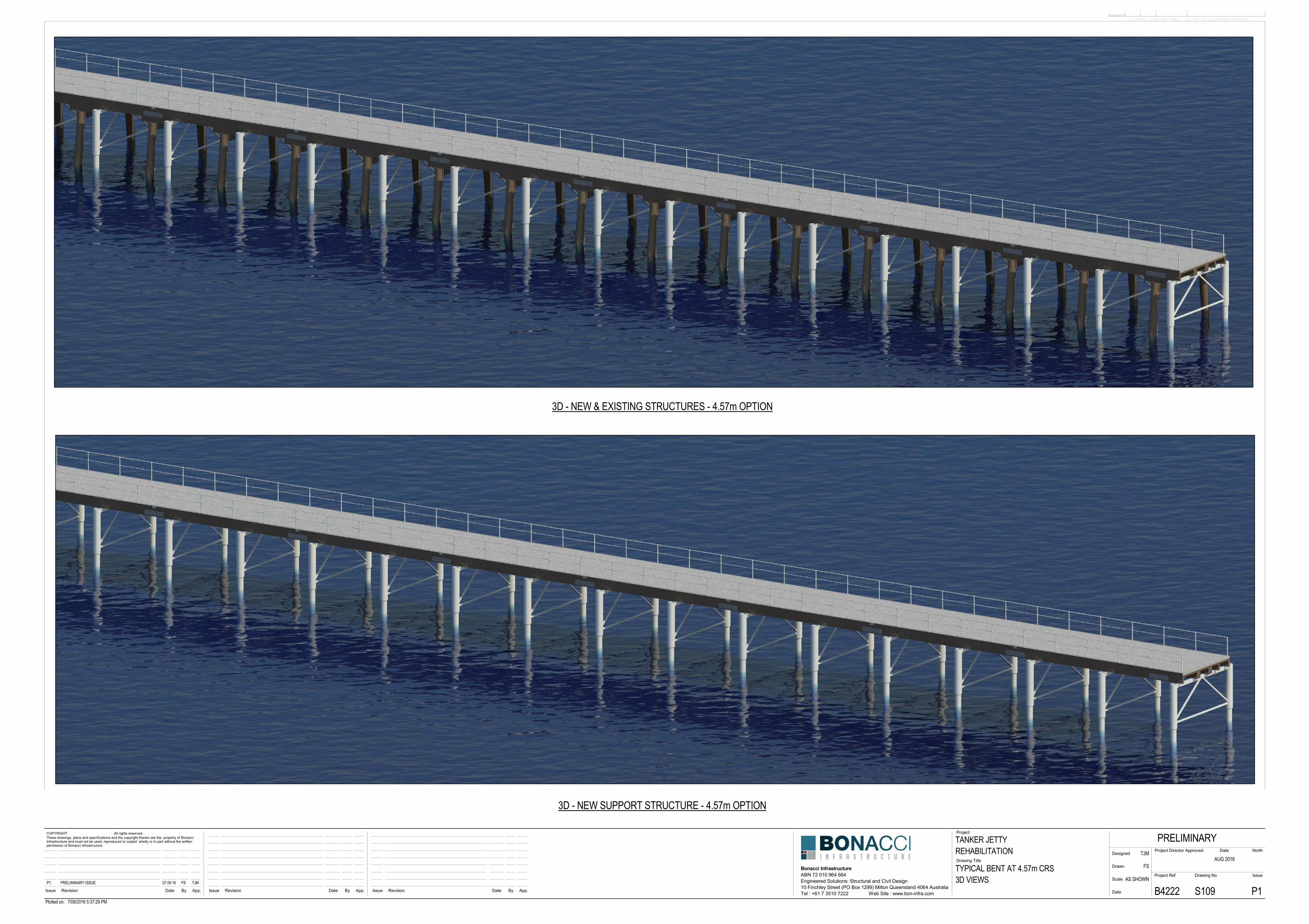
The baseline case is presented herein as the most cost-effective solution to preserve the Jetty in its current position and at its current length. It is also the solution that seeks to achieve the lowest cost base whilst addressing the key concerns and aspiration of stakeholders. That is, it is a solution that:
x Preserves the Jetty at is current length for use by the Esperance community and for tourism. x Replaces the entire sub-structure with new material to address the Shire Councils primary
safety, liability, insurance and maintenance concerns. x Retains the original superstructure, the deck curvature and the Jetty’s physical position for
Heritage and Indigenous significance. 9.3.1 New Pile Configuration
The existing Jetty has piles installed on the incline, known as raked piles. The inclination of the rake is 1:8. Construction of raked piles is significantly more difficult than the installation of vertical piles. This is primarily because the temporary housing required to support a raked pile during its installation is more complex than that required for a vertical. This is because the driving hammer is inclined and also offset from the pile toe - because of the rake. This lateral offset generates temporary lateral loads
Tanker Jetty Remediation Report 10 Esperance, Western Australia
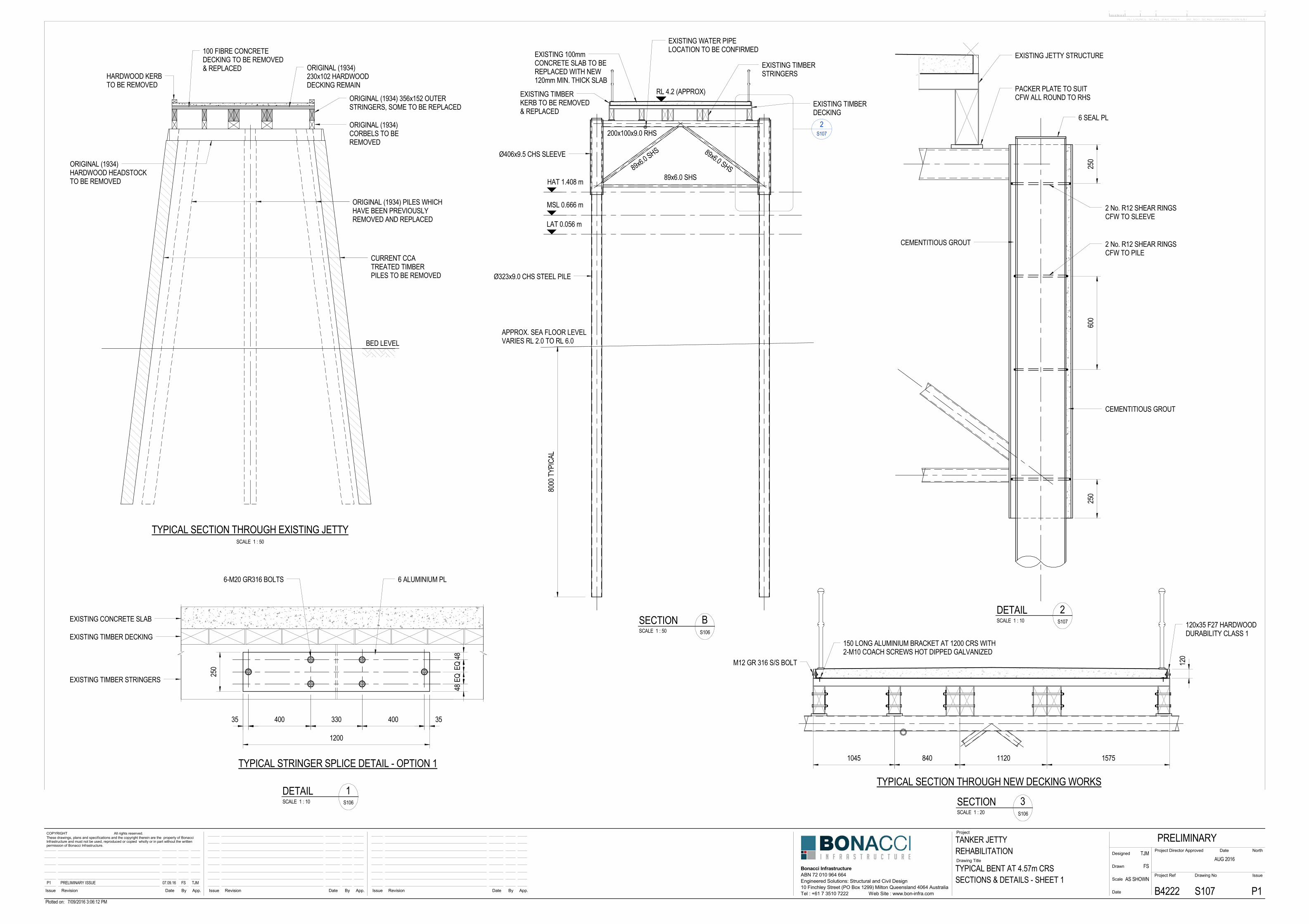
during the driving operation and these loads need to be resisted by either the Jetty or the barge from which the piling is being undertaken. The Jetty in its current condition can only sustain very modest lateral loads and would not be able to resist the temporary loads generated by the driving of raked piles without the inclusion of a secondary support system. This means that the cost and time required to install raked piles would be greater, compared to vertical piles. It was on this basis that vertical piles are proposed for the Baseline case. 9.3.2 The argument for a sleeved pile arrangement
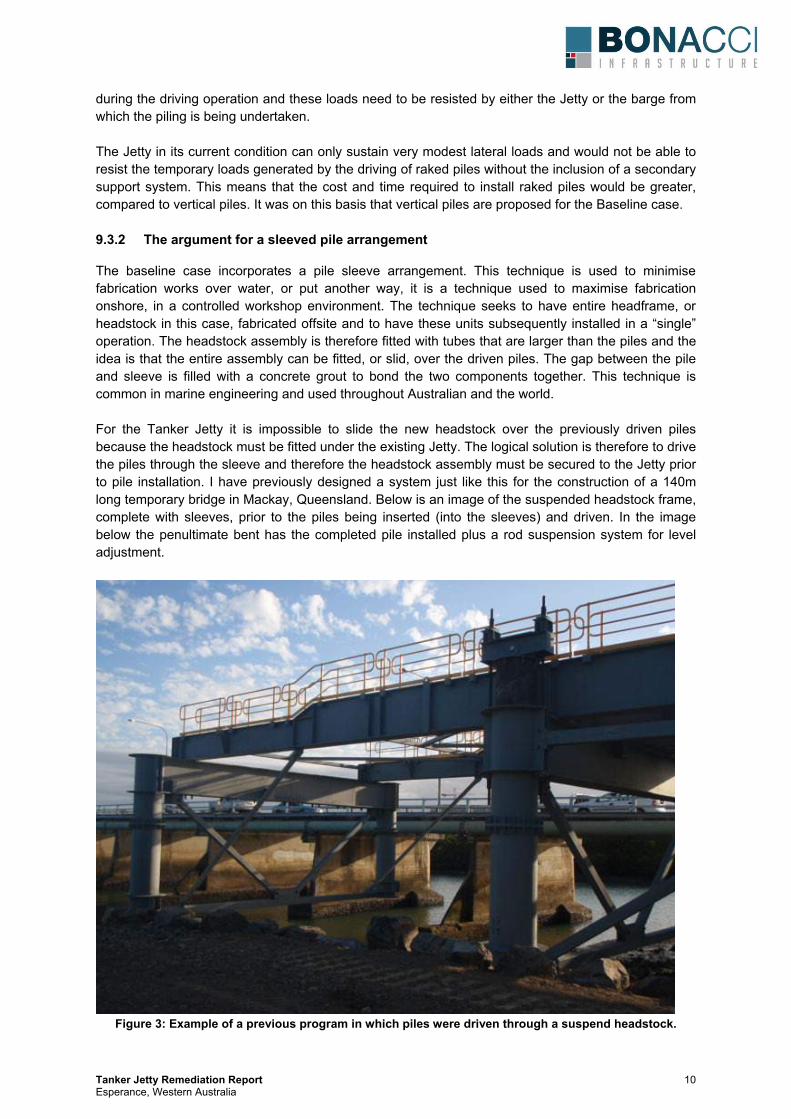
The baseline case incorporates a pile sleeve arrangement. This technique is used to minimise fabrication works over water, or put another way, it is a technique used to maximise fabrication onshore, in a controlled workshop environment. The technique seeks to have entire headframe, or headstock in this case, fabricated offsite and to have these units subsequently installed in a “single” operation. The headstock assembly is therefore fitted with tubes that are larger than the piles and the idea is that the entire assembly can be fitted, or slid, over the driven piles. The gap between the pile and sleeve is filled with a concrete grout to bond the two components together. This technique is common in marine engineering and used throughout Australian and the world. For the Tanker Jetty it is impossible to slide the new headstock over the previously driven piles because the headstock must be fitted under the existing Jetty. The logical solution is therefore to drive the piles through the sleeve and therefore the headstock assembly must be secured to the Jetty prior to pile installation. I have previously designed a system just like this for the construction of a 140m long temporary bridge in Mackay, Queensland. Below is an image of the suspended headstock frame, complete with sleeves, prior to the piles being inserted (into the sleeves) and driven. In the image below the penultimate bent has the completed pile installed plus a rod suspension system for level adjustment.
Figure 3: Example of a previous program in which piles were driven through a suspend headstock.
Tanker Jetty Remediation Report 11 Esperance, Western Australia
The sleeve arrangement is therefore fundamental to the success of the sub-structure rebuild, as it facilitates:
a) High quality offsite fabrication and painting of the entire headstock, with no requirement for welding or painting over water.
b) A temporary piling gate arrangement is not required as the sleeve performs this function. c) Pile position tolerance is guaranteed as the piles are driven through their permanent
headstock. d) Headstock installation can be advanced ahead of the piling works to ensure this activity is not
on the construction programs critical path. e) Prior to grouting the pile-sleeve assembly, the pile and sleeved headstock can be used to
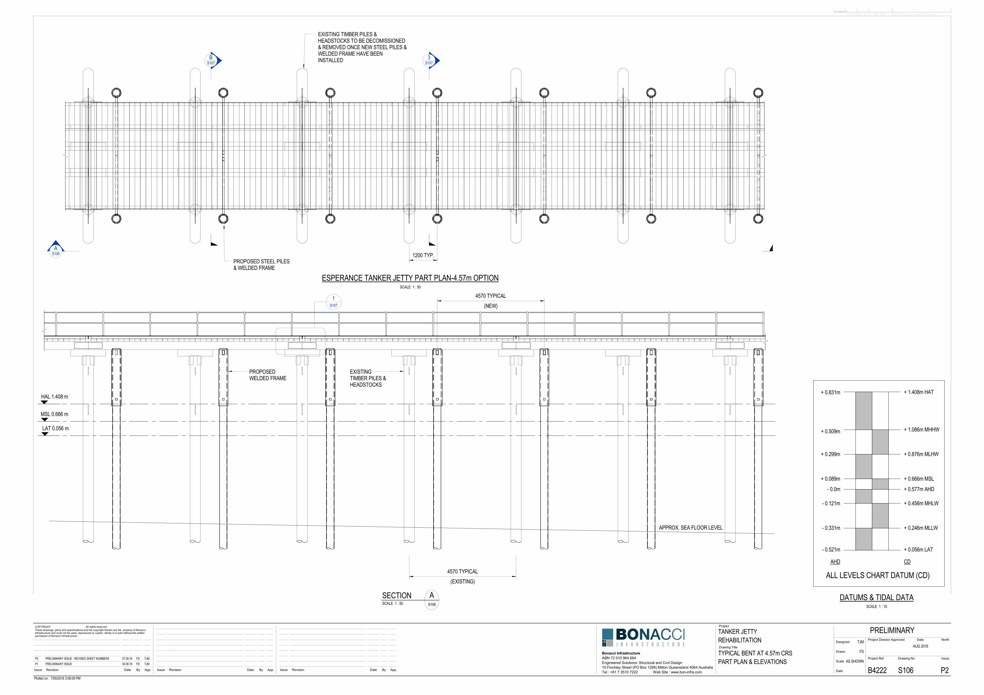
relevel the deck. 9.3.3 New Pile Bent Position
As previous mentioned herein, it is impractical to consider the installation of a new sub-structure bent in the same location as the current bent. It is therefore proposed that the new bents be located 1.2m away from the existing bents. The 1.2m distance was selected for practical reasons to aid in construction and in this sense there is some latitude to alter the dimension should there be an argument to do so. The proposed design assumes that the existing bents provide no support to the rehabilitated Jetty and therefore the existing bents can be completed removed, if so desired. Presently there is a butt joint between adjacent stringers on every second bent - each stringer spans two bents. Clearly, an existing bent under a stringer joint can’t be removed prior to the joint being modified. The modification proposed is the installation of a 1.2m long aluminium slice plate across each stringer joint. The plate does not need to reinstate the flexural capacity of the stringer, rather, its design purpose is to transfer only shear between the two stringers. The splice detail has been developed assuming the stringers are seasoned Jarrah with a joint strength Group classification of JD2. The slice detail is shown on drawing S107. 9.3.4 Superstructure works
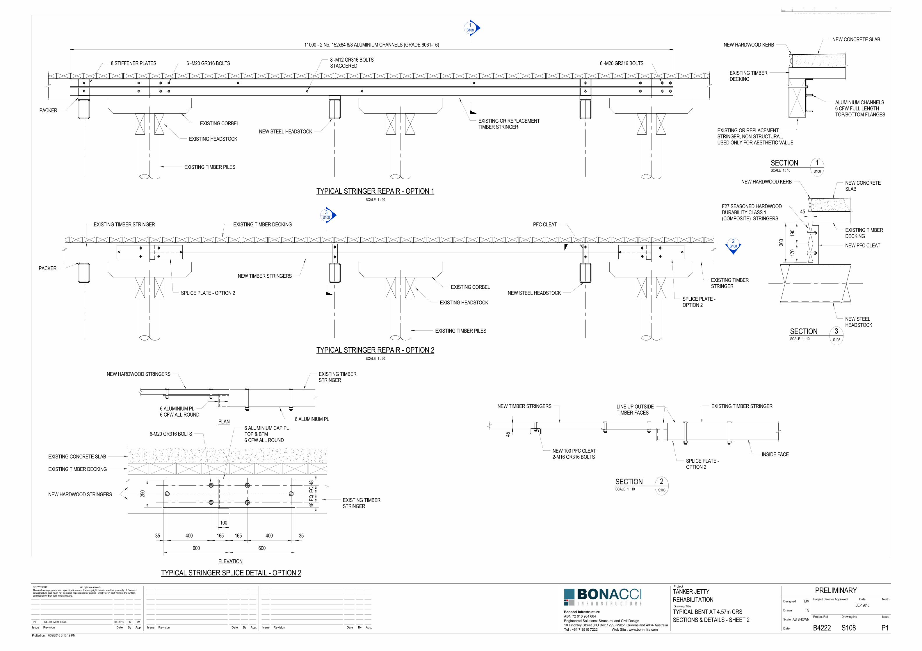
The existing HW stringers are generally in good condition, with the exception of several external stringers, which display unacceptable deterioration. These individual stringers have been identified on the rehabilitation drawings and must be replaced, or repaired. The proposal herein includes two options for this repair, either using a retrofitted aluminium beam, that will be hidden from view, or a new compound HW timber member. Both options are equally viable and shown on Drawing S108. A new 130mm thick concrete walking surface is proposed for the Jetty. The current decking is 100mm thick fibremesh. The new concrete deck has been sized to carry the 5kPa crowd load in full. That is, the existing original HW deck timbers, that shall remain in place, are not required from a strength point of view, rather, they will function only as the soffit form - as they did for the original concrete pour. 9.3.5 Durability
The Baseline case presents a steel sub-structure solution, which is typical for modern marine works in Australia. The durability treatment that has been assumed and costed within this report is as follows:
a) All mild carbon steel has been sized assuming a 3mm corrosion loss all round. b) A passive zinc anode cathodic protection system for all piles has been assumed and costed. c) A marine epoxy paint system, such as Interzone 954, to all mild carbon steel has been
assumed and costed.
Tanker Jetty Remediation Report 12 Esperance, Western Australia
The durability regime listed above is typical for all modern commercial marine infrastructure around Australia, save for the fact that on major infrastructure an impressed current cathodic protection system is used, as opposed to the anode system proposed here. Such a regime is considered to provide a design life of 30-50 years depending on the degree of maintenance provided by the asset owner and the prevailing environmental conditions (water temperature, swell height). 9.4 Option 2 – Improved aesthetic and heritage case
The baseline case was developed to fulfil the requirement for the most cost effective design solution. The aesthetic of vertical piles is, however, not overly sympathetic to the original bent geometry. Accordingly, a second design option is presented, refer drawing S115, which is in principle similar to the baseline case, however, there are two key differences. Those being the piles are installed with the 1:8 rake, as per the current Jetty, and the piles are shown as HW timber piles. Whilst not shown on the drawings, the use of steel tubular piles (instead of HW timber) for this case is very much an option. The use of unprotected HW timber piles does have the potential to attract durability concerns. The Australian Guidelines for the Design of Maritime Structures, AS4997, suggests that timber piles exposed to marine organisms have an expected duration until the “first maintenance” of 5-10 years. Conversely, if the pile is not exposed to marine organisms the duration to first maintenance is cited as 10-30 years. It is important to appreciate that exposure is not necessarily connected to chemical treatment of the pile. That is, a chemically treated pile may still be vulnerable to marine organism attack, such as the toredo worm. The best protection available for a timber pile is to physical wrap it in a membrane to prevent exposure to the marine organism larvae that migrate through the tidal zone. The most likely source for HW piles would be the Australian supplier “Koppers”. Kopper’s recommend double H6 chemical treatment for marine piles and suggest that this treatment, in southern (cooler) waters, will achieve a design life of 30 years. If the pile is wrapped with a membrane, they suggest a 75 year design life is achievable. At this stage we have opted to show a full wrap system for timber piles, to avoid debate over durability issues. The protection system proposed is the Denso “Seashield Series 60 System”, a copy of the supplier’s Brochure is included in Appendix B. A final visible sheath of this wrapping system is black HDPE (plastic). The visible portion of the piles will therefore be black in colour. 9.5 Abutment works and Heritage Opportunity
The current abutment is a relatively narrow aluminium gangway onto the existing Jetty. The gangway is approximately 1.2m wide, whereas the Jetty is 4.6m wide. A photo of the gangway is shown below. It has been assumed that this existing arrangement will remain for the baseline case, to minimise costs. However, the opportunity exists to improve upon this somewhat unattractive and restrictive (narrow) entrance onto the Jetty. In particular, I suggest consideration be given to the design of a special feature “Entry span” constructed from or featuring the original and salvaged Jetty timber.
10 REHABILITATION COSTING AND CONSTRUCTION PROGRAM
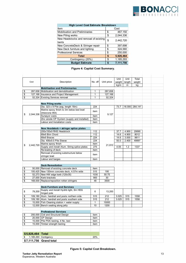
The baseline case presented in the design drawings (Appendix A) was issued to a third party Marine construction contractor based in Western Australia. This company has provided an independent construction estimate for the project and they are also a contender for executing the works should they proceed. Below is a high level Capital Cost summary followed by a more detailed breakdown. The headline construction cost is $5.9M but a 20% contingency allowance takes the estimate, for budgetary purposes, to $7.1M.
Tanker Jetty Remediation Report 13 Esperance, Western Australia
Figure 4: Capital Cost Summary.
Figure 5: Capital Cost Breakdown.
Unit weight
Unit length
Total weight
kg/m m kgMobilisation and Preliminaries
287,658$ Mobilisation and demobilisation 1 287,658 127,168$ Insurance and Project Management 1 127,168 52,324$ Existing Services removal 1 52,324
New Piling worksDia. 323 x 9 Pile (avg. length 16m) 224 73.7 16.000 264,141 Marine epoxy finish to 3m below bed level (Interzone 954)
item
Surveyor costs itemZinc anode CP System (supply and installed) itemLabour and Installation costs item
New Headstock + stringer splice plates200x150x9 RHS Headstock 112 37.7 4.900 2069089x6 Btm Chord 112 14.6 4.900 801289x6 Braces 224 14.6 3.000 9811Dia. 406x9.5 Pile Sleeve 224 93.0 2.400 49997Marine epoxy finish itemSupply and install Alum. String splice plates 275 4.05 1.2 1337Re-leveling of deck itemRemoval of existing substructure below stringer level
item
Labour and barges item
Deck Remediation50,000$ Removal of existing concrete deck item
100,425$ New 130mm concrete deck, 4.57m wide 515 19552,273$ New HW edge kerb (120x35) 1030 50.7527,000$ Kerb brackets 900 30
168,000$ Replace/reposition rotten stringers 48 3500
Deck Furniture and Services
79,200$ Supply and Install Hydrib light, 6m HDG hinged pole
6 13,200
109,180$ Alum. handrail and posts northern side 515 212 3.025 515 1558109,180$ Alum. handrail and posts southern side 515 212 3.025 515 155815,000$ Fish Cleaning station + water supply 1 1500012,000$ Bench seating along jetty 10 1200
Professional Services200,000$ Civil and Structural Design item20,000$ CP Design item15,000$ Pile PDA testing, 4 No. test item15,000$ Timber strength testing item
5,926,464$ Total1,185,293$ Contigency 20%
7,111,756$ Grand total
2,044,336$ 9,127
21,810 2,442,720$
Unit priceNo. offDescriptionCost
Item CostMobilisation and Preliminaries 467,150$ New Piling works 2,044,336$ New Headstocks and removal of existing bents
2,442,720$
New ConcreteDeck & Stringer repair 397,698$ New Deck furniture and lighting 324,560$ Professional Services 250,000$
Total 5,926,464$ Contingency (20%) 1,185,293$ Budget Estimate 7,111,756$
High Level Cost Estimate Breakdown
Tanker Jetty Remediation Report 14 Esperance, Western Australia
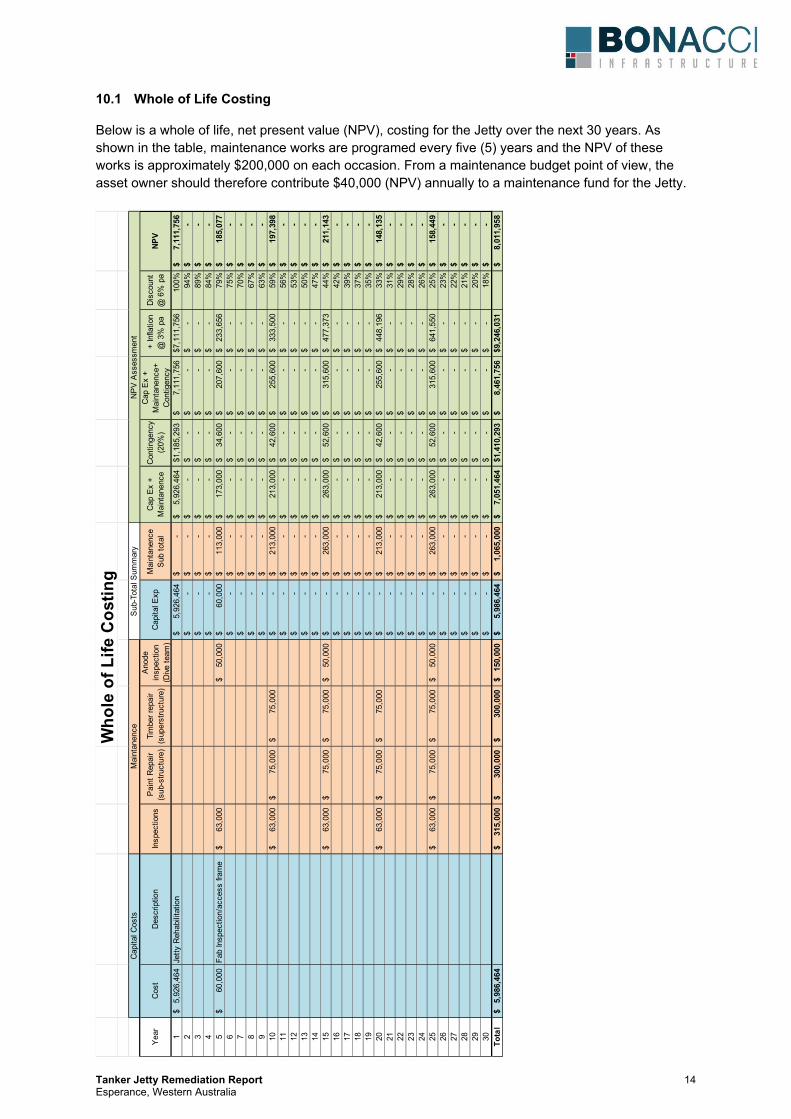
10.1 Whole of Life Costing
Below is a whole of life, net present value (NPV), costing for the Jetty over the next 30 years. As shown in the table, maintenance works are programed every five (5) years and the NPV of these works is approximately $200,000 on each occasion. From a maintenance budget point of view, the asset owner should therefore contribute $40,000 (NPV) annually to a maintenance fund for the Jetty.
Who
le o
f Life
Cos
ting
Year
Cos
tD
escr
iptio
nIn
spec
tions
Pain
t Rep
air
(sub
-stru
ctur
e)Ti
mbe
r rep
air
(sup
erst
ruct
ure)
Anod
e in
spec
tion
(Dive
team
)Ca
pita
l Exp
Mai
ntan
ence
S
ub to
tal
Cap
Ex +
M
aint
anen
ceC
ontin
genc
y (2
0%)
Cap
Ex
+ M
aint
anen
ce+
Con
tigen
cy
+ In
flatio
n @
3%
pa
Disc
ount
@
6%
pa
NPV
15,
926,
464
$
Jetty
Reh
abili
tatio
n5,
926,
464
$
-
$
5,92
6,46
4$
1,18
5,29
3$
7,11
1,75
6$
7,11
1,75
6$
100%
7,11
1,75
6$
2-
$
-$
-
$
-$
-
$
-
$
94%
-$
3
-$
-
$
-$
-
$
-$
-$
89
%-
$
4-
$
-$
-
$
-$
-
$
-
$
84%
-$
5
60,0
00$
Fa
b In
spec
tion/
acce
ss fr
ame
63,0
00$
50,0
00$
60,0
00$
11
3,00
0$
17
3,00
0$
34,6
00$
207,
600
$
233,
656
$
79%
185,
077
$
6-
$
-$
-
$
-$
-
$
-
$
75%
-$
7
-$
-
$
-$
-
$
-$
-$
70
%-
$
8-
$
-$
-
$
-$
-
$
-
$
67%
-$
9
-$
-
$
-$
-
$
-$
-$
63
%-
$
1063
,000
$
75
,000
$
75,0
00$
-$
21
3,00
0$
21
3,00
0$
42,6
00$
255,
600
$
333,
500
$
59%
197,
398
$
11-
$
-$
-
$
-$
-
$
-
$
56%
-$
12
-$
-
$
-$
-
$
-$
-$
53
%-
$
13-
$
-$
-
$
-$
-
$
-
$
50%
-$
14
-$
-
$
-$
-
$
-$
-$
47
%-
$
1563
,000
$
75
,000
$
75,0
00$
50,0
00$
-$
26
3,00
0$
26
3,00
0$
52,6
00$
315,
600
$
477,
373
$
44%
211,
143
$
16-
$
-$
-
$
-$
-
$
-
$
42%
-$
17
-$
-
$
-$
-
$
-$
-$
39
%-
$
18-
$
-$
-
$
-$
-
$
-
$
37%
-$
19
-$
-
$
-$
-
$
-$
-$
35
%-
$
2063
,000
$
75
,000
$
75,0
00$
-$
21
3,00
0$
21
3,00
0$
42,6
00$
255,
600
$
448,
196
$
33%
148,
135
$
21-
$
-$
-
$
-$
-
$
-
$
31%
-$
22
-$
-
$
-$
-
$
-$
-$
29
%-
$
23-
$
-$
-
$
-$
-
$
-
$
28%
-$
24
-$
-
$
-$
-
$
-$
-$
26
%-
$
2563
,000
$
75
,000
$
75,0
00$
50,0
00$
-$
26
3,00
0$
26
3,00
0$
52,6
00$
315,
600
$
641,
550
$
25%
158,
449
$
26-
$
-$
-
$
-$
-
$
-
$
23%
-$
27
-$
-
$
-$
-
$
-$
-$
22
%-
$
28-
$
-$
-
$
-$
-
$
-
$
21%
-$
29
-$
-
$
-$
-
$
-$
-$
20
%-
$
30-
$
-$
-
$
-$
-
$
-
$
18%
-$
To
tal
5,98
6,46
4$
31
5,00
0$
300,
000
$
300,
000
$
150,
000
$
5,98
6,46
4$
1,06
5,00
0$
7,05
1,46
4$
1,41
0,29
3$
8,46
1,75
6$
9,24
6,03
1$
8,01
1,95
8$
Cap
ital C
osts
Mai
ntan
ence
Sub
-Tot
al S
umm
ary
NPV
Ass
essm
ent
Tanker Jetty Remediation Report 15 Esperance, Western Australia
10.2 Construction Program (Timing)
With respect to program, different Marine contractors will use different plant and may approach the construction staging in different ways. Nevertheless, there are practical constraints that will be common to all bidders of the work and in this sense a construction program estimate can be developed. Again, I have sought and received external advice concerning construction timelines and offer the following summary for the purposes of preliminary planning. I highlight my expectation that this preliminary program is likely to be reduced in a competitive tender situation. Whilst undertaking water based construction activities, I suggest that the contractor should program the works such that the critical path (a program concept) is the installation and driving of piles. Removal of the existing concrete deck and its replacement should be off the critical path. Likewise, the stringer replacement should be off the critical path and this is done by having a separate work front for this activity. If this is done, the headstock installation could be programmed as the critical path on a 1.5 day cycle time in which all other activities happen in parallel and off the critical path. Doing this brings the core construction program to 34 weeks (28 weeks const. + 6 weeks inclement weather). As per the budget cost estimate, allow for a 20% contingency this means the entire construction program could take up to 40 weeks to complete. In addition to the above, the Jetty could be progressively opened to the public, in say 3No. x 170m long sections. Below is a high level overall program after funding is secured:
x 1 month for Design and Consultation x 1 month for Approvals and Shire Council ratification x 1 month tender period x 1 month to review tender, negotiations and award. x 1 month post award before the Contractor is mobilised on site, plus the commencement of
early procurement activities (1st batch of piles and headstocks + painting). x 9 months construction, but open a 170m long section every 3 months

Tanker Jetty Remediation Report Appendices Esperance, Western Australia
Appendix A: Design drawings
110
143
31
40
50
60
70
80
90
100
120
130
140
EXISTING GANGWAY
EXISTING TANKER JETTY
INDICATE EXISTINGPIER No.
0 10 30 50 10020
REFERENCE SCALE BAR ONLY - DO NOT SCALE DRAWING CONTENT
App.ByDateRevisionIssue
Project
Drawing Title
Issue Revision Date By App.App.
Project Ref
Date
Scale
Drawn
Designed
IssueDrawing No
Project Director Approved Date
COPYRIGHT All rights reserved.These drawings, plans and specifications and the copyright therein are the property of BonacciInfrastructure and must not be used, reproduced or copied wholly or in part without the writtenpermission of Bonacci Infrastructure.
ByDateRevisionIssue
Bonacci InfrastructureABN 72 010 964 664
Tel : +61 7 3510 7222 Web Site : www.bon-infra.com
North
10 Finchley Street (PO Box 1299) Milton Queensland 4064 AustraliaEngineered Solutions: Structural and Civil Design
Plotted on: 7/09/2016 3:06:00 PM
TANKER JETTY
GENERAL ARRANGEMENT PLAN
REHABILITATIONPRELIMINARY
SEP 2016
B4222 S101 P2
TJM
FS
AS SHOWNP1 PRELIMINARY ISSUE 30.08.16 FS TJMP2 PRELIMINARY ISSUE - REVISED SHEET NUMBERS 07.09.16 FS TJM
SCALE 1 : 1500
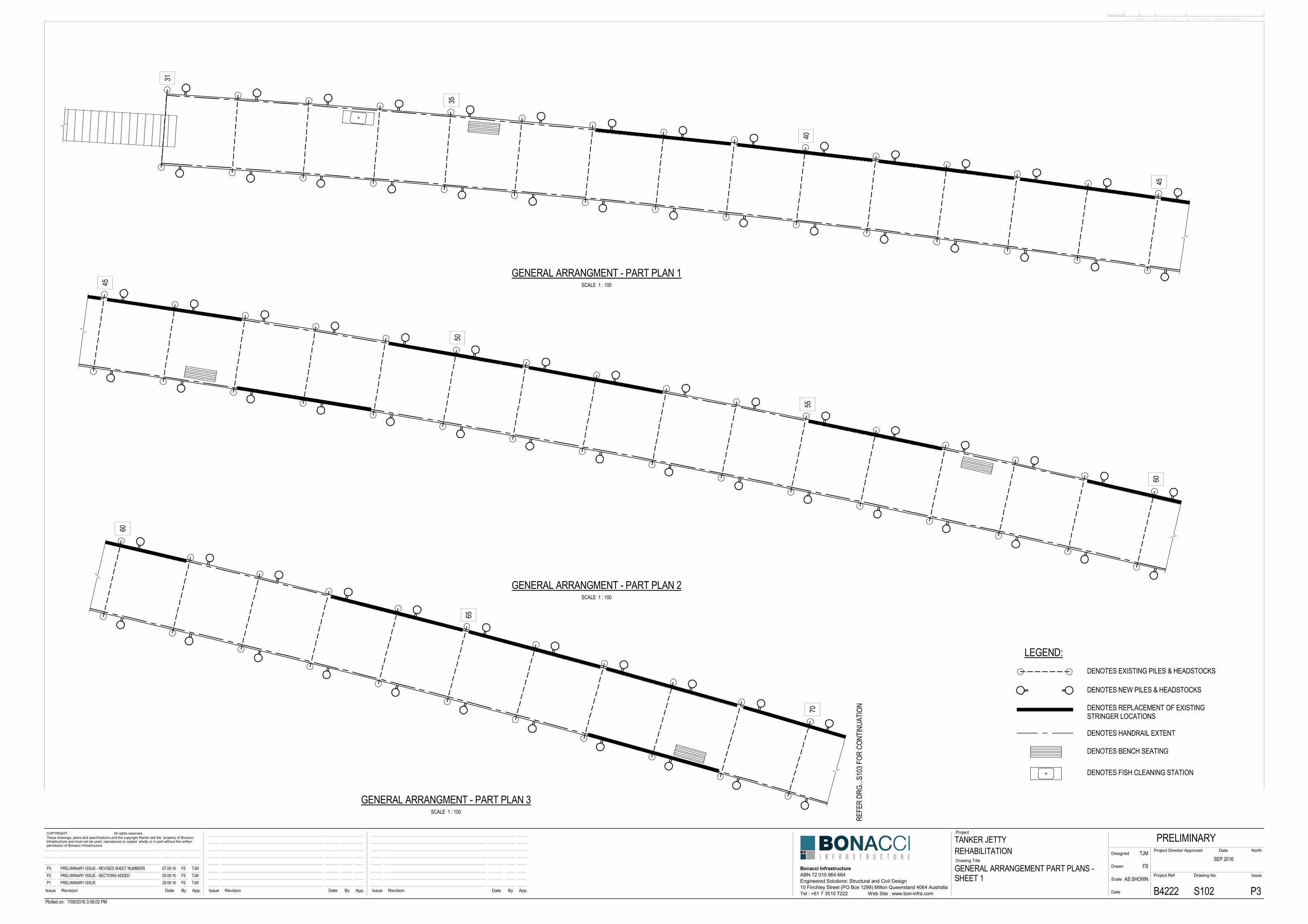
GENERAL ARRANGMENT - EXISTING TANKER JETTY
31
35
40
45
45
50
55
60
60
65
70
R EFE
R DR
G.. .S
103 F
OR C
O NTI
NUAT
ION
LEGEND:
DENOTES HANDRAIL EXTENT
DENOTES NEW PILES & HEADSTOCKS
DENOTES EXISTING PILES & HEADSTOCKS
DENOTES BENCH SEATING
DENOTES FISH CLEANING STATION
DENOTES REPLACEMENT OF EXISTINGSTRINGER LOCATIONS
0 10 30 50 10020
REFERENCE SCALE BAR ONLY - DO NOT SCALE DRAWING CONTENT
App.ByDateRevisionIssue
Project
Drawing Title
Issue Revision Date By App.App.
Project Ref
Date
Scale
Drawn
Designed
IssueDrawing No
Project Director Approved Date
COPYRIGHT All rights reserved.These drawings, plans and specifications and the copyright therein are the property of BonacciInfrastructure and must not be used, reproduced or copied wholly or in part without the writtenpermission of Bonacci Infrastructure.
ByDateRevisionIssue
Bonacci InfrastructureABN 72 010 964 664
Tel : +61 7 3510 7222 Web Site : www.bon-infra.com
North
10 Finchley Street (PO Box 1299) Milton Queensland 4064 AustraliaEngineered Solutions: Structural and Civil Design
Plotted on: 7/09/2016 3:06:02 PM
TANKER JETTY
GENERAL ARRANGEMENT PART PLANS -SHEET 1
REHABILITATIONPRELIMINARY
SEP 2016
B4222 S102 P3
TJM
FS
AS SHOWNP1 PRELIMINARY ISSUE 29.08.16 FS TJMP2 PRELIMINARY ISSUE - SECTIONS ADDED 05.09.16 FS TJMP3 PRELIMINARY ISSUE - REVISED SHEET NUMBERS 07.09.16 FS TJM
SCALE 1 : 100
GENERAL ARRANGMENT - PART PLAN 1
SCALE 1 : 100
GENERAL ARRANGMENT - PART PLAN 2
SCALE 1 : 100
GENERAL ARRANGMENT - PART PLAN 3
70
75
80
85
R EFE
R DR
G.. .S
102 F
OR C
O NTI
NUAT
ION
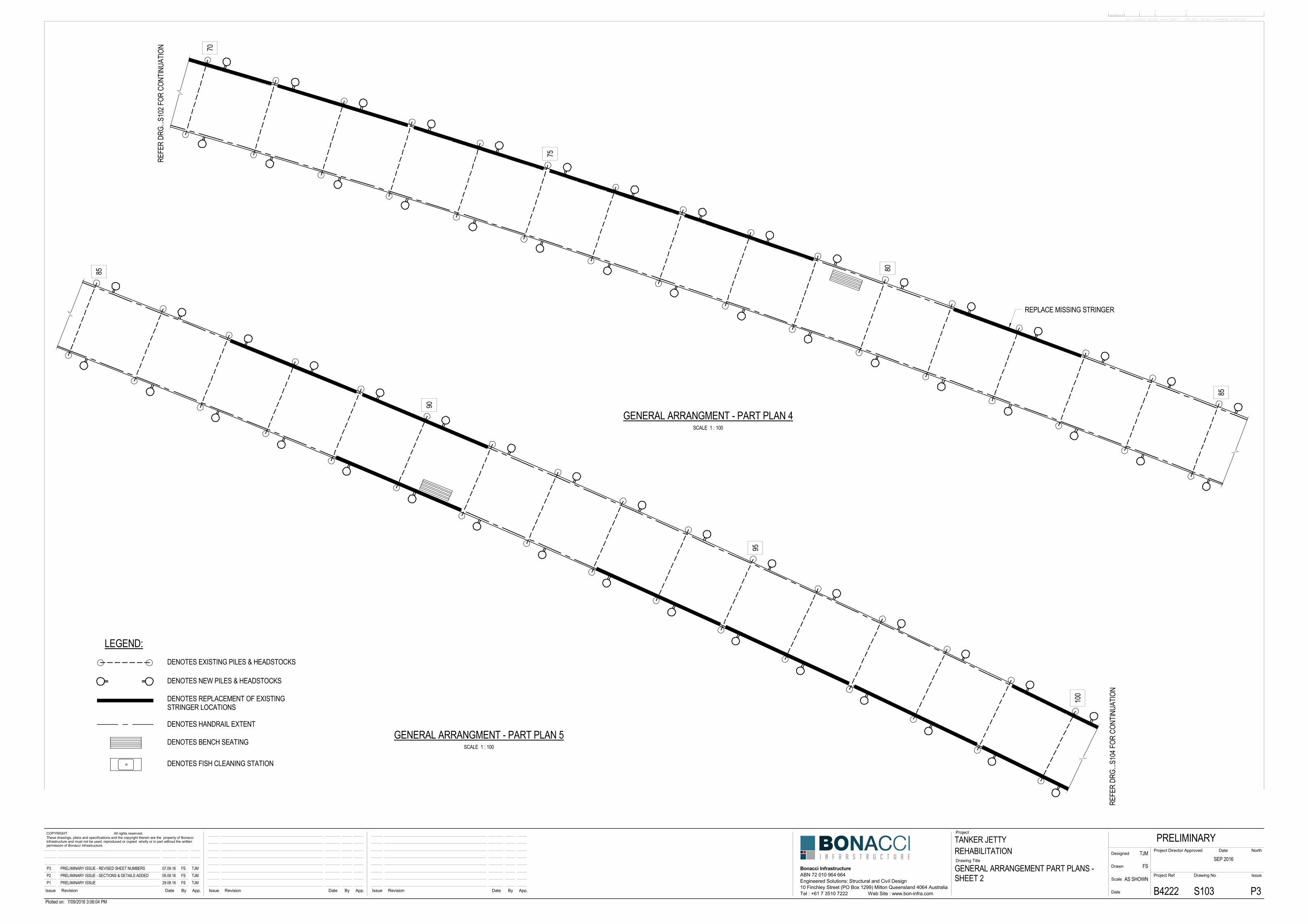
REPLACE MISSING STRINGER
85
90
95
100
R EFE
R DR
G.. .S
104 F
OR C
O NTI
NUAT
ION
LEGEND:
DENOTES HANDRAIL EXTENT
DENOTES NEW PILES & HEADSTOCKS
DENOTES EXISTING PILES & HEADSTOCKS
DENOTES BENCH SEATING
DENOTES FISH CLEANING STATION
DENOTES REPLACEMENT OF EXISTINGSTRINGER LOCATIONS
0 10 30 50 10020
REFERENCE SCALE BAR ONLY - DO NOT SCALE DRAWING CONTENT
App.ByDateRevisionIssue
Project
Drawing Title
Issue Revision Date By App.App.
Project Ref
Date
Scale
Drawn
Designed
IssueDrawing No
Project Director Approved Date
COPYRIGHT All rights reserved.These drawings, plans and specifications and the copyright therein are the property of BonacciInfrastructure and must not be used, reproduced or copied wholly or in part without the writtenpermission of Bonacci Infrastructure.
ByDateRevisionIssue
Bonacci InfrastructureABN 72 010 964 664
Tel : +61 7 3510 7222 Web Site : www.bon-infra.com
North
10 Finchley Street (PO Box 1299) Milton Queensland 4064 AustraliaEngineered Solutions: Structural and Civil Design
Plotted on: 7/09/2016 3:06:04 PM
TANKER JETTY
GENERAL ARRANGEMENT PART PLANS -SHEET 2
REHABILITATIONPRELIMINARY
SEP 2016
B4222 S103 P3
TJM
FS
AS SHOWNP1 PRELIMINARY ISSUE 29.08.16 FS TJMP2 PRELIMINARY ISSUE - SECTIONS & DETAILS ADDED 05.09.16 FS TJMP3 PRELIMINARY ISSUE - REVISED SHEET NUMBERS 07.09.16 FS TJM
SCALE 1 : 100
GENERAL ARRANGMENT - PART PLAN 4
SCALE 1 : 100
GENERAL ARRANGMENT - PART PLAN 5
100
105
110
115
R EFE
R DR
G.. .S
103 F
OR C
O NTI
NUAT
ION
115
120
125
R EFE
R DR
G.. .S
105 F
OR C
O NTI
NUAT
ION
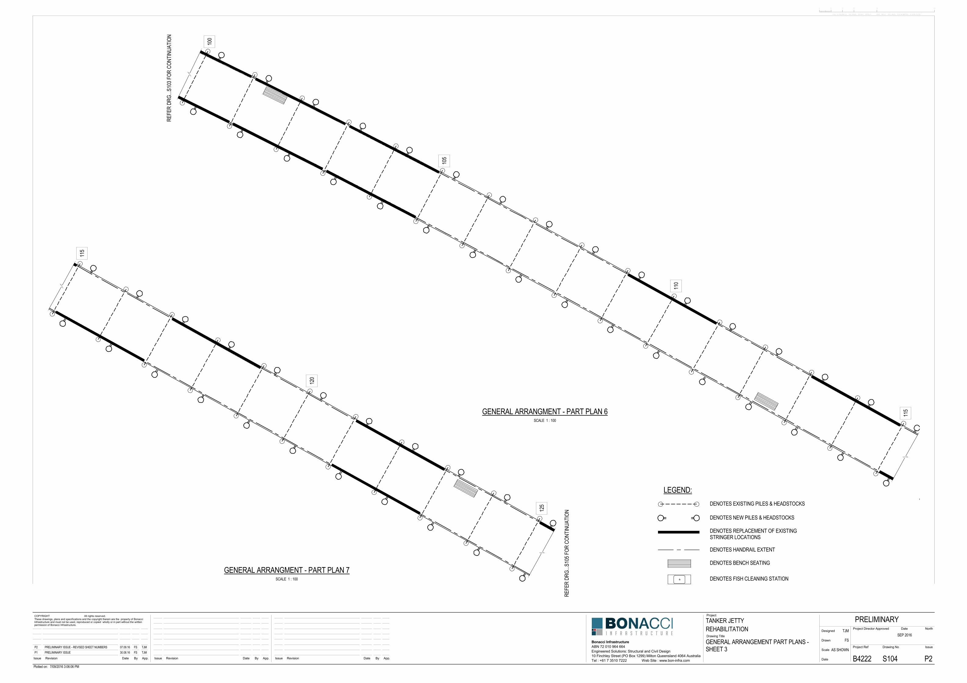
LEGEND:
DENOTES HANDRAIL EXTENT
DENOTES NEW PILES & HEADSTOCKS
DENOTES EXISTING PILES & HEADSTOCKS
DENOTES BENCH SEATING
DENOTES FISH CLEANING STATION
DENOTES REPLACEMENT OF EXISTINGSTRINGER LOCATIONS
0 10 30 50 10020
REFERENCE SCALE BAR ONLY - DO NOT SCALE DRAWING CONTENT
App.ByDateRevisionIssue
Project
Drawing Title
Issue Revision Date By App.App.
Project Ref
Date
Scale
Drawn
Designed
IssueDrawing No
Project Director Approved Date
COPYRIGHT All rights reserved.These drawings, plans and specifications and the copyright therein are the property of BonacciInfrastructure and must not be used, reproduced or copied wholly or in part without the writtenpermission of Bonacci Infrastructure.
ByDateRevisionIssue
Bonacci InfrastructureABN 72 010 964 664
Tel : +61 7 3510 7222 Web Site : www.bon-infra.com
North
10 Finchley Street (PO Box 1299) Milton Queensland 4064 AustraliaEngineered Solutions: Structural and Civil Design
Plotted on: 7/09/2016 3:06:06 PM
TANKER JETTY
GENERAL ARRANGEMENT PART PLANS -SHEET 3
REHABILITATIONPRELIMINARY
SEP 2016
B4222 S104 P2
TJM
FS
AS SHOWNP1 PRELIMINARY ISSUE 30.08.16 FS TJMP2 PRELIMINARY ISSUE - REVISED SHEET NUMBERS 07.09.16 FS TJM
SCALE 1 : 100
GENERAL ARRANGMENT - PART PLAN 6
SCALE 1 : 100
GENERAL ARRANGMENT - PART PLAN 7
125
130
135
140
143
R EFE
R DR
G.. .S
104 F
OR C
O NTI
NUAT
ION
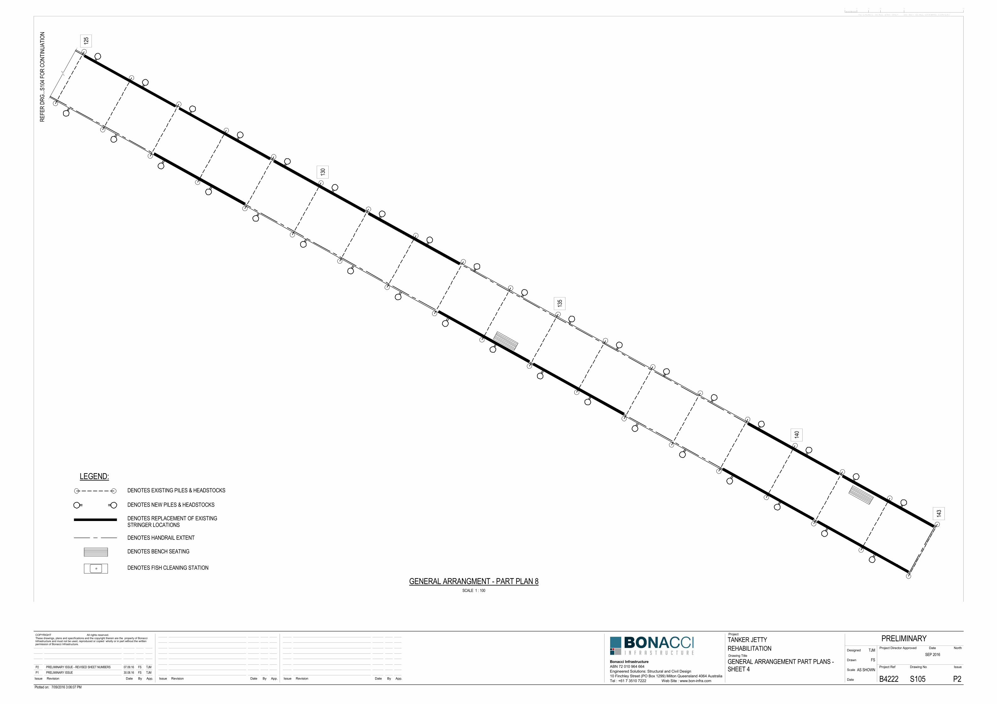
LEGEND:
DENOTES HANDRAIL EXTENT
DENOTES NEW PILES & HEADSTOCKS
DENOTES EXISTING PILES & HEADSTOCKS
DENOTES BENCH SEATING
DENOTES FISH CLEANING STATION
DENOTES REPLACEMENT OF EXISTINGSTRINGER LOCATIONS
0 10 30 50 10020
REFERENCE SCALE BAR ONLY - DO NOT SCALE DRAWING CONTENT
App.ByDateRevisionIssue
Project
Drawing Title
Issue Revision Date By App.App.
Project Ref
Date
Scale
Drawn
Designed
IssueDrawing No
Project Director Approved Date
COPYRIGHT All rights reserved.These drawings, plans and specifications and the copyright therein are the property of BonacciInfrastructure and must not be used, reproduced or copied wholly or in part without the writtenpermission of Bonacci Infrastructure.
ByDateRevisionIssue
Bonacci InfrastructureABN 72 010 964 664
Tel : +61 7 3510 7222 Web Site : www.bon-infra.com
North
10 Finchley Street (PO Box 1299) Milton Queensland 4064 AustraliaEngineered Solutions: Structural and Civil Design
Plotted on: 7/09/2016 3:06:07 PM
TANKER JETTY
GENERAL ARRANGEMENT PART PLANS -SHEET 4
REHABILITATIONPRELIMINARY
SEP 2016
B4222 S105 P2
TJM
FS
AS SHOWNP1 PRELIMINARY ISSUE 30.08.16 FS TJMP2 PRELIMINARY ISSUE - REVISED SHEET NUMBERS 07.09.16 FS TJM
SCALE 1 : 100
GENERAL ARRANGMENT - PART PLAN 8
BS107
AS106
PROPOSED STEEL PILES& WELDED FRAME
EXISTING TIMBER PILES &HEADSTOCKS TO BE DECOMISSIONED& REMOVED ONCE NEW STEEL PILES &WELDED FRAME HAVE BEENINSTALLED
1200 TYP.
3S107
HAL 1.408 m
MSL 0.666 m
LAT 0.056 m
PROPOSEDWELDED FRAME
EXISTINGTIMBER PILES &HEADSTOCKS
APPROX. SEA FLOOR LEVEL
1S107 (NEW)
4570 TYPICAL
(EXISTING)
4570 TYPICAL
+ 0.056m LAT
+ 0.246m MLLW
+ 0.456m MHLW
+ 0.577m AHD
+ 0.666m MSL
+ 0.876m MLHW
+ 1.086m MHHW
+ 1.408m HAT
- 0.521m
- 0.331m
- 0.121m
- 0.0m
+ 0.089m
+ 0.299m
+ 0.509m
+ 0.831m
AHD CD
ALL LEVELS CHART DATUM (CD)
0 10 30 50 10020
REFERENCE SCALE BAR ONLY - DO NOT SCALE DRAWING CONTENT
App.ByDateRevisionIssue
Project
Drawing Title
Issue Revision Date By App.App.
Project Ref
Date
Scale
Drawn
Designed
IssueDrawing No
Project Director Approved Date
COPYRIGHT All rights reserved.These drawings, plans and specifications and the copyright therein are the property of BonacciInfrastructure and must not be used, reproduced or copied wholly or in part without the writtenpermission of Bonacci Infrastructure.
ByDateRevisionIssue
Bonacci InfrastructureABN 72 010 964 664
Tel : +61 7 3510 7222 Web Site : www.bon-infra.com
North
10 Finchley Street (PO Box 1299) Milton Queensland 4064 AustraliaEngineered Solutions: Structural and Civil Design
Plotted on: 7/09/2016 3:06:09 PM
TANKER JETTY
TYPICAL BENT AT 4.57m CRSPART PLAN & ELEVATIONS
REHABILITATIONPRELIMINARY
AUG 2016
B4222 S106 P2
TJM
FS
AS SHOWNP1 PRELIMINARY ISSUE 30.08.16 FS TJMP2 PRELIMINARY ISSUE - REVISED SHEET NUMBERS 07.09.16 FS TJM
SCALE 1 : 50
ESPERANCE TANKER JETTY PART PLAN-4.57m OPTION
SECTIONSCALE 1 : 50 S106
ASCALE 1 : 10
DATUMS & TIDAL DATA
EXISTING 100mmCONCRETE SLAB TO BEREPLACED WITH NEW120mm MIN. THICK SLAB
EXISTING TIMBERSTRINGERS
EXISTING WATER PIPELOCATION TO BE CONFIRMED
MSL 0.666 m
LAT 0.056 m
HAT 1.408 m
8000
TYP
ICAL
89x6.0 SHS89x6.0 SHS
89x6.0 SHS
2S107200x100x9.0 RHS
RL 4.2 (APPROX)
Ø406x9.5 CHS SLEEVE
EXISTING TIMBERDECKING
EXISTING TIMBERKERB TO BE REMOVED& REPLACED
Ø323x9.0 CHS STEEL PILE
APPROX. SEA FLOOR LEVELVARIES RL 2.0 TO RL 6.0
1200
35 400 35400330
4848
EQEQ
250
EXISTING CONCRETE SLAB
EXISTING TIMBER DECKING
EXISTING TIMBER STRINGERS
6-M20 GR316 BOLTS 6 ALUMINIUM PL
TYPICAL STRINGER SPLICE DETAIL - OPTION 1
600
PACKER PLATE TO SUITCFW ALL ROUND TO RHS
2 No. R12 SHEAR RINGSCFW TO SLEEVE
2 No. R12 SHEAR RINGSCFW TO PILE
CEMENTITIOUS GROUT
EXISTING JETTY STRUCTURE
6 SEAL PL
250
250
CEMENTITIOUS GROUT
1045 840 1120 1575
150 LONG ALUMINIUM BRACKET AT 1200 CRS WITH2-M10 COACH SCREWS HOT DIPPED GALVANIZED
M12 GR 316 S/S BOLT
120x35 F27 HARDWOODDURABILITY CLASS 1
TYPICAL SECTION THROUGH NEW DECKING WORKS
120
HARDWOOD KERBTO BE REMOVED
100 FIBRE CONCRETEDECKING TO BE REMOVED& REPLACED ORIGINAL (1934)
230x102 HARDWOODDECKING REMAIN
ORIGINAL (1934) 356x152 OUTERSTRINGERS, SOME TO BE REPLACED
ORIGINAL (1934)CORBELS TO BEREMOVED
ORIGINAL (1934) PILES WHICHHAVE BEEN PREVIOUSLYREMOVED AND REPLACED
CURRENT CCATREATED TIMBERPILES TO BE REMOVED
BED LEVEL
ORIGINAL (1934)HARDWOOD HEADSTOCKTO BE REMOVED
0 10 30 50 10020
REFERENCE SCALE BAR ONLY - DO NOT SCALE DRAWING CONTENT
App.ByDateRevisionIssue
Project
Drawing Title
Issue Revision Date By App.App.
Project Ref
Date
Scale
Drawn
Designed
IssueDrawing No
Project Director Approved Date
COPYRIGHT All rights reserved.These drawings, plans and specifications and the copyright therein are the property of BonacciInfrastructure and must not be used, reproduced or copied wholly or in part without the writtenpermission of Bonacci Infrastructure.
ByDateRevisionIssue
Bonacci InfrastructureABN 72 010 964 664
Tel : +61 7 3510 7222 Web Site : www.bon-infra.com
North
10 Finchley Street (PO Box 1299) Milton Queensland 4064 AustraliaEngineered Solutions: Structural and Civil Design
Plotted on: 7/09/2016 3:06:12 PM
TANKER JETTY
TYPICAL BENT AT 4.57m CRSSECTIONS & DETAILS - SHEET 1
REHABILITATIONPRELIMINARY
AUG 2016
B4222 S107 P1
TJM
FS
AS SHOWNP1 PRELIMINARY ISSUE 07.09.16 FS TJM
SECTIONSCALE 1 : 50 S106
B
DETAILSCALE 1 : 10 S106
1
DETAILSCALE 1 : 10 S107
2
SECTIONSCALE 1 : 20 S106
3
SCALE 1 : 50
TYPICAL SECTION THROUGH EXISTING JETTY
EXISTING CORBEL
EXISTING HEADSTOCK
EXISTING TIMBER PILES
NEW STEEL HEADSTOCK
EXISTING OR REPLACEMENTTIMBER STRINGER
8 STIFFENER PLATES 6 -M20 GR316 BOLTS 6 -M20 GR316 BOLTS8 -M12 GR316 BOLTSSTAGGERED
PACKER
1S108
11000 - 2 No. 152x64 6/8 ALUMINIUM CHANNELS (GRADE 6061-T6)
EXISTING OR REPLACEMENTSTRINGER, NON-STRUCTURAL,USED ONLY FOR AESTHETIC VALUE
ALUMINIUM CHANNELS6 CFW FULL LENGTHTOP/BOTTOM FLANGES
EXISTING TIMBERDECKING
NEW HARDWOOD KERBNEW CONCRETE SLAB
EXISTING TIMBER DECKING
EXISTING TIMBERSTRINGER
NEW STEEL HEADSTOCKSPLICE PLATE -OPTION 2
NEW TIMBER STRINGERS
PFC CLEATEXISTING TIMBER STRINGER
SPLICE PLATE - OPTION 2EXISTING CORBEL
EXISTING HEADSTOCK
EXISTING TIMBER PILES
PACKER
2S108
3S108
NEW 100 PFC CLEAT2-M16 GR316 BOLTS
SPLICE PLATE -OPTION 2
EXISTING TIMBER STRINGERNEW TIMBER STRINGERS
45
INSIDE FACE
LINE UP OUTSIDETIMBER FACES
EXISTING TIMBERDECKING
NEW STEELHEADSTOCK
NEW PFC CLEAT
F27 SEASONED HARDWOODDURABILITY CLASS 1(COMPOSITE) STRINGERS
170
190
360
45
NEW CONCRETESLAB
NEW HARDWOOD KERB
EXISTING CONCRETE SLAB
EXISTING TIMBER DECKING
NEW HARDWOOD STRINGERS
6-M20 GR316 BOLTS6 ALUMINIUM CAP PLTOP & BTM6 CFW ALL ROUND
TYPICAL STRINGER SPLICE DETAIL - OPTION 2ELEVATION
PLAN
250
35 400
600
165 400 35
48EQ
EQ48
6 ALUMINIUM PL
165
6 ALUMINIUM PL6 CFW ALL ROUND
EXISTING TIMBERSTRINGER
NEW HARDWOOD STRINGERS EXISTING TIMBERSTRINGER
600
100
0 10 30 50 10020
REFERENCE SCALE BAR ONLY - DO NOT SCALE DRAWING CONTENT
App.ByDateRevisionIssue
Project
Drawing Title
Issue Revision Date By App.App.
Project Ref
Date
Scale
Drawn
Designed
IssueDrawing No
Project Director Approved Date
COPYRIGHT All rights reserved.These drawings, plans and specifications and the copyright therein are the property of BonacciInfrastructure and must not be used, reproduced or copied wholly or in part without the writtenpermission of Bonacci Infrastructure.
ByDateRevisionIssue
Bonacci InfrastructureABN 72 010 964 664
Tel : +61 7 3510 7222 Web Site : www.bon-infra.com
North
10 Finchley Street (PO Box 1299) Milton Queensland 4064 AustraliaEngineered Solutions: Structural and Civil Design
Plotted on: 7/09/2016 3:10:19 PM
TANKER JETTY
TYPICAL BENT AT 4.57m CRSSECTIONS & DETAILS - SHEET 2
REHABILITATIONPRELIMINARY
SEP 2016
B4222 S108 P1
TJM
FS
AS SHOWNP1 PRELIMINARY ISSUE 07.09.16 FS TJM
SCALE 1 : 20
TYPICAL STRINGER REPAIR - OPTION 1
SECTIONSCALE 1 : 10 S108
1
SCALE 1 : 20
TYPICAL STRINGER REPAIR - OPTION 2
SECTIONSCALE 1 : 10 S108
2
SECTIONSCALE 1 : 10 S108
3
0 10 30 50 10020
REFERENCE SCALE BAR ONLY - DO NOT SCALE DRAWING CONTENT
App.ByDateRevisionIssue
Project
Drawing Title
Issue Revision Date By App.App.
Project Ref
Date
Scale
Drawn
Designed
IssueDrawing No
Project Director Approved Date
COPYRIGHT All rights reserved.These drawings, plans and specifications and the copyright therein are the property of BonacciInfrastructure and must not be used, reproduced or copied wholly or in part without the writtenpermission of Bonacci Infrastructure.
ByDateRevisionIssue
Bonacci InfrastructureABN 72 010 964 664
Tel : +61 7 3510 7222 Web Site : www.bon-infra.com
North
10 Finchley Street (PO Box 1299) Milton Queensland 4064 AustraliaEngineered Solutions: Structural and Civil Design
Plotted on: 7/09/2016 5:37:29 PM
TANKER JETTY
TYPICAL BENT AT 4.57m CRS3D VIEWS
REHABILITATIONPRELIMINARY
AUG 2016
B4222 S109 P1
TJM
FS
AS SHOWNP1 PRELIMINARY ISSUE 07.09.16 FS TJM
3D - NEW & EXISTING STRUCTURES - 4.57m OPTION
3D - NEW SUPPORT STRUCTURE - 4.57m OPTION
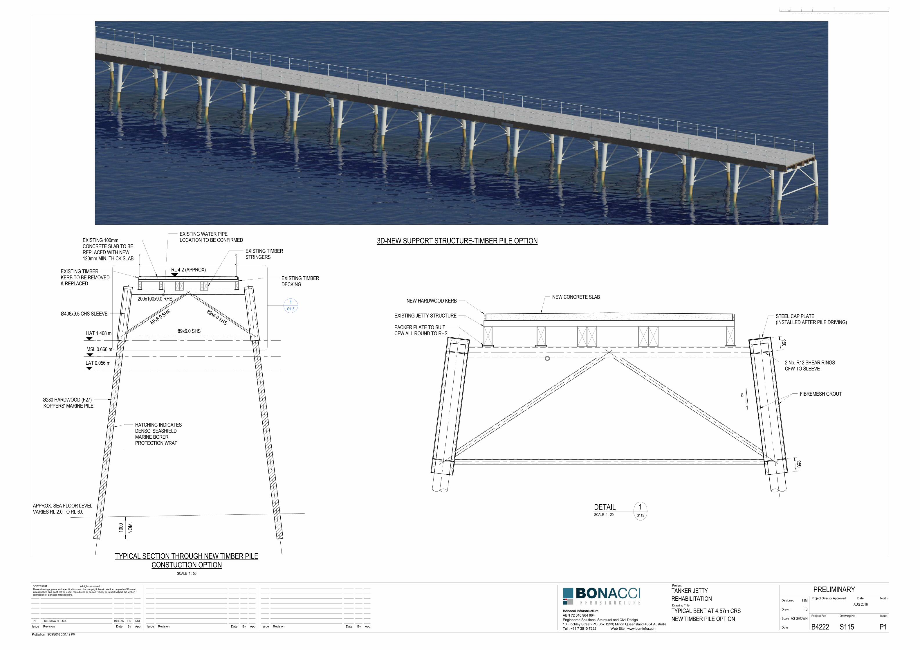
EXISTING 100mmCONCRETE SLAB TO BEREPLACED WITH NEW120mm MIN. THICK SLAB
EXISTING TIMBERSTRINGERS
EXISTING WATER PIPELOCATION TO BE CONFIRMED
MSL 0.666 m
LAT 0.056 m
HAT 1.408 m
1S115
RL 4.2 (APPROX)
Ø406x9.5 CHS SLEEVE
EXISTING TIMBERDECKING
EXISTING TIMBERKERB TO BE REMOVED& REPLACED
Ø280 HARDWOOD (F27)'KOPPERS' MARINE PILE
APPROX. SEA FLOOR LEVELVARIES RL 2.0 TO RL 6.0
200x100x9.0 RHS
89x6.0 SHS89x6.0 SHS
NOM.
1000
HATCHING INDICATESDENSO 'SEASHIELD'MARINE BORERPROTECTION WRAP
89x6.0 SHSPACKER PLATE TO SUITCFW ALL ROUND TO RHS
2 No. R12 SHEAR RINGSCFW TO SLEEVE
EXISTING JETTY STRUCTURE STEEL CAP PLATE(INSTALLED AFTER PILE DRIVING)
FIBREMESH GROUT
NEW HARDWOOD KERBNEW CONCRETE SLAB
250
8
1
250
0 10 30 50 10020
REFERENCE SCALE BAR ONLY - DO NOT SCALE DRAWING CONTENT
App.ByDateRevisionIssue
Project
Drawing Title
Issue Revision Date By App.App.
Project Ref
Date
Scale
Drawn
Designed
IssueDrawing No
Project Director Approved Date
COPYRIGHT All rights reserved.These drawings, plans and specifications and the copyright therein are the property of BonacciInfrastructure and must not be used, reproduced or copied wholly or in part without the writtenpermission of Bonacci Infrastructure.
ByDateRevisionIssue
Bonacci InfrastructureABN 72 010 964 664
Tel : +61 7 3510 7222 Web Site : www.bon-infra.com
North
10 Finchley Street (PO Box 1299) Milton Queensland 4064 AustraliaEngineered Solutions: Structural and Civil Design
Plotted on: 9/09/2016 5:31:12 PM
TANKER JETTY
TYPICAL BENT AT 4.57m CRSNEW TIMBER PILE OPTION
REHABILITATIONPRELIMINARY
AUG 2016
B4222 S115 P1
TJM
FS
AS SHOWNP1 PRELIMINARY ISSUE 09.09.16 FS TJM
SCALE 1 : 50
TYPICAL SECTION THROUGH NEW TIMBER PILECONSTUCTION OPTION
DETAILSCALE 1 : 20 S115
1
3D-NEW SUPPORT STRUCTURE-TIMBER PILE OPTION
NEW WELDEDFRAME
'C' LIFTING HOOK
NEW WELDEDFRAME
'C' LIFTING HOOK
BOLT FRAME TO DECKWHILE PILES ARE DRIVEN
NEW WELDED FRAME
PILES DRIVEN THROUGHWELDED FRAME SLEEVES
MSL 0.666 m
HAT 1.408 m
LAT -0.056 m
APPROX. SEA FLOOR LEVEL
GROUT SLEEVES ONCE PILEFOUNDING DEPTHS HAVEBEEN ACHIEVED & PRIOR TOREMOVING BOLTS
REMOVE BOLTS ONCESLEEVES HAVE BEENGROUT FILLED
MSL 0.666 m
HAT 1.408 m
LAT -0.056 m
APPROX. SEA FLOOR LEVEL
NEW PILES ATFOUNDING DEPTH
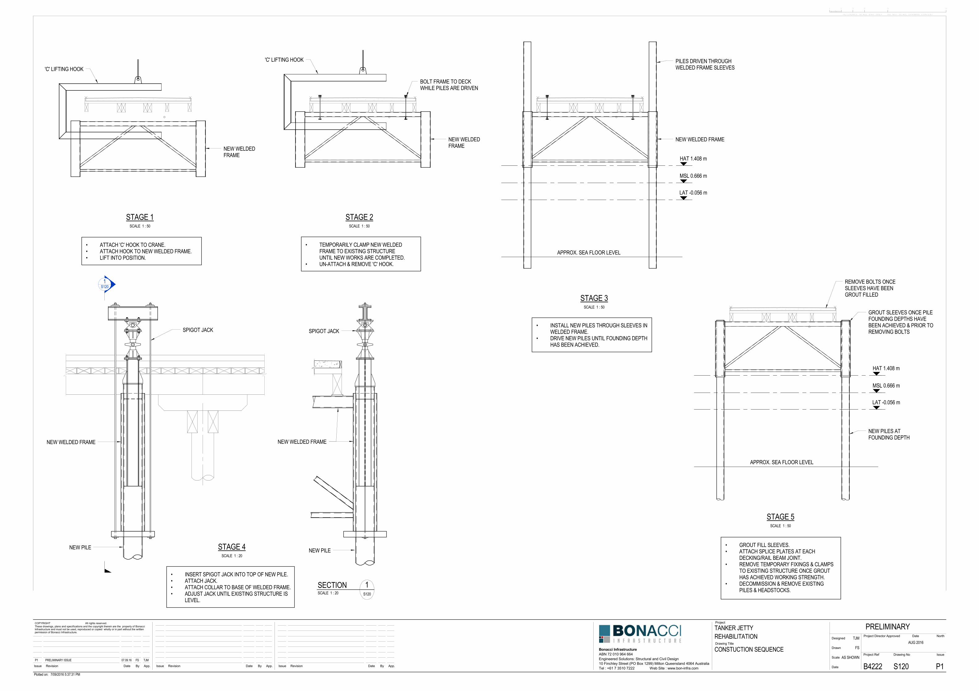
• ATTACH 'C' HOOK TO CRANE.• ATTACH HOOK TO NEW WELDED FRAME.• LIFT INTO POSITION.
• TEMPORARILY CLAMP NEW WELDEDFRAME TO EXISTING STRUCTUREUNTIL NEW WORKS ARE COMPLETED.
• UN-ATTACH & REMOVE 'C' HOOK.
• INSTALL NEW PILES THROUGH SLEEVES INWELDED FRAME.
• DRIVE NEW PILES UNTIL FOUNDING DEPTHHAS BEEN ACHIEVED.
• INSERT SPIGOT JACK INTO TOP OF NEW PILE.• ATTACH JACK.• ATTACH COLLAR TO BASE OF WELDED FRAME.• ADJUST JACK UNTIL EXISTING STRUCTURE IS
LEVEL.
SPIGOT JACK
NEW PILE
NEW WELDED FRAME
1S120
NEW WELDED FRAME
NEW PILE
SPIGOT JACK
• GROUT FILL SLEEVES.• ATTACH SPLICE PLATES AT EACH
DECKING/RAIL BEAM JOINT.• REMOVE TEMPORARY FIXINGS & CLAMPS
TO EXISTING STRUCTURE ONCE GROUTHAS ACHIEVED WORKING STRENGTH.
• DECOMMISSION & REMOVE EXISTINGPILES & HEADSTOCKS.
0 10 30 50 10020
REFERENCE SCALE BAR ONLY - DO NOT SCALE DRAWING CONTENT
App.ByDateRevisionIssue
Project
Drawing Title
Issue Revision Date By App.App.
Project Ref
Date
Scale
Drawn
Designed
IssueDrawing No
Project Director Approved Date
COPYRIGHT All rights reserved.These drawings, plans and specifications and the copyright therein are the property of BonacciInfrastructure and must not be used, reproduced or copied wholly or in part without the writtenpermission of Bonacci Infrastructure.
ByDateRevisionIssue
Bonacci InfrastructureABN 72 010 964 664
Tel : +61 7 3510 7222 Web Site : www.bon-infra.com
North
10 Finchley Street (PO Box 1299) Milton Queensland 4064 AustraliaEngineered Solutions: Structural and Civil Design
Plotted on: 7/09/2016 5:37:31 PM
TANKER JETTY
CONSTUCTION SEQUENCE
REHABILITATIONPRELIMINARY
AUG 2016
B4222 S120 P1
TJM
FS
AS SHOWNP1 PRELIMINARY ISSUE 07.09.16 FS TJM
SCALE 1 : 50
STAGE 1SCALE 1 : 50
STAGE 2
SCALE 1 : 50
STAGE 3
SCALE 1 : 50
STAGE 5
SCALE 1 : 20
STAGE 4
SECTIONSCALE 1 : 20 S120
1

Tanker Jetty Remediation Report Appendices Esperance, Western Australia
Appendix B: Denso Seashield series 60 system
Issue Date: 11/02/11 Page 1 of 4
40 YEARS OF MARINE PROTECTION
• Wire brush, powered wire brush, scraper, water blasting equipment (optional). • Brush cleaning solvent, utility knife, cleaning cloth, hand cleaner, barrier cream. • Diving gear and equipment or overalls, gloves and any other personal protection
equipment deemed necessary by the Safety Data Sheets and Job Safety Analysis conducted prior to the commencement of any work undertaken.
• Denso Seashield Primer. • Denso Seashield Mastic for filling and profiling irregular surfaces. • Denso Seal T or Marine Piling Tape corrosion protection layer. • Denso Ultraflex 1500 or Densopol 80 Tape and Pilemesh for mechanical
protection of the system. • Smartband strapping, buckles and fitting tool supplied by Denso to secure and
hold Pilemesh in place.
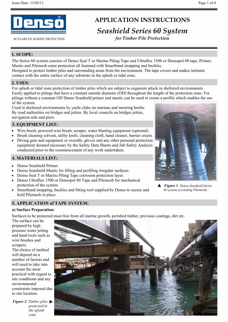
a) Surface Preparation: Surfaces to be protected must free from all marine growth, perished timber, previous coatings, dirt etc. The surface can be prepared by high pressure water jetting and hand tools such as wire brushes and scrapers. The choice of method will depend on a number of factors and will need to take into account the most practical with regard to site conditions and any environmental constraints imposed due to site location.
▲ Figure 1. Denso Seashield Series 60 system (excluding Pilemesh) .
APPLICATION INSTRUCTIONS
Seashield Series 60 System for Timber Pile Protection
1. SCOPE:
2. USES:
3. EQUIPMENT LIST:
5. APPLICATION of TAPE SYSTEM:
4. MATERIALS LIST:
The Series 60 system consists of Denso Seal T or Marine Piling Tape and Ultraflex 1500 or Densopol 80 tape, Primer, Mastic and Pilemesh outer protection all fastened with Smartband strapping and buckles. Designed to protect timber piles and surrounding areas from the environment. The tape covers and makes intimate contact with the entire surface of any substrate in the splash or tidal zone.
For splash or tidal zone protection of timber piles which are subject to organism attack in sheltered environments. Easily applied to pilings that have a constant outside diameter (OD) throughout the length of the protection zone. For pilings without a constant OD Denso Seashield primer and mastic can be used to create a profile which enables the use of the system. Used in sheltered environments by yacht clubs on marinas and mooring berths. By road authorities on bridges and jetties. By local councils on bridges jetties, navigation aids and piers.
Figure 2. Timber piles protected in the splash zone.
►
Issue Date: 11/02/11 Page 2 of 4
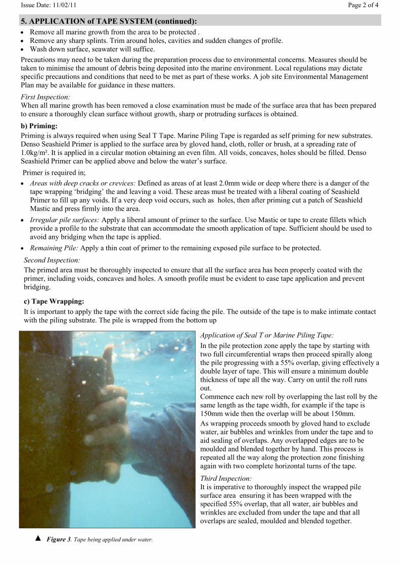
c) Tape Wrapping: It is important to apply the tape with the correct side facing the pile. The outside of the tape is to make intimate contact with the piling substrate. The pile is wrapped from the bottom up
• Remove all marine growth from the area to be protected . • Remove any sharp splints. Trim around holes, cavities and sudden changes of profile. • Wash down surface, seawater will suffice. Precautions may need to be taken during the preparation process due to environmental concerns. Measures should be taken to minimise the amount of debris being deposited into the marine environment. Local regulations may dictate specific precautions and conditions that need to be met as part of these works. A job site Environmental Management Plan may be available for guidance in these matters. First Inspection: When all marine growth has been removed a close examination must be made of the surface area that has been prepared to ensure a thoroughly clean surface without growth, sharp or protruding surfaces is obtained. b) Priming: Priming is always required when using Seal T Tape. Marine Piling Tape is regarded as self priming for new substrates. Denso Seashield Primer is applied to the surface area by gloved hand, cloth, roller or brush, at a spreading rate of 1.0kg/m². It is applied in a circular motion obtaining an even film. All voids, concaves, holes should be filled. Denso Seashield Primer can be applied above and below the water’s surface.
5. APPLICATION of TAPE SYSTEM (continued):
Primer is required in; • Areas with deep cracks or crevices: Defined as areas of at least 2.0mm wide or deep where there is a danger of the
tape wrapping ‘bridging’ the and leaving a void. These areas must be treated with a liberal coating of Seashield Primer to fill up any voids. If a very deep void occurs, such as holes, then after priming cut a patch of Seashield Mastic and press firmly into the area.
• Irregular pile surfaces: Apply a liberal amount of primer to the surface. Use Mastic or tape to create fillets which provide a profile to the substrate that can accommodate the smooth application of tape. Sufficient should be used to avoid any bridging when the tape is applied.
• Remaining Pile: Apply a thin coat of primer to the remaining exposed pile surface to be protected.
Application of Seal T or Marine Piling Tape: In the pile protection zone apply the tape by starting with two full circumferential wraps then proceed spirally along the pile progressing with a 55% overlap, giving effectively a double layer of tape. This will ensure a minimum double thickness of tape all the way. Carry on until the roll runs out. Commence each new roll by overlapping the last roll by the same length as the tape width, for example if the tape is 150mm wide then the overlap will be about 150mm. As wrapping proceeds smooth by gloved hand to exclude water, air bubbles and wrinkles from under the tape and to aid sealing of overlaps. Any overlapped edges are to be moulded and blended together by hand. This process is repeated all the way along the protection zone finishing again with two complete horizontal turns of the tape.
Third Inspection: It is imperative to thoroughly inspect the wrapped pile surface area ensuring it has been wrapped with the specified 55% overlap, that all water, air bubbles and wrinkles are excluded from under the tape and that all overlaps are sealed, moulded and blended together.
Second Inspection: The primed area must be thoroughly inspected to ensure that all the surface area has been properly coated with the primer, including voids, concaves and holes. A smooth profile must be evident to ease tape application and prevent bridging.
Figure 3. Tape being applied under water. ▲
Issue Date: 11/02/11 Page 3 of 4
c) Tape Wrapping (cont): 5. APPLICATION of TAPE SYSTEM (continued):
6. APPLICATION of PILEMESH: A sheet of Denso Pilemesh is cut to suit the circumference of the pile and tape with allowance for a 100 to 150mm overlap. Denso Smartband strapping is then used to secure the Pilemesh at the top and bottom 50mm from its edge and in between at gaps of no more than 500mm apart. Insert the Smartband strap teeth uppermost into one end of the buckle. Wrap the strap around the outside of the Pilemesh and insert into the opposite end of the buckle. Pull the buckle through hand tight before reverting to the Smartband fitting tool to complete tightening. Use the cutter blade on the fitting tool to remove excess strapping. Ensure that all buckles are in the same vertical position on the pile near or on the overlap. If possible the position of the overlap and buckles should be located on any sheltered side of the piles.. Final Inspection: Check that all Pilemesh surfaces are smooth and flat around the pile, all strapping is not loose, that the Pilemesh is securely fixed to the pile and is not able to be moved in any direction.
▲ Timber Pile
Diagram 1. Illustrated example of the Series 60 System
1. Seashield Primer and Mastic
2.Seal T Tape or Marine Piling Tape
Smartband 10 or 19mm Strapping and Buckle
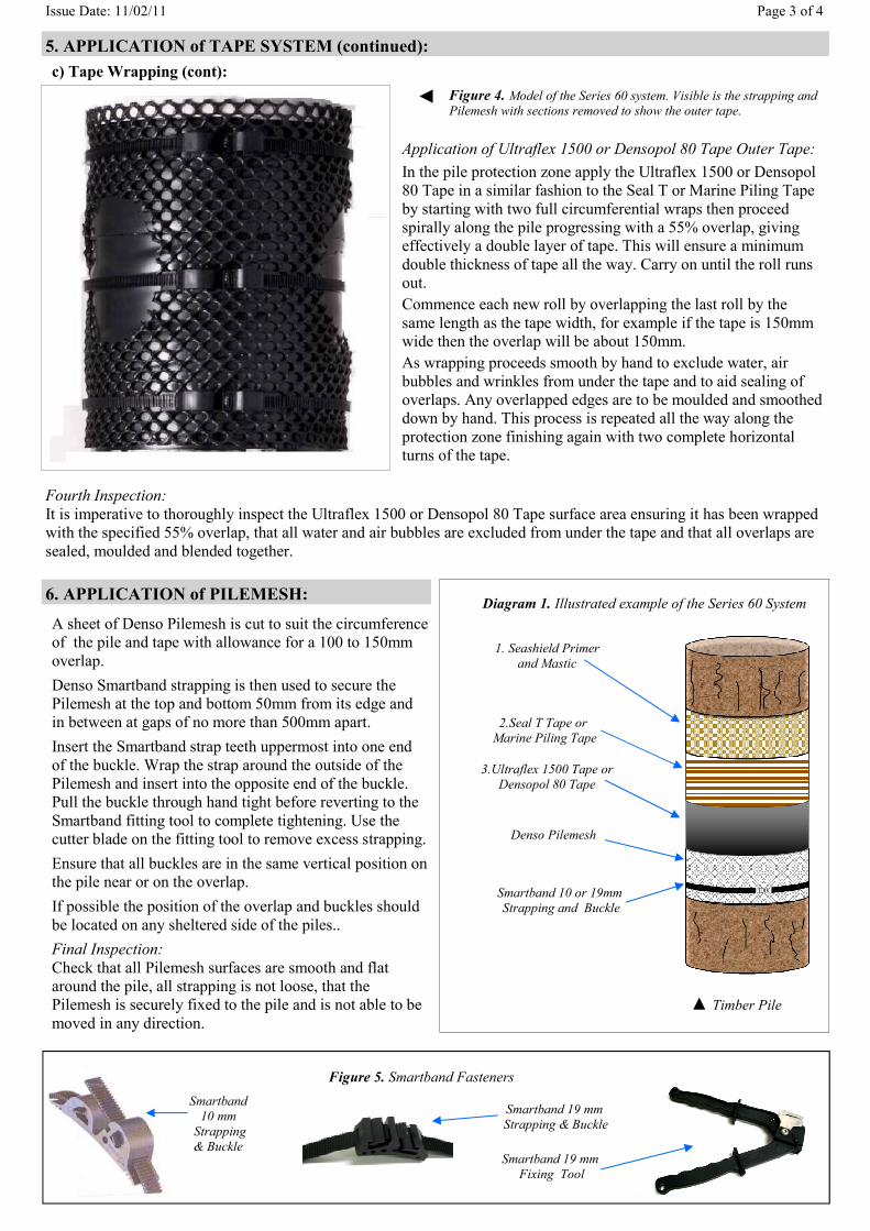
Application of Ultraflex 1500 or Densopol 80 Tape Outer Tape: In the pile protection zone apply the Ultraflex 1500 or Densopol 80 Tape in a similar fashion to the Seal T or Marine Piling Tape by starting with two full circumferential wraps then proceed spirally along the pile progressing with a 55% overlap, giving effectively a double layer of tape. This will ensure a minimum double thickness of tape all the way. Carry on until the roll runs out. Commence each new roll by overlapping the last roll by the same length as the tape width, for example if the tape is 150mm wide then the overlap will be about 150mm. As wrapping proceeds smooth by hand to exclude water, air bubbles and wrinkles from under the tape and to aid sealing of overlaps. Any overlapped edges are to be moulded and smoothed down by hand. This process is repeated all the way along the protection zone finishing again with two complete horizontal turns of the tape.
◄
3.Ultraflex 1500 Tape or Densopol 80 Tape
Denso Pilemesh
Figure 4. Model of the Series 60 system. Visible is the strapping and Pilemesh with sections removed to show the outer tape.
Fourth Inspection: It is imperative to thoroughly inspect the Ultraflex 1500 or Densopol 80 Tape surface area ensuring it has been wrapped with the specified 55% overlap, that all water and air bubbles are excluded from under the tape and that all overlaps are sealed, moulded and blended together.
Smartband 10 mm
Strapping & Buckle
Figure 5. Smartband Fasteners
Smartband 19 mm Strapping & Buckle
Smartband 19 mm Fixing Tool
Issue Date: 11/02/11 Page 4 of 4
Storage: Denso Primer, Mastic and tapes shall be stored in a cool dry place out of direct sunlight between 5° and 25°C. Denso Pilemesh shall be stored the way they arrive and kept out of direct sunlight until they are required.
Transport: Avoid prolonged exposure to high temperatures during transit, preferably in an enclosed vehicle.
Handling: Denso Pilemesh shall be kept rolled and taped to prevent damage ready for transportation to the installation site. Care shall be taken to avoid sudden impact that may tear or damage the material.
Action in case of fire: Extinguish with water fog, dry powder, carbon dioxide or chemical foam. Self-contained breathing apparatus may be required.
Skin Contact: Wash with warm water and mild soap. Use pumiced heavy duty hand cleaner for stubborn stains.
Swallowing: If feeling unwell, seek medical advice. Inhalation: In a fire situation avoid inhaling fumes.
Spillage: No materials classified as hazardous. Pick up and collect material by hand or with absorbent rags or pads.
Disposal: Incineration or landfill in accordance with local regulations.
Other: For more information please refer to Denso safety data and technical data sheets. Available for all system components.
Approved Quality Management System
AS/NZS ISO 9001:2008 Lloyds Register – Certificate No Mel 0927759
Denso (Australia) Pty Ltd
411 - 413 Victoria Street, Brunswick, Vic 3056
Australia MELBOURNE ♦ SYDNEY ♦ ADELAIDE ♦ BRISBANE ♦ PERTH
Tel: + 61 3 93567600 or 1300 658 590 (toll free) ♦ Email: [email protected] ♦ Web: www.densoaustralia.com.au
Denso (New Zealand) Limited Tel: + 64 21 304 660 ♦ Email: [email protected]
A MEMBER OF WINN & COALES INTERNATIONAL
7. SAFETY DATA:

Tanker Jetty Remediation Report Appendices Esperance, Western Australia
Appendix C: Company capability brochures
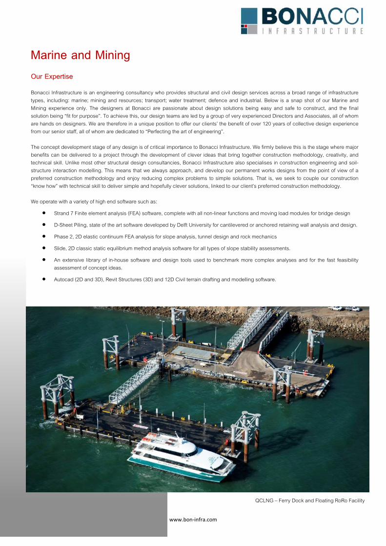
www.bon‐infra.com
Marine and Mining
Our Expertise Bonacci Infrastructure is an engineering consultancy who provides structural and civil design services across a broad range of infrastructure types, including: marine; mining and resources; transport; water treatment; defence and industrial. Below is a snap shot of our Marine and Mining experience only. The designers at Bonacci are passionate about design solutions being easy and safe to construct, and the final solution being “fit for purpose”. To achieve this, our design teams are led by a group of very experienced Directors and Associates, all of whom are hands on designers. We are therefore in a unique position to offer our clients’ the benefit of over 120 years of collective design experience from our senior staff, all of whom are dedicated to “Perfecting the art of engineering”. The concept development stage of any design is of critical importance to Bonacci Infrastructure. We firmly believe this is the stage where major benefits can be delivered to a project through the development of clever ideas that bring together construction methodology, creativity, and technical skill. Unlike most other structural design consultancies, Bonacci Infrastructure also specialises in construction engineering and soil-structure interaction modelling. This means that we always approach, and develop our permanent works designs from the point of view of a preferred construction methodology and enjoy reducing complex problems to simple solutions. That is, we seek to couple our construction “know how” with technical skill to deliver simple and hopefully clever solutions, linked to our client’s preferred construction methodology. We operate with a variety of high end software such as:
x Strand 7 Finite element analysis (FEA) software, complete with all non-linear functions and moving load modules for bridge design
x D-Sheet Piling, state of the art software developed by Delft University for cantilevered or anchored retaining wall analysis and design.
x Phase 2, 2D elastic continuum FEA analysis for slope analysis, tunnel design and rock mechanics
x Slide, 2D classic static equilibrium method analysis software for all types of slope stability assessments.
x An extensive library of in-house software and design tools used to benchmark more complex analyses and for the fast feasibility assessment of concept ideas.
x Autocad (2D and 3D), Revit Structures (3D) and 12D Civil terrain drafting and modelling software.
QCLNG – Ferry Dock and Floating RoRo Facility
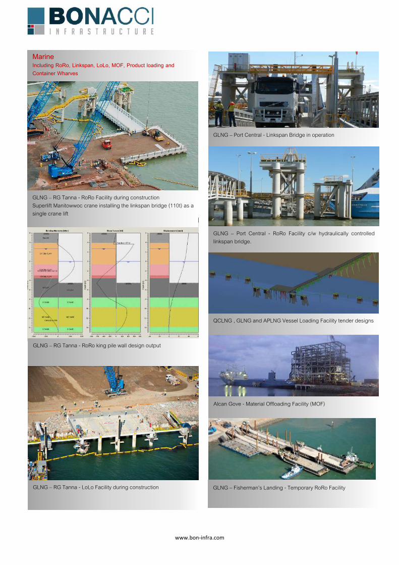
www.bon‐infra.com
GLNG – RG Tanna - RoRo king pile wall design output
GLNG – RG Tanna - LoLo Facility during construction
GLNG – Port Central - Linkspan Bridge in operation
GLNG – Port Central - RoRo Facility c/w hydraulically controlled linkspan bridge.
QCLNG , GLNG and APLNG Vessel Loading Facility tender designs
Alcan Gove - Material Offloading Facility (MOF)
GLNG – RG Tanna - RoRo Facility during construction Superlift Manitowwoc crane installing the linkspan bridge (110t) as a single crane lift
Marine Including RoRo, Linkspan, LoLo, MOF, Product loading and Container Wharves
GLNG – Fisherman’s Landing - Temporary RoRo Facility
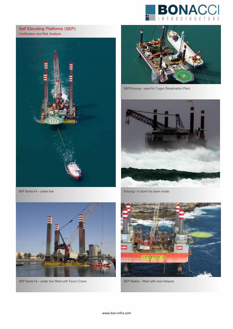
www.bon‐infra.com
Self Elevating Platforms (SEP) Certification and Risk Analysis
SEP Santa Fe - under tow
SEP Ensung - used for Tugun Desalination Plant
Ensung - in storm tie down mode
SEP Santa Fe - under tow fitted with Favco Crane
SEP Seafox - fitted with new Helipad
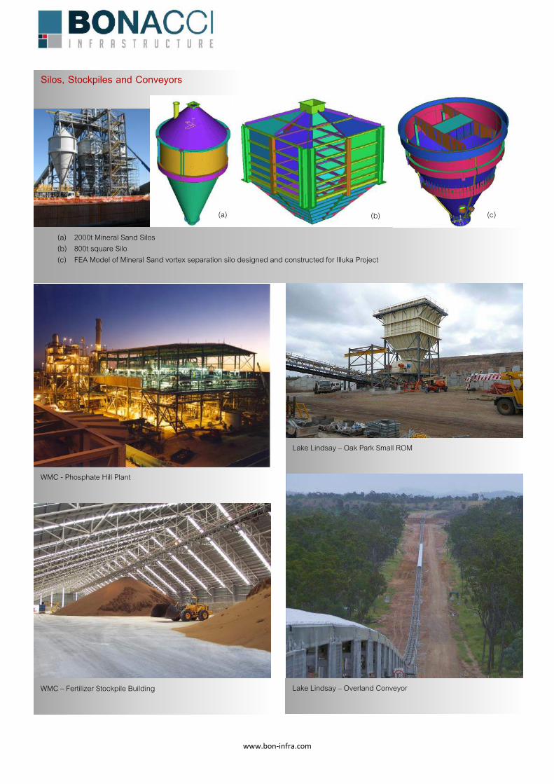
www.bon‐infra.com
Silos, Stockpiles and Conveyors
(a) 2000t Mineral Sand Silos (b) 800t square Silo (c) FEA Model of Mineral Sand vortex separation silo designed and constructed for Illuka Project
(a) (b) (c)
WMC - Phosphate Hill Plant
Lake Lindsay – Overland Conveyor
WMC – Fertilizer Stockpile Building
Lake Lindsay – Oak Park Small ROM

www.bon‐infra.com
Newpac – Coal Stockpile Basin
Ban Houayxai - Gold and Silver Plant
WICET – Coal Reclaim Tunnel
Burnett Dam – RCC Delivery Conveyor
WICET – Reclaim Tunnel - FEA Model of tunnel
www.bon‐infra.com
Our People As with all consultants, it is neither the name nor reputation of the company that defines the quality of the design, but rather the talents and experience of the individual staff involved.
Awards
BRW – Most Innovative Firm 2006
BRW – Best Small Engineering Firm 2006
Institution of Engineers Australia – Engineering Excellence Award – Phosphate Hill Project
Australian Steel Institute – High Commendation Award – Queensland Fertiliser Project
Queensland Steel Detailers Association – Award for Excellence in Design Documentation - Oaky Air Base
CCF Earth Awards – Excellence in Civil Construction – Category 5 – Houghton Highway Bridge Duplication
Contact Information
Bonacci Infrastructure
51 Alfred Street
FORTITUDE VALLEY QLD 4006
Phone +61 7 3510 7222
Email [email protected]
Terry Memory BEng, MEng, RPEQ, NPER
Director
With over 20 years of experience across the maritime sector, the water industry structures and construction engineering, Terry draws upon his strong technical background and breadth of experience to develop simple and effective design solutions for large and small engineering problems alike.
John Velosa BEng, MSc, RPEQ, NPER
Director
John has over 30 years of experience in all design aspects of major civil engineering projects including bridges, tunnels, resources, water and marine infrastructure. With his core strength in structural engineering, he has also lead multi-disciplinary design teams throughout his career in Australia, Asia and Europe.
Dan Hoger BEng, RPEQ
Associate
Dan has 20 years of experience in civil, and 10 years in structural engineering. He has specific design experience in water treatment structures and marine temporary works. His work is characterised by his ability to bring together the complexities of design projects to form practical and buildable design solutions.
George Haddad BEng, RPEQ
Associate
With a focus on ensuring technical excellence in all his designs, George applies his detailed expertise in the design and detailing of structural steel to ensure that the transition from design to fabrication and erection is as seamless as possible.
PERFECTING THE ART OF
ENGINEERING
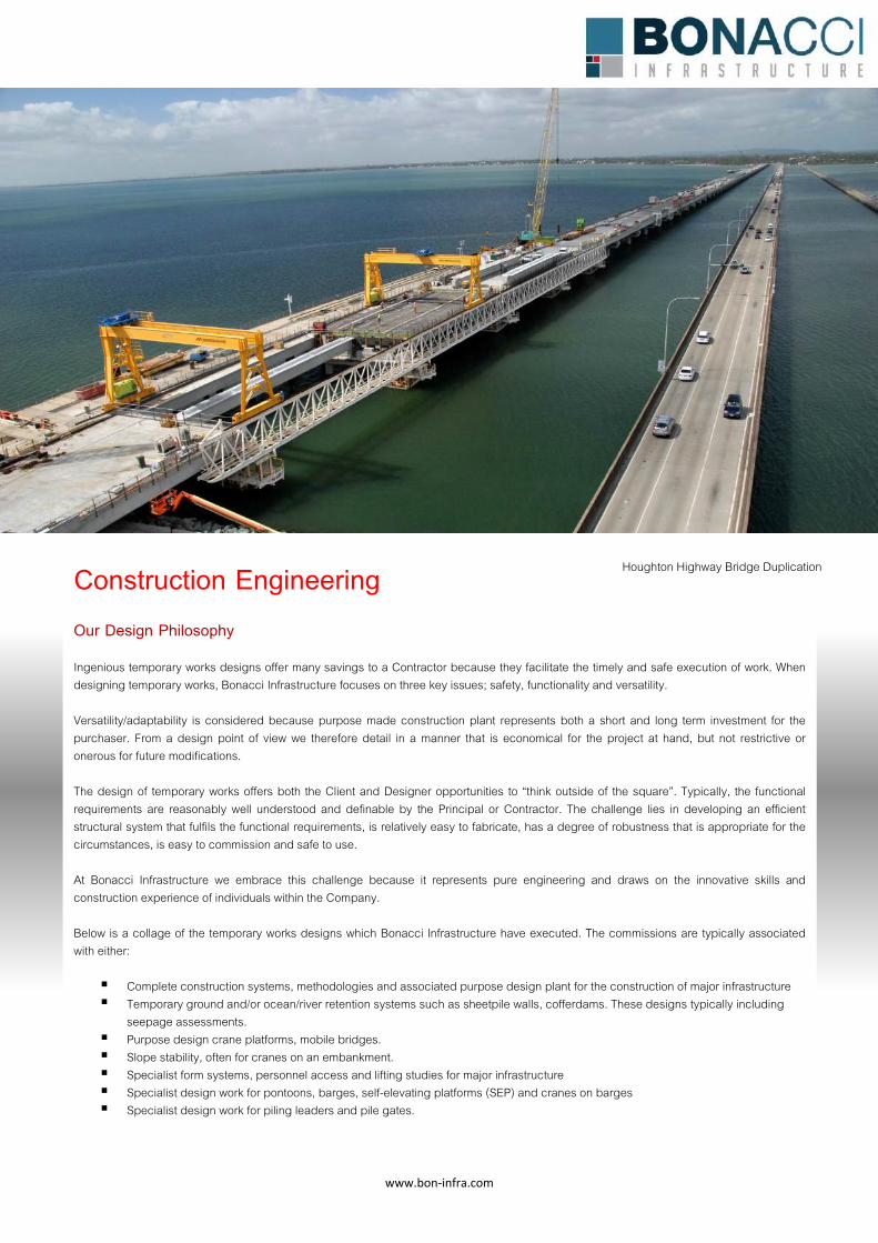
www.bon‐infra.com
Houghton Highway Bridge Duplication
Our Design Philosophy Ingenious temporary works designs offer many savings to a Contractor because they facilitate the timely and safe execution of work. When designing temporary works, Bonacci Infrastructure focuses on three key issues; safety, functionality and versatility. Versatility/adaptability is considered because purpose made construction plant represents both a short and long term investment for the purchaser. From a design point of view we therefore detail in a manner that is economical for the project at hand, but not restrictive or onerous for future modifications. The design of temporary works offers both the Client and Designer opportunities to “think outside of the square”. Typically, the functional requirements are reasonably well understood and definable by the Principal or Contractor. The challenge lies in developing an efficient structural system that fulfils the functional requirements, is relatively easy to fabricate, has a degree of robustness that is appropriate for the circumstances, is easy to commission and safe to use. At Bonacci Infrastructure we embrace this challenge because it represents pure engineering and draws on the innovative skills and construction experience of individuals within the Company. Below is a collage of the temporary works designs which Bonacci Infrastructure have executed. The commissions are typically associated with either: � Complete construction systems, methodologies and associated purpose design plant for the construction of major infrastructure � Temporary ground and/or ocean/river retention systems such as sheetpile walls, cofferdams. These designs typically including
seepage assessments. � Purpose design crane platforms, mobile bridges. � Slope stability, often for cranes on an embankment. � Specialist form systems, personnel access and lifting studies for major infrastructure � Specialist design work for pontoons, barges, self-elevating platforms (SEP) and cranes on barges � Specialist design work for piling leaders and pile gates.
Construction Engineering
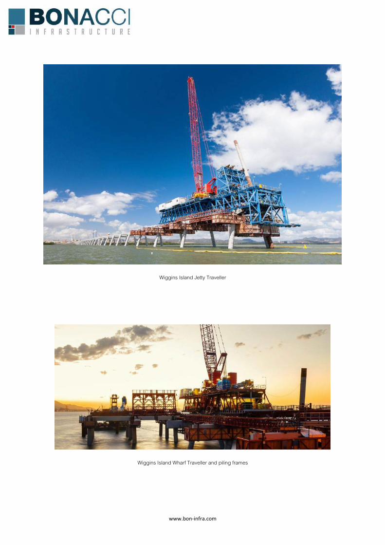
www.bon‐infra.com
Wiggins Island Jetty Traveller
Wiggins Island Wharf Traveller and piling frames
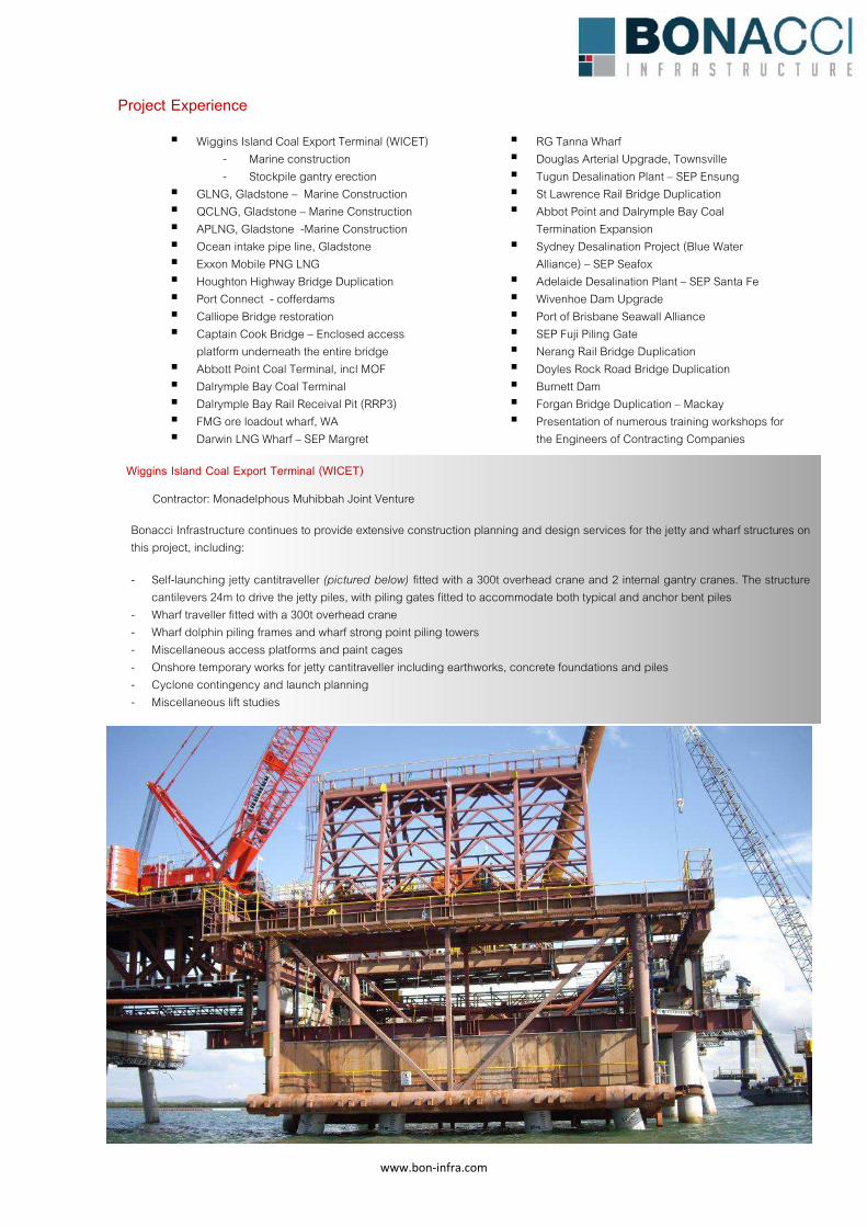
www.bon‐infra.com
Project Experience
� Wiggins Island Coal Export Terminal (WICET) - Marine construction - Stockpile gantry erection
� GLNG, Gladstone – Marine Construction � QCLNG, Gladstone – Marine Construction � APLNG, Gladstone -Marine Construction � Ocean intake pipe line, Gladstone � Exxon Mobile PNG LNG � Houghton Highway Bridge Duplication � Port Connect - cofferdams � Calliope Bridge restoration � Captain Cook Bridge – Enclosed access
platform underneath the entire bridge � Abbott Point Coal Terminal, incl MOF � Dalrymple Bay Coal Terminal � Dalrymple Bay Rail Receival Pit (RRP3) � FMG ore loadout wharf, WA � Darwin LNG Wharf – SEP Margret
� RG Tanna Wharf � Douglas Arterial Upgrade, Townsville � Tugun Desalination Plant – SEP Ensung � St Lawrence Rail Bridge Duplication � Abbot Point and Dalrymple Bay Coal
Termination Expansion � Sydney Desalination Project (Blue Water
Alliance) – SEP Seafox � Adelaide Desalination Plant – SEP Santa Fe � Wivenhoe Dam Upgrade � Port of Brisbane Seawall Alliance � SEP Fuji Piling Gate � Nerang Rail Bridge Duplication � Doyles Rock Road Bridge Duplication � Burnett Dam � Forgan Bridge Duplication – Mackay � Presentation of numerous training workshops for
the Engineers of Contracting Companies
Wiggins Island Coal Export Terminal (WICET)
Contractor: Monadelphous Muhibbah Joint Venture
Bonacci Infrastructure continues to provide extensive construction planning and design services for the jetty and wharf structures on this project, including:
- Self-launching jetty cantitraveller (pictured below) fitted with a 300t overhead crane and 2 internal gantry cranes. The structure cantilevers 24m to drive the jetty piles, with piling gates fitted to accommodate both typical and anchor bent piles
- Wharf traveller fitted with a 300t overhead crane - Wharf dolphin piling frames and wharf strong point piling towers - Miscellaneous access platforms and paint cages - Onshore temporary works for jetty cantitraveller including earthworks, concrete foundations and piles - Cyclone contingency and launch planning - Miscellaneous lift studies
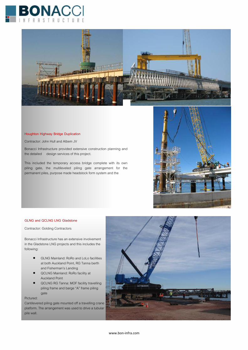
www.bon‐infra.com
Houghton Highway Bridge Duplication
Contractor: John Hull and Albem JV
Bonacci Infrastructure provided extensive construction planning and the detailed design services of this project.
This included the temporary access bridge complete with its own piling gate, the multileveled piling gate arrangement for the permanent piles, purpose made headstock form system and the
GLNG and QCLNG LNG Gladstone
Contractor: Golding Contractors
Bonacci Infrastructure has an extensive involvement in the Gladstone LNG projects and this includes the following:
x GLNG Mainland: RoRo and LoLo facilities at both Auckland Point, RG Tanna berth and Fisherman’s Landing
x QCLNG Mainland: RoRo facility at Auckland Point
x QCLNG RG Tanna: MOF facility travelling piling frame and barge “A” frame piling gate
Pictured: Cantilevered piling gate mounted off a travelling crane platform. The arrangement was used to drive a tubular pile wall.
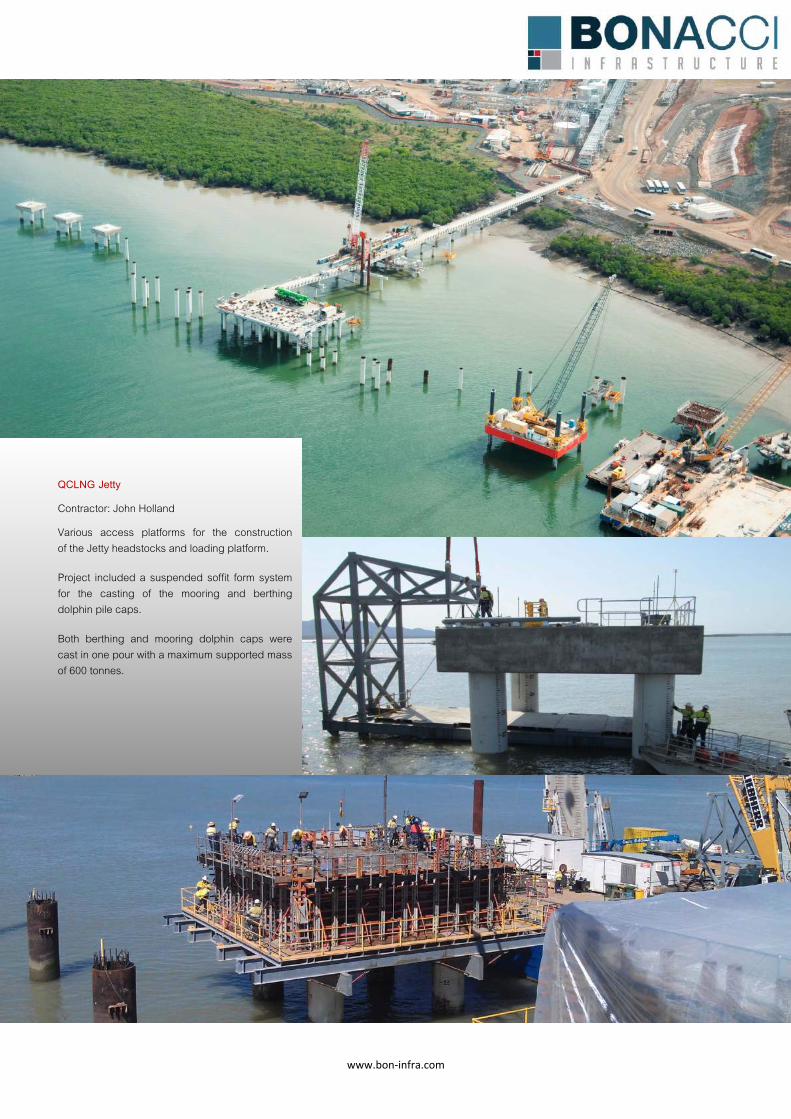
www.bon‐infra.com
QCLNG Jetty
Contractor: John Holland
Various access platforms for the construction of the Jetty headstocks and loading platform.
Project included a suspended soffit form system for the casting of the mooring and berthing dolphin pile caps.
Both berthing and mooring dolphin caps were cast in one pour with a maximum supported mass of 600 tonnes.
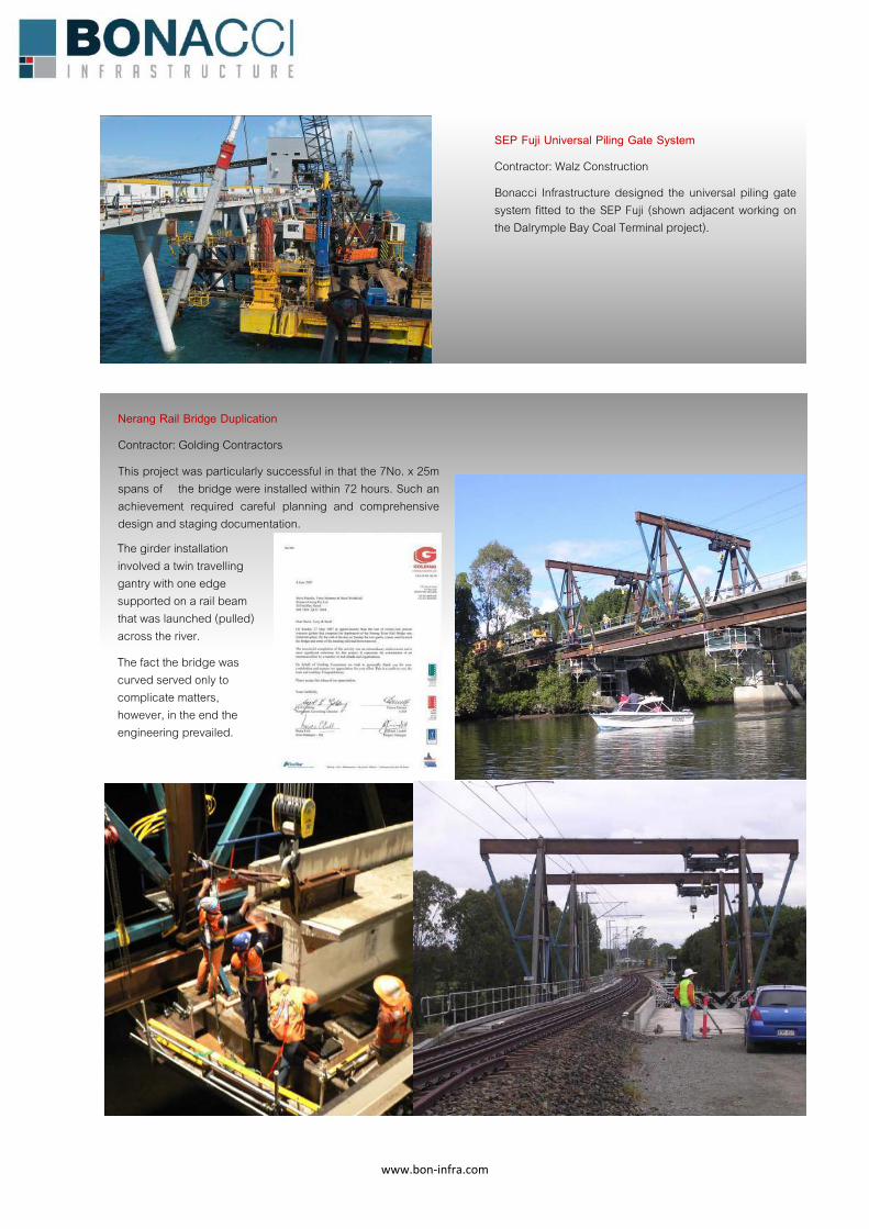
www.bon‐infra.com
SEP Fuji Universal Piling Gate System
Contractor: Walz Construction
Bonacci Infrastructure designed the universal piling gate system fitted to the SEP Fuji (shown adjacent working on the Dalrymple Bay Coal Terminal project).
Nerang Rail Bridge Duplication
Contractor: Golding Contractors
This project was particularly successful in that the 7No. x 25m spans of the bridge were installed within 72 hours. Such an achievement required careful planning and comprehensive design and staging documentation.
The girder installation involved a twin travelling gantry with one edge supported on a rail beam that was launched (pulled) across the river.
The fact the bridge was curved served only to complicate matters, however, in the end the engineering prevailed.
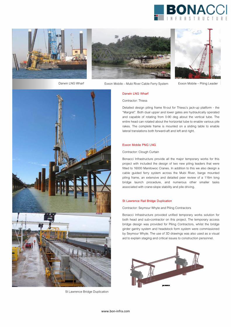
www.bon‐infra.com
St Lawrence Bridge Duplication
Darwin LNG Wharf
Darwin LNG Wharf
Contractor: Thiess
Detailed design piling frame fit-out for Thiess’s jack-up platform - the “Margret”. Both dual upper and lower gates are hydraulically operated and capable of rotating from 0-90 deg about the vertical tube. The entire head can rotated about the horizontal tube to enable various pile rakes. The complete frame is mounted on a sliding table to enable lateral translations both forward-aft and left and right.
Exxon Mobile PNG LNG
Contractor: Clough Curtain
Bonacci Infrastructure provide all the major temporary works for this project with included the design of two new piling leaders that were fitted to 16000 Manitowoc Cranes. In addition to this we also design a cable guided ferry system across the Mubi River, barge mounted piling frame, an extensive and detailed peer review of a 116m long bridge launch procedure, and numerous other smaller tasks associated with crane-slope stability and pile driving.
St Lawrence Rail Bridge Duplication
Contractor: Seymour Whyte and Piling Contractors
Bonacci Infrastructure provided unified temporary works solution for both head and sub-contractor on this project. The temporary access bridge design was provided for Piling Contractors, whilst the bridge girder gantry system and headstock form system were commissioned by Seymour Whyte. The use of 3D drawings was also used as a visual aid to explain staging and critical issues to construction personnel.
Exxon Mobile – Mubi River Cable Ferry System Exxon Mobile – Piling Leader
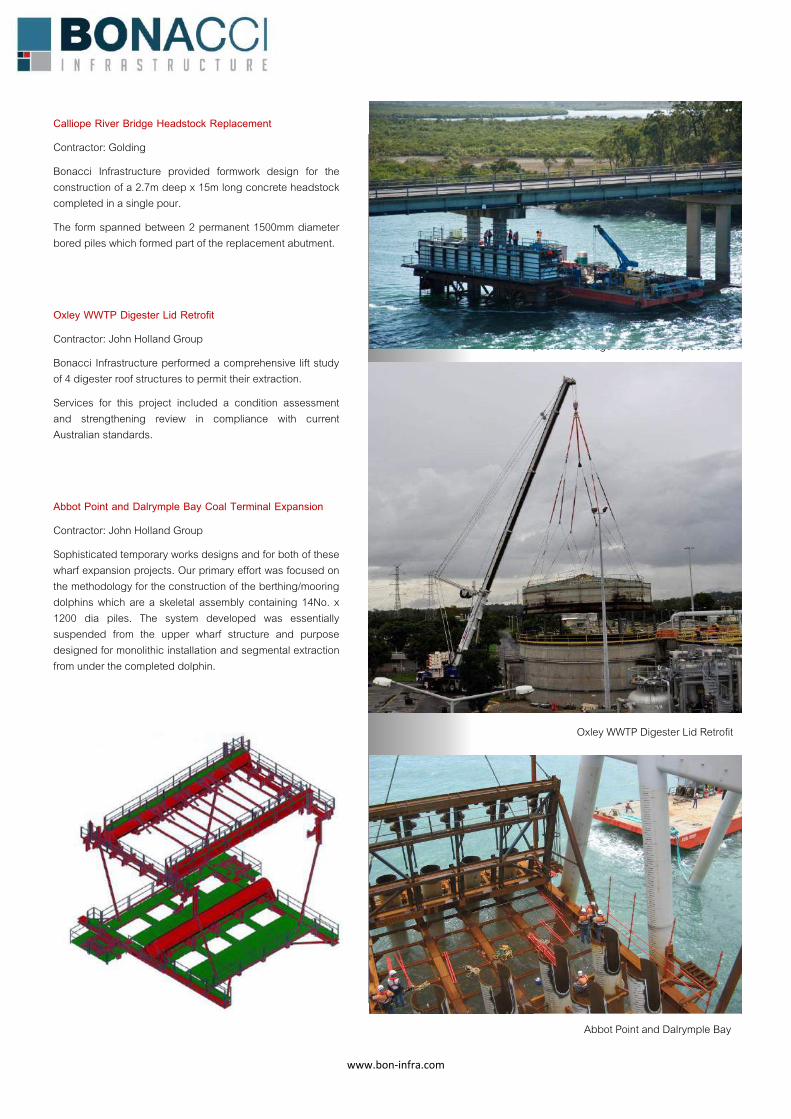
www.bon‐infra.com
Calliope River Bridge Headstock Replacement
Contractor: Golding
Bonacci Infrastructure provided formwork design for the construction of a 2.7m deep x 15m long concrete headstock completed in a single pour.
The form spanned between 2 permanent 1500mm diameter bored piles which formed part of the replacement abutment.
Oxley WWTP Digester Lid Retrofit
Contractor: John Holland Group
Bonacci Infrastructure performed a comprehensive lift study of 4 digester roof structures to permit their extraction.
Services for this project included a condition assessment and strengthening review in compliance with current Australian standards.
Abbot Point and Dalrymple Bay Coal Terminal Expansion
Contractor: John Holland Group
Sophisticated temporary works designs and for both of these wharf expansion projects. Our primary effort was focused on the methodology for the construction of the berthing/mooring dolphins which are a skeletal assembly containing 14No. x 1200 dia piles. The system developed was essentially suspended from the upper wharf structure and purpose designed for monolithic installation and segmental extraction from under the completed dolphin.
Oxley WWTP Digester Lid Retrofit
Callipoe River Bridge Headstock Replacement
Abbot Point and Dalrymple Bay
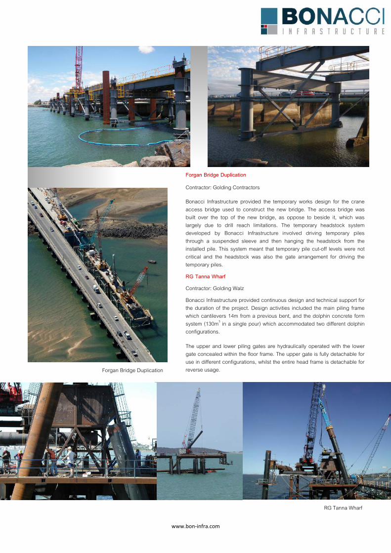
www.bon‐infra.com
RG Tanna Wharf
Forgan Bridge Duplication
Forgan Bridge Duplication
Contractor: Golding Contractors
Bonacci Infrastructure provided the temporary works design for the crane access bridge used to construct the new bridge. The access bridge was built over the top of the new bridge, as oppose to beside it, which was largely due to drill reach limitations. The temporary headstock system developed by Bonacci Infrastructure involved driving temporary piles through a suspended sleeve and then hanging the headstock from the installed pile. This system meant that temporary pile cut-off levels were not critical and the headstock was also the gate arrangement for driving the temporary piles.
RG Tanna Wharf
Contractor: Golding Walz
Bonacci Infrastructure provided continuous design and technical support for the duration of the project. Design activities included the main piling frame which cantilevers 14m from a previous bent, and the dolphin concrete form system (130m3 in a single pour) which accommodated two different dolphin configurations.
The upper and lower piling gates are hydraulically operated with the lower gate concealed within the floor frame. The upper gate is fully detachable for use in different configurations, whilst the entire head frame is detachable for reverse usage.
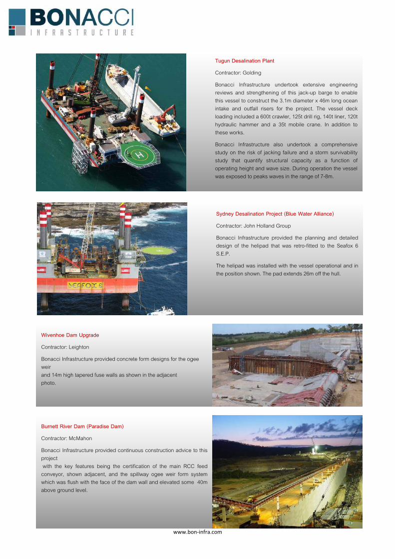
www.bon‐infra.com
Wivenhoe Dam Upgrade
Contractor: Leighton
Bonacci Infrastructure provided concrete form designs for the ogee weir and 14m high tapered fuse walls as shown in the adjacent photo.
Sydney Desalination Project (Blue Water Alliance)
Contractor: John Holland Group
Bonacci Infrastructure provided the planning and detailed design of the helipad that was retro-fitted to the Seafox 6 S.E.P.
The helipad was installed with the vessel operational and in the position shown. The pad extends 26m off the hull.
Burnett River Dam (Paradise Dam)
Contractor: McMahon
Bonacci Infrastructure provided continuous construction advice to this project with the key features being the certification of the main RCC feed conveyor, shown adjacent, and the spillway ogee weir form system which was flush with the face of the dam wall and elevated some 40m above ground level.
Tugun Desalination Plant
Contractor: Golding
Bonacci Infrastructure undertook extensive engineering reviews and strengthening of this jack-up barge to enable this vessel to construct the 3.1m diameter x 46m long ocean intake and outfall risers for the project. The vessel deck loading included a 600t crawler, 125t drill rig, 140t liner, 120t hydraulic hammer and a 35t mobile crane. In addition to these works.
Bonacci Infrastructure also undertook a comprehensive study on the risk of jacking failure and a storm survivability study that quantify structural capacity as a function of operating height and wave size. During operation the vessel was exposed to peaks waves in the range of 7-8m.
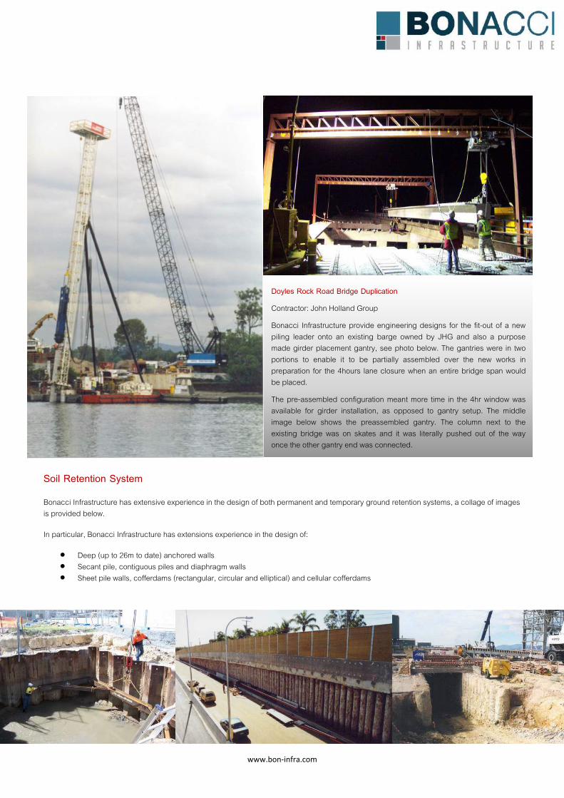
www.bon‐infra.com
Soil Retention System Bonacci Infrastructure has extensive experience in the design of both permanent and temporary ground retention systems, a collage of images is provided below.
In particular, Bonacci Infrastructure has extensions experience in the design of:
x Deep (up to 26m to date) anchored walls x Secant pile, contiguous piles and diaphragm walls x Sheet pile walls, cofferdams (rectangular, circular and elliptical) and cellular cofferdams
Doyles Rock Road Bridge Duplication
Contractor: John Holland Group
Bonacci Infrastructure provide engineering designs for the fit-out of a new piling leader onto an existing barge owned by JHG and also a purpose made girder placement gantry, see photo below. The gantries were in two portions to enable it to be partially assembled over the new works in preparation for the 4hours lane closure when an entire bridge span would be placed.
The pre-assembled configuration meant more time in the 4hr window was available for girder installation, as opposed to gantry setup. The middle image below shows the preassembled gantry. The column next to the existing bridge was on skates and it was literally pushed out of the way once the other gantry end was connected.
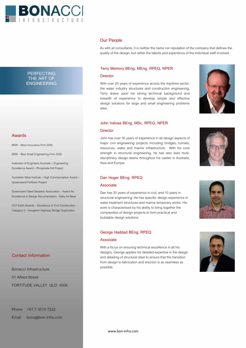
www.bon‐infra.com
Awards
BRW – Most Innovative Firm 2006
BRW – Best Small Engineering Firm 2006
Institution of Engineers Australia – Engineering Excellence Award – Phosphate Hill Project
Australian Steel Institute – High Commendation Award – Queensland Fertiliser Project
Queensland Steel Detailers Association – Award for Excellence in Design Documentation - Oaky Air Base
CCF Earth Awards – Excellence in Civil Construction – Category 5 – Houghton Highway Bridge Duplication
Contact Information
Bonacci Infrastructure
51 Alfred Street
FORTITUDE VALLEY QLD 4006
Phone +61 7 3510 7222
Email [email protected]
PERFECTING THE ART OF
ENGINEERING
Our People As with all consultants, it is neither the name nor reputation of the company that defines the quality of the design, but rather the talents and experience of the individual staff involved.
Terry Memory BEng, MEng, RPEQ, NPER
Director
With over 20 years of experience across the maritime sector, the water industry structures and construction engineering, Terry draws upon his strong technical background and breadth of experience to develop simple and effective design solutions for large and small engineering problems alike.
John Velosa BEng, MSc, RPEQ, NPER
Director
John has over 30 years of experience in all design aspects of major civil engineering projects including bridges, tunnels, resources, water and marine infrastructure. With his core strength in structural engineering, he has also lead multi-disciplinary design teams throughout his career in Australia, Asia and Europe.
Dan Hoger BEng, RPEQ
Associate
Dan has 20 years of experience in civil, and 10 years in structural engineering. He has specific design experience in water treatment structures and marine temporary works. His work is characterised by his ability to bring together the complexities of design projects to form practical and buildable design solutions.
George Haddad BEng, RPEQ
Associate
With a focus on ensuring technical excellence in all his designs, George applies his detailed expertise in the design and detailing of structural steel to ensure that the transition from design to fabrication and erection is as seamless as possible.

Tanker Jetty Remediation Report Appendices Esperance, Western Australia
Appendix D: Terry Memory CV
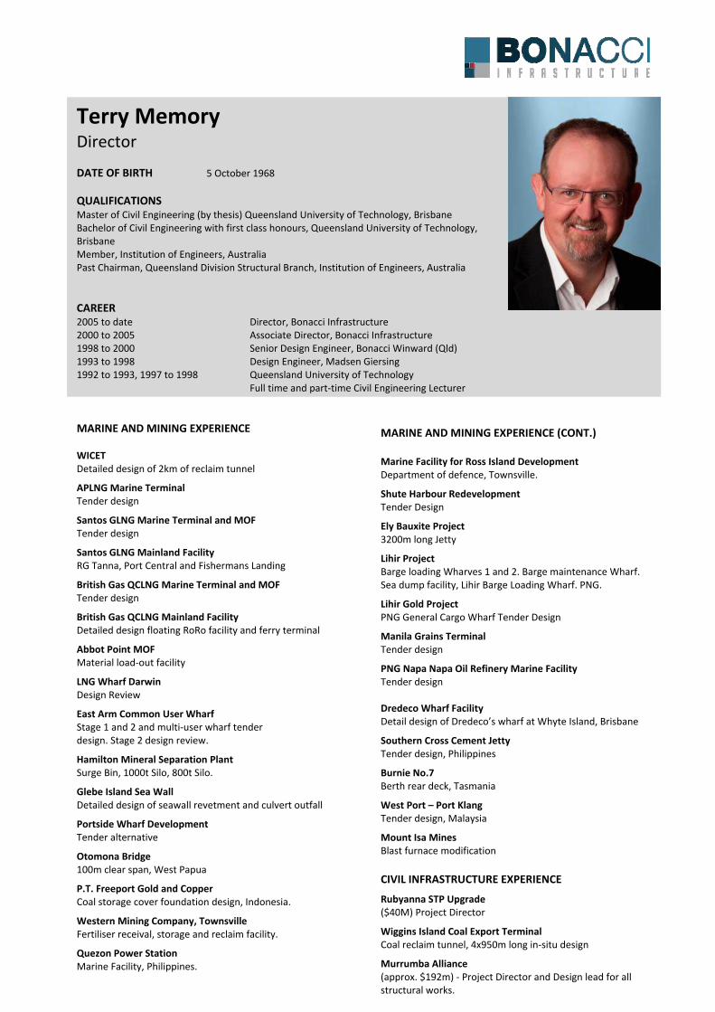
Terry Memory Director DATE OF BIRTH 5 October 1968 QUALIFICATIONS Master of Civil Engineering (by thesis) Queensland University of Technology, Brisbane Bachelor of Civil Engineering with first class honours, Queensland University of Technology, Brisbane Member, Institution of Engineers, Australia Past Chairman, Queensland Division Structural Branch, Institution of Engineers, Australia CAREER 2005 to date Director, Bonacci Infrastructure 2000 to 2005 Associate Director, Bonacci Infrastructure 1998 to 2000 Senior Design Engineer, Bonacci Winward (Qld) 1993 to 1998 Design Engineer, Madsen Giersing 1992 to 1993, 1997 to 1998 Queensland University of Technology Full time and part time Civil Engineering Lecturer MARINE AND MINING EXPERIENCE WICET Detailed design of 2km of reclaim tunnel
APLNG Marine Terminal Tender design
Santos GLNG Marine Terminal and MOF Tender design
Santos GLNG Mainland Facility RG Tanna, Port Central and Fishermans Landing
British Gas QCLNG Marine Terminal and MOF Tender design
British Gas QCLNG Mainland Facility Detailed design floating RoRo facility and ferry terminal
Abbot Point MOF Material load out facility
LNG Wharf Darwin Design Review
East Arm Common User Wharf Stage 1 and 2 and multi user wharf tender design. Stage 2 design review.
Hamilton Mineral Separation Plant Surge Bin, 1000t Silo, 800t Silo.
Glebe Island Sea Wall Detailed design of seawall revetment and culvert outfall
Portside Wharf Development Tender alternative
Otomona Bridge 100m clear span, West Papua
P.T. Freeport Gold and Copper Coal storage cover foundation design, Indonesia.
Western Mining Company, Townsville Fertiliser receival, storage and reclaim facility.
Quezon Power Station Marine Facility, Philippines.
MARINE AND MINING EXPERIENCE (CONT.) Marine Facility for Ross Island Development Department of defence, Townsville.
Shute Harbour Redevelopment Tender Design
Ely Bauxite Project 3200m long Jetty
Lihir Project Barge loading Wharves 1 and 2. Barge maintenance Wharf. Sea dump facility, Lihir Barge Loading Wharf. PNG.
Lihir Gold Project PNG General Cargo Wharf Tender Design
Manila Grains Terminal Tender design
PNG Napa Napa Oil Refinery Marine Facility Tender design Dredeco Wharf Facility Detail design of Dredeco’s wharf at Whyte Island, Brisbane
Southern Cross Cement Jetty Tender design, Philippines
Burnie No.7 Berth rear deck, Tasmania
West Port – Port Klang Tender design, Malaysia
Mount Isa Mines Blast furnace modification CIVIL INFRASTRUCTURE EXPERIENCE
Rubyanna STP Upgrade ($40M) Project Director
Wiggins Island Coal Export Terminal Coal reclaim tunnel, 4x950m long in situ design
Murrumba Alliance (approx. $192m) Project Director and Design lead for all structural works.
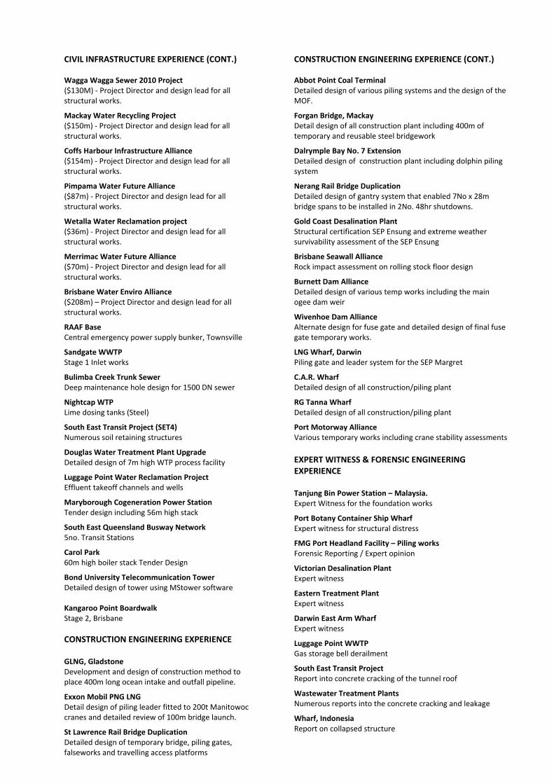
BUILDING STRUCTURES EXPERIENCE
CONSTRUCTION ENGINEERING EXPERIENCE (CONT.) Abbot Point Coal Terminal Detailed design of various piling systems and the design of the MOF.
Forgan Bridge, Mackay Detail design of all construction plant including 400m of temporary and reusable steel bridgework
Dalrymple Bay No. 7 Extension Detailed design of construction plant including dolphin piling system
Nerang Rail Bridge Duplication Detailed design of gantry system that enabled 7No x 28m bridge spans to be installed in 2No. 48hr shutdowns.
Gold Coast Desalination Plant Structural certification SEP Ensung and extreme weather survivability assessment of the SEP Ensung
Brisbane Seawall Alliance Rock impact assessment on rolling stock floor design
Burnett Dam Alliance Detailed design of various temp works including the main ogee dam weir
Wivenhoe Dam Alliance Alternate design for fuse gate and detailed design of final fuse gate temporary works.
LNG Wharf, Darwin Piling gate and leader system for the SEP Margret
C.A.R. Wharf Detailed design of all construction/piling plant
RG Tanna Wharf Detailed design of all construction/piling plant
Port Motorway Alliance Various temporary works including crane stability assessments EXPERT WITNESS & FORENSIC ENGINEERING EXPERIENCE Tanjung Bin Power Station – Malaysia. Expert Witness for the foundation works
Port Botany Container Ship Wharf Expert witness for structural distress
FMG Port Headland Facility – Piling works Forensic Reporting / Expert opinion
Victorian Desalination Plant Expert witness
Eastern Treatment Plant Expert witness
Darwin East Arm Wharf Expert witness
Luggage Point WWTP Gas storage bell derailment
South East Transit Project Report into concrete cracking of the tunnel roof
Wastewater Treatment Plants Numerous reports into the concrete cracking and leakage
Wharf, Indonesia Report on collapsed structure
CIVIL INFRASTRUCTURE EXPERIENCE (CONT.) Wagga Wagga Sewer 2010 Project ($130M) Project Director and design lead for all structural works.
Mackay Water Recycling Project ($150m) Project Director and design lead for all structural works.
Coffs Harbour Infrastructure Alliance ($154m) Project Director and design lead for all structural works.
Pimpama Water Future Alliance ($87m) Project Director and design lead for all structural works.
Wetalla Water Reclamation project ($36m) Project Director and design lead for all structural works.
Merrimac Water Future Alliance ($70m) Project Director and design lead for all structural works.
Brisbane Water Enviro Alliance ($208m) – Project Director and design lead for all structural works.
RAAF Base Central emergency power supply bunker, Townsville
Sandgate WWTP Stage 1 Inlet works
Bulimba Creek Trunk Sewer Deep maintenance hole design for 1500 DN sewer
Nightcap WTP Lime dosing tanks (Steel)
South East Transit Project (SET4) Numerous soil retaining structures
Douglas Water Treatment Plant Upgrade Detailed design of 7m high WTP process facility
Luggage Point Water Reclamation Project Effluent takeoff channels and wells
Maryborough Cogeneration Power Station Tender design including 56m high stack
South East Queensland Busway Network 5no. Transit Stations
Carol Park 60m high boiler stack Tender Design
Bond University Telecommunication Tower Detailed design of tower using MStower software Kangaroo Point Boardwalk Stage 2, Brisbane CONSTRUCTION ENGINEERING EXPERIENCE GLNG, Gladstone Development and design of construction method to place 400m long ocean intake and outfall pipeline.
Exxon Mobil PNG LNG Detail design of piling leader fitted to 200t Manitowoc cranes and detailed review of 100m bridge launch.
St Lawrence Rail Bridge Duplication Detailed design of temporary bridge, piling gates, falseworks and travelling access platforms
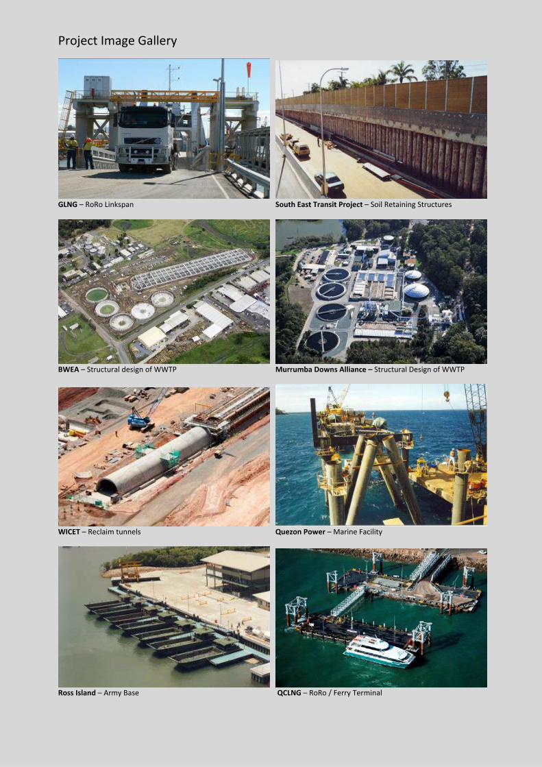
Project Image Gallery
GLNG – RoRo Linkspan South East Transit Project – Soil Retaining Structures
BWEA – Structural design of WWTP Murrumba Downs Alliance – Structural Design of WWTP
WICET – Reclaim tunnels Quezon Power – Marine Facility
Ross Island – Army Base QCLNG – RoRo / Ferry Terminal
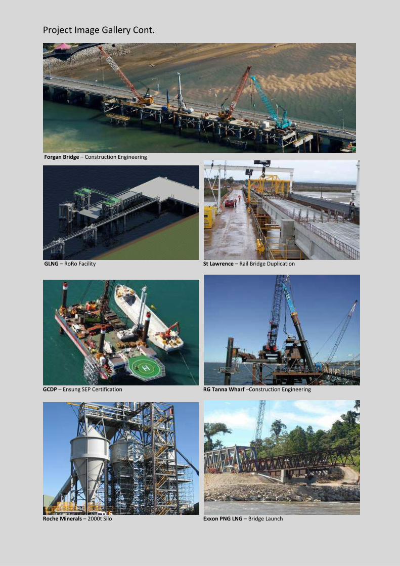
Project Image Gallery Cont.
Forgan Bridge – Construction Engineering
GLNG – RoRo Facility St Lawrence – Rail Bridge Duplication
GCDP – Ensung SEP Certification RG Tanna Wharf –Construction Engineering
Roche Minerals – 2000t Silo Exxon PNG LNG – Bridge Launch