Embed Size (px)
Citation preview
ELSEVIER
Int. J. of Refractory Metals & Hard Materials 14 (1996) 365-381 0 1996 Elsevier Science Limited
Printed in Great Britain. All rights reserved 0263-4368/96/$15.00
PI I: SO263-4368(96)00034-O
Tantalum Protective Thin Coating Techniques for the Chemical Process Industrv: Molten Salts Electrocoating as a New Altekative
Frarqois Cardarelli, * Pierre Taxi1 & Andrk Savall Laboratoire de GCnie Chimique et lklectrochimie, UniversitC Paul Sabatier, URA 192 CNRS, 118, Route de Narbonne, F-31062 Toulouse Cedex, France
(Received 28 February 1996; accepted 19 June 1996)
Abstract: A comparison of corrosion resistance and basic properties of solid tantalum with other high-performance materials used in the Chemical Process Industry (CPI) is given. The corrosive chemicals taken into consideration are strong acidic media. Secondly, it is pointed out that tantalum, which exhibits excellent corrosion resistance, owing to a rapid build-up of passivating protective film in oxidizing conditions, also has good mechanical, thermal and electrical properties which suggest its use when little or no metallic corrosion is tolerated. Thirdly, tantalum thin-layer, coated onto a usual base metal, which offers the same protection as solid metal and avoids its expensive use, is treated. Fourthly, numerous tantalum-coating techniques for clad-vessel and CPI devices are reviewed and compared. Amongst these coating techniques, this paper focuses mainly on two techniques which give a very thin, protective coating against corrosion. Thus, Chemical Vapor Deposition (CVD) and Molten Salt Electro- deposition (MSE) are especially enhanced. Finally, MSE which is still not widely used for manufacturing clad-vessels is examined in greater detail. 0 1996 Elsevier Science Limited
1 INTRODUCTION
In the Chemical Process Industries (CPI), engi- neers encounter a wide range of harsh operat- ing conditions and corrosive chemical environments. This often makes materials speci- fication expensive and time-consuming, requir- ing high-efficiency materials for the process. Actually, several CPI plants have to solve the critical problem of construction material selec- tion. This corrosion comes from the corrosive media employed in such processes (e.g. organic and mineral acids, strong concentrated alkalies hydroxides, molten salts and liquid metals) and severe operating conditions such as high tem- perature and pressure.
Nevertheless, corrosion problems may exist even if process equipment does not show any visible corrosion. As a general rule, slow corro-
*Author to whom all correspondence should be addressed.
365
sion rates degrade the quality of fine chemicals, drugs, foodstuffs and pharmaceuticals. It can poison certain catalysts and induce catalytic reactions of certain hazardous chemicals. Finally, it can be harmful to the environment due to the toxicity of the wastes. Stainless steels, the best known corrosion resistant material, do not always guarantee immunity against corro- sion.
For example, AISI 316L type stainless steel equipment with 1000 m2 surface area which cor- rodes at a rate of 50 pm/year+ (2 mpy’), relea- ses daily into the reactor or the environment the following amounts of metals: 712 g of iron, 186 g of chromium, 132 g of nickel, 33 g of molybdenum, and 22 g of manganese.
‘A construction material is satisfactory against corrosion in a medium when the corrosion rate is below 100 pm/ year (4 mpy), which is equal for a material with a density of 8g.cm-’ to a weight loss of 2.2g.m *.day-‘. *One mil per year (mpy) is accurately equal to 25.4 pm per year (pm/y).
366 F: Cardurelli. I? Tad, A. Sad1
Today, thee are numerous possibilities for preventing severe corrosion of CPI equipment in the area of plant design. The success of these processes depends on the selection of the con- struction materials that are in contact with the corrosive media.
2 ANTI-CORROSION MATERIALS FOR THE CPI
2.1 Common industrial solutions against highly corrosive media
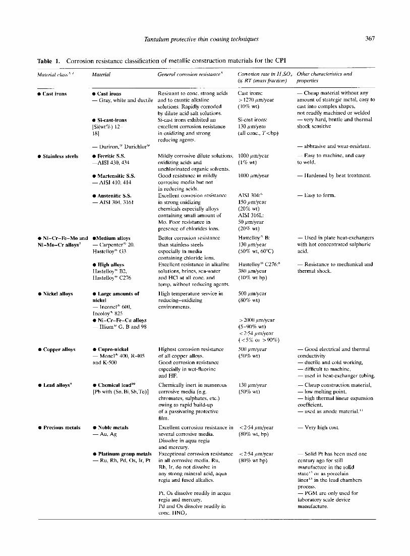
Depending on the aggressiveness of corrosive media, there are a wide range of metallic con- struction materials ranging from steels to non- ferrous alloys’ used in CPI devices. The main corrosive media usually found in chemical pro- cesses are essentially: sulphuric, nitric, hydro- chloric acid and strong alkalies. So, in order to give a simplifying approach, acids (and especially sulphuric acid) are taken for example. This arbitrary choice allows one to give, for each material, an order of magnitude of corro- sion rate’ in this medium. In Table 1, several metallic construction materials are listed according to their corrosion resistance proper- ties. The other criteria for selecting metallic construction material are mechanical, electrical and thermal properties together with cost. These criteria are therefore given in the table.
Examination of the numerous metal and alloy classes shows that only precious metals and refractory metals are suited to resist corrosion in severe operating conditions, but only the latter class is suited for a long service life under harsh conditions, with good engineering proper- ties and moderate costs.
2.2 Refractory metals in the CPI
Some subgroups of inner transition metals’” of the periodic table such as IVB (Ti, Zr, Hf), VB (V, Nb, Ta) and VIB (Cr, MO, W) are some- times used’5.‘h as construction materials in industrial applications. These metals have the following common properties:
- they are refractory metals, where refrac- tory means that their melting point is higher than the setting point of iron (mp 1539°C) Their melting point ranges from 1660°C for tita- nium to 3410°C for tungsten. Rhenium is some-
times taken into account but its use is still negligible;
- they are reactive and therefore combine strongly with oxygen, nitrogen, carbon and other meals and non-metals outside their group, and many of their properties are quite sensitive to relatively small amounts of atomic species;
- they exhibit a Valve Action (VA) property which could be defined as follows: when acting as cathodes these metals allow current to pass but when acting as anodes they prevent passage of current owing to a rapid build-up of an insu- lating (passivating) anodic or oxidizing protec- tive film.
Refractory metals are used for engineering equipment and devices, in the following indus- trial areas:” the Nuclear Power Industry,‘” Pharmaceutical Industry, Chemical Process Industries,‘” Foodstuffs Industries, Marine Engineering”’ (e.g. cathodic current protection of submersed structures such as boats, harbor plants, oil-rigs) and Civil Engineering (e.g. cath- odic current protection of subterranean pipe- lines or reinforced steel concrete). Each refractory metal is assigned to a particular application according to its chemical inert- ness:” See Table 1 for the general properties of these metals.
A general comparison of titanium, zirconium, hafnium, niobium and tantalum chemical resist- ance is shown in Table 2, where the corrosion rate of the five common refractory metals widely used in CPI equipment and of platinum group metals (e.g. iridium), as absolute refer- ence, is listed for several corrosive media. This table shows that the chemical resistance of tan- talum is similar to some PGM such as iridium.
The broadest range of tantalum chemical resistance is a consequence of enhancement of its Valve Action (VA) properties?’ Actually, tantalum’s protective passivating film, Ta20s, which forms spontaneously in oxidizing condi- tions, exhibits more singular poperties than the other reactive metal protective oxide films (e.g. TiOl, ZrO,, HfO,, NbO,). Anodic tantalum pentaoxide has an amorphous structure, is strongly adherent to metal, extremely thin (about l-4 nm) and self-limiting of its own thickness growth. This oxide has very good dielectric properties which is the primary reason for tantalum’s commercial development for highly effective electronic capacitors. Finally,
Tantalum protective thin coating techniques 367
Table 1. Corrosion resistance classification of metallic construction materials for the CPI
Material class ‘. -I Material Generul corrosion resistance ’ Corrosion rate in H,SO, Other characteristics and (IA RT (mass fraction) properties
0 Cast irons 0 Cast irons - Gray, white and ductile
Resistant to cont. strong acids Cast irons: - Cheap material without any
and to caustic alkaline
solutions. Rapidly corroded
by dilute acid-salt solutions.
Si-cast irons exhibited an
excellent corrosion resistance
in oxidizing and strong
reducing agents.
> 1270 pm/year
(10% wt)
Si-cast irons:
130 pm/year
(all cont., T<bp)
amount of strategic metal, easy to
cast into complex shapes,
not readily machined or welded
- very hard, brittle and thermal
shock sensitive 0 Si-cast-irons [Si(wt%) 12-
181
- Duriron,” Durichlor”
0 Ferritic S.S. -AISI 430,434
0 Martensitic S.S. - AISI 410, 414
0 Austenitic S.S. - AISI 304, 3161
- abbrasive and wear-resistant.
- Easy to machine, and easy
to weld. 0 Stainless steels Mildly corrosive dilute solutions,
oxidizing acids and unchlorinated organic solvents.
Good resistance in mildly corrosive media but not
in reducing acids.
Excellent corrosion resistance
in strong oxidizing
chemicals especially alloys
containing small amount of
MO. Poor resistance in
presence of chlorides ions.
Better corrosion resistance
than stainless steels
especially in media
containing chloride ions. Excellent resistance in alkaline
solutions, brines, sea-water
and HCI at all cont. and
temp. without reducing agents.
High temperature service in
reducing-oxidizing
environments.
1000 pm/year
(1% wt)
1000 pm/year - Hardened by heat treatment.
AISI 304:”
150 pm/year
(20% wt)
AISI 316L:
50 pm/year
(20% wt)
Hastelloy‘m B:
130 pm/year
(SO% wt, 60°C)
HastelloyO C276:”
380 pm/year
(10% wt bp)
- Easy to form.
- Used in plate heat-exchangers
with hot concentrated sulphuric
acid.
0 Ni-Cr-Fe-MO and
Ni-Mo-Cr alloys’
@Medium alloys - Carpenter”” 20,
Hastelloya G3
0 High alloys Hastelloy” B2, Hastelloy” C276
- Resistance to mechanical and
thermal shock.
0 Nickel alloys 0 Large amounts of nickel - Inconel” 600,
Incoloy” 825
l Ni-Cr-Fe-Cu alloys - IlliumO G. B and 98
500 /[m/year
(80% wt)
> 2000 pm/year
(5-90% wt) < 254 pm/year
(<S% or >90%)
500 /lm/year
(50% wt) 0 Copper alloys 0 Cupro-nickel
- Monel” 400, R-405
and K-500
Highest corrosion resistance
of all copper alloys.
Good corrosion resistance
especially in wet-fluorine
and HF.
Chemically inert in numerous
corrosive media (e.g.
chromates, sulphates, etc.)
owing to rapid build-up
of a passivating protective
film.
Excellent corrosion resistance in
several corrosive media.
Dissolve in aqua regia
and mercury.
Exceptional corrosion resistance
in all corrosive media. Ru,
Rh, Ir, do not dissolve in any strong mineral acid, aqua regia and fused alkalies.
Pt, OS dissolve readily in aqua
regia and mercury.
Pd and OS dissolve readily in
cont. HNO,
- Good electrical and thermal
conductivity
- ductile and cold working,
- difficult to machine,
- used in heat-exchanger tubing.
- Cheap construction material,
- low melting point,
- high thermal linear expansion
coefficient,
- used as anode material.”
0 Chemical lead” [Pb with (Sn, Bi, Sb,Te)]
0 Lead alloys’ 130 pm/year
(50% wt)
0 Precious metals 0 Noble metals - Au, Ag
< 2.54 pm/year
(80% wt, bp)
- Very high cost
0 Platinum group metals - Ru, Rh, Pd, OS, Ir, Pt
< 2.54 pm/year
(80% wt bp)
- Solid Pt has been used one
century ago for still
manufacture in the solid state” or as porcelain liner” in the lead chambers
process.
- PGM are only used for
laboratory scale device manufacture.
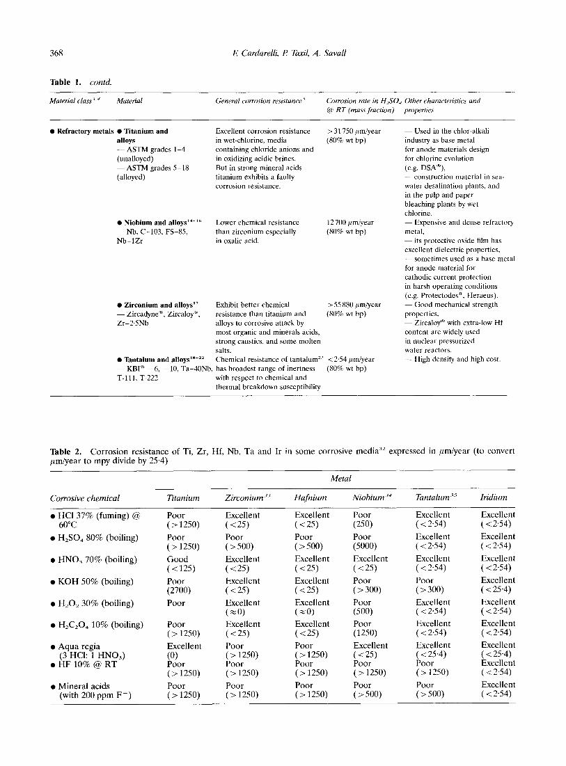
368 I? Cardarelli, I? Tawil, A. Savall
Table 1. contd.
Material class 7, J Material General corrosion resistance ’ Corrosion rate in H,SO, Other characteristics and
@ RT (muss fraction) properties
0 Refractory metals 0 Titanium and alloys - ASTM grades l-4
(unalloyed)
-ASTM grades S-18
(alloyed)
0 Niobium and alloys’4-‘h - Nb, C-103, FS-85,
Nb-1Zr
0 Zirconium and alloys” - Zircadyne”, Zircaloy”,
Zr-2.5Nb
0 Tantalum and alloy~‘~-~~
Excellent corrosion resistance > 31750 ALrniyear in wet-chlorine, media (80% wt bp) containing chloride anions and
in oxidizing acidic brines.
But in strong mineral acids
titanium exhibits a faulty
corrosion resistance.
Lower chemical resistance
than zirconium especially in oxalic acid.
i2700 pm/year
(80% wt bp)
Exhibit better chemical > 55 880 pm/year
resistance than titanium and (80% wt bp) alloys to corrosive attack by
most organic and minerals acids,
strong caustics, and some molten
salts.
Chemical resistance of tantalum” < 2.54 /[m/year
- KBIa -6, - 10, Ta-40Nb, has broadest range of inertness (80% wt bp)
T-l 11, T-222 with respect to chemical and
thermal breakdown susceptibility
- Used in the chlor-alkali
industry as base metal
for anode materials design
for chlorine evolution
(e.g. DSA”), - construction material in sea-
water desalination plants, and
in the pulp and paper
bleaching plants by wet
chlorine.
- Expensive and dense refractory metal, - its protective oxide film has excellent dielectric properties, - sometimes used as a base metal
for anode material for
cathodic current protection
in harsh operating conditions
(e.g. Protectodesa, Heraeus).
- Good mechanical strength
properties,
- Zircaloy” with extra-low Hf
content are widely used
in nuclear pressurized
water reactors. - High density and high cost.
Table 2. Corrosion resistance of Ti, Zr, Hf, Nb, Ta and Ir in some corrosive media” expressed in pm/year (to convert pm/year to mpy divide by 25.4)
Metal
Corrosive chemical
0 yO$g7% (fuming) @
l H,SO, 80% (boiling)
l HNO, 70% (boiling)
l KOH 50% (boiling)
l H,O, 30% (boiling)
Hafiium
Excellent ( <25) Poor ( > 500)
Excellent (<25)
Excellent (~25)
l H&O, 10% (boiling)
l Aqua regia (3 HCl: 1 HNO,)
l HF 10% @ RT
l Mineral acids (with 200 ppm F-)
Titanium
Poor (> 1250)
Poor (>1250)
Good (~125)
Poor (2700)
Poor
Poor (> 1250)
Excellent
L?or (> 1250)
Poor (> 1250)
Zirconium-‘-’
Excellent (<25) Poor ( > 500)
Excellent (~25) Excellent (~25) Excellent (20) Excellent (~25) Poor (> 1250) Poor (> 1250)
Poor (>1250)
Niobium-‘”
Poor (250) Poor (5000)
Excellent (~25) Poor ( > 300)
Excellent (=O) Excellent (~25) Poor (> 1250) Poor (> 1250)
Poor (>1250)
Poor (500) Poor (1250)
Excellent
Lz? (> 1250)
Poor ( 5,500)
Tantalum-‘-5
Excellent ( < 2.54)
Excellent ( < 2.54)
Excellent ( < 2.54)
Poor ( > 300)
Excellent ( < 2.54)
Excellent ( < 2.54)
Excellent $-=Q;.“)
(> 1250)
Poor (> 500)
Iridium
Excellent ( < 2.54)
Excellent ( < 2.54)
Excellent ( < 2.54)
Excellent ( < 25.4)
Excellent ( < 2.54)
Excellent ( < 2.54)
Excellent ( < 25.4) Excellent ( < 2.54)
Excellent ( < 2.54)
Tantalum protective thin coating techniques 369
Ta,O, is formed and persists even in extremely oxygen deficient environments. Nevertheless, tantalum immunity is lost when the metal is in contact with reagents which prevent or slow down oxide layer formation or damage this natural barrier. For example, hydrofluoric acid and fluoride ions, sulphur trioxide and a fortion’ fuming sulphuric acid, concentrated strong alkali hydroxides and fused carbonates rapidly attack tantalum metal.
According to this overview of its chemical resistance, tantalum is an inescapable construc- tion material for chemical equipment submitted to hot and concentrated strong acis (e.g. sul- phuric, nitric, hydrochloric, hydrobromic) and when no corrosion products are tolerated.
2.3 Tantalum selection
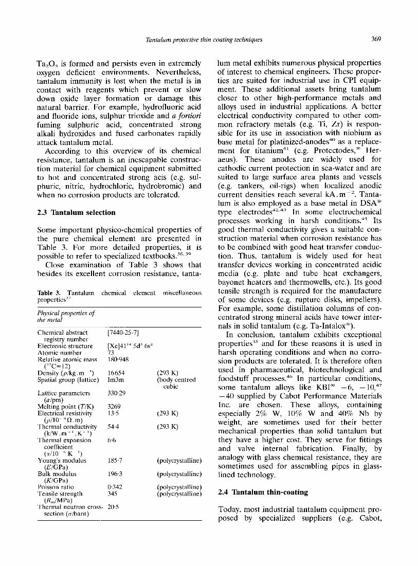
Some important physico-chemical properties of the pure chemical element are presented in Table 3. For more detailed properties, it is possible to refer to specialized textbooks.“8,‘9
Close examination of Table 3 shows that besides its excellent corrosion resistance, tanta-
Table 3. Tantalum chemical element miscellaneous properties”
Physical properties of the metal
Chemical abstract registry number
Electronic structure Atomic number Relative atomic mass
(“C= 12) Density (p/kg. m ‘) Spatial group (lattice)
Lattice parameters (a /pm)
Melting point (T/K) Electrical resistivity
(p/10 ‘Q. m) Thermal conductivity
(k/W.m -‘.K- ‘) Thermal expansion
coefficient (sc/lO ” K ‘)
Young’s modulus (EIGPa)
Bulk modulus (KIGPa)
Poisson ratio Tensile strength __ (R,,/~Pa) c
185.7
196.3
0.342 345
1 hermal neutron cross- 20.5 section (a/barn)
[7440-25-71
[Xe]4114 5d’ 6s’ 73 180.948
16654 Im3m
330.29
(293 K) (body centred
cubic
3269 135 (293 K)
54.4 (293 K)
6.6
(polycrystalline)
(polycrystalline)
(polycrystalline) (polycrystalline)
lum metal exhibits numerous physical properties of interest to chemical engineers. These proper- ties are suited for industrial use in CPI equip- ment. These additional assets bring tantalum closer to other high-performance metals and alloys used in industrial applications. A better electrical conductivity compared to other com- mon refractory metals (e.g. Ti, Zr) is respon- sible for its use in association with niobium as base metal for platinized-anodes4” as a replace- ment for titanium4’ (e.g. Protectodes” Her- aeus). These anodes are widely used for cathodic current protection in sea-water and are suited to large surface area plants and vessels (e.g. tankers, oil-rigs) when localized anodic current densities reach several kA. rnme2. Tanta- lum is also employed as a base metal in DSAa type electrodes42.4’ In some electrochemical processes working in harsh conditions.44 Its good thermal conductivity gives a suitable con- struction material when corrosion resistance has to be combined with good heat transfer conduc- tion, Thus, tantalum is widely used for heat transfer devices working in concentrated acidic media (e.g. plate and tube heat exchangers, bayonet heaters and thermowells, etc.). Its good tensile strength is required for the manufacture of some devices (e.g. rupture disks, impellers). For example, some distillation columns of con- centrated strong mineral acids have tower inter- nals in solid tantalum (e.g. Ta-Intalox@).
In conclusion, tantalum exhibits exceptional properties4” and for these reasons it is used in harsh operating conditions and when no corro- sion products are tolerated. It is therefore often used in pharmaceutical, biotechnological and foodstuff processes.46 In particular conditions, some tantalum alloys like KEV -6, - 1O,47 -40 supplied by Cabot Performance Materials Inc. are chosen. These alloys, containing especially 2% W, 10% W and 40% Nb by weight, are sometimes used for their better mechanical properties than solid tantalum but they have a higher cost. They serve for fittings and valve internal fabrication. Finally, by analogy with glass chemical resistance, they are sometimes used for assembling pipes in glass- lined technology.
2.4 Tantalum thin-coating
Today, most industrial tantalum equipment pro- posed by specialized suppliers (e.g. Cabot,
370 l? Cardarelli, I? Taxil, A. Savall
NRC, Degussa, Danfoss) is made from 0.75 mm thick solid tantalum plates. In the previous paragraph, it was shown that solid tantalum exhibits singular properties but it also has two great drawbacks: high density and high cost.
According to corrosion studies performed by Danzig et a1.,48 a thin tantalum coating (100 ym) provides excellent corrosion resistance for the base metal. So, it is economically advan- tageous to use a thin layer of tantalum clad onto a common base metal. Today, some clad vessels for CPI are made with an ordinary base metal (e.g. steel, copper) coated with tanta- lum.4’, “’ A price comparison of several protec- tive solid metals contained in a thin metallic layer of 100 ,um thickness on a unit surface area of one square meter is given in Table 4.
Examination of Table 4 shows firstly that more economical coatings (e.g. Ti, Zr, Nb) than those made with tantalum are unsatisfactory in harsh corrosive media such as boiling and con- centrated sulphuric acid. Secondly, amongst the excellent metallic protective coatings against corrosion, tantalum coating is the least expen- sive.
Today, there are numerous coating or clad- ding techniques available for tantalum thin layer deposits.54 The following section gives a rapid and concise overview of all these tech- niques.
3 TANTALUM THIN-COATING TECHNIQUES
3.1 General properties of thin-coating
A metallic thin-layer coated onto an ordinary base metal, offers all the advantages of solid
metal such as surface propertie? (e.g. corro- sion resistance, hardness), and avoids the expensive use of solid metal. This allows for a wide diversity of base metals and therefore for the employment of a common and cheap metal (low cost, low density, easy machining, etc.). For example, common metals suitable as the base metal are: carbon steel, cast-iron, mild steel, stainless steels, aluminum, copper, nickel and titanium.
Metallic coatings have a broad range of appli- cations besides corrosion protection, moreover the main principle is always the same:” fabri- cate a composite material with sandwich type structure which exhibits surface properties dif- ferent than the overall solid material.”
Amongst the several classifications of metallic coating techniques, a description of coating techniques by physicochemical principles has been adopted. Today, the following techni- que? for metallic coatings are available: mechanical, physical, chemical and electro- chemical.
Some criteria requirements in thin deposit techniques are: preparation of base metal, dep- osition rate, base metal limitations (e.g. geome-
try, size, temperature, compatibility, etc.), structure and coating-adherence to base metal and throwing power. Economical criteria are: simple plant design, low maintenance costs and minimal capital cost.
As a general rule, metallic coating formation decomposes into three successive or simultane- ous steps as follows: (i) production of specie(s); (ii) mass transfer of the specie(s) from source to base metal surface; and (iii) deposition on the base metal and crystalline-growth of the coating.
3.2 Mechanical cladding processes
Table 4. Cost comparison of thin coatings protection against corrosion in harsh media
Metal cost Density cost of (Cl$. kg ‘)-“. s2 (293 K]“, 100 ,um thin
(p1kg.m ) coating (cl$.mp3
The mechanical cladding techniques described here are based on simple physical principles. Their straightforwardness explains their wide- spread use in the industrial forming of clad- vessels for CPI.
Titanium 250 4540 113 Zirconium 360 6506 234 Niobium 540 8570 463 Tantalum 740 16654 1232 Hafnium 1630 13310 2170 Iridium 4900 22560 11054 Platinum 17400 21450 37 752
3.2. I Loose-lined construction Tantalum liners may be manufactured separa- tely and inserted into vessels without bonding with the base metal. This loose-lined construc- tion is the most economical and widely used fabrication method. Liner thicknesses of
Tantalum protective thin coating techniques 371
0.4-O+ mm are satisfactory against corrosion. It is also possible to improve this technique by welding the liners to the base metal (so-called weld overlay).
Although economical, loose-lined construc- tion has some intrinsic drawbacks: (i) unsuit- ability for vacuum use; (ii) limitation with regard to temperature and pressure; (iii) poor heat transfer coefficient due to the air space between liner and base metal; (iv) difficulty in failure inspection and control and (v) larger thickness of the liner than the 100 pm is required. This technique therefore needs large amounts of expensive solid tantalum plates.
3.2.2 Roll bonding and hot rolling Roll-bonding is a mechanical method of joining metals by applying pressure sometimes com- bined with heat, with or without the use of a filler metal. The clad metal plate and backer, sometimes with intermediate material in order to ensure good bonding, pass through two heavy rollers. When rolling is complete, the sandwich cladding plates are obtained. In this technique, good ductility of the coating metal is the main property required for good bonding. Thus, tan- talum must be very pure [Ta(%wt) >99*9], because small amounts of interstitial elements (e.g. C, N, 0) would have catastrophic effects on ductility. It is possible to work at high tem- perature in order to increase the plastic defor- mation process, but the high temperature requirements (1000°C) lead to work in an inert atmosphere in order to prevent oxidation of reactive metals like tantalum which form tena- cious oxide surface films. This means that tanta- lum roll-bonding is not possible in air.s9 In order to avoid thermal oxidation film formation during heating, the tantalum roll-bonding pro- cess can also be performed in vacuum.6o With this technique, the minimum cladding thickness is about 15 mm. For certain special procedures, tantalum-lined vessels are being produced with 0.25-0.38 mm thick elastomer bonded tantalum sheet on steel plate.
3.2.3 Explosive bonding and cladding Explosive cladding,“’ or explosion bonding and explosion welding, is a method wherein the con- trolled energy of a detonating explosive6’ is used to create a metallurgical bond between two or more similar or dissimilar metals.63 No intermediate filler metal is needed to promote
bonding and no external heat is applied. Explo- sive bonding is a cold pressure-welding unlike fusion welding. During the process, the bonding is performed by high pressure collision of two metallic plates jetted together. Areas as small as a few square centimeters to several square meters have been bonded. Limitations of the explosive bonding are listed below: (i) storage and handling of explosives can be hazardous; (ii) when there is a large difference of density between metals a high quality bonded interface is difficult to achieve and so a filler material is needed; (iii) complex geometries are not suited to explosive bonding because of the high veloc- ity jet expelled; (iv) the preparation and assem- bly of clads is not amenable to automated production techniques, and each assembly requires considerable manual labor; and finally (v) coating thickness is equal to millimeters as an order of magnitude which requires large amounts of solid tantalum.h4
3.2.4 Thermal spraying techniques Thermal spraying methods are used in a wide range of industrial applications.“’ The coating is obtained by projection of molten metal droplets which are carried by compressed gas toward the workpiece. Droplets of liquid metal are obtained by melting metal powder. The size of the powder particles ranges from 10 to 125 pm. Particles are carried by an inert gas (e.g. argon) to a heating source. The heat of the source melts the metal and accelerates it toward the workpiece where particles fuse as interlocking laminates, each layer being fused to the pre- vious one.
The following heating techniques can be used: oxyacetylene-flame (2800°C) detonation (3000°C) or electric arc (4OOO”C), and some- times a high frequency plasma or laser. In the particular case of tantalum only a high tempera- ture source and inert atmosphere are suitable owing to its high melting point and high chemi- cal reactivity with oxygen and nitrogen. Thus arc-spraying, plasma-spraying and detonation gun in a protective gas overcome the limitations of the flame spraying process.
Detonation gun, plasma- and arc-spraying give adherent coatings. Nevertheless, due to its mosaic structure with some defects (e.g. amounts of oxide, vacancies), a sizeable deposit thickness (about 1 mm) is required to protect the base metal against corrosion attack. This
372 l? Cardarelli, El Taxil, A. Savall
great thickness of the coating leads to large amounts of expensive solid tantalum being required. The high costs of the detonation gun process associated with the expensive amount of tantalum come close to the costs of solid metal manufacture.
Therefore, the mechanical techniques des- cribed, in spite of their straightforwardness, have great drawbacks. They need large amounts of solid tantalum, are unsuitable for complex workpiece cladding and need heavy equipment. Furthermore, the preparation of clad-assem- blies is not amenable to automated production techniques and each assembly requires con- siderable preparation.
3.3 Physical coating processes
Physical Vapor Deposition (PVD) allows a thin coating to be obtained under diminished pres- sure and low temperature (typically ranging from 50 to 500°C). This characteristic makes it possible to apply extremely thin metallic coat- ings onto workpieces ready to use (e.g. tem- pered, machined).“” Dimension variations are therefore low after treatment and quite restricted to the thickness of the deposit. Only two PVD methods are suitable for thin tanta- lum-coatings, as mentioned below.
3.3.1 Vacuum deposition The principle of vacuum deposition or evapora- tion is as follows: in a chamber under high vacuum (10 ‘--lo- ’ Pa), vapors of coating metal are produced by heating a metal sample. The vapor is expanded into the vacuum toward the surface of a precleaned base metal. Metallic atoms reach the workpiece by mass diffusion transfer and are condensed in a solid phase onto the cold base metal. Two kinds of heating source are available: (i) direct by resistance heating known as the Joule effect. The metal is contained in a crucible heated by a spiral coil or is deposited onto a refractory filament (e.g. MO, W) submitted to high electric current flow; (ii) indirect heating, where the temperature is raised in order to produce atomic vaporization of the metal using the following techniques: electron beam heating, laser beam irradiation, electric arc heating and induction heating.
The deposition process is achieved under high molecular vacuum to avoid atomic colli- sions with the background gas. So, free atoms
have a quasi straight-line trajectory from source to workpiece.
Tantalum vacuum coating requires harsh experimental conditions owing to the refractory properties of tantalum (mp 2996°C). Thus, tan- talum should be heated above 3350°C in order to get a vapor pressure above 13.33 Pa (O-1 mm Hg).“’ Only electron beam heating usually allows this high operating temperature to be reached.
The advantage of this technique, which gives coherent tantalum deposits, is the high deposi- tion rate (75 /[m/h) combined with simple pilot design (high-vacuum chamber, vacuum pumps, heating device). These characteristics are only attractive for producing tantalum coating on the laboratory scale.
Nevertheless, deposits are often poorly adherent and extremely thin (5 pm). These drawbacks mean that the protection of the base metal against corrosion cannot be guaranteed. Moreover, vacuum deposition is directional; so only the front side of the workpiece is coated which leads to poor throwing power. Finally, high vacuum operating conditions are very diffi- cult to achieve on an industrial scale for large coating equipment.
3.3.2 Cathodic sputtering deposition The cathodic sputtering deposition”” principle is the following: in an inert gas (e.g. argon) cham- ber, under reduced pressure (1 x 10 ’ Pa), a sparkly discharge is produced by a high-voltage application of several kilovolts between the cathode (target) and the anode (base metal); in these conditions, argon atoms are ionized and give a luminescent discharge. A beam which is produced by argon ions accelerated by the high field strength arrives at the cathode. The kinetic energy ranges from 0.1 to 10 keV. Under inci- dent ion impacts, the target atoms are ejected by linear momentum transfer and deposited on the anode. The kinetic energy of the ejected atom is several eV which is 10 times the kinetic energy of a vaporized atom at 1000°C. Thus, this higher energy than vacuum evaporation allows metallic bonding to increase between the coating and the base metal.
Cathodic sputtering has a low throwing power which prohibits its use for complex geometry workpieces. Nevertheless, it is suitable for tan- talum deposition but the deposition rate is low (2 ill m/h)“” combined with a maximum thickness
Tantalum protective thin coating techniques 373
of some micrometers. So, it is not suitable for industrial uses.
To conclude, PVD techniques have great advantages with respect to mechanical methods. They allow a thinner coating than previous techniques which causes less metal consumption and they therefore give cheap composite mate- rials. Nevertheless, a thinner coating does not guarantee corrosion immunity to the base metal even if the coating is adherent. Moreover, experimental operating conditions are unsuit- able for producing large scale coated equipment which excludes them from competitive techni- ques for manufacturing clad-vessels.
3.4 Chemical coating processes
3.4.1 Chemical Vapor Deposition (CVD) The deposit is obtained by chemical reaction between a gaseous reactant at the base metal surface. The decomposition temperature ranges from 600 to 1200°C.
For example, tantalum coating with the CVD process is obtained by reduction of tantalum pentafluoride by hydrogen according to the fol- lowing chemical reaction:”
2TaC1, + 5H, 1ooo”c 2Ta + 10HCl
The experimental conditions, which are given with greatest detail by Spitz & Chevallier” are the following: base metal surface temperature ranging from 1000 to llOO”C, reactive atmos- phere made up of a mixture of gaseous TaCl, and an excess of hydrogen, tantalum pen- tachloride is obtained by in situ direct chlora- tion before introduction into the reactor. Chlorine gas flows over heated tantalum flakes in a small auxiliary reactor.
The deposition rate ranges from 1 to 10 pm/ min.‘* Thin tantalum coatings obtained by CVD are coherent, adherent and have good corrosion resistance properties. This technique has allowed for the production of coherent tanta- lum coatings 20-30 pm thick which provide adequate acid corrosion resistance. This has been deposited on the inner surface of long carbon steel pipes.‘”
Nevertheless, CVD has some drawbacks: the crystalline structure, thickness and adherence of the deposit are very sensitive to the base metal temperature and gaseous stream. A deposition
temperature of lOOO-1100°C results in a loss of the mechanical strength of Fe- and Ni-based alloys. For complex geometry workpieces, good temperature and gaseous stream rate control are difficult to obtain, the reactor vessel size has to be adapted for large workpieces, the reactant gases are synthesized in situ, it is a high-cost plant, there is a loss of large amounts of tanta- lum which deposit on the reactor walls, and unreacted and waste products have to be recov- ered on exit (e.g. HCl).
Tantalum-coated vessels have been per- formed by CVD process on an industrial scale by US companies such as General Technology, Ultramet, Allbright & Wilson’” and Fansteel. For example, there are US patents covering thermowell and bayonet heater manu- facture.75-77 Sometimes a filler metal like tita- nium or copper is inserted between the base metal and the coating to ensure good adhesion or to prevent formation of tantalum carbide in the boundary region with a carbon steel base metal.
3.5 Electrodeposition process
This process for metallic deposit by electrolysis, known as Electroplating,” uses electrochemical reduction of metal ions present in the electro- lyte. This technique allows thin coatings to be prepared with a closed controlled thickness according to Faraday’s law.
Industrial Electroplating Processes (so-called Galvanizing) commonly use aqueous media for common metal electrodeposition (e.g.: Zn, Cu, Ni, Pb).79 Aqueous electrolytes have a narrow potential span which make them unsuitable as an electrodeposit on highly electropositive met- als. Actually, when cathodic potentials are applied to the electrode, the electrochemical reduction of protons occurs with hydrogen evo- lution. This main reaction uses the major part of the reduction current. In spite of certain cathodic materials which exhibit large hydrogen evolution overpotentials (e.g. Zn, Cd, Hg, Pb), it is quite impossible to electrodeposit such metals except certain cases concerning tanta- lum. Actually, tantalum deposits have been obtained in aqueous alkaline media but these deposits were only 2 ,um thick and had poor coherence.*’
Despite their wide potential span, organic media with an appropriate supporting electro-

374 E Cut-dare& F1 Taxil, A. Small
lyte have not been studied and are not used for electroplating owing to their low electrical con- ductivity which increases the Ohmic drop between electrode gap.
By contrast, molten salt based electrolytes are suitable for the electrodeposition of refractory metals.8’ The wide potential span of ionic liq- uids between decomposition limitsa allows the deposition of these highly reactive metals. The various reasons for these results are listed below? a wide potential span of fused salt metal. The high temperature leads to fast elec- trochemical reaction kinetics. The Faradaic effi- ciencies are close to 100%. The melts have high electrical conductivity which minimizes the Ohmic-drop. Coating adherence is enhanced by etching the base metal with molten salt and/or interdiffusion phenomena. The high solubility of electroactive species allows one to work with a high solute content. Good wetting of the cath- ode by molten electrolyte gives good throwing power.
As a general rule, two methods are available to perform molten salt electrodeposition: (i) coherent deposit and (ii) alloyed deposit with base metal.
The Coherent Deposit Process (electroplating process) gives a dense, smooth and adherent coating. It is performed by classic electrolysis. Operating conditions are under galvanostatic control with two electrodes: a soluble metal anode and a cathode as the base metal (cf. Fig.
I)* The main characteristics of the coherent de-
position process are: (i) the concentration of electroactive species is maintained as a constant by an anodic metal dissolution process; (ii) the rate of electrochemical reduction is given by the cathodic current density; and (iii) as a general rule, there is no limitation on the deposit thick- ness, nevertheless the formation of dendrites, which increase roughness and could lead to short circuits in the case of a narrow gap between electrodes, should be avoided.
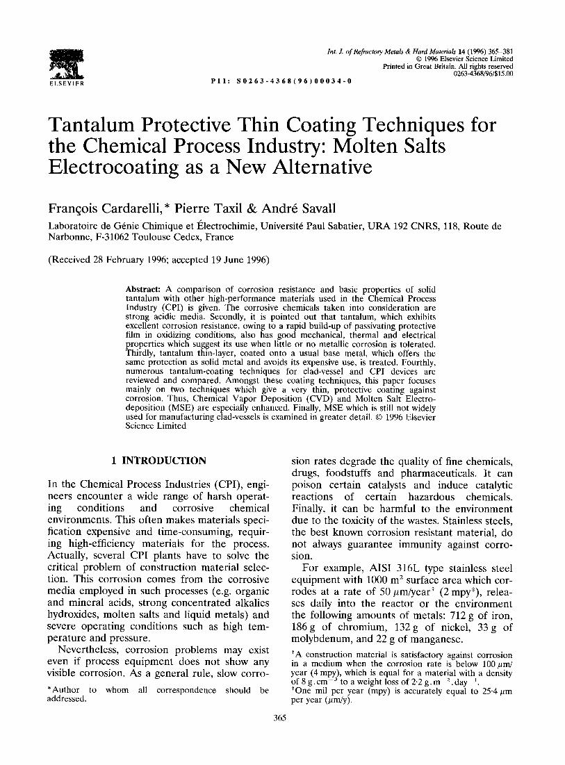
Alloyed deposits with base metal by Metal- liding Process (also known as Electrolyte Cernen- tation, &.&ace Alloying or DifSsion coating) in molten salt is a process in which metallic ions are transferred to the cathode surface where they are reduced in the alloying state with base metal.“4-x” There are two methods for obtaining a surface alloy using metalliding processes.
Soluble Anode
(+I
:
posit
Molten Fluoride Bath
Electrolytic Cell
Fig. 1. Tantalum electroplating process.
(i) Firstly, a simpler method consists of con- necting electrically the electrode which is made of the metal to be deposited (anode) with the base metal electrode (cathode) to give a gal- vanic cell (cf. Fig. 2). When the short-circuit is well established, the redox reaction occurs in which more electropositive metal is oxidized at the anode and gives metal ions which are reduced at the cathode by outer circuit elec-
Cathode Substrate
Metalliding Cell
Fig. 2. Tantalum metalliding process
Tantalum protective thin coating techniques 375
trons and give metal alloying. The sufficient condition for ensuring good metalliding reac- tion is that the deposited metal must be more electropositive (resp. less noble) than the base metal. Thus, the metalliding process is self-sup- porting by galvanic cell electromotive force and no external electrical potential is needed. Cath- odic current densities which depend on the species’ diffusion coefficients range from 1 to 20 mA.cm-‘.
(ii) In the second method the alloying could also be obtained in the following two steps: (1) firstly, short-time electrolysis gives a thin metal coating on the base metal; (2) electrolysis is stopped and the cathode is maintained immersed in the melt for several hours to allow deposit of metal-base metal interdiffusion. Pro- cess validity is close linked to the two metals’ interdiffusion facilities at the operating tem- perature (800-1100°C). For these reasons met- alliding is limited to certain metals. Alloyed deposits are uniform, dense, non-porous and smooth. Stabilized alloyed deposits could be solid-solutions or intermetallic-compounds. The precursors for metalliding in molten salts are from Cook of General Electric”7-90 and Ilyu- shchenko et al.” The deposition mechanism in the particular case of tantalum and niobium onto nickel base metal has been explained by Taxi1 et aZ.“2p”4
In conclusion, refractory metals could be deposited onto a base metal by electrochemistry in molten salts. Electrodeposits are uniform, dense and adherent, however, in some particu- lar cases they could form inter-diffusion alloys. Like CVD, MSE is a suitable technique for obtaining thin protective deposits. In the follow- ing paragraph, tantalum electrodeposition by molten salt is described.
4 MOLTEN SALTS ELECTRODEPOSITION OF TANTALUM
4.1 State of the art
Development of tantalum electrochemistry in molten salts is closely linked with refractory metals electrochemistry. The first studies on tantalum recovery in fused salt by electrolysis appeared in 1931” and concerned metal elec- trowinning. During this period 193Os-1940s electrowinning was the only way of recovering
tantalum metal from ores. Tantalum electro- chemistry in molten salt underwent rapid expansion in the period 1950-1965. The great number of references on the subject concern academic studies on fundamental aspects (e.g. mechanisms, kinetic parameters), and numerous industrial patents (e.g. Norton Co.,“‘~‘“’ Union Carbide Corp*,102. ‘0.3 Horizon Titanium Corp., ‘04-10y Timax Corp.,“’ Ciba Ltd,“‘-“4 Pechiney,‘” SOGEV,“6 Mitsubishi Heavy Industries’ ” ). This large development of tanta- lum metallurgy is the result of major military, nuclear, spatial and aeronautical programs which have involved high refractory material studies for balistics, equipment used to handle liquid metals or molten salts in nuclear power reactor systems, thermal shields for aerospace engines and a selection of high efficiency elec- tronic devices. A wide range of melts and mix- tures has been explored for tantalum electrorecovery ranging from tantalum pentaox- ide diluted in cryolithe melt’ l8 to tantalum fluoride dissolved in chloride or fluoride melts. However, for electroplating applications, the selection of molten alkaline fluorides was high- lighted by industrial studies especially those performed by the two precursors Senderoff and Mellors’ ” from Union Carbide Corp. Actually, they showed that in molten alkaline fluorides, refractory metal electrodeposits were dense, coherent and adherent. Since the 1960s these engineers have carried out a complete review of most of the reactive metals (e.g. Zr,“” ZrBz,“’ Nb, ‘22,‘23 Ta,‘24 MO and W’25,‘26). The tailored operating conditions are protected by patents.‘*‘,“” According to their patents the optimum operating conditions were the follow- ing: a bath obtained from melting the ternary eutectic mixture LiF-NaF-KF (so-called Fli- NaK) with a solute content of K,TaF, ranging from 15 to 40% wt under inert atmosphere, at 800°C cathodic current density of 40 mA. cm -*. Another optimum condition for tantalum electroplating was given later by Bali- khin”” and Balikhin & Sukhoverkov”” which use LiF-NaF-30% K,TaF, at 800°C cathodic current 60 mA.cm-’ give 150 pm tantalum onto copper and steel. These coatings are coherent and non-porous with a Vickers hard- ness Number of 110-120.
The mechanism of electrochemical reduction of Ta(V) in these melts has been discussed; a detailed discussion about tantalum reduction in
376 I? Cardarelli. f! Taxil, A. Savall
fluoride melts has been reviewed by Polyakova et al.‘-”
Taxi1 & Mahenc’-‘* have shown that in a fluoride melt at 800°C the reduction mechanism only occurs in one step as follows:
TaF?- +5ee+Ta”+7Fp
As a general rule, the advantages of tantalum electroplating in molten salts are: high purity tantalum, which is obtained by electrorefining using a soluble anode, and a high current effi- ciency equal to 100%.
MSE allows one to coat several base metals such as steels, and other common construction materials. “‘, ‘X4 The production of tantalum coatings 1 cm thick has also been described in the literature.‘35
4.2 Choice of the melt
The basic criteria required for selecting an elec- trolytic melt are as follows: low vapor pressure, low melting point, high electrical conductivity, low absolute viscosity, wide range of electric potentials, low corrosiveness for cell construc- tion materials, easy to purify and low cost.
As a general rule, inorganic halogenide salts satisfy all these criteria.“’ Amongst the several compounds tested”’ rare earth (e.g. La, Ce), alkaline (e.g. Li, Na, K, Cs) and alkaline-earth (e.g. Be, Mg, Ca, Sr, Ba)lX8 metal chlorides and fluorides, above all, are the most suitable com- pounds. Therefore, without moisture and oxy- gen these inorganic salts give high stability melts. Actually, molten fluorides (resp. chlor- ides) are very sensitive to moisture and oxygen contaminants. With water, the reaction gives highly corrosive hydrogen fluoride (resp. hydro- gen chloride) which readily corrodes cell material.“” With traces of oxygen, fluoride anions give oxifluoride complex anions which react with low-valency cations of the metal and give a protective polymeric film onto the cath- ode which inhibits good deposition.‘4” Molten alkaline fluoride baths are now preferred for electroplating of refractory metals. Actually, fluoride melts exhibit good physicochemical properties suited to molten salt electrodeposi- tion of these metals.‘4’.‘42 They have a low melting point especially if they are used in eutectic mixtures and with a low vapor pressure. On the other hand, fluoride ions exhibit excel-
lent complexation properties, especially with refractory metal cations. This strong field com- plexation increases the high valency cation sta- bility in the melt and avoids disproportionation reactions which could occur during the reduc- tion process. Finally, fluoride melts have strong etching properties on removal of metallic oxide films and so avoid the formation of oxide layer onto the cathode surface. These two character- istics are very favorable for achieving coherent, dense and adherent tantalum deposits onto the base metal. By contrast, the ability of molten fluorides to remove protective oxide from most metallic surfaces is a strong drawback for the selection of good containers for these baths (it will be discussed in the following paragraph).
In practice, only alkaline fluoride melts such as lithium, sodium, potassium are widely used, in eutectic mixtures, with a ternary (LiF-NaF- KF so-called FliNaK), or binary (e.g. LiF-NaF, LiF-KF, NaF-KF) composition. The high hygroscopicity of KF, prohibits its use and in practice the binary eutectic LiF-NaF is selected for industrial uses.
In the melt, tantalum appeared as the com- plex’“’ species TaF;-. The tantalum salt used as a solute in the melt could be tantalum penta- fluoride TaF, or potassium heptafluorotantalate (V) K,TaF,.
4.3 Choice of the container materials
Construction material selection has been reviewed for fluoride melt containers’44 and cell design. 14’ Only a few construction materials are entirely resistant without caution against alka- line fluoride melts at high temperature. These materials are mainly platinum group metals (e.g. Ru, Rh, Pd, OS, Ir, Pt) and their alloys, other precious metals (e.g. Au, Ag), some allo- tropic varieties of carbon (e.g. diamond, graph- ite, pyrolytic carbon, glassy carbon, etc.) and also polymorphous varieties of boron nitride (e.g. sintered, pyrolytic, cubic-borazon). It is obvious, except for graphite and glassy carbon, that the high cost of these materials prohibits their industrial use. Graphite which has been widely used as a crucible material, is not suit- able for this application. Actually, its surface disintegration leads to conductive graphite flakes in the melt. Because of their low density compared with the melt, graphite flakes float and lead to short-circuits between electrodes.
Tantalum protective thin coating techniques 377
Glassy carbon is more sensitive to mechanical strain during crystallization of the bath which often leads to container failure on cooling. Moreover, some common materials are suitable for handling and storing fluoride melts without moisture and oxygen. These materials are pure metals such as copper, nickel, molybdenum, or complex alloys like stainless steels, Hastelloy” X, Monel@ and Inconel600”.
Nickel could be selected advantageously. It exhibits good resistance in fluoride melts with- out moisture, it is easy to machine and is a cheap construction material. Thus, the crucible which has a straight form is machined by turn- ing directly from a pure nickel bar. Wall thick- ness should be large to avoid creep phenomena.
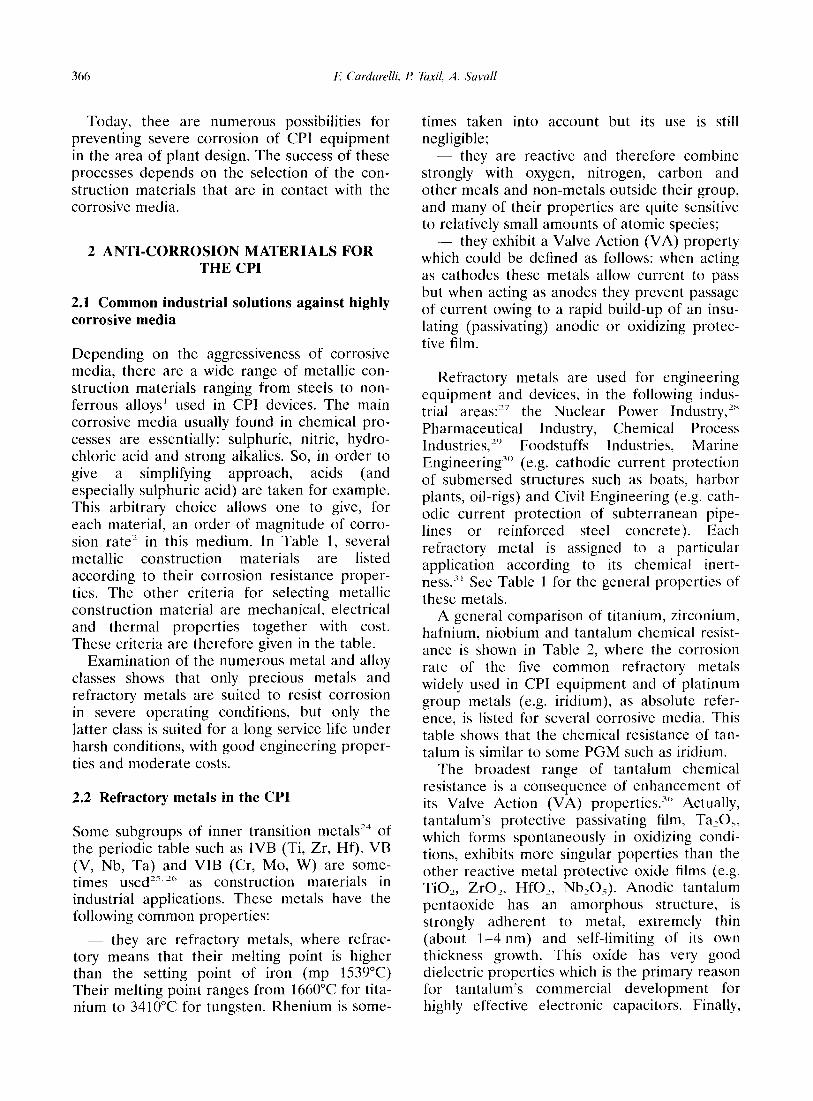
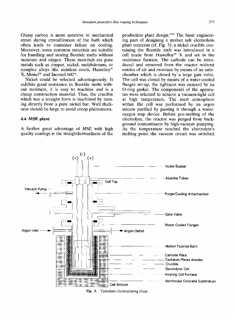
4.4 MSE plant
A further great advantage of MSE with high quality coatings is the straightforwardness of the
Argon inlet -
(- r
!
production plant design.14” The basic engineer- ing part of designing a molten salt electrolysis plant concerns (cf. Fig. 3): a nickel crucible con- taining the fluoride melt was introduced in a cell made from Hastelloya X and set in the resistance furnace. The cathode can be intro- duced and removed from the reactor without entries of air and moisture by means of an ante- chamber which is closed by a large gate valve. The cell was closed by means of a water-cooled flanges set-up, the tightness was ensured by an O-ring gasket. The components of the appara- tus were selected to achieve a vacuum-tight cell at high temperature. The inert atmosphere within the cell was performed by an argon stream purified by passing it through a water- oxygen trap device. Before pre-melting of the electrolyte, the reactor was purged from back- ground contaminants by high-vacuum pumping. As the temperature reached the electrolyte’s melting point the vacuum circuit was switched
Nickel Busbar
I’ Cell Top Alumina Tubes
Purge/Cooling Antechamber
7 ’ (yA Gate Valve
r:-r 01 Water Cooled Flanges n
if===+ -a Argon Outlet
..::.:<+ :: :...:. :: .:
:. .:::... .,
: . ...: :? <,:~:~~j Cell Bottom
Molten Fluoride Bath
Cathode Plate Tantalum Plates Anodes Crucible
Electrolytic Cell
Heating Coil Furnace
Reinforced Concrete Substratum
Fig. 3. Tantalum electroplating plant.
378 F Cardarelli, P Taxil, A. Savall
to a pure argon stream. The electrodes were held by nickel busbars electrically insulated from the reactor by alumina tubes. Electrical power supply was provided by an electric recti- fier. Its design simplicity is equally simple whether for laboratory pilot plant or industrial plants.
5 CONCLUSION
In CPI, the selection of chemically inert con- struction material is a critical problem for engi- neers, especially for processes using highly corrosive chemicals. Amongst the numerous high-performance materials, it has been shown that tantalum is perfectly suited for strong cor- rosive acidic media under severe operating con- ditions owing to its tenacious protective oxide film. In these harsh environments, its corrosion rate is always below 254 ,um/year which ensures a long service life for built-in equipment. More- over, in addition to its chemical inertness, tanta- lum exhibits good mechanical, thermal and electrical properties suited to industrial applica- tions. However, its high cost prohibits solid tan- talum from being used in chemical engineering devices. Nevertheless, clad devices and vessels fabricated from thin tantalum coatings which ensures excellent protection of the base metal against corrosion, are an attractive solution. Amongst the several tantalum coating techni- ques described, the three main techniques which give a protective coating of tantalum against corrosion attack are: Explosion Clad (EC), Chemical Vapor Deposition (CVD) and Molten Salt Electrodeposition (MSE). Explo- sion clad produces a thick coating (1 mm) which leads to large amounts of metal being used. A cheap thin coating (100 pm) can therefore only be obtained with the two last techniques. By contrast with CVD, which has been developed on an industrial scale, MSE is not now widely used for tantalum clad vessel manufacturing. Nevertheless, MSE has many advantages with regard to CVD, such as the accurate control of the coating thickness by current control, the simple design of plants, the high deposition rate (100 ,um/h) and good throwing power. There- fore, in the future, MSE could be an attractive alternative when manufacturing tantalum clad vessels.
1.
2.
3.
4.
5 _ .
6.
7.
8.
9.
10.
11.
12.
13.
14.
15.
16.
17.
18.
19.
20.
21.
22.
23.
REFERENCES
Woldman, N. E., Woldmand’s Engineering Alloys, 6th edition, ed. R. C. Gibbons. ASM, Metals Park, OH, 1979. NACE, Corrosion in Sulphuric Acid. NACE Inter- national, 1992. Bringas, J. E. (ed.), The Metals Black Book, Vol. I, Ferrous Metals, 2nd edition. CAST1 Publishing, Edmonton, Canada, 1995. Bringas, J. E. (ed.), The Metals Red Book, Vol. 2, Nonferrous Metals. CAST1 Publishing, Edmonton, Canada, 1995. Krisher, A. S. & Siebert, W. O., Materials of con- struction. In Peny:y Chemical Engineers’ Handbook, ed. R. E. Perry & D. W. Green, 6th edition. McGraw-Hill, New York, 1984, pp. 23-l to 23-66. McDowell, D. W., Handling mineral acids. Chem. Eng, 11 (1974) 118-23. Colombier, L., Steels and alloys which resist corro- sion at high temperatures. M6tau.x (Corrosion-Inds.), 30 (1955) 294-303. Hughson, R. V., High-nickel alloys for corrosion resistance. Chem. Eng, 83 (1976) 125-36. Hoffmann, W., Lead and Lead Alloys. Springer-Ver- lag, Berlin, 1960. Mao, G. W., Larson, J. G. & Rao, P., Effect of small additions of tin on some properties of lead 4.5% antimony alloys. J. Inst. Metal, 97 (1969) 343-50. Schleicher. H. W., Electrodes for electrolytic pro- cesses, Brit. Pat., 941 177, 1963. Duval, C., Platinc. In Nouveau Traitt de Chimie Min- irule, Tome XIX: Ru-Os-Rh-lr-Pd-Pt, ed. P. Pas- cal. Masson & Cic, Paris, 1958, pp. 725-41. Lunge, G. & Naville, J., Trait& de la Grande lndustrie Chimique, Tome I. Acide Sulfutique et 01&m. Mas- son & Cie, Paris, 1879. Webster, R. T., Niobium in industrial applications. In Refractory Metals and their Industrial Applications, ASTM STP 849, ed. R. E. Smallwood. ASTM, Phil- adelphia, PA, 1984, pp. 18-27. Boehni, H., Corrosion behavior of various rare met- als in aqueous acid solutions with special considera- tion of niobium and tantalum. Schweiz Arch. Angew. Wiss. Tech., 33 (1967) 339-63. Andreeva, V. V., Glukhova, A. I., Donstov, S. N., Moiseeva, I.S. & Mel’nikova, I. V., Resistance to corrosion, electrochemical and mechanical proper- ties, and microstructures of alloys of the niobium- tantalum system. inst. Fiz. Khim. 2 (lY66) 178-90. Yau, T.-L. & Bird, K. W., Manage corrosion with zirconium. Chem. Eng Prog., 91 (1995) 42-6. Fox, F. G., Tantalum as a corrosion-resistant material. Corrosion Prevention and Control. 5 (1958) 44-8. Hampel, C. A., Extraction, chemistry, and applica- tions of tantalum in the chemical industry. Trans. Am. Inst. Mining., Met., Petrol. Engrs, (1956) 97-101. Hampel, C. A., Tantalum makes some products fca- sible. Ind. Eng Chem., 48 (1956) 1979-81. Miller, G. L., Tantalum - its manufacture and chemical uses. Brit. Chem. Eng, 1 (1956) 152-7. Cardonne, S. M., Kumar, P., Michaluk, C. A. & Schwartz, H. D., Tantalum and its alloys. fret. J. Refi Metals & Hard Mater., 13 (199.5) 187-94. Burns, R. H., Shuker, F. S., Jr & Manning, P. E., Industrial applications of corrosion resistant tanta-
Tantalum protective thin coating techniques 379
lum, niobium and their alloys. Refractory Metals and their Industrial Applications, ASTM STP 849, ed. R. E. Smallwood. ASTM, Philadelphia, PA, 1984, pp. 50-69.
Characteristic of tantalided and hafnided samples in highly corrosive electrolyte solutions. Corrosion, 27 (1971) 55-62.
24. Pastonesi, G., Use of metallic materials and corro- sion in the chemical industry. Metall. Ital., 46 (1953) 37-41.
49. Christopher, D., Bimetallic pipe. Mech. Eng, 83 (1961) 68-71.
25. Bayley, K. .I. & Kay, V. B., Fabrication of titanium, tantalum and zirconium for chemical plants. Chem. Process Eng, 49 (1968) 79-81.
26. Sherwood, E. M., Materials of construction: Zr, Hf, MO, Nb, Ta, Re, Cr. Znd. Eng Chem., 49 (1957) 1612-7.
50. Whiting, K. A., Cladding copper articles with niobium or tantalum and platinum outside, US Pat. 3 1.56 976, 1964.
51. 1’Usine Nouvelle, no. 2418, 11 Octobre 1995. 52. Bulk metals Quotation, Marphil International, Paris,
France, October 1995. 53. Emsley, J., The Elements, 2nd edition. Clarendon
Press, Oxford, 1991. 27. Smallwood, R. E., Use of refractory metals in chemi-
cal process industries. In Refractory Metals and their Industrial Applications, ASTM STP 849, ed. R. E. Smallwood. ASTM, Philadelphia, PA, 1984, pp. 106-14.
28. Frost, B. R. T., Nuclear Fuels Elements: Design, Fabri- cation and Per$ormance. Pergamon Press, Oxford, 1982.
54. Maissel, I. & Glang, R., Handbook of Thin Film Technology. McGraw Hill, New York, 1970.
55. Stern, K. H., Metallurgical and Ceramic Coatings. Chapman & Hall, London, 1994.
56. Chapman, B. N. & Anderson, J. C., Science and Technology of Surface Coating. Academic Press, New York, 1974.
29. Hooper, W. H. L., New metals in the oil industry. II Tantalum and niobium. Petroleum, 21 (1958) 313-5.
30. Geld, I., Cathodic protection anode with sections replaceable underwater, US Pat. 3 718 570, 1973.
31. Bayley, K. J. & Kay, V. B., Fabrication of titanium, tantalum, and zirconium for chemical plants. Chem. Process. Eng, 49 (1968) 79-81.
32. Wortly, J. P. A., Corrosion resistance of titanium, zirconium, and tantalum. Corrosion Prevent. Control, 10 (1963) 21-6.
33. Zircadyne” corrosion data, Teledyne Wah Chang Albany, USA, 1995.
57. Bunshah, R. F., Deposition Technology for Film and Coatings. Developments and Applications. Noyes Pub- lications, New Jersey, 1982.
58. Krutenat, R. C., Metallic Coating (Survey). In Kirk- Othmer Encyclopedia of Chemical Technology, 3rd edition, Vol. 15. Wiley-Intersciences, New York, 1983, pp. 241-74.
34. Bishop, C. R., Corrosion test at elevated tempera- tures and pressures. Corrosion, 19 (1963) 308t-14t.
35. Technical Note on K131m-Tantalum, Cabot Perform- ance Material Inc., 1995.
59. Grams, W. R., Cladding the cleaned reactive refrac- tory metals with lower-melting metals in the absence of a reactive atmosphere, US Pat. 3 409 978, 1968.
60. Krupin, A. V., Rolling metal in vacuum. Mosk. Inst. Stali. Splavov, 52 (1968) 153-63.
61. Chelius, J., Explosion-clad sheet metal for corrosion- resistant chemical equipment. Weikst. Korros., 19 (1968) 307-12.
36. Fairbrother, F., Chemistry of Niobium and Tantalum. Elsevier, New York, 1963.
37. Droegkamp, R. E., Schussler, M., Lambert, J. B. & Taylor, D. F., Tantalum and tantalum compounds. In Kirk-Othmer; Encyclopedia of Chemical Tech- nology, 3rd edition, Vol. 22. Wiley-Intersciences, New York, 1984, pp. 541-64.
38. Miller, G. L., Tantalum and Niobium. Academic Press, New York, 1959.
62. Bergmann, 0. R., Cowan, G. R. & Holtzman, A. H., Metallic multilayered composites bonded by explo- sion detonation shock, US Pat. 3 493 353, 1970.
63. Glatz, B., Explosive cladding of metals. Huntn. Listy, 25 (1970) 398-406.
64. Bouckaert, G. P., Hix, H. B. & Chelius, J., Explosive- bonded tantalum-steel vessels. DECHEMA Mono- graph, 76 (1974) 9-22.
39. Sisco, F. T. & Epremian, E. (eds), Columbium and Tantalum. John Wiley & Sons, New York, 1963.
40. Klein, A., Electrode material for electrolytic pro- cesses, US Pat. 3 372 107, 1968.
41. Zungrelb, E. & Schmitz, M., Anode for electrolyte processes. German Pat. 1 286 513, 1969.
42. Beer, H. B., Electrode coated with platinum metal oxide and operating it. Neth. Appl., 6 606 302, 1966.
43. Beer, H. B., Versatile electrode. Neth. Appl., 6 800 834, 1968.
65. Krepski, R. P., Thermal Spray Coating Applications in the Chemical Process Industries. MT1 Publication No. 42, 252 pp, NACE International, 1992.
66. CETIM/Club des Traitements de Surface, Manuel des traitements de su$ace a l’usage des bureaux d’etuds, CETIM, Paris, 1987.
67. Gray, D. E. (ed.), American Institute of Physics Hand- book, 3rd edition. McGraw-Hill, New York, 1972.
68. Richardt, A. & Durand, A.-M. (eds), Le vide, les couches minces, les couches dures. Editions In Fine, Paris, 1994.
44. Okamura, T., Electrodes for electrolytis of chloride- or sulphate-containing solutions, US Pat., 3 497 426, 1964.
69. Umanshii, Ya. S., Urazaliev, U. S. & Ivanov, R. D., Formation of tantalum thin films prepared by cath- odic sputtering. Fiz. Metal Metalloved, 33 (1972) 196-9.
45. Charles, R., Tantalum: its properties and applica- tions in the chemical industry. Chem. Ztg. Chem. App., 93 (1969) 278-90.
46. Jenstrom, E. R. & Schussler, M., Tantalum takes on new applications. Met. Prog., 106 (1974) 67 and 70-l.
47. Stapes, B. G. & Galloway, W. S., Jr, Corrosion per- formance of 90-10 tantalum-tungsten alloy. Mater Prot., 7 (1968) 34-9.
70. Fitzer, E. & Kehr, D., Processing studies of the chemical vapor deposition of niobium and tantalum. Proc. Int. Conf CVD 4th, 1973, pp. 144-6.
71. Spitz, J. & Chevallier, J., Comparative study of tan- talum deposition by chemical vapor deposition and electron beam vacuum evaporation. Proc. bit. Conf CVD 5th, 1975, pp. 204-16.
72. Spitz, J., Proc. European Congr Corrosion 5th, Paris, 1973.
48. Danzig, 1. F., Dempsey, R. M. & La Conti, A. B., 73. Beguin, C., Horrath, E. & Perry, A. J., Tantalum
380 E Cardarelli, R Taxil. A. Savall
coating of mild steel by CVD. Thin Solid Films, 46 (1977) 209-12.
74. Holker, K. U. & Chapman, R. D., Evaporation of metal onto the inner surfaces of hollow annaratus. such as conduit tubes, valves, pumps, etc., Ger. Pat: 2 312 712, 1973.
75. Glaski, F. A., Chemical Vapor Deposition of tanta- lum on steel, US Pat. 3 767 456, 1973.
76. Glaski, F. A., Coating on steel with metals, Ger. Pat. 2 331 576, 1974.
98. Ervin, G., Jr. & Ueltz, H. F. G., Apparatus for con- tinuous production of refractory metal by electrolysis of fused salts, US Pat. 2 837 478, 1958.
99. Washburn, M. E., Cells for metal-metal carbide elec- trolysis, US Pat. 2 838 454, 1958.
100. Erwin, G. & Ueltz, H. F. G., Electrolytic preparation of Th, U, Nb, Ta, V, W, MO, and Cr, Ger. Pat. 1 078 776, 1960.
77. Galski, F. A., Coating steel with tantalum and niobium, US Pat. 3 784 403, 1974.
78. Lowenheim, F. A., Electroplating. McGraw-Hill, New York, 1978.
101. Ueltz, H. F. G., Electrolytic extraction of refractory metals of groups IV, V, and VI from their carbide, US Pat. 2 910 021, 1960.
79. Lowenheim, F. A., Modern Electroplating, 3rd edi- tion. John Wiley, New York, 1974.
80. Bobst, J., Niobium and tantalum electroplating, Ger. Pat. 2 064 586, 1971.
102. Sarla, R. M. & Schneidersmann, E. O., Fused-salt electrolytic cell for producing high-melting reactive metals, such as tantalum, US Pat. 2 957 816, 1960.
103. Union Carbide Corp., Cell for plating heat resistant metals from molten salt mixtures. Neth. Appl. 6 516 263, 1966.
81. Sadoway, D. R., The synthesis of refractory-metal compounds by electrochemical processing in non aqueous media. In Refractory Metals: Extraction, Pro- cessing and Applications. The Minerals, Metals and Materials Society, TMS Publishing, Warrendale, Pennsylvania, PA, 1990, pp. 213-20.
82. Lantelme, E., Inman, D. & Lovering, D. G., Electro- chemistry-1. In Molten Salt Techniques, eds D. G. Lovering, R. J. Gale, Vol. 2. Plenum Press, New York, 1984, pp. 138-220.
104. Horizon Titanium Corp., Electrodeposition of Ti, Zr, Hf, V, Ta, and Nb, Brit. Pat. 778 218, 1957.
105. Horizon Inc., Formation of hard intermetallic coat- ings from electrodeposited layers of refractory met- als. Brit. Pat. 788 804, 1958.
106. Horizon Titanium Corp., Electrodeposition of Ti, Zr, Hf, Ta, V, Nb, Cr, MO, and W, Brit. Pat. 788 295, 1958.
107. Horizon Titanium Corp., Fused-salt bath for electro- deposition of multivalent metals: Ti, Nb, Ta, and V, Brit. Pat. 791 151, 1958.
83. Delimarskii, Iu. K. & Markov, B. F., Electrochemistry of Fused Salts. Sigma Press Publishing, New York, 1961.
84. Cook, N. C., Metalliding. Sci. Amer., 221 (1969) 38-46.
85. Cook, N. C., Diffusion coating metals in molten fluoride baths. Protect. Corrosion Metal Finish. Proc. hat. Conf., Basel, 1966, pp. 151-5.
86. Cook, N. C., Fosnocht, B. A. & Evans, J. D., Alloy- ing of metal surfaces in molten fluorides. Proc. Corzf: NACE 24th, 1968, pp. 520-4.
87. Cook, N. C., Beryllide coatings on metals, US Pat. 3 024 175, 1962.
108. Merlub-Sobel, M., Arnoff, M. J. & Sorkin, J. L., Chlorination and electrolysis of metal oxides in fused salt baths, US Pat. 2 870 073, 1959.
109. Wainer, E., Transition-metal halides for electrodcpo- sition of transition metals, US Pat. 2 894 886, 1959.
110. Timax Corp., Electrolytic preparation of pure bio- bium and tantalum, Brit. Pat. 837 722, 1960.
I Il. Huber, K. & Frost, E., Preparation of niobium and tantalum by melt electrolysis, Ger. Pat. 1 092 217. 1960.
88. Cook, N. C., Boride coatings on metals, US Pat. 3 024 176, 1962.
112. Kern, F., Electrolytic production of niobium and tan- talum, US Pat. 2 981 666, 1961.
113. Kern, F., Tantalum powders by electrolysis, Ger. Pat. I 139 284, 1962.
89. Cook, N. C., Silicide coatings on metals, US Pat. 3 024 177, 1962.
114. Scheller, W. & Blumer, M., Niobium and tantalum, Ger. Pat. 1 139 982, 1962.
90. Cook, N. C., Corrosion-resistant chromide coating, US Pat. 3 232 853, 1966.
115. Pruvot, E., Electrolytic manufacture of tantalum, Fr. Pat. I 199 033, 1959.
91. Iluyshchenko, N. G., Antinogenov, A. I., Belyaeva, G. I., Plotnikova, A. F. & Korlinov, N. I., Tr. 4-ogo Vsesoyuzn. Soveschch., 105, 1968.
92. Taxil, P. & Mahenc, J., The preparation of corro- sion-resistant layers by the electrolytic deposition of tantalum on nickel and stainless steel. Corrosion Sci., 21 (1981) 31-40.
116. SociCtC GCnCrale du Vide, Protecting coating, Neth. Appl., 6 400 547, 1964.
117. Nishio, Y., Oka, T., Ohmae, T. & Yoshida, Y., Steel plated with tantalum or a tantalum alloy, Ger. Pat. 2 010 785, 1971.
93. Taxi], P. & Qiao, Z. Y., Electrochemical alloying of nickel with niobium in molten fluorides. J. Appl. Electrochem., 15 (1985) 947-52.
94. Taxil, P., Formation d’alliages tantale-nickel par voie electrochimique. J. Less Common Metals, 113 (1985) 89-101.
118. Paschen, P. & Koeck, W., Fused salt electrolysis of tantalum. In Refractory Metals: Extraction Processing and Applications. The Minerals, Metals and Materi- als Society, TMS Publishing, Warrendale, Pennsylva- nia, PA, 1990, pp. 221-30.
95. Driggs, F. H. & Lilliendahl, W. C., Preparation of metals powders by electrolysis of fused salts. III Tan- talum. Znd. Eng Chem., 23 (1931) 634-7.
96. Mole Norton Spa, Electrolytic cell, Ital. Pat. 542 178, 1956.
119. Mellors, G. W. & Senderoff, S., Electrolytic deposit of refractory metals, Belg. Pat. 640 801, 1964.
120. Mellors, G. W. & Senderoff, S., Electrodeposition of coherent deposit of refractory metals. III - Zirco- nium. J. Electrochem. Sot., 113 (1966) 60-95.
121. Mellors, G. W. & Senderoff, S., Electrodeposition of coherent deposit of refractory metals. VII - Zirco- nium diboride. J. Electrochem. Sot., 118 (1971) 220-5.
97. Norton Grinding Wheel Co., Electrolytic production 122. Mellors, G. W. & Senderoff, S., Electrodeposition of of Ti, Zr, Hf, V, Nb, Ta, Cr, MO, or W, Brit. Pat. coherent deposit of refractory metals. I - Niobium. 792 716, 1958. J. Electrochem. Sot., 112 (1965) 266-72.
Tantalum protective thin coating techniques 381
123. Senderoff, S. & Mellors, G. W., Electrodeposition of coherent deposit of refractory metals. IV - The electrode reactions in the deposition of niobium. J. Electrochem. Sot., 113 (1966) 66-71.
124. Mellors, G. W., Senderoff, S. & Reihnhart, W. J., Electrodeposition of coherent deposit of refractory metals. II - The electrode reactions in the electro- deposition of tantalum. J. Electrochem. Sot., 112 (1965) 840-5.
125. Mellors, G. W., Senderoff, S. & Reihnhart, W. J., Electrodeposition of coherent deposits of refractory metals. VI - Mechanism of deposition of molybde- num and tungsten from fluoride melts. J. Electro- them. Sot., 114 (1965) 586-7.
126. Mellors, G. W., Senderoff, S. & Rheinhart, W. J., Electrodeposition of coherent deposit of refractory metals. V - Mechanism of deposition of molybde- num and tungsten from chloride melts. J. Electro- them. Sot., 114 (1965) 5.56-60.
127. Mellors, G. W. & Senderoff, S., Novel compounds of tantalum and niobium, US Pat. 3 398 068, 1968.
128. Mellors, G. W. & Senderoff, S., Electrodeposition of Zr, Ta, Nb, Cr, Hf, W. MO, V and their alloys, US Pat. 3 444 058, 1969.
129. Balikhin, V. S., Electroplating of protective tantalum coating. Zasch. Metal., 10 (1974) 459-60.
130. Balikhin, V. S. & Sukhoverkov, I. N., Tantalum elec- troplating. Tsvet. Metal., 3 (1974) 70-l.
131. Polyakova, I. P., Polyakov, E. G., Sorokin, A. I. & Stangrit, P. T., Secondary processes during tantalum electrodeposition in molten salts. J. Appl. Electro- them., 22 (1992) 628-37.
132. Taxil, P. & Mahenc, J., Formation of corrosion- resistant layers by electrodeposition of refractory metals or by alloys electrowinning. J. Appl. Electro- them., 17 (1987) 261-9.
133. Mellors, G. W. & Senderoff, S., Electroforming of refractory metals. Plating, 51 (1966) 972-5.
134. Senderoff, S. & Mellors, G. W., Coherent coating of
refractory metals. Science, 153 (1966) 1475-81. 135. Galopin, M. & Daniel, J. S., Developpement et per-
spectives dans le traitement des metaux en bains ignes. Memoires Scientifiques Revue de Metallurgic, 85-98, Fevrier 1966.
136. Lovering, D. G. & Gale, R. J., Molten Salt Tech- niques, Vols 1-4. Plenum Press, New York, 1983-1993.
137. Janz, G. J., Molten Salts Handbook. Academic Press Publishers, New York, 1967.
138. White, S. H. & Twardoch, U. M., The chemistry and electrochemistry associated with the electroplating of group VIA transition metals. J. Appl. Electrochem., 17 (1987) 225-42.
139. Perry, J. E., Scale-up of cells to electrodeposit refractory metals using molten salts electrolytes, Workshop, London, 7-8 July, 1985.
140. Inman, D., Electrodeposition from molten salts. In Molten Salt Chemistry, ed. G. Mammantov & R. Marassi. Riedel Publishing Company, 1987, pp. 417-24.
142. Sethi, R. S., Electrocoating from molten salts. J. Appl. Electrochem., 9 (1979) 411-26.
143. Greenwood, N. N. & Earnshaw, A., Chemistry of the Elements. Pergamon Press, Oxford, 1984, pp. 1157.
144. Bamberger, C., Experimental techniques. In Molten Fluorides Chemistry, eds. J. Braunstein & G. Mam- mantov, Vol. 3. Plenum Press, New York, 1975, pp. 177-248.
141. Lovering, D. G. & Williams, D. E., In Molten Salt Technology, ed. D. G. Lovering. Plenum Press, New York, 1982, pp. 91-110.
145. White, S. H., Halides. In Molten Salt Techniques, eds D. G. Lovering & R. J. Gale, Vol. 2. Plenum Press, New York, 1984, pp. 19-54.
146. Inman, D. & White, S. H., The production of refrac- tory metals by the electrolysis of molten salts: design factors and limitations. J. Appl. Electrochem., 8 (1978) 375-90.