Embed Size (px)
Citation preview
© KEMET Electronics Corporation • P.O. Box 5928 • Greenville, SC 29606 • 864-963-6300 • www.kemet.com T2063_T500 • 12/5/2017 1One world. One KEMET
Benefits
• Meets or exceeds EIA standard 535BAAC• Weibull failure rate to B Level available• Standard gold-plated termination• RoHS Compliant • Operatingtemperaturerangeof−55°Cto+200°C• 100%steady-stateacceleratedagingat200°C• Voltagederatingis1/3at200°C• Qualifiedat1,000hoursoflifetestat200°Cwith0.33VR
• Taped and reeled per EIA 481• Meets MSL 1 requirements for Pb-free assembly according
to JEDEC J–STD–020 • Surge current options available
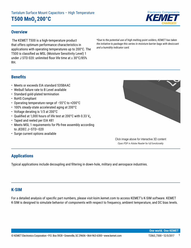
Overview
TheKEMETT500isahigh-temperatureproductthatoffersoptimumperformancecharacteristicsinapplicationswithoperatingtemperaturesupto200°C.TheT500isclassifiedasMSL(MoistureSensitivityLevel)1underJSTD020:unlimitedfloorlifetimeat≤30°C/85%RH.
*Due to the potential use of high melting point solders, KEMET has taken the initiative to package this series in moisture barrier bags with desiccant and a humidity indicator card.
TantalumSurfaceMountCapacitors–HighTemperature
T500 MnO2 200°C
K-SIM
Foradetailedanalysisofspecificpartnumbers,pleasevisitksim.kemet.comtoaccessKEMET’sK-SIMsoftware.KEMETK-SIMisdesignedtosimulatebehaviorofcomponentswithrespecttofrequency,ambienttemperature,andDCbiaslevels.
Applications
Typicalapplicationsincludedecouplingandfilteringindown-hole,militaryandaerospaceindustries.
© KEMET Electronics Corporation • P.O. Box 5928 • Greenville, SC 29606 • 864-963-6300 • www.kemet.com T2063_T500 • 12/5/2017 22
Tantalum Surface Mount Capacitors – High TemperatureT500 MnO2 200°C
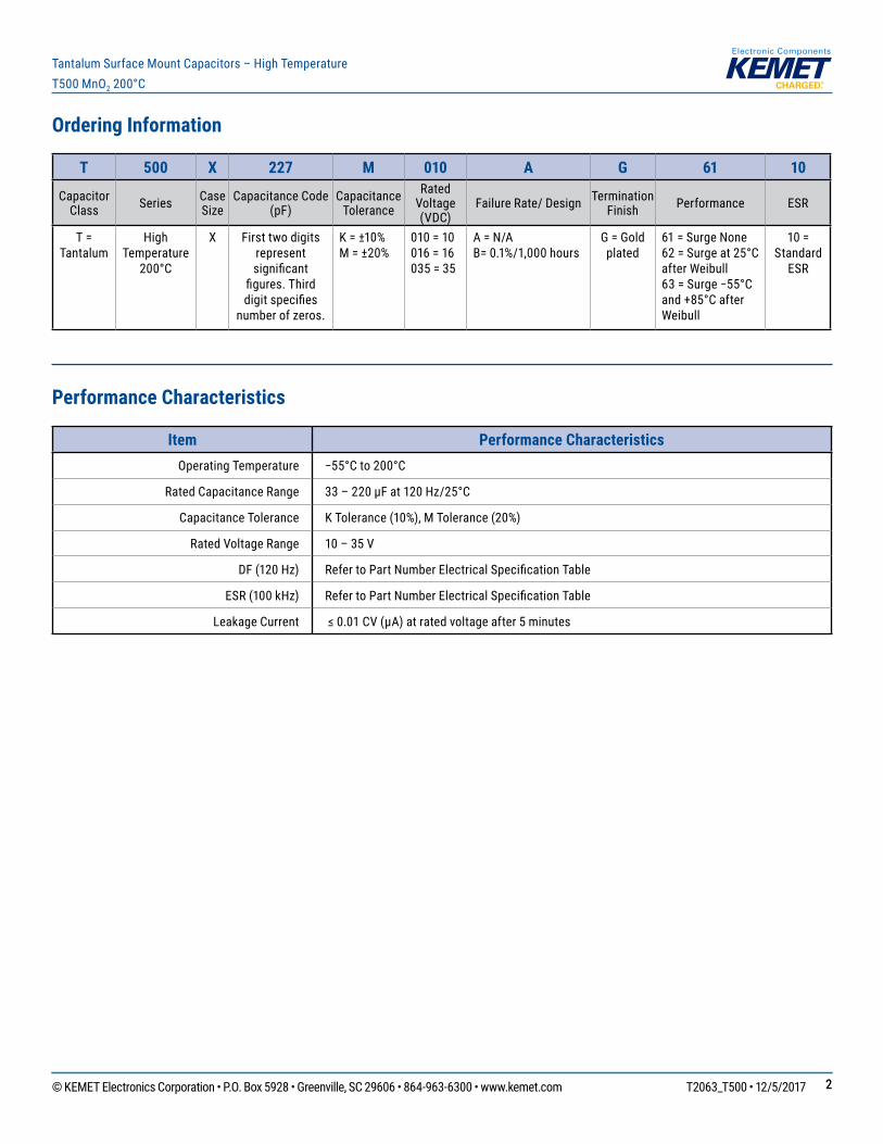
Ordering Information
T 500 X 227 M 010 A G 61 10
Capacitor Class Series Case
SizeCapacitance Code
(pF)Capacitance
Tolerance
Rated Voltage (VDC)
Failure Rate/ Design Termination Finish Performance ESR
T = Tantalum
HighTemperature
200°C
X First two digits represent significant
figures.Thirddigitspecifies
number of zeros.
K = ±10% M = ±20%
010 = 10 016 = 16 035 = 35
A = N/AB=0.1%/1,000hours
G = Gold plated
61 = Surge None62=Surgeat25°Cafter Weibull63=Surge−55°Cand+85°CafterWeibull
10 = Standard
ESR
Performance Characteristics
Item Performance CharacteristicsOperating Temperature −55°Cto200°C
Rated Capacitance Range 33–220µFat120Hz/25°C
Capacitance Tolerance KTolerance(10%),MTolerance(20%)
Rated Voltage Range 10 – 35 V
DF(120Hz) RefertoPartNumberElectricalSpecificationTable
ESR(100kHz) RefertoPartNumberElectricalSpecificationTable
Leakage Current ≤0.01CV(µA)atratedvoltageafter5minutes
© KEMET Electronics Corporation • P.O. Box 5928 • Greenville, SC 29606 • 864-963-6300 • www.kemet.com T2063_T500 • 12/5/2017 33
Tantalum Surface Mount Capacitors – High TemperatureT500 MnO2 200°C
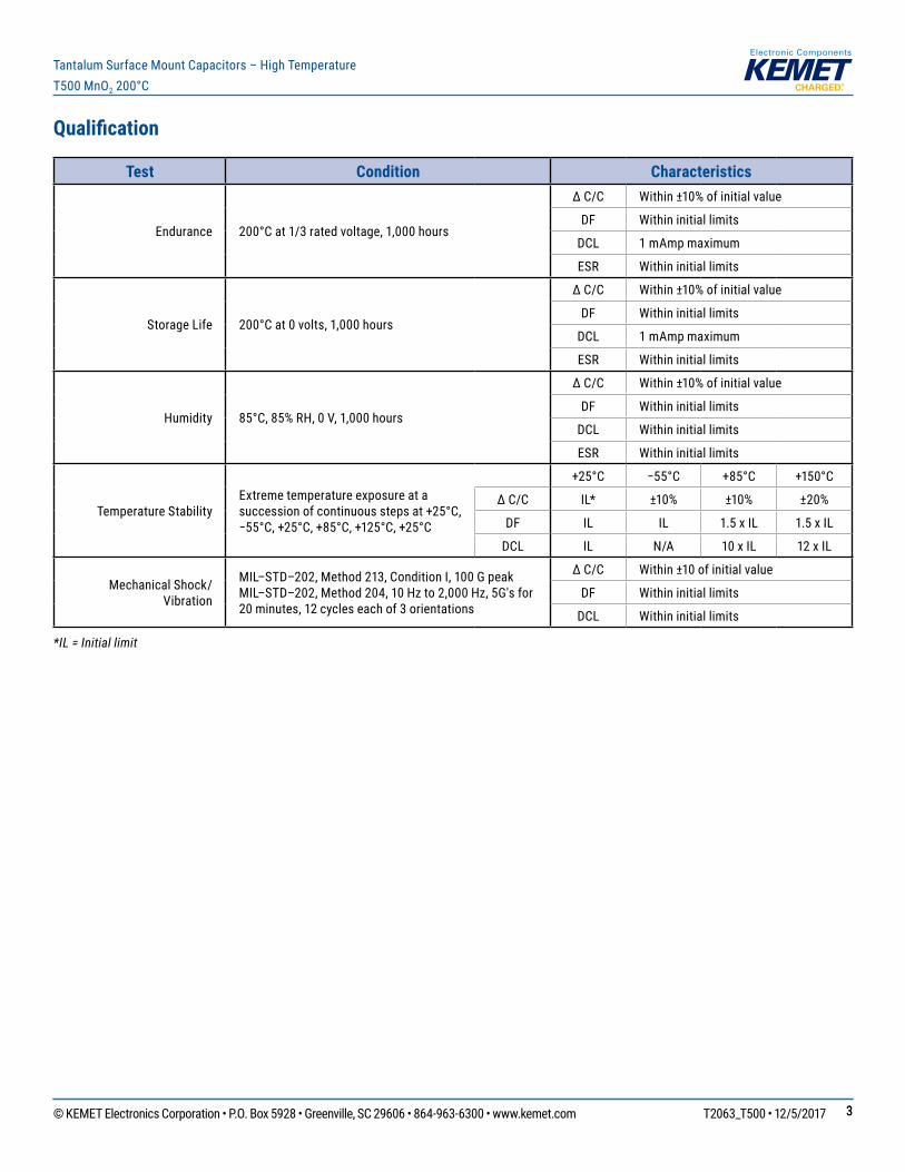
Qualification
Test Condition Characteristics
Endurance 200°Cat1/3ratedvoltage,1,000hours
ΔC/C Within±10%ofinitialvalue
DF Withininitiallimits
DCL 1 mAmp maximum
ESR Withininitiallimits
Storage Life 200°Cat0volts,1,000hours
ΔC/C Within±10%ofinitialvalue
DF Withininitiallimits
DCL 1 mAmp maximum
ESR Withininitiallimits
Humidity 85°C,85%RH,0V,1,000hours
ΔC/C Within±10%ofinitialvalue
DF Withininitiallimits
DCL Withininitiallimits
ESR Withininitiallimits
Temperature StabilityExtreme temperature exposure at a successionofcontinuousstepsat+25°C,−55°C,+25°C,+85°C,+125°C,+25°C
+25°C −55°C +85°C +150°C
ΔC/C IL* ±10% ±10% ±20%
DF IL IL 1.5 x IL 1.5 x IL
DCL IL N/A 10 x IL 12 x IL
MechanicalShock/Vibration
MIL–STD–202,Method213,ConditionI,100GpeakMIL–STD–202,Method204,10Hzto2,000Hz,5G'sfor20minutes,12cycleseachof3orientations
ΔC/C Within±10ofinitialvalue
DF Withininitiallimits
DCL Withininitiallimits
*IL = Initial limit
© KEMET Electronics Corporation • P.O. Box 5928 • Greenville, SC 29606 • 864-963-6300 • www.kemet.com T2063_T500 • 12/5/2017 44
Tantalum Surface Mount Capacitors – High TemperatureT500 MnO2 200°C
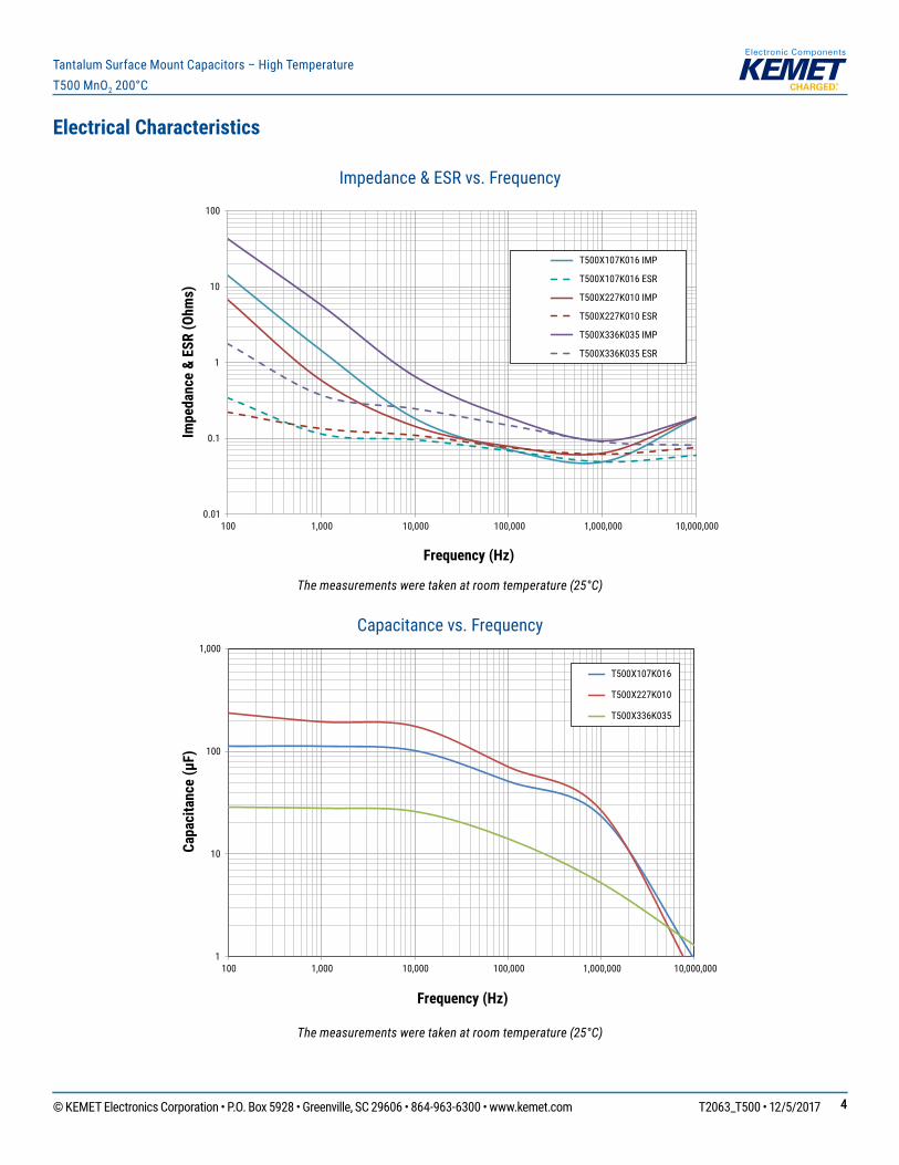
Electrical Characteristics
Impedance & ESR vs. Frequency
The measurements were taken at room temperature (25°C)
Capacitance vs. Frequency
The measurements were taken at room temperature (25°C)
0.01
0.1
1
10
100
100 1,000 10,000 100,000 1,000,000 10,000,000
Impe
danc
e &
ESR
(Ohm
s)
Frequency (Hz)
T500X107K016 IMP
T500X107K016 ESR
T500X227K010 IMP
T500X227K010 ESR
T500X336K035 IMP
T500X336K035 ESR
1
10
100
1,000
100 1,000 10,000 100,000 1,000,000 10,000,000
Capa
cita
nce
(µF)
Frequency (Hz)
T500X107K016
T500X227K010
T500X336K035
© KEMET Electronics Corporation • P.O. Box 5928 • Greenville, SC 29606 • 864-963-6300 • www.kemet.com T2063_T500 • 12/5/2017 55
Tantalum Surface Mount Capacitors – High TemperatureT500 MnO2 200°C
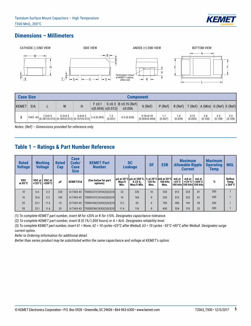
Dimensions – Millimeters
H
X T
B B
G
F E
A
L R
P
SIDE VIEW ANODE (+) END VIEW BOTTOM VIEWCATHODE (-) END VIEW
W
S STermination cutout at KEMET's option,
either end
Case Size Component
KEMET EIA L W H F ±0.1 ±(0.004)
S ±0.3 ±(0.012)
B±0.15(Ref)±0.006 X(Ref) P(Ref) R(Ref) T(Ref) A(Min) G(Ref) E(Ref)
X 7343–43 7.3±0.3 (0.287±0.012)
4.3±0.3 (0.169±0.012)
4.0±0.3 (0.157±0.012) 2.4(0.095) 1.3
(0.051) 0.5(0.020) 0.10±0.10 (0.004±0.004)
1.7 (0.067)
1.0 (0.039)
0.13 (0.005)
3.8 (0.150)
3.5 (0.138)
3.5 (0.138)
Notes: (Ref) – Dimensions provided for reference only.
Table 1 – Ratings & Part Number Reference
Rated Voltage
Working Voltage
Rated Cap
Case Code/ Case Size
KEMET Part Number
DC Leakage DF ESR
Maximum Allowable Ripple
Current
Maximum Operating
TempMSL
VDC at 85°C
VDC at +125°C
VDC at +200°C µF KEMET/EIA (See below for part
options)µA at 20°C
Max/5 Min.
µA at 200°C, 0.33 VR
Max/5 Min.
% at 20°C120 Hz Max.
mΩ at 20°C100 kHz
Max.
mA at +25°C
100 kHz
mA at +125°C 100 kHz
mA at +200°C 100 kHz
°CReflow Temp
≤ 260°C
10 6.6 3.3 220 X/7343-43 T500X227(1)010(2)G(3)10 22 220 10 250 812 325 81 200 1
16 10.6 5.3 100 X/7343-43 T500X107(1)016(2)G(3)10 16 160 8 250 812 325 81 200 1
35 23.1 11.6 10 X/7343-43 T500X106(1)035(2)G(3)10 3.5 35 6 700 486 194 49 200 1
35 23.1 11.6 33 X/7343-43 T500X336(1)035(2)G(3)10 11.6 116 8 600 524 210 52 200 1
(1) To complete KEMET part number, insert M for ±20% or K for ±10%. Designates capacitance tolerance.(2) To complete KEMET part number, insert B (0.1%/1,000 hours) or A = N/A. Designates reliability level.(3) To complete KEMET part number, insert 61 = None, 62 = 10 cycles +25°C after Weibull, 63 = 10 cycles −55°C +85°C after Weibull. Designates surge current option.Refer to Ordering Information for additional detail.Better than series product may be substituted within the same capacitance and voltage at KEMET's option.
© KEMET Electronics Corporation • P.O. Box 5928 • Greenville, SC 29606 • 864-963-6300 • www.kemet.com T2063_T500 • 12/5/2017 66
Tantalum Surface Mount Capacitors – High TemperatureT500 MnO2 200°C
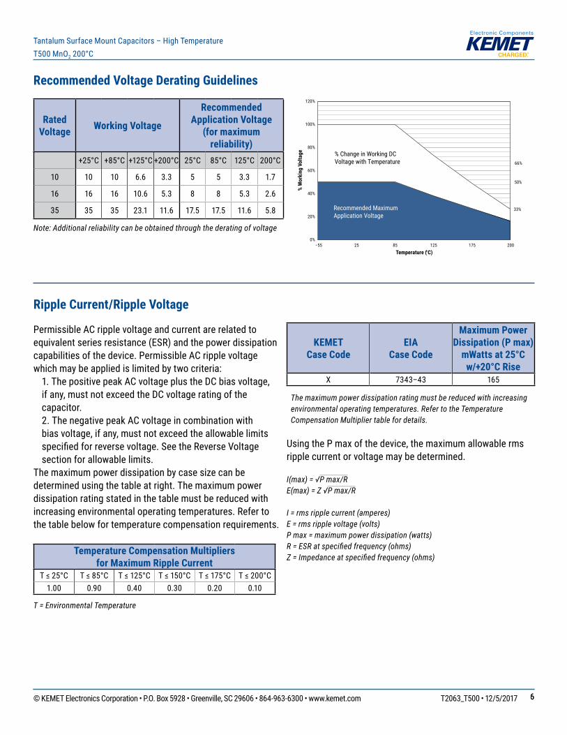
Recommended Voltage Derating Guidelines
Rated Voltage Working Voltage
Recommended Application Voltage
(for maximum reliability)
+25°C +85°C +125°C +200°C 25°C 85°C 125°C 200°C
10 10 10 6.6 3.3 5 5 3.3 1.7
16 16 16 10.6 5.3 8 8 5.3 2.6
35 35 35 23.1 11.6 17.5 17.5 11.6 5.8
Note: Additional reliability can be obtained through the derating of voltage
Ripple Current/Ripple Voltage
Permissible AC ripple voltage and current are related to equivalentseriesresistance(ESR)andthepowerdissipationcapabilitiesofthedevice.PermissibleACripplevoltagewhichmaybeappliedislimitedbytwocriteria: 1.ThepositivepeakACvoltageplustheDCbiasvoltage,ifany,mustnotexceedtheDCvoltageratingofthecapacitor.
2.ThenegativepeakACvoltageincombinationwithbiasvoltage,ifany,mustnotexceedtheallowablelimitsspecifiedforreversevoltage.SeetheReverseVoltagesection for allowable limits.
Themaximumpowerdissipationbycasesizecanbedeterminedusingthetableatright.Themaximumpowerdissipationratingstatedinthetablemustbereducedwithincreasing environmental operating temperatures. Refer to thetablebelowfortemperaturecompensationrequirements.
Temperature Compensation Multipliers for Maximum Ripple Current
T≤25°C T≤85°C T≤125°C T≤150°C T≤175°C T≤200°C1.00 0.90 0.40 0.30 0.20 0.10
T = Environmental Temperature
KEMET Case Code
EIA Case Code
Maximum Power Dissipation (P max)
mWatts at 25°C w/+20°C Rise
X 7343–43 165
The maximum power dissipation rating must be reduced with increasing environmental operating temperatures. Refer to the Temperature Compensation Multiplier table for details.
UsingthePmaxofthedevice,themaximumallowablermsripple current or voltage may be determined.
I(max) = √P max/RE(max) = Z √P max/R
I = rms ripple current (amperes)E = rms ripple voltage (volts)P max = maximum power dissipation (watts)R = ESR at specified frequency (ohms)Z = Impedance at specified frequency (ohms)
0%
20%
40%
60%
80%
100%
120%
−55 25 85 125 175 200
% W
orki
ng V
olta
ge
Temperature (°C)
66%
33%
50%
% Change in Working DCVoltage with Temperature
Recommended MaximumApplication Voltage
© KEMET Electronics Corporation • P.O. Box 5928 • Greenville, SC 29606 • 864-963-6300 • www.kemet.com T2063_T500 • 12/5/2017 77
Tantalum Surface Mount Capacitors – High TemperatureT500 MnO2 200°C
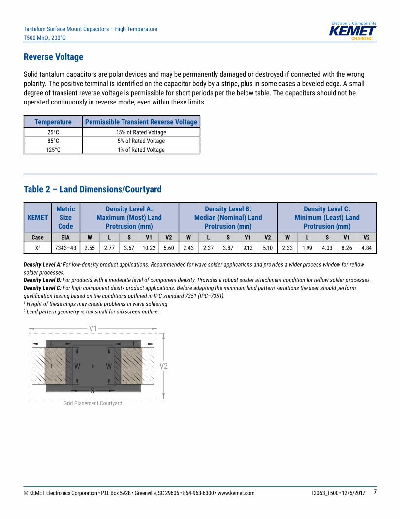
Reverse Voltage
Solidtantalumcapacitorsarepolardevicesandmaybepermanentlydamagedordestroyedifconnectedwiththewrongpolarity.Thepositiveterminalisidentifiedonthecapacitorbodybyastripe,plusinsomecasesabevelededge.Asmalldegreeoftransientreversevoltageispermissibleforshortperiodsperthebelowtable.Thecapacitorsshouldnotbeoperatedcontinuouslyinreversemode,evenwithintheselimits.
Temperature Permissible Transient Reverse Voltage25°C 15% of Rated Voltage85°C 5% of Rated Voltage125°C 1% of Rated Voltage
Table 2 – Land Dimensions/Courtyard
KEMET Metric Size Code
Density Level A: Maximum (Most) Land
Protrusion (mm)
Density Level B: Median (Nominal) Land
Protrusion (mm)
Density Level C: Minimum (Least) Land
Protrusion (mm)Case EIA W L S V1 V2 W L S V1 V2 W L S V1 V2
X1 7343–43 2.55 2.77 3.67 10.22 5.60 2.43 2.37 3.87 9.12 5.10 2.33 1.99 4.03 8.26 4.84
Density Level A: For low-density product applications. Recommended for wave solder applications and provides a wider process window for reflow solder processes. Density Level B: For products with a moderate level of component density. Provides a robust solder attachment condition for reflow solder processes.Density Level C: For high component desity product applications. Before adapting the minimum land pattern variations the user should perform qualification testing based on the conditions outlined in IPC standard 7351 (IPC–7351).1 Height of these chips may create problems in wave soldering.2 Land pattern geometry is too small for silkscreen outline.
L
S
W W
L
V1
V2
Grid Placement Courtyard
© KEMET Electronics Corporation • P.O. Box 5928 • Greenville, SC 29606 • 864-963-6300 • www.kemet.com T2063_T500 • 12/5/2017 88
Tantalum Surface Mount Capacitors – High TemperatureT500 MnO2 200°C
Time
Tem
pera
ture
Tsmin
25
Tsmax
TL
TP Maximum Ramp Up Rate = 3°C/secondMaximum Ramp Down Rate = 6°C/second
tP
tL
ts
25°C to Peak
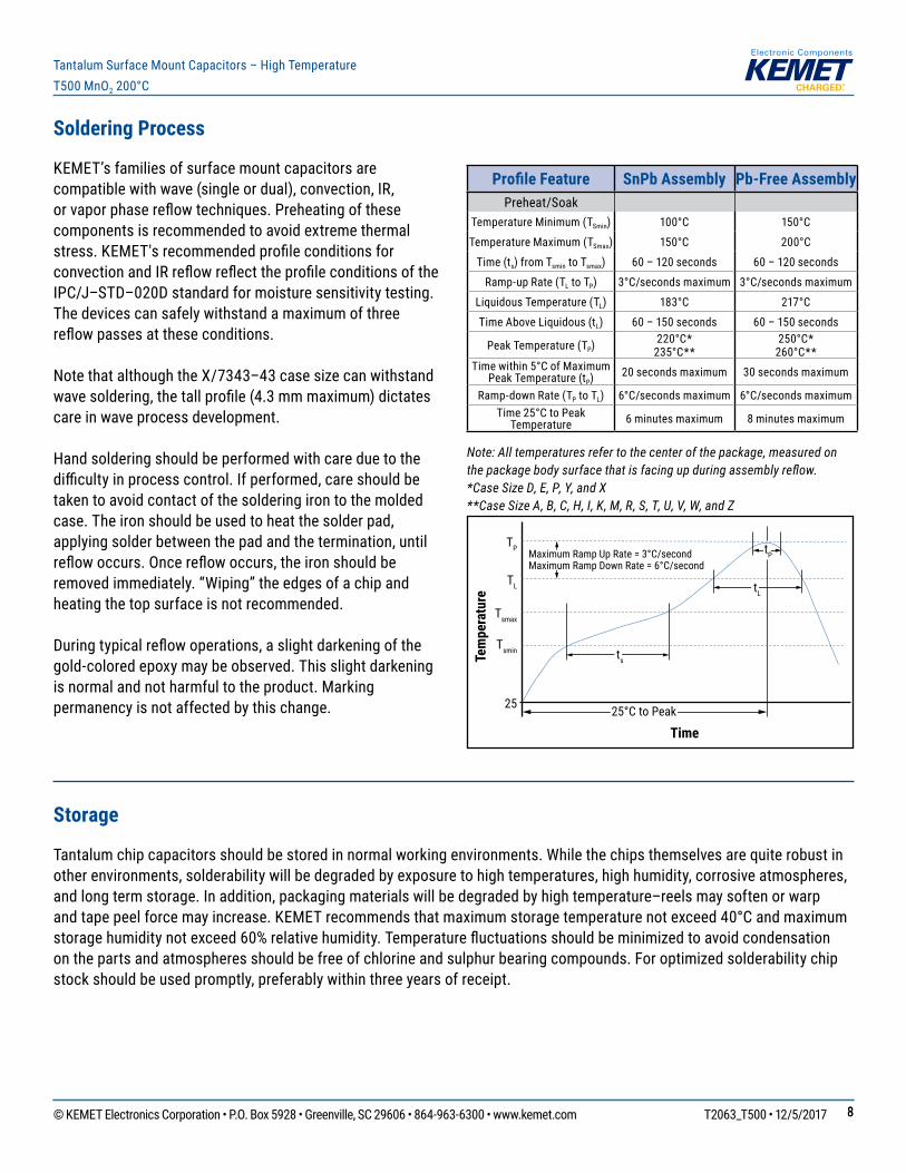
Soldering Process
KEMET’sfamiliesofsurfacemountcapacitorsarecompatiblewithwave(singleordual),convection,IR,orvaporphasereflowtechniques.Preheatingofthesecomponentsisrecommendedtoavoidextremethermalstress.KEMET'srecommendedprofileconditionsforconvectionandIRreflowreflecttheprofileconditionsoftheIPC/J–STD–020D standard for moisture sensitivity testing. Thedevicescansafelywithstandamaximumofthreereflowpassesattheseconditions.
NotethatalthoughtheX/7343–43casesizecanwithstandwavesoldering,thetallprofile(4.3mmmaximum)dictatescare in wave process development.
Handsolderingshouldbeperformedwithcareduetothedifficultyinprocesscontrol.Ifperformed,careshouldbetakentoavoidcontactofthesolderingirontothemoldedcase.Theironshouldbeusedtoheatthesolderpad,applyingsolderbetweenthepadandthetermination,untilreflowoccurs.Oncereflowoccurs,theironshouldberemovedimmediately.“Wiping”theedgesofachipandheatingthetopsurfaceisnotrecommended.
Duringtypicalreflowoperations,aslightdarkeningofthegold-coloredepoxymaybeobserved.Thisslightdarkeningisnormalandnotharmfultotheproduct.Markingpermanencyisnotaffectedbythischange.
Profile Feature SnPb Assembly Pb-Free AssemblyPreheat/Soak
TemperatureMinimum(TSmin) 100°C 150°C
TemperatureMaximum(TSmax) 150°C 200°C
Time(ts)fromTsmin to Tsmax) 60 – 120 seconds 60 – 120 seconds
Ramp-upRate(TL to TP) 3°C/secondsmaximum 3°C/secondsmaximum
LiquidousTemperature(TL) 183°C 217°C
TimeAboveLiquidous(tL) 60 – 150 seconds 60 – 150 seconds
PeakTemperature(TP)220°C*235°C**
250°C*260°C**
Timewithin5°CofMaximum PeakTemperature(tP)
20 seconds maximum 30 seconds maximum
Ramp-downRate(TP to TL) 6°C/secondsmaximum 6°C/secondsmaximumTime25°CtoPeak
Temperature 6 minutes maximum 8 minutes maximum
Note: All temperatures refer to the center of the package, measured on the package body surface that is facing up during assembly reflow. *Case Size D, E, P, Y, and X **Case Size A, B, C, H, I, K, M, R, S, T, U, V, W, and Z
Storage
Tantalumchipcapacitorsshouldbestoredinnormalworkingenvironments.Whilethechipsthemselvesarequiterobustinotherenvironments,solderabilitywillbedegradedbyexposuretohightemperatures,highhumidity,corrosiveatmospheres,andlongtermstorage.Inaddition,packagingmaterialswillbedegradedbyhightemperature–reelsmaysoftenorwarpandtapepeelforcemayincrease.KEMETrecommendsthatmaximumstoragetemperaturenotexceed40°Candmaximumstoragehumiditynotexceed60%relativehumidity.Temperaturefluctuationsshouldbeminimizedtoavoidcondensationonthepartsandatmospheresshouldbefreeofchlorineandsulphurbearingcompounds.Foroptimizedsolderabilitychipstockshouldbeusedpromptly,preferablywithinthreeyearsofreceipt.
© KEMET Electronics Corporation • P.O. Box 5928 • Greenville, SC 29606 • 864-963-6300 • www.kemet.com T2063_T500 • 12/5/2017 99
Tantalum Surface Mount Capacitors – High TemperatureT500 MnO2 200°C
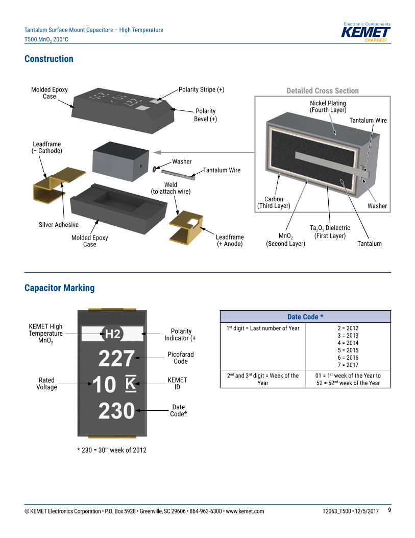
Construction
Leadframe(− Cathode)
Leadframe(+ Anode)
Tantalum Wire
Molded Epoxy Case
Molded Epoxy Case
Polarity Bevel (+)
Weld(to attach wire)
Silver Adhesive
Washer
Polarity Stripe (+) Detailed Cross Section
Tantalum Wire
Tantalum
Ta2O5 Dielectric(First Layer)
Carbon(Third Layer)
Nickel Plating(Fourth Layer)
Washer
MnO2(Second Layer)
Capacitor Marking
KEMET High Temperature
MnO2
Polarity Indicator (+)
Rated Voltage
Picofarad Code
KEMET ID
Date Code*
* 230 = 30th week of 2012
Date Code *1st digit = Last number of Year 2 = 2012
3 = 20134 = 20145 = 20156 = 20167 = 2017
2nd and 3rddigit=WeekoftheYear
01 = 1stweekoftheYearto 52 = 52ndweekoftheYear
© KEMET Electronics Corporation • P.O. Box 5928 • Greenville, SC 29606 • 864-963-6300 • www.kemet.com T2063_T500 • 12/5/2017 1010
Tantalum Surface Mount Capacitors – High TemperatureT500 MnO2 200°C
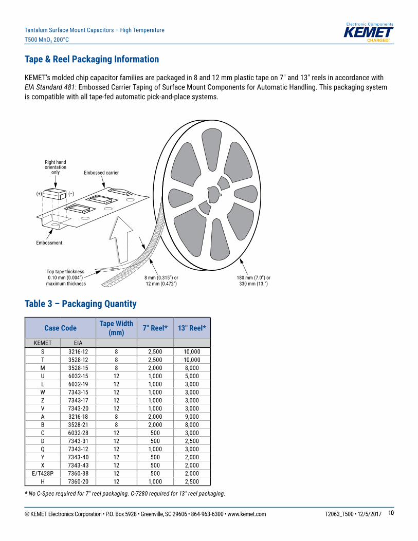
Tape & Reel Packaging Information
KEMET’smoldedchipcapacitorfamiliesarepackagedin8and12mmplastictapeon7"and13"reelsinaccordancewithEIA Standard 481:EmbossedCarrierTapingofSurfaceMountComponentsforAutomaticHandling.Thispackagingsystemiscompatiblewithalltape-fedautomaticpick-and-placesystems.
Embossment
8 mm (0.315”) or12 mm (0.472”)
Embossed carrier
Right handorientation
only
(+) (−)
Top tape thickness0.10 mm (0.004”)
maximum thickness180 mm (7.0”) or
330 mm (13.”)
Table 3 – Packaging Quantity
Case Code Tape Width (mm) 7" Reel* 13" Reel*
KEMET EIAS 3216-12 8 2,500 10,000T 3528-12 8 2,500 10,000M 3528-15 8 2,000 8,000U 6032-15 12 1,000 5,000L 6032-19 12 1,000 3,000W 7343-15 12 1,000 3,000Z 7343-17 12 1,000 3,000V 7343-20 12 1,000 3,000A 3216-18 8 2,000 9,000B 3528-21 8 2,000 8,000C 6032-28 12 500 3,000D 7343-31 12 500 2,500Q 7343-12 12 1,000 3,000Y 7343-40 12 500 2,000X 7343-43 12 500 2,000
E/T428P 7360-38 12 500 2,000H 7360-20 12 1,000 2,500
* No C-Spec required for 7" reel packaging. C-7280 required for 13" reel packaging.
© KEMET Electronics Corporation • P.O. Box 5928 • Greenville, SC 29606 • 864-963-6300 • www.kemet.com T2063_T500 • 12/5/2017 1111
Tantalum Surface Mount Capacitors – High TemperatureT500 MnO2 200°C
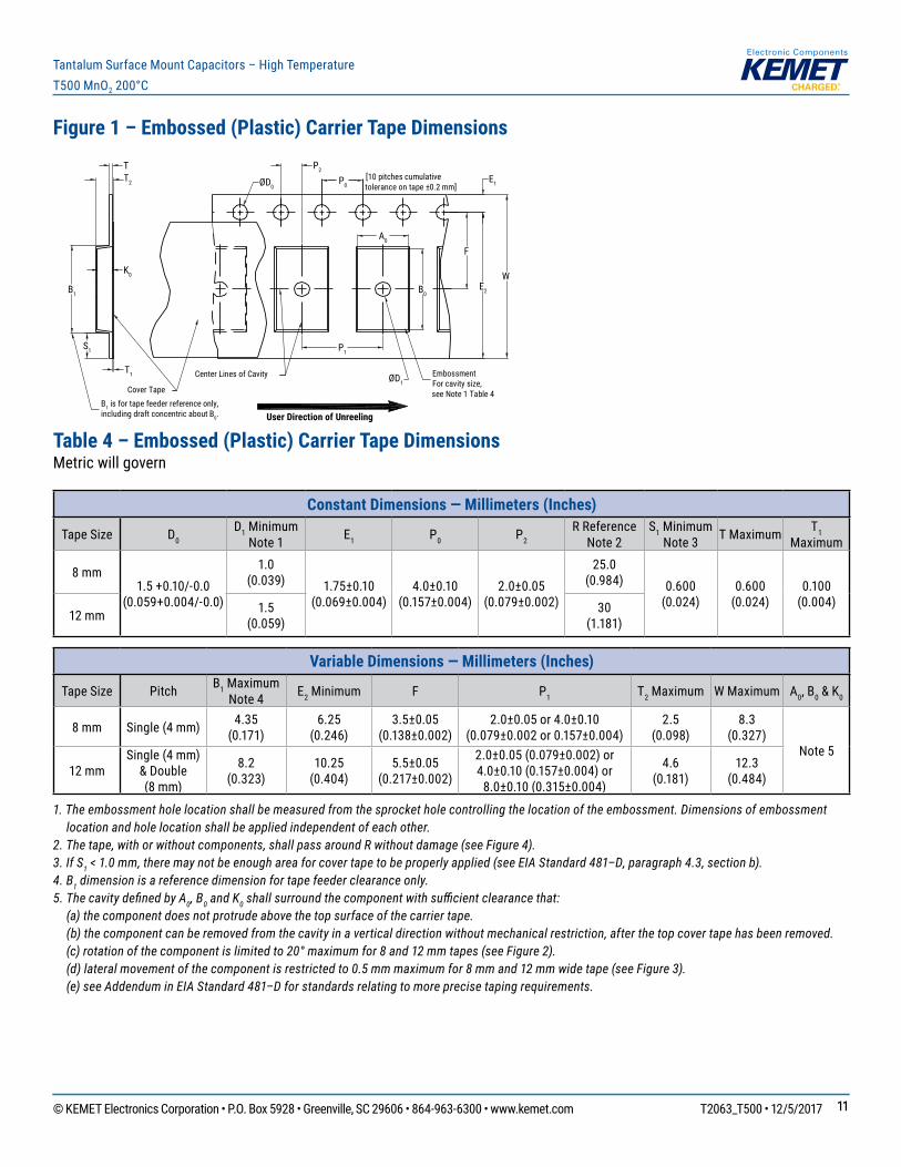
Figure 1 – Embossed (Plastic) Carrier Tape Dimensions
P0
T
F
W
Center Lines of Cavity
A0
B0
User Direction of Unreeling
Cover Tape
K0
B1 is for tape feeder reference only, including draft concentric about B0.
T2
ØD1
ØD0
B1
S1
T1
E1
E2
P1
P2
EmbossmentFor cavity size,see Note 1 Table 4
[10 pitches cumulativetolerance on tape ±0.2 mm]
Table 4 – Embossed (Plastic) Carrier Tape DimensionsMetric will govern
Constant Dimensions — Millimeters (Inches)
Tape Size D0 D1 Minimum
Note 1 E1 P0 P2 R Reference
Note 2S1 Minimum
Note 3 T Maximum T1 Maximum
8 mm1.5+0.10/-0.0
(0.059+0.004/-0.0)
1.0 (0.039) 1.75±0.10
(0.069±0.004)4.0±0.10
(0.157±0.004)2.0±0.05
(0.079±0.002)
25.0 (0.984) 0.600
(0.024)0.600 (0.024)
0.100 (0.004)
12 mm 1.5 (0.059)
30 (1.181)
Variable Dimensions — Millimeters (Inches)
Tape Size Pitch B1 Maximum Note 4 E2 Minimum F P1 T2 Maximum W Maximum A0, B0 & K0
8 mm Single(4mm) 4.35 (0.171)
6.25 (0.246)
3.5±0.05 (0.138±0.002)
2.0±0.05 or 4.0±0.10(0.079±0.002or0.157±0.004)
2.5 (0.098)
8.3 (0.327)
Note 512 mm
Single(4mm)& Double(8mm)
8.2 (0.323)
10.25 (0.404)
5.5±0.05 (0.217±0.002)
2.0±0.05(0.079±0.002)or4.0±0.10(0.157±0.004)or8.0±0.10(0.315±0.004)
4.6 (0.181)
12.3 (0.484)
1. The embossment hole location shall be measured from the sprocket hole controlling the location of the embossment. Dimensions of embossment location and hole location shall be applied independent of each other.
2. The tape, with or without components, shall pass around R without damage (see Figure 4).3. If S1 < 1.0 mm, there may not be enough area for cover tape to be properly applied (see EIA Standard 481–D, paragraph 4.3, section b).4. B1 dimension is a reference dimension for tape feeder clearance only.5. The cavity defi ned by A0, B0 and K0 shall surround the component with suffi cient clearance that: (a) the component does not protrude above the top surface of the carrier tape. (b) the component can be removed from the cavity in a vertical direction without mechanical restriction, after the top cover tape has been removed. (c) rotation of the component is limited to 20° maximum for 8 and 12 mm tapes (see Figure 2). (d) lateral movement of the component is restricted to 0.5 mm maximum for 8 mm and 12 mm wide tape (see Figure 3). (e) see Addendum in EIA Standard 481–D for standards relating to more precise taping requirements.
© KEMET Electronics Corporation • P.O. Box 5928 • Greenville, SC 29606 • 864-963-6300 • www.kemet.com T2063_T500 • 12/5/2017 1212
Tantalum Surface Mount Capacitors – High TemperatureT500 MnO2 200°C
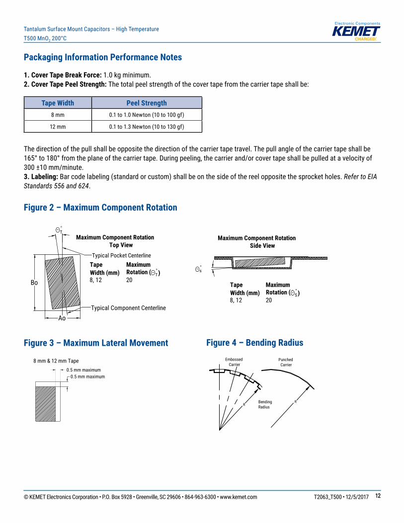
Packaging Information Performance Notes
1. Cover Tape Break Force: 1.0 kg minimum.2. Cover Tape Peel Strength: Thetotalpeelstrengthofthecovertapefromthecarriertapeshallbe:
Tape Width Peel Strength8 mm 0.1to1.0Newton(10to100gf)
12 mm 0.1to1.3Newton(10to130gf)
Thedirectionofthepullshallbeoppositethedirectionofthecarriertapetravel.Thepullangleofthecarriertapeshallbe165°to180°fromtheplaneofthecarriertape.Duringpeeling,thecarrierand/orcovertapeshallbepulledatavelocityof300 ±10 mm/minute.3. Labeling:Barcodelabeling(standardorcustom)shallbeonthesideofthereeloppositethesprocketholes.Refer to EIA Standards 556 and 624.
Figure 2 – Maximum Component Rotation
Ao
Bo
°T
°s
Maximum Component RotationTop View
Maximum Component RotationSide View
TapeWidth (mm)
MaximumRotation ( °
T)8, 12 20
TapeWidth (mm)
MaximumRotation (
8, 12 20 °S)
Typical Pocket Centerline
Typical Component Centerline
Figure 3 – Maximum Lateral Movement
0.5 mm maximum0.5 mm maximum
8 mm & 12 mm Tape
Figure 4 – Bending Radius
RRBending
Radius
EmbossedCarrier
PunchedCarrier
© KEMET Electronics Corporation • P.O. Box 5928 • Greenville, SC 29606 • 864-963-6300 • www.kemet.com T2063_T500 • 12/5/2017 1313
Tantalum Surface Mount Capacitors – High TemperatureT500 MnO2 200°C
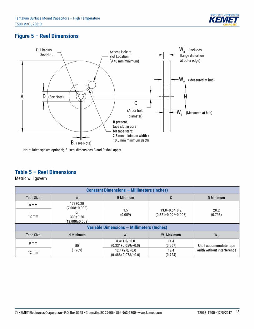
Figure 5 – Reel Dimensions
A D (See Note)
Full Radius,See Note
B (see Note)
Access Hole atSlot Location(Ø 40 mm minimum)
If present,tape slot in corefor tape start:2.5 mm minimum width x10.0 mm minimum depth
W3 (Includes flange distortion at outer edge)
W2 (Measured at hub)
W1 (Measured at hub)
C(Arbor holediameter)
Note: Drive spokes optional; if used, dimensions B and D shall apply.
N
Table 5 – Reel DimensionsMetric will govern
Constant Dimensions — Millimeters (Inches) Tape Size A B Minimum C D Minimum
8 mm 178±0.20 (7.008±0.008)
or330±0.20
(13.000±0.008)
1.5 (0.059)
13.0+0.5/−0.2(0.521+0.02/−0.008)
20.2 (0.795)12 mm
Variable Dimensions — Millimeters (Inches) Tape Size N Minimum W1 W2 Maximum W3
8 mm 50 (1.969)
8.4+1.5/−0.0(0.331+0.059/−0.0)
14.4 (0.567) Shallaccommodatetape
widthwithoutinterference12 mm 12.4+2.0/−0.0(0.488+0.078/−0.0)
18.4 (0.724)
© KEMET Electronics Corporation • P.O. Box 5928 • Greenville, SC 29606 • 864-963-6300 • www.kemet.com T2063_T500 • 12/5/2017 1414
Tantalum Surface Mount Capacitors – High TemperatureT500 MnO2 200°C
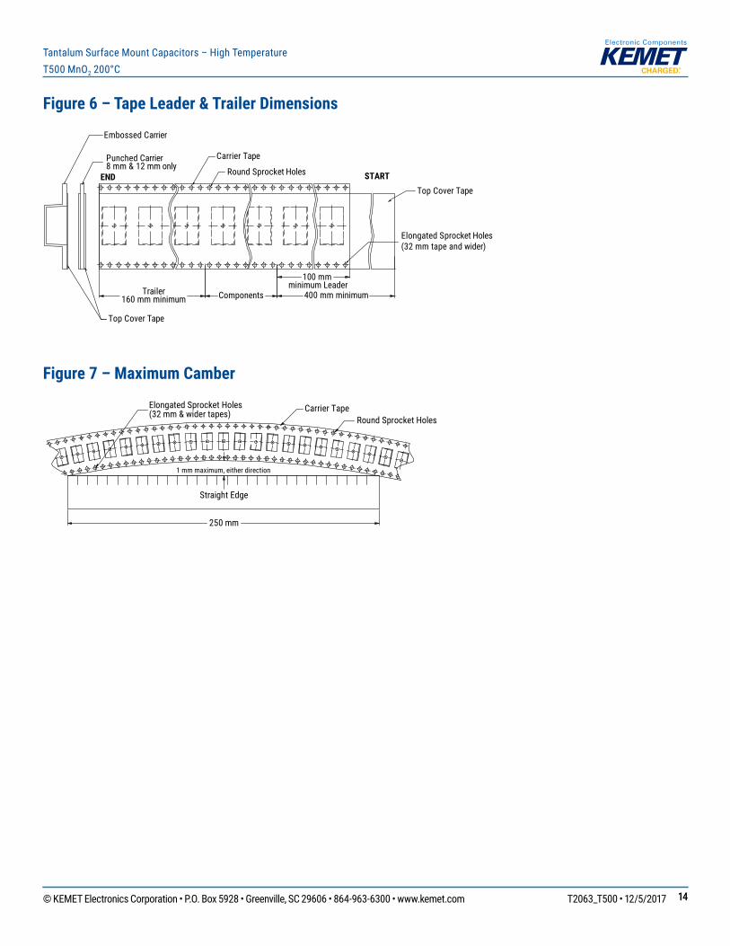
Figure 6 – Tape Leader & Trailer Dimensions
Trailer160 mm minimum
Carrier Tape
END STARTRound Sprocket Holes
Elongated Sprocket Holes(32 mm tape and wider)
Top Cover Tape
Top Cover Tape
Punched Carrier8 mm & 12 mm only
Embossed Carrier
Components
100 mm minimum Leader
400 mm minimum
Figure 7 – Maximum Camber
Carrier TapeRound Sprocket Holes
1 mm maximum, either direction
Straight Edge
250 mm
Elongated Sprocket Holes(32 mm & wider tapes)
© KEMET Electronics Corporation • P.O. Box 5928 • Greenville, SC 29606 • 864-963-6300 • www.kemet.com T2063_T500 • 12/5/2017 1515
Tantalum Surface Mount Capacitors – High TemperatureT500 MnO2 200°C
KEMET Electronics Corporation Sales Offi ces
Foracompletelistofourglobalsalesoffices,pleasevisitwww.kemet.com/sales.
DisclaimerAllproductspecifications,statements,informationanddata(collectively,the“Information”)inthisdatasheetaresubjecttochange.ThecustomerisresponsibleforcheckingandverifyingtheextenttowhichtheInformationcontainedinthispublicationisapplicabletoanorderatthetimetheorderisplaced.
AllInformationgivenhereinisbelievedtobeaccurateandreliable,butitispresentedwithoutguarantee,warranty,orresponsibilityofanykind,expressedorimplied.
StatementsofsuitabilityforcertainapplicationsarebasedonKEMETElectronicsCorporation’s(“KEMET”)knowledgeoftypicaloperatingconditionsforsuchapplications,butarenotintendedtoconstitute–andKEMETspecificallydisclaims–anywarrantyconcerningsuitabilityforaspecificcustomerapplicationoruse.TheInformationisintendedforuseonlybycustomerswhohavetherequisiteexperienceandcapabilitytodeterminethecorrectproductsfortheirapplication.AnytechnicaladviceinferredfromthisInformationorotherwiseprovidedbyKEMETwithreferencetotheuseofKEMET’sproductsisgivengratis,andKEMETassumesnoobligationorliabilityfortheadvicegivenorresultsobtained.
AlthoughKEMETdesignsandmanufacturesitsproductstothemoststringentqualityandsafetystandards,giventhecurrentstateoftheart,isolatedcomponentfailuresmaystilloccur.Accordingly,customerapplicationswhichrequireahighdegreeofreliabilityorsafetyshouldemploysuitabledesignsorothersafeguards(suchasinstallationofprotectivecircuitryorredundancies)inordertoensurethatthefailureofanelectricalcomponentdoesnotresultinariskofpersonalinjuryorproperty damage.
Althoughallproduct–relatedwarnings,cautionsandnotesmustbeobserved,thecustomershouldnotassumethatallsafetymeasuresareindictedorthatothermeasures may not be required.
KEMET is a registered trademark of KEMET Electronics Corporation.
Mouser Electronics
Authorized Distributor
Click to View Pricing, Inventory, Delivery & Lifecycle Information: KEMET:
T500X227K010AG6110 T500X336K035AG6110 T500X107K016AG6110 T500X227K010BG6110
T500X227K010AG6210 T500X227K010BG6210 T500X227K010AG6310 T500X227K010BG6310
T500X227K010AG6410 T500X227K010BG6410 T500X227M010BG6110 T500X227M010AG6210
T500X227M010BG6210 T500X227M010AG6310 T500X227M010BG6310 T500X227M010AG6410
T500X227M010BG6410 T500X227M010AG6110 T500X107K016BG6110 T500X336K035BG6110
T500X107M016BG6210 T500X336M035AG6110 T500X106K035AG6110 T500X336M035BG6210
T500X107M016AG6110


![Index [banelec.online.fr]banelec.online.fr/fab/kemet/HiTemp HiVolt Ceram Caps.pdf · © KEMET Electronics Corporation • PO Box 5928 • Greenville, SC 29606 • 3 High Temperature,](https://img.pdfslide.net/doc/110x75/5e82f745351c113fa578dcdf/index-hivolt-ceram-capspdf-kemet-electronics-corporation-a-po-box-5928.jpg)