Embed Size (px)
Citation preview

Copyright © 2001 Europay International, PBS A/S and Visa International Service Association. All rightsreserved.
Terminal Architecture for PSAM Applications(TAPA)
Application Architecture Specification
Version 2.1
February 2001
February 2001TAPA Application Architecture Version 2.1
Copyright © 2001 Europay International, PBS A/S and Visa International Service Association. All rightsreserved.
i
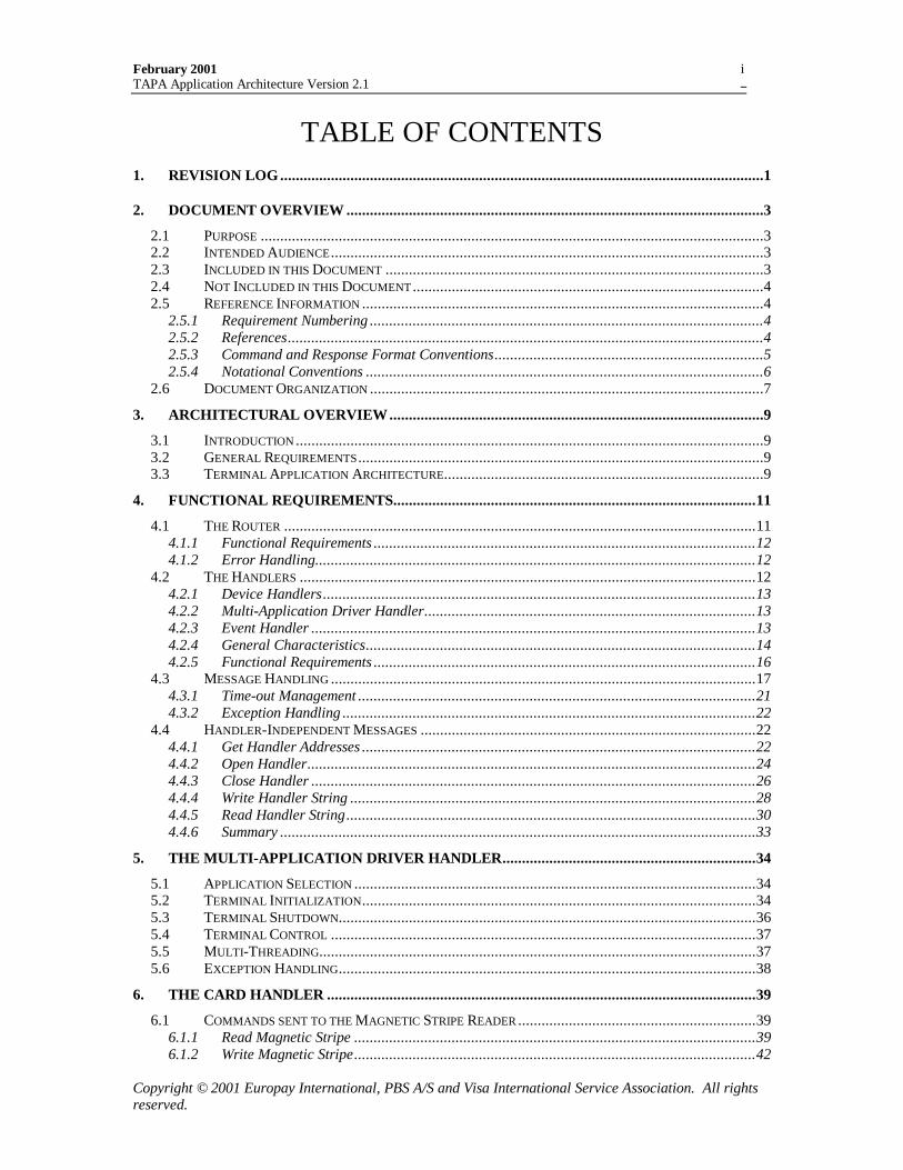
TABLE OF CONTENTS1. REVISION LOG............................................................................................................................1
2. DOCUMENT OVERVIEW ...........................................................................................................3
2.1 PURPOSE .................................................................................................................................32.2 INTENDED AUDIENCE ...............................................................................................................32.3 INCLUDED IN THIS DOCUMENT .................................................................................................32.4 NOT INCLUDED IN THIS DOCUMENT ..........................................................................................42.5 REFERENCE INFORMATION .......................................................................................................4
2.5.1 Requirement Numbering .....................................................................................................42.5.2 References..........................................................................................................................42.5.3 Command and Response Format Conventions.....................................................................52.5.4 Notational Conventions ......................................................................................................6
2.6 DOCUMENT ORGANIZATION .....................................................................................................7
3. ARCHITECTURAL OVERVIEW................................................................................................9
3.1 INTRODUCTION ........................................................................................................................93.2 GENERAL REQUIREMENTS ........................................................................................................93.3 TERMINAL APPLICATION ARCHITECTURE..................................................................................9
4. FUNCTIONAL REQUIREMENTS.............................................................................................11
4.1 THE ROUTER .........................................................................................................................114.1.1 Functional Requirements ..................................................................................................124.1.2 Error Handling.................................................................................................................12
4.2 THE HANDLERS .....................................................................................................................124.2.1 Device Handlers...............................................................................................................134.2.2 Multi-Application Driver Handler.....................................................................................134.2.3 Event Handler ..................................................................................................................134.2.4 General Characteristics....................................................................................................144.2.5 Functional Requirements ..................................................................................................16
4.3 MESSAGE HANDLING .............................................................................................................174.3.1 Time-out Management ......................................................................................................214.3.2 Exception Handling ..........................................................................................................22
4.4 HANDLER-INDEPENDENT MESSAGES ......................................................................................224.4.1 Get Handler Addresses .....................................................................................................224.4.2 Open Handler...................................................................................................................244.4.3 Close Handler ..................................................................................................................264.4.4 Write Handler String ........................................................................................................284.4.5 Read Handler String.........................................................................................................304.4.6 Summary ..........................................................................................................................33
5. THE MULTI-APPLICATION DRIVER HANDLER.................................................................34
5.1 APPLICATION SELECTION .......................................................................................................345.2 TERMINAL INITIALIZATION.....................................................................................................345.3 TERMINAL SHUTDOWN...........................................................................................................365.4 TERMINAL CONTROL .............................................................................................................375.5 MULTI-THREADING................................................................................................................375.6 EXCEPTION HANDLING...........................................................................................................38
6. THE CARD HANDLER ..............................................................................................................39
6.1 COMMANDS SENT TO THE MAGNETIC STRIPE READER .............................................................396.1.1 Read Magnetic Stripe .......................................................................................................396.1.2 Write Magnetic Stripe.......................................................................................................42
February 2001TAPA Application Architecture Version 2.1
Copyright © 2001 Europay International, PBS A/S and Visa International Service Association. All rightsreserved.
ii
6.2 COMMANDS SENT TO THE PROCESSOR CARD READER .............................................................456.2.1 Message Handling............................................................................................................466.2.2 ICC Command/Response ..................................................................................................476.2.3 ICC Power-On..................................................................................................................506.2.4 ICC Power-Off .................................................................................................................516.2.5 ICC Query........................................................................................................................536.2.6 Verify Offline PIN.............................................................................................................54
6.3 COMMANDS SENT TO MEMORY CARD READER........................................................................566.4 COMMANDS SENT TO THE CONTACTLESS CARD READER .........................................................576.5 SUMMARY .............................................................................................................................57
7. THE USER INTERFACE HANDLER........................................................................................58
7.1 MESSAGES SENT TO THE USER INTERFACE HANDLER ..............................................................587.1.1 Display Message ..............................................................................................................587.1.2 Print Message ..................................................................................................................607.1.3 Confirm Amount ...............................................................................................................627.1.4 Purge Print Buffer ............................................................................................................647.1.5 Get Amount ......................................................................................................................667.1.6 Funds Available................................................................................................................66
7.2 PIN PAD HANDLER ................................................................................................................667.2.1 Get Key Check Value ........................................................................................................667.2.2 Get PIN Pad Public Key Record .......................................................................................687.2.3 Verify PSAM Public Key Certificate..................................................................................717.2.4 Submit Initial Key.............................................................................................................737.2.5 Initiate PIN Entry .............................................................................................................797.2.6 Get PIN............................................................................................................................827.2.7 Terminate PIN Entry ........................................................................................................84
7.3 SUMMARY .............................................................................................................................86
8. THE MERCHANT APPLICATION HANDLER .......................................................................88
8.1 MESSAGES SENT TO THE MERCHANT APPLICATION HANDLER..................................................888.1.1 Get Amount ......................................................................................................................888.1.2 Transaction Completed.....................................................................................................918.1.3 Funds Available................................................................................................................928.1.4 Display Message ..............................................................................................................948.1.5 Print commands................................................................................................................94
8.2 SUMMARY .............................................................................................................................94
9. THE PSAM HANDLER...............................................................................................................95
9.1 MESSAGE HANDLING .............................................................................................................959.1.1 Messages sent to the PSAM Handler .................................................................................969.1.2 Messages sent to the PSAM...............................................................................................969.1.3 Messages from the PSAM .................................................................................................99
10. PSAM APPLICATIONS .......................................................................................................103
10.1 PSAM INITIALIZATION ........................................................................................................10310.2 PSAM SHUT-DOWN .............................................................................................................10410.3 PSAM COMMANDS AND RESPONSES ....................................................................................104
10.3.1 Message Formats.......................................................................................................10510.3.2 Application Status Words ...........................................................................................10710.3.3 Start-up PSAM...........................................................................................................10810.3.4 Get Supported AIDs ...................................................................................................11010.3.5 PSAM Shutdown ........................................................................................................11110.3.6 Get Next.....................................................................................................................11310.3.7 Response Command ...................................................................................................11410.3.8 Synchronize PSAM/PIN Pad.......................................................................................115
February 2001TAPA Application Architecture Version 2.1
Copyright © 2001 Europay International, PBS A/S and Visa International Service Association. All rightsreserved.
iii
11. THE DATA STORE HANDLER ..........................................................................................117
11.1 GENERAL REQUIREMENTS ....................................................................................................11711.2 MESSAGES SENT TO THE DATA STORE HANDLER...................................................................117
11.2.1 File Management .......................................................................................................11711.2.2 Create File.................................................................................................................11711.2.3 Delete File .................................................................................................................11911.2.4 Add File Record.........................................................................................................12111.2.5 Get File Record..........................................................................................................12311.2.6 Update File Record....................................................................................................12611.2.7 Find and Get File Record...........................................................................................12811.2.8 Delete File Record .....................................................................................................13011.2.9 Find and Delete File Record ......................................................................................13211.2.10 Clear File ..................................................................................................................134
11.3 SUMMARY ...........................................................................................................................136
12. THE COMMUNICATION HANDLER................................................................................137
12.1 MESSAGES SENT TO THE COMMUNICATION HANDLER ...........................................................13712.1.1 Initiate Communication Session..................................................................................13712.1.2 Terminate Communication Session.............................................................................139
12.2 SUMMARY ...........................................................................................................................140
13. EVENT HANDLER...............................................................................................................141
13.1 EVENT TYPES ......................................................................................................................14113.2 EVENT HANDLER MESSAGES................................................................................................141
13.2.1 Add Event ..................................................................................................................14213.2.2 Get Event...................................................................................................................14213.2.3 Find Event .................................................................................................................14413.2.4 Flush Event Queue.....................................................................................................146
13.3 SUMMARY ...........................................................................................................................148
14. PIN PAD PROCESSING.......................................................................................................149
14.1 OVERVIEW ..........................................................................................................................14914.1.1 Physical Environment ................................................................................................14914.1.2 Establishing the Secure Zone......................................................................................14914.1.3 Supported Configurations ..........................................................................................15014.1.4 Implementation ..........................................................................................................151
14.2 PIN PAD/PSAM INITIALIZATION..........................................................................................15214.3 PIN PROCESSING .................................................................................................................154
14.3.1 Tamper Evident Device State......................................................................................15414.3.2 PIN Entry ..................................................................................................................156
14.4 PIN VERIFICATION ..............................................................................................................16014.4.1 Online PIN Verification..............................................................................................16014.4.2 Offline PIN Verification .............................................................................................161
14.5 SECURITY REQUIREMENTS ...................................................................................................16214.5.1 Business Entities ........................................................................................................16214.5.2 Physical Security Requirements..................................................................................16314.5.3 Logical Security Requirements ...................................................................................16414.5.4 Personalization Requirements ....................................................................................16514.5.5 Minimum PSAM Requirements ...................................................................................167
14.6 CRYPTOGRAPHIC REQUIREMENTS.........................................................................................16814.6.1 Verifying a Certificate - General Requirements...........................................................16814.6.2 Authentication of the PIN Pad Public Key ..................................................................16914.6.3 Authentication of the PSAM Public Key......................................................................17014.6.4 DES and Triple DES ..................................................................................................17214.6.5 Encryption and Decryption ........................................................................................173
February 2001TAPA Application Architecture Version 2.1
Copyright © 2001 Europay International, PBS A/S and Visa International Service Association. All rightsreserved.
iv
14.6.6 MAC computation ......................................................................................................17414.6.7 RSA Operations .........................................................................................................17414.6.8 RSA Padding..............................................................................................................17514.6.9 Certificate Formats....................................................................................................17614.6.10 Expiration of Certificates ...........................................................................................17914.6.11 Replacement of Keys and Certificates.........................................................................17914.6.12 Revocation of Certificates ..........................................................................................18014.6.13 Key Lengths ...............................................................................................................180
15. RESPONSE AND MESSAGE CODES.................................................................................181
15.1 RESPONSE CODES ................................................................................................................18115.2 MESSAGE CODES .................................................................................................................186
16. DATA ELEMENTS...............................................................................................................193
16.1.1 AIDN ..........................................................................................................................19316.1.2 ALG...........................................................................................................................19316.1.3 ALGH ........................................................................................................................19416.1.4 Amount Confirmed Indicator ......................................................................................19416.1.5 Application Status Words (ASW1, ASW2) ...................................................................19516.1.6 ATR (Answer To Reset) ..............................................................................................19516.1.7 [C-APDU] .................................................................................................................19516.1.8 Card Command..........................................................................................................19516.1.9 Card Response...........................................................................................................19516.1.10 CHALLENGE ............................................................................................................19616.1.11 CLA (Class byte)........................................................................................................19616.1.12 CNTAID.......................................................................................................................19616.1.13 CNTSUBADDRESS............................................................................................................19616.1.14 Code Table Index .......................................................................................................19716.1.15 CSN (Certificate Serial Number) ................................................................................19716.1.16 CURR (Currency) ......................................................................................................19716.1.17 CURRC (Currency Code)...........................................................................................19816.1.18 CURRE (Currency Exponent).....................................................................................19816.1.19 Destination Address (DAD) ........................................................................................19816.1.20 DS (Digital Signature) ...............................................................................................19816.1.21 DTHRPDA (Transaction date and time) ........................................................................19916.1.22 Enc(KSESPIN)[PIN]..................................................................................................19916.1.23 Error Response Data..................................................................................................19916.1.24 Event Type Code ........................................................................................................19916.1.25 Event Location...........................................................................................................19916.1.26 File Identifier (IDFILE ) ...............................................................................................20016.1.27 Filler .........................................................................................................................20016.1.28 Format Code..............................................................................................................20016.1.29 Handler Category Address .........................................................................................20016.1.30 Handler Sub-Address .................................................................................................20116.1.31 Historical Bytes .........................................................................................................20116.1.32 IDPP (PIN Pad ID) .....................................................................................................20116.1.33 IDPPCREATOR (Identifier for the Creator of a PIN Pad)..................................................20216.1.34 IDPSAM (Identifier for a PSAM) ...................................................................................20216.1.35 IDPSAMAPP (TAPA PSAM Application Identifier) ..........................................................20216.1.36 IDPSAMCREATOR (Identifier for the Creator of the PSAM) ...............................................20316.1.37 IDSCHEME (Acquirer reference number)........................................................................20316.1.38 INS (Instruction byte) .................................................................................................20316.1.39 KCV (Key Check Value) .............................................................................................20316.1.40 Key Data ...................................................................................................................20416.1.41 KSES .........................................................................................................................20416.1.42 KSESINIT.....................................................................................................................204
February 2001TAPA Application Architecture Version 2.1
Copyright © 2001 Europay International, PBS A/S and Visa International Service Association. All rightsreserved.
v
16.1.43 KSESMAC ....................................................................................................................20416.1.44 KSESPIN .....................................................................................................................20416.1.45 Lc (Data length) .........................................................................................................20516.1.46 Le (Expected data length) ...........................................................................................20516.1.47 LDATA (Data field length).............................................................................................20516.1.48 LEN...........................................................................................................................20516.1.49 LENAID,N.....................................................................................................................20616.1.50 LENREC ......................................................................................................................20616.1.51 LENSKEY .....................................................................................................................20616.1.52 Length .......................................................................................................................20616.1.53 LPKE (Length of a Public Key Exponent) ...................................................................20716.1.54 LPKM (Length of Public Key Modulus) ......................................................................20716.1.55 MAC..........................................................................................................................20716.1.56 Magnetic Stripe Data .................................................................................................20716.1.57 Message Code............................................................................................................20816.1.58 Message Data ............................................................................................................20816.1.59 Message Type ............................................................................................................20816.1.60 NUMFILE..................................................................................................................20816.1.61 Pad Pattern................................................................................................................20916.1.62 PK (Public Key) .........................................................................................................20916.1.63 PKC (Public Key Certificate) .....................................................................................20916.1.64 PKM (Public Key Modulus)........................................................................................20916.1.65 PKR (Public Key Remainder) .....................................................................................21016.1.66 P1, P2 (Parameter bytes) ...........................................................................................21016.1.67 Pointer Orientation....................................................................................................21016.1.68 Message Code............................................................................................................21016.1.69 PIN Pad Identifier......................................................................................................21116.1.70 PS..............................................................................................................................21116.1.71 PSAM Identifier .........................................................................................................21116.1.72 PSAM sub-address .....................................................................................................21116.1.73 Record Data ..............................................................................................................21116.1.74 Record Pointer...........................................................................................................21216.1.75 Record Tag ................................................................................................................21216.1.76 Response Code (RC) ..................................................................................................21216.1.77 Response Data ...........................................................................................................21216.1.78 Returned String..........................................................................................................21316.1.79 RIDPSAM (Registered Identifier Of The Entity Assigning PSAM Creator Ids) ................21316.1.80 Search Type ...............................................................................................................21316.1.81 Session Data ..............................................................................................................21416.1.82 SK (Private Key) ........................................................................................................21416.1.83 Source Address (SAD)................................................................................................21416.1.84 Status Words (SW1, SW2)...........................................................................................21416.1.85 IDTHREAD (Thread Identifier) .......................................................................................21516.1.86 Time ..........................................................................................................................21516.1.87 Timer Flag.................................................................................................................21516.1.88 Track Data.................................................................................................................21516.1.89 Transaction Amount...................................................................................................21616.1.90 Transaction Results....................................................................................................21616.1.91 u ................................................................................................................................21616.1.92 VKPCA, xx ....................................................................................................................216
17. ACRONYMS .........................................................................................................................218
February 2001TAPA Application Architecture Version 2.1
Copyright © 2001 Europay International, PBS A/S and Visa International Service Association. All rightsreserved.
vi
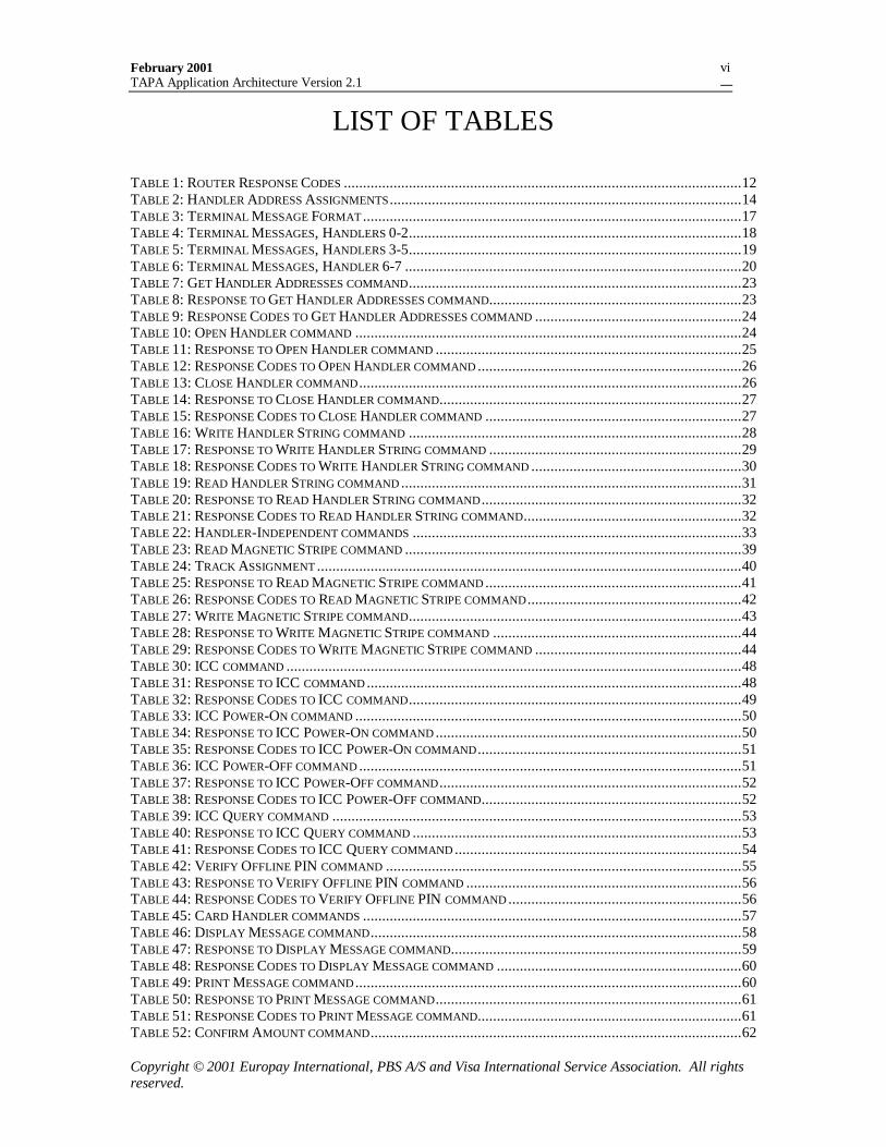
LIST OF TABLES
TABLE 1: ROUTER RESPONSE CODES ........................................................................................................12TABLE 2: HANDLER ADDRESS ASSIGNMENTS ............................................................................................14TABLE 3: TERMINAL MESSAGE FORMAT ...................................................................................................17TABLE 4: TERMINAL MESSAGES, HANDLERS 0-2.......................................................................................18TABLE 5: TERMINAL MESSAGES, HANDLERS 3-5.......................................................................................19TABLE 6: TERMINAL MESSAGES, HANDLER 6-7 ........................................................................................20TABLE 7: GET HANDLER ADDRESSES COMMAND.......................................................................................23TABLE 8: RESPONSE TO GET HANDLER ADDRESSES COMMAND..................................................................23TABLE 9: RESPONSE CODES TO GET HANDLER ADDRESSES COMMAND ......................................................24TABLE 10: OPEN HANDLER COMMAND .....................................................................................................24TABLE 11: RESPONSE TO OPEN HANDLER COMMAND ................................................................................25TABLE 12: RESPONSE CODES TO OPEN HANDLER COMMAND .....................................................................26TABLE 13: CLOSE HANDLER COMMAND ....................................................................................................26TABLE 14: RESPONSE TO CLOSE HANDLER COMMAND...............................................................................27TABLE 15: RESPONSE CODES TO CLOSE HANDLER COMMAND ...................................................................27TABLE 16: WRITE HANDLER STRING COMMAND .......................................................................................28TABLE 17: RESPONSE TO WRITE HANDLER STRING COMMAND ..................................................................29TABLE 18: RESPONSE CODES TO WRITE HANDLER STRING COMMAND .......................................................30TABLE 19: READ HANDLER STRING COMMAND .........................................................................................31TABLE 20: RESPONSE TO READ HANDLER STRING COMMAND ....................................................................32TABLE 21: RESPONSE CODES TO READ HANDLER STRING COMMAND.........................................................32TABLE 22: HANDLER-INDEPENDENT COMMANDS ......................................................................................33TABLE 23: READ MAGNETIC STRIPE COMMAND ........................................................................................39TABLE 24: TRACK ASSIGNMENT ...............................................................................................................40TABLE 25: RESPONSE TO READ MAGNETIC STRIPE COMMAND ...................................................................41TABLE 26: RESPONSE CODES TO READ MAGNETIC STRIPE COMMAND ........................................................42TABLE 27: WRITE MAGNETIC STRIPE COMMAND.......................................................................................43TABLE 28: RESPONSE TO WRITE MAGNETIC STRIPE COMMAND .................................................................44TABLE 29: RESPONSE CODES TO WRITE MAGNETIC STRIPE COMMAND ......................................................44TABLE 30: ICC COMMAND .......................................................................................................................48TABLE 31: RESPONSE TO ICC COMMAND ..................................................................................................48TABLE 32: RESPONSE CODES TO ICC COMMAND.......................................................................................49TABLE 33: ICC POWER-ON COMMAND .....................................................................................................50TABLE 34: RESPONSE TO ICC POWER-ON COMMAND ................................................................................50TABLE 35: RESPONSE CODES TO ICC POWER-ON COMMAND .....................................................................51TABLE 36: ICC POWER-OFF COMMAND ....................................................................................................51TABLE 37: RESPONSE TO ICC POWER-OFF COMMAND ...............................................................................52TABLE 38: RESPONSE CODES TO ICC POWER-OFF COMMAND....................................................................52TABLE 39: ICC QUERY COMMAND ...........................................................................................................53TABLE 40: RESPONSE TO ICC QUERY COMMAND ......................................................................................53TABLE 41: RESPONSE CODES TO ICC QUERY COMMAND ...........................................................................54TABLE 42: VERIFY OFFLINE PIN COMMAND .............................................................................................55TABLE 43: RESPONSE TO VERIFY OFFLINE PIN COMMAND ........................................................................56TABLE 44: RESPONSE CODES TO VERIFY OFFLINE PIN COMMAND .............................................................56TABLE 45: CARD HANDLER COMMANDS ...................................................................................................57TABLE 46: DISPLAY MESSAGE COMMAND.................................................................................................58TABLE 47: RESPONSE TO DISPLAY MESSAGE COMMAND............................................................................59TABLE 48: RESPONSE CODES TO DISPLAY MESSAGE COMMAND ................................................................60TABLE 49: PRINT MESSAGE COMMAND .....................................................................................................60TABLE 50: RESPONSE TO PRINT MESSAGE COMMAND................................................................................61TABLE 51: RESPONSE CODES TO PRINT MESSAGE COMMAND.....................................................................61TABLE 52: CONFIRM AMOUNT COMMAND.................................................................................................62
February 2001TAPA Application Architecture Version 2.1
Copyright © 2001 Europay International, PBS A/S and Visa International Service Association. All rightsreserved.
vii
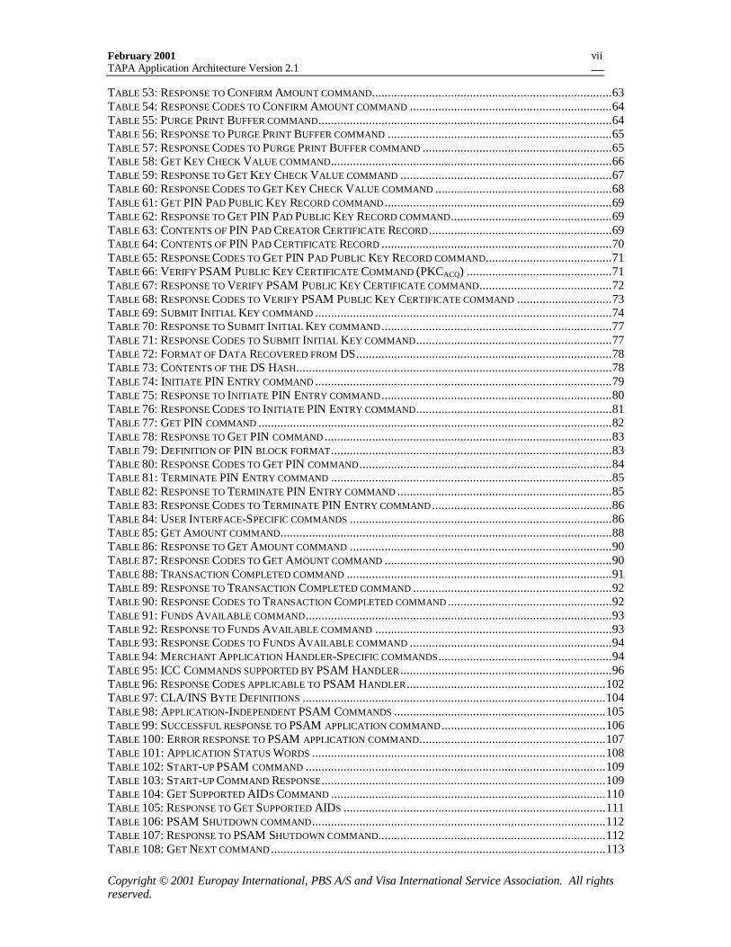
TABLE 53: RESPONSE TO CONFIRM AMOUNT COMMAND............................................................................63TABLE 54: RESPONSE CODES TO CONFIRM AMOUNT COMMAND ................................................................64TABLE 55: PURGE PRINT BUFFER COMMAND.............................................................................................64TABLE 56: RESPONSE TO PURGE PRINT BUFFER COMMAND .......................................................................65TABLE 57: RESPONSE CODES TO PURGE PRINT BUFFER COMMAND ............................................................65TABLE 58: GET KEY CHECK VALUE COMMAND.........................................................................................66TABLE 59: RESPONSE TO GET KEY CHECK VALUE COMMAND ...................................................................67TABLE 60: RESPONSE CODES TO GET KEY CHECK VALUE COMMAND ........................................................68TABLE 61: GET PIN PAD PUBLIC KEY RECORD COMMAND ........................................................................69TABLE 62: RESPONSE TO GET PIN PAD PUBLIC KEY RECORD COMMAND...................................................69TABLE 63: CONTENTS OF PIN PAD CREATOR CERTIFICATE RECORD ..........................................................69TABLE 64: CONTENTS OF PIN PAD CERTIFICATE RECORD .........................................................................70TABLE 65: RESPONSE CODES TO GET PIN PAD PUBLIC KEY RECORD COMMAND........................................71TABLE 66: VERIFY PSAM PUBLIC KEY CERTIFICATE COMMAND (PKCACQ) ..............................................71TABLE 67: RESPONSE TO VERIFY PSAM PUBLIC KEY CERTIFICATE COMMAND..........................................72TABLE 68: RESPONSE CODES TO VERIFY PSAM PUBLIC KEY CERTIFICATE COMMAND ..............................73TABLE 69: SUBMIT INITIAL KEY COMMAND ..............................................................................................74TABLE 70: RESPONSE TO SUBMIT INITIAL KEY COMMAND .........................................................................77TABLE 71: RESPONSE CODES TO SUBMIT INITIAL KEY COMMAND..............................................................77TABLE 72: FORMAT OF DATA RECOVERED FROM DS.................................................................................78TABLE 73: CONTENTS OF THE DS HASH....................................................................................................78TABLE 74: INITIATE PIN ENTRY COMMAND ..............................................................................................79TABLE 75: RESPONSE TO INITIATE PIN ENTRY COMMAND .........................................................................80TABLE 76: RESPONSE CODES TO INITIATE PIN ENTRY COMMAND..............................................................81TABLE 77: GET PIN COMMAND ................................................................................................................82TABLE 78: RESPONSE TO GET PIN COMMAND ...........................................................................................83TABLE 79: DEFINITION OF PIN BLOCK FORMAT.........................................................................................83TABLE 80: RESPONSE CODES TO GET PIN COMMAND ................................................................................84TABLE 81: TERMINATE PIN ENTRY COMMAND .........................................................................................85TABLE 82: RESPONSE TO TERMINATE PIN ENTRY COMMAND ....................................................................85TABLE 83: RESPONSE CODES TO TERMINATE PIN ENTRY COMMAND .........................................................86TABLE 84: USER INTERFACE-SPECIFIC COMMANDS ...................................................................................86TABLE 85: GET AMOUNT COMMAND.........................................................................................................88TABLE 86: RESPONSE TO GET AMOUNT COMMAND ...................................................................................90TABLE 87: RESPONSE CODES TO GET AMOUNT COMMAND ........................................................................90TABLE 88: TRANSACTION COMPLETED COMMAND ....................................................................................91TABLE 89: RESPONSE TO TRANSACTION COMPLETED COMMAND ...............................................................92TABLE 90: RESPONSE CODES TO TRANSACTION COMPLETED COMMAND ....................................................92TABLE 91: FUNDS AVAILABLE COMMAND.................................................................................................93TABLE 92: RESPONSE TO FUNDS AVAILABLE COMMAND ...........................................................................93TABLE 93: RESPONSE CODES TO FUNDS AVAILABLE COMMAND ................................................................94TABLE 94: MERCHANT APPLICATION HANDLER-SPECIFIC COMMANDS.......................................................94TABLE 95: ICC COMMANDS SUPPORTED BY PSAM HANDLER ...................................................................96TABLE 96: RESPONSE CODES APPLICABLE TO PSAM HANDLER ...............................................................102TABLE 97: CLA/INS BYTE DEFINITIONS ................................................................................................104TABLE 98: APPLICATION-INDEPENDENT PSAM COMMANDS ...................................................................105TABLE 99: SUCCESSFUL RESPONSE TO PSAM APPLICATION COMMAND ....................................................106TABLE 100: ERROR RESPONSE TO PSAM APPLICATION COMMAND...........................................................107TABLE 101: APPLICATION STATUS WORDS .............................................................................................108TABLE 102: START-UP PSAM COMMAND ...............................................................................................109TABLE 103: START-UP COMMAND RESPONSE..........................................................................................109TABLE 104: GET SUPPORTED AIDS COMMAND .......................................................................................110TABLE 105: RESPONSE TO GET SUPPORTED AIDS ...................................................................................111TABLE 106: PSAM SHUTDOWN COMMAND.............................................................................................112TABLE 107: RESPONSE TO PSAM SHUTDOWN COMMAND........................................................................112TABLE 108: GET NEXT COMMAND ..........................................................................................................113
February 2001TAPA Application Architecture Version 2.1
Copyright © 2001 Europay International, PBS A/S and Visa International Service Association. All rightsreserved.
viii
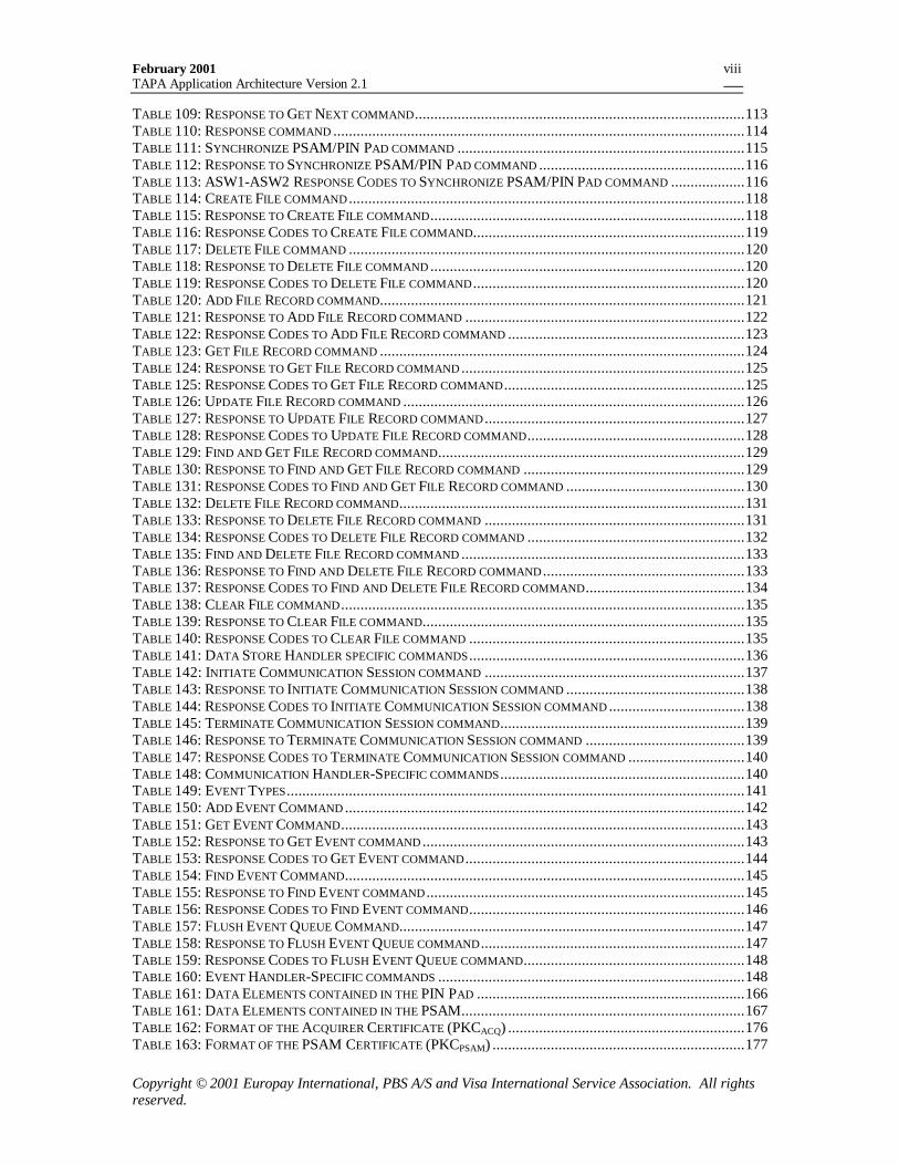
TABLE 109: RESPONSE TO GET NEXT COMMAND.....................................................................................113TABLE 110: RESPONSE COMMAND ..........................................................................................................114TABLE 111: SYNCHRONIZE PSAM/PIN PAD COMMAND ..........................................................................115TABLE 112: RESPONSE TO SYNCHRONIZE PSAM/PIN PAD COMMAND .....................................................116TABLE 113: ASW1-ASW2 RESPONSE CODES TO SYNCHRONIZE PSAM/PIN PAD COMMAND ...................116TABLE 114: CREATE FILE COMMAND ......................................................................................................118TABLE 115: RESPONSE TO CREATE FILE COMMAND.................................................................................118TABLE 116: RESPONSE CODES TO CREATE FILE COMMAND......................................................................119TABLE 117: DELETE FILE COMMAND ......................................................................................................120TABLE 118: RESPONSE TO DELETE FILE COMMAND .................................................................................120TABLE 119: RESPONSE CODES TO DELETE FILE COMMAND ......................................................................120TABLE 120: ADD FILE RECORD COMMAND..............................................................................................121TABLE 121: RESPONSE TO ADD FILE RECORD COMMAND ........................................................................122TABLE 122: RESPONSE CODES TO ADD FILE RECORD COMMAND .............................................................123TABLE 123: GET FILE RECORD COMMAND ..............................................................................................124TABLE 124: RESPONSE TO GET FILE RECORD COMMAND .........................................................................125TABLE 125: RESPONSE CODES TO GET FILE RECORD COMMAND ..............................................................125TABLE 126: UPDATE FILE RECORD COMMAND ........................................................................................126TABLE 127: RESPONSE TO UPDATE FILE RECORD COMMAND ...................................................................127TABLE 128: RESPONSE CODES TO UPDATE FILE RECORD COMMAND........................................................128TABLE 129: FIND AND GET FILE RECORD COMMAND...............................................................................129TABLE 130: RESPONSE TO FIND AND GET FILE RECORD COMMAND .........................................................129TABLE 131: RESPONSE CODES TO FIND AND GET FILE RECORD COMMAND ..............................................130TABLE 132: DELETE FILE RECORD COMMAND.........................................................................................131TABLE 133: RESPONSE TO DELETE FILE RECORD COMMAND ...................................................................131TABLE 134: RESPONSE CODES TO DELETE FILE RECORD COMMAND ........................................................132TABLE 135: FIND AND DELETE FILE RECORD COMMAND .........................................................................133TABLE 136: RESPONSE TO FIND AND DELETE FILE RECORD COMMAND ....................................................133TABLE 137: RESPONSE CODES TO FIND AND DELETE FILE RECORD COMMAND.........................................134TABLE 138: CLEAR FILE COMMAND ........................................................................................................135TABLE 139: RESPONSE TO CLEAR FILE COMMAND...................................................................................135TABLE 140: RESPONSE CODES TO CLEAR FILE COMMAND .......................................................................135TABLE 141: DATA STORE HANDLER SPECIFIC COMMANDS .......................................................................136TABLE 142: INITIATE COMMUNICATION SESSION COMMAND ...................................................................137TABLE 143: RESPONSE TO INITIATE COMMUNICATION SESSION COMMAND ..............................................138TABLE 144: RESPONSE CODES TO INITIATE COMMUNICATION SESSION COMMAND ...................................138TABLE 145: TERMINATE COMMUNICATION SESSION COMMAND...............................................................139TABLE 146: RESPONSE TO TERMINATE COMMUNICATION SESSION COMMAND .........................................139TABLE 147: RESPONSE CODES TO TERMINATE COMMUNICATION SESSION COMMAND ..............................140TABLE 148: COMMUNICATION HANDLER-SPECIFIC COMMANDS ...............................................................140TABLE 149: EVENT TYPES......................................................................................................................141TABLE 150: ADD EVENT COMMAND .......................................................................................................142TABLE 151: GET EVENT COMMAND........................................................................................................143TABLE 152: RESPONSE TO GET EVENT COMMAND ...................................................................................143TABLE 153: RESPONSE CODES TO GET EVENT COMMAND ........................................................................144TABLE 154: FIND EVENT COMMAND.......................................................................................................145TABLE 155: RESPONSE TO FIND EVENT COMMAND ..................................................................................145TABLE 156: RESPONSE CODES TO FIND EVENT COMMAND.......................................................................146TABLE 157: FLUSH EVENT QUEUE COMMAND.........................................................................................147TABLE 158: RESPONSE TO FLUSH EVENT QUEUE COMMAND ....................................................................147TABLE 159: RESPONSE CODES TO FLUSH EVENT QUEUE COMMAND.........................................................148TABLE 160: EVENT HANDLER-SPECIFIC COMMANDS ...............................................................................148TABLE 161: DATA ELEMENTS CONTAINED IN THE PIN PAD .....................................................................166TABLE 161: DATA ELEMENTS CONTAINED IN THE PSAM.........................................................................167TABLE 162: FORMAT OF THE ACQUIRER CERTIFICATE (PKCACQ) .............................................................176TABLE 163: FORMAT OF THE PSAM CERTIFICATE (PKCPSAM) .................................................................177
February 2001TAPA Application Architecture Version 2.1
Copyright © 2001 Europay International, PBS A/S and Visa International Service Association. All rightsreserved.
ix
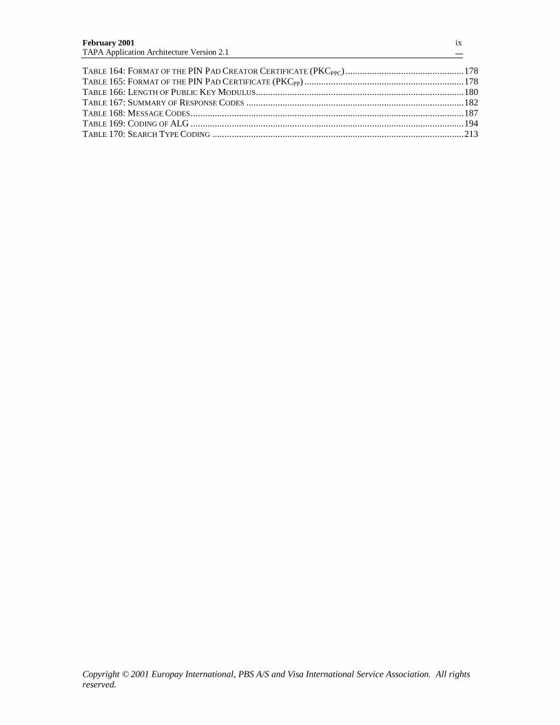
TABLE 164: FORMAT OF THE PIN PAD CREATOR CERTIFICATE (PKCPPC) .................................................178TABLE 165: FORMAT OF THE PIN PAD CERTIFICATE (PKCPP) ..................................................................178TABLE 166: LENGTH OF PUBLIC KEY MODULUS......................................................................................180TABLE 167: SUMMARY OF RESPONSE CODES ..........................................................................................182TABLE 168: MESSAGE CODES.................................................................................................................187TABLE 169: CODING OF ALG .................................................................................................................194TABLE 170: SEARCH TYPE CODING ........................................................................................................213
February 2001TAPA Application Architecture Version 2.1
Copyright © 2001 Europay International, PBS A/S and Visa International Service Association. All rightsreserved.
x
LIST OF FIGURES
FIGURE 1: LOGICAL COMPONENTS OF THE TERMINAL ARCHITECTURE FOR PSAM APPLICATIONS...............10FIGURE 2: TERMINAL PSAM INITIALISATION............................................................................................36FIGURE 3: EXAMPLE OF BYTES READ FROM MAGNETIC STIPE.....................................................................41FIGURE 4: EXAMPLE OF BYTES WRITTEN TO TRACK 3.................................................................................44FIGURE 5: HANDLER TO PROCESSOR CARD INTERFACE..............................................................................46FIGURE 6: PROCESSOR CARD MESSAGE TRANSLATION ..............................................................................47FIGURE 7: PIN SESSION KEY DERIVATION ................................................................................................81FIGURE 8: PIN BLOCK FORMAT................................................................................................................83FIGURE 9: MESSAGE TRANSLATION FOR COMMANDS TO PSAM.................................................................98FIGURE 10: MESSAGE TRANSLATION FOR RESPONSE FROM PSAM ...........................................................100FIGURE 11: PIN PAD AND PSAM KEY HIERARCHY .................................................................................150FIGURE 12: PIN PAD/PSAM ENVIRONMENTS .........................................................................................151FIGURE 13: PSAM/PIN PAD INITIALIZATION ..........................................................................................154FIGURE 14: SEPARATE PIN ENTRY AND AMOUNT CONFIRMATION ...........................................................158FIGURE 15: COMBINED PIN ENTRY AND AMOUNT CONFIRMATION ..........................................................159FIGURE 16: PIN ENTRY WITH NO AMOUNT CONFIRMATION .....................................................................160FIGURE 17: ONLINE PIN VERIFICATION ..................................................................................................161FIGURE 18: TAMPER EVIDENT DEVICE ....................................................................................................164
February 2001TAPA Application Architecture Version 2.1
Copyright © 2001 Europay International, PBS A/S and Visa International Service Association. All rightsreserved.
1
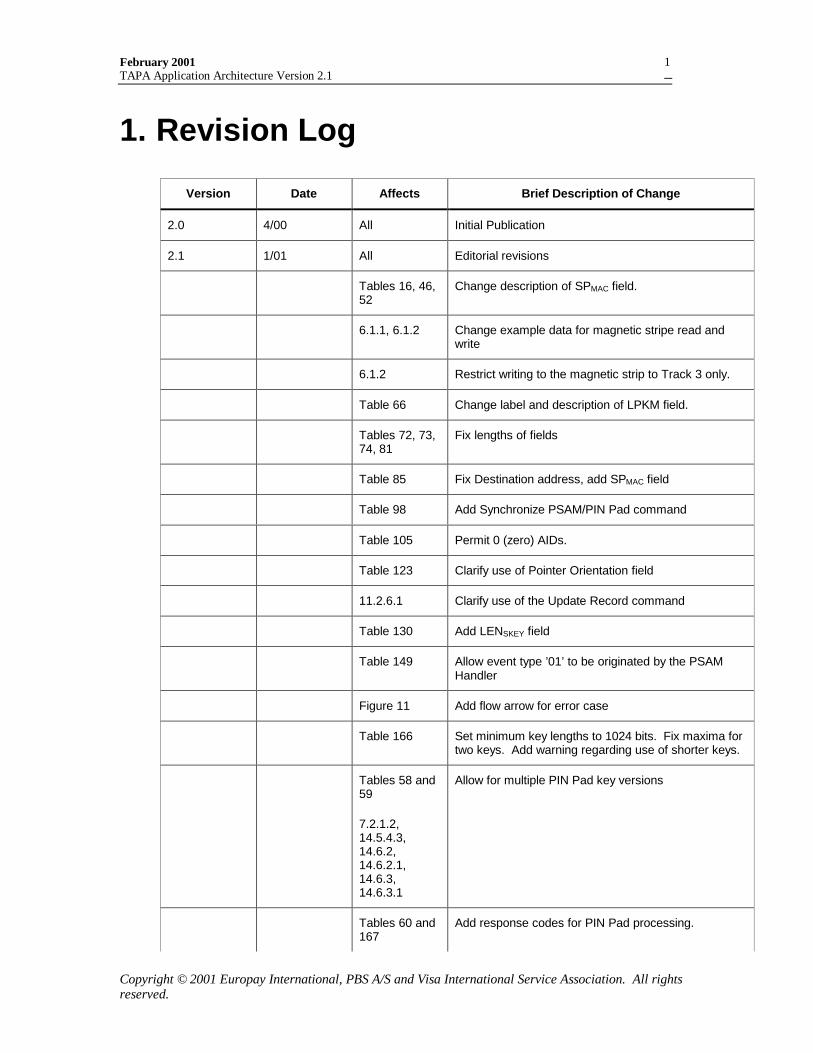
1. Revision Log
Version Date Affects Brief Description of Change
2.0 4/00 All Initial Publication
2.1 1/01 All Editorial revisions
Tables 16, 46,52
Change description of SPMAC field.
6.1.1, 6.1.2 Change example data for magnetic stripe read andwrite
6.1.2 Restrict writing to the magnetic strip to Track 3 only.
Table 66 Change label and description of LPKM field.
Tables 72, 73,74, 81
Fix lengths of fields
Table 85 Fix Destination address, add SPMAC field
Table 98 Add Synchronize PSAM/PIN Pad command
Table 105 Permit 0 (zero) AIDs.
Table 123 Clarify use of Pointer Orientation field
11.2.6.1 Clarify use of the Update Record command
Table 130 Add LENSKEY field
Table 149 Allow event type ’01’ to be originated by the PSAMHandler
Figure 11 Add flow arrow for error case
Table 166 Set minimum key lengths to 1024 bits. Fix maxima fortwo keys. Add warning regarding use of shorter keys.
Tables 58 and59
7.2.1.2,14.5.4.3,14.6.2,14.6.2.1,14.6.3,14.6.3.1
Allow for multiple PIN Pad key versions
Tables 60 and167
Add response codes for PIN Pad processing.
February 2001TAPA Application Architecture Version 2.1
Copyright © 2001 Europay International, PBS A/S and Visa International Service Association. All rightsreserved.
2
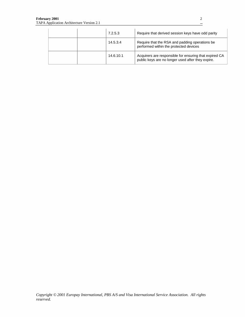
7.2.5.3 Require that derived session keys have odd parity
14.5.3.4 Require that the RSA and padding operations beperformed within the protected devices
14.6.10.1 Acquirers are responsible for ensuring that expired CApublic keys are no longer used after they expire.
February 2001TAPA Application Architecture Version 2.1
Copyright © 2001 Europay International, PBS A/S and Visa International Service Association. All rightsreserved.
3
2. Document Overview2.1 Purpose
The purpose of this document is to provide the informationnecessary for a POS device manufacturer or application developerto gain an understanding of the Terminal Architecture for PSAMApplications (TAPA) for purposes of creating multi-functionapplications.
2.2 Intended Audience
This document is intended for use by all technical staff involved inthe development, testing, operation, and maintenance of one ormore structural components of the Terminal Architecture forPSAM Applications.
2.3 Included in this Document
Included in this document are:
• Overview of the Terminal Architecture for PSAM Applicationsand a description of the individual structural componentscomprising that architecture.
• Description of the general functional requirements to beperformed by each structural component.
• Description of the message formatting, addressing, exchangingof messages between structural components, and command setsused by these components.
• Description of the general message and error handlingprocedures to be conducted within the terminal application.
• Description of the terminal and PSAM initializationprocedures.
February 2001TAPA Application Architecture Version 2.1
Copyright © 2001 Europay International, PBS A/S and Visa International Service Association. All rightsreserved.
4
2.4 Not Included in this DocumentNot included in this document are:
• Specifications already available in other documents, such asthe EMV specifications and ISO standards.
• Scheme specific information related to business requirements,design options, or implementation details – including supportedcommand sets, transaction data flows, or user interfacerequirements.
• Specific message formats or online communication protocolsused.
2.5 Reference Information
2.5.1 Requirement NumberingRequirements in this specification are uniquely numbered with thenumber appearing next to each requirement.
A requirement can have different numbers in different versions ofthe specifications. Hence, all references to a requirement mustinclude the version of the document as well as the requirement’snumber.
2.5.2 ReferencesThe following documents are referenced in this specification:
1. Terminal Architecture for PSAM Applications, Overview,April 2000.
2. Terminal Architecture for PSAM Applications, CEP PSAMApplication Volume 1, February 2001.
3. ISO/IEC 7816-3, 1997-12-15 “Identification cards - Integratedcircuit(s) cards with contacts - Part 3: Electronic signals andtransmission protocols".
4. ISO/IEC 7816-4, First Edition 1995-09-01 “Identification cards– Integrated circuit(s) cards with contacts - Part 4: Inter-industry commands for interchange”.
February 2001TAPA Application Architecture Version 2.1
Copyright © 2001 Europay International, PBS A/S and Visa International Service Association. All rightsreserved.
5
5. ISO/IEC 14443, First Edition 1995-09-01 “Identification cards– Contactless integrated circuit(s) cards – Proximity cards”.
6. ISO/IEC 9797, 1999 “Information technology - Securitytechniques - Message Authentication Codes (MACs) - Part 1:Mechanisms using a block cipher”.
7. EMV, version 3.1.1, 1998-05-31 “Integrated Circuit CardSpecification for Payment Systems”
8. ISO/IEC 646, 1993 “Information Technology - ISO 7-BitCoded Character Set for Information Interchange “
9. ISO 8859, 1987-02-15, First Edition “Information processing –8-bit single-byte coded graphic character sets.”
10. ISO/IEC 7813, 1995 “Identification Cards - FinancialTransaction Cards”
2.5.3 Command and Response Format ConventionsThis specification adopts the following conventions for specifyingthe commands and responses exchanged between the terminal andPSAM applications
PSAM Commands
For commands sent to the PSAM by the MAD-Handler, thisspecification documents the entire ICC Command TerminalMessage (Message Type ‘42’), including the embedded CommandAPDU, which is being forwarded to the PSAM. To aid the PSAMdeveloper, the C-APDU portion is shaded.
For commands sent to the PSAM that are generated by the PSAMHandler, this specification documents the C-APDU, which isgenerated by the PSAM Handler.
PSAM Responses
This specification defines the format and contents of the ResponseTerminal Message (Message Type ‘FF’) received by the MAD-Handler in response to a command sent to the PSAM. The entireresponse message, excluding the Response Code (RC) is sent tothe PSAM Handler by the PSAM within a response APDU. To aidthe PSAM developer, the portion of the response generated by thePSAM is shaded.
February 2001TAPA Application Architecture Version 2.1
Copyright © 2001 Europay International, PBS A/S and Visa International Service Association. All rightsreserved.
6
A detailed description of the message handling performed by thePSAM Handler can be found in section 9.1. A description of thePSAM application requirements is in section 10
2.5.4 Notational ConventionsHexadecimal Notation
Values expressed in hexadecimal form are enclosed in singlequotes (e.g., ‘_’). For example, 27509 decimal is expressed inhexadecimal digits as ‘6B75’.
Letters used to express constant hexadecimal values are alwaysupper case (‘A’ - ‘F’). Where lower case is used, the letters have adifferent meaning explained in the text.
Binary Notation
Values expressed in binary form are followed by a lower case “b”.For example, ‘08’ hexadecimal is expressed in binary as00001000b.
Document Word Usage
The following words are used often in this document and havespecific meanings:
• Must
Defines a product or system capability that is required, compelled,or mandatory.
• Should
Defines a product or system capability that is highlyrecommended.
• May
Defines a product or system capability that is optional.
Notation used in the PIN Pad Cryptography section
⊕ represents the bitwise XOR function
SHA-1 (X) := the SHA-1 hash of X
SHA (X,n) := leftmost n bytes of SHA-1(X)
February 2001TAPA Application Architecture Version 2.1
Copyright © 2001 Europay International, PBS A/S and Visa International Service Association. All rightsreserved.
7
2.6 Document Organization
The document is organized as follows:
• Section 1 is the revision log.
• Section 2 provides an overview of this document.
• Section 3 provides an architectural overview of the TerminalArchitecture for PSAM Applications (TAPA)
• Section 4 provides information concerning the generalfunctional requirements of TAPA architectural components.
• Section 5 describes the processing requirements of the Multi-Application Driver Handler.
• Section 6 describes the processing requirements of the CardHandlers.
• Section 7 describes the processing requirements of the UserInterface Handlers.
• Section 8 describes the processing requirements of theMerchant Application Handlers.
• Section 9 describes the processing requirements of the PSAMHandlers.
• Section 10 describes the requirements for TAPA-compliantPSAM applications
• Section 11 describes the processing requirements of the DataStore Handler.
• Section 12 describes the processing requirements of theCommunication Handler.
• Section 13 describes the processing requirements for the EventHandler.
• Section 14 provides the requirements for PIN Processing whena PSAM is used in conjunction with the PIN Pad.
February 2001TAPA Application Architecture Version 2.1
Copyright © 2001 Europay International, PBS A/S and Visa International Service Association. All rightsreserved.
8
• Section 15 provides a listing of Response Codes that may begenerated.
• Section 16 describes the referenced data elements.
• Section 17 provides a list of acronyms
February 2001TAPA Application Architecture Version 2.1
Copyright © 2001 Europay International, PBS A/S and Visa International Service Association. All rightsreserved.
9
3. Architectural Overview3.1 Introduction
This section provides an overview of the Terminal Architecture forPSAM Applications (TAPA) and outlines the general functionaland processing requirements that this architecture is intended tofulfill. This section will additionally identify and describe thevarious structural components comprising the overall TAPAarchitecture.
3.2 General Requirements
The TAPA application architecture defines a generic Terminal -PSAM interface such that a terminal application may functionusing PSAMs produced by different manufacturers.
The TAPA application architecture supports a multi-functionpoint-of-sale terminal application that can support both EMV andCEP payment applications as well as additional proprietaryapplications such as loyalty programs.
TAPA is designed to be independent of the implementationstrategy chosen and is independent of both terminal operatingsystem and device architecture.
TAPA does not impose restrictions on the type of transmissionprotocol used to exchange messages between most structuralcomponents. However, communication with ICCs is assumed toconform to the command-response protocol defined in reference 4,ISO/IEC 7816-4.
TAPA does not restrict the physical configuration of the terminal.The terminal may exist as either a complete unit of fully integratedcomponents (such as a conventional payment terminal) or mayexist to varying degrees as a distributed system using sharedcomponents such as an Internet payment server.
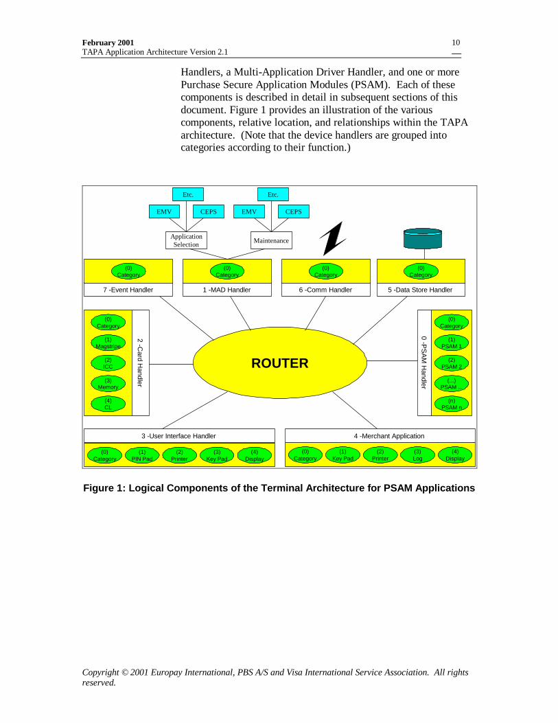
3.3 Terminal Application Architecture
The terminal application architecture consists of a set of logicalcomponents. These components include a Router, a set of Device
February 2001TAPA Application Architecture Version 2.1
Copyright © 2001 Europay International, PBS A/S and Visa International Service Association. All rightsreserved.
10
Handlers, a Multi-Application Driver Handler, and one or morePurchase Secure Application Modules (PSAM). Each of thesecomponents is described in detail in subsequent sections of thisdocument. Figure 1 provides an illustration of the variouscomponents, relative location, and relationships within the TAPAarchitecture. (Note that the device handlers are grouped intocategories according to their function.)
(0)Category
4 -Merchant Application
(1)Key Pad
(2)Printer
(3)Log
(4)Display
(0)Category
2 -Card H
andler
(1)Magstripe
(2)ICC
(3)Memory
(4)CL
PSAM2
(2)(0)
Category
3 -User Interface Handler
(1)PIN Pad
(2)Printer
(3)Key Pad
(4)Display
PSAM2
(2)
(0)Category
0 -PS
AM
Handler
(1)PSAM 1
(2)PSAM 2
(...)PSAM ...
(n)PSAM n
5 -Data Store Handler
(0)Category
6 -Comm Handler
(0)Category
7 -Event Handler
(0)Category
1 -MAD Handler
(0)Category
EMV
ApplicationSelection
CEPS
Etc.
EMV
Maintenance
CEPS
Etc.
ROUTER
Figure 1: Logical Components of the Terminal Architecture for PSAM Applications
February 2001TAPA Application Architecture Version 2.1
Copyright © 2001 Europay International, PBS A/S and Visa International Service Association. All rightsreserved.
11
4. Functional RequirementsThis section provides a detailed description of the variousstructural components comprising the TAPA architecture and theirrespective functional and processing requirements. For eachcomponent, the command and response sets are defined as well asrequired processing and possible Response Codes.
Note: Certain requirements are only applicable if the terminal usesthe PSAM controlled PIN Pad processing specified in section 13.3.Such requirements are prefaced with the phrase “PIN PadRequirement”.
4.1 The Router
The Router functions as a communication channel and is thecentral entity to which all Handlers are attached. Thecommunication channel may be implemented on a variety ofhardware and software protocols such as an internal bus (in thecase of a stand-alone POS device), a LAN in a multi-lanecontroller environment, or TCP/IP if architectural components areremotely distributed on the Internet. In order to accommodate allof the aforementioned configurations, the Router must functionpurely as a simple transport mechanism that is application anddevice independent.
The Router is primarily responsible for the transfer of messages(commands and responses) from one Handler to another. In thisway, the Router functions as a pure transport mechanism --ensuring that messages received from an origination Handler aredelivered to the destination Handler as specified in messageaddress fields. By means of transferring messages from oneHandler to another, the Router also effectively passes applicationcontrol from one Handler to another. Before a destination Handlerresponds to a message, it may initiate a series of messageexchanges to Handlers other than the originator of the message.
Aside from validating the address fields of a message to ensure itcan be delivered to the specified destination, the Router remainsignorant of the data content of the messages it conveys. Thistransparency allows the Router to remain application independent.It is the responsibility of the individual Handlers to validate,process, and respond to the contents of the received message.
February 2001TAPA Application Architecture Version 2.1
Copyright © 2001 Europay International, PBS A/S and Visa International Service Association. All rightsreserved.
12
4.1.1 Functional Requirements
4.1.1.1 The Router must validate the source and destinationaddress and sub-address fields in messages receivedfrom an origination Handler to ensure they aredefined in the specification and are also supportedby the terminal application. This validation processwill ensure that the message can be delivered to theappropriate destination Handler.
4.1.1.2 The Router must not intervene or prevent routablemessages from being delivered to a destinationHandler.
4.1.1.3 The Router should implement some error checkingmechanism to ensure the data integrity of messagesexchanged between handlers across physicalinterfaces. The mechanism implemented is left tothe discretion of the terminal developer; however,LRC or CRC checking is frequently used.
4.1.2 Error Handling
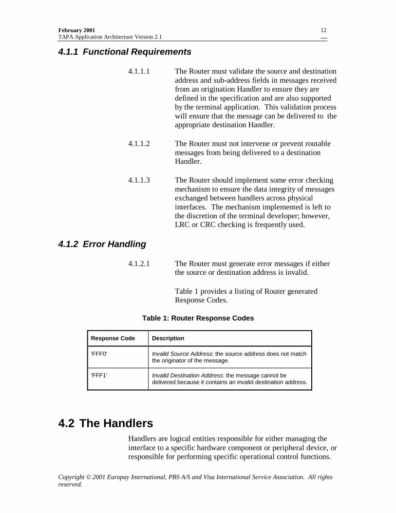
4.1.2.1 The Router must generate error messages if eitherthe source or destination address is invalid.
Table 1 provides a listing of Router generatedResponse Codes.
Table 1: Router Response Codes
Response Code Description
'FFF0' Invalid Source Address: the source address does not matchthe originator of the message.
'FFF1' Invalid Destination Address: the message cannot bedelivered because it contains an invalid destination address.
4.2 The HandlersHandlers are logical entities responsible for either managing theinterface to a specific hardware component or peripheral device, orresponsible for performing specific operational control functions.
February 2001TAPA Application Architecture Version 2.1
Copyright © 2001 Europay International, PBS A/S and Visa International Service Association. All rightsreserved.
13
There are three types of Handler: Device Handlers, the Multi-Application Driver Handler and the Event Handler.
4.2.1 Device HandlersDevice Handlers are logical entities responsible for managing thebi-directional interface to a hardware component or peripheraldevice such as a card reader, modem, or customer keypad. Adevice Handler may manage either a simple or sophisticatedinterface. A Device Handler may be a simple mechanism in thesense that it may only transport a message received from theRouter to the device it operates and automatically respond to theHandler that originated the message. In the other extreme, it maybe a very sophisticated piece of software that analyzes the contentof incoming and outgoing messages in addition to manipulating themessage addresses.
The existence of a Device Handler serves the purpose of shieldinginterface and implementation details for the specific device itsupports from other components in the system. A Device Handlershould therefore perform only those functions directly associatedwith support of the hardware or peripheral equipment it is intendedto support -- thereby allowing Handlers to remain as applicationindependent as possible. Each of these Handlers is described ingreater detail in subsequent sections of this document. Note thatadditional Handlers may be identified and defined as necessary toaccommodate a particular implementation or environment.
4.2.2 Multi-Application Driver HandlerThe Multi-Application Driver Handler is the operative softwarecomponent of the terminal application which, in addition toselecting and controlling transaction processing, performs anumber of operational and maintenance functions. The Multi-Application Driver Handler is described in greater detail in Section5.0.
4.2.3 Event HandlerThe Event Handler is a logical entity responsible for receivingnotification of asynchronous external events and providingnotification of these events to the terminal’s applicationprocessing.
The Device Handlers will forward messages to the Event Handlerwhen events occur such as a card insertion or a key press aredetected. A MAD Handler application, or an entity (such as a
February 2001TAPA Application Architecture Version 2.1
Copyright © 2001 Europay International, PBS A/S and Visa International Service Association. All rightsreserved.
14
PSAM application) to which control has been delegated by theMAD Handler, may retrieve the events and take appropriateactions.
4.2.4 General CharacteristicsThe following characteristics are common to all classes ofHandler:
• Handlers are connected to and communicate directly with theRouter. All messages either originating from or destined forother Handlers must be exchanged via the Router.
• Handlers are application independent in that they may beaccessed by multiple applications resident in the terminal.
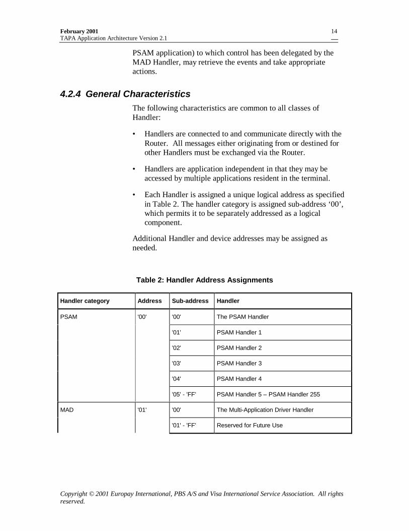
• Each Handler is assigned a unique logical address as specifiedin Table 2. The handler category is assigned sub-address ‘00’,which permits it to be separately addressed as a logicalcomponent.
Additional Handler and device addresses may be assigned asneeded.
Table 2: Handler Address Assignments
Handler category Address Sub-address Handler
PSAM '00' '00' The PSAM Handler
'01' PSAM Handler 1
'02' PSAM Handler 2
'03' PSAM Handler 3
'04' PSAM Handler 4
'05' - 'FF' PSAM Handler 5 – PSAM Handler 255
MAD '01' '00' The Multi-Application Driver Handler
'01' - 'FF' Reserved for Future Use
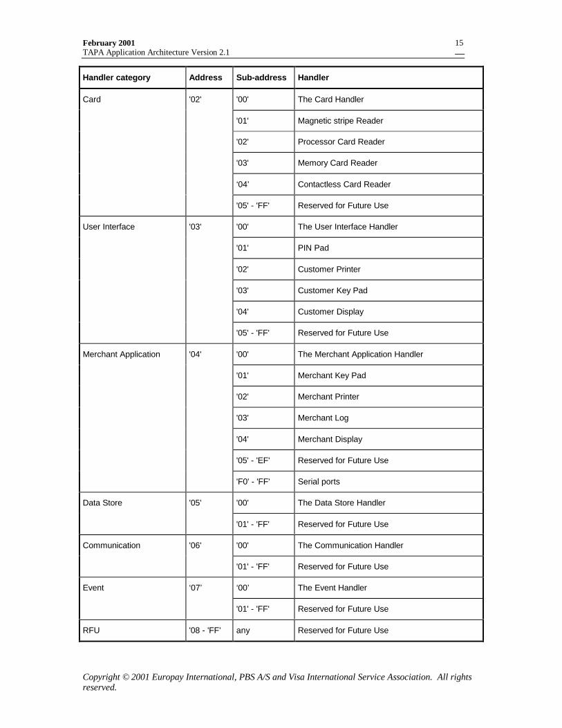
February 2001TAPA Application Architecture Version 2.1
Copyright © 2001 Europay International, PBS A/S and Visa International Service Association. All rightsreserved.
15
Handler category Address Sub-address Handler
Card '02' '00' The Card Handler
'01' Magnetic stripe Reader
'02' Processor Card Reader
'03' Memory Card Reader
‘04’ Contactless Card Reader
'05' - 'FF' Reserved for Future Use
User Interface '03' '00' The User Interface Handler
'01' PIN Pad
'02' Customer Printer
'03' Customer Key Pad
'04' Customer Display
'05' - 'FF' Reserved for Future Use
Merchant Application '04' '00' The Merchant Application Handler
'01' Merchant Key Pad
'02' Merchant Printer
'03' Merchant Log
'04' Merchant Display
'05' - 'EF' Reserved for Future Use
'F0' - 'FF' Serial ports
Data Store '05' '00' The Data Store Handler
'01' - 'FF' Reserved for Future Use
Communication '06' '00' The Communication Handler
'01' - 'FF' Reserved for Future Use
Event ‘07’ ‘00’ The Event Handler
'01' - 'FF' Reserved for Future Use
RFU '08 - 'FF’ any Reserved for Future Use

February 2001TAPA Application Architecture Version 2.1
Copyright © 2001 Europay International, PBS A/S and Visa International Service Association. All rightsreserved.
16
4.2.5 Functional RequirementsThis section defines the functional requirements to be supported byall Handlers.
4.2.5.1 A Handler that receives a command must alwaysrespond to the originator of that command (exceptas noted in Section 13.2.1).
4.2.5.2 Prior to generating a response, a destination Handlermust be permitted to issue commands to Handlersother than the originator of the initial command.
4.2.5.3 A Handler must only respond to the originator ofthe command after all required subsequent dialoguehas been completed with other Handlers.
4.2.5.4 After sending a command, a Handler must not sendanother command to the same destination, or for thesame thread prior to receiving a response (except asnoted in Section 13.2.1). (See section 5.5 for adiscussion of multi-threading)..
4.2.5.5 When constructing a response, the respondingHandler must use the source address and sub-address of the command message as the destinationaddress and sub-address of the response. TheThread Identifier (IDTHREAD) from the originalcommand message must be included in theresponse.
4.2.5.6 A Handler should be limited to performing onlythose functions as needed to either directly supporta particular device or manage a particular operation.
4.2.5.7 When a Handler receives a command message fromanother terminal component, it must return aresponse to the requesting Handler.
A successful response must contain a ResponseCode of ‘0000’.
If the command has not been processes correctly,the handler must return the appropriate ResponseCode.
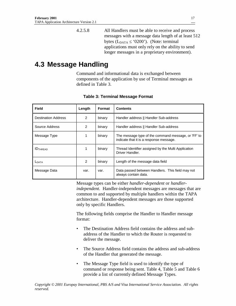
February 2001TAPA Application Architecture Version 2.1
Copyright © 2001 Europay International, PBS A/S and Visa International Service Association. All rightsreserved.
17
4.2.5.8 All Handlers must be able to receive and processmessages with a message data length of at least 512bytes (LDATA ≤ ‘0200’). (Note: terminalapplications must only rely on the ability to sendlonger messages in a proprietary environment).
4.3 Message HandlingCommand and informational data is exchanged betweencomponents of the application by use of Terminal messages asdefined in Table 3.
Table 3: Terminal Message Format
Field Length Format Contents
Destination Address 2 binary Handler address || Handler Sub-address
Source Address 2 binary Handler address || Handler Sub-address
Message Type 1 binary The message type of the command message, or 'FF' toindicate that it is a response message.
IDTHREAD 1 binary Thread Identifier assigned by the Multi ApplicationDriver Handler.
LDATA 2 binary Length of the message data field
Message Data var. var. Data passed between Handlers. This field may notalways contain data.
Message types can be either handler-dependent or handler-independent. Handler-independent messages are messages that arecommon to and supported by multiple handlers within the TAPAarchitecture. Handler-dependent messages are those supportedonly by specific Handlers.
The following fields comprise the Handler to Handler messageformat:
• The Destination Address field contains the address and sub-address of the Handler to which the Router is requested todeliver the message.
• The Source Address field contains the address and sub-addressof the Handler that generated the message.
• The Message Type field is used to identify the type ofcommand or response being sent. Table 4, Table 5 and Table 6provide a list of currently defined Message Types.
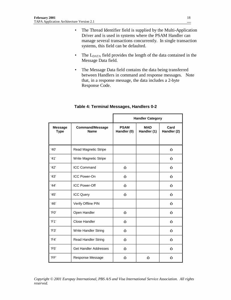
February 2001TAPA Application Architecture Version 2.1
Copyright © 2001 Europay International, PBS A/S and Visa International Service Association. All rightsreserved.
18
• The Thread Identifier field is supplied by the Multi-ApplicationDriver and is used in systems where the PSAM Handler canmanage several transactions concurrently. In single transactionsystems, this field can be defaulted.
• The LDATA field provides the length of the data contained in theMessage Data field.
• The Message Data field contains the data being transferredbetween Handlers in command and response messages. Notethat, in a response message, the data includes a 2-byteResponse Code.
Table 4: Terminal Messages, Handlers 0-2
Handler Category
MessageType
Command/MessageName
PSAMHandler (0)
MADHandler (1)
CardHandler (2)
'40' Read Magnetic Stripe √
'41' Write Magnetic Stripe √
'42' ICC Command √ √
'43' ICC Power-On √ √
'44' ICC Power-Off √ √
'45' ICC Query √ √
‘46’ Verify Offline PIN √
'F0' Open Handler √ √
'F1' Close Handler √ √
'F3' Write Handler String √ √
'F4' Read Handler String √ √
'F5' Get Handler Addresses √ √
'FF' Response Message √ √ √
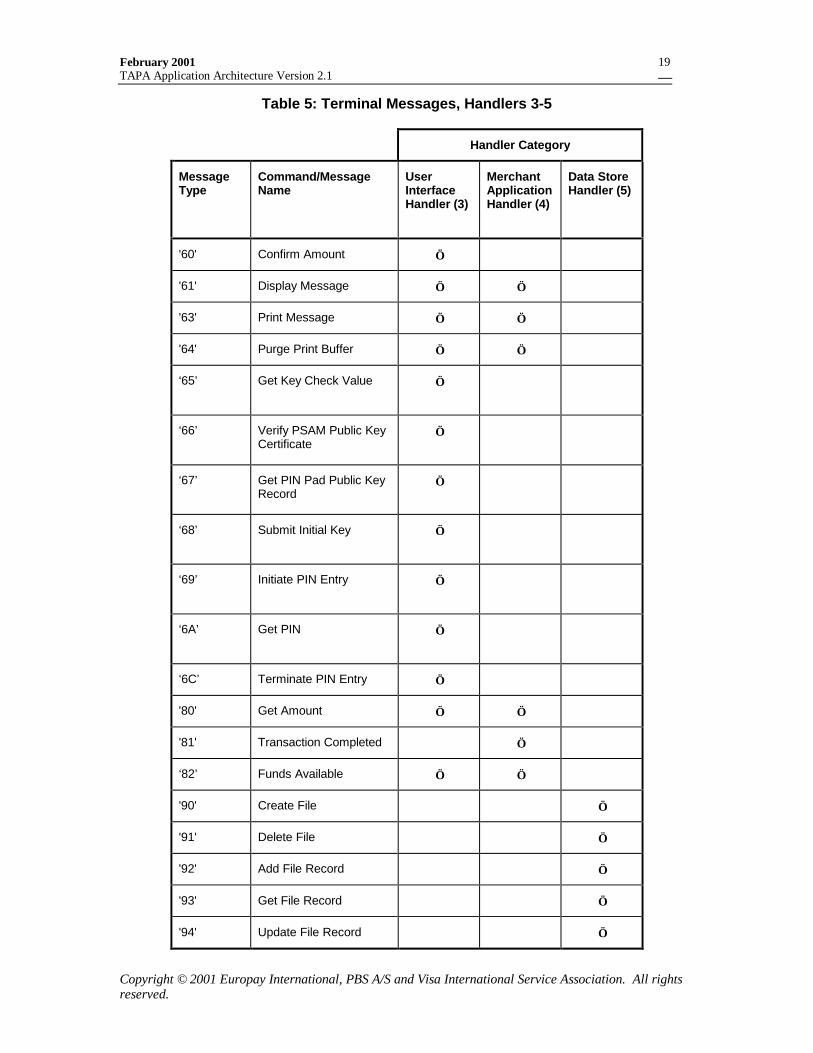
February 2001TAPA Application Architecture Version 2.1
Copyright © 2001 Europay International, PBS A/S and Visa International Service Association. All rightsreserved.
19
Table 5: Terminal Messages, Handlers 3-5
Handler Category
MessageType
Command/MessageName
UserInterfaceHandler (3)
MerchantApplicationHandler (4)
Data StoreHandler (5)
'60' Confirm Amount √
'61' Display Message √ √
'63' Print Message √ √
'64' Purge Print Buffer √ √
‘65’ Get Key Check Value √
‘66’ Verify PSAM Public KeyCertificate
√
‘67’ Get PIN Pad Public KeyRecord
√
‘68’ Submit Initial Key √
‘69’ Initiate PIN Entry √
‘6A’ Get PIN √
‘6C’ Terminate PIN Entry √
'80' Get Amount √ √
'81' Transaction Completed √
‘82’ Funds Available √ √
'90' Create File √
'91' Delete File √
'92' Add File Record √
'93' Get File Record √
'94' Update File Record √
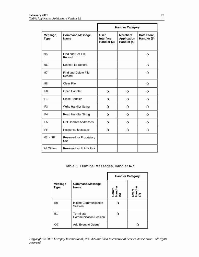
February 2001TAPA Application Architecture Version 2.1
Copyright © 2001 Europay International, PBS A/S and Visa International Service Association. All rightsreserved.
20
Handler Category
MessageType
Command/MessageName
UserInterfaceHandler (3)
MerchantApplicationHandler (4)
Data StoreHandler (5)
'95' Find and Get FileRecord
√
'96' Delete File Record √
'97' Find and Delete FileRecord
√
'98' Clear File √
'F0' Open Handler √ √ √
'F1' Close Handler √ √ √
'F3' Write Handler String √ √ √
'F4' Read Handler String √ √ √
'F5' Get Handler Addresses √ √ √
'FF' Response Message √ √ √
'01' - '3F' Reserved for ProprietaryUse
All Others Reserved for Future Use
Table 6: Terminal Messages, Handler 6-7
Handler Category
MessageType
Command/MessageName
Com
m.
Han
dler
(6)
Eve
ntH
andl
er(7
)
'B0' Initiate CommunicationSession
√
'B1' TerminateCommunication Session
√
'C0' Add Event to Queue √
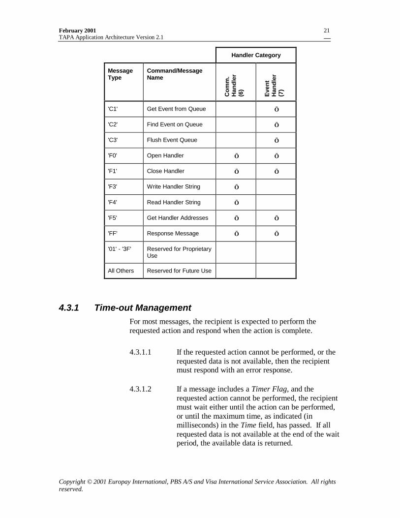
February 2001TAPA Application Architecture Version 2.1
Copyright © 2001 Europay International, PBS A/S and Visa International Service Association. All rightsreserved.
21
Handler Category
MessageType
Command/MessageName
Com
m.
Han
dler
(6)
Eve
ntH
andl
er(7
)
'C1' Get Event from Queue √
'C2' Find Event on Queue √
'C3' Flush Event Queue √
'F0' Open Handler √ √
'F1' Close Handler √ √
'F3' Write Handler String √
'F4' Read Handler String √
'F5' Get Handler Addresses √ √
'FF' Response Message √ √
'01' - '3F' Reserved for ProprietaryUse
All Others Reserved for Future Use
4.3.1 Time-out ManagementFor most messages, the recipient is expected to perform therequested action and respond when the action is complete.
4.3.1.1 If the requested action cannot be performed, or therequested data is not available, then the recipientmust respond with an error response.
4.3.1.2 If a message includes a Timer Flag, and therequested action cannot be performed, the recipientmust wait either until the action can be performed,or until the maximum time, as indicated (inmilliseconds) in the Time field, has passed. If allrequested data is not available at the end of the waitperiod, the available data is returned.
February 2001TAPA Application Architecture Version 2.1
Copyright © 2001 Europay International, PBS A/S and Visa International Service Association. All rightsreserved.
22
For example, if the message is a Read request for200 bytes of data from the CommunicationsHandler – and at the end of the Wait time a 150 byteblock of data is available – then the available 150bytes must be returned in the response.
4.3.1.3 If either the Timer Flag is not set, or if the Timefield contains a value of binary zeros, a response isrequired either when action is complete or when itis known that it cannot be completed.
If there is no malfunctioning identified but theservice cannot be provided, the requester may waitindefinitely.
4.3.2 Exception HandlingIf a handler is not able to perform the requested function, it mustrespond to the sender with a Response Message containing onlythe appropriate Response Code in the message data. SpecificResponse Codes for each message type are defined in thesespecifications. The terminal developer may assign additionalproprietary Response Codes as needed.
The recipient of a response message must handle all of the definedResponse Codes appropriately. Any unknown Response Codesmust be treated as an error.
4.4 Handler-Independent MessagesThis section describes those commands that can be processed byany Handler defined within the TAPA architecture.
4.4.1 Get Handler AddressesThe Get Handler Addresses command is used to obtain a list ofactive and available addresses within a handler category.
4.4.1.1 The Get Handler command must conform to theformat defined in Table 7.
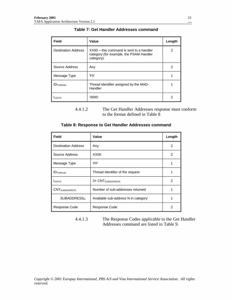
February 2001TAPA Application Architecture Version 2.1
Copyright © 2001 Europay International, PBS A/S and Visa International Service Association. All rightsreserved.
23
Table 7: Get Handler Addresses command
Field Value Length
Destination Address XX00 – this command is sent to a handlercategory (for example, the PSAM Handlercategory).
2
Source Address Any 2
Message Type 'F5' 1
IDTHREAD Thread Identifier assigned by the MAD-Handler
1
LDATA ‘0000’ 2
4.4.1.2 The Get Handler Addresses response must conformto the format defined in Table 8
Table 8: Response to Get Handler Addresses command
Field Value Length
Destination Address Any 2
Source Address XX00 2
Message Type 'FF' 1
IDTHREAD Thread Identifier of the request 1
LDATA 3+ CNTSUBADDRESS 2
CNTSUBADDRESS Number of sub-addresses returned 1
SUBADDRESSN Available sub-address N in category 1
Response Code Response Code 2
4.4.1.3 The Response Codes applicable to the Get HandlerAddresses command are listed in Table 9.
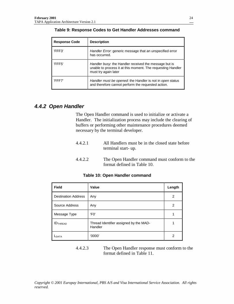
February 2001TAPA Application Architecture Version 2.1
Copyright © 2001 Europay International, PBS A/S and Visa International Service Association. All rightsreserved.
24
Table 9: Response Codes to Get Handler Addresses command
Response Code Description
'FFF3' Handler Error: generic message that an unspecified errorhas occurred.
'FFF5' Handler busy: the Handler received the message but isunable to process it at this moment. The requesting Handlermust try again later
'FFF7' Handler must be opened: the Handler is not in open statusand therefore cannot perform the requested action.
4.4.2 Open HandlerThe Open Handler command is used to initialize or activate aHandler. The initialization process may include the clearing ofbuffers or performing other maintenance procedures deemednecessary by the terminal developer.
4.4.2.1 All Handlers must be in the closed state beforeterminal start- up.
4.4.2.2 The Open Handler command must conform to theformat defined in Table 10.
Table 10: Open Handler command
Field Value Length
Destination Address Any 2
Source Address Any 2
Message Type 'F0' 1
IDTHREAD Thread Identifier assigned by the MAD-Handler
1
LDATA ‘0000’ 2
4.4.2.3 The Open Handler response must conform to theformat defined in Table 11.
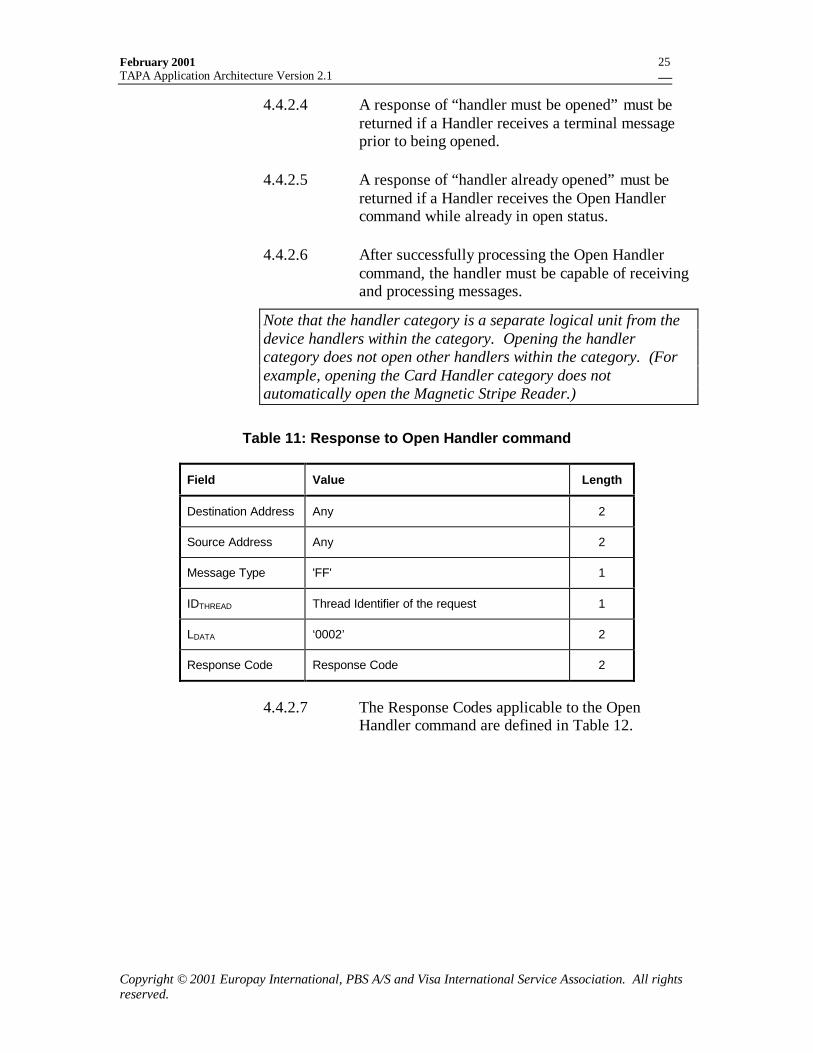
February 2001TAPA Application Architecture Version 2.1
Copyright © 2001 Europay International, PBS A/S and Visa International Service Association. All rightsreserved.
25
4.4.2.4 A response of “handler must be opened” must bereturned if a Handler receives a terminal messageprior to being opened.
4.4.2.5 A response of “handler already opened” must bereturned if a Handler receives the Open Handlercommand while already in open status.
4.4.2.6 After successfully processing the Open Handlercommand, the handler must be capable of receivingand processing messages.
Note that the handler category is a separate logical unit from thedevice handlers within the category. Opening the handlercategory does not open other handlers within the category. (Forexample, opening the Card Handler category does notautomatically open the Magnetic Stripe Reader.)
Table 11: Response to Open Handler command
Field Value Length
Destination Address Any 2
Source Address Any 2
Message Type 'FF' 1
IDTHREAD Thread Identifier of the request 1
LDATA ‘0002’ 2
Response Code Response Code 2
4.4.2.7 The Response Codes applicable to the OpenHandler command are defined in Table 12.
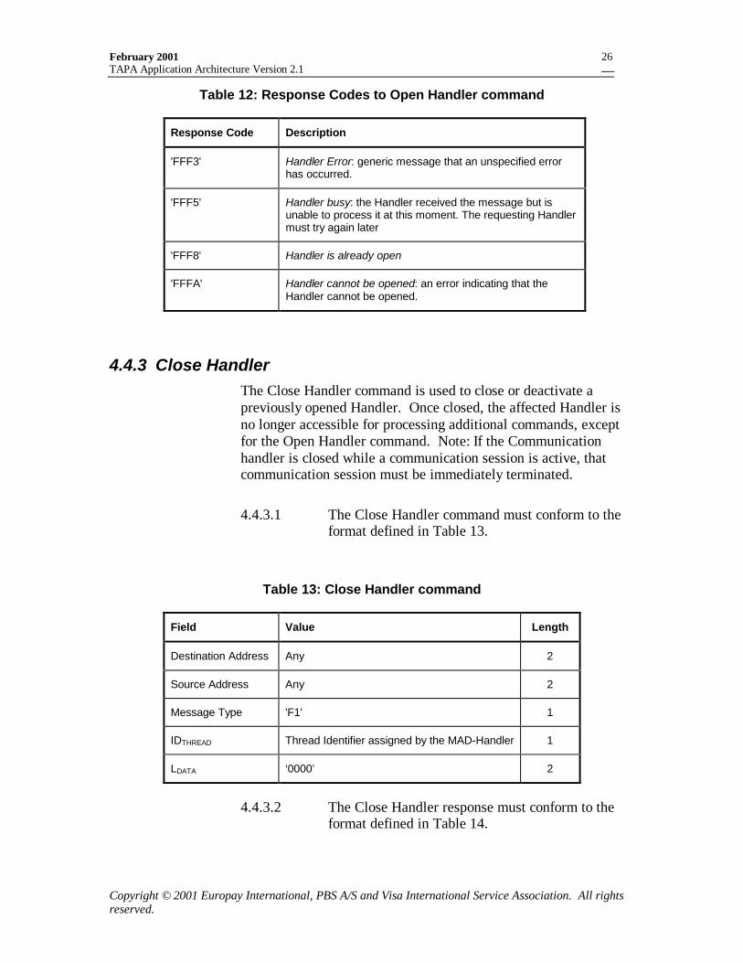
February 2001TAPA Application Architecture Version 2.1
Copyright © 2001 Europay International, PBS A/S and Visa International Service Association. All rightsreserved.
26
Table 12: Response Codes to Open Handler command
Response Code Description
'FFF3' Handler Error: generic message that an unspecified errorhas occurred.
'FFF5' Handler busy: the Handler received the message but isunable to process it at this moment. The requesting Handlermust try again later
'FFF8' Handler is already open
'FFFA' Handler cannot be opened: an error indicating that theHandler cannot be opened.
4.4.3 Close HandlerThe Close Handler command is used to close or deactivate apreviously opened Handler. Once closed, the affected Handler isno longer accessible for processing additional commands, exceptfor the Open Handler command. Note: If the Communicationhandler is closed while a communication session is active, thatcommunication session must be immediately terminated.
4.4.3.1 The Close Handler command must conform to theformat defined in Table 13.
Table 13: Close Handler command
Field Value Length
Destination Address Any 2
Source Address Any 2
Message Type 'F1' 1
IDTHREAD Thread Identifier assigned by the MAD-Handler 1
LDATA ‘0000’ 2
4.4.3.2 The Close Handler response must conform to theformat defined in Table 14.
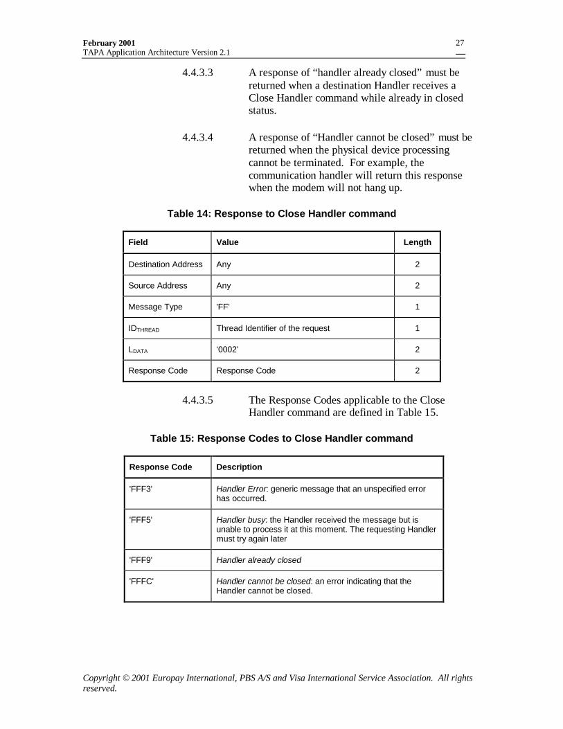
February 2001TAPA Application Architecture Version 2.1
Copyright © 2001 Europay International, PBS A/S and Visa International Service Association. All rightsreserved.
27
4.4.3.3 A response of “handler already closed” must bereturned when a destination Handler receives aClose Handler command while already in closedstatus.
4.4.3.4 A response of “Handler cannot be closed” must bereturned when the physical device processingcannot be terminated. For example, thecommunication handler will return this responsewhen the modem will not hang up.
Table 14: Response to Close Handler command
Field Value Length
Destination Address Any 2
Source Address Any 2
Message Type 'FF' 1
IDTHREAD Thread Identifier of the request 1
LDATA ‘0002’ 2
Response Code Response Code 2
4.4.3.5 The Response Codes applicable to the CloseHandler command are defined in Table 15.
Table 15: Response Codes to Close Handler command
Response Code Description
'FFF3' Handler Error: generic message that an unspecified errorhas occurred.
'FFF5' Handler busy: the Handler received the message but isunable to process it at this moment. The requesting Handlermust try again later
'FFF9' Handler already closed
'FFFC' Handler cannot be closed: an error indicating that theHandler cannot be closed.
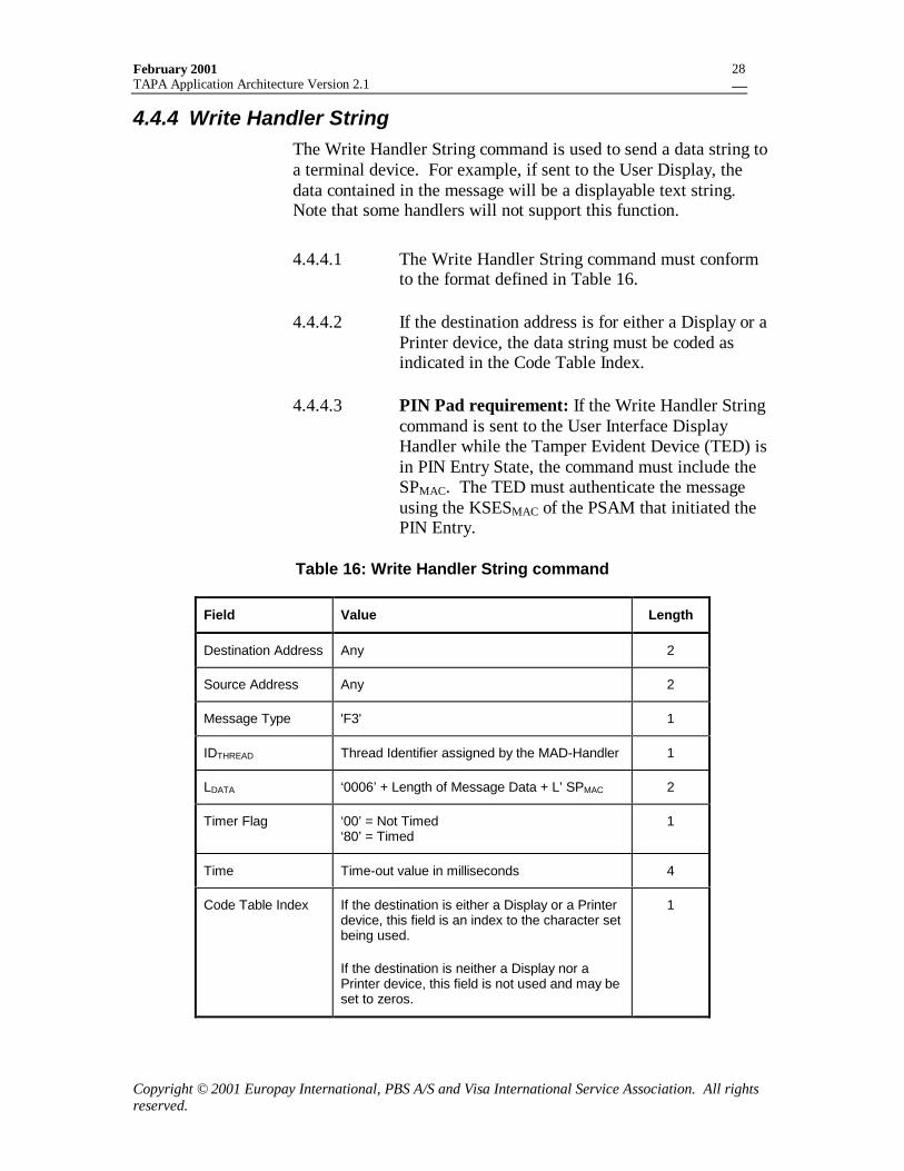
February 2001TAPA Application Architecture Version 2.1
Copyright © 2001 Europay International, PBS A/S and Visa International Service Association. All rightsreserved.
28
4.4.4 Write Handler StringThe Write Handler String command is used to send a data string toa terminal device. For example, if sent to the User Display, thedata contained in the message will be a displayable text string.Note that some handlers will not support this function.
4.4.4.1 The Write Handler String command must conformto the format defined in Table 16.
4.4.4.2 If the destination address is for either a Display or aPrinter device, the data string must be coded asindicated in the Code Table Index.
4.4.4.3 PIN Pad requirement: If the Write Handler Stringcommand is sent to the User Interface DisplayHandler while the Tamper Evident Device (TED) isin PIN Entry State, the command must include theSPMAC. The TED must authenticate the messageusing the KSESMAC of the PSAM that initiated thePIN Entry.
Table 16: Write Handler String command
Field Value Length
Destination Address Any 2
Source Address Any 2
Message Type 'F3' 1
IDTHREAD Thread Identifier assigned by the MAD-Handler 1
LDATA ‘0006’ + Length of Message Data + L’ SPMAC 2
Timer Flag ‘00’ = Not Timed‘80’ = Timed
1
Time Time-out value in milliseconds 4
Code Table Index If the destination is either a Display or a Printerdevice, this field is an index to the character setbeing used.
If the destination is neither a Display nor aPrinter device, this field is not used and may beset to zeros.
1
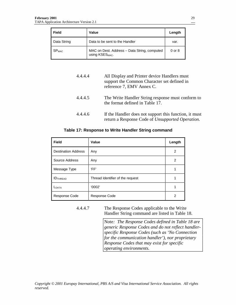
February 2001TAPA Application Architecture Version 2.1
Copyright © 2001 Europay International, PBS A/S and Visa International Service Association. All rightsreserved.
29
Field Value Length
Data String Data to be sent to the Handler var.
SPMAC MAC on Dest. Address – Data String, computedusing KSESMAC.
0 or 8
4.4.4.4 All Display and Printer device Handlers mustsupport the Common Character set defined inreference 7, EMV Annex C.
4.4.4.5 The Write Handler String response must conform tothe format defined in Table 17.
4.4.4.6 If the Handler does not support this function, it mustreturn a Response Code of Unsupported Operation.
Table 17: Response to Write Handler String command
Field Value Length
Destination Address Any 2
Source Address Any 2
Message Type 'FF' 1
IDTHREAD Thread Identifier of the request 1
LDATA ‘0002’ 1
Response Code Response Code 2
4.4.4.7 The Response Codes applicable to the WriteHandler String command are listed in Table 18.
Note: The Response Codes defined in Table 18 aregeneric Response Codes and do not reflect handler-specific Response Codes (such as ‘No Connectionfor the communication handler’), nor proprietaryResponse Codes that may exist for specificoperating environments.
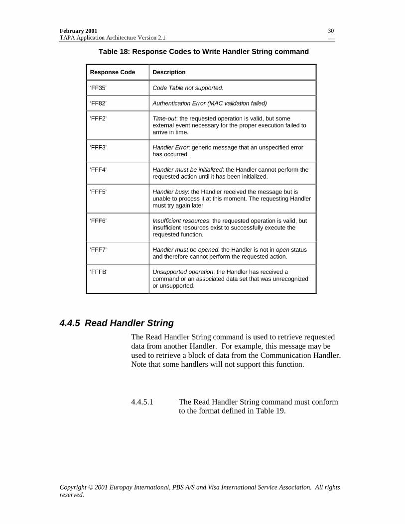
February 2001TAPA Application Architecture Version 2.1
Copyright © 2001 Europay International, PBS A/S and Visa International Service Association. All rightsreserved.
30
Table 18: Response Codes to Write Handler String command
Response Code Description
‘FF35’ Code Table not supported.
‘FF82’ Authentication Error (MAC validation failed)
'FFF2' Time-out: the requested operation is valid, but someexternal event necessary for the proper execution failed toarrive in time.
'FFF3' Handler Error: generic message that an unspecified errorhas occurred.
'FFF4' Handler must be initialized: the Handler cannot perform therequested action until it has been initialized.
'FFF5' Handler busy: the Handler received the message but isunable to process it at this moment. The requesting Handlermust try again later
'FFF6' Insufficient resources: the requested operation is valid, butinsufficient resources exist to successfully execute therequested function.
'FFF7' Handler must be opened: the Handler is not in open statusand therefore cannot perform the requested action.
‘FFFB’ Unsupported operation: the Handler has received acommand or an associated data set that was unrecognizedor unsupported.
4.4.5 Read Handler StringThe Read Handler String command is used to retrieve requesteddata from another Handler. For example, this message may beused to retrieve a block of data from the Communication Handler.Note that some handlers will not support this function.
4.4.5.1 The Read Handler String command must conformto the format defined in Table 19.
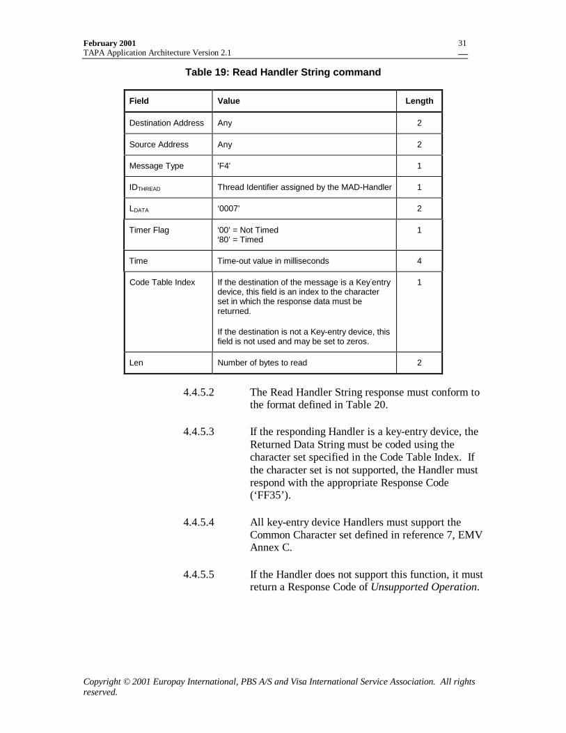
February 2001TAPA Application Architecture Version 2.1
Copyright © 2001 Europay International, PBS A/S and Visa International Service Association. All rightsreserved.
31
Table 19: Read Handler String command
Field Value Length
Destination Address Any 2
Source Address Any 2
Message Type 'F4' 1
IDTHREAD Thread Identifier assigned by the MAD-Handler 1
LDATA ‘0007’ 2
Timer Flag ‘00’ = Not Timed‘80’ = Timed
1
Time Time-out value in milliseconds 4
Code Table Index If the destination of the message is a Key-entrydevice, this field is an index to the characterset in which the response data must bereturned.
If the destination is not a Key-entry device, thisfield is not used and may be set to zeros.
1
Len Number of bytes to read 2
4.4.5.2 The Read Handler String response must conform tothe format defined in Table 20.
4.4.5.3 If the responding Handler is a key-entry device, theReturned Data String must be coded using thecharacter set specified in the Code Table Index. Ifthe character set is not supported, the Handler mustrespond with the appropriate Response Code(‘FF35’).
4.4.5.4 All key-entry device Handlers must support theCommon Character set defined in reference 7, EMVAnnex C.
4.4.5.5 If the Handler does not support this function, it mustreturn a Response Code of Unsupported Operation.
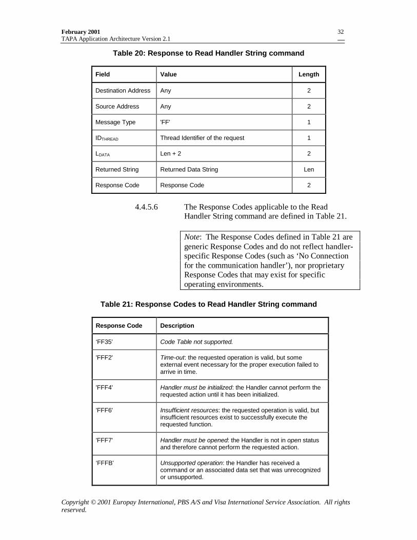
February 2001TAPA Application Architecture Version 2.1
Copyright © 2001 Europay International, PBS A/S and Visa International Service Association. All rightsreserved.
32
Table 20: Response to Read Handler String command
Field Value Length
Destination Address Any 2
Source Address Any 2
Message Type 'FF' 1
IDTHREAD Thread Identifier of the request 1
LDATA Len + 2 2
Returned String Returned Data String Len
Response Code Response Code 2
4.4.5.6 The Response Codes applicable to the ReadHandler String command are defined in Table 21.
Note: The Response Codes defined in Table 21 aregeneric Response Codes and do not reflect handler-specific Response Codes (such as ‘No Connectionfor the communication handler’), nor proprietaryResponse Codes that may exist for specificoperating environments.
Table 21: Response Codes to Read Handler String command
Response Code Description
‘FF35’ Code Table not supported.
'FFF2' Time-out: the requested operation is valid, but someexternal event necessary for the proper execution failed toarrive in time.
'FFF4' Handler must be initialized: the Handler cannot perform therequested action until it has been initialized.
'FFF6' Insufficient resources: the requested operation is valid, butinsufficient resources exist to successfully execute therequested function.
'FFF7' Handler must be opened: the Handler is not in open statusand therefore cannot perform the requested action.
‘FFFB’ Unsupported operation: the Handler has received acommand or an associated data set that was unrecognizedor unsupported.
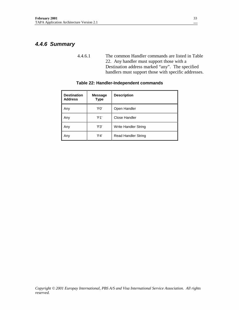
February 2001TAPA Application Architecture Version 2.1
Copyright © 2001 Europay International, PBS A/S and Visa International Service Association. All rightsreserved.
33
4.4.6 Summary
4.4.6.1 The common Handler commands are listed in Table22. Any handler must support those with aDestination address marked “any”. The specifiedhandlers must support those with specific addresses.
Table 22: Handler-Independent commands
DestinationAddress
MessageType
Description
Any 'F0' Open Handler
Any 'F1' Close Handler
Any 'F3' Write Handler String
Any 'F4' Read Handler String
February 2001TAPA Application Architecture Version 2.1
Copyright © 2001 Europay International, PBS A/S and Visa International Service Association. All rightsreserved.
34
5. The Multi-Application DriverHandler
The MAD Handler is the interface to the application software. Thissoftware is responsible for running the transactions to beperformed on the terminal.
The application software may also include functions such asTerminal initialization, Application Maintenance and AcquirerProcessing.
5.1 Application SelectionThe first step in transaction processing consists of ApplicationSelection. This selection process must consider the type of mediabeing presented such as processor cards, memory cards ormagnetic stripe cards and therefore can be based on AID, ATR,insertions, a button pressed or other. The result is that a mutualapplication is agreed upon, often indicated by an AID.
During terminal initialization, the MAD-Handler has constructed across-reference table that associates each supported cardapplication with the identity of the terminal application, whichmust be used for processing. The terminal application is denotedby the IDPSAMAPP. After selecting the card application, the MAD-Handler uses this cross-reference to invoke the correct terminalapplication. (See section 16.1.35 for a description of theIDPSAMAPP.)
5.2 Terminal InitializationAs part of normal terminal start-up, the terminal application mustperform an initialization procedure to ensure that all logicalcomponents are present and functioning normally. The terminalinitialization process must include the following procedures:
5.2.1.1 The MAD-Handler must open any necessary DeviceHandlers through the issuance of multiple OpenHandler commands. The MAD-Handler candetermine the occupied sub-addresses, if any, byusing the Get Handler Addresses command.
5.2.1.2 All PSAMs must be reset by sending an ICCPower-On command to each occupied sub-address.
February 2001TAPA Application Architecture Version 2.1
Copyright © 2001 Europay International, PBS A/S and Visa International Service Association. All rightsreserved.
35
In the response the MAD Handler receives the ATRand, if present, the Historical Bytes.
5.2.1.3 The MAD Handler must issue the Start-up PSAMcommand to each application at each occupiedPSAM sub-address.
5.2.1.4 The MAD Handler must issue the Get SupportedAIDs command to each application at eachoccupied PSAM sub-address.
5.2.1.5 Prior to completing the configuration process, theMAD Handler may be required to send one or moreapplication-specific start-up commands to thePSAM. The format and content of these commandsare outside the scope of this specification, and mustbe defined in the appropriate applicationspecifications.
5.2.1.6 The terminal must successfully perform theinitialization sequence prior to initiating any cardtransactions.
Figure 2 illustrates the PSAM Initialization process. Thecorresponding behavior of the PSAM will be described in section10.1. Section 10.3 contains details about the commands.
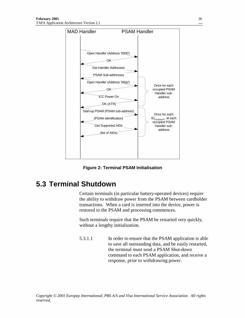
February 2001TAPA Application Architecture Version 2.1
Copyright © 2001 Europay International, PBS A/S and Visa International Service Association. All rightsreserved.
36
MAD Handler PSAM Handler
ICC Power On
Start-up PSAM (PSAM sub-address)
(PSAM Identification)
Open Handler (Address '0000')
OK
Get Handler Addresses
PSAM Sub-addresses
Open Handler (Address '00pp')
OK
OK (ATR)
Get Supported AIDs
(list of AIDs)
Once for eachoccupied PSAM
Handler sub-address
Once for eachIDPSAMAPP at eachoccupied PSAM
Handler sub-address
Figure 2: Terminal PSAM Initialisation
5.3 Terminal ShutdownCertain terminals (in particular battery-operated devices) requirethe ability to withdraw power from the PSAM between cardholdertransactions. When a card is inserted into the device, power isrestored to the PSAM and processing commences.
Such terminals require that the PSAM be restarted very quickly,without a lengthy initialization.
5.3.1.1 In order to ensure that the PSAM application is ableto save all outstanding data, and be easily restarted,the terminal must send a PSAM Shut-downcommand to each PSAM application, and receive aresponse, prior to withdrawing power.
February 2001TAPA Application Architecture Version 2.1
Copyright © 2001 Europay International, PBS A/S and Visa International Service Association. All rightsreserved.
37
5.4 Terminal ControlWhen the terminal is initialized, the MAD Handler Applicationsoftware has control over the terminal’s functioning. The MADHandler applications may temporarily delegate control toapplication processing in other devices – in particular the PSAM.Control is transferred through an application-specific message orcommand sent from a terminal application.
The delegated component will then take over control of theterminal’s functions – issuing messages to devices and receivingresponses. When its processing is completed, it will send aresponse to the MAD Handler application, which resumes control.
5.5 Multi-ThreadingThe TAPA message structure incorporates support for “multi-threading”, where multiple concurrent transactions may be inprocess, in varying states of completion.
An example of an environment where this is required is adistributed POS environment, consisting of a “server”(whichcontains one or more PSAMs, the Data Store and the connection tothe acquirer’s host system) and multiple remote terminals, each ofwhich contains a card reader and a user interface.
In such a system, the MAD Handler application functions aredistributed between the remote terminal and the server. Themessaging between the distributed and centralized parts of theMAD Handler applications is proprietary to the device developerand outside the scope of this specification. This messaging musthowever include identification of the remote terminal.
(For an example of the distribution of functionality for anapplication across a distributed system, please refer to the “RemoteTerminal” discussion in reference 2, Terminal Architecture forPSAM Applications, CEP PSAM Application Volume 1, Section3.)
5.5.1.1 In order to support a multi-threading environment,the MAD Handler must assign a unique identifier(IDTHREAD) to each currently active transaction,which must be used in all Terminal Messagesrelating to that transaction. The IDTHREAD valuemay be reused after a transaction has beenterminated.
February 2001TAPA Application Architecture Version 2.1
Copyright © 2001 Europay International, PBS A/S and Visa International Service Association. All rightsreserved.
38
5.6 Exception HandlingThere are a variety of exception conditions that can occur duringapplication processing in a POS device. This section addresses theexception conditions that affect the interface between the MADHandler application and the PSAM application, and defines a set offunctions that must be provided by the PSAM and terminalapplications in order to allow the other component to attemptrecovery.
Exception conditions fall broadly into the following categories:
• An inability to perform a particular transaction because of aproblem detected during the dialogue with the consumer card.This is normally not a problem with the POS device, andsimply requires completing the transaction in a definedmanner.
• A temporary problem with a particular device. This mayparticularly be the case in a distributed environment wheresome resources are shared. This sort of problem may possiblybe overcome by retrying the failed function.
• A hardware or software problem with the POS device thatprevents continued correct functioning. The resolution to thissort of problem is device and implementation dependent, andoutside the scope of this specification.
Exception processing is specific to each TAPA application (i.e.IDPSAMAPP).
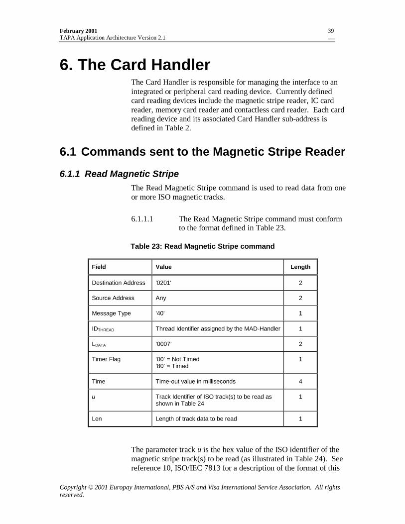
February 2001TAPA Application Architecture Version 2.1
Copyright © 2001 Europay International, PBS A/S and Visa International Service Association. All rightsreserved.
39
6. The Card HandlerThe Card Handler is responsible for managing the interface to anintegrated or peripheral card reading device. Currently definedcard reading devices include the magnetic stripe reader, IC cardreader, memory card reader and contactless card reader. Each cardreading device and its associated Card Handler sub-address isdefined in Table 2.
6.1 Commands sent to the Magnetic Stripe Reader
6.1.1 Read Magnetic StripeThe Read Magnetic Stripe command is used to read data from oneor more ISO magnetic tracks.
6.1.1.1 The Read Magnetic Stripe command must conformto the format defined in Table 23.
Table 23: Read Magnetic Stripe command
Field Value Length
Destination Address '0201' 2
Source Address Any 2
Message Type '40' 1
IDTHREAD Thread Identifier assigned by the MAD-Handler 1
LDATA ‘0007’ 2
Timer Flag ‘00’ = Not Timed‘80’ = Timed
1
Time Time-out value in milliseconds 4
u Track Identifier of ISO track(s) to be read asshown in Table 24
1
Len Length of track data to be read 1
The parameter track u is the hex value of the ISO identifier of themagnetic stripe track(s) to be read (as illustrated in Table 24). Seereference 10, ISO/IEC 7813 for a description of the format of this
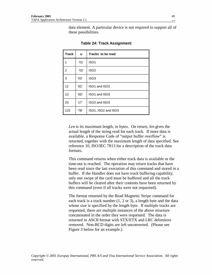
February 2001TAPA Application Architecture Version 2.1
Copyright © 2001 Europay International, PBS A/S and Visa International Service Association. All rightsreserved.
40
data element. A particular device is not required to support all ofthese possibilities.
Table 24: Track Assignment
Track u Tracks to be read
1 ‘01’ ISO1
2 ‘02’ ISO2
3 ‘03’ ISO3
12 ‘0C’ ISO1 and ISO2
13 ‘0D’ ISO1 and ISO3
23 ‘17’ ISO2 and ISO3
123 ‘7B’ ISO1, ISO2 and ISO3
Len is its maximum length, in bytes. On return, len gives theactual length of the string read for each track. If more data isavailable, a Response Code of “output buffer overflow” isreturned, together with the maximum length of data specified. Seereference 10, ISO/IEC 7813 for a description of the track dataformats.
This command returns when either track data is available or thetime-out is reached. The operation may return tracks that havebeen read since the last execution of this command and stored in abuffer. If the Handler does not have track buffering capability,only one swipe of the card must be buffered and all the trackbuffers will be cleared after their contents have been returned bythis command (even if all tracks were not requested).
The format returned by the Read Magnetic Stripe command foreach track is a track number (1, 2 or 3), a length byte and the datawhose size is specified by the length byte. If multiple tracks arerequested, there are multiple instances of the above structureconcatenated in the order they were requested. The data isreturned in ASCII format with STX/ETX and LRC delimitersremoved. Non-BCD digits are left unconverted. (Please seeFigure 3 below for an example.)
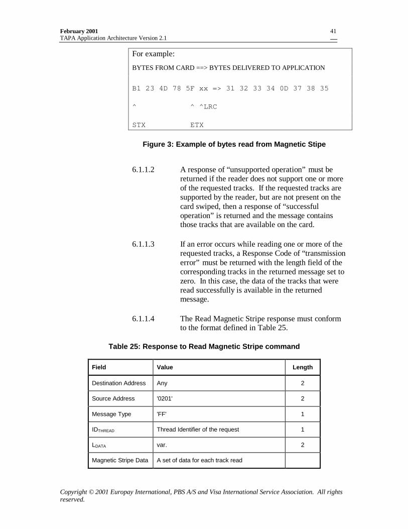
February 2001TAPA Application Architecture Version 2.1
Copyright © 2001 Europay International, PBS A/S and Visa International Service Association. All rightsreserved.
41
For example:
BYTES FROM CARD ==> BYTES DELIVERED TO APPLICATION
B1 23 4D 78 5F xx => 31 32 33 34 0D 37 38 35
^ ^ ^LRC
STX ETX
Figure 3: Example of bytes read from Magnetic Stipe
6.1.1.2 A response of “unsupported operation” must bereturned if the reader does not support one or moreof the requested tracks. If the requested tracks aresupported by the reader, but are not present on thecard swiped, then a response of “successfuloperation” is returned and the message containsthose tracks that are available on the card.
6.1.1.3 If an error occurs while reading one or more of therequested tracks, a Response Code of “transmissionerror” must be returned with the length field of thecorresponding tracks in the returned message set tozero. In this case, the data of the tracks that wereread successfully is available in the returnedmessage.
6.1.1.4 The Read Magnetic Stripe response must conformto the format defined in Table 25.
Table 25: Response to Read Magnetic Stripe command
Field Value Length
Destination Address Any 2
Source Address '0201' 2
Message Type 'FF' 1
IDTHREAD Thread Identifier of the request 1
LDATA var. 2
Magnetic Stripe Data A set of data for each track read
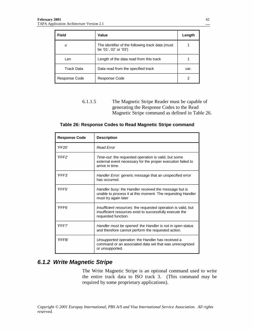
February 2001TAPA Application Architecture Version 2.1
Copyright © 2001 Europay International, PBS A/S and Visa International Service Association. All rightsreserved.
42
Field Value Length
u The identifier of the following track data (mustbe ‘01’, 02’ or ‘03’)
1
Len Length of the data read from this track 1
Track Data Data read from the specified track var.
Response Code Response Code 2
6.1.1.5 The Magnetic Stripe Reader must be capable ofgenerating the Response Codes to the ReadMagnetic Stripe command as defined in Table 26.
Table 26: Response Codes to Read Magnetic Stripe command
Response Code Description
‘FF20’ Read Error
'FFF2' Time-out: the requested operation is valid, but someexternal event necessary for the proper execution failed toarrive in time.
'FFF3' Handler Error: generic message that an unspecified errorhas occurred.
'FFF5' Handler busy: the Handler received the message but isunable to process it at this moment. The requesting Handlermust try again later
'FFF6' Insufficient resources: the requested operation is valid, butinsufficient resources exist to successfully execute therequested function.
'FFF7' Handler must be opened: the Handler is not in open statusand therefore cannot perform the requested action.
‘FFFB’ Unsupported operation: the Handler has received acommand or an associated data set that was unrecognizedor unsupported.
6.1.2 Write Magnetic StripeThe Write Magnetic Stripe is an optional command used to writethe entire track data to ISO track 3. (This command may berequired by some proprietary applications).
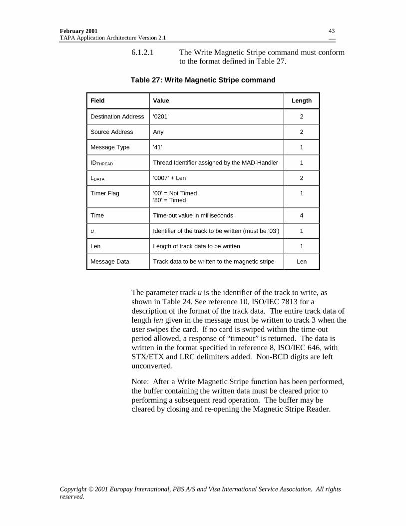
February 2001TAPA Application Architecture Version 2.1
Copyright © 2001 Europay International, PBS A/S and Visa International Service Association. All rightsreserved.
43
6.1.2.1 The Write Magnetic Stripe command must conformto the format defined in Table 27.
Table 27: Write Magnetic Stripe command
Field Value Length
Destination Address '0201' 2
Source Address Any 2
Message Type '41' 1
IDTHREAD Thread Identifier assigned by the MAD-Handler 1
LDATA ‘0007’ + Len 2
Timer Flag ‘00’ = Not Timed‘80’ = Timed
1
Time Time-out value in milliseconds 4
u Identifier of the track to be written (must be ‘03’) 1
Len Length of track data to be written 1
Message Data Track data to be written to the magnetic stripe Len
The parameter track u is the identifier of the track to write, asshown in Table 24. See reference 10, ISO/IEC 7813 for adescription of the format of the track data. The entire track data oflength len given in the message must be written to track 3 when theuser swipes the card. If no card is swiped within the time-outperiod allowed, a response of “timeout” is returned. The data iswritten in the format specified in reference 8, ISO/IEC 646, withSTX/ETX and LRC delimiters added. Non-BCD digits are leftunconverted.
Note: After a Write Magnetic Stripe function has been performed,the buffer containing the written data must be cleared prior toperforming a subsequent read operation. The buffer may becleared by closing and re-opening the Magnetic Stripe Reader.
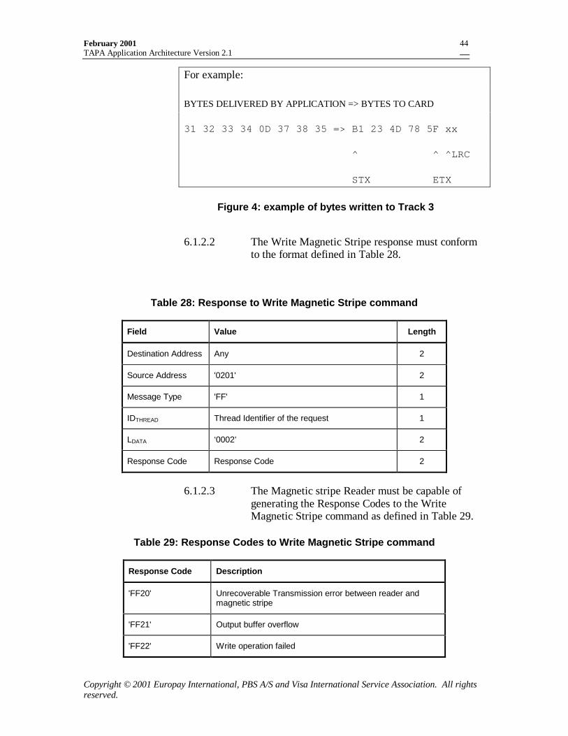
February 2001TAPA Application Architecture Version 2.1
Copyright © 2001 Europay International, PBS A/S and Visa International Service Association. All rightsreserved.
44
For example:
BYTES DELIVERED BY APPLICATION => BYTES TO CARD
31 32 33 34 0D 37 38 35 => B1 23 4D 78 5F xx
^ ^ ^LRC
STX ETX
Figure 4: example of bytes written to Track 3
6.1.2.2 The Write Magnetic Stripe response must conformto the format defined in Table 28.
Table 28: Response to Write Magnetic Stripe command
Field Value Length
Destination Address Any 2
Source Address '0201' 2
Message Type 'FF' 1
IDTHREAD Thread Identifier of the request 1
LDATA ‘0002’ 2
Response Code Response Code 2
6.1.2.3 The Magnetic stripe Reader must be capable ofgenerating the Response Codes to the WriteMagnetic Stripe command as defined in Table 29.
Table 29: Response Codes to Write Magnetic Stripe command
Response Code Description
'FF20' Unrecoverable Transmission error between reader andmagnetic stripe
'FF21' Output buffer overflow
'FF22' Write operation failed
February 2001TAPA Application Architecture Version 2.1
Copyright © 2001 Europay International, PBS A/S and Visa International Service Association. All rightsreserved.
45
Response Code Description
'FFF2' Time-out: the requested operation is valid, but someexternal event necessary for the proper execution failed toarrive in time.
'FFF3' Handler Error: generic message that an unspecified errorhas occurred.
'FFF5' Handler busy: the Handler received the message but isunable to process it at this moment. The requesting Handlermust try again later
'FFF6' Insufficient resources: the requested operation is valid, butinsufficient resources exist to successfully execute therequested function.
'FFF7' Handler must be opened: the Handler is not in open statusand therefore cannot perform the requested action.
‘FFFB’ Unsupported operation: the Handler has received acommand or an associated data set that was unrecognizedor unsupported.
6.2 Commands sent to the Processor Card ReaderThe interface between the Processor Card Reader and the ICC is astandard command-response protocol as defined in reference 4,ISO/IEC 7816-4 and reference 7, EMV, Part II, section 2.1. Thetechnical interface must be as defined in reference 3, ISO/IEC7816-3 and ref 7, EMV – Part I .
The Processor Card Reader is responsible for performing therequired formatting between the command-response protocol andthe Terminal Message formats used among terminal components.Commands are sent to the processor card from other terminalcomponents using the ICC command, which contains within it thecommand APDU to be delivered to the card.
The response APDU from the processor card must then be sent tothe handler that originated the command, embedded within aTerminal response message.
Note that the Response Code contained in the response messageonly reflects whether the receiving handler was able tosuccessfully process the ICC command, forward the C-APDU tothe processor card, and receive a response. If a response isreceived from the processor card, then the Processor Card Readerhas been able to successfully process the command message. TheStatus Words in the reply from the processor card will becontained in the Message Data field returned in the response to the
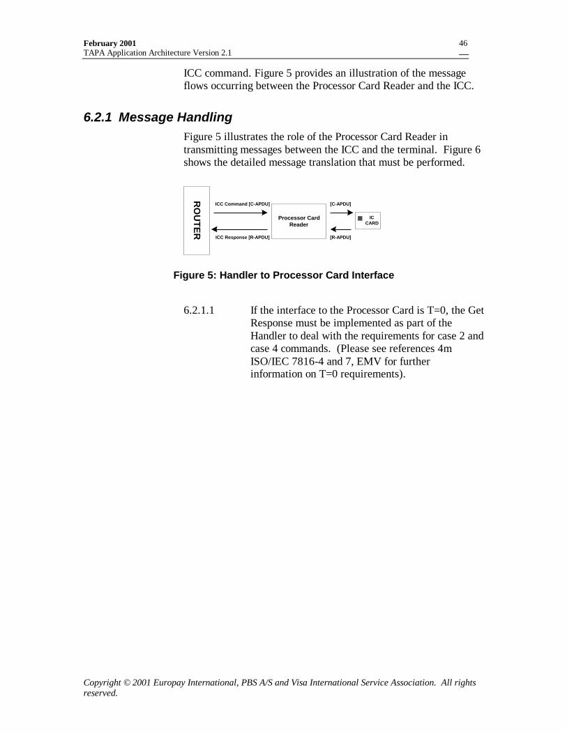
February 2001TAPA Application Architecture Version 2.1
Copyright © 2001 Europay International, PBS A/S and Visa International Service Association. All rightsreserved.
46
ICC command. Figure 5 provides an illustration of the messageflows occurring between the Processor Card Reader and the ICC.
6.2.1 Message HandlingFigure 5 illustrates the role of the Processor Card Reader intransmitting messages between the ICC and the terminal. Figure 6shows the detailed message translation that must be performed.
ICCARD
Processor CardReader
RO
UTE
R
ICC Command [C-APDU]
ICC Response [R-APDU]
[C-APDU]
[R-APDU]
Figure 5: Handler to Processor Card Interface
6.2.1.1 If the interface to the Processor Card is T=0, the GetResponse must be implemented as part of theHandler to deal with the requirements for case 2 andcase 4 commands. (Please see references 4mISO/IEC 7816-4 and 7, EMV for furtherinformation on T=0 requirements).
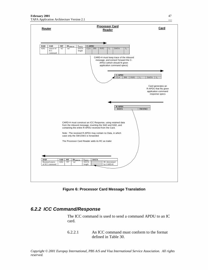
February 2001TAPA Application Architecture Version 2.1
Copyright © 2001 Europay International, PBS A/S and Visa International Service Association. All rightsreserved.
47
Processor CardReader CardRouter
DAD SAD MT IDTHREAD LDATA C-APDU0202 source of
ICCcommand
‘42’ ‘nn’ DATAlength
CLA INS P1P2 Lc DATA Le
CARD-H must keep trace of the inboundmessage, and extract/ forward the C-
APDU (which should fit givenapplication command specs)
Card generates anR-APDU that fits givenapplication command
response specs
C-APDUCLA INS P1P2 Lc DATA Le
� CARD-H must construct an ICC Response, using retained datafrom the inbound message, inverting the SAD and DAD, andcontaining the entire R-APDU received from the Card.
Note : The received R-APDU may contain no Data, in whichcase only the SW1SW2 is forwarded
� The Processor Card Reader adds its RC as trailer
R-APDUDATA SW1SW2
DAD SAD MT IDTHREAD LDATA DATARetained sourceof ICC command
0202 ‘FF’ ‘nn’ DATAlength
RC determinedby CARD-H
Figure 6: Processor Card Message Translation
6.2.2 ICC Command/ResponseThe ICC command is used to send a command APDU to an ICcard.
6.2.2.1 An ICC command must conform to the formatdefined in Table 30.
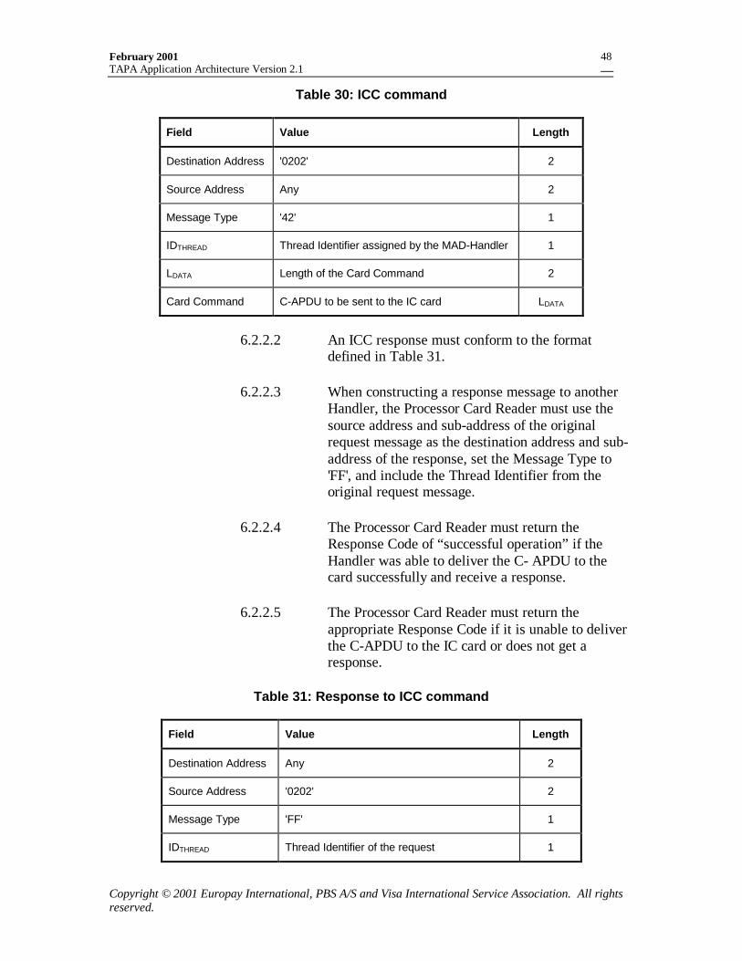
February 2001TAPA Application Architecture Version 2.1
Copyright © 2001 Europay International, PBS A/S and Visa International Service Association. All rightsreserved.
48
Table 30: ICC command
Field Value Length
Destination Address '0202' 2
Source Address Any 2
Message Type '42' 1
IDTHREAD Thread Identifier assigned by the MAD-Handler 1
LDATA Length of the Card Command 2
Card Command C-APDU to be sent to the IC card LDATA
6.2.2.2 An ICC response must conform to the formatdefined in Table 31.
6.2.2.3 When constructing a response message to anotherHandler, the Processor Card Reader must use thesource address and sub-address of the originalrequest message as the destination address and sub-address of the response, set the Message Type to'FF', and include the Thread Identifier from theoriginal request message.
6.2.2.4 The Processor Card Reader must return theResponse Code of “successful operation” if theHandler was able to deliver the C- APDU to thecard successfully and receive a response.
6.2.2.5 The Processor Card Reader must return theappropriate Response Code if it is unable to deliverthe C-APDU to the IC card or does not get aresponse.
Table 31: Response to ICC command
Field Value Length
Destination Address Any 2
Source Address '0202' 2
Message Type 'FF' 1
IDTHREAD Thread Identifier of the request 1
February 2001TAPA Application Architecture Version 2.1
Copyright © 2001 Europay International, PBS A/S and Visa International Service Association. All rightsreserved.
49
Field Value Length
LDATA Length of the Card Response + ‘0002’ 2
Card Response Complete R-APDU from card, including theStatus Words
var.
Response Code Response Code 2
6.2.2.6 The Response Codes applicable to the ICCcommand are defined in Table 32.
Table 32: Response Codes to ICC command
Response Code Description
'FF23' No response from card
'FF24' No card in reader
'FF26' Card buffer overflow
'FF28' Response has no status words
'FF29' Invalid buffer
'FF2A' Other card error
'FF2B’ Card partially in reader
'FFF3' Handler Error: generic message that an unspecified errorhas occurred.
'FFF5' Handler busy: the Handler received the message but isunable to process it at this moment. The requesting Handlermust try again later
'FFF6' Insufficient resources: the requested operation is valid, butinsufficient resources exist to successfully execute therequested function.
'FFF7' Handler must be opened: the Handler is not in open statusand therefore cannot perform the requested action.
‘FFFB’ Unsupported operation: the Handler has received acommand or an associated data set that was unrecognizedor unsupported.
February 2001TAPA Application Architecture Version 2.1
Copyright © 2001 Europay International, PBS A/S and Visa International Service Association. All rightsreserved.
50
6.2.3 ICC Power-OnThe ICC Power-On command is used to apply power to theprocessor card and execute the ‘card reset’ function. The Answerto Reset (ATR) message must be returned in the Message Datafield.
6.2.3.1 The ICC Power-On command must conform to theformat defined in Table 33.
Table 33: ICC Power-On command
Field Value Length
Destination Address '0202' 2
Source Address Any 2
Message Type '43' 1
IDTHREAD Thread Identifier assigned by the MAD-Handler 1
LDATA '0000' 2
6.2.3.2 The ICC Power-On response must conform to theformat defined in Table 34.
Table 34: Response to ICC Power-On command
Field Value Length
Destination Address Any 2
Source Address '0202' 2
Message Type 'FF' 1
IDTHREAD Thread Identifier of the request 1
LDATA Length of the ATR + ‘0002’ 2
ATR ATR from IC Card var.
Response Code Response Code 2
6.2.3.3 The Response Codes applicable to the ICC Power-On command are defined in Table 35.
February 2001TAPA Application Architecture Version 2.1
Copyright © 2001 Europay International, PBS A/S and Visa International Service Association. All rightsreserved.
51
Table 35: Response Codes to ICC Power-On command
Response Code Description
'FF23' No response from card
'FF24' No card in reader
'FF2A' Other card error
'FF2B’ Card partially in reader
'FFF3' Handler Error: generic message that an unspecified errorhas occurred.
'FFF5' Handler busy: the Handler received the message but isunable to process it at this moment. The requesting Handlermust try again later
'FFF6' Insufficient resources: the requested operation is valid, butinsufficient resources exist to successfully execute therequested function.
'FFF7' Handler must be opened: the Handler is not in open statusand therefore cannot perform the requested action.
‘FFFB’ Unsupported operation: the Handler has received acommand or an associated data set that was unrecognizedor unsupported.
6.2.4 ICC Power-OffThe ICC Power-Off command is used when a transactioninvolving an IC card has been completed. Use of this commandmay additionally result in the ejection of the IC card in terminalswhere this feature is warranted.
6.2.4.1 The ICC Power-Off command must conform to theformat defined in Table 36.
Table 36: ICC Power-Off command
Field Value Length
Destination Address '0202' 2
Source Address Any 2
Message Type '44' 1
February 2001TAPA Application Architecture Version 2.1
Copyright © 2001 Europay International, PBS A/S and Visa International Service Association. All rightsreserved.
52
Field Value Length
IDTHREAD Thread Identifier assigned by the MAD-Handler 1
LDATA '0000' 2
6.2.4.2 The ICC Power-Off response must conform to theformat defined in Table 37.
Table 37: Response to ICC Power-Off command
Field Value Length
Destination Address Any 2
Source Address '0202' 2
Message Type 'FF' 1
IDTHREAD Thread Identifier of the request 1
LDATA '0002' 2
Response Code Response Code 2
6.2.4.3 The Response Codes applicable to the ICC Power-Off command are defined in Table 38.
Table 38: Response Codes to ICC Power-Off command
Response Code Description
'FF24' No card in reader
'FF2B’ Card partially in reader
'FFF3' Handler Error: generic message that an unspecified errorhas occurred.
'FFF5' Handler busy: the Handler received the message but isunable to process it at this moment. The requesting Handlermust try again later
'FFF6' Insufficient resources: the requested operation is valid, butinsufficient resources exist to successfully execute therequested function.
February 2001TAPA Application Architecture Version 2.1
Copyright © 2001 Europay International, PBS A/S and Visa International Service Association. All rightsreserved.
53
Response Code Description
'FFF7' Handler must be opened: the Handler is not in open statusand therefore cannot perform the requested action.
‘FFFB’ Unsupported operation: the Handler has received acommand or an associated data set that was unrecognizedor unsupported.
6.2.5 ICC QueryThe ICC Query command is issued to the Processor Card Readerin order to determine if a card is physically present in the ICreader.
6.2.5.1 The ICC Query command must conform to theformat defined in Table 39.
Table 39: ICC Query command
Field Value Length
Destination Address '0202' 2
Source Address Any 2
Message Type '45' 1
IDTHREAD Thread Identifier assigned by the MAD-Handler 1
LDATA '0000' 2
6.2.5.2 The ICC Query response must conform to theformat defined in Table 40.
6.2.5.3 The Handler must return the appropriate ResponseCode if the ICC Query if no card is present.
Table 40: Response to ICC Query command
Field Value Length
Destination Address Any 2
Source Address '0202' 2
Message Type 'FF' 1
IDTHREAD Thread Identifier of the request 1
February 2001TAPA Application Architecture Version 2.1
Copyright © 2001 Europay International, PBS A/S and Visa International Service Association. All rightsreserved.
54
Field Value Length
LDATA '0002' 2
Response Code Response Code 2
6.2.5.4 The Response Codes applicable to the ICC Querycommand are defined in Table 41.
Table 41: Response Codes to ICC Query command
Response Code Description
'FF24' No card in reader
'FF2B’ Card partially in reader
'FFF3' Handler Error: generic message that an unspecified errorhas occurred.
'FFF5' Handler busy: the Handler received the message but isunable to process it at this moment. The requesting Handlermust try again later
'FFF6' Insufficient resources: the requested operation is valid, butinsufficient resources exist to successfully execute therequested function.
'FFF7' Handler must be opened: the Handler is not in open statusand therefore cannot perform the requested action.
‘FFFB’ Unsupported operation: the Handler has received acommand or an associated data set that was unrecognizedor unsupported.
6.2.6 Verify Offline PINThe Verify Offline PIN command is specific to the PIN Padprocessing described in section 13.3. Terminals that do notsupport the PIN Pad Processing do not need to support thiscommand.
The Verify Offline PIN command is an authenticated message,which is used to send a command APDU to the card while theTamper Evident Device (TED) is in PIN Entry State. The C-APDU is encrypted and embedded in a MACed Verify Offline PINmessage, which is sent to the Processor Card Reader.
February 2001TAPA Application Architecture Version 2.1
Copyright © 2001 Europay International, PBS A/S and Visa International Service Association. All rightsreserved.
55
The Processor Card Reader authenticates the message and decryptsthe C-APDU. The subsequent processing is the same as that forthe standard ICC Command message. The response to the VerifyOffline PIN command is also MACed.
6.2.6.1 The Verify Offline PIN command must conform tothe format defined in Table 42.
Table 42: Verify Offline PIN command
Field Value Length
Destination Address '0202' 2
Source Address Any 2
Message Type '46' 1
IDTHREAD Thread Identifier assigned by the MAD-Handler 1
LDATA Length of [C-APDU] + 8 2
[C-APDU] Enc(KSESPIN)[C-APDU] var.
MACVOP MAC on Dest. Address – [C-APDU], computedusing KSESMAC
8
6.2.6.2 The Verify Offline PIN response must conform tothe format defined in Table 43.
6.2.6.3 The Tamper Evident Device must verify theMACVOP in the command using the KSESMAC, anddecrypt the C-APDU using the KSESPIN.
6.2.6.4 When constructing a response message to anotherHandler, the Processor Card Reader must use thesource address and sub-address of the originalrequest message as the destination address and sub-address of the response, set the Message Type to'FF', and include the Thread Identifier from theoriginal request message.
6.2.6.5 The Processor Card Reader must return theResponse Code of “successful operation” if theHandler was able to deliver the C- APDU to thecard successfully and receive a response.
February 2001TAPA Application Architecture Version 2.1
Copyright © 2001 Europay International, PBS A/S and Visa International Service Association. All rightsreserved.
56
6.2.6.6 The Processor Card Reader must return theappropriate Response Code if it is unable to deliverthe C-APDU to the IC card or does not get aresponse.
Table 43: Response to Verify Offline PIN command
Field Value Length
Destination Address Any 2
Source Address '0202' 2
Message Type 'FF' 1
IDTHREAD Thread Identifier of the request 1
LDATA '000A' + length of Card response 2
Card Response Complete R-APDU from card (including SW1-SW2)
var.
MACRVOP MAC over Card Response || MACVOP (from thecommand), computed using KSESMAC
8
Response Code Response Code 2
6.2.6.7 In addition to the Response Codes defined for theICC command (in Table 32), the Response Codesdefined in Table 44 are applicable to the VerifyOffline PIN Command.
Table 44: Response Codes to Verify Offline PIN command
Response Code Description
‘FF82’ Authentication Error (MAC validation failed)
‘FF87’ Tamper Evident Device not in PIN Entry State
6.3 Commands sent to Memory Card ReaderThe interface to memory cards is proprietary and outside the scopeof this specification. In addition to the common handlercommands defined in Section 4.4, it is expected that the commands
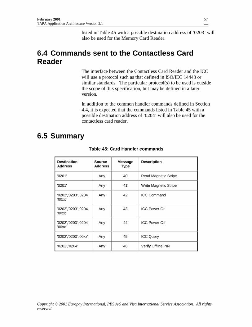
February 2001TAPA Application Architecture Version 2.1
Copyright © 2001 Europay International, PBS A/S and Visa International Service Association. All rightsreserved.
57
listed in Table 45 with a possible destination address of ‘0203’ willalso be used for the Memory Card Reader.
6.4 Commands sent to the Contactless CardReader
The interface between the Contactless Card Reader and the ICCwill use a protocol such as that defined in ISO/IEC 14443 orsimilar standards. The particular protocol(s) to be used is outsidethe scope of this specification, but may be defined in a laterversion.
In addition to the common handler commands defined in Section4.4, it is expected that the commands listed in Table 45 with apossible destination address of ‘0204’ will also be used for thecontactless card reader.
6.5 Summary
Table 45: Card Handler commands
DestinationAddress
SourceAddress
MessageType
Description
'0201' Any '40' Read Magnetic Stripe
'0201' Any '41' Write Magnetic Stripe
'0202','0203',’0204’,’00xx’
Any '42' ICC Command
'0202','0203',’0204’,’00xx’
Any '43' ICC Power-On
'0202','0203',’0204’,’00xx’
Any '44’ ICC Power-Off
'0202','0203',’00xx’ Any '45’ ICC Query
‘0202’,’0204’ Any ‘46’ Verify Offline PIN
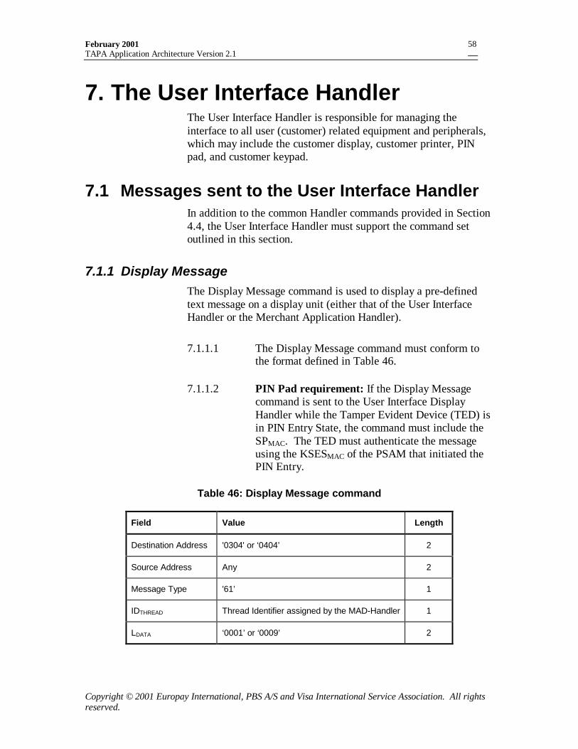
February 2001TAPA Application Architecture Version 2.1
Copyright © 2001 Europay International, PBS A/S and Visa International Service Association. All rightsreserved.
58
7. The User Interface HandlerThe User Interface Handler is responsible for managing theinterface to all user (customer) related equipment and peripherals,which may include the customer display, customer printer, PINpad, and customer keypad.
7.1 Messages sent to the User Interface HandlerIn addition to the common Handler commands provided in Section4.4, the User Interface Handler must support the command setoutlined in this section.
7.1.1 Display MessageThe Display Message command is used to display a pre-definedtext message on a display unit (either that of the User InterfaceHandler or the Merchant Application Handler).
7.1.1.1 The Display Message command must conform tothe format defined in Table 46.
7.1.1.2 PIN Pad requirement: If the Display Messagecommand is sent to the User Interface DisplayHandler while the Tamper Evident Device (TED) isin PIN Entry State, the command must include theSPMAC. The TED must authenticate the messageusing the KSESMAC of the PSAM that initiated thePIN Entry.
Table 46: Display Message command
Field Value Length
Destination Address '0304' or ‘0404’ 2
Source Address Any 2
Message Type '61’ 1
IDTHREAD Thread Identifier assigned by the MAD-Handler 1
LDATA ‘0001’ or ‘0009’ 2
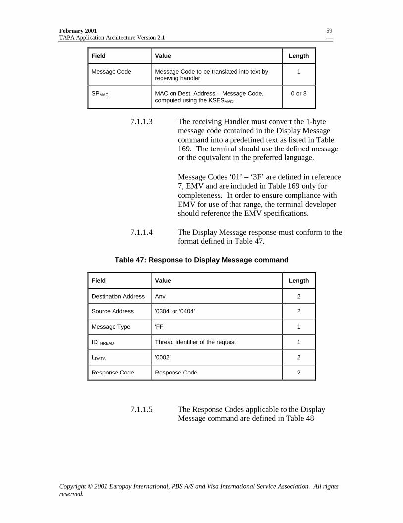
February 2001TAPA Application Architecture Version 2.1
Copyright © 2001 Europay International, PBS A/S and Visa International Service Association. All rightsreserved.
59
Field Value Length
Message Code Message Code to be translated into text byreceiving handler
1
SPMAC MAC on Dest. Address – Message Code,computed using the KSESMAC.
0 or 8
7.1.1.3 The receiving Handler must convert the 1-bytemessage code contained in the Display Messagecommand into a predefined text as listed in Table169. The terminal should use the defined messageor the equivalent in the preferred language.
Message Codes ‘01’ – ‘3F’ are defined in reference7, EMV and are included in Table 169 only forcompleteness. In order to ensure compliance withEMV for use of that range, the terminal developershould reference the EMV specifications.
7.1.1.4 The Display Message response must conform to theformat defined in Table 47.
Table 47: Response to Display Message command
Field Value Length
Destination Address Any 2
Source Address '0304' or ‘0404’ 2
Message Type 'FF' 1
IDTHREAD Thread Identifier of the request 1
LDATA '0002' 2
Response Code Response Code 2
7.1.1.5 The Response Codes applicable to the DisplayMessage command are defined in Table 48
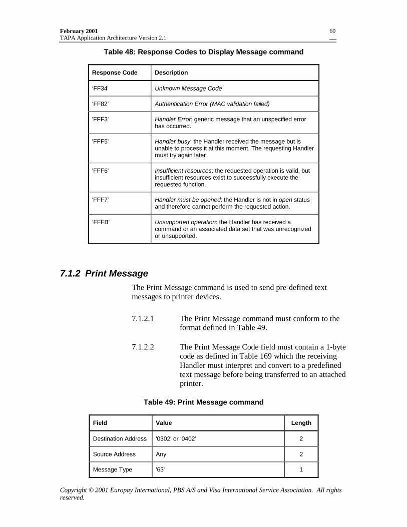
February 2001TAPA Application Architecture Version 2.1
Copyright © 2001 Europay International, PBS A/S and Visa International Service Association. All rightsreserved.
60
Table 48: Response Codes to Display Message command
Response Code Description
‘FF34' Unknown Message Code
‘FF82’ Authentication Error (MAC validation failed)
'FFF3' Handler Error: generic message that an unspecified errorhas occurred.
'FFF5' Handler busy: the Handler received the message but isunable to process it at this moment. The requesting Handlermust try again later
'FFF6' Insufficient resources: the requested operation is valid, butinsufficient resources exist to successfully execute therequested function.
'FFF7' Handler must be opened: the Handler is not in open statusand therefore cannot perform the requested action.
‘FFFB’ Unsupported operation: the Handler has received acommand or an associated data set that was unrecognizedor unsupported.
7.1.2 Print MessageThe Print Message command is used to send pre-defined textmessages to printer devices.
7.1.2.1 The Print Message command must conform to theformat defined in Table 49.
7.1.2.2 The Print Message Code field must contain a 1-bytecode as defined in Table 169 which the receivingHandler must interpret and convert to a predefinedtext message before being transferred to an attachedprinter.
Table 49: Print Message command
Field Value Length
Destination Address '0302' or ‘0402’ 2
Source Address Any 2
Message Type '63' 1
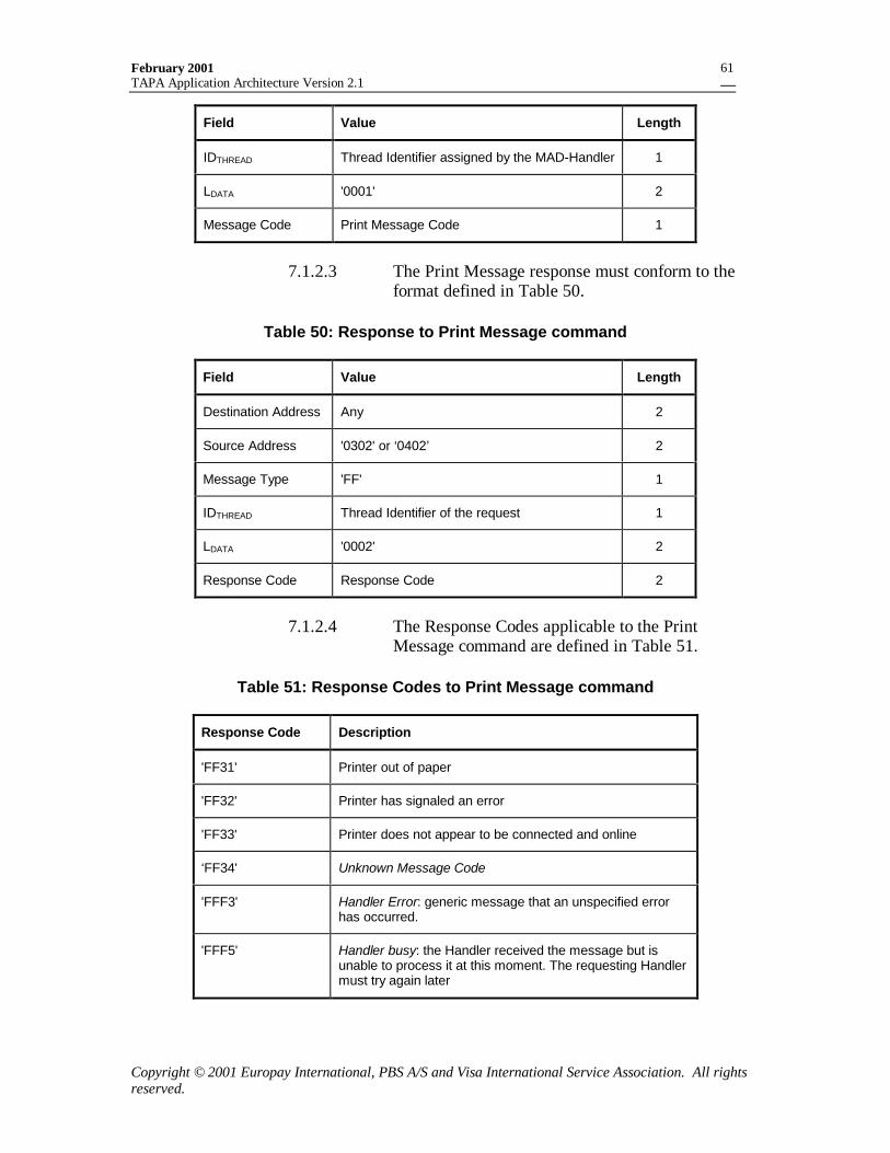
February 2001TAPA Application Architecture Version 2.1
Copyright © 2001 Europay International, PBS A/S and Visa International Service Association. All rightsreserved.
61
Field Value Length
IDTHREAD Thread Identifier assigned by the MAD-Handler 1
LDATA '0001' 2
Message Code Print Message Code 1
7.1.2.3 The Print Message response must conform to theformat defined in Table 50.
Table 50: Response to Print Message command
Field Value Length
Destination Address Any 2
Source Address '0302' or ‘0402’ 2
Message Type 'FF' 1
IDTHREAD Thread Identifier of the request 1
LDATA '0002' 2
Response Code Response Code 2
7.1.2.4 The Response Codes applicable to the PrintMessage command are defined in Table 51.
Table 51: Response Codes to Print Message command
Response Code Description
'FF31' Printer out of paper
'FF32' Printer has signaled an error
'FF33' Printer does not appear to be connected and online
‘FF34' Unknown Message Code
'FFF3' Handler Error: generic message that an unspecified errorhas occurred.
'FFF5' Handler busy: the Handler received the message but isunable to process it at this moment. The requesting Handlermust try again later
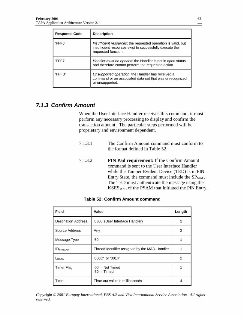
February 2001TAPA Application Architecture Version 2.1
Copyright © 2001 Europay International, PBS A/S and Visa International Service Association. All rightsreserved.
62
Response Code Description
'FFF6' Insufficient resources: the requested operation is valid, butinsufficient resources exist to successfully execute therequested function.
'FFF7' Handler must be opened: the Handler is not in open statusand therefore cannot perform the requested action.
‘FFFB’ Unsupported operation: the Handler has received acommand or an associated data set that was unrecognizedor unsupported.
7.1.3 Confirm AmountWhen the User Interface Handler receives this command, it mustperform any necessary processing to display and confirm thetransaction amount. The particular steps performed will beproprietary and environment dependent.
7.1.3.1 The Confirm Amount command must conform tothe format defined in Table 52.
7.1.3.2 PIN Pad requirement: If the Confirm Amountcommand is sent to the User Interface Handlerwhile the Tamper Evident Device (TED) is in PINEntry State, the command must include the SPMAC.The TED must authenticate the message using theKSESMAC of the PSAM that initiated the PIN Entry.
Table 52: Confirm Amount command
Field Value Length
Destination Address '0300' (User Interface Handler) 2
Source Address Any 2
Message Type '60’ 1
IDTHREAD Thread Identifier assigned by the MAD-Handler 1
LDATA '000C' or ’0014’ 2
Timer Flag ‘00’ = Not Timed‘80’ = Timed
1
Time Time-out value in milliseconds 4
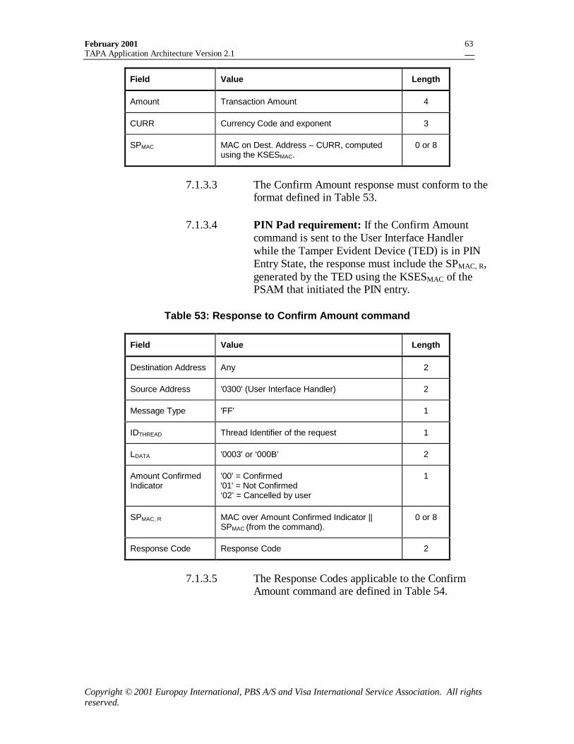
February 2001TAPA Application Architecture Version 2.1
Copyright © 2001 Europay International, PBS A/S and Visa International Service Association. All rightsreserved.
63
Field Value Length
Amount Transaction Amount 4
CURR Currency Code and exponent 3
SPMAC MAC on Dest. Address – CURR, computedusing the KSESMAC.
0 or 8
7.1.3.3 The Confirm Amount response must conform to theformat defined in Table 53.
7.1.3.4 PIN Pad requirement: If the Confirm Amountcommand is sent to the User Interface Handlerwhile the Tamper Evident Device (TED) is in PINEntry State, the response must include the SPMAC, R,generated by the TED using the KSESMAC of thePSAM that initiated the PIN entry.
Table 53: Response to Confirm Amount command
Field Value Length
Destination Address Any 2
Source Address '0300' (User Interface Handler) 2
Message Type 'FF' 1
IDTHREAD Thread Identifier of the request 1
LDATA '0003' or ‘000B’ 2
Amount ConfirmedIndicator
'00' = Confirmed'01' = Not Confirmed‘02’ = Cancelled by user
1
SPMAC, R MAC over Amount Confirmed Indicator ||SPMAC (from the command).
0 or 8
Response Code Response Code 2
7.1.3.5 The Response Codes applicable to the ConfirmAmount command are defined in Table 54.
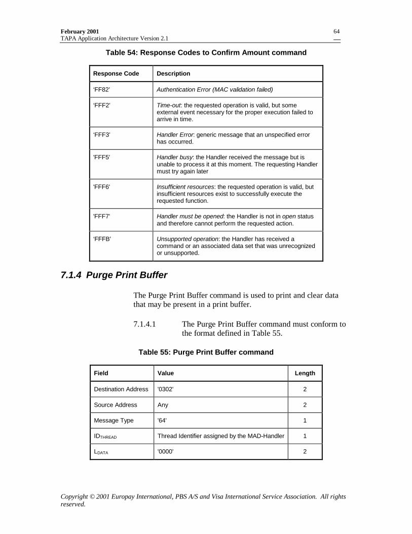
February 2001TAPA Application Architecture Version 2.1
Copyright © 2001 Europay International, PBS A/S and Visa International Service Association. All rightsreserved.
64
Table 54: Response Codes to Confirm Amount command
Response Code Description
‘FF82’ Authentication Error (MAC validation failed)
‘FFF2’ Time-out: the requested operation is valid, but someexternal event necessary for the proper execution failed toarrive in time.
‘FFF3’ Handler Error: generic message that an unspecified errorhas occurred.
'FFF5' Handler busy: the Handler received the message but isunable to process it at this moment. The requesting Handlermust try again later
'FFF6' Insufficient resources: the requested operation is valid, butinsufficient resources exist to successfully execute therequested function.
'FFF7' Handler must be opened: the Handler is not in open statusand therefore cannot perform the requested action.
‘FFFB’ Unsupported operation: the Handler has received acommand or an associated data set that was unrecognizedor unsupported.
7.1.4 Purge Print Buffer
The Purge Print Buffer command is used to print and clear datathat may be present in a print buffer.
7.1.4.1 The Purge Print Buffer command must conform tothe format defined in Table 55.
Table 55: Purge Print Buffer command
Field Value Length
Destination Address '0302' 2
Source Address Any 2
Message Type '64' 1
IDTHREAD Thread Identifier assigned by the MAD-Handler 1
LDATA '0000' 2
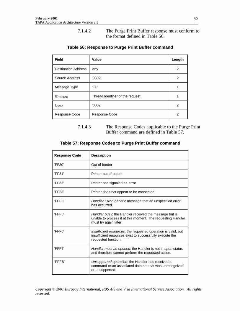
February 2001TAPA Application Architecture Version 2.1
Copyright © 2001 Europay International, PBS A/S and Visa International Service Association. All rightsreserved.
65
7.1.4.2 The Purge Print Buffer response must conform tothe format defined in Table 56.
Table 56: Response to Purge Print Buffer command
Field Value Length
Destination Address Any 2
Source Address '0302' 2
Message Type 'FF' 1
IDTHREAD Thread Identifier of the request 1
LDATA '0002' 2
Response Code Response Code 2
7.1.4.3 The Response Codes applicable to the Purge PrintBuffer command are defined in Table 57.
Table 57: Response Codes to Purge Print Buffer command
Response Code Description
'FF30' Out of border
'FF31' Printer out of paper
'FF32' Printer has signaled an error
'FF33' Printer does not appear to be connected
'FFF3' Handler Error: generic message that an unspecified errorhas occurred.
'FFF5' Handler busy: the Handler received the message but isunable to process it at this moment. The requesting Handlermust try again later
'FFF6' Insufficient resources: the requested operation is valid, butinsufficient resources exist to successfully execute therequested function.
'FFF7' Handler must be opened: the Handler is not in open statusand therefore cannot perform the requested action.
‘FFFB’ Unsupported operation: the Handler has received acommand or an associated data set that was unrecognizedor unsupported.
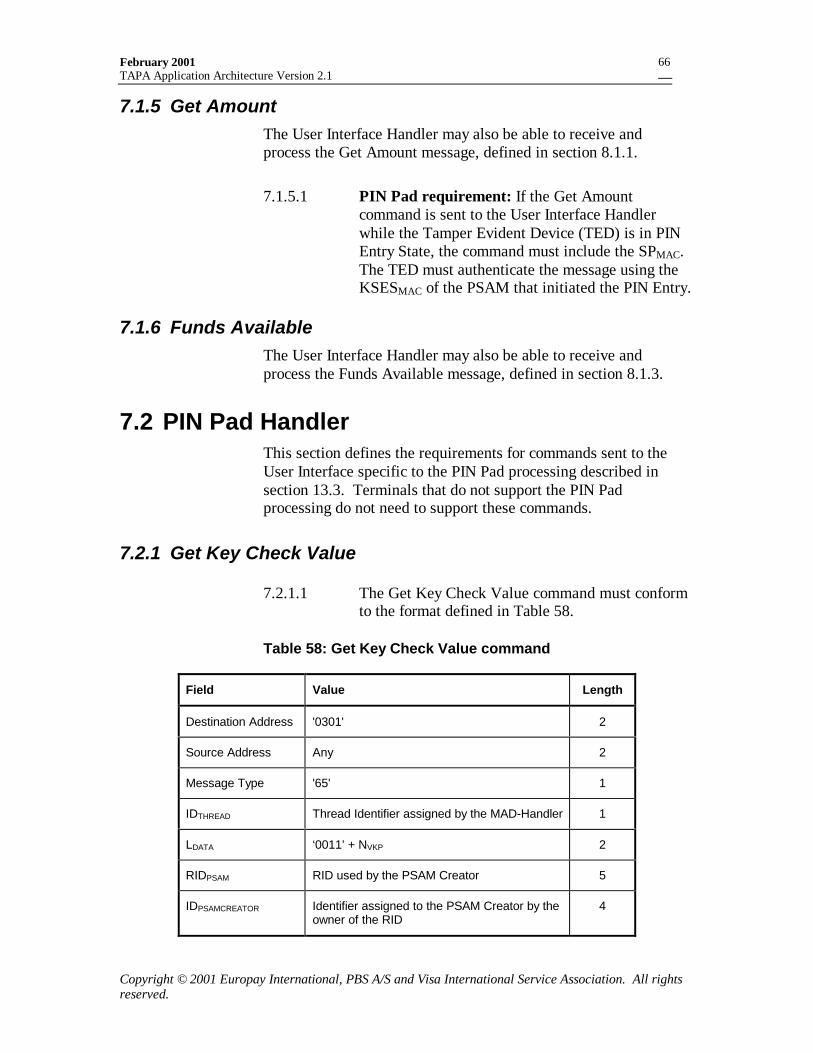
February 2001TAPA Application Architecture Version 2.1
Copyright © 2001 Europay International, PBS A/S and Visa International Service Association. All rightsreserved.
66
7.1.5 Get AmountThe User Interface Handler may also be able to receive andprocess the Get Amount message, defined in section 8.1.1.
7.1.5.1 PIN Pad requirement: If the Get Amountcommand is sent to the User Interface Handlerwhile the Tamper Evident Device (TED) is in PINEntry State, the command must include the SPMAC.The TED must authenticate the message using theKSESMAC of the PSAM that initiated the PIN Entry.
7.1.6 Funds AvailableThe User Interface Handler may also be able to receive andprocess the Funds Available message, defined in section 8.1.3.
7.2 PIN Pad HandlerThis section defines the requirements for commands sent to theUser Interface specific to the PIN Pad processing described insection 13.3. Terminals that do not support the PIN Padprocessing do not need to support these commands.
7.2.1 Get Key Check Value
7.2.1.1 The Get Key Check Value command must conformto the format defined in Table 58.
Table 58: Get Key Check Value command
Field Value Length
Destination Address '0301' 2
Source Address Any 2
Message Type '65' 1
IDTHREAD Thread Identifier assigned by the MAD-Handler 1
LDATA ‘0011’ + NVKP 2
RIDPSAM RID used by the PSAM Creator 5
IDPSAMCREATOR Identifier assigned to the PSAM Creator by theowner of the RID
4
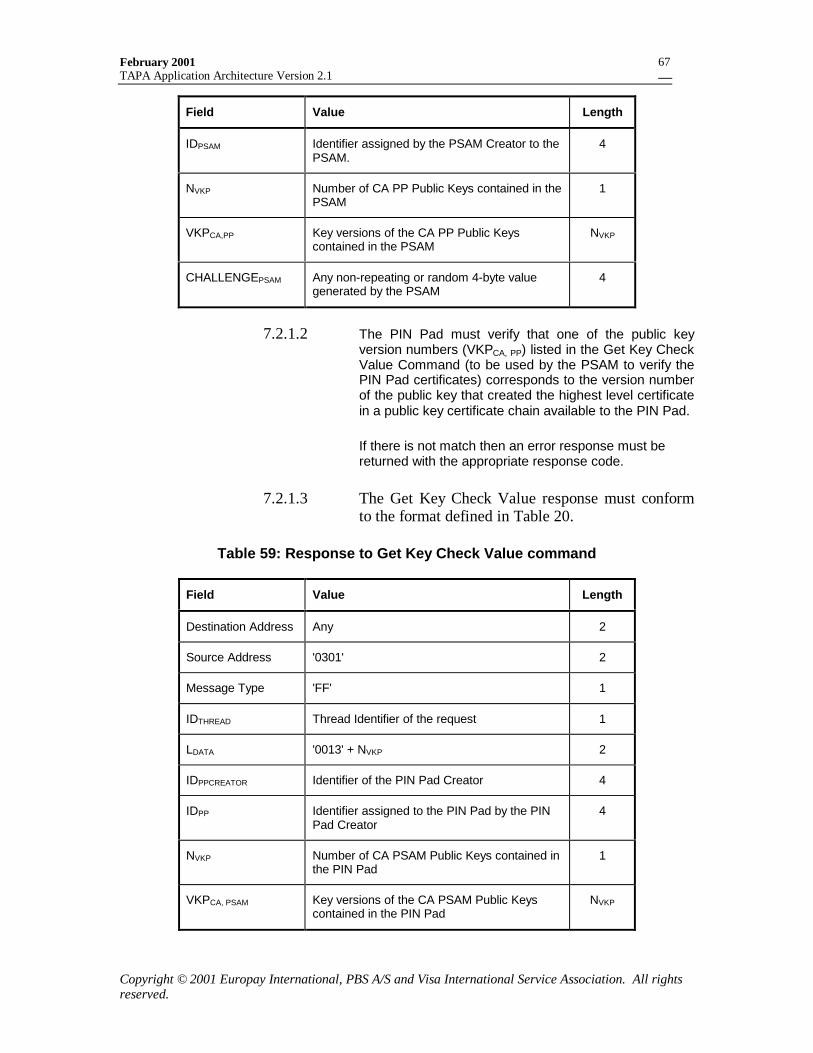
February 2001TAPA Application Architecture Version 2.1
Copyright © 2001 Europay International, PBS A/S and Visa International Service Association. All rightsreserved.
67
Field Value Length
IDPSAM Identifier assigned by the PSAM Creator to thePSAM.
4
NVKP Number of CA PP Public Keys contained in thePSAM
1
VKPCA,PP Key versions of the CA PP Public Keyscontained in the PSAM
NVKP
CHALLENGEPSAM Any non-repeating or random 4-byte valuegenerated by the PSAM
4
7.2.1.2 The PIN Pad must verify that one of the public keyversion numbers (VKPCA, PP) listed in the Get Key CheckValue Command (to be used by the PSAM to verify thePIN Pad certificates) corresponds to the version numberof the public key that created the highest level certificatein a public key certificate chain available to the PIN Pad.
If there is not match then an error response must bereturned with the appropriate response code.
7.2.1.3 The Get Key Check Value response must conformto the format defined in Table 20.
Table 59: Response to Get Key Check Value command
Field Value Length
Destination Address Any 2
Source Address '0301' 2
Message Type 'FF' 1
IDTHREAD Thread Identifier of the request 1
LDATA '0013' + NVKP 2
IDPPCREATOR Identifier of the PIN Pad Creator 4
IDPP Identifier assigned to the PIN Pad by the PINPad Creator
4
NVKP Number of CA PSAM Public Keys contained inthe PIN Pad
1
VKPCA, PSAM Key versions of the CA PSAM Public Keyscontained in the PIN Pad
NVKP
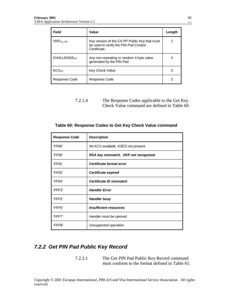
February 2001TAPA Application Architecture Version 2.1
Copyright © 2001 Europay International, PBS A/S and Visa International Service Association. All rightsreserved.
68
Field Value Length
VKPCA, PP Key version of the CA PP Public Key that mustbe used to verify the PIN Pad CreatorCertificate.
1
CHALLENGEPP Any non-repeating or random 4-byte valuegenerated by the PIN Pad
4
KCVPP Key Check Value 3
Response Code Response Code 2
7.2.1.4 The Response Codes applicable to the Get KeyCheck Value command are defined in Table 60.
Table 60: Response Codes to Get Key Check Value command
Response Code Description
‘FF80’ No KCV available, KSES not present
‘FF90’ RSA key mismatch. VKP not recognized
‘FF91’ Certificate format error
‘FF92’ Certificate expired
‘FF93’ Certificate ID mismatch
‘FFF3’ Handler Error
‘FFF5’ Handler busy
‘FFF6’ Insufficient resources
‘FFF7’ Handler must be opened
‘FFFB’ Unsupported operation
7.2.2 Get PIN Pad Public Key Record
7.2.2.1 The Get PIN Pad Public Key Record commandmust conform to the format defined in Table 61.

February 2001TAPA Application Architecture Version 2.1
Copyright © 2001 Europay International, PBS A/S and Visa International Service Association. All rightsreserved.
69
Table 61: Get PIN Pad Public Key Record command
Field Value Length
Destination Address '0301' 2
Source Address Any 2
Message Type '67' 1
IDTHREAD Thread Identifier assigned by the MAD-Handler 1
LDATA ‘0001’ 2
Format Code ‘C2’ = PKCPPC, ‘C4’ = PKCPP 1
7.2.2.2 The Get PIN Pad public Key Record response mustconform to the format defined in Table 62.
Table 62: Response to Get PIN Pad Public Key Record command
Field Value Length
Destination Address Any 2
Source Address '0301' 2
Message Type 'FF' 1
IDTHREAD Thread Identifier of the request 1
LDATA ‘0002’ + Length of RecordPKEY 2
RecordPKEY Record containing tags, certificate(PKCPPC/PKCPP) and remainder (if present)
See Table 63 and Table 64 for the formats ofthe PIN Pad Creator and PIN PAD public keyrecords.
Var.
Response Code Response Code 2
Table 63: Contents of PIN Pad Creator Certificate Record
Description Data element Mandatory orconditional
Length(bytes)
Record Tag ‘85’ M 1
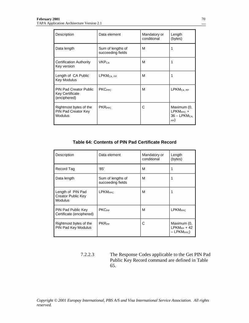
February 2001TAPA Application Architecture Version 2.1
Copyright © 2001 Europay International, PBS A/S and Visa International Service Association. All rightsreserved.
70
Description Data element Mandatory orconditional
Length(bytes)
Data length Sum of lengths ofsucceeding fields
M 1
Certification AuthorityKey version
VKPCA M 1
Length of CA PublicKey Modulus
LPKMCA, PP M 1
PIN Pad Creator PublicKey Certificate(enciphered)
PKCPPC M LPKMCA, PP
Rightmost bytes of thePIN Pad Creator KeyModulus
PKRPPC C Maximum (0,LPKMPPC +36 – LPKMCA,
PP)
Table 64: Contents of PIN Pad Certificate Record
Description Data element Mandatory orconditional
Length(bytes)
Record Tag ‘85’ M 1
Data length Sum of lengths ofsucceeding fields
M 1
Length of PIN PadCreator Public KeyModulus
LPKMPPC M 1
PIN Pad Public KeyCertificate (enciphered)
PKCPP M LPKMPPC
Rightmost bytes of thePIN Pad Key Modulus
PKRPP C Maximum (0,LPKMPP + 42– LPKMPPC)
7.2.2.3 The Response Codes applicable to the Get PIN PadPublic Key Record command are defined in Table65.
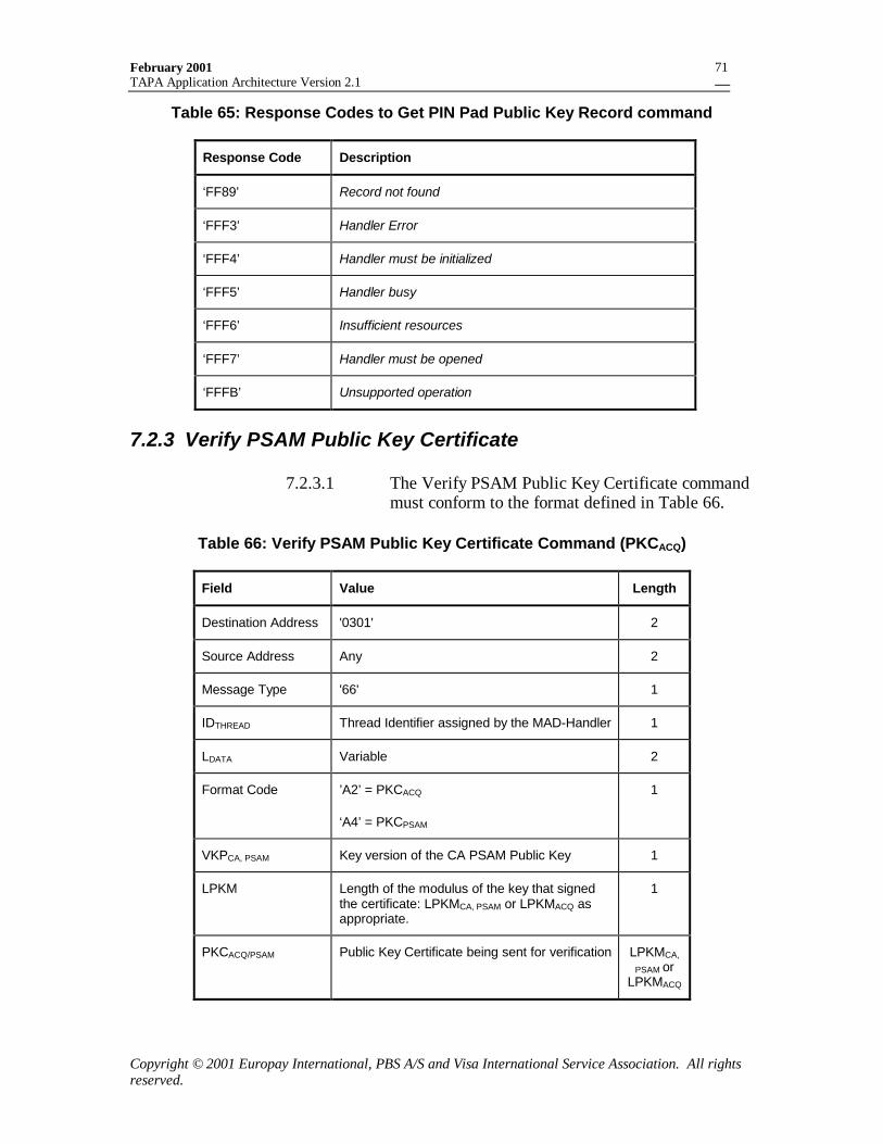
February 2001TAPA Application Architecture Version 2.1
Copyright © 2001 Europay International, PBS A/S and Visa International Service Association. All rightsreserved.
71
Table 65: Response Codes to Get PIN Pad Public Key Record command
Response Code Description
‘FF89’ Record not found
‘FFF3’ Handler Error
‘FFF4’ Handler must be initialized
‘FFF5’ Handler busy
‘FFF6’ Insufficient resources
‘FFF7’ Handler must be opened
‘FFFB’ Unsupported operation
7.2.3 Verify PSAM Public Key Certificate
7.2.3.1 The Verify PSAM Public Key Certificate commandmust conform to the format defined in Table 66.
Table 66: Verify PSAM Public Key Certificate Command (PKCACQ)
Field Value Length
Destination Address '0301' 2
Source Address Any 2
Message Type '66' 1
IDTHREAD Thread Identifier assigned by the MAD-Handler 1
LDATA Variable 2
Format Code ’A2’ = PKCACQ
‘A4’ = PKCPSAM
1
VKPCA, PSAM Key version of the CA PSAM Public Key 1
LPKM Length of the modulus of the key that signedthe certificate: LPKMCA, PSAM or LPKMACQ asappropriate.
1
PKCACQ/PSAM Public Key Certificate being sent for verification LPKMCA,
PSAM orLPKMACQ
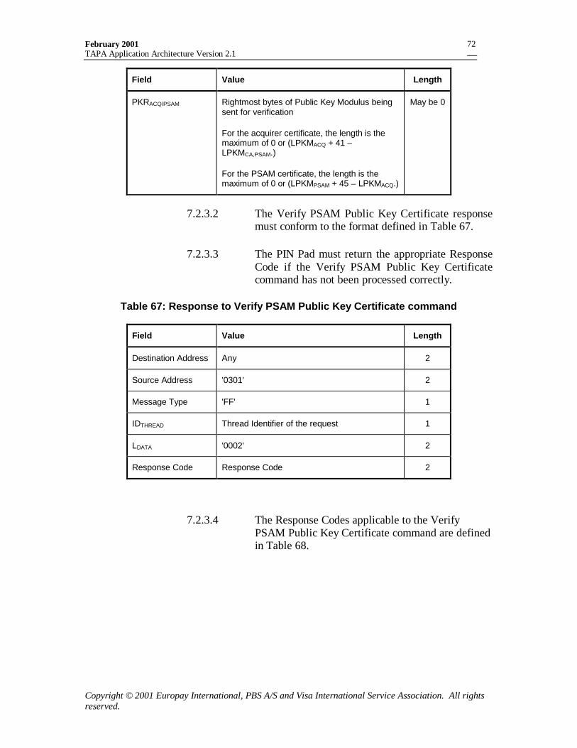
February 2001TAPA Application Architecture Version 2.1
Copyright © 2001 Europay International, PBS A/S and Visa International Service Association. All rightsreserved.
72
Field Value Length
PKRACQ/PSAM Rightmost bytes of Public Key Modulus beingsent for verification
For the acquirer certificate, the length is themaximum of 0 or (LPKMACQ + 41 –LPKMCA,PSAM.)
For the PSAM certificate, the length is themaximum of 0 or (LPKMPSAM + 45 – LPKMACQ.)
May be 0
7.2.3.2 The Verify PSAM Public Key Certificate responsemust conform to the format defined in Table 67.
7.2.3.3 The PIN Pad must return the appropriate ResponseCode if the Verify PSAM Public Key Certificatecommand has not been processed correctly.
Table 67: Response to Verify PSAM Public Key Certificate command
Field Value Length
Destination Address Any 2
Source Address '0301' 2
Message Type 'FF' 1
IDTHREAD Thread Identifier of the request 1
LDATA '0002' 2
Response Code Response Code 2
7.2.3.4 The Response Codes applicable to the VerifyPSAM Public Key Certificate command are definedin Table 68.
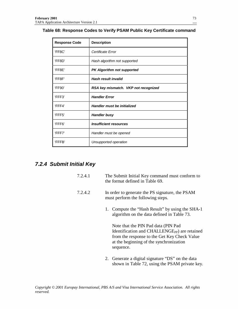
February 2001TAPA Application Architecture Version 2.1
Copyright © 2001 Europay International, PBS A/S and Visa International Service Association. All rightsreserved.
73
Table 68: Response Codes to Verify PSAM Public Key Certificate command
Response Code Description
‘FF8C’ Certificate Error
‘FF8D’ Hash algorithm not supported
‘FF8E’ PK Algorithm not supported
‘FF8F’ Hash result invalid
‘FF90’ RSA key mismatch. VKP not recognized
‘FFF3’ Handler Error
‘FFF4’ Handler must be initialized
‘FFF5’ Handler busy
‘FFF6’ Insufficient resources
‘FFF7’ Handler must be opened
‘FFFB’ Unsupported operation
7.2.4 Submit Initial Key
7.2.4.1 The Submit Initial Key command must conform tothe format defined in Table 69.
7.2.4.2 In order to generate the PS signature, the PSAMmust perform the following steps.
1. Compute the “Hash Result” by using the SHA-1algorithm on the data defined in Table 73.
Note that the PIN Pad data (PIN PadIdentification and CHALLENGEPP) are retainedfrom the response to the Get Key Check Valueat the beginning of the synchronizationsequence.
2. Generate a digital signature “DS” on the datashown in Table 72, using the PSAM private key.
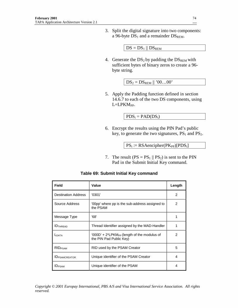
February 2001TAPA Application Architecture Version 2.1
Copyright © 2001 Europay International, PBS A/S and Visa International Service Association. All rightsreserved.
74
3. Split the digital signature into two components:a 96-byte DS1 and a remainder DSREM.
DS = DS1 || DSREM
4. Generate the DS2 by padding the DSREM withsufficient bytes of binary zeros to create a 96-byte string.
DS2 = DSREM || ’00… 00’
5. Apply the Padding function defined in section14.6.7 to each of the two DS components, usingL=LPKMPP.
PDSi = PAD(DSi)
6. Encrypt the results using the PIN Pad’s publickey, to generate the two signatures, PS1 and PS2.
PSi := RSAencipher(PKPP)[PDSi]
7. The result (PS = PS1 || PS2) is sent to the PINPad in the Submit Initial Key command.
Table 69: Submit Initial Key command
Field Value Length
Destination Address '0301' 2
Source Address '00pp' where pp is the sub-address assigned tothe PSAM
2
Message Type '68' 1
IDTHREAD Thread Identifier assigned by the MAD-Handler 1
LDATA ‘000D’ + 2*LPKMPP (length of the modulus ofthe PIN Pad Public Key)
2
RIDPSAM RID used by the PSAM Creator 5
IDPSAMCREATOR Unique identifier of the PSAM Creator 4
IDPSAM Unique identifier of the PSAM 4
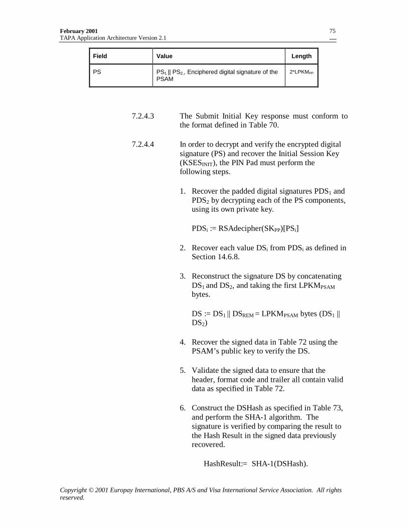
February 2001TAPA Application Architecture Version 2.1
Copyright © 2001 Europay International, PBS A/S and Visa International Service Association. All rightsreserved.
75
Field Value Length
PS PS1 || PS2,, Enciphered digital signature of thePSAM
2*LPKMPP
7.2.4.3 The Submit Initial Key response must conform tothe format defined in Table 70.
7.2.4.4 In order to decrypt and verify the encrypted digitalsignature (PS) and recover the Initial Session Key(KSESINIT), the PIN Pad must perform thefollowing steps.
1. Recover the padded digital signatures PDS1 andPDS2 by decrypting each of the PS components,using its own private key.
PDSi := RSAdecipher(SKPP)[PSi]
2. Recover each value DSi from PDSi as defined inSection 14.6.8.
3. Reconstruct the signature DS by concatenatingDS1 and DS2, and taking the first LPKMPSAMbytes.
DS := DS1 || DSREM = LPKMPSAM bytes (DS1 ||DS2)
4. Recover the signed data in Table 72 using thePSAM’s public key to verify the DS.
5. Validate the signed data to ensure that theheader, format code and trailer all contain validdata as specified in Table 72.
6. Construct the DSHash as specified in Table 73,and perform the SHA-1 algorithm. Thesignature is verified by comparing the result tothe Hash Result in the signed data previouslyrecovered.
HashResult:= SHA-1(DSHash).
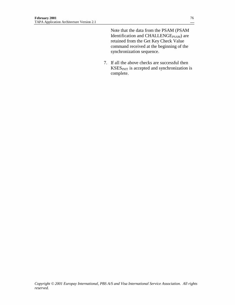
February 2001TAPA Application Architecture Version 2.1
Copyright © 2001 Europay International, PBS A/S and Visa International Service Association. All rightsreserved.
76
Note that the data from the PSAM (PSAMIdentification and CHALLENGEPSAM) areretained from the Get Key Check Valuecommand received at the beginning of thesynchronization sequence.
7. If all the above checks are successful thenKSESINIT is accepted and synchronization iscomplete.
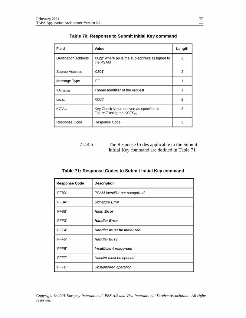
February 2001TAPA Application Architecture Version 2.1
Copyright © 2001 Europay International, PBS A/S and Visa International Service Association. All rightsreserved.
77
Table 70: Response to Submit Initial Key command
Field Value Length
Destination Address '00pp' where pp is the sub-address assigned tothe PSAM
2
Source Address '0301' 2
Message Type 'FF' 1
IDTHREAD Thread Identifier of the request 1
LDATA '0005' 2
KCVPP Key Check Value derived as specified inFigure 7 using the KSESINIT.
3
Response Code Response Code 2
7.2.4.5 The Response Codes applicable to the SubmitInitial Key command are defined in Table 71.
Table 71: Response Codes to Submit Initial Key command
Response Code Description
‘FF83’ PSAM Identifier not recognized
‘FF8A’ Signature Error
‘FF8B’ Hash Error
‘FFF3’ Handler Error
‘FFF4’ Handler must be initialized
‘FFF5’ Handler busy
‘FFF6’ Insufficient resources
‘FFF7’ Handler must be opened
‘FFFB’ Unsupported operation
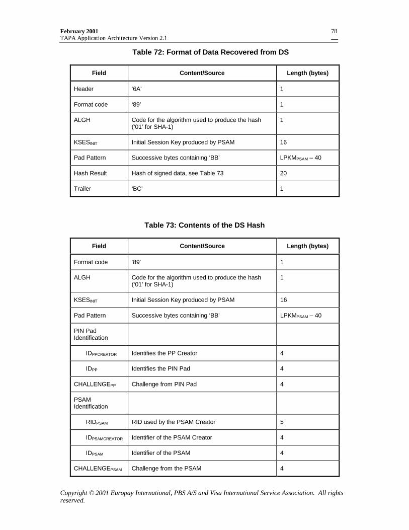
February 2001TAPA Application Architecture Version 2.1
Copyright © 2001 Europay International, PBS A/S and Visa International Service Association. All rightsreserved.
78
Table 72: Format of Data Recovered from DS
Field Content/Source Length (bytes)
Header ‘6A’ 1
Format code ‘89’ 1
ALGH Code for the algorithm used to produce the hash(‘01’ for SHA-1)
1
KSESINIT Initial Session Key produced by PSAM 16
Pad Pattern Successive bytes containing ‘BB’ LPKMPSAM – 40
Hash Result Hash of signed data, see Table 73 20
Trailer ‘BC’ 1
Table 73: Contents of the DS Hash
Field Content/Source Length (bytes)
Format code ‘89' 1
ALGH Code for the algorithm used to produce the hash(‘01’ for SHA-1)
1
KSESINIT Initial Session Key produced by PSAM 16
Pad Pattern Successive bytes containing ‘BB’ LPKMPSAM – 40
PIN PadIdentification
IDPPCREATOR Identifies the PP Creator 4
IDPP Identifies the PIN Pad 4
CHALLENGEPP Challenge from PIN Pad 4
PSAMIdentification
RIDPSAM RID used by the PSAM Creator 5
IDPSAMCREATOR Identifier of the PSAM Creator 4
IDPSAM Identifier of the PSAM 4
CHALLENGEPSAM Challenge from the PSAM 4
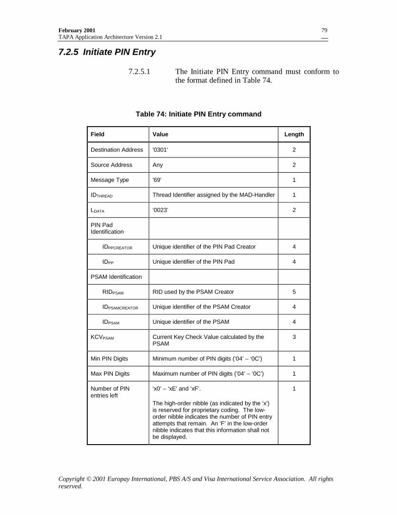
February 2001TAPA Application Architecture Version 2.1
Copyright © 2001 Europay International, PBS A/S and Visa International Service Association. All rightsreserved.
79
7.2.5 Initiate PIN Entry
7.2.5.1 The Initiate PIN Entry command must conform tothe format defined in Table 74.
Table 74: Initiate PIN Entry command
Field Value Length
Destination Address '0301' 2
Source Address Any 2
Message Type '69' 1
IDTHREAD Thread Identifier assigned by the MAD-Handler 1
LDATA ‘0023’ 2
PIN PadIdentification
IDPPCREATOR Unique identifier of the PIN Pad Creator 4
IDPP Unique identifier of the PIN Pad 4
PSAM Identification
RIDPSAM RID used by the PSAM Creator 5
IDPSAMCREATOR Unique identifier of the PSAM Creator 4
IDPSAM Unique identifier of the PSAM 4
KCVPSAM Current Key Check Value calculated by thePSAM
3
Min PIN Digits Minimum number of PIN digits (’04’ – ‘0C’) 1
Max PIN Digits Maximum number of PIN digits (’04’ – ‘0C’) 1
Number of PINentries left
‘x0’ – ‘xE’ and ‘xF’.
The high-order nibble (as indicated by the ‘x’)is reserved for proprietary coding. The low-order nibble indicates the number of PIN entryattempts that remain. An ‘F’ in the low-ordernibble indicates that this information shall notbe displayed.
1
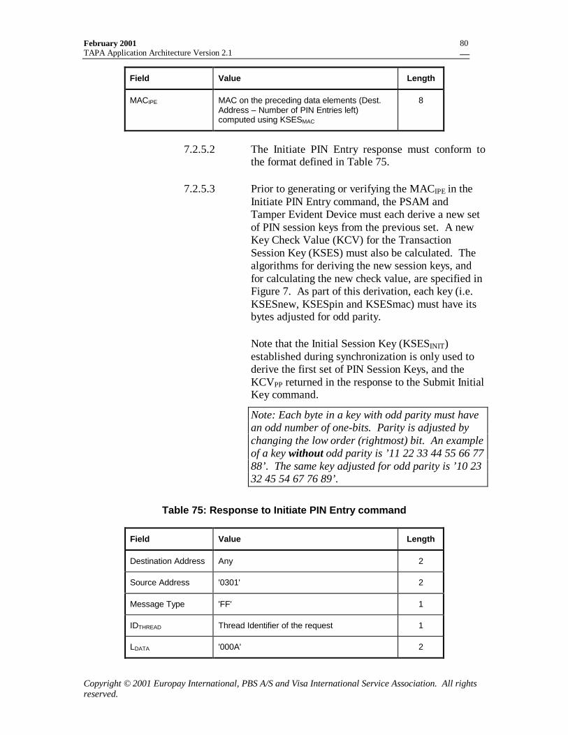
February 2001TAPA Application Architecture Version 2.1
Copyright © 2001 Europay International, PBS A/S and Visa International Service Association. All rightsreserved.
80
Field Value Length
MACIPE MAC on the preceding data elements (Dest.Address – Number of PIN Entries left)computed using KSESMAC
8
7.2.5.2 The Initiate PIN Entry response must conform tothe format defined in Table 75.
7.2.5.3 Prior to generating or verifying the MACIPE in theInitiate PIN Entry command, the PSAM andTamper Evident Device must each derive a new setof PIN session keys from the previous set. A newKey Check Value (KCV) for the TransactionSession Key (KSES) must also be calculated. Thealgorithms for deriving the new session keys, andfor calculating the new check value, are specified inFigure 7. As part of this derivation, each key (i.e.KSESnew, KSESpin and KSESmac) must have itsbytes adjusted for odd parity.
Note that the Initial Session Key (KSESINIT)established during synchronization is only used toderive the first set of PIN Session Keys, and theKCVPP returned in the response to the Submit InitialKey command.
Note: Each byte in a key with odd parity must havean odd number of one-bits. Parity is adjusted bychanging the low order (rightmost) bit. An exampleof a key without odd parity is ’11 22 33 44 55 66 7788’. The same key adjusted for odd parity is ’10 2332 45 54 67 76 89’.
Table 75: Response to Initiate PIN Entry command
Field Value Length
Destination Address Any 2
Source Address '0301' 2
Message Type 'FF' 1
IDTHREAD Thread Identifier of the request 1
LDATA '000A' 2

February 2001TAPA Application Architecture Version 2.1
Copyright © 2001 Europay International, PBS A/S and Visa International Service Association. All rightsreserved.
81
Field Value Length
MACIPER MAC on the MACIPE from the command,computed using KSESMAC
8
Response Code Response Code 2
]}000000000')['0000000KSES3MSB{DES3(:KCV
])[DMDES3(KSES||])[DMDES3(KSES:KSES0000000''0FF000000:DM
000000'F00F000000':DM
])[DPDES3(KSES||])[DPDES3(KSES:KSES000000'F0F0000000':DP000000'FFFF000000':DP
])[DDES3(KSES||])[DDES3(KSES:KSES0'||'0F00000ID:D
F0000000'||'ID:D
NEWNEW
RNEWLNEWMAC
R
L
RNEWLNEWPIN
R
L
ROLDLOLDNEW
PPR
PPL
=
===
===
===
Figure 7: PIN Session Key Derivation
7.2.5.4 The Response Codes applicable to the Initiate PINEntry command are defined in Table 76.
Table 76: Response Codes to Initiate PIN Entry command
Response Code Description
‘FF81’ Wrong PIN Pad ID
‘FF82’ Authentication Error (MAC validation failed)
‘FF83’ PSAM Identifier not recognized
‘FF84’ Parameters out of range
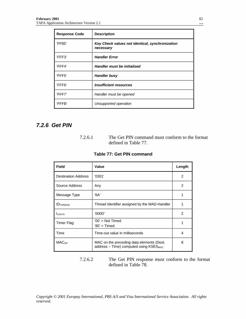
February 2001TAPA Application Architecture Version 2.1
Copyright © 2001 Europay International, PBS A/S and Visa International Service Association. All rightsreserved.
82
Response Code Description
‘FF85’ Key Check values not identical, synchronizationnecessary
‘FFF3’ Handler Error
‘FFF4’ Handler must be initialized
‘FFF5’ Handler busy
‘FFF6’ Insufficient resources
‘FFF7’ Handler must be opened
‘FFFB’ Unsupported operation
7.2.6 Get PIN
7.2.6.1 The Get PIN command must conform to the formatdefined in Table 77.
Table 77: Get PIN command
Field Value Length
Destination Address '0301' 2
Source Address Any 2
Message Type '6A' 1
IDTHREAD Thread Identifier assigned by the MAD-Handler 1
LDATA ‘000D’ 2
Timer Flag ‘00’ = Not Timed‘80’ = Timed
1
Time Time-out value in milliseconds 4
MACGP MAC on the preceding data elements (Dest.address – Time) computed using KSESMAC
8
7.2.6.2 The Get PIN response must conform to the formatdefined in Table 78.
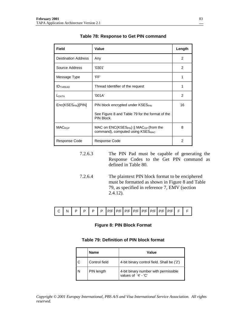
February 2001TAPA Application Architecture Version 2.1
Copyright © 2001 Europay International, PBS A/S and Visa International Service Association. All rightsreserved.
83
Table 78: Response to Get PIN command
Field Value Length
Destination Address Any 2
Source Address '0301' 2
Message Type 'FF' 1
IDTHREAD Thread Identifier of the request 1
LDATA '001A' 2
Enc(KSESPIN)[PIN] PIN block encrypted under KSESPIN
See Figure 8 and Table 79 for the format of thePIN Block.
16
MACRGP MAC on ENC(KSESPIN) || MACGP (from thecommand), computed using KSESMAC
8
Response Code Response Code 2
7.2.6.3 The PIN Pad must be capable of generating theResponse Codes to the Get PIN command asdefined in Table 80.
7.2.6.4 The plaintext PIN block format to be encipheredmust be formatted as shown in Figure 8 and Table79, as specified in reference 7, EMV (section2.4.12).
P/F P/F P/FP/F P/F P/F P/F P/FPPPPNC F F
Figure 8: PIN Block Format
Table 79: Definition of PIN block format
Name Value
C Control field 4-bit binary control field. Shall be ('2')
N PIN length 4-bit binary number with permissiblevalues of '4' - 'C'
February 2001TAPA Application Architecture Version 2.1
Copyright © 2001 Europay International, PBS A/S and Visa International Service Association. All rightsreserved.
84
Name Value
P PIN digit 4-bit binary number with permissiblevalues of '0' - '9'
P/F PIN/Filler Determined by PIN length
F Filler 4-bit binary number with value 'F'
7.2.6.5 The Response Codes applicable to the Get PINcommand are defined in Table 80.
Table 80: Response Codes to Get PIN command
Response Code Description
‘FF82’ Authentication Error (MAC validation failed)
‘FF86’ PIN not available
‘FF87’ Tamper Evident Device not in PIN Entry State
‘FFF2’ Time-out
‘FFF3’ Handler Error
‘FFF4’ Handler must be initialized
‘FFF5’ Handler busy
‘FFF6’ Insufficient resources
‘FFF7’ Handler must be opened
‘FFFB’ Unsupported operation
7.2.7 Terminate PIN Entry
7.2.7.1 The Terminate PIN Entry command must conformto the format defined in Table 81.
February 2001TAPA Application Architecture Version 2.1
Copyright © 2001 Europay International, PBS A/S and Visa International Service Association. All rightsreserved.
85
Table 81: Terminate PIN Entry command
Field Value Length
Destination Address '0301' 2
Source Address Any 2
Message Type '6C' 1
IDTHREAD Thread Identifier assigned by the MAD-Handler 1
LDATA ‘0015’ 2
PIN PadIdentification
IDPPCREATOR Unique identifier of the PIN Pad Creator 4
IDPP Unique identifier of the PIN Pad 4
PSAM Identification
RIDPSAM RID used by the PSAM Creator 5
IDPSAMCREATOR Unique identifier of the PSAM Creator 4
IDPSAM Unique identifier of the PSAM 4
7.2.7.2 The Terminate PIN Entry response must conform tothe format defined in Table 82.
Table 82: Response to Terminate PIN Entry command
Field Value Length
Destination Address Any 2
Source Address '0301' 2
Message Type 'FF' 1
IDTHREAD Thread Identifier of the request 1
LDATA '0002' 2
Response Code Response Code 2
7.2.7.3 The Response Codes applicable to the TerminatePIN Entry command are defined in Table 83.
February 2001TAPA Application Architecture Version 2.1
Copyright © 2001 Europay International, PBS A/S and Visa International Service Association. All rightsreserved.
86
Table 83: Response Codes to Terminate PIN Entry command
Response Code Description
‘FF81’ Wrong PIN Pad ID
‘FF83’ PSAM Identifier not recognized
‘FF87’ Tamper Evident Device not in PIN Entry State
‘FF88’ Termination Failed
‘FFF3’ Handler Error
‘FFF4’ Handler must be initialized
‘FFF5’ Handler busy
‘FFF6’ Insufficient resources
‘FFF7’ Handler must be opened
‘FFFB’ Unsupported operation
7.3 Summary
Table 84: User Interface-Specific commands
DestinationAddress
SourceAddress
MessageType
Description
'0300' Any '60' Confirm Amount
'0304' Any '61' Display a predefined message
'0302' Any '63' Print a predefined message
'0302' Any '64' Purge print buffer
'0300' Any '80' Get Amount
‘0300’ Any ‘82’ Funds Available
‘0301’ Any ‘65’ Get Key Check Value
‘0301’ Any ‘67’ Get PIN Pad Public Key Record
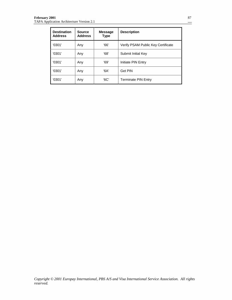
February 2001TAPA Application Architecture Version 2.1
Copyright © 2001 Europay International, PBS A/S and Visa International Service Association. All rightsreserved.
87
DestinationAddress
SourceAddress
MessageType
Description
‘0301’ Any ‘66’ Verify PSAM Public Key Certificate
‘0301’ Any ‘68’ Submit Initial Key
‘0301’ Any ‘69’ Initiate PIN Entry
‘0301’ Any ‘6A’ Get PIN
‘0301’ Any ‘6C’ Terminate PIN Entry
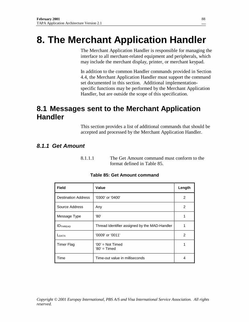
February 2001TAPA Application Architecture Version 2.1
Copyright © 2001 Europay International, PBS A/S and Visa International Service Association. All rightsreserved.
88
8. The Merchant Application HandlerThe Merchant Application Handler is responsible for managing theinterface to all merchant-related equipment and peripherals, whichmay include the merchant display, printer, or merchant keypad.
In addition to the common Handler commands provided in Section4.4, the Merchant Application Handler must support the commandset documented in this section. Additional implementation-specific functions may be performed by the Merchant ApplicationHandler, but are outside the scope of this specification.
8.1 Messages sent to the Merchant ApplicationHandler
This section provides a list of additional commands that should beaccepted and processed by the Merchant Application Handler.
8.1.1 Get Amount
8.1.1.1 The Get Amount command must conform to theformat defined in Table 85.
Table 85: Get Amount command
Field Value Length
Destination Address ‘0300’ or '0400' 2
Source Address Any 2
Message Type '80' 1
IDTHREAD Thread Identifier assigned by the MAD-Handler 1
LDATA '0009' or ‘0011' 2
Timer Flag ‘00’ = Not Timed‘80’ = Timed
1
Time Time-out value in milliseconds 4
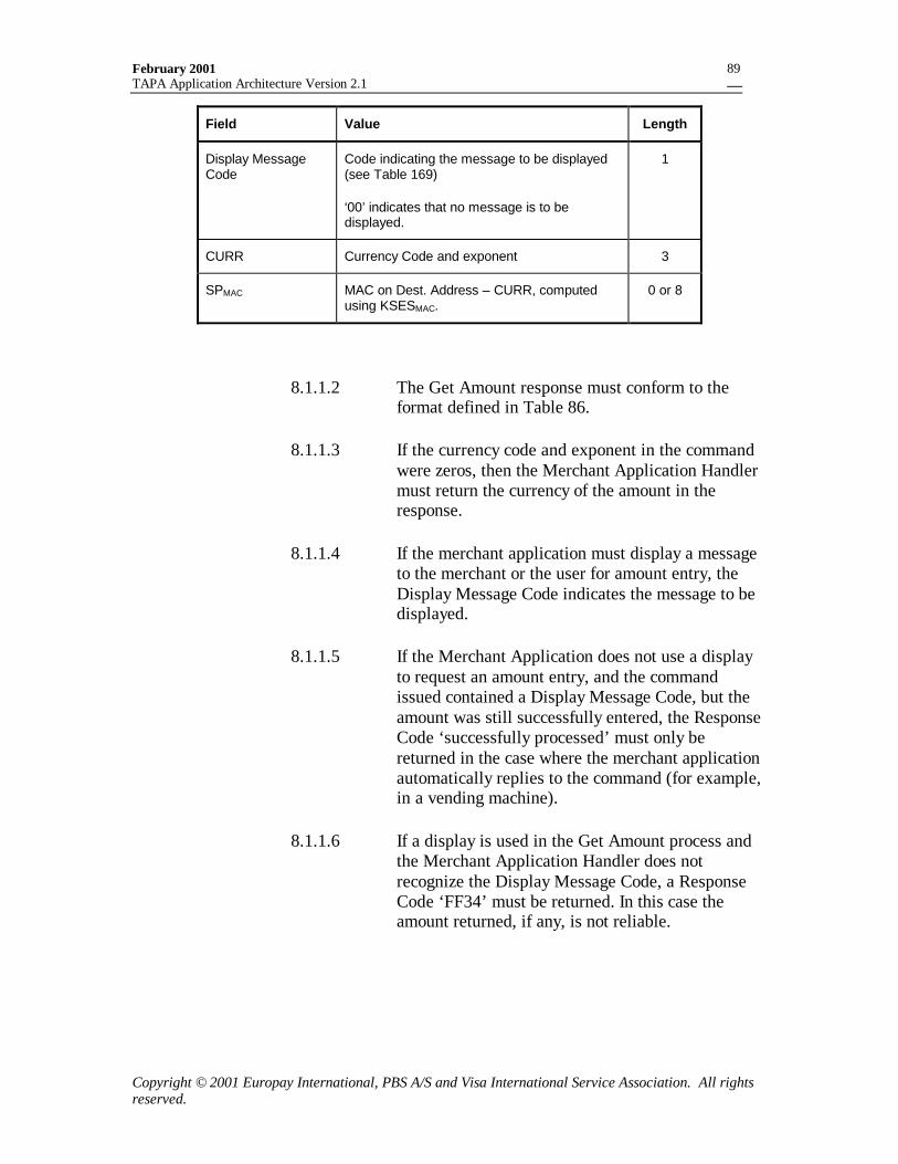
February 2001TAPA Application Architecture Version 2.1
Copyright © 2001 Europay International, PBS A/S and Visa International Service Association. All rightsreserved.
89
Field Value Length
Display MessageCode
Code indicating the message to be displayed(see Table 169)
‘00’ indicates that no message is to bedisplayed.
1
CURR Currency Code and exponent 3
SPMAC MAC on Dest. Address – CURR, computedusing KSESMAC.
0 or 8
8.1.1.2 The Get Amount response must conform to theformat defined in Table 86.
8.1.1.3 If the currency code and exponent in the commandwere zeros, then the Merchant Application Handlermust return the currency of the amount in theresponse.
8.1.1.4 If the merchant application must display a messageto the merchant or the user for amount entry, theDisplay Message Code indicates the message to bedisplayed.
8.1.1.5 If the Merchant Application does not use a displayto request an amount entry, and the commandissued contained a Display Message Code, but theamount was still successfully entered, the ResponseCode ‘successfully processed’ must only bereturned in the case where the merchant applicationautomatically replies to the command (for example,in a vending machine).
8.1.1.6 If a display is used in the Get Amount process andthe Merchant Application Handler does notrecognize the Display Message Code, a ResponseCode ‘FF34’ must be returned. In this case theamount returned, if any, is not reliable.
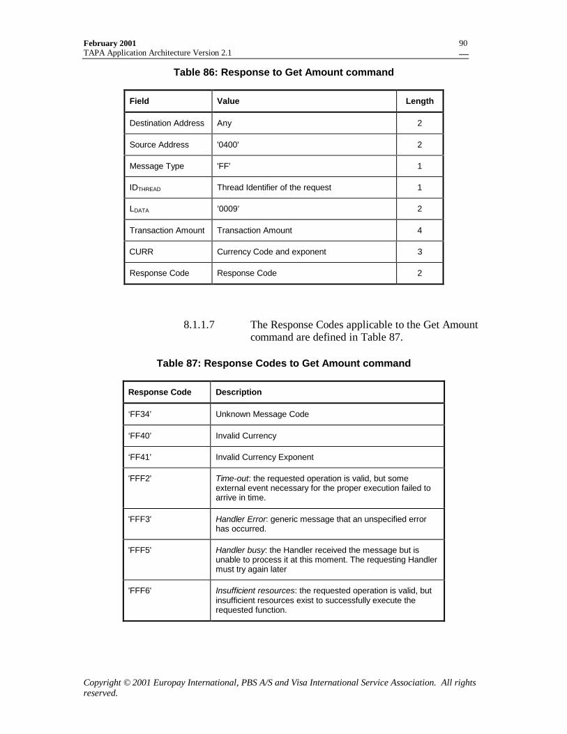
February 2001TAPA Application Architecture Version 2.1
Copyright © 2001 Europay International, PBS A/S and Visa International Service Association. All rightsreserved.
90
Table 86: Response to Get Amount command
Field Value Length
Destination Address Any 2
Source Address '0400' 2
Message Type 'FF' 1
IDTHREAD Thread Identifier of the request 1
LDATA ’0009’ 2
Transaction Amount Transaction Amount 4
CURR Currency Code and exponent 3
Response Code Response Code 2
8.1.1.7 The Response Codes applicable to the Get Amountcommand are defined in Table 87.
Table 87: Response Codes to Get Amount command
Response Code Description
‘FF34’ Unknown Message Code
‘FF40’ Invalid Currency
‘FF41’ Invalid Currency Exponent
'FFF2' Time-out: the requested operation is valid, but someexternal event necessary for the proper execution failed toarrive in time.
'FFF3' Handler Error: generic message that an unspecified errorhas occurred.
'FFF5' Handler busy: the Handler received the message but isunable to process it at this moment. The requesting Handlermust try again later
'FFF6' Insufficient resources: the requested operation is valid, butinsufficient resources exist to successfully execute therequested function.
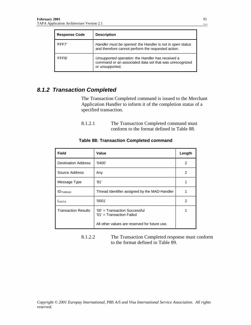
February 2001TAPA Application Architecture Version 2.1
Copyright © 2001 Europay International, PBS A/S and Visa International Service Association. All rightsreserved.
91
Response Code Description
'FFF7' Handler must be opened: the Handler is not in open statusand therefore cannot perform the requested action.
‘FFFB’ Unsupported operation: the Handler has received acommand or an associated data set that was unrecognizedor unsupported.
8.1.2 Transaction CompletedThe Transaction Completed command is issued to the MerchantApplication Handler to inform it of the completion status of aspecified transaction.
8.1.2.1 The Transaction Completed command mustconform to the format defined in Table 88.
Table 88: Transaction Completed command
Field Value Length
Destination Address '0400' 2
Source Address Any 2
Message Type ‘81’ 1
IDTHREAD Thread Identifier assigned by the MAD-Handler 1
LDATA '0001' 2
Transaction Results ‘00’ = Transaction Successful‘01’ = Transaction Failed
All other values are reserved for future use.
1
8.1.2.2 The Transaction Completed response must conformto the format defined in Table 89.
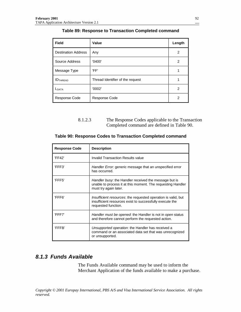
February 2001TAPA Application Architecture Version 2.1
Copyright © 2001 Europay International, PBS A/S and Visa International Service Association. All rightsreserved.
92
Table 89: Response to Transaction Completed command
Field Value Length
Destination Address Any 2
Source Address '0400' 2
Message Type 'FF' 1
IDTHREAD Thread Identifier of the request 1
LDATA '0002’ 2
Response Code Response Code 2
8.1.2.3 The Response Codes applicable to the TransactionCompleted command are defined in Table 90.
Table 90: Response Codes to Transaction Completed command
Response Code Description
'FF42' Invalid Transaction Results value
'FFF3' Handler Error: generic message that an unspecified errorhas occurred.
'FFF5' Handler busy: the Handler received the message but isunable to process it at this moment. The requesting Handlermust try again later.
'FFF6' Insufficient resources: the requested operation is valid, butinsufficient resources exist to successfully execute therequested function.
'FFF7' Handler must be opened: the Handler is not in open statusand therefore cannot perform the requested action.
‘FFFB’ Unsupported operation: the Handler has received acommand or an associated data set that was unrecognizedor unsupported.
8.1.3 Funds AvailableThe Funds Available command may be used to inform theMerchant Application of the funds available to make a purchase.
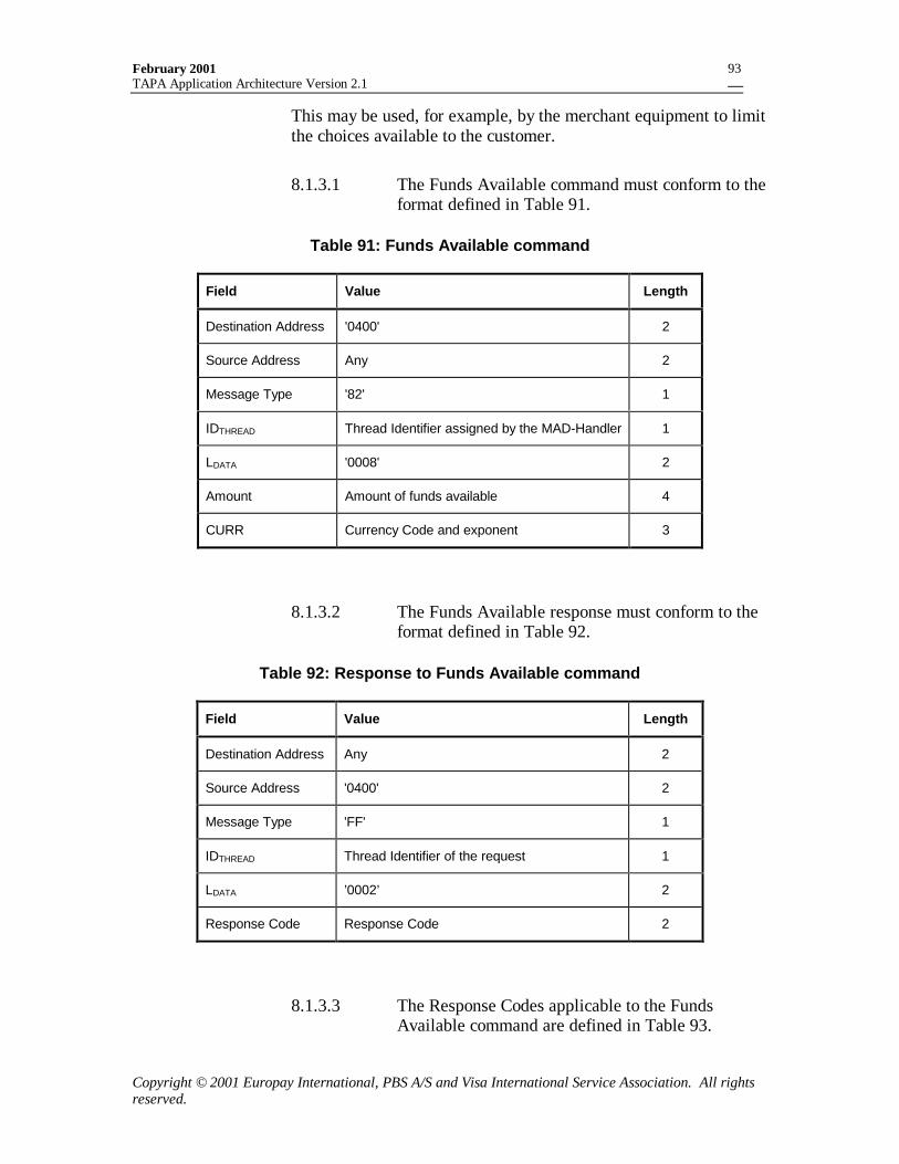
February 2001TAPA Application Architecture Version 2.1
Copyright © 2001 Europay International, PBS A/S and Visa International Service Association. All rightsreserved.
93
This may be used, for example, by the merchant equipment to limitthe choices available to the customer.
8.1.3.1 The Funds Available command must conform to theformat defined in Table 91.
Table 91: Funds Available command
Field Value Length
Destination Address '0400' 2
Source Address Any 2
Message Type '82' 1
IDTHREAD Thread Identifier assigned by the MAD-Handler 1
LDATA '0008' 2
Amount Amount of funds available 4
CURR Currency Code and exponent 3
8.1.3.2 The Funds Available response must conform to theformat defined in Table 92.
Table 92: Response to Funds Available command
Field Value Length
Destination Address Any 2
Source Address '0400' 2
Message Type 'FF' 1
IDTHREAD Thread Identifier of the request 1
LDATA ’0002’ 2
Response Code Response Code 2
8.1.3.3 The Response Codes applicable to the FundsAvailable command are defined in Table 93.
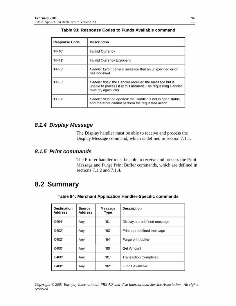
February 2001TAPA Application Architecture Version 2.1
Copyright © 2001 Europay International, PBS A/S and Visa International Service Association. All rightsreserved.
94
Table 93: Response Codes to Funds Available command
Response Code Description
‘FF40’ Invalid Currency
‘FF41’ Invalid Currency Exponent
'FFF3' Handler Error: generic message that an unspecified errorhas occurred.
'FFF5' Handler busy: the Handler received the message but isunable to process it at this moment. The requesting Handlermust try again later
'FFF7' Handler must be opened: the Handler is not in open statusand therefore cannot perform the requested action.
8.1.4 Display MessageThe Display handler must be able to receive and process theDisplay Message command, which is defined in section 7.1.1.
8.1.5 Print commandsThe Printer handler must be able to receive and process the PrintMessage and Purge Print Buffer commands, which are defined insections 7.1.2 and 7.1.4.
8.2 Summary
Table 94: Merchant Application Handler-Specific commands
DestinationAddress
SourceAddress
MessageType
Description
'0404' Any '61' Display a predefined message
'0402' Any '63' Print a predefined message
'0402' Any '64' Purge print buffer
'0400' Any '80' Get Amount
‘0400’ Any ‘81’ Transaction Completed
‘0400’ Any ‘82’ Funds Available
February 2001TAPA Application Architecture Version 2.1
Copyright © 2001 Europay International, PBS A/S and Visa International Service Association. All rightsreserved.
95
9. The PSAM HandlerThe PSAM Handler is responsible for managing the interface toany number of PSAMs that may be resident in the terminal.
The interface between the PSAM Handler and the PSAM is astandard command/response protocol as defined in reference 4,ISO/IEC 7816-4 and reference 7, EMV Part II, section 2.1. ThePSAM is usually implemented as a processor card, where thetechnical interface is either T=0 or T=1, as defined in reference 3,ISO/IEC 7816-3 and reference 7, EMV Part I. However, it ispossible to implement a PSAM in an alternative manner, such as ina Hardware Security Module (HSM) to support a server or otherhigh-volume system.
The PSAM may perform any combination of the followingservices:
• Be the storage medium where application specific code isstored and executed to perform one or more business functionssuch as CEP, EMV or any other application, and henceeffectively run the application.
• Provide specialized cryptography services for one or morepayment applications.
• Provide generic (e.g. ISO/IEC DIS 7816-8) cryptographyservices.
9.1 Message HandlingThe PSAM Handler interface to the PSAM is more complex thanthat between the Card Handler and the processor card. While thePSAM does use the standard command/response protocol, it canhave broader functionality than a normal “smart card” as used for aconsumer card application.
The two principal features of a PSAM, which the PSAM Handlermust cater to, are:
1. The MAD Handler may delegate control over the terminalprocessing to the PSAM. In this case, the PSAM must be ableto send commands to other terminal devices and receive theirresponses. These commands from the PSAM are known as“derived commands”.
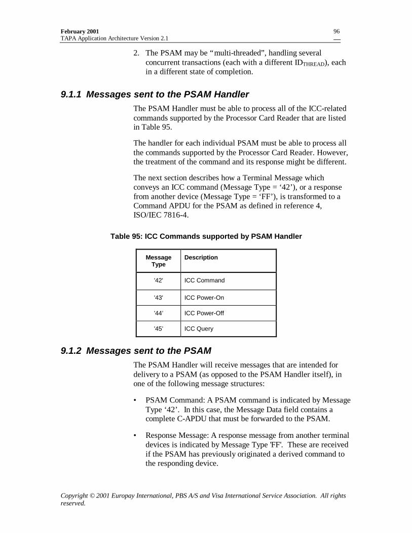
February 2001TAPA Application Architecture Version 2.1
Copyright © 2001 Europay International, PBS A/S and Visa International Service Association. All rightsreserved.
96
2. The PSAM may be “multi-threaded”, handling severalconcurrent transactions (each with a different IDTHREAD), eachin a different state of completion.
9.1.1 Messages sent to the PSAM HandlerThe PSAM Handler must be able to process all of the ICC-relatedcommands supported by the Processor Card Reader that are listedin Table 95.
The handler for each individual PSAM must be able to process allthe commands supported by the Processor Card Reader. However,the treatment of the command and its response might be different.
The next section describes how a Terminal Message whichconveys an ICC command (Message Type = ‘42’), or a responsefrom another device (Message Type = ‘FF’), is transformed to aCommand APDU for the PSAM as defined in reference 4,ISO/IEC 7816-4.
Table 95: ICC Commands supported by PSAM Handler
MessageType
Description
'42' ICC Command
'43' ICC Power-On
'44’ ICC Power-Off
'45’ ICC Query
9.1.2 Messages sent to the PSAMThe PSAM Handler will receive messages that are intended fordelivery to a PSAM (as opposed to the PSAM Handler itself), inone of the following message structures:
• PSAM Command: A PSAM command is indicated by MessageType ‘42’. In this case, the Message Data field contains acomplete C-APDU that must be forwarded to the PSAM.
• Response Message: A response message from another terminaldevices is indicated by Message Type 'FF'. These are receivedif the PSAM has previously originated a derived command tothe responding device.
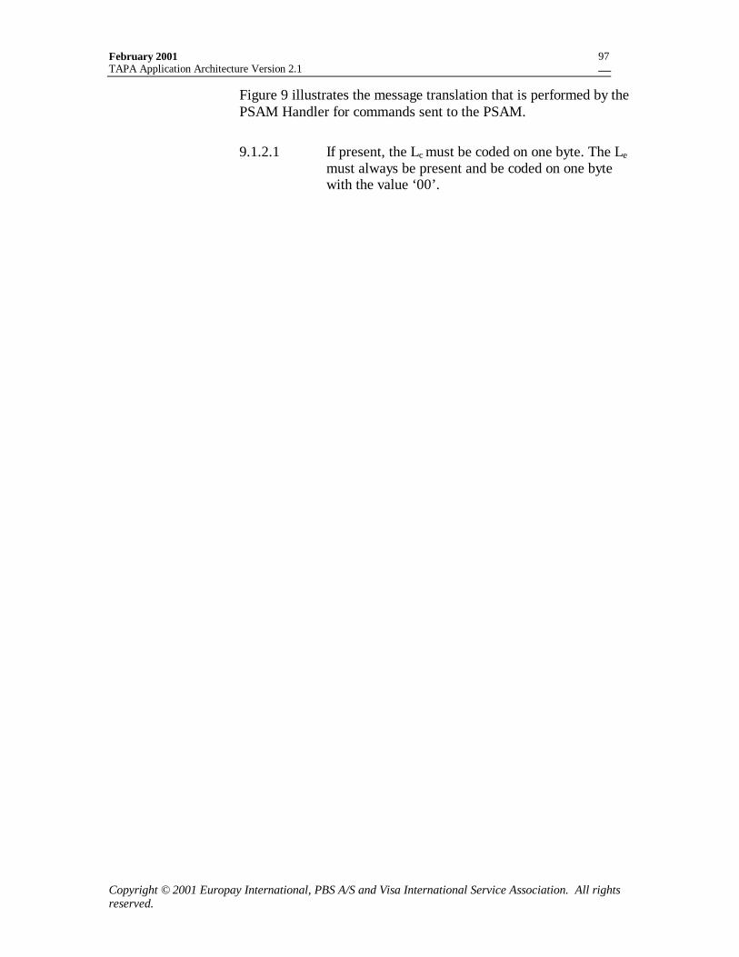
February 2001TAPA Application Architecture Version 2.1
Copyright © 2001 Europay International, PBS A/S and Visa International Service Association. All rightsreserved.
97
Figure 9 illustrates the message translation that is performed by thePSAM Handler for commands sent to the PSAM.
9.1.2.1 If present, the Lc must be coded on one byte. The Lemust always be present and be coded on one bytewith the value ‘00’.
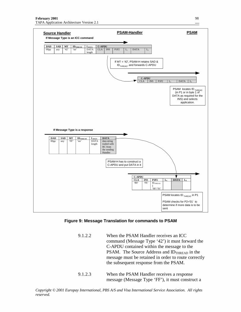
February 2001TAPA Application Architecture Version 2.1
Copyright © 2001 Europay International, PBS A/S and Visa International Service Association. All rightsreserved.
98
PSAM-Handler PSAMSource Handler
DAD SAD MT IDTHREAD LDATA C-APDU00pp any ‘42’ ‘nn’ DATA
lengthCLA INS P1P2 Lc DATA Le
If MT = '42', PSAM-H retains SAD &IDTHREAD, and forwards C-APDU
PSAM locates ID THREAD(in P1 or in byte 1 of
DATA as required for theINS) and selects
application.
C-APDUCLA INS P1P2 Lc DATA Le
If Message Type is an ICC command
If Message Type is a response
DAD SAD MT IDTHREAD LDATA DATA00pp any ‘FF’ ‘nn’ DATA
lengthdata stringtrailed withRC fromthe sendingHandler
PSAM-H has to construct aC-APDU and put DATA in it
PSAM locates ID THREAD in P1
PSAM checks for P2='01' todetermine if more data is to besent
C-APDUCLA INS P1P2 LC DATA LE
‘B0’ ‘FE’ IdTHREAD
||‘00’/’01’
Figure 9: Message Translation for commands to PSAM
9.1.2.2 When the PSAM Handler receives an ICCcommand (Message Type ‘42’) it must forward theC-APDU contained within the message to thePSAM. The Source Address and IDTHREAD in themessage must be retained in order to route correctlythe subsequent response from the PSAM.
9.1.2.3 When the PSAM Handler receives a responsemessage (Message Type ‘FF’), it must construct a
February 2001TAPA Application Architecture Version 2.1
Copyright © 2001 Europay International, PBS A/S and Visa International Service Association. All rightsreserved.
99
Response Command APDU as shown in Table 110and send this command to the PSAM.
9.1.2.4 If the LDATA field in a Response Message exceeds248 bytes, the PSAM Handler must deliver theresponse in multiple response commands. In such aresponse command, the PSAM Handler must set thevalue of P2 equal to ‘01’. If P2 equals ‘01’, then theLc of the response command must be 2481.
9.1.2.5 The PSAM Handler must continue sending responsecommands with P2 = 01 until the remainder of thedata to be sent does not exceed 248 bytes. The finalresponse command of the series must use P2 = 00.
9.1.2.6 If the PSAM Handler receives a command for aPSAM (Message Type ‘42’) and the C-APDUcannot be successfully forwarded to the PSAM, thePSAM Handler must reply to the originator of thecommand with the appropriate Response Code.
9.1.3 Messages from the PSAMThe PSAM will output all messages in the form of ResponseAPDUs. For derived commands being sent to other terminaldevices, the data portion of the Response APDU will be in theTerminal Message format, ready to be delivered to the addressedhandler. For response messages, the PSAM Handler must insertthe correct destination address, and a Response Code, prior toforwarding the message.
Figure 10 illustrates the message translation performed by thePSAM handler when Response APDUs are received from thePSAM.
1 Note that this applies only to response messages (MT = ‘FF’). Some application designs will require thatdata be sent to the PSAM application in commands, which exceed the amount that can be accomodated in asingle C-APDU. In this case, the application design must provide the ability to send the information inmultiple command APDU’s.
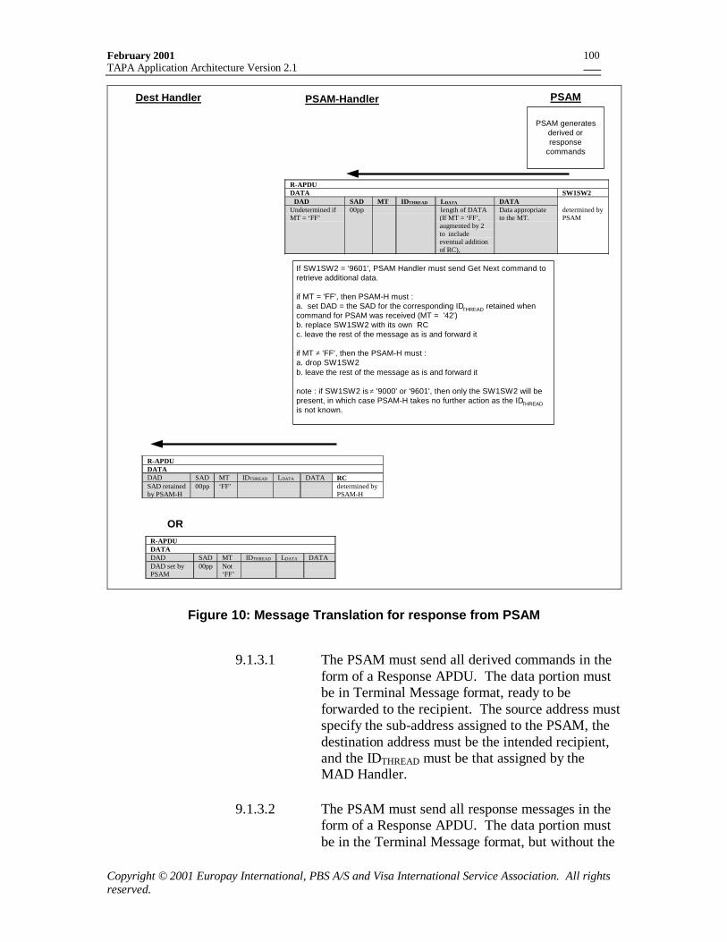
February 2001TAPA Application Architecture Version 2.1
Copyright © 2001 Europay International, PBS A/S and Visa International Service Association. All rightsreserved.
100
PSAM-Handler PSAM
R-APDUDATA SW1SW2
DAD SAD MT IDTHREAD LDATA DATAUndetermined ifMT = ‘FF’
00pp length of DATA(If MT = ‘FF’,augmented by 2to includeeventual additionof RC),
Data appropriateto the MT.
determined byPSAM
If SW1SW2 = '9601', PSAM Handler must send Get Next command toretrieve additional data.
if MT = 'FF', then PSAM-H must :a. set DAD = the SAD for the corresponding IDTHREAD retained whencommand for PSAM was received (MT = '42')b. replace SW1SW2 with its own RCc. leave the rest of the message as is and forward it
if MT ≠ 'FF', then the PSAM-H must :a. drop SW1SW2b. leave the rest of the message as is and forward it
note : if SW1SW2 is ≠ '9000' or '9601', then only the SW1SW2 will bepresent, in which case PSAM-H takes no further action as the IDTHREADis not known.
Dest Handler
R-APDUDATADAD SAD MT IDTHREAD LDATA DATADAD set byPSAM
00pp Not‘FF’
PSAM generatesderived orresponse
commands
R-APDUDATADAD SAD MT IDTHREAD LDATA DATA RCSAD retainedby PSAM-H
00pp ‘FF’ determined byPSAM-H
OR
Figure 10: Message Translation for response from PSAM
9.1.3.1 The PSAM must send all derived commands in theform of a Response APDU. The data portion mustbe in Terminal Message format, ready to beforwarded to the recipient. The source address mustspecify the sub-address assigned to the PSAM, thedestination address must be the intended recipient,and the IDTHREAD must be that assigned by theMAD Handler.
9.1.3.2 The PSAM must send all response messages in theform of a Response APDU. The data portion mustbe in the Terminal Message format, but without the
February 2001TAPA Application Architecture Version 2.1
Copyright © 2001 Europay International, PBS A/S and Visa International Service Association. All rightsreserved.
101
Response Code. The source address must specifythe sub-address assigned to the PSAM, and theIDTHREAD must be that assigned by the MADHandler.
9.1.3.3 If the amount of data to send is greater than 252bytes, the PSAM must deliver the data in multipleresponse APDUs. All but the last one haveSW1SW1 = ‘9601’, indicating more data is tocome. The last response APDU must have statusbytes SW1SW2 = ‘9000’, indicating all data is sentsuccessfully.
9.1.3.4 On receipt of an SW1SW2 = ‘9601’, the PSAMHandler must send a “Get Next” command,requesting further data. The Get Next command isdetailed in Section 10.3.6.
9.1.3.5 The PSAM Handler must concatenate the series ofresponses until all data is received or the Get Nextcommand is rejected.
9.1.3.6 When the PSAM Handler has received the completeresponse from the PSAM, the PSAM handler mustforward the message to the assigned destinationaddress.
If the Message Type is different from ‘FF’, thePSAM Handler passes the message unaltered to therouter.
If the Message Type = ‘FF’, then prior toforwarding the message, the followingmodifications must be made:
• the PSAM Handler must set the destinationaddress to the source address saved from the lastPSAM command (Message Type = ‘42’)received for the specified IDTHREAD.
• the PSAM Handler must insert the two byteResponse Code = ‘0000’.
9.1.3.7 If the response from the PSAM does not contain avalid Terminal Message (that is, the associatedThread cannot be determined, and the destination is
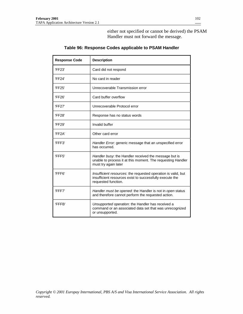
February 2001TAPA Application Architecture Version 2.1
Copyright © 2001 Europay International, PBS A/S and Visa International Service Association. All rightsreserved.
102
either not specified or cannot be derived) the PSAMHandler must not forward the message.
Table 96: Response Codes applicable to PSAM Handler
Response Code Description
'FF23' Card did not respond
'FF24' No card in reader
'FF25' Unrecoverable Transmission error
'FF26' Card buffer overflow
'FF27' Unrecoverable Protocol error
'FF28' Response has no status words
'FF29' Invalid buffer
'FF2A' Other card error
'FFF3' Handler Error: generic message that an unspecified errorhas occurred.
'FFF5' Handler busy: the Handler received the message but isunable to process it at this moment. The requesting Handlermust try again later
'FFF6' Insufficient resources: the requested operation is valid, butinsufficient resources exist to successfully execute therequested function.
'FFF7' Handler must be opened: the Handler is not in open statusand therefore cannot perform the requested action.
‘FFFB’ Unsupported operation: the Handler has received acommand or an associated data set that was unrecognizedor unsupported.
February 2001TAPA Application Architecture Version 2.1
Copyright © 2001 Europay International, PBS A/S and Visa International Service Association. All rightsreserved.
103
10. PSAM ApplicationsA PSAM receives incoming commands, and invokes the correctapplication for processing based on the contents of the command.
The specific requirements for individual PSAM applications aredefined in application-specific specifications. This section definesonly the requirements for generic functionality, common to allapplications.
10.1 PSAM InitializationAfter a terminal resets a PSAM, the terminal applications musteach initialize the corresponding applications in the PSAM(s) bysending the Start-up PSAM command. This command allows theterminal to provide the PSAM with its current assigned “sub-address”, which must be included in subsequent messagesoriginated by the PSAM application.
The response to the command contains the PSAM identification(RIDPSAM||IDPSAMCREATOR||IDPSAM) as a first field and otherapplication specific data following that.
Following the start-up command, each terminal application mayobtain a list of all AIDs, which can be processed by that specificPSAM application.
Using the list of AIDs supported by the different PSAMapplications, the MAD-Handler can determine the set of AIDsmutually supported by the terminal and PSAM, and which PSAMapplication is to be used for each card AID.
The MAD-Handler applications must each perform any start-upprocedures required by the associated specifications. Those start-up procedures will be defined in the application specifications.These application-specific requirements are outside the scope ofthis document.
This section provides an overview of the PSAM initializationsequence. The overall initialization process is described in section5.2.
10.1.1.1 On reset, the PSAM will respond with the ATR,including the Historical Bytes, if any.
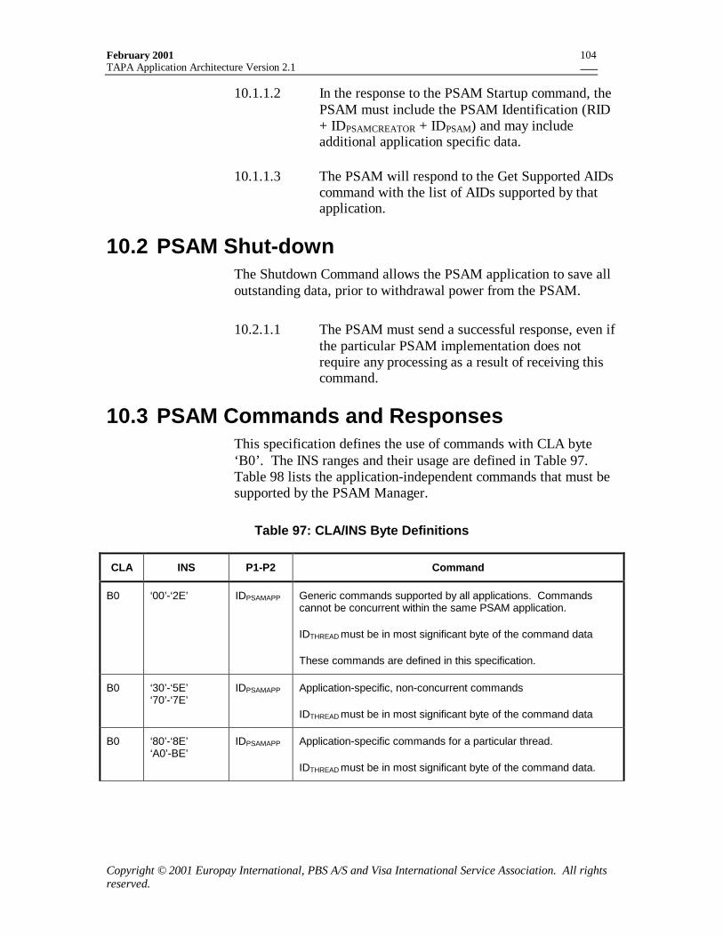
February 2001TAPA Application Architecture Version 2.1
Copyright © 2001 Europay International, PBS A/S and Visa International Service Association. All rightsreserved.
104
10.1.1.2 In the response to the PSAM Startup command, thePSAM must include the PSAM Identification (RID+ IDPSAMCREATOR + IDPSAM) and may includeadditional application specific data.
10.1.1.3 The PSAM will respond to the Get Supported AIDscommand with the list of AIDs supported by thatapplication.
10.2 PSAM Shut-downThe Shutdown Command allows the PSAM application to save alloutstanding data, prior to withdrawal power from the PSAM.
10.2.1.1 The PSAM must send a successful response, even ifthe particular PSAM implementation does notrequire any processing as a result of receiving thiscommand.
10.3 PSAM Commands and ResponsesThis specification defines the use of commands with CLA byte‘B0’. The INS ranges and their usage are defined in Table 97.Table 98 lists the application-independent commands that must besupported by the PSAM Manager.
Table 97: CLA/INS Byte Definitions
CLA INS P1-P2 Command
B0 ‘00’-‘2E’ IDPSAMAPP Generic commands supported by all applications. Commandscannot be concurrent within the same PSAM application.
IDTHREAD must be in most significant byte of the command data
These commands are defined in this specification.
B0 ‘30’-‘5E’‘70’-‘7E’
IDPSAMAPP Application-specific, non-concurrent commands
IDTHREAD must be in most significant byte of the command data
B0 ‘80’-‘8E’‘A0’-BE’
IDPSAMAPP Application-specific commands for a particular thread.
IDTHREAD must be in most significant byte of the command data.
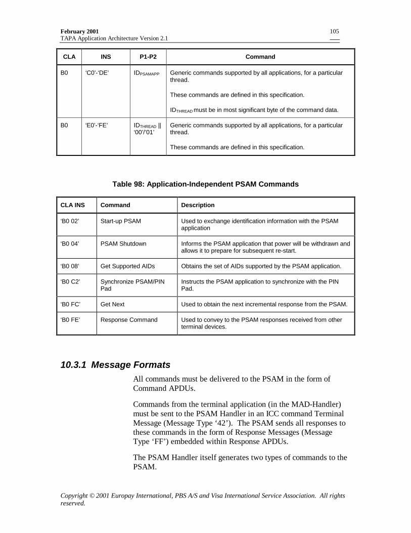
February 2001TAPA Application Architecture Version 2.1
Copyright © 2001 Europay International, PBS A/S and Visa International Service Association. All rightsreserved.
105
CLA INS P1-P2 Command
B0 ‘C0’-‘DE’ IDPSAMAPP Generic commands supported by all applications, for a particularthread.
These commands are defined in this specification.
IDTHREAD must be in most significant byte of the command data.
B0 ‘E0’-‘FE’ IDTHREAD ||‘00’/’01’
Generic commands supported by all applications, for a particularthread.
These commands are defined in this specification.
Table 98: Application-Independent PSAM Commands
CLA INS Command Description
‘B0 02’ Start-up PSAM Used to exchange identification information with the PSAMapplication
‘B0 04’ PSAM Shutdown Informs the PSAM application that power will be withdrawn andallows it to prepare for subsequent re-start.
‘B0 08’ Get Supported AIDs Obtains the set of AIDs supported by the PSAM application.
‘B0 C2’ Synchronize PSAM/PINPad
Instructs the PSAM application to synchronize with the PINPad.
‘B0 FC’ Get Next Used to obtain the next incremental response from the PSAM.
‘B0 FE’ Response Command Used to convey to the PSAM responses received from otherterminal devices.
10.3.1 Message FormatsAll commands must be delivered to the PSAM in the form ofCommand APDUs.
Commands from the terminal application (in the MAD-Handler)must be sent to the PSAM Handler in an ICC command TerminalMessage (Message Type ‘42’). The PSAM sends all responses tothese commands in the form of Response Messages (MessageType ‘FF’) embedded within Response APDUs.
The PSAM Handler itself generates two types of commands to thePSAM.
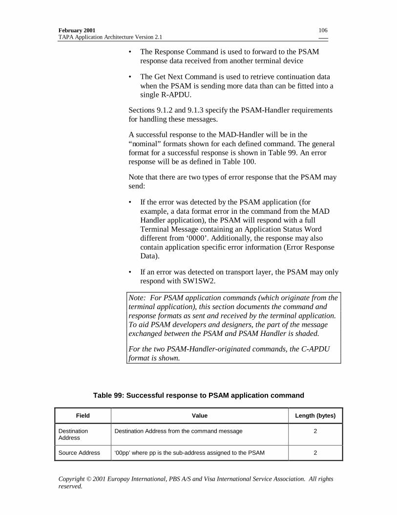
February 2001TAPA Application Architecture Version 2.1
Copyright © 2001 Europay International, PBS A/S and Visa International Service Association. All rightsreserved.
106
• The Response Command is used to forward to the PSAMresponse data received from another terminal device
• The Get Next Command is used to retrieve continuation datawhen the PSAM is sending more data than can be fitted into asingle R-APDU.
Sections 9.1.2 and 9.1.3 specify the PSAM-Handler requirementsfor handling these messages.
A successful response to the MAD-Handler will be in the“nominal” formats shown for each defined command. The generalformat for a successful response is shown in Table 99. An errorresponse will be as defined in Table 100.
Note that there are two types of error response that the PSAM maysend:
• If the error was detected by the PSAM application (forexample, a data format error in the command from the MADHandler application), the PSAM will respond with a fullTerminal Message containing an Application Status Worddifferent from ‘0000’. Additionally, the response may alsocontain application specific error information (Error ResponseData).
• If an error was detected on transport layer, the PSAM may onlyrespond with SW1SW2.
Note: For PSAM application commands (which originate from theterminal application), this section documents the command andresponse formats as sent and received by the terminal application.To aid PSAM developers and designers, the part of the messageexchanged between the PSAM and PSAM Handler is shaded.
For the two PSAM-Handler-originated commands, the C-APDUformat is shown.
Table 99: Successful response to PSAM application command
Field Value Length (bytes)
DestinationAddress
Destination Address from the command message 2
Source Address ‘00pp’ where pp is the sub-address assigned to the PSAM 2
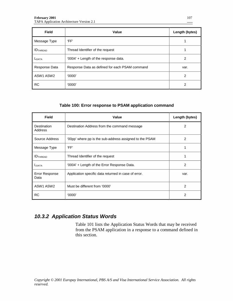
February 2001TAPA Application Architecture Version 2.1
Copyright © 2001 Europay International, PBS A/S and Visa International Service Association. All rightsreserved.
107
Field Value Length (bytes)
Message Type ‘FF’ 1
IDTHREAD Thread Identifier of the request 1
LDATA ‘0004’ + Length of the response data. 2
Response Data Response Data as defined for each PSAM command var.
ASW1 ASW2 ‘0000’ 2
RC ‘0000’ 2
Table 100: Error response to PSAM application command
Field Value Length (bytes)
DestinationAddress
Destination Address from the command message 2
Source Address ‘00pp’ where pp is the sub-address assigned to the PSAM 2
Message Type ‘FF’ 1
IDTHREAD Thread Identifier of the request 1
LDATA ‘0004’ + Length of the Error Response Data. 2
Error ResponseData
Application specific data returned in case of error. var.
ASW1 ASW2 Must be different from ‘0000’ 2
RC ‘0000’ 2
10.3.2 Application Status WordsTable 101 lists the Application Status Words that may be receivedfrom the PSAM application in a response to a command defined inthis section.
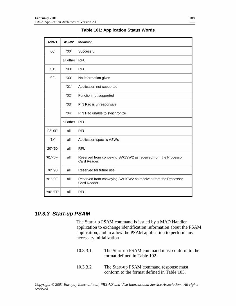
February 2001TAPA Application Architecture Version 2.1
Copyright © 2001 Europay International, PBS A/S and Visa International Service Association. All rightsreserved.
108
Table 101: Application Status Words
ASW1 ASW2 Meaning
‘00’ ‘00’ Successful
all other RFU
‘01’ ‘00’ RFU
‘02’ ‘00’ No information given
‘01’ Application not supported
’02’ Function not supported
‘03’ PIN Pad is unresponsive
‘04’ PIN Pad unable to synchronize
all other RFU
‘03’-0F’ all RFU
‘1x’ all Application-specific ASWs
‘20’-‘60’ all RFU
‘61’-‘6F’ all Reserved from conveying SW1SW2 as received from the ProcessorCard Reader.
‘70’ ‘90’ all Reserved for future use
‘91’-‘9F’ all Reserved from conveying SW1SW2 as received from the ProcessorCard Reader.
‘A0’-‘FF’ all RFU
10.3.3 Start-up PSAMThe Start-up PSAM command is issued by a MAD Handlerapplication to exchange identification information about the PSAMapplication, and to allow the PSAM application to perform anynecessary initialization
10.3.3.1 The Start-up PSAM command must conform to theformat defined in Table 102.
10.3.3.2 The Start-up PSAM command response mustconform to the format defined in Table 103.
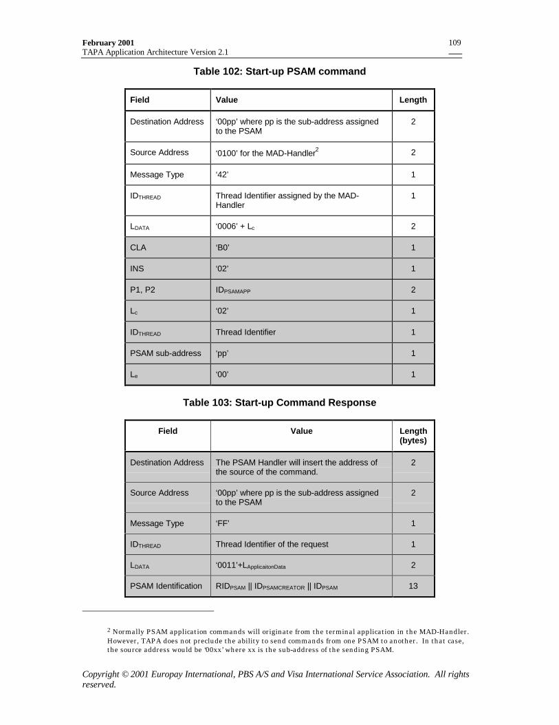
February 2001TAPA Application Architecture Version 2.1
Copyright © 2001 Europay International, PBS A/S and Visa International Service Association. All rightsreserved.
109
Table 102: Start-up PSAM command
Field Value Length
Destination Address ‘00pp’ where pp is the sub-address assignedto the PSAM
2
Source Address ‘0100’ for the MAD-Handler2 2
Message Type ‘42’ 1
IDTHREAD Thread Identifier assigned by the MAD-Handler
1
LDATA ‘0006’ + Lc 2
CLA ‘B0’ 1
INS ‘02’ 1
P1, P2 IDPSAMAPP 2
Lc ‘02’ 1
IDTHREAD Thread Identifier 1
PSAM sub-address ‘pp’ 1
Le ‘00’ 1
Table 103: Start-up Command Response
Field Value Length(bytes)
Destination Address The PSAM Handler will insert the address ofthe source of the command.
2
Source Address ‘00pp’ where pp is the sub-address assignedto the PSAM
2
Message Type ‘FF’ 1
IDTHREAD Thread Identifier of the request 1
LDATA ‘0011’+LApplicaitonData 2
PSAM Identification RIDPSAM || IDPSAMCREATOR || IDPSAM 13
2 Normally PSAM application commands will originate from the terminal application in the MAD-Handler.However, TAPA does not preclude the ability to send commands from one PSAM to another. In that case,the source address would be ‘00xx’ where xx is the sub-address of the sending PSAM.
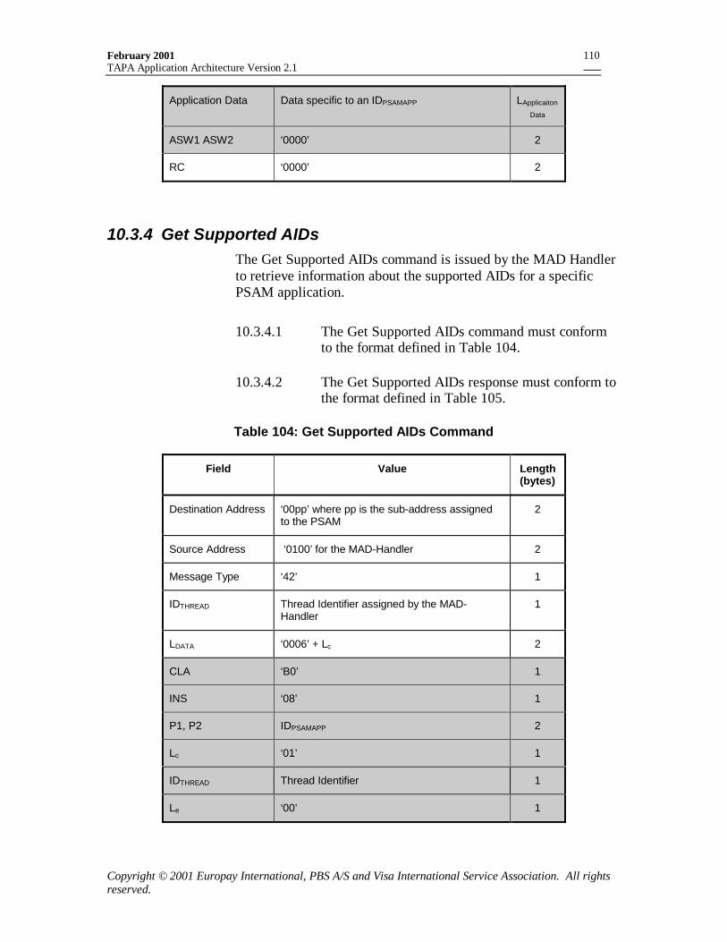
February 2001TAPA Application Architecture Version 2.1
Copyright © 2001 Europay International, PBS A/S and Visa International Service Association. All rightsreserved.
110
Application Data Data specific to an IDPSAMAPP LApplicaiton
Data
ASW1 ASW2 ‘0000’ 2
RC ‘0000’ 2
10.3.4 Get Supported AIDsThe Get Supported AIDs command is issued by the MAD Handlerto retrieve information about the supported AIDs for a specificPSAM application.
10.3.4.1 The Get Supported AIDs command must conformto the format defined in Table 104.
10.3.4.2 The Get Supported AIDs response must conform tothe format defined in Table 105.
Table 104: Get Supported AIDs Command
Field Value Length(bytes)
Destination Address ‘00pp’ where pp is the sub-address assignedto the PSAM
2
Source Address ‘0100’ for the MAD-Handler 2
Message Type ‘42’ 1
IDTHREAD Thread Identifier assigned by the MAD-Handler
1
LDATA ‘0006’ + Lc 2
CLA ‘B0’ 1
INS ‘08’ 1
P1, P2 IDPSAMAPP 2
Lc ‘01’ 1
IDTHREAD Thread Identifier 1
Le ‘00’ 1
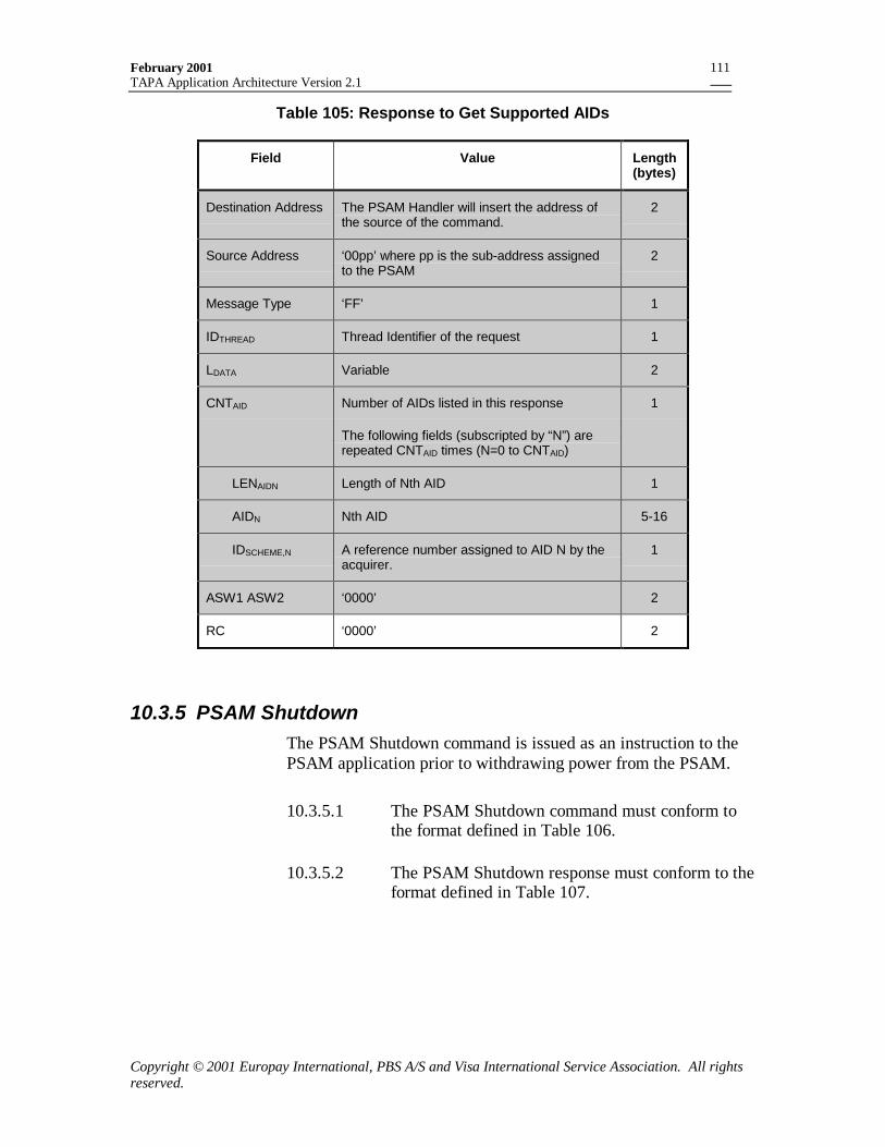
February 2001TAPA Application Architecture Version 2.1
Copyright © 2001 Europay International, PBS A/S and Visa International Service Association. All rightsreserved.
111
Table 105: Response to Get Supported AIDs
Field Value Length(bytes)
Destination Address The PSAM Handler will insert the address ofthe source of the command.
2
Source Address ‘00pp’ where pp is the sub-address assignedto the PSAM
2
Message Type ‘FF’ 1
IDTHREAD Thread Identifier of the request 1
LDATA Variable 2
CNTAID Number of AIDs listed in this response
The following fields (subscripted by “N”) arerepeated CNTAID times (N=0 to CNTAID)
1
LENAIDN Length of Nth AID 1
AIDN Nth AID 5-16
IDSCHEME,N A reference number assigned to AID N by theacquirer.
1
ASW1 ASW2 ‘0000’ 2
RC ‘0000’ 2
10.3.5 PSAM ShutdownThe PSAM Shutdown command is issued as an instruction to thePSAM application prior to withdrawing power from the PSAM.
10.3.5.1 The PSAM Shutdown command must conform tothe format defined in Table 106.
10.3.5.2 The PSAM Shutdown response must conform to theformat defined in Table 107.
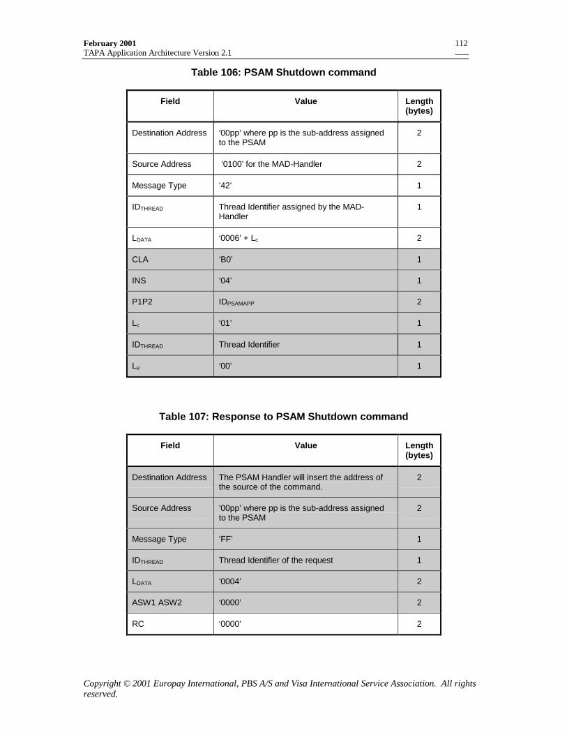
February 2001TAPA Application Architecture Version 2.1
Copyright © 2001 Europay International, PBS A/S and Visa International Service Association. All rightsreserved.
112
Table 106: PSAM Shutdown command
Field Value Length(bytes)
Destination Address ‘00pp’ where pp is the sub-address assignedto the PSAM
2
Source Address ‘0100’ for the MAD-Handler 2
Message Type ‘42’ 1
IDTHREAD Thread Identifier assigned by the MAD-Handler
1
LDATA ‘0006’ + Lc 2
CLA ‘B0’ 1
INS ‘04’ 1
P1P2 IDPSAMAPP 2
Lc ‘01’ 1
IDTHREAD Thread Identifier 1
Le ‘00’ 1
Table 107: Response to PSAM Shutdown command
Field Value Length(bytes)
Destination Address The PSAM Handler will insert the address ofthe source of the command.
2
Source Address ‘00pp’ where pp is the sub-address assignedto the PSAM
2
Message Type ‘FF’ 1
IDTHREAD Thread Identifier of the request 1
LDATA ‘0004’ 2
ASW1 ASW2 ‘0000’ 2
RC ‘0000’ 2
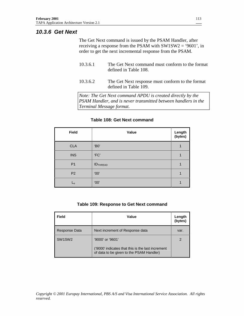
February 2001TAPA Application Architecture Version 2.1
Copyright © 2001 Europay International, PBS A/S and Visa International Service Association. All rightsreserved.
113
10.3.6 Get NextThe Get Next command is issued by the PSAM Handler, afterreceiving a response from the PSAM with SW1SW2 = ‘9601’, inorder to get the next incremental response from the PSAM.
10.3.6.1 The Get Next command must conform to the formatdefined in Table 108.
10.3.6.2 The Get Next response must conform to the formatdefined in Table 109.
Note: The Get Next command APDU is created directly by thePSAM Handler, and is never transmitted between handlers in theTerminal Message format.
Table 108: Get Next command
Field Value Length(bytes)
CLA ‘B0’ 1
INS ‘FC’ 1
P1 IDTHREAD 1
P2 ‘00’ 1
Le ‘00’ 1
Table 109: Response to Get Next command
Field Value Length(bytes)
Response Data Next increment of Response data var.
SW1SW2 ’9000’ or ’9601’
(‘9000’ indicates that this is the last incrementof data to be given to the PSAM Handler)
2
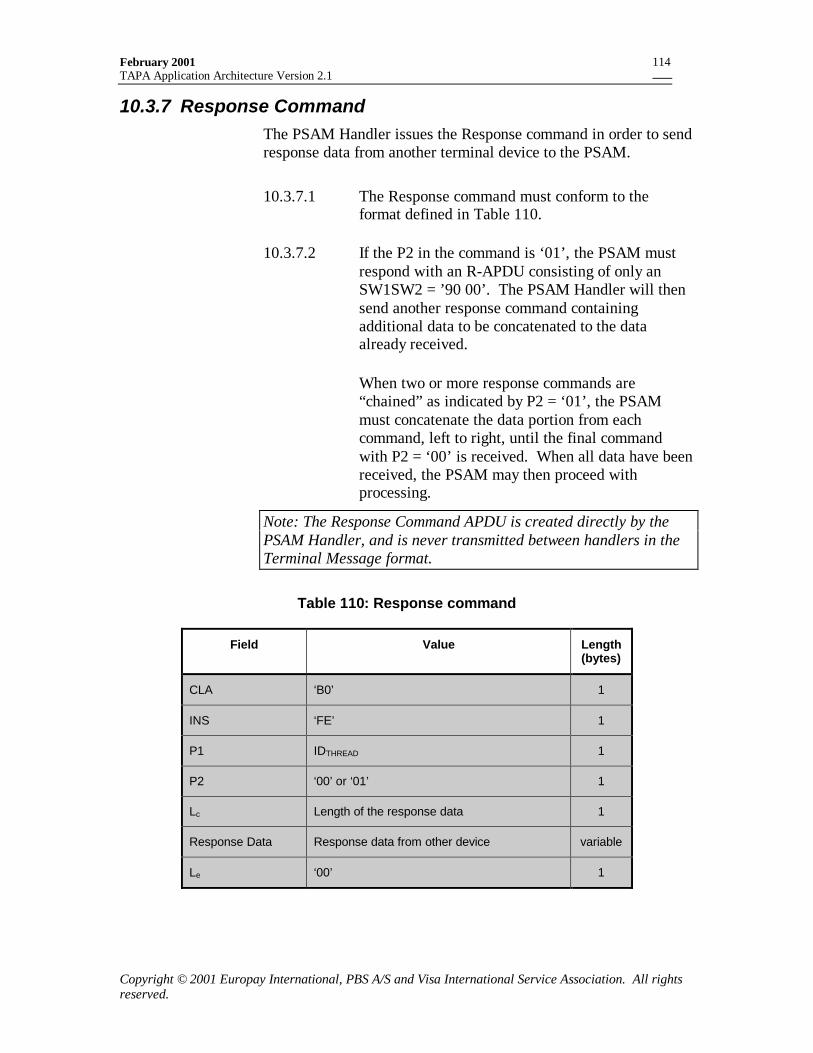
February 2001TAPA Application Architecture Version 2.1
Copyright © 2001 Europay International, PBS A/S and Visa International Service Association. All rightsreserved.
114
10.3.7 Response CommandThe PSAM Handler issues the Response command in order to sendresponse data from another terminal device to the PSAM.
10.3.7.1 The Response command must conform to theformat defined in Table 110.
10.3.7.2 If the P2 in the command is ‘01’, the PSAM mustrespond with an R-APDU consisting of only anSW1SW2 = ’90 00’. The PSAM Handler will thensend another response command containingadditional data to be concatenated to the dataalready received.
When two or more response commands are“chained” as indicated by P2 = ‘01’, the PSAMmust concatenate the data portion from eachcommand, left to right, until the final commandwith P2 = ‘00’ is received. When all data have beenreceived, the PSAM may then proceed withprocessing.
Note: The Response Command APDU is created directly by thePSAM Handler, and is never transmitted between handlers in theTerminal Message format.
Table 110: Response command
Field Value Length(bytes)
CLA ‘B0’ 1
INS ‘FE’ 1
P1 IDTHREAD 1
P2 ‘00’ or ‘01’ 1
Lc Length of the response data 1
Response Data Response data from other device variable
Le ‘00’ 1
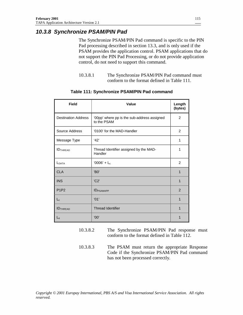
February 2001TAPA Application Architecture Version 2.1
Copyright © 2001 Europay International, PBS A/S and Visa International Service Association. All rightsreserved.
115
10.3.8 Synchronize PSAM/PIN PadThe Synchronize PSAM/PIN Pad command is specific to the PINPad processing described in section 13.3, and is only used if thePSAM provides the application control. PSAM applications that donot support the PIN Pad Processing, or do not provide applicationcontrol, do not need to support this command.
10.3.8.1 The Synchronize PSAM/PIN Pad command mustconform to the format defined in Table 111.
Table 111: Synchronize PSAM/PIN Pad command
Field Value Length(bytes)
Destination Address ‘00pp’ where pp is the sub-address assignedto the PSAM
2
Source Address ‘0100’ for the MAD-Handler 2
Message Type ‘42’ 1
IDTHREAD Thread Identifier assigned by the MAD-Handler
1
LDATA ‘0006’ + Lc 2
CLA 'B0' 1
INS 'C2' 1
P1P2 IDPSAMAPP 2
Lc ‘01’ 1
IDTHREAD Thread Identifier 1
Le ’00’ 1
10.3.8.2 The Synchronize PSAM/PIN Pad response mustconform to the format defined in Table 112.
10.3.8.3 The PSAM must return the appropriate ResponseCode if the Synchronize PSAM/PIN Pad commandhas not been processed correctly.
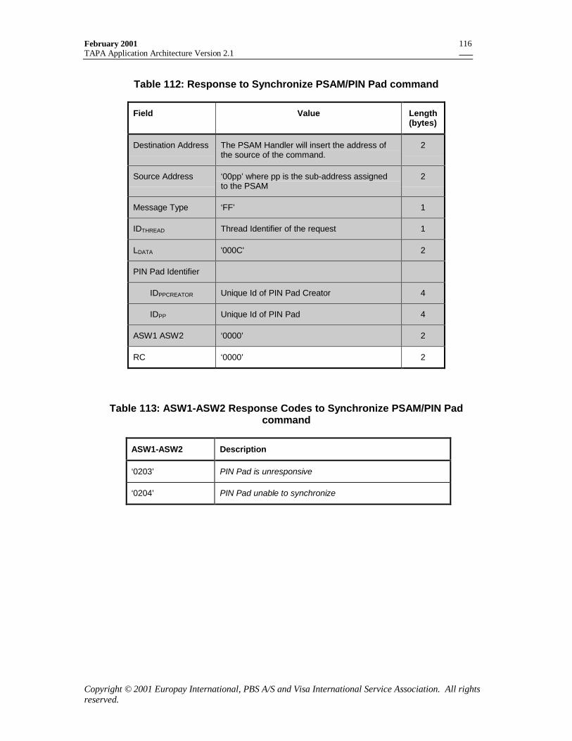
February 2001TAPA Application Architecture Version 2.1
Copyright © 2001 Europay International, PBS A/S and Visa International Service Association. All rightsreserved.
116
Table 112: Response to Synchronize PSAM/PIN Pad command
Field Value Length(bytes)
Destination Address The PSAM Handler will insert the address ofthe source of the command.
2
Source Address ‘00pp’ where pp is the sub-address assignedto the PSAM
2
Message Type ‘FF’ 1
IDTHREAD Thread Identifier of the request 1
LDATA '000C' 2
PIN Pad Identifier
IDPPCREATOR Unique Id of PIN Pad Creator 4
IDPP Unique Id of PIN Pad 4
ASW1 ASW2 ‘0000’ 2
RC ‘0000’ 2
Table 113: ASW1-ASW2 Response Codes to Synchronize PSAM/PIN Padcommand
ASW1-ASW2 Description
‘0203’ PIN Pad is unresponsive
‘0204’ PIN Pad unable to synchronize
February 2001TAPA Application Architecture Version 2.1
Copyright © 2001 Europay International, PBS A/S and Visa International Service Association. All rightsreserved.
117
11. The Data Store HandlerThe Data Store Handler is responsible for managing the non-volatile memory of the terminal.
11.1 General requirementsThe Data Store Handler only recognizes the common Handlercommands: Open Handler and Close Handler.
11.2 Messages sent to the Data Store HandlerThis section provides a list of additional commands that should beaccepted and processed by the Data Store Handler.
11.2.1 File Management
11.2.1.1 The Data Store Handler must provide filemanagement services as requested by other terminalcomponents (typically MAD-Handler and PSAMapplications). Terminal components must be able torequest the storage of both keyed and non-keyedrecords grouped into files.
For the purposes of this section, a “record” isdefined to consist of a string of “key data” (whichmay have length zero) and a string of “record data”.
11.2.1.2 If a keyed file is created, then each record stored inthat file must have a unique key.
11.2.1.3 If a service is requested, it is fulfilled either entirelyor not at all.
11.2.2 Create FileThe Create File command is used to create one or more files withinthe terminal Data Store.
11.2.2.1 The Create File command must conform to theformat defined in Table 114.

February 2001TAPA Application Architecture Version 2.1
Copyright © 2001 Europay International, PBS A/S and Visa International Service Association. All rightsreserved.
118
Table 114: Create File command
Field Value Length
Destination Address '0500' 2
Source Address Any 2
Message Type ‘90’ 1
IDTHREAD Thread Identifier assigned by the MAD-Handler
1
LDATA '0004' 2
NUMFILE Number of files of this type that should becreated
1
LENSKEY Maximum length of search key to associatewith record. (‘00’ if no search key is used).
1
LENREC Maximum length of a record 2
11.2.2.2 The Create File response must conform to theformat defined in Table 115.
11.2.2.3 If there is insufficient memory to successfullyprocess the Create File command, the Data StoreHandler must return a Response Code indicating“Insufficient resources”.
Table 115: Response to Create File command
Field Value Length
Destination Address Any 2
Source Address '0500' 2
Message Type 'FF' 1
IDTHREAD Thread Identifier of the request 1
LDATA 2+2*NUM FILE 2
File Identifiers N file identifiers of the created files 2 *NUMFILE
Response Code Response Code 2
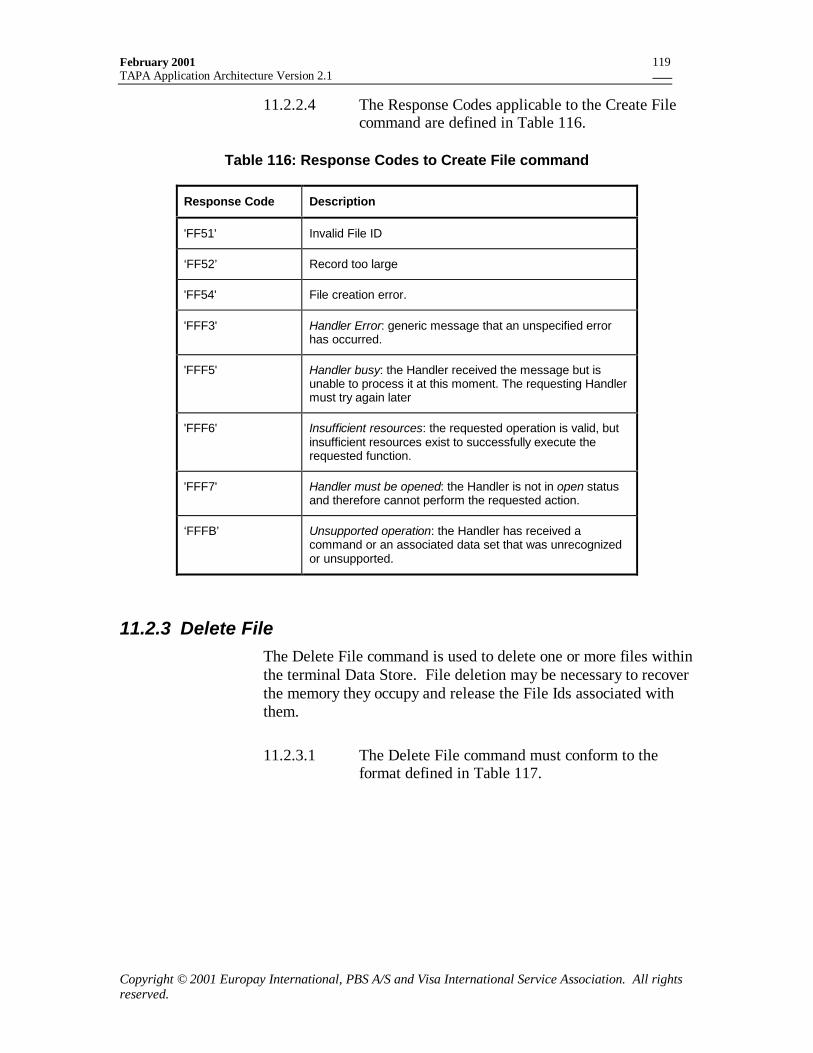
February 2001TAPA Application Architecture Version 2.1
Copyright © 2001 Europay International, PBS A/S and Visa International Service Association. All rightsreserved.
119
11.2.2.4 The Response Codes applicable to the Create Filecommand are defined in Table 116.
Table 116: Response Codes to Create File command
Response Code Description
'FF51' Invalid File ID
‘FF52’ Record too large
'FF54' File creation error.
'FFF3' Handler Error: generic message that an unspecified errorhas occurred.
'FFF5' Handler busy: the Handler received the message but isunable to process it at this moment. The requesting Handlermust try again later
'FFF6' Insufficient resources: the requested operation is valid, butinsufficient resources exist to successfully execute therequested function.
'FFF7' Handler must be opened: the Handler is not in open statusand therefore cannot perform the requested action.
‘FFFB’ Unsupported operation: the Handler has received acommand or an associated data set that was unrecognizedor unsupported.
11.2.3 Delete FileThe Delete File command is used to delete one or more files withinthe terminal Data Store. File deletion may be necessary to recoverthe memory they occupy and release the File Ids associated withthem.
11.2.3.1 The Delete File command must conform to theformat defined in Table 117.
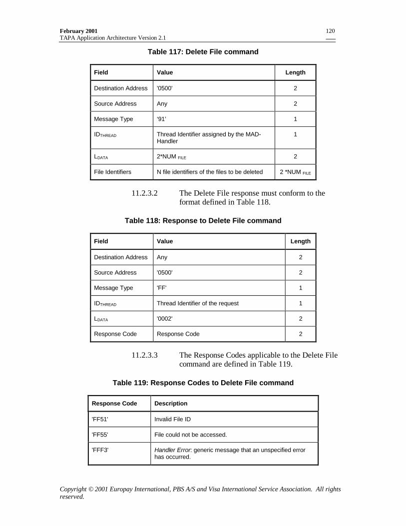
February 2001TAPA Application Architecture Version 2.1
Copyright © 2001 Europay International, PBS A/S and Visa International Service Association. All rightsreserved.
120
Table 117: Delete File command
Field Value Length
Destination Address '0500' 2
Source Address Any 2
Message Type ‘91’ 1
IDTHREAD Thread Identifier assigned by the MAD-Handler
1
LDATA 2*NUM FILE 2
File Identifiers N file identifiers of the files to be deleted 2 *NUM FILE
11.2.3.2 The Delete File response must conform to theformat defined in Table 118.
Table 118: Response to Delete File command
Field Value Length
Destination Address Any 2
Source Address '0500' 2
Message Type 'FF' 1
IDTHREAD Thread Identifier of the request 1
LDATA '0002' 2
Response Code Response Code 2
11.2.3.3 The Response Codes applicable to the Delete Filecommand are defined in Table 119.
Table 119: Response Codes to Delete File command
Response Code Description
'FF51' Invalid File ID
'FF55' File could not be accessed.
'FFF3' Handler Error: generic message that an unspecified errorhas occurred.
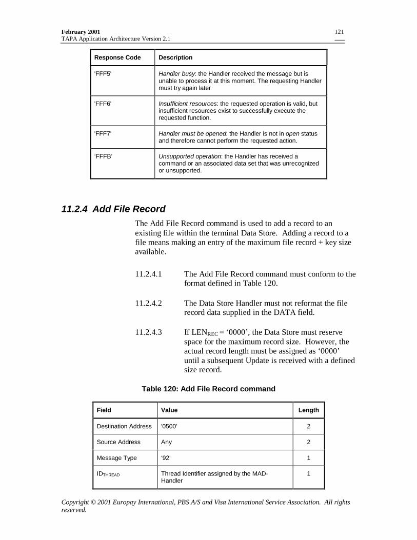
February 2001TAPA Application Architecture Version 2.1
Copyright © 2001 Europay International, PBS A/S and Visa International Service Association. All rightsreserved.
121
Response Code Description
'FFF5' Handler busy: the Handler received the message but isunable to process it at this moment. The requesting Handlermust try again later
'FFF6' Insufficient resources: the requested operation is valid, butinsufficient resources exist to successfully execute therequested function.
'FFF7' Handler must be opened: the Handler is not in open statusand therefore cannot perform the requested action.
‘FFFB’ Unsupported operation: the Handler has received acommand or an associated data set that was unrecognizedor unsupported.
11.2.4 Add File RecordThe Add File Record command is used to add a record to anexisting file within the terminal Data Store. Adding a record to afile means making an entry of the maximum file record + key sizeavailable.
11.2.4.1 The Add File Record command must conform to theformat defined in Table 120.
11.2.4.2 The Data Store Handler must not reformat the filerecord data supplied in the DATA field.
11.2.4.3 If LENREC = ‘0000’, the Data Store must reservespace for the maximum record size. However, theactual record length must be assigned as ‘0000’until a subsequent Update is received with a definedsize record.
Table 120: Add File Record command
Field Value Length
Destination Address '0500' 2
Source Address Any 2
Message Type ‘92’ 1
IDTHREAD Thread Identifier assigned by the MAD-Handler
1
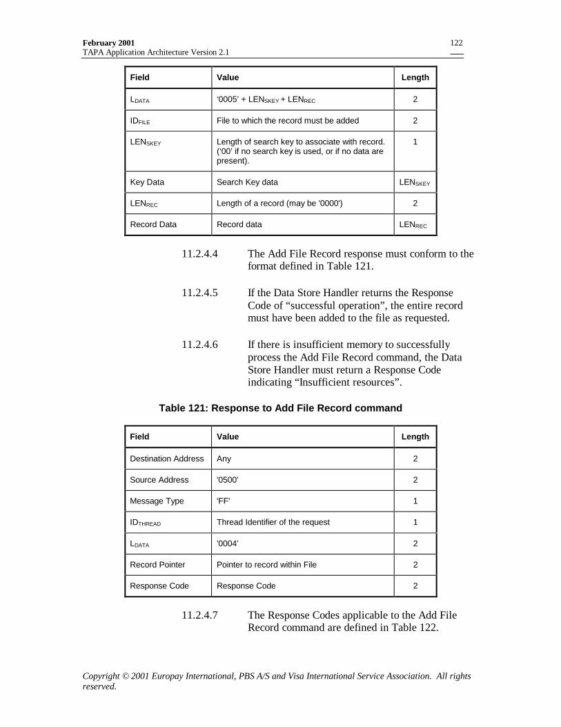
February 2001TAPA Application Architecture Version 2.1
Copyright © 2001 Europay International, PBS A/S and Visa International Service Association. All rightsreserved.
122
Field Value Length
LDATA ‘0005’ + LENSKEY + LENREC 2
IDFILE File to which the record must be added 2
LENSKEY Length of search key to associate with record.(‘00’ if no search key is used, or if no data arepresent).
1
Key Data Search Key data LENSKEY
LENREC Length of a record (may be '0000') 2
Record Data Record data LENREC
11.2.4.4 The Add File Record response must conform to theformat defined in Table 121.
11.2.4.5 If the Data Store Handler returns the ResponseCode of “successful operation”, the entire recordmust have been added to the file as requested.
11.2.4.6 If there is insufficient memory to successfullyprocess the Add File Record command, the DataStore Handler must return a Response Codeindicating “Insufficient resources”.
Table 121: Response to Add File Record command
Field Value Length
Destination Address Any 2
Source Address '0500' 2
Message Type 'FF' 1
IDTHREAD Thread Identifier of the request 1
LDATA '0004' 2
Record Pointer Pointer to record within File 2
Response Code Response Code 2
11.2.4.7 The Response Codes applicable to the Add FileRecord command are defined in Table 122.
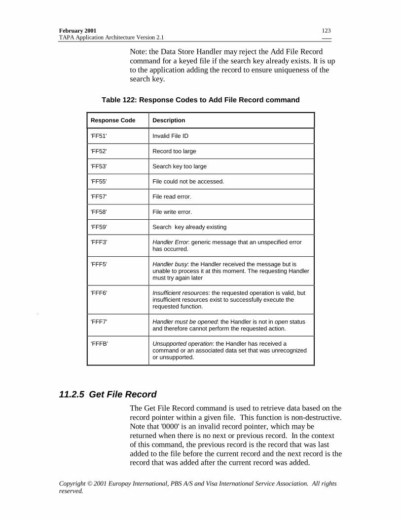
February 2001TAPA Application Architecture Version 2.1
Copyright © 2001 Europay International, PBS A/S and Visa International Service Association. All rightsreserved.
123
Note: the Data Store Handler may reject the Add File Recordcommand for a keyed file if the search key already exists. It is upto the application adding the record to ensure uniqueness of thesearch key.
Table 122: Response Codes to Add File Record command
Response Code Description
'FF51' Invalid File ID
'FF52' Record too large
'FF53' Search key too large
'FF55' File could not be accessed.
'FF57' File read error.
'FF58' File write error.
‘FF59’ Search key already existing
'FFF3' Handler Error: generic message that an unspecified errorhas occurred.
'FFF5' Handler busy: the Handler received the message but isunable to process it at this moment. The requesting Handlermust try again later
'FFF6' Insufficient resources: the requested operation is valid, butinsufficient resources exist to successfully execute therequested function.
'FFF7' Handler must be opened: the Handler is not in open statusand therefore cannot perform the requested action.
‘FFFB’ Unsupported operation: the Handler has received acommand or an associated data set that was unrecognizedor unsupported.
11.2.5 Get File RecordThe Get File Record command is used to retrieve data based on therecord pointer within a given file. This function is non-destructive.Note that '0000' is an invalid record pointer, which may bereturned when there is no next or previous record. In the contextof this command, the previous record is the record that was lastadded to the file before the current record and the next record is therecord that was added after the current record was added.
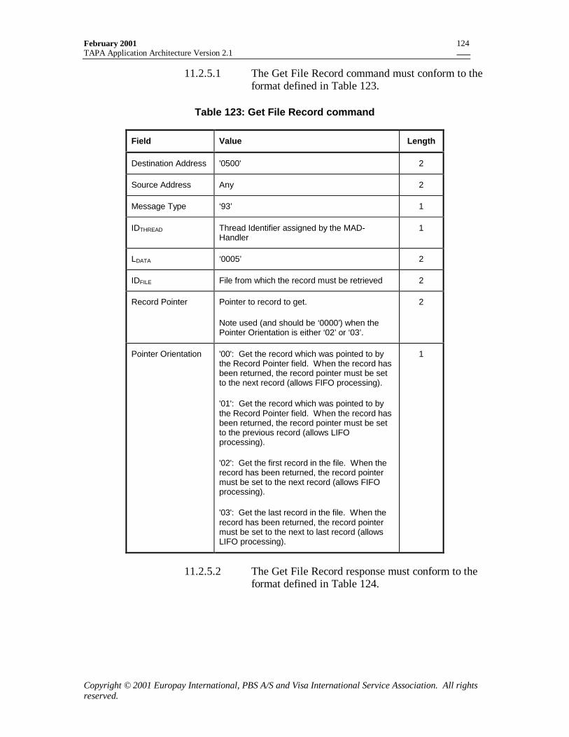
February 2001TAPA Application Architecture Version 2.1
Copyright © 2001 Europay International, PBS A/S and Visa International Service Association. All rightsreserved.
124
11.2.5.1 The Get File Record command must conform to theformat defined in Table 123.
Table 123: Get File Record command
Field Value Length
Destination Address '0500' 2
Source Address Any 2
Message Type ‘93’ 1
IDTHREAD Thread Identifier assigned by the MAD-Handler
1
LDATA ‘0005’ 2
IDFILE File from which the record must be retrieved 2
Record Pointer Pointer to record to get.
Note used (and should be ‘0000’) when thePointer Orientation is either ‘02’ or ‘03’.
2
Pointer Orientation '00': Get the record which was pointed to bythe Record Pointer field. When the record hasbeen returned, the record pointer must be setto the next record (allows FIFO processing).
'01': Get the record which was pointed to bythe Record Pointer field. When the record hasbeen returned, the record pointer must be setto the previous record (allows LIFOprocessing).
'02': Get the first record in the file. When therecord has been returned, the record pointermust be set to the next record (allows FIFOprocessing).
'03': Get the last record in the file. When therecord has been returned, the record pointermust be set to the next to last record (allowsLIFO processing).
1
11.2.5.2 The Get File Record response must conform to theformat defined in Table 124.
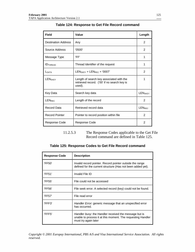
February 2001TAPA Application Architecture Version 2.1
Copyright © 2001 Europay International, PBS A/S and Visa International Service Association. All rightsreserved.
125
Table 124: Response to Get File Record command
Field Value Length
Destination Address Any 2
Source Address '0500' 2
Message Type 'FF' 1
IDTHREAD Thread Identifier of the request 1
LDATA LENSKEY + LENREC + ‘0007’ 2
LENSKEY Length of search key associated with theretrieved record. (‘00’ if no search key isused).
1
Key Data Search key data LENSKEY
LENREC Length of the record 2
Record Data Retrieved record data LENREC
Record Pointer Pointer to record position within file 2
Response Code Response Code 2
11.2.5.3 The Response Codes applicable to the Get FileRecord command are defined in Table 125.
Table 125: Response Codes to Get File Record command
Response Code Description
'FF50' Invalid record pointer. Record pointer outside the rangedefined for the current structure (Has not been added yet).
'FF51' Invalid File ID
'FF55' File could not be accessed
'FF56' File seek error. A selected record (key) could not be found.
'FF57' File read error
'FFF3' Handler Error: generic message that an unspecified errorhas occurred.
'FFF5' Handler busy: the Handler received the message but isunable to process it at this moment. The requesting Handlermust try again later
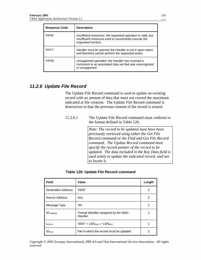
February 2001TAPA Application Architecture Version 2.1
Copyright © 2001 Europay International, PBS A/S and Visa International Service Association. All rightsreserved.
126
Response Code Description
'FFF6' Insufficient resources: the requested operation is valid, butinsufficient resources exist to successfully execute therequested function.
'FFF7' Handler must be opened: the Handler is not in open statusand therefore cannot perform the requested action.
‘FFFB’ Unsupported operation: the Handler has received acommand or an associated data set that was unrecognizedor unsupported.
11.2.6 Update File RecordThe Update File Record command is used to update an existingrecord with an amount of data that must not exceed the maximumindicated at file creation. The Update File Record command isdestructive in that the previous content of the record is erased.
11.2.6.1 The Update File Record command must conform tothe format defined in Table 126.
Note: The record to be updated must have beenpreviously retrieved using either the Get FileRecord command or the Find and Get File Recordcommand. The Update Record command mustspecify the record pointer of the record to beupdated. The data included in the Key Data field isused solely to update the indicated record, and notto locate it.
Table 126: Update File Record command
Field Value Length
Destination Address '0500' 2
Source Address Any 2
Message Type ‘94’ 1
IDTHREAD Thread Identifier assigned by the MAD-Handler
1
LDATA ‘0007’ + LENSKEY + LENREC 1
IDFILE File in which the record must be updated 2
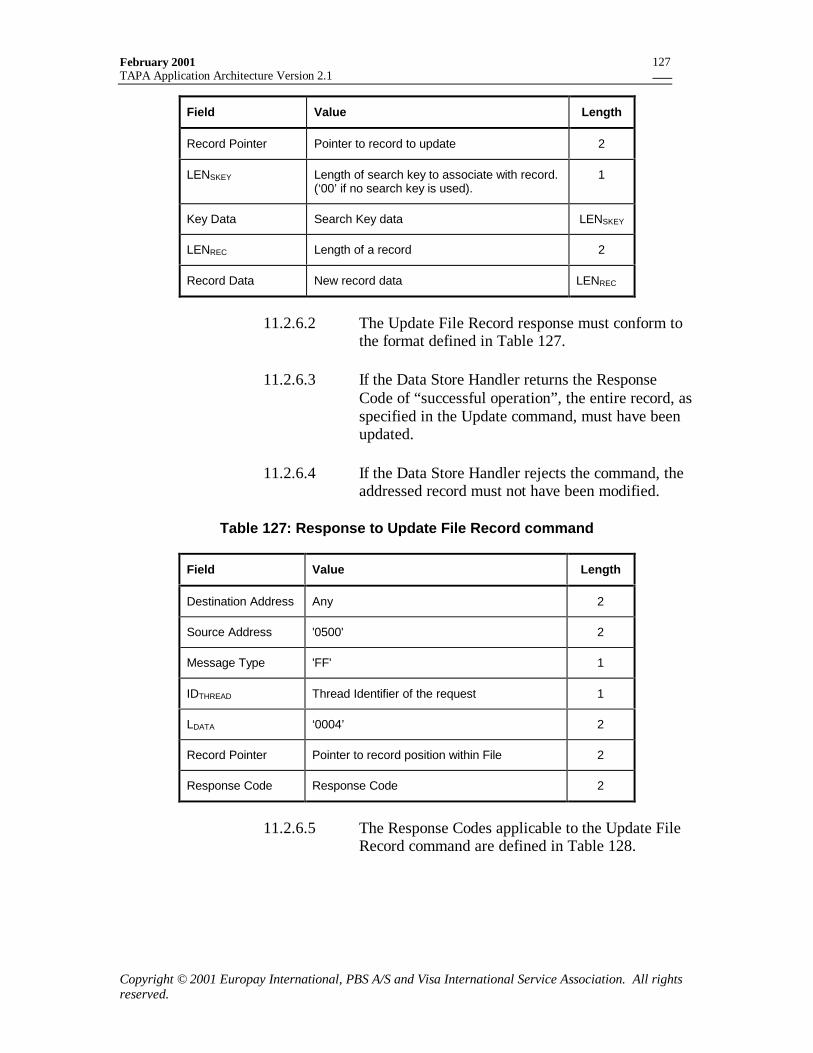
February 2001TAPA Application Architecture Version 2.1
Copyright © 2001 Europay International, PBS A/S and Visa International Service Association. All rightsreserved.
127
Field Value Length
Record Pointer Pointer to record to update 2
LENSKEY Length of search key to associate with record.(‘00’ if no search key is used).
1
Key Data Search Key data LENSKEY
LENREC Length of a record 2
Record Data New record data LENREC
11.2.6.2 The Update File Record response must conform tothe format defined in Table 127.
11.2.6.3 If the Data Store Handler returns the ResponseCode of “successful operation”, the entire record, asspecified in the Update command, must have beenupdated.
11.2.6.4 If the Data Store Handler rejects the command, theaddressed record must not have been modified.
Table 127: Response to Update File Record command
Field Value Length
Destination Address Any 2
Source Address '0500' 2
Message Type 'FF' 1
IDTHREAD Thread Identifier of the request 1
LDATA ‘0004’ 2
Record Pointer Pointer to record position within File 2
Response Code Response Code 2
11.2.6.5 The Response Codes applicable to the Update FileRecord command are defined in Table 128.
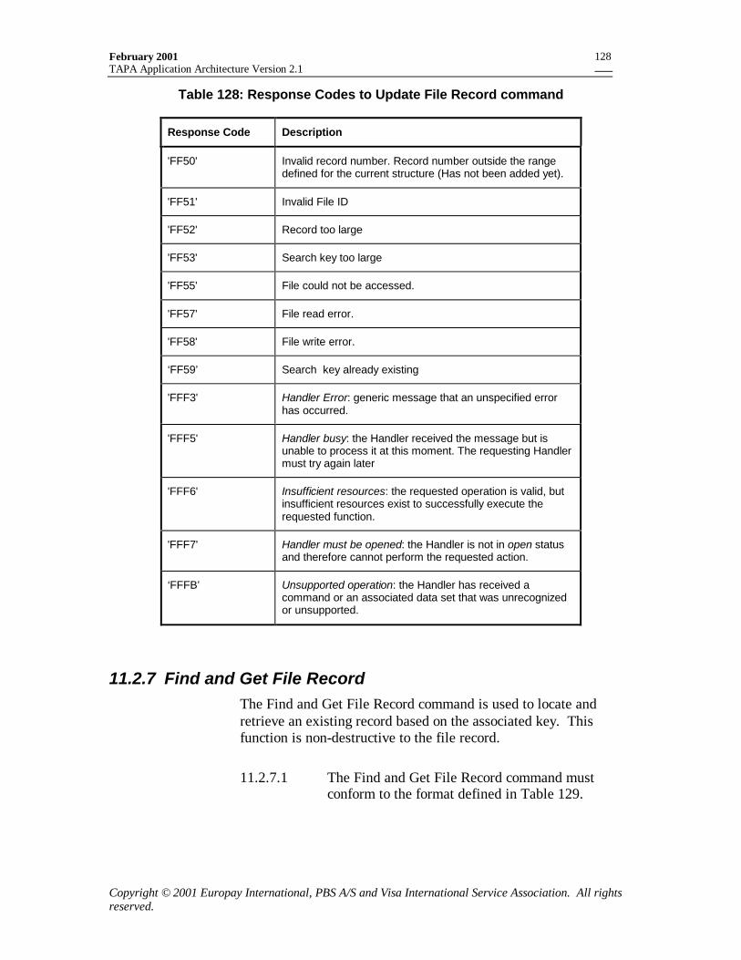
February 2001TAPA Application Architecture Version 2.1
Copyright © 2001 Europay International, PBS A/S and Visa International Service Association. All rightsreserved.
128
Table 128: Response Codes to Update File Record command
Response Code Description
'FF50' Invalid record number. Record number outside the rangedefined for the current structure (Has not been added yet).
'FF51' Invalid File ID
'FF52' Record too large
'FF53' Search key too large
'FF55' File could not be accessed.
'FF57' File read error.
'FF58' File write error.
‘FF59’ Search key already existing
'FFF3' Handler Error: generic message that an unspecified errorhas occurred.
'FFF5' Handler busy: the Handler received the message but isunable to process it at this moment. The requesting Handlermust try again later
'FFF6' Insufficient resources: the requested operation is valid, butinsufficient resources exist to successfully execute therequested function.
'FFF7' Handler must be opened: the Handler is not in open statusand therefore cannot perform the requested action.
‘FFFB’ Unsupported operation: the Handler has received acommand or an associated data set that was unrecognizedor unsupported.
11.2.7 Find and Get File RecordThe Find and Get File Record command is used to locate andretrieve an existing record based on the associated key. Thisfunction is non-destructive to the file record.
11.2.7.1 The Find and Get File Record command mustconform to the format defined in Table 129.
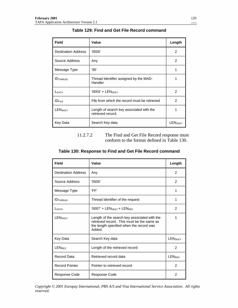
February 2001TAPA Application Architecture Version 2.1
Copyright © 2001 Europay International, PBS A/S and Visa International Service Association. All rightsreserved.
129
Table 129: Find and Get File Record command
Field Value Length
Destination Address '0500' 2
Source Address Any 2
Message Type ‘95’ 1
IDTHREAD Thread Identifier assigned by the MAD-Handler
1
LDATA ‘0003’ + LENSKEY 2
IDFILE File from which the record must be retrieved 2
LENSKEY Length of search key associated with theretrieved record.
1
Key Data Search Key data LENSKEY
11.2.7.2 The Find and Get File Record response mustconform to the format defined in Table 130.
Table 130: Response to Find and Get File Record command
Field Value Length
Destination Address Any 2
Source Address '0500' 2
Message Type 'FF' 1
IDTHREAD Thread Identifier of the request 1
LDATA ‘0007’ + LENSKEY + LENREC 2
LENSKEY Length of the search key associated with theretrieved record. This must be the same asthe length specified when the record wasAdded.
1
Key Data Search Key data LENSKEY
LENREC Length of the retrieved record 2
Record Data Retrieved record data LENREC
Record Pointer Pointer to retrieved record 2
Response Code Response Code 2
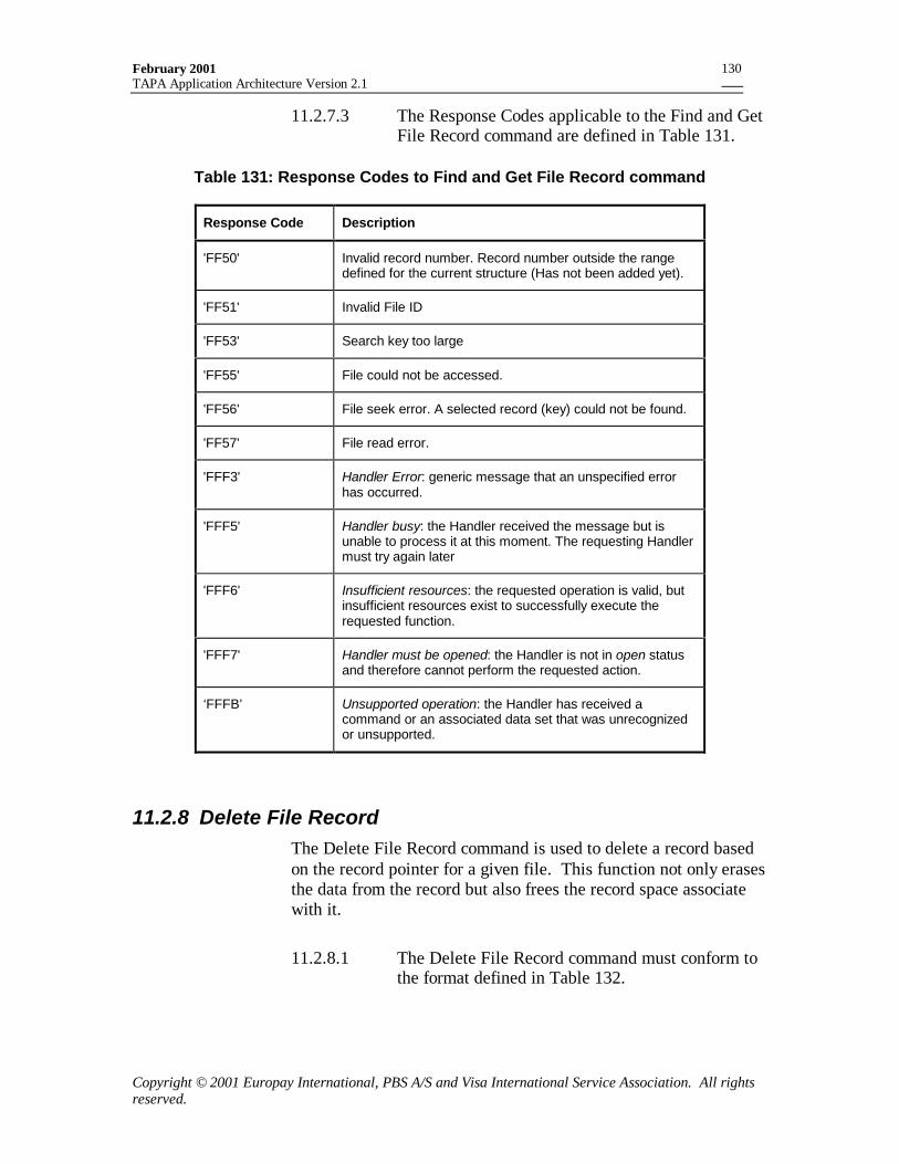
February 2001TAPA Application Architecture Version 2.1
Copyright © 2001 Europay International, PBS A/S and Visa International Service Association. All rightsreserved.
130
11.2.7.3 The Response Codes applicable to the Find and GetFile Record command are defined in Table 131.
Table 131: Response Codes to Find and Get File Record command
Response Code Description
'FF50' Invalid record number. Record number outside the rangedefined for the current structure (Has not been added yet).
'FF51' Invalid File ID
'FF53' Search key too large
'FF55' File could not be accessed.
'FF56' File seek error. A selected record (key) could not be found.
'FF57' File read error.
'FFF3' Handler Error: generic message that an unspecified errorhas occurred.
'FFF5' Handler busy: the Handler received the message but isunable to process it at this moment. The requesting Handlermust try again later
'FFF6' Insufficient resources: the requested operation is valid, butinsufficient resources exist to successfully execute therequested function.
'FFF7' Handler must be opened: the Handler is not in open statusand therefore cannot perform the requested action.
‘FFFB’ Unsupported operation: the Handler has received acommand or an associated data set that was unrecognizedor unsupported.
11.2.8 Delete File RecordThe Delete File Record command is used to delete a record basedon the record pointer for a given file. This function not only erasesthe data from the record but also frees the record space associatewith it.
11.2.8.1 The Delete File Record command must conform tothe format defined in Table 132.
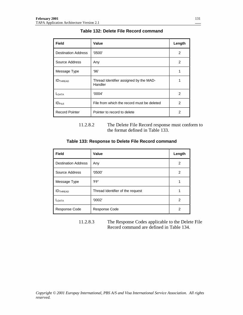
February 2001TAPA Application Architecture Version 2.1
Copyright © 2001 Europay International, PBS A/S and Visa International Service Association. All rightsreserved.
131
Table 132: Delete File Record command
Field Value Length
Destination Address '0500' 2
Source Address Any 2
Message Type ‘96’ 1
IDTHREAD Thread Identifier assigned by the MAD-Handler
1
LDATA ‘0004’ 2
IDFILE File from which the record must be deleted 2
Record Pointer Pointer to record to delete 2
11.2.8.2 The Delete File Record response must conform tothe format defined in Table 133.
Table 133: Response to Delete File Record command
Field Value Length
Destination Address Any 2
Source Address '0500' 2
Message Type 'FF' 1
IDTHREAD Thread Identifier of the request 1
LDATA '0002' 2
Response Code Response Code 2
11.2.8.3 The Response Codes applicable to the Delete FileRecord command are defined in Table 134.
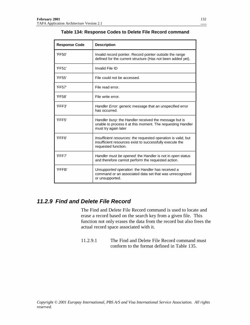
February 2001TAPA Application Architecture Version 2.1
Copyright © 2001 Europay International, PBS A/S and Visa International Service Association. All rightsreserved.
132
Table 134: Response Codes to Delete File Record command
Response Code Description
'FF50' Invalid record pointer. Record pointer outside the rangedefined for the current structure (Has not been added yet).
'FF51' Invalid File ID
'FF55' File could not be accessed.
'FF57' File read error.
'FF58' File write error.
'FFF3' Handler Error: generic message that an unspecified errorhas occurred.
'FFF5' Handler busy: the Handler received the message but isunable to process it at this moment. The requesting Handlermust try again later
'FFF6' Insufficient resources: the requested operation is valid, butinsufficient resources exist to successfully execute therequested function.
'FFF7' Handler must be opened: the Handler is not in open statusand therefore cannot perform the requested action.
‘FFFB’ Unsupported operation: the Handler has received acommand or an associated data set that was unrecognizedor unsupported.
11.2.9 Find and Delete File RecordThe Find and Delete File Record command is used to locate anderase a record based on the search key from a given file. Thisfunction not only erases the data from the record but also frees theactual record space associated with it.
11.2.9.1 The Find and Delete File Record command mustconform to the format defined in Table 135.
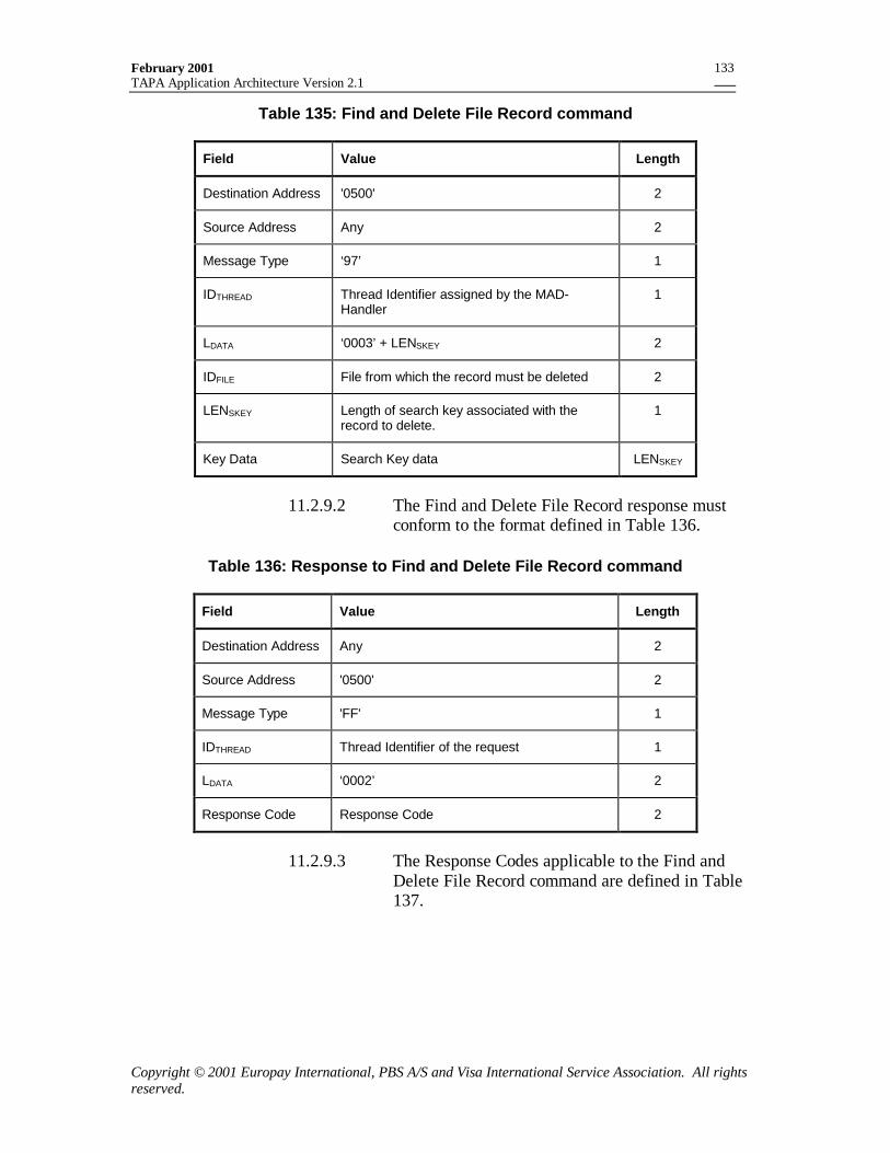
February 2001TAPA Application Architecture Version 2.1
Copyright © 2001 Europay International, PBS A/S and Visa International Service Association. All rightsreserved.
133
Table 135: Find and Delete File Record command
Field Value Length
Destination Address '0500' 2
Source Address Any 2
Message Type ‘97’ 1
IDTHREAD Thread Identifier assigned by the MAD-Handler
1
LDATA ‘0003’ + LENSKEY 2
IDFILE File from which the record must be deleted 2
LENSKEY Length of search key associated with therecord to delete.
1
Key Data Search Key data LENSKEY
11.2.9.2 The Find and Delete File Record response mustconform to the format defined in Table 136.
Table 136: Response to Find and Delete File Record command
Field Value Length
Destination Address Any 2
Source Address '0500' 2
Message Type 'FF' 1
IDTHREAD Thread Identifier of the request 1
LDATA ‘0002’ 2
Response Code Response Code 2
11.2.9.3 The Response Codes applicable to the Find andDelete File Record command are defined in Table137.
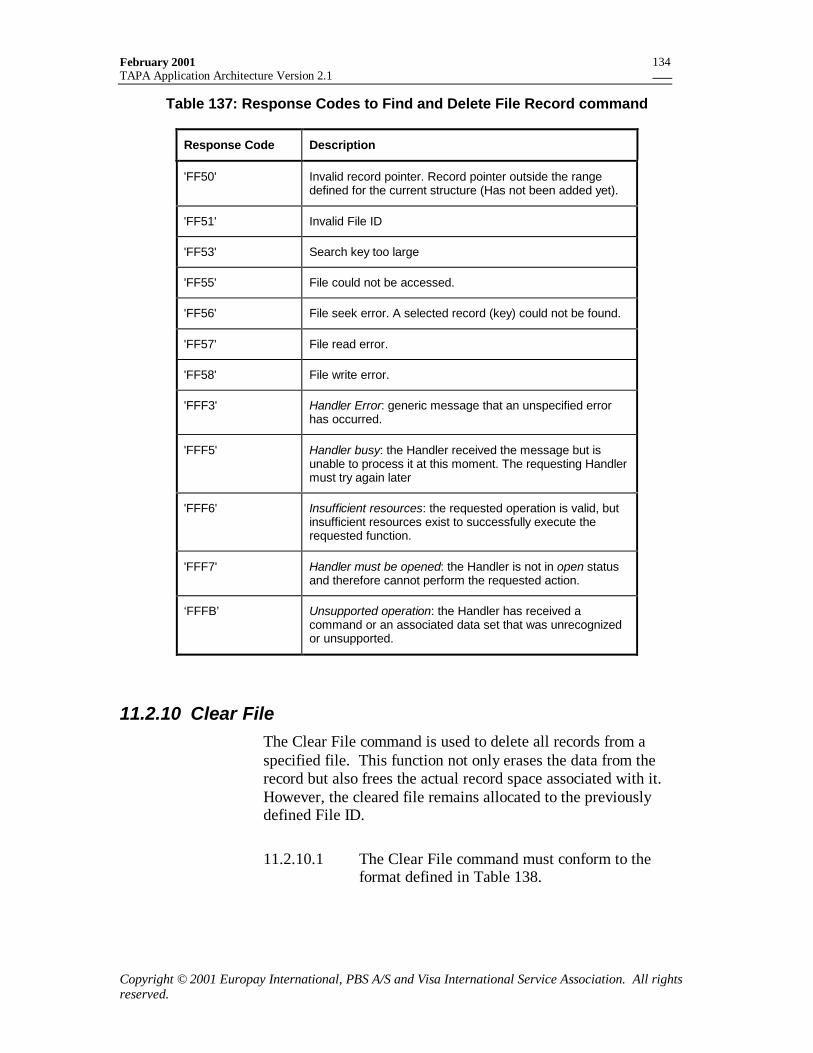
February 2001TAPA Application Architecture Version 2.1
Copyright © 2001 Europay International, PBS A/S and Visa International Service Association. All rightsreserved.
134
Table 137: Response Codes to Find and Delete File Record command
Response Code Description
'FF50' Invalid record pointer. Record pointer outside the rangedefined for the current structure (Has not been added yet).
'FF51' Invalid File ID
'FF53' Search key too large
'FF55' File could not be accessed.
'FF56' File seek error. A selected record (key) could not be found.
'FF57' File read error.
'FF58' File write error.
'FFF3' Handler Error: generic message that an unspecified errorhas occurred.
'FFF5' Handler busy: the Handler received the message but isunable to process it at this moment. The requesting Handlermust try again later
'FFF6' Insufficient resources: the requested operation is valid, butinsufficient resources exist to successfully execute therequested function.
'FFF7' Handler must be opened: the Handler is not in open statusand therefore cannot perform the requested action.
‘FFFB’ Unsupported operation: the Handler has received acommand or an associated data set that was unrecognizedor unsupported.
11.2.10 Clear FileThe Clear File command is used to delete all records from aspecified file. This function not only erases the data from therecord but also frees the actual record space associated with it.However, the cleared file remains allocated to the previouslydefined File ID.
11.2.10.1 The Clear File command must conform to theformat defined in Table 138.
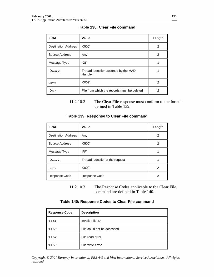
February 2001TAPA Application Architecture Version 2.1
Copyright © 2001 Europay International, PBS A/S and Visa International Service Association. All rightsreserved.
135
Table 138: Clear File command
Field Value Length
Destination Address '0500' 2
Source Address Any 2
Message Type ‘98’ 1
IDTHREAD Thread Identifier assigned by the MAD-Handler
1
LDATA '0002' 2
IDFILE File from which the records must be deleted 2
11.2.10.2 The Clear File response must conform to the formatdefined in Table 139.
Table 139: Response to Clear File command
Field Value Length
Destination Address Any 2
Source Address '0500' 2
Message Type 'FF' 1
IDTHREAD Thread Identifier of the request 1
LDATA '0002' 2
Response Code Response Code 2
11.2.10.3 The Response Codes applicable to the Clear Filecommand are defined in Table 140.
Table 140: Response Codes to Clear File command
Response Code Description
'FF51' Invalid File ID
'FF55' File could not be accessed.
'FF57' File read error.
'FF58' File write error.
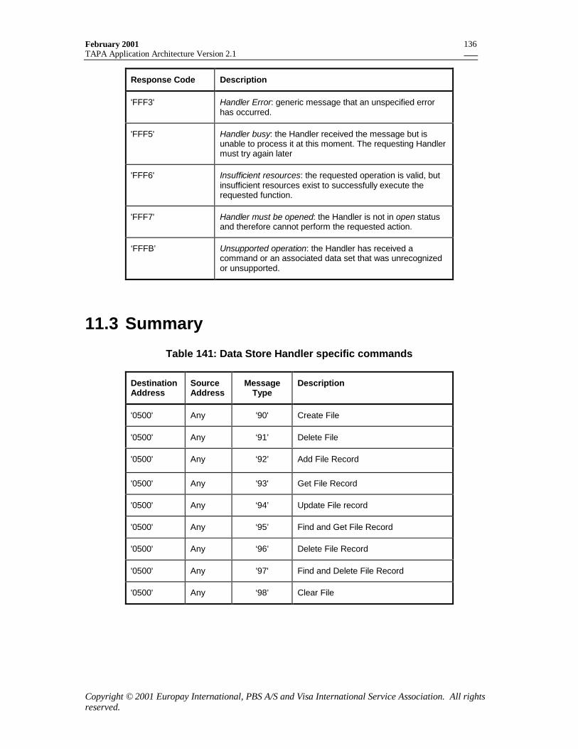
February 2001TAPA Application Architecture Version 2.1
Copyright © 2001 Europay International, PBS A/S and Visa International Service Association. All rightsreserved.
136
Response Code Description
'FFF3' Handler Error: generic message that an unspecified errorhas occurred.
'FFF5' Handler busy: the Handler received the message but isunable to process it at this moment. The requesting Handlermust try again later
'FFF6' Insufficient resources: the requested operation is valid, butinsufficient resources exist to successfully execute therequested function.
'FFF7' Handler must be opened: the Handler is not in open statusand therefore cannot perform the requested action.
‘FFFB’ Unsupported operation: the Handler has received acommand or an associated data set that was unrecognizedor unsupported.
11.3 Summary
Table 141: Data Store Handler specific commands
DestinationAddress
SourceAddress
MessageType
Description
'0500' Any '90' Create File
'0500' Any ‘91’ Delete File
'0500' Any ‘92’ Add File Record
'0500' Any '93' Get File Record
'0500' Any ‘94’ Update File record
'0500' Any ‘95’ Find and Get File Record
'0500' Any ‘96’ Delete File Record
'0500' Any '97' Find and Delete File Record
'0500' Any ‘98’ Clear File
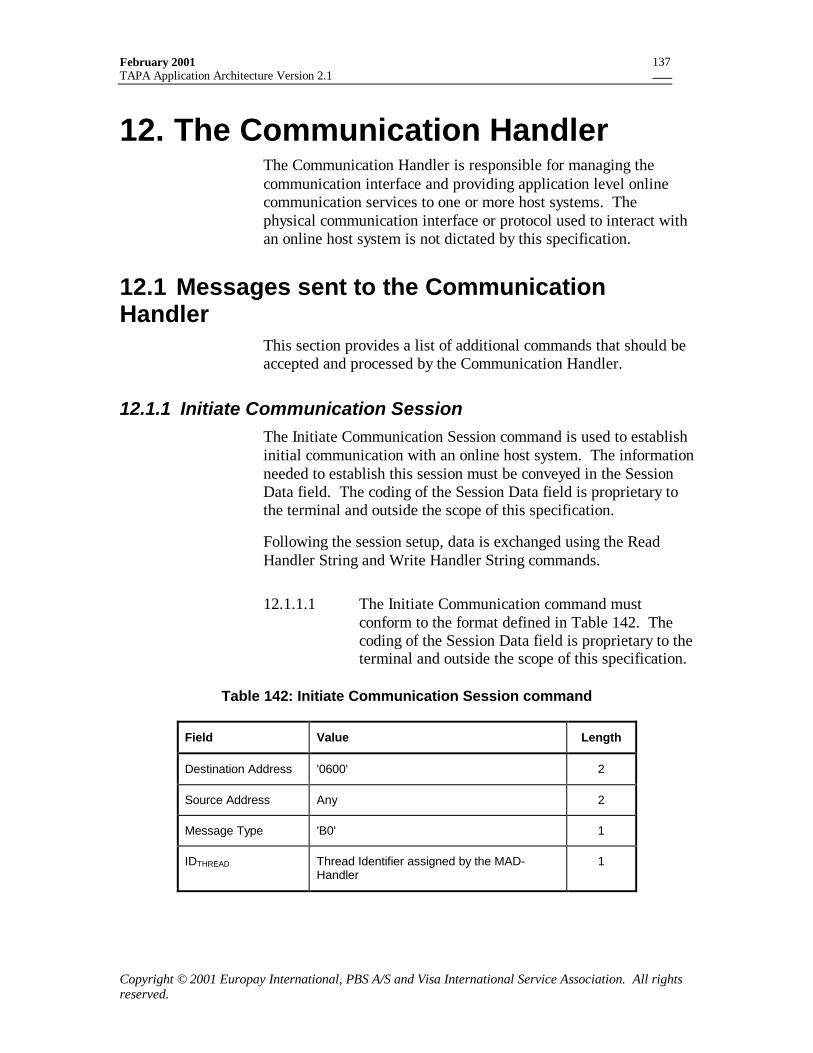
February 2001TAPA Application Architecture Version 2.1
Copyright © 2001 Europay International, PBS A/S and Visa International Service Association. All rightsreserved.
137
12. The Communication HandlerThe Communication Handler is responsible for managing thecommunication interface and providing application level onlinecommunication services to one or more host systems. Thephysical communication interface or protocol used to interact withan online host system is not dictated by this specification.
12.1 Messages sent to the CommunicationHandler
This section provides a list of additional commands that should beaccepted and processed by the Communication Handler.
12.1.1 Initiate Communication SessionThe Initiate Communication Session command is used to establishinitial communication with an online host system. The informationneeded to establish this session must be conveyed in the SessionData field. The coding of the Session Data field is proprietary tothe terminal and outside the scope of this specification.
Following the session setup, data is exchanged using the ReadHandler String and Write Handler String commands.
12.1.1.1 The Initiate Communication command mustconform to the format defined in Table 142. Thecoding of the Session Data field is proprietary to theterminal and outside the scope of this specification.
Table 142: Initiate Communication Session command
Field Value Length
Destination Address '0600' 2
Source Address Any 2
Message Type 'B0' 1
IDTHREAD Thread Identifier assigned by the MAD-Handler
1
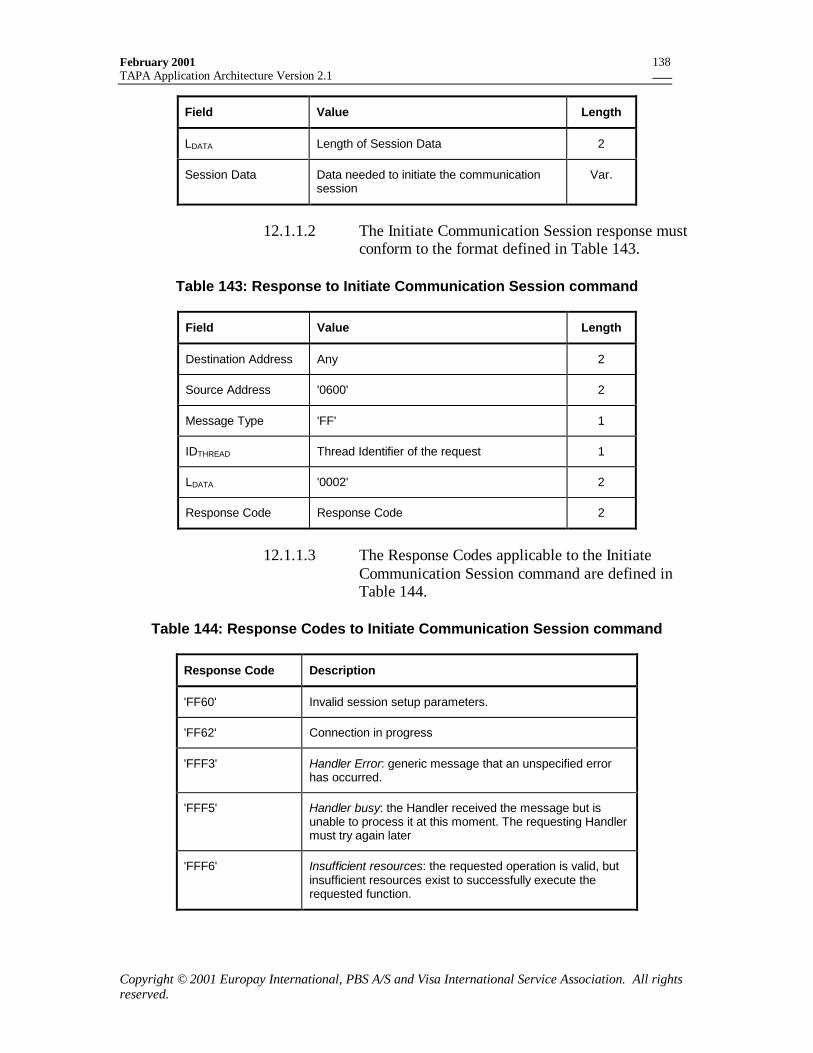
February 2001TAPA Application Architecture Version 2.1
Copyright © 2001 Europay International, PBS A/S and Visa International Service Association. All rightsreserved.
138
Field Value Length
LDATA Length of Session Data 2
Session Data Data needed to initiate the communicationsession
Var.
12.1.1.2 The Initiate Communication Session response mustconform to the format defined in Table 143.
Table 143: Response to Initiate Communication Session command
Field Value Length
Destination Address Any 2
Source Address '0600' 2
Message Type 'FF' 1
IDTHREAD Thread Identifier of the request 1
LDATA '0002' 2
Response Code Response Code 2
12.1.1.3 The Response Codes applicable to the InitiateCommunication Session command are defined inTable 144.
Table 144: Response Codes to Initiate Communication Session command
Response Code Description
'FF60' Invalid session setup parameters.
'FF62' Connection in progress
'FFF3' Handler Error: generic message that an unspecified errorhas occurred.
'FFF5' Handler busy: the Handler received the message but isunable to process it at this moment. The requesting Handlermust try again later
'FFF6' Insufficient resources: the requested operation is valid, butinsufficient resources exist to successfully execute therequested function.
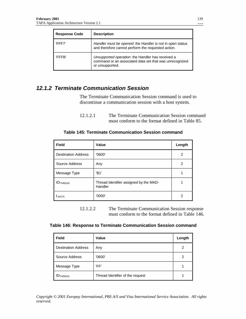
February 2001TAPA Application Architecture Version 2.1
Copyright © 2001 Europay International, PBS A/S and Visa International Service Association. All rightsreserved.
139
Response Code Description
'FFF7' Handler must be opened: the Handler is not in open statusand therefore cannot perform the requested action.
‘FFFB’ Unsupported operation: the Handler has received acommand or an associated data set that was unrecognizedor unsupported.
12.1.2 Terminate Communication SessionThe Terminate Communication Session command is used todiscontinue a communication session with a host system.
12.1.2.1 The Terminate Communication Session commandmust conform to the format defined in Table 85.
Table 145: Terminate Communication Session command
Field Value Length
Destination Address '0600' 2
Source Address Any 2
Message Type 'B1' 1
IDTHREAD Thread Identifier assigned by the MAD-Handler
1
LDATA '0000' 2
12.1.2.2 The Terminate Communication Session responsemust conform to the format defined in Table 146.
Table 146: Response to Terminate Communication Session command
Field Value Length
Destination Address Any 2
Source Address '0600' 2
Message Type 'FF' 1
IDTHREAD Thread Identifier of the request 1
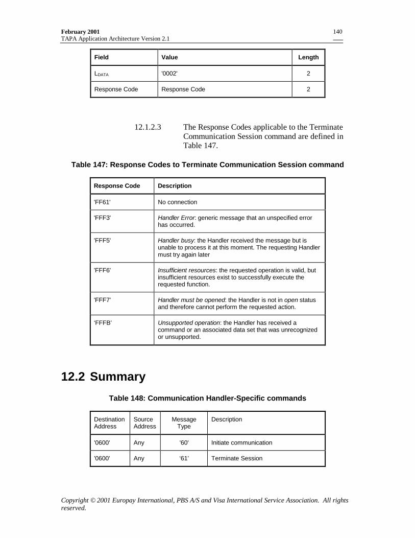
February 2001TAPA Application Architecture Version 2.1
Copyright © 2001 Europay International, PBS A/S and Visa International Service Association. All rightsreserved.
140
Field Value Length
LDATA '0002' 2
Response Code Response Code 2
12.1.2.3 The Response Codes applicable to the TerminateCommunication Session command are defined inTable 147.
Table 147: Response Codes to Terminate Communication Session command
Response Code Description
'FF61' No connection
'FFF3' Handler Error: generic message that an unspecified errorhas occurred.
'FFF5' Handler busy: the Handler received the message but isunable to process it at this moment. The requesting Handlermust try again later
'FFF6' Insufficient resources: the requested operation is valid, butinsufficient resources exist to successfully execute therequested function.
'FFF7' Handler must be opened: the Handler is not in open statusand therefore cannot perform the requested action.
‘FFFB’ Unsupported operation: the Handler has received acommand or an associated data set that was unrecognizedor unsupported.
12.2 Summary
Table 148: Communication Handler-Specific commands
DestinationAddress
SourceAddress
MessageType
Description
'0600' Any '60' Initiate communication
'0600' Any ‘61’ Terminate Session
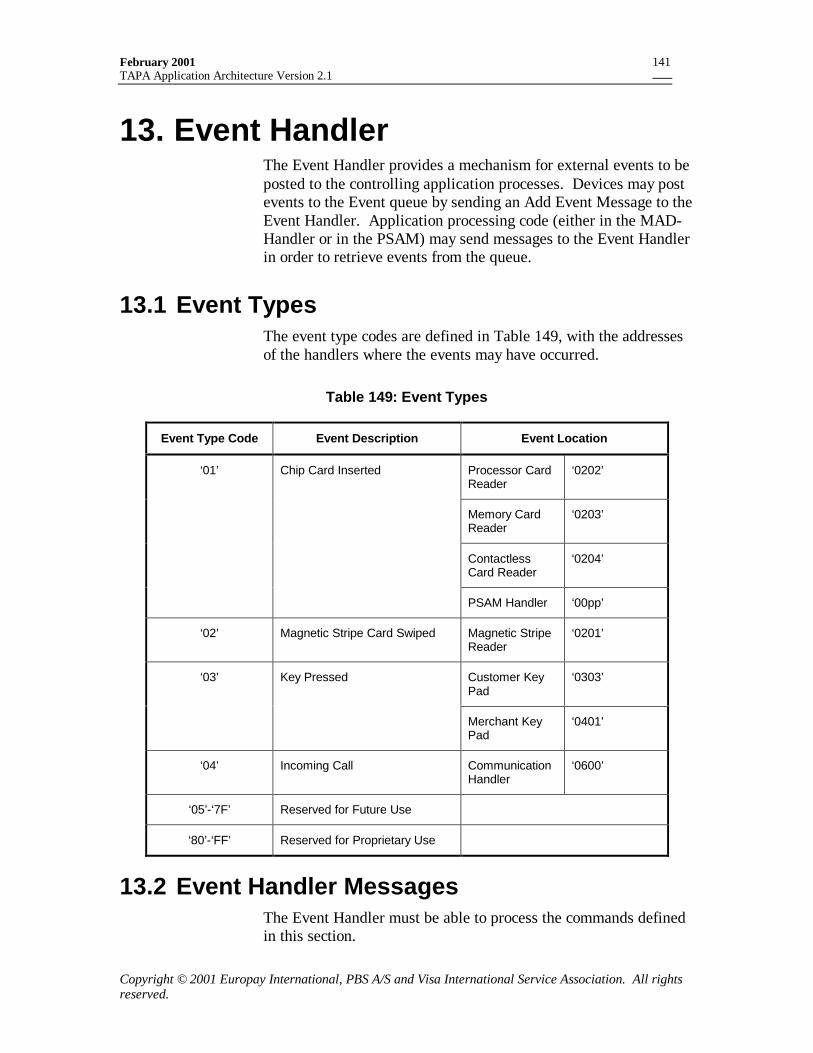
February 2001TAPA Application Architecture Version 2.1
Copyright © 2001 Europay International, PBS A/S and Visa International Service Association. All rightsreserved.
141
13. Event HandlerThe Event Handler provides a mechanism for external events to beposted to the controlling application processes. Devices may postevents to the Event queue by sending an Add Event Message to theEvent Handler. Application processing code (either in the MAD-Handler or in the PSAM) may send messages to the Event Handlerin order to retrieve events from the queue.
13.1 Event TypesThe event type codes are defined in Table 149, with the addressesof the handlers where the events may have occurred.
Table 149: Event Types
Event Type Code Event Description Event Location
Processor CardReader
‘0202’
Memory CardReader
‘0203’
ContactlessCard Reader
‘0204’
‘01’ Chip Card Inserted
PSAM Handler ‘00pp’
‘02’ Magnetic Stripe Card Swiped Magnetic StripeReader
‘0201’
Customer KeyPad
‘0303’‘03’ Key Pressed
Merchant KeyPad
‘0401’
‘04’ Incoming Call CommunicationHandler
‘0600’
‘05’-‘7F’ Reserved for Future Use
‘80’-‘FF’ Reserved for Proprietary Use
13.2 Event Handler MessagesThe Event Handler must be able to process the commands definedin this section.
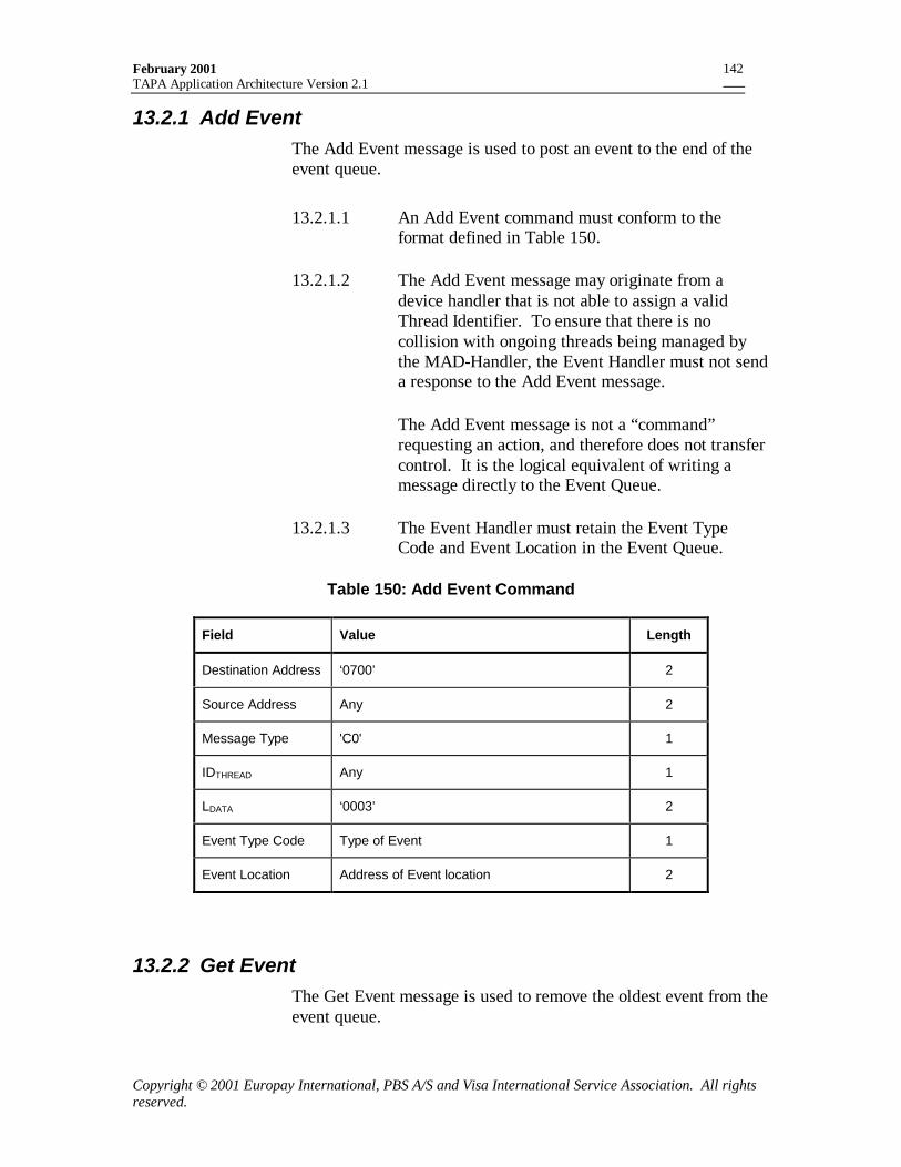
February 2001TAPA Application Architecture Version 2.1
Copyright © 2001 Europay International, PBS A/S and Visa International Service Association. All rightsreserved.
142
13.2.1 Add EventThe Add Event message is used to post an event to the end of theevent queue.
13.2.1.1 An Add Event command must conform to theformat defined in Table 150.
13.2.1.2 The Add Event message may originate from adevice handler that is not able to assign a validThread Identifier. To ensure that there is nocollision with ongoing threads being managed bythe MAD-Handler, the Event Handler must not senda response to the Add Event message.
The Add Event message is not a “command”requesting an action, and therefore does not transfercontrol. It is the logical equivalent of writing amessage directly to the Event Queue.
13.2.1.3 The Event Handler must retain the Event TypeCode and Event Location in the Event Queue.
Table 150: Add Event Command
Field Value Length
Destination Address ‘0700’ 2
Source Address Any 2
Message Type 'C0' 1
IDTHREAD Any 1
LDATA ‘0003’ 2
Event Type Code Type of Event 1
Event Location Address of Event location 2
13.2.2 Get EventThe Get Event message is used to remove the oldest event from theevent queue.
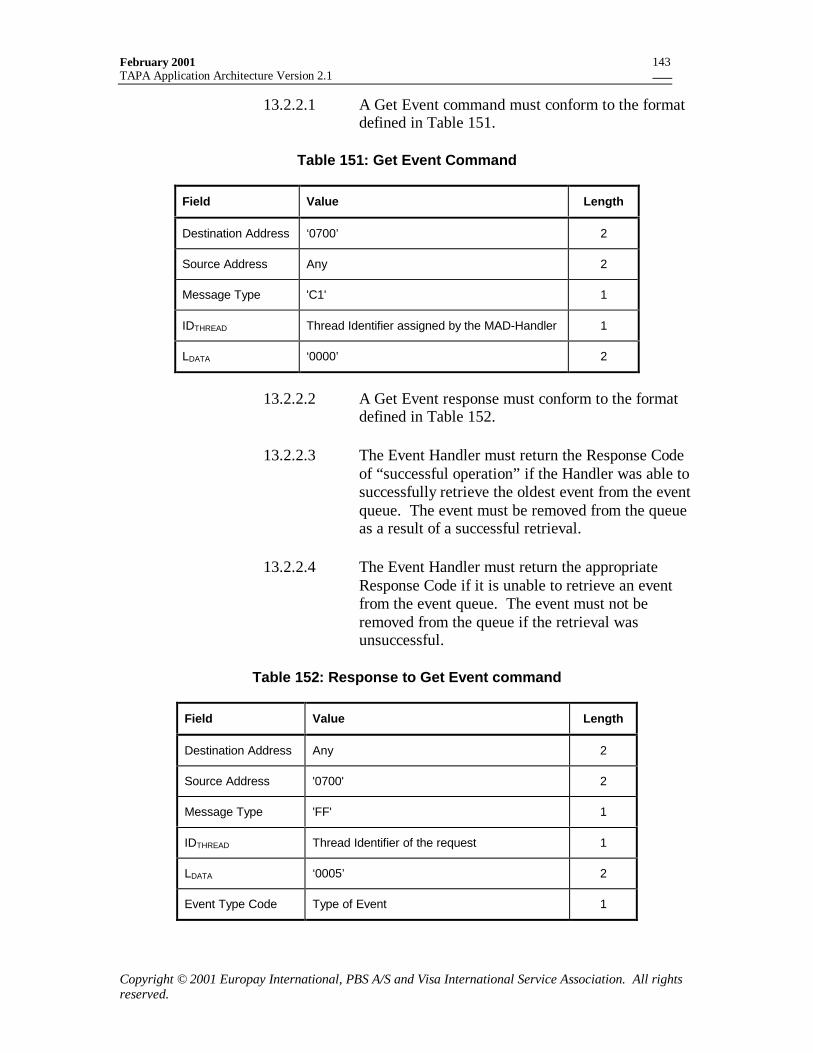
February 2001TAPA Application Architecture Version 2.1
Copyright © 2001 Europay International, PBS A/S and Visa International Service Association. All rightsreserved.
143
13.2.2.1 A Get Event command must conform to the formatdefined in Table 151.
Table 151: Get Event Command
Field Value Length
Destination Address ‘0700’ 2
Source Address Any 2
Message Type 'C1' 1
IDTHREAD Thread Identifier assigned by the MAD-Handler 1
LDATA ‘0000’ 2
13.2.2.2 A Get Event response must conform to the formatdefined in Table 152.
13.2.2.3 The Event Handler must return the Response Codeof “successful operation” if the Handler was able tosuccessfully retrieve the oldest event from the eventqueue. The event must be removed from the queueas a result of a successful retrieval.
13.2.2.4 The Event Handler must return the appropriateResponse Code if it is unable to retrieve an eventfrom the event queue. The event must not beremoved from the queue if the retrieval wasunsuccessful.
Table 152: Response to Get Event command
Field Value Length
Destination Address Any 2
Source Address '0700' 2
Message Type 'FF' 1
IDTHREAD Thread Identifier of the request 1
LDATA ‘0005’ 2
Event Type Code Type of Event 1
February 2001TAPA Application Architecture Version 2.1
Copyright © 2001 Europay International, PBS A/S and Visa International Service Association. All rightsreserved.
144
Field Value Length
Event Location Address of Event location 2
Response Code Response Code 2
13.2.2.5 The Response Codes applicable to the Get Eventcommand are defined in Table 153.
Table 153: Response Codes to Get Event command
Response Code Description
‘FF72’ No Events in Queue
'FFF3' Handler Error: generic message that an unspecified errorhas occurred.
'FFF5' Handler busy: the Handler received the message but isunable to process it at this moment. The requesting Handlermust try again later
'FFF6' Insufficient resources: the requested operation is valid, butinsufficient resources exist to successfully execute therequested function.
'FFF7' Handler must be opened: the Handler is not in open statusand therefore cannot perform the requested action.
‘FFFB’ Unsupported operation: the Handler has received acommand or an associated data set that was unrecognizedor unsupported.
13.2.3 Find EventThe Find Event message is used to find the first (or oldest)message of a particular type, or for a particular location, andremove it from the event queue.
13.2.3.1 A Find Event command must conform to the formatdefined in Table 154.
February 2001TAPA Application Architecture Version 2.1
Copyright © 2001 Europay International, PBS A/S and Visa International Service Association. All rightsreserved.
145
Table 154: Find Event Command
Field Value Length
Destination Address ‘0700’ 2
Source Address Any 2
Message Type 'C2' 1
IDTHREAD Thread Identifier assigned by the MAD-Handler 1
LDATA ‘0004’ 2
Search Type See Table 171 1
Event Type Code Event Type to find 1
Event Location Event location to find 2
13.2.3.2 A Find Event response must conform to the formatdefined in Table 155.
13.2.3.3 The Event Handler must return the Response Codeof “successful operation” if the Handler was able tosuccessfully find and retrieve an event from thequeue. The event must be removed from the queueas a result of a successful retrieval.
13.2.3.4 The Event Handler must return the appropriateResponse Code if it is unable to find or retrieve anevent from the event queue. No event must beremoved from the queue if the retrieval wasunsuccessful.
Table 155: Response to Find Event command
Field Value Length
Destination Address Any 2
Source Address '0700' 2
Message Type 'FF' 1
IDTHREAD Thread Identifier of the request 1
LDATA ‘0005’ 2
Event Type Code 1
February 2001TAPA Application Architecture Version 2.1
Copyright © 2001 Europay International, PBS A/S and Visa International Service Association. All rightsreserved.
146
Field Value Length
Event Location 2
Response Code Response Code 2
13.2.3.5 The Response Codes applicable to the Find Eventcommand are defined in Table 156.
Table 156: Response Codes to Find Event command
Response Code Description
‘FF72’ No Events in Queue
‘FF73’ No Matching Events in Queue
'FFF3' Handler Error: generic message that an unspecified errorhas occurred.
'FFF5' Handler busy: the Handler received the message but isunable to process it at this moment. The requesting Handlermust try again later
'FFF6' Insufficient resources: the requested operation is valid, butinsufficient resources exist to successfully execute therequested function.
'FFF7' Handler must be opened: the Handler is not in open statusand therefore cannot perform the requested action.
‘FFFB’ Unsupported operation: the Handler has received acommand or an associated data set that was unrecognizedor unsupported.
13.2.4 Flush Event QueueThe Flush Event Queue is used remove all outstanding events fromthe event queue.
13.2.4.1 A Flush Event Queue command must conform tothe format defined in Table 157.
February 2001TAPA Application Architecture Version 2.1
Copyright © 2001 Europay International, PBS A/S and Visa International Service Association. All rightsreserved.
147
Table 157: Flush Event Queue Command
Field Value Length
Destination Address ‘0700’ 2
Source Address Any 2
Message Type 'C3' 1
IDTHREAD Thread Identifier assigned by the MAD-Handler 1
LDATA ‘0000’ 2
13.2.4.2 A Flush Event Queue response must conform to theformat defined Table 158.
13.2.4.3 The Event Handler must return the Response Codeof “successful operation” if the Handler was able tosuccessfully flush all events from the queue.
13.2.4.4 The Event Handler must return the appropriateResponse Code if it is unable to empty the eventqueue. No event must be removed from the queue ifthe flush was unsuccessful.
Table 158: Response to Flush Event Queue command
Field Value Length
Destination Address Any 2
Source Address '0700' 2
Message Type 'FF' 1
IDTHREAD Thread Identifier of the request 1
LDATA ‘0002’ 2
Response Code Response Code 2
13.2.4.5 The Response Codes applicable to the Flush EventQueue command are defined in Table 159.
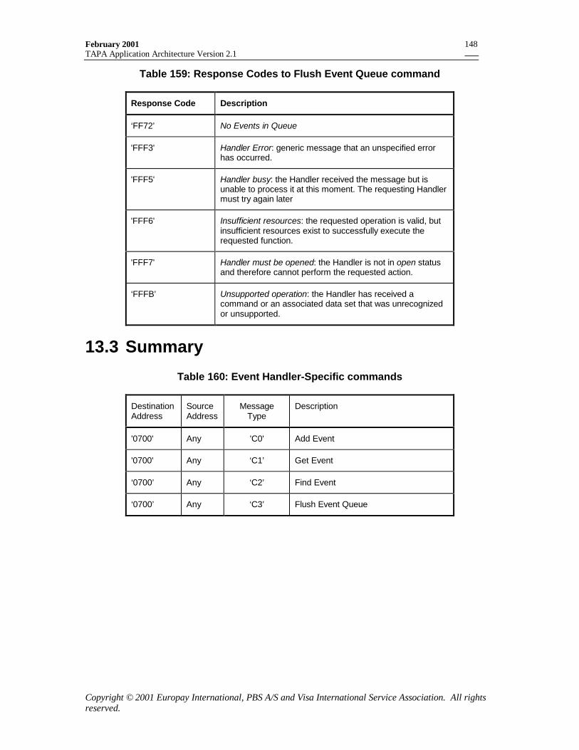
February 2001TAPA Application Architecture Version 2.1
Copyright © 2001 Europay International, PBS A/S and Visa International Service Association. All rightsreserved.
148
Table 159: Response Codes to Flush Event Queue command
Response Code Description
‘FF72’ No Events in Queue
'FFF3' Handler Error: generic message that an unspecified errorhas occurred.
'FFF5' Handler busy: the Handler received the message but isunable to process it at this moment. The requesting Handlermust try again later
'FFF6' Insufficient resources: the requested operation is valid, butinsufficient resources exist to successfully execute therequested function.
'FFF7' Handler must be opened: the Handler is not in open statusand therefore cannot perform the requested action.
‘FFFB’ Unsupported operation: the Handler has received acommand or an associated data set that was unrecognizedor unsupported.
13.3 Summary
Table 160: Event Handler-Specific commands
DestinationAddress
SourceAddress
MessageType
Description
'0700' Any 'C0' Add Event
'0700' Any ‘C1’ Get Event
‘0700’ Any ‘C2’ Find Event
‘0700’ Any ‘C3’ Flush Event Queue
February 2001TAPA Application Architecture Version 2.1
Copyright © 2001 Europay International, PBS A/S and Visa International Service Association. All rightsreserved.
149
14. PIN Pad Processing14.1 Overview
In order to support applications that require use of PINs, thisspecification defines a method of establishing and using a securezone between a PSAM application and the PIN Pad. This facilityprovides the following features:
• The acquirer’s online PIN Encryption keys are maintained inthe PSAM, rather than the PIN Pads.
• Application-specific logic for PIN verification is maintained inthe PSAM rather than the PIN Pad.
• Multiple acquirers, responsible for different applications, maysecurely use the same PIN pad.
14.1.1 Physical Environment
14.1.1.1 The PIN Pad, with its keypad, must be containedwithin a Tamper Evident Device (TED), whichmust also contain the Processor Card Reader andthe User Interface Display. Each of these devices isaddressed as specified in Table 2.
14.1.2 Establishing the Secure ZoneTo transmit enciphered PINs between the PIN Pad and a PSAMapplication, a secure zone must first be established between thetwo entities. This is done using public key cryptography toestablish an initial symmetric PIN Session master key.Subsequently, symmetric key cryptography (triple-DES) is usedfor PIN encryption and message authentication between theentities.
The PIN Pad and the PSAM each contain their own uniqueasymmetric key pairs (SKPP, PKPP) and (SKPSAM, PKPSAM). Thepublic keys are certified by the PIN Pad Creator and by theAcquirer’s agent, known as the PSAM Creator, respectively. (Forthe remainder of this section, this entity will be referred to as theAcquirer. If the PSAM’s are created by multiple systems on behalfof the Acquirer, each system must have its own unique PSAMCreator Identifier and must have a different set of public keys.)
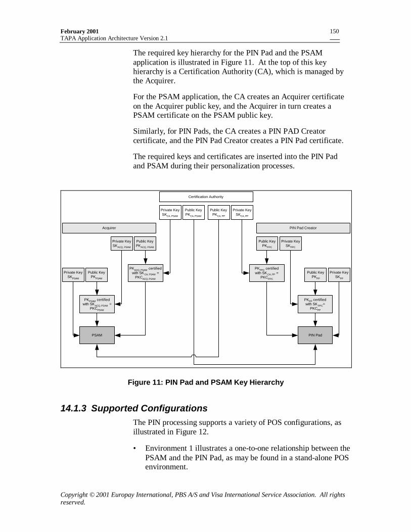
February 2001TAPA Application Architecture Version 2.1
Copyright © 2001 Europay International, PBS A/S and Visa International Service Association. All rightsreserved.
150
The required key hierarchy for the PIN Pad and the PSAMapplication is illustrated in Figure 11. At the top of this keyhierarchy is a Certification Authority (CA), which is managed bythe Acquirer.
For the PSAM application, the CA creates an Acquirer certificateon the Acquirer public key, and the Acquirer in turn creates aPSAM certificate on the PSAM public key.
Similarly, for PIN Pads, the CA creates a PIN PAD Creatorcertificate, and the PIN Pad Creator creates a PIN Pad certificate.
The required keys and certificates are inserted into the PIN Padand PSAM during their personalization processes.
Public KeyPKACQ, PSAM
Private KeySKACQ, PSAM
Public KeyPKCA, PSAM
Private KeySKCA, PSAM
Private KeySKCA, PP
Public KeyPKCA, PP
Public KeyPKPSAM
Private KeySKPPC
Public KeyPKPPC
PKPSAM certifiedwith SKACQ, PSAM =
PKCPSAM
PIN Pad
Certification Authority
PIN Pad CreatorAcquirer
PKACQ, PSAM certifiedwith SK CA, PSAM =
PKCACQ, PSAM
PKPPC certifiedwith SK CA, PP =
PKCPPC
PSAM
Private KeySKPP
Public KeyPKPP
PKPP certifiedwith SK PPC=
PKCPP
Private KeySKPSAM
Figure 11: PIN Pad and PSAM Key Hierarchy
14.1.3 Supported ConfigurationsThe PIN processing supports a variety of POS configurations, asillustrated in Figure 12.
• Environment 1 illustrates a one-to-one relationship between thePSAM and the PIN Pad, as may be found in a stand-alone POSenvironment.
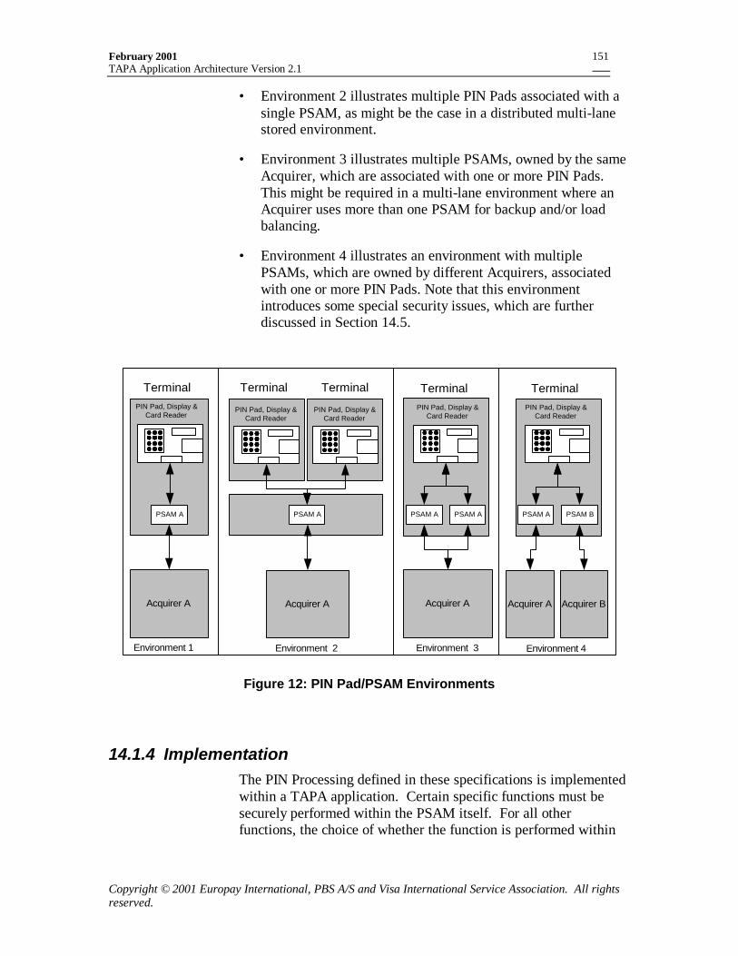
February 2001TAPA Application Architecture Version 2.1
Copyright © 2001 Europay International, PBS A/S and Visa International Service Association. All rightsreserved.
151
• Environment 2 illustrates multiple PIN Pads associated with asingle PSAM, as might be the case in a distributed multi-lanestored environment.
• Environment 3 illustrates multiple PSAMs, owned by the sameAcquirer, which are associated with one or more PIN Pads.This might be required in a multi-lane environment where anAcquirer uses more than one PSAM for backup and/or loadbalancing.
• Environment 4 illustrates an environment with multiplePSAMs, which are owned by different Acquirers, associatedwith one or more PIN Pads. Note that this environmentintroduces some special security issues, which are furtherdiscussed in Section 14.5.
PSAM A
Acquirer A
PSAM A PSAM A
Acquirer A
PSAM A PSAM B
Acquirer BAcquirer A
Terminal Terminal Terminal
Environment 1 Environment 3 Environment 4
PIN Pad, Display &Card Reader
PIN Pad, Display &Card Reader
PIN Pad, Display &Card Reader
PSAM A
Acquirer A
Environment 2
Terminal Terminal
PIN Pad, Display &Card Reader
PIN Pad, Display &Card Reader
Figure 12: PIN Pad/PSAM Environments
14.1.4 ImplementationThe PIN Processing defined in these specifications is implementedwithin a TAPA application. Certain specific functions must besecurely performed within the PSAM itself. For all otherfunctions, the choice of whether the function is performed within
February 2001TAPA Application Architecture Version 2.1
Copyright © 2001 Europay International, PBS A/S and Visa International Service Association. All rightsreserved.
152
the PSAM or the MAD-Handler part of the application is up to theapplication designer.
The functions that must be performed within the PSAM arespecified in section 14.5.3.
14.2 PIN Pad/PSAM InitializationDuring PSAM initialization, each PSAM application that uses PINProcessing must be synchronized with the PIN Pad(s). In order toperform synchronization, the application engages in a dialoguewith the PIN Pad in order to establish a secure zone using a sharedsymmetric key.
14.2.1.1 The application must begin the synchronizationprocess by sending the Get Key Check Valuecommand to the PIN Pad. The response identifiesthe PIN Pad, and provides information about itscurrent keys, including a check value (KCVPIN) ofthe current Transaction Session Key (KSES). Thischeck value must be compared to the key checkvalue of the PSAM’s current PIN Session masterkey (KCVPSAM). If the check values are the same,then the two entities are currently synchronized andno further dialogue is necessary.
14.2.1.2 The application must send the Get PIN Pad PublicKey Record commands to the PIN Pad to retrievethe PIN Pad certificates. These certificates must beverified by the PSAM, and the PIN Pad’s public keyrecovered from them.
14.2.1.3 The application must send PSAM certificates to thePIN Pad, using the Verify PSAM Public KeyCertificate command. The PIN Pad must verify thePSAM’s certificates and recover the PSAM’s publickey.
Note: The required processing for verifying the certificates andrecovering the public keys is defined in section 14.6.
14.2.1.4 The PSAM must generate an Initial Session Key,which must be sent to the PIN Pad by theapplication using the Submit Initial Key command.The Submit Initial Key command contains a public-key signature (PS), which must be generated by the
February 2001TAPA Application Architecture Version 2.1
Copyright © 2001 Europay International, PBS A/S and Visa International Service Association. All rightsreserved.
153
PSAM. The PIN Pad must verify the PS andrecover from it the Initial Session Key.
Note: The required processing for generating and verifying the PSand recovering the Initial Session Key is defined in section 14.6.
14.2.1.5 If the application control is implemented in thePSAM, the MAD-Handler application must initiatethe synchronization process by sending aSynchronize PIN Pad command to the PSAMapplication for each PIN Pad with which the PSAMmust have a relationship. This command is definedin section 10.3.
Figure 13illustrates the message flow for the case where theapplication control is implemented within the PSAM.
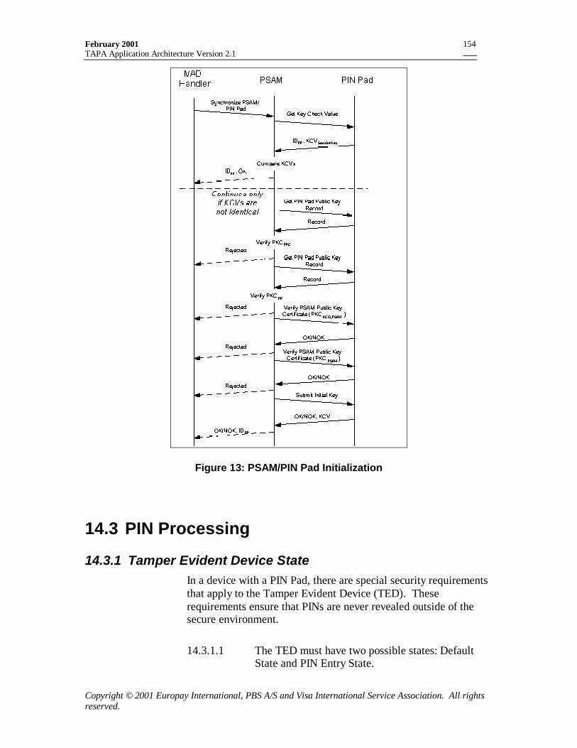
February 2001TAPA Application Architecture Version 2.1
Copyright © 2001 Europay International, PBS A/S and Visa International Service Association. All rightsreserved.
154
Figure 13: PSAM/PIN Pad Initialization
14.3 PIN Processing
14.3.1 Tamper Evident Device StateIn a device with a PIN Pad, there are special security requirementsthat apply to the Tamper Evident Device (TED). Theserequirements ensure that PINs are never revealed outside of thesecure environment.
14.3.1.1 The TED must have two possible states: DefaultState and PIN Entry State.
February 2001TAPA Application Architecture Version 2.1
Copyright © 2001 Europay International, PBS A/S and Visa International Service Association. All rightsreserved.
155
14.3.1.2 The TED must be in Default State after terminalinitialization.
14.3.1.3 The TED must be put into PIN Entry State after thePIN Pad has received and authenticated a validInitiate PIN Entry command. The TED must nottransition to PIN Entry State under any othercircumstances.
14.3.1.4 The TED must be returned to Default State whenthe PIN Pad receives a Terminate PIN Entrycommand. This command is not authenticated, andis not signed by the PSAM.
14.3.1.5 When the TED is in Default State:
• The numeric keys on the PIN Pad must bedisabled.
• No authentication is required on messages thatsend text to the User Display. Any applicationmay freely send display messages to the UserInterface Handler display.
• The Processor Card Reader must only acceptplaintext Card commands sent using the ICCCommand message. The Verify Offline PINCommand message must not be accepted.
14.3.1.6 When the TED is in PIN Entry State:
• The numeric keys are enabled on the PIN Pad.
• The User Interface Handler must only accept“authorized” messages, which cause text to bedisplayed. An authorized message includesmessages that contain a MAC generated by thePSAM, which sent the Initiate PIN Entry.Alternatively, it may be a command thatsupplies a numbered message that has beenpersonalized into the TED as valid.
• The Processor Card Reader may acceptencrypted Card commands sent using the VerifyOffline PIN Command message.
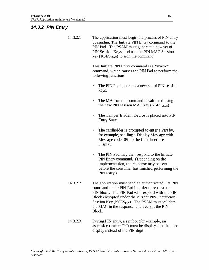
February 2001TAPA Application Architecture Version 2.1
Copyright © 2001 Europay International, PBS A/S and Visa International Service Association. All rightsreserved.
156
14.3.2 PIN Entry
14.3.2.1 The application must begin the process of PIN entryby sending The Initiate PIN Entry command to thePIN Pad. The PSAM must generate a new set ofPIN Session Keys, and use the PIN MAC Sessionkey (KSESMAC) to sign the command.
This Initiate PIN Entry command is a “macro”command, which causes the PIN Pad to perform thefollowing functions:
• The PIN Pad generates a new set of PIN sessionkeys.
• The MAC on the command is validated usingthe new PIN session MAC key (KSESMAC).
• The Tamper Evident Device is placed into PINEntry State.
• The cardholder is prompted to enter a PIN by,for example, sending a Display Message withMessage code ‘09’ to the User InterfaceDisplay.
• The PIN Pad may then respond to the InitiatePIN Entry command. (Depending on theimplementation, the response may be sentbefore the consumer has finished performing thePIN entry.)
14.3.2.2 The application must send an authenticated Get PINcommand to the PIN Pad in order to retrieve thePIN block. The PIN Pad will respond with the PINBlock encrypted under the current PIN EncryptionSession Key (KSESPIN). The PSAM must validatethe MAC in the response, and decrypt the PINBlock.
14.3.2.3 During PIN entry, a symbol (for example, anasterisk character “*”) must be displayed at the userdisplay instead of the PIN digit.
February 2001TAPA Application Architecture Version 2.1
Copyright © 2001 Europay International, PBS A/S and Visa International Service Association. All rightsreserved.
157
14.3.2.4 Error handling procedures, such as deletion ofincorrect entered PIN digits, must be handledinternally by the Tamper Evident Device.
In some environments, the application may send additionalcommands to the User Interface Handler while PIN Entry is inprogress. As noted previously, any commands that require text tobe displayed must be “authorized”.
In particular, the application may send a Confirm Amount messageduring this period. This command must be authenticated while inPIN Entry State.
The particular means of handling a Confirm Amount receivedduring PIN Entry is environment specific. One possibleimplementation is to display the amount confirmation requestalong with the PIN entry request. In this case a single key pressfrom the consumer will serve both as the amount confirmation andas the PIN entry.
The following three diagrams (Figure 14, Figure 15 and Figure 16)are examples of message flows within the Tamper Evident Device,and of the user interface, during PIN Entry. These samplediagrams illustrate the case where the application control is withinthe PSAM.
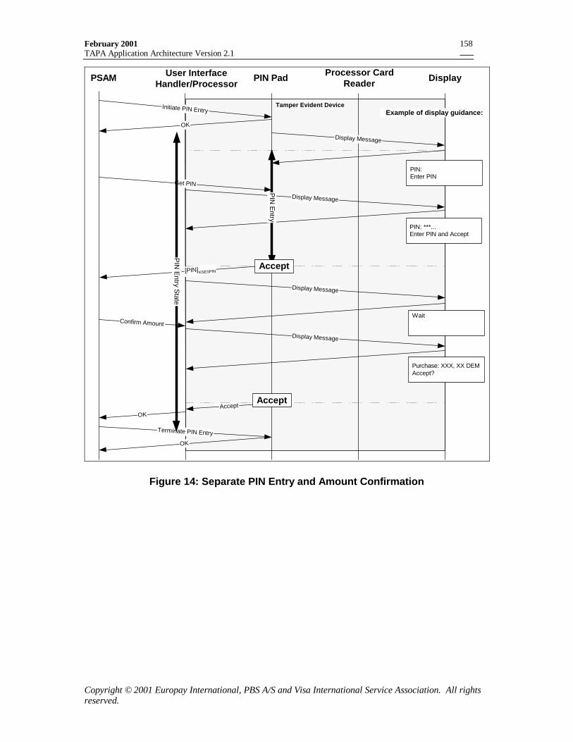
February 2001TAPA Application Architecture Version 2.1
Copyright © 2001 Europay International, PBS A/S and Visa International Service Association. All rightsreserved.
158
PSAM PIN Pad Processor CardReader Display
Confirm Amount
OK
PIN: Enter PIN
Example of display guidance:Tamper Evident Device
PIN: ***... Enter PIN and Accept
User InterfaceHandler/Processor
Purchase: XXX, XX DEM Accept?
Display Message
Accept
Display Message
Initiate PIN Entry
OK
Get PIN
[PIN]KSESPIN
Display Message
Wait
Display Message
PIN
Entry
Accept
Accept
Terminate PIN Entry
OK
PIN
Entry S
tate
Figure 14: Separate PIN Entry and Amount Confirmation
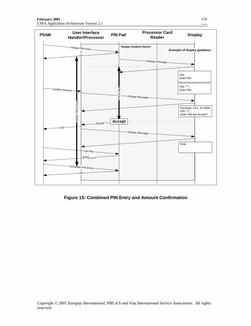
February 2001TAPA Application Architecture Version 2.1
Copyright © 2001 Europay International, PBS A/S and Visa International Service Association. All rightsreserved.
159
PSAM PIN Pad Processor CardReader Display
Confirm Amount
OK
PIN: Enter PIN
Example of display guidance:Tamper Evident Device
PIN: ***... Enter PIN
User InterfaceHandler/Processor
Purchase: XXX, XX DEM PIN: ***... Enter PIN and Accept?
Display Message
Accept
Display Message
Initiate PIN Entry
OK
Get PIN
[PIN]KSESPIN
Display MessageP
IN E
ntry
Wait
Accept
Terminate PIN Entry
PIN
Entry S
tateOK
Figure 15: Combined PIN Entry and Amount Confirmation

February 2001TAPA Application Architecture Version 2.1
Copyright © 2001 Europay International, PBS A/S and Visa International Service Association. All rightsreserved.
160
PSAM PIN Pad Processor CardReader Display
PIN: Enter PIN
Example of display guidance:Tamper Evident Device
PIN: ***... Enter PIN and Accept
User InterfaceHandler/Processor
Display Message
Display Message
Initiate PIN Entry
OK
Get PIN
[PIN]KSESPIN
Wait
Display Message
PIN
Entry
Accept
Terminate PIN EntryOK
PIN
Entry S
tate
Figure 16: PIN Entry with no Amount Confirmation
14.4 PIN VerificationDepending on the requirements of the payment application, PINverification may be performed in one of three ways:
1. Online PIN verification, where the PIN is sent encrypted to theacquirer for transmission to the card issuer.
2. Offline plaintext PIN verification, where the PIN is sent to thecard for verification in the clear.
3. Offline encrypted PIN verification, where the PIN sent to thecard for verification encrypted under a key known to the card.
14.4.1 Online PIN VerificationIf online PIN verification is to be performed, the applicationsends the PIN to the Acquirer encrypted in accordance with themethod implemented by the Acquirer. This might for exampleuse a PIN Encryption key established between the PSAM and
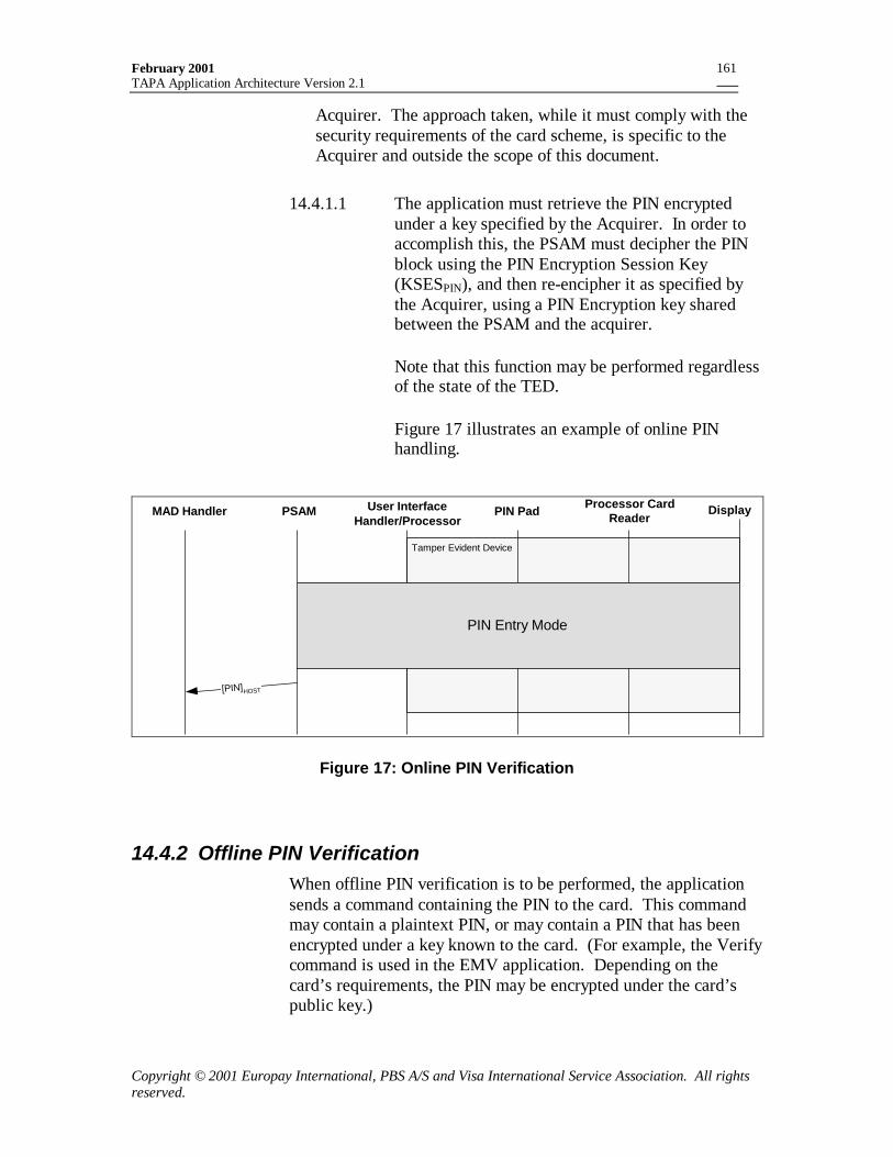
February 2001TAPA Application Architecture Version 2.1
Copyright © 2001 Europay International, PBS A/S and Visa International Service Association. All rightsreserved.
161
Acquirer. The approach taken, while it must comply with thesecurity requirements of the card scheme, is specific to theAcquirer and outside the scope of this document.
14.4.1.1 The application must retrieve the PIN encryptedunder a key specified by the Acquirer. In order toaccomplish this, the PSAM must decipher the PINblock using the PIN Encryption Session Key(KSESPIN), and then re-encipher it as specified bythe Acquirer, using a PIN Encryption key sharedbetween the PSAM and the acquirer.
Note that this function may be performed regardlessof the state of the TED.
Figure 17 illustrates an example of online PINhandling.
MAD Handler PSAM PIN Pad Processor CardReader
Display
[PIN]HOST
Tamper Evident Device
User InterfaceHandler/Processor
PIN Entry Mode
Figure 17: Online PIN Verification
14.4.2 Offline PIN VerificationWhen offline PIN verification is to be performed, the applicationsends a command containing the PIN to the card. This commandmay contain a plaintext PIN, or may contain a PIN that has beenencrypted under a key known to the card. (For example, the Verifycommand is used in the EMV application. Depending on thecard’s requirements, the PIN may be encrypted under the card’spublic key.)
February 2001TAPA Application Architecture Version 2.1
Copyright © 2001 Europay International, PBS A/S and Visa International Service Association. All rightsreserved.
162
14.4.2.1 The PSAM must encrypt the PIN verificationcommand APDU under the PIN session encryptionkey. The encrypted command must be sent to theProcessor Card Reader using the Verify Offline PINmessage. This message must be MACed using thePIN MAC Session Key (KSESMAC).
The message is authenticated and the commandAPDU decrypted within the Tamper EvidentDevice. The C-APDU is then forwarded to thecard.
14.4.2.2 The response to the Verify Offline PIN messagecontains the card application’s response to the PINverification command. The response messagecontains a MAC, which must be verified by thePSAM.
Note that, as previously specified, offline PIN verification mayonly be performed while the TED is in PIN Entry State.
14.5 Security Requirements
14.5.1 Business Entities
14.5.1.1 The Primary Acquirer is the entity responsible forspecifying, developing and maintaining the PINPads and (at least) one of the PSAMs (even ifsubcontracted to a third party). The PrimaryAcquirer may be the Certification Authority.
14.5.1.2 The Certification Authority (CA) is responsible forcertifying the Acquirers` PIN processing systems(including Host systems, PSAMs and PIN Pads).
14.5.1.3 The certification of the Acquirer public keys mustrepresent the approval by the CA of the Acquirer’sPSAM and Host-based PIN processors.
14.5.1.4 The CA must be approved by the Card Schemes forwhich PIN processing is performed.
14.5.1.5 If a Secondary Acquirer introduces a newapplication (and PSAM) which requires PINentering, it is the responsibility of the CA to certify
February 2001TAPA Application Architecture Version 2.1
Copyright © 2001 Europay International, PBS A/S and Visa International Service Association. All rightsreserved.
163
that the level of security provided by the SecondaryAcquirer is sufficient.
14.5.1.6 The Primary Acquirer may permit any number of(certified) Secondary Acquirer PSAMs to beinstalled in their terminal and thereby have access tothe PIN Pad(s).
14.5.1.7 The Primary Acquirer must know the identities ofall the PSAMs in each of their terminals.
14.5.1.8 The Primary Acquirer must know the identities ofall the PIN Pads configured with each of theirPSAMs.
14.5.1.9 The IDPPCREATOR and IDPP must uniquely identifythe PIN Pad to the Acquirer. There is norequirement that the PIN Pad be globallyidentifiable.
14.5.2 Physical Security Requirements
14.5.2.1 The PIN Pad, Processor Card Reader and the UserInterface Display must be integrated parts of aTamper Evident Device as illustrated in Figure 18.
14.5.2.2 The PSAM must satisfy any physical securityrequirements as specified by the Card Schemes forwhich processing will be performed.
14.5.2.3 The PIN Pad itself must be tamper responsive andmeet all PIN Pad security requirements imposed bythe card schemes for which it will be used.
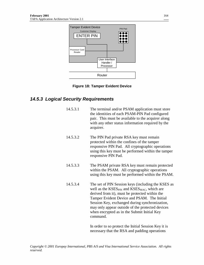
February 2001TAPA Application Architecture Version 2.1
Copyright © 2001 Europay International, PBS A/S and Visa International Service Association. All rightsreserved.
164
ENTER PIN
Processor CardReader
User InterfaceHandler /Processor
Tamper Evident DeviceCustomer Display
Router
PIN Pad
Figure 18: Tamper Evident Device
14.5.3 Logical Security Requirements
14.5.3.1 The terminal and/or PSAM application must storethe identities of each PSAM-PIN Pad configuredpair. This must be available to the acquirer alongwith any other status information required by theacquirer.
14.5.3.2 The PIN Pad private RSA key must remainprotected within the confines of the tamperresponsive PIN Pad. All cryptographic operationsusing this key must be performed within the tamperresponsive PIN Pad.
14.5.3.3 The PSAM private RSA key must remain protectedwithin the PSAM. All cryptographic operationsusing this key must be performed within the PSAM.
14.5.3.4 The set of PIN Session keys (including the KSES aswell as the KSESPIN and KSESMAC, which arederived from it), must be protected within theTamper Evident Device and PSAM. The InitialSession Key, exchanged during synchronization,may only appear outside of the protected deviceswhen encrypted as in the Submit Initial Keycommand.
In order to so protect the Initial Session Key it isnecessary that the RSA and padding operations
February 2001TAPA Application Architecture Version 2.1
Copyright © 2001 Europay International, PBS A/S and Visa International Service Association. All rightsreserved.
165
defined in sections 7.2.4.2 and 7.2.4.4 be performedwithin the protected devices.
14.5.3.5 The set of PIN Session keys must only be used inthe manner specified within this document; theymust not be used for any other purposes.
14.5.3.6 Only an authenticated Initiate PIN Entry commandmay cause the Tamper Evident Device to be putinto PIN Entry state.
14.5.3.7 When in PIN Entry State the Display may onlyshow messages authenticated by the PSAM.Authenticated messages includes generic writestring messages sent from the PSAM with a MAC,as well as messages referenced by “MessageCodes”, which have been personalized into the PINPad.
14.5.3.8 When in PIN Entry State, any commands thatrequire authentication must not be accepted by theTamper Evident Device if they do not contain aMAC from the PSAM that sent the Initiate PINEntry command.
14.5.3.9 A PIN must never appear in plaintext outside theconfines of the PSAM or Tamper Evident Device.
14.5.4 Personalization Requirements
14.5.4.1 After personalization and initial synchronization,the PIN Pad must contain the data elements definedin Table 161.
14.5.4.2 After personalization and configuration the PSAMmust contain the PIN related data elements definedin Table 162.
14.5.4.3 The PIN Pad and PSAM must each be personalizedwith at least one key/certificate hierarchy chain andone CA public key. Depending on the acquirer’srequirements for the life span of the PIN Pad andPSAM and on the CA’s requirements for migrationto longer key lengths, additional chains and CApublic keys may be inserted at personalization.
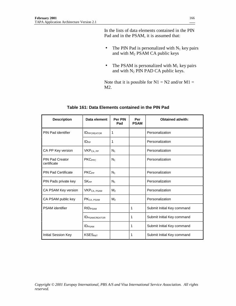
February 2001TAPA Application Architecture Version 2.1
Copyright © 2001 Europay International, PBS A/S and Visa International Service Association. All rightsreserved.
166
In the lists of data elements contained in the PINPad and in the PSAM, it is assumed that:
• The PIN Pad is personalized with N1 key pairsand with M2 PSAM CA public keys
• The PSAM is personalized with M1 key pairsand with N2 PIN PAD CA public keys.
Note that it is possible for N1 = N2 and/or M1 =M2.
Table 161: Data Elements contained in the PIN Pad
Description Data element Per PINPad
PerPSAM
Obtained at/with:
IDPPCREATOR 1 PersonalizationPIN Pad identifier
IDPP 1 Personalization
CA PP Key version VKPCA, PP N1 Personalization
PIN Pad Creatorcertificate
PKCPPC N1 Personalization
PIN Pad Certificate PKCPP N1 Personalization
PIN Pads private key SKPP N1 Personalization
CA PSAM Key version VKPCA, PSAM M2 Personalization
CA PSAM public key PKCA, PSAM M2 Personalization
RIDPSAM 1 Submit Initial Key command
IDPSAMCREATOR 1 Submit Initial Key command
PSAM identifier
IDPSAM 1 Submit Initial Key command
Initial Session Key KSESINIT 1 Submit Initial Key command
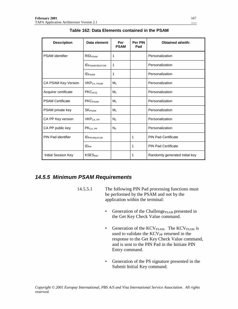
February 2001TAPA Application Architecture Version 2.1
Copyright © 2001 Europay International, PBS A/S and Visa International Service Association. All rightsreserved.
167
Table 162: Data Elements contained in the PSAM
Description Data element PerPSAM
Per PINPad
Obtained at/with:
RIDPSAM 1 Personalization
IDPSAMCREATOR 1 Personalization
PSAM identifier
IDPSAM 1 Personalization
CA PSAM Key Version VKPCA, PSAM M1 Personalization
Acquirer certificate PKCACQ M1 Personalization
PSAM Certificate PKCPSAM M1 Personalization
PSAM private key SKPSAM M1 Personalization
CA PP Key version VKPCA, PP N2 Personalization
CA PP public key PKCA, PP N2 Personalization
IDPPCREATOR 1 PIN Pad CertificatePIN Pad identifier
IDPP 1 PIN Pad Certificate
Initial Session Key KSESINIT 1 Randomly generated initial key
14.5.5 Minimum PSAM Requirements
14.5.5.1 The following PIN Pad processing functions mustbe performed by the PSAM and not by theapplication within the terminal:
• Generation of the ChallengePSAM presented inthe Get Key Check Value command.
• Generation of the KCVPSAM. The KCVPSAM isused to validate the KCVPP returned in theresponse to the Get Key Check Value command,and is sent to the PIN Pad in the Initiate PINEntry command.
• Generation of the PS signature presented in theSubmit Initial Key command.
February 2001TAPA Application Architecture Version 2.1
Copyright © 2001 Europay International, PBS A/S and Visa International Service Association. All rightsreserved.
168
• Generation of the MAC on all authenticatedcommands sent to the PIN Pad.
• Verification of the MAC on all authenticatedresponses received from the PIN Pad.
• Decryption and encryption of the PIN.
• Encryption of any commands used for PINverification being sent to the IC card.
14.6 Cryptographic Requirements
14.6.1 Verifying a Certificate - General RequirementsThis section defines the general requirements for certificateverification in accordance with ISO/IEC 9796-2. This correspondsto the process defined in Annex E.2.1.3 of EMV 3.1.1.
Verification of a certificate begins with recovery of the certificatedata using the appropriate public key (either the CA public key orthe key resulting from verification of the next higher levelcertificate) and its associated algorithm ALGP.
14.6.1.1 Recovery of the certificate data must be performedusing the process described in Annex F.2.1 of EMV3.1.1.
14.6.1.2 The recovery can only be performed if the length ofthe certificate is the same as the length of themodulus of the public key used in the verification.If the lengths are different, verification has failed.
14.6.1.3 After recovering the recoverable certificate data, theheader (first byte) and the trailer (last byte) must bechecked. The header must be ‘6A’ (if there is anassociated remainder field) or ‘4A’ (if there is noassociated remainder field) and the trailer must be‘BC’. If this is not the case then verification of thecertificate has failed.
14.6.1.4 If the public key algorithm indicator is notrecognized then verification has failed.
February 2001TAPA Application Architecture Version 2.1
Copyright © 2001 Europay International, PBS A/S and Visa International Service Association. All rightsreserved.
169
14.6.1.5 The hash value is a 20 byte field immediatelypreceding the trailer (last byte) of the recoveredcertificate data and must be verified according tothe following procedure:
The following data must be concatenated in order(left to right):
1. All data beginning with the format code in therecovered certificate data (which is always thesecond byte of the recovered certificate data) upto and including the last byte before the hashvalue, in the order in which it appears in therecovered certificate data.
2. The Public Key Remainder (PKR), if it exists.
14.6.1.6 The hash algorithm indicated in the certificate(SHA-1 is the only hash algorithm supported) mustbe applied to the concatenation, producing a 20-byteresult. This result is compared to the hash valuerecovered from the certificate. If they are unequal,then certificate verification has failed.
14.6.2 Authentication of the PIN Pad Public KeyThe PSAM must determine the correct set of certificates to be usedfor a transaction by examining the list of key versions(VKPCA, PSAM) returned by the PIN Pad in its response to the GetKey Check Value command.
PSAM Authentication of the PIN Pad public key consists of:
1. Determination that a public key hierarchy in the PIN Pad canbe processed by the PSAM.
2. Use of the Get PIN Pad Public Key Record command toretrieve certificates from the PIN Pad.
3. Verification of the certificates.
14.6.2.1 The PSAM must verify that a version (VKPCA, PP) ofthe CA public key used to create the PIN PadCreator certificate (and so identified in the responseto the Get Key Check Value command) matches aversion number of a PKCA, PP in the PSAM. If thereis no match, the process is aborted.
February 2001TAPA Application Architecture Version 2.1
Copyright © 2001 Europay International, PBS A/S and Visa International Service Association. All rightsreserved.
170
14.6.2.2 The PSAM issues Get PIN Pad public key recordcommands to obtain certificate records from thePIN Pad. The PSAM must verify the certificates insequence:
• The PIN Pad Creator certificate, using theALGCA,PP and the PKCA,PP specified by theVKPCA,PP.
• The PIN Pad certificate, using the ALGPPC andthe PKPPC retrieved from the PIN Pad Creatorcertificate.
14.6.2.3 The general checks in Section 14.6.1 must beperformed. If any of these fail then PIN Pad publickey authentication has failed.
14.6.2.4 The PSAM must also check that:
1. the IDPPCREATOR retrieved from the PIN PadCreator certificate is the same as that providedin the response to the Get Key Check Valuecommand.
2. The Format code retrieved from the PIN PadCreator certificate is equal to 'C2'.
3. IDPPCREATOR and IDPP retrieved from the PINPad certificate are the same as those provided inthe response to the Get Key Check Valuecommand.
4. The Format code retrieved from the PIN Padcertificate is equal to 'C4'.
5. For each certificate, the month specified in theCertificate Expiration Date is equal to or laterthan the current month.
If any these checks fail, then the PIN Pad public keyhas failed authentication.
14.6.3 Authentication of the PSAM Public KeyThe PIN Pad contains one or more CA public keys (PKCA,PSAM) forthe purpose of authenticating the PSAM in the POS device. The
February 2001TAPA Application Architecture Version 2.1
Copyright © 2001 Europay International, PBS A/S and Visa International Service Association. All rightsreserved.
171
PSAM must contain the necessary certificates for use with aPKCA,PSAM in the PIN Pad.
PIN Pad authentication of the PSAM public key consists of:
1. Determination by the PSAM that the PIN Pad can process apublic key hierarchy in the PSAM.
2. Use of the Verify PSAM Public Key Certificate command tosend certificates from the PSAM to the PIN Pad.
3. PIN Pad verification of the certificates.
14.6.3.1 After receiving and validating the response to theGet Key Check Value command (with KCVs notidentical), the PSAM must verify that a version ofthe CA public key (VKPCA,PSAM) in the response tothe Get Key Check Value command matches a CApublic key version under which the PSAM iscertified. If there is no match, the process isaborted.
Certificates are provided to the PIN Pad using theVerify PSAM Public Key Certificate as shown inSection 7.2.3. The format of the certificate recordsis described in Section 14.6.9.
14.6.3.2 The PSAM must send and the PIN Pad must verifycertificates in sequence:
• The Acquirer certificate, using the ALGCA,PSAMand the PKCA,PSAM specified by the VKPCA,PSAM.
• The PSAM certificate, using the ALGACQ andthe PKACQ retrieved from the Acquirercertificate.
14.6.3.3 The general checks in Section 14.6.1 must beperformed. If any of these fail then PSAM publickey authentication has failed.
14.6.3.4 The PIN Pad must also check that
1. RIDPSAMCREATOR and IDPSAMCREATOR retrievedfrom the PSAM certificate are the same as theRIDPSAMCREATOR and IDPSAMCREATOR retrieved
February 2001TAPA Application Architecture Version 2.1
Copyright © 2001 Europay International, PBS A/S and Visa International Service Association. All rightsreserved.
172
from the Acquirer Certificate which in turn arethe same as the RIDPSAMCREATOR andIDPSAMCREATOR in the Get Key Check Valuecommand.
2. The Format code retrieved from the Acquirercertificate is equal to 'A2'.
3. IDPSAM retrieved from the PSAM certificate isthe same as the IDPSAM provided in the Get KeyCheck Value command.
4. The Format code retrieved from the PSAMcertificate is equal to 'A4'.
5. For each certificate the last day of the monthspecified in the Certificate Expiration Date isequal to or later than the PIN Pad reference date(if it has one).
If any these checks fail, then the PSAM public keyhas failed authentication.
14.6.4 DES and Triple DESDES and Triple DES are block ciphers standardized in FIPS PUB46-3.
DES, denoted DES()[], operates on a 64-bit input block and a 64-bit key to produce a 64-bit output block. The number of effectivekey bits in a DES key is only 56 because every 8th bit of the 64-bitkey takes on the value of a parity bit, thereby ensuring that thereare an odd number of "1"s in each key byte.
Triple DES, denoted DES3()[], is implemented using threeiterations of the DES block cipher with two independent DES keysK1 and K2.
Specifically, the ciphertext Y of an 8-byte input block X is
Y = DES3(K1, K2)[X] = DES(K1)[DES-1(K2)[DES(K1)[X]]].
Decryption is performed as
X = DES3-1(K1, K2)[Y] = DES-1(K1)[DES(K2)[DES-1(K1)[Y]]]
Note that for general encryption the padding and blocking processin Section 14.6.5 should be adhered to.
February 2001TAPA Application Architecture Version 2.1
Copyright © 2001 Europay International, PBS A/S and Visa International Service Association. All rightsreserved.
173
14.6.5 Encryption and Decryption
14.6.5.1 To encrypt any message, MSG, it must first bepadded to the right with ‘80’ and then with as many‘00’ bytes as necessary (possibly zero) until it is amultiple of 8 bytes:
X : = MSG||'80'||'00'||… ||'00';
14.6.5.2 X is then divided into 8-byte blocks X1, X2, .., Xkand processed using Triple DES in Cipher BlockChaining mode:
Y0 = ‘0000000000000000’
Yi = DES3(K1,K2)[Xi ⊕ Yi-1] for i = 1 to k
14.6.5.3 The encrypted message is
Enc(K1,K2)[MSG] : = Y = Y1 || … || Yk
Note that this process always involves message padding so thatwhen the message is an eight-byte PIN block the ciphertext will be16-bytes long.
14.6.5.4 In order to decrypt a ciphertext message theencryption processed is merely reversed as shownbelow.
1. If the ciphertext is not a multiple of 8 bytes thendecryption has failed.
2. Divide the ciphertext Y into 8 byte blocks:
Y : = Y1 || … || Yk
3. Compute the blocks Xi as follows:
Xi = DES3-1(K1,K2)[Yi] ⊕ Yi-1 for i = 1 to k,where Y0 = ‘0000000000000000’
4. Concatenate the blocks Xi to form
X : = X1 || X2 || … || Xk
February 2001TAPA Application Architecture Version 2.1
Copyright © 2001 Europay International, PBS A/S and Visa International Service Association. All rightsreserved.
174
5. Strip off all trailing zero bytes (possibly none)from X and then the final ‘80’ byte to formMSG. If this last step is not possible thendecryption has failed.
6. If all the preceding steps are successful thenDec(K1,K2)[Y] := MSG
14.6.6 MAC computationMACs are computed using DES in Cipher Block Chaining Modewith Triple DES applied to the last block.
The MAC computation is denoted by MAC(K1, K2)[D]. Thecomputation conforms to ISO/IEC 9797-1:1999 Mechanism 3,using padding method 2 and DES as the block cipher. This is alsodescribed in EMV annex E1.2.
14.6.6.1 Input D to the MAC is first padded to the right with‘80’. The result is then padded to the right withenough bytes of ‘00’ (possibly none) to make theresult a multiple of 8 bytes long.
X: = MSG||'80'||'00'||… ||'00';
14.6.6.2 X is then divided into 8-byte blocks X1, X2, .., Xkand processed using Single DES in Cipher BlockChaining mode:
Y0 = ‘0000000000000000’
Yi = DES(K1)[Xi ⊕ Yi-1] for i = 1 to k
14.6.6.3 Finally the 8-byte MAC is computed as
MAC(K1,K2)[D] := DES(K1)[DES-1(K2)[Yk]]
14.6.7 RSA Operations
14.6.7.1 All RSA operations must be performed as describedin reference 7, EMV, annexes E and F.
The RSAencipher function corresponds to theRecover function defined in reference 7, EMV,Annex F.
February 2001TAPA Application Architecture Version 2.1
Copyright © 2001 Europay International, PBS A/S and Visa International Service Association. All rightsreserved.
175
The RSAdecipher function corresponds to the Signfunction defined in reference 7, EMV, Annex F.
14.6.8 RSA Padding
14.6.8.1 The process of RSA padding of data D of length 96bytes (768 bits) to a length L bytes (where L ≥113)is as defined below.
1. Generate a 16 byte random number r and a 1-byte random number α whose most significantbit is forced to ”0”.
2. Form G(r) by concatenating
SHA-1 (r || ‘00’) || SHA-1(r || ‘01’) || SHA-1(r ||‘02’) ||etc… until its length equals or exceeds L-17 bytes and then take the leftmost L-17 bytesas G(r).
3. Pad D to the left with (L-113) bytes of binaryzeros. (D will now have a length of L-17 bytes).
4. Compute:
PAD(D) := α || (D ⊕ G(r) ) || (r ⊕ SHA (D ⊕ G(r), 16))
14.6.8.2 D is recovered from PAD(D) as follows:
1. Define PAD(D) := α || β || γ, where
α is the first byte of PAD(D)β is the next L-17 bytes of PAD(D), andcorresponds to D ⊕ G(r)γ is the next (and final) 16 bytes of PAD(D)
2. Skip the first byte, α;
3. Compute R:= SHA(β, 16) ⊕ γ
4. Compute G(R)
5. D is the rightmost 96 bytes of β ⊕ G(R)
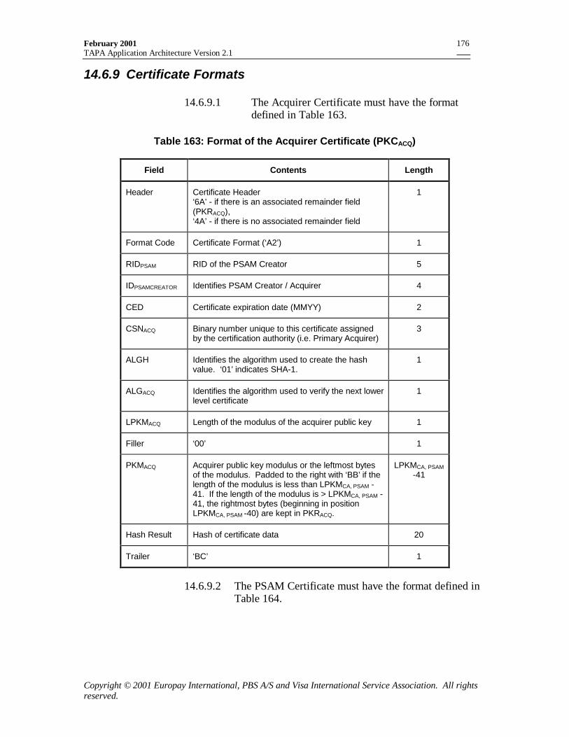
February 2001TAPA Application Architecture Version 2.1
Copyright © 2001 Europay International, PBS A/S and Visa International Service Association. All rightsreserved.
176
14.6.9 Certificate Formats
14.6.9.1 The Acquirer Certificate must have the formatdefined in Table 163.
Table 163: Format of the Acquirer Certificate (PKCACQ)
Field Contents Length
Header Certificate Header‘6A’ - if there is an associated remainder field(PKRACQ),‘4A’ - if there is no associated remainder field
1
Format Code Certificate Format (‘A2’) 1
RIDPSAM RID of the PSAM Creator 5
IDPSAMCREATOR Identifies PSAM Creator / Acquirer 4
CED Certificate expiration date (MMYY) 2
CSNACQ Binary number unique to this certificate assignedby the certification authority (i.e. Primary Acquirer)
3
ALGH Identifies the algorithm used to create the hashvalue. ‘01’ indicates SHA-1.
1
ALGACQ Identifies the algorithm used to verify the next lowerlevel certificate
1
LPKMACQ Length of the modulus of the acquirer public key 1
Filler ‘00’ 1
PKMACQ Acquirer public key modulus or the leftmost bytesof the modulus. Padded to the right with ‘BB’ if thelength of the modulus is less than LPKMCA, PSAM -41. If the length of the modulus is > LPKMCA, PSAM -41, the rightmost bytes (beginning in positionLPKMCA, PSAM -40) are kept in PKRACQ.
LPKMCA, PSAM-41
Hash Result Hash of certificate data 20
Trailer ‘BC’ 1
14.6.9.2 The PSAM Certificate must have the format defined inTable 164.
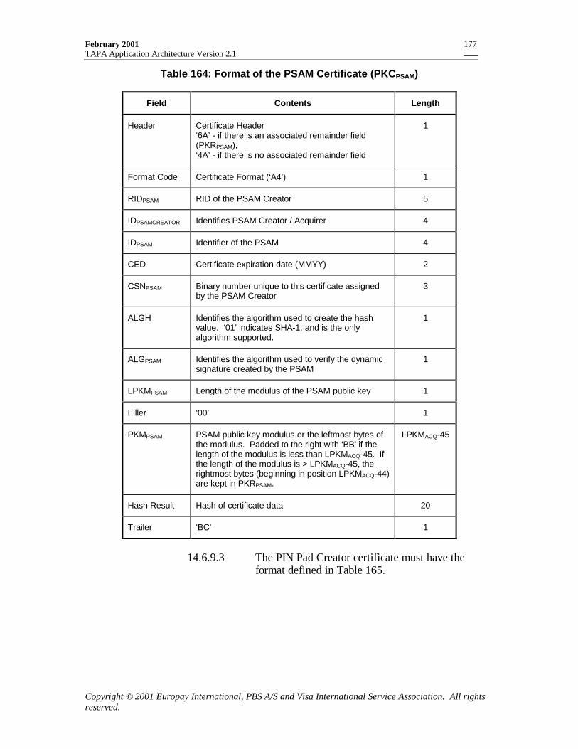
February 2001TAPA Application Architecture Version 2.1
Copyright © 2001 Europay International, PBS A/S and Visa International Service Association. All rightsreserved.
177
Table 164: Format of the PSAM Certificate (PKCPSAM)
Field Contents Length
Header Certificate Header‘6A’ - if there is an associated remainder field(PKRPSAM),‘4A’ - if there is no associated remainder field
1
Format Code Certificate Format (‘A4’) 1
RIDPSAM RID of the PSAM Creator 5
IDPSAMCREATOR Identifies PSAM Creator / Acquirer 4
IDPSAM Identifier of the PSAM 4
CED Certificate expiration date (MMYY) 2
CSNPSAM Binary number unique to this certificate assignedby the PSAM Creator
3
ALGH Identifies the algorithm used to create the hashvalue. ‘01’ indicates SHA-1, and is the onlyalgorithm supported.
1
ALGPSAM Identifies the algorithm used to verify the dynamicsignature created by the PSAM
1
LPKMPSAM Length of the modulus of the PSAM public key 1
Filler ‘00’ 1
PKMPSAM PSAM public key modulus or the leftmost bytes ofthe modulus. Padded to the right with ‘BB’ if thelength of the modulus is less than LPKMACQ-45. Ifthe length of the modulus is > LPKMACQ-45, therightmost bytes (beginning in position LPKMACQ-44)are kept in PKRPSAM.
LPKMACQ-45
Hash Result Hash of certificate data 20
Trailer ‘BC’ 1
14.6.9.3 The PIN Pad Creator certificate must have theformat defined in Table 165.
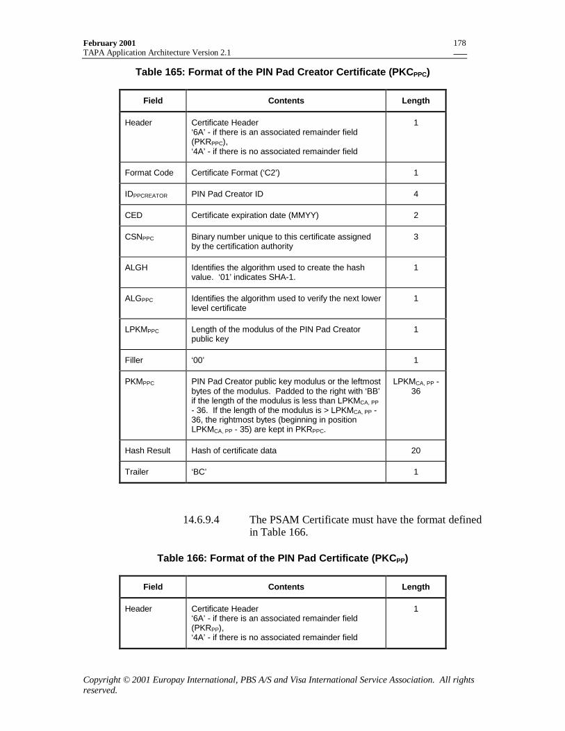
February 2001TAPA Application Architecture Version 2.1
Copyright © 2001 Europay International, PBS A/S and Visa International Service Association. All rightsreserved.
178
Table 165: Format of the PIN Pad Creator Certificate (PKCPPC)
Field Contents Length
Header Certificate Header‘6A’ - if there is an associated remainder field(PKRPPC),‘4A’ - if there is no associated remainder field
1
Format Code Certificate Format (‘C2’) 1
IDPPCREATOR PIN Pad Creator ID 4
CED Certificate expiration date (MMYY) 2
CSNPPC Binary number unique to this certificate assignedby the certification authority
3
ALGH Identifies the algorithm used to create the hashvalue. ‘01’ indicates SHA-1.
1
ALGPPC Identifies the algorithm used to verify the next lowerlevel certificate
1
LPKMPPC Length of the modulus of the PIN Pad Creatorpublic key
1
Filler ‘00’ 1
PKMPPC PIN Pad Creator public key modulus or the leftmostbytes of the modulus. Padded to the right with ‘BB’if the length of the modulus is less than LPKMCA, PP- 36. If the length of the modulus is > LPKMCA, PP -36, the rightmost bytes (beginning in positionLPKMCA, PP - 35) are kept in PKRPPC.
LPKMCA, PP -36
Hash Result Hash of certificate data 20
Trailer ‘BC’ 1
14.6.9.4 The PSAM Certificate must have the format definedin Table 166.
Table 166: Format of the PIN Pad Certificate (PKCPP)
Field Contents Length
Header Certificate Header‘6A’ - if there is an associated remainder field(PKRPP),‘4A’ - if there is no associated remainder field
1
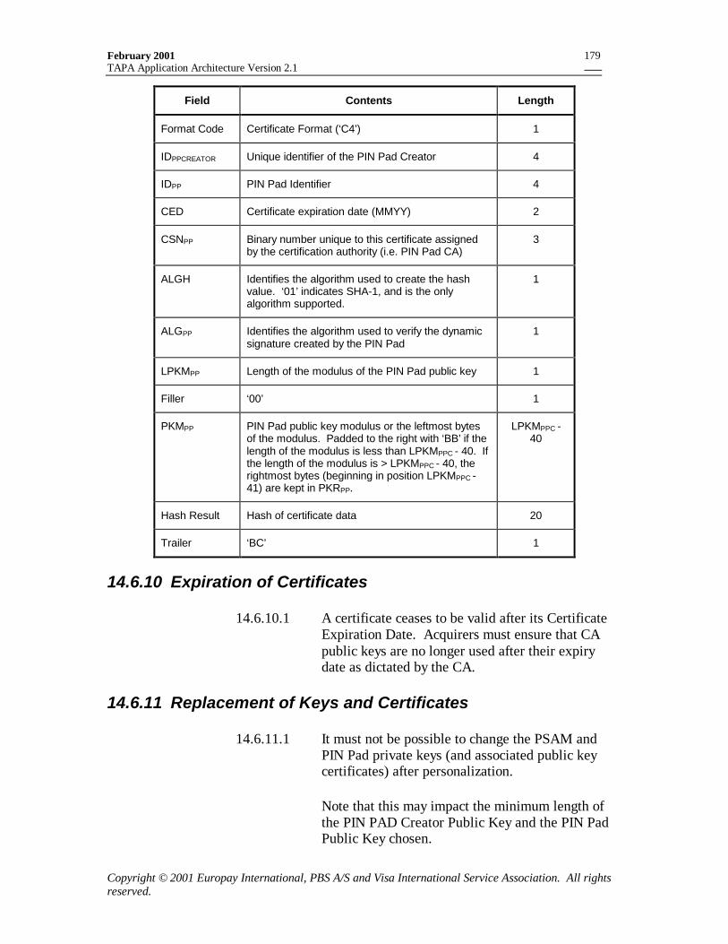
February 2001TAPA Application Architecture Version 2.1
Copyright © 2001 Europay International, PBS A/S and Visa International Service Association. All rightsreserved.
179
Field Contents Length
Format Code Certificate Format (‘C4’) 1
IDPPCREATOR Unique identifier of the PIN Pad Creator 4
IDPP PIN Pad Identifier 4
CED Certificate expiration date (MMYY) 2
CSNPP Binary number unique to this certificate assignedby the certification authority (i.e. PIN Pad CA)
3
ALGH Identifies the algorithm used to create the hashvalue. ‘01’ indicates SHA-1, and is the onlyalgorithm supported.
1
ALGPP Identifies the algorithm used to verify the dynamicsignature created by the PIN Pad
1
LPKMPP Length of the modulus of the PIN Pad public key 1
Filler ‘00’ 1
PKMPP PIN Pad public key modulus or the leftmost bytesof the modulus. Padded to the right with ‘BB’ if thelength of the modulus is less than LPKMPPC - 40. Ifthe length of the modulus is > LPKMPPC - 40, therightmost bytes (beginning in position LPKMPPC -41) are kept in PKRPP.
LPKMPPC -40
Hash Result Hash of certificate data 20
Trailer ‘BC’ 1
14.6.10 Expiration of Certificates
14.6.10.1 A certificate ceases to be valid after its CertificateExpiration Date. Acquirers must ensure that CApublic keys are no longer used after their expirydate as dictated by the CA.
14.6.11 Replacement of Keys and Certificates
14.6.11.1 It must not be possible to change the PSAM andPIN Pad private keys (and associated public keycertificates) after personalization.
Note that this may impact the minimum length ofthe PIN PAD Creator Public Key and the PIN PadPublic Key chosen.
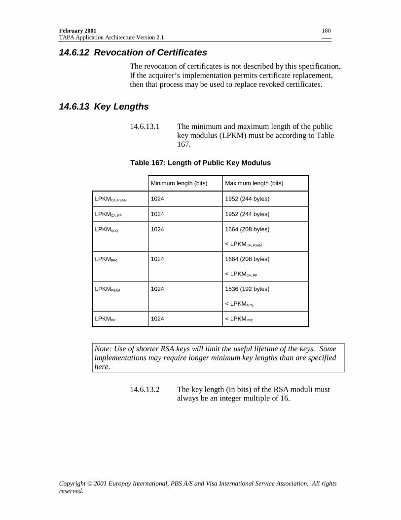
February 2001TAPA Application Architecture Version 2.1
Copyright © 2001 Europay International, PBS A/S and Visa International Service Association. All rightsreserved.
180
14.6.12 Revocation of CertificatesThe revocation of certificates is not described by this specification.If the acquirer’s implementation permits certificate replacement,then that process may be used to replace revoked certificates.
14.6.13 Key Lengths
14.6.13.1 The minimum and maximum length of the publickey modulus (LPKM) must be according to Table167.
Table 167: Length of Public Key Modulus
Minimum length (bits) Maximum length (bits)
LPKMCA, PSAM 1024 1952 (244 bytes)
LPKMCA, PP 1024 1952 (244 bytes)
LPKMACQ 1024 1664 (208 bytes)
< LPKMCA, PSAM
LPKMPPC 1024 1664 (208 bytes)
< LPKMCA, PP
LPKMPSAM 1024 1536 (192 bytes)
< LPKMACQ
LPKMPP 1024 < LPKMPPC
Note: Use of shorter RSA keys will limit the useful lifetime of the keys. Someimplementations may require longer minimum key lengths than are specifiedhere.
14.6.13.2 The key length (in bits) of the RSA moduli mustalways be an integer multiple of 16.
February 2001TAPA Application Architecture Version 2.1
Copyright © 2001 Europay International, PBS A/S and Visa International Service Association. All rightsreserved.
181
15. Response and Message Codes15.1 Response Codes
This section contains a summary of Response Codes that may begenerated by various components of the terminal application.
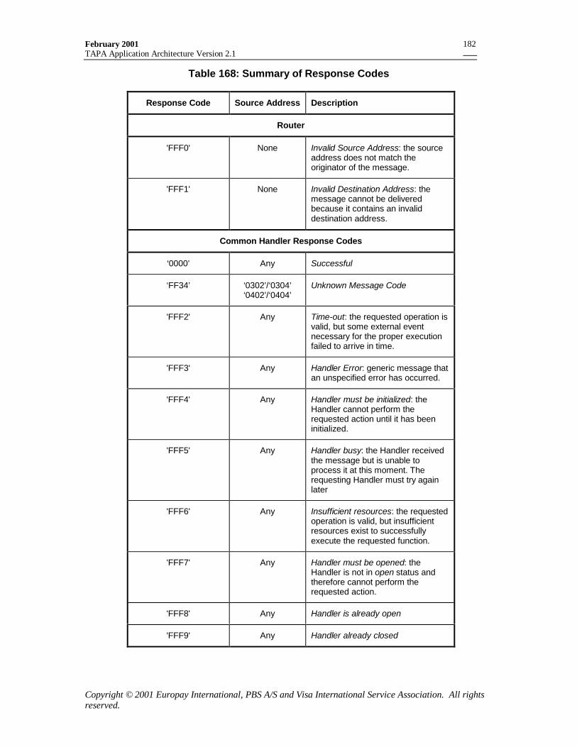
February 2001TAPA Application Architecture Version 2.1
Copyright © 2001 Europay International, PBS A/S and Visa International Service Association. All rightsreserved.
182
Table 168: Summary of Response Codes
Response Code Source Address Description
Router
'FFF0' None Invalid Source Address: the sourceaddress does not match theoriginator of the message.
'FFF1' None Invalid Destination Address: themessage cannot be deliveredbecause it contains an invaliddestination address.
Common Handler Response Codes
‘0000’ Any Successful
‘FF34’ ‘0302’/‘0304’‘0402’/‘0404’
Unknown Message Code
'FFF2' Any Time-out: the requested operation isvalid, but some external eventnecessary for the proper executionfailed to arrive in time.
'FFF3' Any Handler Error: generic message thatan unspecified error has occurred.
'FFF4' Any Handler must be initialized: theHandler cannot perform therequested action until it has beeninitialized.
'FFF5' Any Handler busy: the Handler receivedthe message but is unable toprocess it at this moment. Therequesting Handler must try againlater
'FFF6' Any Insufficient resources: the requestedoperation is valid, but insufficientresources exist to successfullyexecute the requested function.
'FFF7' Any Handler must be opened: theHandler is not in open status andtherefore cannot perform therequested action.
'FFF8' Any Handler is already open
'FFF9' Any Handler already closed
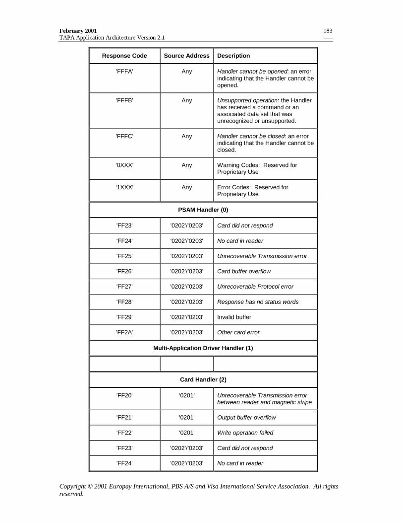
February 2001TAPA Application Architecture Version 2.1
Copyright © 2001 Europay International, PBS A/S and Visa International Service Association. All rightsreserved.
183
Response Code Source Address Description
'FFFA' Any Handler cannot be opened: an errorindicating that the Handler cannot beopened.
'FFFB’ Any Unsupported operation: the Handlerhas received a command or anassociated data set that wasunrecognized or unsupported.
'FFFC’ Any Handler cannot be closed: an errorindicating that the Handler cannot beclosed.
‘0XXX’ Any Warning Codes: Reserved forProprietary Use
‘1XXX’ Any Error Codes: Reserved forProprietary Use
PSAM Handler (0)
'FF23' '0202'/'0203' Card did not respond
'FF24' '0202'/'0203' No card in reader
'FF25' '0202'/'0203' Unrecoverable Transmission error
'FF26' '0202’/’0203' Card buffer overflow
'FF27' '0202’/’0203' Unrecoverable Protocol error
'FF28' '0202’/’0203' Response has no status words
'FF29' '0202’/’0203' Invalid buffer
'FF2A' '0202’/’0203' Other card error
Multi-Application Driver Handler (1)
Card Handler (2)
'FF20' ‘0201’ Unrecoverable Transmission errorbetween reader and magnetic stripe
'FF21' '0201' Output buffer overflow
'FF22' '0201' Write operation failed
'FF23' '0202’/’0203' Card did not respond
'FF24' '0202’/’0203' No card in reader
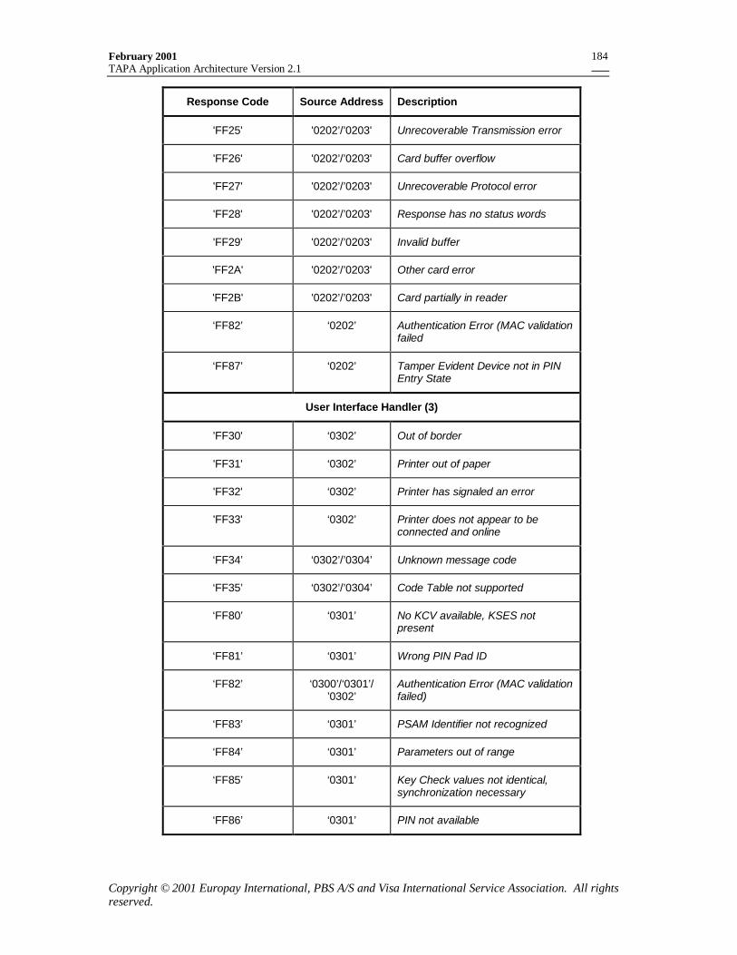
February 2001TAPA Application Architecture Version 2.1
Copyright © 2001 Europay International, PBS A/S and Visa International Service Association. All rightsreserved.
184
Response Code Source Address Description
'FF25' '0202’/’0203' Unrecoverable Transmission error
'FF26' '0202’/’0203' Card buffer overflow
'FF27' '0202’/’0203' Unrecoverable Protocol error
'FF28' '0202’/’0203' Response has no status words
'FF29' '0202’/’0203' Invalid buffer
'FF2A' '0202’/’0203' Other card error
'FF2B' '0202’/’0203' Card partially in reader
‘FF82’ ‘0202’ Authentication Error (MAC validationfailed
‘FF87’ ‘0202’ Tamper Evident Device not in PINEntry State
User Interface Handler (3)
'FF30' ‘0302’ Out of border
'FF31' ‘0302’ Printer out of paper
'FF32' ‘0302’ Printer has signaled an error
'FF33' ‘0302’ Printer does not appear to beconnected and online
‘FF34’ ‘0302’/’0304’ Unknown message code
‘FF35’ ‘0302’/’0304’ Code Table not supported
‘FF80’ ‘0301’ No KCV available, KSES notpresent
‘FF81’ ‘0301’ Wrong PIN Pad ID
‘FF82’ ‘0300’/‘0301’/’0302’
Authentication Error (MAC validationfailed)
‘FF83’ ‘0301’ PSAM Identifier not recognized
‘FF84’ ‘0301’ Parameters out of range
‘FF85’ ‘0301’ Key Check values not identical,synchronization necessary
‘FF86’ ‘0301’ PIN not available
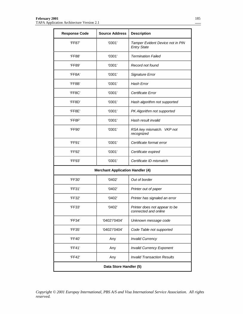
February 2001TAPA Application Architecture Version 2.1
Copyright © 2001 Europay International, PBS A/S and Visa International Service Association. All rightsreserved.
185
Response Code Source Address Description
‘FF87’ ‘0301’ Tamper Evident Device not in PINEntry State
‘FF88’ ‘0301’ Termination Failed
‘FF89’ ‘0301’ Record not found
‘FF8A’ ‘0301’ Signature Error
‘FF8B’ ‘0301’ Hash Error
‘FF8C’ ‘0301’ Certificate Error
‘FF8D’ ‘0301’ Hash algorithm not supported
‘FF8E’ ‘0301’ PK Algorithm not supported
‘FF8F’ ‘0301’ Hash result invalid
‘FF90’ ‘0301’ RSA key mismatch. VKP notrecognized
‘FF91’ ‘0301’ Certificate format error
‘FF92’ ‘0301’ Certificate expired
‘FF93’ ‘0301’ Certificate ID mismatch
Merchant Application Handler (4)
'FF30' ‘0402’ Out of border
'FF31' ‘0402’ Printer out of paper
'FF32' ‘0402’ Printer has signaled an error
'FF33' ‘0402’ Printer does not appear to beconnected and online
‘FF34’ ‘0402’/’0404’ Unknown message code
‘FF35’ ‘0402’/’0404’ Code Table not supported
‘FF40’ Any Invalid Currency
‘FF41’ Any Invalid Currency Exponent
‘FF42’ Any Invalid Transaction Results
Data Store Handler (5)
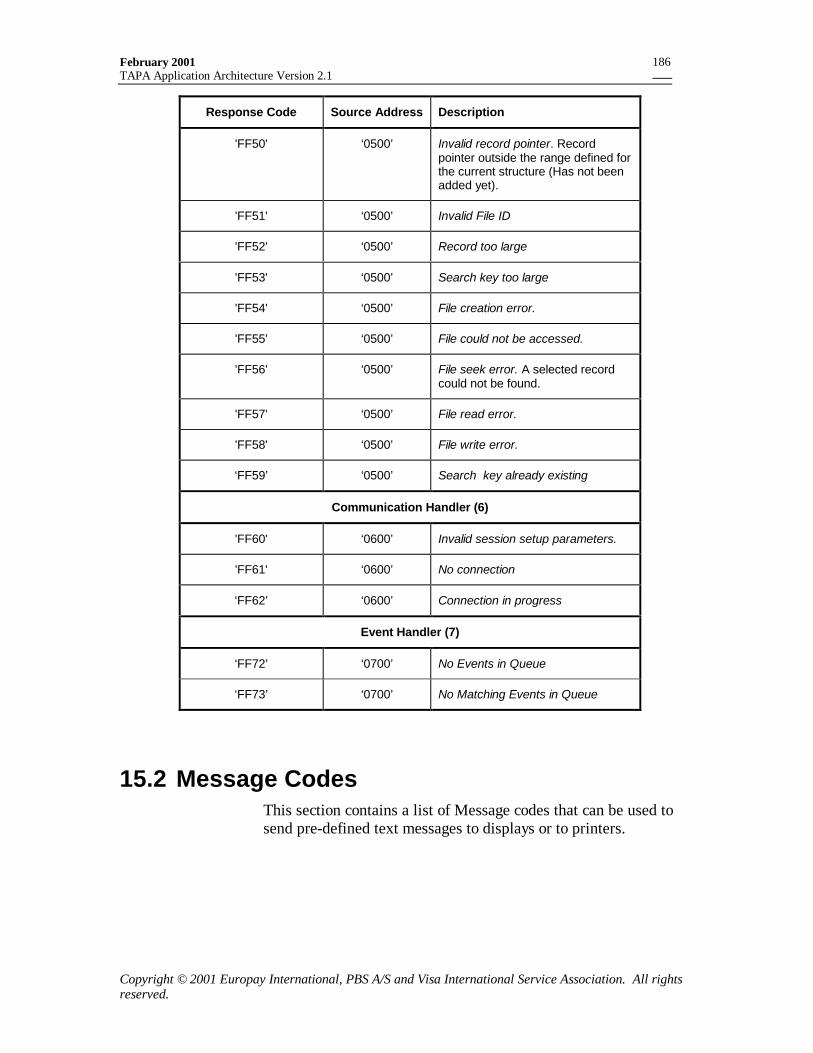
February 2001TAPA Application Architecture Version 2.1
Copyright © 2001 Europay International, PBS A/S and Visa International Service Association. All rightsreserved.
186
Response Code Source Address Description
'FF50' ‘0500’ Invalid record pointer. Recordpointer outside the range defined forthe current structure (Has not beenadded yet).
'FF51' ‘0500’ Invalid File ID
'FF52' ‘0500’ Record too large
'FF53' ‘0500’ Search key too large
'FF54' ‘0500’ File creation error.
'FF55' ‘0500’ File could not be accessed.
'FF56' ‘0500’ File seek error. A selected recordcould not be found.
'FF57' ‘0500’ File read error.
'FF58' ‘0500’ File write error.
‘FF59’ ‘0500’ Search key already existing
Communication Handler (6)
'FF60' ‘0600’ Invalid session setup parameters.
'FF61' ‘0600’ No connection
‘FF62’ ‘0600’ Connection in progress
Event Handler (7)
‘FF72’ ‘0700’ No Events in Queue
‘FF73’ ‘0700’ No Matching Events in Queue
15.2 Message CodesThis section contains a list of Message codes that can be used tosend pre-defined text messages to displays or to printers.
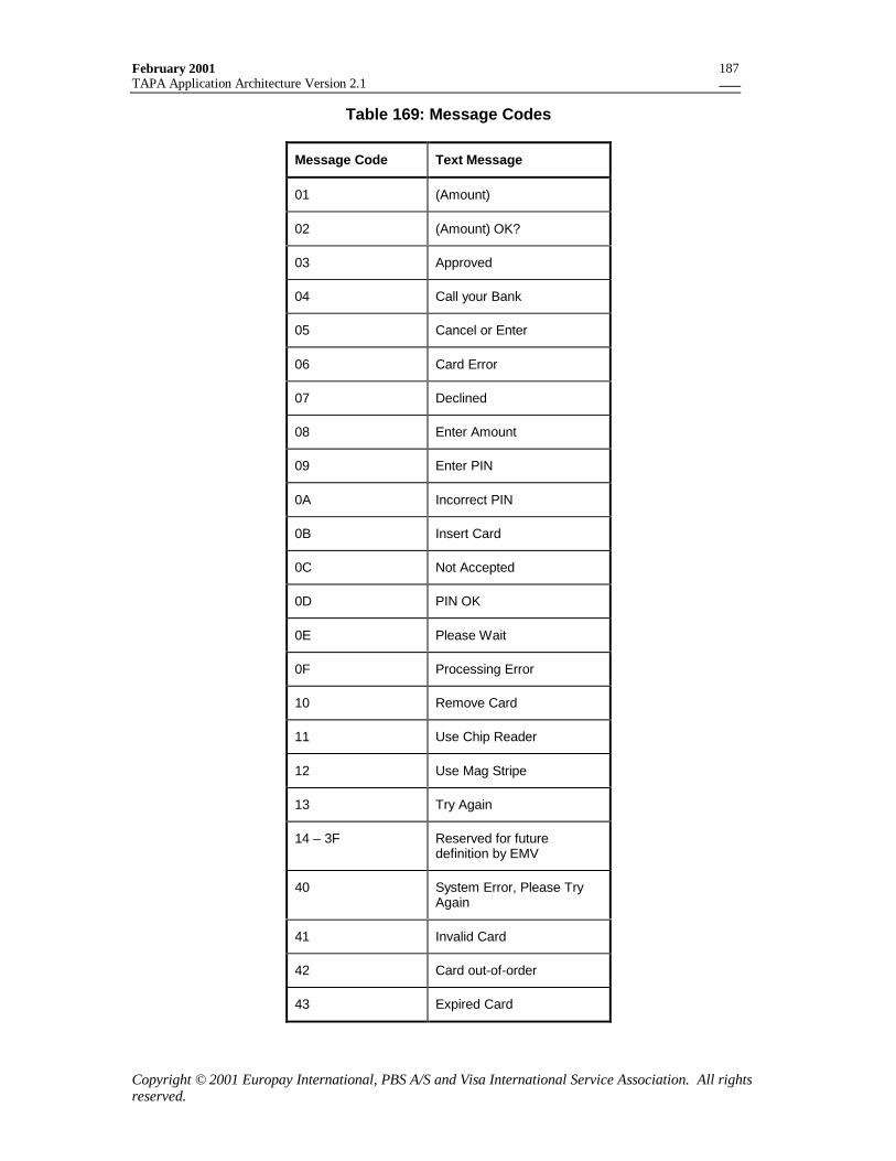
February 2001TAPA Application Architecture Version 2.1
Copyright © 2001 Europay International, PBS A/S and Visa International Service Association. All rightsreserved.
187
Table 169: Message Codes
Message Code Text Message
01 (Amount)
02 (Amount) OK?
03 Approved
04 Call your Bank
05 Cancel or Enter
06 Card Error
07 Declined
08 Enter Amount
09 Enter PIN
0A Incorrect PIN
0B Insert Card
0C Not Accepted
0D PIN OK
0E Please Wait
0F Processing Error
10 Remove Card
11 Use Chip Reader
12 Use Mag Stripe
13 Try Again
14 – 3F Reserved for futuredefinition by EMV
40 System Error, Please TryAgain
41 Invalid Card
42 Card out-of-order
43 Expired Card
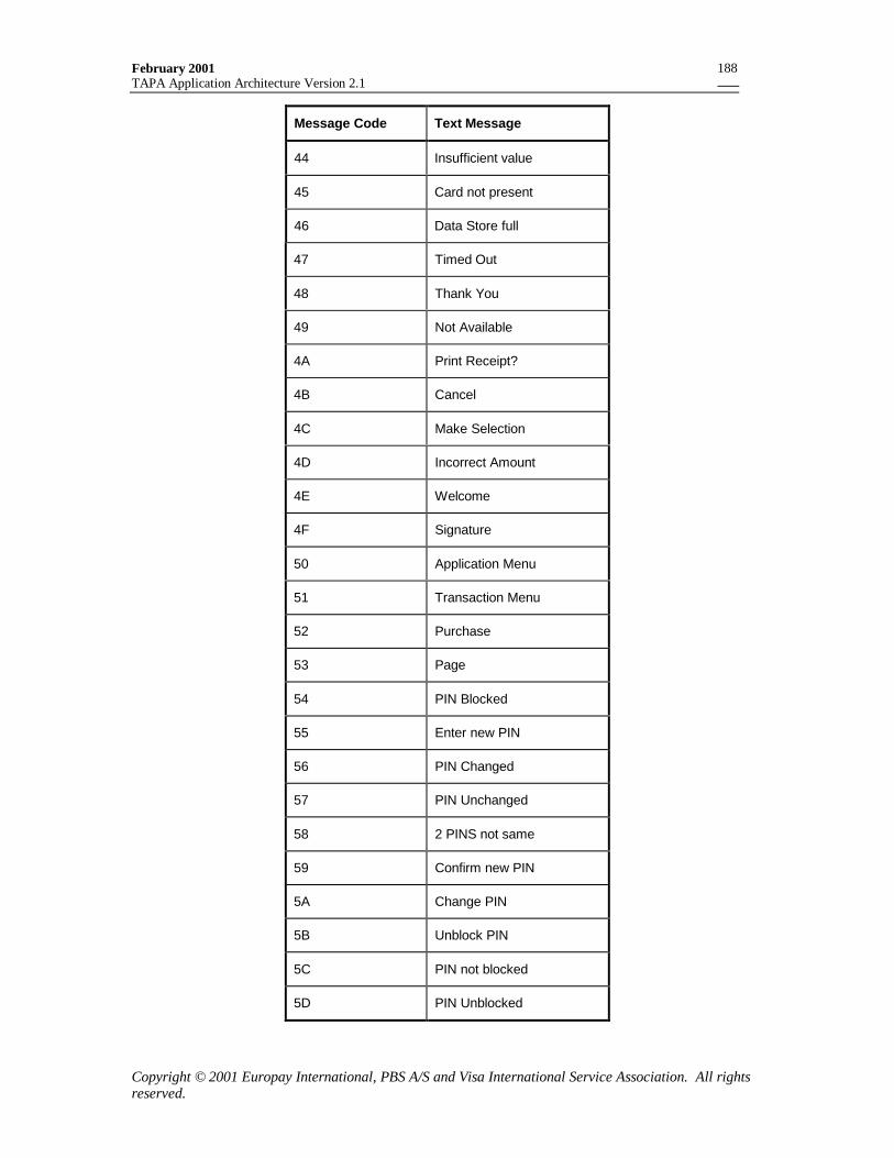
February 2001TAPA Application Architecture Version 2.1
Copyright © 2001 Europay International, PBS A/S and Visa International Service Association. All rightsreserved.
188
Message Code Text Message
44 Insufficient value
45 Card not present
46 Data Store full
47 Timed Out
48 Thank You
49 Not Available
4A Print Receipt?
4B Cancel
4C Make Selection
4D Incorrect Amount
4E Welcome
4F Signature
50 Application Menu
51 Transaction Menu
52 Purchase
53 Page
54 PIN Blocked
55 Enter new PIN
56 PIN Changed
57 PIN Unchanged
58 2 PINS not same
59 Confirm new PIN
5A Change PIN
5B Unblock PIN
5C PIN not blocked
5D PIN Unblocked
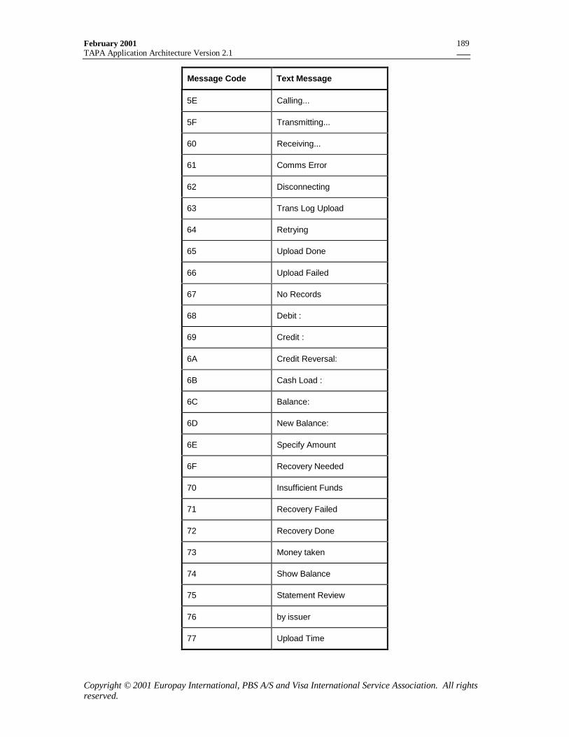
February 2001TAPA Application Architecture Version 2.1
Copyright © 2001 Europay International, PBS A/S and Visa International Service Association. All rightsreserved.
189
Message Code Text Message
5E Calling...
5F Transmitting...
60 Receiving...
61 Comms Error
62 Disconnecting
63 Trans Log Upload
64 Retrying
65 Upload Done
66 Upload Failed
67 No Records
68 Debit :
69 Credit :
6A Credit Reversal:
6B Cash Load :
6C Balance:
6D New Balance:
6E Specify Amount
6F Recovery Needed
70 Insufficient Funds
71 Recovery Failed
72 Recovery Done
73 Money taken
74 Show Balance
75 Statement Review
76 by issuer
77 Upload Time
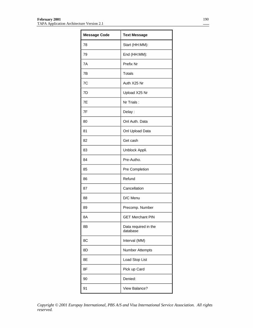
February 2001TAPA Application Architecture Version 2.1
Copyright © 2001 Europay International, PBS A/S and Visa International Service Association. All rightsreserved.
190
Message Code Text Message
78 Start (HH:MM):
79 End (HH:MM):
7A Prefix Nr
7B Totals
7C Auth X25 Nr
7D Upload X25 Nr
7E Nr Trials :
7F Delay :
80 Onl Auth. Data
81 Onl Upload Data
82 Get cash
83 Unblock Appli.
84 Pre-Autho.
85 Pre Completion
86 Refund
87 Cancellation
88 D/C Menu
89 Precomp. Number
8A GET Merchant PIN
8B Data required in thedatabase
8C Interval (MM)
8D Number Attempts
8E Load Stop List
8F Pick up Card
90 Denied:
91 View Balance?
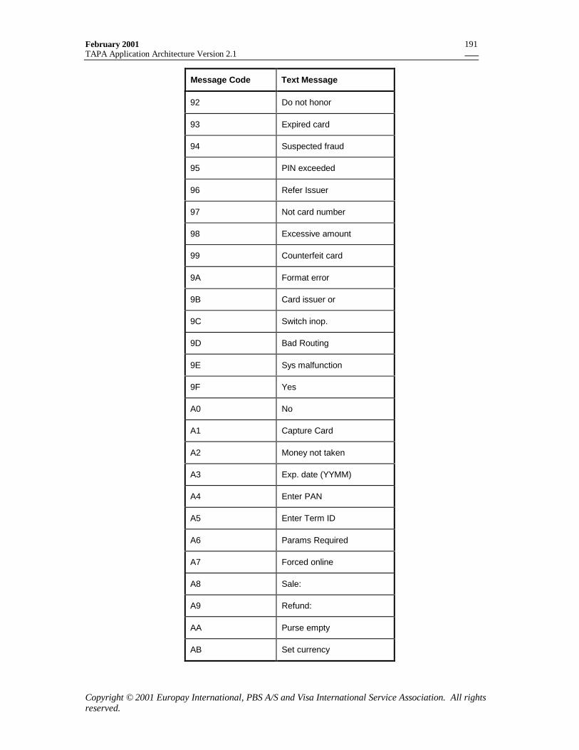
February 2001TAPA Application Architecture Version 2.1
Copyright © 2001 Europay International, PBS A/S and Visa International Service Association. All rightsreserved.
191
Message Code Text Message
92 Do not honor
93 Expired card
94 Suspected fraud
95 PIN exceeded
96 Refer Issuer
97 Not card number
98 Excessive amount
99 Counterfeit card
9A Format error
9B Card issuer or
9C Switch inop.
9D Bad Routing
9E Sys malfunction
9F Yes
A0 No
A1 Capture Card
A2 Money not taken
A3 Exp. date (YYMM)
A4 Enter PAN
A5 Enter Term ID
A6 Params Required
A7 Forced online
A8 Sale:
A9 Refund:
AA Purse empty
AB Set currency
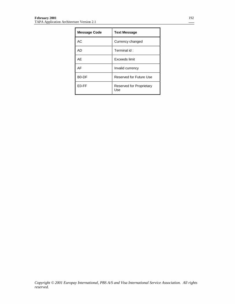
February 2001TAPA Application Architecture Version 2.1
Copyright © 2001 Europay International, PBS A/S and Visa International Service Association. All rightsreserved.
192
Message Code Text Message
AC Currency changed
AD Terminal id :
AE Exceeds limit
AF Invalid currency
B0-DF Reserved for Future Use
E0-FF Reserved for ProprietaryUse
February 2001TAPA Application Architecture Version 2.1
Copyright © 2001 Europay International, PBS A/S and Visa International Service Association. All rightsreserved.
193
16. Data Elements16.1.1 AIDN
Purpose: To indicate an AID that is supported by the PSAM, and which PSAMapplication is to be used to process transactions for that AID. Usedduring the Application Selection process.
Format: 5-16 bytes (binary).
Contents: RID || PIX where the RID is the five-byte global registered identifier asspecified in ISO/IEC 7816-5 and the PIX (0-11 bytes) is at the schemeprovider’s discretion.
16.1.2 ALG
Purpose: To indicate the public key algorithm used in public key cryptographyduring the synchronization between a PIN Pad and a PSAM application.It also indicates the value of the public key exponent that is certified bythis certificate.
Format: 1 byte (binary).
Content: See Table 170
Remarks: Used to identify the algorithm that is used to verify the next lower levelcertificate or signature. The subscript indicates the certificate containingthe ALG.
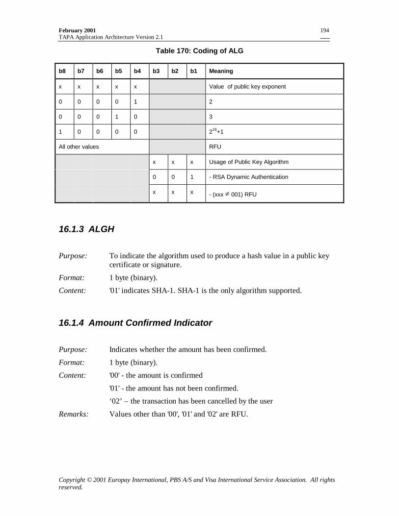
February 2001TAPA Application Architecture Version 2.1
Copyright © 2001 Europay International, PBS A/S and Visa International Service Association. All rightsreserved.
194
Table 170: Coding of ALG
b8 b7 b6 b5 b4 b3 b2 b1 Meaning
x x x x x Value of public key exponent
0 0 0 0 1 2
0 0 0 1 0 3
1 0 0 0 0 216+1
All other values RFU
x x x Usage of Public Key Algorithm
0 0 1 - RSA Dynamic Authentication
x x x - (xxx ≠ 001) RFU
16.1.3 ALGH
Purpose: To indicate the algorithm used to produce a hash value in a public keycertificate or signature.
Format: 1 byte (binary).
Content: '01' indicates SHA-1. SHA-1 is the only algorithm supported.
16.1.4 Amount Confirmed Indicator
Purpose: Indicates whether the amount has been confirmed.
Format: 1 byte (binary).
Content: '00' - the amount is confirmed
'01' - the amount has not been confirmed.
‘02’ – the transaction has been cancelled by the user
Remarks: Values other than '00', '01' and '02' are RFU.
February 2001TAPA Application Architecture Version 2.1
Copyright © 2001 Europay International, PBS A/S and Visa International Service Association. All rightsreserved.
195
16.1.5 Application Status Words (ASW1, ASW2)
Purpose: Indicates the results of a “process” command sent to the PSAM.
Format: 2 bytes (binary).
Content: As defined in section 10.3.2
16.1.6 ATR (Answer To Reset)
Purpose: Conveys the ATR returned by an IC card.
Format: Variable length, binary format
Content: As defined in ISO 7816-3 and EMV
16.1.7 [C-APDU]
Purpose: To hold an encrypted Card Command being sent to an ICC.
Format: Variable length
Content: A C-APDU encrypted under the current PIN session encryption key(KSESPIN).
16.1.8 Card Command
Purpose: To convey a Command APDU being sent to an IC card.
Format: variable length
Content: A C-APDU as defined in reference 4, ISO/IEC 7816-4.
16.1.9 Card Response
Purpose: To convey a Response APDU from an IC card.
Format: variable length
Content: A complete R-APDU, including the Status Words, as defined in reference4, ISO/IEC 7816-4.
February 2001TAPA Application Architecture Version 2.1
Copyright © 2001 Europay International, PBS A/S and Visa International Service Association. All rightsreserved.
196
16.1.10 CHALLENGE
Purpose: A number generated by the PIN Pad or PSAM, which allows each toauthenticate that messages have been received from a valid device.
Format: 4 bytes (binary).
Content: Any non-repeating or random value.
Remarks: The subscript indicates whether the PIN Pad or the PSAM generated theChallenge.
16.1.11 CLA (Class byte)
Purpose: To form a command code.
Format: 1 byte (binary).
Remarks: CLA is the ISO assigned instruction class byte, which in conjunctionwith the INS field forms the command code. See ISO/IEC 7816-4 for adiscussion of the Class byte.
16.1.12 CNTAID
Purpose: To indicate the number of AIDs being returned in the response to a GetSupported AIDs command.
Format: 1 byte (binary).
Content: 8-bit value, coded as an unsigned integer.
Remarks: Used with the command "Get Supported AIDs".
16.1.13 CNTSUBADDRESS
February 2001TAPA Application Architecture Version 2.1
Copyright © 2001 Europay International, PBS A/S and Visa International Service Association. All rightsreserved.
197
Purpose: To indicate the number of sub-addresses being returned in the response tothe Get Handler Addresses command
Format: 1 byte (binary).
Content: Holds the number of sub-addresses returned.
Remarks: Used with the command Get Handler Addresses
16.1.14 Code Table Index
Purpose: Identifies the character set in which display, printer or key-entered data iscoded.
Format: BCD, 1 byte
Content: ‘00’ indicates the Command Character Set defined in reference 7, EMVAnnex C.
‘nn’ indicates a code table as defined in reference 9, ISO 8859.
16.1.15 CSN (Certificate Serial Number)
Purpose: Unique number assigned to the certificate by the creator of the certificate.
Format: 3 bytes (binary).
Content: A unique number for a certificate.
16.1.16 CURR (Currency)
Purpose: Identifies the currency for a transaction
Format: BCD, 3 bytes in the form ‘0c cc 0e’, where ccc is the code assigned to thecurrency by ISO 4217, and e is the exponent.
Content: CURR contains both the currency code (CURRC) and the exponent(CURRE)
February 2001TAPA Application Architecture Version 2.1
Copyright © 2001 Europay International, PBS A/S and Visa International Service Association. All rightsreserved.
198
16.1.17 CURRC (Currency Code)
Purpose: Identifies the currency for a transaction
Format: BCD, 2 bytes in the form ‘0c cc’, where ccc is the code assigned to thecurrency by ISO 4217.
Content: CURRC contains only the currency code
16.1.18 CURRE (Currency Exponent)
Purpose: Identifies the exponent of the currency of a transaction
Format: BCD, 1 bytes in the form ‘0e’
Content: CURRE contains only the currency exponent
16.1.19 Destination Address (DAD)
Purpose: To identify the device to which a terminal message must be delivered.
Format: 2 bytes (binary).
Content: A handler address.
16.1.20 DS (Digital Signature)
Purpose: A digital signature created by the PSAM to allow the PIN Pad toauthenticate the PSAM during synchronization
Format: Variable length (binary) (The length of the PSAM public key modulus(LPKMPSAM) determines the length of DS.
Content: See section 7.2.4
February 2001TAPA Application Architecture Version 2.1
Copyright © 2001 Europay International, PBS A/S and Visa International Service Association. All rightsreserved.
199
16.1.21 DTHRPDA (Transaction date and time)
Purpose: To indicate a date and time.
Format: 5 bytes (BCD).
Content: 10 BCD digits: YYMMDDHHMM.
16.1.22 Enc(KSESPIN)[PIN]
Purpose: To hold an encrypted PIN block.
Format: 16 bytes (binary).
Content: Encrypted PIN block.
Remarks: See Figure 8 and Table 79 for the format of the PIN block.
16.1.23 Error Response Data
Purpose: To hold application specific response data.
Format: Variable length.
Content: Application-specific error response data.
16.1.24 Event Type Code
Purpose: To indicate the type of event.
Format: 1 byte (binary).
Content: See Table 149.
16.1.25 Event Location
Purpose: To indicate the handler that posted an event.
Format: 2 bytes (binary).
Content: A handler address.
February 2001TAPA Application Architecture Version 2.1
Copyright © 2001 Europay International, PBS A/S and Visa International Service Association. All rightsreserved.
200
16.1.26 File Identifier (IDFILE )
Purpose: Identifies a particular file that has been created in the data store.
Format: 2 bytes (binary).
Content: The unique identifier of a file.
Remarks A value of zeros (‘0000’) is not valid
16.1.27 Filler
Purpose: Used to fill out a record or block
Format: 1 byte (binary).
16.1.28 Format Code
Purpose: To indicate the type of certificate.
Format: 1 byte (binary).
Content: 8-bit value, unsigned integer.
Remarks: Examples of Format Codes: 'C2' = PKCPPC, 'C4' = PKCPP, 'A2' =PKCACQ, 'A4' = PKCPSAM
16.1.29 Handler Category Address
Purpose: Indicates the address of a Handler Category
Format: 1 byte (binary).
Content: Each device handler category is assigned a one-byte address. Individualhandlers are located by their handler category address, followed by a sub-handler address.
February 2001TAPA Application Architecture Version 2.1
Copyright © 2001 Europay International, PBS A/S and Visa International Service Association. All rightsreserved.
201
16.1.30 Handler Sub-Address
Purpose: In combination with the Handler category address, identifies a particularhandler.
Format: 1 byte (binary)
Content: Each device handler is assigned a two-byte address. Individual handlersare located by their handler category address, followed by a sub-handleraddress.
16.1.31 Historical Bytes
Purpose: The historical bytes are an optional element in the Answer-to-Reset froman IC card. The historical bytes designate general information, forexample, the card manufacturer, the chip inserted in the card, the maskedROM in the chip, the life-cycle state of the card.
Format: 0-15 bytes (binary).
Remarks: The contents of the historical bytes are at the discretion of the card issuer.See reference 4, ISO/IEC 7816-4 for additional information.
16.1.32 IDPP (PIN Pad ID)
Purpose: To identify a PIN Pad
Format: 4 bytes (binary).
Content: Serial number of the PIN Pad assigned by the PIN Pad Creator.
Remarks: Assigned by the entity identified by IDPPCREATOR. With the IDPPCREATORidentifies a PIN Pad within a POS device.
February 2001TAPA Application Architecture Version 2.1
Copyright © 2001 Europay International, PBS A/S and Visa International Service Association. All rightsreserved.
202
16.1.33 IDPPCREATOR (Identifier for the Creator of a PIN Pad)
Purpose: To identify the system or entity which generates personalization data forPIN Pads and assigns the IDPP.
Format: 4 bytes (binary).
Content: Number assigned to the PIN Pad Creator.
Remarks: Assigned by the primary acquirer. With the IDPPCREATOR identifies a PINPad within a POS device.
16.1.34 IDPSAM (Identifier for a PSAM)
Purpose: To identify a PSAM.
Format: 4 bytes (binary).
Content: Serial number of the PSAM assigned by the PSAM Creator.
Remarks: Assigned by the entity identified by IDPSAMCREATOR. With the RIDPSAMand the IDPSAMCREATOR uniquely identifies a PSAM.
16.1.35 IDPSAMAPP (TAPA PSAM Application Identifier)
Purpose: To identify a particular PSAM application
Format: 2 bytes (binary).
Content: • The first nibble is coded as follows:‘0’-‘7’ = applicationspecification defined by the international payment schemes.
§ ‘0’ = CEP application, ‘1’-‘7’ = RFU
• ‘8’-‘F’ = proprietary application specification.
February 2001TAPA Application Architecture Version 2.1
Copyright © 2001 Europay International, PBS A/S and Visa International Service Association. All rightsreserved.
203
16.1.36 IDPSAMCREATOR (Identifier for the Creator of the PSAM)
Purpose: To identify the system or entity which generates personalization data forPSAMs and assigns the IDPSAM.
Format: 4 bytes (binary).
Remarks: Assigned by the owner of the RIDPSAM. With the RIDPSAM, uniquelyidentifies the entity creating a PSAM.
16.1.37 IDSCHEME (Acquirer reference number)
Purpose: Used to identify a particular AID or scheme supported by the Acquirer
Format: 1 byte (binary).
Remarks: Assigned by the Acquirer or processor.
16.1.38 INS (Instruction byte)
Purpose: To identify a command.
Format: 1 byte.
Remarks: Used in conjunction with CLA to identify a command. See ISO/IEC7816-4.
16.1.39 KCV (Key Check Value)
Purpose: To verify the status of the session key shared between a PSAM and a PINPad.
Format: 3 bytes (binary).
Content: The 3 most significant bytes of the result of a triple-DES encryption of an8-byte block of binary zeros.
Remarks: The subscript indicates whether the PSAM or the PIN Pad computed theKCV.
February 2001TAPA Application Architecture Version 2.1
Copyright © 2001 Europay International, PBS A/S and Visa International Service Association. All rightsreserved.
204
16.1.40 Key Data
Purpose: The data to be used as a unique key for a data store record.
Format: LENSKEY bytes (binary).
Content: Any.
Remarks: Used when searching, adding and deleting data in records in files.
16.1.41 KSES
Purpose: A master session key used to derive session keys that are used for PINencryption and MACs between the PIN Pad and the PSAM.
Format: 16 bytes (binary).
16.1.42 KSESINIT
Purpose: To provide an initial key which is used to derive the first session key.
Format: 16 bytes (binary).
Remarks: Generated by the PSAM during synchronization with the PIN Pad.
16.1.43 KSESMAC
Purpose: A session key used to authenticate messages exchanged between thePSAM and the PIN Pad.
Format: 16 bytes (binary).
Remarks: Derived from the current master session key (KSES).
16.1.44 KSESPIN
Purpose: A session key used to encrypt PIN data being exchanged between thePSAM and the PIN Pad.
Format: 16 bytes (binary).
Remarks: Derived from the current master session key (KSES).
February 2001TAPA Application Architecture Version 2.1
Copyright © 2001 Europay International, PBS A/S and Visa International Service Association. All rightsreserved.
205
16.1.45 Lc (Data length)
Purpose: To indicate the number of bytes present in the data field of a command.
Format: 1 byte (binary).
Content: 8-bit value, coded as an unsigned integer.
Remarks: Omitted if no data is sent in a command. See ISO/IEC 7816-4.
16.1.46 Le (Expected data length)
Purpose: To indicate the maximum number of bytes expected in a response to acommand.
Format: 1 byte (binary).
Content: 8-bit value, coded as an unsigned integer.
Remarks: A value of ‘00’ indicates that the card must return all available data.Please see ISO/IEC 7816-4.
16.1.47 LDATA (Data field length)
Purpose: To indicate the length of a data field in a Terminal Message.
Format: 2 bytes (binary).
Remarks Message data lengths of at least 512 bytes must be supported. Terminalapplications must only rely on the ability to send longer messages in aproprietary environment.
16.1.48 LEN
Purpose: To indicate a length.
Format: 2 bytes (binary).
Content: 16-bit value, unsigned.
Remarks: Used to indicate a number of bytes to read.
February 2001TAPA Application Architecture Version 2.1
Copyright © 2001 Europay International, PBS A/S and Visa International Service Association. All rightsreserved.
206
16.1.49 LENAID,N
Purpose: To indicate the length of the N’th AID in the response to the GetSupported AIDs PSAM command.
Format: 1 byte (binary).
Content: 8-bit value, coded as an unsigned integer.
16.1.50 LENREC
Purpose: To indicate the length of a record.
Format: 2 bytes (binary).
Content: 16-bit value, coded as an unsigned integer.
Remarks: If the LENREC is coded as '0000' in an Add Record message, themaximum record size must be reserved. The actual record size ismaintained as ‘0000’ until a subsequent “Update Record” message
16.1.51 LENSKEY
Purpose: Indicates the length of the search key assigned to a file in the data store
Format: 1 byte (binary).
Content:
Remarks:
16.1.52 Length
Purpose: To indicate a length.
Format: 1 byte (binary).
Content: 8-bit value, coded as an unsigned integer.
February 2001TAPA Application Architecture Version 2.1
Copyright © 2001 Europay International, PBS A/S and Visa International Service Association. All rightsreserved.
207
16.1.53 LPKE (Length of a Public Key Exponent)
Purpose: To indicate the length of a Public Key Exponent.
Format: 1 byte (binary).
Remarks: The subscript indicates the exponent being referred to.
16.1.54 LPKM (Length of Public Key Modulus)
Purpose: To indicate the length in bytes of a Public Key Modulus.
Format: 1 byte (binary).
Remarks The subscript indicates the modulus being referred to.
16.1.55 MAC
Purpose: A MAC providing authentication of a data exchange between a PSAMand PIN Pad.
Format: 8 byte (binary).
Remarks: The subscript indicates the particular message in which the MAC islocated. The data being MACed is specified in each applicable message.
16.1.56 Magnetic Stripe Data
Purpose: To hold a set of data from a track.
Format: Variable
Content: Any.
Remarks: Includes u, Len and track Data.
February 2001TAPA Application Architecture Version 2.1
Copyright © 2001 Europay International, PBS A/S and Visa International Service Association. All rightsreserved.
208
16.1.57 Message Code
Purpose: To indicate a pre-defined message to be displayed or printed
Format: 1 byte (binary).
Content: See Table 169
16.1.58 Message Data
Purpose: The data portion of a Terminal message.
Format: Variable
Content: Specific to the Message Type
16.1.59 Message Type
Purpose: To identify the type of message.
Format: 1 byte (binary).
Content: SeeTable 4, Table 5 and Table 6.
Remarks: If Message Type is 'FF' the message is a response, any other valueindicates the message type of a command.
16.1.60 NUMFILE
Purpose: To indicate the number of files to create.
Format: 1 byte (binary).
Content: 8-bit value, coded as an unsigned integer.
February 2001TAPA Application Architecture Version 2.1
Copyright © 2001 Europay International, PBS A/S and Visa International Service Association. All rightsreserved.
209
16.1.61 Pad Pattern
Purpose: Padding bytes required in a public key certificate or signature
Format: variable length (binary).
Content: Successive bytes containing 'BB'
16.1.62 PK (Public Key)
Purpose: A public key is used by an entity to verify a certificate or signaturecreated by the owner of the public key. The public key of a PIN Pad isused by the PSAM for the purpose of encrypting messages to the PINPad.
Format: Variable length (binary).
Remarks: The subscript indicates the entity to which the public key belongs. Apublic key consists of the modulus (PKM) and the exponent (indicated inthe ALG field).
16.1.63 PKC (Public Key Certificate)
Purpose: A public key certificate is created by the next higher entity in thecertificate hierarchy.
Format: Variable length (binary). The length is the same of the length of thesigning public key modulus.
Remarks: The subscript indicates the entity to which the certificate belongs.
16.1.64 PKM (Public Key Modulus)
Purpose: A public key modulus is a component of a public key.
Format: Variable length (binary).
Remarks: The subscript indicates the entity to which the modulus belongs.
February 2001TAPA Application Architecture Version 2.1
Copyright © 2001 Europay International, PBS A/S and Visa International Service Association. All rightsreserved.
210
16.1.65 PKR (Public Key Remainder)
Purpose: Contains the rightmost bytes of the Public Key Modulus when the entiremodulus will not fit into the public key certificate.
Format: Variable length (binary).
Remarks: The subscript indicates the associated public key.
16.1.66 P1, P2 (Parameter bytes)
Purpose: To set up parameters for a PSAM command
Format: 2 bytes.
Remarks: See ISO/IEC 7816-4.
16.1.67 Pointer Orientation
Purpose: Indicates the starting location for a Get File Record, and “next record”pointer that must be returned.
Format: 1 byte (binary).
Content: ‘01’-‘03’, See Table 123
Remarks: Values other than ‘01’-‘03’ are reserved for future use
16.1.68 Message Code
Purpose: To identify a predefined text for display or printing.
Format: 1 byte (binary).
Content: See Table 169
Remarks: Used by the "Print Message" and Display commands.
February 2001TAPA Application Architecture Version 2.1
Copyright © 2001 Europay International, PBS A/S and Visa International Service Association. All rightsreserved.
211
16.1.69 PIN Pad Identifier
Purpose: Unique PIN Pad identifier.
Format: 8 bytes (binary).
Content: IDPPCREATOR || IDPP.
16.1.70 PS
Purpose: A digital signature used to provide mutual authentication between aPSAM and a PIN Pad, and to exchange the Initial Session Key(KSESINIT).
Format: Variable, binary
Content: Encrypted digital signature of the PSAM. See 7.2.4
16.1.71 PSAM Identifier
Purpose: Unique PSAM identifier.
Format: 13 bytes (binary).
Content: RIDPSAM || IDPSAMCREATOR || IDPSAM.
16.1.72 PSAM sub-address
Purpose: Identifies the Handler sub-address assigned to the PSAM.
Format: 1 byte (binary).
Content: The PSAM sub-address.
16.1.73 Record Data
Purpose: The data stored in a record in a file.
Format: LENREC bytes.
Content: Data contained in a record in a given file.
February 2001TAPA Application Architecture Version 2.1
Copyright © 2001 Europay International, PBS A/S and Visa International Service Association. All rightsreserved.
212
16.1.74 Record Pointer
Purpose: To identify a record in a file.
Format: 2 bytes (binary).
Content: 16-bit value, unsigned.
Remarks A value of zeros (‘0000’) is not valid.
Once the record pointer has been assigned, it cannot be changed.
16.1.75 Record Tag
Purpose: Indicates the contents of a record read from the PIN Pad
Format: 1 byte.
Content: ‘85’
16.1.76 Response Code (RC)
Purpose: The Handler or Device uses the Response Code to indicate a problemhandling a Terminal Message command.
Format: 2 bytes (binary).
Content: See Table 168
16.1.77 Response Data
Purpose: Contains the data being returned in response to a card or PSAMcommand.
Format: Variable
Content: The contents are specific to the command being responded to.

February 2001TAPA Application Architecture Version 2.1
Copyright © 2001 Europay International, PBS A/S and Visa International Service Association. All rightsreserved.
213
16.1.78 Returned String
Purpose: A string of data returned in response to a Read String message.
Format: Len bytes (binary).
16.1.79 RIDPSAM (Registered Identifier Of The Entity AssigningPSAM Creator Ids)
Purpose: To make the identifier of a PSAM Creator unique.
Format: 5 bytes (binary).
Remarks: The identifier of the entity that assigns identifiers to certified PSAMCreators (IDPSAMCREATOR), assigned as specified in ISO/IEC 7816-5.
16.1.80 Search Type
Purpose: To allow the application to search for a particular type of event (forexample, card inserted), and/or an event that occurred at a specific device(for example, the customer keypad).
Format: 1 byte (binary).
Contents See Table 171.
Table 171: Search Type Coding
b8 b7 b6 b5 b4 b3 b2 b1 Meaning
x x x x x x RFU
1 Search by Event Type
1 Search by Event Location
February 2001TAPA Application Architecture Version 2.1
Copyright © 2001 Europay International, PBS A/S and Visa International Service Association. All rightsreserved.
214
16.1.81 Session Data
Purpose: To hold data necessary to initiate a communication session.
Format: Var.
Content: Any.
16.1.82 SK (Private Key)
Purpose: An asymmetric private key used by a PSAM for the purpose ofgenerating signatures and by a PIN Pad for the purpose of decryption.
Format: Variable length, binary
Remarks: The subscript identifies the entity to which the key belongs
16.1.83 Source Address (SAD)
Purpose: To identify the source of a given command or response.
Format: 2 bytes (binary).
Content: A handler address.
16.1.84 Status Words (SW1, SW2)
Purpose: To indicate the result of a command sent to an ICC.
Format: 2 bytes (binary).
Content: See ISO/IEC 7816-4.
Remarks: A value of ’96 01’ is used by the PSAM to indicate that additionalresponse data is available. The additional data is retrieved with a GetNext command.
February 2001TAPA Application Architecture Version 2.1
Copyright © 2001 Europay International, PBS A/S and Visa International Service Association. All rightsreserved.
215
16.1.85 IDTHREAD (Thread Identifier)
Purpose: To identify a particular thread in a multi-threading terminal
Format: 1 byte (binary).
Content: The Thread Identifier can have any value in the range '00' - 'FF'.
Remarks: The MAD Handler assigns the Thread Identifier. A value may be re-usedwhen a thread is completed.
16.1.86 Time
Purpose: To specify a time-out value.
Format: 4 bytes (binary).
Content: The time-out value in milliseconds.
Remarks: Time indicates the maximum time after which either data or an errorresponse must be returned
16.1.87 Timer Flag
Purpose: To indicate that a time-out value is specified.
Format: 1 byte (binary).
Content: '00' - the message is not timed
'80' - the message is timed.
16.1.88 Track Data
Purpose: To hold track data from a magnetic stripe.
Format: Variable
Content: Depends on the track being read
February 2001TAPA Application Architecture Version 2.1
Copyright © 2001 Europay International, PBS A/S and Visa International Service Association. All rightsreserved.
216
16.1.89 Transaction Amount
Purpose: To indicate the transaction amount.
Format: 4 bytes (binary).
Content: The transaction amount is unsigned.
Remarks: The value represents the lowest denominator for the correspondingCurrency Code, e.g. for USD, amounts are represented in 1/100 USDunits, i.e. cents.
16.1.90 Transaction Results
Purpose: To indicate to the Merchant Application Handler the results of atransaction, thus allowing the merchant equipment to dispense goods ortake other action as required.
Format: 1 byte (binary).
Content: '00' - the transaction was successful
'01' - the transaction failed.
16.1.91 u
Purpose: To identify the track(s) on the magnetic stripe to be read.
Format: 1 byte (binary).
Content: The ISO identifier of the track to be read.
Remarks: u can have the values '01', '02', '03', '0C', '0D', '17' and '7B' representingtrack ISO 1, ISO 2, ISO 3, ISO 1&2, ISO 1&3, ISO 2&3 and ISO1&2&3.
16.1.92 VKPCA, xx
Purpose: Indicates the version of the CA public key used to produced the PIN PadCreator or PSAM Creator certificate
Format: 1 byte (binary).
Remarks: The subscript indicates which CA key is referenced
February 2001TAPA Application Architecture Version 2.1
Copyright © 2001 Europay International, PBS A/S and Visa International Service Association. All rightsreserved.
217
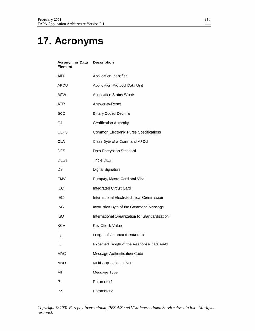
February 2001TAPA Application Architecture Version 2.1
Copyright © 2001 Europay International, PBS A/S and Visa International Service Association. All rightsreserved.
218
17. Acronyms
Acronym or DataElement
Description
AID Application Identifier
APDU Application Protocol Data Unit
ASW Application Status Words
ATR Answer-to-Reset
BCD Binary Coded Decimal
CA Certification Authority
CEPS Common Electronic Purse Specifications
CLA Class Byte of a Command APDU
DES Data Encryption Standard
DES3 Triple DES
DS Digital Signature
EMV Europay, MasterCard and Visa
ICC Integrated Circuit Card
IEC International Electrotechnical Commission
INS Instruction Byte of the Command Message
ISO International Organization for Standardization
KCV Key Check Value
Lc Length of Command Data Field
Le Expected Length of the Response Data Field
MAC Message Authentication Code
MAD Multi-Application Driver
MT Message Type
P1 Parameter1
P2 Parameter2
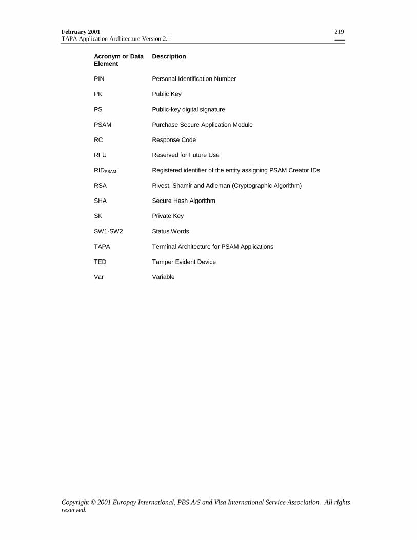
February 2001TAPA Application Architecture Version 2.1
Copyright © 2001 Europay International, PBS A/S and Visa International Service Association. All rightsreserved.
219
Acronym or DataElement
Description
PIN Personal Identification Number
PK Public Key
PS Public-key digital signature
PSAM Purchase Secure Application Module
RC Response Code
RFU Reserved for Future Use
RIDPSAM Registered identifier of the entity assigning PSAM Creator IDs
RSA Rivest, Shamir and Adleman (Cryptographic Algorithm)
SHA Secure Hash Algorithm
SK Private Key
SW1-SW2 Status Words
TAPA Terminal Architecture for PSAM Applications
TED Tamper Evident Device
Var Variable