Embed Size (px)
Citation preview
ARMY RESEARCH LABORATORY
A Comparison of Soldier Performance Using Current Land Navigation Equipment With
Information Integrated on a Helmet- Mounted Display
Monica M. Glumm William P. Marshak
Teresa A. Branscome Mary Mc.Wesler Debra J. Patton
Linda L. Mullins
ARL-TR-1604 APRIL 1998
19980527 081 ^FQOäinY
Approved for public release; distribution is unlimited.
BLANK PAGES WERE REMOVED FROM THIS DOCUMENT.
Trekker™ is a trademark of Rockwell International Corporation, Collins Avionics and Communications Division.
Velcro® is a registered trademark of Velcro USA, Inc., Manchester, NH.
The findings in this report are not to be construed as an official Department of the Army position unless so designated by other authorized documents.
Citation of manufacturer's or trade names does not constitute an official endorsement or approval of the use thereof.
Destroy this report when it is no longer needed. Do not return it to the originator.
Army Research Laboratory Aberdeen Proving Ground, MD 21005-5425
ARL-TR-1604 April 1998
A Comparison of Soldier Performance Using Current Land Navigation Equipment With Information Integrated on a Helmet-Mounted Display
Monica M. Glumm William P. Marshak Teresa A. Branscome Mary Mc.Wesler Debra J. Pattern Linda L. Mullins Human Research & Engineering Directorate
Approved for public release; distribution is unlimited.
Abstract
The report describes a field study designed to measure soldier performance of land navigation and other mission tasks using current navigational equipment and to compare these data with performance using navigational information integrated on a helmet-mounted display (HMD). Measures of stress, cognitive performance, and workload were also obtained. The results indicated that the soldiers traveled less distance between waypoints and experienced lower levels of mental workload using information presented on the HMD than they did using current navigational equipment. As might be expected, differences in time between manual and automatic map updates were significant, but no differences were found between current equipment and the HMD condition in object detection, determination of magnetic azimuth, or call for fire tasks. Differences between conditions in levels of stress and cognitive performance were not significant.
ACKNOWLEDGMENTS
The authors would like to express their appreciation to our Federated Lab Consortium partners and colleagues from Rockwell International and Sytronics, Inc., who provided hardware and software support to this investigation. Special thanks to Rockwell's Vince Märzen and Jim Parent (component supply and support), Sytronics' David Belt, Jim Scheid, Todd Grimes, Glen Geisen (software development), and Dr. David Darkow and Bill Barnett (hardware integration).
We would also like to express our gratitude to Dan Wheeler of the Public Works Directorate at APG for his time and patience in the development of maps and for lending software to support the tactical scenarios. Thanks to Lynn Graham of the Program Manager's Office-Global Positioning System (PM-GPS) for lending GPS receivers and ancillary equipment, and to Mike May es and Joanne Buckingham of Communications Security at APG who maintained the accuracy of our GPS units.
Thanks to those at the Human Research and Engineering Directorate (HRED) of the U.S. Army Research Laboratory, particularly Jack Waugh for his assistance in defining the paths and object positions, to Mike Kosinski for the construction of the protractors with which our soldiers so accurately plotted coordinates, and to Dennis Hash and Nickey Keenan for their support in all phases and facets of this investigation. We would also like to express our appreciation to SFC Bobby King who assisted as pilot subject, trainer, and lane walker, and to SSG Brian James for the valuable extra set of hands he provided during training and testing.
Last but never least, we are particularly grateful to the soldiers who participated in this investigation. We thank them for their enthusiasm, dedication, and opinions, and particularly their patience and sense of humor.
in
CONTENTS
EXECUTIVE SUMMARY 3
INTRODUCTION 7
OBJECTIVE 9
METHOD 9
Test Participants 9 Apparatus 10 Procedures 17
RESULTS 25
Land Navigation 25 HMD Employment 33 HMD Display Format Use 34 Other Mission Tasks 36 Probe Questions and Situation Awareness 37 Workload (NASA-TLX) 38 Stress 39 Cognitive Performance 39 CPASE and NASA-TLX 41 Behavioral Anchored Rating Scales 41 Soldier Preferences and Comments 43
DISCUSSION 43
CONCLUSIONS AND RECOMMENDATIONS 49
REFERENCES '. 51
APPENDICES
A. Demographic Questionnaire 53 B. Salivary Amylase Field Test and Stress Questionnaires 57 C. Cognitive Performance Assessment for Stress and Endurance (CPASE) 69 D. NASA-Task Load Index 83 E. Behavioral Anchored Rating Scales 89 F. Post-Test Questionnaires 99
DISTRIBUTION LIST 103
REPORT DOCUMENTATION PAGE Ill
FIGURES
1. Iterative Approach to Examining the Effects of HMDs and Alternate Display Technologies and Techniques on Infantry Soldier Performance 8
2. Conventional Land Navigation Equipment 11 3. HMD-Equipped Soldier 12 4. The Trekker™ 2010 System: 386 Processor and Head-Mounted Display 14 5. The HMD's Digital Map Display With Overlaid Symbology and
Navigational Information 15 6. The HMD's Rolling Compass Display Including Symbology and
Navigational Information 16 7. Keypad and Glide-Point Mouse 17 8. Test Paths A and B With Waypoint Positions and Leg Lengths 21 9. Raw Data (300 points) From the GPS Receiver Using the P(Y) Precision
Code (scale increment = 10 meters) 26 10. GPS Data Filtered Using a ±5-Point Moving Window Average (scale
increments = 10 meters) 27 11. Rmse With Standard Errors as a Function of Leg 28 12. Average Distance Traveled, Standardized by Leg Length With Standard
Errors for HMD and Current Navigational Equipment 30 13. Mean Mission Velocity With Standard Errors by Path Leg 31 14. Mean Travel Velocity With Standard Errors by Path Leg 33 15. Mean Weighted Ratings of Sources of Workload and Overall Workload 38 16. Sinusoidal and Offset Function Deviation From a Straight-Line Path 44 17. Soldier Deviation From Leg 4 (Path A) Using Current Equipment 46
TABLES
1. Navigational Equipment by Condition 10 2. Design Matrix and Counterbalancing Scheme 20 3. ANOVA Results of Rmse 28 4. ANOVA Results of Standardized Distance Traveled 29 5. ANOVA Results of Velocity (mission) 31 6. ANOVA Results of Velocity (travel) 32 7. HMD Employment During Navigation of Training (t) and Test (A and B)
Paths 34 8. HMD Display Format Use During Navigation of Training (t) and Test
(A and B) Paths 35 9. Signal Detection (d') for Current Equipment and HMD Performance on
Probe Questions 37 10. Results of Analysis of Soldier Responses on Behavioral Anchored Rating
Scales 41 11. Results of Correlation Analysis of Soldier-Lane Walker Responses on
Behavioral Anchored Rating Scales 42
EXECUTIVE SUMMARY
This report presents the results of the first in a series of field investigations designed to
quantify the effects of helmet-mounted display (HMD) technology on the performance of the
dismounted infantry soldier. The objective of this field experiment was to measure soldier
performance of land navigation and other mission tasks using current navigational equipment and to
compare these data with performance using navigational information integrated on an HMD.
Measures of stress, cognitive performance, workload, and situation awareness were also obtained.
In this study, each of 12 soldiers performed land navigation and other soldier tasks in each
of two conditions. In one condition, the soldier was provided conventional land navigation
equipment that included a paper map, protractor, lensatic compass, and a hand-held global
positioning system (GPS) receiver. In the second condition, the soldier wore an HMD that
integrated information supplied by a GPS and an electronic compass in each of two visual displays.
The two displays included a map of the area to be navigated and a rolling compass display.
In both conditions, the soldier wore a backpack that contained the digitally aided soldier for
human engineering research (DASHER) system. DASHER consists of a small commercial 386
computer, sound generation, a GPS, an electronic compass, and a stereo audio recorder. The
system is a self-contained simulator-recorder that uses a position-based script to simulate
connectivity with a command network presenting information about troop movement as well as
data for land navigation. In the current equipment condition, DASHER was used for task
administration and data collection only. In the HMD condition, DASHER generated the visual
displays and associated navigational data presented on the HMD.
Each soldier was trained and tested in one equipment condition before being trained and
tested in the other. Training included both classroom and field instruction in which the soldier was
trained to a point at which he achieved an asymptote in the performance of land navigation and
other soldier tasks using the equipment specific to that condition.
Measures of stress and cognitive performance were obtained on a day before training and
testing, as well as before and immediately after training and testing in each equipment condition.
Measures of stress were also obtained at the midpoint of each path that the soldiers navigated.
During testing in each condition, the soldier navigated a different unmarked path through
densely wooded terrain. Each path was 3 kilometers long and consisted of four legs of different
lengths. The soldier was instructed to navigate each leg of the path as quickly and as accurately as
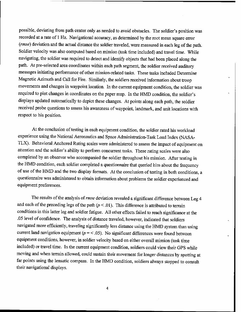
possible, deviating from path center only as needed to avoid obstacles. The soldier's position was
recorded at a rate of 1 Hz. Navigational accuracy, as determined by the root mean square error
(rmse) deviation and the actual distance the soldier traveled, were measured in each leg of the path.
Soldier velocity was also computed based on mission (task time included) and travel time. While
navigating, the soldier was required to detect and identify objects that had been placed along the
path. At pre-selected area coordinates within each path segment, the soldier received auditory
messages initiating performance of other mission-related tasks. These tasks included Determine
Magnetic Azimuth and Call for Fire. Similarly, the soldiers received information about troop
movements and changes in waypoint location. In the current equipment condition, the soldier was
required to plot changes in coordinates on the paper map. In the HMD condition, the soldier's
displays updated automatically to depict these changes. At points along each path, the soldier
received probe questions to assess his awareness of waypoint, landmark, and unit locations with
respect to his position.
At the conclusion of testing in each equipment condition, the soldier rated his workload
experience using the National Aeronautics and Space Administration-Task Load Index (NASA-
TLX). Behavioral Anchored Rating scales were administered to assess the impact of equipment on
attention and the soldier's ability to perform concurrent tasks. These rating scales were also
completed by an observer who accompanied the soldier throughout his mission. After testing in
the HMD condition, each soldier completed a questionnaire that queried him about the frequency
of use of the HMD and the two display formats. At the conclusion of testing in both conditions, a
questionnaire was administered to obtain information about problems the soldier experienced and equipment preferences.
The results of the analysis of rmse deviation revealed a significant difference between Leg 4
and each of the preceding legs of the path (p < .01). This difference is attributed to terrain
conditions in this latter leg and soldier fatigue. All other effects failed to reach significance at the
.05 level of confidence. The analysis of distance traveled, however, indicated that soldiers
navigated more efficiently, traveling significantly less distance using the HMD system than using
current land navigation equipment (p = < .05). No significant differences were found between
equipment conditions, however, in soldier velocity based on either overall mission (task time
included) or travel time. In the current equipment condition, soldiers could view their GPS while
moving and when terrain allowed, could sustain their movement for longer distances by spotting at
far points using the lensatic compass. In the HMD condition, soldiers always stopped to consult their navigational displays.
In the analyses of soldier velocity, main effects were also found for path leg. These main effects are primarily attributed to significantly lower velocities achieved in Leg 3 where thorny vegetation was denser than in each of the other three legs of the path. The analyses revealed
significant interactions among navigational equipment, leg, and a control variable (equipment, path, and order of presentation). These interactions are attributed to the significantly higher velocities achieved in teg 4 of the path when soldiers navigated Path-A using current equipment first. Velocities in subsequent legs of Path A using current equipment were significantly lower than in Leg 1, as were velocities in both equipment conditions in all legs of both test paths where equipment conditions and-or paths A and B were presented in a different order. This finding
reflects the mildness of the terrain in Leg 1 of Path A, by comparison to the increased density of
the vegetation in all other legs of both test paths. It may also indicate the soldiers' premature expectations that their task would be easy combined with their skill and confidence in navigating this milder terrain with the familiar lensatic compass.
Situation awareness, as measured by probe questions, was not significantly affected by test condition. No differences were found between conditions in the number of objects detected along the path or in time to perform other mission-related tasks (i.e., Determine Magnetic Azimuth and Call for Fire). However, in the current equipment condition, manual map updates noting changes in unit position and waypoint destination were more time consuming by comparison to the HMD condition where such changes were displayed automatically. The soldiers' overall ratings of workload, as measured by the NASA-TLX, were significantly higher using current equipment than using the HMD system (p < .05). Ratings of mental workload were also higher in the current equipment condition (p < .05). This latter finding may reflect the differences in the level of automation between current equipment and the HMD system, which impacted the amount of mental processing required to perform some mission tasks. Also, in the HMD condition, soldiers noted that the displays provided them all the information they needed and were "easy to use, read and follow".
The results of the analyses of the psychological stress perception measures indicated little to no psychological stress associated with either experimental condition. Therefore, although differences were found in the current equipment condition between earlier measures of salivary amylase (i.e., baseline and during test) and post-test levels (p < .05), these differences are not attributed to an increase in psychological stress but rather to an increase in physiological stress related to an increase in physical activity imposed by manipulation of more equipment. No differences were found between conditions in cognitive performance. In the HMD condition, however, post-performance scores on spatial rotation were unexpectedly higher than pre-measure
scores (p < .05). This finding is attributed to practice that the soldiers received in mentally rotating
the HMD's map display that was fixed in the north-up direction. Generally, differences were also
found between baseline and post measures for word recall and addition. As expected, performance
was significantly higher for the baseline measure of word recall (p < .05). However, baseline scores
were significantly lower than the post measure for the addition task (p < .05). As for spatial
rotation, this latter finding is attributed to practice effects. In both the HMD and current
equipment conditions, soldier tasks involved mental math.
The findings of this investigation appear to indicate that the effective integration of
navigational information on an HMD can measurably enhance navigational efficiency by providing
the soldier readily accessible and easily interpretable information about his or her position.
Although the reduction in the distance traveled by the HMD-equipped soldier did not bring about
the expected increase in velocity, greater efficiency in navigating from point to point can
potentially result in lower levels of fatigue and improved performance upon arrival at the soldier's
destination. Significant reductions in the soldier's mental workload, as well as a decrease in the
soldier's overall workload experience, are also achievable using an HMD. However, it is important
to note that, although the findings of this study appear to favor the HMD, results may differ with
other display formats and increases in the quantity of information displayed. Whether the above
advantages in performance and reduced workload using the HMD are attributable to the effective
integration of displayed information, head-mounting of the displays, or both, remains uncertain.
A COMPARISON OF SOLDIER PERFORMANCE USING CURRENT LAND NAVIGATION EQUIPMENT WITH NAVIGATION INFORMATION
INTEGRATED ON A HELMET-MOUNTED DISPLAY
INTRODUCTION
A helmet-mounted display (HMD) is a part of the integrated headgear assembly sub-
system (IHAS) which is a component of the Land Warrior System. The Land Warrior System is
expected to enhance the soldier's performance and survivability in the future battlefield.
However, the effects of HMDs on soldier performance, whether positive or negative, have not
been quantified.
Although HMDs have been used successfully in military aviation, they have not been
used without concern as to their effects on pilot perception and attention (Fischer, Haines, &
Price, 1980; Iavecchia, Iavecchia, & Roscoe, 1988; Weintraub & Ensing, 1992), and the role they
might have played in aviation accidents (Rash, Verona, Crowley, 1990). An abundance of
literature relates to the design of HMDs for the aviator (Hughes, Chason, & Schwank, 1973;
Foyle, McCann, Sanford, & Schwirtzke, 1993; Larish & Wickens, 1991; Wickens & Long, 1995),
but there is little that focuses on the design of these displays for the dismounted soldier or the
effects HMDs might have on the soldier's performance.
HMDs are not a uniform class of displays. They include discriminating differences such
as color versus monochrome, monocular versus binocular, opaque versus "see through," visually
coupled and uncoupled, and display formats with differing frames of reference. Yeh and Wickens
(1997) examined research issues associated with the use of HMDs, addressing issues that
characterize different display formats and performance measurement using these displays. They
report literature that contains few field studies, and findings that are somewhat mixed on the
performance advantages of HMDs.
In 1995 and 1997 reports about tactical displays for soldiers, the National Research
Council (NRC) provides a broad review of the available literature concerning HMDs, noting data
gaps and research issues that must be addressed to determine the usability of these displays by
the dismounted soldier. Among NRC's concerns are that HMDs might compete for the soldiers'
attention, reduce their awareness of the situation immediately around them, and conflict with
their performance of other critical tasks.
Previous modeling and system analysis efforts have attempted to estimate the effects of
the Land Warrior System on mission performance and workload (Adkins, Murphy, Hemenway,
Archer, & Bayless, 1996; McNinch, 1995). "Best guesses" were often used to derive these
estimates because data and information about the use of this equipment by the soldier were
lacking.
In support of the soldier and the goals of the Land Warrior System, the Human Research
& Engineering Directorate (HRED) of the U.S. Army Research Laboratory (ARL) is conducting
research to quantify the effects of HMDs and alternate display technologies on soldier
performance, and trade-offs between visually and auditorially displayed information. This
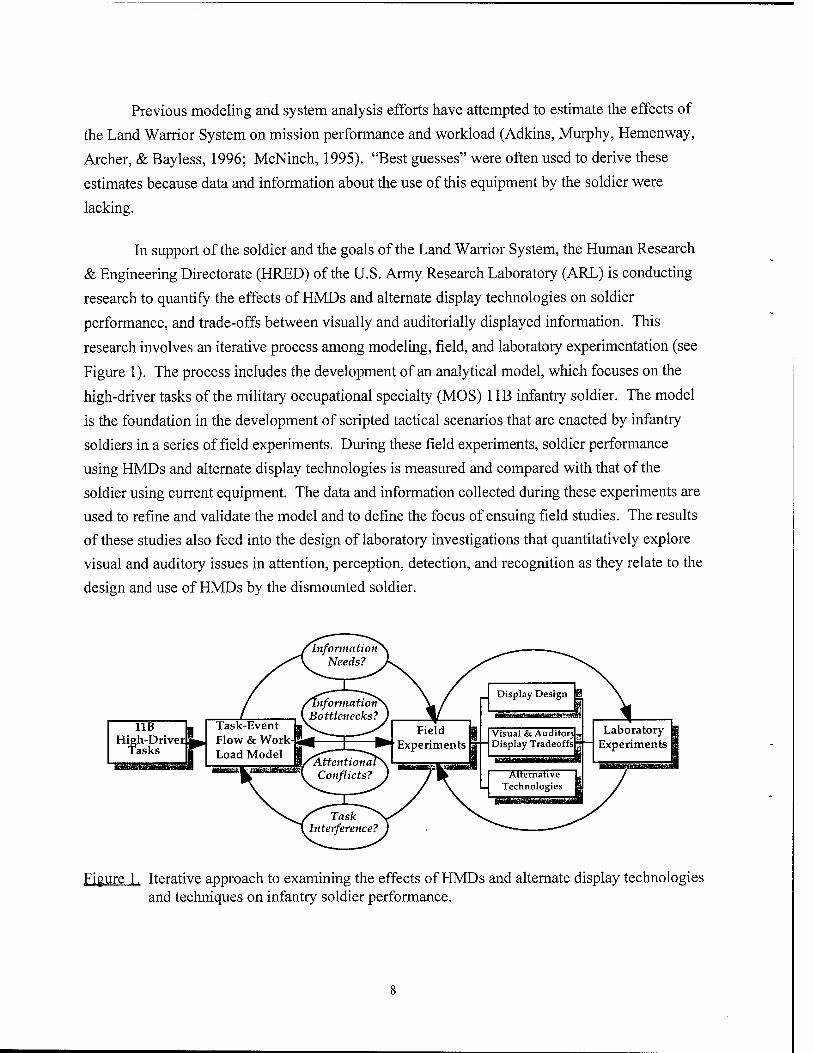
research involves an iterative process among modeling, field, and laboratory experimentation (see
Figure 1). The process includes the development of an analytical model, which focuses on the
high-driver tasks of the military occupational specialty (MOS) 1 IB infantry soldier. The model
is the foundation in the development of scripted tactical scenarios that are enacted by infantry
soldiers in a series of field experiments. During these field experiments, soldier performance
using HMDs and alternate display technologies is measured and compared with that of the
soldier using current equipment. The data and information collected during these experiments are
used to refine and validate the model and to define the focus of ensuing field studies. The results
of these studies also feed into the design of laboratory investigations that quantitatively explore
visual and auditory issues in attention, perception, detection, and recognition as they relate to the
design and use of HMDs by the dismounted soldier.
11B I. High-Driver, w
Tasks IB~ '
Task-Event Flow & Work-] Load Model
Figure 1. Iterative approach to examining the effects of HMDs and alternate display technologies and techniques on infantry soldier performance.
As a first step in this research process, ARL queried subject matter experts (SME) to
identify tasks of the 1 IB soldier that might benefit most from HMD technology. These SMEs
were from the Infantry Center at Ft. Benning, Georgia, and all were familiar with HMDs and the
Land Warrior System. Many of the tasks that the SMEs identified were land navigation tasks.
These tasks, along with other critical tasks of the 1 IB soldier, were used to construct a Task-
Event Flow and Workload model within the context of a movement-to-contact/attack mission
scenario. In this model, the soldier uses more conventional land navigation equipment: the
lensatic compass and paper map. However, in recent battlefields, some soldiers have also been
provided a global positioning system (GPS) receiver. This lightweight, hand-held device provides
the soldier his or her position coordinates at a rate of 1 Hz; however, a lensatic compass is still
required to provide information about the soldier's azimuth orientation. What would be the
effect on soldier performance if the information provided by the paper map, compass, and GPS
unit were all integrated on an HMD?
The present study was the first in a series of field experiments that are a part of the
process described. The study was a joint effort by ARL and partners within the Federated Lab
Consortium: Sytronics, Inc., and Rockwell International. Rockwell International supplied the
HMD and the computer that drives it (the Trekker™ System). Sytronics integrated this
equipment with an electronic compass and provided the programming support for display of
navigation and other tactical information to the HMD-equipped soldier. Rockwell and Sytronics
also developed a unique plan to use this equipment with a GPS to automatically and
unobtrusively initiate tasks and measure and record the soldier's performance in both test
conditions (Marshak, Glumm, Märzen, Wesler, & Scheid, 1996).
OBJECTIVE
The objective of this field experiment was to measure soldier performance of land
navigation and other mission tasks using current navigational equipment and to compare these
data with performance using navigational information integrated on an HMD. Measures of
stress, cognitive performance, and workload were also obtained.
METHOD
Test Participants
Twelve male infantry soldiers participated in this study. The soldiers ranged in age from
19 to 38 years with an average age of 29. Their MOSs were Dismounted Infantry (1 IB) and
Mechanized Infantry (1 IM). Their time in service and time in MOS both ranged from 1 to 20
years with an average of 9 years. When asked to rate their land navigation skills, seven of the
soldiers rated their skills as "good" or "excellent," three "neither good nor bad," and three "poor"
or "fair." All met visual acuity requirements established for this study of 20/20 in one eye and at
least 20/30 in the other eye (corrected or uncorrected) and passed tests for color and stereo
vision.
Apparatus
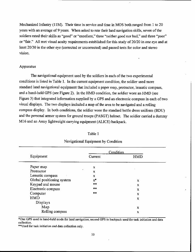
The navigational equipment used by the soldiers in each of the two experimental
conditions is listed in Table 1. In the current equipment condition, the soldier used more
standard land navigational equipment that included a paper map, protractor, lensatic compass,
and a hand-held GPS (see Figure 2). In the HMD condition, the soldier wore an HMD (see
Figure 3) that integrated information supplied by a GPS and an electronic compass in each of two
visual displays. The two displays included a map of the area to be navigated and a rolling
compass display. In both conditions, the soldier wore the standard battle dress uniform (BDU)
and the personal armor system for ground troops (PASGT) helmet. The soldier carried a dummy
Ml6 and an Army lightweight carrying equipment (ALICE) backpack.
Table 1
Navigational Equipment by Condition
Condition Equipment Current HMD
Paper map x Protractor x Lensatic compass x Global positioning system x* x Keypad and mouse ** x Electronic compass ** x
Computer ** x HMD x
Displays Map x Rolling compass x
♦One GPS used in hand-held mode for land navigation; second GPS in backpack used for task initiation and data collection. **Used for task initiation and data collection only.
10
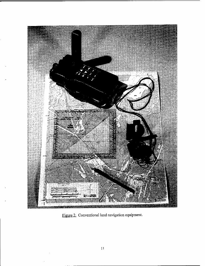
Figure 2. Conventional land navigation equipment.
11
Figure 3. HMD-equipped soldier.
In both conditions, the soldier's backpack contained a small 386 computer, GPS, electronic compass, and an audio cassette recorder. This equipment was integrated by Sytronics, Inc., in a system called the digitally aided soldier for human engineering research (DASHER).
DASHER, which included a 3.6-kilogram (8-lb) 12-volt battery, weighed approximately 12.7 kilograms (28 lb). During the study, DASHER was used in both conditions to initiate mission tasks and record soldier performance. The system used a position-based script to simulate connectivity with a command network that presented information auditorially about troop movement and changes in waypoint location. The stereo cassette recorder was used to monitor computer output and record soldier comments. DASHER's software was written in Borland C++. In the current equipment condition, DASHER was used for task administration and data collection only. In the HMD condition, DASHER generated the visual displays and associated navigational data presented on the HMD. In both conditions, computer interface and response to
12
various scenario events were input to a keypad and glide-point mouse worn on the soldier's belt.
A description of the navigational equipment used by the soldiers in the current equipment and
HMD conditions of the study, along with the components of the DASHER system, follows.
Lensatic Compass
In the current equipment condition, the soldier used a standard military lensatic
compass to determine his orientation and the azimuth which he was traveling. The compass has
a vertical sight in the lid and a separate lens that the soldier uses to align a landmark and read the
bearing.
Paper Map and Protractor
In the current equipment condition, the soldier was provided a paper map of the
area of operation. In the HMD condition, this same map was one of two digital displays used
for navigation. The map was derived using digital ortho-photography and was accurate to within
0.46 meter (1.5 feet). It depicted streams, marsh, trees and foliage, dirt paths and improved
roads, and other landmarks provided on standard military maps. A legend defining these terrain
features and landmarks was included. Because the area of operation in this field experiment
would appear the size of a postage stamp on a standard 1:50000-meter military map and would
not allow the needed level of detail, the scale of the map was increased to 1:6000 meter. A
protractor was also constructed based on the standard military protractor (Graphic Training Aid
5-2-12) for use with this map in plotting position coordinates and in calculating distance and
azimuth.
Global Positioning System Receiver
The GPS used in this investigation is called the PLGR. It is a hand-held unit
(AN/PSN-11) developed for the military by Rockwell International and when de-encrypted
(P[Y] mode), can provide an accuracy of ±10 meters or better. In both test conditions, the GPS
provided position coordinates that initiated specific task events. In the HMD condition,
position information supplied by the GPS, along with orientation information supplied by an
electronic compass, was integrated into the two navigational displays. In the current equipment
condition, the soldier was provided position coordinates on a hand-held GPS. The hand-held
GPS was used primarily in the navigational mode to provide information similar to that provided
in the HMD condition. This information included the soldier's distance in meters to the left or
right of path centerline and the range to his next waypoint. Position information supplied by the
GPS was updated at a rate of 1 Hz.
13
Electronic Compass
An electronic compass (ClOO), developed by KVH (not an acronym) Industries,
was used to supply orientation information. This compass is based on magnetic flux sensing
technology and has ±0.5 (±10 mils) accuracy with 0.1 (1 mil) resolution. The compass was
located in the soldier's backpack and was used to measure the soldier's azimuth orientation at a
rate of 1 Hz.
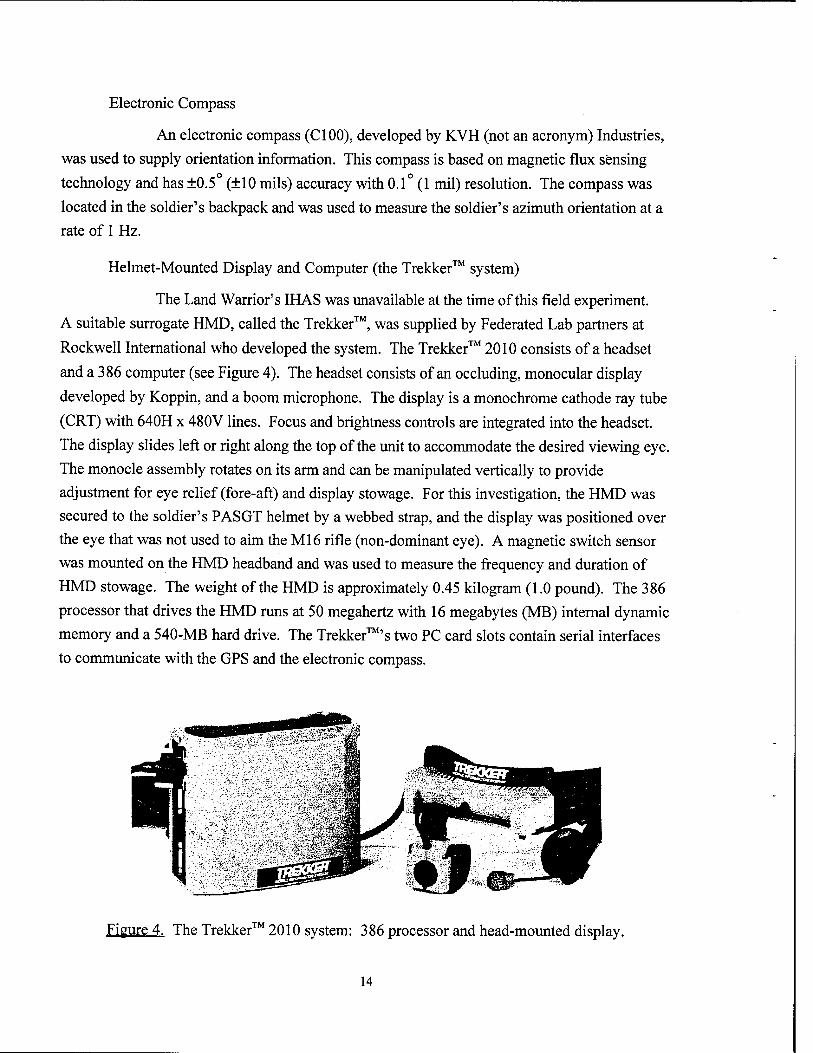
Helmet-Mounted Display and Computer (the Trekker™ system)
The Land Warrior's IHAS was unavailable at the time of this field experiment.
A suitable surrogate HMD, called the Trekker™, was supplied by Federated Lab partners at
Rockwell International who developed the system. The Trekker™ 2010 consists of a headset
and a 386 computer (see Figure 4). The headset consists of an occluding, monocular display
developed by Koppin, and a boom microphone. The display is a monochrome cathode ray tube
(CRT) with 640H x 480V lines. Focus and brightness controls are integrated into the headset.
The display slides left or right along the top of the unit to accommodate the desired viewing eye.
The monocle assembly rotates on its arm and can be manipulated vertically to provide
adjustment for eye relief (fore-aft) and display stowage. For this investigation, the HMD was
secured to the soldier's PASGT helmet by a webbed strap, and the display was positioned over
the eye that was not used to aim the Ml6 rifle (non-dominant eye). A magnetic switch sensor
was mounted on the HMD headband and was used to measure the frequency and duration of
HMD stowage. The weight of the HMD is approximately 0.45 kilogram (1.0 pound). The 386
processor that drives the HMD runs at 50 megahertz with 16 megabytes (MB) internal dynamic
memory and a 540-MB hard drive. The Trekker™'s two PC card slots contain serial interfaces
to communicate with the GPS and the electronic compass.
Figure 4. The Trekker™ 2010 system: 386 processor and head-mounted display.
14
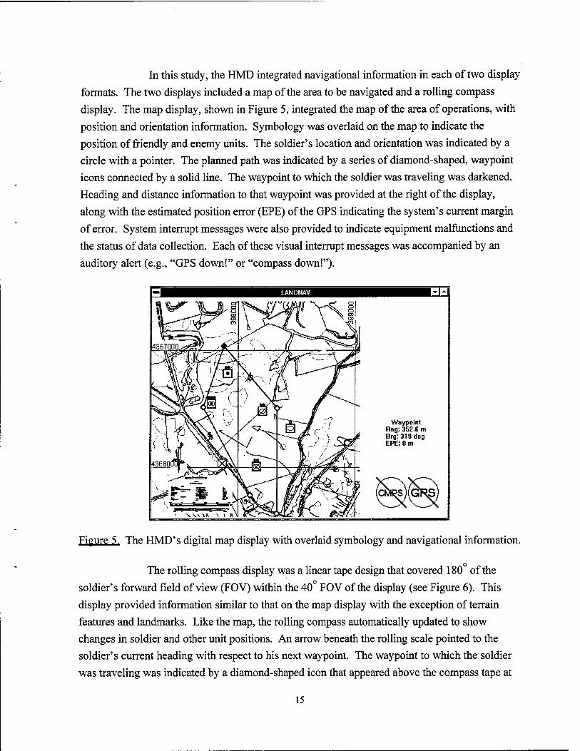
In this study, the HMD integrated navigational information in each of two display formats. The two displays included a map of the area to be navigated and a rolling compass display. The map display, shown in Figure 5, integrated the map of the area of operations, with position and orientation information. Symbology was overlaid on the map to indicate the position of friendly and enemy units. The soldier's location and orientation was indicated by a circle with a pointer. The planned path was indicated by a series of diamond-shaped, waypoint icons connected by a solid line. The waypoint to which the soldier was traveling was darkened. Heading and distance information to that waypoint was provided at the right of the display, along with the estimated position error (EPE) of the GPS indicating the system's current margin of error. System interrupt messages were also provided to indicate equipment malfunctions and
the status of data collection. Each of these visual interrupt messages was accompanied by an auditory alert (e.g., "GPS down!" or "compass down!").
Waypoint Rng: 352.6 m Brg:319deg EPE: 0 m
Figure 5. The HMD's digital map display with overlaid symbology and navigational information.
The rolling compass display was a linear tape design that covered 180 of the soldier's forward field of view (FOV) within the 40 FOV of the display (see Figure 6). This display provided information similar to that on the map display with the exception of terrain features and landmarks. Like the map, the rolling compass automatically updated to show changes in soldier and other unit positions. An arrow beneath the rolling scale pointed to the soldier's current heading with respect to his next waypoint. The waypoint to which the soldier was traveling was indicated by a diamond-shaped icon that appeared above the compass tape at
15
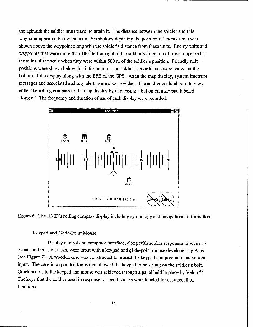
the azimuth the soldier must travel to attain it. The distance between the soldier and this
waypoint appeared below the icon. Symbology depicting the position of enemy units was
shown above the waypoint along with the soldier's distance from these units. Enemy units and
waypoints that were more than 180° left or right of the soldier's direction of travel appeared at
the sides of the scale when they were within 500 m of the soldier's position. Friendly unit
positions were shown below this information. The soldier's coordinates were shown at the
bottom of the display along with the EPE of the GPS. As in the map display, system interrupt
messages and associated auditory alerts were also provided. The soldier could choose to view
either the rolling compass or the map display by depressing a button on a keypad labeled
"toggle." The frequency and duration of use of each display were recorded.
Figure 6. The HMD's rolling compass display including symbology and navigational information.
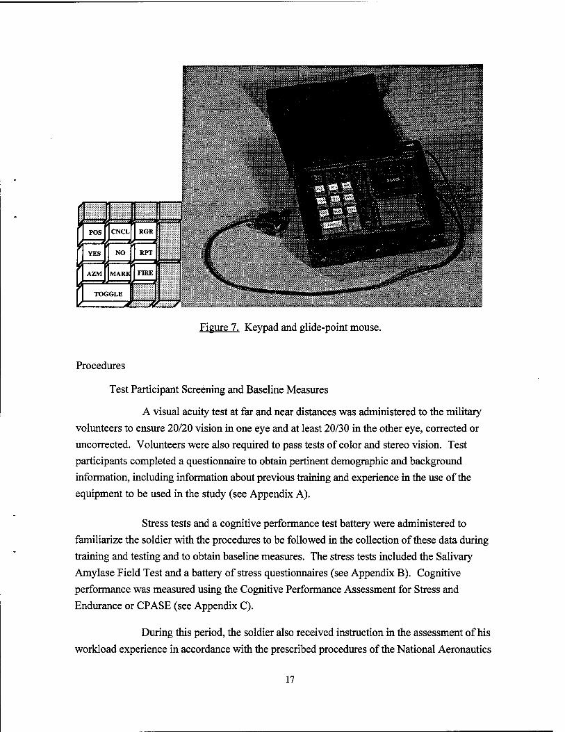
Keypad and Glide-Point Mouse
Display control and computer interface, along with soldier responses to scenario
events and mission tasks, were input with a keypad and glide-point mouse developed by Alps
(see Figure 7). A wooden case was constructed to protect the keypad and preclude inadvertent
input. The case incorporated loops that allowed the keypad to be strung on the soldier's belt.
Quick access to the keypad and mouse was achieved through a panel held in place by Velcro®.
The keys that the soldier used in response to specific tasks were labeled for easy recall of
functions.
16
3* POS
YES 34
AZM
CNCL
3K NO
MARK
TOGGLE
RGR
RPT
FIRE
-JtL
.--r-rfSAW' ■■•■■■ m
Figure 7. Keypad and glide-point mouse.
Procedures
Test Participant Screening and Baseline Measures
A visual acuity test at far and near distances was administered to the military
volunteers to ensure 20/20 vision in one eye and at least 20/30 in the other eye, corrected or
uncorrected. Volunteers were also required to pass tests of color and stereo vision. Test
participants completed a questionnaire to obtain pertinent demographic and background
information, including information about previous training and experience in the use of the
equipment to be used in the study (see Appendix A).
Stress tests and a cognitive performance test battery were administered to
familiarize the soldier with the procedures to be followed in the collection of these data during
training and testing and to obtain baseline measures. The stress tests included the Salivary
Amylase Field Test and a battery of stress questionnaires (see Appendix B). Cognitive
performance was measured using the Cognitive Performance Assessment for Stress and
Endurance or CPASE (see Appendix C).
During this period, the soldier also received instruction in the assessment of his
workload experience in accordance with the prescribed procedures of the National Aeronautics
17
and Space Administration-Task Load Index (NASA-TLX). The NASA-TLX uses rating scales to
assess mental, physical, and temporal demands, performance, effort, and frustration. In this
technique, a weight is initially obtained for each of the six workload factors based on the subject's
responses to pair-wise comparisons among these factors. In these comparisons, the six factors are
presented in 15 possible pairs, and for each pair, the subject is asked to circle the factor that he or
she perceives to contribute more to his or her workload experience. The subject then completes
rating scales that provide a measure of the magnitude of the workload for each factor. Those
factors perceived by the subject to be most important in his or her workload experience are given
more weight in computing the overall workload score. Definitions of each of the six workload
factors assessed, the pair-wise comparisons, and rating scales are provided in Appendix D.
Training
The duration of training and testing for each of the 12 soldiers was 4 days.
Training and testing in one of the two equipment conditions were conducted on Day 1 and Day
2, respectively. Training and testing in the second condition were conducted on Day 3 and Day
4. Two soldiers were trained and tested at one time. On Day 1 and 2, one soldier was trained in
one equipment condition while the second soldier was trained in the other. On Day 3 and 4, the
conditions in which these soldiers were trained and tested were reversed.
In each condition, training included both classroom and field instruction during
which the soldier was trained to a point at which he achieved an asymptote in the performance of
land navigation and other soldier tasks using the equipment specific to that condition. The
Salivary Amylase Field Test, stress questionnaires, and the CPASE test battery were
administered immediately before and after training in each condition.
Current Equipment Training
Training with current equipment began with a pace count followed by
instruction and practice in the operation of the lensatic compass and the GPS receiver. GPS
training focused on those modes that the soldier needed to retrieve information similar to that
supplied in the HMD condition (e.g., "position" and "navigation" modes). The soldier also
received instruction and practice in the use of the protractor and paper map. In this portion of
the training, the soldier was provided the coordinates of paths similar to those that he would
navigate during testing. In each practice run, the soldier was required to plot a different path
segment and compute its distance and azimuth. The soldier performed consecutive runs until he
reached an asymptote in time and error.
18
Initial instruction in the performance of other mission tasks was provided
in simulated "walk throughs" of the training path. For this portion of the training, the soldier
was seated with his back to a computer monitor that displayed the training path. The instructor,
aided by icons denoting scenario events, "walked" the cursor along the path, initiating auditory
messages relayed through speakers that would cue the soldier to perform a specific task. In the
initial "walk through," the instructor described the procedures that were to be followed in the
performance of each task and the required inputs to the keypad and mouse. In ensuing walk
throughs, the soldier described these procedures to the instructor and practiced these inputs with
the keypad and mouse.
Before field instruction, the soldier was required to plot the coordinates of
the training path and compute the azimuth and distance he was to travel between waypoints.
The soldier was also required to plot the "current" position of enemy and friendly units. Time
and errors were recorded. The soldier was informed of any errors and corrected the map
accordingly. The soldier then completed three runs on the actual training path. The training path
consisted of three 200-meter segments for a total path length of 600 meters. In each of the three
segments, the soldier performed all tasks that would be performed during testing. The soldier
was accompanied on the training path by a "lane walker." This lane walker also accompanied the
soldier throughout testing in each equipment condition. The primary purpose of the lane walker
was to ensure the soldier's safety. Other functions included equipment troubleshooting, data
collection, and administration of the stress tests and cognitive test battery.
HMD Training
In the HMD condition, the soldiers were instructed in the interpretation of
the symbology and the reading of navigational information provided on the digital map and rolling
compass displays. As during training in the current equipment condition, instruction and
practice in the performance of mission tasks were provided in simulated "walk throughs" of the
training path. However, during training in the HMD condition, the soldier viewed the training
path on the computer monitor, as he would when wearing the HMD. The soldier then completed
three runs on the 600-meter training path, performing all tasks that would be performed during
the test period.
Testing
During testing, each of the 12 soldiers navigated a different path in each of the two
equipment conditions. As shown in Table 2, the order of presentation of these conditions and
paths was counterbalanced among the 12 soldiers.
19
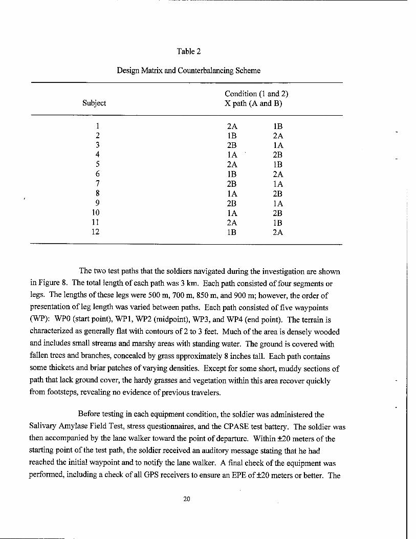
Table 2
Design Matrix and Counterbalancing Scheme
2A IB IB 2A 2B 1A 1A 2B 2A IB IB 2A 2B 1A 1A 2B 2B 1A 1A 2B 2A IB IB 2A
Condition (1 and 2) Subject X path (A and B)
1 2 3 4 5 6 7 8 9
10 11 12
The two test paths that the soldiers navigated during the investigation are shown
in Figure 8. The total length of each path was 3 km. Each path consisted of four segments or
legs. The lengths of these legs were 500 m, 700 m, 850 m, and 900 m; however, the order of
presentation of leg length was varied between paths. Each path consisted of five waypoints
(WP): WP0 (start point), WFT, WP2 (midpoint), WP3, and WP4 (end point). The terrain is
characterized as generally flat with contours of 2 to 3 feet. Much of the area is densely wooded
and includes small streams and marshy areas with standing water. The ground is covered with
fallen trees and branches, concealed by grass approximately 8 inches tall. Each path contains
some thickets and briar patches of varying densities. Except for some short, muddy sections of
path that lack ground cover, the hardy grasses and vegetation within this area recover quickly
from footsteps, revealing no evidence of previous travelers.
Before testing in each equipment condition, the soldier was administered the
Salivary Amylase Field Test, stress questionnaires, and the CPASE test battery. The soldier was
then accompanied by the lane walker toward the point of departure. Within ±20 meters of the
starting point of the test path, the soldier received an auditory message stating that he had
reached the initial waypoint and to notify the lane walker. A final check of the equipment was
performed, including a check of all GPS receivers to ensure an EPE of ±20 meters or better. The
20
lane walker reminded the soldier of the mission and the tasks that he was to perform. The soldier
was also reminded that all tasks were equally important, as were the speed and accuracy with
which he performed these tasks.
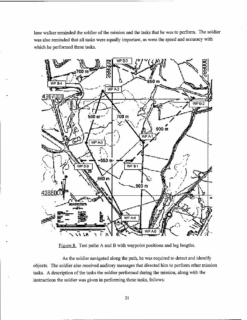
X w
Figure 8. Test paths A and B with waypoint positions and leg lengths.
As the soldier navigated along the path, he was required to detect and identify
objects. The soldier also received auditory messages that directed him to perform other mission
tasks. A description of the tasks the soldier performed during the mission, along with the
instructions the soldier was given in performing these tasks, follows:
21
Navigation
The soldier was instructed that speed and accuracy were equally important
when traveling from waypoint to waypoint. He was told to maintain his position on a straight-
line course, deviating only as far as necessary to avoid obstacles. In case of a detour, he was to
return to the path as soon as possible and resume his straight-line course to the next waypoint.
The lane walker, equipped with a separate GPS, provided one warning at 20 meters' deviation
from the path and one warning at 40 meters' deviation, with a reminder that the soldier should
check his navigational equipment. At 60 meters' deviation from the path, the lane walker guided
the soldier back to path center. The soldier's absolute position was recorded at a rate of 1 Hz,
along with the EPE of the GPS. Navigational accuracy was examined from two perspectives: the
root mean square error (rmse) deviation from the straight-line path and the actual distance the
soldier traveled. The rmse deviation between a specified path and the path traveled has been
used as a measure of performance in previous studies (Kelly, 1969; Purvis, 1991). As an average,
rmse allows direct comparison of paths of dissimilar length. However, Purvis (1991) found that
strategies used by pilots when landing in cross-wind conditions unduly inflated the rmse. In the
present study, there was concern that the rmse might be similarly inflated by strategies used by
infantry soldiers in avoiding terrain hazards and other obstacles during land navigation.
Therefore, the actual distance traveled by the soldier was used as a second measure of
navigational accuracy. Measures of the soldier's velocity within each leg of the path were
computed by dividing the time to navigate each leg by the actual distance the soldier traveled.
Velocity was computed for both mission time and travel time. Mission time was computed from
the time of departure from one waypoint to the time of arrival at the next waypoint and included
the time to perform all mission-related tasks. Travel time was based on mission time minus task
time. The time spent at each WP was not included in calculations of mission or travel time, nor
was any time spent in diagnosing and resolving equipment problems.
Detect and Identify Objects
Five objects were positioned within each leg of each path. Each leg
included one mine, one antenna, one oil drum, and two enemy personnel (wooden silhouettes).
The order in which these objects appeared within each leg and the distance between objects were
randomized. Immediately upon detection of an object, the soldier was required to depress the
"report" button on the keypad, annotating the data file. The soldier then identified the object
describing the size, activity, location, unit, time, and equipment (SALUTE). The SALUTE
report was recorded by an audio recorder located in the soldier's backpack.
22
Determine Magnetic Azimuth
At a predetermined area coordinate within each leg of the test path, the
soldier received an auditory message stating "Mark position of the next waypoint and determine
magnetic azimuth." In the current equipment condition, the soldier oriented his body in the
direction of his next waypoint and depressed a button labeled "mark" on the keypad. He then
read his azimuth from the lensatic compass and depressed the "azimuth" button. In the HMD
condition, when the soldier oriented his body in the direction of his next waypoint and depressed
the "mark" button, a line was interjected within the map display extending from the icon denoting
his position toward the next waypoint. If the line did not intersect the center of the waypoint,
the soldier depressed the "cancel" button which withdrew the line. The soldier then reoriented
his body and once again depressed the "mark" button. If the line now intersected the waypoint,
the soldier read the azimuth presented on the map display and depressed the "azimuth" button.
For both conditions, time to perform this task was based on the time from initiation of the
auditory message to the time the soldier depressed the "azimuth" button.
Call for Fire
At a predetermined area coordinate within each segment of the test path,
the soldier received an auditory message stating "Align on last reported target and call for fire."
This target or object was normally located within ±20 m of the soldier's position. In the current
equipment condition, the soldier oriented his body in the direction of the object and depressed
the "mark" button. He then depressed the "position" button on the GPS to obtain the
coordinates of his position. He derived an estimate of the coordinates of the object by estimating
its distance from his position and using the lensatic compass to determine its azimuth. The
soldier then spoke the coordinates of the object aloud and depressed the "fire" button. In the
HMD condition, the soldier oriented his body toward the object and depressed the "mark"
button. A line was interjected within the map display that extended from the soldier's position
toward the object the soldier was facing. The line was marked in increments of 25 meters. Using
the glide-point mouse, the soldier positioned the cursor at the point on the line at which he
estimated the object to be and depressed the left mouse button. The coordinates of the object
then appeared in the display. If for any reason the soldier was not satisfied with this input or
the resultant object coordinates, he could withdraw the line by depressing the "cancel" button
and could begin again. If the soldier was satisfied with the input and the object's coordinates, he
spoke the coordinates of the object that appeared on the map display and depressed the "fire"
button. For both conditions, time to perform this task was based upon the time from initiation
of the auditory message to the time the soldier depressed the "fire" button.
23
Fragmentary Order (FRAGO)
At a predetermined waypoint within each path, the soldier received an
auditory message changing the coordinates of the next waypoint to which he was to navigate.
For example, the message stated "Prepare for map update-Move waypoint 3 from 4366125
northing 398345 easting to 4367236 northing 398006 easting." In both conditions, the message
repeated every 45 seconds until the soldier acknowledged that he noted the change by depressing
"Roger." In the current equipment condition, the soldier wrote the new coordinates on the map.
He then plotted these new coordinates and calculated the distance and azimuth he must travel to
the new waypoint. Upon completion of this task, the soldier depressed the "report" button.
The lane walker informed the soldier of any errors in plotting or calculation, and the soldier
corrected the map accordingly. Time to perform this task was calculated from the time between
depression of the "Roger" button to the time of depression of the "report" button. In the HMD
condition, the map and rolling compass displays updated automatically to reflect the new
waypoint, and the soldier only needed to depress the "Roger" button.
Troop Movements
At pre-planned area coordinates along each path, the soldier received
auditory messages changing the coordinate position of enemy or other friendly units within the
area. For example, the message stated "Prepare for map update-Move enemy unit reported at
4366125 northing 398245 easting. Unit is now located at 4367236 northing 398006 easting." As
for the FRAGO, the message repeated every 45 seconds until the soldier depressed the "Roger"
button to acknowledge the change. In the current equipment condition, the soldier plotted this
change in position on the paper map; in the HMD condition, the soldier's displays updated
automatically to reflect these troop movements. As for the FRAGO, the time to perform this
task was calculated from the time between depression of the "Roger" button to the time of
depression of the "report" button. In the HMD condition, the map and rolling compass displays
updated automatically to reflect the unit's new position, and the soldier only needed to depress
the "Roger" button.
Probe Questions
One presumed advantage of HMDs is the increased availability of
information to the wearer. To test this hypothesis, a measure of awareness was obtained using
probe questions. This method of measuring awareness was first used by Marshak, Kuperman,
Ramsey, and Wilson (1987) and was refined by Amburn (1994). Awareness relates to the
information that an individual can recall from his or her short-term memory. Typically, specifics
24
are not easily recalled. Therefore, in the probe question method, the question protocol is limited to
a recognition response of a simple "yes" or "no". The "yes-no" format also allows analysis of
responses using signal detection theory. A simple fact in short-term memory is treated like a signal
embedded in the noise of other memories. The sensitivity measure (d') measures the. salience of
information in short-term memory. In the present study, 16 probe questions (four questions per
path leg) were delivered to the soldier by computer-generated audio at pre-determined area
coordinates within each path. These questions were used to assess the soldier's awareness of
information provided on the paper map and digital displays in both the current equipment and
HMD test conditions, respectively. The questions queried the soldier about his heading or the
location of waypoints, landmarks, or other units with respect to his position (example: "Is there
an enemy unit within 100 meters to your right?"). The soldier responded to these questions by
depressing the "yes" or "no" buttons on the keypad. In the current equipment condition, the
soldier was not allowed to consult the map until he responded to the question. Similarly, in the
HMD condition, the soldier's displays temporarily blanked.
Other During and Post Measures
At the midpoint of the path, the soldier was administered the Salivary
Amylase Field Test and stress questionnaires. These stress tests were also administered
immediately upon path completion, along with the CPASE test battery. Upon returning to the
command center, the soldier assessed his workload experience using the NASA-TLX. Both the
soldier and lane walker completed questionnaires (Behavioral Anchored Rating scales) that assessed
the impact of equipment on attention and the soldier's ability to perform concurrent tasks (see
Appendix E). After testing in the HMD condition, each soldier completed a questionnaire that
queried him about the frequency of use of the HMD and individual display formats. After
completion of testing in both conditions, a post-test questionnaire was administered to obtain
information about problems the soldier experienced and his equipment preferences. Post-test
questionnaires are provided in Appendix F.
RESULTS
Land Navigation
Post Processing of Position Data
Raw position data were logged from the PLGR using the P(Y) precision military
signal. The precision signal can achieve ±10-meter accuracy or better without needing a differential
25
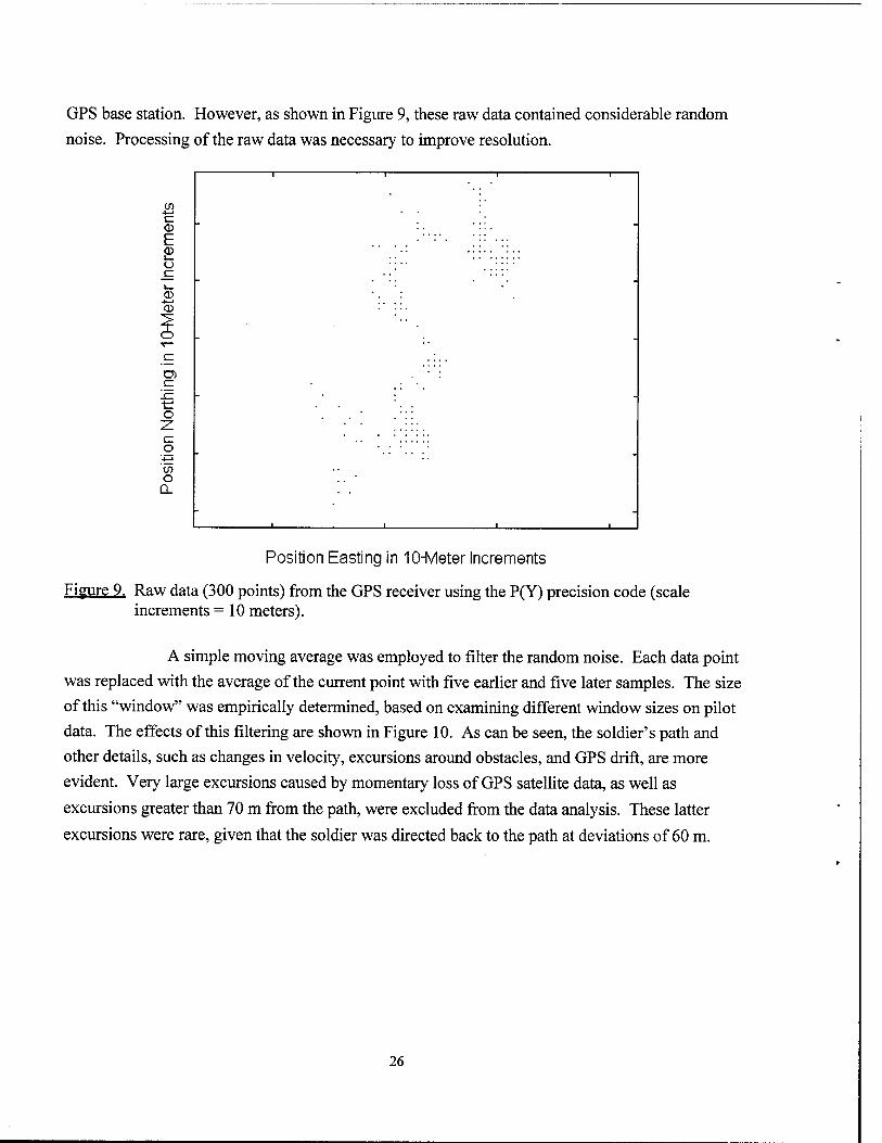
GPS base station. However, as shown in Figure 9, these raw data contained considerable random
noise. Processing of the raw data was necessary to improve resolution.
CO 4—1
<x> E <D i_ <_>
__■
<D 4—» 0>
t: o 2
to o
Q_
Position Easting in 10-Meter Increments
Figure 9. Raw data (300 points) from the GPS receiver using the P(Y) precision code (scale increments =10 meters).
A simple moving average was employed to filter the random noise. Each data point
was replaced with the average of the current point with five earlier and five later samples. The size
of this "window" was empirically determined, based on examining different window sizes on pilot
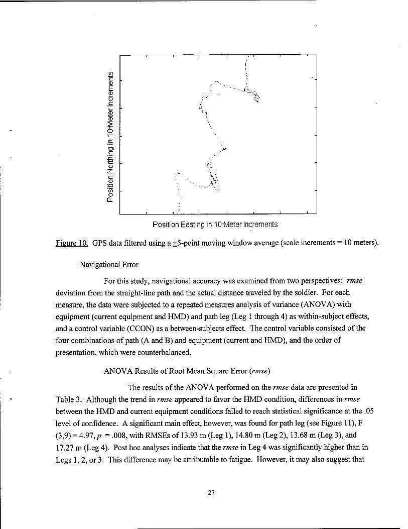
data. The effects of this filtering are shown in Figure 10. As can be seen, the soldier's path and
other details, such as changes in velocity, excursions around obstacles, and GPS drift, are more
evident. Very large excursions caused by momentary loss of GPS satellite data, as well as
excursions greater than 70 m from the path, were excluded from the data analysis. These latter
excursions were rare, given that the soldier was directed back to the path at deviations of 60 m.
26
in
E 0>
0) 4—1
o
tn o
CL
1 -- 1 1 1
( 1 1 1
.-.,•' ••■.<.
rt
-
>*»
-
' ■ v.
> 1 ..." 1 1 ■ ■ i
Position Easting in 10-Meter Increments
Figure 10. GPS data filtered using a ±5-point moving window average (scale increments = 10 meters).
Navigational Error
For this study, navigational accuracy was examined from two perspectives: rmse
deviation from the straight-line path and the actual distance traveled by the soldier. For each
measure, the data were subjected to a repeated measures analysis of variance (ANOVA) with
equipment (current equipment and HMD) and path leg (Leg 1 through 4) as within-subject effects,
and a control variable (CCON) as a between-subjects effect. The control variable consisted of the
four combinations of path (A and B) and equipment (current and HMD), and the order of
presentation, which were counterbalanced.
ANOVA Results of Root Mean Square Error (rmse)
The results of the ANOVA performed on the rmse data are presented in
Table 3. Although the trend in rmse appeared to favor the HMD condition, differences in rmse
between the HMD and current equipment conditions failed to reach statistical significance at the .05
level of confidence. A significant main effect, however, was found for path leg (see Figure 11), F
(3,9) = 4.97, p = .008, with RMSEs of 13.93 m (Leg 1), 14.80 m (Leg 2), 13.68 m (Leg 3), and
17.27 m (Leg 4). Post hoc analyses indicate that the rmse in Leg 4 was significantly higher than in
Legs 1, 2, or 3. This difference may be attributable to fatigue. However, it may also suggest that
27
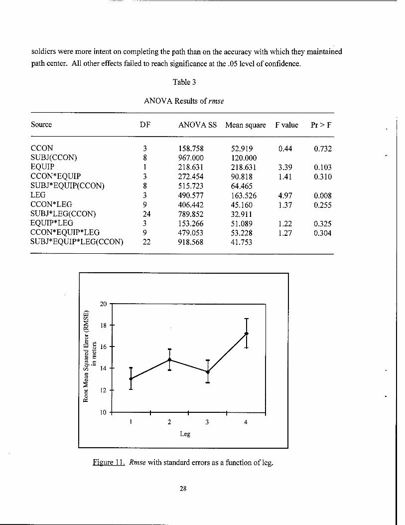
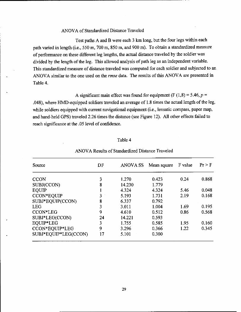
soldiers were more intent on completing the path than on the accuracy with which they maintained path center. All other effects failed to reach significance at the .05 level of confidence.
Table 3
ANOVA Results of rmse
Source DF ANOVA SS Mean square F value Pr > F
CCON 3 158.758 52.919 0.44 0.732 SUBJ(CCON) 8 967.000 120.000 EQUIP 1 218.631 218.631 3.39 0.103 CCON*EQUIP 3 272.454 90.818 1.41 0.310 SUBJ*EQUIP(CCON) 8 515.723 64.465 LEG 3 490.577 163.526 4.97 0.008 CCON*LEG 9 406.442 45.160 1.37 0.255 SUBJ*LEG(CCON) 24 789.852 32.911 EQUIP*LEG 3 153.266 51.089 1.22 0.325 CCON*EQUIP*LEG 9 479.053 53.228 1.27 0.304 SUBJ*EQUIP*LEG(CCON) 22 918.568 41.753
Figure 11. Rmse with standard errors as a function of leg.
28
ANOVA of Standardized Distance Traveled
Test paths A and B were each 3 km long, but the four legs within each
path varied in length (i.e., 550 m, 700 m, 850 m, and 900 m). To obtain a standardized measure
of performance on these different leg lengths, the actual distance traveled by the soldier was
divided by the length of the leg. This allowed analysis of path leg as an independent variable.
This standardized measure of distance traveled was computed for each soldier and subjected to an
ANOVA similar to the one used on the rmse data. The results of this ANOVA are presented in
Table 4.
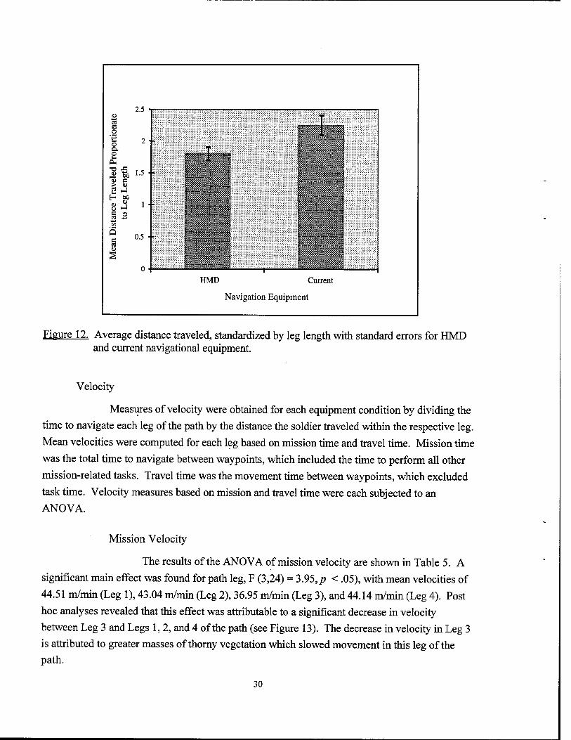
A significant main effect was found for equipment (F (1,8) = 5.46,/? =
.048), where HMD-equipped soldiers traveled an average of 1.8 times the actual length of the leg,
while soldiers equipped with current navigational equipment (i.e., lensatic compass, paper map,
and hand-held GPS) traveled 2.26 times the distance (see Figure 12). All other effects failed to
reach significance at the .05 level of confidence.
Table 4
ANOVA Results of Standardized Distance Traveled
Source DF ANOVA SS Mean square F value Pr>F
CCON 3 1.270 0.423 0.24 0.868 SUBJ(CCON) 8 14.230 1.779 EQUIP 1 4.324 4.324 5.46 0.048 CCON*EQUIP 3 5.193 1.731 2.19 0.168 SUBJ*EQUIP(CCON) 8 6.337 0.792 LEG 3 3.011 1.004 1.69 0.195 CCON*LEG 9 4.610 0.512 0.86 0.568 SUBJ*LEG(CCON) 24 14.221 0.593 EQUIP*LEG 3 1.755 0.585 1.95 0.160 CCON*EQUIP*LEG 9 3.296 0.366 1.22 0.345 SUBJ*EQUIP*LEG(CCON) 17 5.101 0.300
29
2.5 2 cd C o '€ o a. o
tM
OH
<o c > D
B C3 u
2 -I
1.5 -1
1 -I
0.5 ■!
HMD Current
Navigation Equipment
Figure 12. Average distance traveled, standardized by leg length with standard errors for HMD and current navigational equipment.
Velocity
Measures of velocity were obtained for each equipment condition by dividing the
time to navigate each leg of the path by the distance the soldier traveled within the respective leg.
Mean velocities were computed for each leg based on mission time and travel time. Mission time
was the total time to navigate between waypoints, which included the time to perform all other
mission-related tasks. Travel time was the movement time between waypoints, which excluded
task time. Velocity measures based on mission and travel time were each subjected to an
ANOVA.
Mission Velocity
The results of the ANOVA of mission velocity are shown in Table 5. A
significant main effect was found for path leg, F (3,24) = 3.95,p < .05), with mean velocities of
44.51 m/min (Leg 1), 43.04 m/min (Leg 2), 36.95 m/min (Leg 3), and 44.14 m/min (Leg 4). Post
hoc analyses revealed that this effect was attributable to a significant decrease in velocity
between Leg 3 and Legs 1, 2, and 4 of the path (see Figure 13). The decrease in velocity in Leg 3
is attributed to greater masses of thorny vegetation which slowed movement in this leg of the path.
30
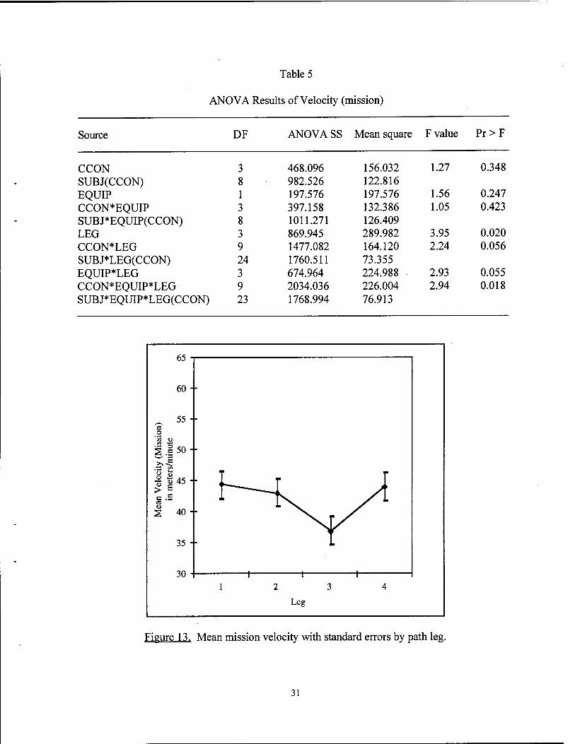
Table 5
ANOVA Results of Velocity (mission)
Source DF ANOVASS Mean square F value Pr>F
CCON 3 468.096 156.032 1.27 0.348 SUBJ(CCON) 8 982.526 122.816 EQUIP 1 197.576 197.576 1.56 0.247 CCON*EQUIP 3 397.158 132.386 1.05 0.423 SUBJ*EQUIP(CCON) 8 1011.271 126.409 LEG 3 869.945 289.982 3.95 0.020 CCON*LEG 9 1477.082 164.120 2.24 0.056 SUBJ*LEG(CCON) 24 1760.511 73.355 EQUIP*LEG 3 674.964 224.988 2.93 0.055 CCON*EQUIP*LEG 9 2034.036 226.004 2.94 0.018 SUBJ*EQUIP*LEG(CCON) 23 1768.994 76.913
OJ "
60 ■
55 - c _o
5 ! 50 •
51 8 S ||45-
c .£ a o 2 40-
35 -
JU 1 i i i
12 3 4
Leg
Figure 13. Mean mission velocity with standard errors by path leg.
31
Finally, the ANOVA also revealed a significant three-way Equipment x
Path Leg x Control Variable interaction (F (9,23) = 2.94, p < .018). This interaction is attributed
to the significantly higher velocities achieved in Leg 1 of the test path when soldiers navigated
Path A first using current equipment. Velocities in subsequent legs of Path A using current
equipment were significantly lower than in Leg 1, as were velocities in both equipment conditions
in all legs of both test paths where equipment conditions and-or paths A and B were presented in
a different order. This finding may reflect the mildness of the terrain in Leg 1 of Path A by
comparison to other legs of both test paths which contained denser and sometimes thorny
vegetation. It may also reflect the soldiers' premature expectations that their task would be easy,
as well as their skill and confidence in navigating this milder terrain with the familiar lensatic
compass. All other effects failed to reach significance at the .05 level of confidence.
Travel Velocity
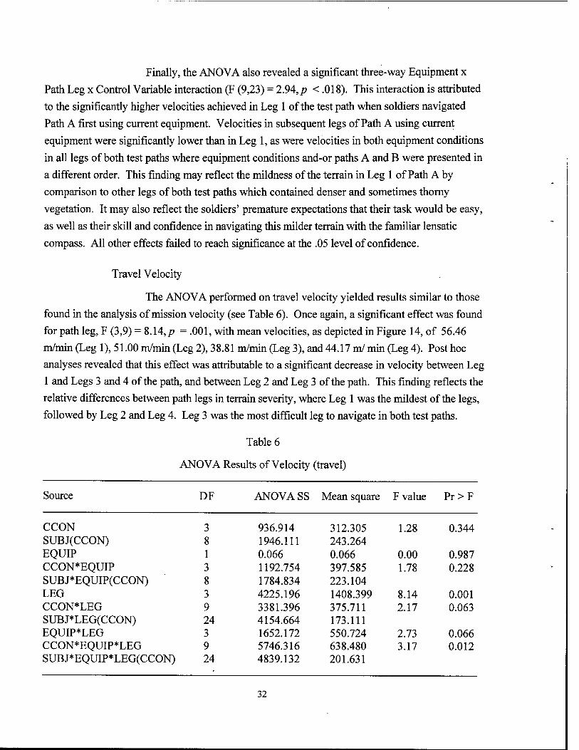
The ANOVA performed on travel velocity yielded results similar to those
found in the analysis of mission velocity (see Table 6). Once again, a significant effect was found
for path leg, F (3,9) = 8.14,/p = .001, with mean velocities, as depicted in Figure 14, of 56.46
m/min (Leg 1), 51.00 m/min (Leg 2), 38.81 m/min (Leg 3), and 44.17 ml min (Leg 4). Post hoc
analyses revealed that this effect was attributable to a significant decrease in velocity between Leg
1 and Legs 3 and 4 of the path, and between Leg 2 and Leg 3 of the path. This finding reflects the
relative differences between path legs in terrain severity, where Leg 1 was the mildest of the legs,
followed by Leg 2 and Leg 4. Leg 3 was the most difficult leg to navigate in both test paths.
Table 6
ANOVA Results of Velocity (travel)
Source DF ANOVA SS Mean square F value Pr>F
CCON 3 936.914 312.305 1.28 0.344 SUBJ(CCON) 8 1946.111 243.264 EQUIP 1 0.066 0.066 0.00 0.987 CCON*EQUIP 3 1192.754 397.585 1.78 0.228 SUBJ*EQUIP(CCON) 8 1784.834 223.104 LEG 3 4225.196 1408.399 8.14 0.001 CCON*LEG 9 3381.396 375.711 2.17 0.063 SUBJ*LEG(CCON) 24 4154.664 173.111 EQUIP*LEG 3 1652.172 550.724 2.73 0.066 CCON*EQUIP*LEG 9 5746.316 638.480 3.17 0.012 SUBJ*EQUIP*LEG(CCON) 24 4839.132 201.631
32
oo •
60 ■
55 - *ö3 > S £ .£ 50 - ^-§ %B 5 145- B .5 S3 <U
S 40 -
35 -
30 i 1 1 1 12 3 4
Leg
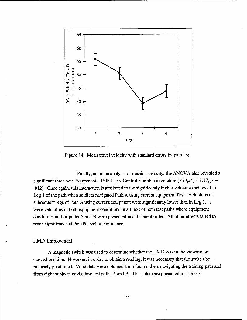
Figure 14. Mean travel velocity with standard errors by path leg.
Finally, as in the analysis of mission velocity, the ANOVA also revealed a significant three-way Equipment x Path Leg x Control Variable interaction (F (9,24) = 3.17,/? = .012). Once again, this interaction is attributed to the significantly higher velocities achieved in Leg 1 of the path when soldiers navigated Path A using current equipment first. Velocities in subsequent legs of Path A using current equipment were significantly lower than in Leg 1, as were velocities in both equipment conditions in all legs of both test paths where equipment conditions and-or paths A and B were presented in a different order. All other effects failed to reach significance at the .05 level of confidence.
HMD Employment
A magnetic switch was used to determine whether the HMD was in the viewing or stowed position. However, in order to obtain a reading, it was necessary that the switch be precisely positioned. Valid data were obtained from four soldiers navigating the training path and from eight subjects navigating test paths A and B. These data are presented in Table 7.
33
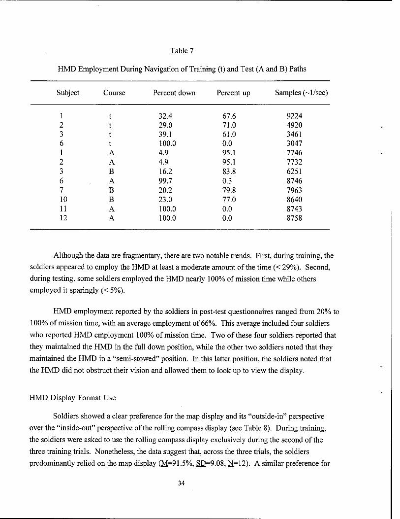
Table 7
HMD Employment During Navigation of Training (t) and Test (A and B) Paths
Subject Course Percent down Percent up Samples (~l/sec)
1 t 32.4 67.6 9224 2 t 29.0 71.0 4920 3 t 39.1 61.0 3461 6 t 100.0 0.0 3047 1 A 4.9 95.1 7746 2 A 4.9 95.1 7732 3 B 16.2 83.8 6251 6 A 99.7 0.3 8746 7 B 20.2 79.8 7963 10 B 23.0 77.0 8640 11 A 100.0 0.0 8743 12 A 100.0 0.0 8758
Although the data are fragmentary, there are two notable trends. First, during training, the
soldiers appeared to employ the HMD at least a moderate amount of the time (< 29%). Second,
during testing, some soldiers employed the HMD nearly 100% of mission time while others
employed it sparingly (< 5%).
HMD employment reported by the soldiers in post-test questionnaires ranged from 20% to
100% of mission time, with an average employment of 66%. This average included four soldiers
who reported HMD employment 100% of mission time. Two of these four soldiers reported that
they maintained the HMD in the full down position, while the other two soldiers noted that they
maintained the HMD in a "semi-stowed" position. In this latter position, the soldiers noted that
the HMD did not obstruct their vision and allowed them to look up to view the display.
HMD Display Format Use
Soldiers showed a clear preference for the map display and its "outside-in" perspective
over the "inside-out" perspective of the rolling compass display (see Table 8). During training,
the soldiers were asked to use the rolling compass display exclusively during the second of the
three training trials. Nonetheless, the data suggest that, across the three trials, the soldiers
predominantly relied on the map display (M=91.5%, SD=9.08. N=12). A similar preference for
34
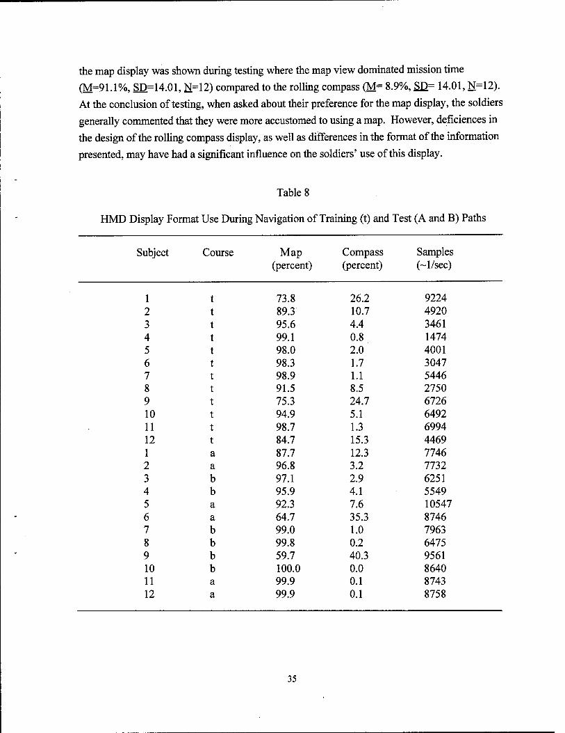
the map display was shown during testing where the map view dominated mission time (M=91.1%, SD=14.01, N=12) compared to the rolling compass (M= 8.9%, SD= 14.01, N=12). At the conclusion of testing, when asked about their preference for the map display, the soldiers generally commented that they were more accustomed to using a map. However, deficiences in the design of the rolling compass display, as well as differences in the format of the information presented, may have had a significant influence on the soldiers' use of this display.
Table 8
HMD Display Format Use During Navigation of Training (t) and Test (A and B) Paths
Subject Course Map Compass Samples
(percent) (percent) (~l/sec)
1 73.8 26.2 9224
2 89.3 10.7 4920
3 95.6 4.4 3461
4 99.1 0.8 1474 5 98.0 2.0 4001 6 98.3 1.7 3047 7 98.9 1.1 5446 8 91.5 8.5 2750 9 75.3 24.7 6726 10 94.9 5.1 6492 11 98.7 1.3 6994 12 84.7 15.3 4469 1 a 87.7 12.3 7746 2 a 96.8 3.2 7732 3 b 97.1 2.9 6251 4 b 95.9 4.1 5549 5 a 92.3 7.6 10547 6 a 64.7 35.3 8746 7 b 99.0 1.0 7963 8 b 99.8 0.2 6475 9 b 59.7 40.3 9561 10 b 100.0 0.0 8640 11 a 99.9 0.1 8743 12 a 99.9 0.1 8758
35
Other Mission Tasks
Detect and Identity Objects
Of the 15 objects positioned along a path, the mean number of objects detected
and identified in the current equipment and HMD conditions was 6.33 (SD = 2.67) and 7.33 (SD
= 2.39), respectively. Analysis indicated that there was no significant difference between
equipment conditions in the performance of this task.
Determine Magnetic Azimuth
Mean times to determine magnetic azimuth in the current equipment and HMD
conditions were 0.71 min (SD = 0.31) and 0.73 min (SD = 0.42), respectively. Analysis
indicated that there was no significant difference between conditions in the time to perform this
task.
Call for Fire
Mean times to call for fire in the current equipment and HMD conditions were
1.92 min (SD = 0.42) and 1.46 min (SD = 0.84), respectively. Analysis indicated that there was
no significant difference between conditions in the time to perform this task.
Troop Movements and FRAGO
In the HMD condition, the mean time from initiation of an auditory message that
alerted the soldier of a troop movement, to the time that he acknowledged the change was 0.59
min (SD = 0.17). In the current equipment condition, the mean time from initiation of the
auditory message to the time that the soldier completed a manual update of the map was 3.49
min (SD = 1.48). As might be expected, differences between equipment conditions in time to
complete this task were significant, t (11) = 6.94,;? <.001.
In the HMD condition, the mean time from initiation of an auditory message that
alerted the soldier of a change in waypoint location (FRAGO) to the time at which the soldier
acknowledged this change was 0.54 min (SD = 0.22). In the current equipment condition, the
mean time from initiation of the auditory message to the time that he completed a manual update
of the map was 8.99 min (SD = 7.38). Again, as expected, differences between equipment
conditions in time to complete this task were significant, t (10) = 3.83,/? = .003.
36
Probe Questions and Situation Awareness
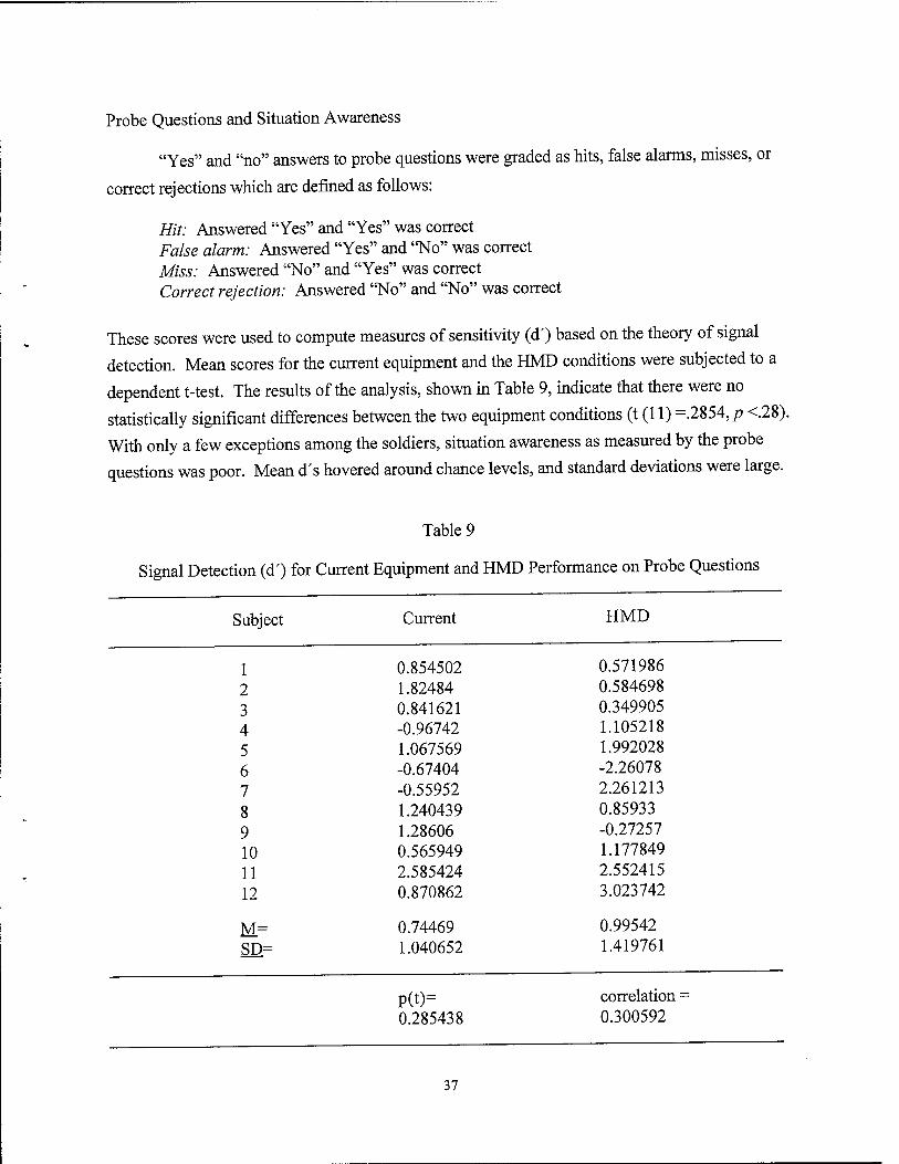
"Yes" and "no" answers to probe questions were graded as hits, false alarms, misses, or
correct rejections which are defined as follows:
Hit: Answered "Yes" and "Yes" was correct False alarm: Answered "Yes" and "No" was correct Miss: Answered "No" and "Yes" was correct Correct rejection: Answered "No" and "No" was correct
These scores were used to compute measures of sensitivity (d') based on the theory of signal
detection. Mean scores for the current equipment and the HMD conditions were subjected to a
dependent t-test. The results of the analysis, shown in Table 9, indicate that there were no
statistically significant differences between the two equipment conditions (t (11) =.2854, p <.28).
With only a few exceptions among the soldiers, situation awareness as measured by the probe
questions was poor. Mean d's hovered around chance levels, and standard deviations were large.
Table 9
Signal Detection (<T) for Current Equipment and HMD Performance on Probe Questions
Subject Current HMD
1 0.854502 0.571986
2 1.82484 0.584698
3 0.841621 0.349905
4 -0.96742 1.105218
5 1.067569 1.992028
6 -0.67404 -2.26078
7 -0.55952 2.261213
8 1.240439 0.85933
9 1.28606 -0.27257
10 0.565949 1.177849
11 2.585424 2.552415
12 0.870862 3.023742
M= 0.74469 0.99542
SD= 1.040652 1.419761
P(t)= correlation =
0.285438 0.300592
37
Workload (NASA-TLX)
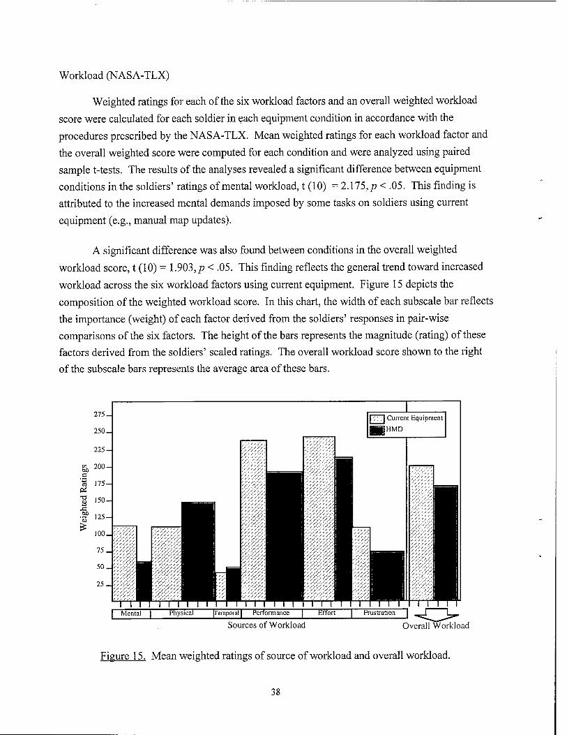
Weighted ratings for each of the six workload factors and an overall weighted workload
score were calculated for each soldier in each equipment condition in accordance with the
procedures prescribed by the NASA-TLX. Mean weighted ratings for each workload factor and
the overall weighted score were computed for each condition and were analyzed using paired
sample t-tests. The results of the analyses revealed a significant difference between equipment
conditions in the soldiers' ratings of mental workload, t (10) = 2.115, p < .05. This finding is
attributed to the increased mental demands imposed by some tasks on soldiers using current
equipment (e.g., manual map updates).
A significant difference was also found between conditions in the overall weighted
workload score, t (10) = 1.903, p < .05. This finding reflects the general trend toward increased
workload across the six workload factors using current equipment. Figure 15 depicts the
composition of the weighted workload score. In this chart, the width of each subscale bar reflects
the importance (weight) of each factor derived from the soldiers' responses in pair-wise
comparisons of the six factors. The height of the bars represents the magnitude (rating) of these
factors derived from the soldiers' scaled ratings. The overall workload score shown to the right
of the subscale bars represents the average area of these bars.
275-1
250
225-1
| Mental
Current Equipment
HMD
m [Temporal | Performance | Effort
Sources of Workload Overall Workload
Figure 15. Mean weighted ratings of source of workload and overall workload.
38
Stress
Willingness, Importance, and Confidence Levels
The participants' ratings of willingness (mean = 94.17, +SEM = 3.30) and
importance (mean = 88.33, +SEM = 3.39), indicate that they were very willing to complete the
study and believed that the study was of great importance to future soldiers. The confidence
levels of the participants, as measured by the Self-Efficacy scale (SES), parallels these findings,
regardless of condition (F (1,19) = .27, p = 0.659).
Psychological Stress Levels
A three-way multivariate analysis of variance (MANOVA) (Condition x
Measures x Sessions) was performed to determine if there were differences between equipment
conditions across measures of psychological stress obtained using the Multiple Affect Adjective
Checklist-Revised (MAACL-R). No statistically significant differences were found (Wilks' A, =
0.305; F (7,12) = 1.324,p = 0.366). A three-way MANOVA was also performed to determine
if there were differences between conditions in measures of stress obtained using the Specific
Rating of Events (SRE) scale and the Subjective Stress scale (SUBJ). No statistically significant
differences were found using either of these subscales (Wilks' X = 0.093; F (14,3) = 0.483,/? =
0.699).
Salivary Amylase Field Test
A repeated measures ANOVA was conducted on salivary amylase across seven
time points: baseline, pre HMD, during HMD, post HMD, pre current, during current, post
current. Significant differences were found (Wilks' X = 0.097; F (6,12) = 9.22, p = 0.008). The
results of post hoc comparisons using paired t-tests indicate a significant difference between
baseline and post current (t (6,12) = - 4.52, p = 0.001) and during current and post current
(t (6,12) = - 4.00, p = 0.002). Because salivary amylase is affected by physiological as well as
psychological Stressors and because the results of other stress tests revealed little to no
psychological stress, differences between earlier measures of salivary amylase levels and post-
test measures are not attributed to an increase in mental stress but rather to an increase in
physical activity imposed by manipulation of more equipment.
Cognitive Performance
Cognitive performance tasks included verbal memory, logical reasoning, addition, and
spatial rotation. To delineate performance differences, each test was evaluated as to the number
39
of items completed correctly. A separate session (pre/post) by condition (current/HMD)
repeated measure ANOVA was computed for each performance variable. Baseline measures
were not included in these ANOVAs. Shifts from baseline were evaluated by computing a
MANOVA for each performance variable across the five sessions (baseline, pre/post measures
for current and HMD conditions). One subject did not complete the baseline tests, so the
MANOVAs were computed using 11 subjects.
Verbal Memory
This short-term memory test required written recall of 12 single- and double-
syllable words. No significant effects were found in the ANOVA. The multivariate analysis
across trials, which included the baseline measure, showed a significant difference (F (4,40) =
3.35,/? <.02). Pair-wise comparisons indicated that the baseline measure, with a mean of 7.2,
was significantly higher than for the other four trials.
Logical Reasoning
This reasoning task (Baddeley, 1968) involved 32 evaluations of two-letter pairs
and a phrase describing the letter pair ordering. Each evaluation was judged as "true" or "false."
Significant changes in performance were not found in the analysis of this measure.
Addition
For this computation task, soldiers were given 30 seconds to complete 15
problems of adding two randomly selected three-digit numbers together. The ANOVA did not
reveal any significant effects. However, the MANOVA indicated a significant effect for trials (F
(4,40) = 5.702,p <.001), with paired comparisons showing that baseline was significantly lower
than the other four trials.
Spatial Rotation
Soldiers' performance of the spatial rotation task involved pattern recognition and
figure rotation. Eighteen evaluations were presented for this task. The ANOVA indicated there
was a significant main effect for trials (F (1,11) = 5.5,p < .04). Pair-wise comparisons indicated
that the pre-test for the HMD condition (mean = 9.4) was significantly lower than post measures
for current (mean =12) and HMD (mean = 11.4) tests. No significant effects were found for the
baseline analysis.
40
CPASEandNASA-TLX
Correlations were computed to examine the relationship between workload (as measured by the NASA-TLX) and changes in cognitive performance for each condition. The only significant correlation occurred for the HMD condition between the temporal factor of the NASA-TLX and logical reasoning, r (10) = -0.71, p <.009. This negative correlation indicates that as perception of temporal workload increases, the difference between pre and post scores on the logical reasoning task narrows. The expected finding would be a greater disparity between pre and post measures, with performance deteriorating at a faster rate as temporal demands increased. A better understanding of this unexpected result requires further testing.
Behavioral Anchored Rating Scales
Soldier Observations
For each question, the soldiers' scaled observations (1 to 5) were tabulated, and means computed for each question for each of the two equipment conditions. The results of paired sample t-tests revealed significant differences between conditions on 2 of 13 questions (see Table 10). Differences in the soldiers' observations relating to interference between the navigational equipment and other mission-related items favored the HMD condition, t (11) = -2.880,/? < .01. The soldiers' observations also indicated greater interest in this new technology, t (11) = -2.244, p < .01. These differences reflect some of the more common concerns noted by soldiers in the post-test questionnaires related to the amount of equipment they had to carry in the current equipment condition and the soldiers' preference for the HMD.
Table 10
Results of the Analysis of Soldier Responses on Behavioral Anchored Rating Scales
Question Condition Mean df SD t P
l-2b
3-2b
Did the navigational equipment interfere with the soldier's ability to use other mission equipment (e.g., M16 rifle)?
Was the soldier interested in the navigational equipment?
Current
HMD
Current
HMD
3.083
4.250
3.667
4.250
11
11
11
11
.996
1.215
.888
.866
-2.880 <.01
-2.244 <.01
41
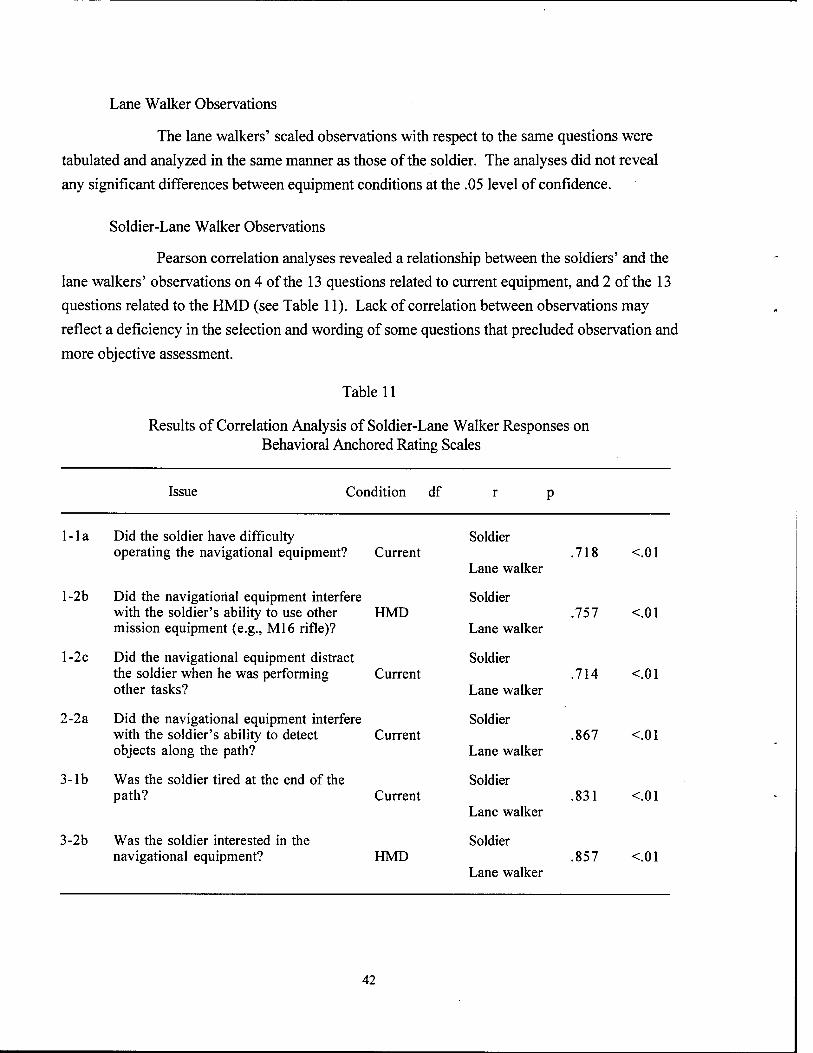
Lane Walker Observations
The lane walkers' scaled observations with respect to the same questions were
tabulated and analyzed in the same manner as those of the soldier. The analyses did not reveal
any significant differences between equipment conditions at the .05 level of confidence.
Soldier-Lane Walker Observations
Pearson correlation analyses revealed a relationship between the soldiers' and the
lane walkers' observations on 4 of the 13 questions related to current equipment, and 2 of the 13
questions related to the HMD (see Table 11). Lack of correlation between observations may
reflect a deficiency in the selection and wording of some questions that precluded observation and
more objective assessment.
Table 11
Results of Correlation Analysis of Soldier-Lane Walker Responses on Behavioral Anchored Rating Scales
Issue Condition df
1 -1 a Did the soldier have difficulty operating the navigational equipment? Current
l-2b Did the navigational equipment interfere with the soldier's ability to use other HMD mission equipment (e.g., Ml6 rifle)?
l-2c Did the navigational equipment distract the soldier when he was performing Current other tasks?
2-2a Did the navigational equipment interfere with the soldier's ability to detect Current objects along the path?
3-lb Was the soldier tired at the end of the path? Current
3-2b Was the soldier interested in the navigational equipment? HMD
Soldier
Lane walker
Soldier
Lane walker
Soldier
Lane walker
Soldier
Lane walker
Soldier
Lane walker
Soldier
Lane walker
.718
.757
.714
.867
.831
.857
<.01
<.01
<.01
<.01
<.01
<.01
42
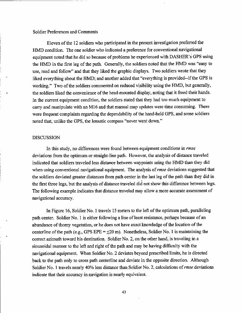
Soldier Preferences and Comments
Eleven of the 12 soldiers who participated in the present investigation preferred the HMD condition. The one soldier who indicated a preference for conventional navigational equipment noted that he did so because of problems he experienced with DASHER'S GPS using the HMD in the first leg of the path. Generally, the soldiers noted that the HMD was "easy to use, read and follow" and that they liked the graphic displays. Two soldiers wrote that they liked everything about the HMD; and another added that "everything is provided--if the GPS is
working." Two of the soldiers commented on reduced visibility using the HMD, but generally,
the soldiers liked the convenience of the head-mounted display, noting that it freed their hands. In the current equipment condition, the soldiers stated that they had too much equipment to carry and manipulate with an Ml6 and that manual map updates were time consuming. There were frequent complaints regarding the dependability of the hand-held GPS, and some soldiers noted that, unlike the GPS, the lensatic compass "never went down."
DISCUSSION
In this study, no differences were found between equipment conditions in rmse
deviations from the optimum or straight-line path. However, the analysis of distance traveled indicated that soldiers traveled less distance between waypoints using the HMD than they did when using conventional navigational equipment. The analysis of rmse deviations suggested that the soldiers deviated greater distances from path center in the last leg of the path than they did in the first three legs, but the analysis of distance traveled did not show this difference between legs. The following example indicates that distance traveled may allow a more accurate assessment of navigational accuracy.
In Figure 16, Soldier No. 1 travels 15 meters to the left of the optimum path, paralleling path center. Soldier No. 1 is either following a line of least resistance, perhaps because of an abundance of thorny vegetation, or he does not have exact knowledge of the location of the centerline of the path (e.g., GPS EPE = ±20 m). Nonetheless, Soldier No. 1 is maintaining the correct azimuth toward his destination. Soldier No. 2, on the other hand, is traveling in a sinusoidal manner to the left and right of the path and may be having difficulty with the navigational equipment. When Soldier No. 2 deviates beyond prescribed limits, he is directed back to the path only to cross path centerline and deviate in the opposite direction. Although Soldier No. 1 travels nearly 40% less distance than Soldier No. 2, calculations of rmse deviations indicate that their accuracy in navigation is nearly equivalent.
43
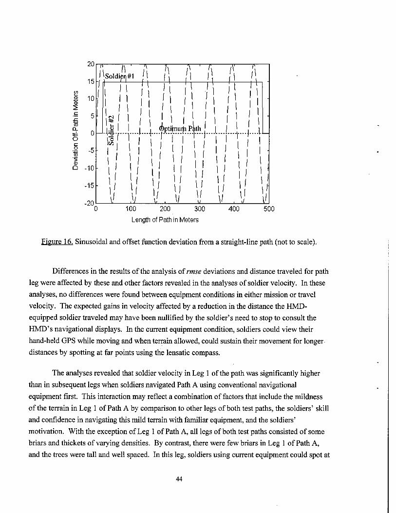
o_ o c o
'*—i
> 0) Q
20
15 en
S 10
-10
-15
-20
Soldifi]#l
1 TV
* 1 u. 1.2
■TO
5- I
l/ \ I
/*/ r~^7
Ml1
d)pti(muiji Pkth
/ \) _u_ \/
100 200 300
Length of Path in Meters
400 500
Figure 16. Sinusoidal and offset function deviation from a straight-line path (not to scale).
Differences in the results of the analysis of rmse deviations and distance traveled for path
leg were affected by these and other factors revealed in the analyses of soldier velocity. In these
analyses, no differences were found between equipment conditions in either mission or travel
velocity. The expected gains in velocity affected by a reduction in the distance the HMD-
equipped soldier traveled may have been nullified by the soldier's need to stop to consult the
HMD's navigational displays. In the current equipment condition, soldiers could view their
hand-held GPS while moving and when terrain allowed, could sustain their movement for longer
distances by spotting at far points using the lensatic compass.
The analyses revealed that soldier velocity in Leg 1 of the path was significantly higher
than in subsequent legs when soldiers navigated Path A using conventional navigational
equipment first. This interaction may reflect a combination of factors that include the mildness
of the terrain in Leg 1 of Path A by comparison to other legs of both test paths, the soldiers' skill
and confidence in navigating this mild terrain with familiar equipment, and the soldiers'
motivation. With the exception of Leg 1 of Path A, all legs of both test paths consisted of some
briars and thickets of varying densities. By contrast, there were few briars in Leg 1 of Path A,
and the trees were tall and well spaced. In this leg, soldiers using current equipment could spot at
44
distances using the conventional lensatic compass, stopping less frequently. Vegetation progressively thickened in subsequent legs of the path, reducing visibility and perhaps any expectations that the task would be easy. To maintain the path in areas where vision at distances was reduced, the soldiers had to stop more frequently to consult their navigational equipment. Progress through sections of the path that contained briars was slower and more fatiguing. The fact that no differences were found between Leg 1 and subsequent legs of Path A when this path was navigated second may reflect the soldiers' more realistic expectations of the terrain that lay
ahead and the soldiers' attempts to pace themselves.
In both equipment conditions, soldier velocity decreased significantly in Leg 3 of the path. In both paths, Leg 3 contained greater masses of thorny vegetation than the other three legs and was the most difficult leg to navigate. In this leg, path center ran between two marshy areas near which briar patches thickened and water at times was above the soldiers' boots. For safety, the soldiers were advised to adhere to the path as closely as possible to avoid more difficult terrain. The reduction in soldier velocity in Leg 3 may therefore have been artificially inflated by their attempts to heed this advice. Navigational accuracy may have also been influenced by experimenters' intervention.
Because of the thick briars in Leg 3, many soldiers had difficulty in finding Waypoint 3 (WP3), thus further decreasing measures of velocity on this leg. Upon reaching WP3, most soldiers were fatigued. However, "home" was just a leg away and there is reason to believe that the return to velocity in Leg 4 was related to the "goal box" effect where there is a tendency to accelerate when the end is near.
After Leg 3, soldiers may have been more intent on the speed at which they completed the path rather than on the accuracy with which they maintained path center. Briar patches in Leg 4 were not as dense as in Leg 3 and were more navigable. In Leg 4, vegetation progressively thinned at distances beyond 15 meters from path center. Naturally, the soldiers chose the path of least resistance. Figure 17 most clearly demonstrates the accuracy with which one soldier, using current equipment, maintained azimuth, paralleling path center and avoiding briars that would impede his progress. As demonstrated before, traveling at an offset parallel to the centerline of the path in Leg 4 would inflate the rmse deviation but not necessarily the actual distance the soldier traveled. However, at deviations beyond 20 meters from path center, some mission tasks that were programmed for presentation within a specific area coordinate were not initiated. This may have inflated measures of mission velocity in Leg 4.
45
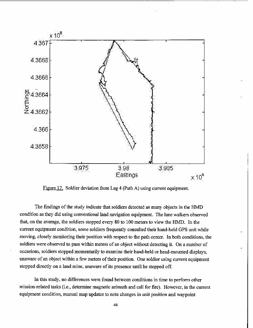
x10
4.3658 -
3.975 3.98 Eastings
3.985 xlCT
Figure 17. Soldier deviation from Leg 4 (Path A) using current equipment.
The findings of the study indicate that soldiers detected as many objects in the HMD condition as they did using conventional land navigation equipment. The lane walkers observed that, on the average, the soldiers stopped every 80 to 100 meters to view the HMD. In the current equipment condition, some soldiers frequently consulted their hand-held GPS unit while moving, closely monitoring their position with respect to the path center. In both conditions, the soldiers were observed to pass within meters of an object without detecting it. On a number of occasions, soldiers stopped momentarily to examine their hand-held or head-mounted displays, unaware of an object within a few meters of their position. One soldier using current equipment stopped directly on a land mine, unaware of its presence until he stepped off.
In this study, no differences were found between conditions in time to perform other mission-related tasks (i.e., determine magnetic azimuth and call for fire). However, in the current equipment condition, manual map updates to note changes in unit position and waypoint
46
destination consumed more time by comparison to the HMD condition where such changes were
displayed automatically.
The soldiers' overall ratings of workload, as measured by the NASA-TLX, were
significantly higher using current navigational equipment than using the HMD system. In the
calculation of these overall ratings, the ratings of those workload factors that contributed most to
the soldier's workload experience are given more weight, thus enhancing the sensitivity of this
measure. The reduction in overall workload in the HMD condition reflects the advantages of the
system that are supported by the soldiers' preference for the HMD and related comments (i.e.,
"freed my hands," "easy to read and follow," "everything was provided"). The soldiers'
performance and the level of effort they expended to attain this performance appeared to have
the greatest influence on the soldiers' workload experience in both equipment conditions;
however, in the analyses of differences between each of the six workload factors, the only
difference found between conditions was in the area of mental demands. This latter finding
reflects the interpretability of the display as well as differences in the level of automation
between current equipment and the HMD system which may have impacted the amount of
mental processing required to perform some mission tasks.
The results of the analyses of the psychological stress perception measures indicated
little or no psychological stress associated with either experimental condition. However, the
results of the Salivary Amy läse Field Test indicated that, in the current equipment condition,
differences between earlier measures of salivary amylase and post-test measures were significant.
Because salivary amylase is affected by physiological as well as psychological Stressors and
because the results of other stress tests revealed little to no psychological stress, differences
between salivary amylase measures in the current equipment condition are not attributed to an
increase in mental stress but rather to an increase in physical activity imposed by manipulation
of more equipment.
No differences were found between conditions in cognitive performance. In the HMD
condition, however, post performance scores on Spatial Rotation were unexpectedly higher than
pre-measure scores. This finding is attributed to the practice the soldiers received in mentally
rotating the HMD's map display that was fixed in the north-up direction. Generally, differences
were also found between baseline and post measures for Word Recall and Addition. As expected,
performance was significantly higher for the baseline measure of Word Recall. However, baseline
scores were significantly lower than the post measure for the Addition task. As for Spatial
47
Rotation, this latter finding is attributed to practice effects. In both the HMD and current
equipment conditions, soldier tasks involved mental math.
Situation awareness, as measured by probe questions, was not significantly affected by
test condition. Although it might seem intuitive that having information constantly available on
an HMD would increase awareness, this did not appear to be the case. Data obtained about
HMD employment, although fragmentary, indicate that many of the soldiers maintained the
display in the stowed position 75% or more of mission time. Even then, when soldiers stopped
to view their HMD, it is suspected that they were more focused on navigational information. On
these occasions, the soldiers may not have paid close attention to their position with respect to
other units or terrain landmarks even though they were fully aware that their knowledge of the
situation would be frequently tested.
In the current equipment condition, the lensatic compass and the hand-held GPS supplied
the soldiers all the information needed to maintain their path between waypoints. It was
observed that the soldiers seldom attended to their paper map except during map updates or at
times to verify the accuracy of their response to a probe question. In the current equipment
condition, the soldiers' hands were already overburdened, and they were less inclined to stop to
retrieve the map from their pocket. However, despite the rationale that may explain the lack of
difference between the two equipment conditions using this measure of situation awareness, there
are problems that can occur in the administration and response to probe questions that cannot be
ascertained from the data. Further assessment of this technique is required to determine its
effectiveness as a measure of situation awareness.
In the HMD condition, the soldiers showed a clear preference for the map display and its
outside-in perspective over the inside-out perspective of the rolling compass. The map display
leveraged considerable transfer of training from the current method and was easy to use.
Although soldiers stated that they were more accustomed to using a map, it is possible that
deficiences in the design of the rolling compass display may have had a significant influence on its
usage. The rolling compass did not depict terrain features or landmarks, nor did it provide a
360 perspective of the battlefield, and unit positions beyond its 180° field of view were not
readily interpreted. Although the rolling compass display was used less often than the map
display, these deficiences could have potentially impacted the accuracy of the soldiers' response
to probe questions.
48
Understanding the findings of this navigational experiment requires a perspective on the method and its limits. Testing the effectiveness of helmet-mounted navigational displays is necessarily confounded by the proficiency and motivation of the military participants and the tested system's particular implementation. Training was identified early as crucial in the evaluation, and considerable attention was devoted to ensuring soldier proficiency using both the HMD and current navigational equipment. If training did exert some influence on the outcome of the study, however, it is expected that the bias would favor the more familiar, conventional tools of navigation. Then, the improvements measured using the HMD system in this study would be
conservative estimates of that system's advantage.
CONCLUSIONS AND RECOMMENDATIONS
The findings of this investigation appear to indicate that the effective integration of navigational information on an HMD can measurably enhance navigational efficiency by providing the soldier readily accessible and easily interpretable information on his or her position. Although the reduction in the distance traveled by the HMD-equipped soldier did not bring about the expected increase in his velocity, greater efficiency in navigating from point to point
can potentially result in lower levels of fatigue and improved performance upon arrival at the soldier's destination. Significant reductions in the soldier's mental workload, as well as a decrease in the soldier's overall workload experience, are also achievable using an HMD. However, it is important to note that, although the findings of this study appear to favor the HMD, results could possibly differ with other display formats and increases in the quantity of information displayed. Whether these advantages in performance and reduced workload using the HMD are attributable to the effective integration of displayed information, head-mounting of the displays, or both, remains uncertain.
The present field experiment validates the concept that objective data can be collected by the same apparatus that is acting as the evaluation system. Employing relatively low-cost mimic systems based on commercial off-the-shelf components can provide valuable part-task information for the development of specialized hardware and software such as the Land Warrior soldier electronics suite.
In this study, the precision code GPS was accurate enough to identify soldier position. The DASHER map display had a 4-meter/pixel resolution, and jitter that was attributable to fluctuations in GPS accuracy was not noticeable unless the receiver lost lock and a large drift occurred. Initial concerns about the use of P(Y)-GPS to evaluate navigational performance were
49
partially alleviated. Post-processing the raw data by filtering with a moving average dramatically improved accuracy. Accuracy may be further improved by adding a dead-reckoning system to dampen GPS drift. This means that field research can be conducted anywhere without the
expense of differential GPS base stations, allowing data collection in conjunction with field exercises such as those at the National Training Center or base ranges.
The next generation DASHER system will support a 4- to 6-inch wearable flat panel display. An ensuing study might compare helmet-mounted and body-mounted displays to determine whether HMD costs are justified by a performance advantage. Current research plans are to examine trade-offs between visually and auditorially displayed information that can be implemented for both conventional equipment as well as HMD technology. Auditory cues, for
example, could be used to indicate the position of other tactical units or the soldier's position
with respect to the optimum path, thus off-loading the visual channel. Further research is needed
to define the soldier's information requirements and the format in which this information should be presented. Field experimentation is required to quantify the impact of these new display technologies and techniques on individual soldier and higher unit performance in the environment within which this equipment will be used.
50
REFERENCES
Adkins, R., Murphy, W., Hemenway, M., Archer., R., & Bayless, L. (1996). HARDMAN III analysis of land warrior system (LWS^ (Contractor Report ARL-CR-291). Aberdeen Proving Ground, MD: U.S. Army Research Laboratory.
Amburn, P. (1994). Development and evaluation of an air-to-air combat debriefing system using a head-mounted display. Unpublished doctoral dissertation, University of North Carolina, Chapel Hill.
Baddeley, A. (1968). A 3-minute reasoning task based on grammatical transformation. Psvchonomic Science. 10.341-342.
Fischer, E., Haines, R.F., & Price, TA. (1980). Cognitive issues in head-up displays (NASA Technical Paper 1711). Moffett Field, CA: NASA Ames Research Center.
Foyle, D.C., McCann, R.S., Sanford, B.D., & Schwirtzke, M.F.J. (1993). Attentional effects with superimposed symbology: Implications for head-up displays (HUD). Proceedings of the 37th Annual Meeting of the Human Factors and Ergonomics Society. 2.1340-1344.
Hughes, R.L., Chason, L.R., & Schwank, J.C.H. (1973). Psychological considerations in the design of helmet-mounted displays and sights: Overview and annotated bibliography (AMRL-TR-73- 16). Wright-Patterson Air Force Base, OH: Aerospace Medical Research Laboratory.
Iavecchia, J.H., Iavecchia, H.P., & Roscoe, S.N. (1988). Accommodation to head-up virtual images. Human Factors. 30f6\ pp. 689-702.
Kelly, C.R. (1969) The measurement of tracking proficiency, Human Factors. 11(1). 43-64.
Larish, I.A., & Wickens, CD. (1991). Attention and HMDs: Flying in the dark? SID International Symposium Digest of Technical Papers. Playa del Rey, CA: Society for Information Display.
Marshak, W.P., Kuperman, G., Ramsey, E., & Wilson, D. (1987). Situation awareness in map displays. Proceedings of the Human Factors Society 31st Annual Meeting. 1. 533-535. New York: Human Factors Society.
Marshak, W.P., Glumm, M. M., Märzen, V.P., Wesler, M.Mc, & Scheid, J. (1996). Measuring head-mounted display effectiveness in land navigation. Proceedings of the Joint Services Data Exchange for Guidance. Navigation, and Control. Orlando, Florida.
McNinch, L. (1995). 21 CLW GEN II soldier system ATP task performance analysis report ("Vol 1_&2} (Contract No. DAA60-94-C-1065). Scottsdale, AZ: Motorola.
51
National Research Council (1995). Human factors in the design of tactical display systems for the individual soldier: Phase I. Washington, DC: National Academy Press.
National Research Council (1997). Tactical Display for Soldiers. Washington, DC: National Academy Press.
Purvis, B. (1991). An evaluation of B-1B pilot performance during simulated instrument approaches and without status information (Report No. AL-TR-1992-0088). Wright- Patterson AFB, OH: Armstrong Laboratory. (DTIC No. A263874).
Rash, C.E., Verona, R.W., & Crowley, J.S. (1990). Human factors and safety considerations of night vision systems flight using thermal imaging systems. Proceedings of SPIE - The International Society for Optical Engineering. 1290.142-164.
Weintaub, DJ., & Ensing, M.J. (1992). Human factors issues in head-up display design: The book of HUD (SOAR CSERIAC State-of-the-art Report 92-2). Wright Patterson AFB, OH: Crew Systems Ergonomics Information Analysis Center.
Wickens, CD., & Long, J. (1995). Object- vs. space-based models of visual attention: Implications for the design of head-up displays. Journal of Experimental Psychology: Applied. L179-193.
Yeh, M., & Wickens, CD. (1997). Performance issues in head mounted displays. Report prepared for the Interactive Displays Federated Laboratory, University of Illinois: Beckman Institute.
52
APPENDIX A
DEMOGRAPHIC QUESTIONNAIRE
53
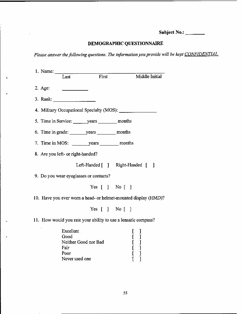
Subject No.:
DEMOGRAPHIC QUESTIONNAIRE
Please answer the following questions. The information you provide will be kept CONFIDENTIAL.
1. Name:
2. Age:
3. Rank:
Last First Middle Initial
4. Military Occupational Specialty (MOS):
5. Time in Service: years months
6. Time in grade: years months
7. Time in MOS: years months
8. Are you left- or right-handed?
Left-Handed[ ] Right-Handed [ ]
9. Do you wear eyeglasses or contacts?
Yes [ ] No [ ]
10. Have you ever worn a head- or helmet-mounted display (HMD)?
Yes [ ] No [ ]
11. How would you rate your ability to use a lensatic compass?
Excellent Good Neither Good nor Bad Fan- Poor Never used one
55
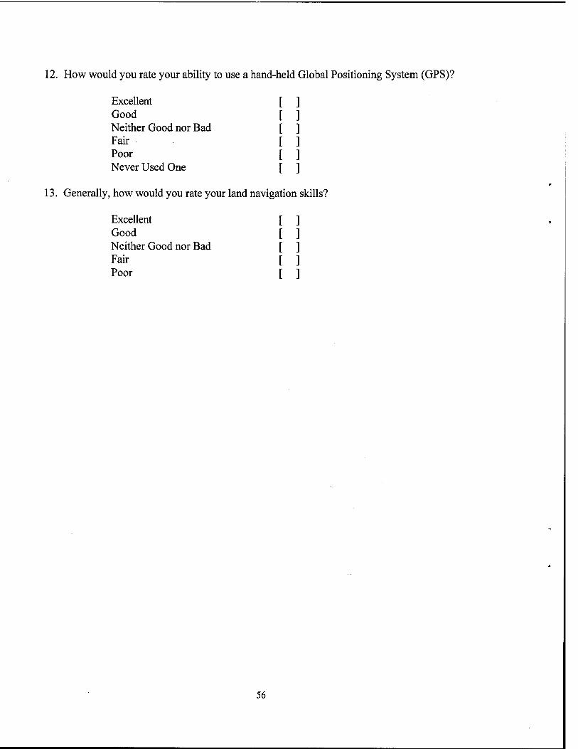
12. How would you rate your ability to use a hand-held Global Positioning System (GPS)?
Excellent Good Neither Good nor Bad Fair Poor Never Used One
13. Generally, how would you rate your land navigation skills?
Excellent Good Neither Good nor Bad Fair Poor
56
APPENDIX B
SALIVARY AMYLASE FIELD TEST AND STRESS QUESTIONNAIRES
57
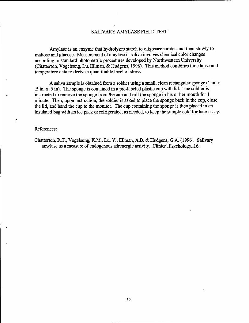
SALIVARY AMYLASE FIELD TEST
Amylase is an enzyme that hydrolyzes starch to oligosaccharides and then slowly to maltose and glucose. Measurement of amylase in saliva involves chemical color changes according to standard photometric procedures developed by Northwestern University (Chatterton, Vogelsong, Lu, Ellman, & Hudgens, 1996). This method combines time lapse and temperature data to derive a quantifiable level of stress.
A saliva sample is obtained from a soldier using a small, clean rectangular sponge (1 in. x .5 in. x .5 in). The sponge is contained in a pre-labeled plastic cup with lid. The soldier is instructed to remove the sponge from the cup and roll the sponge in his or her mouth for 1 minute. Then, upon instruction, the soldier is asked to place the sponge back in the cup, close the lid, and hand the cup to the monitor. The cup containing the sponge is then placed in an insulated bag with an ice pack or refrigerated, as needed, to keep the sample cold for later assay.
References:
Chatterton, R.T., Vogelsong, K.M., Lu, Y., Ellman, A.B. & Hudgens, G.A. (1996). Salivary amylase as a measure of endogenous adrenergic activity. Clinical Psychology. 16.
59
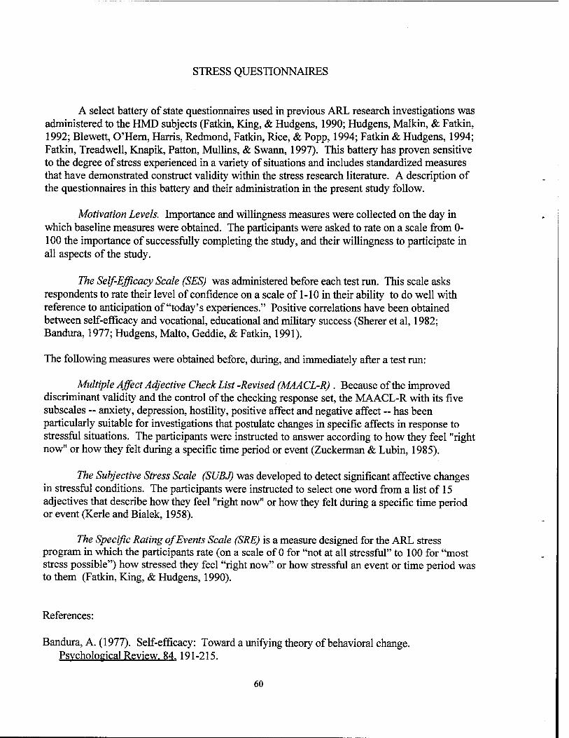
STRESS QUESTIONNAIRES
A select battery of state questionnaires used in previous ARL research investigations was administered to the HMD subjects (Fatkin, King, & Hudgens, 1990; Hudgens, Malkin, & Fatkin, 1992; Blewett, O'Hern, Harris, Redmond, Fatkin, Rice, & Popp, 1994; Fatkin & Hudgens, 1994; Fatkin, Treadwell, Knapik, Patton, Mullins, & Swann, 1997). This battery has proven sensitive to the degree of stress experienced in a variety of situations and includes standardized measures that have demonstrated construct validity within the stress research literature. A description of the questionnaires in this battery and their administration in the present study follow.
Motivation Levels. Importance and willingness measures were collected on the day in which baseline measures were obtained. The participants were asked to rate on a scale from 0- 100 the importance of successfully completing the study, and their willingness to participate in all aspects of the study.
The Self-Efficacy Scale (SES) was administered before each test run. This scale asks respondents to rate their level of confidence on a scale of 1-10 in their ability to do well with reference to anticipation of "today's experiences." Positive correlations have been obtained between self-efficacy and vocational, educational and military success (Sherer et al, 1982; Bandura, 1977; Hudgens, Malto, Geddie, & Fatkin, 1991).
The following measures were obtained before, during, and immediately after a test run:
Multiple Affect Adjective Check List -Revised (MAACL-R) . Because of the improved discriminant validity and the control of the checking response set, the MAACL-R with its five subscales ~ anxiety, depression, hostility, positive affect and negative affect — has been particularly suitable for investigations that postulate changes in specific affects in response to stressful situations. The participants were instructed to answer according to how they feel "right now" or how they felt during a specific time period or event (Zuckerman & Lubin, 1985).
The Subjective Stress Scale (SUBJ) was developed to detect significant affective changes in stressful conditions. The participants were instructed to select one word from a list of 15 adjectives that describe how they feel "right now" or how they felt during a specific time period or event (Kerle and Bialek, 1958).
The Specific Rating of Events Scale (SRE) is a measure designed for the ARL stress program in which the participants rate (on a scale of 0 for "not at all stressful" to 100 for "most stress possible") how stressed they feel "right now" or how stressful an event or time period was to them (Fatkin, King, & Hudgens, 1990).
References:
Bandura, A. (1977). Self-efficacy: Toward a unifying theory of behavioral change. Psychological Review. 84.191-215.
60
Blewett, W.K., O'Hern, M., Harris, L., Redmond, D.P., Fatkin, L.F., Rice, DJ., & Popp, K. (1994). A P2NBC2 report: Patient decontamination at mobile medical facilities. Aberdeen Proving Ground, MD: Edgewood Research, Development, and Engineering Center.
Fatkin, L.T., & Hudgens, G.A. (1994). Stress perceptions of soldiers participating in training at the Chemical Defense Training Facility: The mediating effects of motivation, experience, and confidence level (ARL-TR-365). Aberdeen Proving Ground, MD: U.S. Army Research Laboratory.
Fatkin, L.T., King, J.M., & Hudgens, G.A. (1990). Evaluation of stress experienced bv Yellowstone Armv fire fighters f ARL-TM 9-90). Aberdeen Proving Ground, MD: U.S. Army Research Laboratory.
Hudgens, G.A., Malto, B.O., Geddie, J.C., & Fatkin, L.T. (1991). Stress evaluation for the TOW Accuracy Study (TN No. 5-91). Aberdeen Proving Ground, MD: U.S. Army Human Engineering Laboratory.
Kerle, R.H., & Bialek, H. M. (1958). The construction, validation, and application of a Subjective Stress Scale (Staff Memorandum Fighter IV, Study 23). Presidio of Monterey, CA: US Army Leadership Human Research Unit.
Sherer, M., Maddux, J.E., Mercandante, B., Prentice-Dunn, S., Jacobs, B., & Rogers, R.W. (1982). The self-efficacy scale: Construction and validation. Psychological Reports. 51. 663-671.
Zuckerman, M., & Lubin, B. (1985). Manual for the Multiple Affect Adjective Check List- Revised. San Diego, CA: Educational and Industrial Testing Service.
61
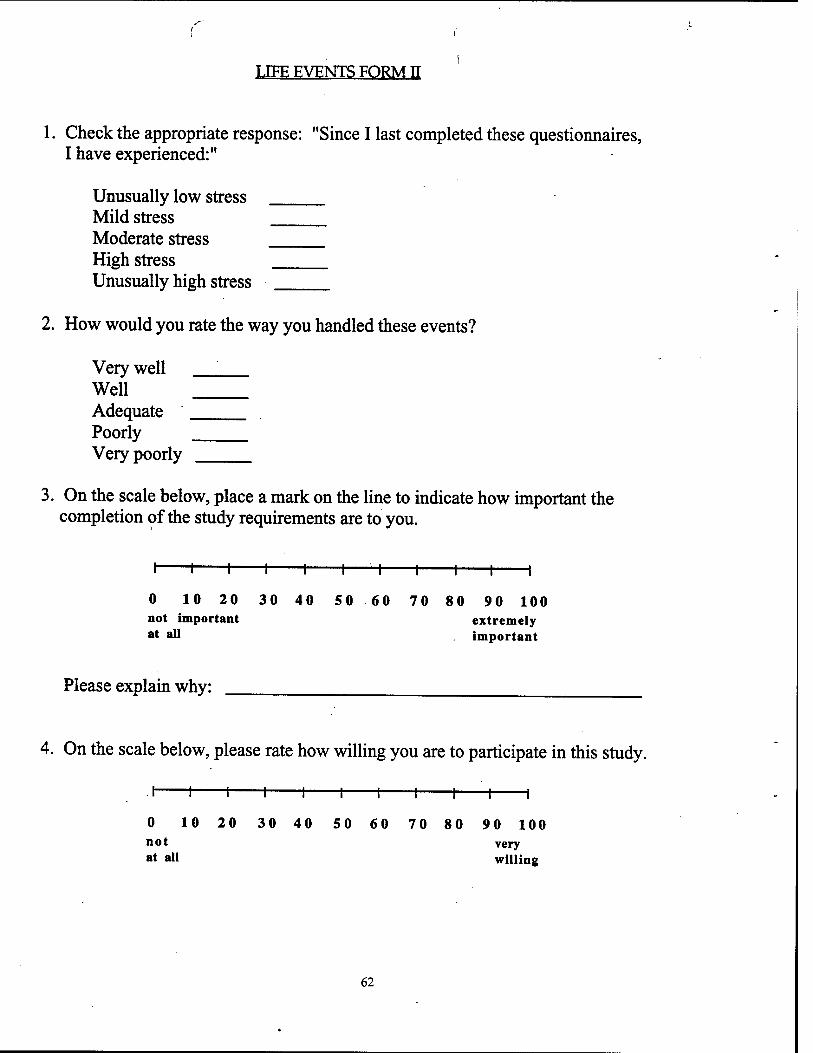
LIFE EVENTS FORM TT
1. Check the appropriate response: "Since I last completed these questionnaires, I have experienced:"
Unusually low stress Mild stress Moderate stress High stress Unusually high stress
2. How would you rate the way you handled these events?
Very well ' Well Adequate Poorly Very poorly
3. On the scale below, place a mark on the line to indicate how important the completion of the study requirements are to you.
I 1 1 1 1 1—H 1 1 1 1
0 10 20 30 40 50 60 70 80 90 100 not important extremely at all important
Please explain why:
4. On the scale below, please rate how willing you are to participate in this study.
-i 1-
0 10 20 30 40 50 60 70 80 90 100 not very at all willing
62
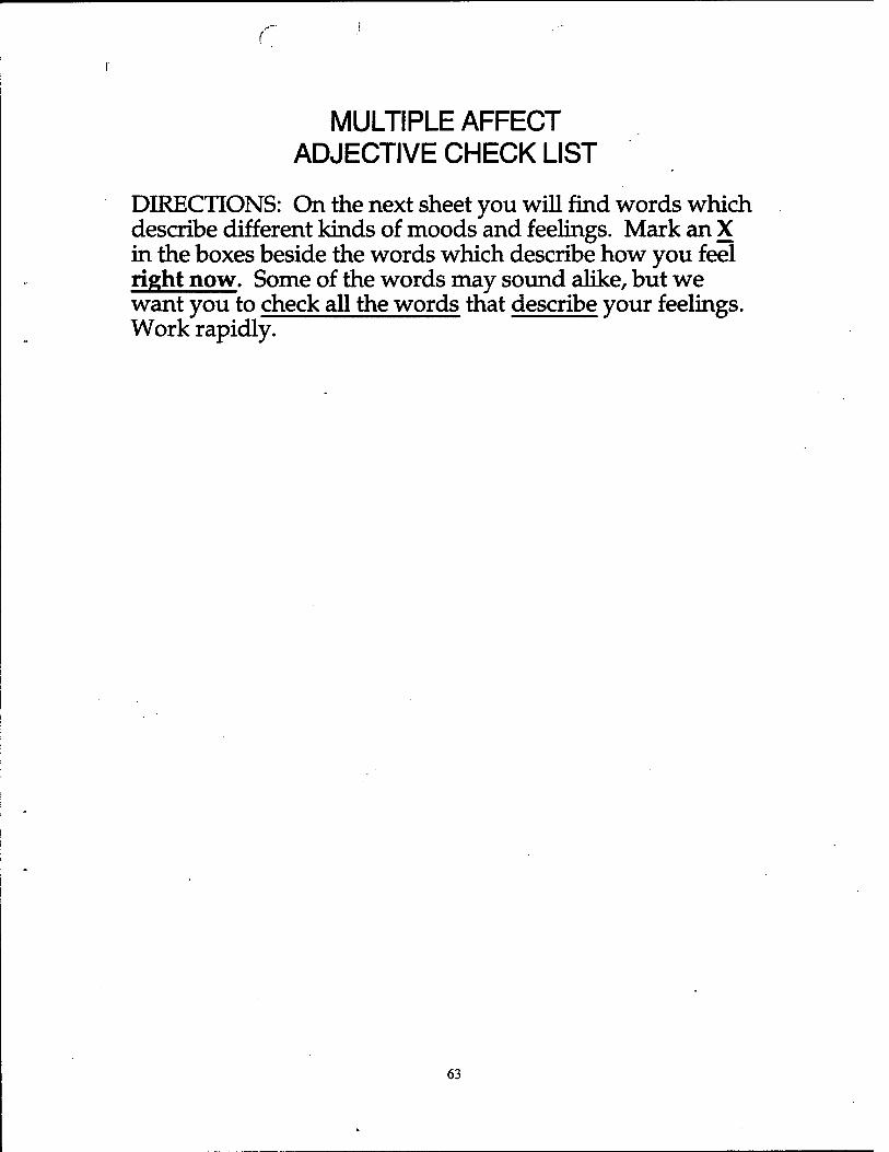
MULTIPLE AFFECT ADJECTIVE CHECK LIST
DIRECTIONS: On the next sheet you will find words which describe different kinds of moods and feelings. Mark an X in the boxes beside the words which describe how you feel right now. Some of the words may sound alike, but we want you to check all the words that describe your feelings. Work rapidly.
63
r
MULTIPLE AFFECT ADJECTIVE CHECK LIST
DIRECTIONS: On the next sheet you will find words which describe different kinds of moods and feelings. Mark an X in the boxes beside the words which describe how you felt while completing the training Some of the words may sound alike, but we want you to check all the wnrH« that describe your feelings. Work rapidly.
64
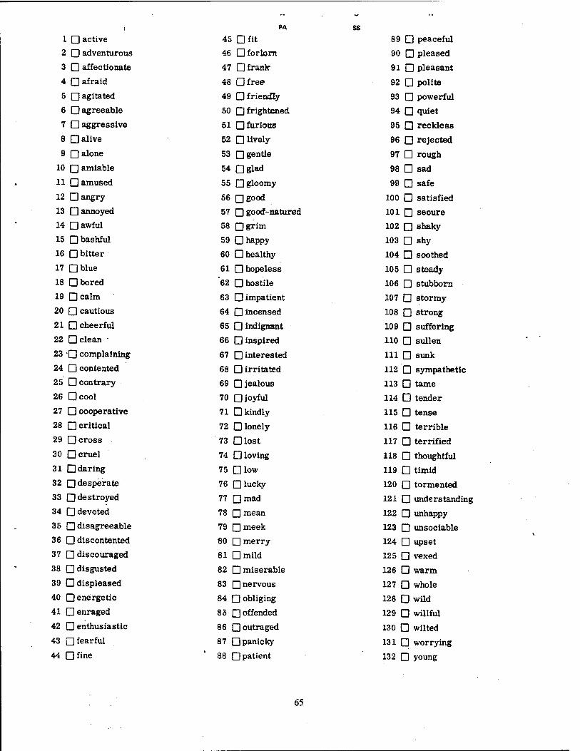
1 □ active
2 □ adventurous
3 D affectionate
4 □ afraid
5 □ agitated
6 D agreeable
7 □ aggressive
8 □ alive
9 □ alone
10 □ amiable
11 D amused
12 D angry
13 □ annoyed
14 □ awful
15 □ bashful
16 Q bitter
17 DWue
18 D bored
19 Dcalm
20 Q cautious
21 □ cheerful
22 □ clean
23 O complaining
24 □ contented
25 D contrary
26 Dcool
27 D cooperative
28 □ critical
29 Qcross
30 □ cruel
31 □ daring
32 □ desperate
33 □ destroyed
34 D devoted
35 □ disagreeable
36 Q discontented
37 □ discouraged
38 □ disgusted
39 D displeased
40 □energetic
41 □ enraged
42 □ enthusiastic
43 □fearful
44 nfine
PA
45 □ fit 46 □ forlorn
47 □ frank'
48 Qfree
49 □ friendly
50 □ frightened
51 □furious
52 □ lively
53 □gentle
54 Qglad
55 □ gloomy
56 Qgood
57 □good-natured
58 ngrim
59 □ happy
60 □ healthy
61 □ hopeless
'62 □ hostile
63 □ impatient
64 □ incensed
65 □ indignant
66 □ inspired
67 □ interested
68 □ irritated
69 □ jealous
70 □joyful
71 □ kindly
72 □ lonely
73 □ lost
74 □ loving
75 Dlow
76 □ lucky
77 Qmad
78 □ mean
79 Qmeek
80 □ merry
81 Qmild
82 □ miserable
83 □nervous
84 □ obliging
85 □ offended
86 □ outraged
87 □ panicky
88 □ patient
ss 89 □ 90 □ 91 □ 92 □ 93 □ 94 □ 95 □ 96 □ 97 □ 98 □ 99 □
100 □ 101 □ 102 □ 103 □ 104 □ 105 □ 106 □ 107 □ 108 □ 109 Q
110 □
111 □ 112 □ 113 □ 114 □ 115 □ 116 □ 117 □ 118 □ 119 □ 120 □ 121 □ 122 □ 123 □ 124 □ 125 □ 126 □ 127 □ 128 □ 129 □ 130 □ 131 □ 132 □
peaceful
pleased
pleasant
polite
pc-werful
quiet
reckless
rejected
rough
sad
safe
satisfied
secure
shaky
shy
soothed
steady
stubborn
stormy
strong
suffering
sullen
sunk
sympathetic
tame
tender
tense
terrible
terrified
thoughtful
timid
tormented
understanding
unhappy
unsociable
upset
vexed
warm
whole
wild
willful
wilted
worrying
young
65
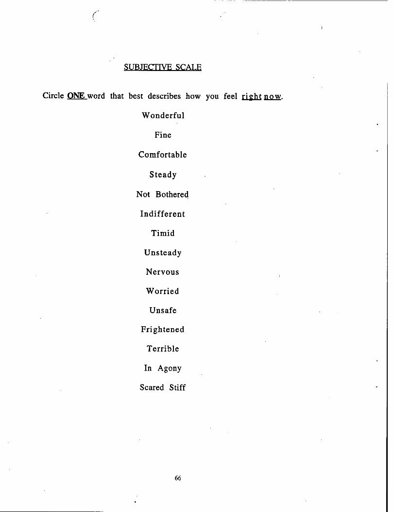
SUBJECTIVE SCALE
Circle QNEword that best describes how you feel right now.
Wonderful
Fine
Comfortable
Steady
Not Bothered
Indifferent
Timid
Unsteady
Nervous
Worried
Unsafe
Frightened
Terrible
In Agony
Scared Stiff
66
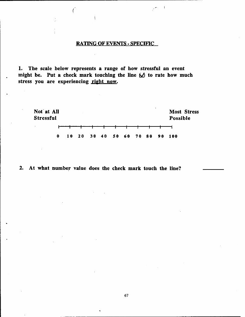
RATING OF EVENTS - SPECIFIC
1. The scale below represents a range of how stressful an event might be. Put a check mark touching the line M to rate how much stress you are experiencing right now.
Not at All Most Stress Stressful Possible
I 1 1 1 1 1 1 1 1 1 1
0 10 20 30 40 50 60 70 80 90 100
2. At what number value does the check mark touch the line?
67
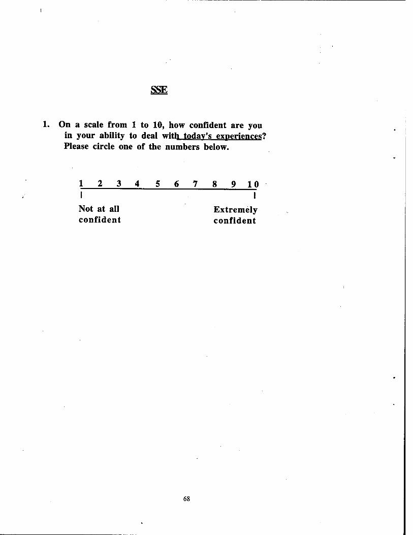
SSE
1. On a scale from 1 to 10, how confident are you in your ability to deal with today's experiences? Please circle one of the numbers below.
1234 56789 10 I I
Not at all Extremely confident confident
68
APPENDIX C
COGNITIVE PERFORMANCE ASSESSMENT FOR STRESS AND ENDURANCE (CPASE)
69
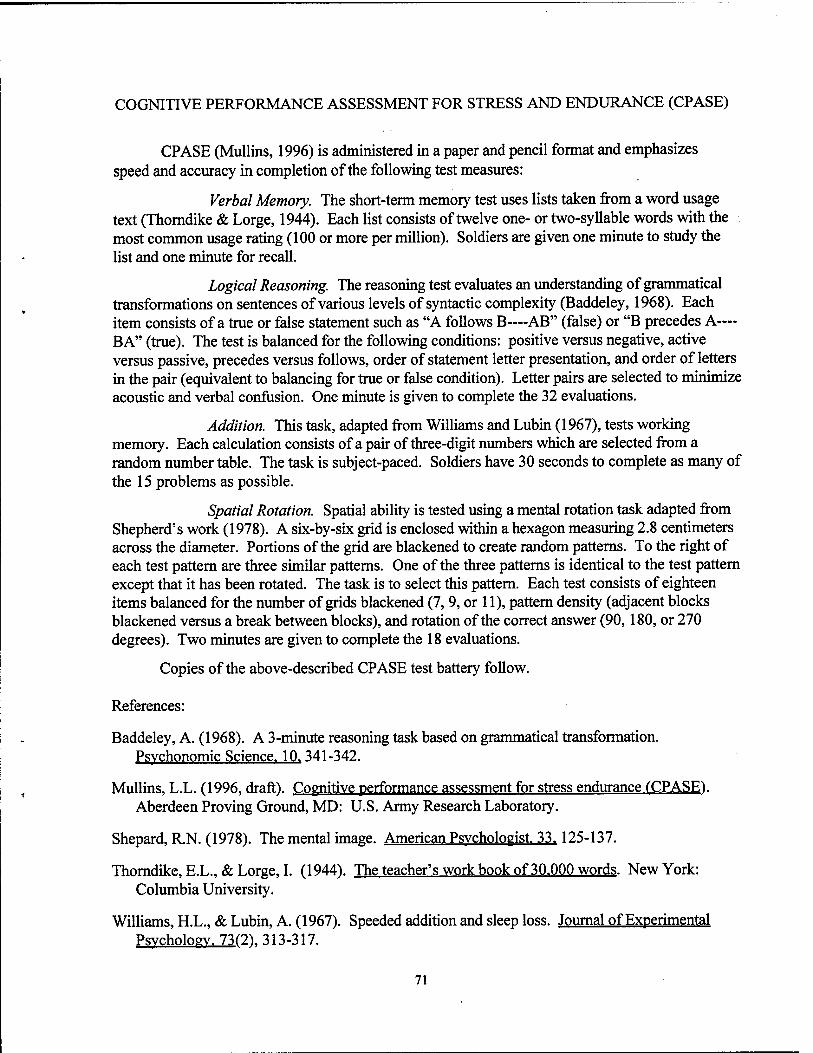
COGNITIVE PERFORMANCE ASSESSMENT FOR STRESS AND ENDURANCE (CPASE)
CPASE (Mullins, 1996) is administered in a paper and pencil format and emphasizes speed and accuracy in completion of the following test measures:
Verbal Memory. The short-term memory test uses lists taken from a word usage text (Thorndike & Lorge, 1944). Each list consists of twelve one- or two-syllable words with the most common usage rating (100 or more per million). Soldiers are given one minute to study the list and one minute for recall.
Logical Reasoning. The reasoning test evaluates an understanding of grammatical transformations on sentences of various levels of syntactic complexity (Baddeley, 1968). Each item consists of a true or false statement such as "A follows B—AB" (false) or "B precedes A— BA" (true). The test is balanced for the following conditions: positive versus negative, active versus passive, precedes versus follows, order of statement letter presentation, and order of letters in the pair (equivalent to balancing for true or false condition). Letter pairs are selected to minimize acoustic and verbal confusion. One minute is given to complete the 32 evaluations.
Addition. This task, adapted from Williams and Lubin (1967), tests working memory. Each calculation consists of a pair of three-digit numbers which are selected from a random number table. The task is subject-paced. Soldiers have 30 seconds to complete as many of the 15 problems as possible.
Spatial Rotation. Spatial ability is tested using a mental rotation task adapted from Shepherd's work (1978). A six-by-six grid is enclosed within a hexagon measuring 2.8 centimeters across the diameter. Portions of the grid are blackened to create random patterns. To the right of each test pattern are three similar patterns. One of the three patterns is identical to the test pattern except that it has been rotated. The task is to select this pattern. Each test consists of eighteen items balanced for the number of grids blackened (7,9, or 11), pattern density (adjacent blocks blackened versus a break between blocks), and rotation of the correct answer (90,180, or 270 degrees). Two minutes are given to complete the 18 evaluations.
Copies of the above-described CPASE test battery follow.
References:
Baddeley, A. (1968). A 3-minute reasoning task based on grammatical transformation. Psychonomic Science. 10.341-342.
Mullins, L.L. (1996, draft). Cognitive performance assessment for stress endurance f CPASE). Aberdeen Proving Ground, MD: U.S. Army Research Laboratory.
Shepard, R.N. (1978). The mental image. American Psychologist. 33.125-137.
Thorndike, EX., & Lorge, I. (1944). The teacher's work book of 30.000 words. New York: Columbia University.
Williams, H.L., & Lubin, A. (1967). Speeded addition and sleep loss. Journal of Experimental Psychology. 73(2\ 313-317.
71

WORD RECALL TASK
INSTRUCTIONS: You will receive a page with of a list of twelve words. Keep this list face down until you are instructed to start the test. Read through the list and write each word in the recopy column as quickly as possible. You will have one minute to write and study the words. You will be asked to recall these words later in the session.
Do not turn to the next page until instructed to do so.
72

Word List Recopy
law
free
flower
going
happy
sweet
friend
window
man
fresh
spring
paper
Listl
73

Word Recall Task
Listl
74
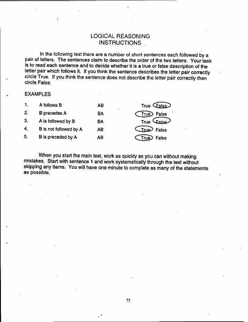
LOGICAL REASONING INSTRUCTIONS
In the following test there are a number of short sentences each followed by a pair of letters. The sentences claim to describe the order of the two letters. Your task is to read each sentence and to decide whether it is a true or false description of the letter pair which follows it. If you think the sentence describes the letter pair correctly circle True. If you think the sentence does not describe the letter pair correctly then circle False.
EXAMPLES
1. A follows B AB True <£aj§£>
2. B precedes A BA CTwe> False '
3. A is followed by B BA True
4. B is not followed by A AB C Tm&> False
5. B is preceded by A AB CTrue> False
When you start the main test, work as quickly as you can without making mistakes. Start with sentence 1 and work systematically through the test without skipping any items. You will have one minute to complete as many of the statements as possible.
75
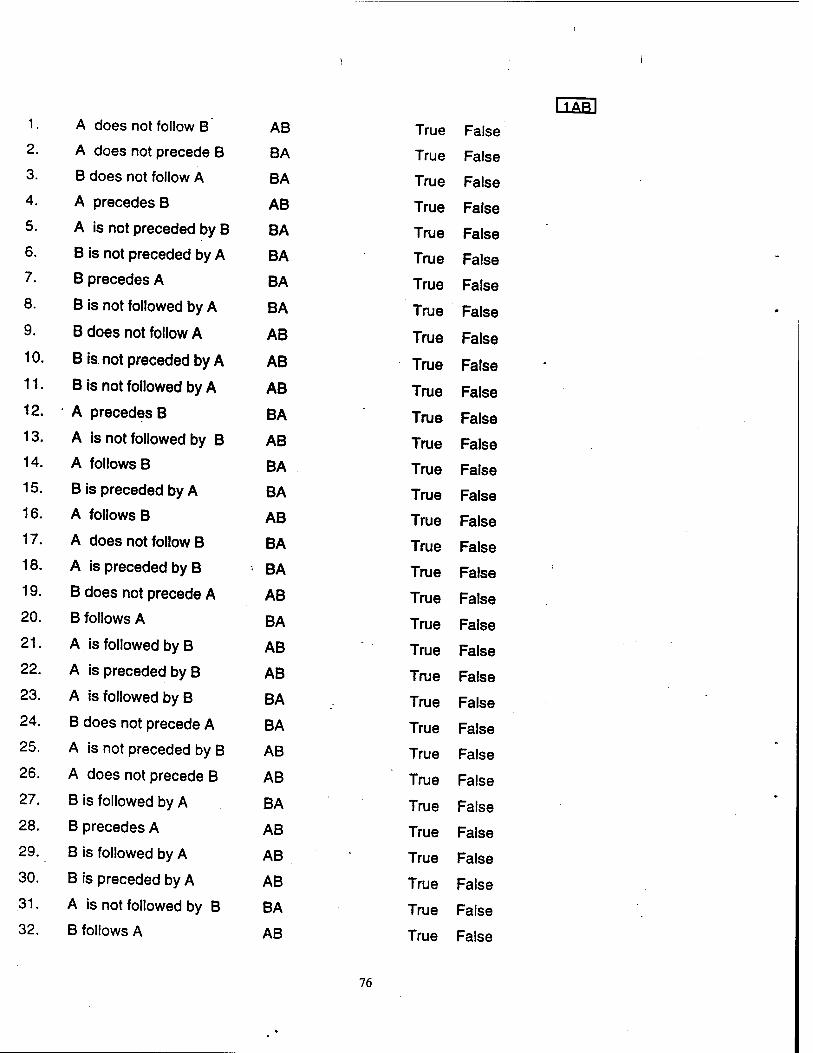
1 • A does not follow B AB
2. A does not precede B BA
3. B does not follow A BA
4. A precedes B AB
5. A is not preceded by B BA
6. B is not preceded by A BA
7. B precedes A BA
8. B is not followed by A BA
9. B does not follow A AB
10. B is. not preceded by A AB
11. B is not followed by A AB
12. A precedes B BA
13. A is not followed by B AB
14. A follows B BA
15. B is preceded by A BA
16. A follows B AB
17. A does not follow B BA
18. A is preceded by B BA
19. B does not precede A AB
20. B follows A BA
21. A is followed by B AB
22. A is preceded by B AB
23. A is followed by B BA
24. B does not precede A BA
25. A is not preceded by B AB
26. A does not precede B AB
27. B is followed by A BA
28. B precedes A AB
29. B is followed by A AB
30. B is preceded by A AB
31. A is not followed by B BA
32. B follows A AB
[TAR] True False
True False
True False
True False
True False
True False
True False
True False
True False
True False
True False
True False
True False
True False
True False
True False
True False
True False
True False
True False
True False
True False
True False
True False
True False
True False
True False
True False
True False
True False
True False
True False
76
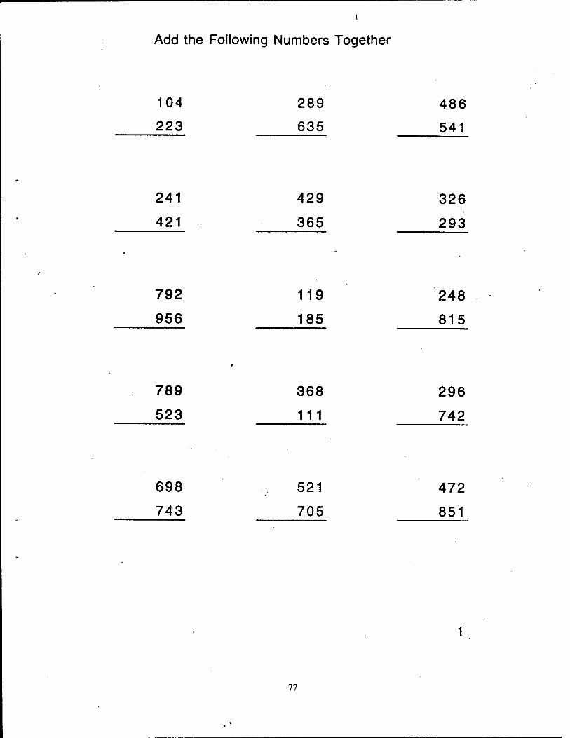
Add the Following Numbers Together
104 289 486
223 635 541
241 429 326
421 365 293
792 119 248
956 185 815
789 368 296
523 111 742
698 521 472
743 705 851
77
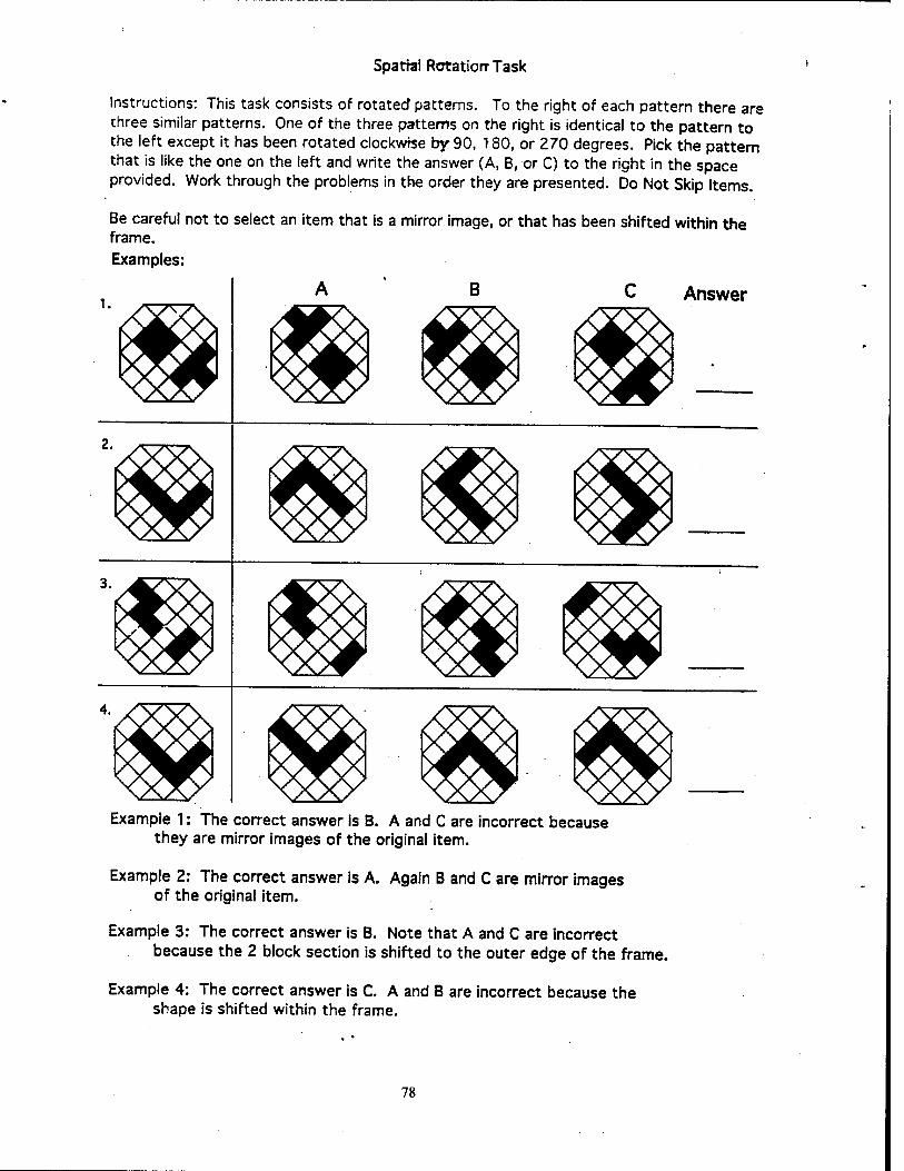
Spatial Rotatiorr Task
Instructions: This task consists of rotated patterns. To the right of each pattern there are three similar patterns. One of the three patterns on the right is identical to the pattern to the left except it has been rotated clockwise by 90, T80, or 270 degrees. Pick the pattern that is like the one on the left and write the answer (A, B, or C) to the right in the space provided. Work through the problems in the order they are presented. Do Not Skip Items.
Be careful not to select an item that is a mirror image, or that has been shifted within the frame. Examples:
C Answer
Example 1: The correct answer is B. A and C are incorrect because they are mirror images of the original item.
Example 2: The correct answer is A. Again B and C are mirror images of the original item.
Example 3: The correct answer is B. Note that A and C are incorrect because the 2 block section is shifted to the outer edge of the frame.
Example 4: The correct answer is C. A and B are incorrect because the shape is shifted within the frame.
78
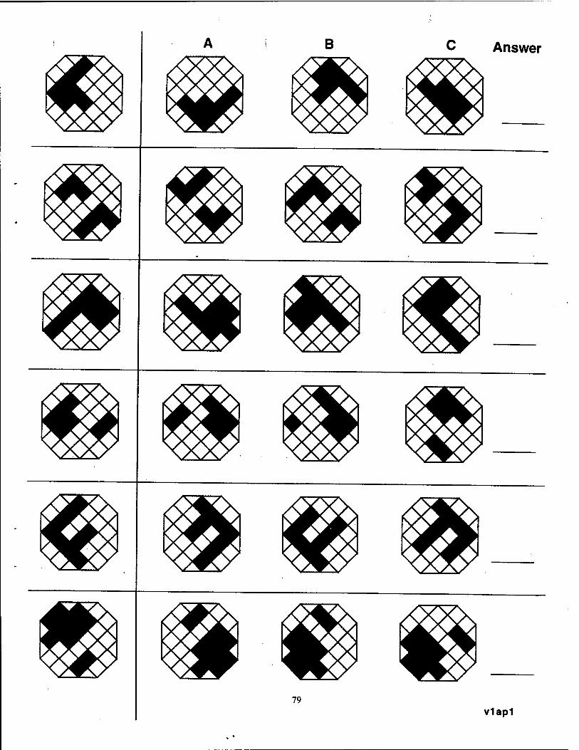
B
79
C Answer
v1ap1
B C Answer
80
v1ap2
B Answer
81 v1ap3
APPENDIX D
NASA-TASK LOAD INDEX
83
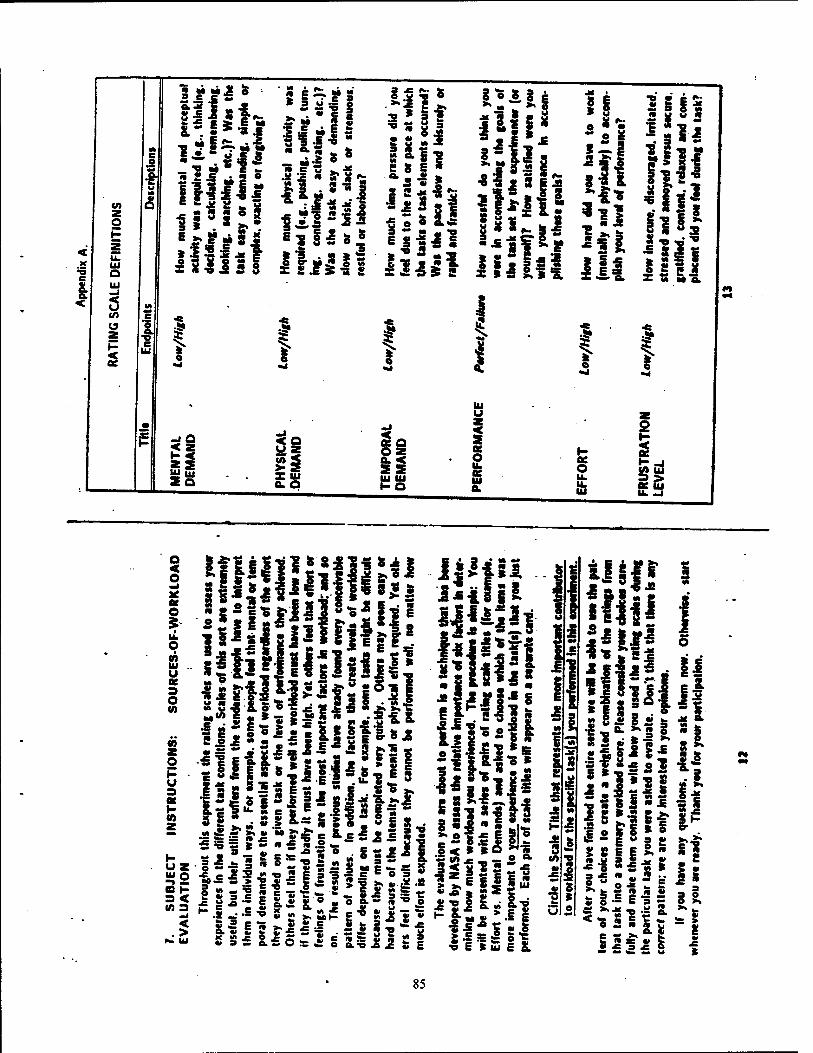
a. <
tu Q
< U (A
I tu
1 MMJ! & • 2 £ & •»
I»1*1I S3 '2
§
* ~ u •£ 3 ü-B § M «S 5 * e
liil« S X •» ■_
•a ?"! <• » 81"
* ss <• ^ e
!
3*g • • SUM
§ 8 I
■go* a - a 6|s
! e
S
I 1 *
i! s s
f
1 1
i 1
f
Si
if
o
• 8
"8
5si* »I 1*
8a
li
s il * 3
ii SO ES
Jo
II UJ IU h- O
IU u
o o u. u> u
O P 21 H_j go, 0- UJ
Q < O
O
O ■ 0)
8fiiI11»*ill*4l
UBilllflfllll!
UHH ■ilJsl
■e * < .>
I«. UJ
21
2j,6|sp
85
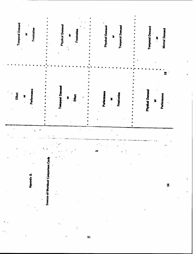
a.
v»?
*
a K
<
i u
e
V)
86
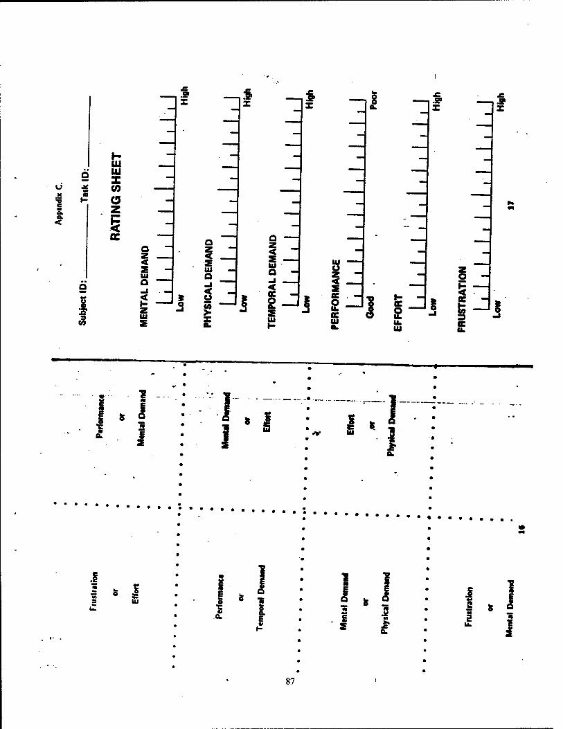
3 31 ^t 8
_s 3
x
H UJ UJ z CO a
ft s
9 CO
a z < 2 IU o -I
s Z IU
\ z.
5
tu a
3
Z < S - UJ a -
UJ u < a
j iJ s UJ
JfiC . -
& UJ
^ —
3, 13 UJ
C u.
I
5
I 1 I i
I * I 3 W
I 1 S
<g I E
I t
I 1
6 S
je M
I
s Ik
87
APPENDIX E
BEHAVIORAL ANCHORED RATING SCALES
89
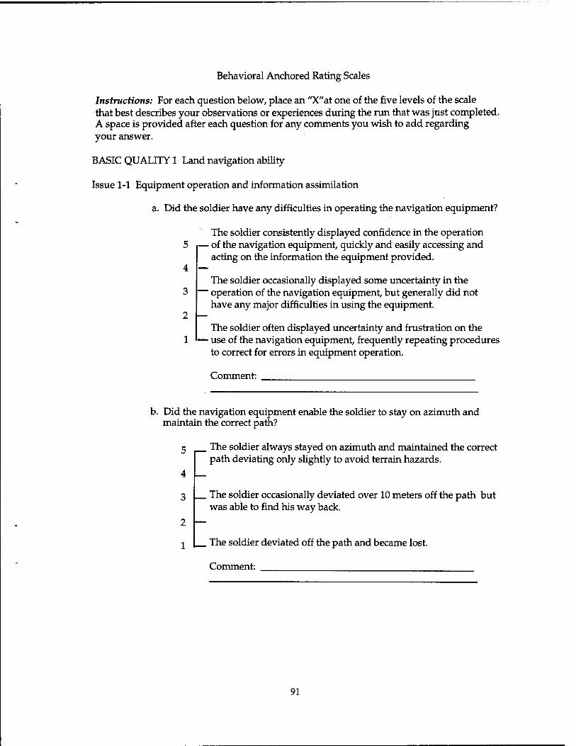
Behavioral Anchored Rating Scales
Instructions: For each question below, place an "X"at one of the five levels of the scale that best describes your observations or experiences during the run that was just completed. A space is provided after each question for any comments you wish to add regarding your answer.
BASIC QUALITY 1 Land navigation ability
Issue 1-1 Equipment operation and information assimilation
a. Did the soldier have any difficulties in operating the navigation equipment?
The soldier consistently displayed confidence in the operation 5 — of the navigation equipment, quickly and easily accessing and
acting on the information the equipment provided. 4
3
2 —
The soldier occasionally displayed some uncertainty in the ' operation of the navigation equipment, but generally did not have any major difficulties in using the equipment.
The soldier often displayed uncertainty and frustration on the ■ use of the navigation equipment, frequently repeating procedures to correct for errors in equipment operation.
Comment:
b. Did the navigation equipment enable the soldier to stay on azimuth and maintain the correct path?
5 The soldier always stayed on azimuth and maintained the correct path deviating only slightly to avoid terrain hazards.
4
3 The soldier occasionally deviated over 10 meters off the path but was able to find his way back.
1 I The soldier deviated off the path and became lost.
Comment:
91
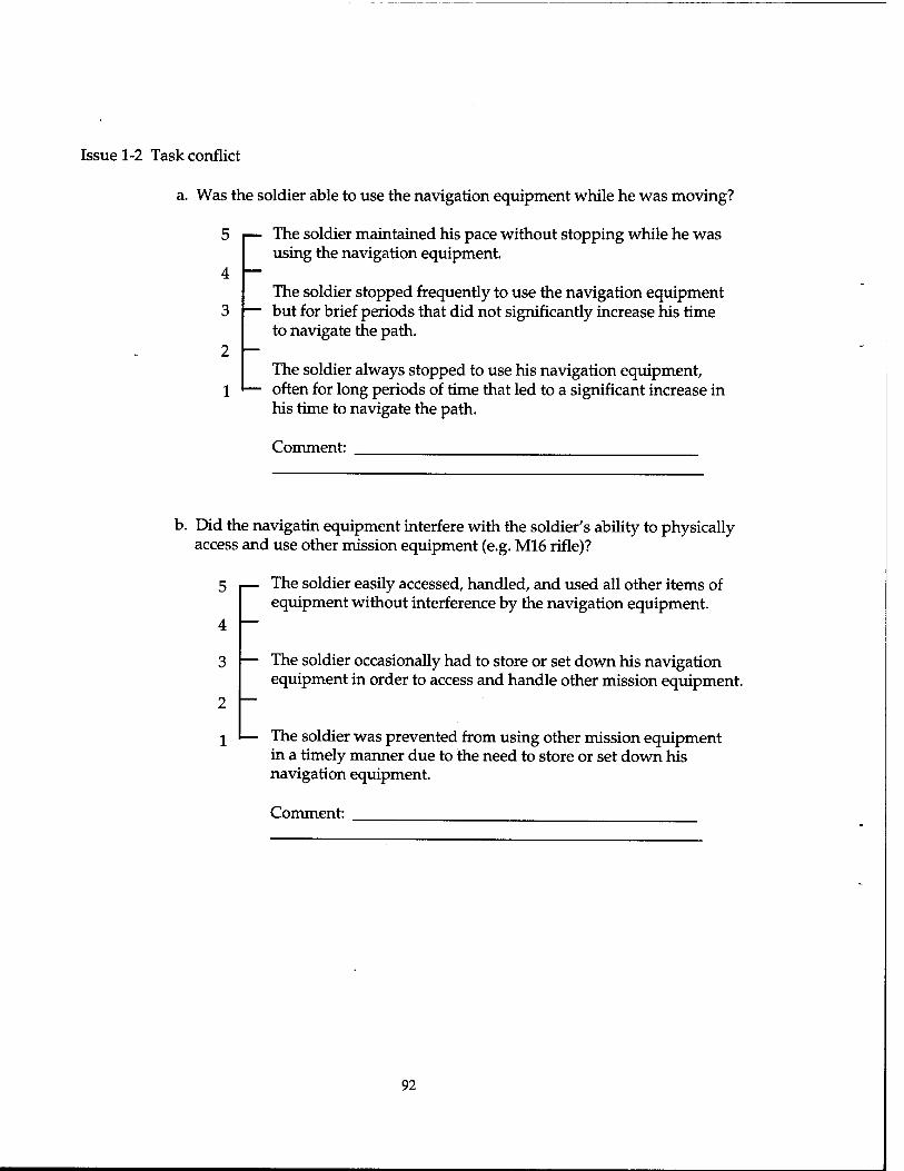
Issue 1-2 Task conflict
a. Was the soldier able to use the navigation equipment while he was moving?
5
4
The soldier maintained his pace without stopping while he was using the navigation equipment.
The soldier stopped frequently to use the navigation equipment 3 |— but for brief periods that did not significantly increase his time
to navigate the path. 2 I—
The soldier always stopped to use his navigation equipment, - often for long periods of time that led to a significant increase in
his time to navigate the path.
Comment:
b. Did the navigatin equipment interfere with the soldier's ability to physically access and use other mission equipment (e.g. M16 rifle)?
5 |— The soldier easily accessed, handled, and used all other items of equipment without interference by the navigation equipment.
4 I-
3
2
1
The soldier occasionally had to store or set down his navigation equipment in order to access and handle other mission equipment.
The soldier was prevented from using other mission equipment in a timely manner due to the need to store or set down his navigation equipment.
Comment:
92
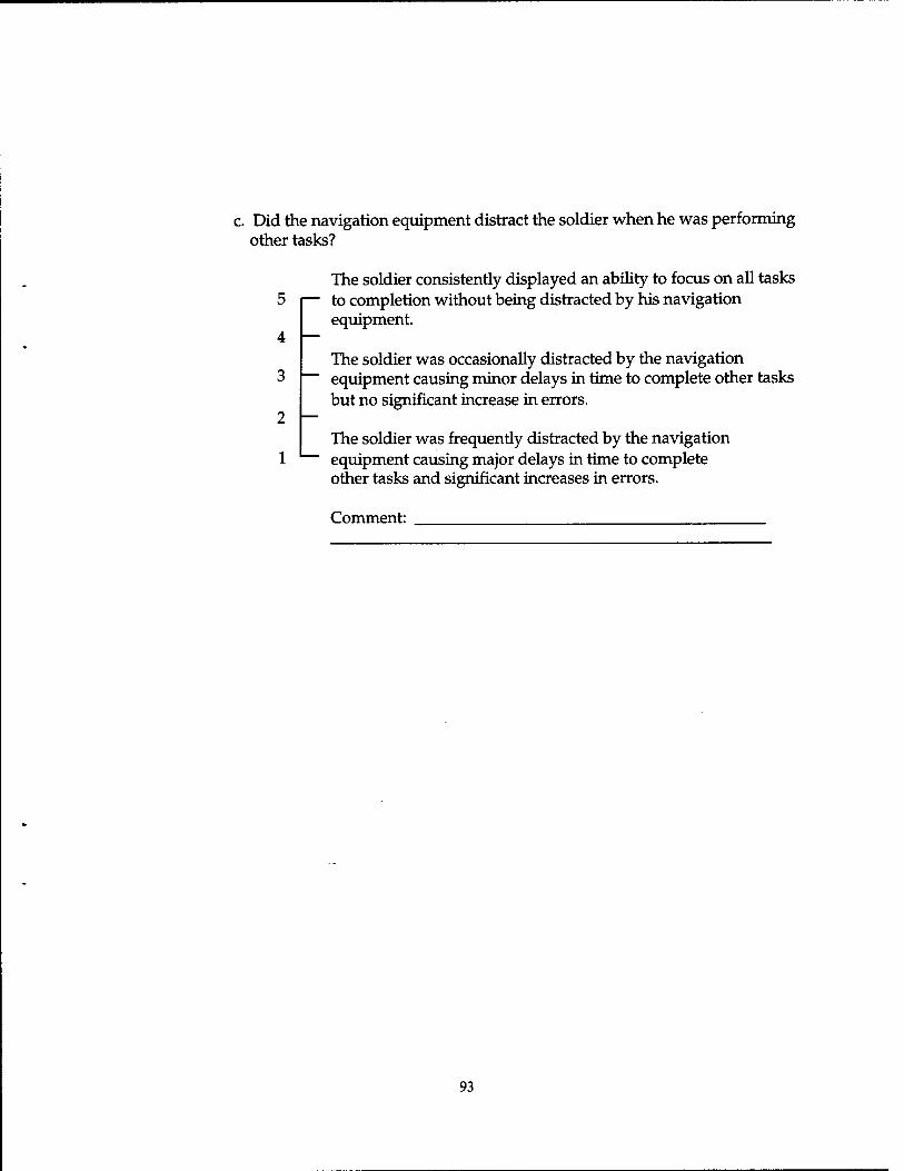
c. Did the navigation equipment distract the soldier when he was performing other tasks?
5
4
3
2
1
The soldier consistently displayed an ability to focus on all tasks to completion without being distracted by his navigation equipment.
The soldier was occasionally distracted by the navigation equipment causing minor delays in time to complete other tasks but no significant increase in errors.
The soldier was frequently distracted by the navigation equipment causing major delays in time to complete other tasks and significant increases in errors.
Comment:
93
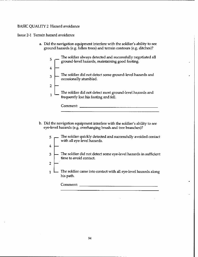
BASIC QUALITY 2 Hazard avoidance
Issue 2-1 Terrain hazard avoidance
a. Did the navigation equipment interfere with the soldier's ability to see ground hazards (e.g. fallen trees) and terrain contours (e.g. ditches)?
_ The soldier always detected and successfully negotiated all ground-level hazards, maintaining good footing.
4
3
2 I—
1
The soldier did not detect some ground-level hazards and occasionally stumbled.
The soldier did not detect most ground-level hazards and frequently lost his footing and fell.
Comment:
b. Did the navigation equipment interfere with the soldier's ability to see eye-level hazards (e.g. overhanging brush and tree branches)?
5
4
3
2
The soldier quickly detected and successfully avoided contact with all eye-level hazards.
— The soldier did not detect some eye-level hazards in sufficient time to avoid contact.
1 I— The soldier came into contact with all eye-level hazards along his path.
Comment:
94

Issue 2-2 Threat detection and recognition
a. Did the navigation equipment interfere with the soldier's ability to detect objects along the path?
5 — The soldier quickly detected all objects along the path.
4
3
2
1
The soldier only detected objects that were on one side of the path on near his position.
The soldier did not detect most objects along the path regardless — of the location of the objects.
Comment:
b. Did the navigation equipment interfere with the soldier's ability to locate the enemy?
c The soldier immediately detected and accurately acquired the enemy.
4
3
2 |—
1
— The soldier was often slow in detecting and locating the enemy.
The soldier was often unaware of enemy contact.
Comment:
95
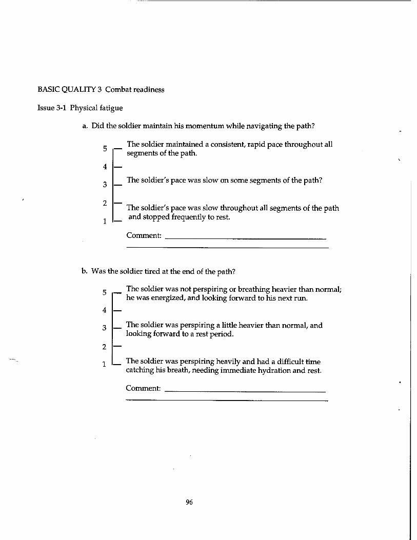
BASIC QUALITY 3 Combat readiness
Issue 3-1 Physical fatigue
a. Did the soldier maintain his momentum while navigating the path?
,. The soldier maintained a consistent, rapid pace throughout all segments of the path.
4
3
2
1
The soldier's pace was slow on some segments of the path?
The soldier's pace was slow throughout all segments of the path and stopped frequently to rest.
Comment:
b. Was the soldier tired at the end of the path?
c The soldier was not perspiring or breathing heavier than normal; he was energized, and looking forward to his next run.
4
3
2
1
The soldier was perspiring a little heavier than normal, and looking forward to a rest period.
The soldier was perspiring heavily and had a difficult time catching his breath, needing immediate hydration and rest.
Comment:
96
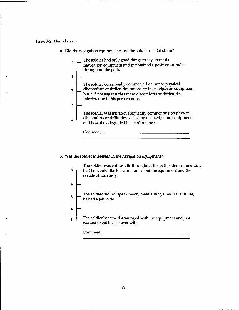
Issue 3-2 Mental strain
a. Did the navigation equipment cause the soldier mental strain?
The soldier had only good things to say about the navigation equipment and maintained a positive attitude throughout the path.
3 —
The soldier occasionally commented on minor physical discomforts or difficulties caused by the navigation equipment, but did not suggest that these discomforts or difficulties interfered with his performance.
The soldier was irritated, frequently commenting on physical 1 | discomforts or diffiulties caused by the navigation equipment
and how they degraded his performance.
Comment:
b. Was the soldier interested in the navigation equipment?
The soldier was enthusiatic throughout the path; often commenting 5 |— that he would like to learn more about the equipment and the
results of the study.
3
2
1
The soldier did not speak much, maintaining a neutral attitude; he had a job to do.
The soldier became discouraged with the equipment and just wanted to get the job over with.
Comment:
97
APPENDIX F
POST-TEST QUESTIONNAIRES
99
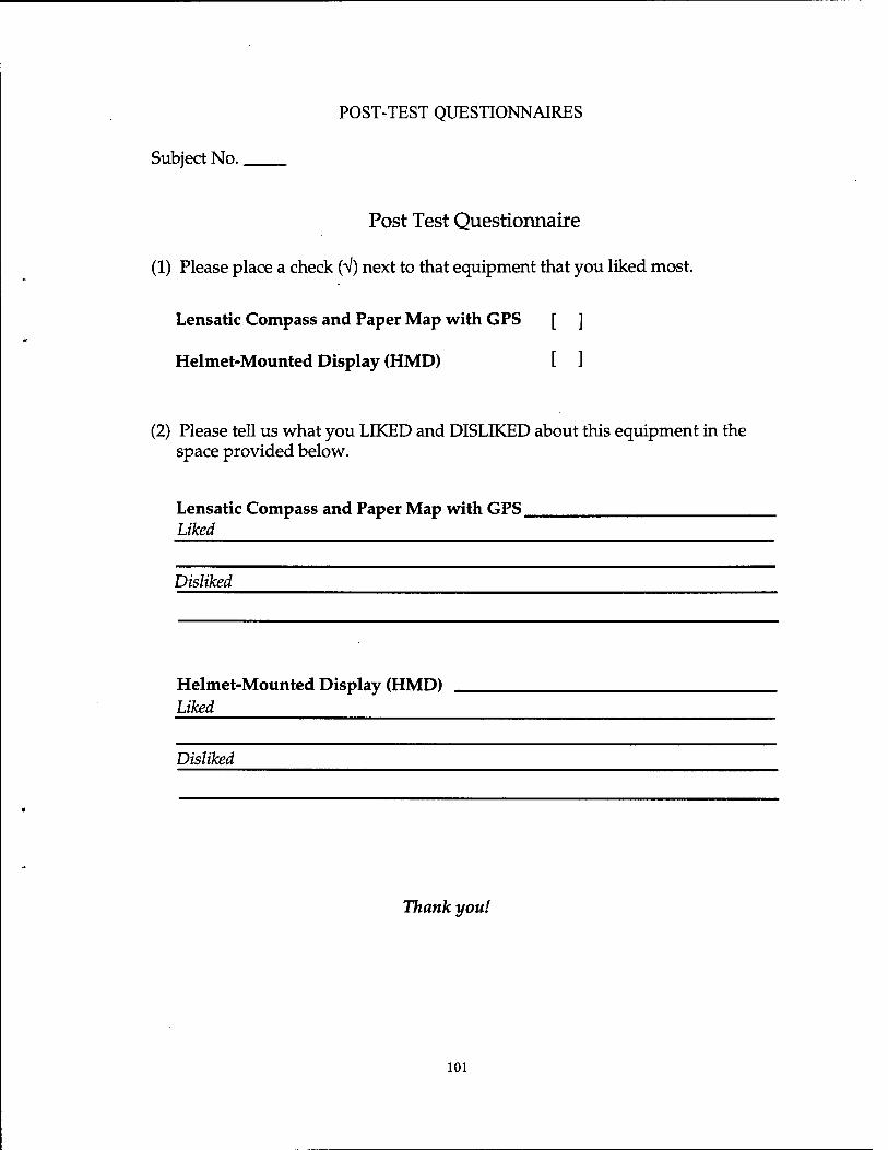
POST-TEST QUESTIONNAIRES
Subject No.
Post Test Questionnaire
(1) Please place a check (V) next to that equipment that you liked most.
Lensatic Compass and Paper Map with GPS [ ]
Helmet-Mounted Display (HMD) [ ]
(2) Please tell us what you LIKED and DISLIKED about this equipment in the space provided below.
Lensatic Compass and Paper Map with GPS. Liked
Disliked
Helmet-Mounted Display (HMD) Liked
Disliked
Thank you!
101
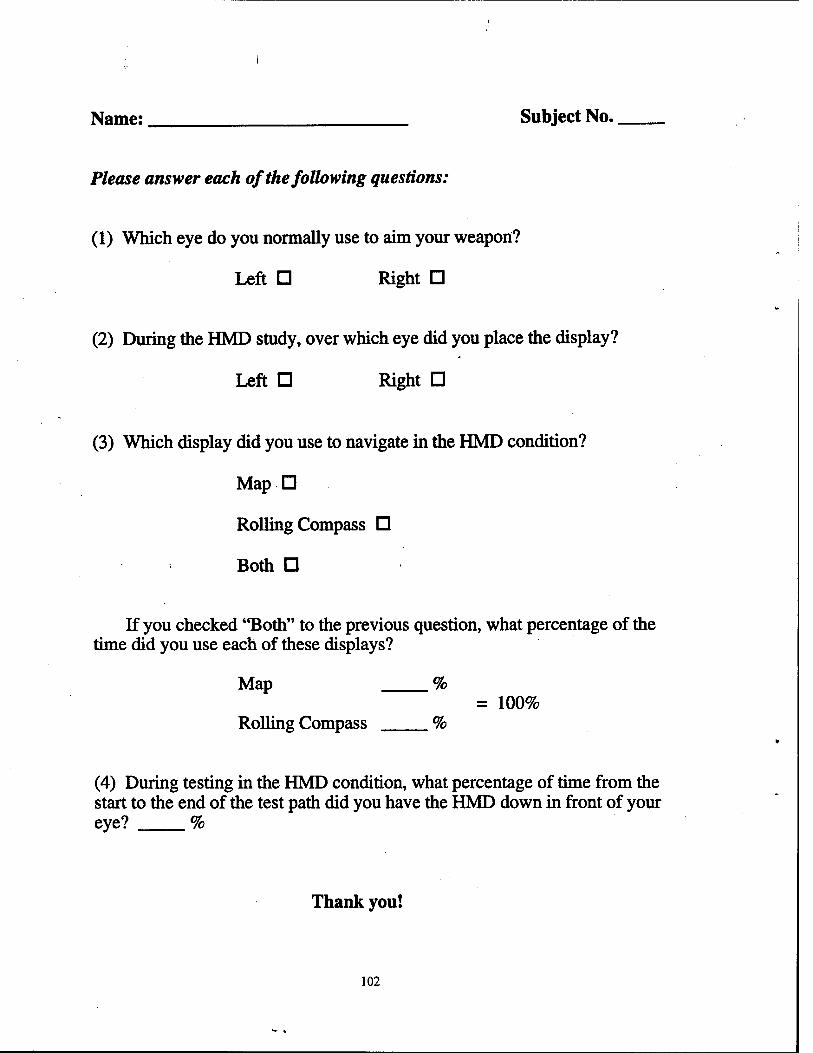
Name: Subject No. _
Please answer each of the following questions:
(1) Which eye do you normally use to aim your weapon?
Left D Right D
(2) During the HMD study, over which eye did you place the display?
Left D Right D
(3) Which display did you use to navigate in the HMD condition?
Map D
Rolling Compass D
Both D
If you checked "Both" to the previous question, what percentage of the time did you use each of these displays?
Map % = 100%
Rolling Compass %
(4) During testing in the HMD condition, what percentage of time from the start to the end of the test path did you have the HMD down in front of your eye? %
Thank you!
102
NO. OF COPIES ORGANIZATION
ADMINISTRATOR DEFENSE TECHNICAL INFO CENTER ATTN DTICDDA 8725 JOHN J KINGMAN RD STE 0944 FTBELVOIR VA 22060-6218
DIRECTOR US ARMY RESEARCH LABORATORY ATTN AMSRLCSALTA REC MGMT 2800 POWDER MILL RD ADELPHIMD 20783-1197
DIRECTOR US ARMY RESEARCH LABORATORY ATTN AMSRLCILL TECH LIB 2800 POWDER MILL RD ADELPHIMD 207830-1197
DIRECTOR US ARMY RESEARCH LABORATORY ATTN AMSRLCSALTP TECH PUB BR 2800 POWDER MILL RD ADELPHIMD 20783-1197
DIRECTORATE FOR MANPRINT ATTN DAPEMR DEPUTY CHIEF OF STAFF PERSONNEL 300 ARMY PENTAGON WASHINGTON DC 20310-0300
DIRECTOR ARMY AUDIOLOGY & SPEECH CENTER WALTER REED ARMY MED CENTER WASHINGTON DC 20307-5001
OUSD(A)/DDDR&E(R&A)/E&LS PENTAGON ROOM3D129 WASHINGTON DC 20301-3080
NO. OF COPIES
1
ORGANIZATION
COMMANDER US ARMY RESEARCH INSTITUTE ATTN PERIZT(DR E M JOHNSON) 5001 EISENHOWER AVENUE ALEXANDRIA VA 22333-5600
DEFENSE LOGISTICS STUDIES INFORMATION EXCHANGE
ATTN DIRECTOR DLSIE ATSZ DL BLDG 12500 2401 QUARTERS ROAD FORT LEE VA 23801-1705
DEPUTY COMMANDING GENERAL ATTN EXS(Q) MARINE CORPS RD&A COMMAND QUANTICO VA 22134
HEADQUARTERS USATRADOC ATTN ATCD SP FORT MONROE VA 23651
COMMANDER USATRADOC COMMAND SAFETY OFFICE ATTN ATOS (MR PESSAGNO/MR LYNE) FORT MONROE VA 23651-5000
COMMANDER US ARMY MATERIEL COMMAND ATTN AMCAM 5001 EISENHOWER AVENUE ALEXANDRIA VA 22333-0001
DIRECTOR TDAD DCST ATTN ATTG C BLDG 161 FORT MONROE VA 23651-5000
CODE 1142PS OFFICE OF NAVAL RESEARCH 800 N QUINCY STREET ARLINGTON VA 22217-5000
WALTER REED ARMY INST OF RSCH ATTN SGRD UWI C (COL REDMOND) WASHINGTON DC 20307-5100
DR ARTHUR RUBIN NATL INST OF STANDARDS & TECH BUILDING 226 ROOM A313 GAITHERSBURG MD 20899
COMMANDER USA OPERATIONAL TEST & EVAL AGENCY ATTN CSTE TSM 4501 FORD AVE ALEXANDRIA VA 22302-1458
USA BIOMEDICAL R&D LABORATORY ATTN LIBRARY FORTDETRICK BUILDING 568 FREDERICK MD 21702-5010
HQ USAMRDC ATTN SGRD PLC FORTDETRICK MD 21701
103
NO. OF COPIES ORGANIZATION
NO. OF COPIES ORGANIZATION
1 COMMANDER USA AEROMEDICAL RESEARCH LAB ATTN LIBRARY FORTRUCKER AL 36362-5292
1 US ARMY SAFETY CENTER ATTN CSSC SE FORTRUCKER AL 36362
1 CHIEF ARMY RESEARCH INSTITUTE
AVIATION R&D ACTIVITY ATTN PERIIR FORTRUCKER AL 36362-5354
1 AIR FORCE FLIGHT DYNAMICS LAB ATTN AFWAL/FIES/SURVIAC WRIGHT PATTERSON AFB OH 45433
1 AAMRL/HE WRIGHT PATTERSON AFB OH
45433-6573
1 US ARMY NATICK RD&E CENTER ATTN STRNC YBA NATICK MA 01760-5020
1 US ARMY TROOP SUPPORT CMD NATICK RD&E CENTER ATTN BEHAVIORAL SCI DIV SSD NATICK MA 01760-5020
1 US ARMY TROOP SUPPORT CMD NATICK RD&E CENTER ATTN TECH LIBRARY (STRNC MIL) NATICK MA 01760-5040
1 DR RICHARD JOHNSON HEALTH & PERFORMANCE DIVISION US ARIEM NATICK MA 01760-5007
1 LOCKHEED SANDERS INC BOXMER24 1583 NASHUA NH 03061-0868
1 MEDICAL LIBRARY BLDG 148 NAVAL SUBMARINE MEDICAL RSCH LAB BOX 900 SUBMARINE BASE NEW LONDON GROTON CT 06340
1 USAF ARMSTRONG LAB/CFTO ATTN DR F WESLEY BAUMGARDNER SUSTAINED OPERATIONS BRANCH BROOKS AFB TX 78235-5000
1 DR JON FALLESEN ARI FIELD UNIT PO BOX 3407 FORT LEAVENWORTH KS 66027-0347
COMMANDER USAMC LOGISTICS SUPPORT ACTIVITY ATTN AMXLSAE REDSTONE ARSENAL AL 35898-7466
ARI FIELD UNIT FORT KNOX BUILDING 2423 PERI IK FORT KNOX KY 40121-5620
COMMANDANT USA ARTILLERY & MISSILE SCHOOL ATTN USAAMS TECH LIBRARY FORT SILL OK 73503
COMMANDER WHITE SANDS MISSILE RANGE ATTN STEWS TE RE WHITE SANDS MISSILE RANGE NM
88002
COMMANDER WHITE SANDS MISSILE RANGE ATTN TECHNICAL LIBRARY WHITE SANDS MISSILE RANGE NM
88002
USA TRADOC ANALYSIS COMMAND ATTN ATRC WSR (D ANGUIANO) WHITE SANDS MISSILE RANGE NM
88002-5502
STRICOM 12350 RESEARCH PARKWAY ORLANDO FL 32826-3276
COMMANDER USA TANK-AUTOMOTIVE R&D CENTER ATTN AMSTA RS/D REES WARREN MI 48090
COMMANDER USA COLD REGIONS TEST CENTER ATTN STECR TS A APO AP 96508-7850
INSTITUTE FOR DEFENSE ANALYSES ATTN DR JESSE ORLANSKY 1801 N BEAUREGARD STREET ALEXANDRIA VA 22311
104
NO. OF COPIES
1
ORGANIZATION
GOVT PUBLICATIONS LIBRARY 409 WILSON M UNIVERSITY OF MINNESOTA MINNEAPOLIS MN 55455
MR R BEGGS BOEING-HELICOPTER CO P30-18 PO BOX 16858 PHILADELPHIA PA 19142
DR ROBERT KENNEDY ESSEX CORPORATION SUITE 227 1040 WOODCOCK ROAD ORLANDO FL 32803
DR NANCY ANDERSON DEPARTMENT OF PSYCHOLOGY UNIVERSITY OF MARYLAND COLLEGE PARK MD 20742
DR ARTHUR S KAMLET BELL LABORATORIES 6200 EAST BROAD STREET COLUMBUS OH 43213
GENERAL MOTORS CORPORATION NORTH AMERICAN OPERATIONS PORTFOLIO ENGINEERING CENTER HUMAN FACTORS ENGINEERING ATTN MR A J ARNOLD STAFF PROJ ENG ENGINEERING BLDG 30200 MOUND RD BOX 9010 WARREN MI 48090-9010
GENERAL DYNAMICS LAND SYSTEMS DIV LIBRARY PO BOX 1901 WARREN MI 48090
DRMMAYOUB DIRECTOR INST FOR ERGONOMICS RESEARCH TEXAS TECH UNIVERSITY LUBBOCK TX 79409
MR KENNETH C CROMBIE TECHNICAL LIBRARIAN E104 DELCO SYSTEMS OPERATIONS 6767 HOLLISTER AVENUE GOLETA CA 93117
MR WALT TRUSZKOWSKI NASA/GODDARD SPACE FLIGHT CENTER CODE 588.0 GREENBELT MD 20771
NO. OF COPIES
1
ORGANIZATION
DIRECTOR US ARMY AEROFLIGHT DYNAMICS DIR ATTN SAVRT AF D (A W KERR) AMES RESEARCH CENTER (MS 215-1) MOFFETT FIELD CA 94035-1099
DR NORMAN BADLER DEPT OF COMPUTER & INFORMATION
SCIENCE UNIVERSITY OF PENNSYLVANIA PHILADELPHIA PA 19104-6389
COMMANDER US ARMY RESEARCH INSTITUTE
OF ENVIRONMENTAL MEDICINE NATICK MA 01760-5007
DR DANIEL J POND BATTELLE PNL/K6-66 PO BOX 999 RICHLAND WA 99350
HQDA(DAPEZXO) ATTN DRFISCHL WASHINGTON DC 20310-0300
HUMAN FACTORS ENG PROGRAM DEPT OF BIOMEDICAL ENGINEERING COLLEGE OF ENGINEERING &
COMPUTER SCIENCE WRIGHT STATE UNIVERSITY DAYTON OH 45435
COMMANDER USA MEDICAL R&D COMMAND ATTN SGRD PLC (LTC K FRIEDL) FORTDETRICK MD 21701-5012
PEO STANDARD ARMY MGMT INFORMATION SYSTEM
ATTN AS PES STOP C-3 FT BELVOIR VA 22060-5456
PEO ARMORED SYS MODERNIZATION US ARMY TANK-AUTOMOTIVE CMD ATTN SFAEASMS WARREN MI 48397-5000
PEO COMBAT SUPPORT ATTN AMCPEO CS US ARMY TANK AUTOMOTIVE CMD WARREN MI 48397-5000
105
NO. OF COPIES
1
ORGANIZATION
PEO MGMT INFORMATION SYSTEMS ATTN ASPEM STOP C-2 BLDG 1465 FTBELVOIR VA 22060-5456
PEO ARMAMENTS ATTN AMCPEOAR BLDG 171 PICATINNY ARSENAL NJ 07806-5000
PEO INTELLIGENCE & ELECTRONIC WARFARE
ATTN AMCPEOIEW VINT HILL FARMS STATION BLDG 197 WARRENTON VA 22186-5115
PEO COMMUNICATIONS ATTN SFAECMRE FTMONMOUTH NJ 07703-5000
PEO AIR DEFENSE ATTN SFAEADS US ARMY MISSILE COMMAND REDSTONE ARSENAL AL 35898-5750
PEO STRATEGIC DEFENSE PO BOX 15280 ATTN DASD ZA US ARMY STRATEGIC DEFENSE CMD ARLINGTON VA 22215-0280
PROGRAMMANAGER RAH-66 ATTN SFAEAV BLDG 5300 SPARKMAN CENTER REDSTONE ARSENAL AL 35898 .
DENNIS L SCHMCKLY CREW SYSTEMS ENGINEERING MCDONNELL DOUGLAS HELICOPTER 5000 EAST MCDOWELL ROAD MESA AZ 85205-9797
JON TATRO HUMAN FACTORS SYSTEM DESIGN BELL HELICOPTER TEXTRON INC PO BOX 482 MAIL STOP 6 FT WORTH TX 76101
CHIEF CREW SYSTEMS INTEGRATION SIKORSKY AIRCRAFT M/S S3258 NORTH MAIN STREET STRATFORD CT 06602
NO. OF COPIES
1
ORGANIZATION
GENERAL ELECTRIC COMPANY ARMAMENT SYSTEMS DEPT RM 1309 ATTN HF/MANPRINT R C MCLANE LAKESIDE AVENUE BURLINGTON VT 05401-4985
OASD (FM&P) WASHINGTON DC 20301-4000
COMMANDER US ARMY MATERIEL COMMAND ATTN AMCDEAQ 5001 EISENHOWER AVENUE ALEXANDRIA VA 22333
COMMANDANT US ARMY ARMOR SCHOOL ATTN ATSB CDS (MR LIPSCOMB) FTKNOX KY 40121-5215
COMMANDER US ARMY AVIATION CENTER ATTN ATZQ CDM S (MR MCCRACKEN) FTRUCKERAL 36362-5163
COMMANDER US ARMY SIGNAL CTR & FT GORDON ATTN ATZHCDM FT GORDON GA 30905-5090
DIRECTOR US ARMY AEROFLIGHT DYNAMICS DIR MAIL STOP 239-9 NASA AMES RESEARCH CENTER MOFFETT FIELD CA 94035-1000
PROJECT MANAGER SIGNALS WARFARE ATTN SFAEIEW SG (ALAN LINDLEY) BLDG P-181 VINT HELL FARMS STATION WARRENTON VA 22186-5116
COMMANDER MARINE CORPS SYSTEMS COMMAND ATTN CBGT QUANTICO VA 22134-5080
DIRECTOR AMC-FIELD ASSIST IN SCIENCE & TECHNOLOGY
ATTN AMC-FAST (RICHARD FRANSEEN) FTBELVOIR VA 22060-5606
106
NO. OF COPTF.S
1
ORGANIZATION
COMMANDER US ARMY FORCES COMMAND ATTN FCDJSA BLDG 600 AMC FAST SCIENCE ADVISER FTMCPHERSON GA 30330-6000
COMMANDER I CORPS AND FORT LEWIS AMC FAST SCIENCE ADVISER ATTN AFZHCSS FORT LEWIS WA 98433-5000
HQ m CORPS & FORT HOOD OFFICE OF THE SCIENCE ADVISER ATTN AFZFCSSA FORT HOOD TX 76544-5056
COMMANDER HQ XVniABN CORPS & FORT BRAGG OFFICE OF THE SCI ADV BLDG 1-1621 ATTN AFZAGDFAST FORT BRAGG NC 28307-5000
SOUTHCOM WASHINGTON FIELD OFC 1919 SOUTH EADS ST SUITE L09 AMC FAST SCIENCE ADVISER ARLINGTON VA 22202
HQ US SPECIAL OPERATIONS CMD AMC FAST SCIENCE ADVISER ATTN SOSD MACDILL AIR FORCE BASE TAMPA FL 33608-0442
HQ US ARMY EUROPE AND 7TH ARMY ATTN AEAGXSA OFFICE OF THE SCIENCE ADVISER APOAE 09014
COMMANDER HQ 21ST THEATER ARMY AREA CMD AMC FAST SCIENCE ADVISER ATTN AERSA APOAE 09263
COMMANDER HEADQUARTERS USEUCOM AMC FAST SCIENCE ADVISER UNIT 30400 BOX 138 APOAE 09128
NO. OF COPIES
1
ORGANTZATTON
HQ 7TH ARMY TRAINING COMMAND UNIT #28130 AMC FAST SCIENCE ADVISER ATTN AETTSA APOAE 09114
COMMANDER HHC SOUTHERN EUROPEAN TASK FORCE ATTN AESE SA BUILDING 98 AMC FAST SCIENCE ADVISER APOAE 09630
COMMANDER US ARMY PACIFIC AMC FAST SCIENCE ADVISER ATTN APSA FT SHAFTER HI 96858-5L00
COMMANDER US ARMY JAPAN/IX CORPS UNIT 45005 ATTN APAJ SA AMC FAST SCIENCE ADVISERS APOAP 96343-0054
AMC FAST SCIENCE ADVISERS PCS #303 BOX 45 CS-SO APO AP 96204-0045
COMMANDER ALASKAN COMMAND ATTN SCIENCE ADVISOR (MR GRILLS) 6-900 9TH ST STE 110 ELMENDORFAFB ALASKA 99506
CDR & DIR USAE WATERWAYS EXPERIMENTAL STATION
ATTN CEWES IM MI R (A S CLARK) CDDEPT#1153 3909 HALLS FERRY ROAD VICKSBURG MS 39180-6199
DR SEHCHANG HAH DEPT OF BEHAVIORAL SCIENCES &
LEADERSHIP BUILDING 601 ROOM 281 US MILITARY ACADEMY WEST POINT NEW YORK 10996-1784
US ARMY RESEARCH INSTITUTE ATTN PERI DC (DOROTHY L FINLEY) 2423 MORANDE STREET FORTKNOX KY 40121-5620
107
NO. OF COPIES
l
ORGANIZATION
DENNIS SCHMIDT HQDA DAMO FDQ 400 ARMY PENTAGON WASHINGTON DC 20310-0460
US MILITARY ACADEMY MATHEMATICAL SCIENCES CENTER OF
EXCELLENCE DEPT OF MATHEMATICAL SCIENCES ATTN MDNA MAJ DON ENGEN THAYERHALL WEST POINT NY 10996-1786
NAIC/DXLA 4180 WATSON WAY WRIGHT PATTERSON AFB OH
45433-5648
CECOM SP & TERRESTRIAL COM DIV ATTN AMSEL RD ST MC M
H SOICHER FTMONMOUTHNJ 07703-5203
PRIN DPTY FOR TECH GY HDQ US ARMY MAIL CMND ATTN AMCDCGT M FISETTE 5001 EISENHOWER AVE ALEXANDRIA VA 22333-0001
PRIN DPTY FOR ACQTN HDQ US ARMY MATL CMND ATTN AMCDCGA D ADAMS 5001 EISENHOWER AVE ALEXANDRIA VA 22333-0001
DPTY CG FOR RDE HDQ US ARMY MATL CMND
ATTN AMCRD BG BEAUCHAMP 5001 EISENHOWER AVE ALEXANDRIA VA 22333-0001
DPTY ASST SCY FOR RSRCH & TECH SARD-TT F MILTON RM 3EA79 THE PENTAGON WASHINGTON DC 20310-0103
ODCSOPS D SCHMIDT WASHINGTON DC 20310-1001
OSD OUSD(A&T)/ODDDR&E(R) JLUPO THE PENTAGON WASHINGTON DC 20301-7100
NO. OF COPIES
1
ORGANTZATTON
ARL ELECTROMAG GROUP CAMPUS MAIL CODE F0250 A TUCKER UNIVERSITY OF TEXAS AUSTIN TX 78712
CECOM PMGPS COLS YOUNG FTMONMOUTHNJ 07703
GPS JOINT PROG OFC DIR COL J CLAY 2435 VELA WAY STE 1613 LOS ANGELES AFB CA 90245-5500
ELECTRONIC SYSTEMS DIV DIR CECOM RDEC JNIEMELA FTMONMOUTHNJ 07703
DARPA L STOTTS
J PENNELLA B KASPAR
3701 N FAIRFAX DR ARLINGTON VA 22203-1714
SPECIAL ASST TO THE WING CDR 50SW/CCX CAPT P H BERNSTEIN 300 O'MALLEY AVE STE 20 FALCON AFB CO 80912-3020
ARLHRED AVNC FIELD ELEMENT ATTN AMSRL HR MJ (R ARMSTRONG) PO BOX 620716 BLDG 514 FTRUCKER AL 36362-0716
ARLHRED MICOM FIELD ELEMENT ATTN AMSRL HR MO (T COOK) BUILDING 5400 ROOM C242 REDSTONE ARSENAL AL 35898-7290
ARL HRED USAADASCH FLD ELEMENT ATTN AMSRL HR ME (K REYNOLDS) ATTN ATSACD 5800 CARTER ROAD FORT BLISS TX 79916-3802
ARLHRED ARDEC FIELD ELEMENT ATTN AMSRL HR MG (R SPINE) BUILDING 333 PICATINNY ARSENAL NJ 07806-5000
108
NO. OF COPIES
1
ORGANIZATION
ARLHRED ARMC FIELD ELEMENT ATTN AMSRL HR MH (J JOHNSON) BLDG1109B 3RD FLOOR FTKNOX KY 40121-5215
ARLHRED CECOM FIELD ELEMENT ATTN AMSRL HR ML (J MARTIN) MYER CENTER RM 3C214 FTMONMOUTH NJ 07703-5630
ARL HRED FT BELVOIR FIELD ELEMENT ATTN AMSRL HR MK (P SCHOOL) 10115 GRIDLEYROAD SUITE 114 FORT BELVOIR VA 22060-5846
ARLHRED FT HOOD FIELD ELEMENT ATTN AMSRL HR MV (E SMOOTZ) HQTEXCOM BLDG 91012 RM 111 FT HOOD TX 76544-5065
ARLHRED NATICK FIELD ELEMENT ATTN AMSRL HR MQ (M FLETCHER) ATTN SSCNC A (D SEARS) USASSCOM NRDEC BLDG 3 RMR-140 NATICK MA 01760-5015
ARLHRED FT HUACHUCA FLD ELEMENT ATTN AMSRL HR MY (B KNAPP) GREELY HALL (BLDG 61801 RM2631) FORT HUACHUCA AZ 85613-5000
ARL HRED FT LEAVENWORTH FLD ELE ATTN AMSRL HR MP (D UNGVARSKY) TPIO ABCS 415 SHERMAN AVE RM 327 FT LEAVENWORTH KS 66027-1344
ARL HRED FLW FIELD ELEMENT ATTN AMSRL HR MZ (A DAVISON)* 320 ENGINEER LOOP STE 166 FT LEONARD WOOD MO 65473-8929
ARLHRED OPTEC FIELD ELEMENT ATTN AMSRL HR MR (D HEADLEY) PARK CENTER IV RM 1450 4501 FORD AVENUE ALEXANDRIA VA 22302-1458
ARL HRED SC&FG FIELD ELEMENT ATTN AMSRL HR MS (L BUCKALEW) SIGNAL TOWERS RM 207 FORT GORDON GA 30905-5233
NO. OF COPIES
1
ORGANIZATION
ARLHRED STRICOM FIELD ELEMENT ATTN AMSRL HR MT (A GALBAVY) 12350 RESEARCH PARKWAY ORLANDO FL 32826-3276
ARLHRED TACOM FIELD ELEMENT ATTN AMSRL HR MU (M SINGAPORE) BLDG200A 2ND FLOOR WARREN MI 48397-5000
ARLHRED USAFAS FIELD ELEMENT ATTN AMSRL HR MF (L PIERCE) BLDG 3040 RM220 FORT SILL OK 73503-5600
ARLHRED USAIC FIELD ELEMENT ATTN AMSRL HR MW (E REDDEN) BLDG 4 ROOM 332 FTBENNING GA 31905-5400
ARL HRED USASOC FIELD ELEMENT ATTN AMSRL HR MN (F MALKIN) HQ USASOC BLDGE2929 FORT BRAGG NC 28307-5000
US ARMY RSCH DEV STDZN GP-UK ATTN DR MICHAEL H STRUB PSC 802 BOX 15 FPOAE 09499-1500
DR J MANCUSI MCNC ELEC TECH DIVISION PO BOX 12889 3021 CORNWALLIS RD RSCH TRIANGLE PARK NC 27709-2889
DR CELESTINE NTUEN NC A&T STATE UNIVERSITY COLLEGE OF ENG DEPT OF IND ENG 1601 E MARKET ST MCNAIRHALL ROOM422A GREENSBORO NC 27410
BECKMAN INSTITUTE UNIVERSITY OF ILLINOIS ATTN DR GEORGE MCCONKIE
DR THOMAS HUANG - DR CHRIS WICKENS
405 N MATTHEWS AVENUE URBANAIL 61801
109
NO. OF COPIES ORGANIZATION
1 DR WILLIAM MARSHAK SYTRONICS INC 4433 DAYTON-XENIA RD BLDG 1 DAYTON OH 45432
1 DR MARIUS VASSILIOU ROCKWELL SCIENCE CENTER 1049 CAMINO DOS RIOS THOUSAND OAKS CA 91360
1 DR V MÄRZEN ROCKWELL COLLINS INC COLLINS AVIONICS & COM DIV 350 COLLINS ROAD NE CEDAR RAPIDS IA 52498
ABERDEEN PRDVTNfi fiTtnTTMn
2 DIRECTOR US ARMY RESEARCH LABORATORY ATTN AMSRLCI LP (TECH LB) BLDG 305 APGAA
1 LIBRARY ARL BLDG 459 APG-AA
1 ARL SLAD ATTN AMSRL BS (DR JT KLOPCIC) BLDG 328 APG-AA
1 USMC LIAISON OFFICE ATTN AMSTML RYAN BUILDING APG-AA
1 USATECOM RYAN BUILDING APG-AA
1 COMMANDER CHEMICAL BIOLOGICAL AND DEFENSE
COMMAND ATTN AMSCB CI APG-EA
1 CDN ARMY LO TO TECOM ATTN AMSTECL TECOM HQ RYAN BLDG
1 ARLHRED ERDEC FIELD ELEMENT ATTN AMSRL HR MM (R MCMAHON) BLDG 459 APG-AA
110
REPORT DOCUMENTATION PAGE Form Approved OMB No. 0704-0188
Public reporting burden for this collection of information is estimated to average 1 hour per response, including the time for reviewing instructions, searching existing data sources, gathering and maintaining the data needed, and completing and reviewing the collection of information. Send comments regarding this burden estimate or any other aspect of this collection of information, including suggestions for reducing this burden, to Washington Headquarters Services, Directorate for Information Operations and Reports, 1215 Jefferson Davis Highway, Suite 1204, Arlington, VA 22202-4302, and to the Office of Management and Budget, Paperwork Reduction Project (0704-0188), Washington, DC 20503.
1. AGENCY USE ONLY (Leave blank) 2. REPORT DATE
April 1998
3. REPORT TYPE AND DATES COVERED
Final
4. TITLE AND SUBTITLE
A Comparison of Soldier Performance Using Current Land Navigation Equipment With Information Integrated on a Helmet-Mounted Display
5. FUNDING NUMBERS
AMS Code 611102.74A00011 PR:1L1611102.74A PE: 6.11.10
6. AUTHOR(S)
Glumm, M.M.; Marshak, W.P.; Branscome, T.A.; Wesler, M.M.; Patton, DJ.; Mullins, L.L.
7. PERFORMING ORGANIZATION NAME(S) AND ADDRESS(ES)
U.S. Army Research Laboratory Human Research & Engineering Directorate Aberdeen Proving Ground, MD 21005-5425
8. PERFORMING ORGANIZATION REPORT NUMBER
9. SPONSORING/MONITORING AGENCY NAME(S) AND ADDRESS(ES) U.S. Army Research Laboratory
Human Research & Engineering Directorate
Aberdeen Proving Ground, MD 21005-5425
10. SPONSORING/MONITORING AGENCY REPORT NUMBER
ARL-TR-1604
11.SUPPLEMENTARY NOTES
12a. DISTRIBUTION/AVAILABILITY STATEMENT
Approved for public release; distribution is unlimited.
12b. DISTRIBUTION CODE
13. ABSTRACT (Maximum 200 words)
The report describes a field study designed to measure soldier performance of land navigation and other mission tasks using current navigational equipment and to compare these data with performance using navigational information integrated on a
helmet-mounted display (HMD). Measures of stress, cognitive performance, and workload were also obtained. The results indicated that the soldiers traveled less distance between waypoints and experienced lower levels of mental workload using information presented on the HMD than they did using current navigational equipment. As might be expected, differences in time between manual and automatic map updates were significant, but no differences were found between current equipment and the HMD condition in object detection, determination of magnetic azimuth, or call for fire tasks. Differences between conditions in levels of stress and cognitive performance were not significant.
14. SUBJECT TERMS
displays HMD soldier performance
helmet-mounted displays navigation
15. NUMBER OF PAGES 115
16. PRICE CODE
17. SECURITY CLASSIFICATION OF REPORT
Unclassified
18. SECURITY CLASSIFICATION OF THIS PAGE
Unclassified
19. SECURITY CLASSIFICATION OF ABSTRACT
Unclassified
20. LIMITATION OF ABSTRACT
NSN 7540-01-280-5500 111 Standard Form 298 (Rev. 2-89) Prescribed by ANSI Std. Z39-18 298-102