Embed Size (px)
Citation preview
contents
Introduction
Owner’s Statement
Architect’s Statement
Contractor’s Statement
Cast in Place Coordination
Structural Steel
Working Within the Site
Bassett Creek
Building Around the Rail Lines
Following the Bridges
Two Structures, One Building
Summary
AIA 2010TAP/BIMAwards
Category A:BIM Excellence Awards
TARGET FIELD: REMOVING THE VARIABLES THROUGH BIM
Introduction: Fitting In
Built on one of the most complex sites imaginable, the Minnesota Twins new stadium, Target Field, faced challenges that could only be surmounted through extensive use of building information tools and procedures. Situated on a roughly 8 acre site, the building expands to nearly 12 acres on the main concourse. At that elevation the building ties in with elements on every side of the job. To the north and south, two bridges. To the east, a 99,000 square foot plaza extending over an interstate highway. To the West, a smaller promenade spanning two heavy rail lines. And below, an underground creek of unknown size and location. Each of these elements presented potentially precipitous obstacles that could only be averted through careful and precise modeling.
Cast in Place Design Through Coordination
“The site conditions made this ballpark the most complex
we’ve ever completed.”
- Senior Principal,Sports Facility Engineer
Successes
• Structural shop drawings review durations were minimized in many cases to 2-3 days through collocation and electronic/model sharing.
• Responses to RFI’s were able to be determined as a team through model analysis. Often times resulting in same day turnaround of associated documentation.
• Involving field personnel in coordination activities improved constructability and provided a better understanding of upcoming work.
Challenges
• The central building information model was comprised of numerous models. A major challenge on a job of this size and speed is to reconcile design and construction models and maintain a single accurate base file.
• Sharing models without rights of reliance and a supporting contract structure.
• Hardware and network capabilities for managing large detailed models.

Owner’s Statement
“This is truly an historic day in Twins history,” said Jerry Bell, president of Twins Sports, Inc. “Considering the complexity of the site and extreme level of attention to detail in design and construction, to be complete two months ahead of schedule is a feat to be recognized and celebrated.”
Architect’s Statement
“Building information modeling was invaluable to maintaining the integrity of our design by giving us the flexibility to understand design options before any work is put in place.”
Contractor’s Statement
The construction BIM, created from the 2D contract documents, was this job’s bible. We basically used it as the lexus of all design and construction information. It was crucial for shop-drawings, schedule logic review, for MEP coordination and constructability issues. In other words, it was used not only to track, but to choreograph construction activities. Our subs, for instance, could only have managed their extensive workforces amidst all the other workforces with the ability to pre-plan in great detail, an ability unthinkable without the model. This was the largest schedule and the most complicated site in company history and we finished it early—three months ahead of schedule. It would have never been done without BIM.

COORDINATION MODELS
MEP/Interior Walls Ceilings
Structural Precast
Back-up Support Steel
Enclosure
Miscellaneous Metals
Structural Steel
MEP Above & Below Ground Coordination
MEP Penetrations
Deck Formwork
Cast in Place Reinforcing
Pipe Pile Layout
Safety & Logistics PlansErection Plans
Architectural Precast
Structural Precast
Steel Structure
Foundation+
Pipe Piles+
Underground MEP
Cast-in-Place Concrete Structure
3D Survey Field Coordinates
Field Use Drawings & Layout
Contract DocumentsRequest for information
The workflow diagram represents the development of the model. Specifically, creating a base model from the contract documents, in much the same way that the information would be processed in the field. Building upon this required incorporating shop drawing information as well as field verified 3D survey coordinates, the model was continuously developed in concert with the various stages of coordination. From this information, field assistance drawings and field use drawings were created to ensure that work was installed as coordinated, greatly reducing the need to work out problems after they were already put in place.
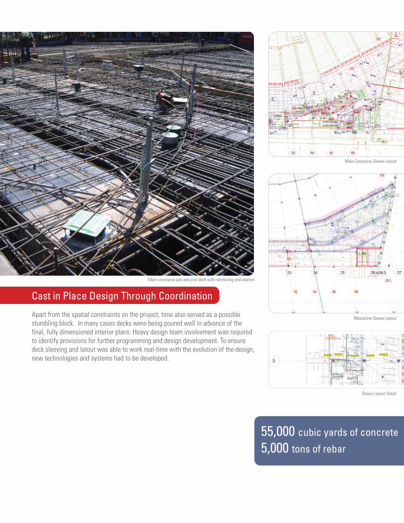
55,000 cubic yards of concrete
5,000 tons of rebar
Main Concourse Sleeve Layout
Mezzanine Sleeve Layout
Sleeve Layout Detail
Main concourse pan and joist deck with reinforcing and sleeves
Cast in Place Design Through Coordination
Apart from the spatial constraints on the project, time also served as a possible stumbling block. In many cases decks were being poured well in advance of the final, fully dimensioned interior plans. Heavy design team involvement was required to identify provisions for further programming and design development. To ensure deck sleeving and latout was able to work real-time with the evolution of the design, new technologies and systems had to be developed.
70% of construction wastewas diverted from landfills
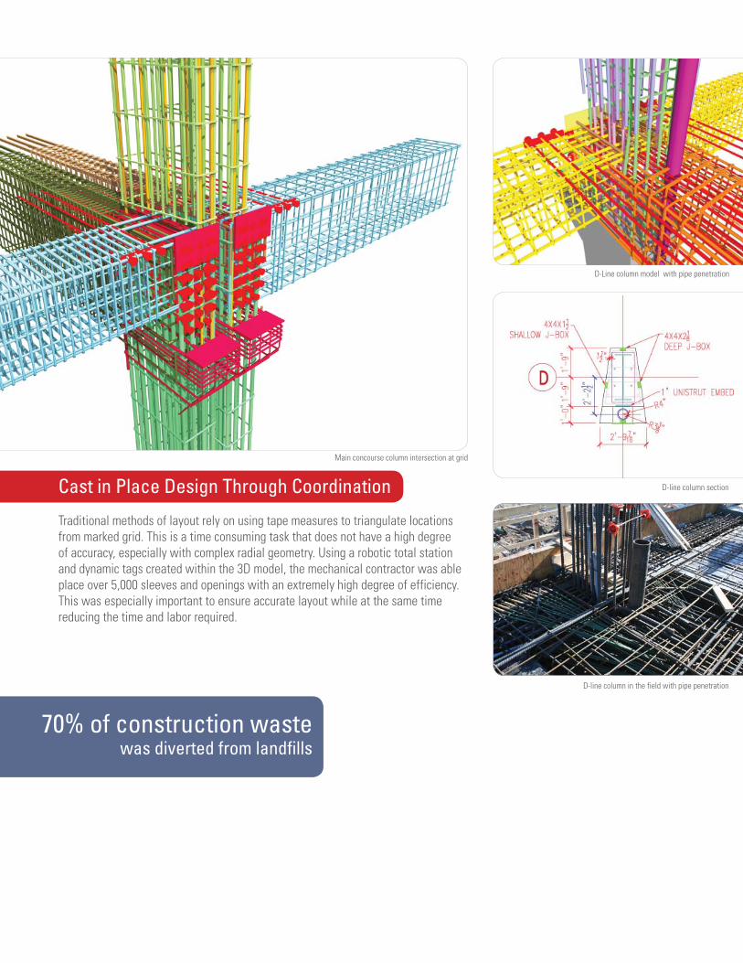
D-Line column model with pipe penetration
D-line column section
D-line column in the field with pipe penetration
Cast in Place Design Through Coordination
Traditional methods of layout rely on using tape measures to triangulate locations from marked grid. This is a time consuming task that does not have a high degree of accuracy, especially with complex radial geometry. Using a robotic total station and dynamic tags created within the 3D model, the mechanical contractor was able place over 5,000 sleeves and openings with an extremely high degree of efficiency. This was especially important to ensure accurate layout while at the same time reducing the time and labor required.
Main concourse column intersection at grid
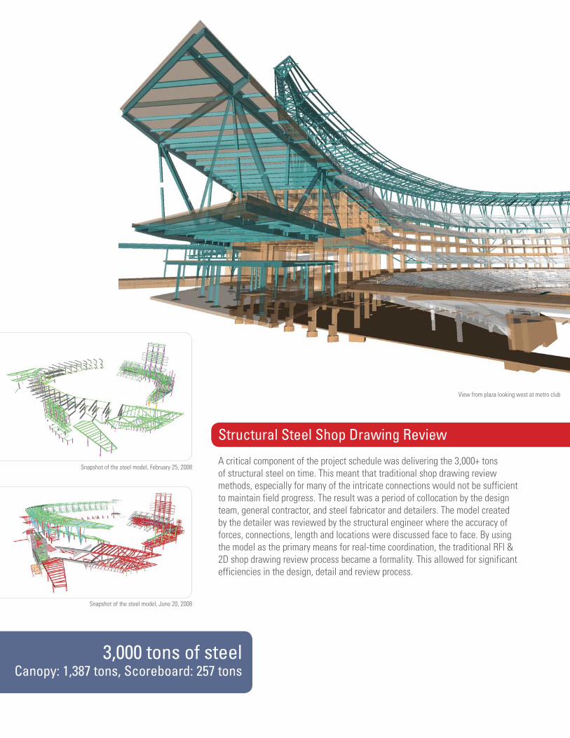
3,000 tons of steelCanopy: 1,387 tons, Scoreboard: 257 tons
Snapshot of the steel model, February 25, 2008
Snapshot of the steel model, June 20, 2008
View from plaza looking west at metro club
Structural Steel Shop Drawing Review
A critical component of the project schedule was delivering the 3,000+ tons of structural steel on time. This meant that traditional shop drawing review methods, especially for many of the intricate connections would not be sufficient to maintain field progress. The result was a period of collocation by the design team, general contractor, and steel fabricator and detailers. The model created by the detailer was reviewed by the structural engineer where the accuracy of forces, connections, length and locations were discussed face to face. By using the model as the primary means for real-time coordination, the traditional RFI & 2D shop drawing review process became a formality. This allowed for significant efficiencies in the design, detail and review process.
“It was like stuffing 12 pounds of potatoes into
an 8 pound bag.”
- Nadine Post,Engineering News-Record
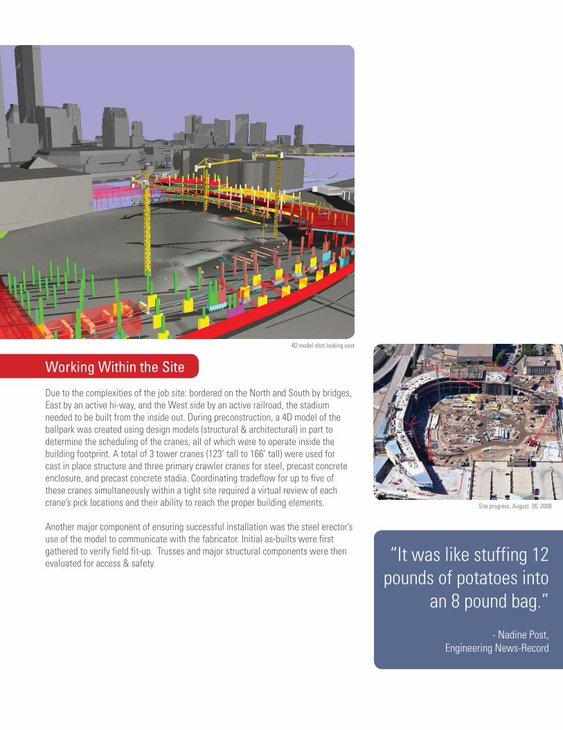
4D model shot looking east
Site progress, August 26, 2008
Working Within the Site
Due to the complexities of the job site: bordered on the North and South by bridges, East by an active hi-way, and the West side by an active railroad, the stadium needed to be built from the inside out. During preconstruction, a 4D model of the ballpark was created using design models (structural & architectural) in part to determine the scheduling of the cranes, all of which were to operate inside the building footprint. A total of 3 tower cranes (123’ tall to 166’ tall) were used for cast in place structure and three primary crawler cranes for steel, precast concrete enclosure, and precast concrete stadia. Coordinating tradeflow for up to five of these cranes simultaneously within a tight site required a virtual review of each crane’s pick locations and their ability to reach the proper building elements.
Another major component of ensuring successful installation was the steel erector’s use of the model to communicate with the fabricator. Initial as-builts were first gathered to verify field fit-up. Trusses and major structural components were then evaluated for access & safety.
90% of rainfallis captured + treated
Field varified coordinates of the creek
Model shot of transfer beam and creek
Field use drawing of transfer beam
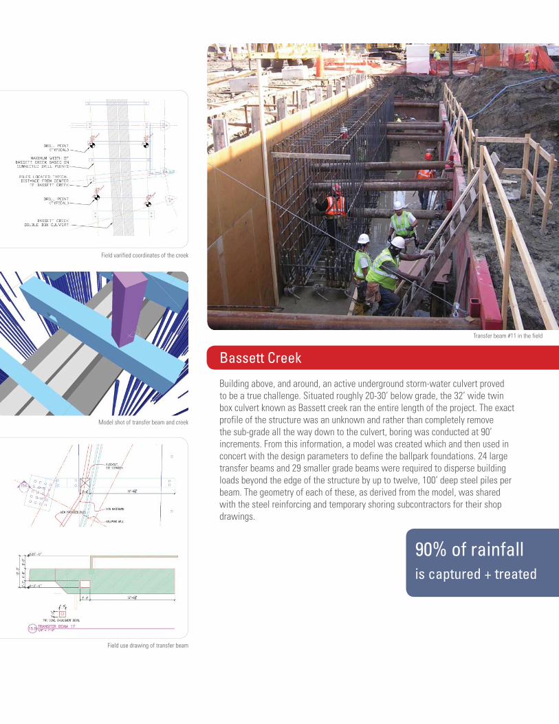
Transfer beam #11 in the field
Bassett Creek
Building above, and around, an active underground storm-water culvert proved to be a true challenge. Situated roughly 20-30’ below grade, the 32’ wide twin box culvert known as Bassett creek ran the entire length of the project. The exact profile of the structure was an unknown and rather than completely remove the sub-grade all the way down to the culvert, boring was conducted at 90’ increments. From this information, a model was created which and then used in concert with the design parameters to define the ballpark foundations. 24 large transfer beams and 29 smaller grade beams were required to disperse building loads beyond the edge of the structure by up to twelve, 100’ deep steel piles per beam. The geometry of each of these, as derived from the model, was shared with the steel reinforcing and temporary shoring subcontractors for their shop drawings.

Scoreboard:
57 feet tall, 101 feet wide
Cast in place girder over rail lines
Northstar train at Target Field Station and model shot looking south
Model shot looking north over BNSF and Northstar rail lines
Building Around the Rail Lines
Running below the main concourse on the western edge of the stadium are two rail lines, Burlington Northern Santa Fe and Minnesota’s new heavy gauge commuter train service (Northstar). Trains for these lines moved through the construction site up to 14 times a day, during work hours. In addition to presenting scheduling challenges--work had to be stopped each time a train passed--these functioning railroads also required that stringent clearances be adhered to, both above and below grade.
Accessed by:light rail, city bus,
pedestrian bridges, Northstar commuter rail,
Cedar Lake bike trail, I-394, I-94
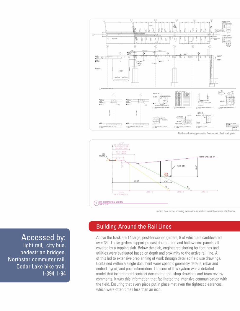
Field use drawing generated from model of railroad girder
Section from model showing excavation in relation to rail line zones of influence
Building Around the Rail Lines
Above the track are 14 large, post-tensioned girders, 8 of which are cantilevered over 34’. These girders support precast double-tees and hollow core panels, all covered by a topping slab. Below the slab, engineered shoring for footings and utilities were evaluated based on depth and proximity to the active rail line. All of this led to extensive preplanning of work through detailed field use drawings. Contained within a single document were specific geometry details, rebar and embed layout, and pour information. The core of this system was a detailed model that incorporated contract documentation, shop drawings and team review comments. It was this information that facilitated the intensive communication with the field. Ensuring that every piece put in place met even the tightest clearances, which were often times less than an inch.
9,900 square feetof pedestrian bridge construction over I-394
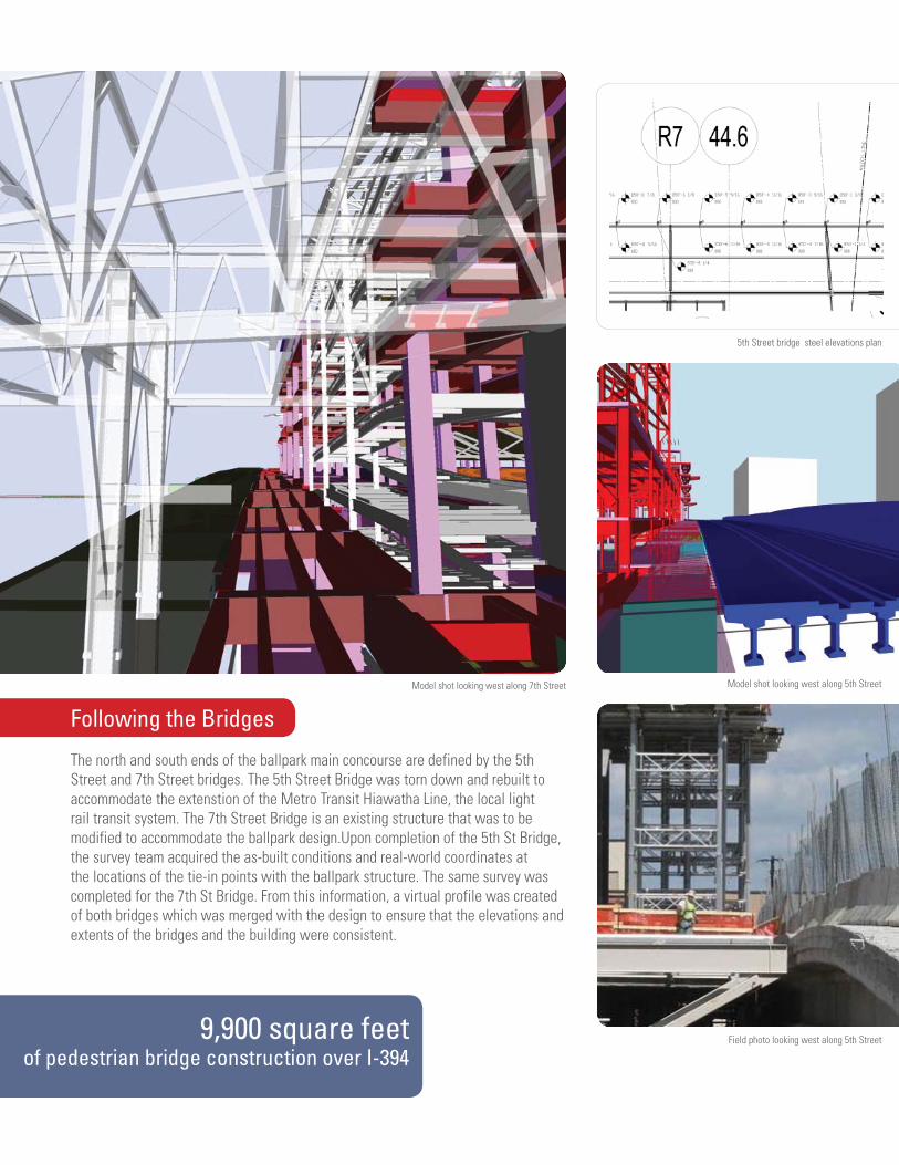
5th Street bridge steel elevations plan
Model shot looking west along 5th Street
Field photo looking west along 5th Street
Model shot looking west along 7th Street
Following the Bridges
The north and south ends of the ballpark main concourse are defined by the 5th Street and 7th Street bridges. The 5th Street Bridge was torn down and rebuilt to accommodate the extenstion of the Metro Transit Hiawatha Line, the local light rail transit system. The 7th Street Bridge is an existing structure that was to be modified to accommodate the ballpark design.Upon completion of the 5th St Bridge, the survey team acquired the as-built conditions and real-world coordinates at the locations of the tie-in points with the ballpark structure. The same survey was completed for the 7th St Bridge. From this information, a virtual profile was created of both bridges which was merged with the design to ensure that the elevations and extents of the bridges and the building were consistent.
over 100,000square feet of limestone
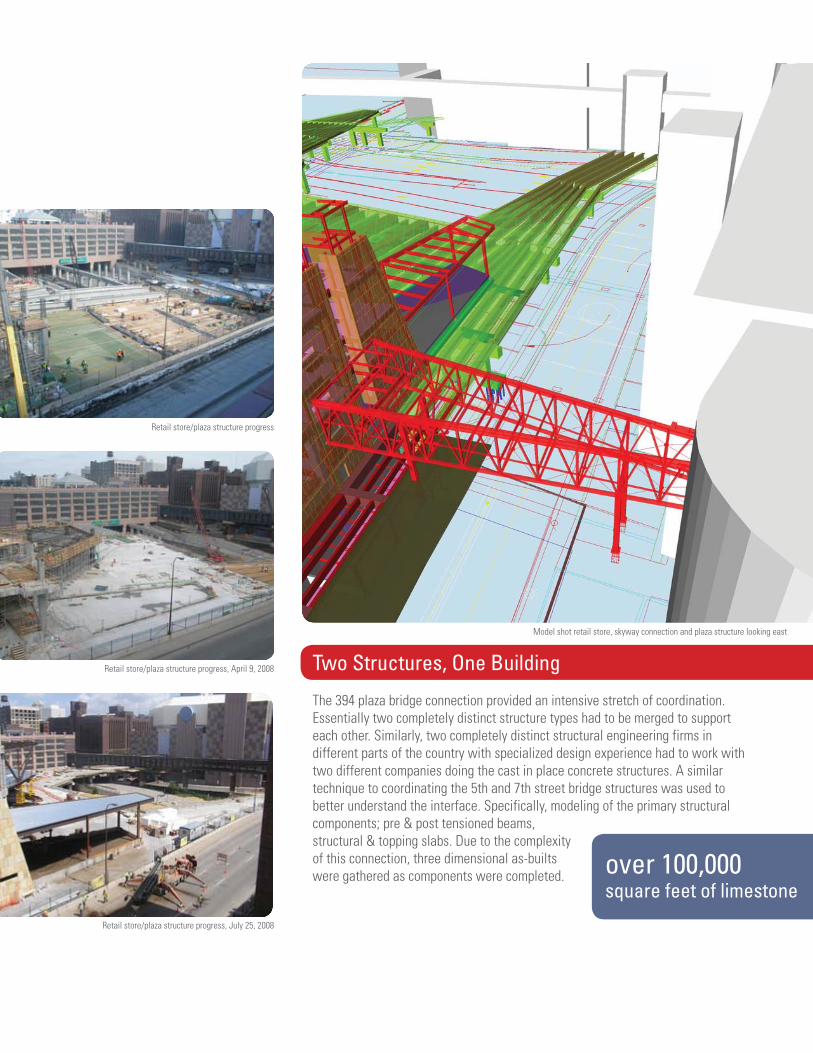
Retail store/plaza structure progress
Retail store/plaza structure progress, April 9, 2008
Retail store/plaza structure progress, July 25, 2008
Model shot retail store, skyway connection and plaza structure looking east
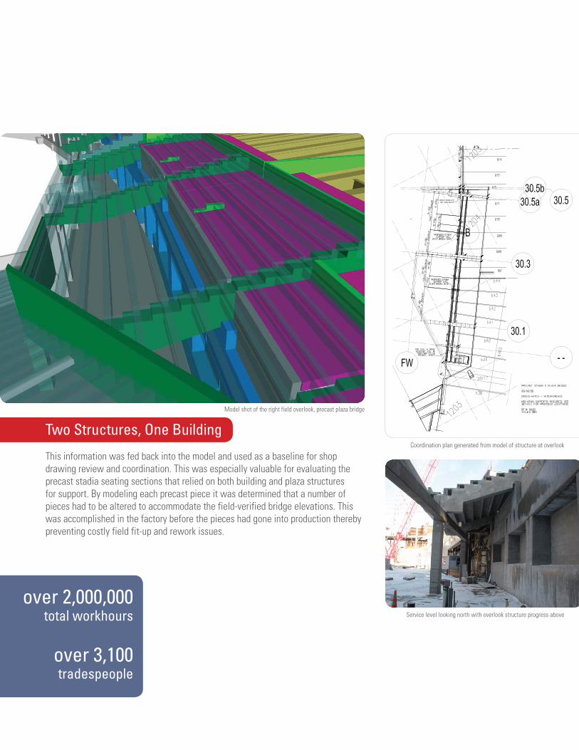
Two Structures, One Building
The 394 plaza bridge connection provided an intensive stretch of coordination. Essentially two completely distinct structure types had to be merged to support each other. Similarly, two completely distinct structural engineering firms in different parts of the country with specialized design experience had to work with two different companies doing the cast in place concrete structures. A similar technique to coordinating the 5th and 7th street bridge structures was used to better understand the interface. Specifically, modeling of the primary structural components; pre & post tensioned beams, structural & topping slabs. Due to the complexity of this connection, three dimensional as-builts were gathered as components were completed.
over 2,000,000total workhours
over 3,100tradespeople
Model shot of the right field overlook, precast plaza bridge
Coordination plan generated from model of structure at overlook
Service level looking north with overlook structure progress above
Two Structures, One Building
This information was fed back into the model and used as a baseline for shop drawing review and coordination. This was especially valuable for evaluating the precast stadia seating sections that relied on both building and plaza structures for support. By modeling each precast piece it was determined that a number of pieces had to be altered to accommodate the field-verified bridge elevations. This was accomplished in the factory before the pieces had gone into production thereby preventing costly field fit-up and rework issues.
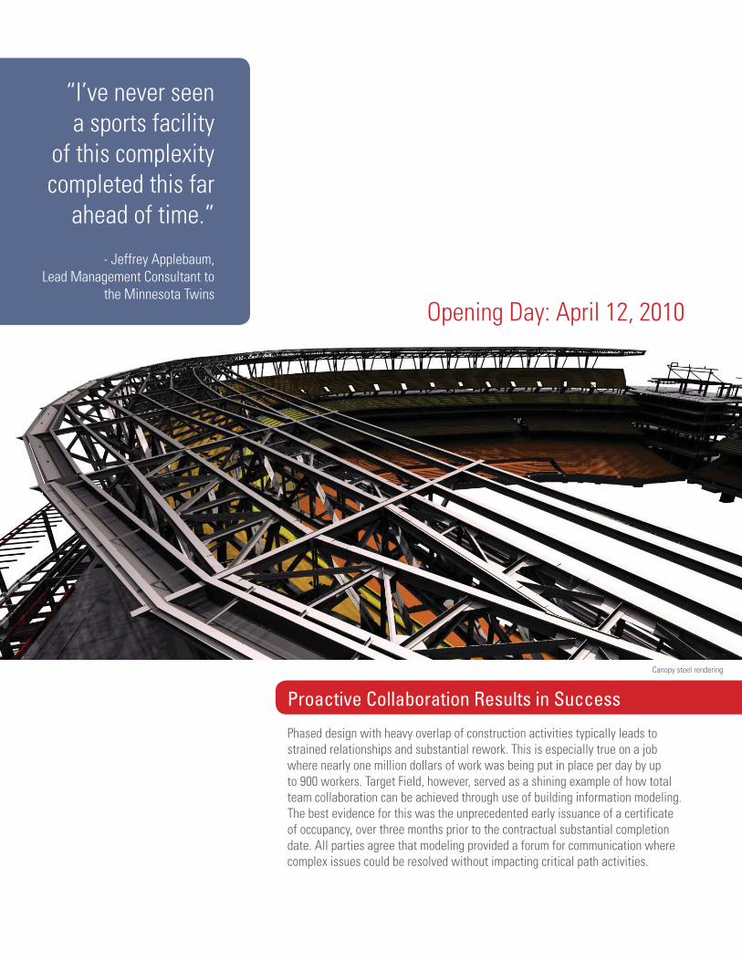
“I’ve never seen a sports facility
of this complexity completed this far
ahead of time.”
- Jeffrey Applebaum,Lead Management Consultant to
the Minnesota TwinsOpening Day: April 12, 2010
Canopy steel rendering
Proactive Collaboration Results in Success
Phased design with heavy overlap of construction activities typically leads to strained relationships and substantial rework. This is especially true on a job where nearly one million dollars of work was being put in place per day by up to 900 workers. Target Field, however, served as a shining example of how total team collaboration can be achieved through use of building information modeling. The best evidence for this was the unprecedented early issuance of a certificate of occupancy, over three months prior to the contractual substantial completion date. All parties agree that modeling provided a forum for communication where complex issues could be resolved without impacting critical path activities.