Embed Size (px)
Citation preview
Legal Notice
All information included in this document is subject to change without notice. The Members of the TAS3
Consortium make no warranty of any kind with regard to this document, including, but not limited to, the
implied warranties of merchantability and fitness for a particular purpose. The Members of the TAS3
Consortium shall not be held liable for errors contained herein or direct, indirect, special, incidental or
consequential damages in connection with the furnishing, performance, or use of this material.
SEVENTH FRAMEWORK PROGRAMME
Challenge 1
Information and Communication Technologies
Trusted Architecture for Securely Shared Services
Document Type: Deliverable
Title: TAS3 Architecture
Work Package: WP2
Deliverable Nr: D2.1
Dissemination: Public
Preparation Date: 8th July, 2011
Version: 2.24
TAS3 Architecture, v2.24 8 July, 2011
TAS3_D2p1_Arch-v-2.24 Page 2 of 170
The TAS3 Consortium
Beneficiary Name Country Short Role
1 KU Leuven BE KUL Project Mgr
2 Synergetics NV/SA BE SYN Partner
3 University of Kent UK KENT Partner
4 University of Karlsruhe DE KARL Partner
5 Technische Universiteit Eindhoven NL TUE Partner
6 CNR/ISTI IT CNR Partner
7 University of Koblenz-Landau DE UNIKOL
D
Partner
8 Vrije Universiteit Brussel BE VUB Partner
9 University of Zaragoza ES UNIZAR Partner
10 University of Nottingham UK NOT Partner
11 SAP Research DE SAP Coordinator
12 EIfEL FR EIF Partner
13 Intalio UK INT Partner
14 Risaris IR RIS Partner
15 Kenteq NL KETQ Partner
16 Oracle UK ORACLE Partner
17 Custodix BE CUS Partner
18 Medisoft NL MEDI Partner
19 KIT DE KARL Partner
20 Symlabs PT SYM Partner
Disclaimer: This document has not been reviewed or approved by European Commission.
Contributors
Name Organisation
1 Joseph Alhadeff Oracle
2 Brendan Van Alsenoy KUL
3 Guglielmo De Angelis CNR/ISTI
4 Michele Bezzi SAP
5 David Chadwick KENT
6 Brecht Claerhout CUS
7 Danny De Cock KUL
8 Marc Van Coillie EIF
9 Elisa Costante TUE
10 Ioana-Georgiana Ciuciu VUB
11 Carlos Flavian ZAR
12 Michal Guinaliù ZAR
13 Seda Gürses KUL
14 Ingo Dahn UNIKOLD
15 Thorsten Haberecht KARL
16 Jerry den Hartog TUE
17 Jeroen Hoppenbrouwers SYN
18 Sampo Kellomäki (main contributor) SYN
19 Thomas Kirkham NOT
20 Michael Kutscher UNIKOLD
TAS3 Architecture, v2.24 8 July, 2011
TAS3_D2p1_Arch-v-2.24 Page 3 of 170
Name Organisation
21 Keqin Li SAP
22 Stijn Lievens KENT
23 Gilles Montagnon SAP
24 Jutta Mülle KARL
25 Jens Müller KARL
26 Jean-Christophe Pazzaglia SAP
27 Lex Pohlman KENTEQ
28 Quentin Reul VUB
29 Brian Reynolds RIS
30 Marc Santos UNIKOLD
31 Luis Schilders CUS
32 Magali Seguran SAP
33 Silvia von Stackelberg KARL
34 Slim Trabelsi SAP
35 Luk Vervenne SYN
36 Sara Winfield NOT
37 Gang Zhao VUB
TAS3 Architecture, v2.24 8 July, 2011
TAS3_D2p1_Arch-v-2.24 Page 4 of 170
Contents
LIST OF FIGURES ........................................................................ 11
ARCHITECTURE EXECUTIVE SUMMARY ..................................... 13
1 INTRODUCTION ........................................................................ 15
1.1 TAS3 ARCHITECTURE AT GLANCE ................................................................. 15
1.2 METHODOLOGY ............................................................................................. 17
1.3 NORMATIVE CLAIM ....................................................................................... 18
1.4 REVIEW OF PREVIOUS WORK ........................................................................ 18
1.5 READER‟S GUIDE .......................................................................................... 19
2 TAS3 HIGH LEVEL ARCHITECTURE ........................................ 21
2.1 OVERVIEW .................................................................................................... 21
2.2 BASIC ARCHITECTURAL ENTITIES ................................................................ 22
2.2.1 Major Components ............................................................................... 22 2.2.2 Enforcement Points on Web Service Call Path ................................... 26 2.2.3 Authorization Infrastructure ............................................................... 27
2.3 MAJOR FLOWS: FRONT CHANNEL AND BACK CHANNEL ............................... 29
2.4 OVERVIEW OF DATA MODELS ....................................................................... 31
2.4.1 Federation Relations for Core Security Architecture ......................... 31 2.4.2 Personal Data and Applications .......................................................... 33 2.4.3 Using Sticky Policies to Protect Data .................................................. 33 2.4.4 Using Encryption to Protect Data ....................................................... 33
2.5 AUTHORIZATION PROCESS ............................................................................ 34
2.6 ENFORCEMENT PROCESS .............................................................................. 35
2.7 CONFIGURATION PROCESS ........................................................................... 37
2.8 AUDIT ........................................................................................................... 38
3 CORE SECURITY ARCHITECTURE ............................................ 42
3.1 FLOWS .......................................................................................................... 42
3.2 TOKENS, ACCESS CREDENTIALS ................................................................... 43
3.2.1 Attribute Pull Model ............................................................................ 43 3.2.2 Linking Service: Attribute Push Model ............................................... 53 3.2.3 Simple Attribute Push Model .............................................................. 57
3.3 DELEGATION ................................................................................................. 58
3.3.1 Invitation Based Token Approach ....................................................... 59 3.3.2 Delegation by Direct Authorization Rule ............................................ 60 3.3.3 Delegation to Well Known Delegate .................................................... 60 3.3.4 Multi-layer (Chained) Delegation ........................................................ 61
3.4 BREAK-THE-GLASS AUTHORIZATION ............................................................ 61

TAS3 Architecture, v2.24 8 July, 2011
TAS3_D2p1_Arch-v-2.24 Page 5 of 170
3.5 TRUST AND PRIVACY NEGOTIATION .............................................................. 61
3.6 INTEROPERATION ACROSS TRUST NETWORKS .............................................. 62
3.6.1 Semantic Interoperability – OBIS the Ontology-based Interoperation
Service ........................................................................................................... 62
3.7 PROPERTIES OF WEB SERVICE BINDING ....................................................... 64
4 APPLICATION SPECIFIC ARCHITECTURE ................................ 65
4.1 PROTOCOL SUPPORT FOR CONVEYANCE OF STICKY POLICIES ...................... 65
4.2 LEGACY INTEGRATION STRATEGY................................................................. 66
4.3 THE APPLICATION‟S PEP .............................................................................. 68
4.4 REPUTATION FEEDBACK ............................................................................... 70
4.5 SECURITY ENFORCEMENT FOR BUSINESS PROCESSES ................................. 70
AS SHOWN, SPECIAL COMPONENTS ARE ONLY NEEDED FOR SECURITY
FUNCTIONALITY SPECIFIC TO BUSINESS PROCESSES. THEY INTEGRATE WITH THE
OVERALL TAS³ SECURITY ARCHITECTURE. ......................................................... 71
4.6 BUSINESS PROCESS REGISTRATION .............................................................. 71
5 USING BUSINESS PROCESS MODELLING TO CONFIGURE THE
COMPONENTS ............................................................................. 72
6 OVERSIGHT AND MONITORING ................................................ 75
6.1 DASHBOARD .................................................................................................. 76
6.2 RIGHT OF ACCESS, RECTIFICATION, AND DELETION ..................................... 76
6.2.1 Identification of Source of Authority ................................................... 77 6.2.2 Facilitating Self Service Interface to Right of Access ......................... 77 6.2.3 Propagation of Rectifications by the Source of Authority ................... 77
6.3 ON-LINE COMPLIANCE TESTING ................................................................... 78
6.3.1 Involved Actors .................................................................................... 79 6.3.2 On-line Testing Process and Architecture .......................................... 80
6.4 OPERATIONS MONITORING AND INTRUSION DETECTION .............................. 83
6.5 LOG AUDIT .................................................................................................... 84
6.5.1 Log Collection and Storage .................................................................. 85 6.5.2 Privacy Issues: What to Collect and What to Report .......................... 86
6.6 ADMINISTRATIVE OVERSIGHT ....................................................................... 86
7 CONCLUSION: TAS3 IS SECURE AND TRUSTWORTHY .............. 87
ANNEX A: ENUMERATION OF AUDIT EVENTS ............................ 89
ANNEX B: TAS3 RISK ASSESSMENT ........................................... 94
B.1 EXECUTIVE SUMMARY.................................................................................. 94
B.2 INTRODUCTION ............................................................................................ 94
B.3 RISK ANALYSIS METHODS ............................................................................ 94
TAS3 Architecture, v2.24 8 July, 2011
TAS3_D2p1_Arch-v-2.24 Page 6 of 170
B.3.1 OCTAVE (Operationally Critical Threat, Asset, and Vulnerability
Evaluation) ................................................................................................... 94 B.3.2 CRAMM ............................................................................................... 95 B.3.3 Microsoft‟s Security Risk Management .............................................. 95 B.3.4 CORAS ................................................................................................. 96 B.3.5 ISO/IEC 27001 (BS7799-2:2002) ......................................................... 97
B.4 OUR METHODOLOGY ..................................................................................... 97
B.5 RISK ASSESSMENT METHODOLOGY .............................................................. 98
B.5.1 Identify the Components ..................................................................... 99 B.5.2 Identify the Sub Component ............................................................. 100 B.5.3 Identify the assets ............................................................................. 101 B.5.4 Indentify the Threats ........................................................................ 101 B.5.5 Identify the Attacks........................................................................... 102 B.5.6 Identify the mitigation ...................................................................... 103
B.6 T3-ACVS: AUTHORIZATION CREDENTIAL VALIDATION SERVICE ............... 106
B.7 T3-BP-CLIENT: BUSINESS PROCESS USER INTERFACE ............................ 107
B.7.1 Entry points ....................................................................................... 107 B.7.2 Asset: State of process instances, confidentiality and integrity of
process data ................................................................................................ 107
B.8 T3-BP-DEL: BUSINESS PROCESS DELEGATION SERVICE .......................... 107
B.8.1 Entry points ....................................................................................... 107 B.8.2 Asset: Integrity of user-task assignment .......................................... 108
B.9 T3-BP-ENGINE-ODE: APACHE ODE BUSINESS PROCESS EXECUTION
ENGINE ............................................................................................................ 108
B.9.1 Entry points ....................................................................................... 108 B.9.2 Asset: Executable process models ..................................................... 108 B.9.3 Asset: Running process instances (state and data) .......................... 109
B.10 T3-BP-ENGINE-ODE: APACHE ODE BUSINESS PROCESS EXECUTION
ENGINE ............................................................................................................ 109
B.10.1 Entry points ..................................................................................... 109 B.10.2 Asset: Executable process models ................................................... 109 B.10.3 Asset: Running process instances (state and data) ........................ 110
B.11 T3-BP-MGR: BUSINESS PROCESS ADMINISTRATION INTERFACE ............ 110
B.11.1 Entry points ..................................................................................... 110 B.11.2 Asset: Status of business process instances ................................... 110
B.12 T3-BP-PEP: BUSINESS PROCESS POLICY ENFORCEMENT POINT ............ 111
B.12.1 Entry points ..................................................................................... 111 B.12.2 Asset: Correct policy enforcement ................................................... 111
B.13 T3-BP-PIP: BUSINESS PROCESS POLICY INFORMATION POINT ............... 112
B.13.1 Entry points ..................................................................................... 112 B.13.2 Asset: Correct information for policy enforcement ......................... 112
B.14 T3-BP-SMC: BUSINESS PROCESS SECURITY CONFIGURATION COMPONENT
......................................................................................................................... 113
TAS3 Architecture, v2.24 8 July, 2011
TAS3_D2p1_Arch-v-2.24 Page 7 of 170
B.14.1 Entry points ..................................................................................... 113 B.14.2 Asset: Business process security annotations and security ........... 113 B.14.3 Asset: Security enhanced business process models and business
process security configurations generated by the SMC component .......... 113
B.15 T3-BUS-AUD: AUDIT EVENT BUS ........................................................... 114
B.15.1 Entry points ..................................................................................... 114 B.15.2 Asset: Channels of audit event type ............................................... 114 B.15.3 Asset: Status of audit event type .................................................... 114
B.16 T3-DEL: DELEGATION SERVICE ............................................................... 115
B.16.1 Entry points ..................................................................................... 115 B.16.2 Assets ............................................................................................... 115 B.16.3 Threats ............................................................................................ 115
B.17 T3-IDP-ACSIS ......................................................................................... 116
B.17.1 Entry points ..................................................................................... 116 B.17.2 Data assets ...................................................................................... 117 B.17.3 Nonfunctional assets ....................................................................... 117 B.17.4 Attacks and mitigation .................................................................... 117
B.18 T3-IDP-SHIB: SHIBBOLETH IDP ............................................................. 118
B.18.1 Entry Points .................................................................................... 118 B.18.2 Asset: Issued Credentials ................................................................ 118 B.18.3 Asset: Private Signing Keys of the Service ..................................... 118 B.18.4 Asset: User Database (Attributes and Authentication Credentials)
..................................................................................................................... 119 B.18.5 Asset: Session Information............................................................. 121 B.18.6 Asset: Configuration Files of the Service ....................................... 121 B.18.7 Non-functional Asset: User Consent and Control of Data Release 121 B.18.8 Non-functional Asset: Organisation Control of Data Release ....... 121
B.19 T3-IDP-SHIB-AGG: ENHANCEMENT TO SHIBBOLETH IDP TO SUPPORT
ATTRIBUTE AGGREGATION ................................................................................ 121
B.19.1 Entry points .................................................................................... 121 B.19.2 Asset: The Audit Trail .................................................................... 121 B.19.3 Asset: SAWS Records a Secure Audit Trail ................................... 123 B.19.4 Asset: Private Keys for Signing/Encrypting .................................. 123
B.20 T3-LOG-SAWS: SECURE AUDITING WEB SERVICE ................................. 124
B.20.1 Entry points .................................................................................... 124 B.20.2 Asset: The Audit Trail .................................................................... 124 B.20.3 Asset: SAWS Records a Secure Audit Trail ................................... 125 B.20.4 Asset: Private Keys for Signing/Encrypting .................................. 126
B.21 T3-LOG-WRAP-SAWS: WRAPPER WEB SERVICE AROUND SAWS WITH
EXTENSIONS ..................................................................................................... 126
B.21.1 Entry points .................................................................................... 126 B.21.2 Asset: Audit Trails ......................................................................... 126
B.22 T3-OCT: ONLINE COMPLIANCE TESTING ................................................ 127
B.22.1 Entry points .................................................................................... 127
TAS3 Architecture, v2.24 8 July, 2011
TAS3_D2p1_Arch-v-2.24 Page 8 of 170
B.22.2 Non-Functional Assets ................................................................... 127
B.23 T3-OCT-PLANNER: TEST PLANNER FOR THE ONLINE COMPLIANCE
TESTING ........................................................................................................... 128
B.24 T3-PDP-BP: Business Process Policy Decision Point ....................... 128
B.25 TAS3 -ONT-SER: ONTOLOGY SERVER .................................................... 129
B.25.1 Entry Points ................................................................................... 129 B.25.2 Asset: Ontology Server ................................................................... 129
B.26 T3-PDP-BTG: BREAK THE GLASS PDP .................................................... 130
B.26.1 Entry points ..................................................................................... 130 B.26.2 Asset: The BTG-State of the System .............................................. 130
B.27 T3-PDP-M: POLICY DECISION POINT/MASTER PDP ................................ 130
B.28 T3-PDP-P: PERMIS PDP ........................................................................ 130
B.28.1 Entry Points .................................................................................... 130 B.28.2 Asset: Authorisation Policy ............................................................. 130
B.29 T3-PDP-T: TRUST POLICY DECISION POINT ............................................ 131
B.29.1 Entry points ..................................................................................... 131 B.29.2 Asset: Trust Policy........................................................................... 131 B.29.3 Asset: Trust-PDP Evaluation Service ............................................. 132
B.30 T3-PEP-AI: APPLICATION-INDEPENDENT POLICY ENFORCEMENT POINT 133
B.30.1 Entry Points ................................................................................... 133 B.30.2 Asset: Built-in Policies ................................................................... 133 B.30.3 Asset: Configuration File ............................................................... 133 B.30.4 Asset: Roots of Trust (PKCs) for Signature Verification ............... 134 B.30.5 Asset: System Coordinates Decision Making ................................ 134 B.30.6 Asset: The Sticky Store .................................................................. 134
B.31 T3-POL-GUI: GRAPHICAL POLICY EDITOR .............................................. 135
B.31.1 Entry points .................................................................................... 135 B.31.2 Asset: Information in Configuration File....................................... 135 B.31.3 Asset: Private Signing Key Used to Sign Policies ......................... 135
B.32 T3-POL-CNL: CONTROLLED NATURAL LANGUAGE POLICY EDITOR ....... 136
B.33 T3-POL-WIZ: WIZARD POLICY EDITOR .................................................... 136
B.34 T3-PORT-JBOSS: JBOSS PORTAL FRAMEWORK ..................................... 136
B.34.1 Entry points .................................................................................... 136 B.34.2 Asset: user data (functional data) and user credentials (non-
functional data) ........................................................................................... 136 B.34.3 Asset: internal data (non-functional data)..................................... 138
B.35 T3-REP-FEDORA: TAS3 REFERENCE REPOSITORY ................................ 140
B.35.1 Entry points .................................................................................... 140 B.35.2 Asset: user data (functional data) and credentials (non-
functional data) ........................................................................................... 140 B.35.3 Asset: internal data (non-functional data)..................................... 141

TAS3 Architecture, v2.24 8 July, 2011
TAS3_D2p1_Arch-v-2.24 Page 9 of 170
B.36 T3-REP-JFEDORA: JFEDORA LIBRARY FOR TAS3 GENERIC DATA
FORMAT ............................................................................................................ 143
B.36.1 Entry points .................................................................................... 143 B.36.2 Asset: Message based on Generic Data Format ............................ 143
B.37 T3-SG-BASE: SOA GATEWAY BASE SYSTEM .......................................... 143
B.37.1 Entry points .................................................................................... 143 B.37.2 Asset: Backend Legacy data ........................................................... 143 B.37.3 Asset: Server Configuration Files .................................................. 144
B.38 T3-SG-WSP: SOA GATEWAY WEB SERVICE PROVIDER .......................... 144
B.38.1 Entry points .................................................................................... 144 B.38.2 Asset: Web services hosted by T3-SG- WSP component ............... 144
B.39 T3-SP-CVT: EUROPASS CV TRANSCODING WEB SERVICE ...................... 145
B.39.1 Entry Points ................................................................................... 145 B.39.2 Assets .............................................................................................. 145 B.39.3 Threats ........................................................................................... 145
B.40 T3-SP-MATCHER: JOB PROFILE MATCHING SERVICE .......................... 146
B.40.1 Entry points .................................................................................... 146 B.40.2 Asset: Program logic that matches profiles of individuals to opportu-
nities ........................................................................................................... 146
B.41 T3-STACK AND T3-SSO-ZXID ............................................................... 146
B.41.1 Entry points .................................................................................... 146 B.41.2 Data assets ..................................................................................... 146 B.41.3 Nonfunctional assets ...................................................................... 147 B.41.4 Attacks and mitigation ................................................................... 147
B.42 T3-TPN-TB2: TRUST NEGOTIATION MODULE ......................................... 147
B.42.1 Entry points .................................................................................... 147 B.42.2 Assets .............................................................................................. 147 B.42.3 Threats ........................................................................................... 147 B.42.4 Attacks ............................................................................................ 148
B.43 T3-TRU-CTM: CREDENTIAL BASED TRUST SERVICE COMPONENT .......... 148
B.43.1 Entry points .................................................................................... 148 B.43.2 Asset: Credentials .......................................................................... 148 B.43.3 Asset: CTM Web Service ................................................................ 149
B.44 T3-TRU-KPI: KEY PERFORMANCE INDICATORS ..................................... 150
B.44.1 Entry points .................................................................................... 150 B.44.2 Asset: KPI Engine .......................................................................... 150
B.45 T3-TRU-RTM: REPUTATION TRUST MANAGEMENT SERVICE ................. 150
B.45.1 Entry points .................................................................................... 150 B.45.2 Asset: Feedback .............................................................................. 151 B.45.3 Asset: RTM Web Service ................................................................ 151
ANNEX C: USER-CENTRICITY IN TAS3 ................................ 153
TAS3 Architecture, v2.24 8 July, 2011
TAS3_D2p1_Arch-v-2.24 Page 10 of 170
C.1 EXECUTIVE SUMMARY................................................................................ 153
C.2 DEFINING ELEMENTS OF USER-CENTRICITY IN TAS³ ................................. 153
C.2.1 The user‟s ability to express privacy preferences ............................. 153 C 2.2 The user‟s ability to manage his own partial identities ................... 155 C 2.3 The user‟s ability to express trust preferences and provide feedback
..................................................................................................................... 155 C 2.4 The user‟s ability to view his personal data ..................................... 156 C 2.5 The user‟s ability to over-ride access controls .................................. 156 C 2.6 Enhanced transparency .................................................................... 157
REFERENCES ............................................................................ 159
TAS3 Architecture, v2.24 8 July, 2011
TAS3_D2p1_Arch-v-2.24 Page 11 of 170
List of Figures
Figure 2.1: Using TAS3 top level model to start modelling of organizations that
participate in Trust Network. ............................................................................... 21
Figure 2.2: Major components of Organization Domain. ...................................... 24
Figure 2.3: Front End calls Web Service, passing through 4 enforcement points
(callouts, per Fig-2.2 of D7.1). ............................................................................... 26
Figure 2.4: Recursive Web Service calls. ............................................................... 27
Figure 2.5: Authorization Infrastructure. ............................................................. 28
Figure 2.6: Front Channel and Back Channel Flows (the numbering indicates
typical sequence of events). ................................................................................... 30
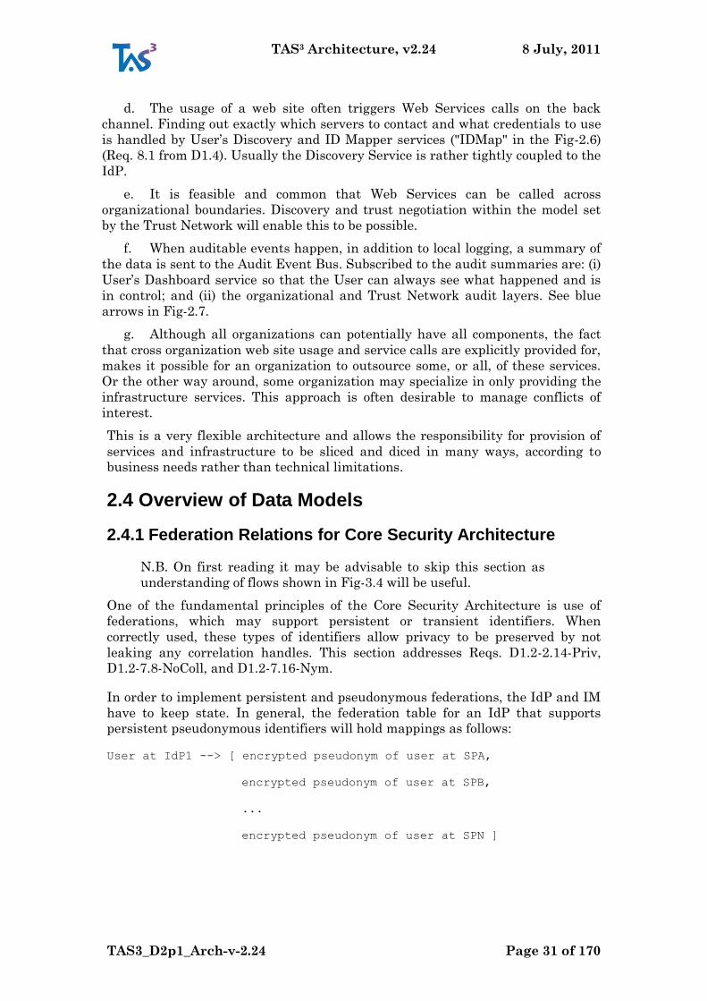
Figure 2.7: Audit Event Bus (the numbering indicates typical sequence of events,
the e-numbers indicate audit events) .................................................................... 32
Figure 2.8: Authorization Process ......................................................................... 34
Figure 2.9: Using model to configure Authorization Process ......................................... 36
Figure 2.10: Arrangement of enforcement points in web service call flow
(numbered callouts, per Fig-2.2 of D7.1). .............................................................. 36
Figure 2.11: Pushing configurations from model. ........................................................ 38
Figure 2.12: Configuration from Model (the numbering indicates typical sequence
of events) ................................................................................................................ 40
Figure 2.13: Auditing an authorization decision. ......................................................... 41
Figure 2.14: Monitoring operation of the network using the configured model. .. 41
Figure 3.1: General detailed flow of a service request .................................................. 42
Figure 3.2: Flow at front channel ............................................................................... 45
Figure 3.3 The Trusted Attribute Aggregation Service (TAAS) ........................... 46
Figure 3.4: Flow of front channel call that makes a call on back channel. ....................... 48
Figure 3.5: Single Sign-On (2,3), Discovery (4), and call to WSP (5). The blue ball
represents discovery bootstrap. ............................................................................. 50
Figure 3.6: Discovery Registration Using Front Channel Interface. ................................ 51
Figure 3.7: Flow of recursive calls on back channel. .................................................... 53
Figure 3.8: Linking Service: Registration phase. .......................................................... 54
Figure 3.9: Linking Service: Login with attribute push phase. ....................................... 55
TAS3 Architecture, v2.24 8 July, 2011
TAS3_D2p1_Arch-v-2.24 Page 12 of 170
Figure 3.10: The enhanced login screen for attribute aggregation. ................................. 56
Figure 4.1: Application Integration: PEP implemented directly in application. . 66
Figure 4.2: Application Integration: Simple Application Dependent PEP
implemented in application itself. ......................................................................... 67
Figure 4.3: Application Integration using ADPEP and (A) SOA Gateway, (B) WP8
DB as frontend to SOA GW, (C) WP8 database. ................................................... 68
Figure 6.1: Overview of On-line Compliance Testing ........................................... 79
Figure 6.2: UML Component Diagram of the On-line Compliance Testing (OCT).
................................................................................................................................ 83
Keyword List
Architecture, Security, Trust, Privacy
TAS3 Architecture, v2.24 8 July, 2011
TAS3_D2p1_Arch-v-2.24 Page 13 of 170
Architecture Executive Summary
This document contains version 2 of the TAS3 system architecture (by system
architecture we mean the conceptual design that defines the structure and
behaviour of a TAS3 trust network). As the Description of Work states, the TAS3
project‟s main objective is to provide a next generation trust & security
architecture that is ready to (1) meet the requirements of complex and highly
versatile business processes, (2) enable the dynamic user-centric management of
policies and (3) ensure end-to-end secure transmission of personal information
and user- controlled attributes between heterogeneous, context dependent and
continuously changing systems. This architecture has been designed to fulfil the
above objectives through a combination of:
providing users with the ability to meaningfully give their consent to the
use of their personal information
ensuring a complete set of audit information is recorded by a TAS3 trust
network and that users have the ability to directly or indirectly see the
audit information that pertains to their personal information. Note that
there will not be a single central audit log that contains all the information.
Instead the central audit log will only contain summary information. If a
person needs to drill down into the distributed audit trail, he will need to be
authorised and obtain sufficient permissions to access the various local
audit logs.
a legal framework and set of model contracts that will contractually bind all
service providers into
operating in a trustworthy manner e.g. so as to honour the choices of users
concerning the handling of their personal information
a set of trusted third parties that facilitate the sharing of trust related
information such as public keys, authorization attributes, and reputation
information
strong cryptographic algorithms and privacy preserving protocols
end to end security through application layer encryption and digital signing
sticky policies that cryptographically bind data and policies together, along
with a policy enforcement infrastructure that controls access to all
resources
quality assurance and testing technology and actors to test if on-line
services actually behave in compliance with their specifications.
This architecture document describes the conceptual entities that are needed and
the services they should provide in order to operate a TAS3 trust network. These
trust and privacy enhancing services include: authorization services, secure
business process management services, delegation services, privacy preserving
discovery services, identity management services, secure repository services and
trust and reputation services. All of these services are usually needed regardless
of the applications that might run in a TAS3 trust network. However, small
centralized trust networks may be able to dispense with one or more of these
TAS3 Architecture, v2.24 8 July, 2011
TAS3_D2p1_Arch-v-2.24 Page 14 of 170
trust and privacy enhancing services, e.g. discovery or delegation services,
depending upon their requirements.
This architecture contains many novel features such as: a trust infrastructure
based on novel metrics, actor behaviour and structural components which can be
correlated together, an authorisation infrastructure which supports multiple
policy languages and conflict resolution, an obligation infrastructure which
enforces privacy throughout the trust network, and a distributed audit system
which can be cross correlated via a central summary audit system operated by
the trusted network provider. These are described in more detail in the specific
work package deliverables.
The TAS3 architecture is designed to be standards, protocol, data and application
agnostic so that any protocol capable of implementing the flows and satisfying
the service requirements can potentially be used by any application.
Annex A lists the events that should be captured in the secure audit trails of a
TAS3 trust network
Annex B summarizes the threats that the TAS3 architecture is designed to
protect against
Annex C summarises the user centricity of TAS3.
Scope. The TAS3 project has a narrower scope than the architecture that is
documented here. This is natural as the novel research contributions of TAS3 are
being made only in some areas of the architecture. However the full architecture
needs to be documented as this will be needed both to successfully test the
research results and to provide a production service. We present a comprehensive
architecture that addresses actual use cases end-to-end, rather than simply an
architecture of the services that are within the scope of our research.
TAS3 Architecture, v2.24 8 July, 2011
TAS3_D2p1_Arch-v-2.24 Page 15 of 170
1 Introduction
1.1 TAS3 Architecture at Glance
The TAS3 architecture provides the high level design of an infrastructure
intended to provide the next generation of trust & security eco-systems that can
(1) meet the requirements of complex and highly versatile business processes, (2)
enable the dynamic user-centric management of policies and (3) ensure end-to-
end secure transmission of personal information and user-controlled attributes
between heterogeneous, context dependent and continuously changing systems.
The trusted architecture is built on three foundations: technical, policy and legal.
The technical architecture, introduced and described at a high level in this
document, presents the different services that are needed in order to operate a
trust network (or eco-system). Other work package deliverables provide more
detailed designs of some of these services.
The technical architecture proposes a number of Policy Decision Points (PDPs)
that are services capable of evaluating policies of various kinds and returning
policy decisions to their callers - the Policy Enforcement Points (PEPs). The
correct enforcement of user‟s policies engenders trust in a network. Many policies
in a TAS3 trust network will be sticky policies, meaning that the policy and the
data to which it pertains, are cryptographically bound together, thereby ensuring
that the policy is always there to be correctly enforced. Various types of policy
and PDP are envisaged, trust PDPs, privacy PDPs, authorisation PDPs,
delegation PDPs etc. Details of these PDPs and the policies they support will be
provided in more detail in other workpackage deliverables e.g. from WP4, WP5,
and WP7.
The legal framework and set of model contracts will be further developed in WP6.
They are being designed to contractually bind all the service providers into
operating in a trustworthy manner, for example, so as to honour all the choices of
users concerning the handling of their personal information. As many trust
enabling factors as possible will be built into the technical infrastructure
described in this deliverable, thereby automating the controls and freeing
organisations from the worry and overhead of ensuring that they do the right
thing. When it is not possible to engender trust through technical controls alone,
then legal controls through our model contracts will be used as the controls of
last resort.
This architecture document describes a service oriented trust network. All the
conceptual entities that are needed to form a trust and privacy preserving secure
network operate as service providers and service consumers, and they collaborate
together to provide the security services to end users. These trust, privacy and
security services are application independent and are designed to ensure that
whatever application the user is using, the application and its data are as secure,
trustworthy and privacy preserving as is possible, given the risk assessment and
cost constraints of the trust network. (We accept that absolute security is both
technically impossible and financially unaffordable.)
TAS3 Architecture, v2.24 8 July, 2011
TAS3_D2p1_Arch-v-2.24 Page 16 of 170
The trust and privacy enhancing services offered by TAS3 include:
authorization services, whose purpose is to answer the question "is this
subject authorised to access this resource in this way"
authentication services, whose purpose is to identify a subject and validate
that the communicating party is indeed the identified subject
privacy preserving services whose purpose is to provide pseudonymous
identities for users and minimise the cross linking of identities
trust negotiation services whose purpose is to determine if the remote
communicating party is trustworthy enough to start a dialogue
secure business process management services whose purpose is to ensure
that business processes operate securely, and can be dynamically modified
securely
delegation services, whose purpose is to delegate credentials from a
delegator to a delegate
discovery services, whose purpose is to inform clients where particular
services can be found
trusted registries, whose purpose is to keep a directory of all services in the
trust network who are known to provide services conforming to the TAS3
specifications
attribute authorities whose purpose is to assert that particular users have
particular attributes
identity management services, which are a combination of an
authentication service and an attribute authority
secure repository services, whose purpose is to store users‟ personal data
securely and give users complete control over who should access their data
and how they should handle it once they are given access to it
trust and reputation services, whose purpose is to answer the question "how
trustworthy is this actor (service provider or end user)"
secure audit services whose purpose is to keep a tamper resistant record of
transactions within the trust network so that legally admissible evidence
can be obtained in the case of a dispute.
on-line compliance testing services whose purpose is to ensure that all the
services in a trust network comply with their published specifications and
policies.
All of these services are usually needed regardless of the applications that might
run in a TAS3 trust network. However, small centralized trust networks may be
able to dispense with one or more of these trust and privacy enhancing services,
e.g. discovery or delegation services, depending upon their requirements.
The TAS3 architecture is designed to be standards and protocol agnostic so that
any protocol capable of implementing the message flows and service
requirements of the conceptual service providers can potentially be used by any
application. However, in order to ensure interworking between the prototypes
being developed in this project, we have had to choose a subset of current state of
TAS3 Architecture, v2.24 8 July, 2011
TAS3_D2p1_Arch-v-2.24 Page 17 of 170
the art protocols. Deliverable D2.4 maps (some of) our services onto the latest
state of the art application independent protocols as far as is currently possible.
Further standardization effort which is needed in order to fully complete this
mapping is documented in D2.4 and in other TAS3 deliverables.
1.2 Methodology
In presenting the architecture, we follow the FMC (Fundamental Modelling
Concepts) [FMC03] methodology for presenting the high level static structure.
For flow diagrams we use a mixture of UML [UML2] sequence diagrams and ad-
hoc "white boards". The richness of the latter allow us to better convey relevant
control flow and dataflow aspects simultaneously.
For more detailed descriptions we use UML [UML2] modelling, with occasional
ad-hoc diagrams to clarify aspects that are not easily communicated using
formalisms.
While we usually define, inline, the terminology we use, the authorative
definitions are in [TAS3GLOS]. All architecture documents use this same
Glossary and it will not be duplicated in the individual documents.
The stakeholders in context of TAS3 Architecture are
Users accessing their own data
Professionals working on the data of others
Service Providers, TTP Operators, and Trust Guarantor (jointly Deployers)
Security Officers
Implementers
TAS3 Members
Policy Makers
EC Framework Program 7.
The TAS3 mandate is to build secure, trustworthy, and user-centric technology
([TAS3DOW] section B.0 "Summary"), thus we have adopted a methodology
where every composition and flow includes a User facet. Most of the flows are
viewed from the User perspective and the business and regulatory aspects are
filled in from this perspective. Given that gaining trust of the Users is
fundamental to wide spread adoption, we have opted to emphasize security,
transparency, privacy, and user control when trading off efficiency and
simplicity.
This document has two goals: (1) Act as an authorative and prescriptive
definition of the TAS3 architecture, and (2) communicate the architecture to the
stakeholders, especially Deployers and Implementers. The latter goal is much in
line with "Architect as Communicator" in Fig-1 of [FMC03].
TAS3 Architecture, v2.24 8 July, 2011
TAS3_D2p1_Arch-v-2.24 Page 18 of 170
1.3 Normative Claim
This document describes the final version of the TAS3 Architecture in a
normative and prescriptive way. Any implementation or deployment claiming "
TAS3 compliance" MUST abide by this document as well as [TAS3PROTO], and
[TAS3COMPLIANCE]. A deployment usually has to satisfy additional
requirements of the Trust Guarantor‟s Governance or Consortium Agreement
and certification procedures, some of which concern the software implementation
and others the organizational properties. Use of TAS3 Brand is governed by a
separate TAS3 Brand Agreement.
This document uses the keywords (MUST, SHOULD, etc.) of [RFC2119]. All text
is normative unless expressly identified as non-normative. Prose and
specification have precedence over examples, which in absence of normative text,
should be considered RECOMMENDATIONS. Examples as used in the
documents are illustrative of the application of the relevant principles contained
in the documents and are not statements of principles.
This architecture, and related documents are copyrighted works of TAS3
Consortium members, as identified and dated. All Rights Reserved. This
architecture, and related documents, are versioned and subject to change without
notice. No warranty or guarantee is given. This architecture, and related
specifications can be implemented on Royalty Free terms by anyone. However, no
warranty regarding IPR infringement is given. For further details, please see
[TAS3CONSOAGMT].
1.4 Review of Previous Work
TAS3 extends the State of the Art, as established by Identity Web Services
Framework [IDWSF08], [HafnerBreu09], the Nessi Reference Architecture
[NexofRA09], and Access-eGov Platform Architecture [AeGArch07]. [IDWSF08]
includes a high level view, derived from documented requirements, and a low
level implementable profile of various specifications backed up by
interoperability and certification programs that verify interoperability in real
life. [NexofRA09] only provides high level view and does not address identity
issues (they even use term "federation" inaccurately, liable to cause confusion
with Identity Federations) or interoperable protocol profiles - the definition of
NEXOF Compliant Platform (NCP) is too vague and there are no interoperability
or certification programs - [NexofRA09] fails to recognize clear prior art in
[IDWSF08]. TAS3 extends the State of the Art by combining the web service, or
SOA, framework with comprehensive authorization and trust management
system, modelling domain, compliance validation (i.e. interoperability), and legal
framework - in a whole that is concretely implementable. TAS3 addresses Long
lifetime, Different Owners, and heterogenous IT environment concerns listed in
[NexofRA09], Section 3.3. NexofRA discovery does not address discovery indexed
by identity, though it does address discoverability by developers, which may be
important for adoption.
[AeGArch07] architecture does not specify any concrete and interoperable
implementation profile and its security details are vague. Never-the-less, they
mention (but do not normatively reference) SAML SSO (no version), and WS-
TAS3 Architecture, v2.24 8 July, 2011
TAS3_D2p1_Arch-v-2.24 Page 19 of 170
Security (no specific version or profile). They do recognize need for registry and
discovery function, but do not discuss the interesting parts. Overall it appeared
that their main ambition is not in architecture. They overviewed existing art and
picked SOA and applied it to their problem domain using existing concepts
without details research in the architecture area.
They use WSMO (http://www.wsmo.org/) based WSMX (Web Services Execution
Environment).
The Web Service Modeling Ontology (WSMO) aims at describing Web Services in
a machine understandable format, and thus enabling the automatic discovery,
selection and composition of Web Service. As a result, WSMO provides a
semantic to allow multiple organisations to cooperate for the completion of a
service. For example, the Accredetation of Prior Learning (APL) process
[TAS3D91PilotUC] requires multiple organisations to be contacted to build the
portfolio of a candidate. WSMO is divided in four core components; namely
ontologies, web services, goals, and mediators. The ontology element provides a
syntax to describe ontological entities (e.g. concept, relation, axiom), which can
then be used to represent the semantic of a domain of discourse. In other words,
the ontology provides a common conceptualisation of the domain used the other
WSMO components. The web service element semantically defines every aspect
relevant to web services, such as functionalities and interfaces. For example, the
functionality of a web service is expressed in terms of its capabilities and of the
pre- and post-conditions associated to them. The goal element specifies the users‟
objectives to be fulfilled by the execution of one or more web services. Finally, the
mediator element establishes interoperability between mismatched resources.
For example, it resolves mismatches in heterogeneous ontologies by finding
mappings between their respective ontological entities.
1.5 Reader’s Guide
This document conforms to the TAS3 project-wide glossary [TAS3GLOS].
If you are a nontechnical reader you may want to start from Annex C to get
overall understanding of the user experience, then skim the main document and
perhaps consulting Figs 2.1 may be useful. You should also consult [TAS3BIZ]
which gives a good motivation for the work shown here. You may also find
[TAS3WP] and web site www.tas3.eu helpful in understanding the overall TAS3
concept.
If you are a researcher, this document is the right place to start to see where your
research may fit within the architecture.
If you are a software developer you will want to read this document, but you will
also want to read carefully [TAS3PROTO], which details protocol versions and
gives suggestions about available open source packages that implement these
protocols.
If you are a deployer, you should skim this document, perhaps look at
[TAS3PROTO], and then work through [TAS3COMPLIANCE] as you prepare for
your TAS3 certification.
TAS3 Architecture, v2.24 8 July, 2011
TAS3_D2p1_Arch-v-2.24 Page 20 of 170
If you are a reviewer, you should read Section 2 and then any other sections or
annexes that interest you.
TAS3 Architecture, v2.24 8 July, 2011
TAS3_D2p1_Arch-v-2.24 Page 21 of 170
2 TAS3 High Level Architecture
2.1 Overview
Basic security measures. Secure encryption, message digest, and digital
signature algorithms are used through out where applicable. All Users and
System Entities are authenticated to appropriate degree. For the latter this
means PKI authentication, but for the former anything from passwords to
hardware tokens is possible. The details of these algorithms are not repeated
here, but are covered in [TAS3PROTO] and [TAS3COMPLIANCE].
The TAS3 Architecture is a reusable overarching design that can be instantiated
any number of times. It specifies a Trust Network (TN) and the manner in which
the players, including Users and Service Providers, interact in the Trust
Network. The TN may be composed of several organizations, mainly Service
Providers (SPs), each of which may constitute a subnetwork and may participate
in several other Trust Networks. The architecture addresses interaction of the
subnetworks with each other and the top level Trust Networks. We also foresee
multiple Trust Networks coexisting and interacting to various degrees. An
organization can simultaneously belong to multiple TNs as long as it can
simultaneously satisfy the requirements of each network.
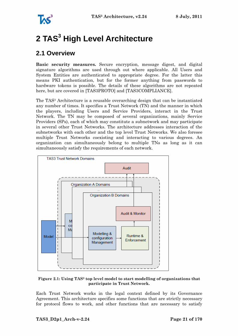
Figure 2.1: Using TAS3 top level model to start modelling of organizations that
participate in Trust Network.
Each Trust Network works in the legal context defined by its Governance
Agreement. This architecture specifies some functions that are strictly necessary
for protocol flows to work, and other functions that are necessary to satisfy
TAS3 Architecture, v2.24 8 July, 2011
TAS3_D2p1_Arch-v-2.24 Page 22 of 170
nonfunctional properties like "secure" and "trustworthy". To impose on the
players that the latter functions are implemented as well, we rely on legal
obligation that stems from the Governance Agreement, as well as certification
and audit programs, operated by the Trust Guarantor, to check that the legal
obligations are met initially and on continued basis.
TAS3 Trust Network Domain. Consider Fig-2.1 where a Trust Network (TN),
has chosen to adopt the overall TAS3 approach (which this and other documents
specify). This means that at the "Summit" there is a Trust Guarantor (TG) who
imposes on the TN the rules and model of operation. TG usually employs a
Security Officer to maintain and enforce the model. The individual organizations
may also have Security Officers responsible for their internal modelling and
auditing.
Model. The Trust Network Domain configuration will be expressed using
business process models, ontologies, and other models. The models are refined by
each organization in their Modelling and Configuration Management. There will
be several ontologies: architectural roles (e.g. Service Requester, Services
Provider, Identity Provider), security ontology, privacy and data protection
ontology and trust ontology. Payload services may define application specific
ontologies, but they are not in scope of the TAS3 architecture. Ontologies in TAS3
are further discussed in [TAS3D22UPONTO]. Some mandatory policies
emanating from EU will be modelled by the TAS3 project and incorporated to
every TAS3 Compliant Trust Network Model (Req. D1.2-6.15-MinPolicy).
Audit and Oversight. The Trust Guarantor in its oversight role will operate
compliance validation and audit functions. Each organization is expect to operate
similar functions locally as Audit & Monitor. The audit trail stays principally
within the organization, with Trust Guarantor only seeing summary records.
There are some network wide reporting and auditing requirements that
guarantee that other parties in the network, and especially users, have enough
transparency to operation of each party. This helps to transparently understand
that what has happened is legitimate, prevent fraud, and increase overall trust
in the network - a key business goal of TAS3.
Runtime and Enforcement concerns delivering the useful payload services,
with appropriate mechanisms to authenticate and identify Users and Systems, as
well as authorize the operations. Most of technical realization of TAS3 happens in
this area.
Cross Domain and Cross Context. TAS3 Architecture expressly enables
operation of services across domains. This can mean several organizations in one
Trust Network, or it could even mean interworking of several Trust Networks.
2.2 Basic Architectural Entities
In this section we drill down in the static component view of TAS3 architecture.
2.2.1 Major Components
Our architecture, see Fig-2.2 starts with User interacting with the Runtime &
Enforcement area. Since TAS3 architecture is user centric, all action starts
TAS3 Architecture, v2.24 8 July, 2011
TAS3_D2p1_Arch-v-2.24 Page 23 of 170
directly or indirectly with the User. Even offline, user not-present, processes are
seen to have been authorized by the User at some earlier time.
In the Runtime area, the User will interact with Payload services to obtain the
tangible business benefits that motivated him to use the services in the first
place. However, for the Payload to work in secure and trustworthy manner,
services from Infrastructure are needed. For the system as a whole to remain
secure and trusted, functions in the Audit and Monitor area are needed. They
will receive their input through Audit Event Bus of the Runtime environment.
Front End Service. User‟s principal point of interaction with the system is a
GUI, most commonly a Web GUI. This is a special kind of Service Provider that
instead of speaking Web Services, e.g. SOAP, offers a user friendly interface. The
Front End Services often call Web Services to perform all or parts of the
functionality they provide. It is possible that the GUI is generated to match a
Business Process Model.
Web Service. Machine accessible endpoint fromwhich data or action services
can be obtained. Machine to-machine nature of Web Services is in contrast with
the user-to-machine nature of the Front End Services.
The exact sequence of Web Services called will depend on a business process,
whether expressly modelled or implicit to the design of the web services. A
business process can encompass several Front Ends and the Web Services they
call.
Business Process Engine is an orchestrating entity that controls how Front
Ends and Service Providers, often Web Services, work together to achieve the
objectives of the business process. It is depicted here as being a separate service,
but "in process" realizations are equally likely. In such case the Business Process
Engine would be inside the Front End Service, perhaps as linked in library. The
role of the Business Process Engine is to serve payload business processes. There
is a similar Trust Network Process Manager entity that, while technically
similar, will exclusively execute business processes critical to the TN itself.
Dashboard is an important auditing and trust building feature of the TAS3
Architecture. It is a user interface, a Web GUI, that allows the User to
understand and audit how the system as a whole uses his Personally Identifiable
Information (PII). The Dashboard may also integrate a user interaction facility,
PII Consent Service, for asking users consent or other input that is required for a
business process to advance. A listing of the business processes in which the user
has participated, or is participating currently is provided as well as a listing of
Service Providers that hold data about the user or have handled his data. All
these features provide transparency. (Reqs. D1.2-2.11-Transp, D1.2-3.3-Dash,
D1.2-6.3-WhatHowWhyWho, and D1.2-12.15-Valid)
Identity Provider is the point where Users actually authenticate to the system.
After authentication, the IdP issues a Single Sign-On (SSO) token so that the
Front End Service can complete the login process. IdP has also an important role
in providing Id Mapper bootstrap token for the User.
TAS3 Architecture, v2.24 8 July, 2011
TAS3_D2p1_Arch-v-2.24 Page 24 of 170
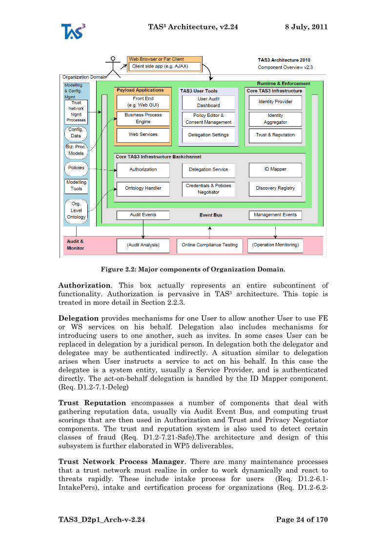
Figure 2.2: Major components of Organization Domain.
Authorization. This box actually represents an entire subcontinent of
functionality. Authorization is pervasive in TAS3 architecture. This topic is
treated in more detail in Section 2.2.3.
Delegation provides mechanisms for one User to allow another User to use FE
or WS services on his behalf. Delegation also includes mechanisms for
introducing users to one another, such as invites. In some cases User can be
replaced in delegation by a juridical person. In delegation both the delegator and
delegatee may be authenticated indirectly. A situation similar to delegation
arises when User instructs a service to act on his behalf. In this case the
delegatee is a system entity, usually a Service Provider, and is authenticated
directly. The act-on-behalf delegation is handled by the ID Mapper component.
(Req. D1.2-7.1-Deleg)
Trust Reputation encompasses a number of components that deal with
gathering reputation data, usually via Audit Event Bus, and computing trust
scorings that are then used in Authorization and Trust and Privacy Negotiator
components. The trust and reputation system is also used to detect certain
classes of fraud (Req. D1.2-7.21-Safe).The architecture and design of this
subsystem is further elaborated in WP5 deliverables.
Trust Network Process Manager. There are many maintenance processes
that a trust network must realize in order to work dynamically and react to
threats rapidly. These include intake process for users (Req. D1.2-6.1-
IntakePers), intake and certification process for organizations (Req. D1.2-6.2-
TAS3 Architecture, v2.24 8 July, 2011
TAS3_D2p1_Arch-v-2.24 Page 25 of 170
IntakeOrg), and user‟s access to his own data and audit trail (Req. D1.2-6.8-
UserAccess). The application specific business processes belong to Business
Process Engine, above.
Id Mapper (IM) is used to translate User‟s IM token (Id Mapper bootstrap
token) to a token usable for Web Service that is about to be called. Such
translation is necessary as the user is known by different pseudonym at different
services. This is used to express act-on-behalf relationships where Service
Provider (delegatee) wields a token provided by Id Mapper (or in some cases by
IdP). (Req. D1.2-2.3- BMs)
Registry Server contains knowledge about which end point serves which type of
service for any given User. Typically Registry is queried as a preparatory step of
web service call proper, but it could be queried in advance. (Req. D1.2-2.3-BMs)
Linking Service (aka Identity Aggregation) provides a facility for a user to
indicate how he wishes his attributes to be aggregated. This links together the
user's accounts at different IdPs, allowing the user to aggregate attributes from
multiple IdPs in a single session with a service provider.
Obligations Service (not depicted) provides a way to process many commonly
occurring obligations such as data retention limit. Obligation handlers register
with the obligations service. The service uses this information to advertise its
capabilities in satisfying obligations. This leads to trust and privacy negotiation.
Trust and Privacy Negotiator. This is the server side of the negotiation. Every
Service Requester, such as Front End Service, must implement Trust and
Privacy Negotiator Client Agent (not shown in the figure). The Client Agent can
be implemented as a web service and the Service Requester merely performs a
web service call to the agent, which then engages in trust and privacy negotiation
protocol with the web service provider‟s Trustand Privacy Negotiator. Trust and
Privacy Negotiator functions in many ways similar to the registry, but instead of
returning all end points, only some are returned based on trust scoring. The
Trust and Privacy Negotiator relies on the user's Linking Service in order to
access all the distributed attributes of the user.
Modelling and Configuration Management is connected to the TN level
modelling. It also contains local ontologies, such as trust and privacy ontologies,
and local Models and Configurations. All of these may be edited using Modelling
Tools. From Models and Ontologies, configuration items can be generated and
pushed to the Runtime using Management Event Bus, as governed by the Trust
Network Process Manager.
An essential element of this architecture are community-managed ontologies,
which allow for unambiguous, but flexible, meaning agreement at all times. We
can envisage several roles for these ontologies. It first provides a machine-
understandable documentation of the architecture as well as a formal vehicle to
exchange explicit semantic agreements (i.e. commitments) between partners and,
eventually, systems. Thus, these commitments will enable the enforcement of
(organisational and/or legal) policies within the TAS3 architecture. For example
in Role-Based Access Control (RBAC), the role of a subject in one organisation
may be different to that in another organisation where access is being granted.
TAS3 Architecture, v2.24 8 July, 2011
TAS3_D2p1_Arch-v-2.24 Page 26 of 170
The ontology will allow the roles to be mapped to each other so as to be able to
enforce authorization based on the privileges assigned to that role.
Secondly, the ontologies will assure that relevant parts of the system commit to
the same interpretation of possibly ambiguous elements to allow for meaning
alignment, certification and early conflict discovery. These ontologies will enable
improved understanding; common methods of expressing terms enabling people
and organisations to better trust each other in these application environments.
TAS3 will integrate these architecture elements into a fully embedded trust
framework to automate business processes managing personal information,
which will result in considerable societal benefits. The Semantic Interoperability
Engine (Fig-3.15) will facilitate the interoperability across different contexts (e.g.
across different organizations). Ontologies are further discussed in
[TAS3D22UPONTO].
2.2.2 Enforcement Points on Web Service Call Path
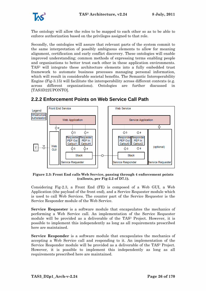
Figure 2.3: Front End calls Web Service, passing through 4 enforcement points
(callouts, per Fig-2.2 of D7.1).
Considering Fig-2.3, a Front End (FE) is composed of a Web GUI, a Web
Application (the payload of the front end), and a Service Requester module which
is used to call Web Services. The counter part of the Service Requester is the
Service Responder module of the Web Service.
Service Requester is a software module that encapsulates the mechanics of
performing a Web Service call. An implementation of the Service Requester
module will be provided as a deliverable of the TAS3 Project. However, it is
possible to implement this independently as long as all requirements prescribed
here are maintained.
Service Responder is a software module that encapsulates the mechanics of
accepting a Web Service call and responding to it. An implementation of the
Service Responder module will be provided as a deliverable of the TAS3 Project.
However, it is possible to implement this independently as long as all
requirements prescribed here are maintained.
TAS3 Architecture, v2.24 8 July, 2011
TAS3_D2p1_Arch-v-2.24 Page 27 of 170
PEPOut-Rq. Service Requester Outbound Policy Enforcement Point (PEP). This
PEP is used to check whether data can be submitted to the Web Service, or
whether the call can be made at all. The PEP will contact organization‟s Master
PDP to obtain a policy decision.
PEPIn-Rs. Service Responder Inbound PEP. This PEP is used to check whether
data or call can be accepted by the Web Service. It also records what obligations
and policies does the Service Requester pledge to honour. These will be checked
later by PEPOut-Rs.
PEPOut-Rs. Service Responder Outbound PEP. This PEP is used to filter the
data on responder side and to perform any responder obligations attached to the
data. In particular, the pledges recorded by PEPIn-Rs are checked against
obligations and sticky policies attached to the data and if found unsatisfiable
either data is filtered out or operation aborted. If no data can be returned, an
error response will still be returned.
PEPIn-Rq. Service Requester Inbound PEP. This PEP is used to extract and
perform or record for later performance any obligations attached to the response.
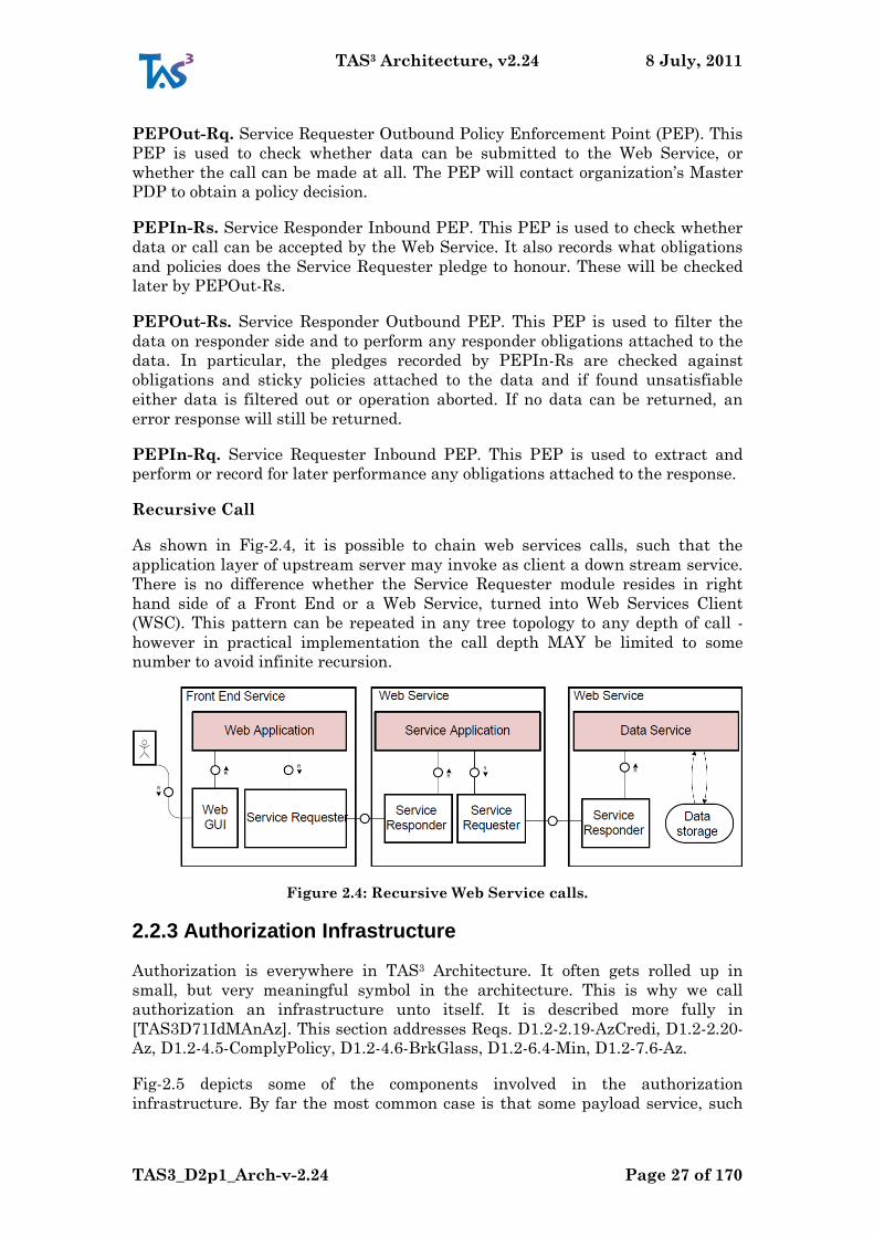
Recursive Call
As shown in Fig-2.4, it is possible to chain web services calls, such that the
application layer of upstream server may invoke as client a down stream service.
There is no difference whether the Service Requester module resides in right
hand side of a Front End or a Web Service, turned into Web Services Client
(WSC). This pattern can be repeated in any tree topology to any depth of call -
however in practical implementation the call depth MAY be limited to some
number to avoid infinite recursion.
Figure 2.4: Recursive Web Service calls.
2.2.3 Authorization Infrastructure
Authorization is everywhere in TAS3 Architecture. It often gets rolled up in
small, but very meaningful symbol in the architecture. This is why we call
authorization an infrastructure unto itself. It is described more fully in
[TAS3D71IdMAnAz]. This section addresses Reqs. D1.2-2.19-AzCredi, D1.2-2.20-
Az, D1.2-4.5-ComplyPolicy, D1.2-4.6-BrkGlass, D1.2-6.4-Min, D1.2-7.6-Az.
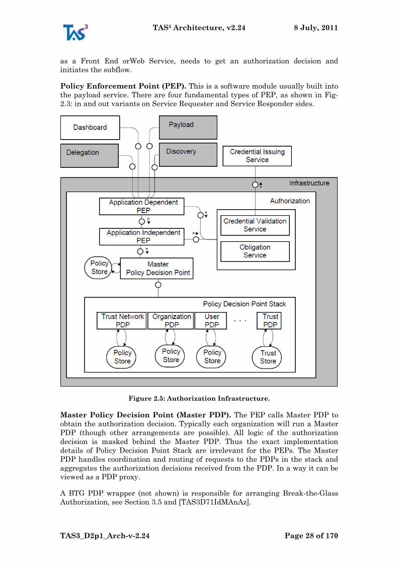
Fig-2.5 depicts some of the components involved in the authorization
infrastructure. By far the most common case is that some payload service, such
TAS3 Architecture, v2.24 8 July, 2011
TAS3_D2p1_Arch-v-2.24 Page 28 of 170
as a Front End orWeb Service, needs to get an authorization decision and
initiates the subflow.
Policy Enforcement Point (PEP). This is a software module usually built into
the payload service. There are four fundamental types of PEP, as shown in Fig-
2.3: in and out variants on Service Requester and Service Responder sides.
Figure 2.5: Authorization Infrastructure.
Master Policy Decision Point (Master PDP). The PEP calls Master PDP to
obtain the authorization decision. Typically each organization will run a Master
PDP (though other arrangements are possible). All logic of the authorization
decision is masked behind the Master PDP. Thus the exact implementation
details of Policy Decision Point Stack are irrelevant for the PEPs. The Master
PDP handles coordination and routing of requests to the PDPs in the stack and
aggregates the authorization decisions received from the PDP. In a way it can be
viewed as a PDP proxy.
A BTG PDP wrapper (not shown) is responsible for arranging Break-the-Glass
Authorization, see Section 3.5 and [TAS3D71IdMAnAz].
TAS3 Architecture, v2.24 8 July, 2011
TAS3_D2p1_Arch-v-2.24 Page 29 of 170
Trust Network PDP processes the policies that are coordinated at the Trust
Network level, including the Legal Policies.. It can be implemented as a central
Trust Network-wide service, or it can be distributed so that there is an instance
of a Trust Network PDP at each SP, but the policies are centrally coordinated
and pushed to the instances, perhaps using the Trust Network Process Manager.
Organization PDP processes the policies that an organization maintains. These
policies may be over and above the Trust Network-wide policies, since every
organisation has to abide by the rules of the trust network and the law. The
distinction from Trust Network PDP is maintained because the authority for
deciding the policies is different.
User PDP function may implement User specific policies, i.e. policies set by the
User. This could also involve evaluation of Sticky Policies. In practise, the User
PDP may be implemented inside the Master PDP process.
Trust PDP is an interface to the Trust and Reputation Management subsystem
which allows the Master PDP to query whether a contemplated action is
acceptable from Trust and Reputation perspective. Such query has the advantage
that the Trust and Reputation system does not need to disclose to the Master
PDP the exact parameters that lead to this decision. The deliverables of WP5
elaborates on the structure and design of Trust PDP and Trust and Reputation
System at large.
Credential Validation Service (CVS) is a subsystem that helps PEP to
establish the validity of the credentials and attributes it is about to pass to the
Master PDP. Typically these are received from front channel interaction or from
an earlier web service call. The validation involves checking that they are
properly signed and that trust to the signing authority exists. Some namespace
and syntax checks may be performed as well. The CVS may call on other
components of the architecture to perform its functions.
Policy Information Point (PIP) is used to fetch additional attributes that may
be needed for policy evaluation. The PIP may call, in a recursive manner, on
other components of the architecture to perform its functions. Special care needs
to be taken in preventing infinite recursion and to ensure that the policies in the
recursive levels allow the information to be returned for purpose of policy
evaluation. The PIP may be called either from the PEP or from the Master PDP.
The exact choice is a question of optimization. The set of attributes needed for
policy evaluation is determined by the SP, is shown to the user, and the user then
chooses which of his attributes he wishes to submit in order to fulfil the SP's
requirements. If further attributes are needed later on in a business process, the
SP can subsequently reveal its requirements to the user, allowing him to choose
some more.
2.3 Major Flows: Front Channel and Back Channel
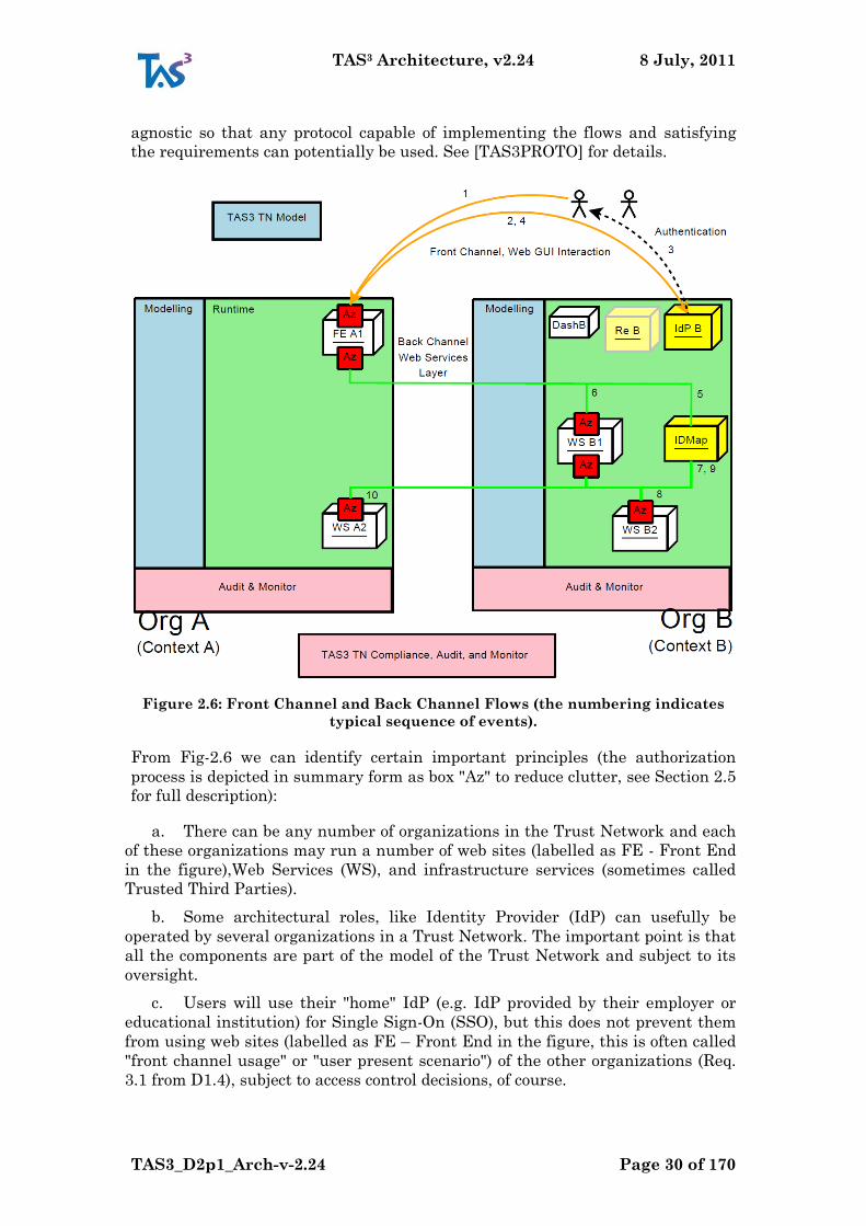
Implementable Flows. The flows we present are designed to be implementable
with existing state-of-the-art protocols and software stacks. In particular
standards based approaches are used for authentication, delegation, token
passing, identity mapping, service discovery, authorization, and web services
calls. Despite this, the present high level architecture is designed to be standards
TAS3 Architecture, v2.24 8 July, 2011
TAS3_D2p1_Arch-v-2.24 Page 30 of 170
agnostic so that any protocol capable of implementing the flows and satisfying
the requirements can potentially be used. See [TAS3PROTO] for details.
Figure 2.6: Front Channel and Back Channel Flows (the numbering indicates
typical sequence of events).
From Fig-2.6 we can identify certain important principles (the authorization
process is depicted in summary form as box "Az" to reduce clutter, see Section 2.5
for full description):
a. There can be any number of organizations in the Trust Network and each
of these organizations may run a number of web sites (labelled as FE - Front End
in the figure),Web Services (WS), and infrastructure services (sometimes called
Trusted Third Parties).
b. Some architectural roles, like Identity Provider (IdP) can usefully be
operated by several organizations in a Trust Network. The important point is that
all the components are part of the model of the Trust Network and subject to its
oversight.
c. Users will use their "home" IdP (e.g. IdP provided by their employer or
educational institution) for Single Sign-On (SSO), but this does not prevent them
from using web sites (labelled as FE – Front End in the figure, this is often called
"front channel usage" or "user present scenario") of the other organizations (Req.
3.1 from D1.4), subject to access control decisions, of course.
TAS3 Architecture, v2.24 8 July, 2011
TAS3_D2p1_Arch-v-2.24 Page 31 of 170
d. The usage of a web site often triggers Web Services calls on the back
channel. Finding out exactly which servers to contact and what credentials to use
is handled by User‟s Discovery and ID Mapper services ("IDMap" in the Fig-2.6)
(Req. 8.1 from D1.4). Usually the Discovery Service is rather tightly coupled to the
IdP.
e. It is feasible and common that Web Services can be called across
organizational boundaries. Discovery and trust negotiation within the model set
by the Trust Network will enable this to be possible.
f. When auditable events happen, in addition to local logging, a summary of
the data is sent to the Audit Event Bus. Subscribed to the audit summaries are: (i)
User‟s Dashboard service so that the User can always see what happened and is
in control; and (ii) the organizational and Trust Network audit layers. See blue
arrows in Fig-2.7.
g. Although all organizations can potentially have all components, the fact
that cross organization web site usage and service calls are explicitly provided for,
makes it possible for an organization to outsource some, or all, of these services.
Or the other way around, some organization may specialize in only providing the
infrastructure services. This approach is often desirable to manage conflicts of
interest.
This is a very flexible architecture and allows the responsibility for provision of
services and infrastructure to be sliced and diced in many ways, according to
business needs rather than technical limitations.
2.4 Overview of Data Models
2.4.1 Federation Relations for Core Security Architecture
N.B. On first reading it may be advisable to skip this section as
understanding of flows shown in Fig-3.4 will be useful.
One of the fundamental principles of the Core Security Architecture is use of
federations, which may support persistent or transient identifiers. When
correctly used, these types of identifiers allow privacy to be preserved by not
leaking any correlation handles. This section addresses Reqs. D1.2-2.14-Priv,
D1.2-7.8-NoColl, and D1.2-7.16-Nym.
In order to implement persistent and pseudonymous federations, the IdP and IM
have to keep state. In general, the federation table for an IdP that supports
persistent pseudonymous identifiers will hold mappings as follows:
User at IdP1 --> [ encrypted pseudonym of user at SPA,
encrypted pseudonym of user at SPB,
...
encrypted pseudonym of user at SPN ]
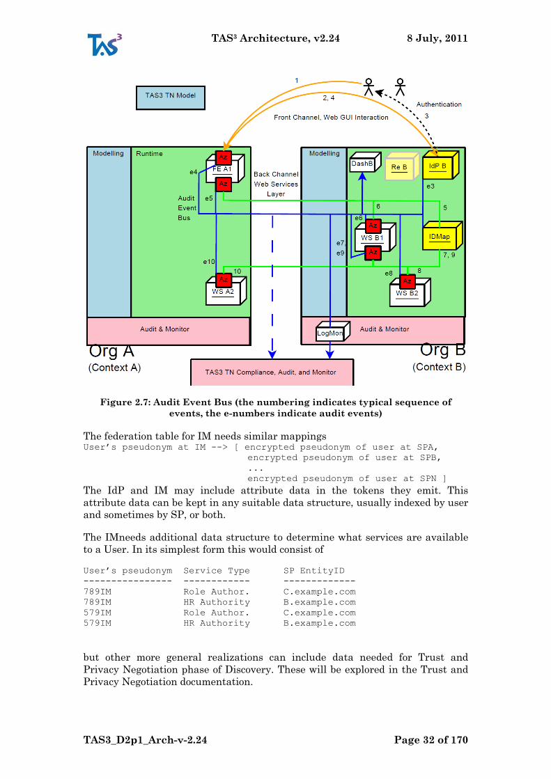
TAS3 Architecture, v2.24 8 July, 2011
TAS3_D2p1_Arch-v-2.24 Page 32 of 170
Figure 2.7: Audit Event Bus (the numbering indicates typical sequence of
events, the e-numbers indicate audit events)
The federation table for IM needs similar mappings User’s pseudonym at IM --> [ encrypted pseudonym of user at SPA,
encrypted pseudonym of user at SPB,
...
encrypted pseudonym of user at SPN ]
The IdP and IM may include attribute data in the tokens they emit. This
attribute data can be kept in any suitable data structure, usually indexed by user
and sometimes by SP, or both.
The IMneeds additional data structure to determine what services are available
to a User. In its simplest form this would consist of
User’s pseudonym Service Type SP EntityID
---------------- ------------ -------------
789IM Role Author. C.example.com
789IM HR Authority B.example.com
579IM Role Author. C.example.com
579IM HR Authority B.example.com
but other more general realizations can include data needed for Trust and
Privacy Negotiation phase of Discovery. These will be explored in the Trust and
Privacy Negotiation documentation.
TAS3 Architecture, v2.24 8 July, 2011
TAS3_D2p1_Arch-v-2.24 Page 33 of 170
An IdP may have a limited form of this table to cover the necessity of emitting IM
bootstrap token during SSO.
All parties - IdP, IM, and SP (FE or WS) - need to maintain some metadata about
each other. Such metadata may include SOAP endpoints, protocol profiles and
bindings to use, etc. These will generally be specified in protocol specific
documents as adopted in [TAS3PROTO], but for general idea the reader may
want to see [SAML2meta].
There is also the requirement for a user to be able to aggregate his attributes
together in order to gain access to web services. This requires an attribute
linking service, which is fully described in [TAS3D71IdMAnAz].
2.4.2 Personal Data and Applications
A SP can use whatever data model it desires (TAS3 Architecture is not
prescriptive in this regard) in storing the data about the Users as long as itmeets
security and privacy guarantees detailed in [TAS3COMPLIANCE]. The
persistent pseudonym of the User suggests an obvious database key, but other
arrangements are possible.
TAS3 Architecture foresees aggregation of data from multiple sources with its
support for policy aggregation. One common realization of this approach is to
consider a document as a collection of external data streams, please see
[TAS3D81RepoSW]. This approach will be supported by some of the TAS3
software deliverables (e.g. output of WP8).
2.4.3 Using Sticky Policies to Protect Data
Sticky policies can be attached to most data items and are especially foreseen to
protect personal data and control its dissemination. The purpose for which the
data was collected is expressed in the sticky policy. This section addresses Reqs.
D1.2-2.21-DataProtLaw, D1.2-6.5-Purpose, and D1.2-4.1-EnfUCPol. Data origin
and collection method can also be indicated using sticky policies (Req. D1.2-6.8-
UserAccess).
Sticky policies are evaluated as part of the authorization process. In an untrusted
network they should ideally be bound to the data they protect by encryption and
signing that would prevent disclosure of the data unless the policy evaluates to
permit. However, this is a difficult research problem to address, and untrusted
networks are outside the scope of TAS3. In a TAS3 trust network the SPs are
deemed to be trustworthy to the extent that they will obey sticky policies when
they receive them. Therefore policies are bound to the data they protect by digital
signing, but are not encrypted. If an SP receives data which the sticky policy says
it should not have, then its inbound PEP will refuse to accept the data.
2.4.4 Using Encryption to Protect Data
All protocol flows use encryption. Usually this will be in form of connection level
encryption, but in certain cases application layer public key encryption will be
used to protect tokens or attribute data while it is in transit through an
intermediary (e.g. IM token when passing through FE).

TAS3 Architecture, v2.24 8 July, 2011
TAS3_D2p1_Arch-v-2.24 Page 34 of 170
2.5 Authorization Process
This section partially addresses Req. D1.2-6.12-Sec.
Fig-2.8 depicts refined structure of the Authorization Process.
1. Central notion is that theWeb Service PEP ("=" above theWS1 in the
figure) calls aMaster PDP, which then gathers the authorization from whatever
sources it can.
2. Some of the data used for the decision may have come from the Web
Service itself (it may have been inline in the Request, or the Web Service may
know it otherwise), but if additional data is needed, the Master PDP will contact
Policy Information Points (PIPs) as appropriate. (Processing of PIP request itself
is an instance of Enforcement and Authorization Process, thus giving all of this
rather recursive flavour.)
3. Trust and/or Reputation may be a factor in the authorization decision.
This is handled by modelling the Trust and Reputation Provider (labelled as just
"Trust" in the figure) as just another PDP that Master PDP calls. The feedback
and inputs to the Reputation computation are not shown here.
4. Business-process-management systems need to enforce history-based
authorization constraints such as separation of duty (SoD) or binding of duty
(BoD). These constraints are enforced by a component of the secure BPMS
(Section 4.5), while the part of authorization for tasks in business processes that
does not depend on history information is delegated to the Master PDP.
Figure 2.8: Authorization Process
TAS3 Architecture, v2.24 8 July, 2011
TAS3_D2p1_Arch-v-2.24 Page 35 of 170
5. Given that sticky policies may potentially be written in different policy
languages, the Master PDP will detect the language and call appropriate PDP to
have the policy interpreted.
2.6 Enforcement Process
This section partially addresses Req. D1.2-6.12-Sec.
When a Web Services call is made, there are several control points in the flow, as
shown in Fig-2.10.
1. Request is first controlled by a Requester, i.e. on Client side, for being an
acceptable request. For example, if the request is about to submit data to the
Service Provider, there may be several policies about what can be submitted.
2. The controls can have multiple facets, i.e. the application programmer
may have programmed in some implicit policies, the organization that operates
the application may have some policies of its own, the Trust Network is certain to
have policies, and finally the User himself may have set up some policies (which
may involve attaching sticky policies to the data). Conceptually these are
addressed by a PEP contactingMaster PDP which may contact stake holder
specific PDPs. If different stake holder policies result in a conflict, the Master
PDP implements a Conflict Resolution Policy to arrive at a decision. An
alternative approach is to use Identity Governance Framework [IGF] CARML
declaration to set up the PEP, or some part of it.
3. After request has been authorized to send, the Service Provider will
examine if the request is acceptable using a similar stack of PEPs. Examination
on Service Provider side is the "traditional" enforcement point that most people
think about. It filters out inappropriate data requests as well as illicit writes.
4. When preparing to ship response, the Service Provider uses a PEP and
Master PDP to further filter the response. Although the request side PEP should
have made sure that only legitimate requests can ever
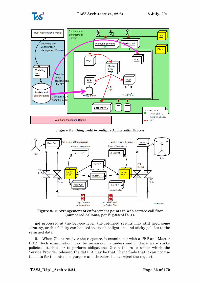
TAS3 Architecture, v2.24 8 July, 2011
TAS3_D2p1_Arch-v-2.24 Page 36 of 170
Figure 2.9: Using model to configure Authorization Process
Figure 2.10: Arrangement of enforcement points in web service call flow
(numbered callouts, per Fig-2.2 of D7.1).
get processed at the Service level, the returned results may still need some
scrutiny, or this facility can be used to attach obligations and sticky policies to the
returned data.
5. When Client receives the response, it examines it with a PEP and Master
PDP. Such examination may be necessary to understand if there were sticky
policies attached, or to perform obligations. Given the rules under which the
Service Provider released the data, it may be that Client finds that it can not use
the data for the intended purpose and therefore has to reject the request.
TAS3 Architecture, v2.24 8 July, 2011
TAS3_D2p1_Arch-v-2.24 Page 37 of 170
6. Not depicted, but logically part of the Client Request sending side are also
a. discovery
b. trust negotiation and establishment
c. signing of request
7. Not depicted, but logically part of the Service Provider Request processing
are also
a. trust negotiation and establishment
b. validation of message structure
c. signature validation
8. Not depicted, but logically part of the Service Provider Response sending
side are also
a. signing of response
9. Not depicted, but logically part of the Client Response reception side are
also
a. validation of message structure
b. validation of correlation
c. signature validation
d. processing obligations
2.7 Configuration Process
TAS3 is pervasively model driven. Fig-2.11 shows how a business process model
can drive auditing processes, or even influence the Dashboard user interface so
that Users can visualize the processes.
Fig-2.9, shows how models are used to configure policies for the PDPs. It also
shows an alternate approach where PEP itself can be directly configured, e.g.
using Identity Governance Framework [IGF] CARML and/or AAPML.
From the model the Trust Guarantor is able to derive
Basic trust configuration, i.e. who belongs to the network
a white list of members
metadata to configure trust in the members
Configurations to be pushed to operational elements of the network so that
they will consistently enforce the process and trust model and the security
model of the Trust Network.
Operations Monitoring setup, e.g. if alerts are coming from some node, what
Networks Operations Centre (NOC) process should they enter, where
should they be disseminated, who should see them, and who is responsible
for response
On-line compliance testing configuration. This will drive a robot, spider if
you like, that will comb through the Trust Network on a regular basis to
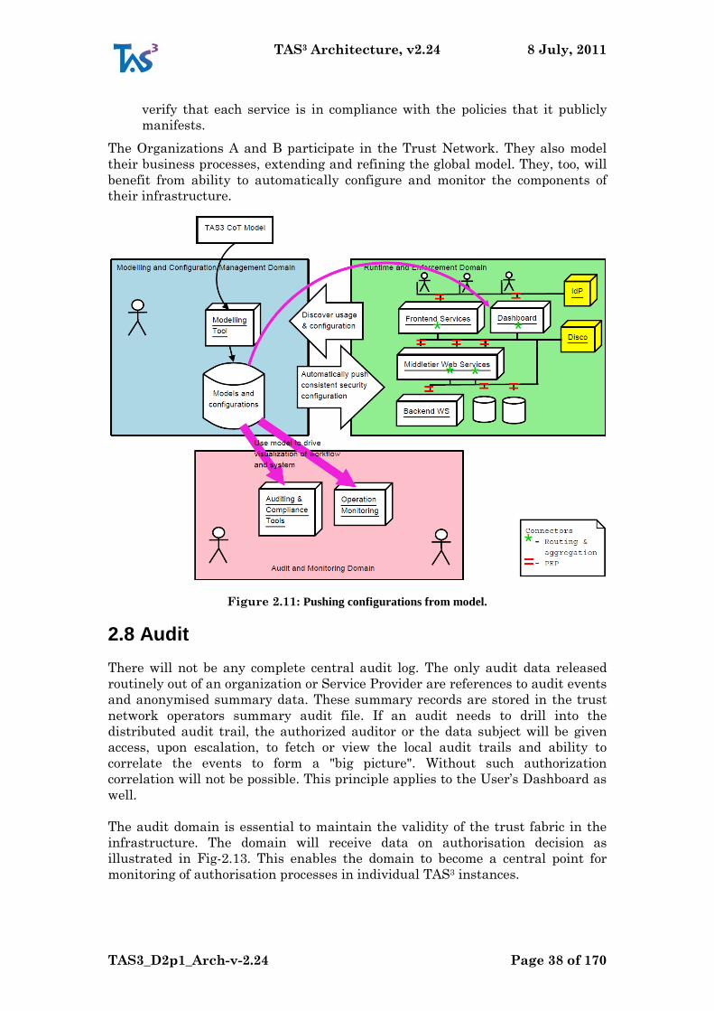
TAS3 Architecture, v2.24 8 July, 2011
TAS3_D2p1_Arch-v-2.24 Page 38 of 170
verify that each service is in compliance with the policies that it publicly
manifests.
The Organizations A and B participate in the Trust Network. They also model
their business processes, extending and refining the global model. They, too, will
benefit from ability to automatically configure and monitor the components of
their infrastructure.
Figure 2.11: Pushing configurations from model.
2.8 Audit
There will not be any complete central audit log. The only audit data released
routinely out of an organization or Service Provider are references to audit events
and anonymised summary data. These summary records are stored in the trust
network operators summary audit file. If an audit needs to drill into the
distributed audit trail, the authorized auditor or the data subject will be given
access, upon escalation, to fetch or view the local audit trails and ability to
correlate the events to form a "big picture". Without such authorization
correlation will not be possible. This principle applies to the User‟s Dashboard as
well.
The audit domain is essential to maintain the validity of the trust fabric in the
infrastructure. The domain will receive data on authorisation decision as
illustrated in Fig-2.13. This enables the domain to become a central point for
monitoring of authorisation processes in individual TAS3 instances.
TAS3 Architecture, v2.24 8 July, 2011
TAS3_D2p1_Arch-v-2.24 Page 39 of 170
The services in the auditing and monitoring domain will receive other forms of
data linked to trust from the TAS3 infrastructure. This data will also include
information on service invocations and workflow execution. The data from the
results of these events will be stored in two main sets of services in the auditing
and monitoring domain, there are auditing and compliance tools and operation
monitoring tools.
It is important to note that these two sets of information will be handled quite
separately. The operation monitoring tools will be operated by the applications
code and will be application specific, whereas the auditing and monitoring will be
operated by the TAS3 security layer and will be application independent.
The data collected from the monitoring in the audits can be then used by
elements in the infrastructure such as the Dashboard. This will enable users to
look at both how their data has been used in the infrastructure and also if any
services have failed in this execution. In cases of failure or rogue behaviour the
negative feedback from this can be fed to the Trust and Reputation service.
It is possible to store audit events referring to a particular business-process
instance in the BPMS and present them to end users visually using the graphical
representation of the process created in the modelling phase.
Some Audit Principles:
Nobody should be able to tamper with the audit trail without detection.
This includes insertion or removal of audit records, altering of audit records
and deletion of entire audit files.
Nobody should be able to put together the entire audit trail without proper
authorization
When answering a user audit request, the initial answer may have coarse
granularity, such as organizations that have accessed. Only upon more
thorough, authorized, investigation more detail, such as employees that
have accessed would be revealed.
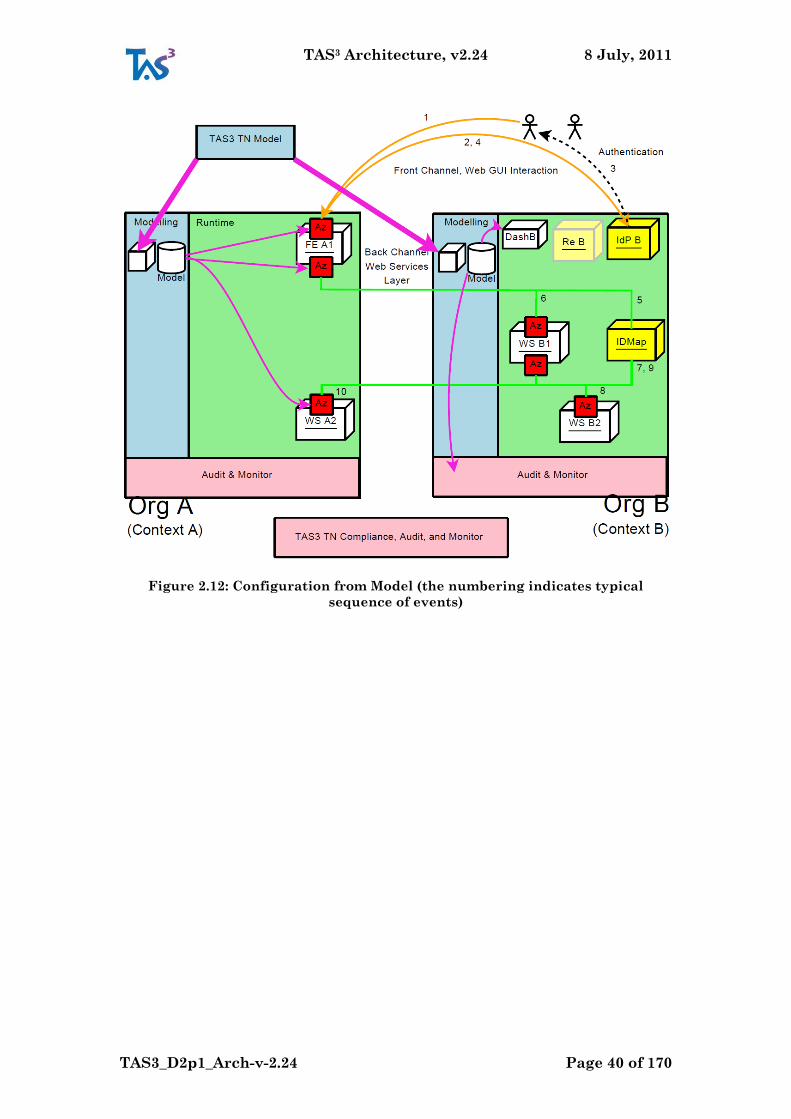
TAS3 Architecture, v2.24 8 July, 2011
TAS3_D2p1_Arch-v-2.24 Page 40 of 170
Figure 2.12: Configuration from Model (the numbering indicates typical
sequence of events)
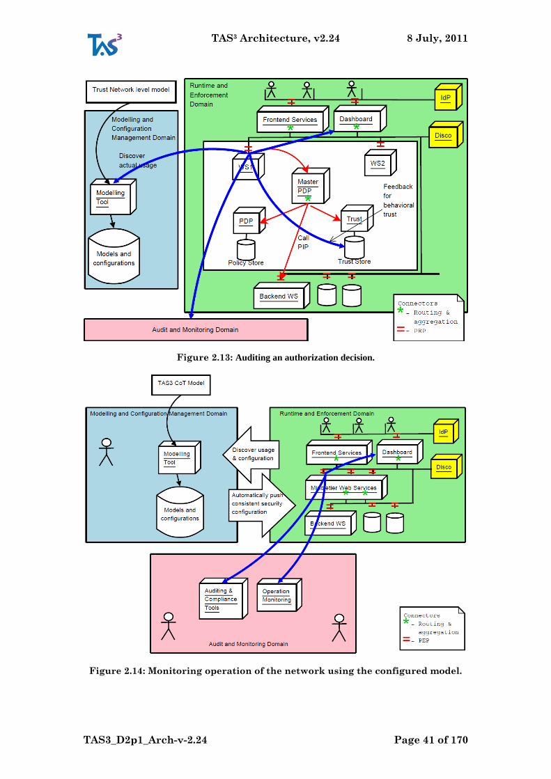
TAS3 Architecture, v2.24 8 July, 2011
TAS3_D2p1_Arch-v-2.24 Page 41 of 170
Figure 2.13: Auditing an authorization decision.
Figure 2.14: Monitoring operation of the network using the configured model.
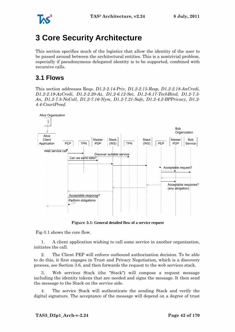
TAS3 Architecture, v2.24 8 July, 2011
TAS3_D2p1_Arch-v-2.24 Page 42 of 170
3 Core Security Architecture
This section specifies much of the logistics that allow the identity of the user to
be passed around between the architectural entities. This is a nontrivial problem,
especially if pseudonymous delegated identity is to be supported, combined with
recursive calls.
3.1 Flows
This section addresses Reqs. D1.2-2.14-Priv, D1.2-2.15-Resp, D1.2-2.18-AnCredi,
D1.2-2.19-AzCredi, D1.2-2.20-Az, D1.2-6.12-Sec, D1.2-6.17-TechBind, D1.2-7.3-
An, D1.2-7.8-NoColl, D1.2-7.16-Nym, D1.2-7.21-Safe, D1.2-4.2-BPPrivacy, D1.2-
4.4-CourtProof.
Figure 3.1: General detailed flow of a service request
Fig-3.1 shows the core flow.
1. A client application wishing to call some service in another organization,
initiates the call.
2. The Client PEP will enforce outbound authorization decision. To be able
to do this, it first engages in Trust and Privacy Negotiation, which is a discovery
process, see Section 3.6, and then forwards the request to the web services stack.
3. Web services Stack (the "Stack") will compose a request message
including the identity tokens that are needed and signs the message. It then send
the message to the Stack on the service side.
4. The service Stack will authenticate the sending Stack and verify the
digital signature. The acceptance of the message will depend on a degree of trust
TAS3 Architecture, v2.24 8 July, 2011
TAS3_D2p1_Arch-v-2.24 Page 43 of 170
on the signing party, which was established during the Trust and Privacy
Negotiation.
5. The service inbound PEP will consult the Master PDP to determine if the
service request should be allowed to go forward.
6. The inbound PEP will pass the request to the payload service, which will
reply.
7. The outbound PEP of the Service will validate that the data can be
released and attach obligations.
8. The Stack at the service correlates the response to the request, signs it
and sends the response.
9. The client Stack receives the response, checks its correlation with the
request, and verifies the signatures in the response.
10. The client inbound PEP checks that the response is authorized and
complies with the obligations that were received.
11. The payload message is passed to the Client Application.
3.2 Tokens, Access Credentials
A central problem in multi-tier (or recursive) web services architecture is
propagation of identity, or identity handle, to all tiers, while preserving privacy
separation (resilience to collusion) between the parties.
The identity handle can allow, if chosen, linking of user‟s consequtive visits
together so that the service can collect data about the user for future reference
and provision of the service. In this case the user is persistently identified, but to
preserve privacy, the user will be identified differently towards different parties.
This prevents collusion by the parties.
Sometimes it is undesirable for the service to link relate visits of the user
together. In this case user is identified transiently, i.e. by one-time
pseudorandom identifier (Req. D1.2-7.18-Seq). Within one overall session, user
can be identified persistently towards one service while at the same time
transiently towards another service.
In general access credentials come in the form of tokens that are digitally signed
by a system entity, usually a Trusted Third Party, such as an IdP or ID Mapper
service. Reader can use SAML assertion [SAML2core] as a mental model, though
this is not the only possible technology choice.
This section addresses Reqs. D1.2-7.4-MultiCred and D1.2-7.18-Seq.
3.2.1 Attribute Pull Model
Target model. Fully capable. All use cases work and best privacy
properties. This model has been extensively studied in Liberty
Alliance standardization work (n.b. this does not limit its
applicability to Liberty ID-WSF - same concept can be
implemented using other web service specifications, albeit with
lesser maturity). This model addresses minimal disclosure
TAS3 Architecture, v2.24 8 July, 2011
TAS3_D2p1_Arch-v-2.24 Page 44 of 170
particularly well, thus contributing to satisfying Reqs. D1.2-2.14-
Priv D1.2-2.21-DataProtLaw, D1.2-6.4-Min, D1.2-7.5-Min, D1.2-
7.12-CredStepUp, D1.2-6.86-Min, D1.2-9.1-SecData.
The Pull Model consists of front channel SSO layer and back channel web
services layer. The "pull" refers to the strategy where attributes are requested
from their authorative sources only on as needed basis. This has several benefits:
1. Minimal disclosure - only needed attributes are generated and shipped
2. Direct relationship with Attribute Authority. No intermediaries which could
gain undue knowledge. This may also reduce crypto overhead as protection
against the in-transit man-in-the-middle is not needed.
3. Intermediaries do not need to guess what attributes might be needed down the
web services call chain or in a particular variant of a business process.
4. Fully dynamic and recursive operation that supports several Business Process
Topologies. At least all forms of sequence (horizontal or vertical) and trees are
supported. Support for a DAG would seem feasible. Other topologies need further
study.
Use Case User U authenticates with a service provider A through her IdP1. A
needs to invoke further service providers with reference to U.
Problem Definition If the trusted architecture uses a unique, even if random
and transitory, userID throughout then such a userID would allow
multiple parties to collude and correlate all data belonging to U.
Objective The system must avoid producing correlation handles in the process.
Solution Idea Each service provider knows the user by a different
randomuserID, a persistent pseudonym. And these pseudonyms are held
by a mapping service. When one service provider wants to pass on the
request to another service provider, it can ask mapping service for a
lookup of the pseudonymous userID in the target service provider.
Given that the user‟s pseudonym at the other provider is encrypted in transit,
this solution avoids any service providers sharing correlation handles in the
clear. (N.B. In this system the two service providers invoking each other‟s
services are still able to directly collude by comparing the encrypted token that
they have exchanged with each other, see Threat T107-LogTokLeak. The solution
is to not log the tokens, see CR53-DontLogTok.) However, this would violate the
previously stated audit principles. Furthermore, one service provider can obtain
encrypted tokens for every other service provider from the mapping service, and
pass these on, thereby being able to collude to correlate the user's account at each
SP. We therefore conclude that there is no technical solution to the problem of
collusion, and instead, the requirement to not collude to correlate a user's
identity must be specified as part of the legal agreement of the trust network.
3.2.1.1 Front Channel
Trivial situation is when the payload application consists entirely of a web gui or
web site, without any web services call. Never-the-less, this is a very important
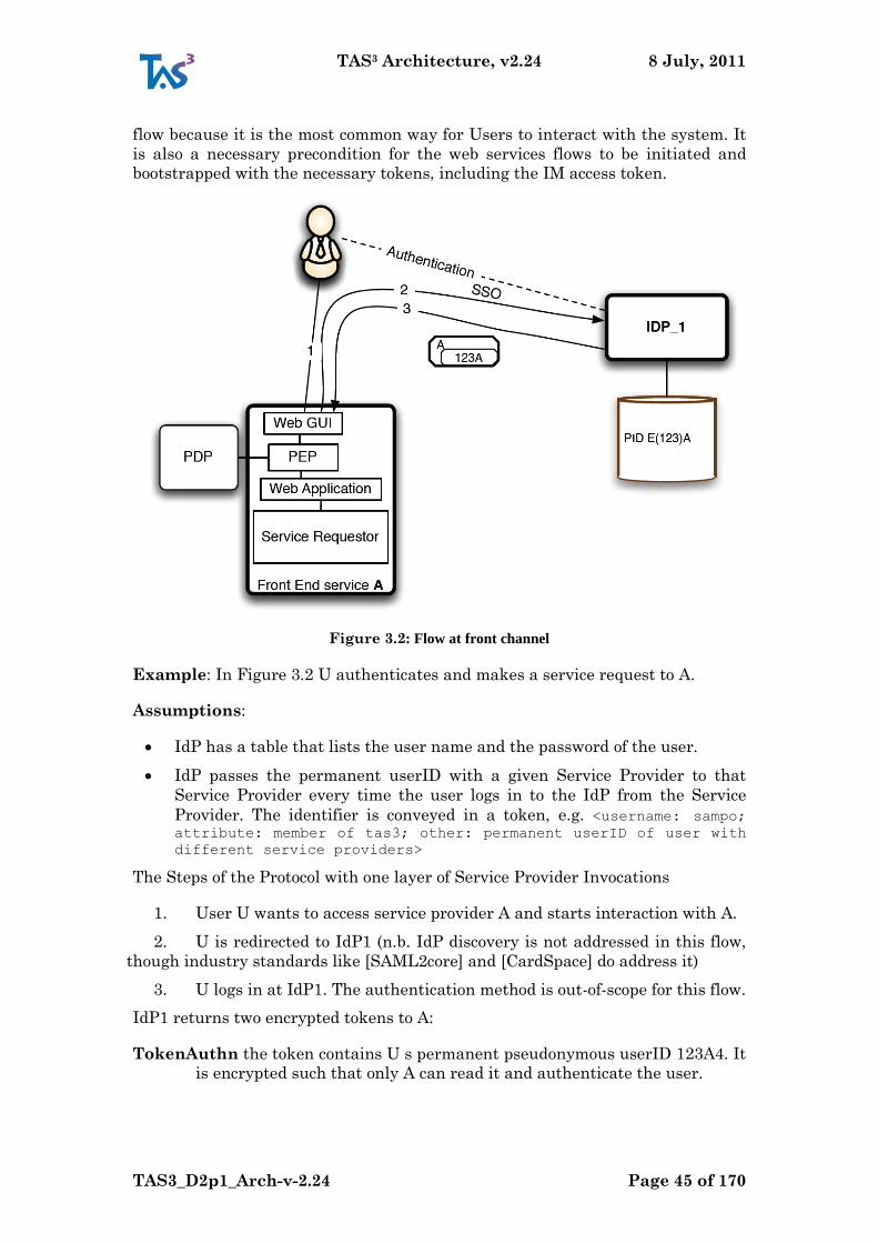
TAS3 Architecture, v2.24 8 July, 2011
TAS3_D2p1_Arch-v-2.24 Page 45 of 170
flow because it is the most common way for Users to interact with the system. It
is also a necessary precondition for the web services flows to be initiated and
bootstrapped with the necessary tokens, including the IM access token.
Figure 3.2: Flow at front channel
Example: In Figure 3.2 U authenticates and makes a service request to A.
Assumptions:
IdP has a table that lists the user name and the password of the user.
IdP passes the permanent userID with a given Service Provider to that
Service Provider every time the user logs in to the IdP from the Service
Provider. The identifier is conveyed in a token, e.g. <username: sampo; attribute: member of tas3; other: permanent userID of user with
different service providers>
The Steps of the Protocol with one layer of Service Provider Invocations
1. User U wants to access service provider A and starts interaction with A.
2. U is redirected to IdP1 (n.b. IdP discovery is not addressed in this flow,
though industry standards like [SAML2core] and [CardSpace] do address it)
3. U logs in at IdP1. The authentication method is out-of-scope for this flow.
IdP1 returns two encrypted tokens to A:
TokenAuthn the token contains U s permanent pseudonymous userID 123A4. It
is encrypted such that only A can read it and authenticate the user.
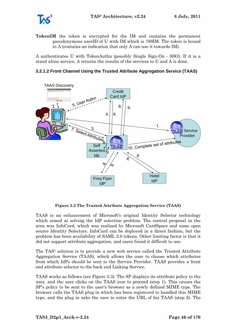
TAS3 Architecture, v2.24 8 July, 2011
TAS3_D2p1_Arch-v-2.24 Page 46 of 170
TokenIM the token is encrypted for the IM and contains the permanent
pseudonymous userID of U with IM which is 789IM. The token is bound
to A (contains an indication that only A can use it towards IM).
A authenticates U with TokenAuthn (possibly Single Sign-On - SSO). If it is a
stand alone service, A returns the results of the services to U and A is done.
3.2.1.2 Front Channel Using the Trusted Attribute Aggregation Service (TAAS)
Service
Provider
Freq Flyer
IdP
Hotel
IdP
Credit
Card IdP
3.
Self
Asserted
Idp
4. 6.
8. 9.
8.
9.
TAAS Discovery
Figure 3.3 The Trusted Attribute Aggregation Service (TAAS)
TAAS is an enhancement of Microsoft's original Identity Selector technology
which aimed at solving the IdP selection problem. The central proposal in the
area was InfoCard, which was realized by Microsoft CardSpace and some open
source Identity Selectors. InfoCard can be deployed in a direct fashion, but the
problem has been availability of SAML 2.0 tokens. Other limiting factor is that it
did not support attribute aggregation, and users found it difficult to use.
The TAS3 solution is to provide a new web service called the Trusted Attribute
Aggregation Service (TAAS), which allows the user to choose which attributes
from which IdPs should be sent to the Service Provider. TAAS provides a front
end attribute selector to the back end Linking Service.
TAAS works as follows (see Figure 3.3). The SP displays its attribute policy to the
user, and the user clicks on the TAAS icon to proceed (step 1). This causes the
SP's policy to be sent to the user's browser as a newly defined MIME type. The
browser calls the TAAS plug-in which has been registered to handled this MIME
type, and the plug in asks the user to enter the URL of his TAAS (step 2). The
TAS3 Architecture, v2.24 8 July, 2011
TAS3_D2p1_Arch-v-2.24 Page 47 of 170
user can enter a new URL, or select one stored in his bookmarks. This solves two
problems simultaneously - the IdP selection problem, as well as resistance to
phishing attacks, since it is the user who decides which web service his browser
should now contact.
The browser contacts the user's TAAS (step 3), and the TAAS asks the user to
authenticate to it, as in Figure 3.2 above (steps 4 to 6). The IdP returns two
authentication assertions to TAAS, one containing a random session identifier for
the user in this session, and one containing the user‟s permanent identifier at
TAAS. Once the user has been identified by his permanent identifier, the TAAS
filters the SP's policy against the user's available attributes. TAAS displays each
of the SP's attribute requirements to the user, along with his available
attributes, asking the user to choose which of his attributes he wants to send to
the SP (step 7). The user chooses the ones he wants, thereby providing consent,
in line with data protection legislation.
TAAS now sends attribute requests to each of the user's IdPs (step 8), and they
return attribute assertions encrypted to the SP (step 9), so that they are
confidentially protected end to end. TAAS aggregates these responses and sends
the combined set of attribute assertions, plus any user self-asserted attributes,
plus the original authentication assertion from step 6, to the SP (step 10). Each of
these assertions refer to the user using the same random session ID. The SP is
thus able to verify that a) the user has been authenticated and b) the user does
have the combined set of asserted attributes, without being given any persistent
identifier for the user, thus preserving the user‟s privacy.
3.2.1.3 Back Channel, Simple
This flow expands on front channel by adding one web services call on back
channel. This section addresses Req. D1.2-3.10-JITPerm.
Example: In our concrete example U authenticates and makes a service request
to A which invokes another service provider B which also contains information
about user U.
Assumptions:
There is service provider IdMapper (IM). Each user usually has one IM that
knows the permanent userIDs at the different service providers.
IdPs know the IMs of the users (there are several ways to know. See section
on user registration in this document to be written.)
IdP/IM produce IM tokens. The IM tokens include the following information
(which means this information is known to the IdP s and IMs):
IM address
the permanent pseudonymous userID of the user at the IM
which service provider can use the token
how many times and how long the token can be used (some of that could be
pushed to a PDP attached to the IM, except the constraint about who can
use it)
The Steps of the Protocol with one layer of Service Provider Invocations
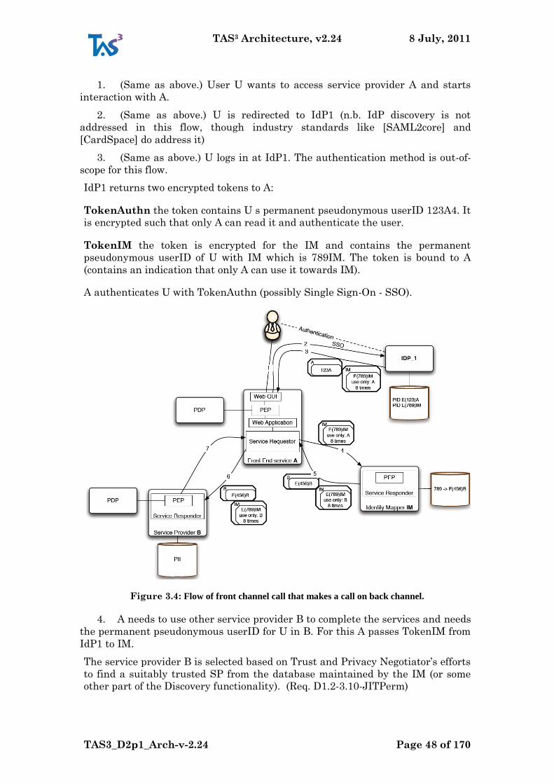
TAS3 Architecture, v2.24 8 July, 2011
TAS3_D2p1_Arch-v-2.24 Page 48 of 170
1. (Same as above.) User U wants to access service provider A and starts
interaction with A.
2. (Same as above.) U is redirected to IdP1 (n.b. IdP discovery is not
addressed in this flow, though industry standards like [SAML2core] and
[CardSpace] do address it)
3. (Same as above.) U logs in at IdP1. The authentication method is out-of-
scope for this flow.
IdP1 returns two encrypted tokens to A:
TokenAuthn the token contains U s permanent pseudonymous userID 123A4. It
is encrypted such that only A can read it and authenticate the user.
TokenIM the token is encrypted for the IM and contains the permanent
pseudonymous userID of U with IM which is 789IM. The token is bound to A
(contains an indication that only A can use it towards IM).
A authenticates U with TokenAuthn (possibly Single Sign-On - SSO).
Figure 3.4: Flow of front channel call that makes a call on back channel.
4. A needs to use other service provider B to complete the services and needs
the permanent pseudonymous userID for U in B. For this A passes TokenIM from
IdP1 to IM.
The service provider B is selected based on Trust and Privacy Negotiator‟s efforts
to find a suitably trusted SP from the database maintained by the IM (or some
other part of the Discovery functionality). (Req. D1.2-3.10-JITPerm)
TAS3 Architecture, v2.24 8 July, 2011
TAS3_D2p1_Arch-v-2.24 Page 49 of 170
IM decrypts TokenIM from IdP1 and sees the user U registered as 789IM in its
database. This with the token serves to authenticate the user to IM. Provided
that the expiration time of the token is relatively short, the user can be assumed
to be present (User Present scenario).
IM looks up the userID of 789IM for service provider B which is 456B (the lookup
values can be in encrypted form).
5. IM encrypts two new tokens for the invoked service providers B and gives
them to A.
TokenUIDinB the token is encrypted for B. The token contains the
pseudonymous identity of user U at B. In this case it is: 456B.
TokenIM the token is encrypted for the IM and contains the userID of U with
IM which is 789IM The token is bound to B.
6. A sends a request to B for a service for U and sends the two tokens from
the IM.
B decrypts the token and recognizes the user as having UserID 456B in its
database.
B sees that 456B is the user U . It calls the authorization function to see if U is
authorized. Assuming the answer is granted, the service is provided.
If B needs to invoke further services with a service provider C it communicates
with the IM of U using its TokenIM and repeats the steps 4 through 6. See the
recursive case, below.
7. B returns a result to A which completes the service and returns result to
user U.
If a User has multiple IMs, multiple IM tokens would be generated if there was
no way to ask User‟s choice or other deciding rule to pick just one. This may
result in practise nearly all IMs being aware of each other, but this need not
always be the case and even partially populated IM matrix would remain useful
to the user. Further, the IM matrix may be different for different users.
3.2.1.4 IM Bootstrap Token Minting and Passing through Front Channel
A key complication in the operation of the back channel is how to get the ball
rolling, i.e. where do the first tokens come, before we can discover more tokens.
The simple idea of just using the front channel token has undesireable privacy
ramifications as it would provide a correlation handle between the SP and the
discovery.
Such correlation handle can be avoided by bootstrapping procedure where the
IdP provides a separate, encrypted, token for access to the discovery. Although
SP will be an intermediary in passing the token to the discovery, it can not learn
a correlation handle due to the encryption. Consider Fig-3.5 where the Single
Sign-On (SSO) assertion (a7n), shown as red oval, is minted by the IdP, with
another assertion, the discovery bootstrap token shown as blue ball, in it. The SP
will establish session for the User (Principal) using the SSO assertion. When it
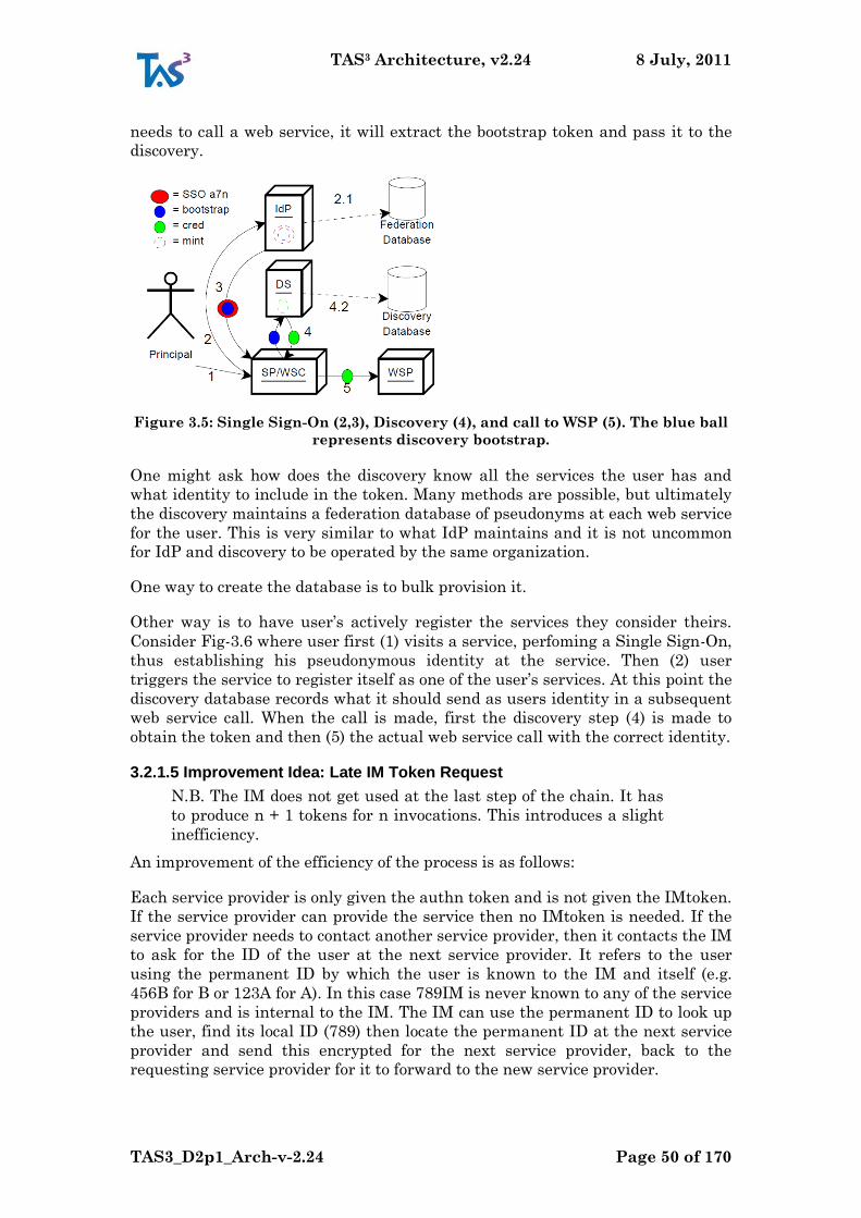
TAS3 Architecture, v2.24 8 July, 2011
TAS3_D2p1_Arch-v-2.24 Page 50 of 170
needs to call a web service, it will extract the bootstrap token and pass it to the
discovery.
Figure 3.5: Single Sign-On (2,3), Discovery (4), and call to WSP (5). The blue ball
represents discovery bootstrap.
One might ask how does the discovery know all the services the user has and
what identity to include in the token. Many methods are possible, but ultimately
the discovery maintains a federation database of pseudonyms at each web service
for the user. This is very similar to what IdP maintains and it is not uncommon
for IdP and discovery to be operated by the same organization.
One way to create the database is to bulk provision it.
Other way is to have user‟s actively register the services they consider theirs.
Consider Fig-3.6 where user first (1) visits a service, perfoming a Single Sign-On,
thus establishing his pseudonymous identity at the service. Then (2) user
triggers the service to register itself as one of the user‟s services. At this point the
discovery database records what it should send as users identity in a subsequent
web service call. When the call is made, first the discovery step (4) is made to
obtain the token and then (5) the actual web service call with the correct identity.
3.2.1.5 Improvement Idea: Late IM Token Request
N.B. The IM does not get used at the last step of the chain. It has
to produce n + 1 tokens for n invocations. This introduces a slight
inefficiency.
An improvement of the efficiency of the process is as follows:
Each service provider is only given the authn token and is not given the IMtoken.
If the service provider can provide the service then no IMtoken is needed. If the
service provider needs to contact another service provider, then it contacts the IM
to ask for the ID of the user at the next service provider. It refers to the user
using the permanent ID by which the user is known to the IM and itself (e.g.
456B for B or 123A for A). In this case 789IM is never known to any of the service
providers and is internal to the IM. The IM can use the permanent ID to look up
the user, find its local ID (789) then locate the permanent ID at the next service
provider and send this encrypted for the next service provider, back to the
requesting service provider for it to forward to the new service provider.
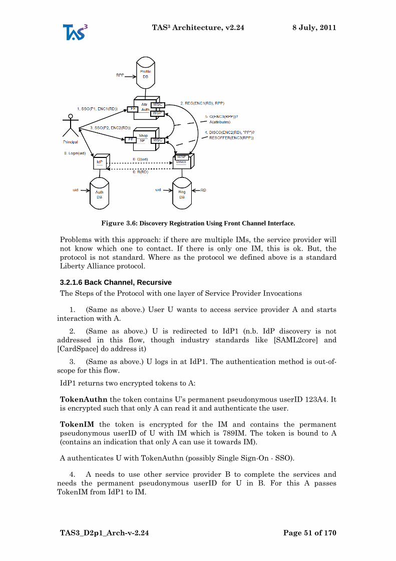
TAS3 Architecture, v2.24 8 July, 2011
TAS3_D2p1_Arch-v-2.24 Page 51 of 170
Figure 3.6: Discovery Registration Using Front Channel Interface.
Problems with this approach: if there are multiple IMs, the service provider will
not know which one to contact. If there is only one IM, this is ok. But, the
protocol is not standard. Where as the protocol we defined above is a standard
Liberty Alliance protocol.
3.2.1.6 Back Channel, Recursive
The Steps of the Protocol with one layer of Service Provider Invocations
1. (Same as above.) User U wants to access service provider A and starts
interaction with A.
2. (Same as above.) U is redirected to IdP1 (n.b. IdP discovery is not
addressed in this flow, though industry standards like [SAML2core] and
[CardSpace] do address it)
3. (Same as above.) U logs in at IdP1. The authentication method is out-of-
scope for this flow.
IdP1 returns two encrypted tokens to A:
TokenAuthn the token contains U‟s permanent pseudonymous userID 123A4. It
is encrypted such that only A can read it and authenticate the user.
TokenIM the token is encrypted for the IM and contains the permanent
pseudonymous userID of U with IM which is 789IM. The token is bound to A
(contains an indication that only A can use it towards IM).
A authenticates U with TokenAuthn (possibly Single Sign-On - SSO).
4. A needs to use other service provider B to complete the services and
needs the permanent pseudonymous userID for U in B. For this A passes
TokenIM from IdP1 to IM.
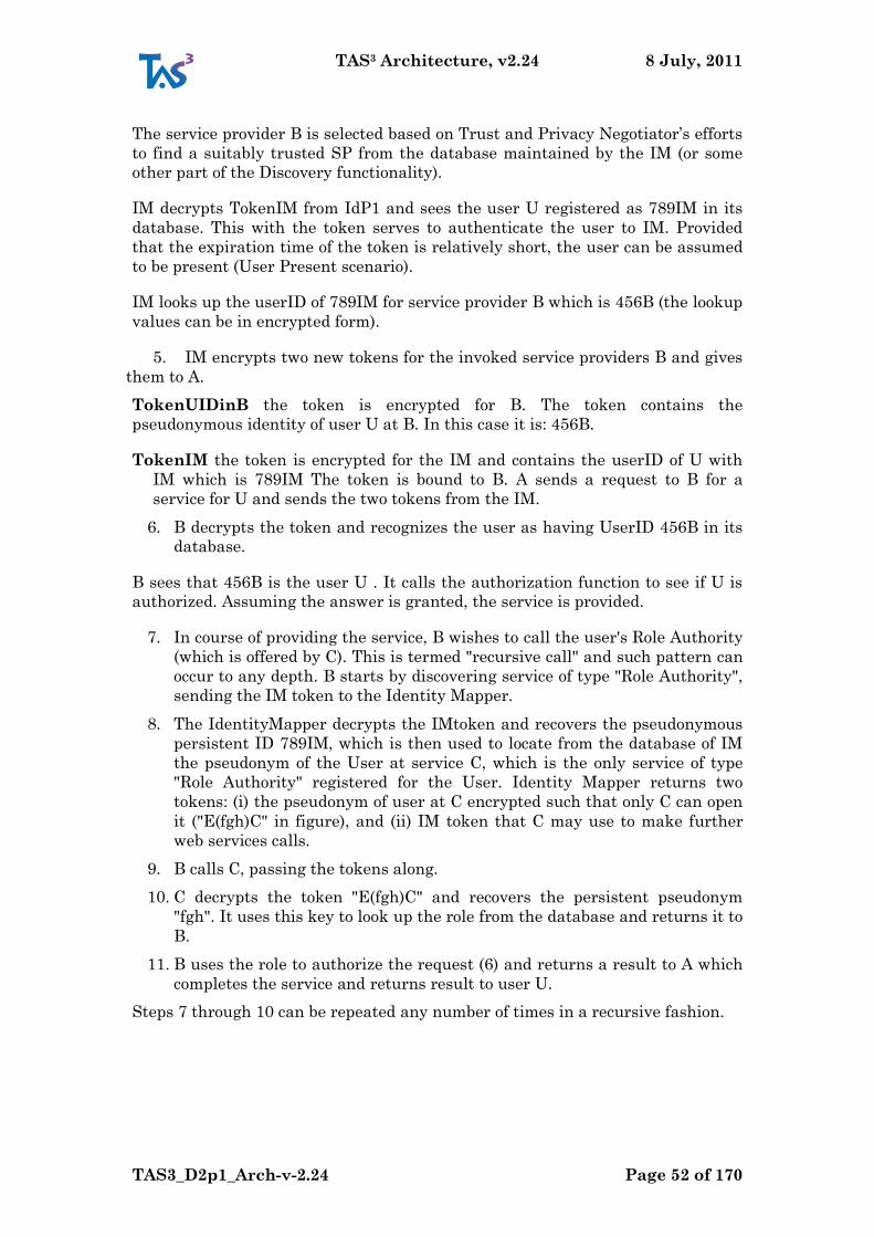
TAS3 Architecture, v2.24 8 July, 2011
TAS3_D2p1_Arch-v-2.24 Page 52 of 170
The service provider B is selected based on Trust and Privacy Negotiator‟s efforts
to find a suitably trusted SP from the database maintained by the IM (or some
other part of the Discovery functionality).
IM decrypts TokenIM from IdP1 and sees the user U registered as 789IM in its
database. This with the token serves to authenticate the user to IM. Provided
that the expiration time of the token is relatively short, the user can be assumed
to be present (User Present scenario).
IM looks up the userID of 789IM for service provider B which is 456B (the lookup
values can be in encrypted form).
5. IM encrypts two new tokens for the invoked service providers B and gives
them to A.
TokenUIDinB the token is encrypted for B. The token contains the
pseudonymous identity of user U at B. In this case it is: 456B.
TokenIM the token is encrypted for the IM and contains the userID of U with
IM which is 789IM The token is bound to B. A sends a request to B for a
service for U and sends the two tokens from the IM.
6. B decrypts the token and recognizes the user as having UserID 456B in its
database.
B sees that 456B is the user U . It calls the authorization function to see if U is
authorized. Assuming the answer is granted, the service is provided.
7. In course of providing the service, B wishes to call the user's Role Authority
(which is offered by C). This is termed "recursive call" and such pattern can
occur to any depth. B starts by discovering service of type "Role Authority",
sending the IM token to the Identity Mapper.
8. The IdentityMapper decrypts the IMtoken and recovers the pseudonymous
persistent ID 789IM, which is then used to locate from the database of IM
the pseudonym of the User at service C, which is the only service of type
"Role Authority" registered for the User. Identity Mapper returns two
tokens: (i) the pseudonym of user at C encrypted such that only C can open
it ("E(fgh)C" in figure), and (ii) IM token that C may use to make further
web services calls.
9. B calls C, passing the tokens along.
10. C decrypts the token "E(fgh)C" and recovers the persistent pseudonym
"fgh". It uses this key to look up the role from the database and returns it to
B.
11. B uses the role to authorize the request (6) and returns a result to A which
completes the service and returns result to user U.
Steps 7 through 10 can be repeated any number of times in a recursive fashion.
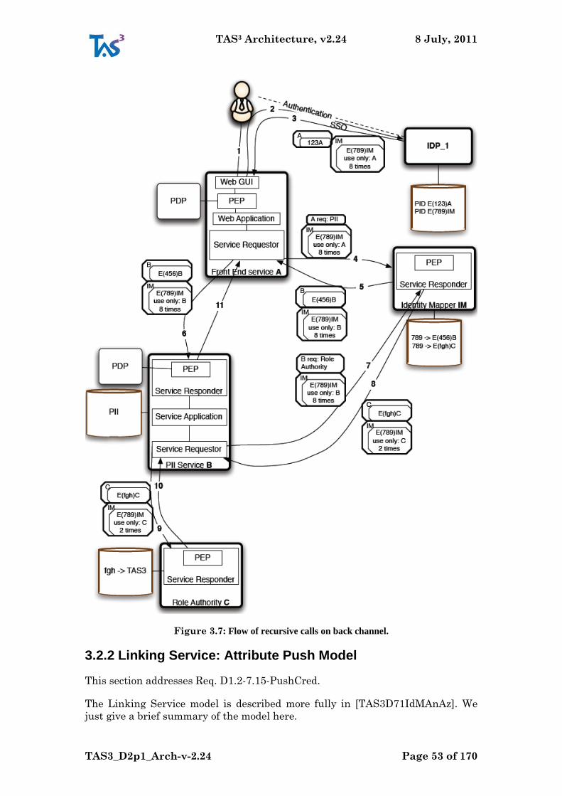
TAS3 Architecture, v2.24 8 July, 2011
TAS3_D2p1_Arch-v-2.24 Page 53 of 170
Figure 3.7: Flow of recursive calls on back channel.
3.2.2 Linking Service: Attribute Push Model
This section addresses Req. D1.2-7.15-PushCred.
The Linking Service model is described more fully in [TAS3D71IdMAnAz]. We
just give a brief summary of the model here.
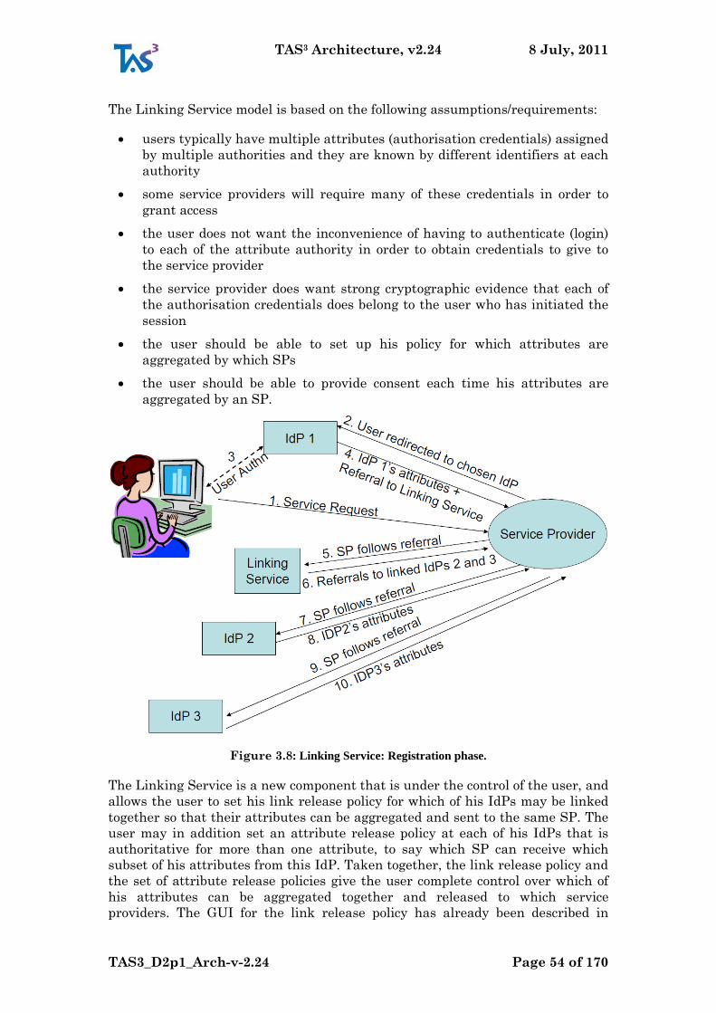
TAS3 Architecture, v2.24 8 July, 2011
TAS3_D2p1_Arch-v-2.24 Page 54 of 170
The Linking Service model is based on the following assumptions/requirements:
users typically have multiple attributes (authorisation credentials) assigned
by multiple authorities and they are known by different identifiers at each
authority
some service providers will require many of these credentials in order to
grant access
the user does not want the inconvenience of having to authenticate (login)
to each of the attribute authority in order to obtain credentials to give to
the service provider
the service provider does want strong cryptographic evidence that each of
the authorisation credentials does belong to the user who has initiated the
session
the user should be able to set up his policy for which attributes are
aggregated by which SPs
the user should be able to provide consent each time his attributes are
aggregated by an SP.
Figure 3.8: Linking Service: Registration phase.
The Linking Service is a new component that is under the control of the user, and
allows the user to set his link release policy for which of his IdPs may be linked
together so that their attributes can be aggregated and sent to the same SP. The
user may in addition set an attribute release policy at each of his IdPs that is
authoritative for more than one attribute, to say which SP can receive which
subset of his attributes from this IdP. Taken together, the link release policy and
the set of attribute release policies give the user complete control over which of
his attributes can be aggregated together and released to which service
providers. The GUI for the link release policy has already been described in

TAS3 Architecture, v2.24 8 July, 2011
TAS3_D2p1_Arch-v-2.24 Page 55 of 170
Section ??. The GUI for the attribute release policy will be very similar to this,
but instead of associating IdPs with SPs, the user will associate attributes with
SPs. Note that in many cases attribute release policies will not be needed since
most IdPs are typically only authoritative for one attribute.
Once the user has linked his IdPs together and set his link release policy at the
Linking Service, the user contacts an SP for a service. The front channel steps
are as follows
1. User contacts SP asking for a Service
2. SP and/or user interact, allowing IdP choice as usual
3. User is redirected to chosen IdP and Authentication with the IdP takes
place as usual
4. In addition the User can tick a box giving consent for attribute
aggregation to take place in this session (see Fig-3.10)
1. User makes a service request. 2. User is redirected to her
chosen IdP 3. User authenticates to IdP 1. 4. IdP 1 returns an
authentication statement + attribute assertions + referral to
linking service 5. SP follows referral 6. Linking service looks up
IDP 1:PID 1 of user and finds links to other IdPs. 7. Linking
service requests attributes from linked IdPs using respective PIDs
8. IdPs return signed and encrypted (to SP) attribute assertions. 9.
Linking service relays all attribute assertions to SP.
Figure 3.9: Linking Service: Login with attribute push phase.
5. User is redirected back to SP and is granted access to the service.
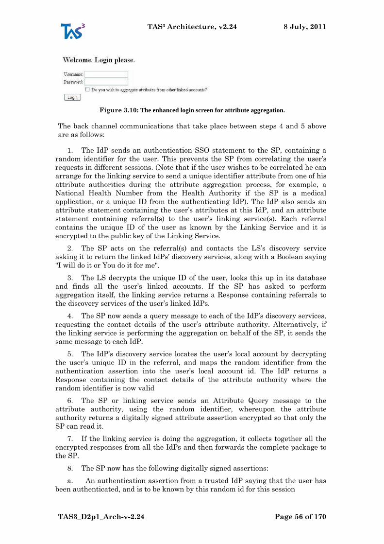
TAS3 Architecture, v2.24 8 July, 2011
TAS3_D2p1_Arch-v-2.24 Page 56 of 170
Figure 3.10: The enhanced login screen for attribute aggregation.
The back channel communications that take place between steps 4 and 5 above
are as follows:
1. The IdP sends an authentication SSO statement to the SP, containing a
random identifier for the user. This prevents the SP from correlating the user‟s
requests in different sessions. (Note that if the user wishes to be correlated he can
arrange for the linking service to send a unique identifier attribute from one of his
attribute authorities during the attribute aggregation process, for example, a
National Health Number from the Health Authority if the SP is a medical
application, or a unique ID from the authenticating IdP). The IdP also sends an
attribute statement containing the user‟s attributes at this IdP, and an attribute
statement containing referral(s) to the user‟s linking service(s). Each referral
contains the unique ID of the user as known by the Linking Service and it is
encrypted to the public key of the Linking Service.
2. The SP acts on the referral(s) and contacts the LS‟s discovery service
asking it to return the linked IdPs‟ discovery services, along with a Boolean saying
"I will do it or You do it for me".
3. The LS decrypts the unique ID of the user, looks this up in its database
and finds all the user‟s linked accounts. If the SP has asked to perform
aggregation itself, the linking service returns a Response containing referrals to
the discovery services of the user‟s linked IdPs.
4. The SP now sends a query message to each of the IdP‟s discovery services,
requesting the contact details of the user‟s attribute authority. Alternatively, if
the linking service is performing the aggregation on behalf of the SP, it sends the
same message to each IdP.
5. The IdP‟s discovery service locates the user‟s local account by decrypting
the user‟s unique ID in the referral, and maps the random identifier from the
authentication assertion into the user‟s local account id. The IdP returns a
Response containing the contact details of the attribute authority where the
random identifier is now valid
6. The SP or linking service sends an Attribute Query message to the
attribute authority, using the random identifier, whereupon the attribute
authority returns a digitally signed attribute assertion encrypted so that only the
SP can read it.
7. If the linking service is doing the aggregation, it collects together all the
encrypted responses from all the IdPs and then forwards the complete package to
the SP.
8. The SP now has the following digitally signed assertions:
a. An authentication assertion from a trusted IdP saying that the user has
been authenticated, and is to be known by this random id for this session
TAS3 Architecture, v2.24 8 July, 2011
TAS3_D2p1_Arch-v-2.24 Page 57 of 170
b. A set of attribute assertions from trusted attribute authorities saying
that the user known by this random id possesses this set of attributes
c. Based on the above the SP can authorize the user to access the requested
resources, sure in the knowledge that trusted authorities have both authenticated
the user and assigned attributes to her.
3.2.2.1 N-Tier Linking Service Model
This section addresses Req. D1.2-7.1-Deleg.
If the SP above needs to subcontract one or more tasks to a backend service, and
that backend service is to act from an authorization perspective as if the user
herself had contacted it directly, then the backend service will need to be given
the user‟s authorization attributes. Whilst there have been many previous
models for dynamic delegation of authority none of them to the best of our
knowledge have supported attribute based delegation simultaneously with
privacy protection of the delegator‟s and delegate‟s identities. We have solved this
in TAS3 by the process of delegation by invitation (see section 3.3.1 below and
section 6.3 in D7.1).
The user contacts a delegation service and delegates her attributes to the first
SP, bestowing these credentials with delegation rights. The first SP uses these
credentials to authorize the user, and then delegates them further to the backend
SP, optionally bestowing further delegation rights on the backend SP in case it
needs to subcontract further. The advantage of this model is that the backend SP
does not need to trust the first SP, since the latter has specifically been delegated
rights to it by the user. By combining the linking and delegation services to work
together in a trustworthy manner we allow the user to delegate attributes from
multiple IdPs to an SP.
3.2.3 Simple Attribute Push Model
Recommended approach for initial deployments that have not
yet developed full infrastructure.
In this model some commonly needed, or "enabler", attributes such as Trust
Network membership or role are supplied directly as part of Single Sign-On
(SSO) or web service tokens. Other perhaps justifiable attributes, that do not
provoke overdue privacy or legal implications, could be
legally nonbinding nickname for greeting user
user‟s preferred language
This model implies that IdP or IDMapper assume some of the responsibilities of
an Attribute Authority. This is well supported in existing protocols and available
software implementations. It is also probably the largest operation model in use
today in existing federations. For example, this is the model used by all
Shibboleth implementations such as the UK academic community federation
which has over 800 IdPs and SPs since it was launched in August 2008.
Drawbacks of this approach are
TAS3 Architecture, v2.24 8 July, 2011
TAS3_D2p1_Arch-v-2.24 Page 58 of 170
1. Only a very narrow set of attributes will be universally needed by nearly
all Front Ends orWeb Services.
2. Danger of nonadherence to minimal disclosure principles - its easy to have
creep where "just one more" attribute is added to support "just one more"
application. This is also wasteful in that cost for generating attribute statements
that are seldom needed is still paid on every transaction.
A solution to this is to have an Attribute Release Policy (ARP) at the IdP which
provides rules for which attributes should be released to which SPs. In this way
the attributes can be effectively filtered before release. The ARP is set by the user
and/or the IdP itself, and open source software does exist for this. The design is
very similar to the IdP Release Policy of the Linking Service described in Section
3.2.2, above. Still, this approach lacks granularity as the attribute needs of a SP
are assumed to be always the same, while in reality SP may run various different
business processes with different needs.
3. Postponement of moving to full pull model.
3.3 Delegation
This section addresses Reqs. D1.2-3.7-Deleg and D1.2-7.1-Deleg.
Technical clarification: Here "Delegation" means assignment of
one User‟s privilege attributes, and the access rights they imply to
another User. This is distinct from merely instructing some web
application or service to login on one‟s behalf - some other
practitioners call also this "delegation", but we call this
masquerade since the service cannot tell the difference between
the real user and the so called delegate. This is so common that it
is the base case, and does not need special mention.
It should be noted that some system entities may be modelled as
juridical persons and can, thus, participate in Delegation like the
Users can.
General properties of delegation are
Express and auditable act of delegation, with indication of registration
(where needed).
- Specification of delegatee
- Specification of delegator
- Specification of scope
- Attribute to be delegated (exceptionally a specific task may be delegated)
- Specification delegation constraints such as expiry time and other policy
constraints such as SPs at which delegated tokens can be used.
Specification of recursion i.e. (if delegate can recursively delegate, and if so, to
what depth)
Ability to revoke, with extent to which this is possible, such as
- At any step of sub-delegation chain
TAS3 Architecture, v2.24 8 July, 2011
TAS3_D2p1_Arch-v-2.24 Page 59 of 170
- Any superior ancestor can revoke any descendant
Verification by Relying Party based on presented delegation tokens
Transparency: ability for user to verify which delegations have in fact been
exercised or formally accepted.
This could be implemented by the Delegation Service feeding information about
each invitation usage to the Audit Event Bus, where the Dashboard picking up
the information and displaying it to the delegator when he/she comes to consult
it. Also, when a Service Responder, or its CVS or PDP, consumes a delegation
token, it will inform the Audit Event Bus so that the Dashboard can have the big
picture of the delegation usage.
Delegation is also discussed in section 6 "The Delegation Service" of
[TAS3D42Repo] and in section 6 of Deliverable D7.1 [TAS3D71IdMAnAz].
Designation of Delegatee may be by
Delegation to anyone (or first one) possessing an invitation token
Delegation to someone specific
- How is the someone to be identified? Well known unique ID is an option.
Delegation to anyone having a specific role
Delegation to anyone having some relationship to the Delegator
Delegation to anyone having some relationship to previous tasks, business
process steps, or environmental context (e.g. physical access).
It is important that delegators be able to revoke any delegations that they have
initiated. However, whether a delegator can revoke any delegates of his delegates
– so called cascading revocations - depends upon whether the delegation service
keeps a full history of the delegation chains or not.
3.3.1 Invitation Based Token Approach
TAS3 has implemented the Delegation by Invitation method, using a Delegation
Web Service. The steps involved in the delegation by invitation method are as
follows:
1. The Delegation Service identifies the delegator
2. The Delegation Service checks that delegator has the attribute(s) he wishes
to delegate and that he is allowed to delegate it (them) to anyone
3. The Delegation Service issues and invitation token to the delegator
4. The Delegator gives the invitation token to the chosen delegate
5. The Delegate contacts the Delegation Service, authenticates to it via his
chosen IdP and presents the invitation token
6. The Delegation Service validates the invitation token and confirms that the
delegate has all the necessary attributes
TAS3 Architecture, v2.24 8 July, 2011
TAS3_D2p1_Arch-v-2.24 Page 60 of 170
7. The Delegation Service confirms the delegation and stores the delegated
attribute along with the delegate‟s newly created entry.
8. The Delegation Service is now able to issue the delegated attribute to the
delegate whenever he authenticates and asks for it.
Further details about the Delegation Service can be found in D7.1
3.3.1.1 Reuse of Invitation Token
One salient property of this delegation by invitation method is that the invitation
token may be requested by the delegator for one time use or multiple use. For one
time use, once the invitation token is presented by a delegate, it is discarded by
the Delegation Service and thereafter cannot be presented again. Any subsequent
attempts to present the same invitation token will fail. However if multiple use is
requested, the delegator can give the invitation token to multiple delegates, and
each one can present it to the Delegation Service. Each delegate will be asssigned
the delegated attribute and the invitation token will remain valid. The invitation
token will cease to be valid after a certain amount of time or after a certain
number of uses. Note that with multiple use, the delegator can only revoke all
the delegates, or none. It is not possible to revoke individual delegates since they
were all delegated via the same invitation token. This is not the case with one
time use, as each delegate can be individually revoked.
3.3.2 Delegation by Direct Authorization Rule
In this model the resource owner (delegator), knowing the delegate‟s full set of
identity attributes, creates an access control rule at the resource that simply
authorizes anyone with these attributes to access the resource.
The ability to assign access to other users can be regulated by policies that are
checked by the sticky policy interface, e.g. by consulting a PDP.
When a delegate accesses the resource, he identifies himself using the usual
token passing flow, and his identity attributes are given to the resource. The
resource‟s PDP is able to match his identity attributes to the policy authorizing
the access and grant access.
In its basic form the ABAC model allows the holder of any identity attributes to
access any resource that accepts the attributes and the identity (identifier) of the
role holder is irrelevant, thus permitting use of pseudonyms or transient
identifiers that improve the privacy.
3.3.3 Delegation to Well Known Delegate
If the Delegate can be uniquely identified by the delegator, the delegator can
instruct the Delegation Service to create a signed (by Delegation Service) token
specifically for the delegate. This is the case for example, when users are
identified by LDAP distinguished names or SPs have well known URLs. Since
the TAS3 infrastructure is based on the use of pseudonymous and random
identifiers to identity human users, then the approach of using unique identifiers
will not be adopted for human users. It can be easily adopted for identifying SPs,
as a choice of the application user interface.
TAS3 Architecture, v2.24 8 July, 2011
TAS3_D2p1_Arch-v-2.24 Page 61 of 170
3.3.4 Multi-layer (Chained) Delegation
The attribute based delegation methods described above lend themselves to
multi-layer (chained) delegation. In this case the delegation is made with the
right to sub-delegate and the delegate is able to request that further delegation
invitation tokens are created, which can be passed to the next delegate in the
chain. The length of the delegation chain is initially controlled by the original
delegator, but subsequent delegators in the chain can shorten the chain if they
wish. Note that it is never possible to increase the length of the delegation chain
that has been set by the original delegator.
For access authorization, when a delegation service is used, only the last step of a
delegation chain is important, but for audit purposes the full chain is needed.
3.4 Break-the-Glass Authorization
This section addresses Reqs. D1.2-3.9-BPRecover, D1.2-4.6-BrkGlass, and D1.2-
7.22-BrkGlass. See [TAS3D71IdMAnAz] for further discussion of the Break-the-
Glass authorization.
In a Break-the-Glass scenario an operation would not normally be authorized
given the actor and the resource (including owner of the resource), but given
justified and legitimate imperative need, the operation is authorized, usually
with additional auditing enabled.
A classical example would be an unconscious patient brought to an emergency
ward. The physician has imperative need to access the patient records, yet the
patient cannot consent to the access.
The TAS3 approach is as follows
State driven Break-the-Glass: In this approach the authorisation
infrastructure records the state of the glass, whether it is broken or not. Glass
state is multi-dimensional and can be assigned to any attributes of the
authorisation decision request e.g. per subject, per action, per resource, per day
etc. The user attempts access to the resource, and the PEP attempts
authorization, which fails. The PDP returns a new “BTG” response to the PEP.
The PEP proceeds to ask consent from the user ("Do you want to invoke Break-
the-Glass privileges and additional auditing?") using the interaction facilities of
the architecture. If the user answer is Yes, then the PEP sends a Break the Glass
request to the authorisation infrastructure, which then sets the appropriate glass
state to broken. After this the user may access the resource as normal.
Enabling Break-the-Glass forces additional audit messages to be generated at the
PEP and by the service overall. There will also be an audit entry on the PDP side,
permitting better cross correlation of the audit trails. Break the Glass is
described more fully in section 3 of D7.1.
3.5 Trust and Privacy Negotiation
This section addresses Req. D1.2-7.17-Increm.
TAS3 Architecture, v2.24 8 July, 2011
TAS3_D2p1_Arch-v-2.24 Page 62 of 170
The purpose of trust and privacy negotiation is: to determine whether or not the
web service client (WSC) and the SP possess the required attributes
(authorization credentials) in order for the WSC to access the service (i.e. to
enable the WSC and the SP to establish mutual trust); and in cases where both
the WSC and the SP do possess the required attributes/credentials, which subset
of them, disclosed by the WSC to the SP, is sufficient to grant access to the
resource.
We have developed a special form of credential disclosure policy which we call
„CUP‟ (for “COSIC UniPro”), and extended the TrustBuilder2 framework
[TrustBuilder2]. CUP policies are based on the UniPro approach [UniPro] of
automated trust negotiation. UniPro allows SPs (and WSCs) to partially disclose
access control policies, so as to facilitate progress in the negotiation protocol. The
concrete protocol and implementation mechanics are described fully in sections
11 and 12 of D7.1
3.6 Interoperation across Trust Networks
The general approach for interoperation across Trust Networks is described in
[LibertyInterFed], which focuses on the token passing flows in an inter-
federation situation. In addition to token passing, interoperability at the data
level is needed, i.e. the ontologies in use in the different Trust Networks either
need to be the same or they need to be mapped. In particular, authorization
critical data needs to be mapped.
3.6.1 Semantic Interoperability – OBIS the Ontology-based Interoperation Service
This section satisfied Reqs. D1.2-2.23-SemIOP, D1.2-3.14-PIIPolicyDisco, and
D1.2-3.15-SecPreserve.
One of the main challenges of TAS3 is to guarantee the correct interpretation and
implementation of data protection policies, while sharing, accessing, and using
information processing services in federated environments. These are essential
elements of trust that are required for various stakeholders, especially end-user,
to participate in any implementation of the TAS3 architecture. As new service
providers join a TAS3 federation, with new policies that are protecting their
resources and new credentials that are assigned to their users, it cannot be
guaranteed that all federation members will use the same terminology for the
same concepts. To solve this, some federation have mandated that all members
use the same vocabularies, credentials and policy terms. But this is unrealistic in
large scale multi-national federations.
The TAS3 approach is, instead, to introduce an ontology-based interoperation web
service (OBIS). This is configured with the vocabularies of all the service
providers, and consequently is able to calculate the dominance relationship
between two security concepts inferred from an access request term and a local
authorization policy term, based on the generic ontology-based data matching
framework (ODMF) [ODMF]. The OBIS web service differs from existing
approaches by providing a method for the association of policies and controls
from all the service providers in a federated system and being integrated into the

TAS3 Architecture, v2.24 8 July, 2011
TAS3_D2p1_Arch-v-2.24 Page 63 of 170
authorization infrastructure. In the proposed approach, every stakeholder
expresses his authorization policy using his own vocabulary, and when a policy
engine receives an authorization request containing an unknown term, it
semantically matches this to one that is locally known by the authorization
policy. This linguistic-based approach is adopted in the privacy domain in order
to allow different non-technical users (and organizations) to express their
security policies in an intelligible way, through the use of natural language, thus
enforcing the user-centricity aspect.
Figure 3.11. Authorization Architecture
The OBIS service, described in deliverables D2.2 and D7.1, is located in the
authorization infrastructure as shown in Figure 3.11. The authorization process
consists of the following steps. The Service Requester (SR) launches a request to
access a resource protected by various authorization policies. The resource‟s
Policy Enforcement Point (PEP) intercepts the request and passes it to the
Application Independent Policy Enforcement Point (AIPEP). This initially
contacts the Credential Validation Service (CVS) to validate the requestor‟s
credentials (i.e. attribute claims) which typically have been issued by multiple
different attribute authorities in the federation (not shown in Figure 3.11). The
CVS uses its local credential validation policy to determine which credentials are
valid. If the CVS cannot validate any credential, it contacts OBIS to determine
the relationship between the presented attributes and the ones in its policy.
Based on the domination relationship returned by OBIS, the CVS is able to
return the set of valid attributes to the AIPEP. The AIPEP now contacts the
Master PDP, passing the valid attributes, and asking for an access control
decision. The Master PDP calls the set of subordinate PDPs which support
different access control policy languages (e.g. XACML and PERMIS). This
ensures that all service providers do not need to support the same policy
language, and that policies in different languages can be passed between
providers and still enforced by them. If a PDP is not able to make an access
control decision, then it calls OBIS to calculate the semantic relation between
TAS3 Architecture, v2.24 8 July, 2011
TAS3_D2p1_Arch-v-2.24 Page 64 of 170
terms in the access request. Based on the values returned by OBIS, the access
request is either granted or denied.
3.7 Properties of Web Service Binding
Web Service Binding is a set of features that the communications layer is
assumed to have. These features are often required by more sophisticated
protection mechanisms like the token passing flows. They often address basic and
well known threats like replay, unauthorized, and man-in-the middle attacks in a
basic way while other mechanisms may address the same topics
comprehensively, but in a more expensive way. Many of these features may seem
self-evident, but we need to list them even if just to state the obvious.
1. Mutual authentication of the communicating entities MUST be possible.
Usually this is done using transport layer digital certificates, but other
approaches are possible.
2. Link confidentiality MUST be possible, usually using transport layer
encryption.
3. Correlation MUST be possible
- Request-Response Correlation
- Business Process identification in correlation
4. Redirection should be supported for flexibility
5. Re-credentialing MUST be supported (Req. D1.2-3.9-BPRecover)
6. Asynchronous message passing SHOULD be suppoted
7. Interaction Callback (or Exception Request)
- Interaction Redirect (Req. D1.2-3.9-BPRecover)
- Interaction Service (Req. D1.2-3.9-BPRecover)
8. Digital signing of messages for nonrepudiation (Reqs. D1.2-2.11-Transp,
D1.2-2.15-Resp, D1.2-4.4-CourtProof)
9. Conveyance of Invoker and Target Identities, if web service uses identity.

TAS3 Architecture, v2.24 8 July, 2011
TAS3_D2p1_Arch-v-2.24 Page 65 of 170
4 Application Specific Architecture
4.1 Protocol Support for Conveyance of Sticky Policies
Most of the protocol flows of TAS3 use industry standard Web Services bindings
and Web Services payload protocols. It is an explicit design goal that existing
services are enabled with minor disruption.
A pertinent problem with existing payload service protocols is how to express the
sticky policies that generally have to be bound to the data with a digital
signature. Following approaches have been identified
1. Treat all data in one request-response pair as having the same Sticky
Policies. In this cases relatively nonintrusive methods like SOAP headers
and LDAP controls can be used to indicate the sticky policies. We call this
Security Header (SH) approach. This approach is already available as
<UsageDirective> SOAP header defined in [IDWSF08].
2. Use the extension points of the payload protocol to express the Sticky
Policies. We call this approach Application Protocol Enhancement (APE), see
[TAS3D71IdMAnAz] section 8.2. This approach gives granular Sticky
Policies that are naturally associated with the data and does not alter the top
levels of protocol processing. If the client and server are updated to
understand this scheme then it works well. Eventually new payload protocols
should be specified with TAS3 APE feature built in. A danger of this
approach is that if the client is not updated, it may just silently ignore the
Sticky Policies. However conformance testing will solve this problem.
3. Expand the data model to carry sticky policies. This is really a special case of
APE with similar merits and problems. One benefit is that it is sometimes
easier to extend a datamodel than a protocol.
4. Encapsulating Security Layer (ESL), see [TAS3D71IdMAnAz] section 8.2.
Wrap the payload protocol in a TAS3 defined encapsulating protocol that
contains all the TAS3 specifics and in particular the sticky policies.
Advantages of this approach include
The encapsulated protocol does not need to be modified at all
Possibility to add sticky policies to protocols that do not offer extension
points and that are not under control of the implementer.
Disadvantages of this approach are
More invasive on outer layers of the protocol stack. This may make it
difficult to integrate to existing protocol stack.
If the payload protocol is not SOAP, or otherwise has poor impedance match
to the TAS3 ESL protocol, then integration may be impossible.
Association of the sticky policies to the data will require awkward
correlation of data items to the policies. In particular, if the data does not
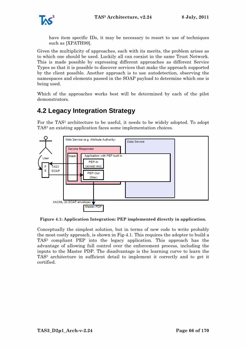
TAS3 Architecture, v2.24 8 July, 2011
TAS3_D2p1_Arch-v-2.24 Page 66 of 170
have item specific IDs, it may be necessary to resort to use of techniques
such as [XPATH99].
Given the multiplicity of approaches, each with its merits, the problem arises as
to which one should be used. Luckily all can coexist in the same Trust Network.
This is made possible by expressing different approaches as different Service
Types so that it is possible to discover services that make the approach supported
by the client possible. Another approach is to use autodetection, observing the
namespaces and elements passed in the SOAP payload to determine which one is
being used.
Which of the approaches works best will be determined by each of the pilot
demonstrators.
4.2 Legacy Integration Strategy
For the TAS3 architecture to be useful, it needs to be widely adopted. To adopt
TAS3 an existing application faces some implementation choices.
Figure 4.1: Application Integration: PEP implemented directly in application.
Conceptually the simplest solution, but in terms of new code to write probably
the most costly approach, is shown in Fig-4.1. This requires the adopter to build a
TAS3 compliant PEP into the legacy application. This approach has the
advantage of allowing full control over the enforcement process, including the
inputs to the Master PDP. The disadvantage is the learning curve to learn the
TAS3 architecture in sufficient detail to implement it correctly and to get it
certified.
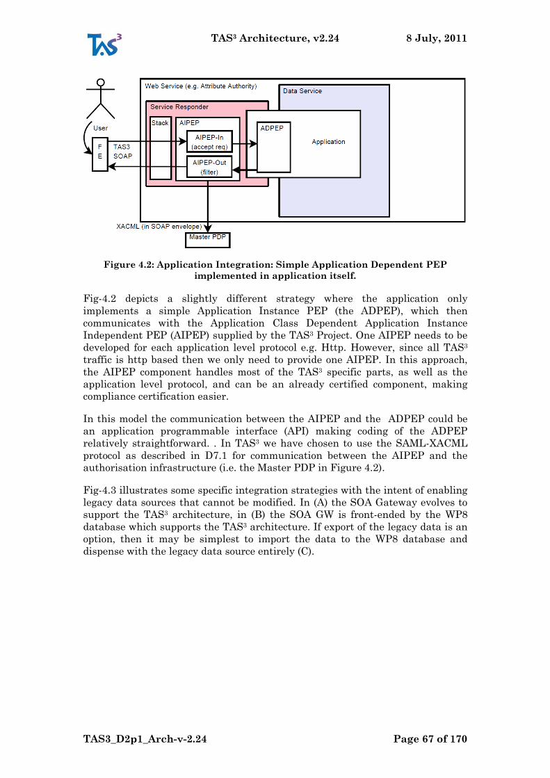
TAS3 Architecture, v2.24 8 July, 2011
TAS3_D2p1_Arch-v-2.24 Page 67 of 170
Figure 4.2: Application Integration: Simple Application Dependent PEP
implemented in application itself.
Fig-4.2 depicts a slightly different strategy where the application only
implements a simple Application Instance PEP (the ADPEP), which then
communicates with the Application Class Dependent Application Instance
Independent PEP (AIPEP) supplied by the TAS3 Project. One AIPEP needs to be
developed for each application level protocol e.g. Http. However, since all TAS3
traffic is http based then we only need to provide one AIPEP. In this approach,
the AIPEP component handles most of the TAS3 specific parts, as well as the
application level protocol, and can be an already certified component, making
compliance certification easier.
In this model the communication between the AIPEP and the ADPEP could be
an application programmable interface (API) making coding of the ADPEP
relatively straightforward. . In TAS3 we have chosen to use the SAML-XACML
protocol as described in D7.1 for communication between the AIPEP and the
authorisation infrastructure (i.e. the Master PDP in Figure 4.2).
Fig-4.3 illustrates some specific integration strategies with the intent of enabling
legacy data sources that cannot be modified. In (A) the SOA Gateway evolves to
support the TAS3 architecture, in (B) the SOA GW is front-ended by the WP8
database which supports the TAS3 architecture. If export of the legacy data is an
option, then it may be simplest to import the data to the WP8 database and
dispense with the legacy data source entirely (C).

TAS3 Architecture, v2.24 8 July, 2011
TAS3_D2p1_Arch-v-2.24 Page 68 of 170
Figure 4.3: Application Integration using ADPEP and (A) SOA Gateway, (B) WP8
DB as frontend to SOA GW, (C) WP8 database.
4.3 The Application’s PEP
The Application‟s Policy Enforcement Point (PEP) is a gateway that provides
access to the TAS3 infrastructure for applications like web applications with a
web frontend, business process engines, databases or repositories and many other
systems, which are either requesting or responding over a TAS3 secured and
trusted channel. Per section 2.2.1 (see also Fig-2.2), the PEP belongs to the Front
End Services and Web Service components inside the Payload boundary. The
PEP can be considered as consisting of two parts, the Application Class
Dependent Application Instance Independent PEP (AIPEP) and the Application
Instance Dependent PEP (ADPEP).
As described in Section 2.2.2, the PEP is divided into two different types:
1. ServiceRequester PEP: This web service is part of the Front End Services.
Internally, the ServiceRequester PEP constitutes together with the Stack,
the Service Requester. The Stack handles SOAP protocol details. The
Application Class Dependent Application Instance Independent PEP (AI
PEP) contacts the Master PDP, which contacts the different PDPs like the
User PDP, Organization PDP or a Trust PDP to decide whether a request is
trusted or not.
The main task of the ADPEP is to collect all required information for an
appropriate request that has to be checked by the TAS3 authorization
infrastructure, give this to the AIPEP then route the request (assuming it is
granted) in an appropriate way to the ‟Service Application‟ and then give the
results back to the AIPEP. Further information about the payload, which
builds up the request, can be found in [TAS3D81RepoSW] figure 8. Common
information about the functionalities of the ServiceRequester PEP can be
found in [TAS3D81RepoSW] and in [TAS3D83CliSW].
The next steps before sending the request are done by the ‟Stack‟. As
mentioned before, the ‟Stack‟ (and its main component: the AIPEP) is
application instance independent. Its main task is the preparation of the
TAS3 Architecture, v2.24 8 July, 2011
TAS3_D2p1_Arch-v-2.24 Page 69 of 170
request. The message has to be signed and augmented according to web
services binding. WP4, WP5 and especially WP7 work on this security
related part of the service requester, whereas WP8 is responsible for the
application dependent part.
2. ServiceResponder PEP: This second application dependent service, which
functions as responder, is part of the Service Responder component in the
Web Service boundary (see Fig-2.3). In analogy to the ServiceRequester PEP,
the ServiceResponder PEP also needs the Application Instance Dependent
PEP (ADPEP) and the ‟Stack‟ (with AIPEP and its underlying PDPs) to
function correctly. That means, signing and preparation of the message
according to the web service binding, the policy checks and the
communication with the ‟Trust policy decision point‟, as done by the ‟Stack
components‟.
The main task of the ADPEP is to receive granted requests, route them in an
appropriate way to the ‟Service Application‟ and then check with the AIPEP
if the results can be sent back in the response to the requester. More details
about the functionalities of the ServiceResponder PEP can be found in
[TAS3D81RepoSW] in chapter 3.2.
Auxiliary components in the ADPEP Service
To fulfil the mentioned functions of the ADPEP Services (Requester and
Responder), some auxiliary services are required. These services belong to tasks
(Task 8.3 - see DoW), which are documented in [TAS3D82BackOffice].
These services neither store person related data nor serve the user directly. They
provide ontologies and metadata, perform search and aggregation operations and
transform data into specific formats. The back office services are a component of
the TAS3 Trusted Application Infrastructure but not of the core TAS3 Trust and
Security Infrastructure.
The main Auxiliary or Back Office Services and Components are:
The Generic Data Format ([TAS3D82BackOffice], section 2.1.2) used to
store data in TAS3 repositories1
Services to transform ([TAS3D82BackOffice], section 2.1) data from a
custom source format to the Generic Data Format and from the Generic
Data Format to a format, which is requested (and supported).
Aggregation Service ([TAS3D82BackOffice], section 2.2) and Policy
Aggregation ([TAS3D82BackOffice], chapter 8)
Request Logger Service ([TAS3D82BackOffice], section 3.2) to store
information on requests issued and responses received by TAS3 web
services for auditing and maintenance purposes
1 Marc: not applicable for eHealth because of legal issues
TAS3 Architecture, v2.24 8 July, 2011
TAS3_D2p1_Arch-v-2.24 Page 70 of 170
4.4 Reputation Feedback
The workflows have a feedback collection step. This feedback is collected by a
user interface and then sent to the Trust and Reputation Server by means of a
web service call (e.g. SOAP). The call will contain, in addition to the feedback
score, workflow context information, such as the role in which the user acts in as
well as pseudonym of the user at the Trust and Reputation Service (see below). If
the user is giving feedback about another user, he will know the other user‟s
pseudonym through the business process context. This architecture allows the
Trust and Reputation Server to correlate feedback from different sources without
the sources having a correlation handle for the user.
The pseudonym of the user at the Trust and Reputation Server is obtained by
means of normal discovery and ID mapping .
4.5 Security Enforcement for Business Processes
Business processes, when executed in a business-process-management system
(BPMS), expose rich context information. This information can be used for
security enforcement. Indeed, it is imperative to do so to provide tight security
that adapts to situations where classical security models are too static.
Furthermore, it is necessary to define security policies that take context into
account. Security components specific to BPM are necessary to deal with
business-process-specific context information and enforce business-process-
specific security rules [SecureBPMSArch2011].
More specifically, the following security context accrues for business-process
instances: (1) Activity context of calls (web-service calls or creation of human
tasks), i.e. which activity in which process instance has caused the call, (2)
Associated entities, which are entitites like users or external data sources
associated with a process instance (either with the entire process instance, or
with some element of it). (3) Execution state, for example activities waiting for
execution.
Security configuration respecting such context can come in different forms, most
importantly as declarative policies or simple variables. Several sources are
possible. The most simplistic way is to assume default values. More flexible
approaches are security policies for business-process models, which can be
derived from annotations to graphical process models, and deriving settings from
user interactions at run-time (e.g., a user giving his consent at run time that the
business process accesses his/her personal data). When more than one policy
exists, conflicts can arise. Such conflicts must be resolved; WP7 has explored
respective mechanisms.
The architecture of a secure BPMS must be able to handle the security context
and security configuration just described, and should should follow additional
design goals. Namely it should require few changes to existing BPMS, follow
standard architectures such as the XACML reference architecture and the WfMC
workflow reference model, and preserve the structure of security constraints on
the enforcement level in order to allow for better traceability.
TAS3 Architecture, v2.24 8 July, 2011
TAS3_D2p1_Arch-v-2.24 Page 71 of 170
The security-enforcement extensions of a BPMS (to be used in the TAS³
architecture) look as follows:
Business process definitions are transformed so that web-service calls and
requests for the creation of human tasks are sent to a policy enforcement
point (PEP), augmented with the context of the call.
For web-service calls, the PEP includes the correct token, determines the
service to call (possibly from a previous service-selection step) and makes
the call.
The worklist handler (business-process client) is modified to ask for
authorization whenever it allows a task to be performed.
For human tasks, the PEP stores the context of their creation and assigns a
unique ID. It adds these context to authorization queries before sending
them to a PDP.
A business-process policy information point (BP-PIP) stores context
information persistently.
Tokens acquired (e.g., through SSO by the BPMS acting as a frontend
service) are stored in a special store, to be used for outgoing calls.
A special policy decision point for business processes (PDP-BP) performs
authorization decision based on security rules specific to business processes.
For example, it evaluates history-based constraints such as binding of duty
(BoD). The non-history-based part can be delegated to an “ordinary” PDP.
The security configuration of a business-process instance can be changed
based on user interactions. Synchronous user interactions are included into
the business-process definitions, while special components provide for
asynchronous user interactions.
As shown, special components are only needed for security functionality specific
to business processes. They integrate with the overall TAS³ security architecture.
4.6 Business Process Registration
When user is about to start participating in a business process, he gets
information about the business process policy and has to give his consent to
participate in the business process. The business process policy contains a
declaration about the data needs and other participants of the business process
from a security and trust perspective. Such declaration is prepared from the
business process model with its security and trust constraints.
Each business process model can be viewed as a high level service and can be
described by a service type. This makes it possible to discover trusted (according
to a trust policy) Service Providers who implement the business process.
.
TAS3 Architecture, v2.24 8 July, 2011
TAS3_D2p1_Arch-v-2.24 Page 72 of 170
5 Using Business Process Modelling to Configure the Components
This section addresses Reqs. D1.2-3.2-ModelDrivenCfg, D1.2-3.12-SPManifest,
D1.2-6.3-WhatHowWhyWho, and D1.2-6.4-Min.
The TAS3 architecture covers a lot of functionality and some of this functionality
needs to be configured carefully to match each other to ensure smooth operation
from the perspective of the users, such smooth operation is perceived by users as
dependability and trustworthiness, so it is a prerequisite for good public image of
a Trust Network.
Correct configuration will also be essential for ensuring that services function
securely. Given that most security technology is quite brittle and even minute
misconfigurations lead to failure, there will be operational and commercial
pressure to turn off those nonfunctional, but essential features that appear to be
"causing trouble". This is an extremely dangerous slippery slope that any Trust
Network MUST avoid. Liberty Alliance and SAML Interoperability and
Certification programmes have clearly demonstrated this to be a real peril.
Therefore it is necessary that it is possible to correctly configure the trust
network such that it will work right on the first try.
Complexity of a typical Trust Network, along with all of its member systems, is of
such a high degree that it is infeasible to configure it sufficiently correctly by a
manual approach. Humans make mistakes. An automated, model driven
configuration is the only way to create accurate and correct configuration. The
corner stone is Business Process Modelling. From this model, which exists both
at the top Trust Network level and at the organizational level, it should be
possible to derive the following outputs:
1. Circle of Trust parameters to facilitate federation and SSO configuration,
e.g., white list of roots of trust for both authentication and authorization,
trusted Certificates for TLS [RFC3548] and Signing, or Metadata for
entities.
2. Declarative Statements about attribute needs of the Clients involved in
business processes as well as policies under which providers are willing to
release attributes. This output will be a business process policy and
configuration parameters of the BP specific PEP. An alternative could be
[CARML] and [AAPML] files, see further [IGF], that can be used to
automatically configure IGF enabled layers of Client Request PEP and
Provider Request PEP.
3. Some of the top level policies that apply to the Trust Network and its
members. This should facilitate configuration of the PDPs.
4. Policies, Business Process Models, and Interface Descriptions (e.g. WSDL)
that are needed as input for Compliance Validation and User Information
to select trusted applications, i.e. adequate business processes.
TAS3 Architecture, v2.24 8 July, 2011
TAS3_D2p1_Arch-v-2.24 Page 73 of 170
5. Business Process Models that are needed as input for Business Process
Visualization, e.g., at the Dashboard.
6. Policy and business process model descriptions needed by the
Configuration and security infrastructure management for business
process management.
7. Contractual information behind a business process will influence the
business process model itself and has an impact on the security rules,
roles, and policies related to the business process.
8. Security rules that guide selection of web services and use of secure
entities (data), i.e. influence the discovery service.
Security exceptions during business processes will raise an exception. Unhandled
exceptions will block or break the process (go to an operator or help desk). The
challenge is to handle the exceptions by explicit routines in the business process
model or in some cases by using alternative paths (i.e. subprocesses) to allow the
process to complete or even to look ahead and avoid exceptions before they occur
by such means.
Business processes can have more complex topology than sequences of web
services or just trees.
Our contribution to these requirements is to (1) descriptively specify security
constraints, (2) automatically transform these constraints into enforcement level.
The modelling of the processes takes place at the business level. This is the right
abstraction level to define security rules relevant to the business processes and
their components. Therefore a model-driven approach seems useful to allow
security specifications at the business level and transform them to the execution
level, e.g. to security rules for processes as role definitions and delegations or
authorization rules or other ways to configure the security framework.
We provide a language that is sufficiently broad and deep to represent security
constraints. It also supports security-specific user involvements, which we have
identified systematically. Business Process Analysts can specify the security
aspects, e.g. of a service selection, by annotation terms with few parameters.
Our language is embedded in BPMN. The BPMN 2.0 standard itself does not
support security aspects. However, it provides so-called artifacts to facilitate
comments within business processes. By using BPMN artifacts as containers for
constraints, our approach is BPMN 2.0 standard conform at a syntax level. This
follows one of our goals to architectural design, i.e. minimizing changes of
existing components of business process management. We conceptually provide
security annotations for the following BPMN 2.0 elements: activities, groups of
activities, pools and lanes, data, events, and message flows. Additionally, we use
the concept of (security) roles. Roles can be assigned to the BPMN elements pools
and lanes or to activities (or group of activities). According to the BPMN
standard, an activity can be a simple task or a sub-process. Our security
annotations are grouped into different security categories, i.e., authorization,
delegation, authentication, auditing, data and message flow security, and user
interactions.

TAS3 Architecture, v2.24 8 July, 2011
TAS3_D2p1_Arch-v-2.24 Page 74 of 170
When transforming our security constraints, we have observed that there are
three different kinds of targets: security policies at an abstraction level
comparable to the one of XACML, adaptations of the process schema, and
parameter settings for invocations of security components. Regarding realization,
dedicated security components of our extended secure BPMS transform the
security-enhanced business-process models into executable BPEL processes.
These components assign users to tasks, enforce process-specific security policies,
and manage security-relevant variables of the business process for configuration,
e.g. of the PEP and PDP.
Further, also parameters to configure the trust management can be derived, e.g.,
places in the process where users may have the opportunity to provide feedback
about the behaviour of used components thus supplying the behavioural trust
management.
Additionally, we propose and provide an ontology-based approach for modelling
security annotations of BPMN process diagrams. This contributes to improve
usability of security modelling in supporting users, i.e. the business analysists
and security designers, with a knowledge base of available annotations and its
syntax and parameters.
In summary, our approach supports process designers and programmers by
providing a broad range of integrated security functionality at modelling level
and transforms it automatically to the execution and enforcement level.
TAS3 Architecture, v2.24 8 July, 2011
TAS3_D2p1_Arch-v-2.24 Page 75 of 170
6 Oversight and Monitoring
For a TAS3 compliant Trust Network to gain a trustworthy reputation and to
ensure that belonging to the Trust Network really enables lower cost of operation
through lesser fraud, improved trust, and ultimately less need for formal audits,
it must take proactive and mandatory activities to monitor its activities and stop
any fraudulent practices before they become a problem, ideally even before they
become publicly known.
This section addresses Reqs. D1.2-2.11-Transp, D1.2-2.12-Compr, D1.2-2.15-
Resp, D1.2-2.16-Mitigate, D1.2-2.17-AuditUntamp, D1.2-2.21-DataProtLaw,
D1.2-2.22-GovtAccess, D1.2-12.13-Vfy, and D1.2-12.15- Valid.
In TAS3, the monitoring should happen at levels of
1. Continued automated, robotic, testing that compares results to both modelled
expectations and past results. This is one of the focus areas of TAS3. See: On-
line Compliance Testing (OCT).
2. Operations monitoring to determine uptime and performance of services, as
well as detection of anomalies. Trouble ticket system for reporting and
rectification of operational errors, as well as intrusion detection scans and
monitoring are included here as well. Use of industry standard solutions is
recommended as TAS3 does not plan additional research in this area.
3. Log audit. Some part of log audit is handled in operations monitoring, above,
but logs will contain a wealth of additional information, such as usage
patterns to inform new investment and areas of innovation, which can be
extracted using data mining techniques. Use of industry standard solutions
is encouraged in general as the only connection with TAS3 research is in the
area of gathering inputs for reputation scoring.
4. Formal compliance audits should occasionally be carried out manually to
ensure that the automated monitoring and audit mechanisms, above, are
functioning correctly. These audits may be mandated by legislation or by
governance agreement and are typically fairly costly affairs with reputable
outside consultants specializing in organizational and IT audits. The TAS3
contribution for this area stems from recommendations and guidelines of the
project legal team.
5. Administrative Oversight. The Trust Guarantor will take the necessary
administrative steps to ensure that the Trust Network is adequately
monitored, mostly automatically, but with necessary and timely manual
intervention. The Trust Guarantor may, according to the Governance
Agreement, be monitored by an Advisory Board, Management Board, and
ultimately General Assembly.
Section of 4.3.7 "Management" of [NexofRA09] discusses the need for
management interfaces in services components. TAS3 is compatible with these
requirements.
TAS3 Architecture, v2.24 8 July, 2011
TAS3_D2p1_Arch-v-2.24 Page 76 of 170
6.1 Dashboard
Below we list the DASHBOARD views, features and functions for the users:
1. Portal for all connected Service Providers (including the TAS IdP) (Reqs. D1.2-
9.3-SSO)
2. Accept Terms&Conditions for TAS3 (Reqs. D1.2-6.1, D1.2-6.2-Intake Process)
3. Accept Terms&Conditions for SPs (Reqs. D1.2-6.1, D1.2-6.2-Intake Process)
4. Manage and view Policy Settings (Reqs. D1.2-9.2-Policies, D1.2-9.9-Change
policies, D1.2-9.10-Policy user interface)
5. Manage and view Transaction History (Reqs. D1.2-2.11-Transparancy)
6. Manage and view Data Discovery Service (Reqs. D1.2-2.3-Discovery Service)
7. Manage and view Trust Rankings (show the scorings of SPs - discover all)
(Reqs. D1.2-2.11-Transp., D1.2-5.12-Trust ranking providers)
8. Manage and view the accessed data and attempts at it (Reqs. D1.2-9.5-Audit
trail, D1.2-9.8-Access request, D1.2-7.28-Audit, D1.2-9.5-Trail, D1.2-9.8-UAudit)
9. Obtain legal confirmation of Views and Settings
10. Provide reputation feedback to the TAS3 system (Reqs. D1.2-5.5-Trust
feedback, D1.2-6.87-Use of feedback)
11. Contact the TAS3 system administrator (email, address, faq‟s)
12. Information for users (individuals, providers, technicians) on TAS3
13. Manage and view the Workflow (BPE-Intalio)
14. Accept reactions from users (feed-back, complaints) (Reqs. D1.2-6.1 Intake
Process, D1.2-6.9-Complaint)
15. Display Legal information (Reqs. D1.2-6.1 Intake Process)
6.2 Right of Access, Rectification, and Deletion
The data subject has the right to know what data is held about him and has the
right to (request that the keeper) rectify or delete incorrect information (however,
in the case of some data, such as sensitive medical or criminal data, the subject
may not be allowed to read, edit or delete the data).
In online transactions it is important to be able to tell where the data originated
so that the user can contact the right authority.
TAS3 Architecture, v2.24 8 July, 2011
TAS3_D2p1_Arch-v-2.24 Page 77 of 170
6.2.1 Identification of Source of Authority
The primary means of addressing the Right of Access is mandatory identification
of the authority from where the data originated. TAS3 attribute authorities
MUST identify themselves in the data set. One of the following approaches is
acceptable:
1. If data is conveyed in SAML assertion and the origin of the data is the same
as the assertion‟s Issuer, then the assertion‟s Issuer field is taken as
sufficient identification of the authority.
2. If data is conveyed in an X509 attribute certificate and the origin of the data
is the same as the certificate‟s Issuer, then the certificate‟s Issuer field is
taken as sufficient identification of the authority.
3. Include in the data set an attribute named urn:tas3:issuer whose value is the
Entity ID of the issuer.
The Right of Access, Rectification, and Deletion ultimately needs to be satisfied
at the origin of the data, known as the Source of Authority. To facilitate this
process, the Service Providers that are consumers or users of the data MUST
display the identity of the source of any given data item or data set. Another way
for the user to find out the source of the data used in transactions is to see it in
the Dashboard.
Either way, the user is then expected to direct his Right of Access, Rectification,
or Deletion requests directly to the Source of Authority. The user MAY request
deletion of the local copy from the SP using the data, but the using SP is not
responsible for correcting the data at the source. Instead the user really needs to
contact the Source of Authority.
6.2.2 Facilitating Self Service Interface to Right of Access
To facilitate self service interfaces for Right of Access, Rectification, or Deletion,
the data set SHOULD include the attribute urn:tas3:issuer:selfmgmt whose
value is a URL to the user self management web GUI, where user MUST be able
to satisfy his Right of Access, and MAY be able to satisfy Rectification and
Deletion, subject to applicable authorization policies (e.g. user will not be allowed
to edit his health records, only his doctor can).
6.2.3 Propagation of Rectifications by the Source of Authority
The Source of Authority MUST keep a record of the parties to which it released
data. The concerned user SHOULD be able to query this record using the self
service interface. The records need to be kept in the minimum for the duration
specified by the trust network, but in no case for less than 6 hours.
When a data using SP requests data, it SHOULD also create a subscription to
receive rectifications to the data. The Source of Authority‟s records MUST show if
the requester created a subscription, i.e. whether it is possible to propagate
rectifications to it. The Source of Authority MAY refuse data requests, or attach
TAS3 Architecture, v2.24 8 July, 2011
TAS3_D2p1_Arch-v-2.24 Page 78 of 170
short data retention obligations to the requests, from SPs that do not create
subscriptions to receive rectifications.
When a user rectifies or deletes data the authority MUST check its records for
SPs that have received the data and by virtue of emitted data retention
obligations MAY still have copies of the data. If such party has subscribed to the
changes, the authority MUST propagate the changes of the data, unless the user
has given explicit instructions to the contrary.
Soliciting user‟s instructions on this matter is OPTIONAL. If the receiving party
has not subscribed for the updates, and the user has not instructed to withhold
propagation, the authority MUST log to the audit bus a notice of inability to
propagate changes. The Dashboard will pick up these notices and allow the user
to see them so that the user is aware of incomplete propagation.
When propagating rectifications, the receiving partyMUST further propagate, if
it has given data to any further parties.
6.3 On-line Compliance Testing
This section addresses Reqs. D1.2-6.14-Compat, D1.2-6.15-MinPolicy, and D1.2-
12.16-OnlineTst.
Implementation of SOA based applications result from the integration of several
services. Services composing an application can change at run-time without
informing all the other services integrated in the application. Furthermore,
features like dynamic binding, or context-dependency prevent knowing before
run-time the actual interaction among service instances.
Speaking in general terms, services are typically controlled and owned by
different organizations. Thus, dealing with architectures that are not under the
full control of one organization, means that the service lifecycle cannot be
structured in well-defined development stages. In particular, for a (composite)
service it is not clear when testing activities start or should end.
To ensure trust and dependability, the TAS3 architecture must also include
adequate technology and actors to test that services within a TAS3 Trust
Network behave in compliance with their expected specifications. Such testing
activities must be performed on-line by special TAS3 guards, verifying that the
services with a choreography actually behave as expected.
To achieve trustworthy SOA, there is the need to develop and use a methodology
and tools supporting the "perpetual" (i.e. event-driven, periodically) and
automatic testing of software services. The benefits with the "perpetual" and
automatic testing are:
repeatability of testing (improving the efficiency and the efficacy of the test)
increase the quality and the trust perceived by the users of the service
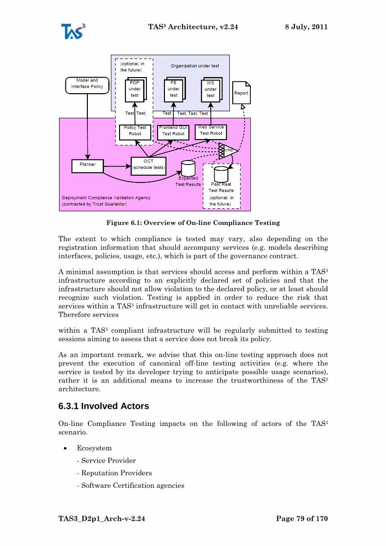
TAS3 Architecture, v2.24 8 July, 2011
TAS3_D2p1_Arch-v-2.24 Page 79 of 170
Figure 6.1: Overview of On-line Compliance Testing
The extent to which compliance is tested may vary, also depending on the
registration information that should accompany services (e.g. models describing
interfaces, policies, usage, etc.), which is part of the governance contract.
A minimal assumption is that services should access and perform within a TAS3
infrastructure according to an explicitly declared set of policies and that the
infrastructure should not allow violation to the declared policy, or at least should
recognize such violation. Testing is applied in order to reduce the risk that
services within a TAS3 infrastructure will get in contact with unreliable services.
Therefore services
within a TAS3 compliant infrastructure will be regularly submitted to testing
sessions aiming to assess that a service does not break its policy.
As an important remark, we advise that this on-line testing approach does not
prevent the execution of canonical off-line testing activities (e.g. where the
service is tested by its developer trying to anticipate possible usage scenarios),
rather it is an additional means to increase the trustworthiness of the TAS3
architecture.
6.3.1 Involved Actors
On-line Compliance Testing impacts on the following of actors of the TAS3
scenario.
Ecosystem
- Service Provider
- Reputation Providers
- Software Certification agencies
TAS3 Architecture, v2.24 8 July, 2011
TAS3_D2p1_Arch-v-2.24 Page 80 of 170
- Deployment certification and audit agencies
- Compliance Authority
Components
- Web Service (WSP)
- IdP (Identity Provider)
- Service Registry
- Id Mapper
- Linking Service
- Organizational PDPs
- Trust Network PDP
6.3.2 On-line Testing Process and Architecture
The TAS3 architecture includes an on-line testing infrastructure, in which, the
TAS3 services are tested according to a set of published models describing specific
behavioural characteristics of the service itself. In the following, the term OCT
refers both to the on-line compliance testing process and to the infrastructure
that implements it.
With respect to the current scope of the TAS3 architecture, the compliance testing
functionality requires that each service exposes within the TAS3 choreography its
public interface (i.e. its exported operations) and the public policies it will comply
with (or a references to them). In particular, each service is tested on-line when it
requests to be registered to a TAS3 directory service. Further on-line test sessions
can be activated by the compliance testing (i.e. Trust Network level) directory
service either in event-driven or periodic fashion.
Directory Services within a TAS3 architecture interact with testing components
to detect services failures. The compliance testing increases trust both on the
TAS3 architecture and the linked services. A software service willing to be
registered to a TAS3 directory service, may also have to comply with other
policies that are not publicly manifested. In this case the service will not be
tested with respect to such policies since such behaviour is hidden from the
external interfaces of the service.
During the on-line compliance testing process, references to the service should
not be retrievable by means of the directory service. At the end of the compliance
verification process, if and only if all the tests have been successfully executed,
service references will be listed by the directory service.
During the on-line testing, the OCT activates tester robots. Each tester invokes
the service under test simulating service requests with identity credentials taken
from a pre-packed identity test suite. The tester robot collects the service reply
(i.e. either a response message, or a deny access), and compares it with the
expected results: a difference between the service reply and the expected result
reveals a mismatch between how the service policy is manifested and how the
policy is implemented within the service.
TAS3 Architecture, v2.24 8 July, 2011
TAS3_D2p1_Arch-v-2.24 Page 81 of 170
Note that the TAS3 architecture has a precise requirement that error messages
returned after a request for a resource (e.g. "access denied" message) must be
identifiable as such. Applications might masquerade error messages for user-
friendliness (e.g. they could produce a "pretty formatted" page); nonetheless, the
TAS3 architecture needs to be able to unambiguously recognize error messages
without the need to delve into the semantics of the payload of the message. This
is accomplished by each application declaring to the on-line compliance testing
infrastructure at least one successful and one failing test case with exact
description of what the messages look like and what are the relevant parts.
In real life scenarios, a service under testmay need to access external services
when invoked by the tester robot. Indeed, in some cases a testing interaction
between the service under test and externally invoked service may have
permanent effects (e.g. on a stateful resource). Let‟s consider that the service
under test queries the directory service to lookup a relevant end point. In this
case, OCT should consider that the registry may return a reference to a Proxy
version of the required service: this service will implement the same interface as
the required service. Doing so, the real implementation of registered services is
hidden to those services waiting for compliance validation - a useful feature while
project is ongoing and full service is yet unavailable.
In such cases, the directory service and OCT have to be able to link to an existing
service proxy or to generate new ones. Obviously this will increase the complexity
of the framework and asks for the provisioning of service description models
suitable for automatic generation of service stubs.
Fig-6.2 depicts a UML Diagram describing the components of the On-line
Compliance Testing framework. In the following we list a detailed descriptions of
each component:
Compliance Validator Discovery Service: according to the architecture given
in Fig-6.2, this component enhances the functionality provided by the
Discovery Service. In particular, the Compliance Validator Discovery
Service is a Discovery Service able to apply the compliance validation at
runtime. The Compliance Validator Discovery Service aggregates three sub-
components: the Compliance Validator, the Proxy Factory and the Pending
Services DB.
Compliance Validator : this component activates the testing session when a
service makes a request for being included in a TAS3 infrastructure. The
testing session will result in a sequence of invocations to the services
requesting to be registered. In case the testing session does not highlight
any error the service will be registered otherwise the request will be
rejected.
Tester Robot: this is the component that actually runs the test on a given
service. In particular, the Compliance Validator activates the Tester Robot
passing to it a reference to the service that needs to be tested and to the
corresponding test suites to use.
Request Generator: this component defines which is the next invocation to
make to the service under test in order to assess its correctness;
TAS3 Architecture, v2.24 8 July, 2011
TAS3_D2p1_Arch-v-2.24 Page 82 of 170
Test Checker: this is the component that checks that the replies of the
service under test actually conform to what is specified;
Test Attribute Generator: this component defines which attribute values
are to be used in the testing invocations.
Front Channel Tester: this component extends the Tester Robot adding to
the tester component specific features to interact with the front channel of a
service application in TAS3. Since this component is a Tester Robot, it has
all the features that a Tester Robot has, including the relationship with the
other components (e.g. Request Generator, Test Checker, Test Attribute
Generator).
Back Channel Tester: this component extends the Tester Robot adding to
the tester component specific features to interact with the back channel of a
service application in TAS3. Since this component is a Tester Robot, it has
all the features that a Tester Robot has, including the relationship with the
other components (e.g. Request Generator, Test Checker, Test Attribute
Generator).
DB of Roles as Signed Test Response: this DB contains the identity test
suite that the tester can use to test other services simulating a different
identity.
DB Test Report: in this DB the compliance validator logs the result of a
testing session and the possible failures highlighted.
Proxy Factory: this component automatically generates proxy services to
simulate already registered services.
Pending Services DB: this DB will contain the identities of services that
requested to enter a TAS3 infrastructure precinct but still did not pass the
testing session. Services in such DB are not returned as result of a
discovery request. Identities are removed from this DB when the
corresponding testing session is terminated.
Note that, each entity (i.e. components or artifacts) in the diagram, has a role
with respect to the domain organization. Specifically, according to the general
architecture depicted in Fig-2.2:
The artifacts Public Iterface, and Public Policy, are entities within
theModelling&Configuration Management area,
The OCT components (Compliance Validator Discovery Service, Compliance
Validator, Tester Robot, Request Generator, Test Checker, Test Attribute
Generator, Front ChannelTester, Back Channel Tester, DB of Roles, DB
Test Report, Proxy Factory, and Pending Services DB) are entities within
the Audit & Monitor area,
The components IDP, Discovery Service, and Web Service, are entities
within the Runtime & Enforcement area.
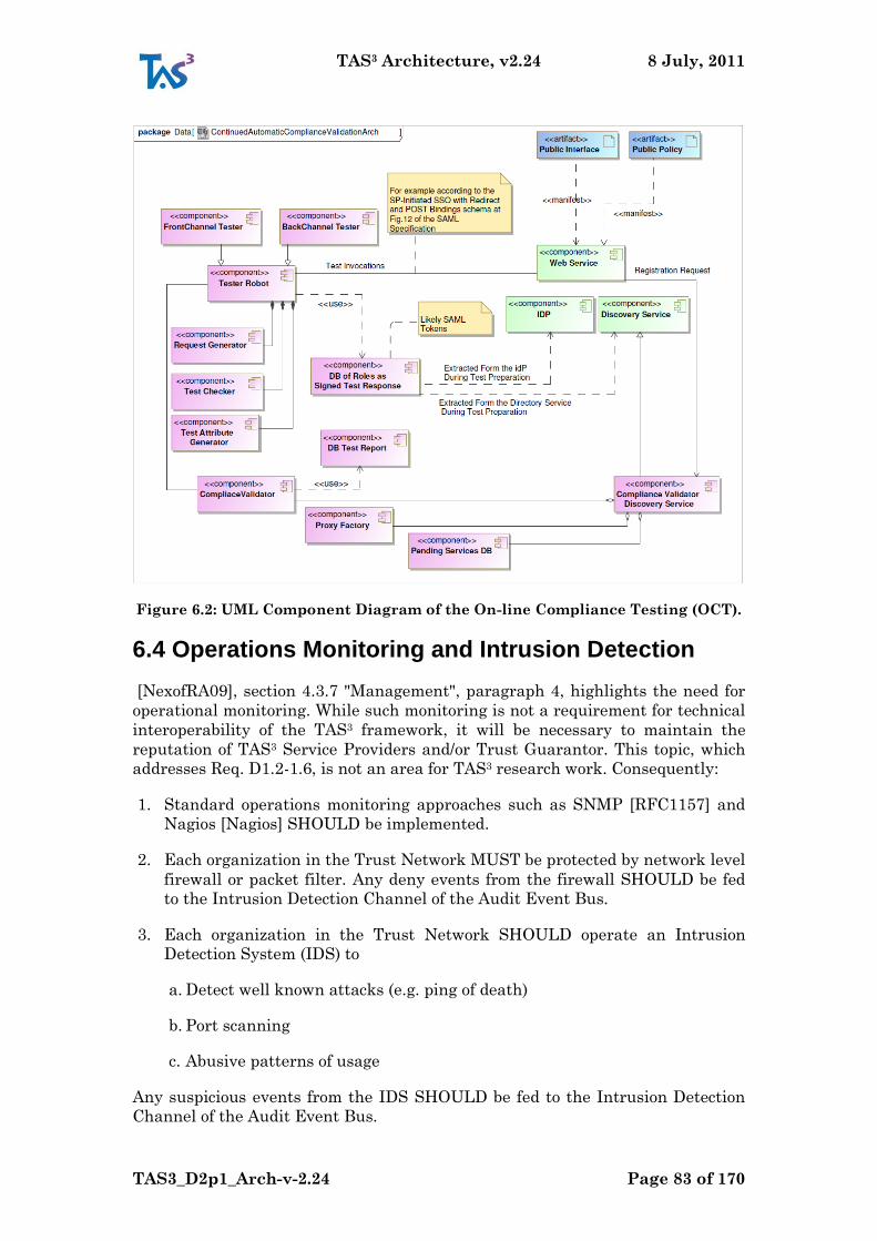
TAS3 Architecture, v2.24 8 July, 2011
TAS3_D2p1_Arch-v-2.24 Page 83 of 170
Figure 6.2: UML Component Diagram of the On-line Compliance Testing (OCT).
6.4 Operations Monitoring and Intrusion Detection
[NexofRA09], section 4.3.7 "Management", paragraph 4, highlights the need for
operational monitoring. While such monitoring is not a requirement for technical
interoperability of the TAS3 framework, it will be necessary to maintain the
reputation of TAS3 Service Providers and/or Trust Guarantor. This topic, which
addresses Req. D1.2-1.6, is not an area for TAS3 research work. Consequently:
1. Standard operations monitoring approaches such as SNMP [RFC1157] and
Nagios [Nagios] SHOULD be implemented.
2. Each organization in the Trust Network MUST be protected by network level
firewall or packet filter. Any deny events from the firewall SHOULD be fed
to the Intrusion Detection Channel of the Audit Event Bus.
3. Each organization in the Trust Network SHOULD operate an Intrusion
Detection System (IDS) to
a. Detect well known attacks (e.g. ping of death)
b. Port scanning
c. Abusive patterns of usage
Any suspicious events from the IDS SHOULD be fed to the Intrusion Detection
Channel of the Audit Event Bus.
TAS3 Architecture, v2.24 8 July, 2011
TAS3_D2p1_Arch-v-2.24 Page 84 of 170
6.5 Log Audit
This section addresses Reqs. D1.2-2.17-AuditUntamp, D1.2-3.3-Dash, D1.2-6.10-
Redress, and D1.2-7.21-Safe.
Log audit has several goals
1. In case of attempted repudiation, prove that events happened
2. For investigation, browse and visualize events so that a human investigator
can get a relevant and sufficient overview.
3. On an ongoing basis automatically detect noncompliant events
4. On an ongoing basis ensure that the systems are functioning correctly
5. Provide statistics about users and their behaviour
6. Provide statistics about system use and behaviour
7. Provide baseline of information that allows trust, security, and access control
mechanisms to be cross checked
Log audit raises several issues
A. Collection
B. Distribution
C. Privacy
D. Retention
E. Falsification
F. Omission
G. Denial of Service and overwhelming the logging system
The log audit could also be used for billing in some circumstances, but in general
we recommend that billing systems be built separately so that they can be cross
checked against the logging to detect errors.
A taxonomy of audit events is presented in Annex A "Enumeration of Audit
Events".
Some design requirements for Audit Log Files are discussed in [TAS3D42Repo].
Further requirements include
I. Append mode of access: Only append mode of access should be allowed, so
that users or applications cannot rewind an audit log file and delete or
modify information that has already been stored there
II. Authorised writing: Only authorised parties should be able to append log
records to the audit trail. Though unauthorised applications or attackers
TAS3 Architecture, v2.24 8 July, 2011
TAS3_D2p1_Arch-v-2.24 Page 85 of 170
may gain access to the audit trail and try to append fake log records to the
audit trail, or modify or remove the audit trail, this should be detected by
the tamper detection mechanism.
III. Timestamps: Every record in the audit trail should be timestamped to
provide a trusted record of when the audit data was received. We note that
if the audit service is trusted to record the audit data without tampering
with it, then it should also be trusted to append the correct time to the
data. Therefore we do not require a secure time stamping service.
IV. Secure communication: if the audit service operates as a web service then
there should be secure communications between the clients and the server
in order to ensure tamper resistance, data integrity and authorised
connection.
V. Secure storage on untrusted media: Since an audit trail may be viewed on
untrusted machines, the security mechanisms should ensure persistent
and resilient storage of the audit trail, and ensure detection of tampering
of the audit trail - modification, deletion, insertion, truncation, or
replacement. If tampering is detected, the audit service should be able to
notify the security auditor.
VI. Support multiple simultaneous clients: The audit service should be easily
and conveniently accessible and it should be able to serve multiple client
applications simultaneously.
VII. Logging efficiency: The computational work and the storage size required
by the audit service should be as efficient as possible.
VIII. Contents transparency: the audit service should be able to record any
digital content coming from any service.
IX. Authorised reading: Since the audit trail may contain personal or
sensitive information, then the audit service should ensure that only
authorised applications or people have the privilege to read the audit trail.
The audit trail may be encrypted to further protect confidentiality.
6.5.1 Log Collection and Storage
This section addresses Req. D1.2-2.22-GovtAccess.
In the TAS3 architecture the audit trail is collected and stored locally primarily
at the system entities, such as SPs, IdPs, the IM, and the like or near them in the
organizations that operate these entities. Everyone that collects a log is bound by
a Governance Agreement so that responsible behaviour can be enforced when
technical solutions fall short in some area of protection.
The log events originate in various components at various times, see Annex A
"Enumeration of Audit Events" for an idea of the types of events that will be
generated. For example, Web Services Stack component will check signatures on
the tokens (assertions) that are presented and log both positive and negative
outcomes.
TAS3 Architecture, v2.24 8 July, 2011
TAS3_D2p1_Arch-v-2.24 Page 86 of 170
The system entities that collect the audit trail or the centralized audit function of
the organization report the events in summary form, containing pointers to the
actual audit records, to the Audit Event Bus. Each component may keep its local
log in its own format (in future we may provide a standard format), but the
summary logging to the Audit Event Bus will follow the TAS3 standard format.
To facilitate standard format summary logging, TAS3 may provide a reusable
software library.
The Audit Event Bus is divided into channels to which different events are
broadcast. This allows minimal exposure as subscriptions can be on the basis of
only relevant events. The subscriptions can also be controlled such that only
authorized parties with "need to know" can see certain types of events (see req IX
above).
The Audit Event Bus is potentially implemented as part of a more generic Event
Bus infrastructure, but due to special privacy and security requirements, Audit
Events MUST NOT be mixed with other business messages, unless in encrypted
form. If the generic event bus supports an encrypted private channel, a VPN if
you like, then sharing of the infrastructure may be possible.
The Audit Bus infrastructure MUST be free of conflicts of interest. In particular,
it should not be operated by one of the SPs. In case the Event Bus sharing is
implemented, then the operator of the shared infrastructure MUST be free of
conflict of interest as well.
6.5.2 Privacy Issues: What to Collect and What to Report
This satisfies Req. D1.2-4.2-BPPrivacy.
The main issues are
1. Avoid logging anything to the summary audit trail that could become a
correlation handle
2. Avoid logging PII to the summary audit trail unless absolutely necessary
Generally a lot of detail will be logged locally. This will include the tokens used in
identification of the user, usually in pseudonymous form as well as the PII
handled by the Service Provider. This detail tends to be necessary to legally
protect the Service Provider. TAS3 does not restrict what information SPs can log
locally.
6.6 Administrative Oversight
This section partially addresses Req. D1.2-6.10-Redress.
Administrative oversight and stake holder issues are covered in [TAS3BIZ].
TAS3 Architecture, v2.24 8 July, 2011
TAS3_D2p1_Arch-v-2.24 Page 87 of 170
7 Conclusion: TAS3 is Secure and
Trustworthy
The comprehensive approach of the TAS3 architecture and framework achieves
real and tangible overall security and trustworthiness gains when compared with
state of the art for multiplayer networks of comparable size. The TAS3 features
that contribute to this are
1. Legal concerns are built-in from the ground up
2. A comprehensive and strong digitally signed audit trail
3. A conditionally pseudonymous audit trail to guarantee the privacy of Users
who play by the rules, while allowing abuse to be exposed through
collaboration of Service Providers.
4. A fully pseudonymous design at all layers to protect user privacy
5. Fully encrypted and digitally signed messages using strong algorithms
6. Based on state-of-the-art Single Sign-On protocol standard (SAML 2.0) which
has had extensive security review
Extensive security review and scrutiny already done
Multiple commercial and open source implementations that are mature.
Certification program for implementations further ensures quality
7. Based on state-of-the-art Identity Web Service Protocol standards (ID-WSF
2.0) which have had extensive security review
Extensive security review and scrutiny already done
Multiple commercial and open source implementations
Certification program for implementations further ensures quality
8. Enhanced authorization infrastructure which significantly improves upon
the current XACMLv2 standard
Extensive security review and scrutiny already done
Multiple commercial and open source implementations
9. Ability to use risk control and reputation
10. Use of ontologies to ensure consistent interpretation of data and
authorization rules
11. On-line Compliance Testing for early detection of discrepancies and problems
12. Business Process Modelling driven configuration to ensure consistently
correct configuration
TAS3 Architecture, v2.24 8 July, 2011
TAS3_D2p1_Arch-v-2.24 Page 88 of 170
13. TAS3 has performed a systematic threat and risk analysis (see Annex B) to
ensure that the architecture addresses the widest possible range of security
and privacy threats.
14. Software engineering techniques used by the project to consistently achieve
high quality and absence of security bugs in the software components that
are TAS3 deliverables.
The TAS3 Architecture is novel as a blueprint that brings together identity
management, attribute based access control, business process modelling, and
dynamic trust. The architecture acts as an interoperability profile for various
standards based protocols covering these areas. Other areas of innovation are
user transparency features like the Dashboard, user accessible audit trail, and
automated compliance validation; privacy protection using sticky policies;
marriage of trust and privacy Negotiation with discovery and trust scoring;
secure dynamic business processes; and built-in first class support for delegation.
TAS3 Architecture, v2.24 8 July, 2011
TAS3_D2p1_Arch-v-2.24 Page 89 of 170
Annex A: Enumeration of Audit Events
To understand the wealth of audit trail data we start by enumerating them all:
1. Session Events Channel:
a. Session creation (possibly even an anonymous session)
b. Session upgrade (e.g. SSO on an anonymous session, step-up auth)
c. Session refresh
d. Session termination
e. Session expiry
f. Session revival (if appropriate, could be used as a factor in authentication)
2. User Authentication Events Channel:
a. Positive
b. Failure with Retry
c. Definitive Failure
3. Token Issuing Channel:
a. Tokens issued with:
i. Issuer
ii. Subject
iii. Audience
iv. Policy constraints
v. Validity time and/or usage count
vi. General content of the token
b. Token validation at relying party
c. Token use, to the appropriate extent
d. Token revocation when applicable
4. Authorization Channel:
a. Az request parameters
b. Az decision returned
c. Obligations

TAS3 Architecture, v2.24 8 July, 2011
TAS3_D2p1_Arch-v-2.24 Page 90 of 170
5. Service Requester Channel:
a. Choice of Service Provider
i. Discovery
ii. Hardwired choice of Service
iii. Automated or algorithmic Choice of Service
iv. Choice of Service solicited from the User
b. Trust negotiation steps
c. Consent to send data, consent points, how was the answer obtained (e.g.
automatic vs. interaction)
d. Service Call event
i. Signature preparation, including choice of signing key
ii. Log of content of the message
iii. Peer authentication
iv. Success or failure to send message
e. Service Call exception
i. Redirect or end point change
ii. Recredentialing
iii. Interaction requested
iv. Replay after interaction
v. Dry-run
f. Service Call Response
i. Log of content of the message
ii. Peer authentication (usually by Request-Response pattern)
iii. Success or failure to receive message
g. Service Call Response exception
i. Failures, as detailed on the Faults Channel
ii. Application layer success or failure
h. Obligations processing
i. Presence of obligation
TAS3 Architecture, v2.24 8 July, 2011
TAS3_D2p1_Arch-v-2.24 Page 91 of 170
ii. Specific processing steps
iii. Failure to process obligation
6. Service Responder Channel:
a. Trust establishment and trust negotiation steps
b. Request Acceptance
c. Response filtering and authorization decision
d. Attachment of obligations
2. PII Collection Channel
3. PII Release Channel
4. User Registration Channel:
a. Register
b. Modify
c. Deregister
5. SP Registration Channel:
a. Register
b. Modify
c. Change of Control
d. Deregister
6. User Reputation Channel:
a. Explicit complaint or praise
b. Other events that affect reputation
7. Service Reputation Channel:
a. Explicit complaint or praise
b. Other events that affect reputation
8. Browsing Event Channel (usually not shared)
9. Faults Channel:
a. Malformed protocol message
b. Insufficient sec mech
TAS3 Architecture, v2.24 8 July, 2011
TAS3_D2p1_Arch-v-2.24 Page 92 of 170
c. Signature verification fault
i. Malformed
ii. Crypto (public key or hash)
iii. Certificate validity (missing CA trust chain)
d. Inappropriate use
i. Audience
ii. Constraints
e. Expired tokens
f. Replay of message or token
g. Unsolicited message
h. Missing database entry
i. Explicit fault report
10. DoS Channel:
a. Invocation frequency alert
b. Data volume alert
c. Explicit DoS report (e.g. from monitoring organizations)
11. Intrusion Detection System and Firewall ACL Channel:
a. Scan alert
b. Attack fingerprint alert
c. Firewall deny rule triggered
12. Operations monitoring Channel:
a. Server / Service
i. Up
ii. Down
iii. Scheduled downtime
iv. Congested
v. Retry
vi. Fail Over
TAS3 Architecture, v2.24 8 July, 2011
TAS3_D2p1_Arch-v-2.24 Page 93 of 170
13. Audit Operation Channel (very restricted circulation):
a. Undertaking audits
b. Outcomes of audit
14. Billing Event Channel
15. Customer Care Event Channel
TAS3 Architecture, v2.24 8 July, 2011
TAS3_D2p1_Arch-v-2.24 Page 94 of 170
Annex B: TAS3 Risk Assessment
B.1 Executive Summary
Threat modelling aims at studying the potential problems and attacks against a
system in order to document how attacks are mitigated. In this document, we
analyze threats and suggest solutions in order to produce internal threat analysis
document. It provides an assessment on how threats are mitigated and which
threats are remaining. It only provides the threat model of components developed
in this research project. TAS3 is an integration project with the vision of
implementing an architecture. Such an architecture-driven approach means to
use a methodology where the assessment can be done by component.
The document contains a brief overview of some existing methods, the description
of the methodology adopted (derived from the NIST800-30 Microsoft
methodology) and the risk assessment by components.
In the deliverable D2.1, the TAS3 Architecture has already presented some
inputs in this direction (Annex B that summarizes the threats that the TAS3
architecture is designed to protect against).
B.2 Introduction
This section provides a brief overview over some of the existing methods and
standards related to risk analysis. It concludes by identifying some issues that to
little degree are covered by the current state of the art. Most of the existing
methods have been presented in [?].
B.3 Risk Analysis Methods
B.3.1 OCTAVE (Operationally Critical Threat, Asset, and Vulnerability Evaluation)
OCTAVE [Alberts01] is a general approach for evaluating and managing
information security risks. As information security includes issues related to both
business and technology, an inter-disciplinary analysis team that includes people
from both the business units and the IT department performs the evaluation. The
evaluation is performed in three phases:
Phase 1 Build Asset-Based Threat Profiles. The analysis team identifies what is
important to the organization, i.e. what are the information-related assets
of the organization, and reviews what is currently being done to protect
those assets. The analysis team also selects the critical assets that are most
important to the organization. The team then describes security
requirements for the critical assets and identifies threats to the critical
assets.
Phase 2 Identify Infrastructure Vulnerabilities. The team evaluates the
information in-frastructure and identifies key information technology
systems and components re-lated to each critical asset. Key components are
TAS3 Architecture, v2.24 8 July, 2011
TAS3_D2p1_Arch-v-2.24 Page 95 of 170
examined for weaknesses (technol-ogy vulnerabilities) that can lead to
unauthorized action against critical assets.
Phase 3 Develop Security Strategy and Plans. The analysis team identifies risks
to the organization‟s critical assets and decides what to do about them. The
team cre-ates a protection strategy for the organization and mitigation
plans to address the risks to the critical assets, based upon an analysis of
the information gathered.
OCTAVE provides a snapshot analysis at a given point in time. Therefore,
OCTAVE advises that the organization either performs new evaluations
periodically or triggered by major events, such as corporate reorganization or
redesign of the computing infrastructure. OCTAVE comes with predefined
templates for documenting information during the analysis.
B.3.2 CRAMM
CRAMM (CCTA Risk Analysis and Management Method [Siemens10]) provides a
stepwise and disciplined risk analysis method that takes both technical and non-
technical (e.g. physical and human) aspects of security into account. In its
original form, it was adopted as a standard by the U.K. government organization
CCTA (Central Computer and Telecommunications Agency). Similarly to
OCTAVE, CRAMM defines three stages of analysis:
Stage 1 Asset identification and valuation. The reviewer identifies the physical
(e.g. IT hardware), software (e.g. application packages), data (e.g. the
information held on the IT system) and location assets that make up the
information system. Value is assigned to assets.
Stage 2 Threat and vulnerability assessment. The likelihood of potential
problems are identified, taking into consideration both accidental and
deliberate threats, such as hacking, viruses, equipment or software failure,
wilful damage or terrorism, and errors made by people. Based on this, the
risk level is calculated.
Stage 3 Countermeasure selection and recommendation. The measure of risk is
evaluated in order to decide what countermeasures should be implemented.
CRAMM provides a countermeasure library where a threshold level is
associated with the countermeasures, thereby providing aid in the decision
whether to implement a given countermeasure.
During a CRAMM analysis, the reviewer gathers information by interviewing the
asset owners, system users, technical support staff and security manager. A
standardized CRAMM format is used for documenting results, mostly in the form
of specialized tables.
B.3.3 Microsoft’s Security Risk Management
Microsoft has developed their own risk guideline [Microsoft06]. This guideline
defines the Microsoft Security Risk Management Process, which has four primary
phases:
TAS3 Architecture, v2.24 8 July, 2011
TAS3_D2p1_Arch-v-2.24 Page 96 of 170
Phase 1 Assessing risk. Data are gathered in order to identify risks to the
business, and to prioritize between the risks.
Phase 2 Conducting decision support. Functional requirements to mitigate risks
are defined. Control solutions (treatments) are identified and evaluated,
and a cost-benefit analysis is performed.
Phase 3 Implementing controls. The chosen control solutions are implemented
and deployed.
Phase 4 Measuring program effectiveness. The risk management process is
analyzed for effectiveness, and an evaluation of whether the controls
provide the expected degree of protection is performed.
As risk management is viewed as an ongoing process, these phases constitutes
the parts of a risk management cycle. The guideline also goes further than
defining this cycle. For example, it provides lists of common assets, threats and
vulnerabilities. However, these are not intended to be comprehensive, and
analysts are encouraged to add or delete items as necessary.
For example, the risk management guide for IT systems (NIST800-30) [NIST-
SP800-30]. defines a methodology to assess risks while developing an application.
B.3.4 CORAS
CORAS [BraberEA07] is a method for conducting security risk analysis. CORAS
provides a customized graphical language for threat and risk modelling, and
comes with de-tailed guidelines explaining how the language should be used to
capture and model relevant information during the various stages of the security
analysis. In this respect CORAS is model-based. Special CORAS diagrams are
used for documenting intermediate results, and for presenting the overall
conclusions. The CORAS language is supported by a structured semantics
translating CORAS diagrams into natural language (English) sentences
[DahlEA07]. Following the CORAS method, a security risk analysis is conducted
in seven steps:
Step 1 The first step involves an introductory meeting. The main item on the
agenda for this meeting is to get the representatives of the client to present their
overall goals of the analysis and the target they wish to have analyzed. Hence,
during the initial step the analysts will gather information based on the client‟s
presentations and discussions.
Step 2 The second step also involves a separate meeting with representatives of
the client. However, this time the analysts will present their understanding of
what they learned at the first meeting and from studying documentation that has
been made available to them by the client. The second step also involves a rough,
high-level security analysis. During this analysis the first threats,
vulnerabilities, threat scenarios and unwanted incidents are identified. They will
be used to help with directing and scoping the more detailed analysis still to
come.
TAS3 Architecture, v2.24 8 July, 2011
TAS3_D2p1_Arch-v-2.24 Page 97 of 170
Step 3 The third step involves a more refined description of the target to be
analysed, and also all assumptions and other preconditions being made. Step
three is terminated once all this documentation has been approved by the client.
Step 4 This step is organised as a workshop, drawn from people with expertise on
the target of the analysis. The goal is to identify as many potential unwanted
incidents as possible, as well as threats, vulnerabilities and threat scenarios.
Step 5 The fifth step is also organised as a workshop. This time the focus is on
estimating consequences and likelihood values for each of the identified
unwanted inci-dents.
Step 6 This step involves giving the client the first overall risk picture. This will
typically trigger some adjustments and corrections.
Step 7 The last step is devoted to treatment identification, as well as addressing
cost/benefit issues of the treatments. This step is best organized as a workshop.
The terminology of CORAS is to a large degree taken from the standard
(Standars Australia / Standars New Zealand 2004). Therefore, the conceptual
foundation is to a large degree in accordance to this standard.
B.3.5 ISO/IEC 27001 (BS7799-2:2002)
ISO 27001 is a standard [ISO27001]. The risk assessment concerns a generic
requirement that risk assessment has to be made through a recognized method
but no support is provided.
The Risk treatment is a generic recommendation that risk treatment has to be
made.
The risk acceptance concerns an indirectly implied through "statement of
applicability".
This standard is dedicated to a process of certification. It enables the comparison
of an information security management system through a series of controls. This
standard does not cover risk analysis or certification of the Risk Management. Of
UK origin, this standard has been adopted by ISO with some modifications. A
certificate granted according to this standard confirms the compliance of an
organization with defined requirements to information security management and
a set of security controls.
B.4 Our methodology
Here are some advantages/disadvantages of each of the methods described above:
OCTAVE is a self-directed approach, meaning that people from an organization
assume responsibility for setting the organization‟s security strategy. OCTAVES
is a variation of the approach tailored to the limited means and unique
constraints typically found in small organizations (less than 100 people).
OCTAVE is led by a small, interdisciplinary team (three to five people) of an
organization‟s personnel who gather
TAS3 Architecture, v2.24 8 July, 2011
TAS3_D2p1_Arch-v-2.24 Page 98 of 170
and analyze information, producing a protection strategy and mitigation plans
based on the organization‟s unique operational security risks. To conduct
OCTAVE effectively, the team must have broad knowledge of the organization‟s
business and security processes, so it will be able to conduct all activities by
itself.
CRAMM is a risk analysis method developed by the British government
organization CCTA (Central Communication and Telecommunication Agency),
now renamed the Office of Government Commerce (OGC). A tool having the same
name supports the method: CRAMM. The CRAMM method is rather difficult to
use without the CRAMM tool. The first releases of CRAMM (method and tool)
were based on best practices of British government organizations. At present
CRAMMis the UK government‟s preferred risk analysis method, but CRAMM is
also used in many countries outside the UK. CRAMM is especially appropriate
for large organizations, like government bodies and industry.
Special Publication 800-series report gives very detailed guidance and
identification of what should be considered within a Risk Management and Risk
Assessment in computer security. There are some detailed checklists, graphics
(including flowchart) and mathematical formulas, as well as references that are
mainly based on US regulatory issues.
The main innovations of the CORAS project stem from its emphasis on
integrating risk analysis tightly into a UML and RM-ODP setting, supported by
an iterative process, and underpinned by a platform for tool-integration targeting
openness and interoperability.
The standard ISO/IEC 27001 (BS7799-2:2002) does not cover risk analysis or
certification of the Risk Management.
What we need is a directed and detailed approach and NIST800-30 answers in
big part to this. To evaluate the threat against TAS3 components, a methodology
based on the book "Threat Modeling" [SwiderskiSnyder04] has been chosen. This
threat modeling is quite similar to NIST800-30 but proposes deeper analysis that
can be directly integrated with software development tool enabling threat
modelling from design to test. Even if both approaches would be suitable, the
latter has been chosen for pragmatic reasons: a European project already worked
successfully with this methodology (the Mosquito Project). Then, to fulfill
specificities of collaborative research projects, we slightly changed the approach.
Indeed, threat modeling is generally used to study threats against an application
or a system and to verify that common threat are correctly handled and
mitigated. In TAS3, we focus on the threat model of the TAS3 components and are
thus confronted to uncommon threats and mitigations.
B.5 Risk Assessment Methodology
The following methodology is used in this document:
i. Identify Components
j. Identify sub components and entry points
TAS3 Architecture, v2.24 8 July, 2011
TAS3_D2p1_Arch-v-2.24 Page 99 of 170
k. Identify Assets
l. Identify Threat
m. Identify Attacks
n. Identify Mitigation
For each of the last four sections, we propose a list of possible choices. These
choices are just given as examples, they may not cover the entire spectrum of
threats, attacks, or mitigation.
B.5.1 Identify the Components2
The threat model is defined component by component since components can be
reused in different applications and to let project partner work on their own
component(s) in parallel.
Here is the list of TAS3 components:
1. T3-ACVS: Authorization Credential Validation Service
2. T3-BP-CLIENT: Business Process User Interface
3. T3-BP-DEL: Business Process Delegation Service
4. T3-BP-ENGINE-ODE: Apache ODE Business Process Execution Engine
5. T3-BP-MGR: Business Process Administration Interface
6. T3-BP-PEP: Business Process Policy Enforcement Point
7. T3-BP-PIP: Business Process Policy Information Point
8. T3-BP-SMC: Business Process Security Configuration Component
9. T3-BUS-AUD: Audit Event Bus
10. T3-DEL: Delegation Service
11. T3-IDB-ACSIS
12. T3-IDP-SHIB: Shibboleth IDP
13. T3-IDP-SHIB-AGG: Enhancement to Shibboleth IDP to support attribute
aggregation
14. T3-LOG-SAWS: Secure Auditing Web Service
15. T3-LOG-WRAP-SAWS: Wrapper Web service around SAWS with extensions
16. T3-OCT: Online Compliance Testing
2 This section may need to be updated in September once the final components for the
pilots are finished.
TAS3 Architecture, v2.24 8 July, 2011
TAS3_D2p1_Arch-v-2.24 Page 100 of 170
17. T3-OCT-PLANNER: Test Planner fo the Online Compliance Testing
18. T3-ONT-SER: Ontology Server
19. T3-PDP-BP: Business Process Policy Decision Point
20. T3-PDP-BTG: Break the Glass PDP
21. T3-PDP-M: Policy Decision Point/Master PDP
22. T3-PDP-P: PERMIS PDP
23. T3-PDP-T: Trust Policy Decision Point
24. T3-PEP-AI: Application-independent Policy Enforcement Point
25. T3-POL-GUI: Graphical Policy Editor
26. T3-POL-CNL: Controlled Natural Language Policy Editor
27. T3-POL-WIZ: Wizard Policy Editor
28. T3-PORT-JBOSS: JBOSS portal framework
29. T3-REP-FEDORA: TAS3 reference repository
30. T3-REP-JFEDORA: JFEDORA Library for TAS3 Generic Data Format
31. T3-SG-BASE: SOA Gateway Base System
32. T3-SG-WSP: SOA Gateway Web Service Provider
33. T3-SP-CVT: Europass CV Transcoding Web Service
34. T3-SP-MATCHER: Job Profile Matching Service
35. T3-STACK and T3-SSO-ZXID
36. T3-TPN-TB2: Trust Negotiation Module
37. T3-TRU-CTM: Credential based trust service
38. T3-TRU-KPI: Key Performance Indicators
39. T3-TRU-RTM: Reputation Trust Management Service
40. T3-ZXID-LINUX-X86: ZXID library and tools for TAS3 in apache, Java, PHP,
and C
41. ZXID-SRC: Sources for the ZXID package
B.5.2 Identify the Sub Component
Each component offers different entry points, i.e. borderlines between the
component and the external world that may be under attack. We distinguish two
TAS3 Architecture, v2.24 8 July, 2011
TAS3_D2p1_Arch-v-2.24 Page 101 of 170
types of entry points: "intended" entry points, i.e. entry point that are visible to
other trust domains (WS-Trust interface, etc.) and "internal" entry points that
are not directly related to the TAS3 framework (http-level attacks, direct DB
access, getting access to OS key store, etc.).
B.5.3 Identify the assets
Each component has assets, i.e. valuable pieces of information or functionalities
that have to be protected against attackers. We can distinguish between
functional assets, i.e. assets related to the application itself (e.g. medical data in
e-health service), and non-functional assets, i.e. assets related to the TAS3
framework itself. This document focuses on the TAS3 components and mainly
describes non functional assets. This is not covered by traditional approaches.
B.5.4 Indentify the Threats
A threat is a high-level description explaining what can go wrong (e.g. personal
data disclosed, critical data destroyed). It is not directly related to the technology
used to implement the component.
1. Auditing and Logging
- User denies performing an operation
- Attackers exploit an application without leaving a trace
- Attackers cover their tracks
2. Authentication
- Network eavesdropping
- Brute force attacks
- Dictionary attacks
- Cookie replay attacks
- Credential theft
3. Authorization
- Elevation of privilege
- Disclosure of confidential data
- Data tampering
- Luring attacks
4. Configuration Management
- Unauthorized access to administration interfaces
- Unauthorized access to configuration stores
- Retrieval of plaintext configuration secrets
- Lack of individual accountability
- Over-privileged process and service accounts
5. Cryptography
TAS3 Architecture, v2.24 8 July, 2011
TAS3_D2p1_Arch-v-2.24 Page 102 of 170
- Poor key generation or key management
- Weak or custom encryption
- Checksum spoofing
6. Exception Management
- Attacker reveals implementation details
- Denial of service
- Sensitive Data
- Access to sensitive data in storage
- Network eavesdropping
- Data tampering
7. Input / Data Validation
- Buffer overflows
- Cross-site scripting
- SQL injection
- Canonicalization
- Query string manipulation
- Form field manipulation
- Cookie manipulation
- HTTP header manipulation
8. Session Management
- Session hijacking
- Session replay
- Man in the middle
B.5.5 Identify the Attacks
An attack is a concrete way to make a threat real (e.g. attacker gets access to
personal databy). Attacks can be related to the technology used to implement the
component. Here some examples of potential attacks.
Buffer Overflow Attack
Canonicalization Attack
Chosen Plaintext Attack
Cross Site Scripting Attack
Denial of Service Attack
Forceful Browsing Attack
Format String Attack
HTTP Replay Attack
TAS3 Architecture, v2.24 8 July, 2011
TAS3_D2p1_Arch-v-2.24 Page 103 of 170
Integer Overflow Attack
LDAP Injection Attack
Man in the Middle Attack
Network Eavesdropping Attack
One-click Attack
Credentials Brute Force Attack
Password Dictionary Attack
Repudiation Attack
Response Splitting Attack
Server-side Code Injection Attack
Session Hijacking Attack
SQL Injection Attack
XML Injection Attack
B.5.6 Identify the mitigation
Mitigation is a mechanism to prevent the attack. Mitigations can be features of
the framework (e.g. credentials are signed by issuers), can be mechanisms offered
by underlying OS or network (e.g. private keys are stored in the machine‟s key
store) or can be missing (e.g. not implemented). In this last case, the threat is not
mitigated. However, it is useful to know that this threat exists. For instance, the
fact that non-repudiation is not ensured for message X in component Y can be
acceptable for a type of application but when the same component would be
reused in another application, mitigation may be necessary.
For mitigation, the following are used:
Implemented Mitigation means that the mitigation is implemented and used
in the demonstrator.
Exisiting Mitigation means that there is an existingmitigation that could be used
without implementation specific to TAS3. For instance using https or a firewall
would mitigate the attack.
Not Implemented Mitigation means that the mitigation has not been
implemented. A solution is known but more development is required to use it.
No Mitigation means that there is no solution to mitigate the attack. In this
case the attack has to be "acceptable".
When multiple mitigations exist, they are listed in the tree, i.e. by default there
is an "or" operator between tree‟s nodes where Implemented or :( equals
Implemented.
1. Input / Data Validation
- Assume all input is malicious.
TAS3 Architecture, v2.24 8 July, 2011
TAS3_D2p1_Arch-v-2.24 Page 104 of 170
- Centralize your approach.
- Do not rely on client-side validation.
- Be careful with canonicalization issues.
- Reject known bad input
- Constrain input.
- Validate data for type, length, format, and range.
- Reject known bad input.
- Sanitize input.
- Encrypt sensitive cookie state.
- Make sure that users do not bypass your checks.
- Validate all values sent from the client.
- Do not trust HTTP header information.
- Encrypt sensitive cookie state.
- Do not trust fields that the client can manipulate (query strings, form
fields, cookies, or HTTP headers).
- Validate all values sent from the client.
- Do not trust input
- Consider centralized input validation.
- Do not rely on client-side validation.
- Be careful with canonicalization issues.
- Constrain, reject, and sanitize input.
- Validate for type, length, format, and range.
2. Authentication
- Do not use passwords. Use hardware authentication tokens instead.
- Separate public and restricted areas.
- Use account lockout policies for end-user accounts.
- Support password expiration periods.
- Be able to disable accounts.
- Do not store passwords in user stores.
- Use strong passwords.
- Do not send passwords over the wire in plaintext.
- Protect authentication cookies.
- Partition site by anonymous, identified, and authenticated area.
- Support password expiration periods and account disablement.
- Do not store credentials (use one-way hashes with salt).
TAS3 Architecture, v2.24 8 July, 2011
TAS3_D2p1_Arch-v-2.24 Page 105 of 170
- Encrypt communication channels to protect authentication tokens.
- Pass Forms authentication cookies only over HTTPS connections.
3. Authorization
- Use multiple gatekeepers.
- Restrict user access to system-level resources.
- Consider authorization granularity.
- Use least privileged accounts.
- Consider authorization granularity.
- Enforce separation of privileges.
- Restrict user access to system-level resources.
4. Auditing and Logging
- Audit and log access across application tiers.
- Consider identity flow.
- Log key events.
- Secure log files.
- Back up and analyze log files regularly.
- Identify malicious behavior.
- Know what good traffic looks like.
- Audit and log activity through all of the application tiers.
- Secure access to log files.
5. Configuration Management
- Secure your configuration store.
- Maintain separate administration privileges.
- Use least privileged process and service accounts.
- Do not store credentials in plaintext.
- Use strong authentication and authorization on administration interfaces.
- Do not use the LSA.
- Secure the communication channel for remote administration.
- Avoid storing sensitive data in the Web space.
6. Sensitive Data
- Do not store database connections, passwords, or keys in plaintext.
- Avoid storing secrets in the Local Security Authority (LSA).
- Retrieve sensitive data on demand.
- Encrypt the data or secure the communication channel.
TAS3 Architecture, v2.24 8 July, 2011
TAS3_D2p1_Arch-v-2.24 Page 106 of 170
- Do not store sensitive data in persistent cookies.
- Do not pass sensitive data using the HTTP-GET protocol.
- Avoid storing secrets.
- Secure the communication channel.
- Provide strong access controls on sensitive data stores.
7. Session Management
- Use SSL to protect session authentication cookies.
- Encrypt the contents of the authentication cookies.
- Limit session lifetime.
- Protect session state from unauthorized access. Secure the channel.
- Encrypt the contents of authentication cookies.
- Protect session state from unauthorized access.
8. Cryptography
- Do not develop your own cryptography.
- Use the correct algorithm and correct key size.
- Secure your encryption keys.
- Use tried and tested platform features.
- Keep unencrypted data close to the algorithm.
- Cycle your keys periodically.
- Store keys in a restricted location.
- Exception Management
- Do not leak information to the client.
- Log detailed error messages.
- Catch exceptions.
- Use structured exception handling.
- Do not reveal sensitive application implementation details.
- Do not log private data such as passwords.
- Consider a centralized exception management framework.
B.6 T3-ACVS: Authorization Credential Validation Service
This is part of the T3-PEP-AI component.
TAS3 Architecture, v2.24 8 July, 2011
TAS3_D2p1_Arch-v-2.24 Page 107 of 170
B.7 T3-BP-CLIENT: Business Process User Interface
B.7.1 Entry points
i. Intended entry point: User interface
ii. Intended entry point: SSO-related Communication with IdP
iii. Intended entry point :Communication to BP-Engine - Starting process
instances, creating and completing tasks
iv. Internal entry point: Policy Store
v. Intended entry point : Decision requests to the T3-PDP-BP
B.7.2 Asset: State of process instances, confidentiality and integrity of process data
i. Ability to start processes
ii. Ability to complete tasks
iii. Access to process data
Threat 1 Unauthorized access to tasks (i.e., viewing or completing tasks).
Attack Session hijacking attack
Mitigation Implemented Usage of SSL to protect
session authentication cookies
Mitigation Implemented Limit session lifetime
Threat 2 Phishing attack.
An attacker can present a site similar to the T3-BP-CLIENT to the user and
make him confuse this fake site with the real site. It can thus trick him to
enter confidential information because he believes a legitimate business
process requests the information.
Mitigation Implemented Use SSL certificate
Use an SSL certificate to proof the site‟s identity. This should be
accompanied by teaching users basic security precautions on the Web.
B.8 T3-BP-DEL: Business Process Delegation Service
B.8.1 Entry points
i. Intended entry point: Interface for re-assigning tasks to another user
ii. Internal entry point: Decision requests to the T3-PDP-BP
TAS3 Architecture, v2.24 8 July, 2011
TAS3_D2p1_Arch-v-2.24 Page 108 of 170
iii. Internal entry point: Registration of changed task assignment in the T3-
BP-PIP
B.8.2 Asset: Integrity of user-task assignment
The current functionality of the T3-BP-DEL is re-assignment of tasks from one
user to another. Normally, requests to do so are authenticated and authorized.
Threat 1 Assignment of tasks caused by other user than the current owner (or
an authorized administrator)
Attack Pose as another user when requesting task-reassignment
Existing mitigation Use TAS3 authentication mechanism (identity
assertions) to validate requests.
Threat 2 Re-assignment of tasks to non-authorized users
Attack Spoof PDP response
Implemented mitigation PDP and T3-BP-DEL run on the same
dedicated machine.
Existing mitigitation Encrypt and sign communication with PDP
B.9 T3-BP-ENGINE-ODE: Apache ODE Business Process Execution Engine
B.9.1 Entry points
i. Intended entry point: Process deployment
ii. Internal entry point: Interaction with BP-Client
iii. Internal entry point: Interfaces for communication with PEP
B.9.2 Asset: Executable process models
Process models define the behavior of applications and deal with sensitive
information.
Threat 1 Flawed business process with unintended behavior
Attack Unauthorized deployment of of process models
Implemented mitigation Password authentication of administrator
access to process deployment
Existing mitigation Strong authentication (cryptographic identity
assertions)
Not implemented mitigation Fine-grained authorization rules for
process models.
TAS3 Architecture, v2.24 8 July, 2011
TAS3_D2p1_Arch-v-2.24 Page 109 of 170
Not implemented mitigation Logging of modifications to process models.
B.9.3 Asset: Running process instances (state and data)
The engine executes instances of business processes. Correct application behavior
relies on the state and data of these instances.
Threat Stopping running process instances
If running business process instances are stopped, they won‟t complete,
possibly causing inconsistent behavior, and preventing reaching the
application goal.
Attack Unauthorized access to administration interface
Implemented mitigation Password authentication of administrator
access to process deployment
Existing mitigation Strong authentication (cryptographic identity
assertions)
Not implemented mitigation Fine-grained authorization rules for
process models.
Not implemented mitigation Logging of modifications to process models.
B.10 T3-BP-ENGINE-ODE: Apache ODE Business Process Execution Engine
B.10.1 Entry points
i. Intended entry point: Process deployment
ii. Internal entry point: Interaction with BP-Client
iii. Internal entry point: Interfaces for communication with PEP
B.10.2 Asset: Executable process models
Process models define the behavior of applications and deal with sensitive
information.
Threat Flawed business process with unintended behavior
Attack Unauthorized deployment of of process models
Implemented mitigation Password authentication of administrator
access to process deployment
Existing mitigation Strong authentication (cryptographic identity
assertions)
TAS3 Architecture, v2.24 8 July, 2011
TAS3_D2p1_Arch-v-2.24 Page 110 of 170
Not implemented mitigation Fine-grained authorization rules for
process models.
Not implemented mitigation Logging of modifications to process models.
B.10.3 Asset: Running process instances (state and data)
The engine executes instances of business processes. Correct application behavior
relies on the state and data of these instances.
Threat Stopping running process instances
If running business process instances are stopped, they won‟t complete,
possibly causing inconsistent behavior, and preventing reaching the
application goal.
Attack Unauthorized access to administration interface
Implemented mitigation Password authentication of administrator
access to process deployment
Existing mitigation Strong authentication (cryptographic identity
assertions)
Not implemented mitigation Fine-grained authorization rules for
process models.
Not implemented mitigation Logging of modifications to process models.
B.11 T3-BP-MGR: Business Process Administration Interface
B.11.1 Entry points
i. Internal entry point: Communication with T3-BP-ENGINE-ODE
ii. Intended entry point: Graphical user interface
B.11.2 Asset: Status of business process instances
The T3-BP-MGR will trigger adaption of business process models and especially
the migration of running business process instances to a new version of a model.
Threat Unauthorized alteration of business process instances, unauthorized
disclosure of process instance status.
Attack 1 Spoofing identity of authorized user in communication between T3-
BP-MGR and the engine.
Existing mitigation Strong authentication (cryptographic identity
assertions)
Attack 2 Illegitimate operations by authorized users.
TAS3 Architecture, v2.24 8 July, 2011
TAS3_D2p1_Arch-v-2.24 Page 111 of 170
The user might use a altered client software. If checks only occur at client
side, the user might be able to perform unauthorized actions in the engine.
Not implemented mitigation Perform all necessary checks (also) on
server side.
Existing mitigation Log all activities for audit purposes, limit the people
allowed to perform management activities on the engine.
Attack 3 Spyware
An attacker can try to provide the user with an altered client software,
which requests the user to authenticate normally, but makes other requests
than what the user thinks he has authorized.
Existing mitigation Control software installation on the user‟s computer.
If software installation is not controlled, the user‟s system has to be
considered insecure anyway, which makes it prone to all sorts of attacks.
B.12 T3-BP-PEP: Business Process Policy Enforcement Point
B.12.1 Entry points
i. Internal entry point: Communication between PEP and PIP
ii. Internal entry point: Communication between PEP and T3-BP-ENGINE-
ODE
iii. Internal entry point: Communication with T3-PDP-BP (policy decision
requests and responses)
B.12.2 Asset: Correct policy enforcement
Threat 1 A process communicates without policy enforcement
Attack 1 Process models containing direct calls to third party web services,
bypassing the PEP
Implemented mitigation Manual check of process models
Not implemented mitigation Automatic check of process models
Not implemented mitigation Integration of the PEP as a layer in the
web service stack of the execution engine
Attack 2 Calling the process‟ web service interfaces directly, bypassing the
PEP
Existing mitigation Block access from outside using a firewall.
TAS3 Architecture, v2.24 8 July, 2011
TAS3_D2p1_Arch-v-2.24 Page 112 of 170
Not implemented mitigation Integration of the PEP as a layer in the
web service stack of the execution engine
Threat 2 Tricking PEP into using a rogue PDP
Attack Changing PDP address in PEP configuration.
Implemented mitigation Protect PEP code and configuration from
unauthorized alteration using file system permissions.
B.13 T3-BP-PIP: Business Process Policy Information Point
B.13.1 Entry points
i. Internal entry point: Communication between PEP and PIP
ii. Communication with T3-BP-ENGINE-ODE
iii. Communication with PDP
B.13.2 Asset: Correct information for policy enforcement
Threat 1 Context information about processes not up to date.
The context of a process (current point of execution, assigned users)
continuously changes. Up-to-date information is necessary for correct policy
enforcement.
Attack Interrupt communication between engine and PIP. Implemented
mitigation: Run engine and PIP on the same dedicated machine.
This makes it much harder to interrupt communication.
Existing mitigation Enforce a time-to-live on information in the PIP,
check directly on the engine if TTL is expired.
Threat 2: PIP accepts and provides invalid/untrusted context information.
Attack Push incorrect context information to the PIP.
Existing mitigation Cryptographically sign messages to the PIP.
Existing mitigation Correctly configure trusted sources.
Existing mitigation Only accept input from the same host (using a
firewall) which only runs BP-related component.
TAS3 Architecture, v2.24 8 July, 2011
TAS3_D2p1_Arch-v-2.24 Page 113 of 170
B.14 T3-BP-SMC: Business Process Security Configuration Component
The T3-BP-SMC processes security specifications for business processes (either
as annotations or separate specifications) and translates them into business
process related security configuration (e.g. business process policies) and
enhances business process models with explicit security subprocesses.
B.14.1 Entry points
i. Intended interface: Security configuration user interface
ii. Intended interface: Processing of annotations to business process model
security enhancements
iii. Intended interface: Processing of additional business process security
configuration
iv. Internal interface: Deployment of security configuration to runtime
components.
B.14.2 Asset: Business process security annotations and security
Threat 1 Inaccurate use of business process security annotations or
specifications
Attack Process security modeler makes faulty or incomplete security
annotations or specifications
Mitigation Process security modeler has to be trained for working with
business process security annotations and specifications.
Threat 2 Unauthorized modification of business process security annotations or
specifications
Attack Unauthorized person changes the security configuration of a business
process.
Not implemented mitigation User access control for SMC component, for
business process models with security annotations and for security
specification files.
B.14.3 Asset: Security enhanced business process models and business process security configurations generated by the SMC component
Threat Unauthorized modification of security enhanced business process models
or security configurations.
TAS3 Architecture, v2.24 8 July, 2011
TAS3_D2p1_Arch-v-2.24 Page 114 of 170
Attack Unauthorized person changes the security configuration of a business
process or the security enhanced business process itself.
Not implemented mitigation Secured deployment of business processes
and appropriate security configurations from the SMC component to the
business process engine (T3-BPENGINE-ODE): Webservice calls with
signed file transfer.
Implemented Mitigation User access control on application and file
system level for the business process engine.
B.15 T3-BUS-AUD: Audit Event Bus
B.15.1 Entry points
i. Intended Entry point: Interface with subscription clients
ii. Intended Entry point: Interface with notification clients
iii. Intended Entry point: Interface with update clients
B.15.2 Asset: Channels of audit event type
Threat Overload of service creating failure in audit notifications
Attack Denial of service
Not Implemented Mitigation To prevent a denial of service attack the
services calling the audit bus will be limited to specific pre- authenticated
TAS3 infrastructure services. Specific terms of behaviour will govern these
services and the Audit Bus will be monitored to detect if a service making
calls to the bus is in breach of these (an example could be behaviour that
can be deemed as a denial of service attack). In this case the offending
service will be reported to the appropriate authority and blacklisted from
calling the bus. The architecture will also be designed to allow scaling and
multiple audit bus implementations to manage load better.
B.15.3 Asset: Status of audit event type
Threat 1 Unauthorised invocation of the audit bus
Attack Unauthorised access to audit bus Web service interface
Not Implemented Mitigation In order to update the status of an audit
event or invoke the bus a token will be needed. The token is used to present
the correct credentials to the audit bus server. This token comes from the
main TAS3 authorisation infrastructure.
Threat 2 Audit bus notification leak
Attack Unauthorised access to audit bus notifications
TAS3 Architecture, v2.24 8 July, 2011
TAS3_D2p1_Arch-v-2.24 Page 115 of 170
B.16 T3-DEL: Delegation Service
B.16.1 Entry points
i. SOAP web interface
ii. Apache PHP client
iii. Shell or root shell administrative login
B.16.2 Assets
i. Issued credentials (these are cryptographically protected)
ii. Private signing key of the delegation issuing service
iii. Configuration file (list of trusted proxies)
iv. Trust store of the delegation issuing service (application server)
v. The delegation policy (this is cryptographically protected)
B.16.3 Threats
i. Unauthorized delegation
ii. Unauthorized revocation (leading to denial-of-service)
iii. Denial-of-service attack so that authorised requests will be denied
Attack 1 Compromising the private signing key of the service.
A compromise of the signing key of the delegation issuing service could lead to
fake credentials being issued, and hence to unauthorized delegations.
Existing Mitigation Keep the private key of the delegation issuing service in
a password protected key store. Use file system permissions to prevent the
service configuration file from being read by any entity except the application
server running the service. Use an account with limited capabilities (no login
shell) to run the application server. If no direct access to the delegation issuing
service is required (e.g. when accessing service through a trusted proxy) the
application server can be kept behind a firewall.
Attack 2: Listing oneself as a trusted proxy.
By definition, a trusted proxy is trusted to tell the delegation
issuing service who the actual issuer is. If one can add oneself to
the list of trusted proxies and obtain an SSL certificate that will
be trusted by delegation issuing service (or its application server)
then one can make false issuing requests (that will be accepted if
they obey the delegation policy). Likewise, once the delegation
issuing service is fooled into thinking that one is a trusted proxy,
one can make bogus revocation requests.
TAS3 Architecture, v2.24 8 July, 2011
TAS3_D2p1_Arch-v-2.24 Page 116 of 170
Existing Mitigation: Use file system permission to prevent unauthorized
modification of the service configuration file (which contains the list of trusted
proxies). Alternatively digitally sign the configuration file. Or use a password
protected trust store to prevent unauthorized modification of it. Use a
reputable CA, or an in house CA (with an off line private key) to issue SSL
certificates to the trusted proxies.
Attack 3 Modifying or replacing the delegation policy.
If one can modify the delegation policy then one can for instance add oneself as
a trusted attribute issuer, or add oneself as a member of a specific domain etc.
Implemented Mitigation Use a (self-signed) X.509 AC to hold the delegation
policy. Use signature verification prior to loading the policy to ensure the
integrity of the X.509 AC. Use file system permissions to protect the
delegation issuing service‟s configuration files from unauthorized modification.
This configuration file contains the policy reference, policy location and the
certificates that are the roots of trust of the signature verification process.
Attack 4 Gaining access to the credential repository.
Since the credentials are digitally signed then it is not possible to either
modify a credential or mint a new one without access to the signing key. If an
attacker gains access to the credential repository she can only delete the
credentials in the repository. This will have the effect that legitimate access
requests will be denied by a PDP when configured to pull from this repository.
Existing Mitigation Restrict access to the credential repository by for
instance keeping it behind a firewall. When using an LDAP repository
configure it so that the login credentials given write access to the repository
cannot be obtained by simply sniffing the network.
Attack 5 Obtain the password of a legitimate user of the DIS client.
Once an attacker has obtained the password of a legitimate user of the DIS
client, then she can make false delegation requests.
Existing Mitigation Use an SSL connection to protect the password from
being visible on the Internet. Configure the (Apache) web server to not serve
the DIS client pages on a http only connection. Ensure that user passwords
are strong and impossible to dictionary attack.
B.17 T3-IDP-ACSIS
B.17.1 Entry points
i. Shell or root shell (or ssh) administrative login
ii. TAS3 designed management interfaces (none yet)
iii. Product specific management interfaces
TAS3 Architecture, v2.24 8 July, 2011
TAS3_D2p1_Arch-v-2.24 Page 117 of 170
- - New user registration (feature to allow anonymous new user to self
register)
- - Auto-CoT (fully automatic metadata exchange and trust establishment
with anonymous third party SPs)
- - New service registration (feature to allow anonymous 3rd party to
register new services)
iv. Web GUI
v. SOAP web service
- - SSO
- - SLO
- - Discovery query
B.17.2 Data assets
i. Private keys of the service itself
ii. Circle-of-Trust database
iii. Discovery Registrations
iv. User database
- • User names
- • Authentication credentials (password hash, Yubikey shared secret)
- • User‟s attribute data
v. Federation database: name id mappings
vi. Session store
B.17.3 Nonfunctional assets
i. Privacy preserving through avoidance of correlation handles
ii. User consent and control of data release
iii. Organizational control of data release
iv. Nonrepudiation
v. Accountability
vi. Credible authentication of users
vii. Credible authentication of system entities
B.17.4 Attacks and mitigation
Too numerous to describe exhaustively in one afternoon *** TBD
TAS3 Architecture, v2.24 8 July, 2011
TAS3_D2p1_Arch-v-2.24 Page 118 of 170
Generally the data assets are protected using Unix filesystem permissions
against shell and local Unix process access. This, of course, is of little value
against root. Therefore deployment MUST use nonroot users for running all
TAS3 related processes as well as for most administrative tasks.
The TAS3 designed and product specific management interfaces follow good
coding practises (e.g. check for ".." in path) to only allow designed access to
the data assets.
Web GUI is coded such that only authorized accesses are possible
SOAP web service is coded such that only authorized accesses are possible
Appropriate crypto layer (such as TLS) is applied in Web GUI, SOAP, and
ssh entry points
B.18 T3-IDP-SHIB: Shibboleth IDP
B.18.1 Entry Points
i. SOAP Authentication Service Endpoint
ii. SOAP Attribute Authority Endpoint
iii. Shell or root shell administrative login
B.18.2 Asset: Issued Credentials
Threat Issues Credentials used by More than One Party
Attack Replay Attack
If intercepted by a third party, credentials may be submitted to the SP at
which they are valid multiple times. Without adequate replay protection this
may allow multiple users to access the service using the same set of
credentials
Existing Mitigation Replay Detection
Implement checks at the SP to log the details of each incoming message so
that if the same message is passed to the SP multiple times it can be
recognised and the presenter denied access.
B.18.3 Asset: Private Signing Keys of the Service
Threat Private Signing Key of the Service is Compromised
A compromise of the signing key of the modified IdP could lead to fake
attribute or authorisation credentials being issued, and allow an untrusted
service to masquerade as the IdP entity.
Attack Attacker Gains Access to Machine Hosting the Service
Existing Mitigation Use Password Protected Key Store
TAS3 Architecture, v2.24 8 July, 2011
TAS3_D2p1_Arch-v-2.24 Page 119 of 170
Keep the private key of the IdP in a password protected key store.
Existing Mitigation Use File System Permissions
Use file system permissions to prevent the service configuration file from
being read by any entity except the application server running the
service.
Existing Mitigation Use Restricted Account
Use an account with limited capabilities (no login shell) to run the
application server.
Existing Mitigation Restrict Access to Service
If no direct access to the IdP is required (e.g. when accessing service
through a trusted proxy) the application server can be kept behind a
firewall.
B.18.4 Asset: User Database (Attributes and Authentication Credentials)
Threat 1 User Authentication Credentials are Compromised
Once an attacker has obtained the password of a legitimate user of the IdP
client, then she can masquerade as the user throughout the federation.
Attack 1 Dictionary attack
An attacker may attempt to obtain the username / password combination of a
legitimate user of the IdP by performing a dictionary attack on the
authentication page.
Implemented Mitigation Restriction of Number of Authentication Requests
The authentication endpoint should monitor the number of authentication
attempts that are made for each incoming authentication session. After a
configurable number of failed authentication attempts have been made the
authentication attempt should fail and return an error message to the requesting
SP.
Attack 2 Network Sniffing
Implemented Mitigation Use SSL/TLS connection
Use an SSL connection to protect the password from being visible on the
Internet. Con- figure the (Apache) web server to not serve the IdP
authentication pages on a http only connection.
Implemented Mitigation Use Different Authentication Mechanism
Implement two factor or challenge/response authentication mechanisms
to increase the user‟s level of assurance.
TAS3 Architecture, v2.24 8 July, 2011
TAS3_D2p1_Arch-v-2.24 Page 120 of 170
Threat 2 IdP Assertions are Reused (Credential Theft)
Attack Assertions are Stolen
Once issued by the IdP attribute and authorisation credentials may be
stolen in transit by an intermediary and presented to another SP in
order to grant another user access.
Implemented Mitigation:: Limited Life Time
Every credential should be short lived to prevent an attacker having
unlimited time to reuse the credential.
Implemented Mitigation:: Restrict SPs at which Assertion is valid
Each credential should be encrypted to the intended recipient
making the credential worthless to all but the intended recipient.
SPs should obey any audience restriction present in the assertion.
Implemented Mitigation:: Tie Authentication and Attribute Assertion
Together
Each attribute credential should contain a Subject that is identical
to that of the Subject of the preceding authentication assertion to
prevent it from being used as part of a different session.
Threat 3 User Attributes are Disclosed to Unauthorised Party
User attributes should not be disclosed to unauthorized parties.
Attack Network Sniffing
Implemented Mitigation Use of Cryptographic Techniques
All incoming messages are encrypted using the IdPs public key and the
IdP encrypts all outgoing messages using the public key of the recipient
SP.
Threat 4 Compromise of Backend Database / LDAP Server
If an attacker can access or modify the backend database/LDAP server then
she may be able to edit the credentials.
Attack Unauthorised Access Gained to Backend Data Store
Existing Mitigation Use of Firewall
Use a firewall to restrict access to the backend data store. This need not
be accessible from the Internet, even if the IdP has to be.
Existing Mitigation Use of SSL/TLS
When administrator access is needed to the backend data store, then the
credentials should not be conveyed in clear text. Communication with
the database should either be local or over SSL.
TAS3 Architecture, v2.24 8 July, 2011
TAS3_D2p1_Arch-v-2.24 Page 121 of 170
B.18.5 Asset: Session Information
B.18.6 Asset: Configuration Files of the Service
Threat Unauthorised Modification of the Configuration Files
If an attacker can modify the IdPs configuration files then they can edit the
attributes that will be released from the IdP, add additional un-trusted
attribute sources, or remove security precautions such as the signing and
encryption of outgoing messages.
Attack Attacker Gains Unauthorised Access and Modifies Configuration
Files
Existing Mitigation Use of File System Permissions
Use file system permissions to prevent the service configuration files
from being read by any entity except the application server running the
service.
Existing Mitigation Use of Restricted Account
Use an account with limited capabilities (no login shell) to run the
application server.
B.18.7 Non-functional Asset: User Consent and Control of Data Release
B.18.8 Non-functional Asset: Organisation Control of Data Release
B.19 T3-IDP-SHIB-AGG: Enhancement to Shibboleth IDP to support attribute aggregation
Please note: The more general risk analysis presented in preceding Section 2.18
for the Shibboleth IdP also applies to this section. The additional risks presented
below apply only to the changes required to support aggregation.
B.19.1 Entry points
i. SOAP web interface for auditing
ii. SOAP web interface for enquiries
iii. Administrative shell login
iv. Application management console of application server
B.19.2 Asset: The Audit Trail
Threat 1 Modification of Audit Trail
TAS3 Architecture, v2.24 8 July, 2011
TAS3_D2p1_Arch-v-2.24 Page 122 of 170
Attack Attacker Accesses Auditing Service Machine and Modifies/Deletes the
Audit Trail
An attacker may gain unauthorized access to the machine hosting the
logging service. In this way she may be able to modify or remove the audit
trail.
Implemented Mitigation Cryptographic Protection
The SAWS audit trail structure uses cryptographic techniques to ensure
that unauthorized modification of the audit trail will not go unnoticed. It
uses heartbeats to ensure that records are not removed from the end. It
chains audit files together to ensure that complete audit files cannot be
deleted without notice. It periodically creates new audit files to ensure
they do not become too long.
Existing Mitigation File System Permissions
Use file system permissions to restrict access to the audit trail, e.g. only
allow the appli- cation server‟s account to write to the file.
Existing Mitigation Use Restricted Account
Run the application server with a restricted account (e.g. an account
without a login shell). Restrict access to the machine hosting the
logging service by e.g. running it behind a firewall if possible.
Existing Mitigation Backup the Audit Trail
Periodically backup complete audit files to CD-ROM or similar to
prevent loss or modi- fication in case of an attack.
Threat 2 Unauthorised Disclosure of Audit Trail Contents
Attack 1 Attacker Obtains Complete Copy of Audit Trail
If the machine hosting the audit service (or one of the machines holding the
backup of the audit trail) is compromised then it may be possible that the
attacker gets to read access to audit information that she shouldn‟t be able
to read.
Implemented Mitigation Encryption of Audit Trail Data
If confidentiality of the audited data is important then the audit service
can be configured to encrypt the audited data with a symmetric key.
This symmetric key is stored in the audit trail, encrypted with the public
key of the persons authorised to read the contents of the trail. In this
way, the audit trail is not readable by subjects not having one of the
correct private keys.
Attack 2 Attacker Abuses the Enquiry Service
An attacker may abuse the enquiry service by issuing search requests for
data that she isn‟t allowed to see.
TAS3 Architecture, v2.24 8 July, 2011
TAS3_D2p1_Arch-v-2.24 Page 123 of 170
Existing Mitigation Use Authorisation on Enquiry Service
The enquiry service is still in an embryonic state of implementation, but
it is envisaged that a PDP will be used both before searching the audit
trail and to filter the results re- turned to the requester. The enquiry
service will run over SSL and will require client authentication, possibly
using a list of trusted proxies to say who the actual requester is.
B.19.3 Asset: SAWS Records a Secure Audit Trail
Threat Denial of Service for Legitimate Clients
Attack Attacker Swamps Service with Requests
Implemented Mitigation Only Allow Known Clients
The auditing service only accepts messages from known clients. This is
ensured by con- figuring the application server to run the auditing service
over SSL only. The application server has to be configured to require client
authentication. Configure the trust store to only accept messages from
clients having a certificate issued by a trusted CA. Further, the SAWS
configuration file contains a list of known clients; only these are allowed to
add messages to the audit trail.
Existing Mitigation Use Firewall
When the IP-addresses of the attacker are known these can already be
blocked on the level of the (operating-system) firewall, so that they never
reach the application server.
B.19.4 Asset: Private Keys for Signing/Encrypting
Threat Compromise of the Private Signing or Encryption Key
Attack Attacker Gains Access to Machine Hosting Auditing Service
An attacker may gain access to the machine hosting the audit service and
in this way obtain a copy of service‟s secrets. For instance, if a copy of the
private signing key is obtained, then an attacker would be able to modify
the audit trail without this being noticed.
Implemented Mitigation Use of Password Protected Key Stores
Use password protected key stores (which can optionally require more
than one password to be opened) to hold the service‟s secrets. The
passwords are asked for interactively and are not stored in the
configuration file. Only when automatic (i.e. without human
intervention) start up of the service is required do you need to store
passwords in a file. This file should be properly protected using file
system permissions and should only be readable by the application
server hosting the audit service.
Existing Mitigation Use of TPM to Store Secrets
TAS3 Architecture, v2.24 8 July, 2011
TAS3_D2p1_Arch-v-2.24 Page 124 of 170
The encrypted software keystore could be replaced with a hardware TPM
based keystore which will forbid tampering or unauthorised access.
Existing Mitigation File System Permissions
B.20 T3-LOG-SAWS: Secure Auditing Web Service
B.20.1 Entry points
i. SOAP web interface for auditing
ii. SOAP web interface for enquiries
iii. Administrative shell login
iv. Application management console of application server
B.20.2 Asset: The Audit Trail
Threat 1 Modification of Audit Trail
Attack Attacker Accesses Auditing Service Machine and Modifies/Deletes the
Audit Trail
An attacker may gain unauthorized access to the machine hosting the
logging service. In this way she may be able to modify or remove the audit
trail.
Implemented Mitigation Cryptographic Protection
The SAWS audit trail structure uses cryptographic techniques to ensure
that unauthorized modification of the audit trail will not go unnoticed. It
uses heartbeats to ensure that records are not removed from the end. It
chains audit files together to ensure that complete audit files cannot be
deleted without notice. It periodically creates new audit files to ensure
they do not become too long.
Existing Mitigation File System Permissions
Use file system permissions to restrict access to the audit trail, e.g. only
allow the appli- cation server‟s account to write to the file.
Existing Mitigation Use Restricted Account
Run the application server with a restricted account (e.g. an account
without a login shell). Restrict access to the machine hosting the
logging service by e.g. running it behind a firewall if possible.
Existing Mitigation Backup the Audit Trail
Periodically backup complete audit files to CD-ROM or similar to
prevent loss or modification in case of an attack.
TAS3 Architecture, v2.24 8 July, 2011
TAS3_D2p1_Arch-v-2.24 Page 125 of 170
Threat 2 Unauthorised Disclosure of Audit Trail Contents
Attack 1 Attacker Obtains Complete Copy of Audit Trail
If the machine hosting the audit service (or one of the machines holding the
backup of the audit trail) is compromised then it may be possible that the
attacker gets to read access to audit information that she shouldn‟t be able
to read.
Implemented Mitigation Encryption of Audit Trail Data
If confidentiality of the audited data is important then the audit service
can be configured to encrypt the audited data with a symmetric key.
This symmetric key is stored in the audit trail, encrypted with the public
key of the persons authorised to read the contents of the trail. In this
way, the audit trail is not readable by subjects not having one of the
correct private keys.
Attack 2 Attacker Abuses the Enquiry Service
An attacker may abuse the enquiry service by issuing search requests for
data that she isn‟t allowed to see.
Existing Mitigation Use Authorisation on Enquiry Service
The enquiry service is still in an embryonic state of implementation, but
it is envisaged that a PDP will be used both before searching the audit
trail and to filter the results re- turned to the requester. The enquiry
service will run over SSL and will require client authentication, possibly
using a list of trusted proxies to say who the actual requester is.
B.20.3 Asset: SAWS Records a Secure Audit Trail
Threat Denial of Service for Legitimate Clients
Attack Attacker Swamps Service with Requests
Implemented Mitigation Only Allow Known Clients
The auditing service only accepts messages from known clients. This is ensured
by con- figuring the application server to run the auditing service over SSL only.
The application server has to be configured to require client authentication.
Configure the trust store to only accept messages from clients having a certificate
issued by a trusted CA. Further, the SAWS configuration file contains a list of
known clients; only these are allowed to add messages to the audit trail.
Existing Mitigation Use Firewall
When the IP-addresses of the attacker are known these can already be blocked on
the level of the (operating-system) firewall, so that they never reach the
application server.
TAS3 Architecture, v2.24 8 July, 2011
TAS3_D2p1_Arch-v-2.24 Page 126 of 170
B.20.4 Asset: Private Keys for Signing/Encrypting
Threat Compromise of the Private Signing or Encryption Key
Attack Attacker Gains Access to Machine Hosting Auditing Service
An attacker may gain access to the machine hosting the audit service and
in this way obtain a copy of service‟s secrets. For instance, if a copy of the
private signing key is obtained, then an attacker would be able to modify
the audit trail without this being noticed.
Implemented Mitigation Use of Password Protected Key Stores
Use password protected key stores (which can optionally require more
than one password to be opened) to hold the service‟s secrets. The
passwords are asked for interactively and are not stored in the
configuration file. Only when automatic (i.e. without human
intervention) start up of the service is required do you need to store
passwords in a file. This file should be properly protected using file
system permissions and should only be readable by the application
server hosting the audit service.
Existing Implementation Use of TPM to Store Secrets
The encrypted software keystore could be replaced with a hardware TPM
based keystore which will forbid tampering or unauthorised access.
Existing Mitigation File System Permissions
B.21 T3-LOG-WRAP-SAWS: Wrapper Web service around SAWS with extensions
B.21.1 Entry points
o. SOAP client
B.21.2 Asset: Audit Trails
Threat 1 Traceless Exploitation
Attack Attackers exploit an application without leaving a trace
Mitigation Identify malicious behaviour.
Threat 2 Disguising the attack
Attack Attackers cover their tracks
Existing Mitigation Using audit/log files
Existing Mitigation Audit and log activity through all of the application
tiers.
TAS3 Architecture, v2.24 8 July, 2011
TAS3_D2p1_Arch-v-2.24 Page 127 of 170
Existing Mitigation Secure access to log files.
B.22 T3-OCT: Online Compliance Testing
The TAS3 architecture supports a novel testing approach for services that are
running within a TAS3 choreography. Such approach is implemented within the
TAS3 architecture by the OCT (On-line Com- pliance Testing) component. The
novel idea behind OCT is that services are submitted to the execution of a set of
test cases in their real execution environment, while they possibly interact with
other services. The service under tests are unaware that some invocation they
receive comes from OCT. OCT validation may be performed periodically or after
some relevant event, aiming at verifying that every service in the TAS3
federation abides by the manifested policies and/or complies with the functional
specifications. As detailed in D10.2, on-line testing in TAS3 is applied in order to
reduce the risk that services within a circle of trust (i.e. service federation) will
get in contact with unreliable services. Therefore services within the federation
will be regularly submitted to on-line testing to assess that they comply with
their public and manifested policies. Also, the scenario we foreseen for OCT
assumes that, within the federation, services admit that different requesters may
play different roles. Service clients collect credentials in order to prove the role
that they are playing as requesters. Thus, the authorization/authentication
layers in TAS3 (e.g. the IdP components) collaborates with OCT components
signing role assertions that would be used in running the test cases.
Note that the OCT components uses the security layer provided by the TAS3
architecture. Thus it exists a strict dependency in term of security vulnerabilities
with the issues described for the T3-STACK and the component T3-SSO-ZXID
(see Section 4.39).
B.22.1 Entry points
i. Intended Entry Point: SOAP Binding with the IdP
ii. Internal Entry Point: The API of the OCT component, used in order to
implement the test-driver
B.22.2 Non-Functional Assets
i. the OCT component credentials
ii. user/test user credentials
iii. QoS of the service under test
The following threats are relate to the non functional assets
Threat 1 The service under test have to be unaware of the TAS3 testing session,
the credential issued for testing purposes can be actually spent as valid
credential within the federation.Malicious services may obtain from the IdP
credential that was originally issued only for testing purposes and use them
illicitly.
TAS3 Architecture, v2.24 8 July, 2011
TAS3_D2p1_Arch-v-2.24 Page 128 of 170
Attack 1 Man in the middle
Malicious services can sniff the communication between the OCTcomponent
and the IdPs in TAS3
Attack 2 Spoofing
Malicious services masquerade their interaction to the IdP as the OCT
component. Implemented Mitigation::
i. Usage of SSL or TLS Client Certificate toprotect session
authentication in the communication between the OCT
component and the
ii. Use the security assets of the TAS3 -STACK
iii. Limit session lifetime
Threat 2 A massive use of the on-line testing process can affect the QoS of the
service under test.
Attack Denial of Service (DoS)
Malicious services that have gained the OCT credential can exploit them
running Denial-Of- Services attacks to other services in the TAS3
choreography
Implemented Mitigation Use the security assets of the TAS3 -STACK
Threat 3 The credential used during an on-line testing session may have
undesired effect on actual users.
The threat 4.18.2.5 does not refer to any specific attack. However, as potential
errors and failures of the on-line testing activity may generate unconsidered
security leak affecting real user, we recommended some implemented
mitigations for this threat.
Implemented Mitigation Create and use realistic test user
B.23 T3-OCT-PLANNER: Test Planner for the Online Compliance Testing
The TAS3 -OCT-PLANNER is an off-line component. With respect to the TAS3
Architecture it belongs to the Modeling & Configuration Management
Realm. In particular, the TAS3 -OCT-PLANNER can be used off-line in order to
moel test cases, and it is not affected by run-time security issues.
B.24 T3-PDP-BP: Business Process Policy Decision Point
The need of this component is currently not clear; see PDP-M and PDP-P for
possible attacks;
TAS3 Architecture, v2.24 8 July, 2011
TAS3_D2p1_Arch-v-2.24 Page 129 of 170
B.25 TAS3 -ONT-SER: Ontology Server
B.25.1 Entry Points
Command line access
J2EE Interface: uses JBoss, which provides means for security
(authentication, etc.)
Intended Entry point:
i. J2EE Bean delegating calls to internal beans
ii. LEXONBASE (CRUD LEXON & CONTEXT)
iii. COMMITMENT (CRUD COMMITMENT)
iv. VERSIONNING (prototype)
v. PERSPECTIVE CONFLICT MANAGEMENT (prototype)
B.25.2 Asset: Ontology Server
Threat Trust Policy Disclosure/Modification (heading4)
Attack 1 The administrator access to the repository and disclose/change the
trust policies
Existing Mitigation External Monitoring and Logging mechanism
Standard provided by JBoss for the application server WEB CONSOLE +
logging via shell Keeping of who modified what in the business layer
Attack 2 Unauthorized access to the ontology server
Existing Mitigation Logging and monitoring mechanisms
The data assets are stored in a Postgres database on a Linux server,
which is protected through the login to the database.
The J2EE interface uses username and passwords to enable authorised
access to the data. The REST interface will be implemented and will give
authorised access to people with the right credentials/tokens.
Existing Mitigation: Use of authorization mechanisms
- provided by JBoss
- IP blocked for 10 minutes after 3 unsuccessful logins (prevent
intrusion
- no open ports
Attack 3 forcing the access to the database
TAS3 Architecture, v2.24 8 July, 2011
TAS3_D2p1_Arch-v-2.24 Page 130 of 170
Existing Mitigation Use of secure channels for data transmissions (i.e.
HTTPS)
B.26 T3-PDP-BTG: Break the Glass PDP
This is part of theT3-PEP-AI component. Here we discuss an additional asset
specific to the T3-PDP- BTG
B.26.1 Entry points
See entry points of T3-PEP-AI.
B.26.2 Asset: The BTG-State of the System
Threat Unauthorised Modification of the BTG-State
When an attacker manages to modify the BTG state, then she may be able to
get access to certain resources without actually breaking the glass, hereby
circumventing any obligations (such as audit and notification) that may be
associated with breaking the glass.
Attack Gain Access to Machine Hosting BTG-State and Modify It
Existing Mitigation In-Memory Only Implementation
The BTG-state is implemented in-memory only, making it hard for an
attacker to modify it as the operating system manages the boundaries
between the memory areas assigned to different applications.
B.27 T3-PDP-M: Policy Decision Point/Master PDP
This is part of theT3-PEP-AI component.
B.28 T3-PDP-P: PERMIS PDP
B.28.1 Entry Points
i. Java API
B.28.2 Asset: Authorisation Policy
Threat Policy is Modified
Attack Attacker Modifies Authorisation Policy
An attacker tries to edit the authorisation policy in order to grant access to
people who should not have access or deny access to people who should have
access.
Implemented Mitigation Cryptographic Protection
TAS3 Architecture, v2.24 8 July, 2011
TAS3_D2p1_Arch-v-2.24 Page 131 of 170
The PERMIS policy is designed to be digitally signed and the PERMIS
engine validates the signature at start up time. Hence an attacker would
need to gain access to the private key of the policy author in order to
effectively edit the policy.
B.29 T3-PDP-T: Trust Policy Decision Point
B.29.1 Entry points
i. Internal Entry point: Shell or root shell
ii. Intended Entry point: Trust PDP Evaluation Request
iii. Intended Entry point: Trust PDP Call-back Function
iv. Intended Entry point: Returned value from Trust Service call
v. Intended Entry point: Trust Policy Repository Interfaces
B.29.2 Asset: Trust Policy
Threat Trust Policy Disclosure/Modification
A malicious agent accesses the trust policies and discloses or manipulates
them. Like any policies, manipulation needs to be prevented and the policies
are sensitive information that should be protected from being revealed.
Attack Malicious administrator
A malicious administrator accesses to the repository and discloses/changes
the trust policies.
Existing Mitigation External monitoring and logging mechanisms to
track the administrator‟s activities. These mechanisms should be external
to the Trust-PDP in order to avoid their manipulation performed by the
administrator.
Attack Unauthorized access
A malicious agent gains access to the trust policy repository to
disclose/change the trust policies.
Existing Mitigation Logging and monitoring mechanisms to track the
access records and to detect illegal behaviours.
Existing Mitigation Use of authorization mechanisms to control the
access to the trust policy repository.
Attack Man in the Middle or network eavesdropping
A malicious agent gains the access to the trust policies during the
querying/updating pro- cess.
TAS3 Architecture, v2.24 8 July, 2011
TAS3_D2p1_Arch-v-2.24 Page 132 of 170
Existing Mitigation Use of secure channels for data transmissions (i.e.
HTTPS).
B.29.3 Asset: Trust-PDP Evaluation Service
Threat 1 Trust-PDP service not available
A malicious agent makes the Trust-PDP unavailable for the intended users.
Attack Denial of Service (DOS) attack
A malicious agent or a collectiveness of malicious agents saturates the
Trust-PDP evaluation service with a huge amount of requests.
Implemented Mitigation The existence of monitoring and logging
mechanisms to trace sus- pect behaviours.
Existing Mitigation The utilization of a firewall for the input/output
traffic filtering.
Existing Mitigation Geographically restrictions on access domain: the
service is made avail- able only to well known locations where requests are
expected from.
Threat 2 Unauthorized Access to the Trust PDP evaluation service
A malicious agent uses the Trust-PDP evaluation service, sending requests
and obtaining responses to use for malevolent purposes.
Attack Brute Force or Password Dictionary
A malicious agent obtains the access performing a brute force attack (trying
all the possible passwords) or a password dictionary attack (trying with the
most likelihood passwords).
Existing Mitigation Mechanisms that press for the usage of strong and
effective passwords.
Implemented Mitigation Logging and monitoring mechanisms to detect
possible misbehaviours.
Implemented Mitigation Single Sign On (SSO) authorization
mechanisms to automatically and safely generate strong and secure tokens.
Threat 3 Request/Response Modification
A malicious agent changes the request or the response in order to manipulate
the results of the evaluation.
Attack Parameter Tampering or Man in the Middle.
A malicious agent gains the access to the messages exchanged during a
request/response process and alters such messages in a malevolent way.
TAS3 Architecture, v2.24 8 July, 2011
TAS3_D2p1_Arch-v-2.24 Page 133 of 170
Existing Mitigation Data integrity check mechanisms to verify that a
response is feasible for a given request.
Existing Mitigation Mechanisms to link the response message to its
associated request message.
Existing Mitigation Use of secure channels for data transmissions (i.e.
HTTPS)
B.30 T3-PEP-AI: Application-independent Policy Enforcement Point
B.30.1 Entry Points
i. SOAP web interface
ii. Administrative shell login
B.30.2 Asset: Built-in Policies
Threat Unauthorised Modification of Built-in Policies
Attack Attacker manages to replace the policy contents of a built-in policy
If an attacker gains access to the machine hosting the policies (which is not
necessarily the same as the machine hosting the AIPEP) then maybe she
can replace a built-in policy with one of her own making.
Implemented Mitigation Cryptographic Protection
For PERMIS policies this attack is defended against by encapsulating
the policy in a (self signed) X.509 Attribute Certificate. The
cryptographic signature on the X.509 AC prevents tampering with its
contents.
Existing Mitigation File System Permissions
For other policy formats, in particular XACML policies for the Sun
XACML PDP or for the trust PDP, no such cryptographic protection
exists at the moment. File system permissions can give some protection:
the policies should only be readable (and not even writeable) by the AI-
PEP itself.
B.30.3 Asset: Configuration File
Threat Unauthorised Modification of Configuration File
Attack Attacker Modifies Configuration File
If an attacker gains access to the machine hosting the AI-PEP, then she
may be able to modify the configuration file e.g. to load an additional policy
or to remove a policy which would deny her access.
TAS3 Architecture, v2.24 8 July, 2011
TAS3_D2p1_Arch-v-2.24 Page 134 of 170
The configuration file also contains the roots of trust for signature
verification, so the attacker might also able to add a PKC of her liking to as
a root of trust.
Existing Mitigation File System Permissions
Use file system permissions to protect the configuration file from being
changed. Configura- tion file should only be readable by account running
the AI-PEP service.
Existing Mitigation Use Restricted Account
The AI-PEP service should be run under an account with very few
permissions, e.g. without remote login capabilities.
B.30.4 Asset: Roots of Trust (PKCs) for Signature Verification
Threat Attacker Adds/Deletes/Replaces the PKCs used for Signature
Verification
Attack Attacker Gains Access to Machine with PKCs and Modifies Them
Existing Mitigation File System Permissions
Existing Mitigation Use a Password Protected Trust Store
Keeping the PKCs in a password protected trust store requires the
attacker to guess the password for the trust store (or otherwise break its
security).
Existing Mitigation Use Restricted Account
B.30.5 Asset: System Coordinates Decision Making
Threat System Crashes
Attack An Attacker Crafts a Malicious Message in Order to Crash the System
An attacker might attempt to send an authorization request (or a request to
validate some credentials) to is formed in such a way as to make the server
crash.
Implemented Mitigation Use of Schema Checking
The system is built in such a way that only requests conforming to the
schema ever reach the server. A SOAP message not conforming to the
schema is discarded by the Axis2 SOAP layer around the actual server.
B.30.6 Asset: The Sticky Store
Threat Unauthorised Modification of Sticky Store
TAS3 Architecture, v2.24 8 July, 2011
TAS3_D2p1_Arch-v-2.24 Page 135 of 170
Since the sticky store holds the binding between resources and the policies
applicable to them, modifying this store might get an attacker unauthorised
access to resources.
Attack Attacker Modifies the Sticky Store by Gaining Access to the Machine
Hosting the Sticky Store
Non existing Mitigation Use Proper Access Control to Sticky Store
The sticky store hasn‟t been fully implemented yet. A first version will be
a simple in- memory implementation of the sticky store which is by
definition hard to modify for an attacker. However, once a persistent
implementation (e.g. by using a relational database) is used then proper
access controls need to be in place to prevent unauthorised access to this
persistent storage.
B.31 T3-POL-GUI: Graphical Policy Editor
B.31.1 Entry points
Graphical User Interface of the application
B.31.2 Asset: Information in Configuration File
Threat Credentials to Policy Repository are Leaked
Attack 1 Attacker Reads Configuration File
Existing Mitigation File System Permissions
Non existing Mitigation Don‟t Store Secrets in the Configuration File
Attack 2 Attacker Sniffs Network Communication
Existing Mitigation Use SSL/TLS for Communication between PE and
Repository
B.31.3 Asset: Private Signing Key Used to Sign Policies
Threat Compromise of the signing key
Attack Attacker Gains Access to Machine Running PE and Obtains Signing
Key
Implemented Mitigation Use a Password Protected Key Store for the
Private Key
Implemented Mitigation Do Not Store Password in a File
TAS3 Architecture, v2.24 8 July, 2011
TAS3_D2p1_Arch-v-2.24 Page 136 of 170
B.32 T3-POL-CNL: Controlled Natural Language Policy Editor
This is the same application as T3-POL-GUI.
B.33 T3-POL-WIZ: Wizard Policy Editor
This is the same application as T3-POL-GUI.
B.34 T3-PORT-JBOSS: JBOSS portal framework
The JBoss portal is used to display some portlets that embed different
applications of TAS3 and its partners. For example it is possible to choose the
audit viewer-portlet (TAS3 -component) and a business process-portlet (later from
a TAS3 -associate).
The applications itself run on the server of its provider. The JBoss portal only
shows the view on the applications. Later on these portlets will be able to
communicate with each other e.G. to exchange authentication information.
The JBoss server and the underlying application stack (apache, tomcat, java) is
an open source product.
B.34.1 Entry points
Intended Entry points
i. WebGui to access the JBoss portal
ii. Idp to get user authentication
iii. Portlets (to show the information of the external applications)
Internal Entry points
i. Shell or root shell (or ssh) for administrative login
ii. Tomcat management interface
iii. JBoss portal management interfaces
B.34.2 Asset: user data (functional data) and user credentials (non-functional data)
Threat 1 catch of user data
Attack Man-in-the-Middle-attack
Sniffing and/or modifying the communication between the JBoss portal and
the user or other TAS3 components. e.G. catching of passwords or user data.
Existing Mitigation end-to-end-encryption
TAS3 Architecture, v2.24 8 July, 2011
TAS3_D2p1_Arch-v-2.24 Page 137 of 170
End-to-end-encryption of the whole communication between the TAS3 -
components, the user and the JBoss portal could prevent a Man-in-the-
middle-attack.
Threat 2 Application Stack
To run JBoss or a fedora-repository several additional underlying components
are needed. This is e.g. the operating system, ssh, apache, tomcat and the
application (Jboss or fedora) itself.
Attack 1 Flaws in the software components itself
Flaws in the software components (e.G. buffer overflow) enable attackers to
obtain more rights than they used to have.
Existing Mitigation Automatically installed updates prevent older
versions and flaws
Attack 2 Misconfiguration, e.g. guestuser with administrative rights
Existing Mitigation continuous control and tests with security-tools
Attack 3 easy/bad passwords
Easy passwords e.g. "test" or "secure" can be hacked very easily. This can
give an attacker the identity and the rights of the user.
Existing Mitigation: use of blacklists and password rules
Blacklists can be used to prevent trivial passwords and
strong password rules ensure secure passwords.
Attack 4 careless user management
Careless user management (e.G. expired users are not removed) allow users
to have more rights than they should have.
Existing Mitigation strict and clear rules and processes for TAS3 partners
and members Continuous checks by the administrators and clear and strict
processes for internal user management can support the user management.
Rules and processes should be part of the legal documents for TAS3
partnership / member - registration.
Threat 3 compromised other TAS3 -components
Attack 1 compromised idp
A compromised idp could concede wrong data and additional rights to an
user.
Existing Mitigation ensure Trustworthiness
IdPs and other security-relevant components and partners have to be
trustworthy and con- trolled internally and regularly
TAS3 Architecture, v2.24 8 July, 2011
TAS3_D2p1_Arch-v-2.24 Page 138 of 170
Attack 2 toxic portlets
Portlets could contain unwanted functionality (e.G. additional user request
for user id and password that is locally stored –> password phishing) that
could allow a Misuse of data.
Existing Mitigation mandatory previous checks
Portlets should to be checked mandatory before used in the context of
TAS3. Also changes made to the portlets should be notified
automatically.
Attack 3 DoS-attack
Due to Denial-of-Service-attacks a user could be redirected‟ to specific and
perhaps modified servers and service providers.
Existing Mitigation Continuous monitoring of availability, continuous
checks of log files
B.34.3 Asset: internal data (non-functional data)
Threat 1 catch of internal data
Attack Man-in-the-Middle-attack
Sniffing and/or modifying the communication between the JBoss portal and
the adminstrators or other TAS3 components. e.G. catching of passwords or
user data.
Existing Mitigation::end-to-end-encryption
End-to-end-encryption of the whole communication between
the TAS3 -components, the user and the JBoss portal
could prevent a Man-in-the-middle-attack.
Threat 2 Application Stack
To run JBoss or a fedora-repository several additional underlying components
are needed. This is e.g. the operating system, ssh, apache, tomcat, and the
application (Jboss/fedora) itself.
Attack 1 Flaws in the software components itself
Flaws in the software components (e.G. buffer overflow) enable attackers to
obtain more ac- cess the server at system level..
Existing Mitigation Automatically installed updates prevent older
versions and flaws
Attack 2 Misconfiguration, e.G. guestuser with administrative rights
Existing Mitigation continuous control and tests with security-tools
Attack 3 easy/bad passwords
TAS3 Architecture, v2.24 8 July, 2011
TAS3_D2p1_Arch-v-2.24 Page 139 of 170
Easy passwords e.G. "test" or "secure" can be hacked very easily. This can
give an attacker the identity and the rights of the user.
Existing Mitigation use of blacklists and password rules
Blacklists can be used to prevent trivial passwords and strong password
rules ensure se- cure passwords. This should be fixed especially for
administrators.
Attack 4 careless user management
Careless user management (e.G. expired users are not removed) allow
users/admins to ac- cess the system even if they should not be allowed any
more.
Existing Mitigation strict and clear rules and processes for TAS3 partners
and members Continuous checks by the administrators and clear and strict
processes for internal user management can support the user management.
Rules and processes should be part of the legal documents for TAS3
partnership / member - registration. Especially when a admin is leaving the
account has to be closed and the system should be checked for backdoors.
Threat 3 compromised other TAS3 -components
Attack 1 compromised idp
A compromised idp could concede wrong data and additional rights to an
user.
Existing Mitigation ensure Trustworthiness
IdPs and other security-relevant components and partners have to be
trustworthy and con- trolled internally and regularly.
Attack 2 toxic portlets
Portlets could have access to internal data and pass that to an external
receiver.
Existing Mitigation mandatory previous checks
Portlets should to be checked mandatory before used in the context of
TAS3. Also changes made to the portlets should be notified
automatically.
Attack DoS-attack
Due to Denial-of-Service-attacks a user could be "redirected" to specific and
perhaps modified servers and service providers.
Existing Mitigation Continuous monitoring of availability, continuous
checks of log files
TAS3 Architecture, v2.24 8 July, 2011
TAS3_D2p1_Arch-v-2.24 Page 140 of 170
B.35 T3-REP-FEDORA: TAS3 reference repository
UNIKOLD
The Fedora repository is used as a reference repository. It stores user specific
data and retrieves it upon confirmed and authorized (service) requests.
The repository itself runs on the server of its provider. The fedora repository and
the underlying appli- cation stack (apache, tomcat, java) is an open source
product. It is enriched by separately programmed modules for TAS3.
B.35.1 Entry points
Intended Entry points
web service interface to access the repository data
Internal Entry points
i. Shell or root shell (or ssh) for administrative login
ii. Tomcat management interface
iii. fedora repository management interface
iv. Idp to get user authentication
v. PDP to verify the authorization
B.35.2 Asset: user data (functional data) and credentials (non-functional data)
4.31.2.1. Threat catch of user data
4.31.2.1.1. Attack Man-in-the-Middle-attack
Sniffing and/or modifying the communication between the fedora-server and
other TAS3 components. e.G. catching of credentials or user data.
4.31.2.1.1.1. Existing Mitigation::end-to-end-encryption
End-to-end-encryption of the whole communication between the TAS3 -
components, the user and the fedora-repository could prevent a Man-in-the-
middle-attack.
4.31.2.2. Threat Application Stack
To run a fedora-repository several additional underlying components are needed.
This is e.g. the oper- ating system, ssh, apache, tomcat, java, dbxml, database
and the application (Jboss or fedora) itself.
4.31.2.2.1. Attack Flaws in the software components itself
TAS3 Architecture, v2.24 8 July, 2011
TAS3_D2p1_Arch-v-2.24 Page 141 of 170
Flaws in the software components (e.G. buffer overflow) enable attackers to
obtain more rights than they used to have.
4.31.2.2.1.1. Existing Mitigation Automatically installed updates prevent older
versions and flaws
4.31.2.2.2. Attack Misconfiguration
e.G. guestuser with administrative rights
4.31.2.2.2.1. Existing Mitigation continuous control and checks with security-
tools
4.31.2.3. Threat compromised other TAS3 -components
4.31.2.3.1. Attack compromised PDP
A compromised PDP could concede wrong requests.
4.31.2.3.1.1. Existing Mitigation ensure Trustworthiness
PDPs and other security-relevant components and partners have to be
trustworthy and controlled inter- nally and regularly
4.31.2.3.2. Attack DOS-attack
Due to Denial-of-Service-attacks a valid request could be blocked before it
reaches the repository or the answer of the repository could be blocked.
4.31.2.3.2.1. Existing Mitigation Continuous monitoring of availability,
continuous checks of log files
B.35.3 Asset: internal data (non-functional data)
Threat catch of internal data
4.31.3.1.1. Attack Man-in-the-Middle-attack
Sniffing and/or modifying the communication between the Fedora repository and
the adminstrators or other TAS3 components. e.G. catching of passwords or user
data could be a security problem.
4.31.3.1.1.1. Existing Mitigation::end-to-end-encryption
End-to-end-encryption of the whole communication between the TAS3 -
components, the user and the
Fedora repository could prevent a Man-inthe-middle-attack.
4.31.3.2. Threat Application Stack
To run a fedora-repository several additional underlying components are needed.
This is e.g. the oper- ating system, ssh, apache, tomcat, java, dbxml, a database
and the fedora repository application itself.
TAS3 Architecture, v2.24 8 July, 2011
TAS3_D2p1_Arch-v-2.24 Page 142 of 170
4.31.3.2.1. Attack Flaws in the software components itself
Flaws in the software components (e.G. buffer overflow) enable attackers to
obtain access the server at system level..
4.31.3.2.1.1. Existing Mitigation Automatically installed updates prevent older
versions and flaws
4.31.3.2.2. Attack Misconfiguration
e.G. guestuser with administrative rights
4.31.3.2.2.1. Existing Mitigation continuous control and tests with security-tools
4.31.3.2.3. Attack easy/bad passwords
Easy passwords e.G. "test" or "secure" can be hacked very easily. This can give an
attacker the identity and the rights of the user.
4.31.3.2.3.1. Existing Mitigation use of blacklists and password rules
Blacklists can be used to prevent trivial passwords and strong password rules
ensure secure passwords. This should be fixed especially for administrators.
4.31.3.2.4. Attack careless user management
Careless user management (e.G. expired users are not removed) allow
users/admins to access the system even if they should not be allowed any more..
4.31.3.2.4.1. Existing Mitigation strict and clear rules and processes for TAS3
partners and members
Continuous checks by the administrators and clear and strict processes for
internal user management can support the user management. Rules and
processes should be part of the legal documents for TAS3 partnership / member -
registration. Especially when a admin is leaving the account has to be closed and
the system should be checked for backdoors.
4.31.3.3. Threat compromised other TAS3 -components
4.31.3.3.1. Attack DOS-attack
Due to Denial-of-Service-attacks a user could be "redirected" to specific and
perhaps modified servers and service providers.
Existing Mitigation Continuous monitoring of availability, continuous checks
of log files
TAS3 Architecture, v2.24 8 July, 2011
TAS3_D2p1_Arch-v-2.24 Page 143 of 170
B.36 T3-REP-JFEDORA: JFEDORA Library for TAS3
Generic Data Format
B.36.1 Entry points
Java (JAR) library interface
B.36.2 Asset: Message based on Generic Data Format
Threat Exploitation of messages
Attack Attackers exploit an application without leaving a trace
Existing Mitigation Identify malicious behavior.
Attack Attackers cover their tracks
Existing Mitigation Audit and log activity through all of the application
tiers.
Existing Mitigation Secure access to log files
B.37 T3-SG-BASE: SOA Gateway Base System
B.37.1 Entry points
i. Internal Entry point: HTTP PUT/DELETE Method for specific files in
configuration directory
ii. Internal Entry point: Shell login to machine for administration
iii. Intended Entry point: A SOAP web service call via the T3-SG-WSP
component
B.37.2 Asset: Backend Legacy data
Threat SOA Gateway not available
Attack DOS Attack
Existing Mitigation Monitoring and Logging mechanisms
Existing Mitigation Firewalls utilization
Implemented Mitigation Reject requests not validated by T3-SG-WSP
component.
Threat Unauthorized Access to the SOA Gateway services
Attack Read/update data using SOA Gateway services
Existing Mitigation Require use of HTTPS
TAS3 Architecture, v2.24 8 July, 2011
TAS3_D2p1_Arch-v-2.24 Page 144 of 170
Implemented Mitigation Reject requests not validated by T3-SG-WSP
component.
Implemented Mitigation Ensure TAS3 security is always enabled on the
SOA Gateway.
B.37.3 Asset: Server Configuration Files
Threat Gain SSH access to machine
Attack Once SSH access is granted, the attacker has access to sensitive data.
Implemented Mitigation Ensure credentials are secure. Use SSH
public/private key ex- change.
B.38 T3-SG-WSP: SOA Gateway Web Service Provider
B.38.1 Entry points
i. Intended Entry Point: SOAP Web services with TAS3 Security
ii. Internal Entry point: IdP to get user authentication.
iii. Internal Entry point: PDP to verify authorization
B.38.2 Asset: Web services hosted by T3-SG- WSP component
Threat 1 Read/update using SOAP Web services
Attack Use the existing web services to read or update existing sensitive data.
Implemented Mitigation Ensure TAS3 security is always enabled on the
SOA Gateway.
Implemented Mitigation Ensure that requests that do not pass the
validation are rejected, and the access attempt logged.
Threat 2 Request/Response Modification
Attack Parameter Tampering, Man in the Middle
Implemented Mitigation Request/response encoding using ZXID.
Threat 3 Unauthorized Access to the SOA Gateway services
Attack Read/update data using SOA Gateway services
Implemented Mitigation Reject requests not validated by ZXID AZ API
component.
Implemented Mitigation Enforce authorization based on the PDP
response.
TAS3 Architecture, v2.24 8 July, 2011
TAS3_D2p1_Arch-v-2.24 Page 145 of 170
B.39 T3-SP-CVT: Europass CV Transcoding Web Service
B.39.1 Entry Points
i. Intended entry point: SOAP Back office Web services without TAS3
Security
ii. Internal entry point: Authentication key (password) to secure the
requesting service.
B.39.2 Assets
i. Backend temporary personal data storage (optional, used for some
transformation which needs to send back a link to a file instead of the CV
data itself)
ii. Service/server configuration files
B.39.3 Threats
i. Denial of service
ii. Access to sensitive data in storage
iii. XML injection using Web services, XML
B.39.3.1 Attack
Use the existing web services for:
i. XML Injection Attack
ii. Buffer Overflow Attack.
Not existing Mitigation Validate incoming XML using the corresponding XML
Schemas (valid for XML transformation based on Europass Cedefop XML
schemas, Hr-XML Schemas, IMS ePortfolio (NL) schemas but not for Leap2a or
hResume (i.e. Linkedin) transformations.
B.39.3.2 Attack
Use the existing web services for:
iii. Denial of Service Attack
Not existing Mitigation Be sure that optional support of requesting service ID
is enabled (which provide a first basic level of security). Update the internal code
to replace service ID support by a more secure service authentication token.
TAS3 Architecture, v2.24 8 July, 2011
TAS3_D2p1_Arch-v-2.24 Page 146 of 170
B.40 T3-SP-MATCHER: Job Profile Matching Service
B.40.1 Entry points
i. Intended Entry point: Web service interface for invoking service
B.40.2 Asset: Program logic that matches profiles of individuals to opportu- nities
Threat 1 Unauthorised invocation
Attack: Unauthorised call to WS interface
Not Implemented Mitigation In order to call the matcher a valid token will be
needed. The token issued will come from the main TAS3 authorisation
infrastructure and present the correct credentials to the service.
Threat 2 Overload of service creating failure in audit notifications
Attack Denial of service
Implemented Mitigation To prevent a denial of service attack calling services
will be limited to specific to those which have been pre-authenticated by the TAS3
infrastructure. Specific terms of behavi
B.41 T3-STACK and T3-SSO-ZXID
B.41.1 Entry points
i. Shell or root shell (or ssh) administrative login
ii. TAS3 designed management interfaces (none yet)
iii. Product specific management interfaces
- Auto-CoT (fully automatic metadata exchange and trust establishment
with anonymous third party SPs)
iv. Web GUI
v. SOAP web service
- SLO
- WSP
B.41.2 Data assets
i. Private keys of the service itself
ii. Circle-of-Trust database
iii. Service specific user data stores
TAS3 Architecture, v2.24 8 July, 2011
TAS3_D2p1_Arch-v-2.24 Page 147 of 170
iv. Session cache, including EPRs
B.41.3 Nonfunctional assets
i. Privacy preserving through avoidance of correlation handles
ii. User consent and control of data release
iii. Organizational control of data release
iv. User choice of WSP
v. Nonrepudiation
vi. Accountability
vii. Credible authentication of system entities
B.41.4 Attacks and mitigation
Too numerous to describe exhaustively in one afternoon *** TBD
Generally the data assets are protected using Unix filesystem permissions
against shell and local Unix process access. This, of course, is of little value
against root. Therefore deployment MUST use nonroot users for running all
TAS3 related processes as well as for most administrative tasks.
The TAS3 designed and product specific management interfaces follow good
coding practises (e.g. check for ".." in path) to only allow designed access to
the data assets.
Web GUI is coded such that only authorized accesses are possible
SOAP web service is coded such that only authorized accesses are possible
Appropriate crypto layer (such as TLS) is applied in Web GUI, SOAP, and
ssh entry points
B.42 T3-TPN-TB2: Trust Negotiation Module
B.42.1 Entry points
Credentials and Policy Negotiation (CPN) is a web service that can be called
upon by any authorised TAS3 infrastructure component.
B.42.2 Assets
The user‟s attribute credentials and release policies.
B.42.3 Threats
Exposure of the user‟s attributes credentials and release policies without the
user‟s consent.
TAS3 Architecture, v2.24 8 July, 2011
TAS3_D2p1_Arch-v-2.24 Page 148 of 170
B.42.4 Attacks
The user‟s attribute credentials are not exposed without his consent because the
CPN agent enforces the user‟s release policies. Preventing unauthorised exposure
is the very essence of the CPN agent functionality.
However, administrative action at the CPN server‟s site can also lead to
unauthorised exposure. This is not prevented by technical means but should be
ensured at the CPN agent‟s site by implementation of physical security coupled
with appropriate personnel processes.
B.43 T3-TRU-CTM: Credential based trust service Component
B.43.1 Entry points
i. Internal Entry point: Shell or root shell
ii. Intended Entry point: CTM web service Interfaces
iii. Intended Entry point: Credentials Repository Interfaces
B.43.2 Asset: Credentials
Threat 1 Credentials Disclosure/Modification.
Credentials are sensitive information encapsulating roles and attributes
referring to the users. For this reasons their disclosure or modification is a
threat for the system.
Attack 1 Unauthorized access to the credentials repository
A malicious access to the credentials repository performed by the
administrator or an unau- thorized user in order to disclose or modify the
stored credentials.
Existing Mitigation The use of external monitoring and logging
mechanisms to trace and detect suspect activities. These mechanisms
should be external to avoid the manipulation of the records performed by
malicious administrators.
Implemented Mitigation The usage of an authentication mechanism to
prevent the access to the credentials repository performed by unknown or
unauthorized agents.
Attack 2 Man in the middle, tampering
A malicious agent gains the access to the credentials intercepting the
message exchanged during the querying/updating process involving the
credentials repository.
TAS3 Architecture, v2.24 8 July, 2011
TAS3_D2p1_Arch-v-2.24 Page 149 of 170
Implemented Mitigation The credentials have a digital signature that
makes difficult, for a malicious agent, to fake credentials.
Existing Mitigation The use of secure channels for data transmissions
(i.e. HTTPS).
Threat 2 Unauthorized Access to the CTM service functionalities
The access to the CTM service functionalities itself grants the disclosure of
credentials. The re- sponse of the service, indeed, brings the credentials.
Attack Brute Force or Password Dictionary
A malicious agent gains the access to the service and obtains the
credentials performing a brute force or a password dictionary attack.
Implemented Mitigation Single Sign On (SSO) authorization
mechanisms to automatically and safely generate strong and secure tokens.
Existing Mitigation Mechanisms that press for the usage of strong and
effective passwords.
Implemented Mitigation Logging and monitoring mechanisms to detect
possible misbehaviours.
B.43.3 Asset: CTM Web Service
Threat 1 CTM not available
A malicious agent makes the CTM web service unavailable for the intended
users.
Attack Denial of Service (DOS) Attack
A malicious agent or a collectiveness of malicious agents saturates the CTM
service with a huge amount of requests.
Implemented Mitigation The existence of monitoring and logging
mechanisms to trace sus- pect behaviours.
Implemented Mitigation The CTM service is not registered in a public
register. Only the Trust-PDP has a list of trusted CTM services.
Existing Mitigation The utilization of a firewall for the input output
traffic filtering.
Threat 2 Request/Response Modification
A malicious agent gains the access to the request/response messages
exchanged during a CTM service call process in order to modify the results of
the service.
Attack Parameter Tampering, Man in the Middle
TAS3 Architecture, v2.24 8 July, 2011
TAS3_D2p1_Arch-v-2.24 Page 150 of 170
The request/response messages are modified eavesdropping the network
used to exchange the messages.
Implemented Mitigation The credentials have a digital signature that
makes difficult, for a malicious agent, to fake credentials.
Existing Mitigation Use of secure channels for data transmissions (i.e.
HTTPS)
B.44 T3-TRU-KPI: Key Performance Indicators
B.44.1 Entry points
i. Internal Entry point: KPI Data Base
ii. Intended Entry Point: Online sources of KPIs
B.44.2 Asset: KPI Engine
Threat 1 Fake sources
Attack a fake host is simulating an online KPI source in order to provide
garbage and fake data to the KPI engine
Existing Mitigation Authentication mechanism
Threat 2 KPI values modification
Attack man in the middle attack, interception and modification of the KPI
messages sent by the KPI sources to the KPI engine
Existing Mitigation Securing the communication channel (SSL, TLS)
Existing Mitigation Signing the content of the messages
Threat 3 Privacy leaks
Attack Sniffing the traffic in order to guess the business objectives of a user
or a company.
Existing Mitigation Securing the communication channel (SSL, TLS)
B.45 T3-TRU-RTM: Reputation Trust Management Service
B.45.1 Entry points
i. Intended Entry point: Shell or root shell
ii. Intended Entry point: RTM web service Interfaces for Trust PPD
iii. Intended Entry point: RTM web service Interfaces for the Feedback
Service
TAS3 Architecture, v2.24 8 July, 2011
TAS3_D2p1_Arch-v-2.24 Page 151 of 170
iv. Intended Entry point: RTM web service Interfaces for feedback submitting
v. Internal Entry point: Feedback Repository Interfaces
B.45.2 Asset: Feedback
Threat Feedback Disclosure/Modification
Feedbacks are sensitive information because a user would like to feel free to
release negative feed- back without the counterpart knew about that. For
these reason the disclosure or the modification of feedback represents a threat
for the system.
Attack Unauthorized Access to the feedback repository
A malicious access to the feedback repository performed by the
administrator or an unauthorized user in order to disclose or modify the
stored feedback.
Implemented Mitigation The usage of an authentication mechanism to
prevent the access to the feedback repository performed by unknown or
unauthorized agents.
Existing Mitigation The use of external monitoring and logging mechanisms
to trace and detect suspect activities. These mechanisms should be external to
avoid the manipulation of feedback performed by malicious administrators.
Attack Man in the Middle, tampering
A malicious agent gains the access to the feedback intercepting the message
exchanged during the querying/updating process involving the feedback
repository.
Existing Mitigation Use of secure channels for data transmissions (i.e.
HTTPS)
B.45.3 Asset: RTM Web Service
Threat 1 RTM not available
A malicious agent makes the RTM web service unavailable for the intended
users.
Attack Denial of Service (DOS) Attack
A malicious agent or a collectiveness of malicious agents saturates the RTM
service with a huge amount of requests.
Implemented Mitigation The existence of monitoring and logging
mechanisms to trace suspect behaviours.
Implemented Mitigation The RTM service is not registered in a public
register. Only the Trust- PDP has a list of trusted RTM services.
TAS3 Architecture, v2.24 8 July, 2011
TAS3_D2p1_Arch-v-2.24 Page 152 of 170
Existing Mitigation The utilization of a firewall for the input output
traffic filtering.
Threat 2 Unauthorized Access to the RTM functionalities
The access to the RTM service functionalities can reveal the reputation of an
agent.
Attack Brute Force or Password Dictionary
A malicious agent gains the access to the service and obtains the
credentials performing a brute force or a password dictionary attack.
Implemented Mitigation Single Sign On (SSO) authorization
mechanisms to automatically and safely generate strong and secure tokens.
Existing Mitigation Mechanisms that press for the usage of strong and
effective passwords.
Implemented Mitigation Logging and monitoring mechanisms to detect
possible misbehaviours.
Threat 3 Request / Response Modification
A malicious agent modifies the request or the response changing the
reputation values for malevolent purposes.
Attack Parameter Tampering, Man in the Middle
The request/response messages are modified eavesdropping the network
used to exchange the messages.
Existing Mitigation Use of secure channels for data transmissions (i.e.
HTTPS)
TAS3 Architecture, v2.24 8 July, 2011
TAS3_D2p1_Arch-v-2.24 Page 153 of 170
Annex C: User-Centricity in TAS3
C.1 Executive Summary
This document provides a final iteration of the agreed defining elements of user-
centricity in TAS³. These elements have been identified based on existing
deliverables, email discussions and meeting interaction. The subsequent sections
list these elements and provide references to the deliverables that cover these
aspects of user-centricity. This list has been continuously refined throughout the
development of the project.
C.2 Defining elements of user-centricity in TAS³
C.2.1 The user’s ability to express privacy preferences
Within TAS³ every data subject user will be provided with the opportunity to
express his or her own privacy preferences with regards to at least the following
aspects of the processing operations that take place within the TAS³ network:
- the categories of recipients of his or her personal data. The interface
provided to the user shall be sufficiently granular to allow him or her both
to identify categories of recipients, and also to exclude particular entities
as potential recipients (e.g. to deny a particular physician future access to
his/her PHR);
- what their processing capabilities shall be (e.g, read, write, edit, delete, ...)
towards which data elements;
- for which context/purpose (e.g. pursuant to self-initiated job application
but not for headhunting purposes; or when being referred to this doctor for
treatment, etc);
- to formulate constraints (e.g. specify the time-period in which the
processing operation is allowed to take place);
whether or not an operation is to be dependent on specific obligations (e.g.
notification to audit and oversight committee).
The user’s privacy preferences will be translated operationally within the TAS³
network in mainly three ways:
1. Either through a constrained delegation process (see deliverables D2.1
[TAS3ARCH], D7.1 [D7.1], D3.1 [AeGArch07]);
2. Under a policy-based approach(see deliverable D6.3 [D6.3]);
3. Or a combination of both 1 and 2.
In each of these instances the interface for the user will be the so-called
„dashboard’ (see D2.1 [TAS3ARCH]), which may be under control of a business
TAS3 Architecture, v2.24 8 July, 2011
TAS3_D2p1_Arch-v-2.24 Page 154 of 170
process (see D3.1 [AeGArch07]). Under all three approaches, the user’s privacy
preferences will be translated into so-called „sticky policies‟, which shall be
attached to the data to ensure that all data recipients along the value chain are
aware of usage restrictions (and to ensure that they are subsequently enforced at
every stage; and passed on further if necessary).
In order to ensure proper enforcement, the consent by the data subject shall
operate as a default requirement (policy condition) for any authorization decision
by Policy Decision Points (PDPs) whenever appropriate. Other consent directives
(e.g. restrictions with regards to subsequent use) shall be enforced by securely
associating these instructions with the data as sticky policies.
The user has the possibility to express his/her privacy preferences in natural
language, which will then be translated into machine-understandable format
(RDF(S)/OWl) thanks to an ontology grounded in natural language (see
deliverables D6.3 [D6.3], D2.2 [TAS3D22UPONTO] and D2.3 [D2.3]).
The ontology strengthens the user-centricity aspect since it allows use of partner-
specific terminology in federated environments formed by multiple organizations,
ensuring interoperability and openness in the TAS3 architecture.
Note 1: The user‟s expression of privacy preferences of course needs to take place
within certain parameters. These parameters shall be clearly described in the
initial privacy notice provided to the data subject during the intake/enrolment
process. In particular, the user shall be notified of those aspects that he or she
MUST subscribe to, such as processing operations, which may take place
pursuant to legal obligations incumbent upon the user or the TAS³ network, or
further processing for statistical purposes. The certain parameters influencing
users‟ privacy preferences will change during participation in the TAS³ network
dependent on the concrete process the user is involved in. E.g., the parameters
are dependent on the purpose and the type of usage of the user‟s data, but are
known at the start of the process to some degree (e.g. it is not always clear which
concrete service providers will be called) and is concretized during the process
execution. This will make it possible to predefine parts of the privacy preferences
presenting the user with the known information (of the business process policy)
and to concretize it during execution eventually (if wished by the user) by
additional user interaction.
While pre-authorization is a possibility for relatively simple processes, more
complex processes may require additional consent capture. After all, the user‟s
general privacy preferences are intended to serve multiple purposes, and
therefore cannot adapt to all situations or remove the need for additional consent
in case of new or unanticipated uses of information (e.g. new service, new
function involving different recipients). In order to accommodate the need for
subsequent consent capture, a „call-back‟ process shall be in place that alerts the
individual to an unanticipated situation or „out-of-policy„ request for use of or
access to information (see D2.1 [TAS3ARCH]). In other words, for most processes
the user will exercise control prior to the moment that a service provider requests
to undertake processing (pre-authorization), for others they will have to
authorize the transaction at the moment that it is requested (user call-back).
TAS3 Architecture, v2.24 8 July, 2011
TAS3_D2p1_Arch-v-2.24 Page 155 of 170
C 2.2 The user’s ability to manage his own partial identities
In addition to deciding which attributes he or she discloses to which service
provider (and under which conditions), the user will also have the opportunity to
choose which partial digital identities (identity providers or other authoritative
sources for attribute information) he or she uses to provide these attributes.
In this regard the TAS³ approach is somewhat similar to the Microsoft Cardspace
model; however, the TAS³ approach, called the Trusted Attribute Aggregation
Service [Chadwick11] [TAS3ARCH] i.e.TAAS, (formerly CardSpace in the Cloud)
is more advanced for four main reasons. First, the user has the ability to become
actively involved in the management of the identifiers/ pseudonyms associated
with his respective digital identities, and the correlations between them. Second,
the TAS³ approach provides for an important functionality currently not provided
by Cardspace, namely the ability to aggregate attributes across different partial
identities to respond to a single request from a service provider, without
compromising the privacy of the data subject with regards to the identifiers
associated with these different partial identities. Thirdly, the TAAS interface
filters the user‟s available identity attributes against the service provider‟s stated
policy, and allows the user to select individual attributes to fulfill each of the SP‟s
attribute requirements, unlike in Cardspace where the user has to select an
entire information card from one IdP, which may contain many different
attributes. Fourthly, the concept of Level of Assurance is built into TAAS, so that
the SP is provided with an assurance level for each attribute assertion that it
receives. In this way the SP can make trust decisions about the presented
attributes.
Another advantage provided by TAS³ is the governance framework. The contract
framework, coupled with the required polices, creates an ecosystem-wide binding
of obligations.
D6.2.
C 2.3 The user’s ability to express trust preferences and provide feedback
The user’s ability to express trust preferences in TAS³ is accommodated by
allowing the user to specify the „trust rating’ or „trust score’ [Böhm10] that is
required for entities in order for them to be involved in processing operations
involving his or her personal data. If the trust ranking of a chosen entity falls
below the level specified by the user before the process is completed, the user will
be notified and given the opportunity to terminate the process.
Example: A user may specify that head-hunters are authorized to access his e-
Portfolio for placement purposes, but he trusts only head-hunters with a
sufficiently high rating based on several trust factors. This condition then
applies cumulatively along with the user’s specified privacy preferences. So head-
hunter X may initially have been authorized to access the user’s e-Portfolio as far
as the trust and privacy preferences were concerned (because the user has
specified that his e-Portfolio may be accessed by head-hunters for placement
purposes). If the trust rating of the head-hunter drops during the process (for
example because other users give negative feedback on him), the head-hunter
TAS3 Architecture, v2.24 8 July, 2011
TAS3_D2p1_Arch-v-2.24 Page 156 of 170
fails to meet the required trust rating and is denied access. The user is then
notified and may decide between choosing another service provider, changing the
further processing logic, or terminating the process.
The user is also provided with a feedback mechanism, in which he or she can
share experiences with regard to particular service providers. The resulting
feedback in turn affects the `reputation‟ trust factor and thus also the overall
„trust rating’ of the service provider in question.
See deliverable D5.4 [D5.4] (expression of trust preferences into policies), D5.2
[D5.2] (trust management based on user feedback), D5.3 [D5.3] (measuring
different trust factors), D2.1 [TAS3ARCH] (subrole of auditor); upcoming
deliverable D6.2 [NexofRA09] will address contractual issues related to
reputation based service providers and any oversight processes/policies to help
assure correctness and fairness; deliverables in WP 3 (especially D3.3 [D3.3] ,
D3.1 [AeGArch07]) provide the ability to apply and dynamically adapt trust
policies and feedback in a process-specific context, this is handled in policies and
supported by process-controlled user interactions; the final iteration of D9.2
[D9.2] will include user trust perception; which trust factors matter most to users
in deciding their trust in service providers.
C 2.4 The user’s ability to view his personal data
The user will have the ability to view his or her personal data through the
application As part of the trust network each data holder shall be obliged to
provide a service that allows the user to view his or her personal data.
Additionally, the dashboard will provide the data subject with an overview of
Service Providers that have accessed his or her personal data.
C 2.5 The user’s ability to over-ride access controls
In some situations a user may be denied access to protected resources when he or
she ought to have been, or needs to be, granted access. This could arise for a
variety of reasons, such as emergencies, wrongly configured policies, or
unexpected circumstances. Examples of each are: a patient is rushed to the
accident and emergency department of the hospital and the treating doctor does
not have access to the patient‟s medical records, or a new member of staff joins
the organisation and is only granted partial rights to various resources so she
cannot complete some of her assigned tasks, or a user is working late in the office
to finish off an important bid proposal, and he needs to get access to the
manager‟s financial figures in order to compute some project costs, but he is
denied access. In all of these cases the user needs to over-ride the deny decision
in order to gain access to the resource, as the time taken to apply for an official
policy change might take days or certainly hours to complete, by which time it
could be too late. TAS3 has implemented Break the Glass policies [Ferreira09],
which allow defined classes of user to over-ride deny decisions when they
determine themselves that there is an operational need to do so. Such instances
do not go unnoticed however, because the TAS3 infrastructure allows obligations
to be configured into the policy, such that these obligations will be enacted
whenever a user decides to break the glass. These obligations could be to email
the user‟s manager, or write the glass breakage to a secure tamperproof audit
log. In all cases the user will need to justify his break the glass action at a later
TAS3 Architecture, v2.24 8 July, 2011
TAS3_D2p1_Arch-v-2.24 Page 157 of 170
date, since the system will have notified the event to the appropriate entity.
Important points to note are: break the glass permission is not given to everyone
– the security officer determines which class of user should have this permission
– so the ability to break the glass is controlled by the authorisation policy; such
break-the-glass privileged users are themselves empowered to decide whether
they wish to break the glass or not – if they do not, there is no consequence, if
they do, they will need to justify their decision at a later time (see D7.1 [D7.1]).
C 2.6 Enhanced transparency
TAS³ shall ensure that, as a rule, no operation upon personal data will be
authorized within the TAS³ network without the prior consent of the data
subject.
However, notice and consent typically only provide „ex ante’ transparency
towards the data subject. The data subject usually has no or only limited means
of verifying whether or not the data recipient has adhered to the asserted or
negotiated policies.
TAS³ will enhance transparency towards the data subject by providing him or her
with the opportunity to verify after the fact which actions upon his or her
personal data have taken place. Due to the advanced level of security and
accountability mechanisms applied throughout the TAS³ network, the user will
be able to obtain a much higher degree of assurance that his or her privacy
preferences have in fact been adhered to.
See deliverable D2.1 [TAS3ARCH] (dashboard)
There are two levels of audit facilities investigated in TAS³:
1. There is a common TAS³ audit log format and audit bus used by all
components in a TAS³-compliant trust network. The components insert
the log data into a central database using the audit bus and the audit
service.
The audit log viewer, which is integrated in the dashboard, retrieves the
log messages relevant for a particular user from a database via the audit
service . It also allows to sort and filter log messages, providing users with
a quick overview. Because this log viewer exposes the bare log messages,
it is fit for „level 2‟ users. Inexperienced end users might require more
support or a simpler view on the audit information.
2. The lifecycle for business processes pursued by WP3 (presented in D3.1
[AeGArch07]) envisages business processes designed in the form of
graphical process models (BPMN diagrams), to which security properties
are annotated. These annotated models are then translated into
executable BPEL process that make use of the components of a secure
business-process-management system (BPMS) embedded in a TAS³ trust
network (the transformation and run-time components are described in
D3.2 [D3.2]).
WP3 is about to develop a tool that visualizes the execution of business-
process instances, with a focus on security. The tool will be browser-based
TAS3 Architecture, v2.24 8 July, 2011
TAS3_D2p1_Arch-v-2.24 Page 158 of 170
and will show execution progress and data flow based on the BPMN
diagram of a process. 'Focus on security' is twofold: first, the tool will
visualize who has accessed which of someone's data at which time.
Second, the tool will visualize security-specific properties, both on the type
and the instance level. The tool will enable WP3 to carry out user studies
based on the tool. The goal is to find out which security concepts are most
important to users, and how they should be visualized. While the tool is
planned as a prototype, it can showcase how to use the audit data
generated by TAS³ business processes to provide a user-friendly audit
facility. It is expected that the results will not be specific to business
processes, but can be generalized to other applications and security
features of TAS³.
3. The tool discussed in the prior item will also allow visualisation of the
interplay of TAS³ security components to some degree, provided they have
been modelled as BPMN diagrams. This can help end users understand
how security in TAS³ works. As an example, think of the different web
pages a user has to visit during single sign-on (SSO). When the data flow
in the background is presented to the user visually, he/she will better
understand the purpose of SSO.
TAS3 Architecture, v2.24 8 July, 2011
TAS3_D2p1_Arch-v-2.24 Page 159 of 170
References
[AAPML] Prateek Mishra, ed.: "AAPML: Attribute Authority Policy Markup Lan-
guage", Working Draft 08, Nov. 28, 2006, Liberty Alliance / Oracle.
http://www.oracle.com/technology/tech/standards/idm/igf/pdf/IGF-
AAPML-spec-08.pdf
[AcctSvc] "Liberty ID-WSF Accounting Service Specification"
[AdvClient] "Liberty ID-WSF Advanced Client Technologies Overview", liberty-
idwsf-adv-client- v1.0.pdf
[AeGArch07] "D3.1 Access-eGov Platform Architecture", Access-eGov consortium,
Feb 12, 2007. http://www.accessegov.org/acegov/uploadedFiles/webfiles/
cffile_4_3_07_3_25_17_PM.pdf, also http://www.accessegov.org/acegov/
web/uk/index.jsp?id=50268
[Alberts01] Alberts, C. J., & Dorofee, A. J. (2001). OCTAVE Criteria Version 2.0.
Tech. Report CMU/SEI-2001-TR-016. ESC-TR-2001-016.
[AMQP06] "AMQP: A General-Purpose Middleware Standard" (a.k.a Advanced
Message Queueing Protocol), 2006.
[Anderson07] Anne Anderson: "Web Services Profile of XACML (WS-XACML)
Version 1.0", Working Draft 10, OASIS XACML Technical
Committee, 10 August 2007, avail- able at http://www.oasis-
open.org/committees/download.php/24950/xacml-3.0-profile-
webservices-v1-wd-10.zip
[Böhm10] Böhm, K. Etalle, S. Hartog, J.I. den, Hütter, C., Trabelsi, S.,
Trivellato, D. & Zannone, N. (2010). A flexible architecture for privacy-
aware trust management. Journal of Theoretical and Applied
Electronic Commerce Research, 5(2), 77-96.
[BraberEA07] Den Braber, F., Hogganvik, I., Lund, M. S., Stølen, K., & Vraalsen,
F. (2007). Model- based security analysis in seven steps - a guided tour
to the CORAS method. BT Tech- nology Journal, 25(1), pp. 101-117.
[CardSpace] InfoCard protocol (aka CardSpace) from Microsoft
[CARML] Phil Hunt and Prateek Mishra, eds.: "Liberty IGF Client Attribute
Requirements Markup Language (CARML) Specification", Draft 1.0-
12, Liberty Alliance, 2008.
http://www.projectliberty.org/liberty/resource_center/specifications/igf_
1_0_specs
[Castano07] Castano, S., Ferrara, A., Montanelli, S., Hess, G. N., and Bruno, S.
(2007). State of the art on ontology coordination and matching. Report
FP6-027538, BOEMIE.
TAS3 Architecture, v2.24 8 July, 2011
TAS3_D2p1_Arch-v-2.24 Page 160 of 170
[Chadwick08] David Chadwick: "Functional Components of Grid Service Provider
Authorisation Ser- vice Middleware", Open Grid Forum, 17 September,
2008. (*** AuthzFunc0.7.doc)
[Chadwick09] David Chadwick: "FileSpace - An Alternative to CardSpace that
supports Multi- ple Token Authorisation and Portability Between
Device". Presented at IDtrust 2009, the 8th Symposium on Identity
and Trust on the Internet, NIST, Gaithersberg, April 2009. Available
from http://middleware.internet2.edu/idtrust/2009/papers/08-chadwick-
filespace.pdf
[ChadwickEA09] David W Chadwick, Sassa Otenko and Tuan Anh Nguyen.
"Adding Support to XACML for Multi-Domain User to User Dynamic
Delegation of Authority". Interna- tional Journal of Information
Security. Volume 8, Number 2 / April, 2009 pp 137-152. DOI
10.1007/s10207-008-0073-y
[ChadwickEA09b] David W Chadwick, Linying Su, Romain Laborde: "Use of
XACML Request Context to Obtain an Authorisation Decision".
GFD.159. 13 November 2009. Available from
http://www.ogf.org/documents/GFD.159.pdf
[ChadwickSu09] David Chadwick, Linying Su: "Use of WS-TRUST and
SAML to access a Credential Validation Service". GFD.157. 13
November 2009. Available from
http://www.ogf.org/documents/GFD.157.pdf
[Chadwick11] David W Chadwick, George Inman, Kristy Siu. “Expression of
Interest – Improving Identity Management on the Internet” Presented
at W3C Identity in the Browser Workshop, Mountain View, May 2011.
Available from http://www.w3.org/2011/identity-
ws/papers/idbrowser2011_submission_12.pdf
[CogWalkthruWeb]
http://www.cc.gatech.edu/classes/cs3302/documents/cog.walk.html
[CVS-SAML-WS-Trust] David Chadwick and Linying Su: "Use of WS-TRUST
and SAML to access a Credential Validation Service", Open Grid
Forum, 2008. (*** WS-TrustProfile0.8.doc)
[D2.3] “TAS3 Lower Common Ontology”. TAS3 Deliverable D2.3, v.2.0, 17 Dec
2010.
[D3.2] “Open Source software and documentation implementing the design”,
TAS3 deliverable D3.2, v.10 (1.0), 29 June 2011.
[D3.3] “Integration with TAS3 trust applications of employment and eHealth
processes”, TAS3 deliverable D3.3, v.2.0, 30 Dec 2010.
[D5.2] “Behavioral Trust Management Engine”, TAS3 deliverable D5.2, v.2.0, 30
June 2010.
[D5.3] “Novel Trust Metrics”, TAS3 deliverable D5.3, v.1, 31 March 2010.
TAS3 Architecture, v2.24 8 July, 2011
TAS3_D2p1_Arch-v-2.24 Page 161 of 170
[D5.4] “Trust Tool Set”, TAS3 deliverable D5.4, v3.0, 27 June 2011.
[D6.3] “Controlled Natural Language Policies”. TAS3 Deliverable D6.3 v2.2. 25
June 2011.
[D7.1] “Design of Identity Management, Authentication and Authorization
Infrastructure”. TAS3 Deliverable D7.1 v3.0.1. 20 Dec 2010
[D9.2] “Pilot evaluation report”, TAS3 deliverable D9.2, v.2.0, 24 June 2009.
[DahlEA07] Dahl, H., Hogganvik, I., & Stølen, K. (2007). Structured semantics
for the CORAS security risk modelling language. Pre-proceedings of the
2nd International Workshop on Interoperability Solutions on Trust,
Security, Policies and QoS for Enhanced Enterprise Systems (IS-
TSPQ‟07), (pp. 79-92).
[DesignPat] "Liberty ID-WSF Design Patterns", liberty-idwsf-dp-v1.0.pdf
[Dieng98] Dieng, R. and Hug, S. (1998). Comparison of "personal ontologies"
represented through conceptual graphs. In Proceedings of the 13th
European Conference on Artificial Intel- ligence (ECAI 98), pages 341-
345, Brighton, UK.
[Disco2] Cahill, ed.: "Liberty ID-WSF Discovery service 2.0", liberty-idwsf-disco-
svc-2.0-errata- v1.0.pdf from http://projectliberty.org/resource_center/
[Disco12] Liberty ID-WSF Discovery service 1.2 (liberty-idwsf-disco-svc-v1.2.pdf)
[DST11] Liberty DST v1.1
[DST21] Sampo Kellomäki and Jukka Kainulainen, eds.: "Liberty Data Services
Template 2.1", Liberty Alliance, 2007. liberty-idwsf-dst-v2.1.pdf from
http://projectliberty.org/resource_center/specifications/
[DST20] Sampo Kellomäki and Jukka Kainulainen, eds.: "Liberty DST v2.0",
Liberty Alliance, 2006.
[Enisa10] Inventory of Risk Management / Risk Assessment Methods. http://rm-
inv.enisa.europa.eu/rm_ra_methods.html (fethced 25.6.2010)
[Ferreira09] Ana Ferreira, David W Chadwick, Pedro Farinha, Ricardo Correia.,
Gansen Zhao, Rui Chilro, Luis Antunes. “How to securely break into
RBAC: the BTG-RBAC model”, Annual Computer Security Applications
Conference, Honolulu, Hawaii, December 2009. pp23-31.
[FF12] Liberty ID Federation Framework 1.2, Protocols and Schemas
[FMC03] Frank Keller, Siegfried Wendt: "FMC: An Approach Towards
Architecture-Centric Sys- tem Development", Hasso Plattner Institute
for Software Systems Engineering, 2003.
[FMCWeb] "Fundamental Modeling Concepts" http://fmc-modeling.org/
[GiraoSarma10] João Girão and Amardeo Sarma: "IDentity Engineered
Architecture (IDEA)", in Towards the Future Internet, G.
TAS3 Architecture, v2.24 8 July, 2011
TAS3_D2p1_Arch-v-2.24 Page 162 of 170
Tselentis et al. (Eds.), IOS Press, 2010. (STAL9781607505396-
0085.pdf)
[HafnerBreu09] Hafner & Breu: "Security Engineering for Service-Oriented
Architectures", Springer, 2009.
[Hardt09] Dick Hardt and Yaron Goland: "Simple Web Token (SWT)", Version
0.9.5.1, Microsoft, Nov. 4, 2009 (SWT-v0.9.5.1.pdf)
[IAF] Russ Cutler, ed.: "Identity Assurance Framework", Liberty Al- liance,
2007. File: liberty-identity-assurance-framework-v1.0.pdf (from
http://projectliberty.org/liberty/resource_center/papers)
[ICAMSAML2] Terry McBride and Dave Silver, eds.: "Federal Identity,
Credentialing, and Access Man- agement Security Assertions Markup
Language (SAML) 2.0 Profile", version 0.1.0 draft, Feb 17, 2010,
Federal-ICAMSC-SAML-20-Profile-Draftv010-36529.pdf
[IDDAP] Sampo Kellomäki, ed.: "Liberty Identity based Directory Access
Protocol", Liberty Al- liance, 2007.
[IDFF12] http://www.projectliberty.org/resources/specifications.php
[IDFF12meta] Peted Davis, ed., "Liberty Metadata Description and Discovery
Specification", version 1.1, Liberty Alliance Project, 2004. (liberty-
metadata-v1.1.pdf)
[IDPP] Sampo Kellomäki, ed.: "Liberty Personal Profile specification", Liberty
Alliance, 2003. [IDWSF08] Conor Cahill et al.: "Liberty Alliance Web
Services Framework: A Technical Overview", Liberty Alliance, 2008.
File: idwsf-intro-v1.0.pdf (from
http://projectliberty.org/liberty/resource_center/papers)
[IDWSF2IOP] Eric Tiffany, ed.:"Liberty ID-WSF 2.0 Interoperability Testing
Procedures", Ver- sion Draft 1.0-01, 16. Aug. 2006. File: ID-WSF-2-0-
TestProcedures-v1-01.pdf, from http://projectliberty.org/
[IDWSF2MRD] "Liberty ID-WSF 2.0 Marketing Requirements Document", Lib-
erty Alliance, 2006. File: liberty-idwsf-2.0-mrd-v1.0.pdf (from
http://projectliberty.org/liberty/strategic_initiatives/requirements/)
[IDWSF2Overview] "Liberty ID-WSF Architecture Overview", liberty-idwsf-
overview-v2.0.pdf from
http://projectliberty.org/resource_center/specifications
[IDWSF2SCR] "Liberty ID-WSF 2.0 Static Conformance Requirements", liberty-
idwsf-2.0-scr-1.0- errata-v1.0.pdf
[IDWSFSecPriv] "Liberty ID-WSF Security & Privacy Overview", liberty-
idwsf-security-privacy- overview-v1.0.pdf from
http://projectliberty.org/resource_center/specifications/
TAS3 Architecture, v2.24 8 July, 2011
TAS3_D2p1_Arch-v-2.24 Page 163 of 170
[IGF] "An Overview of the Identity Governance Framework", Liberty Al- liance,
2007. File: overview-id-governance-framework-v1.0.pdf (from
http://projectliberty.org/liberty/resource_center/papers)
[Interact2] "Liberty ID-WSF Interaction Service", liberty-idwsf-interaction-svc-
2.0-errata-v1.0.pdf from
http://projectliberty.org/resource_center/specifications/
[ISO27001] ISO standard 27001: http://www.iso.org
[Kellomaki08] Sampo Kellomäki: "Query Extension for SAML AuthnRequest",
feature request to OA- SIS Security Services Technical Committee
(SSTC), 2008. See OASIS SSTC mailing list archive.
[Levenshtein66] Levenshtein, V. I. (1966). Binary codes capable of correcting
deletions, insertions and reversals. Soviet Physics Doklady, 10:707+.
[LibertyInterFed] Carolina Canales Valenzuela, Sampo Kellomäki, eds.:
"Access to Identity- Enabled Web Services in Cross-Border, Inter-
Federation Scenarios", Liberty Alliance, 2007. File: access-to-identity-
enabled-services-in-inter-cot-scenarios-v1.0.pdf (from
http://projectliberty.org/liberty/resource_center/papers)
[LibertyLegal] Victoria Sheckler, ed.: "Contractual Framework Outline for
Circles of Trust", Liberty Alliance, 2007. File: Liberty Legal
Frameworks.pdf (from
http://projectliberty.org/liberty/resource_center/papers)
[LibertyXF] Sampo Kellomäki, ed.: "Cross Operation of Single Sign-On,
Federation, and Identity Web Services Frameworks", Liberty Alliance,
2006.
[Madsen03] Paul Madsen: "WS-Trust: Interoperable Security for Web Services"
Available from http://www.xml.com/pub/a/ws/2003/06/24/ws-trust.html
[Mbanaso09] U.M. Mbanaso, G.S. Cooper, David Chadwick, Anne Anderson:
"Obligations of Trust for Privacy and Confidentiality in Distributed
Transactions", Internet Research. Vol 19, No 2, 2009, pp. 153-173.
[Meier08] J.D. Meier: "Threats, Attacks, Vulnerabilities, and Countermeasures",
30.3.2008. http://shapingsoftware.com/2008/03/30/threats-attacks-
vulnerabilities- and-countermeasures/
[Meier09] J.D. Meier: "Security Hot Spots", 9.3.2009.
http://shapingsoftware.com/2009/03/09/security- hot-spots/
[Microsoft06] Microsoft Centre of Excellence. (2006). The Security Risk
Management Guideline. Mi- crosoft Solutions for Security and
Compliance.
[MS-MWBF] Microsoft Web Browser Federated Sign-On Protocol
Specification, 20080207, http://msdn2.microsoft.com/en-
us/library/cc236471.aspx
TAS3 Architecture, v2.24 8 July, 2011
TAS3_D2p1_Arch-v-2.24 Page 164 of 170
[Nagios] "System, Network, and Application Monitor", the latest incarnation of
the Satan and Net Saint saga, http://www.nagios.org/
[NexofRA09] "Deliverable D6.2 RA Model V2.0", All NEXOF-RA Partners, NESSI
Strategic Project and External Contributors, 2009.
[NIST-SP800-30] Gary Stoneburner, Alice Goguen, and Alexis Feringa: "Risk
Management Guide for Information Technology Systems",
Recommendations of the National Institute of Standards and
Technology, NIST, 2002. http://csrc.nist.gov/publications/nistpubs/800-
30/sp800-30.pdf
[NIST-SP800-42] John Wack, Miles Tracy and Murugiah Souppaya: "Guideline
Network Security", Recommendations of the National Institute of
Standards and Technology, NIST, 2002.
http://csrc.nist.gov/publications/nistpubs/800-30-42/sp800-42.pdf
[NIST-SP800-63] William E. Burr, Donna F. Dodson, Ray A. Perlner, W. Timothy
Polk, Sarbari Gupta, Emad A. Nabbus: "Electronic Authentication
Guideline", Recommendations of the Na- tional Institute of Standards
and Technology, NIST Special Publication 800-63-1, Feb 2008.
http://csrc.nist.gov/publications/nistpubs/
[OAUTH] http://oauth.net/
[ODMF] P. De Baer, Y. Tang and R. Meersman, “An ontology-based data
matching framework: use case competency-based HRM”, in Proc. of the
4th Int. OntoContent‟09 Workshop, On the Move to Meaningful
Internet Systems, LNCS, pp. 514-523, Portugal, 2009.
[OpenID] http://openid.net/
[OWL-S-Web] David Martin, ed.: "OWL-S: Semantic Markup for Web Services",
W3C, 22. Nov, 2004. http://www.w3.org/Submission/OWL-S/
[PCI08] "Payment Card Industry Data Security Standard", Version 1.2, Oct 2008,
PCI Security Standards Council. Document pci_dss_v1-2.pdf from
https://www.pcisecuritystandards.org/security_standards/pci_dss.shtml
[Peeters09] Roel Peeters, Koen Simoens, Danny De Cock, and Bart Preneel:
"Cross-Context Dele- gation through Identity Federation", KUL 2009
(To be published?)
[PeopleSvc] "Liberty ID-WSF People Service Specification", liberty-idwsf-
people-service-1.0- errata-v1.0.pdf from
http://projectliberty.org/resource_center/specifications/
[PERMIS] D.W.Chadwick and A. Otenko: "The PERMIS X.509 Role Based
Privilege Management Infrastructure". Future Generation Computer
Systems, Vol 19, Issue 2, Feb 2003. pp 277-289
[RFC1157] J. Case et al.: " A Simple Network Management Protocol (SNMP)",
RFC 1157, 1990. [RFC1950] P. Deutcsh, J-L. Gailly: "ZLIB Compressed
TAS3 Architecture, v2.24 8 July, 2011
TAS3_D2p1_Arch-v-2.24 Page 165 of 170
Data Format Specification version 3.3", Aladdin Enterprises, Info-ZIP,
May 1996
[RFC1951] P. Deutcsh: "DEFLATE Compressed Data Format Specification
version 1.3", Aladdin Enterprises, May 1996
[RFC1952] P. Deutcsh: "GZIP file format specification version 4.3", Aladdin
Enterprises, May 1996 [RFC2119] S. Bradner, ed.: "Key words for use
in RFCs to Indicate Requirement Levels", Harvard University, 1997.
[RFC2138] C. Rigney et al.: "Remote Authentication Dial In User Service
(RADIUS)", RFC 2138, April 1997.
[RFC2139] C. Rigney: "RADIUS Accounting", RFC 2139, April 1997.
[RFC2246] T. Dierks and C. Allen: "The TLS Protocol Version 1.0", RFC 2246,
January 1999. [RFC2251] M. Wahl, T. Howes, S. Kille: "Lightweight
Directory Access Protocol (v3)", RFC 2251, December 1997.
[RFC2256] Wahl, M., "A Summary of the X.500(96) User Schema for use with
LDAPv3", RFC 2256, December 1997.
[RFC2560] Myers et al., "X.509 Internet Public Key Infrastructure Online
Certificate Status Protocol - OCSP", RFC 2560, June 1999.
[RFC2798] M. Smith: "Definition of the inetOrgPerson LDAP Object Class",
Netscape Communi- cations, RFC 2798, April 2000.
[RFC3548] S. Josefsson, ed.: "The Base16, Base32, and Base64 Data Encodings",
July 2003. (Sec- tion 4 describes Safebase64)
[RFC3588] P. Calhoun et al.: "Diameter Base Protocol", RFC 3588, September
2003.
[RFC3768] R. Hinden, ed.: "Virtual Router Redundancy Protocol (VRRP)", RFC
3768, April 2004. [SAML2LOA] OASIS. "Level of Assurance
Authentication Context Profiles for SAML 2.0" Working Draft 01. 01
July 2008 [SAML11core] SAML 1.1 Core, OASIS, 2003
[SAML11bind] "Bindings and Profiles for the OASIS Security Assertion Markup
Language (SAML) V1.1", Oasis Standard, 2.9.2003, oasis-sstc-saml-
bindings-1.1
[SAML2core] "Assertions and Protocols for the OASIS Security Assertion Markup
Language (SAML) V2.0", Oasis Standard, 15.3.2005, saml-core-2.0-os
[SAML2prof] "Profiles for the OASIS Security Assertion Markup Language
(SAML) V2.0", Oasis Standard, 15.3.2005, saml-profiles-2.0-os
[SAML2profErrata] OASIS. "Profiles for the OASIS Security Assertion Markup
Language (SAML) V2.0 - Errata Composite Working Draft", 12
February 2006
TAS3 Architecture, v2.24 8 July, 2011
TAS3_D2p1_Arch-v-2.24 Page 166 of 170
[SAML2bind] "Bindings for the OASIS Security Assertion Markup Language
(SAML) V2.0", Oasis Standard, 15.3.2005, saml-bindings-2.0-os
[SAML2context] "Authentication Context for the OASIS Security Assertion
Markup Language (SAML) V2.0", Oasis Standard, 15.3.2005, saml-
authn-context-2.0-os
[SAML2meta] Cantor, Moreh, Philpott, Maler, eds., "Metadata for the OASIS
Security Assertion Markup Language (SAML) V2.0", Oasis Standard,
15.3.2005, saml-metadata-2.0-os
[SAML2security] "Security and Privacy Considerations for the OASIS Security
Assertion Markup Lan- guage (SAML) V2.0", Oasis Standard,
15.3.2005, saml-sec-consider-2.0-os
[SAML2conf] "Conformance Requirements for the OASIS Security Assertion
Markup Language (SAML) V2.0", Oasis Standard, 15.3.2005, saml-
conformance-2.0-os
[SAML2glossary] "Glossary for the OASIS Security Assertion Markup Language
(SAML) V2.0", Oasis Standard, 15.3.2005, saml-glossary-2.0-os
[SAML2SimpleSign] "SAML 2.0 POST Simple Sign Binding", OASIS, 2008.
[Schema1-2] Henry S. Thompson et al. (eds): XML Schema Part 1: Structures,
2nd Ed., WSC Rec- ommendation, 28. Oct. 2004,
http://www.w3.org/2002/XMLSchema
[SecMech2] "Liberty ID-WSF 2.0 Security Mechanisms", liberty-idwsf-security-
mechanisms-core-2.0-errata-v1.0.pdf from
http://projectliberty.org/resource_center/specifications
[SecureBPMSArch2011] Jens Müller and Klemens Böhm, “The Architecture of a
Secure Business-Process-Management System in Service-Oriented
Environments”, in: Proceedings of the 9th IEEE European Conference
on Web Services (ECOWS 2011), Lugano, Switzerland, September 2011
(to appear)
[Shibboleth] http://shibboleth.internet2.edu/shibboleth-documents.html
[SHPS] Conor Cahill, et al.: "Service Hosting and Proxying Service Specification",
Liberty Al- liance Project, 15. Dec. 2006.
[Siemens10] Cram Methods http://www.cramm.com (fetched in 25.6.2010)
[SOAPAuthn2] "Liberty ID-WSF Authentication, Single Sign-On, and Identity
Mapping Services Specification", liberty-idwsf-authn-svc-2.0-errata-
v1.0.pdf from http://projectliberty.org/resource_center/specifications/
[SOAPBinding2] "Liberty ID-WSF SOAP Binding Specification", liberty-idwsf-
soap-binding-2.0-errata- v1.0.pdf from
http://projectliberty.org/resource_center/specifications
TAS3 Architecture, v2.24 8 July, 2011
TAS3_D2p1_Arch-v-2.24 Page 167 of 170
[SOX02] "Sarbanes-Oxley Act of 2002", Public Law 107-204, United States,
2002. http://frwebgate.access.gpo.gov/cgi-
bin/getdoc.cgi?dbname=107_cong_public_laws&docid=f:publ204.107
[SUBS2] "Liberty ID-WSF Subscriptions and Notifications Specification", liberty-
idwsf-subs- v1.0.pdf from
http://projectliberty.org/resource_center/specifications/
[SwiderskiSnyder04] Frank Swiderski and Window Snyder. Threat Modeling.
Microsoft Press, 2004. [SWIG] Simplified Interface and Wrapper
Generator by Dave Beazley. www.swig.org [TAS3ARCH] Sampo
Kellomäki, ed.: "TAS3 Architecture", TAS3 Consortium, 2009.
Document: tas3-arch-vXX.pdf, also deliverable D2.1, document: tas3-
deliv-2_1-arch-v17_2.pdf
[TAS3ARCH] "TAS3 Architecture", TAS3 Consortium, TAS3 Deliverable D2.1, v24,
10 July 2011. Document: TAS3- arch-v24.pdf
[TAS3BIZ] Luk Vervenne, ed.: "TAS3 Business Model", TAS3 Consortium, 2009.
[TAS3COMPLIANCE] Sampo Kellomäki, ed.: "TAS3 Compliance Requirements",
TAS3 Consortium, 2009. Document: tas3-compliance-vXX.pdf
[TAS3CONSOAGMT] "TAS3 Consortium Agreement", TAS3 Consortium, 2008.
(Not publicly avail- able.)
[TAS3D12DESIGNRAR] David Chadwick (Kent), Seda Gürses (KUL), eds.:
"Require- ments Assessment Report", TAS3 Consortium, 20090102.
Document: TAS3_D1p2_Requirements_Assesment_Report_1_V1p0.pdf
[TAS3D14DESIGNREQ] Gilles Montagnon (SAP), ed.: "Design Requirements",
TAS3 Consortium, 20081221. Document:
TAS3_D1p4_Design_Requirements_1_V2p0.pdf
[TAS3D22UPONTO] Quentin Reul (VUB), ed.: "Common Upper Ontologies",
TAS3 Consortium, Deliverable D2.2, 7.5.2009. Document:
D2.2_ver1.7.pdf
[TAS3D41ID] Sampo Kellomäki, ed.: "Identifier and Discovery Function", TAS3
Deliverable 4.1, 2009. Document: tas3-disco-v01.pdf
[TAS3D42Repo] David Chadwick, ed.: "Specification of information containers
and authentic reposito- ries", TAS3 Deliverable 4.2, 2009.
[TAS3D62Contract] Joseph Alhadef, Brendan Van Alsenoy: "Contractual
Framework", v3.0, TAS3 De- liverable D6.1, December 2009.
[TAS3D71IdMAnAz] TAS3 Deliverable 7.1. "Design of Identity Management,
Authentication and Au- thorization Infrastructure" 3 Jan 2009.
[TAS3D81RepoSW] "Software Documentation System: Repository Services",
UniKOLD, TAS3 Deliv- erable 8.1, 2009.
TAS3 Architecture, v2.24 8 July, 2011
TAS3_D2p1_Arch-v-2.24 Page 168 of 170
[TAS3D82BackOffice] "Back Office Services with Documentation", TAS3
Consortium, 2009. [TAS3D83CliSW] "TAS3 Client Software with User
Guide", TAS3 Consortium, 2009. [TAS3D91PilotUC] "Pilot Use Cases",
Deliverable D9.1, TAS3 Consortium, 2009.
[TAS3DOW] "TAS3 Description of Work", TAS3 Consortium, 2008. (Not publicly
available.) File:
TAS3_DescriptionOfWork.DoW.technical.annex.final.version.20071030.
[TAS3GLOS] Quentin Reul (VUB), ed.: "TAS3 Glossary", TAS3 Consortium,
2009. Document: tas3- glossary-vXX.pdf
[TAS3PROTO] Sampo Kellomäki, ed.: "TAS3 Protocols and Concrete
Architecture", TAS3 Consortium, 2009. Document: tas3-proto-vXX.pdf
[TAS3RISK] Magalie Seguran, ed.: "TAS3 Risk Assessment", TAS3 Consortium,
2010. Document: tas3-risk-vXX.pdf
[TAS3TECHQUIZ] Sampo Kellomäki, ed.: "TAS3 Technical Self-Assessment
Questionnaire", TAS3 Consortium, 2010. Document: tas3-tech-quiz-
vXX.pdf
[TAS3THREAT] Sampo Kellomäki, ed.: "TAS3 Threat Analysis", TAS3
Consortium, 2009. Document: tas3-threats-vXX.pdf
[TAS3USERCENT] Gilles Montagnon, ed.: "TAS3 User Centricity Report", TAS3
Consortium, 2010. Document: tas3-user-cent-vXX.pdf
[TAS3WP] "TAS3 Architecture White Paper", TAS3 Consortium, 2009 (as of
20090324 to be published).
[Tom09] Allen Tom, et al.: "OAuth Web Resource Authorization Profiles (OAuth
WRAP)", Ver- sion 0.9.7.2, Google, Microsoft, and Yahoo, Nov. 5, 2009
(WRAP-v0.9.7.2.pdf)
[TrustBuilder2] Adam J. Lee, Marianne Winslett and Kenneth J. Perano:
"TrustBuilder2: A Reconfigurable Framework for Trust Negotiation",
IFIP Trust Management Conference, June 2009. In IFIP Advances in
Information and Communication Technology, Trust Management III,
176-195. Springer Boston, 2009.
[UML2] http://www.sparxsystems.com.au/resources/uml2_tutorial/
[UNDP07] "e-Government Interoperability Guide", United Nations
Development Programme, 2007. http://www.apdip.net/projects/gif/GIF-
Guide.pdf
[UniPro] Winslett, Ting Yu and Marianne. "A Unified Scheme for Resource
Protection in Automated Trust Negotiation." IEEE Symposium
Security and Privacy. IEEE, 2003.
TAS3 Architecture, v2.24 8 July, 2011
TAS3_D2p1_Arch-v-2.24 Page 169 of 170
[VenturiEA08] V. Venturi, et al.: "Use of SAML to retrieve Authorization
Credentials", Open Grid Forum, 2008. (*** Attribute
PullProfilev1.5.doc; CVS related)
[Wharton94] C. Wharton et al. "The cognitive walkthrough method: a
practitioner‟s guide" in J. Nielsen & R. Mack "Usability Inspection
Methods" pp. 105-140, Wiley, 1994. [WSML-Web] "Web Services
Modelling Language" http://www.wsmo.org/wsml/
[WSMO05] D. Roman, U. Keller, H. Lausen, J. de Bruijn, R. Lara, M. Stollberg,
A. Polleres, C.
Feier, C. Bussler, and D. Fensel (2005). "Web Service Modeling Ontology". In
Applied Ontology 1, pages 77-106.
[WSMO-Web] "Web Services Modelling Ontology" http://www.wsmo.org/
[WSPolicy] Bajaj et al.: "Web Services Policy Framework (WS-Policy) and
Web Ser- vices Policy Attachment (WS-PolicyAttachment)", W3C,
March 2006. http://schemas.xmlsoap.org/ws/2004/09/policy/
[WSTrust] "WS-Trust 1.3", CD 6, OASIS, Sept 2006. (*** WS-Trust, STS, etc.)
[X520] ITU-T Rec. X.520, "The Directory: Selected Attribute Types",
1996. [X521] ITU-T Rec. X.521, "The Directory: Selected Object
Classes", 1996.
[XACML2] "eXtensible Access Control Markup Language (XACML)" v2.0, OASIS
Standard, February 2005. From http://www.oasis-
open.org/committees/tc_home.php?wg_abbrev=xacml
[XACML2SAMLold] "SAML 2.0 Profile of XACML, Version 2, Working Draft 5",
19 July 2007, OA- SIS. (*** instead of "SAML 2.0 profile of XACML
v2.0, ERRATA, Working Draft 01, 17 November 2005" which is the
version that the profile is currently based on; XACML-
ContextProfile1.1.doc from Open Grid Forum - OGF)
[XACML2SAML] "SAML 2.0 Profile of XACML, Version 2, Committee Draft", 16
April 2009 [XML] http://www.w3.org/TR/REC-xml
[XML-C14N] XML Canonicalization (non-exclusive),
http://www.w3.org/TR/2001/REC-xml-c14n-20010315; J. Boyer:
"Canonical XML Version 1.0", W3C Recommendation, 15.3.2001,
http://www.w3.org/TR/xml-c14n, RFC3076
[XML-EXC-C14N] Exclusive XML Canonicalization, http://www.w3.org/TR/xml-
exc-c14n/ [XMLDSIG] "XML-Signature Syntax and Processing",
W3C Recommendation, 12.2.2002, http://www.w3.org/TR/xmldsig-core,
RFC3275
[XMLENC] "XML Encryption Syntax and Processing", W3C
Recommendation, 10.12.2002, http://www.w3.org/TR/xmlenc-core
TAS3 Architecture, v2.24 8 July, 2011
TAS3_D2p1_Arch-v-2.24 Page 170 of 170
[XPATH99] James Clark and Steve DeRose, eds. "XML Path Language (XPath)
Version 1.0", W3C Recommendation 16 November 1999. From:
http://www.w3.org/TR/xpath
[ZXIDREADME] Sampo Kellomäki: "README.zxid" file from zxid.org, 2009.
Document ID tas3-deliv-2_1-arch-v23.pdf
URL path https://portal.tas3.eu/arch/review/tas3-deliv-2_1-arch-v23.pdf


![The MicroRNA390/TAS3 Pathway Mediates Symbiotic · The MicroRNA390/TAS3 Pathway Mediates Symbiotic Nodulation and Lateral Root Growth1[OPEN] ... aInstituto de Biotecnología y Biología](https://img.pdfslide.net/doc/110x75/5ba480a709d3f2af168da32f/the-microrna390tas3-pathway-mediates-the-microrna390tas3-pathway-mediates.jpg)