Embed Size (px)
Citation preview
Task 2: Passive Solar Distillation of ARD Waters
Presented by:
Agustin Caceres
Caitlyn Chambers Luke Galuska Chris Graham Devin Hazlett Alex Raney
Stephanie Shreve Anna Stoller
Michael D. Ackerson, Ph.D. W. Roy Penney, Ph.D.
Department of Chemical Engineering Bell Engineering Center Fayetteville, AR 72701
March 2017
Table of Contents
1.0 Executive Summary…………………………..………………………….……………………1
2.0 Problem Statement ……………………………………..………………………….…………..3
3.0 Site Background………………………..…………………………………………………...…4
4.0Technology Background Research…………………..……………………………….…….…..5
5.0 Full-Scale Process Summary ………………………………………..…...……………………7
5.1 Overview……………………………………………………..……………………......7
5.2 Construction……...…………..………………………………………………….…….8
5.3 Thermosiphons…………………………...……………………………………………9
5.4 Life Time of Project………………….……………………..…………….…………..11
6.0 Economic Analysis………………………………………………….…………………….….11
7.0 Bench-Scale Testing…………………..………..…………………………………………….13
8.0 Mathematical Model…...…………………………………………………………….……….15
9.0 Regulations…...……………………………………………………….……………….18
10.0 Safety Considerations………………….……………………………………………...19
11.0 Public Involvement……….…………..……………………………………………….19
12.0 Scalability…….………………………………………………………………………19
13.0 Conclusions ………………….……...………..…………………………………….….20
References………………….……………………………………………………………..21
Audits……………………………………………………………………………………………..i
Task 2, University of Arkansas 1
1.0 EXECUTIVE SUMMARY
Arkansas Razorback Distillers (A.R.D.) has developed a passive solar distillation system
for treating acid rock drainage (ARD) from legacy (i.e., abandoned) mines. The solar still
addresses the need to reduce both the metal sulfate contaminants as well as the acidity of acid
rock drainage. During the design phase, A.R.D. addressed the need for the system to be low
cost, simple, and effective for general use as well as for a specified location. To demonstrate the
applicability of the solar still, A.R.D. used the Freeport McMoRan Inc. Copper Queen legacy
mine in Bisbee, Arizona, as a base case scenario. The mine was visited to gain insight regarding
the problem and its solution.
Research was conducted to evaluate treatment technologies including, solar stills,
bioreactors, solar ponds and reverse osmosis to determine the best method to treat contaminated
water. The key factors in choosing the appropriate technology included long-term cost,
durability, required maintenance, simplicity, and efficiency. A.R.D’s design is close to that of a
traditional solar still with the exception that water vapor is not reclaimed. In the full-scale unit,
five gallons per minute of ARD water is evaporated, and the vapor is not condensed because no
economical use for the water was determined.
In the full-scale design, sunlight enters through a six-millimeter thick double pane
polycarbonate roof, heating the water and vaporizing it. The water vapor/air mixture is forced
from the still and ambient air is pulled into the still via a thermosiphon. The purpose of
introducing the outside air is to maintain a low relative humidity within the still to increase the
driving force for greater evaporation rates. In the bench-scale design, the thermosiphon effect is
demonstrated by using exhaust fans. Rather than removing the salt brine continuously throughout
the process, A.R.D. decided to allow the salts to precipitate and collect at the bottom of the solar
stills. The salts will be removed in a batch process every twenty years with little effect on the
efficiency of the solar still. The removal of salts after twenty years simplifies the operation of the
still as well as reduces operating costs.
The solar still will be positioned near mining stockpiles where the acid rock drainage
originates. Rather than building one large solar still, A.R.D.’s design uses multiple smaller solar
stills in parallel to achieve the same results. In the full-scale system, there are 27 individual stills,
and each solar still is 102 feet long, 22 feet wide and 10.5 feet high. The full-scale solar
distillation unit was designed to handle the task mandated five gallons per minute of

Task 2, University of Arkansas 2
contaminated water. Each solar still will cost about $40,000, which includes the cost of materials
and construction. The total initial capital cost for twenty years for the system is $1,100,000. This
corresponds to $18 per square foot.
The design parameters of the still were determined by testing a 4-foot by 8-foot bench-
scale apparatus and developing a mathematical model. A.R.D. has shown that the bench-scale
can achieve a daily average flow rate of 7.6 mL per minute. Recommendations to improve the
still to achieve ten mL/min are included.
This report provides a detailed explanation of the location, technology, process summary,
economic analysis, experimental results, regulations, safety considerations, and scalability for a
solar distillation system at the legacy Copper Queen Mine in Bisbee, Arizona.
Task 2, University of Arkansas 3
2.0 PROBLEM STATEMENT
Acid rock drainage (ARD) poses a threat to water quality throughout the western United
States. An estimated 33,000 mines have caused surface or groundwater contamination on
federally regulated lands alone. Of these, 8,474 have recorded environmental impacts that remain
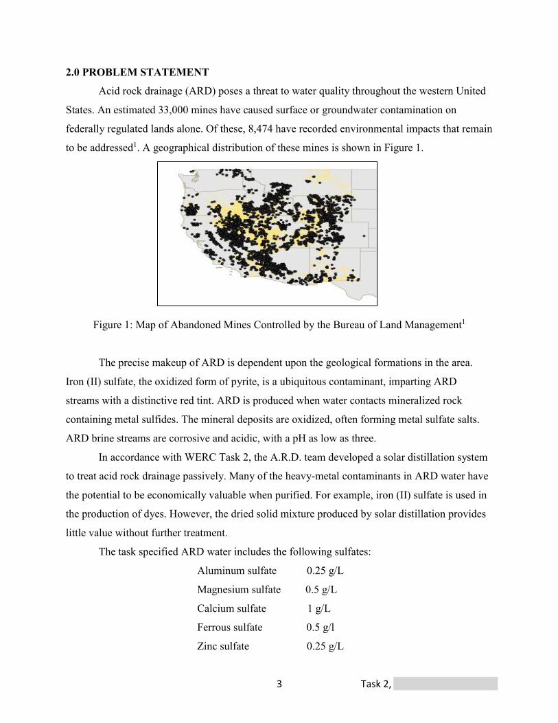
to be addressed1. A geographical distribution of these mines is shown in Figure 1.
Figure 1: Map of Abandoned Mines Controlled by the Bureau of Land Management1
The precise makeup of ARD is dependent upon the geological formations in the area.
Iron (II) sulfate, the oxidized form of pyrite, is a ubiquitous contaminant, imparting ARD
streams with a distinctive red tint. ARD is produced when water contacts mineralized rock
containing metal sulfides. The mineral deposits are oxidized, often forming metal sulfate salts.
ARD brine streams are corrosive and acidic, with a pH as low as three.
In accordance with WERC Task 2, the A.R.D. team developed a solar distillation system
to treat acid rock drainage passively. Many of the heavy-metal contaminants in ARD water have
the potential to be economically valuable when purified. For example, iron (II) sulfate is used in
the production of dyes. However, the dried solid mixture produced by solar distillation provides
little value without further treatment.
The task specified ARD water includes the following sulfates:
Aluminum sulfate 0.25 g/L
Magnesium sulfate 0.5 g/L
Calcium sulfate 1 g/L
Ferrous sulfate 0.5 g/l
Zinc sulfate 0.25 g/L
Task 2, University of Arkansas 4
Due to the remote location in which the design would be utilized, no available utilities
could be relied upon beyond basic gravity feeding infrastructure. The projected useful life of the
solar distillation system is 20 years. This is limited by the expected lifetime of high-grade
polycarbonate and treated plywood.
3.0 SITE BACKGROUND
Following the recommendations of the team’s contacts at Freeport-McMoRan Inc.,
A.R.D. has identified the Copper Queen legacy mine in Bisbee, Arizona as an ideal initial
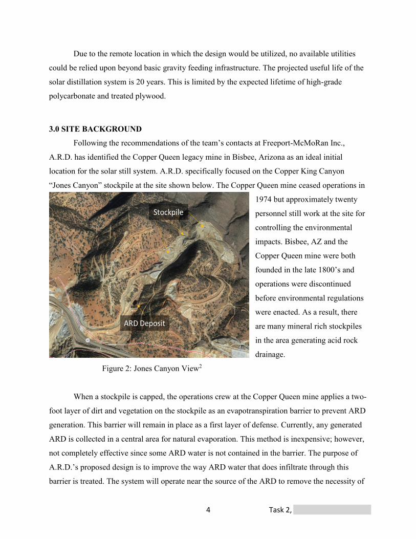
location for the solar still system. A.R.D. specifically focused on the Copper King Canyon
“Jones Canyon” stockpile at the site shown below. The Copper Queen mine ceased operations in
1974 but approximately twenty
personnel still work at the site for
controlling the environmental
impacts. Bisbee, AZ and the
Copper Queen mine were both
founded in the late 1800’s and
operations were discontinued
before environmental regulations
were enacted. As a result, there
are many mineral rich stockpiles
in the area generating acid rock
drainage.
Figure 2: Jones Canyon View2
When a stockpile is capped, the operations crew at the Copper Queen mine applies a two-
foot layer of dirt and vegetation on the stockpile as an evapotranspiration barrier to prevent ARD
generation. This barrier will remain in place as a first layer of defense. Currently, any generated
ARD is collected in a central area for natural evaporation. This method is inexpensive; however,
not completely effective since some ARD water is not contained in the barrier. The purpose of
A.R.D.’s proposed design is to improve the way ARD water that does infiltrate through this
barrier is treated. The system will operate near the source of the ARD to remove the necessity of

Task 2, University of Arkansas 5
pumping the water long distances. The environment in the Bisbee area is ideal for the A.R.D.
proposed system because of the high solar availability (285 sunny days per year) and an average
solar irradiance of 6.59-kilowatt hour per square meter per day. Both of these parameters are
higher than the United States average. These and other important environmental information is
shown in Table 1 below.
Table 1: Environmental Conditions of Bisbee, AZ3
Month: Jan. Feb. Mar. Apr. May June July Aug. Sep. Oct. Nov. Dec.
Average High
Temperature:
(°F)
56 60 66 73 81 89 87 84 82 74 64 56
Average Low
Temperature (°F)
32 34 37 43 51 59 62 61 56 46 37 32
Average Rainfall:
(inch)
1.46 1.3 .94 .51 .31 .75 4.21 4.21 1.81 1.1 1.06 1.42
Average Solar
Irradiance:
(kWh/m2/day)
5.67 6.09 7.02 7.51 7.32 7.19 6.47 6.87 7.06 6.7 5.96 5.24
4.0 TECHNOLOGY BACKGROUND RESEARCH
Literature research revealed several possible technologies that could be used in ARD
treatment: reverse osmosis, bioreactors, ionic exchange systems, permeable-reactive barriers,
catalytic bed reactors, gas redox displacement, zeolites absorption, and several distillation
technologies including solar ponds and solar stills. For this project, long-term costs, durability,
passiveness, and simplicity were the primary parameters used in the technology selection. The
majority of these technologies are not viable options, given the problem at hand. Permeable-
reactive barriers, ionic exchange membranes, catalytic bed reactors, gas redox displacement, and
zeolites absorption were all quickly disregarded due to the high material cost, continuous
monitoring, and high metal selectivity4. While several methods of treatment were considered, the
most common techniques are listed in Table 2 where advantages and disadvantages are included.

Task 2, University of Arkansas 6
Table 2: Alternate Technologies Summarization5, 6, 7, 8, 9, 10, 11
Technology Advantage Disadvantages
Solar Pond x Inexpensive x Passive x Ease of construction
x Inefficient x Requires a large area x Wildlife is not protected
Bioreactor
x No power required once implemented
x Uses naturally occurring anaerobic bacteria from dirt
x Proven technology
x H2S Production x Quality of discharge is
inconsistent x Constant monitoring and
maintenance x Requires additional chemicals
to feed bacteria
Reverse
Osmosis
x Easily scaled to desired capacity
x Widely applicable x Proven technology
x Expensive membrane replacement
x Needs large solar array for powering pumps
x Temperature sensitive x Lower recovery than distillation
processes x Potential for membrane scaling x Constant monitoring and
maintenance
Solar Still
x Simple operation and maintenance
x Passive system x Reduced heat losses x No re-release of
contaminants
x Requires a large area for high production rates
x Needs adequate sunlight x Air flow required
Solar ponds are large pools of impure water that utilize solar radiation to evaporate water
to the atmosphere. This method was not chosen because of the inefficient rate of evaporation.
Passive sulfate-reducing bioreactors are synthetic bio-systems that capitalize on
ecological and geochemical reactions to purify ARD water. This method was rejected due to
high cost and probable hydrogen sulfide (H2S) production11. The Copper Queen mine in Bisbee
has implemented this process in the past to treat ARD water. There was an incident where an
H2S leak occurred and shortly after the system was retired12.
RO systems utilize membranes purify water10. While RO is capable of higher production
than the solar still, the disadvantages associated with the energy requirements, complex
Task 2, University of Arkansas 7
operation, fouling, and maintenance outweigh the production rate for the conditions specified in
the problem statement.
A.R.D. selected the solar still as the most cost effective technology for its passivity,
simple operation, and lower energy requirements.
5.0 FULL-SCALE PROCESS SUMMARY
5.1 Overview
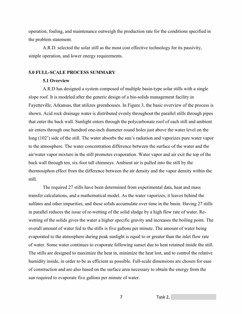
A.R.D has designed a system composed of multiple basin-type solar stills with a single
slope roof. It is modeled after the generic design of a bio-solids management facility in
Fayetteville, Arkansas, that utilizes greenhouses. In Figure 3, the basic overview of the process is
shown. Acid rock drainage water is distributed evenly throughout the parallel stills through pipes
that enter the back wall. Sunlight enters through the polycarbonate roof of each still and ambient
air enters through one hundred one-inch diameter round holes just above the water level on the
long (102’) side of the still. The water absorbs the sun’s radiation and vaporizes pure water vapor
to the atmosphere. The water concentration difference between the surface of the water and the
air/water vapor mixture in the still promotes evaporation. Water vapor and air exit the top of the
back wall through ten, six-foot tall chimneys. Ambient air is pulled into the still by the
thermosiphon effect from the difference between the air density and the vapor density within the
still.
The required 27 stills have been determined from experimental data, heat and mass
transfer calculations, and a mathematical model. As the water vaporizes, it leaves behind the
sulfates and other impurities, and these solids accumulate over time in the basin. Having 27 stills
in parallel reduces the issue of re-wetting of the solid sludge by a high flow rate of water. Re-
wetting of the solids gives the water a higher specific gravity and increases the boiling point. The
overall amount of water fed to the stills is five gallons per minute. The amount of water being
evaporated to the atmosphere during peak sunlight is equal to or greater than the inlet flow rate
of water. Some water continues to evaporate following sunset due to heat retained inside the still.
The stills are designed to maximize the heat in, minimize the heat lost, and to control the relative
humidity inside, in order to be as efficient as possible. Full-scale dimensions are chosen for ease
of construction and are also based on the surface area necessary to obtain the energy from the
sun required to evaporate five gallons per minute of water.
Task 2, University of Arkansas 8
Figure 3: Basic Model Process Overview
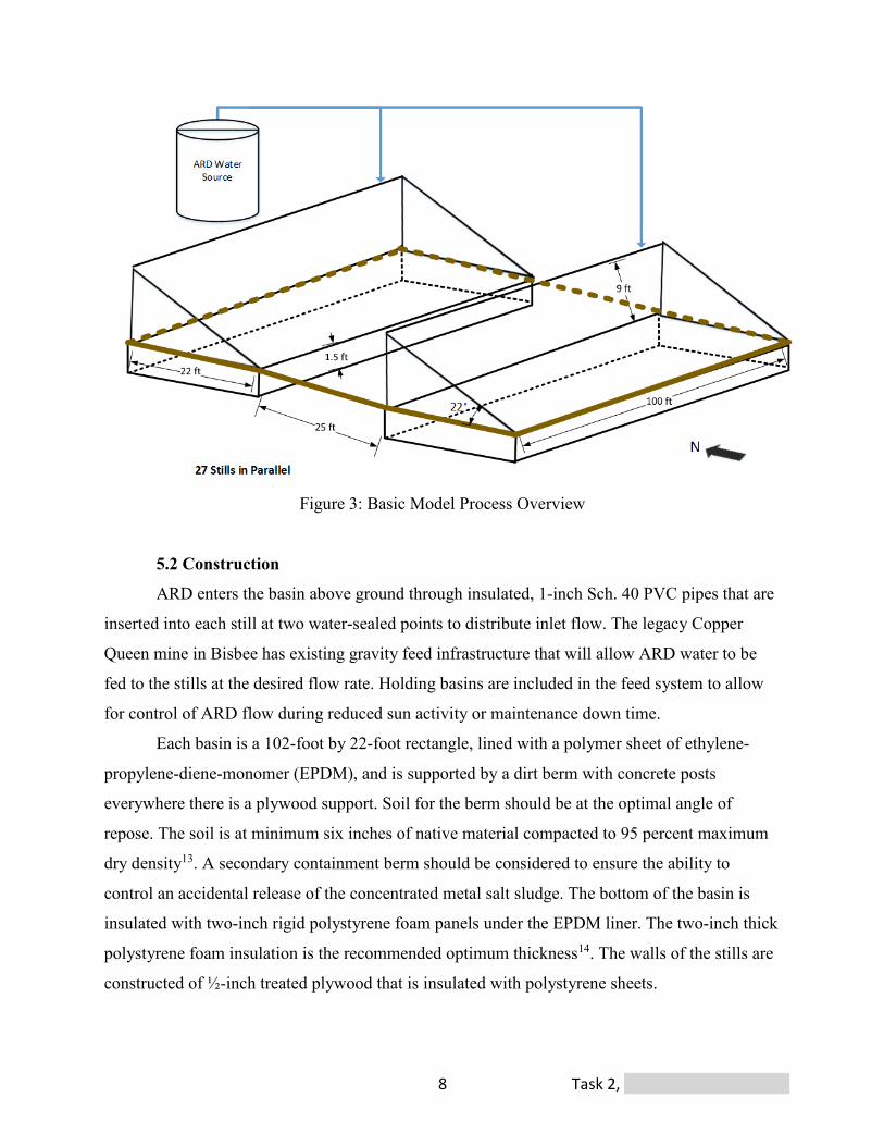
5.2 Construction
ARD enters the basin above ground through insulated, 1-inch Sch. 40 PVC pipes that are
inserted into each still at two water-sealed points to distribute inlet flow. The legacy Copper
Queen mine in Bisbee has existing gravity feed infrastructure that will allow ARD water to be
fed to the stills at the desired flow rate. Holding basins are included in the feed system to allow
for control of ARD flow during reduced sun activity or maintenance down time.
Each basin is a 102-foot by 22-foot rectangle, lined with a polymer sheet of ethylene-
propylene-diene-monomer (EPDM), and is supported by a dirt berm with concrete posts
everywhere there is a plywood support. Soil for the berm should be at the optimal angle of
repose. The soil is at minimum six inches of native material compacted to 95 percent maximum
dry density13. A secondary containment berm should be considered to ensure the ability to
control an accidental release of the concentrated metal salt sludge. The bottom of the basin is
insulated with two-inch rigid polystyrene foam panels under the EPDM liner. The two-inch thick
polystyrene foam insulation is the recommended optimum thickness14. The walls of the stills are
constructed of ½-inch treated plywood that is insulated with polystyrene sheets.
Task 2, University of Arkansas 9
Clear, six-millimeter-thick, double-pane polycarbonate is the material of construction for
the roof, and it is secured with an aluminum support structure. The selection of polycarbonate
balances low cost, good mechanical properties, and transmission of solar radiation. While there
are thicker polycarbonate sheets that minimize the heat lost through the sheet, it is at the cost of
losing some of the transmittance of the polycarbonate, and A.R.D determined that this trade-off
was not worthwhile. The polycarbonate sheet has a light transmittance of 82 percent15. The angle
at which the polycarbonate is installed is 22 degrees to ensure that the average direction of solar
radiation is directed into the still. In addition to the angle, it is important that the stills are facing
due south, as this is the most convenient position for capturing the sun’s energy over a whole
year. Similar to how typical greenhouses are constructed, multiple 6-foot wide and 24-foot long
polycarbonate sheets are fitted together in a support system and connected with aluminum
glazing. The channel openings in the polycarbonate sheets are sealed with U-shaped aluminum
channels to prevent condensation build-up inside the channels, as well as prevent the presence of
fouling within the panels. The channels of the polycarbonate sheet are oriented in the vertical
direction to allow the maximum amount of solar radiation to enter the still.
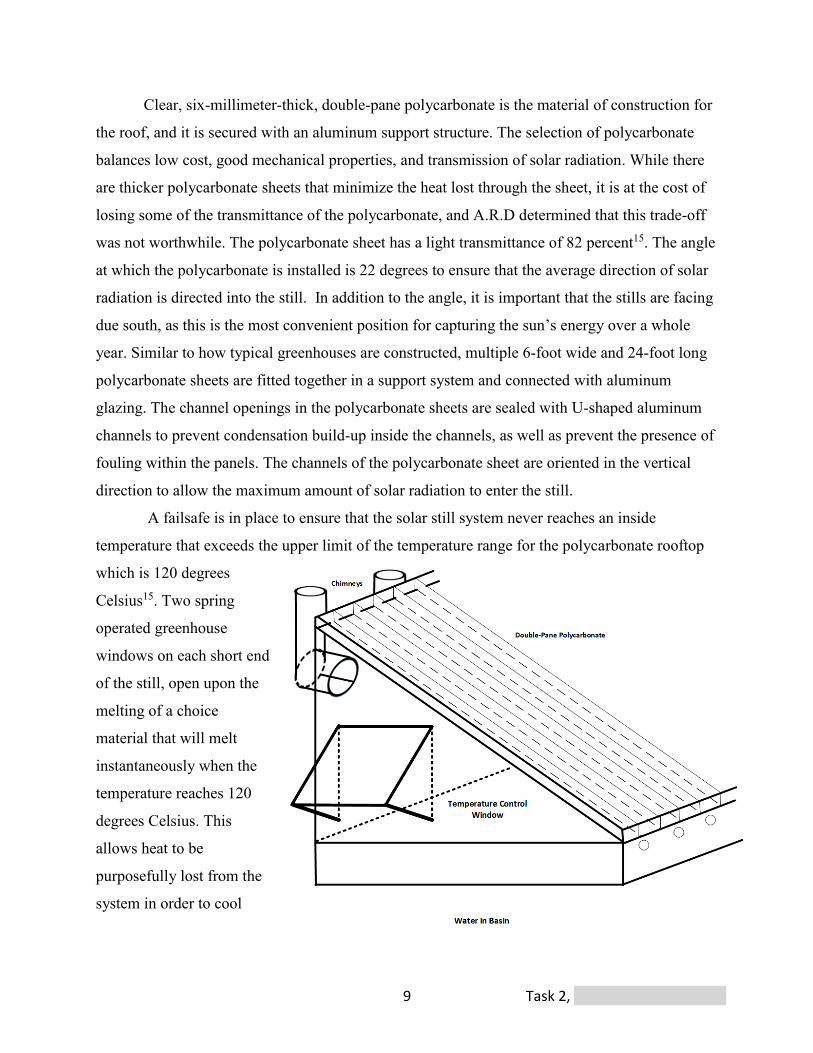
A failsafe is in place to ensure that the solar still system never reaches an inside
temperature that exceeds the upper limit of the temperature range for the polycarbonate rooftop
which is 120 degrees
Celsius15. Two spring
operated greenhouse
windows on each short end
of the still, open upon the
melting of a choice
material that will melt
instantaneously when the
temperature reaches 120
degrees Celsius. This
allows heat to be
purposefully lost from the
system in order to cool
Figure 4: Side View of Still
Task 2, University of Arkansas 10
down the still. The windows will re-close upon contraction of the material back to its locked
position.
5.3 Thermosiphons
Vapor is continuously expelled through ten thermosiphon chimneys evenly spaced along
the back wall of each still. The chimney pipes are constructed of three-inch diameter PVC pipes
that are each six feet tall. These dimensions were determined based on the amount of water vapor
and air mixture that needs to be expelled from each still to achieve five gallons per minute of
evaporation in total. The density difference between the ambient air and the vapor inside the still
and inside the chimneys is the mechanism that moves the gases through the still16. The natural
draft creates a pressure differential between the entering air and the exiting gases, which
provides the motive force for flow to occur. Bernoulli’s equation for flow into and through a hole
was utilized to size the one hundred, one-inch diameter holes that allow air in. The purpose of
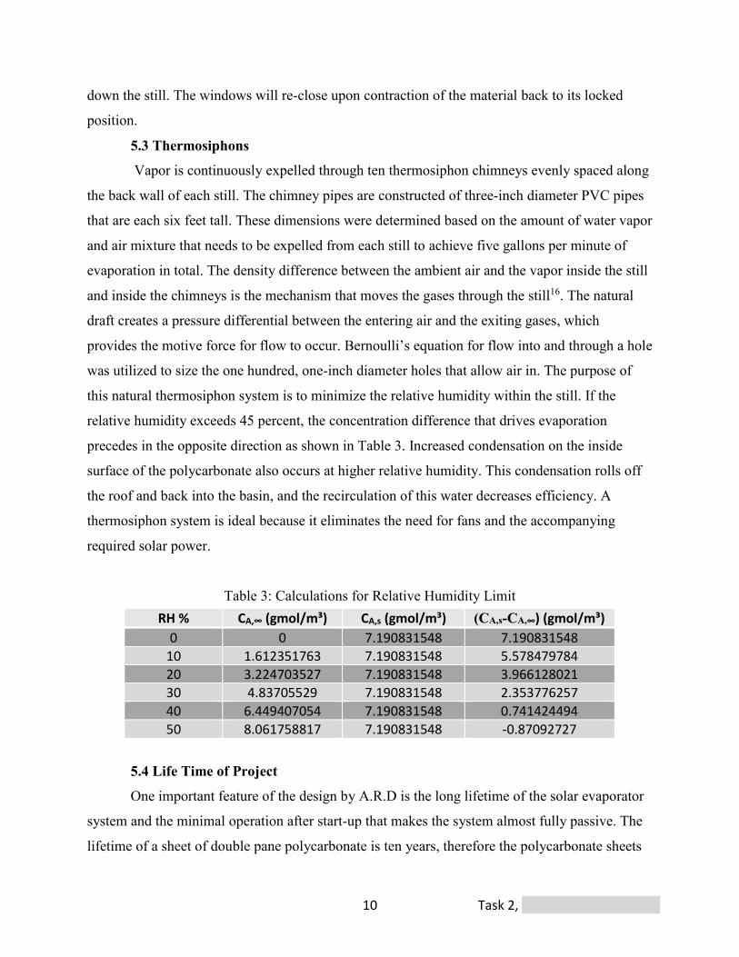
this natural thermosiphon system is to minimize the relative humidity within the still. If the
relative humidity exceeds 45 percent, the concentration difference that drives evaporation
precedes in the opposite direction as shown in Table 3. Increased condensation on the inside
surface of the polycarbonate also occurs at higher relative humidity. This condensation rolls off
the roof and back into the basin, and the recirculation of this water decreases efficiency. A
thermosiphon system is ideal because it eliminates the need for fans and the accompanying
required solar power.
Table 3: Calculations for Relative Humidity Limit
5.4 Life Time of Project
One important feature of the design by A.R.D is the long lifetime of the solar evaporator
system and the minimal operation after start-up that makes the system almost fully passive. The
lifetime of a sheet of double pane polycarbonate is ten years, therefore the polycarbonate sheets
RH % CA,∞ (gmol/m³) CA,s (gmol/m³) (CA,s-CA,∞) (gmol/m³) 0 0 7.190831548 7.190831548
10 1.612351763 7.190831548 5.578479784 20 3.224703527 7.190831548 3.966128021 30 4.83705529 7.190831548 2.353776257 40 6.449407054 7.190831548 0.741424494 50 8.061758817 7.190831548 -0.87092727
Task 2, University of Arkansas 11
will need to be replaced once during the lifetime of the project. A schedule will be implemented
to service the replacement of the polycarbonate sheets during the winter when efficiency is
lowest. The remainder of the design includes the metal support system and concrete
reinforcements, which will have a lifetime greater than 20 years. Solids will continuously
accumulate in the bottom of the basin, and after 20 years, there will be 1.3 inches of dried
particle accumulation within each of the 27 stills. This is calculated by determining that the mass
of the sulfates left behind is 2.5 grams per liter of feed water, the solids average a specific gravity
of 2.5, and the bottom surface are of one basin is 2,244 square feet. Since the water is fed at
approximately the same rate at which the water is evaporated, the solids will be relatively dry.
The solids will be removed using pneumatic solids removal trucks, which are similar to vacuum
trucks. There will be multiple access points constructed in the unit to allow the truck to access
the entire area of the still. A schedule should be determined to remove solids so that it is done
one still at a time and does not disturb the system overall. A use for the removed metal sludge
should be determined to improve the rate of return on this project. The best use would be to use a
method to separate the sulfates into their individual species to be sold.
The minimum amount of maintenance required to ensure the success of the system will
be to survey the system of solar stills once every two to three months. Maintenance will include,
clearing the polycarbonate roof of any debris and ensuring that the one-inch feed water pipes are
clear of build-up by using pressurized air. Iron oxidation can be a problem in transporting ARD
water through the PVC pipes, therefore more frequent maintenance will be required. In total
6,480 hours of maintenance is required over the lifetime of all the stills.
6.0 ECONOMIC ANALYSIS
An analysis of the capital cost associated with each component of the construction
materials and upfront construction labor costs for the solar still is shown in Table 4. The total
maintenance cost is projected to be $360 annually per still. Labor costs reflect that three workers
are present for one hour, four times a year. Three employees will be present throughout
maintenance to ensure workplace safety. The total cost per square foot of this solar still design is
compared to that of a 100-foot by 30-foot greenhouse that was analyzed by the Department of
Agriculture at the University of Arkansas17. Waste disposal costs are neglected in the capital cost

Task 2, University of Arkansas 12
analysis due to the desire of Freeport McMoRan Inc. to find a beneficial end use of the solid
sludge, as informed during the Copper Queen mine visit.
Table 4: Single Still Cost Analysis17,18,19,20,21,22,23,24,25,26,27,28,29
Material UOM Amount Rate Contribution2' X 18" X 18" Concrete Footers ft3 333 12.00$ 3,996$
Pad Leveling Dirt Work ft2 2224 0.34$ 756$ Labor and Rebar 1,100$ Polystyrene Insulation8' X 4' X 2" sheet 70 30.00$ 2,100$
Drivable Gravel Road ft2 1200 1.00$ 1,200$ EPDM Pond Liner30' x 100' 45 mil unit 1,830$
Topsoil Excavation yd3 40 100.00$ 4,000$
Turf ft2 1056 0.45$ 475$ Land Cost Acre 2 -$ -$ Polystyrene Insulation8' X 4' X 2" sheet 35 30.00$ 1,050$ Plywood 1/2"X 8' X 4' sheet 78 20.00$ 1,560$ Treated Wood Supports 2'' X 4'' X 10' board 74 4.00$ 296$
Frame Assembly ft2 2224 0.53$ 1,179$ Polycarbonate 6 mm 6' X 24' sheet 17 204.00$ 3,468$
Aluminum Glazing Cap 8' unit 52 10.00$ 520$ Aluminum End Cap 8' unit 25 17.00$ 425$ Polycarbonate Replacement (10 years) 5,250.00$ Miscellaneous Hardware 2,500$ Roofing Structural Support 5,000$ Outbuilding Permitting 979$ Automatic Spring Vent unit 2 63.00$ 126$
Solids ManagementPneumatic Solids Removal700 Gallon Truck hr 6 71.14$ 427$ SCH 40 PVC 3" ft 65 4.60$ 299$ 90° 3" PVC Elbow unit 10 2.78$ 28$ 3" Tank Vent Cap unit 10 13.50$ 135$ Cable Support System 500$ TOTAL ESTIMATION 39,199$ Useful Life Cost per Year 1,959.94$
Cost per ft2 17.63$
Average Cost of Greenhouse per ft2 25.00$
Safety and Permitting
Thermosiphons
Conclusions
Base and Dirt work
Walls and Supports
Roofing

Task 2, University of Arkansas 13
7.0 BENCH-SCALE TESTING
The bench-scale solar distillation unit consists of two parts: a basin and a sloped top, as
shown in Figure 5. The 8-foot by 4-foot by ½-foot basin was constructed with ½-inch plywood.
This material was chosen as the frame for its insulating characteristics and low price. The basin
is lined with a dark-grey, 40-mil PVC liner that absorbs solar radiation and maintains a
waterproof interior. PVC was chosen over other polymer liners due to its durability and local
availability. The sloped top consists of a tilted plywood back, two triangular sides, a front piece,
and a bottom connection channel that fits tightly over the basin. The perimeter of the plywood
supports a ten-millimeter clear polycarbonate sheet. The bench-scale contains a ten-millimeter
polycarbonate sheet for convenience of ordering as well as experimental curiosity. Polycarbonate
is inexpensive, transparent in the visible/near-IR region, opaque to long-IR radiation, has high
impact resistance, and has a large service temperature range. The polycarbonate edges lie inside
aluminum channels, which permanently fasten it to the wooden frame of the still. The aluminum
channels block wind from entering the gap in-between the two layers of the polycarbonate,
ensuring maximum insulative properties. The wooden frame is surrounded by two-inch
polystyrene insulation for added heat retention.
Figure 5: Front View of Bench-Scale Design
Task 2, University of Arkansas 14
0
10
20
30
40
50
60
70
80
90
6:57 11:45 16:33 21:21 2:09 6:57
Tem
pera
ture
(C )
Time Starting Morning of 2-22
2-22 Comparison of Vapor and WaterTemperature
Vapor Temperature Water Temperature
Temperature Inversion at 16:58Max Water Temp at 64.5 at 15:21Max Vapor Temp 83.5 C at 13:52
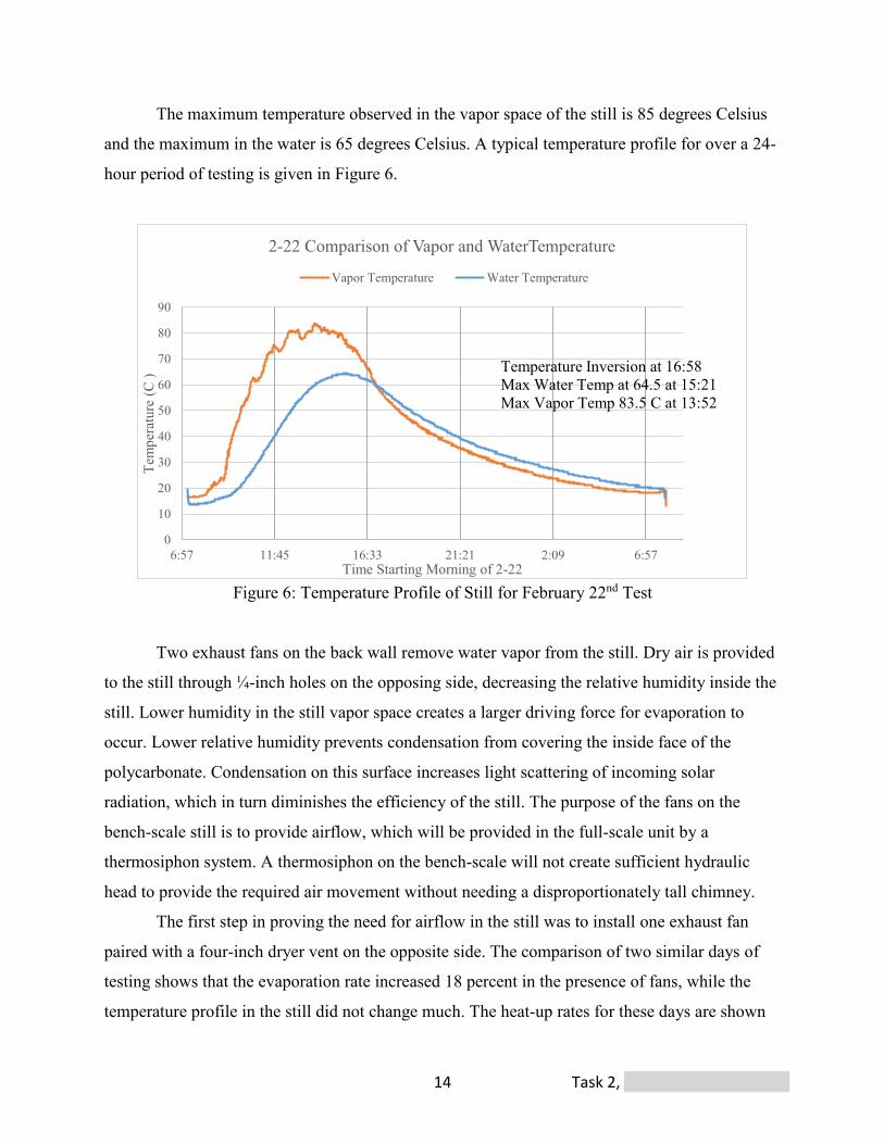
The maximum temperature observed in the vapor space of the still is 85 degrees Celsius
and the maximum in the water is 65 degrees Celsius. A typical temperature profile for over a 24-
hour period of testing is given in Figure 6.
Figure 6: Temperature Profile of Still for February 22nd Test
Two exhaust fans on the back wall remove water vapor from the still. Dry air is provided
to the still through ¼-inch holes on the opposing side, decreasing the relative humidity inside the
still. Lower humidity in the still vapor space creates a larger driving force for evaporation to
occur. Lower relative humidity prevents condensation from covering the inside face of the
polycarbonate. Condensation on this surface increases light scattering of incoming solar
radiation, which in turn diminishes the efficiency of the still. The purpose of the fans on the
bench-scale still is to provide airflow, which will be provided in the full-scale unit by a
thermosiphon system. A thermosiphon on the bench-scale will not create sufficient hydraulic
head to provide the required air movement without needing a disproportionately tall chimney.
The first step in proving the need for airflow in the still was to install one exhaust fan
paired with a four-inch dryer vent on the opposite side. The comparison of two similar days of
testing shows that the evaporation rate increased 18 percent in the presence of fans, while the
temperature profile in the still did not change much. The heat-up rates for these days are shown

Task 2, University of Arkansas 15
y = 0.2769x + 21.018
y = 0.2186x + 8.4016
0102030405060708090
100
0 50 100 150 200 250
Tem
pera
ture
(Cel
sius
)
Minutes
Heat-Up Rates3/7/17
Vapor Heat up Rate Water Heat up
in Figures 7 and 8. In Trial 1, the four cfm fan was choked down to about half the flow rate. In
Trial 2, the four cfm was operated without any additional constraint. Each trial was conducted
over the course of 12 hours, specifically sunrise to sundown. Similar weather conditions were
observed for each trial: few clouds, frequent wind gusts, and a high ambient temperature of 15.5
degrees Celsius. Over the course of Trial 1, the vapor space and water in the basin reached
temperatures of 84 and 64.5 degrees Celsius respectively. Trial 2 experienced a maximum vapor
space and water temperature of 84 and 64 degrees Celsius, despite higher airflow. Heat-up rates
were comparable for each trial, but were slightly higher when airflow was lower. Faster
condensation formation was observed on the polycarbonate surface when utilizing the lesser
airflow, which decreased overall evaporation. The daily average evaporation rate was 5.8
mL/min in Trial 1, and 7.1 mL/min in Trial 2. This was determined through suctioning the
remaining water with a shop vacuum and recording the difference in weight of the empty
vacuum and the water-filled vacuum.
Figure 7: Heat-Up Rate Trial
Task 2, University of Arkansas 16
y = 0.2209x + 15.262
y = 0.2165x + 37.399
0
10
20
30
40
50
60
70
80
90
0 50 100 150 200 250
Tem
pera
ture
(C )
Minutes starting 8:45
Heat-Up Rates3/10/17
Water Heat Up Vapor Heat Up
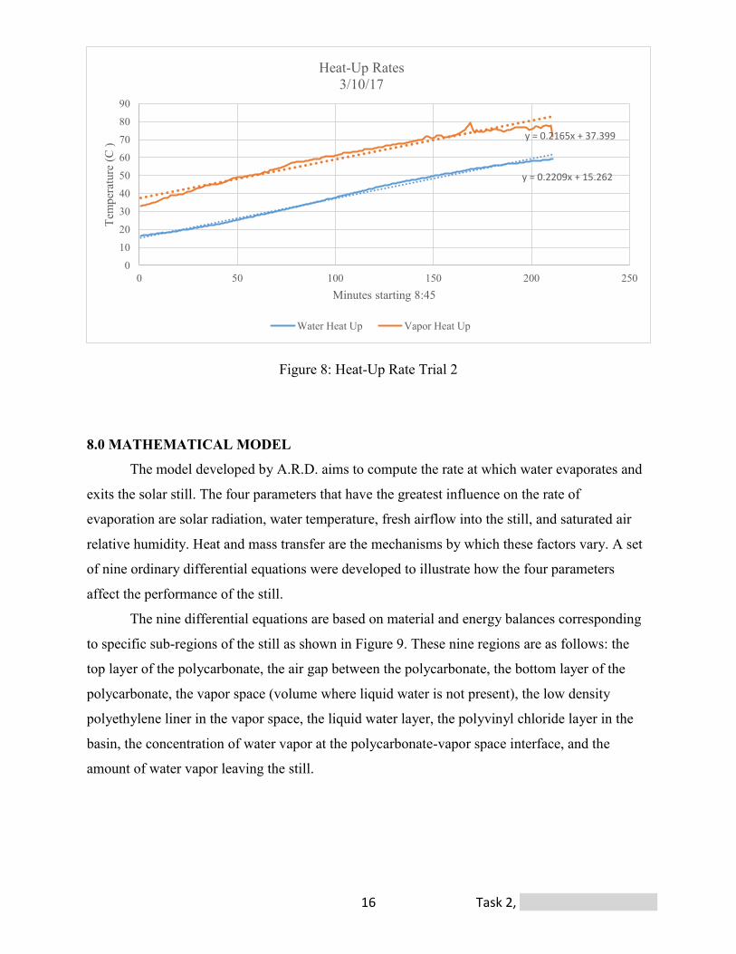
Figure 8: Heat-Up Rate Trial 2
8.0 MATHEMATICAL MODEL
The model developed by A.R.D. aims to compute the rate at which water evaporates and
exits the solar still. The four parameters that have the greatest influence on the rate of
evaporation are solar radiation, water temperature, fresh airflow into the still, and saturated air
relative humidity. Heat and mass transfer are the mechanisms by which these factors vary. A set
of nine ordinary differential equations were developed to illustrate how the four parameters
affect the performance of the still.
The nine differential equations are based on material and energy balances corresponding
to specific sub-regions of the still as shown in Figure 9. These nine regions are as follows: the
top layer of the polycarbonate, the air gap between the polycarbonate, the bottom layer of the
polycarbonate, the vapor space (volume where liquid water is not present), the low density
polyethylene liner in the vapor space, the liquid water layer, the polyvinyl chloride layer in the
basin, the concentration of water vapor at the polycarbonate-vapor space interface, and the
amount of water vapor leaving the still.

Task 2, University of Arkansas 17
Solar radiation
Reflection from water
Absorbed by basin
Absorbed by water
Evaporation
Losses to surroundings
Losses to surroundings
Convective losses from wind
Radiation through polycarbonate
Conduction through polycarbonate
Mass transfer in
Mass transfer out
Figure 9: Heat and Mass Transfer in Still
Solar radiation is the initiating parameter for each energy balance. Data for the average
solar flux reaching the Earth’s surface, daily average temperatures, outside relative humidity, and
wind speed were researched for Fayetteville, AR and Las Cruces, NM. These two locations were
chosen because they are where the still is being tested. Curves were fitted to each set of data. The
process of fitting curves to data is a simple way to get the variance required for the transient
behavior of the still.
The following assumptions were made to simplify the calculations: each region of the
still is at a uniform temperature, the amount of radiation emitted from the liners is negligible,
long wavelength radiation cannot escape through the double paned polycarbonate sheet, the
change in water level is negligible, and average physical properties over the temperature range.
Each of the differential equations that are coded into the mathematical model are shown below in
equations (1) through (9).

Task 2, University of Arkansas 18
(1) 𝑑𝑇𝑝𝑐𝑡
𝑑𝑡= 𝑓𝑟𝑎𝑐𝑡𝑖𝑜𝑛 𝑎𝑏𝑠𝑜𝑟𝑏𝑒𝑑𝑝𝑐∗𝑄𝑟𝑎𝑑𝑠∗𝑆𝐴𝑝𝑐+ℎ𝑎𝑔∗𝑆𝐴𝑝𝑐∗(𝑇𝑎𝑔−𝑇𝑝𝑐𝑡)−ℎ𝑜𝑢𝑡𝑠𝑖𝑑𝑒∗𝑆𝐴𝑝𝑐∗(𝑇𝑝𝑐𝑡−𝑇𝑎𝑚𝑏𝑖𝑒𝑛𝑡))
𝜌𝑝𝑐∗𝑆𝐴𝑝𝑐∗𝑥𝑝𝑐∗𝐶𝑝𝑝𝑐
(2) 𝑑𝑇𝑎𝑔
𝑑𝑡= ℎ𝑎𝑔∗𝑆𝐴𝑝𝑐∗(𝑇𝑝𝑐𝑏−𝑇𝑎𝑔)−ℎ𝑎𝑔∗𝑆𝐴𝑝𝑐∗(𝑇𝑎𝑔−𝑇𝑝𝑐𝑡)
𝜌𝑎𝑖𝑟∗𝑆𝐴𝑝𝑐∗𝑥𝑎𝑔∗𝐶𝑝𝑎𝑖𝑟
(3) 𝑑𝑇𝑝𝑐𝑏
𝑑𝑡=
𝑓𝑟𝑎𝑐𝑡𝑖𝑜𝑛 𝑎𝑏𝑠𝑜𝑟𝑏𝑒𝑑𝑝𝑐∗𝑄𝑟𝑎𝑑𝑡𝑟𝑎𝑛𝑠𝑝𝑐𝑡∗𝑆𝐴𝑝𝑐+15∗ℎ𝑙𝑑𝑝𝑒𝑣𝑠∗𝑆𝐴𝑝𝑐∗(𝑇𝑣𝑠−𝑇𝑝𝑐𝑏)−ℎ𝑎𝑔∗𝑆𝐴𝑝𝑐∗(𝑇𝑝𝑐𝑏−𝑇𝑎𝑔)
𝜌𝑝𝑐∗𝑆𝐴𝑝𝑐∗𝑥𝑝𝑐∗𝐶𝑝𝑝𝑐
(4) 𝑑𝑇𝑣𝑠𝑑𝑡
=
𝑓𝑟𝑎𝑐𝑡𝑖𝑜𝑛 𝑎𝑏𝑠𝑜𝑟𝑏𝑒𝑑𝑣𝑠∗𝑄𝑟𝑎𝑑𝑡𝑟𝑎𝑛𝑠𝑝𝑐𝑏∗𝑆𝐴𝑣𝑠−15∗ℎ𝑙𝑑𝑝𝑒𝑣𝑠∗𝑆𝐴𝑣𝑠∗(𝑇𝑙𝑑𝑝𝑒−𝑇𝑣𝑠 )+𝑁𝐴∗𝑆𝐴𝑤𝑎𝑡𝑒𝑟∗𝑀𝑤𝑤𝑎𝑡𝑒𝑟∗𝐻𝑣𝑎𝑝𝑜𝑟𝑖𝑧𝑎𝑡𝑖𝑜𝑛∗
𝑚𝑎𝑖𝑟𝑙𝑒𝑎𝑣𝑖𝑛𝑔 𝐶𝑝𝑎𝑖𝑟∗(𝑇𝑣𝑠−𝑇𝑎𝑚𝑏𝑖𝑒𝑛𝑡)− 𝑉𝑤𝑣𝑙𝑒𝑎𝑣𝑖𝑛𝑔∗𝜌𝑤𝑣∗𝐻𝑣𝑎𝑝𝑜𝑟𝑖𝑧𝑎𝑡𝑖𝑜𝑛
𝜌𝑤𝑣𝑎∗𝑉𝑣𝑠∗𝐶𝑝𝑤𝑣𝑎
(5) 𝑑𝑇𝑙𝑑𝑝𝑒
𝑑𝑡=
𝑓𝑟𝑎𝑐𝑡𝑖𝑜𝑛 𝑎𝑏𝑠𝑜𝑟𝑏𝑒𝑑𝑙𝑑𝑝𝑒∗𝑄𝑟𝑎𝑑𝑡𝑟𝑎𝑛𝑠𝑝𝑐𝑏∗𝑆𝐴𝑣𝑠∗0.75−15∗ℎ𝑙𝑑𝑝𝑒𝑣𝑠∗𝑆𝐴𝑣𝑠∗(𝑇𝑙𝑑𝑝𝑒−𝑇𝑣𝑠)−(𝑇𝑙𝑑𝑝𝑒−𝑇𝑎𝑚𝑏𝑖𝑒𝑛𝑡)𝑅𝑡𝑤𝑜𝑜𝑑𝑠𝑡𝑦𝑟𝑒𝑛𝑒𝑣𝑠
𝜌𝑙𝑑𝑝𝑒∗𝑆𝐴𝑙𝑑𝑝𝑒∗𝑥𝑙𝑑𝑝𝑒∗𝐶𝑝𝑙𝑑𝑝𝑒
(6) 𝑑𝑇𝑤𝑎𝑡𝑒𝑟𝑑𝑡
=
𝑓𝑟𝑎𝑐𝑡𝑖𝑜𝑛 𝑎𝑏𝑠𝑜𝑟𝑏𝑒𝑑𝑤𝑎𝑡𝑒𝑟∗𝑄𝑟𝑎𝑑𝑡𝑟𝑎𝑛𝑠𝑝𝑐𝑏∗𝑆𝐴𝑤𝑎𝑡𝑒𝑟+ℎ𝑤𝑎𝑡𝑒𝑟∗𝑆𝑎𝑃𝑉𝐶∗(𝑇𝑃𝑉𝐶−𝑇𝑤𝑎𝑡𝑒𝑟)
−𝑚𝑤𝑎𝑡𝑒𝑟∗𝐶𝑝𝑤𝑎𝑡𝑒𝑟∗(𝑇𝑤𝑎𝑡𝑒𝑟−𝑇𝑤𝑎𝑡𝑒𝑟0)−𝑁𝐴∗𝑀𝑤𝑤𝑎𝑡𝑒𝑟∗𝐻𝑣𝑎𝑝𝑜𝑟𝑖𝑧𝑎𝑡𝑖𝑜𝑛+15∗ℎ𝑙𝑑𝑝𝑒∗𝑆𝐴𝑤𝑎𝑡𝑒𝑟∗(𝑇𝑣𝑠−𝑇𝑤𝑎𝑡𝑒𝑟)
𝜌𝑤𝑎𝑡𝑒𝑟∗𝑆𝐴𝑤𝑎𝑡𝑒𝑟∗𝑥𝑤𝑎𝑡𝑒𝑟∗𝐶𝑝𝑤𝑎𝑡𝑒𝑟
(7) 𝑑𝑇𝑃𝑉𝐶𝑑𝑡
=
𝑓𝑟𝑎𝑐𝑡𝑖𝑜𝑛 𝑎𝑏𝑠𝑜𝑟𝑏𝑒𝑑𝑃𝑉𝐶∗𝑄𝑟𝑎𝑑𝑡𝑟𝑎𝑛𝑠𝑤∗𝑆𝐴𝑃𝑉𝐶−ℎ𝑤𝑎𝑡𝑒𝑟∗𝑆𝐴𝑤𝑎𝑡𝑒𝑟∗(𝑇𝑃𝑉𝐶−𝑇𝑤𝑎𝑡𝑒𝑟)−
(𝑇𝑃𝑉𝐶−𝑇𝑎𝑚𝑏𝑖𝑒𝑛𝑡)𝑅𝑡𝑤𝑜𝑜𝑑𝑠𝑡𝑦𝑟𝑒𝑛𝑒𝑤𝑔
−(𝑇𝑃𝑉𝐶−𝑇𝑎𝑚𝑏𝑖𝑒𝑛𝑡)
𝑅𝑡𝑤𝑜𝑜𝑑𝑠𝑡𝑦𝑟𝑒𝑛𝑒𝑤𝑠𝑖𝑑𝑒𝑠
𝜌𝑃𝑉𝐶∗𝑆𝐴𝑃𝑉𝐶∗𝑥𝑃𝑉𝐶∗𝐶𝑝𝑃𝑉𝐶
(8) 𝑑𝐶𝐴∞𝑑𝑡
= 𝑉𝑓𝑎𝑛∗𝑀𝑤𝑤𝑎𝑡𝑒𝑟∗𝐶𝐴𝑜𝑢𝑡𝑠𝑖𝑑𝑒+𝑁𝐴∗𝑆𝐴𝑤𝑎𝑡𝑒𝑟∗𝑀𝑤𝑤𝑎𝑡𝑒𝑟−𝑉𝑓𝑎𝑛∗𝑀𝑤𝑤𝑎𝑡𝑒𝑟∗𝐶𝐴∞
𝑅𝐻𝑝𝑐𝑖𝑛𝑡𝑒𝑟𝑓𝑎𝑐𝑒∗𝑀𝑤𝑤𝑎𝑡𝑒𝑟∗𝑆𝐴𝑤𝑎𝑡𝑒𝑟∗𝑥𝑤𝑎𝑡𝑒𝑟
(9) 𝑑𝑚𝑤𝑣𝑠𝑡𝑖𝑙𝑙𝑑𝑡
= 𝑉𝑓𝑎𝑛 ∗ 𝑀𝑤𝑤𝑎𝑡𝑒𝑟 ∗ 𝐶𝐴∞
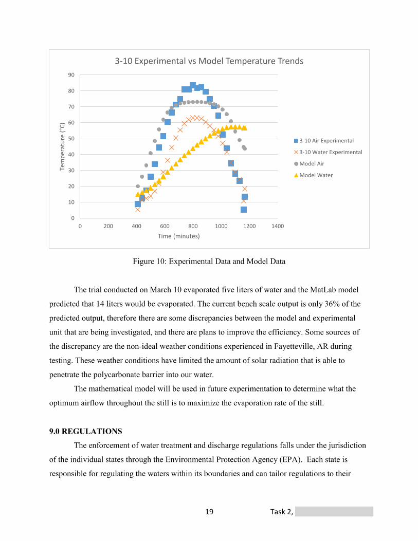
A comparison between the experimental data taken on March 10, 2017 and the
mathematical model data for the conditions seen on that day is shown in Figure 10. The model
accurately predicts the temperature profile for the water and vapor space temperatures to what is
observed in the bench-scale. The difference in the water temperature profile can be attributed to
the way the water temperature is measured for the bench-scale. A thermocouple with a data
logger is inserted inside the still touching the water. However, the water level is distributed very
thin across the basin, and therefore the thermocouple may not remain in the water throughout the
twelve-hour testing time.
Task 2, University of Arkansas 19
0
10
20
30
40
50
60
70
80
90
0 200 400 600 800 1000 1200 1400
Tem
pera
ture
(°C
)
Time (minutes)
3-10 Experimental vs Model Temperature Trends
3-10 Air Experimental
3-10 Water Experimental
Model Air
Model Water
Figure 10: Experimental Data and Model Data
The trial conducted on March 10 evaporated five liters of water and the MatLab model
predicted that 14 liters would be evaporated. The current bench scale output is only 36% of the
predicted output, therefore there are some discrepancies between the model and experimental
unit that are being investigated, and there are plans to improve the efficiency. Some sources of
the discrepancy are the non-ideal weather conditions experienced in Fayetteville, AR during
testing. These weather conditions have limited the amount of solar radiation that is able to
penetrate the polycarbonate barrier into our water.
The mathematical model will be used in future experimentation to determine what the
optimum airflow throughout the still is to maximize the evaporation rate of the still.
9.0 REGULATIONS
The enforcement of water treatment and discharge regulations falls under the jurisdiction
of the individual states through the Environmental Protection Agency (EPA). Each state is
responsible for regulating the waters within its boundaries and can tailor regulations to their
Task 2, University of Arkansas 20
specific needs, provided the state adopts regulations that meet or exceed minimum federal
standards30.
The primary regulatory means for ensuring public water quality in the United States is the
Clean Water Act (CWA)31. The goals of the CWA are to protect water quality for wildlife and
recreation and to eliminate the discharge of pollutants into navigable and surface waters. The
National Pollutant Discharge Elimination System (NPDES), established under Section 402 of the
CWA, regulates sources that discharge pollutants into U.S. public waters or publicly owned
treatment works (POTW) 32. This design evaporates the water and will not discharge to U.S.
public waters or POTW, therefore an NPDES permit is not necessary.
Arizona Pollution Discharge Elimination System (AZPDES) is responsible for mine
drainage discharge for the state of Arizona. AZPDES requires an individual permit to discharge
water through a point source into U.S. waters. Since only water vapor will be exiting the still, an
AZPDES individual permit will not be required33.
The excess sludge is considered hazardous due to the zinc and iron sulfates present and
its low pH, therefore Large Quantity Generator (LQG) EPA regulations must be considered34.
The left over salts are retained in the still until a final cleaning out procedure. Due to this
technicality, they are still in a process vessel, and not a generated waste and are therefore exempt
from LQG regulations during operation35,36. This was determined when visiting the Fayetteville
Biosolids Management facility.
Building codes and regulations will also need to be considered before constructing the
solar stills. The stills will not be considered confined spaces since there will be many entries and
exits available for workers37. The structure is considered a membrane structure. According to
section 3102 of the International Building Code, facilities not intended for human occupancy are
required to meet only sections 3102.3.1 and 3102.7 requirements. Section 3102.3.1 states that the
interior liner must be noncombustible unless the liner is 0.5 mm thick plastic or less for use in
greenhouses. The structure will also need to be able to sustain dead loads, seismic loads, those
due to tension, and live loads, which include wind, flood, or snow38. This is accounted for in the
design with the concrete support for the basin of each still.
When constructing a dirt berm, the Cochise Country zoning regulations require adequate
plant material or ground cover treatment to prevent erosion39. AZDEQ regulations require a
composite liner of at least 30-mil thick to line the bottom of the dirt berm pond13.
Task 2, University of Arkansas 21
10.0 SAFETY CONSIDERATIONS
The prominent health and safety concerns include thermal hazards, installation, and
maintenance. Since the solar stills will be constructed in a desert area, construction is best
accomplished in early mornings and late evenings to prevent the effects of dehydration and heat
exhaustion. The same precaution will need to take place when doing maintenance on the still
since it will operate at approximately 80 degrees Celsius. The maintenance team will need to
wait until the still has cooled below 60 degrees Celsius before entering it. Proper hydration and
safety techniques must be taught and always followed. Since the concentrated sulfate sludge is
hazardous, maintenance workers will need to wear chemical suits when cleaning the still. The
still could become a confined space so it is necessary to ensure that in the construction of the
still, multiple points of entry are included. Before construction begins, a meeting will be held to
address safety concerns. Bacteria growth is a potential problem in any moist, enclosed space,
especially Legionnaire organisms. However, since the stills operate at temperatures above 60
degrees Celsius, conditions are sufficient to prevent normal bacteria growth.
11.0 PUBLIC INVOLVEMENT
An important element for the success of this design process is informing the local
communities, the closest one being the town of Bisbee. Citizens should be made aware of the
treatment process and learn how it can improve their environment. To accomplish this task, an
informational presentation will be given at a Bisbee town hall meeting. This presentation will
discuss what ARD water is, the negative effects it has, and how to solve this problem. In
addition, there will be a short tutorial at the end teaching community members how to spot ARD
water, and whom they should report any sightings to. This presentation will also address any
concerns the local residents may have.
12.0 SCALABILITY Ease of construction is important for both scaling up and down any design. A.R.D.
designed the full-scale solar distillation system prior to testing the bench-scale apparatus.
Therefore, the bench scale accurately represents the efficiency of the larger full-scale version.
The only significant difference between the two scales is that the full-scale will have a
Task 2, University of Arkansas 22
significantly larger vapor space to liquid space ratio. This occurs because the desired water level
will remain low to decrease the time required to heat up the still each day. This will increase the
driving force for evaporation because more vapor will need to be generated to effect the
humidity level. Taking into account that the full scale will have a thermosiphon to keep the
humidity low as well, the driving force to cause evaporation will only increase.
13.0 CONCLUSIONS The total initial capital cost for 27 stills is $1,100,000. The monthly payment if amortized
over twenty years, with a 5% interest, is $7,128. The yearly cost of operation checks for all units
is $10,000. The end of life labor cost for removing the solids is $3,800 for all units. Therefore,
the cost of this system at the end of the project lifetime is $1,900,000. This cost includes the
interest on the necessary loan. There are 52,560,000 gallons of water distilled over the lifetime of
this project, which amounts to $36 per 1,000 gallons. The main objective of this report was to
present a description of the multiple solar still system designed by A.R.D. If this design is
implemented, it should be an excellent method for passively treating acid mine drainage and
evaporating it to the atmosphere. This design was created from research, site characteristics,
bench-scale experiments, and data collection. The solar still system was designed with safety, the
community, and sustainability in mind.
Task 2, University of Arkansas 23
REFERENCES
[1] "Abandoned Mine Lands." Abandoned Mine Lands. N.p., 09 Sept. 2016. Web. 16 Mar. 2017.
<https://www.blm.gov/wo/st/en/prog/more/Abandoned_Mine_Lands.html>.
[2] " Earth." Google Earth. N.p., n.d. Web. 16 Mar.
[3] "Solar Energy and Solar Power in Bisbee, AZ." Solar Energy Local. N.p., n.d. Web. 16 Mar.
2017. <https://solarenergylocal.com/states/arizona/bisbee/>.
[4] Cook, Sean M. Assessing the Use and Application of Zero-Valent Iron Nanoparticle
Technology for Remediation at Contaminated Sites (n.d.): n. pag. Jackson State
University. Web. <https://clu-in.org/download/studentpapers/Zero-Valent-Iron-
Cook.pdf>.
[5] “SOL-BRINE.” Development of an advanced, innovative, energy autonomous system for the
treatment of brine from seawater desalination plants. N.p.. Web. 14 Mar 2014.
<http://uest.ntua.gr/solbrine/uploads/files/Deliverable_1.1.pdf>.
[6] “The Disadvantages of Solar Ponds.” Opposing Views. N.p.. Web. 14 Mar 2014.
<http://science.opposingviews.com/disadvantages-solar- ponds-23243.html>
[7] "Sandia National Laboratories- Molten Salt Project." JB Henderson Construction, n.d. Web.
16 Mar. 2017. <http://wwwsandia.gov/water/project/desalination1.html>.
[8] Malik, M.A.S., Tiwari, G.N., Kumar, A., Sodha, M.S. Solar Distillation, Pergamon Press,
Oxford, 1982.
[9] WWW Global EnviroScience Technologies: Reverse Osmosis <http://www.get-
inc.com/ROTechDisc.htm>
[10] "Reverse Osmosis Water Treatment." Reverse Osmosis Water Treatment. N.p., n.d. Web.
[11] "Biochemical Reactors." Mining Waste Treatment Technology Selection. Environmental
Council of the States, Aug. 2010. Web.
[12] "Bisbee Plant Furlough." BQE Water. N.p., 02 Dec. 2016. Web. 16 Mar. 2017.
<https://www.bqewater.com/bisbee-plant-furlough/>.
[13] "Arizona Mining Guidance Manual BADCT." (n.d.): n. pag. Arizona Department of
Environmental Quality. Web. 16 Mar. 2017.
<http://legacy.azdeq.gov/environ/water/wastewater/download/badctmanual.pdf>.
[14] "Effect of Insulation Thickness on the Productivity of Basin Type Solar Stills: An

Task 2, University of Arkansas 24
Experimental Verification under Local Climate." Effect of Insulation Thickness on the
Productivity of Basin Type Solar Stills: An Experimental Verification under Local
Climate. N.p., n.d. Web. 16 Mar. 2017.
<http://www.sciencedirect.com/science/article/pii/S0196890409002258?np=y&npKey=f
8ddac527494d1c92e7cbb8ebf2c33a3157dab8080624037bf12710f47d6440a>.
[15] "LEXAN®Thermoclear ® Multi-wall." Technical Manual (n.d.): n. pag. Sundance Supply.
Web. 16 Mar. 2017. <https://www.sundancesupply.com/wp-
content/uploads/2016/11/Lexan.pdf>.
[16] "Chimney Draft." Chimney Draft. N.p., n.d. Web. 16 Mar. 2017.
<http://www.rumford.com/draft.html>.
[17] Robbins, James. "Starting a Greenhouse Business (Part 1)." (n.d.): n. pag. University of
Arkansas Division of Agriculture. Web. 16 Mar. 2017.
<https://www.uaex.edu/publications/pdf/FSA-6051.pdf>.
[18] "Home | Concrete Services NWA | 479.751.SLAB." Concrete Services NWA. N.p., n.d.
Web. 16 Mar. 2017. <http://www.concreteservicesnwa.com/>.
[19] "30' X 100' Firestone 45 Mil EPDM Pond Liner." Pondliner.com. N.p., n.d. Web. 16 Mar.
2017. <https://www.pondliner.com/30-x-100-firestone-45-mil-epdm-pond-liner>.
[20] "Water-based, 100% Acrylic, Smooth, Waterproof Coating for Airless Spray Application."
MasterProtect HB 200. N.p., n.d. Web. 16 Mar. 2017. <https://www.master-builders-
solutions.basf.us/en-us/products/masterprotect/1853>.
[21] "Owens Corning FOAMULAR 150 2 In. X 4 Ft. X 8 Ft. R-10 Scored Squared Edge
Insulation Sheathing-45W." The Home Depot. N.p., 04 Jan. 2017. Web. 16 Mar. 2017.
<http://www.homedepot.com/p/Owens-Corning-FOAMULAR-150-2-in-x-4-ft-x-8-ft-R-
10-Scored-Squared-Edge-Insulation-Sheathing-45W/100320352>.
[22] http://www.homedepot.com/p/15-32-in-x-4-ft-x-8-ft-3-Ply-RTD-Sheathing-
166073/100067329
[23] "2 In. X 4 In. X 10 Ft. #2 and Better Kiln Dried Douglas Fir Board-HCF-KDDF-PRIME-
2x4x10." The Home Depot. N.p., 02 Dec. 2016. Web. 16 Mar. 2017.
<http://www.homedepot.com/p/2-in-x-4-in-x-10-ft-2-and-Better-Kiln-Dried-Douglas-Fir-
Board-HCF-KDDF-PRIME-2x4x10/206804060>.
[24] "Polycarboate Panels." Greenhouse Polycarbonate Panels, Sheets & More | Greenhouse
Task 2, University of Arkansas 25
Megastore. N.p., n.d. Web. 16 Mar. 2017.
<http://www.greenhousemegastore.com/category/plastic-sheets>.
[25] "Learn How Much It Costs to Get a Building Permit." 2017 Building Permit Costs | How
Much Does It Cost To Get a Permit. N.p., n.d. Web. 16 Mar. 2017.
<http://www.homeadvisor.com/cost/architects-and-engineers/get-a-building-permit/>.
[26] “Excavation Costs & Prices - ProMatcher Cost Report." Excavation Costs & Prices –
ProMatcher Cost Report. N.p., n.d. Web. 16 Mar. 2017.
<http://excavation.promatcher.com/cost/>.
[27] "Home." Greenhouse Polycarbonate Panels, Sheets & More | Greenhouse Megastore. N.p.,
n.d. Web. 16 Mar. 2017. <http://www.greenhousemegastore.com/category/plastic-
sheets>.
[28] Http://www.prominentweb.com, Prominent Web Design. "Vacuum Tankers Phoenix AZ."
Vacuum Tankers | Vacuum Truck | Overley's. N.p., n.d. Web. 16 Mar. 2017.
<http://overleys.com/vacuum_tanker.html>.
[29] Moor, Tom. "How Much Does a Gravel Driveway Cost?" Angie's List | Join for FREE to
See 10 Million Verified Reviews. N.p., 22 Feb. 2016. Web. 16 Mar. 2017.
<https://www.angieslist.com/articles/how-much-does-gravel-driveway-cost.htm>.
[30] New Mexico Administrative Code (NMAC). Title 20. Online.
<http://www.nmcpr.state.nm.us/nmac/_title20/title20.htm>
[31] Clean Water Act - Clean Water Act. Online. <http://www.epa.gov/r5water/cwa.htm>
[32] NPDES Regulations. Online. <http://cfpub.epa.gov/npdes/regs.cfm?program_id=0>.
[33] Arizona Mining Permitting Guide. Phoenix, AZ: Arizona Department of Mines and Mineral
Resources, 2011. Arizona Department of Environmental Quality. U.S. Department of the
Interior. Web.
[34] "40 CFR 261.32 - Hazardous Wastes from Specific Sources." LII / Legal Information
Institute. N.p., n.d. Web. 16 Mar. 2017.
<https://www.law.cornell.edu/cfr/text/40/261.32>.
[35] "ECFR — Code of Federal Regulations." U.S. Government Publishing Office. N.p., 7 Mar.
2017. Web. 09 Mar. 2017.
[36] Managing Hazardous Waste. N.p.: n.p., 1989. Arizona Department of Environmental

Task 2, University of Arkansas 26
Quality. Web. 16 Mar. 2017.
<http://legacy.azdeq.gov/environ/waste/hazwaste/download/managehw.pdf>.
[37] "Confined Spaces." United States Department of Labor. Occupational Safety and Health
Administration, n.d. Web.
[38] "Chapter 31." International Building Code. N.p.: ICC, 2003. N. pag. Internatinal Building
Code. 2003. Web.
[39] "Planning and Zoning." Planning and Zoning | Cochise County. N.p., 28 Mar. 1970. Web.
16 Mar. 2017. <https://www.cochise.az.gov/planning-and-zoning/home>.

i Task 2, University of Arkansas
AUDITS
ii Task 2, University of Arkansas

iii Task 2, University of Arkansas
iv Task 2, University of Arkansas
WERC 2017
Passive Solar Distillation
Of ARD Waters – Task 2
Arkansas Razorbacks Distillation
Department of Chemical Engineering
University of Arkansas
Fayetteville, AR
Jerry Genz – City of Fayetteville Biosolids Management Site Lead Operator
I have had the privilege of reviewing the Arkansas Razorbacks Distillation Team’s paper on
“Passive Solar Distillation of ARD Waters”. I manage the day to day activities at the Biosolids
Management Site where six Solar Drying Houses are operated. I have a background in EPA and
OSHA compliance related to the General Industry sector and hold a Level 3 Wastewater License.
The report generated by the Arkansas Razorback Distillation Team is well researched and
captures the fundamental steps of an intriguing process to treat acid rock drainage waters.
A few observations and comments:
§ Evaporators are often used to treat hazardous wastes. Would the regulating agency
consider ARD waters a hazardous waste and therefore the use of the evaporator as a treatment
method? That tie could bring in the need for an Air Permit evaluation.
§ The conditionally exempt small quantity generator status is the correct category based on
the report data. However, the continued search for an end point recycler for the metals laden
sludge would make the process even more environmentally friendly, possibly support a quicker
return on investment, and reduce regulatory compliance reporting.
§ Placement of the single entry door into the still is important as related to the Confined
Space issue. If the single door is located at the end of the 102 foot long still, that may be
considered “limited” means of entry or egress. Couple that with the still containing or having the
potiental to contain a hazardous atmosphere and it becomes a Permit Required Confined Space.
Placement of the entry door and further research into the makeup of the still’s atmosphere may
be necessary.

v Task 2, University of Arkansas
§ Building in a secondary containment concept may be worth investigating. If the still is
damaged in some fashion, the ability to control the release of the concentrated metal laden sludge
would be advantageous.
The Arkansas Razorbacks Distillation Team’s report is very well thought out and researched.
Most impressive is the low technology approach that keeps investment costs and inputs to a
minimum. I was impressed with the Team’s resourcefulness to use the Biosolids Management
Site as a source of information. It is encouraging to see the Team working to resolve identified
issues and improve system efficiency.
vi Task 2, University of Arkansas
March 15, 2017 AUDIT
Issuing Organization: New Mexico State University 2017 International Environmental Design Contest Task 2: Passive Solar Distillation of ARD Waters Submitting Organization: University of Arkansas College of Engineering Department of Chemical Engineering Bell Engineering Center Fayetteville, AR 72701 Arkansas Razorbacks Distillation (A.R.D.) Team Reviewer: Albert Ilges, Program Manager, Water Research Foundation, Ret. I am privileged to have been asked to conduct an audit review for the written report of WERC’s Task 2 that has been prepared by students at the University of Arkansas. Task 2 requires the design of a passive solar distillation system that can treat up to 5 gallons per minute of acid rock drainage (ARD). The solar system is to be specifically designed for a remote site with limited access and no utilities other than solar energy. The system must produce clean water suitable for discharge and precipitated salts for disposal.
Task 2 guidelines state that the design should provide specific details and outcomes as follows:
¾ Estimate the total surface area of solar capture that will be required to treat the flow.
¾ The design should require no outside power source. All equipment should operate using gravity or solar power.
¾ Address materials of construction for this acidic water. ¾ Address design considerations for variable solar availability (i.e. nights, cloudy
days and winter). ¾ Address how the solids generated from salts in the water will be stored and
managed. ¾ Address expected water quality of the clean water at discharge.
Review Comments
Overall, the written report is well organized, concise and written clearly. WERC’s written report guidelines for page length, formatting and required components i.e., public involvement, economic analysis and safety all appear to be complied with. Members of the team visited the Freeport-McMoRan Copper Queen mining site in Bisbee, AZ., the proposed site for the full-scale installation of their solar still design. Very commendable.
vii Task 2, University of Arkansas
Several technologies were evaluated based on a literature review and resulted in the selection of a solar still design due to the economics and ease of operation. Health issues of operating and maintaining the still are addressed (may be add some info on the lead/acid batteries) and a public education/information town hall are planned. It is not clear how close the nearest town is to the mine site.
Regulatory requirements for discharge of the evaporated water and construction permits for the 27 stills are discussed.
The following comments are offered for consideration in the hopes some may be used to strengthen the team’s efforts and increase the likelihood for the full-scale construction of their design:
x Show the calculations you use to derive data, i.e., “there would be 1.3 inches of particle accumulation throughout each of the 27 stills”. (pg 11)
x Include costs for the land required for the stills. x Develop cost savings of using solar stills to that of the current mitigation process. x Include the cost for transporting and disposing of the hazardous precipitates. x Discuss any potential for volatile organic compounds (VOCs) found in permanent anti-
fog coatings and EPDM that could degrade the quality of the discharged water vapor. x Identify potential beneficial uses for the 52,560,000 gallons of evaporated water that will
be discharged, it’s in a desert environment. x Expand upon creative ways like the vertical wicks to increase efficiency i.e., heat
exchangers; pre-heating the air used to control the relative humidity; rather than insulating the 1” feed lines paint the pipes black and expose them to the sunlight.
My congratulations to each of the team’s members on a great team effort, it was encouraging to read your report and it gives me great hope to see how our talented university students are preparing to lead us into a brighter future.
Albert Ilges
viii Task 2, University of Arkansas