Embed Size (px)
Citation preview
Task Order F20 Bradley West/New Generation Aircraft Gates April 19, 2010 Project #: DA-4274
Issued For: Gates Bulletin #01 26 1200-1 Medium-Voltage Transformers
SECTION 26 1200 - MEDIUM-VOLTAGE TRANSFORMERS
PART 1 - GENERAL
1.1 SUMMARY
A. Section includes dry-type pad-mounted distribution transformers.
1.2 REFERENCES
A. American National Standards Institute:
1. ANSI C37.47 - American National Standard Specifications for Distribution Fuse Disconnecting Switches, Fuse Supports, and Current-Limiting Fuses.
2. ANSI C57.12.55 - Dry Type Transformers in Unit Installations, Including Unit Substations-Conformance Standard.
B. Institute of Electrical and Electronics Engineers:
1. IEEE 386 - Standard for Separable Insulated Connector Systems for Power Distribution Systems Above 600 V.
2. IEEE C57.12.91 - Standard Test Code for Dry-Type Distribution and Power Transformers. 3. IEEE C57.13 - Standard Requirements for Instrument Transformers. 4. IEEE C57.94 - Recommended Practice for Installation, Application, Operation, and Maintenance
of Dry-Type General Purpose Distribution and Power Transformers.
C. National Electrical Manufacturers Association:
1. NEMA 260 - Safety Labels for Padmounted Switchgear and Transformers Sited in Public Areas. 2. NEMA AB 1 - Molded Case Circuit Breakers and Molded Case Switches.
D. International Electrical Testing Association:
1. NETA ATS - Acceptance Testing Specifications for Electrical Power Distribution Equipment and Systems.
1.3 SUBMITTALS
A. Section 01 33 00 - Submittal Procedures: Submittal procedures.
B. Shop Drawings: Indicate electrical characteristics and connection requirements, outline dimensions, connection and support points, weight, specified ratings and materials.
C. Product Data: Submit electrical characteristics and connection requirements, standard model design tests, and options.

Task Order F20 Bradley West/New Generation Aircraft Gates April 19, 2010 Project #: DA-4274
Issued For: Gates Bulletin #01 26 1200-2 Medium-Voltage Transformers
D. Test Reports: Indicate procedures and results for specified factory and field testing and inspection.
E. Manufacturer's Field Reports: Indicate activities on site, final adjustments and overcurrent protective device coordination curves, adverse findings, and recommendations.
1.4 CLOSEOUT SUBMITTALS
A. Section 01 70 00 - Execution and Closeout Requirements: Closeout procedures.
B. Project Record Documents: Include copy of manufacturer's certified drawings.
1.5 QUALIFICATIONS
A. Manufacturer: Company specializing in manufacturing products specified in this section with minimum three years documented experience.
B. Testing Agency: Company member of International Electrical Testing Association and specializing in testing products specified in this section with minimum ten (10) years documented experience.
C. Seismic testing of equipment and certification as per IBC 2006/CBC 2007 sections 1704 through 1708. Provide necessary anchorage and illustration details.
1.6 DELIVERY, STORAGE, AND HANDLING
A. Section 01 60 00 - Product Requirements: Product storage and handling, storing, and protecting products.
B. Protect dry type transformers from moisture by using heaters in accordance with manufacturer’s instructions.
1.7 FIELD MEASUREMENTS
A. Verify field measurements prior to fabrication.
1.8 MAINTENANCE MATERIALS
A. Section 01 70 00 - Execution and Closeout Requirements: Spare parts and maintenance products.
B. Furnish two sets each of special tools required to operate and maintain transformer.
1.9 EXTRA MATERIALS
A. Section 01 70 00 - Execution and Closeout Requirements: Spare parts and maintenance products.
B. Furnish two of each size and type fuse.
Task Order F20 Bradley West/New Generation Aircraft Gates April 19, 2010 Project #: DA-4274
Issued For: Gates Bulletin #01 26 1200-3 Medium-Voltage Transformers
PART 2 - PRODUCTS
2.1 DRY TYPE TRANSFORMERS
A. Manufacturers:
1. General Electric. 2. Square “D”. 3. ABB.
B. Product Description: ANSI C57.12.55; three phase, pad-mounted, self-cooled transformer unit with solid-cast windings.
C. Cooling and Temperature Rise: ANSI C57.12.55; Class AA. 220 degree C insulation class with 80 degree C rise over 40 degree C ambient.
2.2 SERVICE CONDITIONS
A. Meet requirements for usual service conditions described in ANSI C57.12.55 and for specified unusual service conditions.
2.3 RATINGS
A. Capacity: As shown on drawings.
B. Primary Voltage: 34.5 kV delta connected.
C. Taps: Standard primary de-energized taps plus or minus2.5% full capacity.
D. Secondary Voltage: 277/480 volts, wye connected.
E. Impedance: Minimum as shown on Single Line Diagrams.
F. Basic Impulse Level: High Voltage – 150 kV, Low Voltage 10 kV.
G. Impedance: 5.75% ANSI Standard (plus 7.5% tolerance).
2.4 ACCESSORIES
A. Accessories: ANSI C57.12.55, standard accessories.
B. Tap Changer: Standard tap jumper links. Externally-operated type.
C. Primary Terminations: Standard mechanical lugs conforming to IEEE / ANSI standards. Bushing wells conforming to IEEE 386; furnish three for radial feed.

Task Order F20 Bradley West/New Generation Aircraft Gates April 19, 2010 Project #: DA-4274
Issued For: Gates Bulletin #01 26 1200-4 Medium-Voltage Transformers
2.5 FABRICATION
A. Conform to requirements of ANSI C57.12.28.
2.6 FACTORY FINISHING
A. Clean surfaces before applying paint.
B. Apply corrosion-resisting primer to surfaces.
C. Finish Color: Manufacturer's standard light gray finish.
2.7 SOURCE QUALITY CONTROL (AND TESTS)
A. Provide factory tests conforming to IEEE C57.12.91. Include routine tests as defined in ANSI C57.12.55 and the following other tests:
1. Impedance voltage and load loss. 2. Dielectric tests. 3. Audible sound level. 4. Short circuit capability. – Provide typical standard factory test report and no destructive testing is
required. 5. Telephone influence factor (TIF).
B. Make completed transformer available for inspection at manufacturer's factory prior to packaging for shipment. Notify LAWA and Designer at least fourteen days before inspection is allowed.
C. Allow witnessing of factory inspections and tests at manufacturer's test facility. Notify LAWA and Designer at least fourteen days before inspections and tests are scheduled.
PART 3 - EXECUTION
3.1 EXAMINATION
A. Section 01 3000 - Administrative Requirements: Coordination and project conditions.
B. Verify pads and supports are suitable for installation.
3.2 INSTALLATION
A. Install in accordance with IEEE C57.94.
B. Install plumb and level on concrete pad.
C. Install safety labels in accordance with NEMA 260.

Task Order F20 Bradley West/New Generation Aircraft Gates April 19, 2010 Project #: DA-4274
Issued For: Gates Bulletin #01 26 1200-5 Medium-Voltage Transformers
D. Install engraved plastic nameplates in accordance with Section 26 0553.
E. Ground and bond substation in accordance with Section 26 0526.
3.3 FIELD QUALITY CONTROL
A. Section 01 4000 - Quality Requirements 01 7000 - Execution and Closeout Requirements:Field inspecting, testing, adjusting, and balancing.
B. Inspect and test in accordance with NETA ATS, except Section 4.
C. Perform inspections and tests listed in NETA ATS, Section 7.2. Include the following optional tests:
1. Power factor or dissipation-factor tests. 2. Winding-resistance tests for each winding at nominal tap setting. 3. Individual excitation current tests on each phase.
3.4 ADJUSTING
A. Section 01 70 00 - Execution and Closeout Requirements: Testing, adjusting, and balancing.
B. Adjust primary taps so secondary voltage is above and within 2 percent of rated voltage.
END OF SECTION

Task Order F20 Bradley West/New Generation Aircraft Gates April 19, 2010 Project #: DA-4274
Issued For: Gates Bulletin #01 26 1313-1 Metal-Clad Switchgear (VacClad) – Medium Voltage
SECTION 26 1313 – METAL-CLAD SWITCHGEAR (VACCLAD) – MEDIUM VOLTAGE
PART 1 - GENERAL
1.1 SCOPE
A. The Contractor shall furnish and install the equipment as specified herein and as shown on the contract drawings.
1.2 RELATED SECTIONS
A. Section 26 0513 – Medium VoltageCables.
1.3 REFERENCES
A. The metal-clad switchgear and all components shall be designed, manufactured and tested in accordance with the latest applicable standards of NEMA SG-4 and SG-5, and but not limited to, ANSI/IEEE 37.20.2.
1.4 SUBMITTALS – FOR REVIEW/APPROVAL
A. The following information shall be submitted to the Engineer:
1. Master drawing index 2. Front view elevation 3. Floor plan 4. Top view 5. Single line diagram 6. Nameplate schedule 7. Component list 8. Conduit entry/exit locations 9. Assembly ratings including:
a. Short-circuit rating b. Voltage c. Continuous current d. Basic impulse level for equipment over 600 volts
10. Major component ratings including:
a. Voltage b. Continuous current c. Interrupting ratings
11. Cable terminal sizes

Task Order F20 Bradley West/New Generation Aircraft Gates April 19, 2010 Project #: DA-4274
Issued For: Gates Bulletin #01 26 1313-2 Metal-Clad Switchgear (VacClad) – Medium Voltage
12. Product data sheets
B. Where applicable, the following additional information shall be submitted to the Engineer:
1. Busway connection 2. Connection details between close-coupled assemblies 3. Composite floor plan of close-coupled assemblies 4. Key interlock scheme drawing and sequence of operations 5. Descriptive bulletins
C. Submit shop drawings after Short Circuit and Overcurrent Protective Device Coordination Study, Section 26 05 73, is approved. Shop drawings submitted without approved study will be returned and not reviewed.
D. AIC ratings shown on the single line diagrams are approximate values only. The AIC ratings of all submitted equipment must conform to the approved Short Circuit and Overcurrent Protective Device Coordination Study.
E. The electrical contractor shall submit ¼”=1’0” scale sketches of all electrical rooms and areas including actual dimensions of all equipment in electrical rooms and indicate clearances per NEC, as well as door swings or other obstacles. Sketches shall be submitted along with or prior to shop drawing submittals. Shop drawing submittal without sketches shall be returned and not reviewed.
1.5 SUBMITTALS – FOR CONSTRUCTION
A. The following information shall be submitted for record purposes:
1. Final as-built drawings and information for items listed in Paragraph 1.04, and shall incorporate all changes made during the manufacturing process.
2. Wiring diagrams 3. Certified production test reports 4. Installation information including equipment anchorage provisions 5. Seismic certification as specified
1.6 QUALIFICATIONS
A. The manufacturer of the assembly shall be the manufacturer of the major components within the assembly.
B. For the equipment specified herein, the manufacturer shall be ISO 9001 or 9002 certified.
C. The manufacturer of this equipment shall have produced similar electrical equipment for a minimum period of twenty-five (25) years. When requested by the Engineer, an acceptable list of installations with similar equipment shall be provided demonstrating compliance with this requirement.
D. Provide Seismic tested equipment as follows:
1. The equipment and major components shall be suitable for and certified to meet all applicable seismic requirements of the 2006 International Building Code (IBC) & 2007 California Building
Task Order F20 Bradley West/New Generation Aircraft Gates April 19, 2010 Project #: DA-4274
Issued For: Gates Bulletin #01 26 1313-3 Metal-Clad Switchgear (VacClad) – Medium Voltage
Code (CBC) Sections 1704 through 1708 for Site Classification D application and highest 1.5 importance factor. Guidelines for the installation consistent with these requirements shall be provided by the switchgear manufacturer and be based upon testing of representative equipment. The test response spectrum shall be based upon a 5% minimum damping factor, IBC: a peak of 2.45g’s (3.2-11 Hz), and a ZPA of 0.98g’s applied at the base of the equipment. The tests shall fully envelop this response spectrum for all equipment natural frequencies up to at least 35 Hz. The certificate of compliance with the requirements shall show that the shake table tested forces that the equipment can withstand exceed the Site Classification D requirements by a 15% margin. Equipment must utilize the shake table test method; computer modeling, calculations or historical data are not acceptable.
2. The following minimum mounting and installation guidelines shall be met, unless specifically modified by the above referenced standards.
a. The Contractor shall provide equipment anchorage details, coordinated with the equipment mounting provision, prepared and stamped by a licensed civil engineer in the state. Mounting recommendations shall be provided by the manufacturer based upon approved shake table tests used to verify the seismic design of the equipment.
b. The equipment manufacturer shall certify that the equipment can withstand, that is, function following the seismic event, including both vertical and lateral required response spectra as specified in above codes.
c. The equipment manufacturer shall document the requirements necessary for proper seismic mounting of the equipment. Seismic qualification shall be considered achieved when the capability of the equipment, meets or exceeds the specified response spectra.
E. All switchgear shall have LADBS approved lab test certification.
1.7 REGULATORY REQUIREMENTS
1.8 DELIVERY, STORAGE AND HANDLING
A. Equipment shall be handled and stored in accordance with manufacturer’s instructions. One (1) copy of these instructions shall be included with the equipment at time of shipment.
B. Shipping groups shall be designed to be shipped by truck, rail, or ship. Indoor groups shall be bolted to skids. Breakers and accessories shall be packaged and shipped separately.
C. Split shipping packages are a must to accommodate designed access hatchway. Refer to drawings.
D. Switchgear shall be equipped to be handled by crane. Where cranes are not available, switchgear shall be suitable for skidding in place on rollers using jacks to raise and lower the groups.
E. Switchgear being stored prior to installation shall be stored so as to maintain the equipment in a clean and dry condition. If stored outdoors, indoor gear shall be covered and heated, and outdoor gear shall be heated.
1.9 OPERATION AND MAINTENANCE MANUALS

Task Order F20 Bradley West/New Generation Aircraft Gates April 19, 2010 Project #: DA-4274
Issued For: Gates Bulletin #01 26 1313-4 Metal-Clad Switchgear (VacClad) – Medium Voltage
A. Equipment operation and maintenance manuals shall be provided with each assembly shipped, and shall include instruction leaflets and instruction bulletins for the complete assembly and each major component.
PART 2 - PRODUCTS
2.1 MANUFACTURERS
A. Cutler-Hammer
B. Square D
C. General Electric
D. The listing of specific manufacturers above does not imply acceptance of their products that do not meet the specified ratings, features and functions. Manufacturers listed above are not relieved from meeting these specifications in their entirety.
2.2 RATINGS
A. The switchgear described in this specification shall be designed for operation on a 34.5 kV, three-phase, 3 wire, solidly grounded ungrounded low impedance grounded high impedance grounded, 60-hertz system.
B. Each circuit breaker shall have the following ratings: Maximum Voltage 38 kV BIL Rated 170 150 kV Peak
Continuous Current (38 kV) 1200A for mains and tie. Feeders – 600 A.
Short-Circuit Current at rated Maximum kV 40 kA RMS sym
Rated Voltage Range Factor K 1.0
Closing and Latching Capability 108 kA Crest Maximum Symmetrical Interrupting and 3-Second Rating 40 kA RMS SYM
Rated Interrupting Time Cycle 3
2.3 CONSTRUCTION
A. The switchgear assembly shall consist of individual vertical sections housing various combinations of circuit breakers and auxiliaries, bolted to form a rigid metal-clad switchgear assembly. Metal side sheets shall provide grounded barriers between adjacent structures and solid removable metal barriers shall isolate the major primary sections of each circuit. Hinged rear doors, complete with provisions for padlocking, shall be provided.
Task Order F20 Bradley West/New Generation Aircraft Gates April 19, 2010 Project #: DA-4274
Issued For: Gates Bulletin #01 26 1313-5 Metal-Clad Switchgear (VacClad) – Medium Voltage
B. The stationary primary contacts shall be silver-plated and recessed within insulating tubes. A steel shutter shall automatically cover the stationary primary disconnecting contacts when the breaker is in the disconnected position or out of the cell. The 38kV circuit breakers shall be a roll-out design to allow withdrawal for inspection and maintenance without the use of a separate lifting device.
2.4 BUS
A. The main bus shall be copper with fluidized bed epoxy flame-retardant and track-resistant insulation. The bus supports between units shall be flame-retardant, track-resistant, cycloaliphatic epoxy for 38-kV class. The switchgear shall be constructed so that all buses, bus supports and connections shall withstand stresses that would be produced by currents equal to the momentary ratings of the circuit breakers. Main bus for 38 kV shall be rated 1200 ampere. Insulated copper main bus shall be provided and have provisions for future extension. All bus joints shall be plated, bolted and insulated with easily installed boots. The bus shall be braced to withstand fault currents equal to the close and latch rating of the breakers. The temperature rise of the bus and connections shall be in accordance with ANSI standards and documented by design tests.
B. A copper ground bus shall extend the entire length of the switchgear.
2.5 WIRING/TERMINATIONS
A. The switchgear manufacturer shall provide suitable terminal blocks for secondary wire terminations and a minimum of 10% spare terminals shall be provided. One control circuit cutout device shall be provided in each circuit breaker housing. Switchgear secondary wire shall be #14 AWG, type SIS rated 600 volt, 90 degrees C, furnished with wire markers at each termination. Wires shall terminate on terminal blocks with marker strips numbered in agreement with detailed connection diagrams.
B. Incoming line and feeder cable lugs of the type and size indicated elsewhere shall be furnished.
2.6 CIRCUIT BREAKERS
A. The circuit breakers shall be horizontal drawout type, capable of being withdrawn on rails. The breakers shall be operated by a motor-charged stored energy spring mechanism, charged normally by a universal electric motor and in an emergency by a manual handle. The primary disconnecting contacts shall be silver-plated copper.
B. Each circuit breaker shall contain three vacuum interrupters separately mounted in a self-contained, self-aligning pole unit, which can be removed easily. The vacuum interrupter pole unit shall be mounted on cycloaliphatic epoxy supports for 38 kV class. A contact wear gap indicator for each vacuum interrupter, which requires no tools to indicate available contact life, shall be easily visible when the breaker is removed from its compartment. The current transfer from the vacuum interrupter moving stem to the breaker main conductor shall be a non-sliding design. The breaker front panel shall be removable when the breaker is withdrawn for ease of inspection and maintenance.
C. The secondary contacts shall be silver-plated and shall automatically engage in the breaker operating position, which can be manually engaged in the breaker test position.

Task Order F20 Bradley West/New Generation Aircraft Gates April 19, 2010 Project #: DA-4274
Issued For: Gates Bulletin #01 26 1313-6 Metal-Clad Switchgear (VacClad) – Medium Voltage
D. Interlocks shall be provided to prevent closing of a breaker between operating and test positions, to trip breakers upon insertion or removal from housing and to discharge stored energy mechanisms upon insertion or removal from the housing. The breaker shall be secured positively in the housing between and including the operating and test positions.
E. The breakers shall be electrically operated by the following control voltages: 240 volt AC close and AC capacitor trip.
F. Each breaker shall be complete with control switch and red and green indicating lights to indicate breaker contact position.
G. AC control voltage shall be derived from control transformers mounted in the switchgear. A separate control transformer shall be provided on each side of the tie breaker. An automatic throwover control scheme shall be provided and factory wired to provide reliable control power to the entire lineup when one incoming source has failed, but the other source is available. Each control transformer shall be sized to handle the control load of the entire lineup.
2.7 PROTECTIVE RELAYS
A. The switchgear manufacturer shall furnish and install, in the metal-clad switchgear, the quantity, type and rating of protection relays as indicated on the drawings and described hereafter in this specification.
B. Microprocessor-Based Protective Relay
C. FP-5000 Protective Relay
1. The protective relays for the Mains/Tie & Feeder circuit protection shall be a single multifunction, microprocessor-based relay that provides three-phase and ground instantaneous and time overcurrent protection, ANSI 50/51, 50/51G, or 50/51N, and voltage protection, metering and control functions as described below. The relay shall be Cutler-Hammer device type FP-5000 or approved equal having all the features and functions herein specified.
2. The relay shall be a solid-state microprocessor-based multifunctional type that operates from the 5 ampere secondary output of current transformers. The relay shall provide ANSI 50/51 protective functions for each of the three (3) phases, and ANSI 50/51N or 50/51G ground fault protection functions as shown on the plans or as determined by the coordination study. The relay shall be true rms sensing of each phase and ground. Ground element shall be capable of being utilized in residual, zero sequence, ground source connection schemes, or deactivated.
3. The relay shall provide the following protection functions:
a. Phase overcurrent (forward/ reverse (67) or both (50/51)): Two inverse time overcurrent (51P-1, 51P-2) functions and two instantaneous overcurrent (50P-1, 50P-2) functions with adjustable time delay
b. Directional Ground inverse time overcurrent and two instantaneous overcurrent functions from calculated values with adjustable time delay (forward/reverse (67G), or both (51G, 50G-1, 50G-2))
c. Directional Ground inverse time overcurrent and two instantaneous overcurrent functions from measured values with adjustable time delay (forward/reverse (67G), or both (51X, 50X-1, 50X-2))
d. Ground directional option for Zero Sequence Voltage Polarizing, Negative Sequence Polarizing or Ground Current Polarizing

Task Order F20 Bradley West/New Generation Aircraft Gates April 19, 2010 Project #: DA-4274
Issued For: Gates Bulletin #01 26 1313-7 Metal-Clad Switchgear (VacClad) – Medium Voltage
e. Negative sequence overcurrent protection with adjustable time delay (46) f. Three-phase overvoltage protection with adjustable time delay (59) g. Three-phase undervoltage protection with adjustable time delay (27) h. Overfrequency protection with adjustable time delay (81O) i. Negative sequence overvoltage protection with adjustable time delay (47) j. Underfrequency protection with adjustable time delay (81U) k. Breaker failure protection with adjustable time delay (50BF). l. Reverse/Forward Power (32-1, 32-2) m. Sync Check (25) n. Power Factor (55)
4. The primary current transformer ratings being used for phase and ground protection feeding the device shall be programmable for current transformers with primary current ratings from 1 through 6,000 amperes, in 1 ampere steps.
5. The ground current input and ground protection elements shall be independent of the phase inputs and shall be capable of being connected to the phase residual current transformer connection or to a zero sequence current transformer.
6. Both the phase and ground protection curves shall be independently field selectable and programmable with or without load. Curves shall be selectable from the following: ANSI/IEEE: Moderately inverse, very inverse, and extremely inverse IEC: A, B or C Thermal: Flat, It, I2t, I4t Thermal curves shall be similar to those on low voltage trip units for close coordination with downstream devices.
7. The relay shall have six trip rated contact outputs that may be programmed for any protection function operation output.
8. The relay shall have a front panel display of relay condition, breaker status and trip condition. 9. The relay shall have a built-in alphanumeric display capable of displaying the following
information with metering accuracy phase current +/- 0.5% or +/- 0.025A from 0.02 to 20.0 per unit, ground current +/- 0.5% of full scale (In) from 0.2 to 2.0 per unit.
a. Individual phase and ground currents with phase angles b. Phase-to-ground and phase-to-phase voltages with phase angles c. Watts d. Vars e. VA f. Frequency g. Power factor – apparent and displacement h. Demand and Peak demand (ampere, Watt, VAR, and VA) with date and time stamp since
last reset i. Forward, reverse and net watthours with start date and time stamp j. Lead, lag and net var hours with start date and time stamp k. VA-hours with start date and time stamp l. Minimum/maximum values of current, voltage, watts, vars, VA, frequency, apparent pf and
displacement pf with date and time stamping m. Percent THD of voltage and current n. Positive, negative and zero sequence components of voltage and current with
phase angles.

Task Order F20 Bradley West/New Generation Aircraft Gates April 19, 2010 Project #: DA-4274
Issued For: Gates Bulletin #01 26 1313-8 Metal-Clad Switchgear (VacClad) – Medium Voltage
10. Relay shall have the following features:
a. Integral manual testing capability for both phase and ground overcurrent protection functions
b. Zone selective interlocking capability for phase and ground fault protection. This function shall be provided and factory wired. Where zone selective interlocking is not an integral part of the protective device, a full bus differential scheme shall be required for both phase and ground, in addition to specified time overcurrent and instantaneous overcurrent phase and ground fault protection. Bus differential scheme shall be provided with separate differential current transformers for all incoming and outgoing loads, as well as appropriate differential relays (ANSI 87 and 87G) as approved by the Engineer.
c. Real-time clock for stamping of events, trips and minimum/maximum values with 1 mS time resolution
d. Trip coil-monitoring circuits e. User interface for programming and retrieving data from the front of the unit without
additional equipment f. Eight (8) contact inputs that are user programmable g. Continuous self-testing of internal circuitry h. Self-diagnostic capability and a relay healthy alarm output i. Integral test program for testing the relay operation by simulating current and voltage
conditions internally j. Unit failure alarm contact for customer use k. Programmable lockout/self-reset after trip function l. Programmable set points for device curve selection m. Programmable inputs, such as current transformer ratios n. Access to program and test modes shall be via sealable hinged cover and password
protected for security.
11. Relay shall record information on the last 16 faults including:
a. Date, time, currents and voltages at the time of fault b. Waveforms of the voltages and currents.
12. Relay shall record the last 100 events into an event log with date and time stamping 13. Relay shall have programmable logic control functions including logic gates and timer
for control of auxiliary functions 14. Relay shall provide and retain relay communication address and check sum setting verification in
non-volatile memory chip within the permanently installed case. 15. Relay shall be suitable for operating temperatures from -30 degrees to 55 degrees C. Relay shall
be suitable for operating with humidity from 0 to 95% relative humidity (non-condensing).
16. Relay shall have the following communications ports:
a. A rear communication port that is FSK based and supports local area network compatible to Cutler-Hammer PowerNet or IMPACC systems.
b. A rear communication port that is RS-485 based and supports the Modbus RTU protocol. c. A front communication port supporting ASCI communications to a personal computer or
laptop computer. d. Relay shall be capable of the following over the communication network: Ability to
transmit all information contained in the relay such as currents, set points, cause of trip, magnitude of trip current, waveforms and open-close trip status. Ability to close and open the associated breaker with proper access code from remote location over the
Task Order F20 Bradley West/New Generation Aircraft Gates April 19, 2010 Project #: DA-4274
Issued For: Gates Bulletin #01 26 1313-9 Metal-Clad Switchgear (VacClad) – Medium Voltage
communication network when the relay is configured in remote close/open mode.
17. Relay shall have communication ability to open and close the breaker remotely via password protected access or locally from the front of the relay.
18. Relay shall store four setting groups which can be called for via communications, front panel operation or contact input.
19. Relay trip contacts shall not change state if power is lost or an undervoltage occurs. These contacts shall only cause a trip upon detection of an overcurrent or fault condition based upon programmed settings.
20. A relay healthy alarm output shall be normally energized and shall drop out if a relay failure is detected in the self-test function or if control power is lost.
21. The relay shall be suitable for operating on control power with a nominal input voltage of 125 Vac or 250 Vac (60 Hz). When AC control power schemes are shown on the drawings, in addition to control power transformer or remote control power shown or herein specified, a single-phase uninterruptable power supply shall be included to supply control power to protective devices.
2.8 AUXILIARY DEVICES
A. Ring type current transformers shall be furnished as indicated on the contract drawings. The thermal and mechanical ratings of the current transformers shall be coordinated with the circuit breakers. Their accuracy rating shall be equal to or higher than ANSI standard requirements. Shorting terminal blocks shall be furnished on the secondary of all the current transformers.
B. Voltage and control power transformers of the quantity and ratings indicated in the detailed specification shall be supplied. Voltage transformers shall be mounted in drawout drawers contained in an enclosed auxiliary compartment. Control power transformers up to 15 kV, 15 kVA, single-phase shall be mounted in drawout drawers. Control power transformer and voltage transformers for 38 kV class switchgear shall be fixed mounted with primary fuses in a drawout auxiliary drawer. Rails shall be provided as applicable for each drawer to permit easy inspection, testing and fuse replacement. Shutters shall isolate primary bus stabs when drawers are withdrawn.
C. A mechanical interlock shall be provided to require the secondary breaker to be open before the CPT drawer or CPT primary fuse drawer can be withdrawn.
2.9 AUTOMATIC THROWOVER SYSTEM – OPEN TRANSITION
A. Dual Source, With Tie, Open Transition Automatic Transfer Control System
1. Where indicated on the drawings, provide an automatic transfer control system for control of three circuit breakers. The logic of the transfer control system functions shall be provided via a microprocessor. The set points shall be field adjustable without the use of special tools
2. The transfer control system shall be provided with a local display. The display shall show the status of the system as it is operating. When timers are functioning, the display shall show the timer counting down. All time delays shall be capable of being set from the front of the display using a timer setting screen
3. The transfer control system includes the following features:
a. Time delay to transfer on loss of Source 1, adjustable. b. Time delay to transfer on loss of Source 2, adjustable. c. Time delay re-transfer to Source 1, adjustable.

Task Order F20 Bradley West/New Generation Aircraft Gates April 19, 2010 Project #: DA-4274
Issued For: Gates Bulletin #01 26 1313-10 Metal-Clad Switchgear (VacClad) – Medium Voltage
d. Time delay re-transfer to Source 2, adjustable. e. Time delay neutral (main and tie open), adjustable. f. The local system display shall show the following: Main- Tie- Main one line diagram;
main and tie breaker status (open, closed, tripped, out of cell); readout marked “Source 1” and “Source 2” to indicate that respective source voltages are available; automatic/manual mode select pushbutton; pushbuttons for manual breaker control; and alarm information (loss of source, breaker trip).
4. Sequence of Operation – Automatic Mode
a. Under normal conditions, the main breakers are closed and the tie breaker is open. b. Upon phase loss or loss of phase-to-phase voltage of either utility source to between 80%
and 100% of nominal, and after a time delay, adjustable from 1 to 60 seconds to override momentary dips and outages the transfer control system shall open the affected main breaker and close the tie breaker.
c. When normal voltage has been restored after a time delay, adjustable from 10 to 600 seconds (to ensure the integrity of the source), the transfer control system shall open the tie breaker. The transfer control system shall have an adjustable neutral position timer (0-10 seconds) to allow voltage to decay sufficiently before the affected main breaker is then closed (open transition retransfer).
d. If Source 2 should fail while carrying the load, transfer to Source 1 shall be made instantaneously upon restoration of Source 1 to satisfactory conditions.
e. If both sources should fail simultaneously, no action shall be taken. f. If the main or tie breakers trip due to a fault, the transfer control system shall be reset to
manual mode and manual operation of that breaker shall be prevented until its overcurrent trip switch is reset.
5. Sequence of Operation – Manual Mode
a. While in manual mode, breakers shall be capable of being opened and closed using control switches or pushbuttons on the transfer control system display. Electrical interlocking shall be provided to prevent the closing of both mains and the tie simultaneously.
6. Provide a control power transformer for each source with control power transfer scheme 7. Provide electrically operated main and tie circuit breakers 8. Provide a programmable logic controller with 24 volts dc ride-through power supply 9. Provide an industrial display panel
2.10 OWNER METERING
A. Provide owner metering devices where shown on the drawings. Where indicated, provide a separate owner metering compartment with front hinged doors. Include associated instrument transformers.
B. Provide current transformers for metering as shown on the drawings. Current transformers shall be wired to shorting type terminal blocks.
C. Provide potential transformers including primary and secondary fuses with disconnecting means for metering as shown on the drawings.
D. Microprocessor-based metering system. Power Xpert 8000

Task Order F20 Bradley West/New Generation Aircraft Gates April 19, 2010 Project #: DA-4274
Issued For: Gates Bulletin #01 26 1313-11 Metal-Clad Switchgear (VacClad) – Medium Voltage
1. Where indicated on the drawings, provide a microprocessor based line of Power Quality complete 8000 Meters, designated PX-M consisting of a Power Quality Meter Base(s) designated PX-B along with an integrally mounted Power Quality Meter Display designated PX-D. The PX-M shall be equal to Cutler-Hammer type PowerXpert 8000 having the features and functions as shown on the drawings and herein specified. PX-B shall be NEMA 1 rated and PX-D shall be NEMA 12 rated.
2. Complete PX-8000 shall be have the following minimum listings and/or certifications:
a. Safety: UL 61010A-1, EN 610101. b. Accuracy: ANSI C12.20 Class 0.2, IEC/EN60687 0.2 for revenue meters. c. EMC: FCC Part 15 Subpart B Class A immunity. d. IEC Standards: 50081-2, 61000-3, 61000-4, and 61000-6.
3. Meter shall be supplied suitable for standard 120/240 Vac as required or indicated on the drawings.
4. Current inputs for each channel shall be from standard instrument current transformers.
a. The analog current input shall be converted to 1024 samples per cycle with a delta-sigma converter digitally filtered down to 256 samples per cycle for anti-aliasing.
b. Meter burden shall be less than 10 milliohms. c. Overload withstand capability shall be a minimum of 500A for 1 second, non-repeating. d. Input range capability shall be 0.005 to 20 amperes.
5. Voltage inputs for each channel shall allow for connection into circuits with the following parameters:
a. Input range of 600V L-L, 347V L-N direct connected. b. PT primary input of 120 volts to 500,000 volts. c. Nominal full-scale value of 700 volts rms. d. Input impedance of 2 mega ohms. e. The analog voltage input shall be converted to 1024 samples per cycle by means of a delta
sigma converter and digitally filtered down to 256 samples per cycle for anti-phasing.
6. The PX-Metering series shall be capable of monitoring, displaying, and communicating the below true rms minimum information where applicable with the accuracy as indicated of read or calculated values based on 3 to 300% full scale. The PX-Metering series shall be suitable for installation in single phase, two or three wire systems or in three phase, three or four wire systems
a. AC current (amperes) in A, B and C phase, 3-phase average, Neutral (N) and Ground (G). A total of five (5) current inputs shall be provided. Accuracy of all current inputs shall be 0.05% reading, +/- 0.01% of full scale. Provide neutral and ground current transformers. The 5 ampere current inputs shall withstand 40 amperes continuous and 300 amperes for 1 second. Current transformer ratios shall be selectable.
b. AC voltage (volts) for A-B, B-C and C-A, phase average, A-N, B-N and C-N, average phase to N, and N to G. Accuracy of all voltage inputs shall be +/- 0.1% reading, +/-0.05% maximum of full scale. Capable of metering up to 600 volt without external Potential Transformers (PTs) and up to 500 kV with appropriate PTs.
c. Real Power (Watts), Reactive Power (vars), Apparent Power (VA), for each phase and system. Accuracy +/- 0.10% reading and +/- 0.0025% full scale. Forward/Reverse indication shall be provided.
d. Accumulated, Incremental and conditional measurement for Real Energy (WH), Reactive Energy (VARH), Apparent Energy (VAH) for each phase and system. Accuracy +/- 0.10%

Task Order F20 Bradley West/New Generation Aircraft Gates April 19, 2010 Project #: DA-4274
Issued For: Gates Bulletin #01 26 1313-12 Metal-Clad Switchgear (VacClad) – Medium Voltage
reading and +/- 0.0025% full scale. Forward/Reverse and Net difference indication shall be provided.
e. Frequency (Hz) Accuracy +/- 0.01 hertz. f. Demand values including present, running average, last complete interval and peak for
System Current (Amperes). Demand values including present, running average, last complete interval, peak and coincident with peak kVA and kW demand for System Real Power (Watts), System Reactive Power (vars), and System Apparent Power (VA).
g. Power Factor for both Displacement only 60-cycle fundamental Watts to VA and Apparent total Watts to total vars including harmonics for A, B and C phase and 3 phase average. Accuracy +/- 0.10% at unity PF and +/-0.30% at 0.5 PF.
h. Current percent Total Harmonic Distortion (THD) in A, B and C phase and N. i. Voltage percent THD in A-B, B-C and C-A phase, A-N, B-N and C-N. j. K-Factor (sum of the squares of harmonic currents times the square of their harmonic
numbers). k. Transformer Derating Factor (1.414 divided by the Crest Factor). l. Crest Factor (ratio of peak current to rms current). m. CBEMA (ITIC) curve data n. Flicker data o. Nines (9’s) availability data. p. Power Quality Index
7. The PX series shall provide the following sampling capabilities:
a. A/D technology, sampling at 1024 samples per cycle. b. Over-sampling and quantizing filtering to eliminate false signal noise. c. ITIC representation of power events. d. DV/dt triggers for sub-cycle oscillatory transients. Both dv/dt and absolute threshold
triggering shall be supported on all voltage inputs, including N-G voltage. e. Six (6) MHz/ one (1) MHz capture of impulsive transients. 20 ms of data shall be captured
at six (6) MHz or 120 ms of data shall be captured at one (1) MHz. f. Waveform recorded at 100,000 high rate samples per cycle. Waveforms shall be displayed
on standard web browser without requiring separately purchased and installed software. g. Three-phase voltage and neutral-to-ground fast transient capture. h. Absolute threshold and dV/dt triggering.
8. The PX series shall provide the following advanced analysis features:
a. Calculation of harmonic magnitudes and phase angle for each phase voltage and current through the 85th harmonic.
b. Waveforms shall be available in non-volatile memory and retrievable via file transfer protocol (FTP) in COMTRADE file format over the Internet network. No special software shall be required to download or view waveforms. Waveforms shall be viewable within standard web browser.
c. Historical Trending: Historical trend logging for graphical viewing from the Local PX-D display or from an embedded WEB server. The graphical views of historical data shall support both pan and zoom functions. All standard metering parameters shall be logged as part of the standard meter functionality including minimum, maximum and average for each metered parameter. The minimum and maximum readings shall be based on 200ms calculations. The averages shall be calculated over the user selected time interval period. Minimum storage capacity for standard trend plots shall be as follows: 1) One-minute intervals for 9 days. 2) Sixty-minute intervals for 540 days.

Task Order F20 Bradley West/New Generation Aircraft Gates April 19, 2010 Project #: DA-4274
Issued For: Gates Bulletin #01 26 1313-13 Metal-Clad Switchgear (VacClad) – Medium Voltage
3) Data storage up to 512 MB.
d. Time of Use Monitoring: Time of use monitoring shall include: 1) Four rate periods for time of use revenue metering. 2) Total rate independent of time of use. 3) Up to 4 rate schedules (weekdays and weekends).
e. Energy Profile: Energy profile data shall include recording of real and reactive energy forward, reverse, net and absolute sum as well as apparent energy (KVAH). Up to eight (8) status inputs shall be configurable as energy accumulators for counting KYZ pulse inputs. These readings shall be stored over a configurable interval from 1 to 60 minutes as well as in daily and weekly totals. Storage capacity shall be as follows: 1) Sixty-two (62) days of fifteen (15) minute interval energy and pulse interval data.
(Fixed interval capacity shall equal 5,952 intervals configurable from 1 to 60 minutes).
2) Three hundred and seventy-two (372) days of 1 day accumulated energy and pulse interval data.
3) Two Hundred and eight (208) weeks of one (1) week accumulated energy and pulse interval data.
f. Event Triggers: The PX-M shall have a quantity of five (5) types of configurable event triggers configurable using a web browser consisting of 1) Out of limits, 2) Demand overload, 3) ITIC, 4) Sub-Cycle disturbance and 5) Fast Transient. The web browser shall not require any user-installed software. These triggers shall permit pickup, reset and pickup delay to be user configurable. When a trigger occurs, actions shall include Performance monitoring (Nines (9s) analysis, Capturing Waveform, Capture all metered parameters, and ability to send by email and/or activate a relay output. The meter graphic display PX-MD shall flash an LED to annunciate the alarm condition and an audible alarm shall be available. The following trigger options shall be included: 1) Out of limits – one hundred and five (105) triggers. 2) Demand overload – Ten (10) triggers. 3) ITIC curve display sag or swell voltage events – Eight (8) triggers. 4) Fast transient – dV/dt and absolute per phase. 5) Sub-cycle disturbance – dV/dt and absolute.
g. Event Logging: The PX-M or embedded WEB Server shall allow the user to view a list of triggered events along with any captured parameters, event details, and triggered waveforms. In addition, a separate event log shall include logging of activities including acknowledged triggers, new minimum and maximum events, and systems operations, such as resets. The size of each event log shall be virtually unlimited based only on the memory option selected.
h. ITIC Analysis Plot: The PX-M or embedded WEB Server shall include a graphic display of the Information Technology Industry Council (ITIC) plot with counts of disturbances and transients that have occurred. The ITIC plot shall organize events into eight (8) distinct disturbance zones corresponding to the severity of the event and a ninth (9th) zone for transients. A pass/fail count shall be displayed to indicate how many events are outside the ITIC limits. Operator clicking of any counter, or the event itself in the ITIC WEB page shall link the user to the event view and display all triggered events in the selected zone making it easy to view disturbance waveforms associated with the ITIC plot.
i. Sag/Swell and Waveform recording: Sixty (60) cycles of waveform shall be recorded at 256 samples per cycle including 30 cycles of pre and post event data. The embedded WEB server shall be capable of supporting viewing of all triggered waveforms one channel at a
Task Order F20 Bradley West/New Generation Aircraft Gates April 19, 2010 Project #: DA-4274
Issued For: Gates Bulletin #01 26 1313-14 Metal-Clad Switchgear (VacClad) – Medium Voltage
time and shall include the ability to zoom and to scroll horizontally using a slider bar. Waveforms shall be stored in non-volatile flash memory using industry standard COMTRADE format. Waveforms shall be automatically sent out as COMTRADE attachments to an email following an event, or shall be retrievable from an FTP directory structure from the meter’s memory.
j. Minimum and Maximum values for the following parameters: 1) Voltage L-L and L-N 2) Current per phase 3) Apparent Power Factor and Displacement Power Factor 4) Real, Reactive, and Apparent total Power 5) THD voltage L-L and L-N 6) THD Current per phase 7) Frequency
9. The PX-8000 meter base and display shall have a digital Input/Output (I/O) card which shall include:
a. Eight (8) digital inputs – self sourced 24 Vdc. These shall be interrupt driven, allowing for 1ms accuracy of digital events time stamps when utilizing local NTP server. Inputs shall be configurable for demand synch, and pulse counting. Inputs selected for pulse counting shall be scalable. Interval by interval pulse recordings shall be maintained in the PX-M/PX-B profile memory and shall be capable of being displayed graphically.
b. Three (3) relay outputs – 5A maximum form C continuous, 380Vac maximum, 125Vdc maximum. Outputs shall be suitable for KYX or alarm annunciation. Relay outputs shall have the following minimum ratings: 1) Make: 30A, 30 Vdc, 120-240 Vac. 2) Break: 5A, 30 Vdc, 120-240 Vac. 3) Resistive load: 0.5A, 125Vdc; 0.25A, 250 Vdc. 4) Mechanical Operations: 1,000,000 no-load and100,000 under rated voltage and
current. 5) Output Relay when event triggered shall be capable of operating in timed, normal or
latched mode.
c. Two (2) solid state outputs – 80 mA maximum continuous, 30 Vdc maximum.
10. The PX-8000 base and display shall be provided with multiple communications ports and protocols, including the following minimum capability:
a. RS-232 b. RS-485 c. RJ-45 10/100 Base-T Local Ethernet Configuration Port for local WEB server connection d. Modbus RTU e. Modbus TCP f. HTML web pages g. File transfer protocol (FTP) h. Ethernet TCP/IP
11. The PX-8000 graphically display shall utilize a simple “twist and click” navigation control dial to easily navigate the menus, select links to related pages, and to drill down into increasing levels of further details. A “back” key shall be provided for easy navigation to higher level screens. The graphical display shall have the following features:
Task Order F20 Bradley West/New Generation Aircraft Gates April 19, 2010 Project #: DA-4274
Issued For: Gates Bulletin #01 26 1313-15 Metal-Clad Switchgear (VacClad) – Medium Voltage
a. Backlight LCD remote graphics display with 320 x 240 pixels. This display must supporting reviewing, displaying and scrolling through waveform captures without requiring a separate computer or separately purchased software.
b. Capable of being mounted to the Meter base unit or remote mounting of display up to 2000 ft away with capability of displaying up to 16 base units or complete Meters.
c. A set of screens including real time data, trend lots, waveform views and ITIC plot. d. Allow basic device setup and password protected resets. e. An audible alarm to annunciate alarm conditions.
12. The WEB server shall provide the user with remote WEB access to all the metered, trend and waveform information. The WEB server shall include real time monitored information in both numeric and graphical visual formats.
13. The meter shall be cable of providing the graphically display of the following Main Meter Menu Screens:
a. Meter Screen providing: 1) Volts: L-L and L-N, and average 2) Frequency 3) Current and average phase A, B, and C, N & G
b. Power Screen providing: 1) Energy 2) Demand 3) Power Factor
c. Quality Screen providing: 1) Total Harmonic Distortion (THD) of volts and current 2) Flicker 3) Percent Nines (9s) reliability
d. Events screen providing: 1) Latest events 2) Enabled Triggers 3) Historical Events
e. Set-up screen providing: 1) View set-up 2) Edit set-up 3) Login 4) Logout
14. A tool bar for screen selection which is always present and viewable shall be provided along the bottom of the graphical display. Selection of one of the main screens shall be by turning the navigation knob and highlighting the desired screen. Once selected, pressing the knob shall make the selection.
2.11 ENCLOSURES
A. The switchgear described in these specifications shall be indoor construction, with devices arranged as shown on contract drawings.
Task Order F20 Bradley West/New Generation Aircraft Gates April 19, 2010 Project #: DA-4274
Issued For: Gates Bulletin #01 26 1313-16 Metal-Clad Switchgear (VacClad) – Medium Voltage
2.12 NAMEPLATES
A. Engraved nameplates, mounted on the face of the assembly, shall be furnished for all main and feeder circuits as indicated on the drawings. Nameplates shall be laminated plastic, black characters on white background, and secured with screws. Characters shall be 3/16-inch high, minimum. Furnish master nameplate for each switchgear lineup giving information in accordance with IEEE Std. C37.20.2-1999, Section 7.4.1. Circuit nameplates shall be provided with circuit designations as shown on purchaser’s single-line diagrams.
B. Control components mounted within the assembly, such as fuse blocks, relays, pushbuttons, switches, etc., shall be suitably marked for identification corresponding to appropriate designations on manufacturer’s wiring diagrams.
2.13 FINISH
A. The finish shall consist of a coat of gray (ANSI-61), thermosetting, polyester powder paint applied electrostatically to pre-cleaned and phosphatized steel and aluminum for internal and external parts. The coating shall have corrosion resistance of 600 hours to 5% salt spray.
2.14 ACCESSORIES
A. The switchgear manufacturer shall furnish accessories for test, inspection, maintenance and operation, including:
1. One – Maintenance tool for manually charging the breaker closing spring and manually opening the shutter
2. One – Levering crank for moving the breaker between test and connected positions 3. One – Test jumper for electrically operating the breaker while out of its compartment 4. One – Breaker lifting yoke used for attachment to breaker for lifting breaker on or off
compartment rails, when applicable 5. One – Set of rail extensions and rail clamps, when applicable 6. One – Test cabinet for testing electrically operated breakers outside housing 7. One – Electrical levering device
2.15 CORONA FREE DESIGN
A. The switchgear shall be corona free by design and shall be tested for partial discharges in accordance with EEMAC standard G11-1. The corona discharges measured during the tests shall be less than 100 picocoulombs.
2.16 PARTIAL DISCHARGE SENSING EQUIPMENT
A. The switchgear shall be equipped with factory installed partial discharge sensors and relay for continuous monitoring of the partial discharges under normal operation. The purpose of partial discharge sensing is to identify potential insulation problems (insulation degradation) by trending of PD data over time so that corrective actions can be planned and implemented before permanent insulation deterioration develops.
Task Order F20 Bradley West/New Generation Aircraft Gates April 19, 2010 Project #: DA-4274
Issued For: Gates Bulletin #01 26 1313-17 Metal-Clad Switchgear (VacClad) – Medium Voltage
B. The PD sensing and monitoring system shall consist of sensors and relay specifically developed for such applications, such as Eaton’s RFCT sensor and InsulGard relay, or equivalent. One RFCT sensor shall be installed over floating stress shields of specially designed bus or line side primary bushings, at every two vertical section for detection of partial discharges within the switchgear compartments. An RFCT sensor shall also be provided for installation around ground shields of the incoming or outgoing power cable termination for detection of PD activity in the cables up to 100 feet from the switchgear. Output signals from each RFCT shall be factory wired to PD monitoring relay for continuous monitoring.
2.172.16 CONTROLS & CONTROL TRANSFORMERS
A. The metal-clad switchgear auxiliary section for control and instrumentation shall include the following:
1. Two – Line-to-line voltage transformers where VT’s are shown on the single line diagram 2. Three – Current transformers where CT’s are shown on the single line diagram 3. Two – Single-phase control power transformers with automatic throwover system. The size of the
transformers shall be determined by the VacClad lineup manufacturer and each transformer shall handle the full control power load of the lineup (tie breaker closed, single source available).
4. Microprocessor-based PowerXpert 8000 metering system 5. Additional requirements as shown on the plans
PART 3 - EXECUTION
3.1 FACTORY TESTING
A. The following standard factory tests shall be performed on the circuit breaker element provided under this section. All tests shall be in accordance with the latest version of ANSI standards.
1. Alignment test with master cell to verify all interfaces and interchangeability 2. Circuit breakers operated over the range of minimum to maximum control voltage 3. Factory setting of contact gap 4. One-minute dielectric test per ANSI standards 5. Final inspections and quality checks
B. The following production test shall be performed on each breaker housing:
1. Alignment test with master breaker to verify interfaces 2. One-minute dielectric test per ANSI standards on primary and secondary circuits 3. Operation of wiring, relays and other devices verified by an operational sequence test 4. Final inspection and quality check
C. The manufacturer shall provide three (3) certified copies of factory test reports.
D. Factory tests as outlined above under 3.02.B shall be witnessed by the owner’s representative.
1. The manufacturer shall notify the owner two (2) weeks prior to the date the tests are to be performed.
2. The manufacturer shall include the cost of transportation and lodging for up to three (3) owner’s representatives. The cost of meals and incidental expenses shall be the owner’s responsibility.

Task Order F20 Bradley West/New Generation Aircraft Gates April 19, 2010 Project #: DA-4274
Issued For: Gates Bulletin #01 26 1313-18 Metal-Clad Switchgear (VacClad) – Medium Voltage
3.2 FIELD QUALITY CONTROL
A. Provide the services of a qualified factory-trained manufacturer’s representative to assist the Contractor in installation and startup of the equipment specified under this section for a period of 5 working days. The manufacturer’s representative shall provide technical direction and assistance to the contractor in general assembly of the equipment, connections and adjustments, and testing of the assembly and components contained therein.
B. The Contractor shall provide three (3) copies of the manufacturer’s field startup report.
3.3 MANUFACTURER’S CERTIFICATION
A. A qualified factory-trained manufacturer’s representative shall certify in writing that the equipment has been installed, adjusted and tested in accordance with the manufacturer’s recommendations.
B. The Contractor shall provide three (3) copies of the manufacturer’s representative’s certification.
3.4 TRAINING
A. The Contractor shall provide a training session for up to five (5) owner’s representatives for 3 normal workdays at a job site location determined by the owner.
B. The training session shall be conducted by a manufacturer’s qualified representative. Training program shall include instructions on the assembly, circuit breaker, protective devices, and other major components.
3.5 INSTALLATION
A. The Contractor shall install all equipment per the manufacturer’s recommendations and contract drawings.
B. All necessary hardware to secure the assembly in place shall be provided by the Contractor.
3.6 FIELD ADJUSTMENTS
A. The relays shall be set in the field by:
1. A qualified representative of the manufacturer, retained by the Contractor, in accordance with settings designated in a coordinated study of the system as required elsewhere in the contract documents.
END OF SECTION

Task Order F20 Bradley West/New Generation Aircraft Gates April 19, 2010 Project #: DA-4274
Issued For: Gates Bulletin #01 26 1316-1 34.5 kV Metering Switchgear
SECTION 26 1316 – 34.5 kV METERING SWITCHGEAR
PART 1 - GENERAL
1.1 SCOPE
A. The Contractor shall furnish and install the 34.5 kV metering switchgear as specified herein and as shown on the contract drawings.
1.2 RELATED SECTIONS
A. Section 26 1313 – Metal-Clad Switchgear (Vacclad) – Medium Voltage
1.3 REFERENCES
A. The 34.5 kV metering switchgear and all components shall be designed, manufactured and tested in accordance with the latest applicable standards as follows:
1. ANSI/IEEE C37.20.3 2. ANSI/IEEE C37.20.4 3. ANSI C37.22 4. ANSI C37.57, C37.58 5. NEMA SG5 6. NEMA SG6 7. EEMAC G8-3.3
1.4 SUBMITTALS – FOR REVIEW/APPROVAL
A. The following information shall be submitted to the Engineer:
1. Master drawing index 2. Front view elevation 3. Floor plan 4. Top view 5. Single line 6. Nameplate schedule 7. Component list 8. Conduit entry/exit locations 9. Assembly ratings including:
a. Short-circuit rating b. Voltage c. Continuous current d. Basic Impulse Level

Task Order F20 Bradley West/New Generation Aircraft Gates April 19, 2010 Project #: DA-4274
Issued For: Gates Bulletin #01 26 1316-2 34.5 kV Metering Switchgear
10. Major component ratings including:
a. Voltage b. Continuous current c. Interrupting ratings
11. Cable terminal sizes
B. Where applicable or required by the Engineer the following additional information shall be submitted to the Engineer:
1. Bus duct connection 2. Connection details between close-coupled assemblies 3. Composite floor plan of close-coupled assemblies 4. Electrical schematic diagram 5. Key interlock scheme drawing and sequence of operations 6. Descriptive bulletins 7. Product data sheets
C. Submit shop drawings after Short Circuit and Overcurrent Protective Device Coordination Study, Section 26 05 73, is approved. Shop drawings submitted without approved study will be returned and not reviewed.
D. AIC ratings shown on the single line diagrams are approximate values only. The AIC ratings of all submitted equipment must conform to the approved Short Circuit and Overcurrent Protective Device Coordination Study.
E. The electrical contractor shall submit ¼”=1’0” scale sketches of all electrical rooms and areas including actual dimensions of all equipment in electrical rooms and indicate clearances per NEC, as well as door swings or other obstacles. Sketches shall be submitted along with or prior to shop drawing submittals. Shop drawing submittal without sketches shall be returned and not reviewed.
1.5 SUBMITTALS – FOR CONSTRUCTION
A. The following information shall be submitted for record purposes:
1. Final as-built drawings and information for items listed in Paragraph 1.04, and shall incorporate all changes made during the manufacturing process
2. Wiring diagrams 3. Certified production test reports 4. Installation information including equipment anchorage provisions 5. Seismic certification as specified
1.6 QUALIFICATIONS
A. The manufacturer of the assembly shall be the manufacturer of the major components within the assembly.
B. For the equipment specified herein, the manufacturer shall be ISO 9001 or 9002 certified.

Task Order F20 Bradley West/New Generation Aircraft Gates April 19, 2010 Project #: DA-4274
Issued For: Gates Bulletin #01 26 1316-3 34.5 kV Metering Switchgear
C. The manufacturer of this equipment shall have produced similar electrical equipment for a minimum period of five (5) years. When requested by the Engineer, an acceptable list of installations with similar equipment shall be provided demonstrating compliance with this requirement.
D. Provide Seismic tested equipment as follows:
1. The equipment and major components shall be suitable for and certified to meet all applicable seismic requirements of the IBC 2006/2007 California Building Code (CBC) Sections 1704 through 1708application. Guidelines for the installation consistent with these requirements shall be provided by the switchgear manufacturer and be based upon testing of representative equipment. Seismic importance factor shall be 1.5.
E. Switchgear shall have LADBS approved test lab certification.
1.7 REGULATORY REQUIREMENTS
1.8 DELIVERY, STORAGE AND HANDLING
A. Equipment shall be handled and stored in accordance with manufacturer’s instructions. One (1) copy of these instructions shall be included with the equipment at time of shipment.\
B. Each switchgear assembly shall be split into shipping groups for handling as indicated on the drawings or per the manufacturer’s recommendations. Shipping groups shall be designed to be shipped by truck, rail or ship. Shipping groups shall be bolted to skids. Accessories shall be packaged and shipped separately. Each switchgear shipping group shall be equipped with lifting eyes for handling solely by crane.
1.9 OPERATION AND MAINTENANCE MANUALS
A. Equipment operation and maintenance manuals shall be provided with each assembly shipped, and shall include instruction leaflets and instruction bulletins for the complete assembly and each major component. products
PART 2 - PRODUCTS
2.1 MANUFACTURERS
A. Cutler-Hammer
B. Square D
C. General Electric
D. The listing of specific manufacturers above does not imply acceptance of their products that do not meet the specified ratings, features and functions. Manufacturers listed above are not relieved from meeting these specifications in their entirety.
Task Order F20 Bradley West/New Generation Aircraft Gates April 19, 2010 Project #: DA-4274
Issued For: Gates Bulletin #01 26 1316-4 34.5 kV Metering Switchgear
2.2 RATINGS
A. The switchgear described in this specification shall be designed for operation on a 34.5kV, three-phase, 3 wire, solidly grounded60-hertz system.
B. Each circuit breaker shall have the following ratings: Maximum Voltage: 38 kV BIL Rated: 170 150 kV Peak Continuous Current (38 kV): 600 Ampere Short-Circuit Current at rated Maximum kV: 40 kA RMS sym Rated Voltage Range Factor K: 1 Closing and Latching Capability: 108 kA Crest Maximum Symmetrical Interrupting and 3-Second Rating 40 ka RMS SYM Rated Interrupting Time 5 Cycle
2.3 CONSTRUCTION
A. The switchgear assembly shall consist of individual vertical sections housing various combinations of circuit breakers and auxiliaries, bolted to form a rigid metal-clad switchgear assembly. Metal side sheets shall provide grounded barriers between adjacent structures and solid removable metal barriers shall isolate the major primary sections of each circuit. Hinged rear doors, complete with provisions for padlocking, shall be provided.
B. The stationary primary contacts shall be silver-plated and recessed within insulating tubes. A steel shutter shall automatically cover the stationary primary disconnecting contacts when the breaker is in the disconnected position or out of the cell. The 38 kV circuit breaker shall be roll-out design.
2.4 BUS
A. The main bus shall be copper with fluidized bed epoxy flame-retardant and track-resistant insulation. The bus supports between units shall be flame-retardant, track-resistant, cycloaliphatic epoxy for 38-kV class. The switchgear shall be constructed so that all buses, bus supports and connections shall withstand stresses that would be produced by currents equal to the momentary ratings of the circuit breakers. Main bus 38 kV shall be rated 1200 ampere. Insulated copper main bus shall be provided and have provisions for future extension. All bus joints shall be plated, bolted and insulated with easily installed boots. The bus shall be braced to withstand fault currents equal to the close and latch rating of the breakers. The temperature rise of the bus and connections shall be in accordance with ANSI standards and documented by design tests.
B. A copper ground bus shall extend the entire length of the switchgear.
2.5 WIRING/TERMINATIONS
A. The switchgear manufacturer shall provide suitable terminal blocks for secondary wire terminations and a minimum of 10% spare terminals shall be provided. One control circuit cutout device shall be provided in each circuit breaker housing. Switchgear secondary wire shall be #14 AWG, type SIS rated 600 volt, 90 degrees C, furnished with wire markers at each termination. Wires shall terminate on terminal blocks with marker strips numbered in agreement with detailed connection diagrams.

Task Order F20 Bradley West/New Generation Aircraft Gates April 19, 2010 Project #: DA-4274
Issued For: Gates Bulletin #01 26 1316-5 34.5 kV Metering Switchgear
B. Incoming line and feeder cable lugs of the type and size indicated elsewhere shall be furnished.
2.6 CIRCUIT BREAKERS
A. The circuit breakers shall be horizontal drawout type, capable of being withdrawn on rails. The breakers shall be operated by a motor-charged stored energy spring mechanism, charged normally by a universal electric motor and in an emergency by a manual handle. The primary disconnecting contacts shall be silver-plated copper.
B. Each circuit breaker shall contain three vacuum interrupters separately mounted in a self-contained, self-aligning pole unit, which can be removed easily. The vacuum interrupter pole unit shall be mounted on cycloaliphatic epoxy supports for 38 kV class]. A contact wear gap indicator for each vacuum interrupter, which requires no tools to indicate available contact life, shall be easily visible when the breaker is removed from its compartment. The current transfer from the vacuum interrupter moving stem to the breaker main conductor shall be a non-sliding design. The breaker front panel shall be removable when the breaker is withdrawn for ease of inspection and maintenance.
C. The secondary contacts shall be silver-plated and shall automatically engage in the breaker operating position, which can be manually engaged in the breaker test position.
D. Interlocks shall be provided to prevent closing of a breaker between operating and test positions, to trip breakers upon insertion or removal from housing and to discharge stored energy mechanisms upon insertion or removal from the housing. The breaker shall be secured positively in the housing between and including the operating and test positions.
E. The breakers shall be electrically operated by the following control voltages:120 volt AC close and AC capacitor trip.
F. Each breaker shall be complete with control switch and red and green indicating lights to indicate breaker contact position.
G. AC control voltage shall be derived from a control power transformer mounted in the switchgear.
2.7 PROTECTIVE RELAYS
A. The switchgear manufacturer shall furnish and install, in the metal-clad switchgear, the quantity, type and rating of protection relays as indicated on the drawings and described hereafter in this specification.
B. Microprocessor-Based Protective Relay Cutler-Hammer FP-5000 Microprocessor-based multi-function protective relay, ANSI device function 51/50, 51N/50N, 50BF, 25, 32, 46, 67, 27, 59, 47, 81O,81U and 86. Also includes metering functions.
2.8 AUXILIARY DEVICES

Task Order F20 Bradley West/New Generation Aircraft Gates April 19, 2010 Project #: DA-4274
Issued For: Gates Bulletin #01 26 1316-6 34.5 kV Metering Switchgear
A. Ring type current transformers shall be furnished as indicated on the contract drawings. The thermal and mechanical ratings of the current transformers shall be coordinated with the circuit breakers. Their accuracy rating shall be equal to or higher than ANSI standard requirements. Shorting terminal blocks shall be furnished on the secondary of all the current transformers.
B. Voltage and control power transformers of the quantity and ratings indicated in the detailed specification shall be supplied. Voltage transformers shall be mounted in drawout drawers contained in an enclosed auxiliary compartment. Control power transformer and voltage transformers for 38 kV class switchgear shall be fixed mounted with primary fuses in a drawout auxiliary drawer. Rails shall be provided as applicable for each drawer to permit easy inspection, testing and fuse replacement. Shutters shall isolate primary bus stabs when drawers are withdrawn.
C. A mechanical interlock shall be provided to require the secondary breaker to be open before the CPT drawer or CPT primary fuse drawer can be withdrawn.
2.9 UTILITY METERING
A. Where shown on drawings, provide separate barriered-off utility metering compartment or structure complete with hinged sealable door. Bus work shall include provisions for mounting utility company current transformers (G.E. Model JKW-7) and potential transformers (G.E. model JVT-200) as required by the utility company.
2.10 OWNER METERING
A. Provide owner metering devices where shown on the drawings. Where indicated, provide a separate owner metering compartment with front hinged doors. Include associated instrument transformers.
B. Provide current transformers for metering as shown on the drawings. Current transformers shall be wired to shorting type terminal blocks.
C. Provide potential transformers including primary and secondary fuses with disconnecting means for metering as shown on the drawings.
D. Microprocessor-based metering system.
2.11 ENCLOSURES
A. The switchgear described in these specifications shall be weatherproof, aisleless construction for outdoor service. Each shipping group shall be mounted upon an integral base frame with a weatherproof enclosure for assembly in the field into a complete metal-enclosed switchgear assembly with a weatherproof door provided on the breaker drawout side of each vertical section. Enclosure shall be constructed per IEEE/ANSI C37.20.3 outdoor specifications for NEMA 4 rating.
B. Heaters shall be wired to provide temporary heating during storage.
2.12 NAMEPLATES

Task Order F20 Bradley West/New Generation Aircraft Gates April 19, 2010 Project #: DA-4274
Issued For: Gates Bulletin #01 26 1316-7 34.5 kV Metering Switchgear
A. Engraved nameplates, mounted on the face of the assembly, shall be furnished for all feeder circuits as indicated on the drawings. Nameplates shall be laminated plastic, black characters on white background, and secured with screws. Characters shall be 3/16-inch high, minimum. Furnish master nameplate for each switchgear lineup giving information in accordance with IEEE Std. C37.20.2-1999, Section 7.4.1. Circuit nameplates shall be provided with circuit designations as shown on purchaser’s single-line diagrams.
B. Control components mounted within the assembly, such as fuse blocks, relays, pushbuttons, switches, etc., shall be suitably marked for identification corresponding to appropriate designations on manufacturer’s wiring diagrams.
2.13 FINISH
A. The finish shall consist of a coat of gray (ANSI-61), thermosetting, polyester powder paint applied electrostatically to pre-cleaned and phosphatized steel and aluminum for internal and external parts. The coating shall have corrosion resistance of 600 hours to 5% salt spray.
2.14 ACCESSORIES
A. The switchgear manufacturer shall furnish accessories for test, inspection, maintenance and operation, including:
1. One – Maintenance tool for manually charging the breaker closing spring and manually opening the shutter
2. One – Levering crank for moving the breaker between test and connected positions 3. One – Test jumper for electrically operating the breaker while out of its compartment 4. One – Breaker lifting yoke used for attachment to breaker for lifting breaker on or off
compartment rails, when applicable 5. One – Set of rail extensions and rail clamps, when applicable 6. One – Test cabinet for testing electrically operated breakers outside housing 7. One – Electrical levering device
2.15 CORONA FREE DESIGN
A. The switchgear shall be corona free by design and shall be tested for partial discharges in accordance with EEMAC standard G11-1. The corona discharges measured during the tests shall be less than 100 picocoulombs.
2.16 PARTIAL DISCHARGE SENSING EQUIPMENT
A. The switchgear shall be equipped with factory installed partial discharge sensors and relay for continuous monitoring of the partial discharges under normal operation. The purpose of partial discharge sensing is to identify potential insulation problems (insulation degradation) by trending of PD data over time so that corrective actions can be planned and implemented before permanent insulation deterioration develops.
B. The PD sensing and monitoring system shall consist of sensors and relay specifically developed for such applications, such as Eaton’s RFCT sensor and InsulGard relay, or equivalent. One RFCT sensor shall be
Task Order F20 Bradley West/New Generation Aircraft Gates April 19, 2010 Project #: DA-4274
Issued For: Gates Bulletin #01 26 1316-8 34.5 kV Metering Switchgear
installed over floating stress shields of specially designed bus or line side primary bushings, at every two vertical section for detection of partial discharges within the switchgear compartments. An RFCT sensor shall also be provided for installation around ground shields of the incoming or outgoing power cable termination for detection of PD activity in the cables up to 100 feet from the switchgear. Output signals from each RFCT shall be factory wired to PD monitoring relay for continuous monitoring.
PART 3 - EXECUTION
3.1 FACTORY TESTING
A. The following standard factory tests shall be performed on the circuit breaker element provided under this section. All tests shall be in accordance with the latest version of ANSI standards.
1. Alignment test with master cell to verify all interfaces and interchangeability 2. Circuit breakers operated over the range of minimum to maximum control voltage 3. Factory setting of contact gap 4. One-minute dielectric test per ANSI standards 5. Final inspections and quality checks
B. The following production test shall be performed on each breaker housing:
1. Alignment test with master breaker to verify interfaces 2. One-minute dielectric test per ANSI standards on primary and secondary circuits 3. Operation of wiring, relays and other devices verified by an operational sequence test 4. Final inspection and quality check
C. The manufacturer shall provide three (3) certified copies of factory test reports.
D. Factory tests as outlined above under 3.02.B shall be witnessed by the owner’s representative.
1. The manufacturer shall notify the owner two (2) weeks prior to the date the tests are to be performed.
2. The manufacturer shall include the cost of transportation and lodging for up to three (3) owner’s representatives. The cost of meals and incidental expenses shall be the owner’s responsibility.
3.2 FIELD QUALITY CONTROL
A. Provide the services of a qualified factory-trained manufacturer’s representative to assist the Contractor in installation and startup of the equipment specified under this section for a period of 7 working days. The manufacturer’s representative shall provide technical direction and assistance to the contractor in general assembly of the equipment, connections and adjustments, and testing of the assembly and components contained therein.
B. The Contractor shall provide three (3) copies of the manufacturer’s field startup report.
3.3 MANUFACTURER’S CERTIFICATION

Task Order F20 Bradley West/New Generation Aircraft Gates April 19, 2010 Project #: DA-4274
Issued For: Gates Bulletin #01 26 1316-9 34.5 kV Metering Switchgear
A. A qualified factory-trained manufacturer’s representative shall certify in writing that the equipment has been installed, adjusted and tested in accordance with the manufacturer’s recommendations.
B. The Contractor shall provide three (3) copies of the manufacturer’s representative’s certification.
3.4 TRAINING
A. The Contractor shall provide a training session for up to five (5) owner’s representatives for 7 normal workdays at a job site location determined by the owner.
B. The training session shall be conducted by a manufacturer’s qualified representative. Training program shall include instructions on the assembly, circuit breaker, protective devices, and other major components.
3.5 INSTALLATION
A. The Contractor shall install all equipment per the manufacturer’s recommendations and contract drawings.
B. All necessary hardware to secure the assembly in place shall be provided by the Contractor.
3.6 FIELD ADJUSTMENTS
A. The relays shall be set in the field by:
B. The Contractor in accordance with settings designated in a coordination study of the system as required elsewhere in the contract documents or qualified representative of the manufacturer, retained by the Contractor, in accordance with settings designated in a coordinated study of the system as required elsewhere in the contract documents.
3.7 FIELD TESTING
END OF SECTION
Task Order F20 Bradley West/New Generation Aircraft Gates April 19, 2010Project #: DA-4274
Issued For: Gates Bulletin #01 28 1300-1 ACCESS CONTROL and ALARM MONITORING SYSTEM
(ACAMS)
SECTION 28 1300 – ACCESS CONTROL and ALARM MONITORING SYSTEM (ACAMS)
PART 1 - GENERAL
1.1 SUMMARY
A. This section specifies the minimum requirements for access control, door alarms, intrusion detection, and monitoring and control provisions for the Tom Bradley International Terminal Modifications - Bradley West New Generation Aircraft Gates project.
B. The ACAMS shall be an extension to the access control and alarms monitoring system currently deployed within the TBIT and throughout the Los Angeles International Airport (Airport). It is anticipated that the ACAMS system will be upgraded to the GE Picture Perfect version 4.0 (or higher) in time for this project deployment.
C. The standard access control panel deployed throughout the Airport is the GE Micro/5. The Micro/5 panels communicate to the host Picture Perfect server via IP Ethernet communication over the Airport network.
D. Access control panels and electrified locking hardware power supplies shall be located in Communications Rooms as indicated in the drawings.
E. The established access card format standard for the TBIT shall be the HID iClass format. Access control card readers must be fully compatible with this format.
1.2 RELATED SECTIONS
A. DIVISION 01 – GENERAL REQUIREMENTS
B. DIVISION 08 – OPENINGS
1. Section 08 1113 Hollow Metal Doors and Frames 2. Section 08 1119 Stainless-Steel Doors and Frames 3. Section 08 3113 Access doors and Frames 4. Section 08 3323 Overhead Coiling Doors 5. Section 08 7100 Door Hardware 6. Section 08 7113 Automatic Door Operators
C. DIVISION 14 – CONVEYING EQUIPMENT
1. Section 14 2150 APTA Heavy Duty Transit Type Machine Room-Less Elevators
D. DIVISION 26 – ELECTRICAL
E. DIVISION 27 – COMMUNICATIONS
F. DIVISION 28 – ELECTRONIC SAFETY AND SECURITY
Task Order F20 Bradley West/New Generation Aircraft Gates April 19, 2010Project #: DA-4274
Issued For: Gates Bulletin #01 28 1300-2 ACCESS CONTROL and ALARM MONITORING SYSTEM
(ACAMS)
1. Section 28 2300 Video Surveillance (VSS) 2. Section 28 3100 Fire Detection and alarm
1.3 REFERENCES
A. Comply with all applicable codes and standards and the most current issue of the following publications, including all amendments thereto of the issue that is current on the date of contract award. Applicable requirements of the following publications shall apply to the work under this specification as if fully written herein. Where conflicts exist between the Technical Specification and the referenced publications, local codes shall govern.
1. American Standards Association (ASA). 2. Institute of Electrical and Electronic Engineers (IEEE). 3. National Fire Protection Association (NFPA). 4. National Electrical Manufacturers Association (NEMA). 5. Underwriters Laboratories, Inc. (UL). 6. Federal, State and Municipal Building Codes and all other Authorities having jurisdiction. 7. National Electrical Code (NEC). 8. Insulated Power Cable Engineers Association Specification (IPCEA). 9. American Society for Testing Materials Specification (ASTM). 10. Occupational Safety and Health Administration (OSHA). 11. National Electrical Safety Code (NESC).
B. Special attention shall be made to the following specific codes, standards, and publications where applicable:
1. ANSI B20.1 - Conveyor Safety. 2. ASTM F.1468-93 - Standard Practice For Evaluation. 3. Customs and Border Protection Airport Technical Design Standards for Passenger Processing
Facilities, August 2006. 4. EIA 232-D - Interface between Data Terminal Equipment and Data Circuit-Termination
Equipment Serial Binary Data. 5. EIA RS-310-C - Racks, Panel, and Associated Equipment. 6. FAR 107 - Airport Securities. 7. FAR 108 - Airline Security. 8. NFPA 72-D - Installations, Maintenance and Use of Proprietary Protective Signaling Systems. 9. NFPA 75 - Protection of Electronic Computer Data Processing Equipment. 10. NFPA 77 - Static Electricity. 11. NFPA 78 - Lightning Protection Code. 12. Transportation Security Administration Recommended Security Guidelines for Airport Planning,
Design and Construction, June 15, 2006. 13. UL 294 - Access Control System Units. 14. UL 611 - Central Station Burglar Alarm Units and Systems. 15. UL 634 - Intrusion Detection Units. 16. UL 681 - Installation and Classification of Mercantile and Bank Burglar Alarm Units. 17. UL 796 - Electrical Printed-Wiring Boards. 18. UL 1076 - Proprietary Burglar Alarm Units and Systems. 19. UL 1950 - Information Technology Equipment, including Electrical Business Equipment.
1.4 DEFINITIONS AND ABBREVIATIONS

Task Order F20 Bradley West/New Generation Aircraft Gates April 19, 2010Project #: DA-4274
Issued For: Gates Bulletin #01 28 1300-3 ACCESS CONTROL and ALARM MONITORING SYSTEM
(ACAMS)
A. Terms and abbreviations used in this specification document that are specific to the project, system, and equipment are defined as follows:
B. Definitions
1. LAWA – Los Angeles World Airports 2. Availability – Percentage of a specified time interval that a system's operational functions are
unimpaired. 3. Maintainability – Probability that a failed item or system is restored to an operational-state in time
that the item or system availability objectives are met. 4. Reliability – Probability that a system or item of equipment performs as intended during a unit
interval of time.
C. Abbreviations
1. ACAMS: Access Control and Alarm Monitoring System 2. AFF: Above Floor Finish 3. ANSI: American National Standard Institute 4. ASCII: American Standard Code for Information Interchange 5. AOA: Aircraft Operations Area 6. ATP: Acceptance Test Plan 7. AWG: American Wire Gauge 8. BMS: Balanced Magnetic Switch 9. CBP: U.S. Customs and Border Protection 10. CPU: Central Processing Unit 11. CCTV: Closed Circuit Television 12. EMI: Electromagnetic Interference 13. FAA: Federal Aviation Administration 14. FAR: Federal Aviation Regulation 15. IATA: International Air Transport Association 16. ICAO: International Civil Aviation Organization 17. ICEA: Insulated Cable Engineering Association 18. IDS: Intrusion Detection System 19. ISA: Instrument Society of America 20. LAX: IATA Symbol for the Los Angeles International Airport 21. LCC: Life Cycle Costs 22. LED: Light Emitting Diode 23. MHz: Megahertz 24. MRT: Mean Restoral Time – The mean interval between failure and restoral to operational
status; includes MTTR travel time and response time. 25. MTBF: Mean Time Between Failures – The mean interval that is the sum of MTTF and MRT. 26. MTTF: Mean Time To Failure – The mean interval between placing a specific piece of
equipment or system in service and its operational failure. 27. MTTR: Mean Time To Repair – The mean interval during which the repair process is
successfully performed. 28. O&M: Operations and Maintenance 29. PoE: Power Over Ethernet 30. PTZ: Pan, Tilt, Zoom 31. QC: Quality Control 32. REX: Request to Exit 33. RFI: Radio Frequency Interference 34. SCC: Security Control Center
Task Order F20 Bradley West/New Generation Aircraft Gates April 19, 2010Project #: DA-4274
Issued For: Gates Bulletin #01 28 1300-4 ACCESS CONTROL and ALARM MONITORING SYSTEM
(ACAMS)
35. SCP: Security Control Panel 36. SJB: Security Junction Box 37. TBIT: Tom Bradley International Terminal 38. TSA: Transportation Security Administration 39. UBC: Uniform Building Code 40. UPS: Uninterrupted Power Supply 41. VDT: Video Display Terminal 42. VSS: Video Surveillance System
1.5 SYSTEM DESCRIPTION
A. The security related provisions for the Tom Bradley West New Generation Aircraft Gates Project shall include access control, intrusion detection and duress/assistance alarm equipment, video surveillance cameras and recording equipment, and security system monitoring and control. All security measures are to be applied to interior and/or exterior locations as shown on the drawings. Wherever possible, unless specified elsewhere in the Specifications or Drawings, materials, equipment and installation shall conform to existing TBIT and LAX established standards for the existing ACAMS system.
B. The access control system for LAX and TBIT is a GE Picture Perfect system. Security Control Panels (SCPs) shall be located in identified communications and electrical rooms throughout the terminal as indicated in the drawings.
C. The SCPs shall communicate to the LAX/TBIT existing GE Picture Perfect CPU and software system for monitoring and control. Communications between the GE Picture Perfect CPU shall be via the LAX data network utilizing full duplex Ethernet TCP/IP protocol.
D. Security system electrified door hardware included under this contract as specified in Section 08 7100, Door Hardware shall be provided and installed by the door hardware Contractor. The Security Systems Contractor shall coordinate with the door hardware Contractor. It shall be the responsibility of the Security Systems Contractor to complete the low voltage electrical connections of the electrified door hardware.
E. Power supplies for electrified emergency egress panic door hardware (EPH) shall be provided and installed by the door hardware contractor, and shall be installed as indicated in the Security Door Details. The Security Systems Contractor shall provide the electrical connections between the electrified emergency egress panic door hardware and the EPH power supplies. The Security Systems Contractor shall coordinate with the door hardware contractor.
F. Doors, door frames and openings included under this contract as specified in the Division 08 specification sections shall be provided and installed by the door and door frame Contractor(s). The Security Systems Contractor shall coordinate with the door and door frame Contractor(s) for preparation of doors and frames for door position sensors, for wiring and conduit to and within frames, and for interfaces with door controllers for automatic door operators and overhead coiling doors.
G. For the purpose of establishing the scope of this work, it shall be assumed that the ACAMS system software will be Picture Perfect version 4.0 (or higher), and therefore the ACAMS shall be integrated with the VSS. The ACAMS integration with the VSS shall include, but not be limited to: automated PTZ camera positioning upon ACAMS alarms and events, automated camera call-up and display to VSS monitors upon ACAMS alarms and events, automatically initiate and/or adjust digital recording upon ACAMS alarms and events.

Task Order F20 Bradley West/New Generation Aircraft Gates April 19, 2010Project #: DA-4274
Issued For: Gates Bulletin #01 28 1300-5 ACCESS CONTROL and ALARM MONITORING SYSTEM
(ACAMS)
H. Two (2) spare Category 6a cables, 23 AWG, shall be installed from each ACAMS SJB to telecommunications room as indicated in the Telecommunications drawings. These cables shall be provided and installed by the telecommunications Contractor. The Security Systems Contractor shall coordinate with the telecommunications Contractor, and shall provide space in the SJB for the telecommunication Contractor to install an RJ-45 terminal block for the purpose of terminating and testing the spare Category 6a cables within the SJB.
I.Programming and configuration of GE Picture Perfect software shall be by the LAWA designated ACAMS maintenance Contractor. This scope of work shall include ACAMS programming and configuration. The installing Security Systems Contractor shall secure the services of the LAWA designated ACAMS maintenance Contractor for ACAMS programming and configuration at no additional cost to the Owner.
1.Contact information for the LAWA designated ACAMS maintenance contractor:
Unisys Corporation Benjamin C. Locke, Senior Contracts Manager [email protected] (703) 439-5270
J.I. All ACAMS equipment requiring building power shall be connected to building UPS or Emergency power circuits, as indicated in the drawings. The security systems Contractor shall coordinate with the electrical Contractor.
K.J. ACAMS control of the Pier elevators is required. The Security Systems Contractor shall coordinate with the elevator Contractor to provide elevator control as described below:
1. Card readers shall be installed on Level 3 (ramp level) adjacent to, and interfaced with the elevator call button. The call button will be enabled by an authorized card read of the ACAMS system.
2. Card readers with keypads shall be installed in each elevator cab and interfaced with the floor button for Level 3 in the cab.
3. Provide the required ACAMS control panel equipment to support card reader controlled elevator control.
4. Interfacing between the elevator control system and the ACAMS shall be incorporated to provide the operational parameters as further defined in these specifications.
5. Active Mode: This mode is defined as the Pier elevator operating mode that will prevail during the active enplaning of departing passengers and the deplaning of arriving passengers at any Pier in the Tom Bradley International Terminal following beneficial occupancy of any new gates in the Bradley West program. The following conditions will apply in this mode:
a. Enplaning of Departing International Passengers:
1) The ACAMS controlled doors leading from the departure lounge to the Pier on Level 4 (Departures) shall be in the extended open mode.
2) The ACAMS controlled doors leading from Level 5 (CBP Sterile Corridor) of the Pier to the sterile corridor on Level 5 of the concourse shall be closed and secured.
Task Order F20 Bradley West/New Generation Aircraft Gates April 19, 2010Project #: DA-4274
Issued For: Gates Bulletin #01 28 1300-6 ACCESS CONTROL and ALARM MONITORING SYSTEM
(ACAMS)
b. Deplaning of Arriving International Passengers:
1) The ACAMS controlled doors leading from the departure lounge to the Pier on Level 4 (Departures) shall be closed and secured.
2) The ACAMS controlled doors leading from Level 5 (CBP Sterile Corridor) of the pier to the sterile corridor on Level 5 shall be in the extended open mode.
c. The passenger elevator in the Pier linking Levels 3 (Ramp), Level 4 (Departures) and Level 5 (CBP Sterile Corridor) can be summoned by a passenger to Level 4 by simply pressing an elevator button. Once a passenger enters the elevator cab it can only ascend up to Level 5 by pressing the button for Level 5.
d. The passenger elevator in the Pier linking Levels 3 (Ramp), Level 4 (Departures) and Level 5 (CBP Sterile Corridor) can be summoned to the Level 3 by an authorized card read of the ACAMS system at the card reader on Level 3. Once summoned via ACAMS controlled card the cab shall only descend if it is empty. This shall be determined by the elevator control weight sensor system and no video motion detected. If the cab is occupied it shall ascend to its designated floor and the doors shall open allowing the person(s) to exit. Once the doors close and the weight sensor and video motion systems indicate the cab is empty it shall descent to Level 3 based on the ACAMS-controlled summons. This sequence shall be time delayed; if sensors indicate the cab is still occupied following a programmed period of time an ACAMS alarm shall be generated to the TBIT Post 12 and the video from the elevator camera will indicate the situation. A voice warning recording and flashing a red light will direct the person(s) to exit the cab.
e. An authorized person on either Level 4 (Departures) or Level 5 (CBP Sterile Corridor) needing to take the elevator to Level 3 (Ramp) shall be able to do so via an authorized card read of the ACAMS system at the card reader in the elevator cab. Upon a valid ACAMS card read the button for Level 3 shall be enabled. To insure public passengers do not travel to Level 3 with the authorized user the elevator shall first travel to Level 4 or Level 5 before proceeding to Level 3.
6. Default Mode: This mode is defined as the operating mode for the Pier elevator once all passengers have cleared the Pier either into the sterile corridor in the concourse or into their departing aircraft and only badged personnel authorized to be in the Piers are in the Pier. The following conditions will apply in this mode:
a. The ACAMS controlled doors leading from the departure lounge to the Pier on Level 4 (Departures) shall be closed and secured.
b. The ACAMS controlled doors leading from Level 5 (CBP Sterile Corridor) of the Pier to the sterile corridor on Level 5 of the concourse shall be closed and secured
c. The passenger elevator in the Pier linking Levels 3 (Ramp), Level 4 (Departures) and Level 5 (CBP Sterile Corridor) can be summoned to Level 4 or Level 5 by pressing an elevator call button, or to Level 3 by an authorized card read of the ACAMS system at the card reader on Level 3. When summoned from Level 3 the cab shall descend to Level 3 even if it is occupied by other persons or containers regardless of weight or motion.

Task Order F20 Bradley West/New Generation Aircraft Gates April 19, 2010Project #: DA-4274
Issued For: Gates Bulletin #01 28 1300-7 ACCESS CONTROL and ALARM MONITORING SYSTEM
(ACAMS)
d. An authorized person on either Level 4 (Departures) or Level 5 (CBP Sterile Corridor) needing to take the elevator to Level 3 (Ramp) shall be able to do so via an authorized card read of the ACAMS system at the card reader in the elevator cab. Upon a valid ACAMS card read the button for Level 3 shall be enabled. The cab shall then descend directly to Level 3.
7. Alarm Triggers: TBIT Post 12 shall be notified by ACAMS alarm under the following scenarios:
a. Any ACAMS breach by opening an ACAMS-controlled door without an authorized card read of the ACAMS system.
b. In the Active Mode, when a Pier elevator summoned to Level 3 by the Level 3 ACAMS and call button, and is then not empty of persons as detected by weight or video motion after its door opens at Level 4 or Level 5 after a pre-determined time delay.
L.K. Duress Alarm Systems shall be provided for all CBP Outbound Interview Rooms. Each CBP Outbound Interview Room shall be provided with a duress button, audio/visual alarm and keyed reset/disable control. Each duress system shall be connected to the ACAMS system for alarm monitoring.
1. Mount the duress button on the interior side adjacent to the entry door 42” AFF.
2. Mount the keyed reset/disable control on the outside of the room adjacent to the entry door 42” AFF.
3. Mount the audio/visual alarm on the outside of the room above or adjacent to the entry door at a height consistent with existing alarm horns installed in the TBIT.
4. The Security Contractor shall coordinate and confirm the mounting locations with the Owner prior to installation.
M.L. COMPUTERIZED MAINTENANCE MANAGEMENT SYSTEM (CMMS): LAWA is in the process of procuring and implementing a CMMS. Information regarding all equipment including model, nomenclature, serial number, function, location, recommended preventative maintenance schedule and other pertinent data will be stored in the CMMS database. Contractor shall include in their Bid the cost for collecting and inputting this data for all systems and equipment provided by this Contract into this database.
1.6 SUBSTITUTIONS
A. All products identified, as a product with “no substitutions”, shall be supplied as specified. Contractor shall be responsible for identifying any specified products that do not meet the necessary requirements for building a full and complete system at the time of bid. Contractor shall submit a list of these products with an engineered solution to the LAWA or persons appointed by the LAWA for review and approval prior to making any changes.
B. Contractor may submit alternate products for any products identified with an “or approved equal”. Any alternate products to be supplied shall be identified by product and submitted with product specification sheets and a spreadsheet for each product providing a line-by-line comparison of the alternate product with the specified product. A summary or the alternate product’s advantage shall also be included. Products submitted for consideration as “equal” will be evaluated for technical equivalence and

Task Order F20 Bradley West/New Generation Aircraft Gates April 19, 2010Project #: DA-4274
Issued For: Gates Bulletin #01 28 1300-8 ACCESS CONTROL and ALARM MONITORING SYSTEM
(ACAMS)
architectural esthetics. All product alternates must be approved by LAWA or persons designated by LAWA.
1.7 SUBMITTALS
A. Provide in accordance with Division 01 - General Requirements provisions and as indicated elsewhere in the specifications. Submittals shall be provided and approved prior to the commencement of installation activities of the ACAMS. Operations and Maintenance (O&M) Manuals may be submitted prior to final acceptance.
1. Shop Drawings:
a. Provide shop drawings that are applicable and pertain to access control and alarm system provisions.
2. Installation drawings:
a. Floor Plans. b. Riser Diagrams. c. Block diagrams. d. Door Details. e. Point Schedules. f. Connection of all new access control and alarm equipment with new Security Control
Panels (SCPs), including block diagrams and wiring diagrams. g. Connection of new SCPs with the existing access control CPU, including block diagrams
and wiring diagrams. h. Details of connections to power sources, including primary and secondary power supplies,
uninterrupted power supplies, and grounding. i. Details of surge protection device installation. j. Equipment mounting details. k. Details of interconnection to data transmission media and data communication network
including all hardwire and fiber optic systems.
3. As-built drawings: In addition to the Record Drawing requirements set forth in Division 01 – General Requirements, As-built drawings shall fully document and be fully developed and provided, and shall include, but not be limited to:
a. Floor Plans. b. Riser Diagrams. c. Block diagrams. d. Point-to point wiring diagrams. e. Door Details. f. Point Schedules. g. Detail of connections to cameras, monitors, and workstations. h. Details of connections to power sources, including primary and secondary power supplies,
uninterrupted power supplies, and grounding. i. Details of surge protection device installation. j. Equipment mounting details. k. Rack/Cabinet layout elevations and details, including heat and load calculations. l. Details of interconnection to data transmission media and data communication network
including all hardwire and fiber optic systems.
Task Order F20 Bradley West/New Generation Aircraft Gates April 19, 2010Project #: DA-4274
Issued For: Gates Bulletin #01 28 1300-9 ACCESS CONTROL and ALARM MONITORING SYSTEM
(ACAMS)
4. Manufacturers' Data:
a. Security Control Panels. b. Card Reader devices. c. REX devices and related interfaces. d. Door alarm contacts and related interfaces. e. Alarm horns and related interfaces. f. Power supplies. g. Any other equipment installed as part of the system.
5. Description, analyses, and calculations used in sizing equipment. Describe and show how equipment will operate as a system.
6. Manuals:
a. Equipment. b. Operation. c. Maintenance.
7. Test and Acceptance Reports.
B. Submit the following documents in accordance with Division 01 - General Requirements provisions.
1. Installation Documents. 2. Acceptance Test Plan. 3. Quality Assurance Plan. 4. Training Plan and Manuals. 5. Operations and Maintenance (O&M) Manual(s).
1.8 QUALITY ASSURANCE
A. Quality Assurance Program:
1. Contractor shall establish and maintain a quality assurance (QA) program and specific procedures that provide documented evidence of system compliance and ensure that all security system manufactured components and physical plant installation meet or exceed all contract requirements. All inspections and tests that are conducted under this quality assurance program shall be subject to review.
2. Contractor shall fully describe the QA program for both hardware and software. All components and end-items comprising the Contractor provided security system equipment provisions shall be subject to a 100 percent Quality Control (QC) Program before shipment and/or installation. Components and end-items shipped direct from third party manufacturers to the site must also be subject to such a Quality Control Program.
3. Quality Control:
a. As a part of the overall quality assurance, the Contractor shall establish a quality control management system. This system shall include but is not limited to the following:

Task Order F20 Bradley West/New Generation Aircraft Gates April 19, 2010Project #: DA-4274
Issued For: Gates Bulletin #01 28 1300-10 ACCESS CONTROL and ALARM MONITORING SYSTEM
(ACAMS)
1) A correspondence and document tracking system, providing complete tracking of all official project communications
2) A system to document and manage all LAWA owned provisions. The system shall provide the Contractor and the owner a means for identifying and tracking all existing or relocated provision.
B. Qualifications:
1. Contractor shall comply with all Division 01 - General Requirements provisions.
2. Installation Experience:
a. Contractor shall have provided and completed installation services for at least 5 facility sites similar to that which is to be provided for this project.
b. The Contractor shall submit to the Owner a list of references conforming to the experience requirements.
3. Certifications:
a. Contractor shall be certified by the manufacturer(s) for installation of each product to be installed under this specification.
1.9 DELIVERY, STORAGE AND HANDLING
A. Deliver products to site under provisions of Division 01 - General Requirements.
B. Store and protect products under provisions of Division 01 - General Requirements.
C. Coordinate with the Owner, locations and requirements for equipment and product storage.
1.10 SITE CONDITIONS:
A. Environmental Requirements:
1. Comply with all manufacturers’ instructions and recommendations concerning environmental factors.
B. Protection:
1. Fragile Items:
a. Handle any fragile items with care using protective coverings to avoid damage to sensitive instrument relays, and other devices, and to avoid contamination by dirt and debris.
2. Weather and Construction Protection:
a. During installation, provide adequate temporary dust and weather protection for all equipment. Reinstall covers each time any adjustments are made on the equipment.

Task Order F20 Bradley West/New Generation Aircraft Gates April 19, 2010Project #: DA-4274
Issued For: Gates Bulletin #01 28 1300-11 ACCESS CONTROL and ALARM MONITORING SYSTEM
(ACAMS)
C. Existing Conditions:
1. Contractor shall inspect the site and identify all existing security provisions and conditions. This includes identifying any communications and/or ancillary equipment currently existing and/or in use. It shall be the Contractor’s responsibility to identify all existing provisions to be terminated to new, existing, or relocated systems.
2. All provisions shall be identified by the Contractor and documented in the quality control inventory. Individual provision data such as provision type make and model, and serial number shall be obtained by the Contractor at the time of demolition and documented in the quality control inventory.
1.11 SEQUENCING:
A. Systems’ Installation:
1. The systems’ installations shall be sequenced in a fashion to allow proper coordination with all project disciplines.
2. The LAWA access control and CCTV systems are critical airport systems and no unscheduled downtime shall be allowed at any time during construction.
1.12 SCHEDULES
A. Verify schedules and the commissioning date in which work will be performed. Immediately bring to the attention of Owner any schedule slippage or change in start-up/ commissioning date that will affect Contractor's schedule.
1.13 WARRANTY
A. Warranty Requirements: shall be in accordance with the Division 01 - General Requirements.
B. Warranty period: One (1) year.
C.In addition to the Warranty Requirements set forth in accordance with the Division 01 - General Requirements, the following requirements shall apply to the Contractor responsible for performing security equipment related maintenance services of all items covered under warranty:
D.The Contractor’s maintenance personnel shall respond by being on-site within one (1) hour after receiving notice from LAWA staff or having knowledge of a need to service the system. This requirement shall include after-business hours, weekends, and holidays.
E.Repair or service of respective components and/or system shall be made within four (4) hours of the arrival on site.
F.Failure of the Contractor to perform service and maintenance services within the total 5-hour allowed response time period will result in a $50.00 penalty for each hour thereafter until such component(s) and/or system(s) are restored and fully operational.
Task Order F20 Bradley West/New Generation Aircraft Gates April 19, 2010Project #: DA-4274
Issued For: Gates Bulletin #01 28 1300-12 ACCESS CONTROL and ALARM MONITORING SYSTEM
(ACAMS)
1.Service Requirements During Warranty Period:
a.Major System Failures: The Contractor’s maintenance personnel shall respond by being on-site within one (1) hour after receiving notice from LAWA staff or having knowledge of a need to service the system. Repair or service of respective components and/or system shall be made within four (4) hours of the arrival on site. This requirement shall include after-business hours, weekends, and holidays. Failure of the Contractor to perform equipment O&M services within the total 5-hour allowed response time period will result in a $50.00 penalty for each hour thereafter until such component(s) and/or system is restored and fully operational. For the purpose of this contract, failures are defined as follows:
1)Complete failure of the components controlling the system security equipment or interfacing with existing system equipment.
2)Complete or partial failure of a SCP, resulting in the loss of monitoring or reporting capability.
3)Complete failure of the security equipment, resulting in loss of all system capability.
4)Failure of security equipment, resulting in loss of use of installed access control stations (Card Readers).
b.Minor System Failures:
1)All other failures shall be considered minor failures. The Contractor’s maintenance personnel shall respond by being on-site within one (1) hour after receiving notice from LAWA staff or having knowledge of a need to service the system. Repair or service of respective components and/or system shall be made within four (4) hours of the arrival on site. This requirement shall include after-business hours, weekends, and holidays. Failure of the Contractor to perform equipment O&M services within the total 5-hour allowed response time period will result in a $50.00 penalty for each hour thereafter until such component(s) and/or system is restored and fully operational.
c.Owner agrees to call a Contractor-provided telephone number to effect Contactor notification of maintenance problems. Owner shall make reasonable repeat attempts to make notification. However, response time requirements shall be measured from the time of the first attempt by Owner to notify Contractor.
d.C. Spare Parts:
a)1. The Contractor shall provide to LAWA an inventory of security equipment spare parts, materials, consumables, and any other system item in order to meet the specified warranty maintenance requirements and keep the security equipment in a continuous operational mode during the warranty period. The quantity of spare parts shall equal no less that 10% of the items provided and installed under this contract.
2.Maintenance Requirements During Warranty Period:
a.Examine security system equipment and related components semi-annually. Clean and adjust equipment as required. Repair or replace parts whenever required. Use parts produced by the manufacturer of the original equipment.

Task Order F20 Bradley West/New Generation Aircraft Gates April 19, 2010Project #: DA-4274
Issued For: Gates Bulletin #01 28 1300-13 ACCESS CONTROL and ALARM MONITORING SYSTEM
(ACAMS)
b.Provide emergency call-back service at all hours for this maintenance period.
c.Maintain locally, near the Place of the Work, an adequate stock of parts for replacement or emergency purposes. Have personnel available to ensure the fulfillment of this maintenance service, without unreasonable loss of time.
d.Perform maintenance work using competent and qualified personnel, under the supervision and in the direct employ of the Security Systems Contractor.
e.Maintenance service shall not be assigned or transferred to others.
PART 2 - PRODUCTS
2.1 GENERAL
A. Provide and install required cabling, connectors, patch cords, resister packs, terminators, and all other miscellaneous items required for a fully functional system.
B. Unless otherwise specified, products for the ACAMS shall be consistent with the established standards for LAX and TBIT.
C. Latest technology available: Products shall be provided as specified. In the event the manufacturer(s) of specified products and materials have upgraded or replaced the specified products and materials with newer or improved technologies at the time of purchase, the newer or improved products or materials shall be provided. Latest technology products and materials shall be operationally and functionally equivalent or superior to the specified products and materials. Products and materials shall be purchased by the Contractor in a timely manner to meet construction schedules, but shall not be purchased so far advanced of the date(s) of installation that they become technologically obsolete or replaced with newer technologies.
D. ACAMS commissioning shall be conducted in accordance with LAWA ACAMS Commissioning Flow Chart.
E. In addition to any acceptance testing requirements specified elsewhere, the ACAMS shall be fully tested and accepted, with test results recorded individual test reports for review and acceptance. All ACAMS devices and equipment shall be tested. Test and acceptance reports shall include, but not be limited to:
1. Card reader controlled doors, including but not limited to:
a. Valid card read. b. Invalid card read. c. Valid request-to-exit. d. Door forced open. e. Door held open. f. Door shunt. g. Local alarm.
2. Alarm and monitor points.

Task Order F20 Bradley West/New Generation Aircraft Gates April 19, 2010Project #: DA-4274
Issued For: Gates Bulletin #01 28 1300-14 ACCESS CONTROL and ALARM MONITORING SYSTEM
(ACAMS)
3. ACAMS input and output interfaces.
4. ACAMS integration with VSS and cameras.
2.2 ACCESS CONTROL PANEL
A. GE M3000, with internal 12 VDC, 6 amp power supply. No substitutions.
1. Include GE PXNplus CPU board.
2. Must be fully compatible with the LAWA Picture Perfect Server Software.
3. Provide and install one (1) 12 Volt, 12 Amp Hour sealed gel type battery for each GE M3000.
B. Card Reader Interface Module
1. GE 8RP model 110100501, no substitutions.
C. Output interface module
1. Provide and install a minimum of one (1) per M3000, and as required to support outputs as indicated in the specifications and drawings.
2. GE DOR model 110078001, no substitutions.
D. Input interface module
1. Provide and install a minimum of one (1) per M3000, and as required to support inputs as indicated in the specifications and drawings.
2. GE DI model 110072003, no substitutions.
E. Wiegand Interface Unit
1. Provided and install as required to support card readers as indicated in the specifications and drawings.
2. Install in SJBs located near ACAMS doors.
3. GE model WIU-4, no substitutions.
2.3 POWER SUPPLIES:
A. Wall Mount 1. 24VDC Power
a. A minimum of one (1) 24VDC, 10 Amp Power Supply shall be provided for each GE M3000 Access control Panel , with no more than eight (8) doors (including one (1) electric

Task Order F20 Bradley West/New Generation Aircraft Gates April 19, 2010Project #: DA-4274
Issued For: Gates Bulletin #01 28 1300-15 ACCESS CONTROL and ALARM MONITORING SYSTEM
(ACAMS)
lock and one (1) alarm horn per door) powered from a single wall mount 24VDC Power Supply. Each door shall be powered from a dedicated current protected output.
b. Provide and install two (2) 12 Volt, 12 Amp Hour sealed gel type batteries for each 24VDC Power Supply.
c. Altronix AL1024ULACM, or approved equal.
2. 12VDC Power
a. Provide as required for 12 volt devices not powered by other sources.
b. Provide and install two (2) 12 Volt, 12 Amp Hour sealed gel type batteries for each 12VDC Device Power Supply.
c. Altronix, AL1012ULACM, or approved equal.
2.4 CARD READERS
A. Card Readers and Card Readers with Keypads shall be compatible with Federal Information Processing Standards Publication 201 (FIPS 201).
B. Card Readers and Card Readers with Keypads shall be compatible with LAX HID issued identification and access control cards, and shall be compatible HID 13.56 MHz Contactless Smart Card technologies.
C. Card Reader
1. HID model R40, no substitutions.
D. Card Reader with Keypad
1. HID model RK40, no substitutions.
2.5 DOOR POSITION SWITCHES (ALARM CONTACTS)
A. Door Position Switches shall be compatible with the door style and door materials.
B. Door Position Switches shall be magnetic activated and shall be flush mounted wherever possible.
C. Flush Mount
1. GE 1078/1076 Series, or approved equal.
D. Surface Mount
1. Surface mounted Door Position Switches shall be high security triple-biased devices.
2. GE 2700 Series, or approved equal.
Task Order F20 Bradley West/New Generation Aircraft Gates April 19, 2010Project #: DA-4274
Issued For: Gates Bulletin #01 28 1300-16 ACCESS CONTROL and ALARM MONITORING SYSTEM
(ACAMS)
2.6 ALARM HORNS
A. Alarm Horns shall be installed as indicated in the drawings. Alarm Horns shall be installed at a height and in a manner consistent with existing alarms horns installed in the TBIT.
1. Alarm Horns shall be connected to the output interface module provided in the door’s associated GE M3000 access control panel.
B. Interior Alarm Horns
1. System Sensor MHW, or approved equal.
C. Exterior Alarm Horns
1. Cooper Notification model MID-DC, or approved equal.
2.7 AUDIO / VISUAL ALARM SIGNALS
A. Audio/Visual Alarm Signals shall be installed as indicated in the drawings. Audio/Visual Alarm Signals shall be installed at a height and in a manner consistent with existing alarms horns installed in the TBIT.
B. Prior to the installation of the Audio/Visual Alarm Signals the Security Systems Contractor shall coordinate with the Owner and the CBP with respect to the selection of the color of the strobe lens and the tone and level of the audible alarm signal. The Security Systems Contractor shall demonstrate to the Owner and the CBP a functional Audio/Visual Alarm Signal device, including all available colored strobe lens options.
1. Safety Technology, Inc. (STI) model SA5000 with back-box kit SUB-SA504, or approved equal,
2.8 DURESS ALARM BUTTONS
A. Mushroom Style
1. Mushroom Style Duress Alarm Buttons shall be installed as indicated in the drawings. Unless indicated otherwise, Mushroom Style Duress Alarm Buttons shall be wall mounted 42” AFF.
2. Mushroom Style Duress Alarm Buttons shall be latching when activated and require key reset.
3. Mounting plate shall be stainless steel.
a. Alarm Controls model KR-1-1, or approved equal.
2.9 SJB CABINET
1. 16.00” x 16.00” x 6.62”, NEMA Type 1, hinged door. Provide with back panel and keyed cylinder lock.
2. Hoffman A16N16ALP, or approved equal.

Task Order F20 Bradley West/New Generation Aircraft Gates April 19, 2010Project #: DA-4274
Issued For: Gates Bulletin #01 28 1300-17 ACCESS CONTROL and ALARM MONITORING SYSTEM
(ACAMS)
2.10 WIRE AND CABLE
A. Low voltage wire and cable shall be provided and installed.
B. Wire and cable shall be selected and used as appropriate for the device application in accordance with the device manufacturer’s specifications, voltage and load, and distance of the wire/cable run.
C. Wire and cable runs shall be “home run”. Mid run splices shall not be permitted.
D. Wire and cable shall be Belden, West Penn, Contractors Wire and Cable, or approved equal.
2.11 MATERIALS
A. Color and Finish Selection:
1. In all public areas and in all other areas visible from public areas or from the exterior of the building, colors and finishes shall match the custom color and finish samples on file with the Owner. In all other areas, applicable colors and finishes shall be selected by the Owner from the manufacturer’s standard color and finish schedule. For such areas, submit manufacturer’s standard color and finish schedule(s).
2.12 EQUIPMENT
A. All equipment shall be installed in accordance with this specification. Provide and install any and all equipment necessary to provide a complete and operating system, and meet the full intent of this design and other specifications within these construction documents. Any equipment such as consumables, terminators, or any other materials or equipment needed to install this system shall be considered ancillary and be provided as a part of this project. Contractor shall provide cable for all security systems and integration of sub-systems. Cable shall be provided in accordance with manufacturer specifications for the equipment it is terminating to.
PART 3 - EXECUTION
3.1 EXAMINATION
A. Inspect the jobsite and survey the conditions to be encountered during performance of the work. This shall be accomplished prior to starting the work. Failure of Contractor to become familiar with the site conditions shall not relieve Contractor of responsibility for full completion of the work in accordance with the contract provisions.
B. Verify that all conduit, wires, cables, security equipment are installed and ready for connection and integration with the rest of the system.
C. Examine area to be protected and verify that environmental characteristics will not affect effective communication and interfacing. Report observed problems in writing.

Task Order F20 Bradley West/New Generation Aircraft Gates April 19, 2010Project #: DA-4274
Issued For: Gates Bulletin #01 28 1300-18 ACCESS CONTROL and ALARM MONITORING SYSTEM
(ACAMS)
D. Determine that power supplies, conduit, wires, cables, connections, and equipment are ready for installation and interfacing before attempting installation.
E. Check all power and communications cabling for continuity before making connections.
F. Visually inspect each piece of equipment, determine defects, and correct.
G. Make arrangements through Owner and inspect locations where installation work will be performed. Verify that conditions found are in accordance with drawings and are acceptable for Contractor's installation work. Report any discrepancies in writing to Owner, stating suggested means of correction. As may be required, inspect existing inside and outside cable plant to determine system runs and interface conditions. Coordinate with Owner to establish interfaces.
3.2 INSTALLATION
A. Compliance:
1. Install the equipment in accordance with the contract documents, all applicable codes and standards and the Manufacturer's written instructions. The installed system shall meet all applicable equipment and performance requirements.
B. Standardization:
1. Standardize the installation practices and material to provide uniform materials and procedures to the maximum extent possible.
C. Locations:
1. Locate pull boxes, wire-ways or other items requiring inspection, removal, or replacement conveniently and accessibly with reference to the finished facilities.
D. Electrical Service:
1. Installation of electrical service to equipment shall conform to specific UBC Codes and Standards, NFPA 70, and other applicable requirements.
E. Electrical Equipment Inspection:
1. Provide electrical equipment inspection in accordance with NEMA PB 2.1 Part VII.
F. Installation Requirements:
1. Install all system components, including furnished equipment, and appurtenances in accordance with the manufacturer's instructions, and as shown, and shall furnish all necessary interconnections, services, and adjustments required for a complete and operable system as specified and shown. Control signal, communications, and data transmission line grounding shall be installed as necessary to preclude ground loops, noise, and surges from adversely affecting system operation.
Task Order F20 Bradley West/New Generation Aircraft Gates April 19, 2010Project #: DA-4274
Issued For: Gates Bulletin #01 28 1300-19 ACCESS CONTROL and ALARM MONITORING SYSTEM
(ACAMS)
2. Install the security system equipment in accordance with the standards for safety, NFPA 70, UL 681, UL 1037 and UL 1076, and the appropriate installation manual for each equipment type. Components within the system shall be configured with appropriate service points to pinpoint system trouble in less than 20 minutes.
3. All wiring, including low voltage wiring outside the control console, cabinets, boxes, and similar enclosures, shall be installed in rigid galvanized steel conduit conforming to UL 6 (when outdoors), or electric metallic tubing (EMT) when indoors. Minimum conduit size shall be 3/4-inch. All other electrical work shall be as specified with electrical specifications and drawings that are part of the contract document and as shown. Grounding shall be installed as necessary to preclude ground loops, noise, and surges from adversely affecting system operation.
a. Detailed shop drawings shall be provided as part of the submittal process. The shop drawings shall include, but not be limited to exposed conduit and devices, including hangars, brackets, back boxes and related equipment.
4. All equipment connected to alternating current circuits shall be protected from power line surges. Equipment protection shall meet the requirements of ANSI C62.41. Fuses shall not be used for surge protection.
5. All inputs shall be protected against surges induced on device wiring. Outputs shall be protected against surges induced on control and device wiring installed outdoors and as shown. All communications equipment shall be protected against surges induced on any communications circuit. All cables and conductors, except fiber-optics, which serve as communications circuits from the existing access control CPU to field equipment, and between field equipment, shall have surge protection circuits installed at each end. Protection shall be furnished at equipment, and additional triple electrode gas surge protectors rated for the application on each wire-line circuit shall be installed within 3 feet of the building cable entrance. Fuses shall not be used for surge protection. The inputs and outputs shall be tested in both normal mode and common mode using the following two wave-forms:
a. A 10 microsecond rise time by 1000 microsecond pulse width wave-form with a peak voltage of 1500 volts and a peak current of 60 amperes.
b. An 8 microsecond rise time by 20 microsecond pulse width wave-form with a peak voltage of 1000 volts and a peak current of 500 amperes.
6. Calibrate all equipment.
7. Inspect each component, determine obvious defects, and correct.
8. All electrical work shall be in accordance with Section 16000.
9. Test ground rods in accordance with IEEE No. 142.
10. Perform tests as recommended by manufacturer or as required to ensure the security equipment is operating properly and meets specified requirements.
11. Correct all deficiencies detected and retest affected components.
12. Record test data, tabulate, and write narrative describing tests, results, deficiencies found, corrective measures, and results of retesting. Certify that the security equipment has been tested and is ready for performance verification testing.
Task Order F20 Bradley West/New Generation Aircraft Gates April 19, 2010Project #: DA-4274
Issued For: Gates Bulletin #01 28 1300-20 ACCESS CONTROL and ALARM MONITORING SYSTEM
(ACAMS)
13. Use Permanent Room Numbers as indicated on the Room Finish Schedules for construction period identification of rooms and building spaces. All required shop drawings and submittals, including manuals and Project Record Drawings shall identify rooms and spaces using the Permanent Room Numbers. Permanent identification devices including signage, equipment nameplates, and panels shall use the Permanent Room Numbers.
G. Marking:
1. Equipment Name Plates: The following requirements shall apply:
a. General. Attach a permanent, corrosion-resistant name plate to each equipment component showing the manufacturer's name, address, serial number and equipment rating. Each name plate shall be clearly visible on the exterior of equipment. Components located within equipment enclosures shall also be provided with name plates.
b. Location and Fastening. Provide nameplates to identify all equipment components. Provide each panel assembly with a name plate on the interior of equipment enclosures, indicating number of equipment and unit of assembly. Fasten name plates securely with slotted stainless steel screws. The use of adhesive for fastening name plates will not be permitted.
2. Control and Display Labels:
a. Use. Each control, display and any other item of equipment that must be located, identified, read or manipulated shall be appropriately and clearly labeled to permit rapid and accurate identification of its operating state of position.
b. Orientation. Orient labels and information thereon horizontally so that they may be read quickly and easily. Vertical orientation shall be used only where space is limited.
c. Locations. Locate labels so that there is no confusion as to which item they identify. Labels shall not obscure any other information required by the operator. Controls shall not obscure labels. The location of labels shall be consistent.
3. Wire and Cable
a. All terminations and wiring shall be labeled in accordance with LAWA ITG Infrastructure Standards of Practice dated October 22, 2004.
b. Service Loops: Service loops shall be provided for all ACAMS cabling within the Telecommunication Rooms. Service loops shall be of sufficient length to facilitate relocating wall mounted ACAMS control panels and power supplies to the Security racks without splices. Service loops shall be coiled and contained in appropriately sized pull boxes.
3.3 FIELD QUALITY CONTROL
A. General:
1. Conduct an Installation Test and total Acceptance Test upon completion of equipment installation. Testing shall be coordinated as necessary, to demonstrate that all interfaces have been successfully implemented.
B. Installation and Acceptance Test Procedures and Reports:
Task Order F20 Bradley West/New Generation Aircraft Gates April 19, 2010Project #: DA-4274
Issued For: Gates Bulletin #01 28 1300-21 ACCESS CONTROL and ALARM MONITORING SYSTEM
(ACAMS)
1. General: Installation and acceptance tests shall be conducted in the normal operational environment to the maximum extent possible. The tests shall represent operation in the normal mode in which each system will operate. If interfaces are incomplete, provide simulation of those interfaces so that the system may be tested as a complete and stand-alone entity. Perform all equipment repair and/or adjustment that may be required during acceptance testing.
2. Availability Tests: Installation and acceptance testing shall include conducting individual availability tests for each equipment item. Requirements for availability tests are as follows:
a. Availability shall be determined in accordance with Quality Control procedures, except for the test duration as specified herein.
b. The availability tests shall consist of the equipment being operated as a complete stand-alone entity with the exception that incomplete interfaces may be simulated. In all other respects, the equipment shall be operated in the mode that would normally prevail.
c. The duration of each availability test, as a minimum, shall consist of a 5 day period with the availability ratios of 100% being met or exceeded over the total period.
d. Demonstration of equipment reliability shall be accomplished as part of, and in support of, availability testing. This demonstration shall verify that predicted reliability has been realized by measured Mean Time Between Failure (MTBF).
e. Demonstration of equipment maintainability shall also be accomplished as part of, and in support of, availability testing. In this demonstration, verify that the objectives of the maintainability program have been realized by measured Mean Time To Repair (MTTR). The maintainability demonstration shall include preparation and use of a failure log.
f. Equipment preventive maintenance or service shall be excluded from measurement of maintainability. However, Contractor shall conduct at least one period of preventive maintenance during availability testing to demonstrate compliance with the maintenance plan.
g. Submit availability test reports to Owner for review. Test reports shall include tabulations of MTBF and MTTR.
C. System Commissioning:
1. General: Contractor shall be responsible for ensuring that the installation and related interfaces is completed and operational at least thirty (30) days prior to scheduled beneficial occupancy. In the event the installation and related interfaces is not completed and operational by the scheduled beneficial occupancy date, Contractor shall establish and submit a security plan to Owner that complies with FAR Part 107.14 and related Owner security requirements. The security plan shall be submitted to Owner and FAA for approval. The security plan, revisions, and security measures to be deployed until such time the new security equipment is completed and operational shall be at Contractor's expense.
a. After all installation and acceptance test requirements specified have been complied with, the equipment shall be commissioned. After commissioning has been completed, Owner will take possession of the equipment and utilize it in accordance with the conditions described in the contract documents.
2. Prerequisites To System Commissioning
a. Outstanding work items that may exist, such as facility interfaces, project record drawings, and/or in-process change orders, shall be documented and submitted to Owner for review prior to start of equipment commissioning. Documentation of outstanding work items shall take the form of punch lists of critical action items lists that describe the work, the expected
Task Order F20 Bradley West/New Generation Aircraft Gates April 19, 2010Project #: DA-4274
Issued For: Gates Bulletin #01 28 1300-22 ACCESS CONTROL and ALARM MONITORING SYSTEM
(ACAMS)
completion schedule, and the impact upon operation. Depending upon the nature of the outstanding work item, Owner may grant a waiver to accomplish partial commissioning of any of the equipment. Completion of waived outstanding work items shall then be assigned to the post-commissioning operations and maintenance.
b. Preliminary testing of ACAMS devices, including but not limited to access controlled door devices, control panels and alarm monitor devices, shall be conducted and witnessed by the Owner on a separate Picture Perfect server/workstation platform prior to activation and commissioning of the ACAMS devices on the existing LAWA production Picture Perfect server. The test Picture Perfect platform shall be provided by the Security Systems Contractor.
3. Commissioning Procedure
a. The commissioning procedure shall be witnessed by Owner. The commissioning procedure shall be conducted by Contractor and shall consist of a detailed inspection, and physical accounting of each equipment item. An operational demonstration shall then be conducted in which the equipment shall function in the normal operational mode, and shall operate completely error-free in terms of hardware and software performance. Occurrence of any equipment failure shall terminate the demonstration. The demonstration shall restart and run for a period of time designated by Owner after the failure has been corrected. Except for any outstanding work items as previously described, this shall complete the commissioning procedure.
3.4 OPERATIONS AND MAINTENANCE DOCUMENTATION
A. Provide Owner with applicable Operations and Maintenance (O&M) manual(s) that describe the equipment installed under this contract. The O&M manual(s) shall, as a minimum, consist of an operations section, a maintenance section, and a drawings section when necessary.
B. Documentation: Except as otherwise specified, all documentation shall contain sufficient written text and illustrations necessary to present a full description of the equipment, including an overview, concept of operation and/or maintenance, operating instructions using all functions and capabilities, and interfaces with other systems/subsystems. The requirements are as follows:
1. System Description:
a. Describe as Installed. Fully describe the equipment as installed. Present a complete, organized, and comprehensive overview of the entire equipment. Information presented shall include, but not be limited to the following:
1) Equipment overview description, theory of operation. 2) Overview of recommended equipment operating policies. 3) Summary plans, layouts, and block diagrams, as appropriate. 4) Interrelationships overview of each item of equipment with other systems and
subsystems, equipment, utilities, or other installations. 5) Significant characteristics of the equipment. 6) Other information, as necessary, to achieve a thorough understanding of the
operation of the equipment.

Task Order F20 Bradley West/New Generation Aircraft Gates April 19, 2010Project #: DA-4274
Issued For: Gates Bulletin #01 28 1300-23 ACCESS CONTROL and ALARM MONITORING SYSTEM
(ACAMS)
b. Equipment Functions. Provide a full and comprehensive discussion of the function of each primary item of equipment.
c. Equipment Illustrations. Provide line drawings, renderings or photographic illustrations of each item of equipment. Illustrations shall include assemblies, subassemblies, and major components. All operating features shall be clearly identified by name and location on the equipment.
d. Special Or Non-Standard Installations. In situations where off-the-shelf items of equipment are combined into special or non-standard installations, provide separate sections containing complete operation related information for each non-standard or specialized configuration of equipment as installed.
e. Operating Instructions. Operating instructions shall be clear, simple, and concise for each item of equipment to be used by operating personnel for day-to-day operation. It shall be in such format that photocopy of operating instructions for the item of equipment could be provided to operation for use. Operating instructions shall consist of:
1) Warning Information. Provide emergency or special warnings, instructions and procedures pertaining to the equipment.
2) System Operation. Provide sequential, step-by-step instructions on how to properly perform all operational tasks and procedures associated with equipment operation, in any mode, under both normal and abnormal and emergency conditions. Also, instructions on how the operator may test the equipment to verify correct operation, detect and identify malfunctions, and return the equipment to normal operation.
3) Equipment Performance. Provide equipment operational limitations and how it shall be operated to obtain the best performance. If applicable, also provide instructions on how to modify equipment performance to suit individual needs or conditions.
f. Drawings. Provide all drawings, illustrations, and equipment related reference materials not provided elsewhere within the manual(s). This documentation shall be assembled in the manner specified herein, shall be listed in Table of Contents, and shall contain the following information as a minimum:
1) Mechanical drawings showing dimensions. 2) Schematic drawings and diagrams for each item of equipment. 3) Equipment schematic drawings. 4) Contractor shall ensure that the latest project record drawings are incorporated in all
final copies of manuals as part of the Completion of Work; and shall update these in all copies to reflect any changes made during Maintenance.
5) Interface drawings. 6) Other related documentation.
END OF SECTION 28 1300
Task Order F20 Bradley West/New Generation Aircraft Gates April 19, 2010Project #: DA-4274
Issued For: Gates Bulletin #01 28 2300-1 VIDEO SURVEILLANCE (VSS)
SECTION 28 2300 – VIDEO SURVEILLANCE SYSTEM (VSS)
PART 1 - GENERAL
1.1 SUMMARY
A. This section specifies the minimum requirements for closed circuit television (CCTV) systems, including but not limited to: cameras, camera mounts and housings, power supplies, workstations, digital recording and archiving systems, and software licenses for the Bradley West New Generation Aircraft Gates.
B. The VSS system is a network based system utilizing IP camera technology with power over Ethernet (PoE). Video transmission is via the LAX VLAN system.
C. The VSS shall be an extension of the existing CCTV system currently deployed within the TBIT. This existing system is the Genetec Omnicast Video Surveillance system.
1.2 RELATED SECTIONS
A. DIVISION 01 – GENERAL REQUIREMENTS
B. DIVISION 14 – CONVEYING EQUIPMENT
C. DIVISION 26 – ELECTRICAL
D. DIVISION 27 – COMMUNICATIONS
E. DIVISION 28 – ELECTRONIC SAFETY AND SECURITY 1. Section 28 1300 Access Control and Alarm Monitoring System (ACAMS) 2. Section 28 3100 Fire Detection and Alarm
1.3 REFERENCES
A. Comply with all applicable codes and standards and the most current issue of the following publications, including all amendments thereto of the issue that is current on the date of contract award. Applicable requirements of the following publications shall apply to the work under this specification as if fully written herein. Where conflicts exist between the Technical Specification and the referenced publications, local codes shall govern. The Contractor shall install the VSS in accordance with FAA/TSA publications CFR 49 parts 1542/1544 governing airport security systems and operations, and subsequent TSA issued directives.
1. American Standards Association (ASA). 2. Institute of Electrical and Electronic Engineers (IEEE). 3. National Fire Protection Association (NFPA). 4. National Electrical Manufacturers Association (NEMA). 5. Underwriters Laboratories, Inc. (UL). 6. Federal, State and Municipal Building Codes and all other Authorities having jurisdiction.

Task Order F20 Bradley West/New Generation Aircraft Gates April 19, 2010Project #: DA-4274
Issued For: Gates Bulletin #01 28 2300-2 VIDEO SURVEILLANCE (VSS)
7. National Electrical Code (NEC). 8. Insulated Power Cable Engineers Association Specification (IPCEA). 9. American Society for Testing Materials Specification (ASTM). 10. Occupational Safety and Health Administration (OSHA). 11. National Electrical Safety Code (NESC).
B. Special attention shall be made to the following specific codes, standards, and publications where applicable:
1. ANSI B20.1 - Conveyor Safety. 2. ASTM F.1468-93 - Standard Practice For Evaluation. 3. Customs and Border Protection Airport Technical Design Standards for Passenger Processing
Facilities, August 2006. 4. EIA 232-D - Interface between Data Terminal Equipment and Data Circuit-Termination
Equipment Serial Binary Data. 5. EIA RS-310-C - Racks, Panel, and Associated Equipment. 6. FAR 107 - Airport Securities. 7. FAR 108 - Airline Security. 8. NFPA 72-D - Installations, Maintenance and Use of Proprietary Protective Signaling Systems. 9. NFPA 75 - Protection of Electronic Computer Data Processing Equipment. 10. NFPA 77 - Static Electricity. 11. NFPA 78 - Lightning Protection Code. 12. Transportation Security Administration Recommended Security Guidelines for Airport Planning,
Design and Construction, June 15, 2006. 13. UL 294 - Access Control System Units. 14. UL 611 - Central Station Burglar Alarm Units and Systems. 15. UL 634 - Intrusion Detection Units. 16. UL 681 - Installation and Classification of Mercantile and Bank Burglar Alarm Units. 17. UL 796 - Electrical Printed-Wiring Boards. 18. UL 1076 - Proprietary Burglar Alarm Units and Systems. 19. UL 1950 - Information Technology Equipment, including Electrical Business Equipment.
1.4 DEFINITIONS AND ABBREVIATIONS
A. Terms and abbreviations used in this specification document that are specific to the project, system, and equipment are defined as follows:
B. Definitions
1. LAWA – Los Angeles World Airports 2. Availability – Percentage of a specified time interval that a system's operational functions are
unimpaired. 3. Maintainability – Probability that a failed item or system is restored to an operational-state in time
that the item or system availability objectives are met. 4. Reliability – Probability that a system or item of equipment performs as intended during a unit
interval of time.
C. Abbreviations
1. ACAMS Access Control and Alarm Monitoring System 2. AFF: Above Floor Finish
Task Order F20 Bradley West/New Generation Aircraft Gates April 19, 2010Project #: DA-4274
Issued For: Gates Bulletin #01 28 2300-3 VIDEO SURVEILLANCE (VSS)
3. ANSI: American National Standard Institute 4. ASCII: American Standard Code for Information Interchange 5. AOA: Aircraft Operations Area 6. ATP: Acceptance Test Plan 7. AWG American Wire Gauge 8. BMS: Balanced Magnetic Switch 9. CBP: U.S. Customs and Border Protection 10. CPU: Central Processing Unit 11. CCTV: Closed Circuit Television 12. EMI: Electromagnetic Interference 13. FAA: Federal Aviation Administration 14. FAR: Federal Aviation Regulation 15. IATA: International Air Transport Association 16. ICAO: International Civil Aviation Organization 17. ICEA: Insulated Cable Engineering Association 18. IDS: Intrusion Detection System 19. ISA: Instrument Society of America 20. LAX: IATA Symbol for the Los Angeles International Airport 21. LCC: Life Cycle Costs 22. LED: Light Emitting Diode 23. MHz: Megahertz 24. MRT: Mean Restoral Time – The mean interval between failure and restoral to operational
status; includes MTTR travel time and response time. 25. MTBF: Mean Time Between Failures – The mean interval that is the sum of MTTF and MRT. 26. MTTF: Mean Time To Failure – The mean interval between placing a specific piece of
equipment or system in service and its operational failure. 27. MTTR: Mean Time To Repair – The mean interval during which the repair process is
successfully performed. 28. O&M: Operations and Maintenance 29. PoE: Power Over Ethernet 30. PTZ: Pan, Tilt, Zoom 31. QC: Quality Control 32. REX: Request to Exit 33. RFI: Radio Frequency Interference 34. SCC: Security Control Center 35. SCP: Security Control Panel 36. TBIT: Tom Bradley International Terminal 37. TSA: Transportation Security Administration 38. UBC: Uniform Building Code 39. UPS: Uninterrupted Power Supply 40. VDT: Video Display Terminal 41. VSS: Video Surveillance System
1.5 SYSTEM DESCRIPTION
A. The security system related provisions for the Tom Bradley West/New Generation Aircraft Gates Project shall include access control, intrusion detection and duress/assistance alarm equipment, video surveillance cameras and recording equipment, and security system monitoring and control. All security measures are to be applied to interior and/or exterior locations as shown on the drawings. Wherever possible, unless specified elsewhere in the Specifications or Drawings, materials, equipment and

Task Order F20 Bradley West/New Generation Aircraft Gates April 19, 2010Project #: DA-4274
Issued For: Gates Bulletin #01 28 2300-4 VIDEO SURVEILLANCE (VSS)
installation shall conform to existing TBIT and LAX established standards for the existing TBIT CCTV system.
B. The installation of video surveillance cameras and related equipment shall include the use of fixed and Pan/Tilt/Zoom (PTZ) color cameras.
C. All cameras shall be IP camera technology and connect to switches as indicated in the Telecommunications specifications and drawings.
D. Where possible, cameras shall be capable of being powered by PoE technology. PoE power for cameras shall originate from the network switches provided under Section 27 2100 – Data Communications, Switches, Hubs and Routers.
E. All cameras shall use an unshielded twisted pair (UTP) cable system. Camera video signals and power shall be via the same cable where possible. Cameras that require greater power than can be provided by the standard 802.3af PoE provided by the network switches shall be powered by centralized rack mounted high power PoE power injectors or centralized rack mounted CCTV power supplies where possible.
F. The VSS shall be integrated with the ACAMS. The VSS integration with the ACAMS shall include, but not be limited to: automated PTZ camera positioning upon ACAMS alarms and events, automated camera call-up and display to VSS monitors upon ACAMS alarms and events, automatically initiate and/or adjust digital recording upon ACAMS alarms and events for multiple cameras and multiple events per camera.
G. Category 6a cables, 23 AWG, shall be installed from each camera to telecommunications room as indicated in the Telecommunications drawings. These cables shall be provided and installed by the telecommunications Contractor. The security Contractor shall coordinate with the telecommunications Contractor.
H. All VSS equipment requiring building power shall be connected to building UPS circuits. The security systems Contractor shall coordinate with the electrical Contractor.
I. Programming and configuration of Genetec Omnicast Video Surveillance system software shall be by the LAWA designated CCTV maintenance contractor. This scope of work shall include CCTV programming and configuration. The installing security Contractor shall secure the services of the LAWA designated CCTV maintenance contractor for CCTV programming and configuration at no additional cost to the Owner.
1. Contact information for the LAWA designated CCTV maintenance contractor:
Direct A/V Lawrence M. Frontino, President [email protected] (310) 676-4100
J. Included in the programming and configuration of the Genetec Omnicast shall be the assignments of the cameras to stakeholder user groups as indicated in the drawings. The Contractor shall coordinate with LAWA for the purpose of finalizing user groups, and shall include at no additional cost to the Owner up to four (4) camera assignments to site and user groups per camera.
K. Contractor shall import drawings of the concourses showing camera locations into the Genetec application. Contractor shall import AutoCAD drawings and remove all layers except the basic floor

Task Order F20 Bradley West/New Generation Aircraft Gates April 19, 2010Project #: DA-4274
Issued For: Gates Bulletin #01 28 2300-5 VIDEO SURVEILLANCE (VSS)
plan. Floor plans shall be such that the stakeholder can view an entire section for each level (i.e. north concourse - one drawing per level, south concourse - one drawing per level). Contractor to work with LAWA to identify the most suitable amount of area per concourse/level that can be displayed on the monitor. Contractor shall coordinate with LAWA to ensure that drawings imported provide stakeholders the ability to select cameras and view live images from the imported drawings/floor plan and that the floor plans reflect the areas effectively.
L. COMPUTERIZED MAINTENANCE MANAGEMENT SYSTEM (CMMS): LAWA is in the process of procuring and implementing a CMMS. Information regarding all equipment including model, nomenclature, serial number, function, location, recommended preventative maintenance schedule and other pertinent data will be stored in the CMMS database. Contractor shall include in their Bid the cost for collecting and inputting this data for all systems and equipment provided by this Contract into this database.
1.6 SUBSTITUTIONS
A. All products identified as a product with “no substitutions” shall be supplied as specified. Contractor shall be responsible for identifying any specified products that do not meet the necessary requirements for building a full and complete system at the time of bid. Contractor shall submit a list of these products with an engineered solution to the LAWA or persons appointed by the LAWA for review and approval prior to making any changes.
B. Contractor may submit alternate products for any products identified with an “or approved equal”. Any alternate products to be supplied shall be identified by product and submitted with product specification sheets and a spreadsheet for each product providing a line-by-line comparison of the alternate product with the specified product. A summary or the alternate product’s advantage shall also be included. Products submitted for consideration as “equal” will be evaluated for technical equivalence and architectural esthetics. All product alternates must be approved by LAWA or persons designated by LAWA.
1.7 SUBMITTALS
A. Provide in accordance with Division 01 - General Requirements provisions and as indicated elsewhere in the specifications. Submittals shall be provided and approved prior to the commencement of installation activities of the VSS. Operations and Maintenance (O&M) Manuals may be submitted prior to final acceptance.
1. Shop Drawings:
a. Provide shop drawings that are applicable and pertain to the CCTV system provisions.
2. Installation drawings shall include, but not be limited to:
a. Floor Plans. b. Riser Diagrams. c. Block diagrams. d. Camera Details. e. Point Schedules. f. Detail of connections to cameras, monitors, and workstations.

Task Order F20 Bradley West/New Generation Aircraft Gates April 19, 2010Project #: DA-4274
Issued For: Gates Bulletin #01 28 2300-6 VIDEO SURVEILLANCE (VSS)
g. Details of connections to power sources, including primary and secondary power supplies, uninterrupted power supplies, and grounding.
h. Details of surge protection device installation. i. Equipment mounting details. j. Rack/Cabinet layout elevations and details, including heat and load calculations. k. Details of interconnection to data transmission media and data communication network
including all hardwire and fiber optic systems.
3. As-built drawings: In addition to the Record Drawing requirements set forth in Division 01 – General Requirements, As-built drawings shall fully document and be fully developed and provided, and shall include, but not be limited to:
a. Floor Plans. b. Riser Diagrams. c. Block diagrams. d. Point-to point wiring diagrams. e. Camera Details. f. Point Schedules. g. Detail of connections to cameras, monitors, and workstations. h. Details of connections to power sources, including primary and secondary power supplies,
uninterrupted power supplies, and grounding. i. Details of surge protection device installation. j. Equipment mounting details. k. Rack/Cabinet layout elevations and details, including heat and load calculations. l. Details of interconnection to data transmission media and data communication network
including all hardwire and fiber optic systems.
4. Manufacturers' Data:
a. Cameras. b. Lenses. c. Camera Housings d. Camera Mounts. e. Workstations. f. Video Displays. g. Power Supplies. h. Any other equipment installed as part of the system.
5. Description, analyses, and calculations used in sizing equipment. Describe and show how equipment will operate as a system.
6. Manuals:
a. Equipment. b. Operation. c. Maintenance.
7. Test and Acceptance Reports.
B. Submit the following documents in accordance with the Division 01 - General Requirements provisions.
1. Installation Documents.
Task Order F20 Bradley West/New Generation Aircraft Gates April 19, 2010Project #: DA-4274
Issued For: Gates Bulletin #01 28 2300-7 VIDEO SURVEILLANCE (VSS)
2. Acceptance Test Plan. 3. Quality Assurance Plan. 4. Training Plan and Manuals. 5. Operations and Maintenance (O&M) Manual(s).
1.8 QUALITY ASSURANCE
A. Quality Assurance Program:
1. Contractor shall establish and maintain a quality assurance (QA) program and specific procedures that provide documented evidence of system compliance and ensure that all security system manufactured components and physical plant installation meet or exceed all contract requirements. All inspections and tests that are conducted under this quality assurance program shall be subject to review.
2. Contractor shall fully describe the QA program for both hardware and software. All components and end-items comprising the Contractor provided security system equipment provisions shall be subject to a 100 percent Quality Control (QC) Program before shipment and/or installation. Components and end-items shipped direct from third party manufacturers to the site must also be subject to such a Quality Control Program.
3. Quality Control:
a. As a part of the overall quality assurance, the Contractor shall establish a quality control management system. This system shall include but is not limited to the following:
1) A correspondence and document tracking system, providing complete tracking of all official project communications
2) A system to document and manage all LAWA owned provisions. The system shall provide the Contractor and the owner a means for identifying and tracking all existing or relocated provision.
B. Qualifications:
1. Contractor shall comply with all Division 01 - General Requirements provisions.
2. Installation Experience:
a. Contractor shall have provided and completed installation services for at least 5 facility sites similar to that which is to be provided for this project.
b. The Contractor shall submit to the Owner a list of references conforming to the experience requirements.
3. Certifications:
a. Contractor shall be certified by the manufacturer(s) for installation of each product to be installed under this specification.
1.9 DELIVERY, STORAGE AND HANDLING:

Task Order F20 Bradley West/New Generation Aircraft Gates April 19, 2010Project #: DA-4274
Issued For: Gates Bulletin #01 28 2300-8 VIDEO SURVEILLANCE (VSS)
A. Deliver products to site under provisions of Division 01 - General Requirements.
B. Store and protect products under provisions of Division 01 - General Requirements.
C. Coordinate with the Owner, locations and requirements for equipment and product storage.
1.10 SITE CONDITIONS:
A. Environmental Requirements:
1. Comply with all manufacturers’ instructions and recommendations concerning environmental factors.
B. Protection:
1. Fragile Items:
a. Handle any fragile items with care using protective coverings to avoid damage to sensitive instrument relays, and other devices, and to avoid contamination by dirt and debris.
2. Weather and Construction Protection:
a. During installation, provide adequate temporary dust and weather protection for all equipment. Reinstall covers each time any adjustments are made on the equipment.
C. Existing Conditions:
1. Contractor shall inspect the site and identify all existing security provisions and conditions. This includes identifying any communications and/or ancillary equipment currently existing and/or in use. It shall be the Contractor’s responsibility to identify all existing provisions to be terminated to new, existing, or relocated systems.
2. All provisions shall be identified by the Contractor and documented in the quality control inventory. Individual provision data such as provision type make and model, and serial number shall be obtained by the Contractor at the time of demolition and documented in the quality control inventory.
1.11 SEQUENCING:
A. Systems’ Installation:
1. The systems’ installations shall be sequenced in a fashion to allow proper coordination with all project disciplines.
2. The LAWA access control and CCTV systems are critical airport systems and no unscheduled downtime shall be allowed at any time during construction.
1.12 SCHEDULES

Task Order F20 Bradley West/New Generation Aircraft Gates April 19, 2010Project #: DA-4274
Issued For: Gates Bulletin #01 28 2300-9 VIDEO SURVEILLANCE (VSS)
A. Verify schedules and the commissioning date in which work will be performed. Immediately bring to the attention of Owner any schedule slippage or change in start-up/ commissioning date that will affect Contractor's schedule.
1.13 WARRANTY
A. Warranty Requirements: In accordance with Division 01 - General Requirements.
B. Warranty period: One (1) year.
C. In addition to the Warranty Requirements set forth in accordance with the Division 01 - General Requirements, the following requirements shall apply to the Contractor responsible for performing security equipment related maintenance services of all items covered under warranty:
D. The Contractor’s maintenance personnel shall respond by being on-site within one (1) hour after receiving notice from LAWA staff or having knowledge of a need to service the system. This requirement shall include after-business hours, weekends, and holidays.
E. Repair or service of respective components and/or system shall be made within four (4) hours of the arrival on site.
F. Failure of the Contractor to perform service and maintenance services within the total 5-hour allowed response time period will result in a $50.00 penalty for each hour thereafter until such component(s) and/or system(s) are restored and fully operational.
1. Service Requirements During Warranty Period:
a. Major System Failures: The Contractor’s maintenance personnel shall respond by being on-site within one (1) hour after receiving notice from LAWA staff or having knowledge of a need to service the system. Repair or service of respective components and/or system shall be made within four (4) hours of the arrival on site. This requirement shall include after-business hours, weekends, and holidays. Failure of the Contractor to perform equipment O&M services within the total 5-hour allowed response time period will result in a $50.00 penalty for each hour thereafter until such component(s) and/or system is restored and fully operational. For the purpose of this contract, failures are defined as follows:
1) Complete failure of the components controlling the system security equipment or interfacing with existing system equipment, including but not limited to servers, fiber channel switches and RAID array storage.
2) Complete failure of the security equipment, resulting in loss of all system capability.
b. Minor System Failures:
1) All other failures shall be considered minor failures. The Contractor’s maintenance personnel shall respond by being on-site within one (1) hour after receiving notice from LAWA staff or having knowledge of a need to service the system. Repair or service of respective components and/or system shall be made within four (4) hours of the arrival on site. This requirement shall include after-business hours, weekends,

Task Order F20 Bradley West/New Generation Aircraft Gates April 19, 2010Project #: DA-4274
Issued For: Gates Bulletin #01 28 2300-10 VIDEO SURVEILLANCE (VSS)
and holidays. Failure of the Contractor to perform equipment O&M services within the total 5-hour allowed response time period will result in a $50.00 penalty for each hour thereafter until such component(s) and/or system is restored and fully operational.
c. Owner agrees to call a Contractor-provided telephone number to effect Contactor notification of maintenance problems. Owner shall make reasonable repeat attempts to make notification. However, response time requirements shall be measured from the time of the first attempt by Owner to notify Contractor.
d. Spare Parts: a) The Contractor shall provide to LAWA an inventory of security equipment
spare parts, materials, consumables, and any other system item in order to meet the specified warranty maintenance requirements and keep the security equipment in a continuous operational mode during the warranty period. The quantity of spare parts shall equal no less that 10% of the items provided and installed under this contract.
2. Maintenance Requirements During Warranty Period:
a. Examination and preventive maintenance of security system equipment shall be performed every three months or per manufacturers’ recommended preventive maintenance schedule, whichever is more frequent. Clean and adjust equipment as required. Repair or replace parts whenever required. Use parts produced by the manufacturer of the original equipment.
b. Provide emergency call-back service at all hours for this maintenance period.
c. Maintain locally, near the Place of the Work, an adequate stock of parts for replacement or emergency purposes. Have personnel available to ensure the fulfillment of this maintenance service, without unreasonable loss of time.
d. Perform maintenance work using competent and qualified personnel, under the supervision and in the direct employ of the Security Contractor.
e. Maintenance service shall not be assigned or transferred to others.
PART 2 - PRODUCTS
2.1 GENERAL
A. Provide and install required cabling, connectors, patch cords, terminators, and all other miscellaneous items required for a fully functional system.
B. Unless otherwise specified, products for the VSS shall be consistent with the established standards for LAX and TBIT.
C. Latest technology available: Products shall be provided as specified. In the event the manufacturer(s) of specified products and materials have upgraded or replaced the specified products and materials with
Task Order F20 Bradley West/New Generation Aircraft Gates April 19, 2010Project #: DA-4274
Issued For: Gates Bulletin #01 28 2300-11 VIDEO SURVEILLANCE (VSS)
newer or improved technologies at the time of purchase, the newer or improved products or materials shall be provided. Latest technology products and materials shall be operationally and functionally equivalent or superior to the specified products and materials. Products and materials shall be purchased by the Contractor in a timely manner to meet construction schedules, but shall not be purchased so far advanced of the date(s) of installation that they become technologically obsolete or replaced with newer technologies.
2.2 CAMERAS
A. Cameras shall be compatible with the Genetec Omnicast system deployed within the TBIT.
B. In addition to any acceptance testing requirements specified elsewhere, cameras shall be fully adjusted and tested to provide optimal video pictures and signals. All camera adjustments and settings available shall be utilized and adjusted. All camera adjustments and settings shall be recorded in individual camera test reports for review and acceptance.
C. PTZ Dome Cameras, Interior:
1. Mounting options shall include:
a. Ceiling Surface Mount b. Ceiling Flush Mount c. Pendant Mount d. Wall / Column Mount
2. Digital Video Compression methods supported shall include:
a. H.264 b. Motion JPEG
3. Video Resolutions shall include:
a. 4CIF b. 2CIF c. CIF d. QCIF
4. Frame Rate shall be capable of no less than thirty (30) images per second for all required Digital Video Compression methods and all required Video Resolutions.
5. Video Streams: A minimum of three (3) simultaneous video streams shall be supported.
6. Preset Positions: A minimum of one-hundred (100) PTZ presets shall be supported.
7. Pan Movement:
a. 360° continuous pan rotation. b. 0.03° to 300° per second, minimum.
8. Tilt Movement:
Task Order F20 Bradley West/New Generation Aircraft Gates April 19, 2010Project #: DA-4274
Issued For: Gates Bulletin #01 28 2300-12 VIDEO SURVEILLANCE (VSS)
a. 180°, minimum. b. 0.03° to 300° per second, minimum. c. Image shall auto-flip 180° at the bottom of the tilt travel.
9. Zoom Capability: 4.7 ~ 84.6mm 18x optical zoom, minimum with 12x digital zoom minimum.
10. Iris Control: Automatic with manual override.
11. Auto Focus shall be supported.
12. Dome: Dome color shall be “smoked” and shall induce a maximum light attenuation of 0.5 f-stop light loss.
13. Axis model P5534, or approved equal.
D. PTZ Dome Cameras, Exterior:
1. Mounting options shall include:
a. Wall / Column Mount b. Parapet Mount
2. Day / Night Functionality: Automatic Day / Night functionality shall be supported. a. Minimum Illumination
1) Color: 0.5 lux at 30 IRE 2) Black and White: 0.008 lux at 30 IRE
3. Digital Video Compression methods supported shall include:
a. H.264 b. Motion JPEG
4. Video Resolutions shall include:
a. 4CIF b. 2CIF c. CIF d. QCIF
5. Frame Rate shall be capable of no less than thirty (30) images per second for all required Digital Video Compression methods and all required Video Resolutions.
6. Video Streams: A minimum of three (3) simultaneous video streams shall be supported.
7. Preset Positions: A minimum of one-hundred (100) PTZ presets shall be supported, with a minimum accuracy of 0.5°.
8. Pan Movement:
a. 360° continuous pan rotation. b. 0.05° to 450° per second, minimum.
Task Order F20 Bradley West/New Generation Aircraft Gates April 19, 2010Project #: DA-4274
Issued For: Gates Bulletin #01 28 2300-13 VIDEO SURVEILLANCE (VSS)
9. Tilt Movement: a. 220°, minimum. b. 0.05° to 450° per second, minimum. c. Image shall auto-flip 180° at the bottom of the tilt travel.
10. Zoom Capability: 3.4 ~ 119mm 35x optical zoom, minimum with 12x digital zoom minimum.
11. Iris Control: Automatic with manual override.
12. Auto Focus shall be supported.
13. Electronic Image Stabilization shall be supported.
14. Dome: Dome color shall be “smoked” and shall induce a maximum light attenuation of 0.5 f-stop light loss.
15. Environmental Housing: Environmental Housing shall be suited for outdoor weather exposed conditions and shall include sunshield, fan and heater.
16. Axis model Q6032-E, or approved equal.
E. Fixed CCTV Cameras, Interior:
1. Mounting options shall include:
a. Ceiling Surface Mount b. Ceiling Flush Mount c. Wall Surface d. Wall / Column Mount
2. Digital Video Compression methods supported shall include:
a. H.264 b. Motion JPEG
3. Video Resolutions shall include:
a. 4CIF b. 2CIF c. CIF d. QCIF
4. Frame Rate shall be capable of no less than thirty (30) images per second for all required Digital Video Compression methods and all required Video Resolutions.
5. Video Streams: A minimum of three (3) simultaneous video streams shall be supported.
6. Lens:
a. Iris Control: Automatic with manual override. b. Focus: Manual
Task Order F20 Bradley West/New Generation Aircraft Gates April 19, 2010Project #: DA-4274
Issued For: Gates Bulletin #01 28 2300-14 VIDEO SURVEILLANCE (VSS)
c. Focal Length: 2.8 ~ 10.0 mm, minimum.
7. Dome: Dome color shall be “smoked” and shall induce a maximum light attenuation of 0.5 f-stop light loss.
8. Axis model P3301, or approved equal.
F. Fixed CCTV Cameras, Exterior:
1. Mounting options shall include:
a. Ceiling Surface Mount b. Ceiling Flush Mount c. Wall Surface d. Wall / Column Mount
2. Day / Night Functionality: Automatic Day / Night functionality shall be supported.
a. Minimum Illumination
1) 6mm: a) Color: 0.2 lux b) Black and White: 0.04 lux.
2) 12mm: a) Color: 0.3 lux. b) Black and White: 0.05 lux.
3. Digital Video Compression methods supported shall include:
a. H.264 b. Motion JPEG
4. Video Resolutions shall include:
a. 4CIF b. 2CIF c. CIF d. QCIF
5. Frame Rate shall be capable of no less than thirty (30) images per second for all required Digital Video Compression methods and all required Video Resolutions.
6. Video Streams: A minimum of three (3) simultaneous video streams shall be supported.
7. Lens:
a. Iris Control: Automatic with manual override. b. Focus: Manual c. Focal Length: Coordinate focal length selection with the Owner or Owner’s representative
prior to installation.

Task Order F20 Bradley West/New Generation Aircraft Gates April 19, 2010Project #: DA-4274
Issued For: Gates Bulletin #01 28 2300-15 VIDEO SURVEILLANCE (VSS)
1) Close View: 2.5 ~ 6.0 mm, minimum. 2) Long View: 3.3 ~ 12.0 mm, minimum.
8. Dome: Dome color shall be “smoked” and shall induce a maximum light attenuation of 0.5 f-stop light loss.
9. Environmental Housing: Environmental Housing shall be suited for outdoor weather exposed conditions.
10. Axis model P3343-VE, or approved equal.
G. Elevator Cameras:
1. Mounting: Elevator cameras shall be mounted in corner housings, security rated and suitable for elevator applications.
a. Pelco EH2400, or approved equal.
2. Day / Night Functionality: Automatic Day / Night functionality shall be supported.
a. Minimum Illumination
1) Color: 0.4 lux at 50 IRE 2) Black and White: 0.04 lux at 50 IRE
3. Digital Video Compression methods supported shall include:
a. H.264 b. JPEG c. MPEG
4. Video Resolutions shall include:
a. 4CIF b. 2CIF c. CIF d. QCIF
5. Frame Rate shall be capable of no less than thirty (30) images per second for JPEG and MPEG, and no less than ten (10) images per second for H.264.
6. Video Streams: A minimum of three (3) simultaneous video streams shall be supported.
7. Lens:
a. Iris Control: Automatic with manual override. b. Focus: Manual c. Focal Length: Vari-focal, 2.9 to 8.0 mm, with horizontal viewing angles 94° to 34°.
8. General purpose input and output ports.

Task Order F20 Bradley West/New Generation Aircraft Gates April 19, 2010Project #: DA-4274
Issued For: Gates Bulletin #01 28 2300-16 VIDEO SURVEILLANCE (VSS)
a. Inputs and outputs shall be fully supported by the Genetec Omnicast system. b. Inputs: Two (2) alarm input shall be provided, minimum. c. Outputs: Two (2) auxiliary relay output shall be provided, minimum.
9. Sony model SNC-CS50N, or approved equal.
2.3 CAMERA POWER SUPPLIES:
A. Exterior Environmental PTZ Dome Camera Power Supply: Exterior Environmental PTZ Dome Camera Power Supply shall be fully compatible with, and fully support the power requirements of the Exterior PTZ Dome Cameras with environmental heater and blower. Power supplies for Exterior Environmental PTZ Dome Cameras may be installed adjacent to, or in close proximity to the camera(s) and may be exempt from the requirement of centralized rack mounted power supplies. The security systems Contractor shall coordinate with the electrical Contractor for the provisions of electrical power for Exterior Environmental PTZ Dome Cameras installed adjacent to, or in close proximity to the camera(s).
B. 802.3at PoE Power Injector: For cameras requiring 802.3at PoE power, provide and install rack mounted power injectors in the Security Rack(s) as required.\
1. Provide with port configurations to support required cameras plus 25% spare capacity, with a minimum of 12 (twelve) ports per unit.
2. Shall provide 36 watts per port over two pairs.
3. PoE 802.3af backwards compatible.
4. Microsemi PowerDsine model PD-9000G, or approved equal.
2.4 VIDEO ENCODER
A. Video Encoders shall be compatible with the Genetec Omnicast system deployed within the TBIT.
B. Video Encoders shall be provided, installed and configured as replacements to existing Verint video encoders.
1. Existing Verint encoders are 8-channel units connected to existing analog cameras and video feeds, and are located throughout TBIT in existing telecommunications rooms. The contractor shall coordinate with the Owner with respect to the locations of the existing encoders to be replaced.
2. A minimum of 39 Verint Encoders shall be replaced with a minimum of 51 6-input blade encoders and 22 3-blade capacity rack enclosures.
C. New Video Encoders shall be configured for H.264 video compression..
D. Video Encoders shall be blade encoders installed in 1U rack mount chassis.
1. Video Encoder blades shall be Axis Q7406, or approved equal.

Task Order F20 Bradley West/New Generation Aircraft Gates April 19, 2010Project #: DA-4274
Issued For: Gates Bulletin #01 28 2300-17 VIDEO SURVEILLANCE (VSS)
2. Video Encoder chassis shall be Axis 291, or approved equal.
2.42.5 VIDEO SURVEILLANCE HEAD-END SYSTEMS:
A. Overview:
1. The existing TBIT Genetec Omnicast Video Surveillance system shall be expanded and upgraded, and shall be a fully redundant integrated system with video servers and storage at two separate locations within TBIT with partial failover capability between the locations.
2. Components of the system shall include, but not be limited to:
a. Server array to support the VSS system servers. b. RAID storage array to hold 60 days of of 100TB of usable video storage at each location. c. A limited video offloading capability. d. Connectivity to the LAWA LAN. e. Existing monitoring and controlling locations. f. New monitoring and control locations. g. Dell tape drive.
3. The contractor shall be responsible for the final design of the VSS Head-end systems, including, but not limited to the determination of the number of required components and the distribution of functions to servers. The selection and configuration of standard Genetec failover possible between the two Head-end locations (as defined below) shall be coordinated with LAWA IT. Full redundancy is not required, but the capability of either location to operate without the other location operating is required. The contractor shall be responsible for coordination with LAWA IT for the distribution of cameras between the two locations.
4. Locations of redundant head-end systems and workstations:
a. Existing TBIT video storage and server system is located in TBIT Telecommunications Room TR1A and shall be upgraded to meet the requirements of these specifications.
b. NewA new TBIT video storage and server system shall be located provided in new Telecommunications Room 3N2-23.
c. Both Head-end locations shall be designed and configured as equivalents to each other. c.d. A new New and upgraded workstations shall be provided in the relocated LAWA Police
TBIT Post 12.as further specified herein.
5. Retrofit requirements of existing systems at TBIT:
a. The existing video management system at TBIT is the Genetec Omnicast 4.1 system and it shall be upgraded to make it compatible with the VSS and incorporate all the existing CCTV cameras and video links, to form a seamless unified system as further specified.
b. This upgrade shall include video storage servers, raid and tape drive storage, network components, software and any other devices and components and software and cameras, as required, to make a complete and working system.
c. Once integrated into the new VSS, all components shall be subject to the same warranty and maintenance requirements as indicated in the specifications.
6. Phasing of implementation:
Task Order F20 Bradley West/New Generation Aircraft Gates April 19, 2010Project #: DA-4274
Issued For: Gates Bulletin #01 28 2300-18 VIDEO SURVEILLANCE (VSS)
a. The system installation and upgrade shall be phased with the other construction activities of the project. The Contractor shall note that the existing VSS system is an active airport security system, any therefore operational downtime of any existing or new components shall be minimized and all outages shall be coordinated with Airport Operations, Federal agencies, LAX Police and LAWA IT as necessary.
7. Communications requirements for VLAN utilization and management:
a. The VSS system shall use the planned LAX LAN facilities of the Bradley West Concourses, per the Division 27 specifications and drawings. The VSS system shall be separated from the other systems by means of a VLAN configuration to preserve security and provide a QOS protection.
b. The proposed VLAN configuration shall be submitted to the airport for review and approval before installation commences.
c. Note that the existing systems at TBIT have an existing VLAN structure on an existing Cisco network which is planned to be merged with the Bradley West system and that the VLAN implementation plan shall allow for migration of this existing structure at minimal impact to existing functionality.
d. The VSS system shall allow monitoring of its systems and network by the existing LAWA IT network management system “Cisco Works” to be installed in Bradley West.
e. Network video loss, network connectivity loss, server loss, RAID loss etc and other significant events shall be annunciated at the VSS user workstations and be reported to and annunciated by the network management system.
f. In addition there is a requirement to support remote access to video by workstations connected to the LAX MPLS LAN, which will be interconnected to the communication switches in the TBIT building. The design of the VSS shall support such a connection; however the establishment of the link outside of the TBIT site is the responsibility of the airport.
8. ACAMS Integration requirements:
a. The VSS system shall be integrated with the ACAMS system to allow automatic call up of selected video feeds on ACAMS alarms, and also the passing of specific of alarm information from the VSS to the ACAMS, such as motion detection and video loss. This integration shall be implemented at both server locations so as to provide a level of redundancy for this link.
9. Existing Video system links:
a. The existing video system at TBIT has links with existing Pelco matrix video systems in TBIT and throughout LAX. These links are implemented by a “virtual matrix” type application. These links shall be sustained and supported by the VSS.
10. Video backup and archive facility:
Task Order F20 Bradley West/New Generation Aircraft Gates April 19, 2010Project #: DA-4274
Issued For: Gates Bulletin #01 28 2300-19 VIDEO SURVEILLANCE (VSS)
a. The existing configuration at TBIT includes a Dell tape vault video backup system. This shall be retained and re-configured so that it is capable of backing up video from any part of the VSS. This component need not be redundant.
11. Provide all software licenses required for a fully functional system as specified and shown in the
drawings, including but not limited to:
a. Genetec Omnicast camera licenses. b. Genetec Omnicast workstation licenses. c. Genetec Omnicast Server licenses d. Operating system licenses.
B. Video system software requirements:
1. Description
a. The video management software currently in use at TBIT is Omnicast 4.1 by Genetec. The software to be supplied to upgrade and expand the VSS at Bradley West shall be the latest version of this software available at time of acceptance, and support all the requirements specified herein.
2. Compatibility
a. The software shall be compatible with the specified CCTV cameras and all the cameras in the existing TBIT system(s) which shall be supported by the VSS.
b. In addition the system shall utilize the following software:
1) Operating system: Windows version 7 2) Servers Windows 2008 3) Data Base Windows SQL 2008
c. Should any component of software available not be compatible with the above, the Contractor shall coordinate with LAWA IT to install the available software and migrate to the above standards before system acceptance at no additional cost to the Owner.
d. Software shall be compatible with the standard LAWA network management software “Cisco Works”.
e. The VSS system shall integrate with the LAWA virus detection system “Symantec” to allow use of this system to check the video system for viruses under operator control.
f. The system shall integrate with the LAWA standard Microsoft software update capability to allow selected updates to software to be installed under operator control.
3. Manufacturers
a. Genetec video management software shall be provided, with no substitutions. A fully redundant configuration shall be provided, excluding the tape drive component.
Task Order F20 Bradley West/New Generation Aircraft Gates April 19, 2010Project #: DA-4274
Issued For: Gates Bulletin #01 28 2300-20 VIDEO SURVEILLANCE (VSS)
4. Performance availability
a. The system shall be configured to provide 99.99% availability overall. All servers shall be duplicated with an instance at each server location. This includes, but is not limited to, video archive servers, directory servers and domain controllers.
b. The VSS system shall be capable of supporting at least 1000 CCTV cameras, 32 workstations in concurrent use, plus concurrent video offloading capabilities.
c. Video shall be displayed at any workstation within one second of requesting for live video and five seconds for archived video stored on the RAID.
d. Video shall be displayed in real time and neither the live nor the archive players shall have any noticeable delay in presentation at any time.
5. Licenses:
a. The system shall be supplied with licenses for each and every software component. These licenses shall be perpetual and not require any annual upgrade fee.
b. The Contractor shall provide all required unit based licenses, including but not limited to, licenses for CCTV cameras, servers, workstations and RAID arrays. An additional 30% more licenses shall be furnished than are required for each license type.
c. Documentation of these licenses shall be submitted to LAWA IT at end of the warranty period.
6. Software Components:
a. All necessary Genetec components shall be provided. The Contractor shall provide a list of proposed Genetec software components for review and approval prior to implementation.
7. User interface requirements:
a. The system shall support the existing and new monitoring workstation locations as indicated herein.
b. At the existing monitoring workstation locations in TBIT all existing functionality, including all map displays, shall be sustained and upgraded as required.
c. At the new monitoring workstation locations full functionality of Genetec including graphic and map display capabilities shall be implemented. The user interface shall support the ACAMS integration as specified.
d. Some of the existing monitoring locations are outside of the TBIT construction site and are at locations within the LAX campus. These are be connected via the LAWA MPLS system. The VSS shall be configured to be compatible with the MPLS system for these specific connections.
e. The VSS system interface to the LAWA ACAMS system shall use the standard Genetec GE/PPV4 pug-in to allow auto call up of video on specific access control events. The
Task Order F20 Bradley West/New Generation Aircraft Gates April 19, 2010Project #: DA-4274
Issued For: Gates Bulletin #01 28 2300-21 VIDEO SURVEILLANCE (VSS)
Contractor shall provide, install and fully configure the plug-in for a fully functioning integrated system.
f. This plug-in shall be modified as required by means of the Genetec SDK to allow use of alarm specific identification information from the ACS to retrieve specific video sequences in the VSS system, and allow effective alarm queue management in the VSS system.
g. The LAWA ACAMS system is accessible via the LAX LAN network.
h. The nature and details of this user interface and integration shall be submitted to LAWA IT for review and approval prior to implementation.
8. Integration requirements:
a. The system shall interface with the following systems:
1) The LAWA/LAX VLAN Network 2) The TBIT/LAX Access Control System (ACAMS) 3) The existing TBIT Pelco video system(s) 4) The LAWA CAD system in the dispatch center. (not in scope) 5) The LAWA software backup system 6) The LAWA network management system 7) The LAWA update system (for software patches and upgrades) 8) The LAWA directory structure 9) The LAWA virus checking capability. 10) Software imaging system.
9. Storage requirements:
a. The system shall support 60 days of video storage online via have a minimum of 100TB of usable video storage RAID at each location (as further specified herein) for all CCTV cameras in TBIT plus a 30% expansion allowance. The system shall be sized, configured and provided to support 800 1000 cameras. The anticipated standard video compression method is H.264. The anticipated standard record rate for cameras is 15 frames per second at 2CIF, or equivalent. The Security Contractor shall be responsible to coordinate with LAWA IT for the purpose of determining the recording configurations of each camera, including all new and a minimum of 300 existing cameras, and configure each camera accordingly. Each camera shall be configured for non-event and event recording, with up to three (3) events per camera. Events may be ACAMS Picture Perfect generated events, Genetec generated events or video motion events.
b. Alarm and bookmarked video shall be capable of being stored and offloaded separately from normal video.
10. Management requirements:
a. The system shall be capable of being managed from any workstation connected via the LAX VLAN and any directly attached workstation in either of the two main video server rooms (TR1A and 3N2-23). See Division 27.
11. QA/QC standards:

Task Order F20 Bradley West/New Generation Aircraft Gates April 19, 2010Project #: DA-4274
Issued For: Gates Bulletin #01 28 2300-22 VIDEO SURVEILLANCE (VSS)
a. The system shall be implemented according to LAWA ITD QA/QC standards.
12. Software imaging system and data base backup:
a. The system shall be provided with a software imaging system to allow images of all servers and workstations to be held on redundant servers so that in event of a failure of a component an alternative can be inserted and the software loaded expediently from this source via the network. Similarly the system shall be provided with a means to offload the data bases and configuration tables and reload them via the network as required into any server or workstation.
C. Server requirements:
1. Description
a. This section describes the hardware and software requirements for the various servers of the VSS system.
2. Server types:
a. Server types shall include, but are not limited to:
1) Video archive servers 2) Video failover servers 3) Video directory servers 4) Video gateway servers 5) Domain servers 6) Backup servers 7) Virus protection servers 8) Network management servers
b. The contractor is responsible for providing as many servers as is required by their final design to support the functionality described in these specifications.
c. All servers shall be of the same type and manufacturer and have similar configuration, only variable by network and fiber channel interfacing requirements.
3. Performance and availability:
a. The system shall be configured so that each type of server has 99.999% availability and provide the responsiveness specified herein.
4. Capacity, and expansion:
a. The servers provided shall support the maximum specified load of CCTV cameras and user interfaces, and integration requirements plus support an expansion capacity of 30% in each category.
b. A minimum of one extra video server shall be provided, installed and made operative at each location to allow for reconfiguration and expansion.
Task Order F20 Bradley West/New Generation Aircraft Gates April 19, 2010Project #: DA-4274
Issued For: Gates Bulletin #01 28 2300-23 VIDEO SURVEILLANCE (VSS)
5. Interfaces: Network and fiber channel:
a. The servers shall interface to the LAWA network and also to the first level RAID storage systems via fiber channel as required. Interfacing to the LAWA network shall be via 1 GB links.
6. Management and reporting:
a. The servers shall provide appropriate status information and allow management by the LAWA network management and control system as appropriate.
7. QA/QC standards:
a. The system shall be implemented according to LAWA ITD QA/QC standards.
8. The servers shall utilize:
1) Operating system: Windows 7 2) Servers Windows 2008 3) Data base Windows SQL 2008
9. Manufacturers
a. Servers:
1) HP Proliant G6 series, or approved equal.
10. All equipment and software utilized shall be certified by Genetec and any other utilized software vendor as being suitable for use with their software.
11. Locations:
a. The existing TBIT video storage and server system location TR1A. b. The new video systems storage and server locations 3N2-23.
D. Level 1 SAN requirements
1. Description:
a. This section describes the level one storage requirements, that is the video and metadata, storagewhich shall be the capability required to store up to 60 days video at full motion video (30 FPS) at 4CIFa minimum of 100TB of video data (video and metadata) at each of the two redundant locations within TBIT.
2. Performance, response, availability:
a. The systems provided shall provide at least 99.999 % availability and protection at RAID level 6. The system shall provide the capacity to ensure that retrieved video is available at a workstation within one seconds of identification for live video and five seconds for archived but not offloaded video. The system shall support up to 24 workstations requesting such video data from either location simultaneously.
Task Order F20 Bradley West/New Generation Aircraft Gates April 19, 2010Project #: DA-4274
Issued For: Gates Bulletin #01 28 2300-24 VIDEO SURVEILLANCE (VSS)
3. Capacity, and expansion:
a. The system shall provide a base 60 days plus an installed expansion capacity for an additional 20 days of video storage and a capability to upgrade to 90 days availability100TB of video storage at each location, plus any other storage required, and the capacity to increase video storage by 50%.
4. Interfaces :
a. The system shall interface to the network to allow monitoring and management but shall use fiber channel for attachment to video servers independent of the network.
5. Management and reporting:
a. The storage shall provide appropriate status information and allow management by the LAWA network and application management and control system as appropriate.
6. Standards
a. The first level SAN shall utilize or be compatible with the following software standards:
1) Operating system: Windows 7 2) Servers Windows 2008 3) Data base Windows SQL 2008 4) RAID RAID level 6
7. Acceptable Manufacturers:
a. Fiber channel switch:
1) Q logic 2) IBM 3) DELL 4) Brocade
b. RAID:
1) Dell 2) IBM 3) Promise
8. Locations:
a. The existing TBIT video storage and server system location TR1A. b. The new video systems storage and server locations 3N2-23.
9. QA/QC standards:
a. The system shall be implemented according to LAWA ITD QA/QC standards.
E. SAN Level 2 requirements: (Not in scope)
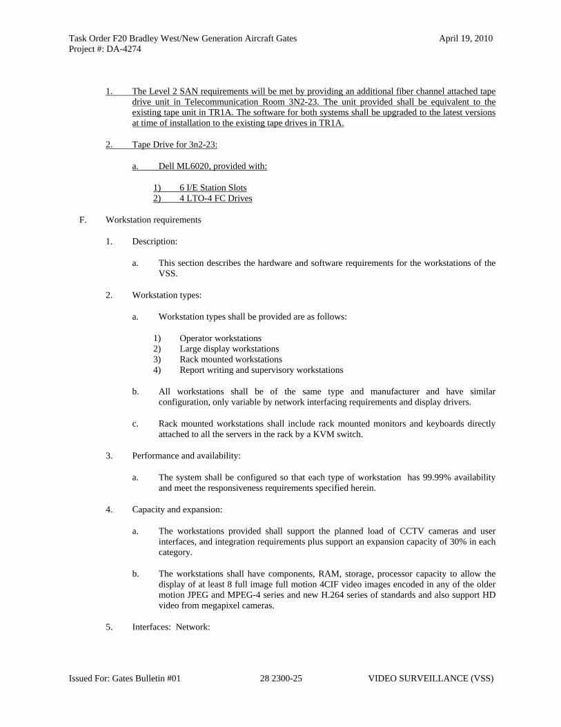
Task Order F20 Bradley West/New Generation Aircraft Gates April 19, 2010Project #: DA-4274
Issued For: Gates Bulletin #01 28 2300-25 VIDEO SURVEILLANCE (VSS)
1. The Level 2 SAN requirements will be met by providing an additional fiber channel attached tape drive unit in Telecommunication Room 3N2-23. The unit provided shall be equivalent to the existing tape unit in TR1A. The software for both systems shall be upgraded to the latest versions at time of installation to the existing tape drives in TR1A.
2. Tape Drive for 3n2-23:
a. Dell ML6020, provided with:
1) 6 I/E Station Slots 2) 4 LTO-4 FC Drives
F. Workstation requirements
1. Description:
a. This section describes the hardware and software requirements for the workstations of the VSS.
2. Workstation types:
a. Workstation types shall be provided are as follows:
1) Operator workstations 2) Large display workstations 3) Rack mounted workstations 4) Report writing and supervisory workstations
b. All workstations shall be of the same type and manufacturer and have similar configuration, only variable by network interfacing requirements and display drivers.
c. Rack mounted workstations shall include rack mounted monitors and keyboards directly attached to all the servers in the rack by a KVM switch.
3. Performance and availability:
a. The system shall be configured so that each type of workstation has 99.99% availability and meet the responsiveness requirements specified herein.
4. Capacity and expansion:
a. The workstations provided shall support the planned load of CCTV cameras and user interfaces, and integration requirements plus support an expansion capacity of 30% in each category.
b. The workstations shall have components, RAM, storage, processor capacity to allow the display of at least 8 full image full motion 4CIF video images encoded in any of the older motion JPEG and MPEG-4 series and new H.264 series of standards and also support HD video from megapixel cameras.
5. Interfaces: Network:

Task Order F20 Bradley West/New Generation Aircraft Gates April 19, 2010Project #: DA-4274
Issued For: Gates Bulletin #01 28 2300-26 VIDEO SURVEILLANCE (VSS)
a. The workstations shall interface to the network via 1 GB link(s) as required. The workstations shall interface with the selected displays as required.
6. Management and reporting:
a. The workstations shall provide appropriate status information and allow management by the LAWA network management and control system as appropriate.
7. QA/QC standards:
a. The system shall be implemented according to LAWA ITD QA/QC standards.
8. The workstations shall utilize:
1) Operating system: Windows 7 2) Servers Windows 2008 3) Data base Windows SQL 2008
9. Manufactures
a. Workstations from the following manufacturers are acceptable:
1) HP Z600 or Z800 series, or approved equal.
10. Displays:
a. The displays for rack mount workstations shall be 19 inch rack mounted LCD screens.
b. Displays for operator workstations shall be dual 24 inch LCD displays.
c. Displays for management workstations shall be single 24 inch LCD displays.
d. Displays for large screen workstations shall be at 40 inch LED, minimum.
e. In each case the best possible display quality shall be provided that is compatible with Genetec and appropriate drivers provided.
f. Displays for the following manufacturers are acceptable:
1) 24 inch: View Sonic, or approved equal.
2) 40 inch or larger, NEC, or approved equal consistent with 40 inch displays specified in Section 27 4219 – Electronic Visual Information Display Systems (EVIDS).
11. Printers:
a. Printers shall be provided for management workstations.
b. Printers shall be HP laser jet type CP4000 series, configured with the maximum amount of memory, or approved equal.
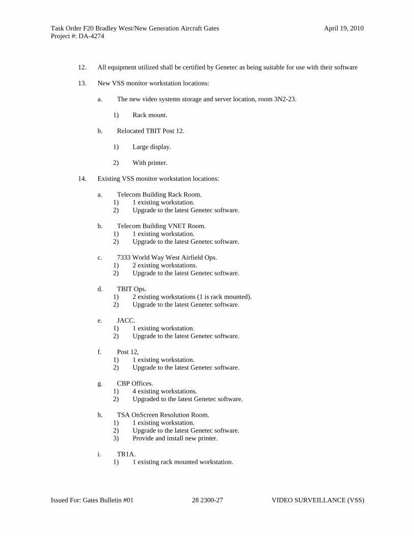
Task Order F20 Bradley West/New Generation Aircraft Gates April 19, 2010Project #: DA-4274
Issued For: Gates Bulletin #01 28 2300-27 VIDEO SURVEILLANCE (VSS)
12. All equipment utilized shall be certified by Genetec as being suitable for use with their software
13. New VSS monitor workstation locations:
a. The new video systems storage and server location, room 3N2-23.
1) Rack mount.
b. Relocated TBIT Post 12.
1) Large display.
2) With printer.
14. Existing VSS monitor workstation locations:
a. Telecom Building Rack Room. 1) 1 existing workstation. 2) Upgrade to the latest Genetec software.
b. Telecom Building VNET Room. 1) 1 existing workstation. 2) Upgrade to the latest Genetec software.
c. 7333 World Way West Airfield Ops. 1) 2 existing workstations. 2) Upgrade to the latest Genetec software.
d. TBIT Ops. 1) 2 existing workstations (1 is rack mounted). 2) Upgrade to the latest Genetec software.
e. JACC. 1) 1 existing workstation. 2) Upgrade to the latest Genetec software.
f. Post 12, 1) 1 existing workstation. 2) Upgrade to the latest Genetec software.
g. CBP Offices. 1) 4 existing workstations. 2) Upgraded to the latest Genetec software.
h. TSA OnScreen Resolution Room. 1) 1 existing workstation. 2) Upgrade to the latest Genetec software. 3) Provide and install new printer.
i. TR1A. 1) 1 existing rack mounted workstation.

Task Order F20 Bradley West/New Generation Aircraft Gates April 19, 2010Project #: DA-4274
Issued For: Gates Bulletin #01 28 2300-28 VIDEO SURVEILLANCE (VSS)
2) Upgrade to the latest Genetec software.
j. Baggage Control Room. 1) 1 existing workstation. 2) Upgrade to the latest Genetec software.
G. Support
1. In addition to the specified services required during the warranty period, the Contractor shall provide factory call-in support services to be made available to LAWA personnel for the length of the warranty period.
2. Support of the virus protection system and Microsoft update services as required in these specifications shall be provided during the warranty period. At a minimum, the Security Contractor shall perform monthly manual virus protection updates and scans, and manual Microsoft updates, using LAWA provided sources.
H. Licenses
1. The number of licenses required for each software component shall be the number installed plus 30%. The licenses shall be transmitted to LAWA IT in both a spreadsheet listing details and paper format. The development licenses including SDK etc are only required in one instance. All licenses shall be permanent and not require any annual fee etc.
2. Sixteen (16) additional monitoring workstation licenses shall be provided.
I. Training
1. In addition to any other training requirements specified elsewhere, the following specific VSS system training shall be provided:
a. Genetec operator training b. Genetec system administrator training c. Genetec plug in and SDK training d. Backup and restore software operations and administration e. SAN and/or tape software operation and administration f. System Administration and software maintenance training in any utility compiler, software
development environment or script tool used in development of software specifically for this project.
2. Numbers of LAWA staff required to be trained are as follows:
a. Genetec operator training. Operator training shall be provided in shifts as follows:
b. Four sessions: Two for the swing shift and two for the day shift, per users group. Each session shall support up to 5 attendees.
1) Operator training shall be provided for the following user groups:
a) CBP

Task Order F20 Bradley West/New Generation Aircraft Gates April 19, 2010Project #: DA-4274
Issued For: Gates Bulletin #01 28 2300-29 VIDEO SURVEILLANCE (VSS)
b) Operations c) TSA d) Airport Police e) Airlines
c. Genetec system admin training, 6 attendees. d. Genetec maintenance training, 6 attendees. e. Genetec plug in and SDK training, 6 attendees. f. Backup and restore software, 6 attendees. g. SAN and/or tape software, 6 attendees. h. Any utility compiler, script tool used in development, 6 attendees.
3. Each training course shall be professionally video-taped and the tape/DVD provided to LAWA no later than at system acceptance for use by LAWA for training subsequent LAWA personnel. Training shall be provided by factory representatives of each component. Training shall be provided on site or at a location with 25 miles of site.
4. All training shall be provided in a classroom based environment. Each attendee shall have his/her own workstation. Provision of these workstations shall be the responsibility of the Contractor. The system on which training shall be conducted shall be setup to simulate or use the system as actually installed at TBIT and not a generic sample setup.
5. Training programs shall be provided to LAWA IT for review and approval at least four weeks prior to the start of any training session.
J. Documentation
1. Documentation shall be provided as specified elsewhere.. Additionally, the Contractor shall provide:
a. A complete design document outlining software and hardware configuration, location and interconnectivity of all components both hardware and software; to be provided before the pre-installation test.
b. Complete configuration information for all hardware and software components and devices by the acceptance test
c. Full source codes of any software scripts or firmware or setup files, implemented specifically for this project, at the successful completion of the acceptance test
d. A working setup of any utilities, compilers loaders, SDKs etc which were used to develop the above on a development system configuration. Location to be coordinated with the airport. Delivery at system acceptance
e. A permanent license for the use of all the above at TBIT: Delivery at system acceptance
f. Backup copies and installation disks for any off the shelf software procured separately or installed on delivery of any hardware. Delivery at system acceptance
g. A recording of 30 seconds of sample video for every CCTV camera on the system at time of acceptance. Delivery at system acceptance
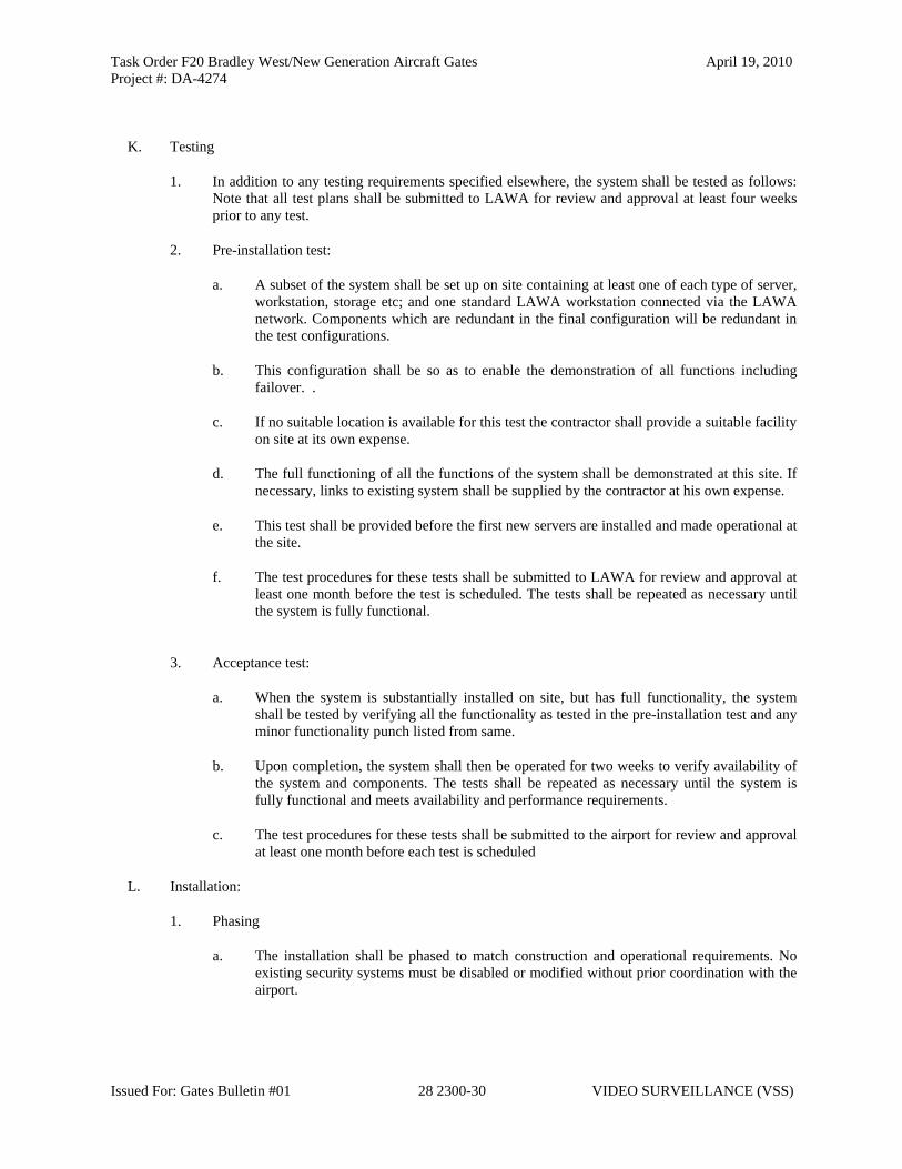
Task Order F20 Bradley West/New Generation Aircraft Gates April 19, 2010Project #: DA-4274
Issued For: Gates Bulletin #01 28 2300-30 VIDEO SURVEILLANCE (VSS)
K. Testing
1. In addition to any testing requirements specified elsewhere, the system shall be tested as follows: Note that all test plans shall be submitted to LAWA for review and approval at least four weeks prior to any test.
2. Pre-installation test:
a. A subset of the system shall be set up on site containing at least one of each type of server, workstation, storage etc; and one standard LAWA workstation connected via the LAWA network. Components which are redundant in the final configuration will be redundant in the test configurations.
b. This configuration shall be so as to enable the demonstration of all functions including failover. .
c. If no suitable location is available for this test the contractor shall provide a suitable facility on site at its own expense.
d. The full functioning of all the functions of the system shall be demonstrated at this site. If necessary, links to existing system shall be supplied by the contractor at his own expense.
e. This test shall be provided before the first new servers are installed and made operational at the site.
f. The test procedures for these tests shall be submitted to LAWA for review and approval at least one month before the test is scheduled. The tests shall be repeated as necessary until the system is fully functional.
3. Acceptance test:
a. When the system is substantially installed on site, but has full functionality, the system shall be tested by verifying all the functionality as tested in the pre-installation test and any minor functionality punch listed from same.
b. Upon completion, the system shall then be operated for two weeks to verify availability of the system and components. The tests shall be repeated as necessary until the system is fully functional and meets availability and performance requirements.
c. The test procedures for these tests shall be submitted to the airport for review and approval at least one month before each test is scheduled
L. Installation:
1. Phasing
a. The installation shall be phased to match construction and operational requirements. No existing security systems must be disabled or modified without prior coordination with the airport.

Task Order F20 Bradley West/New Generation Aircraft Gates April 19, 2010Project #: DA-4274
Issued For: Gates Bulletin #01 28 2300-31 VIDEO SURVEILLANCE (VSS)
2. Installation shall be by factory trained staff for each hardware and software component.
M. Commissioning:
1. This system shall be provided with additional commissioning services in addition to those specified elsewhere. Specifically the Contractor shall be additionally responsible for:
a. System setup
b. User group, password and camera site assignment within Genetec and other software components.
c. Camera setup in system, including but not limited to frame rate, resolution, motion detection, encoding technology and site and user groups.
d. Implementing and commissioning the link to ACAMS
e. Implementing and commissioning the link to the LAWA Computer Aided Dispatch system as required.
f. Implementing and commissioning the link to the existing TBIT Pelco systems as required.
g. Video and alarm setup programming
h. Genetec CCTV Map Graphics development and implementation, including importation of AutoCAD and suitable satellite graphics, and map object definition and placement.
i. Setting up, provisioning, implementing, commissioning and operating an appropriate video archiving process for a period of at least six months.
j. On site initial operations and technical support from Genetec Professional Services Group for a period of at least six monthsshall be provided for a minimum of 320 hours. This technical support shall be used on an on-call basis at the Owner’s discretion.
2. The schedule for these activities shall be coordinated with LAWA IT. The scope of these activities shall include the existing cameras at TBIT.
N. Software Virus scan
1. After each installation of any software and before any integration, each item of software both initial release, and subsequent releases and patches, shall be scanned for viruses by the LAWA approved virus system with an up to date list of threats at that time
2. Before the system is made operational the whole system, including each and every processor and internal hard drives shall be rescanned with an up to date list of threats at that time
2.52.6 WIRE AND CABLE

Task Order F20 Bradley West/New Generation Aircraft Gates April 19, 2010Project #: DA-4274
Issued For: Gates Bulletin #01 28 2300-32 VIDEO SURVEILLANCE (VSS)
A. Low voltage wire and cable shall be provided and installed as required, except as otherwise indicated in the drawings and specifications.
B. Wire and cable shall be selected and used as appropriate for the device application in accordance with the device manufacturer’s specifications, voltage and load, and distance of the wire/cable run.
C. Wire and cable runs shall be “home run”. Mid run splices shall not be permitted.
D. Wire and cable shall be Belden, West Penn, Contractors Wire and Cable, or approved equal.
2.62.7 MATERIALS
A. Color and Finish Selection:
1. In all public areas and in all other areas visible from public areas or from the exterior of the building, colors and finishes shall match the custom color and finish samples on file with the Owner. In all other areas, applicable colors and finishes shall be selected by the Owner from the manufacturer’s standard color and finish schedule. For such areas, submit manufacturer’s standard color and finish schedule(s).
2.72.8 EQUIPMENT
A. All equipment shall be installed in accordance with this specification. Provide and install any and all equipment necessary to provide a complete and operating system, and meet the full intent of this design and other specifications within these construction documents. Any equipment such as consumables, terminators, or any other materials or equipment needed to install this system shall be considered ancillary and be provided as a part of this project. Contractor shall provide cable for all security systems and integration of sub-systems. Cable shall be provided in accordance with manufacturer specifications for the equipment it is terminating to.
PART 3 - EXECUTION
3.1 EXAMINATION
A. Inspect the jobsite and survey the conditions to be encountered during performance of the work. This shall be accomplished prior to starting the work. Failure of Contractor to become familiar with the site conditions shall not relieve Contractor of responsibility for full completion of the work in accordance with the contract provisions.
B. Verify that all conduit, wires, cables, security equipment are installed and ready for connection and integration with the rest of the system.
C. Examine area to be protected and verify that environmental characteristics will not affect effective communication and interfacing. Report observed problems in writing.
D. Determine that power supplies, conduit, wires, cables, connections, and equipment are ready for installation and interfacing before attempting installation.
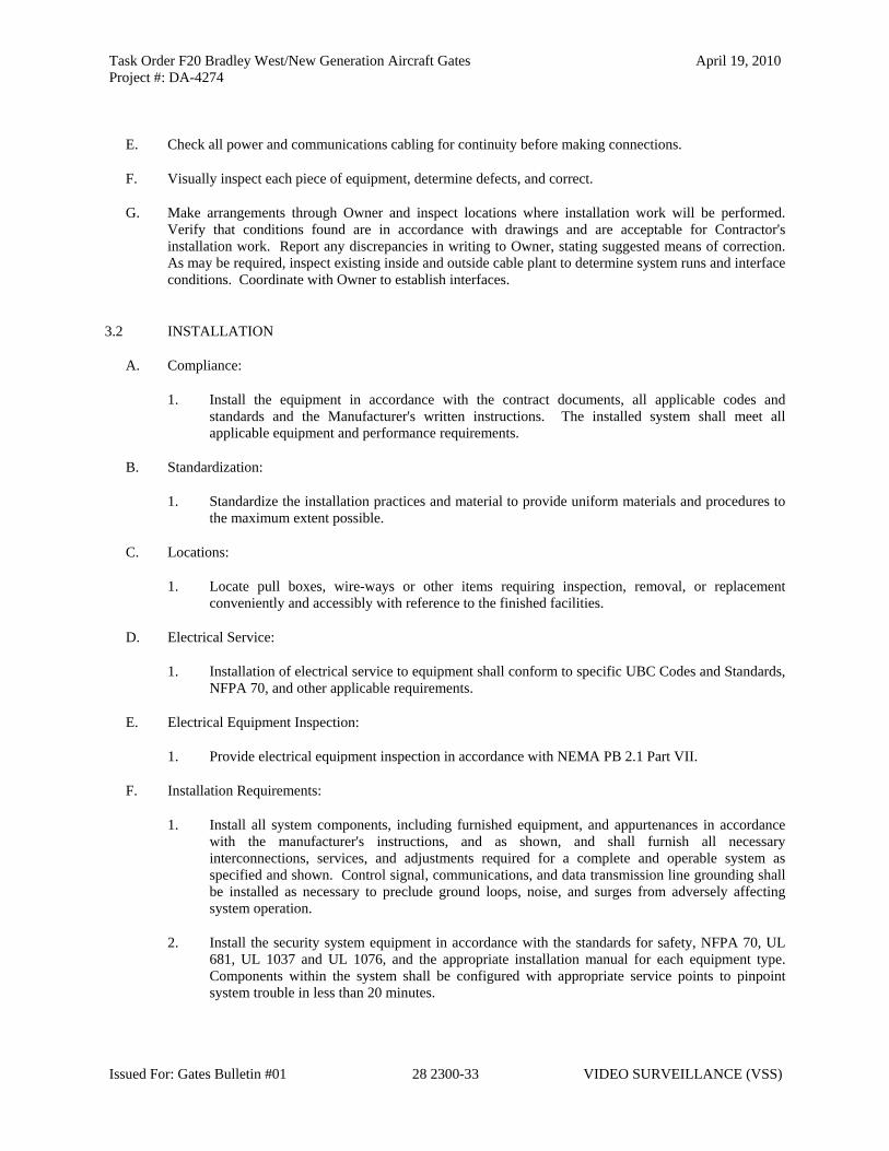
Task Order F20 Bradley West/New Generation Aircraft Gates April 19, 2010Project #: DA-4274
Issued For: Gates Bulletin #01 28 2300-33 VIDEO SURVEILLANCE (VSS)
E. Check all power and communications cabling for continuity before making connections.
F. Visually inspect each piece of equipment, determine defects, and correct.
G. Make arrangements through Owner and inspect locations where installation work will be performed. Verify that conditions found are in accordance with drawings and are acceptable for Contractor's installation work. Report any discrepancies in writing to Owner, stating suggested means of correction. As may be required, inspect existing inside and outside cable plant to determine system runs and interface conditions. Coordinate with Owner to establish interfaces.
3.2 INSTALLATION
A. Compliance:
1. Install the equipment in accordance with the contract documents, all applicable codes and standards and the Manufacturer's written instructions. The installed system shall meet all applicable equipment and performance requirements.
B. Standardization:
1. Standardize the installation practices and material to provide uniform materials and procedures to the maximum extent possible.
C. Locations:
1. Locate pull boxes, wire-ways or other items requiring inspection, removal, or replacement conveniently and accessibly with reference to the finished facilities.
D. Electrical Service:
1. Installation of electrical service to equipment shall conform to specific UBC Codes and Standards, NFPA 70, and other applicable requirements.
E. Electrical Equipment Inspection:
1. Provide electrical equipment inspection in accordance with NEMA PB 2.1 Part VII.
F. Installation Requirements:
1. Install all system components, including furnished equipment, and appurtenances in accordance with the manufacturer's instructions, and as shown, and shall furnish all necessary interconnections, services, and adjustments required for a complete and operable system as specified and shown. Control signal, communications, and data transmission line grounding shall be installed as necessary to preclude ground loops, noise, and surges from adversely affecting system operation.
2. Install the security system equipment in accordance with the standards for safety, NFPA 70, UL 681, UL 1037 and UL 1076, and the appropriate installation manual for each equipment type. Components within the system shall be configured with appropriate service points to pinpoint system trouble in less than 20 minutes.

Task Order F20 Bradley West/New Generation Aircraft Gates April 19, 2010Project #: DA-4274
Issued For: Gates Bulletin #01 28 2300-34 VIDEO SURVEILLANCE (VSS)
3. All wiring, including low voltage wiring outside the control console, cabinets, boxes, and similar enclosures, shall be installed in rigid galvanized steel conduit conforming to UL 6 (when outdoors), or electric metallic tubing (EMT) when indoors. Minimum conduit size shall be 3/4-inch. All other electrical work shall be as specified with electrical specifications and drawings that are part of the contract document and as shown. Grounding shall be installed as necessary to preclude ground loops, noise, and surges from adversely affecting system operation.
a. Detailed shop drawings shall be provided as part of the submittal process. The shop drawings shall include, but not be limited to exposed conduit and devices, including hangars, brackets, back boxes and related equipment.
4. All equipment connected to alternating current circuits shall be protected from power line surges. Equipment protection shall meet the requirements of ANSI C62.41. Fuses shall not be used for surge protection.
5. All inputs shall be protected against surges induced on device wiring. Outputs shall be protected against surges induced on control and device wiring installed outdoors and as shown. All communications equipment shall be protected against surges induced on any communications circuit. All cables and conductors, except fiber-optics, which serve as communications circuits from the existing access control CPU to field equipment, and between field equipment, shall have surge protection circuits installed at each end. Protection shall be furnished at equipment, and additional triple electrode gas surge protectors rated for the application on each wire-line circuit shall be installed within 3 feet of the building cable entrance. Fuses shall not be used for surge protection. The inputs and outputs shall be tested in both normal mode and common mode using the following two wave-forms:
a. A 10 microsecond rise time by 1000 microsecond pulse width wave-form with a peak voltage of 1500 volts and a peak current of 60 amperes.
b. An 8 microsecond rise time by 20 microsecond pulse width wave-form with a peak voltage of 1000 volts and a peak current of 500 amperes.
6. Calibrate all equipment.
7. Inspect each component, determine obvious defects, and correct.
8. All electrical work shall be in accordance with Section 16000.
9. Test ground rods in accordance with IEEE No. 142.
10. Perform tests as recommended by manufacturer or as required to ensure the security equipment is operating properly and meets specified requirements.
11. Correct all deficiencies detected and retest affected components.
12. Record test data, tabulate, and write narrative describing tests, results, deficiencies found, corrective measures, and results of retesting. Certify that the security equipment has been tested and is ready for performance verification testing.
13. Use Permanent Room Numbers as indicated on the Room Finish Schedules for construction period identification of rooms and building spaces. All required shop drawings and submittals, including manuals and Project Record Drawings shall identify rooms and spaces using the Permanent Room
Task Order F20 Bradley West/New Generation Aircraft Gates April 19, 2010Project #: DA-4274
Issued For: Gates Bulletin #01 28 2300-35 VIDEO SURVEILLANCE (VSS)
Numbers. Permanent identification devices including signage, equipment nameplates, and panels shall use the Permanent Room Numbers.
14. The Security Contractor shall be responsible to verify with the Owner the exact final location of each camera prior to installation. The Security Contractor shall be responsible to coordinate with lighting, signage and other sub-contractors to avoid conflicts with intended fields of view as indicated in the drawings.
G. Marking:
1. Equipment Name Plates: The following requirements shall apply:
a. General. Attach a permanent, corrosion-resistant name plate to each equipment component showing the manufacturer's name, address, serial number and equipment rating. Each name plate shall be clearly visible on the exterior of equipment. Components located within equipment enclosures shall also be provided with name plates.
b. Location and Fastening. Provide nameplates to identify all equipment components. Provide each panel assembly with a name plate on the interior of equipment enclosures, indicating number of equipment and unit of assembly. Fasten name plates securely with slotted stainless steel screws. The use of adhesive for fastening name plates will not be permitted.
2. Control and Display Labels:
a. Use. Each control, display and any other item of equipment that must be located, identified, read or manipulated shall be appropriately and clearly labeled to permit rapid and accurate identification of its operating state of position.
b. Orientation. Orient labels and information thereon horizontally so that they may be read quickly and easily. Vertical orientation shall be used only where space is limited.
c. Locations. Locate labels so that there is no confusion as to which item they identify. Labels shall not obscure any other information required by the operator. Controls shall not obscure labels. The location of labels shall be consistent.
3. Wire and Cable
a. All terminations and wiring shall be labeled in accordance with LAWA ITG Infrastructure Standards of Practice dated October 22, 2004.
3.3 FIELD QUALITY CONTROL
A. General:
1. Conduct an Installation Test and total Acceptance Test upon completion of equipment installation. Testing shall be coordinated as necessary, to demonstrate that all interfaces have been successfully implemented.
B. Installation and Acceptance Test Procedures and Reports:
1. General: Installation and acceptance tests shall be conducted in the normal operational environment to the maximum extent possible. The tests shall represent operation in the normal

Task Order F20 Bradley West/New Generation Aircraft Gates April 19, 2010Project #: DA-4274
Issued For: Gates Bulletin #01 28 2300-36 VIDEO SURVEILLANCE (VSS)
mode in which each system will operate. If interfaces are incomplete, provide simulation of those interfaces so that the system may be tested as a complete and stand-alone entity. Perform all equipment repair and/or adjustment that may be required during acceptance testing.
2. Availability Tests: Installation and acceptance testing shall include conducting individual availability tests for each equipment item. Requirements for availability tests are as follows:
a. Availability shall be determined in accordance with Quality Control procedures, except for the test duration as specified herein.
b. The availability tests shall consist of the equipment being operated as a complete stand-alone entity with the exception that incomplete interfaces may be simulated. In all other respects, the equipment shall be operated in the mode that would normally prevail.
c. The duration of each availability test, as a minimum, shall consist of a 5 day period with the availability ratios of 100% being met or exceeded over the total period.
d. Demonstration of equipment reliability shall be accomplished as part of, and in support of, availability testing. This demonstration shall verify that predicted reliability has been realized by measured Mean Time Between Failure (MTBF).
e. Demonstration of equipment maintainability shall also be accomplished as part of, and in support of, availability testing. In this demonstration, verify that the objectives of the maintainability program have been realized by measured Mean Time To Repair (MTTR). The maintainability demonstration shall include preparation and use of a failure log.
f. Equipment preventive maintenance or service shall be excluded from measurement of maintainability. However, Contractor shall conduct at least one period of preventive maintenance during availability testing to demonstrate compliance with the maintenance plan.
g. Submit availability test reports to Owner for review. Test reports shall include tabulations of MTBF and MTTR.
C. System Commissioning:
1. General: Contractor shall be responsible for ensuring that the installation and related interfaces is completed and operational at least thirty (30) days prior to scheduled beneficial occupancy. In the event the installation and related interfaces is not completed and operational by the scheduled beneficial occupancy date, Contractor shall establish and submit a security plan to Owner that complies with FAR Part 107.14 and related Owner security requirements. The security plan shall be submitted to Owner and FAA for approval. The security plan, revisions, and security measures to be deployed until such time the new security equipment is completed and operational shall be at Contractor's expense.
a. After all installation and acceptance test requirements specified have been complied with, the equipment shall be commissioned. After commissioning has been completed, Owner will take possession of the equipment and utilize it in accordance with the conditions described in the contract documents.
2. Prerequisites To System Commissioning
Task Order F20 Bradley West/New Generation Aircraft Gates April 19, 2010Project #: DA-4274
Issued For: Gates Bulletin #01 28 2300-37 VIDEO SURVEILLANCE (VSS)
a. Outstanding work items that may exist, such as facility interfaces, project record drawings, and/or in-process change orders, shall be documented and submitted to Owner for review prior to start of equipment commissioning. Documentation of outstanding work items shall take the form of punch lists of critical action items lists that describe the work, the expected completion schedule, and the impact upon operation. Depending upon the nature of the outstanding work item, Owner may grant a waiver to accomplish partial commissioning of any of the equipment. Completion of waived outstanding work items shall then be assigned to the post-commissioning operations and maintenance.
3. Commissioning Procedure
a. The commissioning procedure shall be witnessed by Owner. The commissioning procedure shall be conducted by Contractor and shall consist of a detailed inspection, and physical accounting of each equipment item. An operational demonstration shall then be conducted in which the equipment shall function in the normal operational mode, and shall operate completely error-free in terms of hardware and software performance. Occurrence of any equipment failure shall terminate the demonstration. The demonstration shall restart and run for a period of time designated by Owner after the failure has been corrected. Except for any outstanding work items as previously described, this shall complete the commissioning procedure.
3.4 OPERATIONS AND MAINTENANCE DOCUMENTATION
A. Provide Owner with applicable Operations and Maintenance (O&M) manual(s) that describe the equipment installed under this contract. The O&M manual(s) shall, as a minimum, consist of an operations section, a maintenance section, and a drawings section when necessary.
B. Documentation: Except as otherwise specified, all documentation shall contain sufficient written text and illustrations necessary to present a full description of the equipment, including an overview, concept of operation and/or maintenance, operating instructions using all functions and capabilities, and interfaces with other systems/subsystems. The requirements are as follows:
1. System Description:
a. Describe as Installed. Fully describe the equipment as installed. Present a complete, organized, and comprehensive overview of the entire equipment. Information presented shall include, but not be limited to the following:
1) Equipment overview description, theory of operation. 2) Overview of recommended equipment operating policies. 3) Summary plans, layouts, and block diagrams, as appropriate. 4) Interrelationships overview of each item of equipment with other systems and
subsystems, equipment, utilities, or other installations. 5) Significant characteristics of the equipment. 6) Other information, as necessary, to achieve a thorough understanding of the operation
of the equipment.
b. Equipment Functions. Provide a full and comprehensive discussion of the function of each primary item of equipment.
Task Order F20 Bradley West/New Generation Aircraft Gates April 19, 2010Project #: DA-4274
Issued For: Gates Bulletin #01 28 2300-38 VIDEO SURVEILLANCE (VSS)
c. Equipment Illustrations. Provide line drawings, renderings or photographic illustrations of each item of equipment. Illustrations shall include assemblies, subassemblies, and major components. All operating features shall be clearly identified by name and location on the equipment.
d. Special Or Non-Standard Installations. In situations where off-the-shelf items of equipment are combined into special or non-standard installations, provide separate sections containing complete operation related information for each non-standard or specialized configuration of equipment as installed.
e. Operating Instructions. Operating instructions shall be clear, simple, and concise for each item of equipment to be used by operating personnel for day-to-day operation. It shall be in such format that photocopy of operating instructions for the item of equipment could be provided to operation for use. Operating instructions shall consist of:
1) Warning Information. Provide emergency or special warnings, instructions and procedures pertaining to the equipment.
2) System Operation. Provide sequential, step-by-step instructions on how to properly perform all operational tasks and procedures associated with equipment operation, in any mode, under both normal and abnormal and emergency conditions. Also, instructions on how the operator may test the equipment to verify correct operation, detect and identify malfunctions, and return the equipment to normal operation.
3) Equipment Performance. Provide equipment operational limitations and how it shall be operated to obtain the best performance. If applicable, also provide instructions on how to modify equipment performance to suit individual needs or conditions.
f. Drawings. Provide all drawings, illustrations, and equipment related reference materials not provided elsewhere within the manual(s). This documentation shall be assembled in the manner specified herein, shall be listed in Table of Contents, and shall contain the following information as a minimum:
1) Mechanical drawings showing dimensions. 2) Schematic drawings and diagrams for each item of equipment. 3) Equipment schematic drawings. 4) Contractor shall ensure that the latest project record drawings are incorporated in all
final copies of manuals as part of the Completion of Work; and shall update these in all copies to reflect any changes made during Maintenance.
5) Interface drawings. 6) Other related documentation.
3.5
END OF SECTION 28 2300