Embed Size (px)
Citation preview

1099-01-1110 - VERSION E
2012

Camoplast Solideal Inc.4162, Burrill - Local A
Shawinigan, (Québec) G9N 0C3 CANADA
E-mail: [email protected]: www.camoplastsolideal.com
IMPORTANT
The Camoplast UTV T4S, from Camoplast Hi-Performance Tracks,where first and foremost designed to provide the bestperformance in terms of traction and floatation in conditions ofextreme terrain such as deep snow and mud. The track were alsodesigned for side-by-side type vehicles that can ride at a maximumspeed of 40 km/h (about 70 km/ h on speedometer). Exceeding thisspeed when the terrain conditions are dry can cause prematurewear and or major breakdowns on the track system. If breakageoccurs due to excessive speed, damage will not be covered undernormal warranty. It is the user's responsibility to abide by theseterms of use.
IMPORTANT
Please read carefully each part of this document as well as modelspecific Installation Guidelines prior to assembling, installing andusing the track system.
IMPORTANT
The way to use the Camoplast Hi-Performance Tracks CamoplastUTV T4S track system has a direct link with the longevity of thesystem components. Sportive driving, rapid direction changesand repeated fast turns (more specifically on power steeringvehicles) are not advised. This driving manners increase risk ofderailing and can cause premature wear and or major breakdownson the track system which will not be covered under normalwarranty.
Original noticeOther languages translation available at www.camoplastsolideal.com
® and MC are trademarks of Camoplast Solideal Inc.All rights reserved. ©2015 Camoplast Solideal Inc.
Printed in Canada.

TABLE OF CONTENTS
INTRODUCTION . . . . . . . . . . . . . . . . . . . . . . . . . . . . . . . . . . . . . . . . . . . . . . . . 1
SAFETY . . . . . . . . . . . . . . . . . . . . . . . . . . . . . . . . . . . . . . . . . . . . . . . . . . . . . . . 1
GENERAL INFORMATION . . . . . . . . . . . . . . . . . . . . . . . . . . . . . . . . . . . . . . . . . 2
HINTS AND TIPS . . . . . . . . . . . . . . . . . . . . . . . . . . . . . . . . . . . . . . . . . . . . . . . . 2
USER NOTICE AND DISCLAIMER . . . . . . . . . . . . . . . . . . . . . . . . . . . . . . . . . . 3
USING THE ATV WITH TRACKS . . . . . . . . . . . . . . . . . . . . . . . . . . . . . . . . . . . . 5
INSTALLATION, REMOVAL AND RE-INSTALLATION . . . . . . . . . . . . . . . . . . . 15
ADJUSTMENTS . . . . . . . . . . . . . . . . . . . . . . . . . . . . . . . . . . . . . . . . . . . . . . . . 19
INSTALLATION OF A RUBBER TRACK . . . . . . . . . . . . . . . . . . . . . . . . . . . . . 34
BREAK-IN PERIOD . . . . . . . . . . . . . . . . . . . . . . . . . . . . . . . . . . . . . . . . . . . . . 36
REPLACEMENT OF A WHEEL WITH EXTRACTOR . . . . . . . . . . . . . . . . . . . 37
MAINTENANCE SCHEDULE . . . . . . . . . . . . . . . . . . . . . . . . . . . . . . . . . . . . . . 39
TORQUE TABLE . . . . . . . . . . . . . . . . . . . . . . . . . . . . . . . . . . . . . . . . . . . . . . . 40
STORAGE . . . . . . . . . . . . . . . . . . . . . . . . . . . . . . . . . . . . . . . . . . . . . . . . . . . . 40
WEAR . . . . . . . . . . . . . . . . . . . . . . . . . . . . . . . . . . . . . . . . . . . . . . . . . . . . . . . . 41
WARRANTY . . . . . . . . . . . . . . . . . . . . . . . . . . . . . . . . . . . . . . . . . . . . . . . . . . . 46
TROUBLESHOOTING . . . . . . . . . . . . . . . . . . . . . . . . . . . . . . . . . . . . . . . . . . . 48
SERIAL NUMBER LOCATION . . . . . . . . . . . . . . . . . . . . . . . . . . . . . . . . . . . . . 49
TECHNICAL SUPPORT . . . . . . . . . . . . . . . . . . . . . . . . . . . . . . . . . . . . . . . . . . 50
’’CE’’ DECLARATION OF CONFORMITY . . . . . . . . . . . . . . . . . . . . . . . . . . . . 51
PARTS LIST . . . . . . . . . . . . . . . . . . . . . . . . . . . . . . . . . . . . . . . . . . . . . . . . . . . 53
INTRODUCTION
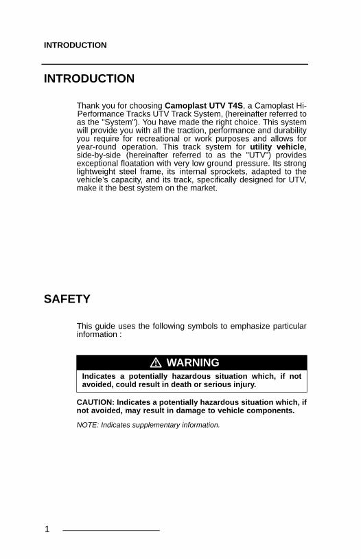
INTRODUCTION
Thank you for choosing Camoplast UTV T4S, a Camoplast Hi-Performance Tracks UTV Track System, (hereinafter referred toas the "System"). You have made the right choice. This systemwill provide you with all the traction, performance and durabilityyou require for recreational or work purposes and allows foryear-round operation. This track system for utility vehicle,side-by-side (hereinafter referred to as the "UTV") providesexceptional floatation with very low ground pressure. Its stronglightweight steel frame, its internal sprockets, adapted to thevehicle’s capacity, and its track, specifically designed for UTV,make it the best system on the market.
SAFETY
This guide uses the following symbols to emphasize particularinformation :
CAUTION: Indicates a potentially hazardous situation which, ifnot avoided, may result in damage to vehicle components.
NOTE: Indicates supplementary information.
� WARNINGIndicates a potentially hazardous situation which, if notavoided, could result in death or serious injury.
1

GENERAL INFORMATION
GENERAL INFORMATION
All figures, information or photos presented in this documentare up to date at the time of publication. However, they maychange without notice.
Read and follow indications of the UTV user manual andinstallation guidelines carefully. Their contents remainsapplicable after installating of the System.
This document should be read by every person who drives theUTV equipped with the System.
This document is an integral part of the System. Pass it alongto any new System owner.
Consult legal authorities where you drive your UTV equippedwith the System before usage to ensure that you respect allapplicable laws and regulations.
UTV track systems are designed to reduce ground pressureand increase vehicle traction. However, during normaloperating conditions, vehicle speed will be reduced, comparedto a wheeled vehicle.
HINTS AND TIPS
Before leaving for an excursion, make sure you have thefollowing within arms reach : 12 mm, 14mm, 15 mm, 16 mm, 17mm, 19mm and 30 mm wrenches, one axe, one shovel, onetow cable, a lifting jack and one adjustable wrench.
Generally, the slower you go, the better the traction will be.
For riding or excursions in unknown, or remote terrain, makesure you have a cellular phone or satellite phone, a first aid kitand spare parts in your possession.
When driving off trails, always be cautious to the presence ofhidden obstacles.
When driving in deep snow, do not intentionally spin the track(tracks keep on turning while the vehicule does not).This couldcause the vehicle to get stuck.
2

USER NOTICE AND DISCLAIMER
USER NOTICE AND DISCLAIMER
The Camoplast UTV T4S System was initially designed to beused in winter conditions and was then adapted to be used infall and spring conditions.
This document holds important information regarding driving anUTV equipped with the Camoplast UTV T4S System byCamoplast Hi-Performance Tracks. It is mandatory that everyuser takes the time to carefully read, understand and then con-sult this reference manual and user guide as well as the UTVowner's manual as needed. When purchasing either a new orused track System, the user must obtain all documentationrelated to the System, including manuals and guides related tothe UTV on which the System is installed. If need be, contactthe Camoplast Hi-Performance Tracks products dealer nearestto you to obtain any additional information. You may alsoconsult the Camoplast Solideal Web site at www.camoplastsolideal.com and contact our technical supportby email at [email protected].
Camoplast Hi-Performance Tracks believes that there arecertain risks related to the installation and use of the System.Our experience shows that the System is safe. However, theuser must be aware of the risks related with driving an UTV withthe particularities of this type of System. The UTV driver must,at all times, respect all applicable laws and regulations, theindications of the System manufacturer and the indicationsfrom the vehicle manufacturer fixed by law, namely when agerestrictions exist and UTV base equipment is required(headlights, flashers and brake lights, rearview mirror, etc.).The user must always wear adequate safety equipment, suchas a helmet, safety glasses (or visor), protective clothing, bootsand gloves. It is understood that driving while impaired orintoxicated presents a danger for the UTV user and others andis against the law.
The System consists of many moving parts, includingtransmission wheels. If an object lodges itself or becomesjammed into the System and blocks the track, it is mandatory tostop the engine and the vehicle and apply the security brakebefore removing object said. By avoiding to do so, the userexposes himself to sudden movement of the UTV or tobreakage of a part or component coming from the System,which could cause severe injuries. It is also very important towear full length clothing and always avoid hanging or stringyaccessories.
Driving an UTV equipped with such a System requiresparticular precautions and a knowledge of proper drivingtechniques of such vehicles. An evaluation by the user of theconditions and terrain (state of the ground, grade of hill, densityof snow, etc.) is equally essential. An UTV equipped with a
3

USER NOTICE AND DISCLAIMER
System cannot compete and/or be used to perform stunts,acrobatics or other exploits, as these could result in loss ofcontrol or severe injuries.
Insufficient knowledge of an UTV during down hill riding, climbsand crossing of obstacles and turns can result in tipping or rollover, and can cause severe injuries.
Carrying a passenger, a load or attaching a tow can cause theUTV to be less stable, and affect driveability. Unless otherwiseprescribed by law and by the UTV manufacturer, you must notcarry a passenger, loads or tow any objects.
The installation of a System:
• Increases ground clearance.• Changes the center of gravity.• Increases the UTV width and weight.• Reduces ground pressure.
These parameters will effectively change driving characteristicsof an UTV equipped with the System.
Consequentially, it is highly recommended that the user adaptshis driving style in function of the new characteristics mentionedabove. The driver must always use caution when he crossesobstacles, circulates through narrow paths, meets vehiclescoming in the opposing direction, etc.
As it was designed, the System will considerably reduce theUTV top speed and can falsify the speedometer. Generally, theSystem transmission wheel diameter is less than that of thetire. Therefore, the vehicle speed will be less than that actuallydisplayed. Whether the UTV is equipped or not with theSystem, users must always adapt the speed to actual drivingconditions. Users must never exceed speed limits or drivefaster than their capacities allow. Excessive speed remains oneof the main causes of severe accidents on UTV.
Camoplast Hi-Performance Tracks is proud to offer UTVconversion kits within its wide range of products. UTV TrackSystems are not only reliable, but safe. However, there arerisks inherent to driving an UTV equipped with the System. It istherefore very important that any driver familiarizes himself withproper driving techniques of an UTV equipped with a System,and that he adapts his driving to his level of experience andcontinually evaluates operating conditions and terrain to safelyand efficiently make the best of these Camoplast Hi-Performance Tracks UTV track systems.
4
USING THE ATV WITH TRACKS
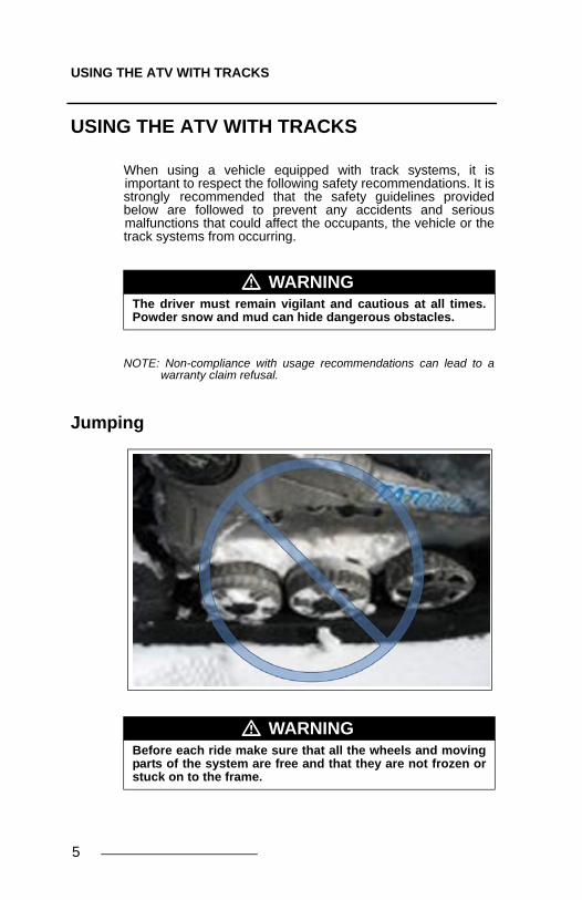
USING THE ATV WITH TRACKS
When using a vehicle equipped with track systems, it isimportant to respect the following safety recommendations. It isstrongly recommended that the safety guidelines providedbelow are followed to prevent any accidents and seriousmalfunctions that could affect the occupants, the vehicle or thetrack systems from occurring.
NOTE: Non-compliance with usage recommendations can lead to awarranty claim refusal.
Jumping
� WARNINGThe driver must remain vigilant and cautious at all times.Powder snow and mud can hide dangerous obstacles.
� WARNINGBefore each ride make sure that all the wheels and movingparts of the system are free and that they are not frozen orstuck on to the frame.
5

USING THE ATV WITH TRACKS
6
Steep descents
� WARNINGIt is not advisable to change direction during steepdescents. This can lead to a serious malfunction of theUTV’s steering system and track systems. During a steepdescent, it is advisable to keep the handlebar in a forwarddirection and to begin turning when the UTV is on flatground, thus to avoid subjecting the components of thevehicle and the system to any high stress.

USING THE ATV WITH TRACKS
Descending and being stuck in reverse
� WARNINGIf the rear track systems get stuck in the snow, avoidmoving or towing the vehicle in reverse to ease it from itsposition , as this could lead to a malfunction of thesystems. If possible, move it in the forward direction to freeit from the snow. It is advisable to remove the snow fromthe top of the rear track systems and to compact it usingyour feet, behind the systems to dislodge the track.Shovelling remains the best alternative in this situation.
7

USING THE ATV WITH TRACKS
Towing a vehicle out of the snow
� WARNINGIf your vehicle must be towed out of the snow, never tow itin the direction in which it sank. Tow the vehicle in thedirection of the trail it left as it became stuck.
8

USING THE ATV WITH TRACKS
Driving over an obstacle
Driving over a steep ridge
� WARNINGIt is not advisable to attempt to drive over an obstacle, sucha tree trunk, a big rock or a steep ridge that could lodgeitself between the front and the rear track systems andimmobilize the vehicle. The best option remains to bypassthis type of obstacle.
9

USING THE ATV WITH TRACKS
Exceeding the anti-rotation stroke on rough terrain
� WARNINGNever exceed anti-rotation stroke of the front and rear tracksystems, system or vehicle faillure may occur. It isrecommended to drive on a surface on which the tracksystem is always fully supported.
10

USING THE ATV WITH TRACKS
Driving over an obstacle of more than 12 inches
� WARNINGIt is not advisable to attempt to drive over an obstacle ofmore than 12 inches, such a tree trunk, a stump or a bigrock. If the situation appears, inserted a log or a pebble todecrease the height of the obstacle and facilitate thedriving over this obstacle.
11

USING THE ATV WITH TRACKS
Sharp turns in locked 4x4 mode
NOTE: Somes vehicles don’t have unlocked 4x4 mode on the reardifferential, for those vehicles avoid the current situation, takewider turns instead.
Location of the towing cable
� WARNINGNever do sharp turns in locked diffential 4x4 mode on asticky terrain without lubrification. The track system isdesigned to slip into the drive system, keeping the vehiclefrom being overloaded.
� WARNINGIf your vehicle must be towed out of the snow, do notsecure the cable on the track systems to tow the vehicle,the towing cable must be fixed on the vehicle frame.
12

USING THE ATV WITH TRACKS
13
Jumping
Special recommandations
� WARNINGIt is strictly forbidden to jump with vehicles equipped withtrack systems. These systems were not designed to carryout this type of operation. An UTV equipped with theSystem must never be used for the following activities:races, rallies, jumps, stunts, acrobatics or any otherextreme applications.
� WARNINGNever exceed vehicle cargo and tow capacity specified byyour vehicle manufacturer on any type of terrain.
� WARNINGIn loaded / working mode (100 kg and over) reducesignificantly your speed and be extra careful on roughterrain.
� WARNINGReduce your speed at all times, a track system installed onyour vehicle does'nt have the same absorbtion capacity asmanufacturer's tires.

USING THE ATV WITH TRACKS
14
� WARNINGAlways operate in 4x4 mode, this significantly reducespossibility of derailling in any conditions.
� WARNINGIt is the driver’s responsibility to verify that the air intake ofthe vehicle is well adapted to weather conditions and is notblocked by snow accumulation.
� WARNINGThe driving characteristics of your ATV will change with theinstallation of the System. It is important to take the time tobecome familliar with the Systems.
� WARNINGWhen travelling in groups, people driving behind vehiclesequipped with a track system should by warned, as thetracks can propel dangerous objects. Be especially cau-tious on “rocky” trails.
� WARNINGAdapt your driving style to surrounding conditions(weather, traffic, etc.) and to your driving abilities.
� WARNINGAllow for a greater braking distance and periodically applythe brakes while driving to prevent ice buildup on brakecomponents.
� WARNINGAlways follow the UTV manufacturer's safety rules and reg-ulations regarding, for exemple passengers transportation,maximum loads, ect.
� WARNINGIt is the driver’s responsibility to follow the recommendedschedules maintenance further described in this manual.

INSTALLATION, REMOVAL AND RE-INSTALLATION
INSTALLATION, REMOVAL AND RE-INSTALLATION
Always follow good shop practices. The place where you will beworking must be security, clean, bright and well ventilated. Ifyou are to use a floor jack, never use it as a stand. Always useappropriate stands. To avoid vehicle movement duringoperations, place blocks behind wheels that remain in contactwith the ground. These recommendations also apply whenremoving parts.
Read this manual before proceeding with the installationwork. Read Installation Guidelines included with theSystem for installation instructions dedicated to your UTVmodel.
When the system is removed and when the wheels arereinstalled on vehicle, make sure that you reinstall all thecomponents of origin (wheels, guards, etc.) such as theywere in the initial condition on the vehicle.
� WARNINGNever place body parts under the vehicle unless it issecurely placed on appropriate stands. Severe injuriescould occur if the vehicle collapses or moves. Do not use alifting device as a secure stand.
� WARNINGBefore beginning the installation, ensure you that thevehicle is immobilized and that the engine is stopped.
� WARNINGTo avoid any possibilities of burn, leave time at the engineand the exhaust to cool before beginning the installation ofthe system.
15

INSTALLATION, REMOVAL AND RE-INSTALLATION
InstallationExecute all tasks described in Installation Guidelines of thevehicle model. Then, proceed to adjust the angle of attack,alignment and track tension as described in this manual. Testdrive and the adjustments must be verified second time afterthe first use, re-adjust as required.
RemovalCAUTION: Leaving anchor brackets attached to suspensionarms or anti-rotation bars attached to the skid plate when theUTV rides on wheels he can result from it grave damages inthe vehicle. Never leave components other than the skid plateand foot rest reinforcement parts.
Using a lifting device, raise the UTV and install appropriatestands. Ensure that the vehicle is immobilized and safe to workon.
� WARNINGTo avoid any injury to your hands during the manipulationof the systems, we recommend you to manipulate thesystems at places indicated in following figure (near to huband near to the anchoring of the anti-pivot).
16
INSTALLATION, REMOVAL AND RE-INSTALLATION
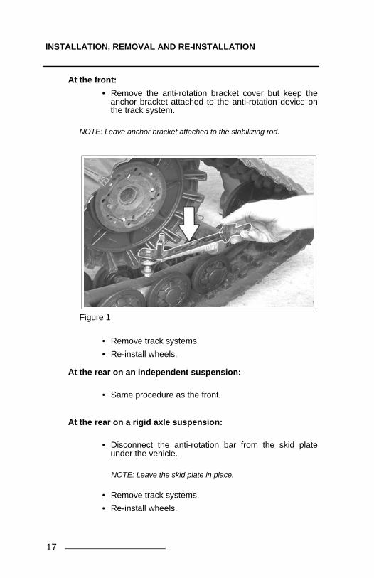
At the front:
• Remove the anti-rotation bracket cover but keep theanchor bracket attached to the anti-rotation device onthe track system.
NOTE: Leave anchor bracket attached to the stabilizing rod.
Figure 1
• Remove track systems.
• Re-install wheels.
At the rear on an independent suspension:
• Same procedure as the front.
At the rear on a rigid axle suspension:
• Disconnect the anti-rotation bar from the skid plateunder the vehicle.
NOTE: Leave the skid plate in place.
• Remove track systems.
• Re-install wheels.
17

INSTALLATION, REMOVAL AND RE-INSTALLATION
Re-installationAlways clean wheel hubs on the UTV before installing wheelsor track systems.
Figure 2
NOTE: Clean wheel hubs.
• Re-install track systems at the rear and securestabilizing rod to anchor bracket for rigid axle.
• Re-install track systems at the front.
• Tighten the fasteners in an alternate crosswise patternto the torque recommended by the manufacturer.
• Verify track tension. Adjust if required.
• Verify angle of attack. Adjust if required.
• Verify alignment. Adjust if required.
18

ADJUSTMENTS
ADJUSTMENTS
Angle of attack for front tracks systems
NOTE: Before adjusting your kit, make sure the vehicle is on a hard andflat surface like concrete. No lifting device should be installed.
To obtain the correct angle of attack on front tracks systems,perform the following :
• Loosen the nut (1) compressing the spring of thestabilizing rod (refer to Figure 3).
Figure 3
IMPORTANTVerifying your adjustments on the system is mandatoryafter the first use of the vehicle, the track tension,alignment and angle of attack of the each track systemsmust be re-verified. Bad adjustments can decrease theperformance of the system and create premature wear ofcertains components
19

ADJUSTMENTS
• Orient the steering wheel and the track systemsstraight forward.
• Temporarily apply pressure to the front of the track tomake sure that it stays flat on the ground.
• Install a flat bar on rear wheels of the track systemsand measure the height as shown on Figure 4.
Figure 4
• Set the nut (2) shown on Figure 5 until the flat barreaches 315 ± 5 mm above the ground. For right handside, rotating the wrench towards A makes the systemrotate towards C while rotating the wrench towards Bmakes the system rotate towards D (reverse for lefthand side).
20

ADJUSTMENTS
.
Figure 5
• Turn the nut (1) until it comes in contact with the spring,then compress the spring by turning this nut 1.5 turns(refer to Figure 6).
Figure 6
21

ADJUSTMENTS
NOTE: In certain rare cases, where the adjustment of the nut (article 1on Figure 6) compressing the spring, is close to the end of thethreaded rod, lengthen the assembly by loosening the locknut(article 3 on Figure 7) and unscrewing the rod end so that amaximum 19 mm of its threads are visible. Make sure that thelocknut is well tightened after the installation.
Figure 7
Basic Tuning (front track systems):
• An adjustment of more than 315 mm measured withthe flat bar, gives easier steering with wobbling effect athigh speed.
• An adjustment of less than 315 mm measured with theflat bar, gives harder steering and more stability at highspeed.
• More spring preload (compression) : notrecommended.
• Less spring preload (compression): gives betterarticulation when riding on deep and powder snow. Itwill not affect the steering effort.
NOTE: Once the adjustments of the angle of attack on the frontsystems are completed, verify once again the adjustments toconfirm.
22

ADJUSTMENTS
Angle of attack for rear track systemsTo obtain the correct angle of attack on rear tracks systems,perform the following :
Vehicles with rigid axle or trailing arm suspension
• Loosen the nut (1) compressing the spring of thestabilizing rod (see Figure 8).
• Set the nut (2) to obtain a distance of 15-20 mm asshown.
• Turn the nut (1) until it comes in contact with the spring,then compress the spring by turning this nut 1.5 turns.
Figure 8
NOTE: Once the adjustments of the angle of attack on the rear systemsare completed, verify once again the adjustments to confirm.
23

ADJUSTMENTS
24
Vehicles with independent suspension
• Loose the bolts (1) and (2) of the bracket anti-rotation(3) to allow at the anti-rotation retainer (4) to rotate inthe axe. (See Figure 9).
Figure 9
• Attach the stabilizing rod (1) to anti-rotation bracketinstalled on the suspension a-arm. (See Figure 10).
• Loosen the nut (2) compressing the spring of thestabilizing rod. The nut does not apply pressure on thespring (refer to Figure 10).
Figure 10

ADJUSTMENTS
• Loosen the nut (3) compressing the rubber cone of thestabilizing rod. The nut does not apply pressure on therubber cone (refer to Figure 11).
Figure 11
• Position the anti-rotation retainer at 90o (perpendicular)with the stabilizing rod. Tightened the two fixation bolts(1 and 2) of the bracket anti-rotation with a torque of50 N-m. (See Figure 12).
Figure 12
25

ADJUSTMENTS
26
• Turn the nut (3) until the rubber cone are in contact withthe housing of the anti-rotation retainer. The nut doesnot apply pressure on rubber cone (See Figure 13).
Figure 13
• Turn the nut (2) until it comes in contact with the spring.Then compress the spring by turning the nutcompletely twice (See Figure 14).
Figure 14
NOTE: Once the adjustments of the angle of attack on the rear systemsare completed, verify once again the adjustments to confirm.
ADJUSTMENTS
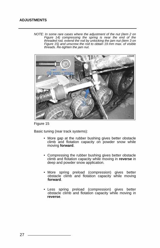
NOTE: In some rare cases where the adjustment of the nut (item 2 onFigure 14) compressing the spring is near the end of thethreaded rod, extend the rod by unlocking the jam nut (item 3 onFigure 15) and unscrew the rod to obtain 19 mm max. of visiblethreads. Re-tighten the jam nut.
Figure 15
Basic tuning (rear track systems):
• More gap at the rubber bushing gives better obstacleclimb and flotation capacity on powder snow whilemoving forward.
• Compressing the rubber bushing gives better obstacleclimb and flotation capacity while moving in reverse indeep and powder snow application.
• More spring preload (compression) gives betterobstacle climb and flotation capacity while movingforward.
• Less spring preload (compression) gives betterobstacle climb and flotation capacity while moving inreverse.
27

ADJUSTMENTS
Alignment It is required to align the tracks when the vehicle is placed onthe ground. Before the measurements, move the vehicleforwards on a distance of approximately 3 meters. Use a tapefor the following measurements.
NOTE: Every time the measurement has to be verified, drive in reverse,then, drive forward again on about 3 m.
NOTE: Verify the condition of the components of the steering systembefore adjusting the parallelism. Components damaged canprevent a proper ajustment and impair a good operation of thesystem
Figure 16
The distance between the outside wheels of the front axle(Measure A) and the rear axle (Measure B) should be equal orgreater by 3mm at the most.
Measure A - Measure B = 0 to 3mm
NOTA: It is easier to begin the parallelism adjustment when theadjustment is open (Measure B - Measure A positive) thanwhen it is closed (Measure B- Measure A negative). Startingwith an open adjustment of the parallelism allow a betterprecision in the adjustment.
28

ADJUSTMENTS
Figure 17
Method of ajustment
To adjust the UTV, first unscrew the nut (1) of the coupling rodof the vehicle's direction system (2), screw or unscrew thecoupling rod of an equal number of revolutions on the bothsides of the vehicle. See Figure 17.
NOTE: During the unscrewing of the nut (1) of each coupling rod of thevehicle's direction system (2), remember that certain nuts havereversed thread. Make sure to unlock the nut in the proper rota-tional direction.
NOTE: The parallelism adjustment of the front track systems is veryimportant and has a direct link with the longevity of the systemcomponents. Users must follow attentively the adjustment andverification recommendations of this manual.
NOTE: Once the parallelism adjustment of the front track systems iscompleted, verify once more the adjustment to confirm.
29

ADJUSTMENTS
30
Measure A: Measure the distance which separates the externalplastic wheels of the front axle on the front track systems. SeeFigure 18 and Figure 19.
Figure 18 (Distance between the front plastic wheels)
Figure 19 ( Distance between the front plastic wheels)

ADJUSTMENTS
Measure B: Measure the distance which separates the externalplastic wheels of the rear axle on the front track systems. SeeFigure 20 and Figure 21.
Figure 20 ( Distance between the rear plastic wheels)
Figure 21 ( Distance between the rear plastic wheels)
31
ADJUSTMENTS
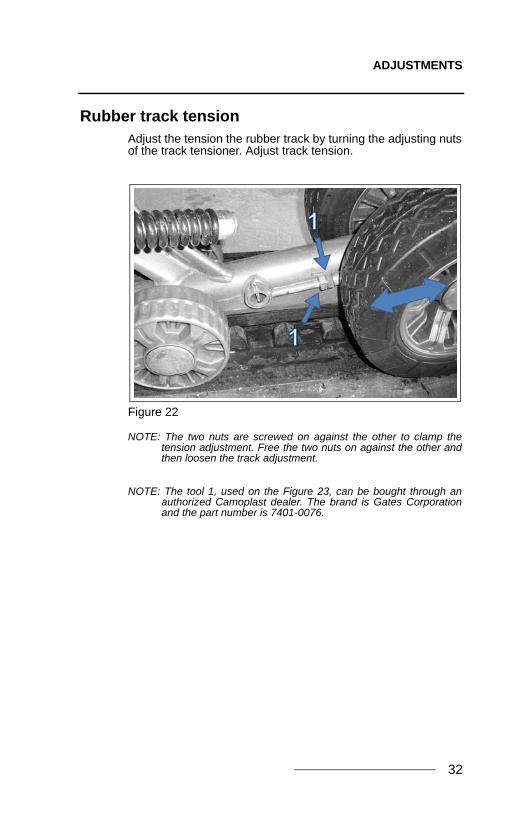
Rubber track tensionAdjust the tension the rubber track by turning the adjusting nutsof the track tensioner. Adjust track tension.
Figure 22
NOTE: The two nuts are screwed on against the other to clamp thetension adjustment. Free the two nuts on against the other andthen loosen the track adjustment.
NOTE: The tool 1, used on the Figure 23, can be bought through anauthorized Camoplast dealer. The brand is Gates Corporationand the part number is 7401-0076.
32

ADJUSTMENTS
The following table indicates the force (1) applied and thedeflection (2) which must occur according to the conditions ofuse.
Figure 23
Basic tuning
• A higher rubber track tension reduces the risk of“detracking” and reduces drive “ratcheting” (for severeuse only).
• A lower rubber track tension provides betterperformance, better rolling and better fuel economy(recreational use).
Final check
Ride at slow speed on a distance of about 1.5 km. Evaluatetrack system performance and re-adjust as required.
Season Track Force DeflectionFront 15 kg 19 mmRear 15 kg 19 mmFront 11 kg 19 mmRear 11 kg 19 mm
Summer
Winter (snow)
33

INSTALLATION OF A RUBBER TRACK
INSTALLATION OF A RUBBER TRACK
If possible, position the vehicle on a flat and level surface (or ona suitable lift device). Turn off the engine.
Proceed as follows :
• Set rubber track tension to the minimum (refer toFigure 24).
Figure 24
34

INSTALLATION OF A RUBBER TRACK
• Remove the two 255 mm wheels opposite to the tracktensioner side (refer to Figure 25).
Figure 25
• Install the rubber track
NOTE: Compare with the other rubber tracks to find thecorrect orientation.
• Re-install 255 mm wheels.
• Adjust track tension. Refer to ‘Rubber track tension” onpage 32.
35

BREAK-IN PERIOD
BREAK-IN PERIOD
A break-in period is necessary in order to allow the componentsof the system to match themselves to each others.
During the break-in period (4 hours or 80 kilometers), followthese recommendations :
• Avoid running under dry and clean conditions. (Forexample: asphalts, hay or straw field, etc).
• Start sharp turns at very low speed: (10 km/h maximumreal speed).
A GOOD break-in period must be done in a lubricatedenvironment such as water, mud, snow, soft soil, sand, dust,etc.
A BAD break-in period can generate smoke, odors of burnedrubber as well as plastic deposits on the sprocket and/or theframe.
1ST hour 2SC hour 3TH hour15 km/h max 25 km/h max 35 km/h max
real speed real speed real speedTrack tension X XAlignment X X X XAngle of attack X XBolts torque XVisual inspection X X X X
VERIFICATION INSTALLATION
BREAK IN PERIOD
36
REPLACEMENT OF A WHEEL WITH EXTRACTOR
REPLACEMENT OF A WHEEL WITH EXTRACTOR
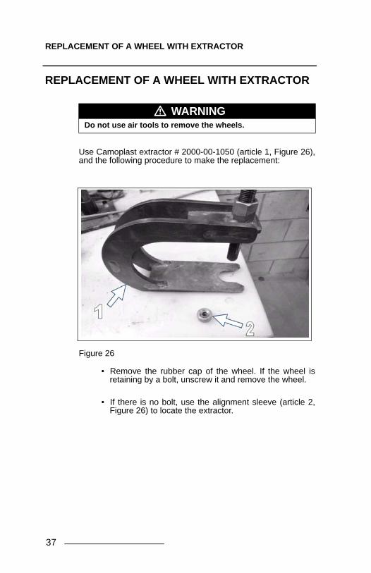
Use Camoplast extractor # 2000-00-1050 (article 1, Figure 26),and the following procedure to make the replacement:
Figure 26
• Remove the rubber cap of the wheel. If the wheel isretaining by a bolt, unscrew it and remove the wheel.
• If there is no bolt, use the alignment sleeve (article 2,Figure 26) to locate the extractor.
� WARNINGDo not use air tools to remove the wheels.
37

REPLACEMENT OF A WHEEL WITH EXTRACTOR
• Install the extractor under the wheel as shown onFigure 27
• Then screw the threaded rod to remove the wheel.
.
Figure 27
• Insert the new wheel on the shaft until it reaches theshoulder.
38

MAINTENANCE SCHEDULE
MAINTENANCE SCHEDULE
For optimum performance and maximum durability, please referto the following maintenance grid :
NOTE: Do not use a brake cleaning solvent to clean the track system.This may damage sealing components and stickers.
� WARNINGDo not insert hands nor feet into or near the system unlessthe engine is off, and the vehicle is stopped with thesecurity brake engaged.
Winter condition Abrasive 4 seasons condition
General: Bolts torque 20 hours 20 hoursGeneral: Vehicle alignment 10 hours 10 hoursGeneral: Visual inspection Before riding Before riding
Track: Tension 20 hours 20 hoursTrack: Wear Once per year Once per yearWheels: Lateral wear Once per year 40 hoursWheels: Bearings Once per year 20 hoursFrame: Track guide wear Once per year 20 hoursFrame: Main hub bearing Once per year 50 hoursFrame: Stabilizer (tandem) Once per year 50 hoursFrame: Cracks & Inspection Once per year Once per yearAnti-rotation: Adjustment / Bolt torque 20 hours 20 hoursAnti-rotation: Cracks and deformation Before riding Before ridingSprocket: Wear Once per year 50 hours
Element to check and maintain
MAINTENANCE PROGRAM
After break-inFrequency
39

TORQUE TABLE
TORQUE TABLE
NOTE: Use a threadlocker Loctite 263 type or its equivalent at theindicated places in the explode view of the system in thismanual.
STORAGE
The best way to store the System is to lay down each frame onits side, away from direct sunlight.
Figure 28
� WARNINGOvertightening the bolts of some parts may damage themand security features may be affected.
Bolt N-m (lb/ft)
M8 - 8.8 25 (18)M10 - 8.8 50 (36)M10 - 10.9 70 (50)M12 - 10.9 125 (92)
40
WEAR
41
WEAR
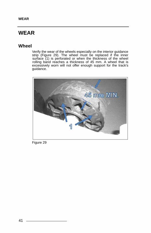
WheelVerify the wear of the wheels especially on the interior guidancestrip (Figure 29). The wheel must be replaced if the innersurface (1) is perforated or when the thickness of the wheelrolling band reaches a thickness of 45 mm. A wheel that isexcessively worn will not offer enough support for the track'sguidance.
Figure 29

WEAR
Urethane tireVerify the wear of the urethane tires especially on the interiorguidance strip (1) and between the tire profiles (2). The wheelmust be replaced if the inner surface is worn out or the tire iscracked between the tire profiles. A wheel that is excessivelyworn will not offer enough support for the track's guidance.Refer to Figure 30.
Figure 30
TrackVerify the wear of the track by inspecting the rolling path, thedriving lug, the profile and the internal and external condition ofthe track's carcass. Make sure that the track’s internal structureare not visible at cuts or worn area. Too much wear could causedamage to the wheels and to the track's guide.
42

WEAR
Track GuideVerify the wear of the track guide by measuring the width of theguide. If dimensions of the guide illustrated in Figure 31 arelower than 5 mm, at any place, replace the part. If the guidancestrip is worn so that the concave shape is no longer visible,replace the part. An overly worn track guide could prematurelywear the other components of guidance of the system.
Figure 31
43

WEAR
SprocketCheck the wear of the sprocket by measuring the part asillustrated on Figure 32. Replace the part when dimensions arelower than 19 mm. An excessive wear could lower theefficiency of the drive of the track and reduce the system’sperformance.
Figure 32
44

WEAR
Anti-rotationVerify the wear of anti-rotation system, mainly at the ball joint(Figure 33) to make sure that it is not seized or extremely loose.Ball joint damage could harm the performance of the tracksystem.
.
Figure 33
45

WARRANTY
WARRANTY
Camoplast Hi-Performance Tracks guarantees that the new, unusedCamoplast UTV T4S System (System) installed by an authorizeddealer or distributor is free from any defects in materials andworkmanship during the period and in conditions described below.When operating a new Camoplast UTV T4S System, the useragrees that the present form is applicable and exclusive, that theyhave been signified and that they have been accepted by him/her atthe time of purchase.
The UTV Camoplast UTV T4S track system is covered by amanufacturer warranty (warranty). The warranty coversmanufacturing defects related with materials and workmanship. Theinstallation and maintenance of the System is always theresponsibility of the owner.
PERIOD OF COVERAGE
The warranty is valid for a period of twelve (12) months following thedate of purchase. This warranty does not apply to normalmaintenance.
The warranty applies exclusively to parts and components of thetrack system. All paint defects on the System (frames andcomponents) are not covered.
The warranty is not valid if the System is not installed by anauthorized Camoplast Hi-Performance Tracks network dealer ordistributor.
This warranty specifically excludes any damage or breakage to theUTV and related defects on the UTV, whether or not these werecaused or believed to be caused by the System.
The manufacturer is not responsible for damages, injuries or losscaused at the time of or after installing of the System on the vehicle.
For a warranty to be valid, the System owner must comply withmanufacturer notices and warnings. In addition, all claims must beaccompanied by a proof of purchase (original receipt or salecontract) and work or repairs must be performed by an authorizedCamoplast Hi-Performance Tracks dealer. All claims not previouslyapproved and authorized by Camoplast Hi-Performance Tracks willbe rejected.
The following situations and items are not under anycircumstances covered by the warranty :
1) Any and all consequential damages, including, but not limited to,indirect costs, such as towing, storage, phone calls, renting,transportation, inconveniences, insurance coverage,reimbursement of loss, loss of time and loss of revenue, etc.
2) Damage resulting from faulty installation.
3) Damage resulting from normal parts wear or progressivedeterioration owing to the distance covered with a vehicle on whichthe System is installed.
46

WARRANTY
4) Damage resulting in non-compliance with the user manual andwith maintenance instructions recommended in the user’s manualand other technical documents.
5) Damage resulting in abusive use, abnormal use, negligence oreven a use which does not comply with recommendations of themanual, excess weight or loading, including excessive number ofpassengers.
6) Labour costs, parts and materials related any and allmaintenance costs.
7) Damage resulting from faulty repairs, improper maintenance orany unauthorized changes made to the System other than thosespecified by the manufacturer or from the installation of non-originalor unauthorized parts that were not produced or approved byCamoplast Hi-Performance Tracks.
8) Damage resulting from an accident, incident, robbery, vandalism,war or unforeseen event or act of God.
9) Regardless of cause, damage resulting from inexperience,driving errors, accident or other incident.
10) The use of the System on a vehicle used for public rental,including by a previous owner, will render this warranty null andvoid.
11) The use of the System in races, rallies or other competitiveevents/activities of this type, at any time, including from a previousowner or in conditions that do not comply with those described bythe manufacturer will render the warranty null and void.
Any repaired or replaced components or parts are guaranteed onlyto the extent of the original warranty. in other words: if a warrantedpart was replaced after five (5) months, the new replacement partwill only be guaranteed for seven (7) months, for a total of twelve(12) months. In no event shall the warranty extend beyond a total oftwelve (12) months from the date of original System purchase.
In all cases, the warranty is limited to a maximum of the originalpurchase price or the fair market value of the System. CamoplastHi-Performance Tracks will have final authority in determining thefair market value of a used System. The warranty is applicablewithin the limits and conditions initially provided for in if the Systemis determined to be unusable due to accident or improper repair, thewarranty will be considered null and void without further recourseavailable to the System owner.
The manufacturer, the retailer and / or the repair shop shall not beheld responsible for any delays caused by material, parts orcomponents availability or backorder.
*Shipping and handling costs, as well as any fees related withshipping or transportation of the System to the dealer location arethe responsibility of the System owner.
Camoplast Hi-Performance Tracks reserves its sole and exclusiveright to update or modify this warranty without impact on end users.All previous terms and conditions of the warranty at time ofpurchase will be respected.
47
TROUBLESHOOTING
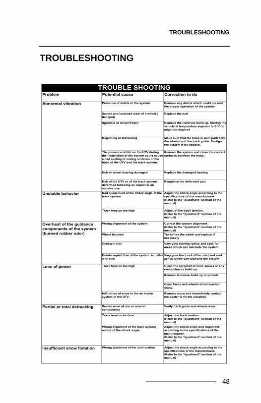
TROUBLESHOOTING
Problem Potential cause Correction to do
Presence of debris in the system. Remove any debris which could prevent the proper operation of the system
Severe and localized wear of a wheel ( flat spot)
Replace the part
Sprocket or wheel frozen Remove the ice/snow build up. Storing the vehicle at temperature superior to 0 °C to might be required
Beginning of detracking Make sure that the track is well guided by the wheels and the track guide. Realign the system if it's needed.
The presence of dirt on the UTV during the installation of the system could cause a bad seating of mating surfaces of the hubs of the UTV and the track system.
Remove the system and clean the contact surfaces between the hubs.
Hub or wheel bearing damaged Replace the damaged bearing
Hub of the UTV or of the track system deformed following an impact or an abusive use
Remplace the deformed part
Bad ajustement of the attack angle of the track system.
Adjust the attack angle according to the specifications of the manufacturer.(Refer to the "ajustment" section of the manual)
Track tension too high Adjust of the track tension.(Refer to the "ajustment" section of the manual)
Wrong alignment of the system Correct the system alignment(Refer to the "ajustment" section of the manual)
Wheel blocked Try to free the wheel and replace if necessary
Constant turn Vary your turning radius and seek for areas which can lubricate the system
Uninterrupted Use of the system in paths with ruts
Vary your line ( out of the ruts) and seek zones which can lubricate the system
Clean the sprocket of mud, snows or any contaminants build up.
Remove ice/snow build up on wheels
Clear frame and wheels of compacted snow.
Infiltration of snow in the air intake system of the UTV.
Remove snow and immediately contact the dealer to fix the situation.
Severe wear of one or several components
Verify track guide and wheels wear.
Track tension too low Adjust the track tension.(Refer to the "ajustment" section of the manual)
Wrong alignment of the track system and/or of the attack angle.
Adjust the attack angle and alignment according to the specifications of the manufacturer.(Refer to the "ajustment" section of the manual)
Insufficient snow flotation Wrong ajustment of the anti-rotation Adjust the attack angle according to the specifications of the manufacturer.(Refer to the "ajustment" section of the manual)
TROUBLE SHOOTING
Loss of power
Partial or total detracking
Track tension too high
Overheat of the guidance components of the system (burned rubber odor)
Unstable behavior
Abnormal vibration
48

SERIAL NUMBER LOCATION
SERIAL NUMBER LOCATION
The following pictures show the location of the serial numbers onthe track system frame (Figure 34) and rubber track (Figure 35).
Figure 34
Figure 35
49

TECHNICAL SUPPORT
TECHNICAL SUPPORT
If your dealer or distributor is unable to solve a problem relatedwith the System, you may contact the Camoplast Hi-Performance Tracks support team from Monday to Friday.
Camoplast Solideal Inc.4162, Burrill - Local A
Shawinigan, (Québec) G9N 0C3 CANADA
E-mail: [email protected]: www.camoplastsolideal.com
50

’’CE’’ DECLARATION OF CONFORMITY
’’CE’’ DECLARATION OF CONFORMITY
"CE" DECLARATION OF CONFORMITY
WE:
����������� CAMOPLAST SOLIDEAL INC.� ���� ����������������������
������� ����!"�#$%�&�����'�()��*�+�
,-.�����/��
0���1��� ���2��3�4��565���'%��2��3
HEREBY SOLE RESPONSABILITY THE CONFORMITY OF THE PRODUCT SERIES
,. ����� ��7�����85��956%35�.������
WITH THE FOLLOWING STANDARDS
������ �1��� ����
:����*;) ,�%4���6�����<�1�56���6��� �**�:�����**:��=�:� ��<%69��<�������%�9 �))�:���;*>*:��=�:� ���<��3�69��55%553%�6 �**>
AND IN CONFORMITY WITH THOSE EC DIRECTIVES:
������ �1��� �����**�?��?� ��<%69��<�3�����%�9�'��%�6�@%5 �**�
.����� ������� ����!"�#$%�&�����'�
�,.����������AAAAAAAAAAAAAAAAAAAAAAAAAAAAAAAAAAAAAAAAAA
�1����AAAAAAAAAAAAAAAAAAAAAAAAAAAAAAAAAAAAAAAAAAAAAAAAAAAAAAAAA
����AAAAAAAAAAAAAAA �1(������AAAAAAAAAAAAAAAAAAAAAAAAAAAAAAAAAAA
51

This page is left intentionally blank.
53
43
15
13
4730
18
2223
44
42
26
F
17
H
14
29
38
37
12
31
34
21
40
41
75
68
34
2
16
24
10
48
33
32
27
25
46
48
44
28
9
39
19
11
45
35
36
I1
AJ
20
D
E
G
K
C
B
43
15
13
4730
18
2223
44
42
26
F
17
H
14
29
38
37
12
31
34
21
40
41
75
68
34
2
16
24
10
48
33
32
27
25
46
48
44
28
9
39
19
11
45
35
36
I1
AJ
20
D
E
G
K
C
B
RV00167-00_A

54
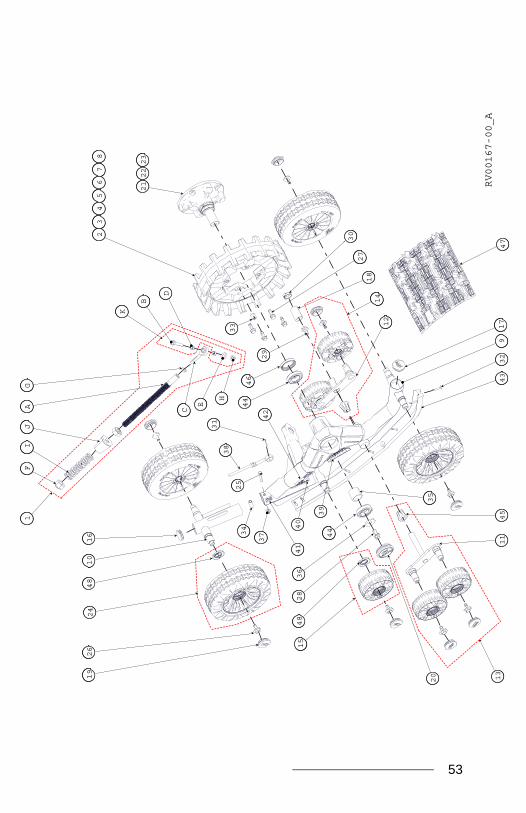
ITEM # PART # DESCRIPTION QTY
TATOU UTV T4S MY2012 FRONT LEFT & RIGHT1 1001-00-7005 STABILIZING ROD ASS'Y / BRAS STABILISATEUR ASSEMBLÉ - 370 LBS/IN2 1009-00-7115 INJ SPROCKET, 15 TEETH / BARBOTIN INJ, 15 DENTS 13 1009-00-7116 INJ SPROCKET, 16 TEETH / BARBOTIN INJ, 16 DENTS 14 1009-00-7117 INJ SPROCKET, 17 TEETH / BARBOTIN INJ, 17 DENTS 15 1009-00-7118 INJ SPROCKET, 18 TEETH / BARBOTIN INJ, 18 DENTS 16 1009-08-7116 SPROCKET, 16 TEETH, 5 BOLTS PATTERN / BARBOTIN 16 DENTS, 5 BOULONS 17 1009-08-7117 SPROCKET, 17 TEETH, 5 BOLTS PATTERN / BARBOTIN 17 DENTS, 5 BOULONS 18 1009-08-7118 SPROCKET, 18 TEETH, 5 BOLTS PATTERN / BARBOTIN 18 DENTS, 5 BOULONS 1
9-A 1010-00-8022 RH FRONT FRAME / CADRE AVANT DROIT - TATOU UTV 4S 19-B 1011-00-8022 LH FRONT FRAME / CADRE AVANT GAUCHE - TATOU UTV 4S 110 1014-00-8022 TENSIONNER / TENSIONNEUR - TATOU UTV4S 111 1015-00-8000 WIDE WHEEL STABILIZER, SHORT / STABILISATEUR ROUES LARGES , COURT 112 1015-00-8001 WIDE WHEEL STABILIZER, LONG / STABILISATEUR ROUES LARGES, LONG 113 1015-00-8010 STABILIZER, SHORT, WHEELS ASS'Y / STABILISATEUR, COURT ASSEMBLÉ 114 1082-00-7140 STABILIZER LONG COMPLET KIT / STABILISATEUR LONG ENSEMBLE COMPLET 115 1016-00-4132 132mm x 50mm WHEEL ASS'Y / ENSEMBLE DE ROUES 132mm x 50mm 616 1017-00-0001 2 LIPS CAP, 1-3/4" O.D. TUBE / BOUCHON DOUBLE REBORD, 1-3/4" O.D. TUBE 217 1017-00-0010 2 LIPS CAP, 2" O.D. TUBE (LDPE) / BOUCHON DOUBLE REBORD, 2" O.D. TUBE 118 1017-00-0011 DUST CAP, STABILIZER / PARE-POUSSIÈRE, STABILISATEUR 119 1017-00-0110 2 LIPS CAP, 2" O.D. TUBE (ESPRENE) / BOUCHON DOUBLE REBORD, 2" O.D. TUBE 1020 1017-00-7081 HUB CAP BLUE ASS'Y / CAP DE MOYEU BLEU ASSEMBLÉ 121 1019-08-0002 5 BOLTS PATERN HUB ASS'Y / ESSIEU ASSEMBLÉ, BOULONNAGE 5 TROUS 122 1019-05-0010 POLARIS HUB, ASS'Y / ESSIEU POLARIS, ASSEMBLÉ 123 1019-77-0031 UTV MULTI-MODEL HUB, ASS'Y / UTV ESSIEU MULTI-MODÈLES, ASSEMBLÉ 124 1024-00-1255 WHEEL (4.10/3.50-6) ASSY / ROUE (4.10/3.50-6) ASSEMBLÉ 425 1033-08-0060 HEX SCR / VIS HEX - ISO 4014, 8.8, ZP / M8x1.25x60 126 1033-10-2026 HEX SCR W/WASH / VIS HEX A/ ROND - 30x3, 8.8, ZP, TL 9S-1026 / M10x1.5x25 1027 1036-10-4030 SERRATED HEX SCR / BOUL HEX DENTELÉ - DIN 6921, 10.9, ZP, TL 9S-1026 / M10x1.5x30 428 1036-12-4030 HEX FLG SCR / BOUL HEX À EMBASE - DIN 6921, 10.9, ZP, TL 9S-1026 / M12x1.75x30 129 1033-12-9025 HEX SCR W/ WASH / VIS HEX A/ ROND - 25x3, 10.9, YP, TL 9S-1026 / M12x1.75x25 130 1037-00-0001 T-RAP / ATTACHE NYLON - 8" LG. 131 1042-00-0001 COTTER PIN / GOUPILLE - ISO 1234 ZP,1/8" x1-3/4" 132 1049-00-0007 WAFER SQ DR DRILL SCR / VIS AUTOTARAUDEUSE - Z P, #12-24 x 1.5" 733 1050-00-0011 BUSHING / COUSSINET - 5/8" O.D. x 27/32" I.D. x 18" LG 434 1051-00-0015 TENSIONNER BUSHING / COUSSINET TENSIONNEUR 135 1051-00-0037 INTERNAL SPACER / ESPACEUR INTERNE 136 1061-00-0025 WASHER SPINDLE HUB / RONDELLE AXE MOYEU - ID. 0.52 X OD. 1.63 X 0.109 THK. 137 1074-08-0001 HEX FL NY NUT / ÉCROU HEX NYLON EMBASE - ISO 4161, 8.8, ZP / M8x1.25 138 1082-00-7050 TENSIONNER ROD ASS'Y / TIGES DE TENSIONNEUR ASSEMBLÉ 139 1083-00-8002 STICKER - WARNING / AUTOCOLLANT - AVERTISSEMENT 140 - STICKER - SERIAL NUMBER / AUTOCOLLANT - NO SÉRIE - TATOU UTV T4S 1
41-A 1083-00-8100 STICKER - FRONT LEFT PICTOGRAM / PICTOGRAMME AVANT GAUCHE 141-B 1083-00-8110 STICKER - FRONT RIGHT PICTOGRAM / PICTOGRAMME AVANT DROIT 142 1083-00-8450 STICKER / AUTOCOLLANT - TATOU UTV T4S MY2012 143 1085-00-8000 TRACK GUIDE FRONT / GUIDE DE CHENILLE AVANT - TATOU UTV T4S 144 1090-00-0001 BALL BEARING, SEALED / ROULEMENT À BILLES, HERMÉTIQUE - 6007 DU2 245 1093-00-7000 RUBBER CONE, STABILIZER / CONE DE CAOUTCHOUC, STABILISATEUR 246 1093-00-7002 SHAFT SEAL / JOINT D'ÉTANCHÉITÉ POUR ARBRE - 50 x 62 x 10 TC 147 1093-00-8000 TRACK / CHENILLE - 12.5'' x 98.57'' x 1.000'' (9131S) 148 1093-00-7011 SHAFT SEAL / JOINT D'ÉTANCHÉITÉ - 28 x 48 x 6 TC 12
A 1000-00-7002 THREADED ROD, STABILIZING ROD / TIGE FILETÉE, BRAS STABILISATEUR 1B 1033-10-1060 HEX SCR / VIS HEX - ISO 4014, 10.9 ZP / M10x1.5x60 1C 1047-00-7010 ROD END, STABILIZING ROD / TIGE À ŒIL, BRAS STABILISATEUR 1D 1050-00-0013 ROD END SPACER / ESPACEUR TIGE À ŒIL 2E 1060-00-0004 WASHER / RONDELLE - 8, ZP, 7/16IDx1ODx0,072T 1F 1071-20-0001 HEX NYLON NUT / HEX NYLON NUT - ISO 7040 8.8, ZP / M20x2.5 2G 1073-12-3002 HEX THIN NUT / ÉCROU MINCE HEX - 8.8, ISO 4037, ZP / M12x1.25 1H 1074-10-0001 HEX FL NY NUT / ÉCROU HEX NYLON EMBASE - ISO 4161, 8.8, ZP / M10x1.5 1I 1080-00-0004 COMPRESSION SPRING / RESSORT DE COMPRESSION - 370 LBS/IN 1J 1093-00-7007 RUBBER DAMPER / AMORTISSEUR EN CAOUTCHOUC 1K 1033-AS-0025 STABILIZING ROD SHORT BOLTS KIT / ENSEMBLE BOULON COURT BRAS STABILISATEUR 1
2011-11-14 / rev B

55

56
ITEM # PART # DESCRIPTION QTY
TATOU UTV T4S MY2012 REAR LEFT & RIGHT1 1009-00-7115 INJ SPROCKET, 15 TEETH / BARBOTIN INJ, 15 DENTS 12 1009-00-7116 INJ SPROCKET, 16 TEETH / BARBOTIN INJ, 16 DENTS 13 1009-00-7117 INJ SPROCKET, 17 TEETH / BARBOTIN INJ, 17 DENTS 14 1009-00-7118 INJ SPROCKET, 18 TEETH / BARBOTIN INJ, 18 DENTS 15 1009-08-7116 SPROCKET, 16 TEETH, 5 BOLTS PATTERN / BARBOTIN 16 DENTS, 5 BOULONS 16 1009-08-7117 SPROCKET, 17 TEETH, 5 BOLTS PATTERN / BARBOTIN 17 DENTS, 5 BOULONS 17 1009-08-7118 SPROCKET, 18 TEETH, 5 BOLTS PATTERN / BARBOTIN 18 DENTS, 5 BOULONS 1
8-A 1012-00-8022 RH REAR FRAME / CADRE ARRIÈRE CÔTÉ DROIT - TATOU UTV T4S 18-B 1013-00-8022 LH REAR FRAME / CADRE ARRIÈRE CÔTÉ GAUCHE - TATOU UTV T4S 19 1014-00-8022 TENSIONNER / TENSIONNEUR - TATOU UTV T4S 110 1015-00-8000 WIDE WHEEL STABILIZER, SHORT / STABILISATEUR ROUES LARGES , COURT 111 1015-00-8001 WIDE WHEEL STABILIZER, LONG / STABILISATEUR ROUES LARGES, LONG 112 1015-00-8010 STABILIZER, SHORT, WHEELS ASS'Y / STABILISATEUR, COURT ASSEMBLÉ 113 1082-00-7140 STABILIZER LONG COMPLET KIT / STABILISATEUR LONG ENSEMBLE COMPLET 114 1016-00-4132 132mm x 50mm WHEEL ASS'Y / ENSEMBLE DE ROUES 132mm x 50mm 815 1017-00-0001 2 LIPS CAP, 1-3/4" O.D. TUBE / BOUCHON DOUBLE REBORD, 1-3/4" O.D. TUBE 216 1017-00-0010 2 LIPS CAP, 2" O.D. TUBE (LDPE) / BOUCHON DOUBLE REBORD, 2" O.D. TUBE 117 1017-00-0011 DUST CAP, STABILIZER / PARE-POUSSIÈRE, STABILISATEUR 118 1017-00-0110 2 LIPS CAP, 2" O.D. TUBE (ESPRENE) / BOUCHON DOUBLE REBORD, 2" O.D. TUBE 1219 1017-00-7081 HUB CAP BLUE ASS'Y / CAP DE MOYEU BLEU ASSEMBLÉ 120 1019-08-0002 5 BOLTS PATERN HUB ASS'Y / ESSIEU ASSEMBLÉ, BOULONNAGE 5 TROUS 121 1019-05-0010 POLARIS HUB, ASS'Y / ESSIEU POLARIS, ASSEMBLÉ 122 1019-77-0031 UTV MULTI-MODEL HUB, ASS'Y / UTV ESSIEU MULTI-MODÈLES, ASSEMBLÉ 123 1024-00-1255 WHEEL (4.10/3.50-6) ASSY / ROUE (4.10/3.50-6) ASSEMBLÉ 424 1033-08-0060 HEX SCR / VIS HEX - ISO 4014, 8.8, ZP / M8x1.25x60 125 1033-10-2026 HEX SCR W/WASH / VIS HEX A/ ROND - 30x3, 8.8, ZP, TL 9S-1026 / M10x1.5x25 1226 1036-10-4030 SERRATED HEX SCR / BOUL HEX DENTELÉ - DIN 6921, 10.9, ZP, TL 9S-1026 / M10x1.5x30 627 1036-12-4030 HEX FLG SCR / BOUL HEX À EMBASE - DIN 6921, 10.9, ZP, TL 9S-1026 / M12x1.75x30 128 1033-12-9025 HEX SCR W/ WASH / VIS HEX A/ ROND - 25x3, 10.9, YP, TL 9S-1026 / M12x1.75x25 129 1037-00-0001 T-RAP / ATTACHE NYLON - 8" LG. 130 1042-00-0001 COTTER PIN / GOUPILLE - ISO 1234 ZP,1/8" x1-3/4" 131 1049-00-0007 WAFER SQ DR DRILL SCR / VIS AUTOTARAUDEUSE - Z P, #12-24 x 1.5" 732 1050-00-0011 BUSHING / COUSSINET - 5/8" O.D. x 27/32" I.D. x 18" LG 433 1051-00-0015 TENSIONNER BUSHING / COUSSINET TENSIONNEUR 134 1051-00-0037 INTERNAL SPACER / ESPACEUR INTERNE 135 1061-00-0025 WASHER SPINDLE HUB / RONDELLE AXE MOYEU - ID. 0.52 X OD. 1.63 X 0.109 THK. 136 1074-08-0001 HEX FL NY NUT / ÉCROU HEX NYLON EMBASE - ISO 4161, 8.8, ZP / M8x1.25 137 1082-00-7050 TENSIONNER ROD ASS'Y / TIGES DE TENSIONNEUR ASSEMBLÉ 138 1083-00-8002 STICKER - WARNING / AUTOCOLLANT - AVERTISSEMENT 139 - STICKER - SERIAL NUMBER / AUTOCOLLANT - NO SÉRIE - TATOU UTV T4S 1
40-A 1083-00-8120 STICKER - REAR LEFT PICTOGRAM / PICTOGRAMME ARRIÈRE GAUCHE 140-B 1083-00-8130 STICKER - REAR RIGHT PICTOGRAM / PICTOGRAMME ARRIÈRE DROIT 141 1083-00-8450 STICKER / AUTOCOLLANT - TATOU UTV T4S MY2012 142 1085-00-8001 TRACK GUIDE REAR / GUIDE DE CHENILLE ARRIÈRE - TATOU UTV T4S 143 1090-00-0001 BALL BEARING, SEALED / ROULEMENT À BILLES, HERMÉTIQUE - 6007 DU2 244 1093-00-7000 RUBBER CONE, STABILIZER / CONE DE CAOUTCHOUC, STABILISATEUR 245 1093-00-7002 SHAFT SEAL / JOINT D'ÉTANCHÉITÉ POUR ARBRE - 50 x 62 x 10 TC 146 1093-00-8001 TRACK / CHENILLE - 13.5'' x 116.7'' x 1.000'' (9132S) 147 1093-00-7011 SHAFT SEAL / JOINT D'ÉTANCHÉITÉ - 28 x 48 x 6 TC 12
2011-11-14 / rev B

57

58
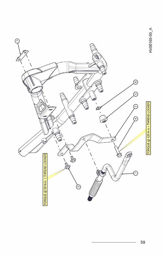
ITEM # PART # DESCRIPTION QTYTATOU UTV T4S MY2012 INDEPENDEND SUSPENSION (IS)
1 1000-00-8002 THREADED ROD, LONG / TIGE FILETÉE, LONGUE 12 1001-00-8005 STABILIZING ROD ASS'Y / BRAS STABILISATEUR ASSEMBLÉ - 480 LBS/IN 13 1015-00-8250 UNIVERSAL BRACKET ANTI-ROT. ASSY. (IS) / ANCRAGE UNIVERSEL ANTI-ROT. ASS. (SI) 14 1015-00-7026 BACK PLATE / PLAQUE DE FIXATION ARRIÈRE 15 1033-10-1080 HEX SCR / VIS HEX - ISO 4014, 10.9, ZP / M10x1.5x80 16 1033-10-2026 HEX SCR W/WASH / VIS HEX A/ ROND - 30x3, 8.8, YZN, TL 9S-1026 / M10x1.5x25 37 1047-00-7010 ROD END, STABILIZING ROD / TIGE À ŒIL, BRAS STABILISATEUR 28 1050-00-0013 ROD END SPACER / ESPACEUR POUR TIGE À ŒIL 19 1050-06-0758 SPACER, ANTIROTATION / ESPACEUR, ANTI-ROTATION 110 1060-00-0004 WASHER / RONDELLE - 8, ZP, 7/16IDx1ODx0,072T 111 1071-20-0001 HEX NYLON NUT, ISO 7040 8.8, ZP / M20x2.5 312 1073-12-3002 HEX THIN NUT / ÉCROU MINCE HEX - 8.8, ISO 4037, ZP / M12x1.25 213 1074-10-0001 HEX FL NY NUT / ÉCROU HEX NYLON EMBASE - ISO 4161, 8.8, ZP / M10x1.5 114 1080-00-0901 COMPRESSION SPRING / RESSORT DE COMPRESSION - 480 LBS/IN 315 1093-00-7007 RUBBER DAMPER / AMORTISSEUR EN CAOUTCHOUC 116 1033-AS-0075 STABILIZING ROD LONG BOLTS KIT / ENSEMBLE BOULON LONG BRAS STABILISATEUR 1
2011-11-14 / rev B
59

60
ITEM # PART # DESCRIPTION QTYTATOU UTV T4S MY2012 RIGID SUSPENSION (RS)
1 1015-00-7026 BACK PLATE / PLAQUE DE FIXATION ARRIÈRE 12-A 1015-00-8004 LH, BRACKET ANTI-ROTATION UTV (RS) / ANCRAGE ANTI-ROTATION UTV, GAUCHE (ER) 12-B 1015-00-8014 RH, BRACKET ANTI-ROTATION UTV (RS) / ANCRAGE ANTI-ROTATION UTV, DROIT (ER) 13 1033-10-2026 HEX SCR W/WASH / VIS HEX A/ ROND - 30x3, 8.8, YZN, TL 9S-1026 / M10x1.5x25 24 1035-12-1050 HEX SCR FLANGE / VIS HEX À REBORDS - , ISO 8102, 10.9, ZP / M12-1.75x50 15 1050-00-8000 BUSHING, ANTI-ROTATION UTV (RS) / COUSSINET, ANTI-ROTATION UTV (RS) 16 1093-00-0020 O-RING / JOINT TORIQUE - 26 x 29 x 1.5 17 VAR REFER TO INSTALLATION GUIDE LINES DOCUMENTATION / RÉFÉRER À LA DOCUMENTATION DU GUIDE D'INSTALLATION 1
2011-11-14 / rev B