Embed Size (px)
Citation preview
Brussels, 18-20 February 2008 – Dissemination of information workshop 1
EUROCODESBackground and Applications
EN 1992-1-2Fire design of concrete structures
Tauno HietanenFinnish Concrete Industry Association
convenor of Project Teams- ENV 1992-1-2- EN 1992-1-2
Brussels, 18-20 February 2008 – Dissemination of information workshop 2
EUROCODESBackground and Applications
EN 1992-1-2Fire design of concrete structures
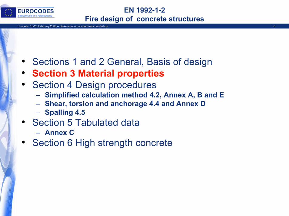
• Sections 1 and 2 General, Basis of design • Section 3 Material properties• Section 4 Design procedures
– Simplified calculation method 4.2, Annex A, B and E– Shear, torsion and anchorage 4.4 and Annex D– Spalling 4.5
• Section 5 Tabulated data– Annex C
• Section 6 High strength concrete
Brussels, 18-20 February 2008 – Dissemination of information workshop 3
EUROCODESBackground and Applications Project Team
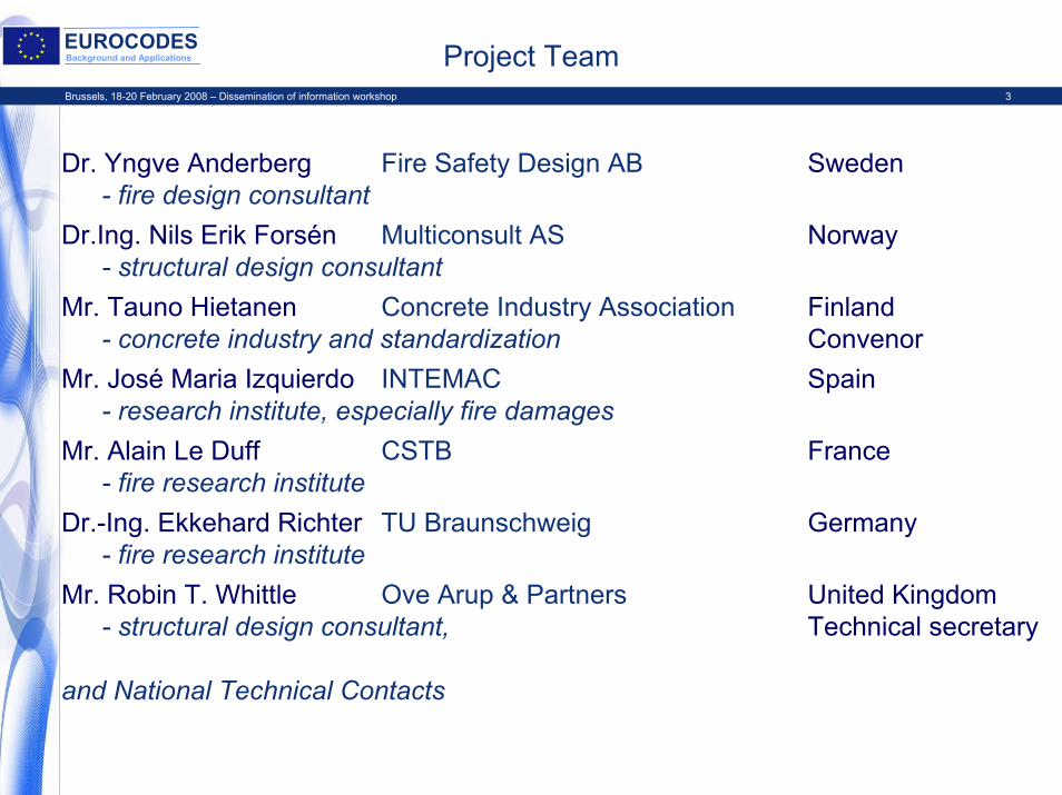
Dr. Yngve Anderberg Fire Safety Design AB Sweden- fire design consultant
Dr.Ing. Nils Erik Forsén Multiconsult AS Norway - structural design consultant
Mr. Tauno Hietanen Concrete Industry Association Finland- concrete industry and standardization Convenor
Mr. José Maria Izquierdo INTEMAC Spain- research institute, especially fire damages
Mr. Alain Le Duff CSTB France- fire research institute
Dr.-Ing. Ekkehard Richter TU Braunschweig Germany - fire research institute
Mr. Robin T. Whittle Ove Arup & Partners United Kingdom- structural design consultant, Technical secretary
and National Technical Contacts
Brussels, 18-20 February 2008 – Dissemination of information workshop 4
EUROCODESBackground and Applications Technical background
• CEB Bulletins ”Fire design of concrete structure”, latest No 208 July 1991
• EC 2:Part 10, 1990, prepared for the Commission by experts J.C, Dotreppe (B), L. Krampf (D), J. Mathez(F)– including material properties harmonized between
EC 2, 3 and 4• ENV 1992-1-2 November 1995
– and national comments on ENV• Project Team started the revision 1999 and prEN
was approved for Formal Vote 2002
Brussels, 18-20 February 2008 – Dissemination of information workshop 5
EUROCODESBackground and Applications Scope of EN 1992-1-2
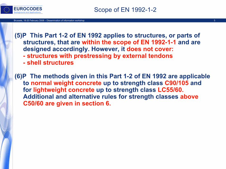
(5)P This Part 1-2 of EN 1992 applies to structures, or parts of structures, that are within the scope of EN 1992-1-1 and are designed accordingly. However, it does not cover:- structures with prestressing by external tendons- shell structures
(6)P The methods given in this Part 1-2 of EN 1992 are applicable to normal weight concrete up to strength class C90/105 and for lightweight concrete up to strength class LC55/60.Additional and alternative rules for strength classes above C50/60 are given in section 6.
Brussels, 18-20 February 2008 – Dissemination of information workshop 6
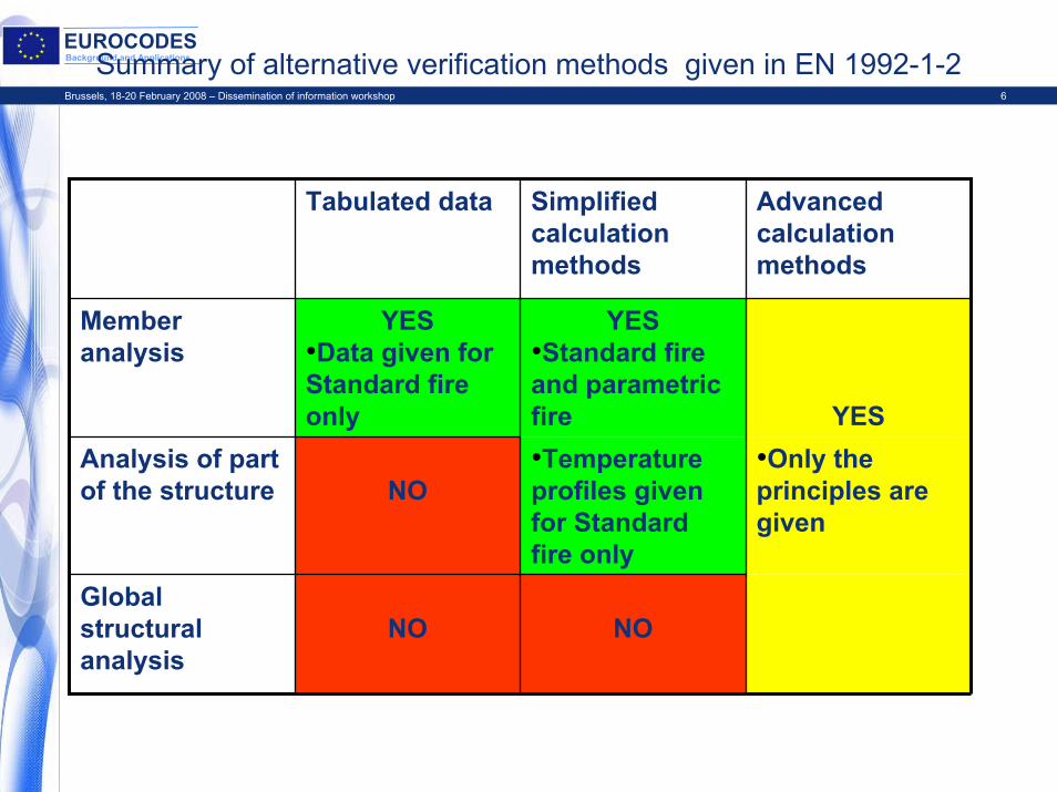
EUROCODESBackground and ApplicationsSummary of alternative verification methods given in EN 1992-1-2
Tabulated data Simplified calculation methods
Advanced calculation methods
Member analysis
YES•Data given for Standard fire only
YES•Standard fire and parametric fire YES
Analysis of part of the structure NO
•Temperature profiles given for Standard fire only
•Only the principles are given
Global structural analysis
NO NO
Brussels, 18-20 February 2008 – Dissemination of information workshop 7
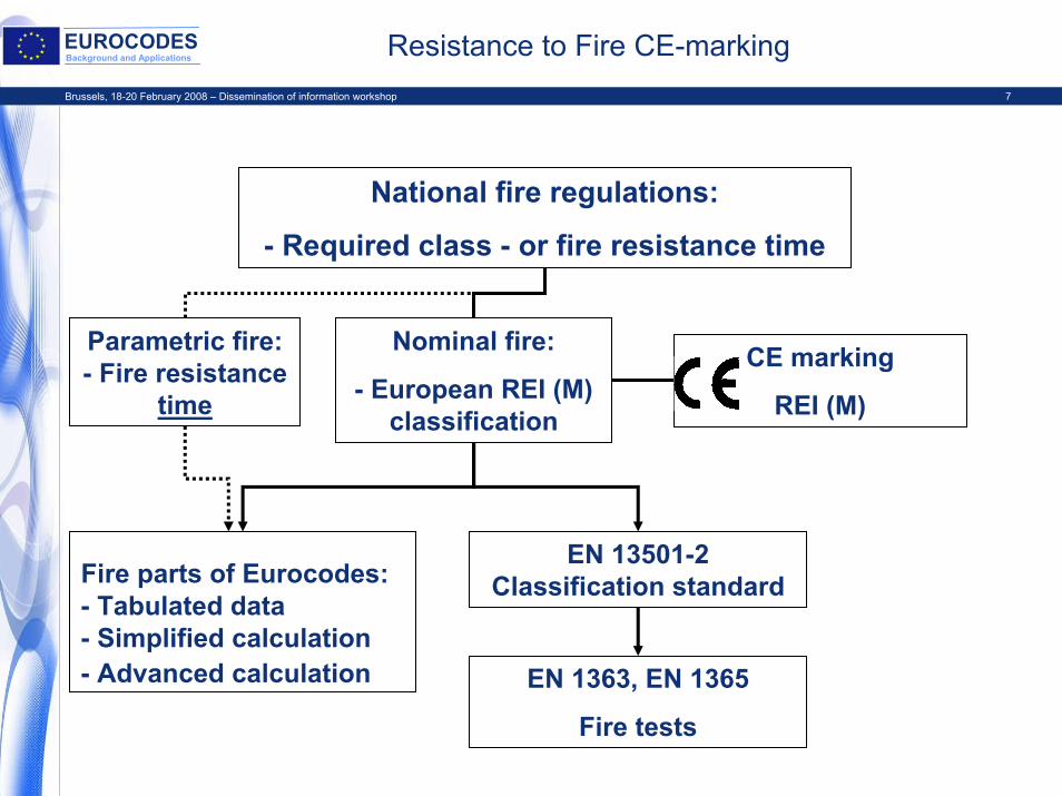
EUROCODESBackground and Applications Resistance to Fire CE-marking
National fire regulations:
- Required class - or fire resistance time
Parametric fire: - Fire resistance
time
Nominal fire:
- European REI (M) classification
Fire parts of Eurocodes:- Tabulated data- Simplified calculation- Advanced calculation
EN 13501-2 Classification standard
EN 1363, EN 1365
Fire tests
CE marking
REI (M)
Brussels, 18-20 February 2008 – Dissemination of information workshop 8
EUROCODESBackground and Applications
EN 1992-1-2Fire design of concrete structures
• Sections 1 and 2 General, Basis of design• Section 3 Material properties• Section 4 Design procedures
– Simplified calculation method 4.2, Annex A, B and E– Shear, torsion and anchorage 4.4 and Annex D– Spalling 4.5
• Section 5 Tabulated data– Annex C
• Section 6 High strength concrete
Brussels, 18-20 February 2008 – Dissemination of information workshop 9
EUROCODESBackground and Applications Section 3 Material properties
• Strength and deformation properties in Section 3 are given for simplified and advanced calculation methods
• Strength reduction curves for Tabulated data (in Section 5) and Simplified calculation methods (in Section 4) are derived from material properties in section 3
• Thermal properties are given in Section 3 for calculation of temperature distribution inside the structure
• Material properties for lightweight concrete are not given due to wide range of lightweight aggregates
– this does not exclude use of lightweight aggregate concrete, see e.g. Scope and Tabulated data
• Strength and deformation properties are applicable to heating rates similar to standard fire curve (between 2 and 50 K/min)
• Residual strength properties are not given
Brussels, 18-20 February 2008 – Dissemination of information workshop 10
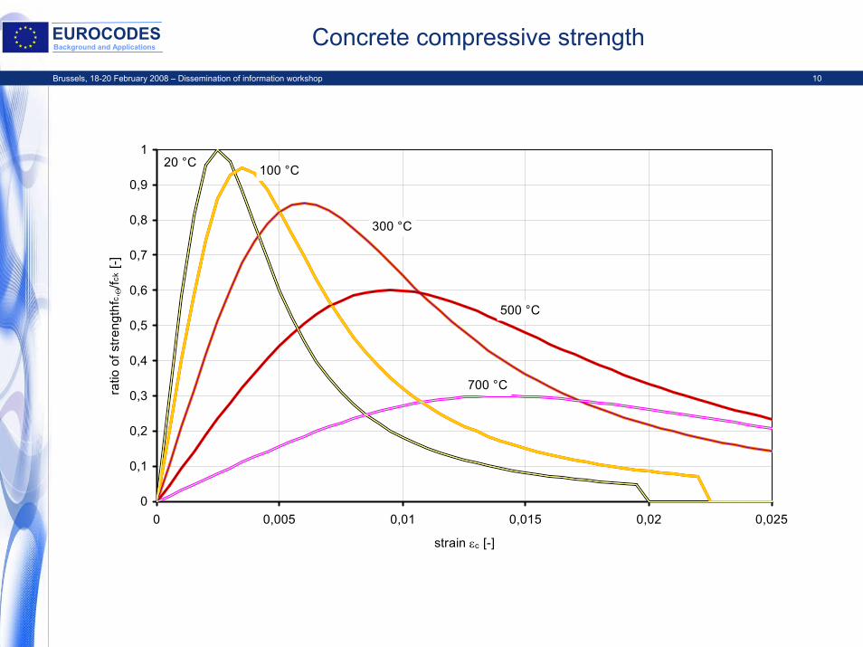
EUROCODESBackground and Applications Concrete compressive strength
0
0,1
0,2
0,3
0,4
0,5
0,6
0,7
0,8
0,9
1
0 0,005 0,01 0,015 0,02 0,025
strain εc [-]
ratio
of s
treng
thfc,
Θ/fc
k [-]
100 °C
300 °C
500 °C
700 °C
20 °C
Brussels, 18-20 February 2008 – Dissemination of information workshop 11
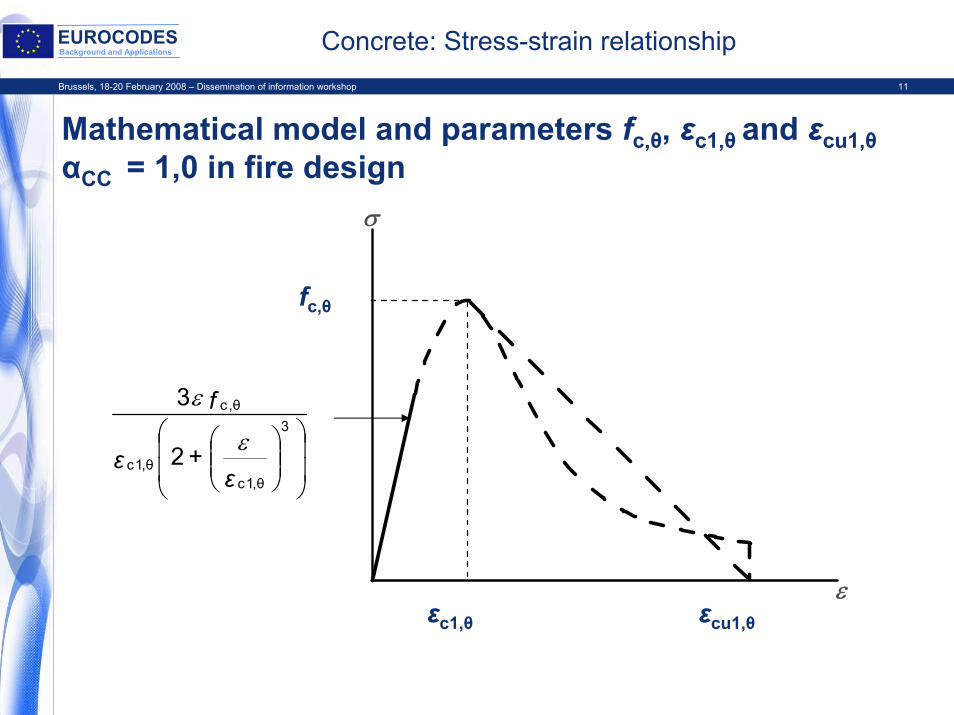
EUROCODESBackground and Applications Concrete: Stress-strain relationship
Mathematical model and parameters fc,θ, εc1,θ and εcu1,θαCC = 1,0 in fire design
σ
εc1,θ εcu1,θε
fc,θfc,θ
εc1,θ εcu1,θ
⎟⎟
⎠
⎞
⎜⎜
⎝
⎛⎟⎟⎠
⎞⎜⎜⎝
⎛3
θ,1cθ,1c
θ,c
2
3
ε+ε
f
ε
ε
Brussels, 18-20 February 2008 – Dissemination of information workshop 12
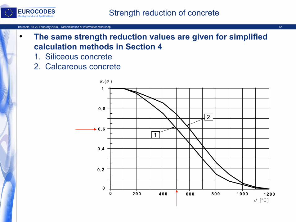
EUROCODESBackground and Applications Strength reduction of concrete
• The same strength reduction values are given for simplified calculation methods in Section 41. Siliceous concrete2. Calcareous concrete
0 ,8
1
0
1 0 ,6
0 ,2
0 ,4
1 00 02 0 0 80 04 00 12 000 60 0
k c(θ )
θ [°C ]
2
Brussels, 18-20 February 2008 – Dissemination of information workshop 13
EUROCODESBackground and Applications
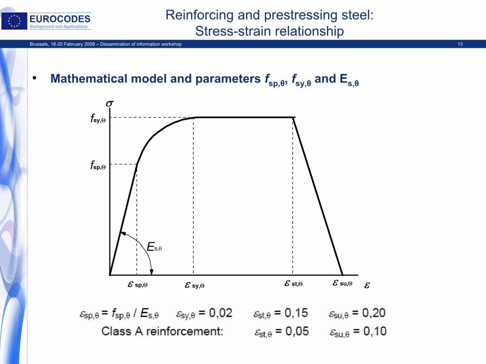
Reinforcing and prestressing steel:Stress-strain relationship
• Mathematical model and parameters fsp,θ, fsy,θ and Es,θ
σ
ε sp,Θ ε sy,Θ ε st,Θ ε su,Θ ε
fsy,Θ
fsp,Θ
Es,θ
Brussels, 18-20 February 2008 – Dissemination of information workshop 14
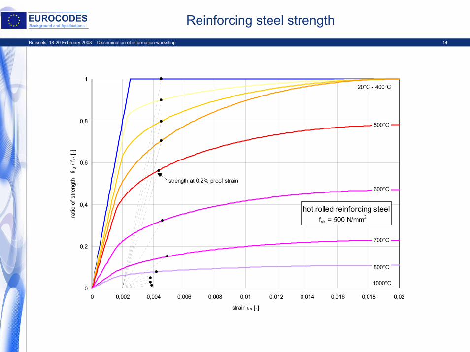
EUROCODESBackground and Applications Reinforcing steel strength
0
0,2
0,4
0,6
0,8
1
0 0,002 0,004 0,006 0,008 0,01 0,012 0,014 0,016 0,018 0,02
strain εs [-]
ratio
of s
treng
th
fs, /
fyk [-
]
500°C
600°C
700°C
800°C
20°C - 400°C
hot rolled reinforcing steel fyk = 500 N/mm2
1000°C
strength at 0.2% proof strain
Brussels, 18-20 February 2008 – Dissemination of information workshop 15
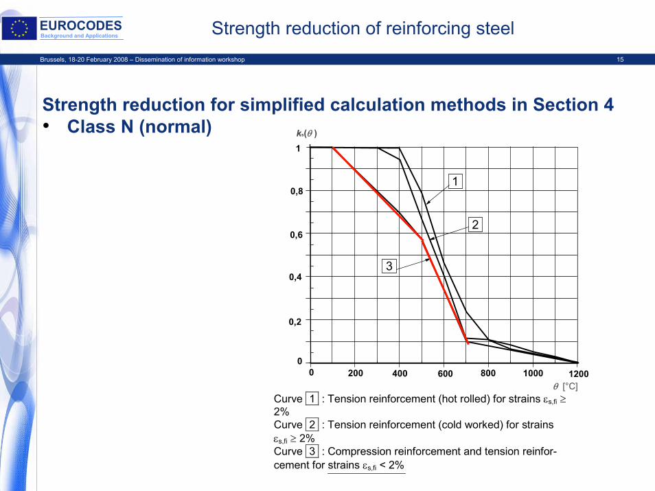
EUROCODESBackground and Applications Strength reduction of reinforcing steel
Strength reduction for simplified calculation methods in Section 4• Class N (normal)
Curve 1 : Tension reinforcement (hot rolled) for strains εs,fi ≥ 2% Curve 2 : Tension reinforcement (cold worked) for strains εs,fi ≥ 2% Curve 3 : Compression reinforcement and tension reinfor-cement for strains εs,fi < 2%
0,8
1
0
1
2
3
0,6
0,2
0,4
1000200 800400 12000 600
ks(θ )
θ [°C]
Brussels, 18-20 February 2008 – Dissemination of information workshop 16
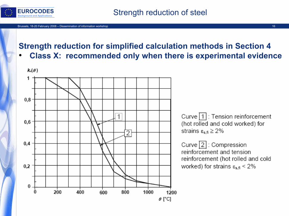
EUROCODESBackground and Applications Strength reduction of steel
Strength reduction for simplified calculation methods in Section 4• Class X: recommended only when there is experimental evidence
Brussels, 18-20 February 2008 – Dissemination of information workshop 17
EUROCODESBackground and Applications Reinforcing steel Class X
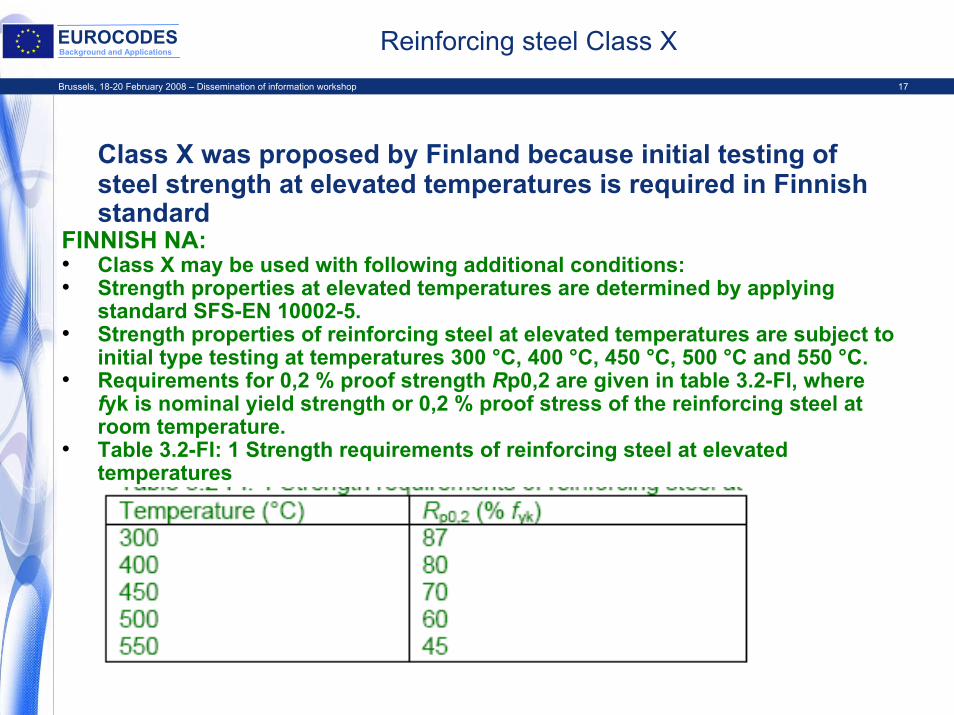
Class X was proposed by Finland because initial testing of steel strength at elevated temperatures is required in Finnish standard
FINNISH NA:• Class X may be used with following additional conditions: • Strength properties at elevated temperatures are determined by applying
standard SFS-EN 10002-5.• Strength properties of reinforcing steel at elevated temperatures are subject to
initial type testing at temperatures 300 °C, 400 °C, 450 °C, 500 °C and 550 °C.• Requirements for 0,2 % proof strength Rp0,2 are given in table 3.2-FI, where
fyk is nominal yield strength or 0,2 % proof stress of the reinforcing steel at room temperature.
• Table 3.2-FI: 1 Strength requirements of reinforcing steel at elevated temperatures
Brussels, 18-20 February 2008 – Dissemination of information workshop 18
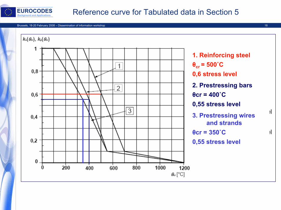
EUROCODESBackground and Applications Reference curve for Tabulated data in Section 5
1. Reinforcing steel θcr = 500˚C 0,6 stress level
2. Prestressing bars θcr = 400˚C 0,55 stress level
3. Prestressing wires and strands
θcr = 350˚C 0,55 stress level
Brussels, 18-20 February 2008 – Dissemination of information workshop 19
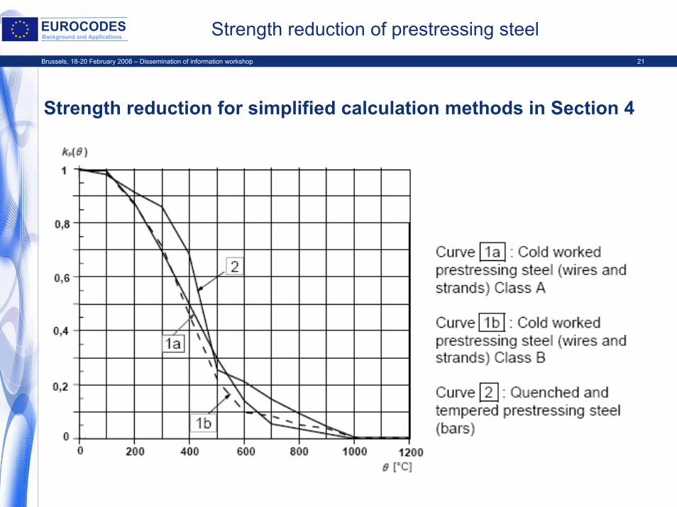
EUROCODESBackground and Applications Strength reduction of prestressing steel
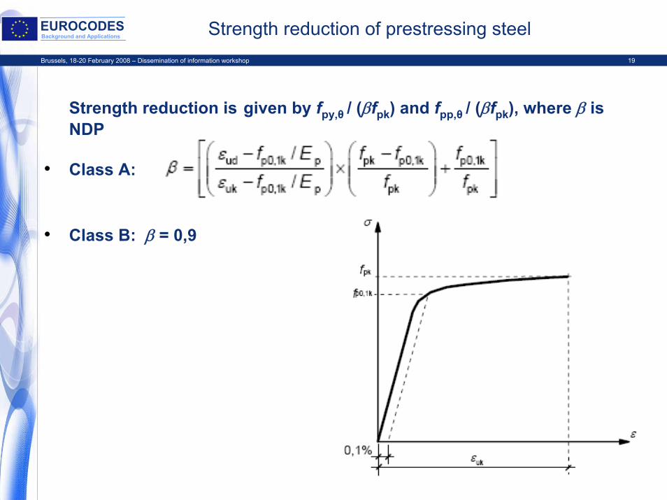
Strength reduction is given by fpy,θ / (βfpk) and fpp,θ / (βfpk), where β is NDP
• Class A:
• Class B: β = 0,9
Brussels, 18-20 February 2008 – Dissemination of information workshop 20
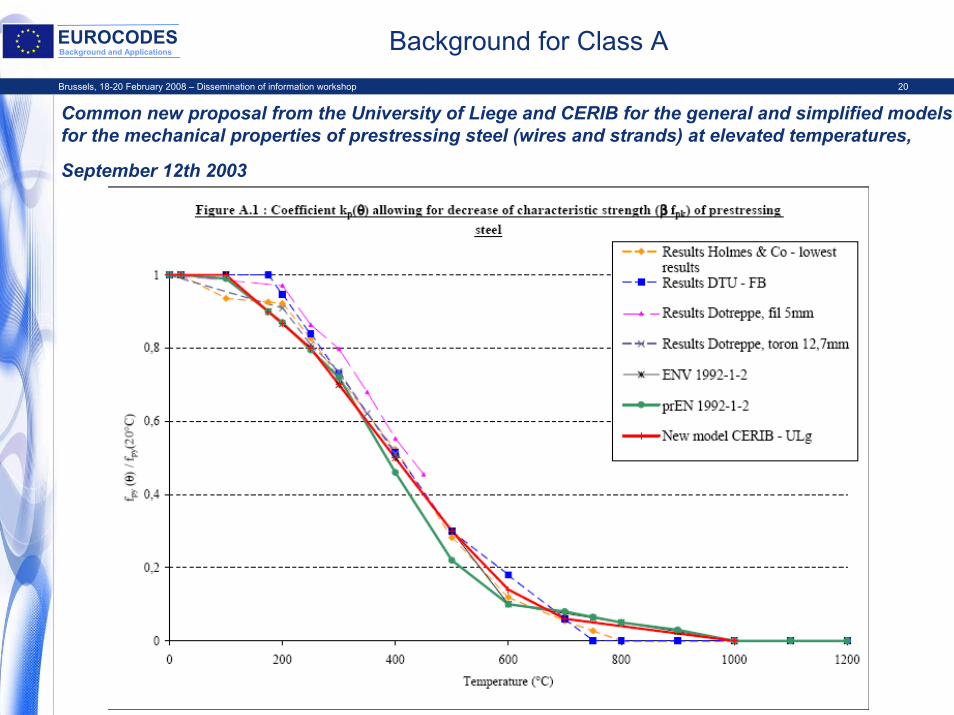
EUROCODESBackground and Applications Background for Class A
Common new proposal from the University of Liege and CERIB for the general and simplified models for the mechanical properties of prestressing steel (wires and strands) at elevated temperatures,
September 12th 2003
Brussels, 18-20 February 2008 – Dissemination of information workshop 21
EUROCODESBackground and Applications Strength reduction of prestressing steel
Strength reduction for simplified calculation methods in Section 4
Brussels, 18-20 February 2008 – Dissemination of information workshop 22
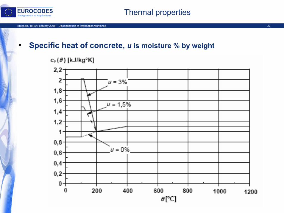
EUROCODESBackground and Applications Thermal properties
• Specific heat of concrete, u is moisture % by weight
Brussels, 18-20 February 2008 – Dissemination of information workshop 23
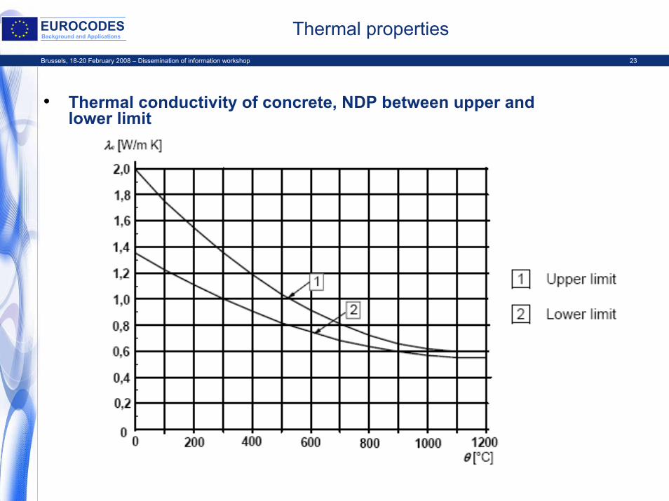
EUROCODESBackground and Applications Thermal properties
• Thermal conductivity of concrete, NDP between upper and lower limit
Brussels, 18-20 February 2008 – Dissemination of information workshop 24
EUROCODESBackground and Applications Background for thermal conductivity
• Project Team EN 1992-1-2 made a lot of calibrations to temperatures measured in fire tests of typical concrete structures, and the lower limit fits very well
• Design rules for steel-concrete composite structures (mainly including heavy steel sections) seem to be calibrated to the upper limit
• A compromise was made on TC 250 level: NDP between upper and lower limit
• EN 1992-1-2, 3.3.3:• Note 2: Annex A is compatible with the lower limit. The
remaining clauses of this part 1-2 are independent of the choice of thermal conductivity. For high strength concrete, see 6.3.
Brussels, 18-20 February 2008 – Dissemination of information workshop 25
EUROCODESBackground and Applications
EN 1992-1-2Fire design of concrete structures
• Sections 1 and 2 General, Basis of design • Section 3 Material properties• Section 4 Design procedures
– Simplified calculation method 4.2, Annex A, B and E– Shear, torsion and anchorage 4.4 and Annex D– Spalling 4.5
• Section 5 Tabulated data– Annex C
• Section 6 High strength concrete
Brussels, 18-20 February 2008 – Dissemination of information workshop 26
EUROCODESBackground and Applications Design methods
• advanced calculation methods for simulating the behaviour of structural members, parts of the structure or the entire structure, see 4.3– only principles are given, no detailed design rules
• simplified calculation methods for specific types of members, see 4.2– Annex B.1 “500°C isotherm method”
developed by Dr Yngve Anderberg, earlier published in Sweden and in CEB Bulletins
– Annex B.2 “Zone method”developed by Dr Kristian Hertz, earlier published in Denmark and in ENV 1992-1-2
• detailing according to recognised design solutions (tabulated dataor testing), see Section 5
• Shear, torsion and anchorage; spalling; joints
Brussels, 18-20 February 2008 – Dissemination of information workshop 27
EUROCODESBackground and Applications Simplified calculation method
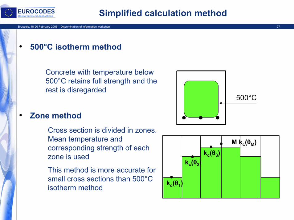
• 500°C isotherm method
• Zone method • • •
Concrete with temperature below 500°C retains full strength and the rest is disregarded
Cross section is divided in zones. Mean temperature and corresponding strength of each zone is used
This method is more accurate for small cross sections than 500°C isotherm method
500°C
kc(θ1)
kc(θ2)kc(θ3)
M kc(θM)
Brussels, 18-20 February 2008 – Dissemination of information workshop 28
EUROCODESBackground and Applications 500°C isotherm method
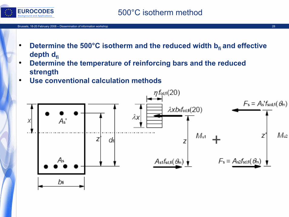
• Determine the 500°C isotherm and the reduced width bfi and effective depth dfi
• Determine the temperature of reinforcing bars and the reduced strength
• Use conventional calculation methods
Brussels, 18-20 February 2008 – Dissemination of information workshop 29
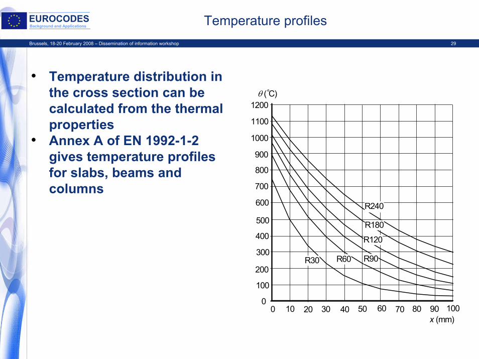
EUROCODESBackground and Applications Temperature profiles
x (mm)0 10 20 30 40 50 60 70 80 90 100
300
200
0
400
600
800
1000
1200 θ ( C)
1100
900
700
500
100
R30 R60 R90
R120
R180
R240
• Temperature distribution in the cross section can be calculated from the thermal properties
• Annex A of EN 1992-1-2 gives temperature profiles for slabs, beams and columns
Brussels, 18-20 February 2008 – Dissemination of information workshop 30
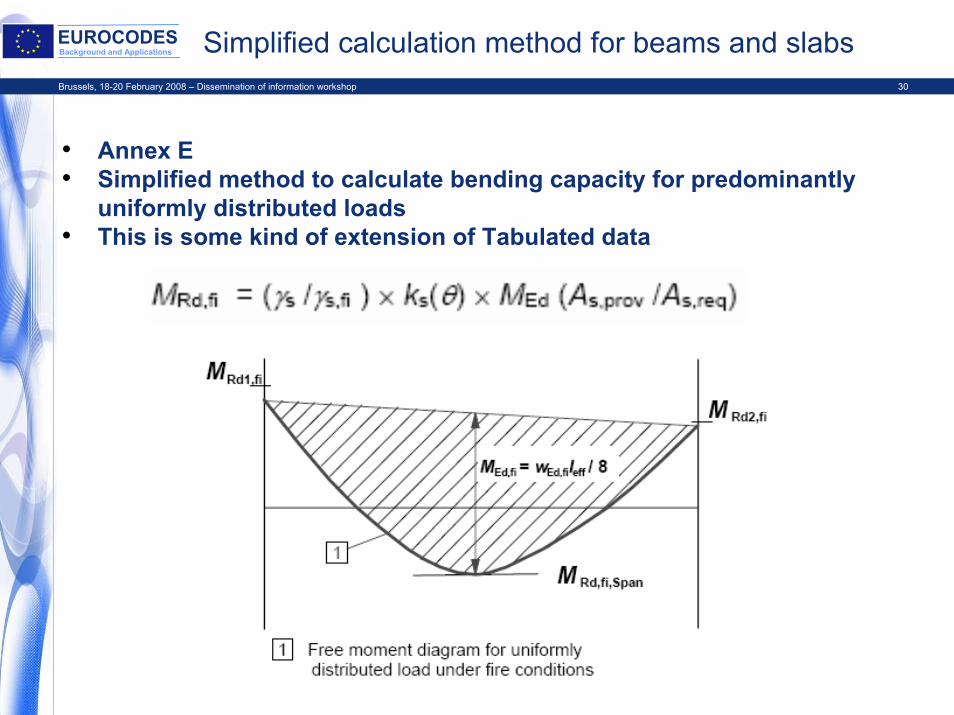
EUROCODESBackground and Applications Simplified calculation method for beams and slabs
• Annex E• Simplified method to calculate bending capacity for predominantly
uniformly distributed loads• This is some kind of extension of Tabulated data
Brussels, 18-20 February 2008 – Dissemination of information workshop 31
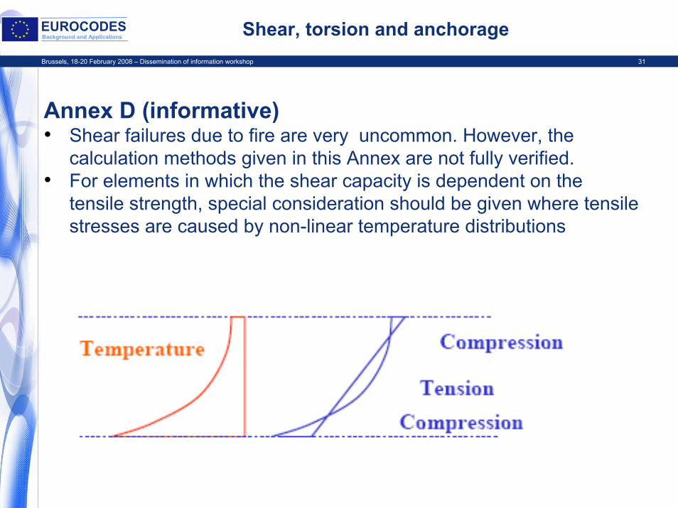
EUROCODESBackground and Applications Shear, torsion and anchorage
Annex D (informative)• Shear failures due to fire are very uncommon. However, the
calculation methods given in this Annex are not fully verified.• For elements in which the shear capacity is dependent on the
tensile strength, special consideration should be given where tensile stresses are caused by non-linear temperature distributions
Brussels, 18-20 February 2008 – Dissemination of information workshop 32
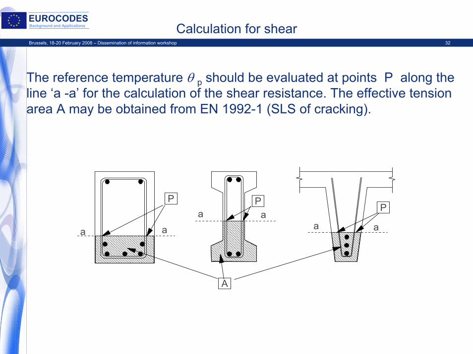
EUROCODESBackground and Applications Calculation for shear
The reference temperature θ p should be evaluated at points P along the line ‘a -a’ for the calculation of the shear resistance. The effective tension area A may be obtained from EN 1992-1 (SLS of cracking).
a
a aa aa
P P P
A
Brussels, 18-20 February 2008 – Dissemination of information workshop 33
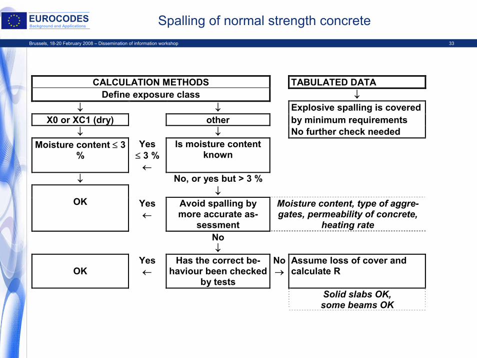
EUROCODESBackground and Applications Spalling of normal strength concrete
CALCULATION METHODS TABULATED DATADefine exposure class ↓
↓ ↓ Explosive spalling is coveredX0 or XC1 (dry) other by minimum requirements
↓ ↓ No further check neededMoisture content ≤ 3
%Yes
≤ 3 %←
Is moisture contentknown
↓ No, or yes but > 3 %↓
OK Yes←
Avoid spalling bymore accurate as-
sessment
Moisture content, type of aggre-gates, permeability of concrete,
heating rateNo↓
OKYes←
Has the correct be-haviour been checked
by tests
No→
Assume loss of cover andcalculate R
Solid slabs OK,some beams OK
Brussels, 18-20 February 2008 – Dissemination of information workshop 34
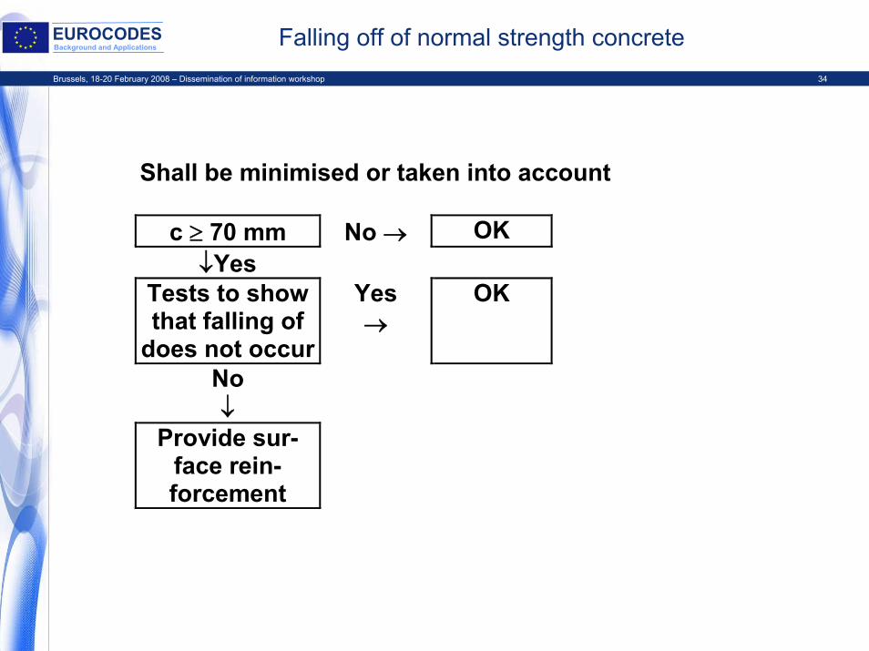
EUROCODESBackground and Applications Falling off of normal strength concrete
Shall be minimised or taken into account
c ≥ 70 mm No → OK↓Yes
Tests to showthat falling of
does not occur
Yes→
OK
No↓
Provide sur-face rein-forcement
Brussels, 18-20 February 2008 – Dissemination of information workshop 35
EUROCODESBackground and Applications
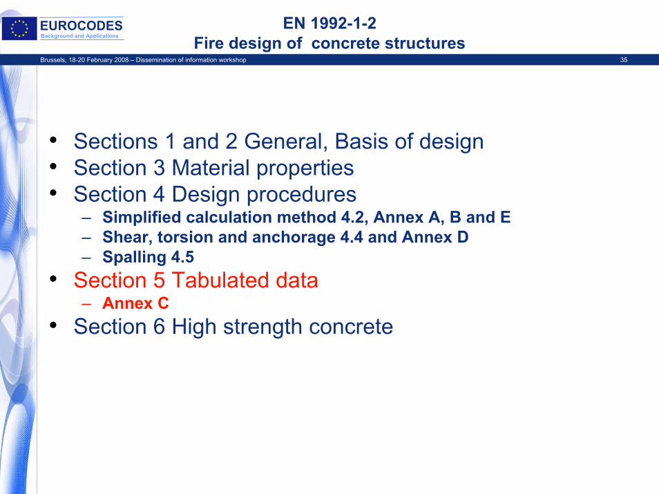
EN 1992-1-2Fire design of concrete structures
• Sections 1 and 2 General, Basis of design • Section 3 Material properties• Section 4 Design procedures
– Simplified calculation method 4.2, Annex A, B and E– Shear, torsion and anchorage 4.4 and Annex D– Spalling 4.5
• Section 5 Tabulated data– Annex C
• Section 6 High strength concrete
Brussels, 18-20 February 2008 – Dissemination of information workshop 36
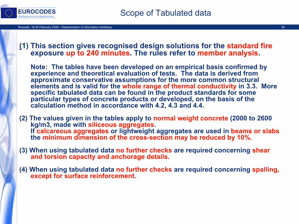
EUROCODESBackground and Applications Scope of Tabulated data
(1) This section gives recognised design solutions for the standard fireexposure up to 240 minutes. The rules refer to member analysis.
Note: The tables have been developed on an empirical basis confirmed by experience and theoretical evaluation of tests. The data is derived from approximate conservative assumptions for the more common structural elements and is valid for the whole range of thermal conductivity in 3.3. More specific tabulated data can be found in the product standards for some particular types of concrete products or developed, on the basis of the calculation method in accordance with 4.2, 4.3 and 4.4.
(2) The values given in the tables apply to normal weight concrete (2000 to 2600 kg/m3, made with siliceous aggregates.If calcareous aggregates or lightweight aggregates are used in beams or slabsthe minimum dimension of the cross-section may be reduced by 10%.
(3) When using tabulated data no further checks are required concerning shear and torsion capacity and anchorage details.
(4) When using tabulated data no further checks are required concerning spalling, except for surface reinforcement.
Brussels, 18-20 February 2008 – Dissemination of information workshop 37
EUROCODESBackground and Applications Tabulated data - General
Tabulated data are based on a reference load level ηfi = 0,7, unless otherwise stated in the relevant clauses.Note: Where the partial safety factors specified in the National Annexes of EN 1990 deviate from those indicated in 2.4.2, the above value ηfi = 0,7 may not be valid. In such circumstances the value of ηfi for use in a Country may be found in its National Annex.
For walls and columns load level ηfi or degree of utilisation μfiis included in the tables
Linear interpolation between the values in the tables may be carried out
Brussels, 18-20 February 2008 – Dissemination of information workshop 38
EUROCODESBackground and Applications Load level and degree of utilisation
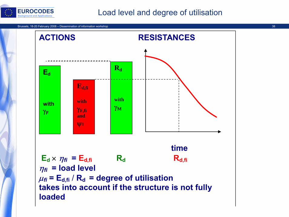
ACTIONS RESISTANCES
Ed
withγF
Ed,fi
withγF,fiandψfi
Rd
withγM
time Ed × ηfi = Ed,fi Rd Rd,fi ηfi = load level μfi = Ed,fi / Rd = degree of utilisation takes into account if the structure is not fully loaded
Brussels, 18-20 February 2008 – Dissemination of information workshop 39
EUROCODESBackground and Applications Tabulated data – main principle
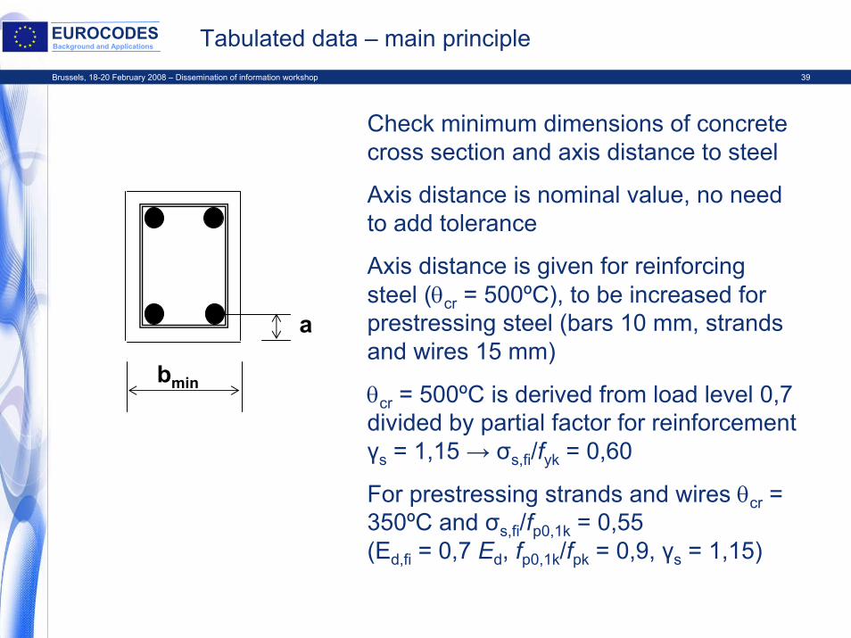
bmin
a
Check minimum dimensions of concrete cross section and axis distance to steel
Axis distance is nominal value, no need to add tolerance
Axis distance is given for reinforcing steel (θcr = 500ºC), to be increased for prestressing steel (bars 10 mm, strands and wires 15 mm)
θcr = 500ºC is derived from load level 0,7 divided by partial factor for reinforcement γs = 1,15 → σs,fi/fyk = 0,60
For prestressing strands and wires θcr = 350ºC and σs,fi/fp0,1k = 0,55(Ed,fi = 0,7 Ed, fp0,1k/fpk = 0,9, γs = 1,15)
Brussels, 18-20 February 2008 – Dissemination of information workshop 40
EUROCODESBackground and Applications Tabulated data in EN 1992-1-2
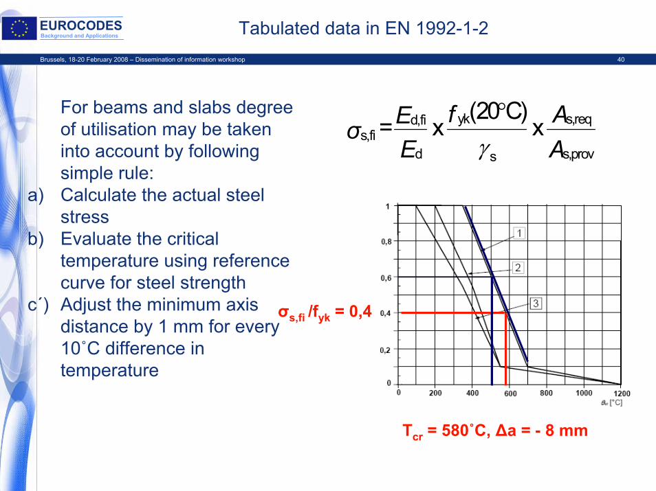
For beams and slabs degree of utilisation may be taken into account by following simple rule:
a) Calculate the actual steel stress
b) Evaluate the critical temperature using reference curve for steel strength
c´) Adjust the minimum axis distance by 1 mm for every 10˚C difference in temperature
f AEσE A
yk s,reqd,fis,fi
d s,provs
(20 C) = x x
γ°
σs,fi /fyk = 0,4
Tcr = 580˚C, Δa = - 8 mm
Brussels, 18-20 February 2008 – Dissemination of information workshop 41
EUROCODESBackground and Applications Tabulated data for columns
• Completely revised• Two optional methods are given
– Method A is derived from test results, but field of application is limited to buckling length ≤ 3 m and first order eccentricity ≤0,15h to 0,4h (depending on the National Annex)
– Method B is based on calculations, it is more conservative and many interpolations are needed. Limitations for normative table:eccentricity ≤ 0,25h and λfi ≤ 309 pages of tables in Annex C
Brussels, 18-20 February 2008 – Dissemination of information workshop 42
EUROCODESBackground and Applications Parameters for columns
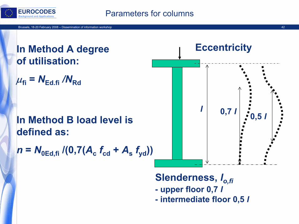
In Method A degree of utilisation:
μfi = NEd.fi /NRd
In Method B load level is defined as:
n = N0Ed,fi /(0,7(Ac fcd + As fyd))
Slenderness, lo,fi- upper floor 0,7 l- intermediate floor 0,5 l
l 0,7 l 0,5 l
Eccentricity
Brussels, 18-20 February 2008 – Dissemination of information workshop 43
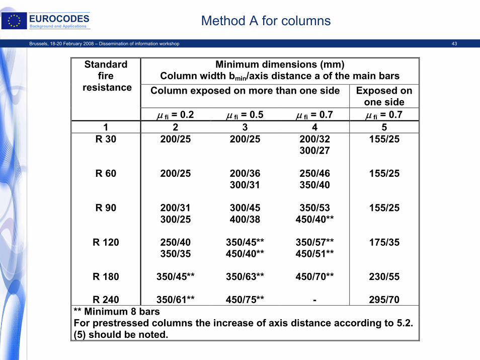
EUROCODESBackground and Applications Method A for columns
Minimum dimensions (mm) Column width bmin/axis distance a of the main bars
Column exposed on more than one side Exposed on one side
Standard fire
resistance
μ fi = 0.2 μ fi = 0.5 μ fi = 0.7 μ fi = 0.7 1 2 3 4 5
R 30
R 60
R 90
R 120
R 180
R 240
200/25
200/25
200/31 300/25
250/40 350/35
350/45**
350/61**
200/25
200/36 300/31
300/45 400/38
350/45** 450/40**
350/63**
450/75**
200/32 300/27
250/46 350/40
350/53
450/40**
350/57** 450/51**
450/70**
-
155/25
155/25
155/25
175/35
230/55
295/70 ** Minimum 8 bars For prestressed columns the increase of axis distance according to 5.2. (5) should be noted.
Brussels, 18-20 February 2008 – Dissemination of information workshop 44
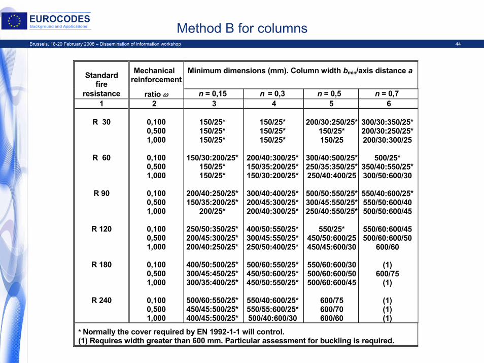
EUROCODESBackground and Applications Method B for columns
Standard
fire
Mechanical reinforcement
Minimum dimensions (mm). Column width bmin/axis distance a
resistance ratio ω n = 0,15 n = 0,3 n = 0,5 n = 0,7 1 2 3 4 5 6
R 30
R 60
R 90
R 120
R 180
R 240
0,100 0,500 1,000
0,100 0,500 1,000
0,100 0,500 1,000
0,100 0,500 1,000
0,100 0,500 1,000
0,100 0,500 1,000
150/25* 150/25* 150/25*
150/30:200/25*
150/25* 150/25*
200/40:250/25* 150/35:200/25*
200/25*
250/50:350/25* 200/45:300/25* 200/40:250/25*
400/50:500/25* 300/45:450/25* 300/35:400/25*
500/60:550/25* 450/45:500/25* 400/45:500/25*
150/25* 150/25* 150/25*
200/40:300/25* 150/35:200/25* 150/30:200/25*
300/40:400/25* 200/45:300/25* 200/40:300/25*
400/50:550/25* 300/45:550/25* 250/50:400/25*
500/60:550/25* 450/50:600/25* 450/50:550/25*
550/40:600/25* 550/55:600/25* 500/40:600/30
200/30:250/25*
150/25* 150/25
300/40:500/25*250/35:350/25*250/40:400/25
500/50:550/25*300/45:550/25*250/40:550/25*
550/25*
450/50:600/25450/45:600/30
550/60:600/30500/60:600/50500/60:600/45
600/75 600/70 600/60
300/30:350/25* 200/30:250/25* 200/30:300/25
500/25*
350/40:550/25* 300/50:600/30
550/40:600/25* 550/50:600/40 500/50:600/45
550/60:600/45 500/60:600/50
600/60
(1) 600/75
(1)
(1) (1) (1)
* Normally the cover required by EN 1992-1-1 will control. (1) Requires width greater than 600 mm. Particular assessment for buckling is required.
Brussels, 18-20 February 2008 – Dissemination of information workshop 45
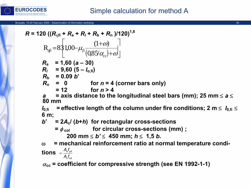
EUROCODESBackground and Applications Simple calculation for method A
R = 120 ((Rηfi + Ra + Rl + Rb + Rn )/120)1,8
( ) ⎥⎦
⎤⎢⎣
⎡+
+−=
ωαωμηcc
fifi /85,0)1(00,183R
Ra = 1,60 (a – 30)Rl = 9,60 (5 – lo,fi)Rb = 0.09 b’Rn = 0 for n = 4 (corner bars only)
= 12 for n > 4a = axis distance to the longitudinal steel bars (mm); 25 mm ≤ a ≤80 mml0,fi = effective length of the column under fire conditions; 2 m ≤ l0,fi ≤6 m;b’ = 2Ac/ (b+h) for rectangular cross-sections = φ col for circular cross-sections (mm) ;
200 mm ≤ b’ ≤ 450 mm; h ≤ 1,5 b.ω = mechanical reinforcement ratio at normal temperature condi-tions
cdc
yds
fAfA
=
αcc = coefficient for compressive strength (see EN 1992-1-1)
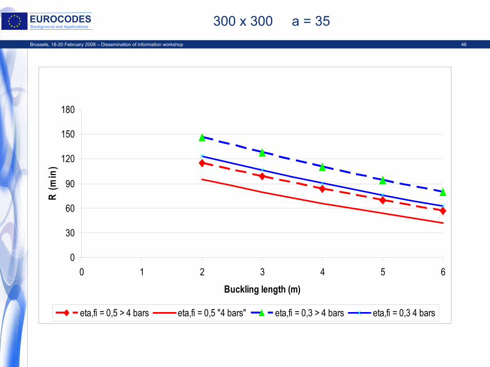
Brussels, 18-20 February 2008 – Dissemination of information workshop 46
EUROCODESBackground and Applications 300 x 300 a = 35
0
30
60
90
120
150
180
0 1 2 3 4 5 6
Buckling length (m)
R (m
in)
eta,fi = 0,5 > 4 bars eta,fi = 0,5 "4 bars" eta,fi = 0,3 > 4 bars eta,fi = 0,3 4 bars
Brussels, 18-20 February 2008 – Dissemination of information workshop 47
EUROCODESBackground and Applications Walls
• Tabulated data as in ENV• Fire walls have been added
– Classification M, to be used only if there are national requirements
– Data taken from DIN standard
Brussels, 18-20 February 2008 – Dissemination of information workshop 48
EUROCODESBackground and Applications Beams, slabs, tensile members
• In principle the same as in ENV• Some numerical values have been checked, e.g.
– Rule for increase of axis distance in I-beam web (validity of expression 5.10)
– Three classes for I-beam web thickness (NDP)– Minimum width of continuous beams– Flat slab thicknesses have been checked (to more conservative
direction)
Brussels, 18-20 February 2008 – Dissemination of information workshop 49
EUROCODESBackground and Applications
EN 1992-1-2Fire design of concrete structures
• Sections 1 and 2 General, Basis of design • Section 3 Material properties• Section 4 Design procedures
– Simplified calculation method 4.2, Annex A, B and E– Shear, torsion and anchorage 4.4 and Annex D– Spalling 4.5
• Section 5 Tabulated data– Annex C
• Section 6 High strength concrete
Brussels, 18-20 February 2008 – Dissemination of information workshop 50
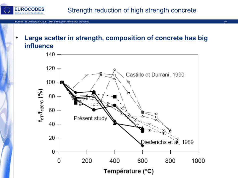
EUROCODESBackground and Applications Strength reduction of high strength concrete
• Large scatter in strength, composition of concrete has big influence
Brussels, 18-20 February 2008 – Dissemination of information workshop 51
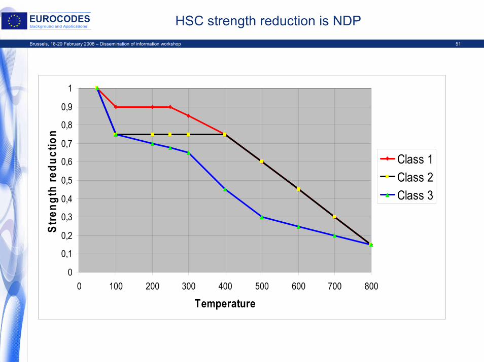
EUROCODESBackground and Applications HSC strength reduction is NDP
0
0,1
0,2
0,3
0,4
0,5
0,6
0,7
0,8
0,9
1
0 100 200 300 400 500 600 700 800
Temperature
Stre
ngth
redu
ctio
n
Class 1Class 2Class 3
Brussels, 18-20 February 2008 – Dissemination of information workshop 52
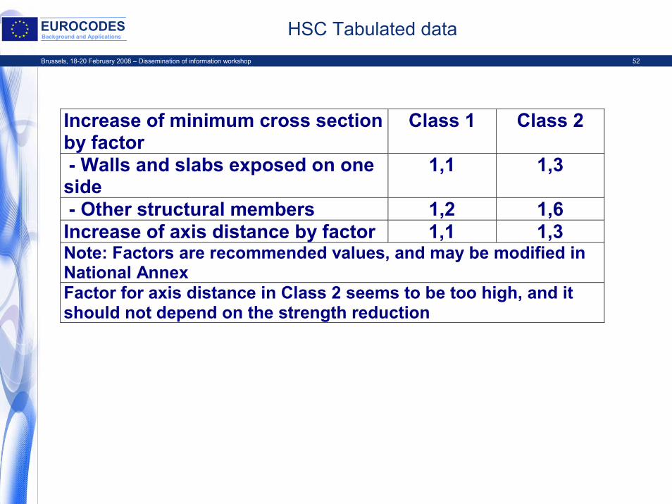
EUROCODESBackground and Applications HSC Tabulated data
Increase of minimum cross section by factor
Class 1 Class 2
- Walls and slabs exposed on one side
1,1 1,3
- Other structural members 1,2 1,6 Increase of axis distance by factor 1,1 1,3 Note: Factors are recommended values, and may be modified in National Annex Factor for axis distance in Class 2 seems to be too high, and it should not depend on the strength reduction
Brussels, 18-20 February 2008 – Dissemination of information workshop 53
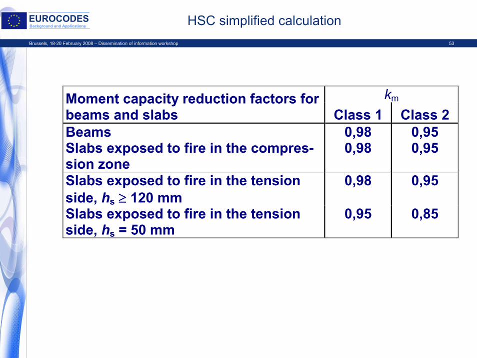
EUROCODESBackground and Applications HSC simplified calculation
km Moment capacity reduction factors for beams and slabs Class 1 Class 2 Beams 0,98 0,95 Slabs exposed to fire in the compres-sion zone
0,98 0,95
Slabs exposed to fire in the tension side, hs ≥ 120 mm
0,98 0,95
Slabs exposed to fire in the tension side, hs = 50 mm
0,95 0,85
Brussels, 18-20 February 2008 – Dissemination of information workshop 54
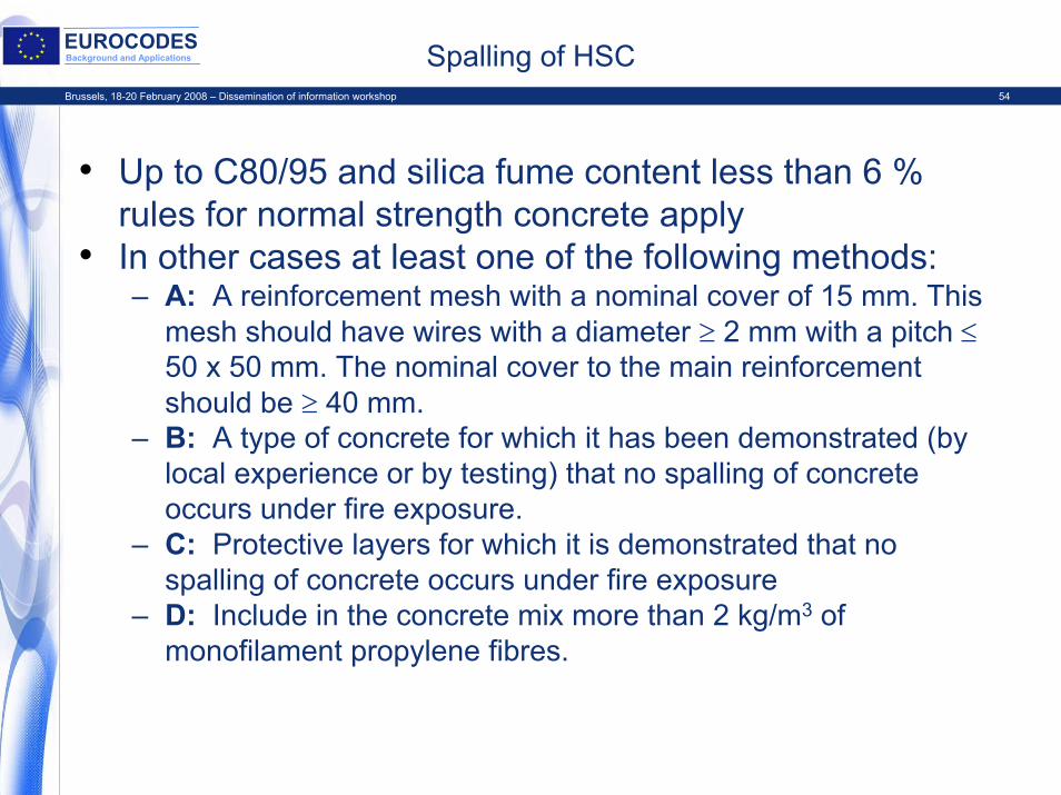
EUROCODESBackground and Applications Spalling of HSC
• Up to C80/95 and silica fume content less than 6 % rules for normal strength concrete apply
• In other cases at least one of the following methods:– A: A reinforcement mesh with a nominal cover of 15 mm. This
mesh should have wires with a diameter ≥ 2 mm with a pitch ≤50 x 50 mm. The nominal cover to the main reinforcement should be ≥ 40 mm.
– B: A type of concrete for which it has been demonstrated (by local experience or by testing) that no spalling of concrete occurs under fire exposure.
– C: Protective layers for which it is demonstrated that no spalling of concrete occurs under fire exposure
– D: Include in the concrete mix more than 2 kg/m3 of monofilament propylene fibres.
Brussels, 18-20 February 2008 – Dissemination of information workshop 55
EUROCODESBackground and Applications Background documentation
• Project Team has written ”Main background document” describing main changes to ENV
• It refers to other numbered documents called BDA (Background Document Annex)
• These documents have been delivered to CEN/TC 250/SC 2.
End of presentation