Embed Size (px)
Citation preview
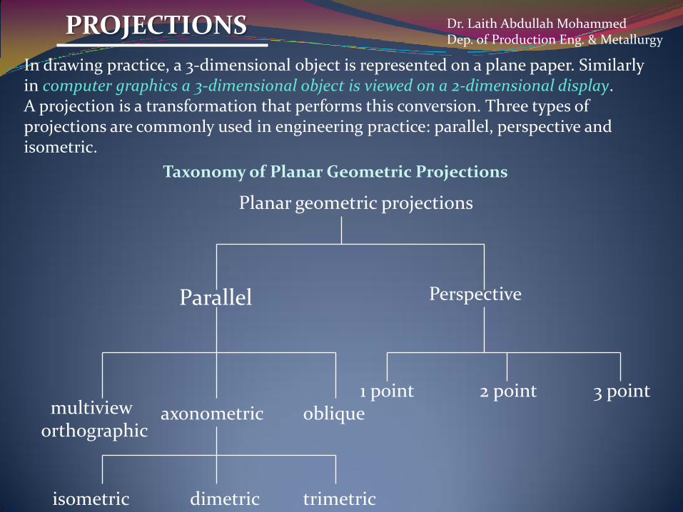
In drawing practice, a 3-dimensional object is represented on a plane paper. Similarly in computer graphics a 3-dimensional object is viewed on a 2-dimensional display. A projection is a transformation that performs this conversion. Three types of projections are commonly used in engineering practice: parallel, perspective and isometric.
PROJECTIONS
Taxonomy of Planar Geometric Projections
Parallel Perspective
axonometricmultivieworthographic
oblique
isometric dimetric trimetric
2 point1 point 3 point
Planar geometric projections
Dr. Laith Abdullah MohammedDep. of Production Eng. & Metallurgy

This is the simplest of the projection methods. Fig. shows the projection of a cube on to a projection plane. The projectors, which are lines passing through the corners of the object are all parallel to each other. It is only necessary to project the end points of a line in 3-D and then join these projected points. This speeds up the transformation process.However a major disadvantage of parallel projection is lack of depth information.
1. Parallel (Orthogonal) Projection:
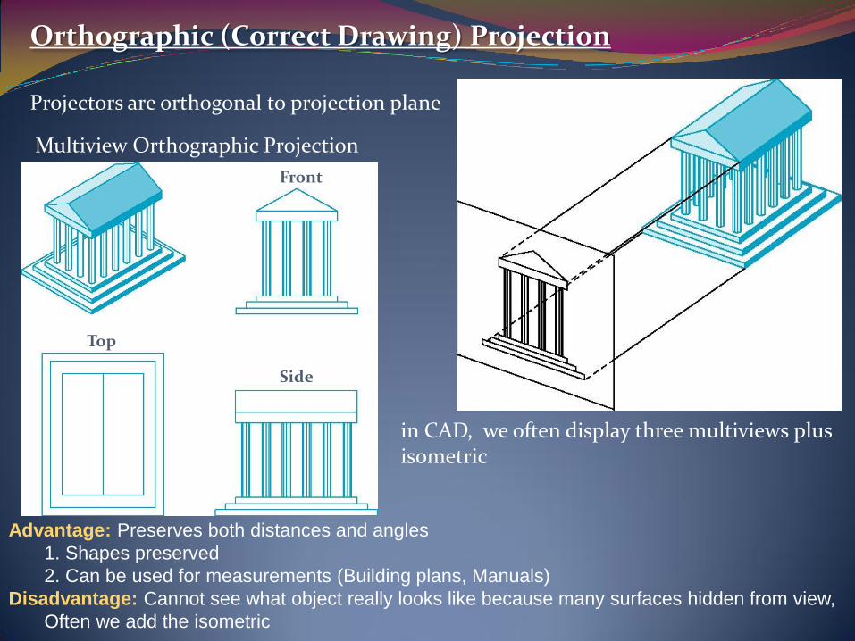
Orthographic (Correct Drawing) Projection
Projectors are orthogonal to projection plane
Multiview Orthographic Projection
in CAD, we often display three multiviews plus isometric
Top
Side
Front
Advantage: Preserves both distances and angles
1. Shapes preserved
2. Can be used for measurements (Building plans, Manuals)
Disadvantage: Cannot see what object really looks like because many surfaces hidden from view,
Often we add the isometric

2. Perspective Projection
The perspective projection enhances the realism of displayed image by providing the viewerwith a sense of depth. Portions of the object farther away from the viewer are drawn smaller then those in the foreground. This is more realistic as it is the way we see an object. In perspective projection the projections connect the eye with every point of the object andtherefore all projections converge to the eye.
As the display screen is a two-dimensional space, we cannot display three-dimensionalobjects but only their projections.

In isometric projection the three orthogonal edges of an object are inclined equally to the projection plane. Because of the relative ease of projection and the ability to give 3-D perception, isometric projection is widely used in computer aided design.
In computer aided design the co-ordinates of the drawing are available in their naturalco-ordinate system. These are transformed suitably to enable the viewer different views or rotate the object in such away that all the faces of the object are made visible continuously. There are several uses for this technique in product design. Hence good design packages incorporate several viewing transformation techniques. The viewing parameters depend upon the system graphics standard followed in developing the graphics package. The algorithms for these viewing transformations are available in literature.
3. Isometric Projection

Axonometric projection:
Same as perspective projection except that the projectors are parallel.This means that there are no vanishing points.
Depending on the orientation of the object, Axonometric projection can be divided into three classes:
1. Trimetric.2. Dimetric.3. Isometric.
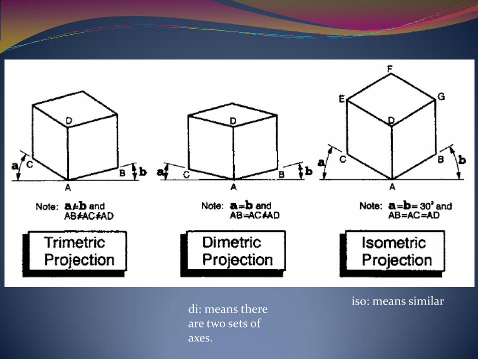
iso: means similardi: means there are two sets of axes.

Oblique projection:
The object is aligned such that one face (the front face) is parallel to the picture plane.The projection lines are still parallel but they are not perpendicular to the picture plane.It has the advantage that the features of the front face can be drawn exactly as they are, with no distortion.

Drawings are two-dimensional representations of objects that allow you to record sizes and shapes preciselyTo provide a complete and clear description, the views must be systematically arrangedThe system of views is called multiview projection
Views of Objects
Dr. Laith Abdullah MohammedDep. of Production Eng. & Metallurgy
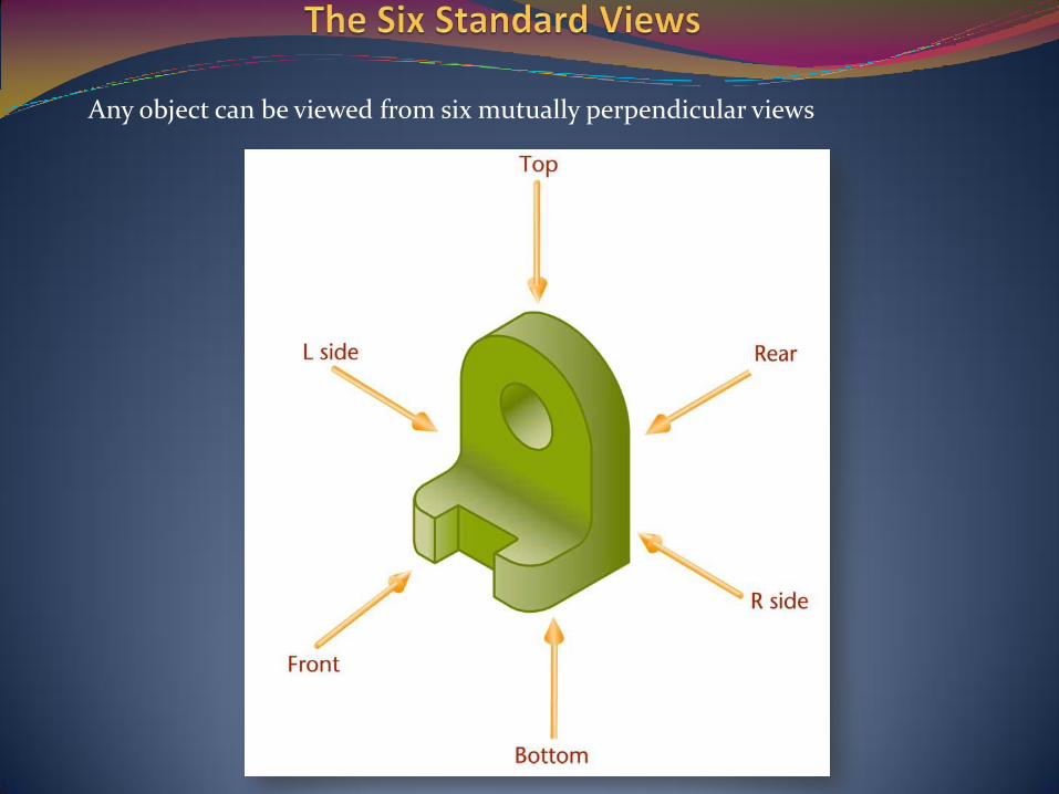
Any object can be viewed from six mutually perpendicular views

Standard 2D views

These views are called principal views and are arranged in a standard way
The top, front, and bottom views align verticallyThe rear, left-side, front, and right-side views align horizontally

The three principal dimensions of an object are:
Width
Height
Depth
Any principal view shows two of the three principal dimensions
Height is shown in the rear, left-side, front, and right sideWidth is shown in the rear, top, front, and bottomDepth is shown in the left-side, top, right-side, and bottom views

Projection Method
Frontal plane – the plane upon which the frontal view is projected Horizontal plane – the plane upon which the top view is projected Profile plane – the plane upon which the side view is projected
The Glass Box
One way to understand the standard arrangement of views on a sheet of paper is to envision the object in a glass boxThe outside observer would see six standard views of the object through the sides of this imaginary glass box
Dr. Laith Abdullah MohammedDep. of Production Eng. & Metallurgy

The Glass Box
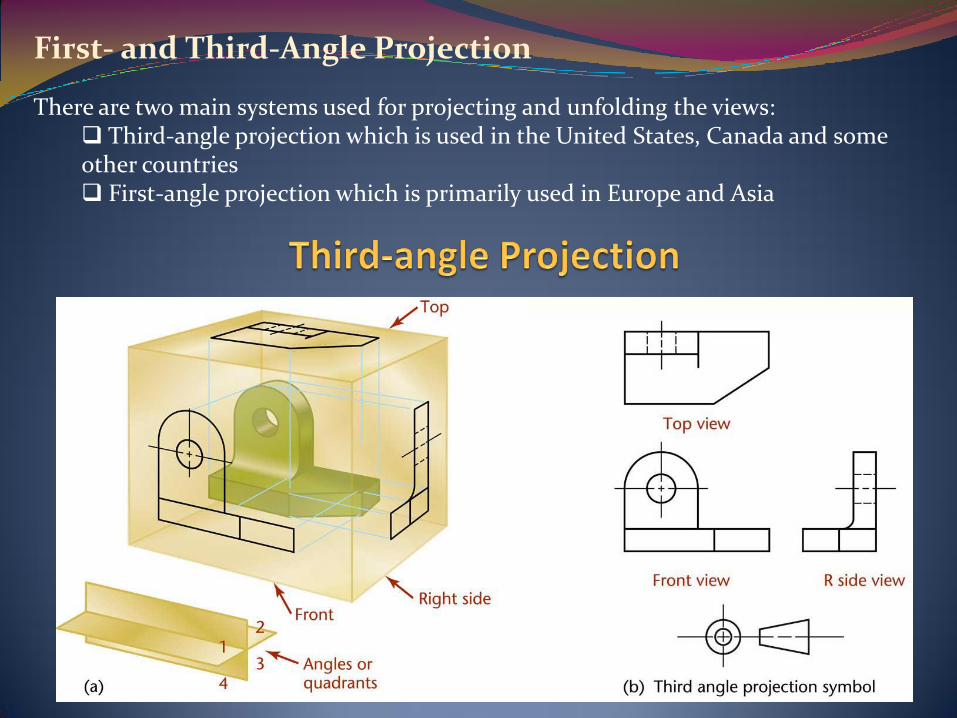
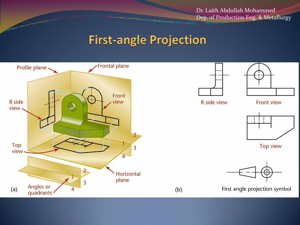
First- and Third-Angle Projection
There are two main systems used for projecting and unfolding the views: Third-angle projection which is used in the United States, Canada and some other countries First-angle projection which is primarily used in Europe and Asia
Dr. Laith Abdullah MohammedDep. of Production Eng. & Metallurgy
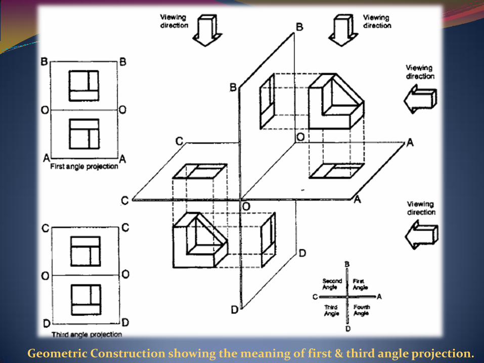
Geometric Construction showing the meaning of first & third angle projection.
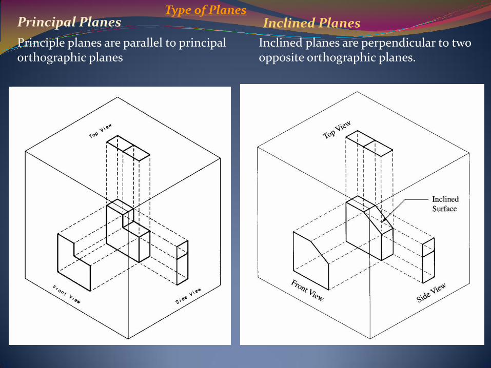
Principal Planes
Principle planes are parallel to principal orthographic planes
Inclined planes are perpendicular to two opposite orthographic planes.
Inclined PlanesType of Planes

Oblique planes are neither parallel nor perpendicular to any principal orthographic planes.
Oblique Planes Dr. Laith Abdullah MohammedDep. of Production Eng. & Metallurgy