Embed Size (px)
Citation preview
TB 11-5820-890-20-107
TECHNICAL BULLETIN
INSTALLATION INSTRUCTIONS FORINSTALLATION KIT,
ELECTRONIC EQUIPMENT, MK-2852/VRC(NSN 5895-01-431-3287) (EIC: N/A)
TO PERMIT INSTALLATION OF RADIO SETAN/VRC-87/88/90 SERIES
IN ANINTEGRATED METEOROLOGICAL SYSTEM (IMETS)
AN/TMQ-41
Approved for public release; distribution is unlimited.
HEADQUARTERS, DEPARTMENT OF THE ARMY
1 SEPTEMBER 1999
TB 11-5820-890-20-107
i
TECHNICAL BULLETIN HEADQUARTERS,DEPARTMENT OF THE ARMY
NO. 11-5820-890-20-107 WASHINGTON, D.C., 1 SEPTEMBER 1999
INSTALLATION INSTRUCTIONS FORINSTALLATION KIT
ELECTRONIC EQUIPMENT MK-2852/VRC(NSN 5895-01-431-3287) (EIC: N/A)
TO PERMIT INSTALLATION OF RADIO SETSAN/VRC-87/88/90 SERIES
IN ANINTEGRATED METEOROLOGICAL SYSTEM (IMETS) AN/TMQ-40
REPORTING OF ERRORS AND RECOMMENDING IMPROVEMENTS
You can help improve this manual. If you find any mistakes or if you know of a way to improve the procedures, pleaselet us know. Mail your letter, DA Form 2028 (Recommended Changes to Publications and Blank Forms), or DA Form2028-2 located in the back of this manual direct to: Commander, US Army Communications-Electronics CommandFort Monmouth, ATTN: AMSEL-LC-LEO-D-CS-CFO, Fort Monmouth, NJ 07703-5000. The Fax number is 732-532-1413, DSN 992-1413. You may also e-mail your recommendation to [email protected].
In either case, a reply will be furnished direct to you.
TABLE OF CONTENTSSubject Section Page
Scope ............................................................................................................................. 0.1 1General Information ....................................................................................................... 0.2 1Maintenance Forms, Records, and Reports ................................................................. 0.3 1Reports of Maintenance and Unsatisfactory Equipment............................................... 0.3.1 1Report of Packing and Handling Deficiencies ............................................................... 0.3.2 1Discrepancy in Transportation Deficiency Report (TDR) (SF 361)............................... 0.3.3 1Consolidated Index of Army Publications...................................................................... 0.4 1Purpose of Installation.................................................................................................... 1. 2End Item or System to be Modified ............................................................................... 2. 2Application Times........................................................................................................... 3. 2Time for Completion of Installation ................................................................................ 3.1 2Time for Installation of One Assembly or Component .................................................. 3.2 2Preparation for Installation ............................................................................................. 4. 2Preparation of Shelter .................................................................................................... 4.1 2Preparation of MK .......................................................................................................... 4.2 2MK, Distribution, and Consumables .............................................................................. 4.3 3Tools and Test, Measurement, and DiagnosticEquipment (TMDE) Required ........................................................................................ 4.4 6Installation Procedures................................................................................................... 5. 7Installation of Antenna, Vehicular, AS-3900/VRC (antenna) ........................................ 5.1 9Installation of Antenna Base .......................................................................................... 5.1.1 9Installation of Top Antenna Assembly ........................................................................... 5.1.2 11
TB 11-5820-890-20-107
ii
Installation of Mounting Base, Electrical EquipmentMT-6352/VRC (mounting base)..................................................................................... 5.2 12Installation of Loudspeaker, Control Unit, LS-671/VRC (speaker) ............................... 5.3 14Installation of Cables...................................................................................................... 5.4 16Post-Installation and Checkout ...................................................................................... 5.5 18Appendix A References ................................................................................................ A-1
LIST OF ILLUSTRATIONS
Figure Title Page
4-1 MK Illustrated Parts List.............................................................................................................55-1(1) MK and Radio Installation: MK Equipment Locations..............................................................75-1(2) MK and Radio Installation: Radio Equipment Locations..........................................................85-2 Antenna Base Installation ..........................................................................................................105-3 Top Antenna Assembly Installation ...........................................................................................115-4 Mounting Base Installation.........................................................................................................135-5(1) Speaker Installation ...................................................................................................................155-5(2) Speaker Installation: Optional Location....................................................................................155-6 Cable Installation: Speaker and Power Cabling.......................................................................175-7 Cable Diagram: For AN/VRC-87/88/90 Series.........................................................................19
LIST OF TABLES
Table Title Page
4-1 Parts List for Installation of Radio Set AN/VRC-87/88/90 Series ...............................................4
TB 11-5820-890-20-107
1
0.1 SCOPE.
This technical bulletin provides installation instructions for Installation Kit, Electronic Equipment MK-2852/VRC,commonly referred to as the Mounting Kit (MK). The MK shall be installed into the following type of shelter(s):
• Integrated Meteorological System (IMETS), AN/TMQ-40.
The MK is used for installation of radio set components at field locations. The information contained in this technicalbulletin is the official authorization to perform the installation at the unit maintenance level.
NOTES
• This technical bulletin is not an authorization for requisition or turn-in of shelters.
• This technical bulletin does not establish quantity or types of shelters assigned to using units.
This technical bulletin does not contain information on the maintenance or replacement of the MKs. This information iscontained in the MAC of TM 11-5820-890-20-2, TM 11-5820-890-20-4 and RPSTL of TM 11-5820-890-20P.
0.2 GENERAL INFORMATION.
The MK becomes operable when all the radio set components are installed in the shelter and correct power is supplied.Refer to TM 11-5820-890-20-1 or TM 11-5820-890-20-4 for installation, Operational (OP) Check instructions, andrequired maintenance procedures. Refer to TM 11-5820-890-20P for repair parts. Refer to SB 11-131-2 for InstallationKit repair parts.
Included in the radio set AN/VRC-87/88/90 Series is:
• Radio Set AN/VRC-87/88/90 Series (for RT-1523(C)/U)
0.3 MAINTENANCE FORMS, RECORDS, AND REPORTS.
0.3.1 Reports of Maintenance and Unsatisfactory Equipment. See Section 4.2.2.3 for information.
0.3.2 Report of Packing and Handling Deficiencies. See Section 4.2.2.1 for information.
0.3.3 Discrepancy in Transportation Deficiency Report (TDR) (SF361). See Section 4.2.2.2 for information.
0.4 CONSOLIDATED INDEX OF ARMY PUBLICATIONS.
Refer to the latest issue of DA Pam 25-30 to determine whether there are new changes, or additional publicationspertaining to the equipment.
TB 11-5820-890-20-107
2
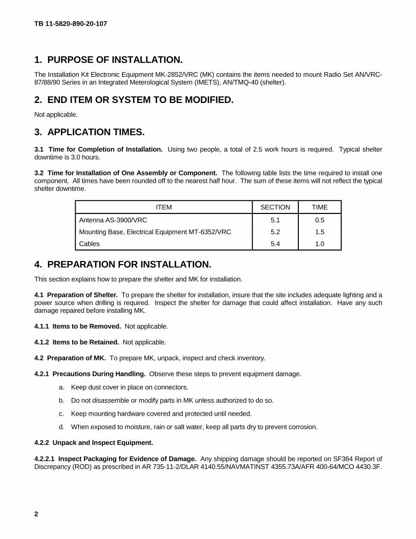
1. PURPOSE OF INSTALLATION.
The Installation Kit Electronic Equipment MK-2852/VRC (MK) contains the items needed to mount Radio Set AN/VRC-87/88/90 Series in an Integrated Meterological System (IMETS), AN/TMQ-40 (shelter).
2. END ITEM OR SYSTEM TO BE MODIFIED.
Not applicable.
3. APPLICATION TIMES.
3.1 Time for Completion of Installation. Using two people, a total of 2.5 work hours is required. Typical shelterdowntime is 3.0 hours.
3.2 Time for Installation of One Assembly or Component. The following table lists the time required to install onecomponent. All times have been rounded off to the nearest half hour. The sum of these items will not reflect the typicalshelter downtime.
ITEM SECTION TIME
Antenna AS-3900/VRC 5.1 0.5
Mounting Base, Electrical Equipment MT-6352/VRC 5.2 1.5
Cables 5.4 1.0
4. PREPARATION FOR INSTALLATION.
This section explains how to prepare the shelter and MK for installation.
4.1 Preparation of Shelter. To prepare the shelter for installation, insure that the site includes adequate lighting and apower source when drilling is required. Inspect the shelter for damage that could affect installation. Have any suchdamage repaired before installing MK.
4.1.1 Items to be Removed. Not applicable.
4.1.2 Items to be Retained. Not applicable.
4.2 Preparation of MK. To prepare MK, unpack, inspect and check inventory.
4.2.1 Precautions During Handling. Observe these steps to prevent equipment damage.
a. Keep dust cover in place on connectors.
b. Do not disassemble or modify parts in MK unless authorized to do so.
c. Keep mounting hardware covered and protected until needed.
d. When exposed to moisture, rain or salt water, keep all parts dry to prevent corrosion.
4.2.2 Unpack and Inspect Equipment.
4.2.2.1 Inspect Packaging for Evidence of Damage. Any shipping damage should be reported on SF364 Report ofDiscrepancy (ROD) as prescribed in AR 735-11-2/DLAR 4140.55/NAVMATINST 4355.73A/AFR 400-64/MCO 4430.3F.
TB 11-5820-890-20-107
3
4.2.2.2 Unpack and Inventory MK. If any item is missing, fill out and forward Transportation Deficiency Report (TDR)(SF361) as described in AR 55-38/NAVSUPINST 4610.33C/AFR 75-18/MCO P4610.19D/DLAR 4500.15.
4.2.2.3 Examine Each Item for Damage. If any item is damaged, fill out and forward SF364 Report of Discrepancy(ROD) as prescribed in AR 735-11-2/DLAR 4140.55/NAVMATINST 4355.73A/AFR-400-64/MCO 4430.3F. Alldamages should be reported as prescribed in DA Pam 738-750, as contained in Maintenance Management Update.
4.3 MK, Distribution and Consumables.
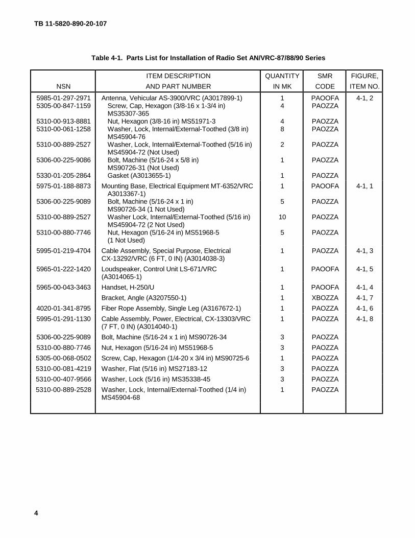
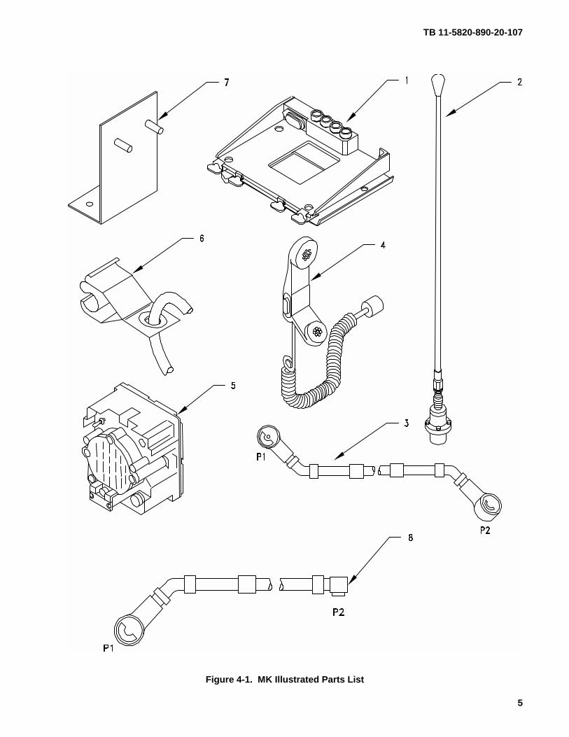
4.3.1 Items Supplied in MK and/or Required for Installation. Use Table 4-1 and Figure 4-1 to identify and inventoryMK parts.
4.3.2 Distribution and Issue Instructions.
a. US Forces: Do not requisition MK. They will be shipped automatically.
b. US Army Depots: Requisition MK through supply channels.
c. Multiservice: Instructions shall be included for multiservice modifications.
d. MAP/MAS Countries: Instructions shall be provided for MAP/MAS countries.
TB 11-5820-890-20-107
4
Table 4-1. Parts List for Installation of Radio Set AN/VRC-87/88/90 Series
NSN
ITEM DESCRIPTION
AND PART NUMBER
QUANTITY
IN MK
SMR
CODE
FIGURE,
ITEM NO.
5985-01-297-29715305-00-847-1159
5310-00-913-88815310-00-061-1258
5310-00-889-2527
5306-00-225-9086
5330-01-205-2864
Antenna, Vehicular AS-3900/VRC (A3017899-1)Screw, Cap, Hexagon (3/8-16 x 1-3/4 in)MS35307-365Nut, Hexagon (3/8-16 in) MS51971-3Washer, Lock, Internal/External-Toothed (3/8 in)MS45904-76Washer, Lock, Internal/External-Toothed (5/16 in)MS45904-72 (Not Used)Bolt, Machine (5/16-24 x 5/8 in)MS90726-31 (Not Used)Gasket (A3013655-1)
14
48
2
1
1
PAOOFAPAOZZA
PAOZZAPAOZZA
PAOZZA
PAOZZA
PAOZZA
4-1, 2
5975-01-188-8873
5306-00-225-9089
5310-00-889-2527
5310-00-880-7746
Mounting Base, Electrical Equipment MT-6352/VRCA3013367-1)Bolt, Machine (5/16-24 x 1 in)MS90726-34 (1 Not Used)Washer Lock, Internal/External-Toothed (5/16 in)MS45904-72 (2 Not Used)Nut, Hexagon (5/16-24 in) MS51968-5(1 Not Used)
1
5
10
5
PAOOFA
PAOZZA
PAOZZA
PAOZZA
4-1, 1
5995-01-219-4704 Cable Assembly, Special Purpose, ElectricalCX-13292/VRC (6 FT, 0 IN) (A3014038-3)
1 PAOZZA 4-1, 3
5965-01-222-1420 Loudspeaker, Control Unit LS-671/VRC(A3014065-1)
1 PAOOFA 4-1, 5
5965-00-043-3463 Handset, H-250/U 1 PAOOFA 4-1, 4
Bracket, Angle (A3207550-1) 1 XBOZZA 4-1, 7
4020-01-341-8795 Fiber Rope Assembly, Single Leg (A3167672-1) 1 PAOZZA 4-1, 6
5995-01-291-1130 Cable Assembly, Power, Electrical, CX-13303/VRC(7 FT, 0 IN) (A3014040-1)
1 PAOZZA 4-1, 8
5306-00-225-9089 Bolt, Machine (5/16-24 x 1 in) MS90726-34 3 PAOZZA
5310-00-880-7746 Nut, Hexagon (5/16-24 in) MS51968-5 3 PAOZZA
5305-00-068-0502 Screw, Cap, Hexagon (1/4-20 x 3/4 in) MS90725-6 1 PAOZZA
5310-00-081-4219 Washer, Flat (5/16 in) MS27183-12 3 PAOZZA
5310-00-407-9566 Washer, Lock (5/16 in) MS35338-45 3 PAOZZA
5310-00-889-2528 Washer, Lock, Internal/External-Toothed (1/4 in)MS45904-68
1 PAOZZA
TB 11-5820-890-20-107
5
Figure 4-1. MK Illustrated Parts List
TB 11-5820-890-20-107
6
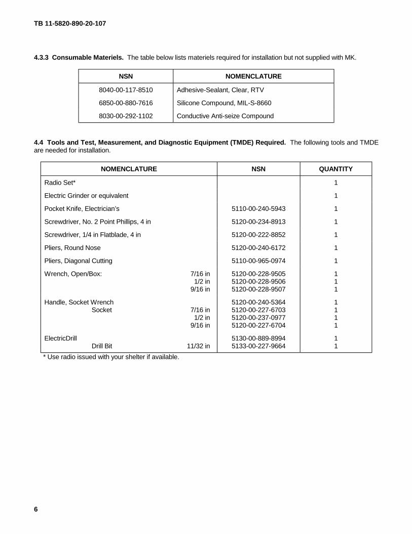
4.3.3 Consumable Materiels. The table below lists materiels required for installation but not supplied with MK.
NSN NOMENCLATURE
8040-00-117-8510 Adhesive-Sealant, Clear, RTV
6850-00-880-7616 Silicone Compound, MIL-S-8660
8030-00-292-1102 Conductive Anti-seize Compound
4.4 Tools and Test, Measurement, and Diagnostic Equipment (TMDE) Required. The following tools and TMDEare needed for installation.
NOMENCLATURE NSN QUANTITY
Radio Set* 1
Electric Grinder or equivalent 1
Pocket Knife, Electrician’s 5110-00-240-5943 1
Screwdriver, No. 2 Point Phillips, 4 in 5120-00-234-8913 1
Screwdriver, 1/4 in Flatblade, 4 in 5120-00-222-8852 1
Pliers, Round Nose 5120-00-240-6172 1
Pliers, Diagonal Cutting 5110-00-965-0974 1
Wrench, Open/Box: 7/16 in1/2 in
9/16 in
5120-00-228-95055120-00-228-95065120-00-228-9507
111
Handle, Socket WrenchSocket 7/16 in
1/2 in9/16 in
5120-00-240-53645120-00-227-67035120-00-237-09775120-00-227-6704
1111
ElectricDrillDrill Bit 11/32 in
5130-00-889-89945133-00-227-9664
11
* Use radio issued with your shelter if available.

TB 11-5820-890-20-107
7
5. INSTALLATION PROCEDURES.
This section describes where and how to install MK items in the shelter. See Figure 5-1 for an overall view of wherevehicular and MK equipment, as well as radio components, typically will be installed. When installing MKequipment, be sure to read and follow instructions and illustrations carefully.
Figure 5-1(1). MK and Radio Installation: MK Equipment Locations
TB 11-5820-890-20-107
8
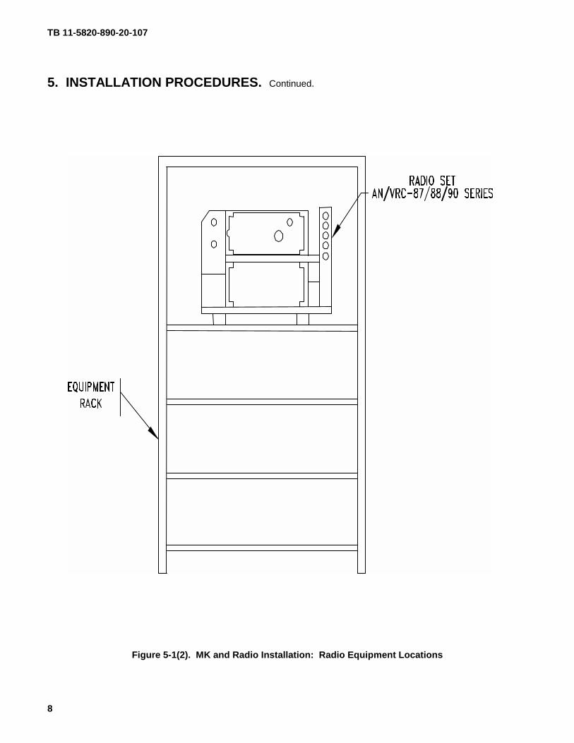
5. INSTALLATION PROCEDURES. Continued.
Figure 5-1(2). MK and Radio Installation: Radio Equipment Locations
TB 11-5820-890-20-107
9
5.1 Installation of Antenna, Vehicular, AS-3900/VRC (antenna).
5.1.1 Installation of Antenna Base. Use the following procedures to install antenna base. See Figure 5-1(1) forlocation.
ITEM ACTION REMARKS
NOTE
Apply a thin coat of adhesive-sealant to both sides of each internal/external-toothed (IET) washerduring installation, and to the area of contact where IET washer is to be placed.
a. Existing antennabracket.
De-install and retain the existing cover plate andmounting hardware.
b. Gasket (2). Place on existing antenna bracket and alignmounting holes. See Figure 5-2.
c. Antenna base (1). Place on top of gasket (2) and antenna bracket;then align mounting holes.
d. Four cap screws (3),eight internal/external-toothed (IET) washers(4) and four nuts (5).
Install and secure to antenna base (1) andantenna bracket.
Tools: 9/16 in socket and 9/16 inopen/box wrench.
e. Existing antennabracket.
Remove and discard existing antenna bracketbolt from upper right hand mounting hole. Retainexisting IET washer.
f. Ground strap (6), onecap screw (7), one IETwasher (8) and existingIET washer.
Install and secure to upper right hand mountinghole in antenna bracket and shelter wall. SeeFigure 5-2.
Tools: 7/16 in socket and 7/16 inopen/box wrench.
g. Existing RF cable (9). Attach one end to connector J1 of antenna base(1) and attach the other end to existing RFconnector on shelter wall. See Figure 5-2.
h. Existing antenna bracketcover plate.
Re-install to existing antenna bracket.
TB 11-5820-890-20-107
10
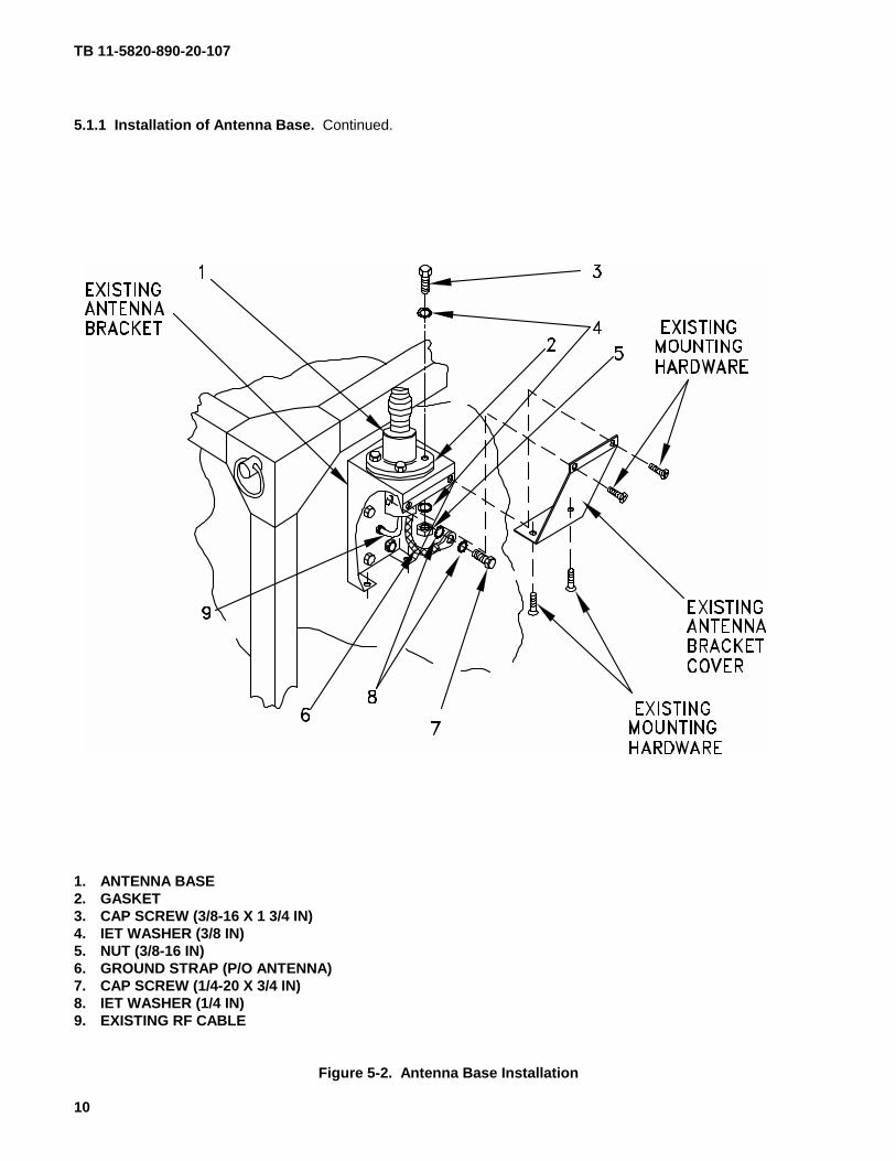
5.1.1 Installation of Antenna Base. Continued.
1. ANTENNA BASE2. GASKET3. CAP SCREW (3/8-16 X 1 3/4 IN)4. IET WASHER (3/8 IN)5. NUT (3/8-16 IN)6. GROUND STRAP (P/O ANTENNA)7. CAP SCREW (1/4-20 X 3/4 IN)8. IET WASHER (1/4 IN)9. EXISTING RF CABLE
Figure 5-2. Antenna Base Installation
TB 11-5820-890-20-107
11
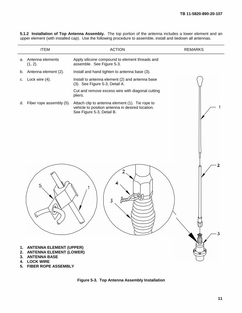
5.1.2 Installation of Top Antenna Assembly. The top portion of the antenna includes a lower element and anupper element (with installed cap). Use the following procedure to assemble, install and tiedown all antennas.
ITEM ACTION REMARKS
a. Antenna elements Apply silicone compound to element threads and(1, 2). assemble. See Figure 5-3.
b. Antenna element (2). Install and hand tighten to antenna base (3).
c. Lock wire (4). Install to antenna element (2) and antenna base(3). See Figure 5-3, Detail A.
Cut and remove excess wire with diagonal cuttingpliers.
d. Fiber rope assembly (5). Attach clip to antenna element (1). Tie rope tovehicle to position antenna in desired location.See Figure 5-3, Detail B.
1. ANTENNA ELEMENT (UPPER)2. ANTENNA ELEMENT (LOWER)3. ANTENNA BASE4. LOCK WIRE5. FIBER ROPE ASSEMBLY
Figure 5-3. Top Antenna Assembly Installation
TB 11-5820-890-20-107
12
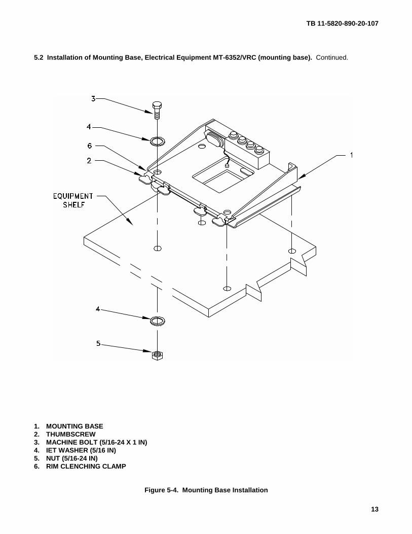
5.2 Installation of Mounting Base, Electrical Equipment MT-6352/VRC (mounting base). Remove and retainthe attached bag of 5/16 mounting hardware for installation. To insure good electrical grounding, any rust, corrosionor paint around mounting holes in electrical radio shelf should be removed before installing the mounting base. SeeFigure 5-4 for location and perform the following steps.
ITEM ACTION REMARKS
NOTE
Apply a thin coat of adhesive-sealant to both sides of each internal/external-toothed (IET) washerduring installation, and to the area of contact where IET washer is to be placed.
a. Mounting base (1) andexisting equipmentshelf.
Remove a 2” square area of paint on theunderside of the mounting base (1) around leftfront and rear mounting holes. Remove a 2”square area of paint on the existing radio shelfaround the mounting holes that mate with leftfront and rear mounting holes of mounting base(1). Clean the paint removed areas and apply athin coat of conductive anti-seize compound.
Tools: Electric grinder orequivalent.
a. Mounting base (1). Place on equipment shelf over existing holes.See Figure 5-4.
b. Two outer thumbscrews(2).
Turn ccw until both sets of threads have clearedcenter of holes.
c. Mounting base (1). Align four holes with matching hole pattern inshelf.
d. Four machine bolts (3),eight IET washers (4)and four nuts (5).
Install and secure to mounting base (1) and shelf. Tools: 1/2 in socket and 1/2 inopen/box wrench.
e. Two outer thumbscrews(2).
Tighten and secure to rim clenching clamps (6)and mounting base (1).
TB 11-5820-890-20-107
13
5.2 Installation of Mounting Base, Electrical Equipment MT-6352/VRC (mounting base). Continued.
1. MOUNTING BASE2. THUMBSCREW3. MACHINE BOLT (5/16-24 X 1 IN)4. IET WASHER (5/16 IN)5. NUT (5/16-24 IN)6. RIM CLENCHING CLAMP
Figure 5-4. Mounting Base Installation
TB 11-5820-890-20-107
14
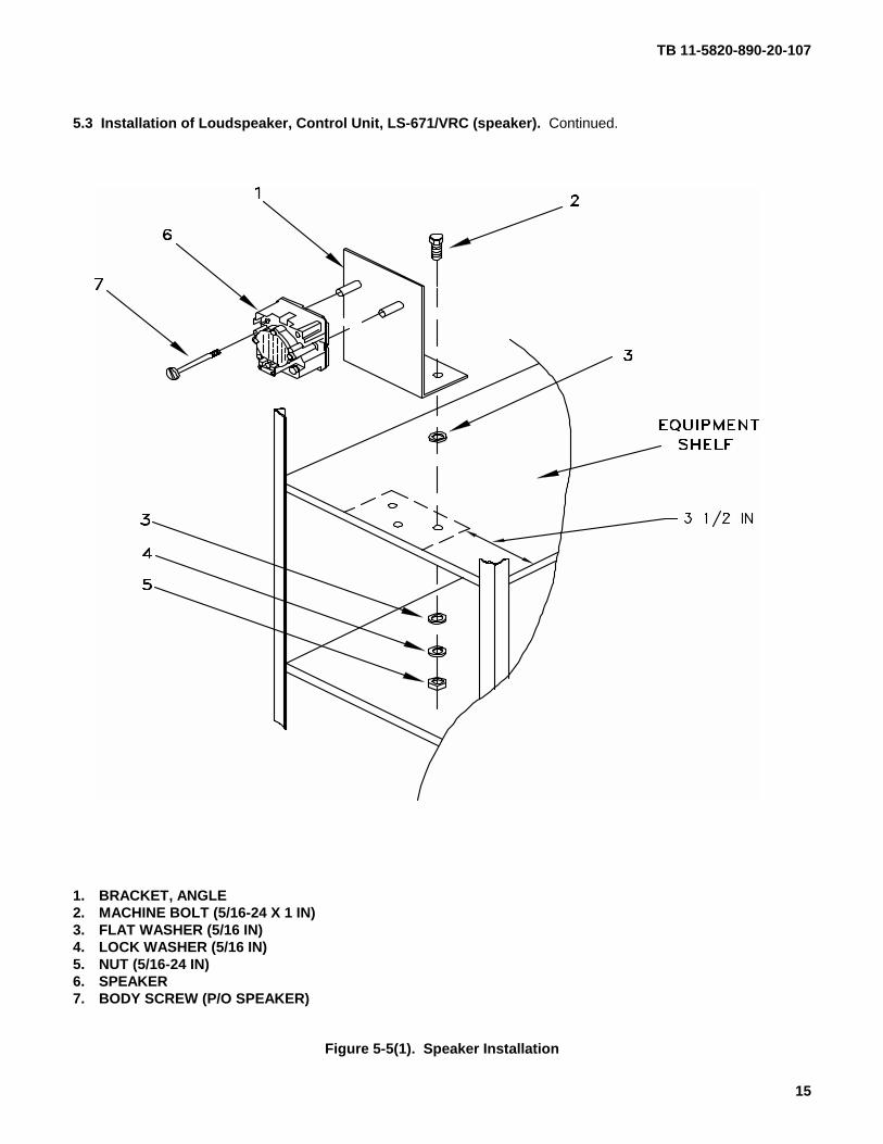
5.3 Installation of Loudspeaker, Control Unit, LS-671/VRC (speaker). Use the following procedures to installspeaker.
ITEM ACTION REMARKS
a. Bracket, angle (1). Using dimensions shown and bracket, angle (1)as a template, drill three 11/32 in diameter holesin radio shelf. See Figure 5-5(1).
Tools: Electric drill and 11/32 indrill bit.
b. Three machine bolts (2),three flat washers (3),three lock washers (4)and three nuts (5).
Install and secure to bracket, angle (1) and radioshelf.
Tools: 1/2 in socket and 1/2 inopen/box wrench.
c. Speaker (6). Place on bracket, angle (1).
d. Two externally-relievedbody screws (7).
Thread through speaker (6) and secure tobracket, angle (1).
Tools: Flat blade screwdriver.
e. Handset. Connect and secure to speaker (6) connector J2.
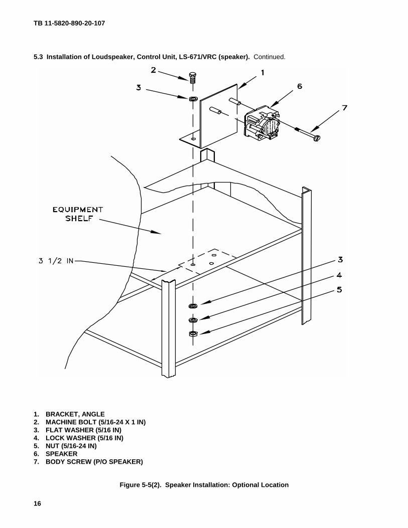
f. Steps a through e. Use to install speaker at optional location. SeeFigure 5-5(2).
TB 11-5820-890-20-107
15
5.3 Installation of Loudspeaker, Control Unit, LS-671/VRC (speaker). Continued.
1. BRACKET, ANGLE2. MACHINE BOLT (5/16-24 X 1 IN)3. FLAT WASHER (5/16 IN)4. LOCK WASHER (5/16 IN)5. NUT (5/16-24 IN)6. SPEAKER7. BODY SCREW (P/O SPEAKER)
Figure 5-5(1). Speaker Installation
TB 11-5820-890-20-107
16
5.3 Installation of Loudspeaker, Control Unit, LS-671/VRC (speaker). Continued.
1. BRACKET, ANGLE2. MACHINE BOLT (5/16-24 X 1 IN)3. FLAT WASHER (5/16 IN)4. LOCK WASHER (5/16 IN)5. NUT (5/16-24 IN)6. SPEAKER7. BODY SCREW (P/O SPEAKER)
Figure 5-5(2). Speaker Installation: Optional Location
TB 11-5820-890-20-107
17
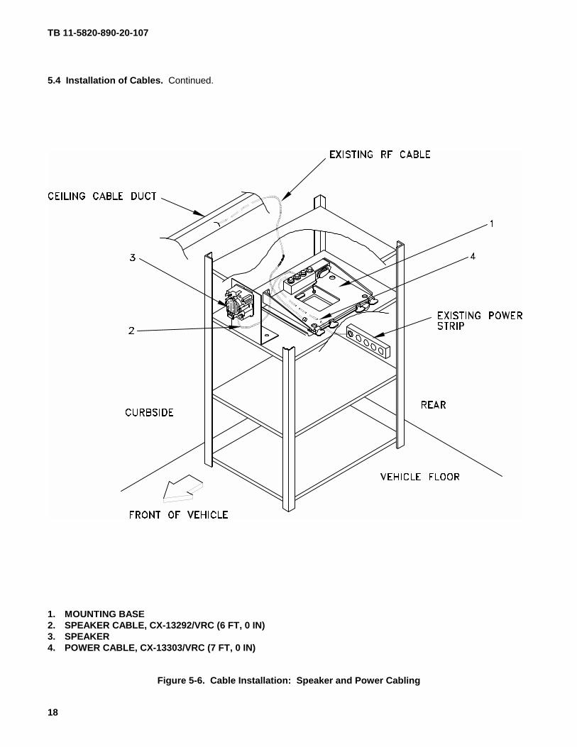
5.4. Installation of Cables. To accomplish the installation, leave loop clamps and tiedown straps loose enough toadjust cable slack and allow easy adjustment of equipment. When installation is complete, tighten and secure allclamps, clips and tiedown straps.
WARNING
Make sure shelter power source is positioned OFF or disconnected before installing cables.
ITEM ACTION REMARKS
a. Existing RF cable. Position on left side of mounting base (1).
b. Speaker cable (2)connector P1.
Connect and secure to speaker (3) connector J1. SeeFigure 5-6.
c. Speaker cable (2)connector P2.
Connect and secure to mounting base (1) connector J3.
d. Power cable (4)connector P1.
Connect and secure to power strip. See Figure 5-6.
e. Power cable (4)connector P2.
Route forward along curbside wall then upward alongvertical rail and connect and secure to mounting base(1) connector J1. See Figure 5-6.
TB 11-5820-890-20-107
18
5.4 Installation of Cables. Continued.
1. MOUNTING BASE2. SPEAKER CABLE, CX-13292/VRC (6 FT, 0 IN)3. SPEAKER4. POWER CABLE, CX-13303/VRC (7 FT, 0 IN)
Figure 5-6. Cable Installation: Speaker and Power Cabling
TB 11-5820-890-20-107
19
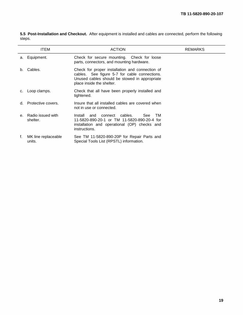
5.5 Post-Installation and Checkout. After equipment is installed and cables are connected, perform the followingsteps.
ITEM ACTION REMARKS
a. Equipment. Check for secure mounting. Check for looseparts, connectors, and mounting hardware.
b. Cables. Check for proper installation and connection ofcables. See figure 5-7 for cable connections.Unused cables should be stowed in appropriateplace inside the shelter.
c. Loop clamps. Check that all have been properly installed andtightened.
d. Protective covers. Insure that all installed cables are covered whennot in use or connected.
e. Radio issued withshelter.
Install and connect cables. See TM11-5820-890-20-1 or TM 11-5820-890-20-4 forinstallation and operational (OP) checks andinstructions.
f. MK line replaceableunits.
See TM 11-5820-890-20P for Repair Parts andSpecial Tools List (RPSTL) information.
TB 11-5820-890-20-107
20
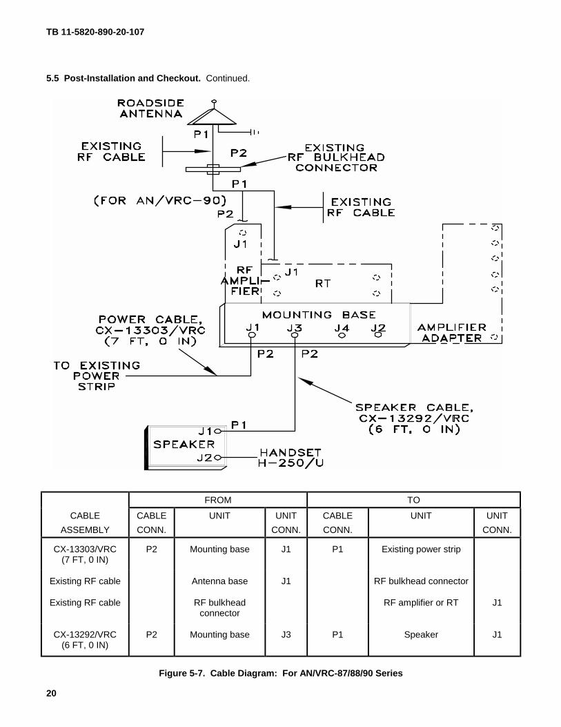
5.5 Post-Installation and Checkout. Continued.
FROM TO
CABLE
ASSEMBLY
CABLE
CONN.
UNIT UNIT
CONN.
CABLE
CONN.
UNIT UNIT
CONN.
CX-13303/VRC(7 FT, 0 IN)
P2 Mounting base J1 P1 Existing power strip
Existing RF cable Antenna base J1 RF bulkhead connector
Existing RF cable RF bulkheadconnector
RF amplifier or RT J1
CX-13292/VRC(6 FT, 0 IN)
P2 Mounting base J3 P1 Speaker J1
Figure 5-7. Cable Diagram: For AN/VRC-87/88/90 Series
TB 11-5820-890-20-107
A-1/(A-2 blank)
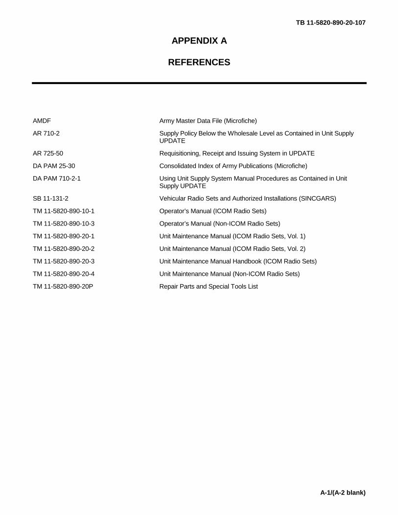
APPENDIX A
REFERENCES
AMDF Army Master Data File (Microfiche)
AR 710-2 Supply Policy Below the Wholesale Level as Contained in Unit SupplyUPDATE
AR 725-50 Requisitioning, Receipt and Issuing System in UPDATE
DA PAM 25-30 Consolidated Index of Army Publications (Microfiche)
DA PAM 710-2-1 Using Unit Supply System Manual Procedures as Contained in UnitSupply UPDATE
SB 11-131-2 Vehicular Radio Sets and Authorized Installations (SINCGARS)
TM 11-5820-890-10-1 Operator’s Manual (ICOM Radio Sets)
TM 11-5820-890-10-3 Operator’s Manual (Non-ICOM Radio Sets)
TM 11-5820-890-20-1 Unit Maintenance Manual (ICOM Radio Sets, Vol. 1)
TM 11-5820-890-20-2 Unit Maintenance Manual (ICOM Radio Sets, Vol. 2)
TM 11-5820-890-20-3 Unit Maintenance Manual Handbook (ICOM Radio Sets)
TM 11-5820-890-20-4 Unit Maintenance Manual (Non-ICOM Radio Sets)
TM 11-5820-890-20P Repair Parts and Special Tools List
– 1 –
By Order of the Secretary of the Army:
ERIC K. SHINSEKI General, United States Army Official: Chief of Staff
9916743
DISTRIBUTION:
To be distributed in accordance with the initial distribution number (IDN) 361008 requirements forTB 11–5820–890–20–107.
RECOMMENDED CHANGES TO EQUIPMENT TECHNICAL PUBLICATIONS
PREVIOUS EDITIONSARE OBSOLETE
P.S. - IF YOUR OUTFIT WANTS TO KNOW ABOUT YOURRECOMMENDATION MAKE A CARBON COPY OF THISAND GIVE IT TO YOUR HEADQUARTERS.
DA 2028�2FORM1 JUL 79
TE
AR
AL
ON
G D
OT
TE
D L
INE
BE EXACT PIN�POINT WHERE IT IS
SOMETHING WRONG
PUBLICATION NUMBER PUBLICATION DATE PUBLICATION TITLE
IN THIS SPACE TELL WHAT IS WRONG AND WHAT SHOULD BE DONE ABOUT IT:
DATE SENT
FROM: (PRINT YOUR UNIT'S COMPLETE ADDRESS)
WITH THIS PUBLICATION
THEN ... JOT DOWN THE INFO
ABOUT IT ON THIS FORM.
CAREFULLY TEAR IT OUT.
FOLD IT AND DROP IT IN THE
MAIL.
PRINTED NAME, GRADE OR TITLE AND TELEPHONE NUMBER SIGN HERE
PAGENO
PARA�GRAPH
FIGURENO
TABLENO
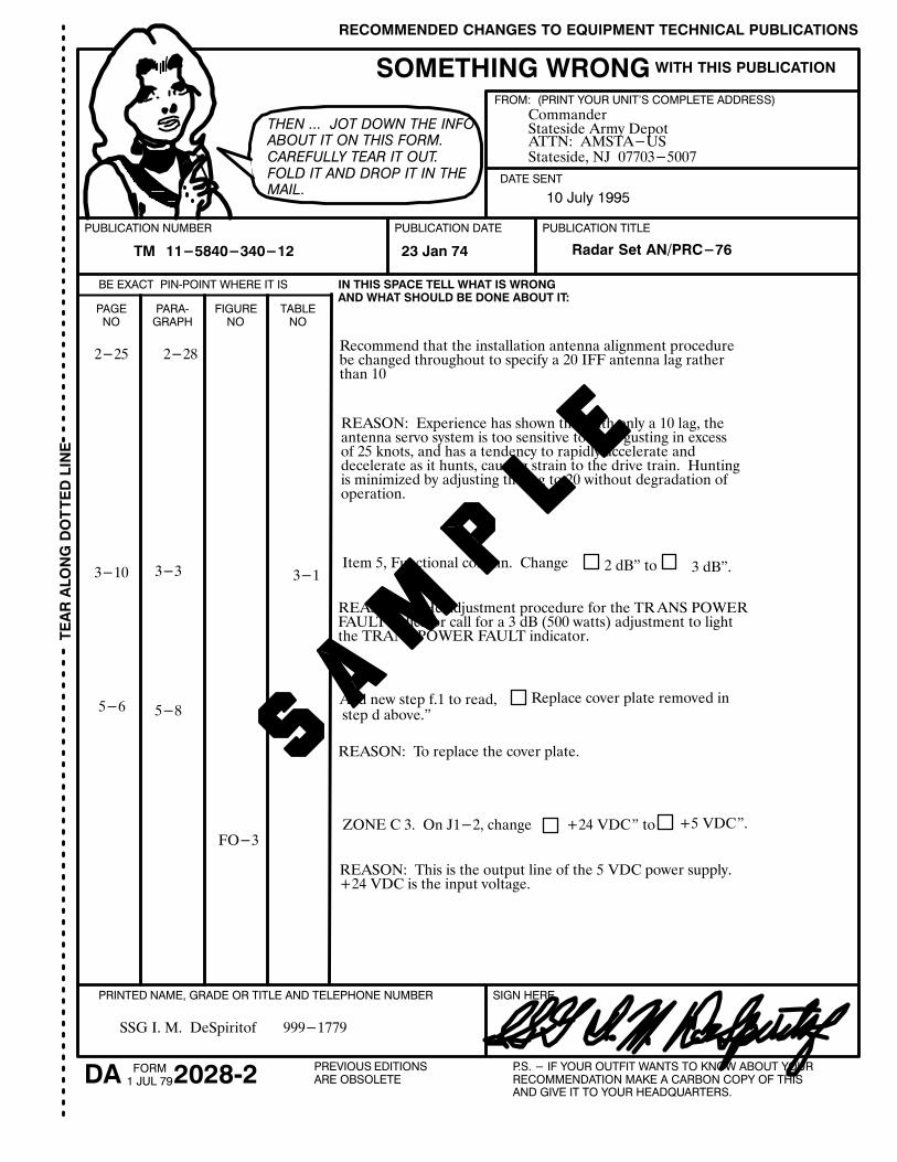
TM 11-5840-340-12 Radar Set AN/PRC-7623 Jan 74
2-25 2-28Recommend that the installation antenna alignment procedurebe changed throughout to specify a 20 IFF antenna lag ratherthan 10
REASON: Experience has shown that with only a 10 lag, theantenna servo system is too sensitive to wind gusting in excessof 25 knots, and has a tendency to rapidly accelerate and decelerate as it hunts, causing strain to the drive train. Huntingis minimized by adjusting the lag to 20 without degradation ofoperation.
3-10 3-3 3-1Item 5, Functional column. Change 2 dB" to 3 dB".
REASON: THe adjustment procedure for the TRANS POWERFAULT indicator call for a 3 dB (500 watts) adjustment to lightthe TRANS POWER FAULT indicator.
5-6 5-8Add new step f.1 to read, Replace cover plate removed in step d above."
REASON: To replace the cover plate.
FO-3ZONE C 3. On J1-2, change +24 VDC" to +5 VDC".
REASON: This is the output line of the 5 VDC power supply.+24 VDC is the input voltage.
SSG I. M. DeSpiritof 999-1779
CommanderStateside Army DepotATTN: AMSTA-USStateside, NJ 07703-5007
10 July 1995
RECOMMENDED CHANGES TO EQUIPMENT TECHNICAL PUBLICATIONS
PREVIOUS EDITIONSARE OBSOLETE
P.S. - IF YOUR OUTFIT WANTS TO KNOW ABOUT YOURRECOMMENDATION MAKE A CARBON COPY OF THISAND GIVE IT TO YOUR HEADQUARTERS.
DA 2028�2FORM1 JUL 79
TE
AR
AL
ON
G D
OT
TE
D L
INE
BE EXACT PIN�POINT WHERE IT IS
SOMETHING WRONG
PUBLICATION NUMBER PUBLICATION DATE PUBLICATION TITLE
IN THIS SPACE TELL WHAT IS WRONG AND WHAT SHOULD BE DONE ABOUT IT:
DATE SENT
WITH THIS PUBLICATION
THEN ... JOT DOWN THE INFO
ABOUT IT ON THIS FORM.
CAREFULLY TEAR IT OUT.
FOLD IT AND DROP IT IN THE
MAIL.
PRINTED NAME, GRADE OR TITLE AND TELEPHONE NUMBER SIGN HERE
PAGENO
PARA�GRAPH
FIGURENO
TABLENO
TE
AR
AL
ON
G D
OT
TE
D L
INE
REVERSE OF DA FORM 2028-2
FOLD BACK
OFFICIAL BUSINESS
DEPARTMENT OF THE ARMY
FILL IN YOUR UNIT'S ADDRESS
Commander
U.S. Army Communications�Electronics Command
and Fort Monmouth
ATTN: AMSEL�LC�LEO�D-CS-CFO
Fort Monmouth, New Jersey 07703�5000
PLEASEAFFIX
STAMPPOSTAGEREQUIRED
FOLD BACK

PIN: 077363–000

This fine document...
Was brought to you by me:
Liberated Manuals -- free army and government manuals
Why do I do it? I am tired of sleazy CD-ROM sellers, who take publicly available information, slap “watermarks” and other junk on it, and sell it. Those masters of search engine manipulation make sure that their sites that sell free information, come up first in search engines. They did not create it... They did not even scan it... Why should they get your money? Why are not letting you give those free manuals to your friends?
I am setting this document FREE. This document was made by the US Government and is NOT protected by Copyright. Feel free to share, republish, sell and so on.
I am not asking you for donations, fees or handouts. If you can, please provide a link to liberatedmanuals.com, so that free manuals come up first in search engines:
<A HREF=http://www.liberatedmanuals.com/>Free Military and Government Manuals</A>
– SincerelyIgor Chudovhttp://igor.chudov.com/
– Chicago Machinery Movers