Embed Size (px)
Citation preview

TECHNICAL BULLETIN
TB-354 March 2017 (Expires 3/2019)
Select Beam Design Tables The following information is intended to assist building designers and/or building officials in selecting appropriate Trus Joist® beam products. The tables have been drafted to be similar to the span tables found in Part 9 of the National Building Code of Canada (NBC) 2015 and the Ontario Building Code (OBC) 2012. It is the responsibility of the building designer and/or building official to confirm the conditions of the beam to be within the limitations of these tables.
The tables included in this technical bulletin provide maximum load solutions for select 1.55E TimberStrand® LSL and 2.0E Microllam® LVL. The member widths considered are 1 ¾″, 3 ½″, 5 ¼″, and 7″. The member depths considered are 9 ½″ and 11 ⅞″. The tables encompass four different design loads. For each design load, three different load configurations are considered. The first load configuration involves only a uniformly distributed load. The second and third load configurations involve a standardized uniformly distributed load combined with a single concentrated load that is located within a specific region along the beam span.
It is important to note that the values in these tables apply to only simple span beams. For continuous spans, cantilevers, and other applications, use Forte® software by Weyerhaeuser. For additional design information, including multi-ply connections, please reference Specifier′s Guide for Trus Joist® Beams, Headers, and Columns (Canada-East: TJ-9500 \ Canada-West: TJ-9505). Should the building designer and/or building official have any questions, please contact your local Weyerhaeuser representative.
List of Tables
Design Load: 40 psf (Live) \ 10 psf (Dead)
• Maximum Supported Length for Uniformly Loaded Beams . . . . . . . . . . . . Page 3
• Maximum Concentrated Load (Design Load Area) for Beams – End-Span to Quarter-Span . . . . . . Page 4
• Maximum Concentrated Load (Design Load Area) for Beams – Quarter-Span to Mid-Span . . . . . . Page 5
Design Load: 40 psf (Live) \ 15 psf (Dead)
• Maximum Supported Length for Uniformly Loaded Beams . . . . . . . . . . . . Page 6
• Maximum Concentrated Load (Design Load Area) for Beams – End-Span to Quarter-Span . . . . . . Page 7
• Maximum Concentrated Load (Design Load Area) for Beams – Quarter-Span to Mid-Span . . . . . . Page 8
Design Load: 40 psf (Live) \ 22 psf (Dead)
• Maximum Supported Length for Uniformly Loaded Beams . . . . . . . . . . . . Page 9
• Maximum Concentrated Load (Design Load Area) for Beams – End-Span to Quarter-Span . . . . . . Page 10
• Maximum Concentrated Load (Design Load Area) for Beams – Quarter-Span to Mid-Span . . . . . . Page 11
Design Load: 40 psf (Live) \ 30 psf (Dead)
• Maximum Supported Length for Uniformly Loaded Beams . . . . . . . . . . . . Page 12
• Maximum Concentrated Load (Design Load Area) for Beams – End-Span to Quarter-Span . . . . . . Page 13
• Maximum Concentrated Load (Design Load Area) for Beams – Quarter-Span to Mid-Span . . . . . . Page 14
Design Example
A design example is provided on page 16. The design example considers two (2) beams with unique loading conditions. It is intended to help interpret the tables and encourage ease of use for building designers and/or building officials.
Page 1 of 18
1.888.453.8358 ● www.wy.com/woodproducts

TECHNICAL BULLETIN
TB-354 March 2017 (Expires 3/2019) How to Read These Tables
The content within a cell varies depending on the load configuration. The figures below illustrate the type of information contained within a cell for each general load configuration.
UNIFORMLY LOADED BEAMS
CONCENTRATED LOAD (DESIGN LOAD AREA) FOR BEAMS
Minimum Bearing Length Adjustment for SPF Plate
The tabulated values for supported length, concentrated load, and/or design load area assume the beam is bearing on either an SPF column (No. 2 or better) or 2x4 SPF plate (3.50″ maximum plate width). If the actual value for supported length, concentrated load, and/or design load area is less than the tabulated value, the minimum bearing length for SPF plate may be reduced. For the supported length tables, the reduced minimum bearing length (𝐿𝐿𝑏𝑏′ ) is a product of the load ratio and tabulated minimum bearing length. For the concentrated load tables, the equation for reduced minimum bearing length is given in the table below. It is important to note that the minimum bearing length for all Trus Joist® beam products is 1.50″ regardless of the load conditions.
BEARING LENGTH ADJUSTMENT FORMULA – UNIFORMLY LOADED BEAMS
𝐿𝐿𝑏𝑏′ = (Load Ratio) × 𝐿𝐿𝑏𝑏,0
BEARING LENGTH ADJUSTMENT FORMULA – CONCENTRATED LOAD (DESIGN LOAD AREA) FOR BEAMS
Load Ratio
Reduced Minimum Bearing Length[1] (𝑳𝑳𝒃𝒃′ ) [in]
Beam Width
1 ¾″ 3 ½″ 5 ¼″ 7″
≤ 25% 0.25𝐿𝐿𝑏𝑏,0 + 0.09ℓ 1.50 1.50
50% 0.50𝐿𝐿𝑏𝑏,0 + 0.05ℓ 0.50𝐿𝐿𝑏𝑏,0 + 0.03ℓ 0.50𝐿𝐿𝑏𝑏,0 + 0.02ℓ
75% 0.75𝐿𝐿𝑏𝑏,0 + 0.03ℓ 0.75𝐿𝐿𝑏𝑏,0 + 0.02ℓ 0.75𝐿𝐿𝑏𝑏,0 + 0.01ℓ [1] Absolute minimum bearing length = 1.50″ Where:
Load Ratio = actual supported lengthtabulated supported length
OR actual concentrated loadtabulated concentrated load
OR actual design load areatabulated design load area
𝐿𝐿𝑏𝑏,0 = tabulated minimum bearing length for SPF plate [in] ℓ = tabulated clear span [ft]
Maximum Concentrated Load [lb] Design Load Area [ft2] Minimum Bearing Length (Column or Hanger / SPF Plate) [in]
Maximum Supported Length
Minimum Bearing Length (Column or Hanger / SPF Plate) [in]
Page 2 of 18
1.888.453.8358 ● www.wy.com/woodproducts

Page 3 of 18
1.888.453.8358 ● www.wy.com/woodproducts
TECHNICAL BULLETIN
TB-354 March 2017 (Expires 3/2019)
ℓ [ft]
Total Factored Load = (1.25 × 𝐷𝐷𝐿𝐿 + 1.5 × 𝐿𝐿𝐿𝐿) = 1.25(10) + 1.5(40) = 72.5 psf
𝑤𝑤𝑇𝑇 = 72.5 psf × (Maximum Supported Length [ft])
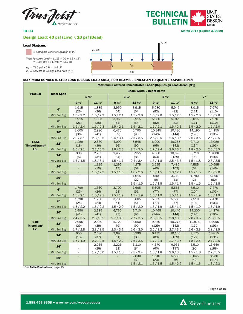
Design Load: 40 psf (Live) \ 10 psf (Dead)
Load Diagram:
MAXIMUM SUPPORTED LENGTH FOR UNIFORMLY LOADED BEAMS[1][2][3]
Product Clear Span
Maximum Supported Length[4][5]
Beam Width \ Beam Depth
1 ¾″ 3 ½″ 5 ¼″ 7″
9 ½″ 11 ⅞″ 9 ½″ 11 ⅞″ 9 ½″ 11 ⅞″ 9 ½″ 11 ⅞″
1.55E TimberStrand®
LSL
6′ 13′-8″ 13′-8″ 27′-4″ 27′-4″ 41′-0″ 40′-11″ 54′-8″ 54′-7″
Min. End Brg. 1.5 / 2.8 1.5 / 2.8 1.5 / 2.8 1.5 / 2.8 1.5 / 2.8 1.5 / 2.8 1.5 / 2.8 1.5 / 2.8
8′ 10′-3″ 10′-3″ 20′-7″ 20′-6″ 30′-10″ 30′-9″ 41′-2″ 41′-1″
Min. End Brg. 1.5 / 2.8 1.5 / 2.8 1.5 / 2.8 1.5 / 2.8 1.5 / 2.8 1.5 / 2.8 1.5 / 2.8 1.5 / 2.8
10′ 6′-1″ 10′-0″ 12′-3″ 20′-1″ 18′-4″ 30′-1″ 24′-5″ 40′-1″
Min. End Brg. 1.5 / 2.1 1.8 / 3.5 1.5 / 2.1 1.9 / 3.5 1.5 / 2.1 1.8 / 3.5 1.5 / 2.1 1.8 / 3.5
12′ 3′-8″ 6′-11″ 7′-4″ 13′-10″ 11′-0″ 20′-10″ 14′-8″ 27′-9″
Min. End Brg. 1.5 / 1.5 1.5 / 2.9 1.5 / 1.5 1.5 / 2.9 1.5 / 1.5 1.5 / 2.9 1.5 / 1.5 1.5 / 2.9
14′ 2′-4″ 4′-6″ 4′-9″ 9′-0″ 7′-1″ 13′-6″ 9′-6″ 18′-1″
Min. End Brg. 1.5 / 1.5 1.5 / 2.2 1.5 / 1.5 1.5 / 2.2 1.5 / 1.5 1.5 / 2.2 1.5 / 1.5 1.5 / 2.2
16′ - 3′-1″ 3′-3″ 6′-2″ 4′-10″ 9′-3″ 6′-5″ 12′-4″
Min. End Brg. - 1.5 / 1.7 1.5 / 1.5 1.5 / 1.7 1.5 / 1.5 1.5 / 1.7 1.5 / 1.5 1.5 / 1.7
20′ - - - 3′-3″ 2′-6″ 4′-11″ 3′-5″ 6′-6″
Min. End Brg. - - - 1.5 / 1.5 1.5 / 1.5 1.5 / 1.5 1.5 / 1.5 1.5 / 1.5
2.0E Microllam®
LVL
6′ 12′-10″ 12′-10″ 25′-8″ 25′-7″ 38′-6″ 38′-5″ 51′-4″ 51′-3″
Min. End Brg. 1.5 / 2.7 1.5 / 2.7 1.5 / 2.7 1.5 / 2.7 1.5 / 2.7 1.5 / 2.7 1.5 / 2.7 1.5 / 2.7
8′ 9′-8″ 9′-8″ 19′-4″ 19′-3″ 28′-11″ 28′-11″ 38′-7″ 38′-6″
Min. End Brg. 1.5 / 2.7 1.5 / 2.7 1.5 / 2.7 1.5 / 2.7 1.5 / 2.7 1.5 / 2.7 1.5 / 2.7 1.5 / 2.7
10′ 7′-11″ 10′-0″ 15′-9″ 20′-1″ 23′-8″ 30′-1″ 31′-6″ 40′-2″
Min. End Brg. 1.6 / 2.8 2.0 / 3.5 1.5 / 2.7 2.0 / 3.5 1.6 / 2.8 2.0 / 3.5 1.5 / 2.7 2.0 / 3.5
12′ 4′-9″ 8′-5″ 9′-6″ 16′-9″ 14′-2″ 25′-2″ 18′-11″ 33′-6″
Min. End Brg. 1.5 / 2.0 2.0 / 3.5 1.5 / 2.0 2.0 / 3.5 1.5 / 2.0 2.0 / 3.5 1.5 / 2.0 2.0 / 3.5
14′ 3′-1″ 5′-10″ 6′-1″ 11′-8″ 9′-2″ 17′-6″ 12′-3″ 23′-3″
Min. End Brg. 1.5 / 1.5 1.6 / 2.9 1.5 / 1.5 1.6 / 2.9 1.5 / 1.5 1.6 / 2.9 1.5 / 1.5 1.6 / 2.8
16′ 2′-1″ 4′-0″ 4′-2″ 8′-0″ 6′-3″ 12′-0″ 8′-4″ 15′-11″
Min. End Brg. 1.5 / 1.5 1.5 / 2.2 1.5 / 1.5 1.5 / 2.2 1.5 / 1.5 1.5 / 2.2 1.5 / 1.5 1.5 / 2.2
20′ - 2′-1″ 2′-2″ 4′-2″ 3′-3″ 6′-4″ 4′-4″ 8′-5″
Min. End Brg. - 1.5 / 1.5 1.5 / 1.5 1.5 / 1.5 1.5 / 1.5 1.5 / 1.5 1.5 / 1.5 1.5 / 1.5 *See Table Footnotes on page 15.
𝑤𝑤𝑇𝑇 [plf]
ℓ4� ℓ
2� ℓ4�
Page 4 of 18
1.888.453.8358 ● www.wy.com/woodproducts
TECHNICAL BULLETIN
TB-354 March 2017 (Expires 3/2019)
ℓ [ft]
𝑃𝑃𝑇𝑇 [lb]
= Allowable Zone for Location of 𝑃𝑃𝑇𝑇
Total Factored Load = (1.25 × 𝐷𝐷𝐿𝐿 + 1.5 × 𝐿𝐿𝐿𝐿) = 1.25(10) + 1.5(40) = 72.5 psf
𝑤𝑤𝑇𝑇 = 72.5 psf × 2 ft = 145 plf 𝑃𝑃𝑇𝑇 = 72.5 psf × (Design Load Area [ft2])
Design Load: 40 psf (Live) \ 10 psf (Dead)
Load Diagram:
MAXIMUM CONCENTRATED LOAD (DESIGN LOAD AREA) FOR BEAMS – END-SPAN TO QUARTER-SPAN[1][2][3][4]
Product Clear Span
Maximum Factored Concentrated Load[5] [lb] (Design Load Area[6] [ft2])
Beam Width \ Beam Depth
1 ¾″ 3 ½″ 5 ¼″ 7″
9 ½″ 11 ⅞″ 9 ½″ 11 ⅞″ 9 ½″ 11 ⅞″ 9 ½″ 11 ⅞″
1.55E TimberStrand®
LSL
6′ 1,915 1,885 3,950 3,915 5,980 5,945 8,015 7,970 (26) (26) (54) (54) (82) (82) (111) (110)
Min. End Brg. 1.5 / 2.2 1.5 / 2.2 1.5 / 2.1 1.5 / 2.0 1.5 / 2.0 1.5 / 2.0 1.5 / 2.0 1.5 / 2.0
8′ 1,915 1,885 3,950 3,915 5,980 5,945 8,015 7,970 (26) (26) (54) (54) (82) (82) (111) (110)
Min. End Brg. 1.5 / 2.4 1.5 / 2.3 1.5 / 2.1 1.5 / 2.1 1.5 / 2.1 1.5 / 2.1 1.5 / 2.0 1.5 / 2.0
10′ 2,605 2,980 6,475 6,705 10,345 10,430 14,190 14,155 (36) (41) (89) (93) (143) (144) (196) (195)
Min. End Brg. 2.0 / 3.1 2.3 / 3.5 2.4 / 3.4 2.5 / 3.5 2.6 / 3.5 2.6 / 3.5 2.6 / 3.5 2.6 / 3.5
12′ 1,280 2,830 4,090 6,545 6,900 10,265 9,710 13,980 (18) (39) (56) (90) (95) (142) (134) (193)
Min. End Brg. 1.5 / 2.1 2.2 / 3.5 1.6 / 2.3 2.5 / 3.5 1.7 / 2.4 2.6 / 3.5 1.8 / 2.5 2.6 / 3.5
14′ 330 2,235 2,455 6,255 4,580 10,095 6,710 13,800 (5) (31) (34) (86) (63) (139) (93) (190)
Min. End Brg. 1.5 / 1.5 1.8 / 3.1 1.5 / 1.7 2.4 / 3.4 1.5 / 1.8 2.5 / 3.5 1.5 / 1.8 2.6 / 3.5
16′ - 1,115 1,265 4,275 2,925 7,435 4,585 10,595 - (15) (17) (59) (40) (103) (63) (146)
Min. End Brg. - 1.5 / 2.2 1.5 / 1.5 1.6 / 2.6 1.5 / 1.5 1.9 / 2.7 1.5 / 1.5 2.0 / 2.8
20′ - - - 1,615 690 3,710 1,780 5,800 - - - (22) (9) (51) (25) (80)
Min. End Brg. - - - 1.5 / 1.5 1.5 / 1.5 1.5 / 1.7 1.5 / 1.5 1.5 / 1.8
2.0E Microllam®
LVL
6′ 1,790 1,760 3,700 3,665 5,605 5,565 7,510 7,470 (25) (24) (51) (51) (77) (77) (104) (103)
Min. End Brg. 1.5 / 2.1 1.5 / 2.1 1.5 / 1.9 1.5 / 1.9 1.5 / 1.9 1.5 / 1.9 1.5 / 1.9 1.5 / 1.9
8′ 1,790 1,760 3,700 3,665 5,605 5,565 7,510 7,470 (25) (24) (51) (51) (77) (77) (104) (103)
Min. End Brg. 1.5 / 2.2 1.5 / 2.2 1.5 / 2.0 1.5 / 2.0 1.5 / 1.9 1.5 / 1.9 1.5 / 1.9 1.5 / 1.9
10′ 2,990 2,985 6,730 6,710 10,465 10,440 14,200 14,170 (41) (41) (93) (93) (144) (144) (196) (195)
Min. End Brg. 2.4 / 3.5 2.5 / 3.5 2.7 / 3.5 2.7 / 3.5 2.8 / 3.5 2.8 / 3.5 2.8 / 3.5 2.8 / 3.5
12′ 2,095 2,830 5,720 6,550 9,350 10,275 12,975 13,995 (29) (39) (79) (90) (129) (142) (179) (193)
Min. End Brg. 1.7 / 2.8 2.3 / 3.5 2.3 / 3.1 2.6 / 3.5 2.5 / 3.2 2.7 / 3.5 2.6 / 3.3 2.8 / 3.5
14′ 950 2,680 3,690 6,390 6,435 10,105 9,175 13,815 (13) (37) (51) (88) (89) (139) (127) (191)
Min. End Brg. 1.5 / 1.9 2.2 / 3.5 1.5 / 2.2 2.6 / 3.5 1.7 / 2.4 2.7 / 3.5 1.8 / 2.4 2.7 / 3.5
16′ - 2,035 2,225 6,110 4,370 9,935 6,510 13,640 - (28) (31) (84) (60) (137) (90) (188)
Min. End Brg. - 1.7 / 3.0 1.5 / 1.6 2.5 / 3.4 1.5 / 1.8 2.6 / 3.5 1.5 / 1.8 2.7 / 3.5
20′ - - - 2,830 1,640 5,530 3,045 8,230 - - - (39) (23) (76) (42) (114)
Min. End Brg. - - - 1.5 / 2.1 1.5 / 1.5 1.5 / 2.2 1.5 / 1.5 1.6 / 2.3 *See Table Footnotes on page 15.
𝑤𝑤𝑇𝑇 [plf]
ℓ4� ℓ
2� ℓ4�

Page 5 of 18
1.888.453.8358 ● www.wy.com/woodproducts
TECHNICAL BULLETIN
TB-354 March 2017 (Expires 3/2019)
ℓ [ft]
= Allowable Zone for Location of 𝑃𝑃𝑇𝑇
Total Factored Load = (1.25 × 𝐷𝐷𝐿𝐿 + 1.5 × 𝐿𝐿𝐿𝐿) = 1.25(10) + 1.5(40) = 72.5 psf
𝑤𝑤𝑇𝑇 = 72.5 psf × 2 ft = 145 plf 𝑃𝑃𝑇𝑇 = 72.5 psf × (Design Load Area [ft2])
𝑃𝑃𝑇𝑇 [𝑙𝑙𝑙𝑙]
Design Load: 40 psf (Live) \ 10 psf (Dead)
Load Diagram:
MAXIMUM CONCENTRATED LOAD (DESIGN LOAD AREA) FOR BEAMS – QUARTER-SPAN TO MID-SPAN[1][2][3][4]
Product Clear Span
Maximum Factored Concentrated Load[5] [lb] (Design Load Area[6] [ft2])
Beam Width \ Beam Depth
1 ¾″ 3 ½″ 5 ¼″ 7″
9 ½″ 11 ⅞″ 9 ½″ 11 ⅞″ 9 ½″ 11 ⅞″ 9 ½″ 11 ⅞″
1.55E TimberStrand®
LSL
6′ 3,480 3,470 7,555 7,540 11,630 11,610 15,705 15,680 (48) (48) (104) (104) (160) (160) (217) (216)
Min. End Brg. 1.5 / 2.8 1.5 / 2.8 1.5 / 2.8 1.5 / 2.8 1.5 / 2.8 1.5 / 2.8 1.5 / 2.8 1.5 / 2.8
8′ 3,270 3,260 7,330 7,310 11,390 11,365 15,450 15,415 (45) (45) (101) (101) (157) (157) (213) (213)
Min. End Brg. 1.5 / 2.8 1.5 / 2.8 1.5 / 2.8 1.5 / 2.8 1.5 / 2.8 1.5 / 2.8 1.5 / 2.8 1.5 / 2.8
10′ 1,870 4,010 4,645 9,015 7,425 14,025 10,200 19,030 (26) (55) (64) (124) (102) (193) (141) (262)
Min. End Brg. 1.5 / 2.0 1.8 / 3.5 1.5 / 2.0 1.8 / 3.5 1.5 / 2.0 1.8 / 3.5 1.5 / 2.0 1.8 / 3.5
12′ 915 2,675 2,920 6,440 4,925 10,200 6,930 13,960 (13) (37) (40) (89) (68) (141) (96) (193)
Min. End Brg. 1.5 / 1.5 1.5 / 2.7 1.5 / 1.5 1.5 / 2.7 1.5 / 1.5 1.5 / 2.7 1.5 / 1.5 1.5 / 2.7
14′ - 1,595 1,745 4,455 3,260 7,320 4,770 10,185 - (22) (24) (61) (45) (101) (66) (140)
Min. End Brg. - 1.5 / 2.1 1.5 / 1.5 1.5 / 2.1 1.5 / 1.5 1.5 / 2.1 1.5 / 1.5 1.5 / 2.1
16′ - 795 895 3,040 2,075 5,285 3,250 7,530 - (11) (12) (42) (29) (73) (45) (104)
Min. End Brg. - 1.5 / 1.7 1.5 / 1.5 1.5 / 1.7 1.5 / 1.5 1.5 / 1.6 1.5 / 1.5 1.5 / 1.6
20′ - - - 1,145 485 2,625 1,260 4,105 - - - (16) (7) (36) (17) (57)
Min. End Brg. - - - 1.5 / 1.5 1.5 / 1.5 1.5 / 1.5 1.5 / 1.5 1.5 / 1.5
2.0E Microllam®
LVL
6′ 3,225 3,220 7,050 7,040 10,875 10,855 14,695 14,670 (45) (44) (97) (97) (150) (150) (203) (202)
Min. End Brg. 1.5 / 2.7 1.5 / 2.7 1.5 / 2.7 1.5 / 2.7 1.5 / 2.7 1.5 / 2.7 1.5 / 2.7 1.5 / 2.7
8′ 3,020 3,010 6,830 6,810 10,635 10,610 14,445 14,410 (42) (42) (94) (94) (147) (146) (199) (199)
Min. End Brg. 1.5 / 2.7 1.5 / 2.7 1.5 / 2.7 1.5 / 2.7 1.5 / 2.7 1.5 / 2.7 1.5 / 2.7 1.5 / 2.7
10′ 2,675 4,010 6,260 9,025 9,840 14,035 13,425 19,045 (37) (55) (86) (124) (136) (194) (185) (263)
Min. End Brg. 1.5 / 2.6 2.0 / 3.5 1.5 / 2.5 2.0 / 3.5 1.5 / 2.5 2.0 / 3.5 1.5 / 2.5 2.0 / 3.5
12′ 1,495 3,770 4,085 8,625 6,675 13,475 9,265 18,315 (21) (52) (56) (119) (92) (186) (128) (253)
Min. End Brg. 1.5 / 1.9 2.0 / 3.5 1.5 / 1.9 1.9 / 3.4 1.5 / 1.8 1.9 / 3.4 1.5 / 1.8 1.9 / 3.4
14′ 675 2,425 2,625 6,120 4,575 9,815 6,525 13,510 (9) (33) (36) (84) (63) (135) (90) (186)
Min. End Brg. 1.5 / 1.5 1.5 / 2.7 1.5 / 1.5 1.5 / 2.7 1.5 / 1.5 1.5 / 2.6 1.5 / 1.5 1.5 / 2.6
16′ - 1,445 1,580 4,340 3,100 7,240 4,620 10,140 - (20) (22) (60) (43) (100) (64) (140)
Min. End Brg. - 1.5 / 2.2 1.5 / 1.5 1.5 / 2.1 1.5 / 1.5 1.5 / 2.1 1.5 / 1.5 1.5 / 2.1
20′ - - - 2,005 1,160 3,915 2,150 5,825 - - - (28) (16) (54) (30) (80)
Min. End Brg. - - - 1.5 / 1.5 1.5 / 1.5 1.5 / 1.5 1.5 / 1.5 1.5 / 1.5 *See Table Footnotes on page 15.
𝑤𝑤𝑇𝑇 [plf]
ℓ4� ℓ
2� ℓ4�

Page 6 of 18
1.888.453.8358 ● www.wy.com/woodproducts
TECHNICAL BULLETIN
TB-354 March 2017 (Expires 3/2019)
ℓ [ft]
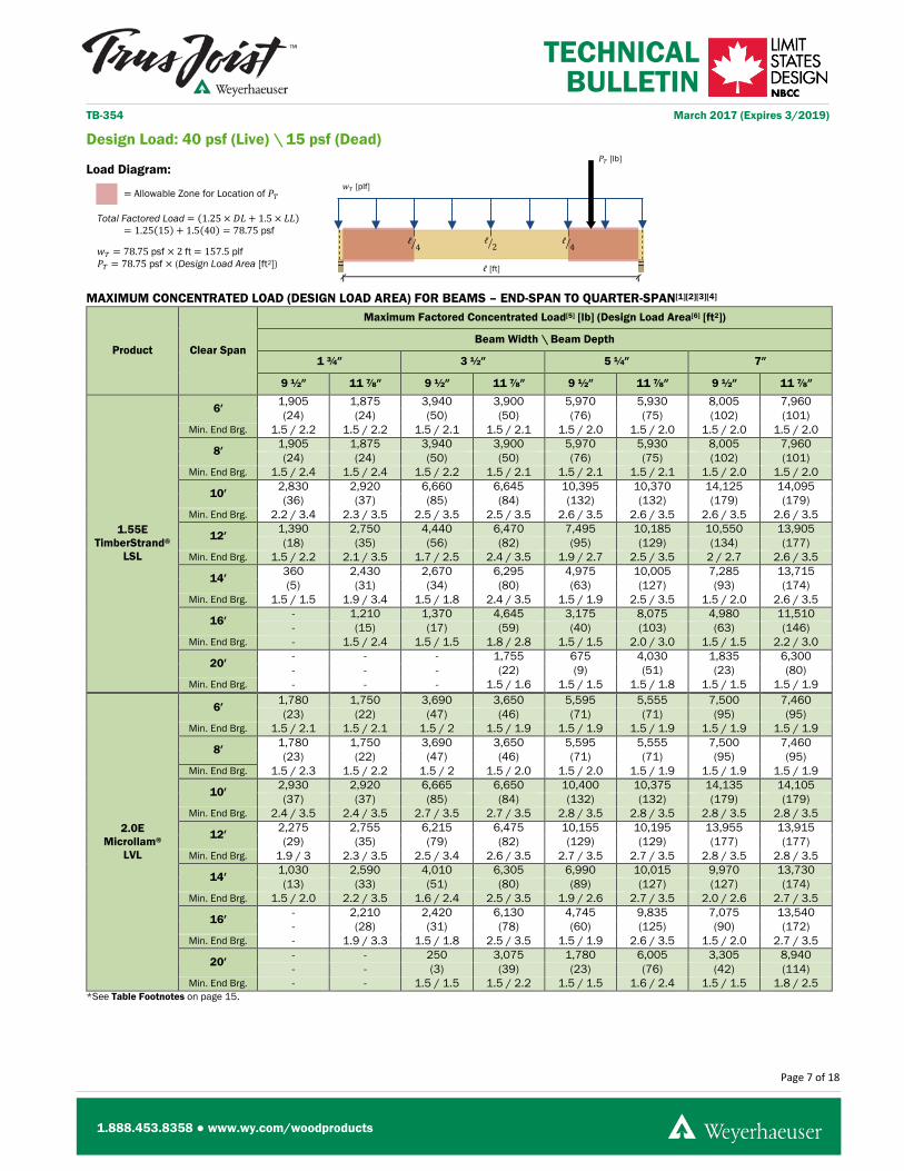
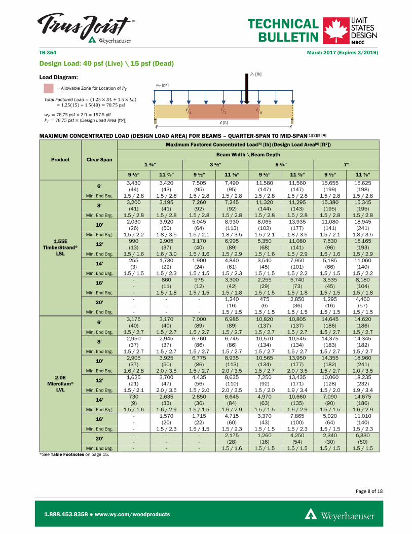
Total Factored Load = (1.25 × 𝐷𝐷𝐿𝐿 + 1.5 × 𝐿𝐿𝐿𝐿) = 1.25(15) + 1.5(40) = 78.75 psf
𝑤𝑤𝑇𝑇 = 78.75 psf × (Maximum Supported Length [ft])
Design Load: 40 psf (Live) \ 15 psf (Dead)
Load Diagram:
MAXIMUM SUPPORTED LENGTH FOR UNIFORMLY LOADED BEAMS[1][2][3]
Product Clear Span
Maximum Supported Length[4][5]
Beam Width \ Beam Depth
1 ¾″ 3 ½″ 5 ¼″ 7″
9 ½″ 11 ⅞″ 9 ½″ 11 ⅞″ 9 ½″ 11 ⅞″ 9 ½″ 11 ⅞″
1.55E TimberStrand®
LSL
6′ 12′-7″ 12′-7″ 25′-2″ 25′-2″ 37′-9″ 37′-8″ 50′-4″ 50′-3″
Min. End Brg. 1.5 / 2.8 1.5 / 2.8 1.5 / 2.8 1.5 / 2.8 1.5 / 2.8 1.5 / 2.8 1.5 / 2.8 1.5 / 2.8
8′ 9′-6″ 9′-5″ 18′-11″ 18′-11″ 28′-5″ 28′-4″ 37′-10″ 37′-9″
Min. End Brg. 1.5 / 2.8 1.5 / 2.8 1.5 / 2.8 1.5 / 2.8 1.5 / 2.8 1.5 / 2.8 1.5 / 2.8 1.5 / 2.8
10′ 6′-1″ 9′-3″ 12′-3″ 18′-6″ 18′-4″ 27′-8″ 24′-5″ 36′-11″
Min. End Brg. 1.5 / 2.3 1.9 / 3.5 1.5 / 2.3 1.9 / 3.5 1.5 / 2.3 1.8 / 3.5 1.5 / 2.3 1.8 / 3.5
12′ 3′-8″ 6′-11″ 7′-4″ 13′-10″ 11′-0″ 20′-10″ 14′-8″ 27′-9″
Min. End Brg. 1.5 / 1.7 1.7 / 3.1 1.5 / 1.7 1.7 / 3.1 1.5 / 1.7 1.7 / 3.2 1.5 / 1.7 1.7 / 3.2
14′ 2′-4″ 4′-6″ 4′-9″ 9′-0″ 7′-1″ 13′-6″ 9′-6″ 18′-1″
Min. End Brg. 1.5 / 1.5 1.5 / 2.4 1.5 / 1.5 1.5 / 2.4 1.5 / 1.5 1.5 / 2.4 1.5 / 1.5 1.5 / 2.4
16′ - 3′-1″ 3′-3″ 6′-2″ 4′-10″ 9′-3″ 6′-5″ 12′-4″
Min. End Brg. - 1.5 / 1.9 1.5 / 1.5 1.5 / 1.9 1.5 / 1.5 1.5 / 1.9 1.5 / 1.5 1.5 / 1.9
20′ - - - 3′-3″ 2′-6″ 4′-11″ 3′-4″ 6′-6″
Min. End Brg. - - - 1.5 / 1.5 1.5 / 1.5 1.5 / 1.5 1.5 / 1.5 1.5 / 1.5
2.0E Microllam®
LVL
6′ 11′-10″ 11′-9″ 23′-7″ 23′-7″ 35′-5″ 35′-4″ 47′-3″ 47′-2″
Min. End Brg. 1.5 / 2.7 1.5 / 2.7 1.5 / 2.7 1.5 / 2.7 1.5 / 2.7 1.5 / 2.7 1.5 / 2.7 1.5 / 2.7
8′ 8′-11″ 8′-10″ 17′-9″ 17′-9″ 26′-8″ 26′-7″ 35′-6″ 35′-5″
Min. End Brg. 1.5 / 2.7 1.5 / 2.7 1.5 / 2.7 1.5 / 2.7 1.5 / 2.7 1.5 / 2.7 1.5 / 2.7 1.5 / 2.7
10′ 7′-11″ 9′-3″ 15′-9″ 18′-6″ 23′-8″ 27′-9″ 31′-6″ 36′-11″
Min. End Brg. 1.7 / 3 2.0 / 3.5 1.7 / 3.0 2.0 / 3.5 1.7 / 3.0 2.0 / 3.5 1.7 / 3.0 2.0 / 3.5
12′ 4′-9″ 7′-9″ 9′-6″ 15′-5″ 14′-2″ 23′-2″ 18′-11″ 30′-10″
Min. End Brg. 1.5 / 2.2 2.0 / 3.5 1.5 / 2.2 2.0 / 3.5 1.5 / 2.2 2.0 / 3.5 1.5 / 2.2 2.0 / 3.5
14′ 3′-1″ 5′-10″ 6′-1″ 11′-8″ 9′-2″ 17′-6″ 12′-3″ 23′-3″
Min. End Brg. 1.5 / 1.6 1.7 / 3.1 1.5 / 1.6 1.7 / 3.1 1.5 / 1.6 1.7 / 3.1 1.5 / 1.6 1.7 / 3.1
16′ 2′-1″ 4′-0″ 4′-2″ 8′-0″ 6′-3″ 12′-0″ 8′-4″ 15′-11″
Min. End Brg. 1.5 / 1.5 1.5 / 2.4 1.5 / 1.5 1.5 / 2.4 1.5 / 1.5 1.5 / 2.4 1.5 / 1.5 1.5 / 2.4
20′ - 2′-1″ 2′-2″ 4′-2″ 3′-3″ 6′-4″ 4′-4″ 8′-5″
Min. End Brg. - 1.5 / 1.6 1.5 / 1.5 1.5 / 1.6 1.5 / 1.5 1.5 / 1.6 1.5 / 1.5 1.5 / 1.6 *See Table Footnotes on page 15.
𝑤𝑤𝑇𝑇 [plf]
ℓ4� ℓ
2� ℓ4�
Page 7 of 18
1.888.453.8358 ● www.wy.com/woodproducts
TECHNICAL BULLETIN
TB-354 March 2017 (Expires 3/2019)
ℓ [ft]
𝑃𝑃𝑇𝑇 [lb]
= Allowable Zone for Location of 𝑃𝑃𝑇𝑇
Total Factored Load = (1.25 × 𝐷𝐷𝐿𝐿 + 1.5 × 𝐿𝐿𝐿𝐿) = 1.25(15) + 1.5(40) = 78.75 psf
𝑤𝑤𝑇𝑇 = 78.75 psf × 2 ft = 157.5 plf 𝑃𝑃𝑇𝑇 = 78.75 psf × (Design Load Area [ft2])
Design Load: 40 psf (Live) \ 15 psf (Dead)
Load Diagram:
MAXIMUM CONCENTRATED LOAD (DESIGN LOAD AREA) FOR BEAMS – END-SPAN TO QUARTER-SPAN[1][2][3][4]
Product Clear Span
Maximum Factored Concentrated Load[5] [lb] (Design Load Area[6] [ft2])
Beam Width \ Beam Depth
1 ¾″ 3 ½″ 5 ¼″ 7″
9 ½″ 11 ⅞″ 9 ½″ 11 ⅞″ 9 ½″ 11 ⅞″ 9 ½″ 11 ⅞″
1.55E TimberStrand®
LSL
6′ 1,905 1,875 3,940 3,900 5,970 5,930 8,005 7,960 (24) (24) (50) (50) (76) (75) (102) (101)
Min. End Brg. 1.5 / 2.2 1.5 / 2.2 1.5 / 2.1 1.5 / 2.1 1.5 / 2.0 1.5 / 2.0 1.5 / 2.0 1.5 / 2.0
8′ 1,905 1,875 3,940 3,900 5,970 5,930 8,005 7,960 (24) (24) (50) (50) (76) (75) (102) (101)
Min. End Brg. 1.5 / 2.4 1.5 / 2.4 1.5 / 2.2 1.5 / 2.1 1.5 / 2.1 1.5 / 2.1 1.5 / 2.0 1.5 / 2.0
10′ 2,830 2,920 6,660 6,645 10,395 10,370 14,125 14,095 (36) (37) (85) (84) (132) (132) (179) (179)
Min. End Brg. 2.2 / 3.4 2.3 / 3.5 2.5 / 3.5 2.5 / 3.5 2.6 / 3.5 2.6 / 3.5 2.6 / 3.5 2.6 / 3.5
12′ 1,390 2,750 4,440 6,470 7,495 10,185 10,550 13,905 (18) (35) (56) (82) (95) (129) (134) (177)
Min. End Brg. 1.5 / 2.2 2.1 / 3.5 1.7 / 2.5 2.4 / 3.5 1.9 / 2.7 2.5 / 3.5 2 / 2.7 2.6 / 3.5
14′ 360 2,430 2,670 6,295 4,975 10,005 7,285 13,715 (5) (31) (34) (80) (63) (127) (93) (174)
Min. End Brg. 1.5 / 1.5 1.9 / 3.4 1.5 / 1.8 2.4 / 3.5 1.5 / 1.9 2.5 / 3.5 1.5 / 2.0 2.6 / 3.5
16′ - 1,210 1,370 4,645 3,175 8,075 4,980 11,510 - (15) (17) (59) (40) (103) (63) (146)
Min. End Brg. - 1.5 / 2.4 1.5 / 1.5 1.8 / 2.8 1.5 / 1.5 2.0 / 3.0 1.5 / 1.5 2.2 / 3.0
20′ - - - 1,755 675 4,030 1,835 6,300 - - - (22) (9) (51) (23) (80)
Min. End Brg. - - - 1.5 / 1.6 1.5 / 1.5 1.5 / 1.8 1.5 / 1.5 1.5 / 1.9
2.0E Microllam®
LVL
6′ 1,780 1,750 3,690 3,650 5,595 5,555 7,500 7,460 (23) (22) (47) (46) (71) (71) (95) (95)
Min. End Brg. 1.5 / 2.1 1.5 / 2.1 1.5 / 2 1.5 / 1.9 1.5 / 1.9 1.5 / 1.9 1.5 / 1.9 1.5 / 1.9
8′ 1,780 1,750 3,690 3,650 5,595 5,555 7,500 7,460 (23) (22) (47) (46) (71) (71) (95) (95)
Min. End Brg. 1.5 / 2.3 1.5 / 2.2 1.5 / 2 1.5 / 2.0 1.5 / 2.0 1.5 / 1.9 1.5 / 1.9 1.5 / 1.9
10′ 2,930 2,920 6,665 6,650 10,400 10,375 14,135 14,105 (37) (37) (85) (84) (132) (132) (179) (179)
Min. End Brg. 2.4 / 3.5 2.4 / 3.5 2.7 / 3.5 2.7 / 3.5 2.8 / 3.5 2.8 / 3.5 2.8 / 3.5 2.8 / 3.5
12′ 2,275 2,755 6,215 6,475 10,155 10,195 13,955 13,915 (29) (35) (79) (82) (129) (129) (177) (177)
Min. End Brg. 1.9 / 3 2.3 / 3.5 2.5 / 3.4 2.6 / 3.5 2.7 / 3.5 2.7 / 3.5 2.8 / 3.5 2.8 / 3.5
14′ 1,030 2,590 4,010 6,305 6,990 10,015 9,970 13,730 (13) (33) (51) (80) (89) (127) (127) (174)
Min. End Brg. 1.5 / 2.0 2.2 / 3.5 1.6 / 2.4 2.5 / 3.5 1.9 / 2.6 2.7 / 3.5 2.0 / 2.6 2.7 / 3.5
16′ - 2,210 2,420 6,130 4,745 9,835 7,075 13,540 - (28) (31) (78) (60) (125) (90) (172)
Min. End Brg. - 1.9 / 3.3 1.5 / 1.8 2.5 / 3.5 1.5 / 1.9 2.6 / 3.5 1.5 / 2.0 2.7 / 3.5
20′ - - 250 3,075 1,780 6,005 3,305 8,940 - - (3) (39) (23) (76) (42) (114)
Min. End Brg. - - 1.5 / 1.5 1.5 / 2.2 1.5 / 1.5 1.6 / 2.4 1.5 / 1.5 1.8 / 2.5 *See Table Footnotes on page 15.
𝑤𝑤𝑇𝑇 [plf]
ℓ4� ℓ
2� ℓ4�
Page 8 of 18
1.888.453.8358 ● www.wy.com/woodproducts
TECHNICAL BULLETIN
TB-354 March 2017 (Expires 3/2019)
ℓ [ft]
= Allowable Zone for Location of 𝑃𝑃𝑇𝑇
Total Factored Load = (1.25 × 𝐷𝐷𝐿𝐿 + 1.5 × 𝐿𝐿𝐿𝐿) = 1.25(15) + 1.5(40) = 78.75 psf
𝑤𝑤𝑇𝑇 = 78.75 psf × 2 ft = 157.5 plf 𝑃𝑃𝑇𝑇 = 78.75 psf × (Design Load Area [ft2])
𝑃𝑃𝑇𝑇 [𝑙𝑙𝑙𝑙]
Design Load: 40 psf (Live) \ 15 psf (Dead)
Load Diagram:
MAXIMUM CONCENTRATED LOAD (DESIGN LOAD AREA) FOR BEAMS – QUARTER-SPAN TO MID-SPAN[1][2][3][4]
Product Clear Span
Maximum Factored Concentrated Load[5] [lb] (Design Load Area[6] [ft2])
Beam Width \ Beam Depth
1 ¾″ 3 ½″ 5 ¼″ 7″
9 ½″ 11 ⅞″ 9 ½″ 11 ⅞″ 9 ½″ 11 ⅞″ 9 ½″ 11 ⅞″
1.55E TimberStrand®
LSL
6′ 3,430 3,420 7,505 7,490 11,580 11,560 15,655 15,625 (44) (43) (95) (95) (147) (147) (199) (198)
Min. End Brg. 1.5 / 2.8 1.5 / 2.8 1.5 / 2.8 1.5 / 2.8 1.5 / 2.8 1.5 / 2.8 1.5 / 2.8 1.5 / 2.8
8′ 3,200 3,195 7,260 7,245 11,320 11,295 15,380 15,345 (41) (41) (92) (92) (144) (143) (195) (195)
Min. End Brg. 1.5 / 2.8 1.5 / 2.8 1.5 / 2.8 1.5 / 2.8 1.5 / 2.8 1.5 / 2.8 1.5 / 2.8 1.5 / 2.8
10′ 2,030 3,920 5,045 8,930 8,065 13,935 11,080 18,945 (26) (50) (64) (113) (102) (177) (141) (241)
Min. End Brg. 1.5 / 2.2 1.8 / 3.5 1.5 / 2.1 1.8 / 3.5 1.5 / 2.1 1.8 / 3.5 1.5 / 2.1 1.8 / 3.5
12′ 990 2,905 3,170 6,995 5,350 11,080 7,530 15,165 (13) (37) (40) (89) (68) (141) (96) (193)
Min. End Brg. 1.5 / 1.6 1.6 / 3.0 1.5 / 1.6 1.5 / 2.9 1.5 / 1.6 1.5 / 2.9 1.5 / 1.6 1.5 / 2.9
14′ 255 1,730 1,900 4,840 3,540 7,950 5,185 11,060 (3) (22) (24) (61) (45) (101) (66) (140)
Min. End Brg. 1.5 / 1.5 1.5 / 2.3 1.5 / 1.5 1.5 / 2.3 1.5 / 1.5 1.5 / 2.2 1.5 / 1.5 1.5 / 2.2
16′ - 860 975 3,300 2,255 5,740 3,535 8,180 - (11) (12) (42) (29) (73) (45) (104)
Min. End Brg. - 1.5 / 1.8 1.5 / 1.5 1.5 / 1.8 1.5 / 1.5 1.5 / 1.8 1.5 / 1.5 1.5 / 1.8
20′ - - - 1,240 475 2,850 1,295 4,460 - - - (16) (6) (36) (16) (57)
Min. End Brg. - - - 1.5 / 1.5 1.5 / 1.5 1.5 / 1.5 1.5 / 1.5 1.5 / 1.5
2.0E Microllam®
LVL
6′ 3,175 3,170 7,000 6,985 10,820 10,805 14,645 14,620 (40) (40) (89) (89) (137) (137) (186) (186)
Min. End Brg. 1.5 / 2.7 1.5 / 2.7 1.5 / 2.7 1.5 / 2.7 1.5 / 2.7 1.5 / 2.7 1.5 / 2.7 1.5 / 2.7
8′ 2,950 2,945 6,760 6,745 10,570 10,545 14,375 14,345 (37) (37) (86) (86) (134) (134) (183) (182)
Min. End Brg. 1.5 / 2.7 1.5 / 2.7 1.5 / 2.7 1.5 / 2.7 1.5 / 2.7 1.5 / 2.7 1.5 / 2.7 1.5 / 2.7
10′ 2,905 3,925 6,775 8,935 10,565 13,950 14,355 18,960 (37) (50) (86) (113) (134) (177) (182) (241)
Min. End Brg. 1.6 / 2.8 2.0 / 3.5 1.5 / 2.7 2.0 / 3.5 1.5 / 2.7 2.0 / 3.5 1.5 / 2.7 2.0 / 3.5
12′ 1,625 3,700 4,435 8,635 7,250 13,435 10,060 18,235 (21) (47) (56) (110) (92) (171) (128) (232)
Min. End Brg. 1.5 / 2.1 2.0 / 3.5 1.5 / 2.0 2.0 / 3.5 1.5 / 2.0 1.9 / 3.4 1.5 / 2.0 1.9 / 3.4
14′ 730 2,635 2,850 6,645 4,970 10,660 7,090 14,675 (9) (33) (36) (84) (63) (135) (90) (186)
Min. End Brg. 1.5 / 1.6 1.6 / 2.9 1.5 / 1.5 1.6 / 2.9 1.5 / 1.5 1.6 / 2.9 1.5 / 1.5 1.6 / 2.9
16′ - 1,570 1,715 4,715 3,370 7,865 5,020 11,010 - (20) (22) (60) (43) (100) (64) (140)
Min. End Brg. - 1.5 / 2.3 1.5 / 1.5 1.5 / 2.3 1.5 / 1.5 1.5 / 2.3 1.5 / 1.5 1.5 / 2.3
20′ - - - 2,175 1,260 4,250 2,340 6,330 - - - (28) (16) (54) (30) (80)
Min. End Brg. - - - 1.5 / 1.6 1.5 / 1.5 1.5 / 1.5 1.5 / 1.5 1.5 / 1.5 *See Table Footnotes on page 15.
𝑤𝑤𝑇𝑇 [plf]
ℓ4� ℓ
2� ℓ4�

Page 9 of 18
1.888.453.8358 ● www.wy.com/woodproducts
TECHNICAL BULLETIN
TB-354 March 2017 (Expires 3/2019)
ℓ [ft]
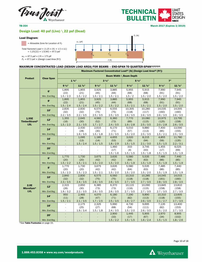
Total Factored Load = (1.25 × 𝐷𝐷𝐿𝐿 + 1.5 × 𝐿𝐿𝐿𝐿) = 1.25(22) + 1.5(40) = 87.5 psf
𝑤𝑤𝑇𝑇 = 87.5 psf × (Maximum Supported Length [ft])
Design Load: 40 psf (Live) \ 22 psf (Dead)
Load Diagram:
MAXIMUM SUPPORTED LENGTH FOR UNIFORMLY LOADED BEAMS[1][2][3]
Product Clear Span
Maximum Supported Length[4][5]
Beam Width \ Beam Depth
1 ¾″ 3 ½″ 5 ¼″ 7″
9 ½″ 11 ⅞″ 9 ½″ 11 ⅞″ 9 ½″ 11 ⅞″ 9 ½″ 11 ⅞″
1.55E TimberStrand®
LSL
6′ 11′-4″ 11′-4″ 22′-8″ 22′-7″ 34′-0″ 33′-11″ 45′-4″ 45′-3″
Min. End Brg. 1.5 / 2.8 1.5 / 2.8 1.5 / 2.8 1.5 / 2.8 1.5 / 2.8 1.5 / 2.8 1.5 / 2.8 1.5 / 2.8
8′ 8′-6″ 8′-6″ 17′-1″ 17′-0″ 25′-7″ 25′-6″ 34′-1″ 34′-0″
Min. End Brg. 1.5 / 2.8 1.5 / 2.8 1.5 / 2.8 1.5 / 2.8 1.5 / 2.8 1.5 / 2.8 1.5 / 2.8 1.5 / 2.8
10′ 5′-10″ 8′-4″ 11′-8″ 16′-7″ 17′-6″ 24′-11″ 23′-4″ 33′-3″
Min. End Brg. 1.5 / 2.5 1.9 / 3.5 1.5 / 2.5 1.8 / 3.5 1.5 / 2.5 1.8 / 3.5 1.5 / 2.5 1.9 / 3.5
12′ 3′-6″ 6′-7″ 6′-11″ 13′-2″ 10′-5″ 19′-10″ 13′-10″ 26′-5″
Min. End Brg. 1.5 / 1.8 1.8 / 3.3 1.5 / 1.8 1.8 / 3.3 1.5 / 1.8 1.8 / 3.3 1.5 / 1.8 1.8 / 3.3
14′ 2′-2″ 4′-3″ 4′-5″ 8′-6″ 6′-7″ 12′-9″ 8′-10″ 17′-1″
Min. End Brg. 1.5 / 1.5 1.5 / 2.5 1.5 / 1.5 1.5 / 2.5 1.5 / 1.5 1.5 / 2.5 1.5 / 1.5 1.5 / 2.5
16′ - 2′-11″ 2′-11″ 5′-9″ 4′-5″ 8′-8″ 5′-11″ 11′-7″
Min. End Brg. - 1.5 / 2.0 1.5 / 1.5 1.5 / 2.0 1.5 / 1.5 1.5 / 2.0 1.5 / 1.5 1.5 / 2.0
20′ - - - 2′-11″ 2′-2″ 4′-5″ 2′-11″ 5′-11″
Min. End Brg. - - - 1.5 / 1.5 1.5 / 1.5 1.5 / 1.5 1.5 / 1.5 1.5 / 1.5
2.0E Microllam®
LVL
6′ 10′-8″ 10′-7″ 21′-3″ 21′-3″ 31′-11″ 31′-10″ 42′-6″ 42′-5″
Min. End Brg. 1.5 / 2.7 1.5 / 2.7 1.5 / 2.7 1.5 / 2.7 1.5 / 2.7 1.5 / 2.7 1.5 / 2.7 1.5 / 2.7
8′ 8′-0″ 8′-0″ 16′-0″ 15′-11″ 24′-0″ 23′-11″ 32′-0″ 31′-11″
Min. End Brg. 1.5 / 2.7 1.5 / 2.7 1.5 / 2.7 1.5 / 2.7 1.5 / 2.7 1.5 / 2.7 1.5 / 2.7 1.5 / 2.7
10′ 7′-7″ 8′-4″ 15′-1″ 16′-8″ 22′-8″ 24′-11″ 30′-2″ 33′-3″
Min. End Brg. 1.8 / 3.2 2.0 / 3.5 1.8 / 3.2 2.0 / 3.5 1.8 / 3.2 2.0 / 3.5 1.8 / 3.2 2.0 / 3.5
12′ 4′-6″ 6′-11″ 9′-0″ 13′-11″ 13′-6″ 20′-10″ 18′-0″ 27′-9″
Min. End Brg. 1.5 / 2.3 2.0 / 3.5 1.5 / 2.3 2.0 / 3.5 1.5 / 2.3 2.0 / 3.5 1.5 / 2.3 2.0 / 3.5
14′ 2′-11″ 5′-6″ 5′-9″ 11′-1″ 8′-8″ 16′-7″ 11′-6″ 22′-2″
Min. End Brg. 1.5 / 1.7 1.8 / 3.2 1.5 / 1.7 1.8 / 3.3 1.5 / 1.7 1.8 / 3.3 1.5 / 1.7 1.8 / 3.3
16′ - 3′-9″ 3′-10″ 7′-6″ 5′-10″ 11′-3″ 7′-9″ 15′-1″
Min. End Brg. - 1.5 / 2.5 1.5 / 1.5 1.5 / 2.5 1.5 / 1.5 1.5 / 2.5 1.5 / 1.5 1.5 / 2.5
20′ - - - 3′-10″ 2′-11″ 5′-10″ 3′-11″ 7′-9″
Min. End Brg. - - - 1.5 / 1.6 1.5 / 1.5 1.5 / 1.7 1.5 / 1.5 1.5 / 1.7 *See Table Footnotes on page 15.
𝑤𝑤𝑇𝑇 [plf]
ℓ4� ℓ
2� ℓ4�
Page 10 of 18
1.888.453.8358 ● www.wy.com/woodproducts
TECHNICAL BULLETIN
TB-354 March 2017 (Expires 3/2019)
ℓ [ft]
𝑃𝑃𝑇𝑇 [lb]
= Allowable Zone for Location of 𝑃𝑃𝑇𝑇
Total Factored Load = (1.25 × 𝐷𝐷𝐿𝐿 + 1.5 × 𝐿𝐿𝐿𝐿) = 1.25(22) + 1.5(40) = 87.5 psf
𝑤𝑤𝑇𝑇 = 87.5 psf × 2 ft = 175 plf 𝑃𝑃𝑇𝑇 = 87.5 psf × (Design Load Area [ft2])
Design Load: 40 psf (Live) \ 22 psf (Dead)
Load Diagram:
MAXIMUM CONCENTRATED LOAD (DESIGN LOAD AREA) FOR BEAMS – END-SPAN TO QUARTER-SPAN[1][2][3][4]
Product Clear Span
Maximum Factored Concentrated Load[5] [lb] (Design Load Area[6] [ft2])
Beam Width \ Beam Depth
1 ¾″ 3 ½″ 5 ¼″ 7″
9 ½″ 11 ⅞″ 9 ½″ 11 ⅞″ 9 ½″ 11 ⅞″ 9 ½″ 11 ⅞″
1.55E TimberStrand®
LSL
6′ 1,895 1,855 3,925 3,885 5,955 5,915 7,990 7,945 (22) (21) (45) (44) (68) (68) (91) (91)
Min. End Brg. 1.5 / 2.3 1.5 / 2.2 1.5 / 2.1 1.5 / 2.1 1.5 / 2 1.5 / 2.0 1.5 / 2.0 1.5 / 2.0
8′ 1,895 1,855 3,925 3,885 5,955 5,915 7,990 7,945 (22) (21) (45) (44) (68) (68) (91) (91)
Min. End Brg. 1.5 / 2.4 1.5 / 2.4 1.5 / 2.2 1.5 / 2.2 1.5 / 2.1 1.5 / 2.1 1.5 / 2.0 1.5 / 2.0
10′ 2,835 2,830 6,570 6,555 10,305 10,280 14,035 14,005 (32) (32) (75) (75) (118) (117) (160) (160)
Min. End Brg. 2.2 / 3.5 2.2 / 3.5 2.5 / 3.5 2.5 / 3.5 2.6 / 3.5 2.6 / 3.5 2.6 / 3.5 2.6 / 3.5
12′ 1,355 2,645 4,560 6,360 7,770 10,080 10,975 13,795 (16) (30) (52) (73) (89) (115) (125) (158)
Min. End Brg. 1.5 / 2.3 2.1 / 3.5 1.7 / 2.7 2.4 / 3.5 1.9 / 2.8 2.5 / 3.5 2.0 / 2.8 2.6 / 3.5
14′ - 2,430 2,615 6,170 5,010 9,880 7,400 13,590 - (28) (30) (71) (57) (113) (85) (155)
Min. End Brg. - 1.9 / 3.5 1.5 / 1.8 2.3 / 3.5 1.5 / 2.0 2.5 / 3.5 1.5 / 2.1 2.5 / 3.5
16′ - 1,095 1,185 4,655 3,020 8,215 4,855 11,780 - (13) (14) (53) (35) (94) (56) (135)
Min. End Brg. - 1.5 / 2.4 1.5 / 1.5 1.8 / 2.9 1.5 / 1.5 2.1 / 3.0 1.5 / 1.5 2.2 / 3.1
20′ - - - 1,460 310 3,745 1,455 6,025 - - - (17) (4) (43) (17) (69)
Min. End Brg. - - - 1.5 / 1.6 1.5 / 1.5 1.5 / 1.8 1.5 / 1.5 1.5 / 1.9
2.0E Microllam®
LVL
6′ 1,770 1,730 3,675 3,635 5,580 5,535 7,485 7,440 (20) (20) (42) (42) (64) (63) (86) (85)
Min. End Brg. 1.5 / 2.2 1.5 / 2.1 1.5 / 2.0 1.5 / 2.0 1.5 / 1.9 1.5 / 1.9 1.5 / 1.9 1.5 / 1.9
8′ 1,770 1,730 3,675 3,635 5,580 5,535 7,485 7,440 (20) (20) (42) (42) (64) (63) (86) (85)
Min. End Brg. 1.5 / 2.3 1.5 / 2.3 1.5 / 2.1 1.5 / 2.0 1.5 / 2.0 1.5 / 2.0 1.5 / 1.9 1.5 / 1.9
10′ 2,840 2,830 6,575 6,560 10,310 10,285 14,045 14,015 (32) (32) (75) (75) (118) (118) (161) (160)
Min. End Brg. 2.3 / 3.5 2.4 / 3.5 2.6 / 3.5 2.6 / 3.5 2.7 / 3.5 2.7 / 3.5 2.8 / 3.5 2.8 / 3.5
12′ 2,315 2,650 6,385 6,370 10,115 10,090 13,845 13,810 (26) (30) (73) (73) (116) (115) (158) (158)
Min. End Brg. 1.9 / 3.2 2.2 / 3.5 2.6 / 3.5 2.6 / 3.5 2.7 / 3.5 2.7 / 3.5 2.7 / 3.5 2.7 / 3.5
14′ 950 2,465 4,070 6,180 7,190 9,890 10,310 13,605 (11) (28) (47) (71) (82) (113) (118) (155)
Min. End Brg. 1.5 / 2.1 2.1 / 3.5 1.7 / 2.5 2.5 / 3.5 1.9 / 2.7 2.6 / 3.5 2.1 / 2.7 2.7 / 3.5
16′ - 2,175 2,325 5,990 4,730 9,695 7,135 13,400 - (25) (27) (68) (54) (111) (82) (153)
Min. End Brg. - 1.9 / 3.4 1.5 / 1.8 2.4 / 3.5 1.5 / 2.0 2.6 / 3.5 1.5 / 2.0 2.7 / 3.5
20′ - - - 2,900 1,445 5,905 2,970 8,905 - - - (33) (17) (67) (34) (102)
Min. End Brg. - - - 1.5 / 2.2 1.5 / 1.5 1.6 / 2.4 1.5 / 1.5 1.8 / 2.6 *See Table Footnotes on page 15.
𝑤𝑤𝑇𝑇 [plf]
ℓ4� ℓ
2� ℓ4�

Page 11 of 18
1.888.453.8358 ● www.wy.com/woodproducts
TECHNICAL BULLETIN
TB-354 March 2017 (Expires 3/2019)
ℓ [ft]
= Allowable Zone for Location of 𝑃𝑃𝑇𝑇
Total Factored Load = (1.25 × 𝐷𝐷𝐿𝐿 + 1.5 × 𝐿𝐿𝐿𝐿) = 1.25(22) + 1.5(40) = 87.5 psf
𝑤𝑤𝑇𝑇 = 87.5 psf × 2 ft = 157.5 plf 𝑃𝑃𝑇𝑇 = 87.5 psf × (Design Load Area [ft2])
𝑃𝑃𝑇𝑇 [𝑙𝑙𝑙𝑙]
Design Load: 40 psf (Live) \ 22 psf (Dead)
Load Diagram:
MAXIMUM CONCENTRATED LOAD (DESIGN LOAD AREA) FOR BEAMS – QUARTER-SPAN TO MID-SPAN[1][2][3][4]
Product Clear Span
Maximum Factored Concentrated Load[5] [lb] (Design Load Area[6] [ft2])
Beam Width \ Beam Depth
1 ¾″ 3 ½″ 5 ¼″ 7″
9 ½″ 11 ⅞″ 9 ½″ 11 ⅞″ 9 ½″ 11 ⅞″ 9 ½″ 11 ⅞″
1.55E TimberStrand®
LSL
6′ 3,355 3,350 7,430 7,420 11,505 11,485 15,580 15,555 (38) (38) (85) (85) (131) (131) (178) (178)
Min. End Brg. 1.5 / 2.8 1.5 / 2.8 1.5 / 2.8 1.5 / 2.8 1.5 / 2.8 1.5 / 2.8 1.5 / 2.8 1.5 / 2.8
8′ 3,105 3,100 7,165 7,150 11,225 11,200 15,285 15,250 (36) (35) (82) (82) (128) (128) (175) (174)
Min. End Brg. 1.5 / 2.8 1.5 / 2.8 1.5 / 2.8 1.5 / 2.8 1.5 / 2.8 1.5 / 2.8 1.5 / 2.8 1.5 / 2.8
10′ 2,100 3,800 5,300 8,810 8,495 13,815 11,695 18,825 (24) (43) (61) (101) (97) (158) (134) (215)
Min. End Brg. 1.5 / 2.3 1.8 / 3.5 1.5 / 2.3 1.8 / 3.5 1.5 / 2.3 1.8 / 3.5 1.5 / 2.3 1.8 / 3.5
12′ 970 3,015 3,255 7,340 5,545 11,665 7,835 15,990 (11) (34) (37) (84) (63) (133) (90) (183)
Min. End Brg. 1.5 / 1.7 1.7 / 3.1 1.5 / 1.7 1.6 / 3.1 1.5 / 1.6 1.6 / 3.1 1.5 / 1.6 1.6 / 3.1
14′ - 1,730 1,860 4,995 3,565 8,260 5,265 11,525 - (20) (21) (57) (41) (94) (60) (132)
Min. End Brg. - 1.5 / 2.4 1.5 / 1.5 1.5 / 2.4 1.5 / 1.5 1.5 / 2.3 1.5 / 1.5 1.5 / 2.3
16′ - 775 840 3,310 2,145 5,840 3,445 8,370 - (9) (10) (38) (25) (67) (39) (96)
Min. End Brg. - 1.5 / 1.9 1.5 / 1.5 1.5 / 1.9 1.5 / 1.5 1.5 / 1.9 1.5 / 1.5 1.5 / 1.8
20′ - - - 1,035 - 2,650 1,030 4,265 - - - (12) - (30) (12) (49)
Min. End Brg. - - - 1.5 / 1.5 - 1.5 / 1.5 1.5 / 1.5 1.5 / 1.5
2.0E Microllam®
LVL
6′ 3,105 3,100 6,925 6,915 10,750 10,730 14,575 14,550 (35) (35) (79) (79) (123) (123) (167) (166)
Min. End Brg. 1.5 / 2.7 1.5 / 2.7 1.5 / 2.7 1.5 / 2.7 1.5 / 2.7 1.5 / 2.7 1.5 / 2.7 1.5 / 2.7
8′ 2,855 2,850 6,665 6,650 10,475 10,450 14,280 14,250 (33) (33) (76) (76) (120) (119) (163) (163)
Min. End Brg. 1.5 / 2.7 1.5 / 2.7 1.5 / 2.7 1.5 / 2.7 1.5 / 2.7 1.5 / 2.7 1.5 / 2.7 1.5 / 2.7
10′ 2,895 3,805 6,685 8,815 10,475 13,830 14,265 18,840 (33) (43) (76) (101) (120) (158) (163) (215)
Min. End Brg. 1.6 / 2.9 2.0 / 3.5 1.6 / 2.8 2.0 / 3.5 1.5 / 2.7 2.0 / 3.5 1.5 / 2.7 2.0 / 3.5
12′ 1,650 3,555 4,625 8,530 7,595 13,330 10,570 18,130 (19) (41) (53) (97) (87) (152) (121) (207)
Min. End Brg. 1.5 / 2.2 2.0 / 3.5 1.5 / 2.1 2.0 / 3.5 1.5 / 2.1 1.9 / 3.5 1.5 / 2.1 1.9 / 3.4
14′ 675 2,710 2,895 6,950 5,115 11,090 7,335 15,205 (8) (31) (33) (79) (58) (127) (84) (174)
Min. End Brg. 1.5 / 1.7 1.7 / 3.1 1.5 / 1.6 1.7 / 3.0 1.5 / 1.6 1.7 / 3.0 1.5 / 1.6 1.7 / 3.0
16′ - 1,545 1,650 4,845 3,355 8,145 5,065 11,440 - (18) (19) (55) (38) (93) (58) (131)
Min. End Brg. - 1.5 / 2.4 1.5 / 1.5 1.5 / 2.4 1.5 / 1.5 1.5 / 2.4 1.5 / 1.5 1.5 / 2.4
20′ - - - 2,055 1,025 4,180 2,100 6,305 - - - (23) (12) (48) (24) (72)
Min. End Brg. - - - 1.5 / 1.6 1.5 / 1.5 1.5 / 1.6 1.5 / 1.5 1.5 / 1.6 *See Table Footnotes on page 15.
𝑤𝑤𝑇𝑇 [plf]
ℓ4� ℓ
2� ℓ4�

Page 12 of 18
1.888.453.8358 ● www.wy.com/woodproducts
TECHNICAL BULLETIN
TB-354 March 2017 (Expires 3/2019)
ℓ [ft]
Total Factored Load = (1.25 × 𝐷𝐷𝐿𝐿 + 1.5 × 𝐿𝐿𝐿𝐿) = 1.25(30) + 1.5(40) = 97.5 psf
𝑤𝑤𝑇𝑇 = 97.5 psf × (Maximum Supported Length [ft])
Design Load: 40 psf (Live) \ 30 psf (Dead)
Load Diagram:
MAXIMUM SUPPORTED LENGTH FOR UNIFORMLY LOADED BEAMS[1][2][3]
Product Clear Span
Maximum Supported Length[4][5]
Beam Width \ Beam Depth
1 ¾″ 3 ½″ 5 ¼″ 7″
9 ½″ 11 ⅞″ 9 ½″ 11 ⅞″ 9 ½″ 11 ⅞″ 9 ½″ 11 ⅞″
1.55E TimberStrand®
LSL
6′ 10′-2″ 10′-2″ 20′-4″ 20′-4″ 30′-6″ 30′-5″ 40′-8″ 40′-7″
Min. End Brg. 1.5 / 2.8 1.5 / 2.8 1.5 / 2.8 1.5 / 2.8 1.5 / 2.8 1.5 / 2.8 1.5 / 2.8 1.5 / 2.8
8′ 7′-8″ 7′-8″ 15′-4″ 15′-3″ 22′-11″ 22′-11″ 30′-7″ 30′-6″
Min. End Brg. 1.5 / 2.8 1.5 / 2.9 1.5 / 2.8 1.5 / 2.8 1.5 / 2.8 1.5 / 2.8 1.5 / 2.8 1.5 / 2.8
10′ 5′-2″ 7′-5″ 10′-4″ 14′-11″ 15′-6″ 22′-4″ 20′-8″ 29′-10″
Min. End Brg. 1.5 / 2.4 1.8 / 3.5 1.5 / 2.4 1.8 / 3.5 1.5 / 2.4 1.8 / 3.5 1.5 / 2.4 1.8 / 3.5
12′ 3′-1″ 5′-10″ 6′-2″ 11′-8″ 9′-3″ 17′-7″ 12′-3″ 23′-5″
Min. End Brg. 1.5 / 1.7 1.7 / 3.3 1.5 / 1.7 1.7 / 3.3 1.5 / 1.7 1.7 / 3.3 1.5 / 1.7 1.7 / 3.3
14′ - 3′-9″ 3′-11″ 7′-7″ 5′-10″ 11′-4″ 7′-10″ 15′-1″
Min. End Brg. - 1.5 / 2.5 1.5 / 1.5 1.5 / 2.5 1.5 / 1.5 1.5 / 2.5 1.5 / 1.5 1.5 / 2.5
16′ - 2′-7″ 2′-7″ 5′-1″ 3′-11″ 7′-8″ 5′-3″ 10′-3″
Min. End Brg. - 1.5 / 2.0 1.5 / 1.5 1.5 / 1.9 1.5 / 1.5 1.5 / 1.9 1.5 / 1.5 1.5 / 1.9
20′ - - - 2′-7″ - 3′-11″ 2′-7″ 5′-3″
Min. End Brg. - - - 1.5 / 1.5 - 1.5 / 1.5 1.5 / 1.5 1.5 / 1.5
2.0E Microllam®
LVL
6′ 9′-6″ 9′-6″ 19′-1″ 19′-1″ 28′-7″ 28′-7″ 38′-2″ 38′-1″
Min. End Brg. 1.5 / 2.7 1.5 / 2.7 1.5 / 2.7 1.5 / 2.7 1.5 / 2.7 1.5 / 2.7 1.5 / 2.7 1.5 / 2.7
8′ 7′-2″ 7′-2″ 14′-4″ 14′-4″ 21′-6″ 21′-6″ 28′-8″ 28′-8″
Min. End Brg. 1.5 / 2.7 1.5 / 2.7 1.5 / 2.7 1.5 / 2.7 1.5 / 2.7 1.5 / 2.7 1.5 / 2.7 1.5 / 2.7
10′ 6′-8″ 7′-6″ 13′-4″ 14′-11″ 20′-1″ 22′-5″ 26′-9″ 29′-10″
Min. End Brg. 1.8 / 3.1 2.0 / 3.5 1.8 / 3.1 2.0 / 3.5 1.8 / 3.1 2.0 / 3.5 1.8 / 3.1 2.0 / 3.5
12′ 4′-0″ 6′-3″ 8′-0″ 12′-6″ 12′-0″ 18′-8″ 15′-11″ 24′-11″
Min. End Brg. 1.5 / 2.3 2.0 / 3.5 1.5 / 2.3 2.0 / 3.5 1.5 / 2.3 2.0 / 3.5 1.5 / 2.2 2.0 / 3.5
14′ 2′-7″ 4′-11″ 5′-1″ 9′-10″ 7′-8″ 14′-8″ 10′-2″ 19′-7″
Min. End Brg. 1.5 / 1.7 1.8 / 3.2 1.5 / 1.7 1.8 / 3.2 1.5 / 1.7 1.8 / 3.2 1.5 / 1.7 1.8 / 3.2
16′ - 3′-4″ 3′-5″ 6′-8″ 5′-2″ 10′-0″ 6′-10″ 13′-4″
Min. End Brg. - 1.5 / 2.5 1.5 / 1.5 1.5 / 2.5 1.5 / 1.5 1.5 / 2.5 1.5 / 1.5 1.5 / 2.5
20′ - - - 3′-5″ 2′-7″ 5′-2″ 3′-6″ 6′-10″
Min. End Brg. - - - 1.5 / 1.6 1.5 / 1.5 1.5 / 1.7 1.5 / 1.5 1.5 / 1.6 *See Table Footnotes on page 15.
𝑤𝑤𝑇𝑇 [plf]
ℓ4� ℓ
2� ℓ4�

Page 13 of 18
1.888.453.8358 ● www.wy.com/woodproducts
TECHNICAL BULLETIN
TB-354 March 2017 (Expires 3/2019)
ℓ [ft]
𝑃𝑃𝑇𝑇 [lb]
= Allowable Zone for Location of 𝑃𝑃𝑇𝑇
Total Factored Load = (1.25 × 𝐷𝐷𝐿𝐿 + 1.5 × 𝐿𝐿𝐿𝐿) = 1.25(30) + 1.5(40) = 97.5 psf
𝑤𝑤𝑇𝑇 = 97.5 psf × 2 ft = 195 plf 𝑃𝑃𝑇𝑇 = 97.5 psf × (Design Load Area [ft2])
Design Load: 40 psf (Live) \ 30 psf (Dead)
Load Diagram:
MAXIMUM CONCENTRATED LOAD (DESIGN LOAD AREA) FOR BEAMS – END-SPAN TO QUARTER-SPAN[1][2][3][4]
Product Clear Span
Maximum Factored Concentrated Load[5] [lb] (Design Load Area[6] [ft2])
Beam Width \ Beam Depth
1 ¾″ 3 ½″ 5 ¼″ 7″
9 ½″ 11 ⅞″ 9 ½″ 11 ⅞″ 9 ½″ 11 ⅞″ 9 ½″ 11 ⅞″
1.55E TimberStrand®
LSL
6′ 1,875 1,835 3,910 3,865 5,940 5,895 7,975 7,925 (19) (19) (40) (40) (61) (60) (82) (81)
Min. End Brg. 1.5 / 2.3 1.5 / 2.3 1.5 / 2.1 1.5 / 2.1 1.5 / 2.0 1.5 / 2.0 1.5 / 2.0 1.5 / 2.0
8′ 1,875 1,835 3,910 3,865 5,940 5,895 7,975 7,925 (19) (19) (40) (40) (61) (60) (82) (81)
Min. End Brg. 1.5 / 2.5 1.5 / 2.5 1.5 / 2.2 1.5 / 2.2 1.5 / 2.1 1.5 / 2.1 1.5 / 2.1 1.5 / 2.1
10′ 2,695 2,725 6,465 6,450 10,200 10,175 13,935 13,900 (28) (28) (66) (66) (105) (104) (143) (143)
Min. End Brg. 2.1 / 3.5 2.2 / 3.5 2.4 / 3.5 2.5 / 3.5 2.5 / 3.5 2.6 / 3.5 2.6 / 3.5 2.6 / 3.5
12′ 1,105 2,525 4,265 6,240 7,430 9,955 10,595 13,675 (11) (26) (44) (64) (76) (102) (109) (140)
Min. End Brg. 1.5 / 2.2 2.0 / 3.5 1.6 / 2.6 2.4 / 3.5 1.9 / 2.7 2.5 / 3.5 2.0 / 2.8 2.6 / 3.5
14′ - 2,125 2,305 6,030 4,670 9,735 7,030 13,445 - (22) (24) (62) (48) (100) (72) (138)
Min. End Brg. - 1.8 / 3.3 1.5 / 1.8 2.3 / 3.5 1.5 / 1.9 2.4 / 3.5 1.5 / 2.0 2.5 / 3.5
16′ - 765 855 4,280 2,665 7,795 4,480 11,310 - (8) (9) (44) (27) (80) (46) (116)
Min. End Brg. - 1.5 / 2.2 1.5 / 1.5 1.7 / 2.8 1.5 / 1.5 2.0 / 3.0 1.5 / 1.5 2.1 / 3.1
20′ - - - 1,050 - 3,300 1,040 5,550 - - - (11) - (34) (11) (57)
Min. End Brg. - - - 1.5 / 1.5 - 1.5 / 1.7 1.5 / 1.5 1.5 / 1.8
2.0E Microllam®
LVL
6′ 1,750 1,710 3,660 3,615 5,565 5,520 7,470 7,420 (18) (18) (38) (37) (57) (57) (77) (76)
Min. End Brg. 1.5 / 2.2 1.5 / 2.2 1.5 / 2.0 1.5 / 2.0 1.5 / 1.9 1.5 / 1.9 1.5 / 1.9 1.5 / 1.9
8′ 1,750 1,710 3,660 3,615 5,565 5,520 7,470 7,420 (18) (18) (38) (37) (57) (57) (77) (76)
Min. End Brg. 1.5 / 2.4 1.5 / 2.4 1.5 / 2.1 1.5 / 2.1 1.5 / 2.0 1.5 / 2.0 1.5 / 1.9 1.5 / 1.9
10′ 2,735 2,730 6,470 6,455 10,205 10,185 13,945 13,910 (28) (28) (66) (66) (105) (104) (143) (143)
Min. End Brg. 2.3 / 3.5 2.3 / 3.5 2.6 / 3.5 2.6 / 3.5 2.7 / 3.5 2.7 / 3.5 2.8 / 3.5 2.8 / 3.5
12′ 2,050 2,525 6,160 6,245 9,995 9,965 13,725 13,685 (21) (26) (63) (64) (103) (102) (141) (140)
Min. End Brg. 1.7 / 3.0 2.1 / 3.5 2.5 / 3.5 2.5 / 3.5 2.7 / 3.5 2.7 / 3.5 2.7 / 3.5 2.7 / 3.5
14′ 665 2,325 3,740 6,035 6,820 9,750 9,900 13,460 (7) (24) (38) (62) (70) (100) (102) (138)
Min. End Brg. 1.5 / 1.9 2.0 / 3.5 1.5 / 2.4 2.5 / 3.5 1.8 / 2.6 2.6 / 3.5 2.0 / 2.7 2.7 / 3.5
16′ - 1,830 1,980 5,825 4,355 9,530 6,730 13,235 - (19) (20) (60) (45) (98) (69) (136)
Min. End Brg. - 1.8 / 3.2 1.5 / 1.7 2.4 / 3.5 1.5 / 1.9 2.5 / 3.5 1.5 / 2.0 2.6 / 3.5
20′ - - - 2,470 1,030 5,430 2,530 8,395 - - - (25) (11) (56) (26) (86)
Min. End Brg. - - - 1.5 / 2.1 1.5 / 1.5 1.5 / 2.4 1.5 / 1.5 1.7 / 2.5 *See Table Footnotes on page 15.
𝑤𝑤𝑇𝑇 [plf]
ℓ4� ℓ
2� ℓ4�

Page 14 of 18
1.888.453.8358 ● www.wy.com/woodproducts
TECHNICAL BULLETIN
TB-354 March 2017 (Expires 3/2019)
ℓ [ft]
= Allowable Zone for Location of 𝑃𝑃𝑇𝑇
Total Factored Load = (1.25 × 𝐷𝐷𝐿𝐿 + 1.5 × 𝐿𝐿𝐿𝐿) = 1.25(30) + 1.5(40) = 97.5 psf
𝑤𝑤𝑇𝑇 = 97.5 psf × 2 ft = 157.5 plf 𝑃𝑃𝑇𝑇 = 97.5 psf × (Design Load Area [ft2])
𝑃𝑃𝑇𝑇 [𝑙𝑙𝑙𝑙]
Design Load: 40 psf (Live) \ 30 psf (Dead)
Load Diagram:
MAXIMUM CONCENTRATED LOAD (DESIGN LOAD AREA) FOR BEAMS – QUARTER-SPAN TO MID-SPAN[1][2][3][4]
Product Clear Span
Maximum Factored Concentrated Load[5] [lb] (Design Load Area[6] [ft2])
Beam Width \ Beam Depth
1 ¾″ 3 ½″ 5 ¼″ 7″
9 ½″ 11 ⅞″ 9 ½″ 11 ⅞″ 9 ½″ 11 ⅞″ 9 ½″ 11 ⅞″
1.55E TimberStrand®
LSL
6′ 3,275 3,265 7,350 7,335 11,425 11,405 15,500 15,470 (34) (34) (75) (75) (117) (117) (159) (159)
Min. End Brg. 1.5 / 2.8 1.5 / 2.8 1.5 / 2.8 1.5 / 2.8 1.5 / 2.8 1.5 / 2.8 1.5 / 2.8 1.5 / 2.8
8′ 3,000 2,990 7,060 7,040 11,115 11,090 15,175 15,140 (31) (31) (72) (72) (114) (114) (156) (155)
Min. End Brg. 1.5 / 2.8 1.5 / 2.8 1.5 / 2.8 1.5 / 2.8 1.5 / 2.8 1.5 / 2.8 1.5 / 2.8 1.5 / 2.8
10′ 1,935 3,665 5,090 8,670 8,245 13,680 11,400 18,685 (20) (38) (52) (89) (85) (140) (117) (192)
Min. End Brg. 1.5 / 2.3 1.8 / 3.5 1.5 / 2.3 1.8 / 3.5 1.5 / 2.2 1.8 / 3.5 1.5 / 2.2 1.8 / 3.5
12′ 790 2,810 3,045 7,080 5,305 11,345 7,565 15,615 (8) (29) (31) (73) (54) (116) (78) (160)
Min. End Brg. 1.5 / 1.7 1.6 / 3.1 1.5 / 1.6 1.6 / 3.1 1.5 / 1.6 1.6 / 3.0 1.5 / 1.6 1.6 / 3.0
14′ - 1,515 1,640 4,735 3,320 7,955 5,000 11,180 - (16) (17) (49) (34) (82) (51) (115)
Min. End Brg. - 1.5 / 2.4 1.5 / 1.5 1.5 / 2.3 1.5 / 1.5 1.5 / 2.3 1.5 / 1.5 1.5 / 2.3
16′ - 545 605 3,040 1,890 5,540 3,175 8,040 - (6) (6) (31) (19) (57) (33) (82)
Min. End Brg. - 1.5 / 1.9 1.5 / 1.5 1.5 / 1.9 1.5 / 1.5 1.5 / 1.8 1.5 / 1.5 1.5 / 1.8
20′ - - - 740 - 2,335 735 3,930 - - - (8) - (24) (8) (40)
Min. End Brg. - - - 1.5 / 1.5 - 1.5 / 1.5 1.5 / 1.5 1.5 / 1.5
2.0E Microllam®
LVL
6′ 3,020 3,015 6,845 6,830 10,670 10,650 14,490 14,465 (31) (31) (70) (70) (109) (109) (149) (148)
Min. End Brg. 1.5 / 2.7 1.5 / 2.7 1.5 / 2.7 1.5 / 2.7 1.5 / 2.7 1.5 / 2.7 1.5 / 2.7 1.5 / 2.7
8′ 2,745 2,740 6,555 6,540 10,365 10,340 14,175 14,140 (28) (28) (67) (67) (106) (106) (145) (145)
Min. End Brg. 1.5 / 2.7 1.5 / 2.7 1.5 / 2.7 1.5 / 2.7 1.5 / 2.7 1.5 / 2.7 1.5 / 2.7 1.5 / 2.7
10′ 2,790 3,670 6,580 8,680 10,370 13,690 14,160 18,700 (29) (38) (68) (89) (106) (140) (145) (192)
Min. End Brg. 1.6 / 2.9 2.0 / 3.5 1.6 / 2.8 2.0 / 3.5 1.5 / 2.7 2.0 / 3.5 1.5 / 2.7 2.0 / 3.5
12′ 1,465 3,390 4,395 8,385 7,330 13,205 10,265 18,005 (15) (35) (45) (86) (75) (135) (105) (185)
Min. End Brg. 1.5 / 2.2 2.0 / 3.5 1.5 / 2.1 2.0 / 3.5 1.5 / 2.1 1.9 / 3.5 1.5 / 2.1 1.9 / 3.4
14′ 470 2,475 2,660 6,660 4,850 10,845 7,040 15,030 (5) (25) (27) (68) (50) (111) (72) (154)
Min. End Brg. 1.5 / 1.7 1.7 / 3.1 1.5 / 1.6 1.7 / 3.0 1.5 / 1.6 1.7 / 3.0 1.5 / 1.6 1.7 / 3.0
16′ - 1,300 1,405 4,555 3,090 7,815 4,775 11,070 - (13) (14) (47) (32) (80) (49) (114)
Min. End Brg. - 1.5 / 2.4 1.5 / 1.5 1.5 / 2.4 1.5 / 1.5 1.5 / 2.4 1.5 / 1.5 1.5 / 2.3
20′ - - - 1,750 730 3,845 1,790 5,945 - - - (18) (7) (39) (18) (61)
Min. End Brg. - - - 1.5 / 1.6 1.5 / 1.5 1.5 / 1.6 1.5 / 1.5 1.5 / 1.6 *See Table Footnotes on page 15.
𝑤𝑤𝑇𝑇 [plf]
ℓ4� ℓ
2� ℓ4�

TECHNICAL BULLETIN
TB-354 March 2017 (Expires 3/2019)
Table Footnotes
MAXIMUM SUPPORTED LENGTH FOR UNIFORMLY LOADED BEAMS
[1] Table values apply only to simple span beams with full lateral support of the compression edge. - Deflection criteria = L/360 live load (LL); L/240 total load (TL). - Simple span means a total of two bearing points, located at the ends of the member (i.e. no cantilevers). Beams/joists that run continuously over three or more supports are not simple span.
[2] Column minimum bearing lengths assume column member is SPF No. 2 or better. Plate minimum bearing lengths assume plate member is SPF (fcp = 5.3 MPa = 768.7 psi).
[3] Refer to Specifier′s Guide TJ-9500 (Canada-East) \ TJ-9505 (Canada-West) for complete design and installation information. [4] Supported Length applies only where the floor supports residential areas as described in NBC 2015 Table 4.1.5.3 and OBC
2012 Table 4.1.5.3; or the loading does not exceed the values specified in the load diagram above the table. [5] Supported Length is half the sum of the joist spans on both sides of the beam; joists must be simple span.
MAXIMUM CONCENTRATED LOAD (DESIGN LOAD AREA) FOR BEAMS – END-SPAN TO QUARTER-SPAN
[1] Table values apply only to simple span beams with full lateral support of the compression edge. - Deflection criteria = L/360 live load (LL); L/240 total load (TL). - Simple span means a total of two bearing points, located at the ends of the member (i.e. no cantilevers). Beams/joists that run continuously over three or more supports are not simple span.
[2] Location (x) of concentrated load: inside face of support ≤ x ≤ quarter-point of clear span (i.e. shaded region in load diagram above table).
[3] Column minimum bearing lengths assume column member is SPF No. 2 or better. Plate minimum bearing lengths assume plate member is SPF (fcp = 5.3 MPa = 768.7 psi).
[4] Refer to Specifier′s Guide TJ-9500 (Canada-East) \ TJ-9505 (Canada-West) for complete design and installation information. [5] Beam also supports a maximum 24″ floor tributary load as described by the load diagram above the table. [6] Design Load Area is in reference to floors supporting residential areas as described in NBC 2015 Table 4.1.5.3 and OBC 2012
Table 4.1.5.3; or the loading does not exceed the values specified in the load diagram above the table.
MAXIMUM CONCENTRATED LOAD (DESIGN LOAD AREA) FOR BEAMS – QUARTER-SPAN TO MID-SPAN
[1] Table values apply only to simple span beams with full lateral support of the compression edge. - Deflection criteria = L/360 live load (LL); L/240 total load (TL). - Simple span means a total of two bearing points, located at the ends of the member (i.e. no cantilevers). Beams/joists that run continuously over three or more supports are not simple span.
[2] Location (x) of concentrated load: quarter-point of clear span ≤ x ≤ midpoint of clear span (i.e. shaded region in load diagram above table).
[3] Column minimum bearing lengths assume column member is SPF No. 2 or better. Plate minimum bearing lengths assume plate member is SPF (fcp = 5.3 MPa = 768.7 psi).
[4] Refer to Specifier′s Guide TJ-9500 (Canada-East) \ TJ-9505 (Canada-West) for complete design and installation information. [5] Beam also supports a maximum 24″ floor tributary load as described by the load diagram above the table. [6] Design Load Area is in reference to floors supporting residential areas as described in NBC 2015 Table 4.1.5.3 and OBC 2012
Table 4.1.5.3; or the loading does not exceed the values specified in the load diagram above the table.
Page 15 of 18
1.888.453.8358 ● www.wy.com/woodproducts
TECHNICAL BULLETIN
TB-354 March 2017 (Expires 3/2019)
Design Example
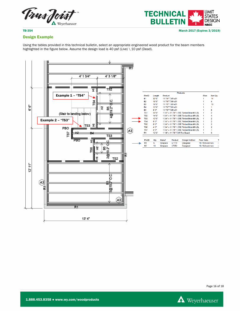
Using the tables provided in this technical bulletin, select an appropriate engineered wood product for the beam members highlighted in the figure below. Assume the design load is 40 psf (Live) \ 10 psf (Dead).
Example 1 – “TS4”
Example 2 – “TS3”
Page 16 of 18
1.888.453.8358 ● www.wy.com/woodproducts

TECHNICAL BULLETIN
TB-354 March 2017 (Expires 3/2019)
Example 1 – “TS4”
Beam Grade: 1.55E TimberStrand® LSL Beam Size: 1 ¾″ x 11 ⅞″ Clear Span: 6′-6″ Bearing: Interior Floor Beam (LF179 Face Mount Hanger – see Simpson Strong-Tie® C-C-CAN2015) Supported Length: (Half-span of B5 joists) + (Half-length of stair stringer) = 2′-2″ + 2′-1″ = 4′-3″
>>> Maximum Supported Length = 10′-3″
Actual Load Area = 4′-3″ OK
>>> Minimum End Bearing Length = 1.5″ (Column or Hanger) / 3.5″ (SPF Plate)
Actual End Bearing Length #1 = 2.0″ (LF179 Face Mount Hanger) OK
Actual End Bearing Length #2 = 2.0″ (LF179 Face Mount Hanger) OK
Page 17 of 18
1.888.453.8358 ● www.wy.com/woodproducts
TECHNICAL BULLETIN
TB-354 March 2017 (Expires 3/2019)
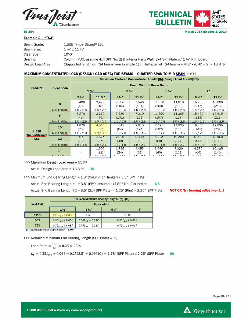
Example 2 – “TS3”
Beam Grade: 1.55E TimberStrand® LSL Beam Size: 1 ¾″ x 11 ⅞″ Clear Span: 10′-0″ Bearing: Column (PBO; assume 4x4 SPF No. 2) & Interior Party Wall (2x4 SPF Plate w/ 1 ¼″ Rim Board) Design Load Area: (Supported length on TS4 beam from Example 1) x (Half-span of TS4 beam) = 4′-3″ x (6′-6″ ÷ 2) = 13.8 ft2
>>> Maximum Design Load Area = 55 ft2
Actual Design Load Area = 13.8 ft2 OK
>>> Minimum End Bearing Length = 1.8″ (Column or Hanger) / 3.5″ (SPF Plate)
Actual End Bearing Length #1 = 3.5″ (PBO; assume 4x4 SPF No. 2 or better) OK
Actual End Bearing Length #2 = 3.5″ (2x4 SPF Plate) – 1.25″ (Rim) = 2.25″ (SPF Plate) NOT OK (try bearing adjustment...)
>>> Reduced Minimum End Bearing Length (SPF Plate) = 𝐿𝐿𝑏𝑏′
Load Ratio = 13.855
= 0.25 = 25%
𝐿𝐿𝑏𝑏′ = 0.25𝐿𝐿𝑏𝑏,0 + 0.09ℓ = 0.25(3.5) + 0.09(10) = 1.78″ (SPF Plate) ≤ 2.25″ (SPF Plate) OK
Page 18 of 18
1.888.453.8358 ● www.wy.com/woodproducts