Embed Size (px)
Citation preview

TBS CORE PNP PRO The all-in-one FPV power supply and flight OSD
Revision 2014-06-16
The TBS CORE PRO is the progression of our
TBS CORE PNP system. It now supports GPS to
help navigation and a new range of TBS
telemetry modules to take your FPV experience
to the next level. We are leveraging some of the
same core components we used in the earlier
CORE series and our TBS DISCOVERY PRO
multirotor. Making this the most advanced CORE PNP system available. It also comes with the same
easy-to-connect cables - no soldering required to install this unit.
It supplies selectable 5V or 12V to video transmitter and camera regardless of input voltage (2S to 6S). The TBS
CORE PNP PRO can supply video transmitters with up to 1W of emitted power (EIRP) and a standard FPV camera,
or charge a GoPro camera in-flight.
The built-in OSD (switchable) provides vital information of the state of the aircraft. No more throttle loss due to
over depleted batteries, flying at the edge of control signal, or forgetting to charge spare FPV system batteries.
Coupled with the new GPS module, the OSD will help you navigate and estimate distances, speed, and heading.
In a nutshell, the TBS CORE PNP PRO is a light-weight OSD and filtered power supply, feeding the pilot camera
and video transmitter, all in one compact package. It makes FPV setups super-easy and is a safety feature every
FPV aircraft should have. Suitable for any airplane and multirotor of any size. The simplified wiring reduces
points of failure and lets you focus on flying instead of worrying.
Key features
• Dual 2S to 6S input voltage - additional input for backup (2S only)
• Constant 5V @ max. 2A and 12V @ max. 600mA - individually, not combined!
• OSD with GPS, battery voltage, current consumption, signal strength, callsign and timer display
• Telemetry audio downlink or video input and mono audio pass-through
• Very high switching efficiency
• Extremely low ripple and low RF noise, two stage filtered and shielded casing
• Supports 1W VTX with only minor airflow
• All necessary cables included
• Software upgradable and configurable
• Small size, 27mm x 47mm x12mm, only 15.6 grams
1
Important
To keep the system stable and in a healthy condition, make a note of the following.
• Do not hot-plug the system - disconnect battery power when setting up or reconfiguring the system
• Backup power 2S only - a separate backup LiPo battery pack should not exceed 2S
• Calibrate on the field before your first flight - the signal strength indicator and compass is best
calibrated in conditions similar to the flight environment
Specifications
Functions: Voltage regulator, on-screen display, current sensor, flight location data
Input voltage: 2S to 6S (7.4 to 26V DC) - backup power max. 2S
Output voltage: 5V @ 2A, 12V @ 600mA - individually, not combined (max. 8-10W load)
Switching efficiency: >85% at nominal load
Audio source: External left/right channel pass-through or telemetry audio
Video signal: 1.0Vp-p 75 Ohm video signal
RSSI signal: Analog voltage, digital PWM signal and EzUHF OSD Link
Current sensor: 100A max. - digital interface, power tap for regulators
USB type: Micro USB
Port connectors: Molex PicoBlade 1.25mm pitch sockets
Working temperature: 0 - 40°C
Dimensions: 27 (H) x 47 (W) x 12 (D) mm
Weight: 15.6g
Kit contents: 1x TBS CORE PNP PRO, 1x TBS current sensor module, 2x BST cables, 1x EZUHF Link cable, 1x 3-pin RSSI cable, 1x Camera and 1x VTx pigtail cables
Optional Accessories: 1x TBS GPS module with backup power
2

TBS CORE PNP PRO Unit
The TBS CORE PNP PRO filters EMI and other sources of interference and protects your sensitive FPV electronics.
The end result of this is increased video range.
It also sports two new BST (BlackSheep Telemetry) ports which are future proofed, which means new modules
can be added at later time to extend the life and usability of the product. The on-board micro USB connector
lets you upgrade the software when new firmwares are announced. The unit is shielded to let you use it in long
range situations, e.g. for UHF.
Pilot camera and video transmitter connect to their corresponding designators on the unit - necessary cables
normally included with the camera/vtx. All connectors are plug&play, requiring no soldering to get the product
running.
The included 100A current sensor module is an ideal companion for your R/C airplane or multirotor. It senses
the current consumptions whilst the model is in operation, letting you know how much of the battery capacity
has been used. The current sensor is now digital which means it provides a very accurate read-out. It can be
calibrated from the OSD if needed, but comes pre-calibrated out of the box.
As always, the OSD provides real-time information to the pilot about the battery voltage, current consumption,
flight time and control signal/RSSI. If your setup is sporting an EzUHF 8-ch receiver (diversity or lite), the
extended link information can be displayed on the OSD.
3

CORE On-Screen Display (OSD) In FPV, simple is better. Wire clutter from many different devices all connected together creates a sophisticated
conglomeration of ground-loops and “antennas” that can have significant impact on the reliability of your FPV
system and your FPV experience.
For this reason, we made wiring simple and the OSD will detect which modules are connected and only display
the information which is absolutely necessary - this keeps the screen layout simple and clean. Helpful telemetry
information, indicators and warning messages will show only when needed.
A complete read-out of all the available OSD telemetry is annotated in the image below.
4

The OSD can be turned off completely by going into the CORE menu system, see section later in the manual for
details. If for some reason the CORE processor stops working, the camera video feed will still be relayed to the
video transmitter without interruption.
When the aircraft has landed, a summary screen will automatically be displayed showing vital information about
the flight. Great for competitions, gatherings and long range flights.
The above summary screen is explain in detail below.
• Flew like a girl - Yes/No - Built-in TBS flight scoring system giving you our instant judgement
• Used capacity - mAh - Total battery power consumed for the flight
• Max. distance - m, ft - Furthest point away from launch/home location
• Travel distance - m, ft - Cumulative distance covered
• Max. climb - m, ft - Altitude difference between max. altitude and launch
• Max. altitude - m, ft - Highest ASL point reached during the flight
• Max. speed - km/h, mi/h, kts/h - Top speed reached during the flight
• Avg. speed - km/h, mi/h, kts/h - Average speed during the flight
• Flight time - mm:ss - Total duration of the flight
• Latitude, Longitude - GPS coordinates, updated every 30 seconds
5

Setup and installation
The photo above shows a common setup for an airplane or multirotor. A diagram to install the TBS CORE PNP
PRO on the TBS DISCOVERY PRO is included on the next page.
Installation is fool proof, just plug your camera and video transmitter into the corresponding sockets and
connect the current sensor module between your model and battery pack. All your plane's electronics should be
powered normally after the current sensor XT60 connector. If your receiver supports RSSI (Receiver Signal
Strength Indicator) output, hook it up to get additional telemetry data on the R/C link displayed on the OSD.
Positioning the TBS CORE PNP PRO in your model requires some planning. Please keep adequate separation
between unit and your R/C receiver. The TBS CORE series includes two very powerful switching-regulators
which can interfere with your UHF receiver when placed in close proximity. This is not something that is unique
to this product but rather to all devices with switching regulators. The noise decreases exponentially with
distance, so every centimeter or inch helps get more range out of your system. A UHF R/C system can fly to
about 15 km (approx. 10 miles) with the TBS CORE PNP PRO sitting in close proximity on a small multirotor
frame. It is essential to keep a good distance between the GPS antenna (passive) and VTx antenna (active) to get
a proper GPS lock.
Since the unit is based on switching regulators, it does not need to be ventilated or exposed and can be tucked
away in your aircraft for maximum durability.
6

XT60
TBS CORE PNP PRO installation diagram for TBS DISCOVERY PRO
VTX
8 7
6 5
4 3
2 1
- + S
PPM Gimbal
Bottom lin
k
IMU/GoPro
Roll
Pitch
VTX
CAM
5V 1
2V
5V 12V
Aud
ioVi
deo
Gn
dPw
r
Pwr
Gn
d
Aud
ioVi
deo
GP Out Sel
VTX2 Switch
Vb
at
Gn
d
Vid
eoVTX2
GndVccRxTx
UA
RT
Gimbal
EzUHF RSSI Link
Gimal RollGimbal PitchGimbal PPM
Camera switchAnalog RSSI
Flight controller PPM
Pilot camera
TBS COREPNP PRO
CAMBST
RSSIBST
VTXLINK
B-PWRUSB
UP ENTER DN
Current sensor
+
-- --
+
--
+
--
PPM
+ --
+ --
S + -
DISC
OV
ERY PRO
Top Lin
k
++Batte
ry50A
XT60 XT60PWR
IN
BST
PWROUT
Bottom plate
Top
plat
e
From battery
TBS CORE PNP PRO unit
Note: no power or audio lead(available separately)
Caution: do not use the normal CAM-cable to connect the CORE PRO to the DISCOVERY PRO
(two voltage sources con�ict)
XT60
Note: mount unit in center of the bottomplate, on top of the �ight controller (NAZA),or on the left side on the bottom plate
rev. June 2014 - by ivc.no/tbs
Note 1: disable the on-board DISCOVERY PROOSD in the CORE menu using the buttons onthe top plate - else the OSDs will overlap.
CH1CH2CH3CH4CH5CH6CH7CH8
EzUHF receiver (if used)
GPS module (optional)
Note 2: the pilot camera and GoPro HD cameraswitching is still performed by the on-boardTBS DISCOVERY PRO CORE.
Note 3: since there are now essentially two COREs, you can solder the jumper on the GoProadapter board to enable charging at 1A rate.
Note 4: to save weight and bulk, considerremoving the plastic case for the current sensor and connectors on one or both sides.
Left side

Pre-configuration
Before connecting any device to the TBS CORE PNP PRO, the unit has to be configured to output the correct
voltage for your specific pilot camera and video transmitter. The audio source, which is transmitted down via
the video transmitter, can also be changed to carry either telemetry data or just pure audio.
To do the change, remove the 4 Philips screws on the bottom of the unit and remove the bottom cover.
Voltage selection
The default voltage out of CAM socket is 12V and the VTX socket is 5V. For powering 5V cameras (e.g. FPV CCD
cameras) or 12V transmitters, open the unit by removing the rear 4 screws and change the solder jumpers on
the left side of the internal board. The solder pads are conveniently labelled. Solder a bridge between the
center solder pad and the left (12V) or the right (5V) of the VTX and CAM pads, respectively - do NOT
short-circuit all three pads.
Switches and pin-jumpers are a very frequent point of failure in many FPV systems. Therefore, we have decided
to use solder-pads for maximum security and durability.
7

Configuration for:
• 12V Pilot camera
• 5V Video transmitter
Configuration for:
• 5V Pilot camera
• 12V Video transmitter
Configuration for:
• 12V Pilot camera
• 12V Video transmitter
Configuration for:
• 5V Pilot camera
• 5V Video transmitter
Important: when using video transmitters with on-board voltage regulators (e.g. IMRC VTx), it is recommended
to connect the positive and ground lead directly to the main power leads instead to maintain good switching
efficiency and stability.
8

Audio source
Audio source is by default configured for TELM to route telemetry data from the CORE processor to the video
transmitter downlink.
External audio can be connected via the CAM-port. The audio in is the white wire on the camera cable. To
enable external audio, open the unit by removing the 4 screws, as shown above. On the AUD solder pads,
solder a bridge between the center pad and EXT-pad. To change it back to telemetry, undo the bridge and join
center pad and the TELM-pad.
Configuration for:
• TELMetry audio source
Configuration for:
• EXTernal audio source (via CAM)
The TBS CORE PNP PRO has no on-board microphone to keep the size down, but can still be connected
externally via the CAM-port.
9
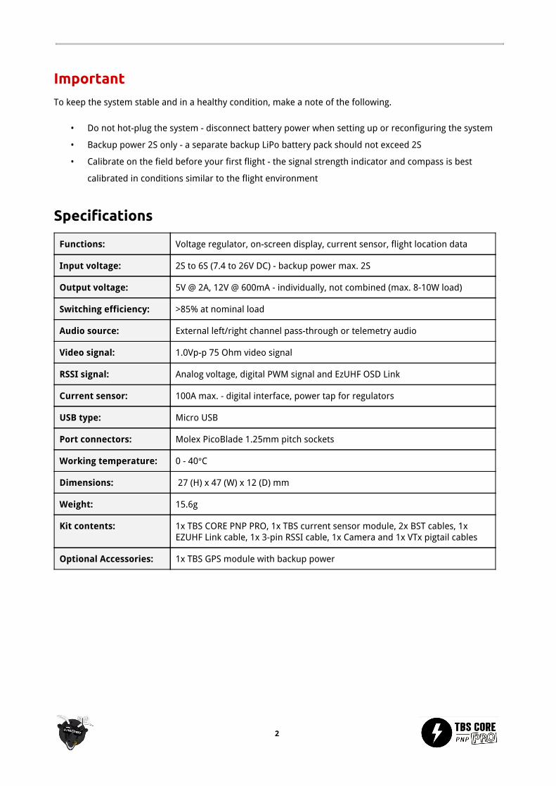
BlackSheep Telemetry ports (2xBST)
There are two BST ports on the left side of the unit. These can be used to connect a range of compatible
modules for the TBS CORE PNP PRO to provide telemetry data. This modular system allows you to custom fit
your model depending on your exact needs and weight budget. The pin-out is the same for all BST modules.
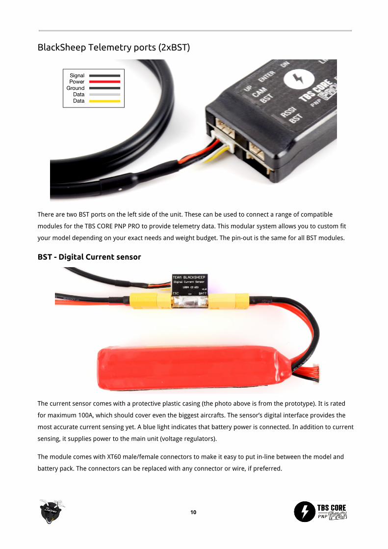
BST - Digital Current sensor
The current sensor comes with a protective plastic casing (the photo above is from the prototype). It is rated
for maximum 100A, which should cover even the biggest aircrafts. The sensor’s digital interface provides the
most accurate current sensing yet. A blue light indicates that battery power is connected. In addition to current
sensing, it supplies power to the main unit (voltage regulators).
The module comes with XT60 male/female connectors to make it easy to put in-line between the model and
battery pack. The connectors can be replaced with any connector or wire, if preferred.
10

BST - GPS module
The GPS module on the TBS CORE PNP PRO gives you real-time location information in the OSD. It displays an
arrow indicating home location (where power was applied), speed (km/h), distance (m) and altitude (m).
When power is first applied, the GPS will start to search for minimum 4 satellites to get a lock. A blinking blue
light means that it is searching for satellites, a solid blue light means the GPS is locked and ready.
The module comes in a protective plastic casing with a mounting pole to keep it away from noise electronics
(the photo above is from the prototype). It is recommended that you install the pole in the center of the
platform (near Center of Gravity) and away from powerful video transmitters.
BST - GPS conversion adapter
We have developed a conversion adapter which allows you to use existing gear you might already have, e.g. DJI
GPS puck or EzUHF GPS.
11

Video transmitter port (VTX)
A video transmitter can be installed on the VTX port. The TBS CORE PNO PRO can power any video transmitter
up to 1W. You can customize the included cable to suite your particular VTx, but be cautious of the voltage
selection and wire polarity.
Camera port (CAM)
A pilot camera can be installed on the CAM port. The port has input for both video and audio - if external audio
jumper is enabled inside the unit. An external microphone can be connected to the white (audio) and black (-)
wires.
12

RSSI port
The R/C receiver signal strength (RSSI) of the control link can be displayed as part of the OSD screen. The RSSI
port supports analog voltage and digital PWM input. After being calibrated, the value will change from 0% to
100% depending on how far away the receiver (model) is from the transmitter 0% means no signal, 100%
means full signal. It is a good rule of thumb to return when the figure approaches 60% to ensure good
operational conditions.
If your R/C receiver supports RSSI output, connect a cable from the receiver output to RSSI port on the TBS
CORE PNP PRO. Both analog voltage and digital PWM signal types are supported, and must be configured in the
CORE menu before it is displayed properly.
Some receivers are generating a digital PWM signal with too high frequency - this requires a low-pass filter to
convert the signal to analog voltage. The RSSI port is not needed when using a EzUHF receiver via the Link port,
see the next section.
Link port (LINK)
If you own a EzUHF long range receiver, you can connect the EzUHF to the TBS CORE PNP PRO to make use of the
extra telemetry data available.
The EzUHF 5-pin (3 wire) Link cable is required to connect your EzUHF 8-ch Diversity or Lite receiver to the TBS
CORE PNP PRO. The EzUHF 4-ch receiver does not provide the EzUHF OSD Link.
Connect the EzUHF Link cable to the Link port on the unit. In the CORE menu, change the RSSI setting to LINK to
enable the communication. No further calibration or setup is needed.
13

In the OSD, the following telemetry information will be displayed:
• The received signal strength (RSSI) for each antenna on the diversity model and a single read-out on
the lite model
• The overall signal quality (in percentages) which include packet loss
A good rule of thumb is to return when the RSSI value on the EzUHF reception dips below -90 or link quality
below 80%, whichever comes first.
Backup Power port (B-PWR)
This port allows you to connect an extra battery for safety on airplanes and wings. This provides a
fully-redundant secondary backup battery to power your FPV system. If the main battery pack is depleted
complete or disconnects for some reason, the backup battery provides video downlink to locate the aircraft.
Note: it does not power the R/C control system, only the FPV system. Backup power is not recommended, or
needed, on a multirotor, since the multirotor will unfortunately fall out of the sky if the main battery fails.
14

The backup power port is selected when the voltage of the main battery is lower than the backup battery. To
add backup power to the system, connect an 2S (7.4V) battery (max. allowed) to the B-PWR port using a 2-pin
Molex PicoBlade 1.25 cable.
The ground lead (-) is the one closest to the side of the unit and the positive (+) toward the middle/Link port.
USB port
To make the configuration easy, we have developed an application which faces directly with the CORE via a USB
micro connector. No additional drivers are required to use the application. See the following section for how to
upgrade the firmware and configure the CORE.
15

Configuration
When power is supplied to the system, a boot screen will display detected the video format (NTSC/PAL), any
connected BST modules and the battery type (2S-6S). The battery type detection is only available if the voltage
warning is set to Auto.
Configuring and calibrating the TBS CORE PNP PRO is incredibly simple. Either use our TBS Agent software
which interacts with the the unit via USB, or use the built-in OSD configuration menu. To use the OSD menu,
power up your FPV system and hold the ENTER-button for 3 seconds to bring up the OSD menu. It is easily
navigated using the up-, down- and enter buttons.
The configuration menu is laid out in groups where each section has specific settings and calibration steps. The
default value is listed as the first option in the following pages.
16

Units
The units used to display the speed, distance and altitude can
be changed individually to either Metric, Imperial or Knots.
• Speed - Metric (km/h), Imperial (mi/h), Knots (kts/h)
• Distance - Metric (m), Imperial (ft)
• Altitude - Metric (m), Imperial (ft)
Compass calibration
When the GPS module is connected, the home direction arrow
will only display properly after a 360 degree rotation
calibration has been performed. The calibration sets the
offset value for the compass. To get the best accuracy, do
this outdoors at the field.
• Step 1 - Move the GPS module away from other
electronics and magnets, select Start Calibration
• Step 2 - With the GPS module level in your hand, rotate it one full 360 degree turn and press Enter
• Step 2 - For the first flight the calibration will capture additional data to fine tuned the calibration
• Note: an “!” will be displayed next to the home arrow indicating that it is in learning mode
This is only necessary to do this once, but it may be necessary to recalibrate the compass if you have moved a
significant distance away from the initial calibration - the magnetic north will probably be significantly off.
RSSI
The source of the RSSI read-out on the OSD can be one of
three types. If analog (voltage) or digital (PWM) is used, the
maximum and minimum signal strength has to be recorded
using the calibration routine.
• Source - Analog (voltage)/Digital (PWM)/Link (EzUHF
OSD Link) - RSSI signal type
• Alarm - Enable/Disable - Will display a textual warning and the RSSI read-out will blink when the signal
is critical
• Calibration - Used to set the maximum (100%) and minimum (0%) signal value for Analog or Digital
signal source
17

Calibration:
• Step 1 - Turn on the R/C transmitter and move the radio 1-2 meters away from the R/C receiver, select
Calibration and press Enter to set the Max. value (best signal)
• Step 2 - Turn off the R/C transmitter and press Enter to set the Min. value (no signal)
EzUHF OSD Link receives and displays the numeric values directly from the EzUHF Rx, no calibration needed.
Battery
The system will detect the voltage of battery (2S-6S) during
the boot process. By default, a textual warning will be
displayed when the battery dips below a critical level (default
3.5V per cell).
• Alarm - Enable/Disable - Show warning when
battery voltage crosses critical level
• Level input - Auto/Manual - How to detect the
number of battery cells/voltage
• Warning level - <value>V - Set the threshold when a low voltage alarm should be triggered
General
Change how the HAM callsign is displayed, either Off, Always
or Minutely. The exact GPS coordinates can be displayed on
the bottom screen to make it easy to locate a downed model
by looking at any ground station recordings.
• Shown Callsign - Minutely/Always/Off - How to
display the HAM callsign and mm:ss timer - it is
possible to change the callsign in the TBS Agent
application
• Show Position - No/Yes - Whether to display the GPS coordinates on the bottom of the screen - useful
to recover a downed aircraft
• OSD Color - White/Black - Set the text color of the entire OSD layout - white with black outline or black
with white outline
• Power Index - Off, mAh/km mAh/mile, mWh/km mWh/mile - show energy consumed per unit distance,
i.e. mAh or mWh per km or mile - useful efficiency indicator for long range flights
18

TBS Agent configuration software We have made a special software package to interact with the TBS CORE PNP PRO. It makes upgrading the
firmware easy and configuration a blast - just point&click to change a setting.
Installation
Download the installer from http://www.team-blacksheep.com/corepro/agent (Windows XP/7/8, 64-bit
required) - no drivers needed to use the application, but an Internet connection is required to download the
latest firmware.
Disconnect the flight battery and any backup battery power from the unit and plug in a micro USB cable on the
right side. The software will automatically detect the unit and offer you the option to upgrade the firmware if a
newer version is available.
When the status indicator is green and says ‘Connected’, you can upgrade, downgrade or change any of the
OSD settings.
To upgrade the firmware, select the latest version from the drop-down menu and click Update. Make sure that
the current sensor and GPS module is connected. The blue light on the current sensor will start to blink rapidly,
followed by rapid blinking on the GPS module - indicating that the module is being upgraded. The process will
take about 1 minute. All previous settings are kept and reused.
19

Configuration
It is possible to change any of the settings found in the OSD configuration menu using the TBS Agent - with the
exception of the calibration of the compass and analog/digital RSSI levels, these still has to be performed with
the model and unit powered from the main flight battery.
One additional feature found in the TBS Agent is ability to change the HAM callsign to suit your own preference.
It can be 0 to 10 characters long (A-Z 0-9 ? ! . - allowed.)
20

Good practices We have compiled a list of all of practices which have been tried and tested in countless environments and
situations by the TBS crew and other experienced FPV pilots.
Follow these simple rules, even if rumors on the internet suggest otherwise, and you will have success in FPV.
● Start with the bare essentials and add equipment one step at a time, after each new equipment was
added to proper range- and stress tests.
● Do not fly with a video system that is capable of outperforming your R/C system in terms of range.
● Do not fly with a R/C frequency higher than the video frequency (e.g. 2.4GHz R/C, 900MHz video).
● Monitor the vitals of your plane (R/C link and battery). Flying with a digital R/C link without RSSI is
dangerous.
● Do not use 2.4GHz R/C unless you fly well within its range limits, in noise-free environments and always
within LOS. Since this is most likely never the case, it is recommended to not use 2.4GHz R/C systems for
longer range FPV.
● Do not fly at the limits of video, if you see noise in your picture, turn around and buy a higher-gain
receiver antenna before going out further.
● Shielded wires or twisted cables only, anything else picks up RF noise and can cause problems.
● When using powerful R/C transmitters, make sure your groundstation equipment is properly shielded.
● Adding Return-To-Home (RTH) to an unreliable system does not increase the chances of getting your
plane back. Work on making your system reliable without RTH first, then add RTH as an additional safety
measure if you must.
● Avoid powering the VTx directly from battery, step-up or step-down the voltage and provide a
constant level of power to your VTx. Make sure your VTx runs until your battery dies.
● Do not power your camera directly unless it works along the complete voltage range of your battery.
Step-up or step-down the voltage and provide a constant level of power to your camera. Make sure
your camera runs until your battery dies.
● A single battery system is safer than using two dedicated batteries for R/C and FPV. Two batteries in
parallel even further mitigate sources of failure.
● For maximum video range and “law compatibility”, use 2.4GHz video with high-gain antennas.
● When flying with R/C buddies that fly on 2.4GHz, or when flying in cities, it is perfectly possible to use
2.4GHz video provided you stick to the channels that do not lie in their band (CH5 to CH8 for Lawmate
systems, available from TBS).
● Do not use diversity video receivers as a replacement for pointing your antennas, diversity should be
used to mitigate polarization issues.
● Improving the antenna gain on the receiver end is better than increasing the output power (except in
RF-noisy areas). More tx power causes more issues with RF on your plane. 500mW is plenty of power!
21

● Try to achieve as much separation of the VTx and R/C receiver as possible to lower the RF noise floor
and EMI interference.
● Do not buy the cheapest equipment unless it is proven to work reliably (e.g. parts falling off, multitudes
of bug fix firmware updates, community hacks and mods are a good indicator of poor quality and
something you do NOT want to buy for a safe system). Do due diligence and some research before
sending your aircraft skyward.
22

Troubleshooting
● Issue: GPS does not seem to lock
Solution: Try to move the GPS module as far away from switching power regulators, UHF transmitters,
pilot cameras and video transmitters. Leave the GPS to initialize for 30 seconds before moving the
model.
● Issue: Firmware update failed and the device is not showing any OSD anymore
Solution: Disconnect any power supply and USB cable. Press and hold the enter button and plug-in the
USB cable. This will boot the TBS CORE PNP PRO in a emergency mode. You can now upload a working
firmware to the device by the TBS Agent software.
Manual written and designed by ivc.no in cooperation with TBS.
23