Embed Size (px)
Citation preview
Page 1 of 35
USER MANUAL
Part 1 – all users
TOUCHCLAVE-R AUTOCLAVES
ADVANCED STERILIZING TECHNOLOGY
TCR-AUTOCLAVE PART 1 – ALL USERS Issue 1
FM 23948 0617

Page 2 of 35

Page 3 of 35
NOTICE
Copyright in this document is the property of LTE Scientific Limited (“LTE”). No part of this document may be copied, reproduced, or stored in a retrieval system without the prior
written permission of LTE. The design rights in the products described in this document, including both hardware and software features, are the property of LTE.
Whilst all reasonable precautions have been taken to ensure the accuracy and relevance of
this document, LTE does not accept liability for any errors or omissions, or for any damage or
loss resulting from the use of the information contained herein.
LTE reserves the right to revise or replace any or all of the contents of this document without notice for any reason. Such reasons may include the need to reflect changes to the products
or any of their features or attributes, or to revise the wording of this document.
Issue Date: 07.03.2012

Page 4 of 35
Page 5 of 35
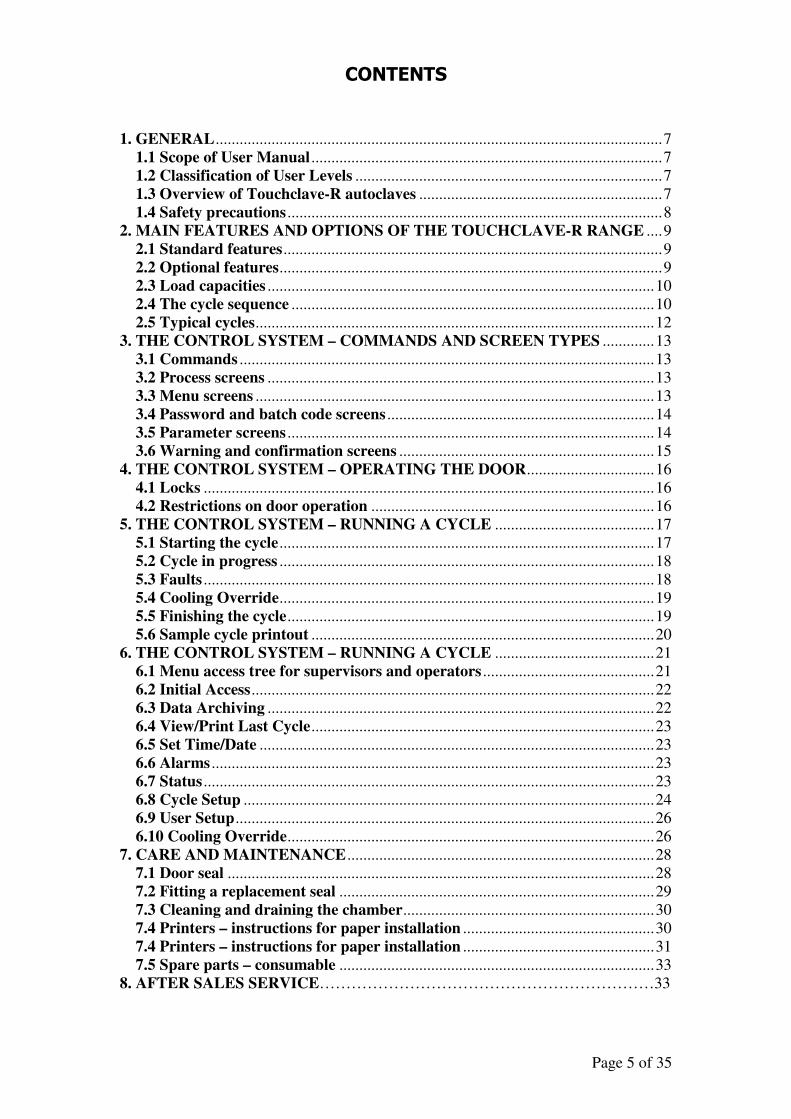
CONTENTS
1. GENERAL ................................................................................................................ 7
1.1 Scope of User Manual ........................................................................................ 7
1.2 Classification of User Levels ............................................................................. 7
1.3 Overview of Touchclave-R autoclaves ............................................................. 7
1.4 Safety precautions .............................................................................................. 8
2. MAIN FEATURES AND OPTIONS OF THE TOUCHCLAVE-R RANGE .... 9
2.1 Standard features ............................................................................................... 9
2.2 Optional features ................................................................................................ 9
2.3 Load capacities ................................................................................................. 10
2.4 The cycle sequence ........................................................................................... 10
2.5 Typical cycles .................................................................................................... 12
3. THE CONTROL SYSTEM – COMMANDS AND SCREEN TYPES ............. 13
3.1 Commands ........................................................................................................ 13
3.2 Process screens ................................................................................................. 13
3.3 Menu screens .................................................................................................... 13
3.4 Password and batch code screens ................................................................... 14
3.5 Parameter screens ............................................................................................ 14
3.6 Warning and confirmation screens ................................................................ 15
4. THE CONTROL SYSTEM – OPERATING THE DOOR ................................ 16
4.1 Locks ................................................................................................................. 16
4.2 Restrictions on door operation ....................................................................... 16
5. THE CONTROL SYSTEM – RUNNING A CYCLE ........................................ 17
5.1 Starting the cycle .............................................................................................. 17
5.2 Cycle in progress .............................................................................................. 18
5.3 Faults ................................................................................................................. 18
5.4 Cooling Override .............................................................................................. 19
5.5 Finishing the cycle ............................................................................................ 19
5.6 Sample cycle printout ...................................................................................... 20
6. THE CONTROL SYSTEM – RUNNING A CYCLE ........................................ 21
6.1 Menu access tree for supervisors and operators ........................................... 21
6.2 Initial Access ..................................................................................................... 22
6.3 Data Archiving ................................................................................................. 22
6.4 View/Print Last Cycle ...................................................................................... 23
6.5 Set Time/Date ................................................................................................... 23
6.6 Alarms ............................................................................................................... 23
6.7 Status ................................................................................................................. 23
6.8 Cycle Setup ....................................................................................................... 24
6.9 User Setup ......................................................................................................... 26
6.10 Cooling Override ............................................................................................ 26
7. CARE AND MAINTENANCE ............................................................................. 28
7.1 Door seal ........................................................................................................... 28
7.2 Fitting a replacement seal ............................................................................... 29
7.3 Cleaning and draining the chamber ............................................................... 30
7.4 Printers – instructions for paper installation ................................................ 30
7.4 Printers – instructions for paper installation ................................................ 31
7.5 Spare parts – consumable ............................................................................... 33
8. AFTER SALES SERVICE………………………………………………………33

Page 6 of 35
Page 7 of 35
1. GENERAL
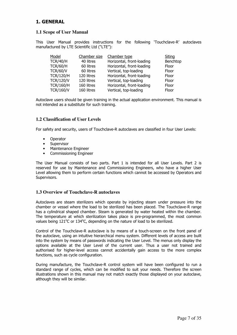
1.1 Scope of User Manual
This User Manual provides instructions for the following ‘Touchclave-R’ autoclaves manufactured by LTE Scientific Ltd (“LTE”):
Model Chamber size Chamber type Siting
TCR/40/H 40 litres Horizontal, front-loading Benchtop
TCR/60/H 60 litres Horizontal, front-loading Floor TCR/60/V 60 litres Vertical, top-loading Floor
TCR/120/H 120 litres Horizontal, front-loading Floor TCR/120/V 120 litres Vertical, top-loading Floor
TCR/160/H 160 litres Horizontal, front-loading Floor TCR/160/V 160 litres Vertical, top-loading Floor
Autoclave users should be given training in the actual application environment. This manual is not intended as a substitute for such training.
1.2 Classification of User Levels
For safety and security, users of Touchclave-R autoclaves are classified in four User Levels:
• Operator
• Supervisor
• Maintenance Engineer
• Commissioning Engineer
The User Manual consists of two parts. Part 1 is intended for all User Levels. Part 2 is
reserved for use by Maintenance and Commissioning Engineers, who have a higher User Level allowing them to perform certain functions which cannot be accessed by Operators and
Supervisors.
1.3 Overview of Touchclave-R autoclaves Autoclaves are steam sterilizers which operate by injecting steam under pressure into the
chamber or vessel where the load to be sterilized has been placed. The Touchclave-R range
has a cylindrical shaped chamber. Steam is generated by water heated within the chamber. The temperature at which sterilization takes place is pre-programmed, the most common
values being 121oC or 134oC, depending on the nature of load to be sterilized.
Control of the Touchclave-R autoclave is by means of a touch-screen on the front panel of the autoclave, using an intuitive hierarchical menu system. Different levels of access are built
into the system by means of passwords indicating the User Level. The menus only display the
options available at the User Level of the current user. Thus a user not trained and authorised for higher-level access cannot accidentally gain access to the more complex
functions, such as cycle configuration.
During manufacture, the Touchclave-R control system will have been configured to run a
standard range of cycles, which can be modified to suit your needs. Therefore the screen illustrations shown in this manual may not match exactly those displayed on your autoclave,
although they will be similar.
Page 8 of 35
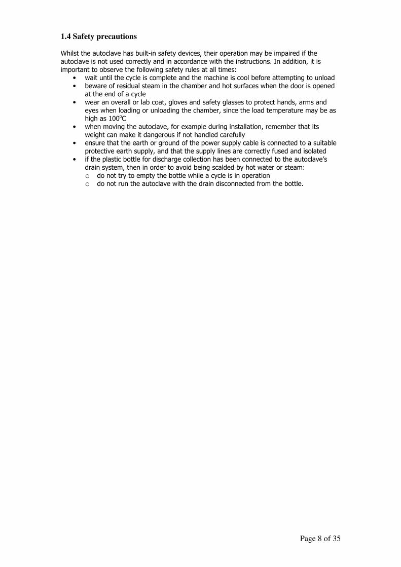
1.4 Safety precautions Whilst the autoclave has built-in safety devices, their operation may be impaired if the
autoclave is not used correctly and in accordance with the instructions. In addition, it is
important to observe the following safety rules at all times: • wait until the cycle is complete and the machine is cool before attempting to unload
• beware of residual steam in the chamber and hot surfaces when the door is opened
at the end of a cycle
• wear an overall or lab coat, gloves and safety glasses to protect hands, arms and
eyes when loading or unloading the chamber, since the load temperature may be as high as 100oC
• when moving the autoclave, for example during installation, remember that its
weight can make it dangerous if not handled carefully • ensure that the earth or ground of the power supply cable is connected to a suitable
protective earth supply, and that the supply lines are correctly fused and isolated
• if the plastic bottle for discharge collection has been connected to the autoclave’s
drain system, then in order to avoid being scalded by hot water or steam:
o do not try to empty the bottle while a cycle is in operation o do not run the autoclave with the drain disconnected from the bottle.
Page 9 of 35
2. MAIN FEATURES AND OPTIONS OF THE TOUCHCLAVE-R RANGE
2.1 Standard features
All Touchclave autoclaves share the same intuitive and powerful control system, allowing different levels of access and control, and precise control of the machine. The specification,
configuration and performance vary according to the model purchased and any extra features which have been fitted.
Touchclave-R models use “in chamber” heaters for steam generation. The base shelf in the chamber covers a reservoir in which the heaters are located. The functioning of the autoclave
depends on having water in this reservoir. If there is no water, steam generation cannot occur. Therefore the reservoir needs to be filled with water, either manually or using the
Automatic Water Fill feature, before the cycle can proceed.
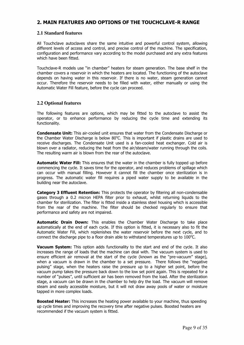
2.2 Optional features The following features are options, which may be fitted to the autoclave to assist the
operator, or to enhance performance by reducing the cycle time and extending its functionality.
Condensate Unit: This air-cooled unit ensures that water from the Condensate Discharge or the Chamber Water Discharge is below 80oC. This is important if plastic drains are used to
receive discharges. The Condensate Unit used is a fan-cooled heat exchanger. Cold air is blown over a radiator, reducing the heat from the air/steam/water running through the coils.
The resulting warm air is blown from the rear of the autoclave.
Automatic Water Fill: This ensures that the water in the chamber is fully topped up before
commencing the cycle. It saves time for the operator, and reduces problems of spillage which can occur with manual filling. However it cannot fill the chamber once sterilization is in
progress. The automatic water fill requires a piped water supply to be available in the building near the autoclave.
Category 3 Effluent Retention: This protects the operator by filtering all non-condensable gases through a 0.2 micron HEPA filter prior to exhaust, whilst returning liquids to the
chamber for sterilization. The filter is fitted inside a stainless steel housing which is accessible from the rear of the machine. The filter should be checked regularly to ensure that
performance and safety are not impaired.
Automatic Drain Down: This enables the Chamber Water Discharge to take place
automatically at the end of each cycle. If this option is fitted, it is necessary also to fit the Automatic Water Fill, which replenishes the water reservoir before the next cycle, and to
connect the discharge pipe to a floor drain able to withstand temperatures up to 100oC.
Vacuum System: This option adds functionality to the start and end of the cycle. It also
increases the range of loads that the machine can deal with. The vacuum system is used to ensure efficient air removal at the start of the cycle (known as the “pre-vacuum” stage),
when a vacuum is drawn in the chamber to a set pressure. There follows the “negative pulsing” stage, when the heaters raise the pressure up to a higher set point, before the
vacuum pump takes the pressure back down to the low set point again. This is repeated for a
number of “pulses”, until sufficient air has been removed from the load. After the sterilization stage, a vacuum can be drawn in the chamber to help dry the load. The vacuum will remove
steam and easily accessible moisture, but it will not draw away pools of water or moisture tapped in more complex loads.
Boosted Heater: This increases the heating power available to your machine, thus speeding
up cycle times and improving the recovery time after negative pulses. Boosted heaters are
recommended if the vacuum system is fitted.
Page 10 of 35
Keep-warm Facility: Following completion of a cycle, this optional facility allows the
autoclave to keep media warm until removed from the chamber.
Printer: The thermal data printer provides details of each cycle in hard copy form.
Data Archiving: With this option, all cycles are recorded onto an integral flash card system.
The record of each cycle shows the date, time, batch number, operator identification and all cycle data or failures. The record can be printed via the thermal data printer (if fitted), or
may be viewed on a PC using a serial data cable. The current cycle can also be viewed as a
real-time graph, showing chamber pressure, load temperature and exhaust temperature using the system software.
Increased Cycle Memory: This option allows the number of available operating cycles
stored in the control system to be increased from 8 to 20. This is useful if a wide variety of
loads is to be sterilized by the autoclave.
Modem link: This optional feature allows remote connection to the machine, in order to interrogate the system control software and make changes if required.
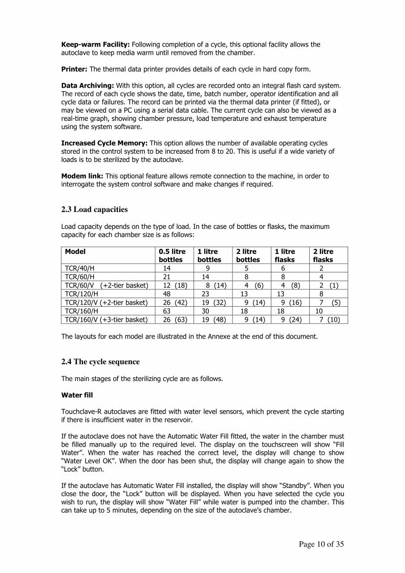
2.3 Load capacities
Load capacity depends on the type of load. In the case of bottles or flasks, the maximum capacity for each chamber size is as follows:
Model 0.5 litre bottles
1 litre bottles
2 litre bottles
1 litre flasks
2 litre flasks
TCR/40/H 14 9 5 6 2
TCR/60/H 21 14 8 8 4
TCR/60/V (+2-tier basket) 12 (18) 8 (14) 4 (6) 4 (8) 2 (1)
TCR/120/H 48 23 13 13 8
TCR/120/V (+2-tier basket) 26 (42) 19 (32) 9 (14) 9 (16) 7 (5)
TCR/160/H 63 30 18 18 10
TCR/160/V (+3-tier basket) 26 (63) 19 (48) 9 (14) 9 (24) 7 (10)
The layouts for each model are illustrated in the Annexe at the end of this document.
2.4 The cycle sequence
The main stages of the sterilizing cycle are as follows.
Water fill
Touchclave-R autoclaves are fitted with water level sensors, which prevent the cycle starting
if there is insufficient water in the reservoir.
If the autoclave does not have the Automatic Water Fill fitted, the water in the chamber must
be filled manually up to the required level. The display on the touchscreen will show “Fill Water”. When the water has reached the correct level, the display will change to show
“Water Level OK”. When the door has been shut, the display will change again to show the
“Lock” button.
If the autoclave has Automatic Water Fill installed, the display will show “Standby”. When you close the door, the “Lock” button will be displayed. When you have selected the cycle you
wish to run, the display will show “Water Fill” while water is pumped into the chamber. This can take up to 5 minutes, depending on the size of the autoclave’s chamber.
Page 11 of 35
Air removal
If the autoclave does not have the Vacuum option fitted, the display will show “Steam Purge”,
which is the stage when air is removed from the chamber. The water in the bottom of the chamber is heated to produce steam, which escapes through a valve at the rear of the
machine, carrying the air in the chamber with it.
For loads that are more likely to trap air, such as plastic discard, a vacuum system is recommended. The stages displayed in this case are “Pre-Vacuum” and “Negative Pulsing”
(as explained above for the Vacuum System option). The vacuum has superior air removal,
but may increase the overall length of the cycle.
Heating up
The autoclave raises its pressure and temperature to the set sterilizing values specified for
the cycle. The time taken by this stage depends on the level of the set points and the contents of the load to be sterilized. The load probe should be placed either in the load to be
sterilized or in a simulated load device. The stage will be complete when the sterilizing temperature has been reached.
Sterilizing
During this stage, the cycle achieves its objective. Whilst the sterilizing temperature can be set for any given cycle at any value between 1050C and 1360C, the values most commonly
chosen are 1210C or 1340C, depending on the nature of load to be sterilized (see below). If the printer is fitted, its output during this stage will provide proof that the load has been
sterilized. The length of time for sterilization can also be selected by the user, up to a
maximum of 30 minutes.
Cooling
The final stage is “Cooling”. The cooling fan blows air over the chamber until the temperature
has been reduced to the desired level (usually 80oC). Three types of cooling are available on Touchclave-R models:
• Normal cooling allows the steam pressure to drop gradually until it reaches
atmospheric pressure, relying on fans to perform the cooling action. • Dynamic cooling works in a similar manner until the pressure has dropped to
1150mba, when the machine blows air through the chamber, thus speeding up the
cooling action and helping to dry the load. • Ballast cooling maintains the chamber pressure during cooling by replacing the steam
with air. This method minimises the fluid loss and is recommended for media loads.
Page 12 of 35
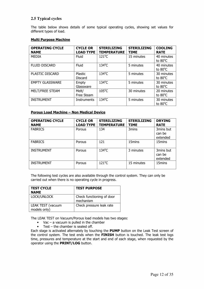
2.5 Typical cycles The table below shows details of some typical operating cycles, showing set values for
different types of load.
Multi Purpose Machine
OPERATING CYCLE
NAME
CYCLE OR
LOAD TYPE
STERILIZING
TEMPERATURE
STERILIZING
TIME
COOLING
RATE
MEDIA Fluid 121oC 15 minutes 40 minutes
to 80oC
FLUID DISCARD Fluid 134oC 5 minutes 40 minutes to 80oC
PLASTIC DISCARD Plastic
Discard
134oC 5 minutes 30 minutes
to 80oC
EMPTY GLASSWARE Empty Glassware
134oC 5 minutes 30 minutes to 80oC
MELT/FREE STEAM Melt/
Free Steam
105oC 30 minutes 20 minutes
to 80oC
INSTRUMENT Instruments 134oC 5 minutes 30 minutes to 80oC
Porous Load Machine – Non Medical Device
OPERATING CYCLE
NAME
CYCLE OR
LOAD TYPE
STERILIZING
TEMPERATURE
STERILIZING
TIME
DRYING
RATE
FABRICS Porous 134 3mins 3mins but
can be extended
FABRICS Porous 121 15mins 15mins
INSTRUMENT Porous 134oC 3 minutes 3mins but
can be extended
INSTRUMENT Porous 121oC 15 minutes 15mins
The following test cycles are also available through the control system. They can only be
carried out when there is no operating cycle in progress.
TEST CYCLE
NAME
TEST PURPOSE
LOCK/UNLOCK Check functioning of door
mechanism
LEAK TEST (vacuum
models only)
Check pressure leak rate
The LEAK TEST on Vacuum/Porous load models has two stages:
• Vac – a vacuum is pulled in the chamber
• Test – the chamber is sealed off.
Each stage is activated alternately by touching the PUMP button on the Leak Test screen of the control system. The test ends when the FINISH button is touched. The leak test logs
time, pressures and temperature at the start and end of each stage, when requested by the
operator using the PRINT/LOG button.
Page 13 of 35
3. THE CONTROL SYSTEM – COMMANDS AND SCREEN TYPES
The main command buttons and types of display screen of the touchscreen control system
are described in this section.
3.1 Commands The basic commands are common to all the screens. They appear on the screens as touch
buttons with the following functions:
� To return to the previous screen – this button appears at top right on the screen.
���� ���� To move forwards or back to another screen within a set of screens.
� � To move between multiple sets of screens.
+/Y -/N To move up or down between multiple-choice options for values on a screen. � � To move up or down through the menu options.
���� To select or enter the highlighted option.
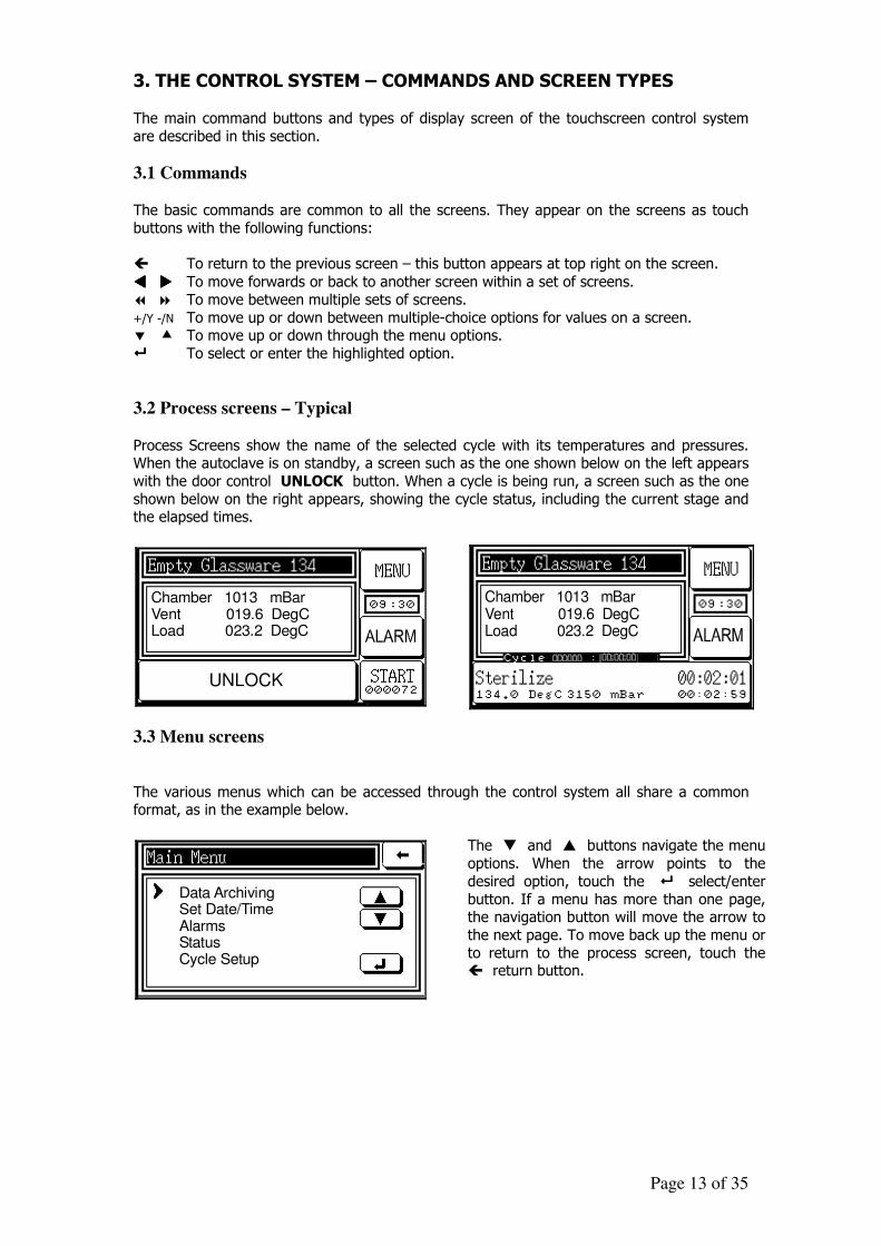
3.2 Process screens – Typical
Process Screens show the name of the selected cycle with its temperatures and pressures. When the autoclave is on standby, a screen such as the one shown below on the left appears
with the door control UNLOCK button. When a cycle is being run, a screen such as the one
shown below on the right appears, showing the cycle status, including the current stage and the elapsed times.
UNLOCK
Chamber 1013 mBarVent 019.6 DegCLoad 023.2 DegC
3.3 Menu screens
Chamber 1013 mBarVent 019.6 DegCLoad 023.2 DegC
The various menus which can be accessed through the control system all share a common format, as in the example below.
Data ArchivingSet Date/TimeAlarmsStatusCycle Setup
The � and � buttons navigate the menu
options. When the arrow points to the
desired option, touch the ���� select/enter
button. If a menu has more than one page, the navigation button will move the arrow to
the next page. To move back up the menu or
to return to the process screen, touch the � return button.
Page 14 of 35
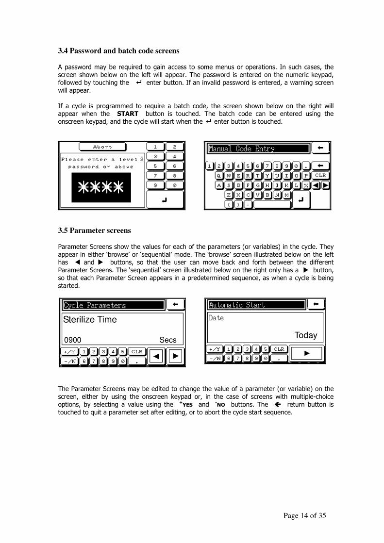
3.4 Password and batch code screens
A password may be required to gain access to some menus or operations. In such cases, the screen shown below on the left will appear. The password is entered on the numeric keypad,
followed by touching the ���� enter button. If an invalid password is entered, a warning screen
will appear.
If a cycle is programmed to require a batch code, the screen shown below on the right will appear when the START button is touched. The batch code can be entered using the
onscreen keypad, and the cycle will start when the ���� enter button is touched.
3.5 Parameter screens
Parameter Screens show the values for each of the parameters (or variables) in the cycle. They
appear in either ‘browse’ or ‘sequential’ mode. The ‘browse’ screen illustrated below on the left has � and � buttons, so that the user can move back and forth between the different
Parameter Screens. The ‘sequential’ screen illustrated below on the right only has a � button,
so that each Parameter Screen appears in a predetermined sequence, as when a cycle is being
started.
Sterilize Time
0900 Secs
Today
The Parameter Screens may be edited to change the value of a parameter (or variable) on the
screen, either by using the onscreen keypad or, in the case of screens with multiple-choice
options, by selecting a value using the +YES and -NO buttons. The � return button is
touched to quit a parameter set after editing, or to abort the cycle start sequence.
Page 15 of 35
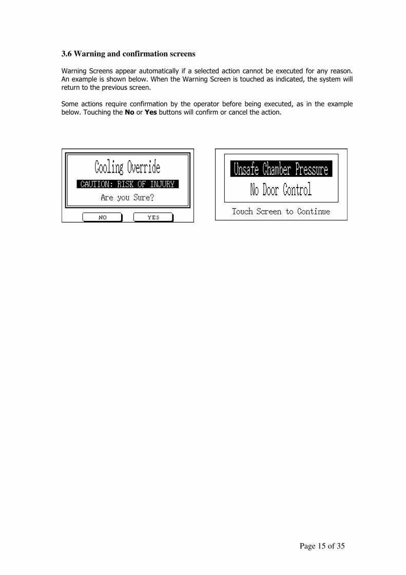
3.6 Warning and confirmation screens
Warning Screens appear automatically if a selected action cannot be executed for any reason. An example is shown below. When the Warning Screen is touched as indicated, the system will
return to the previous screen.
Some actions require confirmation by the operator before being executed, as in the example
below. Touching the No or Yes buttons will confirm or cancel the action.
Page 16 of 35
4. THE CONTROL SYSTEM – OPERATING THE DOOR It is only possible to operate the door of the chamber when there is no cycle in progress and no
automatic start has been set.
4.1 Locks
Locking The door lock is operated by closing the door and touching the LOCK button on the screen.
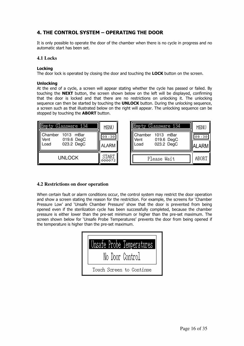
Unlocking
At the end of a cycle, a screen will appear stating whether the cycle has passed or failed. By
touching the NEXT button, the screen shown below on the left will be displayed, confirming that the door is locked and that there are no restrictions on unlocking it. The unlocking
sequence can then be started by touching the UNLOCK button. During the unlocking sequence, a screen such as that illustrated below on the right will appear. The unlocking sequence can be
stopped by touching the ABORT button.
UNLOCK
Chamber 1013 mBarVent 019.6 DegCLoad 023.2 DegC
Chamber 1013 mBarVent 019.6 DegCLoad 023.2 DegC
4.2 Restrictions on door operation
When certain fault or alarm conditions occur, the control system may restrict the door operation and show a screen stating the reason for the restriction. For example, the screens for ‘Chamber
Pressure Low’ and ‘Unsafe Chamber Pressure’ show that the door is prevented from being
opened even if the sterilization cycle has been successfully completed, because the chamber pressure is either lower than the pre-set minimum or higher than the pre-set maximum. The
screen shown below for ‘Unsafe Probe Temperatures’ prevents the door from being opened if the temperature is higher than the pre-set maximum.
Page 17 of 35
5. THE CONTROL SYSTEM – RUNNING A CYCLE
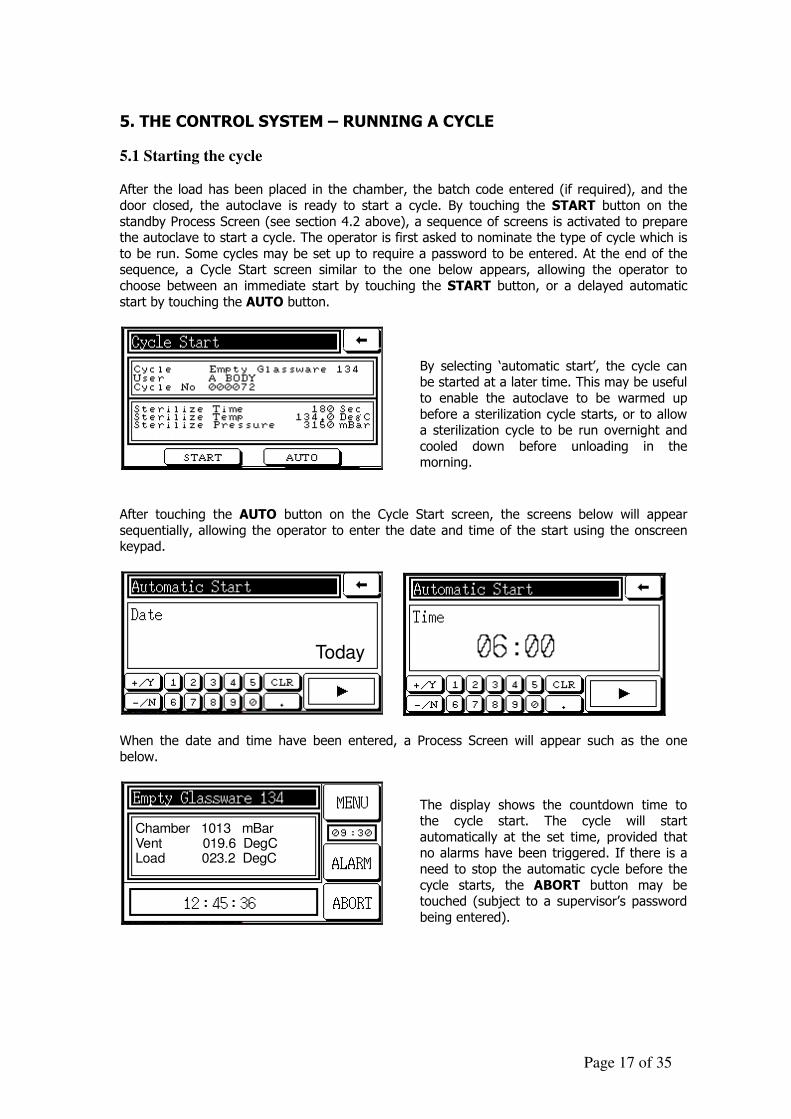
5.1 Starting the cycle After the load has been placed in the chamber, the batch code entered (if required), and the
door closed, the autoclave is ready to start a cycle. By touching the START button on the
standby Process Screen (see section 4.2 above), a sequence of screens is activated to prepare the autoclave to start a cycle. The operator is first asked to nominate the type of cycle which is
to be run. Some cycles may be set up to require a password to be entered. At the end of the sequence, a Cycle Start screen similar to the one below appears, allowing the operator to
choose between an immediate start by touching the START button, or a delayed automatic
start by touching the AUTO button.
By selecting ‘automatic start’, the cycle can be started at a later time. This may be useful
to enable the autoclave to be warmed up
before a sterilization cycle starts, or to allow a sterilization cycle to be run overnight and
cooled down before unloading in the morning.
After touching the AUTO button on the Cycle Start screen, the screens below will appear
sequentially, allowing the operator to enter the date and time of the start using the onscreen keypad.
Today
When the date and time have been entered, a Process Screen will appear such as the one
below.
Chamber 1013 mBarVent 019.6 DegCLoad 023.2 DegC
The display shows the countdown time to the cycle start. The cycle will start
automatically at the set time, provided that no alarms have been triggered. If there is a
need to stop the automatic cycle before the
cycle starts, the ABORT button may be touched (subject to a supervisor’s password
being entered).
Page 18 of 35
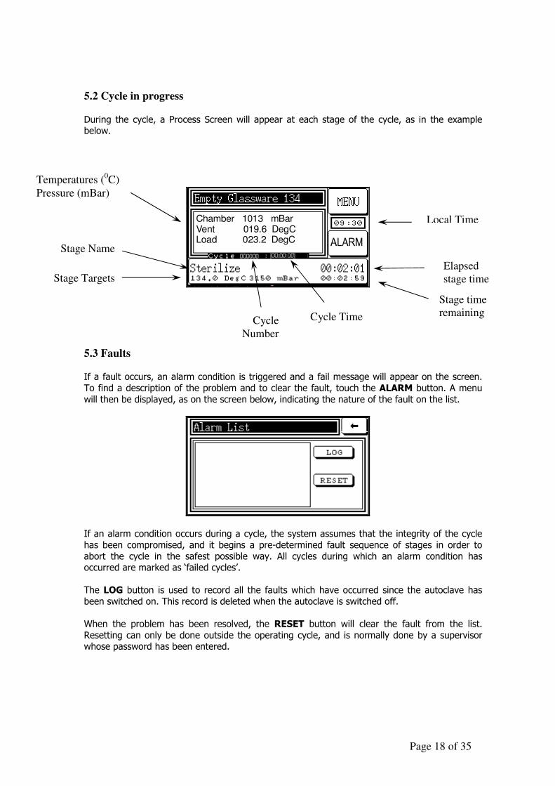
5.2 Cycle in progress
During the cycle, a Process Screen will appear at each stage of the cycle, as in the example below.
Chamber 1013 mBarVent 019.6 DegCLoad 023.2 DegC
5.3 Faults If a fault occurs, an alarm condition is triggered and a fail message will appear on the screen.
To find a description of the problem and to clear the fault, touch the ALARM button. A menu
will then be displayed, as on the screen below, indicating the nature of the fault on the list.
If an alarm condition occurs during a cycle, the system assumes that the integrity of the cycle
has been compromised, and it begins a pre-determined fault sequence of stages in order to
abort the cycle in the safest possible way. All cycles during which an alarm condition has occurred are marked as ‘failed cycles’.
The LOG button is used to record all the faults which have occurred since the autoclave has
been switched on. This record is deleted when the autoclave is switched off.
When the problem has been resolved, the RESET button will clear the fault from the list.
Resetting can only be done outside the operating cycle, and is normally done by a supervisor whose password has been entered.
Local Time
Temperatures (0C)
Pressure (mBar)
Stage Name
Stage Targets Elapsed
stage time
Cycle Time
Stage time
remaining Cycle
Number
Page 19 of 35
5.4 Cooling Override It is possible to shorten the overall cycle time by accessing the Cooling Override through the
menu, which can bring the cooling stage to an end after the temperature has reduced to below
100oC (rather than the normal 80oC). If the Cooling Override is used, care must be taken to ensure that the temperature inside the chamber is safe for the load when it is suddenly exposed
to ambient air temperature. It is recommended that the user draws up a procedure for use of the Cooling Override function, and that its availability is limited to supervisors.
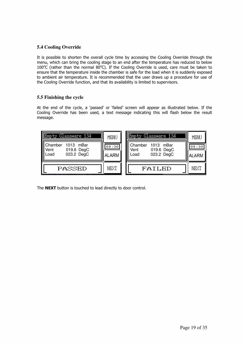
5.5 Finishing the cycle
At the end of the cycle, a ‘passed’ or ‘failed’ screen will appear as illustrated below. If the Cooling Override has been used, a text message indicating this will flash below the result
message.
Chamber 1013 mBarVent 019.6 DegCLoad 023.2 DegC
Chamber 1013 mBarVent 019.6 DegCLoad 023.2 DegC
The NEXT button is touched to lead directly to door control.
Page 20 of 35
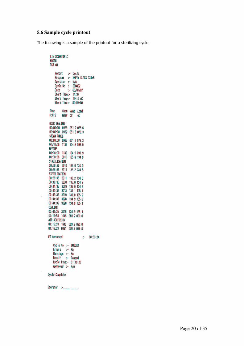
5.6 Sample cycle printout
The following is a sample of the printout for a sterilizing cycle.
Page 21 of 35
6. THE CONTROL SYSTEM – RUNNING A CYCLE
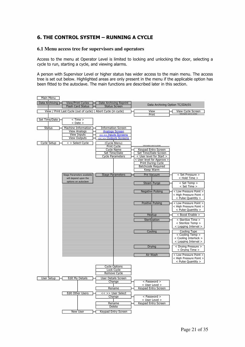
6.1 Menu access tree for supervisors and operators Access to the menu at Operator Level is limited to locking and unlocking the door, selecting a
cycle to run, starting a cycle, and viewing alarms.
A person with Supervisor Level or higher status has wider access to the main menu. The access tree is set out below. Highlighted areas are only present in the menu if the applicable option has
been fitted to the autoclave. The main functions are described later in this section.
New User Keypad Entry Screen
< User Level >Rename Keypad Entry ScreenDelete
Edit Other Users << >> User SelectChange < Password >
Change < Password >< User Level >
Rename Keypad Entry Screen
< Pulse Quantity >
Lock CycleRemove Cycle
User Setup Edit My Details User Details Screen
< Drying Time >
Air Wash < Low Pressure Point >< High Pressure Point >
< Cooling Interlock >
Stage Parameters available
will depend upon the
Drying < Drying Pressure >
options on autoclave
< Boost Enable >
< Sterilize Time >< Sterilize Temp >
< High Pressure Point >< Pulse Quantity >
Heatup
Sterilization
< Set Temp >
Pre Vacuum
< Set Time >
< Low Pressure Point >
Keypad Entry Screen
Stage Parameters < Set Pressure >< Hold Time >
View Outputs << >> Outputs Screens
Cycle Setup < > Select Cycle (Cycle Menu)
View Analogs Analogs ScreenView Inputs << >> Inputs Screens
< Date >
Status Machine Information Information Screen
< Time >
View / Print Last Cycle (out of cycle) | Abort Cycle (in cycle)
Set Time/Date
View Cycle ScreenInformation sent to printer
Main Menu
Data Archiving View/Print Cycles Date Archiving ReprintData Archiving Option TC/IDA/01
Flash Card Status Status Screen
ViewPrint
< User level for Approve >
Set Time/Date Set Time/Date Screen
Print Cycle Information sent to printer
Cycle Name
Cycle Parameters < User level for Start >
Print During CycleBatchcode Required
Keep Warm
Negative Pulsing
Steam Purge
< Logging Interval >
Cooling Type
Cycle Options
Positive Pulsing < Low Pressure Point >< High Pressure Point >< Pulse Quantity >
< Logging Interval >
Cooling< Cooling Temp >
Page 22 of 35
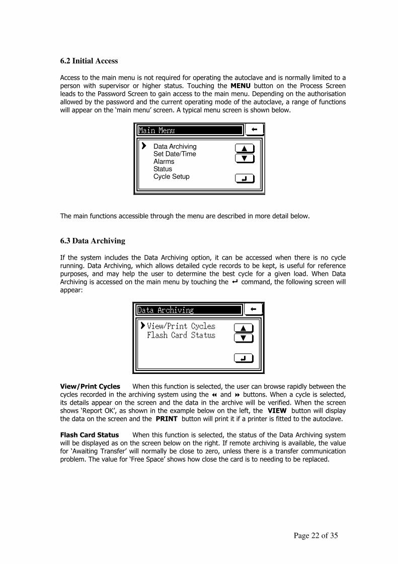
6.2 Initial Access Access to the main menu is not required for operating the autoclave and is normally limited to a
person with supervisor or higher status. Touching the MENU button on the Process Screen leads to the Password Screen to gain access to the main menu. Depending on the authorisation
allowed by the password and the current operating mode of the autoclave, a range of functions
will appear on the ‘main menu’ screen. A typical menu screen is shown below.
Data ArchivingSet Date/TimeAlarmsStatusCycle Setup
The main functions accessible through the menu are described in more detail below.
6.3 Data Archiving If the system includes the Data Archiving option, it can be accessed when there is no cycle
running. Data Archiving, which allows detailed cycle records to be kept, is useful for reference purposes, and may help the user to determine the best cycle for a given load. When Data
Archiving is accessed on the main menu by touching the ���� command, the following screen will
appear:
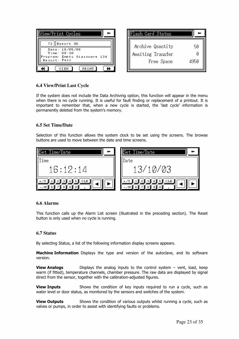
View/Print Cycles When this function is selected, the user can browse rapidly between the cycles recorded in the archiving system using the � and � buttons. When a cycle is selected,
its details appear on the screen and the data in the archive will be verified. When the screen shows ‘Report OK’, as shown in the example below on the left, the VIEW button will display
the data on the screen and the PRINT button will print it if a printer is fitted to the autoclave.
Flash Card Status When this function is selected, the status of the Data Archiving system
will be displayed as on the screen below on the right. If remote archiving is available, the value for ‘Awaiting Transfer’ will normally be close to zero, unless there is a transfer communication
problem. The value for ‘Free Space’ shows how close the card is to needing to be replaced.
Page 23 of 35
6.4 View/Print Last Cycle If the system does not include the Data Archiving option, this function will appear in the menu
when there is no cycle running. It is useful for fault finding or replacement of a printout. It is important to remember that, when a new cycle is started, the ‘last cycle’ information is
permanently deleted from the system’s memory.
6.5 Set Time/Date Selection of this function allows the system clock to be set using the screens. The browse
buttons are used to move between the date and time screens.
6.6 Alarms
This function calls up the Alarm List screen (illustrated in the preceding section). The Reset
button is only used when no cycle is running.
6.7 Status
By selecting Status, a list of the following information display screens appears.
Machine Information Displays the type and version of the autoclave, and its software
version.
View Analogs Displays the analog inputs to the control system – vent, load, keep warm (if fitted), temperature channels, chamber pressure. The raw data are displayed by signal
direct from the sensor, together with the calibration-adjusted figures.
View Inputs Shows the condition of key inputs required to run a cycle, such as
water level or door status, as monitored by the sensors and switches of the system.
View Outputs Shows the condition of various outputs whilst running a cycle, such as valves or pumps, in order to assist with identifying faults or problems.
Page 24 of 35
Sterilization Information Displays the F0 value (a measure of sterilization) for the last cycle. This information can be useful for improving cycle times.
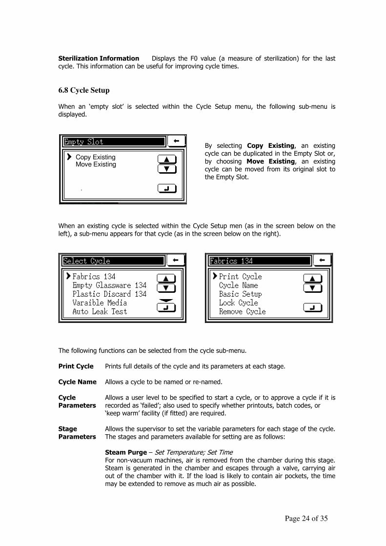
6.8 Cycle Setup
When an ‘empty slot’ is selected within the Cycle Setup menu, the following sub-menu is displayed.
Copy ExistingMove Existing
By selecting Copy Existing, an existing
cycle can be duplicated in the Empty Slot or,
by choosing Move Existing, an existing cycle can be moved from its original slot to
the Empty Slot.
When an existing cycle is selected within the Cycle Setup men (as in the screen below on the
left), a sub-menu appears for that cycle (as in the screen below on the right).
The following functions can be selected from the cycle sub-menu.
Print Cycle Prints full details of the cycle and its parameters at each stage.
Cycle Name Allows a cycle to be named or re-named.
Cycle Allows a user level to be specified to start a cycle, or to approve a cycle if it is
Parameters recorded as ‘failed’; also used to specify whether printouts, batch codes, or ‘keep warm’ facility (if fitted) are required.
Stage Allows the supervisor to set the variable parameters for each stage of the cycle.
Parameters The stages and parameters available for setting are as follows:
Steam Purge – Set Temperature; Set Time For non-vacuum machines, air is removed from the chamber during this stage. Steam is generated in the chamber and escapes through a valve, carrying air
out of the chamber with it. If the load is likely to contain air pockets, the time
may be extended to remove as much air as possible.
Page 25 of 35
Pre-Vacuum (if vacuum fitted) – Set Pressure; Hold Time The set temperature determines the pressure to which the vessel is drawn down (for example, 500mBar), in order to begin removing air before
sterilization. When this pressure is reached, the Hold Time determines the time in seconds for which the pressure is to be held.
Negative Pulsing (if vacuum fitted) – Low & High Pressure Points; Pulse Quantity Vacuum systems have superior air removal, but may increase the length of the cycle. Low and high pressure limits are normally set at around 500mBar and
800mBar respectively. The air is removed during a set quantity of pulses. On Porous load machines low and high pressure limits are 200mBar and 800mBar
Positive Pulsing – Low & High Pressure Points; Pulse Quantity To ensure steam penetration into the product
Low and high pressure limits are normally set at around 1100mBar and 1900mBar respectively. The process is complete after a set quantity of pulses
normally 3-5.
Heat up – Boost Factor The controlling temperature of the autoclave can be set at a specified temperature over the set sterilizing temperature, until the load reaches the set
sterilizing temperature. This procedure can reduce overall cycle time, with the risk of overshooting the upper controlling temperature, so it may be suitable for
discard loads but not media loads. The setting range is from zero to
250mb/2.50C.
Sterilization – Sterilize Time; Sterilize Temperature; Logging Interval The purpose of the autoclave is to sterilize the load effectively, and the
appropriate Sterilize Time (measured in seconds) will depend on the type of
load. Sterilize Temperature also depends on the type of load, and for most loads is between 1150C and 1360C. The Logging Interval, also measured
seconds, determines how often the cycle details are recorded or printed during this stage.
Cooling – Not available on Porous load machines Cooling Type; Cooling Temperature; Cooling Interlock; Logging Interval ‘Cooling type’ offers a choice of: a. normal cooling, which relies on fan cooling while the steam pressure slowly
drops to atmospheric pressure; or b. dynamic cooling, which uses fan cooling until the pressure has dropped to
1150mba, when air is blown through the chamber to reduce cooling time
and assist in drying the load; or c. ballast cooling, which maintains pressure in the chamber while replacing the
steam with air, thus avoiding loss of fluids, particularly for media loads.
‘Cooling temperature’ sets the temperature to which the load must reduce
before it is safe to open the door. To ensure the setting operates safely, the load probe must be within either the load or a simulated load.
‘Cooling Interlock’ is an optional safety measure which is best suited to liquid
loads. When the temperature is set, the cooling cycle is prevented from ending until the temperature of both the load and the chamber have reduces to the set
level. This setting requires a separate probe to monitor the chamber
temperature.
Page 26 of 35
‘Logging Interval’ determines how often the cycle details are recorded or
printed during this stage.
Lock Cycle Enables the cycle to be locked or unlocked. A locked cycle cannot be used.
Remove Cycle Allows the cycle to be removed from the menu, thereby creating an Empty Slot.
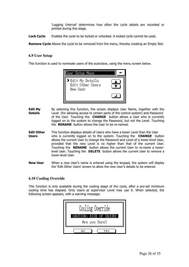
6.9 User Setup This function is used to nominate users of the autoclave, using the menu screen below.
Edit My By selecting this function, the screen displays User Name, together with the
Details Level (for allowing access to certain parts of the control system) and Password of the User. Touching the CHANGE button allows a User who is currently
logged on to the system to change the Password, but not the Level. Touching the RENAME button allows the User to be re-named.
Edit Other This function displays details of Users who have a lower Level than the User Users who is currently logged on to the system. Touching the CHANGE button
allows the current User to change the Password and Level of a lower-level User, provided that the new Level is no higher than that of the current User.
Touching the RENAME button allows the current User to re-name a lower-
level User. Touching the DELETE button allows the current User to remove a lower-level User.
New User When a new User’s name is entered using the keypad, the system will display
the ‘Edit Other Users’ screen to allow the new User’s details to be entered.
6.10 Cooling Override This function is only available during the cooling stage of the cycle, after a pre-set minimum
cooling time has elapsed. Only Users at supervisor Level may use it. When selected, the following screen appears, with a warning message:

Page 27 of 35
By touching the YES button, the autoclave will move to the next stage in the cycle. When the
cycle has finished, the User will be warned that this function was used and will not be permitted to move on to door control until the User’s password has been entered. Door control will
continue to be restricted until the temperature is below the temperatures specified in the cycle parameters.
Page 28 of 35
7. CARE AND MAINTENANCE Touchclave autoclaves are designed to be easy to maintain. Simple preventive maintenance, as
described in this section, will assist in achieving this objective, whilst prolonging the life and reliability of the autoclave.
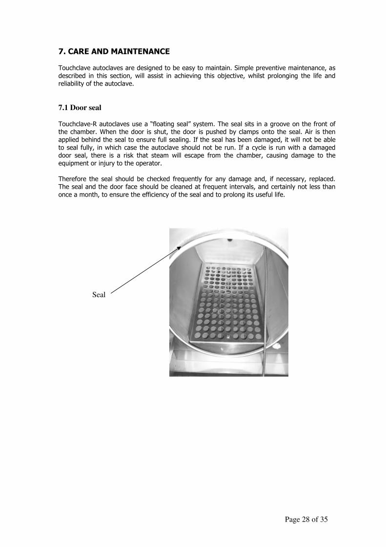
7.1 Door seal
Touchclave-R autoclaves use a “floating seal” system. The seal sits in a groove on the front of the chamber. When the door is shut, the door is pushed by clamps onto the seal. Air is then
applied behind the seal to ensure full sealing. If the seal has been damaged, it will not be able
to seal fully, in which case the autoclave should not be run. If a cycle is run with a damaged door seal, there is a risk that steam will escape from the chamber, causing damage to the
equipment or injury to the operator.
Therefore the seal should be checked frequently for any damage and, if necessary, replaced. The seal and the door face should be cleaned at frequent intervals, and certainly not less than
once a month, to ensure the efficiency of the seal and to prolong its useful life.
Seal
Page 29 of 35
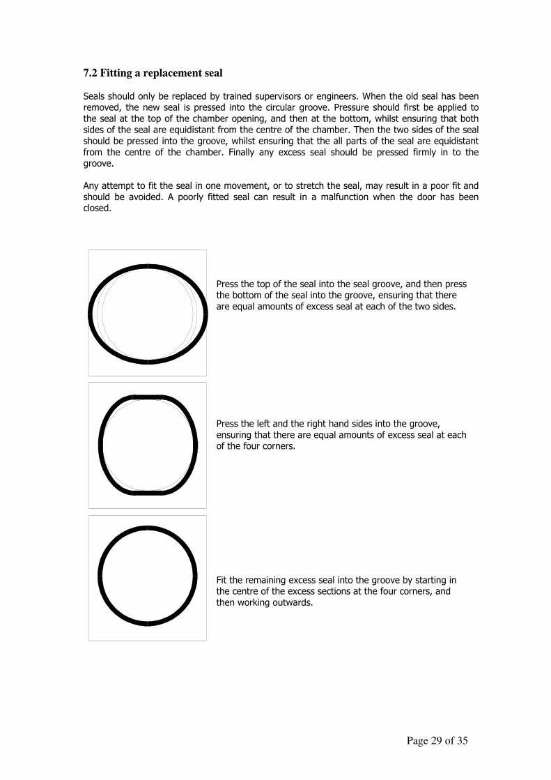
7.2 Fitting a replacement seal
Seals should only be replaced by trained supervisors or engineers. When the old seal has been removed, the new seal is pressed into the circular groove. Pressure should first be applied to
the seal at the top of the chamber opening, and then at the bottom, whilst ensuring that both sides of the seal are equidistant from the centre of the chamber. Then the two sides of the seal
should be pressed into the groove, whilst ensuring that the all parts of the seal are equidistant
from the centre of the chamber. Finally any excess seal should be pressed firmly in to the groove.
Any attempt to fit the seal in one movement, or to stretch the seal, may result in a poor fit and
should be avoided. A poorly fitted seal can result in a malfunction when the door has been closed.
Press the top of the seal into the seal groove, and then press the bottom of the seal into the groove, ensuring that there
are equal amounts of excess seal at each of the two sides.
Press the left and the right hand sides into the groove,
ensuring that there are equal amounts of excess seal at each of the four corners.
Fit the remaining excess seal into the groove by starting in the centre of the excess sections at the four corners, and
then working outwards.
Page 30 of 35
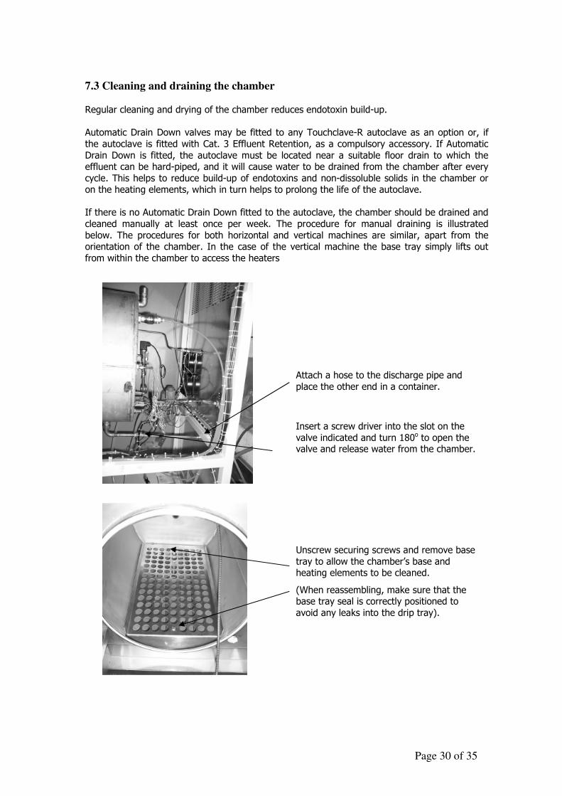
7.3 Cleaning and draining the chamber Regular cleaning and drying of the chamber reduces endotoxin build-up.
Automatic Drain Down valves may be fitted to any Touchclave-R autoclave as an option or, if
the autoclave is fitted with Cat. 3 Effluent Retention, as a compulsory accessory. If Automatic
Drain Down is fitted, the autoclave must be located near a suitable floor drain to which the effluent can be hard-piped, and it will cause water to be drained from the chamber after every
cycle. This helps to reduce build-up of endotoxins and non-dissoluble solids in the chamber or on the heating elements, which in turn helps to prolong the life of the autoclave.
If there is no Automatic Drain Down fitted to the autoclave, the chamber should be drained and
cleaned manually at least once per week. The procedure for manual draining is illustrated
below. The procedures for both horizontal and vertical machines are similar, apart from the orientation of the chamber. In the case of the vertical machine the base tray simply lifts out
from within the chamber to access the heaters
Attach a hose to the discharge pipe and
place the other end in a container.
Insert a screw driver into the slot on the
valve indicated and turn 180o to open the valve and release water from the chamber.
Unscrew securing screws and remove base
tray to allow the chamber’s base and heating elements to be cleaned.
(When reassembling, make sure that the base tray seal is correctly positioned to
avoid any leaks into the drip tray).
Page 31 of 35
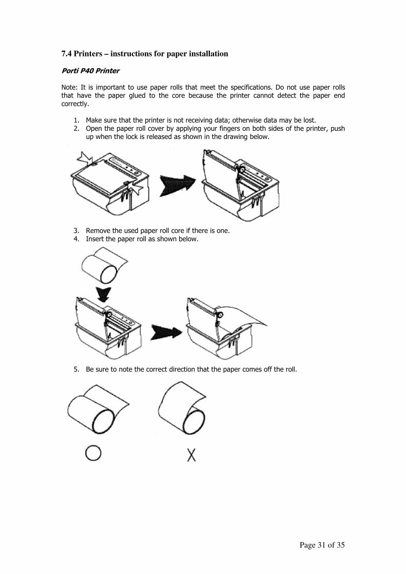
7.4 Printers – instructions for paper installation
Porti P40 Printer
Note: It is important to use paper rolls that meet the specifications. Do not use paper rolls that have the paper glued to the core because the printer cannot detect the paper end
correctly.
1. Make sure that the printer is not receiving data; otherwise data may be lost.
2. Open the paper roll cover by applying your fingers on both sides of the printer, push up when the lock is released as shown in the drawing below.
3. Remove the used paper roll core if there is one.
4. Insert the paper roll as shown below.
5. Be sure to note the correct direction that the paper comes off the roll.
Page 32 of 35
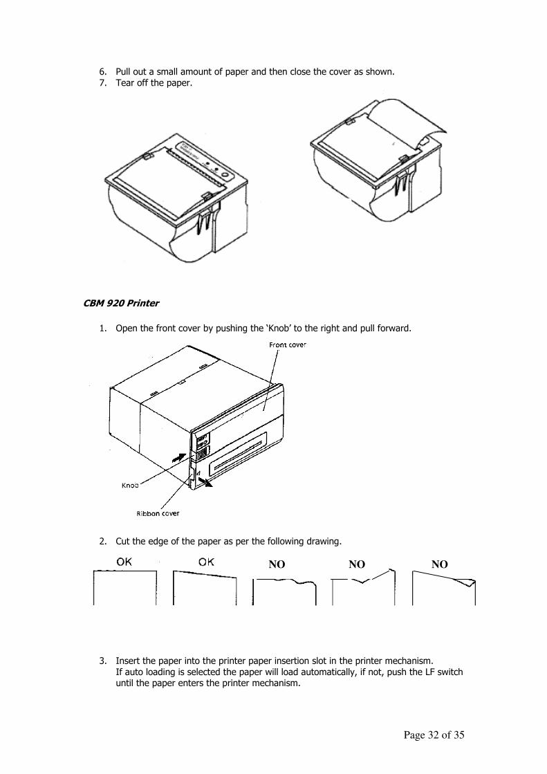
6. Pull out a small amount of paper and then close the cover as shown.
7. Tear off the paper.
CBM 920 Printer
1. Open the front cover by pushing the ‘Knob’ to the right and pull forward.
2. Cut the edge of the paper as per the following drawing.
3. Insert the paper into the printer paper insertion slot in the printer mechanism.
If auto loading is selected the paper will load automatically, if not, push the LF switch until the paper enters the printer mechanism.
NO
NO NO
Page 33 of 35
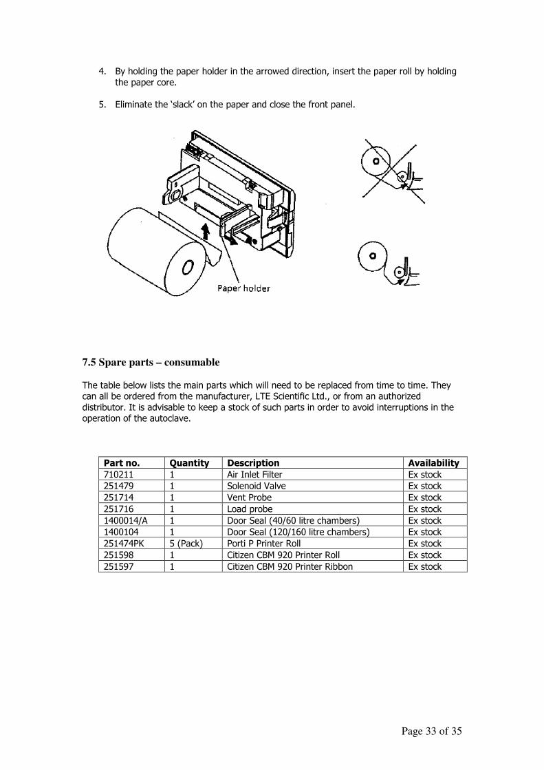
4. By holding the paper holder in the arrowed direction, insert the paper roll by holding
the paper core.
5. Eliminate the ‘slack’ on the paper and close the front panel.
7.5 Spare parts – consumable
The table below lists the main parts which will need to be replaced from time to time. They can all be ordered from the manufacturer, LTE Scientific Ltd., or from an authorized
distributor. It is advisable to keep a stock of such parts in order to avoid interruptions in the operation of the autoclave.
Part no. Quantity Description Availability
710211 1 Air Inlet Filter Ex stock
251479 1 Solenoid Valve Ex stock
251714 1 Vent Probe Ex stock
251716 1 Load probe Ex stock
1400014/A 1 Door Seal (40/60 litre chambers) Ex stock
1400104 1 Door Seal (120/160 litre chambers) Ex stock
251474PK 5 (Pack) Porti P Printer Roll Ex stock
251598 1 Citizen CBM 920 Printer Roll Ex stock
251597 1 Citizen CBM 920 Printer Ribbon Ex stock
Page 34 of 35
8. AFTER SALES SERVICES
8.1 General 8.1.1 LTE Scientific Ltd has a nationwide team of Service Engineers,
supported by service specialists based at our headquarters near Oldham. We pride ourselves on both the quality and speed of response we offer.
8.1.2 Before requesting any type of after sales service please obtain the
serial number of the equipment concerned.
8.1.3 Before commencing any repair or maintenance work it is the customers’ responsibility to ensure that the product is free from contamination that would be hazardous to the health of our Service personnel. This is a requirement of the Health & Safety at Work Act of 1974 and to meet our mutual responsibilities we will request you to complete a Safety Clearance Certificate prior to commencement of work.
8.2 Warranty 8.2.1 UK
Your product is warranted against the defects in materials and workmanship for 12 months from date of shipment.
8.2.2 Overseas
Your product will be warranted by LTE’s distributor company. 8.2.3 Limitations
Warranty cover will not apply to defects arising from:
• Improper use by the user • Unauthorised modifications • Operation of the products in unfavourable environments - see section 2 Full details of warranty conditions are contained in our Conditions of Sale - a copy of which is available on request.
Page 35 of 35
8.3 Maintenance Service Contracts
Regular servicing of the product will ensure it achieves maximum performance and provides years of uninterrupted service. We recommend that you take out a Preventative Maintenance Contract upon installation. This can include multiple unit contracts, regular calibration checks, all tailor made to suit your own specific requirements. LTE maintenance is cost effective, convenient and flexible to suit your needs.
8.4 Other Service Options 8.4.1 An Emergency Call-Out Service is available which provides you with the
assurance that, in the event of a break down, an LTE Service Engineer will be with you quickly to get you operational again.
8.4.2 Full training is available for the users, in the various operational
procedures to ensure optimum performance. 8.4.3 To ensure that the equipment meets NAMAS (National Measurement
Accreditation Service) standards, we recommend regular instrument calibration. All work would be carried out using NAMAS accredited measuring equipment.
8.5 OVERSEAS SERVICE
For customers outside the UK we are always available to try to help if you have a problem, however, we would recommend that you contact the company from whom you bought the product. Don’t forget to quote the Serial Number.
8.6 CONTACT DETAILS
Should you need to contact us here at LTE, for any reason, please do not hesitate to call us as we will be only too happy to help.
TEL : 01457 876221 FAX : 01457 870131 Email [email protected]