Embed Size (px)
Citation preview
2
OVERVIEW This document is organized into three sections that describe the process of selecting a robotic device for general and specific applications in the transit environment. The first section, “Environments,” identifies the expected conditions in which a device must operate and through which it must navigate. The second section, “Available Robotic Systems,” explains the features available for robot devices and provides a market survey of readily available systems that are appropriate for at least some transit applications. Finally, the section called “Selection Analysis” identifies the limitations in meeting the requirement specifications for transit applications. This section also reviews operator demands, training, and maintenance. This illustration is based on a review of several transit environments. When selecting a robotic device for transit applications, end users should strive to ensure that the physical and operational capabilities of the device meet the demands of the targeted transit environments.
ENVIRONMENTS In this section, the transit environments in which a robotic device must be able to function are listed and illustrated. These environments are discussed in the subsections titled “Structures,” “Vehicles,” “Roadways and Terrain,” “Weather Conditions,” “Optical Navigation Environments,” “Radio Environments,” “Hazardous Environments,” and “Other Requirements.” Both normal conditions and hazardous situations are examined. At the end of the “Environments” section, a compilation of robotic device performance requirements is assigned values, and constraining specifications are tabulated. This requirements specification defines the goals for a robotic device in a generic transit application.
Structures For the purpose of this report, structures are defined as buildings that are boarding/alighting points, equipment or vehicle storage garages, or permanent structures that in other ways provide a service to the transit system. This section does not include tunnels or bridges; these will be discussed later. Train and bus stations are structures of primary interest. They range in complexity of design and layout from small, one-room Quonsets to substantial buildings. Two environmental conditions will be considered here and throughout this report: standard obstacles under normal operating circumstances and random obstacles in disaster situations. Under normal conditions, the size of a robotic device should allow it to negotiate seating benches, fare collection equipment, ticketing counters, restrooms, offices, and so forth. Stairs and stairwell landing areas will define the robotic device climbing and turning requirements. The reach of the articulating arm that might carry a gripper, camera, or other sensor should be sufficient to access any elevated surfaces and recesses. In a disaster such as a building collapse, debris, rubble, and fallen structures will determine the robot height dimension and climbing requirement. Exemplary environments will be examined and a compilation of robotic device requirements relating to mobility and service capabilities in structures will be presented.
Washington DC Union Station Photo by Mark M. Piotrowski, courtesy of Washington, D.C. Chapter NRHS

In general, for normal operating conditions, large and small stations and terminals present identical obstacles. Although a terrorist attack is more likely to occur at a large busy terminal, smaller stations tend to have slightly smaller spaces and therefore are more demanding environments for robot use. Thus, for this report, local commuter stations were studied because they represent worst-case examples. Smaller stations are also more numerous and may provide more opportunities for the investigation of false alarms than larger stations. Two stations were analyzed, a commuter train station and a bus station in southern California. The train station waiting
Commuter train station, track level3
Elevator outside clearance
room presented no remarkable challenges to a robotic device as it was built for handicapped access. Handicapped access provides more than adequate mobility and reach clearances for almost all robot devices in the small-to-medium class. Access to the train, however, requires the use of a footbridge and an elevator. In the event of a disaster (assuming that conventional access would not be functional), access to the train would require a descent down a 60% grade or approximately a 1,000-foot drive on gravel. Further, in the event of structure collapse, in this station or in larger stations, access would be restricted in height to ground-based supporting structures such as counters or platforms. Although the bus station access was not as challenging, the structure makes identical demands on robotic devices.
Other structures, such as storage and repair buildings, were also examined. Lack of handicapped access meant that for a robotic device to function in these structures, it would need to have stair- climbing capability. In general, a robotic device would not have size restrictions in order to function in these structures.
Elevators
Footbridge
Grade Free access on gravel 1000 feet away
Commuter train station, street level - footbridge connecting north- and south-bound boarding/alighting platforms

4
Courtesy of Center for Robot-Assisted Search and Rescue
By permission of Amtrak Cascades
Structure disasters produce several types of environments for robots, as seen in their use at the World Trade Center. These include small passageways (typically in the ducting between floors), highly variable passageways caused by random building members and material distributions, and impenetrable areas or tall drop-offs. Investigating these different environments requires an arsenal of specialized robotic devices. However, it is highly impractical for any one agency to own this number of devices. More typically, a single bomb of relatively low energy will demolish a portion of a building (as seen in some
terrorism acts in the Middle East). This kind of destruction produces a more negotiable environment, consisting of passageways created by structure collapse onto desks, seats, and so forth, and produces 2- to 10-inch diameter rubble and steps.
Vehicles
Vehicle Access/Egress Vehicle entrance and egress present the most challenging mobility constraints on a robotic device. Although handicapped access allows good mobility to seating and restrooms, such access is not afforded to locations that are apt to have suspicious packages, perpetrator hiding places, or injured passengers. Further, the handicapped assist equipment may not be available in the event of a disaster or even a minor power outage. An analysis was performed on several vehicles, including commuter trains of pre- and post-1980s vintage, an intercity bus, and a trolley. Shown on the following page are the critical constraining dimensions of these vehicles for establishing robot requirements. Shown on the next page are data on vehicle parameters that will dictate the robotic device’s physical dimensions, stair-climbing ability, and power requirements. In “Vehicle Pathways, Overheads, and Transitions,” data on vehicle parameters that will dictate the device's turning radius, manipulator arm reach and dexterity requirements are provided. In the section, “Vehicle Special Obstacles,” data on vehicle parameters such as extreme stair pitch and passageways of unusually small width are provided. In “Vehicle Special Obstacles,” the vehicle parameters created by disaster situations are also discussed.

36" Width
Train pre-1980s
Intercity Bus
Commuter Trolley
8"
11"
12"
8"
Platform
14"
24" Width
Ground
18"
8"
8"
24" Width
5
Platform
Track bed
11"
Landing
12"8"
9"
8"
11"
3"5"

Vehicle Pathways, Overheads, and Transitions Shown below are corridors, seating, and overhead baggage compartments for typical transit vehicles. The arrangement and dimensions of these items are the primary factors in determining the requirements for a robot arm—typically a device that has multiple links and joints, provides
an extension for reaching, and terminates in a claw-like gripper. Looking into an overhead carrier and removing a package or deploying an X-ray camera to examine a package under a seat are just two examples of the demands on the arm and gripper. Shown below are examples of the kind of detailed drawings of vehicle floor plans that would be needed to determine robotic device requirements.
Train post-1980s Train pre-1980s Intercity Bus Commuter Trolley
6
Luggage Carrier
24"
21"(64" high)
Restroom
35"
40"
42"16"
27"Stairs
Seats
Luggage Carrier
16"(32"up to 12") 30"
(63" high) 24"(63" & 68" highat ramp extremes)
Luggage Carrier
14"39"
Seats
36"
Seats
Ramp
10"39"
24"
Train post-1980s Train pre-1980s Bus

Bus 16” x 24” step to corridor transition
20
20”
Compared with trains, buses have few unique mobility obstacles. With some exceptions, public transit buses are designed primarily for seated transport and do not have features such as diners, sleepers, or unique function areas. Because of this and the shorter commutes than trains, buses have comparatively smaller mobility areas and present the more stringent access requirements. On buses, the height of the first step, steepness of steps, transition from steps to corridor, and width of corridor all make access more difficult for a robotic device.
Vehicle Special Obstacles Rail cars comprise a wide variety of designs for functions ranging from dining to sleeping. Although no special function cars were studied for this report, a commuter train provided many obstacles that would challenge a robotic device. Shown below are features of a dining area on an upper deck. These features include a steep and narrow stair climb, an extremely small turning landing, and a dining floor raised above a very narrow corridor. Also shown is a stairway transition to upper-level seating, which has a severe stair incline and a small transition landing.
Narrow stairs ” wide, 50% pitch
36” wRaised eating deck wide x 13” high corridor
Stair-to-corridor transition landing 24” x 40”
7
Stair-to-corridor transition landing 36” x 36”
Stairs ide, 50% pitch
8
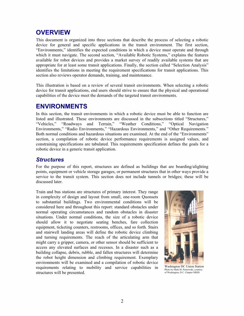
By permission of North Bank Fred
Personal items within vehicles can be as much of an obstacle for a robotic device as vehicle structure. Obstacles such as randomly placed luggage can present a formidable mobility impasse for a robotic device, even if it is not operating in a disaster situation. Such obstacles have a wide variety of shapes and sizes; no a priori standard can be used. Stair-climb and debris-diameter parameters should be used to estimate a robotic device's ability to negotiate random items. The effects of a disaster—debris, wreckage, and angle of floor and walls—also cannot be predicted, and any attempt at a specification must be tempered with a classification of the severity of the situation. Robots are primarily used in a disaster for search and observation in impenetrable locations. In the worst-case scenario, the vehicle height will be reduced to the height of other supporting structures such as seat bases, tables, and so forth. In such cases, attempts at conventional access are typically abandoned, and the robotic device is deployed through a window. In hazardous situations, the device is sometimes thrown through the window. Therefore, a critical requirement for the device, in addition to climbing and debris-traversing ability, is small physical size. Requirement specifications for incline climb, debris diameter, and physical size
will all need to be considered in selecting a robotic device; however, it is important to remember that deployment of robotic devices in a disaster situation is a best-effort basis.


![SEATTLE, WASHINGTON - Transportation Research …onlinepubs.trb.org/onlinepubs/tcrp/tcrp90v1_cs/Seattle.pdfSEATTLE, WASHINGTON (USA) METRO Bus Travel SUMMARY The 2.1-mile [1.3-kilometer]](https://img.pdfslide.net/doc/110x75/5aae0d327f8b9a59478b8b64/seattle-washington-transportation-research-washington-usa-metro-bus-travel.jpg)